CW Generator 2408L/AL 2420L/AL 2426L/AL 2440L/AL Signal Generator 2408M/AM 2420M/AM 2426M/AM 2440M/AM Frequency Range 10 MHz - 8 GHz 10 MHz - 20 GHz 10 MHz - 26.5 GHz 10 MHz - 40 GHz 2400 Series Microwave Synthesizer Datasheet Available Options and Accessories 22 Rear RF output (standard for A Series) 24 Internal Modulation Generator (M Series only) 26 Step Attenuator 28 High Stability Timebase (standard for L/M Series) 43 Frequency & Power Sweep (L/M Series only) 45 Rack Ears (L/M Series only) 48 Automation Xpress Software/Automation Xpress Interface (AXI) Fast Frequency Switching The fast frequency switching of the Giga-tronics 2400 Series Microwave Synthesizer pays dividends in any test environment where large amounts of data are collected. Regardless of the complexity of your application, such as antenna characterization or RFIC testing, the 2400 Series will quickly prove itself as your best test investment by providing quick settling of amplitude and frequency for minimum waiting between measurement points. In addition, the 2400 Series Automation Xpress software and interface option ensures unmatched 2.5 ms CW frequency and power switching performance, providing fast and flexible data exchange rates for faster testing and more device throughput. Low Phase Noise The Giga-tronics 2400 Series Microwave Synthesizers deliver state of the art phase noise and fast switching simultaneously. The 2400 Series low noise, high power and excellent phase stability are ideal for serving as your measurement system’s local oscillator and makes it suitable to serve as a low jitter clock. Faster to Program Every 2400 Series Microwave Synthesizer comes with Giga-tronics WaveMaker, a PC based software package designed for enhanced user interface and automatic test systems. WaveMaker leverages industry-leading software applications and familiar Windows drop-down menus and other functions to perform tasks. Using any Windows-based application, such as Microsoft™ Excel or Notepad, engineers can create, manage and download complex lists in a matter of seconds-right from the comfort of their desktop PC. Simpler to Operate From the first glance, it’s clear the Giga-tronics 2400 Series is different. Its innovative design and intuitive interface will make you productive right out of the box. The 2400 was designed to streamline user navigation by moving complex testing functions from the front panel to the desktop PC. The result is a groundbreaking system that reduces training time, speeds workflow and dramatically boosts end-user productivity. To enhance user navigation, we minimized the number of soft screens and menu layers, simplifying content and improving operational performance. That means you’ll spend less time scrolling through data menus and more time getting your work done. 2400A Series Optimized for ATE With the 2400A Series, ATE integrators now have a system source specifically designed to match their unique performance needs. The 2400A Series works seamlessly with other instruments. It includes hardware triggering and synchronization signals with programmable delay to allow coordination with other test products in your system. Emulating other industry-standard microwave synthesizers can be accommodated, making the 2400A Series the ideal choice for upgrading older systems. The 2400A Series standard features include a 3U rack mountable microwave synthesizer with rack ears, a high stability timebase option, rear RF-output, GPIB-interface, and a blank front panel-all for one competitive price. Advanced Test Equipment Rentals www.atecorp.com 800-404-ATEC (2832) ® E s t a blishe d 1 9 8 1
Available Options and Accessories22 Rear RF output (standard for A Series)24 Internal Modulation Generator (M Series only)26 Step Attenuator28 High Stability Timebase (standard for L/M Series)43 Frequency & Power Sweep (L/M Series only) 45 Rack Ears (L/M Series only)48 Automation Xpress Software/Automation Xpress
Interface (AXI)
Fast Frequency SwitchingThe fast frequency switching of the Giga-tronics 2400 Series Microwave Synthesizer pays dividends in any test environment where large amounts of data are collected. Regardless of the complexity of your application, such as antenna characterization or RFIC testing, the 2400 Series will quickly prove itself as your best test investment by providing quick settling of amplitude and frequency for minimum waiting between measurement points. In addition, the 2400 Series Automation Xpress software and interface option ensures unmatched 2.5 ms CW frequency and power switching performance, providing fast and flexible data exchange rates for faster testing and more device throughput.
Low Phase NoiseThe Giga-tronics 2400 Series Microwave Synthesizers deliver state of the art phase noise and fast switching simultaneously. The 2400 Series low noise, high power and excellent phase stability are ideal for serving as your measurement system’s local oscillator and makes it suitable to serve as a low jitter clock.
Faster to ProgramEvery 2400 Series Microwave Synthesizer comes with Giga-tronics WaveMaker, a PC based software package designed for enhanced user interface and automatic test systems. WaveMaker leverages industry-leading software applications and familiar Windows drop-down menus and other functions to perform tasks. Using any Windows-based application, such as Microsoft™ Excel or Notepad, engineers can create, manage and download complex lists in a matter of seconds-right from the comfort of their desktop PC.
Simpler to OperateFrom the first glance, it’s clear the Giga-tronics 2400 Series is different. Its innovative design and intuitive interface will make you productive right out of the box. The 2400 was designed to streamline user navigation by moving complex testing functions from the front panel to the desktop PC. The result is a groundbreaking system that reduces training time, speeds workflow and dramatically boosts end-user productivity. To enhance user navigation, we minimized the number of soft screens and menu layers, simplifying content and improving operational performance. That means you’ll spend less time scrolling through data menus and more time getting your work done.
2400A Series Optimized for ATEWith the 2400A Series, ATE integrators now have a system source specifically designed to match their unique performance needs. The 2400A Series works seamlessly with other instruments. It includes hardware triggering and synchronization signals with programmable delay to allow coordination with other test products in your system. Emulating other industry-standard microwave synthesizers can be accommodated, making the 2400A Series the ideal choice for upgrading older systems. The 2400A Series standard features include a 3U rack mountable microwave synthesizer with rack ears, a high stability timebase option, rear RF-output, GPIB-interface, and a blank front panel-all for one competitive price.
Advanced Test Equipment Rentalswww.atecorp.com 800-404-ATEC (2832)
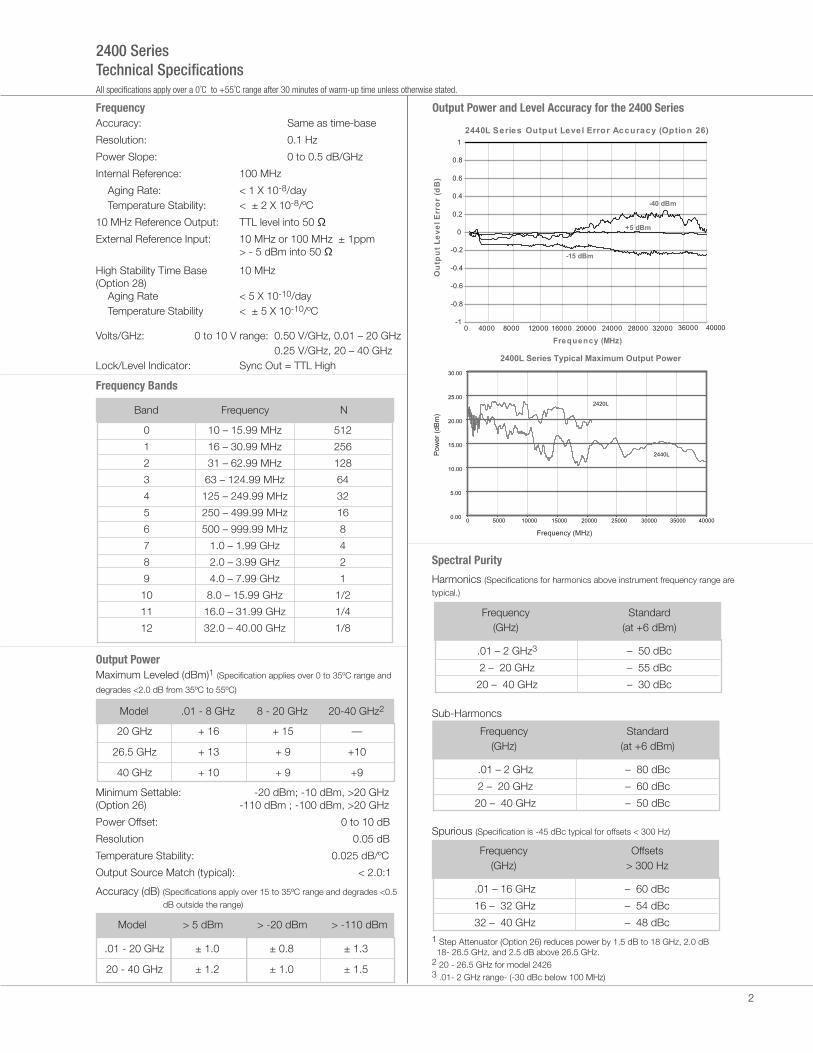
Output PowerMaximum Leveled (dBm)1 (Specification applies over 0 to 35ºC range and
degrades <2.0 dB from 35ºC to 55ºC)
Output Power and Level Accuracy for the 2400 Series
Spectral Purity
Harmonics (Specifications for harmonics above instrument frequency range are
typical.)
Sub-Harmoncs
Spurious (Specification is -45 dBc typical for offsets < 300 Hz)
1 Step Attenuator (Option 26) reduces power by 1.5 dB to 18 GHz, 2.0 dB 18- 26.5 GHz, and 2.5 dB above 26.5 GHz.2 20 - 26.5 GHz for model 24263 .01- 2 GHz range- (-30 dBc below 100 MHz)
Frequency(GHz)
Standard (at +6 dBm)
.01 – 2 GHz3
2 – 20 GHz
20 – 40 GHz
– 50 dBc
– 55 dBc
– 30 dBc
Frequency(GHz)
Standard (at +6 dBm)
.01 – 2 GHz
2 – 20 GHz
20 – 40 GHz
– 80 dBc
– 60 dBc
– 50 dBc
Frequency(GHz)
Offsets> 300 Hz
.01 – 16 GHz
16 – 32 GHz
32 – 40 GHz
– 60 dBc
– 54 dBc
– 48 dBc
0
1
2
3
4
5
6
7
8
9
10
11
12
10 – 15.99 MHz
16 – 30.99 MHz
31 – 62.99 MHz
63 – 124.99 MHz
125 – 249.99 MHz
250 – 499.99 MHz
500 – 999.99 MHz
1.0 – 1.99 GHz
2.0 – 3.99 GHz
4.0 – 7.99 GHz
8.0 – 15.99 GHz
16.0 – 31.99 GHz
32.0 – 40.00 GHz
512
256
128
64
32
16
8
4
2
1
1/2
1/4
1/8
Band Frequency N
2
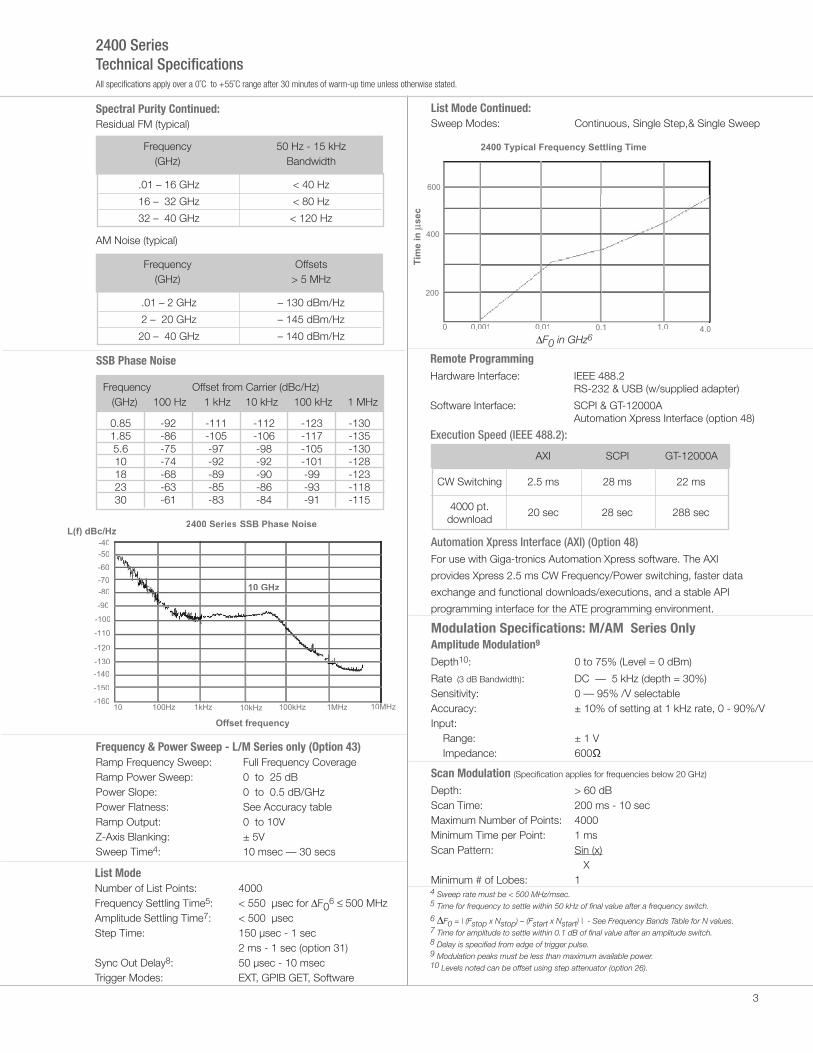
2400 Typical Frequency Settling Time
200
400
0 0.001 0.01 0.1 1.0 4.0
600
Tim
e i
n µ
se
c
2400 S ries SSB Phase Noise
-150
-140
-130
-120
-110
-50
10 100Hz 1kHz 10kHz 100kHz 1MHz Hz10MH
10 GHz
-100
-60
-70
-80
-90
-160
L(f) dBc/Hz
-40
Offset frequency
2400 SeriesTechnical SpecificationsAll specifications apply over a 0˚C to +55˚C range after 30 minutes of warm-up time unless otherwise stated.
SSB Phase Noise
Frequency Offset from Carrier (dBc/Hz) (GHz) 100 Hz 1 kHz 10 kHz 100 kHz 1 MHz
0.851.855.610182330
-92-86-75-74-68-63-61
-111-105-97-92-89-85-83
-112-106-98-92-90-86-84
-123-117-105-101-99-93-91
-130-135-130-128-123-118-115
Frequency(GHz)
50 Hz - 15 kHzBandwidth
.01 – 16 GHz
16 – 32 GHz
32 – 40 GHz
< 40 Hz
< 80 Hz
< 120 Hz
Frequency(GHz)
Offsets> 5 MHz
.01 – 2 GHz
2 – 20 GHz
20 – 40 GHz
– 130 dBm/Hz
– 145 dBm/Hz
– 140 dBm/Hz
Spectral Purity Continued:Residual FM (typical)
AM Noise (typical)
Frequency & Power Sweep - L/M Series only (Option 43)Ramp Frequency Sweep: Ramp Power Sweep:Power Slope:Power Flatness:Ramp Output:Z-Axis Blanking:Sweep Time4:
Full Frequency Coverage0 to 25 dB0 to 0.5 dB/GHzSee Accuracy table0 to 10V± 5V10 msec — 30 secs
List Mode Number of List Points: 4000 Frequency Settling Time5: < 550 µsec for ∆F0
Rate (3 dB Bandwidth): DC — 5 kHz (depth = 30%)Sensitivity: 0 — 95% /V selectableAccuracy: ± 10% of setting at 1 kHz rate, 0 - 90%/VInput:
Range: ± 1 VImpedance: 600Ω
Scan Modulation (Specification applies for frequencies below 20 GHz)
Depth: > 60 dBScan Time: 200 ms - 10 secMaximum Number of Points: 4000Minimum Time per Point: 1 msScan Pattern: Sin (x) XMinimum # of Lobes: 1
Modulation Specifications: M/AM Series Only
∆F0 in GHz6
Automation Xpress Interface (AXI) (Option 48)For use with Giga-tronics Automation Xpress software. The AXI
provides Xpress 2.5 ms CW Frequency/Power switching, faster data
exchange and functional downloads/executions, and a stable API
programming interface for the ATE programming environment.
3
4 Sweep rate must be < 500 MHz/msec.5 Time for frequency to settle within 50 kHz of final value after a frequency switch.
6 ∆F0 = | (Fstop x Nstop) – (Fstart x Nstart) | - See Frequency Bands Table for N values.7 Time for amplitude to settle within 0.1 dB of final value after an amplitude switch.8 Delay is specified from edge of trigger pulse.9 Modulation peaks must be less than maximum available power.10 Levels noted can be offset using step attenuator (option 26).
On/Off Ratio: 80 dB
Rise/Fall Times:
Pulse Modulation (Specifcation applies for frequencies above 500 MHz)
.5 - 20 GHz20- 40 GHz
< 10 ns< 25 ns
Frequency Rise Time
Giga-tronics Support ServicesAt Giga-tronics, we understand the challenges you face. Our support services begin from the moment you call us. We help you achieve both top-line growth and bottom-line efficiencies by working to identify your precise needs and implement smart and result orientated solutions.We believe and commit ourselves in providing you with more than our superior test solutions.
www.gigatronics.com/emailupdatesGet the latest information on Giga-tronics products & applications
11 Duty Cycle must be > 0.01%)
Data subject to change without notice.
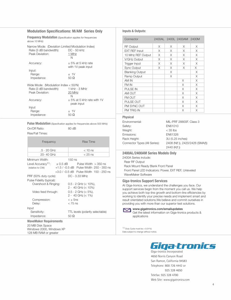
RF Output X X X XEXT REF Input X X X X10 MHz REF Output X X X XV/GHz Output X X X XTrigger Input X X X XSync Output X X X XBlanking Output X XRamp Output X XAM IN X XFM IN X XPULSE IN X XAM OUT X XFM OUT X XPULSE OUT X XPM SYNC OUT X XPM TRIG IN X X