ML15.051 MiniLine-2 5V, 3A, SINGLE PHASE INPUT POWER SUPPLY 100-240V Wide Range Input NEC Class 2 Compliant Adjustable Output Voltage Efficiency up to 77.2% Compact Design, Width only 22.5mm Full Output Power Between -10°C and +60°C Large International Approval Package 3 Year Warranty 1/22 GENERAL DESCRIPTION A compact size, light weight, simple mounting onto the DIN-rail and the utilization of only quality components are what makes the MiniLine power supplies so easy to use and install within seconds. A rugged electrical and mechanical design as well as a high immunity against electrical disturbances on the mains provides reliable output power. This offers superior protection for equipment which is connected to the public mains network or is exposed to a critical industrial environment. The MiniLine series offers output voltages from 5 to 56Vdc and a power rating from 15W to 120W. SHORT-FORM DATA Output voltage DC 5V Adjustment range 5 – 5.5V Output current 3A at 5V Output power 15W Output ripple < 50mVpp 20Hz to 20MHz Input voltage AC 100-240V -15% / +10% Mains frequency 50-60Hz ±6% AC Input current 0.28 / 0.17A at 120 / 230Vac Power factor 0.51 / 0.44 at 120 / 230Vac AC Inrush current typ. 16 /31A peak value at 120/230Vac, 40°C and cold start DC Input 88-375Vdc Efficiency 76.8 / 77.2% at 120 / 230Vac Losses 4.6 / 4.5W at 120 / 230Vac Temperature range -10°C to +70°C operational Derating 0.4W/°C +60 to +70°C Hold-up time typ. 45 / 186ms at 120 / 230Vac Dimensions 22.5x75x91mm WxHxD Weight 130g / 0.29lb ORDER NUMBERS Power Supply ML15.051 5V Standard unit MARKINGS UL 508 UL 60950-1 NEC Class 2 Class I Div 2 CSA 22.2 No107.1 Marine EMC, LVD, RoHS Mar. 2013 / Rev. 2.1 DS-ML15.051-EN All parameters are specified at 5V, 3A, 230Vac input, 25°C ambient and after a 5 minutes run-in time unless otherwise noted. www.pulspower.com Phone +49 89 9278 0 Germany
Transcript
ML15.051
MiniLine-2 5V, 3A, SINGLE PHASE INPUT
POWER SUPPLY 100-240V Wide Range Input NEC Class 2 Compliant Adjustable Output Voltage Efficiency up to 77.2% Compact Design, Width only 22.5mm Full Output Power Between -10°C and +60°C Large International Approval Package 3 Year Warranty
1/22
GENERAL DESCRIPTION A compact size, light weight, simple mounting onto the DIN-rail and the utilization of only quality components are what makes the MiniLine power supplies so easy to use and install within seconds.
A rugged electrical and mechanical design as well as a high immunity against electrical disturbances on the mains provides reliable output power. This offers superior protection for equipment which is connected to the public mains network or is exposed to a critical industrial environment.
The MiniLine series offers output voltages from 5 to 56Vdc and a power rating from 15W to 120W.
SHORT-FORM DATA
Output voltage DC 5V Adjustment range 5 – 5.5V Output current 3A at 5V Output power 15W Output ripple < 50mVpp 20Hz to 20MHz Input voltage AC 100-240V -15% / +10% Mains frequency 50-60Hz ±6% AC Input current 0.28 / 0.17A at 120 / 230Vac Power factor 0.51 / 0.44 at 120 / 230Vac AC Inrush current typ. 16 /31A peak value at
120/230Vac, 40°C and cold start
DC Input 88-375Vdc Efficiency 76.8 / 77.2% at 120 / 230Vac Losses 4.6 / 4.5W at 120 / 230Vac Temperature range -10°C to +70°C operational Derating 0.4W/°C +60 to +70°C Hold-up time typ. 45 / 186ms at 120 / 230Vac Dimensions 22.5x75x91mm WxHxD Weight 130g / 0.29lb
ORDER NUMBERS Power Supply ML15.051 5V Standard unit
MARKINGS
UL 508
UL 60950-1 NEC Class 2
Class I Div 2
CSA 22.2 No107.1
Marine
EMC, LVD, RoHS
Mar. 2013 / Rev. 2.1 DS-ML15.051-EN All parameters are specified at 5V, 3A, 230Vac input, 25°C ambient and after a 5 minutes run-in time unless otherwise noted.
www.pulspower.com Phone +49 89 9278 0 Germany
ML15.051
MiniLine-2 5V, 3A, SINGLE PHASE INPUT
INDEX
Page Page
1. Intended Use .......................................................3 2. Installation Requirements...................................3 3. AC-Input...............................................................4 4. DC-Input...............................................................5 5. Input Inrush Current ...........................................5 6. Output .................................................................6 7. Hold-up Time.......................................................7 8. Efficiency and Power Losses................................8 9. Functional Diagram.............................................9 10. Front Side and User Elements.............................9 11. Terminals and Wiring........................................10 12. Lifetime Expectancy and MTBF.........................10 13. EMC....................................................................11 14. Environment ......................................................12 15. Protection Features ...........................................13 16. Safety Features ..................................................13 17. Dielectric Strength ............................................14
21.1. Peak Current Capability ...........................17 21.2. Back-feeding Loads ..................................17 21.3. External Input Protection.........................18 21.4. Parallel Use to Increase Output Power....18 21.5. Parallel Use for Redundancy ....................19 21.6. Series Operation .......................................19 21.7. Inductive and Capacitive Loads................19 21.8. Operation on Two Phases ........................20 21.9. Use Without PE on the Input ...................20 21.10. Use in a Tightly Sealed Enclosure ............21 21.11. Mounting Orientations ............................22
The information presented in this document is believed to be accurate and reliable and may change without notice.
The housing is patent by PULS (US patent No US D442,923S)
No part of this document may be reproduced or utilized in any form without permission in writing from the publisher.
TERMINOLOGY AND ABREVIATIONS PE and symbol PE is the abbreviation for Protective Earth and has the same meaning as the symbol .
Earth, Ground This document uses the term “earth” which is the same as the U.S. term “ground”.
T.b.d. To be defined, value or description will follow later.
AC 230V A figure displayed with the AC or DC before the value represents a nominal voltage with standard tolerances (usually ±15%) included. E.g.: DC 12V describes a 12V battery disregarding whether it is full (13.7V) or flat (10V)
230Vac A figure with the unit (Vac) at the end is a momentary figure without any additional tolerances included.
50Hz vs. 60Hz As long as not otherwise stated, AC 100V and AC 230V parameters are valid at 50Hz and AC 120V parameters are valid at 60Hz mains frequency.
Mar. 2013 / Rev. 2.1 DS-ML15.051-EN All parameters are specified at 5V, 3A, 230Vac input, 25°C ambient and after a 5 minutes run-in time unless otherwise noted.
www.pulspower.com Phone +49 89 9278 0 Germany
2/22
ML15.051
MiniLine-2 5V, 3A, SINGLE PHASE INPUT
1. INTENDED USE This device is designed for installation in an enclosure and is intended for the general use such as in industrial control, office, communication, and instrumentation equipment.
Do not use this power supply in equipment, where malfunction may cause severe personal injury or threaten human life.
2. INSTALLATION REQUIREMENTS This device may only be installed and put into operation by qualified personnel.
This device does not contain serviceable parts. The tripping of an internal fuse is caused by an internal defect.
If damage or malfunction should occur during installation or operation, immediately turn power off and send unit to the factory for inspection.
Mount the unit on a DIN-rail so that the output terminals are located on top and input terminal on the bottom. For other mounting orientations see de-rating requirements in this document.
This device is designed for convection cooling and does not require an external fan. Do not obstruct airflow and do not cover ventilation grid (e.g. cable conduits) by more than 30%!
Keep the following installation clearances: 40mm on top, 20mm on the bottom 15mm on the left or right sides in case the adjacent device is a heat source (e.g. another power supply).
WARNING Risk of electrical shock, fire, personal injury or death. - Do not use the power supply without proper grounding (Protective Earth). Use the terminal on the input block for
earth connection and not one of the screws on the housing. - Turn power off before working on the device. Protect against inadvertent re-powering. - Make sure that the wiring is correct by following all local and national codes. - Do not modify or repair the unit. - Do not open the unit as high voltages are present inside. - Use caution to prevent any foreign objects from entering into the housing. - Do not use in wet locations or in areas where moisture or condensation can be expected. - Do not touch during power-on, and immediately after power-off. Hot surface may cause burns.
Notes for use in hazardous location areas:
The power supply is suitable for use in Class I Division 2 Groups A, B, C, D locations.
WARNING EXPLOSION HAZARDS!
Substitution of components may impair suitability for this environment. Do not disconnect the unit or operate the voltage adjustment unless power has been switched off or the area is known to be non-hazardous.
A suitable enclosure must be provided for the end product which has a minimum protection of IP54 and fulfils the requirements of the EN 60079-15:2010.
Mar. 2013 / Rev. 2.1 DS-ML15.051-EN All parameters are specified at 5V, 3A, 230Vac input, 25°C ambient and after a 5 minutes run-in time unless otherwise noted.
www.pulspower.com Phone +49 89 9278 0 Germany
3/22
ML15.051
MiniLine-2 5V, 3A, SINGLE PHASE INPUT
3. AC-INPUT
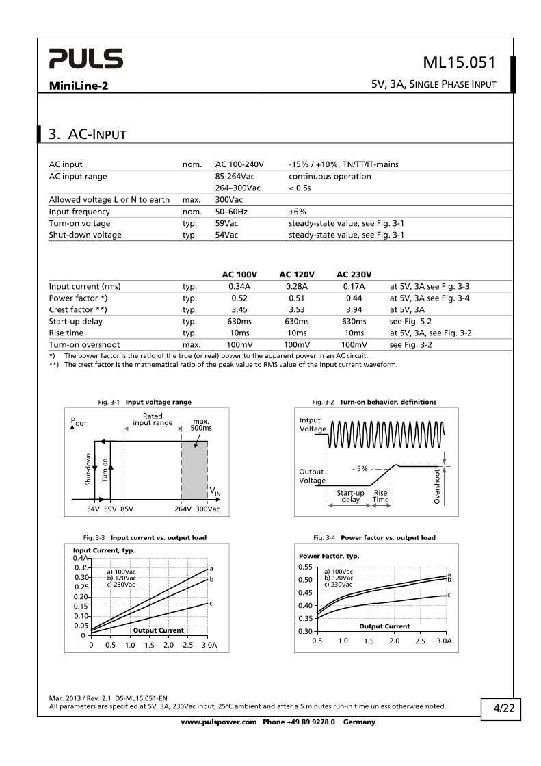
AC input nom. AC 100-240V -15% / +10%, TN/TT/IT-mains AC input range 85-264Vac continuous operation 264–300Vac < 0.5s Allowed voltage L or N to earth max. 300Vac Input frequency nom. 50–60Hz ±6% Turn-on voltage typ. 59Vac steady-state value, see Fig. 3-1
Shut-down voltage typ. 54Vac steady-state value, see Fig. 3-1
AC 100V AC 120V AC 230V Input current (rms) typ. 0.34A 0.28A 0.17A at 5V, 3A see Fig. 3-3
Power factor *) typ. 0.52 0.51 0.44 at 5V, 3A see Fig. 3-4
Crest factor **) typ. 3.45 3.53 3.94 at 5V, 3A Start-up delay typ. 630ms 630ms 630ms see Fig. 5 2 Rise time typ. 10ms 10ms 10ms at 5V, 3A, see Fig. 3-2
Turn-on overshoot max. 100mV 100mV 100mV see Fig. 3-2*) The power factor is the ratio of the true (or real) power to the apparent power in an AC circuit. **) The crest factor is the mathematical ratio of the peak value to RMS value of the input current waveform.
Fig. 3-1 Input voltage range Fig. 3-2 Turn-on behavior, definitions
Turn
-on
85V
Ratedinput range max.
500ms
VIN
POUT
54V 300Vac264V
Shu
t-d
ow
n
59V
Start-updelay
RiseTime O
vers
ho
ot- 5%Output
Voltage
IntputVoltage
Fig. 3-3 Input current vs. output load Fig. 3-4 Power factor vs. output load
3.0A0.5 1.0 2.000
0.10
0.4AInput Current, typ.
2.5
0.20
1.5
0.25
0.15
0.05
0.300.35
b
c
aa) 100Vacb) 120Vacc) 230Vac
Output Current
3.0A0.5 1.0 1.5 2.50.30
0.35
0.40
0.45
0.50
0.55
Power Factor, typ.
a) 100Vacb) 120Vacc) 230Vac
b
c
a
2.0
Output Current
Mar. 2013 / Rev. 2.1 DS-ML15.051-EN All parameters are specified at 5V, 3A, 230Vac input, 25°C ambient and after a 5 minutes run-in time unless otherwise noted.
www.pulspower.com Phone +49 89 9278 0 Germany
4/22
ML15.051
MiniLine-2 5V, 3A, SINGLE PHASE INPUT
4. DC-INPUT
DC input nom. DC 110-300V -20%/+25% DC input range min. 88-375Vdc continuous operation DC input current typ. 0.16A / 0.057A 110Vdc / 300Vdc, at 5V, 3A Turn-on voltage typ. 80Vdc steady state value Shut-down voltage typ. 60Vdc steady state value
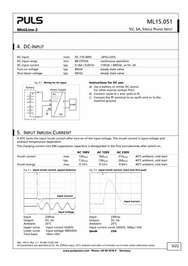
Fig. 4-1 Wiring for DC Input Instructions for DC use:
+
-
Load
L
N
PE
+
-
Power Supply
AC
DC
Battery
internalfused
a) Use a battery or similar DC source. For other sources contact PULS
b) Connect +pole to L and –pole to N. c) Connect the PE terminal to an earth wire or to the
machine ground.
5. INPUT INRUSH CURRENT A NTC limits the input inrush current after turn-on of the input voltage. The inrush current is input voltage and ambient temperature dependent.
The charging current into EMI suppression capacitors is disregarded in the first microseconds after switch-on.
AC 100V AC 120V AC 230V Inrush current max. 13Apeak 16Apeak 31Apeak 40°C ambient, cold start typ. 11Apeak 13Apeak 26Apeak 40°C ambient, cold start Inrush energy max. 0.1A2s 0.1A2s 0.4A2s 40°C ambient, cold start
Fig. 5-1 Input inrush current, typical behavior Fig. 5-2 Input inrush current, zoom into first peak
Input Voltage
Input Current
Input Current
Input: 230Vac Output: 5V, 3A Ambient: 25°C Upper curve: Input current 5A/DIV Lower curve: Input voltage 500V/DIV Time basis: 10ms / DIV
Input: 230Vac Output: 5V, 3A Ambient: 25°C Input current curve: 5A/DIV, 500μs / DIV Ipeak 23A
Mar. 2013 / Rev. 2.1 DS-ML15.051-EN All parameters are specified at 5V, 3A, 230Vac input, 25°C ambient and after a 5 minutes run-in time unless otherwise noted.
www.pulspower.com Phone +49 89 9278 0 Germany
5/22
ML15.051
MiniLine-2 5V, 3A, SINGLE PHASE INPUT
6. OUTPUT
Output voltage nom. 5V Adjustment range min. 5-5.5V guaranteed max. 6V *) at clockwise end position of potentiometer Factory setting 5.1V ±0.2%, at full load, cold unit Line regulation max. 10mV 85-264Vac Load regulation max. 100mV static value, 0A 3A Ripple and noise voltage max. 50mVpp 20Hz to 20MHz, 50Ohm Output capacitance typ. 4 800μF Output current nom. 3A at 5V, see Fig. 6-1
nom. 2.72A at 5.5V, see Fig. 6-1
Output power nom. 15W Short-circuit current min. hiccup mode see Fig. 6-2
max. 3A rms-current short circuit impedance <10mOhm, unit makes start-up
attempts at short-circuit (hiccup-mode) *) This is the maximum output voltage which can occur at the clockwise end position of the potentiometer due to tolerances. It is not a
guaranteed value which can be achieved. The typical value which can be achieved by turning the potentiometer to the clock-wise end position is 5.8V.
Fig. 6-1 Output voltage vs. output current, typ.
Fig. 6-2 Hiccup mode; output current at shorted output, 230Vac, typ.
Output Voltage
00
1
2
6V
3
4
5
3.5A2.51.50.5 2.01.0 3.0
AdjustmentRange
Output Current
ContinuousHiccup Mode
OutputCurrent
0
3.3A
45ms
t
235ms 235ms
Peak current capability (up to several milliseconds)
The power supply can deliver a peak current which is higher than the specified short term current. This helps to start current demanding loads or to safely operate subsequent circuit breakers.
The extra current is supplied by the output capacitors inside the power supply. During this event, the capacitors will be discharged and causes a voltage dip on the output. Detailed curves can be found in chapter 21.1.
Peak current voltage dips typ. from 5V to 2.4V at 6A for 50ms, resistive load typ. from 5V to 1.0V at 15A for 2ms, resistive load typ. from 5V to 0.8V at 15A for 5ms, resistive load
Mar. 2013 / Rev. 2.1 DS-ML15.051-EN All parameters are specified at 5V, 3A, 230Vac input, 25°C ambient and after a 5 minutes run-in time unless otherwise noted.
www.pulspower.com Phone +49 89 9278 0 Germany
6/22
ML15.051
MiniLine-2 5V, 3A, SINGLE PHASE INPUT
7. HOLD-UP TIME
AC 100V AC 120V AC 230V Hold-up Time typ. 61ms 93ms 340ms at 5V, 1.5A, see Fig. 7-1
typ. 29.5ms 45ms 186ms at 5V, 3A, see Fig. 7-1
Note: At no load, the hold-up time can be up to several seconds. The green DC-ok lamp is also on during this time
Fig. 7-1 Hold-up time vs. input voltage Fig. 7-2 Shut-down behavior, definitions
Mar. 2013 / Rev. 2.1 DS-ML15.051-EN All parameters are specified at 5V, 3A, 230Vac input, 25°C ambient and after a 5 minutes run-in time unless otherwise noted.
www.pulspower.com Phone +49 89 9278 0 Germany
7/22
ML15.051
MiniLine-2 5V, 3A, SINGLE PHASE INPUT
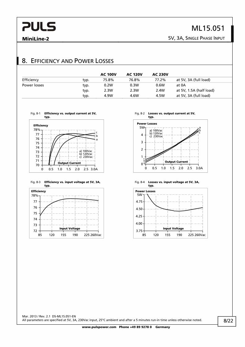
8. EFFICIENCY AND POWER LOSSES
AC 100V AC 120V AC 230V Efficiency typ. 75.8% 76.8% 77.2% at 5V, 3A (full load) Power losses typ. 0.2W 0.3W 0.6W at 0A typ. 2.3W 2.3W 2.4W at 5V, 1.5A (half load) typ. 4.9W 4.6W 4.5W at 5V, 3A (full load)
Fig. 8-1 Efficiency vs. output current at 5V, typ.
Fig. 8-2 Losses vs. output current at 5V, typ.
Efficiency
0
71727374757677
70
78%
3.0A1.0 1.5 2.5
Output Current
0.5 2.0
a) 100Vacb) 120Vacc) 230Vac
bc
a
Power Losses
0 0.5 3.0A0
2
3
5W
4
1.0 1.5 2.0
Output Current
2.5
a) 100Vacb) 120Vacc) 230Vac
bc
a
1cba
Fig. 8-3 Efficiency vs. input voltage at 5V, 3A, typ.
Fig. 8-4 Losses vs. input voltage at 5V, 3A, typ.
Efficiency
85 120 155 190 225 260Vac72
73
74
75
76
77
78%
Input Voltage
Power Losses
3.75
4.25
4.50
4.75
5W
85 120 155 190 225 260Vac
Input Voltage
4.00
Mar. 2013 / Rev. 2.1 DS-ML15.051-EN All parameters are specified at 5V, 3A, 230Vac input, 25°C ambient and after a 5 minutes run-in time unless otherwise noted.
www.pulspower.com Phone +49 89 9278 0 Germany
8/22
ML15.051
MiniLine-2 5V, 3A, SINGLE PHASE INPUT
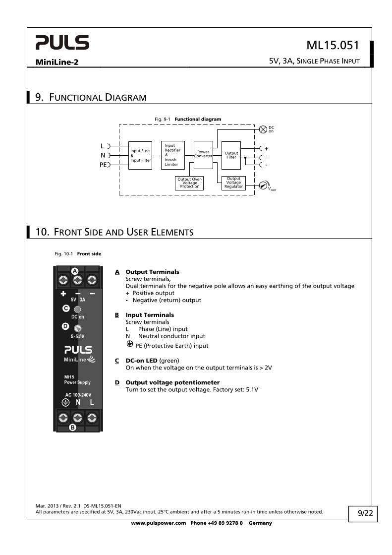
9. FUNCTIONAL DIAGRAM
Fig. 9-1 Functional diagram
Input Fuse&Input Filter
LN
Output Over-Voltage
Protection
InputRectifier&InrushLimiter
PowerConverter
OutputVoltage
Regulator
+--
OutputFilter
VOUT
DCon
PE
10. FRONT SIDE AND USER ELEMENTS
Fig. 10-1 Front side
A Output Terminals Screw terminals, Dual terminals for the negative pole allows an easy earthing of the output voltage + Positive output - Negative (return) output B Input Terminals Screw terminals L Phase (Line) input N Neutral conductor input
PE (Protective Earth) input C DC-on LED (green) On when the voltage on the output terminals is > 2V D Output voltage potentiometer
Turn to set the output voltage. Factory set: 5.1V
Mar. 2013 / Rev. 2.1 DS-ML15.051-EN All parameters are specified at 5V, 3A, 230Vac input, 25°C ambient and after a 5 minutes run-in time unless otherwise noted.
www.pulspower.com Phone +49 89 9278 0 Germany
9/22
ML15.051
MiniLine-2 5V, 3A, SINGLE PHASE INPUT
11. TERMINALS AND WIRING All terminals are easy to access when mounted on the panel. Input and output terminals are separated from each other (input below, output above) to help in error-free wiring.
Instructions: a) Use appropriate copper cables that are designed for minimum operating temperatures of:
60°C for ambient up to 45°C and 75°C for ambient up to 60°C minimum. b) Follow national installation codes and installation regulations! c) Ensure that all strands of a stranded wire enter the terminal connection! d) Up to two stranded wires with the same cross section are permitted in one connection point (except PE wire). e) Do not use the unit without PE connection. f) Screws of unused terminal compartments should be securely tightened. g) Ferrules are allowed.
12. LIFETIME EXPECTANCY AND MTBF These units are extremely reliable and use only the highest quality materials. The number of critical components such as electrolytic capacitors has been reduced.
AC 100V AC 120V AC 230V Lifetime expectancy *) 66 000h 70 000h 93 000h at 5V, 3A and 40°C > 15 years > 15 years > 15 years at 5V, 1.5A and 40°C > 15 years > 15 years > 15 years at 5V, 3A and 25°C MTBF **) SN 29500, IEC 61709 2 479 000h 2 838 000h 2 686 000h at 5V, 3A and 40°C 4 066 000h 4 654 000h 4 405 000h at 5V, 3A and 25°C MTBF **) MIL HDBK 217F 1 175 000h 1 251 000h 1 145 000h at 5V, 3A and 40°C; Ground Benign GB40 1 575 000h 1 676 000h 1 534 000h at 5V, 3A and 25°C; Ground Benign GB25 *) The Lifetime expectancy shown in the table indicates the minimum operating hours (service life) and is determined by the lifetime
expectancy of the built-in electrolytic capacitors. Lifetime expectancy is specified in operational hours and is calculated according to the capacitor’s manufacturer specification. The prediction model allows only a calculation of up to 15 years from date of shipment.
**) MTBF stands for Mean Time Between Failure, which is calculated according to statistical device failures, and indicates reliability of a device. It is the statistical representation of the likelihood of a unit to fail and does not necessarily represent the life of a product.
The MTBF figure is a statistical representation of the likelihood of a device to fail. A MTBF figure of e.g. 1 000 000h means that statistically one unit will fail every 100 hours if 10 000 units are installed in the field. However, it can not be determined if the failed unit has been running for 50 000h or only for 100h.
Mar. 2013 / Rev. 2.1 DS-ML15.051-EN All parameters are specified at 5V, 3A, 230Vac input, 25°C ambient and after a 5 minutes run-in time unless otherwise noted.
www.pulspower.com Phone +49 89 9278 0 Germany
10/22
ML15.051
MiniLine-2 5V, 3A, SINGLE PHASE INPUT
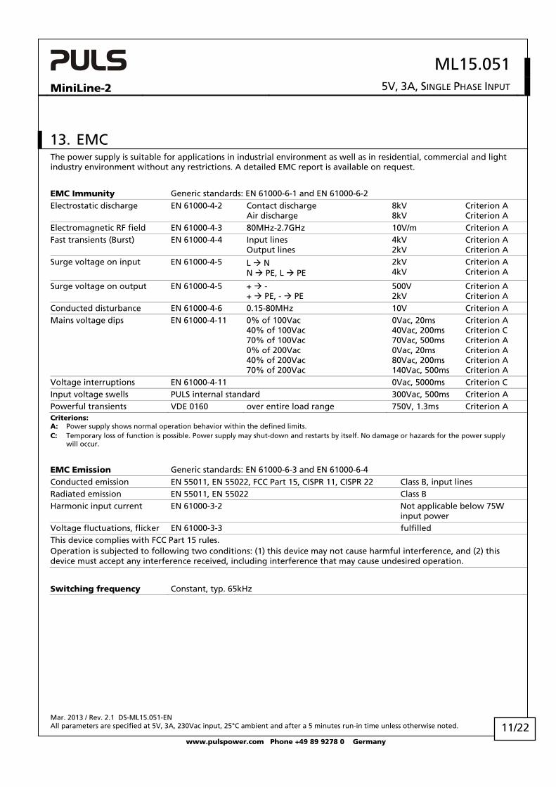
13. EMC The power supply is suitable for applications in industrial environment as well as in residential, commercial and light industry environment without any restrictions. A detailed EMC report is available on request.
EMC Immunity Generic standards: EN 61000-6-1 and EN 61000-6-2 Electrostatic discharge EN 61000-4-2 Contact discharge
Air discharge 8kV 8kV
Criterion A Criterion A
Electromagnetic RF field EN 61000-4-3 80MHz-2.7GHz 10V/m Criterion A Fast transients (Burst) EN 61000-4-4 Input lines
Output lines 4kV 2kV
Criterion A Criterion A
Surge voltage on input EN 61000-4-5 L N N PE, L PE
2kV 4kV
Criterion A Criterion A
Surge voltage on output EN 61000-4-5 + - + PE, - PE
500V 2kV
Criterion A Criterion A
Conducted disturbance EN 61000-4-6 0.15-80MHz 10V Criterion A Mains voltage dips EN 61000-4-11 0% of 100Vac
Criterion A Criterion C Criterion A Criterion A Criterion A Criterion A
Voltage interruptions EN 61000-4-11 0Vac, 5000ms Criterion C Input voltage swells PULS internal standard 300Vac, 500ms Criterion A Powerful transients VDE 0160 over entire load range 750V, 1.3ms Criterion A Criterions: A: Power supply shows normal operation behavior within the defined limits. C: Temporary loss of function is possible. Power supply may shut-down and restarts by itself. No damage or hazards for the power supply
will occur.
EMC Emission Generic standards: EN 61000-6-3 and EN 61000-6-4 Conducted emission EN 55011, EN 55022, FCC Part 15, CISPR 11, CISPR 22 Class B, input lines Radiated emission EN 55011, EN 55022 Class B Harmonic input current EN 61000-3-2 Not applicable below 75W
input power Voltage fluctuations, flicker EN 61000-3-3 fulfilled This device complies with FCC Part 15 rules. Operation is subjected to following two conditions: (1) this device may not cause harmful interference, and (2) this device must accept any interference received, including interference that may cause undesired operation.
Switching frequency Constant, typ. 65kHz
Mar. 2013 / Rev. 2.1 DS-ML15.051-EN All parameters are specified at 5V, 3A, 230Vac input, 25°C ambient and after a 5 minutes run-in time unless otherwise noted.
www.pulspower.com Phone +49 89 9278 0 Germany
11/22
ML15.051
MiniLine-2 5V, 3A, SINGLE PHASE INPUT
14. ENVIRONMENT
Operational temperature *) -10°C to +70°C (14°F to 158°F) Reduce output power according Fig. 14-1
Storage temperature -40 to +85°C (-40°F to 185°F) For storage and transportation Output de-rating 0.4W/°C 60-70°C (140°F to 158°F) Humidity **) 5 to 95% r.H. IEC 60068-2-30 Vibration sinusoidal 2-17.8Hz: ±1.6mm; 17.8-500Hz: 2g
2 hours / axis IEC 60068-2-6
Shock 30g 6ms, 20g 11ms 3 bumps / direction, 18 bumps in total
IEC 60068-2-27
Altitude 0 to 6000m (0 to 20 000ft) Reduce output power or ambient temperature above 2000m sea level.
Altitude de-rating 1W/1000m or 5°C/1000m above 2000m (6500ft), see Fig. 14-2
Over-voltage category III IEC 62103, EN 50178, altitudes up to 2000m II Altitudes from 2000m to 6000m Degree of pollution 2 IEC 62103, EN 50178, not conductive LABS compatibility The unit does not release any silicone or other LABS-critical substances and is suitable for
use in paint shops. *) Operational temperature is the same as the ambient temperature and is defined as the air temperature 2cm below the unit. **) Do not energize while condensation is present
Fig. 14-1 Output power vs. ambient temp. Fig. 14-2 Output power vs. altitude
0-10 0 20 40 70°C
2.5
5.0
7.5
10.0
12.5
15W
60
Ambient Temperature
AllowableOutput Power
00 2000 4000 6000m
2.5
5.0
7.5
10.0
12.5
15W
Altitude
A... Tamb < 60°CB... Tamb < 50°CC... Tamb < 40°C
AB
C
AllowableOutput Power
Mar. 2013 / Rev. 2.1 DS-ML15.051-EN All parameters are specified at 5V, 3A, 230Vac input, 25°C ambient and after a 5 minutes run-in time unless otherwise noted.
www.pulspower.com Phone +49 89 9278 0 Germany
12/22
ML15.051
MiniLine-2 5V, 3A, SINGLE PHASE INPUT
15. PROTECTION FEATURES
Output protection Electronically protected against overload, no-load and short-circuits *) Output over-voltage protection typ. 8.7Vdc
max. 9.6Vdc In case of an internal power supply fault, a redundant circuit limits the maximum output voltage. In such a case, the output shuts down and stays down until the input voltage is turned off and on again.
Output over-current protection electronically limited see Fig. 6-2
Degree of protection IP 20 EN/IEC 60529 Penetration protection > 2.5mm in diameter e.g. screws, small parts Over-temperature protection Not included Input transient protection MOV Metal Oxide Varistor Internal input fuse T3.15A H.B.C. not user replaceable *) In case of a protection event, audible noise may occur.
16. SAFETY FEATURES
Input / output separation *) SELV IEC/EN 60950-1 PELV IEC/EN 60204-1, EN 50178, IEC 62103, IEC 60364-4-41 Class of protection I PE (Protective Earth) connection required II (with restrictions) for use without PE connection contact PULS Isolation resistance > 5MOhm Input to output, 500Vdc Touch current (leakage current) typ. 0.17mA / 0.38mA 100Vac, 50Hz, TN-,TT-mains / IT-mains typ. 0.24mA / 0.55mA 120Vac, 60Hz, TN-,TT-mains / IT-mains typ. 0.40mA / 0.86mA 230Vac, 50Hz, TN-,TT-mains / IT-mains < 0.21mA / 0.44mA 110Vac, 50Hz, TN-,TT-mains / IT-mains < 0.30mA / 0.66mA 132Vac, 60Hz, TN-,TT-mains / IT-mains < 0.54mA / 1.08mA 264Vac, 50Hz, TN-,TT-mains / IT-mains *) Double or reinforced insulation
Mar. 2013 / Rev. 2.1 DS-ML15.051-EN All parameters are specified at 5V, 3A, 230Vac input, 25°C ambient and after a 5 minutes run-in time unless otherwise noted.
www.pulspower.com Phone +49 89 9278 0 Germany
13/22
ML15.051
MiniLine-2 5V, 3A, SINGLE PHASE INPUT
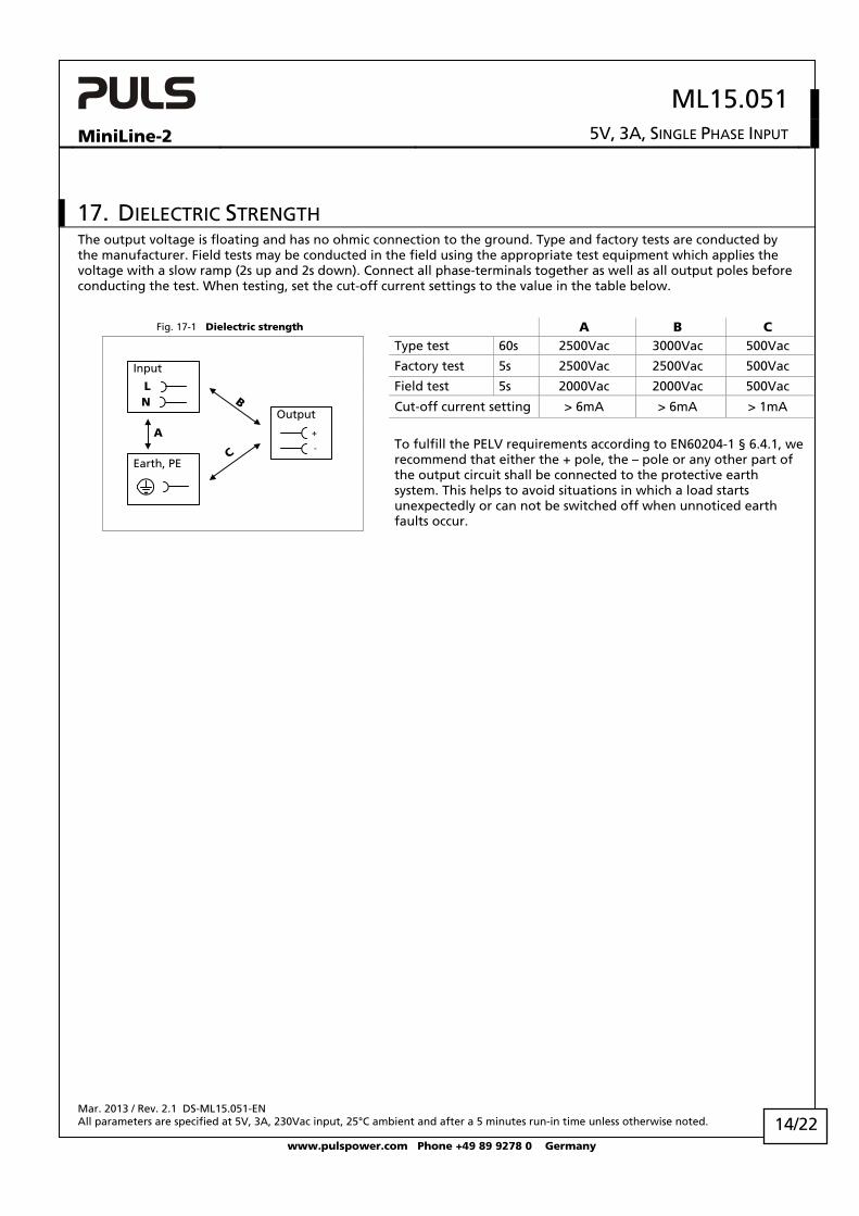
17. DIELECTRIC STRENGTH The output voltage is floating and has no ohmic connection to the ground. Type and factory tests are conducted by the manufacturer. Field tests may be conducted in the field using the appropriate test equipment which applies the voltage with a slow ramp (2s up and 2s down). Connect all phase-terminals together as well as all output poles before conducting the test. When testing, set the cut-off current settings to the value in the table below.
Fig. 17-1 Dielectric strength A B C Type test 60s 2500Vac 3000Vac 500Vac
Factory test 5s 2500Vac 2500Vac 500Vac
Field test 5s 2000Vac 2000Vac 500Vac
Cut-off current setting > 6mA > 6mA > 1mA
A
C
NL
Input
Earth, PE
Output
-
+
B
To fulfill the PELV requirements according to EN60204-1 § 6.4.1, we recommend that either the + pole, the – pole or any other part of the output circuit shall be connected to the protective earth system. This helps to avoid situations in which a load starts unexpectedly or can not be switched off when unnoticed earth faults occur.
Mar. 2013 / Rev. 2.1 DS-ML15.051-EN All parameters are specified at 5V, 3A, 230Vac input, 25°C ambient and after a 5 minutes run-in time unless otherwise noted.
www.pulspower.com Phone +49 89 9278 0 Germany
14/22
ML15.051
MiniLine-2 5V, 3A, SINGLE PHASE INPUT
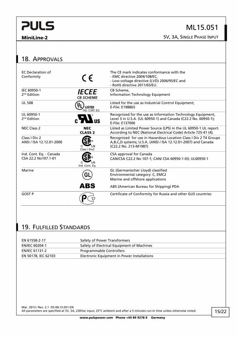
18. APPROVALS
EC Declaration of Conformity
The CE mark indicates conformance with the - EMC directive 2004/108/EC, - Low-voltage directive (LVD) 2006/95/EC and - RoHS directive 2011/65/EU.
IEC 60950-1 2nd Edition
CB Scheme, Information Technology Equipment
UL 508
Listed for the use as Industrial Control Equipment; E-File: E198865
UL 60950-1 2nd Edition
Recognized for the use as Information Technology Equipment, Level 3 in U.S.A. (UL 60950-1) and Canada (C22.2 No. 60950-1); E-File: E137006
NEC Class 2 NEC CLASS 2
Listed as Limited Power Source (LPS) in the UL 60950-1 UL report. According to NEC (National Electrical Code) Article 725-41 (4).
Class I Div 2 ANSI / ISA 12.12.01-2000
Class I Div2
Recognized for use in Hazardous Location Class I Div 2 T4 Groups A,B,C,D systems; U.S.A. (ANSI / ISA 12.12.01-2007) and Canada (C22.2 No. 213-M1987)
Ind. Cont. Eq. - Canada CSA 22.2 No107.1-01
Ind. Cont. Eq.
CSA approval for Canada CAN/CSA C22.2 No 107-1; CAN/ CSA 60950-1-03; UL60950-1
Certificate of Conformity for Russia and other GUS countries
19. FULFILLED STANDARDS
EN 61558-2-17 Safety of Power Transformers EN/IEC 60204-1 Safety of Electrical Equipment of Machines EN/IEC 61131-2 Programmable Controllers EN 50178, IEC 62103 Electronic Equipment in Power Installations
Mar. 2013 / Rev. 2.1 DS-ML15.051-EN All parameters are specified at 5V, 3A, 230Vac input, 25°C ambient and after a 5 minutes run-in time unless otherwise noted.
www.pulspower.com Phone +49 89 9278 0 Germany
15/22
ML15.051
MiniLine-2 5V, 3A, SINGLE PHASE INPUT
20. PHYSICAL DIMENSIONS AND WEIGHT
Weight 130g / 0.29lb DIN-Rail Use 35mm DIN-rails according to EN 60715 or EN 50022 with a height of 7.5 or 15mm.
The DIN-rail height must be added to the unit depth (91mm) to calculate the total required installation depth.
Installation Clearances See chapter 2
Fig. 20-1 Front view Fig. 20-2 Side view
Mar. 2013 / Rev. 2.1 DS-ML15.051-EN All parameters are specified at 5V, 3A, 230Vac input, 25°C ambient and after a 5 minutes run-in time unless otherwise noted.
www.pulspower.com Phone +49 89 9278 0 Germany
16/22
ML15.051
MiniLine-2 5V, 3A, SINGLE PHASE INPUT
21. APPLICATION NOTES
21.1. PEAK CURRENT CAPABILITY Solenoids, contactors and pneumatic modules often have a steady state coil and a pick-up coil. The inrush current demand of the pick-up coil is several times higher than the steady-state current and usually exceeds the nominal output current (including the PowerBoost) The same situation applies, when starting a capacitive load.
Branch circuits are often protected with circuit breakers or fuses. In case of a short or an overload in the branch circuit, the fuse needs a certain amount of over-current to trip or to blow. The peak current capability ensures the safe operation of subsequent circuit breakers.
Assuming the input voltage is turned on before such an event, the built-in large sized output capacitors inside the power supply can deliver extra current. Discharging this capacitor causes a voltage dip on the output. The following two examples show typical voltage dips:
Fig. 21-1 Peak loading with 2x the nominal current for 50ms, typ.
Fig. 21-2 Peak loading with 5x the nominal current for 5ms, typ.
10ms/DIV
OutputVoltage
OutputCurrent
5.1V
0A
6A2.4V
1ms/DIV
OutputVoltage
OutputCurrent
5.1V
0A
15A
0.8V
Peak load 6A (resistive load) for 50ms Output voltage dips from 5.1V to 2.4V.
Peak load 15A (resistive load) for 5ms Output voltage dips from 5.1V to 0.8V.
21.2. BACK-FEEDING LOADS Loads such as decelerating motors and inductors can feed voltage back to the power supply. This feature is also called return voltage immunity or resistance against Back- E.M.F. (Electro Magnetic Force).
The maximum allowed feed back voltage is 6.3Vdc. The absorbing energy can be calculated according to the built-in large sized output capacitor which is specified in chapter 6.
This power supply is resistant and does not show malfunctioning when a load feeds back voltage to the power supply. It does not matter, whether the power supply is on or off. However, please note that the output voltage can dip to zero for approximately 200ms if the back-feed voltage is removed.
Mar. 2013 / Rev. 2.1 DS-ML15.051-EN All parameters are specified at 5V, 3A, 230Vac input, 25°C ambient and after a 5 minutes run-in time unless otherwise noted.
www.pulspower.com Phone +49 89 9278 0 Germany
17/22
ML15.051
MiniLine-2 5V, 3A, SINGLE PHASE INPUT
21.3. EXTERNAL INPUT PROTECTION The unit is tested and approved for branch circuits up to 20A. An external protection is only required, if the supplying branch has an ampacity greater than this. Check also local codes and local requirements. In some countries local regulations might apply.
If an external fuse is necessary or utilized, minimum requirements need to be considered to avoid nuisance tripping of the circuit breaker. A minimum value of 6A B- or 3A C-Characteristic breaker should be used.
21.4. PARALLEL USE TO INCREASE OUTPUT POWER ML15.051 power supplies can be paralleled to increase the output power. This power supply has no feature included which balances the load current between the power supplies. Usually the power supply with the higher adjusted output voltage draws current until it goes into current limitation. This means no harm to this power supply as long as the ambient temperature stays below 45°C. The ML15.051 can also be paralleled with power supplies from MiniLine series with 5V output voltage. The output voltages of all power supplies shall be adjusted to the same value (±100mV). A fuse or diode on the output of each unit is only required if more than three units are connected in parallel. If a fuse (or circuit breaker) is used, choose one with approximately 150% of the rated output current of one power supply. Keep an installation clearance of 15mm (left / right) between two power supplies and avoid installing the power supplies on top of each other. Do not use power supplies in parallel in mounting orientations other than the standard mounting orientation (input terminals on the bottom and output terminals on top of the unit). Pay attention that leakage current, EMI, inrush current, harmonics will increase when using multiple power supplies.
Unit A
AC
DC
Unit B
AC
DC
-
+-
+
Load
+
-
Mar. 2013 / Rev. 2.1 DS-ML15.051-EN All parameters are specified at 5V, 3A, 230Vac input, 25°C ambient and after a 5 minutes run-in time unless otherwise noted.
www.pulspower.com Phone +49 89 9278 0 Germany
18/22
ML15.051
MiniLine-2 5V, 3A, SINGLE PHASE INPUT
21.5. PARALLEL USE FOR REDUNDANCY Power supplies can be paralleled for redundancy to gain higher system availability. Redundant systems require a certain amount of extra power to support the load in case one power supply unit fails. The simplest way is to put two power supplies in parallel. This is called a 1+1 redundancy. In case one power supply unit fails, the other one is automatically able to support the load current without any interruption. Redundant systems for a higher power demand are usually built in a N+1 method. E.g. five power supplies, each rated for 3A are paralleled to build a 12A redundant system.
Please note: This simple way to build a redundant system does not cover failures such as an internal short circuit in the secondary side of the power supply. In such a case, the defect unit becomes a load for the other power supplies and the output voltage can not be maintained any more. This can only be avoided by utilizing decoupling diodes which are included in the decoupling module MLY02.100.
Recommendations for building redundant power systems:
a) Use separate input fuses for each power supply.
b) Monitor the individual power supply units.
c) 1+1 Redundancy is allowed up to an ambient temperature of 60°C N+1 Redundancy is allowed up to an ambient temperature of 45°C
d) It is desirable to set the output voltages of all units to the same value (± 100mV) or leave it at the factory setting.
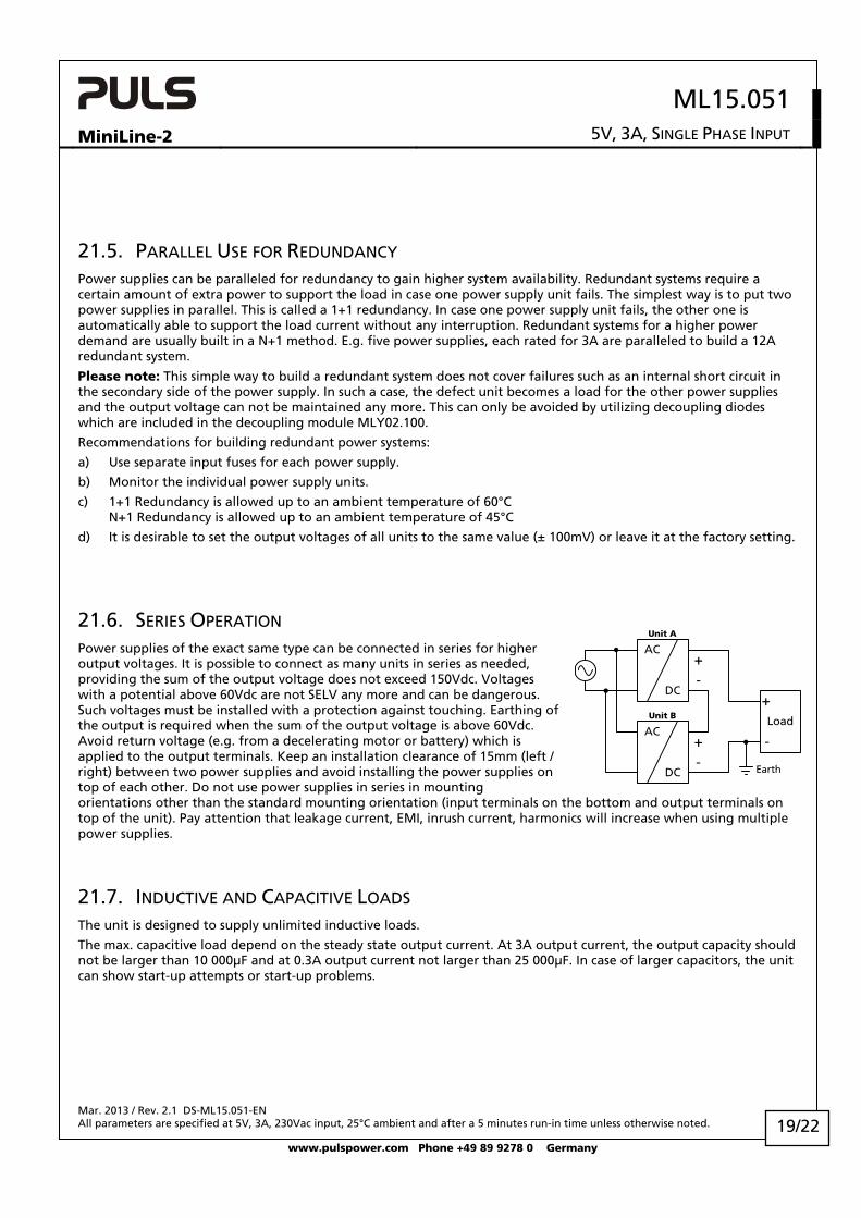
21.6. SERIES OPERATION Power supplies of the exact same type can be connected in series for higher output voltages. It is possible to connect as many units in series as needed, providing the sum of the output voltage does not exceed 150Vdc. Voltages with a potential above 60Vdc are not SELV any more and can be dangerous. Such voltages must be installed with a protection against touching. Earthing of the output is required when the sum of the output voltage is above 60Vdc. Avoid return voltage (e.g. from a decelerating motor or battery) which is applied to the output terminals. Keep an installation clearance of 15mm (left / right) between two power supplies and avoid installing the power supplies on top of each other. Do not use power supplies in series in mounting orientations other than the standard mounting orientation (input terminals on the bottom and output terminals on top of the unit). Pay attention that leakage current, EMI, inrush current, harmonics will increase when using multiple power supplies.
Earth
Unit A
AC
DC
Unit B
AC
DC
-
+-
+
Load
+
-
21.7. INDUCTIVE AND CAPACITIVE LOADS The unit is designed to supply unlimited inductive loads.
The max. capacitive load depend on the steady state output current. At 3A output current, the output capacity should not be larger than 10 000μF and at 0.3A output current not larger than 25 000μF. In case of larger capacitors, the unit can show start-up attempts or start-up problems.
Mar. 2013 / Rev. 2.1 DS-ML15.051-EN All parameters are specified at 5V, 3A, 230Vac input, 25°C ambient and after a 5 minutes run-in time unless otherwise noted.
www.pulspower.com Phone +49 89 9278 0 Germany
19/22
ML15.051
MiniLine-2 5V, 3A, SINGLE PHASE INPUT
21.8. OPERATION ON TWO PHASES
240V
+10
% m
ax.
Fuse
L2
L1
L3
L
N
PE
Power Supply
AC
DC
internalfuse
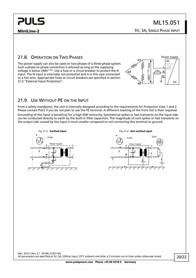
The power supply can also be used on two-phases of a three-phase-system. Such a phase-to-phase connection is allowed as long as the supplying voltage is below 240V+10%. Use a fuse or a circuit breaker to protect the N input. The N input is internally not protected and is in this case connected to a hot wire. Appropriate fuses or circuit breakers are specified in section 21.3 “External Input Protection”.
21.9. USE WITHOUT PE ON THE INPUT From a safety standpoint, the unit is internally designed according to the requirements for Protection Class 1 and 2. Please contact PULS if you do not plan to use the PE terminal. A different marking of the front foil is then required.
Grounding of the input is beneficial for a high EMI immunity: Symmetrical spikes or fast transients on the input side can be conducted directly to earth by the built-in filter capacitors. The magnitude of such spikes or fast transients on the output side caused by the input is much smaller compared to not connecting this terminal to ground.
Fig. 21-3 Earthed input Fig. 21-4 Not earthed input
Surge
Y
X
L
N
Ground
Power Supply+
-
Surge
X
L
N
Power Supply+
-
24V
Spike
Mar. 2013 / Rev. 2.1 DS-ML15.051-EN All parameters are specified at 5V, 3A, 230Vac input, 25°C ambient and after a 5 minutes run-in time unless otherwise noted.
www.pulspower.com Phone +49 89 9278 0 Germany
20/22
ML15.051
MiniLine-2 5V, 3A, SINGLE PHASE INPUT
21.10. USE IN A TIGHTLY SEALED ENCLOSURE When the power supply is installed in a tightly sealed enclosure, the temperature inside the enclosure will be higher than outside. In such situations, the inside temperature defines the ambient temperature for the power supply.
The following measurement results can be used as a reference to estimate the temperature rise inside the enclosure.
The power supply is placed in the middle of the box, no other heat producing items are inside the box
Case A: Load: 5V, 3A; load is placed outside the box Temperature inside the box: 38.2°C (in the middle of the right side of the power supply with a distance of 1cm) Temperature outside the box: 26.0°C Temperature rise: 12.2K
Case B: Load: 5V, 2.4A; (=80%) load is placed outside the box Temperature inside the box: 35.3°C (in the middle of the right side of the power supply with a distance of 1cm) Temperature outside the box: 25.6°C Temperature rise: 9.7K
Mar. 2013 / Rev. 2.1 DS-ML15.051-EN All parameters are specified at 5V, 3A, 230Vac input, 25°C ambient and after a 5 minutes run-in time unless otherwise noted.
www.pulspower.com Phone +49 89 9278 0 Germany
21/22
ML15.051
MiniLine-2 5V, 3A, SINGLE PHASE INPUT
Mar. 2013 / Rev. 2.1 DS-ML15.051-EN All parameters are specified at 5V, 3A, 230Vac input, 25°C ambient and after a 5 minutes run-in time unless otherwise noted.
www.pulspower.com Phone +49 89 9278 0 Germany
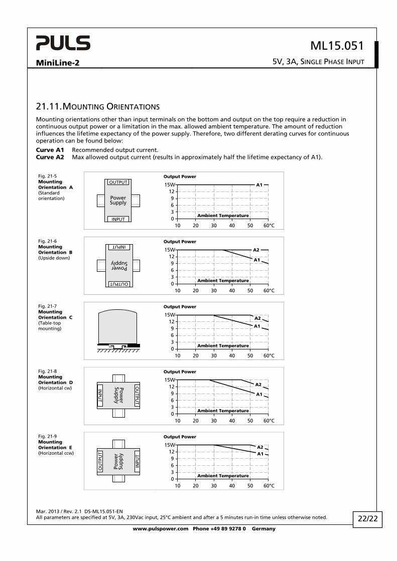
21.11. MOUNTING ORIENTATIONS Mounting orientations other than input terminals on the bottom and output on the top require a reduction in continuous output power or a limitation in the max. allowed ambient temperature. The amount of reduction influences the lifetime expectancy of the power supply. Therefore, two different derating curves for continuous operation can be found below:
Curve A1 Recommended output current. Curve A2 Max allowed output current (results in approximately half the lifetime expectancy of A1).
Fig. 21-5 Mounting Orientation A (Standard orientation) Power
Supply
OUTPUT
INPUT
Output Power
010 20 30 40 60°C
3
912
15W
50
A1
6
Ambient Temperature
Fig. 21-6 Mounting Orientation B (Upside down)
PowerSupply
OUTPUT
INPUT
Output Power
010 20 30 40 60°C
3
912
15W
50
6
A1
A2
Ambient Temperature
Fig. 21-7 Mounting Orientation C (Table-top mounting)
Output Power
010 20 30 40 60°C
3
912
15W
50
6
A1
A2
Ambient Temperature
Fig. 21-8 Mounting Orientation D (Horizontal cw) Po