45
GE Consumer & Industrial Power Protection Control and Automation For industrial applications ED.03 Plug-in relays and Auxiliary contactors GE imagination at work

@
GE Consumer & IndustrialPower Protection
Control and AutomationFor industrial applications ED.03
Plug-in relays and Auxiliary contactors
Power Protection (formerly GE Power Controls), a division of GE Consumer & Industrial, is a first class European supplier of low-voltage products including wiring devices, residential and industrial electrical distribution components, automation products, enclosures and switchboards. Demand for the company’s products comes from, wholesalers, installers, panel-board builders, contractors, OEMsand utilities worldwide.
www.ge.com/ex/powerprotectionwww.ge.com/eu/powerprotection
GE INDUSTRIAL BELGIUMPOWER PROTECTIONNieuwevaart 51B-9000 Gent - BelgiumTel. +32/9 265 21 11Fax +32/9 265 28 00E-mail: [email protected]
GE POWER CONTROLS Ltd 129-135 Camp Road St Albans Herts AL1 5HL United Kingdom Customer Service Tel. 0800 587 1251 Fax 0800 587 1239 [email protected]
GE Consumer & IndustrialPower Protection
680804Ref. C/4551/E/EX 11.0 Ed. 09/07
© Copyright GE Consumer & Industrial 2007
3958
4
Control and Autom
ationG
E Consum
er & Industrial
GE imagination at workGE imagination at work
ED.02
Plug-in relays & Auxiliary contactors
APlug-in relays and Auxiliary contactors
Motor protection devices
Contactors and Thermal overload relays
Motorstarters
Control and signalling units
Electronic relays
Limit switches
Speed drive units
Main switches
Numerical index
A.1
B
C
D
E
F
G
H
I
X
Everything is under control
A.3
A.7
A.14
A.17
A.26
A.31
A.40
A.23
A.34
A.36
A.42
Series PRC - Plug-in relays
Order codes
Technical data
Dimensions
Series M - Auxiliary minicontactors
Order codes
Technical data
Terminal numbering
Dimensions
Series RL - Auxiliary contactors
Order codes
Technical data
Terminal numbering
Dimensions
A
A.2
B
C
D
E
F
G
H
I
X
Plug
-in re
lays
Series PRC Series PRC
Plug-in relaysCECSAcULVDE
Approvals
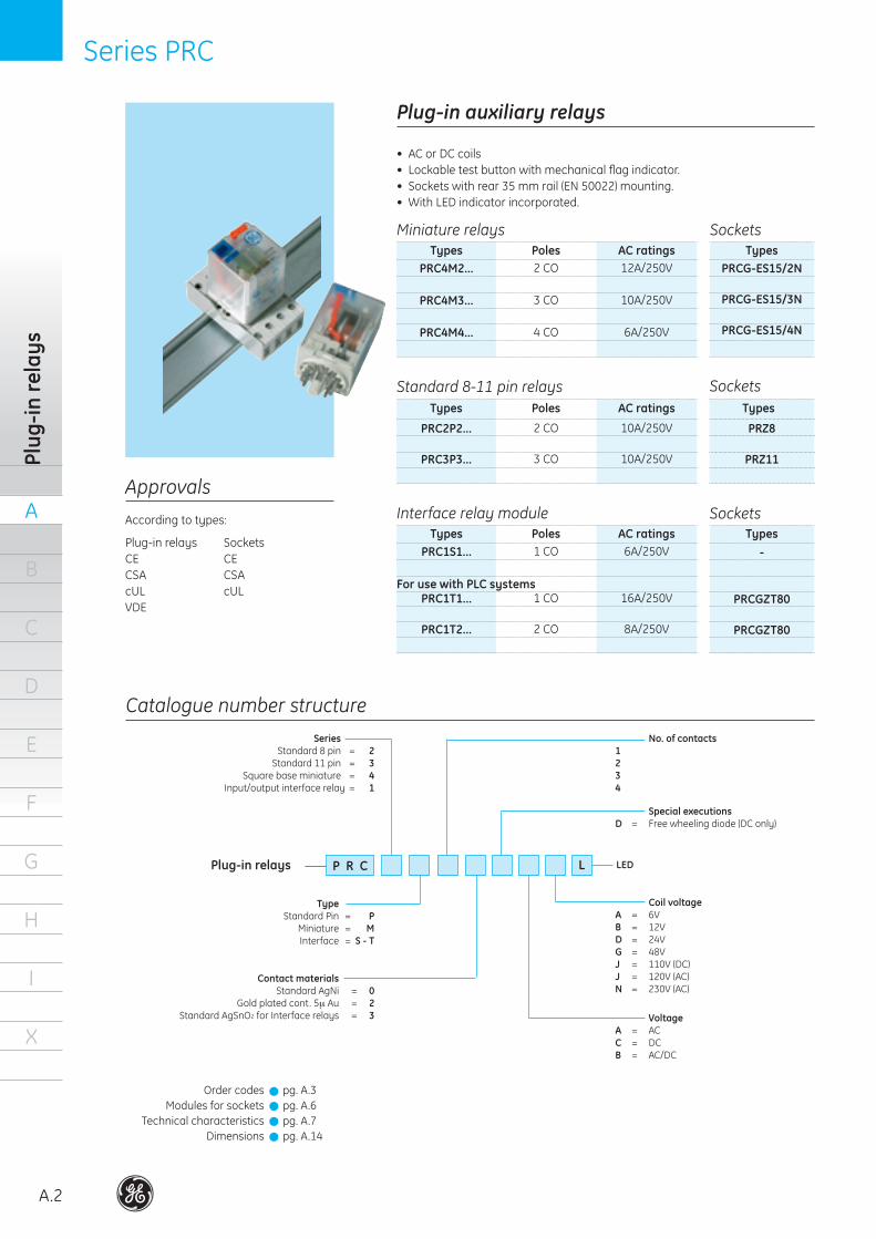
Plug-in auxiliary relays
According to types:
SocketsCECSAcUL
PRC2P2...
PRC3P3...
2 CO
3 CO
10A/250V
10A/250V
Types Poles AC ratings
Standard 8-11 pin relays
• ACorDCcoils• Lockabletestbuttonwithmechanicalflagindicator.• Socketswithrear35mmrail(EN50022)mounting.• WithLEDindicatorincorporated.
PRC4M2...
PRC4M3...
PRC4M4...
2 CO
3 CO
4 CO
12A/250V
10A/250V
6A/250V
Types Poles AC ratingsMiniature relays
Interface relay module
PRZ8
PRZ11
Types
Sockets
PRCG-ES15/2N
PRCG-ES15/3N
PRCG-ES15/4N
TypesSockets
PRC1S1...
PRC1T1...
PRC1T2...
1 CO
1 CO
2 CO
6A/250V
16A/250V
8A/250V
Types Poles AC ratings-
PRCGZT80
PRCGZT80
TypesSockets
Order codesModules for sockets
Technical characteristicsDimensions
pg. A.3pg. A.6pg. A.7pg. A.14
Catalogue number structure
P R C
Series Standard 8 pin = 2 Standard 11 pin = 3 Square base miniature = 4 Input/output interface relay = 1
Plug-in relays
Type Standard Pin = P Miniature = M Interface = S - T
No. of contacts1234
Special executionsD = Freewheelingdiode(DConly)
VoltageA = ACC = DCB = AC/DC
Contact materials Standard AgNi = 0 Gold plated cont. 5µ Au = 2 Standard AgSnO2 for Interface relays = 3
Coil voltageA = 6VB = 12VD = 24VG = 48VJ = 110V(DC)J = 120V(AC)N = 230V(AC)
LED
For use with PLC systems
!!!!
L
Series PRC Series PRC
A
A.3
B
C
D
E
F
G
H
I
X
Order codes
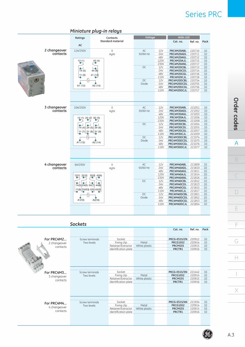
0AgNi
12A/250V AC50/60 Hz
DC
DCDiode
12V24V48V
120V230V12V24V48V
110V12V24V48V
110V
PRC4M20ABLPRC4M20ADLPRC4M20AGLPRC4M20AJLPRC4M20ANLPRC4M20CBLPRC4M20CDLPRC4M20CGLPRC4M20CJL
PRC4M20DCBLPRC4M20DCDLPRC4M20DCGLPRC4M20DCJL
10101010101010101010101010
220710220711220712220715220717220713220714220716220718220754220755220756220757
ContactsStandard material
Cat. no. Ref. no. Pack
AC
Ratings With LED
0AgNi
10A/250V AC50/60 Hz
DC
DCDiode
12V24V48V
120V230V12V24V48V
110V12V24V48V
110V
PRC4M30ABLPRC4M30ADLPRC4M30AGLPRC4M30AJLPRC4M30ANLPRC4M30CBLPRC4M30CDLPRC4M30CGLPRC4M30CJL
PRC4M30DCBLPRC4M30DCDLPRC4M30DCGLPRC4M30DCJL
10101010101010101010101010
221051221052221053221056221058221054221055221057221059221074221075221076221077
0AgNi
6A/250V AC50/60 Hz
DC
DCDiode
12V24V48V
120V230V12V24V48V
110V12V24V48V
110V
PRC4M40ABLPRC4M40ADLPRC4M40AGLPRC4M40AJLPRC4M40ANLPRC4M40CBLPRC4M40CDLPRC4M40CGLPRC4M40CJL
PRC4M40DCBLPRC4M40DCDLPRC4M40DCGLPRC4M40DCJL
10101010101010101010101010
221809221810221811221814221816221812221813221815221817221851221852221853221854
2 changeovercontacts
3 changeovercontacts
4 changeovercontacts
PRCG-ES15/2NPRCG1052PRCMS35PRCTR1
Screw terminalsTwo levels
10101010
SocketFixing clip
Retainer/ExtractorIdentification plate
MetalWhiteplastic
PRCG-ES15/3NPRCG1052PRCMS35PRCTR1
Screw terminalsTwo levels
10101010
SocketFixing clip
Retainer/ExtractorIdentification plate
MetalWhiteplastic
PRCG-ES15/4NPRCG1052PRCMS35PRCTR1
Screw terminalsTwo levels
10101010
SocketFixing clip
Retainer/ExtractorIdentification plate
MetalWhiteplastic
220912220914220915220916
221442220914220915220916
221934220914220915220916
Cat. no. Ref. no. Pack
For PRC4M2...2 changeover
contacts
For PRC4M3...3 changeover
contacts
For PRC4M4...4 changeover
contacts
Sockets
Miniature plug-in relaysVoltage
A
A.4
B
C
D
E
F
G
H
I
X
Plug
-in re
lays
Series PRC Series PRC
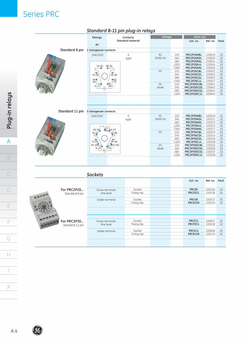
0AgNi
ContactsStandard material
Cat. no. Ref. no. Pack
10A/250V AC50/60 Hz
DC
DCdiode
12V24V48V
120V230V12V24V48V
110V12V24V48V
110V
PRC2P20ABLPRC2P20ADLPRC2P20AGLPRC2P20AJLPRC2P20ANLPRC2P20CBLPRC2P20CDLPRC2P20CGLPRC2P20CJL
PRC2P20DCBLPRC2P20DCDLPRC2P20DCGLPRC2P20DCJL
AC
Ratings
0AgNi
10A/250V AC50/60 Hz
DC
DCdiode
12V24V48V
120V230V12V24V48V
110V12V24V48V
110V
PRC3P30ABLPRC3P30ADLPRC3P30AGLPRC3P30AJLPRC3P30ANLPRC3P30CBLPRC3P30CDLPRC3P30CGLPRC3P30CJL
PRC3P30DCBLPRC3P30DCDLPRC3P30DCGLPRC3P30DCJL
10101010101010101010101010
10101010101010101010101010
220019220020220021220024220026220022220023220025220027220041220042220043220044
220310220311220312220315220317220313220314220316220318220335220336220337220338
2 changeover contacts
Standard 8-11 pin plug-in relaysWith LEDVoltage
3 changeover contacts
Standard 8 pin
Standard 11 pin
Cat. no. Ref. no. Pack
PRCZ8PRCPZ11
Screw terminalsOne level
1010
SocketFixing clip
PRCG8PRCR159
Solder terminal 1010
SocketFixing clip
PRCZ11PRCPZ11
Screw terminalsOne level
1010
SocketFixing clip
PRCG11PRCR159
Solder terminal 1010
SocketFixing clip
220216220218
220217220219
220647220218
220648220219
For PRC3P30...Standard 11 pin
For PRC2P20...Standard 8 pin
Sockets
Series PRC Series PRC
A
A.5
B
C
D
E
F
G
H
I
X
Order codes
3
AgSnO2
- AC
DC
AC/DC
230V
12V24V
24V
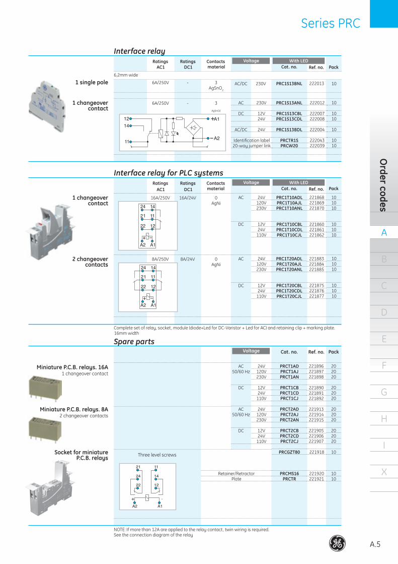
PRC1S13ANL
PRC1S13CBLPRC1S13CDL
PRC1S13BDL
PRCTR1SPRCW20
222012
222007222008
222004
222043222039
Contacts material
Cat. no. Ref. no. PackDC1
Ratings
6,2mm wide
Interface relayWith LEDVoltage
Identification label20-way jumper link
1 changeovercontact
0AgNi
16A/24V 24V120V230V
12V24V
110V
Completesetofrelay,socket,module(diode+LedforDC-Varistor+LedforAC)andretainingclip+markingplate.16mm width
1 changeovercontact
16A/250V
0AgNi
8A/24V AC
DC
24V120V230V
12V24V
110V
PRC1T20ADLPRC1T20AJLPRC1T20ANL
PRC1T20CBLPRC1T20CDLPRC1T20CJL
101010
101010
2 changeovercontacts
8A/250V
AC50/60 Hz
DC
24V120V230V
12V24V
110V
PRCT1ADPRCT1AJPRCT1AN
PRCT1CBPRCT1CDPRCT1CJ
202020
202020
Cat. no. Ref. no. PackVoltage
Miniature P.C.B. relays. 16A1 changeover contact
AC50/60 Hz
DC
24V120V230V
12V24V
110V
PRCT2ADPRCT2AJPRCT2AN
PRCT2CBPRCT2CDPRCT2CJ
202020
202020
Miniature P.C.B. relays. 8A
2 changeover contacts
PRCGZT80
PRCMS16PRCTR
10
1010
Socket for miniature P.C.B. relays Three level screws
Retainer/RetractorPlate
AC1Ratings
6A/250V
NOTE: If more than 12A are applied to the relay contact, twin wiring is required.See the connection diagram of the relay
221868221869221870
221860221861221862
221883221884221885
221875221876221877
221896221897221898
221890221891221892
221913221914221915
221905221906221907
221918
221920221921
Contactsmaterial
Cat. no. Ref. no. PackDC1
Ratings
Interface relay for PLC systemsWith LEDVoltage
AC1Ratings
Spare parts
3AgSnO2
-6A/250V AC/DC 230V PRC1S13BNL
10
1010
10
1010
2220131 single pole
PRC1T10ADLPRC1T10AJLPRC1T10ANL
PRC1T10CBLPRC1T10CDLPRC1T10CJL
AC
DC
101010
101010
10
A
A.6
B
C
D
E
F
G
H
I
X
Plug
-in re
lays
Series PRC Series PRC
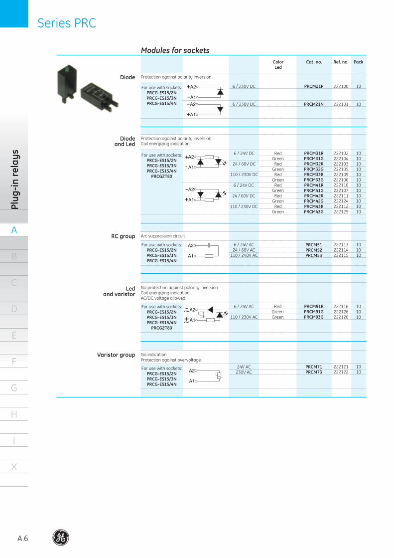
Modules for socketsCat. no. Ref. no. Pack
Protection against polarity inversion
6 / 230V DC PRCM21P 10
6 / 230V DC PRCM21N 10
6 / 24V DC
24 / 60V DC
110 / 230V DC
PRCM31RPRCM31GPRCM32RPRCM32GPRCM33RPRCM33G
101010101010
222100
222101
222102222104222103222105222109222106
For use with sockets:PRCG-ES15/2NPRCG-ES15/3NPRCG-ES15/4N
Protection against polarity inversionCoil energizing indication
For use with sockets:PRCG-ES15/2NPRCG-ES15/3NPRCG-ES15/4N
PRCGZT80
6 / 24V DC
24 / 60V DC
110 / 230V DC
PRCM41RPRCM41GPRCM42RPRCM42GPRCM43RPRCM43G
101010101010
222110222107222111222124222112222125
Arc suppression circuit
6 / 24V AC24 / 60V AC
110 / 240V AC
PRCM51PRCM52PRCM53
101010
222113222114222115
For use with sockets:PRCG-ES15/2NPRCG-ES15/3NPRCG-ES15/4N
Diode
RC group
No protection against polarity inversionCoil energizing indicationAC/DC voltage allowed
6 / 24V AC
110 / 230V AC
PRCM91RPRCM91GPRCM93G
101010
222116222126222120
For use with sockets:PRCG-ES15/2NPRCG-ES15/3NPRCG-ES15/4N
PRCGZT80
Ledand varistor
No indicationProtection against overvoltage
24V AC230V AC
PRCM71PRCM73
1010
222121222122
For use with sockets:PRCG-ES15/2NPRCG-ES15/3NPRCG-ES15/4N
Varistor group
Diodeand Led
ColorLed
RedGreen
RedGreen
RedGreen
RedGreen
RedGreen
RedGreen
RedGreenGreen
Series PRC Series PRC
A
A.7
B
C
D
E
F
G
H
I
X
Technical data
Nominalload (A)Dielectricstrength (kV) Adjacentscrews (kV) Screws-rail (kV)Terminals Type
Max.torque (Nm) Protection category Capacity Solidwire (mm2) Flexible wireAmbient temperature (ºC)
10(250V)
2.53
ScrewM3, Pozidriv
0,7IP202x2.5
22-14AWG-40...+70
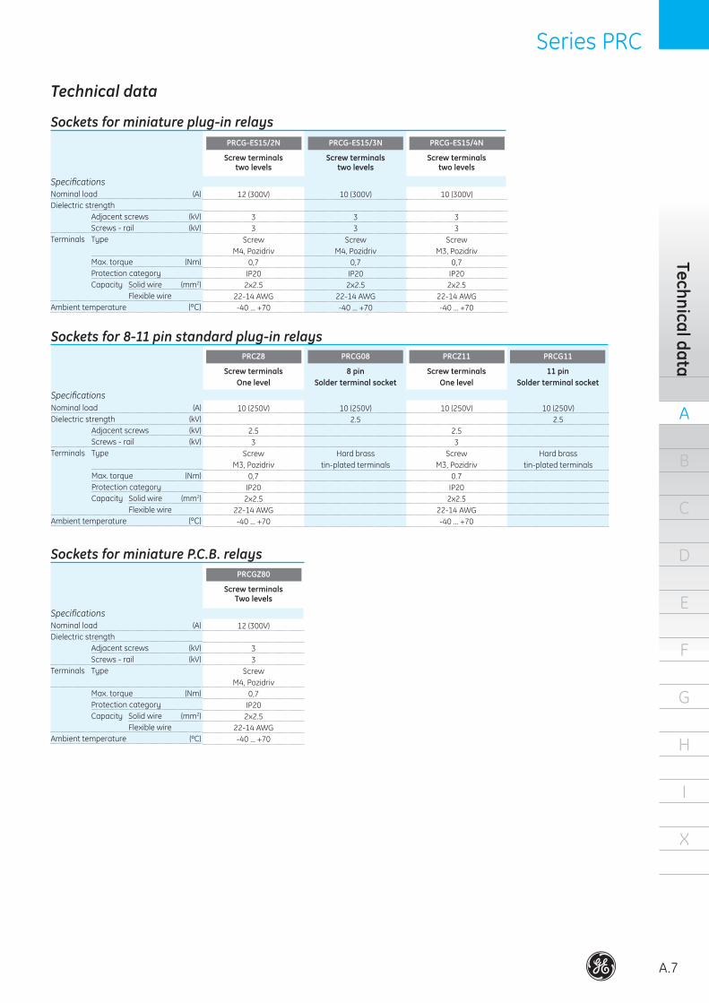
Specifications
11 pinSolder terminal socket
PRCG11
Screw terminalsOne level
PRCZ11
8 pinSolder terminal socket
PRCG08
Screw terminalsOne level
PRCZ8
10(250V)2.5
Hard brasstin-plated terminals
10(250V)
2.53
ScrewM3, Pozidriv
0.7IP202x2.5
22-14AWG-40...+70
Nominalload (A)Dielectric strength Adjacentscrews (kV) Screws-rail (kV)Terminals Type
Max.torque (Nm) Protection category Capacity Solidwire (mm2) Flexible wireAmbient temperature (ºC)
12(300V)
33
ScrewM4, Pozidriv
0,7IP202x2.5
22-14AWG-40...+70
Specifications
Screw terminalstwo levels
PRCG-ES15/4N
Screw terminalstwo levels
PRCG-ES15/3N
Screw terminalstwo levels
PRCG-ES15/2N
10(300V)
33
ScrewM4, Pozidriv
0,7IP202x2.5
22-14AWG-40...+70
10(300V)
33
ScrewM3, Pozidriv
0,7IP202x2.5
22-14AWG-40...+70
Nominalload (A)Dielectric strength Adjacentscrews (kV) Screws-rail (kV)Terminals Type
Max.torque (Nm) Protection category Capacity Solidwire (mm2) Flexible wireAmbienttemperature (ºC)
12(300V)
33
ScrewM4, Pozidriv
0,7IP202x2.5
22-14AWG-40...+70
Specifications
Screw terminalsTwo levels
PRCGZ80
Sockets for 8-11 pin standard plug-in relays
Sockets for miniature plug-in relays
Sockets for miniature P.C.B. relays
Technical data
10(250V)2.5
Hard brasstin-plated terminals
A
A.8
B
C
D
E
F
G
H
I
X
Plug
-in re
lays
Series PRC Series PRC
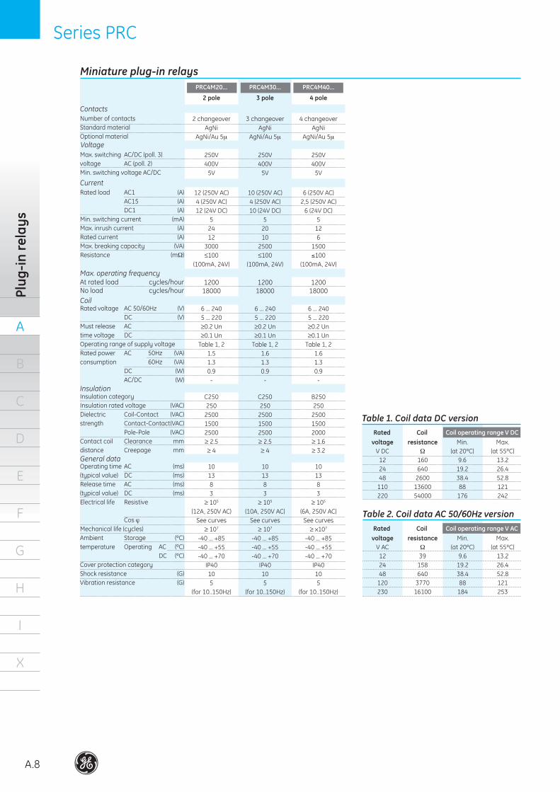
Miniature plug-in relays
Ratedload AC1 (A) AC15 (A) DC1 (A)Min.switchingcurrent (mA)Max.inrushcurrent (A)Ratedcurrent (A)Max.breakingcapacity (VA)Resistance (mΩ)
Current
Max.switching AC/DC(poll.3)voltage AC(poll.2)Min. switching voltage AC/DC
Voltage
Number of contactsStandard materialOptional material
Contacts
Ratedvoltage AC50/60Hz (V) DC (V)Must release AC time voltage DCOperating range of supply voltageRatedpower AC 50Hz (VA)consumption 60Hz (VA) DC (W) AC/DC (W)
Coil
Insulation categoryInsulationratedvoltage (VAC)Dielectric Coil-Contact (VAC)strength Contact-Contact(VAC) Pole-Pole (VAC)Contact coil Clearance mmdistance Creepage mm
Insulation
OperatingtimeAC (ms)(typicalvalue) DC (ms)Releasetime AC (ms)(typicalvalue) DC (ms)Electrical life Resistive
Cos ϕ ϕMechanicallife(cycles)Ambient Storage (ºC)temperature Operating AC (ºC) DC (ºC)Cover protection categoryShockresistance (G)Vibrationresistance (G)
General data
2 pole
PRC4M20...
12(250VAC)4(250VAC)12(24VDC)
52412
3000H100
(100mA,24V)
250V400V
5V
2 changeoverAgNi
AgNi/Au 5µ
6 ... 2405 ... 220G0.2 UnG0.1 Un
Table 1, 21.51.30.9-
C250250
250015002500G 2.5G 4
101383
G 105
(12A,250VAC)See curvesG 107
-40...+85-40...+55-40...+70
IP40105
(for10..150Hz)
At rated load cycles/hourNo load cycles/hour
Max. operating frequency
1200
18000
3 pole
PRC4M30...
10(250VAC)4(250VAC)10(24VDC)
52010
2500H100
(100mA,24V)
250V400V
5V
3 changeoverAgNi
AgNi/Au 5µ
6 ... 2405 ... 220G0.2 UnG0.1 Un
Table 1, 21.61.30.9-
C250250
250015002500G 2.5G 4
101383
G 105
(10A,250VAC)See curvesG 107
-40...+85-40...+55-40...+70
IP40105
(for10..150Hz)
120018000
4 pole
PRC4M40...
6(250VAC)2,5(250VAC)6(24VDC)
5126
1500≤100
(100mA,24V)
250V400V
5V
4 changeoverAgNi
AgNi/Au 5µ
6 ... 2405 ... 220G0.2 UnG0.1 Un
Table 1, 21.61.30.9-
B250250
250015002000G 1.6G 3.2
101383
G 105
(6A,250VAC)See curvesG x107
-40...+85-40...+55-40...+70
IP40105
(for10..150Hz)
120018000
voltage resistance Min. Max. V DC Ω (at20ºC) (at55ºC) 12 160 9.6 13.2 24 640 19.2 26.4 48 2600 38.4 52.8 110 13600 88 121 220 54000 176 242
Rated Coil Coil operating range V DC
voltage resistance Min. Max. V AC Ω (at20ºC) (at55ºC) 12 39 9.6 13.2 24 158 19.2 26.4 48 640 38.4 52.8 120 3770 88 121 230 16100 184 253
Rated Coil Coil operating range V AC
Table 1. Coil data DC version
Table 2. Coil data AC 50/60Hz version
Series PRC Series PRC
A
A.9
B
C
D
E
F
G
H
I
X
Technical data
.
.
.
.
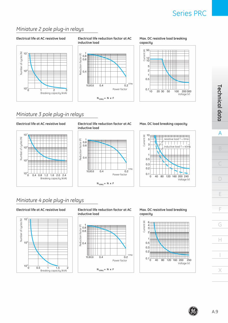
Miniature 3 pole plug-in relays
Electrical life at AC resistive load Electrical life reduction factor at AC inductive load
Max. DC load breaking capacity
Num
bero
fcycles(N)
Breakingcapacity(kVA)
Redu
ctionfactor(F)
Power factor
N cosϕ= N x F
Current(A)
Voltage(V)
inductive load T = 40ms
resistive load T = 0ms
Miniature 4 pole plug-in relays
Electrical life at AC resistive load Electrical life reduction factor at AC inductive load
Max. DC resistive load breaking capacity
Num
bero
fcycles(N)
Breakingcapacity(kVA)
Redu
ctionfactor(F)
Power factor
N cosϕ= N x F
Current(A)
Voltage(V)
cosϕ
Miniature 2 pole plug-in relays
Electrical life at AC resistive load Electrical life reduction factor at AC inductive load
Max. DC resistive load breaking capacity
Num
bero
fcycles(N)
Breakingcapacity(kVA)
Redu
ctionfactor(F)
Power factor
N cosϕ= N x F
Current(A)
Voltage(V)
cosϕ
.
.
.
. . . .
.
.
. . . . . .
.
.
.
. . . .
. .
.
.
.
. . . .
.
.
.
.
cosϕ
A
A.10
B
C
D
E
F
G
H
I
X
Plug
-in re
lays
Series PRC Series PRC
.
.
.
.
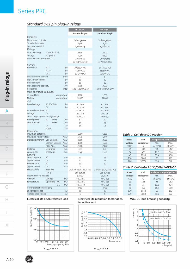
Standard 8-11 pin plug-in relays
Standard 8-pin
PRC2P20...
Ratedload AC1 (A) AC15 (A) DC1 (A)Min.switchingcurrent (mA)Max.inrushcurrent (A)Ratedcurrent (A)Max.breakingcapacity (VA)Resistance (mΩ)
10(250VAC)4(250VAC)10(24VDC)
53010
2500H100(100mA,24V)
Current
Maxswitching AC/DC(poll.3)voltage AC(poll.2)Min switching voltage AC/DC
250V400V
10V(AgNi)5V(AgNi/Au5µ)
Voltage
Number of contactsStandard materialOptional material
2 changeoverAgNi
AgNi/Au 5µ
Contacts
Ratedvoltage AC50/60Hz (V) DC (V)Must release time AC voltage DCOperating range of supply voltageRatedpower AC 50Hz (VA)consumption 60Hz (VA) DC (W) AC/DC (W)
6 ... 2406 ... 220G0.15 UnG0.1 Un
Table 1, 22,72,51,5-
Coil
Insulation categoryInsulationratedvoltage (VAC)Dielectricstrength Coil-Contact (VAC) Contact-Contact (VAC) Pole-Pole (VAC)Distance Clearance mmcontact coil Creepage mm
C250250
250015002000G 3G 4.2
Insulation
Operatingtime AC (ms)(typicalvalue) DC (ms)Releasetime AC (ms)(typicalvalue) DC (ms)Electrical life Resistive Cos ϕMechanicallife(cycles)Ambient Storage (ºC)temperature Operating AC (ºC) DC (ºC)Cover protection categoryShockresistance (G)Vibrationresistance (G)
1212107
G 2x10⁵(10A,250VAC)See curvesG 2x10⁷
-40...+85-40...+55-40...+70
IP40105
General
PRC3P30...
10(250VAC)4(250VAC)10(24VDC)
53010
2500H100(100mA,24V)
250V400V
10V(AgNi)5V(AgNi/Au5µ)
3 changeoverAgNi
AgNi/Au 5µ
6 ... 2406 ... 220G0.15 UnG0.1 Un
Table 1, 22,72,51,5-
C250250
250015002000G 3G 4.2
1212107
G 2x10⁵(10A,250VAC)See curvesG 2x10⁷
-40...+85-40...+55-40...+70
IP40105
At rated load cycles/hourNo load cycles/hour
120012000
Max. operating frequency 1200
12000
Table 1. Coil data DC version
Table 2. Coil data AC 50/60Hz version
voltage resistance Min. Max. V DC Ω (at20ºC) (at55ºC) 12 110 9.6 13.2 24 430 19.2 26.4 48 1750 38.4 52.8 110 9200 88 121 220 37000 176 242
Rated Coil Coil operating range V DC
voltage resistance Min. Max. V AC Ω (at20ºC) (at55ºC) 12 18.5 9.6 13.2 24 75 19.2 26.4 48 305 38.4 52.8 120 1910 96 132 230 7080 184 253
Rated Coil Coil operating range V AC
Electrical life at AC resistive load Electrical life reduction factor at AC inductive load
Max. DC load breaking capacity
Num
bero
fcycles(N)
Breakingcapacity(kVA)
N cosϕ= N x F
Redu
ctio
n fa
ctor
Power factor
N cosϕ= N x F
Current(A)
Voltage(V)
inductive load T = 40ms
resistive load T = 0ms
. . . . . .
.
.
.
.
.
.
.
.. . . . . . . . .
Standard 11-pin

Series PRC Series PRC
A
A.11
B
C
D
E
F
G
H
I
X
Technical data
Interface plug-in relays
Ratedload AC1 (A) AC15 (A) DC1 (A)Min.switchingcurrent (mA)Max.inrushcurrent(A)Ratedcurrent (A)Max.breakingcapacity (VA)Resistance (mΩ)
Current
Maxswitching AC/DC(poll.3)voltage AC(poll.2)Min switching voltage AC/DC
Voltage
Number of contactsStandard materialOptional material
Contacts
Ratedvoltage AC/DC (V) AC50/60Hz (V) DC (V)Must release time AC voltage DCOperating range of supply voltageRatedpower AC 50Hz (VA)consumption 60Hz (VA) DC (W) AC/DC (W)
Coil
Insulation categoryInsulationratedvoltage (VAC)Dielectricstrength Coil-Contact (VAC) Contact-Contact (VAC) Pole-Pole (VAC)Distance Clearance mmcontact coil Creepage mm
Insulation
Operatingtime AC (ms)(typicalvalue) DC (ms)Releasetime AC (ms)(typicalvalue) DC (ms)Electrical life Resistive Cos ϕMechanicallife(cycles)Ambient Storage (ºC)temperature Operating AC (ºC) DC (ºC)Cover protection categoryShockresistance (G)Vibrationresistance (G)
General
At rated loadNo load
Max. operating frequency
PRC1S13...
6(250VAC) 6(24VDC)101561500VH100(100mA,24V)
AC 250V / DC 150VAC 400V / DC 300V12V
1 changeoverAgSnO2
24, 23023012, 24G0,2 UnG0,1 UnSee Table 10.6...1.9-0.330.48(at24V),1.8(at230V)
C25040040001000-G 8G 8
86158
20x106
-40...+70-20...+55-20...+55IP20100.062’’ DA(10...55Hz)
360 cycles/hour72000 cycles/hour
voltage Min. Max. V 12 DC 9 17 24 DC 17 30 24 AC/DC 18 30 230 AC 80 250 230 AC/DC 185 250
Rated Coil operating range V DC
Table 1. Interface relay
A
A.12
B
C
D
E
F
G
H
I
X
Plug
-in re
lays
Series PRC Series PRC
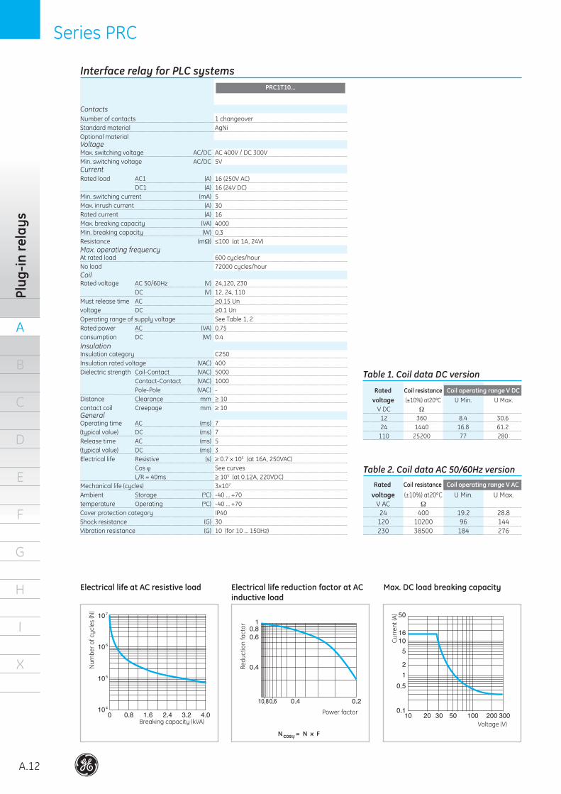
Electrical life at AC resistive load Electrical life reduction factor at AC inductive load
Max. DC load breaking capacity
Num
bero
fcycles(N)
Breakingcapacity(kVA)
Redu
ctio
n fa
ctor
Power factor
N cosϕ= N x F
Current(A)
Voltage(V)
Interface relay for PLC systems
Ratedload AC1 (A) DC1 (A)Min.switchingcurrent (mA)Max.inrushcurrent (A)Ratedcurrent (A)Max.breakingcapacity (VA)Min.breakingcapacity (W)Resistance (mΩ)
Current
Max. switching voltage AC/DCMin. switching voltage AC/DC
Voltage
Number of contactsStandard materialOptional material
Contacts
Ratedvoltage AC50/60Hz (V) DC (V)Must release time AC voltage DCOperating range of supply voltageRatedpower AC (VA)consumption DC (W)
Coil
Insulation categoryInsulationratedvoltage (VAC)Dielectricstrength Coil-Contact (VAC) Contact-Contact (VAC) Pole-Pole (VAC)Distance Clearance mmcontact coil Creepage mm
Insulation
Operatingtime AC (ms)(typicalvalue) DC (ms)Releasetime AC (ms)(typicalvalue) DC (ms)Electricallife Resistive (s) Cos ϕ L/R = 40msMechanicallife(cycles)Ambient Storage (ºC)temperature Operating (ºC)Cover protection categoryShockresistance (G)Vibrationresistance (G)
General
At rated loadNo load
Max. operating frequency
16(250VAC)16(24VDC)5301640000,3H100(at1A,24V)
AC 400V / DC 300V5V
1 changeoverAgNi
24,120, 23012, 24, 110G0.15 UnG0.1 UnSee Table 1, 20.750.4
C25040050001000-G 10G 10
7753G 0.7 x 10⁵ (at16A,250VAC)See curvesG 105 (at0.12A,220VDC)3x10⁷
-40...+70-40...+70IP403010(for10...150Hz)
600 cycles/hour72000 cycles/hour
Table 1. Coil data DC version
Table 2. Coil data AC 50/60Hz version
voltage (±10%)at20ºC U Min. U Max. V DC Ω 12 360 8.4 30.6 24 1440 16.8 61.2 110 25200 77 280
Rated Coil resistance Coil operating range V DC
voltage (±10%)at20ºC U Min. U Max. V AC Ω 24 400 19.2 28.8 120 10200 96 144 230 38500 184 276
Rated Coil resistance Coil operating range V AC
.
.
.
. . .
. . . . .
.
.
PRC1T10...
Series PRC Series PRC
A
A.13
B
C
D
E
F
G
H
I
X
Technical data
Ratedload AC1 (A) DC1 (A)Min.switchingcurrent (mA)Max.inrushcurrent (A)Ratedcurrent (A)Max.breakingcapacity (VA)Min.breakingcapacity (W)Resistance (mΩ)
Current
Max. switching voltage AC/DCMin. switching voltage AC/DC
Voltage
Number of contactsStandard materialOptional material
Contacts
Ratedvoltage AC50/60Hz (V) DC (V)Must release time AC voltage DCOperating range of supply voltageRatedpower AC (VA)consumption DC (W)
Coil
Insulation categoryInsulationratedvoltage (VAC)Dielectricstrength Coil-Contact (VAC) Contact-Contact (VAC) Pole-Pole (VAC)Distance Clearance mmcontact coil Creepage mm
Insulation
Operatingtime AC (ms)(typicalvalue) DC (ms)Releasetime AC (ms)(typicalvalue) DC (ms)Electricallife Resistive (s) Cos ϕ L/R = 40msMechanicallife(cycles)Ambient Storage (ºC)temperature Operating (ºC)Cover protection categoryShockresistance (G)Vibrationresistance (G)
General
At rated loadNo load
Max. operating frequency
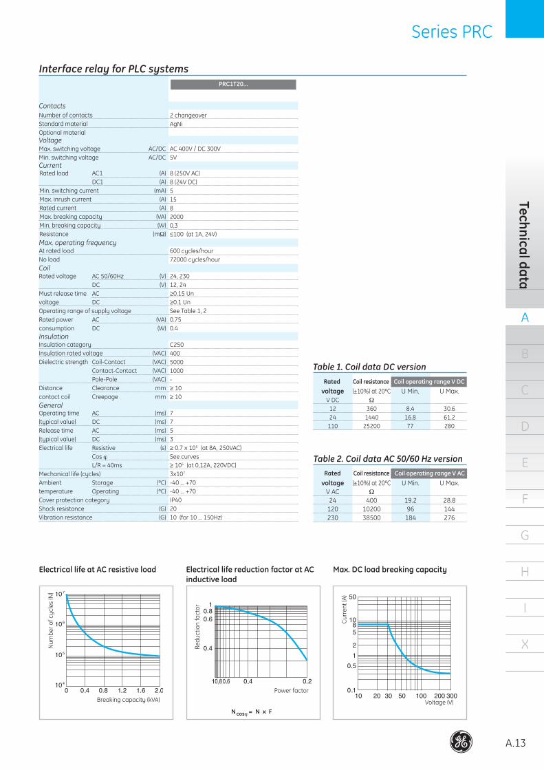
PRC1T20...
8(250VAC)8(24VDC)515820000,3H100(at1A,24V)
AC 400V / DC 300V 5V
2 changeoverAgNi
24, 23012, 24G0.15 UnG0.1 UnSee Table 1, 20.750.4
C25040050001000-G 10G 10
7753G 0.7 x 10⁵ (at8A,250VAC)See curvesG 105 (at0,12A,220VDC)3x10⁷
-40...+70-40...+70IP402010(for10...150Hz)
600 cycles/hour72000 cycles/hour
Table 1. Coil data DC version
Table 2. Coil data AC 50/60 Hz version
voltage (±10%)at20ºC U Min. U Max. V DC Ω 12 360 8.4 30.6 24 1440 16.8 61.2 110 25200 77 280
Rated Coil resistance Coil operating range V DC
voltage (±10%)at20ºC U Min. U Max. V AC Ω 24 400 19.2 28.8 120 10200 96 144 230 38500 184 276
Rated Coil resistance Coil operating range V AC
Electrical life at AC resistive load Electrical life reduction factor at AC inductive load
Max. DC load breaking capacity
Num
bero
fcycles(N)
Breakingcapacity(kVA)
Redu
ctio
n fa
ctor
Power factor
N cosϕ= N x F
Current(A)
Voltage(V)
.
.
.
. . .. . . .
.
.
Interface relay for PLC systems
A
A.14
B
C
D
E
F
G
H
I
X
Plug
-in re
lays
Series PRC Series PRC
..
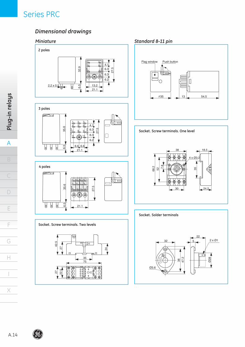
2 poles
3 poles
4 poles
Dimensional drawings
.
.
. ..
.
.
.
Socket. Screw terminals. One level
Socket. Solder terminals
. .
.
.
. .
.
.
.
.
.
..
.
.
.
.
.
. ..
.
..
.
Socket. Screw terminals. Two levels
Standard 8-11 pinMiniature
Series PRC Series PRC
A
A.15
B
C
D
E
F
G
H
I
X
Dim
ensions
. . ..
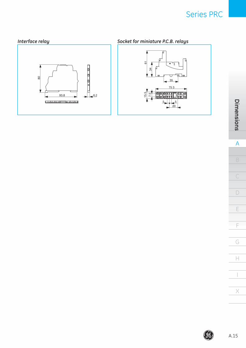
Interface relay Socket for miniature P.C.B. relays
A
A.16
B
C
D
E
F
G
H
I
X
Auxi
liary
min
icon
tact
ors
Series M Series M
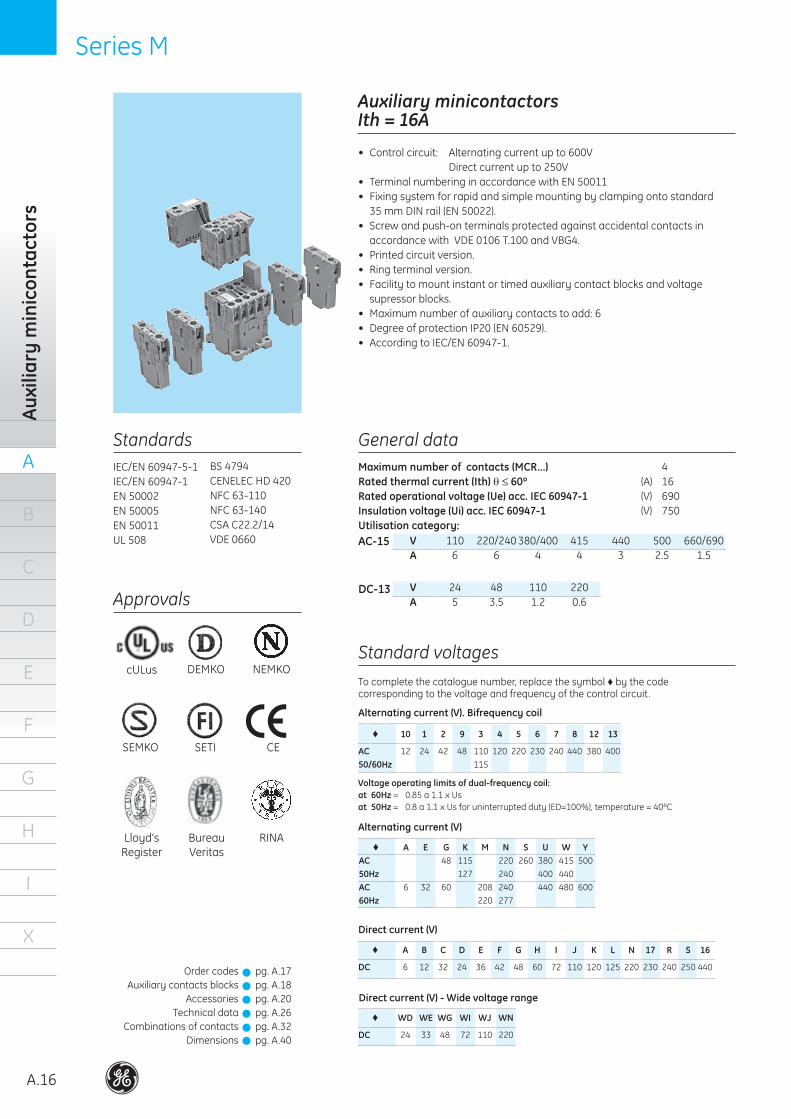
Auxiliary minicontactorsIth = 16A
• Controlcircuit: Alternatingcurrentupto600V Directcurrentupto250V• TerminalnumberinginaccordancewithEN50011• Fixingsystemforrapidandsimplemountingbyclampingontostandard 35mmDINrail(EN50022).
• Screwandpush-onterminalsprotectedagainstaccidentalcontactsin accordancewithVDE0106T.100andVBG4.
• Printedcircuitversion.• Ringterminalversion.• Facilitytomountinstantortimedauxiliarycontactblocksandvoltage supressorblocks.
• Maximumnumberofauxiliarycontactstoadd:6• DegreeofprotectionIP20(EN60529).• AccordingtoIEC/EN60947-1.
General dataMaximum number of contacts (MCR...) 4Rated thermal current (Ith) θ H 60º (A) 16Rated operational voltage (Ue) acc. IEC 60947-1 (V) 690Insulation voltage (Ui) acc. IEC 60947-1 (V) 750Utilisation category:AC-15
DC-13
V 110 220/240380/400 415 440 500 660/690 A 6 6 4 4 3 2.5 1.5
V 24 48 110 220 A 5 3.5 1.2 0.6
IEC/EN60947-5-1IEC/EN60947-1EN50002EN50005EN50011UL508
StandardsBS4794CENELECHD420NFC63-110NFC63-140CSAC22.2/14VDE0660
© A E G K M N S U W YAC 48 115 220 260 380 415 50050Hz 127 240 400 440AC 6 32 60 208 240 440 480 60060Hz 220 277
© 10 1 2 9 3 4 5 6 7 8 12 13
AC 12 24 42 48 110 120 220 230 240 440 380 40050/60Hz 115
Voltage operating limits of dual-frequency coil:at 60Hz = 0.85a1.1xUsat 50Hz= 0.8a1.1xUsforuninterruptedduty(ED=100%),temperature=40ºC
© A B C D E F G H I J K L N 17 R S 16
DC 6 12 32 24 36 42 48 60 72 110 120 125 220 230 240 250440
Standard voltages
Alternating current (V). Bifrequency coil
Alternating current (V)
Direct current (V)
Approvals
Tocompletethecataloguenumber,replacethesymbol©bythecode correspondingtothevoltageandfrequencyofthecontrolcircuit.
cULus NEMKO
SEMKO SETI
DEMKO
Lloyd’sRegister
BureauVeritas
RINA
OrdercodesAuxiliarycontactsblocks
AccessoriesTechnicaldata
CombinationsofcontactsDimensions
pg.A.17pg.A.18pg.A.20pg.A.26pg.A.32pg.A.40
© WD WE WG WI WJ WN
DC 24 33 48 72 110 220
Direct current (V) - Wide voltage range
!!!!!!
CE
Series M Series M
A
A.17
B
C
D
E
F
G
H
I
X
Order codes
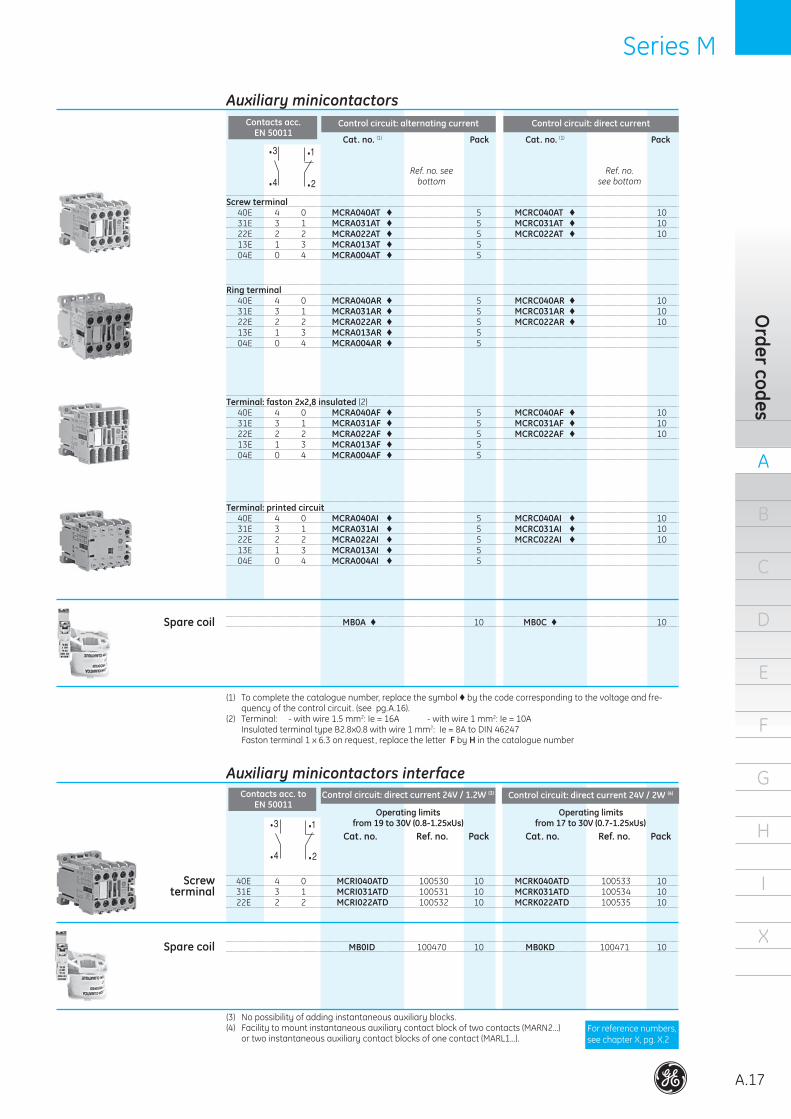
Screw terminal 40E 4 0 MCRA040AT © 5 MCRC040AT © 10 31E 3 1 MCRA031AT © 5 MCRC031AT © 10 22E 2 2 MCRA022AT © 5 MCRC022AT © 10 13E 1 3 MCRA013AT © 5 04E 0 4 MCRA004AT © 5
MB0A © 10 MB0C © 10
Terminal: faston 2x2,8 insulated (2) 40E 4 0 MCRA040AF © 5 MCRC040AF © 10 31E 3 1 MCRA031AF © 5 MCRC031AF © 10 22E 2 2 MCRA022AF © 5 MCRC022AF © 10 13E 1 3 MCRA013AF © 5 04E 0 4 MCRA004AF © 5
Terminal: printed circuit 40E 4 0 MCRA040AI © 5 MCRC040AI © 10 31E 3 1 MCRA031AI © 5 MCRC031AI © 10 22E 2 2 MCRA022AI © 5 MCRC022AI © 10 13E 1 3 MCRA013AI © 5 04E 0 4 MCRA004AI © 5
Cat. no. (1) Pack
Control circuit: alternating current
Cat. no. (1) Pack
Control circuit: direct current
Spare coil
40E 4 0 MCRI040ATD 100530 10 MCRK040ATD 100533 10 31E 3 1 MCRI031ATD 100531 10 MCRK031ATD 100534 10 22E 2 2 MCRI022ATD 100532 10 MCRK022ATD 100535 10
Screwterminal
Cat. no. Ref. no. Pack
Control circuit: direct current 24V / 1.2W (3) Control circuit: direct current 24V / 2W (4)
MB0ID 100470 10 MB0KD 100471 10Spare coil
(1) Tocompletethecataloguenumber,replacethesymbol©bythecodecorrespondingtothevoltageandfre-quencyofthecontrolcircuit.(seepg.A.16).
(2) Terminal: -withwire1.5mm2:Ie=16A -withwire1mm2:Ie=10A InsulatedterminaltypeB2.8x0.8withwire1mm2:Ie=8AtoDIN46247 Fastonterminal1x6.3onrequest,replacetheletterF by Hinthecataloguenumber
(3) Nopossibilityofaddinginstantaneousauxiliaryblocks.(4) Facilitytomountinstantaneousauxiliarycontactblockoftwocontacts(MARN2...)
ortwoinstantaneousauxiliarycontactblocksofonecontact(MARL1...).
Ring terminal 40E 4 0 MCRA040AR © 5 MCRC040AR © 10 31E 3 1 MCRA031AR © 5 MCRC031AR © 10 22E 2 2 MCRA022AR © 5 MCRC022AR © 10 13E 1 3 MCRA013AR © 5 04E 0 4 MCRA004AR © 5
•1
•2
•3
•4
•1
•2
•3
•4Ref. no. see
bottomRef. no.
see bottom
•1
•2
•3
•4
•1
•2
•3
•4
Forreferencenumbers,seechapterX,pg.X.2
Operating limits from 19 to 30V (0.8-1.25xUs)
Operating limits from 17 to 30V (0.7-1.25xUs)
Cat. no. Ref. no. Pack
Auxiliary minicontactors
Auxiliary minicontactors interface
Contacts acc. EN 50011
Contacts acc. to EN 50011
A
A.18
B
C
D
E
F
G
H
I
X
Auxi
liary
min
icon
tact
ors
Series M Series M
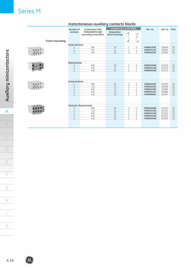
Number of Combination with contacts MCRA040AT© (40E) Designation according to EN 50011 (block marking)
Cat. no. Ref. no. Pack
Screw terminal 2 60E 20 2 0 MARN220AT 100994 10 2 51E 11 1 1 MARN211AT 100993 10 2 42E 02 0 2 MARN202AT 100992 10
Screw terminal 4 80E 40 4 0 MARN440AT 100991 10 4 71E 31 3 1 MARN431AT 100990 10 4 62E 22 2 2 MARN422AT 100989 10 4 53E 13 1 3 MARN413AT 100988 10 4 44E 04 0 4 MARN404AT 100987 10
Front mounting
Ring terminal 2 60E 20 2 0 MARN220AR 103349 10 2 51E 11 1 1 MARN211AR 103350 10 2 42E 02 0 2 MARN202AR 103351 10
Terminal : Ring terminal 4 80E 40 4 0 MARN440AR 103352 10 4 71E 31 3 1 MARN431AR 103353 10 4 62E 22 2 2 MARN422AR 103354 10 4 53E 13 1 3 MARN413AR 103355 10 4 44E 04 0 4 MARN404AR 103300 10
•1
•2
•3
•4
•1
•2
•3
•4
Instantaneous auxiliary contacts blocksContacts acc. to EN 50005
Series M Series M
A
A.19
B
C
D
E
F
G
H
I
X
Order codes
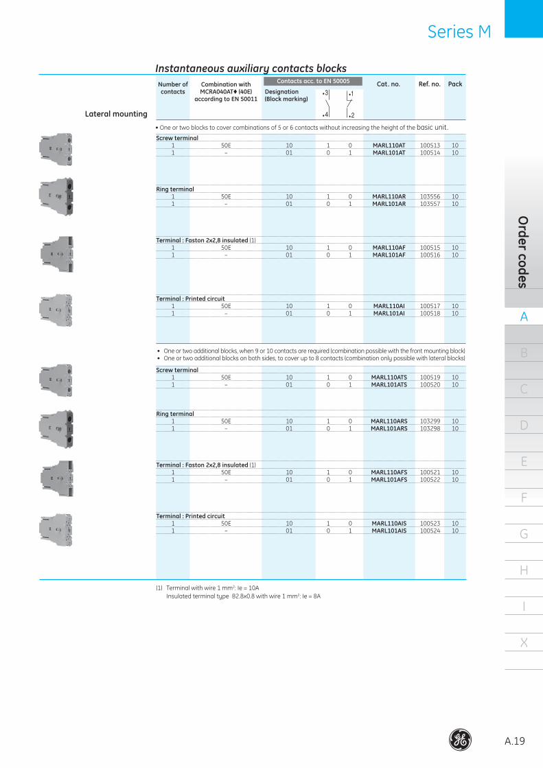
Screw terminal 1 50E 10 1 0 MARL110AT 100513 10 1 – 01 0 1 MARL101AT 100514 10
Ring terminal 1 50E 10 1 0 MARL110AR 103556 10 1 – 01 0 1 MARL101AR 103557 10
Terminal : Faston 2x2,8 insulated (1) 1 50E 10 1 0 MARL110AF 100515 10 1 – 01 0 1 MARL101AF 100516 10
Terminal : Printed circuit 1 50E 10 1 0 MARL110AI 100517 10 1 – 01 0 1 MARL101AI 100518 10
•Oneortwoblockstocovercombinationsof5or6contactswithoutincreasingtheheightofthebasicunit.
• Oneortwoadditionalblocks,when9or10contactsarerequired(combinationpossiblewiththefrontmountingblock)• Oneortwoadditionalblocksonbothsides,tocoverupto8contacts(combinationonlypossiblewithlateralblocks)
Number of Combination with contacts MCRA040AT© (40E) Designation according to EN 50011 (Block marking)
Cat. no. Ref. no. Pack
Lateral mounting
(1) Terminalwithwire1mm2:Ie=10A InsulatedterminaltypeB2.8x0.8withwire1mm2:Ie=8A
Screw terminal 1 50E 10 1 0 MARL110ATS 100519 10 1 – 01 0 1 MARL101ATS 100520 10
Ring terminal 1 50E 10 1 0 MARL110ARS 103299 10 1 – 01 0 1 MARL101ARS 103298 10
Terminal : Faston 2x2,8 insulated (1) 1 50E 10 1 0 MARL110AFS 100521 10 1 – 01 0 1 MARL101AFS 100522 10
Terminal : Printed circuit 1 50E 10 1 0 MARL110AIS 100523 10 1 – 01 0 1 MARL101AIS 100524 10
•1
•2
•3
•4
•1
•2
•3
•4
Instantaneous auxiliary contacts blocksContacts acc. to EN 50005
A
A.20
B
C
D
E
F
G
H
I
X
Auxi
liary
min
icon
tact
ors
Series M Series M
Cat. no. Ref. no. Pack
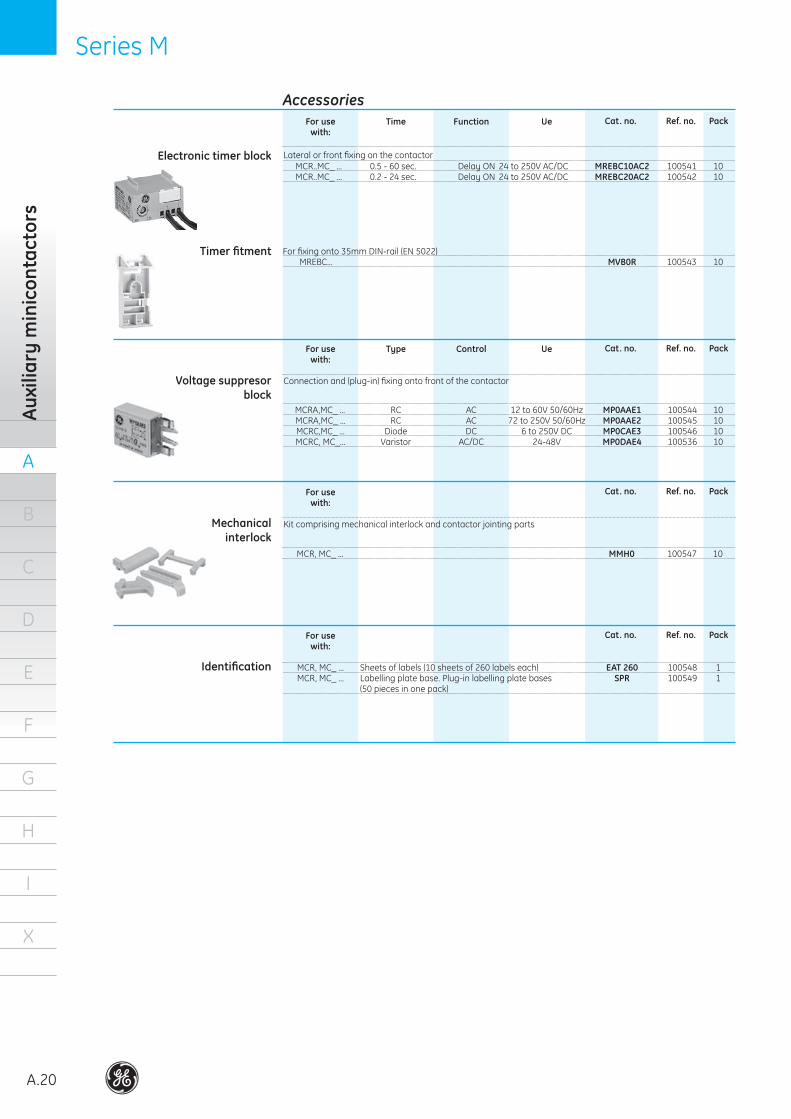
For use Time Function Ue with:
MCR..MC_... 0.5-60sec. DelayON 24to250VAC/DC MREBC10AC2 100541 10 MCR..MC_... 0.2-24sec. DelayON 24to250VAC/DC MREBC20AC2 100542 10
Forfixingonto35mmDIN-rail(EN5022) MREBC... MVB0R 100543 10
Lateralorfrontfixingonthecontactor
Timer fitment
Electronic timer block
For use Type Control Ue with:
MCRA,MC_... RC AC 12to60V50/60Hz MP0AAE1 100544 10 MCRA,MC_... RC AC 72to250V50/60Hz MP0AAE2 100545 10 MCRC,MC_... Diode DC 6to250VDC MP0CAE3 100546 10 MCRC,MC_... Varistor AC/DC 24-48V MP0DAE4 100536 10
Connectionand(plug-in)fixingontofrontofthecontactorVoltage suppresor block
For use with:
MCR,MC_... MMH0 100547 10
KitcomprisingmechanicalinterlockandcontactorjointingpartsMechanicalinterlock
For use with:
MCR,MC_... Sheetsoflabels(10sheetsof260labelseach) EAT 260 100548 1 MCR,MC_... Labellingplatebase.Plug-inlabellingplatebases SPR 100549 1 (50piecesinonepack)
Identification
Cat. no. Ref. no. Pack
Cat. no. Ref. no. Pack
Cat. no. Ref. no. Pack
Accessories
Series M Series M
A
A.21
B
C
D
E
F
G
H
I
X
Order codes
Notes
. . . . . . . . . . . . . . . . . . . . . . . . . . . . . . . . . . . . . .
. . . . . . . . . . . . . . . . . . . . . . . . . . . . . . . . . . . . . .
. . . . . . . . . . . . . . . . . . . . . . . . . . . . . . . . . . . . . .
. . . . . . . . . . . . . . . . . . . . . . . . . . . . . . . . . . . . . .
. . . . . . . . . . . . . . . . . . . . . . . . . . . . . . . . . . . . . .
. . . . . . . . . . . . . . . . . . . . . . . . . . . . . . . . . . . . . .
. . . . . . . . . . . . . . . . . . . . . . . . . . . . . . . . . . . . . .
. . . . . . . . . . . . . . . . . . . . . . . . . . . . . . . . . . . . . .
. . . . . . . . . . . . . . . . . . . . . . . . . . . . . . . . . . . . . .
. . . . . . . . . . . . . . . . . . . . . . . . . . . . . . . . . . . . . .
. . . . . . . . . . . . . . . . . . . . . . . . . . . . . . . . . . . . . .
. . . . . . . . . . . . . . . . . . . . . . . . . . . . . . . . . . . . . .
. . . . . . . . . . . . . . . . . . . . . . . . . . . . . . . . . . . . . .
. . . . . . . . . . . . . . . . . . . . . . . . . . . . . . . . . . . . . .
. . . . . . . . . . . . . . . . . . . . . . . . . . . . . . . . . . . . . .
. . . . . . . . . . . . . . . . . . . . . . . . . . . . . . . . . . . . . .
. . . . . . . . . . . . . . . . . . . . . . . . . . . . . . . . . . . . . .
. . . . . . . . . . . . . . . . . . . . . . . . . . . . . . . . . . . . . .
. . . . . . . . . . . . . . . . . . . . . . . . . . . . . . . . . . . . . .
. . . . . . . . . . . . . . . . . . . . . . . . . . . . . . . . . . . . . .
. . . . . . . . . . . . . . . . . . . . . . . . . . . . . . . . . . . . . .
. . . . . . . . . . . . . . . . . . . . . . . . . . . . . . . . . . . . . .
. . . . . . . . . . . . . . . . . . . . . . . . . . . . . . . . . . . . . .
. . . . . . . . . . . . . . . . . . . . . . . . . . . . . . . . . . . . . .
. . . . . . . . . . . . . . . . . . . . . . . . . . . . . . . . . . . . . .
. . . . . . . . . . . . . . . . . . . . . . . . . . . . . . . . . . . . . .
. . . . . . . . . . . . . . . . . . . . . . . . . . . . . . . . . . . . . .
. . . . . . . . . . . . . . . . . . . . . . . . . . . . . . . . . . . . . .
. . . . . . . . . . . . . . . . . . . . . . . . . . . . . . . . . . . . . .
. . . . . . . . . . . . . . . . . . . . . . . . . . . . . . . . . . . . . .
. . . . . . . . . . . . . . . . . . . . . . . . . . . . . . . . . . . . . .
. . . . . . . . . . . . . . . . . . . . . . . . . . . . . . . . . . . . . .
. . . . . . . . . . . . . . . . . . . . . . . . . . . . . . . . . . . . . .
. . . . . . . . . . . . . . . . . . . . . . . . . . . . . . . . . . . . . .
. . . . . . . . . . . . . . . . . . . . . . . . . . . . . . . . . . . . . .
. . . . . . . . . . . . . . . . . . . . . . . . . . . . . . . . . . . . . .
. . . . . . . . . . . . . . . . . . . . . . . . . . . . . . . . . . . . . .
. . . . . . . . . . . . . . . . . . . . . . . . . . . . . . . . . . . . . .
. . . . . . . . . . . . . . . . . . . . . . . . . . . . . . . . . . . . . .
. . . . . . . . . . . . . . . . . . . . . . . . . . . . . . . . . . . . . .
. . . . . . . . . . . . . . . . . . . . . . . . . . . . . . . . . . . . . .
. . . . . . . . . . . . . . . . . . . . . . . . . . . . . . . . . . . . . .
. . . . . . . . . . . . . . . . . . . . . . . . . . . . . . . . . . . . . .
. . . . . . . . . . . . . . . . . . . . . . . . . . . . . . . . . . . . . .
. . . . . . . . . . . . . . . . . . . . . . . . . . . . . . . . . . . . . .
. . . . . . . . . . . . . . . . . . . . . . . . . . . . . . . . . . . . . .
. . . . . . . . . . . . . . . . . . . . . . . . . . . . . . . . . . . . . .
. . . . . . . . . . . . . . . . . . . . . . . . . . . . . . . . . . . . . .
A
A.22
B
C
D
E
F
G
H
I
X
Auxi
liary
con
tact
ors
SeriesRL SeriesRL
IEC/EN60947-5-1IEC/EN60947-1EN90947EN60947EN50005EN50011UL508NEMAICS1
Standards
BS4794CENELECHD410CENELECHD420NFC63-110NFC63-140CSAC22.2/14VDE0660/102
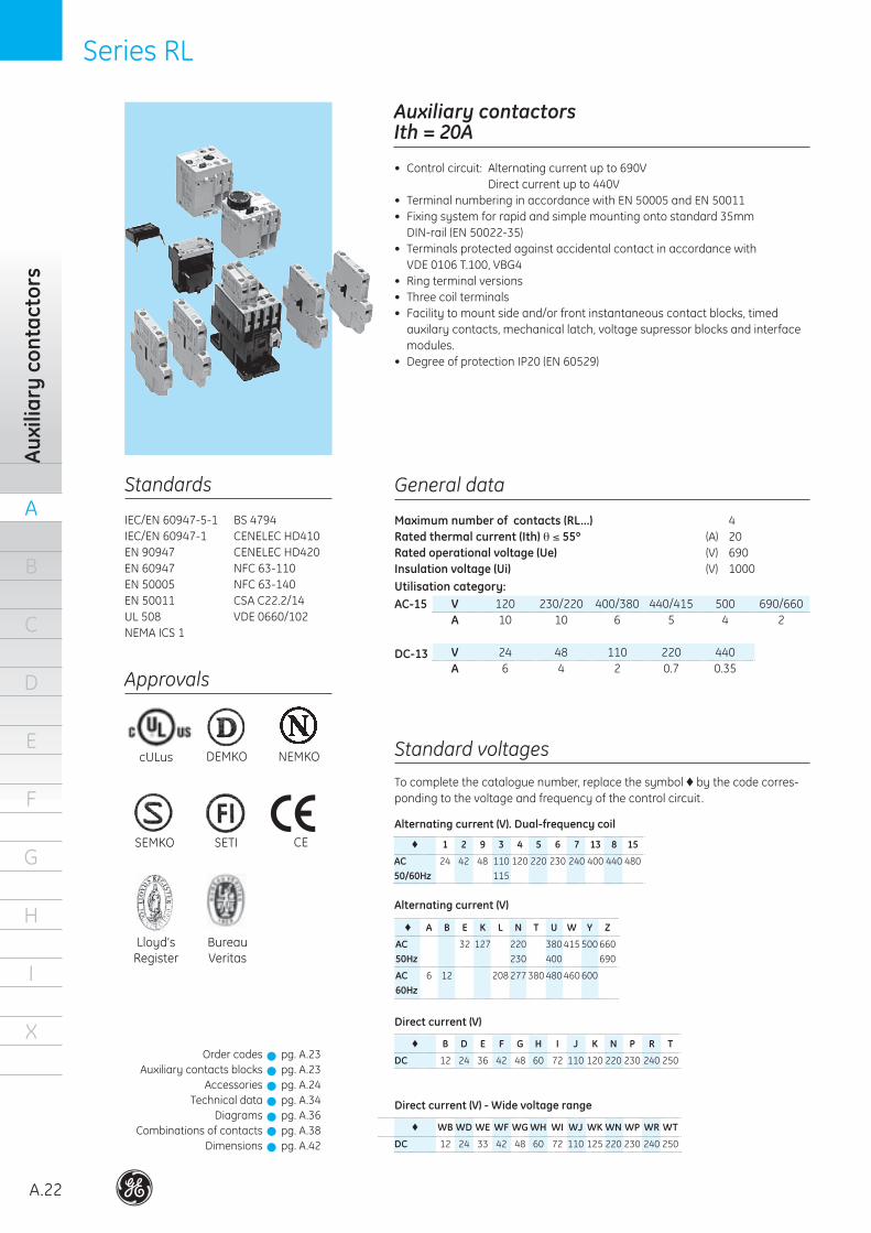
Auxiliary contactors Ith = 20A
• Controlcircuit: Alternatingcurrentupto690V Directcurrentupto440V• TerminalnumberinginaccordancewithEN50005andEN50011• Fixingsystemforrapidandsimplemountingontostandard35mm DIN-rail(EN50022-35)
• Terminalsprotectedagainstaccidentalcontactinaccordancewith VDE0106T.100,VBG4• Ringterminalversions• Threecoilterminals• Facilitytomountsideand/orfrontinstantaneouscontactblocks,timedauxilarycontacts,mechanicallatch,voltagesupressorblocksandinterfacemodules.
• DegreeofprotectionIP20(EN60529)
General data
Maximum number of contacts (RL...) 4Rated thermal current (Ith) θ ≤ 55º (A) 20Rated operational voltage (Ue) (V) 690Insulation voltage (Ui) (V) 1000Utilisation category:AC-15
DC-13
V 120 230/220 400/380 440/415 500 690/660 A 10 10 6 5 4 2
Standard voltages
Tocompletethecataloguenumber,replacethesymbol©bythecodecorres-pondingtothevoltageandfrequencyofthecontrolcircuit.
V 24 48 110 220 440 A 6 4 2 0.7 0.35
© A B E K L N T U W Y Z
AC 32 127 220 38041550066050Hz 230 400 690
AC 6 12 20827738048046060060Hz
© 1 2 9 3 4 5 6 7 13 8 15
AC 24 42 48 11012022023024040044048050/60Hz 115
Alternating current (V). Dual-frequency coil
Alternating current (V)
Direct current (V)
pg.A.23pg.A.23pg.A.24pg.A.34pg.A.36pg.A.38pg.A.42
© WB WD WE WF WG WH WI WJ WK WN WP WR WT
DC 12 24 33 42 48 60 72 110125220230240250
Direct current (V) - Wide voltage range
OrdercodesAuxiliarycontactsblocks
AccessoriesTechnicaldata
DiagramsCombinationsofcontacts
Dimensions
Approvals
cULus NEMKO
SEMKO SETI
DEMKO
Lloyd’sRegister
BureauVeritas
!!!!!!!
CE
© B D E F G H I J K N P R T
DC 12 24 36 42 48 60 72 110120220230240250
SeriesRL SeriesRL
A
A.23
B
C
D
E
F
G
H
I
X
Order codes
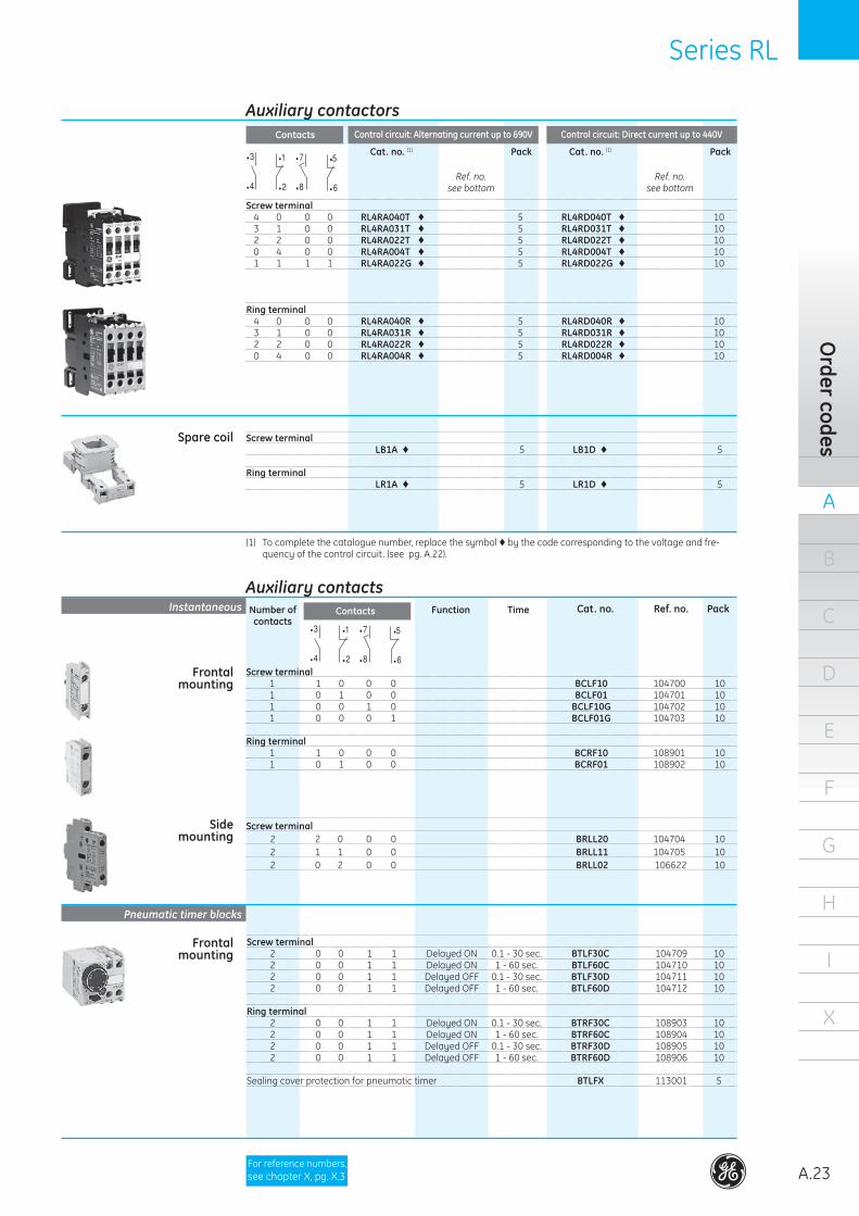
Screw terminal 4 0 0 0 RL4RA040T © 5 RL4RD040T © 10 3 1 0 0 RL4RA031T © 5 RL4RD031T © 10 2 2 0 0 RL4RA022T © 5 RL4RD022T © 10 0 4 0 0 RL4RA004T © 5 RL4RD004T © 10 1 1 1 1 RL4RA022G © 5 RL4RD022G © 10
Ring terminal 4 0 0 0 RL4RA040R © 5 RL4RD040R © 10 3 1 0 0 RL4RA031R © 5 RL4RD031R © 10 2 2 0 0 RL4RA022R © 5 RL4RD022R © 10 0 4 0 0 RL4RA004R © 5 RL4RD004R © 10
Cat. no. (1) Pack
Control circuit: Alternating current up to 690V Control circuit: Direct current up to 440V
Screw terminal LB1A © 5 LB1D © 5
Ring terminal LR1A © 5 LR1D © 5
Spare coil
Auxiliary contacts
Frontal mounting
Cat. no. Ref. no. Pack
Screw terminal 1 1 0 0 0 BCLF10 104700 10 1 0 1 0 0 BCLF01 104701 10 1 0 0 1 0 BCLF10G 104702 10 1 0 0 0 1 BCLF01G 104703 10 Ring terminal 1 1 0 0 0 BCRF10 108901 10 1 0 1 0 0 BCRF01 108902 10
Screw terminal 2 2 0 0 0 BRLL20 104704 10 2 1 1 0 0 BRLL11 104705 10 2 0 2 0 0 BRLL02 106622 10
(1) Tocompletethecataloguenumber,replacethesymbol©bythecodecorrespondingtothevoltageandfre-quencyofthecontrolcircuit.(seepg.A.22).
Side mounting
Screw terminal 2 0 0 1 1 DelayedON 0.1-30sec. BTLF30C 104709 10 2 0 0 1 1 DelayedON 1-60sec. BTLF60C 104710 10 2 0 0 1 1 DelayedOFF 0.1-30sec. BTLF30D 104711 10 2 0 0 1 1 DelayedOFF 1-60sec. BTLF60D 104712 10
Ring terminal 2 0 0 1 1 DelayedON 0.1-30sec. BTRF30C 108903 10 2 0 0 1 1 DelayedON 1-60sec. BTRF60C 108904 10 2 0 0 1 1 DelayedOFF 0.1-30sec. BTRF30D 108905 10 2 0 0 1 1 DelayedOFF 1-60sec. BTRF60D 108906 10
Sealingcoverprotectionforpneumatictimer BTLFX 113001 5
Number of Function Time contacts
Frontalmounting
•7
•8
•5
•6
•7
•8
•5
•6
•1
•2
•3
•4
•1
•2
•3
•4Ref. no.
see bottomRef. no.
see bottom
Forreferencenumbers,seechapterX,pg.X.3
•7
•8
•5
•6
•7
•8
•5
•6
•1
•2
•3
•4
•1
•2
•3
•4
Instantaneous
Pneumatic timer blocks
Cat. no. (1) Pack
Auxiliary contactors Contacts
Contacts
A
A.24
B
C
D
E
F
G
H
I
X
Auxi
liary
con
tact
ors
SeriesRL SeriesRL
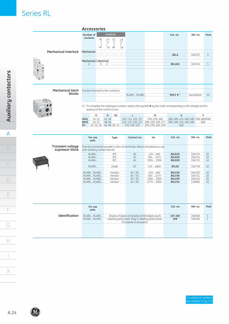
RL4RA...,RL4RD... RMLF © (1) seebottom 20
FrontalmountedtothecontactorMechanical latchblocks
D G HC J N U Y50Hz 24,32 42,48 110,115,120,127 220,230,240 380,400,415,440,480 500,660/69060HZ 24,32 48,60 110,115,120,127 208,220,240,277 380,400,415,440,480 600DC 24,32,36 42,48 60,72 110,120,125 220,230,240,250 440
(1) Tocompletethecataloguenumber,replacethesymbol©bythecodecorrespondingtothevoltageandfre-quencyofthecontrolcircuit.
Cat. no. Ref. no. Pack
For use Type Control circ. Ue with:
RL4RA... R/C AC 12V...48V BSLR2G 104713 10 RL4RA... R/C AC 50V...127V BSLR2K 104714 10 RL4RA... R/C AC 130V...250V BSLR2R 104715 10
RL4RD... Diode DC 12V...600V BSLDZ 104719 10
RL4RA...,RL4RD... Varistor AC/DC 24V...48V BSLV3G 104720 10 RL4RA...,RL4RD... Varistor AC/DC 50V...127V BSLV3K 104721 10 RL4RA...,RL4RD... Varistor AC/DC 130V...250V BSLV3R 104722 10 RL4RA...,RL4RD... Varistor AC/DC 277V...500V BSLV3U 110836 10
Directlyconnectedparalleltothecoilterminals,allowssimultaneoususewithauxiliarycontactblocks.
Transient voltage supressor block
Number of contacts
Cat. no. Ref. no. Pack
Mechanical - - - - - BELA 104723 5
Mechanical / electrical 2 0 2 - - BELA02 104724 5
Mechanical interlock
For use with:
RL4RA...,RL4RD... Sheetsoflabels(10sheetsof260labelseach) EAT 260 100548 1 RL4RA...,RL4RD... Labellingplatebase.Plug-inlabelingplatebases SPR 100549 1 (50piecesinonepack)
Identification
•7
•8
•5
•6
•7
•8
•5
•6
•1
•2
•3
•4
•1
•2
•3
•4
Cat. no. Ref. no. Pack
Forreferencenumbers,seechapterX,pg.X.3
Accessories Contacts
SeriesRL SeriesRL
A
A.25
B
C
D
E
F
G
H
I
X
Order codes
Electronic timer module
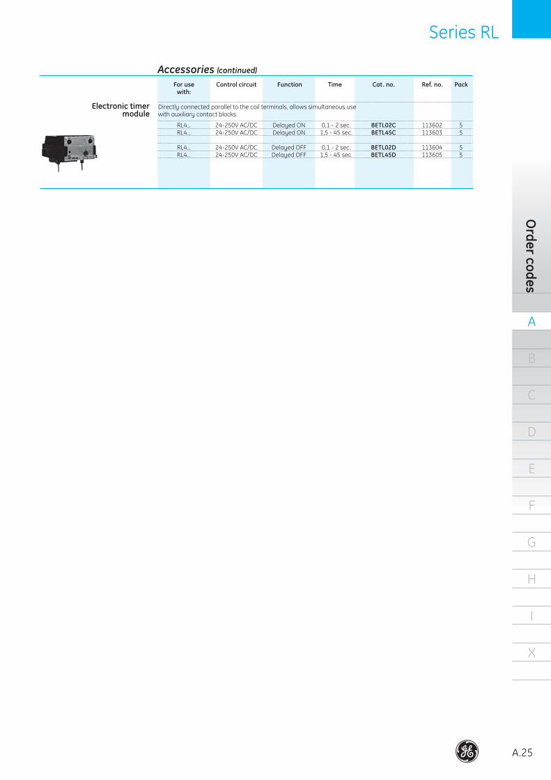
Cat. no. Ref. no. Pack
For use Control circuit Function Time with:
RL4... 24-250VAC/DC DelayedON 0,1-2sec. BETL02C 113602 5 RL4... 24-250VAC/DC DelayedON 1,5-45sec. BETL45C 113603 5
RL4... 24-250VAC/DC DelayedOFF 0,1-2sec. BETL02D 113604 5 RL4... 24-250VAC/DC DelayedOFF 1,5-45sec. BETL45D 113605 5
Directlyconnectedparalleltothecoilterminals,allowssimultaneoususewithauxiliarycontactblocks.
Accessories (continued)
A
A.26
B
C
D
E
F
G
H
I
X
Auxi
liary
min
icon
tact
ors
Series M Series M
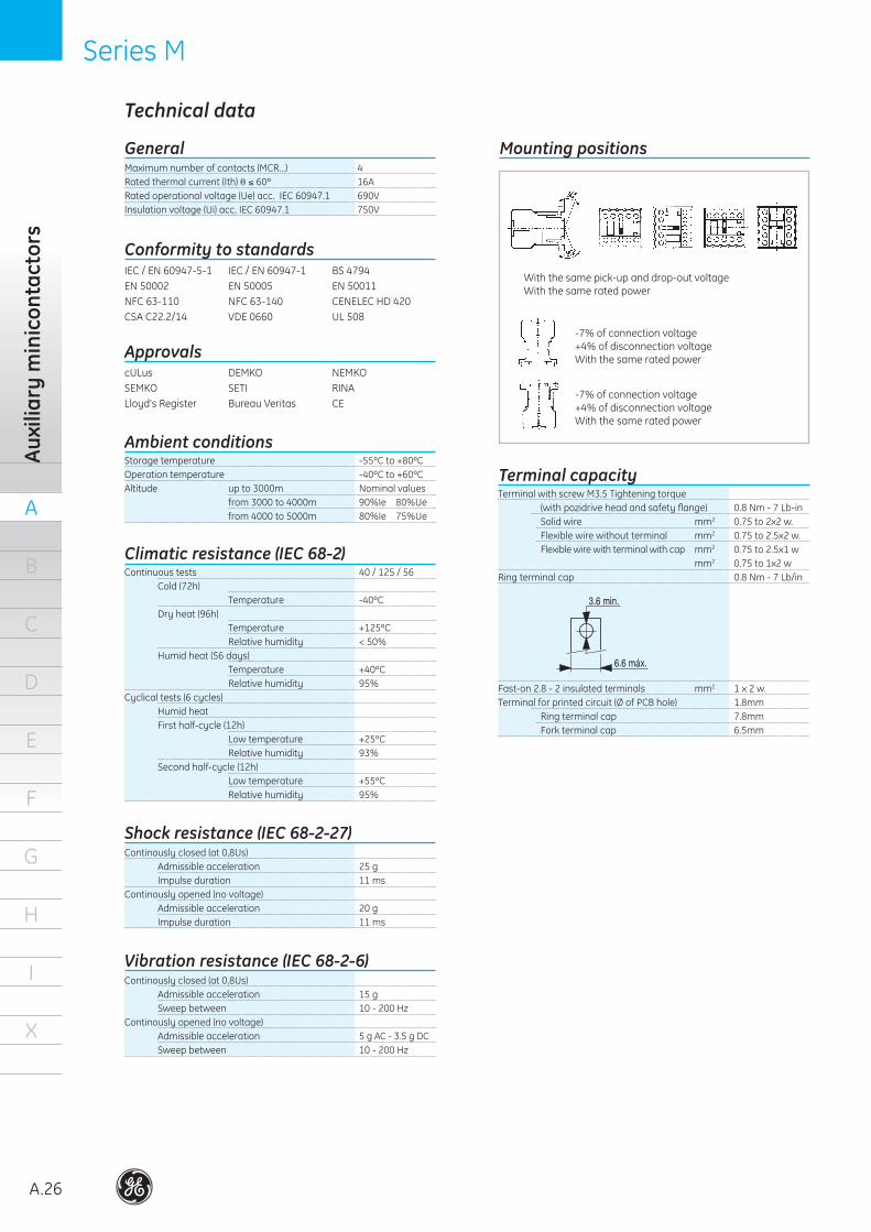
GeneralMaximum number of contacts (MCR...) 4Rated thermal current (Ith) θ ≤ 60º 16ARated operational voltage (Ue) acc. IEC 60947.1 690VInsulation voltage (Ui) acc. IEC 60947.1 750V
Conformity to standardsIEC / EN 60947-5-1 IEC / EN 60947-1 BS 4794EN 50002 EN 50005 EN 50011NFC 63-110 NFC 63-140 CENELEC HD 420 CSA C22.2/14 VDE 0660 UL 508
ApprovalscULus DEMKO NEMKOSEMKO SETI RINALloyd’s Register Bureau Veritas CE
Storage temperature -55ºC to +80ºCOperation temperature -40ºC to +60ºCAltitude up to 3000m Nominal values from 3000 to 4000m 90%Ie 80%Ue from 4000 to 5000m 80%Ie 75%Ue
Ambient conditions
Continuous tests 40 / 125 / 56 Cold (72h) Temperature -40ºC Dry heat (96h) Temperature +125ºC Relative humidity < 50% Humid heat (56 days) Temperature +40ºC Relative humidity 95%Cyclical tests (6 cycles) Humid heat First half-cycle (12h) Low temperature +25ºC Relative humidity 93% Second half-cycle (12h) Low temperature +55ºC Relative humidity 95%
Climatic resistance (IEC 68-2)
Continously closed (at 0,8Us) Admissible acceleration 25 g Impulse duration 11 msContinously opened (no voltage) Admissible acceleration 20 g Impulse duration 11 ms
Shock resistance (IEC 68-2-27)
Continously closed (at 0,8Us) Admissible acceleration 15 g Sweep between 10 - 200 HzContinously opened (no voltage) Admissible acceleration 5 g AC - 3.5 g DC Sweep between 10 - 200 Hz
Vibration resistance (IEC 68-2-6)
With the same pick-up and drop-out voltageWith the same rated power
-7% of connection voltage+4% of disconnection voltageWith the same rated power
Terminal with screw M3.5 Tightening torque (with pozidrive head and safety flange) 0.8 Nm - 7 Lb-in Solid wire mm2 0.75 to 2x2 w. Flexible wire without terminal mm2 0.75 to 2.5x2 w. Flexible wire with terminal with cap mm2 0.75 to 2.5x1 w mm2 0.75 to 1x2 wRing terminal cap 0.8 Nm - 7 Lb/in
Fast-on 2.8 - 2 insulated terminals mm2 1 x 2 w.Terminal for printed circuit (Ø of PCB hole) 1.8mm Ring terminal cap 7.8mm Fork terminal cap 6.5mm
Terminal capacity
Mounting positions
-7% of connection voltage+4% of disconnection voltageWith the same rated power
Technical data
Series M Series M
A
A.27
B
C
D
E
F
G
H
I
X
Technical data
Control circuitMCRA... MCRC... MCRC... MCRI...
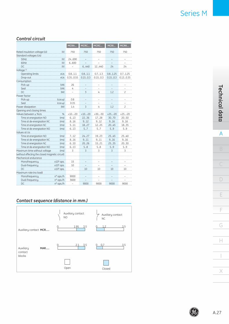
Rated insulation voltage (Ui) (V) 750 750 750 750 750Standard voltages (Us) 50Hz (V) 24...690 – – – – 60Hz (V) 6...600 – – – – DC (V) – 6...440 12...440 24 24Voltage (1) Operating limits xUs 0.8...1.1 0.8...1.1 0.7...1.3 0.8...1.25 0.7...1.25 Drop-out xUs 0.35...0.55 0.15...0.3 0.15...0.3 0.15...0.3 0.13...0.35Consumption Pick-up (VA) 26 – – – – Seal (VA) 4 – – – – DC (W) – 3 4 1.2 2Power factor Pick-up (cos ϕ) 0.8 – – – – Seal (cos ϕ) 0.35 – – – –Power dissipation (W) 1.4 3 4 1.2 2Opening and closing timesValues between ± %Us % +10...-20 +10...-20 +30...-30 +25...-20 +25...-20 Time at energisation NO (ms) 6...13 22...36 17...28 30...70 20...50 Time at de-energisation NC (ms) 8...16 9...12 9...12 9...16 9...16 Time at energisation NC (ms) 5...11 18...27 12...25 20...45 18...35 Time at de-energisation NO (ms) 6...13 5...7 5...7 5...9 5...9Values at Us Time at energisation NO (ms) 7...12 24...27 19...23 25...45 25...40 Time at de-energisation NC (ms) 8...16 9...11 9...11 9...16 9...16 Time at energisation NC (ms) 6...10 20...26 15...21 25...35 20...30 Time at de-energisation NO (ms) 6...13 5...8 5...8 5...9 5...9Maximum time without voltage (ms) 3 3 3 3 3(without effecting the closed magnetic circuit)Mechanical endurance Monofrequency x106 ops. 15 – – – – Dual-frequency x106 ops. 10 – – – – DC x106 ops. – 10 10 10 10Maximum rate (no load) Monofrequency n° ops./h 9000 – – – – Dual-frequency n° ops./h 3600 – – – – DC n° ops./h – 9000 9000 9000 9000
Contact sequence (distance in mm.)
0 1.95 3.5
Auxiliary contactNO
0 1.2 3.5
Auxiliary contactNC
0 2.1 3.5 0 0.7 3.5Auxiliary MAR..... contactblocks
Auxiliary contact MCR.....
Open Closed
MCRK...
A
A.28
B
C
D
E
F
G
H
I
X
Auxi
liary
min
icon
tact
ors
Series M Series M
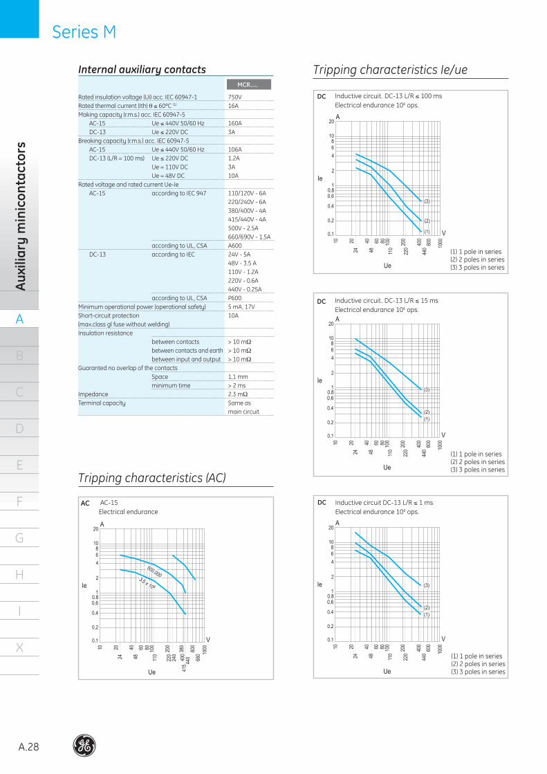
Rated insulation voltage (Ui) acc. IEC 60947-1 750VRated thermal current (Ith) θ ≤ 60ºC (1) 16AMaking capacity (r.m.s.) acc. IEC 60947-5 AC-15 Ue ≤ 440V 50/60 Hz 160A DC-13 Ue ≤ 220V DC 3ABreaking capacity (r.m.s.) acc. IEC 60947-5 AC-15 Ue ≤ 440V 50/60 Hz 106A DC-13 (L/R = 100 ms) Ue ≤ 220V DC 1.2A Ue = 110V DC 3A Ue = 48V DC 10ARated voltage and rated current Ue-Ie AC-15 according to IEC 947 110/120V - 6A 220/240V - 6A 380/400V - 4A 415/440V - 4A 500V - 2.5A 660/690V - 1.5A according to UL, CSA A600 DC-13 according to IEC 24V - 5A 48V - 3.5 A 110V - 1.2A 220V - 0.6A 440V - 0.25A according to UL, CSA P600Minimum operational power (operational safety) 5 mA, 17VShort-circuit protection 10A (max.class gl fuse without welding) Insulation resistance between contacts > 10 mΩ between contacts and earth > 10 mΩ between input and output > 10 mΩGuaranted no overlap of the contacts Space 1,1 mm minimum time > 2 msImpedance 2.3 mΩTerminal capacity Same as main circuit
Internal auxiliary contacts Tripping characteristics Ie/ue
Tripping characteristics (AC)
AC AC-15Electrical endurance
(1) 1 pole in series(2) 2 poles in series(3) 3 poles in series
Inductive circuit. DC-13 L/R ≤ 100 msElectrical endurance 106 ops.
DC
DC Inductive circuit. DC-13 L/R ≤ 15 msElectrical endurance 106 ops.
DC Inductive circuit DC-13 L/R ≤ 1 ms Electrical endurance 106 ops.
MCR.....
.
.
.
.
.
.
.
.
.
.
.
.
.
.
.
.
.
.
.
.
.
(1) 1 pole in series(2) 2 poles in series(3) 3 poles in series
(1) 1 pole in series(2) 2 poles in series(3) 3 poles in series
Series M Series M
A
A.29
B
C
D
E
F
G
H
I
X
Technical data
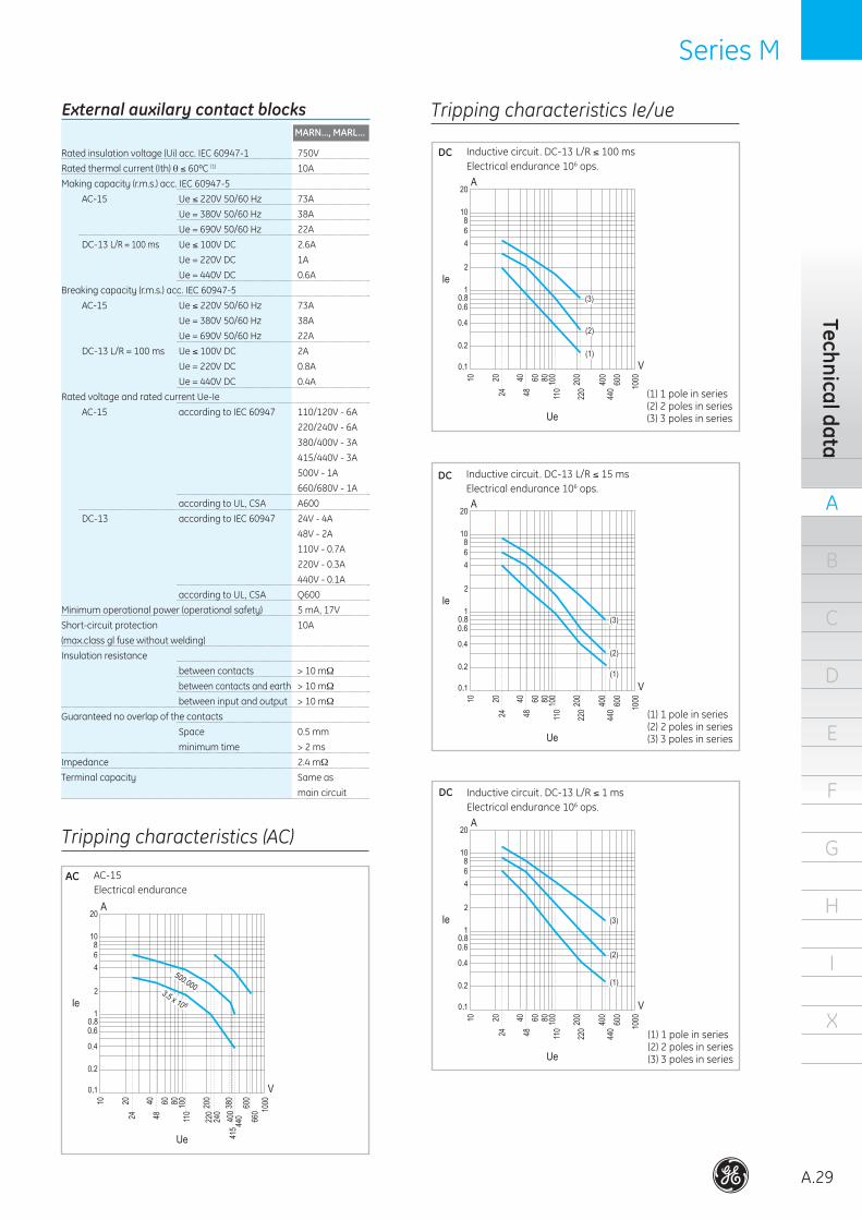
External auxilary contact blocks
Rated insulation voltage (Ui) acc. IEC 60947-1 750V
Rated thermal current (Ith) θ ≤ 60ºC (1) 10A
Making capacity (r.m.s.) acc. IEC 60947-5
AC-15 Ue ≤ 220V 50/60 Hz 73A
Ue = 380V 50/60 Hz 38A
Ue = 690V 50/60 Hz 22A
DC-13 L/R = 100 ms Ue ≤ 100V DC 2.6A
Ue = 220V DC 1A
Ue = 440V DC 0.6A
Breaking capacity (r.m.s.) acc. IEC 60947-5
AC-15 Ue ≤ 220V 50/60 Hz 73A
Ue = 380V 50/60 Hz 38A
Ue = 690V 50/60 Hz 22A
DC-13 L/R = 100 ms Ue ≤ 100V DC 2A
Ue = 220V DC 0.8A
Ue = 440V DC 0.4A
Rated voltage and rated current Ue-Ie
AC-15 according to IEC 60947 110/120V - 6A
220/240V - 6A
380/400V - 3A
415/440V - 3A
500V - 1A
660/680V - 1A
according to UL, CSA A600
DC-13 according to IEC 60947 24V - 4A
48V - 2A
110V - 0.7A
220V - 0.3A
440V - 0.1A
according to UL, CSA Q600
Minimum operational power (operational safety) 5 mA, 17V
Short-circuit protection 10A (max.class gl fuse without welding)
Insulation resistance between contacts > 10 mΩ
between contacts and earth > 10 mΩ
between input and output > 10 mΩ
Guaranteed no overlap of the contacts
Space 0.5 mm
minimum time > 2 ms
Impedance 2.4 mΩ
Terminal capacity Same as
main circuit
Tripping characteristics (AC)
AC AC-15Electrical endurance
Tripping characteristics Ie/ue
Inductive circuit. DC-13 L/R ≤ 100 msElectrical endurance 106 ops.
DC
DC Inductive circuit. DC-13 L/R ≤ 15 msElectrical endurance 106 ops.
DC Inductive circuit. DC-13 L/R ≤ 1 ms Electrical endurance 106 ops.
MARN..., MARL...
.
.
.
.
.
.
.
.
.
.
.
.
.
.
.
.
.
.
.
.
.
(1) 1 pole in series(2) 2 poles in series(3) 3 poles in series
(1) 1 pole in series(2) 2 poles in series(3) 3 poles in series
(1) 1 pole in series(2) 2 poles in series(3) 3 poles in series
A
A.30
B
C
D
E
F
G
H
I
X
Auxi
liary
min
icon
tact
ors
Series M Series M
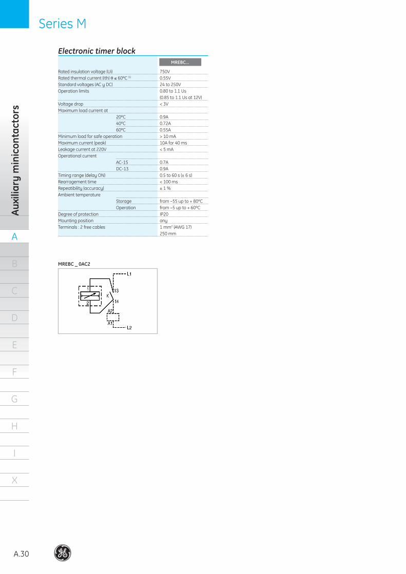
Electronic timer block
Rated insulation voltage (Ui) 750VRated thermal current (Ith) θ ≤ 60ºC (1) 0.55VStandard voltages (AC y DC) 24 to 250VOperation limits 0.80 to 1.1 Us (0.85 to 1.1 Us at 12V)Voltage drop < 3VMaximum load current at 20ºC 0.9A 40ºC 0.72A 60ºC 0.55AMinimum load for safe operation > 10 mAMaximum current (peak) 10A for 40 msLeakage current at 220V < 5 mAOperational current AC-15 0.7A DC-13 0.9ATiming range (delay ON) 0.5 to 60 s (± 6 s)Rearragement time < 100 msRepeatibility (accuracy) ± 1 %Ambient temperature Storage from –55 up to + 80ºC Operation from –5 up to + 60ºCDegree of protection IP20Mounting position anyTerminals : 2 free cables 1 mm2 (AWG 17) 250 mm
MREBC _ 0AC2
MREBC...
Series M Series M
A
A.31
B
C
D
E
F
G
H
I
X
Technical data
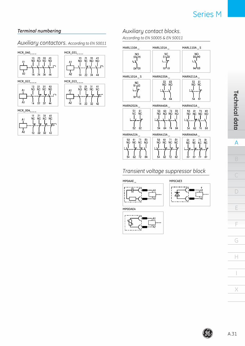
Auxiliary contactors. According to EN 50011
MCR_040_ _ _ MCR_031_ _ _
MCR_022_ _ _ MCR_013_ _ _
MCR_004_ _ _
Auxiliary contact blocks. According to EN 50005 & EN 50011
MARL110A _ MARL101A _ MARL110A _ S
MARL101A _ S MARN220A _ MARN211A _
MARN202A _ MARN440A _ MARN431A _
MARN422A _ MARN413A _ MARN404A _
Transient voltage suppressor block
MP0AAE _ MP0CAE3
MP0DAE4
Terminal numbering
A
A.32
B
C
D
E
F
G
H
I
X
Auxi
liary
min
icon
tact
ors
Series M Series M
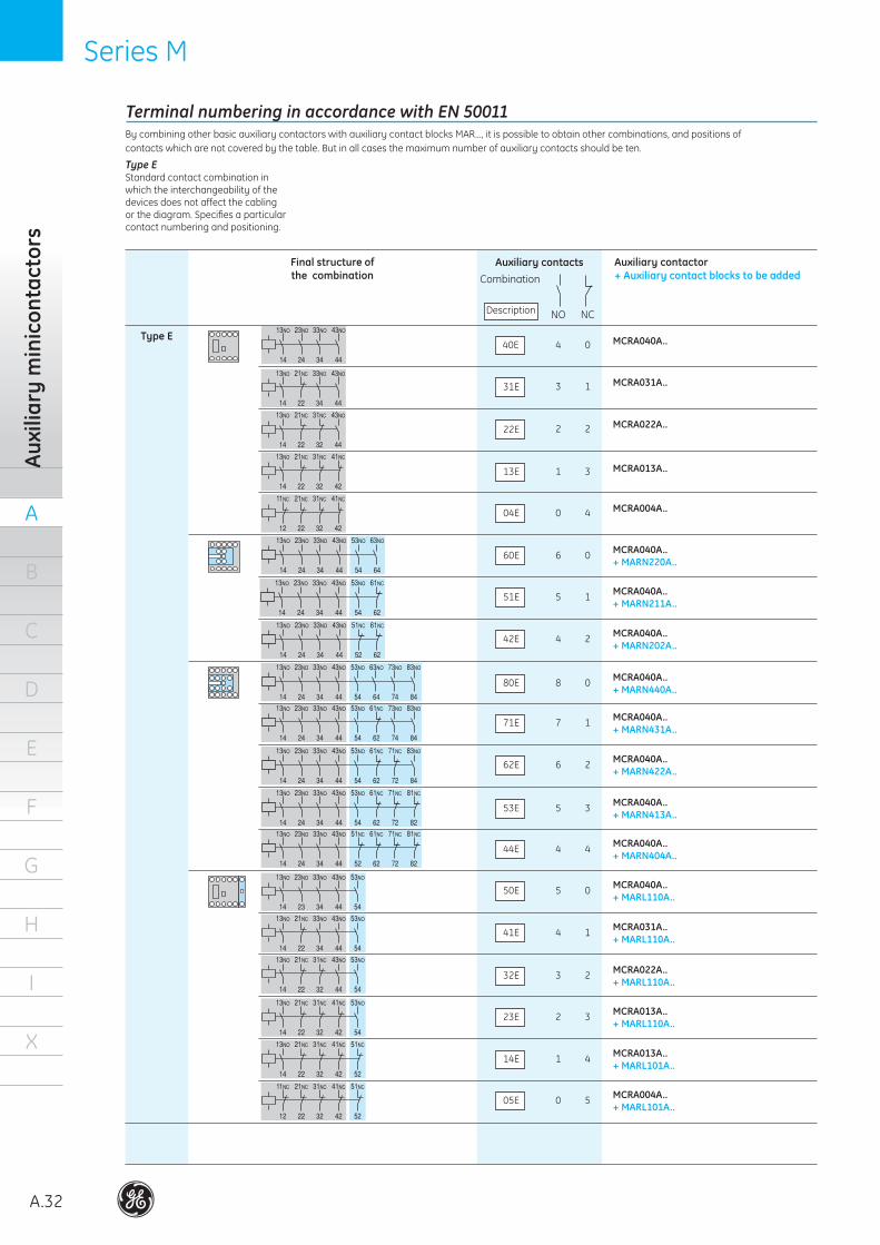
Terminal numbering in accordance with EN 50011
NO NC
Auxiliary contactsCombination
Description
Final structure of the combination
MCRA040A..+ MARN220A..
40E
By combining other basic auxiliary contactors with auxiliary contact blocks MAR..., it is possible to obtain other combinations, and positions of contacts which are not covered by the table. But in all cases the maximum number of auxiliary contacts should be ten.
Type E Standard contact combination in which the interchangeability of the devices does not affect the cabling or the diagram. Specifies a particular contact numbering and positioning.
Auxiliary contactor+ Auxiliary contact blocks to be added
Type E4 0
31E 3 1
22E 2 2
13E 1 3
04E 0 4
60E 6 0
MCRA040A..+ MARN211A..
51E 5 1
MCRA040A..+ MARN202A..
42E 4 2
MCRA040A..+ MARN440A..
80E 8 0
MCRA040A..+ MARN431A..
71E 7 1
MCRA040A..+ MARN422A..
62E 6 2
MCRA040A..+ MARN413A..
53E 5 3
MCRA040A..+ MARN404A..
44E 4 4
MCRA040A..+ MARL110A..
50E 5 0
MCRA031A..+ MARL110A..
41E 4 1
MCRA022A..+ MARL110A..
32E 3 2
MCRA013A..+ MARL110A..
23E 2 3
MCRA013A..+ MARL101A..
14E 1 4
MCRA004A..+ MARL101A..
05E 0 5
MCRA040A..
MCRA031A..
MCRA022A..
MCRA013A..
MCRA004A..
Series M Series M
A
A.33
B
C
D
E
F
G
H
I
X
Technical data
NO NC
Auxiliary contactsCombination
Description
Final structure of the combination
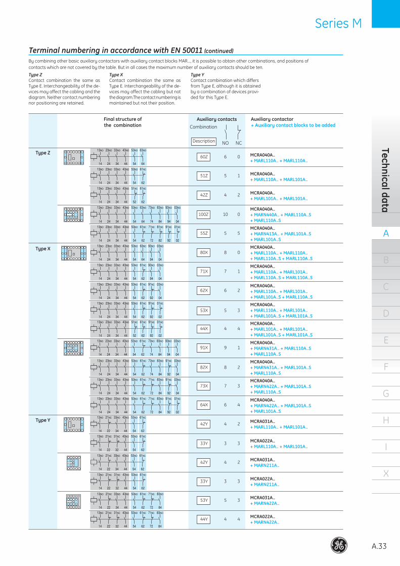
60Z
Auxiliary contactor+ Auxiliary contact blocks to be added
Type Z6 0
51Z 5 1
42Z 4 2
100Z 10 0
55Z 5 5
80X 8 0
71X 7 1
62X 6 2
53X 5 3
44X 4 4
91X 9 1
82X 8 2
73X 7 3
64X 6 4
MCRA031A..+ MARL110A.. + MARL101A..
42Y 4 2
MCRA022A..+ MARL110A.. + MARL101A..
33Y 3 3
MCRA031A..+ MARN211A..
42Y 4 2
MCRA022A..+ MARN211A..
33Y 3 3
MCRA031A..+ MARN422A..
53Y 5 3
MCRA040A..+ MARL110A.. + MARL110A..
MCRA040A..+ MARL110A.. + MARL101A..
MCRA040A..+ MARL101A.. + MARL101A..
MCRA040A..+ MARN440A.. + MARL110A..S + MARL110A..S
MCRA040A..+ MARN413A.. + MARL101A..S+ MARL101A..S
Type X MCRA040A..+ MARL110A.. + MARL110A..+ MARL110A..S + MARL110A..S
MCRA040A..+ MARL110A.. + MARL101A..+ MARL110A..S + MARL110A..S
MCRA040A..+ MARL110A.. + MARL101A..+ MARL101A..S + MARL110A..S
MCRA040A..+ MARL110A.. + MARL101A..+ MARL101A..S + MARL101A..S
MCRA040A..+ MARL101A.. + MARL101A..+ MARL101A..S + MARL101A..S
MCRA040A..+ MARN431A.. + MARL110A..S+ MARL110A..S
MCRA040A..+ MARN431A.. + MARL101A..S+ MARL110A..S
MCRA040A..+ MARN422A.. + MARL101A..S+ MARL110A..S
MCRA040A..+ MARN422A.. + MARL101A..S+ MARL101A..S
Type Y
MCRA022A..+ MARN422A..
44Y 4 4
Terminal numbering in accordance with EN 50011 (continued)
By combining other basic auxiliary contactors with auxiliary contact blocks MAR..., it is possible to obtain other combinations, and positions of contacts which are not covered by the table. But in all cases the maximum number of auxiliary contacts should be ten.
Type Y Contact combination which differs from Type E, although it is obtained by a combination of devices provi-ded for this Type E.
Type X Contact combination the same as Type E. Interchangeability of the de-vices may affect the cabling but not the diagram.The contact numbering is maintained but not their position.
Type ZContact combination the same as Type E. Interchangeability of the de-vices may affect the cabling and the diagram. Neither contact numbering nor positioning are retained.
A
A.34
B
C
D
E
F
G
H
I
X
Auxi
liary
con
tact
ors
Series RL Series RL
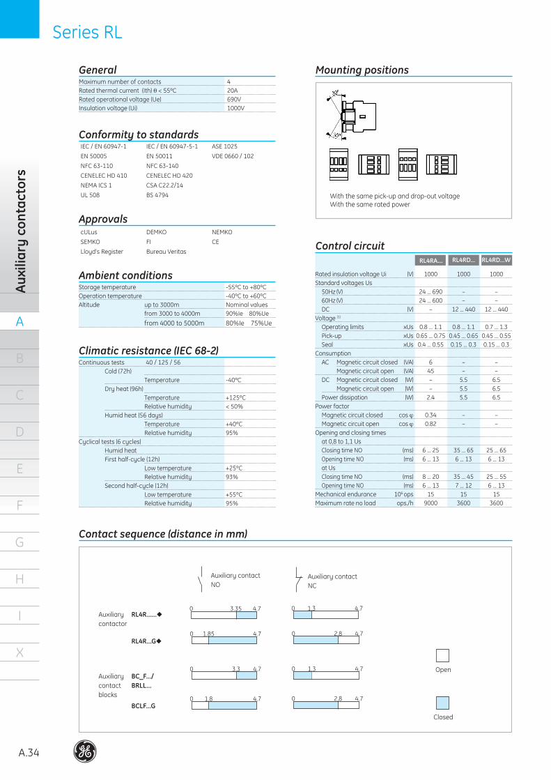
GeneralMaximum number of contacts 4Rated thermal current (Ith) θ < 55ºC 20ARated operational voltage (Ue) 690VInsulation voltage (Ui) 1000V
Conformity to standardsIEC / EN 60947-1 IEC / EN 60947-5-1 ASE 1025
EN 50005 EN 50011 VDE 0660 / 102
NFC 63-110 NFC 63-140
CENELEC HD 410 CENELEC HD 420
NEMA ICS 1 CSA C22.2/14
UL 508 BS 4794
ApprovalscULus DEMKO NEMKO
SEMKO FI CE
Lloyd’s Register Bureau Veritas
Storage temperature -55ºC to +80ºCOperation temperature -40ºC to +60ºCAltitude up to 3000m Nominal values from 3000 to 4000m 90%Ie 80%Ue
from 4000 to 5000m 80%Ie 75%Ue
Ambient conditions
Continuous tests 40 / 125 / 56 Cold (72h) Temperature -40ºC Dry heat (96h) Temperature +125ºC Relative humidity < 50% Humid heat (56 days) Temperature +40ºC Relative humidity 95%Cyclical tests (6 cycles) Humid heat First half-cycle (12h) Low temperature +25ºC Relative humidity 93% Second half-cycle (12h) Low temperature +55ºC Relative humidity 95%
Climatic resistance (IEC 68-2)
With the same pick-up and drop-out voltageWith the same rated power
Mounting positions
RL4RA... RL4RD...
Auxiliary contactNO
Auxiliary contactNC
Open
Closed
Auxiliary RL4R...... contactor
RL4R...G
Auxiliary BC_F.../contact BRLL... blocks
BCLF...G
0 3.35 4.7 0 1.3 4.7
0 1.85 4.7 0 2.8 4.7
0 3.3 4.7 0 1.3 4.7
0 1.8 4.7 0 2.8 4.7
RL4RD...W
Rated insulation voltage Ui (V) 1000 1000 1000Standard voltages Us 50Hz (V) 24 ... 690 – – 60Hz (V) 24 ... 600 – – DC (V) – 12 ... 440 12 ... 440Voltage (1)
Operating limits xUs 0.8 ... 1.1 0.8 ... 1.1 0.7 ... 1.3 Pick-up xUs 0.65 ... 0.75 0.45 ... 0.65 0.45 ... 0.55 Seal xUs 0.4 ... 0.55 0.15 ... 0.3 0.15 ... 0.3Consumption AC Magnetic circuit closed (VA) 6 – – Magnetic circuit open (VA) 45 – – DC Magnetic circuit closed (W) – 5.5 6.5 Magnetic circuit open (W) – 5.5 6.5 Power dissipation (W) 2.4 5.5 6.5Power factor Magnetic circuit closed cos ϕ 0.34 – – Magnetic circuit open cos ϕ 0.82 – –Opening and closing times at 0,8 to 1,1 Us Closing time NO (ms) 6 ... 25 35 ... 65 25 ... 65 Opening time NO (ms) 6 ... 13 6 ... 13 6 ... 13 at Us Closing time NO (ms) 8 ... 20 35 ... 45 25 ... 55 Opening time NO (ms) 6 ... 13 7 ... 12 6 ... 13Mechanical endurance 106 ops 15 15 15Maximum rate no load ops./h 9000 3600 3600
Control circuit
Contact sequence (distance in mm)
Series RL Series RL
A
A.35
B
C
D
E
F
G
H
I
X
Technical data
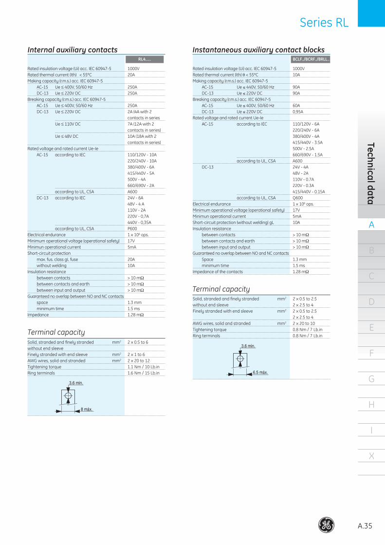
Internal auxiliary contactsRL4.....
Rated insulation voltage (Ui) acc. IEC 60947-5 1000VRated thermal current (Ith) θ < 55ºC 20AMaking capacity (r.m.s.) acc. IEC 60947-5 AC-15 Ue ≤ 400V, 50/60 Hz 250A DC-13 Ue ≤ 220V DC 250ABreaking capacity (r.m.s.) acc. IEC 60947-5 AC-15 Ue ≤ 400V, 50/60 Hz 250A DC-13 Ue ≤ 220V DC 2A (4A with 2 contacts in series Ue ≤ 110V DC 7A (12A with 2 contacts in series) Ue ≤ 48V DC 10A (18A with 2 contacts in series)Rated voltage and rated current Ue-Ie AC-15 according to IEC 110/120V - 10A 220/240V - 10A 380/400V - 6A 415/440V - 5A 500V - 4A 660/690V - 2A according to UL, CSA A600 DC-13 according to IEC 24V - 6A 48V - 4 A 110V - 2A 220V - 0,7A 440V - 0,35A according to UL, CSA P600Electrical endurance 1 x 10⁶ ops.Minimum operational voltage (operational safety) 17VMinimun operational current 5mAShort-circuit protection max. fus. class gL fuse 20A without welding 10AInsulation resistance between contacts > 10 mΩ between contacts and earth > 10 mΩ between input and output > 10 mΩGuaranteed no overlap between NO and NC contacts space 1.3 mm minimum time 1.5 msImpedance 1.28 mΩ
Instantaneous auxiliary contact blocksBCLF../BCRF../BRLL..
Rated insulation voltage (Ui) acc. IEC 60947-5 1000VRated thermal current (Ith) θ < 55ºC 10AMaking capacity (r.m.s.) acc. IEC 60947-5 AC-15 Ue ≤ 440V, 50/60 Hz 90A DC-13 Ue ≤ 220V DC 90ABreaking capacity (r.m.s.) acc. IEC 60947-5 AC-15 Ue ≤ 400V, 50/60 Hz 60A DC-13 Ue ≤ 220V DC 0,95ARated voltage and rated current Ue-Ie AC-15 according to IEC 110/120V - 6A 220/240V - 6A 380/400V - 4A 415/440V - 3.5A 500V - 2.5A 660/690V - 1.5A according to UL, CSA A600 DC-13 24V - 4A 48V - 2A 110V - 0.7A 220V - 0.3A 415/440V - 0.15A according to UL, CSA Q600Electrical endurance 1 x 10⁶ ops.Minimum operational voltage (operational safety) 17VMinimun operational current 5mAShort-circuit protection (without welding) gL 10AInsulation resistance between contacts > 10 mΩ between contacts and earth > 10 mΩ between input and output > 10 mΩGuaranteed no overlap between NO and NC contacts Space 1.3 mm minimum time 1.5 msImpedance of the contacts 1.28 mΩ
Terminal capacitySolid, stranded and finely stranded mm2 2 x 0.5 to 6without end sleeveFinely stranded with end sleeve mm2 2 x 1 to 6AWG wires, solid and stranded mm2 2 x 20 to 12 Tightening torque 1.1 Nm / 10 Lb.inRing terminals 1.6 Nm / 15 Lb.in
Terminal capacitySolid, stranded and finely stranded mm2 2 x 0.5 to 2.5without end sleeve 2 x 2.5 to 4Finely stranded with end sleeve mm2 2 x 0.5 to 2.5 2 x 2.5 to 4AWG wires, solid and stranded mm2 2 x 20 to 10Tightening torque 0.8 Nm / 7 Lb.inRing terminals 0.8 Nm / 7 Lb.in
.
.
.
A
A.36
B
C
D
E
F
G
H
I
X
Auxi
liary
con
tact
ors
Series RL Series RL
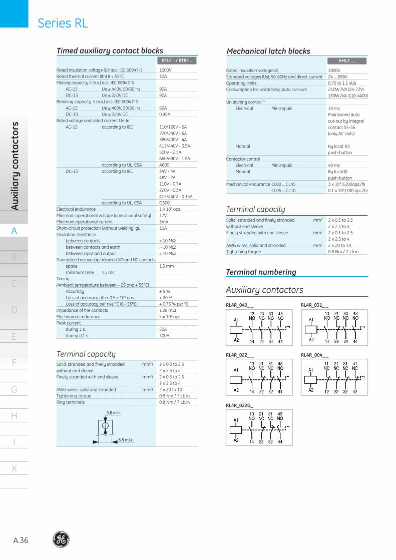
Timed auxiliary contact blocksBTLF... / BTRF...
Rated insulation voltage (Ui) acc. IEC 60947-5 1000VRated thermal current (Ith) θ < 55ºC 10AMaking capacity (r.m.s.) acc. IEC 60947-5 AC-15 Ue ≤ 440V, 50/60 Hz 90A DC-13 Ue ≤ 220V DC 90ABreaking capacity (r.m.s.) acc. IEC 60947-5 AC-15 Ue ≤ 400V, 50/60 Hz 60A DC-13 Ue ≤ 220V DC 0.95ARated voltage and rated current Ue-Ie AC-15 according to IEC 110/120V - 6A 220/240V - 6A 380/400V - 4A 415/440V - 3.5A 500V - 2.5A 660/690V - 1.5A according to UL, CSA A600 DC-13 according to IEC 24V - 4A 48V - 2A 110V - 0.7A 220V - 0.3A 415/440V - 0.15A according to UL, CSA Q600Electrical endurance 1 x 10⁶ ops.Minimum operational voltage (operational safety) 17V Minimum operational current 5mAShort-circuit protection (without welding) gL 10AInsulation resistance between contacts > 10 MΩ between contacts and earth > 10 MΩ between input and output > 10 MΩGuaranteed no overlap between NO and NC contacts space 1.3 mm minimum time 1.5 msTiming (Ambient temperature between – 25 and + 55ºC) Accuracy ± 5 % Loss of accuracy after 0.5 x 10⁶ ops. + 20 % Loss of accuracy per rise ºC (0 - 55ºC) + 0.75 % per °CImpedance of the contacts 1.28 mΩMechanical endurance 5 x 10⁶ ops.Peak current during 1 s. 50A during 0.1 s. 100A
Mechanical latch blocksRMLF.....
Rated insulation voltage(Ui) 1000VStandard voltages (Us); 50-60Hz and direct current 24 ... 690VOperating limits 0.75 to 1.1 xUsConsumption for unlatching (auto cut-out) 210W /VA (24-72V) 130W /VA (110-440V)Unlatching control (1) Electrical Min.impuls 10 ms Maintained auto cut-out by integral contact 55-56 (only AC slots) Manual By local (0) push-buttonContactor control Electrical Min.impuls 40 ms Manual By local (I) push-buttonMechanical endurance CL00 ... CL45 3 x 10⁶ (1200ops./h) CL05 ... CL10 0.1 x 10⁶ (300 ops./h)
Terminal capacitySolid, stranded and finely stranded (mm2) 2 x 0.5 to 2.5without end sleeve 2 x 2.5 to 4Finely stranded with end sleeve (mm2) 2 x 0.5 to 2.5 2 x 2.5 to 4AWG wires, solid and stranded (mm2) 2 x 20 to 10Tightening torque 0.8 Nm / 7 Lb.in Ring terminals 0.8 Nm / 7 Lb.in
Terminal capacitySolid, stranded and finely stranded mm2 2 x 0.5 to 2.5without end sleeve 2 x 2.5 to 4Finely stranded with end sleeve mm2 2 x 0.5 to 2.5 2 x 2.5 to 4AWG wires, solid and stranded mm2 2 x 20 to 10Tightening torque 0.8 Nm / 7 Lb.in
.
.
Terminal numbering
Auxiliary contactors
RL4R_040_ _ RL4R_031_ _
RL4R_022_ _ RL4R_004_ _
RL4R_022G_
Series RL Series RL
A
A.37
B
C
D
E
F
G
H
I
X
Technical data
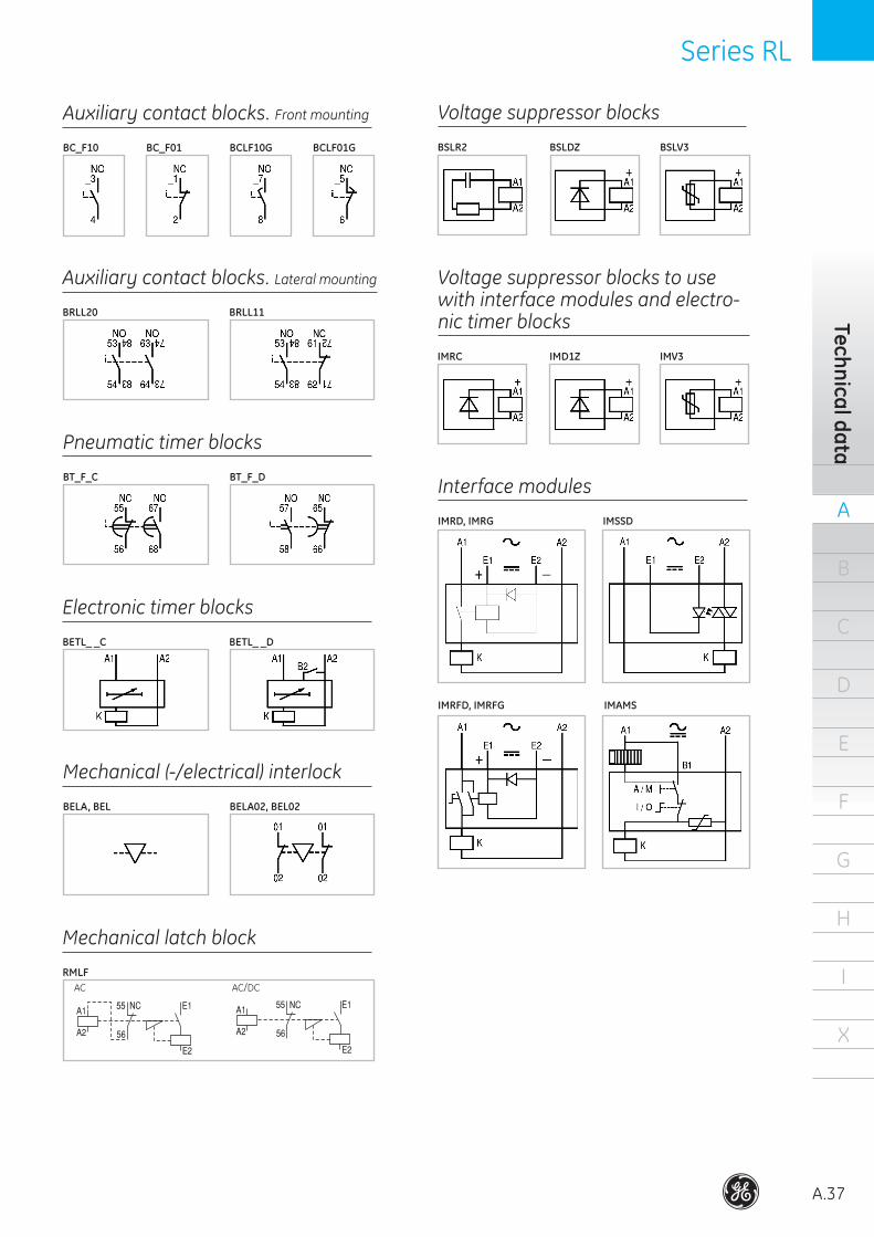
Auxiliary contact blocks. Front mounting
BC_F10 BCLF01GBC_F01 BCLF10G
Auxiliary contact blocks. Lateral mounting
BRLL20 BRLL11
Pneumatic timer blocks
BT_F_C BT_F_D
Electronic timer blocks
BETL_ _C BETL_ _D
Mechanical (-/electrical) interlock
BELA, BEL BELA02, BEL02
Mechanical latch block
RMLF
Voltage suppressor blocks
BSLR2 BSLDZ BSLV3
Voltage suppressor blocks to use with interface modules and electro-nic timer blocks
IMRC IMD1Z IMV3
Interface modules
IMRD, IMRG IMSSD
IMRFD, IMRFG IMAMS
AC AC/DC
A
A.38
B
C
D
E
F
G
H
I
X
Auxi
liary
con
tact
ors
Series RL Series RL
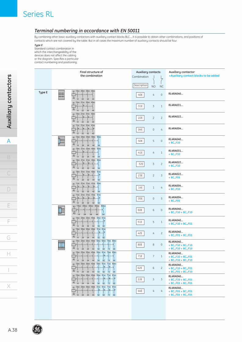
NO NC
Auxiliary contactsCombination
Description
Final structure ofthe combination
40E
Auxiliary contactor+Auxiliary contact blocks to be added
Type E4 0
31E 3 1
22E 2 2
04E 0 4
5 0
41E 4 1
32E 3 2
23E 2 3
14E 1 4
05E 0 5
60E 6 0
51E 5 1
42E 4 2
80E 8 0
71E 7 1
62E 6 2
53E 5 3
44E 4 4
RL4RA040...
RL4RA031...
RL4RA022...
RL4RA004...
RL4RA040...+ BC_F10
Terminal numbering in accordance with EN 50011By combining other basic auxiliary contactors with auxiliary contact blocks BLC..., it is possible to obtain other combinations, and positions of contacts which are not covered by the table. But in all cases the maximum number of auxiliary contacts should be four.
RL4RA031...+ BC_F10
RL4RA022...+ BC_F10
RL4RA022...+ BC_F01
RL4RA004...+ BC_F10
RL4RA004...+ BC_F01
RL4RA040...+ BC_F10 + BC_F10
RL4RA040...+ BC_F10 + BC_F01
RL4RA040...+ BC_F01 + BC_F01
RL4RA040...+ BC_F10 + BC_F10+ BC_F10 + BC_F10
RL4RA040...+ BC_F10 + BC_F01+ BC_F10 + BC_F10
RL4RA040...+ BC_F10 + BC_F01+ BC_F01 + BC_F10
RL4RA040...+ BC_F10 + BC_F01+ BC_F01 + BC_F01
RL4RA040...+ BC_F01 + BC_F01+ BC_F01 + BC_F01
Type E Standard contact combination in which the interchangeability of the devices does not affect the cabling or the diagram. Specifies a particular contact numbering and positioning.
50E
Series RL Series RL
A
A.39
B
C
D
E
F
G
H
I
X
Technical data
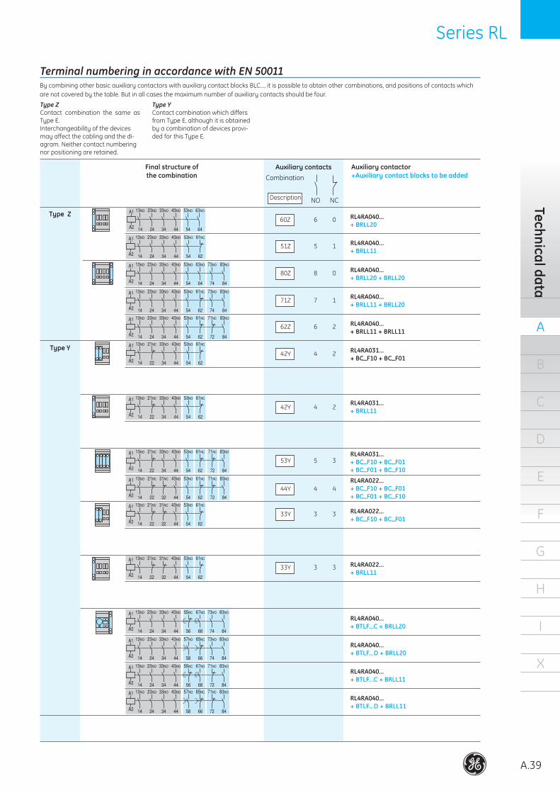
NO NC
Auxiliary contactsCombination
Description
Final structure ofthe combination
60Z
Auxiliary contactor+Auxiliary contact blocks to be added
Type Z6 0
51Z 5 1
80Z 8 0
71Z 7 1
62Z 6 2
42Y 4 2
42Y 4 2
53Y 5 3
44Y 4 4
33Y 3 3
33Y 3 3
RL4RA031...+ BC_F10 + BC_F01+ BC_F01 + BC_F10
RL4RA022...+ BC_F10 + BC_F01
RL4RA022...+ BRLL11
RL4RA040...+ BTLF...C + BRLL20
RL4RA040...+ BRLL20
RL4RA040...+ BRLL11
RL4RA040...+ BRLL20 + BRLL20
RL4RA040...+ BRLL11 + BRLL20
RL4RA040...+ BRLL11 + BRLL11
Type Y RL4RA031...+ BC_F10 + BC_F01
RL4RA031...+ BRLL11
RL4RA022...+ BC_F10 + BC_F01+ BC_F01 + BC_F10
RL4RA040...+ BTLF...D + BRLL20
RL4RA040...+ BTLF...C + BRLL11
RL4RA040...+ BTLF...D + BRLL11
Terminal numbering in accordance with EN 50011By combining other basic auxiliary contactors with auxiliary contact blocks BLC..., it is possible to obtain other combinations, and positions of contacts which are not covered by the table. But in all cases the maximum number of auxiliary contacts should be four.
Type Y Contact combination which differs from Type E, although it is obtained by a combination of devices provi-ded for this Type E.
Type ZContact combination the same as Type E.Interchangeability of the devices may affect the cabling and the di-agram. Neither contact numbering nor positioning are retained.
A
A.40
B
C
D
E
F
G
H
I
X
Auxi
liary
min
icon
tact
ors
Series M Series M
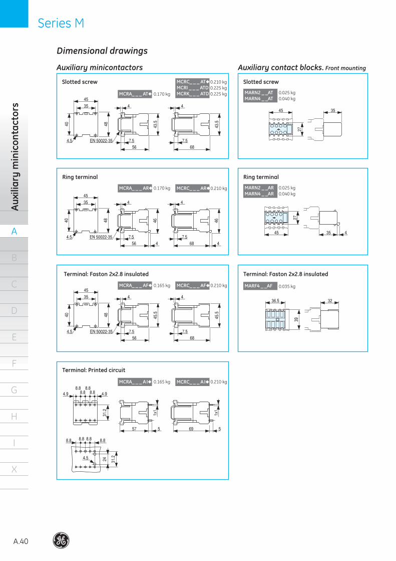
Auxiliary contact blocks. Front mountingAuxiliary minicontactors
Dimensional drawings
MCRC_ _ _ AT
MCRI _ _ _ ATDMCRK_ _ _ ATDMCRA_ _ _ AT
MCRA_ _ _ AF MCRC_ _ _ AF
MCRA_ _ _ A I MCRC_ _ _ A I
MARN2 _ _ATMARN4 _ _AT
.. .
. . .
.
. . . .
. .
. .
.
.
.
MCRA_ _ _ AR MCRC_ _ _ AR
. . .
. .
. .
.
Slotted screw
Ring terminal
Terminal: Faston 2x2.8 insulated
Terminal: Printed circuit
Slotted screw
Ring terminal
MARF4 _ _AF
Terminal: Faston 2x2.8 insulated
.
0.170 kg
0.210 kg0.225 kg0.225 kg
0.170 kg 0.210 kg
0.165 kg 0.210 kg
0.165 kg 0.210 kg
0.025 kg0.040 kg
MARN2 _ _ARMARN4 _ _AR
0.025 kg0.040 kg
0.035 kg
Series M Series M
A
A.41
B
C
D
E
F
G
H
I
X
Dim
ensions
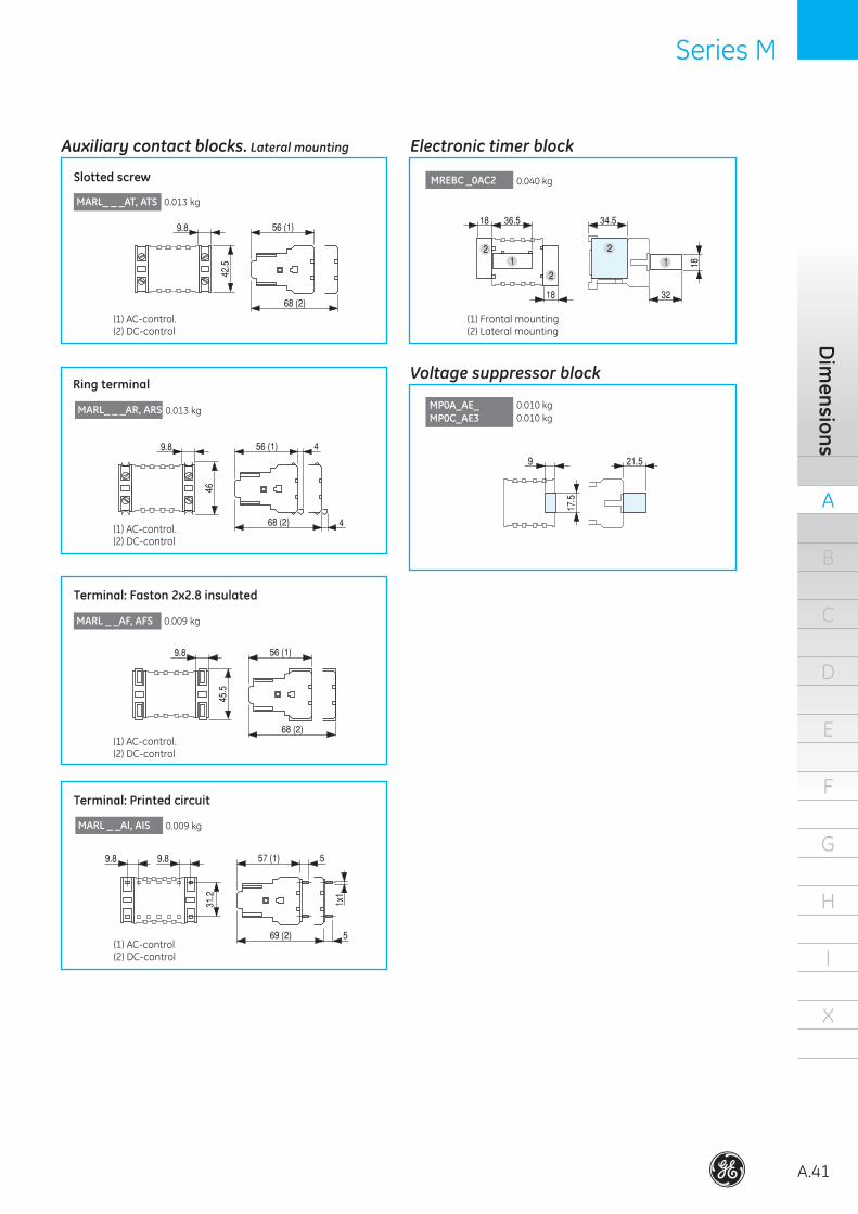
Voltage suppressor block
Electronic timer blockAuxiliary contact blocks. Lateral mounting
(1) AC-control.(2) DC-control
MARL_ _ _AT, ATS
MARL_ _ _AR, ARS
Slotted screw
Ring terminal
MARL _ _AF, AFS
Terminal: Faston 2x2.8 insulated
..
.
(1) AC-control.(2) DC-control
.
.
(1) AC-control.(2) DC-control
MARL _ _AI, AIS
Terminal: Printed circuit
(1) AC-control(2) DC-control
. .
.0.013 kg
0.013 kg
0.009 kg
0.009 kg
(1) Frontal mounting(2) Lateral mounting
MREBC _0AC2
. .
MP0A_AE_MP0C_AE3
.
.
0.040 kg
0.010 kg0.010 kg
A
A.42
B
C
D
E
F
G
H
I
X
Auxi
liary
con
tact
ors
Series RL Series RL
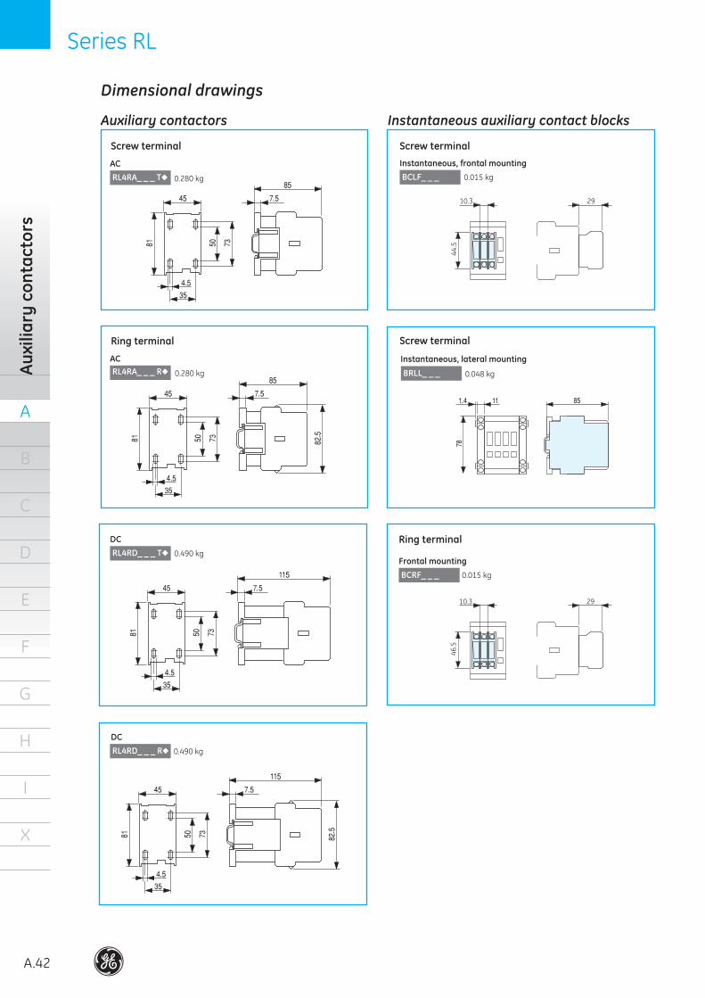
Instantaneous auxiliary contact blocksAuxiliary contactors
BCLF_ _ _
Screw terminal
Instantaneous, frontal mounting
RL4RA_ _ _ T
Screw terminal
.
.
AC
RL4RA_ _ _ R
Ring terminal
AC
RL4RD_ _ _ T
DC
RL4RD_ _ _ R
DC
.
.
.
.
.
.
10.3 29
44.5
.
.
BRLL_ _ _
Instantaneous, lateral mounting
.
BCRF_ _ _
Ring terminal
Frontal mounting
0.280 kg
0.490 kg
0.015 kg
0.048 kg0.280 kg
0.490 kg
0.015 kg
Dimensional drawings
10.3 29
46.5
Screw terminal
Series RL Series RL
A
A.43
B
C
D
E
F
G
H
I
X
Dim
ensions
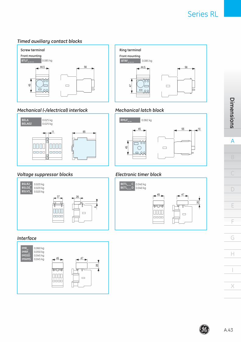
Timed auxiliary contact blocks
BTLF_ _ _
Screw terminalFront mounting
.
BTRF_ _ _
Ring terminal
Front mounting0.085 kg 0.085 kg
.
Mechanical latch blockMechanical (-/electrical) interlock
Electronic timer blockVoltage suppressor blocks
Interface
BELABELA02
RMLF_ _
BSLR2_BSLDZ_BSLV3_
BETL_ _ CBETL_ _ D
IMR_IMRF_IMSSDIMAMS
0.025 kg0.025 kg
0.082 kg
0.020 kg0.020 kg0.020 kg
0.040 kg0.040 kg
0.060 kg0.050 kg0.045 kg0.045 kg

@
Power Protection (formerly GE Power Controls), a division of GE Consumer & Industrial, is a first class European supplier of low-voltage products including wiring devices, residential and industrial electrical distribution components, automation products, enclosures and switchboards. Demand for the company’s products comes from, wholesalers, installers, panel-board builders, contractors, OEMsand utilities worldwide.
www.ge.com/ex/powerprotectionwww.ge.com/eu/powerprotection
GE Consumer & IndustrialPower Protection
680804Ref. C/4601/E/EX 2.5 Ed. 05/09
© Copyright GE Consumer & Industrial 2009
4896
2
GE imagination at work
GE imagination at work
GE imagination at work
GE imagination at work
GE imagination at work
GE imagination at work
GE imagination at work
GE imagination at work
GE imagination at work
GE POWER CONTROLS Ltd Houghton CentreSalthouse RoadNorthampton NN4 7EXUnited Kingdom
Customer Service Tel. 0800 587 1251 Fax 0800 587 1239 E-mail: [email protected]
GE CONSUMER & INDUSTRIAL HUNGARYVáci út 77 H-1340 Budapest Hungary
Customer Service Tel. +361 447 6046 Fax +361 447 5060 E-mail: mea.export [email protected]: www.gepowershop.com
GE CONSUMER & INDUSTRIALPOWER PROTECTIONNieuwevaart 51B-9000 GentBelgium
Tel. +32/9 265 21 11Fax +32/9 265 28 00E-mail: [email protected]


