53
An Overview to IWCF Well Control Certification Course (DRILLER/SUPERVISOR LEVEL) Day 3 Prepared by: Engr. Muhammad Nauman Awan
| Date post: | 18-Jul-2016 |
| Category: |
Documents |
| Upload: | nomiawan66 |
| View: | 132 times |
| Download: | 2 times |
An Overview to IWCF Well Control Certification Course
(DRILLER/SUPERVISOR LEVEL)
Day 3
Prepared by:
Engr. Muhammad Nauman Awan
Table of Contents DAY-3 ---- Session – I ................................................................................................................................. 1
Insider blowout preventer (IBOP) ................................................................................................................. 4
Full Open Safety Valve (FOSV) ................................................................................................................... 6
Bit Float (Float sub) ...................................................................................................................................... 7
Valve Pullers, Float Collar ............................................................................................................................ 8
Fast Shut off Coupling .................................................................................................................................. 9
Drop in check valve .................................................................................................................................... 10
Function testing of BOP .............................................................................................................................. 11
BOP testing period, Full BOP test .............................................................................................................. 12
High pressure test for RAMS and auxiliary equipment, Annular Preventer ............................................... 12
General Pressure Test Requirement ............................................................................................................ 13
Pressure tested with test Plug, With Cup type tester ................................................................................... 14
Casing pressure Test ................................................................................................................................... 15
Pressure Test Procedure, HCR (Valve #4) and Pipe rams test ................................................................... 16
Valve #3 and Annular Preventer Test, Blind rams, Choke manifold valves testing ................................... 17
Well Heads and BOP Equipment Testing ................................................................................................... 19
Pressure Test Frequencies, Pressure Test Casing Strings ........................................................................... 20
Functional Tests, Inspection and Precautions ............................................................................................. 22
Closing and opening ratios of BOP............................................................................................................. 23
Accumulator (Koomey) .............................................................................................................................. 24
Accumulator Capacity ................................................................................................................................ 26
4-Way Valve Operation in Blow Out Preventer Accumulator (Koomey) Unit .......................................... 28
DAY-3 ---- Session - II ........................................................................................................................... 31
Pressure test procedure for choke and kill manifold ................................................................................... 31
Choke Drill Steps ........................................................................................................................................ 31
BOP drills, Kick Drill While Drilling (Pit Drill) ........................................................................................ 32
Kick Drill While Tripping (Trip Drills), Volumetric Stripping Drill (Strip Drills) .................................... 33
After Completing the Strip Drill ................................................................................................................. 34
Reporting, Variable Bore Ram, Pipe Ram .................................................................................................. 35
Responsibilities for Well Control ............................................................................................................... 36
DAY-3 ---- Session - III ......................................................................................................................... 38
Rotating Head (RCDs), Gas or Air drilling ................................................................................................ 38
Flow drilling................................................................................................................................................ 39

Geothermal Drilling, Overbalanced Drilling .............................................................................................. 41
Workover Operations, Operating Guidelines .............................................................................................. 42
Rig Crew Training, High-Pressure Rotating Head ..................................................................................... 43
Cup Tester, Test Plug .................................................................................................................................. 45
PVT (Pit Volume Totalizer), Flow Sensor, Mud Gas Separator ................................................................. 46
Bore Protector, Retrievable Wear Bushing & Tie-Down Flange Assembly............................................... 48
Test Plug Assembly .................................................................................................................................... 48
DAY-3 ---- Session - IV ......................................................................................................................... 50
Ring joint gaskets ........................................................................................................................................ 50
DAY-3 --------------- Session – I
Special Equipment
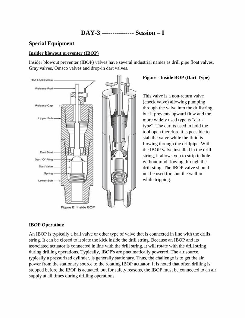
Insider blowout preventer (IBOP)
Insider blowout preventer (IBOP) valves have several industrial names as drill pipe float valves,
Gray valves, Omsco valves and drop-in dart valves.
Figure - Inside BOP (Dart Type)
This valve is a non-return valve
(check valve) allowing pumping
through the valve into the drillstring
but it prevents upward flow and the
more widely used type is “dart-
type”. The dart is used to hold the
tool open therefore it is possible to
stab the valve while the fluid is
flowing through the drillpipe. With
the IBOP valve installed in the drill
string, it allows you to strip in hole
without mud flowing through the
drill sting. The IBOP valve should
not be used for shut the well in
while tripping.
IBOP Operation:
An IBOP is typically a ball valve or other type of valve that is connected in line with the drills
string. It can be closed to isolate the kick inside the drill string. Because an IBOP and its
associated actuator is connected in line with the drill string, it will rotate with the drill string
during drilling operations. Typically, IBOP's are pneumatically powered. The air source,
typically a pressurized cylinder, is generally stationary. Thus, the challenge is to get the air
power from the stationary source to the rotating IBOP actuator. It is noted that often drilling is
stopped before the IBOP is actuated, but for safety reasons, the IBOP must be connected to an air
supply at all times during drilling operations.
IBOP for top drive can be divided into Upper IBOP and Lower IBOP; they are control valves
which are used with the top drive system. Usually the two valves connected to the top drive
drilling device. The IBOP adopts high reliable metal seal. So it can bear high pressure upward
and downward. The working pressure can be achieved 10000 psi or 15000 psi. When well kick
occurring, the upper IBOP can be closed by remote controlled, but the lower IBOP will be
closed manually. Actuator for top drive is a subsidiary body which controls open and close of
Upper IBOP. It works with other accessories of the rig, so that control opening and closing of
Upper IBOP on any height of derrick driller console. Both the valve body cavity and accessories
have special anticorrosive processing, so that prolong the working life.
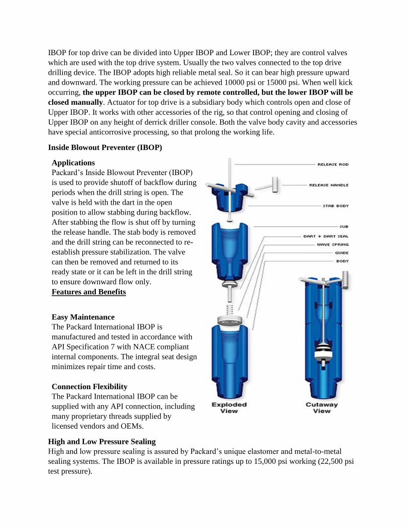
Inside Blowout Preventer (IBOP)
Applications
Packard’s Inside Blowout Preventer (IBOP)
is used to provide shutoff of backflow during
periods when the drill string is open. The
valve is held with the dart in the open
position to allow stabbing during backflow.
After stabbing the flow is shut off by turning
the release handle. The stab body is removed
and the drill string can be reconnected to re-
establish pressure stabilization. The valve
can then be removed and returned to its
ready state or it can be left in the drill string
to ensure downward flow only.
Features and Benefits
Easy Maintenance
The Packard International IBOP is
manufactured and tested in accordance with
API Specification 7 with NACE compliant
internal components. The integral seat design
minimizes repair time and costs.
Connection Flexibility
The Packard International IBOP can be
supplied with any API connection, including
many proprietary threads supplied by
licensed vendors and OEMs.
High and Low Pressure Sealing
High and low pressure sealing is assured by Packard’s unique elastomer and metal-to-metal
sealing systems. The IBOP is available in pressure ratings up to 15,000 psi working (22,500 psi
test pressure).
An inside BOP (Gray valve) is used when hanging off the drill string in the well head and is
installed one single below the hang-off tool. It shall not be installed when the string is hung off
with the bit in open hole, (so that wireline tools may be run). An inside BOP will also be used
when stripping in pipe. It should always be available on the drill floor ready for use.
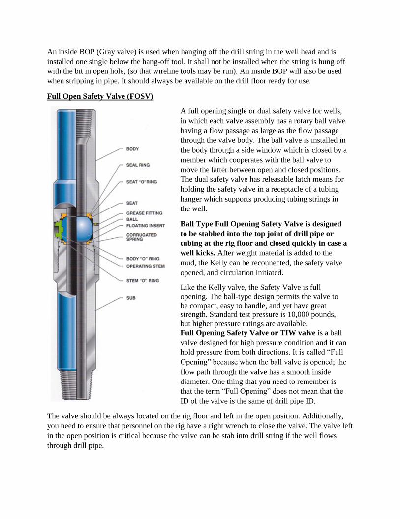
Full Open Safety Valve (FOSV)
A full opening single or dual safety valve for wells,
in which each valve assembly has a rotary ball valve
having a flow passage as large as the flow passage
through the valve body. The ball valve is installed in
the body through a side window which is closed by a
member which cooperates with the ball valve to
move the latter between open and closed positions.
The dual safety valve has releasable latch means for
holding the safety valve in a receptacle of a tubing
hanger which supports producing tubing strings in
the well.
Ball Type Full Opening Safety Valve is designed
to be stabbed into the top joint of drill pipe or
tubing at the rig floor and closed quickly in case a
well kicks. After weight material is added to the
mud, the Kelly can be reconnected, the safety valve
opened, and circulation initiated.
Like the Kelly valve, the Safety Valve is full
opening. The ball-type design permits the valve to
be compact, easy to handle, and yet have great
strength. Standard test pressure is 10,000 pounds,
but higher pressure ratings are available.
Full Opening Safety Valve or TIW valve is a ball
valve designed for high pressure condition and it can
hold pressure from both directions. It is called “Full
Opening” because when the ball valve is opened; the
flow path through the valve has a smooth inside
diameter. One thing that you need to remember is
that the term “Full Opening” does not mean that the
ID of the valve is the same of drill pipe ID.
The valve should be always located on the rig floor and left in the open position. Additionally,
you need to ensure that personnel on the rig have a right wrench to close the valve. The valve left
in the open position is critical because the valve can be stab into drill string if the well flows
through drill pipe.
For good drilling practices, you must have all size full opening safety valves which can be
screwed into each size of drill pipe, drill collar, tubing, etc on the rig. When there is any string in
the hole, the correct connection of the valve must be ready on the rig floor to stab in.
Furthermore, it is a good practice to install the valve when there is a sting left on the rotary table
during rig performs any tasks. The full opening safety valve should be used for shutting the well
in while tripping.
Bit Float (Float sub)
Float subs are used to house a float valve, also known as a back pressure valve. The float valve
functions as a safety between the wellbore and the inside of the drillstring to prevent drilling
fluids from back flowing up to surface.
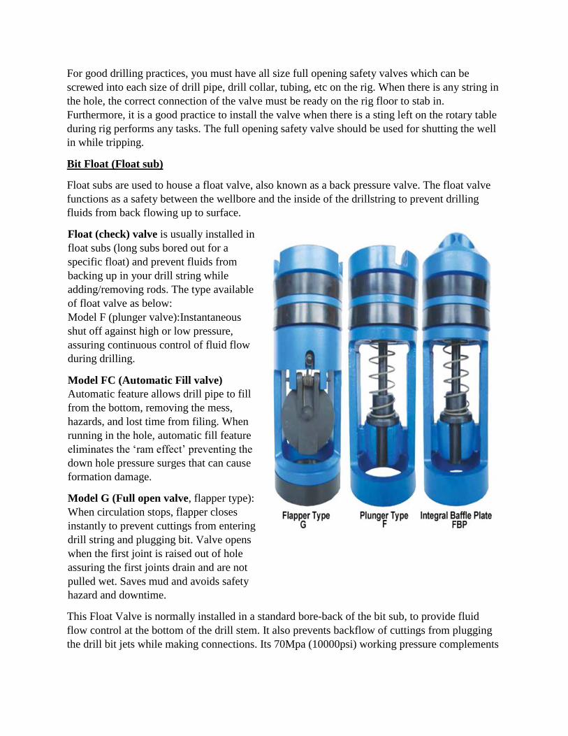
Float (check) valve is usually installed in
float subs (long subs bored out for a
specific float) and prevent fluids from
backing up in your drill string while
adding/removing rods. The type available
of float valve as below:
Model F (plunger valve):Instantaneous
shut off against high or low pressure,
assuring continuous control of fluid flow
during drilling.
Model FC (Automatic Fill valve)
Automatic feature allows drill pipe to fill
from the bottom, removing the mess,
hazards, and lost time from filing. When
running in the hole, automatic fill feature
eliminates the ‘ram effect’ preventing the
down hole pressure surges that can cause
formation damage.
Model G (Full open valve, flapper type):
When circulation stops, flapper closes
instantly to prevent cuttings from entering
drill string and plugging bit. Valve opens
when the first joint is raised out of hole
assuring the first joints drain and are not
pulled wet. Saves mud and avoids safety
hazard and downtime.
This Float Valve is normally installed in a standard bore-back of the bit sub, to provide fluid
flow control at the bottom of the drill stem. It also prevents backflow of cuttings from plugging
the drill bit jets while making connections. Its 70Mpa (10000psi) working pressure complements

today`s high pressure BOP stacks. When the flapper is held open by the built-in latch, the drill
pipe fills from the bottom.
This eliminates the mess and lost time of filling operations, Tuning in with the flapper
open also reduces the potential of formation damage from pressure surges caused by the bit
acting as a piston or ram as it is lowered into the hole. The flapper latch is automatically
released by initial circulation of drilling fluid through the valve. During normal
circulation, the flapper is fully open and out of the way. The large bore of the Valve provides
minimum flow restriction. When circulation is stopped. The flapper is closed by the flapper
spring .Preventing backflow through the bit.
When run in the closed position, the Valve allows the drill pipe to be floated in while
only partially filled with drilling fluid. This lowers the effective weight of the drill
string and reduces strain on rig equipment. The Float Valve Sub is a bit sub in which a float
valve is be installed.
Float subs are always used when drilling pilot holes, and can also be used when drilling 36", 26"
(or 22"), and 17 1/2" (or 16") hole sections.
When using float subs, the following procedures shall be carried out:
1. When running in hole, break circulation as soon as all the drill collars and one stand of drill
pipe are in the hole. This checks the correct operation of the float sub.
2. Fill up the drill pipe every ten stands.
3. Run in slowly and carefully to avoid excessive surging as the drill pipe has effectively a closed
end.
Valve Pullers
Valve pullers are an essential part in the
removal of float valves from the bit sub.
Model G pullers serve a dual purpose as they
are also used in the removing and installing of
the seal retainer ring when changing out the
valve seal.
Model F
Puller
MODEL F (TOP) PULLER
The Model F valve (top) puller is designed to remove float valves from the top of the sub.
Simply squeeze the forks together and press against the head of the valve plunger. Once the
forks are engaged with the cage the valve can be pulled. Disengage by sliding the separator
away from the valve and squeezing the forks together and the puller can be removed.
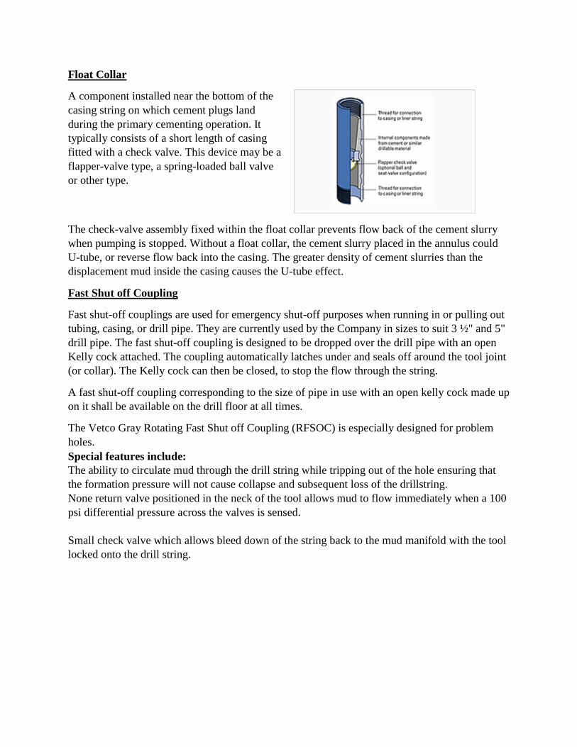
Float Collar
A component installed near the bottom of the
casing string on which cement plugs land
during the primary cementing operation. It
typically consists of a short length of casing
fitted with a check valve. This device may be a
flapper-valve type, a spring-loaded ball valve
or other type.
The check-valve assembly fixed within the float collar prevents flow back of the cement slurry
when pumping is stopped. Without a float collar, the cement slurry placed in the annulus could
U-tube, or reverse flow back into the casing. The greater density of cement slurries than the
displacement mud inside the casing causes the U-tube effect.
Fast Shut off Coupling
Fast shut-off couplings are used for emergency shut-off purposes when running in or pulling out
tubing, casing, or drill pipe. They are currently used by the Company in sizes to suit 3 ½" and 5"
drill pipe. The fast shut-off coupling is designed to be dropped over the drill pipe with an open
Kelly cock attached. The coupling automatically latches under and seals off around the tool joint
(or collar). The Kelly cock can then be closed, to stop the flow through the string.
A fast shut-off coupling corresponding to the size of pipe in use with an open kelly cock made up
on it shall be available on the drill floor at all times.
The Vetco Gray Rotating Fast Shut off Coupling (RFSOC) is especially designed for problem
holes.
Special features include:
The ability to circulate mud through the drill string while tripping out of the hole ensuring that
the formation pressure will not cause collapse and subsequent loss of the drillstring.
None return valve positioned in the neck of the tool allows mud to flow immediately when a 100
psi differential pressure across the valves is sensed.
Small check valve which allows bleed down of the string back to the mud manifold with the tool
locked onto the drill string.
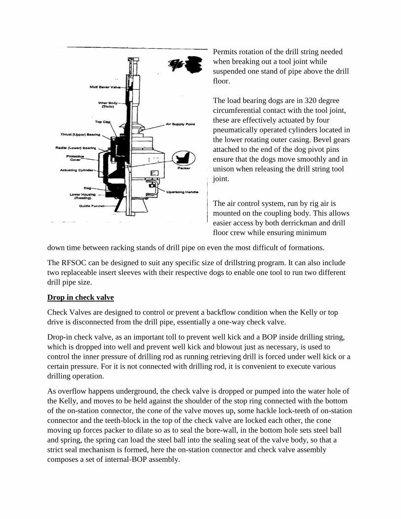
Permits rotation of the drill string needed
when breaking out a tool joint while
suspended one stand of pipe above the drill
floor.
The load bearing dogs are in 320 degree
circumferential contact with the tool joint,
these are effectively actuated by four
pneumatically operated cylinders located in
the lower rotating outer casing. Bevel gears
attached to the end of the dog pivot pins
ensure that the dogs move smoothly and in
unison when releasing the drill string tool
joint.
The air control system, run by rig air is
mounted on the coupling body. This allows
easier access by both derrickman and drill
floor crew while ensuring minimum
down time between racking stands of drill pipe on even the most difficult of formations.
The RFSOC can be designed to suit any specific size of drillstring program. It can also include
two replaceable insert sleeves with their respective dogs to enable one tool to run two different
drill pipe size.
Drop in check valve
Check Valves are designed to control or prevent a backflow condition when the Kelly or top
drive is disconnected from the drill pipe, essentially a one-way check valve.
Drop-in check valve, as an important toll to prevent well kick and a BOP inside drilling string,
which is dropped into well and prevent well kick and blowout just as necessary, is used to
control the inner pressure of drilling rod as running retrieving drill is forced under well kick or a
certain pressure. For it is not connected with drilling rod, it is convenient to execute various
drilling operation.
As overflow happens underground, the check valve is dropped or pumped into the water hole of
the Kelly, and moves to be held against the shoulder of the stop ring connected with the bottom
of the on-station connector, the cone of the valve moves up, some hackle lock-teeth of on-station
connector and the teeth-block in the top of the check valve are locked each other, the cone
moving up forces packer to dilate so as to seal the bore-wall, in the bottom hole sets steel ball
and spring, the spring can load the steel ball into the sealing seat of the valve body, so that a
strict seal mechanism is formed, here the on-station connector and check valve assembly
composes a set of internal-BOP assembly.
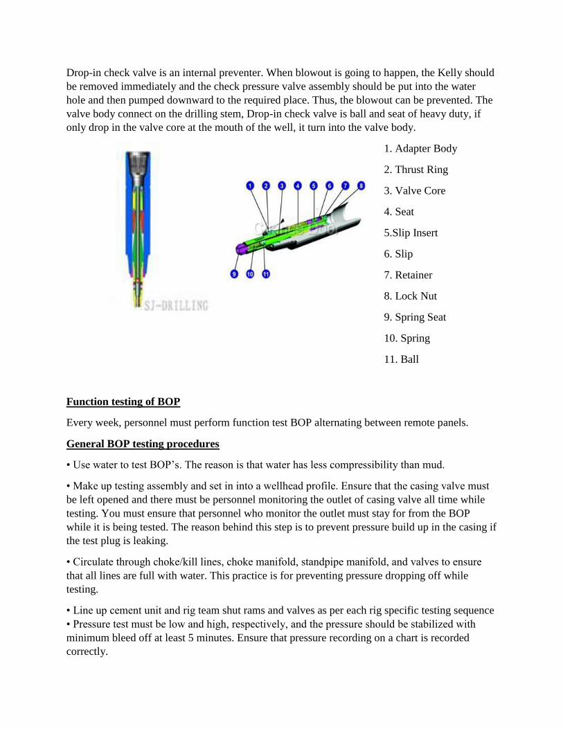
Drop-in check valve is an internal preventer. When blowout is going to happen, the Kelly should
be removed immediately and the check pressure valve assembly should be put into the water
hole and then pumped downward to the required place. Thus, the blowout can be prevented. The
valve body connect on the drilling stem, Drop-in check valve is ball and seat of heavy duty, if
only drop in the valve core at the mouth of the well, it turn into the valve body.
1. Adapter Body
2. Thrust Ring
3. Valve Core
4. Seat
5.Slip Insert
6. Slip
7. Retainer
8. Lock Nut
9. Spring Seat
10. Spring
11. Ball
Function testing of BOP
Every week, personnel must perform function test BOP alternating between remote panels.
General BOP testing procedures
• Use water to test BOP’s. The reason is that water has less compressibility than mud.
• Make up testing assembly and set in into a wellhead profile. Ensure that the casing valve must
be left opened and there must be personnel monitoring the outlet of casing valve all time while
testing. You must ensure that personnel who monitor the outlet must stay for from the BOP
while it is being tested. The reason behind this step is to prevent pressure build up in the casing if
the test plug is leaking.
• Circulate through choke/kill lines, choke manifold, standpipe manifold, and valves to ensure
that all lines are full with water. This practice is for preventing pressure dropping off while
testing.
• Line up cement unit and rig team shut rams and valves as per each rig specific testing sequence
• Pressure test must be low and high, respectively, and the pressure should be stabilized with
minimum bleed off at least 5 minutes. Ensure that pressure recording on a chart is recorded
correctly.

• Ensure that any equipment does not pass a pressure test requirement must be reported to
supervisors.
• Continue pressure testing until all equipment is tested as per each rig specific.
• Rig down testing assembly.
BOP testing period
Function test BOP: Every week, personnel must perform function test BOP alternating between
remote panels.
Full BOP test: There are 3 categories that you should consider for full BOP test.
1. Prior to supping the well or the first time that BOP is installed on the well.
2. After repairing or disconnecting of any pressure sealing elements of BOP.
3. As per MMS, you can use BOP for 21 days (3 weeks) before you need to test it again. Or you
must follow the local regulations. For example, in the North Sea, they allow you only 14 days
before next BOP test.
High pressure test for RAMS and auxiliary equipment
High pressure test to rated working pressure of RAMS BOP and auxiliary equipment OR rated
working pressure of your wellhead. Select the lower number. For example, you BOP is rated for
10,000 psi and your wellhead is rated for 6500 psi. Your high pressure test for the RAMS BOP
and auxiliary equipment must be only 6500 psi.
High pressure test for Annular Preventer
High pressure test should apply to 70% of rated working pressure or RAMS test pressure. Select
the lower number. For example, you test your ram at 5,000 psi and the annular working pressure
is 6,500 psi. You need to test your annular to 3500 psi (70% of rams testing pressure).
Low pressure test for both annular and RAMs preventer
200 – 300 psi should be applied for a low pressure test and the period is 5 minutes.
Function testing
The function test should be carried out on each round trip but not more than once per day. The
test should be conducted while tripping the drill pipe with the bit inside casing.
Before applying pressure testing to Preventers, perform the following:
(1) Each Remote control panel should be used to operate the BOP & valves.
(2) Close and open all preventers, Annular preventer must never be closed in an empty hole.
(3) Blind ram should be operated for function test while string is out of hole.
(4) Pipe rams must be closed against correct size of pipe in the well.

(5) Annular preventers should not be operated on each round trip. They should, however, be
function tested once a week.
(6) Operations of shear ram, if available in the stack, should be kept to bare minimum.
(7) The valves on BOP stack, wellhead and choke / kill manifold (excluding the hydraulic and
adjustable chokes which are function tested on each round trip) should be function tested at least
once a week.
Pressure testing of BOP
General Pressure Test Requirement
All BOP equipment pressure tests should be conducted in accordance with following guidelines:
1) Test frequency -BOP equipment should be pressure tested as follow:
When installed.
Before drilling out each string of casing.
Following disconnection or repair any wellbore pressure seal in the Wellhead/BOP stack
(limited to the affected components only).
Note: when rams are changed, the casing/tubing rams (and annular preventer) should be tested to
lesser or the high pressure test or one half the rate working pressure. pressure tested with test
plug and casing/tubing joint to 80% of pipe burst rating of the casing or rated working pressure
of BOP (whichever is less).
All BOP test maximum of every 21 days.
2) All pressure tests should be performed using clear water.

3) Check and Record the nitrogen-pre-charge pressure of each accumulator bottle.
4) Keep the relevant well head side out let valves open while using test plug for all BOP pressure
test.
5) Test Pressure
The low-pressure test of each piece of BOP equipment should be conducted at a
pressure of 200-350 psi.
High pressure-test should be conducted at rated working pressure of the weakest
component.
Option1: pressure tested with test plug.
High pressure should be 70%rated work pressure of annular Preventer and 100% rated work
pressure of rams preventer and 100%rated work pressure of wellhead (whichever is less).
Option 2: pressure tested with cup type tester
High pressure should be 70%rated work pressure of annular Preventer and 100%rated work
pressure of wellhead and 80% of pipe burst rating of the casing (whichever is less).
6) Low-pressure test should be performed first. Do not test to the high-pressure and bleed down
to the low-pressure.
7) All the high pressure tests must be held to 7Mpa for 5 minutes, then maximum testing
pressure for 10 minutes, the observable pressure decline should be in allowed range. All pressure
test to be recorded and charted if available.
8) Choke manifold and kill manifold should be tested separately simultaneously with normal rig
operations if a test port is available.
9) Remote control panel (must have two one on rig floor and other or ground easy accessible
area) should be operated for all BOP pressure test. No BOP opening after BOP test should be
done before checking the Release of the pressure and the operating should be done by authorized
person
10) Only authorized personnel shall go in test area to inspect for leaks when equipment is under
pressure.
11) All the pressure test should be conducted with a test pump, rig pumps or the cement units
(the cost of the cement unit will be paid by the rig as result of no test pump provide by the rig).
12) All test results should be documented on a pressure record with following information:
Date of test
Well name
Driller
Toolpusher or Drilling Engineer
Drilling Supervisor
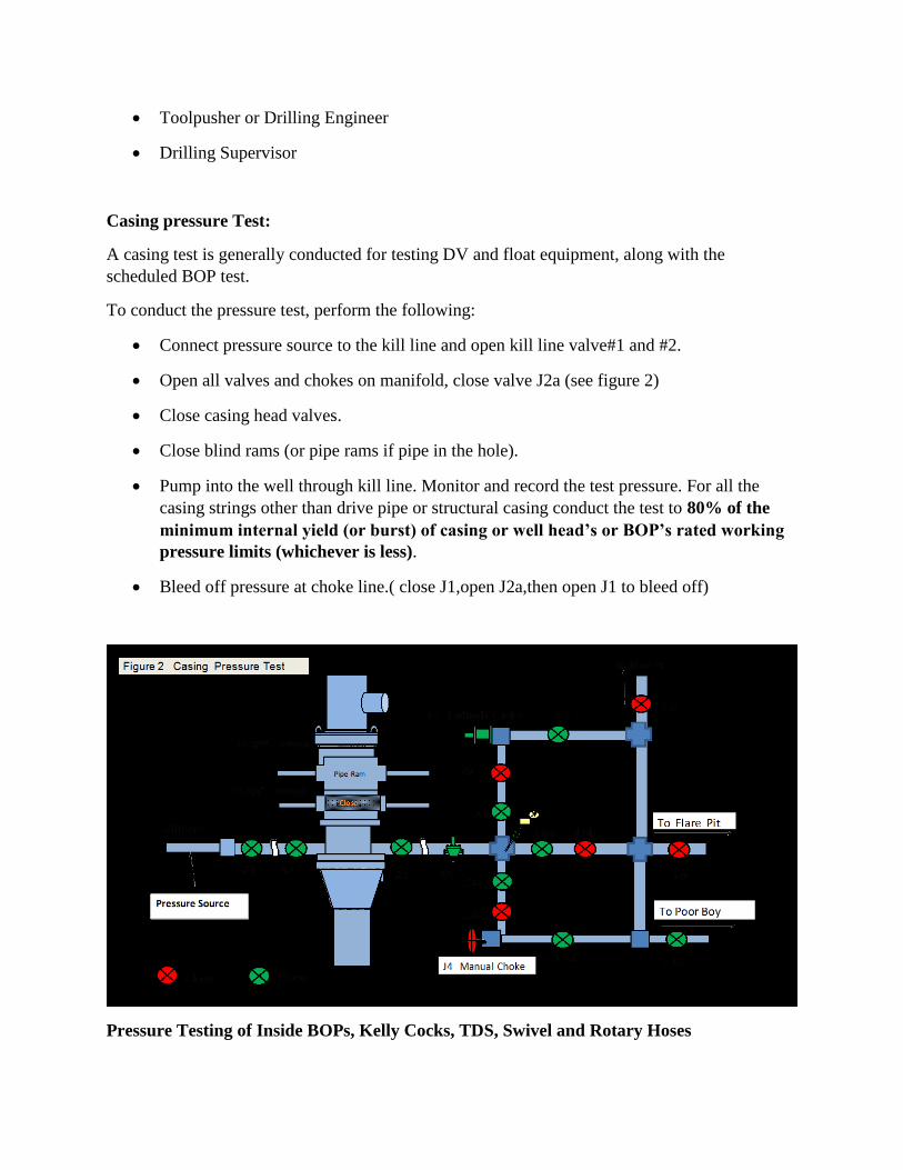
Casing pressure Test:
A casing test is generally conducted for testing DV and float equipment, along with the
scheduled BOP test.
To conduct the pressure test, perform the following:
Connect pressure source to the kill line and open kill line valve#1 and #2.
Open all valves and chokes on manifold, close valve J2a (see figure 2)
Close casing head valves.
Close blind rams (or pipe rams if pipe in the hole).
Pump into the well through kill line. Monitor and record the test pressure. For all the
casing strings other than drive pipe or structural casing conduct the test to 80% of the
minimum internal yield (or burst) of casing or well head’s or BOP’s rated working
pressure limits (whichever is less).
Bleed off pressure at choke line.( close J1,open J2a,then open J1 to bleed off)
Pressure Testing of Inside BOPs, Kelly Cocks, TDS, Swivel and Rotary Hoses
While carrying out pressure testing of above items also, it is recommended that test pressure
should be applied from the direction in which they would experience pressure during actual well
kick situation.
1) Pick up Kelly / TDS.
2) Make up Full Opening Safety Valve (FOSV) on bottom of lower Kelly cock.
3) Make up Inside BOP on the bottom of FOSV.
4) Make up adapter sub on bottom of inside BOP and complete connection of test line from
cementing unit or test pump to adapter sub.
5) Apply test pressure first up to 200-350 psi and then raise to rated working pressure of inside
BOP. Hold pressure 5 minutes.
6) Release pressure and disconnect adapter sub from inside BOP, disconnect inside BOP and
connect adapter sub to FOSV with test lines.
7) Close FOSV and apply test pressure up to 200-350psi. Watch for any leakage. If no leakage,
increase test pressure to rated working pressure of FOSV and hold pressure for 5 minutes. After
test is over release pressure.
8) Test lower Kelly cock, upper Kelly cock, swivel / TDS, rotary hose and stand pipe valves one
by one. Applied test pressure should not exceed rated working pressure of the item being tested
or the working pressure of the weakest member exposed to test pressure, whichever is less.
Note: Make sure that Kelly / TDS, stand pipe etc. are full with water (test fluid) and air is not
trapped in it.
Pressure Test Procedure
1. 21 1/4″ BOP Stack (17 1/2″ hole section):
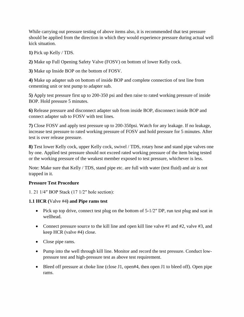
1.1 HCR (Valve #4) and Pipe rams test
Pick up top drive, connect test plug on the bottom of 5-1/2″ DP, run test plug and seat in
wellhead.
Connect pressure source to the kill line and open kill line valve #1 and #2, valve #3, and
keep HCR (valve #4) close.
Close pipe rams.
Pump into the well through kill line. Monitor and record the test pressure. Conduct low-
pressure test and high-pressure test as above test requirement.
Bleed off pressure at choke line (close J1, open#4, then open J1 to bleed off). Open pipe
rams.
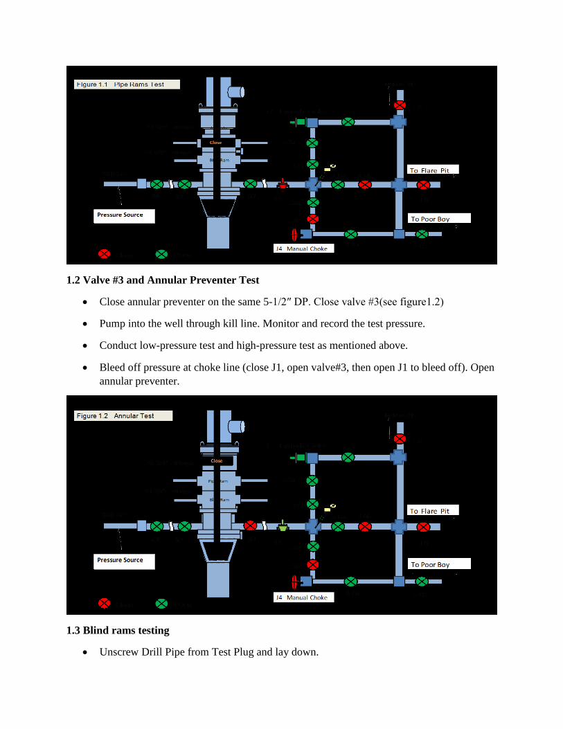
1.2 Valve #3 and Annular Preventer Test
Close annular preventer on the same 5-1/2″ DP. Close valve #3(see figure1.2)
Pump into the well through kill line. Monitor and record the test pressure.
Conduct low-pressure test and high-pressure test as mentioned above.
Bleed off pressure at choke line (close J1, open valve#3, then open J1 to bleed off). Open
annular preventer.
1.3 Blind rams testing
Unscrew Drill Pipe from Test Plug and lay down.
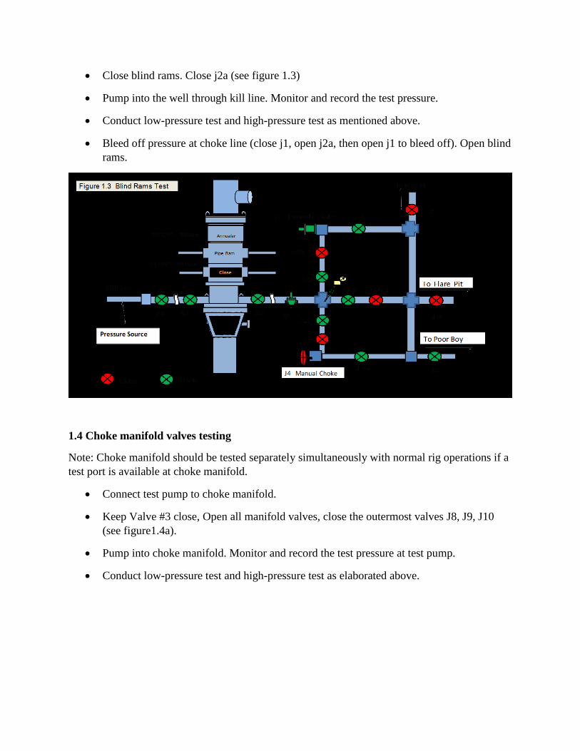
Close blind rams. Close j2a (see figure 1.3)
Pump into the well through kill line. Monitor and record the test pressure.
Conduct low-pressure test and high-pressure test as mentioned above.
Bleed off pressure at choke line (close j1, open j2a, then open j1 to bleed off). Open blind
rams.
1.4 Choke manifold valves testing
Note: Choke manifold should be tested separately simultaneously with normal rig operations if a
test port is available at choke manifold.
Connect test pump to choke manifold.
Keep Valve #3 close, Open all manifold valves, close the outermost valves J8, J9, J10
(see figure1.4a).
Pump into choke manifold. Monitor and record the test pressure at test pump.
Conduct low-pressure test and high-pressure test as elaborated above.

Open outermost choke manifold valves J8, J9, J10. Close valves J5, J6b, J7a (see figure
1.4b).
Pump into choke manifold. Monitor and record the test pressure.
Conduct low-pressure test and high-pressure test as elaborated above.
Pressure Testing of Well Control Equipment
Well Heads and BOP Equipment
Pressure tests on the ram type preventers, other BOP equipment, wellhead components and their
connections in general shall be made in line with API RP 53, but see Drilling Program for the
minimum required test pressures.
Where wellhead or BOP outlets are opened for testing or any other purposes they shall not be left
unattended under any circumstances.
Manufacturer's approved handles shall be securely fitted to all wellhead and BOP valves
During subsequent drilling operations, the equipment shall be pressure-tested at regular intervals
using a plug type or cup type tester. Test to at least the anticipated pressures or to the original
casing test pressure (in case a cup type tester is used), whichever is lower.
Plug and cup type testers suitable for pressure-testing the wellhead and BOP equipment on all
casing strings shall be available on the rig site.
Use proper cup size for various casing weights. Retrievable packers with large slip areas may
also be used if available.
The pressure test shall consist of:
Low pressure test - 500 psi
High pressure test to the full rated working pressure of the equipment
All equipment shall hold the low pressure test for 10 minutes and the high pressure test
for 10 minutes.
Pressure Test Wellhead Equipment
After each complete installation, the wellhead and ram type BOP equipment shall be pressure-
tested, using a plug type tester, to the rated working pressure of the wellhead, the ram type
preventers or the pressure detailed in the Drilling Program, whichever is lower. The wellhead
side outlets below the tester shall be open, to prevent pressuring the casing.
Seals and bushings around casing stubs shall be tested through the test port to only 50% of the
collapse rating of the casing provided that this does not exceed the manufacturers rating for the
casing hanger when piston forces and string weight are taken into account. These seals can later
be tested to 65% of the casing burst rating (or flange rating whichever is the lower) using a cup-
type tester (test port open). Ensure that the cup-type tester does not leak and the drill pipe is
open so that the cemented casing is not tested as well.
During the drilling and completion phase, the outer side outlets of the wellhead exposed to the
live annulus shall have manually operated side outlet valves.
Pressure Test BOP equipment
The annular preventer shall be pressure-tested to maximum 70% of its rated working pressure
unless specified differently in the Drilling Program, and then only when closed around the pipe.
The complete BOP operating unit shall be tested in accordance with Manufacturer's
recommendations and pressure-tested to its rated working pressure / well rated pressure,
whichever is lower.
The choke manifold, valves, kill and choke lines and valves on side outlets shall be pressure-
tested with water to the test pressure of the ram type preventers.
All lines shall be flushed to ensure they are not blocked. No tests shall be performed against
closed chokes.
The Kelly and Kelly stop-cocks shall be pressure-tested to their rated working pressure with a
test sub. Pumps, discharge lines standpipe manifold shall be pressure tested.
If the BOP has been pressure and function tested on the stump, or if a new spool has been
installed, only the new connections need testing.
If the BOP is moved between wells, the BOP shall be fully pressure/function tested prior to any
operations on that well.
Pressure Test Frequencies
The pressure tests of all blowout preventers, wellhead components and their connections, BOP
operating unit, choke manifold, kill and choke lines, kelly and kelly-cocks shall be made:
After installation of wellhead and BOP assembly and prior to drilling.
Every 14 days. This period between tests may be extended, depending on the type of
operation being carried out and yet to be carried out during that period, but only after
consultation with the Head of Operations.
Prior to drilling into a suspected high pressure zone.
After setting casing and re-nippling BOP.
When rough drilling conditions are experienced e.g. stack shaking.
After changing out rams.
Any time requested by the Drilling Supervisor.
The results of all pressure tests shall be recorded on the Test Sheet for Blowout Preventers and
Related Equipment.
Pressure Test Casing Strings
After Installation
Newly installed casing strings shall be pressure tested to pressures as given in the Drilling
Program. The test pressures will depend on the reservoir and the well location
(onshore/offshore). Ideally, this should be performed immediately once the cement slurry is in
place (i.e. immediately after bumping the top plug) to prevent the formation of a micro-annuli.
The test pressure shall be limited by the internal yield (burst) pressure of the casing (or coupling,
if lower) and/or the maximum collapse pressure of the cementing plugs. The effects of
differential pressure resulting from a difference in the fluid level and/or a difference in mud
density in the casing and annulus shall be considered when establishing the internal test pressure.
In the case of liners, the test pressure immediately after bump should not exceed 1500 psi unless
specifically authorized in the drilling program.
Note: The acceptance criteria for the test shall be a stable pressure (i.e. straight line on the
pressure recorder) for a minimum of 10 minutes.
Casing test pressures are predetermined due to drilling in known reservoirs.
In general the following equations may be used for casing pressure tests.
For Production Casing the maximum expected surface pressure shall consider closed in pressure
arising from complete evacuation of the string to hydrocarbon gas from the deepest TD:
Surface Pressuremax = Po - HHgas
Po = Reservoir Pore Pressure @ deepest section TD as per well proposal (psi)
HHgas = (TVD of Section TD) x (Expected Gas Gradient) (psi)
For Intermediate Casing the intermediate casing string shall be tested to the maximum expected
surface pressure as defined in its design criteria which shall be clearly identified in the Drilling
Program.
In general the maximum surface pressure shall be the lesser of:
a. Closed in casing head pressure arising from the casing being completely evacuated to
hydrocarbon gas from the casing shoe using the formation strength gradient criteria
Surface Pressuremax = Maximum Pressure at Shoe - HHgas
Max Pressure at Shoe = Max expected formation strength gradient at shoe x Shoe depth (psi)
b. Closed in casing head pressure arising from the casing being completely evacuated to
hydrocarbon gas from deepest section TD using the pore pressure gradient criteria.
Surface Pressuremax = Po - HHgas
Po= Reservoir Pore Pressure @ deepest section TD as per well proposal (psi)
HHgas = TVD of Section TD x expected gas gradient (psi)
Subsequent Casing Pressure Tests
Cemented casing shall not be tested to excessive pressure as this may lead to loss of zonal
isolation - ballooning of the casing can cause the formation of a micro-annulus after the test.
Note: In wells where casing wear or corrosion is experienced or expected, caliper logs should
be performed. The reduced strength of the casing can thus be calculated and if this value is less
than the operating (design) criteria then these criteria and pressure testing requirements will have
to be reviewed to prevent total failure of the casing. Operating (design) criteria and pressure
testing requirements may also be changed due to changes in downhole reservoir pressures
(depletion) or the installation of a straddle or tie-back string to cover detected weak spots in the
string. The basis for design of pressure tests shall be highlighted in the Drilling Program.
Functional Tests, Inspection and Precautions
BOP’s shall be function tested daily. All pressure and manually operated kill and choke line
valves and Kelly cocks shall be function tested every 7 days.
The blind rams or blind/shear rams shall be functioned each time the bit is pulled.
Should any of the above tests indicate faulty equipment, this equipment shall be repaired before
drilling or any other operation related thereto is continued.
Frequently inspect tightness of flange bolts and clamps, particularly before and after pressure
testing.
Pump through kill and choke lines at regular intervals. Do not leave weighted mud in choke
manifold and kill lines but ensure that they are kept full of fluid.
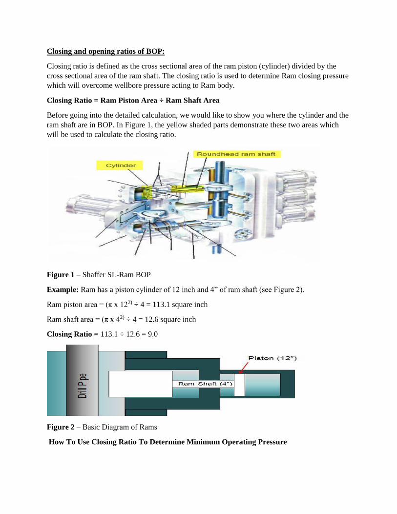
Closing and opening ratios of BOP:
Closing ratio is defined as the cross sectional area of the ram piston (cylinder) divided by the
cross sectional area of the ram shaft. The closing ratio is used to determine Ram closing pressure
which will overcome wellbore pressure acting to Ram body.
Closing Ratio = Ram Piston Area ÷ Ram Shaft Area
Before going into the detailed calculation, we would like to show you where the cylinder and the
ram shaft are in BOP. In Figure 1, the yellow shaded parts demonstrate these two areas which
will be used to calculate the closing ratio.
Figure 1 – Shaffer SL-Ram BOP
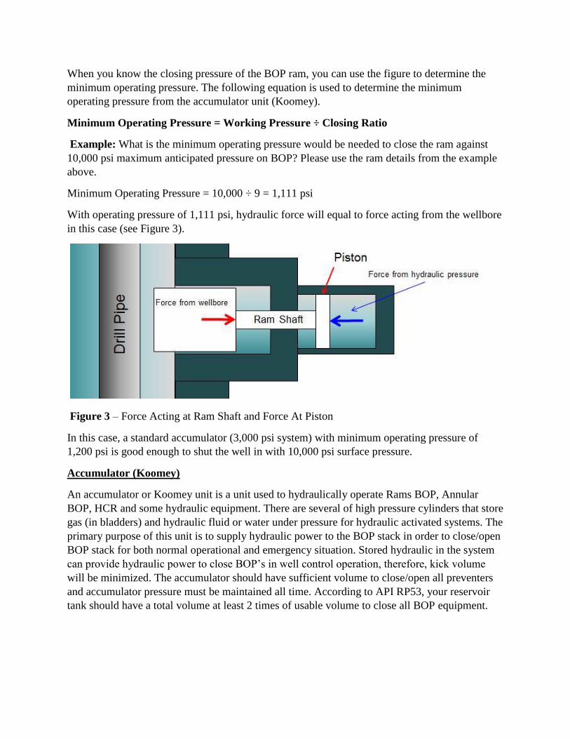
Example: Ram has a piston cylinder of 12 inch and 4” of ram shaft (see Figure 2).
Ram piston area = (π x 122) ÷ 4 = 113.1 square inch
Ram shaft area = (π x 42) ÷ 4 = 12.6 square inch
Closing Ratio = 113.1 ÷ 12.6 = 9.0
Figure 2 – Basic Diagram of Rams
How To Use Closing Ratio To Determine Minimum Operating Pressure
When you know the closing pressure of the BOP ram, you can use the figure to determine the
minimum operating pressure. The following equation is used to determine the minimum
operating pressure from the accumulator unit (Koomey).
Minimum Operating Pressure = Working Pressure ÷ Closing Ratio
Example: What is the minimum operating pressure would be needed to close the ram against
10,000 psi maximum anticipated pressure on BOP? Please use the ram details from the example
above.
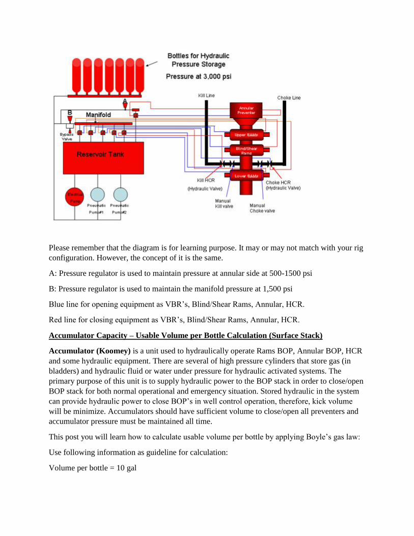
Minimum Operating Pressure = 10,000 ÷ 9 = 1,111 psi
With operating pressure of 1,111 psi, hydraulic force will equal to force acting from the wellbore
in this case (see Figure 3).
Figure 3 – Force Acting at Ram Shaft and Force At Piston
In this case, a standard accumulator (3,000 psi system) with minimum operating pressure of
1,200 psi is good enough to shut the well in with 10,000 psi surface pressure.
Accumulator (Koomey)
An accumulator or Koomey unit is a unit used to hydraulically operate Rams BOP, Annular
BOP, HCR and some hydraulic equipment. There are several of high pressure cylinders that store
gas (in bladders) and hydraulic fluid or water under pressure for hydraulic activated systems. The
primary purpose of this unit is to supply hydraulic power to the BOP stack in order to close/open
BOP stack for both normal operational and emergency situation. Stored hydraulic in the system
can provide hydraulic power to close BOP’s in well control operation, therefore, kick volume
will be minimized. The accumulator should have sufficient volume to close/open all preventers
and accumulator pressure must be maintained all time. According to API RP53, your reservoir
tank should have a total volume at least 2 times of usable volume to close all BOP equipment.

Pressure based on 3,000 psi surface stack system that you should check on BOP remote
panel and Koomey unit is listed below:
• Manifold pressure at +/- 1,500 psi
• Accumulator pressure at +/- 3,000 psi
• Annular preventer at +/- 500 – 1,500 psi
• Rig Air at +/- 100 – 130 psi
There are 4 main components of the Koomey unit as follows:
• Accumulators
• Pumping system (electric and pneumatic pumps)
• Manifold system
• Reservoir tank
According to API RP 53, there must be 2 or 3 independent sources of power that will be
available for each closing unit. Typically, you will these following sources:
• Hydraulic with pressure charged in the bottles.
• Pneumatic • Electric
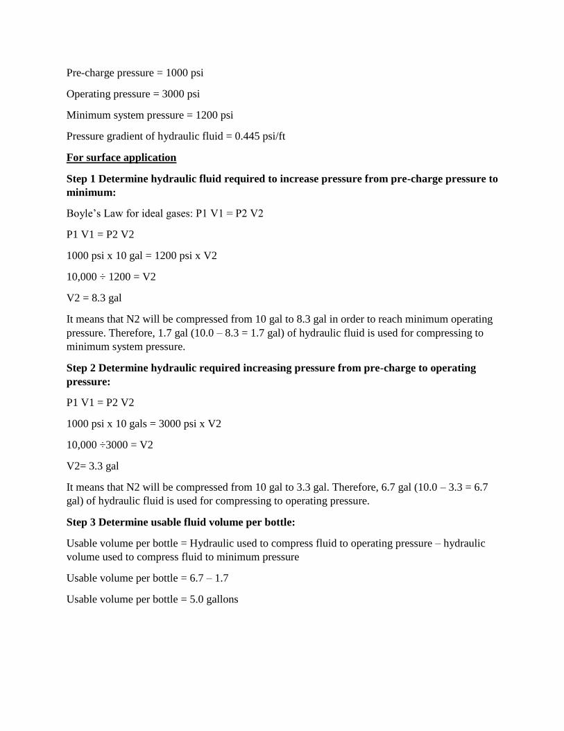
The diagram below demonstrates how the accumulator is lined up for the surface stack.
Please remember that the diagram is for learning purpose. It may or may not match with your rig
configuration. However, the concept of it is the same.
A: Pressure regulator is used to maintain pressure at annular side at 500-1500 psi
B: Pressure regulator is used to maintain the manifold pressure at 1,500 psi
Blue line for opening equipment as VBR’s, Blind/Shear Rams, Annular, HCR.
Red line for closing equipment as VBR’s, Blind/Shear Rams, Annular, HCR.
Accumulator Capacity – Usable Volume per Bottle Calculation (Surface Stack)
Accumulator (Koomey) is a unit used to hydraulically operate Rams BOP, Annular BOP, HCR
and some hydraulic equipment. There are several of high pressure cylinders that store gas (in
bladders) and hydraulic fluid or water under pressure for hydraulic activated systems. The
primary purpose of this unit is to supply hydraulic power to the BOP stack in order to close/open
BOP stack for both normal operational and emergency situation. Stored hydraulic in the system
can provide hydraulic power to close BOP’s in well control operation, therefore, kick volume
will be minimize. Accumulators should have sufficient volume to close/open all preventers and
accumulator pressure must be maintained all time.
This post you will learn how to calculate usable volume per bottle by applying Boyle’s gas law:
Use following information as guideline for calculation:
Volume per bottle = 10 gal
Pre-charge pressure = 1000 psi
Operating pressure = 3000 psi
Minimum system pressure = 1200 psi
Pressure gradient of hydraulic fluid = 0.445 psi/ft
For surface application
Step 1 Determine hydraulic fluid required to increase pressure from pre-charge pressure to
minimum:
Boyle’s Law for ideal gases: P1 V1 = P2 V2
P1 V1 = P2 V2
1000 psi x 10 gal = 1200 psi x V2
10,000 ÷ 1200 = V2
V2 = 8.3 gal
It means that N2 will be compressed from 10 gal to 8.3 gal in order to reach minimum operating
pressure. Therefore, 1.7 gal (10.0 – 8.3 = 1.7 gal) of hydraulic fluid is used for compressing to
minimum system pressure.
Step 2 Determine hydraulic required increasing pressure from pre-charge to operating
pressure:
P1 V1 = P2 V2
1000 psi x 10 gals = 3000 psi x V2
10,000 ÷3000 = V2
V2= 3.3 gal
It means that N2 will be compressed from 10 gal to 3.3 gal. Therefore, 6.7 gal (10.0 – 3.3 = 6.7
gal) of hydraulic fluid is used for compressing to operating pressure.
Step 3 Determine usable fluid volume per bottle:
Usable volume per bottle = Hydraulic used to compress fluid to operating pressure – hydraulic
volume used to compress fluid to minimum pressure
Usable volume per bottle = 6.7 – 1.7
Usable volume per bottle = 5.0 gallons
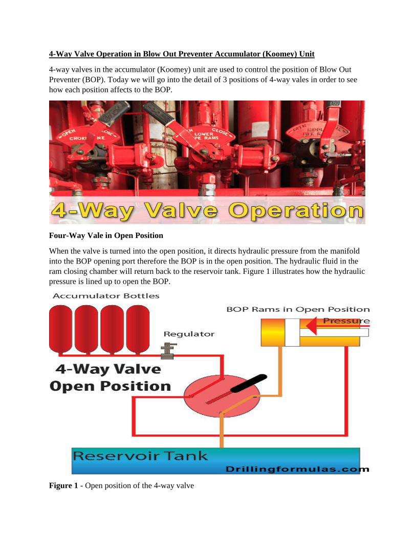
4-Way Valve Operation in Blow Out Preventer Accumulator (Koomey) Unit
4-way valves in the accumulator (Koomey) unit are used to control the position of Blow Out
Preventer (BOP). Today we will go into the detail of 3 positions of 4-way vales in order to see
how each position affects to the BOP.
Four-Way Vale in Open Position
When the valve is turned into the open position, it directs hydraulic pressure from the manifold
into the BOP opening port therefore the BOP is in the open position. The hydraulic fluid in the
ram closing chamber will return back to the reservoir tank. Figure 1 illustrates how the hydraulic
pressure is lined up to open the BOP.
Figure 1 - Open position of the 4-way valve
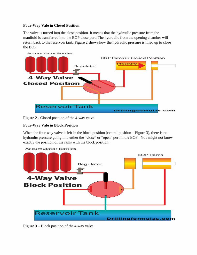
Four-Way Vale in Closed Position
The valve is turned into the close position. It means that the hydraulic pressure from the
manifold is transferred into the BOP close port. The hydraulic from the opening chamber will
return back to the reservoir tank. Figure 2 shows how the hydraulic pressure is lined up to close
the BOP.
Figure 2 - Closed position of the 4-way valve
Four-Way Vale in Block Position
When the four-way valve is left in the block position (central position – Figure 3), there is no
hydraulic pressure going into either the “close” or “open” port in the BOP. You might not know
exactly the position of the rams with the block position.
Figure 3 – Block position of the 4-way valve
In normal drilling operation, you should never leave in the block position. However, the valves
can be left in the block position during rig move and repairing operation.
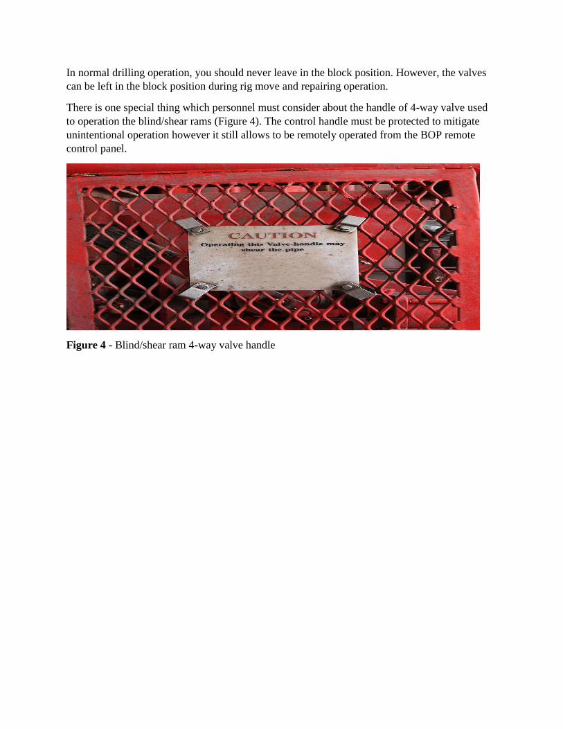
There is one special thing which personnel must consider about the handle of 4-way valve used
to operation the blind/shear rams (Figure 4). The control handle must be protected to mitigate
unintentional operation however it still allows to be remotely operated from the BOP remote
control panel.
Figure 4 - Blind/shear ram 4-way valve handle
DAY-3 --------------- Session - II
Pressure test procedure for choke and kill manifold
The choke manifold is then tested by:
Closing the manual valve next to the BOP on the choke line.
Attach test line to choke manifold.
Test all valves in the proper sequence.
Make sure header (watermelon, etc.) is open-ended.
When filling stack, ensure that the choke manifold can be pumped through.
Once a test is achieved, close the next set of valves, open valves behind the set that was
closed and continue this process until all valves have been tested.
Importance of Choke Drill and Its Procedure
Choke drill is one of well control drills that will improve crew competency in driller’s method.
The advantages from the choke drill are as follows:
• Get more familiar to practice controlling the pressure via a choke on the rig
• Get more understanding about lag time
• Practice the procedure to obtain the shut-in drill pipe pressure
• Ensure the surface well control equipment as pressure gauges, choke, BOP is ready for work
• Get more practices when attempting to bring the pump up to kill speed, slow the pump down
and change the pump rate
Choke Drill Steps are listed below:
1. Trip in hole above top of cement
2. Fill the pipe and circulate seawater or mud around for few minutes
3. Close annular preventer or upper rams preventer
4. Pressure up annulus to 200 psi (the pressure may be different depending on the company
policy.)
5. Line up the pump
6. Pump slowly to bump the float and obtain shut in drill pipe pressure
7. Bring the pump to kill rate by holding casing pressure constant – personnel need to adjust the
choke
8. Measure lag time for the drill pipe gage after the adjustment of choke is made.
9. Change circulation rate by holding casing pressure constant. Crew needs to adjust choke to
achieve this.
10. Shut the pump down by holding casing pressure constant.
11. Bleed off pressure and line up for drilling operation
BOP drills
Three types of drills are to be exercised, one while drilling with the kelly on the string, one
normally while tripping without the kelly on the string and one with the bit off bottom ie.:
Kick Drill While Drilling (pit drill)
Kick Drill While Tripping (trip drill)
Kick Drill While Bit off Bottom (strip drill).
General Requirements
The following guidelines shall be followed for well control drills:
Well control drills shall be initiated by the contractor or the Drilling Supervisor and
performed under the supervision of the Drilling Supervisor to ensure that the crews are
adequately trained and prepared to implement well control procedures correctly.
Well control drills shall only be conducted when they do not complicate ongoing
operations. A kick should be simulated by manipulation of a primary kick indicator such
as the tank level indicator or the flow line indicator.
The drills described in the above section include the full sequence of shutting in a well.
The critical reaction time shall be measured up to the point when the well is closed in.
Trip drills shall only be conducted if the BHA is inside the casing shoe.
Out-of-hole drills may be conducted at any time when out of hole with no tools or
wireline through the BOP stack.
Kick Drill While Drilling - Pit Drills Procedure
Before drilling out to any shoe, and at the discretion of the Drilling Supervisor, but not less than
once every week per crew while normal drilling operations are in progress.
1. INITIATE kick verbally or by raising a float (normally Drilling Supervisor or Toolpusher).
2. On initiation the crew leader is to ALERT the crew and STOP the rotary.
3. PULL Kelly above the rotary table until the lower Kelly cock is above the drilling floor, at
same time SLOW DOWN the pump.
4. STOP the pumps.
5. CLOSE the annular preventer
6. OPEN the hydraulic operated valve in the side outlet from the BOP stack to the choke
manifold (The inner valve is always open under normal conditions).
Note: A diagram with all relevant measurement relating to tool joint position should be
available to the driller at the BOP control panel.
7. TAKE readings of the closed-in annulus and drillpipe pressures.
8. MEASURE the ‘gain’ in the active mud tank.
9. END drill, RETURN all settings to normal operating mode.
Kick Drill While Tripping – Trip Drills Procedure
At the discretion of the Drilling Supervisor, but not less than once every two weeks per crew
while normal drilling operations are in progress.
1. Initiate kick verbally or by raising a float in the trip tank.
2. On initiation the crew leader (Driller/Assistant driller) is to alert the crew.
3. Bring tool joint to rotary level.
4. Install stabbing valve in open position (hand tight).
5. Close stabbing valve.
6. Close the annular preventer.
7. Open hydraulic operated valve in the side outlet from the BOP stack to the choke manifold.
Note: A diagram with all relevant measurements relating to tool joint position shall be available
to the driller at the BOP control panel.
8. Install circulating head, make up correct torque, open stabbing valve and take readings of the
closed-in annulus and drillpipe pressure.
9. Read gain in trip tank.
10. End drill, return all settings to normal operating mode.
Volumetric Stripping Drill - Procedure
Strip Drills
A combined volumetric/stripping drill should preferably be performed once per week per crew.
The drill shall only be conducted after a casing string (ideally the 9 5/8" or Production string) has
been cemented and pressure tested and prior to drilling out the shoe track.
Note: The Annular Preventer shall be pressure tested following the stripping drill.
1. Hold a “strip drill” in the casing before drilling out the shoe track.
2. RIH to 1 000 ft above top cement.
3. Hold a kick drill. Close annular preventer
4. Install inside BOP. Open stabbing valve.
5. Apply 500 psi pressure on the annulus through the kill line
6. Reduce closing pressure of the annular preventer to minimum avoiding leakage (make sure
bushings are locked!).
7. Open valve to surge bottle in annular closing line.
8. Connect line from choke manifold to trip tank. Trip tank to be half full. Check if trip tank
drains into strip tank.
9. Set up flow line so that any fluid that leaks through annular preventer goes into trip tank.
10. Make up next stand. (Have a good file on the floor to remove tong and slip marks on the
pipe.)
11. Strip stand in hole and maintain pressure on annulus constant by bleeding off through the
choke. Run pipe slowly to avoid pressure surges. Measure volume of mud bleed off and ensure
total volume is equal to closed end volume of stand stripped into hole.
12. When complete stand is run in, Close In at choke manifold by closing valve behind the
choke.
13. Drain closed end volume of one stand out of trip tank into stripping tank.
14. Install next stand.
15. Continue stripping until crew is familiar with operation.
Note: Check if all equipment is working properly and calibrations of tanks is correct. Ensure
crews are fully aware that Kelly Cock has to be put on before the inside BOP.
After Completing the Strip Drill
1. Bleed Off annulus pressure through choke.
2. Close valve to surge bottle in annular preventer closing line.
3. Increase annular pressure to normal operating pressure.
4. Open annular preventer.
5. Close HCR. Set up choke manifold for normal drilling.
6. Pull back to remove inside BOP and Kelly cock.
7. Close Kelly cock (in case pressure trapped in below Inside BOP).
8. Remove inside BOP.
9. Open Kelly cock carefully to check for pressure.
10. Remove Kelly cock.
11. Test bag type preventer prior to continuing operations.
Reporting
The Driller is to document the drill in the IADC report under remarks. The following shall be
recorded.
Type of drill.
Time of drill.
Reaction time in seconds from the moment the kick is simulated until the well is closed
in. The designated crew member is a member of the drill crew who is present on the drill
floor at the time of a BOP drill or well control situation. All drill crew members must be
capable and able to react correctly to the drill or real well control situation.
The total time taken for the drill. The time taken should be less than a pre-determined
benchmark. If not, the drill shall be repeated.
The following shall be recorded on the DDR:
The reaction time from the moment the kick is simulated until the designated crew
member is ready to start the closing procedure.
The total time it takes to complete the entire drill.
Time drill was held (to determine which crew performed the drill).
Variable Bore Ram
A ram type blowout preventer includes variable ram packers for sealing about tubular of
different outside diameters in the bore of the preventer housing or about a single tubular having a
variable outside diameter. Each ram packer includes a body of elastomeric material formed about
vertical ribs to conform to tubular having variable OD within a certain range.
Pipe Ram
A type of sealing element in high-pressure split seal blowout preventers that is manufactured
with a half-circle hole on the edge (to mate with another horizontally opposed pipe ram) sized to
fit around drillpipe. Most pipe rams fit only one size or a small range of drillpipe sizes and do not
close properly around drillpipe tool joints or drill collars. A relatively new style is the variable
bore ram, which is designed and manufactured to properly seal on a wider range of pipe sizes.
Responsibilities for Well Control
Primary well control shall be maintained at all times. In the event secondary control becomes
necessary, the well shall be brought back under control as safely as possible.
For each well control operation all personnel shall have a pre-assigned task appropriate to their
function. All personnel shall also ensure familiarity with Company well control procedures.
The well control responsibilities during well killing operations are given in the following table.
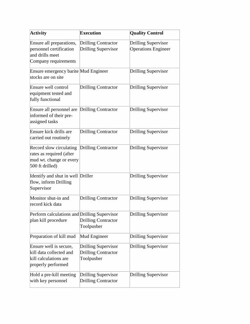
Activity Execution Quality Control
Ensure all preparations,
personnel certification
and drills meet
Company requirements
Drilling Contractor
Drilling Supervisor
Drilling Supervisor
Operations Engineer
Ensure emergency barite
stocks are on site
Mud Engineer Drilling Supervisor
Ensure well control
equipment tested and
fully functional
Drilling Contractor Drilling Supervisor
Ensure all personnel are
informed of their pre-
assigned tasks
Drilling Contractor Drilling Supervisor
Ensure kick drills are
carried out routinely
Drilling Contractor Drilling Supervisor
Record slow circulating
rates as required (after
mud wt. change or every
500 ft drilled)
Drilling Contractor Drilling Supervisor
Identify and shut in well
flow, inform Drilling
Supervisor
Driller Drilling Supervisor
Monitor shut-in and
record kick data
Drilling Contractor Drilling Supervisor
Perform calculations and
plan kill procedure
Drilling Supervisor
Drilling Contractor
Toolpusher
Drilling Supervisor
Preparation of kill mud Mud Engineer Drilling Supervisor
Ensure well is secure,
kill data collected and
kill calculations are
properly performed
Drilling Supervisor
Drilling Contractor
Toolpusher
Drilling Supervisor
Hold a pre-kill meeting
with key personnel
Drilling Supervisor
Drilling Contractor
Drilling Supervisor
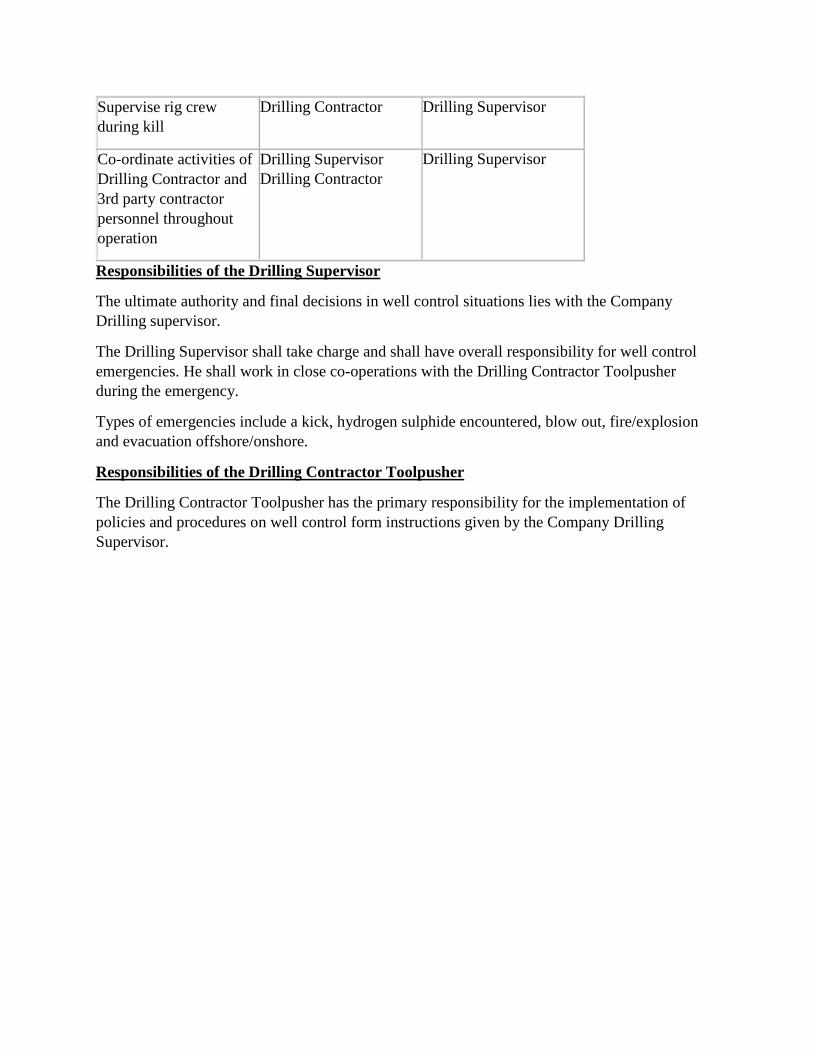
Supervise rig crew
during kill
Drilling Contractor Drilling Supervisor
Co-ordinate activities of
Drilling Contractor and
3rd party contractor
personnel throughout
operation
Drilling Supervisor
Drilling Contractor
Drilling Supervisor
Responsibilities of the Drilling Supervisor
The ultimate authority and final decisions in well control situations lies with the Company
Drilling supervisor.
The Drilling Supervisor shall take charge and shall have overall responsibility for well control
emergencies. He shall work in close co-operations with the Drilling Contractor Toolpusher
during the emergency.
Types of emergencies include a kick, hydrogen sulphide encountered, blow out, fire/explosion
and evacuation offshore/onshore.
Responsibilities of the Drilling Contractor Toolpusher
The Drilling Contractor Toolpusher has the primary responsibility for the implementation of
policies and procedures on well control form instructions given by the Company Drilling
Supervisor.
DAY-3 --------------- Session - III
Rotating Head (RCDs)
A rotating, low pressure sealing device used in drilling operations utilizing air, gas, or foam (or
any other drilling fluid whose hydrostatic pressure is less than the formation pressure) to seal
around the drill stem above the top of the BOP stack.
Rotating head” means a rotating, pressure sealing device used in drilling operations utilizing air,
gas, foam, or any other drilling fluid whose hydrostatic pressure is less than the formation
pressure.
A rotating control head functions as a rotating flow diverter and diverts the drilling flow of
lubricants and drill clippings away from the drill stack. The rotating flow diverter is mounted on
top of the BOP stack beneath the drilling floor of the drilling rig (typically on top of the annular
preventer).
The main purpose of a rotating control head is to enhance personnel safety and environmental
protection. In many applications, the well is being drilled underbalanced (the formation pore
pressure exceeds the well bore pressure). If a permeable zone is encountered, the rotating control
head provides the primary barrier shielding the rig floor from a release of formation fluids. The
BOP stack provides additional barriers if the rotating control head fails or if its working pressure
rating is reached.
Example underbalanced drilling applications include drilling with natural gas, air, foams, or mist
in impermeable rock; flow drilling (also called producing while drilling); and geothermal drilling
(steam wells).
In other drilling applications, the well is drilled with sufficient mud density to control formation
pressure, and the rotating control head provides a secondary barrier to the release of well fluids
at the rig floor. Example overbalanced drilling applications include drilling in an
environmentally sensitive area with a closed loop system, drilling with oil-based muds, drilling
in an area known to contain H2S, drilling while reverse-circulating, and drilling in extremely
cold climates.
In addition to these drilling applications, workover operations involving the use of nitrogen or
other gases also sometimes call for the use of a rotating control head.
Gas or Air drilling
Air and natural gas drilling were some of the first applications of rotating control heads, and
these applications continue to account for a significant number of the units in service. Air or gas
drilling can be used for intervals of a borehole that have a high rock strength and a very low
permeability, such that the borehole will not collapse and the well cannot flow. The drilling rate
possible with air or natural gas is usually at least twice as fast as that with clear water and four
times as fast as that with mud.
A typical equipment arrangement for this application. A rotating control head diverts potentially
hazardous gas and dust away from the rig floor through a blooie line to a reserve pit that is
located at least 200 ft from the rig.
If natural gas is used, the gas is burned continuously at the end of the blooie line. When natural
gas is not available in the field, air can be used as the circulating fluid. Multiple compressors
may be needed to provide the necessary air pressure and flow rate. Small amounts of formation
hydrocarbons mixed with compressed air can be explosive. Also, spontaneous combustion can
occur downhole.
During air drilling, the rotating control head is an essential safety device needed to protect the rig
floor area from explosions and fire. A rotating control head working pressure of 500 psi is
generally used for this application. A conventional blooieout preventer stack is used below the
rotating control head to allow the well to be shut in if an unexpected permeable formation is
encountered, and the well begins to flow.
When formations that produce small volumes of water are encountered, the rock cuttings tend to
stick together and no longer can be easily blooien from the well. This problem can sometimes be
solved by injecting a mixture of soap and water into the gas stream to make a foam-type drilling
fluid. Drilling rates with foam are generally less than with air but more than with water or mud.
Depending on the capability of the formations to produce water, a mist-type flow pattern could
be more economical than foam.
Flow drilling
The fastest growing application of rotating control head technology is flow drilling or producing
while drilling. This technique often is used in horizontal wells drilled into fractured formations
having a low permeability matrix, such as the Austin chalk or the Bakkan shale. Flow drilling
has also been practiced in horizontal wells to exploit coal gas methane.
One of the most difficult problems to solve in drilling a horizontal well is to prevent formation
damage or plugging of fractures during drilling and completing the well. If these problems are
not addressed, the productivity of a horizontal well will be much less than expected from
theoretical calculations and could be uneconomical.
In flow drilling, the productive zone is drilled underbalanced so that flow is from the formation
to the well. The formation must be competent enough so the borehole will not collapse because
of the pressure underbalance.
Because maintaining underbalance during tripping operations may not be possible, clear fluids
are usually used to minimize damage during these periods. If clear fluids are not economically
feasible for the density range needed, then the mud should be designed to minimize formation
damage to the extent possible.
A typical surface equipment layout for flow drilling. A rotating control head is used to divert the
flow from the wellhead through the surface separation facility. The sizing and configuration of
the surface equipment must be carefully designed to allow drilling to proceed safely. The size of

the separators and flare lines must be large enough to handle the maximum anticipated peak gas
rate from the well. Flow drilling should not be attempted if an upper limit of gas flow rate cannot
be estimated and designed for with a high degree of confidence.
The maximum operating pressure of the separator is set by the depth of the liquid seal (U-tube)
placed in the ground downstream of the separator and the density of the drilling fluid. The liquid
seal design shown has been found to be much more dependable than float-controlled valves
previously used for this application.
The working pressure of the rotating control head or equivalent safety device must be large
enough to prevent too much liquid from being unloaded from the well when a highly gas-
contaminated region of fluid is pumped to the surface.
During flow drilling, a kick is usually taken when a fractured portion of the reservoir is
penetrated. Drilling is not stopped to circulate the kick to the surface in the conventional manner,
however. Instead, drilling continues with the choke wide open and the well bore pressure below
formation pressure by the desired amount of underbalance.
When cross flow between different fracture systems is not too severe, a constant underbalance
can be maintained while the kick is circulated to the surface if the drilling fluid density, pump
rate, and circulating drill pipe pressure are held constant. The flow from the fractures tends to
decrease with time as the compressed fluid in the fracture is depleted or the fracture zone is
drilled through.
As the kick is circulated to the surface and begins to expand, it is usually necessary to gradually
close the choke to hold the circulating drill pipe pressure constant and prevent excessive
unloading of the drilling fluid from the annulus. The wellhead pressure then increases.
The higher the working pressure of the rotating control head or equivalent device, the larger the
range of control afforded the choke operator. Also, the higher the circulating rate, the higher is
the needed wellhead pressure to prevent excessive unloading. Thus, flow drilling is especially
challenging in large diameter boreholes.
Underground cross flow within the lateral section of the well often occurs when a new fracture
system is encountered. This cross flow greatly complicates the well control strategy and often
leads to a trial and error approach, in which circulating bottom hole pressure and drilling fluid
density are varied in an attempt to again find the best operating conditions for the available
surface equipment.
The returns from the well must be constantly monitored to assist in detecting the downhole loss
of fluids. The vertical part of the well can act as a separator, with much of the drilling fluid being
lost to one fracture system while hydrocarbons preferentially flow to the surface. In many cases
in the Austin chalk, drilling continues even without returns to the surface. Cuttings are very fine
and are taken by the lower-pressured fractures.
Ideally, the entire lateral in a horizontal well should be drilled with one bottom hole assembly to
avoid tripping operations during which the underbalanced pressure condition opposite the
productive formation is usually lost. Failure of one of the components in the bottom hole
assembly (such as the mud motor, measurement while drilling tool, or bit), however, is common
before the lateral is completed.
The following is one technique used to top-kill the well during trips:
Strip back into the casing under pressure using the rotating control head.
Begin pumping a heavy fluid down the annulus while stripping out of the hole using the
rotating control head.
Pump at a rate that will fill the annulus with a volume of mud equal to the displacement
plus the capacity of the pipe being removed from the well.
The casing pressure will continually decline as pipe is pulled, and the well is usually dead by the
time the top drill collar is reached. The density increase of the kill slug can be based on the
observed casing pressure when pumping is started and the effective length of the total kill slug
volume to be placed in the well.
Another alternative is to bullhead heavy mud into the well, but this method may increase the risk
of formation damage.
Geothermal drilling
Rotating control heads are also an important component for drilling steam wells in a geothermal
field. These wells are allowed to produce steam during drilling operations.
Because the location of the fractures and hot rock are often difficult to predict, the quality of
steam coming from the well is continuously monitored. Drilling is stopped when steam of
sufficient quality is produced.
A high working pressure is not needed for geothermal drilling, and dual rubber sealing elements
(with dual clamps) are available that will allow a seal to be maintained on both the drill pipe and
the drill collars.
The top seal is removed when the top drill collar is reached, and the lower seal becomes
effective. When the bit reaches the surface, the blind rams can be closed below the bit to seal
against steam production while the bit is changed.
Overbalanced drilling
Flow through the rotary table is also possible during overbalanced drilling. The gas contained
within the pore space of the rock being destroyed by the bit will always become mixed with the
drilling fluid. This gas is often called drilled gas. If an oil-based drilling fluid is used, the drilled
gas will normally dissolve in the mud. When the mud containing the dissolved gas is pumped
near the surface, however, the release in hydrostatic pressure allows the gas to come out of
solution.
Hazardous situations can result in which the gas/mud mixture is violently spewed through the
rotary table. Cases have been reported in which oil mud and gas spewed to the crown block
while the blooie out preventers were being closed.
Even when a water-based mud is being used, drilled gas can cause severe gas cutting at the
surface. This gas cutting is particularly dangerous in H2S areas. Rotating control heads can
provide a secondary barrier in addition to the mud hydrostatic pressure to provide additional
personnel safety and environmental protection. In environmentally sensitive areas with zero-
discharge requirements, a rotating control head helps to maintain a closed loop system.
One recommended arrangement for containing drilled gas is to use a flow line degasser upstream
of the shale shaker. This arrangement also provides a convenient location for sampling and
monitoring mud gas composition.
Rotating control heads can also function as an annular pack-off device in a diverter system
designed to handle unexpected shallow gas flows. In some cases, the shallow gas kicks reach the
rig floor before the rig crew has time to close the diverter head.
Some operators use a rotating control head as a backup system to a diverter head in extremely
cold climates where the hydraulic control lines to the diverter head have an increased risk of
freezing.
Workover operations
Many workover operations are conducted with snubbing units with coiled tubing or small
diameter drill pipe. The new high-pressure rotating control heads offer economical conventional
methods of well re-entry for some of these applications that do not require extremely high
surface pressures.
The high-pressure rotating heads offer some advantages for making bit trips or running fishing
tools which require stripping and rotating the drill pipe to complete the workover task
successfully.
Rotating control heads can also be used for special drilling or milling situations which call for
reverse circulation of the cuttings up the work string while the pipe is rotated from the surface.
Rotating control heads have also been used when nitrogen or other gases were injected into the
well bore.
Operating guidelines
Sealing elements used in rotating control heads have a finite service life. Hard banding on drill
pipe, tong marks on drill pipe and saver subs, sharp edges on Kellys and Kelly cocks, and BOP
stack misalignments all reduce sealing element life.
The three-sided design of the tri-kelly is better for rotating heads than a hex-kelly because of the
larger radius used to round the corners. The hex-kelly is better than a square Kelly for increased
sealing element life, however. A square Kelly cannot be used with the high-pressure rotating
control heads.
There is no means for rotating the sealing elements of a rotating control head with the pipe when
a top drive is used to rotate the drillstring. This slightly reduces the life of the sealing element in
a rotating control head. Because drill pipe is round, however, the rate of wear is not as great as
would be present if the Kelly were rotated inside a stationary sealing element.
Periodic inspections should be conducted to ensure that the center line of the BOP stack is
maintained within 1/2 in. of alignment with the center line of free hanging pipe. The drillstring
(including all components to be stripped through the stripper rubbers), kelly, and kelly cock
should also be inspected periodically for external damage and tong marks.
Changing sealing elements only after a leak develops is bad practice. Each sealing element
should be inspected during every trip and at least once a day. For flow drilling operations, it is a
good idea to inspect the sealing elements at least once per tour.
The elements should be changed whenever uneven wear is detected or when about 50% of the
useful life has been expended. In addition, the rotating control head should be pressure tested to
its working pressure whenever the BOP stack is tested.
In H2S areas, it is imperative that H2S monitors be used and maintained in calibration. Flow
drilling should be stopped if H2S is detected in the air.
Rig Crew Training
It is important to include the rotating control head in the routine training program used for field
personnel. Operation and inspection procedures should be established before drilling begins.
BOP drills must address the type of operations conducted. In underbalanced drilling, emphasis
must be placed on monitoring pressures while drilling and during stripping operations. It is
important for field personnel to understand the pressure criteria being used to discontinue drilling
and the additional pressure barriers afforded by the BOP stack. Contingency plans for various
potential problems, such as seal failures, H2S detection, and fires, should be developed and
practiced.
The standard kill sheets and procedures usually taught in well control schools do not apply to
flow drilling operations. Prior to becoming involved in flow drilling operations, the crew should
have more specialized training in the kick circulation procedures to be used.
High-Pressure Rotating Head
In a high-pressure rotating control head, steel-reinforced rubber elements provide the seal around
the Kelly or drillstring, allowing all of the annular well fluid to be diverted to the flow line or
choke manifold. The use of multiple rubber sealing elements provides redundant protection
against a sudden large leak and allows a higher working pressure.
The type of rubber used can be varied to provide optimal protection for the fluid composition and
temperature expected in the return flow. The shape of the sealing element can be selected to
cause the closing forces pressing the seal against the Kelly or pipe to be assisted by wellhead
pressure.
Wear because of Kelly rotation can be eliminated by allowing the sealing elements to rotate with
the Kelly. The rotary force is transmitted to the sealing assembly by means of a kelly-driven
bushing that has an inner passage matched to the shape of the Kelly.
The bushing rides on the Kelly and drops into the rotary drive of the control head when the kelly
is lowered. Dogs on the kelly-driven bushing engage the rotary drive of the rotating control head
when the Kelly is rotated. Wear of the sealing elements still occurs from vertical pipe movement
through the sealing elements and is caused primarily by the tool joints, rough hard banding,
sharp edges on the Kelly, and tong marks.
The difficulty of manufacturing an effective high-pressure seal with an acceptable operating life
increases tremendously with the diameter of the tool joints. Drill pipe with a 4.5-in. OD is most
commonly used in high-pressure rotating head applications; however, newer designs that can
also accommodate 5-in. drill pipe are becoming available.
A bearing assembly allows rotation of the inner seal assembly within a stationary outer housing
or bowl. The bearing assembly must resist and operate under a large upward thrust caused by the
wellhead pressure. For example, an operating pressure of 1,500 psi in an 11-in. bore containing
4.5-in. pipe would cause an upward force of 118,000 lb.
An oil lubricating system maintains a constant flow of filtered oil through the bearing assembly.
In addition, a chilled-water circulating system removes heat caused by rotation under a high
thrust load. A power unit skid contains the water chiller, the oil and cooling-water reservoirs, the
circulating pumps, and controls.
The bearing and seal assembly lock into a lower bowl. Connections to the flow line and blooie
out preventer stack are also an integral part of the bowl.
A hydraulically operated clamp at the top of the bowl allows the bearing and seal assembly to be
inserted or removed quickly from the bowl. Typically, the bearing and seal assembly are lowered
into place through the rotary table by riding on the last joint of drill pipe (just above the top drill
collar) when the drillstring is run in the well.
Similarly, the bearing and seal assembly are removed through the rotary table above the top
collar when the drillstring is tripped out of the well. A remote monitoring console is generally
used on the rig floor to provide the driller with wellhead pressure, oil pressure, and hydraulic
clamp pressure information. The control system for operating the hydraulic clamp is also located
in this rig floor unit.
Usually the well is dead when the bottom hole assembly is tripped. Killing the well during trips
is not thought to cause significant formation damage as long as clear fluids are being used to drill
the well.
A typical blooie out preventer (BOP) stack containing a rotating control head. The rotating
control head is located at the top of the stack and provides a barrier to release of fluids beneath
the rig floor when the seal assembly is in place.
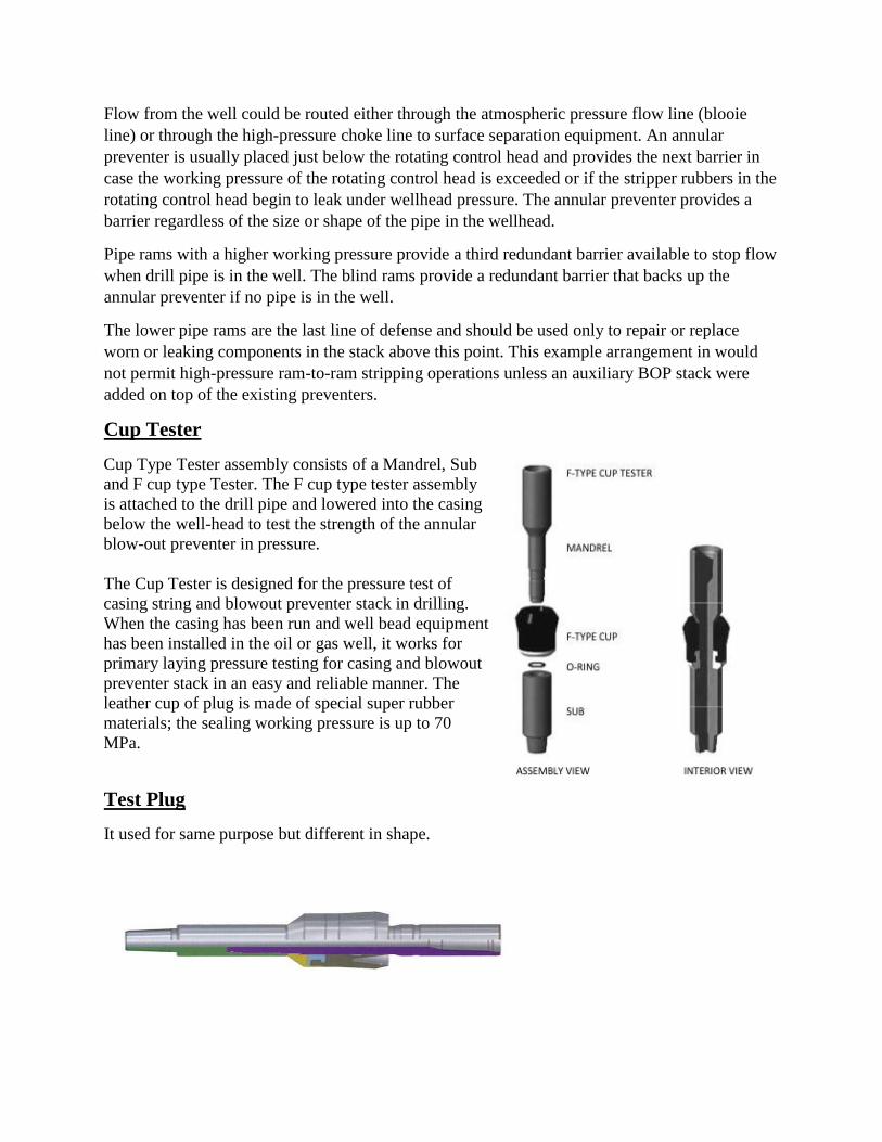
Flow from the well could be routed either through the atmospheric pressure flow line (blooie
line) or through the high-pressure choke line to surface separation equipment. An annular
preventer is usually placed just below the rotating control head and provides the next barrier in
case the working pressure of the rotating control head is exceeded or if the stripper rubbers in the
rotating control head begin to leak under wellhead pressure. The annular preventer provides a
barrier regardless of the size or shape of the pipe in the wellhead.
Pipe rams with a higher working pressure provide a third redundant barrier available to stop flow
when drill pipe is in the well. The blind rams provide a redundant barrier that backs up the
annular preventer if no pipe is in the well.
The lower pipe rams are the last line of defense and should be used only to repair or replace
worn or leaking components in the stack above this point. This example arrangement in would
not permit high-pressure ram-to-ram stripping operations unless an auxiliary BOP stack were
added on top of the existing preventers.
Cup Tester
Cup Type Tester assembly consists of a Mandrel, Sub
and F cup type Tester. The F cup type tester assembly
is attached to the drill pipe and lowered into the casing
below the well-head to test the strength of the annular
blow-out preventer in pressure.
The Cup Tester is designed for the pressure test of
casing string and blowout preventer stack in drilling.
When the casing has been run and well bead equipment
has been installed in the oil or gas well, it works for
primary laying pressure testing for casing and blowout
preventer stack in an easy and reliable manner. The
leather cup of plug is made of special super rubber
materials; the sealing working pressure is up to 70
MPa.
Test Plug
It used for same purpose but different in shape.
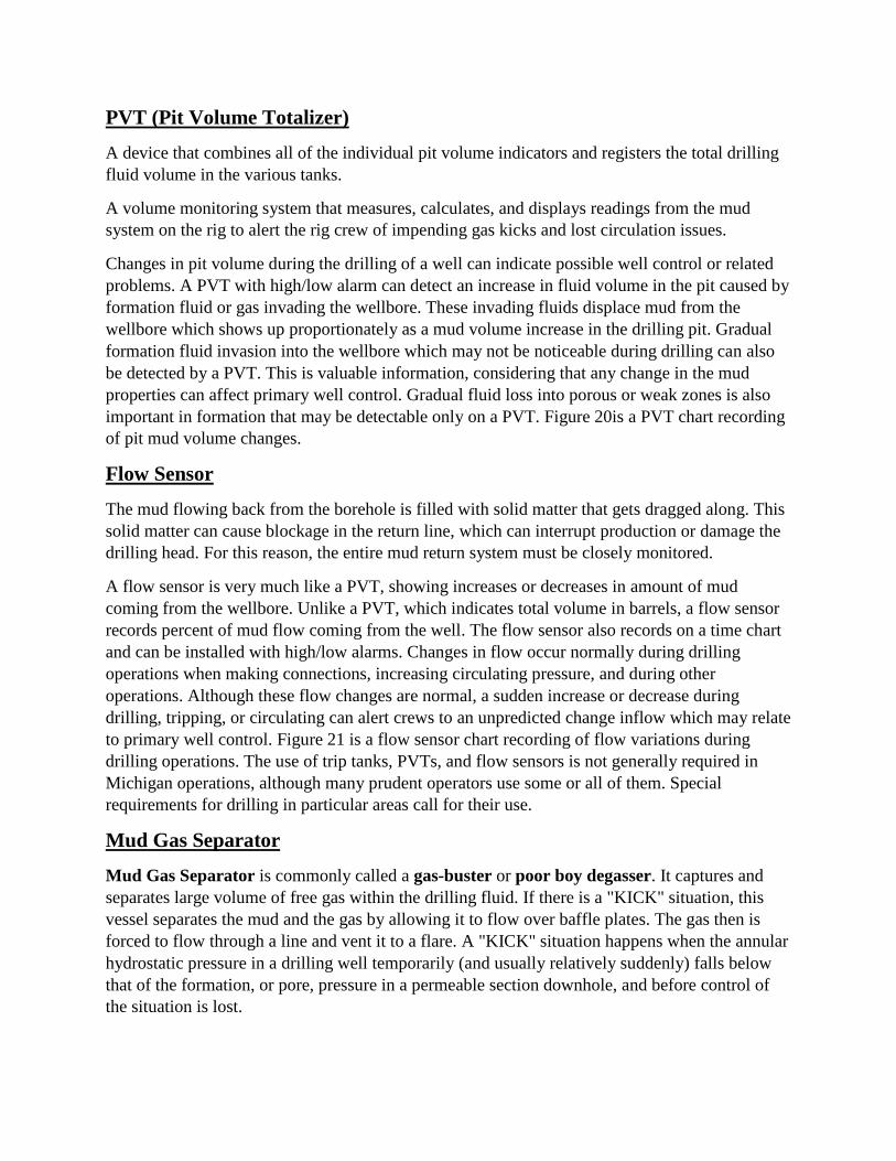
PVT (Pit Volume Totalizer)
A device that combines all of the individual pit volume indicators and registers the total drilling
fluid volume in the various tanks.
A volume monitoring system that measures, calculates, and displays readings from the mud
system on the rig to alert the rig crew of impending gas kicks and lost circulation issues.
Changes in pit volume during the drilling of a well can indicate possible well control or related
problems. A PVT with high/low alarm can detect an increase in fluid volume in the pit caused by
formation fluid or gas invading the wellbore. These invading fluids displace mud from the
wellbore which shows up proportionately as a mud volume increase in the drilling pit. Gradual
formation fluid invasion into the wellbore which may not be noticeable during drilling can also
be detected by a PVT. This is valuable information, considering that any change in the mud
properties can affect primary well control. Gradual fluid loss into porous or weak zones is also
important in formation that may be detectable only on a PVT. Figure 20is a PVT chart recording
of pit mud volume changes.
Flow Sensor
The mud flowing back from the borehole is filled with solid matter that gets dragged along. This
solid matter can cause blockage in the return line, which can interrupt production or damage the
drilling head. For this reason, the entire mud return system must be closely monitored.
A flow sensor is very much like a PVT, showing increases or decreases in amount of mud
coming from the wellbore. Unlike a PVT, which indicates total volume in barrels, a flow sensor
records percent of mud flow coming from the well. The flow sensor also records on a time chart
and can be installed with high/low alarms. Changes in flow occur normally during drilling
operations when making connections, increasing circulating pressure, and during other
operations. Although these flow changes are normal, a sudden increase or decrease during
drilling, tripping, or circulating can alert crews to an unpredicted change inflow which may relate
to primary well control. Figure 21 is a flow sensor chart recording of flow variations during
drilling operations. The use of trip tanks, PVTs, and flow sensors is not generally required in
Michigan operations, although many prudent operators use some or all of them. Special
requirements for drilling in particular areas call for their use.
Mud Gas Separator
Mud Gas Separator is commonly called a gas-buster or poor boy degasser. It captures and
separates large volume of free gas within the drilling fluid. If there is a "KICK" situation, this
vessel separates the mud and the gas by allowing it to flow over baffle plates. The gas then is
forced to flow through a line and vent it to a flare. A "KICK" situation happens when the annular
hydrostatic pressure in a drilling well temporarily (and usually relatively suddenly) falls below
that of the formation, or pore, pressure in a permeable section downhole, and before control of
the situation is lost.
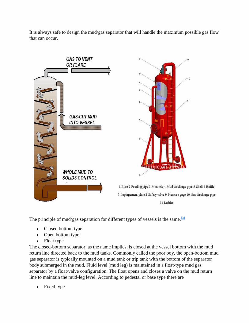
It is always safe to design the mud/gas separator that will handle the maximum possible gas flow
that can occur.
The principle of mud/gas separation for different types of vessels is the same.[3]
Closed bottom type
Open bottom type
Float type
The closed-bottom separator, as the name implies, is closed at the vessel bottom with the mud
return line directed back to the mud tanks. Commonly called the poor boy, the open-bottom mud
gas separator is typically mounted on a mud tank or trip tank with the bottom of the separator
body submerged in the mud. Fluid level (mud leg) is maintained in a float-type mud gas
separator by a float/valve configuration. The float opens and closes a valve on the mud return
line to maintain the mud-leg level. According to pedestal or base type there are
Fixed type
Elevating type
Poor boy degasser in China is usually named according to vessel diameter.
Principle of operation
The principle behind the mud gas separator is relatively simple. On the figure, the mud and gas
mixture is fed at the inlet allowing it to impinge on a series of baffles designed to separate gas
and mud. The free gas then is moved into the flare line to reduce the threat of toxic and
hazardous gases and the mud then discharges to the shale shaker and to the tank.
Bore Protector and Bore Protector Handling Tool
During the drilling cycle, when drill bits or other service tools are landed or retrieved, damage
can be incurred to the bore of the casing suspension housing. Because of this, many operators opt
to preserve the internal preparation of the suspension housing with a bore protector. The bore
protector is retained inside the casing suspension housing and is isolated from the housing bore
by means of elastomer O-rings. The bore protector is manufactured close to tolerance of the
casing suspension housing and features dove-tailed seal grooves; for more secure retention of the
O-rings during landing and retrieving operations. Bore protectors are available for type "GC- 22"
and type "GSB" casing suspension housings.
Retrievable Wear Bushing & Tie-Down Flange Assembly
Like the bore protector, a wear bushing is available for all Galaxy "GC-22" and "GSB" series
casing suspension housings. Its purpose is the same as that of a bore protector - to preserve the
internal preparation of the casing suspension housing. Unlike the bore protector, the wear
bushing is retained in a tie-down flange assembly. Therefore, tie-down flanges must be
employed whenever wear bushings are employed.
Test Plug Assembly
The primary purpose of this tool is for testing of the blow out preventer stack above the casing
head housing. The Galaxy design test plug is a four part assembly consisting of:
1. Test plug body with seal rings
2. Test plug bushing with seal rings
3. Retaining nut
4. Inner plug (when operator specified)
The test plug assembly is lowered on the drilling string to its seating position in the casing head
housing or casing head spool. Galaxy's test plugs are normally equipped with a 4 1/2" female
internal flush (IF) threaded connection on top and a 4 1/2" male internal flush (IF) threaded

connection on the bottom. Connections with other thread profiles in 4 1/2" can be provided upon
request. Frequent inspection and service is recommended.
All drilling assistance tools including: bore protector handling tools, wear bushing tie-down
flanges, double studded or drilled pack-off flanges, spacer flanges and test plug assemblies, are
available from Galaxy on a rental basis. Due to the expendable nature of bore protectors and
wear bushings, these items are not available on a rental basis.
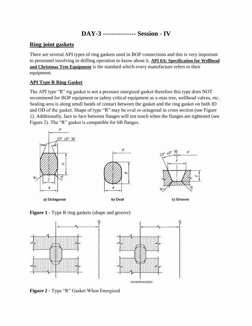
DAY-3 --------------- Session - IV
Ring joint gaskets
There are several API types of ring gaskets used in BOP connections and this is very important
to personnel involving in drilling operation to know about it. API 6A: Specification for Wellhead
and Christmas Tree Equipment is the standard which every manufacture refers to their
equipment.
API Type R Ring Gasket
The API type “R” rig gasket is not a pressure energized gasket therefore this type does NOT
recommend for BOP equipment or safety critical equipment as x-mas tree, wellhead valves, etc.
Sealing area is along small bands of contact between the gasket and the ring gasket on both ID
and OD of the gasket. Shape of type “R” may be oval or octagonal in cross section (see Figure
1). Additionally, face to face between flanges will not touch when the flanges are tightened (see
Figure 2). The “R” gasket is compatible for 6B flanges.
Figure 1 - Type R ring gaskets (shape and groove)
Figure 2 - Type “R” Gasket When Energized
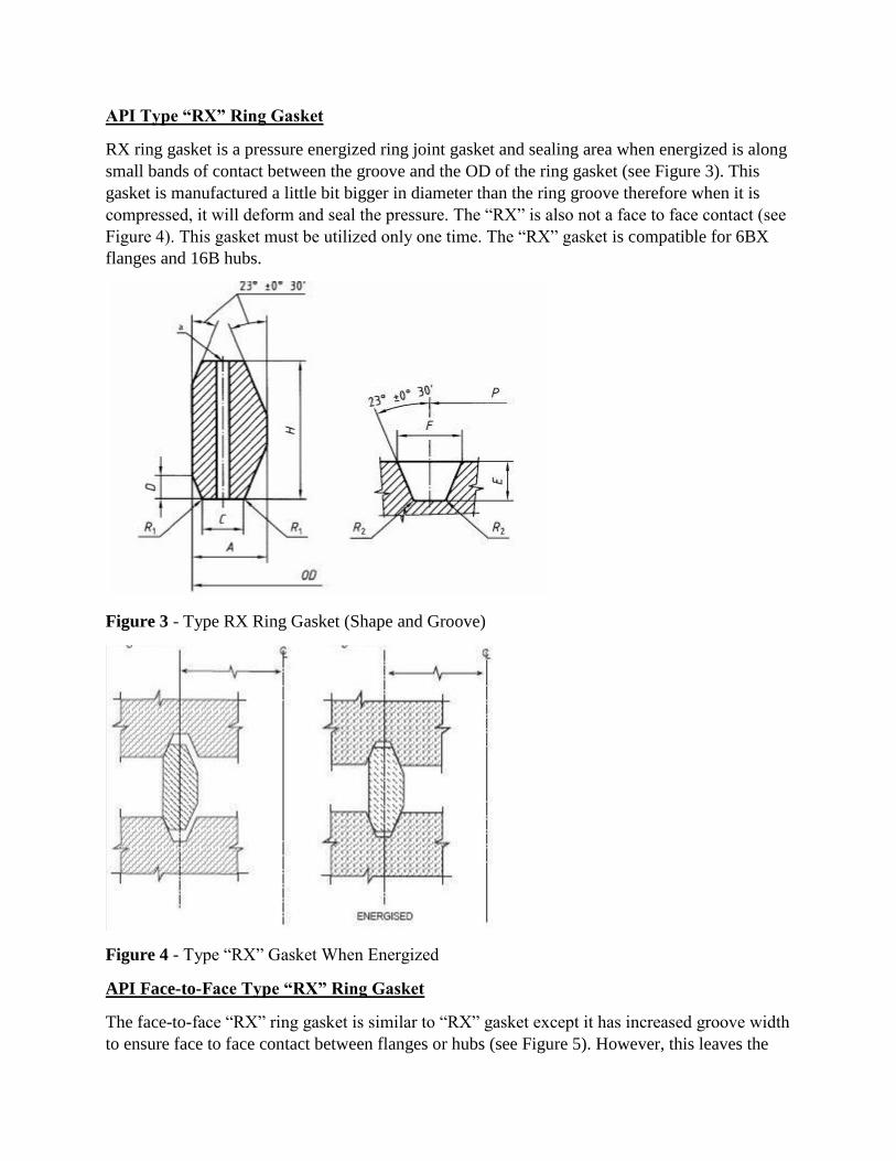
API Type “RX” Ring Gasket
RX ring gasket is a pressure energized ring joint gasket and sealing area when energized is along
small bands of contact between the groove and the OD of the ring gasket (see Figure 3). This
gasket is manufactured a little bit bigger in diameter than the ring groove therefore when it is
compressed, it will deform and seal the pressure. The “RX” is also not a face to face contact (see
Figure 4). This gasket must be utilized only one time. The “RX” gasket is compatible for 6BX
flanges and 16B hubs.
Figure 3 - Type RX Ring Gasket (Shape and Groove)
Figure 4 - Type “RX” Gasket When Energized
API Face-to-Face Type “RX” Ring Gasket
The face-to-face “RX” ring gasket is similar to “RX” gasket except it has increased groove width
to ensure face to face contact between flanges or hubs (see Figure 5). However, this leaves the
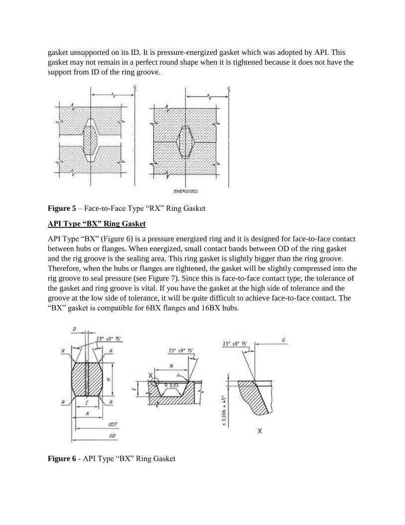
gasket unsupported on its ID. It is pressure-energized gasket which was adopted by API. This
gasket may not remain in a perfect round shape when it is tightened because it does not have the
support from ID of the ring groove.
Figure 5 – Face-to-Face Type “RX” Ring Gasket
API Type “BX” Ring Gasket
API Type “BX” (Figure 6) is a pressure energized ring and it is designed for face-to-face contact
between hubs or flanges. When energized, small contact bands between OD of the ring gasket
and the rig groove is the sealing area. This ring gasket is slightly bigger than the ring groove.
Therefore, when the hubs or flanges are tightened, the gasket will be slightly compressed into the
rig groove to seal pressure (see Figure 7). Since this is face-to-face contact type, the tolerance of
the gasket and ring groove is vital. If you have the gasket at the high side of tolerance and the
groove at the low side of tolerance, it will be quite difficult to achieve face-to-face contact. The
“BX” gasket is compatible for 6BX flanges and 16BX hubs.
Figure 6 - API Type “BX” Ring Gasket
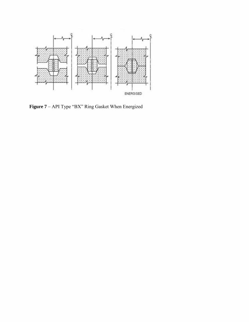
Figure 7 – API Type “BX” Ring Gasket When Energized


