3 07/07 General and Technical Information Safety Notes and Product Application In the continuous development of hardware for the precast industry, Dayton Superior places great emphasis on ensur- ing that material supplied from its manufacturing plants meets or exceeds safety requirements for lifting, handling and connecting precast concrete elements. Dayton Superior and/or independent testing laboratories have conducted tests on products shown in this handbook. The safe working loads listed were determined from these tests and were established with the following factors in mind: 1) All safe working loads shown are based on the item being new or in “as new” condition. 2) No loads greater than the product’s safe working load. 3) All inserts properly embedded and firmly fixed in place in sound, normal weight concrete so that the vertical axis of the insert is perpendicular to the lifting surface. 4) All bolted hardware has full bearing on the concrete surface and all attachment bolts bear fully on the hardware. Do not subject hardware to side loading that will cause additional and unintended loading. 5) Erection and attachment bolts are of proper length and are well tightened to prevent hardware slippage and bolt bending. 6) Coil bolts have at least the specified minimum penetration through the insert coil, but do not bear on concrete at the bottom of the void. 7) Concrete compressive strength (f’c) at time of initial use is at least the strength listed in the appropriate insert selection chart. 8) Inserts are properly located in relation to edges, corners and openings and at a proper distance to permit the development of a full concrete shear cone. Refer to the minimum edge distances shown in the appropriate insert selection chart. 9) Tensile load on the insert has been calculated, including the effect of both axial and transverse loads, as transmitted by the crane lines to the hardware. 10) No impact wrenches will be used to tighten bolts used for lifting, handling, transporting, connecting or bracing. 11) All zinc plated medium-high carbon, or high carbon steel items have been properly baked to relieve embrittlement. Not doing so may result in premature failure. 12) There has been no welding on any portion of an insert or to lifting hardware units after they have left a Dayton Superior manufacturing plant. Welding may cause embrittlement, which can result in a premature failure. Welding requires a good working knowledge of materials, heat treatment and welding procedures. Since Dayton Superior cannot control field conditions or workmanship, Dayton Superior DOES NOT GUARANTEE any product altered in any way after leaving the factory. Safety Factors A safety factor applied to a particular product is a variable, depending on the degree of hazard or risk involved in the application of that product. In precast concrete construction various conditions can often increase loading, as well as the degree of risk involved. Adhesion of the concrete element to the form, jerking of the crane during lifting, use of a crane not adequate for the job, bouncing the precast element after it has been lifted, handling the element more than antici- pated, transporting over rough surfaces, etc., all have high risk factors. In cases such as these, the user should increase the safety factor accordingly. Dayton Superior recommends that the following minimum safety factors be used when determining a product’s safe working load and that the provisions of OSHA (Occupational Safety and Health Administration Act, Part 1910) be strictly followed when considering safety factors: If a different safety factor from one shown in this handbook is required for any reason, the following equation is used to increase or reduce a safe working load: New Safe Working Load = Old Safe Working Load x Old Safety Factor New Safety Factor Warning: New safe working load must not exceed the product’s mechanical capacity divided by the new safety factor. Intended Use of Product Safety Factor 2 to 1 3 to 1 4 to 1 5 to 1 Brace Anchors Permanent Connections Inserts used for lifting and handling Hardware used for lifting and handling General and Technical Information
Transcript
307/07
General and Technical Information
Safety Notes and Product ApplicationIn the continuous development of hardware for the precast industry, Dayton Superior places great emphasis on ensur-
ing that material supplied from its manufacturing plants meets or exceeds safety requirements for lifting, handling and connecting precast concrete elements. Dayton Superior and/or independent testing laboratories have conducted tests on products shown in this handbook. The safe working loads listed were determined from these tests and were established with the following factors in mind:
1) All safe working loads shown are based on the item being new or in “as new” condition.
2) No loads greater than the product’s safe working load.
3) All inserts properly embedded and firmly fixed in place in sound, normal weight concrete so that the vertical axis of the insert is perpendicular to the lifting surface.
4) All bolted hardware has full bearing on the concrete surface and all attachment bolts bear fully on the hardware. Do not subject hardware to side loading that will cause additional and unintended loading.
5) Erection and attachment bolts are of proper length and are well tightened to prevent hardware slippage and bolt bending.
6) Coil bolts have at least the specified minimum penetration through the insert coil, but do not bear on concrete at the bottom of the void.
7) Concrete compressive strength (f ’c) at time of initial use is at least the strength listed in the appropriate insert selection chart.
8) Inserts are properly located in relation to edges, corners and openings and at a proper distance to permit the development of a full concrete shear cone. Refer to the minimum edge distances shown in the appropriate insert selection chart.
9) Tensile load on the insert has been calculated, including the effect of both axial and transverse loads, as transmitted by the crane lines to the hardware.
10) No impact wrenches will be used to tighten bolts used for lifting, handling, transporting, connecting or bracing.
11) All zinc plated medium-high carbon, or high carbon steel items have been properly baked to relieve embrittlement. Not doing so may result in premature failure.
12) There has been no welding on any portion of an insert or to lifting hardware units after they have left a Dayton Superior manufacturing plant. Welding may cause embrittlement, which can result in a premature failure. Welding requires a good working knowledge of materials, heat treatment and welding procedures. Since Dayton Superior cannot control field conditions or workmanship, Dayton Superior DOES NOT GUARANTEE any product altered in any way after leaving the factory.
Safety Factors
A safety factor applied to a particular product is a variable, depending on the degree of hazard or risk involved in the application of that product. In precast concrete construction various conditions can often increase loading, as well as the degree of risk involved. Adhesion of the concrete element to the form, jerking of the crane during lifting, use of a crane not adequate for the job, bouncing the precast element after it has been lifted, handling the element more than antici-pated, transporting over rough surfaces, etc., all have high risk factors. In cases such as these, the user should increase the safety factor accordingly.
Dayton Superior recommends that the following minimum safety factors be used when determining a product’s safe working load and that the provisions of OSHA (Occupational Safety and Health Administration Act, Part 1910) be strictly followed when considering safety factors:
If a different safety factor from one shown in this handbook is required for any reason, the following equation is used to increase or reduce a safe working load:
New Safe Working Load = Old Safe Working Load x Old Safety Factor
New Safety Factor
Warning: New safe working load must not exceed the product’s mechanical capacity divided by the new safety factor.
Intended Use of ProductSafety Factor
2 to 1
3 to 1
4 to 1
5 to 1
Brace Anchors
Permanent Connections
Inserts used for lifting and handling
Hardware used for lifting and handling
Gen
eral
an
d
Tech
nic
al
Info
rm
ati
on
4 07/07
General and Technical Information
USERS OF Dayton Superior PRODUCTS MUST EVALUATE THE PRODUCT
FACTORS, CALCULATE SAFE WORKING LOADS AND CONTROL ALL FIELD
CONDITIONS TO PREVENT APPLICATION OF LOADS IN EXCESS OF THE SAFE
WORKING LOAD.
Factors Affecting the Load-Carrying Capacity of an Insert
Attachment Bolt and Hardware Considerations:
The selection of an attachment bolt diameter will depend upon the job the bolt is required to do. If, for instance, bolts are to be used repeatedly and are subject to tension and shear, choose a bolt at least one size larger in diameter than static loading conditions would require. Since coil bolts are not intended for bending loads, care must be taken to be sure that the bolts are properly tightened.
Bolt failures are generally caused by excessive thread wear, field modification, or bending and/or straightening of bolts. It is the responsibility of the user to continually inspect bolts and working hardware for wear and discard the parts when wear is noted. Do not straighten bent bolts, discard and replace them. Also, any bolts known to have been used at loads of 70%, or more, of ultimate strength should be removed from service and discarded. Such bolts may have been stretched sufficiently to become brittle-hard and could lead to premature failure of the bolts. Every user must establish a control program to replace attachment bolts after a predetermined number of uses, regardless of their appearance.
Lifting hardware shown in this handbook is subject to wear, misuse, overloading, corrosion, deformation, intentional alteration and other factors that could affect the hardware’s safe working load. Therefore, the user must inspect the con-dition of the hardware units regularly to determine if they can be used at their rated safe working load. If not, they must be removed from service. The frequency of inspection is best determined by the user and is dependent upon factors such as frequency of use, period of use and environmental conditions.
The Mechanical Strength of the InsertLifting inserts/anchors displayed in this handbook are fabricated from carbon steel that has sufficient strength to
safely carry the specified safe working loads. Many of the inserts/anchors herein can be special ordered, fabricated from stainless steel material. When an insert is fabricated from stainless steel, it may have a lower safe working load than the safe working load published for the corresponding carbon steel insert. Contact a Dayton Superior Technical Services Department for safe working loads of inserts fabricated from stainless steel.
Gen
eral
an
d
Tech
nic
al
Info
rm
ati
on
507/07
General and Technical Information
The Strength of the ConcreteWhen a load is applied to an insert embedded in concrete, it induces a corresponding resistive force in the concrete.
Insert failures can be predicted with a reasonable degree of accuracy by using the following equation for concretereak-out from ACI 318 Appendix D.
f'c = Compressive strength of the concrete at time of lift
Pconcrete = 0.75 x jc,N x l x 24 x √ f'chef1.5
Pconcrete = Maximum tension load carried by concrete and;
l = Reduction factor for use with lightweight concrete, see page 6;
jc,N = Factor for cracked concrete: 1.0 if cracked and 1.25 if uncracked.
When the value of Pconcrete exceeds the ultimate mechanical tensile capacity of the insert, the insert will fail. It is appar-ent that the shear cone becomes larger as the insert is embedded deeper in the concrete. Sufficient depth of embedment would theoretically permit the development of the full ultimate strength of the insert.
Deep embedment is generally considered impractical for precast concrete, but some types of anchors depend upon this principle for their effectiveness. The Dayton Superior F-1 Screw Anchor and P-52 Swift Lift Anchor are two examples.
All other factors being equal, depth of embedment has more effect on the strength of a concrete insert than any other single factor. A concrete insert under tensile loading to failure will fail in one of four ways:
1) The entire insert may pull out of the concrete with little apparent damage to the concrete (see Illustration B on page 8). Such failures are rare and, when they do occur, are the result of bond failure between the concrete and insert. These failures usually occur in “green” and/or low strength concrete.
2) The entire insert may pull out of the concrete bringing with it a cone of concrete having its apex slightly above the most deeply embedded part of the insert (see Illustration C). Such failures usually occur in relatively low strength concrete in which the tensile strength of the “shear cone” surrounding the insert is not as great as the strength of the insert itself.
3) A failure may also occur through breakage of the insert. Coil type inserts will usually fail at a point just below the helically wound wire coil. A small cone of concrete will usually be pulled out of the concrete surface (see Illustration D). This cone will have its apex at a point just below the coil. The base diameter will be approximately twice the cone height. Swift Lift Inserts will fail by fracturing of the shaft diameter of the insert (see Illustration E).
Pconcrete
Concrete Surface
Surface Area of
Theoretical Shear Cone
Surface Area of Theoretical Shear Cone
Pconcrete
Concrete Surface
dh
35°
35°
Surface Area of Theoretical Shear Cone
Pconcrete
Concrete Surface
dh
dh
Illustration A1
Illustration A3
Illustration A2
Warning! Adding rebar to the horizontal portion of an insert will reduce the depth of the shear cone (le), resulting in a reduced insert capacity. When rebar are added for insert stability, they should be placed against the vertical portion of the insert and at least 1" away from the horizontal portion.
Gen
eral
an
d
Tech
nic
al
Info
rm
ati
on
For inserts located near an edge preventing development of a full shear cone please contact a Dayton Superior Technical Services Department for insert capabilities.
hef
hef
35°
hef
6 07/07
General and Technical Information
These failures occur in high strength concrete when an insert is loaded beyond the ultimate strength of the insert. Failures of this type are due to a definite overload being applied to the inserts. Such failures can be prevented by choos-ing inserts of capacity suitable to job conditions.
4) When bolting coil type inserts, the bolt should always extend the proper amount beyond the bottom of the insert coil. Failure to do this causes the entire bolt load to be transferred to fewer turns of the coil, causing an increased load per weld contact point. The coil will then unwind, much like a corkscrew, resulting in a failure (see Illustration F).
Safe Working Load Reduction Factors for Inserts Used inLightweight Concrete
Insert safe working loads, shown in this handbook, were derived from analysis and testing of Dayton Superior inserts used in normal weight (150 pcf) concrete. The safe working load of the insert is dependent upon the compressive strength of the concrete in which it is embedded. Therefore, when Dayton Superior inserts are used in lightweight concrete precast elements, the safe working load of the inserts must be recalculated to compensate for the reduction in concrete density. Multiply the published safe working loads by a reduction factor, shown in the table, to obtain the corrected safe working load. The table, shown below, displays the various reduction factors recommended by Dayton Superior for lightweight concrete.
Interested readers are referred to Section 11.2 of the American Concrete Institute’s “Building Code Requirements for Reinforced
Concrete” (ACI 318) for additional information.
P
P
P P
P
Illustration DIllustration CIllustration B
Illustration E Illustration F
Safe Working Load Reduction FactorConcrete Type
Normal Weight
Sand and Lightweight Aggregates
All Lightweight Materials with a Weight of 110 PCF or more
All Lightweight Materials with a Weight of 110 PCF or less
1.0
0.7
0.6
Verify by Testing
Gen
eral
an
d
Tech
nic
al
Info
rm
ati
on
707/07
General and Technical Information
Location of InsertEmbedment of inserts closer to an edge than the minimum edge distances, shown in this handbook, will greatly reduce
the effective area of the resisting concrete shear cone and will reduce the insert’s tension safe working load. The shaded area of the shear cone, shown in the illustrations below, indicates the extent the shear cone area is reduced. Tension safe working loads of inserts used in thin wall conditions or near a free edge or corner must, therefore, be reduced in proportion to the reduction in effective shear cone area (see Illustrations G & H).
Another condition frequently encountered is that of an insert embedded near a free edge or corner and loaded in a transverse direction to the axis of the bolt, toward the free edge of the concrete. Contact a Dayton Superior Technical Services Department for safe working loads of inserts used in this type of condition.
Insert PlacementInserts must be placed accurately. An insert’s safe working load decreases sharply if it is not perpendicular to the
bearing surface, or if it is not in line with the applied force.
Inserts lend themselves to being located and held correctly (by bolts and brackets or by tying to the reinforcing steel) before the casting operation begins. Failure to achieve proper insert placement is careless field installation. It is also important to place inserts so that the depth of thread is constant for the same size insert throughout a job. This will eliminate potential bolt engagement mistakes by the erection crew. Inserts should always be kept clean of dirt, ice or other objects that will interfere with attachment of the lifting hardware.
Wrong
(Too Low)
Illustration I
Illustration G Illustration H
D
de
P
D
D
de
P Tension
P Shearor
D = Insert Minimum Edge Distance Required to Develop Insert’s Safe Working Load
de = Actual Edge Distance
Wrong
(Too High)
Wrong
(Angled)Right
P
1/2" Minimum to Develop Insert Safe Working Load
90°
Note: For ferrule inserts, establish this dimension and maintain for all similar sized inserts on a project. For coil inserts, the coil bolt must penetrate through the insert coil by the proper amount.
Gen
eral
an
d
Tech
nic
al
Info
rm
ati
on
8 07/07
General and Technical Information
Edge and Shear LoadingAnother condition frequently encountered is an insert embedded near a free edge or corner and loaded in a direction
transverse to the axis of the bolt, toward the free edge. Edge lift panels are examples of this condition.
Many tests have shown that edge inserts loaded transversely to destruction (see Illustration L) finally fail because of an initial failure of the concrete over the coil. This initial failure transfers the entire load to the insert struts. If the load is large enough, the struts will fail in bending or shear or both.
An analysis of tests indicates that the ultimate load on edge inserts loaded in the direction of the free edge is a func-tion of the distance from the insert to the free edge. The effect of bolt diameter and insert configuration appears to be of secondary and negligible importance. For conditions where shear loading must be considered, it is appropriate to use the following equation from ACI 318 Appendix D:
Shear Safe Working Load (lbs.) =
With the maximum shear safe working load equal to, or less than, the insert’s tension Safe Working Load.
Where:
jc = Cracked concrete factor: 1.0 for cracked concrete and 1.4 if uncracked.
l = Reduction factor for lightweight concrete, see page 6.
le = Minimum of embedment length or 8 x (n x do).
n = Number of struts on the insert.
do = Diameter of the insert struts.
f ’c = Specified concrete compressive strength.
ca1 = Distance from centerline of the insert to the edge.
For conditions where a corner or thickness in direction of embedment is less than 1.5 x ca1 or an adjacent insert is closer than 3 x ca1 contact Dayton Superior Technical Services Department for insert capacities.
For cases where increased shear capacity is required, the addition of pre-formed shear bars over the top of the insert will greatly increase the distribution of the load. Shear bars, when used, must be in solid contact with the insert to be effective.
If accurate capacities of inserts are desired, several inserts with shear bars should be tested in job size panels.
Combined Shear and TensionInserts and bolts that are subjected to combined shear and tension loadings should satisfy the following
equation:
( fv )5/3
+ ( ft )
5/3 < 1.0 Fv Ft
Where:
fv = Applied shear load;
Fv = Shear safe working load;
ft = Applied tension load;
Ft = Tension safe working load.
ca1
Shaded areas indicate probable tensile stress pattern in concrete near edge insert subject to load “P.”
Point “X”
Point “X”
P
Dotted line indicates line of probable concrete failure Point “X”– point of possible strut fracture.Illustration L
Gen
eral
an
d
Tech
nic
al
Info
rm
ati
on
ψc
l⋅ 8⋅le
n do
⋅
0.2
n do
⋅⋅ f'c
⋅ ca1( )1.5⋅
Appropriate Safety Factor
907/07
9
General and Technical Information
NC Threaded Bolt Selection Chart
ASTM A-307 Bolts ASTM A-325 or A-449 BoltsNominal Bolt Diameter and
Threads per Inch Tension Shear Tension Shear
1/4"– 20
3/8"– 16
1/2"– 13
5/8"– 11
3/4"– 10
7/8"– 9
1"– 8
1-1/8"– 7
1-1/4"– 7
1-1/2"– 6
625 lbs.
1,500 lbs.
2,800 lbs.
4,500 lbs.
6,600 lbs.
9,200 lbs.
12,100 lbs.
15,200 lbs.
19,300 lbs.
28,100 lbs.
350 lbs.
900 lbs.
1,700 lbs.
2,700 lbs.
4,000 lbs.
5,600 lbs.
7,400 lbs.
9,400 lbs.
12,000 lbs.
17,500 lbs.
1,250 lbs.
3,100 lbs.
5,600 lbs.
9,000 lbs.
13,300 lbs.
18,400 lbs.
24,200 lbs.
26,700 lbs.
33,900 lbs.
49,100 lbs.
725 lbs.
1,800 lbs.
3,400 lbs.
5,400 lbs.
8,100 lbs.
11,300 lbs.
14,900 lbs.
16,400 lbs.
21,000 lbs.
30,600 lbs.
Gen
eral
an
d
Tech
nic
al
Info
rm
ati
on
Torque-Tension RelationshipFor some types of bolted connections, it may be desirable to have a minimum clamping force (tension load).
Due to the many variables associated with tightening bolted connections, it is possible to experience as much as a ± 25% variation in the amount of clamping force applied to similar connections receiving identical torque.
The following equation is taken from “Fasteners Standards – Sixth Edition,” published by Industrial Fasteners Institute, East Ohio Building, 1717 East 9th Street, Suite 1105, Cleveland, Ohio 44114-2879. It is used to provide an “estimate” of the torque required to apply a given preload to a bolted connection.
T = KDP 12
Where: T = Torque (ft. lbs.); K = Torque coefficient; D = Nominal bolt diameter; P = Tension in bolt (Ibs.)
The torque coefficient is the critical factor in the above formula. It is best to experimentally determine K for critical applications using actual connection materials and assembly tools.
Arbitrary values for K are often assigned in non-critical applications, as follows:
K = .20 for NC threaded bolts per “Fasteners Standards – Sixth Edition” K = .30 for Coil threaded bolts per test results.
The torque coefficient will vary from the values, shown above, when bolts have been plated, greased or coated with other types of lubricant.
NC Threaded Bolt CapacitiesPermanent connections in precast construction are normally made with either ferrule inserts or slotted inserts using
National Course (NC) threaded bolts. NC threaded bolts are normally not supplied by Dayton Superior. However, as a con-venience to the precast designer, the following chart is listed.
Safe working loads shown provide a factor of safety of approximately 3 to 1 (ultimate to Safe Working Load). Shear Safe Working Load assumes that the threads are included in the shear plane. 1/4"–20, 3/8"–16 and 1/2"–13 bolts are not recommended for use as structural fasteners. For combined shear/tension interaction, refer to page 12.
Condition of LoadingsAll safe working loads shown in this handbook are for static load conditions only. If dynamic forces or impact loading con-
ditions are anticipated, the safe working load must be reduced accordingly.
Care must be exercised to see that all inserts and hardware units are properly aligned, all lifting plates and bolts properly
secured, all rigging is equalized, and properly sized crane cables utilized.
Warning: When in doubt about the proper use or installation of a Dayton Superior precast product, contact Dayton Superior for
clarification. Failure to do so may result in safety hazards, exposing workers in the vicinity of the precast yard or job site to the
possibility of injury or death.
10 07/07
General and Technical Information
ASTM A-123 Zinc (Hot Dipped Galvanized) Coating on Iron or Steel
Product Type Material Approximate Thickness
Wire
Wire
Wire
Steel or Plate
Steel or Plate
Steel or Plate
.142" to .186" diameter
.187" to .249" diameter
.250" diameter or larger
.030" to .062" thick
.063" to .124" thick
.125" or thicker
.002"
.003"
.004"
.002"
.003"
.004"
ASTM A-153 Zinc Coatings (Hot Dip) on Iron or Steel Hardware
Product Type Class Approximate Thickness
Castings
Steel, 3/16" and thicker
Steel, 3/16" and thinner
A
B1
B2
.004"
.004"
.003"
ASTM B-633 Electro Deposited Coatings of Zinc on Iron and Steel
Service Condition Exposure Approximate Thickness
SC-4
SC-3
SC-2
SC-1
.001"
.0005"
.0003"
.0002"
Very Severe
Severe
Moderate
Mild
ASTM B-633 Continued
Type After Plating Coating
1
2
3
4
As Plated
Colored Chromate
Colorless Chromate
Phosphate
Note: Electro-galvanized or hot dipped galvanized items fabricated from medium high carbon or high carbon steel must be properly treated to minimize hydrogen embrittlement. Failure to properly bake these items may result in a drastic reduction in their safe working load and premature failure resulting in property damage, injuries or death.
Gen
eral
an
d
Tech
nic
al
Info
rm
ati
on
Corrosion ProtectionThe Dayton Superior precast products shown in this handbook are available in several different finishes or coatings.
These finishes vary in the degree of corrosion protection provided. Standard finish is PLAIN and will normally be furnished if no finish is specified. All COREWALL products will be furnished with a “D” Coat finish, if finish is not specified. Finishes available are as follows:
PLAIN or unfinished steel is sometimes referred to as BLACK or RAW. PLAIN finished material will rust when exposed to the environment.
ELECTRO-GALVANIZED finish is a zinc plated finish that provides a varying degree of corrosion protection depending on the thickness of the zinc plating and type of after-plating coating specified. This finish is recommended for threaded products. Dayton Superior electro-galvanizing conforms to ASTM Standard B-633, Service Condition 1 as plated. Other options available under this ASTM Standard are listed below.
HOT DIPPED GALVANIZED or HDG products are zinc coated by the hot-dipped process and will provide better corrosion protection than electro-galvanized finished products due to the thicker HDG zinc coating. This finish is not recommended for threaded products due to potential assembly problems. Dayton Superior hot dipped galvanizing conforms to ASTM A-123 or A-153.
EPOXY-POLYESTER or EPOXY finish is a dielectric material that is used to provide corrosion protection for steel products that are to be embedded in precast concrete. This material is usually applied to a coating thickness between 5 and 12 mils. Epoxy-Polyester finish is normally specified when an affordable solution to salt spray corrosion is required. Not recommended for use where threads are to be coated.
STAINLESS STEEL is recommended for its excellent corrosion protection that will resist ordinary rusting. Type 304 Stainless Steel is recommended for use in precast products. It is the most economical type of stainless steel available for its level of corrosion resistance. Note that Type 304 Stainless Steel will rust when exposed to certain chemicals used to acid wash the surface of architectural precast concrete.
ASTM Standards For Corrosion Resisting Coatings
1107/07
General and Technical Information
Condition of LoadingThe preceding paragraphs have been devoted to the behavior of concrete inserts under straight tensile loading. Obviously, there are many conditions of loading other than direct tension. Most situations will require consideration of shearing and/or bending forces applied to the insert through the anchor bolt or other connecting hardware. A common condition occurs when a precast concrete element is lifted by means of inserts in each end without a spreader bar (see Illustration J). When a load P is carried by only two inserts, the vertical reaction R that must be carried by each insert is 1/2 P. There is also an additional vertical force V, that must be added to R, that is caused by the horizontal component H of force T.
The horizontal force H that is exerted on the insert and on the concrete surrounding it is proportional to the total load and to the angle a included between the sling and the surface of the concrete. This force may be expressed by the equa-tion:
H = P (cot a). 2
The magnitude of the tensile force on the sling is proportional to the total load and to the angle a. This force may be expressed by the equation:
T = P
2 sin a .
As angle a decreases, the values of H and T increase. As angle a approaches 0°, the magnitude of both H and T approaches infinity. Conversely, as angle a increases, the values of H and T decrease, so that as angle a approaches 90°, force T approaches the value of 1/2 P and force H approaches 0.
It is readily apparent that the use of long slings will greatly reduce destructive forces on the slings, the lifting hardware and on the precast element itself.
H = Horizontal component of sling load which is equal to the induced shear load.
V = Vertical force on insert caused by force H
applied at distance e from face of concrete.
C = Resultant of compressive forces on concrete.
d = Distance from center line of anchor bolt to toe
of bearing plate.
e = Distance from face of concrete to point of
application of force H.
x = Distance from toe of bearing plate to C.
b = Width of bearing plate–(not shown)
f’c = Ultimate compression strength of the concrete.
aSee Detail A
Illustration J
P
Detail A
T
H
R = 1/2 P
Illustration K
d
He
SHEAR
C
X
V
(d - x)
Gen
eral
an
d
Tech
nic
al
Info
rm
ati
on
12 07/07
General and Technical Information
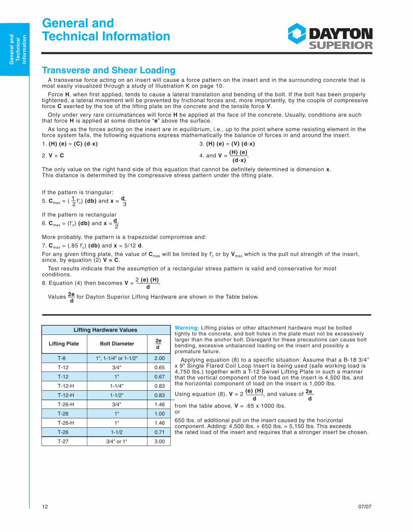
Transverse and Shear LoadingA transverse force acting on an insert will cause a force pattern on the insert and in the surrounding concrete that is
most easily visualized through a study of Illustration K on page 10.
Force H, when first applied, tends to cause a lateral translation and bending of the bolt. If the bolt has been properly tightened, a lateral movement will be prevented by frictional forces and, more importantly, by the couple of compressive force C exerted by the toe of the lifting plate on the concrete and the tensile force V.
Only under very rare circumstances will force H be applied at the face of the concrete. Usually, conditions are such that force H is applied at some distance “e” above the surface.
As long as the forces acting on the insert are in equilibrium, i.e., up to the point where some resisting element in the force system fails, the following equations express mathematically the balance of forces in and around the insert.
1. (H) (e) = (C) (d-x) 3. (H) (e) = (V) (d-x)
2. V = C 4. and V = (H) (e)
. (d-x)
The only value on the right hand side of this equation that cannot be definitely determined is dimension x. This distance is determined by the compressive stress pattern under the lifting plate.
If the pattern is triangular:
5. Cmax = ( 1 f'c) (db) and x = d. 2 3
If the pattern is rectangular
6. Cmax = (f'c) (db) and x = d. 2
More probably, the pattern is a trapezoidal compromise and:
7. Cmax = (.85 f'c) (db) and x = 5/12 d.
For any given lifting plate, the value of Cmax will be limited by f'c or by Vmax which is the pull out strength of the insert, since, by equation (2) V = C.
Test results indicate that the assumption of a rectangular stress pattern is valid and conservative for most conditions.
8. Equation (4) then becomes V = 2 (e) (H)
. d
Values 2e for Dayton Superior Lifting Hardware are shown in the Table below. d
Warning: Lifting plates or other attachment hardware must be bolted tightly to the concrete, and bolt holes in the plate must not be excessively larger than the anchor bolt. Disregard for these precautions can cause bolt bending, excessive unbalanced loading on the insert and possibly a premature failure.
Applying equation (8) to a specific situation: Assume that a B-18 3/4" x 9" Single Flared Coil Loop Insert is being used (safe working load is 4,750 lbs.) together with a T-12 Swivel Lifting Plate in such a manner that the vertical component of the load on the insert is 4,500 lbs. and the horizontal component of load on the insert is 1,000 lbs.
Using equation (8), V = 2 (e) (H)
, and values of 2e d d
from the table above, V = .65 x 1000 lbs.or
650 lbs. of additional pull on the insert caused by the horizontal component. Adding: 4,500 lbs. + 650 lbs. = 5,150 lbs. This exceeds the rated load of the insert and requires that a stronger insert be chosen.
Lifting Hardware Values
Lifting Plate Bolt Diameter2e
d —
T-8
T-12
T-12
T-12-H
T-12-H
T-26-H
T-26
T-26-H
T-26
T-27
2.00
0.65
0.67
0.83
0.83
1.46
1.00
1.46
0.71
3.00
1", 1-1/4" or 1-1/2"
3/4"
1"
1-1/4"
1-1/2"
3/4"
1"
1"
1-1/2
3/4" or 1"
Gen
eral
an
d
Tech
nic
al
Info
rm
ati
on
1307/07
Calculating Sling/Anchor Loads
Applies to Swift Lift; Fleet-Lift and Utility AnchorsThe table shows multiplication factors that are used in a simplified method to determine
the increased load transferred from the sling to the anchor when using multi-leg slings. As the fleet angle (0) increases, the sling load increases and transfers an even larger to the anchor.
P = Actual weight of precast element including adhesion
= Fleet angle
F = Multiplication factor
P x F = Effective weight of precast element
P1 = P2 = Anchor load using 2-leg sling
P1 = P2 = P x F/2 anchors
Calculating Sling/Anchor Loads
Applies to Swift Lift; Fleet-Lift and Utility AnchorsWhen anchors are not located equally about the center of gravity of the precast
element, calculate the applied anchor loads statically.
The load will always balance under the crane hook. Calculate anchor loads as follows:
P1 = P x b/a + b
P2 = P x a/a + b
Rigging For Traveling Over Rough
GroundWhen a precast element is to transported over rough
ground, use a 60˚ “V” type rigging. This will help reduce dynamic loads.
When using forklift to transport precast elements over rough ground, Dayton Superior recommends that the user reduce the anchor safe working load by 50%. This safe working load reduction will help offset the effects of any dynamic loads that might occur.
Gen
eral
an
d
Tech
nic
al
Info
rm
ati
on
General and Technical Information
FleetAngle
“0”
MultiplicationFactor
“F”
0˚ 1.00
16˚ 1.01
30˚ 1.04
45˚ 1.08
60˚ 1.16
75˚ 1.26
90˚ 1.41
105˚ 1.64
120˚ 2.00
P
F F
P1 P2
0
0
Warning: Avoid the use of Fleet Angles greater than 120˚ as their use can overload and fall anchors causing a premature failure resulting is property damage, serious personal injury or death.
Right
Load Diagram Compressive Force in Concrete
Wrong
P2P1a
90˚
Reaction of Anchor
Resultant Load on Anchor
˚Varies
90˚
b
P
14 07/07
General and Technical Information
Gen
eral
an
d
Tech
nic
al
Info
rm
ati
on
RiggingAs with all lifting systems, the selection of the proper lifting anchor is based on several factors. One of the most impor-
tant is the accurate determination of the load that will be applied to each anchor. When using certain rigging arrange-ments it is impossible to accurately determine the load that is applied to each anchor. this is due to the tolerances in sling lengths and the location of the lifting anchors in the precast concrete element. In order to eliminate this problem, and make certain that the applied loads are equalized to each of the lifting anchors, an equalizer (spreader) beam and rollers blocks are used.
The use of equalizer beams and roller blocks permits a qualified person to determine the exact load distribution. When an equalizer beam and roller blocks are used in the plant, they must also be used in the field. If the user is in doubt about the field use of an equalizer beam and roller blocks, then only two anchors should be assumed to be load carry-ing.
Several typical rigging arrangements are shown below along with a determination as to the number of anchors that will be load carrying.
The above assumes that the anchors are spaced equally about the center of gravity of the precast concrete element and that the center of lift is directly above the center of gravity. Failure to locate the center of lift directly over the center of gravity will cause the precast element to tilt.
Illustration R13 anchors will carry load when used
on round precast concrete elements with the anchors spaced 120˚ apart.
2 anchors will carry load when used on square or rectangular precast elements.
Illustration R22 anchors will carry load when
using 4 individual slings. The other 2 anchors will act to balance the precast concrete element.
Illustration R34 anchors will carry load when using
2 individual slings running over 2 roller blocks supported by an equalizer beam.
Illustration R44 anchors will carry load when using 4 individual slings
in conjunction with the Dayton Superior T-46 Spreader Beam with Twin 7-1/2-ton Shackles.
Illustration R52 anchors will carry load when using 4 individual slings
attached to a 3 beam equalizer beam. This rigging arrange-ment should be used when angle pulls need to be avoided.
120˚
120˚
120˚
1507/07
Selecting the Proper InsertThe following factors should be considered when determining the load per insert:
1) Weight of the concrete shape,
2) Adhesion to the form surface,
3) Type of concrete (normal, lightweight or all lightweight materials),
4) Dynamic loads (impact due to handling, transporting or erecting conditions),
5) Concrete compressive strength at time of initial lift,
6) Number of lifting points and type of rigging to be used,
Determining the dead load weight of a precast concrete section is straight forward, although serious errors are easy to make, such as: 1. Miscalculations involving symmetrical panels; 2. Forgetting that a panel is normal weight concrete and using the unit weights of lightweight concrete and 3. Neglecting adhesion to the form.
In addition, transporting the panel in the storage yard over bumpy conditions introduces dynamic loads that must also be anticipated. Removing the precast element from the form can induce forces that, in effect, increase the dead load weight at a critical time, when the concrete compressive strength is at its lowest value. Depending on the quality of release agent used, the following adhesion loads should be considered when determining the “additional” weight of the concrete element:
Concrete Forms up to 20 Ibs./sq. ft.
Steel Forms up to 25 Ibs./sq. ft.
Plywood Forms up to 50 Ibs./sq. ft. (Flat Surface)
Plywood Forms up to 75 Ibs./sq. ft. (Ribbed Surface)
The type of concrete used determines the unit weight characteristics and the resultant ability of the concrete to resist the pullout forces introduced by the insert. See page 8 for the proper load reduction factors that must be applied to insert safe working loads when an insert is embedded in lightweight concrete.
Consideration must also be given to dynamic loads that can occur in the plant, in the storage yard, as well as during transportation to the job site and during erection. It is suggested that a detailed study be made of the various handling, storage, transporting and erection forces. The user is cautioned to be aware of these additional forces and to give due consideration to their effect on the insert’s safe working load.
Example OneSelect the proper length and capacity of insert based on the use of a spreader frame, as shown below, that will
allow equal loading on all four inserts. Assume normal weight concrete having a compressive strength of 2,700 psi at initial lift.
Dead Load Weight = 15' x 8' x 12.5 Ibs./sq. ft. x 6" = 9,000 Ibs.
Adhesion to Form = 15' x 8' x 75 Ibs./sq. ft. = 9,000 Ibs. (Ribbed Surface)
Select the following insert: P-52 4 ton x 4 3/4" long Swift Lift Anchor in 3,000 psi normal weight concrete.
General and Technical Information
Illustration M
90°6"
15'-0
"
8'-0"
Gen
eral
an
d
Tech
nic
al
Info
rm
ati
on
16 07/07
Example TwoSelect the proper length and capacity of insert, based on the use of a spreader beam and slings at a 60° angle with
the top surface of the precast section. Assume normal weight concrete having a compressive strength of 4,000 psi at initial lift and the use of 1" diameter T-12 Swivel Lifting Plates.
Dead Load Weight = 20' x 7' x 12.5 Ibs./sq. ft. x 6" = 10,500 Ibs.Adhesion to Form = 20' x 7' x 25 Ibs./sq. ft. = 3,500 Ibs.
Effective Weight of Panel = 14,000 Ibs.
Therefore, the vertical reaction that must be carried by each
insert = 14,000 lbs.
= 3,500 lbs. 4 inserts
H = 3,500 Ibs. x cot. 60° = 3,500 Ibs. x .578 orH = 2,023 Ibs./insert
V = 2 e
x 2,023 Ibs. = .65 x 2,023 or dV = 1,315 Ibs./insert
Select the following insert: F-56 Expanded Coil Insert, 1" diameter x 5 1/2" long, 6,250 Ibs. Safe Working Load.
Check combined tension and shear as follows:
( 4,815 lbs. )5/3 +
( 2,023 lbs. )5/3 = .80. Since this is less than 1.0, the insert which was 6,250 lbs. 4,800 lbs. selected is suitable for use.
Example ThreeSelect the proper length and capacity of an insert based on the use of a four sling lift (see warning note below) with
cables at a 60° angle to the top surface of the precast section. Assume lightweight concrete having a unit weight of 115 lbs./cu. ft., a compressive strength at initial lift of 4,000 psi and the use of 1-1/2" diameter T-12 Swivel Lift Plates.
Dead Load Weight = 9' x 10' x 9.58 Ibs./sq. ft. x 14" = 12,071 Ibs. Adhesion to Form = 9' x 10' x 20 Ibs./sq. ft. = 1,800 Ibs.
Effective Weight of Precast Section = 13,871 Ibs.
Therefore, the vertical reaction that must be carried by each
insert = 13,871 lbs.
= 6,936 lbs. 2 inserts
H = 6,936 Ibs. x cot. 60° = 6,936 Ibs. x .578 orH = 4,009 Ibs./insert
V = 2 e
x 4,009 Ibs. = .833 x 4,009 Ibs. or dV = 3,339 Ibs./insert
Select the F-60 Expanded Coil Insert, 1-1/2" diameter x 12" long, 16,250 lbs. Safe Working Load.
Multiply Safe Working Load by reduction factor of .7 for lightweight concrete,
16,250 Ibs. x .7 = 11,375 Ibs. Safe Working Load in lightweight concrete.
As the reduced Safe Working Load is greater than the 10,275 Ibs. Ioad required, it appears this insert is suitable for use. However, combined shear and tension must be checked as follows:
(10,275 lbs.)5/3 +
(4,009 lbs.)5/3 = 1.01, which means this insert must be replaced with a stronger insert.
11,375 lbs. 11,750 lbs.
Warning: When individual slings are used, any two inserts must be capable of lifting/handling the precast section. This is due to unequal sling lengths and the resulting loads that are transferred to the shorter slings. In this application, only two slings carry the total load while the other two slings are simply used to balance the load.
Gen
eral
an
d
Tech
nic
al
Info
rm
ati
on
General and Technical Information
Illustration P
14" 60°
10'-0
"
9'-0"
Illustration N
20'-0
"6"
60°
7'-0"
1707/07
Coil Insert Safe Working Load Reduction Factors For Free Edge Conditions–Tension Loadings Only
Reduced Safe Working Load is based on 1/2" setback from face of concrete.For Safe Working Load on other insert loading conditions, contact a Dayton Superior Technical Service Department.
How to Use Reduction Factors:To obtain an insert’s reduced safe working load for free edge conditions, multiply the safe working load listed in
the insert selection chart by the appropriate reduction factor from the above chart. Do not apply these reduction factors to other types or sizes of inserts.
Example:Using a B-2 Coil Tie Insert x 8" long in a 2-1/2" free edge condition, multiply the safe working load of 9,000 lbs. by
a reduction factor of .80 to arrive at the reduced safe working load of 7,200 lbs.
General andTechnical Information
Minimum D + de
de
P
D
Concrete Face
de = Free edge distance
D = Minimum edge distance required to develop a full shear cone–see insert selection charts for this dimension
2D = Minimum insert spacing when using two or more inserts
Note: For insert capacities under shear loading conditions, please refer to page 12.
Coil Insert Safe Working Load Reduction Factors For Thin Wall Conditions–Tension Loadings Only
Reduced Safe Working Load is based on 1/2" setback from face of concrete.For Safe Working Load on other insert loading conditions, contact a Dayton Superior Technical Service Department.When an insert is not positioned at the center line of the wall, the effective wall thickness is twice the actual edge distance.
How to Use Reduction Factors:To obtain an insert’s reduced safe working load for thin wall conditions, multiply the safe working load listed in the
insert selection chart by the appropriate reduction factor from the above chart. Do not apply these reduction factors to other types or sizes of inserts.
Example:Using a B-2 Coil Tie Insert x 12" long in an 8" thin wall condition, multiply the safe working load of 13,500 lbs.
by a reduction factor of .61 to arrive at the reduced safe working load of 8,235 lbs..
T de
PD
Concrete Face T = Wall thickness
de = Actual edge distance
D = Minimum edge distance required to develop a full shear cone–see insert selection charts for this dimension
2D = Minimum insert spacing when using two or more inserts
Note: For insert capacities under shear loading conditions, please refer to page 12.