DBEM and FEM Analysis of an Extrusion Press Fatigue Failure R. Citarella, G. Cricrì, M. Lepore, and M. Perrella 1 Introduction This paper illustrates an application of the Dual Boundary Element Method (DBEM) [1, 2], as implemented in a commercial code [3], to the simulation of a fatigue crack propagation phenomenon affecting the main cylinder of an extrusion press for aluminum sections (Figs. 1, 2, 3 and 4). Such methodology is particu- larly effective for simulation of three-dimensional single/multiple crack propagation under the hypothesis of isotropic and linear elastic material properties [4–8, 9]. The aforementioned crack propagates through the thickness, causing a leakage of the pressurized oil and consequent production stop after 1,310,400 cycles (the extrusion press had been working for 11 years, 240 working days per year, 5 days per week, 24 h per day, with basic cycles lasting 3 min each). The fatigue load is induced by the pressure variation inside the cylinder from 0 to 300 bar for each cycle, as needed to push each section through the extrusion hole. The main aim of the simulation is to assess the most probable initial crack dimensions that, after the recorded in service fatigue cycles, lead to the final crack scenario. Once assessed the initial crack scenario it is possible to understand if there was any possibility to detect such crack before the assembly phase, by using non destructive detection techniques, and if there was a rogue flaw introduced by the manufacturing process. 2 Problem Description and DBEM Analysis The cylinder (Figs. 1, 2, 3 and 4) is made of cast iron and the related fatigue properties (Table 1), consistent with the NASGRO 3 crack propagation formula (Eq. 1), are provided in the NASGRO database where the material is indicated as [A1AC50AB1]. The cylinder is constrained along the cylinder axial direction by the R. Citarella (B ) Department of Mechanical Engineering, University of Salerno, 84084 Fisciano SA, Italy e-mail: [email protected]181 A. Öchsner et al. (eds.), Materials with Complex Behaviour, Advanced Structured Materials 6, DOI 10.1007/978-3-642-12667-3_12, C Springer-Verlag Berlin Heidelberg 2010
Transcript
DBEM and FEM Analysis of an ExtrusionPress Fatigue Failure
R. Citarella, G. Cricrì, M. Lepore, and M. Perrella
1 Introduction
This paper illustrates an application of the Dual Boundary Element Method(DBEM) [1, 2], as implemented in a commercial code [3], to the simulation of afatigue crack propagation phenomenon affecting the main cylinder of an extrusionpress for aluminum sections (Figs. 1, 2, 3 and 4). Such methodology is particu-larly effective for simulation of three-dimensional single/multiple crack propagationunder the hypothesis of isotropic and linear elastic material properties [4–8, 9].
The aforementioned crack propagates through the thickness, causing a leakageof the pressurized oil and consequent production stop after 1,310,400 cycles (theextrusion press had been working for 11 years, 240 working days per year, 5 daysper week, 24 h per day, with basic cycles lasting 3 min each).
The fatigue load is induced by the pressure variation inside the cylinder from 0to 300 bar for each cycle, as needed to push each section through the extrusion hole.
The main aim of the simulation is to assess the most probable initial crackdimensions that, after the recorded in service fatigue cycles, lead to the final crackscenario. Once assessed the initial crack scenario it is possible to understand if therewas any possibility to detect such crack before the assembly phase, by using nondestructive detection techniques, and if there was a rogue flaw introduced by themanufacturing process.
2 Problem Description and DBEM Analysis
The cylinder (Figs. 1, 2, 3 and 4) is made of cast iron and the related fatigueproperties (Table 1), consistent with the NASGRO 3 crack propagation formula(Eq. 1), are provided in the NASGRO database where the material is indicated as[A1AC50AB1]. The cylinder is constrained along the cylinder axial direction by the
R. Citarella (B)Department of Mechanical Engineering, University of Salerno, 84084 Fisciano SA, Italye-mail: [email protected]
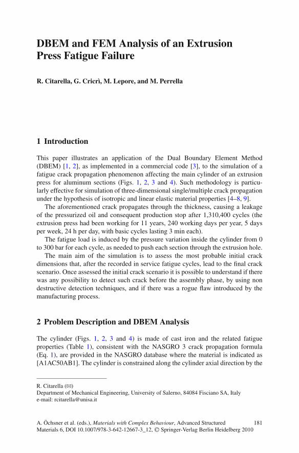
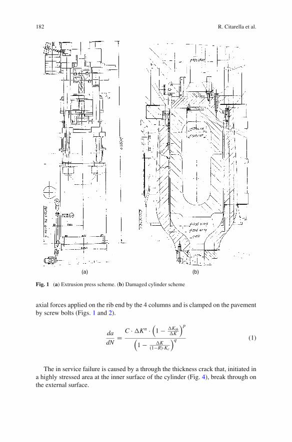
axial forces applied on the rib end by the 4 columns and is clamped on the pavementby screw bolts (Figs. 1 and 2).
da
dN=
C ·�Kn ·(
1 − �Kth�K
)p
(1 − �K
(1−R)·Kc
)q (1)
The in service failure is caused by a through the thickness crack that, initiated ina highly stressed area at the inner surface of the cylinder (Fig. 4), break through onthe external surface.
DBEM and FEM Analysis of an Extrusion Press Fatigue Failure 183
Fig. 4 Internal view of damaged cylinder (left) during welding repair operations and close-up ofthe crack under repair (right)
184 R. Citarella et al.
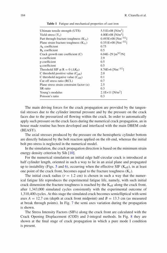
Table 1 Fatigue and mechanical properties of cast iron
Ultimate tensile strength (UTS) 5.51E+08 [N/m2]Yield stress (Ys) 4.00E+08 [N/m2]Part through fracture toughness (K1e) 0.493E+08 [Nm–3/2]Plane strain fracture toughness (K1c) 0.351E+08 [Nm–3/2]Ak coefficient 0.75Bk coefficient 0.5Crack growth rate coefficient (C) 6.04E–29 [m5/2/N]n coefficient 2.9p coefficient 0.5q coefficient 0.5Threshold SIF at R = 0 (�K0) 8.76E+6 [Nm–3/2]C threshold positive value (Cpth) 2.0C threshold negative value (Cnth) 0.1Cut off stress ratio (RCL) 0.7Plane stress strain constraint factor (α) 2.5SR ratio 0.3Young’s modulus 2.1E+11 [N/m2]Poisson’s ratio 0.3
The main driving forces for the crack propagation are provided by the tangen-tial stresses due to the cylinder internal pressure and by the pressure on the crackfaces due to the pressurized oil flowing within the crack. In order to automaticallyapply such pressure on the crack faces during the numerical crack propagation, an inhouse made routine has been developed and interfaced with the main DBEM code(BEASY).
The axial stresses produced by the pressure on the hemispheric cylinder bottomare directly balanced by the bolt reaction applied on the rib end, whereas the initialbolt pre-stress is neglected in the numerical model.
In the simulation, the crack propagation direction is based on the minimum strainenergy density criterion by Sih [10].
For the numerical simulation an initial edge half-circular crack is introduced athalf cylinder length, oriented in such a way to lie in an axial plane and propagatedup to instability (Figs. 5 and 6), occurring when the effective SIF (Keff), in at leastone point of the crack front, becomes equal to the fracture toughness (Kc).
The initial crack radius (r = 1.2 cm) is chosen in such a way that the numer-ical fatigue life reproduces the experimental fatigue life, namely, with such initialcrack dimension the fracture toughness is reached by the Keff along the crack front,after 1,343,000 simulated cycles consistently with the experimental outcome of1,310,400 cycles. At this stage the simulated crack becomes semielliptical with semiaxes A = 12.7 cm (depth at crack front midpoint) and B = 13.3 cm (as measuredat break through points). In Fig. 7 the semi axes variation during the propagationis shown.
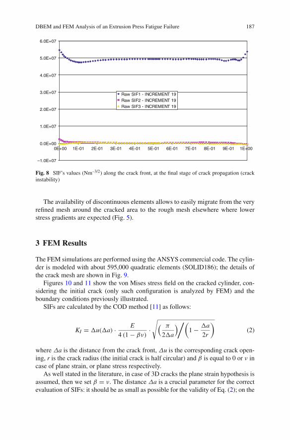
The Stress Intensity Factors (SIFs) along the crack front are calculated with theCrack Opening Displacement (COD) and J-integral methods. In Fig. 8 they areshown at the final stage of crack propagation in which a pure mode I conditionis present.
DBEM and FEM Analysis of an Extrusion Press Fatigue Failure 185
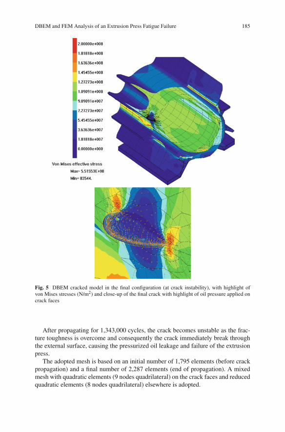
Fig. 5 DBEM cracked model in the final configuration (at crack instability), with highlight ofvon Mises stresses (N/m2) and close-up of the final crack with highlight of oil pressure applied oncrack faces
After propagating for 1,343,000 cycles, the crack becomes unstable as the frac-ture toughness is overcome and consequently the crack immediately break throughthe external surface, causing the pressurized oil leakage and failure of the extrusionpress.
The adopted mesh is based on an initial number of 1,795 elements (before crackpropagation) and a final number of 2,287 elements (end of propagation). A mixedmesh with quadratic elements (9 nodes quadrilateral) on the crack faces and reducedquadratic elements (8 nodes quadrilateral) elsewhere is adopted.
186 R. Citarella et al.
Fig. 6 DBEM cracked modelin the final configuration(at crack instability), withhighlight of von Misesstresses (N/m2), and close-upof the final crackinternal view
Fig. 8 SIF’s values (Nm–3/2) along the crack front, at the final stage of crack propagation (crackinstability)
The availability of discontinuous elements allows to easily migrate from the veryrefined mesh around the cracked area to the rough mesh elsewhere where lowerstress gradients are expected (Fig. 5).
3 FEM Results
The FEM simulations are performed using the ANSYS commercial code. The cylin-der is modeled with about 595,000 quadratic elements (SOLID186); the details ofthe crack mesh are shown in Fig. 9.
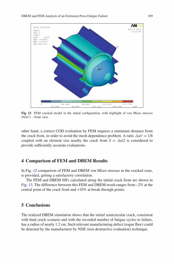
Figures 10 and 11 show the von Mises stress field on the cracked cylinder, con-sidering the initial crack (only such configuration is analyzed by FEM) and theboundary conditions previously illustrated.
SIFs are calculated by the COD method [11] as follows:
KI = �u(�a) · E
4 (1 − βν) ·√( π
2�a
)/(1 − �a
2r
)(2)
where Δa is the distance from the crack front, Δu is the corresponding crack open-ing, r is the crack radius (the initial crack is half circular) and β is equal to 0 or ν incase of plane strain, or plane stress respectively.
As well stated in the literature, in case of 3D cracks the plane strain hypothesis isassumed, then we set β = ν. The distance Δa is a crucial parameter for the correctevaluation of SIFs: it should be as small as possible for the validity of Eq. (2); on the
188 R. Citarella et al.
Fig. 9 Mesh details in the cracked zone for the initial cracked configuration
Fig. 10 FEM cracked model in the initial configuration, with highlight of von Mises stresses(N/m2) – rear view
DBEM and FEM Analysis of an Extrusion Press Fatigue Failure 189
Fig. 11 FEM cracked model in the initial configuration, with highlight of von Mises stresses(N/m2) – front view
other hand, a correct COD evaluation by FEM requires a minimum distance fromthe crack front, in order to avoid the mesh dependence problem. A ratio Δa/r = 1/8coupled with an element size nearby the crack front S = Δa/2 is considered toprovide sufficiently accurate evaluations.
4 Comparison of FEM and DBEM Results
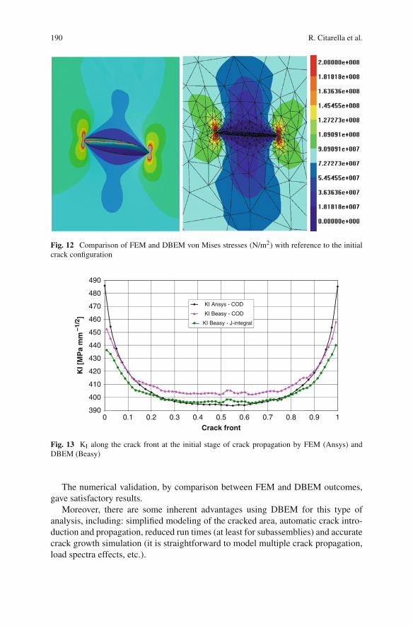
In Fig. 12 comparison of FEM and DBEM von Mises stresses in the cracked zone,is provided, getting a satisfactory correlation.
The FEM and DBEM SIFs calculated along the initial crack front are shown inFig. 13. The difference between this FEM and DBEM result ranges from –2% at thecentral point of the crack front and +10% at break through points.
5 Conclusions
The realized DBEM simulation shows that the initial semicircular crack, consistentwith final crack scenario and with the recorded number of fatigue cycles to failure,has a radius of nearly 1.2 cm. Such relevant manufacturing defect (rogue flaw) couldbe detected by the manufacturer by NDE (non destructive evaluation) technique.
190 R. Citarella et al.
Fig. 12 Comparison of FEM and DBEM von Mises stresses (N/m2) with reference to the initialcrack configuration
390
400
410
420
430
440
450
460
470
480
490
0 0.1 0.2 0.3 0.4 0.5 0.6 0.7 0.8 0.9 1
KI [
MP
a m
m –1
/2]
Crack front
KI Ansys - COD
KI Beasy - COD
KI Beasy - J-integral
Fig. 13 KI along the crack front at the initial stage of crack propagation by FEM (Ansys) andDBEM (Beasy)
The numerical validation, by comparison between FEM and DBEM outcomes,gave satisfactory results.
Moreover, there are some inherent advantages using DBEM for this type ofanalysis, including: simplified modeling of the cracked area, automatic crack intro-duction and propagation, reduced run times (at least for subassemblies) and accuratecrack growth simulation (it is straightforward to model multiple crack propagation,load spectra effects, etc.).
DBEM and FEM Analysis of an Extrusion Press Fatigue Failure 191
References
1. Y. Mi, M.H. Aliabadi, Dual boundary element method for three dimensional fracture mechan-ics analysis. Eng. Anal. Bound. Elem. 10, 161–171 (1992)
2. Y. Mi, Three-Dimensional Analysis of Crack Growth, Topics in Engineering, vol. 28 (Computa-tional Mechanics Publications, Southampton, 1996)
3. C. M. BEASY Ltd., BEASY V10r10 Documentation, Southampton (2009)4. C. Calì, R. Citarella, M. Perrella, Three-Dimensional Crack Growth: Numerical Evaluations
and Experimental Tests, Biaxial/Multiaxial Fatigue and Fracture, ESIS Publication, vol. 31(Elsevier, Amsterdam, 2003)
6. R. Citarella, F.G. Buchholz, Comparison of crack growth simulation by DBEM and FEMfor SEN-specimens undergoing torsion or bending loading. J. Eng. Fract. Mech. 75, 489–509(2008)
7. R. Citarella, F.G. Buchholz, Comparison of DBEM and FEM crack path predictions withexperimental findings for a SEN-specimen under anti-plane shear loading. Key Eng. Mater.348–349, 129–132 (2007)
8. A. Leski, Implementation of the virtual crack closure technique in engineering FE calculations.Finite Elem. Anal. Des. 43(3), 261–268 (2007)
9. K.S. Venkatesha, T.S. Ramamurthy, B. Dattaguru, Generalized modified crack closure integral(GMCCI) and its application to interface crack problems. Comput. Struct. 60(4), 665–676(1996)
10. G.C. Sih, B.C.K. Cha, A fracture criterion for three-dimensional crack problems. J. Eng. Fract.Mech. 6, 699–732 (1974)