DC-8™ Jetliner Series 10 to 40 Pilot’s Notes Please note that Flight Simulator X Steam Edition must be installed correctly on your PC prior to the installation and use of this DC-8 simulation.
Transcript
DC-8™ Jetliner Series 10 to 40
Pilot’s Notes
Please note that Flight Simulator X Steam Edition must be installed correctly on your
PC prior to the installation and use of this DC-8 simulation.
Power plants .................................................................................................................................................. 5
AIRCRAFT IN THIS SIMULATION .............................................................................................................................. 5
Technical Support ............................................................................................................................................... 7
First Officer’s panel .......................................................................................................................................... 16
Centre panel ..................................................................................................................................................... 16
Aft centre console ............................................................................................................................................ 20
Engineer’s control pedestal ......................................................................................................................... 23
Fire control system ...................................................................................................................................... 39
TUTORIAL – FLYING THE DC-8 ............................................................................................................................... 42
Flight plan ......................................................................................................................................................... 42
Getting started ................................................................................................................................................. 43
3
Starting the engines ......................................................................................................................................... 50
Before start ...................................................................................................................................................... 62
Before take-off ................................................................................................................................................. 66
Before landing .................................................................................................................................................. 67
After landing ..................................................................................................................................................... 68
‘Ship One’ was the first variant of the DC-8. It was developed for domestic service
and was powered by four Pratt & Whitney JT3C-6 turbojets, each producing 13,500lb
of thrust. It is depicted here shortly after roll-out, featuring the shorter wingtips (by
three feet) and systems probe mounted on the port wing.
Douglas (N8008D)
6
DC-8-12 The Series 12 was the first variant of the DC-8 to enter airline service. It was developed for domestic service and was powered by four Pratt & Whitney water-injected JT3C-6 engines, each producing 13,500lb of thrust.
N804E
N8013U
DC-8-21
The Series 20 saw the introduction of the more powerful Pratt & Whitney JT4A-3
turbojets which each produced 15,800lb of thrust. This additional thrust allowed for a
gross weight increase of over 10,000lb. A total of 49 DC-8-20s were delivered to
major domestic and international airlines. Many would go on to be converted to later
versions, thus getting a second lease of life.
N8021U
N8608
EC-BZQ
NE572C
N821F
DC-8-32
The Series 30 featured an upgraded airframe for use on intercontinental routes, with
JT4A turbojets, a 30% increase in fuel capacity and strengthened landing gear. 57
aircraft were produced.
SE-DBA
N804PA
HB-IDA
PH-DCG
5Y-ASA
DC-8-42
32 DC-8-40s were built. The -40 was essentially a Series 30 aircraft but fitted with
Rolls-Royce Conway 509 turbofans. These engines were more efficient, quieter and
produced less smoke, but despite these benefits the Series 40 failed to sell in great
numbers due to the reluctance of US airlines to purchase an airliner fitted with
engines manufactured overseas and their desire to wait for the more advanced Pratt
& Whitney JT3D turbofan which was due to be introduced.
I-DIWM
7
CF-CPJ
CF-TJF
N9604Z
CU-T1210
6YJME
INSTALLATION
Installation is handled by Steam after purchase of the product. After purchasing the
product the files will be downloaded and installation into the Scenery Library will be
automatic.
Accessing the aircraft
To access the DC-8 variants in FSX:SE.
1. Click on ‘Free Flight’.
2. Select ‘Just Flight’ from the ‘Publisher’ drop-down menu.
3. Select ‘Douglas’ from the Manufacturer drop-down and choose one of the DC-8
variants.
Tick the ‘Show all variations’ box to see all the available liveries.
Updates Updates to the product will automatically be deployed, downloaded and installed via Steam to all users who own the product.
Technical Support To obtain technical support (in English) please visit the Support pages at justflight.com. As a Just Flight customer you can obtain free technical support for any Just Flight or Just Trains product. For support specifically on the Steam version of the add-on please contact Dovetail Games. https://dovetailgames.kayako.com/
Regular News To get the latest news about Just Flight products, sign up for our newsletter at https://www.justflight.com/
The DC-8 is very similar in size, layout and appearance to its competitor, the Boeing
707, for which it was often mistaken. Significant differences which are immediately
noticeable are the signature nostril intakes in the nose and the ‘double bubble’
design of the fuselage, designed to provide greater strength at high altitude
pressures.
Large luggage compartments are positioned on the right side of the aircraft and the
electrically operated doors open inwards. Many airlines made use of specially
designed cargo containers which were shaped to fit these bays perfectly.
The aircraft features landing lights mounted in retractable pods beneath each wing
and wing lighting mounted within the wing roots.
9
The engines fitted to the early DC-8s were turbojets which operated with reverse
thrust capability and ‘silencers’ called ejectors which extended aft to cover the
exhausts in an attempt to reduce noise. These ejectors carried the reverser buckets
which, when reverse thrust was selected, closed completely over the exhausts and
directed the gases forward.
The engines were typically very smoky affairs and a DC-8 on a full-power take-off
was not the finest example of low emissions!
Special reverser smoke has been created for these Just Flight DC-8 aircraft and
when you apply reverse thrust you will see this smoke exiting from the sides of the
engines.
10
Another unique feature of the DC-8’s engines was their use in braking the aircraft
during flight; the inner two engines could be put into reverse thrust mode to slow the
aircraft, providing a similar effect to spoilers.
In fact, spoilers were never used on DC-8s for braking during flight. The resulting
disturbance to airflow over the wing would produce very unstable flight
characteristics, so the spoilers are restricted to ground use only.
Spoilerons are employed on the DC-8, however, but only when the landing gear is
extended at slow speeds. Only the three outer panels extend as aileron aids for
manoeuvring at slow speeds. A guide to the correct use of reversers and spoilers is
included in the flight guide later in this manual.
The split flaps on the DC-8 are huge and extremely effective, so much so that
although they will extend to a full 48 degrees, this setting is only ever rarely used.
15-20 degrees is the norm for take-off and landing. Full deployment is used to assist
with braking on landing and in adverse weather conditions.
The leading edges of the wings on early DC-8s have small slats which open before
the main flaps to assist with lift.
The unique features of the DC-8 design extend to the landing gear. In a tight turning
circle, each rear-wheel bogie will automatically disconnect from the main chassis and
rotate towards the direction of the turn in order to reduce friction and wear on the
large tyres. Only one of the bogies rotates, in the direction of the turn.
The bogies are also designed to remain level when the weight is lifted from the gear.
They do not droop like they do on most modern aircraft, which allows for a more
compact retraction system.
11
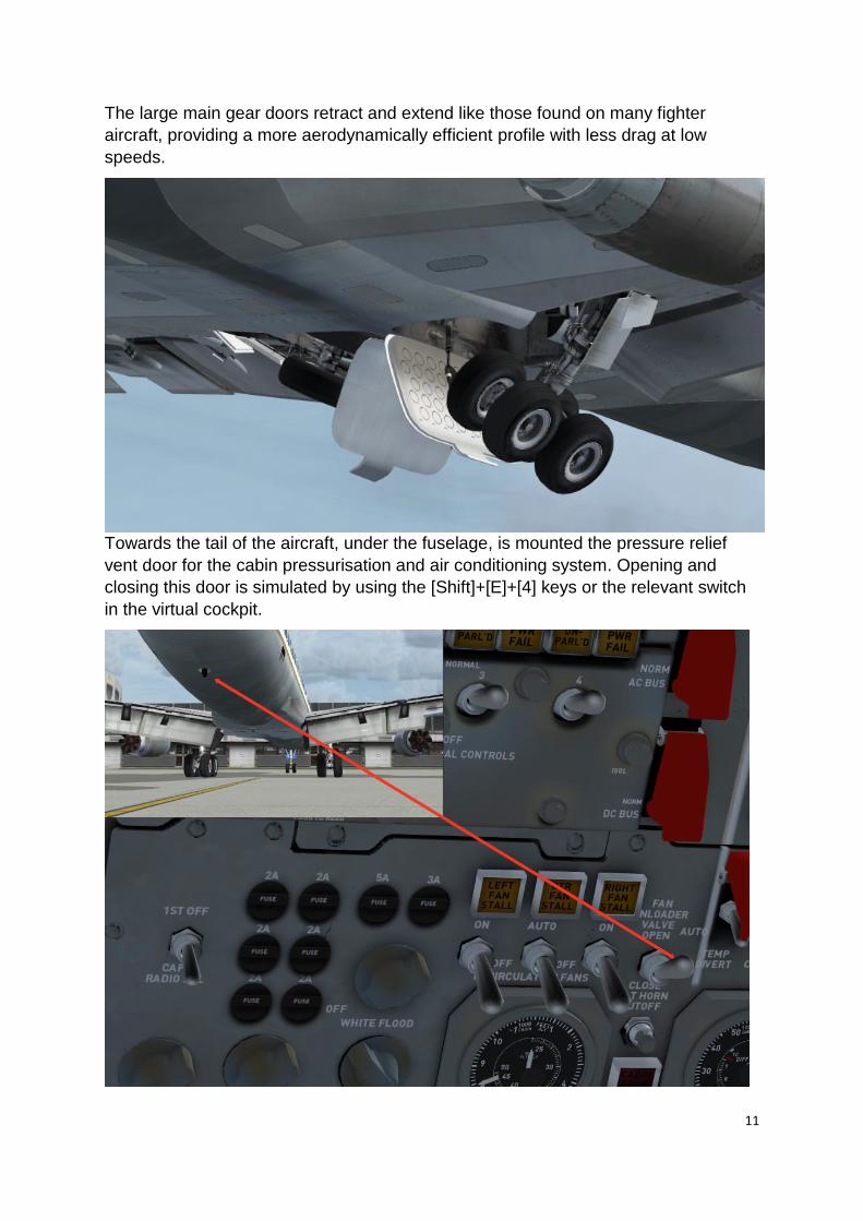
The large main gear doors retract and extend like those found on many fighter
aircraft, providing a more aerodynamically efficient profile with less drag at low
speeds.
Towards the tail of the aircraft, under the fuselage, is mounted the pressure relief
vent door for the cabin pressurisation and air conditioning system. Opening and
closing this door is simulated by using the [Shift]+[E]+[4] keys or the relevant switch
in the virtual cockpit.
12
The DC-8 has a large tall fin and rudder to maintain directional stability. Heavy duty
hinges and a large trim tab deal with the powerful aerodynamic forces and provide
improved lateral control.
COCKPIT GUIDE
The cockpit can be divided into nine areas:
• Captain’s panel
• First Officer’s panel
• Centre panel
• Forward centre console
• Throttle quadrant
• Aft centre console
• Flight Engineer’s panel
• Overhead panel
• Navigator’s panel
The following pages will guide you through these areas.
Many bespoke animations and much special programming code has been used in
the cockpit to replicate the systems and functionality of the real aircraft, so we
recommend that you read this Cockpit Guide and the rest of this manual to learn the
location and function of all the controls and systems.
13
Captain’s panel
1. Parking brake and nose-wheel steering tiller
2. Windscreen heater/rain disperser
3. Comparator (annunciator fail lights)
4. NAV 1 course deviation indicator (CDI)
5. RMI (NAV 1 / ADF 1 and NAV 2 / ADF2)
6. Airspeed indicator (ASI)
7. Radio altimeter
8. Mach meter
9. True airspeed
10. Artificial horizon indicator (AHI)
11. Horizontal situation indicator (HSI)
12. DME display (displays NAV 2 distance)
13. Marker lights
14. Altimeter
15. Vertical speed indicator (VSI)
16. Anti-skid and spoiler position caution lights
17. Clock
18. Outside air temperature
14
For a clearer view of the instruments, toggle the yoke visibility using the PITCH TRIM COMP switch mounted to the left of the centre console, in front of the NO STEP placard. There are three ASI units in the cockpit: those of the Captain, First Officer and Navigator. They all function in the same way. The ASI has setting bugs for V-speeds fixed around the bezel. To set these, click and drag or use the mouse-wheel. The red bug setter is for maximum speed (VMO) and the red light will illuminate when this set speed is exceeded.
The artificial horizon indicator is fitted with a flight director (FD). The instrument has a
control knob to activate the different functions – OFF, HDG (heading) and V/L (VOR
LOC). The yellow wing-shaped flight director indicator that displays within the AHI
will indicate the direction in which to turn or bank the aircraft to establish the turn
necessary to achieve a given heading (set by the heading control knob on the HSI or
to intercept the radial for VOR navigation and ILS approaches indicated by the RMI).
The RMI has dual-function needles. Using the two control knobs at the base of the
instrument, you can select either VOR or ADF functions for each needle. The large
white needle indicates either NAV 1 or ADF 1 depending on the position of the
corresponding control knob. When the needle is indicating NAV 1, a light in the top of
the instrument will illuminate. Similarly, the yellow needle indicates either NAV 2 or
ADF 2 and has its own control knob and warning light.
15
The HSI can be driven either by NAV 1 or NAV 2, depending on the position of the
switch at the bottom of the gauge.
The altimeter replicates a real-world type used in early DC-8s. The barometric
pressure setting can be changed by left- or right-clicking the knob (or using the
mouse-wheel). The needle reads off the height in 100-foot increments and the drum
reads off the height in 1,000-foot increments up to 40,000 feet where the instrument
becomes unreliable.
16
First Officer’s panel
The First Officer’s panel closely mirrors the Captain’s panel in its layout. The
differences are listed below.
1. Anti-skid switch 2. Maximum airspeed warning light 3. Flap position indicator 4. Autopilot servo indicators (aileron, elevator and rudder) 5. Wing slats caution light
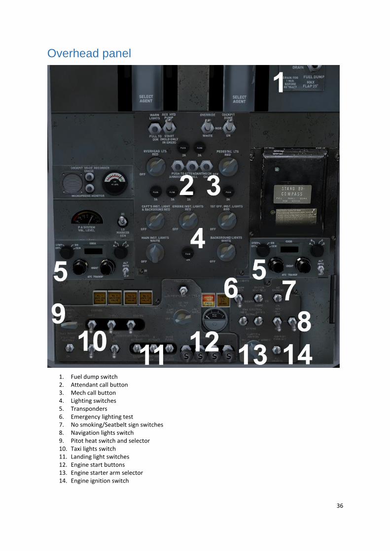
Centre panel
1. Master caution light (push to reset) 2. Master fire warning light (push to reset) 3. Hydraulic brake pressure gauge 4. Altitude alerter 5. Standby AHI 6. Engine oil pressure warning lights 7. Engine Pressure Ratio (EPR) gauges 8. Exhaust Gas Temperature (EGT) gauges 9. N1 RPM gauges 10. Fuel flow gauges 11. Landing gear lever 12. Landing gear door warning lights 13. Landing gear test light switch
17
EPR gauges
The EPR gauge indicates a power setting for a given engine. This is used in combination with special
EPR tables to establish the correct throttle settings for a given cruise altitude and speed. The EPR bugs can be set to the desired thrust reading using left- or right-click (or the mouse-wheel), and the selected setting is indicated in the tumbler window. Throttles can then be adjusted to achieve the desired thrust range.
Forward centre console
1. ADF 1 radio 2. COM 1 radio 3. Weather radar 4. ADF 2 radio 5. COM 2 radio
18
Weather radar
With the increasing amount of third-party radar add-ons becoming available, we
have placed a placeholder gauge tile in the centre screen of the weather radar
(WXR) unit. The panel CFG file has an entry for a radar gauge to allow you to install
a third-party radar gauge into this virtual cockpit.
A third-party radar add-on will usually be supplied with an entry for the panel CFG.
We have provided a placeholder entry which can be replaced with the entry supplied
Note: The gauge we have listed and provided in the folder is just a placeholder
weather map.
Please note the texture file name $AH_WXR. This is the gauge surface you will use
to ‘mount’ your new gauge.
So, the entry should be edited to:
Gauge00=Source for new gauge! Newgaugename, xposition,y position,size,size
You should now see your gauge displayed in the virtual cockpit radar unit.
Adjustment will be required to get the correct size, orientation etc., depending on the
type of gauge you are using.
19
Throttle quadrant
1. Thrust reverse bucket/door indicators 2. Elevator trim lever 3. Elevator trim indicator 4. Fuel shut-off levers 5. Thrust reverse levers 6. Throttle levers 7. Spoiler lever 8. Flap lever
Please ensure that the fuel shut-off switches are in the OPEN position before starting the engines. The flaps are normally set to between 15 and 20 degrees for take-off, with full flaps only used in emergencies.
20
Aft centre console
1. Autopilot 2. NAV 1 radio 3. NAV 2 radio 4. COM/MIC controls (non-functional) 5. Rudder trim knob 6. Aileron trim knob
21
Autopilot panel
The aircraft is fitted with an independent autopilot and flight director. This means that you can select different modes on the flight director and autopilot at the same time, for example HDG mode on the autopilot and VOR LOC mode on the flight director. The autopilot has the following modes:
• MAN (manual) – the aircraft’s pitch and roll can be controlled with the vert(ical) speed wheel and turn knob
• HDG – the autopilot will hold the heading selected by the bug on the HSI • VOR LOC – navigation hold mode (VOR/LOC hold with NAV selected, or GPS hold with GPS selected) • AUTO GS / MAN GS – approach hold mode
The vertical speed wheel will control aircraft pitch if MAN mode is selected and the ALTITUDE knob is set to PITCH HOLD. If the ALTITUDE knob is set to VERT HOLD, it will control vertical speed. The tooltip will change to reflect whether pitch or VS is being selected. To hold your current altitude, select VERT HOLD and then rotate the vertical speed wheel until the tooltip shows ‘0ft/min’. The servo lever has three positions:
• AUTOPILOT – autopilot and yaw damper engaged • OFF – autopilot and yaw damper disengaged • DAMPER – autopilot disengaged, yaw damper engaged
The autopilot and flight director are compatible with the default control assignments: [Z], [Ctrl]+[Z], [Ctrl]+[H] etc.
22
Flight Engineer’s panel
You can toggle the First Officer’s seat back by clicking on the armrest for better access to the Flight Engineer’s panel.
23
Engineer’s control pedestal
1. Cabin temperature setting levers (selected setting shown on gauges) 2. Aileron and rudder hydraulic levers (set to maximum/up position prior to flight) 3. Cabin pressure lever (selected setting shown on gauges) 4. Hydraulic pump lever 5. Generator disconnect switches
As per the real aircraft, the generator disconnect switches can only be used once during a flight. You will not be able to put the affected generator back online until you are back on the ground.
24
Electrical subpanel
1. Power switch 2. DC BUS switch 3. AC BUS switch 4. DC generator gauges (load/volts) 5. Generator temperature gauges 6. Generator warning annunciators 7. AC generator gauges (load) 8. Generator switches 9. Bus fail annunciators 10. Emergency bus power switches
25
11. AC voltmeter
The three-way POWER switch (BATT/OFF/EXT PWR) controls the electrical power
source. The master battery is selected when the switch is in the BATT (up) position.
This will turn on the main batteries, allowing power to be used by systems such as
instrumentation and engine starters etc. and energising the bus system switches for
AC and DC circuitry.
The DC BUS SWITCH under the red cover must be set to the ‘Normal’ position (its
default position). This switch brings the DC system online and is indicated through
the DC gauges on the electrical panel.
Similarly, the AC BUS SWITCH must be set to ‘Normal’ to bring the AC power circuit
(generators) online, indicated by the AC instruments on the electrical panel.
When the aircraft is powered up, the DC and AC BUS switches under the red safety
covers are designed to isolate these systems in an emergency and should not be
used in normal operation thereafter.
Switching the three-way POWER switch to the ‘OFF’ position powers down the
aircraft electrical systems at shutdown.
Switching to the ‘EXT PWR’ position brings the GPU (Ground Power Unit) online for charging the batteries and engine start. The GPU and starter truck will appear beside the nose gear.
With engines running and voltages stabilised, the ground power switch should be returned to the BATT position and the blue annunciator will no longer be illuminated.
The top row of gauges show the DC generator load outputs for each individual
generator. If you knock a generator offline, the other generators that remain in
operation will increase their loads accordingly to compensate and this will be
indicated on these gauges. Also, the affected generator will generate fault conditions
26
on the annunciators for drive oil and general failures. The gauge at the extreme right
of this row is the battery voltage indicator.
The next row of gauges displays the running temperatures for the generators.
Immediately below the annunciators you will find the AC load read-outs for each
generator. Again, taking a generator offline will have an impact on the read-outs for
the other generators which are still online.
An AC voltmeter is supplied. This instrument serves all four generators and the read-
outs are selected for each one by rotating the knob immediately below to the desired
generator. The knob also has a position for the battery, which will indicate the state
of charge. This should be in the region of 30 volts with four generators running.
There are four generator switches. These will take a generator online or offline as
indicated by the state of the BUS PWR FAIL annunciator. BUS power switches are
also provided below the annunciators. Switching off BUS power will disconnect the
generator without taking it offline. The annunciator will light to show the state of that
BUS circuit.
27
Hydraulics subpanel
1. Fire warning annunciators and test lights 2. Passenger oxygen venting and supply switch 3. Cockpit flight recorder switch (set to ON before flight) 4. Fire test switches 5. Fire/smoke detector test system 6. Hydraulic system gauges 7. Main gear spoiler test 8. Hydraulic control switches 9. Vibration monitor gauges 10. Vibration warning light and test 11. N1 RPM gauges 12. Hydraulic fluid quantity gauge
28
Fire warning annunciators can be tested for correct operation by using their
individual test switches found immediately below each of the annunciators. In the
case of a real fire, these annunciators will illuminate depending on the engine
affected by the fire in conjunction with the master fire warning annunciator. Fire
annunciators are fully automatic and will no longer be illuminated once the fire is out.
No resetting is required.
There are five smoke detectors in the cargo holds and the warning annunciator
serves all five. Turning the test knob will test each in turn. Return the knob to the
OFF/NORMAL position for flight.
To the right, immediately below the engine fire test switches, are the hydraulics
monitoring gauges: a gauge for the hydraulic fluid temperature, one for hydraulic oil
quantity and four hydraulic pressure gauges, one for each engine. Hydraulic pump
switches must be ON before engine start.
The BYPASS HYDRAULIC PUMP switches are isolated from each other and only
affect the hydraulic system gauge. Moving the hydraulic power levers for the aileron
and rudder on the Engineer’s control pedestal will cause the annunciators to
extinguish on this panel, showing that the system is operating normally.
Below these are the engine vibration read-outs for each engine. An abnormal read-
out will indicate a fault with that engine, making it run erratically. A read-out ranging
from around 0.5 to as much as 2.0 can be considered within normal operating range.
N1 RPM gauges are below, together with a gauge showing the total engine oil
quantity.
29
Engine management subpanel
1. Engine oil quantity gauges 2. Engine oil pressure gauges 3. Engine oil temperature gauges 4. Oil cooler door switches 5. Fuel annunciator lights 6. Engine temperature setting control 7. Engine auto/manual switch 8. Airframe temperature setting control 9. Airframe auto/manual switch 10. Tail surface de-icing switch and test
To configure the de-icing system, turn the control knob to the current temperature (usually during flight unless you are flying in the Antarctic!). Switch to manual mode to activate or leave everything on auto and let the system handle it for you. Tail de-icing is manually controlled using the switch.
The engine oil quantity for each engine is shown in the top four gauges of this
section. Below these are gauges for oil pressure and temperatures for each engine.
Should the oil temperature rise, particularly at idle when on the ground, switch the oil
cooler doors to OPEN.
At the bottom of this panel you will see a number of blue annunciator buttons. These
indicate the state or position of the various fuel tank valves. Once you are
comfortable with the operation of the fuel management panel, they will serve as
handy reminders of the fuel set-up that you are currently running.
30
Cabin subpanel
All the various gauges, buttons and switches are animated but some are non-
functional in this simulation.
Air pressure is available on engine start and is monitored using the manifold
pressure and air temperature gauges.
There are four air conditioning compressors which are activated individually by the
four cabin compressor switches. Warning annunciators will glow if there is a problem
with any part of this system.
Excess pressure can be released by using the fan unloader switch which will open a
special vent in the underside of the aircraft’s tail.
A cabin temperature gauge will display the temperature in the passenger cabin or
the flight deck by using the appropriate switch to the left.
Immediately below is a vertical speed indicator (VSI).
Also on this part of the Engineer’s panel are conventional lighting switches for the
cabin and cockpit and, to the left, a small subpanel carrying switches for emergency
rudder power and ground spoiler power should the servos fail.
31
Fuel subpanel
1. Fuel tank selector levers 2. Crossfeed levers 3. Fuel tank boost pump switches 4. Fuel tank fill valve switches 5. Fuel tank automatic shut-off indicators and test selector switch 6. Engine fuel temperature switch and indicator 7. Fuel pressure indicators 8. Fuel tank quantity indicators 9. Engine fuel pump low pressure lights 10. Alternate tank quantity low indicating lights
11. Fuel dump nozzles handle
32
GENERAL The fuel system provides the engines with fuel and is designed to maintain structural integrity while keeping the aircraft’s centre of gravity within limits. The DC-8-10 to -21 variants are fitted with eight fuel tanks: four main tanks with corresponding alternate tanks. The DC-8-32 and -42 variants are fitted with an additional centre wing auxiliary tank, increasing the range of these variants. The tanks are arranged in four independent fuel systems with a main and an alternate tank for each engine. Fuel is normally supplied to an engine from its main tank. First the auxiliary tank and then the alternate tanks should be used to maintain the main tanks at the required fuel levels. Fuel from the centre wing auxiliary tank is pumped through a selector valve to a crossfeed manifold to replenish the main tanks. Fuel from the alternate tanks is pumped into the corresponding main tank through its fill valve. Each tank is provided with an electronically driven boost pump to be used for fuel transfer and, when necessary, to provide adequate fuel flow and pressure to an engine-driven boost pump. Note: The centre wing auxiliary tank controls and indicators are present on the earlier variants of the DC-8 but they serve no purpose due to the absence of that fuel tank. The fuel subpanel also features controls and indicators for a forward auxiliary tank, but these too are inoperative as the forward auxiliary tank was only fitted to later variants of the DC-8, as featured in Just Flight’s DC-8 Jetliner Series 50 to 70 add-on.
33
FUEL MANAGEMENT The fuel system should be managed to ensure a fuel loading which will provide proper structural integrity while keeping the aircraft’s centre of gravity within limits. To maintain the required fuel loading, the fuel usage sequence should be as follows:
Fuel from the centre wing auxiliary tank is used to maintain the main tanks at the required level until the auxiliary tank fuel is depleted.
When the auxiliary tank fuel is depleted, the inboard alternate tanks are used to keep the inboard main tanks full and fuel is used from the outboard main tanks.
When the inboard alternate tanks are empty, fuel is used from the inboard main tanks and the outboard alternate tank fuel is used to maintain the outboard main tanks at approximately 7,000lb until the outboard alternate fuel is depleted.
At this point all main tanks should contain the same of fuel. FUEL TANK AUTOMATIC SHUT-OFF A fuel tank automatic shut-off system is installed, which will automatically shut off the flow of fuel:
To each fuel tank during fuel transfer when the tank is filled to capacity or
To the main tanks No.1 and No.4 when they are being replenished by their alternate tanks and they reach approximately 7,000lb.
FIRE SHUT-OFF LEVERS Fire shut-off levers, located on the overhead panel, control fuel fire shut-off valves installed on the main fuel supply lines to the engines. When closed, the valve stops the flow of fuel to the engine. FUEL SHUT-OFF LEVERS Four fuel shut-off levers, one for each engine, are located aft of the throttles. Each lever has the positions FUEL ON and FUEL OFF. Each lever is connected to the fuel shut-off lever on its respective fuel control unit. When a lever is moved to the FUEL ON position, the switch for the corresponding engine ignition system is actuated and fuel is allowed to flow from the engine fuel control unit to the engine. Moving the shut-off lever to the FUEL OFF position stops the flow of fuel into the fuel control unit and de-energises the ignition system if it is still on. FUEL TANK SELECTOR LEVERS The fuel subpanel has six fuel tank selector levers, one for each engine fuel system and one for the centre wing auxiliary tank and forward auxiliary tank. The levers are connected to their corresponding tank selector valve. The main tank selector levers have positions labelled MAIN, ALT and OFF. When a selector lever is moved to the MAIN position, the valve routes fuel to the engine from its corresponding main tank. When a selector is moved to the ALT position, the valve routes fuel from the alternate tank directly to the corresponding engine. When a selector is moved to the OFF position, the valve shuts off fuel flow from both the corresponding main and alternate tanks. The centre wing auxiliary tank selector lever has positions labelled OFF and CENTER WING AUX. When the selector is in the CENTER WING AUX position, the selector valve is positioned to allow fuel to enter the
34
crossfeed manifold where it is then available to the tank fill valves for replenishing the tanks or the crossfeed valves for direct crossfeed to an engine. CROSSFEED LEVERS The fuel subpanel has four crossfeed levers which are connected to their corresponding crossfeed valve. Each lever has the positions NORMAL and CROSSFEED. When a lever is in the NORMAL position, the corresponding crossfeed valve is closed. Moving the lever to the CROSSFEED position opens the crossfeed valve, permitting fuel flow either to or from the crossfeed manifold. Each crossfeed valve is located between the crossfeed manifold and the engine fuel supply line. Normally there is no fuel flow from the manifold to the engine supply line. However, if you wish to use fuel from one engine fuel system for another engine, the crossfeed lever can be used to route fuel into the crossfeed manifold. Fuel from the crossfeed manifold can then be used to supply:
Any or all of the engines directly through their corresponding crossfeed valves or
Any or all tanks through their corresponding fill valves. FUEL TANK BOOST PUMP SWITCHES The fuel subpanel has four main tank, four alternate tank, and one auxiliary tank boost pump switches. Placing a switch in the BOOST (up) position energises an electrically driven fuel tank boost pump. The corresponding fuel tank boost pump switch must be turned on to transfer fuel from an alternate or auxiliary tank to a main tank and, when necessary, provide adequate fuel flow and pressure to the engine-driven fuel boost pump. FUEL TANK FILL VALVE SWITCHES The fuel subpanel has ten fuel tank fill valve switches, one switch for each tank. The main tank switches are rotary types, and the alternate and auxiliary tank switches are toggle types. Each switch has a labelled FILL position. The off position is unmarked. Moving the switch for a particular tank to the FILL position opens the electric fill valve of that tank. When the electric fill valve is open, fuel can be pumped into the tank from the crossfeed manifold, through the fuel level shut-off valve. When the tank is full, the fuel level shut-off valve will automatically close. Moving the switch to the off position closes the electric fill valve.
35
FUEL TANK AUTOMATIC SHUT-OFF INDICATORS AND TEST SELECTOR SWITCH A fuel tank automatic shut-off system indication and test selector switch located above the fuel subpanel has positions labelled TEST, NORM and VALVE CLOSED. When the switch is placed in the TEST position, a valve in the crossfeed manifold opens, allowing fuel flow into a small tank. When the tank fills, the valve closes (simulating a full tank condition), the fuel level shut-off valve closes, and the fuel tank automatic shut-off closed indicating light illuminates. The time from switch operation to light indication is approximately three seconds. When the selector switch is placed in the VALVE CLOSED INDICATION position, the fuel tank automatic shut-off closed indicating light illuminates when the fuel level shut-off valve closes. When the selector switch is placed in the NORM position, the fuel tank automatic shut-off closed indicating light circuit is de-energised. FUEL PRESSURE INDICATORS The fuel subpanel has four fuel pressure indicators which indicate the inlet pressure at the corresponding engine main fuel pump. Each indicator is calibrated in PSIG with a green and red bank to indicate normal and maximum values. FUEL TANK QUANTITY INDICATORS The fuel subpanel has ten fuel tank quantity indicators, one for each fuel tank. Each indicator has a pointer and is calibrated in thousands of pounds. FUEL TANK AUTOMATIC SHUT-OFF CLOSED INDICATING LIGHTS Blue fuel tank automatic shut-off closed indicating lights, one for each tank, illuminate when the corresponding fuel level shut-off valve is closed, provided the fuel tank automatic shut-off system indicating and test selector switch is in either the TEST or VALVE CLOSED position. The light extinguishes when the corresponding fuel level shut-off valve is opened or when the automatic shut-off system indicating and test selector switch is placed in the NORM position. ALTERNATE TANK QUANTITY LOW INDICATING LIGHTS Two amber alternate tank quality low indicating lights, one for each outboard alternate tank (No.1 and No.4), illuminate if the fuel level in an outboard alternate tank drops approximately 500lb below full while there is more than 7,500lb of fuel in the corresponding outbound main tank.
• TAXI – a lower intensity light is turned on for taxiing
• LAND – a higher intensity lamp is turned on as a landing light
Similarly, the landing light switches have three positions:
• OFF – the system is retracted and off
• EXTEND – the light-pods are extended
• LAND – the light is turned on
A floodlight switch is provided, immediately to the right of the landing lights. This is a
two-way switch: WING and GROUND FLOOD. With WING selected, the wing
inspection lights mounted high on the fuselage forward sides are illuminated.
With GROUND selected, two floodlights mounted in the wing roots will illuminate the
ground at 45 degrees from the forward line, to assist ground crews at night.
By pressing the centre ATTENDANT CALL button, you can call up the passenger
stairs truck which positions itself at the rear passenger door on the port side. Press
[Shift]+[E] to open the door and [Shift]+[E]+[3] to extend the air stairs to the correct
door height.
38
Press the MECH CALL button to toggle the chocks and flags whilst on the ground.
39
The procedure for engine start requires that you first arm the ignition, followed by the ignition switch, before pressing the starters. You will find that unless you follow this procedure you will not be able to use the starter buttons. To start the engines, you need to select external power (EXT PWR) using the three-way power switch on the Engineer’s panel. You can start all four engines using external power or, alternatively, one engine can be started and then the power switch can be returned to the battery (BATT) position before starting the remaining three engines using cross-bleed. You can also use [Ctrl]+[E] to automatically start all four engines. Remember to crank the fuel dump nozzles down (using the handle on the Flight Engineer’s desk) before using the fuel dump switch. You will not be able to use the switch unless you do. This prevents accidental dumping when the nozzles are stowed and allows for the draining of the system before and after use.
Fire control system The fire control system is functional in this simulation. Unlike in the real aircraft, however, you have the option of resetting it once used.
40
To operate the system, lift the clear perspex cover for the affected engine (1 through 4, left to right). Click on the red lever. The lever will swing down to the discharge position as will the agent/select lever. To reset the system, simply click on the red lever again and close the cover. Reset the master fire warning on the glareshield panel. The fire warning annunciators on the Flight Engineer’s panel will reset automatically once the fire is extinguished.
41
Navigator’s panel
1. Passenger oxygen control panel 2. LORAN (LOng RAnge Navigation system) control (non-functional) 3. COM and MIC panel (non-functional) 4. Clock 5. Drift meter (non-functional) 6. VOR/RMI gauge 7. Radio altimeter 8. Airspeed indicator (ASI) 9. Altimeter
42
TUTORIAL – FLYING THE DC-8
(Dallas/Fort Worth to Kansas City)
For this tutorial flight we will be departing from Dallas/Fort Worth International Airport
(KDFW) in Texas, USA. We will be heading north-east, flying over Tulsa, before
beginning our approach into Kansas City from the south.
Covering a distance of approximately 400 nautical miles, this route is the ideal length
for learning about the various systems on board the DC-8. For this flight we will be
piloting a Delta Air Lines DC-8-10 (N801E), powered by four Pratt & Whitney JT3C
engines, each producing 13,500lb of thrust. Here are the details for today’s flight:
Flight plan
KDFW – CVE (116.20) – TUL (114.40) – DO (359.0) – KMCI
Estimated time en route: One hour (subject to weather) Route distance: 405 nautical miles Departure time: 1300 (local time) Cruise altitude: 25,000 feet Weather: Clear Now that we are prepared for the flight we can proceed to the cockpit to begin our pre-flight checks. To load up the DC-8 tutorial flight:
43
1. FSX: Steam Edition.
2. If you are using FSX:SE, select the Free Flight menu.
3. Choose Load.
4. Select DC-8 tutorial flight from the list of saved flights.
5. Click on Fly Now!
You should now find yourself sitting in the cockpit of a DC-8-21 located at Dallas/Fort Worth International, gate A15. The cockpit is currently in a ‘cold and dark’ state, i.e. all the cockpit systems are switched off, just as you would find the aircraft prior to the first flight of the day. This means we will need to spend some additional time setting up the cockpit, but doing so will allow you to learn a considerable amount about the features and functions on board this classic jet airliner.
You can, of course, jump straight into the DC-8 and start the engines using
[Ctrl]+[E] in the usual manner, but there are certain features which you will miss if
you choose to do this. For example, the DC-8’s complex multi-tank fuel delivery and
crossfeed systems have been faithfully replicated.
Getting started
Press the MECH CALL button in the centre of the overhead panel to ensure that the
‘remove before flight’ flags and wheel chocks are in place, then press the
ATTENDANT CALL button to enable the air stairs.
The first thing we need to do is get the aircraft ready for passenger boarding and cargo loading. Press [Ctrl]+[J] to request the jetway and, once it has docked with the aircraft, press [Shift]+[E] to open the main passenger door and [Shift]+[E]+[2] to open the cargo doors. The cabin crew and ground handlers can now begin their preparations for passenger boarding and cargo loading while we continue setting up the aircraft ready for the flight ahead. We can now power up the aircraft. Cycle through the views using the [S] key until you reach the ‘Virtual Cockpit’ viewpoint and then press [A] until the ‘Engineer Station’ viewpoint is selected.
The electrical system on the DC-8 has an internal battery and an external (ground)
power supply option. The external power supply can be switched on by setting the
power supply switch on the Engineer’s panel to the EXT PWR (down) position. A
blue annunciator button will illuminate to indicate that external power is being used.
We will later use external power to start engine 3 and then switch to battery power
and use cross-bleed to start engines 1, 2 and 4.
44
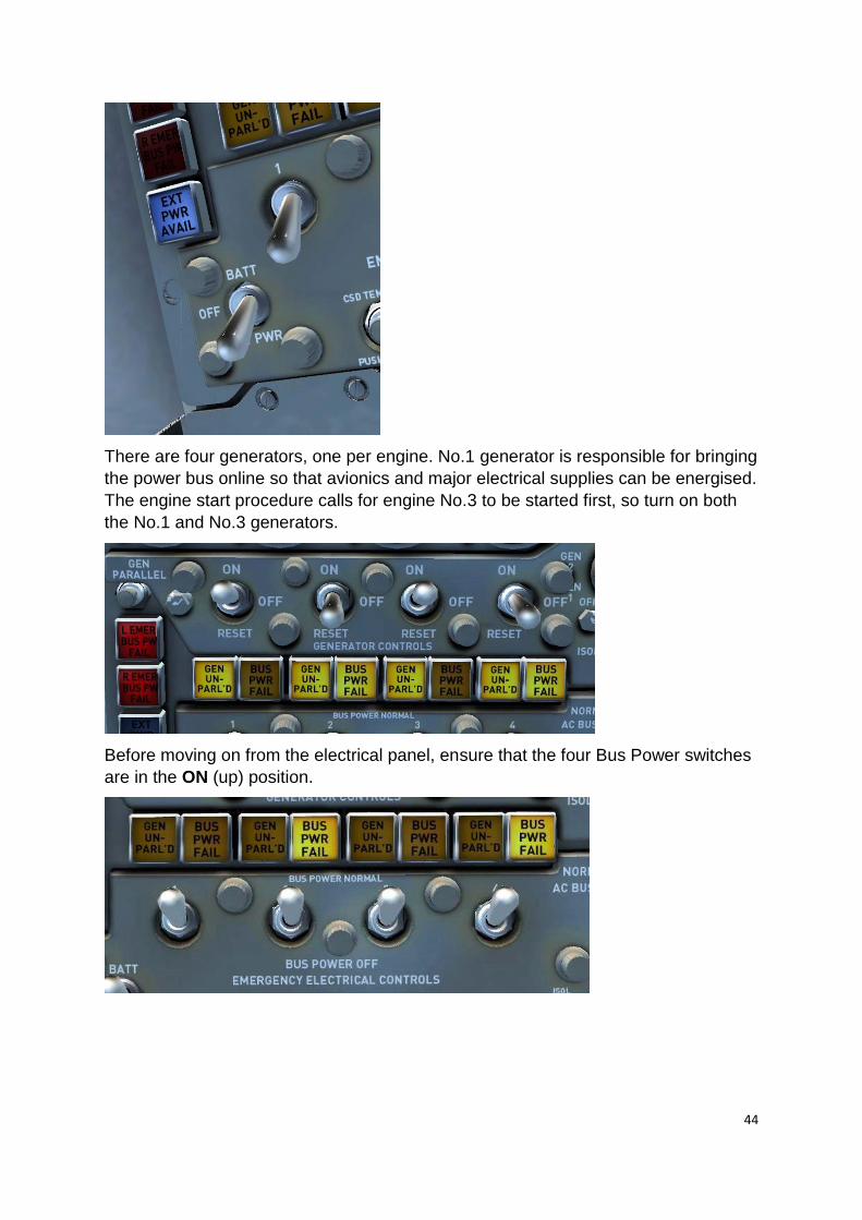
There are four generators, one per engine. No.1 generator is responsible for bringing
the power bus online so that avionics and major electrical supplies can be energised.
The engine start procedure calls for engine No.3 to be started first, so turn on both
the No.1 and No.3 generators.
Before moving on from the electrical panel, ensure that the four Bus Power switches
are in the ON (up) position.
45
Move across to the top right of the Engineer’s panel. Open the red safety cover, move the FLIGHT RECORD switch to the ON (up) position and then close the cover.
Now switch on the GALLEY PWR and set the monitoring switch to AUTO.
Before moving down the panel, test the engine fire and cargo smoke warning lights, using the four ENG FIRE WARN TEST switches and the SMOKE DETECT knob.
46
As you move down the panel, make sure that the hydraulic quantity (HYD QTY) needle is within the normal range.
Start the AUX HYD PUMP (auxiliary hydraulic pump) and ensure that the hydraulic pressure rises.
Switch off the auxiliary hydraulic pump before moving on to the engine management panel, checking that the engine oil quantity for each of the four engines is at its maximum value.
47
On the large fuel panel, verify that you have sufficient fuel for this flight.
Proceeding up the left-hand side of the panel, move the four CABIN COMPRESSOR switches to the ON position. Check that the needles on the corresponding gauges, located above the switches, rise but remain below the red marker lines.
Finally, move the three RECIRCULATING FANS switches to the ON/AUTO position and the two FREON COMPRESSORS to the NORM position.
48
We now need to focus on the overhead panel, so press the [A] key to cycle through the viewpoints until you reach ‘Overhead Panel’. Switch ON the PROBE HEATERS and check that the PITOT AMPS needle rises.
On the right side of the panel, make sure that the EMER (emergency) LIGHTS are set to ARM and both the FASTEN SEATBELTS and NO SMOKING switches are set to ON.
Switch ON the position and beacon lights.
The final checklist items prior to engine start relate to navigation following departure. Toggle the NAV/GPS switch to GPS. This will allow us to hold the GPS flight plan with the autopilot.
49
On the HSI (Horizontal Situation Indicator), rotate the HDG bug to 174 degrees. This will be our initial heading following take-off.
To adjust the HDG bug more easily, you might need to toggle the yoke visibility. To do this, click on the PITCH TRIM COMP switch located to the right of the Captain’s knee.
Finally, tune the frequency of the first waypoint on our route (CVE VOR – 116.20)
into the NAV 1 radio. We will make a turn towards the VOR before commanding the
autopilot to maintain our GPS flight plan.
50
Starting the engines
Before starting the engines we need to secure the aircraft. Request the jetway to disconnect by pressing [Ctrl]+[J] and then press [Shift]+[E] and [Shift]+[E]+[2] to close the doors.
Moving over to the fuel subpanel on the Engineer’s station, confirm that:
The engine 1, 2, 3 and 4 tank levers are in the MAIN (up) position.
The four crossfeed levers are in the NORMAL (up) position.
The fill valve switches are all set to OFF.
The main tank boost pump switches are all set to BOOST & FEED (up).
This configuration will allow fuel to flow from each of the main tanks to their
corresponding engines during start, taxi, take-off and climb.
To enable the engine start buttons, rotate the ignition arming knob to the ARMED
position and switch ON the ignition over-ride switch.
Push the engine No.3 start switch in. When the engine begins to spool up, ensure
that the engine No.3 fuel shut-off lever (located aft of the throttle levers) is set to ON.
Once the engine has started, return the engine No.3 start switch to the OFF (out)
position.
51
Moving the power switch on the Engineer’s panel to the BATT (up) position with
another left mouse-click will bring the internal battery supply online.
Rotate the VOLT & FREQ knob to the BATT position and verify that the battery is
supplying voltage.
Now start engines 4, 2 and then 1 using the same procedure as before.
Once all four engines have been successfully started, switch OFF the ignition over-
ride switch and rotate the ignition arming knob to the OFF position.
On the Engineer’s panel, switch ON generators 2 and 4.
52
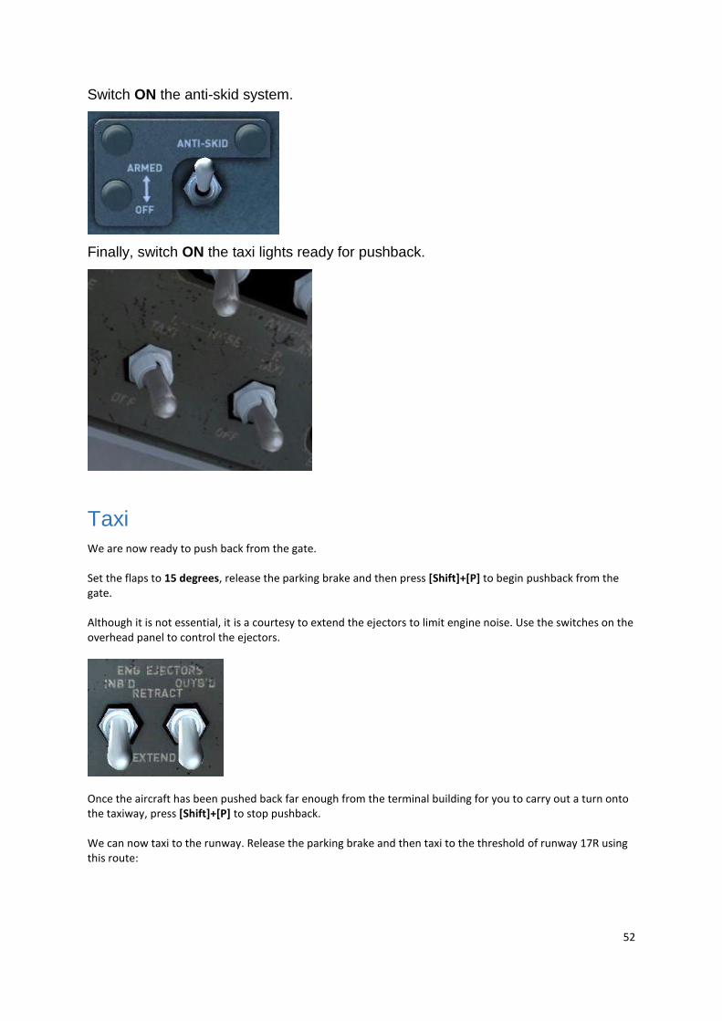
Switch ON the anti-skid system.
Finally, switch ON the taxi lights ready for pushback.
Taxi
We are now ready to push back from the gate. Set the flaps to 15 degrees, release the parking brake and then press [Shift]+[P] to begin pushback from the gate. Although it is not essential, it is a courtesy to extend the ejectors to limit engine noise. Use the switches on the overhead panel to control the ejectors.
Once the aircraft has been pushed back far enough from the terminal building for you to carry out a turn onto the taxiway, press [Shift]+[P] to stop pushback. We can now taxi to the runway. Release the parking brake and then taxi to the threshold of runway 17R using this route:
53
Take-off
Having received clearance for take-off, taxi onto the runway and switch ON the
landing lights. Retract both the inboard and outboard ejectors.
Line up with the runway centre line and then come to a stop. Bring the throttle levers forward to around 25%, check that the engines are stable using the engine instrument gauges and then advance the throttles to apply full power. As the aircraft starts to gather speed, keep it running down the centre line with small rudder inputs. As you approach 140 knots start to raise the nose of the aircraft. Slowly bring the nose up to approximately 10 degrees as you lift off the runway. The aircraft will begin to climb away from the runway and you should be clear of the ground by the time you reach 160 knots. Raise the undercarriage using the [G] key and adjust the elevator trim as required to maintain a 15-degree pitch, manually holding the runway heading (174 degrees).
54
Passing through 185 knots, retract flaps to 10 degrees then retract them fully as you
pass 215 knots.
Reduce power and maintain 220 knots indicated. Climb at approximately 1,500 feet per minute by adjusting power and climb rate.
We can now engage the autopilot to maintain the climb. Engage the autopilot by
moving the servo lever to the AUTOPILOT position. The autopilot will maintain the
aircraft’s current pitch and hold wings level.
55
Rotate the ALTITUDE knob to the VERT HOLD position and then rotate the VERT
SPEED wheel to select +2500 (feet per minute). Finally, rotate the AP SELECT
knob to the HDG position. The autopilot will now maintain the heading selected using
the HSI bug (174 degrees).
Now rotate the HSI bug to make a turn towards the CVE VOR that we tuned in
before departure. Use the RMI pointer to judge what heading is required.
56
Once the aircraft has stabilised on a direct course towards the VOR, rotate the AP
SELECT knob to select navigation hold mode (LOC/VOR). The aircraft will turn to
intercept your GPS flight plan to Kansas City.
When the aircraft has finished intercepting the course, which can be verified by
checking the GPS, increase your speed from 220 knots to 250 knots.
Passing through 10,000ft, switch off the landing lights and increase your speed to 280 knots.
Cruise
We should reach our cruising altitude somewhere north of Dallas. As you begin to approach the cruise altitude (25,000ft), use the vert speed wheel to gradually reduce the rate of climb. On reaching 25,000 feet, reduce the vertical speed to 0ft/min (level flight). Allow the aircraft to accelerate before adjusting power to maintain 280 knots. Turn OFF the No Smoking and Seatbelt signs, and monitor and balance the fuel load by referring to the fuel sequence in the cockpit guide section of this manual.
Whilst in the cruise, take some time to explore the cockpit further and review the
functionality covered in the COCKPIT GUIDE of this manual.
57
Descent
As you approach approximately 80 nautical miles from your destination (KMCI), as displayed on the GPS unit, you should begin your descent. Reduce your airspeed to 250 knots and then use the vert speed wheel to select a vertical speed of -1,500ft/min.
To reduce the workload on approach, we will tune the ILS frequency and select the course for runway 01L at Kansas City now. Using the CRS knob on the HSI, select a course of 009 degrees. As GPS mode is currently selected, the selected course won’t be shown on the HSI itself, but it will become visible when we switch back to NAV mode.
Now tune the ILS frequency (110.50) into the NAV1 radio. You will need to select the frequency on the STBY box before using the ACT/STBY switch to flip it over to the ACTIVE box.
58
Finally, rotate the flight director mode knob to the V/L position to display guidance for the localiser. As you pass through 18,000 feet, turn ON the No Smoking and Seatbelt signs.
Approach
You should reach 10,000ft approximately 20 miles south of the DOTTE NDB (DO) waypoint. Reduce your airspeed to 220 knots and initiate a descent to 3,500ft at -1,800ft/min. Spoilers are not used on the descent for normal flight, but reverse thrust is permitted for air braking on engines 3 and 4 only.
59
Extend the ejectors for engines 3 and 4 by using the INBD ENG INJECTORS switch on the overhead panel. Use the speed brake control lever or keyboard assignment for the spoilers to extend the reverser buckets. Use the system sparingly and always return to normal flight operation when the desired speed is reached. Note: For convenience, the ejectors can be extended and retracted using keystrokes. Inner ejectors can be operated using a keystroke for ‘Ballast Valve’ and the outer ejectors can be operated using a keystroke for ‘Water Rudder’. Both of these assignments can be set in the FSX Control Settings menu. As you approach 10nm from DOTTE NDB (DO), move the NAV/GPS switch to the NAV position. The aircraft will begin a shallow bank to intercept the localiser for runway 01L. The aircraft will stabilise on the localiser and continue descending towards 3,500ft. As the glideslope needle on the attitude indicator and HSI moves up the gauge and reaches the central position, rotate the AP SELECT knob to select GS AUTO (approach) mode.
If you are slightly below the glideslope, use the vertical speed wheel to reduce your rate of descent to intercept it. After a short time, you should stabilise with a descent rate of approximately -800ft/min. Once stable on the approach, begin slowing to your approach speed of 150 knots. Set the flaps to 15 degrees as you slow through 215 knots and 25 degrees at 205 knots indicated. Lower your landing gear as you pass through 190 knots. Extend the landing light pods using [Shift]+[E]+[3] and turn on the landing lights once you are on final approach. On reaching 500ft, as indicated on the radio altimeter, disengage the autopilot and hand-fly the remainder of the approach, making use of the PAPI lights to remain on the glideslope.
60
Landing
As you pass over the runway threshold, retard the throttle levers to idle to achieve a
touchdown speed of approximately 135 knots.
As the nose-gear touches down, apply reverse thrust and extend the ground spoilers
using the speedbrake lever or keyboard assignment.
As you slow to below 80 knots, disengage reverse thrust and slow the aircraft to 20
knots before exiting the runway.
Retract the flaps and ejectors, and lower the spoilers once you have vacated the
runway. Switch OFF your landing lights and switch ON your taxi lights before taxiing
to the nearest available gate.
Once you have reached the gate and set the parking brakes, switch OFF your taxi
lights, move the four fuel shut-off levers just aft of the throttle levers to the OFF
position and set the beacon light switch on the overhead panel to OFF.
On the Engineer’s panel, move the engine 1, 2, 3 and 4 tank levers to the OFF (down) position and switch OFF the boost pump switches.
Release the passengers from their seats by switching OFF the Seatbelt signs.
61
On the overhead panel, press the ATTENDANT CALL and MECH CALL buttons to enable the ground equipment.
Finally, request the jetway and then open the passenger and cargo doors using [Ctrl]+[J], [Shift]+[E] and [Shift]+[E]+[2]. Congratulations – you have completed the DC-8 tutorial flight!
FUEL DUMP The DC-8’s fuel dump system is replicated in this simulation. You must first extend the nozzles below each wing by using the crank at the end of the Flight Engineer’s desk, then you can use the dump activation switch on the overhead panel. Fuel dumping is rapid so remember to turn it off once fuel reaches the required level! You must use the master switch on the overhead panel to stop the fuel dump prior to cranking up the dump nozzles.
62
CHECKLISTS
The following checklists are also available in the DC-8 kneeboard.
Before start PARKING BRAKE SET BATTERY SWITCH EXTERNAL POWER BATTERY VOLTAGE CHECKED HYDRAULIC QUANTITY CHECKED
63
AUXILIARY HYDRAULIC PUMP START AUTOPILOT CHECKED/ OFF STABILISER TRIM CHECKED AUX HYD PUMP PRESSURE CHECKED AUX HYD PUMP OFF OIL QUANTITY CHECKED FUEL LOAD CHECKED FIRE WARNING CHECKED W/S HEAT WARM UP COCKPIT INST LIGHTS SET PITOT HEAT CHECKED/OFF CABIN SIGNS ON IGNITION OFF START SELECTOR SWITCH OFF EMERGENCY EXIT LIGHTS ARMED/LIGHT OUT CAPT'S FLT INST & WARNING LIGHTS PUSH/TEST CAPT'S ALTIMETER CHECKED CAPT'S RADIO ALTIMETER CHECKED ADFs CHECKED/SET TRANSPONDER STANDBY MARKER BEACON ON EMERGENCY AIR BRAKE HANDLE SAFETIED/OFF STATIC SELECTORS NORMAL ANTI-SKID SWITCH CHECKED/OFF ENG INST & WARNING LIGHTS CHECKED
64
REVERSER LIGHTS TEST SPOILER LEVER RETRACTED/OFF POWER LEVERS IDLE FUEL SHUT-OFF LEVERS OFF WEATHER RADAR (WHERE FITTED) STANDBY RUDDER/AILERON TRIM CHECKED FO FLT INST & WARNING LIGHTS CHECKED FO ALTIMETER SET/CHECKED FO RADIO ALTIMETER SET/CHECKED FO RAIN REMOVAL OFF FO NAV/RADIO SWITCH RADIO EMERGENCY LIGHTS ARMED COMPASSES SYNCED & CROSS-
CHECKED HYDRAULIC PRESSURE & QUANTITY CHECKED HYDRAULIC SYSTEM SELECTOR NORMAL CABIN PRESSURISATION SET & AUTO
Start FUEL SYSTEM MAIN TANKS, CROSSFEED OFF, PUMPS ON STABILISER & TRIM TABS SET PARKING BRAKE SET START ARM SW ARMED MASTER IGNITION OVERRIDE SET ANTI-COLLISION LIGHTS ON
65
GALLEY POWER OFF START SW PER ENGINE PULL (RETURN AFTER
ENGINE STARTS) FUEL SHUT-OFF LEVERS PER ENGINE ON RAIN REMOVAL LEVER CHECKED ELECTRICAL SYSTEM CHECKED HYDRAULIC SYSTEM CHECKED COCKPIT HEAT AS REQUIRED ENGINE GAUGES CHECKED NORMAL BATTERY SWITCH BATTERY
Taxi FLIGHT CONTROLS CHECKED ANTI-ICE & DE-ICE AS REQUIRED PITOT HEAT ON/WARN LIGHTS OUT OAT CHECKED YAW DAMPER CHECKED STABILISER & TRIM TABS SET FLAPS AND SLOTS SET/CHECKED FLIGHT INSTRUMENTS/NAVs SET/CHECKED ALT/RADIO ALT SET/CHECKED FLIGHT RECORDER ON OBTAIN CLEARANCES AS REQUIRED
66
Before take-off TRANSPONDER SET ON ANTI-SKID ARMED EXTERIOR LIGHTS ON FLAPS SET/CHECKED AUTOPILOT CHECK/OFF AUTOTHROTTLE CHECK/OFF
Take-off [H2] THROTTLES 80% N2 PARKING BRAKE RELEASED THROTTLES 100% V1, V2 AS DIRECTED
Climb GEAR UP (ABOVE 120 KIAS) FLAPS & SLOTS UP CABIN SIGNS AS REQUIRED FUEL MANAGEMENT CHECKED/SET GALLEY POWER ON CABIN CHIME – 10,000 FT 3 CHIMES EXTERIOR LIGHTS AS REQUIRED
67
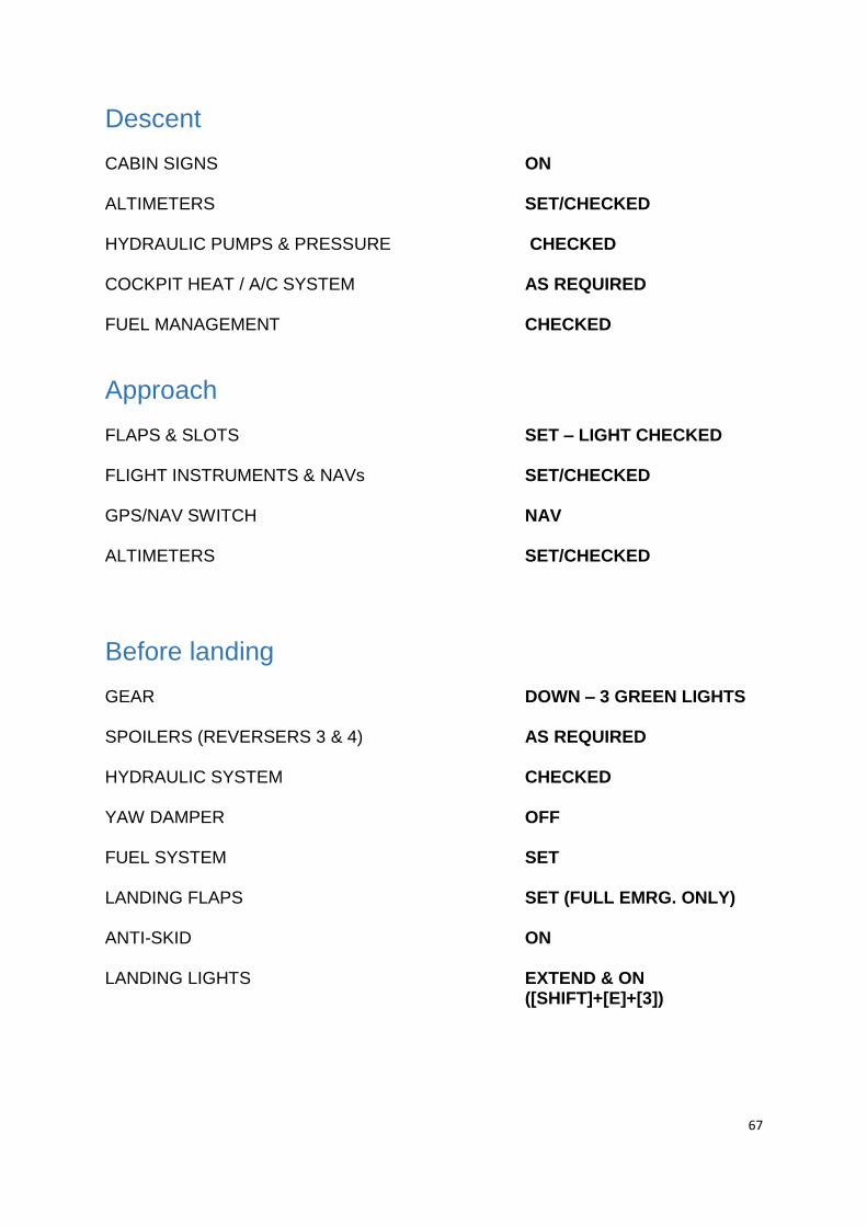
Descent CABIN SIGNS ON ALTIMETERS SET/CHECKED HYDRAULIC PUMPS & PRESSURE CHECKED COCKPIT HEAT / A/C SYSTEM AS REQUIRED FUEL MANAGEMENT CHECKED
Approach FLAPS & SLOTS SET – LIGHT CHECKED FLIGHT INSTRUMENTS & NAVs SET/CHECKED GPS/NAV SWITCH NAV ALTIMETERS SET/CHECKED
Before landing GEAR DOWN – 3 GREEN LIGHTS SPOILERS (REVERSERS 3 & 4) AS REQUIRED HYDRAULIC SYSTEM CHECKED YAW DAMPER OFF FUEL SYSTEM SET LANDING FLAPS SET (FULL EMRG. ONLY) ANTI-SKID ON LANDING LIGHTS EXTEND & ON
([SHIFT]+[E]+[3])
68
After landing FLAPS & SPOILERS RETRACTED WINDSHIELD & PITOT HEAT OFF EXTERIOR LIGHTS AS REQUIRED BOOST PUMPS OFF GALLEY POWER/MAST HEAT OFF AUTOTHROTTLE OFF/CHECK
Parking PARKING BRAKE SET/ON LANDING/TAXI LIGHTS RETRACTED/OFF CABIN SIGNS OFF ANTI-COLLISION LIGHTS OFF STANDBY ATTITUDE INDICATOR CAGE RADIOS OFF COCKPIT HEAT / A/C SYSTEM OFF BATTERY SWITCH OFF/EXT PWR FLIGHT RECORDER OFF EMERGENCY EXIT LIGHTS OFF/CHECKED IGNITIONS OFF EXTERIOR LIGHTS OFF
69
Shutdown PARKING BRAKE SET/ON THROTTLES IDLE FUEL CUT-OFF LEVERS PER ENGINE OFF IGNITION MASTER AND ENGINE SEL OFF/DISABLED FUEL SYSTEM TANKS OFF, CROSSFEED OFF, PUMPS OFF
70
CREDITS Models and textures – Aeroplane Heaven Cockpit coding – Aeroplane Heaven, Martyn Northall Liveries – Dave Sweetman Flight dynamics – Wayne Tudor Sounds – Turbine Sound Studios Project Management – Martyn Northall, Alex Ford Installer – Martin Wright Design – Fink Creative