1 DC Axial Flow Fans with Low-Speed Alarm MDA Series This series features a built-in alarm circuit that the host controller can recognize if the fan speed drops. This is important for noticing quick drops in the cooling capacity of the fan caused by a service life of the fan or by the ingress of a foreign objects. Features " The Low-Speed Alarm: $ $ An alarm is output when the fan speed drops to 70% or less. Rated speed Low-Speed Alarm Signal No Alarm Output Low-Speed Alarm Output Host Controller Alarm Output Speed 70% max. Easy-to-Connect Fan Types are also Available. $ $ We have a cable with a connector for easy connection in addition to the standard lead wire type. The connector type fan can reduce wiring. Maintenance is also very easy because the fans can be replaced just by disconnecting the connector. All Necessary Items for Installation are Included. $ $ The finger guard, cable with connector (connector type only) and mounting screws are included, so they can be used immediately. Fan Cable with Connector (Included) Mounting Screws (Included) Finger Guard (Included)
Transcript
1
DC Axial Flow Fans with Low-Speed Alarm
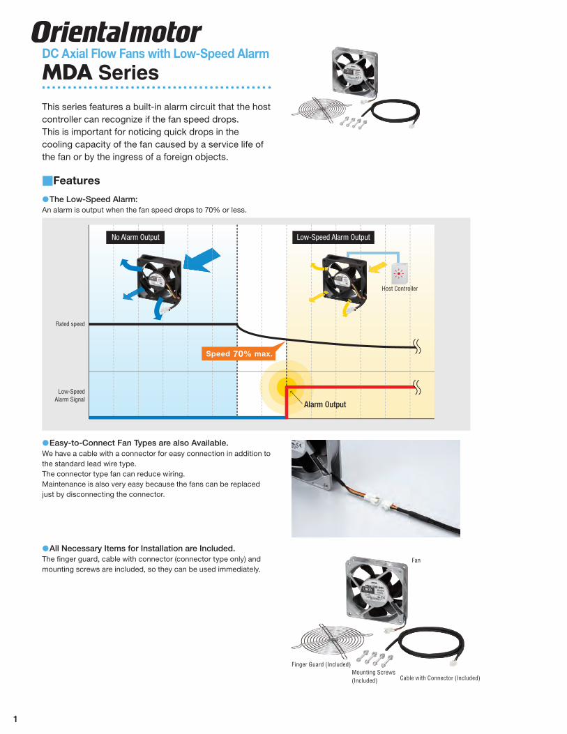
MDA SeriesThis series features a built-in alarm circuit that the host controller can recognize if the fan speed drops.This is important for noticing quick drops in the cooling capacity of the fan caused by a service life of the fan or by the ingress of a foreign objects.
Features"
The Low-Speed Alarm:$$An alarm is output when the fan speed drops to 70% or less.
Rated speed
Low-SpeedAlarm Signal
No Alarm Output Low-Speed Alarm Output
Host Controller
Alarm Output
Speed 70% max.
Easy-to-Connect Fan Types are also Available.$$We have a cable with a connector for easy connection in addition to the standard lead wire type. The connector type fan can reduce wiring.Maintenance is also very easy because the fans can be replaced just by disconnecting the connector.
All Necessary Items for Installation are Included. $$The finger guard, cable with connector (connector type only) and mounting screws are included, so they can be used immediately.
Fan
Cable with Connector (Included)Mounting Screws(Included)
Finger Guard (Included)
2
Contributes to Increased Reliability of Equipment.$$If you use the MDA Series:An alarm is output when the fan speed drops due to the service life of the fan or the ingress of foreign objects.This makes it possible to order and replace the fan before it stops.Even if the cooling capacity of the fan decreases, the effect of that on the equipment can be minimized.
Fan Arrangementand Replacement
Alarm Output
When fan speed drops
Host Controller
If a fan with low-speed alarm is not used:
If the drop in fan speed is left unaddressed, it will lead to a rise in the temperature inside the equipment. This will then affect the equipment.
Fan Stops
Heatgeneration!
Use the MDA Series in the Following Scenario.
When a Spare Fan is Installed$$ When Multiple Fans are Installed$$
Spare FanSince multiple fans are installed, you cannot identify which fan is failing when the cooling capacity decreases.This leads to the replacement of all fans.
AlarmOutput
Host Controller
A spare fan is installed in case the cooling capacity decreases.
An alarm is output when the fan speed drops. As a result, no spare fan needs to be installed.
Lineup■■
MDA Series Power Supply VoltageFrame Size [mm (in.)]
M140 (M5.51)
M119 (M4.69)
M92 (M3.62)
M80 (M3.15)
M62 (M2.44)
Lead wireConnector
12 VDC $ $ $ $24 VDC $ $ $ $ $48 VDC $
If MDA Series is Used:
If MDA Series is Used:
You can identify which fan is failing because an alarm is output. As a result, only the fan with low speed can be replaced.
3
General Specifications■■
Item Specifications
Insulation Resistance10 MV or more when 250 VDC megger (MDA1451: 500 VDC megger) is applied between the windings and the frame after continuous operation under normal ambient temperature and humidity.
Dielectric StrengthSufficient to withstand 500 V at 50 Hz applied between the windings and the frame for 1 minute after continuous operation under normal ambient temperature and humidity.
Temperature Rise10ºC (18°F) or less measured by the thermometer method after the temperature of the case has stabilized after continuous operation under normal ambient temperature and humidity. (MDA1451: 15˚C [27°F] or less)
Operating Voltage Rangew15% of the rated voltage MDA1225: w10% of the rated voltage
Thermal Class UL/CSA standards: 105 (A), EN standards: 120 (E)Overheat Protection Built-in overheat protection circuitAmbient Temperature s10pr60˚C (r14pr140°F)Ambient Humidity 85% or less (non-condensing)
Color Frame: Black: MDA925, MDA825, MDA625
Unpainted (Aluminum): MDA1451, MDA1225Blades: Black
MaterialsFan Frame: Die cast aluminum: MDA1451, MDA1225
The alarm specifications vary depending on the type of alarm.Check the alarm specifications according to the model name you use.Specifications can also be referred to by the alarm specifications number shown on the specifications for each product.
An alarm is output when the fan speed drops to a specific level. Output mode is electronic output.Alarm
Specifications Number
R
0 VGND
●Models ◇MDA Series: MDA1451-□(H)G
●Alarm Speci�cations ●Example of Alarm Circuit Connection
Yellow
Black
Fan Customer's Circuit
←
30 VDC max.15 mA
max.
Alarm Activation SpeedOutput Mode
Output Condition
Maximum Rating
Delay Function
1800±400 r/minOpen-Collector Output
Normal Operation: L Level (Internal transistor ON)Alarm Output: H Level (Internal transistor OFF)
Maximum Applied Voltage: 30 VDC max.Maximum Inflow Current: 15 mA max.
Built-In Starting Delay Time: 10 sec. max.(The alarm function starts monitoring within 10 sec. after the power is turned on.)
a
Alarm Specifications
Number
R
0 VGND
●Models ◇MDA Series: MDA1225-□(H)G
●Alarm Speci�cations ●Example of Alarm Circuit Connection
Yellow
Black
Fan Customer's Circuit
←
30 VDC max.15 mA
max.
Alarm Activation SpeedOutput Mode
Output Condition
Maximum Rating
Delay Function
2100±400 r/minOpen-Collector Output
Normal Operation: L Level (Internal transistor ON)Alarm Output: H Level (Internal transistor OFF)
Maximum Applied Voltage: 30 VDC max.Maximum Inflow Current: 15 mA max.
Built-In Starting Delay Time: 10 sec. max.(The alarm function starts monitoring within 10 sec. after the power is turned on.)
With Alarm#Operating Voltage Range: w15% (Applies to each voltage)Materials Frame: Die cast aluminum Blades: Polycarbonate (Flammability grade V-0)Overheat Protection: Built-in overheat protection circuitBearings: Ball bearings
Specifications "
FunctionModel Voltage
VDCCurrent
ASpeedr/min
Max. Air Flow Max. Static Pressure Noise LeveldB (A)Lead Wire Type Connector Type m3/min CFM Pa inH2O
Low-Speed Alarm, Electronic Alarm Type<Alarm Specifications: a>
Air Flow" – Static Pressure Characteristics (Characteristics when a finger guard is not installed)
140
160
180
200
120
100
80
60
40
20
01.0 2.0 7.05.0 6.04.03.0
Stat
ic P
ress
ure
[Pa]
0
400
1200
1600
2000
2400
2800
3200
3600
4000
800
Spee
d [r
/min
]
0
0.1
0.3
0.4
0.5
0.6
0.7
0.8
0.2
Stat
ic P
ress
ure
[inH2
O]
Air Flow [m3/min]
0 50 100 150 200Air Flow [CFM]
Speed
Static Pressure
Dimensions" Unit = mm (in.)
Lead Wire Type$$Mass: 0.65 kg (1.43 lb.)
E109
124.5±0.5 (4.90±0.02)
124.
5±0.
5 ( 4.90±
0.02
)
8×ϕ4.3(ϕ0.169)
140
( 5.51)
51 (2.01)6 (0.24)300 (12)
10 (0.39)
140 (5.51)
UL Style 3385, AWG24
6 (0.24)
Rotation Direction
Air Flow
Protective Earth TerminalM4
The following items are included in each product.
Fan, Finger Guard, Cable with Connector✽, Mounting Screws (M4×70 mm (2.76 in)), Operating ManualConnector Type only✽✽
6
Connector Type$$Fan$◇
Mass: 0.65 kg (1.43 lb.) E117
140
( 5.51)
124.
5±0.
5 ( 4.90±
0.02
)
51 (2.01)6 (0.24) 6 (0.24)
140 (5.51)124.5±0.5 (4.90±0.02)
100 (4)
8×ϕ4.3 (ϕ0.169)
Air Flow
Housing:SMR-03V-N (J.S.T.)
RotationDirection
Protective Earth TerminalM4UL Style 3385,
AWG24
Cable with Connector (Included)$◇1000 (39.37)
ϕ4.8 (ϕ0.19)
Housing: SMP-03V-NC (J.S.T.)
Core Wires AWG22
Finger Guard (Included, common to lead wire type and $$connector type)
Conformed Component for Safety StandardsMass: 64 g (2.3 oz.)
E0525 (0.20)
178(7.01)
4.3 (0.169)
146 (5
.75)
134 (5.28)
Panel Cut-Out" Unit = mm (in.)
4×ϕ4.5(ϕ0.177)
ϕ147
(ϕ5.79)
138 (5.43)124.5 (4.90)
138
( 5.43)
124.
5 ( 4.90)
Outlet Side/Intake Side
Connection Diagrams"
Lead Wire Type$$
GND+
PE
BlackYellow
Red
Alarm Output
24 VDC or 48 VDC
Connector Type$$
GND
+RedYellow
Black
24 VDC or 48 VDC
Alarm Output
Cable with Connector
PE
Accessories"Product Model
Finger Guard FG14DFilter FL14
When installing a finger guard on both sides, please purchase one additional accessory finger $$guard.For detailed accessories information see Oriental Motor General Catalog or visit $$www.orientalmotor.com.
7
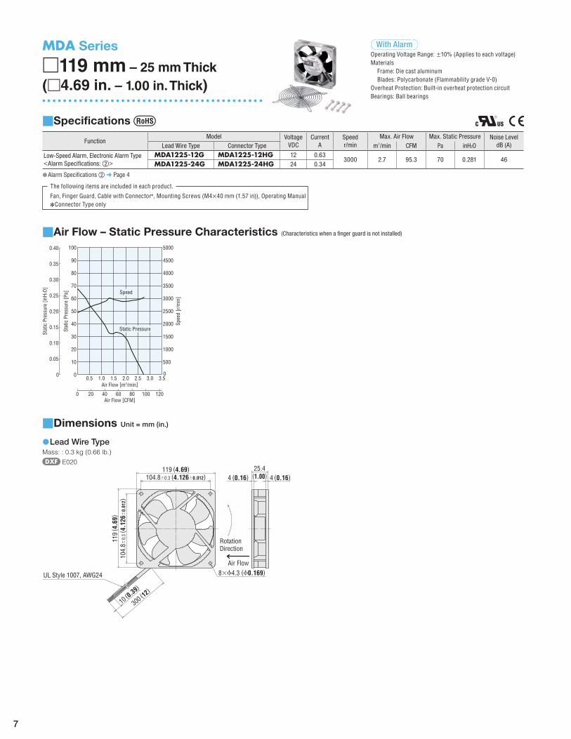
MDA Series
M119 mm – 25 mm Thick(M4.69 in. – 1.00 in. Thick)
With Alarm#Operating Voltage Range: w10% (Applies to each voltage)Materials Frame: Die cast aluminum Blades: Polycarbonate (Flammability grade V-0)Overheat Protection: Built-in overheat protection circuitBearings: Ball bearings
Specifications "
FunctionModel Voltage
VDCCurrent
ASpeedr/min
Max. Air Flow Max. Static Pressure Noise LeveldB (A)Lead Wire Type Connector Type m3/min CFM Pa inH2O
Air Flow" – Static Pressure Characteristics (Characteristics when a finger guard is not installed)
70
80
90
100
60
50
40
30
20
10
00.5 1.0 3.52.5 3.02.01.5
0
500
1500
2000
2500
3000
3500
4000
4500
5000
1000
Spee
d [r
/min
]
Air Flow [m3/min]
0 4020 60 80 100 120Air Flow [CFM]
Stat
ic P
ress
ure
[Pa]
0
0.05
0.15
0.20
0.25
0.30
0.35
0.40
0.10
Stat
ic P
ress
ure
[inH2
O] Speed
Static Pressure
Dimensions" Unit = mm (in.)
Lead Wire Type$$Mass: : 0.3 kg (0.66 lb.)
E020
104.8±0.3 (4.126±0.012)
104.
8±0.
3 ( 4.126
±0.01
2)
8×ϕ4.3 (ϕ0.169)
119 (4.69)
119
( 4.69)
10 (0.39
)
300 (12)
25.4(1.00)4 (0.16) 4 (0.16)
UL Style 1007, AWG24
Air Flow
Rotation Direction
The following items are included in each product.
Fan, Finger Guard, Cable with Connector✽, Mounting Screws (M4×40 mm (1.57 in)), Operating ManualConnector Type only✽✽
8
Connector Type$$Fan$◇
50 (2)
119
( 4.69)
25.4(1.00)4 (0.16) 4 (0.16)
119 (4.69)104.8±0.3 (4.126±0.012)
104.
8±0.
3 ( 4.126
±0.01
2)
8×ϕ4.3 (ϕ0.169)
Housing: SMR-04V-N (J.S.T.)
Air Flow
Rotation Direction
UL Style 1007,AWG24
Cable with Connector (Included)$◇1000 (39.37)
ϕ4.8 (ϕ0.19)
Housing: SMP-03V-NC (J.S.T.)
Core Wires AWG22
Finger Guard (Included, common to lead wire type and $$connector type)
Conformed Component for Safety StandardsMass: 45 g (1.59 oz.)
E051
150 (5.91)
115 (4.53)
4.3 (0.169)
5 (0.20)
Panel Cut-Out" Unit = mm (in.)
116 (4.57
)
104.8 (4.126)116 (4.57)
104.
8 ( 4.126
)11
6 ( 4.57)
104.8 (4.126)
104.
8 ( 4.126
)
Outlet Side Intake Side
4×ϕ4.5 (ϕ0.177)
4×ϕ4.5 (ϕ0.177)
ϕ136 (ϕ5.3
5)
Connection Diagrams"
Lead Wire Type$$
GND+
BlackYellow
Red
Alarm Output
12 VDC or 24 VDC
Connector Type$$
GND
+Red
Yellow
Black
Alarm Output
12 VDC or 24 VDC
Cable with Connector
Accessories"Product Model
Finger Guard FG12DFilter FL12
Screen FS12SWhen installing a finger guard on both sides, please purchase one additional accessory finger $$guard.For detailed accessories information see Oriental Motor General Catalog or visit $$www.orientalmotor.com.
9
MDA Series
M92 mm – 25 mm Thick(M3.62 in. – 1.00 in. Thick)
With Alarm#Operating Voltage Range: w15% (Applies to each voltage)Materials Frame: Polycarbonate (Flammability grade V-0) Blades: Polycarbonate (Flammability grade V-0)Overheat Protection: Built-in overheat protection circuitBearings: Ball bearings
Specifications "
FunctionModel Voltage
VDCCurrent
ASpeedr/min
Max. Air Flow Max. Static Pressure Noise LeveldB (A)Lead Wire Type Connector Type m3/min CFM Pa inH2O
Air Flow" – Static Pressure Characteristics (Characteristics when a finger guard is not installed)
70
80
90
100
60
50
40
30
20
10
01.61.0 1.2 1.40.80.60.40.2
0
500
1500
2000
2500
3000
3500
4000
4500
5000
1000
Spee
d [r
/min
]
Air Flow [m3/min]
0 10 20 30 40 50Air Flow [CFM]
Stat
ic P
ress
ure
[Pa]
0
0.05
0.15
0.20
0.25
0.30
0.35
0.40
0.10
Stat
ic P
ress
ure
[inH2
O]
Speed
Static Pressure
Dimensions" Unit = mm (in.)
Lead Wire Type$$Mass: 0.12 kg (0.26 lb.)
E022
82.5±0.3 (3.248±0.012)
82.5
±0.
3 ( 3.248
±0.01
2)
4×ϕ4.3 (ϕ0.169)
92 (3.62)
92 ( 3
.62)
10 (0.39
)
300 (12)
25.4(1.00)
UL Style 1007, AWG24
Rotation Direction Air Flow
The following items are included in each product.
Fan, Finger Guard, Cable with Connector✽, Mounting Screws (M4×40 mm (1.57 in)), Operating ManualConnector Type only✽✽
Alarm Specifications $$ c ➜ Page 4
10
Connector Type$$Fan$◇
Mass: 0.12 kg (0.26 lb.) E121
92 ( 3
.62)
92 (3.62)82.5±0.3 (3.248±0.012)
82.5
±0.
3 ( 3.248
±0.01
2)
50 (2)
4×ϕ4.3 (ϕ0.169)
25.4(1.00)
Housing: SMR-03V-N(J.S.T.)
Air FlowRotationDirection
UL Style 1007, AWG24
Cable with Connector (Included)$◇1000 (39.37)
ϕ4.8 (ϕ0.19)
Housing: SMP-03V-NC (J.S.T.)
Core Wires AWG22
Finger Guard (Included, common to lead wire type and $$connector type)
Conformed Component for Safety StandardsMass: 28 g (0.99 oz.)
E049
118.6 (4.67)
84 (3.31)
5 (0.20)4.3 (0.169)
Panel Cut-Out" Unit = mm (in.)
90
(3.54
)
82.5 (3.248)90 (3.54)
82.5
( 3.248
)90
( 3.54)
82.5 (3.248)
82.5
( 3.248
)
Outlet Side Intake Side
4×ϕ4.5(ϕ0.177)
4×ϕ4.5(ϕ0.177)
ϕ106
(ϕ4.17
)
Connection Diagrams"
Lead Wire Type$$
+GND
RedBlack
Yellow
12 VDC or 24 VDC
Alarm Output
Connector Type$$
GND
+RedYellow
Black
12 VDC or 24 VDC
Alarm Output
Cable with Connector
Accessories"Product Model
Finger Guard FG9DFilter FL9
Screen FS9SUse M3 screws to install the $$ FL9 filter to the fan frame.When installing a finger guard on both sides, please purchase one additional accessory finger $$guard.For detailed accessories information see Oriental Motor General Catalog or visit $$www.orientalmotor.com.
11
MDA Series
M80 mm – 25 mm Thick(M3.15 in. – 1.00 in. Thick)
With Alarm#Operating Voltage Range: w15% (Applies to each voltage)Materials Frame: Polycarbonate (Flammability grade V-0) Blades: Polycarbonate (Flammability grade V-0)Overheat Protection: Built-in overheat protection circuitBearings: Ball bearings
Specifications "
FunctionModel Voltage
VDCCurrent
ASpeedr/min
Max. Air Flow Max. Static Pressure Noise LeveldB (A)Lead Wire Type Connector Type m3/min CFM Pa inH2O
Air Flow" – Static Pressure Characteristics (Characteristics when a finger guard is not installed)
1.40.8 1.0 1.20.60.40.20
10
30
40
50
60
70
80
90
100
20
0
500
1500
2000
2500
3000
3500
4000
4500
5000
1000
Spee
d [r
/min
]
Air Flow [m3/min]
0 10 20 30 40Air Flow [CFM]
Stat
ic P
ress
ure
[Pa]
0
0.05
0.15
0.20
0.25
0.30
0.35
0.40
0.10
Stat
ic P
ress
ure
[inH2
O]
Speed
Static Pressure
Dimensions" Unit = mm (in.)
Lead Wire Type$$Mass: 0.11 kg (0.24 lb.)
E023
71.5±0.3 (2.815±0.012)
71.5±
0.3 ( 2
.815
±0.01
2)
4×ϕ4.3 (ϕ0.169)
80 (3.15)
80 ( 3
.15)
25.4(1.00)
10 (0.39
)
300 (12)
UL Style 1007, AWG24
Rotation Direction
Air Flow
The following items are included in each product.
Fan, Finger Guard, Cable with Connector✽, Mounting Screws (M4×40 mm (1.57 in)), Operating ManualConnector Type only✽✽
Alarm Specifications $$ c ➜ Page 4
12
Connector Type$$Fan$◇
Mass: 0.11 kg (0.24 lb.) E122
50 (2)
80 (3.15)71.5±0.3
(2.815±0.012)
80 ( 3
.15)
71.5
±0.
3
( 2.815
±0.01
2)
4×ϕ4.3 (ϕ0.169)
25.4
(1.00)
Housing: SMR-03V-N (J.S.T.)
Air FlowRotationDirection
UL Style 1007, AWG24
Cable with Connector (Included)$◇1000 (39.37)
ϕ4.8 (ϕ0.19)
Housing: SMP-03V-NC (J.S.T.)
Core Wires AWG22
Finger Guard (Included, common to lead wire type and $$connector type)
Conformed Component for Safety StandardsMass: 24 g (0.85 oz.)
E048
103.2 (4.06)
80 (3.15)
4.3 (0.169)
5 (0.20)
Panel Cut-Out" Unit = mm (in.)
78(3.0
7)ϕ91
(ϕ3.58
)
71.5 (2.815)
Outlet Side Intake Side
78 (3.07)
71.5
( 2.815
)78
( 3.07)
71.5 (2.815)
71.5
( 2.815
)
4×ϕ4.5(ϕ0.177)
4×ϕ4.5(ϕ0.177)
Connection Diagrams"
Lead Wire Type$$
+GND
RedBlack
Yellow
12 VDC or 24 VDC
Alarm Output
Connector Type$$
GND
+RedYellow
Black
12 VDC or 24 VDC
Alarm Output
Cable with Connector
Accessories"Product Model
Finger Guard FG8DFilter FL8
Screen FS8SWhen installing a finger guard on both sides, please purchase one additional accessory finger $$guard.For detailed accessories information see Oriental Motor General Catalog or visit $$www.orientalmotor.com.
13
MDA Series
M62 mm – 25 mm Thick(M2.44 in. – 1.00 in. Thick)
With Alarm#Operating Voltage Range: w15% (Applies to each voltage)Materials Frame: Polycarbonate (Flammability grade V-0) Blades: Polycarbonate (Flammability grade V-0)Overheat Protection: Built-in overheat protection circuitBearings: Ball bearings
Specifications "
FunctionModel Voltage
VDCCurrent
ASpeedr/min
Max. Air Flow Max. Static Pressure Noise LeveldB (A)Lead Wire Type Connector Type m3/min CFM Pa inH2O
Air Flow" – Static Pressure Characteristics (Characteristics when a finger guard is not installed)
60
70
80
90
50
40
30
20
10
6000
7000
8000
9000
5000
4000
3000
2000
1000
00.1 0.2 0.70.5 0.60.40.3
0
Air Flow [m3/min]
0 5 10 15 20Air Flow [CFM]
Stat
ic P
ress
ure
[Pa]
0
0.05
0.15
0.20
0.25
0.30
0.35
0.10
Spee
d [r
/min
]
Stat
ic P
ress
ure
[inH 2
O]
Speed
Static Pressure
Dimensions" Unit = mm (in.)
Lead Wire Type$$Mass: 0.1 kg (0.22 lb.)
E024
4×ϕ3.7 (ϕ0.146)
50±0.3
(1.969±0.012)
50±
0.3
( 1.969
±0.01
2)
25.4(1.00)
10 ( 0
.39)
300
( 12)
62 (2.44)
UL Style 1007, AWG24
Air Flow62 ( 2
.44)
RotationDirection
The following items are included in each product.
Fan, Finger Guard, Cable with Connector✽, Mounting Screws (M3×40 mm (1.57 in)), Operating ManualConnector Type only✽✽
14
Connector Type$$Fan$◇
Mass: 0.1 kg (0.22 lb.) E123
50 ( 2
)25.4
(1.00)
62 (2.44)50±0.3
(1.969±0.012)
62 ( 2
.44)
50±
0.3
( 1.969
±0.01
2)
4×ϕ3.7(ϕ0.146)
Housing: SMR-03V-N (J.S.T.)
Air FlowRotationDirection
UL Style 1007, AWG24
Cable with Connector (Included)$◇1000 (39.37)
ϕ4.8 (ϕ0.19)
Housing: SMP-03V-NC (J.S.T.)
Core Wires AWG22
Finger Guard (Included, common to lead wire type and $$connector type)
Conformed Component for Safety StandardsMass: 8.3 g (0.29 oz.)
E087
4.3 (0.169)4 (0.16)
50 (1.97)
72.7 (2.86)
Panel Cut-Out" Unit = mm (in.)
ϕ65
(ϕ2.56
)
4×ϕ3.5(ϕ0.138)
4×ϕ3.5(ϕ0.138)
60.5
(2.38)
50 (1.969)58 (2.28)
50 ( 1
.969
)58
( 2.28)
50 (1.969)
50 ( 1
.969
)
Outlet Side Intake Side
Connection Diagrams"
Lead Wire Type$$
+GND
RedBlack
Yellow
12 VDC or 24 VDC
Alarm Output
Connector Type$$
GND
+RedYellow
Black
12 VDC or 24 VDC
Alarm Output
Cable with Connector
Accessories"Product Model
Finger Guard FG6DFilter FL6
Screen FS6SWhen installing a finger guard on both sides, please purchase one additional accessory finger $$guard.For detailed accessories information see Oriental Motor General Catalog or visit $$www.orientalmotor.com.
Specifications are subject to change without notice.This catalog was published in February, 2012. #407


![· Web viewThere are other definitions of MDA; of particular note is that included in An MDA Manifesto [MDA Manifesto] as published by the MDA Journal: “In essence, the foundations](https://static.documents.pub/doc/80x56/5b2adca07f8b9afd328b48f5/-web-viewthere-are-other-definitions-of-mda-of-particular-note-is-that-included.jpg)


![UML and MDA for Transactional Level Modeling - …1].pdf · UML and MDA for Transactional Level Modeling S. Bocchio, ... UML and MDA for TLM 6 ... executable. UML and MDA for TLM](https://static.documents.pub/doc/80x56/5b64578d7f8b9a687e8d318d/uml-and-mda-for-transactional-level-modeling-1pdf-uml-and-mda-for-transactional.jpg)
