165 2016-01 Speed signal 168 Alarm signal 172 Vario-Pro / Speed setting / Control input 177 Protected fans, degree of protection: IP 54 / IP 68 181 DC fans - specials Information DC axial fans DC fans - specials ACmaxx / EC fans AC axial fans Accessories Representatives DC centrifugal fans AC centrifugal fans
Transcript
165
2016
-01
Speed signal 168Alarm signal 172Vario-Pro / Speed setting / Control input 177Protected fans, degree of protection: IP 54 / IP 68 181
DC fans - specials
Info
rmat
ion
DC a
xial
fans
DC fa
ns -
spe
cial
sAC
max
x / E
C fa
nsAC
axi
al fa
nsAc
cess
orie
sRe
pres
enta
tives
DC c
entr
ifuga
l fan
sAC
cen
trifu
gal f
ans
166
2016
-01
Cooling capacity and efficiencyGreater power density, increasing miniaturization and extreme electroniccomponent density are placing increased demands on the coolingcapacity and efficiency of fans. Therefore, intelligent and space-savingintegration of the fan in the device configuration is very important:
• Tailor-made cooling adapted to the situation as and when required.
• Programmable cooling by defining speed profiles.
• Transparency of function thanks to complete, interactive monitoring inall operating conditions.
Standard fans in electronics cooling have proven themselves a milliontimes over.
With a constant speed and an appropriate sound level, they continuouslyprovide the air flow required for extreme cases. But these extremesituations occur seldom – if at all – during operation. What is needed isan intelligent fan that adapts automatically to the level of cooling requiredat the time.
ebm-papst provides intelligent cooling concepts that are optimallyadapted to practical requirements. For example:
1. Speed adjustment via temperature sensorebm-papst answers with a complete range of DC fans with temperature-controlled speed adjustment via a temperature sensor, available in avariety of standard dimensions.
Installation is very simple. Either an external temperature sensor in theform of an exposed wire that can be placed anywhere, or an internalsensor located directly in the fan hub in the air flow provides continuousand undissipated thermal information to the control electronics for speedadjustment. A range of temperature sensors can be found on page 178.
2. DC fans with separate control inputOpen or closed-loop speed control is also possible with DC fans that havea separate control input. So a control voltage or a pulse-width modulatedsignal can be used to vary the speed. These options are used primarily indevices that have the appropriate standard interfaces and require variedfans depending on the load.
Technical information
DC fans - specials
Technical information
167
2016
-01
3. Speed signalDC fans with speed signal.The integrated "electronic tachometer" continuously provides an actualspeed signal for external evaluation. A very simple signal evaluation onthe customer side informs the user of the current fan speed at all times.The speed signal is provided by a separate wire.
4. Alarm signalFor applications that require monitored fan operation with an alarmsignal, ebm-papst offers a number of alarm signals variants. Dependingon the type of fan in question, the signal will either be static, alreadyevaluated, or a continuous, interface-compatible, high or low signal. The alarm signal is provided by a separate wire.
5. Turbo drivesFans with three-phase EC drives and microprocessor-controlled motorelectronics. The torque of these three-phase motors, which is virtuallyindependent of the rotor position, allows the fan to run very smoothly. The speed of these fans can be controlled over a very wide speed rangeby means of PWM, analog voltage, or temperature. Optionally, the fanscan be supplied with reversible direction of rotation and active brakeoperation.
6. Vario-Pro fansThis high-end fan concept by ebm-papst with programmed intelligenceand customer-specific integrated functions makes your electronicscooling even more versatile and competitive. Vario-Pro provides greatereconomy for all demanding cooling tasks – especially those that requiregreater safety, more flexibility, and intelligent features like an alarmfunction, speed control, etc.
The key to the success of Vario-Pro is: Tailor-made software instead ofpermanently installed hardware, because software modules programmedfor motor control and application intelligence do the work that used to beperformed by analog components in the past. This central control unit ofthe Vario-Pro comprises a microcontroller and an EEPROM, where all itsfeatures are stored.
7. Protection against environmental conditionsSome applications place particular demands on the fans’ resistance to environmental conditions, such as dust, moisture, water, and salt. ebm-papst offers solutions for adapting fans to these conditions.
Info
rmat
ion
DC a
xial
fans
DC fa
ns -
spe
cial
sAC
max
x / E
C fa
nsAC
axi
al fa
nsAc
cess
orie
sRe
pres
enta
tives
DC c
entr
ifuga
l fan
sAC
cen
trifu
gal f
ans
DC fans - specials
168
2016
-01
Speed signal /2
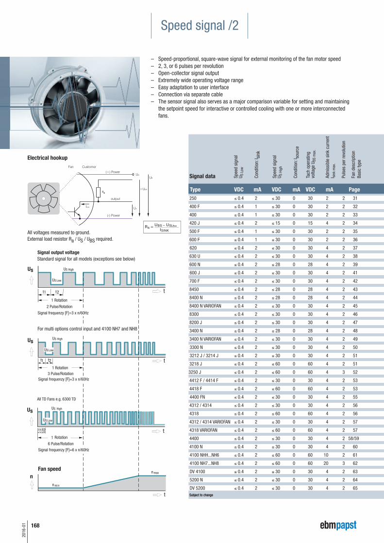
– Speed-proportional, square-wave signal for external monitoring of the fan motor speed– 2, 3, or 6 pulses per revolution– Open-collector signal output – Extremely wide operating voltage range – Easy adaptation to user interface– Connection via separate cable – The sensor signal also serves as a major comparison variable for setting and maintaining
the setpoint speed for interactive or controlled cooling with one or more interconnectedfans.
Electrical hookup
All voltages measured to ground.External load resistor Ra / US / UBS required.
Spee
d si
gnal
U S L
ow
Cond
ition
: Isi
nk
Spee
d si
gnal
U S H
igh
Cond
ition
: Iso
urce
Tach
ope
ratin
gvo
ltage
UBS
max
.
Adm
issi
ble
sink
cur
rent
I sink
max
.
Puls
es p
er re
volu
tion
Fan
desc
riptio
nBa
sic
type
Signal data
Type VDC mA VDC mA VDC mA Page250 £ 0.4 2 £ 30 0 30 2 2 31
400 F £ 0.4 1 £ 30 0 30 2 2 32
400 £ 0.4 1 £ 30 0 30 2 2 33
420 J £ 0.4 2 £ 15 0 15 4 2 34
500 F £ 0.4 1 £ 30 0 30 2 2 35
600 F £ 0.4 1 £ 30 0 30 2 2 36
620 £ 0.4 2 £ 30 0 30 4 2 37
630 U £ 0.4 2 £ 30 0 30 4 2 38
600 N £ 0.4 2 £ 28 0 28 4 2 39
600 J £ 0.4 2 £ 30 0 30 4 2 41
700 F £ 0.4 2 £ 30 0 30 4 2 42
8450 £ 0.4 2 £ 28 0 28 4 2 43
8400 N £ 0.4 2 £ 28 0 28 4 2 44
8400 N VARIOFAN £ 0.4 2 £ 30 0 30 4 2 45
8300 £ 0.4 2 £ 30 0 30 4 2 46
8200 J £ 0.4 2 £ 30 0 30 4 2 47
3400 N £ 0.4 2 £ 28 0 28 4 2 48
3400 N VARIOFAN £ 0.4 2 £ 30 0 30 4 2 49
3300 N £ 0.4 2 £ 30 0 30 4 2 50
3212 J / 3214 J £ 0.4 2 £ 30 0 30 4 2 51
3218 J £ 0.4 2 £ 60 0 60 4 2 51
3250 J £ 0.4 2 £ 60 0 60 4 3 52
4412 F / 4414 F £ 0.4 2 £ 30 0 30 4 2 53
4418 F £ 0.4 2 £ 60 0 60 4 2 53
4400 FN £ 0.4 2 £ 30 0 30 4 2 55
4312 / 4314 £ 0.4 2 £ 30 0 30 4 2 56
4318 £ 0.4 2 £ 60 0 60 4 2 56
4312 / 4314 VARIOFAN £ 0.4 2 £ 30 0 30 4 2 57
4318 VARIOFAN £ 0.4 2 £ 60 0 60 4 2 57
4400 £ 0.4 2 £ 30 0 30 4 2 58/59
4100 N £ 0.4 2 £ 30 0 30 4 2 60
4100 NHH...NH6 £ 0.4 2 £ 60 0 60 10 2 61
4100 NH7...NH8 £ 0.4 2 £ 60 0 60 20 3 62
DV 4100 £ 0.4 2 £ 30 0 30 4 2 63
5200 N £ 0.4 2 £ 30 0 30 4 2 64
DV 5200 £ 0.4 2 £ 30 0 30 4 2 65Subject to change
250 £ 0.4 2 £ 30 0 30 2 2 31
400 F £ 0.4 1 £ 30 0 30 2 2 32
400 £ 0.4 1 £ 30 0 30 2 2 33
420 J £ 0.4 2 £ 15 0 15 4 2 34
500 F £ 0.4 1 £ 30 0 30 2 2 35
600 F £ 0.4 1 £ 30 0 30 2 2 36
620 £ 0.4 2 £ 30 0 30 4 2 37
630 U £ 0.4 2 £ 30 0 30 4 2 38
600 N £ 0.4 2 £ 28 0 28 4 2 39
600 J £ 0.4 2 £ 30 0 30 4 2 41
700 F £ 0.4 2 £ 30 0 30 4 2 42
8450 £ 0.4 2 £ 28 0 28 4 2 43
8400 N £ 0.4 2 £ 28 0 28 4 2 44
8400 N VARIOFAN £ 0.4 2 £ 30 0 30 4 2 45
8300 £ 0.4 2 £ 30 0 30 4 2 46
8200 J £ 0.4 2 £ 30 0 30 4 2 47
3400 N £ 0.4 2 £ 28 0 28 4 2 48
3400 N VARIOFAN £ 0.4 2 £ 30 0 30 4 2 49
3300 N £ 0.4 2 £ 30 0 30 4 2 50
3212 J / 3214 J £ 0.4 2 £ 30 0 30 4 2 51
3218 J £ 0.4 2 £ 60 0 60 4 2 51
3250 J £ 0.4 2 £ 60 0 60 4 3 52
4412 F / 4414 F £ 0.4 2 £ 30 0 30 4 2 53
4418 F £ 0.4 2 £ 60 0 60 4 2 53
4400 FN £ 0.4 2 £ 30 0 30 4 2 55
4312 / 4314 £ 0.4 2 £ 30 0 30 4 2 56
4318 £ 0.4 2 £ 60 0 60 4 2 56
4312 / 4314 VARIOFAN £ 0.4 2 £ 30 0 30 4 2 57
4318 VARIOFAN £ 0.4 2 £ 60 0 60 4 2 57
4400 £ 0.4 2 £ 30 0 30 4 2 58/59
4100 N £ 0.4 2 £ 30 0 30 4 2 60
4100 NHH...NH6 £ 0.4 2 £ 60 0 60 10 2 61
4100 NH7...NH8 £ 0.4 2 £ 60 0 60 20 3 62
DV 4100 £ 0.4 2 £ 30 0 30 4 2 63
5200 N £ 0.4 2 £ 30 0 30 4 2 64
DV 5200 £ 0.4 2 £ 30 0 30 4 2 65Subject to change
V m V m V m 5 2 0 5 2 2
5 2 0 6 2 2
5 2 0 6 4 2
5 2 0 6 2 6
7 2 0 6 2 2
7 2 0 3 2 2
7 2 0 1 2 2
6 2 0 6 2 2
6 2 0 6 2 6
6 2 0 6 2 6
6 2 0 6 2 6
6 2 0 6 2 2
D 2 0 6 2 6
2 2 0 6 2 6
R 2 0 3 4 2
R 2 0 3 4
R 2 0 3 4 2
R 2 0 3 4 2
R 2 0 3 4 2
R 2 0 3 4 2
R 3 0 6 4 2
R 2 0 3 2 2
R 2 0 6 2 6
R 2 0 6 2 6
R 2 0 6 2 6
R 2 0 6 2 6
R 2 0 6 2 6
R 2 0 3 4 2
R 2 0 6 2 6
R 2 0 6 2 6
R 2 0 6 2 6
R 2 0 6 2 6
R 2 0 6 2 6
R 2 0 6 2 6
R 2 0 6 2 6
R 2 0 6 2 6 S
169
2016
-01
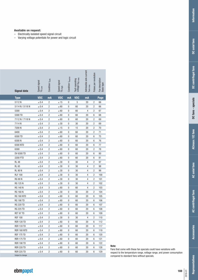
Available on request: – Electrically isolated speed signal circuit – Varying voltage potentials for power and logic circuit
0 3 2 2
0 3 2 2
0 3 2 2
0 1 4 2
0 3 2 2
0 3 2 2
0 3 4
0 3 4 2
0 2 4 2
0 3 4 2
0 3 4 2
0 2 4 2
0 2 4 2
0 3 4 2
0 3 4 2
0 3 4 2
0 2 4 2
0 3 4 2
0 3 4 2
0 3 4 2
0 6 4 2
0 6 4 3
Type VDC mA VDC mA VDC mA Page 5112 N £ 0.4 2 £ 15 0 5 20 2 66
Note: Fans that come with these fan specials could have variations with respect to the temperature range, voltage range, and power consumptioncompared to standard fans without specials.
Inform
ation
DC axial fa
nsDC
fans
- spe
cials
ACmax
x / E
C fans
AC axial fa
nsAc
cess
ories
Repres
entativ
esDC
cen
trifu
gal fan
sAC
cen
trifu
gal fan
s
170
2016
-01
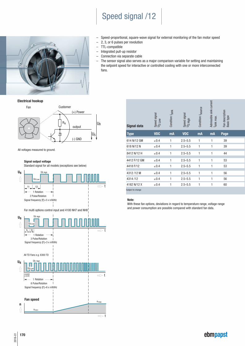
Speed signal /12
– Speed-proportional, square-wave signal for external monitoring of the fan motor speed– 2, 3, or 6 pulses per revolution– TTL-compatible– Integrated pull-up resistor– Connection via separate cable – The sensor signal also serves as a major comparison variable for setting and maintaining
the setpoint speed for interactive or controlled cooling with one or more interconnectedfans.
Electrical hookup
All voltages measured to ground.
Type VDC mA VDC mA mA Page
Spee
d si
gnal
U S L
ow
Cond
ition
: Isi
nk
Spee
d si
gnal
U S H
igh
Cond
ition
: Iso
urce
Adm
issi
ble
sink
cur
rent
I s
ink
max
.
Fan
desc
riptio
nBa
sic
type
Signal data
614 N/12 GM £ 0.4 1 2.5–5.5 1 1 39
618 N/12 N £ 0.4 1 2.5–5.5 1 1 39
8412 N/12 H £ 0.4 1 2.5–5.5 1 1 44
4412 F/12 GM £ 0.4 1 2.5–5.5 1 1 53
4418 F/12 £ 0.4 1 2.5–5.5 1 1 53
4312 /12 M £ 0.4 1 2.5–5.5 1 1 56
4314 /12 £ 0.4 1 2.5–5.5 1 1 56
4182 N/12 X £ 0.4 1 2.5–5.5 1 1 60
Subject to change
Note: With these fan options, deviations in regard to temperature range, voltage rangeand power consumption are possible compared with standard fan data.
171
2016
-01
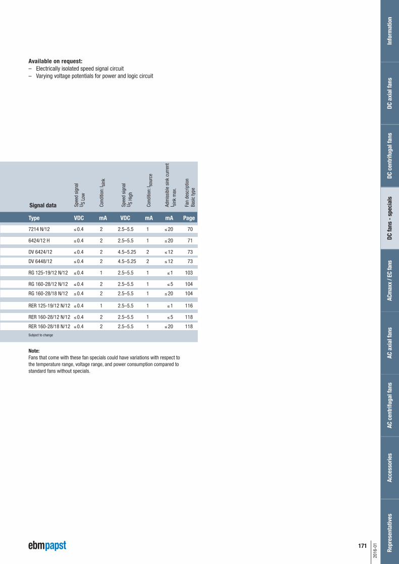
Available on request: – Electrically isolated speed signal circuit – Varying voltage potentials for power and logic circuit
Type VDC mA VDC mA mA Page
7214 N/12 £ 0.4 2 2.5–5.5 1 £ 20 70
6424/12 H £ 0.4 2 2.5–5.5 1 £ 20 71
DV 6424/12 £ 0.4 2 4.5–5.25 2 £ 12 73
DV 6448/12 £ 0.4 2 4.5–5.25 2 £ 12 73
RG 125-19/12 N/12 £ 0.4 1 2.5–5.5 1 £ 1 103
RG 160-28/12 N/12 £ 0.4 2 2.5–5.5 1 £ 5 104
RG 160-28/18 N/12 £ 0.4 2 2.5–5.5 1 £ 20 104
RER 125-19/12 N/12 £ 0.4 1 2.5–5.5 1 £ 1 116
RER 160-28/12 N/12 £ 0.4 2 2.5–5.5 1 £ 5 118
RER 160-28/18 N/12 £ 0.4 2 2.5–5.5 1 £ 20 118
Subject to change
Spee
d si
gnal
U S L
ow
Cond
ition
: Isi
nk
Spee
d si
gnal
U S H
igh
Cond
ition
: Iso
urce
Adm
issi
ble
sink
cur
rent
I s
ink
max
.
Fan
desc
riptio
nBa
sic
type
Signal data
Note: Fans that come with these fan specials could have variations with respect tothe temperature range, voltage range, and power consumption compared tostandard fans without specials.
Info
rmat
ion
DC a
xial
fans
DC fa
ns -
spe
cial
sAC
max
x / E
C fa
nsAC
axi
al fa
nsAc
cess
orie
sRe
pres
enta
tives
DC c
entr
ifuga
l fan
sAC
cen
trifu
gal f
ans
172
2016
-01
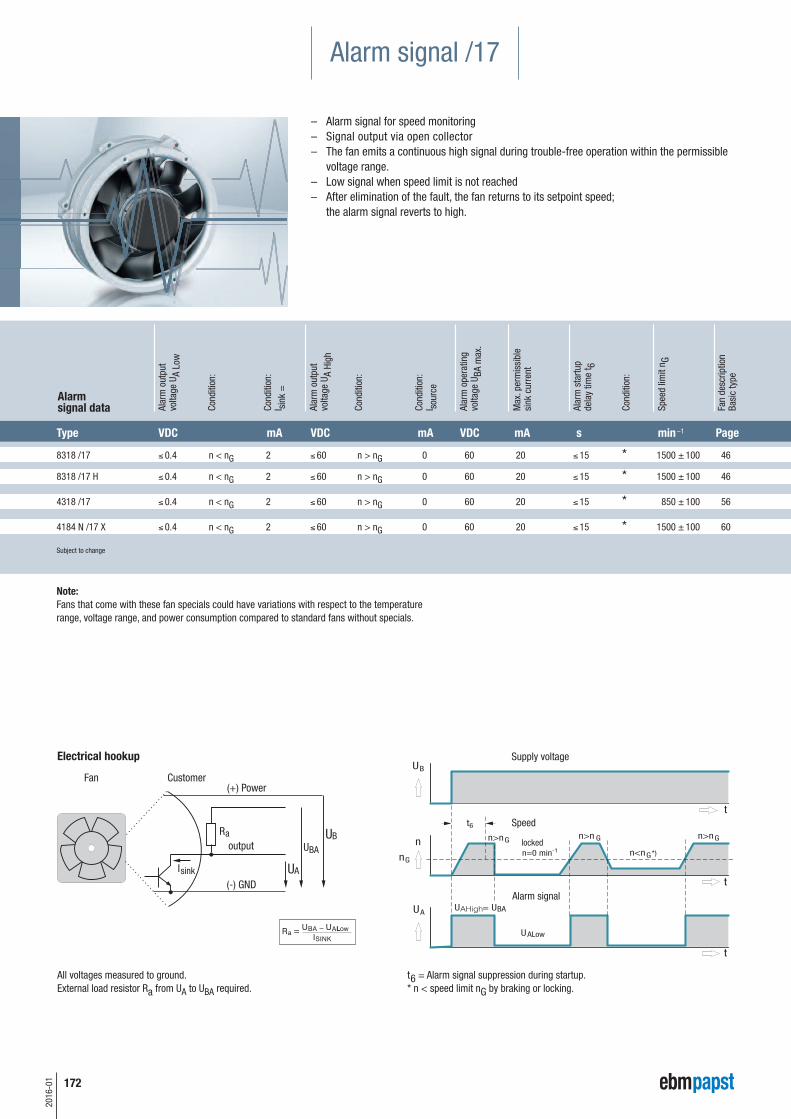
Alarm signal /17
– Alarm signal for speed monitoring– Signal output via open collector– The fan emits a continuous high signal during trouble-free operation within the permissible
voltage range.– Low signal when speed limit is not reached– After elimination of the fault, the fan returns to its setpoint speed;
the alarm signal reverts to high.
t6 = Alarm signal suppression during startup.* n < speed limit nG by braking or locking.
All voltages measured to ground.External load resistor Ra from UA to UBA required.
Electrical hookup
8318 /17 £ 0.4 n < nG 2 £ 60 n > nG 0 60 20 £ 15 * 1500 ± 100 46
8318 /17 H £ 0.4 n < nG 2 £ 60 n > nG 0 60 20 £ 15 * 1500 ± 100 46
4318 /17 £ 0.4 n < nG 2 £ 60 n > nG 0 60 20 £ 15 * 850 ± 100 56
4184 N /17 X £ 0.4 n < nG 2 £ 60 n > nG 0 60 20 £ 15 * 1500 ± 100 60
Subject to change
Alar
m o
utpu
tvo
ltage
UA
Low
Cond
ition
:
Cond
ition
:I s
ink
=
Alar
m o
utpu
tvo
ltage
UA
High
Cond
ition
:
Cond
ition
:I s
ourc
e
Alar
m o
pera
ting
volta
ge U
BA m
ax.
Max
. per
mis
sibl
e si
nk c
urre
nt
Alar
m s
tartu
pde
lay
time
t 6
Cond
ition
:
Spee
d lim
it n G
Fan
desc
riptio
nBa
sic
type
Type VDC mA VDC mA VDC mA s min –1 Page
Alarm signal data
Note: Fans that come with these fan specials could have variations with respect to the temperaturerange, voltage range, and power consumption compared to standard fans without specials.
Supply voltage
173
2016
-01
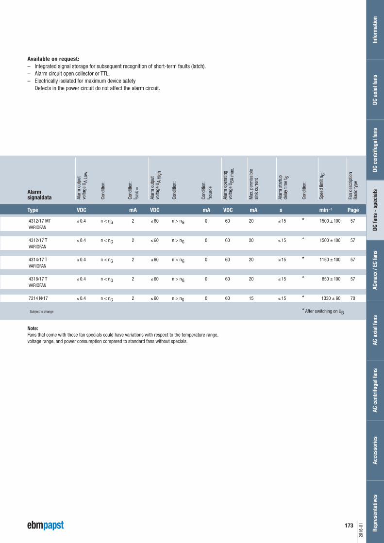
Available on request: – Integrated signal storage for subsequent recognition of short-term faults (latch).– Alarm circuit open collector or TTL.– Electrically isolated for maximum device safety
Defects in the power circuit do not affect the alarm circuit.
T V m V m V m s m P
4312/17 MT £ 0.4 n < n 2 £ 60 n > n 0 60 20 £ 15 * 1500 ± 100 57 VARIOFAN
4312/17 T £ 0.4 n < n 2 £ 60 n > n 0 60 20 £ 15 * 1500 ± 100 57 VARIOFAN
4314/17 T £ 0.4 n < n 2 £ 60 n > n 0 60 20 £ 15 * 1150 ± 100 57 VARIOFAN
4318/17 T £ 0.4 n < n 2 £ 60 n > n 0 60 20 £ 15 * 850 ± 100 57 VARIOFAN
7214 N/17 £ 0.4 n < nG 2 £ 60 n > nG 0 60 15 £ 15 * 1330 ± 60 70
Subject to change * After switching on UB
Alar
m o
utpu
tvo
ltage
UA
Low
Cond
ition
:
Cond
ition
:I s
ink
=
Alar
m o
utpu
tvo
ltage
UA
High
Cond
ition
:
Cond
ition
:I s
ourc
e
Alar
m o
pera
ting
volta
ge U
BA m
ax.
Max
. per
mis
sibl
e si
nk c
urre
nt
Alar
m s
tartu
pde
lay
time
t 6
Cond
ition
:
Spee
d lim
it n G
Fan
desc
riptio
nBa
sic
type
Type VDC mA VDC mA VDC mA s min –1 Page
Note: Fans that come with these fan specials could have variations with respect to the temperature range,voltage range, and power consumption compared to standard fans without specials.
Alarm signaldata
Info
rmat
ion
DC a
xial
fans
DC fa
ns -
spe
cial
sAC
max
x / E
C fa
nsAC
axi
al fa
nsAc
cess
orie
sRe
pres
enta
tives
DC c
entr
ifuga
l fan
sAC
cen
trifu
gal f
ans
G
G
G
G
G
G
G
G
174
2016
-01
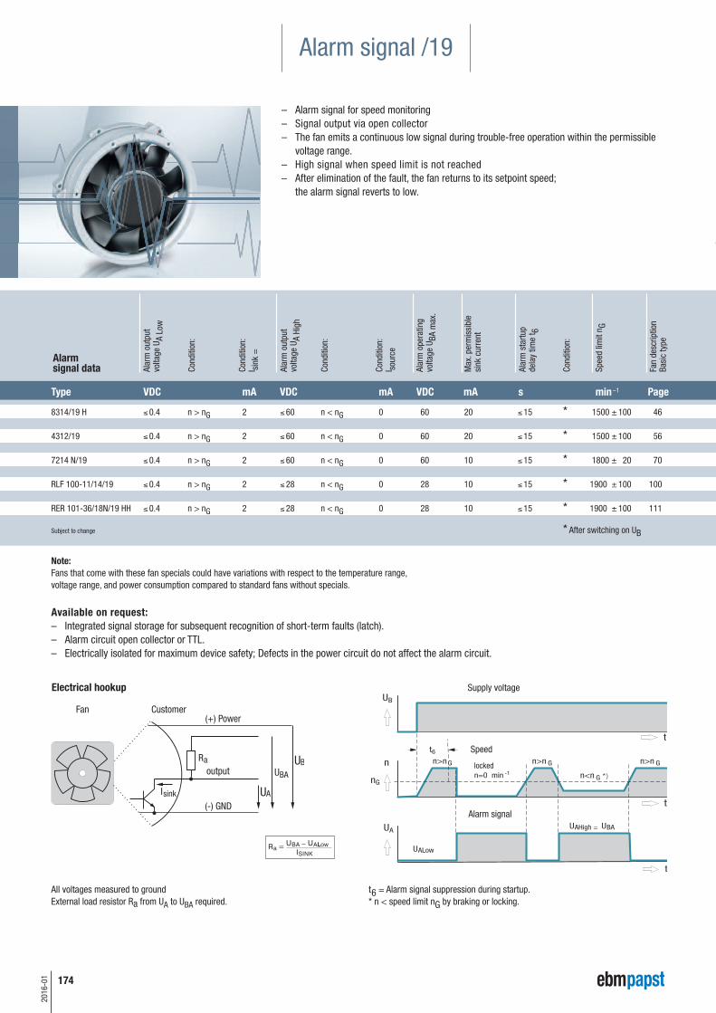
All voltages measured to groundExternal load resistor Ra from UA to UBA required.
Electrical hookup
t6 = Alarm signal suppression during startup.* n < speed limit nG by braking or locking.
8314/19 H £ 0.4 n > nG 2 £ 60 n < nG 0 60 20 £ 15 * 1500 ± 100 46
4312/19 £ 0.4 n > nG 2 £ 60 n < nG 0 60 20 £ 15 * 1500 ± 100 56
7214 N/19 £ 0.4 n > nG 2 £ 60 n < nG 0 60 10 £ 15 * 1800 ± 20 70
RLF 100-11/14/19 £ 0.4 n > nG 2 £ 28 n < nG 0 28 10 £ 15 * 1900 ± 100 100
RER 101-36/18N/19 HH £ 0.4 n > nG 2 £ 28 n < nG 0 28 10 £ 15 * 1900 ± 100 111
Subject to change * After switching on UB
Alar
m o
utpu
tvo
ltage
UA
Low
Cond
ition
:
Cond
ition
:I s
ink
=
Alar
m o
utpu
tvo
ltage
UA
High
Cond
ition
:
Cond
ition
:I s
ourc
e
Alar
m o
pera
ting
volta
ge U
BA m
ax.
Max
. per
mis
sibl
e si
nk c
urre
nt
Alar
m s
tartu
pde
lay
time
t 6
Cond
ition
:
Spee
d lim
it n G
Fan
desc
riptio
nBa
sic
type
Type VDC mA VDC mA VDC mA s min –1 Page
Alarm signal data
Note: Fans that come with these fan specials could have variations with respect to the temperature range,voltage range, and power consumption compared to standard fans without specials.
Available on request: – Integrated signal storage for subsequent recognition of short-term faults (latch).– Alarm circuit open collector or TTL.– Electrically isolated for maximum device safety; Defects in the power circuit do not affect the alarm circuit.
Alarm signal /19
– Alarm signal for speed monitoring– Signal output via open collector– The fan emits a continuous low signal during trouble-free operation within the permissible
voltage range.– High signal when speed limit is not reached– After elimination of the fault, the fan returns to its setpoint speed;
the alarm signal reverts to low.
Supply voltage
175
2016
-01
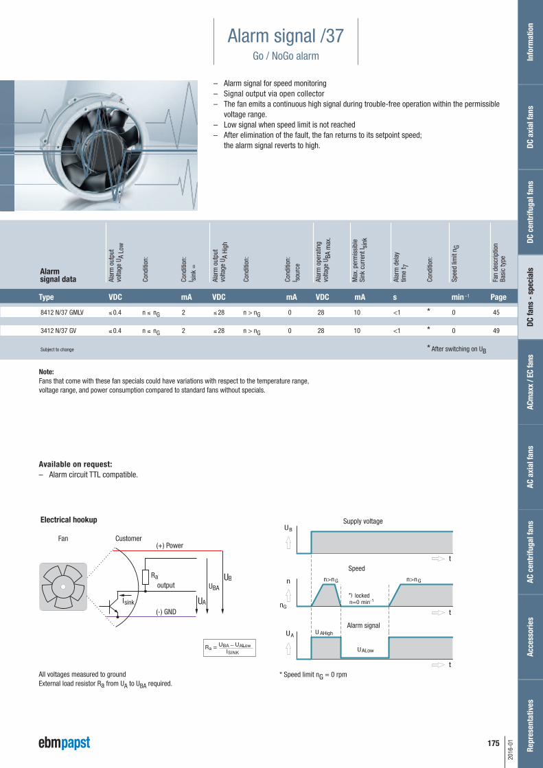
Alarm signal /37Go / NoGo alarm
– Alarm signal for speed monitoring– Signal output via open collector– The fan emits a continuous high signal during trouble-free operation within the permissible
voltage range.– Low signal when speed limit is not reached– After elimination of the fault, the fan returns to its setpoint speed;
the alarm signal reverts to high.
All voltages measured to groundExternal load resistor Ra from UA to UBA required.
Electrical hookup
* Speed limit nG = 0 rpm
8412 N/37 GMLV £ 0.4 n £ nG 2 £ 28 n > nG 0 28 10 <1 * 0 45
3412 N/37 GV £ 0.4 n £ nG 2 £ 28 n > nG 0 28 10 <1 * 0 49
Subject to change * After switching on UB
Alar
m o
utpu
tvo
ltage
UA
Low
Cond
ition
:
Cond
ition
:I s
ink
=
Alar
m o
utpu
tvo
ltage
UA
High
Cond
ition
:
Cond
ition
:I s
ourc
e
Alar
m o
pera
ting
volta
ge U
BA m
ax.
Max
. per
mis
sibl
e Si
nk c
urre
nt I s
ink
Alar
m d
elay
time
t 7
Cond
ition
:
Spee
d lim
it n G
Fan
desc
riptio
nBa
sic
type
Type VDC mA VDC mA VDC mA s min –1 Page
Alarm signal data
Available on request: – Alarm circuit TTL compatible.
Note: Fans that come with these fan specials could have variations with respect to the temperature range,voltage range, and power consumption compared to standard fans without specials.
Info
rmat
ion
DC a
xial
fans
DC fa
ns -
spe
cial
sAC
max
x / E
C fa
nsAC
axi
al fa
nsAc
cess
orie
sRe
pres
enta
tives
DC c
entr
ifuga
l fan
sAC
cen
trifu
gal f
ansSupply voltage
176
2016
-01
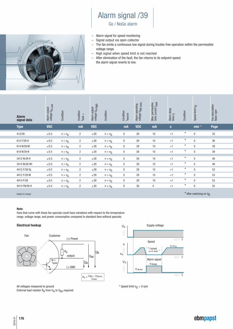
Alarm signal /39Go / NoGo alarm
– Alarm signal for speed monitoring– Signal output via open collector– The fan emits a continuous low signal during trouble-free operation within the permissible
voltage range.– High signal when speed limit is not reached– After elimination of the fault, the fan returns to its setpoint speed;
the alarm signal reverts to low.
Electrical hookup
All voltages measured to groundExternal load resistor Ra from UA to UBA required.
* Speed limit nG = 0 rpm
412/39 £ 0.5 n > nG 2 £ 28 n = nG 0 28 10 <1 * 0 33
612 F/39 H £ 0.5 n > nG 2 £ 28 n = nG 0 28 10 <1 * 0 36
614 N/39 M £ 0.5 n > nG 2 £ 28 n = nG 0 28 10 <1 * 0 39
618 N/39 N £ 0.5 n > nG 2 £ 28 n = nG 0 28 10 <1 * 0 39
3412 N/39 H £ 0.5 n > nG 2 £ 28 n = nG 0 28 10 <1 * 0 48
3414 N/39 HH £ 0.5 n > nG 2 £ 28 n = nG 0 28 10 <1 * 0 48
4412 F/39 GL £ 0.5 n > nG 2 £ 28 n = nG 0 28 10 <1 * 0 53
4412 F/39 M £ 0.5 n > nG 2 £ 28 n = nG 0 28 10 <1 * 0 53
4414 F/39 £ 0.5 n > nG 2 £ 28 n = nG 0 28 10 <1 * 0 53
4414 FN/39 H £ 0.4 n > nG 2 £ 30 n = nG 0 30 4 <1 * 0 55
Subject to change * After switching on UB
Alar
m o
utpu
tvo
ltage
UA
Low
Cond
ition
:
Cond
ition
:I s
ink
=
Alar
m o
utpu
tvo
ltage
UA
High
Cond
ition
:
Cond
ition
:I s
ourc
e
Alar
m o
pera
ting
volta
ge U
BA m
ax.
Max
. per
mis
sibl
e Si
nk c
urre
nt I s
ink
Alar
m d
elay
time
t 7
Cond
ition
:
Spee
d lim
it n G
Fan
desc
riptio
nBa
sic
type
Type VDC mA VDC mA VDC mA s min–1 Page
Alarm signal data
Note: Fans that come with these fan specials could have variations with respect to the temperaturerange, voltage range, and power consumption compared to standard fans without specials.
Supply voltage
177
2016
-01
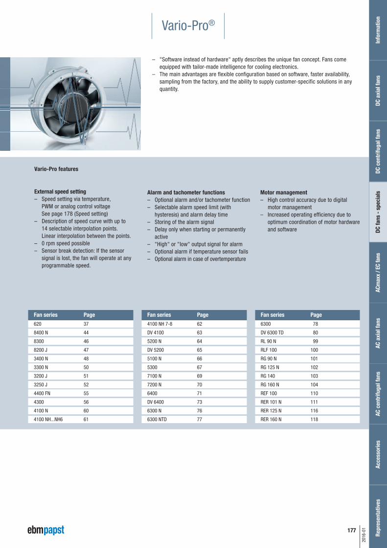
Vario-Pro®
– "Software instead of hardware" aptly describes the unique fan concept. Fans comeequipped with tailor-made intelligence for cooling electronics.
– The main advantages are flexible configuration based on software, faster availability,sampling from the factory, and the ability to supply customer-specific solutions in anyquantity.
620 37
8400 N 44
8300 46
8200 J 47
3400 N 48
3300 N 50
3200 J 51
3250 J 52
4400 FN 55
4300 56
4100 N 60
4100 NH...NH6 61
Fan series Page
4100 NH 7-8 62
DV 4100 63
5200 N 64
DV 5200 65
5100 N 66
5300 67
7100 N 69
7200 N 70
6400 71
DV 6400 73
6300 N 76
6300 NTD 77
Fan series Page
6300 78
DV 6300 TD 80
RL 90 N 99
RLF 100 100
RG 90 N 101
RG 125 N 102
RG 140 103
RG 160 N 104
REF 100 110
RER 101 N 111
RER 125 N 116
RER 160 N 118
Fan series Page
Vario-Pro features
External speed setting– Speed setting via temperature,
PWM or analog control voltage See page 178 (Speed setting)
– Description of speed curve with up to14 selectable interpolation points. Linear interpolation between the points.
– 0 rpm speed possible– Sensor break detection: If the sensor
signal is lost, the fan will operate at anyprogrammable speed.
hysteresis) and alarm delay time– Storing of the alarm signal– Delay only when starting or permanently
active– "High" or "low" output signal for alarm– Optional alarm if temperature sensor fails– Optional alarm in case of overtemperature
Motor management– High control accuracy due to digital
motor management– Increased operating efficiency due to
optimum coordination of motor hardwareand software
Info
rmat
ion
DC a
xial
fans
DC fa
ns -
spe
cial
sAC
max
x / E
C fa
nsAC
axi
al fa
nsAc
cess
orie
sRe
pres
enta
tives
DC c
entr
ifuga
l fan
sAC
cen
trifu
gal f
ans
178
2016
-01
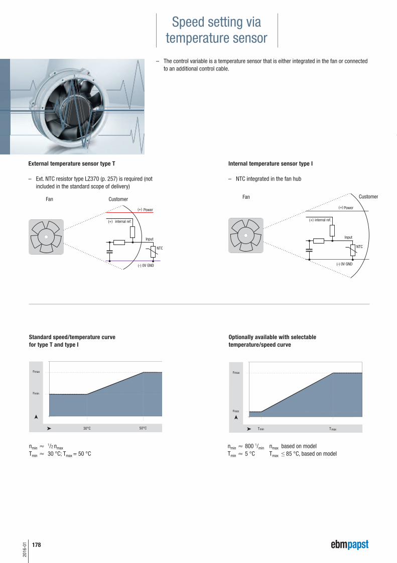
Speed setting viatemperature sensor
– The control variable is a temperature sensor that is either integrated in the fan or connectedto an additional control cable.
External temperature sensor type T
– Ext. NTC resistor type LZ370 (p. 257) is required (notincluded in the standard scope of delivery)
nmin 800 1/min nmax based on modelTmin 5 °C Tmax ≤ 85 °C, based on model
nmin 1/2 nmax
Tmin 30 °C; Tmax = 50 °C
Internal temperature sensor type I
– NTC integrated in the fan hub
Standard speed/temperature curvefor type T and type I
Optionally available with selectable temperature/speed curve
internal ref.
30°C 50°C
nmax
nmin
T T
nmax
max
nmin
min
internal ref.
179
2016
-01
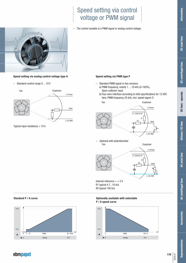
Speed setting via control voltage or PWM signal
– The control variable is a PWM signal or analog control voltage.
Speed setting via PWM type P
– Standard PWM signal in two versionsa) PWM frequency, mainly 1 ... 10 kHz (0-100%), Open-collector inputb) Four-wire interface according to Intel specifications for 12 VDC fans, PWM frequency 25 kHz, incl. speed signal /2
Speed setting via analog control voltage type A
– Standard control range 0 ... 10 V
– Optional with potentiometer
Typical input resistance > 10 k�
Internal reference = + 5 VR1 typical 4.7...10 kΩ
R2 typical 100 kΩ
Standard P / A curve Optionally available with selectableP / A speed curve
Info
rmat
ion
DC a
xial
fans
DC fa
ns -
spe
cial
sAC
max
x / E
C fa
nsAC
axi
al fa
nsAc
cess
orie
sRe
pres
enta
tives
DC c
entr
ifuga
l fan
sAC
cen
trifu
gal f
ans
internal ref.
internal ref.
2016
-01
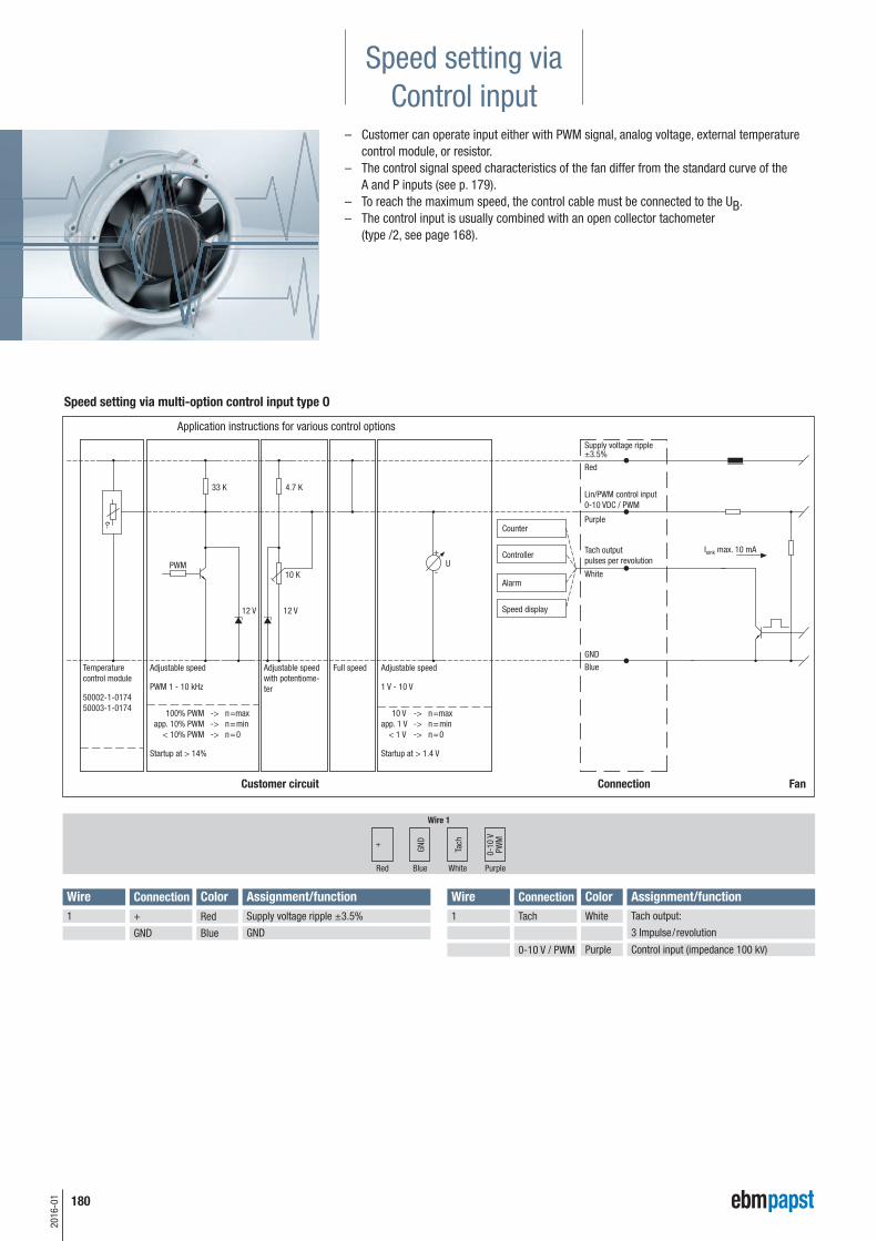
Speed setting viaControl input
– Customer can operate input either with PWM signal, analog voltage, external temperaturecontrol module, or resistor.
– The control signal speed characteristics of the fan differ from the standard curve of the A and P inputs (see p. 179).
– To reach the maximum speed, the control cable must be connected to the UB.– The control input is usually combined with an open collector tachometer
(type /2, see page 168).
+
0-10
VPW
M
Tach
GND
Wire Connection Color Assignment/function Wire Connection Color Assignment/function1 1+ Red Supply voltage ripple ±3.5% Tach White
0-10 V / PWM Purple Control input (impedance 100 kV)
GND Blue GND
Wire 1
Red PurpleWhiteBlue
Tach output:
3 Impulse/revolution
Speed setting via multi-option control input type O
Application instructions for various control options
Connection Fan
Purple
Lin/PWM control input0-10 VDC / PWM
180
181
2016
-01
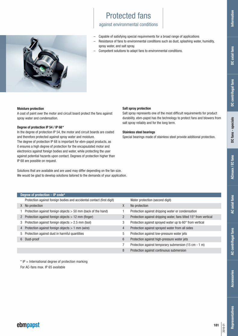
Protected fansagainst environmental conditions
– Capable of satisfying special requirements for a broad range of applications– Resistance of fans to environmental conditions such as dust, splashing water, humidity,
spray water, and salt spray.– Competent solutions to adapt fans to environmental conditions.
Degree of protection – IP code*
Solutions that are available and are used may differ depending on the fan size.We would be glad to develop solutions tailored to the demands of your application.
Moisture protectionA coat of paint over the motor and circuit board protect the fans againstspray water and condensation.
Degree of protection IP 54 / IP 68* In the degree of protection IP 54, the motor and circuit boards are coatedand therefore protected against spray water and moisture.The degree of protection IP 68 is important for ebm-papst products, as it ensures a high degree of protection for the encapsulated motor andelectronics against foreign bodies and water, while protecting the useragainst potential hazards upon contact. Degrees of protection higher thanIP 68 are possible on request.
Salt spray protectionSalt spray represents one of the most difficult requirements for productdurability. ebm-papst has the technology to protect fans and blowers fromsalt spray reliably and for the long term.
Stainless steel bearingsSpecial bearings made of stainless steel provide additional protection.
Protection against foreign bodies and accidental contact (first digit) Water protection (second digit)
X No protection X No protection
1 Protection against foreign objects > 50 mm (back of the hand) 1 Protection against dripping water or condensation
2 Protection against foreign objects > 12 mm (finger) 2 Protection against dripping water, fans tilted 15° from vertical
3 Protection against foreign objects > 2.5 mm (tool) 3 Protection against sprayed water up to 60° from vertical
4 Protection against foreign objects > 1 mm (wire) 4 Protection against sprayed water from all sides
5 Protection against dust in harmful quantities 5 Protection against low-pressure water jets
6 Dust-proof 6 Protection against high-pressure water jets
7 Protection against temporary submersion (15 cm - 1 m)