DC Fans DC Fans Overview 17 DC Axial Fans 21 DC Radial Fans 71 DC Fans Cross-Flow 86 DC-Lüfter 15 Technology DC Axial Fans DC Radial Fans Specials ACmaxx AC Axial Fans AC Radial Fans Accessories
Transcript
DC Fans
DC Fans Overview 17
DC Axial Fans 21
DC Radial Fans 71
DC Fans Cross-Flow 86
DC
-Lü
fter
15
Tech
no
log
yD
C A
xia
l Fa
ns
DC
Ra
dia
l Fa
ns
Sp
ecia
lsA
Cm
axx
AC
Axia
l Fa
ns
AC
Ra
dia
l Fa
ns
Access
ori
es
16
DC Fans
Range of fans
Users of ebm-papst fans have the widest rangeof DC axial fans at their disposal: From 25 mmto 280 mm in size. Every single type of fan canbe optimally integrated in the respective appli-ance concept. The highly economic brushlessmotor technology of these fans provides aunique variety of intelligent innovations that can be realised today at prices that would havebeen unthinkable just a few years ago.
Electronic protection against reverse polarity
ebm-papst DC fans have electronically commu-tated drives with electronic protection againstreverse polarity.The electronics are convenientlylocated in the fan hub.
Product life expectancy
A distinctive feature of DC fan technology is the convincingly high product life expectancy.Thanks to the excellent efficiency of the brush-less drives, the thermal load of the bearings isreduced thus considerably increasing the life expectancy of the fans.
Protection Class
DC fans with sleeve and ball bearings arepowered by Class E insulated motors. All ebm-papst fans conform to the requirements ofProtection Class IP 20. Fans conforming to IP 54and special protection classes are also avail-able.
Supply voltage
The supply voltage of ebm-papst DC fans canbe varied thus the airflow can be matchedoptimally to the cooling requirements and noisereduced to a minimum. ebm-papst DC fans can be driven with voltages that are reduced asmuch as 50 % or increased by 25 % of theirnominal voltage (see voltage range in the tablescontaining technical data).
Speed control
VARIOFAN – the fans with IC technology andtemperature-dependent speed control. VARIO-FANS always cool at the speed required by theappliance resulting in speeds as much as 50%lower than those of standard fans and a drasticreduction of the noise level in almost all operat-ing conditions. VARIOFANs are controlled withoutdissipation losses: At lower speeds their powerconsumption is reduced proportionally.
S-Force
The new S-Force fans with their extremely highblower capacity of up to 950 m3/h and pressurebuild-up of up to 1200 Pascal are capable ofdealing with the extreme heat load. If needed,these fans can produce up to 100% more outputunder full load and they work with a much broa-der delivery bandwidth than current models.This makes them ideal for equipment andsystems with a high density of components.Thanks to intelligent motor features, they can beindividually adapted for any application. S-Forcefans are available in 5 standard dimensions.
Highlights:– Compact fan with low power consumption.
General characteristics:– Material: fiberglass-reinforced plastic. Impeller PA, housing PBT.– Fully integrated electronic commutation.– Protected against reverse polarity and blocking.– Connection via single wire AWG 28, TR 64. Stripped and tinned ends.– Blowing over struts. Rotational direction CCW looking at rotor.– Mass: 5 g.
DC Axial FansSeries 250 25 x 25 x 8 mm
Tech
no
log
yD
C A
xia
l Fa
ns
AC
ma
xx
AC
Axia
l Fa
ns
AC
Ra
dia
l Fa
ns
Access
ori
es
1 2
10
pf
20
3 4
�
m³/h
Pa
V•
2
1
3
�
�
30
40
50
0 0,4 0,8 1,2 1,6 2,0 2,4 CFM
0,1
50,1
00,0
5(in
HO
)²
Nominal Data
Spec
ials
Type m3/h CFM V DC V DC dB(A) Bel / Watt min-1 °C Hours Hours P. 90
* at 55 °C
DC
Ra
dia
l Fa
ns
Sp
ecia
ls
Nom
ina
l V
olt
ag
e
Air F
low
Air F
low
Volta
ge R
ange
Nois
e
Soun
d Po
wer
Sint
ec-S
leev
e Be
arin
gsBa
ll Be
arin
gs
Pow
er In
put
Nom
inal
Spe
ed
Tem
pera
ture
Ran
ge
Serv
ice
Life
L10
(20
°C)
eb
m-p
apst
Sta
ndar
d
Serv
ice
Life
L10
(60
°C)
ebm
-pap
st S
tand
ard
Life
exp
ecta
ncy
L 10Δ
(40
°C) s
ee P
age
13
Curv
e
HP
New M
odels
max. 9 m3/h
22
Nominal Data Spec
ials
Type m3/h CFM V DC V DC dB(A) Bel / Watt min-1 °C Hours Hours P. 90
Highlights:– Compact fan with low power consumption.– Some models suitable for use at high ambient temperatures.
General characteristics:– Material: fiberglass-reinforced plastic. impeller PA, housing PBT.– Fully integrated electronic commutation.– Protected against reverse polarity and blocking.– Electrical connection via single leads AWG 28, TR 64. Stripped and tinned ends.– Blowing over struts. Rotational direction CCW looking at rotor.– Mass: 17 g.
DC Axial FansSeries 400 F 40 x 40 x 10 mm
0 1 2 3 4 5
2 4
10
pf
20
6 8
�
m³/h
Pa
V•
30
1
2
�
�
15
25
5
3
CFM
0,1
00,0
80,0
60,0
40,0
2(in
HO
)²
Nom
ina
l V
olt
ag
e
Air F
low
Air F
low
Volta
ge R
ange
Nois
e
Soun
d Po
wer
Sint
ec-S
leev
e Be
arin
gsBa
ll Be
arin
gs
Pow
er In
put
Nom
inal
Spe
ed
Tem
pera
ture
Ran
ge
Serv
ice
Life
L10
(20
°C)
ebm
-pap
st S
tand
ard
Serv
ice
Life
(60
°C)
ebm
-pap
st S
tand
ard
Life
exp
ecta
ncy
L 10Δ
(40
°C) s
ee p
age
13
Curv
e
New M
odels
Models with Temperature range up to +85 °C.
HP
23
Highlights:– Compact fan with low power consumption.– Some models suitable for use at high ambient temperatures.
General characteristics:– Material: fiberglass-reinforced plastic. Impeller PA, housing PBT.– Fully integrated electronic commutation.– Protected against reverse polarity and blocking.– Electrical connection via single leads AWG 28, TR 64. Stripped and tinned ends.– Blowing over struts. Rotational direction CCW looking at rotor.– Mass: 27 g.
DC Axial FansSeries 400 40 x 40 x 20 mm
0 1 2 3 4 5 6 7
2 4
10
pf
30
20
6 8 10
�
m³/h
Pa
V•
40
1
2
�
�
50
CFM
0,1
50,1
00,0
5(in
HO
)²
Nominal Data Spec
ials
Type m3/h CFM V DC V DC dB(A) Bel / Watt min-1 °C Hours Hours P. 90/98
Highlights:– Highly stable characteristic curve for high air flow with high back pressure.– Low operating noise at high back pressure.
General characteristics:– Material: fiberglass-reinforced plastic. Impeller PA, housing PBT.– Fully integrated electronic commutation.– Protected against reverse polarity and blocking.– Electrical connection via single leads AWG 26, TR 64. Stripped and tinned ends.– Blowing over struts. Rotational direction CCW looking at rotor.– Mass: 50 g.
DC Axial FansSeries 400 J 40 x 40 x 25 mm
0 2 4 6 8 10 12
5
pf
200
50
10
�
m³/h
Pa
V•
1
2
�
�
15 20
150
100
3
CFM
0,6
0,4
0,2
(in
HO
)²
Nom
ina
l V
olt
ag
e
Air F
low
Air F
low
Volta
ge R
ange
Nois
e
Soun
d Po
wer
Sint
ec-S
leev
e Be
arin
gsBa
ll Be
arin
gs
Pow
er In
put
Nom
inal
Spe
ed
Tem
pera
ture
Ran
ge
Serv
ice
Life
L10
(40
°C)
ebm
-pap
st S
tand
ard
Serv
ice
Life
L10
(Tm
ax)
ebm
-pap
st S
tand
ard
Life
exp
ecta
ncy
L 10Δ
(40
°C) s
ee p
age
13
Curv
e
IP54�HP
25
Highlights:– Compact fan with low power consumption.– Some models suitable for use at high ambient temperatures.
General characteristics:– Material: fiberglass-reinforced plastic. Impeller PA, housing PBT.– Fully integrated electronic commutation.– Protected against reverse polarity and blocking.– Electrical connection via single leads AWG 28, TR 64. Stripped and tinned ends.– Blowing over struts. Rotational direction CCW looking at rotor.– Mass: 25 g.
DC Axial FansSeries 500 F 50 x 50 x 15 mm
0 2 4 6 8 10
5
10
pf
30
20
10
�
m³/h
Pa
V•
2
�
�
15
25
15
5
CFM
0,1
00,0
80,0
60,0
40,0
2(in
HO
)²
1
Nominal Data Spec
ials
Type m3/h CFM V DC V DC dB(A) Bel / Watt min-1 °C Hours Hours P. 90
Highlights:– Compact fan with low power consumption.– Some models suitable for use at high ambient temperatures.
General characteristics:– Material: fiberglass-reinforced plastic. Impeller PA, housing PBT.– Fully integrated electronic commutation.– Protected against reverse polarity and blocking.– Electrical connection via single leads AWG 28, TR 64. Stripped and tinned ends.– Blowing over struts. Rotational direction CCW looking at rotor.– Mass: 30 g.
DC Axial FansSeries 600 F 60 x 60 x 15 mm
0 3 6 9 12 15 18
5
pf
5
10
�
m³/h
Pa
V•
1
2
�
�
15 20
10
3
25
15
20
25
CFM
0,0
80,0
60,0
40,0
2(in
HO
)²
Nom
ina
l V
olt
ag
e
Air F
low
Air F
low
Volta
ge R
ange
Nois
e
Soun
d Po
wer
Sint
ec-S
leev
e Be
arin
gsBa
ll Be
arin
gs
Pow
er In
put
Nom
inal
Spe
ed
Tem
pera
ture
Ran
ge
Serv
ice
Life
L10
(20
°C)
ebm
-pap
st S
tand
ard
Serv
ice
Life
L10
(60
°C)
ebm
-pap
st S
tand
ard
Life
exp
ecta
ncy
L 10Δ
(40
°C) s
ee p
age
13
Curv
e
New M
odels
Models with Temperature range up to +80 / 85 °C.
HPPWM
max. 67 m3/h
27
DC Axial FansSeries 620 60 x 60 x 25 mm
Highlights:
– Highly stable characteristic curve for high air flow with high back pressure.– Motor with very low structure-borne noise.– Innovative impeller with winglets for low noise.– Control inputs, alarm and speed signals available on request.
General characteristics:– Material: fiberglass-reinforced plastic. Impeller PA, housing PBT.– Fully integrated electronic commutation.– Protected against reverse polarity and blocking.– Electrical connection via single leads AWG 22, TR 64. Stripped and tinned ends.– Blowing over struts. Rotational direction CW looking at rotor.– Mass: 85 g.
Nominal Data Spec
ials
Type m3/h CFM V DC V DC dB(A) Bel / Watt min-1 °C Hours Hours P. 90
– Ball bearings and sleeve bearings available.– Some models suitable for use at high ambient temperatures to 85 °C.
General characteristics:– Material: fiberglass-reinforced plastic. Impeller PA, housing PBT.– Fully integrated electronic commutation.– Protected against reverse polarity and blocking.– Electrical connection via single leads AWG 22, TR 64. Stripped and tinned ends.– Blowing over struts. Rotational direction CW looking at rotor.– Mass: 66 g.
DC Axial FansSeries 600 N 60 x 60 x 25 mm
0 5 10 15 20 25 30
10 20
20
60
pf
80
100
30 40 50
�
m³/h
Pa
V•
1
2
3
�
�
40
4
5
6
CFM
0,3
0,2
0,1
(in
HO
)²
Nominal Data Spec
ials
Type m3/h CFM V DC V DC dB(A) Bel / Watt min-1 °C Hours Hours P. 90-98
Type m3/h CFM V DC V DC dB(A) Bel / Watt min-1 °C Hours Hours P. 97
0 3 6 9 12 15 18
10 20
20
10
pf
30
40
15 25 30
�
�
�
m³/h
Pa
V•
2
5
1
30°C 55°C
612 NGMI
CFM
0,1
50,1
00,0
5(in
HO
)²
0 3 6 9 12 15 18
10 20
20
10
pf
30
40
15 25 30
�
�
�
m³/h
Pa
V•
4
5
3
30°C 55°C
612 NMI
CFM
0,1
00,1
50,0
5(in
HO
)²
0 4 8 12 16 20
10 20
20
pf
40
30
�
�
�
m³/h
Pa
V•
6
5
30°C 55°C
60
CFM
0,2
00,2
50,1
50,1
00,0
5(in
HO
)² 612 NGNI
612 NNI
612 NGNV
Highlights:
– Open loop speed control by means of external or internal temperature sensor.– Automatic speed adjustment according to cooling requirements.
General characteristics:– Material: fiberglass-reinforced plastic. Impeller PA, housing PBT.– Fully integrated electronic commutation.– Protected against reverse polarity and blocking.– Electrical connection via single leads AWG 22, TR 64. Stripped and tinned ends.– Blowing over struts. Rotational direction CW looking at rotor.– Mass: 66 g.
DC Axial FansSeries 600 N VARIOFAN 60 x 60 x 25 mm
612 NGMI18 10.6
12 8...12.614 3.5 1.3 2 150
-20...+65 80 000 / 45 000 160 0001
35 20.6 28 4.6 1.7 4 100 2
612 NMI16 9.4
12 8...12.616 3.6 1.0 2 400
-20...+65 80 000 / 45 000 160 000 3
35 20.6 28 4.6 1.4 4 100 4
612 NGNI23 13.5
12 8...12.618 3.8 1.7 2 900
-20...+65 70 000 / 40 000 142 5005
41 24.1 35 5.0 2.4 5 100 6
612 NNI23 13.5
12 8...12.618 3.8 1.2 2 900
-20...+65 70 000 / 40 000 142 5005
41 24.1 35 5.0 1.5 5 100 6
612 NGNV23 13.5
12 8...12.618 3.8 1.7 2 900
-20...+65 70 000 / 40 000 142 500 5
41 24.1 35 5.0 2.4 5 100 6 /37
30°C
55°C
30°C
55°C
30°C
55°C
30°C
55°C
30°C
55°C
Tech
no
log
yD
C A
xia
l Fa
ns
DC
Ra
dia
l Fa
ns
Sp
ecia
lsA
Cm
axx
AC
Axia
l Fa
ns
AC
Ra
dia
l Fa
ns
Access
ori
es
IT HPNG
+
Temperature Sensor
NTC
The temperature sensor for control-ling the motor speed is not includedin delivery.Temperature sensor LZ 370 seeaccessories.
Air
flow
NTC -
Temperature
Sensor
Temperature sensor (NTC-resistor) for controlling the motorspeed is positioned directly in theair flow.
Nominal Data
V-Types I-Types
Nom
ina
l V
olt
ag
e
Air F
low
Air F
low
Volta
ge R
ange
Nois
e
Soun
d Po
wer
Sint
ec-S
leev
e Be
arin
gsBa
ll Be
arin
gs
Pow
er In
put
Nom
inal
Spe
ed
Tem
pera
ture
Ran
ge
Serv
ice
Life
L10
(40
°C)
ebm
-pap
st S
tand
ard
Serv
ice
Life
L10
(Tm
ax)
ebm
-pap
st S
tand
ard
Life
exp
ecta
ncy
L 10Δ
(40
°C) s
ee p
age
13
Curv
e
max. 70 m3/h
30
Highlights:
– Highly stable characteristic curve for high air flow with high back pressure.– Innovative impeller with winglets for low noise.
General characteristics:– Material: fiberglass-reinforced plastic. Impeller PA, housing PBT.– Fully integrated electronic commutation.– Protected against reverse polarity and blocking.– Electrical connection via single leads AWG 24, TR 64. Stripped and tinned ends.– Blowing over struts. Rotational direction CW looking at rotor.– Mass: 100 g.
DC Axial FansSeries 600 J 60 x 60 x 32 mm
0 8 16 24 32 40
10 20
50
pf
30 40
�
m³/h
Pa
V•
�
�
50 60
250
200
150
100
300
CFM
1,0
0,8
0,6
0,4
0,2
(in
HO
)²
1
Nominal Data Spec
ials
Type m3/h CFM V DC V DC dB(A) Bel / Watt min-1 °C Hours Hours P. 90
– Highly stable characteristic curve for high air flow with high back pressure.– Low operating noise at high back pressure.
General characteristics:– Material: fiberglass-reinforced plastic. Impeller PA, housing PBT.– Fully integrated electronic commutation.– Protected against reverse polarity and blocking.– Electrical connection via single leads AWG 28, TR 64. Stripped and tinned ends.– Blowing over struts. Rotational direction CCW looking at rotor.– Mass: 53 g.
DC Axial FansSeries 700 F 70 x 70 x 15 mm
Nominal Data Spec
ials
Type m3/h CFM V DC V DC dB(A) Bel / Watt min-1 °C Hours Hours P. 90
*Version with 3-pole Molex plug housing 22-01-2035Molex Contacts 08-50-0113
Tech
no
log
yD
C A
xia
l Fa
ns
DC
Ra
dia
l Fa
ns
Sp
ecia
lsA
Cm
axx
AC
Axia
l Fa
ns
AC
Ra
dia
l Fa
ns
Access
ori
es
max. 44 m3/h
HPNG
Nom
ina
l V
olt
ag
e
Air F
low
Air F
low
Volta
ge R
ange
Nois
e
Soun
d Po
wer
Sint
ec-S
leev
e Be
arin
gsBa
ll Be
arin
gs
Pow
er In
put
Nom
inal
Spe
ed
Tem
pera
ture
Ran
ge
Serv
ice
Life
L10
(40
°C)
ebm
-pap
st S
tand
ard
Serv
ice
Life
L10
(Tm
ax)
ebm
-pap
st S
tand
ard
Life
exp
ecta
ncy
L 10Δ
(40
°C) s
ee p
age
13
Curv
e
32
max. 88 m3/h
HPPWMNG
Highlights:– Highly stable characteristic curve for high air flow at high back pressure.– Motor with very low structure-borne noise properties.– Innovative impeller with winglets for low noise.– Extremely quiet Sintec-sleeve bearing.– Models with 25 kHz PWM control and speed signal.General characteristics:– Material: fiberglass-reinforced plastic. Impeller PA, housing PBT.– Fully integrated electronic commutation.– Protected against reverse polarity and blocking.– Electrical connection via single leads AWG 24, TR 64. Stripped and tinned ends.– Blowing over struts. Rotational direction CCW looking at rotor.– Mass: 105 g.
DC Axial FansSeries 8450 80 x 80 x 25 mm
0 10 20 30 40
20 40 60 80
10
20
30
40
50
60
pf
�
m³/h
Pa
V•
�
�
0,0
80,1
20,1
6(in
HO
)²
CFM
1
2
3
4
5
Nominal Data Spec
ials
Type m3/h CFM V DC V DC dB(A) Bel / Watt min-1 °C Hours Hours P.
Highlights:– Ball bearings and sleeve bearings available.– Some models suitable for use at high ambient temperatures to 85 °C.
General characteristics:– Material: fiberglass-reinforced plastic. Impeller PA, housing PBT.– Fully integrated electronic commutation.– Protected against reverse polarity and blocking.– Electrical connection via single leads AWG 24, TR 64. Stripped and tinned ends.– Blowing over struts. Rotational direction CCW looking at rotor.– Mass: 95 g.
DC Axial FansSeries 8400 N 80 x 80 x 25 mm
0 8 16 24 32 40
10 20
10
30
pf
40
30 40
�
m³/h
Pa
V•
1
2
3
�
�
20
5
50 60
4
CFM
0,1
00,1
50,0
5(in
HO
)²
33
Tech
nolo
gyDC
Axi
al F
ans
DC R
adia
l Fan
sSp
ecia
lsAC
max
xA
C A
xia
l Fa
ns
AC R
adia
l Fan
sAc
cess
orie
s
max. 79 m3/h
APWM IP54�HPITNG
Nom
ina
l V
olt
ag
e
Air F
low
Air F
low
Volta
ge R
ange
Nois
e
Soun
d Po
wer
Sint
ec-S
leev
e Be
arin
gsBa
ll Be
arin
gs
Pow
er In
put
Nom
inal
Spe
ed
Tem
pera
ture
Ran
ge
Serv
ice
Life
L10
(40
°C)
ebm
-pap
st S
tand
ard
Serv
ice
Life
L10
(Tm
ax)
ebm
-pap
st S
tand
ard
Life
exp
ecta
ncy
L 10Δ
(40
°C) s
ee p
age
13
Curv
e
34
Highlights:
– Open loop speed control by means of external or internal temperature sensor.– Automatic speed adjustment according to cooling requirements.
General characteristics:– Material: fiberglass-reinforced plastic. Impeller PA, housing PBT.– Fully integrated electronic commutation.– Protected against reverse polarity and blocking.– Electrical connection via single leads AWG 24, TR 64. Stripped and tinned ends.– Blowing over struts. Rotational direction CCW looking at rotor.– Mass: 95 g.
DC Axial FansSeries 8400 N VARIOFAN 80 x 80 x 25 mm
Nominal Data Spec
ials
Type m3/h CFM V DC V DC dB(A) Bel / Watt min-1 °C Hours Hours P. 97
8412 NGLV20 11.8
12 10...14< 10 < 3 0.9 900
-20...+70 80 000 / 40 000 160 0001
33 19.4 12 3.5 1.1 1 500 2
8412 NGMLV27 15.9
12 8...14< 10 3.0 1.1 1 200
-20...+70 80 000 / 40 000 160 000 3
/3745 26.6 19 3.9 1.5 2 050 4
8412 NGMV35 20.6
12 8...14< 13 3.5 1.4 1 600
-20...+70 80 000 / 35 000 125 0005
58 34.1 26 4.3 2.0 2 600 6
8412 NGMI35 20.6
12 8...14< 13 3.5 1.4 1 600
-20...+70 80 000 / 35 000 125 0005
58 34.1 26 4.3 2.0 2 600 6
0 4 8 12 16 20
10 20
2,5
pf
5
30
�
�
�
m³/h
Pa
V•
2
1
30°C 50°C
8412 NGLV
7,5
CFM
0,0
30,0
20,0
1(in
HO
)²
0 5 10 15 20 25
10 20
pf
5
30
�
�
�
m³/h
Pa
V•
4
3
30°C 50°C
8412 NGMLV
10
15
40
CFM
0,0
60,0
40,0
2(in
HO
)²
0 5 10 15 20 25 30
10 20
pf
5
30
�
�
�
m³/h
Pa
V•
6
30°C 50°C
15
20
40
10
25
50
5
CFM
0,0
80,0
60,0
40,0
2(in
HO
)² 8412 NGMV
8412 NGMI
30°C
50°C
30°C
50°C
30°C
50°C
30°C
50°C
max. 58 m3/h
HPITNG
+
Temperature Sensor
NTC
The temperature sensor for control-ling the motor speed is not includedin delivery.Temperature sensor LZ 370 seeaccessories.
Air
flow
NTC -
Temperature
Sensor
Temperature sensor (NTC-resistor) for controlling the motorspeed is positioned directly in theair flow.
V-Types I-Types
Nom
ina
l V
olt
ag
e
Air F
low
Air F
low
Volta
ge R
ange
Nois
e
Soun
d Po
wer
Sint
ec-S
leev
e Be
arin
gsBa
ll Be
arin
gs
Pow
er In
put
Nom
inal
Spe
ed
Tem
pera
ture
Ran
ge
Serv
ice
Life
L10
(4
0 °C
)eb
m-p
apst
Sta
ndar
d
Serv
ice
Life
L10
(Tm
ax)
ebm
-pap
st S
tand
ard
Life
exp
ecta
ncy
L 10Δ
(40
°C) s
ee p
age
13
Curv
e
Nominal Data Spec
ials
Type m3/h CFM V DC V DC dB(A) Bel / Watt min-1 °C Hours Hours P. 90-96
– Ball bearings and sleeve bearings available.– Optional Vario-Pro: Highly adaptable software configuration of the fan enables
a tailor-made solution to the specific requirements of your applications.
General characteristics:– Material: fiberglass-reinforced plastic. Impeller PA, housing PBT.– Fully integrated electronic commutation.– Protected against reverse polarity and blocking.– Electrical connection via single leads AWG 22, TR 64. Stripped and tinned ends.– Blowing over struts. Rotational direction CW looking at rotor.– Mass: 170 g.
Type m3/h CFM V DC V DC dB(A) Bel / Watt min-1 °C Hours Hours P. 90
max. 222 m3/h
HPAPWMITNG
New
S-Force
Mod
els
Highlights:
– Highly stable characteristic curve for high air flow with high back pressure.– Innovative impeller with winglets for low noise.– Optional Vario-Pro: Highly adaptable software configuration of the fan enables
a tailor-made solution to the specific requirements of your applications.
General characteristics:– Material: fiberglass-reinforced plastic. Impeller PA, housing PBT.– Fully integrated electronic commutation. Protected against reverse polarity and blocking.– Electrical connection via single leads AWG 24 (H3 and H4: AWG 22), TR 64.
Stripped and tinned ends.– Blowing over struts. Rotational direction CCW looking at rotor.– Mass: 160 g (H3 and H4: 200 g).
8200 JH3 and JH4 also as standard with PWM control input and speed signal.Speed control range from 2000 min-1 up to maximum nominal speed. Stationary at 0 % PWM,maximum speed when no sensor is connected.
Nominal Data Spec
ials
Type m3/h CFM V DC V DC dB(A) Bel / Watt min-1 °C Hours Hours P. 90/98
– Ball bearings and sleeve bearings available.– Some models suitable for use at high ambient temperatures to 85 °C.
General characteristics:– Material: fiberglass-reinforced plastic. Impeller PA, housing PBT.– Fully integrated electronic commutation.– Protected against reverse polarity and blocking.– Electrical connection via single leads AWG 24, TR 64. Stripped and tinned ends.– Blowing over struts. Rotational direction CCW looking at rotor.– Mass: 100 g.
DC Axial FansSeries 3400 N 92 x 92 x 25 mm
0 10 20 30 40 50
20
20
10
pf
30
40
�
m³/h
Pa
V•
1
2
3
�
�
40
5
8060
4
CFM
0,1
00,1
50,0
5(in
HO
)²
Other 48 V DC Models on request.
37
Tech
no
log
yD
C A
xia
l Fa
ns
DC
Ra
dia
l Fa
ns
Sp
ecia
lsA
Cm
axx
AC
Axia
l Fa
ns
AC
Ra
dia
l Fa
ns
Access
ori
es
max. 102 m3/h
APWM IP54�HPITNG
Nom
ina
l V
olt
ag
e
Air F
low
Air F
low
Volta
ge R
ange
Nois
e
Soun
d Po
wer
Sint
ec-S
leev
e Be
arin
gsBa
ll Be
arin
gs
Pow
er In
put
Nom
inal
Spe
ed
Tem
pera
ture
Ran
ge
Serv
ice
Life
L10
(40
°C)
ebm
-pap
st S
tand
ard
Serv
ice
Life
L10
(Tm
ax)
ebm
-pap
st S
tand
ard
Life
exp
ecta
ncy
L 10Δ
(40
°C) s
ee p
age
13
Curv
e
max. 84 m3/h
38
Highlights:– Open loop speed control by means of external or internal temperature sensor.– Automatic speed adjustment according to cooling requirements.
General characteristics:– Material: fiberglass-reinforced plastic. Impeller PA, housing PBT.– Fully integrated electronic commutation.– Protected against reverse polarity and blocking.– Electrical connection via single leads AWG 24, TR 64. Stripped and tinned ends.– Blowing over struts. Rotational direction CCW looking at rotor.– Mass: 100 g.
DC Axial FansSeries 3400 N VARIOFAN 92 x 92 x 25 mm
0 8 16 24 32 40
10 20
pf
5
30
�
�
�
m³/h
Pa
V•
30°C 50°C
3412 NGV
15
20
40
10
50
3
60
4
70
25
CFM
0,0
80,0
60,0
40,0
2(in
HO
)²
0 8 16 24 32 40
10 20
pf
5
30
�
�
�
m³/h
Pa
V•
30°C 50°C
3412 NGMV
15
20
40
10
50
1
60
2
CFM
0,0
80,0
60,0
40,0
2(in
HO
)²
Nominal Data Spec
ials
Type m3/h CFM V DC V DC dB(A) Bel / Watt min-1 °C Hours Hours P. 97
3412 NGMV44 25.9
12 8...1414 3.5 1.5 1 400
-20...+70 75 000 / 37 500 142 500 1
/3772 42.4 28 4.3 2.0 2 300 2
3412 NGV50 29.4
12 8...12.616 3.7 1.6 1 600
-20...+70 75 000 / 37 500 142 500 3
/3784 49.4 32 4.7 2.5 2 700 4
+
Temperature Sensor
NTC
The temperature sensor for controlling the motor speed is not included in delivery.Temperature sensor LZ 370 see accessories.
30°C
50°C
30°C
50°C
HPITNG
Nom
ina
l V
olt
ag
e
Air F
low
Air F
low
Volta
ge R
ange
Nois
e
Soun
d Po
wer
Sint
ec-S
leev
e Be
arin
gsBa
ll Be
arin
gs
Pow
er In
put
Nom
inal
Spe
ed
Tem
pera
ture
Ran
ge
Serv
ice
Life
L10
(40
°C)
ebm
-pap
st S
tand
ard
Serv
ice
Life
L10
(Tm
ax)
ebm
-pap
st S
tand
ard
Life
exp
ecta
ncy
L 10Δ
(40
°C) s
ee p
age
13
Curv
e
Nominal Data
Type m3/h CFM V DC V DC dB(A) Bel / Watt min-1 °C Hours Hours P.90-94
Highlights:– Ball bearings and sleeve bearings available.– Optional Vario-Pro: Highly adaptable software configuration of the fan enables
a tailor-made solution to the specific requirements of your applications.
General characteristics:– Material: fiberglass-reinforced plastic. Impeller PA, housing PBT.– Fully integrated electronic commutation.– Protected against reverse polarity and blocking.– Electrical connection via single leads AWG 22, TR 64. Stripped and tinned ends.– Blowing over struts. Rotational direction CW looking at rotor.– Mass: 190 g.
DC Axial FansSeries 3300 92 x 92 x 32 mm
39
Tech
no
log
yD
C A
xia
l Fa
ns
DC
Ra
dia
l Fa
ns
Sp
ecia
lsA
Cm
axx
AC
Axia
l Fa
ns
AC
Ra
dia
l Fa
ns
Access
ori
es
max. 107 m3/h
HPA SPIP54�
PWMITNG
Spec
ials
0 10 20 30 40 50 60
20 40
20
pf
40
30
60 80 100
�
m³/h
Pa
V•
60
1
2
�
�
10
50
70
3
5
6
4
CFM
0,1
50,1
00,0
5(in
HO
)²
0,2
00,2
5
Rotor protrusion max. 0.4 mm.
Nom
ina
l V
olt
ag
e
Air F
low
Air F
low
Volta
ge R
ange
Nois
e
Soun
d Po
wer
Sint
ec-S
leev
e Be
arin
gsBa
ll Be
arin
gs
Pow
er In
put
Nom
inal
Spe
ed
Tem
pera
ture
Ran
ge
Serv
ice
Life
L10
(4
0 °C
)eb
m-p
apst
Sta
ndar
d
Serv
ice
Life
L10
(Tm
ax)
ebm
-pap
st S
tand
ard
Life
exp
ecta
ncy
L 10Δ
(40
°C) s
ee p
age
13
Curv
e
max. 280 m3/h
Type m3/h CFM V DC V DC dB(A) Bel / Watt min-1 °C Hours Hours P. 90
– Highly stable characteristic curve for high air flow with high back pressure.– Innovative impeller with winglets for low noise.– Optional Vario-Pro: Highly adaptable software configuration of the fan enables
a tailor-made solution to the specific requirements of your applications.
General characteristics:– Material: fiberglass-reinforced plastic. Impeller PA, housing PBT.– Fully integrated electronic commutation. Protected against reverse polarity and blocking.– Electrical connection via single leads AWG 24 (H3 and H4: AWG 22), TR 64.
Stripped and tinned ends.– Blowing over struts. Rotational direction CW looking at rotor.– Mass: 240 g (H3 and H4: 280 g).
DC Axial FansSeries 3200 J 92 x 92 x 38 mm
200
50
pf
100
200
100
�
�
�
m³/h
Pa
V•
40 60
300
150
80 100 CFM
0,8
1,2
0,4
(in
HO
)²
2
1
0 25 50 75 100 125
50 100
pf
100
150
�
�
�
m³/h
Pa
V•
300
400
500
600
200
200
250
CFM
2,0
2,4
0,8
1,2
1,6
0,4
(in
HO
)²
4
700
150
3
Nominal Data Spec
ials
HPA IP54�
PWMITNG
Nom
ina
l V
olt
ag
e
Air F
low
Air F
low
Volta
ge R
ange
Nois
e
Soun
d Po
wer
Sint
ec-S
leev
e Be
arin
gsBa
ll Be
arin
gs
Pow
er In
put
Nom
inal
Spe
ed
Tem
pera
ture
Ran
ge
Serv
ice
Life
L10
(40
°C)
ebm
-pap
st S
tand
ard
Serv
ice
Life
L10
(Tm
ax)
ebm
-pap
st S
tand
ard
Life
exp
ecta
ncy
L 10Δ
(40
°C) s
ee p
age
13
Curv
e
New
S-Force
Mod
els
3200 JH3 and JH4 also as standard with PWM control input and speed signal.Speed control range from 2000 min-1 up to maximum nominal speed. Stationary at 0 % PWM,maximum speed when no sensor is connected.
0 15 30 45 60 75 90
25 50
20
pf
40
30
75 100 125
�
m³/h
Pa
V•
1
2
�
�
10
50
3
4
CFM
0,1
50,1
00,0
5(in
HO
)²
Available on request:Fan housing with moulded-inspacers. For mounting over both flanges.
Highlights:
– Ball bearings and sleeve bearings available.– Open loop speed control available on request.– Alarm and speed signals available on request.
General characteristics:– Material: fiberglass-reinforced plastic. Impeller PA, housing PBT.– Fully integrated electronic commutation.– Protected against reverse polarity and blocking.– Electrical connection via single leads AWG 24, TR 64. Stripped and tinned ends.– Blowing over struts. Rotational direction CCW looking at rotor.– Mass: 175 g.
DC Axial FansSeries 4400 F 119 x 119 x 25 mm
Nominal Data Spec
ials
Type m3/h CFM V DC V DC dB(A) Bel / Watt min-1 °C Hours Hours P.90-98
– Highly stable characteristic curve for high air flow with high back pressure.– Innovative impeller with winglets for low noise.– Optional Vario-Pro: Highly adaptable software configuration of the fan enables
a tailor-made solution to the specific requirements of your applications.
General characteristics:– Material: fiberglass-reinforced plastic. Impeller PA, housing PBT.– Fully integrated electronic commutation.– Protected against reverse polarity and blocking.– Electrical connection via single leads AWG 22, TR 64. Stripped and tinned ends.– Blowing over struts. Rotational direction CCW looking at rotor.– Mass: 240 g.
DC Axial FansSeries 4400 FN 119 x 119 x 25 mm
42
max. 225 m3/h
HPAPWMITNG
20 40 60 80 100 1200
50 100
pf
50
75
25
150
�
�
�
m³/h
Pa
V•
150
175
125
200
100
CFM
1
2
Nom
ina
l V
olt
ag
e
Air F
low
Air F
low
Volta
ge R
ange
Nois
e
Soun
d Po
wer
Sint
ec-S
leev
e Be
arin
gsBa
ll Be
arin
gs
Pow
er In
put
Nom
inal
Spe
ed
Tem
pera
ture
Ran
ge
Serv
ice
Life
L10
(40
°C)
ebm
-pap
st S
tand
ard
Serv
ice
Life
L10
(Tm
ax)
ebm
-pap
st S
tand
ard
Life
exp
ecta
ncy
L 10Δ
(40
°C) s
ee p
age
13
Curv
e
Highlights:
– Ball bearings and sleeve bearings available.
General characteristics:– Material: fiberglass-reinforced plastic. Impeller PA, housing PBT.– Fully integrated electronic commutation.– Protected against reverse polarity and blocking.– Electrical connection via single leads AWG 22, TR 64. Stripped and tinned ends.– Blowing over struts. Rotational direction CCW looking at rotor.– Mass: 230 g.
DC Axial FansSeries 4300 N 119 x 119 x 32 mm
0 15 30 45 60 75 90
25 50
20
pf
40
75 100 125
�
m³/h
Pa
V•
60
150
80
1
�
�
2
3
4
5
CFM
0,3
0,2
0,1
(in
HO
)²
Nominal Data Spec
ials
Type m3/h CFM V DC V DC dB(A) Bel / Watt min-1 °C Hours Hours P. 90
– Ball bearings and sleeve bearings available.– Optional Vario-Pro: Highly adaptable software configuration of the fan enables
a tailor-made solution to the specific requirements of your applications
General characteristics:– Material: fiberglass-reinforced plastic. Impeller PA, housing PBT.– Fully integrated electronic commutation.– Protected against reverse polarity and blocking.– Electrical connection via single leads AWG 22, TR 64. Stripped and tinned ends.– Blowing over struts. Rotational direction CW looking at rotor.– Mass: 220 g.
DC Axial FansSeries 4300 119 x 119 x 32 mm
0 15 30 45 60 75 90
25 50
20
pf
40
75 100 125
�
m³/h
Pa
V•
60
150
80
1
�
�
2
3
4
5
CFM
0,3
0,2
0,1
(in
HO
)²
Rotor protrusion max. 0.4 mm.
HPA IP54� SPPWMITNG
Nom
ina
l V
olt
ag
e
Air F
low
Air F
low
Volta
ge R
ange
Nois
e
Soun
d Po
wer
Sint
ec-S
leev
e Be
arin
gsBa
ll Be
arin
gs
Pow
er In
put
Nom
inal
Spe
ed
Tem
pera
ture
Ran
ge
Serv
ice
Life
L10
(40
°C)
ebm
-pap
st S
tand
ard
Serv
ice
Life
L10
(Tm
ax)
ebm
-pap
st S
tand
ard
Life
exp
ecta
ncy
L 10Δ
(40
°C) s
ee p
age
13
Curv
e
max. 170 m3/h
Nominal Data Spec
ials
Type m3/h CFM V DC V DC dB(A) Bel / Watt min-1 °C Hours Hours P. 94
Highlights:
– Open loop speed control by means of external or internal temperature sensor.– Automatic speed adjustment according to cooling requirements.
General characteristics:– Material: fiberglass-reinforced plastic. Impeller PA, housing PBT.– Fully integrated electronic commutation.– Protected against reverse polarity and blocking.– Electrical connection via single leads AWG 22, TR 64. Stripped and tinned ends.– Blowing over struts. Rotational direction CW looking at rotor.– Mass: 220 g.
DC Axial FansSeries 4300 VARIOFAN 119 x 119 x 32 mm
Rotor protrusion max. 0.4 mm.
+
Temperature Sensor
NTC
0 10 20 30 40 50 60 70
20 40
10
pf
30
20
60 80 100
�
m³/h
Pa
V•
40
�
�
4312 MV
25°C 50°C
1
2
CFM
0,1
00,1
50,0
5(in
HO
)²
0 15 30 45 60 75 90
25 50
20
pf
40
30
75 100 125
�
m³/h
Pa
V•
�
�
10
50
60
4
3
50°C
25
30°C
°C/
4312 T
4314 V
CFM
0,2
00,1
50,1
00,0
5(in
HO
)²
0 15 30 45 60 75 90
25 50
20
pf
40
30
75 100 125
�
m³/h
Pa
V•
�
�
10
50
60
50°C25°C
4318 V
5
6
CFM
0,2
00,1
50,1
00,0
5(in
HO
)²
The temperature sensor for controlling the motor speed is not included in delivery.Temperature sensor LZ 370 see accessories.
4312 MV68 40.4
12 8...1522 3.7 1.5 1 150
-20...+65 70 000 / 40 000 142 5001
/17140 82.4 39 5.3 3.0 2 300 2
4312 T85 50.0
12 8...13.229 4.2 2.4 1 400
-20...+65 65 000 / 35 000 132 5003
/17170 100.1 45 5.8 5.5 2 800 4
4314 V85 50.0
24 21...2729 4.2 3.0 1 400
-20...+65 65 000 / 35 000 132 5003
/17170 100.1 45 5.8 5.4 2 800 4
4318 V61 35.9
48 40...5321 — 2.6 1 000
-20...+65 65 000 / 35 000 132 5005
/17170 100.1 45 5.8 5.4 2 800 6
25°C
50°C
25°C
50°C
30°C
50°C
25°C
50°C
45
Tech
no
log
yD
C A
xia
l Fa
ns
DC
Ra
dia
l Fa
ns
Sp
ecia
lsA
Cm
axx
AC
Axia
l Fa
ns
AC
Ra
dia
l Fa
ns
Access
ori
es
HPAPWMITNG
Nom
ina
l V
olt
ag
e
Air F
low
Air F
low
Volta
ge R
ange
Nois
e
Soun
d Po
wer
Sint
ec-S
leev
e Be
arin
gsBa
ll Be
arin
gs
Pow
er In
put
Nom
inal
Spe
ed
Tem
pera
ture
Ran
ge
Serv
ice
Life
L10
(40
°C)
ebm
-pap
st S
tand
ard
Serv
ice
Life
L10
(Tm
ax)
ebm
-pap
st S
tand
ard
Life
exp
ecta
ncy
L 10Δ
(40
°C) s
ee p
age
13
Curv
e
max. 285 m3/h
46
Nominal Data Spec
ials
Type m3/h CFM V DC V DC dB(A) Bel / Watt min-1 °C Hours Hours P. 90
Highlights:– Innovative impeller with winglets for low noise.– Control inputs, alarm and speed signals available on request.
General characteristics:– Material: fiberglass-reinforced plastic. Impeller PA, housing PBT.– Fully integrated electronic commutation.– Protected against reverse polarity and blocking.– Electrical connection via single leads AWG 24, TR 64. Stripped and tinned ends.– Blowing over struts. Rotational direction CW looking at rotor.– Mass: 250 g.
DC Axial FansSeries 4400 119 x 119 x 38 mm
25 50 75 100 1250
50 100
pf
25
150
�
�
�
m³/h
Pa
V•
75
100
125
200
50
CFM
4
3
2
1
0,4
0,3
0,2
0,1
(in
HO
)²
20 40 60 80 100 120 1400
50 100
pf
25
150
�
�
�
m³/h
Pa
V•
75
100
125
150
175
200 250
50
5
CFM
0,4
0,5
0,6
0,3
0,2
0,1
(in
HO
)²
HPAPWMITNG
Nom
ina
l V
olt
ag
e
Air F
low
Air F
low
Volta
ge R
ange
Nois
e
Soun
d Po
wer
Sint
ec-S
leev
e Be
arin
gsBa
ll Be
arin
gs
Pow
er In
put
Nom
inal
Spe
ed
Tem
pera
ture
Ran
ge
Serv
ice
Life
L10
(40
°C)
ebm
-pap
st S
tand
ard
Serv
ice
Life
L10
(Tm
ax)
ebm
-pap
st S
tand
ard
Life
exp
ecta
ncy
L 10Δ
(40
°C) s
ee p
age
13
Curv
e
New M
odels
max. 184 m3/h
Highlights:
– Ball bearings and sleeve bearings available.– Optional Vario-Pro: Highly adaptable software configuration of the fan enables
a tailor-made solution to the specific requirements of your applications.
General characteristics:– Material: fiberglass-reinforced plastic. Impeller PA, housing PBT.– Fully integrated electronic commutation.– Protected against reverse polarity and blocking.– Electrical connection via single leads AWG 22, TR 64. Stripped and tinned ends.– Blowing over struts. Rotational direction CCW looking at rotor.– Mass: 290 g.
DC Axial FansSeries 4200 119 x 119 x 38 mm
0 15 30 45 60 75 90
25 50
20
pf
40
75 100 125
�
m³/h
Pa
V•
60
150
80
1
�
�
2
3
4
CFM
0,2
0,3
0,1
(in
HO
)²
Nominal Data Spec
ials
Type m3/h CFM V DC V DC dB(A) Bel / Watt min-1 °C Hours Hours P. 90-98
Type m3/h CFM V DC V DC dB(A) Bel / Watt min-1 °C Hours Hours P. 90-94
Highlights:
– Highly stable characteristic curve for high air flow with high back pressure.– Low operating noise at high back pressure.– Optional Vario-Pro: Highly adaptable software configuration of the fan enables
a tailor-made solution to the specific requirements of your applications.General characteristics:– Material: aluminium housing, fiberglass-reinforced PA impeller; housing with grounding lug
for screw M4 x 8 (Torx).– Fully integrated electronic commutation.– Protected against reverse polarity and blocking.– Electrical connection with flat pin terminals, 2.8 x 0.5 mm. Optional with leads.– Air intake over struts. Rotational direction CCW looking at rotor.– Mass: 390 g.
DC Axial FansSeries 4100 N 119 x 119 x 38 mm
0 20 40 60 80 100 120
40 80
40
pf
80
60
120 160 200
�
m³/h
Pa
V•
120
1
2
�
�
20
100
1403
CFM
0,5
0,4
0,3
0,2
0,1
(in
HO
)²
HPA SPIP54�
PWMITNG
Nom
ina
l V
olt
ag
e
Air F
low
Air F
low
Volta
ge R
ange
Nois
e
Soun
d Po
wer
Sint
ec-S
leev
e Be
arin
gsBa
ll Be
arin
gs
Pow
er In
put
Nom
inal
Spe
ed
Tem
pera
ture
Ran
ge
Serv
ice
Life
L10
(4
0 °C
)eb
m-p
apst
Sta
ndar
d
Serv
ice
Life
L10
(Tm
ax)
ebm
-pap
st S
tand
ard
Life
exp
ecta
ncy
L 10Δ
(40
°C) s
ee p
age
13
Curv
e
max. 440 m3/h
Highlights:
– Highly stable characteristic curve for high air flow with high back pressure.– Low operating noise at high back pressure.– Optional Vario-Pro: Highly adaptable software configuration of the fan enables
a tailor-made solution to the specific requirements of your applications.General characteristics:– Material: aluminium housing, fiberglass-reinforced PA impeller; housing with grounding lug
for screw M4 x 8 (Torx).– Fully integrated electronic commutation.– Protected against reverse polarity and blocking.– Electrical connection via single leads AWG 22, UL1007, TR 64, bared and tin-plated– Air intake over struts. Rotational direction CCW looking at rotor.– Mass: 390 g.
DC Axial FansSeries 4100 N High Performance 119 x 119 x 38 mm
0 50 100 150 200 250
100 200
50
100
200
250
300
pf
350
300 400
�
m³/h
Pa
V•
�
�
150
CFM
1,0
1,2
0,8
0,6
0,4
0,2
(in
HO
)²
2
1
3
50 100 150 200 2500
100 200
100
300
400
500
pf
600
300 400
�
m³/h
Pa
V•
4
5
�
�
200
CFM
0,4
0,8
1,2
1,6
2,0
(in
HO
)²
Nominal Data Spec
ials
Type m3/h CFM V DC V DC dB(A) Bel / Watt min-1 °C Hours Hours P. 90
Type m3/h CFM V DC V DC dB(A) Bel / Watt min-1 °C Hours Hours P. 90
Spec
ials
Nom
ina
l V
olt
ag
e
Air F
low
Air F
low
Volta
ge R
ange
Nois
e
Soun
d Po
wer
Sint
ec-S
leev
e Be
arin
gsBa
ll Be
arin
gs
Pow
er In
put
Nom
inal
Spe
ed
Tem
pera
ture
Ran
ge
Serv
ice
Life
L10
(40
°C)
ebm
-pap
st S
tand
ard
Serv
ice
Life
L10
(Tm
ax)
ebm
-pap
st S
tand
ard
Life
exp
ecta
ncy
L 10Δ
(40
°C) s
ee p
age
13
Curv
e
New
S-Force
Mod
els
Highlights:
– Highly stable characteristic curve for high air flow with high back pressure.– Low operating noise at high back pressure.– Available as standard with PWM control input and speed signal, additional inputs and outputs on
request. 3-phase fan drive with high degree of running smoothness.General characteristics:– Material: aluminium housing, fiberglass-reinforced PA impeller; housing with grounding lug
for screw M4 x 8 (Torx).– Protected against reverse polarity and blocking.– Electrical connection via single leads AWG 20, sensor and control leads AWG 22, UL1007, TR
64. Stripped and tinned ends.– Air intake over struts. Rotational direction CW looking at rotor.– Mass: 425 g.
Speed control range from 500 min-1 up to maximum nominal speed. Stationary at 0 % PWM,maximum speed when no sensor is connected.
51
Highlights:
– Diagonal compact fan with low noise and high pressure saddle.– Highly stable characteristic curve for high air flow with high back pressure.– Optional Vario-Pro: Highly adaptable software configuration of the fan enables
a tailor-made solution to the specific requirements of your applications.General characteristics:– Material: aluminium housing, fiberglass-reinforced PA impeller; housing with grounding lug
for screw M4 x 8 (Torx).– Fully integrated electronic commutation.– Protected against reverse polarity and blocking.– Electrical connection via single leads AWG 22, TR 64, bared and tin-plated– Blowing over struts. Rotational direction CCW looking at rotor.– Mass: 375 g (with aluminium housing : 455 g).
DC Diagonal FansSeries DV 4100 119 x 119 x 38 mm
0 30 60 90 120 150
50 100
pf
50
150
�
�
�
m³/h
Pa
V•
150
200
250
300
200
100
250
CFM
1
1,0
0,8
0,6
0,4
0,2
(in
HO
)²
Nominal Data Spec
ials
Type m3/h CFM V DC V DC dB(A) Bel / Watt min-1 °C Hours Hours P. 90
– Optional Vario-Pro: Highly adaptable software configuration of the fan enables a tailor-made solution to the specific requirements of your applications.
General characteristics:– Material: fiberglass-reinforced plastic. Impeller PA, housing PBT.– Fully integrated electronic commutation.– Protected against reverse polarity and blocking.– Electrical connection via single leads AWG 22, TR 64. Stripped and tinned ends.– Blowing over struts. Rotational direction CCW looking at rotor.– Mass: 310 g.
DC Axial FansSeries 5200 N 127 x 127 x 38 mm
0 40 80 120 160 200
100
50
100
pf
150
200
�
m³/h
Pa
V•
200
300
1
3
�
�
4
2
CFM
0,8
0,6
0,4
0,2
(in
HO
)²
HPA SPIP54�
PWMITNG
Nom
ina
l V
olt
ag
e
Air F
low
Air F
low
Volta
ge R
ange
Nois
e
Soun
d Po
wer
Sint
ec-S
leev
e Be
arin
gsBa
ll Be
arin
gs
Pow
er In
put
Nom
inal
Spe
ed
Tem
pera
ture
Ran
ge
Serv
ice
Life
L10
(40
°C)
ebm
-pap
st S
tand
ard
Serv
ice
Life
L10
(Tm
ax)
ebm
-pap
st S
tand
ard
Life
exp
ecta
ncy
L 10Δ
(40
°C) s
ee p
age
13
Curv
e*Modelle NHH: Fan housingwith moulded-in spacers.
Type m3/h CFM V DC V DC dB(A) Bel / Watt min-1 °C Hours Hours P. 90
NEW DV 5214 /2HP 324 190.7 24 16...30 62 7.2 38.5 6 000 -20...+65 62 500*/35 000* 125 000* 2
53
Highlights:
– Diagonal compact fan with low noise and high pressure saddle.– Highly stable characteristic curve for high air flow with high back pressure.– Optional Vario-Pro: Highly adaptable software configuration of the fan enables
a tailor-made solution to the specific requirements of your applications.– DV 5214 /2HP with PWM control input and speed signal, additional inputs and outputs on request.General characteristics:– Material: housing of fiberglass-reinforced plastic, optional of aluminium. Metal flange. Impel-
ler of fiberglass-reinforced plastic PA; housing with grounding lug for screw M4 x 8 (Torx).– Fully integrated electronic commutation. Protected against reverse polarity and blocking.– Electrical connection via single leads AWG 22, TR 64, bared and tin-plated.– Blowing over struts. Rotational direction CCW looking at rotor.– Mass: 415 g (with metal housing: 490 g).
DC Diagonal Fans Series DV 5200 127 x 127 x 38 mm
25 50 75 100 125 150 1750
50 100
pf
150
�
�
�
m³/h
Pa
V•
300
400
200
100
200
250
2
1
CFM
1,2
1,6
0,8
0,4
(in
HO
)²
Nominal Data Spec
ials
Tech
no
log
yD
C A
xia
l Fa
ns
DC
Ra
dia
l Fa
ns
Sp
ecia
lsA
C A
xia
l Fa
ns
AC
Ra
dia
l Fa
ns
Access
ori
es
max. 324 m3/h
HPA SPIP54�
PWMITNG
Model available as standard with PWM control input and speed signal. Other models on request.
Nom
ina
l V
olt
ag
e
Air F
low
Air F
low
Volta
ge R
ange
Nois
e
Soun
d Po
wer
Sint
ec-S
leev
e Be
arin
gsBa
ll Be
arin
gs
Pow
er In
put
Nom
inal
Spe
ed
Tem
pera
ture
Ran
ge
Serv
ice
Life
L10
(40
°C)
ebm
-pap
st S
tand
ard
Serv
ice
Life
L10
(Tm
ax)
ebm
-pap
st S
tand
ard
Life
exp
ecta
ncy
L 10Δ
(40
°C) s
ee p
age
13
Curv
e
New M
odels
*preliminarily
Speed control range from 1000 min-1 up to maximum nominal speed. Stationary at 0 % PWM,maximum speed when no sensor is connected.
AC
ma
xx
max. 250 m3/h
54
Nominal Data Spec
ials
Type m3/h CFM V DC V DC dB(A) Bel / Watt min-1 °C Hours Hours P. 90-94
– Material for aluminium housing and impeller; housing with grounding lug for screw M4 x 8(Torx). 48 V version incl. screws.
– Fully integrated electronic commutation.– Protected against reverse polarity and blocking.– Electrical connection via single leads AWG 22, TR 64, bared and tin-plated.– Blowing over struts. Rotational direction CCW looking at rotor.– Mass: 650 g.
DC Axial FansSeries 5100 N 135 x 135 x 38 mm
0 25 50 75 100 125
50
pf
80
20
100
�
m³/h
Pa
V•
1
2
�
�
150 200
60
40
CFM
0,3
0,2
0,1
(in
HO
)²
HPA SPIP54�
PWMITNG
Nom
ina
l V
olt
ag
e
Air F
low
Air F
low
Volta
ge R
ange
Nois
e
Soun
d Po
wer
Sint
ec-S
leev
e Be
arin
gsBa
ll Be
arin
gs
Pow
er In
put
Nom
inal
Spe
ed
Tem
pera
ture
Ran
ge
Serv
ice
Life
L10
(40
°C)
ebm
-pap
st S
tand
ard
Serv
ice
Life
L10
(Tm
ax)
ebm
-pap
st S
tand
ard
Life
exp
ecta
ncy
L 10Δ
(40
°C) s
ee p
age
13
Curv
e
Type m3/h CFM V DC V DC dB(A) Bel / Watt min-1 °C Hours Hours P. 90, 101
Highlights:– 3-phase fan drive high degree of running smoothness.– Highly stable characteristic curve for high air flow with high back pressure.– Low operating noise at high back pressure.– Standard with PWM control input and speed signal, additional inputs and outputs on request.
General characteristics:– Material: aluminium housing, fiberglass-reinforced PA impeller; housing with grounding lug
for screw M4 x 8 (Torx).– Protected against reverse polarity and blocking.– Electrical connection via single leads AWG 20, TR 64. Stripped and tinned ends.– Air intake over struts. Rotational direction CCW looking at rotor.– Mass: 900 g.
Speed control range from 1000 min-1 up to maximum nominal speed. Stationary at 0 % PWM,maximum speed when no sensor is connected.
AC
ma
xx
56
max. 420 m3/h
HPA SPIP54�
PWMITNG
Type m3/h CFM V DC V DC dB(A) Bel / Watt min-1 °C Hours Hours P. 90/92
Highlights:– Optional Vario-Pro: Highly adaptable software configuration of the fan enables
a tailor-made solution to the specific requirements of your applications.
General characteristics:– Material: Aluminium housing and impeller; housing with grounding lug for screw
M4 x 8 (Torx).– Fully integrated electronic commutation.– Protected against reverse polarity and blocking.– Electrical connection via single leads AWG 22, TR 64, bared and tin-plated.– Air intake over struts. Rotational direction CCW looking at rotor.– Mass: 620 g.
DC Axial FansSeries 7100 N 150 Ø x 38 mm
0 40 80 120 160 200
100
25
50
pf
75
200
�
m³/h
Pa
V•
100
125
300
150
175
1
�
�
2
CFM
0,6
0,5
0,4
0,3
0,2
0,1
(in
HO
)²
Nominal Data
Leads fixed with cable fixer :supernatant of cable fixer 1 mm.
Nom
ina
l V
olt
ag
e
Air F
low
Air F
low
Volta
ge R
ange
Nois
e
Soun
d Po
wer
Sint
ec-S
leev
e Be
arin
gsBa
ll Be
arin
gs
Pow
er In
put
Nom
inal
Spe
ed
Tem
pera
ture
Ran
ge
Serv
ice
Life
L10
(40
°C)
ebm
-pap
st S
tand
ard
Serv
ice
Life
L10
(Tm
ax)
ebm
-pap
st S
tand
ard
Life
exp
ecta
ncy
L 10Δ
(40
°C) s
ee p
age
13
Curv
e
Spec
ials
Nominal Data Spec
ials
Type m3/h CFM V DC V DC dB(A) Bel / Watt min-1 °C Hours Hours P. 90-96
Highlights:– Optional Vario-Pro: Highly adaptable software configuration of the fan enables
a tailor-made solution to the specific requirements of your applications.
General characteristics:– Material: aluminium housing, fiberglass-reinforced PA impeller; housing with grounding lug
for screw M4 x 8 (Torx).– Fully integrated electronic commutation.– Protected against reverse polarity and blocking.– Electrical connection via single leads AWG 22, TR 64, bared and tin-plated.– Blowing over struts. Rotational direction CCW looking at rotor.– Mass: 725 g.
DC Axial FansSeries 7200 N 150 Ø x 55 mm
0 40 80 120 160 200
100
25
50
pf
75
200
�
m³/h
Pa
V•
100
125
300�
�
CFMCFM
1
0,4
0,3
0,2
0,1
(in
HO
)²
57
Tech
nolo
gyDC
Axi
al F
ans
DC R
adia
l Fan
sSp
ecia
lsAC
max
xA
C A
xia
l Fa
ns
AC R
adia
l Fan
sAc
cess
orie
s
max. 360 m3/h
HPA SPIP54�
PWMITNG
Nom
ina
l V
olt
ag
e
Air F
low
Air F
low
Volta
ge R
ange
Nois
e
Soun
d Po
wer
Sint
ec-S
leev
e Be
arin
gsBa
ll Be
arin
gs
Pow
er In
put
Nom
inal
Spe
ed
Tem
pera
ture
Ran
ge
Serv
ice
Life
L10
(4
0 °C
)eb
m-p
apst
Sta
ndar
d
Serv
ice
Life
L10
(Tm
ax)
ebm
-pap
st S
tand
ard
Life
exp
ecta
ncy
L 10Δ
(40
°C) s
ee p
age
13
Curv
e
max. 950 m3/h
58HPAPWMITNG
DC Axial FansSeries 6300 172 Ø x 51 mm
0 100 200 300 400 500 600
200 400
pf
600 800 1000
�
m³/h
Pa
V•
�
�
CFM
2,4
1,6
0,8
(in
HO
)²
3,2
200
400
600
800
1000
1
2
3
Type m3/h CFM V DC V DC dB(A) Bel / Watt min-1 °C Hours Hours P. 90, 101
Highlights:– 3-phase fan drive high degree of running smoothness.– Highly stable characteristic curve for high air flow with high back pressure.– Low operating noise at high back pressure.– Standard with PWM control input and speed signal, additional inputs and outputs on request.
General characteristics:– Material: aluminium housing, fiberglass-reinforced PA impeller; housing with grounding lug for
screw M4 x 8 (Torx).– Protected against reverse polarity and blocking.– Electrical connection via single leads AWG 20, TR 64. Stripped and tinned ends.– Blowing over struts. Rotational direction CCW looking at rotor.– Mass: 910 g.
Speed control range from 1000 min-1 up to maximum nominal speed. Stationary at 0 % PWM,maximum speed when no sensor is connected.
max. 480 m3/h
Type m3/h CFM V DC V DC dB(A) Bel / Watt min-1 °C Hours Hours P.90-96
– VARIOFAN models available with external temperature sensor.– Optional Vario-Pro: Highly adaptable software configuration of the fan enables
a tailor-made solution to the specific requirements of your applications.
General characteristics:– Material: aluminium housing, fiberglass-reinforced PA impeller; housing with grounding lug
for screw M4 x 8 (Torx). 48 V version incl. screws.– Fully integrated electronic commutation.– Protected against reverse polarity and blocking.– Electrical connection with flat pin terminals 3 x 0.5 mm. Optional: Version with leads.– Blowing over struts. Rotational direction CCW looking at rotor.– Mass: 820 g.
DC Axial FansSeries 6200 N 172 Ø x 51 mm
Nominal Data Spec
ials
Temperature sensor (NTC-resistor) for con-trolling the motor speedis positioned directly inthe air flow.
30°C
50°C
30°C
50°C
VARIOFAN – DC fans with temprature-dependent speed control.
* 72 °C upon on request.
0 50 100 150 200 250
100 200
25
50
100
125
150
pf
175
300 400
�
m³/h
Pa
V•
�
�
75
CFM
2
1
3
4
0,5
0,6
0,4
0,3
0,2
0,1
(in
HO
)²
0 40 80 120 160 200
100
25
50
pf
75
200
�
m³/h
Pa
V•
100
125
150
300�
�
6
5
50°C30°C
CFM
0,5
0,4
0,3
0,2
0,1
(in
HO
)²
Tech
no
log
yD
C A
xia
l Fa
ns
DC
Ra
dia
l Fa
ns
Sp
ecia
lsA
Cm
axx
AC
Axia
l Fa
ns
AC
Ra
dia
l Fa
ns
Access
ori
es
HPA SPIP54�
PWMITNG
Nom
ina
l V
olt
ag
e
Air F
low
Air F
low
Volta
ge R
ange
Nois
e
Soun
d Po
wer
Sint
ec-S
leev
e Be
arin
gsBa
ll Be
arin
gs
Pow
er In
put
Nom
inal
Spe
ed
Tem
pera
ture
Ran
ge
Serv
ice
Life
L10
(40
°C)
ebm
-pap
st S
tand
ard
Serv
ice
Life
L10
(Tm
ax)
ebm
-pap
st S
tand
ard
Life
exp
ecta
ncy
L 10Δ
(40
°C) s
ee p
age
13
Curv
e
max. 600 m3/h
60
Nominal Data Spec
ials
Type m3/h CFM V DC V DC dB(A) Bel / Watt min-1 °C Hours Hours P.
6224 NTD...90 53.0
24 16...2818 — 2.0 800
-20...+60 70 000 / 45 000 110 0001
90-96;100-102600 353.1 65 7.4 50.0 5 100 2
6248 NTD...90 53.0
48 40...55*18 — 2.0 800
-20...+60 70 000 / 45 000 110 0001
90-96;100-102600 353.1 65 7.4 50.0 5 100 2
Highlights:– 3-phase fan drive with high degree of running smoothness.– Highly stable characteristic curve for high air flow with high back pressure.– Control inputs, alarm and speed signals available on request.
General characteristics:– Material: aluminium housing, fiberglass-reinforced PA impeller; housing with grounding lug
for screw M4 x 8 (Torx). 48 V version incl. screws.– Fully integrated electronic commutation.– Electrical connection via single leads AWG 22, TR 64. Stripped and tinned ends.– Blowing over struts. Rotational direction CCW looking at rotor. Optional change direction of
rotation.– Mass: 820 g.
DC Axial FansSeries 6200 NTD TURBOFAN 172 Ø x 51 mm
0 50 100 150 200 250 300 350
200 400
200
100
pf
300
400
300 500 600
�
�
�
m³/h
Pa
V•
100
nmin nmax1
2
CFM
1,2
0,8
0,4
(in
HO
)²
min
max
min
max
HPA SPIP54�
PWMITNG
Models 6224 NTD... and 6248 NTD... are available in customer-specific, custom-developed variants only.The data specified here is technically feasible benchmark values. The fans can be specially adapted to your application with signal outputs andcontrol inputs.For details of the technical possibilities, refer to the chapters on the sensor signal, alarm signal and control inputs beginning on page 88.
*Fan with extended voltage range available on request.
Nom
ina
l V
olt
ag
e
Air F
low
Air F
low
Volta
ge R
ange
Nois
e
Soun
d Po
wer
Sint
ec-S
leev
e Be
arin
gsBa
ll Be
arin
gs
Pow
er In
put
Nom
inal
Spe
ed
Tem
pera
ture
Ran
ge
Serv
ice
Life
L10
(40
°C)
ebm
-pap
st S
tand
ard
Serv
ice
Life
L10
(Tm
ax)
ebm
-pap
st S
tand
ard
Life
exp
ecta
ncy
L 10Δ
(40
°C) s
ee p
age
13
Curv
e
max. 540 m3/h
Type m3/h CFM V DC V DC dB(A) Bel / Watt min-1 °C Hours Hours P. 90-94
Highlights:– Diagonal compact fan with low noise and high pressure saddle.– Highly stable characteristic curve for high air flow with high back pressure.
General characteristics:– Material: aluminium housing, fiberglass-reinforced PA impeller; housing with grounding lug
for screw M4 x 8 (Torx). 48 V version incl. screws.– Fully integrated electronic commutation.– Protected against reverse polarity and blocking.– Electrical connection via single leads AWG 22, TR 64. Stripped and tinned ends.– Blowing over struts. Rotational direction CCW looking at rotor.– Mass: 820 g.
DC Diagonal FansSeries DV 6200 172 Ø x 51 mm
50 100 150 200 250 3000
200 400
100
150
200
50
pf
250
300
350
300 500 600
�
�
�
m³/h
Pa
V•
100
CFM
1
1,2
1,0
0,8
0,6
0,4
(in
HO
)²
0,2
Nominal Data Spec
ials
Tech
no
log
yD
C A
xia
l Fa
ns
DC
Ra
dia
l Fa
ns
Sp
ecia
lsA
Cm
axx
AC
Axia
l Fa
ns
AC
Ra
dia
l Fa
ns
Access
ori
es
HPA SPIP54�
PWMITNG
Nom
ina
l V
olt
ag
e
Air F
low
Air F
low
Volta
ge R
ange
Nois
e
Soun
d Po
wer
Sint
ec-S
leev
e Be
arin
gsBa
ll Be
arin
gs
Pow
er In
put
Nom
inal
Spe
ed
Tem
pera
ture
Ran
ge
Serv
ice
Life
L10
(40
°C)
ebm
-pap
st S
tand
ard
Serv
ice
Life
L10
(Tm
ax)
ebm
-pap
st S
tand
ard
Life
exp
ecta
ncy
L 10Δ
(40
°C) s
ee p
age
13
Curv
e
max. 700 m3/h
62
Nominal Data Spec
ials
Type m3/h CFM V DC V DC dB(A) Bel / Watt min-1 °C Hours Hours P.
Highlights:– Diagonal compact fan with low noise and high pressure saddle.– 3-phase fan drive with high degree of running smoothness.– Highly stable characteristic curve for high air flow with high back pressure.– Control inputs, alarm and speed signals available on request.
General characteristics:– Material: aluminium housing, fiberglass-reinforced PA impeller; housing with grounding lug
for screw M4 x 8 (Torx). 48 V version incl. screws.– Fully integrated electronic commutation.– Electrical connection via single leads AWG 22, TR 64. Stripped and tinned ends.– Blowing over struts. Rotational direction CCW looking at rotor.– Mass: 820 g.
DC Diagonal Fans Series DV 6200 TD TURBOFAN 172 Ø x 51 mm
1000 200 300 400
200100 300
100
300
pf
400
500
600
400 500
�
m³/h
Pa
V•
2
�
�
200
600
CFM
nmin nmax1
1,2
1,6
2,0
0,8
0,4
(in
HO
)²
min
max
min
max
HPA SPIP54�
PWMITNG
Models DV 6224 TD... and DV 6248 TD... are available in customer-specific, custom-developed variants only.The data specified here are technically feasible benchmark values. The fans can be specially adapted to your application with signal outputs andcontrol inputs.For details of the technical possibilities, refer to the chapters on the sensor signal, alarm signal and control inputs beginning on page 88.
*Fan with extended voltage range available on request.
Nom
ina
l V
olt
ag
e
Air F
low
Air F
low
Volta
ge R
ange
Nois
e
Soun
d Po
wer
Sint
ec-S
leev
e Be
arin
gsBa
ll Be
arin
gs
Pow
er In
put
Nom
inal
Spe
ed
Tem
pera
ture
Ran
ge
Serv
ice
Life
L10
(40
°C)
ebm
-pap
st S
tand
ard
Serv
ice
Life
L10
(Tm
ax)
ebm
-pap
st S
tand
ard
Life
exp
ecta
ncy
L 10Δ
(40
°C) s
ee p
age
13
Curv
e
New M
odels
max. 480 m3/h
Type m3/h CFM V DC V DC dB(A) Bel / Watt min-1 °C Hours Hours P. 90-92
– VARIOFAN models available with external temperature sensor.– Optional Vario-Pro: Highly adaptable software configuration of the fan enables
a tailor-made solution to the specific requirements of your applications.General characteristics:– Material: aluminium housing, fiberglass-reinforced PA impeller; housing with grounding lug
for screw M4 x 8 (Torx). 48 V version incl. screws.– Fully integrated electronic commutation.– Protected against reverse polarity and blocking.– Electrical connection with flat pin terminals 3 x 0.5 mm.– Blowing over struts. Rotational direction CCW looking at rotor.– Mass: 620 g.
DC Axial FansSeries 6400 172 x 150 x 51 mm
0 50 100 150 200 250
100 200
25
50
100
125
150
pf
175
300 400
�
m³/h
Pa
V•
1
2
3
�
�
75
CFM
0,5
0,6
0,6
0,4
0,3
0,2
0,1
(in
HO
)²
Nominal Data Spec
ials
0 40 80 120 160 200
100
25
50
pf
75
200
�
m³/h
Pa
V•
100
125
150
300�
�
5
4
50°C30°C
CFM
0,5
0,4
0,3
0,2
0,1
(in
HO
)²
Temperature sensor(NTC-resistor) for con-trolling the motorspeed is positioneddirectly in the air flow.
30°C
50°C
30°C
50°C
VARIOFAN – DC fans with temperature-dependent speed control.
* Leads 310 mm.** 72 °C upon request.
Tech
no
log
yD
C A
xia
l Fa
ns
DC
Ra
dia
l Fa
ns
Sp
ecia
lsA
Cm
axx
AC
Axia
l Fa
ns
AC
Ra
dia
l Fa
ns
Access
ori
es
HPA SPIP54�
PWMITNG
Nom
ina
l V
olt
ag
e
Air F
low
Air F
low
Volta
ge R
ange
Nois
e
Soun
d Po
wer
Sint
ec-S
leev
e Be
arin
gsBa
ll Be
arin
gs
Pow
er In
put
Nom
inal
Spe
ed
Tem
pera
ture
Ran
ge
Serv
ice
Life
L10
(40
°C)
ebm
-pap
st S
tand
ard
Serv
ice
Life
L10
(Tm
ax)
ebm
-pap
st S
tand
ard
Life
exp
ecta
ncy
L 10Δ
(40
°C) s
ee p
age
13
Curv
e
DC Axial Fans Series 6400 TD TURBOFAN 172 x 150 x 51 mm
64
Highlights:– 3-phase fan drive with high degree of running smoothness.– Highly stable characteristic curve for high air flow with high back pressure.– Control inputs, alarm and speed signals available on request.
General characteristics:– Material: aluminium housing, fiberglass-reinforced PA impeller; housing with grounding lug for
screw M4 x 8 (Torx). 48 V version incl. screws.– Fully integrated electronic commutation.– Electrical connection via single leads AWG 22, TR 64. Stripped and tinned ends.– Blowing over struts. Rotational direction CCW looking at rotor. Direction of rotation reversible.– Mass: 760 g.
Nominal Data Spec
ials
Type m3/h CFM V DC V DC dB(A) Bel / Watt min-1 °C Hours Hours P.
6424 TD...90 53.0
24 16...2818 — 2.0 800
-20...+60 70 000 / 45 000 110 0001
600 353.1 65 7.4 50.0 5 100 2
6448 TD...90 53.0
48 40...55*18 — 2.0 800
-20...+60 70 000 / 45 000 110 0001 90-96;100-102
600 353.1 65 7.4 50.0 5 100 2
6448 TDHH...90 53.0
48 36...7218 — 2.0 800
-20...+60 70 000 / 45 000 110 0001
90-96;100-102900 529.7 78 8.6 163.0 7500 3
min
max
min
max
min
max
100 200 3000 400 500
300 600
400
500
200
300
100
pf
600
700
800
450 750 900
�
�
�
m³/h
Pa
V•
150
CFM
nmin nmax1
3
2
1,2
1,6
2,0
2,4
2,8
0,8
0,4
(in
HO
)²
max. 900 m3/h
HPA SPIP54�
PWMITNG
Models 6424 TD, 6448 TD... and 6448 TDHH... are available in customer-specific, custom-developed variants only.The data specified here are technically feasible benchmark values. The fans can be specially adapted to your application with signal outputs andcontrol inputs.For details of the technical possibilities, refer to the chapters on the sensor signal, alarm signal and control inputs beginning on page 88.
*Fan with extended voltage range available on request.
Nom
ina
l V
olt
ag
e
Air F
low
Air F
low
Volta
ge R
ange
Nois
e
Soun
d Po
wer
Sint
ec-S
leev
e Be
arin
gsBa
ll Be
arin
gs
Pow
er In
put
Nom
inal
Spe
ed
Tem
pera
ture
Ran
ge
Serv
ice
Life
L10
(40
°C)
ebm
-pap
st S
tand
ard
Serv
ice
Life
L10
(Tm
ax)
ebm
-pap
st S
tand
ard
Life
exp
ecta
ncy
L 10Δ
(40
°C) s
ee p
age
13
Curv
e
max. 530 m3/h
65
Nominal Data Spec
ials
Type m3/h CFM V DC V DC dB(A) Bel / Watt min-1 °C Hours Hours P. 92
Highlights:– Diagonal compact fan with low noise and high pressure saddle.– Highly stable characteristic curve for high air flow with high back pressure.– Optional Vario-Pro: Highly adaptable software configuration of the fan enables
a tailor-made solution to the specific requirements of your applications.General characteristics:– Material: aluminium housing, fiberglass-reinforced PA impeller; housing with grounding lug
for screw M4 x 8 (Torx). 48 V version incl. screws.– Fully integrated electronic commutation.– Protected against reverse polarity and blocking.– Electrical connection via single leads AWG 22, TR 64. Stripped and tinned ends.– Blowing over struts. Rotational direction CCW looking at rotor.– Mass: 820 g.
Highlights:– Diagonal compact fan with low noise and high pressure saddle.– 3-phase fan drive with high degree of running smoothness.– Highly stable characteristic curve for high air flow with high back pressure.– Control inputs, plus alarm and speed signals available on request.
General characteristics:– Material: aluminium housing, fiberglass-reinforced PA impeller; housing with grounding lug
for screw M4 x 8 (Torx). 48 V version incl. screws.– Fully integrated electronic commutation.– Electrical connection via single leads AWG 22, TR 64. Stripped and tinned ends.– Blowing over struts. Rotational direction CCW looking at rotor. Direction of rotation reversible.– Mass: 820 g.
DC Diagonal Fans Series DV 6400 TD TURBOFAN 172 x 160 x 51 mm
1000 200 300
200100 300
100
300
pf
400
500
600
400 500
�
m³/h
Pa
V•
2
�
�
200
600
CFM
nmin nmax1
1,2
1,6
2,0
0,8
0,4
(in
HO
)²
min
max
min
max
Nominal Data Spec
ials
Type m3/h CFM V DC V DC dB(A) Bel / Watt min-1 °C Hours Hours P.
HPA SPIP54�
PWMITNG
Models DV 6424 TD... and DV 6448 TD... are available in customer-specific, custom-developed variants only.The data specified here are technically feasible benchmark values. The fans can be specially adapted to your application with signal outputs andcontrol inputs.For details of the technical possibilities, refer to the chapters on the sensor signal, alarm signal and control inputs beginning on page 88.
Nom
ina
l V
olt
ag
e
Air F
low
Air F
low
Volta
ge R
ange
Nois
e
Soun
d Po
wer
Sint
ec-S
leev
e Be
arin
gsBa
ll Be
arin
gs
Pow
er In
put
Nom
inal
Spe
ed
Tem
pera
ture
Ran
ge
Serv
ice
Life
L10
(40
°C)
ebm
-pap
st S
tand
ard
Serv
ice
Life
L10
(Tm
ax)
ebm
-pap
st S
tand
ard
Life
exp
ecta
ncy
L 10Δ
(40
°C) s
ee p
age
13
Curv
e
max. 925 m3/h
67
Nominal Data Spec
ials
Type m3/h CFM V DC V DC dB(A) Bel / Watt min-1 °C Hours P.
– Material: Die-cast aluminium wall ring, 5 plastic PA blades. Rotor galvanized.– Polarity and locked rotor protection, soft start.– Direction or air flow: “V”, exhaust over struts. Rotational direction CCW looking at rotor.– Type of protection: IP 20. Insulation class: “B”.– Maintenance-free ball bearings.– Control input 0-10 V DC / PWM and tach output.– Lateral cable exit.– Continuous operation (S1).– Mass: 1.8 kg.
Type m3/h CFM V DC V DC dB(A) Bel / Watt min-1 °C Hours P.
68
– Material: Die-cast aluminium wall ring, 9 sheet steel blades. Blades and rotor coated in black.
– Polarity and locked rotor protection.– Direction or air flow: “V”, exhaust over struts. Rotational direction CCW looking at rotor.– Type of protection: IP 42. Insulation class: “B”.– Maintenance-free ball bearings.– Control input 0-10 V DC / PWM and tach output.– Connection leads with terminal strip.– Continuous operation (S1).– Mass: 2.1 kg.
– Material: Die-cast aluminium wall ring, 5 plastic PA blades. Rotor galvanized.– Polarity and locked rotor protection.– Direction or air flow: “V”, exhaust over struts. Rotational direction CCW looking at rotor.– Type of protection: IP 20. Insulation class: “B”.– Maintenance-free ball bearings.– Control input 0-10 V DC / PWM and tach output.– Connection leads with terminal strip.– Continuous operation (S1).– Mass 2.3 kg.
Type m3/h CFM V DC V DC dB(A) Bel / Watt min-1 °C Hours P.
70
– Material: Die-cast aluminium wall ring, 7 sheet steel blades. Blades and rotor coated in black.
– Polarity and locked rotor protection.– Direction or air flow: “V”, exhaust over struts. Rotational direction CCW looking at rotor.– Type of protection: IP 42. Insulation class: “B”.– Maintenance-free ball bearings.– Control input 0-10 V DC / PWM and tach output.– Connection leads with terminal strip.– Continuous operation (S1).– Mass: 2.5 kg.
– Pressure-optimized blower.– Motor with very low structure-borne noise properties.– Forward curved impeller.
General characteristics:– Fiberglass-reinforced plastic scroll housing and impeller.– Fully integrated electronic commutation.– Protected against reverse polarity and blocking.– Direction of air flow: axial suction, radial air outlet.– Electrical connection via single leads AWG 26, TR 64. Stripped and tinned ends.– Mass: 100 g.
DC Radial FansSeries RV 40 105 x 59 x 79 mm
Air
Inta
kel
Ø 30 Ø 31
Ø4
6,5
Ø4
0
18
10,5
2,3
27
2,51
44,9 32,4
18,35
36,35 12
60
,4
45
,78
4,2
(2x)
42
,04
58,850 3 6 9 12 15
5 10
pf
25
15
�
�
�
m³/h
Pa
V•
75
100
125
20
50
25
CFM
1
2
0,4
0,3
0,2
0,1
(in
HO
)²
DC
Ra
dia
l Fa
ns
Sp
ecia
ls
NG HPPWM
72
Nominal Data Spec
ials
Type m3/h CFM V DC V DC Bel / Watt min-1 °C Hours Hours P.
– Noise-optimized air outlet in scroll housing.– Very flat and powerful radial compact fan..– Forward curved impeller.
General characteristics:– Fiberglass-reinforced plastic scroll housing and impeller.– Fully integrated electronic commutation.– Protected against reverse polarity and blocking.– Direction of air flow: axial suction, radial air outlet.– Electrical connection via single leads AWG 26, TR 64. Stripped and tinned ends.– Mass: 40 g.
DC Radial FansSeries RLF 35 51 x 51 x 15 mm
0 1 2 3 4 5 6 7
2 4
pf
6 8 10
�
m³/h
Pa
V•
�
�
175
150
125
100
75
50
25
CFM
0,6
0,5
0,4
0,3
0,2
0,1
(in
HO
)²
1
max. 9.6 m3/h
HP
Nom
ina
l V
olt
ag
e
Air F
low
Air F
low
Volta
ge R
ange
Soun
d Po
wer
Sint
ec-S
leev
e Be
arin
gsBa
ll Be
arin
gs
Pow
er In
put
Nom
inal
Spe
ed
Tem
pera
ture
Ran
ge
Curv
e
Serv
ice
Life
L10
(40
°C)
ebm
-pap
st S
tand
ard
Serv
ice
Life
L10
(Tm
ax)
ebm
-pap
st S
tand
ard
Life
exp
ecta
ncy
L 10Δ
(40
°C) s
ee p
age
13
max. 28 m3/h
73
Tech
no
log
yD
C A
xia
l Fa
ns
AC
ma
xx
AC
Axia
l Fa
ns
AC
Ra
dia
l Fa
ns
Access
ori
es
Nominal Data Spec
ials
Type m3/h CFM V DC V DC Bel / Watt min-1 °C Hours Hours P. 90
– Pressure-optimized blower.– Noise-optimized air outlet in scroll housing.– Forward curved impeller.
General characteristics:– Fiberglass-reinforced plastic scroll housing and impeller.– Fully integrated electronic commutation.– Protected against reverse polarity and blocking.– Direction of air flow: axial suction, radial air outlet.– Electrical connection via single leads AWG 26, TR 64. Stripped and tinned ends.– Mass: 75 g.
– Optional Vario-Pro: Highly adaptable software configuration of the fan enables a tailor-madesolution to the specific requirements of your applications.
– Pressure-optimized blower. Noise-optimized air outlet in scroll housing.– Forward curved impeller.– Integrated retaining ribs for rational assembly.General characteristics:– Fiberglass-reinforced plastic scroll housing and impeller.– Fully integrated electronic commutation.– Protected against reverse polarity and blocking.– Direction of air flow: axial suction, radial air outlet.– Electrical connection via single leads AWG 26, TR 64. Stripped and tinned ends.– Mass: 170 g.
DC Radial FansSeries RL 65 97 x 93,5 x 33 mm
Nominal Data Spec
ials
10 20 300
10 20
200
pf
300
400
30 40 50 60
�
m³/h
Pa
V•
�
�
100
CFM
2
1
1,6
1,2
0,8
0,4
(in
HO
)²
Snap-in fins foreasy assembly
Type m3/h CFM V DC V DC Bel / Watt min-1 °C Hours Hours P. 90
max. 61 m3/h
HPAPWMITNG
Nom
ina
l V
olt
ag
e
Air F
low
Air F
low
Volta
ge R
ange
Soun
d Po
wer
Sint
ec-S
leev
e Be
arin
gsBa
ll Be
arin
gs
Pow
er In
put
Nom
inal
Spe
ed
Tem
pera
ture
Ran
ge
Curv
e
Serv
ice
Life
L10
(40
°C)
ebm
-pap
st S
tand
ard
Serv
ice
Life
L10
(Tm
ax)
ebm
-pap
st S
tand
ard
Life
exp
ecta
ncy
L 10Δ
(40
°C) s
ee p
age
13
75
Tech
no
log
yD
C A
xia
l Fa
ns
AC
Axia
l Fa
ns
AC
Ra
dia
l Fa
ns
Access
ori
es
Nominal Data Spec
ials
Type m3/h CFM V DC V DC Bel / Watt min-1 °C Hours Hours P. 90
– Optional Vario-Pro: Highly adaptable software configuration of the fan enables a tailor-made solution to the specific requirements of your applications.
– Forward curved impeller.
General characteristics:– Fiberglass-reinforced plastic scroll housing and impeller; Housing base of steel plate.– Fully integrated electronic commutation.– Protected against reverse polarity and blocking.– Direction of air flow: axial suction, radial air outlet.– Electrical connection via single leads AWG 22, TR 64. Stripped and tinned ends.– Mass: 420 g.
DC Radial FansSeries RL 90 N 121 x 121 x 37 mm
80
104,8
120,6
12,2
54
57,6
67,4
15,531
6
226,537
60,345°
3,5
4,2
100,8112,7
120,6
71,49
7
0,3_ 0,5+
0,2
+
0,2+
0,2+
0,3
+
0,4+
0,4
+
0,1+
2,5
*
*Speed nut M4 or 8-32UNC. Screw- in depth max.12,5 min 9,0
310
61
0+
1+
0,2
+
0 5 10 15 20 25 30
10 20
pf
50
25
30
�
�
�
m³/h
Pa
V•
100
125
40
75
150
175
200
50
CFM
1
2
0,8
0,6
0,4
0,2
(in
HO
)²
DC
Ra
dia
l Fa
ns
Sp
ecia
lsA
Cm
axx
max. 55 m3/h
HPA SPIP54�
PWMITNG
Nom
ina
l V
olt
ag
e
Air F
low
Air F
low
Volta
ge R
ange
Soun
d Po
wer
Sint
ec-S
leev
e Be
arin
gsBa
ll Be
arin
gs
Pow
er In
put
Nom
inal
Spe
ed
Tem
pera
ture
Ran
ge
Curv
e
Serv
ice
Life
L10
(40
°C)
ebm
-pap
st S
tand
ard
Serv
ice
Life
L10
(Tm
ax)
ebm
-pap
st S
tand
ard
Life
exp
ecta
ncy
L 10Δ
(40
°C) s
ee p
age
13
76
Highlights:
– Very flat and powerful radial compact fans. Pressure-optimized blower.– Optional Vario-Pro: Highly adaptable software configuration of the fan enables a tailor-made
solution to the specific requirements of your applications.– Some models available as standard with PWM control input and speed signal.– Backward curved impeller.General characteristics:– Fiberglass-reinforced plastic scroll housing and impeller. Housing base of galvanised steel
plate.– Fully integrated electronic commutation. Protected against reverse polarity and blocking.– Direction of air flow: axial suction, radial air outlet.– Electrical connection via single leads AWG 22, TR 64. Stripped and tinned ends.– Mass: 320 g.
DC Radial FansSeries RLF 100 127 x 127 x 25 mm
Nominal Data Spec
ials
Type m3/h CFM V DC V DC Bel / Watt min-1 °C Hours Hours P. 90/96
– Optional Vario-Pro: Highly adaptable software configuration of the fan enables a tailor-made solution to the specific requirements of your applications.
– Backward curved impeller.General characteristics:– Fiberglass-reinforced plastic scroll housing and impeller; Housing base of steel plate.– Fully integrated electronic commutation.– Protected against reverse polarity and blocking.– Direction of air flow: axial suction, radial air outlet.– Electrical connection via single leads AWG 22, TR 64. Stripped and tinned ends.
48 V Model: Flat pin 6.3 x 0.8 mm for grounding wire.– Mass: 440 g.
DC Radial FansSeries RG 90 N 135 x 135 x 38 mm
0 5 10 15 20 25 30
10 20
20
60
pf
80
100
30 40 50
�
m³/h
Pa
V•
1
�
�
40
CFM
0,3
0,2
0,1
(in
HO
)²
DC
Ra
dia
l Fa
ns
Sp
ecia
lsA
Cm
axx
max. 55 m3/h
HPA SPIP54�
PWMITNG
Nom
ina
l V
olt
ag
e
Air F
low
Air F
low
Volta
ge R
ange
Soun
d Po
wer
Sint
ec-S
leev
e Be
arin
gsBa
ll Be
arin
gs
Pow
er In
put
Nom
inal
Spe
ed
Tem
pera
ture
Ran
ge
Curv
e
Serv
ice
Life
L10
(40
°C)
ebm
-pap
st S
tand
ard
Serv
ice
Life
L10
(Tm
ax)
ebm
-pap
st S
tand
ard
Life
exp
ecta
ncy
L 10Δ
(40
°C) s
ee p
age
13
78
Highlights:
– Optional Vario-Pro: Highly adaptable software configuration of the fan enables a tailor-made solution to the specific requirements of your applications.
– Backward curved impeller.General characteristics:– Fiberglass-reinforced plastic scroll housing and impeller; Housing base of steel plate.– Fully integrated electronic commutation.– Protected against reverse polarity and blocking.– Direction of air flow: axial suction, radial air outlet.– Electrical connection via single leads AWG 22, TR 64. Stripped and tinned ends.
48 V Model: Flat pin 6.3 x 0.8 mm for grounding wire.– Mass: 730 g.
DC Radial FansSeries RG 125 N 180 x 180 x 40 mm
Nominal Data Spec
ials
Type m3/h CFM V DC V DC Bel / Watt min-1 °C Hours Hours P. 90/92
– Optional Vario-Pro: Highly adaptable software configuration of the fan enables a tailor-made solution to the specific requirements of your applications.
– Backward curved impeller.General characteristics:– Fiberglass-reinforced plastic scroll housing and impeller; Housing base of steel plate.– Fully integrated electronic commutation.– Protected against reverse polarity and blocking.– Direction of air flow: axial suction, radial air outlet.– Electrical connection via single leads AWG 22, TR 64. Stripped and tinned ends.– 48 V Model: Flat pin 6.3 x 0.8 mm for grounding wire.– Mass: 1.4 kg.
DC Radial FansSeries RG 160 N 220 x 220 x 56 mm
0 20 40 60 80
25 50
50
pf
100
75 100 125
�
m³/h
Pa
V•
150
150
200
250
300
350
�
�
CFM
1,0
1,2
0,8
0,6
0,4
0,2
(in
HO
)²
1
2
DC
Ra
dia
l Fa
ns
Sp
ecia
lsA
Cm
axx
max. 209 m3/h
HPA SPIP54�
PWMITNG
Nom
ina
l V
olt
ag
e
Air F
low
Air F
low
Volta
ge R
ange
Soun
d Po
wer
Sint
ec-S
leev
e Be
arin
gsBa
ll Be
arin
gs
Pow
er In
put
Nom
inal
Spe
ed
Tem
pera
ture
Ran
ge
Curv
e
Serv
ice
Life
L10
(40
°C)
ebm
-pap
st S
tand
ard
Serv
ice
Life
L10
(Tm
ax)
ebm
-pap
st S
tand
ard
Life
exp
ecta
ncy
L 10Δ
(40
°C) s
ee p
age
13
DC
Axia
l Fa
ns
80
Nominal Data
Type m3/h CFM V DC V DC Bel / Watt min-1 °C Hours Hours P.
RG 160-28/14 NTD...59 34.7
24 16...28— 2.0 800
-20...+60 55 000 / 27 500 110 0001
90-96;100-102308 217.8 7.5 64.0 4 200 2
RG 160-28/18 NTD...59 181.3
48 38...57— 2.0 800
-20...+70 55 000 / 27 500 110 0001
90-96;100-102308 217.8 7.5 59.0 4 200 2
Highlights:
– Control inputs, alarm and speed signals available on request.– 3-phase fan drive with high degree of running smoothness.– High pressure build-up.– Backward curved impeller.General characteristics:– Fiberglass-reinforced plastic scroll housing and impeller;
Housing base of galvanised steel plate.– Fully integrated electronic commutation.– Direction of air flow: axial suction, radial air outlet.– Electrical connection via single leads AWG 22, TR 64. Stripped and tinned ends.
48 V Model: Flat pin 6.3 x 0.8 mm for grounding wire.– Mass: 1.4 kg.
DC Radial FansSeries RG 160 NTD TURBOFAN 220 x 220 x 56 mm
Models RG 160-28/14 NTD... and RG 160-28/18 NTD... are available in customer-specific, custom-developed variants only.The data specified here are technically feasible benchmark values. The fans can be specially adapted to your application with signal outputs andcontrol inputs.For details of the technical possibilities, refer to the chapters on the sensor signal, alarm signal and control inputs beginning on page 88.
Nom
ina
l V
olt
ag
e
Air F
low
Air F
low
Volta
ge R
ange
Soun
d Po
wer
Sint
ec-S
leev
e Be
arin
gsBa
ll Be
arin
gs
Pow
er In
put
Nom
inal
Spe
ed
Tem
pera
ture
Ran
ge
Curv
e
Serv
ice
Life
L10
(40
°C)
ebm
-pap
st S
tand
ard
Serv
ice
Life
L10
(Tm
ax)
ebm
-pap
st S
tand
ard
Life
exp
ecta
ncy
L 10Δ
(40
°C) s
ee p
age
13
81
Tech
no
log
yA
Cm
axx
AC
Axia
l Fa
ns
AC
Ra
dia
l Fa
ns
Access
ori
es
Type m3/h CFM V DC V DC Bel / Watt min-1 °C Hours Hours P. 90
– Pressure-optimized blower.– Very flat and powerful radial compact fans.– Optional Vario-Pro: Highly adaptable software configuration of the fan enables a tailor-made
solution to the specific requirements of your applications.– Backward curved impeller.General characteristics:– Fiberglass-reinforced plastic scroll housing and impeller.– Fully integrated electronic commutation.– Protected against reverse polarity and blocking.– Direction of air flow: axial suction, radial air outlet.– Electrical connection via single leads AWG 22, TR 64. Stripped and tinned ends.– Mass: 160 g.
DC Radial FansSeries REF 100 104 Ø x 25 mm
24,9
22,4
O72
O56
5,7
+- 0,3
+- 0,4
+- 0,3
M4
(4x)
6d
eep
10 200 30 40 50
20 40
pf
60 80 100
�
m³/h
Pa
V•
1
2
�
�
100
200
300
400
500
CFM
1,6
1,2
0,8
0,4
(in
HO
)
The air flow and noise level of fans without external housing depends on the installation conditions. The stated air flow and noise levels have been measured under thefollowing conditions:Centrifugal fan mounted on a base plate 127 x 127 mm.Cover plate 127 x 127 mm with an air-inlet of Ø 70 mm,concentric to the blower wheel.
R3,5
Air flow
Air flow
2m
m
Nominal Data Spec
ials
DC
Ra
dia
l Fa
ns
Sp
ecia
ls
max. 104 m3/h
HPA IP54�
PWMITNG
Nom
ina
l V
olt
ag
e
Air F
low
Air F
low
Volta
ge R
ange
Soun
d Po
wer
Sint
ec-S
leev
e Be
arin
gsBa
ll Be
arin
gs
Pow
er In
put
Nom
inal
Spe
ed
Tem
pera
ture
Ran
ge
Curv
e
Serv
ice
Life
L10
(40
°C)
ebm
-pap
st S
tand
ard
Serv
ice
Life
L10
(Tm
ax)
ebm
-pap
st S
tand
ard
Life
exp
ecta
ncy
L 10Δ
(40
°C) s
ee p
age
13
DC
Axia
l Fa
ns
82
Highlights:
– Optional Vario-Pro: Highly adaptable software configuration of the fan enables a tailor-madesolution to the specific requirements of your applications.
– Backward curved impeller.
General characteristics:– Fiberglass-reinforced plastic scroll housing and impeller.– Fully integrated electronic commutation.– Protected against reverse polarity and blocking.– Direction of air flow: axial suction, radial air outlet.– Electrical connection via single leads AWG 22, TR 64. Stripped and tinned ends.– Mass: 305 g.
DC Radial FansSeries RER 101 101 Ø x 52 mm
Nominal Data Spec
ials
Type m3/h CFM V DC V DC Bel / Watt min-1 °C Hours Hours P. 96
The air flow and noise level of fans without external housing depends on the installation conditions. The stated air flow and noise levels have been measured under thefollowing conditions:Centrifugal fan mounted on a base plate 148 x 148 mm.Cover plate 148 x 148 mm with an air-inlet of Ø 66 mm,concentric to the blower wheel.
R7
Air flow
Air flow
1m
m
max. 190 m3/h
HPAPWMITNG
Nom
ina
l V
olt
ag
e
Air F
low
Air F
low
Volta
ge R
ange
Soun
d Po
wer
Sint
ec-S
leev
e Be
arin
gsBa
ll Be
arin
gs
Pow
er In
put
Nom
inal
Spe
ed
Tem
pera
ture
Ran
ge
Curv
e
Serv
ice
Life
L10
(4
0 °C
)eb
m-p
apst
Sta
ndar
d
Serv
ice
Life
L10
(Tm
ax)
ebm
-pap
st S
tand
ard
Life
exp
ecta
ncy
L 10Δ
(40
°C) s
ee p
age
13
New M
odels
83
Tech
no
log
yA
Cm
axx
AC
Axia
l Fa
ns
AC
Ra
dia
l Fa
ns
Access
ori
es
Nominal Data Spec
ials
Type m3/h CFM V DC V DC Bel / Watt min-1 °C Hours Hours P. 90/92
– Optional Vario-Pro: Highly adaptable software configuration of the fan enables a tailor-madesolution to the specific requirements of your applications.
– Backward curved impeller.
General characteristics:– Fiberglass-reinforced plastic scroll housing and impeller.– Fully integrated electronic commutation.– Protected against reverse polarity and blocking.– Direction of air flow: axial suction, radial air outlet.– Electrical connection via single leads AWG 22, TR 64. Stripped and tinned ends.– Mass: 320 g.
DC Radial FansSeries RER 125 N 138 Ø x 35 mm
ø5
6
M4
(2x)
5d
eep
ø4
7
40
0
6
ø1
25
419
30,74
350,3+
0,5+
10
+
1+0 20 40 60
20 40
10
20
30
40
50
60
70
pf
80
90
60 80 100
�
m³/h
Pa
V•
2
�
�
CFM
1
0,3
0,2
0,1
(in
HO
)²
200 40 60 80
25 50
50
100
150
200
pf
75 100 125
�
m³/h
Pa
V•
3
�
�
CFM
0,6
0,8
0,4
0,2
(in
HO
)²
The air flow and noise level of fans without external housing depends on the installation conditions. The stated air flow and noise levels have been measured under thefollowing conditions:Centrifugal fan mounted on a base plate 220 x 220 mm.Cover plate 220 x 220 mm with an air-inlet of Ø 86 mm,concentric to the blower wheel.
R5
Air flow
Air flow
2m
m
DC
Ra
dia
l Fa
ns
Sp
ecia
ls
max. 116 m3/h
HPAPWMITNG
Nom
ina
l V
olt
ag
e
Air F
low
Air F
low
Volta
ge R
ange
Soun
d Po
wer
Sint
ec-S
leev
e Be
arin
gsBa
ll Be
arin
gs
Pow
er In
put
Nom
inal
Spe
ed
Tem
pera
ture
Ran
ge
Curv
e
Serv
ice
Life
L10
(4
0 °C
)eb
m-p
apst
Sta
ndar
d
Serv
ice
Life
L10
(Tm
ax)
ebm
-pap
st S
tand
ard
Life
exp
ecta
ncy
L 10Δ
(40
°C) s
ee p
age
13
New M
odels
DC
Axia
l Fa
ns
84
Highlights:
– Optional Vario-Pro: Highly adaptable software configuration of the fan enables a tailor-madesolution to the specific requirements of your applications.
– Backward curved impeller.
General characteristics:– Fiberglass-reinforced plastic scroll housing and impeller.– Fully integrated electronic commutation.– Protected against reverse polarity and blocking.– Direction of air flow: axial suction, radial air outlet.– Electrical connection via single leads AWG 22, TR 64. Stripped and tinned ends.– Mass: 590 g.
DC Radial FansSeries RER 160 N 165 Ø x 51 mm
Nominal Data Spec
ials
Type m3/h CFM V DC V DC Bel / Watt min-1 °C Hours Hours P. 92
The air flow and noise level of fans without external housing depends on the installation conditions. The statedair flow and noise levels have been measured under thefollowing conditions:Centrifugal fan mounted on a base plate 260 x 260 mm.Cover plate 260 x 260 mm with an air-inlet of Ø 100 mm,concentric to the blower wheel.
R5
Air flow
Air flow
2m
m
max. 255 m3/h
HPA SPIP54�
PWMITNG
Nom
ina
l V
olt
ag
e
Air F
low
Air F
low
Volta
ge R
ange
Soun
d Po
wer
Sint
ec-S
leev
e Be
arin
gsBa
ll Be
arin
gs
Pow
er In
put
Nom
inal
Spe
ed
Tem
pera
ture
Ran
ge
Curv
e
Serv
ice
Life
L10
(4
0 °C
)eb
m-p
apst
Sta
ndar
d
Serv
ice
Life
L10
(Tm
ax)
ebm
-pap
st S
tand
ard
Life
exp
ecta
ncy
L 10Δ
(40
°C) s
ee p
age
13
max. 354 m3/h
85
Tech
no
log
yA
C A
xia
l Fa
ns
AC
Ra
dia
l Fa
ns
Access
ori
es
Highlights:
– Control inputs, alarm and speed signals available on request.– 3-phase fan drive with high degree of running smoothness.– High pressure build-up.– Backward curved impeller.
General characteristics:– Fiberglass-reinforced plastic scroll housing and impeller; Housing base of steel plate.– Fully integrated electronic commutation.– Direction of air flow: axial suction, radial air outlet.– Electrical connection via single leads AWG 22, TR 64. Stripped and tinned ends.– Mass: 590 g.
DC Radial FansSeries RER 160 NTD TURBOFAN 165 Ø x 51 mm
50,3
6,1
0,7+
0,8+
ø7
2
ø1
60
42
5
6
ø5
8M
4(4
x)0
,1+
0,3
+
0,5
+
10
1
+
+
ma
x.8
deep
0 50
50 100
200
pf
400
500
300
150 200 250
�
m³/h
Pa
V•
�
�
100
100 150 CFM
nminnmax
1
2
1,6
1,2
0,8
0,4
(in
HO
)
The air flow and noise level of fans without external housing depends on the installation conditions. The statedair flow and noise levels have been measured under thefollowing conditions:Centrifugal fan mounted on a base plate 260 x 260 mm.Cover plate 260 x 260 mm with an air-inlet of Ø 100 mm,concentric to the blower wheel.
Nominal Data Spec
ials
Type m3/h CFM V DC V DC Bel / Watt min-1 °C Hours Hours P.
RER 160-28/18 NTD...66 38.8
48 38...57— 2.0 800
-20...+70 55 000 / 27 500 110 0001
90-96;100-102354 208.4 7.4 43.0 4 200 2
min.
max.
R5
Air flow
Air flow
2m
m
DC
Ra
dia
l Fa
ns
Model RER 160-28/18 NTD... is available in customer-specific, custom-developed variant only.The data specified here are technically feasible benchmark values. The fans can be specially adapted to your application with signal outputs and con-trol inputs.For details of the technical possibilities, refer to the chapters on the sensor signal, alarm signal and control inputs beginning on page 88.
Sp
ecia
lsA
Cm
axx
HPA SPIP54�
PWMITNG
Nom
ina
l V
olt
ag
e
Air F
low
Air F
low
Volta
ge R
ange
Soun
d Po
wer
Sint
ec-S
leev
e Be
arin
gsBa
ll Be
arin
gs
Pow
er In
put
Nom
inal
Spe
ed
Tem
pera
ture
Ran
ge
Curv
e
Serv
ice
Life
L10
(4
0 °C
)eb
m-p
apst
Sta
ndar
d
Serv
ice
Life
L10
(Tm
ax)
ebm
-pap
st S
tand
ard
Life
exp
ecta
ncy
L 10Δ
(40
°C) s
ee p
age
13
DC
Axia
l Fa
ns
86
max. 155 m3/h
HP
Highlights:
– Tangential fans with high air flow.– Large outlet area.
General characteristics:– Motor with ball bearing system. Blower wheel mounting plate with sleeve bearings.– Fan blower and air duct housing of aluminium. Plastic flanges.– Fully integrated electronic commutation.– Protected against reverse polarity and blocking.– Air exhaust through housing port.– Electrical connection via single leads. Stripped and tinned ends.– Mass: 235 / 290 / 380 / 415 g.
DC-Cross-flow BlowersSeries QG 030 201...413 x 50 x 48 mm
Nom
ina
l V
olt
ag
e
Air F
low
Air F
low
Volta
ge R
ange
Soun
d Po
wer
Nois
e
Slee
ve B
earin
gsBa
ll Be
arin
gs
Pow
er In
put
Tem
pera
ture
Ran
ge
Nominal Data Curv
e
Spec
ials
Type m3/h CFM V DC V DC db(A) Bel / Watt °C Hours Hours P.


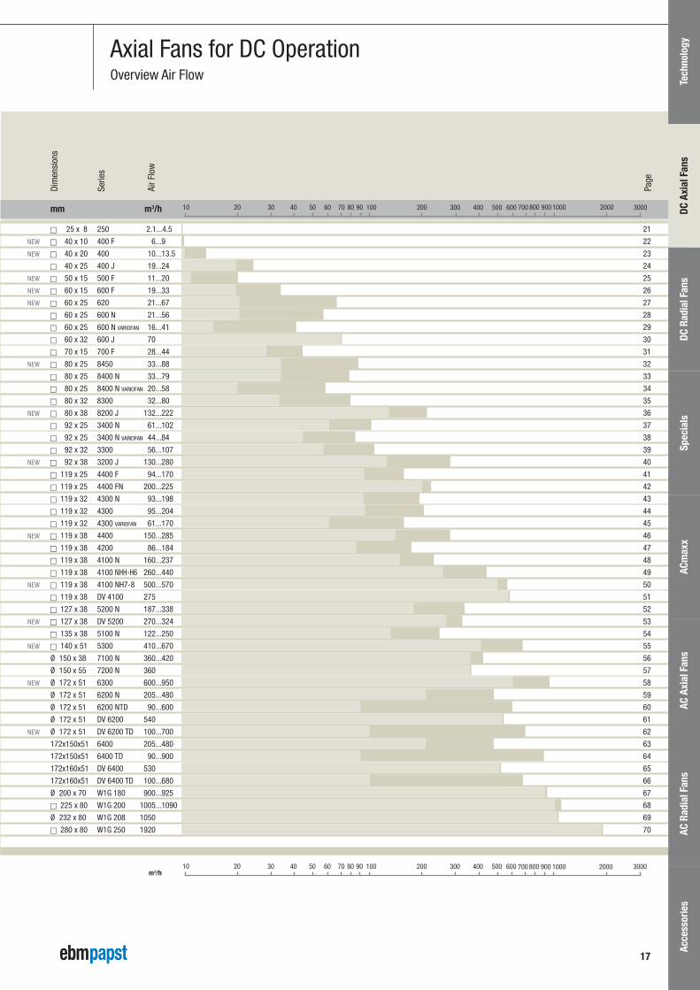
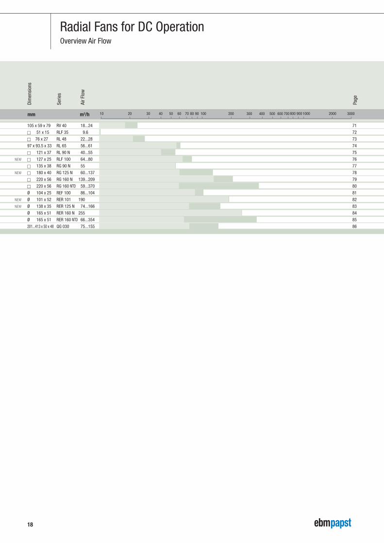


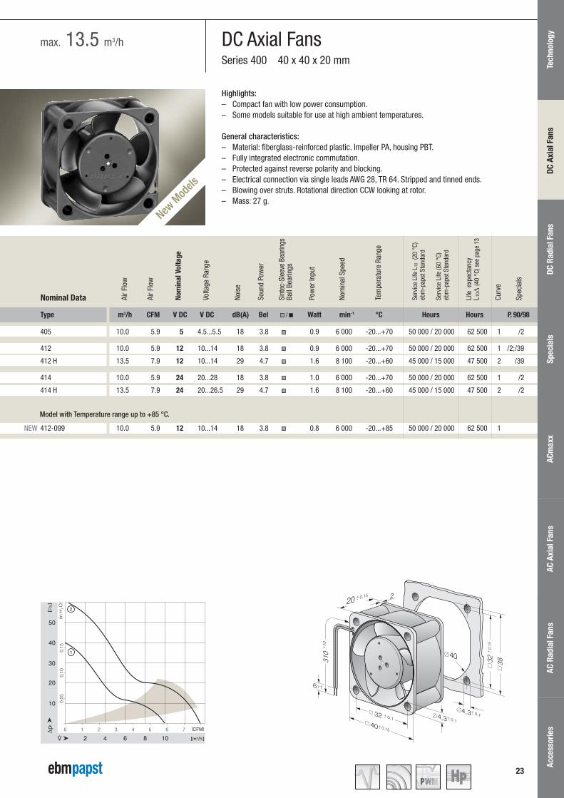
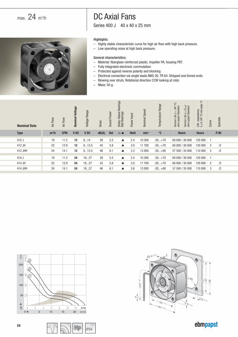

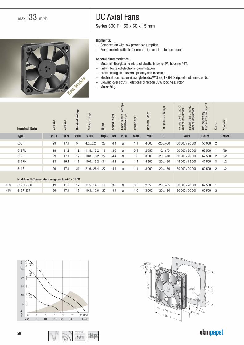
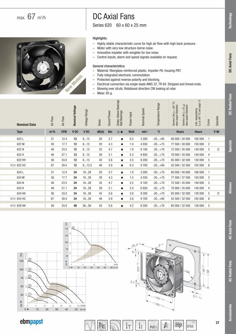


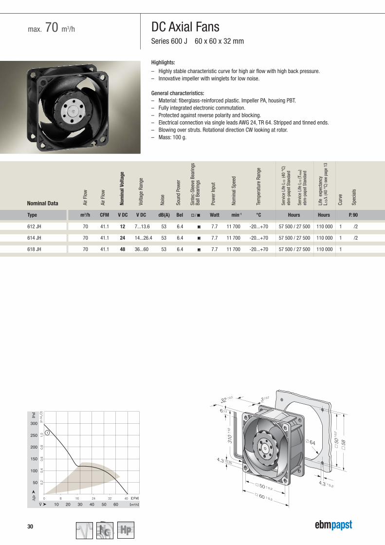

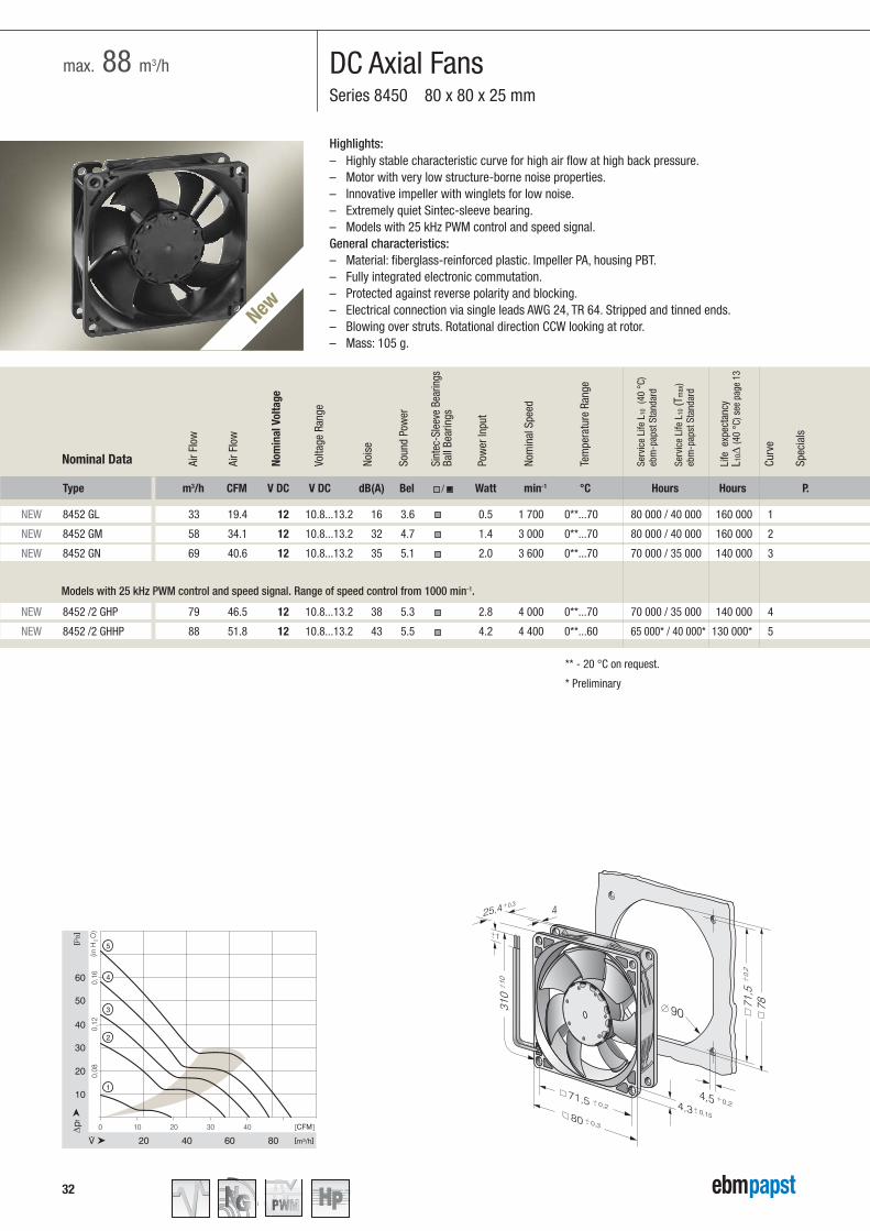


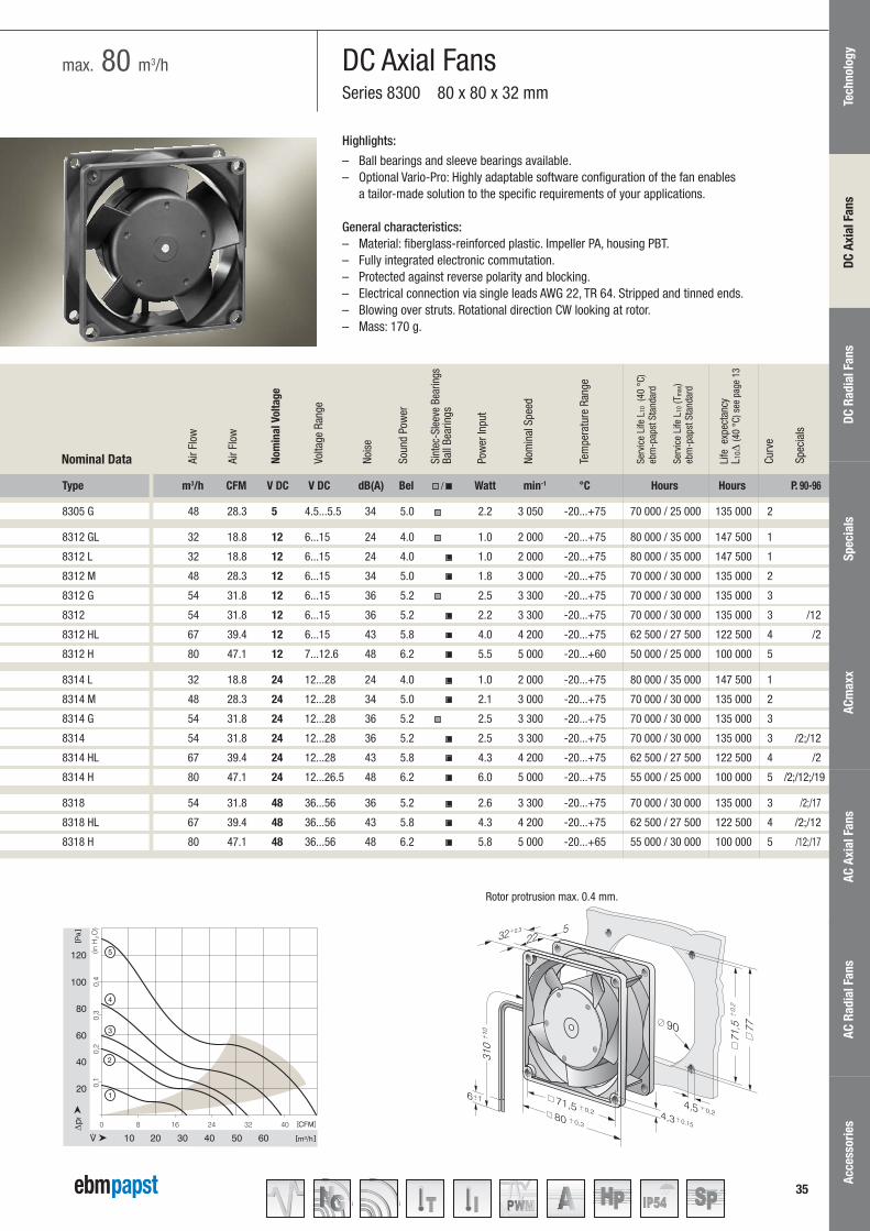

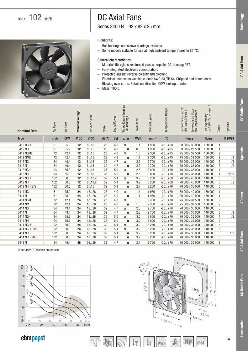


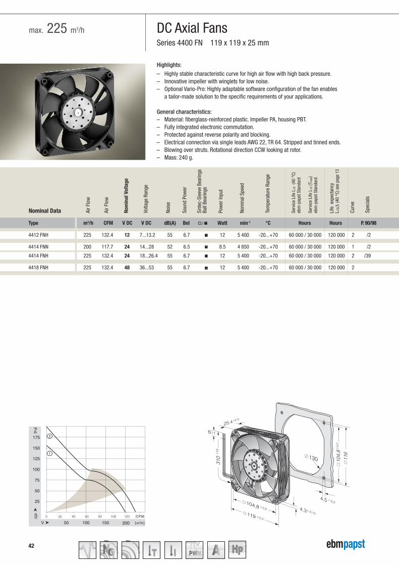


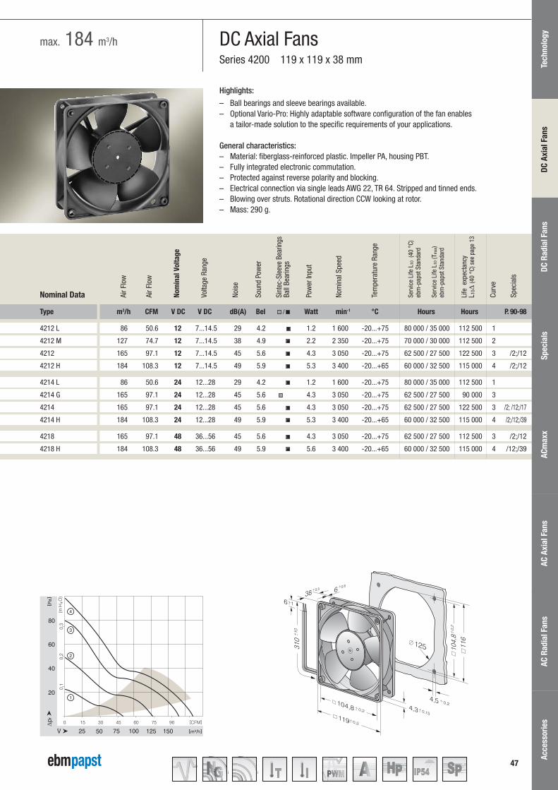

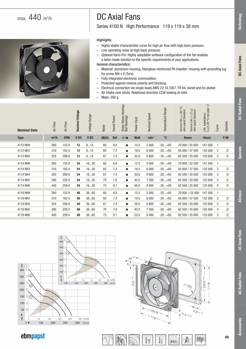


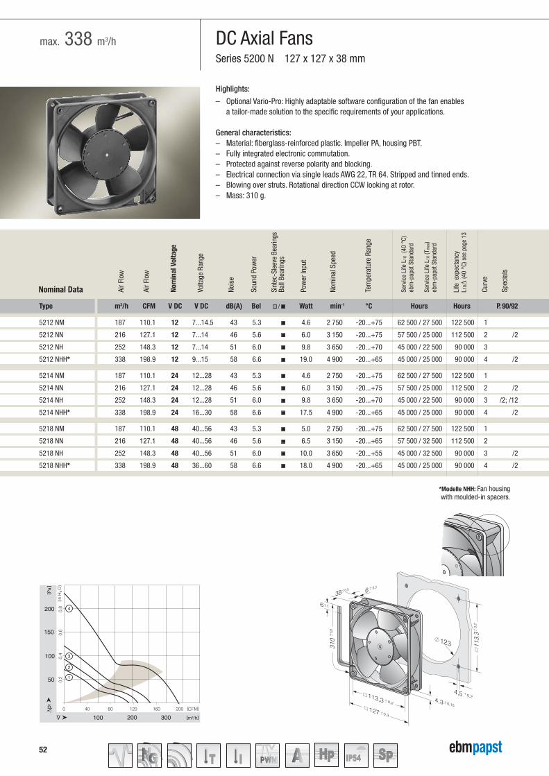
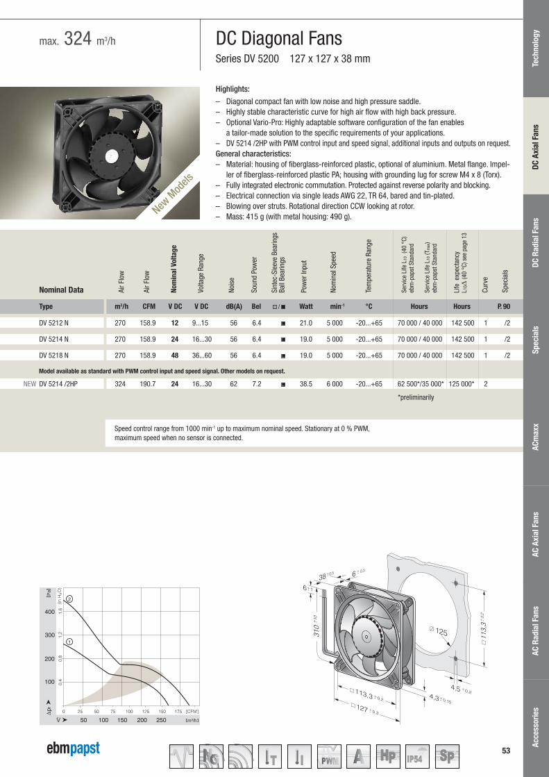
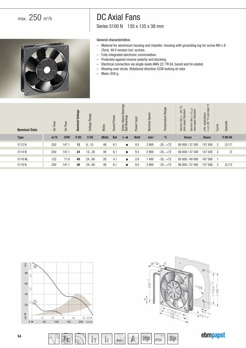

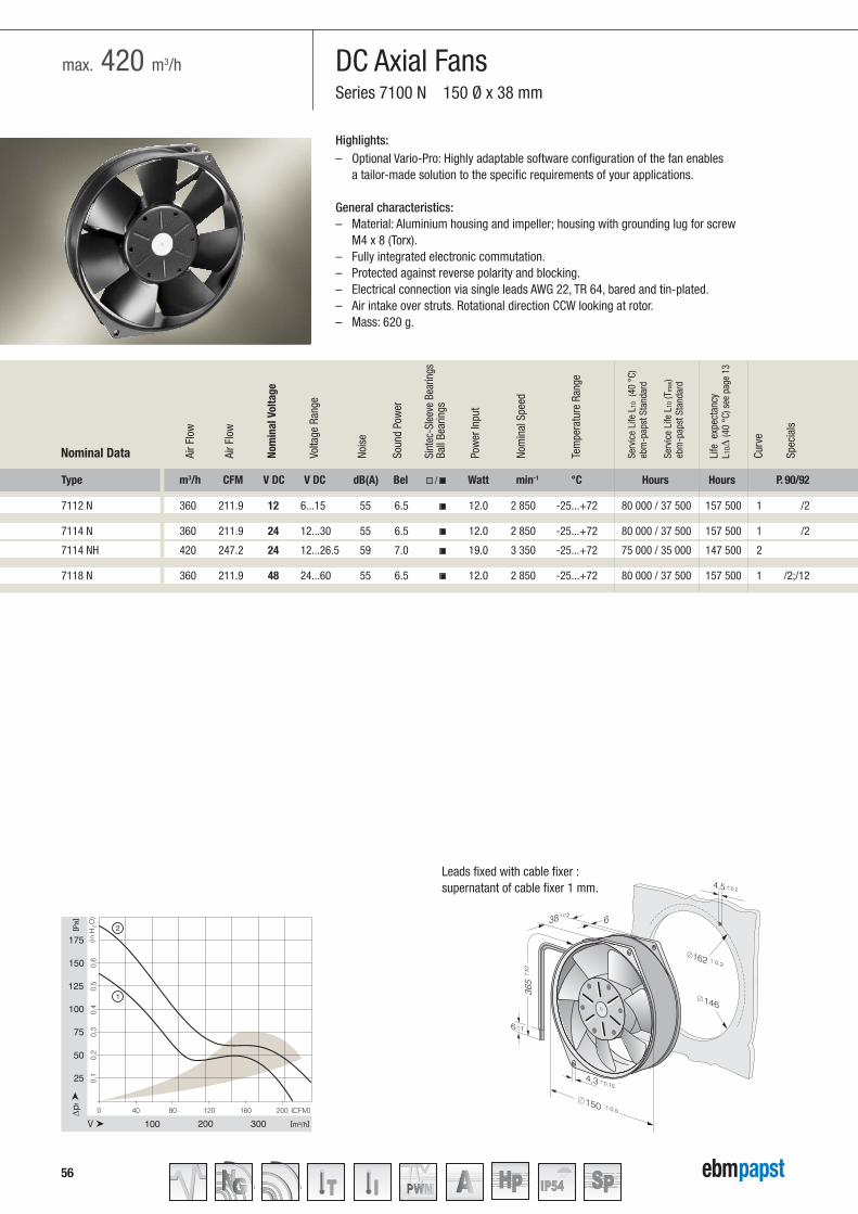
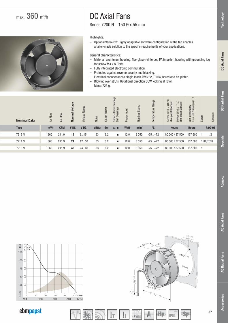


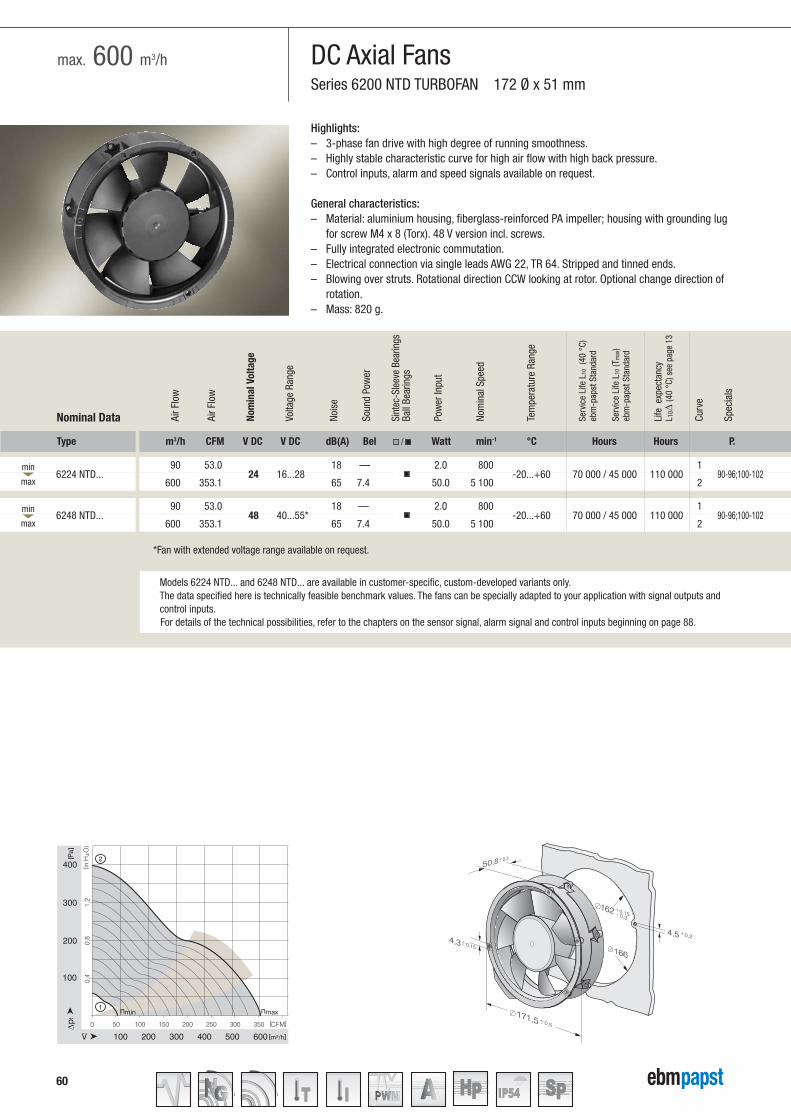
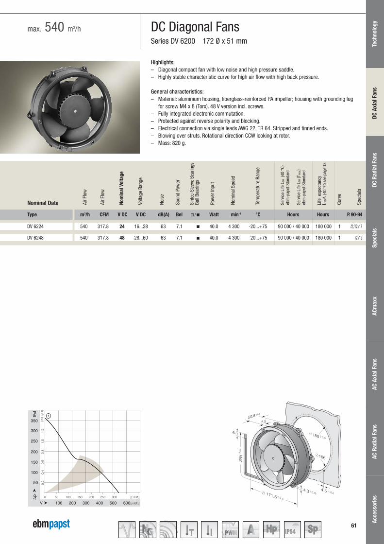


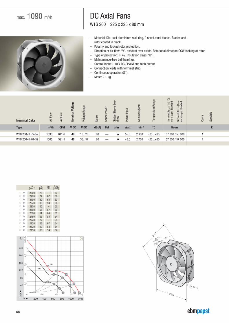

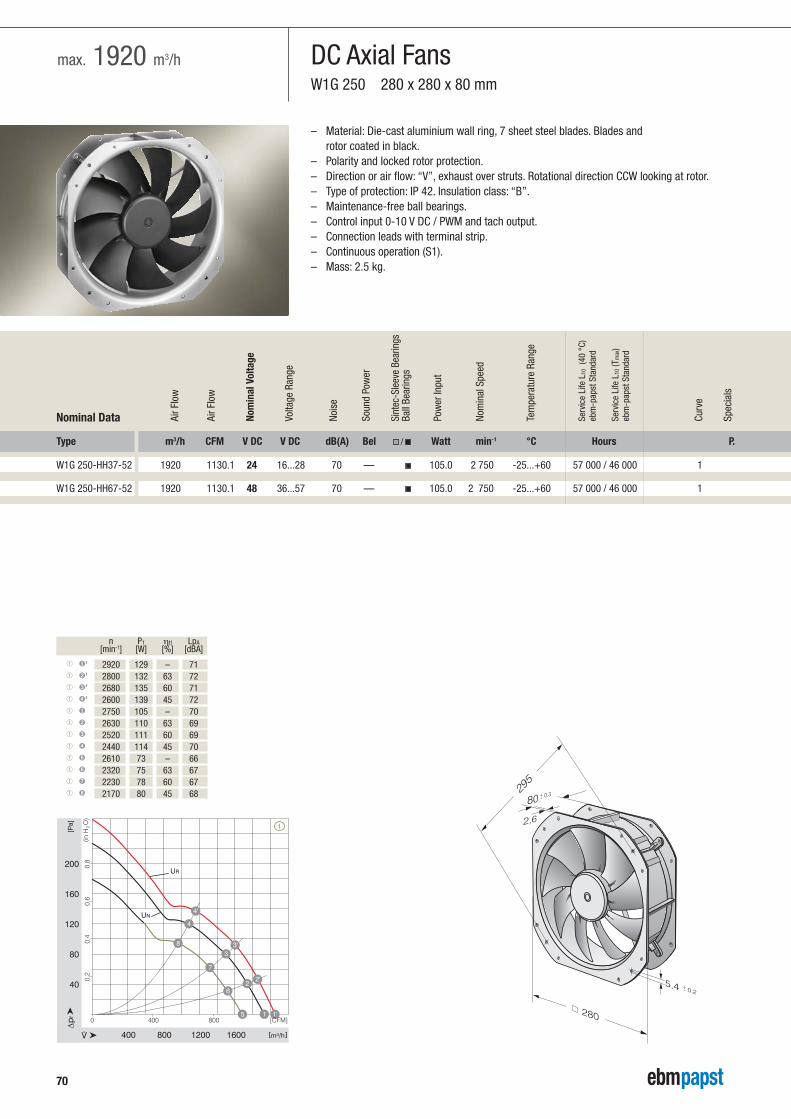


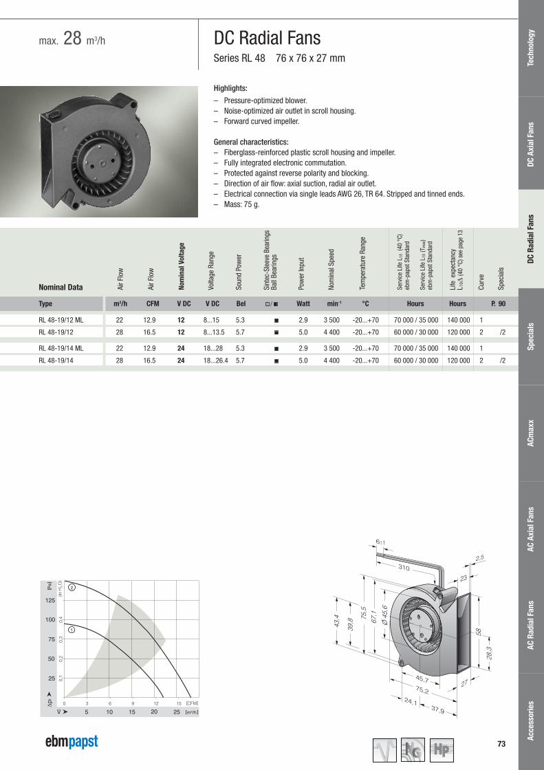


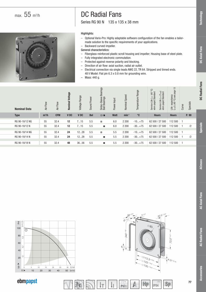


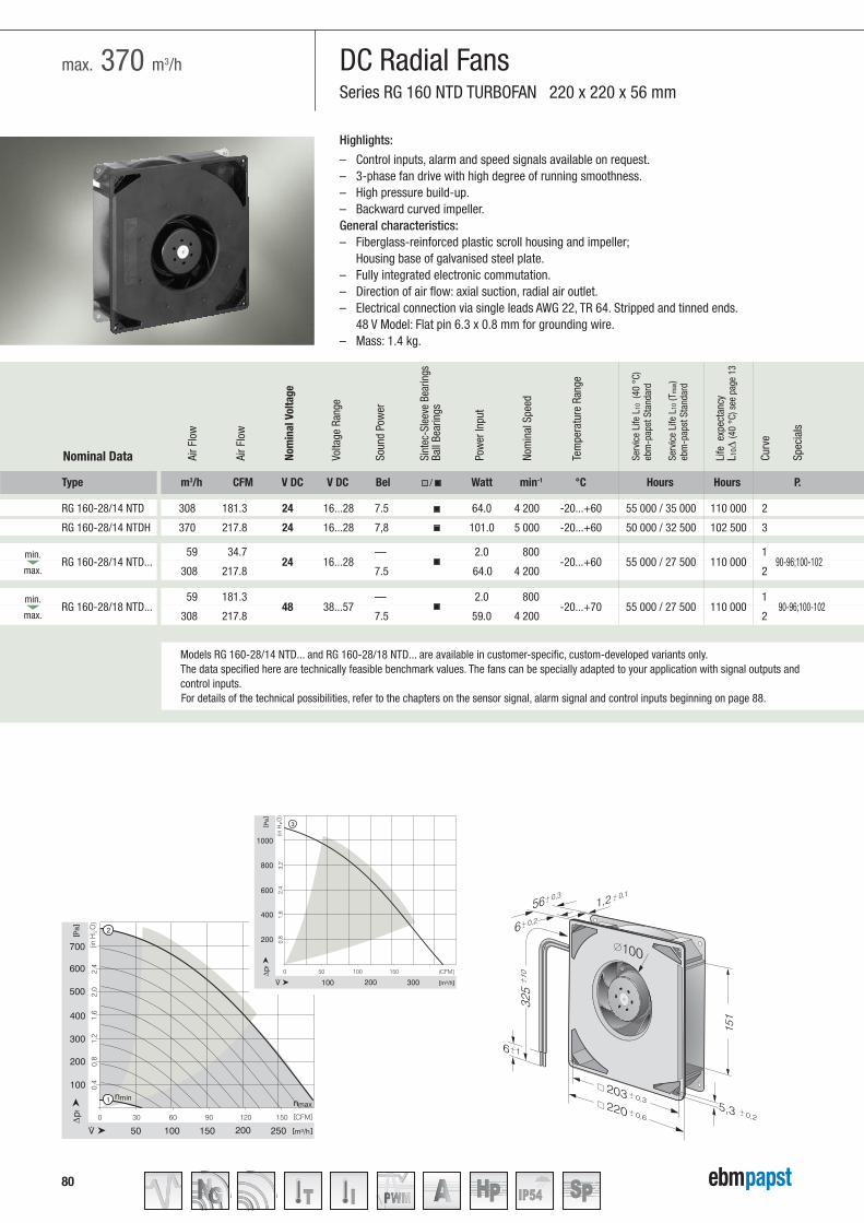

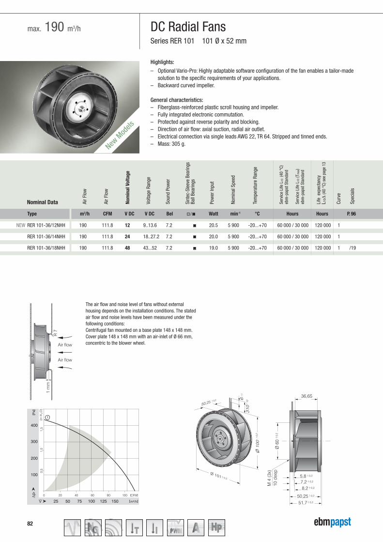
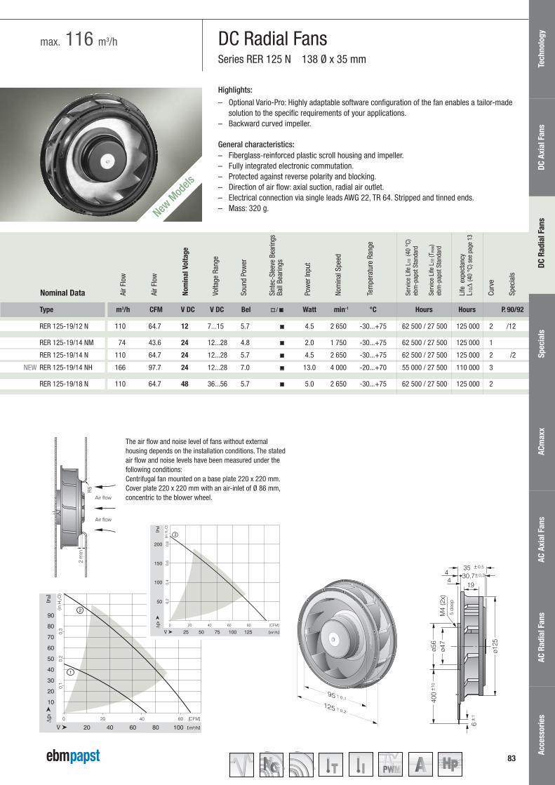
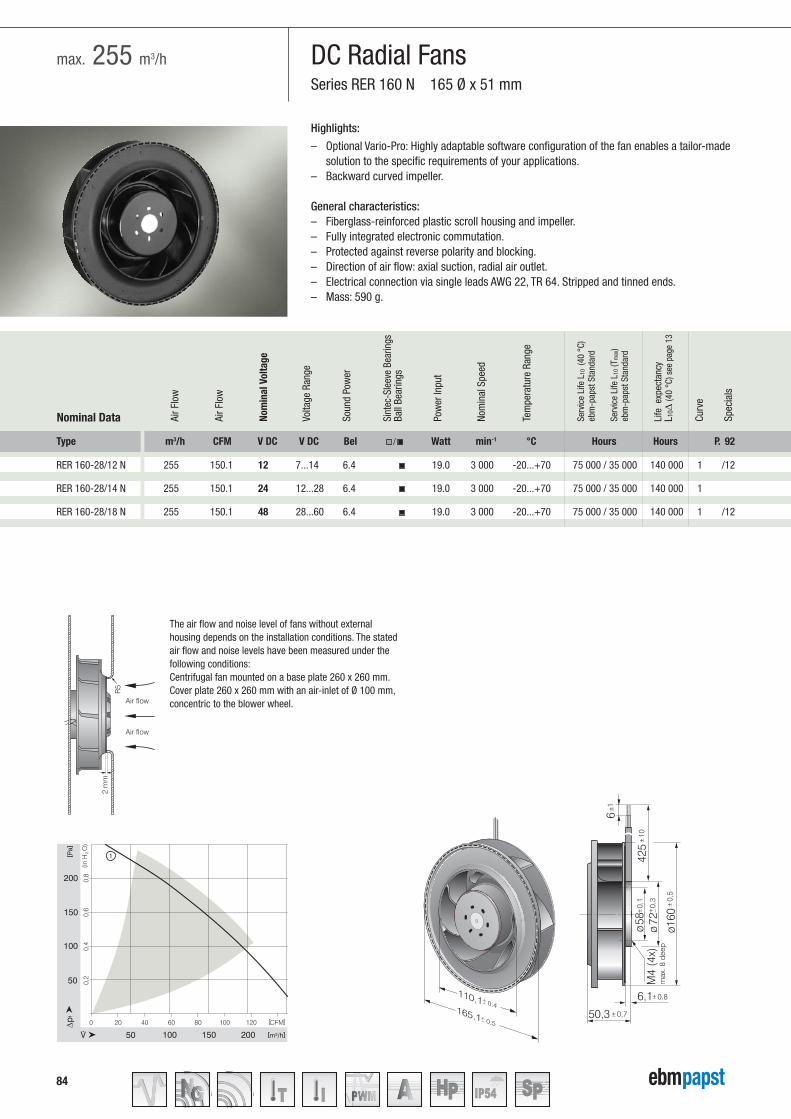
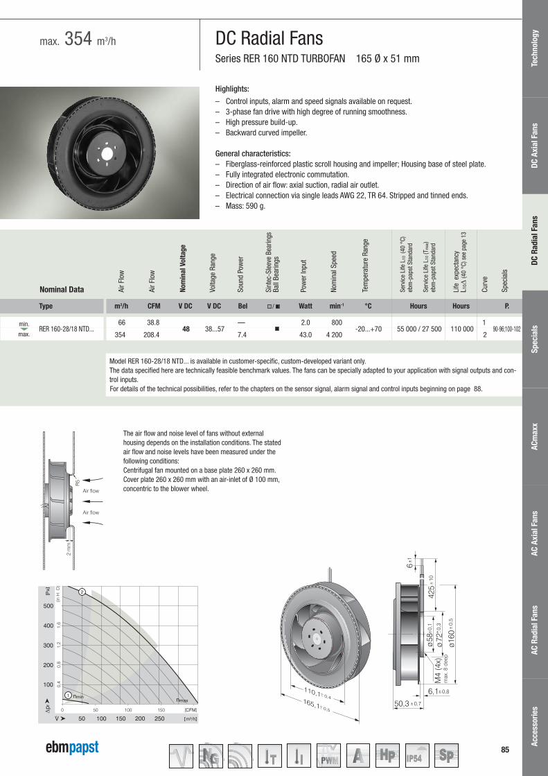


![MEDICAL ROBOTIC - its.ac.id€¦ · 4[BM : 3 x 50] 4[PT : 3 x 50 _] Presentation and brainstorming, ask and answer. 4[FF : 3 x 50”] 4[SA : 3 x 50”] 4[SS : 3 x 50”] Chatting](https://static.documents.pub/doc/80x56/60daab835283c33b4202dd27/medical-robotic-itsacid-4bm-3-x-50-4pt-3-x-50-presentation-and-brainstorming.jpg)


