36
Submittal APC MX28B1200 - 48VDC Output 600A DC Power System Submitted to: Paul Egger Company: Microsoft Corporation DATE: May 1, 2001
Submittal APC MX28B1200 - 48VDC Output
600A DC Power System
Submitted to: Paul Egger Company: Microsoft Corporation DATE: May 1, 2001

CONTENTS
Section I: Bill of Materials…………... Proposed System Weights and Dimensions Section II: DC Plant Technical Description… Description of DC Plant Section III: System Installation Data…. System Drawings Section IV: Literature……………………… DC Plant, Accessories and Battery Solution

SECTION I
Bill of Materials
Includes:
• System Part Numbers • System Descriptions • System Dimensions • System Weights
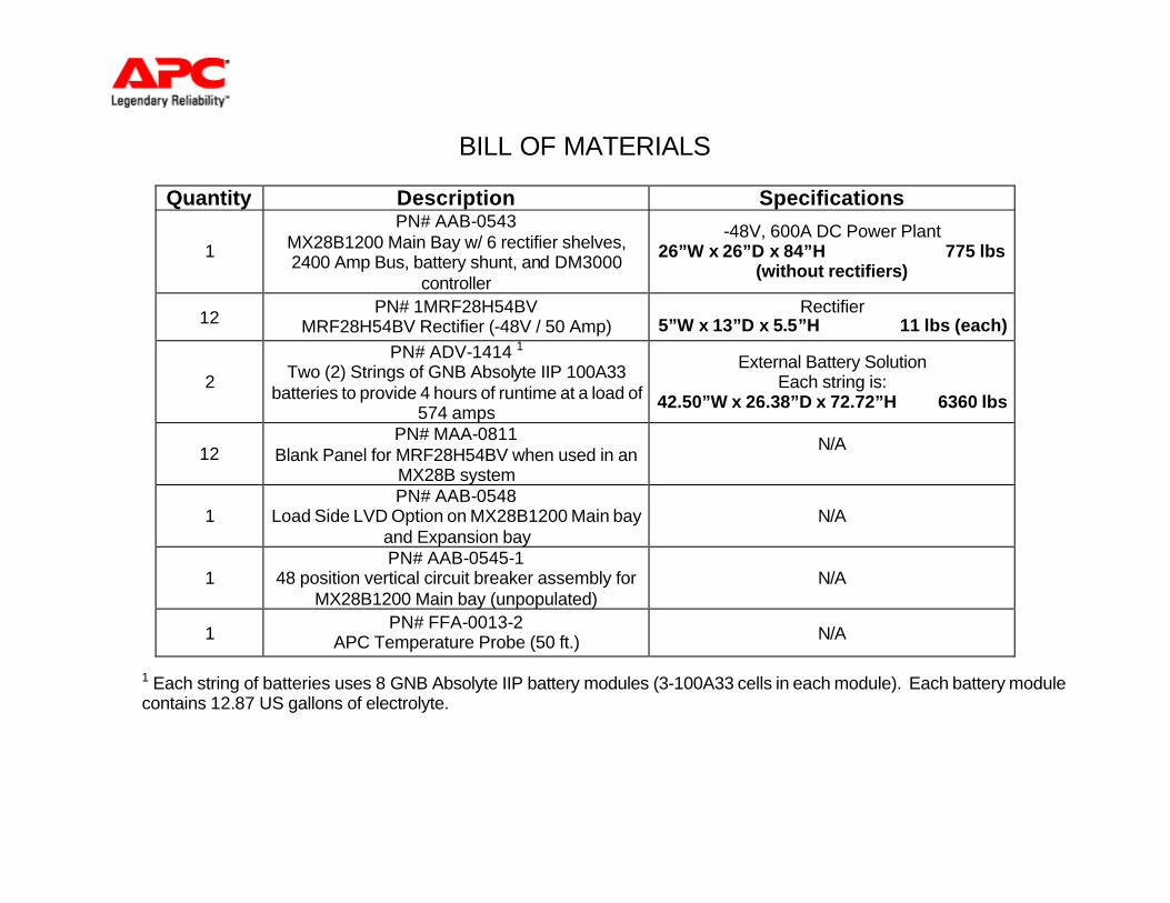
BILL OF MATERIALS
1 Each string of batteries uses 8 GNB Absolyte IIP battery modules (3-100A33 cells in each module). Each battery module contains 12.87 US gallons of electrolyte.
Quantity Description Specifications
1
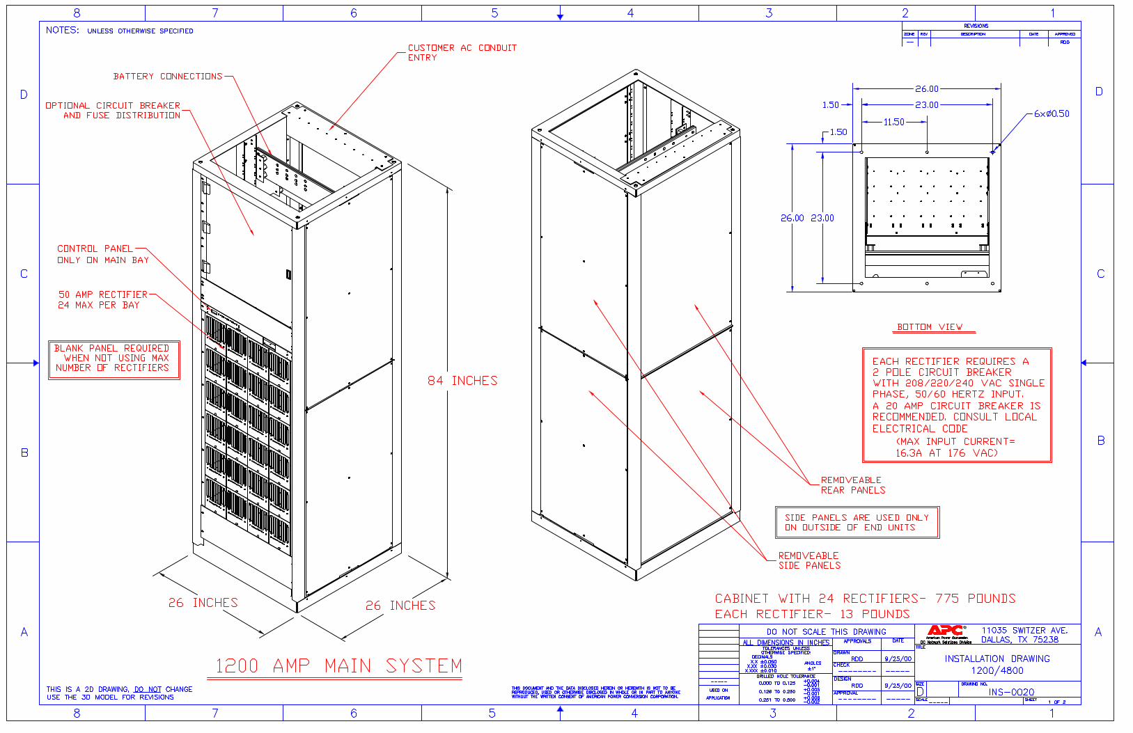
PN# AAB-0543 MX28B1200 Main Bay w/ 6 rectifier shelves, 2400 Amp Bus, battery shunt, and DM3000
controller
-48V, 600A DC Power Plant 26”W x 26”D x 84”H 775 lbs
(without rectifiers)
12 PN# 1MRF28H54BV
MRF28H54BV Rectifier (-48V / 50 Amp) Rectifier
5”W x 13”D x 5.5”H 11 lbs (each)
2
PN# ADV-1414 1
Two (2) Strings of GNB Absolyte IIP 100A33 batteries to provide 4 hours of runtime at a load of
574 amps
External Battery Solution Each string is:
42.50”W x 26.38”D x 72.72”H 6360 lbs
12 PN# MAA-0811
Blank Panel for MRF28H54BV when used in an MX28B system
N/A
1 PN# AAB-0548
Load Side LVD Option on MX28B1200 Main bay and Expansion bay
N/A
1 PN# AAB-0545-1
48 position vertical circuit breaker assembly for MX28B1200 Main bay (unpopulated)
N/A
1 PN# FFA-0013-2
APC Temperature Probe (50 ft.) N/A
SECTION II
DC Plant Technical Description
Includes:
• System Technical Description as reference only. Not necessary for installation. • DC Plant electrical performance data.
Technical Specification for Fully Integrated DC Power Plants in a Range from 50 amps to 4800 amps.
1. GENERAL
1.1. This specification applies to fully integrated power systems based on switch mode rectifier/charger modules with ratings greater than 1,000 watts and less than 6,000 watts output.
1.2. A fully integrated power system is defined as one in which all the functional elements of a power system are mounted in a single chassis, cabinet or a commonly connected and collocated combination of cabinets.
1.3. Where the load requirement exceeds the rectifier capacity of the largest stand-alone integrated power system, the design of the overall power system shall allow for individual systems to be operated in parallel on a common bus, under the supervision of a single system monitor / controller.
1.4. The power system should be designed to provide compact, easy to install, DC power for typical telecommunication loads such as circuit switching, microwave radio, trunking radio, fiber optics, cellular radio, digital loop carriers, paging, specialized mobile radio (SMR) and personal communications systems (PCS).
1.5. The power system shall be capable of operation with or without a battery connected.
1.6. Active power factor correction circuitry shall be used to insure that the rectifier presents a sinusoidal input to the AC supply with minimum harmonic distortion.
1.7. Integrated power systems designed for rack mounting shall be conformance with EIA 19” or 23" standard practices.
1.8. Racks and cabinets shall be designed and constructed to meet the required seismic zone requirements as applicable to the installation location.
1.9. Bus bars within equipment shall be a minimum of 95% tin plated copper, and their width should be sufficient for two-hole lug connections on 1-inch center spacing.
1.10. All power equipment must conform to American National Standards Institute (ANSI) requirements, and shall be National Recognized Testing Laboratory (NRTL) tested to Underwriters Laboratories (UL) 1950.
1.11. The supplier shall meet the requirements of Telcordia GR-1089 and GR-63-CORE as applicable to the equipment and the application.
1.12. The structural members of power equipment shall not carry or conduct load currents. Ferrous materials shall not be used for current carrying parts.
1.13. Metal parts, unless corrosion resistant, shall have a corrosion protection finish. Ferrous parts not required to meet an appearance criteria shall have either zinc plate, or an approved equivalent finish applied
1.14. Insulating materials in arcing paths of contacts, fuses, etc., shall be of the non-tracking type. Insulating material shall not be used that will independently support combustion, or that will ignite from a spark, flame, or heating. The combustion products of insulating materials shall not combine with normal atmospheric air to form acid, toxic, or other deleterious products. An associated battery plant, while considered a potential source of corrosive pollution shall be, designed to meet acceptable industry safety requirements with respect to gassing, temperature control, pollution, and suitability for use in the application.
2. SYSTEM CAPACITY
2.1. The integrated power system shall have a capacity of 1200 amperes at a nominal 48 VDC.
2.2. Initially the system shall be provided with a quantity of rectifier/chargers capable of supporting a load of 600 amps at a nominal 48 VDC. An additional rectifier shall be installed in order to provide N+1 redundancy. All necessary hardware for the addition of rectifiers necessary to support a final load of 1200 amps shall be installed with all internal wiring connected. Any rectifier positions without rectifiers fitted shall have with blank covers.
2.3. The battery plant shall be sized for the maximum specified capacity of the system, or if so indicated, shall support an initial load of 574 amps for 4 hours at a nominal temperature of 25 degrees Fahrenheit to a discharge voltage of 1.75 volts per cell, with expansion capabilities to support an eventual load of 574 amps for 4 hours. Any expansion of the battery plant shall comply with the limitations on parallel strings as detailed in Section 12.
3. MANUFACTURER
3.1. Acceptable vendors of the DC power system and accessories defined in this specification shall be restricted to those companies who are established vendors of this type of equipment either historically or through acquisition.
4. RECTIFIERS
4.1. Each rectifier shall be designed for field replacement without the need for specialized tools or test equipment. Insertion and removal of the rectifier from the mating connector assembly shall not require the isolation of the rectifier from either the AC input or the DC output bus. Vendors offering rectifiers fitted with such manual disconnects shall clearly demonstrate that insertion or removal of such a rectifier without operation of the manual disconnects shall not cause transients greater than those specified under normal rectifier operation.
4.2. Each rectifier shall be capable of accepting an AC input of 176 to 293 VAC, 45 to 65 Hz, single phase.
4.3. Each rectifier shall be equipped with AC input over current protection; either a two pole UL Recognized circuit breaker or UL Listed fuses.
4.4. Each rectifier shall have the capability to independently shut down in the event that the rectifier senses an over voltage condition on its output. For a nominal –48V power system this over voltage point shall be set at 59.5V +/- 0.5V.
4.5. Each rectifier shall be diode or circuit breaker protected on the DC output to ensure that a fault in the rectifier will not short the DC bus.
4.6. The output voltage of each rectifier shall be fully adjustable over the range 48 – 58 V either locally with a control on each rectifier or under the control of central controller.
4.7. Each rectifier shall be current limited at nominal line to a maximum of 105% of rated output current. In addition, the rectifier shall protect itself from an output short circuit by limiting the current to a maximum of 105% of rated current. Once the short circuit is removed, the rectifier shall resume normal operation without manual restart.
4.8. Separate test points shall be provided to measure the exact DC voltage and current output of each rectifier
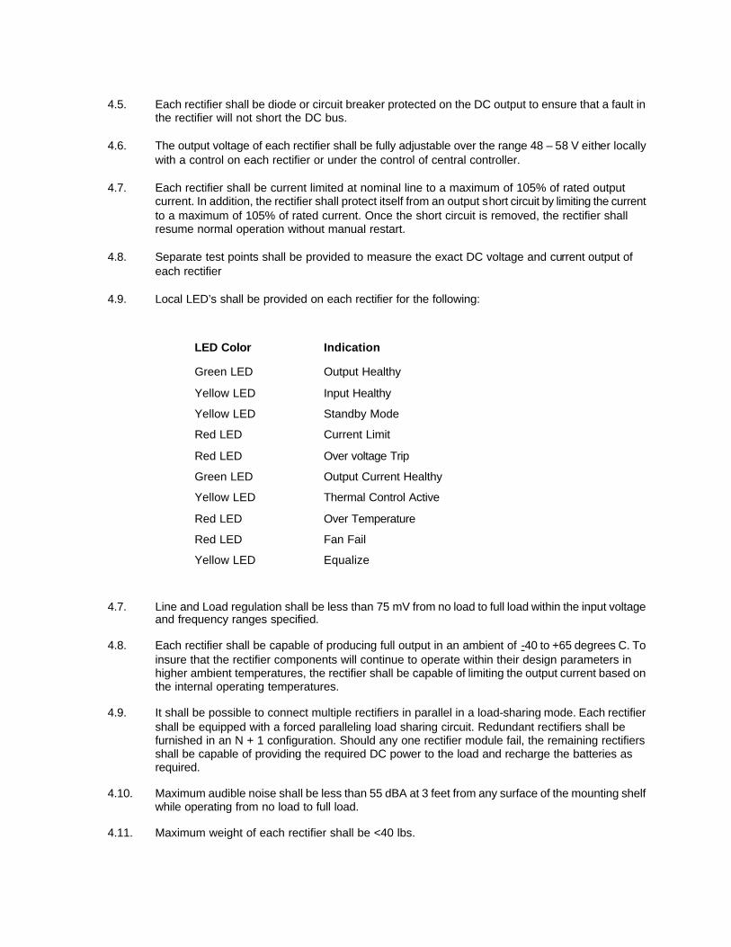
4.9. Local LED’s shall be provided on each rectifier for the following:
LED Color Indication
Green LED Output Healthy
Yellow LED Input Healthy
Yellow LED Standby Mode
Red LED Current Limit
Red LED Over voltage Trip
Green LED Output Current Healthy
Yellow LED Thermal Control Active
Red LED Over Temperature
Red LED Fan Fail
Yellow LED Equalize
4.7. Line and Load regulation shall be less than 75 mV from no load to full load within the input voltage and frequency ranges specified.
4.8. Each rectifier shall be capable of producing full output in an ambient of -40 to +65 degrees C. To insure that the rectifier components will continue to operate within their design parameters in higher ambient temperatures, the rectifier shall be capable of limiting the output current based on the internal operating temperatures.
4.9. It shall be possible to connect multiple rectifiers in parallel in a load-sharing mode. Each rectifier shall be equipped with a forced paralleling load sharing circuit. Redundant rectifiers shall be furnished in an N + 1 configuration. Should any one rectifier module fail, the remaining rectifiers shall be capable of providing the required DC power to the load and recharge the batteries as required.
4.10. Maximum audible noise shall be less than 55 dBA at 3 feet from any surface of the mounting shelf while operating from no load to full load.
4.11. Maximum weight of each rectifier shall be <40 lbs.
4.12. Efficiency of each rectifier from 50% load to full load shall be 90% minimum under all input line
conditions (176 VAC to 293 VAC). The efficiency is to include the Series Diode or any other output protection device.
4.13. The power factor from 50% load to full load shall be .98 minimum at nominal AC inputs of 208, 220, 240 and 277 VAC.
4.14. Psophometric output noise shall be less than 29 dBrnC.
4.15. Output ripple shall be less than 15 mV rms between 10Hz and 100 MHz and less than 40 mV peak-to-peak between 10 and 100 KHz.
5. PRIMARY DC DISTRIBUTION
5.1. The power system shall have the capability to support the number of user circuits as defined in the attached distribution schedule.
5.2. The distribution panels within the power system shall have the capability to support either fuse or circuit breaker distribution.
5.3. Fuses and circuit breakers used shall be rated for DC operation and shall be approved for use in the authority having jurisdiction (AHD) in which they are to be used. They shall be clearly marked with the safety certification and the standard to which they are tested. Certification marks from NRTL’s are acceptable.
5.4. The Interrupting rating of each fuse or circuit breaker shall always exceed the available short circuit current at the point where the over current protection device is connected to the DC source.
5.5. All fuses and circuit breakers shall have the capability to indicate whether the fuse has blown or the circuit breaker has tripped. To facilitate the prompt restoration of service individual status reporting of the fuses and circuit breakers is the preferred option. Where that is not available then the fuses and circuit breakers shall be logically grouped and each group shall be alarmed. Local visual indication of an alarm condition is required.
5.6. If the integral distribution panels of the power bay(s) have insufficient capacity to meet the specified requirements, additional distribution bays may be added. The additional distribution bays shall be designed to allow direct connection to the common system bus.
5.7. The power distribution system shall be configured to allow all user terminations to be made from the front of the unit.
6. SECONDARY DC DISTRIBUTION
6.1. Where specified in the attached distribution schedule, secondary distribution bays shall be provided. These bays shall be designed for operation in the user environment and shall be fully enclosed.
6.2. Secondary Distribution bays shall be designed for use with plug in circuit breakers rated from 1 to 100 amps.

6.3. Each breaker position shall incorporate a tin plated copper pad drilled to accept an industry
standard two-hole crimp lug. The holes shall be internally threaded or be fitted with a threaded insert to allow the attachment of the lug using only one tool.
6.4. The design of the mounting for the plug in circuit breaker shall allow for the replacement of the circuit breaker without the use of tools or the need to disconnect the load cables if installed.
6.5. Secondary distribution bays shall be designed for top or bottom access.
6.6. Secondary Distribution Bays shall be constructed in such a manner to allow for the circuit breakers to be isolated in groups both physically and electrically for the purposes of establishing “A” and “B” redundant feeds to the individual loads. The bays shall incorporate the ability to monitor the voltage and current of each circuit breaker section.
7. GROUND BUS
7.1. Each of the integrated power system modules, cabinets and distribution cabinets shall be equipped with a common ground bus rated at not less than the maximum rating of the system or cabinet in which it is installed.
7.2. This ground bus shall be tin plated copper with a pattern of mounting holes that will allow all the battery and load returns within that system or cabinet to be terminated using appropriately sized two hole compression lugs. All mounting holes on the ground bus shall be threaded or fitted with captive hardware for easy installation of the customer's ground connections in the field.
7.3. In addition to the mounting positions for all the load and battery returns, at least one ground bus within the power system shall have a position available at which a 750 kcmil cable can be terminated in order to allow the DC system to be grounded at the master station grounding bar.
8. SYSTEM MONITOR
The power systems shall be capable of monitoring and/or generating the following alarm conditions:
8.1. Rectifier Fail.
The monitor shall generate this alarm on the failure of one rectifier module.
8.2. Two Rectifiers Fail.
The monitor shall generate this alarm on the failure of two or more rectifier module.
8.3. High Voltage Alarm.
The monitor shall continuously monitor the bus voltage and generate a High Voltage Alarm in the event that the bus voltage exceeds a user-defined value. This alarm shall be in addition to any High Voltage Alarms generated and reported by the individual rectifiers.
8.4. Low Voltage Alarm.
The monitor shall continuously monitor the bus voltage and generate a Low Voltage Alarm in the event that the bus voltage exceeds a user-defined value. This alarm shall be in addition to any Low Voltage Alarms generated and reported by the individual rectifiers.
8.5. System Over-Temperature Alarm
The monitor shall continuously monitor the temperature within the equipment enclosure or rack and generate a System Over-Temperature Alarm in the event that the temperature exceeds a user-defined set point.
8.6. System Low Temperature Alarm
The monitor shall continuously monitor the temperature within the equipment enclosure or rack and generate a System Low Temperature Alarm in the event that the temperature drops below a user-defined set point.
8.7. Distribution Circuit Breaker Trip / Fuse Fail Alarm
The monitor should be capable of identifying up to 72 circuit breaker and 16 fuse alarms. All other distribution alarms should be consolidated and presented as a single alarm.
8.8. Battery Discharge Alarm
The Battery Discharge Alarm shall continuously monitor the battery current during discharge and generate an alarm in the event that the battery discharge current exceeds a user-defined set point.
8.9. Battery High Temperature Alarm
If the power system has been configured for temperature compensated charging. The monitor shall continuously monitor the temperature probe installed at the battery and generate a Battery Over-Temperature Alarm in the event that the temperature exceeds a user-defined set point.
8.10. Battery Low Temperature Alarm
If the power system has been configured for temperature compensated charging. The monitor shall continuously monitor the temperature probe installed at the battery and generate a Battery Low Temperature Alarm in the event that the temperature drops below a user-defined set point.
8.11. User Defined Alarms
The monitor shall have the capability to monitor and report on up to four external contact closures and to allocate user defined functions to each one.
8.12. Major Alarm
The monitor shall have the capability to generate a consolidated alarm that would provide a single alarm indicating that the power system had suffered a failure or failures that could impact the ability to provide sufficient power to support the load. The user shall have the ability to manually or within software, establish the combination of system alarms that would create this alarm condition. Visual indication of this alarm condition shall be provided on the front panel of the monitor and a set of form “C” contacts will be made available to provide remote indication of the alarm.
8.13. Minor Alarm
The monitor shall have the capability to generate a consolidated alarm that would provide a single alarm indicating that the power system had suffered a failure or failures that although not impacting the ability of the power system to support the load, will require attention. The user shall have the ability to manually or within software, establish the combination of system alarms that would create this alarm condition. Visual indication of this alarm condition shall be provided on the front panel of the monitor and a set of form “C” contacts will be made available to provide remote indication of the alarm.
9. SYSTEM CONTROL
The power system shall be capable of controlling the following functions:
9.1. Output Voltage Control
The controller shall allow the user to establish a nominal operating voltage for the system by setting the system output voltage parameter in software. For systems, which have the temperature compensation activated, the voltage setting will reflect the required output voltage at 25 degrees Centigrade.
9.2. Temperature Compensation
Temperature compensation shall be a user selectable feature. If selected the controller shall have the capability to set the required rate of change in millivolts per degree C as specified in the battery manufacturers documentation. It should also have the ability to set both a lower and upper limit after which no further adjustment to the output voltage is made.
9.3. Battery Recharge
To minimize the potential for too much current being drawn by the battery after a discharge, the system control shall have the ability to set the maximum value of recharge current that is recommended by the battery manufacturer.
9.4. Low Voltage Disconnect (LVD)
The controller shall have the ability to control a minimum of two LVD contactors and shall have the capability to set both the dropout and the reconnect thresholds of each contactor independently. In the event that the controller recognizes that the position of an LVD does not match the command status then an alarm shall be generated.
10. REMOTE ACCESS and CONTROL
10.1. Relay Based Alarms
The monitor controller shall have the capability to provide remote indication of the alarm status through the provision of form “C” alarm contacts. In addition to the Major and Minor alarms the monitor shall provide an additional six sets of Form “C” contacts which can be allocated to any of the existing alarms condition generated or consolidated by the monitor.
10.2. Remote Access
The monitor controller shall have as an option the capability of being accessed from a remote location using a number of different communication mediums and protocols.
These methods of access shall include;
Dial up modem
SNMP over 10 base T network
Web Browser over 10 base T network
Telnet over 10 base T network

10.3. Security
A minimum of three levels of security shall be provided to prevent unauthorized changes to the system configurations.
The base level shall require no password but will be restricted to viewing of status only.
Level 2 will allow the user to set base parameters.
Level 3 will allow access to all configurable parameters.
11. AC INPUT
11.1. The power system shall have a removable gland plate, which has adequate area on which to land a minimum of one conduit per rectifier shelf.
11.2. An AC interface area within the power system shall be provided to allow the termination of the AC feeds from a user supplied AC circuit breaker panel. Terminal blocks approved for use in this application shall be provided to terminate both the external AC feeds and all internal AC loads.
11.3. All internal AC loads shall be factory terminated on terminal blocks and clearly identified and marked.
11.4. THHN, THW, or THWN type wire, color coded as indicated below is acceptable for use in the AC circuits. Color Code for AC 120/240 VAC single phase, and 120/208 VAC Three Phase
Line Color
1(A) Black
2(B) Red
3(C) Blue
Neutral White
Grounding Green
Color Code for AC 277/480, Three Phase
Line Color
1(A) Brown
2(B) Orange
3(C) Yellow
Neutral White
Grounding Green
11.5. All AC conductors shall be copper.
12. BATTERIES
12.1. If required, the power system vendor shall supply a battery system that will meet the criteria as defined in paragraph 2.3 of this document.
12.2. For lower power configuration where the battery can be accommodated on battery trays installed within the equipment rack. The battery of choice shall be a 10 year design life, front access , VRLA battery designed specifically for telecommunication applications.
12.3. For medium power requirements and where 10 year design life VRLA battery cells can accommodate the load, a separate battery rack, cabinet, or other containment means may be used.
12.4. Where necessary for higher power applications, VRLA battery cells of a higher design life shall be used.
12.5. Unless otherwise specified, a minimum of two battery strings operating in parallel shall be provided. Each battery string shall be equipped with an appropriately rated battery disconnect device.
12.6. The maximum number of battery strings operated in parallel from a single bus connection shall not exceed five strings. Where more than five strings are required to meet the required load and requested run time. The battery specified shall be a manufacturer assembled configuration of parallel cells or shall include an intermediate bus assembly to equalize the charge voltage across the individual strings.
12.7. Battery disconnects devices shall be sized in such a manner that if the battery plant is placed on discharge while one battery string is off line for maintenance or repair, the remaining battery disconnect(s) shall be capable of carrying the load or recharge current without opening.
12.8. Battery systems shall comply with the seismic zone requirements of the location where they are to be installed.
13. WARRANTY
13.1. The manufacturer shall warrant the rectifier equipment for two years.
13.2. The warranty shall start on day of shipment.
13.3. The battery manufacturer shall warrant the batteries for the design life, with a two year full warranty and the remainder on a pro-rated basis.
SECTION III
DC System Installation Data
Includes:
• Drawings for evaluation and installation of the DC system.

MX28B-1200 System Diagram

SECTION IV
Literature
• Includes applicable brochures for reference only.
Features Ease of Installation
23" Cabinet
Each system contains up totwenty four 50A rectifiers pro-viding 1200A. Rectifiers aremounted four across in six4U shelves
SNMP interface
Battery TemperatureCompensation
Power Factor CorrectedRectifiers
Flexible Output Distributionbuilt in:1-100 Amp Small CircuitBreakers100-700 Amp Large CircuitBreakers70-600 Amp Large Fuses
Output Distribution Bays with:100-700 Amp Large CircuitBreakers70-600 Amp Large Fusesbuilt in
Current metering on large
distribution bays
Typical Applications Cellular and PCS
Distributed Networks
IXC (Inter Exchange Carrier)
ISP
Telehouse
Broadband Wireless
Fiber
Industry Approvals Safety: UL 1950
EMC: Complies with FCC Part
15 Subpart J, Class A
NEBS Pending
Warranty
The MX28B1200/4800 is underwarranty against faulty manufac-ture and faulty components for aperiod of two years from the dateof delivery. Please refer to condi-tions of sale for full details. Wereserve the right to amend specifi-cations without prior notification.
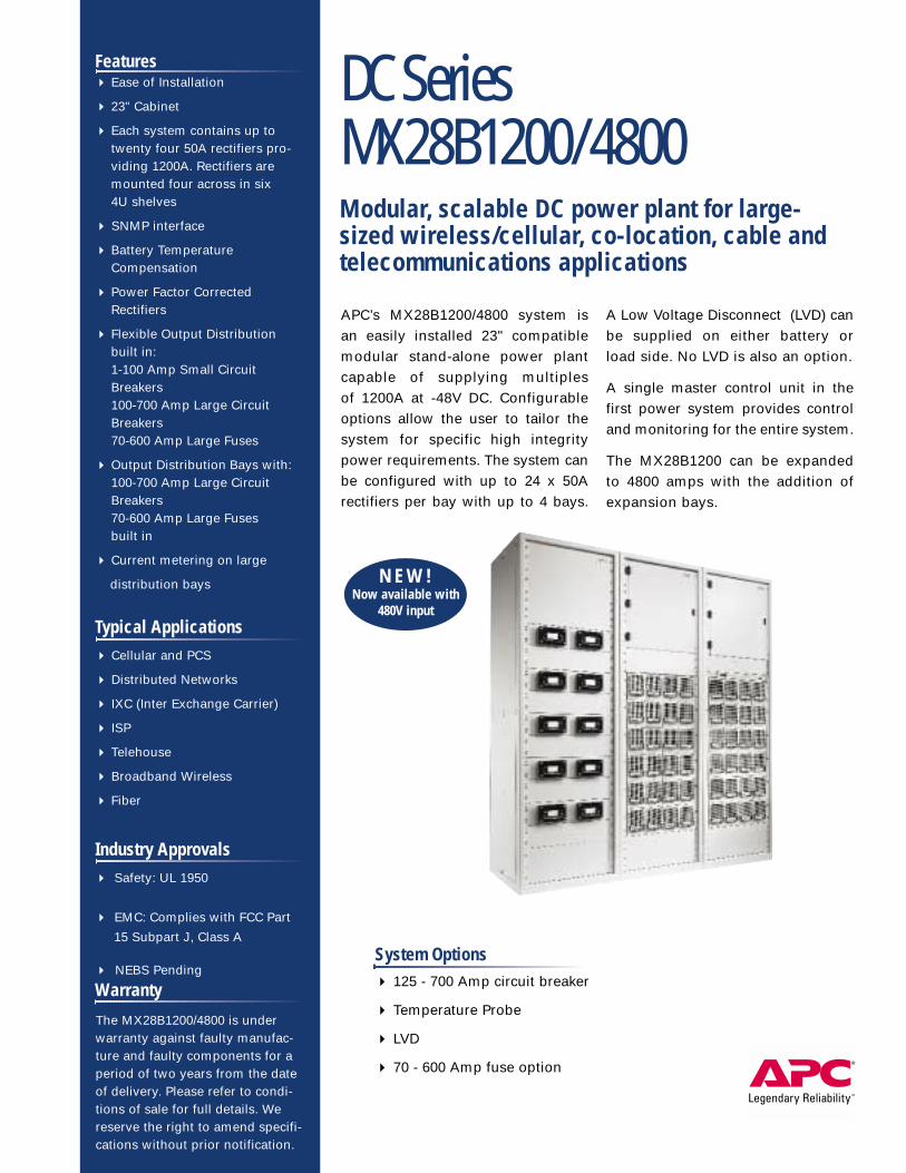
DC SeriesMX28B1200/4800Modular, scalable DC power plant for large-sized wireless/cellular, co-location, cable andtelecommunications applications
APC’s MX28B1200/4800 system is an easily installed 23" compatible modular stand-alone power plantcapable of supplying multiples of 1200A at -48V DC. Configurableoptions allow the user to tailor thesystem for specific high integritypower requirements. The system canbe configured with up to 24 x 50Arectifiers per bay with up to 4 bays.
A Low Voltage Disconnect (LVD) canbe supplied on either battery or load side. No LVD is also an option.
A single master control unit in thefirst power system provides controland monitoring for the entire system.
The MX28B1200 can be expandedto 4800 amps with the addition ofexpansion bays.
System Options 125 - 700 Amp circuit breaker
Temperature Probe
LVD
70 - 600 Amp fuse option
N E W !Now available with
480V input
An optional 48 position plug-in breaker tier provides -48V distribution. Connections for -48 Vdc loads, requiring standard #10-32 two-hole lugs on 5/8"centers, are located directly above the corresponding breaker. Alternative option panels include mounted circuit breakers for 250A to 700A range and70-600 amp large fuse holders. Optional large fuse and large circuit breaker bays are available
Weight 775 lbs. (352 kg)
Mechanical
Color Dawn Gray
Dimensions 23" rack - 26" wide x 26" deep x 84" high (660mm wide x 660mm wide x 2134mm high)
Up to 10,000 ft. (3000m), OperatingUp to 32,000 ft. (10,000m), Storage
-29˚F to +149˚F (-20˚C to +65˚C) Operating-40˚F to +185˚F (-40˚C to +85˚C) Storage0% to 85% RH non-condensing, Operating0% to 95% RH non-condensing, StorageHumidity
Altitude
Up to twenty-four MRF28H54BV or MRF28H54BV50 (277V input) rectifiers can be fitted in the cabinet dependent on system configuration.Rectifiers are forced air cooled with front to rear airflow
Overvoltage 59.5Vdc
Power Factor 99% Typical, 98% Minimum
A rear located enclosure provides a terminal strip(s) for AC input power connectionAC Input Connection
Output voltage 54.0Vdc nominal
Output Current 1200A up to 4800A dependent on configuration
Polarity Positive Earth
3 Phase Input V (nominal) Connection Phase Loading* input current per rectifier Phase loading input current per rectifier*Rectifierat nominal input voltage at nominal input voltage -15%
277/480V 3 phase Wye, 4 wire 11.5A 13.6A 1MRF28H54BV50
400V 3 phase Wye, 4 wire 13.9A 16.3A 1MRF28H54BV
208V 3 phase Delta, 3 wire 15.5A 16.3A 1MRF28H54BV
Safety UL 1950, NEBS pending
DC Output Specifications
Overvoltage
Complies with FCC Part 15 Subpart J, Class A pending
EMC
Safety
AC Input Specifications
Rectifiers
Temperature Compensation The system is offered with or without battery voltage temperature compensation. Optional temperature probe required
System Monitor / Control
Temperature Compensation
Alarm outputs Eight (8) sets of independent Form C contacts. Two (2) are permanently allocated to Major and Minor the remaining 6 are user allocated
Number of Alarm Outputs
Environmental
MX28B/DM3000 microprocessor controlled and monitored
Alarm inputs The monitor can report up to four external alarm conditions. External alarms should be presented by a set of Form C dry contacts per alarm
External Alarm Inputs
EMC
Rectifiers
Ambient Temperature
©2001. All rights reserved. All APC trademarks are property of American Power Conversion. Other trademarks are property of their respective owners. Specifications are subject to change without notice. PART# 996-2166C
For more information call:Tel: 800 800 4APC - US & CanadaTel: 401 789 0204 - World wide
APC CorporateAPC North America132 Fairgrounds RoadWest Kingston RI 02892, USACall: 800 800 4APCFax: 401 789 3710
APC EuropeAPC IrelandBallybrit Business ParkGalway, IrelandCall: +35 391 702000Fax: +35 391 756909
APC Asia PacificAPC AustraliaLevel 1, 27 Northpoint100 Miller StreetNorth Sydney, NSW2060Call: +61 2 9955 9366Fax: +61 2 9955 2844
APC Latin America5301 Blue Lagoon Dr.Suite #610MiamiFL 33126, USACall: 305 266 5005Fax: 305 266 9695
Visit: www.apc.comE-mail: [email protected] Support: support.apcc.comPowerFax™: 800-347-FAXX
APC’s qualitysystem is certified byISO 9002 standards
APC Symmetra® Rack-MountPower Array™ (2-6 kVA)Symmetra RM provides all four components of theSymmetra Power Array: redundancy, scalability, manage-ability and self-serviceability in a rackmount form factor, toprovides high availability for mission critical servers, net-working and telecom equipment.
Also available from APC
N E W !
Output Distribution
*Maximum input current per rectifier will not exceed 16.3A
APC Symmetra® Power Array™ (4-16 kVA)Symmetra Power Array provides redundant power pro-tection with scalability, and manageability for multipleservers and business critical applications. It does forpower protection what RAID did for data storage.
Features 2800W internally fan cooled
AC/DC rectifier module
91% efficiency including series
output diode
High power density 7.8W/in3,
475mW/cm3
Comprehensive alarms and
signals package
Acoustic noise control
-40ºC to +65ºC operation
Field replaceable dust filter option
Hot-pluggable
Unlimited parallel operation
with active current share to form
larger DC systems
Typical Applications PSTN, central office
Network datacom
Distributed power systems
N+1 redundant power systems
Mobile base stations
PABX
Telecom hotels
WarrantyThe MRF2800 is under warranty
against faulty manufacture and
faulty components for a period of
two years from the date of delivery.
Please refer to conditions of sale
for full details. We reserve the right
to amend specifications without
prior notification.
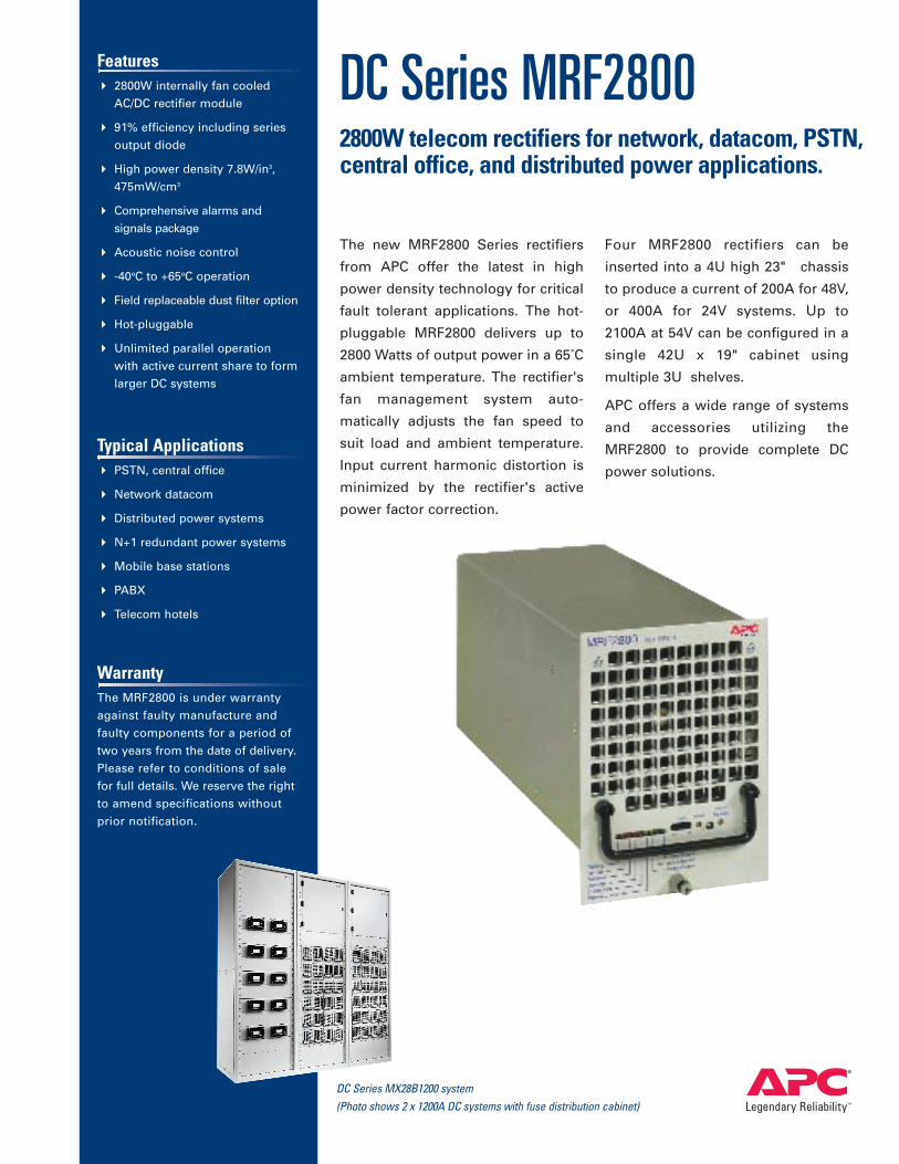
DC Series MRF28002800W telecom rectifiers for network, datacom, PSTN,central office, and distributed power applications.
The new MRF2800 Series rectifiers
from APC offer the latest in high
power density technology for critical
fault tolerant applications. The hot-
pluggable MRF2800 delivers up to
2800 Watts of output power in a 65˚C
ambient temperature. The rectifier's
fan management system auto-
matically adjusts the fan speed to
suit load and ambient temperature.
Input current harmonic distortion is
minimized by the rectifier's active
power factor correction.
Four MRF2800 rectifiers can be
inserted into a 4U high 23" chassis
to produce a current of 200A for 48V,
or 400A for 24V systems. Up to
2100A at 54V can be configured in a
single 42U x 19" cabinet using
multiple 3U shelves.
APC offers a wide range of systems
and accessories utilizing the
MRF2800 to provide complete DC
power solutions.
DC Series MX28B1200 system(Photo shows 2 x 1200A DC systems with fuse distribution cabinet)
Input Specifications Minimum Typical Maximum
Voltage Range, VIN Single phase TN-S Operating 176Vac 230Vac 264Vac(as defined by IEC 364) Absolute maximum 300Vac
Frequency 45Hz 66Hz
R.M.S. Current Maximum power output 230Vac input 13.9A176Vac input 16.3A
Peak Inrush Current 264Vac input 19.5A230Vac input 13.0A
Power 2800W output power 3,140WMaximum load (current limit) 3,400W
Apparent Power Factor 98% 99%
Efficiency VIN=230Vac, POUT=2800W 54V 90% 91%Includes integral series output diode 27V 88% 89%
Harmonic Distortion Units comply with the requirementsof EN61000-3-2 3% 10%thd
Turn On Voltage 165Vac 172Vac 176Vac
Turn Off Voltage 145Vac 152Vac 156Vac
Fusing Internally fitted fuses in live and neutral lines 20AT
54V Output Specifications (For Additional Data, See General Output Specifications, p.3) Minimum Typical Maximum
Factory Set Voltage, VOUT 54.4V 54.5V 54.6V
Adjustment Range For more details see “front panel features” section (p.7) 47.8V 58.0V
Maximum terminal voltage 59.0V
Current, IMAX Continuous <65°C ambient. VOUT =54.5V, VIN >198Vac 50.0A
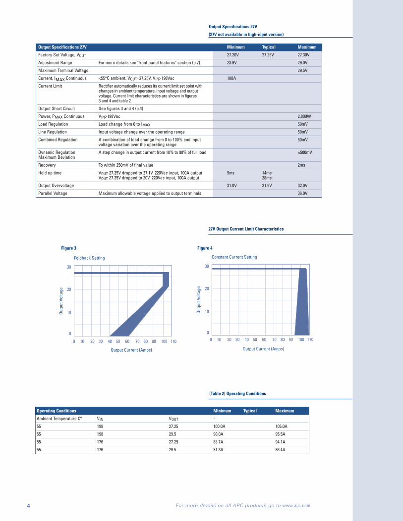
Current Limit Rectifier automatically reduces its current limit set point with changes in ambient temperature, input voltage and output voltage. Current limit characteristics are shown infigures 1 and 2, and table 1 (p.3).
Output Short Circuit See figures 1 and 2 below
Power, PMAX Continuous VIN>198Vac 2,800W
Load Regulation Load change from 0 to IMAX 75mV
Line Regulation Input voltage change over the operating range 75mV
Combined Regulation A combination of load change from 0 to 100% and input 100mVvoltage variation over the operating range
Dynamic Regulation A step change in output current from 10% to 90% of full load ±1VMaximum Deviation
Recovery To within 500mV of final value 2ms
Hold up time VOUT 54.5V dropped to 54.2V, 220Vac input, 50A output 10ms 16msVOUT 54.5V dropped to 40V, 220Vac input, 50A output 32ms
Output Overvoltage 59.0V 59.5V 59.9V
Parallel Voltage Maximum allowable voltage applied to output terminals 80V
MRF2800 Series Standard Input Specification
54V Output Specifications
2 For more details on all APC products go to www.apc.com
Input Specifications Minimum Typical Maximum
Voltage Range, VIN Single phase TN-S Operating 176Vac 277Vac 293Vac(as defined by IEC 364) Absolute maximum 305Vac
Frequency 45Hz 66Hz
R.M.S. Current Maximum power output 277Vac input 14.2A176Vac input 16.0A
Peak Inrush Current 293Vac input 16.0A277Vac input 16.0A
Power 2800W output power 2725W 2889WMaximum load (current limit) 50.0A 53.0A
Apparent Power Factor 98% 99%
Efficiency VIN=230Vac, POUT=2800W 54V 90% 91%Includes integral series output diode 27V 88% 89%
Harmonic Distortion Units comply with the requirementsof EN61000-3-2 3% 10%thd
Turn On Voltage 165Vac 176Vac
Turn Off Voltage 150Vac 176Vac
Fusing Internally fitted fuses in live and neutral lines 16AT
MRF28H54BV50 Input Specification (277V model)

Foldback Setting
60
50
40
30
20
10
00 10 20 30 40 50 60
Constant Current Setting
60
50
40
30
20
10
00 10 20 30 40 50 60
Output Current (Amps) Output Current (Amps)
Outp
ut V
olta
ge
Outp
ut V
olta
ge
Operating Conditions Minimum Typical Maximum
Ambient Temperature Cº VIN VOUT -
65 198 54.5 50.0A 52.5A
65 198 59.0 45.0A 47.8A
65 176 54.5 44.3A 47.1A
65 176 59.0 40.7A 43.2A
General Output Specifications 54V and 27V Minimum Typical Maximum
Remote Sense Total lead voltage drop 1V
Start Up Time From application of line input to output voltage 1.0s 1.5s 3.3sachieving regulation
Rise Time Time for VOUT to rise monotonically to its full value 100ms
Reverse Quiescent Current Source = VOUT connected to output of non energized unit 54V 5mA
Reverse Quiescent Current Source = VOUT connected to output of non energized unit 27V 10mA
Temperature Coefficient Temperature range -25°C to +55°C ±0.015%/°C
Noise, Low Frequency Frequency range 10Hz -100kHz 40mV p-p
Noise, Broadband Frequency range 10Hz - 100MHz 15mV rmsIndividual harmonics 2mV peakComplies with requirements of ETS300386-2-3 and BTNR2511
Noise, Psophometric Weighted to C.C.I.T.T. No. 1 0.7mV rmsC message weighted 29dBrnC
Noise, Acoustic Minimized by allowing 100% IMAX 65°C 198 VacIN 54dBAfan speed to vary 100% IMAX 45°C 230 VacIN 47dBAwith load current 75% IMAX 45°C 230 VacIN 45dBAand ambient temperature 50% IMAX 45°C 230 VacIN 42dBA
50% IMAX 25°C 230 VacIN 38dBA
Series Output Diode Units are fitted with a series diode in the positive output
Series Voltage Units connected in series 150V
54V Output Current Limit Characteristics
MRF2800 Series Operating Conditions
General Output Specifications 54V and 27V
(27V not available in high-input version)
3For more details on all APC products go to www.apc.com
Figure 1 Figure 2
Foldback Setting
30
20
10
0
0 10 20 30 40 50 60 70 80 90 100 110
Output Current (Amps)
Outp
ut V
olta
ge
Constant Current Setting
Output Current (Amps)
30
20
10
0
Outp
ut V
olta
ge
0 10 20 30 40 50 60 70 80 90 100 110
27V Output Current Limit Characteristics
4 For more details on all APC products go to www.apc.com
Figure 3 Figure 4
Operating Conditions Minimum Typical Maximum
Ambient Temperature Cº VIN VOUT -
55 198 27.25 100.0A 105.0A
55 198 29.5 90.0A 95.5A
55 176 27.25 88.7A 94.1A
55 176 29.5 81.3A 86.4A
(Table 2) Operating Conditions
Output Specifications 27V Minimum Typical Maximum
Factory Set Voltage, VOUT 27.20V 27.25V 27.30V
Adjustment Range For more details see "front panel features" section (p.7) 23.9V 29.0V
Maximum Terminal Voltage 29.5V
Current, IMAX Continuous <55°C ambient. VOUT=27.25V, VIN>198Vac 100A
Current Limit Rectifier automatically reduces its current limit set point withchanges in ambient temperature, input voltage and outputvoltage. Current limit characteristics are shown in figures3 and 4 and table 2.
Output Short Circuit See figures 3 and 4 (p.4)
Power, PMAX Continuous VIN>198Vac 2,800W
Load Regulation Load change from 0 to IMAX 50mV
Line Regulation Input voltage change over the operating range 50mV
Combined Regulation A combination of load change from 0 to 100% and input 50mVvoltage variation over the operating range
Dynamic Regulation A step change in output current from 10% to 90% of full load ±500mVMaximum Deviation
Recovery To within 250mV of final value 2ms
Hold up time VOUT 27.25V dropped to 27.1V, 220Vac input, 100A output 9ms 14msVOUT 27.25V dropped to 20V, 220Vac input, 100A output 28ms
Output Overvoltage 31.0V 31.5V 32.0V
Parallel Voltage Maximum allowable voltage applied to output terminals 36.0V
Output Specifications 27V
(27V not available in high-input version)
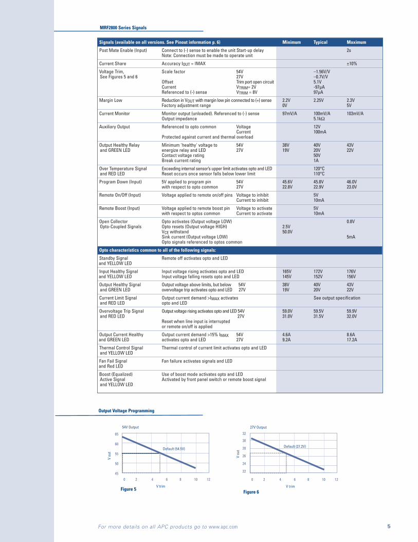
Signals (available on all versions. See Pinout information p. 6) Minimum Typical Maximum
Post Mate Enable (Input) Connect to (-) sense to enable the unit Start-up delay 2sNote: Connection must be made to operate unit
Current Share Accuracy IOUT = IMAX ±10%
Voltage Trim, Scale factor 54V –1.56V/VSee Figures 5 and 6 27V –0.7V/V
Offset Trim port open circuit 5.1VCurrent VTRIM= 2V -97µAReferenced to (-) sense VTRIM = 8V 97µA
Margin Low Reduction in VOUT with margin low pin connected to (+) sense 2.2V 2.25V 2.3VFactory adjustment range 0V 5V
Current Monitor Monitor output (unloaded). Referenced to (-) sense 97mV/A 100mV/A 103mV/AOutput impedance 5.1kΩ
Auxiliary Output Referenced to opto common Voltage 12VCurrent 100mA
Protected against current and thermal overload
Output Healthy Relay Minimum 'healthy' voltage to 54V 38V 40V 43Vand GREEN LED energize relay and LED 27V 19V 20V 22V
Contact voltage rating 50VBreak current rating 1A
Over Temperature Signal Exceeding internal sensor’s upper limit activates opto and LED 120°Cand RED LED Reset occurs once sensor falls below lower limit 110°C
Program Down (Input) 5V applied to program pin 54V 45.6V 45.8V 46.0Vwith respect to opto common 27V 22.8V 22.9V 23.0V
Remote On/Off (Input) Voltage applied to remote on/off pins Voltage to inhibit 5VCurrent to inhibit 10mA
Remote Boost (Input) Voltage applied to remote boost pin Voltage to activate 5Vwith respect to optos common Current to activate 10mA
Open Collector Opto activates (Output voltage LOW) 0.8VOpto-Coupled Signals Opto resets (Output voltage HIGH) 2.5V
VCE withstand 50.0VSink current (Output voltage LOW) 5mAOpto signals referenced to optos common
Opto characteristics common to all of the following signals:
Standby Signal Remote off activates opto and LEDand YELLOW LED
Input Healthy Signal Input voltage rising activates opto and LED 165V 172V 176Vand YELLOW LED Input voltage falling resets opto and LED 145V 152V 156V
Output Healthy Signal Output voltage above limits, but below 54V 38V 40V 43Vand GREEN LED overvoltage trip activates opto and LED 27V 19V 20V 22V
Current Limit Signal Output current demand >IMAX activates See output specificationand RED LED opto and LED
Overvoltage Trip Signal Output voltage rising activates opto and LED 54V 59.0V 59.5V 59.9Vand RED LED 27V 31.0V 31.5V 32.0V
Reset when line input is interruptedor remote on/off is applied
Output Current Healthy Output current demand >15% IMAX 54V 4.6A 8.6Aand GREEN LED activates opto and LED 27V 9.2A 17.2A
Thermal Control Signal Thermal control of current limit activates opto and LEDand YELLOW LED
Fan Fail Signal Fan failure activates signals and LED and Red LED
Boost (Equalized) Use of boost mode activates opto and LEDActive Signal Activated by front panel switch or remote boost signaland YELLOW LED
MRF2800 Series Signals
Output Voltage Programming
5For more details on all APC products go to www.apc.com
54V Output
0 2 4 6 8 10 12
V trim
V ou
t
65
60
55
50
45
Default (54.5V)
27V Output
0 2 4 6 8 10 12
V trim
V ou
t
32
30
28
26
24
22
Default (27.2V)
Figure 5 Figure 6
6 For more details on all APC products go to www.apc.com
Isolation Minimum Typical Maximum
Primary to Ground Test voltage 1500Vac
Secondary to Ground Test voltage 500Vac
Primary to Secondary Test voltage 3000Vac
Ground Leakage Current 240V, 60Hz input 3.5mA
Output to Ground Voltage Working voltage 150Vdc
Signal to Ground Voltage Working voltage 150Vdc
Signal to Output Voltage Working voltage 150Vdc
Environmental Specifications Minimum Typical Maximum
Ambient Temperature (See table on p. 3) Operational -25°C +65°CStarting -40°C +65°CNon-operational -40°C +85°C
Humidity Non-condensing Operational 0% RH 85% RHNon-Operational 0% RH 95% RH
Altitude Operational 0m 3,000m0ft 10,000 ft
Non-Operational 0m 10,000m0ft 30,000 ft
Vibration Compliant with the requirements of BS2011 Test FcDrop and topple - EN60068-2-31 Test EcBump - EN60068-2-47 Test EbTransportation - BS2011 Part 2.1 Test Fc in original packingDrop - EN60068-2-32 Test Ed in original packing
Pollution EN60950 degree 2 i.e. office type environments
MRF2800 Series Environmental Specifications
MRF2800 Series Isolation
Electromagnetic Compatibility
Emission Compliant with EN50081-1(92) with compliance to the following specific conditions:Conducted input 0 – 2kHz EN61000-3-2Conducted input 0.15 – 30MHz EN55022-BRadiated 0.03 – 1GHz EN55022-A at 10mConducted output ETS300386-2-3
Immunity Compliant with EN50082-1(92) with compliance to the following specific conditions:ESD - EN61000-4-2 failure criteria A. 4kV contact.RF Field - EN61000-4-3. 3Vm–1 80% amplitude modulation 0.08 – 1GHz.Fast Transients - EN61000-4-4 failure criteria B. 1kV on ac line, 500V on dc lines.Surge - EN61000-4-5. 2kV line to ground, 1kV line to line on ac input. 500V line to ground and line to line on dc output.Conducted RF - EN61000-4-6. 3Vrms 80% amplitude modulation 0.15 – 80MHz
MRF2800 Series Electromagnetic Compatibility
Approvals and Safety Standards
EN60950 CE marked to the EC low voltage directive
UL1950 CSA NRTL/C approved, file number LR58666
C22.2 #950 CSA NRTL/C approved, file number LR58666
All versions are reliably SELV. For operation above 60V, a non-SELV version must be ordered. Contact APC for details.
This power supply is designed for incorporation within an enclosure. For user safety, the enclosure must protect the user against accidentalcontact with any electrical hazard, associated with the power supply.
Approvals and Safety Standards
Front Panel Features Minimum Typical Maximum
Test Points Output impedence 5.1kΩ Voltage Current 97mV/A 100mV/A 103mV/A
Float/Boost Select Switch selectable higher or lower preset outputvoltage/current limit. Remote boost (input) overrides selection
Float Voltage Adjust 54V 52.0V 58.0V27V 26.0V 29.0V
Boost (Equalized) 54V 53.0V 60.0VVoltage Adjust 27V 26.5V 30.0V
MRF2800 Series Front Panel Features
Signals Pinout Information
7For more details on all APC products go to www.apc.com
Mechanical Specifications MRF28H
External Dimensions 5.0 x 5.5 x 13.0 in. (127.0 x 139.7 x 330.6 mm)
Front Panel Dimensions See mechanical drawing (p.8) 5.2 x 8.7 in. (132.1 x 221 mm)
Weight 11.0 lb. (5.0 kg)
Fixings Units are designed for power shelf mounting
Mounting Orientation See p.8 for mounting options
Ventilation and Cooling Free air flow through the ventilation slots in the front and rear of the unit is required. Units are cooled by integral,customer replaceable fan. Typical full flow 100cfm.
Finish Front panel is finished in grey with grey legend and the body is finished in gold colored chemical etch
Connectors See below
Dust Filter (Optional) Reticulated, open cell polyester based polyurethane foam. See drawing below.
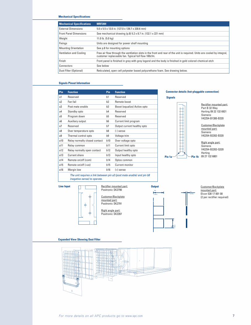
Mechanical Specifications
Pin Function Pin Function
a1 Reserved b1 Reserved
a2 Fan fail b2 Remote boost
a3 Post mate enable b3 Boost (equalize) Active opto
a4 Standby opto b4 Reserved
a5 Program down b5 Reserved
a6 Auxiliary output b6 Current limit program
a7 Reserved b7 Output current healthy opto
a8 Over temperature opto b8 (-) sense
a9 Thermal control opto b9 Voltage trim
a10 Relay normally closed contact b10 Over voltage opto
a11 Relay common b11 Current limit opto
a12 Relay normally open contact b12 Output healthy opto
a13 Current share b13 Input healthy opto
a14 Remote on/off (com) b14 Optos common
a15 Remote on/off (+ve) b15 Current monitor
a16 Margin low b16 (+) sense
The unit requires a link between pin a3 (post mate enable) and pin b8(negative sense) to operate.
Expanded View Showing Dust Filter
Connector details (hot-pluggable connection)
OutputLine Input
Signals
Pin 1a Pin 1b
Rectifier mounted part:Part B 32 Way Harting 09 22 132 6921SiemensV42254-B1300-B320
Customer/Backplatemounted part:SiemensV42254-B2202-B320
Right angle part:SiemensV42254-B2202-Q320Harting09 27 132 6801
Rectifier mounted part:Positronic SK2790
Customer/Backplatemounted part:Positronic SK2791
Right angle part:Positronic SK2287
Customer/Backplatemounted part:Elcon 538 17 001 00(2 per rectifier required)

(2.1
9in.
)
12.7
(4.97 ± 0.008in.)
126.3 ± 0.22.9
39.1
17.8
(0.7
0in.
)
AIRFLOW
(1.2
9in.
)(5
.48
± 0.
016i
n.)
139.
3 ±
0.4
32.7
177.
0 (6
.97i
n.)
(0.06in.)
1.5
(4.9
9 ±
0.00
8in.
)(0
.06i
n.)
1.5
126.
8 ±
0.2
6.5 (0.26in.) DIA. HOLE
(2.60in.)
66.05
132.1 (5.20in.)
8.4
(0.3
3in.
)
(1.69in.)
43.0 222.3 (8.75in.)
(0.5
1in.
)10
1.6
(4.0
0in.
)
(0.11in.)
93.9 (3.69in.)
50.1 (1.97in.)
(1.54in.)
(1.3
75in
.)
55.7
34.9
(0.5
0in.
)
AIRFLOW
(0.06in.)
1.5 328.7 (12.94in.) 4.2 (INPUT)
(0.17in.)
5.0
(0.19in.)
(SIGNALS)
12.8
5
0.5 (0.019in.) PLASTIC SLIDE
0.5 (0.019in.) PLASTIC SLIDE
4 x M4 FIXINGS
(ON REAR FACE)
ACCESS TO MODE SWITCHES
146.8 (5.78in.)
132.
5 (5
.22i
n.)
137.8 (5.43in.)
83.2
(3.2
7in.
)
SOUTHCO ADJUSTABLE GRIP LATCH
PART No. 27-10-501-20
(0.18in.)
(0.68in.)
138.8 ± 0.4
(5.47 ± 0.016in.)17.3
4.5
50.6
(1.9
9in.
)
94.4
(3.7
2in.
)
(1.375in.)(0.48in.)
34.9
(2.17in.)
55.2
12.2
(1.5
6in.
)39
.6
OutputOutput
HealthyHealthy
HealthyHealthy
OutputOutput
IVIV
0
1
V
I
0
1
+V +I V I+V +I V I
BelowDetailPanelFrontSee
See
PanelDetail
Front
Below
MRF28HXXXH
Detail 1 - See Figure 9(pg. 10)
Dimensions
MRF28HXXXV
Units in mm (inches)
wwwwww.apc.com.apc.com
R
DC Series Rectifier
www.apc.com
R
DC Series Rectifierwwwwww.apc.com.apc.com
R
Output
Healthy
Healthy
Output
IVIV
0
1
V
I
0
1
Equalize
Boost/
Float
COM
+V
+I
Curr Limit
Thm Cont
I/P OK
O/P OK
O/P Curr
Overvolts
Standby
Overtemp
Fan Fail
Thermal Control
Current Limit
Overtemp
Overvolts
Fan Fail
Standby
Output Current
Input Healthy
Output Healthy
+V +I V I+V +I V I
FloatCOM Equalize
Boost/
B - signals
Front Panel Detail
www.apc.com
R
www.apc.com
R
www.apc.com
R
DC Series
Rectifier Operating Mode Switches
Mode setting switches are accessed through the side face of the rectifier.
Switch Number Switch Set OFF Switch Set ON Standard Setting
1 (+) Sense remote (+) Sense local ON
2 (-) Sense remote (-) Sense local ON
3 Output set 54.5V/27.25V Reduce output by at least 4.2V/2.1VTo offset output voltage adjust range OFF
4 Normal Voltage Regulation Voltage droop regulation OFF
5 Constant current limit Foldback current limit ON
Rectifier Operating Mode Switches
Dimensions
Front Panel Detail
8For more details on all APC products go to www.apc.com

Ordering Information
Part Number Output voltage Boost V
1MRF28H54BH 54.5V 57.6V
1MRF28H54BV 54.5V 57.6V
1MRF28H27BH 27.25V 28.8V
1MRF28H27BV 27.25V 28.8V
1MRF28H54BV50 54.5V 57.6V 277VAC nominal input
Note: All units are factory set to local sense and foldback current limit. 54V units have a margin low voltage of 52.25V. Consult APC for othersettings. 27V units have a margin low voltage of 25.0V. Consult APC for other settings
Accessory Table
Part Number Product
1MKC2801 Connector kit consisting input output and signals connectors
1MKC2802 Connector kit consisting of right angle input, output and signals connectors
1MS28A MS28A, 19" x 4U mounting shelf to accommodate up to 3 MRF28HXXXV units
1MS28B MS28B, 23" x 4U mounting shelf to accommodate up to 4 MRF28HXXXV units
1MS28CT MS28CT, 19" x 3U mounting shelf to accommodate up to 3 MRF28HXXXH units
1MCA28A Input and signal connector PCB assembly
1MAF28 Replacement Dust filter
1MS28CR Copper riser for side access
Accessory Table
Ordering Information
Example: MRF28H54BV
MRF28 HPackagingH- Standard
54NominalOutputVoltage
BSignalsB - Enhanced
VPackage OrientationH- HorizontalV - Vertical
9 For more details on all APC products go to www.apc.com

Power Dissipation / Heat Loss from DC Series Rectifiers
Rectifier Output Power (Watts)
Efficiency Typical Power (Heat) Loss
Watts BTU/Hour
DC Series TRF5600 5450 87 837 2855
DC Series MRF2800 2725 91 270 919
DC Series MRE2400 2400 91 271 925
DC Series MRC1800 1800 91 199 679
DC Series MRF1700 1640 90 189 644
DC Series MRF1400 1362 90 135 459
DC Series MRE1200 1200 91 119 405
DC Series MRC0800 730 90 81 277
DC Series TWF0500 570 85 106 361
Note: All figures show typical power losses for 230Vac input

¥ 20 Year lifeexpectancy
¥ 105 to 4800 AH
¥ Highest energy density
¥ Simple modular installation
¥ Recyclable to world standards
¥ ULrecognizedcomponent
SPEC
IFIC
ATIO
NS
SPEC
IFIC
ATIO
NS
Section 26.10
B a t t e r i e s
Finally, all cells are capacity tested prior to shipmentto verify attainment of specified ratings.
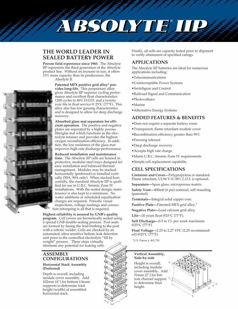
APPLICATIONSThe Absolyte IIP batteries are ideal for numerousapplications including:
¥Telecommunications
¥Uninterruptible Power Systems
¥Switchgear and Control
¥Railroad Signal and Communication
¥Photovoltaics
¥Marine
¥Alternative Energy Systems
ADDED FEATURES & BENEFITS¥Does not require a separate battery room
¥Transparent, flame retardant module cover
¥Recombination efficiency greater than 99%
¥Freezing tolerant
¥Deep discharge recovery
¥Accepts high rate charge
¥Meets U.B.C. Seismic Zone IV requirements
¥Simple cell replacement capability
CELL SPECIFICATIONSContainer and Cover—Polypropylene is standard.Flame retardant, UL94 V-0/28% L.O.I. is optional.
Separators—Spun glass, microporous matrix.
Safety Vent—400mb (6 psi) nominal, self-resealing(patented).
Terminals—Integral solid copper core.
Positive Plate—Patented MFX grid alloy.*
Negative Plate—Lead calcium grid alloy.
Life—20 years float @25¡C (77¡F).
Self Discharge—0.5 to 1% per week maximum@25¡C (77¡F).
Float Voltage—2.23 to 2.27 VPC (2.25 recommend-ed) @25¡C (77¡F).
*U.S. Patent 4, 401,730
Vertical Assembly,Side-by-side
Height is overall,including modulecover assembly. Add51mm (2Ó) for bot-tom channel supportto determine finalheight.
THE WORLD LEADER INSEALED BATTERY POWERProven field experience since 1983. The AbsolyteIIP represents the third generation of the Absolyteproduct line. Without an increase in size, it offers15% more capacity than its predecessor, the
Absolyte II.
Patented MFX positive grid alloy* pro-vides long-life. This proprietary alloygives Absolyte IIP superior cycling perfor-mance and excellent float characteristics:1200 cycles to 80% D.O.D. and a twentyyear life in float service @ 25¡C (77¡F). Thisalloy also has low gassing characteristicsand is designed to allow for deep dischargerecovery.
Absorbed glass mat separators for effi-cient operation. The positive and negativeplates are separated by a highly porousfiberglas mat which functions as the elec-trolyte retainer and provides the highestoxygen recombination efficiency. In addi-tion, the low resistance of the glass matimproves high rate discharge performance.
Reduced installation and maintenancetime. The Absolyte IIP cells are housed inprotective, modular steel trays designed foreasy installation and balanced thermalmanagement. Modules may be stackedhorizontally (preferred) or installed verti-cally (50A, 90A only). When stacked hori-zontally, the standard Absolyte IIP is quali-fied for use in U.B.C. Seismic Zone IVinstallations. With the sealed design, main-tenance is also kept to a minimum. Nowater additions or scheduled equalizationcharges are required. Periodic visualinspections, voltage readings and connec-
tion retorquing is all that is required.
Highest reliability is assured by GNB’s qualityprogram. Cell covers are hermetically sealed usinga special GNB double-sealing process. Post sealsare formed by fusing the lead bushing to the postwith a robotic welder. Cells are checked by anautomated, ultra-sensitive helium leak detectionunit prior to the controlled electrolyte Òfill byweightÓ process. These steps virtually eliminate any potential for leaking cells.
ASSEMBLY CONFIGURATIONSHorizontal Stack Assembly(Preferred)
Depth is overall, includingmodule cover assembly. Add102mm (4Ó) for bottom I-beamsupports to determine totalheight (width) of assembledhorizontal stack.
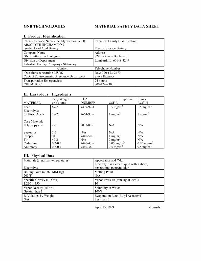
GNB TECHNOLOGIES
I. Product Identification
MATERIAL SAFETY DATA SHEET
Chemical/Trade Name (Identity used on label):ABSOLYTE IIP/CHAMPION Sealed Lead Acid Battery
Chemical Family/Classification:
Electric Storage BatteryCompany Name Address:GNB Battery Technologies 829 Parkview BoulevardDivision or Department Lombard, IL 60148-3249Industrial Battery Company - Stationary Contact Telephone Number Questions concerning MSDS Day: 770-673-2470Contact Environmental Assurance Department Steve EmmonsTransportation Emergencies: 24 hours:CHEMTREC 800-424-9300
II. Hazardous Ingredients
MATERIAL% by Weightor Volume
CAS NUMBER
ExposureOSHA
LimitsACGIH
LeadElectrolyte:(Sulfuric Acid)
Case Material:Polypropylene
SeparatorCopperTinCadmiumAntimony
67-77
18-23
2-5
2-3<1<0.20.2-0.30.2-0.4
7439-92-1
7664-93-9
9003-07-0
N/A7440-50-8N/A7440-43-97440-36-0
.05 mg/m3
1 mg/m3
N/A
N/A1 mg/m32 mg/m30.05 mg/m30.5 mg/m3
.15 mg/m3
1 mg/m3
N/A
N/AN/AN/A0.05 mg/m30.5 mg/m3
III. Physical DataMaterials (at normal temperatures) Appearance and Odor
ElectrolyteElectrolyte is a clear liquid with a sharp,penetrating, pungent odor.
Boiling Point (at 760 MM Hg) Melting Point203¡F N/ASpecific Gravity (H2O=1) Vapor Pressure (mm Hg at 20¡C)1.230-1.350 10Vapor Density (AIR=1) Solubility in WaterGreater than 1 100%% Volatiles by Weight Evaporation Rate (Butyl Acetate=1)N/A Less than 1
April 13, 1999 a2pmsds.
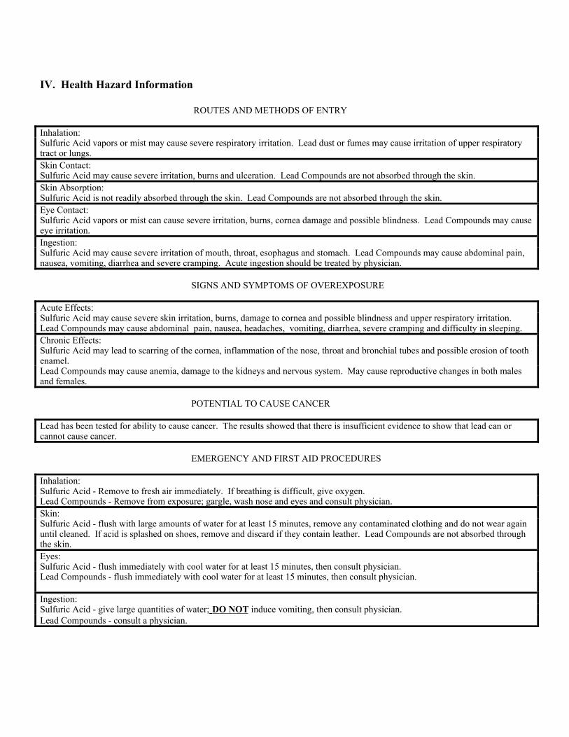
IV. Health Hazard Information
ROUTES AND METHODS OF ENTRY
Inhalation:Sulfuric Acid vapors or mist may cause severe respiratory irritation. Lead dust or fumes may cause irritation of upper respiratorytract or lungs.Skin Contact:Sulfuric Acid may cause severe irritation, burns and ulceration. Lead Compounds are not absorbed through the skin.Skin Absorption:Sulfuric Acid is not readily absorbed through the skin. Lead Compounds are not absorbed through the skin.Eye Contact:Sulfuric Acid vapors or mist can cause severe irritation, burns, cornea damage and possible blindness. Lead Compounds may causeeye irritation.Ingestion:Sulfuric Acid may cause severe irritation of mouth, throat, esophagus and stomach. Lead Compounds may cause abdominal pain,nausea, vomiting, diarrhea and severe cramping. Acute ingestion should be treated by physician.
SIGNS AND SYMPTOMS OF OVEREXPOSURE
Acute Effects:Sulfuric Acid may cause severe skin irritation, burns, damage to cornea and possible blindness and upper respiratory irritation.Lead Compounds may cause abdominal pain, nausea, headaches, vomiting, diarrhea, severe cramping and difficulty in sleeping.Chronic Effects:Sulfuric Acid may lead to scarring of the cornea, inflammation of the nose, throat and bronchial tubes and possible erosion of toothenamel.Lead Compounds may cause anemia, damage to the kidneys and nervous system. May cause reproductive changes in both malesand females.
POTENTIAL TO CAUSE CANCER
Lead has been tested for ability to cause cancer. The results showed that there is insufficient evidence to show that lead can orcannot cause cancer.
EMERGENCY AND FIRST AID PROCEDURES
Inhalation:Sulfuric Acid - Remove to fresh air immediately. If breathing is difficult, give oxygen.Lead Compounds - Remove from exposure; gargle, wash nose and eyes and consult physician.Skin:Sulfuric Acid - flush with large amounts of water for at least 15 minutes, remove any contaminated clothing and do not wear againuntil cleaned. If acid is splashed on shoes, remove and discard if they contain leather. Lead Compounds are not absorbed throughthe skin.Eyes:Sulfuric Acid - flush immediately with cool water for at least 15 minutes, then consult physician.Lead Compounds - flush immediately with cool water for at least 15 minutes, then consult physician.
Ingestion:Sulfuric Acid - give large quantities of water; DO NOT induce vomiting, then consult physician.Lead Compounds - consult a physician.
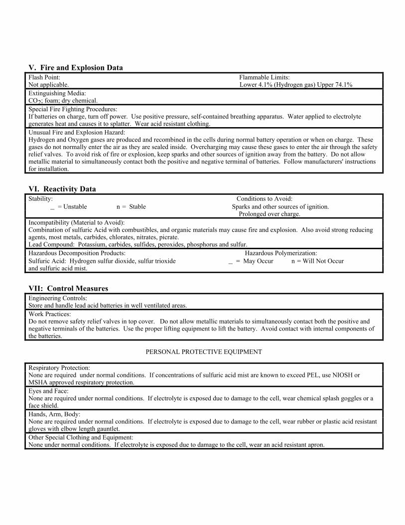
V. Fire and Explosion DataFlash Point: Flammable Limits:Not applicable. Lower 4.1% (Hydrogen gas) Upper 74.1%Extinguishing Media:CO2; foam; dry chemical.Special Fire Fighting Procedures:If batteries on charge, turn off power. Use positive pressure, self-contained breathing apparatus. Water applied to electrolytegenerates heat and causes it to splatter. Wear acid resistant clothing.Unusual Fire and Explosion Hazard:Hydrogen and Oxygen gases are produced and recombined in the cells during normal battery operation or when on charge. Thesegases do not normally enter the air as they are sealed inside. Overcharging may cause these gases to enter the air through the safetyrelief valves. To avoid risk of fire or explosion, keep sparks and other sources of ignition away from the battery. Do not allowmetallic material to simultaneously contact both the positive and negative terminal of batteries. Follow manufacturers' instructionsfor installation.
VI. Reactivity DataStability: Conditions to Avoid: _ = Unstable n = Stable Sparks and other sources of ignition. Prolonged over charge.Incompatibility (Material to Avoid):Combination of sulfuric Acid with combustibles, and organic materials may cause fire and explosion. Also avoid strong reducingagents, most metals, carbides, chlorates, nitrates, picrate.Lead Compound: Potassium, carbides, sulfides, peroxides, phosphorus and sulfur.Hazardous Decomposition Products: Hazardous Polymerization:Sulfuric Acid: Hydrogen sulfur dioxide, sulfur trioxide _ = May Occur n = Will Not Occurand sulfuric acid mist.
VII: Control MeasuresEngineering Controls:Store and handle lead acid batteries in well ventilated areas.Work Practices:Do not remove safety relief valves in top cover. Do not allow metallic materials to simultaneously contact both the positive andnegative terminals of the batteries. Use the proper lifting equipment to lift the battery. Avoid contact with internal components ofthe batteries.
PERSONAL PROTECTIVE EQUIPMENT
Respiratory Protection:None are required under normal conditions. If concentrations of sulfuric acid mist are known to exceed PEL, use NIOSH orMSHA approved respiratory protection.Eyes and Face:None are required under normal conditions. If electrolyte is exposed due to damage to the cell, wear chemical splash goggles or aface shield.Hands, Arm, Body:None are required under normal conditions. If electrolyte is exposed due to damage to the cell, wear rubber or plastic acid resistantgloves with elbow length gauntlet.Other Special Clothing and Equipment:None under normal conditions. If electrolyte is exposed due to damage to the cell, wear an acid resistant apron.
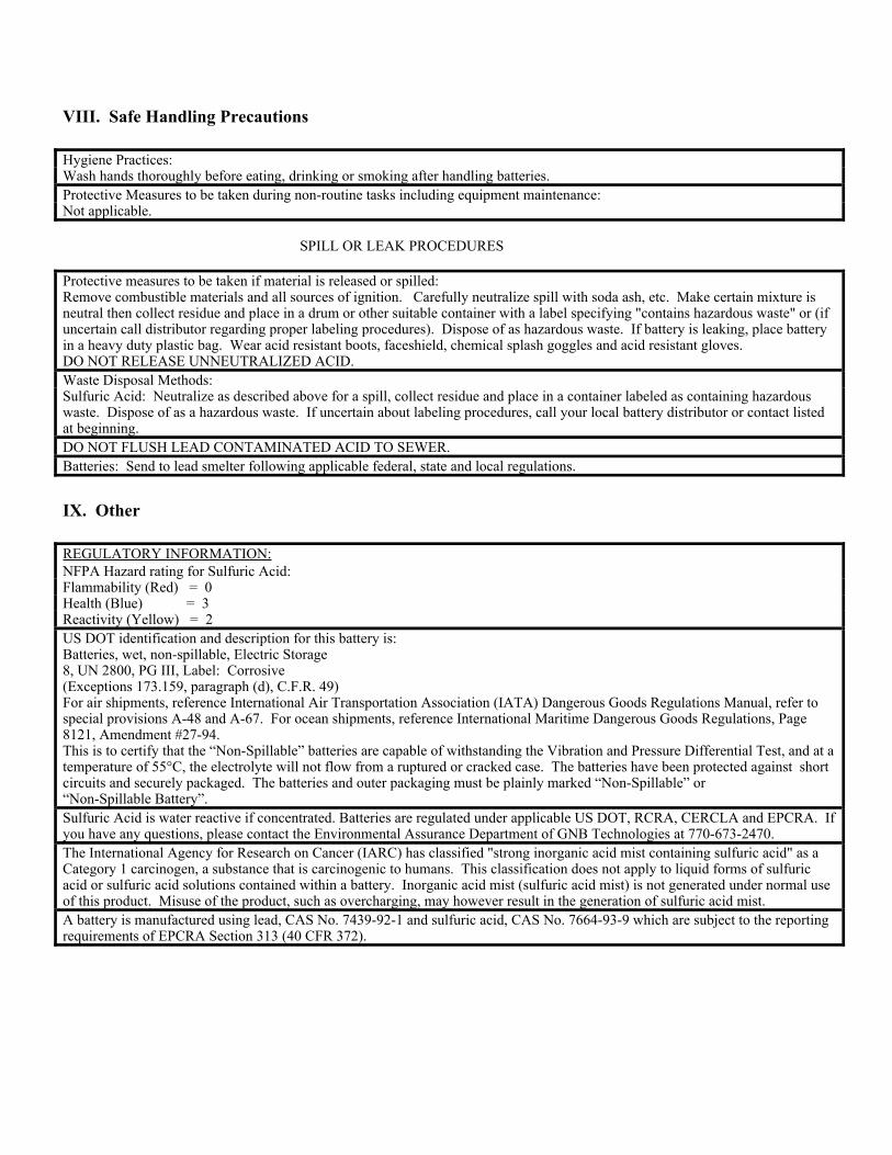
VIII. Safe Handling Precautions
Hygiene Practices:Wash hands thoroughly before eating, drinking or smoking after handling batteries.Protective Measures to be taken during non-routine tasks including equipment maintenance:Not applicable.
SPILL OR LEAK PROCEDURES
Protective measures to be taken if material is released or spilled:Remove combustible materials and all sources of ignition. Carefully neutralize spill with soda ash, etc. Make certain mixture isneutral then collect residue and place in a drum or other suitable container with a label specifying "contains hazardous waste" or (ifuncertain call distributor regarding proper labeling procedures). Dispose of as hazardous waste. If battery is leaking, place batteryin a heavy duty plastic bag. Wear acid resistant boots, faceshield, chemical splash goggles and acid resistant gloves.DO NOT RELEASE UNNEUTRALIZED ACID.Waste Disposal Methods:Sulfuric Acid: Neutralize as described above for a spill, collect residue and place in a container labeled as containing hazardouswaste. Dispose of as a hazardous waste. If uncertain about labeling procedures, call your local battery distributor or contact listedat beginning.DO NOT FLUSH LEAD CONTAMINATED ACID TO SEWER.Batteries: Send to lead smelter following applicable federal, state and local regulations.
IX. Other
REGULATORY INFORMATION:NFPA Hazard rating for Sulfuric Acid:Flammability (Red) = 0Health (Blue) = 3Reactivity (Yellow) = 2US DOT identification and description for this battery is:Batteries, wet, non-spillable, Electric Storage8, UN 2800, PG III, Label: Corrosive(Exceptions 173.159, paragraph (d), C.F.R. 49)For air shipments, reference International Air Transportation Association (IATA) Dangerous Goods Regulations Manual, refer tospecial provisions A-48 and A-67. For ocean shipments, reference International Maritime Dangerous Goods Regulations, Page8121, Amendment #27-94.This is to certify that the ÒNon-SpillableÓ batteries are capable of withstanding the Vibration and Pressure Differential Test, and at atemperature of 55¡C, the electrolyte will not flow from a ruptured or cracked case. The batteries have been protected against shortcircuits and securely packaged. The batteries and outer packaging must be plainly marked ÒNon-SpillableÓ orÒNon-Spillable BatteryÓ.Sulfuric Acid is water reactive if concentrated. Batteries are regulated under applicable US DOT, RCRA, CERCLA and EPCRA. Ifyou have any questions, please contact the Environmental Assurance Department of GNB Technologies at 770-673-2470.The International Agency for Research on Cancer (IARC) has classified "strong inorganic acid mist containing sulfuric acid" as aCategory 1 carcinogen, a substance that is carcinogenic to humans. This classification does not apply to liquid forms of sulfuricacid or sulfuric acid solutions contained within a battery. Inorganic acid mist (sulfuric acid mist) is not generated under normal useof this product. Misuse of the product, such as overcharging, may however result in the generation of sulfuric acid mist.A battery is manufactured using lead, CAS No. 7439-92-1 and sulfuric acid, CAS No. 7664-93-9 which are subject to the reportingrequirements of EPCRA Section 313 (40 CFR 372).


