1 Preface The data communication system DCM (data communication methods) in BS2000 is part of the data communication system. This systerm incorporates hardware for structuring networks and connecting general-purpose computers, PCs and terminals, as well as software for configuring, managing and controlling data communication via these networks. DCM provides the services of these networks as functions in BS2000 in a form that is independent of the type of network and its configuration. DCAM (data communication access method) with all other access methods and access options is embedded in the DCM data communication method of BS2000. The DCAM dynamic subsystem is the access method for program-to-program and program-terminal communication. DCM is composed of the modules: DCAM (Data Communication Access Method) for the implementation of the DCAM interface in ASSEMBLER and COBOL. VTSU (Virtual Terminal Support) for the implementation of the virtual terminals. TIAM (Terminal Interactive Access Method) for the implementation of the RTIO ASSEMBLER interface (remote terminal input output). UTM (Universal Transaction Monitor) for the implementation of the UTM interface. These modules, in turn, have a defined interface to BCAM (Basic Communication Access Method). The tasks common to all access methods, such as transport management, buffering etc. are implemented in this basic module. DCM is mounted on decoupled BS2000 interfaces and also provides decoupled interfaces. DCM offers the following facilities: DCAM access method for communication between programs or programs and terminal. support of terminal programming through the application of virtual terminals; general C program interface SOCKETS for accessing TCP/IP networks; general C interface ICMX offering the OSI transport functionality; administration at optional operator consoles, also, if desired, in a DCAM program using the multiconsole operation module (UCON); powerful support of the established interfaces for timesharing (RTIO). U1786-J-Z135-5-7600 1
Transcript
1 PrefaceThe data communication system DCM (data communication methods) inBS2000 is part of the data communication system. This systermincorporates hardware for structuring networks and connecting general-purposecomputers, PCs and terminals, as well as software for configuring, managing andcontrolling data communication via these networks. DCM provides theservices of these networks as functions in BS2000 in a form that is independent of thetype of network and its configuration. DCAM (data communication access method) withall other access methods and access options is embedded in the DCM datacommunication method of BS2000. The DCAM dynamic subsystem is the accessmethod for program-to-program and program-terminal communication. DCM iscomposed of the modules:
DCAM (Data Communication Access Method) for the implementation of theDCAM interface in ASSEMBLER and COBOL.
VTSU (Virtual Terminal Support) for the implementation of the virtual terminals.
TIAM (Terminal Interactive Access Method) for the implementation of the RTIOASSEMBLER interface (remote terminal input output).
UTM (Universal Transaction Monitor) for the implementation of the UTM interface.
These modules, in turn, have a defined interface to BCAM (Basic Communication Access Method) . The tasks common to all access methods, such as transportmanagement, buffering etc. are implemented in this basic module.
DCM is mounted on decoupled BS2000 interfaces and also provides decoupledinterfaces. DCM offers the following facilities:
DCAM access method for communication between programs or programs andterminal.
support of terminal programming through the application of virtual terminals ;
general C program interface SOCKETS for accessing TCP/IP networks;
general C interface ICMX offering the OSI transport functionality;
administration at optional operator consoles, also, if desired, in a DCAM programusing the multiconsole operation module (UCON) ;
powerful support of the established interfaces for timesharing (RTIO) .
U1786-J-Z135-5-7600 1
Preface
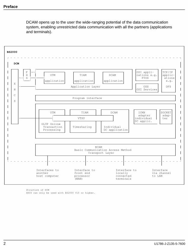
DCAM opens up to the user the wide-ranging potential of the data communicationsystem, enabling unrestricted data communication with all the partners (applicationsand terminals).
Interfaces to Interface to Interface to Interfaceanother front end locally via channelhost computer processor connected to LAN
(WAN) terminals
Structure of DCMXHCS can only be used with BS2000 V10 or higher.
2 U1786-J-Z135-5-7600
Preface
This description of the DCAM (Data Communication Access Method) programinterfaces is intended for various user groups:
O and M specialists and application engineers who want a guide to the scope andcapabilities of the interface.
Programmers (ASSEMBLER, COBOL) wanting to acquire a basic knowledge of thesubject in order to understand and use the more detailed information contained inthe programming manuals.
System and network administrators who do not need to be experts on the interfacebut would like to have a general knowledge of DCAM.
All readers should be familiar with BS2000. The use of DCAM also presupposes aknowledge of either ASSEMBLER or COBOL as well as of the OSI Reference Model.
U1786-J-Z135-5-7600 3
Preface
1.1 Summary of contents
The description of the DCAM communication access method is divided between threemanuals:
"DCAM Program Interfaces""DCAM COBOL Calls""DCAM Macros"
The general description of the DCAM program interface contains basic information forthe DCAM programmer, but is also suitable for those wanting a guide to the scope andcapabilities of the DCAM interface. The DCAM programmer will then find details onprogramming in the descriptions of the DCAM COBOL and DCAM ASSEMBLERinterface according to the language used.
This DCAM manuals contain the descriptions for both DCAM(ISO) transport serviceapplications and DCAM(NEA) transport service applications. Differences between thetwo are discussed where applicable. Passages, sections and entire chapters that applyonly to DCAM(NEA) transport service applications are indicated by a
at the start of the text.
This manual is subdivided as follows:
The chapter ’Introduction to the DCAM interface’ contains general information onthe DCAM interface, and explains basic concepts and points for consideration in theplanning of programs and program systems.
The chapter ’DCAM functions’ describes the functions of all DCAM calls andnotifications.
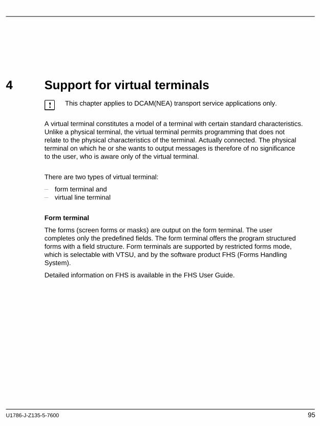
The chapter ’Support for virtual terminals’ contains a brief description of formatterminals, logical line terminals and edit options.
The chapter ’DCAM programs’ outlines the coding of DCAM programs inAssembler and COBOL and describes the execution of these programs.
The Appendix lists the DCAM calls and limit values, and shows how a connectionis set up by the terminal.
4 U1786-J-Z135-5-7600
Preface
The layout of the function description for all DCAM calls and notifications is identical tothe corresponding sections in the manuals for the users of ASSEMBLER and COBOL.This facilitates parallel use of the manuals.
A glossary, list of references and an index are to be found at the end of this manual.
A number of books and guides on computer networks and remote data processing withBS2000 deal with topics related to those discussed in this User Guide. Subjects suchas generation and administration, programming communication processors andterminals, and support for virtual terminals are dealt with in separate manuals.
1.2 Changes since the last version of the manual
Support of logical terminals
This chapter entitled ’Support for virtual terminals’ is shorter than in previous editions.See the "VTSU User Guide" for a detailed description of the VTSU interface, the VTSUcontrol block, the logical control characters and the status information.
Readme file
Information on any functional changes and additions to the current product version canbe found in the product-specific README file. You will find the file on your BS2000computer under the name SYSDOC.product.version.READ-ME.D . The user ID underwhich the README file is cataloged can be obtained from your system administrator.You can view the README file using the /SHOW-FILE command or an editor, and printit out on a standard printer using the following command:
2 Introduction to the DCAM interfaceThe structure of the DCAM programs is determined by the use of the DCAM interfaceand access to the communication system. This chapter describes thefollowing:
the DCAM access method
traffic relations in the data communication system with DCAM
explanation of essential basic concepts
characteristics determining the performance capability of the DCAM interface
the basic structure of a DCAM program
DCAM program planning
U1786-J-Z135-5-7600 7
Introduction DCAM interface
2.1 The Data Communication Access Method DCAM
DCAM offers two different sets of functions:
DCAM(NEA) transport service functions and
DCAM(ISO) transport service functions
DCAM(NEA) transport services
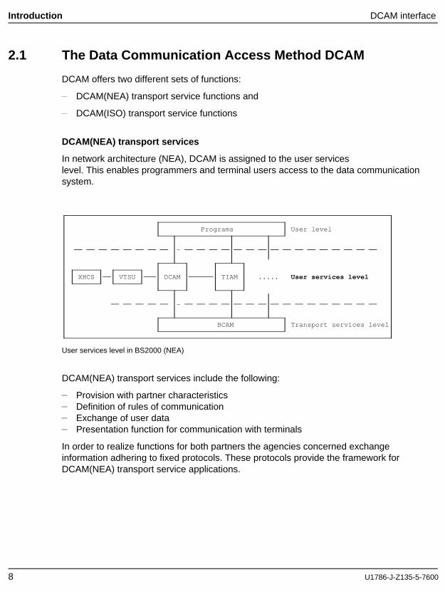
In network architecture (NEA), DCAM is assigned to the user serviceslevel. This enables programmers and terminal users access to the data communicationsystem.
Programs User level
-
XHCS VTSU DCAM TIAM ..... User services level
-
BCAM Transport services level
User services level in BS2000 (NEA)
DCAM(NEA) transport services include the following:
Provision with partner characteristicsDefinition of rules of communicationExchange of user dataPresentation function for communication with terminals
In order to realize functions for both partners the agencies concerned exchangeinformation adhering to fixed protocols. These protocols provide the framework forDCAM(NEA) transport service applications.
8 U1786-J-Z135-5-7600
DCAM interface Introduction
DCAM(ISO) transport services
The DCAM(ISO) transport services enable you to effect data communication on thebasis of the transport services standardized by the ISO. The DCAM interface has beenadapted in accordance with these transport services.
Overview of the OSI Reference Model
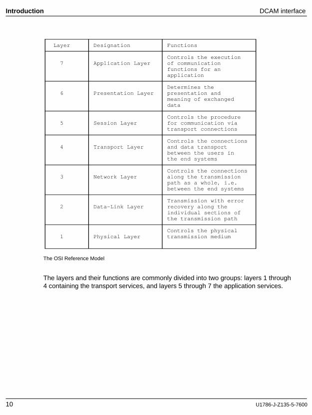
The OSI Reference Model (OSI = "Open Systems Interconnection"), establishes aframework for the classification of services, functions and interfaces. Hence it providesthe basis for non-proprietary communication protocols that allow the interconnection of"open systems".
The following diagram summarizes this model with the 7 layers and their respectivefunctions.
For more information please consult the brochure "Ways to Open Communications".
U1786-J-Z135-5-7600 9
Introduction DCAM interface
Layer Designation Functions
Controls the execution7 Application Layer of communication
functions for anapplication
Determines the6 Presentation Layer presentation and
meaning of exchangeddata
Controls the procedure5 Session Layer for communication via
transport connections
Controls the connections4 Transport Layer and data transport
between the users inthe end systems
Controls the connections3 Network Layer along the transmission
path as a whole, i.e.between the end systems
Transmission with error2 Data-Link Layer recovery along the
individual sections ofthe transmission path
Controls the physical1 Physical Layer transmission medium
The OSI Reference Model
The layers and their functions are commonly divided into two groups: layers 1 through4 containing the transport services, and layers 5 through 7 the application services.
10 U1786-J-Z135-5-7600
DCAM interface Introduction
DCAM(ISO) provides what is purely a transport service within the framework of architecture for communication on the basis of the ISO standard. Thismeans that DCAM(ISO) does not include some of the functions DCAM(NEA) provides.It should be noted particularly that DCAM(ISO) does not support any protocols on ahigher level than the transport service, i.e. no message editing for communication withterminals.
Note that the DCAM(ISO) transport service can be provided on the basis of differentcommunication protocols, e.g. by TCP/IP in conjunction with a convergence protocol.
U1786-J-Z135-5-7600 11
Introduction Traffic relations with DCAM
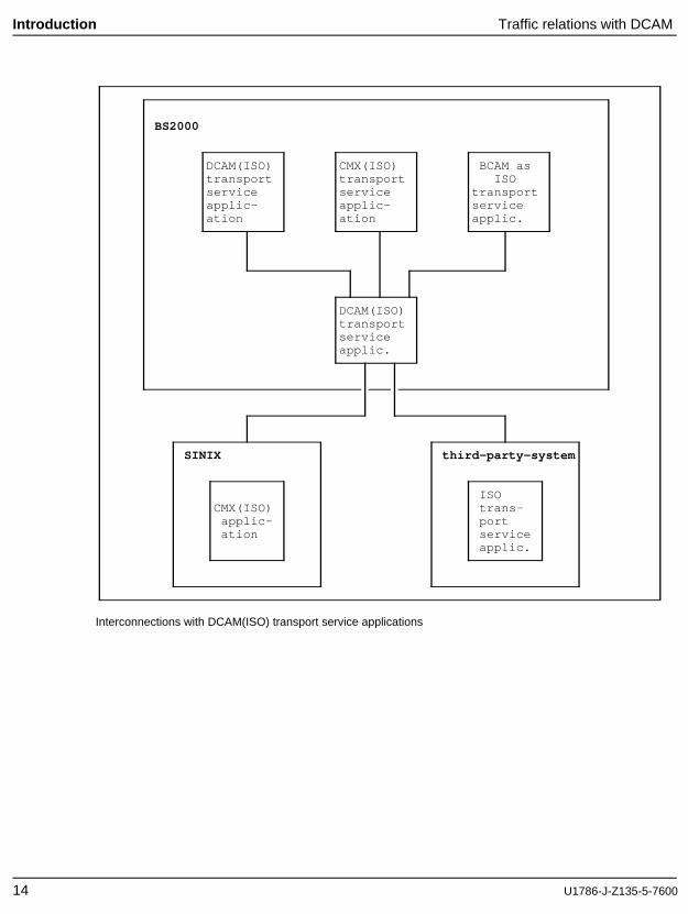
2.2 Traffic relations in the data communication systemwith DCAM
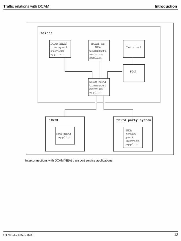
DCAM enables one or more tasks (programs) in the host computer to communicatewith any application/program. DCAM(NEA) also permits communication with one ormore terminals, and DCAM(ISO) permits communication with CMX applications, if theappropriate /BCMAP commands are implemented. DCAM therefore supportsconnections to the following:
other DCAM applications in the same or another BS2000 processorCMX applications in SINIX computersCMX applications in BS2000 computersapplications in third-party-computers, if the appropriate transport serviceis availableterminals
The links can be established via LANs (local area networks), WANs (wide areanetworks) or locally.
12 U1786-J-Z135-5-7600
Traffic relations with DCAM Introduction
BS2000
DCAM(NEA) BCAM astransport NEA Terminalservice transportapplic. service
applic.
PDN
DCAM(NEA)transportserviceapplic.
SINIX third-party system
NEACMX(NEA) trans-
applic. portserviceapplic.
Interconnections with DCAM(NEA) transport service applications
U1786-J-Z135-5-7600 13
Introduction Traffic relations with DCAM
BS2000
DCAM(ISO) CMX(ISO) BCAM astransport transport ISOservice service transportapplic- applic- serviceation ation applic.
DCAM(ISO)transportserviceapplic.
SINIX third-party-system
ISOCMX(ISO) trans-
applic- portation service
applic.
Interconnections with DCAM(ISO) transport service applications
14 U1786-J-Z135-5-7600
Basic concepts Introduction
2.3 Basic concepts
2.3.1 Program, data, task
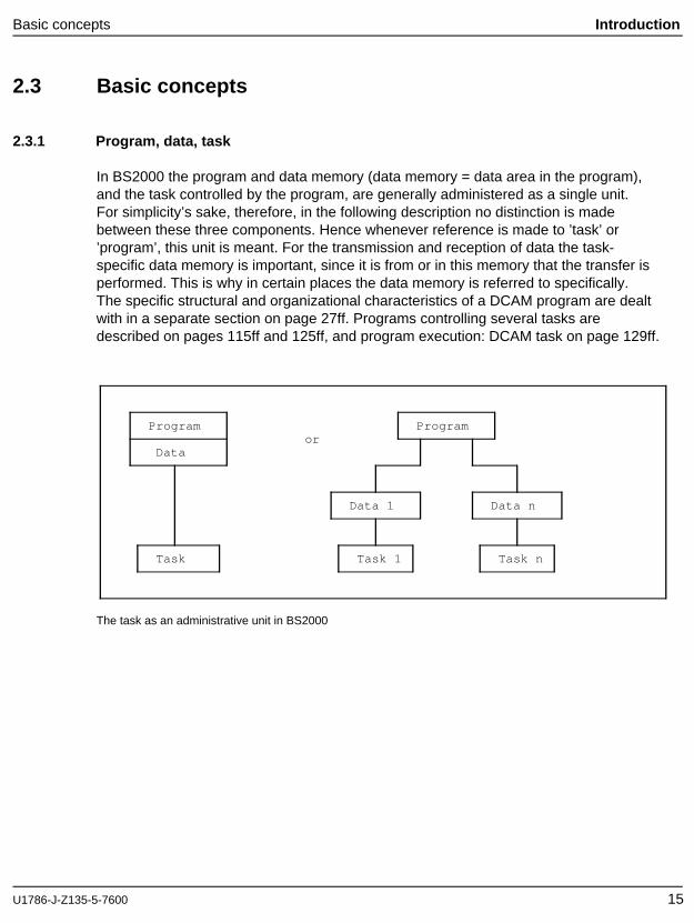
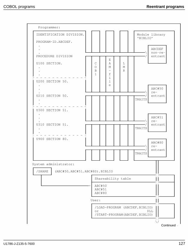
In BS2000 the program and data memory (data memory = data area in the program),and the task controlled by the program, are generally administered as a single unit.For simplicity’s sake, therefore, in the following description no distinction is madebetween these three components. Hence whenever reference is made to ’task’ or’program’, this unit is meant. For the transmission and reception of data the task-specific data memory is important, since it is from or in this memory that the transfer isperformed. This is why in certain places the data memory is referred to specifically.The specific structural and organizational characteristics of a DCAM program are dealtwith in a separate section on page 27ff. Programs controlling several tasks aredescribed on pages 115ff and 125ff, and program execution: DCAM task on page 129ff.
Program Programor
Data
Data 1 Data n
Task Task 1 Task n
The task as an administrative unit in BS2000
U1786-J-Z135-5-7600 15
Introduction Basic concepts
2.3.2 Communication partners
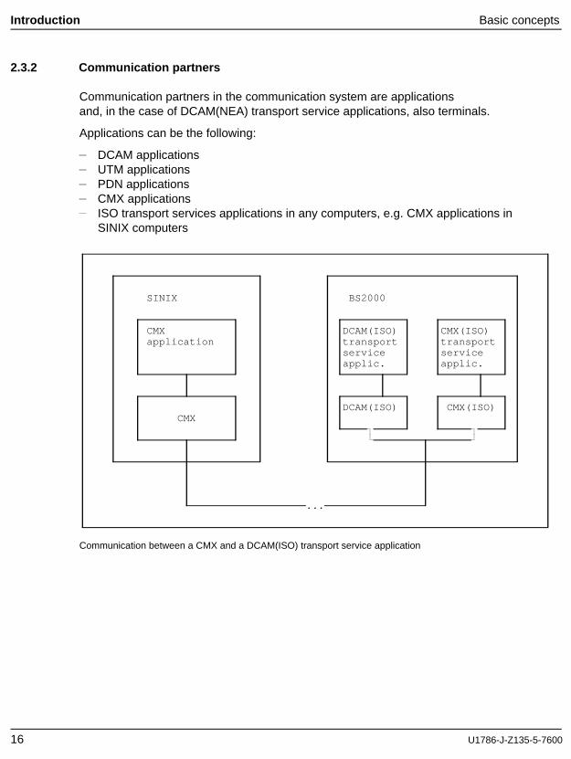
Communication partners in the communication system are applicationsand, in the case of DCAM(NEA) transport service applications, also terminals.
Applications can be the following:
DCAM applicationsUTM applicationsPDN applicationsCMX applicationsISO transport services applications in any computers, e.g. CMX applications inSINIX computers
SINIX BS2000
CMX DCAM(ISO) CMX(ISO)application transport transport
service serviceapplic. applic.
DCAM(ISO) CMX(ISO)CMX
...
Communication between a CMX and a DCAM(ISO) transport service application
16 U1786-J-Z135-5-7600
Basic concepts Introduction
A DCAM application can only exist in a host computer under the control of BS2000. Itis defined in at least one DCAM program and generated by the communication accessmethod. It is administered by the communication access method as an addressableunit for incoming and outgoing messages or notifications, and canceled at the requestof the program. It is the address at which tasks (programs) or groups of tasks areknown to the data communication system. This makes it a communication partner.
The generation of DCAM application type communication partners is a function of theDCAM interface.
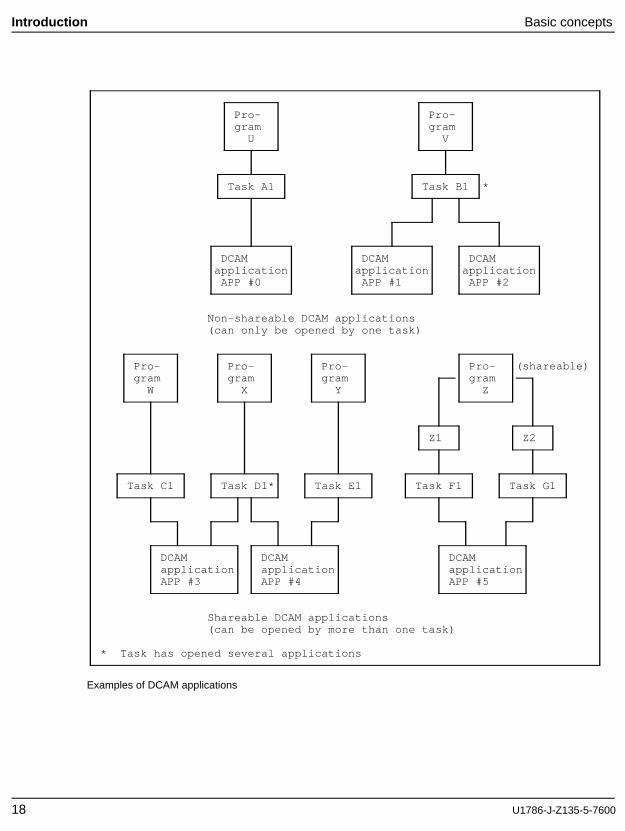
A DCAM application can be opened by one task if defined as non-shareable or by anumber of tasks (shareable). The first opening task is the primary task. Secondarytasks may follow if required. More than one DCAM application can be opened in aprogram. As each one can be considered in isolation, however, this option is notdiscussed any further in this manual. The name of the DCAM application is laid downwhen the application is generated (see example in figure below).
This name can be specified by the user in YOPEN. If the name is not specified by theuser, it is generated by the system, or a predefined name known to the datacommunication system can be used. The name of the DCAM application must beunique in the host computer in which the DCAM application is generated.
applies only to DCAM(NEA) transport service applications:The programmer has no influence over the existence of terminal-typecommunication partners. Such communication partners are generated orremoved either at communication system generation time or by means ofadministration instructions issued by the network administrator.
The terminal is characterized by its technical implementation on the one handand by the person operating it on the other. The interaction of these twoelements, i.e. the device and the user of the device, implements the terminalcommunication partner at a given point in time. This communication partner canonly maintain connections to other partners and transmit and receive data viathese connections with the means provided by the data communication system.
Those users of the data communication system who can set upconnections to other partners are referred to as communication partners in a widersense. In the more restricted sense, this name is used to denote the two partnerslinked by an existing connection.
U1786-J-Z135-5-7600 17
Introduction Basic concepts
Pro- Pro-gram gram
U V
Task A1 Task B1 *
DCAM DCAM DCAMapplication application application
APP #0 APP #1 APP #2
Non-shareable DCAM applications(can only be opened by one task)
Shareable DCAM applications(can be opened by more than one task)
* Task has opened several applications
Examples of DCAM applications
18 U1786-J-Z135-5-7600
Basic concepts Introduction
2.3.3 Addressing
A partner is addressed via two names: the processor node location of the partner andthe name of the communication partner itself.
The name of the processor node and, in the case of DCAM(NEA) transport serviceapplications, the name of the terminal, are defined when the data communicationsystem is generated. The names of the DCAM applications are defined in the programwhen the applications are opened.
All names used can have a maximum length of 8 characters. The first character mustbe alphabetic or $, @, #. Characters 2 through 8 may also comprise the digits 0...9(ASSEMBLER naming convention). A user application name may only begin with adollar sign ’$’ if the application runs under TSOS.
Note
The name of the communication partner in ISO transport service connections is notvalidated for conformance to conventions.
In the case of DCAM(ISO) transport service applications and heterogeneousnetworks it may be necessary to specify different codings or longer partner names.These names are assigned an alias via the /BCMAP console command; this isspecified in the program and adheres to the conventions (see the manual "NetworkManagement in BS2000").
2.3.4 Connections
Before communication can take place between two communication partners, aconnection has to be set up between them. One partner begins by issuing aconnection request (ACQUIRE) , whereupon the other may respond with anacceptance (ACCEPT) , thereby setting up a connection in the data communicationsystem.
Data can then be sent and received across the connection established. In DCAM(ISO)transport service applications, more than one connection can exist between twoapplications (parallel connections). Currently, parallel connections can only beestablished serially.
U1786-J-Z135-5-7600 19
Introduction Characteristic features of DCAM
2.4 Characteristic features of DCAM
2.4.1 Distribution of incoming messages
Messages arriving for a DCAM application can either be distributed via originator-oriented or common receiver queues. These methods are both suitable for shareableand non-shareable DCAM applications.
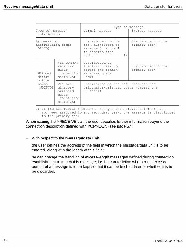
In the case of DCAM(NEA) transport service applications, distribution can also be viadistribution code-oriented queues, but only for shareable DCAM applications.
2.4.1.1 Originator-oriented queue and common receiver queue
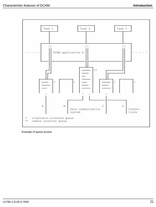
A queue for incoming messages is set up for each established connection enablingoriginator-oriented access to the messages. Access in the order of arrival (regardless ofthe message originator) is implemented by another queue, the common receiver queue.A message is always entered in one of the two queues. The user specifies in theprogram which queue is to be accessed. This is possible during connection setup andcan be re-specified for subsequent processing each time a message is transmitted orreceived.
Hence, for a definable period of time messages can only be fetched via the originator-oriented queue. In the case of shareable applications this creates the link between atask and a connection. The link is lost once the common receiver queue is used again.
The figure below provides an overview.
Task 1 has specified at connection setup or during the last send or receive operationthat it wants to receive messages via connection A, and accesses the associated queuewith receive calls. The same applies to task 3 and connection C. Messages fromconnections B and D are received by task 2 but can also be received by other tasks.
20 U1786-J-Z135-5-7600
Characteristic features of DCAM Introduction
Task 1 Task 2 Task 3
/\ /\ /\
- - - - - DCAM application A - - - - -
**
* * * *
A B C DData communication Connec-system tions
* originator-oriented queue** common receiver queue
Example of queue access
U1786-J-Z135-5-7600 21
Introduction Characteristic features of DCAM
2.4.1.2 Distribution code-oriented queue
This section applies to DCAM(NEA) transport service applications only.
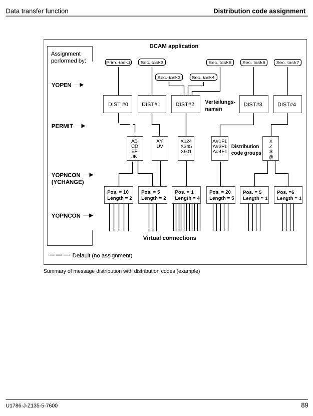
It is presumed that the task group is controlled by programs with different capabilities,i.e. that each program can only process certain messages. The message/program(task) link is established by means of a code which is contained in the message itself.The user can select the code and specifies specific codes when the connection isestablished (for a detailed description of the various options refer to page 68ff). Aseparate queue is created for each code group, and the allocation of the queues to theprograms is controlled by the primary task (special macros are provided for thispurpose, see page 88ff). A distribution name is defined when the application isopened and this is assigned to the distribution codes in order to link them to a task.
The name can be the same for several tasks, as, for instance, when one programcontrols more than one task. DCAM then passes on messages to the various tasks inaccordance with the FIFO principle (first in - first out: the first entry in the queue will bethe first one processed).
When the communication partner enters the code defined at connection setup time orlater, he will reach the task whose distribution name has been assigned to this code bythe primary task.
Thus the primary task controls
the assignment of distribution codes to a connection:when setting up a connection, it determines which codes are to be used and it canredefine these codes for an active connection at any time via a new macro call.
the assignment of the distribution codes to a task by means of the distributionname.
Messages which cannot be delivered because their code is not allocated or is invalidare delivered to the primary task.
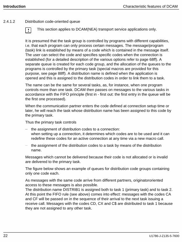
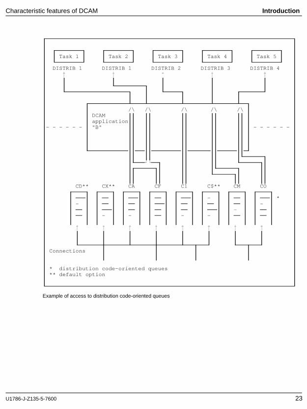
The figure below shows an example of queues for distribution code groups containingonly one code each.
As messages with the same code arrive from different partners, originatororientedaccess to these messages is also possible.The distribution name DISTRIB1 is assigned both to task 1 (primary task) and to task 2.At this point the FIFO rule (see above) comes into effect: messages with the codes CAand CF will be passed on in the sequence of their arrival to the next task issuing areceive call. Messages with the codes CD, CX and C$ are distributed to task 1 becausethey are not assigned to any other task.
22 U1786-J-Z135-5-7600
Characteristic features of DCAM Introduction
Task 1 Task 2 Task 3 Task 4 Task 5
DISTRIB 1 DISTRIB 1 DISTRIB 2 DISTRIB 3 DISTRIB 4
/\ /\ /\ /\ /\DCAMapplication
- - - - - - "B" - - - - - -
CD** CX** CA CF C1 C$** CM CO
- *- -
-- - - -
Connections
* distribution code-oriented queues** default option
Example of access to distribution code-oriented queues
U1786-J-Z135-5-7600 23
Introduction Characteristic features of DCAM
2.4.1.3 Implicit distribution code
This section applies to DCAM(NEA) transport service applications only.
If a sequence of messages contain the same distribution code it is sufficient to specifythis code in the first message. For this purpose the primary task defines a codeindicator character which indicates that a distribution code is included in a messageor message sequence. The distribution code immediately follows this character. In thiscase it may be no more than 7 characters long.
If messages without a distribution code are received, they are allocated according tothe last distribution code received. For subsequent messages DCAM implicitly assumesthe distribution code last in force. This applies until the partner sends a message inwhich a distribution code is explicitly specified.
If a code indicator character has not been defined by the primary task, then adistribution code must be included in each message. Otherwise they will be deliveredto the primary task.
The same applies if, in a sequence of messages, at least one message does notcontain a distribution code.
2.4.2 Calls and notifications
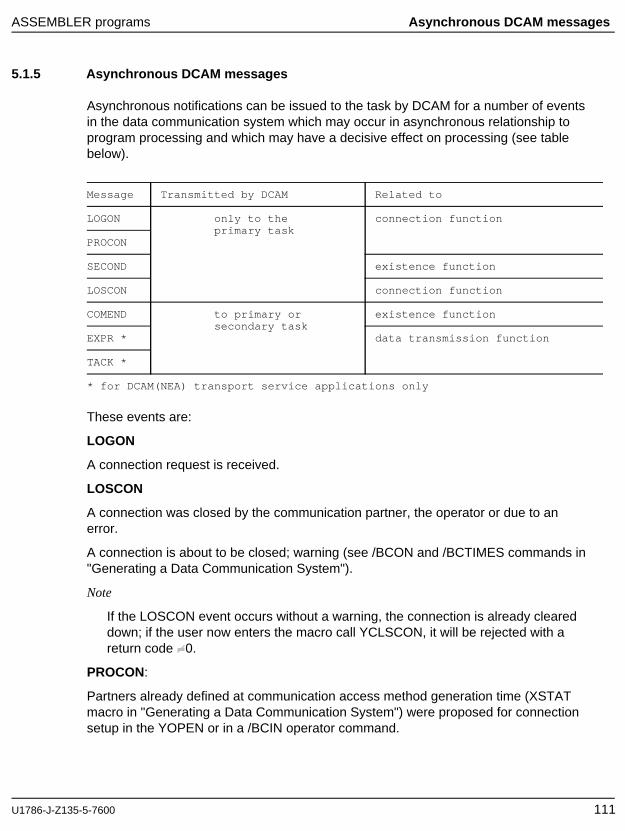
The functions provided by DCAM consist of calls with which the BS2000 user can effectthe execution of certain actions, and of asynchronous notifications (see 111ff) withwhich DCAM informs the user about certain events in the communication system.
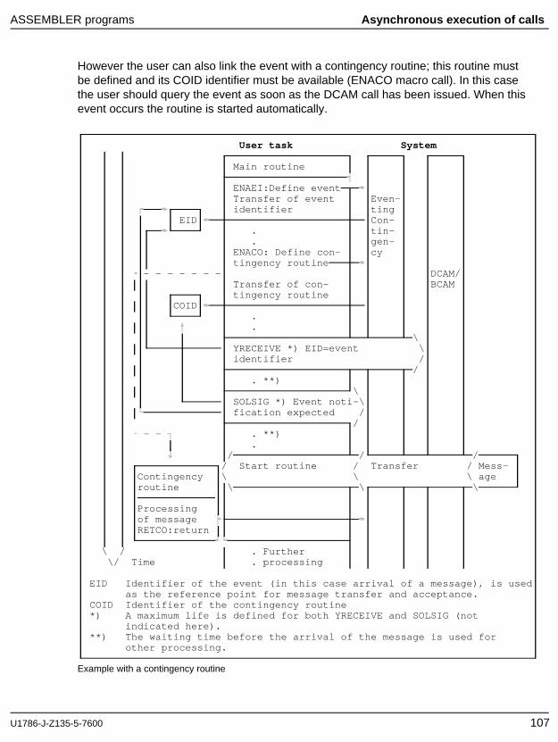
The calls issued to DCAM all begin with the letter Y. They are available either asmacro calls (ASSEMBLER) or as COBOL calls . The calls are terminated afterexecution or when a defined processing period has elapsed (synchronous execution ).It is also possible to have control returned immediately after the call was issued(asynchronous execution). Call termination is indicated by an asynchronous notification which can be queried in the program. A separate (contingency) routine canalso be initiated by the arrival of the notification (see 105ff). This asynchronousprocessing serves especially to make use of the waiting periods.
2.4.3 Protection against unauthorized access
A DCAM application can be protected against unauthorized connection of a taskwithin the host computer. If the application is to be non-shareable, the connection of asecondary task is not possible. In the case of a shareable application, unauthorizedconnection of a secondary task can be prevented by means of a password.
24 U1786-J-Z135-5-7600
Characteristic features of DCAM Introduction
Predefined applications can already be protected against unauthorized opening (by auser password) in the resource definition file at the system generation stage. This RDFpassword must be provided by the primary and secondary task.
The unauthorized setup of a connection can be prevented within the datacommunication system. Firstly, by DCAM applications not accepting connectionrequests, either permanently or for a certain period of time, and secondly, by requiringthat a password be specified in a connection request. Finally the user can opt toaccept or reject a connection request on the basis of the connection message and/orthe address of the requesting partner.These procedures ensure that inadvertent or deliberate illegal access can bemonitored. Passwords can also be dynamically altered for this purpose (see page92ff).
U1786-J-Z135-5-7600 25
Introduction Characteristic features of DCAM
2.4.4 Express messages
This section applies to DCAM(NEA) transport service applications only.
Another aspect of data security, the solution of conflict cases, is also provided for.Unhindered data transmission is ensured in the data communicationsystem by connection-oriented data flow control and capacity distribution. The existingbuffer areas are used by each connection only being allowed to occupy a certain sub-area. Thus, the buffers cannot be completely occupied by the data of one connection.However, to ensure that a connection remains operable in the case of blockageaffecting it, short, fixed-length express messages can be delivered to the destination ashigh-priority messages which bypass the data flow control. Such messages "overtake"the others, so to speak. If the destination so desires, the express message istransferred to it immediately as an asynchronous notification (cf. page 111ff), otherwiseit is entered as far forward in the queue as possible. Express messages cannot betransmitted if the connection is operating with a virtual terminal.
The system can reduce the load on an overloaded connection by temporarilyinterrupting the transmission of messages. This can affect both normal and, in the caseof DCAM(NEA) transport service applications, express messages. As soon as theconnection is ready for use once more, the user can be informed, by means of a GOsignal, that the jam has been cleared and that transmission of messages may berecommenced.
26 U1786-J-Z135-5-7600
Program structure Introduction
2.5 Program structure
2.5.1 Functions of a DCAM program
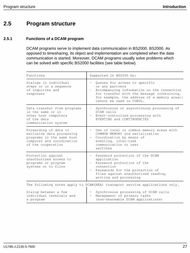
DCAM programs serve to implement data communication in BS2000. BS2000. Asopposed to timesharing, its object and implementation are completed when the datacommunication is started. Moreover, DCAM programs usually solve problems whichcan be solved with specific BS2000 facilities (see table below).
Functions Supported in BS2000 by:
Dialogs in individual - Queues for access to specificsteps or in a sequence or any partnersof inquiries and - Accompanying information on the connectionresponses for transfer with the message (containing,
for example, the address of a memory area);cannot be used in COBOL.
Data transfer from programs - Synchronous or asynchronous processing ofin the same or in DCAM callsother host computers - Event-controlled processing withof the data EVENTING and CONTINGENCIEScommunication system
Forwarding of data to - Use of local or common memory areas withexclusive data processing COMMON MEMORY and serializationprograms in the same host - Coordination by means ofcomputer and coordination eventing, inter-taskof the cooperation communication or user
switches
Protection against - Password protection of the DCAMunauthorized access to applicationprograms or program - Password protection of thesystems or to files connection
- Passwords for the protection offiles against unauthorized reading,writing and processing
The following notes apply to DCAM(NEA) transport service applications only.
Dialog between a few - Synchronous processing of DCAM callsindividual terminals and - Management of primary tasksa program (non-shareable DCAM applications)
U1786-J-Z135-5-7600 27
Introduction Program structure
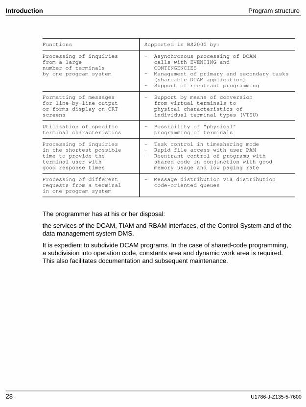
Functions Supported in BS2000 by:
Processing of inquiries - Asynchronous processing of DCAMfrom a large calls with EVENTING andnumber of terminals CONTINGENCIESby one program system - Management of primary and secondary tasks
(shareable DCAM application)- Support of reentrant programming
Formatting of messages - Support by means of conversionfor line-by-line output from virtual terminals toor forms display on CRT physical characteristics ofscreens individual terminal types (VTSU)
Utilization of specific - Possibility of "physical"terminal characteristics programming of terminals
Processing of inquiries - Task control in timesharing modein the shortest possible - Rapid file access with user PAMtime to provide the - Reentrant control of programs withterminal user with shared code in conjunction with goodgood response times memory usage and low paging rate
Processing of different - Message distribution via distributionrequests from a terminal code-oriented queuesin one program system
The programmer has at his or her disposal:
the services of the DCAM, TIAM and RBAM interfaces, of the Control System and of thedata management system DMS.
It is expedient to subdivide DCAM programs. In the case of shared-code programming,a subdivision into operation code, constants area and dynamic work area is required.This also facilitates documentation and subsequent maintenance.
28 U1786-J-Z135-5-7600
Program structure Introduction
2.5.2 Basic structure of a DCAM program
A DCAM program includes the following:
open DCAM applicationestablish a connectiontransmit dataclear connection or close DCAM application
Open DCAM application
To allow a program to be addressed by other communication partners, it must open atleast one DCAM application. The name that is defined at that point forms, together withthe name of the processor (processor node), the address for this application whichmust be unique throughout the network. Furthermore, characteristics of the DCAMapplication are defined, and passwords are specified. The statement that executes thisstage is called YOPEN.
Establish a connection
Before data transmission can take place between two communication partners, one ofthe partners must send a request to establish a connection to the other, who mustaccept this request, i.e. a connection must be set up. Buffering and distribution of themessages are carried out according to the specifications made at this point. Moreover,it is necessary to specify what kind of message editing is desired or whether the userwill take care of message editing himself. In addition, the communication partners canexchange connection messages. The statement for this stage is YOPNCON ACCEPT(accept connection request) or YOPNCON ACQUIRE (output connection request).
Following the two preparatory stages, the message can be received with YRECEIVEand transmitted with YSEND.
Once data transmission is completed, the connection is closed down either explicitlyby the program with YCLSCON or implicitly by closing the DCAM application by meansof the YCLOSE statement, or by the termination of the program. Abnormal terminationof a connection e.g. on the request of the communication partners, line failure orfailure of a processor, can be reported to the program.
In the case of DCAM(NEA) transport service applications, a connection can also becleared down indirectly via the terminal by inputting an agreed end criterion whichmust initiate the execution of YCLSCON in the program.
U1786-J-Z135-5-7600 29
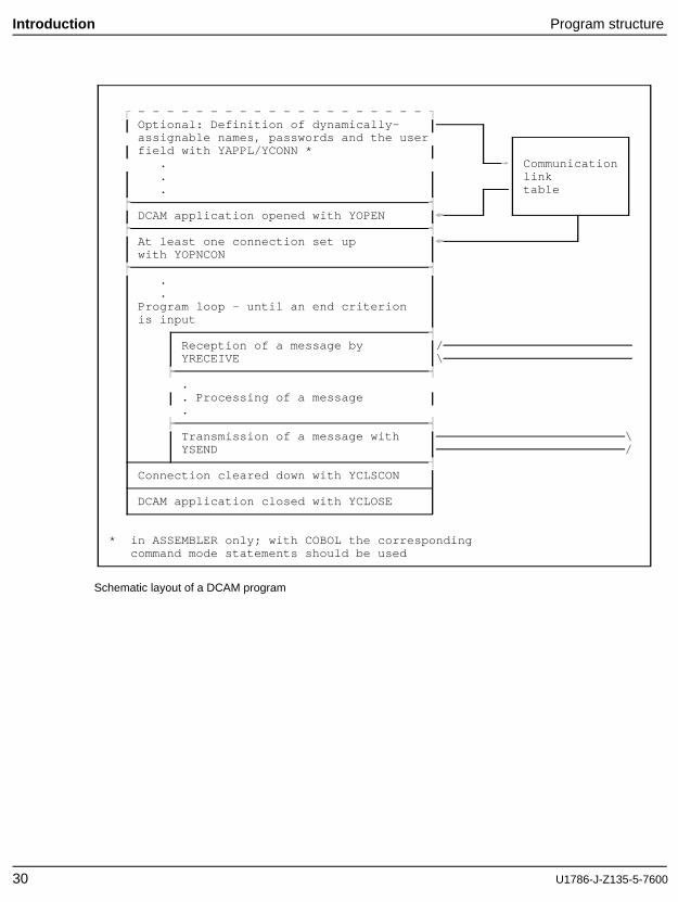
Introduction Program structure
- - - - - - - - - - - - - - - - - - - -Optional: Definition of dynamically-assignable names, passwords and the userfield with YAPPL/YCONN *
. Communication
. link
. table
DCAM application opened with YOPEN
At least one connection set upwith YOPNCON
.
.Program loop - until an end criterionis input
Reception of a message by /YRECEIVE \
.
. Processing of a message
.
Transmission of a message with \YSEND /
Connection cleared down with YCLSCON
DCAM application closed with YCLOSE
* in ASSEMBLER only; with COBOL the correspondingcommand mode statements should be used
Schematic layout of a DCAM program
30 U1786-J-Z135-5-7600
Program structure Introduction
Dynamic name assignment can also influence the structure of the program. Thedynamically allocated names, passwords and the user field must be entered in the CLT(communication link table) prior to the opening of the DCAM application or connectionsetup. A separate program or a leader should therefore contain the YAPPL or YCONNcalls or the /SET-DCAM-APPLICATION-LINK and /SET-DCAM-CONNECTION-LINKcommands should be used accordingly.
Restriction:
The YAPPL and YCONN calls are not available for COBOL programs.
After each call issued to DCAM, a check must be made to see whether it was properlyexecuted. Feedback information (FDBK) is provided for this purpose. The result of thecheck may be that a call is repeated or has to be executed in a different way, thatother measures have to be taken, or that the program run has to be terminated. Theerror handling routine can immediately follow the call. As the same or similar measuresusually have to be taken, it is expedient to generate a central error recovery routinewhich can be invoked again and again.
U1786-J-Z135-5-7600 31
Introduction Program structure
2.5.3 Control of primary and secondary tasks
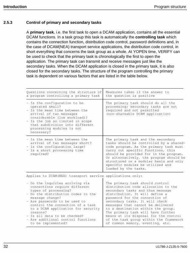
A primary task , i.e. the first task to open a DCAM application, contains all the essentialDCAM functions. In a task group this task is automatically the controlling task whichcontains the connection function, distribution code control, password definitions and, inthe case of DCAM(NEA) transport service applications, the distribution code control, inshort everything that concerns the task group as a whole. At YOPEN time, VERIFY canbe used to check that the primary task is chronologically the first to open theapplication. The primary task can transmit and receive messages just like thesecondary tasks. When the DCAM application is closed in the primary task, it is alsoclosed for the secondary tasks. The structure of the program controlling the primarytask is dependent on various factors that are listed in the table below.
Questions concerning the structure of Measures taken if the answer toa program controlling a primary task the question is positive
- Is the configuration to be The primary task should do all theoperated small? processing; secondary tasks are not
- Is the mean time between the required and not permittedarrival of two messages (non-shareable DCAM application)considerable (low workload)?
- Is the job so limited in scopethat subdivision into differentprocessing modules is notnecessary?
- Is the mean time between the The primary task and the secondaryarrival of two messages short? tasks should be controlled by a shared-
- Is the configuration large? code program. As the primary task must- Is a short processing time carry out specific functions, this
required? should be provided for in the program.Or alternatively, the program should bestructured on a modular basis and onlyspecific modules be utilized andloaded by the tasks.
Applies to DCAM(NEA) transport service applications only:
- Do the inquiries arriving via The primary task should controlconnections require different distribution code allocation to thetypes of processing? secondary tasks and thus message
- Do the distribution codes in the distribution. It will define amessage change? password for the connection of
- Are passwords to be used to secondary tasks. It will checkcontrol the connection of a task messages that cannot be deliveredto a DCAM application for security to a destination within the group.reasons? The primary task will have further
- Is all data to be checked? means at its disposal for the control- Are additional control functions of the task group within the framework
to be implemented? of common memory, eventing, etc.
32 U1786-J-Z135-5-7600
Program structure Introduction
A secondary task , i.e. a task which opens a DCAM application but is not the first todo so, has no influence on the characteristics of the DCAM application, and may haveto specify a password in order to join the group. It can use VERIFY to check whether itis opening the application later than the primary task. It can neither establish nor closedown connections. It has no control function within the group. Its function is totransmit and receive messages and to process them. Therefore, the only aspect ofsignificance with regard to the structure of the program is the way in which YSEND,YRECEIVE or YSENDREC calls are issued and processed. Attention must be paid toany controlling actions by the primary task (connection control). If the DCAMapplication is closed in the secondary task, this has no effect on the other tasks of thegroup.
U1786-J-Z135-5-7600 33
Introduction Program structure
2.5.4 Messages and local data units - more-data function
The sum of all the data which a DCAM(ISO) transport service application wishes tosend as a logical unit via a connection to a connection partner, is termed message(also TSDU = transport service data unit). This message can be of any length.
As a result of fixed requirements in the data communication network (laid down whenthe data communication network is generated) and the way the transport system isimplemented locally (memory management, buffer sizes, etc.) only a limited amount ofdata can be transferred by the application to the transport system at a time using alocal interface call (YSEND, YRECEIVE). This data buffer passed by an interface call isknown as a data unit (also TIDU = transport interface data unit).
DCAM offers you the option of passing large messages for DCAM(ISO) transportservice applications as logical units in a number of interface calls, i.e. in more than onedata unit. This facility is called the more-data function .
DCAM(ISO) transport service applications can specify when the connection is set upwhether or not the more-data function is to be used.
Note
The more-data function is only set in the DCAM of the user’s own computer. It isneither passed to nor negotiated with the connection partner.
The more-data function determines what data units are passed at the local DCAMinterface. It has no bearing on how the "physical" data blocks are split up along thetransmission path to the remote transport system.
The use of the more-data function in one application, does not have any bearing onthe data units in which (logical) messages are sent or received by the connectionpartner.
A few examples have been chosen to illustrate what effect the more-data function canhave.
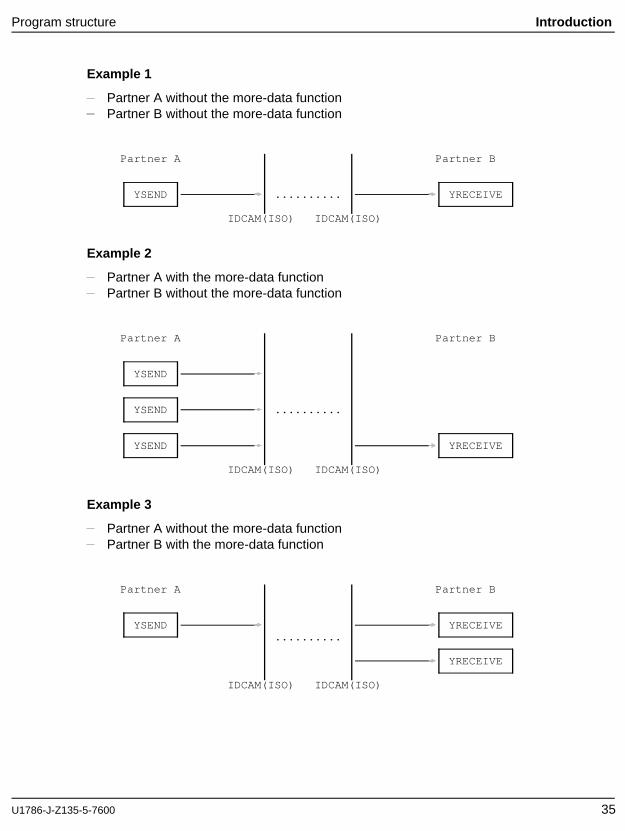
We shall assume that partner A and partner B are both DCAM(ISO) transport serviceapplications. In each example only one (logical) message, sent by A to B, isconsidered.
34 U1786-J-Z135-5-7600
Program structure Introduction
Example 1
Partner A without the more-data functionPartner B without the more-data function
Partner A Partner B
YSEND .......... YRECEIVE
IDCAM(ISO) IDCAM(ISO)
Example 2
Partner A with the more-data functionPartner B without the more-data function
Partner A Partner B
YSEND
YSEND ..........
YSEND YRECEIVE
IDCAM(ISO) IDCAM(ISO)
Example 3
Partner A without the more-data functionPartner B with the more-data function
Partner A Partner B
YSEND YRECEIVE..........
YRECEIVE
IDCAM(ISO) IDCAM(ISO)
U1786-J-Z135-5-7600 35
Introduction Program structure
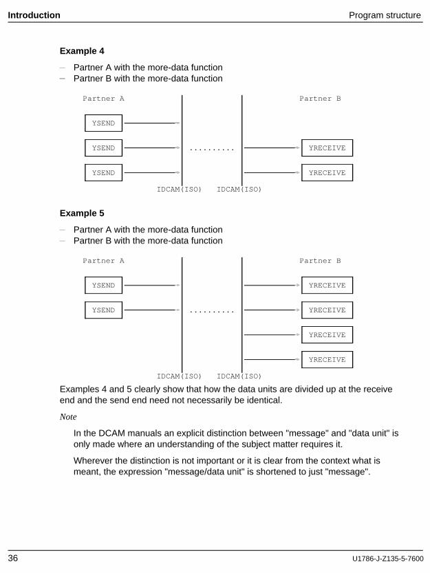
Example 4
Partner A with the more-data functionPartner B with the more-data function
Partner A Partner B
YSEND
YSEND .......... YRECEIVE
YSEND YRECEIVE
IDCAM(ISO) IDCAM(ISO)
Example 5
Partner A with the more-data functionPartner B with the more-data function
Partner A Partner B
YSEND YRECEIVE
YSEND .......... YRECEIVE
YRECEIVE
YRECEIVE
IDCAM(ISO) IDCAM(ISO)
Examples 4 and 5 clearly show that how the data units are divided up at the receiveend and the send end need not necessarily be identical.
Note
In the DCAM manuals an explicit distinction between "message" and "data unit" isonly made where an understanding of the subject matter requires it.
Wherever the distinction is not important or it is clear from the context what ismeant, the expression "message/data unit" is shortened to just "message".
36 U1786-J-Z135-5-7600
Program structure Introduction
2.5.5 Access to terminals
This section applies to DCAM(NEA) transport service applications only.
An important question in the planning of DCAM programs is how the terminals are tobe accessed.
The DCAM programmer has a choice of two methods:
physical programminguse of virtual terminals.
Physical programming requires the operation of a terminal with the control charactersit understands (see User Guides for individual terminals). The programmer winsconsiderable flexibility, but has also the inconvenience of operating with controlcharacters. The virtual terminals relieve him of this inconvenience because all essentialfunctions can be implemented with these standardized terminals (but not with locallyconnected terminals).
The virtual terminals are user service software modules in the datacommunication system. At the logon stage, the communication partners agree onwhich virtual terminal should be used. Certain aspects have to be clarified in order todo this, such as whether a hardcopy unit is connected to a display terminal or a cardreader is to be used.
The programmer has a choice of two types of virtual terminal: the line terminal and theform terminal. For details see ’Logical terminal support’ page 95ff and the ’VTSU UserGuide’.
U1786-J-Z135-5-7600 37
Introduction DCAM partner
2.6 Implementation of distributed processing
The Communication System allows communication between
applications and applications
and between terminals and applications (in the case of DCAM(NEA) transportservice applications)
Both the terminals and applications can be in a LAN or WAN.
Apart from the connection to terminals, this opens up the following possibilities aspartners for a DCAM application:
a DCAM applicationa UTM applicationa CMX applicationa system application (e.g. $DIALOG, $CONSOLE)
2.6.1 A DCAM application as a partner
The communication partner DCAM application is described under ’DCAM functions’ asfrom page 41. This section describes the existence function of a DCAM application(see page 41ff), connection setup between DCAM applications (see page 50ff) anddata transmission between DCAM applications (see page 77ff).
38 U1786-J-Z135-5-7600
DCAM partner Introduction
2.6.2 UTM application as a partner
Communication between a DCAM application and a UTM application is possible if theDCAM has been generated as a communication partner for the UTM application and ifa connection has been established between the two applications. This is true whetherthe applications are in the same or in different host computers.
There are three different ways of establishing a connection between a DCAM and aUTM application:
The UTM application has been generated so that when it is started a connection isestablished. The connection is set up if the DCAM application exists at this momentand explicitly accepts the connection request.
The UTM application has been generated so that connection requests from theDCAM application are accepted. The connection is established if both applicationsexist and if the DCAM application has issued an explicit connection request.
A UTM administration command can be used to cause a connection request to beissued to a DCAM application.
When transmitting data care must be taken that the UTM application has been providedwith a structure. The UTM application is composed of subroutines, which can beaddressed via the transaction codes which they have been allocated. When atransaction is started the data must be included at the beginning of the transactioncode.
U1786-J-Z135-5-7600 39
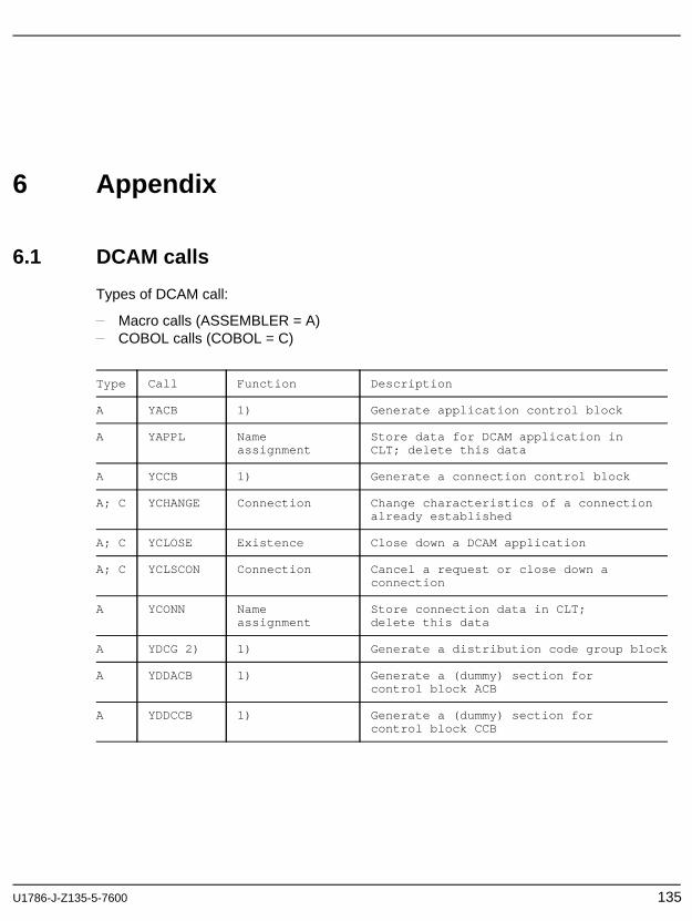
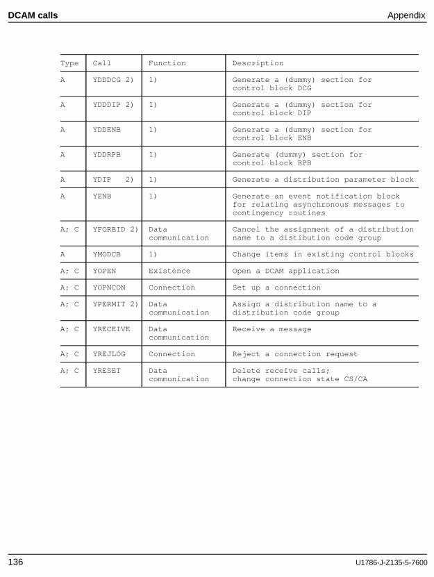
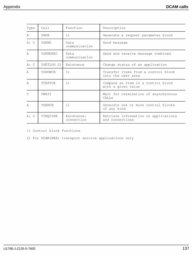
3 DCAM functionsThe functions provided by DCAM can be subdivided into 4 groups:
Existence function
Connection function
Data transmission function
Name assignment function
These functions are described below; the layout corresponds to that of the section"Using the DCAM functions" in the ASSEMBLER programmer’s manual (see "DCAMMacros") and the COBOL programmer’s manual (see "DCAM COBOL Calls"), where thecorresponding calls are listed along with the operands required.
3.1 Existence function
The existence function of the DCAM interface performs the following operations:
Open or generate a DCAM application (YOPEN) .This is the basic function of DCAM, and is executed in different ways depending onthe type of DCAM application involved.
Test the status (YINQUIRE) of a DCAM application .This function serves to check the status of a DCAM application.
Close a DCAM application (YCLOSE) .The DCAM application is closed automatically at the end of the program, but thisfunction can close it at any point in time during the program run.
Additional function for DCAM(NEA) transport service applications:Change the status (YSETLOG) of a DCAM application .This function can be used to dynamically change the state of the DCAMapplication, i.e. its readiness to process connection requests.
U1786-J-Z135-5-7600 41
Open a DCAM application Existence function
3.1.1 Open a DCAM application
A DCAM application is generated when the first program opens it. At the same time theapplication is defined as shareable or non-shareable. A non-shareable application canonly be opened by one program and is also closed by that program. A shareableapplication can also be opened by other programs (secondary tasks). These, however,only link up with the application and have no influence on the definitions made by thefirst program to open/generate the application (primary task). In the case ofDCAM(NEA) transport service applications it is also necessary to specify whether thedistribution code-oriented queues are to be used for message distribution. This resultsin different variants of the YOPEN call.
The ISO attribute must be set in the application control block for all DCAM(ISO)transport service applications. This attribute is then valid for all connections maintainedby this application. Connections using NEA services are not possible for DCAM(ISO)transport service applications.
42 U1786-J-Z135-5-7600
Existence function Open a DCAM application
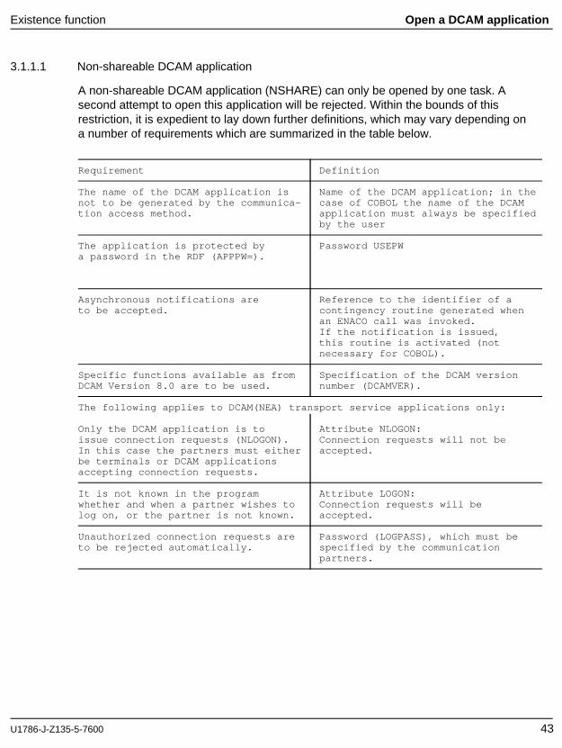
3.1.1.1 Non-shareable DCAM application
A non-shareable DCAM application (NSHARE) can only be opened by one task. Asecond attempt to open this application will be rejected. Within the bounds of thisrestriction, it is expedient to lay down further definitions, which may vary depending ona number of requirements which are summarized in the table below.
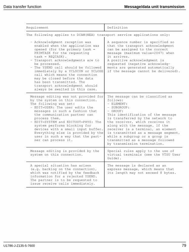
Requirement Definition
The name of the DCAM application is Name of the DCAM application; in thenot to be generated by the communica- case of COBOL the name of the DCAMtion access method. application must always be specified
by the user
The application is protected by Password USEPWa password in the RDF (APPPW= ).
Asynchronous notifications are Reference to the identifier of ato be accepted. contingency routine generated when
an ENACO call was invoked.If the notification is issued,this routine is activated (notnecessary for COBOL).
Specific functions available as from Specification of the DCAM versionDCAM Version 8.0 are to be used. number (DCAMVER).
The following applies to DCAM(NEA) transport service applications only:
Only the DCAM application is to Attribute NLOGON:issue connection requests (NLOGON). Connection requests will not beIn this case the partners must either accepted.be terminals or DCAM applicationsaccepting connection requests.
It is not known in the program Attribute LOGON:whether and when a partner wishes to Connection requests will belog on, or the partner is not known. accepted.
Unauthorized connection requests are Password (LOGPASS), which must beto be rejected automatically. specified by the communication
partners.
U1786-J-Z135-5-7600 43
Open a DCAM application Existence function
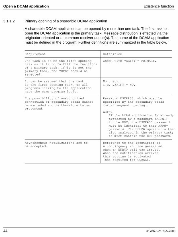
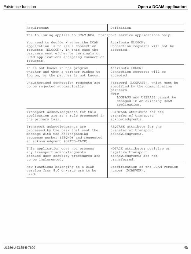
3.1.1.2 Primary opening of a shareable DCAM application
A shareable DCAM application can be opened by more than one task. The first task toopen the DCAM application is the primary task. Message distribution is effected via theoriginator-oriented or or common receiver queue(s). The name of the DCAM applicationmust be defined in the program. Further definitions are summarized in the table below.
Requirement Definition
The task is to be the first opening Check with VERIFY = PRIMARY.task as it is to fulfill the functionsof a primary task. If it is not theprimary task, the YOPEN should berejected.
It can be assumed that the task No check,is the first opening task, or all i.e. VERIFY = NO.programs linking to the applicationhave the same program logic.
The possibility of unauthorized Password USEPASS, which must beconnection of secondary tasks cannot specified by the secondary tasksbe excluded and is therefore to be for subsequent opening.prevented.
Note:If the DCAM application is alreadyprotected by a password (APPW=)in the RDF, the USEPASS passwordmust be identical to that APPW=password. The USEPW operand is thenalso analyzed in the primary task;it must contain the RDF password.
Asynchronous notifications are to Reference to the identifier ofbe accepted. a contingency routine generated
when an ENACO call was issued.When the notification arrives,this routine is activated(not required for COBOL).
44 U1786-J-Z135-5-7600
Existence function Open a DCAM application
Requirement Definition
The following applies to DCAM(NEA) transport service applications only:
You need to decide whether the DCAM Attribute NLOGON:application is to issue connection Connection requests will not berequests (NLOGON). In this case the accepted.partners must either be terminals orDCAM applications accepting connectionrequests.
It is not known in the program Attribute LOGON:whether and when a partner wishes to Connection requests will belog on, or the partner is not known. accepted.
Unauthorized connection requests are Password (LOGPASS), which must beto be rejected automatically. specified by the communication
partners.Note
LOGPASS and USEPASS cannot bechanged in an existing DCAMapplication.
Transport acknowledgments for this PRIMTASK attribute for theapplication are as a rule processed in transfer of transportthe primary task. acknowledgments.
Transport acknowledgments are REQTASK attribute for theprocessed by the task that sent the transfer of transportmessage with the corresponding acknowledgments.sequence number (SEQNO) and requestedan acknowledgment (OPTCD=TACK).
This application does not process NOTACK attribute: positive orany transport acknowledgments negative transportbecause user security procedures are acknowledgments are notto be implemented. transferred.
New functions belonging to a DCAM Specification of the DCAM versionversion from 8.0 onwards are to be number (DCAMVER).used.
U1786-J-Z135-5-7600 45
Open a DCAM application Existence function
3.1.1.3 Primary opening - use of distribution codes
This section applies to DCAM(NEA) transport service applications only.
The primary task that opens a DCAM application can specify that a distribution code isto be used (SHARE,DISCO) in place of the default option for message distribution. Thisis especially useful if the programs involved perform different jobs but are accessed bythe same partners. All the tasks involved must then define distribution code namespermitting association of distribution code(s) and tasks (DISNAME). For furtherdefinitions, see table above.
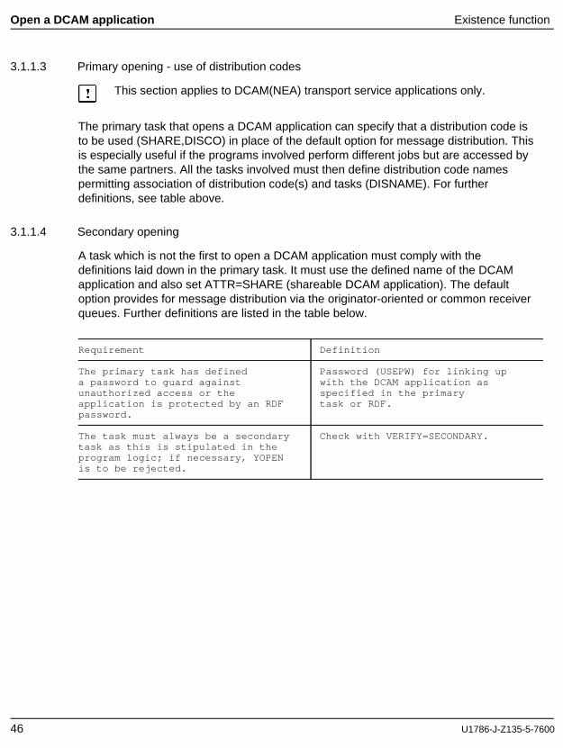
3.1.1.4 Secondary opening
A task which is not the first to open a DCAM application must comply with thedefinitions laid down in the primary task. It must use the defined name of the DCAMapplication and also set ATTR=SHARE (shareable DCAM application). The defaultoption provides for message distribution via the originator-oriented or common receiverqueues. Further definitions are listed in the table below.
Requirement Definition
The primary task has defined Password (USEPW) for linking upa password to guard against with the DCAM application asunauthorized access or the specified in the primaryapplication is protected by an RDF task or RDF.password.
The task must always be a secondary Check with VERIFY=SECONDARY.task as this is stipulated in theprogram logic; if necessary, YOPENis to be rejected.
46 U1786-J-Z135-5-7600
Existence function Open a DCAM application
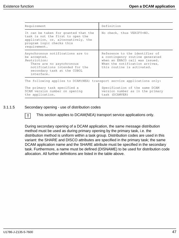
Requirement Definition
It can be taken for granted that the No check, thus VERIFY=NO.task is not the first to open theapplication, or, alternatively, theprogram logic checks thisrequirement.
Asynchronous notifications are to Reference to the identifier ofbe accepted. a contingency routine generatedRestriction: when an ENACO call was issued.
There are no asynchronous When the notification arrives,notifications intended for the this routine is activated.secondary task at the COBOLinterface.
The following applies to DCAM(NEA) transport service applications only:
The primary task specified a Specification of the same DCAMDCAM version number on opening version number as in the primarythe application. task (DCAMVER)
3.1.1.5 Secondary opening - use of distribution codes
This section applies to DCAM(NEA) transport service applications only.
During secondary opening of a DCAM application, the same message distributionmethod must be used as during primary opening by the primary task, i.e. thedistribution method is uniform within a task group. Distribution codes are used in thisvariant: the SHARE and DISCO attributes are specified in the primary task; the sameDCAM application name and the SHARE attribute must be specified in the secondarytask. Furthermore, a name must be defined (DISNAME) to be used for distribution codeallocation. All further definitions are listed in the table above.
U1786-J-Z135-5-7600 47
Altering the state of a DCAM application Existence function
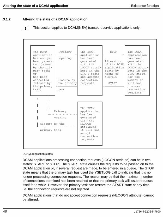
3.1.2 Altering the state of a DCAM application
This section applies to DCAM(NEA) transport service applications only.
The DCAM Primary The DCAM STOP The DCAMapplication application applicationhas not yet opening has been has beenbeen genera- generated Alteration generatedted (opened with the of the DCAM with theby the pri- LOGON attri- application LOGON attri-mary task) bute in the state by bute in theor START state means of STOP state.has been and accepts YSETLOG For thecancelled Closure by connection moment it(closed by the primary requests START will notthe primary processtask) task connection
requests
The DCAMPrimary application
- - - - - - - has beenopening generated
with theClosure by the NLOGON
- - - - - - - - - attribute;primary task it will not
acceptconnectionrequests
DCAM application states
DCAM applications processing connection requests (LOGON attribute) can be in twostates: START or STOP. The START state causes the requests to be passed on to theDCAM application or, if several request are made, to be entered in a queue. The STOPstate means that the primary task has used the YSETLOG call to indicate that it is nolonger processing connection requests. The reason may be that the maximum numberof connections permitted has been reached or that the primary task will issue requestsitself for a while. However, the primary task can restore the START state at any time,i.e. the connection requests are not rejected.
DCAM applications that do not accept connection requests (NLOGON attribute) cannotbe altered.
48 U1786-J-Z135-5-7600
Existence function Altering the state of a DCAM application
3.1.3 Querying the status of a DCAM application
The YINQUIRE call in the ’APPSTAT’ function can be used to query the status of theDCAM application that the user himself has opened, and also the state of a DCAMapplication which was opened in the same host computer and whose name he knows.
3.1.4 Closing a DCAM application
The DCAM application can be closed in two ways:
implicitly by terminating the program in which the DCAM application was opened(normal or abnormal termination) or task abortion
explicitly by means of the YCLOSE call or by means of the /SHUTDOWN, /BCENDor /BCAPPL operator commands.
Explicit closing with YCLOSE will be necessary when, for example, a program is toprocess several DCAM applications consecutively or if definitions are to be changedduring execution. The application can be opened again by the primary task with newdefinitions (name, attributes etc.) after being closed.
The secondary task can close the application at any time without any consequencesfor the other tasks in the group.
If the primary task closes the application,
the DCAM application is canceled;
secondary tasks are informed through initiation of the COMEND contingency routine(see page 111ff) or by feedback information for an incomplete call or the next call;
all existing connections are cleared down.
This also means that data which has already arrived but has not yet been accepted isno longer accessible. Pending connection requests are deleted.
U1786-J-Z135-5-7600 49
Connection setup Connection function
3.2 Connection function
The basic requirement for data transmission is the establishment of a connectionbetween the communication partners after a DCAM application has been opened.
The connection function performs the following:
set up connection (YOPNCON).query entries on partners and connections (YINQUIRE).request rejection of connection request (YREJLOG)cancel request (YCLSCON)close connection (YCLSCON)change characteristics of a connection (YCHANGE)
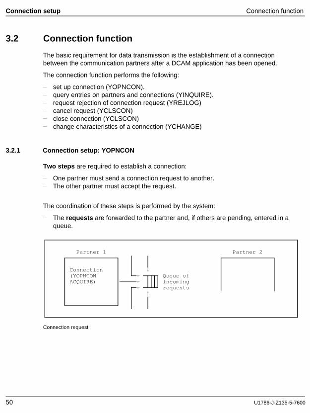
3.2.1 Connection setup: YOPNCON
Two steps are required to establish a connection:
One partner must send a connection request to another.The other partner must accept the request.
The coordination of these steps is performed by the system:
The requests are forwarded to the partner and, if others are pending, entered in aqueue.
Partner 1 Partner 2
Connection(YOPNCON Queue ofACQUIRE) incoming
requests
Connection request
50 U1786-J-Z135-5-7600
Connection function Connection setup
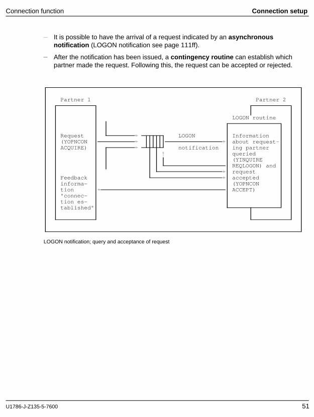
It is possible to have the arrival of a request indicated by an asynchronous notification (LOGON notification see page 111ff).
After the notification has been issued, a contingency routine can establish whichpartner made the request. Following this, the request can be accepted or rejected.
Partner 1 Partner 2
LOGON routine
Request LOGON Information(YOPNCON about request-ACQUIRE) notification ing partner
LOGON notification; query and acceptance of request
U1786-J-Z135-5-7600 51
Connection setup Connection function
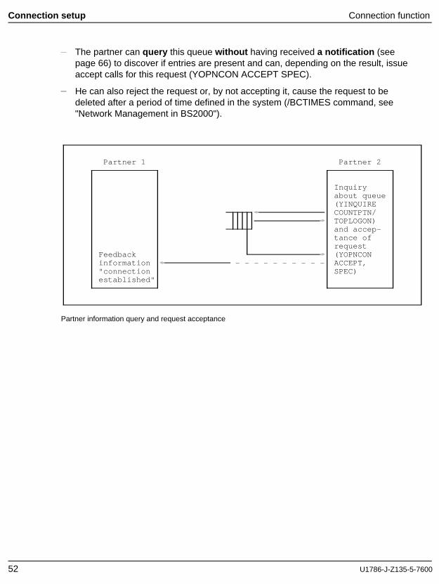
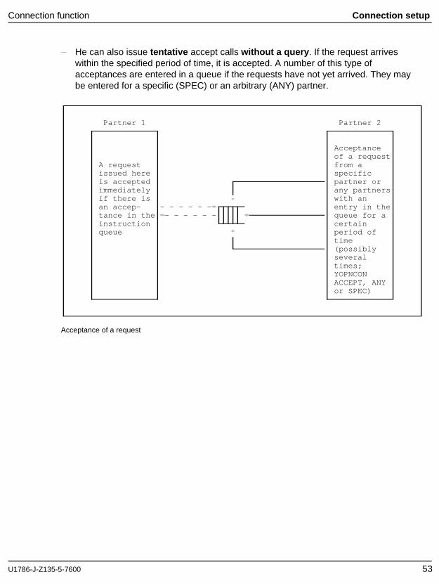
The partner can query this queue without having received a notification (seepage 66) to discover if entries are present and can, depending on the result, issueaccept calls for this request (YOPNCON ACCEPT SPEC).
He can also reject the request or, by not accepting it, cause the request to bedeleted after a period of time defined in the system (/BCTIMES command, see"Network Management in BS2000").
He can also issue tentative accept calls without a query . If the request arriveswithin the specified period of time, it is accepted. A number of this type ofacceptances are entered in a queue if the requests have not yet arrived. They maybe entered for a specific (SPEC) or an arbitrary (ANY) partner.
Partner 1 Partner 2
Acceptanceof a request
A request from aissued here specificis accepted partner orimmediately any partnersif there is with anan accep- - - - - - - entry in thetance in the - - - - - - queue for ainstruction certainqueue period of
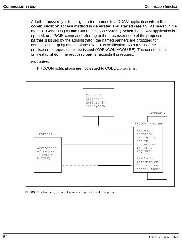
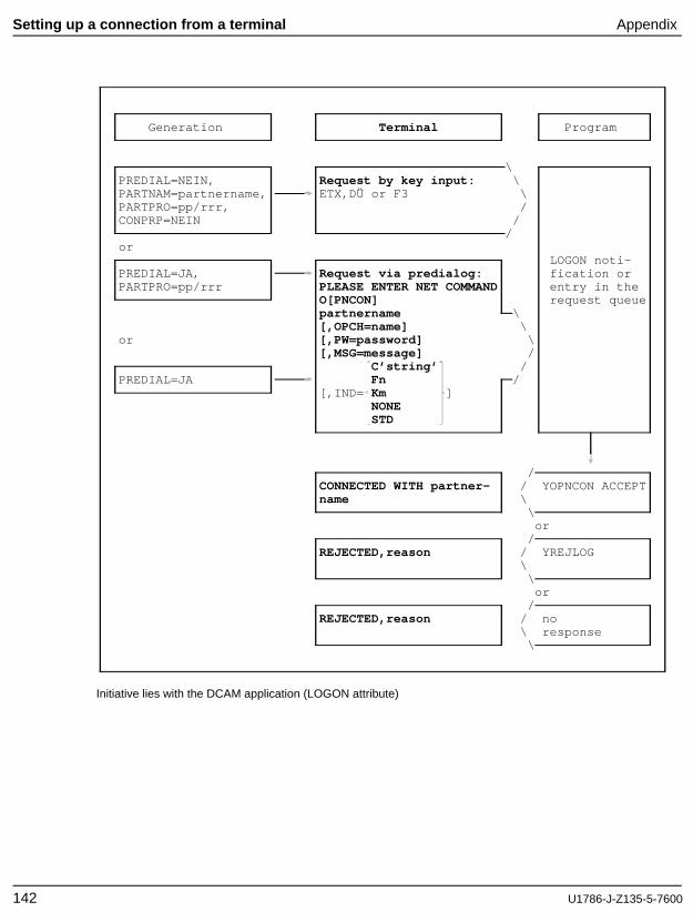
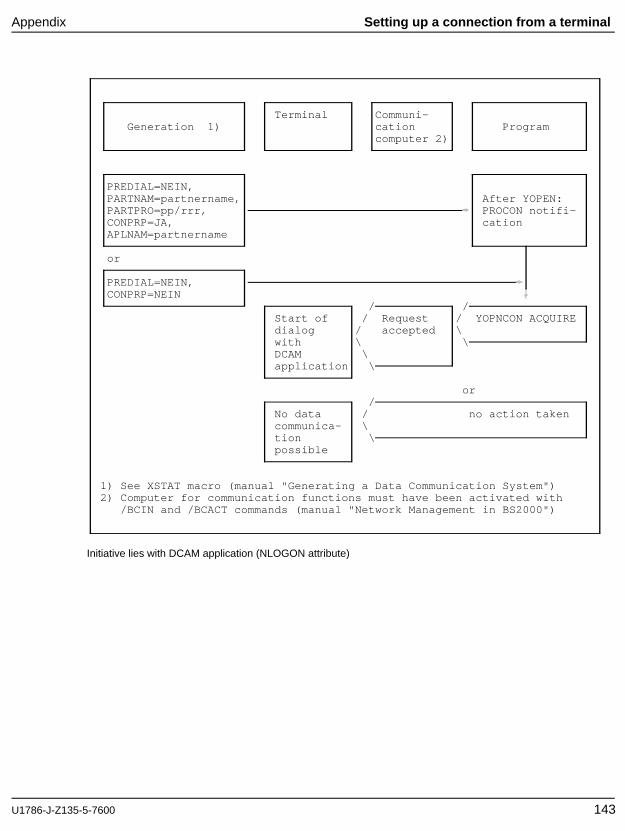
A further possibility is to assign partner names to a DCAM application when the communication access method is generated and started (see XSTAT macro in themanual "Generating a Data Communication System"). When the DCAM application isopened, or a /BCIN command referring to the processor node of the proposedpartner is issued by the administrator, the named partners are proposed forconnection setup by means of the PROCON notification. As a result of thenotification, a request must be issued (YOPNCON ACQUIRE). The connection isonly established if the proposed partner accepts this request.
Restriction:
PROCON notifications are not issued to COBOL programs.
PROCON notification, request to proposed partner and acceptance
54 U1786-J-Z135-5-7600
Connection function Connection setup
Parallel connections can only be set up "serially", i.e. a new parallel connection canonly be established once the previous connection setup has been completed(DCAM(ISO) transport services only).
The rest of this section applies to DCAM(NEA) transport service applicationsonly.
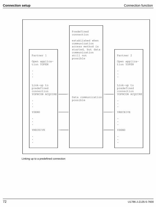
When generating and starting the communication access method, connections(XKON macro), as well as connection proposals, may be predefined.
These connections are already established whenever the communication accessmethod is started. However, data transmission is not possible until the primary taskissues a call which is usually used as a connection request (YOPNCON ACQUIRE).
If the partner is a terminal, it is sufficient for this to be activated and operational.
Every communication partner that issues a logon call has to define the desiredconnection characteristics. When a connection request is made, the partner is informedof that part of the connection characteristics which affects him. This part consists of:
Type of message editing used (EDIT)Specification of the partner initiating data communication (PROC)
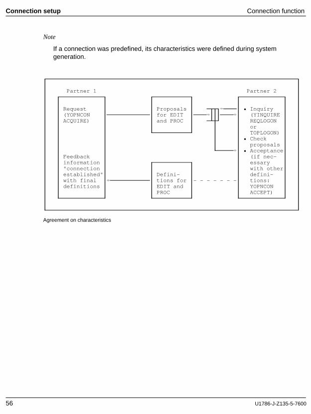
The figure below shows how this information is requested and defined:
Partner 1 sends partner 2 a connection request (YOPNCON ACQUIRE), and alsodefines proposals for EDIT and PROC to partner 2. Partner 2 can react to the call frompartner 1 in two ways:
By requesting the proposals from partner 1 (YINQUIRE) and then checking andeither accepting or rejecting them, i.e. by sending other values for EDIT and PROCback to partner 1 (YOPNCON ACCEPT).
By sending its own values for EDIT and PROC to partner 1 without considering theproposals.
In each case the values sent by partner 2 are binding for partner 1. This means thevalues suggested by partner 1 for EDIT and PROC need not necessarily correspond tothe current values, and therefore the user must inform himself of the appropriate valuesafter the connection is established.
Both in the case of a request for connection setup (YOPNCON ACQUIRE) and theacceptance of the connection (YOPNCON ACCEPT) the partners can send each otherconnection messages.
U1786-J-Z135-5-7600 55
Connection setup Connection function
Note
If a connection was predefined, its characteristics were defined during systemgeneration.
Partner 1 Partner 2
Request Proposals • Inquiry(YOPNCON for EDIT (YINQUIREACQUIRE) and PROC REQLOGON
orTOPLOGON)
• Checkproposals
• AcceptanceFeedback (if nec-information essary"connection with otherestablished" Defini- defini-with final tions for - - - - - - - tions:definitions EDIT and YOPNCON
PROC ACCEPT)
Agreement on characteristics
56 U1786-J-Z135-5-7600
Connection function Connection setup
3.2.1.1 Definition of the connection to be established
The connection to be established has to be defined in the DCAM program. Thefollowing information is required:
Name and processor name (= address) of the partner
This information is used to address a partner when a request is issued or a requestis accepted by a specific partner (SPEC). Processor name =’ ’ addresses the ownprocessor as partner.
If an accept call was issued for any partner (ANY), DCAM returns the partner andprocessor names after completion of the call.
Accompanying information
Here, the user defines an optional character string which, for example, is added toevery message he receives via this connection. It may be the address of a dataarea to be assigned to this connection or the address of a routine which is to beactivated specifically for this connection. This method is particularly useful foraccess to the common receiver queue with YRECEIVE ANY. The content of theaccompanying information is optional; however, it may not exceed 4 bytes.
Restriction:
Accompanying information cannot be defined in COBOL.
Data flow control
In the case of YSEND, there is a possibility of the connection being overloaded, forexample because the partner - which may be in the same system fetches thenotifications too slowly. If this happens the YSEND is not executed: instead, it isterminated with the RC "Wait for GO" (X’10040C00’). A subsequent YSEND on thisconnection cannot be successful until DCAM receives the GO signal. YSENDsissued before the GO signal is received are terminated with the RC "Shortage"(X’10040800’).
If the connection was set up with PROC=SIGNAL, the user is notified when the GOsignal is received (see SOLSIG, BS2000 Executive Macros). In COBOL, this takesthe form of the arrival of the "GOSIGNAL" event after YWAIT. When the GO signal isreceived, the connection is free and data can again be sent. Note that when aconnection is set up with PROC=SIGNAL, the YSEND must include the address ofa valid EID.If the connection is not set up with PROC=SIGNAL, a successful YSEND is the onlyway of ascertaining that the overload has ended.
The GO signal provides no guarantee that the next YSEND call will be successful.
U1786-J-Z135-5-7600 57
Connection setup Connection function
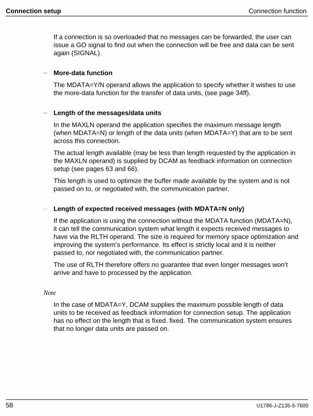
If a connection is so overloaded that no messages can be forwarded, the user canissue a GO signal to find out when the connection will be free and data can be sentagain (SIGNAL).
More-data function
The MDATA=Y/N operand allows the application to specify whether it wishes to usethe more-data function for the transfer of data units, (see page 34ff).
Length of the messages/data units
In the MAXLN operand the application specifies the maximum message length(when MDATA=N) or length of the data units (when MDATA=Y) that are to be sentacross this connection.
The actual length available (may be less than length requested by the application inthe MAXLN operand) is supplied by DCAM as feedback information on connectionsetup (see pages 63 and 66).
This length is used to optimize the buffer made available by the system and is notpassed on to, or negotiated with, the communication partner.
Length of expected received messages (with MDATA=N only)
If the application is using the connection without the MDATA function (MDATA=N),it can tell the communication system what length it expects received messages tohave via the RLTH operand. The size is required for memory space optimization andimproving the system’s performance. Its effect is strictly local and it is neitherpassed to, nor negotiated with, the communication partner.
The use of RLTH therefore offers no guarantee that even longer messages won’tarrive and have to processed by the application.
Note
In the case of MDATA=Y, DCAM supplies the maximum possible length of dataunits to be received as feedback information for connection setup. The applicationhas no effect on the length that is fixed. fixed. The communication system ensuresthat no longer data units are passed on.
58 U1786-J-Z135-5-7600
Connection function Connection setup
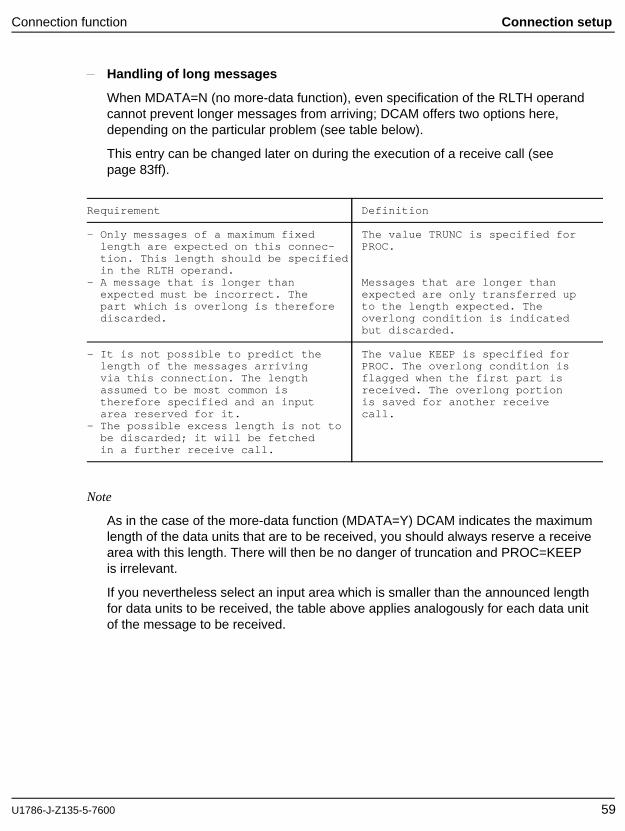
Handling of long messages
When MDATA=N (no more-data function), even specification of the RLTH operandcannot prevent longer messages from arriving; DCAM offers two options here,depending on the particular problem (see table below).
This entry can be changed later on during the execution of a receive call (seepage 83ff).
Requirement Definition
- Only messages of a maximum fixed The value TRUNC is specified forlength are expected on this connec- PROC.tion. This length should be specifiedin the RLTH operand.
- A message that is longer than Messages that are longer thanexpected must be incorrect. The expected are only transferred uppart which is overlong is therefore to the length expected. Thediscarded. overlong condition is indicated
but discarded.
- It is not possible to predict the The value KEEP is specified forlength of the messages arriving PROC. The overlong condition isvia this connection. The length flagged when the first part isassumed to be most common is received. The overlong portiontherefore specified and an input is saved for another receivearea reserved for it. call.
- The possible excess length is not tobe discarded; it will be fetchedin a further receive call.
Note
As in the case of the more-data function (MDATA=Y) DCAM indicates the maximumlength of the data units that are to be received, you should always reserve a receivearea with this length. There will then be no danger of truncation and PROC=KEEPis irrelevant.
If you nevertheless select an input area which is smaller than the announced lengthfor data units to be received, the table above applies analogously for each data unitof the message to be received.
U1786-J-Z135-5-7600 59
Connection setup Connection function
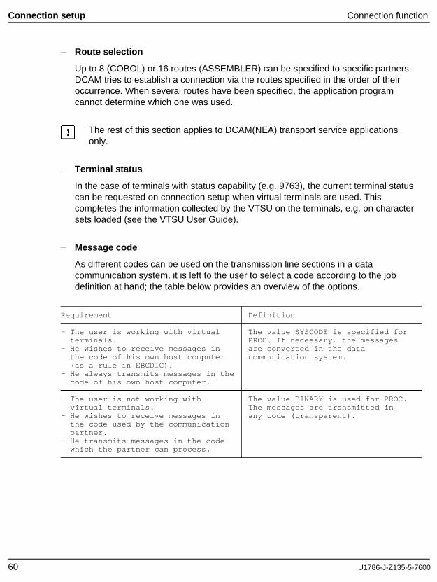
Route selection
Up to 8 (COBOL) or 16 routes (ASSEMBLER) can be specified to specific partners.DCAM tries to establish a connection via the routes specified in the order of theiroccurrence. When several routes have been specified, the application programcannot determine which one was used.
The rest of this section applies to DCAM(NEA) transport service applicationsonly.
Terminal status
In the case of terminals with status capability (e.g. 9763), the current terminal statuscan be requested on connection setup when virtual terminals are used. Thiscompletes the information collected by the VTSU on the terminals, e.g. on charactersets loaded (see the VTSU User Guide).
Message code
As different codes can be used on the transmission line sections in a datacommunication system, it is left to the user to select a code according to the jobdefinition at hand; the table below provides an overview of the options.
Requirement Definition
- The user is working with virtual The value SYSCODE is specified forterminals. PROC. If necessary, the messages
- He wishes to receive messages in are converted in the datathe code of his own host computer communication system.(as a rule in EBCDIC).
- He always transmits messages in thecode of his own host computer.
- The user is not working with The value BINARY is used for PROC.virtual terminals. The messages are transmitted in
- He wishes to receive messages in any code (transparent).the code used by the communicationpartner.
- He transmits messages in the codewhich the partner can process.
60 U1786-J-Z135-5-7600
Connection function Connection setup
The logon password is specified when a connection request is to be made. It mustbe specified in the same way as the partner (in this case a DCAM application)defined it on opening.
Where messages are distributed by means of distribution codes , the reference tothe detailed description of this distribution code must be specified here. This isdescribed in detail on page 68.
The maximum length of data (MAXLN) which is to be transmitted via thisconnection. This is a value ensuring optimum usage of the buffers provided by thesystem; it is not passed on to the communication partner.
Message characteristics which are agreed with the partner As mentioned in thepreceding section, the two partners must agree on some characteristics. These arealso described here.
Initiation of data transmission is also defined. If the DCAM application is to initiatetransmission, APPSTART is set. Otherwise, there is no definition (ANYSTART).
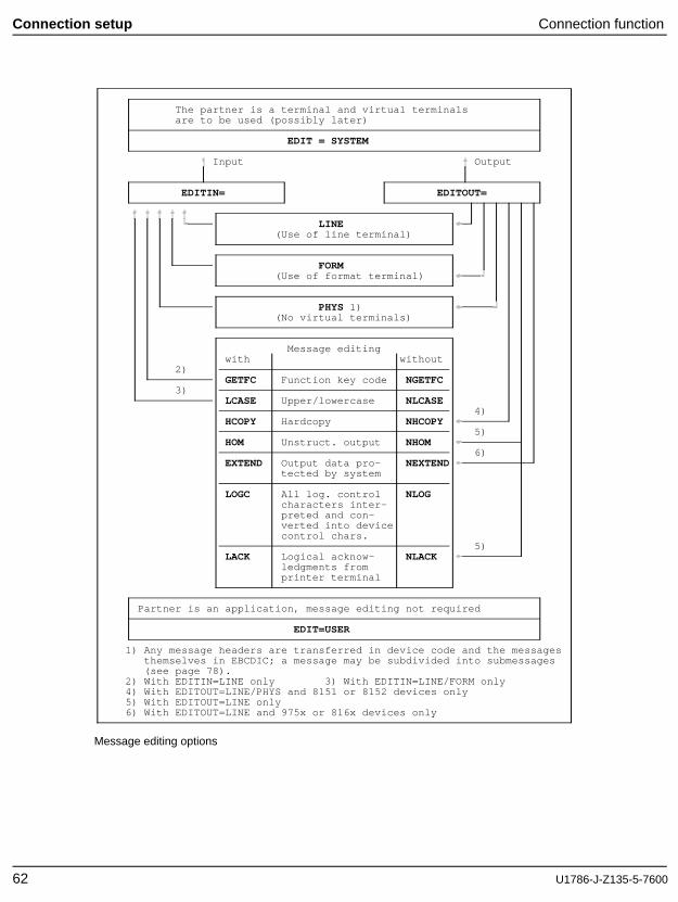
The type of message editing used is defined. It is possible to define messageediting by means of the EDIT options (see figure below and page 95ff).
Note
For connections with EDIT=SYSTEM, where ATTR=DISCO the distribution code isalways edited in the line mode.
U1786-J-Z135-5-7600 61
Connection setup Connection function
The partner is a terminal and virtual terminalsare to be used (possibly later)
EDIT = SYSTEM
Input Output
EDITIN= EDITOUT=
LINE(Use of line terminal)
FORM(Use of format terminal)
PHYS 1)(No virtual terminals)
Message editingwith without
2)GETFC Function key code NGETFC
3)LCASE Upper/lowercase NLCASE
4)HCOPY Hardcopy NHCOPY
5)HOM Unstruct. output NHOM
6)EXTEND Output data pro- NEXTEND
tected by system
LOGC All log. control NLOGcharacters inter-preted and con-verted into devicecontrol chars.
5)LACK Logical acknow- NLACK
ledgments fromprinter terminal
Partner is an application, message editing not required
EDIT=USER
1) Any message headers are transferred in device code and the messagesthemselves in EBCDIC; a message may be subdivided into submessages(see page 78).
2) With EDITIN=LINE only 3) With EDITIN=LINE/FORM only4) With EDITOUT=LINE/PHYS and 8151 or 8152 devices only5) With EDITOUT=LINE only6) With EDITOUT=LINE and 975x or 816x devices only
Message editing options
62 U1786-J-Z135-5-7600
Connection function Connection setup
3.2.1.2 Connection request
A connection request can be sent to any partner in the data communication system.
Applies to DCAM(NEA) transport service applications only:If the partner is a terminal, the associated processor (e.g. a remote front-endprocessor) will answer the request. Otherwise, a response will come from thecommunication access method in BS2000 or from the partner (in this case aDCAM application). At present, there are two possibilities for the processor nodeto which the terminal is connected:
If the processor node receives a request for a terminal that is not ready(switched off in the case of a dedicated circuit, busy in the case of a dial-upline, etc.), this will be rejected.
If the terminal is ready, it is assumed that an operator is also present, andthe connection is established (the processor node accepts the request).
The communication access method in BS2000 applies different criteria. The overviewin the figure below shows that the DCAM user has several control options, includingsome in the program itself, during request processing. A connection message can betransferred along with the request for checking purposes or just for isolatedtransmission. This message can have any content and a maximum length of 32 bytesin the case of DCAM(ISO) or 80 bytes for DCAM(NEA). It is the only message that istransmitted without a connection already established.
A partner wishing to issue a request has to specify the following:
Address of the partner (partner and processor name) to which the request isdirected.
A connection message (optional) to be transmitted along with the request.
Addition specifications for DCAM(NEA)transport service applications:Description of the connection characteristics
Logon password, if required.
Type of message distribution (if distribution codes are not used), i.e. whetherthe messages transmitted via this connection are to be distributed using thecommon receiver queue or the originator-oriented queue.This specification can be altered during data transmission.
U1786-J-Z135-5-7600 63
Connection setup Connection function
If the request was accepted, the partner receives the following feedback information:
The accompanying information defined by the partner.
The maximum length of the messages/data units to be sent via this connection(MAXLN operand).
The maximum length of the data units expected if the more-data function is used.
Additional information in the case of DCAM(NEA) transport serviceapplications:
The final definition for PROC and EDIT.
Information on the partner (partner characteristics).
The possibility of having the statement contained in this call processed asynchronouslyis dealt with in the description of the language features.
Restriction on DCAM(NEA) transport service applications
Connection messages are only delivered to DCAM applications. Terminals attachedto Communication Computers cannot receive connectionmessages.
64 U1786-J-Z135-5-7600
Connection function Connection setup
Transmission by Communication Primary task ofthe data communica- access method DCAM applicationtion system
DCAM applicationthe request was • queries partneraddressed to information
including the• was not opened connection
or message• was opened (YINQUIRE)
• with NLOGON\ attribute • checks the re-
Connection re- \ • with LOGON questing part-quest with \ attribute ner’s specifica-suggestions for \ tions and thenPROC, EDIT and, \ • in STOP status has the follow-where applicable, / or ing choice:a connection / • in START statusmessage / or • either it
/ • the requesting rejects the/ partner has request
specified the (YREJLOG) *required pass-word (LOGPASS)incorrectly or • or it acceptsnot at all the request
(YOPNCON ACCEPT)/ and thus estab-
/ Feedback: lishes the/ "connection established" connection\ with definitions for
\ PROC and EDIT\
* not applicable to COBOL at present
Processing a request for DCAM(NEA) transport service applications
U1786-J-Z135-5-7600 65
Connection setup Connection function
3.2.1.3 Acceptance of a request
The basic description of acceptance is contained in the preceding sections. Thissection contains a summary of the information which can be specified for acceptance.The inter-relationship of the various specifications is shown in the figure below.
Acceptance of a request from
a specific partner (SPEC) any partner (ANY)
Address of partner(name and processor name)
Definition of the connec-tion characteristics
Connection message to be only if message distributionpassed is not via distribution codes
Message distribution viacommon receiver (CA) ororiginator-oriented (CS)queue
synchronous processing asynchronous processing
- - - - - -
Entry in a queue (Q) withmaximum residence time(TOVAL)
Acceptance of a request
66 U1786-J-Z135-5-7600
Connection function Connection setup
Once the call has been executed, the task receives the following information:
the maximum length of messages/data units which can be transmitted on thisconnection (see MAXLN operand)
the maximum length of the data units that are expected if the more-data function isused
Additional information applying to DCAM(NEA) transport service applicationsonly: information about the partner.
In addition, if the request accepted was that of any partner:
the name of the partner andthe partner’s processor nameaccompanying information
U1786-J-Z135-5-7600 67
Connection setup Connection function
3.2.1.4 Connection setup - use of distribution codes
This section applies to DCAM(NEA) transport service applications only.
If messages are to be distributed by means of distribution codes (defined when theapplication is opened), a number of definitions must be made when the connection isset up. The description of a connection contains, in this case, a reference to thatsection that describes the distribution codes. Distribution codes are described in 2stages in order to provide maximum freedom in assigning connections to distributioncodes.
Stage 1
Description of the code position in the message and of the length of the code(s)used. The code must be contained in the first 256 bytes of the message and can havea maximum length of 8 bytes.
In addition: reference to the description of the second stage, which may be present 8times (COBOL) or 16 times (ASSEMBLER).
Stage 2
Description of the codes used by this connection. Up to 8 codes can be described.
These descriptions can be shared, i.e. several connections can use the same stage 1description and several stage 1 descriptions can use a stage 2 description.
The following must be observed:
The codes which are addressed by the same stage 1 description must be uniqueand
must all be of the same length.
If several stage 1 descriptions address a stage 2 description, the lengthspecifications in the stage 1 descriptions must be identical.
68 U1786-J-Z135-5-7600
Connection function Connection setup
The possibilities that result from this method of describing distribution code during thesetting up of a connection are as follows:
Code length, code position in the message and the code sign are defined when theconnection is set up and cannot be altered.
A partner can specify up to 64 (COBOL) or 128 (ASSEMBLER) different distributioncodes in groups of 8. Thus, the partner can either reach one task via up to 8different codes or he can read a varying number of tasks.
The number varies because the assignment of codes and task via the distributioncode name takes place during execution. This assignment is controlled by theprimary task by means of YPERMIT and YFORBID calls (see page 88ff).
U1786-J-Z135-5-7600 69
Connection setup Connection function
Description of Description of Description ofconnection A connection B connection C
Address of dis- Address of dis- Address of dis-tribution code tribution code tribution codedescription X description X description Y
Description ofdistr. codes
Code position a Code position b
Stage 1: Code length a Code length bFormats
Address list of Address list ofcode groups 1-5 code groups 4-8
1 2 3 4 5 6 7 8
Codes Codes Codes Codes Codes Codes Codes Codes
A E K M Q E KStage 2:Values* B F L N B F L
C G O C G R
D H P D H S
I I T
J J
* The codes in groups 1-5 and 4-8 must be unique in either case
Description of formats and values of distribution codes
70 U1786-J-Z135-5-7600
Connection function Connection setup
3.2.1.5 Linking up to a predefined connection
This section applies to DCAM(NEA) transport service applications only.
A predefined connection is determined during the generation of the communication access method . It is established when the communication access method is started.However, the two partners must first connect themselves to the predefined connectionbefore data transmission can begin.
In the case of applications the primary tasks must make a connection request(YOPNCON ACQUIRE). In the case of a terminal this need only be activated andoperational.
Because the characteristics of a predefined connection are determined during thegeneration of the communication access method, and because the connection isautomatically established when this is started, certain special factors are involved:
If data is transmitted before the partner has linked up with the connection, negativeacknowledgments are given.
If a partner wished to withdraw from a connection, the LOSCON routine is notinitiated (the predefined connection remains established).
A YOPNCON ACCEPT SPEC to a predefined partner can never be successfullyterminated. If OPTCD=Q is specified, the call is entered in a queue and isterminated by timeout.
The following specifications cannot be made by a YOPNCON ACQUIRE if theconnections are predefined:
a connection message
a LOGON password
message editing by the system or the user (EDIT=SYSTEM/USER)
start data transmission (PROC=APPSTART/ANYSTART).
U1786-J-Z135-5-7600 71
Connection setup Connection function
Predefinedconnection
established whencommunicationaccess method isstarted, but datacommunication
Partner 1 still not Partner 2possible
Open applica- Open applica-tion YOPEN tion YOPEN
. .
. .
. .
Link-up to Link-up topredefined predefinedconnection connectionYOPNCON ACQUIRE YOPNCON ACQUIRE
Data communication. possible .. .. .
YSEND YRECEIVE
. .
. .
. .
YRECEIVE YSEND
. .
. .
. .
Linking up to a predefined connection
72 U1786-J-Z135-5-7600
Connection function Query entries
3.2.2 Querying entries on partners and connections
As already mentioned in the sections on connection requests and the acceptance ofrequests, it is necessary to query the entries on partners and connections. TheYINQUIRE call, of which several variants are available, is used for this purpose. Forsecondary tasks, only the CIDXLATE, NAMXLATE and, in the case of DCAM(NEA)transport service applications, the request for status information are applicable.
Restriction:In COBOL not all variants of the YINQUIRE call are available.
The table below shows the YINQUIRE variants and the programming languages inwhich each can be used.
Inquiry YINQUIRE variant Programminglanguage
- Which partner is Inquiry after an ASSEMBLERrequesting connection? asynchronous LOGON
- What connection message notificationis to be transmitted and (REQLOGON)what is its length?
for DCAM(NEA) transport serviceapplications only:
What are the proposedcharacteristics of theconnection?
- Which partner is next in Inquiry prior to ASSEMBLER/COBOLthe queue of those acceptance of arequesting connection? request (TOPLOGON)
- What connection messageis to be transmittedand what is its length?
for DCAM(NEA) transport serviceapplications only:
What are the proposedcharacteristics of theconnection?
U1786-J-Z135-5-7600 73
Query entries Connection function
Inquiry YINQUIRE variant Programminglanguage
for DCAM(NEA) transport serviceapplications only:
What characteristic Inquiry as to partner ASSEMBLER/COBOLfeature does the partner characteristicshave? (PTNCHAR, MONCHARS,
PEROTERM, BTERMINF)
- How many partners have Inquiry for number of ASSEMBLER/COBOLsent a request? partners (COUNTPTN)
- With how many partnershas a connection beenestablished?
- What is the identifier of Inquiry for identifier ASSEMBLERthe connection of which CID (NAMXLATE)the partner and theprocessor names are known?
- What are the partner and Inquiry for the partner ASSEMBLERprocessor names of and processor namesa connection whose (CIDXLATE)identifier is known?
74 U1786-J-Z135-5-7600
Connection function Reject request,change characteristics
3.2.3 Rejecting a connection request
The YREJLOG call can be used to reject a logon request; it suffices to specify theaddress of the requesting partner (partner and processor name) obtained by means ofthe YINQUIRE call.
3.2.4 Changing the characteristics of a connection
This section applies to DCAM(NEA) transport service applications only.
The user can change some of the connection characteristics defined during connectionsetup.
Only those characteristics can be changed which exclusively affect the partner makingthe changes, i.e. not those which have been agreed with the communication partner.
In the YCHANGE call, all of the values listed in the following must be set regardless ofwhether they are changed (new) values or the previously set (old) values.
The following can be changed:
Accompanying information
Handling of excess-length messages
Code of the messages
Values for VTSUCB (message editing) see the VTSU User Guide.
If required, address of the distribution code description for changing distributioncodes described in groups (the length and the position in the message and thecode sign cannot be changed).
For further information on these values see "Definition of the connection to beestablished’ (see page 57).
3.2.5 Deleting a connection request
A connection request sent to a partner can be deleted with the YCLSCON call.
The connection request is revoked if the connection is not yet established. If alreadyestablished it is cleared down.
U1786-J-Z135-5-7600 75
Close connection Connection function
3.2.6 Closing a connection
Explicit closing of a connection is possible with the YCLSCON call.
There is no obligation to do this, as all connections are implicitly closed when theDCAM application is closed. Uncollected messages are destroyed when the connectionis closed. Any messages sent immediately before YCLSCON, which had not yet beentransmitted to the receiver, may also be destroyed.
In the case of DCAM(NEA) transport service applications it is advisable to savethe final message with a transport acknowledgment.
Explicit closing may be required for:
putting a time limit on a connection
regulation of data throughput (connections can be closed down in order to giveother connections better throughput rates), etc.
76 U1786-J-Z135-5-7600
Data transmission function
3.3 Data communication function
The requirements for data transmission are fulfilled when a DCAM application has beenopened and a connection established.
The data transmission function performs the following operations:
Transmit a message/data unit (YSEND)
The message/data unit to be transmitted to a communication partner is transferredto the data area of the communication access system.
Receive a message/data unit (YRECEIVE)
The message/data unit from a communication partner (any one, a specific one or,in the case of DCAM(NEA) transport service applications, one with a specificdistribution code) is entered in the data area of the user program.
Transmit and receive combined (YSENDREC)
A message/data unit is entered in the data area of the communication accessmethod by means of this call, and a message/data unit from the samecommunication partner is entered in the partner’s own data area.
Delete receive calls and change the CS/CA state of a connection (YRESET)
With this call a task can delete all its waiting YRECEIVE calls from a specifiedapplication or a specified connection, and it can alter the CS/CA state.
The following additional options are available in the case of DCAM(NEA)transport service applications for controlling message distribution by means ofdistribution codes:
Assign distribution code names to distribution code groups (YPERMIT)
The primary task assigns specific distribution codes to the distribution codename of one or more secondary tasks.
Cancel assignment (YFORBID)
An assignment is canceled by the primary task.
U1786-J-Z135-5-7600 77
Message/data unit transmission Data transfer function
3.3.1 Sending a message/data unit
Every task in a DCAM application can transmit a message/data unit (YSEND) and thisresults in the following action:
The data to be sent to a partner in the form of a message/data unit is transferred tothe data area of the communication access method.
The access method is assigned the job of transmitting the data to the partner.
The call is terminated and the access method starts transmission.
The access method receives a number of user specifications along with themessage/data unit to be transmitted. They are supplemented by specifications definedwhen the connection was set up (see page 57).
The following table lists any additional specifications required under certaincircumstances.
Requirement Definition
After logon, the system announced the The length of the message,data unitmaximum length of messages/data units to be transmitted is specified withinto be transmitted via this connection. the maximum length limits.
Messages/data units arriving on this The originator-oriented queue isconnection are to be received via the set (CS state of the connection).originator-oriented queue.
Messages/data units arriving on this The common receiver is setconnection are to be received via the (CA state of the connection).common receiver.
Upon opening of the connection PROC= For each YSEND call a valid eventSIGNAL was used to request the GO identifier (EID) should besignal in the event of the connection specified, via which a GO signalbeing overloaded. can be issued if necessary.
The more-data function is being The user must specify whether theused across this connection data unit is (OPTCD=GROUP) the last(MDATA=Y). one of a logical message or not
(OPTCD=ELEMENT).
78 U1786-J-Z135-5-7600
Data transfer function Message/data unit transmission
Requirement Definition
The following applies to DCAM(NEA) transport service applications only:
- Acknowledgment reception was A sequence number is specified soenabled when the application was that the transport acknowledgmentopened (for the primary task = can be assigned to the correctPRIMTASK for the requesting message (maximum value=2047) whentask = REQTASK). it arrives.
- Transport acknowledgments are to A positive acknowledgment isbe processed. requested (negative acknowledg-
- The YSEND call should be followed ments are generated automaticallyimmediately by a YCLSCON or YCLOSE if the message cannot be delivered).call which means the connectionmay be closed before the datahas been transmitted. Thetransport acknowledgment shouldalways be awaited in this case.
Message editing was not provided for The message can be classified asby the system on this connection. follows:The following was set: - ELEMENT:- EDIT=USER: The user edits the - SUBGROUP:
messages in such a fashion that - GROUP:the communication partner can This identification of the messageprocess them. is transferred by the network to
- EDIT=SYSTEM and EDITOUT=PHYS: The the receiver, which receives itsystem performs blocking for along with the message. If thedevices with a small input buffer. receiver is a terminal, an elementEverything else is provided by the is transmitted as a message segment,user in such a way that the part- while a subgroup or a group isner can process it. transmitted as a message followed
by transmission termination.
Message editing is provided by the Special rules apply to the use ofsystem on this connection. virtual terminals (see the VTSU User
Guide).
A special situation has arisen The message is declared as an(e.g. backlog on the connection), express message, which means thatwhich was notified by the feedback its length may not exceed 8 bytes.information for a rejected YSEND.The partner is to be requested toissue receive calls immediately.
U1786-J-Z135-5-7600 79
Message/data unit transmission Data transfer function
The rest of this section applies to DCAM(NEA) transport service applicationsonly.
The message layout has to be varied in accordance with the message editing optionselected:
When a line terminal is used (see the VTSU User Guide), the user can subdivide themessages into logical lines. Each of these lines is terminated with the "new line"character, hex 15. The text following the NL character is automatically placed at thebeginning of the next line by the terminal. If the logical line length exceeds the linelength of the terminal, the logical line is subdivided automatically. The beginning of amessage is always placed at the beginning of a line. This is illustrated below by meansof an example.
Message to a line terminal
1st logical line
Only characteristics relating to the user making the changes
2nd logical line
can be altered as follows: NL NL - accompanying info NL
3rd logical line etc.
- Handling overlong messages NL
\ /\ /
\/Display on a 54-character screen, for example
Only characteristics relating to the user making thechanges can be altered as follows:
- accompanying info- handling overlong messages
Message to line terminal
80 U1786-J-Z135-5-7600
Data transfer function Message/data unit transmission
When a format terminal is used, the user transfers the message in the way he or shereceives it from the formatting routine, but without the preceding record length field.The record length must be transferred from the record length field to the correspondingDCAM field.
If the values EDIT=SYSTEM and EDITOUT=PHYS have been set for the connection,each message must be preceded by a header length byte. The binary numbercontained in this byte specifies the length of the following message header (includingthe length byte). The message header is transferred to the terminal without codeconversion in contrast to the message proper, so that the user can use the devicedescription during generation and analysis of the message header. For devices whichdo not process message headers, the message must nonetheless be preceded by aheader length byte, and the length must be set to 1.
The diagram below illustrates how messages should be formatted.
HL MH Message text
\ /\/
Length in HL
\ /\/
Message length
HL = Header length byte; contains length of HL + MH in binaryMH = Message header; length varies depending on the device function; in
device code. Not required for devices controlled in other ways.
Message layout for EDITOUT=PHYS
U1786-J-Z135-5-7600 81
Message/data unit transmission Data transfer function
The message can also be subdivided into message segments in this case and alsowhen EDIT=USER has been set. Each message segment must be appropriatelymarked.
ELEMENT ELEMENT ELEMENT SUBGROUP ELEMENT ELEMENT GROUP
Example of message structuring
Depending on the device type and status, different device responses have to bereckoned with.
Note
Shared physical lines (concentrator) are released once a message segment hasbeen transmitted.
82 U1786-J-Z135-5-7600
Data transfer function Receive message/data unit
3.3.2 Receiving a message/data unit
Reception of a message/data unit means that the message/data unit from the partneris entered in the data area of the receiving partner’s program after having beenremoved from the queue.
This procedure is completed when the YRECEIVE call is terminated provided that thecall was executed synchronously. If the call was executed asynchronously, itscompletion merely means the communication access system has been assigned thejob of transferring the message/data unit when it arrives. An agreed event identifierenables the user to receive a signal when the message/data unit been transferred. Theuser can check for this signal and then process the message/data unit (see page 105).This method allows any delays arising from waiting for a message/data unit to be usedfor other processing operations.
Which messages/data unit a task can receive depends on the type of queue selected:
If the common receiver queue is set (CA state of the connection), the message/dataunit is passed to the first task to access the common receiver queue (ANY).
If the originator-oriented queue is set (CS state of the connection), themessage/data unit is passed to the task that set the originatororiented queue(causing the CS state).
Which message a task can receive also depends in the case of DCAM(NEA)transport service applications on whether it is a normal or an express message.The table below illustrates message distribution according to the type ofmessage.
U1786-J-Z135-5-7600 83
Receive message/data unit Data transfer function
Type of messageType of message Normal message Express messagedistribution
By means of Distributed to the Distributed to thedistribution codes task authorized to primary task(DISCO) receive it according
to distributioncode 1)
Via common Distributed toreceiver the first task to Distributed to thequeue access the common- primary task
Without (connection receiver queuedistri- state CA) (ANY)butioncodes Via ori- Distributed to the task that set the(NDISCO) ginator- originator-oriented queue (caused the
oriented CS state)queue(connectionstate CS)
1) If the distribution code has not yet been provided for or hasnot been assigned to any secondary task, the message is distributedto the primary task.
When issuing the YRECEIVE call, the user specifies further information beyond theconnection description defined with YOPNCON (see page 57):
With respect to the message/data unit :
the user defines the address of the field in which the message/data unit is to beentered, along with the length of this field;
he can change the handling of excess-length messages defined during connectionestablishment to match this message; i.e. he can redefine whether the excessportion of a message is to be kept so that it can be fetched later or whether it is tobe discarded.
84 U1786-J-Z135-5-7600
Data transfer function Receive message/data unit
With respect to call execution :
interrelated information must be specified here, as illustrated below:
1) Reception of a message 2)
from a specific partner from any partner(SPEC) = access to the (ANY) 3) = access tooriginator-oriented the common receiverqueue (only possible if queue (only possible ifit was previously set it was previously setwith YOPNCON, YSEND, with YOPNCON, YSEND,YSENDREC or YRECEIVE = YSENDREC or YRECEIVE =connection state CS) connection state CA)
Connection identifier
2) 2)
The common receiver queue (CA) orthe originator-oriented (CS) queueis set for subsequent messagedistribution
Synchronous processing Asynchronous processingof the call of the call 4)
5)- - - - - - -
Entry in a queue (Q) with maximumresidence time (TOVAL)
1) Setting of CS for this purpose not necessary in the case of messagedistribution with distribution codes.
2) Only possible for message distribution without distribution codes3) The call may be transmitted prior to connection setup. However
it is not executed until at least one connection has been established.4) For further specifications, see page 105.5) Optional: if not specified, the call is terminated immediately even
if it cannot be executed.
Specifications for receiving a message/data unit
U1786-J-Z135-5-7600 85
Receive message/data unit Data transfer function
After the message has been received in the specified area, further information is fedback by DCAM:
Originator specification,if the message was received from any partner (ANY).
Accompanying user informationas defined by the user when the connection was established (message receivedfrom any partner: ANY).
Length of the message/data unitor, if the message/data unit is longer than the storage area, provided, the length ofthe excess portion not yet transferred (KEEP). If the excess-length part is to befetched with another receive call, the originator-oriented queue must have beenselected previously.
When the more-data function (MDATA=Y) is used, an indicator in the feedback fieldis set showing whether the data unit is the last unit of a logical message.
The rest of this section applies to DCAM(NEA) transport service applicationsonly.
Sequence number of messageas specified by the partner or generated by the system (if a terminal was theoriginator).
Structure of the message(entries in the feedback field), i.e. whether an element, the last element of asubgroup or a group was received.
Type of message(entries in feedback field), i.e. whether a normal or express message was received.
86 U1786-J-Z135-5-7600
Data transfer function Receive message/data unit
Whether or not transport acknowledgments can be received depends on thedefinitions made when the application was opened and on the information specifiedwhen the message which is to be acknowledged is transmitted (see table below).
Definition for YSEND or YSENDREC
Definition at YOPEN A positive A positive acknow-of the application acknowledgment is ledgment is notin the primary task requested (TACK) requested (NTACK)
The requesting task Transfer of positive Transfer of negativeis to receive and negative acknowledgments onlyacknowledgments acknowledgments to to the requesting task(REQTASK) the requesting task
The primary task Transfer of positive Transfer of negativeis to receive all and negative acknow- acknowledgments onlythe acknowledgments ledgments to the to the primary task(PRIMTASK) primary task
No acknowledgments Neither positive nor negativeare to be passed acknowledgments are passed(NOTACK)
Unless the use of asynchronous notifications was agreed (see page 111), transportacknowledgments are received with the YRECEIVE call. All information on the type ofacknowledgment etc. is provided in the feedback field of the call. The field ’TACKNO’also contains the sequence number of the message as defined during transmission. Itis thus possible to identify the message.
It should be noted that the reception of a transport acknowledgment with YRECEIVEhas no effect on the setting of the queue (CS/CA) even if this was specified in the call.
Restriction:
Where EDIT=SYSTEM, a second negative transport acknowledgment can bereceived when YSEND is specified. This is passed to the primary task in the case ofSHARE applications irrespective of REQTASK.
U1786-J-Z135-5-7600 87
Transmit,receive,assign distribution code Data transfer function
3.3.3 Combined sending and receiving
The information given on the two separate calls also applies to the combined call. Asthe combination only permits access to the originatororiented queue, the originator-oriented queue must have been set for this connection (=connection state CS) withYOPNCON or a previous YSEND or YRECEIVE.
Restriction:
The YSENDREC call is not available in COBOL.
3.3.4 Canceling receive macros and changing the connection state CS/CA
The YRESET call enables asynchronous YRECEIVE macros to be canceled.
A YRESET(ANY) call cancels all YRECEIVE macros from any partner.
A YRESET(SPEC) call cancels YRECEIVE calls from a specified partner.
A YRESET(SPEC) call also resets the connection state CS/CA. This does not apply toDCAM(NEA) transport service applications using distribution codes specific to queues(ATTR=SHARE,DISCO).
3.3.5 Control distribution code assignment
This section applies to DCAM(NEA) transport service applications only.
The primary task controls distribution code assignment by allocating a distribution codename to a distribution code group or by deleting such an assignment. It defines thedistribution code group for one or more connections when establishing connections(see page 68).
The distribution code name is entered by one or more tasks when opening theapplication (see pages 42 and 47).
The primary task assigns the distribution code names of one or more tasks to thedistribution codes of one or more connections. If the primary task deletes such anassignment, it inhibits data transfer from the connections concerned to the taskconcerned.
88 U1786-J-Z135-5-7600
Data transfer function Distribution code assignment
DCAM applicationAssignmentperformed by:
YOPEN
PERMIT
YOPNCON(YCHANGE)
YOPNCON
Prim.-task1
ABCDEFJK
XYUV
X124X345X901
A#1F1A#3F1A#4F1
XZ$@
Distributioncode groups
Verteilungs-namen
Virtual connections
Default (no assignment)
Sec.-task3 Sec. task4
Sec. task2 Sec. task5 Sec. task6 Sec. task7
DIST #0 DIST#1 DIST#2 DIST#3 DIST#4
Pos. = 10Length = 2
Pos. = 5Length = 2
Pos. = 1Length = 4
Pos. = 20Length = 5
Pos. = 5Length = 1
Pos. =6Length = 1
Summary of message distribution with distribution codes (example)
U1786-J-Z135-5-7600 89
Distribution code assignment Data transfer function
Assign distribution code name to a distribution code group
The YPERMIT call assigns a distribution code name to a distribution code group. Thismeans that tasks which have defined this name can receive messages with the codesof the assigned group.
The following applies:
A group of distribution codes (stage 2 definition) can be assigned to only one distribution code name .
Up to 8 tasks can use the same distribution code name . This becomes necessarywhen a single program controls several tasks (SHARED CODE, see pages 115 and125). Tasks with identical distribution code names are served in accordance with theFIFO principle (FIFO=first in first out: the first entry in the queue will be the first oneprocessed).
Depending on the assignment made, a task can also access the messages in anoriginator-oriented way (YRECEIVE SPEC). It is not necessary to select this queuebeforehand (there is no CS/CA state of the connection when distribution codes areused).
The queues (code groups) are assigned to thedistribution code names via separate datacommunication function calls
*)
Example of task group addressing with distribution codes
90 U1786-J-Z135-5-7600
Data transfer function Distribution code assignment
Messages with distribution codes that were not assigned to a distribution name or thatcannot be interpreted are directed to the primary task.
Old assignments can be replaced by new ones when a new YPERMIT call is issued.
Cancel assignment
If a new assignment is not to be made for a distribution code name but the existingassignment is to be canceled, the YFORBID call can be used. Data which has alreadybeen received is then transferred to the primary task.
U1786-J-Z135-5-7600 91
Name assignment function
3.4 Name assignment function
This function permits parameter values for the DCAM application or the connection tobe specified at run-time only. This is achieved by linking the current values with thosespecified in the program in a task-oriented table (CLT=communication link table). (Thiscan be compared with the entries in the FCB (file control block) of a program whichare updated using the TFT (task file table) whose entries were generated by the FILEmacro or the /SET-FILE-LINK command.)
The opening of the DCAM Name: ABCapplication begins withthe transfer of the Link name: CHAIN4current values from the CLTand ACB control block or Password: PASSthe A structure
.
.
APPLIC4
PASS
.
.
Example of assignment of a DCAM application name
92 U1786-J-Z135-5-7600
Name assignment function
The table is set up:
in the program mode (ASSEMBLER only) by means of the YAPPL macro for entrieson the application, and the YCONN macro for entries on the connection
in the command mode (ASSEMBLER/COBOL) by means of the
/SET-DCAM-APPLICATION-LINK or /REMOVE-DCAM-APPLICATION-LINK for entries on theapplication and
/SET-DCAM-CONNECTION-LINK or /REMOVE-DCAM-CONNECTION-LINK for entries on theconnection (see "User Commands (SDF Format)").
The linkage is established by specifying a link name both in the program and in theCLT. The following values can be updated in this fashion:
• For a DCAM application:
the name of the DCAM application
the password for the connection of a secondary task to an application, asspecified in the primary task
the password for the connection of a secondary task to an application, asspecified in the secondary task.
Additional information for a DCAM(NEA) transport service application:the distribution code name;the password for establishing a connection, as defined in the primary task.
• For the connection:
the name of the partner;the name of the processor node to which the partner is connectedthe accompanying information.
Additional information for DCAM(NEA) transport service applications: thepassword for connection establishment, as specified by the requesting task.
When YOPEN or YOPNCON is executed, the specifications are entered in DCAMcontrol blocks or data structures. They are updated with the values in the CLTproviding it contains entries. If it does not, the original values remain unchanged.Following this, dynamic name assignment for this application or connection is possibleagain only after it has been closed. If CLT entries are to be deleted, the YAPPL orYCONN macro or the corresponding commands with just the link name should beissued.
U1786-J-Z135-5-7600 93
4 Support for virtual terminalsThis chapter applies to DCAM(NEA) transport service applications only.
A virtual terminal constitutes a model of a terminal with certain standard characteristics.Unlike a physical terminal, the virtual terminal permits programming that does notrelate to the physical characteristics of the terminal. Actually connected. The physicalterminal on which he or she wants to output messages is therefore of no significanceto the user, who is aware only of the virtual terminal.
There are two types of virtual terminal:
form terminal andvirtual line terminal
Form terminal
The forms (screen forms or masks) are output on the form terminal. The usercompletes only the predefined fields. The form terminal offers the program structuredforms with a field structure. Form terminals are supported by restricted forms mode,which is selectable with VTSU, and by the software product FHS (Forms HandlingSystem).
Detailed information on FHS is available in the FHS User Guide.
U1786-J-Z135-5-7600 95
Support for virtual terminals
Virtual line terminal
The virtual line terminal is implemented by the software product VTSU (Virtual TerminalSupport) in the BS2000 operating system. In the case of a virtual line terminal anoutput is divided into a number of lines. VTSU supports both Assembler macros andCOBOL data structures for line terminals. By using these macros and data structuresyou can:
create receive fields or symbolic field names for status messages. You can thenquery the corresponding status messages with the YINQUIRE macro.Convert virtual control characters into device-specific control characters. Themechanisms for this purpose are the VTCSET macro and the TIAMCTRC copyelement.Set VTSU parameters. These VTSU parameters define the nature of the virtualterminal and how messages are treated for send and receive. You can specify theparameters in the VTSU control block (VTSUCB) in the YSEND, YRECEIVE andYSENDREC macros.
VTSU is described in detail in the VTSU User Guide.
The status messages on the partner characteristics for COBOL applications aredescribed in the ’DCAM COBOL Calls’ manual.
Edit options
The edit options for connections with EDIT=SYSTEM are replaced by the specificationsin the VTSUCB. As in the VTSUCB, you can use edit options to define the type ofvirtual terminal and message handling for transmitting and receiving. The functionalityof the VTSUCB is considerably wider, however, because new edit options will beavailable only via the VTSUCB.
96 U1786-J-Z135-5-7600
5 DCAM programsThis chapter describes the language-specific characteristics of the DCAM interface.DCAM programs can be generated in ASSEMBLER or COBOL. For detailed instructionson the coding of DCAM programs consult the manuals "DCAM Macros" forASSEMBLER and "DCAM COBOL Calls" for COBOL.
5.1 ASSEMBLER programs
The ASSEMBLER program interface provides the full range of DCAM functions asdescribed in detail above.
The purpose of this section is to provide an overview of the specific interfacecharacteristics.
5.1.1 Macro calls and control blocks
All DCAM functions are activated by macro calls. The action macros always refer tocontrol blocks in which all the parameters are stored. A distinction is made betweentwo groups of calls depending on the type of control block they refer to:
macro calls that refer to an ACB (application control block) , and
macro calls that refer to an RPB (request parameter block) .
The following calls refer to an ACB , which contains all the information on the DCAMapplication:
YOPEN (Open a DCAM application)YCLOSE (Close a DCAM application)
If asynchronous DCAM notifications are to be processed, an ENB (event notification block) is required in addition. The references to the identifiers for the contingencyroutines are stored in this block (see page 111).
YCLOSE the application gency routinesto be startedwhen anasynchronousnotificationarrives
ACB-related macro calls
The following macros refer to an RPB which contains the current parameter values ofthe action calls:
YINQUIRE Request entries on DCAM applications, partners and connections
YOPNCON Open connection
YCLSCON Close connection
YREJLOG Reject logon request
YCHANGE Change connection characteristics
YSEND Transmit message
YRECEIVE Receive message
YSENDREC Transmit message and receive new message
YRESET Delete receive messages and change CS/CA state
Additional macros for DCAM(NEA) transport service applications:
YSETLOG Change status of DCAM application
YPERMIT Permit receipt of message with distribution code
YFORBID Prohibit receipt of message with distribution code
98 U1786-J-Z135-5-7600
ASSEMBLER programs Macro calls/control blocks
The connection control block (CCB) is required in addition to the RPB for variouscalls. The parameters for a connection are located in the CCB.
In the case of DCAM(NEA) transport service applications, the position and lengthof the distribution code, the code sign and the references to assigneddistribution code groups are located in the distribution parameter block(DIP), and the distribution codes themselves in the distribution code group block (DCG).
Note
DCAM users connected to a packet switching network (e.g. Datex-P) via an an X.25interface must note that certain restrictions apply to calls relating to connections ordata transmission. They are described in the manual "DCAM Macros", see sectionentitled ’Effects of the CCITT X.25 Recommendations on the IDCAM user interface’.
U1786-J-Z135-5-7600 99
Macro calls/control blocks ASSEMBLER programs
YSETLOG* Request ACB ApplicationRPB parameter control bl.
blockDescription of
YINQUIRE application
YOPNCON CCB Connectioncontrol bl.
Description ofYCLSCON connection
Description of - - - - - - - - - - - - - - - -YREJLOG the macro call, Description of distr. codes*
if necessaryspecificationof areas for
YCHANGE data accepted/ Distributionpassed etc. DIP parameter
block
YSEND Code sign
Position andlength of dis-
YRECEIVE tribution codesin message
YSENDREC
YRESET DCG 1 ........ DCG 16
Group Groupof of
YPERMIT* distr. distr.codes codes
YFORBID*- - - - - - - - - - - - - - - -
* Applies to DCAM(NEA) transport service applications only
RPB-related macro calls
100 U1786-J-Z135-5-7600
ASSEMBLER programs Macro calls/control blocks
The programmer need not know the internal structure of the control blocks as macrocalls are available to him for the generation and handling of control blocks.
Macro calls for static control block generation :
YACB Generate ACB
YENB Generate ENB
YRPB Generate RPB
YCCB Generate CCB
Additional macros for DCAM(NEA) transport service applications:YDIP Generate DIP
YDCG Generate DCG
In the case of these macro calls, the control blocks are generated during assembly.
The control blocks can also be generated and handled by the user directly via themacro calls YDDACB, YDDCCB, YDDENB and YDDRPB,
and also with YDDDCG and YDDDIP in the case of DCAM(NEA) transportservice applications.
These macro calls describe the layout (DSECT and CSECT) of the control blocks.
U1786-J-Z135-5-7600 101
Macro calls/control blocks ASSEMBLER programs
Dynamic generation of a control block in user memory area (class 6 memory) oroptionally in an area outside the user program (class 5 memory) during the programrun is possible with the macro call YGENCB (generate control block).
The following macros are provided for control block handling:
YMODCB Modify the contents of control block fields
YSHOWCB Transfer the contents of identified control block fields to an areareserved in the program
YTESTCB Compare the control block field contents with specified values.
The control blocks can be created and handled with the aid of these macros onlywhen the DCAM subsystem has been loaded successfully. Note, too, that the DCAMsubsystem status cannot be HOLD/DELETE when any of these macros is used. If atask successfully issued a DCAM command or a DCAM call before enteringHOLD/DELETE, it can work with DCAM until the task is ended, despite a /HOLDsubsystem or /DELETE subsystem (also applicable to %).
The RPB can also be modified with any macro call that addresses it (implicit RPBmodification). It is up to the user either to create several RPB control blocks or alwaysto address the same one and update its contents.
The application characteristics described in the ACB are transferred to DCAM with theYOPEN call. After YOPEN execution, DCAM returns an AID (application identifier)in the ACB. From then on all calls referring to this application may use the address ofthe ACB control block containing this identifier.
ACB
AID *
YSEND RPB
CCB
CID *
* entered by DCAM when the YOPEN or YOPNCON was executed
Example of control block addressing without identifiers
It is also possible to save the AID and to enter it in the RPB used for further calls.
102 U1786-J-Z135-5-7600
ASSEMBLER programs Synchronous execution of calls
* The identifier was savedRPB after YOPEN or YOPNCON and
entered in the RPB withYSEND AID * YMODCB
CID ** ** The identifier was enteredhere after YOPNCON orRECEIVE ANY if this RPBwas used
Example of addressing an RPB in which valid identifiers were entered
In this case the memory area for the ACB can be used for other purposes. The sameapplies to the description of the connection in the CCB and, in the case of DCAM(NEA)transport service applications, also in the DIP and the DCG. The CID (connection identifier) returned in the CCB and RPB can be used after an YOPNCON, for example.YSEND and YRECEIVE or YSENDREC then only require RPB control blocks containingthe relevant AID and CID identifiers. If the entry was not made by DCAM, it can beentered with YMODCB provided the identifier was previously saved with YSHOWCB.
The use of the identifiers is advantageous because DCAM finds all the informationrequired for the call in the RPB. This speeds up processing.
5.1.2 Synchronous execution of DCAM calls
In the case of synchronous execution of DCAM calls, control is only returned to theprogram by task management when this call has been processed by DCAM. If DCAMcan process the call immediately there are no delays. However, with some functions,delays may occur due to DCAM having to wait for a response from the communicationpartner. When a connection is being set up (YOPNCON), the communication partnermust contribute to this operation and when messages are to be received (YRECEIVE),the partner must have sent them and they must be available in the data area of thecommunication system and have been entered in a queue.
The programmer can decide whether and how long he is prepared to wait until the callcan be executed. He defines the maximum waiting time for each call. However, he canalso specify that a call should be terminated immediately even if the instruction cannotbe performed. The call must then be repeated later in the program if required.
U1786-J-Z135-5-7600 103
Synchronous execution of calls ASSEMBLER programs
User task System
Example 1
.
.\
0 YRECEIVE with maximum waiting time \ DCAM/of 80 seconds / BCAM
10 /
20
30Waiting time
40/ / /
50 / Terminate / Transfer / Message.\ call \ \
60 . \ \ \.
70 .. Further processing
80
- - - - - -
Example 2
.
.\
0 YRECEIVE with maximum waiting time \of 30 seconds /
10 /
20 Waiting time/
30 / Terminate call\
40 .\ /. / Message
50 . Further processing \\
60 must befetched withanother
\ / YRECEIVE\/ Time
Examples of synchronous execution of YRECEIVE
104 U1786-J-Z135-5-7600
ASSEMBLER programs Asynchronous execution of calls
5.1.3 Asynchronous execution of DCAM calls
In the case of asynchronous execution of calls, control is returned to the programimmediately when DCAM has accepted the call. This means that any delays can beused for other processing until the call is executed. For the purpose of asynchronousexecution of calls, the user defines an event (ENAEI macro call) and specifies itsidentifier EID in the YOPNCON, YRECEIVE or YSENDREC macro. An event may be, forexample, message transfer. The user can query this event (SOLSIG macro) at thelocation in the program at which he or she wishes to process the message, forexample. The program can wait at this point if the message has not yet arrived.
U1786-J-Z135-5-7600 105
Asynchronous execution of calls ASSEMBLER programs
User task SystemExample 1
Even- DCAM/ENAEI:Define event ting BCAM
Transfer of event id.EID
.
. Further processing\
YRECEIVE *) EID=event \identifier /
/. The waiting time. preceding the arrival / /. of the message is used / Transfer / Message. for further processing \ \. \ \
\SOLSIG *): Event \notification expected /
/.. Processing of the. message
- - - - - -Example 2
ENAEI:Define event
Transfer of eventEID
identifier.. Further processing
\YRECEIVE *) EID = event \identifier /
/. The waiting time. preceding the arrival. of the message is used. for further processing.
\SOLSIG *): Event \notification expected /
/ / // Transfer / Message
Waiting time \ \\ \
\ / . Processing of the\/ Time . message
EID Identifier of the event (in this case, the arrival of the message),is used as the reference point for message transfer and acceptance.
*) A maximum life is defined for YRECEIVE and SOLSIG in each case(not indicated here).
Examples of asynchronous execution of YRECEIVE
106 U1786-J-Z135-5-7600
ASSEMBLER programs Asynchronous execution of calls
However the user can also link the event with a contingency routine; this routine mustbe defined and its COID identifier must be available (ENACO macro call). In this casethe user should query the event as soon as the DCAM call has been issued. When thisevent occurs the routine is started automatically.
User task System
Main routine
ENAEI:Define eventTransfer of event Even-identifier ting
EID Identifier of the event (in this case arrival of a message), is usedas the reference point for message transfer and acceptance.
COID Identifier of the contingency routine*) A maximum life is defined for both YRECEIVE and SOLSIG (not
indicated here).**) The waiting time before the arrival of the message is used for
other processing.
Example with a contingency routine
U1786-J-Z135-5-7600 107
Asynchronous execution of calls ASSEMBLER programs
It should be noted that a maximum lifetime has to be defined for the individual callsand that the lifetimes are related. The lifetime of the SOLSIG should be longer thanthat of the DCAM call, since the SOLSIG might otherwise have to be repeated.
Care should be taken to prevent actions in the program that assume completion ofasynchronous processing without this actually having taken place (closing of theconnection, for instance, while a YRECEIVE is being processed asynchronously).
Restriction:
Up to 8 instructions of the same type can be processed asynchronously at a giventime (see page 138).
In order to be able to access values which were valid when the call was issued or totransfer the address of the control block used, the user can define event information.
This takes place when YOPNCON, YRECEIVE or YSENDREC is issued. It is enteredwhen the event has arrived, either in a defined field (no contingency routine defined) orin a register (contingency routine defined).
108 U1786-J-Z135-5-7600
ASSEMBLER programs Feedback information
5.1.4 Feedback information
The user receives feedback information after the termination of a DCAM call. Thisinformation consists of a 4-byte code which is entered in a field of the ACB or RPBcontrol block, the FDBK field, and in register 15.
FDBK/Register 15
Byte 1 Byte 2 Byte 3 Byte 4(leftmost)
FDB1: FDB2: FDB3: FDB4:Feedback Reason for rejec- Indicators Data indicatorssummary tion (error code)
The feedback information is made up of several bytes. By evaluating byte 1 (FDB1) theuser will have sufficient information to estimate roughly what needs to be done. Theuser can either evaluate byte 2 (FDB2) or make do with a listing that permits laterevaluation. The job on hand will ultimately be the decisive factor in this matter.
Bytes 3 and 4 (FDB 3-4) contain additional information, e.g. last data unit of a messagereceived.
The feedback information is always in the FDBK fields of the appropriate controlblocks.
In the case of a synchronous call , the feedback information includes information onthe processing or rejection of the call.
In the case of an asynchronous call , only information on instruction acceptance orrejection is available in register 15 after completion of the call. Register 15 cannotcontain any values relating to the execution of the instruction at this point. This is onlyavailable in the RPB block after the instruction has been executed. The FDBK field ofthe RPB control block can contain values relating to execution immediately after theasynchronous call is issued, e.g. if a message was already in the input queue when theasynchronous YRECEIVE call was issued or it contains information on acceptance orrejection like register 15.
U1786-J-Z135-5-7600 109
Feedback information ASSEMBLER programs
The user can locate the RPB in the case of an asynchronous call by entering theaddress of the RPB in the EIDREF field. DCAM overwrites the first byte of EIDREF withX’0C’. In 31-bit mode, therefore, EIDREF2 should be used for addresses. The RPOSTADfield must then be 8 bytes long and "RPOSTL=2" must be specified for SOLSIG. After aSOLSIG call the user receives the RPB address via the RPOSTAD field or register 3(contingency). Then he can access the RPB and with YSHOWCB he has access to thefeedback information in the FDBK field. As the asynchronous call can be executedimmediately after the DCAM call, only register 15 should be evaluated to check onacceptance or rejection.
The feedback information from the SOLSIG call (register 15) or the contingency routine(register 2) informs the user whether the event which occurred was the expected oneor whether an error or a timeout occurred, but information on the execution of the callby DCAM is not provided (see SOLSIG in the BS2000 manual "Executive Macros").
In the case of YOPNCON and YRECEIVE, further information apart from the feedbackinformation is provided, but only if the feedback does not indicate any errors i.e.FDB1=X’00’ (see the relevant sections on the functions).
110 U1786-J-Z135-5-7600
ASSEMBLER programs Asynchronous DCAM messages
5.1.5 Asynchronous DCAM messages
Asynchronous notifications can be issued to the task by DCAM for a number of eventsin the data communication system which may occur in asynchronous relationship toprogram processing and which may have a decisive effect on processing (see tablebelow).
Message Transmitted by DCAM Related to
LOGON only to the connection functionprimary task
PROCON
SECOND existence function
LOSCON connection function
COMEND to primary or existence functionsecondary task
EXPR * data transmission function
TACK *
* for DCAM(NEA) transport service applications only
These events are:
LOGON
A connection request is received.
LOSCON
A connection was closed by the communication partner, the operator or due to anerror.
A connection is about to be closed; warning (see /BCON and /BCTIMES commands in"Generating a Data Communication System").
Note
If the LOSCON event occurs without a warning, the connection is already cleareddown; if the user now enters the macro call YCLSCON, it will be rejected with areturn code 0.
PROCON:
Partners already defined at communication access method generation time (XSTATmacro in "Generating a Data Communication System") were proposed for connectionsetup in the YOPEN or in a /BCIN operator command.
U1786-J-Z135-5-7600 111
Asynchronous DCAM messages ASSEMBLER programs
SECOND
A secondary task was opened or closed.
Applies to DCAM(NEA) transport service applications only:The distribution code of a message is assigned to a distribution code namewhich is not opened by any secondary task. The primary task must first issueYFORBID for the distribution code name before it can receive the messageproper.
COMEND
The communication access method was terminated.
Termination is pending (warning) (see /BCTIMES command in "Generating a DataCommunication System").
The DCAM application has been terminated; message to secondary task.
The DCAM application will be terminated shortly; warning to connected secondary task(see /BCTIMES command in "Generating a Data Communication System").
EXPR An express message has arrived.
TACK A transport acknowledgment has arrived.
The DCAM application can be notified of the event concerning it if this is specifiedwhen the application is generated/opened. As the event notification results in acontingency routine being executed, a contingency routine must be defined for anotification to be received. The ENACO macro can be used for this purpose (see"DCAM Macros" manual). The returned identifier (COID) has to be transferred to DCAMvia the ENB event control block (see page 50). The notifications which are to beaccepted and the contingency routine which is to be initiated have to be defined atYOPEN time for the duration of an application.
Primary tasks are notified of all events, secondary tasks only of LOSCON, COMENDand, in the case of DCAM(NEA) transport service applications, EXPR and TACK. If acontingency routine is initiated, registers 1 to 8 contain all the information required forthe processing of the event. The other registers have no defined contents. Input to thebase register contents is the user’s responsibility. Access to register contents of theinterrupted routine or of the main routine is possible with the CONTXT macro. Thepriorities of the contingency routines are established when they are defined (ENACO)and modified via the LEVCO macro.
112 U1786-J-Z135-5-7600
ASSEMBLER programs Asynchronous DCAM messages
DCAM expects a response to each LOGON notification. The response does not have tooccur within the contingency routine itself, just within a certain period of time definedduring the generation of the communication system (/BCTIMES command). If noresponse is received within the time defined, this is interpreted as a rejection of thenotification.
User task System
Main routine
ENACO:Define contin- Even-gency routine ting
- - - - - - Transfer of Con-contingency tin-identifier gency DCAM/
BCAMCOID
\YOPEN Open DCAM applica- \tion, pass COID /
/. Further. process-. ing
/ / // Start routine / Transfer / Express
Contingency \ \ \ messageroutine for \ \ \EXPR
Processingof messageRETCO:return
.
.
\ /\/ Time
COID = Identifier of the contingency routine
Example of express messages being received via an asynchronous DCAM
notification (EXPR), for NEA only
U1786-J-Z135-5-7600 113
Asynchronous DCAM messages ASSEMBLER programs
The decision not to accept certain notifications while a DCAM application is beinggenerated or opened has the following consequences:
LOGON is not defined: Connection requests issued by the communication partnerscan only be processed by means of a YOPNCON call issued during the programrun in case it is needed.
LOSCON is not defined: Notification of connection loss can be obtained at theearliest from the feedback information from a call which refers to this connection.
SECOND is not defined: The primary task must use other means (e.g. eventing) todiscover that a secondary task has opened the application and which distributioncode name it has.
Applies to DCAM(NEA) transport service applications only:The primary task is unaware of messages assigned a distribution code namewithout a connected secondary task. These messages are not received byany task and are deleted after expiry of a system monitoring period.
PROCON is not defined: Pre-defined proposals of connection setup are notreported to the DCAM application.
COMEND is not defined: The fact that the DCAM application or the communicationaccess method no longer exists is indicated in the feedback information at theearliest when the next call is issued to DCAM.
EXPR is not defined: Express messages must be fetched with YRECEIVE in theorder of the incoming messages.
TACK is not defined: Transport acknowledgments must be fetched withYRECEIVE in the order of the incoming messages.
114 U1786-J-Z135-5-7600
ASSEMBLER programs Reentrant programs
5.1.6 Reentrant ASSEMBLER programs
In BS2000, a program can control several tasks, i.e. the program is loaded only oncefor this number of tasks. The results are as follows:
Loading times are shortened as the program is loaded when it is called by thefirst task. When other tasks call it, the program is not loaded again, but used bythem also i.e. it is shared.
Dialog response times are shortened because the DCAM application, acting asthe communication partner, has shared out the "burden" of incoming inquiriesamong several tasks. Timesharing task control is implemented although only oneprogram is used (see page 27).
The system utilization is improved because the paging rate is lower and theprogram is managed only once for several tasks in the main memory and the pagememory.
This processing is only possible if such program modules, which are managed as’shared code ’ in the system, are invariable, i.e. reentrant. Since, however, task-specificI/O areas etc. are usually also required, this means that a program must be dividedinto a ’read-only’ section and a variable section. This procedure is supported by DCAMas follows:
Control blocks can be generated during the program run in a taskoriented areamanaged by DCAM or in a user area.
By means of the MF parameter the parameter list and the operation code (SVC) ofthe macro can be separated for calls generating and handling control blocks.
Register notation is used to a large extent.
U1786-J-Z135-5-7600 115
Reentrant programs ASSEMBLER programs
The table below shows the possibilities available through reentrant programming andthe required subdivision of the program.
Program Invariable Variablesection (shared code) (task-specific)
Instructions - Invariable instruction code - Instruction codeusing EX instruction, if including input tonecessary registers for branch
- Addressing of the variable to invariable modulesection via registers (MF=E) (model A in figure
- If required, provision of below)memory for the variable section(model B in figure below)
Data and - Number constants - I/O areasareas - Text constants - Computation fields
Enter Enter I/O areas, I/O areas,addresses of addresses of operand operandI/O areas, I/O areas, lists, etc. lists, etc.operand operandlists, etc. lists, etc.in registers in registers
Branch to Branch to"MOD2" "MOD2"
MOD2 • Request memory areaReentrant • Transfer I/O areas,
section operand lists, etc.shared code (shared • Addressing via
code) DSECT or register
Task 1 Task n
Model for shared code programming
U1786-J-Z135-5-7600 117
COBOL calls, data structures COBOL programs
5.2 COBOL programs
A series of access modules to DCAM functions are provided in COBOL programspermitting synchronous and asynchronous processing. COBOL programs can controlprimary tasks but are also suited to controlling secondary tasks especially in the caseof more complicated problems (see also page 27).
5.2.1 COBOL calls and data structures
All calls to DCAM are formulated as branches to subroutines (CALL...); the associateddata structures with the parameters and data fields must be declared in the WORKING-STORAGE SECTION.
The following data structures are provided for:
Application structure (A-Struktur) :
The application structure contains the description of the DCAM application. Thismust be present at least once in the program.
Connection structure (V-Struktur) :
The connection structure contains the description of an instruction. This can existfor each connection or just once for several instructions.
Instruction structure (B-Struktur) :
The instruction structure contains the description of an instruction. This can exist foreach instruction or just once for several instructions.
Wait structure (W-Struktur) :
The wait structure contains the description of the operands waiting for termination ofasynchronous CALLs.
• VTSU control block (VTSUCB-Struktur)
The VTSUCB structure contains the VTSU parameters for input and output(see the VTSU User Guide).
• Distribution structure (VTLG-Struktur) :
The distribution structure contains the description of message distribution withdistribution codes. This is only required if message reception is to becontrolled in this way.
118 U1786-J-Z135-5-7600
COBOL programs COBOL calls, data structures
• Data structure (FHS-Struktur) :
This is only necessary if the data are to be formatted with the integrated FHSinterface. (This requires the software product FHS version 3.0 or higher). TheFHS modules must be available in the user TASKLIB.
The following COPY elements are available for all data structures named:
YDDCUAPL for the A structureYDDCUCON for the V structureYDDCUCOM for the B structureYDDCUWAI for the W structure
The following are also available for DCAM(NEA) transport service applications:
VTSUCBC for the VTSUCB structureYDDCUDIS for the VTLG structureFHSMAINP for the FHS operands
U1786-J-Z135-5-7600 119
COBOL calls, data structures COBOL programs
The following table shows which data structures are used in the calls of the individualsubroutines. For some calls an additional area for data acceptance and transfer isrequired.
Some calls require still further areas which are not shown here (refer to "DCAM COBOLCalls").
Function Subroutine Data structures VTSUCB Area FHSpara-
A V B W VTLG 1) meter 1)
Existence YOPEN xfunction YCLOSE xConnec- YOPNCON 2) x x x [x]tion YCLSCON 2) x xfunction YCHANGE 2) x x [x]
YREJLOG x xYSETLOG 1,2) x x
Data YSEND x x x [x] x [x]communi- YRECEIVE x x x [x] x [x]cation YRSET x x xfunction YPERMIT 1,2) x [x] x
YFORBID 1,2) x x
Wait YWAIT x x x xfunction
1) applies to DCAM(NEA) transport service applications only2) only callable with primary task
120 U1786-J-Z135-5-7600
COBOL programs COBOL calls, data structures
The subroutines perform the following functions:
YOPEN open a DCAM applicationYCLOSE close DCAM applicationYOPNCON set up a connectionYCLSCON close a connectionYCHANGE change connection characteristicsYSEND send messageYRECEIVE receive messageYREJLOG reject connection setup requestYRESET reset pending YRECEIVE callsYWAIT wait for DCAM event
The following are additional functions for DCAM(NEA) transport serviceapplications:
YSETLOG change status of a DCAM applicationYPERMIT allow receipt of data via distribution codeYFORBID prohibit receipt of data via distribution code
A special convention applies to status check when this concerns the existence orconnection function. YINQUIRE is used to call for system interrogation. The followinginquiries can be made:
Which partner wishes to establish a connection next, possibly with connectionmessage receipt in LGMSG (TOP)?
How many partners wish to establish a connection or have done so already(CNT)?
What is the status of a certain DCAM application? (APP)
The following inquiries are also made for DCAM(NEA) transport serviceapplications:
What are the partner characteristics (PTN)?Basic information on terminal (BTI).Description of terminal and character sets (MCS).Description of peripherals (POT).
The A and B structures are used, and an area must be specified. The layout of thisarea varies depending on the function of the call. The function is defined in a specialfield.
U1786-J-Z135-5-7600 121
COBOL calls, data structures COBOL programs
Function Subroutine Function Data Areas 1) LGMSGof YINQUIRE structures
A V
Status inquiry YINQUIRE TOP X X X [X]for existence CNT X X Xand APP X X Xconnection PTN 2) X X Xfunction BTI 2) X X X
MCS 2) X X XPOT 2) X X X
1) Area depends on function2) Applies to DCAM(NEA) transport service applications only
Note
The subroutines may also be called using the first four letters in a name, e.g. YOPNinstead of YOPNCON.
To simplify programming, definition of the data structures once in a source code file (PLAM) is recommended. PLAM libraries can be generated and administered by theLMS utility routine. By means of the COPY statement, the stored data structures can betransferred to the program and, if necessary, modified.
122 U1786-J-Z135-5-7600
COBOL programs Execute CALLs
5.2.2 Execute CALLs
5.2.2.1 Synchronous execution
In synchronous execution the next instruction after the branch to the subroutine is onlyexecuted once the DCAM call has been processed. For calls in which delays are likely,a maximum wait period can be defined. Delays may occur in the case of YOPNCON,for example: the wait for a connection setup request or acceptance of the connectionrequest by the partner, or YRECEIVE: arrival of the message from the datacommunication system. The call is terminated after the specified period. If there is tobe no wait, a "tentative" call is issued which must be repeated if necessary.
5.2.2.2 Asynchronous execution
Connection setup and the reception of messages may lead to delays. In order toincrease data throughput, particularly when a large number of partners need to beserved, the delays arising may be utilized for additional processing. The YWAIT enablesthe user to wait for some event. Once this event has occurred, he can resumeprocessing.
Possible events:
OPENED the YOPNCON request has terminated
LETTER the YRECEIVE request has terminated
GOSIGNAL the memory bottleneck has cleared
LOSCON the connection was cleared by the partner or the system
NOEVENT no DCAM event occurred during the wait period
U1786-J-Z135-5-7600 123
Feedback information COBOL programs
5.2.3 Feedback information
After the return from a subroutine, i.e. after execution of a DCAM call, feedbackinformation is stored in the data structure used (application structure or instructionstructure).
The feedback information is subdivided into 3 fields:
return codeerror codeindicator
The return code provides a summary of the information encoded in the error code andthe indicator. It will be needed, for instance, in order to branch to an error routine.
The indicator contains additional information after the execution of YRECEIVE.
Furthermore, the following entries are made in the instruction structure after YRECEIVE:
the actual length of the message received even if the input area was smaller
The following additional entries apply in the case of DCAM(NEA) transportservice applications:
the sequence number of the message received
the sequence number of the acknowledged message if a transportacknowledgment was received.
Additional information is passed in the event of extra calls (YOPEN, YOPNCON,YWAIT) - provided the acknowledgment does not indicate any errors (see section on’Using the functions of DCAM’ in the functional description).
124 U1786-J-Z135-5-7600
COBOL programs Reentrant programs
5.2.4 Reentrant COBOL programs
The essential condition for the reentrant quality of a code is that it is invariable, i.e. thecode is not modified in the course of execution (see page 115). Only then can it bemanaged and used in the system as shared code.
In employing overlay techniques, the COBOL compiler creates a root segment that isvariable (non-reentrant) and various overlays that are, subject to a few restrictions,reentrant. The root segment contains the V constants for linking both the overlays aswell as the COBOL runtime system (ITC...) and the CALL modules. This segment isassigned the name given in the PROGRAM-ID.
NoteIf the COBOL85 compiler is used, the COBOL runtime system is also reentrant.
The overlays are called by the root segment via PERFORM. Their names are made upof the first three characters of the name given in the PROGRAM-ID, one specialcharacter (#) and the overlay number (e.g. ABC#50).
In these overlays, no DCAM COBOL modules may be invoked with CALL as these arevariable (non-reentrant).
When the COBOL85 compiler is used, reentrant code is generated in the overlaysegments.
U1786-J-Z135-5-7600 125
Reentrant programs COBOL programs
ABCDEF e.g. YSEND
Root segment Non-reentrantRoot (non-shareable)
Linkage via segment programV constants components
ABC#1
PERFORMOverlaysegment
Reentrant(shareable)
ABC#2 programcomponents
PERFORMOverlaysegment
Segmentation of a COBOL program
In order to check overlay segments for reentrancy (read-only attribute), the TRAITSstatement must be employed when they are entered in a module library by utilityroutine LMR. This is necessary because the COBOL compiler does not explicitly testthis property at the present time.
For identification purposes, the ANSICOB compiler creates a linkage editor control card(OVERLAY...) at the beginning of a module. During the LMR run these cards areremoved with a corresponding notification. This is necessary, and therefore appropriate,for further processing by the Dynamic Linking Loader (DLL). Only the Dynamic LinkingLoader (DLL) is capable of loading shared code and must in this case be used. It iscalled with
Note, however, that shared modules are only loaded into the system’s class 4 memory,where they are available to all tasks, if the system administrator has entered them intothe appropriate system module tables during initiation of the BS2000 session(cf. "System Controller’s Guide" SHARE command).
Class 6 memory (task-specific) Class 4 memory (common to system)
ABCDEF ABC#50 ABC#51 ABC#80
Generation of shared code
5.2.5 Using other system interfaces
There are no limitations on a DCAM COBOL program within the framework of COBOLuse in BS2000.
Note the possibility of using the SHARED UPDATE mode for the USER, PAM and ISAMaccess methods of the data management system. This mode provides the necessaryprotection mechanisms for access of a task group to a file.
128 U1786-J-Z135-5-7600
Execute DCAM program
5.3 Execution of a DCAM program: DCAM task
At first a DCAM task is just any BS2000 task. As soon as a program opens a DCAMapplication within this task, the task attribute is set to "TP" (transaction processing)provided the JOIN allows this.
Task type Batch or in- Task with task Batch or in-teractive task attribute "TP" teractive task
Before a task can become a DCAM task, it is started as a batch or interactive task withthe /SET-LOGON-PARAMETERS command. This command can be issued
for batch tasks from other tasks by means of ENTER files which contain a/SET-LOGON-PARAMETERS command at the beginning. Batch tasks are started bythe system if the resources are available and the limitation defined by the systemadministrator allows it.
for interactive tasks from any interactive terminal , e.g. an 9750 Data DisplayTerminal. In this case, the task is started immediately.
U1786-J-Z135-5-7600 129
Execute DCAM program
Note
The connection between a terminal and an application is set up as early as duringthe predialog. In the case of interactive tasks, this is the connection between theterminal and the "$DIALOG" application. After such a task has become a DCAMtask, the connection to the terminal remains in existence and it is thus not possibleto set up a connection from this terminal to the DCAM program controlling the task.However, it is possible to check and modify the program from this terminal usingIDA.
BS2000
/SET-LOGON-PARInitiation of an
Terminal interactive task/LOAD-PROGRAM
Loading of aDCAM program
.
.YOPEN
IDA Opening of acommands DCAM appli-
cation ConnectionYOPNCON
Connection and . and data Terminaldata communication . communica-with the inter- .active task in . tion withtimesharing mode . the DCAMvia the "$DIALOG" . application insystem application transaction mode
Timesharing and inquiry-and-transaction processing in a task
130 U1786-J-Z135-5-7600
Execute DCAM program
5.3.2 Terminating a DCAM task
A DCAM task is returned its original task attribute when the program controlling itcloses the last DCAM application or is terminated. It is then managed as a batch orinteractive task as before and is terminated with the /LOGOFF command. Thiscommand can be issued
as the last command in an ENTER file
as input from an interactive terminal
in the program mode by means of the LOGOFF macro or indirectly by means of theTERMJ macro if a branch is made to /LOGOFF.
Tasks can also be terminated by means of
the operator’s /CANCEL-JOB command or
the /CANCEL-JOB command in the interactive task for tasks with the same user ID,but different TSNs
the operator’s /SHUTDOWN command
by abnormal task termination in the case of a system error.
U1786-J-Z135-5-7600 131
Notes on programming
5.3.3 Notes on programming
This section describes typical stumbling blocks in programming. You will find it ofassistance in working with DCAM applications.
Connection setup does not work:
EDIT=SYSTEM is not permitted for communication between applications (alsoapplies to APS applications)EDIT=USER is not permitted for MSN terminalIf YOPNCON OPTCD=ACQUIRE, edit parameters are merely proposals. The nextYOPNCON with this YCCB evaluates the DEXP (data exchange protocol) of the lastconnection instead of the generated value.
Data-flow problems:
a DCAM application is restricted to synchronous send. Synchronization withtransport acknowledgments is inadequate for connections to printers. Printacknowledgments must be specified.
Message is lost:
connection is in the wrong CS/CA state. Note that CS/CA is not evaluated whenacknowledgments are received.
Negative acknowledgment (NACK) received, although no acknowledgment wasrequested:
YSEND allows only for the reception or non-reception of positive acknowledgments.Negative transport acknowledgments can be suppressed only by specifyingNOTACK in the YOPEN.with EDIT=SYSTEM messages can be divided only by VTSU (e.g. RESETmessages). More than one acknowledgment can be issued per message.
Return code X’1808’ after YOPNCON:
the address pointing to the YCCB was destroyed by a previous YOPNCON. youmust send YOPNCON with CCB=CCBADR.
Return code X’20000000’:
DCAM does not guarantee downward compatibility. Phases compiled with DCAMV8.0 are not executable in the DCM V7.01 environment, even when the YGENCBmacro is used.
132 U1786-J-Z135-5-7600
Notes on programming
Line feed before every YSEND:
in contrast to TIAM (WROUT) a user entry is possible at any time in DCAM. This iswhy a new line is started before every SEND.
Last message is lost:
a DISCON can overtake normal messages. The acknowledgment for the lastmessage must be received before the connection is cleared down.
DCAM clears down a connection:
this may happen if an application fails to fetch a large number of transportacknowledgments.
Notes on performance:
PRIM=TASK must not under any circumstances start a PASS or VPASS loop. UseSOLSIG insteadA VPASS after YOPCON has been unnecessary since BS2000 V6.0When transferring files via MSV2 connections (e.g. teleprinter connections), it isalways advisable to use ELEMENT.Connections with EDIT=USER require significantly less input of system resourcesthan connections with EDIT=SYSTEM.
U1786-J-Z135-5-7600 133
6 Appendix
6.1 DCAM calls
Types of DCAM call:
Macro calls (ASSEMBLER = A)COBOL calls (COBOL = C)
Type Call Function Description
A YACB 1) Generate application control block
A YAPPL Name Store data for DCAM application inassignment CLT; delete this data
A YCCB 1) Generate a connection control block
A; C YCHANGE Connection Change characteristics of a connectionalready established
A; C YCLOSE Existence Close down a DCAM application
A; C YCLSCON Connection Cancel a request or close down aconnection
A YCONN Name Store connection data in CLT;assignment delete this data
A YDCG 2) 1) Generate a distribution code group block
A YDDACB 1) Generate a (dummy) section forcontrol block ACB
A YDDCCB 1) Generate a (dummy) section forcontrol block CCB
U1786-J-Z135-5-7600 135
DCAM calls Appendix
Type Call Function Description
A YDDDCG 2) 1) Generate a (dummy) section forcontrol block DCG
A YDDDIP 2) 1) Generate a (dummy) section forcontrol block DIP
A YDDENB 1) Generate a (dummy) section forcontrol block ENB
A YDDRPB 1) Generate (dummy) section forcontrol block RPB
A YDIP 2) 1) Generate a distribution parameter block
A YENB 1) Generate an event notification blockfor relating asynchronous messages tocontingency routines
A; C YFORBID 2) Data Cancel the assignment of a distributioncommunication name to a distibution code group
A YMODCB 1) Change items in existing control blocks
A; C YOPEN Existence Open a DCAM application
A; C YOPNCON Connection Set up a connection
A; C YPERMIT 2) Data Assign a distribution name to acommunication distribution code group
A; C YRECEIVE Data Receive a messagecommunication
A; C YREJLOG Connection Reject a connection request
A; C YRESET Data Delete receive calls;communication change connection state CS/CA
136 U1786-J-Z135-5-7600
Appendix DCAM calls
Type Call Function Description
A YRPB 1) Generate a request parameter block
A; C YSEND Data Send messagecommunication
A YSENDREC Data Send and receive message combinedcommunication
A; C YSETLOG 2) Existence Change status of an application
A YSHOWCB 1) Transfer items from a control blockinto the user area
A YTESTCB 1) Compare an item in a control blockwith a given value
C YWAIT Wait for termination of asynchronousCALLs
A YGENCB 1) Generate one or more control blocksof any kind
A; C YINQUIRE Existence; Retrieve information on applicationsconnection and connections
1) Control block functions
2) For DCAM(NEA) transport service applications only
U1786-J-Z135-5-7600 137
Limit values Appendix
6.2 Limit values
Asynchronous processing
The following table shows how many asynchronous instructions may be processedconcurrently.
Maximum number Valid for call of type Function
8 per application YOPNCON ACCEPT ANY Accept request from any partner
8 per application YOPNCON ACCEPT SPEC Accept request from aspecific partner
128 per applic. YOPNCON ACQUIRE Issue request
8 per task of an YRECEIVE ANY Receive a message from anyapplication partner
8 per connection YRECEIVE SPEC Receive a message from aspecific partner
Use of distribution codes : for NEA transport service only
The following table shows the maximum values for the definition and assignment ofdistribution codes.
Type Upper Applicablelimit to
Number of distribution code groups 8 COBOLper virtual connection 16 ASSEMBLER
Distribution codes per code group 8 ASSEMBLERCOBOL
Tasks per distribution name 8 ASSEMBLERCOBOL
138 U1786-J-Z135-5-7600
Appendix Limit values
A task
can keep a specific number of DCAM applications open concurrently . The precisequantity is to be found in the relevant release notice for the BS2000 operating system.
The number of "non-predefined applications" is also limited. This value can relate to atask or to the system as a whole. These limiting values are defined at system start andcan be modified during operation.
An application can maintain only a certain number of connections simultaneously.There is also a limit to the number of connections a "non-predefined application" canemploy (see above).
Maximum message length (MAXLN) , for NEA transport service only
Local parameter which influences the economy of the buffers provided by the system.It contains the maximum length of the data being sent (Transport Service Data Unit,TSDU).
When EDIT = USER:1 message = 1 TSDU (YSEND)
When EDIT = SYSTEM, EDITOUT = PHYS or FORM:
DCAM transmits the system-edited message in segments, the size of which isdetermined by MAXLN and the device capacity. It is up to the user to ensure thedevice capacity is not exceeded.
Any records longer than MAXLN are truncated during editing.
Maximum length for a user message per YSEND: 32767 bytes
Note
An edited record is always longer than user data as control characters areconverted and protocol labels added.
U1786-J-Z135-5-7600 139
Limit values Appendix
The following table shows the maximum values of MAXLN:
Requested - 65530 Default valueMAXLN
DCAMVER 8.0 8.0 Default value
with DVR 4096 4096MAXLN x = 65530(*) - - - - - - - - - - -
with DAST 4096 32767
(*) The results depend on the hardware/software configuration and generation.
Limit values for resources
The following static maximum values apply in DCAM V11.0:
The number of applications and the number of P1 events is restricted by the BS2000name manager to around 500 per task in the case of BS2000 V9.5 and to around 2000in the case of BS2000 V10 and higher.
In BS2000 the number of P1 contingencies generated for a task but not yet executed islimited.
140 U1786-J-Z135-5-7600
Appendix Setting up a connection from a terminal
6.3 Setting up a connection from a terminal
This section applies to DCAM(NEA) transport service applications only.
Setting up a virtual connection from a terminal is an undertaking which varies inaccordance with the way the terminal itself was generated, with the options that havebeen preset and with the constraints imposed by the relevant DCAM application as thecommunication partner. The following diagrams will try to illustrate two fundamentallydifferent approaches to this:
• the DCAM application required as the prospective partner has already been opened;
• the terminal has been turned on and is operational;
• the physical connection at the level of the transmission line has been or is beingset up in one of the following three ways:
the person attending the terminal has set it up;
the physical connection is a dedicated line and requires no further setup;
the communication computer to which the terminal is connected sets up the lineconnection in response to a YOPNCON ACQUIRE call from the DCAM program.
U1786-J-Z135-5-7600 141
Setting up a connection from a terminal Appendix
Generation Terminal Program
\PREDIAL=NEIN, Request by key input: \PARTNAM=partnername, ETX,DÜ or F3 \PARTPRO=pp/rrr, /CONPRP=NEIN /
/or
LOGON noti-PREDIAL=JA, Request via predialog: fication orPARTPRO=pp/rrr PLEASE ENTER NET COMMAND entry in the
O[PNCON] request queuepartnername \[,OPCH=name] \
or [,PW=password] \[,MSG=message] /
C’string’ /PREDIAL=JA Fn /
[,IND= Km ]NONESTD
/CONNECTED WITH partner- / YOPNCON ACCEPTname \
\or
/REJECTED,reason / YREJLOG
\\
or/
REJECTED,reason / no\ response
\
Initiative lies with the DCAM application (LOGON attribute)
142 U1786-J-Z135-5-7600
Appendix Setting up a connection from a terminal
Terminal Communi-Generation 1) cation Program
computer 2)
PREDIAL=NEIN,PARTNAM=partnername, After YOPEN:PARTPRO=pp/rrr, PROCON notifi-CONPRP=JA, cationAPLNAM=partnername
No data / no action takencommunica- \tion \possible
1) See XSTAT macro (manual "Generating a Data Communication System")2) Computer for communication functions must have been activated with
/BCIN and /BCACT commands (manual "Network Management in BS2000")
Initiative lies with DCAM application (NLOGON attribute)
U1786-J-Z135-5-7600 143
GlossaryCMX application
A communication application running on a SINIX or BS2000 computer andcontrolled by a CMX application program.
communication applicationA facility for processing the messages exchanged by communication partners. It isaddressed by the data communication system via its access point.
communication partnersEntities that maintain connections and exchange data with each other.
[communication] protocolA description of the conditions and formats for transfer of information betweenequivalent functional layers in the data communication system.
communication computerA computer designed specially for communication functions.
communication access methodThe software that provides applications with an interface to the communicationfacility.
connectionA relationship between two communication partners that permits them to exchangedata.
data unitThe quantity of data that can be passed to or received from DCAM with one call.
data communication systemA complex combination of hardware and software products that permitscommunication partners to exchange data in accordance with certain rules.
[DCAM] applicationA communication application that is controlled by at least one DCAM applicationprogram.
[DCAM] application programA program that uses the services of the DCAM access method; it controls one ormore DCAM applications.
U1786-J-Z135-5-7600 145
Glossary
[DCAM] data transmission functionA DCAM function that is related to the transmission and reception of messages andacknowledgments.
[DCAM] eventA DCAM-specific event that can be used for coordination of certain operations in thedata communication system. There is no specific time relationship between itsarrival and the execution of the program (= asynchronous event).
[DCAM] existence functionA DCAM function that is related to the generation and cancellation of DCAMapplications.
[DCAM] name assignment functionA DCAM function that permits the user to generate application programsindependently of static parameter values, such as the DCAM application name, thepartner name, etc.
[DCAM] connection functionA DCAM function that is related to the establishment and clearing down ofconnections.
express messageA message, with a restricted length, that is transmitted with a higher priority thannormal messages.
format terminalAn operating mode of a virtual terminal where the message consists of a format (=entry form, screen mask).
ICMXGeneral C interface offering the OSI transport functionality
line terminalAn operating mode of a virtual terminal where the message is structured in the formof lines.
logical terminal-- virtual terminal
messageA logically related set of data that is to be transmitted to or received from acommunication partner.
146 U1786-J-Z135-5-7600
Glossary
processA facility for executing a program within a task.
shareable DCAM applicationA DCAM application that can be used simultaneously by more than one task.
taskThe carrier for processes. In BS2000, tasks are used, amongst other things, forexecution of user jobs (e.g. batch job, interactive task) or for operation of (DCAM,UTM, TTX) applications (execution of all procedures specified between the BS2000commands LOGON and LOGOFF).
terminal userA person who uses a terminal to exchange data with a communication partner.
transport serviceA service for the exchange of data between communication partners. The transportservice initiates and monitors the transport of messages through the datacommunication system and manages connections.
transport acknowlegmentAn event that provides information about the successful or unsuccessful executionof a data transfer.
virtual terminal (logical terminal)A terminal model whose functions are mapped on the physical characteristics ofvarious terminal types.
XHCSExtended Host Code Support
Software supporting 8-bit terminals.
U1786-J-Z135-5-7600 147
Related publications
Related publicationsDCAM (BS2000/OSD)MacrosUser Guide
DCAM (BS2000/OSD)COBOL CallsUser Guide
CMX (BS2000)Communication Method in BS2000User Guide
XHCSExtended Host Code Support for BS2000/OSDUser Guide
BS2000/OSDExecutive MacrosUser Guide
BS2000/OSDUtility RoutinesUser Guide
BS2000/OSDCommandsVolume 1-7User Guide
150 U1786-J-Z135-5-7600
Related publications
BS2000/OSDSystem ExitsUser Guide
SOCKETS-DE (BS2000)Communication Method in BS2000User Guide
Ways to Open CommunicationsThe ISO-Reference Model in the Context of CommunicationsBrochure
U1786-J-Z135-5-7600 151
Index
Index
AA-Struktur 118ACB 97access protection 24access to terminal 37accompanying information 57acknowledgment, negative 71addressing 19ANY 53ANYSTART 61application 17
alter state 48close 49non-shareable 42open 29query 49shareable 42, 44
application control block 97application structure 118APPSTART 61ASSEMBLER program 97assign distribution code name 90asynchronous execution of calls 105asynchronous notification 111
Mmacro calls 24, 97, 135maximum length of data 61maximum message length 58, 63maximum waiting time 103MAXLN 61message 34
receive 29, 83transmit 29, 78
156 U1786-J-Z135-5-7600
Index
message code 60message distribution with distribution codes 61message editing 61, 80message header 81message length, maximum 58, 63messages 24MF parameter 115more-data function 34, 58
Nname assignment, dynamic 31name assignment function 92NEA transport services 8negative acknowledgment 71NOEVENT 123non-shareable application 42notification, asynchronous 111NSHARE 43
Oopen application 42open system 9OPENED 123opening
primary 44, 46secondary 46
originator-oriented queue 20, 83OSI 9OSI Reference Model 9, 10overlay 125
Pparallel connection 19, 55parameter values 98partner name 57password 24
Contents1 Preface 1.......................1.1 Summary of contents 4..................1.2 Changes since the last version of the manual 5.........
2 Introduction to the DCAM interface 7............2.1 The Data Communication Access Method DCAM 8........2.2 Traffic relations in the data communication system with DCAM 12...2.3 Basic concepts 15.....................2.3.1 Program, data, task 15...................2.3.2 Communication partners 16.................2.3.3 Addressing 19......................2.3.4 Connections 19......................2.4 Characteristic features of DCAM 20..............2.4.1 Distribution of incoming messages 20.............2.4.1.1 Originator-oriented queue and common receiver queue 20......2.4.1.2 Distribution code-oriented queue 22..............2.4.1.3 Implicit distribution code 24.................2.4.2 Calls and notifications 24..................2.4.3 Protection against unauthorized access 24...........2.4.4 Express messages 26...................2.4.5 Data flow control 26....................2.5 Program structure 27....................2.5.1 Functions of a DCAM program 27...............2.5.2 Basic structure of a DCAM program 29.............2.5.3 Control of primary and secondary tasks 32...........2.5.4 Messages and local data units - more-data function 34.......2.5.5 Access to terminals 37...................2.6 Implementation of distributed processing 38...........2.6.1 A DCAM application as a partner 38..............2.6.2 UTM application as a partner 39...............
U1786-J-Z135-5-7600
Contents
3 DCAM functions 41....................3.1 Existence function 41....................3.1.1 Open a DCAM application 42.................3.1.1.1 Non-shareable DCAM application 43..............3.1.1.2 Primary opening of a shareable DCAM application 44.......3.1.1.3 Primary opening - use of distribution codes 46..........3.1.1.4 Secondary opening 46...................3.1.1.5 Secondary opening - use of distribution codes 47.........3.1.2 Altering the state of a DCAM application 48...........3.1.3 Querying the status of a DCAM application 49..........3.1.4 Closing a DCAM application 49................3.2 Connection function 50...................3.2.1 Connection setup: YOPNCON 50...............3.2.1.1 Definition of the connection to be established 57.........3.2.1.2 Connection request 63...................3.2.1.3 Acceptance of a request 66.................3.2.1.4 Connection setup - use of distribution codes 68..........3.2.1.5 Linking up to a predefined connection 71............3.2.2 Querying entries on partners and connections 73.........3.2.3 Rejecting a connection request 75...............3.2.4 Changing the characteristics of a connection 75..........3.2.5 Deleting a connection request 75...............3.2.6 Closing a connection 76...................3.3 Data communication function 77...............3.3.1 Sending a message/data unit 78...............3.3.2 Receiving a message/data unit 83...............3.3.3 Combined sending and receiving 88..............3.3.4 Canceling receive macros and changing the connection state CS/CA 883.3.5 Control distribution code assignment 88.............3.4 Name assignment function 92................
4 Support for virtual terminals 95...............
5 DCAM programs 97....................5.1 ASSEMBLER programs 97.................5.1.1 Macro calls and control blocks 97...............5.1.2 Synchronous execution of DCAM calls 103............5.1.3 Asynchronous execution of DCAM calls 105...........5.1.4 Feedback information 109..................5.1.5 Asynchronous DCAM messages 111..............5.1.6 Reentrant ASSEMBLER programs 115.............
U1786-J-Z135-5-7600
Contents
5.2 COBOL programs 118....................5.2.1 COBOL calls and data structures 118..............5.2.2 Execute CALLs 123.....................5.2.2.1 Synchronous execution 123..................5.2.2.2 Asynchronous execution 123.................5.2.3 Feedback information 124..................5.2.4 Reentrant COBOL programs 125................5.2.5 Using other system interfaces 128...............5.3 Execution of a DCAM program: DCAM task 129..........5.3.1 Starting a DCAM task 129..................5.3.2 Terminating a DCAM task 131.................5.3.3 Notes on programming 132..................
6 Appendix 135.......................6.1 DCAM calls 135......................6.2 Limit values 138......................6.3 Setting up a connection from a terminal 141...........
Glossary 145............................
Related publications 149.......................
Index 153.............................
U1786-J-Z135-5-7600
Edition April 1994 - new edition April 2010. Contains no technical changes.
Comments… Suggestions… Corrections…The User Documentation Department would like to know your opinion on this manual. Your feedback helps us to optimize our documentation to suit your individual needs.
Certified documentation according to DIN EN ISO 9001:2000To ensure a consistently high quality standard anduser-friendliness, this documentation was created tomeet the regulations of a quality management system which complies with the requirements of the standardDIN EN ISO 9001:2000.
cognitas. Gesellschaft für Technik-Dokumentation mbHwww.cognitas.de
Copyright and Trademarks
This manual is printed on paper treated with chlorine-free bleach.
All rights reserved.Delivery subject to availability; right of technical modifications reserved.
All hardware and software names used are trademarks of their respective manufacturers.
On April 1, 2009, Fujitsu became the sole owner of Fujitsu Siemens Computers. This new subsidiary of Fujitsu has been renamed Fujitsu Technology Solutions.This document is an new edition of an earlier manual for a product version which was released a conside-rable time ago in which no changes have been made to the subject matter. Please note that all company references and copyrights in this document have been legally transferred to Fujitsu Technology Solutions. Contact and support addresses will now be offered by Fujitsu Technology Solutions and have the format …@ts.fujitsu.com. The Internet pages of Fujitsu Technology Solutions are available at http://ts.fujitsu.com/...