OSAKA UNIVERSITY DC–DC Converter for DC Distribution and DC Microgrids Yusuke Hayashi 1) , Akira Matsumoto 2) 1) Division of Electrical, Electronic and Information Engineering, Graduate School of Engineering, Osaka University 2) Research and Development Headquarters, NTT Facilities Inc. SANTIAGO 2013 SYMPOSIUM ON MICROGRIDS 1
Transcript
OSAKA UNIVERSITY
DC–DC Converter for DC Distribution and DC Microgrids
Yusuke Hayashi 1), Akira Matsumoto 2)
1) Division of Electrical, Electronic and Information Engineering, Graduate School of Engineering, Osaka University
2) Research and Development Headquarters, NTT Facilities Inc.
• NTT has proposed “THE GREEN VISION 2020” toward low carbon society.
• Energy saving of 100 TWh per year will be achieved in 2025 (Green of ICT).
• In telecom buildings and data centers, energy saving of 23.5 TWh (30% in 2025) has to be accomplished.
- http://www.ntt.co.jp/csr/2010report/special/vision01.html - Y. Sugiyama, “Green ICT toward Low Carbon Society-Green R&D Activities in NTT”, - Proceedings of 4th International Workshop on Green Communications, Kyoto, Japan, 2011.
Power consumption in whole ICT fields Power consumption in telecom buildings and data centers
100 TWh 23.5 TWh
17.5 TWh 64 TWh
SANTIAGO 2013 SYMPOSIUM ON MICROGRIDS
8
*ICT: Information and Communication Technology
OSAKA UNIVERSITY
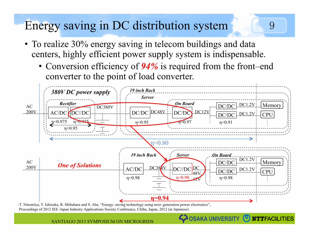
Energy saving in DC distribution system • To realize 30% energy saving in telecom buildings and data
centers, highly efficient power supply system is indispensable. • Conversion efficiency of 94% is required from the front–end
converter to the point of load converter.
AC 200V
DC380V DC48V DC12V
DC1.2V
η=0.95 η=0.95 η=0.97 η=0.91
η=0.80
19 inch Rack Server
380V DC power supply
On Board Rectifier Memory
CPU DC1.2V AC/DC DC//DC DC/DC DC/DC DC/DC DC/DC
AC 200V DC384V DC
48V, 12V
DC1.2V
η=0.98 η=0.98 η=0.98
η=0.94
19 inch Rack Memory
CPU DC1.2V AC/DC DC//DC DC/DC DC/DC
Server On Board
One of Solutions
SANTIAGO 2013 SYMPOSIUM ON MICROGRIDS
9
- T. Ninomiya, Y. Ishizuka, R. Shibahara and S. Abe, “Energy–saving technology using next–generation power electronics”, Proceedings of 2012 IEE–Japan Industry Applications Society Conference, Chiba, Japan, 2012 (in Japanese).
η=0.975 η=0.975
OSAKA UNIVERSITY
Necessity of high performance converter • High performance isolated DC–DC converters ( or DC transformer: fixed
voltage transfer ratio) are necessary.
• To achieve highly efficient and ultra compact converters, • Ultra–low loss and high–speed novel power devices such as SiC and GaN are attractive. • High frequency operation of novel power devices contributes to minimizing passive
components. • Series–parallel connection topology of highly integrated DC–DC converters is one of
options.
• To realize flexible transformer ratios, • Series–parallel connection topology of modular DC–DC converters is one of options.
SANTIAGO 2013 SYMPOSIUM ON MICROGRIDS
10
Target DC–DC in rectifier
Aim
Efficiency 98% 97.5% For Energy saving
Power density 10 W/cm3 2 W/cm3 To be installed into 19 inch rack with customer equipment
Transformer ratio 384 V–12 V and / or 48 V
384 V–384V To connect POL (Point of Load) converters
OSAKA UNIVERSITY SANTIAGO 2013 SYMPOSIUM ON MICROGRIDS
ISOP–IPOS topology • Higher input voltage can be injected in ISOP (Input Series and Output
Parallel) topology. • IPOS (Input Parallel and Output Series) topology makes higher output
voltage. • Conversion efficiency depends on an isolated DC–DC converter
(low–voltage and low–power) module.
SANTIAGO 2013 SYMPOSIUM ON MICROGRIDS
12
Isolated DC–DC converter module
ISOPTopology
IPOSTopology
OSAKA UNIVERSITY
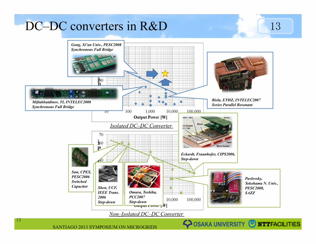
DC–DC converters in R&D
SANTIAGO 2013 SYMPOSIUM ON MICROGRIDS
13
13
Gong, Xi’an Univ., PESC2008 Synchronous Full Bridge
Biela, ETHZ, INTELEC2007 Series Parallel Resonant
Miftakhutdinov, TI, INTELEC2008 Synchronous Full Bridge
Sun, CPES, PESC2006 Switched Capacitor Shen, UCF,
IEEE Trans. 2006 Step-down
Omura, Toshiba, PCC2007 Step-down
Eckardt, Fraunhofer, CIPS2006, Step-down
Pavlovsky, Yokohama N. Univ., PESC2008, SAZZ
Isolated DC–DC Converter
Non–Isolated DC–DC Converter
OSAKA UNIVERSITY
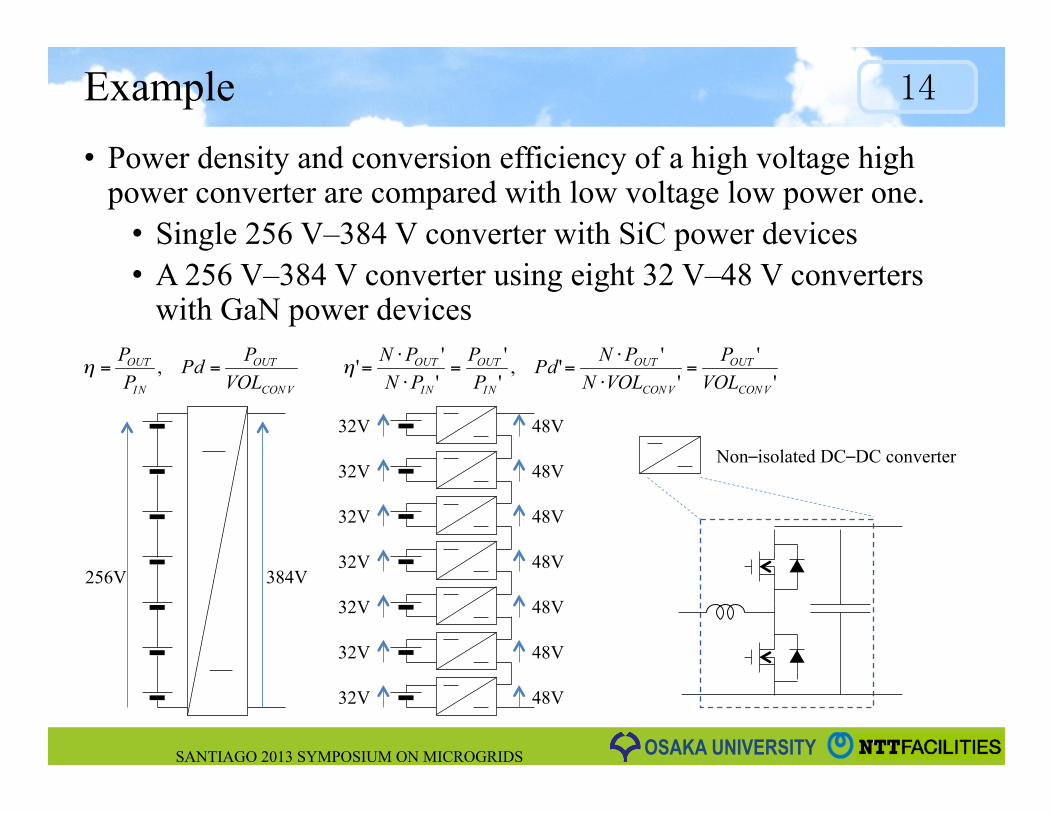
Example • Power density and conversion efficiency of a high voltage high
power converter are compared with low voltage low power one. • Single 256 V–384 V converter with SiC power devices • A 256 V–384 V converter using eight 32 V–48 V converters
with GaN power devices
SANTIAGO 2013 SYMPOSIUM ON MICROGRIDS
14
Non–isolated DC–DC converter
32V
32V
32V
32V
32V
32V
32V
48V
48V
48V
48V
48V
48V
48V
256V 384V
OSAKA UNIVERSITY
Experiments of non–isolated converters
SANTIAGO 2013 SYMPOSIUM ON MICROGRIDS
15
Output Capacitor
SiC Power Devices (TO247 packages) 1200V, 80mΩ
Input Inductor
GaN Power Devices (Bare chips) 100V, 7mΩ
Input Inductor
Output Capacitor
Experimental results of a 32V – 48V converter using GaN–FET (EPC)
Experimental Results of a 256V–384V converter using SiC–MOSFET (CREE)
Gate to Source Voltage (0 V-5 V ) Drain to Source Voltage (0 V-48 V )
Input Current (14.1A) Output Current (9.3A)
Input Voltage (256 V)
Output Voltage (384 V )
Input Current (9.0A) Output Current (6.0A)
100 kHz
1 MHz
OSAKA UNIVERSITY
Input voltage balance in ISOP topology
• Input voltages of converters balances ideally. • Mismatch of output impedances causes the input voltage unbalance
under real circuit operation conditions. • Imbalance of input voltages were calculated when output impedances
vary from 1% to 5% in eight converters. • Input voltages vary 2% from the rated voltage (48 V ± 1V), and the
influence is negligible.
SANTIAGO 2013 SYMPOSIUM ON MICROGRIDS
16
+2%
-2% dc-dc Conv.
dc-dc Conv.
dc-dc Conv.
Ro8
Ro2
Ro1
Vi8
Vi2
Vi1 Vo1
Vo2
Vo8 VLOAD 48V
384V
Rout
Variance
Number connected in series
Output Impedance of converter No.i
Average of output impedances
Input Voltage Unbalance in Series Input Parallel Output Converter
Schematic Diagram of Series-Parallel Connected Converters
Io8
Io2
Io1
OSAKA UNIVERSITY
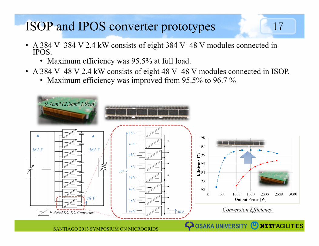
Conversion Efficiency
ISOP and IPOS converter prototypes • A 384 V–384 V 2.4 kW consists of eight 384 V–48 V modules connected in
IPOS. • Maximum efficiency was 95.5% at full load.
• A 384 V–48 V 2.4 kW consists of eight 48 V–48 V modules connected in ISOP. • Maximum efficiency was improved from 95.5% to 96.7 %
SANTIAGO 2013 SYMPOSIUM ON MICROGRIDS
17
9.7cm*12.9cm*1.9cm
Isolated DC-DC Converter
384 V 384 V
48 V
OSAKA UNIVERSITY
384 V–384 V 19.2 kW ISOP–IPOS Converter • Sixty four 48 V–48 V 300 W converter modules (VICOR,
V048F480T006) were utilized. • A 384 V–48 V 2.4 kW consists of eight modules connected in ISOP. • A 384 V–384 V 19.2 kW consists of eight 384 V–48 V 2.4 kW
converters in IPOS. • Maximum conversion efficiency was 96.6% and the power density was
10 W/cm3 without fans. • Maximum efficiency of each 48 V–48 V module is 96.7%.
SANTIAGO 2013 SYMPOSIUM ON MICROGRIDS
18
300mm 160mm
42mm
384 V–384 V 19.2 kW IPOS Converter using eight ISOP converters
Conversion efficiency of 384 V–384 V 19.2 kW converter
384 V–48 V 2.4 kW ISOP converter
[kW]
OSAKA UNIVERSITY
Transient behavior of ISOP converter
• Start-up waveforms were measured under no load condition. • No input voltage unbalances were observed.
• Transient characteristics in rapid load variation were shown. • Input voltage fluctuation was within 100 ± 5 %.
SANTIAGO 2013 SYMPOSIUM ON MICROGRIDS
19
Output Current Io5: 32.4A
Output Current Io6: 38.8A
Input Voltage of Unit No. 5: 48 V Input Voltage: 384 V (100 V/div)
Input Voltage: 48 V (20 V/div)
Input Current: 0 A Output Current: 0 A
Input Voltage of Unit No. 6: 48 V
Start-up waveforms under no load condition
Rapid load variation (1ms, 0%100%)
Rapid load variation (1ms, 100%0%)
OSAKA UNIVERSITY
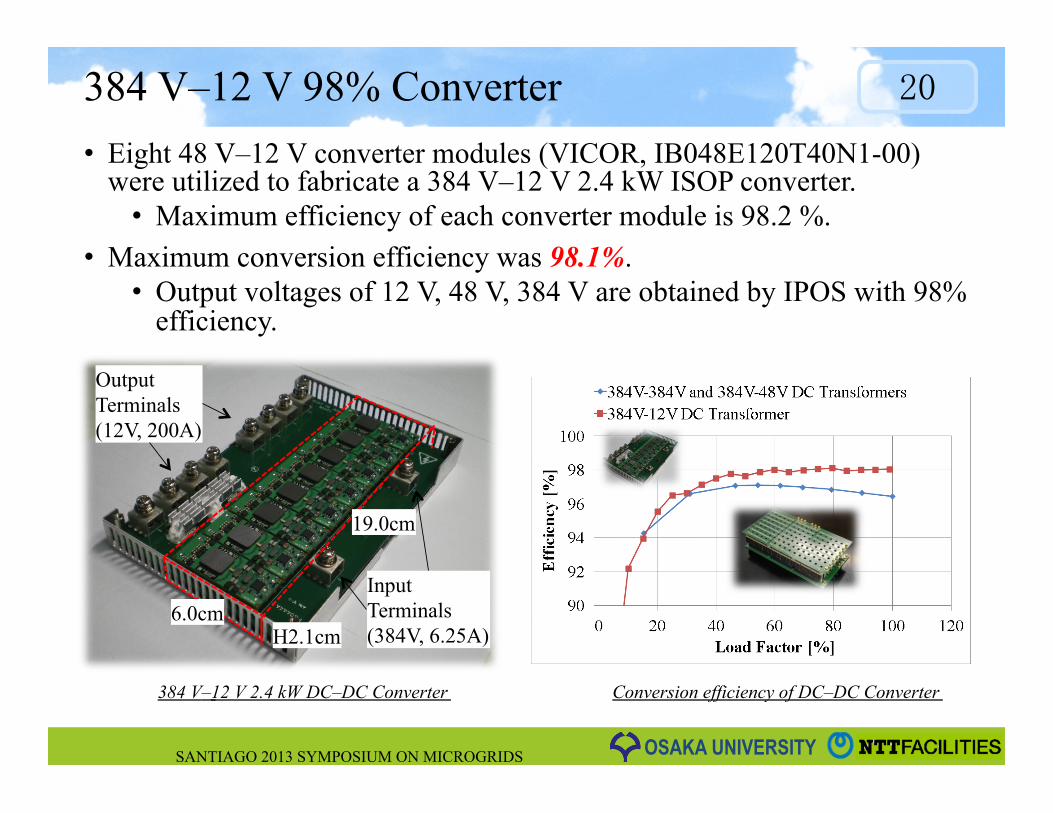
384 V–12 V 98% Converter • Eight 48 V–12 V converter modules (VICOR, IB048E120T40N1-00)
were utilized to fabricate a 384 V–12 V 2.4 kW ISOP converter. • Maximum efficiency of each converter module is 98.2 %.
• Maximum conversion efficiency was 98.1%. • Output voltages of 12 V, 48 V, 384 V are obtained by IPOS with 98%
efficiency.
SANTIAGO 2013 SYMPOSIUM ON MICROGRIDS
20
19.0cm
H2.1cm
Output Terminals (12V, 200A)
Input Terminals (384V, 6.25A)
6.0cm
Conversion efficiency of DC–DC Converter 384 V–12 V 2.4 kW DC–DC Converter
OSAKA UNIVERSITY
Improvement of power density and efficiency • In DC–DC converters for NTT telecom power supply, output power density has
been increasing. • Higher conversion efficiency has been also achieved.
• The 384 V–384 V converter using 48 V–48 V converter modules connected in ISOP–IPOS achieved higher power density.
• Higher efficiency has been also achieved by using 48 V–12 V converters
SANTIAGO 2013 SYMPOSIUM ON MICROGRIDS
21
Conventional 384 V–384 V DC–DC Converter in Rectifier (15 kW)
384 V–12 V DC–DC Conv. (2.4 kW)
384 V–384 V DC–DC Converter (19.2 kW)
OSAKA UNIVERSITY
Conclusions
• DC distribution for telecom buildings and data centers was introduced. • Highly efficient DC power supply is indispensable to realize low
carbon society. • Availability of ISOP–IPOS topology was shown to realize highly
efficient and ultra compact converters. • A 19.2 kW 384 V–384 V converter was fabricated by using sixty–
four 48 V–48 V converter modules with the efficiency of 96.6%. • A 2.4 kW 384 V–12 V converter was fabricated by using eight 48 V–
12 V converter modules with the efficiency of 98.1%. • I/O voltages are arbitrarily selected in ISOP–IPOS topology.
• DC–DC converters with ISOP–IPOS topology contribute to realizing highly efficient DC microgrids.
SANTIAGO 2013 SYMPOSIUM ON MICROGRIDS
22
OSAKA UNIVERSITY
Thank you for your attention.
SANTIAGO 2013 SYMPOSIUM ON MICROGRIDS
23
OSAKA UNIVERSITY SANTIAGO 2013 SYMPOSIUM ON MICROGRIDS
24
OSAKA UNIVERSITY
Power density and efficiency estimation
• Calculation results of efficiency and power density are shown. • Ideal circuit condition: Stored energy in COSS is only
considered to calculate switching loss energy • Real circuit condition: Parameters in the experiment is taken
into account • Higher power density will be achieved in the low voltage and low
power converter
SANTIAGO 2013 SYMPOSIUM ON MICROGRIDS
25
Conversion Efficiency [%]
Power density V.S. switching frequency Power density V.S. conversion efficiency