Technical Report 2009-02-01 Internetworking and Media Communications Research Laboratories Department of Computer Science, Kent State University http://medianet.kent.edu/technicalreports.html DCN@MPLS: A Network Architectural Model for Dynamic Circuit Networking at Multiple Protocol Label Switching Omar Y. Tahboub and Javed I. Khan Networking and Multimedia Communication Lab Computer Science Department Kent State University Kent, Ohio, 44242-0001 Abstract In this technical report, we present DCN@MPLS a protocol extension to multi-protocol label switching technology that can dynamically assign time activated future routes to an MPLS enabled routing infrastructure. We assume that efficient route schedules have been computed by a separate optimization algorithm module linked to the DCN@MPLS route server. In this document we first present the DCN@MPLS architectural model. Next, we present the MPLS protocol extensions to support dynamic circuit networking. I. Introduction In this technical report, we present a network architectural model that implements dynamic circuit operation DCN at the Multi Protocol Labeling Switching MPLS domains namely DCN@MPLS. In addition, the MPLS protocol extensions are implemented by the DCN@MPLS route scheduling tier. These protocol extensions determine the set of label message signaling that enables time-scheduled route information to be distributed to the MPLS domain. More particularly, these extensions are related to the label distribution process handling Constraint-Routing Label Distribution Protocol (CR-LDP). The rest of the paper is organized as follows; section II provides the architectural of MPLS protocol. Section III describes the client tier along with route scheduling. Section IV, describes the DCN@MPLS route scheduling tier. Section V describes the DCN@MPLS protocol extensions to MPLS CR-LDP. Finally, section VII concludes the paper. II. Architectural Overview This DCN@MPLS network architectural model is representing by the four-tier architecture shown in Fig.1. The DCN@MPLS architecture is composed of four tiers: edge, network, routing and scheduling. The edge tier represents the architecture’s acquisition entity to which on-demand data transfers requests are submitted. The network tier represents the physical MPLS network through which data transfers are streamed. The routing tier handles all on-demand data transfer requests, where an end-to-end route is computed and yet scheduled for each request. The scheduling tier represents DCN abstraction layer for the MPLS network, which performs route schedule dissemination to the label switch routers of the network tier. In addition, DCN@MPLS is a set of protocols extension to the MPLS CR-LDP. These extensions describe three DCN primitive route operations: inquiry, response and schedule dissemination. Further, three route dissemination models are described: the first is centralized implementable by classic routing protocols. On the hand, the other two are distributed suitable for intermittent networks.
Transcript
Technical Report 2009-02-01 Internetworking and Media Communications Research Laboratories Department of Computer Science, Kent State University http://medianet.kent.edu/technicalreports.html
DCN@MPLS: A Network Architectural Model for
Dynamic Circuit Networking at Multiple Protocol Label
Switching
Omar Y. Tahboub and Javed I. Khan
Networking and Multimedia Communication Lab
Computer Science Department
Kent State University
Kent, Ohio, 44242-0001
Abstract
In this technical report, we present DCN@MPLS a protocol extension to multi-protocol label switching
technology that can dynamically assign time activated future routes to an MPLS enabled routing infrastructure.
We assume that efficient route schedules have been computed by a separate optimization algorithm module
linked to the DCN@MPLS route server. In this document we first present the DCN@MPLS architectural
model. Next, we present the MPLS protocol extensions to support dynamic circuit networking.
I. Introduction
In this technical report, we present a network architectural model that implements dynamic circuit
operation DCN at the Multi Protocol Labeling Switching MPLS domains namely DCN@MPLS. In
addition, the MPLS protocol extensions are implemented by the DCN@MPLS route scheduling tier. These
protocol extensions determine the set of label message signaling that enables time-scheduled route
information to be distributed to the MPLS domain. More particularly, these extensions are related to the
label distribution process handling Constraint-Routing Label Distribution Protocol (CR-LDP).
The rest of the paper is organized as follows; section II provides the architectural of MPLS protocol.
Section III describes the client tier along with route scheduling. Section IV, describes the DCN@MPLS
route scheduling tier. Section V describes the DCN@MPLS protocol extensions to MPLS CR-LDP.
Finally, section VII concludes the paper.
II. Architectural Overview
This DCN@MPLS network architectural model is representing by the four-tier architecture shown in
Fig.1.
The DCN@MPLS architecture is composed of four tiers: edge, network, routing and scheduling. The
edge tier represents the architecture’s acquisition entity to which on-demand data transfers requests are
submitted. The network tier represents the physical MPLS network through which data transfers are
streamed. The routing tier handles all on-demand data transfer requests, where an end-to-end route is
computed and yet scheduled for each request. The scheduling tier represents DCN abstraction layer for the
MPLS network, which performs route schedule dissemination to the label switch routers of the network
tier.
In addition, DCN@MPLS is a set of protocols extension to the MPLS CR-LDP. These extensions
describe three DCN primitive route operations: inquiry, response and schedule dissemination. Further, three
route dissemination models are described: the first is centralized implementable by classic routing
protocols. On the hand, the other two are distributed suitable for intermittent networks.
Technical Report 2009-02-01 Internetworking and Media Communications Research Laboratories Department of Computer Science, Kent State University http://medianet.kent.edu/technicalreports.html
In the proceeding discussion, we elaborate each tier in the DCN@MPLS network architecture
according to following sequence. The MPLS network domain tier, the client tier, the route scheduling tier
and finally the DCN@MPLS route scheduling tier.
Fig.1: The DCN@MPLS Network Architecture
III. The MPLS Network Domain Tier
In this section we introduce Multiple Protocol Label Switching MPLS and describe the MPLS network
domain tier.
Technical Report 2009-02-01 Internetworking and Media Communications Research Laboratories Department of Computer Science, Kent State University http://medianet.kent.edu/technicalreports.html
A. Multiple Label Protocol Switching
Multiple Label Protocol Switching MPLS will play a major role in techniques of routing,
switching and forwarding packets through the next generation network in order to satisfy the future
demands of Internet applications. [5]
The actual data transmission in MPLS occurs on a Label-Switched Path (LSP), where a LSP is
sequence of labels at each and every node along the path between the source and the destination. The
establishment of LSPs is performed either in control-driven or data-driven fashion. In former, LSPs are
established ahead of the data transmission of data transmission, while in the latter these paths are
established upon the detection of a data flow [3].
In addition, Labels that form the underlying protocol-specific identifiers are distributed using
Label Distribution Protocol (LDP). Each data packet encapsulates and carries the labels during its
journey from the source to the destination. MPLS labels are fixed-length inserted into the packet
header between layer-2 and layer-3 headers, which enables high-speed switching.
An instance of a MPLS network domain is presented in the Fig.2. It can be noted that this network
domain consists of two types of nodes (routers): Label Edge Router (LER) and Label Switch Router
(LSR).
The first type represents the devices that operate at the edge of the access network and MPLS
network. LERs forward traffic to the MPLS network after establishing the LSP. Moreover, these
devices support multiple ports connected to various networks such as ATM, Frame Relay and Ethernet.
The second type represents the set high-speed routes deployed at the core of the MPLS network that
participates in the LSP establishment using the appropriate protocol. Further, LSRs constitutes an LSP.
MPLS supports differentiated services through Forward Equivalence Classes (FEC)s. A FEC
represents a group of packets sharing the similar transport requirements; all packets belonging to the
same FEC are given the same treatment en-route to the destination. These classes are based on service
requirements for a given set of packets (flow) or for an address prefix. Moreover, FEC packet
assignment is done at the LER. Each LSR builds a Label Information Base (LIB) to determine how a
packet must be forwarded based on its label it encapsulates. In addition, a label identifies the path a
packet should traverse, since it is encapsulated into the packet header.
B. The MPLS Network Domain
Generally, a MPLS domain is represented by the directed multi-graph G = (N, E), where N = n1,
n2, …, nm be the set of m label switch routers and E = e1, e2, …, en be the set of edges (links), each
edge ei ∈ E connects a pair of label switch routers (nu, nv) ∈ N.
For each switch router ni ∈ N , ci denotes its service rate in bits per second (bps) and bi denotes
the available storage buffer in bits. For each edge ei ∈ E, bwi denotes its bandwidth (bps) and li
denotes its propagation delay in seconds.
The MPLS domain tier is elaborated in Fig.1 consists of seven label edge routers LER1, LER2,…,
LER7 and ten label switch routers LSR1, LSR2,…, LSR10 and twenty-four links e1, e2,…, e24.
This tier collects node (LSR) and link resources of information to be forwarded to the DCN@MPLS
tiers. As shown in the figure below link resource information is pointed by dashed green arrows, while
node resources information is pointed by blue dashed arrows. Moreover, each LER node in the domain
obtains the time-scheduled route information from the DCN@MPLS tier. Each LER is responsible of
setting up the time-scheduled route from itself to the egress LER according the LSP time-scheduling
information.
IV. The Client Tier
The Client tier represents the user-groups requesting on-demand data flow transmissions via the
underlying the MPLS network domain.
Technical Report 2009-02-01 Internetworking and Media Communications Research Laboratories Department of Computer Science, Kent State University http://medianet.kent.edu/technicalreports.html
Clients of this architecture are multi-disciplinary including science, business, engineering, education,
medicine, and others. For instance, High Definition (HD) video teleconferencing used in business
management and distance learning the enables real-time communication between parity separated by
continentals. Moreover, telemedicine allows specialists to collaborate in conducting sophisticated
operations around the world. These applications commonly have two features: bandwidth-intensive and on-
demand. Bandwidth-intensive applications involve massively large data transfers in the orders Gigabytes
and yet Terabytes per day. Moreover, the on-demand feature implies that dedicated end-to-end circuits
should be established, and network resources have to be allocated in advance.
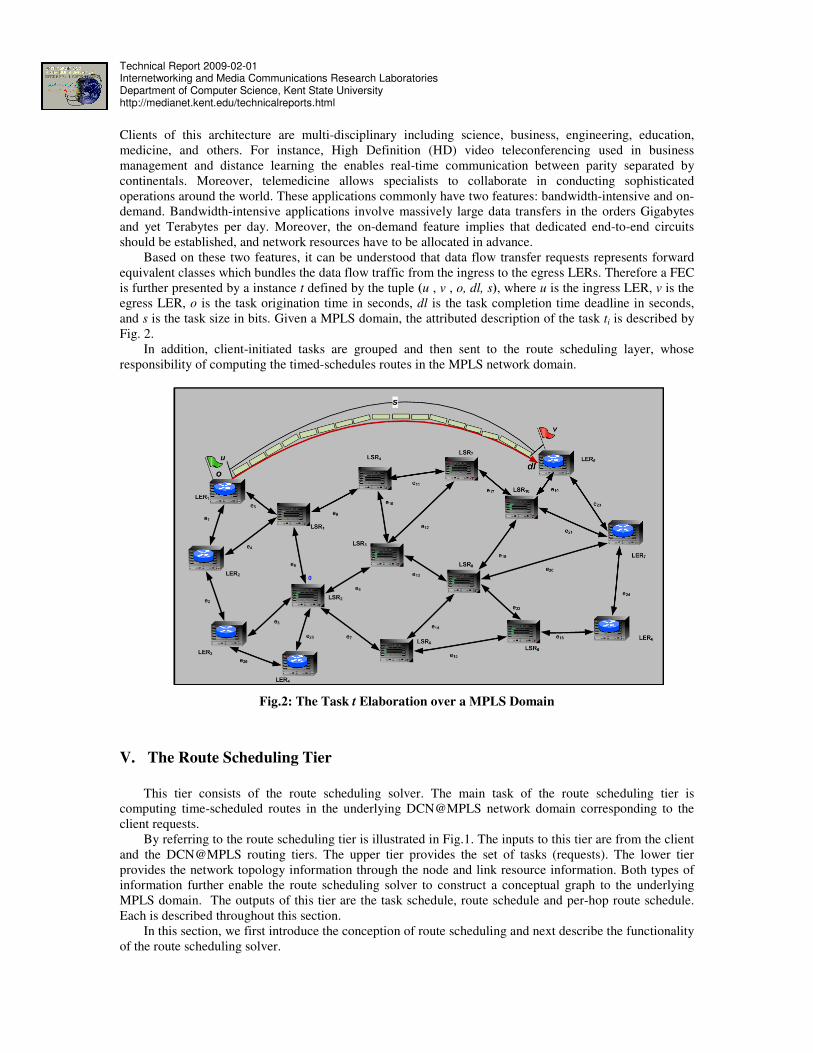
Based on these two features, it can be understood that data flow transfer requests represents forward
equivalent classes which bundles the data flow traffic from the ingress to the egress LERs. Therefore a FEC
is further presented by a instance t defined by the tuple (u , v , o, dl, s), where u is the ingress LER, v is the
egress LER, o is the task origination time in seconds, dl is the task completion time deadline in seconds,
and s is the task size in bits. Given a MPLS domain, the attributed description of the task ti is described by
Fig. 2.
In addition, client-initiated tasks are grouped and then sent to the route scheduling layer, whose
responsibility of computing the timed-schedules routes in the MPLS network domain.
Fig.2: The Task t Elaboration over a MPLS Domain
V. The Route Scheduling Tier
This tier consists of the route scheduling solver. The main task of the route scheduling tier is
computing time-scheduled routes in the underlying DCN@MPLS network domain corresponding to the
client requests.
By referring to the route scheduling tier is illustrated in Fig.1. The inputs to this tier are from the client
and the DCN@MPLS routing tiers. The upper tier provides the set of tasks (requests). The lower tier
provides the network topology information through the node and link resource information. Both types of
information further enable the route scheduling solver to construct a conceptual graph to the underlying
MPLS domain. The outputs of this tier are the task schedule, route schedule and per-hop route schedule.
Each is described throughout this section.
In this section, we first introduce the conception of route scheduling and next describe the functionality
of the route scheduling solver.
Technical Report 2009-02-01 Internetworking and Media Communications Research Laboratories Department of Computer Science, Kent State University http://medianet.kent.edu/technicalreports.html
A. Route Scheduling
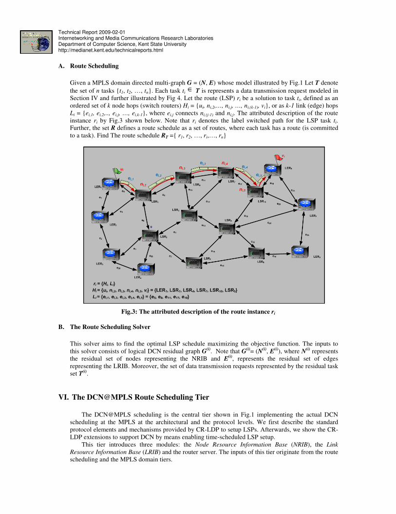
Given a MPLS domain directed multi-graph G = (N, E) whose model illustrated by Fig.1 Let T denote
the set of n tasks t1, t2, …, tn. Each task ti ∈ T is represents a data transmission request modeled in
Section IV and further illustrated by Fig 4. Let the route (LSP) ri be a solution to task ti, defined as an
ordered set of k node hops (switch routers) Hi = ui, ni,2,…, ni,j, …, ni,(k-1), vi, or as k-1 link (edge) hops
Li = ei,1, ei,2,.., ei,j, …, ei,k-1, where ei,j connects ni,(j-1) and ni,j. The attributed description of the route
instance ri by Fig.3 shown below. Note that ri denotes the label switched path for the LSP task ti.
Further, the set R defines a route schedule as a set of routes, where each task has a route (is committed
to a task). Find The route schedule RT = r1, r2, …, ri,…, rn
Fig.3: The attributed description of the route instance ri
B. The Route Scheduling Solver
This solver aims to find the optimal LSP schedule maximizing the objective function. The inputs to
this solver consists of logical DCN residual graph G(i)
. Note that G(i)
= (N(i)
, E(i)
), where N(i)
represents
the residual set of nodes representing the NRIB and E(i)
, represents the residual set of edges
representing the LRIB. Moreover, the set of data transmission requests represented by the residual task
set T(i)
.
VI. The DCN@MPLS Route Scheduling Tier
The DCN@MPLS scheduling is the central tier shown in Fig.1 implementing the actual DCN
scheduling at the MPLS at the architectural and the protocol levels. We first describe the standard
protocol elements and mechanisms provided by CR-LDP to setup LSPs. Afterwards, we show the CR-
LDP extensions to support DCN by means enabling time-scheduled LSP setup.
This tier introduces three modules: the Node Resource Information Base (NRIB), the Link
Resource Information Base (LRIB) and the router server. The inputs of this tier originate from the route
scheduling and the MPLS domain tiers.
Technical Report 2009-02-01 Internetworking and Media Communications Research Laboratories Department of Computer Science, Kent State University http://medianet.kent.edu/technicalreports.html
As given by the router scheduling tier, the task describes a flow transfer request described by the
task ti described by the tuple (ui, vi, oi, dli, si), where ui is the ingress LER, vi is the egress LER, oi is the
transfer origination time (seconds), dli is the transfer completion time, si is the size of the flow in (bits).
The corresponding solution to ti is the route (Label Switched Path) ri given by ni,1, ni,2,…, ni,m, ei,1,
ei,2,…, ei,n , where ni,1, ni,2,…, ni,m is a set of m node hops and ei,1, ei,2,…, ei,n is the set of n link
hops.
In addition, the per-hop route schedule describes uti the per-link transfer schedule of the task ti via
the LSP ri. For each link hop hope ei,j in ri connecting the node-hops pair (ni,j, ni,j+1), ti at ni,k-1 is
decomposed into a set of segments xi,j,1, xi,j,2,…, xi,j,n to be streamed via ei,j.
The transfer of data segment xi,j,k buffered at ni,j to be transferred to ni,j+1 via ei,j is denoted by the
data unit transfer dui,j,k. An instance of the data unit transfer dui,j,k is defined by the tuple (seqi,j,k, szi,j,k,
psi,j,k, pti,j,k, depi,j,k, arri,j,k). Where seqi,j,k is The unit sequence number, szi,j,k is the unit size in bits, psi,j,k
is the data unit processing start time, pti,j,k is the data unit processing time duration at the transmitting
node hop ni,j, , depc,i,k is the departure time from the node hop ni,j, and arrc,i,k is the arrival time to the
node hop ni,j+1. Furthermore, the set of segments xi,j,1, xi,j,2,…, xi,j,n to be transferred from ni,j to ni,j+1
via ei,j is given by the link-hop transfer schedule tsi,j = dui,j,1, dui,j,2,…, dui,j,n. Therefore, the per-hop
route schedule uti is given by the set of all per-link hope transfers along the route ri given by tsi,1,
tsi,2,…, tsi,n.
A. The Node Resource Information Base NRIB
The NRIB is a database server that stores and keeps track of the resources of each label switch
router in the MPLS domain. Node resources information includes available service capacity (bps), total
service capacity (bps), total input/output buffers capacity (bytes) and available input/output buffer
capacities (bytes). For each node n, the NRIB holds two tables: one for the input buffers and other for
the output buffers. The input buffer reservation table in-table holds a record for each data unit transfer
incoming to n. On the other hand, out-table is the output reservation table that holds a record for each
data unit transfer departing n.
An input reservation record in-rsv is given by the tuple (id, tid, nid, rbuf, beg). On the other hand,
the output reservation record out-rsv (id, tid, nid, rbuf, beg, end). For both record types, id is the
resource reservation ID number, tid is the reserving task ID number, nid is the node hop ID, rbuf is the
reserved buffer, beg is the reservation beginning (start) time, and end is the reservation ending time.
From the resource reservation table, node resource information can be derived and further pushed to
the route scheduling tier. Note that in-rsv only holds the beginning time. This because when a data unit
transfer dui,j,k from the node-hop ni,j to ni,j+1 via the link hop ei,j, xi,j,k is first placed in the output buffer
of ni,j prior departure and will be further placed in ni,j+1 input buffer. Therefore, the input buffer is
concerned with start of the reservation, which is the arrival of xi,j,k (arri,j,k), since the end of the
reservation will be determined by ni,j+1 when tsi,j+1 is created.
NRIB acquires link resource information from the MPLS network domain. However, we assume
this is performed through a data acquisition protocol, which is described in future. From the link
resource reservation table, the LRIB computes the available link capacities at each given instance of
time and further transmits them to the route scheduling tier.
B. The Link Resource Information Base LRIB
The LRIB is also a database server, which stores and keeps track of the resources of each link in
the MPLS network domain. Link information includes source LSR, destination LSR, total link capacity
(bps), and propagation delay (seconds). Similar to the NRIB, a reservation table is stored for each link
in the MPLS domain. This table also holds a record for each for each data unit transfer.
A link reservation record l-rsv is given by the tuple (id, tid, lid, src, dst, rbw, fbw, beg, end),
where id is the resource reservation ID number, tid is the reserving task ID number, lid is the link hop
ID, src is the link source node hop, dst is the link destination node hop, rbw is the reserved capacity,
fbw is the available (free) capacity, beg is the reservation beginning (start) time, and , end is the
reservation ending time.
Technical Report 2009-02-01 Internetworking and Media Communications Research Laboratories Department of Computer Science, Kent State University http://medianet.kent.edu/technicalreports.html
LRIB acquires link resource information from the MPLS network domain. However, we assume
this is performed by a data acquisition protocol, which is described in future. Moreover, from the link
resource reservation table, the LRIB computes the available link capacities at each given instance of
time and further transmits them to the route scheduling tier.
C. The Route Server
The route server is a special-purpose application server responsible of disseminating the per-hop
route schedule uti into the LSR belonging to the LSP ri. As described in the architectural overview, the
route server acquires the task schedule Tr, route schedule RT and the per-hop route schedule UTr from
the route scheduling tier. For each triplet (ti ,ri, uti), where ti in Tr, ri in RT and uti in UTr, the route server
performs two tasks: resource reservation and LSP time-schedule dissemination. The latter operation
represents the DCN information dissemination to the reserved LSP. To clearly describe the
functionality of the route server, we devise a LSP scenario shown in the figure below.
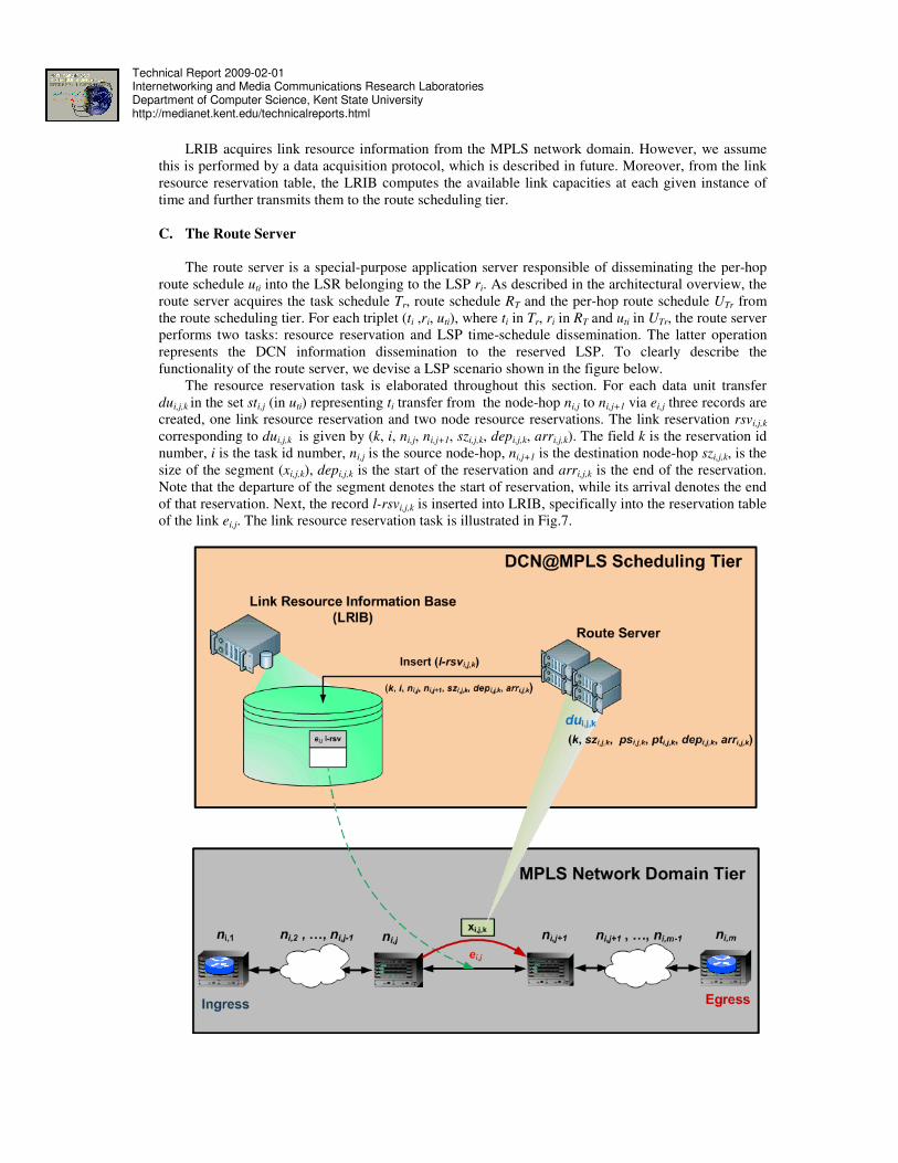
The resource reservation task is elaborated throughout this section. For each data unit transfer
dui,j,k in the set sti,j (in uti) representing ti transfer from the node-hop ni,j to ni,j+1 via ei,j three records are
created, one link resource reservation and two node resource reservations. The link reservation rsvi,j,k
corresponding to dui,j,k is given by (k, i, ni,j, ni,j+1, szi,j,k, depi,j,k, arri,j,k). The field k is the reservation id
number, i is the task id number, ni,j is the source node-hop, ni,j+1 is the destination node-hop szi,j,k, is the
size of the segment (xi,j,k), depi,j,k is the start of the reservation and arri,j,k is the end of the reservation.
Note that the departure of the segment denotes the start of reservation, while its arrival denotes the end
of that reservation. Next, the record l-rsvi,j,k is inserted into LRIB, specifically into the reservation table
of the link ei,j. The link resource reservation task is illustrated in Fig.7.
Technical Report 2009-02-01 Internetworking and Media Communications Research Laboratories Department of Computer Science, Kent State University http://medianet.kent.edu/technicalreports.html
Fig.4: The Link Resource Reservation
In addition for the same data unit transfer dui,j,k , two reservation records are created one for the
output buffer of the node ni,j and another for the input buffer ni,j+1. The output reservation record out-
rsvi,j,k is given by the tuple (k, i, ni,j, szi,j,k, (psi,j,k+pti,j,k), depi,j,k). Moreover, the input record This record
is denoted by in-rsvi,j+1,k is given by the tuple (k,i,ni,j+1,szi,j,k,arri,j,k). Afterwards both out-rsvi,j,k and in-
rsvi,j+1,k are inserted in their corresponding reservation tables in the NRIB. The node resource
reservation is illustrated in Fig.8
The task of disseminating the LSP time schedule involves three operations: acquiring the set of
labels mappings Lai, extracting the timing information from the route schedule uti and distributing the
timing information to each LSR in ri. For better understanding of these operations, we utilize the
following LSP scenario shown in the Fig.9.
The reference scenario consists of two architectural elements the route server and a LSP given
LER1, LER2, LSR1, LSR4, LSR5, LSR8, LSR10, LER5, e1, e4, e9, e10, e13, e18, e19. It has to be
noted that the route server belongs to the DCN@MPLS route scheduling tier, while the LSP belongs to
the MPLS network domain tier.
The task ti represents an instance of FEC (data flow transmission request) from the ingress LER1
to the egress LER5 starting from the time ω = 1 and ending at ω = 40 and the size of data to be
transmitted is 1.5 MB. The LSP ri committed to ti is LER1, LER2, LSR1, LSR4, LSR5, LSR8, LSR10,
LER5, e1, e4, e9, e10, e13, e18, e19.
Technical Report 2009-02-01 Internetworking and Media Communications Research Laboratories Department of Computer Science, Kent State University http://medianet.kent.edu/technicalreports.html
Fig.5: The Node Resource Reservation
Acquiring the label mapping information involves the invocation of the label/request mapping
signaling of CR-LDP illustrated in Fig.10. The outcome of this step is the set Lai denotes the set of
input/output label pairs at each node hop ni,j in ri given as (lii,1, lo i,1), (lii,2, loi,2),…, (lii,k, loi,k),…,(lii,m,
loi,m). Note that lii,k is the kth
input label and loi,k is the output label of the FEC ti passing traversing
through the LSR ni,k.
The route schedule time information is denoted by the estimated data flow starting and ending
times pair (srti,k, endi,k) at each node hop ni,k in ri. The starting srti,k time means the arrival of the first
data segment to the node hop ni,k mapped to the kth
label input/output label pair (lii,k, loi,k) given by
arri,k,1, while the ending time endi,k means the departure of the last (mth
) data segment for that node hop
given by depi,k,m.
Technical Report 2009-02-01 Internetworking and Media Communications Research Laboratories Department of Computer Science, Kent State University http://medianet.kent.edu/technicalreports.html
Fig.6: The LSP reference scenario
Fig.7: LSP Label Acquisition
The label timing pair determines its lifetime inside the FIB, hence the input/output label pair (lii,k,
loi,k) is only valid during the time period [srti,k, endi,k]. The outcome of this operation is the set Ωi =
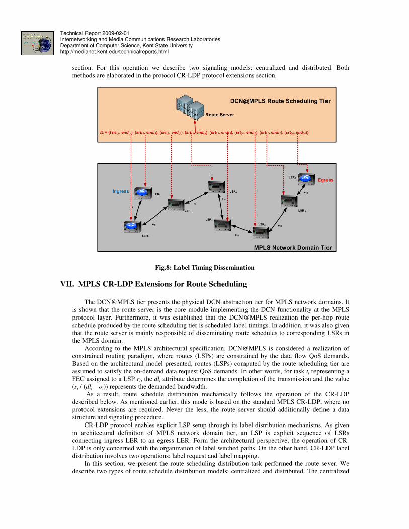
The task of distributing the set Ωi to corresponding the LSRs in ri illustrated in Fig. 11 involves
three signaling operations: label inquiry, label response and label timing that elaborated later in this
Technical Report 2009-02-01 Internetworking and Media Communications Research Laboratories Department of Computer Science, Kent State University http://medianet.kent.edu/technicalreports.html
section. For this operation we describe two signaling models: centralized and distributed. Both
methods are elaborated in the protocol CR-LDP protocol extensions section.
Fig.8: Label Timing Dissemination
VII. MPLS CR-LDP Extensions for Route Scheduling
The DCN@MPLS tier presents the physical DCN abstraction tier for MPLS network domains. It
is shown that the route server is the core module implementing the DCN functionality at the MPLS
protocol layer. Furthermore, it was established that the DCN@MPLS realization the per-hop route
schedule produced by the route scheduling tier is scheduled label timings. In addition, it was also given
that the route server is mainly responsible of disseminating route schedules to corresponding LSRs in
the MPLS domain.
According to the MPLS architectural specification, DCN@MPLS is considered a realization of
constrained routing paradigm, where routes (LSPs) are constrained by the data flow QoS demands.
Based on the architectural model presented, routes (LSPs) computed by the route scheduling tier are
assumed to satisfy the on-demand data request QoS demands. In other words, for task ti representing a
FEC assigned to a LSP ri, the dli attribute determines the completion of the transmission and the value
(si / (dli – oi)) represents the demanded bandwidth.
As a result, route schedule distribution mechanically follows the operation of the CR-LDP
described below. As mentioned earlier, this mode is based on the standard MPLS CR-LDP, where no
protocol extensions are required. Never the less, the route server should additionally define a data
structure and signaling procedure.
CR-LDP protocol enables explicit LSP setup through its label distribution mechanisms. As given
in architectural definition of MPLS network domain tier, an LSP is explicit sequence of LSRs
connecting ingress LER to an egress LER. Form the architectural perspective, the operation of CR-
LDP is only concerned with the organization of label witched paths. On the other hand, CR-LDP label
distribution involves two operations: label request and label mapping.
In this section, we present the route scheduling distribution task performed the route sever. We
describe two types of route schedule distribution models: centralized and distributed. The centralized
Technical Report 2009-02-01 Internetworking and Media Communications Research Laboratories Department of Computer Science, Kent State University http://medianet.kent.edu/technicalreports.html
model is based on the standard label distribution primitives supported by MPLS CR-LDP. On the other
hand, the distributed extends the MPLS CR-LDP with three protocol signaling procedures to enable
route schedule distribution.
A. Centralized DCN@MPLS Route Schedule Distribution
The centralized route scheduling distribution performed by the route server leverages the pre-
excising label distribution mechanisms supported by CR-LDP. This model first determines the
architectural specifications of the route server and label switch routers in the MPLS network
domain. Afterward it describes the CR-LDP protocol signaling procedures involved.
i. Architectural Specifications of Route Server
The route server located in the DCN@MPLS tier is only concerned with two inputs from the route
scheduling tier: The route schedule RT and the task schedule Tr. The route server defines a data
structure called global route schedule described as a table. For each pair (ti, ri) in Tr and RT, This
table stores a record, which determines the initiation time for the LSP represented by ri. A route
schedule record is defined by the tuple (i, oi, Hi), where i is the record ID number, oi is the
origination time of ti and Hi = ui, ni,2, …, ni,m-1, vi is the set of node-hops of ri. The global
schedule data structure is elaborated in the figure shown below.
Fig.9: The Route Server Global Route Schedule
ii. Architectural Specifications of Label Switch Router
Technical Report 2009-02-01 Internetworking and Media Communications Research Laboratories Department of Computer Science, Kent State University http://medianet.kent.edu/technicalreports.html
Each LSR in the MPLS network domain consists of two: information bases: Label Information
Base (LIB) and Forward Information Base (FIB). The overall organization of the LSR is
illustrated in Fig. 10. The LIB is modeled according to per-interface where each network interface
is allocated a label space range. For instance, each LRS could consider 256 labels equally divided
over its interfaces. When an FEC mapping request is received, the interface number is passed to
LIB, where a label value is selected from its corresponding range. Besides the LIB, the FIB is
table that holds the next hop forward mapping of an incoming label. For each FEC, the FIB
maintains a forward record given the tuple (LSPID, FEC, IN-IF, IN-LBL, OUT-IF, OUT-LBL,
NEXT). The attributes are described as follows; LSPID is local LSP id number, FEC is forward
equivalence class equal to the IPv4 address prefix, IN-IF, is the input id number, IN-LBL is input
label value, OUT-IF is the output interface, OUT-LBL is the output label value , NEXT is the next
hop IPv4 address.
Fig.10: The Label Switch Router Data Organization
iii. Centralized Route Scheduling Protocol Signaling
Periodically, the route serve scans the global route schedule and initiates each route LSP
according to its initiation time. It is assumed that the route server timer is given by ω, for route
scheduling record reci, when ω = oi – ∆ the route server initiates the CR-LDP distribution
signaling. Note that ∆ denotes the LSP label distribution and LSP setup latency in seconds. The
CR-LDP label distribution is performed by two protocol signaling operations: label request and
labels mapping. For each operation, CR-LDP defines a Time Length Value TLV message and also
describes signaling steps performed throughout the operation.
CR-LDP defines two label distribution messages initiated by the ingress LER: label request
and label mapping messages. Both messages TLV headers are described in [4]. In this section we
Technical Report 2009-02-01 Internetworking and Media Communications Research Laboratories Department of Computer Science, Kent State University http://medianet.kent.edu/technicalreports.html
describe both operations starting with the label request signaling. We utilize the LSP reference
scenario given by Fig.6.
Fig.11: The label request messaging
Note that the route server initiates the operation from the ingress LER. The label request is
forwarded in a hop-by hop fashion until it arrives to the egress LER.
Fig.11 shown above illustrates the label request initiated by the ingress LER (LER1). Note
that LER1 has already been aware of the entire path to the egress LER (LER5). Hence, LER1
creates the CR-LDP-REQ message shown in Fig.15, where the explicit route consists of ordered
hops LER1 (highlighted in yellow), LER2, LSR1, LSR4, LSR5, LSR8, LSR10 and LER5.
In step-1, the ingress (LER1) builds the request message, pops its hop information from the
explicit route TLV and passes it to the next hop LER2. In step-2, LER2 receives the message,
pops itself from the explicit route TLV. Similar to step-2, steps 3 to 7 perform the same
operations. In step-8, the egress LER5 receives the message and initiates the label mapping
process described in the proceeding discussion.
Once the egress LER receives the label request message; it initiates the label mapping
process performed in a hop-by-hop fashion. Label mapping involves three steps at each hop in the
LSP starting at the egress and ending at the ingress LERs. First, the LIB is inquired an available
label value to be mapped to FEC enclosed in the request message. Second, the label value
obtained from the LIB is mapped to the FEC and a new entry is inserted inside the FIB,
determining the output label value. Third, the label mapping message LDP-LABEL-MAP-MSG-
TLV is sent to the next hop towards the ingress LER . For the label request scenario described
above, we elaborate the label mapping process using Fig.9.
In step-1, LER5 generates 127 as label value for the incoming traffic, whose LSPID is 10. LER5
inserts a new entry in the FIB corresponding to that traffic. As shown the input label is 127 and
the output label is N/A because LER5 is the egress. Next, LER5 generates label mapping message
containing 127 as the input label value and passes to LSR10.
In step-2, LSR10 receives the label mapping message from LER5 and generates label value for
that traffic equal to 189. LSR10 inserts a new entry in its local FIB, whose input label is 189 and
Technical Report 2009-02-01 Internetworking and Media Communications Research Laboratories Department of Computer Science, Kent State University http://medianet.kent.edu/technicalreports.html
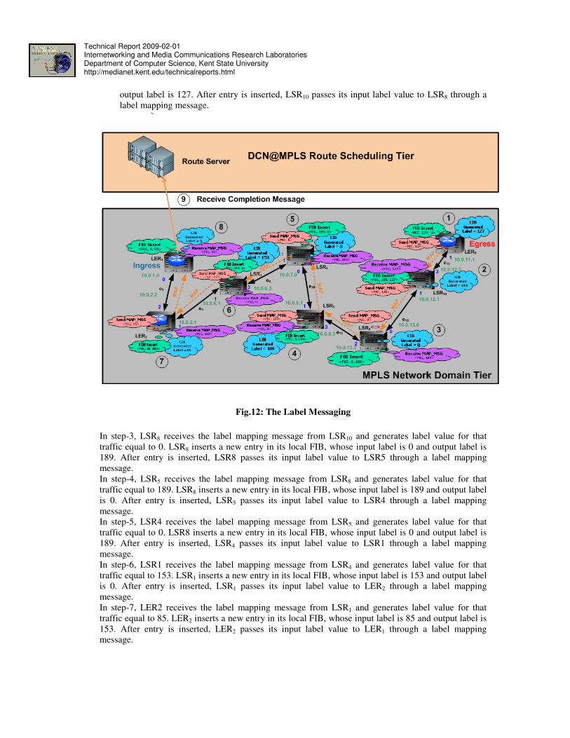
output label is 127. After entry is inserted, LSR10 passes its input label value to LSR8 through a
label mapping message.
`
Fig.12: The Label Messaging
In step-3, LSR8 receives the label mapping message from LSR10 and generates label value for that
traffic equal to 0. LSR8 inserts a new entry in its local FIB, whose input label is 0 and output label is
189. After entry is inserted, LSR8 passes its input label value to LSR5 through a label mapping
message.
In step-4, LSR5 receives the label mapping message from LSR8 and generates label value for that
traffic equal to 189. LSR8 inserts a new entry in its local FIB, whose input label is 189 and output label
is 0. After entry is inserted, LSR5 passes its input label value to LSR4 through a label mapping
message.
In step-5, LSR4 receives the label mapping message from LSR5 and generates label value for that
traffic equal to 0. LSR8 inserts a new entry in its local FIB, whose input label is 0 and output label is
189. After entry is inserted, LSR4 passes its input label value to LSR1 through a label mapping
message.
In step-6, LSR1 receives the label mapping message from LSR4 and generates label value for that
traffic equal to 153. LSR1 inserts a new entry in its local FIB, whose input label is 153 and output label
is 0. After entry is inserted, LSR1 passes its input label value to LER2 through a label mapping
message.
In step-7, LER2 receives the label mapping message from LSR1 and generates label value for that
traffic equal to 85. LER2 inserts a new entry in its local FIB, whose input label is 85 and output label is
153. After entry is inserted, LER2 passes its input label value to LER1 through a label mapping
message.
Technical Report 2009-02-01 Internetworking and Media Communications Research Laboratories Department of Computer Science, Kent State University http://medianet.kent.edu/technicalreports.html
In step-8, LER1 receives the label mapping message from LER2 and generates label value for that
traffic equal to 0. LER2 inserts a new entry in its local FIB, whose input label is 0 and output label is
185.
B. Distributed DCN@MPLS Route Schedule Distribution
The distributed model of route scheduling distribution is based on disseminating the label timing pairs to
each LSR in the LSP. In this model, the route server does not define or utilize any special data structure.
On the other hand, this model augments the LSR forward information base (FIB) data structure and
further defines three protocol signaling operations.
In this section, we first describe the augmented data organization of the FIB. Second we present the CR-
LDP protocol extensions corresponding to three signaling operations. This is due to the fact that CR-LDP
does not enable time-scheduled label distribution. Never the less, CR-LDP allows protocol extensions
through optional messaging that allows experimental operation. In this section, we describe three types of
protocol extensions: data structure, signaling messages, and signaling operations
i. The Architectural Specifications of Label Switch Router
This model defines an additional table associated with the original forward information base. This
table holds the label timing pair for each input/output label-pair in the FIB, namely Label Timing Table
(LTT) illustrated in Fig. 13. Each record in the LTT is defined by the tuple (lspid, start-time, end-time),
where lspid is the LSP id number, start-time is the beginning time of FEC reception denoted by the
lspid, and end-time is the ending time of that FEC reception.
Technical Report 2009-02-01 Internetworking and Media Communications Research Laboratories Department of Computer Science, Kent State University http://medianet.kent.edu/technicalreports.html
Fig.13: The FIB Architectural Specification
When a label is received by an LSR, the local FIB is interrogated to determine appropriate action to be
taken such as label swap, push or pop. The FIB further determines the validity of the input/output label-
pair corresponding to label received. If the local time at the LSR is between [start-time, end-time], then a
label action is taken, and dropped otherwise. Next we present the CR-LDP protocol extensions.
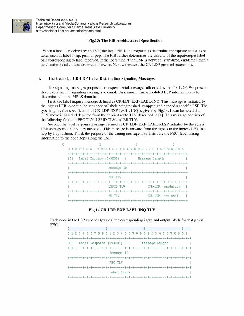
ii. The Extended CR-LDP Label Distribution Signaling Massages
The signaling messages proposed are experimental messages allocated by the CR-LDP. We present
three experimental signaling messages to enable disseminate time-scheduled LSP information to be
disseminated to the MPLS domain.
First, the label inquiry message defined as CR-LDP-EXP-LABL-INQ. This message is initiated by
the ingress LER to obtain the sequence of labels being pushed, swapped and popped a specific LSP. The
type length value specification of CR-LDP-EXP-LABL-INQ is given by Fig.14. It can be noted that
TLV above is based id depicted from the explicit route TLV described in [4]. This message consists of
the following field: id, FEC TLV, LSPID TLV and ER TLV.
Second, the label response message defined as CR-LDP-EXP-LABL-RESP initiated by the egress
LER as response the inquiry message. This message is forward from the egress to the ingress LER in a
hop-by-hop fashion. Third, the purpose of the timing message is to distribute the FECc label timing
information to the node hops along the LSP.
Fig.14 CR-LDP-EXP-LABL-INQ TLV
Each node in the LSP appends (pushes) the corresponding input and output labels for that given
FEC.
Technical Report 2009-02-01 Internetworking and Media Communications Research Laboratories Department of Computer Science, Kent State University http://medianet.kent.edu/technicalreports.html
Fig.15: CR-LDP-EXP-LABL-RESP TLV
At completion of the label inquiry/response operations described earlier, the ingress
precisely estimate the flow (the task tc) arrival and departure times at each hop (LSRs and LERs)
along the LSP (the solution rc). Therefore, the ingress incorporates the label stack with the route
schedule utc to determine tc arrival and departure pair for each hop.
In addition, the label timing pairs are distributed to their corresponding hops using the
experimental message CR-LDP-EXP-TIMING.
Fig.16: CR-LDP-EXP-TIMING TLV
iii. The Extended CR-LDP Label Distribution Signaling Operations
The overall process of distributing time-scheduled LSP information to the MPLS domain
is performed by five operations: label request, label mapping, label inquiry, label response and label
timing.
We consider a task tc is as a data flow representing FECc from an ingress LER (uc) to an
egress LER (vc) and the solution rc (LSP) as solution to tc. Moreover, consider utc is the per-hop
schedule of tc via rc specifying the arrival and departure of each segment (packet) in tc at each hop
along rc. According to the context of MPLS, utc has to be disseminated to all node hops (LERs and
LSRs) along rc in order to determine the life time of the label values generated for FECc stored at
each node hop. In this section we describe the label inquiry, label response and label timing
signaling operations as protocol extensions to CR-LDP label distribution.
First, the purpose of the label inquiry operation to obtains the sequence of input/output
label at each hop along the LSP. This process is illustrated in Fig.17. It is shown that the label
inquiry operation initiated by the ingress LER (LER1). The ingress creates the label inquiry
message, where the explicit route consists of ordered hops LER1 (highlighted in yellow), LER2,
LSR1, LSR4, LSR5, LSR8, LSR10 and LER5.
In step-1, the ingress (LER1) builds the request message, pops its hop information from the explicit
route TLV and passes it to the next hop LER2. In step-2, LER2 receives the message, pops itself
from the explicit route TLV. Similar to step-2, steps 3 to 7 perform the same operations. In step-8,
the egress LER5 receives the message and initiates the label mapping process described in the
proceeding discussion.
Second, the label repose takes a place once the ingress the label request message. The purpose of
this operation is to forward the list of each label input/output pair in a each hop along a given LSP.
The label response message is initiated by the egress and is propagated towards the ingress in hop-
by-hop manner.
Technical Report 2009-02-01 Internetworking and Media Communications Research Laboratories Department of Computer Science, Kent State University http://medianet.kent.edu/technicalreports.html
The label response of the label inquiry scenario described previously is elaborated in
Fig.18. Label response involves three steps at each hop in the LSP starting at the egress and
ending at the ingress LERs. The LSR locks up the FIB for the corresponding input and output
labels for the inquired FEC. Label values obtained from the FIB are appended to the label
response message. Note that egress LSR creates the message and rest of the hops along LSP
appends the FIB label values until it reaches to the ingress LSR. The label response message is
forwarded to the next hop.
Fig.17: The Label Inquiry Messaging Operation
In step-1, LER5 locks up the input/output pair <127, -1> from its local FIB and creates a label
repose message. Due to the fact is the egress node the, there is no output label value; hence -1 is
given as null value. Next, LER5 pushes the pair into the label stack of the response message and
forward it to LSR10. In step-2, LSR10 receives the response message, locks up the input/output
<189, 127> pair from its local FIB. It pushes the pair into the message label stack. Afterwards,
LSR10 forwards the response message to LSR8. In step-3, LSR8 receives the response message
from LSR10, locks up the input/output <0, 189> pair from its local FIB. It pushes the pair into the
message label stack. Afterwards, LSR8 forwards the response message to LSR5.
In step-4, LSR5 receives the response message from LSR8, locks up the input/output <189, 0> pair
from its local FIB. It pushes the pair into the message label stack. Afterwards, LSR5 forwards the
response message to LSR4. In step-5, LSR4 receives the response message from LSR5, locks up the
input/output <0, 189> pair from its local FIB. It pushes the pair into the message label stack.
Afterwards, LSR4 forwards the response message to LSR1.In step-6, LSR1 receives the response
message from LSR4, locks up the input/output <153, 0> pair from its local FIB. It pushes the pair
into the message label stack. Afterwards, LSR1 forwards the response message to LER2.In step-7,
LER2 receives the response message from LSR1, locks up the input/output <85,153> pair from its
local FIB. It pushes the pair into the message label stack. Afterwards, LER2 forwards the response
message to LER1.In step-8, LER1 receives the response message from LER2, locks up the
input/output <0, 85> pair from its local FIB. It pushes the pair into the message label stack. Once
Technical Report 2009-02-01 Internetworking and Media Communications Research Laboratories Department of Computer Science, Kent State University http://medianet.kent.edu/technicalreports.html
the stack of all labels is obtained the ingress node is capable of distributing the temporal
information to each node hop along the LSP.
Fig.18: The Label Response Messaging Operation
Third, the label timing takes a place once the route server receives the label sequence Lai. The
route server builds the label timing schedule Ω, which holds the label starting and ending time
pairs the for a data transfer request representing a FEC.
By referring back to the label inquiry/response scenarios, the ingress LER incorporates the label
stack with the route schedule utc computed for the tc via rc. Assume that utc schedule from the
ingress to the egress nodes is given as follows <1, 2>, <5, 6>, <9, 10>, <14, 15>, <20, 21>, <25,
26>, <31, 32>, <35, 36>.
The label timing update process scenario is elaborated in Fig.15. Note that we only elaborate label
stack field. At each hop starting from the ingress, the local FIB is updated with the task arrival and
departure field. Next, the label timing message is forwarded to the next hop towards the egress
node after two entries are extracted. The first is the hop from the ER field and second is the
corresponding timing entries from the label stack.
In step-1, the ingress node builds the label timing message containing the label stack and the ER
field containing the complete path from LER1 to LER5. LER1 extracts its corresponding hop from
the ER hop and extracts the pair <1, 2> from the label stack. The corresponding entry to (LSPID =
10) in the FIB is updated with <ARR-TIME = 1, DEP-TIME = 2>. Next, LER1 forwards the label
timing message to LER2.
In step-2, the LER2 receives the timing message from LER1 and extracts its corresponding hop
from the ER hop and extracts the pair <5, 6> from the label stack. The corresponding entry to
Technical Report 2009-02-01 Internetworking and Media Communications Research Laboratories Department of Computer Science, Kent State University http://medianet.kent.edu/technicalreports.html
(LSPID = 10) in the FIB is updated with <ARR-TIME = 5, DEP-TIME = 6>. Next, LER2
forwards the label timing message to LSR1.
In step-3, the LSR1 receives the timing message from LER2 and extracts its corresponding hop
from the ER hop and extracts the pair <9, 10> from the label stack. The corresponding entry to
(LSPID = 10) in the FIB is updated with <ARR-TIME = 9, DEP-TIME = 10>. Next, LSR1
forwards the label timing message to LSR4.
Fig.19: The Label Timing Messaging
In step-4, the LSR4 receives the timing message from LSR1 and extracts its corresponding hop
from the ER hop and extracts the pair <14, 15> from the label stack. The corresponding entry to
(LSPID = 10) in the FIB is updated with <ARR-TIME = 14, DEP-TIME = 15>. Next, LSR4
forwards the label timing message to LSR5.
In step-5, the LSR5 receives the timing message from LSR4 and extracts its corresponding hop
from the ER hop and extracts the pair <20, 21> from the label stack. The corresponding entry to
(LSPID = 10) in the FIB is updated with <ARR-TIME = 20, DEP-TIME = 21>. Next, LSR5
forwards the label timing message to LSR8.
In step-6, the LSR8 receives the timing message from LSR5 and extracts its corresponding hop
from the ER hop and extracts the pair <25, 26> from the label stack. The corresponding entry to
(LSPID = 10) in the FIB is updated with <ARR-TIME = 25, DEP-TIME = 26>. Next, LSR8
forwards the label timing message to LSR10.
In step-7, LSR10 receives the timing message from LSR8 and extracts its corresponding hop from
the ER hop and extracts the pair <31, 32> from the label stack. The corresponding entry to (LSPID
= 10) in the FIB is updated with <ARR-TIME = 31, DEP-TIME = 32>. Next, LSR10 forwards the
label timing message to LER5.
Technical Report 2009-02-01 Internetworking and Media Communications Research Laboratories Department of Computer Science, Kent State University http://medianet.kent.edu/technicalreports.html
In step-8, LER5 (egress) receives the timing message from LSR10 and extracts its corresponding
hop from the ER hop and extracts the pair <35, 36> from the label stack. The corresponding entry
to (LSPID = 10) in the FIB is updated with <ARR-TIME = 35, DEP-TIME = 36>. By the
completion of this process, the LSP between LER1 and LER5 become time-scheduled.
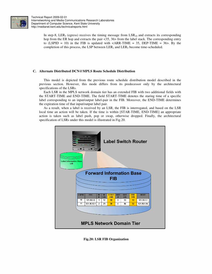
C. Alternate Distributed DCN@MPLS Route Schedule Distribution
This model is depicted from the previous route schedule distribution model described in the
previous section. However, this mode differs from its predecessor only by the architectural
specifications of the LSRs.
Each LSR in the MPLS network domain tier has an extended FIB with two additional fields with
the START-TIME and END-TIME. The field START-TIME denotes the staring time of a specific
label corresponding to an input/output label-pair in the FIB. Moreover, the END-TIME determines
the expiration time of that input/output label pair.
As a result, when a label is received by an LSR, the FIB is interrogated, and based on the LSR
local time an action will be taken. If the time is within [STAR-TIME, END-TIME] an appropriate
action is taken such as label push, pop or swap, otherwise dropped. Finally, the architectural
specification of LSRs under this model is illustrated in Fig.20.
Fig.20: LSR FIB Organization
Technical Report 2009-02-01 Internetworking and Media Communications Research Laboratories Department of Computer Science, Kent State University http://medianet.kent.edu/technicalreports.html
VIII. Conclusion and Future Work
The Internet2 networking model will be the future determinant of network backbone
infrastructures, services and applications trends of the next Internet era. Next generation Internet
backbones infrastructures will be high-performance proving network capacities beyond the limits of
imagination reaching Terabits per second. Given their capabilities, Internet applications will become
bandwidth-intensive demanding massive data transmission volumes in the orders of Terabytes per day.
Moreover, on-demand time-scheduled services will become the trend of high-performance Internet
services.
Based on the near future trends, it is strongly anticipated that the Dynamic Circuit Networking
(DCN) is the key networking model of the next generation Internet infrastructures. The DCN is further
envisioned to be the model of the future high-performance commercial Internet services. As a result,
emerging switching-routing protocols like MPLS would enable on-demand
DC-based services transparently at the network and transportation levels.
On-demand network arbitration forms an interesting challenge to DCN architecture and protocol
design. This is because of its two sub-problems. The former is algorithmic, which is task of finding the
optimal dynamic circuit between the source and the destination nodes. The latter is protocol-mechanic,
which is the problem if collecting and disseminating route schedule information from and to the DCN
domain.
In this technical report, we presented a network architectural model that implements dynamic
circuit operation DCN at the Multi Protocol Labeling Switching MPLS domains namely DCN@MPLS.
In addition, the MPLS protocol extensions are implemented by the DCN@MPLS route scheduling tier.
These protocol extensions determine the set of label message signaling that enables time-scheduled
route information to be distributed to the MPLS domain. More particularly, these extensions are related
to the label distribution process handling Constraint-Routing Label Distribution Protocol (CR-LDP).
On the bases of the achieved contributions described throughout this work, we have arrived to the
following conclusions. First, DCN is strongly anticipated to the be networking model of the Terabit
Internet era and on-demand routing paradigm will be a predominant aspect. Second, on-demand
routing in DCN environments is an instance of scheduling problem, whose heuristic solution aims to
optimize the objective function through incorporating four key operations: task scheduling, optimal
routing, per-hop schedule computation and resource allocation. Third, the expandability of the MPLS
architecture and the CR-LDP protocol seamlessly enables DCN operation at MPLS. Therefore, the
DCN@MPLS architecture has achieved the advantage to be the unprecedented commercial DCN
model of tomorrow’s high-performance Internet services.
The future works aim to extend the research goals achieved in this work and yet propose new
DCN-based networks model. In the future research projects we will focus on achieving two
contributions. Simulating the DCN@MPLS architecture, we will examine two types of heuristics: task
selection (H1) and optimal route computation (H2). We will conduct a number of commercial DCN-
based scenarios using the DCN@MPLS simulator to evaluate the performance of H1 and H2
heuristics. Beyond the scheduling-based DCN@MPLS routing, we further identify a new challenge
related to role of resource limitedness on the overall QoS and its influence of scalability. We remodel a
sharable scheduling-based routing scheme that envisions the DCN as an instance of Disruption
Tolerant Network (DTN), namely Disruption Tolerant-DCN (DT-DCN). According to the DTN
context, link intermittency is logical due to the resource sharable aspect, which limits the link
availability time periods. Never the less, such intermittency is predictable and hence a set of store-and-
forward based per-hop route scheduling algorithms are to be proposed. Finally, after achieving the
latter research contributions, we look forward to build a physical testbed of DCN@MPLS over the
Technical Report 2009-02-01 Internetworking and Media Communications Research Laboratories Department of Computer Science, Kent State University http://medianet.kent.edu/technicalreports.html
[2] Internet2 Consortium, “Internet2’s Dynamic Circuit Network”, public document, url:
www.internet2.edu/pubs/200710-IS-DCN.pdf ,2008.
[3] Rosen E., Viswanathan A. and Callon R., “Multiprotocol Label Switching Architecture”,
RFC 3031, January, 2001.
[4] Jamoussi B., Andersson L., Callon R., Dantu R., Wu L., Doolan P., Worster T., Feldman N.,
Fredette A., Girish M., Gray E., Heinanen J., Kilty T. and Malis A. “Constraint-Based LSP
Setup using LDP”, RFC 3212, January 2002.
[5] The PlanetLab Planetary Network, url:www.planet-lab.org, 2008.