40
DCS 400 INSTALLATION AND SERVICE MANUAL

DCS 400
INSTALLATIONAND
SERVICE MANUAL

N O T I C E
The use of the suspension type fertilizers and lime slurries willsignificantly reduce the life of the plastic parts in the FlowMeter and motorized Control Valve. Check the rotor and inlet hubassembly in the Flow Meter frequently for worn parts. Excessivewear can affect accuracy.
Do not attempt to modify or lengthen any of the three-wire SpeedSensor or Flow Meter cables. Extension cables are available fromyour dealer.
W A R N I N G
Disconnect console before jump starting, charging battery, orwelding on equipment.
1
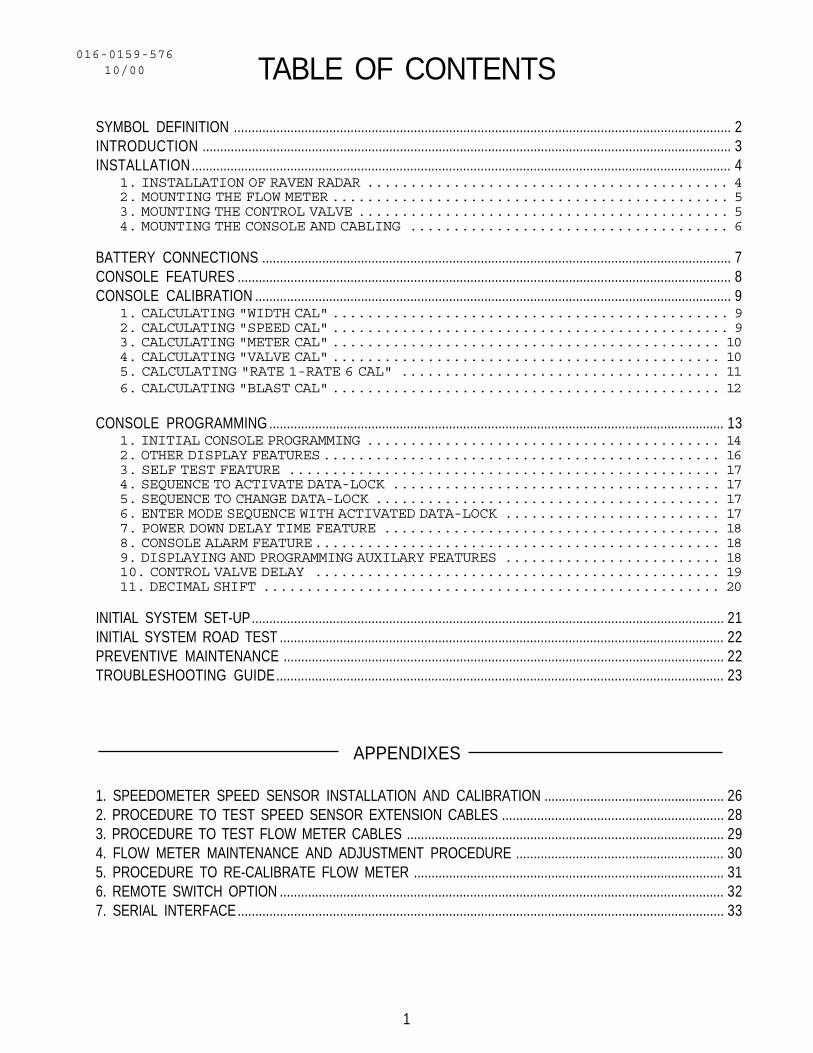
TABLE OF CONTENTS
SYMBOL DEFINITION ............................................................................................................................................. 2INTRODUCTION ...................................................................................................................................................... 3INSTALLATION......................................................................................................................................................... 4
1. INSTALLATION OF RAVEN RADAR .......................................... 42. MOUNTING THE FLOW METER .............................................. 53. MOUNTING THE CONTROL VALVE ........................................... 54. MOUNTING THE CONSOLE AND CABLING ..................................... 6
BATTERY CONNECTIONS ..................................................................................................................................... 7CONSOLE FEATURES ............................................................................................................................................ 8CONSOLE CALIBRATION ....................................................................................................................................... 9
1. CALCULATING "WIDTH CAL" .............................................. 92. CALCULATING "SPEED CAL" .............................................. 93. CALCULATING "METER CAL" ............................................. 104. CALCULATING "VALVE CAL" ............................................. 105. CALCULATING "RATE 1-RATE 6 CAL" ..................................... 116. CALCULATING "BLAST CAL" ............................................. 12
CONSOLE PROGRAMMING ................................................................................................................................. 131. INITIAL CONSOLE PROGRAMMING ......................................... 142. OTHER DISPLAY FEATURES.............................................. 163. SELF TEST FEATURE .................................................. 174. SEQUENCE TO ACTIVATE DATA-LOCK ...................................... 175. SEQUENCE TO CHANGE DATA-LOCK ........................................ 176. ENTER MODE SEQUENCE WITH ACTIVATED DATA-LOCK ......................... 177. POWER DOWN DELAY TIME FEATURE ....................................... 188. CONSOLE ALARM FEATURE............................................... 189. DISPLAYING AND PROGRAMMING AUXILARY FEATURES ......................... 1810. CONTROL VALVE DELAY ............................................... 1911. DECIMAL SHIFT ..................................................... 20
INITIAL SYSTEM SET-UP...................................................................................................................................... 21INITIAL SYSTEM ROAD TEST .............................................................................................................................. 22PREVENTIVE MAINTENANCE ............................................................................................................................. 22TROUBLESHOOTING GUIDE............................................................................................................................... 23
016-0159-57610/00
APPENDIXES
1. SPEEDOMETER SPEED SENSOR INSTALLATION AND CALIBRATION ................................................... 262. PROCEDURE TO TEST SPEED SENSOR EXTENSION CABLES ............................................................... 283. PROCEDURE TO TEST FLOW METER CABLES .......................................................................................... 294. FLOW METER MAINTENANCE AND ADJUSTMENT PROCEDURE ........................................................... 305. PROCEDURE TO RE-CALIBRATE FLOW METER ........................................................................................ 316. REMOTE SWITCH OPTION .............................................................................................................................. 327. SERIAL INTERFACE.......................................................................................................................................... 33

2
SYMBOL DEFINITION
METER CAL CONVERSIONS
To convert the METER CAL number simply divide the original number (number printedon Flow Meter label) by the desired conversion factor.
FOR EXAMPLE:
Original METER CAL No. = METER CAL No. for displays in Fluid Ounces 128
Original METER CAL No. = METER CAL No. for displays in Liters 3.785
Original METER CAL No. = METER CAL No. for displays in PoundsWeight of one gallon
LIQUID CONVERSIONSU.S. Gallons x 128 = Fluid OuncesU.S. Gallons x 3.785 = LitersU.S. Gallons x 0.83267 = Imperial GallonsU.S. Gallons x 8.34 = Pounds (Water)
LENGTH1 millimeter (mm) = 0.039 inch1 centimeter (cm) = 0.393 inch1 meter (m) = 3.281 feet1 kilometer (km) = 0.621 mile1 inch = 25.4 millimeters; 2.54 centimeters1 mile = 1.609 kilometers1 mile = 5280 feet
PRESSURE1 psi = 6.89 kPa1 kPa = 0.145 psi
AREA1 square meter = 10.764 square feet1 hectare (ha) = 2.471 acres; 10,000 square meters1 acre = 0.405 hectare; 43,560 square feet1 square mile = 640 acres; 258.9 hectares
GPM - Gallons per minutelit/min - Liters per minutedl/min - Deciliter per minutePSI - Pounds per square inchkPa - KilopascalGPK - Gallons per 1,000 sq. ft.mm - Millimeterscm - Centimetersdm - Decimetersm - Meter
gal - Gallonslit - LitersMPH - Miles per hourkm - Kilometerskm/h - Kilometers per hourUS - Volume per lane mileSI - Volume per lane kilometerTU - Volume per 1,000 sq. ft.[] - Metric numbers{} - 1,000 sq. ft. numbers
3
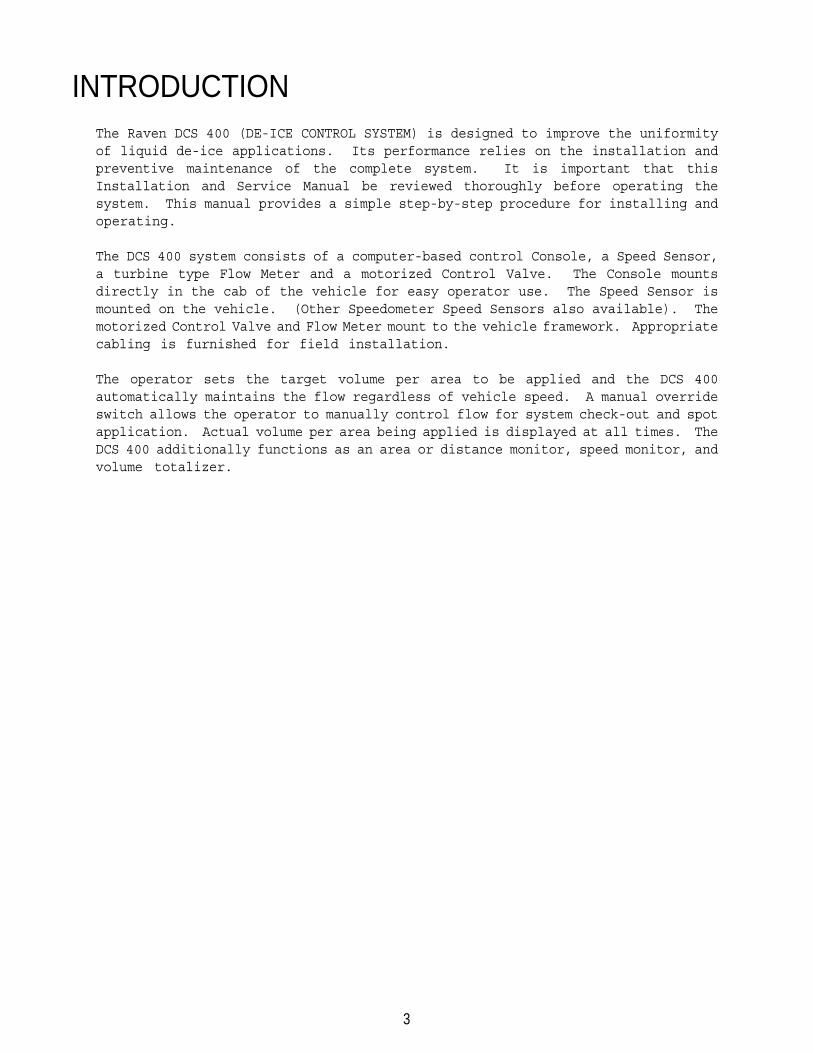
INTRODUCTIONThe Raven DCS 400 (DE-ICE CONTROL SYSTEM) is designed to improve the uniformityof liquid de-ice applications. Its performance relies on the installation andpreventive maintenance of the complete system. It is important that thisInstallation and Service Manual be reviewed thoroughly before operating thesystem. This manual provides a simple step-by-step procedure for installing andoperating.
The DCS 400 system consists of a computer-based control Console, a Speed Sensor,a turbine type Flow Meter and a motorized Control Valve. The Console mountsdirectly in the cab of the vehicle for easy operator use. The Speed Sensor ismounted on the vehicle. (Other Speedometer Speed Sensors also available). Themotorized Control Valve and Flow Meter mount to the vehicle framework. Appropriatecabling is furnished for field installation.
The operator sets the target volume per area to be applied and the DCS 400automatically maintains the flow regardless of vehicle speed. A manual overrideswitch allows the operator to manually control flow for system check-out and spotapplication. Actual volume per area being applied is displayed at all times. TheDCS 400 additionally functions as an area or distance monitor, speed monitor, andvolume totalizer.

4
INSTALLATION1. INSTALLATION OF RAVEN RADAR
For mounting the radar, the following guidelines will assure proper installation:It is suggested that a large heavy mounting bracket, (P/N 107-0159-693) be attachedto the vehicle frame for mounting the radar. (See Appendix 1 for Speedometer SpeedSensor installation instructions).
1) Park vehicle on level surface.
2) Select mounting site by considering the following:a) The line of sight from the lens to the ground must not be obstructed bystructures or tires. Obstructions must not come closer than 20 inches to thebottom of the Radar. See Figures 1 and 2.b) The radar lens must be parallel to the ground from front to back. Radarcan be tilted out 0-15 degrees to provide more clearance and miss obstructions.See Figure 2.c) The radar should be mounted so that the length of the radar is parallel withdirection of vehicle travel.
3) Use carpenters level to verify that mounting bracket is parallel to the ground.
4) Bolt mounting bracket to implement.
5) Bolt radar to mounting bracket using mounting hardware. See Figure 3.
6) Connect radar with Radar Interface Cable (P/N 115-0159-539), to the DCS 400Console. The Red wire should be connected to the Orange cable wire. The Whitewire should be connected to the White cable wire. (See Figure 5 on page 7).
CAUTION: The connection of the radar power in reverse polarity could result indamage to the radar.
FIGURE 1 FIGURE 3
FIGURE 2

5
2. MOUNTING THE FLOW METER
1) Mount Flow Meter horizontally using bracket per Figure 4. All flow throughFlow Meter must go to booms only, i.e., no return line to tank or pump after FlowMeter.
2) For best results, allow a minimum length of 7 1/2 inches of straight hose oninlet of Flow Meter. Bend radius of hose on outlet of Flow Meter should be gradual.
3) Flow must be in direction of arrow on Flow Meter.
FIGURE 4
NOTE: It is essential, when using suspensions, that the system be thoroughlyrinsed out each day after use.
3. MOUNTING THE CONTROL VALVE
1) Mount the motorized Control Valve in the main hose line between the Flow Meterand the booms valves, with motor in the upright position.
2) Connect the Flow Control Cable connectors to Flow Meter, Motorized ControlValve, and boom valves. (Black wire to left boom valve, Brown to center boom valve,and Blue to right boom valve).

6
4. MOUNTING THE CONSOLE AND CABLING
1) Mount the Console to a secure support inside the cab of the vehicle.
2) Connect the Console Control Cable to the plug in the back of the Console.(Reference Figure 5). Route the Console Control Cable out of the vehicle cab andterminate. (Flow Meter extension cables are available from your Dealer).
FIGURE 5
3) Turn POWER ON/OFF switch OFF and route the Red and White battery wires to a12-volt battery. Attach the White battery wires to the NEGATIVE (-) terminal andthe Red battery wire directly to the POSITIVE (+) battery terminal. (See Figure6 on page 8). (DO NOT CONNECT RED AND WHITE WIRES TO THE STARTER). Secure thebattery wires with plastic cable ties. DO NOT tie the battery wires close to theexisting battery leads or any other electrical wiring.
4) Connect the Speed Sensor to the plug in the back of the Console.
5) Secure and tie the Speed Sensor Cable and the Console Control Cable with plasticcable ties.
6) Initial installation of the system is now complete.

7
BATTERY CONNECTIONS
FIGURE 6

8
CE -Use like you do the CE key ona calculator. This key is alsoused to select the features listedin IMPORTANT box above.
CONSOLE FEATURESIMPORTANT: This Console requires selection of US (lane miles), SI [lane km], orTU {1,000 sq. ft.} area; and C-Sd (Standard Valve), C-F (Fast Valve), or C-FC (FastClose Valve); and SP1 (wheel drive, etc.) or SP2 (radar) speed sensor.
ENTER -Used only to enter data intothe Console.
Displays function and calibrationdata.
Booms can be controlled individually,or all at once with MASTER ON/OFFswitch.
Displays operating rate ofapplication.
CALIBRATION KEYS -- Used to enter data into theConsole to calibrate the system.
WIDTH CAL -- Length of BOOM and Lane Width.Select by using up and downarrows.
SPEED CAL -- Determined by Speed SensorMETER CAL -- Flow Meter Calibration NumberVALVE CAL -- Valve Response TimeRATE CAL -- Target Application Rate,
Rate 1-6BLAST CAL -- Target Application Blast Rate
and Blast TimeSELF TEST -- Simulates Vehicle Speed
FUNCTION KEYS -- Used to Display Data
TOTAL AREA -- Total Area AppliedTOTAL VOLUME -- Total Volume AppliedDAY AREA -- Day Area AppliedDAY VOLUME -- Day Volume AppliedDISTANCE -- Distance TraveledSPEED -- Speed of VehicleVOLUME/TANK -- Volume Remaining in Carrier TankTIME -- 24 Hour Clock (Military Time)VOL/MIN -- Volume per MinuteAREA/HOUR -- Area per HourDATA/MENU -- Print Data
POWER -Turns Console power ON orOFF. Turning Console OFF does notaffect the data stored in thecomputer.
Manual override control providescapability for spot spraying.
Select manual or fully automaticcontrol. Can automatically control6 rates.
BLAST button provides change in rateto volume per minute for a selectedamount of time.
Console Revision can be determined by theletter stamped in REV box on label.
Console Program can be determined by theletter stamped in PGM box on label.

9
2. CALCULATING "SPEED CAL"
Initial SPEED CAL is 598 [152]. Complete Steps 1 thru 6 to refine this numberAFTER INITIAL CONSOLE PROGRAMMING, on page 15, has been completed.
1) Set POWER switches to ON, all other switches to OFF.
2) Enter "0" in key labelled:
3) Drive 1 mile [1 kilometer]. To achieve the most accurate calibration,accelerate and decelerate slowly. (CAUTION: Do not use vehicle odometer todetermine distance. Use section lines or highway markers).
4) Read DISTANCE by depressing key labelled:
Distance should read a value of approximately 5280 [1000]. If it reads between5260-5300 [990-1010], the SPEED CAL for the vehicle is 598 [152]. If the DISTANCEdisplay reads any other value, perform the following calculation:
EXAMPLE: Assume DISTANCE reads 5000 [980].
Corrected SPEED CAL = Old SPEED CAL x 5280 DISTANCE
ENGLISH UNITS: METRIC UNITS:= 598 x 5280 = 631.5 = [152] x [1000] = [155] 5000 [980]
5) The number to enter for SPEED CAL is 631 [155].
6) Recheck the new SPEED CAL derived in Step 5 by repeating Steps 2 thru 5.
CONSOLE CALIBRATION1. CALCULATING "WIDTH CAL"
Calculate the width of each boom in inches [cm] by multiplying the number of tipstimes the spacing. Write these boom widths down for future reference whenprogramming the Console.
FIGURE 7

10
3. CALCULATING "METER CAL"
The Flow Meter calibration number is stamped on the tag attached to each Flow Meter.Write down this number for future reference when programming the Console computer.
To convert original METER CAL from gallons to desired units of measure (oz, lbs,or liters per area), see METER CAL CONVERSIONS on page 3. Write down thiscalibration number for future reference when programming the Console.
Valve Backlash Digit -- Controls the time of the first correction pulse aftera change in correction direction is detected.(INC to DEC -or- DEC to INC).
Range: 1 to 9 1-Short Pulse, 9-Long Pulse
Valve Speed Digit -- Controls response time of Control Valve motor.CAUTION: Running the Control Valve too fast will causethe system to oscillate.
C-Sd Valve Control Range: 1 to 9 1-Slow, 9-FastC-F or C-FC Valve Control Range: 0 to 9 9-Slow, 0-Fast
Brake Point Digit -- Sets the percent away from target rate at which theControl Valve motor begins braking, so as not toovershoot the desired rate.
Range: 0 to 9 0 = 5%, 1 = 10%, 9 = 90%
Dead-Band Digit -- Allowable difference between target and actualapplication rate, where rate correction is notperformed.
Range: 1 to 9 1 = 1%, 9 = 9%
For STANDARD VALVE (C-Sd): For FAST VALVE (C-F or C-FC):
4. CALCULATING "VALVE CAL"
1) The initial Control Valve calibration number is 2123 for C-Sd, 743 for C-F orC-FC. After operating the system, you may desire to refine this number. Seedefinitions below.

11
5. CALCULATING "RATE 1 - RATE 6 CAL"
Determine the application rate at which your chemical should be applied. Consultwith your Dealer to ensure your spray nozzles are capable of applying at this rate.
In determining which spray nozzles to use with your sprayer, you must know:
1) Nominal Application Pressure ___ PSI [kpa]2) Target Application Rate ___ gal/lane mile [lit/lane km]3) Target Speed ___ MPH [km/h]4) Nozzle Spacing ___ inches [cm]5) Lane Width ___ feet [meters]
From this information you can then calculate the volume per minute per nozzle asfollows:
GPM = (gal/lane mile) x MPH X inches (720 x lane width)
If Lane Width = 0GPM = (gal/mile) x MPH
60 x (# of tips)
lit/min = (lit/lane km) x (km/hr) x cm (6000 x Lane Width)
If Lane Width = 0lit/min = (lit/km) x (km/hr)
60 x (# of tips)
TurfGPM = GPK x MPH x inches
137
EXAMPLE: 1) Application Pressure = 30 PSI [200 kPa]2) Target Application Rate = 20 gal/lane mile [40 lit/lane km]3) Target Speed = 5.2 MPH [10 km/h]4) Nozzle Spacing = 20 inches [50 cm]5) Lane Width = 8 feet [2 m]
US UNITS GPM = 20 gal/lane mile x 5.2 MPH x 20 inches = .36 720 x 8 ft
SI UNITS [lit/min] = 40 lit/lane km x 10 km/h x 50 cm = 1.67 6000 x 2 m
Turf GPM = .46 GPK x 5.2 MPH x 20 inches = .35 137
Using CAPACITY = .35 GPM [1.67 lit/min] and pressure = 30 PSI [200 kPa], you wouldselect tip number XR8004 from the chart on next page, since it comes closest toproviding the desired output.

12
* Chart data from Spraying Systems Company
VERIFYING FLOW RATE LIMITS:
The flow rate of application must be within the range of that specified for theFlow Meter.
FLOW METER MODEL FLOW RANGERFM 5 0.05-5 GPM [0.2-18.9 lit/min]RFM 15 0.3-15 GPM [1.1-56.8 lit/min]RFM 55/55A 1-55 GPM [3.8-208 lit/min]RFM 100 3-100 GPM [11.4-379 lit/min]RFM 200/200 Poly 15-200 GPM [56.8-757 lit/min]RFM 400 25-400 GPM [94.6-1514 lit/min]
6. CALCULATING "BLAST CAL"
Blast rate entered into BLAST CAL is the application rate in GPM [lit/min] of thesystem when the BLAST button is depressed.
Blast time entered into BLAST CAL is the length of time in seconds that sprayingat the GPM [lit/min] blast rate will continue after the BLAST button is released.

13
CONSOLE PROGRAMMINGWhen entering data into the Console, the entry sequence is always the same. (NOTE:DATA MUST BE ENTERED INTO KEYS 3 THRU 8).
Depress the keys correspond-ing to the number you wish toenter (i.e. "5","7","2").The numbers will be dis-played as they are entered.
Complete the entry by againdepressing the ENTER key.
Depress the key in whichyou wish to enter data.
Depress the ENTER key. An"E" will illuminate in theDATA display.

14
1. INITIAL CONSOLE PROGRAMMING
When you first turn on Console power, after all installation procedures have beencompleted, the Console will flash "CAL" in the RATE display. This means you must"calibrate", or program, the Console before it can be operated. This is a one-time operation which does not have to be repeated. Turning OFF the POWER ON/OFFswitch does not affect the Console memory. All data is retained.
IMPORTANT: If an entry selection error is made during Steps 1-6, place the POWER
ON/OFF switch to OFF. Depress and hold while placing the POWER ON/OFF
switch to ON. This will "reset" the Console. The DATA display will show "US",and the RATE display will show "CAL". The following steps must be followed:
1) Display US (lane miles), SI [lane kilometer], or TU {1000 sq. ft.}.
a) Depressing momentarily steps the DATA display from US to SI.
b) Depressing momentarily steps the DATA display from SI to TU.
c) Depressing momentarily steps the DATA display from TU to US.
2) Selecting US, SI, or TU.a) To select US, SI, or TU, step until the desired code is displayedin DATA display.
b) Momentarily depress . The DATA display will now display SP1.
3) Display SP1 (wheel drives, speedometer, etc.) or SP2 (radar sensors).
a) Depressing momentarily steps the DATA display from SP1 to SP2.
b) Depressing momentarily steps the DATA display from SP2 to SP1.
4) Selecting SP1 or SP2.a) To select SP1 or SP2, step with until desired code is displayed inDATA display.
b) Momentarily depress . The DATA display will now display C-Sd.
5) Display C-Sd (Standard Valve), C-F (Fast Valve), or C-FC (Fast Valve Close).
a) Depressing momentarily steps the DATA display from C-Sd to C-F.
b) Depressing momentarily steps the DATA display from C-F to C-FC.
c) Depressing momentarily steps the DATA display from C-FC to C-Sd.

15
6) Selecting C-Sd, C-F, or C-FC.a) To select C-Sd, C-F, or C-FC step until desired code is displayed.
b) Momentarily depress . The DATA display will now display CAL.
7) Procedure to enter WIDTH CAL:Definition of keys:
Depressing this key displays boom section or lane width in DATA display.EXAMPLE: Lane width will be displayed as LANE, left boom will be displayedas b-L, center boom will be displayed as b-C, and right boom will bedisplayed as b-R. Use up or down arrow keys to toggle between thedifferent boom sections and lane width.
Depressing this key allows you to toggle up the different entries withinWIDTH CAL, RATE CAL, and BLAST CAL.
Depressing this key allows you to toggle down the different entrieswithin WIDTH CAL, RATE CAL, and BLAST CAL.
8) If the application rate is in gal/mile [lit/km], enter "0" for LANE. Left,center, and right booms do not need any value entered.
NOTE: When application rate is in gal/mile [lit/km], the Console WILL NOT adjustflow when turning individual booms ON or OFF.
If the application rate is in gal/lane mile [lit/lane km], enter in the actuallane width in feet [meters] for LANE.
lane mile = lane width x 5280 feet[lane km = lane width x 1000 meters]
Enter in the boom widths calculated per page 10 for b-L, b-C, and b-R. If onlyone or two booms are being used, enter a "0" for any unused booms.
NOTE: When application rate is in gal/lane mile [lit/lane km], the Console willadjust flow when turning individual booms ON or OFF.
9) Enter SPEED CAL in key labelled:
10) Enter METER CAL calibration number in key labelled:
11) Enter VALVE CAL calibration number: C-Sd (2123) in key labelled: C-F (0743) C-FC (0743)
12) Enter Application Rates 1-6 in either gal/mile or gal/lane mile ([lit/km]
or [lit/lane km]) in key labelled:
Use or to toggle between r-01 (rate 1) and r-06 (rate 6).
16
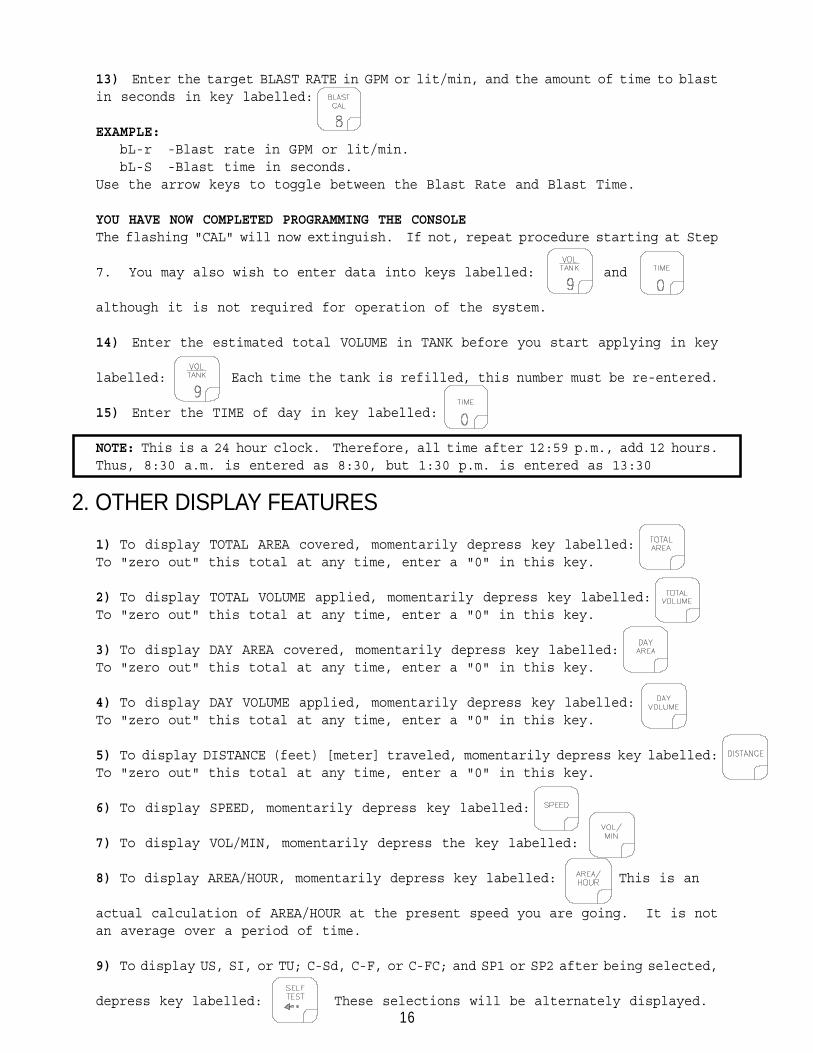
2. OTHER DISPLAY FEATURES
1) To display TOTAL AREA covered, momentarily depress key labelled:To "zero out" this total at any time, enter a "0" in this key.
2) To display TOTAL VOLUME applied, momentarily depress key labelled:To "zero out" this total at any time, enter a "0" in this key.
3) To display DAY AREA covered, momentarily depress key labelled:To "zero out" this total at any time, enter a "0" in this key.
4) To display DAY VOLUME applied, momentarily depress key labelled:To "zero out" this total at any time, enter a "0" in this key.
5) To display DISTANCE (feet) [meter] traveled, momentarily depress key labelled:To "zero out" this total at any time, enter a "0" in this key.
6) To display SPEED, momentarily depress key labelled:
7) To display VOL/MIN, momentarily depress the key labelled:
8) To display AREA/HOUR, momentarily depress key labelled: This is an
actual calculation of AREA/HOUR at the present speed you are going. It is notan average over a period of time.
9) To display US, SI, or TU; C-Sd, C-F, or C-FC; and SP1 or SP2 after being selected,
depress key labelled: These selections will be alternately displayed.
13) Enter the target BLAST RATE in GPM or lit/min, and the amount of time to blastin seconds in key labelled:
EXAMPLE:bL-r -Blast rate in GPM or lit/min.bL-S -Blast time in seconds.
Use the arrow keys to toggle between the Blast Rate and Blast Time.
YOU HAVE NOW COMPLETED PROGRAMMING THE CONSOLEThe flashing "CAL" will now extinguish. If not, repeat procedure starting at Step
7. You may also wish to enter data into keys labelled: and
although it is not required for operation of the system.
14) Enter the estimated total VOLUME in TANK before you start applying in key
labelled: Each time the tank is refilled, this number must be re-entered.
15) Enter the TIME of day in key labelled:
NOTE: This is a 24 hour clock. Therefore, all time after 12:59 p.m., add 12 hours.Thus, 8:30 a.m. is entered as 8:30, but 1:30 p.m. is entered as 13:30

17
3. SELF TEST FEATURE
SELF-TEST allows speed simulation for testing the system while vehicle is not
moving. Enter the simulated operating speed in key labelled:
If 6 MPH [10 km/h] is desired, enter 6.0 [10.0]. Verify SPEED by depressing
key labelled: The SELF-TEST speed will clear itself when motion of
vehicle is detected by the Speed Sensor. A SPEED CAL value of 900 [230] or
greater is recommended when operating in this mode.
NOTE: To prevent nuisance clearing of self-test speed, disconnect speedconnector on back of Console when Radar Speed Sensors are used.
4. SEQUENCE TO ACTIVATE DATA-LOCK
1) Depress for 5 seconds, NEW CODE message will appear.
2) Enter 4-digit code within 15 seconds. EXAMPLE: For 1085, depress:
and
5. SEQUENCE TO CHANGE DATA-LOCK
1) Depress for 5 seconds, OLD CODE message will appear.
2) Enter 4-digit code within 15 seconds.
and NEW CODE message will appear.
Enter 4-digit code within 15 seconds. EXAMPLE: For 1285, depress:
and
6. ENTER MODE SEQUENCE WITH ACTIVATED DATA-LOCK
1) Depress the key into which you wish to enter data.
2) Depress CODE message will appear. Enter your DATA-LOCK CODE. If CODE
is correct, an "E" will appear. Now enter data normally.
* The DATA-LOCK feature prohibits the entry of data without first entering theDATA-LOCK CODE. If DATA-LOCK is not desired, omit Steps 4, 5, and 6. The DATA-LOCK CODE may be cleared by entering a code of "0" or by resetting the Console.
18
9. DISPLAYING & PROGRAMING AUXILLARY FEATURESPRINT MENU
1) Console Data Printout.a) Depress key labelled: DATA display will show P-b (Print Field Begin).
To Print Field Begin, depress .
b) DATA display will now show P-E (Print Field End). To Print Field End, depress
key labelled:
c) While P-E is displayed, if Field Begin is required, depress to toggle
DATA display to P-b. Depress to Print Field Begin.
7. POWER DOWN DELAY TIME FEATURE
If the Console is not used for 10 days, it will go into a power down (low power)mode of operation. In this mode, all data will be retained, but the time of dayclock will be reset to 1:00. The delay is initially set at 10 days, but can bechanged by the user.
1) Displaying delay time.a) Depress key labelled: for 5 seconds, the current delay time (in days)will appear.
2) Changing delay time.a) Depress key labelled: for 5 seconds, the current delay time willappear.
b) Enter new delay time (0 to 200 days) using the same procedure as that forentering other data.
NOTE: When resetting the Console, the delay time will be reset to 10 days.
8. CONSOLE ALARM FEATURE
Console alarm sounds if the application rate is 30% or more away from the targetapplication rate for more than 5 seconds. The "no speed" alarm is 3 beeps, 8 secondpause, then repeat.
ALARM MENU
1) To display ALARM MENU, depress key labelled: "A on" will be displayed in DATA display.
a) Depress momentarily stops the DATA display between "A on" and
"A off". "A on" means alarm is enabled, "A off" means alarm is disabled.
b) Depress to store selection and advance to DISPLAY MENU.

19
10. CONTROL VALVE DELAY
Depress until DATA display flashes. X 0 0 0
The left most digit is the Control Valve delay digit. This feature allows theuser to set a delay between the time the booms are turned on and when the consolebegins to control the flow rate. A value of 1-9 means a delay of 1-9 secondsrespectively. A value of 0 means no delay. This delay is only active if the timebetween turning off and turning on the booms is less than 30 seconds.
DISPLAY MENU ("d on" OR "d off")
1) Selecting "d on" or "d off" (enabling or disabling display smoothing).
a) To select "d on" or "d off" step with until desired code is displayedin DATA display.
b) "d on" means RATE displays application rate when actual rate is within apercentage of application rate. This percentage is determined by the thirddigit of VALVE CAL value as shown:
Break Point Digit(3rd digit) of VALVE CAL 2 1 2 3
0 = 1% + Deadband 5 = 25% + Deadband1 = 3% + Deadband 6 = 30% + Deadband2 = 7% + Deadband 7 = 35% + Deadband3 = 10% + Deadband 8 = 40% + Deadband4 = 20% + Deadband 9 = 45% + DeadbandActual rate is displayed if unit does not reach deadband within 10 seconds."d off" means RATE displays actual rate at all times.
c) Depress to store selection and advance to PRINT MENU.
Valve Control delay digit

20
11. DECIMAL SHIFT
The steps to programming the Console are the same as those described in the CONSOLEPROGRAMMING section of this manual except for METER CAL. It is during this entrythat the decimal point must be shifted to increase the accuracy of the system toaccommodate the application rates of low volume systems.
The following is an example of how a meter calibration constant of 730 would beentered:The sequence to shift the decimal is to depress key labelled:
Enter as the METER CAL constant.
The sequence to unshift the decimal is to omit the key labelled:
Simply enter the METER CAL constant:
Shifting the decimal permits a times 10 resolution of the data. The followingtable illustrates this resolution:
KEY UNSHIFTED SHIFTEDRATE DisplayRATE 1-6 CALBLAST RATE CALVOL/TANKTOTAL VOLUMEFIELD VOLUMEVOL/MIN
When entering RATE 1-6 CAL and BLAST RATE CAL, remember that 2 gal/lane mile [20lit/lane km] is entered as 2.00 [20.0].
00.00 00.00 00.00 000.0 000.0 000.0 000.0
000.0000.0000.00000000000000000
21
INITIAL SYSTEM SET-UP1) Fill tank with water only. (If positive displacement pump is used, open pressurerelief valve, PRV).
2) Place MASTER ON/OFF switch to ON and LEFT, CENTER, and RIGHT switches to OFF.
3) Place RATE switch to M (manual).
4) Place POWER ON/OFF switch to ON.
5) Verify that WIDTH CALS, SPEED CAL, METER CAL, VALVE CAL, RATE CALS, and BLASTCAL have been entered correctly into the Console. In SELF TEST mode, enter thenormal vehicle operating speed.
6) Run pump at normal operating RPM.
7) If centrifugal pump is used, proceed with Step 8. If positive displacementpump is used, set pressure relief valve (PRV) to 65 PSI [450 kPa].
8) Verify that boom valves operate and that no nozzles are plugged by operatingthe LEFT, CENTER, and RIGHT switches.
9) Place LEFT, CENTER, and RIGHT switches to ON.
10) Hold the MANUAL switch in INC position until pressure is at its maximum. Thisassures that the motorized Control Valve is fully open. Verify maximum pressureand RATE. (Pressure gauge is not supplied with the DCS 400).
NOTE: A pressure gauge MUST be installed to properly monitor the system.
11) Adjust agitator line hand valve for desired agitation. Verify maximum pressureis still present.
12) Hold the MANUAL switch to DEC position until pressure is at its minimum. Thisassures that the motorized Control Valve is fully closed. Verify minimum pressureand RATE.

22
INITIAL SYSTEM ROAD TEST1) Drive down road at target speed with all BOOM switches and MASTER switch OFF.Verify SPEED readout on Console.
2) Place MASTER and all BOOM switches ON. Place the RATE switch to 1 (one).Increase or decrease speed by 5 MPH [8 km/h]. The system should automaticallycorrect to the target application rate.
3) If for any reason, the system is unable to correct to the desired RATE, checkfor an empty tank, a plugged line, a malfunctioning pump, improper vehicle speed,or a defect in the system.
4) If the system does not appear to be correcting properly, first review INITIALSYSTEM SET-UP, then refer to SERVICE MANUAL and TROUBLESHOOTING GUIDE.
5) When stopping, switch the MASTER switch OFF to shut off flow. This also shutsoff the area totalizer. When C-FC is selected, and a Fast Close Control Valveis used, flow will shut off automatically when speed is zero.
6) Verify area covered and volume used.
PREVENTIVE MAINTENANCEPreventive maintenance is most important to assure long life of the system. Thefollowing maintenance procedures should be followed on a regular basis:
1) Flush entire system with water after use of suspension type chemicals. Failureto clean system can result in crystallization of chemicals which may plug theFlow Meter, lines, and/or tips.
2) Flush and drain system before storing. FREEZING TEMPERATURES MAY DAMAGE FLOWMETER IF WATER IS NOT DRAINED.
3) Remove Flow Meter at the end of each season. Clean Flow Meter turbine and inlethub. Clean off all metal filings and wettable powders which have hardened on theplastic and metal parts. Check the inlet hub and turbine assembly for worn ordamaged turbine blades and bearings. Flush Flow Meter with clear water and drain.
KEEP FROM FREEZING
4) Remove Console when not in use for extended periods.

23
TROUBLESHOOTING GUIDECORRECTIVE ACTION
1) Check fuse on back of Console2) Check battery connections.3) Check operation of POWER ON/OFF
switch.4) Return Console to your Dealer to
replace Processor Board Assembly.
1) Return Console to your dealer toreplace Face Plate Sub-assembly.
1) Return Console to your Dealer toreplace Face Plate Sub-assembly.
1) Return Console to your Dealer toreplace Face Plate Sub-assemblyand/or Processor Board Assembly.
1) Check battery voltage and batteryconnections.
1) Check battery voltage and batteryconnections.
1) Check battery voltage and batteryconnections.
1) Return Console to Dealer to replaceProcessor Board Assembly.
1) Return Console to Dealer to replaceLCD Display Board Assembly.
1) Check Speed Sensor cable connectorand plug on back of Console forloose pins.
2) Clean pins and sockets on SpeedSensor cable connectors.
3) If no extension cable is used,replace Speed Sensor.
4) If 24 foot Speed Sensor Extensioncable is used, see Appendix 2.
1) Wiggle cable at the Speed Sensorconnector. If speed is displayed,tighten connector or replaceTransducer Assembly.(cont. next page)
PROBLEM
1) NO DISPLAY LIGHTS WITH POWER ON.
2) ALL KEYBOARD LIGHTS ON AT SAMETIME.
3) A DIGIT CANNOT BE ENTERED VIAKEYBOARD.
4) AN INDICATOR LIGHT ON A KEY WILLNOT ILLUMINATE.
5) CONSOLE DISPLAYS FLASHING "CAL"WHENEVER VEHICLE ENGINE ISSTARTED.
6) CONSOLE DISPLAYS FLASHING "CAL"WHENEVER MASTER SWITCH IS TURNEDON OR OFF.
7) CONSOLE DISPLAYS FLASHING "CAL"WHENEVER SPEED IS CHANGED.
8) "TIME" FUNCTION IS INACCURATE ORDRIFTING.
9) ONE DISPLAY DIGIT HAS ONE ORMORE MISSING SEGMENTS.
10) SPEED DISPLAY "0"
11) SPEED INACCURATE OR UNSTABLE(SPEEDOMETER SPEED SENSOR).

24
12) RATE READS "0000".
13) RATE INACCURATE OR UNSTABLE.
14) CAN NOT VARY RATE IN MANUALOPERATION OR IN AUTO.
2) Check Speedometer Cable Adaptor,Key, and Transducer Assembly forproper connections and engagement.
3) Check for kinked Speedometer cableor too sharp of a bend.
4) Replace Speedometer TransducerAssembly.
1) Verify SPEED is registeringaccurately. If SPEED is zero,refer to Troubleshooting Problem10.
2) Verify TOTAL VOLUME is registeringflow. If not, refer to Troubleshooting Problem 16.
1) Verify that all numbers "keyed in"Console are correct. Verify SPEEDis registering accurately. IfSPEED is inaccurate, refer toTroubleshooting Problem 11.
2) In M (manual) operation, verifythat RATE display (GAL/lane mile)holds constant. If not, refer toTroubleshooting Problem 17.
3) In M (manual) operation, checklow end and high end pressurerange. Pressure range must be perInitial System Set-up on page 22.If pressure can not be adjustedmanually, refer to TroubleshootingProblem 16.
4) If problem persists, return Consoleto Dealer to replace ProcessorBoard Assembly.
1) Check cabling to motorized ControlValve for breaks.
2) Check connections in cabling forcleanliness.
3) Verify that there is voltage at thevalve connector by placing MASTERswitch ON; RATE switch to M; andPOWER switch to ON. Manuallyoperate INC/DEC switch to verifyvoltage.
4) Verify that valve is turning, ifnot, replace motorized ControlValve.

25
15) SPRAYER PRESSURE IS CORRECT BUTRATE IS LOW.
16) TOTAL VOLUME DOES NOT REGISTER.
17) TOTAL VOLUME REGISTERS FLOWINACCURATELY.
18) MOTORIZED CONTROL VALVE ROTATESMORE THAN 1/4 TURN.
19) WATER INSIDE COVER OF MOTORIZEDCONTROL VALVE.
20) BOOM VALVE(S) WILL NOT OPERATE.
1) Verify that nozzle strainerscreens or Check Valves are notplugged.
2) Verify that pressure at eachboom is the same.
3) Verify all nozzles are of properand same orifice size. See page13 of Installation Manual.
1) Check Flow Meter cable for breaksand shorts. See Appendix 3 for testprocedure.
2) Check internals of Flow Meter;clean and adjust. See Appendix 4for Flow Meter cleaning andadjustments.
3) Replace Flow Meter Transducer.
1) Verify that arrow on Flow Meter ispointing in direction of flow.
2) See Appendixes 4 and 5.
1) Replace motorized Control Valve.
1) Replace Isolation Flange Assy. andCoupler Shaft.
2) Replace entire motorized ControlValve, if PC Board or Motor iscorroded and will not run.
1) Check cable for wires with breaks.2) Check connectors for cleanliness.3) Check LEFT/CENTER/RIGHT and MASTER
switches for operation.4) Replace boom valves.

26
APPENDIX 1SPEEDOMETER SPEED SENSOR INSTALLATION AND
CALIBRATION
1) Remove the existing speedometer cable from the back of the vehicle speedometer.Pull cable through fire wall into engine compartment.
2) Install adapter and key on speedometer cable and connect to TransducerAssembly. (Some units do not use adapter and key).
3) Connect Extension Cable to Transducer Assembly.
4) Push Extension Cable through fire wall and re-install on speedometer.
5) Connect the cable on the Transducer Assembly to the Console.
6) Secure all Cables with plastic cable ties. The unit is now ready for calibrationwith your vehicle.
7) Complete INITIAL CONSOLE PROGRAMMING on page 15 before doing this procedure.
8) Enter "0" in key labelled:
9) Enter 612 [155] in key labelled:
10) Drive 1 mile [1 km]. (CAUTION: Do not use vehicle odometer to determinedistance. Use section lines or highway markers).
11) Read DISTANCE by depressing key labelled:

27
DISTANCE should read a value of approximately 5280 [1000]. If it reads between5200-5350 [990-1010], the SPEED CAL for your vehicle is 612 [155].
If the DISTANCE display reads any other value, divide SPEED CAL by the valueobserved in DISTANCE, then multiply by 5280 [1000]. This will give you the correctvalue to enter for SPEED CAL. You must round off to the nearest 3 digit number.
EXAMPLE: Assume DISTANCE read 5000 [980].
ENGLISH UNITS: METRIC UNITS:
= 612 x 5280 = 646.3 = [155] x 1000 = 158 5000 980
12) The number to enter for SPEED CAL is 646 [158].
13) Recheck the new SPEED CAL derived above.
a) Zero out DISTANCE display as in Step 8.
b) Enter the new SPEED CAL number as in Step 9.
c) Repeat Steps 10, 11, and 12.

28
APPENDIX 2PROCEDURE TO TEST SPEED SENSOR EXTENSION CABLES
Disconnect extension cable from Speed Sensor Assembly cable. Hold extension cableconnector so that keyway is pointing in the 12 o’clock position.
1) 2 o’clock socket is power.2) 10 o’clock socket is ground.3) 6 o’clock socket is signal.
VOLTAGE READINGS
1) 10 o’clock to 6 o’clock (+5 VDC).2) 10 o’clock to 2 o’clock (+5 VDC).
Procedure to check cable: (NOTE: Console must be programmed with SP1 selected).
l) Enter SPEED CAL number of 1000 in key labelled:
2) Depress key labelled:
3) With small jumper wire (or paper clip), short between 10 o’clock and 6 o’clocksockets with a "short-no short" motion. This should cause a speed reading tobe displayed in the Console. Each time a contact is made, the DISTANCE totalshould increment up 1 or more counts.
4) If DISTANCE does not count up, remove the section of cable and repeat test atconnector next closest to console. Replace defective cable as required.
5) Perform above voltage checks.
6) If all cables test good, replace speed sensor.
NOTE: After testing is complete, re-program Console with correct SP1/SP2 selectedif needed. Re-enter correct SPEED CAL number before application.

29
APPENDIX 3PROCEDURE TO TEST FLOW METER CABLES
Disconnect cable from Flow Meter. Hold Flow Meter cable so that the keyway ispointing in the 12 o’clock position:
1) 2 o’clock socket is ground.2) 10 o’clock socket is power.3) 6 o’clock socket is signal.
VOLTAGE READINGS
1) 2 o’clock to 6 o’clock (+5 VDC).2) 2 o’clock to 10 o’clock (+5 VDC).
Procedure to check cable:
1) Enter a METER CAL number of one (1) in key labelled:
2) Depress key labelled:
3) Place LEFT/CENTER/RIGHT and MASTER switches ON.
4) With small jumper wire (or paper clip), short between 2 o’clock and 6 o’clocksockets with a "short-no short" motion. Each time a contact is made, the TOTALVOLUME should increment up 1 or more counts.
5) If TOTAL VOLUME does not count up, remove the section of cable and repeattest at connector next closest to Console. Replace defective cable as required.
6) Perform above voltage checks.
7) If all cables test good, replace Flow Meter.
NOTE: After testing is complete, re-enter correct METER CAL number beforeapplication.

30
APPENDIX 4FLOW METER MAINTENANCE AND ADJUSTMENT PROCEDURE
1) Remove Flow Meter from sprayer and flush with clean water to remove anychemicals.
2) Remove flange bolts from the Flow Meter.
3) Remove the turbine hub and turbine from inside Flow Meter.
4) Clean turbine and turbine hub of metal filings and any other foreign material,such as wettable powders. Confirm that the turbine blades are not worn. Holdturbine and turbine hub in your hand and spin turbine. It should spin freely withvery little drag.
5) If transducer (XDCR) assembly is replaced or if turbine stud is adjusted orreplaced, verify the turbine fit before reassembling. Hold turbine hub withturbine on transducer. Spin turbine by blowing on it. Tighten turbine stub untilturbine stalls. Loosen turbine stud 1/3 turn. The turbine should spin freely.
6) Re-assemble Flow Meter.
7) Using a low pressure (5 psi) [34.5 kPa] jet of air, verify the turbine spinsfreely. If there is drag, loosen hex stud on the bottom of turbine hub 1/16 turnuntil the turbine spins freely.
8) If turbine spins freely and if cables have checked out per Appendix 3, but FlowMeter still is not totalizing properly, replace Flow Meter transducer.

31
APPENDIX 5PROCEDURE TO RE-CALIBRATE FLOW METER
1) Enter a METER CAL number of 10 [38] in the key labelled:
2) Enter a TOTAL VOLUME of 0 in the key labelled:
3) Switch OFF all booms.
4) Remove a boom hose and place in calibrated 5 gallon [19 liter] container.
5) Switch ON appropriate boom switch and MASTER switch. Pump exactly 10 gallons[38 liters].
6) Readout in TOTAL VOLUME is the new METER CAL number. This number should bewithin +/- 3% of the number stamped on the tag on Flow Meter.
7) Repeat this procedure several times to confirm accuracy. (Always "zero out"the TOTAL VOLUME display before retesting).
NOTE: For greatest precision, set METER CAL to 100 and pump 100 gallons (378 liters)of water.
8) To verify Flow Meter calibration, fill applicator tank with a predeterminedamount of measured liquid (i.e. 250 gallons). DO NOT RELY ON GRADUATION NUMBERSMOLDED INTO APPLICATOR TANK. Empty the applicator tank under normal operatingconditions. If the number displayed under TOTAL VOLUME is different from thepredetermined amount of measured liquid by more than +/- 3%, complete the followingcalculation.
EXAMPLE: METER CAL = 720 [190]TOTAL VOLUME = 260 [984]Predetermined amount of measured liquid = 250 [946]
Corrected METER CAL = METER CAL x TOTAL VOLUME Predetermined amount of measured liquid
ENGLISH UNITS: METRIC UNITS:= 720 x 260 = 749 = [190] x [984] = [198] 250 [946]
Corrected METER CAL = 749 [198]
9) Enter corrected METER CAL before resuming application.

32
APPENDIX 6REMOTE SWITCH OPTION
The REMOTE switch when installed is in parallel with the MASTER switch; thereforeswitching on the REMOTE switch or the MASTER switch will energize the boom valves.
33
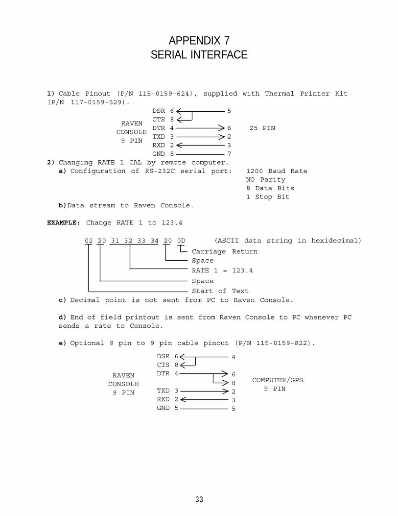
APPENDIX 7SERIAL INTERFACE
1) Cable Pinout (P/N 115-0159-624), supplied with Thermal Printer Kit(P/N 117-0159-529).
DSR 6 5CTS 8DTR 4 6 25 PINTXD 3 2RXD 2 3GND 5 7
2) Changing RATE 1 CAL by remote computer.a) Configuration of RS-232C serial port: 1200 Baud Rate
NO Parity8 Data Bits1 Stop Bit
b)Data stream to Raven Console.
EXAMPLE: Change RATE 1 to 123.4
c) Decimal point is not sent from PC to Raven Console.
d) End of field printout is sent from Raven Console to PC whenever PCsends a rate to Console.
e) Optional 9 pin to 9 pin cable pinout (P/N 115-0159-822).
02 20 31 32 33 34 20 0D (ASCII data string in hexidecimal)
RAVENCONSOLE 9 PIN
4
68235
RAVENCONSOLE9 PIN
DSR 6CTS 8DTR 4
TXD 3RXD 2GND 5
COMPUTER/GPS9 PIN
Carriage ReturnSpace
Space
Start of Text
RATE 1 = 123.4

34

35
RAVEN INDUSTRIES
LIMITED WARRANTY
WHAT IS COVERED?
This warranty covers all defects in workmanship or materialsin your Raven Flow Control Product under normal use,maintenance, and service.
HOW LONG IS THE COVERAGE PERIOD?
This warranty coverage runs for 12 months from the purchase dateof your Raven Flow Control Product. This warranty coverageapplies only to the original owner and is not transferrable.
HOW CAN YOU GET SERVICE?
Bring the defective part, and proof of date of purchase, to yourlocal dealer. If your dealer agrees with the warranty claim,he will send the part, and proof of purchase to his distributoror to Raven for final approval.
WHAT WILL RAVEN INDUSTRIES DO?
When our inspection proves the warranty claim, we will, at ouroption, repair or replace the defective part and pay for returnfreight.
WHAT DOES THIS WARRANTY NOT COVER?
Raven Industries will not assume any expense or liability forrepairs made outside our plant without written consent. We arenot responsible for damage to any associated equipment orproduct and will not be liable for loss of profit or otherspecial damages. The obligation of this warranty is in lieuof all other warranties, expressed or implied, and no personis authorized to assume for us any liability. Damages causedby normal wear and tear, mis-use, abuse, neglect, accident, orimproper installation and maintenance are not covered by thiswarranty.

������ ���. �, ��� 400
10/00 #016�0159�576


