117
INSTRUCTION MANUAL DIGITAL STORAGE OSCILLOSCOPE DCS-4605 B71-0392-01
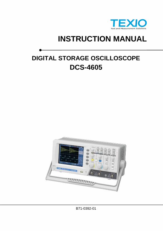
INSTRUCTION MANUAL
DIGITAL STORAGE OSCILLOSCOPE
DCS-4605
B71-0392-01

About a trademark, a registered trademark
A company name and the brand name mentioned in this instruction
manual are the trademark or the registered trademark of each
company or group in each country and region.
About this instruction manual
When copying the part or all of contents of this instruction manual,
seek the copyright holder.
In addition, the specifications of the product and the contents of
this instruction manual are subject to change without notice for
improvement. Please check to our website for the latest version.
Table of Contents
USING THE PRODUCT SAFELY.................................................Ⅰ-Ⅴ
1. GETTING STARTED ...................................... 1 1-1. Main Features .............................................. 1 1-2. Panel Overview ............................................ 3
1-2-1. Front Panel ................................................................... 3 1-2-2. Rear Panel ................................................................... 6 1-2-3. Display .......................................................................... 7
1-3. Setting up the Oscilloscope ........................... 8
2. QUICK REFERENCE ................................... 11 2-1. Menu Tree and Shortcuts ............................. 11
2-1-1. Acquire key ................................................................. 11 2-1-2. CH1/CH2 key ............................................................. 12 2-1-3. Cursor key 1/2 ............................................................ 12 2-1-4. Cursor key 2/2 ............................................................ 13 2-1-5. Display key ................................................................. 13 2-1-6. Autoset key ................................................................. 14 2-1-7. Hardcopy key ............................................................. 14 2-1-8. Help key ..................................................................... 14 2-1-9. Horizontal menu key .................................................. 14 2-1-10. Math key 1/2 (+/-) ....................................................... 15 2-1-11. Math key 2/2 (FFT) ..................................................... 15 2-1-12. Measure key ............................................................... 16 2-1-13. Run/Stop key .............................................................. 16 2-1-14. Save/Recall key 1/9 ................................................... 17 2-1-15. Save/Recall key 2/9 ................................................... 17 2-1-16. Save/Recall key 3/9 ................................................... 18 2-1-17. Save/Recall key 4/9 ................................................... 18 2-1-18. Save/Recall key 5/9 ................................................... 18 2-1-19. Save/Recall key 6/9 ................................................... 19 2-1-20. Save/Recall key 7/9 ................................................... 19 2-1-21. Save/Recall key 8/9 ................................................... 20 2-1-22. Save/Recall key 9/9 ................................................... 20 2-1-23. Trigger key 1/5 ........................................................... 21 2-1-24. Trigger key 2/5 ........................................................... 21 2-1-25. Trigger key 3/5 ........................................................... 22 2-1-26. Trigger key 4/5 ........................................................... 22 2-1-27. Trigger key 5/5 ........................................................... 23
2-1-28. Utility key 1/10 (Utility #1) .......................................... 23 2-1-29. Utility key 2/10 (Utility #2) .......................................... 24 2-1-30. Utility key 3/10 (Utility #3) .......................................... 24 2-1-31. Utility key 4/10 (Hardcopy -Save All) ......................... 24 2-1-32. Utility key 5/10 (Hardcopy -Save Image) ................... 25 2-1-33. Utility key 6/10 (Probe compensation) ....................... 25 2-1-34. Utility key 7/10 (Go-NoGo) ......................................... 25 2-1-35. Utility key 8/10 (Data Logging 1/2)............................. 26 2-1-36. Utility key 9/10 (Data Logging 2/2)............................. 26 2-1-37. Utility key 10/10 (Self CAL Menu) .............................. 26 2-1-38. Default Settings .......................................................... 27
2-2. Built-in Help ................................................ 28
3. MEASUREMENT ......................................... 29 3-1. Basic Measurements ................................... 29
3-1-1. Activating a channel ................................................... 29 3-1-2. Using Autoset ............................................................. 30 3-1-3. Running and stopping the trigger ............................... 31 3-1-4. Changing the horizontal position and scale ............... 32 3-1-5. Changing the vertical position and scale ................... 33 3-1-6. Using the probe compensation signal ....................... 34
3-2. Automatic Measurements ............................ 36 3-2-1. Measurement items ................................................... 36 3-2-2. Automatically measuring the input signals ................ 38
3-3. Cursor Measurements ................................. 39 3-3-1. Using the horizontal cursors ...................................... 39 3-3-2. Using the vertical cursors ........................................... 40
3-4. Math Operations ......................................... 41 3-4-1. Overview .................................................................... 41 3-4-2. Adding, subtracting or multiplying signals ................. 42 3-4-3. Using the FFT function ............................................... 43
3-5. Go No-Go Testing ....................................... 44 3-5-1. Overview .................................................................... 44 3-5-2. Edit: NoGo When ....................................................... 44 3-5-3. Edit: Source ................................................................ 45 3-5-4. Edit: NoGo Violation Conditions ................................ 45 3-5-5. Edit: Template (boundary) ......................................... 46 3-5-6. Run Go-NoGo Tests .................................................. 50
3-6. Data Logging .............................................. 51 3-6-1. Overview .................................................................... 51 3-6-2. Edit: Source ................................................................ 51 3-6-3. Edit: Setup Parameters .............................................. 52
3-6-4. Run Data logging ....................................................... 53
4. CONFIGURATION ....................................... 54 4-1. Acquisition .................................................. 54
4-1-1. Selecting the acquisition mode .................................. 54 4-1-2. Real time vs Equivalent time sampling mode ............ 56
4-2. Display ........................................................ 56 4-2-1. Selecting vector or dot drawing .................................. 56 4-2-2. Accumulating the waveform ....................................... 57 4-2-3. Adjusting the display contrast .................................... 57 4-2-4. Selecting the display grid ........................................... 58
4-3. Horizontal View ........................................... 58 4-3-1. Moving the waveform position horizontally ................ 58 4-3-2. Selecting the horizontal scale .................................... 59 4-3-3. Selecting the waveform update mode ....................... 59 4-3-4. Zooming the waveform horizontally ........................... 60 4-3-5. Viewing waveforms in the X-Y mode ......................... 61
4-4. Vertical View (Channel) ................................ 62 4-4-1. Moving the waveform position vertically .................... 62 4-4-2. Selecting the vertical scale ........................................ 62 4-4-3. Selecting the coupling mode ...................................... 62 4-4-4. Inverting the waveform vertically ................................ 63 4-4-5. Limiting the waveform bandwidth ............................... 64 4-4-6. Probe attenuation level and type ............................... 64
4-5. Trigger ........................................................ 65 4-5-1. Trigger type ................................................................ 65 4-5-2. Trigger parameter ...................................................... 65 4-5-3. Configuring the edge trigger ...................................... 67 4-5-4. Configuring the video trigger ...................................... 68 4-5-5. Configuring the pulse width trigger ............................ 70 4-5-6. Manually triggering the signal .................................... 71
4-6. Remote Control Interface ............................. 72 4-7. Control with the “FreeWave” ......................... 73
4-7-1. System requirements ................................................. 73 4-7-2. Icon ............................................................................. 73 4-7-3. Connect screen .......................................................... 74 4-7-4. Image screen .............................................................. 75 4-7-5. Data screen ................................................................ 76 4-7-6. Command screen ....................................................... 77
4-8. System Settings .......................................... 78 4-8-1. Viewing the system information ................................. 78 4-8-2. Selecting the language ............................................... 78
5. SAVE/RECALL ............................................ 79 5-1. File Structures ............................................ 79
5-1-1. Display image file format ............................................ 79 5-1-2. Waveform file format .................................................. 79 5-1-3. Setup file format ......................................................... 81 5-1-4. Using the USB file utilities .......................................... 82
5-2. Quick Save (HardCopy) ............................... 84 5-3. Save .......................................................... 85
5-3-1. File type/source/destination ....................................... 85 5-3-2. Saving the panel settings ........................................... 86 5-3-3. Saving the waveform ................................................. 87 5-3-4. Saving the display image ........................................... 88 5-3-5. Saving all .................................................................... 88
5-4. Recall ......................................................... 90 5-4-1. File type/source/destination ....................................... 90 5-4-2. Recalling the default panel settings ........................... 90 5-4-3. Recalling a reference waveform to the display .......... 91 5-4-4. Recalling panel settings ............................................. 92 5-4-5. Recalling a waveform ................................................. 93
6. MAINTENANCE........................................... 94 6-1. Vertical Resolution Calibration ..................... 94 6-2. Probe Compensation ................................... 95
7. APPENDIX .................................................. 97 7-1. Fuse Replacement ...................................... 97 7-2. DCS-4605 Specifications ............................. 98
7-2-1. Common specifications .............................................. 98 7-2-2. Probe Specifications ................................................ 100
7-3. Dimensions................................................101 7-4. FAQ ..........................................................102
I
USING THE PRODUCT SAFELY
Preface
To use the product safely, read this instruction manual to the end.
Before using this product, understand how to correctly use it.
If you read this manual but you do not understand how to use it, please
ask us or your local dealer. After you read this manual, save it so that you
can read it, anytime as requied.
Pictorial indication
This instruction manual and product show the warning and caution items
required to safely use the product. The following pictorial indication and
warning character indication are provided.
<Pictorial indication>
Some part of this product or the instruction manual
may shows this pictorial indication. In this case, if the
product is incorrectly used in that part, a serious
danger may be brought about on the user’s body or
the product.
To use the part with this pictorial indication, be sure to
refer to this instruction manual.
WARNING!
If you use the product, ignoring this indication, you
may get killed or seriously injured. This indication
shows that the warning item to avoid the danger is
provided.
CAUTION!
If you incorrectly use the product, ignoring this
indication, you may get slightly injured or the product
may be damaged. This indication shows that the
caution item to avoid the danger is provided.
Please be informed that we are not responsible for any damages to the user or
to the third person, arising from malfunctions or other failures due to wrong
use of the product or incorrect operation, except such responsibility for
damages as required by law.

II
USING THE PRODUCT SAFELY
WARNING! CAUTION!
Do not remove the product’s covers and panels Never remove the product’s covers and panels for any purpose. Otherwise, the user’s electric shock or fire may be incurred.
Warning on using the product Warning items given below are to avoid danger to user’s body and life and avoid the damage or deterioration of the product. Use the product, observing the following warning and caution items.
Warning items on power supply Power supply voltage
The rated power supply voltages of the product are 100, 120, 220 and 240VAC. The rated power supply voltage for each product should be confirmed by reading the label attached on the back of the product or by the “rated” column shown in this instruction manual. The specification of power cord attached to the products is rated to 125VAC for all products which are designed to be used in the areas where commercial power supply voltage is not higher than 125VAC. Accordingly, you must change the power cord if you want to use the product at the power supply voltage higher than 125VAC. If you use the product without changing power cord to 250VAC rated one, electric shock or fire may be caused. When you used the product equipped with power supply voltage switching system, please refer to the corresponding chapter in the instruction manuals of each product.
Power cord (Important) The attached power cord set can be used for this
device only.
If the attached power cord is damaged, stop using the product and call us or your local dealer. If the power cord is used without the damage being removed, an electric shock or fire may be caused.
Protective fuse If an input protective fuse is blown, the product does not operate. For a product with external fuse holder, the fuse may be replaced. As for how to replace the fuse, refer to the corresponding chapter in this instruction manual. If no fuse replacement procedures are indicated, the user is not permitted to replace it. In such case, keep the case closed and consult us or your local dealer. If the fuse is incorrectly replaced, a fire may occur.
III
USING THE PRODUCT SAFELY
Warning item on Grounding
If the product has the GND terminal on the front or rear panel surface, be
sure to ground the product to safely use it.
Warnings on Installation environment
Operating temperature and humidity
Use the product within the operating temperature indicated in the “rating”
temperature column. If the product is used with the vents of the product
blocked or in high ambient temperatures, a fire may occur.
Use the product within the operating humidity indicated in the “rating”
humidity column. Watch out for condensation by a sharp humidity
change such as transfer to a room with a different humidity. Also, do not
operate the product with wet hands. Otherwise, an electric shock or fire
may occur.
Use in gas
Use in and around a place where an inflammable or explosive gas or
steam is generated or stored may result in an explosion and fire. Do not
operate the product in such an environment.
Also, use in and around a place where a corrosive gas is generated or
spreading causes a serious damage to the product. Do not operate the
product in such an environment.
Installation place
Avoid installing the product on inclined places or on places subject to
vibration. Otherwise, the product may slip or fall down to cause
damages or injury accidents.
Do not let foreign matter in
Do not insert metal and inflammable materials into the product from its vent
and spill water on it. Otherwise, electric shock or fire may occur.
Warning item on abnormality while in use
In abnormal situations, such as “smoke”, “fire”, “abnormal smell” or
“irregular noise” occur from the product while in use, stop using the product,
turn off the switch, and remove the power cord plug from the outlet. After
confirming that no other devices catch fire, ask us or your local dealer.
IV
USING THE PRODUCT SAFELY
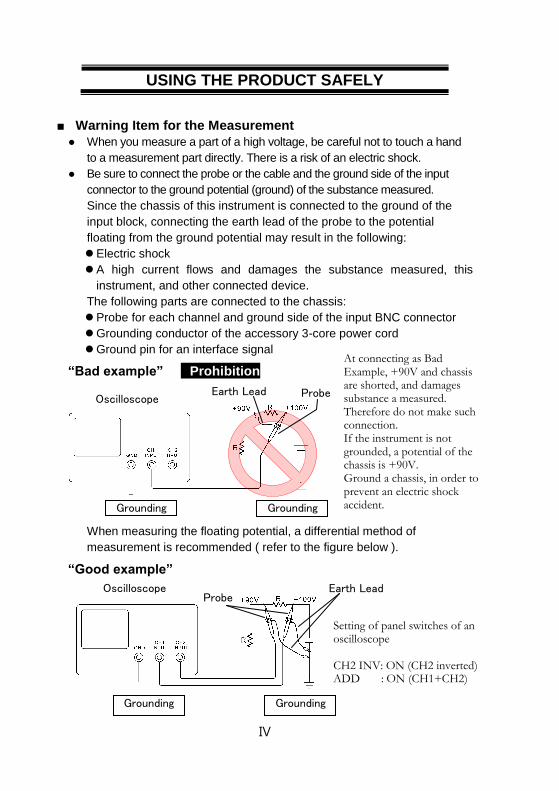
Warning Item for the Measurement
When you measure a part of a high voltage, be careful not to touch a hand
to a measurement part directly. There is a risk of an electric shock.
Be sure to connect the probe or the cable and the ground side of the input
connector to the ground potential (ground) of the substance measured.
Since the chassis of this instrument is connected to the ground of the
input block, connecting the earth lead of the probe to the potential
floating from the ground potential may result in the following:
Electric shock
A high current flows and damages the substance measured, this
instrument, and other connected device.
The following parts are connected to the chassis:
Probe for each channel and ground side of the input BNC connector
Grounding conductor of the accessory 3-core power cord
Ground pin for an interface signal
“Bad example” Prohibition
When measuring the floating potential, a differential method of
measurement is recommended ( refer to the figure below ).
“Good example”
At connecting as Bad Example, +90V and chassis are shorted, and damages substance a measured. Therefore do not make such connection. If the instrument is not grounded, a potential of the chassis is +90V. Ground a chassis, in order to prevent an electric shock accident.
Setting of panel switches of an oscilloscope CH2 INV: ON (CH2 inverted) ADD : ON (CH1+CH2)
Grounding
Oscilloscope Earth Lead Probe
Grounding
Oscilloscope
Grounding Grounding
Earth Lead Probe
V
USING THE PRODUCT SAFELY
Input / Output terminals
Maximum input to terminal is specified to prevent the product from
being damaged. Do not supply input, exceeding the specifications
that are indicated in the "Rating" column in the instruction manual
of the product.
Also, do not supply power to the output terminals from the outside.
Otherwise, a product failure is caused.
Calibration
Although the performance and specifications of the product are checked
under strict quality control during shipment from the factory, they may be
deviated more or less by deterioration of parts due to their aging or others.
It is recommended to periodically calibrate the product so that it is used
with its performance and specifications stable.
For consultation about the product calibration, ask us or your local dealer.
Daily Maintenance
When you clean off the dirt of the product covers, panels, and knobs,
avoid solvents such as thinner and benzene. Otherwise, the paint may
peel off or resin surface may be affected.
To wipe off the covers, panels, and knobs, use a soft cloth with neutral
detergent in it. During cleaning, be careful that water, detergent, or other
foreign matters do not get into the product.
If a liquid or metal gets into the product, an electric shock and fire are
caused. During cleaning, remove the power cord plug from the outlet.
Use the product correctly and safely, observing the above warning and caution
items. Because the instruction manual indicates caution items even in
individual items, observe those caution items to correctly use the product.
If you have questions or comments about the instruction manual, ask us or E-
Mail us.

1
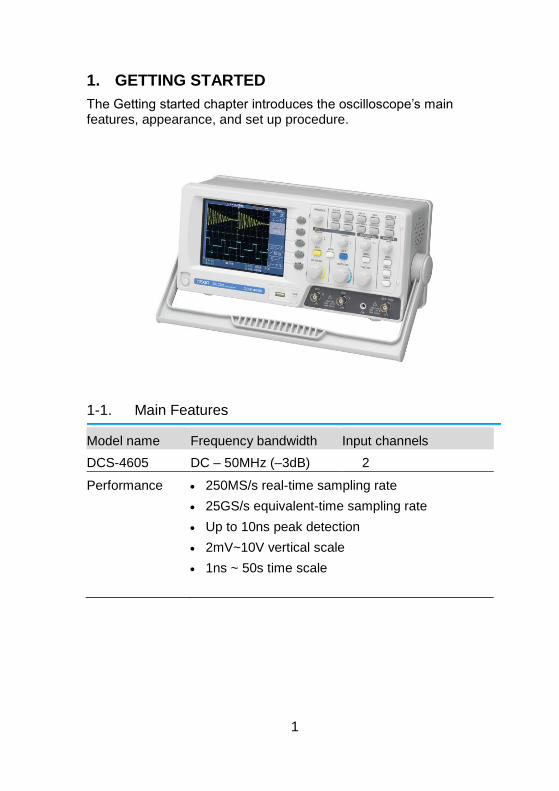
1. GETTING STARTED
The Getting started chapter introduces the oscilloscope’s main features, appearance, and set up procedure.
1-1. Main Features
Model name Frequency bandwidth Input channels
DCS-4605 DC – 50MHz (–3dB) 2
Performance 250MS/s real-time sampling rate
25GS/s equivalent-time sampling rate
Up to 10ns peak detection
2mV~10V vertical scale
1ns ~ 50s time scale
2
Features 5.7 inch color TFT display
Saving and recalling setups and waveforms
19 automatic measurements
Multi-language menu (12 languages)
Math operation: Addition, Subtraction, FFT
Data logging
Go-NoGo testing
Edge, video, pulse width trigger
Compact size: (W) 310 x (D) 140 x (H) 142 mm
Interface USB 2.0 full-speed interface for saving and recalling data
Calibration output
External trigger input
USB slave interface for remote control
3
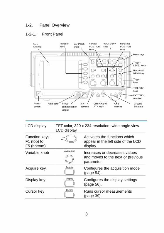
1-2. Panel Overview
1-2-1. Front Panel
LCD
Display
Function
keysVARIABLE
knob
Menu keys
TriggerLEVEL knob
Triggerkeys
Ground
Terminal
CH1terminal
USB port CH2terminal
Probe
compensation
output
EXT TRIGterminal
Powerswitch
HorizontalPOSITION knob
Horizontal MENU key
TIME/DIV knob
CH1/CH2/MATH keys
Vertical POSITION knob
VOLTS/DIV knob
VOLTS/ DIV VOLTS/DIV TIME/ DIV
CH 1 MATH CH 2 MENU MENU
Acquire Display Utility Help
Run/Stop
VARIABLE
FORCE
Autoset
Cursor
SINGLE
HardcopyMeasure Save/ Recall
LEVEL
VERTICAL HORIZONTAL TRIGGER
CH1
CAT300V
M W 15pF
MAX. 300Vpk
1
CH2 EXT TRIG
CAT300V
M W 15pF
MAX. 300Vpk
1
X Y
/
LCD display TFT color, 320 x 234 resolution, wide angle view LCD display.
Function keys: F1 (top) to F5 (bottom)
Activates the functions which appear in the left side of the LCD display.
Variable knob VARIABLE
Increases or decreases values and moves to the next or previous parameter.
Acquire key Acquire
Configures the acquisition mode (page 54).
Display key Display
Configures the display settings (page 56).
Cursor key Cursor
Runs cursor measurements (page 39).
4
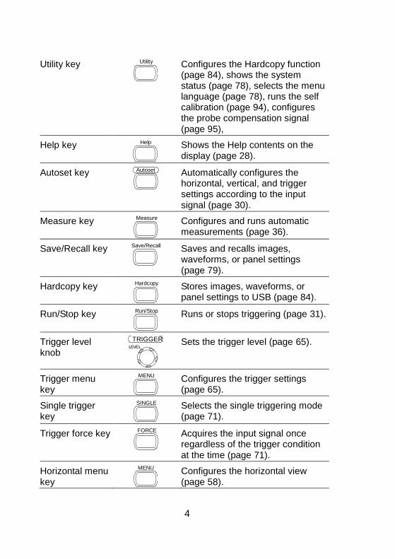
Utility key Utility
Configures the Hardcopy function (page 84), shows the system status (page 78), selects the menu language (page 78), runs the self calibration (page 94), configures the probe compensation signal (page 95),
Help key Help
Shows the Help contents on the display (page 28).
Autoset key Autoset
Automatically configures the horizontal, vertical, and trigger settings according to the input signal (page 30).
Measure key Measure
Configures and runs automatic measurements (page 36).
Save/Recall key Save/Recall
Saves and recalls images, waveforms, or panel settings (page 79).
Hardcopy key Hardcopy
Stores images, waveforms, or panel settings to USB (page 84).
Run/Stop key Run/Stop
Runs or stops triggering (page 31).
Trigger level knob
LEVEL
TRIGGER
Sets the trigger level (page 65).
Trigger menu key
MENU
Configures the trigger settings (page 65).
Single trigger key
SINGLE
Selects the single triggering mode (page 71).
Trigger force key FORCE
Acquires the input signal once regardless of the trigger condition at the time (page 71).
Horizontal menu key
MENU
Configures the horizontal view (page 58).

5
Horizontal position knob
Moves the waveform horizontally (page 58).
TIME/DIV knob TIME/DIV
Selects the horizontal scale (page 59).
Vertical position knob
Moves the waveform vertically (page 62).
CH1/CH2 key CH 1
Configures the vertical scale and coupling mode for each channel (page 62).
VOLTS/DIV knob
VOLTS/DIV
Selects the vertical scale (page 62).
Input terminal CH1
Accepts input signals: 1MΩ±2% input impedance, BNC terminal.
Ground terminal
Accepts the DUT ground lead to achieve a common ground.
MATH key MATH
Performs math operations (page 41).
USB port
Facilitates transferring waveform data, display images, and panel settings (page 79).
Probe compensation output
Outputs a 2Vp-p, square signal for compensating the probe (page 95) or demonstration.
External trigger input
EXT TRIG
Accepts an external trigger signal (page 65).
Power switch
Powers the oscilloscope on or off.
6
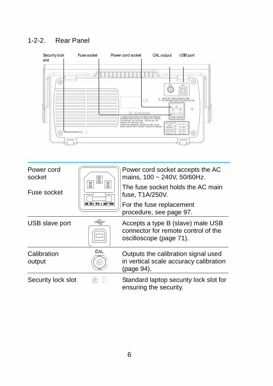
1-2-2. Rear Panel
LINE VOLTAGEAC 100 240V
FUSE RATING
RANGE
T1A 250V
FREQUENCY 50 60Hz
POWER MAX. 18W 40VA
USB portCAL outputPower cord socketFuse socketSecurity lock
slot
Power cord socket
Fuse socket
Power cord socket accepts the AC mains, 100 ~ 240V, 50/60Hz.
The fuse socket holds the AC main fuse, T1A/250V.
For the fuse replacement procedure, see page 97.
USB slave port
Accepts a type B (slave) male USB connector for remote control of the oscilloscope (page 71).
Calibration output
Outputs the calibration signal used in vertical scale accuracy calibration (page 94).
Security lock slot Standard laptop security lock slot for ensuring the security.
7
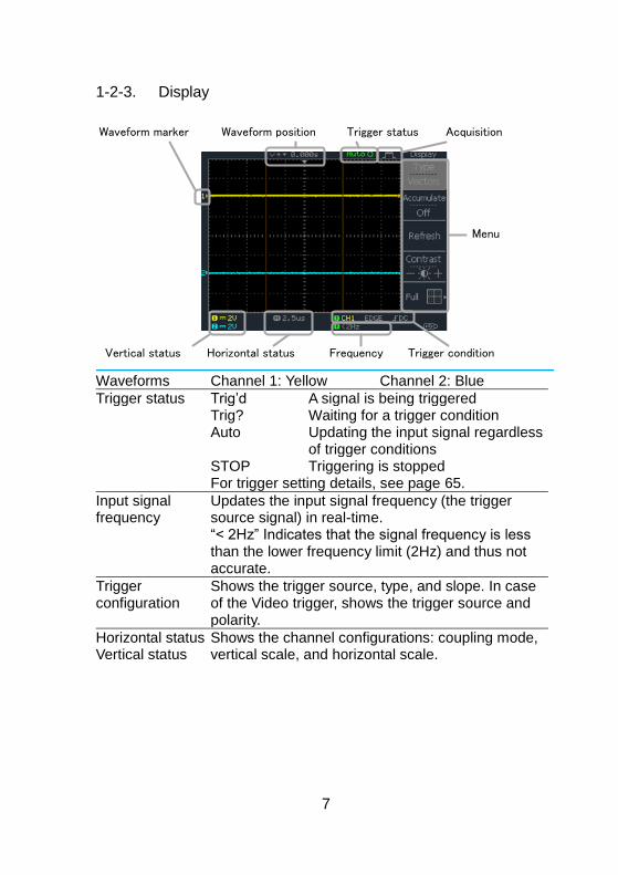
1-2-3. Display
Waveform marker
Vertical status Horizontal status Frequency Trigger condition
Waveform position Trigger status Acquisition
Menu
Waveforms Channel 1: Yellow Channel 2: Blue
Trigger status Trig’d A signal is being triggered Trig? Waiting for a trigger condition Auto Updating the input signal regardless
of trigger conditions STOP Triggering is stopped For trigger setting details, see page 65.
Input signal frequency
Updates the input signal frequency (the trigger source signal) in real-time. “< 2Hz” Indicates that the signal frequency is less than the lower frequency limit (2Hz) and thus not accurate.
Trigger configuration
Shows the trigger source, type, and slope. In case of the Video trigger, shows the trigger source and polarity.
Horizontal status Vertical status
Shows the channel configurations: coupling mode, vertical scale, and horizontal scale.
8
1-3. Setting up the Oscilloscope
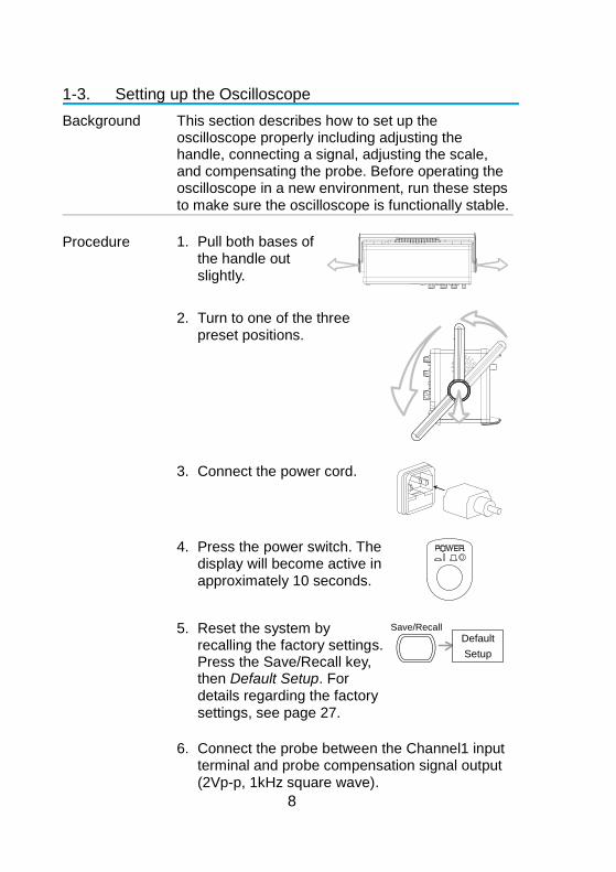
Background This section describes how to set up the oscilloscope properly including adjusting the handle, connecting a signal, adjusting the scale, and compensating the probe. Before operating the oscilloscope in a new environment, run these steps to make sure the oscilloscope is functionally stable.
Procedure 1. Pull both bases of the handle out slightly.
2. Turn to one of the three preset positions.
3. Connect the power cord.
4. Press the power switch. The
display will become active in approximately 10 seconds.
5. Reset the system by recalling the factory settings. Press the Save/Recall key, then Default Setup. For details regarding the factory settings, see page 27.
Default
Setup
Save/Recall
6. Connect the probe between the Channel1 input terminal and probe compensation signal output (2Vp-p, 1kHz square wave).
9
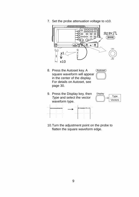
7. Set the probe attenuation voltage to x10.
V O L TS / D I V V O L TS / D I V T I M E / D I V C H 1 M A T H C H 2 M E N U M E N U
A c q u i r e D i s p l a y U t i l i t y H e l p R u n / S t o p
V A R I A B L E
F O R C E
A u t o s et C u r s o r
S I N G L E
H a r d c o p y M e a s u r e S a ve / R e c a l l L E V E L V E R T I C A L H O R I Z O N T A L T R I G G E R
C H 1
C H 2 E X T T R I G C A T 3 0 0 V M W 1 5 p F . 0 0 V p k 1
X Y
X 1 0 X 1
C
H1
x 1
x 1 0
8. Press the Autoset key. A square waveform will appear in the center of the display. For details on Autoset, see page 30.
Autoset
9. Press the Display key, then Type and select the vector
waveform type.
Type
Vectors
Display
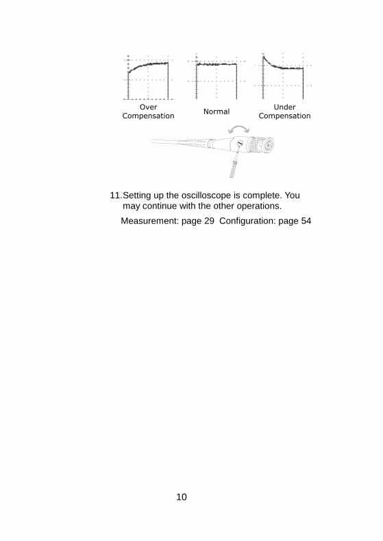
10. Turn the adjustment point on the probe to flatten the square waveform edge.
10
Over Compensation
NormalUnder
Compensation
11. Setting up the oscilloscope is complete. You may continue with the other operations.
Measurement: page 29 Configuration: page 54
11
2. QUICK REFERENCE
This chapter lists the oscilloscope menu tree, operation shortcuts, built-in help coverage, and default factory settings. Use this chapter as a handy reference to access the oscilloscope functions.
2-1. Menu Tree and Shortcuts
Conventions Examples
Normal = Press the functional key for “Normal”
Average = Repeatedly press the functional key for “Average”
Normal ~ Average
= Select a menu from “Normal” to “Average” and press its functionality key
Normal→VAR
= Press the functionality key for “Normal”, and then use the Variable knob
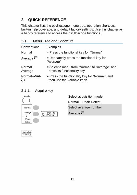
2-1-1. Acquire key
Normal
Peak
Detect
2/ 4 / 8 / 16 / 32/64/ 128/ 256
Average
Sample Rate
500MS/s
Acquire
2
Select acquisition mode
Normal ~ Peak-Detect
Select average number
Average
12
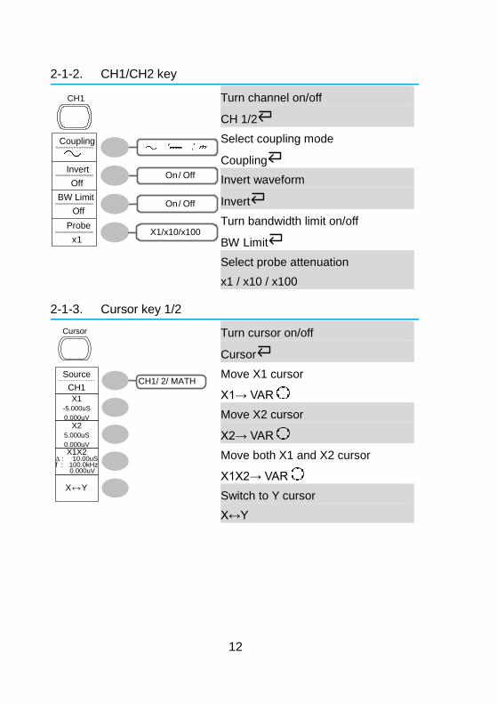
2-1-2. CH1/CH2 key
On/ Off
On/ Off
/ /Coupling
Invert
Off
BW Limit
Off
Probe
x1
CH 1
X1/x10/x100
Turn channel on/off
CH 1/2
Select coupling mode
Coupling
Invert waveform
Invert
Turn bandwidth limit on/off
BW Limit
Select probe attenuation
x1 / x10 / x100
2-1-3. Cursor key 1/2
CH1/ 2/ MATHSource
CH1
X↔Y
Cursor
X1X210.00uS
100.0kHz 0.000uV
X1-5.000uS
0.000uV
X25.000uS
0.000uV
∆ :f :
Turn cursor on/off
Cursor
Move X1 cursor
X1→ VAR
Move X2 cursor
X2→ VAR
Move both X1 and X2 cursor
X1X2→ VAR
Switch to Y cursor
X↔Y
13
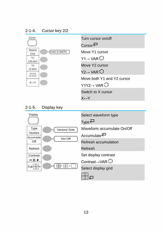
2-1-4. Cursor key 2/2
CH1/ 2/ MATHSource
CH1
X↔Y
Cursor
Y1
123.4mV
Y2
12.9mV
Y1Y210.5mV
Turn cursor on/off
Cursor
Move Y1 cursor
Y1→ VAR
Move Y2 cursor
Y2→ VAR
Move both Y1 and Y2 cursor
Y1Y2→ VAR
Switch to X cursor
X↔Y
2-1-5. Display key
Vectors/ DotsType
Vectors
On/ OffAccumulate
Off
Refresh
Contrast
Full / /
Display
Select waveform type
Type
Waveform accumulate On/Off
Accumulate
Refresh accumulation
Refresh
Set display contrast
Contrast→VAR
Select display grid
14
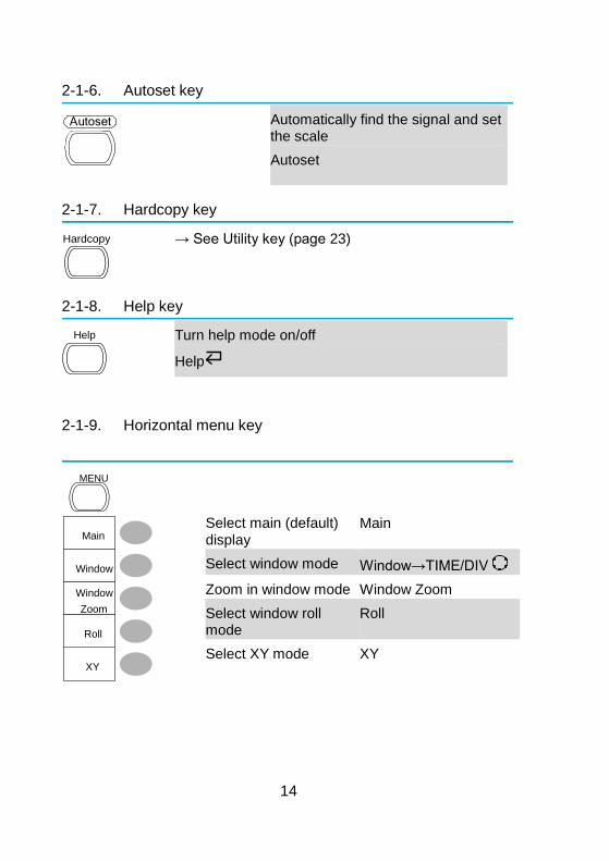
2-1-6. Autoset key
Autoset
Automatically find the signal and set the scale
Autoset
2-1-7. Hardcopy key
Hardcopy
→ See Utility key (page 23)
2-1-8. Help key
Help
Turn help mode on/off
Help
2-1-9. Horizontal menu key
Main
Window
Window
Zoom
XY
Roll
MENU
Select main (default) display
Main
Select window mode Window→TIME/DIV
Zoom in window mode Window Zoom
Select window roll mode
Roll
Select XY mode XY
15
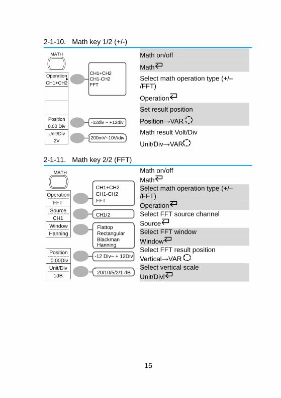
2-1-10. Math key 1/2 (+/-)
Operation
CH1+CH2
Position
0.00 Div
Unit/Div
2V
-12div ~ +12div
CH1+CH2
CH1-CH2
FFT
MATH
200mV~10V/div
Math on/off
Math
Select math operation type (+/–/FFT)
Operation
Set result position
Position→VAR
Math result Volt/Div
Unit/Div→VAR
2-1-11. Math key 2/2 (FFT)
Operation
FFT
Source
CH1
Position
0.00Div-12 Div~ + 12Div
Unit/Div
1dB20/10/5/2/1 dB
Window
Hanning
Flattop
Rectangular
BlackmanHanning
CH1/2
MATH
CH1+CH2
CH1-CH2
FFT
Math on/off
Math
Select math operation type (+/–/FFT)
Operation
Select FFT source channel
Source
Select FFT window
Window
Select FFT result position
Vertical→VAR
Select vertical scale
Unit/Divl
16
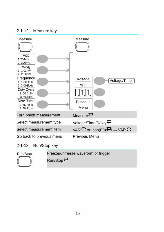
2-1-12. Measure key
Voltage
Vpp
Previous
Menu
Voltage/Time
Vpp 1:204mV
2: 300mV
Vavg 1: 1.93mV
2: 28.0mV
Frequency 1: 1.000kHz
2: 3.003kHz
Duty Cycle1: 50.01%
2: 49.88%
Rise Time1. 76.20us
2. 70.11us
Measure Measure
Turn on/off measurement Measure
Select measurement type Voltage/Time/Delay
Select measurement item VAR or Icon(F3) / → VAR
Go back to previous menu Previous Menu
2-1-13. Run/Stop key
Run/Stop
Freeze/unfreeze waveform or trigger
Run/Stop
17
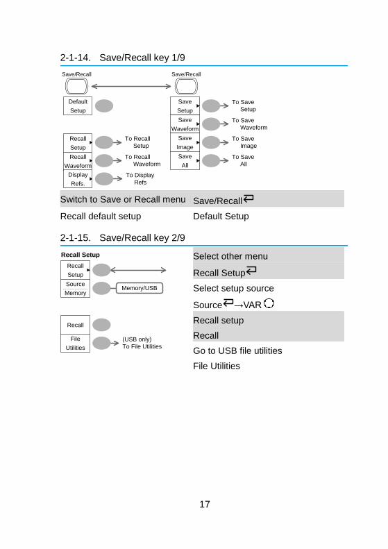
2-1-14. Save/Recall key 1/9
Recall
Setup
Recall
Waveform
Display
Refs.
Save
Setup
Save
Waveform
Save
Image
Save
All
To Recall
Setup
To Save
Setup
To Save
Waveform
To Save
Image
To Save
All
Default
Setup
Save/Recall Save/Recall
To Display
Refs
To Recall
Waveform
Switch to Save or Recall menu Save/Recall
Recall default setup Default Setup
2-1-15. Save/Recall key 2/9
Recall
Setup
Recall
File
Utilities
(USB only)
To File Utilities
Recall Setup
Source
MemoryMemory/USB
Select other menu
Recall Setup
Select setup source
Source →VAR
Recall setup
Recall
Go to USB file utilities
File Utilities
18
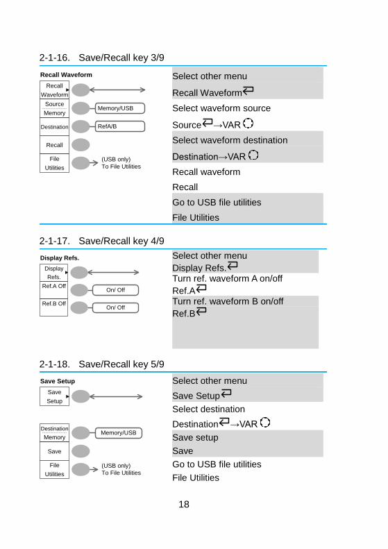
2-1-16. Save/Recall key 3/9
Recall
Waveform
Recall
File
Utilities
Recall Waveform
Destination
Source
MemoryMemory/USB
(USB only)
To File Utilities
RefA/B
Select other menu
Recall Waveform
Select waveform source
Source →VAR
Select waveform destination
Destination→VAR
Recall waveform
Recall
Go to USB file utilities
File Utilities
2-1-17. Save/Recall key 4/9
Display
Refs.
Ref.A Off
Ref.B OffOn/ Off
On/ Off
Display Refs.
Select other menu
Display Refs. Turn ref. waveform A on/off
Ref.A Turn ref. waveform B on/off
Ref.B
2-1-18. Save/Recall key 5/9
Save
Setup
Destination
Memory
Save
File
Utilities
(USB only)
To File Utilities
Save Setup
Memory/USB
Select other menu
Save Setup
Select destination
Destination →VAR
Save setup
Save
Go to USB file utilities
File Utilities
19
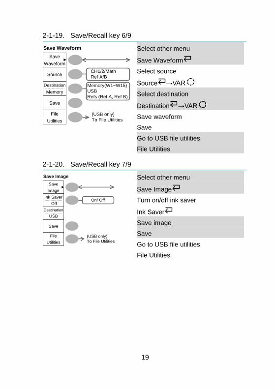
2-1-19. Save/Recall key 6/9
Save
Waveform
Source
Save
File
Utilities
Save Waveform
Destination
Memory
Memory(W1~W15)
USB
Refs (Ref A, Ref B)
(USB only)
To File Utilities
CH1/2/Math
Ref A/B
Select other menu
Save Waveform
Select source
Source →VAR
Select destination
Destination →VAR
Save waveform
Save
Go to USB file utilities
File Utilities
2-1-20. Save/Recall key 7/9
Save
Image
Destination
USB
Save
File
Utilities
(USB only)
To File Utilities
Save Image
Ink Saver
OffOn/ Off
Select other menu
Save Image
Turn on/off ink saver
Ink Saver
Save image
Save
Go to USB file utilities
File Utilities
20
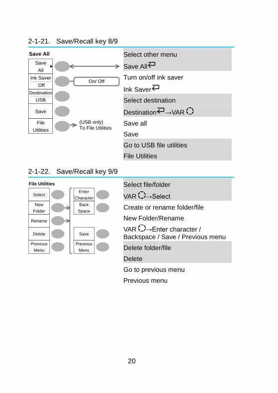
2-1-21. Save/Recall key 8/9
Save
All
Save
File
Utilities
Save All
Destination
USB
(USB only)
To File Utilities
Ink Saver
OffOn/ Off
Select other menu
Save All
Turn on/off ink saver
Ink Saver
Select destination
Destination →VAR
Save all
Save
Go to USB file utilities
File Utilities
2-1-22. Save/Recall key 9/9
Select
Delete
Previous
Menu
File Utilities
Rename
New
Folder
Enter
Character
Save
Previous
Menu
Back
Space
Select file/folder
VAR →Select
Create or rename folder/file
New Folder/Rename
VAR →Enter character / Backspace / Save / Previous menu
Delete folder/file
Delete
Go to previous menu
Previous menu
21
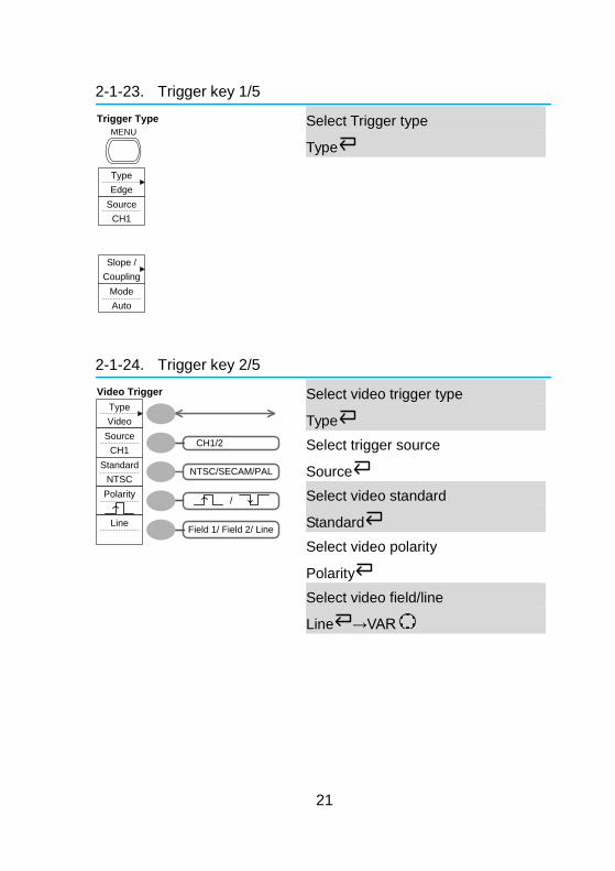
2-1-23. Trigger key 1/5
Type
Edge
Source
CH1
Mode
Auto
Slope /
Coupling
MENU
Trigger Type
Select Trigger type
Type
2-1-24. Trigger key 2/5
Type
Video
Source
CH1
Standard
NTSCNTSC/SECAM/PAL
Line
CH1/2
/
Field 1/ Field 2/ Line
Polarity
Video Trigger
Select video trigger type
Type
Select trigger source
Source
Select video standard
Standard
Select video polarity
Polarity
Select video field/line
Line →VAR
22
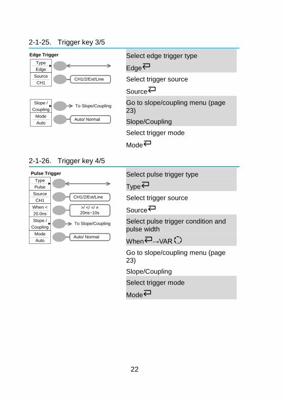
2-1-25. Trigger key 3/5
Type
Edge
Source
CH1
Mode
Auto
Slope /
Coupling
CH1/2/Ext/Line
Auto/ Normal
To Slope/Coupling
Edge Trigger
Select edge trigger type
Edge
Select trigger source
Source
Go to slope/coupling menu (page 23)
Slope/Coupling
Select trigger mode
Mode
2-1-26. Trigger key 4/5
Type
Pulse
Source
CH1
Mode
Auto
Slope /
Coupling
When <
20.0ns
To Slope/Coupling
>/ </ =/ =
20ns~10s
CH1/2/Ext/Line
Pulse Trigger
Auto/ Normal
Select pulse trigger type
Type
Select trigger source
Source
Select pulse trigger condition and pulse width
When →VAR
Go to slope/coupling menu (page 23)
Slope/Coupling
Select trigger mode
Mode
23
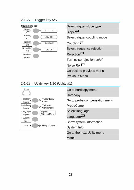
2-1-27. Trigger key 5/5
LF/ HF/ Off
On/ Off
/Slope
Coupling
AC
Rejection
Off
Previous
Menu
Noise Rej
Off
AC/ DC
Coupling/Slope
Select trigger slope type
Slope
Select trigger coupling mode
Coupling
Select frequency rejection
Rejection
Turn noise rejection on/off
Noise Rej
Go back to previous menu
Previous Menu
2-1-28. Utility key 1/10 (Utility #1)
Hardcopy
Menu
More
ProbeComp
Menu
Language
English
To Probe
Comp menu
To Hardcopy
menu
English/
Chinese(T) etc
Utility
Utility #2 menu
System
Info.
Go to hardcopy menu
Hardcopy
Go to probe compensation menu
ProbeComp
Select language
Language
Show system information
System Info.
Go to the next Utility menu
More
24
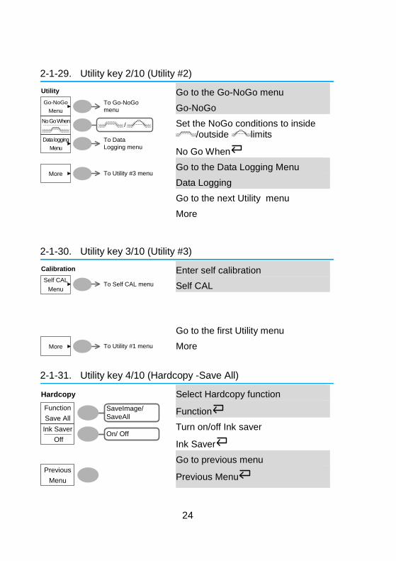
2-1-29. Utility key 2/10 (Utility #2)
Go-NoGo
Menu
/
More
No Go When
Data logging
Menu
Utility
To Go-NoGo
menu
To Data
Logging menu
To Utility #3 menu
Go to the Go-NoGo menu
Go-NoGo
Set the NoGo conditions to inside /outside limits
No Go When
Go to the Data Logging Menu
Data Logging
Go to the next Utility menu
More
2-1-30. Utility key 3/10 (Utility #3)
Self CAL
Menu
Calibration
More To Utility #1 menu
To Self CAL menu
Enter self calibration
Self CAL
Go to the first Utility menu
More
2-1-31. Utility key 4/10 (Hardcopy -Save All)
Function
Save All
SaveImage/
SaveAll
Previous
Menu
On/ OffInk Saver
Off
Hardcopy
Select Hardcopy function
Function
Turn on/off Ink saver
Ink Saver
Go to previous menu
Previous Menu
25
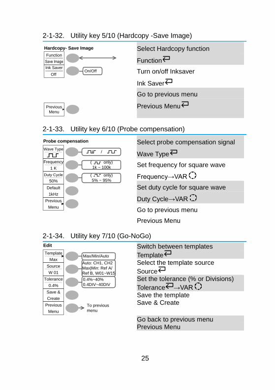
2-1-32. Utility key 5/10 (Hardcopy -Save Image)
Function
Save Image
Previous
Menu
On/OffInk Saver
Off
Hardcopy- Save Image
Select Hardcopy function
Function
Turn on/off Inksaver
Ink Saver
Go to previous menu
Previous Menu
2-1-33. Utility key 6/10 (Probe compensation)
Wave Type
( only)
1k ~ 100k
( only)
5% ~ 95%
Default
1kHz
/
Previous
Menu
Frequency
1 K
Duty Cycle
50%
Probe compensation
Select probe compensation signal
Wave Type
Set frequency for square wave
Frequency→VAR
Set duty cycle for square wave
Duty Cycle→VAR
Go to previous menu
Previous Menu
2-1-34. Utility key 7/10 (Go-NoGo)
0.4%~40%
0.4DIV~40DIV
Max/Min/Auto
To previous
menu
Edit
Template
Max Auto: CH1, CH2
Max|Min: Ref A/
Ref B, W01~W15
Source
W 01
Tolerance
0.4%
Save &
Create
Previous
Menu
Switch between templates
Template Select the template source
Source Set the tolerance (% or Divisions)
Tolerance →VAR Save the template Save & Create
Go back to previous menu Previous Menu
26
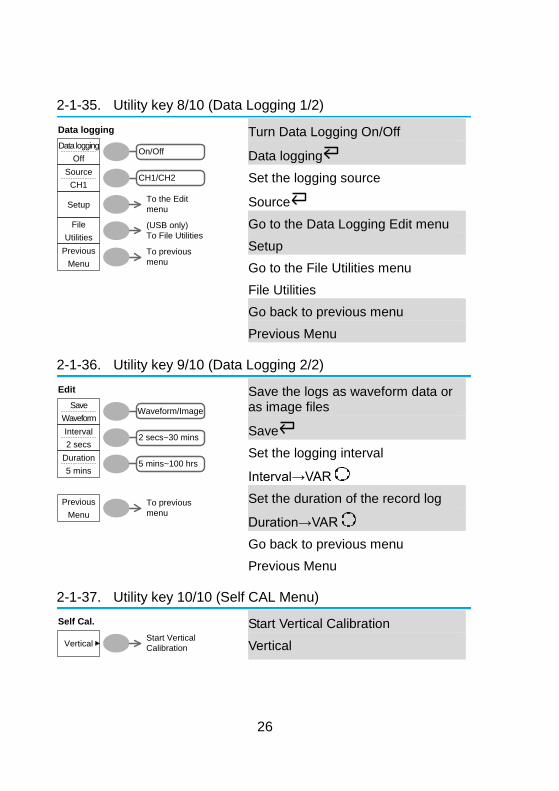
2-1-35. Utility key 8/10 (Data Logging 1/2)
Off
CH1/CH2
On/Off
To previous
menu
Data logging
Data logging
Source
CH1
Setup
File
Utilities
Previous
Menu
(USB only)
To File Utilities
To the Edit
menu
Turn Data Logging On/Off
Data logging
Set the logging source
Source
Go to the Data Logging Edit menu
Setup
Go to the File Utilities menu
File Utilities
Go back to previous menu
Previous Menu
2-1-36. Utility key 9/10 (Data Logging 2/2)
2 secs~30 mins
Waveform/Image
To previous
menu
Edit
Save
Waveform
Interval
2 secs
Duration
5 mins
Previous
Menu
5 mins~100 hrs
Save the logs as waveform data or as image files
Save
Set the logging interval
Interval→VAR
Set the duration of the record log
Duration→VAR
Go back to previous menu
Previous Menu
2-1-37. Utility key 10/10 (Self CAL Menu)
Vertical
Self Cal.
Start Vertical
Calibration
Start Vertical Calibration
Vertical
27
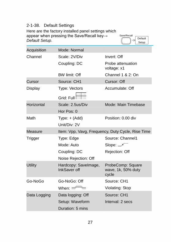
2-1-38. Default Settings
Here are the factory installed panel settings which appear when pressing the Save/Recall key→ Default Setup.
Default
Setup
Save/Recall
Acquisition Mode: Normal
Channel Scale: 2V/Div Invert: Off
Coupling: DC Probe attenuation voltage: x1
BW limit: Off Channel 1 & 2: On
Cursor Source: CH1 Cursor: Off
Display Type: Vectors Accumulate: Off
Grid: Full
Horizontal Scale: 2.5us/Div Mode: Main Timebase
Hor Pos: 0
Math Type: + (Add) Position: 0.00 div
Unit/Div: 2V
Measure Item: Vpp, Vavg, Frequency, Duty Cycle, Rise Time
Trigger Type: Edge Source: Channel1
Mode: Auto Slope:
Coupling: DC Rejection: Off
Noise Rejection: Off
Utility Hardcopy: SaveImage, InkSaver off
ProbeComp: Square wave, 1k, 50% duty cycle
Go-NoGo Go-NoGo: Off Source: CH1
When: Violating: Stop
Data Logging Data logging: Off Source: CH1
Setup: Waveform Interval: 2 secs
Duration: 5 mins
28
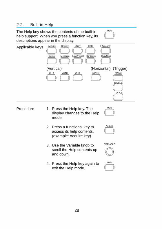
2-2. Built-in Help
The Help key shows the contents of the built-in help support. When you press a function key, its descriptions appear in the display.
Help
Applicable keys Acquire Display Utility Help
Run/Stop
Autoset
Cursor HardcopyMeasure Save/Recall
(Vertical) CH 1 MATH CH 2
(Horizontal) MENU
(Trigger) MENU
FORCE
SINGLE
Procedure 1. Press the Help key. The display changes to the Help mode.
Help
2. Press a functional key to access its help contents. (example: Acquire key)
Acquire
3. Use the Variable knob to scroll the Help contents up and down.
VARIABLE
4. Press the Help key again to exit the Help mode.
Help
29
3. MEASUREMENT
The Measurement chapter describes how to properly observe a signal using the oscilloscope’s basic functions, and how to observe a signal in a detailed manner using some of the advanced functions such as:
Automatic measurements, cursor measurements, and math operations.
3-1. Basic Measurements
This section describes the basic operations required in capturing and viewing an input signal. For more detailed operations, see the following chapters.
Measurements → from page 29
Configuration → from page 54
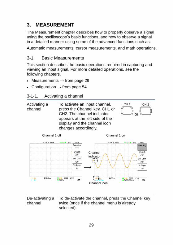
3-1-1. Activating a channel
Activating a channel
To activate an input channel, press the Channel key, CH1 or CH2. The channel indicator appears at the left side of the display and the channel icon changes accordingly.
CH 1
or
CH 2
Channel icon
Channel
indicator
Channel 1 off Channel 1 on
De-activating a channel
To de-activate the channel, press the Channel key twice (once if the channel menu is already selected).
30
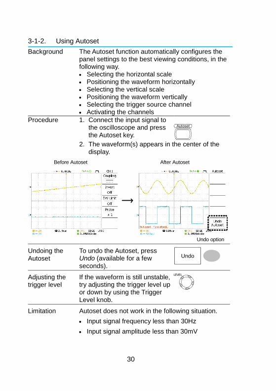
3-1-2. Using Autoset
Background The Autoset function automatically configures the panel settings to the best viewing conditions, in the following way. Selecting the horizontal scale Positioning the waveform horizontally Selecting the vertical scale Positioning the waveform vertically Selecting the trigger source channel Activating the channels
Procedure 1. Connect the input signal to the oscilloscope and press the Autoset key.
Autoset
2. The waveform(s) appears in the center of the
display.
Undo option
Before Autoset After Autoset
Undoing the Autoset
To undo the Autoset, press Undo (available for a few seconds).
Undo
Adjusting the trigger level
If the waveform is still unstable, try adjusting the trigger level up or down by using the Trigger Level knob.
LEVEL
Limitation Autoset does not work in the following situation.
Input signal frequency less than 30Hz
Input signal amplitude less than 30mV
31
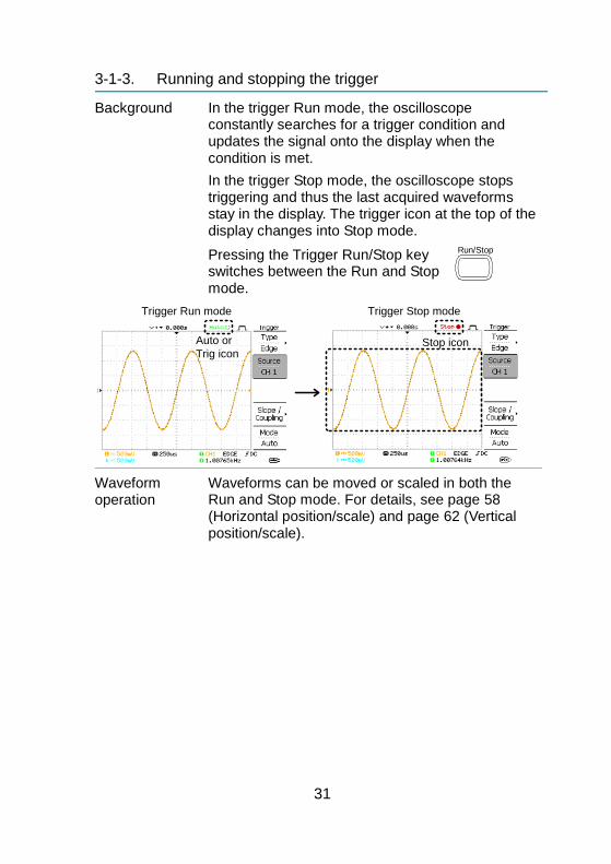
3-1-3. Running and stopping the trigger
Background In the trigger Run mode, the oscilloscope constantly searches for a trigger condition and updates the signal onto the display when the condition is met.
In the trigger Stop mode, the oscilloscope stops triggering and thus the last acquired waveforms stay in the display. The trigger icon at the top of the display changes into Stop mode.
Pressing the Trigger Run/Stop key switches between the Run and Stop mode.
Run/Stop
Trigger Run mode Trigger Stop mode
Stop iconAuto or
Trig icon
Waveform operation
Waveforms can be moved or scaled in both the Run and Stop mode. For details, see page 58 (Horizontal position/scale) and page 62 (Vertical position/scale).
32
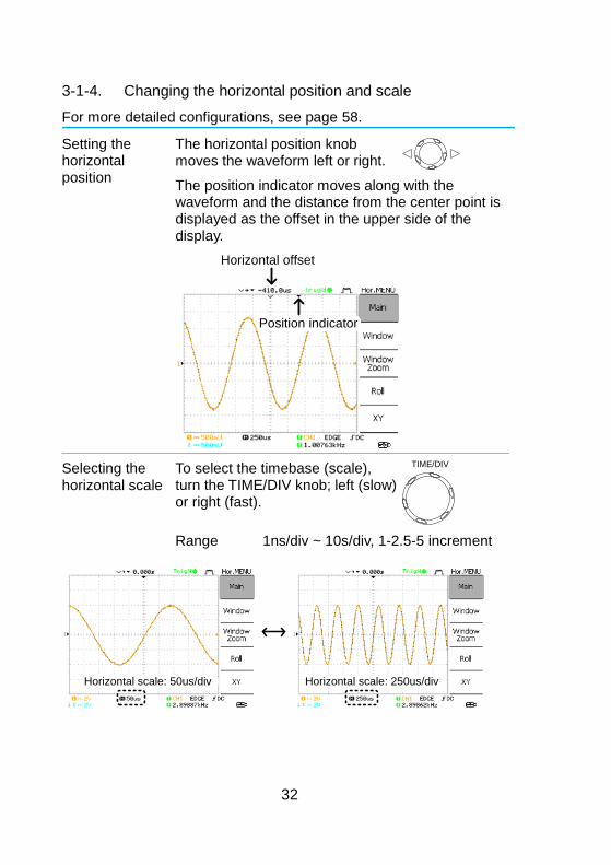
3-1-4. Changing the horizontal position and scale
For more detailed configurations, see page 58.
Setting the horizontal position
The horizontal position knob moves the waveform left or right.
The position indicator moves along with the waveform and the distance from the center point is displayed as the offset in the upper side of the display.
Horizontal offset
Position indicator
Selecting the horizontal scale
To select the timebase (scale), turn the TIME/DIV knob; left (slow) or right (fast).
TIME/DIV
Range 1ns/div ~ 10s/div, 1-2.5-5 increment
Horizontal scale: 50us/div Horizontal scale: 250us/div
33
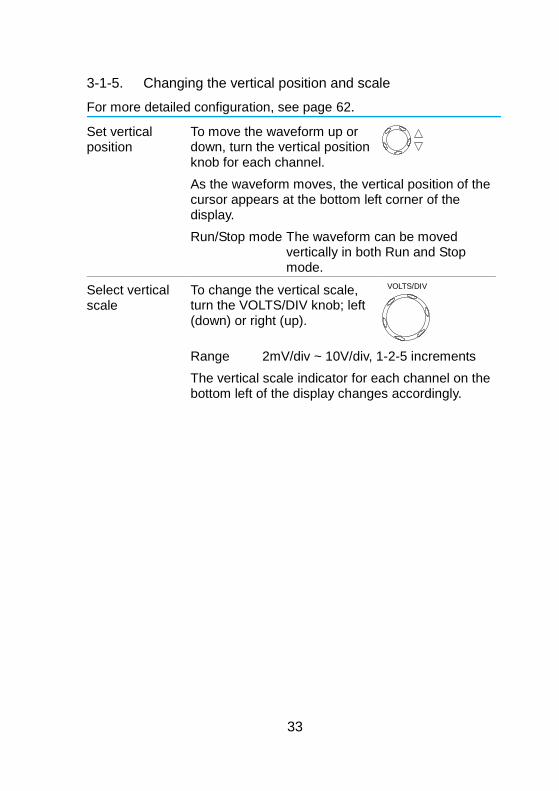
3-1-5. Changing the vertical position and scale
For more detailed configuration, see page 62.
Set vertical position
To move the waveform up or down, turn the vertical position knob for each channel.
As the waveform moves, the vertical position of the cursor appears at the bottom left corner of the display.
Run/Stop mode The waveform can be moved vertically in both Run and Stop mode.
Select vertical scale
To change the vertical scale, turn the VOLTS/DIV knob; left (down) or right (up).
VOLTS/DIV
Range 2mV/div ~ 10V/div, 1-2-5 increments
The vertical scale indicator for each channel on the bottom left of the display changes accordingly.
34
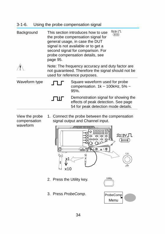
3-1-6. Using the probe compensation signal
Background This section introduces how to use the probe compensation signal for general usage, in case the DUT signal is not available or to get a second signal for comparison. For probe compensation details, see page 95.
Note: The frequency accuracy and duty factor are not guaranteed. Therefore the signal should not be used for reference purposes.
Waveform type
Square waveform used for probe compensation. 1k ~ 100kHz, 5% ~ 95%.
Demonstration signal for showing the effects of peak detection. See page 54 for peak detection mode details.
View the probe compensation waveform
1. Connect the probe between the compensation signal output and Channel input.
V O L TS / D I V V O L TS / D I V T I M E / D I V C H 1 M A T H C H 2 M E N U M E N U
A c q u i r e D i s p l a y U t i l i t y H e l p R u n / S t o p
V A R I A B L E
F O R C E
A u t o s et C u r s o r
S I N G L E
H a r d c o p y M e a s u r e S a ve / R e c a l l L E V E L V E R T I C A L H O R I Z O N T A L T R I G G E R
C H 1
C H 2 E X T T R I G C A T 3 0 0 V M W 1 5 p F . 0 0 V p k 1
X Y
X 1 0 X 1
C
H1
x 1
x 1 0
2. Press the Utility key. Utility
3. Press ProbeComp.
ProbeComp
Menu
35
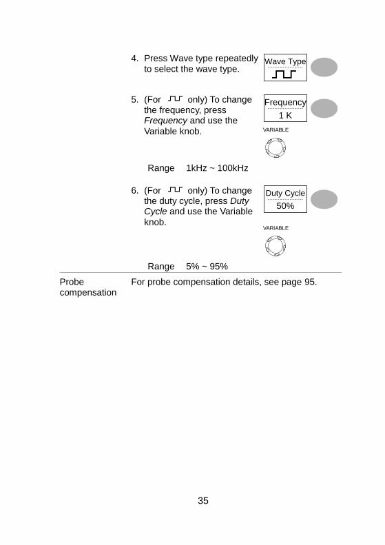
4. Press Wave type repeatedly to select the wave type.
Wave Type
5. (For only) To change the frequency, press Frequency and use the
Variable knob.
Frequency
1 K
VARIABLE
Range 1kHz ~ 100kHz
6. (For only) To change the duty cycle, press Duty Cycle and use the Variable
knob.
Duty Cycle
50%
VARIABLE
Range 5% ~ 95%
Probe compensation
For probe compensation details, see page 95.
36
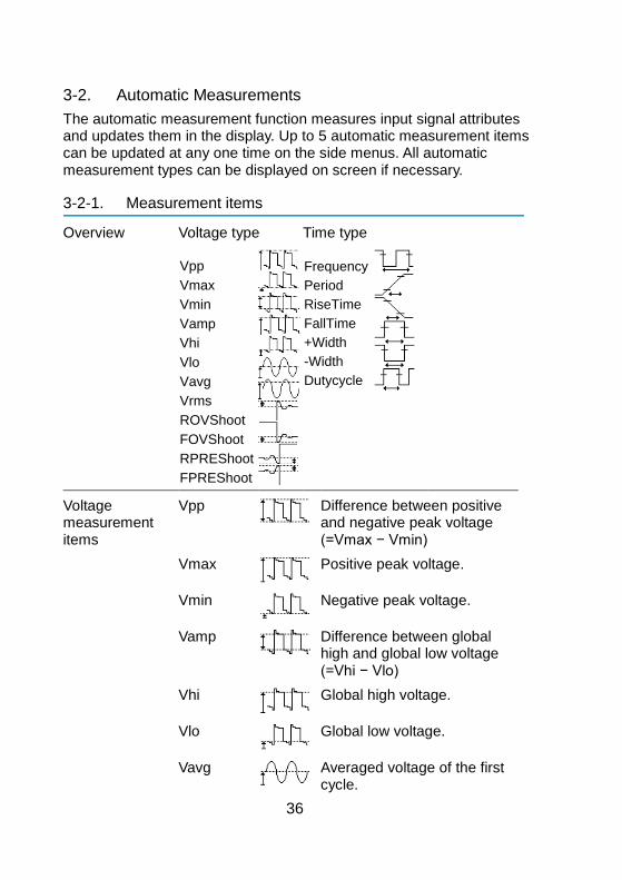
3-2. Automatic Measurements
The automatic measurement function measures input signal attributes and updates them in the display. Up to 5 automatic measurement items can be updated at any one time on the side menus. All automatic measurement types can be displayed on screen if necessary.
3-2-1. Measurement items
Overview Voltage type Time type
Vpp
Vmax
Vmin
Vamp
Vhi
Vlo
Vavg
Vrms
ROVShoot
FOVShoot
RPREShoot
FPREShoot
Frequency
Period
RiseTime
FallTime
+Width
-Width
Dutycycle
Voltage measurement items
Vpp
Difference between positive and negative peak voltage (=Vmax − Vmin)
Vmax
Positive peak voltage.
Vmin
Negative peak voltage.
Vamp
Difference between global high and global low voltage (=Vhi − Vlo)
Vhi
Global high voltage.
Vlo
Global low voltage.
Vavg
Averaged voltage of the first cycle.
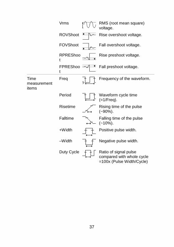
37
Vrms
RMS (root mean square) voltage.
ROVShoot
Rise overshoot voltage.
FOVShoot
Fall overshoot voltage.
RPREShoot
Rise preshoot voltage.
FPREShoot
Fall preshoot voltage.
Time measurement items
Freq
Frequency of the waveform.
Period
Waveform cycle time (=1/Freq).
Risetime
Rising time of the pulse (~90%).
Falltime
Falling time of the pulse (~10%).
+Width
Positive pulse width.
–Width
Negative pulse width.
Duty Cycle
Ratio of signal pulse compared with whole cycle =100x (Pulse Width/Cycle)
38
3-2-2. Automatically measuring the input signals
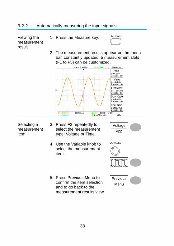
Viewing the measurement result
1. Press the Measure key. Measure
2. The measurement results appear on the menu bar, constantly updated. 5 measurement slots (F1 to F5) can be customized.
Selecting a measurement item
3. Press F3 repeatedly to select the measurement type: Voltage or Time.
Voltage
Vpp
4. Use the Variable knob to select the measurement item.
VARIABLE
5. Press Previous Menu to confirm the item selection and to go back to the measurement results view.
Previous
Menu

39
3-3. Cursor Measurements
Cursor lines, horizontal or vertical, show the precise position of the input waveforms or the math operation results. The horizontal cursors can track time, voltage/current* and frequency, whilst the vertical cursors can track voltage/current*. All measurements are updated in real-time. *probe type dependant (page 64).
3-3-1. Using the horizontal cursors
Procedure 1. Press the Cursor key. The cursors appear in the display.
Cursor
2. Press X↔Y to select the horizontal (X1&X2) cursor. X↔Y
3. Press Source repeatedly to
select the source channel. Source
CH1
Range CH1, 2, MATH 4. The cursor measurement results will appear in
the menu, F2 to F4.
Parameters X1 Time position of the left cursor. (relative to zero)
X2 Time position of the right cursor. (relative to zero)
X1X2 The difference between the X1 and X2. ∆: us The time difference between X1 and X2. f: Hz The time difference converted to
frequency. V/A The voltage/current difference from X1 and
X2. M1:dB Position of the left cursor in dB. M2:dB Position of the right cursor in dB. ∆: dB The dB difference between M1 and M2. Div: The frequency per division.
Moving the horizontal cursors
To move the left cursor, press X1 and then use the Variable knob.
X1-5.000uS
0.000uV To move the right cursor, press
X2 and then use the Variable knob.
X25.000uS
0.000uV
40
To move both cursors at once, press X1X2 and then use the Variable knob.
X1X210.00uS
100.0kHz 0.000uV
∆ :f :
Remove cursors Press Cursor to remove the
onscreen cursors.
Cursor
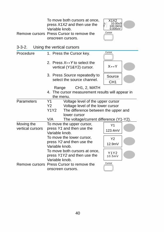
3-3-2. Using the vertical cursors
Procedure 1. Press the Cursor key. Cursor
2. Press X↔Y to select the
vertical (Y1&Y2) cursor. X↔Y
3. Press Source repeatedly to
select the source channel. Source
CH1
Range CH1, 2, MATH 4. The cursor measurement results will appear in
the menu.
Parameters Y1 Voltage level of the upper cursor Y2 Voltage level of the lower cursor Y1Y2 The difference between the upper and
lower cursor V/A The voltage/current difference (Y1-Y2).
Moving the vertical cursors
To move the upper cursor, press Y1 and then use the Variable knob.
Y1
123.4mV
To move the lower cursor, press Y2 and then use the Variable knob.
Y2
12.9mV
To move both cursors at once, press Y1Y2 and then use the Variable knob.
Y1Y210.5mV
Remove cursors Press Cursor to remove the onscreen cursors.
Cursor
41
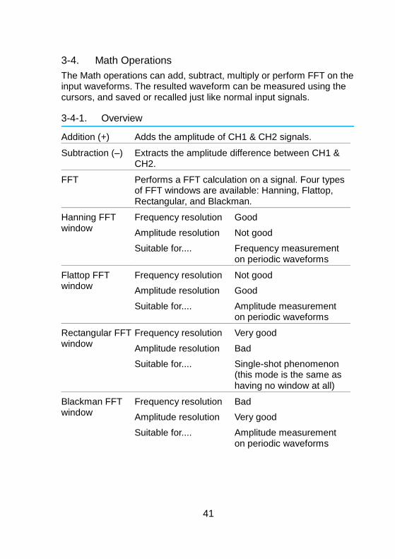
3-4. Math Operations
The Math operations can add, subtract, multiply or perform FFT on the input waveforms. The resulted waveform can be measured using the cursors, and saved or recalled just like normal input signals.
3-4-1. Overview
Addition (+) Adds the amplitude of CH1 & CH2 signals.
Subtraction (–) Extracts the amplitude difference between CH1 & CH2.
FFT Performs a FFT calculation on a signal. Four types of FFT windows are available: Hanning, Flattop, Rectangular, and Blackman.
Hanning FFT window
Frequency resolution Good
Amplitude resolution Not good
Suitable for.... Frequency measurement on periodic waveforms
Flattop FFT window
Frequency resolution Not good
Amplitude resolution Good
Suitable for.... Amplitude measurement on periodic waveforms
Rectangular FFT window
Frequency resolution Very good
Amplitude resolution Bad
Suitable for.... Single-shot phenomenon (this mode is the same as having no window at all)
Blackman FFT window
Frequency resolution Bad
Amplitude resolution Very good
Suitable for.... Amplitude measurement on periodic waveforms
42
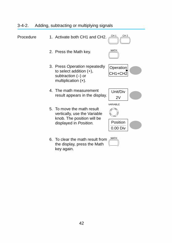
3-4-2. Adding, subtracting or multiplying signals
Procedure 1. Activate both CH1 and CH2. CH 1
CH 2
2. Press the Math key. MATH
3. Press Operation repeatedly to select addition (+), subtraction (–) or multiplication (×).
Operation
CH1+CH2
4. The math measurement result appears in the display.
Unit/Div
2V
5. To move the math result vertically, use the Variable knob. The position will be displayed in Position.
VARIABLE
Position
0.00 Div
6. To clear the math result from the display, press the Math key again.
MATH
43
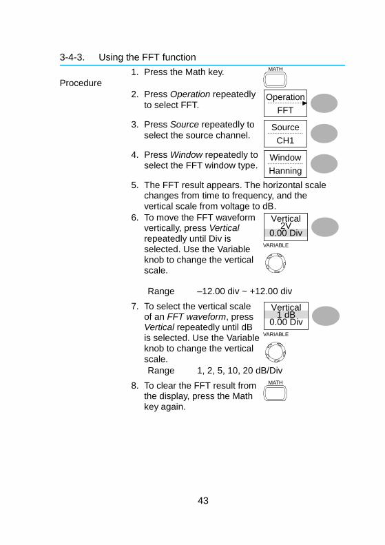
3-4-3. Using the FFT function
Procedure
1. Press the Math key. MATH
2. Press Operation repeatedly
to select FFT. Operation
FFT
3. Press Source repeatedly to
select the source channel. Source
CH1
4. Press Window repeatedly to select the FFT window type.
Window
Hanning
5. The FFT result appears. The horizontal scale changes from time to frequency, and the vertical scale from voltage to dB.
6. To move the FFT waveform vertically, press Vertical repeatedly until Div is selected. Use the Variable knob to change the vertical scale.
Vertical2V
0.00 Div
VARIABLE
Range –12.00 div ~ +12.00 div
7. To select the vertical scale of an FFT waveform, press Vertical repeatedly until dB is selected. Use the Variable knob to change the vertical scale.
Vertical1 dB
0.00 Div
VARIABLE
Range 1, 2, 5, 10, 20 dB/Div
8. To clear the FFT result from the display, press the Math key again.
MATH
44
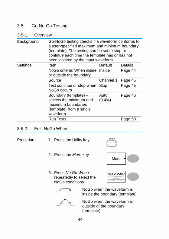
3-5. Go No-Go Testing
3-5-1. Overview
Background Go-NoGo testing checks if a waveform conforms to a user-specified maximum and minimum boundary (template). The testing can be set to stop or continue each time the template has or has not been violated by the input waveform.
Settings Item Default Details
NoGo criteria: When inside or outside the boundary
Inside Page 44
Source Channel 1 Page 45
Test continue or stop when NoGo occurs
Stop Page 45
Boundary (template) – selects the minimum and maximum boundaries (template) from a single waveform
Auto (0.4%)
Page 46
Run Tests Page 50
3-5-2. Edit: NoGo When
Procedure 1. Press the Utility key. Utility
2. Press the More key. More
3. Press No Go When repeatedly to select the NoGo conditions.
No Go When
NoGo when the waveform is inside the boundary (template)
NoGo when the waveform is outside of the boundary (template)
45
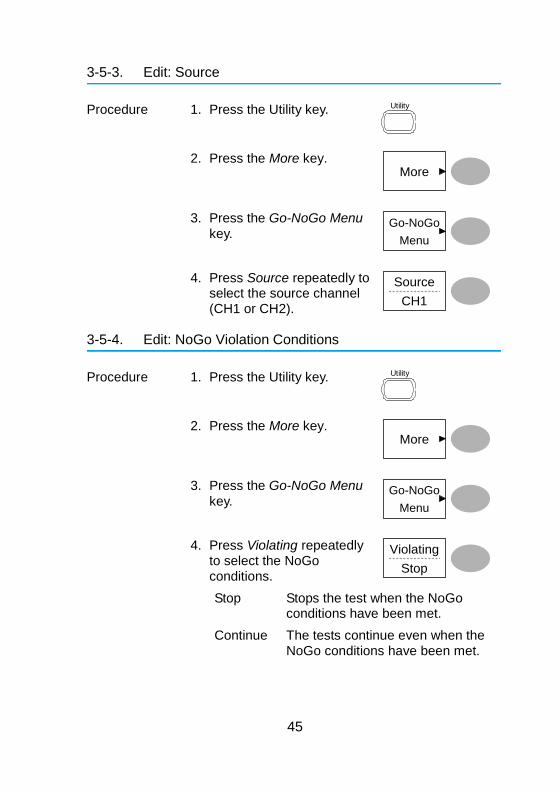
3-5-3. Edit: Source
Procedure 1. Press the Utility key. Utility
2. Press the More key. More
3. Press the Go-NoGo Menu
key. Go-NoGo
Menu
4. Press Source repeatedly to select the source channel (CH1 or CH2).
Source
CH1
3-5-4. Edit: NoGo Violation Conditions
Procedure 1. Press the Utility key. Utility
2. Press the More key. More
3. Press the Go-NoGo Menu
key. Go-NoGo
Menu
4. Press Violating repeatedly to select the NoGo conditions.
Violating
Stop
Stop Stops the test when the NoGo conditions have been met.
Continue The tests continue even when the NoGo conditions have been met.
46
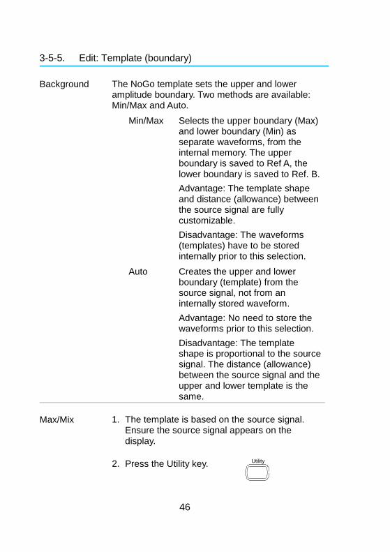
3-5-5. Edit: Template (boundary)
Background The NoGo template sets the upper and lower amplitude boundary. Two methods are available: Min/Max and Auto.
Min/Max Selects the upper boundary (Max) and lower boundary (Min) as separate waveforms, from the internal memory. The upper boundary is saved to Ref A, the lower boundary is saved to Ref. B.
Advantage: The template shape and distance (allowance) between the source signal are fully customizable.
Disadvantage: The waveforms (templates) have to be stored internally prior to this selection.
Auto Creates the upper and lower boundary (template) from the source signal, not from an internally stored waveform.
Advantage: No need to store the waveforms prior to this selection.
Disadvantage: The template shape is proportional to the source signal. The distance (allowance) between the source signal and the upper and lower template is the same.
Max/Mix 1. The template is based on the source signal. Ensure the source signal appears on the display.
2. Press the Utility key. Utility
47
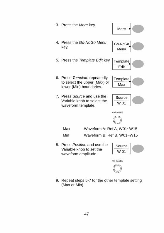
3. Press the More key. More
4. Press the Go-NoGo Menu
key. Go-NoGo
Menu
5. Press the Template Edit key. Template
Edit
6. Press Template repeatedly to select the upper (Max) or lower (Min) boundaries.
Template
Max
7. Press Source and use the Variable knob to select the waveform template.
Source
W 01
VARIABLE
Max Waveform A: Ref A, W01~W15
Min Waveform B: Ref B, W01~W15
8. Press Position and use the Variable knob to set the waveform amplitude.
Source
W 01
VARIABLE
9. Repeat steps 5-7 for the other template setting (Max or Min).
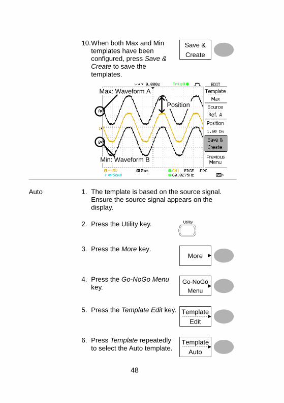
48
10. When both Max and Min templates have been configured, press Save & Create to save the
templates.
Save &
Create
Min: Waveform B
Max: Waveform A
Position
Auto 1. The template is based on the source signal. Ensure the source signal appears on the display.
2. Press the Utility key. Utility
3. Press the More key. More
4. Press the Go-NoGo Menu
key. Go-NoGo
Menu
5. Press the Template Edit key. Template
Edit
6. Press Template repeatedly
to select the Auto template. Template
Auto
49
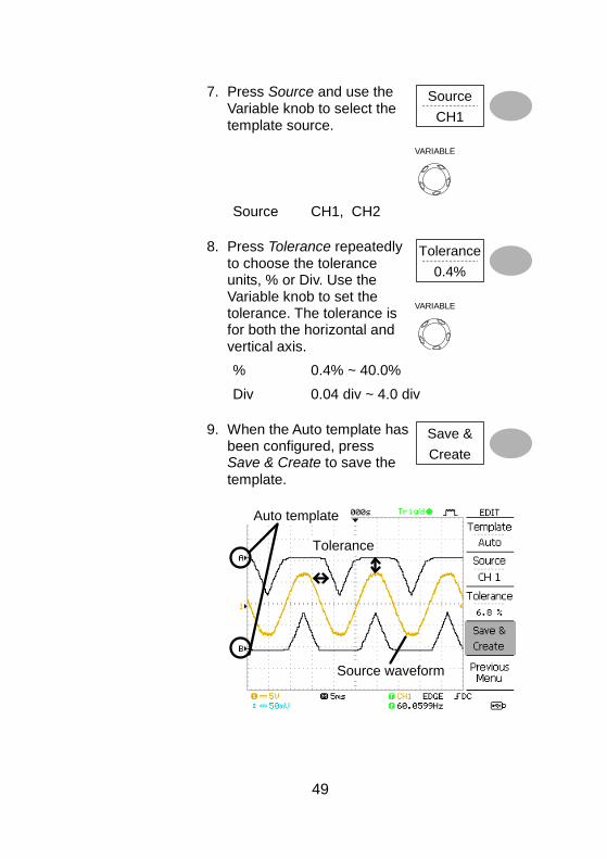
7. Press Source and use the Variable knob to select the template source.
Source
CH1
VARIABLE
Source CH1, CH2
8. Press Tolerance repeatedly to choose the tolerance units, % or Div. Use the Variable knob to set the tolerance. The tolerance is for both the horizontal and vertical axis.
Tolerance
0.4%
VARIABLE
% 0.4% ~ 40.0%
Div 0.04 div ~ 4.0 div
9. When the Auto template has been configured, press Save & Create to save the
template.
Save &
Create
Auto template
Source waveform
Tolerance
50
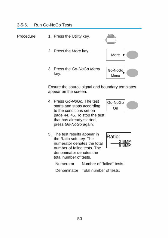
3-5-6. Run Go-NoGo Tests
Procedure 1. Press the Utility key. Utility
2. Press the More key. More
3. Press the Go-NoGo Menu
key. Go-NoGo
Menu
Ensure the source signal and boundary templates appear on the screen.
4. Press Go-NoGo. The test starts and stops according to the conditions set on page 44, 45. To stop the test that has already started, press Go-NoGo again.
Go-NoGo
On
5. The test results appear in the Ratio soft-key. The numerator denotes the total number of failed tests. The denominator denotes the total number of tests.
Ratio:2 BMP9 BMP
Numerator Number of “failed“ tests.
Denominator Total number of tests.
51
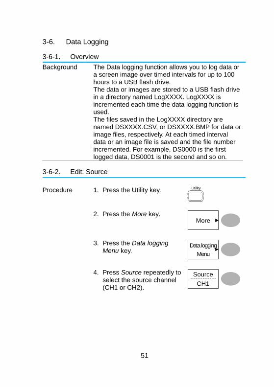
3-6. Data Logging
3-6-1. Overview
Background The Data logging function allows you to log data or a screen image over timed intervals for up to 100 hours to a USB flash drive. The data or images are stored to a USB flash drive in a directory named LogXXXX. LogXXXX is incremented each time the data logging function is used. The files saved in the LogXXXX directory are named DSXXXX.CSV, or DSXXXX.BMP for data or image files, respectively. At each timed interval data or an image file is saved and the file number incremented. For example, DS0000 is the first logged data, DS0001 is the second and so on.
3-6-2. Edit: Source
Procedure 1. Press the Utility key. Utility
2. Press the More key. More
3. Press the Data logging Menu key.
Data logging
Menu
4. Press Source repeatedly to select the source channel (CH1 or CH2).
Source
CH1
52
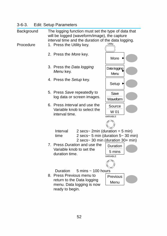
3-6-3. Edit: Setup Parameters
Background The logging function must set the type of data that will be logged (waveform/image), the capture interval time and the duration of the data logging.
Procedure 1. Press the Utility key. Utility
2. Press the More key.
More
3. Press the Data logging
Menu key. Data logging
Menu
4. Press the Setup key. Setup
5. Press Save repeatedly to
log data or screen images. Save
Waveform
6. Press Interval and use the Variable knob to select the interval time.
Source
W 01
VARIABLE
Interval
time 2 secs~ 2min (duration = 5 min) 2 secs~ 5 min (duration 5~ 30 min) 2 secs~ 30 min (duration 30+ min)
7. Press Duration and use the Variable knob to set the duration time.
Duration
5 mins
VARIABLE
Duration 5 mins ~ 100 hours 8. Press Previous menu to
return to the Data logging menu. Data logging is now ready to begin.
Previous
Menu
53
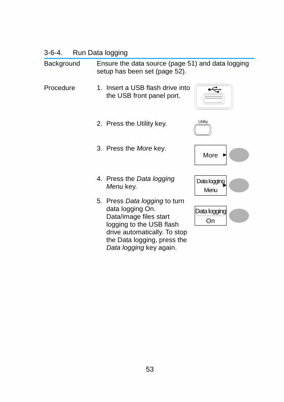
3-6-4. Run Data logging
Background Ensure the data source (page 51) and data logging setup has been set (page 52).
Procedure 1. Insert a USB flash drive into the USB front panel port.
2. Press the Utility key. Utility
3. Press the More key. More
4. Press the Data logging Menu key.
Data logging
Menu
5. Press Data logging to turn data logging On. Data/image files start logging to the USB flash drive automatically. To stop the Data logging, press the Data logging key again.
On
Data logging
54
4. CONFIGURATION
The Configuration chapter describes how to configure panel settings to make measurements and observations suited to the application needs.
4-1. Acquisition
The acquisition process samples the analog input signals and converts them into digital format for internal processing. You may select the normal, average, or peak detect acquisition mode.
4-1-1. Selecting the acquisition mode
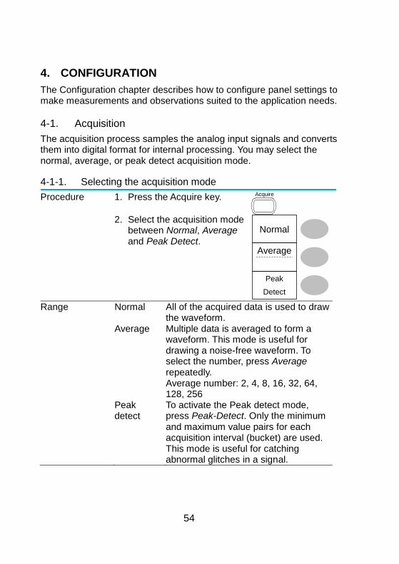
Procedure 1. Press the Acquire key. Acquire
2. Select the acquisition mode
between Normal, Average and Peak Detect.
Normal
Peak
Detect
Average
Range Normal All of the acquired data is used to draw
the waveform. Average Multiple data is averaged to form a
waveform. This mode is useful for drawing a noise-free waveform. To select the number, press Average repeatedly. Average number: 2, 4, 8, 16, 32, 64, 128, 256
Peak detect
To activate the Peak detect mode, press Peak-Detect. Only the minimum and maximum value pairs for each acquisition interval (bucket) are used. This mode is useful for catching abnormal glitches in a signal.
55
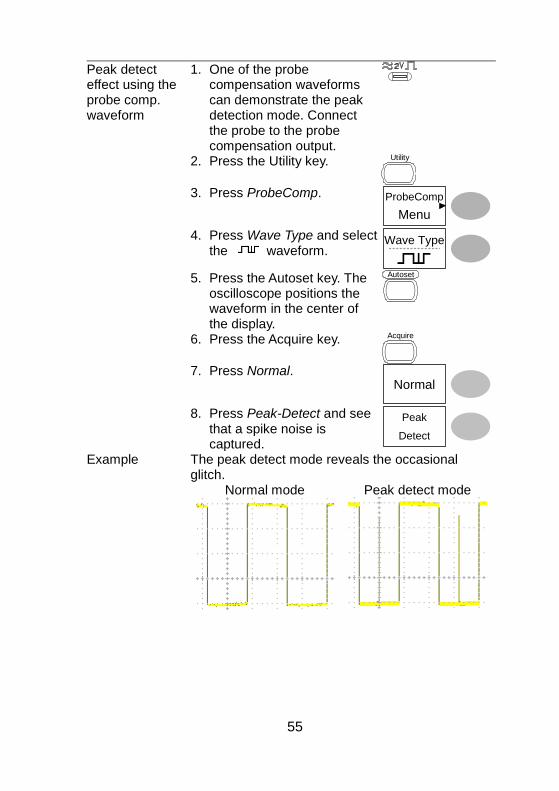
Peak detect effect using the probe comp. waveform
1. One of the probe compensation waveforms can demonstrate the peak detection mode. Connect the probe to the probe compensation output.
2. Press the Utility key. Utility
3. Press ProbeComp. ProbeComp
Menu
4. Press Wave Type and select the waveform.
Wave Type
5. Press the Autoset key. The
oscilloscope positions the waveform in the center of the display.
Autoset
6. Press the Acquire key. Acquire
7. Press Normal.
Normal
8. Press Peak-Detect and see
that a spike noise is captured.
Peak
Detect
Example The peak detect mode reveals the occasional glitch.
Normal mode
Peak detect mode
56
4-1-2. Real time vs Equivalent time sampling mode
Background The oscilloscope automatically switches between two sampling modes, Real-time and Equivalent-time, according to the number of active channels and sampling rate.
Real-time sampling
Once sampled data is used to reconstruct a single waveform. Short-time events might get lost if the sampling rate gets too high. This mode is used when the sampling rate is relatively low (250MS/s or lower).
Equivalent-time sampling
Multiple numbers of sampled data are accumulated to reconstruct a single waveform. ETS restores more waveform detail but takes longer to update the waveform. This mode is used when the sampling rate becomes higher than 250MS/s. The maximum equivalent-time sampling rate is 25GSa/s.
4-2. Display
The Display section describes how to configure the display settings: drawing type, waveform accumulation, contrast adjustment, and grid settings.
4-2-1. Selecting vector or dot drawing
Procedure 9. Press the Display key. Display
10. Press Type repeatedly to select the waveform drawing.
Type
Vectors
Types Dots Only the sampled dots are displayed.
Vectors The sampled dots are connected by
lines.
57
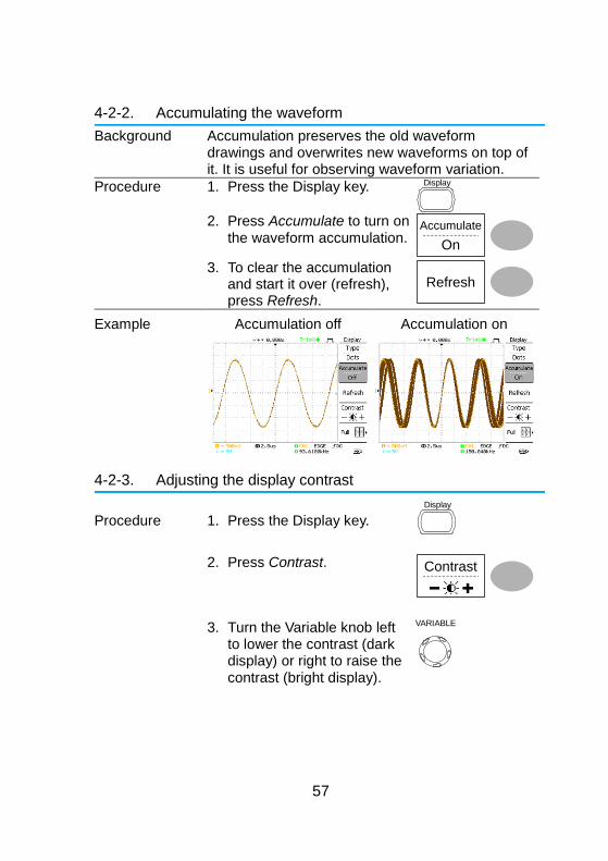
4-2-2. Accumulating the waveform
Background Accumulation preserves the old waveform drawings and overwrites new waveforms on top of it. It is useful for observing waveform variation.
Procedure 1. Press the Display key. Display
2. Press Accumulate to turn on
the waveform accumulation. Accumulate
On
3. To clear the accumulation and start it over (refresh), press Refresh.
Refresh
Example Accumulation off
Accumulation on
4-2-3. Adjusting the display contrast
Procedure 1. Press the Display key.
Display
2. Press Contrast. Contrast
3. Turn the Variable knob left to lower the contrast (dark display) or right to raise the contrast (bright display).
VARIABLE
58
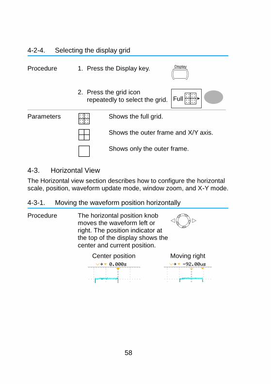
4-2-4. Selecting the display grid
Procedure 1. Press the Display key. Display
2. Press the grid icon repeatedly to select the grid. Full
Parameters
Shows the full grid.
Shows the outer frame and X/Y axis.
Shows only the outer frame.
4-3. Horizontal View
The Horizontal view section describes how to configure the horizontal scale, position, waveform update mode, window zoom, and X-Y mode.
4-3-1. Moving the waveform position horizontally
Procedure The horizontal position knob moves the waveform left or right. The position indicator at the top of the display shows the center and current position.
Center position
Moving right
59
4-3-2. Selecting the horizontal scale
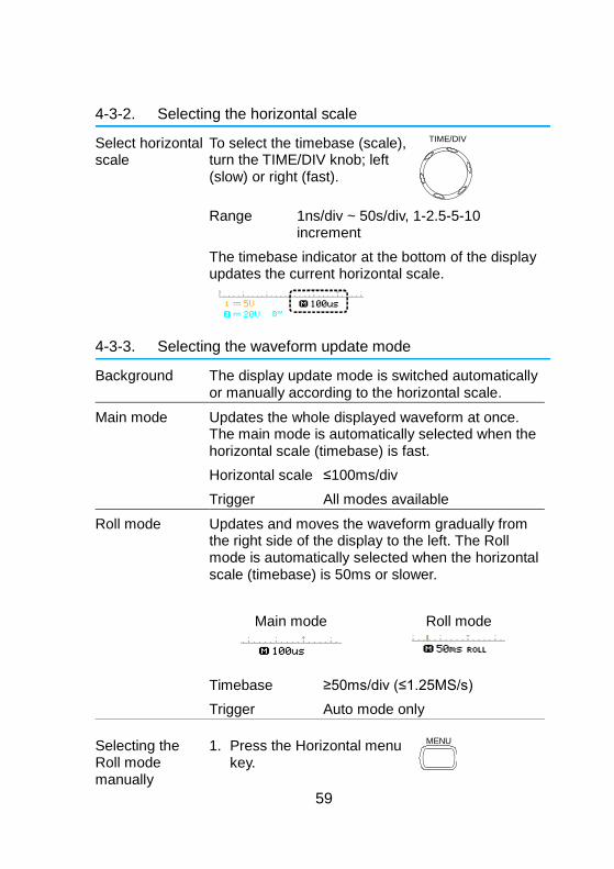
Select horizontal scale
To select the timebase (scale), turn the TIME/DIV knob; left (slow) or right (fast).
TIME/DIV
Range 1ns/div ~ 50s/div, 1-2.5-5-10 increment
The timebase indicator at the bottom of the display updates the current horizontal scale.
4-3-3. Selecting the waveform update mode
Background The display update mode is switched automatically or manually according to the horizontal scale.
Main mode Updates the whole displayed waveform at once. The main mode is automatically selected when the horizontal scale (timebase) is fast.
Horizontal scale ≤100ms/div
Trigger All modes available
Roll mode Updates and moves the waveform gradually from the right side of the display to the left. The Roll mode is automatically selected when the horizontal scale (timebase) is 50ms or slower.
Main mode
Roll mode
Timebase ≥50ms/div (≤1.25MS/s)
Trigger Auto mode only
Selecting the Roll mode manually
1. Press the Horizontal menu key.
MENU
60
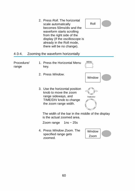
2. Press Roll. The horizontal scale automatically becomes 50ms/div and the waveform starts scrolling from the right side of the display (If the oscilloscope is already in the Roll mode, there will be no change).
Roll
4-3-4. Zooming the waveform horizontally
Procedure/ range
1. Press the Horizontal Menu key.
MENU
2. Press Window. Window
3. Use the horizontal position knob to move the zoom range sideways, and TIME/DIV knob to change the zoom range width.
TIME/DIV
The width of the bar in the middle of the display is the actual zoomed area.
Zoom range 1ns ~ 25s
4. Press Window Zoom. The specified range gets zoomed.
Window
Zoom
61
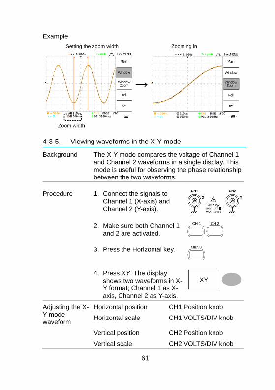
Example
Zoom width
Setting the zoom width Zooming in
4-3-5. Viewing waveforms in the X-Y mode
Background The X-Y mode compares the voltage of Channel 1 and Channel 2 waveforms in a single display. This mode is useful for observing the phase relationship between the two waveforms.
Procedure 1. Connect the signals to Channel 1 (X-axis) and Channel 2 (Y-axis).
2. Make sure both Channel 1 and 2 are activated.
CH 1
CH 2
3. Press the Horizontal key. MENU
4. Press XY. The display shows two waveforms in X-Y format; Channel 1 as X-axis, Channel 2 as Y-axis.
XY
Adjusting the X-Y mode waveform
Horizontal position CH1 Position knob
Horizontal scale CH1 VOLTS/DIV knob
Vertical position CH2 Position knob
Vertical scale CH2 VOLTS/DIV knob
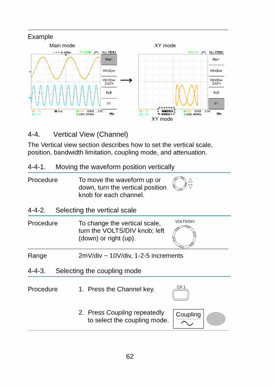
62
Example
Main mode XY mode
XY mode
4-4. Vertical View (Channel)
The Vertical view section describes how to set the vertical scale, position, bandwidth limitation, coupling mode, and attenuation.
4-4-1. Moving the waveform position vertically
Procedure To move the waveform up or down, turn the vertical position knob for each channel.
4-4-2. Selecting the vertical scale
Procedure To change the vertical scale, turn the VOLTS/DIV knob; left (down) or right (up).
VOLTS/DIV
Range 2mV/div ~ 10V/div, 1-2-5 increments
4-4-3. Selecting the coupling mode
Procedure 1. Press the Channel key. CH 1
2. Press Coupling repeatedly
to select the coupling mode. Coupling
63
Range DC coupling mode. The whole portion (AC and DC) of the signal appears on the display.
Ground coupling mode. The display shows only the zero voltage level as a horizontal line. This mode is useful for measuring the signal amplitude with respect to the ground level.
AC coupling mode. Only the AC portion of the signal appears on the display. This mode is useful for observing AC waveforms mixed with DC components.
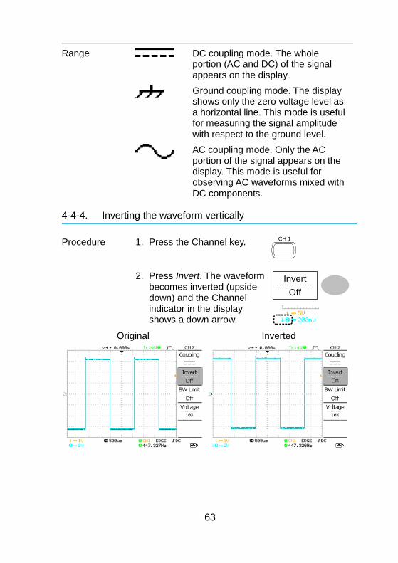
4-4-4. Inverting the waveform vertically
Procedure 1. Press the Channel key. CH 1
2. Press Invert. The waveform becomes inverted (upside down) and the Channel indicator in the display shows a down arrow.
Invert
Off
Original
Inverted
64
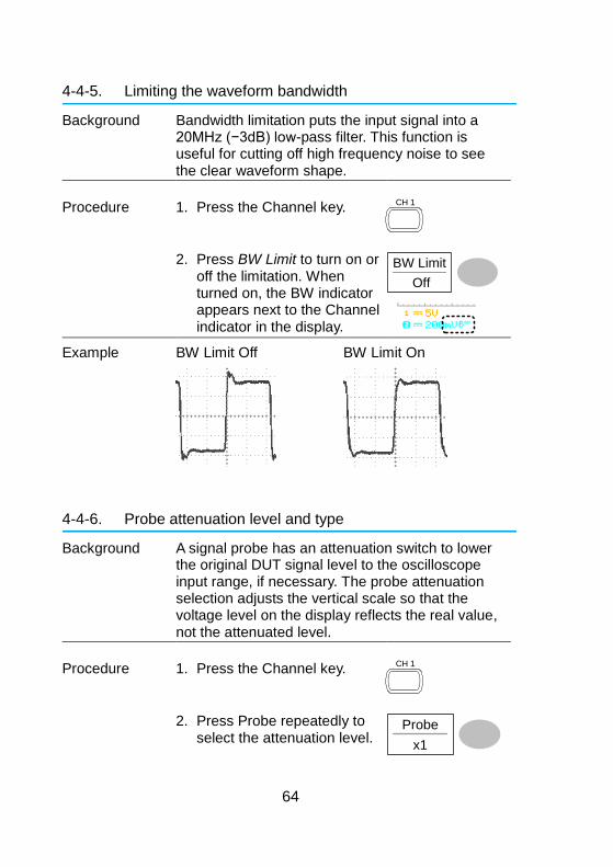
4-4-5. Limiting the waveform bandwidth
Background Bandwidth limitation puts the input signal into a 20MHz (−3dB) low-pass filter. This function is useful for cutting off high frequency noise to see the clear waveform shape.
Procedure 1. Press the Channel key. CH 1
2. Press BW Limit to turn on or off the limitation. When turned on, the BW indicator appears next to the Channel indicator in the display.
BW Limit
Off
Example BW Limit Off
BW Limit On
4-4-6. Probe attenuation level and type
Background A signal probe has an attenuation switch to lower the original DUT signal level to the oscilloscope input range, if necessary. The probe attenuation selection adjusts the vertical scale so that the voltage level on the display reflects the real value, not the attenuated level.
Procedure 1. Press the Channel key. CH 1
2. Press Probe repeatedly to select the attenuation level.
Probe
x1
65
3. The voltage scale in the channel indicator changes accordingly. There is no change in the waveform shape.
Range x1, x10, x100
Note: The attenuation factor adds no influence on the real signal; it only changes the voltage/current scale on the display.
4-5. Trigger
The Trigger function configures the conditions by which the oscilloscope captures the incoming signals.
4-5-1. Trigger type
Edge Triggers when the signal crosses an amplitude threshold in either a positive or negative slope.
Video Extracts a sync pulse from a video format signal and triggers on a specific line or field.
Pulse Triggers when the pulse width of the signal matches the trigger settings.
Indicators Edge/Pulse
(CH1, Edge, Rising edge, DC coupling)
Video
(CH1, Video, Positive polarity, NTSC standard)
4-5-2. Trigger parameter
Trigger source CH1, 2 Channel 1, 2 input signals Line AC mains signal Ext External trigger input signal EXT TRIG
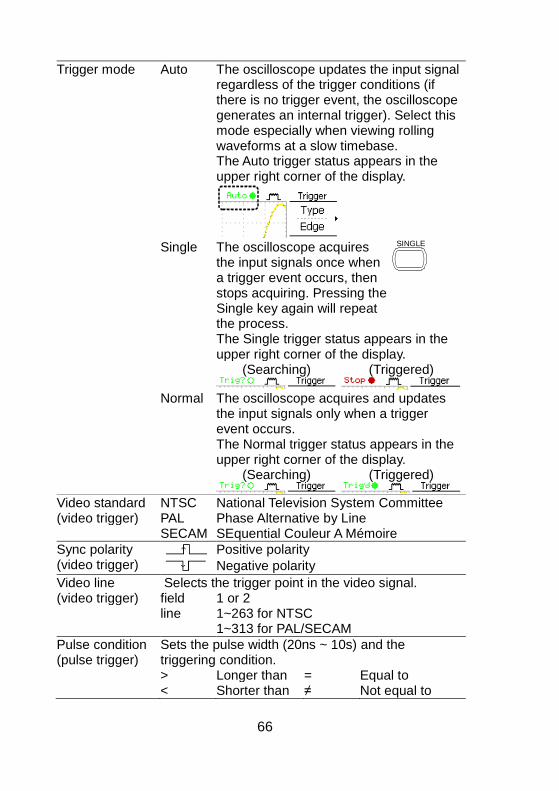
66
Trigger mode Auto The oscilloscope updates the input signal regardless of the trigger conditions (if there is no trigger event, the oscilloscope generates an internal trigger). Select this mode especially when viewing rolling waveforms at a slow timebase.
The Auto trigger status appears in the upper right corner of the display.
Single The oscilloscope acquires
the input signals once when a trigger event occurs, then stops acquiring. Pressing the Single key again will repeat the process.
SINGLE
The Single trigger status appears in the upper right corner of the display.
(Searching)
(Triggered)
Normal The oscilloscope acquires and updates
the input signals only when a trigger event occurs.
The Normal trigger status appears in the upper right corner of the display.
(Searching)
(Triggered)
Video standard (video trigger)
NTSC National Television System Committee PAL Phase Alternative by Line
SECAM SEquential Couleur A Mémoire
Sync polarity (video trigger)
Positive polarity
Negative polarity
Video line (video trigger)
Selects the trigger point in the video signal. field 1 or 2
line 1~263 for NTSC 1~313 for PAL/SECAM
Pulse condition (pulse trigger)
Sets the pulse width (20ns ~ 10s) and the triggering condition.
> Longer than = Equal to < Shorter than ≠ Not equal to
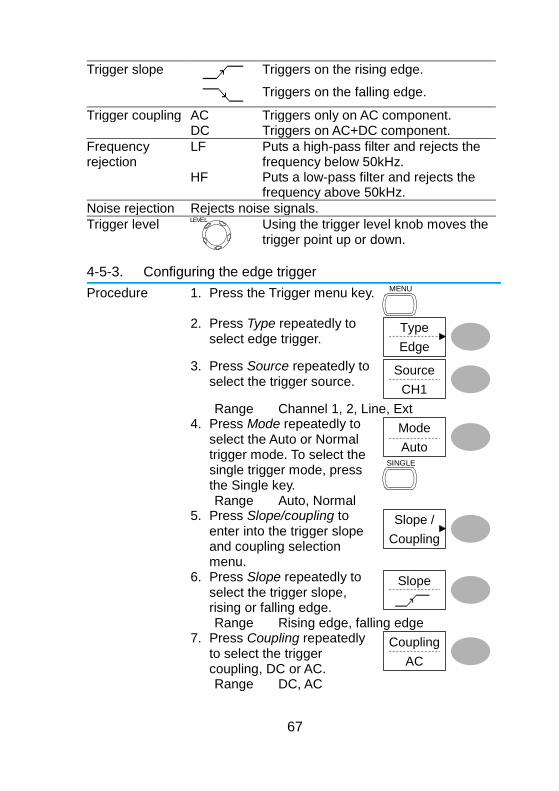
67
Trigger slope
Triggers on the rising edge.
Triggers on the falling edge.
Trigger coupling AC Triggers only on AC component. DC Triggers on AC+DC component.
Frequency rejection
LF Puts a high-pass filter and rejects the frequency below 50kHz.
HF Puts a low-pass filter and rejects the frequency above 50kHz.
Noise rejection Rejects noise signals.
Trigger level LEVEL
Using the trigger level knob moves the trigger point up or down.
4-5-3. Configuring the edge trigger
Procedure 1. Press the Trigger menu key. MENU
2. Press Type repeatedly to
select edge trigger. Type
Edge
3. Press Source repeatedly to select the trigger source.
Source
CH1
Range Channel 1, 2, Line, Ext 4. Press Mode repeatedly to
select the Auto or Normal trigger mode. To select the single trigger mode, press the Single key.
Mode
Auto
SINGLE
Range Auto, Normal 5. Press Slope/coupling to
enter into the trigger slope and coupling selection menu.
Slope /
Coupling
6. Press Slope repeatedly to select the trigger slope, rising or falling edge.
Slope
Range Rising edge, falling edge 7. Press Coupling repeatedly
to select the trigger coupling, DC or AC.
Coupling
AC
Range DC, AC
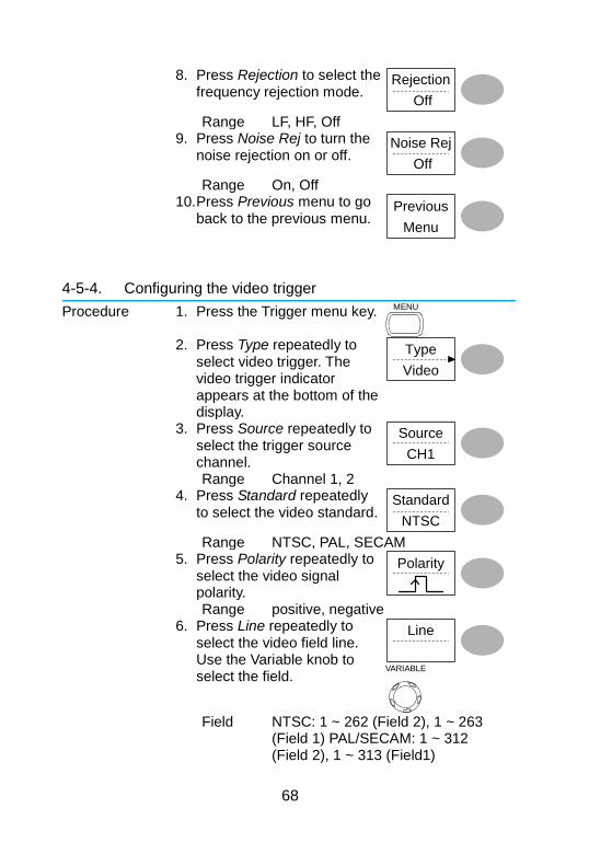
68
8. Press Rejection to select the frequency rejection mode.
Rejection
Off
Range LF, HF, Off 9. Press Noise Rej to turn the
noise rejection on or off. Noise Rej
Off
Range On, Off 10. Press Previous menu to go
back to the previous menu. Previous
Menu
4-5-4. Configuring the video trigger
Procedure 1. Press the Trigger menu key. MENU
2. Press Type repeatedly to
select video trigger. The video trigger indicator appears at the bottom of the display.
Type
Video
3. Press Source repeatedly to select the trigger source channel.
Source
CH1
Range Channel 1, 2 4. Press Standard repeatedly
to select the video standard. Standard
NTSC
Range NTSC, PAL, SECAM 5. Press Polarity repeatedly to
select the video signal polarity.
Polarity
Range positive, negative 6. Press Line repeatedly to
select the video field line. Use the Variable knob to select the field.
Line
VARIABLE
Field NTSC: 1 ~ 262 (Field 2), 1 ~ 263
(Field 1) PAL/SECAM: 1 ~ 312 (Field 2), 1 ~ 313 (Field1)

69
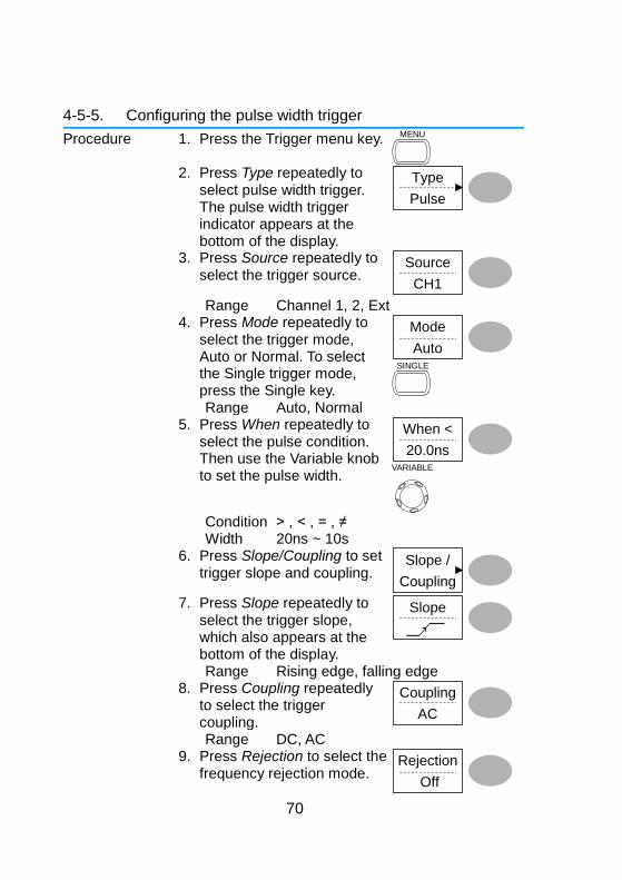
70
4-5-5. Configuring the pulse width trigger
Procedure 1. Press the Trigger menu key. MENU
2. Press Type repeatedly to
select pulse width trigger. The pulse width trigger indicator appears at the bottom of the display.
Type
Pulse
3. Press Source repeatedly to select the trigger source.
Source
CH1
Range Channel 1, 2, Ext 4. Press Mode repeatedly to
select the trigger mode, Auto or Normal. To select the Single trigger mode, press the Single key.
Mode
Auto
SINGLE
Range Auto, Normal 5. Press When repeatedly to
select the pulse condition. Then use the Variable knob to set the pulse width.
When <
20.0ns
VARIABLE
Condition > , < , = , ≠ Width 20ns ~ 10s 6. Press Slope/Coupling to set
trigger slope and coupling. Slope /
Coupling
7. Press Slope repeatedly to select the trigger slope, which also appears at the bottom of the display.
Slope
Range Rising edge, falling edge 8. Press Coupling repeatedly
to select the trigger coupling.
Coupling
AC
Range DC, AC 9. Press Rejection to select the
frequency rejection mode. Rejection
Off
71
Range LF, HF, Off 10. Press Noise Rej to turn the
noise rejection on or off. Noise Rej
Off
Range On, Off 11. Press Previous menu to go
back to the previous menu. Previous
Menu
4-5-6. Manually triggering the signal
Note: This section describes how to manually trigger the input signals when the oscilloscope does not capture them. This section applies to the Normal and Single trigger mode, since in the Auto trigger mode, the oscilloscope keeps updating the input signal regardless of the trigger conditions.
To acquire the signal regardless of trigger conditions
To acquire the input signal regardless of the trigger condition, press the Force key. The oscilloscope captures the signals once.
FORCE
In the Single trigger mode
Press the Single key to start waiting for the trigger condition. To break out of the Single mode, press the Run/Stop key. The trigger mode changes to the Normal mode.
SINGLE
Run/Stop
72
4-6. Remote Control Interface
The Remote control interface section describes how to set up the USB interface for PC connection. Remote control command details are described in the DCS-4605 Programming Manual.
USB connection PC end Type A, host
(Windows7 or higher) DCS-4605 end Type B, slave
Speed USB CLASS
1.1/2.0 (full speed) USB-CDC
Procedure 1. Connect the USB cable to the USB slave port.
2. The USB port may need to be configured if
the USB port is not automatically detected. 3. When the PC asks for the USB driver or
‘Unknown device’ listed in Device Manager, install TEXIO_CDC.inf attached CD.
4. On the PC, activate a terminal application such as Putty. To check the COM port No., see the Device Manager in the PC.
5. Run this query command via the terminal application. *idn? This command should return the manufacturer, model number, serial number, and firmware version in the following format. TEXIO, DCS-4605, XXXXXXX, V1.00
6. Configuring the command interface is complete. Refer to the programming manual for the remote commands and other details.
CAUTION: If there is no response, please confirm a device driver, COM port number or the connection of the cable and so on.
CAUTION: If you change the setting of the USB port in the connection with the PC, May not be able to communicate. Please restart your PC in this case.
73
4-7. Control with the “FreeWave” It is possible to control from PC by using the application the FreeWave attached CD. It is also possible to control the application by using GUI and the command. For details about commands, see the DCS-4605 programming manual.
4-7-1. System requirements OS Microsoft Windows 7 (32bit/64bit) or higher
Required software
Microsoft .NETFramework ver4.0 full Microsoft Visual C++2010 Redistributable Package
Before you install the FreeWave ,Check the required software by ”Control panel > Add or remove program”.
Please install required software If you can’t find. You must have administrator account to install software. This application features and display may change to allow for the upgrade.
4-7-2. Icon
Each screen is switched by selecting icon in the upper part of the screen.The function of the button of each icon is as follows.
Connect
Image
Data
Command
Long memory
NOTE: Long memory is not work at DCS-4605.
74
4-7-3. Connect screen
It is screen to select the model that controls from the Free Wave.
Click the scan icon to Scan for the oscilloscope. Depending on the environment of the PC may take a minute to startup and update.
Click the icon to Scan for the oscilloscope.
Because the model that can connect it is displayed, it selects it clicking.
Information on the equipment that has been selected is displayed.
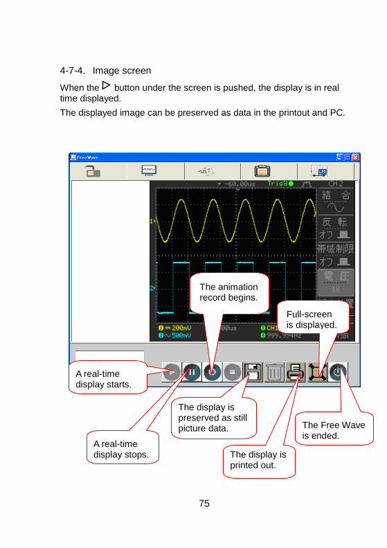
75
4-7-4. Image screen
When the button under the screen is pushed, the display is in real time displayed.
The displayed image can be preserved as data in the printout and PC.
Full-screen is displayed.
The animation record begins.
A real-time display starts.
A real-time display stops.
The display is preserved as still picture data.
The display is printed out.
The Free Wave is ended.
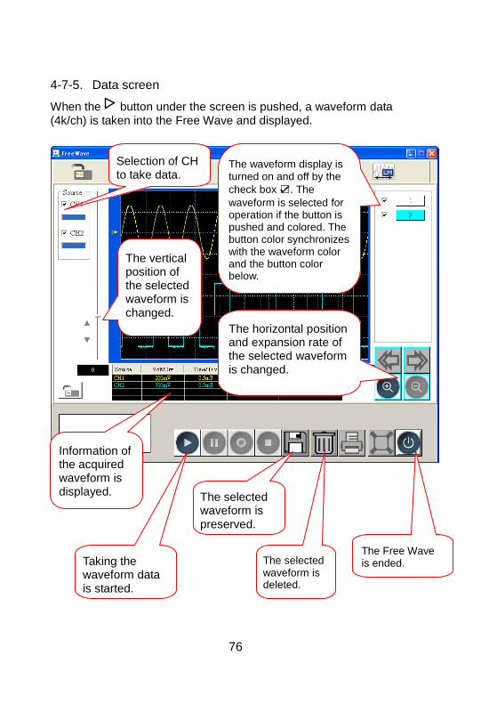
76
4-7-5. Data screen
When the button under the screen is pushed, a waveform data (4k/ch) is taken into the Free Wave and displayed.
Selection of CH to take data.
The waveform display is turned on and off by the
check box . The
waveform is selected for operation if the button is pushed and colored. The button color synchronizes with the waveform color and the button color below.
The horizontal position and expansion rate of the selected waveform is changed.
The vertical position of the selected waveform is changed.
Information of the acquired waveform is displayed.
Taking the waveform data is started.
The selected waveform is preserved.
The selected waveform is deleted.
The Free Wave is ended.
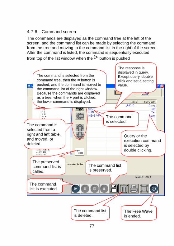
77
4-7-6. Command screen
The commands are displayed as the command tree at the left of the screen, and the command list can be made by selecting the command from the tree and moving to the command list in the right of the screen. After the command is listed, the command is sequentially executed
from top of the list window when the button is pushed
The command is selected from the
command tree, then the ⇒button is
pushed, and the command is moved to the command list of the right window. Because the commands are displayed as a tree, when the + part is clicked, the lower command is displayed.
The response is displayed in query. Except query, double click and set a setting value.
The command is selected.
Query or the execution command is selected by double clicking.
The command is selected from a right and left table, and moved, or deleted.
The preserved command list is called.
The command list is executed.
The command list is preserved.
The command list is deleted.
The Free Wave is ended.
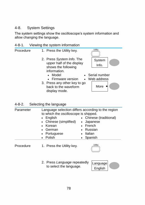
78
4-8. System Settings
The system settings show the oscilloscope’s system information and allow changing the language.
4-8-1. Viewing the system information
Procedure 1. Press the Utility key. Utility
2. Press System Info. The
upper half of the display shows the following information.
System
Info.
Model Serial number Firmware version Web address 3. Press any other key to go
back to the waveform display mode.
More
4-8-2. Selecting the language
Parameter Language selection differs according to the region to which the oscilloscope is shipped.
English Chinese (traditional) Chinese (simplified) Japanese Korean French German Russian Portuguese Italian Polish Spanish
Procedure 1. Press the Utility key.
Utility
2. Press Language repeatedly
to select the language. Language
English
79
5. SAVE/RECALL
The save function allows saving display images, waveform data, and panel settings into the oscilloscope’s internal memory or to the front panel USB port. The recall function allows recalling the default factory settings, waveform data, and panel settings from the oscilloscope’s internal memory or from USB.
5-1. File Structures
Three types of file are available: display image, waveform file, and panel settings.
5-1-1. Display image file format
Format xxxx.bmp (Windows bitmap format)
Contents The current display image in 234 x 320 pixels, color mode. The background color can be inverted (Ink saver function).
5-1-2. Waveform file format
Format xxxx.csv (Comma-separated values format which can be opened in spreadsheet applications such as Microsoft Excel)
Waveform type CH1, 2 Input channel signal Math Math operation result (page 41)
Storage location Internal memory
The oscilloscope’s internal memory, which can hold 15 waveforms.
External USB Flash drive
A USB flash drive (FAT or FAT32 format) can hold practically an unlimited number of waveforms.
Ref A, B Two reference waveforms are used as a buffer to recall a waveform in the display. You have to save a waveform into internal memory or to USB, then copy the waveform into the reference waveform slot (A or B), and then recall the reference waveform into the display.
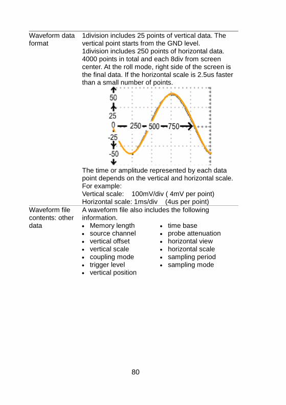
80
Waveform data format
1division includes 25 points of vertical data. The vertical point starts from the GND level. 1division includes 250 points of horizontal data. 4000 points in total and each 8div from screen center. At the roll mode, right side of the screen is the final data. If the horizontal scale is 2.5us faster than a small number of points.
The time or amplitude represented by each data
point depends on the vertical and horizontal scale. For example: Vertical scale: 100mV/div ( 4mV per point) Horizontal scale: 1ms/div (4us per point)
Waveform file contents: other data
A waveform file also includes the following information. Memory length source channel vertical offset vertical scale coupling mode trigger level vertical position
time base probe attenuation horizontal view horizontal scale sampling period sampling mode
81
5-1-3. Setup file format
Format xxxx.set (proprietary format) A setup file saves or recalls the following settings.
Contents Acquire mode Cursor source channel
cursor location cursor on/off
Display dots/vectors grid type
accumulation on/off
Measure item Utility hardcopy type
language Data Logging
settings
ink saver on/off Go-Nogo settings
Horizontal display mode position
scale
Trigger trigger type trigger mode video polarity pulse timing
source channel video standard video line slope/coupling
Channel (vertical)
vertical scale coupling mode bandwidth limit
on/off
vertical position invert on/off probe attenuation
Math operation type vertical position FFT window
source channel unit/div
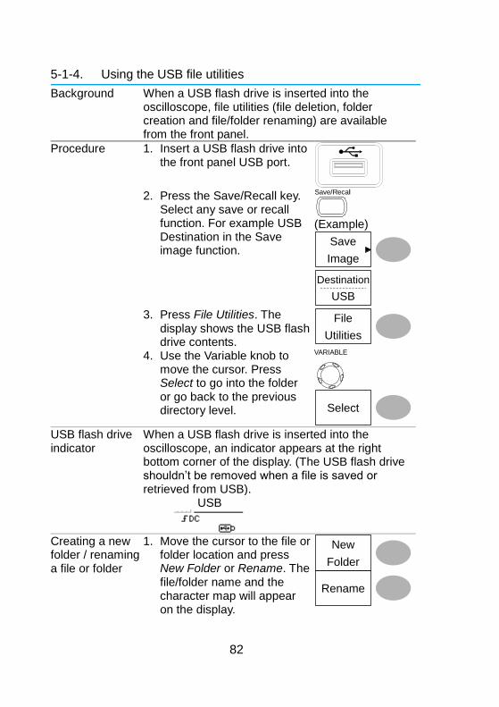
82
5-1-4. Using the USB file utilities
Background When a USB flash drive is inserted into the oscilloscope, file utilities (file deletion, folder creation and file/folder renaming) are available from the front panel.
Procedure 1. Insert a USB flash drive into the front panel USB port.
2. Press the Save/Recall key.
Select any save or recall function. For example USB Destination in the Save image function.
Save/Recall
(Example)
Save
Image
Destination
USB
3. Press File Utilities. The display shows the USB flash drive contents.
File
Utilities
4. Use the Variable knob to move the cursor. Press Select to go into the folder or go back to the previous directory level.
VARIABLE
Select
USB flash drive indicator
When a USB flash drive is inserted into the oscilloscope, an indicator appears at the right bottom corner of the display. (The USB flash drive shouldn’t be removed when a file is saved or retrieved from USB).
USB
Creating a new folder / renaming a file or folder
1. Move the cursor to the file or folder location and press New Folder or Rename. The file/folder name and the character map will appear on the display.
Rename
New
Folder
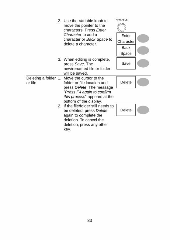
83
2. Use the Variable knob to move the pointer to the characters. Press Enter Character to add a character or Back Space to delete a character.
VARIABLE
Enter
Character
Back
Space
3. When editing is complete, press Save. The new/renamed file or folder will be saved.
Save
Deleting a folder or file
1. Move the cursor to the folder or file location and press Delete. The message “Press F4 again to confirm this process” appears at the bottom of the display.
Delete
2. If the file/folder still needs to be deleted, press Delete again to complete the deletion. To cancel the deletion, press any other key.
Delete
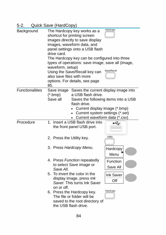
84
5-2. Quick Save (HardCopy)
Background The Hardcopy key works as a shortcut for printing screen images directly to save display images, waveform data, and panel settings onto a USB flash drive card.
Hardcopy
The Hardcopy key can be configured into three types of operations: save image, save all (image, waveform, setup)
Using the Save/Recall key can also save files with more options. For details, see page 85.
Save/Recall
Functionalities Save image (*.bmp)
Saves the current display image into a USB flash drive.
Save all Saves the following items into a USB flash drive. Current display image (*.bmp) Current system settings (*.set) Current waveform data (*.csv)
Procedure 1. Insert a USB flash drive into the front panel USB port.
2. Press the Utility key. Utility
3. Press Hardcopy Menu. Hardcopy
Menu
4. Press Function repeatedly to select Save Image or Save All.
Function
Save All
5. To invert the color in the display image, press Ink Saver. This turns Ink Saver on or off.
Ink Saver
Off
6. Press the Hardcopy key. The file or folder will be saved to the root directory of the USB flash drive.
Hardcopy
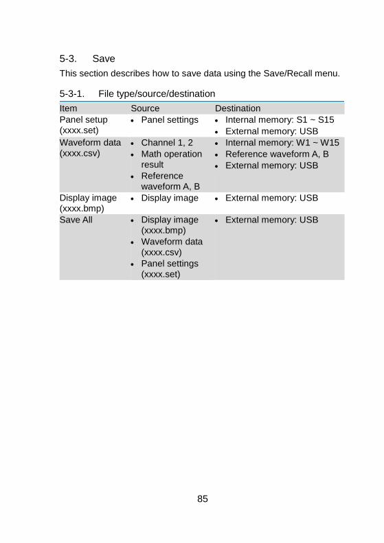
85
5-3. Save
This section describes how to save data using the Save/Recall menu.
5-3-1. File type/source/destination
Item Source Destination
Panel setup (xxxx.set)
Panel settings Internal memory: S1 ~ S15
External memory: USB
Waveform data (xxxx.csv)
Channel 1, 2
Math operation result
Reference waveform A, B
Internal memory: W1 ~ W15
Reference waveform A, B
External memory: USB
Display image (xxxx.bmp)
Display image External memory: USB
Save All Display image (xxxx.bmp)
Waveform data (xxxx.csv)
Panel settings (xxxx.set)
External memory: USB
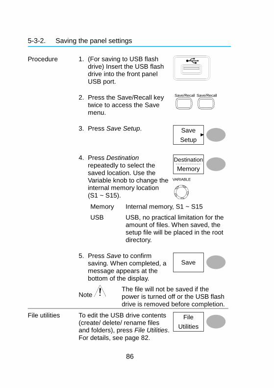
86
5-3-2. Saving the panel settings
Procedure 1. (For saving to USB flash drive) Insert the USB flash drive into the front panel USB port.
2. Press the Save/Recall key twice to access the Save menu.
Save/Recall
Save/Recall
3. Press Save Setup. Save
Setup
4. Press Destination repeatedly to select the saved location. Use the Variable knob to change the internal memory location (S1 ~ S15).
Destination
Memory
VARIABLE
Memory Internal memory, S1 ~ S15
USB USB, no practical limitation for the amount of files. When saved, the setup file will be placed in the root directory.
5. Press Save to confirm saving. When completed, a message appears at the bottom of the display.
Save
Note
The file will not be saved if the power is turned off or the USB flash drive is removed before completion.
File utilities To edit the USB drive contents (create/ delete/ rename files and folders), press File Utilities. For details, see page 82.
File
Utilities

87
5-3-3. Saving the waveform
Procedure 1. (For saving to USB flash drive) Insert the USB flash drive into the front panel USB port.
2. Press the Save/Recall key twice to access the Save menu.
Save/Recall
Save/Recall
3. Press Save Waveform. Save
Waveform
4. Press Source. Use the Variable knob to select the source signal.
Source
VARIABLE
CH1 ~ CH2 Channel 1 ~ 2 signal Math Math operation result (page 41) RefA, B Internally stored reference
waveforms A, B 5. Press Destination
repeatedly to select the file destination. Use the Variable knob to select the memory location.
Destination
Memory
VARIABLE
Memory Internal memory, W1 ~ W15 USB Save to the USB flash drive with a
4k waveform memory length. Ref Internal reference waveform, A/B 6. Press Save to confirm
saving. When completed, a message appears at the bottom of the display.
Save
Note
The file will not be saved if the power is turned off or the USB flash drive is removed from the USB port.
File utilities To edit the USB drive contents (create/ delete/ rename files and folders), press File Utilities. For details, see page 82.
File
Utilities
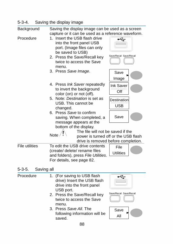
88
5-3-4. Saving the display image
Background Saving the display image can be used as a screen capture or it can be used as a reference waveform.
Procedure 1. Insert the USB flash drive into the front panel USB port. (Image files can only be saved to USB)
2. Press the Save/Recall key twice to access the Save menu.
Save/Recall
Save/Recall
3. Press Save Image. Save
Image
4. Press Ink Saver repeatedly to invert the background color (on) or not (off).
Ink Saver
Off
5. Note: Destination is set as USB. This cannot be changed.
Destination
USB
6. Press Save to confirm saving. When completed, a message appears at the bottom of the display.
Save
Note
The file will not be saved if the power is turned off or the USB flash drive is removed before completion.
File utilities To edit the USB drive contents (create/ delete/ rename files and folders), press File Utilities. For details, see page 82.
File
Utilities
5-3-5. Saving all
Procedure 1. (For saving to USB flash drive) Insert the USB flash drive into the front panel USB port.
2. Press the Save/Recall key twice to access the Save menu.
Save/Recall
Save/Recall
3. Press Save All. The following information will be saved.
Save
All

89
Setup file (Axxxx.set)
Two types of setups are saved: the current panel setting and the last internally saved settings (one of S1 ~ S15).
Display image (Axxxx.bmp)
The current display image in bitmap format.
Waveform data (Axxxx.csv)
Two types of waveform data are saved: the currently active channel data and the last internally saved data (one of W1 ~ W15).
4. Press Ink Saver repeatedly to invert the background color (on) or not (off) for the display image.
Ink Saver
Off
5. Press Destination. Destination
USB
USB Save to the USB flash drive with a 4k waveform memory length.
6. Press Save to confirm saving. When completed, a message appears at the bottom of the display.
Save
Note
The file will not be saved if the power is turned off or the USB flash drive is removed from the USB port. .
7. The current waveform(s) (*.CSV), setup file (*.SET) and display image (*.BMP) are saved to a directory (ALLXXXX).
File utilities To edit the USB drive contents (create/ delete/ rename files and folders), press File Utilities. For details, see page 82.
File
Utilities
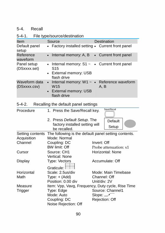
90
5-4. Recall
5-4-1. File type/source/destination
Item Source Destination Default panel setup
Factory installed setting Current front panel
Reference waveform
Internal memory: A, B Current front panel
Panel setup (DSxxxx.set)
Internal memory: S1 ~ S15
External memory: USB flash drive
Current front panel
Waveform data (DSxxxx.csv)
Internal memory: W1 ~ W15
External memory: USB flash drive
Reference waveform A, B
5-4-2. Recalling the default panel settings
Procedure 1. Press the Save/Recall key. Save/Recall
2. Press Default Setup. The
factory installed setting will be recalled.
Default
Setup
Setting contents The following is the default panel setting contents. Acquisition Mode: Normal Channel Coupling: DC Invert: Off BW limit: Off Probe attenuation: x1
Cursor Source: CH1 Horizontal: None Vertical: None Display Type: Vectors Accumulate: Off
Graticule:
Horizontal Scale: 2.5us/div Mode: Main Timebase Math Type: + (Add) Channel: Off Position: 0.00 div Unit/div: 2V Measure Item: Vpp, Vavg, Frequency, Duty cycle, Rise Time Trigger Type: Edge Source: Channel1 Mode: Auto Slope: Coupling: DC Rejection: Off Noise Rejection: Off
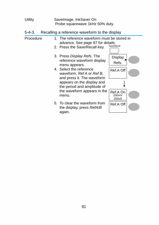
91
Utility SaveImage, InkSaver On Probe squarewave 1kHz 50% duty.
5-4-3. Recalling a reference waveform to the display
Procedure 1. The reference waveform must be stored in advance. See page 87 for details.
2. Press the Save/Recall key. Save/Recall
3. Press Display Refs. The
reference waveform display menu appears.
Display
Refs.
4. Select the reference waveform, Ref A or Ref B, and press it. The waveform appears on the display and the period and amplitude of the waveform appears in the menu.
Ref.A Off
Ref.A On200mV
250uS 5. To clear the waveform from
the display, press RefA/B again.
Ref.A Off
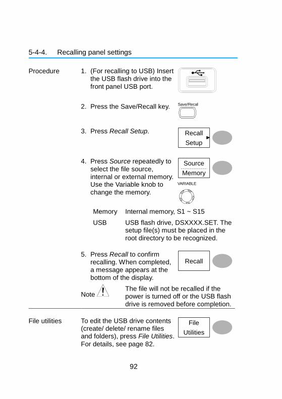
92
5-4-4. Recalling panel settings
Procedure 1. (For recalling to USB) Insert the USB flash drive into the front panel USB port.
2. Press the Save/Recall key. Save/Recall
3. Press Recall Setup. Recall
Setup
4. Press Source repeatedly to select the file source, internal or external memory. Use the Variable knob to change the memory.
Source
Memory
VARIABLE
Memory Internal memory, S1 ~ S15
USB USB flash drive, DSXXXX.SET. The setup file(s) must be placed in the root directory to be recognized.
5. Press Recall to confirm recalling. When completed, a message appears at the bottom of the display.
Recall
Note
The file will not be recalled if the power is turned off or the USB flash drive is removed before completion.
File utilities To edit the USB drive contents (create/ delete/ rename files and folders), press File Utilities.
For details, see page 82.
File
Utilities
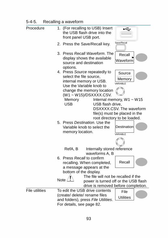
93
5-4-5. Recalling a waveform
Procedure 1. (For recalling to USB) Insert the USB flash drive into the front panel USB port.
2. Press the Save/Recall key. Save/Recall
3. Press Recall Waveform. The
display shows the available source and destination options.
Recall
Waveform
4. Press Source repeatedly to select the file source, internal memory or USB. Use the Variable knob to change the memory location (W1 ~ W15)/DSXXXX.CSV.
Source
Memory
VARIABLE
Memory Internal memory, W1 ~ W15 USB USB flash drive,
DSXXXX.CSV. The waveform file(s) must be placed in the root directory to be loaded.
5. Press Destination. Use the Variable knob to select the memory location.
Destination
VARIABLE
RefA, B Internally stored reference
waveforms A, B 6. Press Recall to confirm
recalling. When completed, a message appears at the bottom of the display.
Recall
Note
The file will not be recalled if the power is turned off or the USB flash drive is removed before completion.
File utilities To edit the USB drive contents (create/ delete/ rename files and folders), press File Utilities. For details, see page 82.
File
Utilities
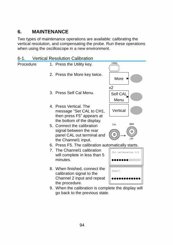
94
6. MAINTENANCE
Two types of maintenance operations are available: calibrating the vertical resolution, and compensating the probe. Run these operations when using the oscilloscope in a new environment.
6-1. Vertical Resolution Calibration
Procedure 1. Press the Utility key. Utility
2. Press the More key twice.
More
x2
3. Press Self Cal Menu. Self CAL
Menu
4. Press Vertical. The message “Set CAL to CH1, then press F5” appears at the bottom of the display.
Vertical
5. Connect the calibration signal between the rear panel CAL out terminal and the Channel1 input.
6. Press F5. The calibration automatically starts.
7. The Channel1 calibration will complete in less than 5 minutes.
Ch1 calibration 1/3
8. When finished, connect the
calibration signal to the Channel 2 input and repeat the procedure.
Done!!
9. When the calibration is complete the display will go back to the previous state.
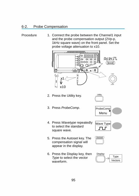
95
6-2. Probe Compensation
Procedure 1. Connect the probe between the Channel1 input and the probe compensation output (2Vp-p, 1kHz square wave) on the front panel. Set the probe voltage attenuation to x10.
V O L TS / D I V V O L TS / D I V T I M E / D I V C H 1 M A T H C H 2 M E N U M E N U
A c q u i r e D i s p l a y U t i l i t y H e l p R u n / S t o p
V A R I A B L E
F O R C E
A u t o s et C u r s o r
S I N G L E
H a r d c o p y M e a s u r e S a ve / R e c a l l L E V E L V E R T I C A L H O R I Z O N T A L T R I G G E R
C H 1
C H 2 E X T T R I G C A T 3 0 0 V M W 1 5 p F . 0 0 V p k 1
X Y
X 1 0 X 1
C
H1
x 1
x 1 0
2. Press the Utility key. Utility
3. Press ProbeComp. ProbeComp
Menu
4. Press Wavetype repeatedly to select the standard square wave.
Wave Type
5. Press the Autoset key. The compensation signal will appear in the display.
Autoset
6. Press the Display key, then Type to select the vector
waveform.
Type
Vectors
Display
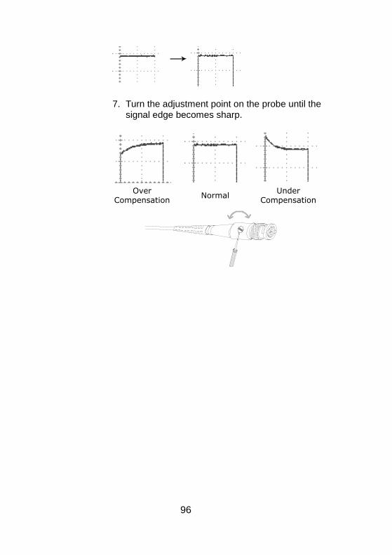
96
7. Turn the adjustment point on the probe until the signal edge becomes sharp.
Over Compensation
NormalUnder
Compensation
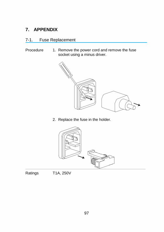
97
7. APPENDIX
7-1. Fuse Replacement
Procedure 1. Remove the power cord and remove the fuse socket using a minus driver.
2. Replace the fuse in the holder.
Ratings T1A, 250V
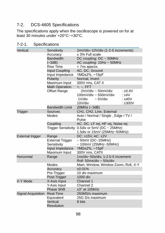
98
7-2. DCS-4605 Specifications
The specifications apply when the oscilloscope is powered on for at least 30 minutes under +20°C~+30°C.
7-2-1. Specifications
Vertical Sensitivity 2mV/div~10V/div (1-2-5 increments) Accuracy ± 3% Full scale
Bandwidth (–3dB)
DC coupling: DC ~ 50MHz AC coupling: 10Hz ~ 50MHz
Rise Time < 7ns approx. Input Coupling AC, DC, Ground Input Impedance 1MΩ±2%, ~15pF Polarity Normal, Invert Maximum Input 300V rms, CAT II Math Operation +, –, FFT Offset Range 2mV/div
100mV/div 1V/div 10V/div
~ 50mV/div ~ 500mV/div ~ 5V/div
: ±0.4V : ±4V : ±40V : ±300V
Bandwidth Limit 20MHz (−3dB)
Trigger Sources CH1, CH2, Line, External Modes Auto / Normal / Single , Edge / TV /
Pulse Coupling AC, DC, LF rej, HF rej, Noise rej Trigger Sensitivity 0.5div or 5mV (DC ~ 25MHz)
1.5div or 15mV (25MHz~50MHz)
External trigger Range DC: ±15V, AC: ±2V External Trigger
Sensitivity ~ 50mV (DC~25MHz) ~ 100mV (25MHz~50MHz)
Input Impedance 1MΩ±2%, ~15pF Maximum Input 300V rms, CATII
Horizontal Range 1ns/div~50s/div, 1-2.5-5 increment Roll: 50ms/div – 50s/div
Modes Main, Window, Window Zoom, Roll, X-Y Accuracy ±0.01% Pre-Trigger 10 div maximum Post-Trigger 1000 div
X-Y Mode X-Axis Input Channel 1 Y-Axis Input Channel 2 Phase Shift ±3° at 100kHz
Signal Acquisition Real-Time 250MS/s maximum Equivalent 25G S/s maximum Vertical
Resolution 8 bits
99
Record Length 4kPoint Acquisition Normal, Peak Detect, Average Peak Detection 10ns (500ns/div ~ 50s/div) Average 2, 4, 8, 16, 32, 64, 128, 256
Cursors and Measurement
Voltage Vpp, Vamp, Vavg, Vrms, Vhi, Vlo, Vmax, Vmin, Rise Preshoot/ Overshoot, Fall Preshoot/ Overshoot
Time Freq, Period, Rise Time, Fall Time, + Width, – Width, Duty Cycle
Cursors Voltage difference (ΔV) and Time difference (ΔT) between cursors
Auto Counter Resolution: 6 digits, Accuracy: ±2% Signal source: All available trigger source except the Video trigger
Control Panel Function
Autoset Automatically adjust Vertical Volt/div, Horizontal Time/div, and Trigger level
Save/Recall Up to 15 sets of measurement conditions and waveforms
Display LCD 5.7 inch, TFT, brightness adjustable Resolution (dots) 234 (Vertical) x 320 (Horizontal) Graticule 8 x 10 divisions Display Contrast Adjustable
Interface USB Slave Connector
USB1.1 & 2.0 full speed compatible (flash disk not supported)
USB Host connector
Image (BMP) and waveform data (CSV)
Probe Compensation Signal
Frequency range 1kHz ~ 100kHz adjustable, 1kHz step
Duty cycle 5% ~ 95% adjustable, 5% step Amplitude 2Vpp±3%
Power Source Line Voltage 100V~240V AC, 47Hz~63Hz Power
Consumption 18W, 40VA maximum
Fuse Rating T1A , 250V
Operation Environment
Ambient temperature 0 ~ 50°C Relative humidity ≤ 80%, 40°C or below
≤ 45%, 41°C~50°C
Storage Environment
Storage Temperature: -10°C~60°C, no condensation- Relative humidity 93% @ 40°C / 65% @ 41°C~60°C
Dimensions 341.5(W) x162.3(H) x 159(D) mm
Weight Approx. 2.5kg
Accessory AC Power cord Probe (See Probe Specifications) ACCESSORY CD-ROM USING THE PRODUCT SAFTY
x1 x2 x1 x1
100
7-2-2. Probe Specifications
Model GTP-100B-4 Position X10 Attenuation Ratio 10:1 Bandwidth DC ~ 100MHz
Input Resistance 10MΩ when used with oscilloscopes with 1MΩ input.
Input Capacitance 14.5pF~17.5pF Compensation Range 5 ~ 30pF
Max. Input Voltage ≤600V DC + ACpk (When the input frequency is high, the maximum voltage will decrease.)
Position X1 Attenuation Ratio 1:1 Bandwidth DC ~ 10MHz
Input Resistance 1MΩ when used with oscilloscopes with 1MΩ input.
Input Capacitance 85pF~115pF Max. Input Voltage ≤200V DC + ACpk
(When the input frequency is high, the maximum voltage will decrease.)
Operating Cond. Temperature –10°C ~ 45°C Relative Humidity ≤85%
anytime without notice for probe model types of similar specification.
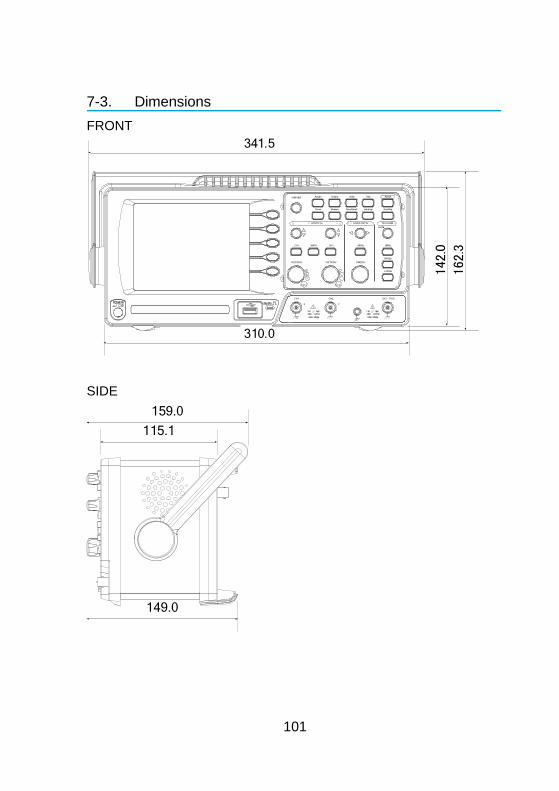
101
7-3. Dimensions
FRONT
VOLTS/DIV VOLTS/DIV TIME/DIV
CH1 MATH CH2 MENU MENU
Acquire Display Utility Help
Run/Stop
VARIABLE
FORCE
Autoset
Cursor
SINGLE
HardcopyMeasure Save/Recall
LEVEL
VERTIC AL HORIZ ONT AL TRI GGER
CH1
CAT300V
M 15pF
MAX. 300Vpk
1
CH2 EXT TRIG
CAT300V
M 15pF
MAX.300Vpk
1
X Y
310.0
341.5
142.
0
162.
3
SIDE
115.1
149.0
159.0
102
7-4. FAQ
• The input signal does not appear in the display. • I want to remove some contents from the display. • The waveform does not update (frozen). • The probe waveform is distorted. • Autoset does not catch the signal well. • I want to clean up the cluttered panel settings. • The accuracy does not match the specifications.
The input signal does not appear in the display.
Make sure you have activated the channel by pressing the CH key (page 29).
I want to remove some contents from the display.
To clear the math result, press the Math key again (page 41). To clear the cursor, press the Cursor key again (page 39). To clear the Help contents, press the Help key again (page 28).
The waveform does not update (frozen).
Press the Run/Stop key to unfreeze the waveform. See page 31 for details. For trigger setting details, see page 65. If this does not help, press the CH key. If the signal still does not appear, press the Autoset key.
The probe waveform is distorted.
You might need to compensate the probe. For details, see page 95. Note that the frequency accuracy and duty factor are not specified for probe compensation waveforms and therefore it should not be used for other reference purposes.
Autoset does not catch the signal well.
The Autoset function does not catch signals well under 30mV or 30Hz. Please operate the oscilloscope manually.
103
I want to clean up the cluttered panel settings.
Recall the default settings by pressing the Save/Recall key→Default Setting. For default setting contents, see page 27.
The saved display image is too dark on the background.
Use the Inksaver function which reverses the background color. For details, see page 88.
The accuracy does not match the specifications.
Make sure the device is powered on for at least 30 minutes, within +20°C~+30°C. This is necessary to stabilize the unit to match the specification.
For more information, contact your local dealer or TEXIO TECHNOLOGY at www.texio.co.jp / [email protected].


7F Towa Fudosan Shin Yokohama Bldg., 2-18-13, Shin Yokohama, Kohoku-ku,
Yokohama, Kanagawa, 222-0033, Japan.
http://www.texio.co.jp/


