A Crane Co. Company IMPORTANT! Read all instructions in this manual before operating pump. As a result of Crane Pumps & Systems, Inc., constant product improvement program, product changes may occur. As such Crane Pumps & Systems reserves the right to change product without prior written notification. 420 Third Street 83 West Drive, Bramton Piqua, Ohio 45356 Ontario, Canada L6T 2J6 Phone: (937) 778-8947 Phone: (905) 457-6223 Fax: (937) 773-7157 Fax: (905) 457-2650 www.cranepumps.com Form No. 120021-Rev. E Series: 5060 Single Stage, Double Suction DEMING DEMING ® INSTALLATION, OPERATION & MAINTENANCE MANUAL Horizontal Split Case Centrifugal Pumps
Transcript
A Crane Co. Company
IMPORTANT! Read all instructions in this manual before operating pump. As a result of Crane Pumps & Systems, Inc., constant product improvement program, product changes may occur. As such Crane Pumps & Systems reserves the right to change product without prior written notifi cation.
420 Third Street 83 West Drive, BramtonPiqua, Ohio 45356 Ontario, Canada L6T 2J6Phone: (937) 778-8947 Phone: (905) 457-6223Fax: (937) 773-7157 Fax: (905) 457-2650www.cranepumps.com Form No. 120021-Rev. E
Series: 5060Single Stage, Double Suction
DEMINGDEMING®
INSTALLATION, OPERATION & MAINTENANCE MANUALHorizontal Split Case Centrifugal Pumps
2
Other brand and product names are trademarks or registered trademarks of their respective holders.Deming® is a registered trademark of Crane Pumps & Systems, Inc. 1996, 12/06 Alteration Rights Reserved
CONTENTS SAFETY FIRST ................................................................................3
A. GENERAL INFORMATION ...............................................................4 Receiving, Storage, Service Centers
E. LOCATING TROUBLE .....................................................................12 CROSS-SECTIONS & PARTS LIST .................................................13 - 14
WARRANTY & RETURNED GOODS ..............................................15
3
Please Read This Before Installing Or Operating Pump. This information is provided for SAFETY and to PREVENT EQUIPMENT PROBLEMS. To help recognize this information, observe the following symbols:
IMPORTANT! Warns about hazards that can result in personal injury orIndicates factors concerned with assembly, installation, operation, or maintenance which could result in damage to the machine or equipment if ignored.
CAUTION! Warns about hazards that can or will cause minor personal injury or property damage if ignored. Used with symbols below.
WARNING! Warns about hazards that can or will cause serious personal injury, death, or major property damage if ignored. Used with symbols below.
Only qualifi ed personnel should install, operate and repair pump. Any wiring of pumps should be performed by a qualifi ed electrician.
WARNING ! To reduce risk of electrical shock, pumps and control panels must be properly grounded in accordance with the National Electric Code (NEC) or the Canadian Electrical Code (CEC) and all applicable state, province, local codes and ordinances. Improper grounding voids warranty.
WARNING! To reduce risk of electrical shock, always disconnect the pump from the power source before handling or servicing. Lock out power and tag.
WARNING! Operation against a closed discharge valve will cause premature bearing and seal failure on any pump, and on end suction and self priming pump the heat build
may cause the generation of steam with resulting dangerous pressures. It is recommended that a high case temperature switch or pressure relief valve be installed on the pump body.
CAUTION ! Pumps build up heat and pressure during operation-allow time for pumps to cool before handling or servicing.
WARNING ! Do not pump hazardous materials (fl ammable, caustic, etc.) unless the pump is specifi cally designed and designated to handle them.
WARNING ! Do not wear loose clothing that may become entangled in moving parts.
WARNING ! Keep clear of suction and discharge openings. DO NOT insert fi ngers in pump with power connected.
Always wear eye protection when working on pumps.
Make sure lifting handles are securely fastened each time before lifting. DO NOT operate pump without safety devices in place. Always replace safety devices that have been removed during service or repair. Secure the pump in its operating position so it can not tip over, fall or slide.
DO NOT exceed manufacturers recommendation for maximum performance, as this could cause the motor to overheat.
WARNING ! To reduce risk of electrical shock, all wiring and junction connections should be made per the NEC or CEC and applicable state or province and local codes. Requirements may vary depending on usage and location.
WARNING! Products returned must be cleaned, sanitized, or decontaminated as necessary prior to shipment, to insure that employees will not be exposed to health hazards in handling said material. All Applicable Laws And Regulations Shall Apply.
Bronze/brass and bronze/brass fi tted pumps may contain lead levels higher than considered safe for potable water systems. Lead is known to cause cancer and birth defects or other reproductive harm. Various government agencies have determined that leaded copper alloys should not be used in potable water applications. For non-leaded copper alloy materials of construction, please contact factory.
Crane Pumps & Systems, Inc. is not responsible for losses, injury, or death resulting from a failure to observe these safety precautions, misuse or abuse of pumps or equipment.
SAFETY FIRST!
Hazardous fl uids can cause fi re or explo-sions, burnes or death could result.
Extremely hot - Severe burnes can occur on contact.
Biohazard can cause serious personal injury.
Hazardous fl uids can Hazard-ous pressure, eruptions or ex-plosions could cause personal injury or property damage.
Rotating machineryAmputation or severe laceration can result.
Hazardous voltage can shock, burn or cause death.
4
A - GENERAL INFORMATION
TO THE PURCHASER:Congratulations! You are the owner of one of the fi nest pumps on the market today. These pumps are products engineered and manufactured of high quality components. With years of pump building experience along with a continuing quality assurance program combine to produce a pump which will stand up to the toughest applications.
Check local codes and requirements before installation. Servicing should be performed by knowledgeable pump service contractors or authorized service stations.
RECEIVING:Upon receiving the pump, it should be inspected for damage or shortages. If damage has occurred, fi le a claim immediately with the company that delivered the pump. If the manual is removed from the crating, do not lose or misplace.
STORAGE:Short Term - Pumps are manufactured for effi cient performance following long inoperative periods in storage.For best results, pumps can be retained in storage, as factory assembled, in a dry atmosphere with constant temperatures for up to six (6) months.
Long Term - Any length of time exceeding six (6) months, but not more than twenty four (24) months. The units should be stored in a temperature controlled area, a roofed over walled enclosure that provides protection from the elements (rain, snow, wind blown dust, etc..), and whose temperature can be maintained between +40 deg. F and +120 deg. F. Pump should be stored in its original shipping container and before initial start up, rotate impeller by hand to assure seal and impeller rotate freely.
SERVICE CENTERS:For the location of the nearest Deming Service Center, check your Deming representative or Crane Pumps & Systems Service Department in Piqua, Ohio, telephone (937) 778-8947 or Crane Pumps & Systems Canada, Inc., Bramton, Ontario, (905) 457-6223.
B - INSTALLATION
1. LOCATIONThe pump should be installed as near the source of liquid as possible with a minimum of piping on the suction side of the pump. The discharge piping should be as direct as possible with a minimum of fi ttings to lower friction loss.
The unit should be installed with adequate head room and a maximum area for inspection and service. The installation should be dry, well ventilated, and protected against moisture and fl ooding.
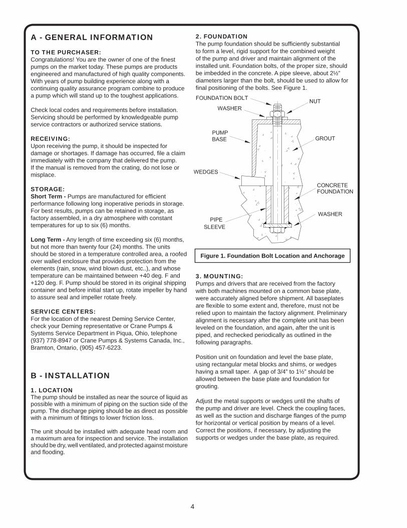
2. FOUNDATIONThe pump foundation should be suffi ciently substantial to form a level, rigid support for the combined weight of the pump and driver and maintain alignment of the installed unit. Foundation bolts, of the proper size, should be imbedded in the concrete. A pipe sleeve, about 2½” diameters larger than the bolt, should be used to allow for fi nal positioning of the bolts. See Figure 1.
3. MOUNTING:Pumps and drivers that are received from the factorywith both machines mounted on a common base plate, were accurately aligned before shipment. All baseplates are fl exible to some extent and, therefore, must not be relied upon to maintain the factory alignment. Preliminary alignment is necessary after the complete unit has been leveled on the foundation, and again, after the unit is piped, and rechecked periodically as outlined in the following paragraphs.
Position unit on foundation and level the base plate,using rectangular metal blocks and shims, or wedges having a small taper. A gap of 3/4” to 1½” should be allowed between the base plate and foundation for grouting.
Adjust the metal supports or wedges until the shafts ofthe pump and driver are level. Check the coupling faces, as well as the suction and discharge fl anges of the pump for horizontal or vertical position by means of a level. Correct the positions, if necessary, by adjusting the supports or wedges under the base plate, as required.
Figure 1. Foundation Bolt Location and Anchorage
5
4. FLEXIBLE COUPLING ALIGNMENTA fl exible coupling should not be used to compensate for misalignment of the pump and driver shafts. The purpose of the fl exible coupling is to compensate for temperature changes and to permit end movement of the shafts without interference with each other, while transmitting power from the driver to the pump.
CAUTION! - Remove and lock out power to driver.
FACTORY ALIGNMENTPump and drivers that are received from the factory with both machines mounted on a common baseplate, were accurately aligned before shipment. All baseplates are fl exible to some extent and, therefore, must not be relied upon to maintain the factory alignment. Preliminary alignment is necessary after the complete unit has been leveled on the foundation and again, after the unit is piped, and rechecked periodically as outlined in the following paragraphs.
FIELD ALIGNMENT - Horizontal UnitsThe faces of the coupling halves should be spaced far enough apart so that they cannot strike each other when the driver rotor is moved toward the pump. The necessary tools for checking the alignment of a fl exible coupling are a straight edge and a taper gauge or a set of feeler gauges.
NOTE: In most cases where extreme accuracy is necessary, a dial indicator may be used to align coupling.Angular alignment check is made by inserting a taper gauge or feelers between the coupling faces at 90-degree intervals around the coupling. The unit will be in angular alignment when the coupling faces are exactly the same distance apart at all points. (See Figure 2).
Parallel alignment check is made by placing a straight edge across both coupling rims at the top, bottom and at both sides. The unit will be in parallel alignment when the straight edge rests evenly on the coupling rim at all positions. Allowance may be necessary for temperature changes and for coupling halves that are not of the same outside diameter. Care must be taken to have the straight edge parallel to the axis of the shafts. Correction for Angular and Parallel Misalignment is made by adjusting the shims under the driver. After each change, it is necessary to recheck the alignment of the coupling halves, as adjustment in one direction may disturb adjustments already made in another direction.
The permissible amount of coupling misalignment will vary with the type of pump and driver, but should be limited to approximately .002 inches per inch of shaft diameter when fi nal adjustment is made. When the units are lined up cold, it is necessary to make allowance for the vertical rise of the driver caused by heating when in operation. When the preliminary alignment has been completed the foundation, bolts should be tightened evenly, but not too fi rmly.
Figure 2
PERFECTALIGMENT
PARALLELMISALIGNMENT
ANGULARMISALIGNMENT
6
WARNING - Coupling guards must be used to avoid serious injury to operating personnel.
FIELD ALIGNMENT - Vertical UnitsTo protect the pump and motor during shipment, the motor and fl exible shaft coupling may be shipped unmounted and must be installed on the pump and properly aligned at the pump site. Clamp an extender to the pump shaft and by using a dial indicator, positioned against the fi nished bore of the top plate of the vertical frame, rotate the pump shaft checking alignment of the pump shaft with the vertical mounting frame. Use the jackscrews in the base of the mounting frame or metal shims under the feet of the pump casing and adjust the pump so that the T.I.R. is within .004”. Lock jack screws with the jam nuts. The shaft position in relation to the fi nished surface at the top plate of the mounting frame should be within T.I.R. of .005”.
Install coupling halves on motor shaft and pump shaft but do not tighten coupling set screws. Position the motor over the pump and complete the coupling assembly according to manufacturer’s recommendation, as the motor comes to rest on the top plate of the vertical mounting frame. Insert and tighten the motor cap screws.
Using an indicator on both the motor shaft and the pump shaft, make sure that the shafts are concentric within .004” and are aligned axially. Tighten coupling set screws.
It is recommended that the motor and pump be dowelled to the vertical mounting frame when the correct alignment has been established. Use Loctite on all dowel pins.
5. GROUTINGGrouting compensates for unevenness in the foundation and prevents vibration and shifting after mounting is complete. Build a form around the base plate to contain the grout, and sprinkle area with water to obtain a good bond. The base should be completely fi lled with a good quality, non-shrinking grout. The usual mixture for grouting is one part Portland cement and two parts sand with suffi cient water to fl ow freely. It is also desirable to grout the leveling pieces, shims or wedges in place. Foundation bolts should be fully tightened when grout has hardened, usually about 48 hours after pouring.
6. PIPINGThe pump suction and discharge connections are not intended to indicate the required suction and discharge pipe sizes. The pipe diameter must be selected according to the requirements of the pumping system and recommended friction losses for the liquid being pumped.
Usually, it is advisable to increase the size of both the suction and discharge pipes at the pump nozzles to have minimum acceptable friction loss, suction pipe should never be smaller in diameter than the pump suction nozzle. When suction pipe is of larger diameter than the pump suction nozzle, an eccentric reducer is required to eliminate possible air or vapor pockets at the pump suction inlet.
Figure 3
7
Figure 4
8
Both suction and discharge pipes must be supported independently near the pump, so that when piping is connected to the pump, no strain will be transmitted to the pump. Piping should be arranged with as few bends as possible, and, preferably, with long radius elbow whenever possible.
Where vibration noises must be kept to a minimum a fl exible connection is recommended on both the suction and discharge lines. This will eliminate any sound being telegraphed through the pipe system.
NOTE: Flexible connector should have limiting bolts to contain hydraulic forces.
SUCTION PIPINGA horizontal suction line must have a gradual rise to the pump. Any high point in the suction pipe can become fi lled with air and prevent proper operation of the pump and may cause loss of prime. The pipe and fi ttings must be free of all air leaks.
Any valves or fi ttings should located at a distance equal to 5 to 10 times the diameter of the suction pipe from the pump suction nozzle. If an elbow must be installed at the pump suction, it should be installed in a vertical position to reduce unequal fl ow into the pump, which may cause cavitation in the pump (See Figure 4).
There is always uneven fl ow in an elbow when it is installed in any position other than a vertical position. This unequal fl ow allows more water to enter one side of the impeller than enters the other side causing a reduction in capacity and effi ciency. This condition may also cause cavitation which would be characterized by noisy operation and shorter pump life.
An eccentric rather than straight reducer and gate vale with stem horizontal rather than vertical should be installed in suction piping. (See Figure 4).
NOTE: A gate valve in the suction piping should not be used as a throttling device, as this may cause the liquid to overheat during operation.
DISCHARGE PIPINGA silent type check valve and a gate valve should be installed in the discharge line. The check valve, placed between the pump and the gate valve, is to protect the pump against pressure surges and to prevent water running back through the pump in case of failure of the driver. The gate valve is used in priming, starting and when shutting down the pump. This is especially important when the pump is operated against a high static head. if increasers are used on the discharge side increase the size of discharge piping, they should be placed between the check valve and pump.
7. LUBRICATIONGrease Lubricated BearingsGrease lubricated bearings are prelubricated at the factory before shipment. See LUBRICATION Section C for recommended lubricants.
Oil Lubricated BearingsPumps furnished with oil lubricated bearings are shipped WITHOUT oil in the housings (31) & (33). To fi ll the oil reservoir in the housing: 1. Install the Trico Opto-Matic constant level oiler (125) with piping as shown with the moveable oiler body at its lowest position.
2. Unscrew the plastic bottle from the oiler. Fill bottle of the oiler and screw ir onto the lower reservoir. Several fi llings of the bottle will be required before the oil level in the bearing reservoir is equal to the level for which the oiler is adjusted. NEVER FILL FRAME RESERVOIR THRU LOWER RESERVOIR OF THE OILER. See LUBRICATION, Section C, for recommended lubricants. When proper oil level is obtained, refi ll and replace the plastic bottle on the oiler. See LUBRICATION, Section C, for proper oil level.
Packing BoxThe pump may be furnished with packing or mechanical shaft seal, as ordered.
Packing is continuously lubricated internally with pumped fl uid. External lubrication may be provided through tapping opening, provided by-pass is plugged with item (263).
Mechanical seals ca be lubricated by: 1. The internal by-pass which leads from the volute to the packing box. When using the internal by-pass it is recommended that the tap in the seal gland be used for the vent.
2. Plugging the internal by-pass with a socket head pipe plug (263) and using an outside source. When using an outside source, it is recommended to use the tap in the seal gland for the inlet and outside tap of the internal by-pass for the vent.
Other LubricationFor proper lubrication of driver bearings and shaft couplings, see manufactures instructions.
8. WIRINGFor electric motor drives, connect power supply to conform with national and local codes. Line voltage and wire capacity must match the ratings stamped on the motor nameplate.
9. ROTATIONBefore starting the pump, check the required direction of rotation of the pump. The proper direction is indicated by a direction arrow on the pump casing. Separate the coupling halves, then start motor to see that it rotates in the direction required by the pump. If it does not, reverse any two main leads of the 3-phase wiring to the motor.The coupling halves can be reconnected and the pump primed for starting.
9
C - OPERATION
1. PRIMINGInstall pet cock (248) on top of casing as shown.
CAUTION: Before starting the pump, the casing and suction line must be fi lled with liquid. The pump must not be run until it is completely fi lled with liquid, because of danger of injuring some of the parts of the pump which depend upon liquid for lubrication. Wearing rings will not seize when the pump is fi lled with liquid but are very liable to do so when the pump is run dry.
Vertical units must be primed through the recirculation line at the top inboard seal gland.
Priming By Suction PressureWhen operating with suction pressure (fl ooded suction), priming may be accomplished by bleeding all the air out of the pump by opening the petcock located at the top of the upper casing or at the top seal gland.
A pump operating under a suction lift may be primed by any of the following methods, as may be best suited to the conditions. The discharge valve should be closed during priming operation.
Priming by Ejector or ExhausterThis method is used when steam, high pressure water, or compressed air is available. 1. Attach an air ejector to the highest point in the pump casing. This will remove the air from the pump and suction line.
Vertical units must be primed through the recirculation line at the top inboard seal gland.
2. As soon as the ejector waste pipe throws water continuously, the pump may be started. After starting, a steady stream of water from the waste pipe indicates the pump is primed. If this stream of water is not obtained, the pump must be stopped at once and the process of priming repeated. A foot valve is unnecessary when this kind of device is used.
3. Open the discharge valve slowly and close off the ejector.
Priming With Foot ValveWhen it is not practicable to prime by ejector or exhauster, the pump may be primed by the use of a foot valve. The foot valve will prevent liquid running out through the suction inlet and the pump can be completely fi lled with liquid from some outside source. Pet cocks on the top of the pump should be opened during fi lling to allow the air to escape. A tight foot valve will keep the pump constantly primed so that the pump may be used for automatic operation. The valve must be inspected frequently, however, to see that it does not develop leaks and thus allow the pump to be started dry.
Priming by Vacuum PumpWhen neither of the above methods of priming are practical, the pump may be primed by the use of a vacuum pump to exhaust the air from the pump casing and suction line. A wet vacuum pump is preferable, as it will not be injured if water enters it. When a dry vacuum pump is used, the installation must be such as to prevent liquid being taken into the air pump. The vacuum pump manufacturer’s instructions should be followed.
2. STARTING THE PUMP
Position of Discharge Valve on StartingA high or medium head centrifugal pump, when primed and operated at full speed with the discharge gate valve closed, requires much less power than when operated at its rated capacity and head with the discharge gate valve open. For this reason it is usually advantageous to have the discharge gate valve closed when the pump is being started. The pump must not be throttled by the use of a valve in the suction line.
WARNING! - Operating the pump with a closed discharge valve can result in excessive heat build-up and should be limited to the shortest practical duration. Operating the pump at
close to shut-off head usually places greater bending strains on the shaft than at operating points near the best effi ciency.
The following important items should be checked as pump is started and placed in operation.
a. Pump and driver securely boltedb. Coupling properly alignedc. Piping completed. Correct pump rotatione. Pump shaft turns freelyf. Discharge valve closedg. Suction valve open (if used)h. Coupling Guard installedi. Pump fully primedj. Pump and driver properly lubricatedk. Seal water valve (if used) open
Only after these items have been checked should the pump be started.
3. INITIAL ADJUSTMENTSOpen discharge valve as soon as operating speed has been reached. After the pump has been started the packing box glands should be tightened to eliminate excessive liquid loss. (Applies only to pumps having packed stuffi ng boxes.) Packing should not be pressed too tight, as this may result in burning the packing and scoring the shaft or shaft sleeve. The best adjustment will allow the liquid to drip slowly from the packing box gland. This will permit proper lubrication of the shaft and dissipate generated heat.
10
As soon as the pump and driver have reached the normal operating temperature, the unit should be shut down for fi nal coupling alignment. This should be done by following the instructions found in Section B, Part 4.
After the unit has been running for about one week, the coupling halves should be given a fi nal check for misalignment caused by pipe strains or temperature strains. If the alignment is correct, both pump and driver may be dowelled to the baseplate if desired.
D. MAINTENANCE
1. LUBRICATIONGrease Lubricated PumpPump bearings are properly lubricated with grease at the factory before shipment. Periods of subsequent lubrication depend on local conditions, loads, speeds, hours of operation and temperature.
Periodic inspection of bearing lubrication should be made and additional grease added as needed. At this time the plug in the bottom of the bearing cover should be removed and the bearing fl ushed with clean grease. A Chevron SRI-2 or Shell Dolium “R” grease is recommended for most installations. Do not overgrease as this causes high bearing temperatures and shortens bearing life. The pump should be run a short time to eject any excess grease and the plug then replaced in the bearing cover.
Oil Lubricated PumpThe pump is shipped without oil in the bearing housings. Fill the reservoir to the proper level from shaft centerline as follows:
The following lubricants are recommended at the operatingtemperature indicated. See Figure 5 for correct oil levels.
Motor bearings should have periodic attention and lubricated in accordance with the motor manufacturer’s recommendations.
2. PACKING BOXThe packing glands should be adjusted occasionally to insure proper packing lubrication. A slow dripping through the gland is recommended for good lubrication and long packing and shaft sleeve life.
When installing new rings of packing, clean packing box and inspect parts for any damage. If the shaft sleeve is worn or grooved, it should be replaced. New packing will not do an adequate sealing job on a worn shaft sleeve.
Insert two new rings of packing in front of lantern ring. Stagger joints to minimize leakage.
Tamp each ring in place. Replace lantern ring. Add two rings of packing behind lantern ring. Replace gland and bolts, rotate shaft and tighten gland securely. Loosen the gland and add the fi nal ring of packing. Be sure lantern ring is positioned to receive lubrication through orifi ce. Tighten nuts securely to seat packing and rotate shaft. After rotating several turns, loosen nuts to fi nger tight for starting.
3. WEARING RINGSWearing rings are fi tted in the casing on all pumps and are standard on the impeller of all pumps with 8” or larger discharge. (Optional on smaller units). These wearing rings provide a close running clearance, to reduce the quantity of liquid leaking from the high pressure side to the suction side. These rings depend on the liquid in the pump for lubrication. They will eventually wear so that the clearance becomes greater and more liquid passes into the suction. This rate of wear depends on the character of the liquid pumped. When worn excessively these rings will cause the pump to loose effi ciency and should be replaced. Recommended wear ring clearances are as follows:
Model C.I. or Bz. Stainless Steel 5061 .009/.014 .019/.024 5062 .011/.016 .021/.026 5063 .013/.018 .023/.028 5064 .016/.023 .029/.036
4. DISASSEMBLYThe following procedure is for complete disassembly of the pump. If complete disassembly is not necessary, use only those steps which apply. a. Disconnect coupling from driver before proceeding. b. Disconnect seal water lines (if used). Remove oiler piping on oil lube pumps. c. Remove split gland and clips. d. Remove bolts and nuts and lift off upper half casing (1B). e. Remove gasket (73) and soak in water. f. Match mark and remove bearing caps (41) and (43). g. Lift out rotating element. h. Remove bearing caps. i. On grease lubricated pumps, open tangs of bearing lockwasher (69), unscrew and remove bearing lock nut (22). Remove lockwasher. For oil lubricated pumps, remove both oil rings (60). Unscrew and remove both bearing lock nuts (22).
Figure 5
11
j. Pull off bearing housings (31) and (33) and bearings (16) and (18). Note: On oil lubricated pumps shaft collar (68) will also be removed. k. Remove bearings from bearing housings. l. Remove defl ectors (40) and casing wearing rings (7). m. Remove packing (13) and lantern rings (29) or seal gland (251), gasket (259) and mechanical seal (65). n. Mark impeller location in relation to pump shaft and remove by unscrewing shaft sleeves (one right hand and one left hand thread). o. If impeller wearing rings are to be replaced remove all twelve set screws (296) and chisel ring (8) from impeller (2).
5. REASSEMBLYThe following procedure is for the complete assembly of the pump. This procedure must be followed for satisfactory operation. If pump is not completely disassembled, use only the steps that are applicable. 1. Press impeller wearing rings (8) onto impeller (2) making sure they are evenly and fully seated. (Impeller wearing rings are standard on pumps with 8” or larger discharge and optional on smaller units.) 2. Position impeller key (32) on pump shaft (6). 3. Slide impeller onto shaft. Center between shaft threads.
IMPORTANT! - When placed in casing, the rotational curve of the impeller blades in relation to the position of the pump discharge must be as shown in Figure 6.
4. Slide shaft sleeve gasket (38) over shaft and place one gasket against each side of the impeller. 5. Thread shaft sleeves (14) and (20) onto shaft, one right and one left hand thread, but do not draw up to impeller nut. 6. Place lantern rings (29), or seals (65), seal gaskets (259) and seal glands (251), on the shaft along with defl ectors (40). 7. Press lip seals (47) into bearing housings (31) and (33) with the retaining spring toward the bearings. Lip seal must be continually lubricated both during and after assembly. 8. Slide bearings (16) and (18) into bearing housings (31) and (33). Press only on the outer bearing race if required.
9. Place bearing assemblies onto shaft. Press only on the inner bearing race if required. 10. On grease lubricated pumps, place the lock washer (69) on the shaft and secure the thrust bearing in place with a lock nut (22).
For oil lubricated pumps, lock the thrust bearing in place with two nuts (22). Lock nuts must be installed so that a groove is created between them. Press a shaft collar (68) onto shaft and against the inboard bearing. Place an oil ring (60) in the groove between the two lock nuts and shaft collar. 11. Press bearing dust cover (123) into bearing cover (37). Then place gaskets (303), (use only on oil lubricated pumps) and bearing covers (35) and (37) on bearing housings and secure with cap screws (245). NOTE: On grease lubricated pumps, the grease fi tting (207) must match the dowel pin hole in the bearing housing.
On oil lubricated pumps, the air vent (235) must match the dowel pin hole in the bearing housing. 12. Position casing wearing rings (7) on the rotating element and lower the complete assembly into the lower casing. The tongue on the casing ring must match the slot in the lower casing. 13. Match bearing caps (41) and (43) to marks on the casing and position on dowel pins (247) which extend from the bearing housings. Fasten securely with cap screws (239). 14. Position impeller in the center of the casing and tighten both shaft sleeves against the impeller. 15. Position the casing gasket on the lower casing. NOTE: On pumps with mechanical seals, allow the gasket to overhand the casing where the seal gland gasket (259) mates. Trim the excess prior to tightening the seal gland.
Inspect inside of both casing halves and remove all foreign objects. Then carefully lower upper casing (1B) onto dowel pin (246). 16. Place swing bolts (209) in proper positions and secure the two casing halves together with nuts (213) and cap screws (215). For pumps using ring type packing: Place packing rings (13) over the pump shaft and slide into stuffi ng box. Alternate position of ring splices 120° apart. Position lantern ring so that seal water passage is in line with the lantern ring.
When packing is complete, place split gland (17), gland clips (206), and nuts (210) on swing bolts. Draw nuts down tight to seat bottom rings of packing, then loosen nuts to fi nger tight for starting.
For pumps using mechanical seal: Place nuts on swing bolts and tighten. Attach piping for seal water if used. 17. Be sure all pipe plugs are in place and rotating element turns freely.
Figure 6
12
6. CONVERSION OF GREASE TO OIL LUBRICATION (or Oil to Grease Lubrication)
Follow steps 8 through 11 of the Disassembly and Reassembly sections.
NOTE: Wash bearings, bearing housings and bearing covers with a suitable solvent to completely remove all old grease.
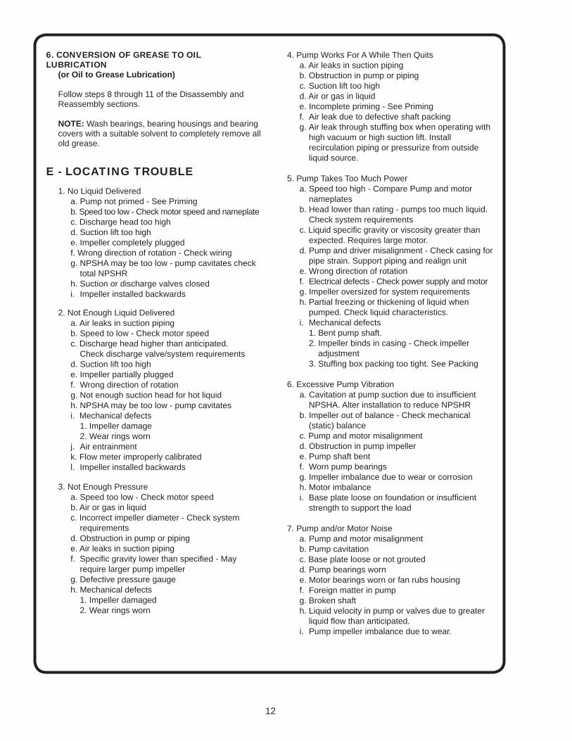
E - LOCATING TROUBLE
1. No Liquid Delivereda. Pump not primed - See Primingb. Speed too low - Check motor speed and nameplatec. Discharge head too highd. Suction lift too highe. Impeller completely pluggedf. Wrong direction of rotation - Check wiringg. NPSHA may be too low - pump cavitates check total NPSHRh. Suction or discharge valves closedi. Impeller installed backwards
2. Not Enough Liquid Delivereda. Air leaks in suction pipingb. Speed to low - Check motor speedc. Discharge head higher than anticipated. Check discharge valve/system requirementsd. Suction lift too high e. Impeller partially pluggedf. Wrong direction of rotationg. Not enough suction head for hot liquidh. NPSHA may be too low - pump cavitatesi. Mechanical defects 1. Impeller damage 2. Wear rings wornj. Air entrainmentk. Flow meter improperly calibratedl. Impeller installed backwards
3. Not Enough Pressure a. Speed too low - Check motor speed b. Air or gas in liquid c. Incorrect impeller diameter - Check system requirements d. Obstruction in pump or piping e. Air leaks in suction piping f. Specifi c gravity lower than specifi ed - May require larger pump impeller g. Defective pressure gauge h. Mechanical defects 1. Impeller damaged 2. Wear rings worn
4. Pump Works For A While Then Quits a. Air leaks in suction piping b. Obstruction in pump or piping c. Suction lift too high d. Air or gas in liquid e. Incomplete priming - See Priming f. Air leak due to defective shaft packing g. Air leak through stuffi ng box when operating with high vacuum or high suction lift. Install recirculation piping or pressurize from outside liquid source.
5. Pump Takes Too Much Power a. Speed too high - Compare Pump and motor nameplates b. Head lower than rating - pumps too much liquid. Check system requirements c. Liquid specifi c gravity or viscosity greater than expected. Requires large motor. d. Pump and driver misalignment - Check casing for pipe strain. Support piping and realign unit e. Wrong direction of rotation f. Electrical defects - Check power supply and motor g. Impeller oversized for system requirements h. Partial freezing or thickening of liquid when pumped. Check liquid characteristics. i. Mechanical defects 1. Bent pump shaft. 2. Impeller binds in casing - Check impeller adjustment 3. Stuffi ng box packing too tight. See Packing
6. Excessive Pump Vibration a. Cavitation at pump suction due to insuffi cient NPSHA. Alter installation to reduce NPSHR b. Impeller out of balance - Check mechanical (static) balance c. Pump and motor misalignment d. Obstruction in pump impeller e. Pump shaft bent f. Worn pump bearings g. Impeller imbalance due to wear or corrosion h. Motor imbalance i. Base plate loose on foundation or insuffi cient strength to support the load
7. Pump and/or Motor Noise a. Pump and motor misalignment b. Pump cavitation c. Base plate loose or not grouted d. Pump bearings worn e. Motor bearings worn or fan rubs housing f. Foreign matter in pump g. Broken shaft h. Liquid velocity in pump or valves due to greater liquid fl ow than anticipated. i. Pump impeller imbalance due to wear.
235 Vent236 Pipe Plug239 Cap Screws245 Cap Screws246 Dowel Pin247 Dowel Pin248 Pet Cock251 Seal Gland259 Seal Gasket263 Pipe Plug When Specifi ed296 Set Screws299 Nipple Reducing300 Tee301 Nipple302 Street Elbow303 Bearing Cover Gasket304 Pipe Plug
A Crane Co. Company 420 Third Street 83 West Drive, BramptonPiqua, Ohio 45356 Ontario, Canada L6T 2J6Phone: (937) 778-8947 Phone: (905) 457-6223Fax: (937) 773-7157 Fax: (905) 457-2650www.cranepumps.com
Limited 24 Month WarrantyCrane Pumps & Systems warrants that products of our manufacture will be free of defects in material and workmanship under normal use and service for twenty-four (24) months after manufacture date, when installed and maintained in accordance with our instructions.This warranty gives you specifi c legal rights, and there may also be other rights which vary from state to state. In the event the product is covered by the Federal Consumer Product Warranties Law (1) the duration of any implied warranties associated with the product by virtue of said law is limited to the same duration as stated herein, (2) this warranty is a LIMITED WARRANTY, and (3) no claims of any nature whatsoever shall be made against us, until the ultimate consumer, his successor, or assigns, notifi es us in writing of the defect, and delivers the product and/or defective part(s) freight prepaid to our factory or nearest authorized service station. Some states do not allow limitations on how long an implied warranty lasts, so the above limitation may not apply. THE SOLE AND EXCLUSIVE REMEDY FOR BREACH OF ANY AND ALL WARRANTIES WITH RESPECT TO ANY PRODUCT SHALL BE TO REPLACE OR REPAIR AT OUR ELECTION, F.O.B. POINT OF MANUFACTURE OR AUTHORIZED REPAIR STATION, SUCH PRODUCTS AND/OR PARTS AS PROVEN DEFECTIVE. THERE SHALL BE NO FURTHER LIABILITY, WHETHER BASED ON WARRANTY, NEGLIGENCE OR OTHERWISE. Unless expressly stated otherwise, guarantees in the nature of performance specifi cations furnished in addition to the foregoing material and workmanship warranties on a product manufactured by us, if any, are subject to laboratory tests corrected for fi eld performance. Any additional guarantees, in the nature of performance specifi cations must be in writing and such writing must be signed by our authorized representative. Due to inaccuracies in fi eld testing if a confl ict arises between the results of fi eld testing conducted by or for user, and laboratory tests corrected for fi eld performance, the latter shall control. RECOMMENDATIONS FOR SPECIAL APPLICATIONS OR THOSE RESULTING FROM SYSTEMS ANALYSES AND EVALUATIONS WE CONDUCT WILL BE BASED ON OUR BEST AVAILABLE EXPERIENCE AND PUBLISHED INDUSTRY INFORMATION. SUCH RECOMMENDATIONS DO NOT CONSTITUTE A WARRANTY OF SATISFACTORY PERFORMANCE AND NO SUCH WARRANTY IS GIVEN.This warranty shall not apply when damage is caused by (a) improper installation, (b) improper voltage (c) lightning (d) excessive sand or other abrasive material (e) scale or corrosion build-up due to excessive chemical content. Any modifi cation of the original equipment will also void the warranty. We will not be responsible for loss, damage or labor cost due to interruption of service caused by defective parts. Neither will we accept charges incurred by others without our prior written approval.This warranty is void if our inspection reveals the product was used in a manner inconsistent with normal industry practice and\or our specifi c recommendations. The purchaser is responsible for communication of all necessary information regarding the application and use of the product. UNDER NO CIRCUMSTANCES WILL WE BE RESPONSIBLE FOR ANY OTHER DIRECT OR CONSEQUENTIAL DAMAGES, INCLUDING BUT NOT LIMITED TO TRAVEL EXPENSES, RENTED EQUIPMENT, OUTSIDE CONTRACTOR FEES, UNAUTHORIZED REPAIR SHOP EXPENSES, LOST PROFITS, LOST INCOME, LABOR CHARGES, DELAYS IN PRODUCTION, IDLE PRODUCTION, WHICH DAMAGES ARE CAUSED BY ANY DEFECTS IN MATERIAL AND\OR WORKMANSHIP AND\OR DAMAGE OR DELAYS IN SHIPMENT. THIS WARRANTY IS EXPRESSLY IN LIEU OF ANY OTHER EXPRESS OR IMPLIED WARRANTY, INCLUDING ANY WARRANTY OF MERCHANTABILITY OR FITNESS FOR A PARTICULAR PURPOSE.No rights extended under this warranty shall be assigned to any other person, whether by operation of law or otherwise, without our prior written approval.
RETURNED GOODSRETURN OF MERCHANDISE REQUIRES A “RETURNED GOODS AUTHORIZATION”.
CONTACT YOUR LOCAL CRANE PUMPS & SYSTEMS, INC. DISTRIBUTOR.
Products Returned Must Be Cleaned, Sanitized, Or Decontaminated As Necessary Prior To Shipment, To Insure That Employees Will Not Be Exposed To Health Hazards In Handling Said Material. All Applicable Laws And Regulations Shall Apply.
IMPORTANT!WARRANTY REGISTRATION
Your product is covered by the enclosed Warranty.To complete the Warranty Registration Form go to:
http://www.cranepumps.com/ProductRegistration/
If you have a claim under the provision of the warranty, contact your local Crane Pumps & Systems, Inc. Distributor.
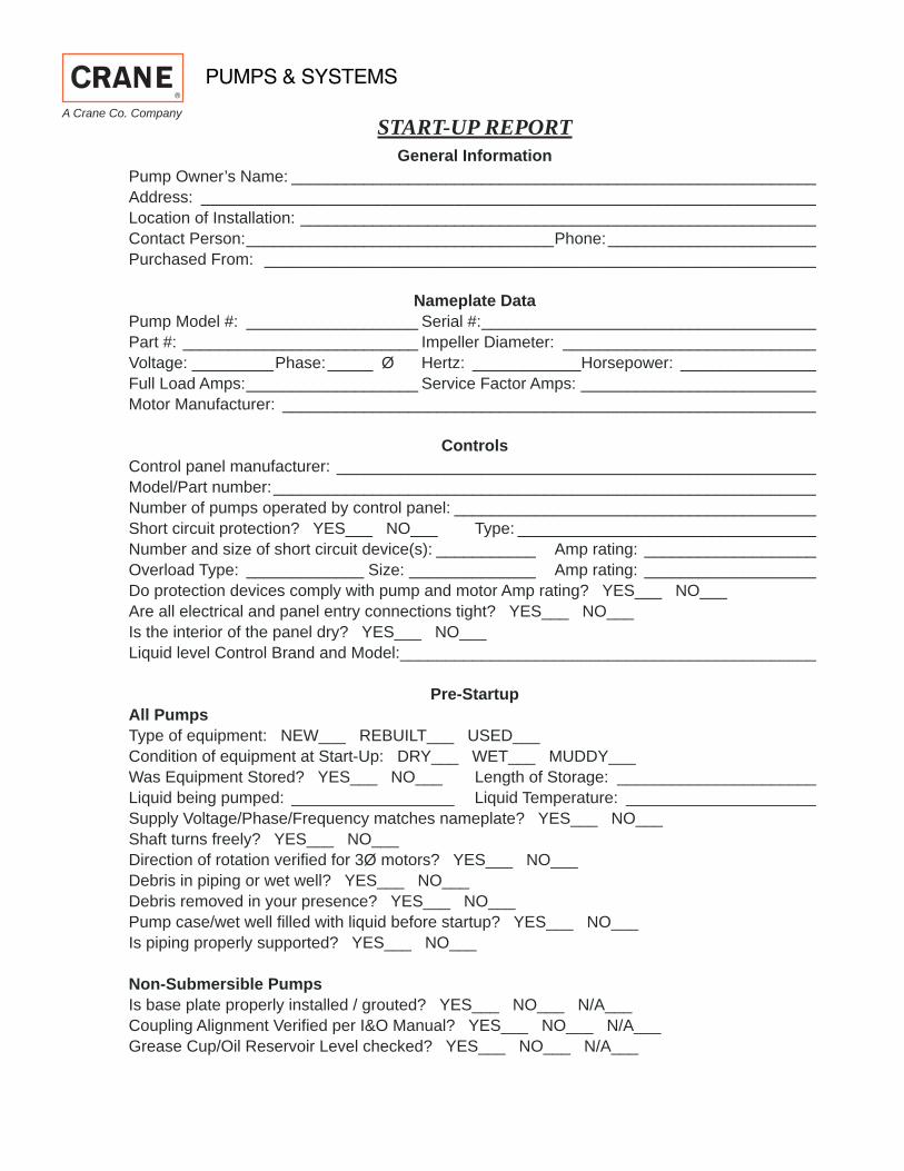
Nameplate DataPump Model #: ___________________ Serial #: _____________________________________Part #: __________________________ Impeller Diameter: ____________________________Voltage: _________Phase: _____ Ø Hertz: ____________Horsepower: _______________Full Load Amps: ___________________ Service Factor Amps: __________________________Motor Manufacturer: ___________________________________________________________
ControlsControl panel manufacturer: _____________________________________________________Model/Part number: ____________________________________________________________Number of pumps operated by control panel: ________________________________________Short circuit protection? YES___ NO___ Type: _________________________________Number and size of short circuit device(s): ___________ Amp rating: ___________________Overload Type: _____________ Size: ______________ Amp rating: ___________________Do protection devices comply with pump and motor Amp rating? YES___ NO___Are all electrical and panel entry connections tight? YES___ NO___Is the interior of the panel dry? YES___ NO___Liquid level Control Brand and Model: ______________________________________________
Pre-StartupAll PumpsType of equipment: NEW___ REBUILT___ USED___Condition of equipment at Start-Up: DRY___ WET___ MUDDY___Was Equipment Stored? YES___ NO___ Length of Storage: ______________________Liquid being pumped: __________________ Liquid Temperature: _____________________Supply Voltage/Phase/Frequency matches nameplate? YES___ NO___Shaft turns freely? YES___ NO___ Direction of rotation verifi ed for 3Ø motors? YES___ NO___Debris in piping or wet well? YES___ NO___Debris removed in your presence? YES___ NO___Pump case/wet well fi lled with liquid before startup? YES___ NO___ Is piping properly supported? YES___ NO___
Non-Submersible PumpsIs base plate properly installed / grouted? YES___ NO___ N/A___Coupling Alignment Verifi ed per I&O Manual? YES___ NO___ N/A___Grease Cup/Oil Reservoir Level checked? YES___ NO___ N/A___
A Crane Co. Company
Submersible PumpsResistance of cable and pump motor (measured at pump control):Red-Black:_______Ohms(Ω) Red-White:_______Ohms(Ω) White-Black:_______Ohms(Ω)Resistance of Ground Circuit between Control Panel and outside of pump: __________Ohms(Ω)MEG Ohms check of insulation:Red to Ground: _________ White to Ground: __________ Black to Ground: ____________
Operational ChecksIs there noise or vibration present? YES___ NO___ Source of noise/vibration: ___________Does check valve operate properly? YES___ NO___ N/A___Is system free of leaks? YES___ NO___ Leaks at: ______________________________Does system appear to operate at design fl ow rate? YES___ NO___Nominal Voltage: _____________________ Phase: 1Ø 3Ø (select one)Voltage Reading at panel connection, Pump OFF: L1, L2 _____ L2, L3 ____ L1, L3 _____Voltage Reading at panel connection, Pump ON: L1, L2 ______ L2, L3 ____ L1, L3 _____Amperage Draw, Pump ON: L1 ____________ L2 _____________ L3 _____________
Submersible PumpsAre BAF and guide rails level / plumb? YES___ NO___Is pump seated on discharge properly? YES___ NO___Are level controls installed away from turbulence? YES___ NO___Is level control operating properly? YES___ NO___ Is pump fully submerged during operation? YES___ NO___