•JUKI DDL-8300N INSTRUCTION MANUAL MANUAL DE INSTRUCCIONES : Read safety instructions carefully and understand them before using. Retain this instruction Manual for future reference. euEnssB' % NOTA: Antes de comenzar a usar esta mdquina lea con detencidn hasta comprender todes las InStrudciones de sequridad.Conserve este Manual de instrucciones a mano para futuras consulfafs. No.OO 29348802 From the library of: Superior Sewing Machine & Supply LLC
Transcript
•JUKI
DDL-8300N
INSTRUCTION MANUAL
MANUAL DE INSTRUCCIONES
: Read safety instructions carefully and understand them before using.Retain this instruction Manual for future reference.
euEnssB'
%
NOTA: Antes de comenzar a usar esta mdquina lea con detencidn hasta comprender todes lasInStrudciones de sequridad.Conserve este Manual de instrucciones a mano para futurasconsulfafs.
No.OO
29348802From the library of: Superior Sewing Machine & Supply LLC
IMPORTANT SAFETY INSTRUCTIONS
Putting sewing systems into operation is prohibited until it has been ascertained that the sewing systems inwhich these sewing machines will be built into, have conformed with the safety regulations in your country.Technical service for those sewing systems is also prohibited.
1. Observe the basic safety measures, including, but not limited to the following ones, whenever you use themachine.
2. Read all the instructions, including, but not limited to this Instruction Manual before you use the machine.In addition, keep this Instruction Manual so that you may read it at anytime when necessary.
3. Use the machine after it has been ascertained that it conforms with safety rules/standards valid in yourcountry.
4. All safety devices must be in position when the machine is ready for work or in operation.The operation without the specified safety devices is not allowed.
5. This machine shall be operated by appropriately-trained operators.6. For your personai protection, we recommend that you wear safety glasses.7. For the following, turn off the power switch or disconnect the power plug of the machine from the
receptacle.7-1 For threading needle(s), looper, spreader etc. and replacing bobbin.7-2 For replacing part(s) of needle, presser foot, throat plate, looper, spreader, feed dog, needle guard, folder,
cloth guide etc.7-3 For repair work.7-4 When leaving the working place or when the working place is unattended.7-5 When using clutch motors without applying brake, it has to be waited until the motor stopped totally.
8. Ifyou should allow oil, grease, etc. used with the machine and devices to come in contact with your eyes orskin or swallow any of such liquid by mistake, immediateiy wash the contacted areas and consuit a medicaldoctor.
9. Tampering with the live parts and devices, regardless of whether the machine is powered, is prohibited.10. Repair, remodeling and adjustment works must only be done by appropriately trained technicians or
specially skilled personnel. Only spare parts designated by JUKI can be used for repairs.11. General maintenance and inspection works have to be done by appropriately trained personnel.12. Repair and maintenance works of electrical components shall be conducted by qualified electric
technicians or under the audit and guidance of specially skilled personnel.Whenever you find a failure of any of electrical components, immediately stop the machine.
13. Before making repair and maintenance works on the machine equipped with pneumatic parts such as an aircylinder, the air compressor has to be detached from the machine and the compressed air supply has to becut off. Existing residual air pressure after disconnecting the air compressor from the machine has to beexpelled. Exceptions to this are only adjustments and performance checks done by appropriately trainedtechnicians or specially skilled personnel.
14. Periodically clean the machine throughout the period of use.
15. Grounding the machine is aiways necessary for the normal operation of the machine. The machine has tobe operated in an environment that is free from strong noise sources such as high-frequency welder.
16. An appropriate power plug has to be attached to the machine by electric technicians. Power plug has to beconnected to a grounded receptacle.
17. The machine is only allowed to t>e used for the purpose intended. Other used are not allowed.18. Remodel or modify the machine in accordance with the safety rules/standards while taking all the effective
safety measures. JUKI assumes no responsibility for damage caused by remodeling or modification of themachine.
19. Warning hints are marked with the two shown symbols.
A Danger of injury to operator or service staffA items requiring special attention
From the library of: Superior Sewing Machine & Supply LLC
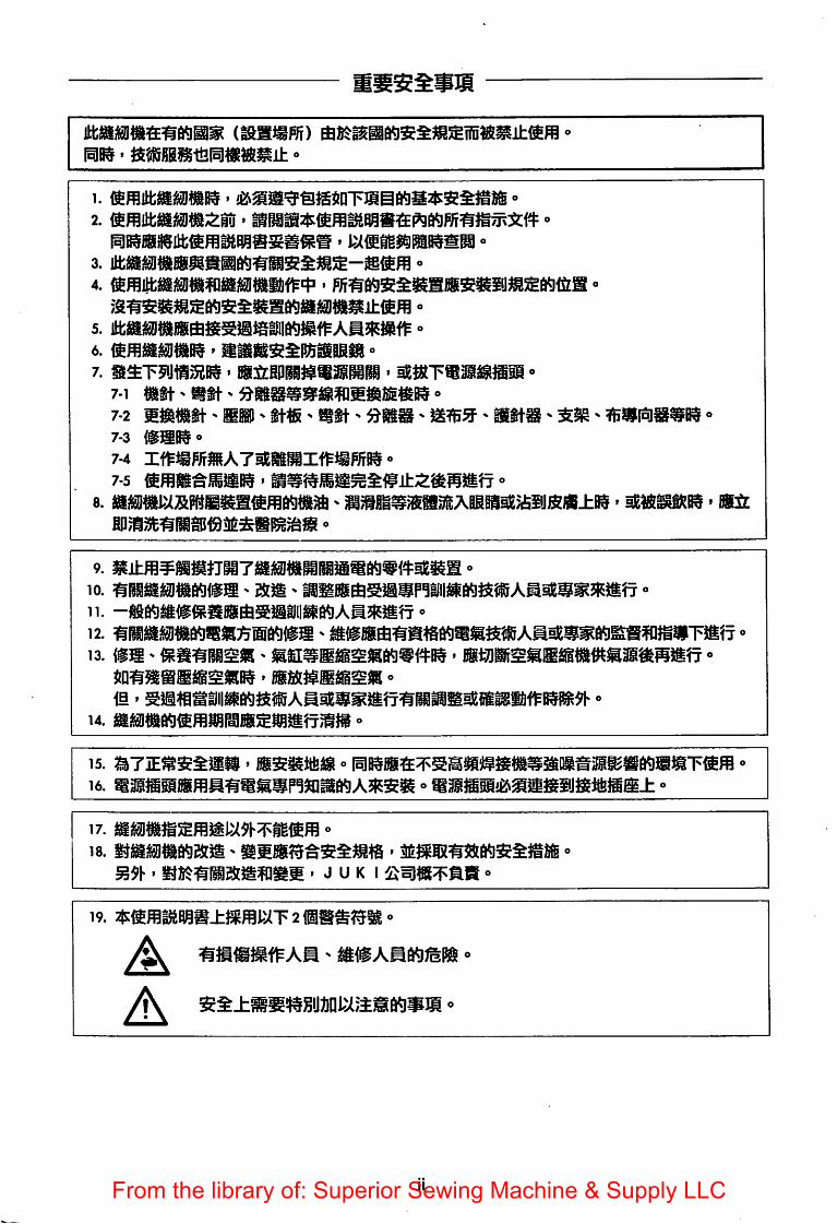
mm •a w^iaii««ii± -
6. ' liiiisssesaiBB^ °7. ' ffillilBP^tSli^liM ' ^tRTS^iSSP o
From the library of: Superior Sewing Machine & Supply LLC
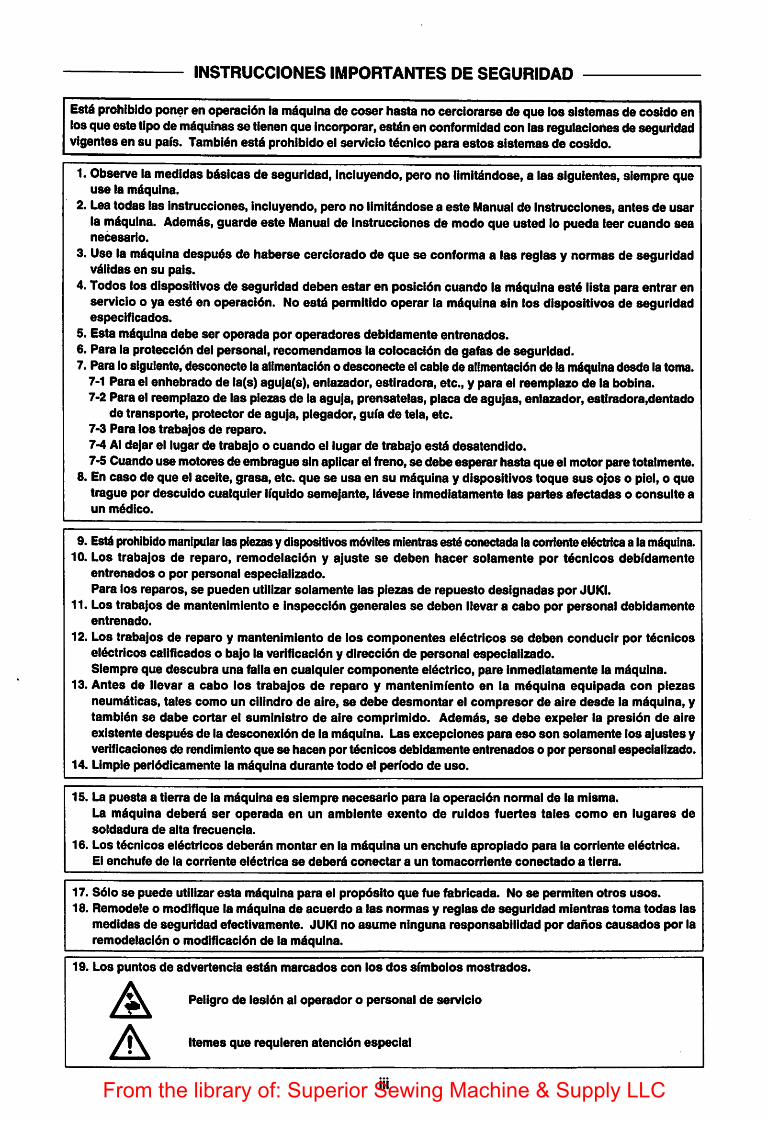
INSTRUCCIONESIMPORTANTES DE SEGURIDAO
Est§prohibido poner en operacidn la mdquina do coser hasta no cerciorarse de que los sistemas de eosido enlosqueeatetipode mdquinas se tienenque Incorporar, estdnen conformidad con las requlaciones de seguridadvigentes en su pafs. Tambi^nestd prohibido el servicio t^cnlco para estos alstemas de cosido.
1. Observe la medidas b^slcas de seguridad, Incluyendo, pero no llmlt^ndose, a las siguientes, slempre queuse la mdquina.
2. Lea todas las Instrucciones, Incluyendo, pero no llmitdndose a este Manual de Instrucciones, antes de usarla mdqulna. Ademds, guarde este Manual de Instrucciones de mode que usted lo pueda leer cuando seanecesarlo.
3. Use la mdquina despu6s de halierse cerciorado de que se conforms a las reglas y normas de seguridadv^lldas en su pals.
4. Todos los dispositlvos de seguridad deben estar en posicldn cuando la m^quina estd lists para entrar enservicio o ya estd en operacidn. No estd permltido operar la mdqulna sin los dispositlvos de seguridadespeclficados.
5. Esta mdquina debe ser operada per operadores debldamente entrenados.6. Para la proteccldn del personal, recomendamos la colocacidn de gafas de seguridad.7. Para losigulente,desconecte la alimentacldn o desconecte el cable de allmentacldn de la mdqulnadesde la toma.
7-1 Para el enhebrado de la(s) aguja(s), enlazador, estlradora, etc., y para el reemplazo de la boblna.7-2 Para el reemplazo de las piezas de la aguja, prensatelas, placa de agujas, enlazador, estiradora,dentado
de transporte, protector de aguja, plegador, gufa de tela, etc.7-3 Para los trabajos de reparo.7-4 Al dejar el lugar de trabajo o cuando el lugar de trabajo estd desatendido.7-5 Cuando use motores de embrague sin aplicar el freno, se debe esperar hasta que el motor pare totalmente.
8. En case de que el aceite, grasa, etc. que se usa en su mdquina y dispositlvos toque sus ojos o plel, o quetrague por desculdo cualquier Ifquido semejante, Idvese Inmediatamente las partes afectadas o consults aun m6dlco.
9. Est4prohibido manipular las piezasy dispositivosmdviles mientrasest§ conectada la corrlenteelectricsa la m^uina.10. Los trabajos de reparo, remodelacldn y ajuste se deben hacer solamente por tdcnicos debfdamente
entrenados o por personal especlallzado.Para los reparos, se pueden utilizar solamente las piezas de repuesto deslgnadas por JUKI.
11. Los trabajos de mantenlmiento e inspeccidn generales se deben llevar a cabo por personal debldamenteentrenado.
12. Los trabajos de reparo y mantenlmiento de los componentes el^ctricos se deben conduclr por t4cnicoseldctricos callflcados o bajo la veriflcacldn y direccidn de personal especlallzado.Slempre que descubra una falla en cualquier componente el6ctrlco, pare Inmediatamente la mdqulna.
13. Antes de llevar a cabo los trabajos de reparo y mantenlmiento en la mdqulna equipada con piezasneumdticas, tales como un clllndro de aire, se debe desmontar el compresor de aire desde la mdqulna, ytambl^n se dabe cortar el sumlnlstro de aire comprlmido. Adem^s, se del>e expeler la presidn de aireexistente despuds de la desconexidn de la m^qulna. Las excepclones para eso son solamente los ajustes yverificaclones de rendimiento que se hacen por t6cnlcos debldamente entrenados o por personal especlallzado.
14. Llmple perlddicamente la m^qulna durante todo el perfodo de use.
15. La puesta a tierra de la m^qulna es slempre necesarlo para la operacidn normal de la misma.La m^qulna deberd ser operada en un amblente exento de ruidos fuertes tales como en lugares desoldadura de alta frecuencla.
16. Los t^cnlcos el6ctricos del)er6n montar en la mdquina un enchufe aproplado para la corrlente el^ctrlca.El enchufe de la corrlente el4ctrlca se deberd conectar a un tomaconiente conectado a tierra.
17. S6lo se puede utilizar esta mdqulna para el propdsito que fue fabrlcada. No se permiten otros uses.18. Remodels o modlfique la mdqulna de acuerdo a las normas y reglas de seguridad mientras toma todas las
medidas de seguridad efectivamente. JUKI no asume ninguna responsabllldad por dahos causados por laremodelacldn o modificacidn de la mdqulna.
19. Los puntos de advertencia estdn marcados con los dos sfmbolos mostrados.
A Peligro de lesldn al operadoropersonal de servicioA Itemes que requleren atencldn especial
IIIFrom the library of: Superior Sewing Machine & Supply LLC
A
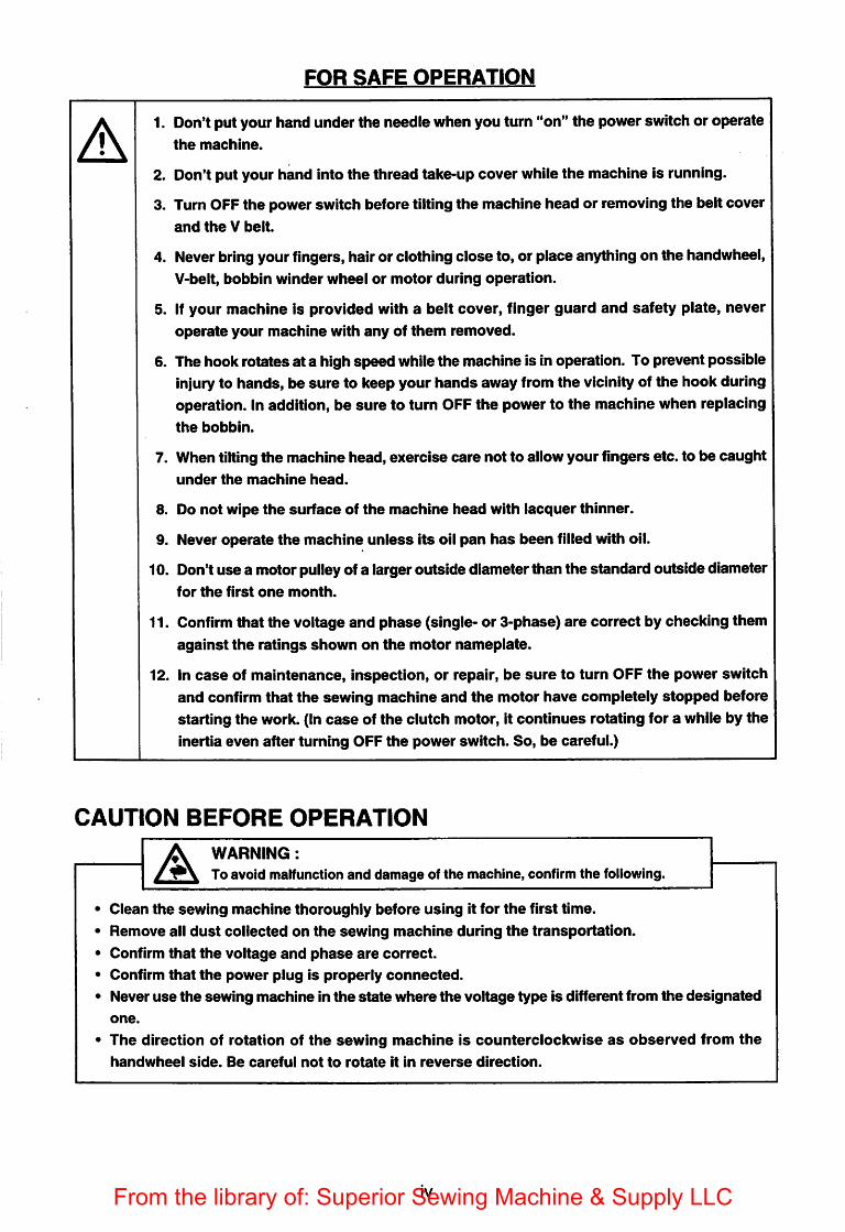
FOR SAFE OPERATION
1. Don't put your hand under the needle when you turn "on" the power switch or operatethe machine.
2. Don't put your hand into the thread take-up cover while the machine is running.
3. Turn OFF the power switch before tilting the machine head or removing the belt coverand the V belt.
4. Never bring your fingers, hair or clothing close to, or place anything on the handwheei,V-belt, bobbin winder wheel or motor during operation.
5. If your machine is provided with a belt cover, finger guard and safety plate, neveroperate your machine with any of them removed.
6. The hook rotates at a high speed while the machine is in operation. To prevent possibleinjury to hands, be sure to keep your hands away from the vicinity of the hook duringoperation. In addition, be sure to turn OFF the power to the machine when replacingthe bobbin.
7. When tilting the machine head, exercise care not to allow your fingers etc. to be caughtunder the machine head.
8. Do not wipe the surface of the machine head with lacquer thinner.
9. Never operate the machine unless its oil pan has been filled with oil.
10. Don't use a motor pulley of a larger outside diameter than the standard outside diameterfor the first one month.
11. Confirm that the voltage and phase (single- or 3-phase) are correct by checking themagainst the ratings shown on the motor nameplate.
12. In case of maintenance, inspection, or repair, be sure to turn OFF the power switch
and confirm that the sewing machine and the motor have completely stopped beforestarting the work. (In case of the clutch motor, it continues rotating for a while by the
inertia even after turning OFF the power switch. So, be careful.)
CAUTION BEFORE OPERATION
AWARNING:
To avoid malfunction and damage of the machine, confirm the following.
• Clean the sewing machine thoroughly before using it for the first time.
• Remove all dust collected on the sewing machine during the transportation.
• Confirm that the voitage and phase are correct.
• Confirm that the power piug is properly connected.
• Never use the sewing machine in the state where the voltage type is different from the designated
one.
• The direction of rotation of the sewing machine is counterclockwise as observed from the
handwheei side. Be careful not to rotate it in reverse direction.
IVFrom the library of: Superior Sewing Machine & Supply LLC
At
4s
i
1ii
'^
^"
CN
-<®
^'
-<M
m•^
i^M
hK
h^
ho
mm
m>
m^
O
Hh
d+i
IKK-
£m1:
mIKmmm
m
mmHh
IImmfr
It
gSil
Ii
K-
11IS
!&8
g§mOKH
hMhII
«o
mmmmmfl-
^o
mm
[1mISmm
m^
§KM
i|
oEE
^m
mh
iffK
-n
mE
im
89K
II
iK-
SiIS
m4
S"c
m@
^-
^s
fmB
m^
mDB
isi!
•-
<S
o
lel
Ifm
Og
indR
m%
EE^
^o
K"^
^o
^li
aa^
oIS
^^
«w
^"
a@
4;:KD
N%
mea
bhIS
s
I
From the library of: Superior Sewing Machine & Supply LLC
A
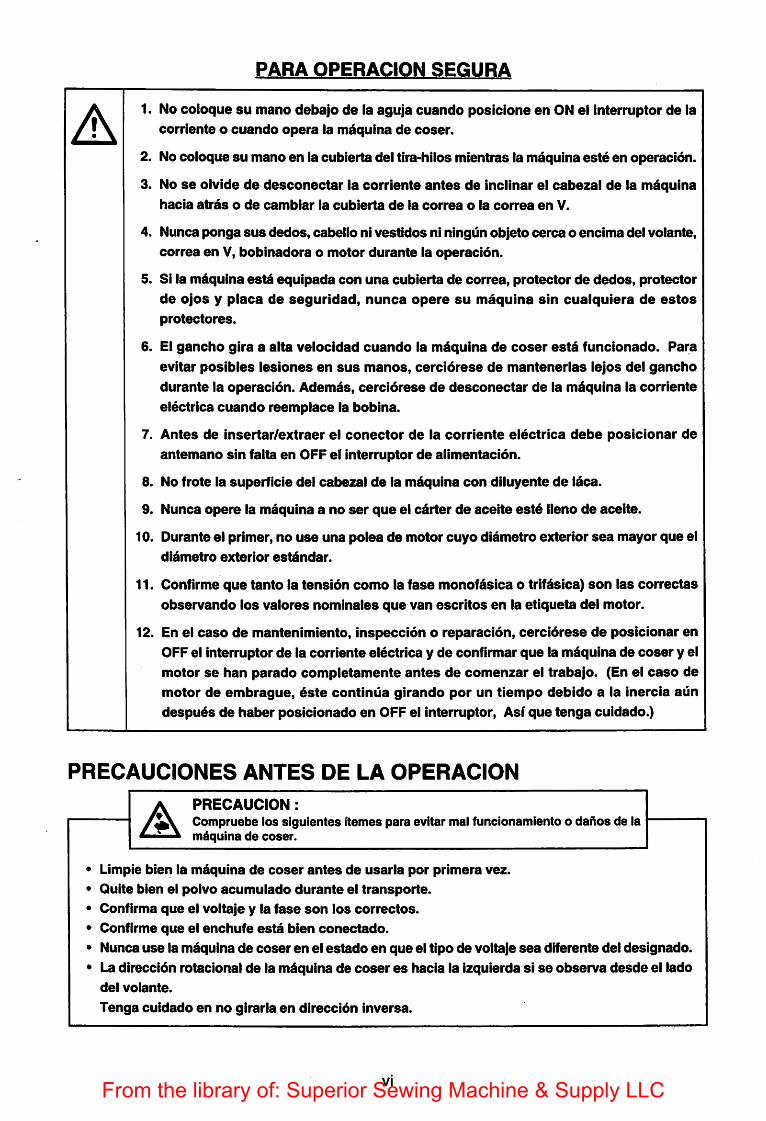
PARA OPERACION SEGURA
1. No coloque su mano debajo de la aguja cuando poslcione en ON el interrupter de lacorriente o cuando opera la m^qulna de coser.
2. No coloque su mano en la cublerta del tira-hilos mientras la maquina este en operacion.
3. No se olvide de desconectar la corriente antes de Inclinar el cabezal de la maquina
hacia atras o de cambiar la cublerta de la correa o la correa en V.
4. Nunca ponga sus dedos, cabello ni vestidos ni ningun objeto cerca o encima del volante,
correa en V, bobinadora o motor durante la operacion.
5. Si la maquina estd equipada con una cublerta de correa, protector de dedos, protector
de ojos y placa de seguridad, nunca opere su maquina sin cualquiera de estos
protectores.
6. El gancho gira a alta velocidad cuando la maquina de coser est^ funcionado. Para
evitar posibles lesiones en sus manos, cerciorese de mantenerlas lejos del gancho
durante la operacion. Ademas, cerciorese de desconectar de la maquina la corriente
electrica cuando reemplace la bobina.
7. Antes de insertar/extraer el conector de la corriente electrica debe posicionar de
antemano sin falta en OFF el interrupter de alimentacion.
8. No frote la superficie del cabezal de la mdquina con diluyente de laca.
9. Nunca opere la maquina a no ser que el carter de aceite est6 lleno de aceite.
10. Durante el primer, no use una polea de motor cuyo diametro exterior sea mayor que el
diametro exterior estdndar.
11. Confirme que tanto la tensidn como la fase monofdsica o trifasica) son las correctas
observando los valores nominates que van escritos en la etiqueta del motor.
12. En el caso de mantenimiento, inspeccion o reparacion, cercidrese de posicionar en
OFF el interrupter de la corriente electrica y de confirmar que la maquina de coser y elmotor se ban parade completamente antes de comenzar el trabajo. (En el caso de
motor de embrague, dste continua girando per un tiempo debido a la inercia aundespuds de haber posicionado en OFF el interrupter, Asi que tenga cuidado.)
PRECAUCIONES ANTES DE LA OPERACION
APRECAUCION :Compruebe los siguientes ftemes para evitar mal funcionamiento o dahos de latndquina de coser.
• Limple bien la mdquina de coser antes de usaria per primera vez.
• Quite blen el polvo acumulado durante el transporte.
• Conflrma que el voltaje y la fase son los correctos.
• Confirme que el enchufe esta blen conectado.
• Nunca use la mdqulna de coser en el estado en que el tipo de voltaje sea diferente del deslgnado.
• La direccion rotacional de la mdquina de coser es hacia la izquierda si se observe desde el lado
del volante.
Tenga cuidado en no giraria en direccidn inverse.
VIFrom the library of: Superior Sewing Machine & Supply LLC
CONTENTS1. SPECIFICATIONS 12. INSTALLATION 13. INSTALLING THE BELT COVER AND THE BOBBIN WINDER 24. ADJUSTING THE HEIGHT OF THE KNEE LIFTER 35. INSTALLING THE THREAD STAND 3
6. LUBRICATION 47. ADJUSTING THE AMOUNT OF OIL (OILSPLASHES) IN THE HOOK 58. ATTACHING THE NEEDLE 79. SETTING THE BOBBIN INTO THE BOBBIN CASE 7
10. ADJUSTING THE STITCH LENGTH 711. PRESSER FOOT PRESSURE 812. HAND LIFTER 8
13. ADJUSTING THE HEIGHT OF THE PRESSER BAR 8
14. THREADING THE MACHINE HEAD 9
15. THREAD TENSION 9
16. THREAD TAKE-UP SPRING 10
17. ADJUSTING THE THREAD TAKE-UP STROKE 10
18. NEEDLE-TO-HOOK RELATIONSHIP 1119. HEIGHT OF THE FEED DOG 12
20. TILT OF THE FEED DOG 1321. ADJUSTING THE FEED TIMING 14
22. MOTOR PULLEYS AND BELTS 15
m m1. 1
2. i
3. 2
4. 3
5. 3
6. 4
7. m) mmyjm 58. 7
9. 7
10. mmmmmmm 711. 812. 8
13. 814. 9
15. 9
16. 10
17. ^HaanisaBa^iasi 1018. "
19. 1220. 13
21. 14
22. 15
VIIFrom the library of: Superior Sewing Machine & Supply LLC
INDICE
1. ESPECIFICACIONES 12. INSTALACION 1
3. INSTALACION DE LA CUBIERTA DE LA CORREA
Y LA BOBINADORA 24. AJUSTE DE LA ALTURA DEL ELEVADOR DE RODILLA 3
5. INSTALACION DEL PEDESTAL DEL HILO 3
6. LUBRICACION 4
7. AJUSTE DE LA CANTIDAD DE ACEITE
(MANCHAS DE ACEITE) EN EL GANCHO 58. COLOCACION DE LA AGUJA 7
9. MODO DE FIJAR LA BOBINA EN LA CAPSULA DE CANILLA 7
10. MODO DE AJUSTAR LA LONGITUD DE PUNTADA 7
11. PRESION DEL PRENSATELAS 8
12. ELEVADOR MANUAL 8
13. AJUSTE DE LA ALTURA DE LA BARRA DEL PRENSATELAS 8
14. ENHEBRADO DE LA MAQUINA 9
15. TENSION DEL HILO 9
16. RESORTE RECOGEDOR DEL HILO 1017. AJUSTE DEL RECORRIDO DEL RECOGEDOR DEL HILO 10
18. RELACION DE AGUJA A GANCHO 11
19. ALTURA DE LOS DIENTES DE ARRASTRE 12
20. INCLINACION DE LOS DIENTES DE ARRASTRE 13
21. AJUSTE DEL SONCRONISMO DEL ARRASTRE DE LAS TELAS 14
22. POLEAS Y CORREAS DEL MOTOR 15
VIIIFrom the library of: Superior Sewing Machine & Supply LLC
Application For medium-weight materials For heavy-weight materials
Sewing speed Max. 5,500 rpm Max. 4,000 rpm
Stitch length Max. 5 mm Max. 5 mm
Needle OBx 1 #9 to #18 DB X 1 #20 to #23
Presser foot lift (by knee lifter) 10 mm (Standard) 13 mm (Max.) 10 mm (Standard) 13 mm (Max.)
Lubricating oil JUKI Machine Oil 7
NoiseWorkplace-related noise at sewing speed n = 4,500 min *: Lpa ^ 83 dB (A)
Noise measurement according to DIN45635-48-A-1.
DDL-8300N DDL-8300NH
m m tpmn • mn
5,5(X)rpm 4,000 rpm
5 mm 5 mm
m tt- DBxl #9---#18 DBxl #20~#23
10 mm 13 mm 10mm 13mm
7 JUKI mm
DDL-8300N DDL-8300NH
Aplicacidn Para materiaies de peso medio Para materiaies pesados
Velocidad de coser Mdx. 5.500 p.p.m. MAX. 4.000 p.p.m.
Largo de la puntada Mdx. 5 mm Mdx. 5 mm
Aguja DBx 1 #9a#18 DB X 1 #20 a #23
Bevacidn del pie prensatelas
(mecfante el elevadorde la rocfiia)
10 mm (est8ndar)
13 mm (mdx.)
10 mm (estdndar)
13 mm (m^.)
Aceite lubricante JUKI Machine Oil 7
RuidoNivel de ruido ralacionado con el puesto de trabajo a velocidad de costura
n = 4.500 min '; Mediddn de ruido Lpa 83 dB (A) en conformidad con DIN45635-48-A-1.
2. INSTALLATION / INSTALACION
o o
22.5 mm J 18.5 mm
T\
e
o
o
From the library of: Superior Sewing Machine & Supply LLC
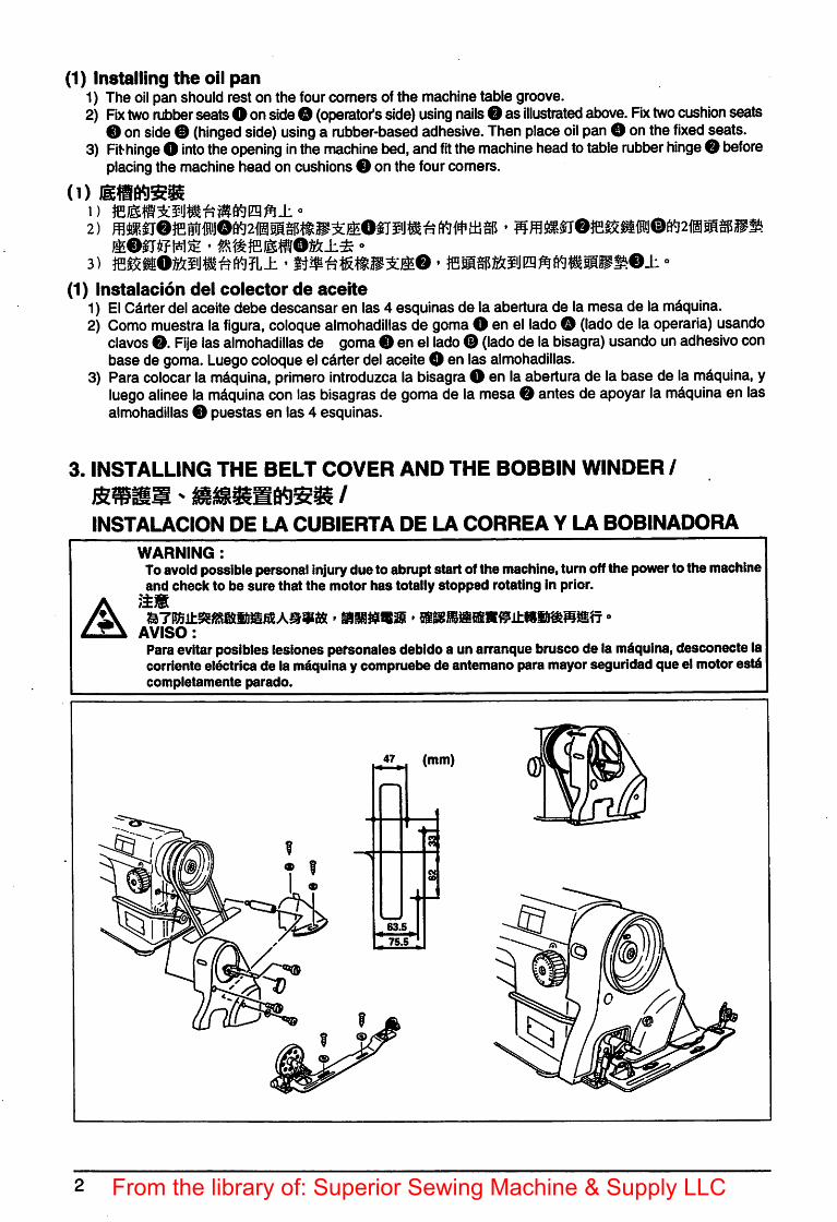
(1) Installing the oil pan1) The oil pan should rest on the four comers of the machine table groove.2) Fix two rubber seats O onsideO (operator's side) using nails O as illustrated above. Fix two cushion seats
O onside® (hinged side) using a rubber-based adhesive. Then place oil pan O onthe fixed seats.3) Fithinge O into the opening in the machine bed, and fit the machine head totable rubber hinge O before
placing the machinehead on cushions 0 on the fourcomers.
(1)
ffiOSJffNS • «Sm}ESffifOK(±i •>
(1) instaiacion del colector de aceite1) El Carterdel aceite debe descansar en las 4 esquinas de la abertura de la mesa de la m^quina.2) Como muestra la figura, coloque almohadillas de gomaO en el ladoO (lado de la operaria) usando
clavos O. Fije las almohadillas de gomaO en el ladoO (lado de la bisagra) usando un adhesivo conbase de goma. Luego coloqueel carter del aceite O en las almohadillas.
3) Para colocar la m^quina, primero introduzca la bisagra O en la abertura de la base de la m^quina, yluego alinee la mdquina con las bisagras de goma de la mesa O antes de apoyar la m^quina en lasalmohadillas O puestas en las 4 esquinas.
3. INSTALLING THE BELT COVER AND THE BOBBIN WINDER /
INSTALACION DE LA CUBIERTA DE LA CORREA Y LA BOBINADORA
A
WARNING:Toavoidpossible personal injurydue to abrupt start of the machine, tum offthe powerto the machineand check to be sure that the motor has totally stopped rotating In prior.
AVISO:Para evitar posibles leslones pefsonales debldo a un arranque brusco de la m^qulna,desconecte lacorrlenteelectricade la maqulnay compruebe de antemano para mayorsegurldad qua el motorestdcompletamente parado.
0
From the library of: Superior Sewing Machine & Supply LLC
4. ADJUSTING THE HEIGHT OF THE KNEE LIFTER /AJUSTE DE LA ALTURA DEL ELEVADOR DE RODILLA
WARNING:To avoid possible personal Injurydue to abrupt start of the machine, turn offthe power to the machine
^ i^otor has totally stopped rotating In prior.' ' mmnmm > °AVISO:
Para evitar poslbles leslones personales debldo a un arranque brusco de la mdqulna, desconecte lacorrlente el6ctrica de la m^qulna y compruebe de antemano para mayor seguridad qua el motor estdcompletamente parado.
0
1) The standard height of the presser foot lifted using the knee lifter is 10 mm.2) Youcan adjust the presser foot lift up to 13 mm using knee lifter adjust screw O •3) When you have adjusted the presser foot lift to over 10 mm, be sure that the bottom end of needle bar <
in its lowest positiondoes not hit presser foot O.
2) 13 mm -3) lOnrni
1) La altura normal que se eleva el pie prensatelas usando el elevador de rodilla es 10 mm.2) Usando el tomillo de ajuste O, Ud. puede ajustar la elevacidn del pie prensatelas usando el elevador de
rodilla hasta un m^imo de 13 mm.
3) Cuando ha ajustado la elevacidn del pie prensatelas a mds de 10 mm, asegurese que el extreme inferiorde la barra de la aguja O, al estar en su posicidn mds baja, no choca con el pie prensatelas 0.
5. INSTALLING THE THREAD STAND//
INSTALACION DEL PEDESTAL DEL HILO
From the library of: Superior Sewing Machine & Supply LLC
6. LUBRICATION / LUBRICACION
A
WARNING:Toavoid possible personal injury duetoabrupt startofthemachine, turnoff thepower tothemachineand check to be sure that the motor has totally stopped rotating in prior.
AVISO:Paraevitar posibies lesionespersonales debido a unarranque bruscode la mdquina, desconecte lacorriente el^ctrica de lam^quina ycompruebe deantemano para mayor seguiidad queel motor estdcompletamente parado.
(1) informacidn sc ia iubricaclon1) Llene elcolector site O con aceite JUKI Machine Oil 7hasta lamarca "HIGH" O •2) SI el nivel del acek«ro^a de lamarca "LOW" 0, rellene elcolector de aceite con elaceite especlflcado.3) 81 el sistemade lubrlcaclbn estd funcionando blen, al hacerfunclonar la m^qulna, puedeversesalplcar
el aceite a trav^s de la mirilla del aceite 0.4) Observeque lacantldadque salpica el aceite no tiene relacidn con la cantldad de aceite lubrlcante.
rAterTcidn Cuando use ia m^uina per primera voz despues do su instalacidnypreparacidn odespue |' i I que no la haya usado por mucho tiempo, haga funcionar ia mdquina a una velocidad de .' \^py 3.000 p.p.m.duranteunos 10 minutos. j
0
Maximum Minimum
HA H'J^Mdxiomo Minimo
1
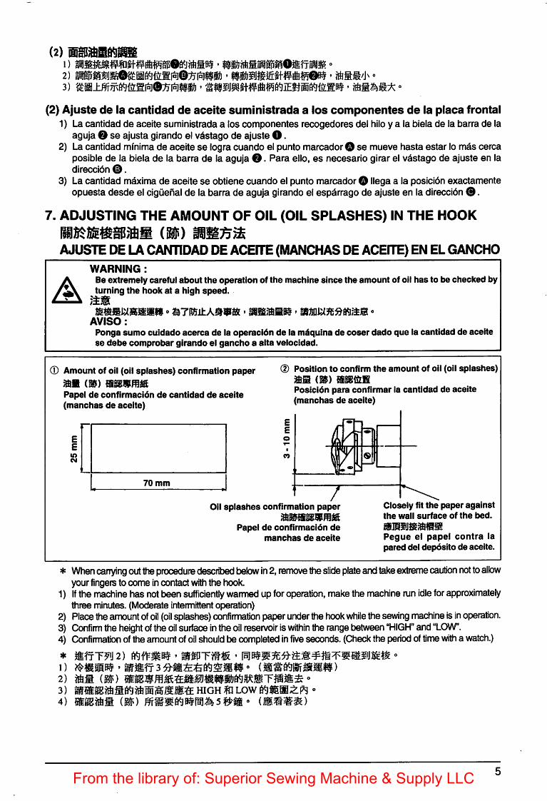
(2) Adjusting the amount of oil suppliedto the face plate parts
1) Adjust the amount ofoil suppliedto the thread take-up and needle barcrank 0 by turning adjust pin O.
2) The minimum amountofoil Is reached when markerdot O Is brought close to needle bar crank 0 byturning the adjust pin In direction 0.
3) The maximum amount of oil Is reached whenmarkerdot O Is broughtto the position just oppositefrom the needle bar crank by turning the adjust pinIn direction 0.
From the library of: Superior Sewing Machine & Supply LLC
(2)
(2) Ajuste de la cantidad de aceite suministrada a ios componentes de la placa frontal1) La cantidad de aceite suministrada a Ios componentes recogedores del hiloy a la biela de la barra de la
aguja e se ajusta girando el vastago de ajuste O.2) Lacantidad minima de aceite se logracuando el punto marcadorO se mueve hasta estar lo mas cerca
posible de la biela de la barra de la aguja O. Para ello, es necesario girar el vastago de ajuste en ladireccibn 0.
3} La cantidad maxima de aceite se obtiene cuando el punto marcador O Hega a la posicidn exactamenteopuesta desde el ciguenal de la barra de aguja girando el esparragode ajuste en la direccion ®.
7. ADJUSTING THE AMOUNT OF OIL (OIL SPLASHES) IN THE HOOK
Be extremely careful about the operation of the machine since the amount of oil has to be checked byturning the hook at a high speed.
}±m
AVISO:Ponga sumo cuidado acerca de la operacldn de la maquina de coser dado que la cantidad de aceitese debe comprobar girando el gancho a alta velocidad.
0 Amount of oil (oil splashes) confirmation paper
m)Papel de confirmacidn de cantidad de aceite(manchas de aceite)
d) Position to confirm the amount of oil (oil splashes)(Si) BigtSlS
Posicidn para confirmar ia cantidad de aceite(manchas de aceite)
70 mm
/)
7m
9V
1 /Oil splashes confirmation paper
Papei de confirmacion demanchas de aceite
Closeiy fit the paper againstthe wall surface of the bed.
Pegue el papel contra lapared del depdsito de aceite.
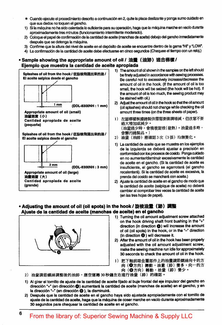
* When carrying outtheprocedure desciitied below in2, remove theslide plate andtakeextreme caution nottoallowyour fingers to come in contact withthe hook.
1) if the machine has notbeen sufficiently warmed upforoperation, makethe machine runidle for approximatelythree minutes. (Moderate intermittentoperation)
2) Placetheamount ofoil (oil splashes)confirmation paperunderthe hook while the sewing machine is in operation.3) Confirm the height ofthe oil surfaceinthe oil reservoir iswithin the rangebetween "HIGH" and "LOW".4) Confirmation oftheamount ofoil should be completed in five seconds.(Check the period oftime with a watch.)
5itfT^0 2) o' mmn 3 )
HIGH m LOW 6^|g@0;tP9 °mm^m ») mmmm)
*
1)2)3)4)
From the library of: Superior Sewing Machine & Supply LLC
* Cuando ejecute elprooedlmiento descrito a continuacion en 2,quite laplacadeslizante yponga sumo cuidado enque BUS dedos no toquen el gancho.
1) Sila m^quina nohasidooalentada losuficiente parasu operaddn, hagaquelam^quina marche en vacfo durarrteaproximadamente tres minutos (funcbnamlento Intemnitente moderado).
2) Coloque elpapelde confirmacidn de lacantldad de aceite(manchasde aceite) debayo delganchoinmedlatamentedespu^s que se detenga la m^quina.
3) Confirme que laaltura delnivel de aceiteen el depdsito de aceitese encuentre dentro de lagama"HI" y "LOW".4) Laconfiimacidn de lacantldad de aceitedebe efectuarse en dnco segundos(Chequee eltiempo conunreloj.)
Sample showing the appropriate amount of oil / Bn'Ejempio que muestra ia cantidad de aceite apropiada
1) Theamountofoil shown in thesamplesontheleftshouldSplashes of oil from the hook / /El aceite salpica desde el gancho
I1t
1
1 mm (DDL-8300NH: 1 mm)
Appropriate amount of oil (small)
Cantldad apropiada de aceite(pequeha)
Splashes of oil from the hook / /El aceite salpica desde el gancho
y
2 mm(DDL-8300NH: 3 mm)
Appropriate amount of oil (large)mwmu (A)Cantldad apropiada de aceite(grande)
be finely adjusted inaccordance with sewingprocesses.Be careful not to excessively increase/decrease theamount of oil in the hook. (If the amount of oil is toosmall, the hook will be seiz^ (the hook will be hot). Ifthe amount of oil Is too much, the sewing product maybe stained with oil.)
2) Adjust the amountofoil In the hookso thatthe oil amount(oil splashes)should notchangewhile checking theoilamount three times (onthe three sheets of paper).
2) mm (») mjsm3>x
1) Lacantidad de aceiteque se muestra en losejemplosde la izquierda se deberd ajustar a precisibn encoiTfoimidadconlosprocesosdecosido. Pongacuidadoen no aumentar/disminuir excesivamente la cantidadde aceite en el gancho. (Si la cantldad de aceite esinsuficiente, el gancho se agarrotarS (el ganchorecalentard). Si la cantidadde aceite es excesiva, laprenda del cosidose manchardcon aceite.)
2) Ajusteiacantidad de aceiteen elganchode modequela cantidad de aceite (salpiquede aceite) no deber^cambiaral comprobartres veces lacantidadde aceite(en las tres hojas de papel).
•Adjusting the amount of oil (oil spots) in the hook/t&WAJiAJuste de ia cantidad de aceite (manchas de aceite) en ei gancho
1) Tuming the oilamount adjustment screw attachedon the hook driving shaft front bushing in the"+"direction (indirection O) will increase the amountof oil (oil spots) in the hook, or in thedirection(indirection O) will decrease it.
2) After the amount ofoil inthe hookhas been properlyadjusted with the oil amount adjustment screw,make the sewing machine runidleforapproximately30 seconds to check the amount of oil In the hook.
2)
1)mm • mm im) * iri-6^:^
1^ (®:^i^) mm^mm m)
1) Al girarel tomillo de ajuste de la cantidad de aceite fijado al buje frontal del eje impulsordel gancho endireccibn"+" (en direccibn O) aumentard la cantidad de aceite (manchas de aceite) en el gancho, y enla direccldn(en direccibn 0), la disminuird.
2) Despu^s que la cantidad de aceite en el gancho haya sido ajustada apropiadamente con el tomillo deajuste de lacantidadde aceite, haga que la irWiquina de coser marcheen vacfoduranteaproximadamente30 segundos para chequear la cantidad de aceite en ei gancho.
From the library of: Superior Sewing Machine & Supply LLC
8. ATTACHING THE NEEDLE / / COLOCACION DE LA AGUJA
A
WARNING:To avoid possible personal injury due to abrupt start of the machine, turn off the power to the machineand check to be sure that the motor has totally stopped rotating in prior.
AVISO:Para evitar posibles iesiones personales debido a un arranque brusco de la mdquina, desconecte lacorriente elTOtrica de la mdquina y compruebe de antemano para mayor seguridad que el motor estacompletamente parado.
9. SETTING THE BOBBIN INTO THE BOBBIN CASE / /
MODO DE FIJAR LA BOBINA EN LA CAPSULA DE CANILLA1) Pass the thread throughthread slitO. and pull the
thread in direction
Byso doing, the thread will pass under the tensionspring and come outfrom notch 0.
2) Check that the bobbin rotates in the direction ofthe arrow when thread 0 is pulled.
1) Rase el hilo por la rendija O de hilo, y tire del hiloen la direccidn 0.De este modo, el hilo pasard por debajo del muelletensory saldra porla muesca0.
2) Compruebe que la bobina gira en la direccibn dela flecha cuando se tira del hilo ®.
0
10. ADJUSTING THE STITCH LENGTH / /
MODO DE AJUSTAR LA LONGITUD DE PUNTADA
From the library of: Superior Sewing Machine & Supply LLC
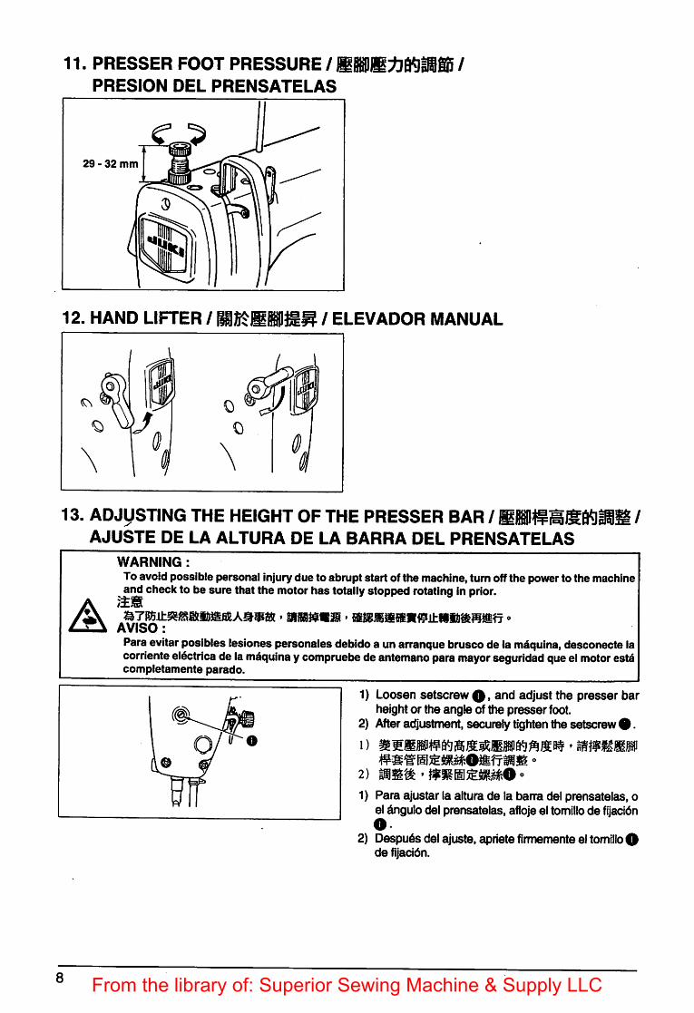
11. PRESSER FOOT PRESSURE / MPS /PRESION DEL PRENSATELAS
29 - 32 mm
12. HAND LIFTER / / ELEVADOR MANUAL
§
13. ADJUSTING THE HEIGHT OF THE PRESSER BAR / /AJUSTE DE LA ALTURA DE LA BARRA DEL PRENSATELAS
A
8
WARNING :To avoid possible personal injurydue to abrupt start of the machine, turn off the power to the machine
^and check to be sure that the motor has totally stopped rotating in prior.
AVISO:Para evitar posibles lesiones personales debido a un arranque brusco de la maquina, desconecte lacorriente el^trica de la maquina ycompruebe deantemano para mayor seguridad que el motor estacompletamente parado.
1) Loosen setscrew 0, and adjust the presser barheight or the angle of the presser foot.
2) After adjustment, securely tightenthe setscrew 0.
2) ^
1) Para ajustar la altura de la barra del prensatelas, oel dngulo del prensatelas, aflojeel tomillo de fijacidno
2) Despu^s del ajuste, apiiete firmemente el tomillo 0de fijacidn.
From the library of: Superior Sewing Machine & Supply LLC
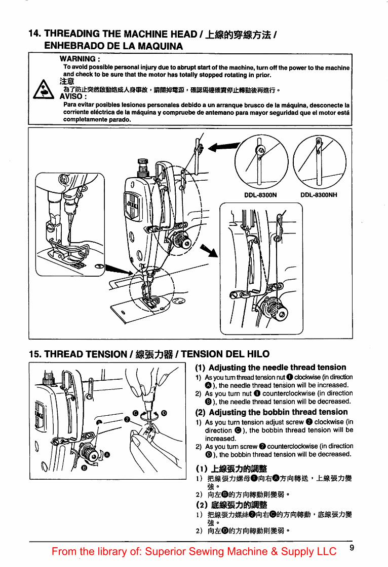
14. THREADING THE MACHINE HEAD / /
ENHEBRADO DE LA MAQUINA
A
WARNING:Toavoid possible personal Injurydue to abrupt start of the machine, turn off the power to the machine
^and check to be sure that the motor has totallystopped rotatingIn prior.
' mmmmm * -AVISO:
Para evitar poslbles leslones personales debldo a un arranque brusco de la maqulna, desconecte lacorrlente electrica de la maqulna y compruebe de antemano para mayor seguiidad que el motor estacompletamente parado.
DDL-8300N DDL-8300NH
15. THREAD TENSION / / TENSION DEL HILO
(1) Adjusting the needle thread tension1) Asyou turn thread tensbn nut O clockwise (in direction
O), the needle thread tension will be increased.2) As you turn nut O counterclockwise (in direction
From the library of: Superior Sewing Machine & Supply LLC
(1) Ajuste de la tension del hilo de la aguja1) Amedida que Ud. gira la tuerca del cabezal de tensidn O hacia la derecha (de la direccidn O). la
tensidn del hilo de la aguja aumentar^.2) Amedida que Ud. gira la tuerca O en el sentidocontrario al del movimiento de los punteros la Izuguierda
(en la direccidn ®), la tensidn del hilo de la aguja disminuird.
(2) Ajuste de la tension del hilo de la bobina1) Amedida que Ud. gira el tomillo de agjuste de latensidn O en elsentido delmovimiento de lospunteros
la derecha (en la direccidn 0), la tensidn del hilo de la bobinaaumentar^.2) Amedida que Ud. girael tomillo 0 en el sentido contrario al del movimiento de lospunteros la izuguierda
(en la direccidn0). la tensidn del hilo de la bobina disminuird.
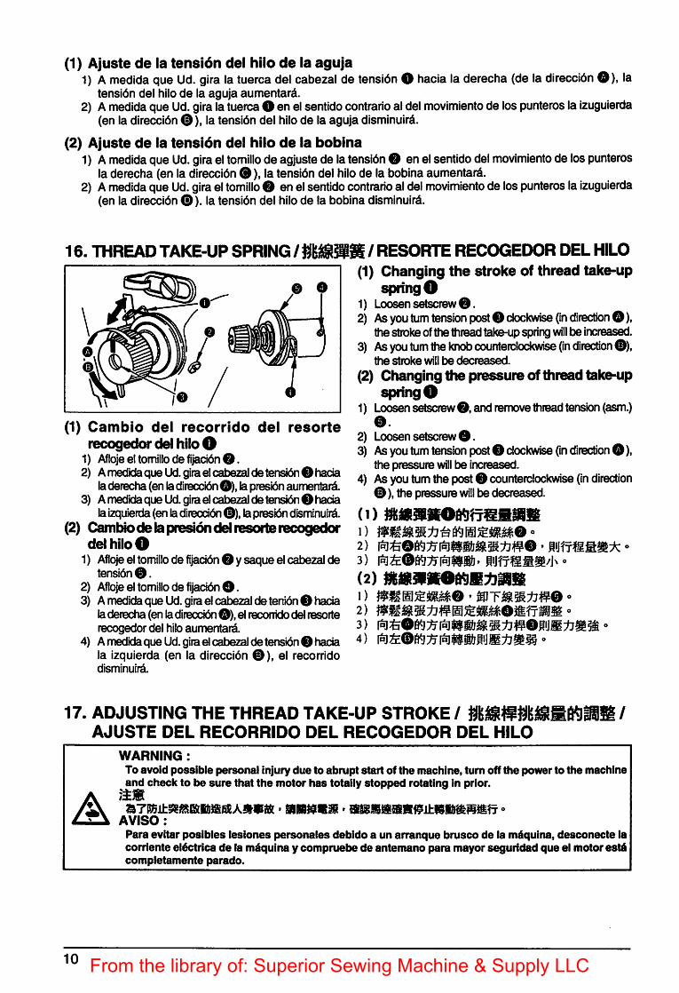
16. THREADTAKE-UP SPRING / Hmmt / RESORTE RECCXSEDOR DEL HILO(1) Changing the stroke of thread take-up
spring O1) Loosen setscrew0.2) As you turn tension post 0 clockwise (in direction O),
the strokeofthe thread take-upspringwill l3e increased.3) As you tum thekriob counterclockwise (In direction 0),
ttie stroke will be decreased.
(2) Changing the pressure of thread take-upspring O
1) Loosen setscrew0, and remove thread tension (asm.)0.
2) Loosen setscrew0.3) As you tum tension post 0 clockwise (in direction 0),
the pressure will be increased.4) Asyou tum the post0 counterclockwise (in direction
0), the pressurewill be decreased.
(1)1)
(2)1) mmm&tmo • '2)
4) '
0 O
0
/
(1) Cambio del recorrldo del resorterecogedor del hiloO
1) Atloje el tomillo de fijacldn 0.2) Amedida que Ud. giraelcabezalde tensidn 0hacia
del hilo O1) Afloje el tomillo de fijacidn 0 ysaque el cabezalde
tensidn 0.2) Afloje el tomillo de fijacidn O.3) Amiedida que Ud. gira el cabezal de tenidn 0 hada
laderecha(enladireccidn O), el reconido delresorterecogedor del hib aumentara.
4) Amedidaque Ud. giraelcabezalde tensbn 0 hadala izquierda (en la direccidn 0), el recorrldodismlnulrd.
17. ADJUSTING THE THREAD TAKE-UP STROKE / /
AJUSTE DEL RECORRIDO DEL RECOGEDOR DEL HILO
A
10
WARNING:To avoid possible personal Injury due to abrupt start of the machine, turn off the power to the machineand check to be sure that the motor has totally stopped rotating In prior.
' -mmnmrn > «AVISO:
Para evitar poslbies lesiones personates debldo a un arranque brusco de la mdqulna, desconecte lacoriiente eldctrica de la mdqulna y compruebe de antemano para mayor seguiidad que el motor est^completamente parado.
From the library of: Superior Sewing Machine & Supply LLC
02)
1) SI cose telas pesadas, mueva la gufa del hllo O hacia la Izqulerda (en ladireccidn O) paraaumentar ellargodel hllo que tirael recogedor.
2) Al cosertelas livlanas, mueva lagufa delhllo O hacIa laderecha (en ladirecclbn 0) lo quedismlnuye ellargo del hllo tiradoporel recogedor.
3) Normalemente, la gufadel hllo O estd poslclonada de manera tal que la Ifnea demarcadora 0 quedealineada con el centro del tomlllo.
18. NEEDLE-TO-HOOK RELATIONSHIP / /
RELACION DE AGUJA A GANCHO
1) When sewing heavy-weight materials, move threadguide O to the left (In direction O) to Increase thelengthof thread pulled out by the thread take-up.
2) When sewing light-weight materials, move threadguide O to the right (In direction ®) to decrease thelength of thread pulled out bythe thread take-up.
3) Normally, threadguideO is positioned In a waythatmarkerline 0 Isalignedwith the center ofthe screw.
1)
A
WARNING:To avoid possible personal injury due to abrupt start of the machine, turn off the power to the machineand check to be sure that the motor has totally stopped rotating in prior.
AVISO:Para evitar posibles lesiones personaies debido a un arranque brusco de la m^quina, desconecte lacorriente eltetrica de la m^quina y compruebe de antemano para mayor seguridad que el motor estdcompletamente parado.
0.04 - 0.1 mm
o
0
(1) Adjust the timing between the needleand the hook as follows :
1) Tum the handwheel to bright the needle bar down tothe towest point ofits stroke, and loosen setscrew O.
(Adjusting the needle bar height)2) (For a DBneedle) Align marker line O on needle
bar 0 with the bottom end of needle bar lowerbushing0, then tighten setscrew O.
(Adjusting position of the hook O)3) (For a DB needle) Loosen the three hook setscrews,
turn the handwheel and align marker line 0 onascending needle bar 0 with the bottom end ofneedle bar lowerbushing 0.
4) After making the adjustments mentioned in theabove steps, align hook blade point 0 with thecenter of needle O. Provide a clearance of 0.04mm to 0.1 mm (DDL-8300NH : 0.06 to 0.17 mm)(reference value) between the needle and the hook,then securely tighten setscrews In the hook.
IIf the clearance between the blade
point of hook and the needle is smaller •than the specified value, the blade Ipoint of hook wiil be damaged. If the jclearance is larger, stitchskipping will |result.
11From the library of: Superior Sewing Machine & Supply LLC
(1) Ajuste el sincronlsmo entre la aguja y el gancho de la manera siguiente:1) Gire el volante para bajar la barra de aguja al punto mas bajode su recorrido, y afloje el tornillo O.
(Modo de ajustar la altura de la barra de aguja)2) (Para una aguja DB) Allnee la lineaO demarcadora en la barra O con el extreme Inferior del buje 0
. AtenVtenfcid Si la separacion entre la punta de la hoja del gancho y la aguja es menor que el valor^especificado, la punta de la hoja del gancho se dahari. Si laseparacion es mayor, se |producira saltode puntada. y
19. HEIGHT OF THE FEED DOG / /
ALTURA DE LOS DIENTES DE ARRASTRE
A
12
WARNING :To avoid possible personal injury due to abrupt start of the machine, turn off the power to the machine
^and check to be sure that the motor has totallystopped rotating in prior.
AVISO :Para evitar posibles lesiones personales debido a un arranque brusco de la m^quina, desconecte lacorriente el6ctrica de la maquina y compruebe de antemano para mayor seguridad que el motor estdcompletamente parado.
^/6a3^ If the clamping pressure is insufficient,'I f fiSk ) the motion of the forked portion |te^me^^vy. y
0
From the library of: Superior Sewing Machine & Supply LLC
Para ajustar la aitura de los dientes de arrastre:
0 Afloje el tomillo O de la ciguenal O.(0 Para hacerel ajuste, mueva la barradel arrastre hacia artibao hacia abajo.0 Aprietefirmemente el tornlllo O.
cidn Si la presion de fijacion es insuficiente, el movimento de la porcion ahorquillada devienepesada.
,Atenfcid
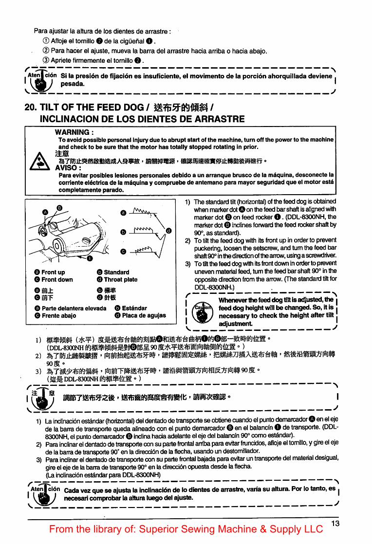
20. TILT OF THE FEED DOG / /
INCLINACION DE LOS DIENTES DE ARRASTRE
A
WARNING :To avoid possible personal Injury due to abrupt start of the machine, turn off the power to the machineand check to be sure that the motor has totally stopped rotating In prior.
AVISO:Para evitar poslbles leslones personales debldo a un arranque brusco de la mdqulna, desconecte lacoriiente eldctrica de la maqulna y compruebe de antemano para mayor segurldad que el motor estacompletamente parado.
2) To tilt the feed dog with its front up in order to preventpuckering, loosenthe setscrew,and turnthe feed barshaft 90° inthe direction ofthe arrow,usinga screwdriver.
3) Totilt the feed dogwith itsfront downinorderto preventuneven materialfeed, turn the feed bar shaft 90° intheopposite direction from the arrow. (The standard tilt forDDL-8300NH.) .
Wheneverthef^ dog tilt isadjusted, the |feed dog height will be changed. So, it is •necessary to check the height after tilt.adjustment '
O Parte delantera elevada 0 Est^ndar0 Frente abajo 0 Placa de agujas
2) Para inclinar el dentado detransporte con suparte frontal arriba para evitar fruncidos, afloje el tomillo, ygire el ejede latjarra de transporte 90' en ladireccidn de laflecha, usando undestomillador.
3) Para inclinar el dentado detransporte con suparte frontal bajada para evitar un transporte del material desigual,gire elejede labarra de transporte 90° en ladirecdon opuesta desde laflecha.(La inclinaddnest^dar para DDL-8300NH)
^ ^AterJ cl6n cada vez que seajusta la inclinacion de lo dientes de arrastre, varia su aitura. For lo tanto, es |vjjPLy necesari comprol)^ la aitura luego del ajuste. ^
13From the library of: Superior Sewing Machine & Supply LLC
21. ADJUSTING THE FEED TIMING / /
AJUSTE DEL SONCRONISMO DEL ARRASTRE DE LAS TELAS
A
WARNING :To avoid possible personal injury due to abrupt start of the machine, turn off the power to the machineand check to be sure that the motor has totally stopped rotating in prior.
AVISO:Para evitar posibles iesiones personaies debido a un arranque brusco de la mdquina, desconecte lacorriente el^trica de la m^quina y compruebe de antemano para mayor seguridad que el motor estdcompletamente parado.
Standard feed timingmmSincronismo est^ndar delarrastre
Advanced feed timing
Avance ei sincronismo del
arrastre
Delayed feed timing
Sincronizacidn de arrastreatrasada
1) Loosenscrews O and O infeed eccentriccam O, move the feed eccentric cam In the direction ofthe arrow or opposite direction of the arrow, andfirmly tighten the screws.
2) For the standard adjustment, adjust so that the topsurface of feed dog and the top end of needle eyeletare flush with the top surface of throat plate whenthe feed dog descends below the throat plate.
3) To advance the feed timing In order to preventuneven material feed, move the feed eccentric camIn the direction of the arrow.
4) To delay the feed timing In order to Increase stitchtightness, move the feed eccentric cam In theopposite direction from the arrow.
mBe careful not to move the feed^eccentric cam too far,or else needle |breakage may result. ^
1) ' e • mwm
2)
1) Afloje los tomlllos O yO en laleva exc^ntrlca de transporte O, mueva laleva exc^ntrlca de transporteen ladlreccl6n de laflecha o en la direccidn opuestade laflecha, yapiiete blen lostomlllos.
2) Para elajuste est^ndar, haga elajuste de modo que lasuperflcle superior del dentado detransporte yelextreme superior del ojal de la aguja queden a ras con la superflcle superior de la placa de agujascuando el dentado de transporte desclendepordebajo de la placade aguja;
3) Para evitar el arrastre disparejo de las telas, puede avanzar la sincronlzacldn del arrastre. Para ello,mueva la leva exc^ntrica en la direccidn de la flecha.
4) Paraaumentar latensldn de las puntadas, puedeatrasar laslncronlzacldn del arrastre. Para ello, muevala levaexcdntrica en la direccidn opuesta de la flecha.
cuidado en no moverdemasiado lejos la levaexcdntricade transporte, porque ellopodria resultar en rotura de la aguja. •
14 From the library of: Superior Sewing Machine & Supply LLC
22. MOTOR PULLEYS AND BELTS/ /
POLEAS Y CORREAS DEL MOTOR
1) A clutch motor with 400W output (1/2 HP) Is used as the standard motor.2) An M-type V belt should be used.3) The relationship between the motor puileys, belt lengths and sewing speeds is shown in the foilowing
tabie:
Motor pulley O.D.
(mm)Motor pulley part No.
Sewing speed (rpm)Belt length Belt part No.
50 Hz 60 Hz
125 MTKP0120000 5,060 1118 mm (44") MTJVM004400
120 MTKP0115000 4,850
1092 mm (43") MTJVM004300115 MTKP0110000 4,630
110 MTKP0105000 4,440
105 MTKP0100000 4,250 5,040
1067 mm (42") MTJVM004200100 MTKP0095000 4,000 4,780
95 MTKP0090000 3,820 4,540
90 MTKP0085000 3,610 4,320
85 MTKP0080000 3,390 4,000
1041 mm (41") MTJVM00410080 MTKP0075000 3,160 3,790
75 MTKP0070000 2,950 3,520
70 MTKP0065000 2,740 3,260
^ The effective diameter of a motor puiley is equivalent to the outside diameter minus 5 mm.The motor should rotate counterclockwise as observed from the handwheel side. Be careful notto allow the motor to rotate in the reverse direction.
2)3) <>
mmmmmm m(rpm)
mmm50 Hz 60 Hz
125 MTKPO120000 5,060 1118 mm (44") MTJVM004400
120 MTKPO115000 4,850
1092 mm (43") MTJVM004300115 MTKPO 110000 4,630
110 MTKPO 105000 4,440
105 MTKPO100000 4,250 5,040
1067 mm (42") MTJVM004200100 MTKP0095000 4,000 4,780
95 MTKP0090000 3,820 4,540
90 MTKP0085000 3,610 4,320
85 MTKP0080000 3,390 4,000
1041 mm (41") MTJVM00410080 MTKP0075000 3,160 3,790
75 MTKP0070000 2,950 3,520
70 MTKP0065000 2,740 3,260
* s mm °
15From the library of: Superior Sewing Machine & Supply LLC
1) Como motor est^ndar se usa un motor de embrague con una potencia de salida de 400W (1/2HP).
2) Se debark usar una correa V tipo-M.
3) La relacion entre las poleas y el motor, la longitud de las correas y la velocidad de cosido se muestran en
la siguiente tabia:
D.E. (Diametro Exterior)
de la polea de motor
No. de pleza de la
polea del motor
Velocidad de coser (p.p.m.) Longitud de la
correa
No. de pleza
de correa50 Hz 60 Hz
125 MTKP0120000 5.060 1118 mm (44") MTJVM004400
120 MTKP0115000 4.850
1092 mm (43") MTJVM004300115 MTKP0110000 4.630
110 MTKP0105000 4.440
105 MTKP0100000 4.250 5.040
1067 mm (42") MTJVM004200100 MTKP0095000 4.000 4.780
95 MTKP0090000 3.820 4.540
90 MTKP0085000 3.610 4.320
85 MTKP0080000 3.390 4.000
1041 mm (41") MTJVM00410080 MTKP0075000 3.160 3.790
75 MTKP0070000 2.950 3.520
70 MTKP0065000 2.740 3.260
* El diametro efectivo de una polea de motor es equivalente al diametro exterior menos 5 mm.* El motor debera girar hacia la izquierda si se observe desde el lado del volante. Ponga culdado
en que el motor no gire en la direcclon inversa.
16 From the library of: Superior Sewing Machine & Supply LLC
•JUKI
JUKI CORPORATIONINTERNATIONAL SALES H.Q.
8-2-1, KOKURYO-CHO,CKOFU-SHI, TOKYO 182-8655, JAPANPHONE; (81)3-3430-4001 to 4005FAX: (81)3-3430-4909 *4914 *4984TELEX :J22967
Please do not hesitate to contact our distr&utors or agents in your area for further information wfren necessary.* The descrfptlon covered In this instruction manual ia subject to change for improvement of the
commodity wtthout notice.
Sirvase ponerse en contacto con nuestros distribuidores o agentes en su Area siempre que necesite algunainformacidn mAs detallada.e La descripcidn que se do en este manual de instrucciones estA sujeta a cambio sin previo aviso por
razones de mqjora de la mercancfa.
01 • 04 Printed (E)From the library of: Superior Sewing Machine & Supply LLC