530
DISTRICT OF COLUMBIA DEPARTMENT OF TRANSPORTATION DESIGN AND ENGINEERING MANUAL April 2009

DISTRICT OF COLUMBIA
DEPARTMENT OF TRANSPORTATION
DESIGN AND ENGINEERING
MANUAL
April 2009

DISTRICT OF COLUMBIA
DEPARTMENT OF TRANSPORTATION
GABE KLEIN, DIRECTOR
KATHLEEN PENNEY, CHIEF ENGINEER
ARDESHEIR NAFICI, DEPUTY CHIEF ENGINEER
GREER GILLIS, DEPUTY CHIEF ENGINEER
MESFIN LAKEW, CHIEF SAFETY, STANDARDS AND QUALITY CONTROL DIVISION
U.S. DEPARTMENT OF TRANSPORTATION FEDERAL HIGHWAY ADMINISTRATION

D.C. Department of Transportation – Design and Engineering Manual
I-i
PART I –PROJECT DEVELOPMENT PROCEDURES............................................. 1
CHAPTER 1 ...................................................................................................................... 1
OVERVIEW...................................................................................................................... 1 1.1 INTRODUCTION ........................................................................................................... 1 1.2 AUTHORITY AND APPLICABILITY................................................................................ 1 1.3 DEFINITIONS ............................................................................................................... 2 1.4 FUTURE CHANGES AND REVISIONS............................................................................. 2
1.4.1 Policy Revisions ................................................................................................. 2 1.4.2 Technical Revisions ........................................................................................... 2
1.5 GOVERNING STANDARDS............................................................................................ 2 1.6 DESIGN EXCEPTIONS................................................................................................... 3
1.6.1 Project Design Exceptions................................................................................. 3 1.6.2 FHWA Approval................................................................................................. 3 1.6.3 Substandard Design Features............................................................................ 4
CHAPTER 2 ...................................................................................................................... 1
PROJECT DEVELOPMENT.......................................................................................... 1 2.1 PROJECT DEVELOPMENT PROCESS ................................................................................. 1
2.1.1 Step 1 - Planning................................................................................................ 1 2.1.2 Step 2 - Prioritization and Budgeting ................................................................ 8 2.1.3 Step 3 - Project Programming ........................................................................... 8 2.1.4 Step 4 - Preliminary Design............................................................................... 9 2.1.5 Step 5 - Final Design ......................................................................................... 9 2.1.6 Step 6 - Bid Process ........................................................................................... 9 2.1.7 Step 7 - Construction ....................................................................................... 10
2.2 PROJECT ROLES AND RESPONSIBILITIES....................................................................... 10 2.3 PROJECT DESIGN REQUIREMENTS ................................................................................ 10
2.3.1 General ............................................................................................................ 10 2.3.2 Field Survey and Mapping............................................................................... 11 2.3.3 Utility Maps ..................................................................................................... 12 2.3.4 Geotechnical Services...................................................................................... 12 2.3.5 Traffic Control Plans ....................................................................................... 12 2.3.6 Electrical Work ................................................................................................ 13 2.3.7 Storm Sewers.................................................................................................... 15 2.3.8 Water, Sewer and Utilities ............................................................................... 15 2.3.9 Landscaping..................................................................................................... 16 2.3.10 Soil Erosion and Sediment Control................................................................ 16 2.3.11 Submittals....................................................................................................... 16 2.3.12 Quality Assurance/Quality Control Program................................................ 26
2.4 PREPARATION OF DRAWINGS ....................................................................................... 27 2.4.1 Drawings.......................................................................................................... 27 2.4.2 Organization Sheets ......................................................................................... 27 2.4.3 Description and Contents of Drawings............................................................ 27
2.5 REQUIRED PLANS......................................................................................................... 45

D.C. Department of Transportation – Design and Engineering Manual
I-ii
CHAPTER 3 ...................................................................................................................... 1
PROJECT MANAGEMENT........................................................................................... 1 3.1 PROJECT MANAGEMENT ................................................................................................ 1
3.1.1 Planning Group Inclusion in the 5-year Capital Improvement Program.......... 1 3.1.2 Design Scoping .................................................................................................. 1 3.1.3 Estimated Construction Costs............................................................................ 1 3.1.4 Budget ................................................................................................................ 2 3.1.5 Obligation .......................................................................................................... 2 3.1.6 Important Phase Dates ...................................................................................... 2 3.1.7 Supplementing the Budget.................................................................................. 3 3.1.8 Day-to-Day Financial Management .................................................................. 3 3.1.9 Payment to Consultant/Contractors .................................................................. 3 3.1.10 Preliminary Design Review (30%) .................................................................. 3 3.1.11 Intermediate Design Review (65%) ................................................................. 3 3.1.12 Value Engineering ........................................................................................... 3 3.1.13 Final Review (100%) ....................................................................................... 4
3.2 MAJOR PROJECT CONSIDERATIONS................................................................................ 4 3.2.1 Environmental.................................................................................................... 5 3.2.2 Traffic................................................................................................................. 5 3.2.3 Structures ........................................................................................................... 7 3.2.4 Materials/Pavement ........................................................................................... 7 3.2.5 Trees and Landscaping ...................................................................................... 8 3.2.6 ROW Acquisition and Clearances ..................................................................... 8 3.2.7 Utilities............................................................................................................... 8 3.2.8 Water, Sewer, and Storm Sewer......................................................................... 9 3.2.9 Agreements and Approvals ................................................................................ 9 3.2.10 Community Involvement................................................................................... 9 3.2.11 Maintenance Input ......................................................................................... 10 3.2.12 L'Enfant Plan ................................................................................................. 10 3.2.13 Capitol Hill .................................................................................................... 10 3.2.14 Historic District/Historic Bridge or on Historic Property ............................ 10 3.2.15 Business Improvement District and Streetscape Enhancement ..................... 11 3.2.16 Bike/Pedestrian Improvements ...................................................................... 11 3.2.17 Rehabilitation or Reconstruction................................................................... 11 3.2.18 Federal Lands Affected .................................................................................. 12
CHAPTER 4 ...................................................................................................................... 1
ENVIRONMENTAL ........................................................................................................ 1 4.1 INTRODUCTION............................................................................................................... 1 4.2 DETERMINATION OF ENVIRONMENTAL ACTION TYPES .................................................. 2 4.3 NEPA ACTION TYPES .................................................................................................... 3
4.3.1 EIS Action – Environmental Impact Statement.................................................. 3 4.3.2 EA/FONSI Action – Environmental Assessment/Finding of No Significant
Impact ............................................................................................................... 4 4.3.3 CE Action – Categorical Exclusions.................................................................. 5

D.C. Department of Transportation – Design and Engineering Manual
I-iii
4.4 DCEPA ACTION TYPES:................................................................................................. 6 4.4.1 Exemption .......................................................................................................... 6 4.4.2 EISF ................................................................................................................... 6 4.4.3 EIS...................................................................................................................... 6
4.5 ENVIRONMENTAL PROCESS............................................................................................ 7 4.6 SECTION 4(F)................................................................................................................ 11 4.7 SECTION 106 - HISTORIC CLEARANCES........................................................................ 11 4.8 FLOOD PLAINS ............................................................................................................. 13 4.9 WETLANDS & WATERS ................................................................................................ 14
4.9.1. Section 404 Permit:......................................................................................... 14 4.9.2 Section 402 Permits: ........................................................................................ 15 4.9.3. Section 401 Permit certification ..................................................................... 16
4.10 U.S. FISH AND WILDLIFE ........................................................................................... 16 4.11 HAZARDOUS WASTE AND MATERIALS/CONTAMINATED SOILS.................................. 16 4.12 NOISE ANALYSIS........................................................................................................ 17 4.13 AIR QUALITY ............................................................................................................. 18 4.14 EROSION CONTROL .................................................................................................... 18 4.15 LOW IMPACT DEVELOPMENT ..................................................................................... 19
CHAPTER 5 ...................................................................................................................... 1
TRAFFIC........................................................................................................................... 1 5.1 TRAFFIC DESIGN DATA .................................................................................................. 2 5.2 TRAFFIC ACCIDENT ANALYSIS....................................................................................... 2 5.3 TURNING MOVEMENTS/ACCESS..................................................................................... 2 5.4 SIGNAL WARRANTS ....................................................................................................... 3 5.5 TRAFFIC MOVEMENT DIAGRAM..................................................................................... 3 5.6 INTERSECTION/INTERCHANGE DESIGN........................................................................... 3 5.7 BIKE/PEDESTRIAN IMPROVEMENTS................................................................................ 4 5.8 AMERICANS WITH DISABILITIES ACT STANDARDS......................................................... 6 5.9 MASS TRANSIT ACCOMMODATIONS............................................................................... 6 5.10 TRAFFIC CALMING ....................................................................................................... 7 5.11 TRAFFIC SIGNAL PLAN................................................................................................. 7 5.12 LIGHTING PLAN............................................................................................................ 8 5.13 PERMANENT SIGNING AND PAVEMENT MARKING........................................................ 8 5.14 CONSTRUCTION TRAFFIC CONTROL PLANS.................................................................. 9
CHAPTER 6 ...................................................................................................................... 1
STRUCTURES.................................................................................................................. 1 6.1 MAJOR STRUCTURE - BRIDGE ........................................................................................ 1 6.2 CULVERT........................................................................................................................ 1 6.3 HYDRAULIC DESIGN ...................................................................................................... 2 6.4 MAJOR STRUCTURE - SPECIAL ....................................................................................... 2 6.5 PEDESTRIAN OVERPASS/UNDERPASS ............................................................................. 2 6.6 ARCHITECTURAL/AESTHETIC TREATMENT .................................................................... 3 6.7 GEOTECHNICAL STUDIES ............................................................................................... 3 6.8 STRUCTURE CONDITION REPORT ................................................................................... 3

D.C. Department of Transportation – Design and Engineering Manual
I-iv
6.9 RETAINING WALLS ........................................................................................................ 3 6.10 NOISE BARRIER WALLS ............................................................................................... 4 6.11 GUIDERAIL/BARRIER DESIGN AND REVIEW ................................................................. 4 6.12 CRASHWORTHY BRIDGE RAIL...................................................................................... 5 6.13 VERTICAL/HORIZONTAL CLEARANCES OF STRUCTURE................................................ 5
CHAPTER 7 ...................................................................................................................... 1
PAVEMENT...................................................................................................................... 1 7.1 PAVEMENT ANALYSIS/DISTRESS.................................................................................... 1 7.2 PAVEMENT JUSTIFICATION REPORT ............................................................................... 1 7.3 GEOTECHNICAL STUDIES ............................................................................................... 2 7.4 FOUNDATION INVESTIGATION/DRILLING ....................................................................... 3 7.5 SELECTION OF PAVEMENT MATERIALS (LIFE-CYCLE COST ANALYSIS)......................... 3
CHAPTER 8 ...................................................................................................................... 1
TREES, PLANTS, AND LANDSCAPING..................................................................... 1 8.1 GENERAL REQUIREMENTS.............................................................................................. 1 8.2 SEEDING/SODDING......................................................................................................... 2 8.3 IRRIGATION SYSTEMS .................................................................................................... 2
CHAPTER 9 ...................................................................................................................... 1
RIGHT OF WAY AND CLEARANCES........................................................................ 1 9.1 GENERAL ....................................................................................................................... 1 9.2 ROW ACQUISITION PROCEDURE.................................................................................... 1
9.2.1 Clearance........................................................................................................... 1 9.2.2 Determination of ROW Needs............................................................................ 1 9.2.3 ROW Authorization............................................................................................ 2 9.2.4 Relocation Assistance ........................................................................................ 3 9.2.5 ROW Changes.................................................................................................... 3
9.3 GOVERNMENT LANDS PERMITS ..................................................................................... 3 9.4 NPS/OTHER FEDERAL LANDS ACQUISITIONS................................................................. 4 9.5 UTILITIES CLEARANCE................................................................................................... 4 9.6 RAILROAD CLEARANCE ................................................................................................. 5
9.6.1 Basic Requirements Necessary for Railroad/Highway Projects ...................... 5 9.6.2 Documentation Generally Required for Railroad/Highway Projects ............... 6 9.6.3 Procedures that Generally Apply on Railroad/Highway Projects .................... 6
9.7 AIRPORT/HELIPORT CLEARANCE ................................................................................... 6
CHAPTER 10 .................................................................................................................... 1
UTILITIES ........................................................................................................................ 1 10.1 DRY UTILITIES ............................................................................................................. 1
10.1.1 Project Manager Responsibilities.................................................................... 1 10.1.2 Utility Company Responsibilities..................................................................... 1
10.2 WATER, SEWER, AND STORM SEWER............................................................................ 2 10.2.1 WASA Engineer................................................................................................ 2
D.C. Department of Transportation – Design and Engineering Manual
I-v
10.2.2 Project Manager Responsibilities.................................................................... 2
CHAPTER 11 .................................................................................................................... 1
DRAFTING STANDARDS.............................................................................................. 1
CHAPTER 12 .................................................................................................................... 1
COMMUNITY INVOLVEMENT .................................................................................. 1 12.1 STEP 1: PLANNING THE COMMUNITY INVOLVEMENT PROGRAM .................................. 1 12.2 STEP 2: DEVELOPING THE COMMUNITY INVOLVEMENT PLAN...................................... 2 12.3 STEP 3: IMPLEMENTING THE COMMUNITY INVOLVEMENT PLAN .................................. 3 12.4 STEP 4: ON-GOING EVALUATION AND MODIFICATION OF THE PLAN (AS NEEDED) ...... 3
CHAPTER 13 .................................................................................................................... 1
AGREEMENTS AND APPROVALS............................................................................. 1 13.1 ENTITY AGREEMENTS .................................................................................................. 1 13.2 UTILITY AGREEMENTS ................................................................................................. 1 13.3 PROCUREMENT AGREEMENTS/PROCEDURES................................................................ 2
13.3.1 Special Bidding Procedures............................................................................. 3 13.3.2 Consultant Selection Process........................................................................... 3
PART II – POLICY AND STANDARDS....................................................................... 1
CHAPTER 14 .................................................................................................................... 1
UTILITIES INSTALLATION IN PUBLIC SPACE..................................................... 1 14.1 GENERAL REQUIREMENTS............................................................................................ 1
14.1.1 Minimum Depth ............................................................................................... 1 14.1.2 Access Covers .................................................................................................. 1 14.1.3 Trees and Large Shrubs Near Utilities ............................................................ 1 14.1.4 Conduits and Sleeves ....................................................................................... 1
14.2 LOCATION CRITERIA .................................................................................................... 2 14.2.1 General ............................................................................................................ 2 14.2.2 Water................................................................................................................ 2 14.2.3 Sanitary Sewer ................................................................................................. 2 14.2.4 Storm Sewer ..................................................................................................... 2 14.2.5 Natural Gas...................................................................................................... 2 14.2.6 Power and Street Lighting ............................................................................... 3
14.3 OTHER UTILITIES ......................................................................................................... 3 14.4 UTILITIES ATTACHMENTS ON BRIDGE.......................................................................... 3
14.4.1 General ............................................................................................................ 3 14.4.2 Supports ........................................................................................................... 4 14.4.3 Plans and Installation Requirements ............................................................... 5 14.4.4 Pipeline Expansion Joints (Water Mains) ....................................................... 6
CHAPTER 15 .................................................................................................................... 1
STRUCTURAL REHABILITATION AND RECONSTRUCTION ........................... 1 15.1 GENERAL ..................................................................................................................... 1
D.C. Department of Transportation – Design and Engineering Manual
I-vi
15.2 MATERIALS.................................................................................................................. 1 15.2.1 Structural Steel................................................................................................. 1 15.2.2 Cast-in- Place Concrete................................................................................... 1 15.2.3 Precast Concrete.............................................................................................. 2
15.3 REINFORCEMENT STEEL............................................................................................... 2 15.3.1 Reinforcement Presentation............................................................................. 2 15.3.2 Reinforcement Designation.............................................................................. 3
15.4 BRIDGE TYPE SELECTION AND GEOMETRICS ............................................................... 4 15.5 GEOMETRICS ON BRIDGES............................................................................................ 5 15.6 VERTICAL CLEARANCE OF STRUCTURES...................................................................... 6
15.6.1 Overhead Structures over Roadways............................................................... 6 15.6.2 Overhead Structures over Interstate System.................................................... 6 15.6.3 Overhead Structures over Freeways and Sections of the Highways
Connecting to Interstate System........................................................................ 6 15.6.4 Pedestrian Overhead Structures over Roadways ............................................ 6 15.6.5 Overhead Structures over Railroads ............................................................... 6
15.7 ALTERNATE DESIGNS................................................................................................... 6 15.7.1 Existing Overhead Sign Structures .................................................................. 6
15.8 LIFE CYCLE COST ANALYSIS ....................................................................................... 7 15.9 RECONSTRUCTION AND REHABILITATION .................................................................... 8
15.9.1. Eligible Work .................................................................................................. 8 15.9.2 Field Condition and Appraisal Survey ............................................................ 8 15.9.3 Concrete Bridge Decks .................................................................................... 9 15.9.4 Special Conditions ......................................................................................... 10
15.10 BRIDGE DECK REHABILITATION .............................................................................. 10 15.10.1 Requirements................................................................................................ 10 15.10.2 Machine For Concrete Deck Overlay Protective Systems........................... 11 15.10.3 Value Engineering ....................................................................................... 11
15.11 BRIDGE DECK EVALUATION SURVEY AND GUIDELINES FOR RESTORATION WORK 12 15.11.1 Deck Evaluation Survey............................................................................... 12 15.11.2 Procedures to Perform Deck Evaluation Survey ......................................... 14 15.11.3 Summary - Sample Calculations and Statements......................................... 16 15.11.4 Composite Results........................................................................................ 17 15.11.5 Conclusions and Recommendations ............................................................ 17
15.12 GUIDELINES FOR DETERMINING DECK CONDITION AND EXTENT OF WORK............. 17 15.12.1 Field Condition Survey ................................................................................ 18 15.12.2 Structural Adequacy..................................................................................... 18 15.12.3 Detailed Field Appraisal.............................................................................. 18 15.12.4 Evaluation of Field Survey Results .............................................................. 19 15.12.5 Category Classification ............................................................................... 19
15.13 RECOMMENDED RESTORATION PROCEDURES .......................................................... 20 15.13.1 Testing Steps ................................................................................................ 20 15.13.2 Restoration Procedures Chart ..................................................................... 21
CHAPTER 16 .................................................................................................................... 1
FOUNDATION DESIGN................................................................................................. 1
D.C. Department of Transportation – Design and Engineering Manual
I-vii
16.1 SUBSURFACE INVESTIGATIONS..................................................................................... 1 16.2 REQUESTS FOR BORINGS .............................................................................................. 1 16.3 GROUND WATER MONITORING.................................................................................... 2 16.4 GEOTECHNICAL REPORTS ............................................................................................ 2 16.5 FOUNDATION REPORTS ................................................................................................ 3 16.6 SPREAD FOOTING FOUNDATIONS ................................................................................. 3 16.7 PILES FOUNDATIONS .................................................................................................... 4
16.7.1 Selection of Pile Type....................................................................................... 4 16.7.2 Pile Types......................................................................................................... 5 16.7.3 Precast-Prestressed Concrete Piles................................................................. 5 16.7.4 Precast-Prestressed Concrete Cylinder Piles.................................................. 6 16.7.5 Cast-in-Place Concrete Piles........................................................................... 6 16.7.6 Steel Shell Piles................................................................................................ 7 16.7.7 Steel Pipe Piles ................................................................................................ 7 16.7.8 Steel H-Piles..................................................................................................... 7 16.7.9 Timber Piles ..................................................................................................... 8 16.7.10 Drilled Shaft Foundations.............................................................................. 9 16.7.11 Types of Drilled Shafts................................................................................... 9 16.7.12 Application of Drilled Shafts ....................................................................... 10
CHAPTER 17 .................................................................................................................... 1
SUBSTRUCTURES.......................................................................................................... 1 17.1 ARCHITECTURAL TREATMENTS.................................................................................... 1 17.2 SUBSTRUCTURE PROTECTION....................................................................................... 1 17.3 SUBSTRUCTURE DRAINAGE.......................................................................................... 1 17.4 ABUTMENT DESIGN...................................................................................................... 2 17.5 CANTILEVER ABUTMENTS............................................................................................ 2 17.6 STUB ABUTMENTS ....................................................................................................... 2 17.7 DESIGN LOADS............................................................................................................. 3
17.7.1 Forces Acting on Abutments ............................................................................ 3 17.8 RETAINING WALL DESIGN ........................................................................................... 4
17.8.1 Retaining Wall Types ....................................................................................... 4 17.8.2 Safety Factors and Design Criteria ................................................................. 5 17.8.3 Proprietary Retaining Walls ............................................................................ 5 17.8.4 Proprietary Wall Design.................................................................................. 6
17.9 STEEL SHEET PILES WALL ........................................................................................... 9 17.10 PIERS.......................................................................................................................... 9
17.10.1 Waterways...................................................................................................... 9 17.10.2 Railroads........................................................................................................ 9 17.10.3 Anchor Bolts................................................................................................. 10
17.11 PIER SELECTION....................................................................................................... 10 17.12 FRAME AND MULTI-COLUMN PIERS......................................................................... 11
17.12.1 Reinforcement .............................................................................................. 11 17.12.2 Construction Joints ...................................................................................... 11 17.12.3 Column Spacing ........................................................................................... 11 17.12.4 Pier Caps ..................................................................................................... 11
D.C. Department of Transportation – Design and Engineering Manual
I-viii
17.12.5 Solid or Hollow Shaft Piers ......................................................................... 12 17.13 PILE BENTS .............................................................................................................. 12 17.14 ROCK RIPRAP ........................................................................................................... 12 17.15 INTEGRAL ABUTMENT BRIDGES............................................................................... 13
17.15.1 Characteristics of Integral Bridges ............................................................. 13 17.15.2 Criteria for Integral Abutment Bridge Design............................................. 14 17.15.3 Design Procedure Guidelines ...................................................................... 14
17.16 CONSTRUCTION PROCEDURES.................................................................................. 23 17.17 SEMI-INTEGRAL ABUTMENT DESIGN ....................................................................... 24
CHAPTER 18 .................................................................................................................... 1
BRIDGE DECK SLABS................................................................................................... 1 18.1 DESIGN CRITERIA......................................................................................................... 1
18.1.1 Thickness.......................................................................................................... 1 18.1.2 Corrosion Protected Reinforcement in Deck Slabs ......................................... 1 18.1.3 Slab Thickness and Reinforcement Steel.......................................................... 2 18.1.4 Haunches on Stringers..................................................................................... 4 18.1.5 Concrete Placing Sequence ............................................................................. 5 18.1.6 Machine Finishing ........................................................................................... 6
18.2 FINISHED DECK ELEVATIONS....................................................................................... 6 18.3 APPROACH SLABS ........................................................................................................ 6 18.4 APPROACH SLAB DESIGN............................................................................................. 7
18.4.1 Reinforcement in Slab ...................................................................................... 7 18.5 MEDIANS...................................................................................................................... 7 18.6 PARAPETS, BARRIERS AND SIDEWALKS JOINTS............................................................ 8 18.7 LONGITUDINAL BRIDGE JOINTS ................................................................................... 8 18.8 CONSTRUCTION JOINTS ................................................................................................ 8 18.9 BRIDGE JOINTS............................................................................................................. 8
18.9.1 Fixed and Expansion........................................................................................ 9 18.9.2 Strip Seal Expansion Dams.............................................................................. 9
18.10 DECK DRAINAGE...................................................................................................... 11 18.10.1 Hydraulic Criteria ....................................................................................... 11 18.10.2 Cross Slopes................................................................................................. 11 18.10.3 Grades.......................................................................................................... 11 18.10.4 Inlets/Scuppers and Downspouts ................................................................. 12 18.10.5 Catch Basin System at Bridge Ends............................................................. 13
CHAPTER 19 .................................................................................................................... 1
PARAPETS AND BRIDGE RAILINGS ........................................................................ 1 19.1 CURB BARRIERS ON PEDESTRIAN SIDEWALKS ............................................................. 1 19.2 FASCIA BARRIERS ON TOP OF SIDEWALKS ................................................................... 1 19.3 PEDESTRIAN RAILS ...................................................................................................... 2 19.4 FASCIA BARRIERS ON BRIDGES WITHOUT SIDEWALKS................................................. 2 19.5 ARCHITECTURAL SAFETY FENCE ON BRIDGE............................................................... 2
19.5.1 Warrants for Safety Fence ............................................................................... 3 19.5.2 Guardrail to Barrier Connections ................................................................... 3

D.C. Department of Transportation – Design and Engineering Manual
I-ix
19.5.3 Sidewalks.......................................................................................................... 3 19.5.4 Curbs................................................................................................................ 3
CHAPTER 20 .................................................................................................................... 1
STRUCTURAL STEEL ................................................................................................... 1 20.1 DESIGN......................................................................................................................... 1
20.1.1 Type of Steel..................................................................................................... 1 20.1.2 Protective Coatings.......................................................................................... 1 20.1.3 Span Type Selection ......................................................................................... 2 20.1.4 Economics of Stringer Design ......................................................................... 3 20.1.5 Fracture Control Plan ..................................................................................... 5 20.1.6 Composite Design ............................................................................................ 6 20.1.7 Camber............................................................................................................. 6 20.1.8 Multiple Span Structures................................................................................ 12 20.1.9 Diaphragms and X-Frames............................................................................ 12 20.1.10 Stability Between Transportation and Erection........................................... 14 20.1.11 Welded Details ............................................................................................. 14 20.1.12 Field Splices................................................................................................. 15
CHAPTER 21 .................................................................................................................... 1
BRIDGE BEARINGS....................................................................................................... 1 21.1 BEARING SELECTION EVALUATION.............................................................................. 1
21.1.1 Reinforced Elastomeric Bearings .................................................................... 1 21.1.2 Neoprene Bearings........................................................................................... 2 21.1.3 Steel Sliding Plate for Expansion Bearings ..................................................... 2 21.1.4 Steel Plate for Fixed Bearings ......................................................................... 2 21.1.5 Rotational Bearings ......................................................................................... 2 21.1.6 Pot Bearings..................................................................................................... 2
21.2 ROCKER BEARINGS ...................................................................................................... 3 21.3 SEISMIC PROVISIONS.................................................................................................... 3
CHAPTER 22 .................................................................................................................... 1
PRESTRESSED CONCRETE BEAMS ......................................................................... 1 22.1 VOIDED SLABS ............................................................................................................. 1 22.2 AASHTO I-GIRDERS................................................................................................... 2 22.3 ADJACENT AND SPREAD BOX GIRDERS........................................................................ 2 22.4 COMPOSITE DESIGN ..................................................................................................... 2 22.5 CAST-IN-PLACE DECK SLABS ...................................................................................... 2 22.6 CONTINUITY FOR LIVE LOAD ....................................................................................... 2 22.7 DIAPHRAGMS ............................................................................................................... 2 22.8 STRANDS...................................................................................................................... 2
22.8.1 Adjacent Voided Slab and Box Beam Design .................................................. 3 22.8.2 Transverse Ties and Keyway Grouting............................................................ 3 22.8.3 Epoxy Waterproofing Seal Coat Limits ........................................................... 4
22.9 CAMBER....................................................................................................................... 4

D.C. Department of Transportation – Design and Engineering Manual
I-x
CHAPTER 23 .................................................................................................................... 1
CULVERTS....................................................................................................................... 1 23.1 WATERWAY OPENINGS ................................................................................................ 1 23.2 HYDRAULIC AND HYDROLOGIC DATA ......................................................................... 1 23.3 GENERAL ..................................................................................................................... 1 23.4 DESIGN CRITERIA FOR PRECAST REINFORCED CONCRETE BOX SECTIONS FOR
CULVERTS................................................................................................................... 2 23.5 RIGID FRAMES ............................................................................................................. 5
23.5.1 Design .............................................................................................................. 5 23.5.2 Thickness.......................................................................................................... 6
23.6 SLAB CULVERT BRIDGES ............................................................................................. 6 23.6.1 Design .............................................................................................................. 6 23.6.2 Thickness.......................................................................................................... 6
23.7 CONCRETE ARCHES...................................................................................................... 7 23.7.1 Design .............................................................................................................. 7 23.7.2 Thickness.......................................................................................................... 7
23.8 PRECAST PROPRIETARY STRUCTURES .......................................................................... 7 23.9 CONCRETE COVER ....................................................................................................... 7
CHAPTER 24 .................................................................................................................... 1
BRIDGE MOUNTED SIGNS.......................................................................................... 1
CHAPTER 25 .................................................................................................................... 1
COFFERDAMS AND SHEET PILING ......................................................................... 1 25.1 COFFERDAMS ............................................................................................................... 1 25.2 TEMPORARY SHEETING ................................................................................................ 1 25.3 SHEETING LEFT IN PLACE ............................................................................................ 1 25.4 CONSTRUCTION REQUIREMENTS.................................................................................. 2 25.5 SUBSURFACE EXPLORATIONS....................................................................................... 2 25.6 PILE FOUNDATIONS...................................................................................................... 2 25.7 SCOUR AT BRIDGES...................................................................................................... 3
25.7.1 Scour, General or Contraction ........................................................................ 3 25.7.2 General ............................................................................................................ 3 25.7.3 Superstructure.................................................................................................. 4 25.7.4 Abutments......................................................................................................... 4 25.7.5 Piers ................................................................................................................. 4 25.7.6 Foundations ..................................................................................................... 5
CHAPTER 26 .................................................................................................................... 1
NOISE BARRIERS .......................................................................................................... 1
26.1 GENERAL ..................................................................................................................... 1 26.2 SEISMIC LOADS............................................................................................................ 4 26.3 FUNCTIONAL REQUIREMENTS ...................................................................................... 4 26.4 MAINTENANCE CONSIDERATIONS ................................................................................ 5 26.5 NOISE BARRIERS ON BRIDGES...................................................................................... 5

D.C. Department of Transportation – Design and Engineering Manual
I-xi
26.6 TYPES OF BARRIERS..................................................................................................... 6 26.6.1 Materials .......................................................................................................... 6 26.6.2 Foundation Design........................................................................................... 7
CHAPTER 27 .................................................................................................................... 1
SOILS INVESTIGATIONS............................................................................................. 1 27.1 GENERAL ..................................................................................................................... 1 27.2 SOIL TESTING............................................................................................................... 1
27.2.1 Timing of Soil Borings ..................................................................................... 1 27.2.2 Frequency of Testing........................................................................................ 1 27.2.3 Location of Samples......................................................................................... 2
27.3 SOIL GROUPING ........................................................................................................... 2 27.3.1 General ............................................................................................................ 2 27.3.2 Composite Samples .......................................................................................... 2
27.4 TESTING ....................................................................................................................... 2 27.4.1 Required Tests.................................................................................................. 2 27.4.2 Classification Testing....................................................................................... 3 27.4.3 Subsurface Explorations .................................................................................. 3 27.4.4 Boring Log Form ............................................................................................. 4 27.4.5 Sub-grade Support Testing .............................................................................. 4 27.4.6 ROW Fill Material Testing .............................................................................. 4
27.5 GEOTECHNICAL REPORT .............................................................................................. 4 27.5.1 Basic Report Requirements.............................................................................. 4 27.5.2 Detailed Report Requirements......................................................................... 4
27.6 SURFACE WATER INVESTIGATION................................................................................ 5 27.6.1 When a Subsurface Water Investigation is Required....................................... 5 27.6.2 Report Requirements........................................................................................ 6
27.7 SOIL PROBLEM MITIGATION ........................................................................................ 6 27.7.1 Mitigation Plans and Approval........................................................................ 6 27.7.2 Mitigation for Swell ......................................................................................... 7 27.7.3 Examples of Swell Mitigation .......................................................................... 7 27.7.4 Mitigation of Unstable Sub-grade (Examples) ................................................ 7 27.7.5 Specific Mitigation Requirements .................................................................... 7
CHAPTER 28 .................................................................................................................... 1
BICYCLE FACILITIES AND SHARED USE PATHS................................................ 1 28.1 GENERAL ..................................................................................................................... 1 28.2 REFERENCES ................................................................................................................ 1 28.3 GENERAL BICYCLE FACILITIES .................................................................................... 1 28.4 ON-STREET BICYCLE FACILITIES DESIGN REQUIREMENTS .......................................... 2
28.4.1 Bike Routes....................................................................................................... 2 28.4.2 Bicycle Lanes ................................................................................................... 2 28.4.3 Signage and Striping........................................................................................ 2 28.4.4 Bicycle Lanes at Intersections ......................................................................... 2 28.4.5 Bicycle Facility Obstructions........................................................................... 3 28.4.6 Actuation Loop................................................................................................. 3

D.C. Department of Transportation – Design and Engineering Manual
I-xii
28.5 OFF-STREET SHARED USE PATH DESIGN REQUIREMENTS ........................................... 3 28.5.1 Shared Use Path Design and Location............................................................ 3 28.5.2 Site Distance, Clearance, Trees, and Vegetation, and Other Obstacles ......... 3 28.5.3 Grade ............................................................................................................... 4 28.5.4 Design Speed.................................................................................................... 4 28.5.5 Cross Slope ...................................................................................................... 4 28.5.6 Drainage .......................................................................................................... 4 28.5.7 Safety Considerations ...................................................................................... 4 28.5.8 Shared Use Paths on Bridges .......................................................................... 5 28.5.9 Shared Use Paths on Underpasses .................................................................. 5
28.6 BICYCLE PARKING ....................................................................................................... 5 28.6.1 Bicycle Rack Design ........................................................................................ 5 28.6.2 Off-Street Bicycle Parking ............................................................................... 5 28.6.3 Placement of Bike Racks in Public Space........................................................ 6
CHAPTER 29 .................................................................................................................... 1
PEDESTRIAN AND AMERICAN DISABILITIES ACT (ADA) FACILITIES........ 1 29.1 GENERAL ..................................................................................................................... 1 29.2 REFERENCES ................................................................................................................ 1 29.3 ADA REQUIREMENTS .................................................................................................. 1 29.4 SIDEWALKS .................................................................................................................. 1
29.4.1 General Layout and Design Criteria ............................................................... 1 29.4.2 Sidewalk Cafes Located Within Public Space ................................................. 4
29.5 CURB RAMPS ............................................................................................................... 4 29.6 UNDERWALK DRAINS (CHASES) .................................................................................. 5 29.7 PEDESTRIAN CROSSINGS .............................................................................................. 5 29.8 HEARING IMPAIRMENTS ............................................................................................... 6 29.9 TACTILE WARNING STRIPS (DETECTABLE WARNINGS) ............................................... 6 29.10 PEDESTRIAN REFUGE AREAS ..................................................................................... 6 29.11 MULTI-USE PATHS..................................................................................................... 7 29.12 PEDESTRIAN MINIMUM CLEAR PATH ......................................................................... 7 29.13 BUS SHELTERS ........................................................................................................... 7
29.13.1 Location ......................................................................................................... 7 29.13.2 Visibility ......................................................................................................... 7 29.13.3 Minimum Size and Capacity .......................................................................... 7 29.13.4 Passenger Loading Pad Requirements .......................................................... 8 29.13.5 Relocation of Shelters .................................................................................... 8 29.13.6 Bicycle Racks and Trash Containers ............................................................. 8 29.13.7 Shelters on Highways..................................................................................... 8
29.14 BUS STOPS ................................................................................................................. 8 29.14.1 Bus Stop Zone Dimensional Requirements .................................................... 8 29.14.2 Bus Pad Requirements ................................................................................... 9
29.15 UNIVERSAL PARKING SPACE DESIGN FOR ACCESSIBLE SPACES WITHIN A PARKING LOT 9
29.16 ACCESSIBLE SPACES = THE MINIMUM NUMBER OF ACCESSIBLE SPACES ................ 10

D.C. Department of Transportation – Design and Engineering Manual
I-xiii
CHAPTER 30 .................................................................................................................... 1
ROADWAY....................................................................................................................... 1 30.1 GENERAL ..................................................................................................................... 1 30.2 AASHTO POLICY AND ITE RECOMMENDED PRACTICE .............................................. 1 30.3 ADA REQUIREMENTS .................................................................................................. 1 30.4 FUNCTIONAL CLASSIFICATION ..................................................................................... 1
30.4.1 General ............................................................................................................ 1 30.4.2 Functional Highway Systems in Urbanized Areas........................................... 2
30.5 DESIGN CONTROLS ...................................................................................................... 2 30.5.1 General ............................................................................................................ 2 30.5.2 Traffic Volume ................................................................................................. 2 30.5.3 Design Speed.................................................................................................... 3 30.5.4 Desired Design Speed for New Streets ............................................................ 4 30.5.5 Highway Capacity............................................................................................ 4
30.6 BASIC GEOMETRIC DESIGN ELEMENTS ........................................................................ 4 30.6.1 General ............................................................................................................ 4 30.6.2 Sight Distances................................................................................................. 6
30.7 HORIZONTAL ALIGNMENT ........................................................................................... 8 30.7.1 General ............................................................................................................ 8 30.7.2 Superelevation.................................................................................................. 8 30.7.3 Curvature ....................................................................................................... 12
30.8 VERTICAL ALIGNMENT .............................................................................................. 12 30.8.1 General .......................................................................................................... 12 30.8.2 Position with Respect to Cross Section.......................................................... 13 30.8.3 Permissible Roadway Grades ........................................................................ 13 30.8.4 Permissible Intersection Grades for New Streets only .................................. 14 30.8.5 Vertical Curves .............................................................................................. 14
30.9 COMBINATION OF HORIZONTAL AND VERTICAL ALIGNMENT .................................... 14 30.10 LANE TRANSITION ................................................................................................... 15 30.11 MAJOR CROSS SECTION ELEMENTS ......................................................................... 15
30.11.1 General ........................................................................................................ 15 30.11.2 Standard Roadway Elements Width for New Streets ................................... 15
30.13 LANE WIDTHS.......................................................................................................... 17 30.14 ROADWAY-RAIL GRADE CROSSINGS ....................................................................... 17
CHAPTER 31 .................................................................................................................... 1
SIDEWALKS, CURB AND GUTTER, MEDIANS, DRIVEWAYS AND ALLEYS. 1 31.1 GENERAL ..................................................................................................................... 1 31.2 SIDEWALKS, ALLEYS AND DRIVEWAY (NON-HISTORICAL) ......................................... 1
31.2.1 Sidewalks.......................................................................................................... 1 31.2.2 Alleys................................................................................................................ 2 31.2.3 Driveways: District Policy............................................................................... 3 31.2.4 Curbs and Gutters............................................................................................ 6
31.3 CURB RETURNS............................................................................................................ 7 31.4 MEDIANS...................................................................................................................... 8

D.C. Department of Transportation – Design and Engineering Manual
I-xiv
31.4.1 General Requirements ..................................................................................... 8 31.4.2 Turn Lane and Access...................................................................................... 9 31.4.3 Drainage .......................................................................................................... 9 31.4.4 Nose.................................................................................................................. 9 31.4.5 Paving .............................................................................................................. 9 31.4.6 Transitions ....................................................................................................... 9 31.4.7 Objects ............................................................................................................. 9
31.5 FIRE DEPARTMENT RESPONSE TIME FACTORS ........................................................... 10 31.6 HISTORICAL DISTRICT SIDEWALKS, CURBS, GUTTERS, CROSSWALKS, BICYCLE AND
HANDICAPPED RAMPS, ROADWAY SURFACES, ALLEYS AND OTHER SPECIAL DISTRICTS................................................................................................................. 10 31.6.1 New/Existing Sidewalks ................................................................................. 12 31.6.2 Curbs.............................................................................................................. 13 31.6.3 Gutters............................................................................................................ 13 31.6.4 Crosswalks ..................................................................................................... 14 31.6.5 Bicycle/Wheelchair Ramps ............................................................................ 14 31.6.6 Alleys.............................................................................................................. 14 31.6.7 Other Special Districts.................................................................................. 15
31.7 BLUESTONE CURBING ................................................................................................ 15
CHAPTER 32 .................................................................................................................... 1
GEOMETRIC DESIGN FOR COLLECTOR STREETS............................................ 1 32.1 INTRODUCTION............................................................................................................. 1 32.2 GENERAL DESIGN CONSIDERATIONS............................................................................ 1 32.3 GEOMETRIC DESIGN..................................................................................................... 1
32.3.1 Design Traffic Volumes.................................................................................... 1 32.3.2 Design Speed.................................................................................................... 1 32.3.3 Sight Distance .................................................................................................. 2 32.3.4 Grades.............................................................................................................. 2 32.3.5 Alignment ......................................................................................................... 2 32.3.6 Pavement Cross-slope...................................................................................... 2 32.3.7 Superelevation.................................................................................................. 2 32.3.8 Number of Lanes .............................................................................................. 2 32.3.9 Width of Roadway ............................................................................................ 3 32.3.10 Parking Lanes ................................................................................................ 3 32.3.11 Medians.......................................................................................................... 3 32.3.12 Curbs.............................................................................................................. 3 32.3.13 Drainage ........................................................................................................ 3 32.3.14 Sidewalks........................................................................................................ 3 32.3.15 Driveways ...................................................................................................... 4 32.3.16 Curb-Cut Ramps ............................................................................................ 4 32.3.17 Roadway Widths for Bridges ......................................................................... 4 32.3.18 Vertical Clearance ......................................................................................... 4 32.3.19 Horizontal Clearance to Obstructions........................................................... 4 32.3.20 ROW Width .................................................................................................... 4 32.3.21 Provisions for Utilities................................................................................... 5
D.C. Department of Transportation – Design and Engineering Manual
I-xv
32.3.22 Border Areas.................................................................................................. 5 32.3.23 Intersection Design ........................................................................................ 5 32.3.24 Railroad – Street Grade Crossing ................................................................. 5 32.3.25 Street and Roadway Lighting......................................................................... 5 32.3.26 Traffic Control Devices.................................................................................. 5 32.3.27 Erosion Control ............................................................................................. 5 32.3.28 Landscaping................................................................................................... 6
32.4 OTHER GEOMETRIC DESIGN CONSIDERATIONS............................................................ 6 32.4.1 Sag Vertical Curves ......................................................................................... 6 32.4.2 Crest Vertical Curves....................................................................................... 6
CHAPTER 33 .................................................................................................................... 1
ROADWAY DRAINAGE ................................................................................................ 1 33.1 GENERAL ..................................................................................................................... 1 33.2 RAINFALL DESIGN FREQUENCY ................................................................................... 1 33.3 RUNOFF........................................................................................................................ 1 33.4 DESIGN FACTORS FOR GUTTER CAPACITY AND CURB INLET SPACING ........................ 2 33.5 STORM WATER INLETS................................................................................................. 2
33.5.1 City Streets ....................................................................................................... 2 33.6 GENERAL REQUIREMENTS FOR INLETS......................................................................... 3 33.7 CONNECT PIPES............................................................................................................ 3 33.8 STORM SEWER PIPE...................................................................................................... 3 33.9 SEWER MANHOLES ...................................................................................................... 3 33.10 TEMPORARY EROSION CONTROL ............................................................................... 4 33.11 SIDEWALK CHASES .................................................................................................... 4 33.12 ADJUST AND RESET SEWER STRUCTURES ................................................................. 4 33.13 STORM WATER DESIGN AND CONSTRUCTION RESPONSIBILITY ................................. 4
CHAPTER 34 .................................................................................................................... 1
PAVEMENT DESIGN ..................................................................................................... 1 34.1 GENERAL ..................................................................................................................... 1
34.1.1 Recommended Minimum Pavement Sections................................................... 1 34.2 PAVEMENT SELECTION................................................................................................. 2 34.3 ENGINEERING CONSIDERATIONS .................................................................................. 2
34.3.1 Principal Factors ............................................................................................. 2 34.3.2 Secondary Factors ........................................................................................... 2 34.3.3 Pavement Selection Flow Chart....................................................................... 3 34.3.4 Pavement Design Procedure............................................................................ 3 34.3.5 Rigid Pavement Design.................................................................................... 3
34.4 FLEXIBLE PAVEMENT DESIGN...................................................................................... 4 34.4.1 Typical Section Design .................................................................................... 5 34.4.2 Edge Course Design ........................................................................................ 5 34.4.3 General Design Considerations....................................................................... 6 34.4.4 Shoulders Width ............................................................................................... 7

D.C. Department of Transportation – Design and Engineering Manual
I-xvi
CHAPTER 35 .................................................................................................................... 1
INTERSECTIONS............................................................................................................ 1 35.1 GENERAL ..................................................................................................................... 1 35.2 INTERSECTION DESIGN CRITERIA................................................................................. 1
35.2.1 Basic Intersection Design ................................................................................ 1 35.2.2 Lane Alignment ................................................................................................ 1 35.2.3 Angle of Intersection ........................................................................................ 2 35.2.4 Horizontal Alignment and Vertical Profile...................................................... 2 35.2.5 Exclusive Left Lane Turns................................................................................ 2 35.2.6 Exclusive and Channelized Right Turn Lanes ................................................. 3 35.2.7 Acceleration/Deceleration Lanes..................................................................... 3 35.2.8 Turning and Curb Radius ................................................................................ 4 35.2.9 Curb Return Grades......................................................................................... 4 35.2.10 Median Islands Separating Opposing Traffic................................................ 4 35.2.11 Dedicated ROW ............................................................................................. 4 35.2.12 Intersection Sight Distance ............................................................................ 4 35.2.13 Channelization ............................................................................................... 5 35.2.14 Roadway Narrowing and Curb Extensions.................................................... 5 35.2.15 Roundabouts .................................................................................................. 7 35.2.16 Concrete Pavement Requirements ................................................................. 8
CHAPTER 36 .................................................................................................................... 1
INTERCHANGES ............................................................................................................ 1 36.1 GENERAL ..................................................................................................................... 1 36.2 WARRANTS FOR INTERCHANGES.................................................................................. 1
36.2.1 Freeways and Interstate Highways.................................................................. 1 36.2.2 City Streets and Highways ............................................................................... 1
36.3 INTERCHANGE DESIGN................................................................................................. 2 36.3.1 Interchange Types............................................................................................ 2 36.3.2 Spacing............................................................................................................. 3 36.3.3 Sight Distance .................................................................................................. 3 36.3.4 Alignment, Profile and Cross Section.............................................................. 3
36.4 RAMPS ......................................................................................................................... 3 36.4.1 General ............................................................................................................ 3 36.4.2 Ramp Capacity................................................................................................. 3 36.4.3 Design Speed.................................................................................................... 5 36.4.4 Grades.............................................................................................................. 5 36.4.5 Sight Distance .................................................................................................. 5 36.4.6 Ramp Widths .................................................................................................... 5 36.4.7 Location of Ramp Intersection on Cross Roads .............................................. 6 36.4.8 Superelevation and Cross Slope For Interchange Ramps ............................... 7
36.5 FREEWAY ENTRANCES AND EXITS ............................................................................... 8 36.5.1 Basic Policy ..................................................................................................... 8 36.5.2 Ramp Terminals ............................................................................................... 8 36.5.3 Distance between Successive Exits .................................................................. 8

D.C. Department of Transportation – Design and Engineering Manual
I-xvii
36.5.4 Auxiliary Lane Lengths .................................................................................... 8 36.5.5 Curbs................................................................................................................ 9
36.6 ADDITIONAL LANES..................................................................................................... 9 36.7 LANE REDUCTION ........................................................................................................ 9 36.8 ROUTE CONTINUITY..................................................................................................... 9 36.9 WEAVING SECTIONS .................................................................................................... 9 36.10 ACCESS CONTROL.................................................................................................... 10
CHAPTER 37 .................................................................................................................... 1
BARRIERS........................................................................................................................ 1 37.1 GENERAL ..................................................................................................................... 1 37.2 GUIDERAIL WARRANTS................................................................................................ 1
37.2.1 General ............................................................................................................ 1 37.2.2 How Warrants are Determined........................................................................ 1 37.2.3 Clear Zone ....................................................................................................... 1 37.2.4 Warrants .......................................................................................................... 2 37.2.5 Drainage Features ........................................................................................... 3 37.2.6 Fixed Objects ................................................................................................... 4 37.2.7 Trees................................................................................................................. 4 37.2.8 Utility Poles ..................................................................................................... 5 37.2.9 Fire Hydrants................................................................................................... 5 37.2.10 Pedestrians..................................................................................................... 5
37.3 DIMENSIONAL CHARACTERISTICS ................................................................................ 6 37.3.1 General Design Considerations....................................................................... 6 37.3.2 Rub Rail ........................................................................................................... 8 37.3.3 At Fixed Objects............................................................................................... 8 37.3.4 On Bridges ....................................................................................................... 8 37.3.5 End Treatments ................................................................................................ 9
37.4 MEDIAN BARRIER ........................................................................................................ 9 37.4.1 Warrants for Median Barriers ......................................................................... 9 37.4.2 Median Barrier Types .................................................................................... 10 37.4.3 End Treatments .............................................................................................. 11
CHAPTER 38 .................................................................................................................... 1
CONSTRUCTION TRAFFIC CONTROL.................................................................... 1
38.1 TRAFFIC CONTROL PLAN (TCP)................................................................................... 1 38.2 CONSTRUCTION SIGNING ............................................................................................. 1 38.3 CHANNELIZING DEVICES.............................................................................................. 1 38.4 SPECIAL DEVICES......................................................................................................... 2 38.5 CONSTRUCTION STAGING/PHASING ............................................................................. 2 38.6 PLAN LAYOUT.............................................................................................................. 2
CHAPTER 39 .................................................................................................................... 1
TRAFFIC CALMING...................................................................................................... 1 39.1 GENERAL ..................................................................................................................... 1
39.1.1 Intended Use .................................................................................................... 1

D.C. Department of Transportation – Design and Engineering Manual
I-xviii
39.1.2 Design Principles............................................................................................. 1 39.1.3 Traffic Calming for New Street Design ........................................................... 2 39.1.4 Roundabouts and Mini Roundabouts............................................................... 2
39.2 TRAFFIC SAFETY PROBLEMS ........................................................................................ 2 39.2.1 Speeding........................................................................................................... 2 39.2.2 Measuring Speed of Roadway.......................................................................... 2 39.2.3 Traffic Intrusion (Cut-through Traffic)............................................................ 3 39.2.4 Pedestrian Safety ............................................................................................. 3 39.2.5 Devices............................................................................................................. 3
39.3 VOLUME CONTROL DEVICES........................................................................................ 4 39.3.1 Forced Turn Barrier (Pork Chops).................................................................. 4 39.3.2 Turn Prohibitors .............................................................................................. 4 39.3.3 Semi-Diverters ................................................................................................. 4 39.3.4 Diagonal Diverters .......................................................................................... 4
39.4 VERTICAL CONTROL MEASURES.................................................................................. 4 39.4.1 Speed Humps, Bumps or Tables....................................................................... 4 39.4.2 Raised Intersections ......................................................................................... 5 39.4.3 Textured Pavements ......................................................................................... 5
39.5 HORIZONTAL CONTROL MEASURES ............................................................................. 5 39.5.1 Neighborhood Traffic Circles .......................................................................... 5 39.5.2 Realigned Intersections.................................................................................... 5 39.5.3 Chicanes........................................................................................................... 5
39.6 NARROWINGS............................................................................................................... 5 39.6.1 Neck-downs/Intersection Chokers ................................................................... 5 39.6.2 Lane Eliminating Choker................................................................................. 6 39.6.3 Center Islands/Medians ................................................................................... 6
39.7 NEIGHBORHOOD IDENTIFICATION ISLAND (GATEWAY DESIGN) .................................. 6 39.8 DROP OFF ZONE FOR SCHOOLS .................................................................................... 6
CHAPTER 40 .................................................................................................................... 1
TRAFFIC SIGNAL DESIGN .......................................................................................... 1 40.1 INTRODUCTION............................................................................................................. 1 40.2 TRAFFIC SIGNAL WARRANTS ....................................................................................... 1 40.3 GUIDELINES FOR LEFT-TURN PHASES .......................................................................... 2 40.4 REMOVAL OF EXISTING SIGNALS ................................................................................. 3 40.5 TRAFFIC SIGNAL DEVELOPMENT PROCEDURES............................................................ 3
40.5.1 Introduction...................................................................................................... 3 40.5.2 Project Report.................................................................................................. 4
40.6 TRAFFIC SIGNAL DESIGN ............................................................................................. 6 40.6.1 Introduction...................................................................................................... 6 40.6.2 Selection of Traffic Signal Operation .............................................................. 8 40.6.3 Selection of Left-Turn Phasing ........................................................................ 8 40.6.4 Simultaneous or Dual Left ............................................................................... 9 40.6.5 Lead-Lag Left Turns ...................................................................................... 10 40.6.6 Opposite or Opposing Left Turns .................................................................. 10 40.6.7 Three-Phase Operation.................................................................................. 10
D.C. Department of Transportation – Design and Engineering Manual
I-xix
40.6.8 Permissive Left-Turn Phasing........................................................................ 10 40.6.9 Location of Controller Cabinets .................................................................... 11 40.6.10 Signal Plan Schedules.................................................................................. 12 40.6.11 Preemption................................................................................................... 12 40.6.12 Railroad Preemption.................................................................................... 12 40.6.13 Emergency Vehicle Preemption................................................................... 16 40.6.14 Bus/Transit Vehicle Priority ........................................................................ 17 40.6.15 Modification of Existing Signals.................................................................. 17 40.6.16 Signals on Poles Owned by Others.............................................................. 18 40.6.17 Temporary Signals for Haul Roads or One-Way Traffic Control in
Construction Zones ......................................................................................... 18 40.6.18 Lane-Use Control Signals............................................................................ 19 40.6.19 Ramp Metering Signals................................................................................ 19 40.6.20 Signals at Movable Bridges ......................................................................... 20
40.7 TRAFFIC SIGNAL OPERATIONS ................................................................................... 20 40.7.1 Introduction.................................................................................................... 20 40.7.2 Review of Traffic Signal Operations.............................................................. 20 40.7.3 Signals at Interchanges.................................................................................. 21 40.7.4 Timing of Green Intervals.............................................................................. 21 40.7.5 Yellow Change Intervals ................................................................................ 21 40.7.6 Red Clearance Intervals ................................................................................ 22 40.7.7 Operation of Pedestrian Indications.............................................................. 22 40.7.8 Accessible Pedestrian Signals........................................................................ 23 40.7.9 Continuity of Operation ................................................................................. 25 40.7.10 Flashing Operation...................................................................................... 25
40.8 FLASHING BEACONS .................................................................................................. 25 40.8.1 Introduction.................................................................................................... 25 40.8.2 Signal Ahead Flashing Beacons .................................................................... 26 40.8.3 Design ............................................................................................................ 27 40.8.4 Warning or Regulatory Sign Flashing Beacons ............................................ 27 40.8.5 Flashing Beacons at School Crosswalks ....................................................... 27 40.8.6 Speed Limit Sign Flashing Beacons............................................................... 28 40.8.7 Intersection Control Flashing Beacons ......................................................... 28 40.8.8 Flashing Beacons for Fire Stations ............................................................... 28 40.8.9 Stop Sign Flashing Beacons .......................................................................... 28 40.8.10 Flashing Beacons at Bus Stops on Freeway Interchanges .......................... 28 40.8.11 Design and Operation.................................................................................. 29
40.9 PS&E SUBMITTALS.................................................................................................... 29 40.10 FINANCING............................................................................................................... 29 40.11 SALVAGED ELECTRICAL EQUIPMENT ....................................................................... 30 40.12 PERMITS................................................................................................................... 30
CHAPTER 41 .................................................................................................................... 1
STREET LIGHTING ....................................................................................................... 1 41.1 STREET AND ALLEY LIGHTING..................................................................................... 1
41.1.1 Guidelines ........................................................................................................ 1

D.C. Department of Transportation – Design and Engineering Manual
I-xx
41.1.2 Residential Areas ............................................................................................. 2 41.1.3 Underground Service ....................................................................................... 2 41.1.4 Streetlight Standard Color............................................................................... 3
41.2 LAYOUT CRITERIA ....................................................................................................... 3 41.2.1 Streets.............................................................................................................. 3 41.2.2 Main line Highways ......................................................................................... 4 41.2.3 Ramps............................................................................................................... 4 41.2.4 Gore Area......................................................................................................... 4 41.2.5 Adjacent to Overpass ....................................................................................... 4
41.3 LIGHTING SYSTEMS...................................................................................................... 4 41.3.1 Refractor Style Cobra (Pendant Arm) ............................................................. 5 41.3.2 Historic Streets................................................................................................. 5 41.3.3 Non-Historic Streets......................................................................................... 5 41.3.4 Standards for Special Streets ........................................................................... 5 41.3.5 Fixtures Attachment to PEPCO Poles ........................................................... 11 41.3.6 Tunnel and Miscellaneous Fixtures ............................................................... 11
41.4 STREET TYPES AND LIGHT LEVEL.............................................................................. 11 41.4.1 Types of City Streets....................................................................................... 11 41.4.2. Level of Luminance ....................................................................................... 12
41.5 LIGHTING AT INTERSECTIONS..................................................................................... 12 41.6 WARRANTS FOR HIGHWAY LIGHTING........................................................................ 13
41.6.1 Step 1.............................................................................................................. 13 41.6.2 Step 2.............................................................................................................. 15
41.7 STREET LIGHTING DESIGN ......................................................................................... 15 41.7.1 Reference Publications .................................................................................. 16 41.7.2 Basis for Lighting Calculation....................................................................... 16 41.7.3 Other Considerations..................................................................................... 17 41.7.4 Lighting Calculations..................................................................................... 17 41.7.5 Power Source ................................................................................................. 18 41.7.6 Under-Deck Lighting ..................................................................................... 20 41.7.7 Sign Lighting.................................................................................................. 20 41.7.8 High Mast Lighting Systems .......................................................................... 21 41.7.9 Existing Highway Lighting System ................................................................ 22 41.7.10 Temporary Lighting ..................................................................................... 22 41.7.11 Conduit......................................................................................................... 22 41.7.12 Cables and Wire........................................................................................... 23
41.8 JUNCTION BOXES AND FOUNDATIONS........................................................................ 23 41.9 VOLTAGE DROP CALCULATION METHOD .................................................................. 24
CHAPTER 42 .................................................................................................................... 1
GUIDELINES FOR THE DESIGN OF GROUND MOUNTED SIGN SUPPORTS 1 42.1 INTRODUCTION............................................................................................................. 1
42.1.1 Overhead Signs ................................................................................................ 1 42.1.2 Ground Mounted Signs .................................................................................... 1
42.2 SMALL HIGHWAY SIGNS .............................................................................................. 2 42.2.1 Step 1................................................................................................................ 2

D.C. Department of Transportation – Design and Engineering Manual
I-xxi
42.2.2 Step 2................................................................................................................ 2 42.2.3 Step 3................................................................................................................ 3 42.2.4 Step 4................................................................................................................ 3 42.2.5 Step 5................................................................................................................ 4
42.3 LARGE HIGHWAY SIGNS .............................................................................................. 4 42.3.1 Non-Breakaway Sign Supports ........................................................................ 4 42.3.2 Nonvegetative Surface Under Overhead Signs and Large Ground Mounted
Signs.................................................................................................................. 6
CHAPTER 43 .................................................................................................................... 1
GUIDELINES FOR PAVEMENT MARKINGS AND SIGNAGE.............................. 1 43.1 INTRODUCTION............................................................................................................. 1 43.2 GENERAL ..................................................................................................................... 1 43.3 PAVEMENT MARKINGS................................................................................................. 1
43.3.1 Size and Dimension of Pavement Markings..................................................... 1 43.3.2 Special Pavement Marking Areas.................................................................... 2
43.4 STOP LINES .................................................................................................................. 3 43.5 LANE LINES ................................................................................................................. 3 43.6 DOUBLE YELLOW CENTER LINES................................................................................. 4 43.7 CROSSWALKS............................................................................................................... 4
43.7.1 Definitions of Types of Crosswalk Markings ................................................... 5 43.8 MINIMUM PARKING DISTANCE FROM A CROSSWALK (LOCATION OF PARKING AN
INTERSECTION) ........................................................................................................... 6 43.8.1 General Restrictions ........................................................................................ 6
43.9 DIAGONAL LINES ......................................................................................................... 6 43.10 PAVEMENT MARKING MESSAGES (SYMBOLS, ARROWS, WORDS) ............................. 6 43.11 PERMANENT STRIPING ............................................................................................... 7 43.12 TEMPORARY STRIPING ............................................................................................... 7 43.13 TRAFFIC SIGNING....................................................................................................... 7
43.13.1 General .......................................................................................................... 7 43.13.2 Traffic Control Signs...................................................................................... 9 43.13.3 Roundabouts .................................................................................................. 9 43.13.4 Bus Stop Signage.......................................................................................... 10
43.14 STANDARD DIMENSIONS FOR VARIOUS STALL WIDTHS AND ANGLES ..................... 10 43.14.1 Typical Family Vehicle Dimensions: ........................................................... 10
CHAPTER 44 .................................................................................................................... 1
GUIDELINES FOR REVIEWING TRAFFIC CONDITIONS AND PREPARING TRAFFIC IMPACT STUDIES ....................................................................................... 1 44.1 INTRODUCTION............................................................................................................. 1 44.2 REQUIREMENTS FOR TRAFFIC CONDITION REVIEW FOR DISTRICT PROJECTS............... 1
44.2.1 Crash Data Analysis ........................................................................................ 1 44.2.2 Capacity Analysis............................................................................................. 1 44.2.3 Gap Study......................................................................................................... 2 44.2.4 Geometric Review ............................................................................................ 2 44.2.5 Existing and Projected Traffic Volumes .......................................................... 3

D.C. Department of Transportation – Design and Engineering Manual
I-xxii
44.2.6 Auxiliary Lanes ................................................................................................ 3 44.2.7 Alternate Routes............................................................................................... 3 44.2.8 Arrival and Departure Hours of a Proposed Development Project ................ 4 44.2.9 Parallel Streets................................................................................................. 4 44.2.10 Past Experience ............................................................................................. 4 44.2.11 Pavement Review ........................................................................................... 5 44.2.12 Pedestrian Volumes ....................................................................................... 5 44.2.13 Bicyclist Volume............................................................................................. 5 44.2.14 Roadside Development................................................................................... 5 44.2.15 Roadside Obstructions ................................................................................... 5 44.2.16 School Route Plan.......................................................................................... 6 44.2.17 Sight Distance ................................................................................................ 6 44.2.18 Spot Speed...................................................................................................... 6 44.2.19 Safe-running Speed ........................................................................................ 7 44.2.20 Recommended Speed for Curves.................................................................... 7 44.2.21 Design Speed.................................................................................................. 7 44.2.22 Travel Time and Delay................................................................................... 8 44.2.23 Load Capacity................................................................................................ 8 44.2.24 Traffic Signals................................................................................................ 8 44.2.25 Lighting.......................................................................................................... 8
CHAPTER 45 .................................................................................................................... 1
REQUIREMENTS FOR TRAFFIC IMPACT STUDIES FOR DEVELOPMENT PROJECTS........................................................................................................................ 1 45.1 PURPOSE OF TRAFFIC IMPACT STUDIES........................................................................ 1 45.2 TRAFFIC IMPACT STUDY OVERVIEW: REQUIREMENTS, MEETINGS AND WAIVERS. ..... 2 45.3 PLANNING HORIZONS AND ROADWAY NETWORK ASSUMPTIONS................................. 3 45.4 TRAFFIC IMPACT REPORT REQUIREMENTS AND FORMAT............................................. 4
CHAPTER 46 .................................................................................................................... 1
PARKING.......................................................................................................................... 1 46.1 ON-STREET PARKING................................................................................................... 1
46.1.1 Non-Parallel Parking....................................................................................... 1 46.2 OFF-STREET PARKING.................................................................................................. 3
46.2.1 Off-Street Handicap Parking Spaces for people with Disabilities .................. 3 46.2.2 Loading Zones.................................................................................................. 4
46.3 BICYCLE PARKING ....................................................................................................... 4
CHAPTER 47 .................................................................................................................... 1
LANDSCAPING DESIGN CRITERIA.......................................................................... 1 47.1 GENERAL ..................................................................................................................... 1 47.2 INTENT ....................................................................................................................... 1 47.3 ROADSIDE DEVELOPMENT ........................................................................................... 1
47.3.1 Local Streets..................................................................................................... 1 47.3.2 Local Street Commercial ................................................................................. 2 47.3.3 Arterials, Collectors, and Gateway Entry Streets............................................ 2
D.C. Department of Transportation – Design and Engineering Manual
I-xxiii
47.3.4 Downtown Streetscape Impact Area................................................................ 2 47.3.5 Medians............................................................................................................ 2 47.3.6 Tree Box ........................................................................................................... 2 47.3.7 Tree Size........................................................................................................... 3 47.3.8 Tree Lawn ........................................................................................................ 4
47.4 PLANTINGS................................................................................................................... 4 47.4.1 Street Trees ...................................................................................................... 4 47.4.2 Location ........................................................................................................... 4 47.4.3 Recommended Turf Grasses ............................................................................ 5 47.4.4 Recommended Trees/Plants ............................................................................. 5 47.4.5 Covers .............................................................................................................. 6
47.5 TREE SPACE BEAUTIFICATION ..................................................................................... 6 47.5.1 Tree Space........................................................................................................ 6 47.5.2 Plants ............................................................................................................... 7 47.5.3 Borders............................................................................................................. 7 47.5.4 Responsibility................................................................................................... 7
47.6 FREEWAYS AND INTERSTATE HIGHWAYS..................................................................... 7 47.6.1 Landscape Treatment....................................................................................... 7 47.6.2 Earthwork ........................................................................................................ 8 47.6.3 Vegetation Clearing ......................................................................................... 8 47.6.4 Revegetation..................................................................................................... 8
CHAPTER 48 .................................................................................................................... 1
APPENDICES................................................................................................................... 1 APPENDIX A......................................................................................................................... 1 DC DEPARTMENT OF TRANSPORTATION (DDOT) PROJECT CHECKLIST ............................. 1 APPENDIX B....................................................................................................................... 16 DEFINITION OF ACRONYMS................................................................................................ 16 APPENDIX C....................................................................................................................... 18 CONSULTANT CHECKLIST .................................................................................................. 18 APPENDIX D....................................................................................................................... 20 STANDARD PLAN ABBREVIATIONS .................................................................................... 20 APPENDIX E ....................................................................................................................... 22 DEFINITIONS ...................................................................................................................... 22 APPENDIX F ....................................................................................................................... 37 PROJECT OWNERS AND STAKEHOLDERS ............................................................................ 37 APPENDIX G....................................................................................................................... 39 CONTENTS OF TRAFFIC IMPACT STUDY ............................................................................. 39 APPENDIX H....................................................................................................................... 40 CONTEXT SENSITIVE DESIGN GUIDELINES......................................................................... 40 APPENDIX I ........................................................................................................................ 40 LIST OF REFERENCE ........................................................................................................... 40

D.C. Department of Transportation – Design and Engineering Manual
1-1
PART I –PROJECT DEVELOPMENT PROCEDURES
CHAPTER 1
OVERVIEW
1.1 Introduction
The District of Columbia – Department of Transportation (DDOT) Manual for Design and Engineering describes the Department’s procedures and standards for preparing project construction documents. The primary purpose of the manual is to enable the District's engineers, consultants, and private developers to efficiently and effectively develop projects that meet the District's policies and standards. The project development standards are written primarily for DDOT projects.
The DDOT Design and Engineering Manual is comprised of two parts: PART I – Project Development Procedures and PART II - Policy and Standards (hereinafter called "manual" or "standards"). This manual defines the policies, procedures, and requirements for the benefit of all parties in order to develop and construct safe, efficient, and easily maintained projects. Therefore, it is the objective of this manual to:
• Ensure that public safety is maintained at all times and that public
inconvenience is minimized to the extent possible. • Maintain public lands and rights-of -way for pedestrian and vehicular use. • Protect the District’s infrastructure investment by establishing standard
design, materials, construction and repair criteria for public improvements. • Assure that the District can continue to fairly and responsibly protect the
public’s health, safety, welfare, and environment. • Preserve the limited physical capacity of the public rights-of-way. • Protect private property from damages that could occur as a result of
construction and repair of public improvements.
The Chief Transportation Engineer provides oversight for all phases of the transportation infrastructure improvement projects in the District of Columbia.
1.2 Authority and Applicability
This manual will be the main source of information and guidance for proposed construction projects in the District. Standards (including revisions and amendments, will apply to all proposed construction in public space. This Manual also augments the latest edition of the DDOT Standard Specifications for Highways and Structures.
D.C. Department of Transportation – Design and Engineering Manual
1-2
1.3 Definitions
Refer to the Appendices at the end of this manual for a list of definitions. 1.4 Future Changes and Revisions
These standards may be periodically updated as necessary to provide additional clarity or to reflect changes generally recognized as best practice in the appropriate professional and trade industries. The Office of the Chief Transportation Engineer will be responsible for amendments and revisions. 1.4.1 Policy Revisions
Policy revisions may be made by an act of the Director for the Department of Transportation or the Chief Transportation Engineer for the Infrastructure Project Management Administration, except for the regulations and legal provisions adopted by an act of law.
1.4.2 Technical Revisions
Technical revisions and corrections to these DDOT Standards shall be made in accordance with good engineering standards and practice. Technical revisions require the approval of the Chief Transportation Engineer. If technical revisions are deemed necessary, the revisions may occur through one of two processes.
1.4.2.1 Normal Technical Revision Process
The normal process occurs during a planned periodic revision. All technical revisions shall be made to these standards as determined necessary.
1.4.2.2 Accelerated Technical Revision Process
The accelerated process may occur in a shorter amount of time when it is determined that an immediate revision is necessary.
1.5 Governing Standards
Governing standards clarify the issue of interpretation and application with regard to provisions within the DDOT standards. The major references for this manual include: 1. Applicable requirements of FHWA 2. AASHTO, A Policy on Geometric Design of Highways and Streets (Green
Book, current version: 2004)

D.C. Department of Transportation – Design and Engineering Manual
1-3
3. AASHTO Standard Specification for Highway Bridges 4. AASHTO Guide for Design of Pavement Structures 5. Manual on Uniform Traffic Control Devices (MUTCD) 6. TRB Highway Capacity Manual 7. American Society for Testing and Materials (ASTM) Whenever a provision of these standards or any provision in any law, ordinance, resolution, rule, or regulation of any kind contains any restrictions covering any of the same subject matter, the standards that are more restrictive or impose higher standards or requirements shall govern.
1.6 Design Exceptions
1.6.1 Project Design Exceptions
Design Exceptions shall be submitted via letter to the Federal Highway Administration (FHWA), D.C. Division Office, when substandard features or design exceptions exist on the project. The design exception letter must discuss the standards in AASHTO “A Policy on Geometric Design of Highways and Streets” that applies, what it would cost to attain the full standard, and the effect that the substandard design is anticipated to have on safety in the future. When possible, the Program Manager should avoid design exceptions. The Program Managers/Project Manager will discuss the need for design exceptions with the Chief Transportation Engineer before a letter is sent to the FHWA. All design exceptions should be identified as a part of the preliminary design review and approved prior to the final design review. The Project Manager should discuss the design exception requests with FHWA to determine necessary approvals and the possibility of project delays.
The FHWA should receive an invitation to the preliminary design review meeting when a design exception is anticipated on a Federal aid project. A list of design exceptions can be found in Part II – Policy and Standards, of this manual. NOTE: Design exceptions apply to the National Highway System (NHS) only.
1.6.2 FHWA Approval
For projects with Federal aid, a formal submittal for exceptions to design standards must be submitted to FHWA for approval prior to the 65% design review. The submittal must include justification for design exceptions and mitigation measures where field conditions, lack of ROW, etc., require the construction of facilities which do not meet minimum standards.

D.C. Department of Transportation – Design and Engineering Manual
1-4
AASHTO design and safety standards are applicable to all projects on the National Highway System (NHS) regardless of funding (Federal or private). Deviations from standards must have approved design exceptions. The FHWA has established 13 controlling criteria requiring formal approval, with the exception of clear zones (23 CFR Part 625, Design Standards for Highways).
1.6.3 Substandard Design Features The Project Manager shall identify substandard design features along with the rationale for the exception (mitigation measures, accident data, and cost analysis for any sub-standard feature must be explained) on the Project Design Exceptions Form (Refer to FHWA FAPG NS 23 CFR 625)

D.C. Department of Transportation – Design and Engineering Manual
2-1
CHAPTER 2
PROJECT DEVELOPMENT 2.1 Project Development Process
DDOT projects are developed and executed through the following steps:
• Planning • Prioritization and budgeting • Project programming • Preliminary design • Final design • Bid process • Construction • As-Built Plans
Although specific tasks may vary from project to project, the general tasks and requirements remain consistent (Refer to the Appendices at the end of this manual for the Project Development Process Flow-chart). 2.1.1 Step 1 - Planning
Planning is the first step in the project development process. This step generally includes document research, data collection, problem assessment, identification of deficiencies, feasibility studies and public involvement. Other tasks in this step may include developing a problem statement, defining the project purpose and goals; key stakeholders; partners and project team members; determining project limiting factors and constraints, and preparing a budget estimate. Please see the following information on project identification:
• Project Identification - Potential Sources of Projects:
• Pavement Index • DDOT Traffic Improvement Studies • High Accident Locations and Traffic Related Problems • Strategic Transportation Plan • Strategic Neighborhood Action Plans (SNAP) • Capital Budget • Transportation Improvement Plan • DC Government Agency Requests • Advisory Neighborhood Commission Requests • Metro Bus Requests • Public Involvement

D.C. Department of Transportation – Design and Engineering Manual
2-2
• Other Sources
• Project Identification Process:
• Complete a Project Description Form for each proposed capital project, including a preliminary description of the project, location, key issues and neighborhood contacts (See Attachment # 1).
• Compile and maintain a list of all projects proposed in the Ward. • Prioritize projects by fiscal year; indicating when all compliance
documents should be completed and the project is ready for the design phase and review with the project team leader.
• On a monthly basis, consult project status with the Project Team Leader.
• Circulate the project list and project descriptions semi-annually to Advisory Neighborhood Commissions and other stakeholders.
• Project Scoping and Resource Allocation:
• Meet with project sponsors and stakeholders to clarify project description and identify project needs and key implementation issues.
• Coordinate with Project Team Leader to determine if any other projects in the Ward impact the proposed project.
• Meet with the Title VI coordinator of the Civil Rights Division to identify potential Title VI and environmental justice (EJ) considerations.
• Modify the project description to incorporate comments and circulate to stakeholders for concurrence.
• Coordinate the project description with Infrastructure Project Management Administration (IPMA), Transportation Policy and Planning Administration (TPPA), and the Traffic Operations Administration (TOA) for review and comment.
• If needed, conduct a transportation study to clarify project needs and requirements:
• Select contractor from list of pre-approved contractors • Negotiate Scope of Work • Obtain FHWA approval (if using federal funds) • Coordinate with stakeholders including DDOT
Administrations • Conduct Study with public review and comment
meetings • Complete report

D.C. Department of Transportation – Design and Engineering Manual
2-3
• Identify funding requirements for design, construction and construction management and identify potential federal and/or local funding sources.
• Verify the availability of federal and/or local funding sources with the Resource Allocation Officer.
• Assess the proposed project using the Project Status Checklist (see Attachment #2) to establish project priority ranking and recommend appropriate fiscal years for project design and construction.
• Notify the DDOT Public Space Management Administration of the proposed project to coordinate with underground utilities.
• Advise Project Team Leader of project status on a monthly basis and obtain confirmation of proposed design and construction schedule.
• Circulate project list and project descriptions semi-annually to Advisory Neighborhood Commissions and other stakeholders.
• Project Approvals:
• Identify federal and/or local environmental approval requirements (CE/FONSI/EA/EIS) and verify with DDOT Environmental Compliance Officer.
• Coordinate with the Title VI coordinator to identify Title VI compliance requirements.
• Identify historic preservation and other compliance requirements (storm water and erosion control permits, land acquisition, etc.)
• Identify any federal or local agencies that will need to review and approve the project (National Capital Planning Commission (NCPC), Fine Arts Comm., Architect of the Capitol, State Historical Preservation Office (SHPO), etc.)
• Develop scope of work and assign environmental and other compliance reports to the task order contractor.
• Coordinate scope of work and compliance report process with stakeholders.
• Coordinate project with all DDOT Agencies. • Submit draft compliance reports to appropriate federal and local
agencies for review and approval. • Advise Project Team Leader of project status on a monthly basis
and obtain final approval for project design. • Circulate project list and project descriptions with compliance
status report semi-annually to Advisory Neighborhood Commissions and other stakeholders.
NOTE: Please see following Attachments:

D.C. Department of Transportation – Design and Engineering Manual
2-4
Attachment #1
Project Description Form
Project Name: _____________________________________________ Team # _____ Project Status: ID SF PA Project Sponsor: _________________________________________________________ Project Priority: H M L Project Location: ________________________________________________________ Project Description:
Stakeholders: Key Issues:

D.C. Department of Transportation – Design and Engineering Manual
2-5
Attachment #2
Project Status Checklist
Project Name: ________________________________________________________________ Date: _________________ Project Location: ________________________________________________________________________
TASK MILESTONES A. Project Identification
Start Date
End Date
Status Comments
Prepare project description including location.
Prepare list of stakeholders.
Prepare Project Description Form (attachment 1).
Prepare Preliminary Project Priority and Schedule.
Advise Team Leader of project.

D.C. Department of Transportation – Design and Engineering Manual
2-6
Project Status Checklist
Project Name: ________________________________________________________________ Date: _________________ Project Location: ________________________________________________________________________
TASK MILESTONES B. Project Scoping and Financing
Start Date
End Date
Status Comments
Meet with stakeholders to confirm project description and location
Coordinate with Team Leader.
Modify project description and circulate to stakeholders for verification.
Identify funding requirements for design, construction and construction management, and identify potential sources of funding.
Verify funding availability with OCFO.
Prioritize project using Project Evaluation Criteria (attachment #2).
Recommend proposed fiscal years for design and construction.
Prepare PAR and 106 forms to obligate funding.
Notify DDOT Public Space Management Admin. of pending project to coordinate utility work.

D.C. Department of Transportation – Design and Engineering Manual
2-7
Project Status Checklist
Project Name: ________________________________________________________________ Date: _________________ Project Location: ________________________________________________________________________
TASK MILESTONES C. Project Approvals
Start Date End Date
Status Comments
Identify Required Approvals (as necessary)
Federal environmental clearance (CE,FONSI, EA, EIS)
4(f) Approval Local environmental clearance (environmental screening form)
Historic Preservation Approval (SHPO)
NCPC Approval Fine Arts Commission Approval. Architect of the Capitol Prepare draft scope of work for required compliance reports.
Coordinate compliance report and draft scope of work with Advisory Neighborhood Commissions and stakeholders.
Assign compliance report to contractor.
Coordinate draft compliance report with ANC and stakeholders.
Submit compliance report to review agency.

D.C. Department of Transportation – Design and Engineering Manual
2-8
2.1.2 Step 2 - Prioritization and Budgeting
Prioritization and Budgeting follows the planning step of the project development process. This step generally includes an assessment of the following: funding resources, prioritization of the project relative to other District needs, initial assessment of ROW needs, identification of environmental clearance requirements, identification of Title VI compliance requirements, continued development of the community involvement process, initiation of the community involvement process, and proposing for inclusion in the District’s budget submission. Below are the steps involved and a sample time frame as a guide:
• Infrastructure Project Management Administration’s (IPMA) Asset
Management Division develops an initial draft of proposed locations for all funding sources from a Pavement Condition Index and the Bridge Condition reports, TPPA’s planning studies and community requests, and Urban Forestry Administration’s (UFA) streetscape program - June.
• Ward Planners and Team Leaders and the Title VI coordinator concurrently review the Initial List -July.
• Draft of DDOT’s 6-year plan is shared with utility companies - August.
• IPMA/TPPA/TOA/UFA prepare budget documents Program Action Requests (PARs, 106 forms and project descriptions) to be transmitted to the Office of Chief Finance Officer (OCFO) for assembly into FY budget request. A copy is sent to TPPA (Budget Coordinator) for review and coordination. August - September.
• Official budget from downtown OCFO call comes in October. DDOT, OCFO make final adjustments based on budget instructions - October.
• OCFO review and coordination of DDOT budget with other citywide budget needs – November/December.
• All current 6-year plans with budgets go to the Mayor for transmittal to the City Council – January.
• Budget approved - March/April. • Streets in current year allocated to funding source by OCFO and
TPPA/IPMA Resource Allocation Officers (Budget Coordinators). • Team Leaders to begin environmental and communication of program
to neighborhoods by TPPA and Preliminary Engineering (PE) by IPMA.
• PE obligation and design (neighborhood interaction and coordination with TPPA/TOA/UFA/OCFO continue to pick up projects by others).
2.1.3 Step 3 - Project Programming
This step generally includes the following: development of final scope, identification of major and minor projects, obligation of funds for

D.C. Department of Transportation – Design and Engineering Manual
2-9
preliminary engineering, and plans for design and construction. The design consultant selection usually occurs prior to project programming of funds. The consultant contract agreements are completed after the funds are secured.
2.1.4 Step 4 - Preliminary Design
Upon obligation of funds for preliminary engineering, the project proceeds to the preliminary design step, including completion of consultant agreements. The purpose of preliminary design is to develop the design of the project to a level of detail needed to support the environmental approval process, preliminary utility involvement and the community involvement process.
The plan must contain Context Sensitive Design (CSD) values, which include being in harmony with respect to cultural characteristics, aesthetics, community values, social needs, natural environment and transportation needs.
Preliminary Design generally includes the following: field survey, collection of necessary traffic and geotechnical data, study of design alternatives, development of preliminary plans for selected alternatives, utility information and discussions, design efforts for meeting the standards without any need for design exceptions, environmental approval process, project specific community involvement, initial cost estimate, and 30% preliminary design review. At the conclusion of preliminary design, the project must be approved by DDOT to proceed with continuation of design.
NOTE: The findings, issues, or deficiencies shall be noted via letter to the Consultant or via memos to the DDOT Project Manager.
2.1.5 Step 5 - Final Design
The final design step involves producing the construction drawings, details, and specifications necessary to bid and construct the project. This step generally includes the following: 65% intermediate design review, 100% final design review, Right of Way (ROW) clearance, utility clearances, environmental clearances, final cost estimates, and wrap up of community involvement. At the conclusion of final design, obligation of funds for construction is required for the project to move forward to the bid process.
2.1.6 Step 6 - Bid Process
The bid process for DDOT projects is managed by the Contracting and Procurement Office (OCP). The Project Manager's role in the process is to

D.C. Department of Transportation – Design and Engineering Manual
2-10
provide technical support in response to bidder questions, input for bid document addenda, and technical evaluation of bid submittals.
2.1.7 Step 7 - Construction
The Program Manager is responsible for construction management for construction and close out of projects in his/her ward area, including approval of shop and working drawings. The District of Columbia, Department of Transportation Standard Specifications for Highways and Structures, including modifications to these specifications, will be used for construction in the District.
2.2 Project Roles and Responsibilities
Numerous divisions, local, regional, and federal agencies are involved in the planning review and design of DDOT projects. Refer to the Appendices at the end of this manual for persons/divisions that may participate in each project.
2.3 Project Design Requirements
2.3.1 General
The general scope of work for project design consists of design, structural analysis, plan preparation, special provisions, cost estimates and bid documents for road reconstruction, upgrading, resurfacing and bridge construction and repair. This includes provisions for curb ramps, streetlights upgrades, traffic signal installation and replacement, sidewalk repair/replacement, curb and gutter repair and replacement, drainage improvements, and tree trimming, planting and/or replacement.
All project design must comply with current design practices and requirements as indicated in Section 1.5 Governing Standards.
Incorporate the applicable District’s standard details, which are available from the Department on electronic files, into full-scale project plans. When full-scale project plans are not developed, include the applicable standard details with the contract special provisions and documents.
Prior to any work occurring, the Project Manager must verify if the facilities are historic, located in historic districts, or require special treatment. The Project Manager/Consultant will coordinate with various offices to identify and respond to their requirements. They will be responsible for seeking timely and relevant input from the various offices and incorporating their responses into the project design. The Project

D.C. Department of Transportation – Design and Engineering Manual
2-11
Manager/consultant will keep the Chief Engineer informed on all dealings with various offices and utility companies and any schedule impacts related to their input.
2.3.2 Field Survey and Mapping
Perform field surveys/mapping and prepare plans to complement the assigned specific highway and/or bridge design project as well as other engineering tasks as may be required, including but not limited to:
• Topography - Prepare all field surveys required for mapping and
referencing within the established project limits. Locate existing streets/bridge, trees, walls, steps, and street level utility appurtenances including manholes, ROW lines, building restriction lines, existing topography under and outsides of the bridge structures and other physical and legal features within the limits of the project.
• Topographical Map - Use a topographical map to show property ties, stations, elevations and controls.
• Cross Sections - Develop cross sections at 50 ft. intervals for the existing streets/highway and bridges along center lines, quarter points, flow lines, tops of curbs, edges of sidewalks, and steps, providing full coverage of the area within the limits of the project.
• Horizontal Control - Furnish horizontal control in the State Plane Coordinate System of the State of Maryland unless otherwise directed.
• Traverse points - Perform a series of conventional horizontal control (the State Plane Coordinate System of the State of Maryland) and vertical control (D.C Datum)) traverses for each street and highway project unless directed otherwise by the Project Manager. The traverse will consist of permanent points set in stable material that will not be disturbed during the course of construction. Tie each traverse point to a minimum of three permanent structures to assist in future recovery.
• Global Positioning - Use Global Positioning System (GPS) equipment to transfer controls to a project street/highway and bridge that is not within two thousand (2,000) ft. of an existing control.
• Survey Permission - Permits to perform field survey are not required, except from the National Park Service. Notify in writing the Project Manager and the adjoining property owners and communities prior to commencing the survey work.
• Survey limits - The width of the survey limits for each street will be from ROW line to ROW line where it can be easily determined. In areas where a ROW line can only be determined by performing a boundary survey, the survey limits for the street will be from the back of the existing sidewalk to the back of existing sidewalk. If additional information is required beyond the ROW line, the District will seek permission from the private property owner (in writing) prior to commencement of any work.

D.C. Department of Transportation – Design and Engineering Manual
2-12
• Final Plans - Incorporate all information into the final contract plans including the utility maps and cross section drawings.
2.3.3 Utility Maps
Obtain existing utility information from utility records from the Department’s Office of Public Space located at 941 North Capitol Street, Washington, D.C. Compilation of such information onto the utility maps is the responsibility of the Consultant. Store this information in Micro Station CADD and show on the preliminary plans, after resolving any discrepancies. At each submission, deliver to the various utility companies the completed utility compilation maps for confirmation and correction. Make any changes to the utility maps resulting from the reviews and coordination with utility companies.
Prepare composite utilities drawings showing all above ground proposed roadway features between the ROW lines such as curb lines, sidewalks, curb ramps, trees, fire hydrants, etc. Show all underground existing and proposed utilities, including electrical conduits, communication lines, sewer and water lines and all other utility appurtenances including catch basins, manholes, legends and notes, and ensure that they do not conflict.
NOTE: Utility test pits may be required to determine the field location of utilities in certain circumstances during the design process. Provisions for the test pits, however, should be included as part of the original contract.
2.3.4 Geotechnical Services
Perform geotechnical services and prepare plans. Perform soil borings, boring logs, test cores, laboratory tests, analyses and recommendations for appropriate action. Perform geotechnical services to complement the specific highway and/or bridge design project.
2.3.5 Traffic Control Plans
Prepare maintenance of traffic, detour, and construction sequence plans. Include all necessary maintenance and protection of traffic features beyond the limits of actual reconstruction. For such plans and any other traffic-related design required for a project, meet with Infrastructure Project Management Administration staff prior to starting design, and work closely with IPMA throughout the entire design process.
Identify needs for temporary use of lands to accomplish traffic detours, work and storage needs, mobilization/ demobilization, etc., and identify needs for temporary relocation of roadside facilities. Show on the plans any required temporary construction for maintaining traffic and address
D.C. Department of Transportation – Design and Engineering Manual
2-13
bike/pedestrian accommodations. Show appropriate safety appurtenances to all phases of construction and traffic, including existing signing and proposed traffic control signing. Develop plans in sufficient detail to establish cost estimates for maintenance of vehicular, bicycle and pedestrian traffic.
2.3.6 Work Zone Safety and Mobility
All Federal Aid projects shall comply with and follow the requirements established in the District of Columbia’s Work Zone safety and Mobility Policy. All projects that meet the criteria shall have a Transportation Management Plan developed. For detailed information, please refer to the Policy Manual.
2.3.6 Electrical Work
2.3.6.1 General
Work to be performed is categorized into traffic signal, streetlight, ITS (Intelligent Transportation System) field equipment and communications design to complement the rehabilitation or reconstruction of street and bridge projects. Include Streetlight and Traffic Signal designs in the project scope of work. Perform traffic signal and streetlight designs by the same consultant or sub-consultant for the entire assigned project or tasks. Conduct a field review of the site to verify existing conditions and features, which affect streetlight and traffic signal designs. Determine the extent and type of replacement or construction from the findings during the field review on the upgrading of the streetlights and traffic signals. Incorporate the streetlight traffic signal plans and ITS equipment, specifications and cost estimate into the contract plans, specifications and cost estimates. Include necessary paving details for restoration of work areas. Develop base maps from the composite utilities drawings showing all above ground proposed roadway features such as curb lines, sidewalks, curb ramps, storm catch basins, trees, fire hydrants etc. between the ROW lines, including all underground utilities in close proximity and/or crossing any existing or proposed streetlight and traffic signal conduits, manholes, foundations or direct buried cable. Indicate wood poles and distribution, and secondary routing on the drawings for those areas of the city, which do not have underground electrical service.

D.C. Department of Transportation – Design and Engineering Manual
2-14
Coordinate and consolidate contract plans, special provisions, quantities and pay items for streetlight, traffic signal, ITS equipment and communication work. Prepare detailed construction cost estimates for electrical work in a format approved by the Department, including all back chargeable or reimbursable costs allowed for Gas Company, Telephone Company and PEPCO work. Electrical Engineers will be required to prepare any electrical drawings (including lighting). Deliver final drawings, sequences of operations, timing sheets, and engineer’s cost estimates, MicroStation CADD files and computer discs to IPMA traffic engineer and TOA traffic system engineers pertaining to electrical work containing any information pertinent to the final submittal in an agreed upon format.
2.3.6.2 Traffic Signal Design
Upon approval of the preliminary plans by the District and FHWA, prepare complete and detailed contract plans, specifications with Pay Item Schedule, and construction cost estimates for a complete job. Prepare traffic signal plans for each detour stage, if applicable, and for the final traffic signal work. Each set of plans will contain proposed roadway features between the ROW lines, specific features such as, cable schematics, the locations of all existing and proposed underground utilities, legends and notes and all dimensioning and details necessary for the proposed traffic signal construction. Incorporate all other ITS equipment design through field finding and from proposed design as a part of electrical traffic signal plan. NOTE: A complete traffic signal sequence of operation and proposed signal timing plan is to accompany each drawing. A detailed engineer’s cost estimate showing quantities is to also accompany each drawing.
2.3.6.3 Street Lighting Design
Upon approval of the preliminary plans by the District and FHWA, prepare complete and detailed contract plans, specifications with Pay Item Schedule, and construction cost estimates for a complete job. Prepare streetlight plans indicating locations, pole and luminary types, conduits, manholes, ROW lines, legends and notes. Each set of plans will contain proposed roadway features between the ROW lines, locations of all existing and proposed underground utilities, proposed

D.C. Department of Transportation – Design and Engineering Manual
2-15
sequence of construction, and all dimensioning and details necessary for the proposed streetlight construction. NOTE: A detailed engineer’s cost estimate showing quantities is to accompany each drawing.
2.3.6.4 Communications Design Develop preliminary design and computation for duct banks to be installed across the street/ highway between controllers required for the communication. Incorporate plans, specifications and cost estimates.
2.3.6.5 Other ITS Design/Field Equipment Work includes incorporating existing condition and/or proposed plans into the electrical plans. Field equipment may include CCTV cameras, CMS, radio transmitter, preemption stand, Weight-in-motion (WIM) and, Weather stations located on DC roadways.
2.3.7 Storm Sewers
WASA has the responsibility to evaluate the capacity, design and construction of the main line storm sewers, separate storm water from sanitary sewer and extension lines, including manholes. For street designs in a private development, the private developers are responsible for designing and constructing the storm water sewer system and obtaining approval from WASA. The DDOT consultant is responsible for adding inlets and lateral piping from inlets to manholes to accommodate drainage from the roadway for the District’s projects. These improvements must meet the requirements of WASA's standards.
Connect catch basins to existing storm sewer lines with basin connecting pipes (minimum size 15 in. diameter). No profile will be required for the connecting pipes for the District projects. The design must conform to the applicable District of Columbia storm drainage criteria for improving the storm water quality.
NOTE: WASA may request design and construction of their storm sewer improvements through the DDOT consultant, or other consultants as necessary to incorporate their work, and then reimburse the cost to DDOT.
2.3.8 Water, Sewer and Utilities
The plans must show all the locations of underground utilities (the compilation). When all of the underground utilities are located, the plans are sent to each utility owner involved for verification of alignment and
D.C. Department of Transportation – Design and Engineering Manual
2-16
depth. The plans should be sent to each utility owner for review through the DDOT Project Manager. Replies from the utilities should be sent to the DDOT Project Manager and forwarded to the Designer/Consultant and revisions made accordingly. Coordination with regard to utility improvements is to be coordinated with WASA, PEPCO, and other utilities involved. The utility companies will review the plans in each of the planned submissions. Incorporate relocation of fire hydrants and associated tasks where existing fire hydrants are impacted due to roadway construction or as directed. Design work for utilities, such as water mains and sanitary sewers, is excluded from the scope of work unless directed otherwise; but incorporate the designs by others into the project and coordinate the work with the utilities. NOTE: WASA and the utility companies may request design and construction of their improvements through DDOT, then reimburse the cost to DDOT.
2.3.9 Landscaping
Landscaping generally includes trimming and/or removal of existing trees, planting new trees, sodding and minor grading for areas within the ROW. Prepare general landscape plans, estimates and specifications. Visit each site and make every effort to save existing healthy trees by adjusting horizontal and vertical grades near mature trees. The proposed top of curb elevations should not exceed 2 in. above or below the existing elevations near live mature trees. Refer to streetlight and UFA Guideline for tree and root trimming.
2.3.10 Soil Erosion and Sediment Control
Prepare plans, drawings, details, estimates and specifications for control of soil erosion and sedimentation during construction in accordance with current guidelines for erosion and sediment control of the District of Columbia Department Environment, Watershed Protection Division.
2.3.11 Submittals
2.3.11.1 Preliminary Plan Submittal – 30% Review
Perform all tasks necessary before 30% review submission for road and bridge projects including but not limited to the following procedures. Also, the Consultant shall arrange a field review with DDOT and FHWA representatives to insure project concurrence.
• Determine all historic structures, historic neighborhoods, or other
requirements to this project and coordinate with Historic Preservation.

D.C. Department of Transportation – Design and Engineering Manual
2-17
• Provide traffic-engineering enhancements intended to improve spot safety, eliminate hazards and comply with basic design criteria and requirements in the project limits. For resolving any conflicts or issues, meet with the responsible IPMA staff.
• Obtain and review any existing or proposed Signs and Markings, and safety improvement designs. These designs, if still applicable, should be incorporated into the new design.
• Determine if geometric changes are warranted to alleviate potential safety or operation problems and to satisfy AASHTO requirements for design speed, horizontal and vertical curvature and capacity criteria. If geometric changes are proposed, prepare drawings showing the proposed changes.
• Determine if roadway warrants widening, especially if the roadway travel lane widths are substandard. If widening is proposed, determine if ROW is available and if trees need to be cut.
• Determine the need for safety appurtenances (guiderail, impact attenuators, etc.).
• Provide horizontal and vertical curvature (profile, high and low points, maximum grade and sight distance, etc) for conformance with AASHTO and DDOT requirements.
• Provide design data (current and projected traffic volumes, percent trucks, directional distribution, etc).
• Indicate a proper scale, format, title block, legends, notes and a North Arrow on drawings. The horizontal scale for the plan sheets will be 1”=20 ft. unless otherwise directed.
• Include all detour routes, traffic control signs and markings, peak hour restriction, staging and construction sequence requirements in the Maintenance of Traffic Plan (MOT). Forward any requirements for signal design and signal timing variation for construction projects to Ward Signal Engineers within a pre-determined time frame to allow proper response.
• Determine if bus operations are involved and if the buses can make the necessary turns. Inform the Project Manager immediately if any bus operation will be potentially affected and coordinate with Metro Bus Operation through the Office of Mass Transit to determine a solution.
• Determine if bike lanes are proposed. Inform the Project Manager immediately if any bike lanes are involved and coordinate with the Department’s Bike coordinator to determine a solution.
• Whenever possible, curb ramps should be perpendicular to the curb and aligned with the crosswalk line farthest from the intersection.
• Consider Low-Impact Development solutions to storm-water. Incorporate latest approved design for water quality structures.
D.C. Department of Transportation – Design and Engineering Manual
2-18
• Perform field reconnaissance and an evaluation of the structural condition of the bridge using the latest National Bridge Inspection Report as a guide.
• Perform seismic studies as required under AASHTO guidelines, and incorporate the findings in the design of the structures.
• Upon completion of the field inspection and seismic studies, prepare a brief report describing the findings, particularly the structural deficiencies encountered and proposed recommendations for corrective action. Provide a bridge analysis and rating for the HS20 AASHTO standard loading (for NHS or heavily traveled roads DDOT may require HS-25), including associated cost analysis to achieve HS20 AASHTO standard loading. Include Inventory and Operating load ratings in the computations based on the Load Factor method for the bridge in accordance with the National Bridge Inspection Standards (NBIS). Provide five copies of the said report to:
Chief Engineer Infrastructure Project Management Administration D. C. Department of Transportation 64 New York Avenue, N.E., First Floor Washington, D.C. 20002
• Determine the extent of bridge rehabilitation or reconstruction and prepare drawings showing plans, elevations and the existing and proposed sections of the bridge, including all related structures and roadways affected from the proposed construction.
• Provide pre-design report details, design issues, resolution reports, status of project, and other relevant information.
• Provide a preliminary cost estimate with a 20% contingency to be used in determining the project budget.
• E-mail or submit the required sets of half-size of rubber-stamp dated preliminary plans and two copies of preliminary construction cost estimates for review and comments when directed, from which two sets of plans will be forwarded to FHWA for review and approval. Include cost of temporary construction, maintenance and protection of traffic, etc. in cost estimates for construction.
• Distribute the plans and special provisions as directed by the Project Manager. The Project Manager will furnish the addresses of the agencies and the specified number of plans to deliver.
• A Preliminary Project Review (PPR) may be scheduled 2-3 weeks after submittal of the plans to provide an opportunity to discuss changes.
NOTE: The preliminary plans for this submittal include all drawings marked with (*), but not limited to the following:

D.C. Department of Transportation – Design and Engineering Manual
2-19
2.3.11.1.1 General Drawings
• Title Sheet * • General Notes* • Standard Symbols & Abbreviation/Summary of Pay
Items and Quantities 2.3.11.1.2 Street/Roadway Drawings
• Existing Survey Plan* • Geometric Layout and Control Points* • General Roadway and bridge Plan* • Roadway and bridge Paving Plan • Existing and Proposed Roadway Typical Sections* • Existing condition plans including signage, marking &
geometries* • Selected design alternative*with final geometries*. • Roadway Profiles- Centerline and Top of Curbs* • Roadway Cross Sections • Roadway Intersection Plan and Joint Layout • Roadway Details- Joint Details, Alley & Driveways
Entrances and Sidewalks • Roadway Miscellaneous Details- Curbs & Gutters,
Islands and Curb/Bike Ramps 2.3.11.1.3 Bridge Drawings
• Bridge Plan and Elevation* • Bridge Deck and Approach Slabs Plan* • Existing and Proposed Bridge Typical Sections* • Bridge Framing Plan* • Steel/Concrete Structural Details • Bridge Bearing Shoes and Structural Details • Bridge Joint Details • Abutments Plan, Elevation, Footing/Foundation and
Section • Retaining Walls Plan, Elevation, Footing/Foundation
and Section • Piers Plan, Elevation, Footing/Foundation and Section • Bridge Railing Plan • Bridge Railing Details* • Bridge Drainage Details* • Bridge Repair Details
D.C. Department of Transportation – Design and Engineering Manual
2-20
2.3.11.1.4 Utility Drawings
• Existing Utilities Plan, Legend and Notes* • Composite Utilities Plan, Legend and Notes • Proposed Storm Water Plan* • Proposed Storm Water Sewer Profiles • Storm Water Structures • Proposed Water Main Plan*(Design by others) • Water Main Details (Design by others) • Cross Sections showing all existing underground
utilities 2.3.11.1.5 Tree and Landscape Drawings
• Trees and Landscape Plan and Schedule of Quantities • Planting Plans and Details
2.3.11.1.6 Electrical Drawings
• Streetlight photometric analysis for existing & proposed
conditions * • Streetlight Plan and Schedule of Quantities * • Traffic Signal Plan and Schedule of Quantities • Communication cables Plan and Schedule of Quantities • Streetlight, Traffic Signal and Communication cables
Details 2.3.11.1.7 Maintenance of Traffic Drawings
• Traffic Detour and Traffic Control Plan* • Sequence of Construction Plan and Schedule of
Quantities * • Proposed Signs and Pavement Marking Plan * • Proposed Sign Schedule and Quantities • Sign Support Details • Pavement Marking Quantities and Details
2.3.11.1.8 Miscellaneous Drawings
• Sediment and Erosion Control Management Plan • Sediment and Erosion Control Details and Notes * • Soils Boring Logs*
2.3.11.2 Intermediate (Pre-final) Plan Submittal – 65% Review
This review will occur while the Consultant continues the design of the project during the review. It is at this time that the Consultant shall
D.C. Department of Transportation – Design and Engineering Manual
2-21
arrange a field meeting with DDOT and FHWA representatives to insure that everyone is in agreement with all aspects of the project design. The 65% review submission for road and bridge projects include, but not limited to the following procedures: • Address the comments from the 30% plan review. • Develop detailed construction plans for the project in the final
format, including TCP, signing and marking drawings for compliance with the MUTCD, District policy and the restrictions established for the project, Pay Items and schedule of quantities.
• Prepare the Special Provisions, including the scope of work for the project, specifications and Pay Items for the materials in the draft format. These items include work that modifies the Blue Book specs.
• Prepare cost estimates using AASHTO Estimator - the estimator will eliminate the contingency and be priced by the appropriate Pay Items listed as the quantities on the plans.
• Incorporate design plans, specifications, Pay Items and cost estimates by others when directed.
• Submit thirty (30) sets of half-size of rubber-stamp dated intermediate plans for review and comments when directed, from which two (2) sets of intermediate plans will be forwarded to FHWA for review and approval. Distribute the plans and special provisions as directed by the Project Manager. The Project Manager will furnish the addresses of the agencies and the specified number of plans and special provisions. Return the review comment list (30 percent) with plans showing items were addressed.
• Furnish 2 copies of updated itemized cost estimates at the time of this submission. The following sheets will be substantially completed and submitted in the following order:
2.3.11.2.1 General Drawings
• Title Sheet • General Notes • Standard Symbols & Abbreviations/Summary of Pay
Items and Quantities 2.3.11.2.2 Street/Roadway Drawings
• Existing Survey Plan • Geometric Layout and Control Points • General Roadway and bridge Plan • Roadway and bridge Paving Plan • Existing and Proposed Roadway Typical Sections

D.C. Department of Transportation – Design and Engineering Manual
2-22
• Existing and proposed roadways geometries, including signs and marking
• Roadway Profiles- Centerline and Top of Curbs • Roadway Cross Sections • Roadway Intersection Plan and Joint Layout • Roadway Details- Joint Details, Alley & Driveways
Entrances and Sidewalks • Roadway Miscellaneous Details- Curbs & Gutters,
islands and Curb/Bike Ramps 2.3.11.2.3 Bridge Drawings
• Bridge Plan and Elevation • Bridge Deck and Approach Slabs Plan • Existing and Proposed Bridge Typical Sections Bridge
Framing Plan • Steel/Concrete Structural Details • Bridge Bearing Shoes and Structural Details • Bridge Joint Details • Abutments Plan, Elevation, Footing/Foundation and
Section • Retaining Walls Plan, Elevation, Footing/Foundation
and Section • Piers Plan, Elevation, Footing/Foundation and Section • Bridge Railing Plan • Bridge Railing Details • Bridge Drainage Details • Bridge Repair Details
2.3.11.2.4 Utility Drawings
• Existing Utilities Plan, Legend and Notes • Composite Utilities Plan, Legend and Notes • Proposed Storm Water Plan • Proposed Storm Water Sewer Profiles • Storm Water Structures • Proposed Water Main Plan (Design by others) • Water Main Details (Design by others) • Cross Sections showing all existing underground
utilities 2.3.11.2.5 Tree and Landscape Drawings
• Trees and Landscape Plan and Schedule of Quantities • Planting Plans and Details

D.C. Department of Transportation – Design and Engineering Manual
2-23
2.3.11.2.6 Electrical Drawings
• Streetlight Plan and Schedule of Quantities • Traffic Signal Plan and Schedule of Quantities • Communication cables Plan and Schedule of Quantities • Streetlight, Traffic Signal and Communication cables
Details • ITS equipment details & quantities
2.3.11.2.7 Maintenance of Traffic Drawings
• Traffic Detour and Traffic Control Plan • Sequence of Construction Plan and Schedule of
Quantities • Existing Signs and Sign Schedule of Quantities • Proposed Signs and Sign Schedule of Quantities • Sign Support Details • Pavement and Crosswalk Marking Plan and Schedule
of Quantities 2.3.11.2.8 Miscellaneous Drawings
• Sediment and Erosion Control Management Plan • Sediment and Erosion Control Details and Notes • Soils Boring Logs
2.3.11.3 Final Construction Plans, Specifications, and Cost Estimates – Final Review:
The Consultant shall conduct a final field review with DDOT and FHWA personnel to insure everyone is in agreement with all aspects of the design and provide the following:
• Incorporate comments from the intermediate plans by the District and FHWA, prepare complete and detailed contract plans, specifications, Pay Item Schedule and construction cost estimates for a complete job, including sequence of construction, detour layout, and maintenance of highway and pedestrian traffic. Incorporate standard contract provisions and appropriate documents into the special provisions.
• Use the Estimator Pay Items numbers for the project and assign special items numbers when standard pay item numbers are not applicable after consulting with the Project Manager. Use item numbers allowed by the AASHTO Software Estimator. Provide detailed specifications for the special items.

D.C. Department of Transportation – Design and Engineering Manual
2-24
• Estimates - Prepare detailed construction cost estimates using most recent DDOT bid costs and information (provided by DDOT contract office) in general subdivided as follows:
- Itemized cost and subtotal for street/highway work, including sidewalks, concrete/steel barriers, street lighting, traffic signal and maintenance of highway traffic and all work associated with the street/roadway, including force account works as directed by the Project Manager. - Itemized cost and subtotal for bridge work, including sidewalks, concrete/steel barriers, street lighting and maintenance of highway traffic and all work associated with the bridge and related structures. - The cost of maintenance of traffic will be divided into costs of individual items that make up the total work. - Include itemized cost and subtotal of work 100% back-chargeable to private utility companies such as Water and Sewer Authority (WASA), Washington Gas, Telephone Company, PEPCO, and Western Union, etc. include pay items and cost for DDOT internal use.
• Final Project Review- Approximately eight weeks prior to P.S & E submission, E-mail or submit forty (40) sets of half-size rubber-stamp dated plans, thirty double-spaced draft copies of Special Provisions and the Pay Item Schedule, and two copies of estimates (plus soft copies [i.e., CD-Rom, floppy] of the estimates, in Excel) for review and comments when directed. Two sets of plans will be forwarded to FHWA for review and approval. The plans and the contract documents for the final review must be complete in details and scope for construction of the project. Plans will not include Contractor's working drawings for concrete forms or other construction method details nor shop drawings for structural and reinforcing steel. The Pay Item Schedule will not contain subtotal breakdown sections.
• Construction Completion Time Analysis - Submit an analysis demonstrating how the number of days for completion stated in the contract special provisions was determined.
• Corrections - Make corrections to plans, specifications, and estimates as directed and within the time limit to be assigned by DDOT. Deliver to DDOT one complete set of half-size of construction contract drawings; one complete set of the Special Provisions (with appendices) single-spaced typed neatly and Pay Item Schedule typed on 8.5 in. by 11 in. white bond paper; and soft copies (i.e., CD-Rom, floppy) of the Special Provisions and Pay Item Schedule (in Microsoft Word). Format order of Special Provisions and the Pay Item Schedule will conform to format currently in use by the District.

D.C. Department of Transportation – Design and Engineering Manual
2-25
• The Special Provisions, Pay Item Schedule and Cost Estimates will be returned to the Consultant for any necessary modifications. Make the modifications within the time limit as assigned by DDOT and return the Special Provisions, Pay Item Schedule and Cost Estimates to DDOT.
2.3.11.4 Plans, Specifications, & Estimates (PS&E) Submittal
When directed, deliver two complete sets of half-size of plans to FHWA for the PS&E review. DDOT will forward the Special Provisions, Pay Item Schedule and cost estimates to FHWA unless otherwise directed. If further comments result from this review, make the necessary modifications.
2.3.11.5 Final Bid Documents
Upon approval by the District and after appropriate documents have been appended to the Special Provisions by DDOT, provide seventy-five sets of final Special Provisions, Bid Forms, and Appendices; seventy-five sets of half-size final Contract Plans. Print the documents on bond paper and bound and covered in conformance with current DDOT practice. The cover sheet and back sheets of the half-size plans, Special Provisions and Pay Item Schedule will be “green”.
Distribute the Contract Plans, Special Provisions, and Appendices to agencies outside of the Reeves Center as directed by DDOT and deliver the remaining sets of Contract Plans, Special Provisions and Appendices to DDOT at the following address: 64 New York Avenue, NE, Washington, DC, 20002, or as directed by the DDOT Project Manager. Furnish electronic files of clear, readable design computations and diagrams for all designed portions of the Project and pay item quantity computations. Deliver to the project manager two soft-copies (i.e., CD, floppy) of final contract drawings (in latest version of Microstation) and two soft-copies of final Special Provisions (in latest version Microsoft Word) and Pay Item Schedule in AASHTO Estimate Format. One soft-copy set of drawings and one soft-copy set of special provisions will be forwarded to the contractor to prepare As-Built drawings and update specifications of the construction project. NOTE: Occasionally, the Consultant may be asked to provide full-size drawings on bond paper or vellum for field use.

D.C. Department of Transportation – Design and Engineering Manual
2-26
2.3.12 Quality Assurance/Quality Control Program 2.3.12.1 Quality Assurance/Quality Control Plan
• Develop and submit a Design Quality Assurance/Quality Control
(QA/QC) Program to the Program Manager for approval. At the start of the project, discuss the QA/QC plan with the Department’s Project Manager. Ensure errors and omissions are minimized, that the contract documents are technically accurate and easily understood, and that all staff members, either from the firm or from affiliated organizations, are aware of the quality assurance program and its implementation.
• Identify the person responsible for the overall Quality Assurance Program for this Contract and the individual responsible for Quality Assurance for each discipline, and correspondingly for Quality Control.
• Perform design analysis and computations in a planned, controlled, and orderly manner; document the findings so that they can be reviewed easily.
• Establish a procedure that will ensure adequate inter-discipline coordination.
• Develop uniform methods for checking and back-checking calculations, designs, drafting and other contract document elements without reliance on review and comments from the Department’s Project Manager.
• Establish a system of independent checking such that the original designer is at no time responsible for verifying his own work.
• Develop a flow chart that will show the proposed process of checking, revision, back checking and coordination between the different disciplines.
• Retain and file all marked plans, draft specifications, calculations, review comments, etc. used in the checking process until completion of design.
• Develop a system to ensure that the latest design criteria and standard drawings are being used.
• Ensure that the pay items, quantities and units of measurement are not in contradiction on contract plans, special provisions, pay item schedule and cost estimates.
• Pay Item completeness and estimated reasonable quantities. • Specifications for non- standard items, special provisions format
and completeness. • Plan clarity and completeness of details. • Conformance with DDOT specifications, guidelines and
standards. • Completeness of dimensions.
D.C. Department of Transportation – Design and Engineering Manual
2-27
2.3.12.2 Quality Assurance Statement:
With each review submittal, the Professional Engineer whose signature and seal will appear on the contract drawings shall submit a statement that states the following: • The standards, codes and criteria applicable to the design have
been observed. • The Quality Assurance/Quality Control Program has been
implemented, and the designs, computations, drawings and other contract elements have been checked thoroughly and back-checked.
2.3.12.3 Documentation
Maintain current Quality Assurance and Quality Control records on approved forms and/or format relative to Quality Assurance and Quality Control operations, activities and checks performed, including the work of joint-venture firms and sub-consultants.
2.4 Preparation of Drawings
2.4.1 Drawings
The designers must provide all necessary information in the drawings for the contractors to understand and build from the proposed design. Do not draw unnecessary repeat drawings unless it is absolutely necessary. The unnecessarily repeating information will cause conflicts when any changes made on the drawings are not carried through on all affected drawings.
2.4.2 Organization Sheets In order for a project to be properly defined, a consistent and well-organized set of documents is essential. Therefore, the following order of Working Drawings shall be implemented on all projects.
2.4.3 Description and Contents of Drawings
2.4.3.1 Title/Cover Sheet
The cover sheet for all projects shall be prepared on a standard sheet. It shall contain the following Items: • Show "District of Columbia" at the top middle of the cover sheet.
In the second line, show "Department of Transportation", which shall be followed by the title of project in the next line.

D.C. Department of Transportation – Design and Engineering Manual
2-28
• Project Title - The project title shall appear on the cover sheet and in the title block of all sheets. On the cover sheet the project title shall appear in large bold letters in the top middle of the sheet under "Department of Transportation."
• Federal Aid Project Number- It shall always be located under the title of the project.
• Length of Project - Indicate the length of project on the Title Sheet under the project title and the F.A.P. number. Length of project is the length between the limits of the project that incorporates all the required work for a project, including the transition area for Asphalt overlay to meet the existing grades.
• Index of the Drawings - It must show the number and the title for each sheet in the entire set of the project drawings. Exclusive sheet for the index shall be used, when the number of sheets is too many to put on the cover sheet. The indexing of drawings will be as follows: - Drawing must be numbered consecutively starting from Sheet No.1, to the last sheet of the project drawings. - Number and title of drawings indicated in the Index shall match the number and title of drawings in the title block of each sheet. (Crosscheck Index with Plan Sheets.)
• Location Map - It is a Base Map in a suitable scale that shows the vicinity of a project and the access to that project from reference point. It must include the following: - A clear readable map having the necessary information and street names. - The map shall show the Limits of Project including Stations. - The map shall show the North Arrow, Graphic Scale and Scale.
• Traffic Design Data Standards- In the preliminary stages of project design, the Traffic Safety and Quality Control Division of IPMA will provide the necessary Traffic Design Data for the Department’s projects. Make necessary studies and calculations, including capacity analysis to show the Level of Service (LOS) for the existing condition of roadways. Show how the new design shall improve the LOS, through channeling and enhancing the roadway geometry, and adjusting the signal timing to meet the current standards. Show the design data for the year of construction and the design speed (not the posted speed) as per requirement of street classification correctly on the cover sheet.
• Standard Title Block - Standard title block shall be used for all drawings.
2.4.3.2 Standard Symbols and Abbreviations
• Symbols and Abbreviation shall be consistent through all contract
documents. For a symbol and/or abbreviation that is not shown in
D.C. Department of Transportation – Design and Engineering Manual
2-29
the District of Columbia Manual, applicable standard symbols and/or abbreviations may be used when properly denoted. No symbol/abbreviation other than the industry standards will be used.
• Show all symbols used on drawings in "Standard Symbols Table". Implement the Standard Symbols on all drawings for consistency. Whenever using a new symbol, it must be defined and added to the Standard Symbols Table. Provide symbols for new (proposed) work, different from existing, to differentiate between new and existing.
• Provide Table of Abbreviations, which must include and define all the abbreviations indicated on the project drawings. Use same Abbreviation on all drawings for consistency.
2.4.3.4 General Notes
• General and/or Construction Notes are required for all projects.
For roadway projects that include rehabilitation of bridges, General Notes are mandatory.
• General Notes shall include but not be limited to the following items: The current Design and construction Specifications, design loads, design method, structural members (Materials & Stresses), structural steel reinforced concrete/and or prestressed concrete, reinforcing/ prestressing steel, reinforcement steel covers, bolts, foundation type and load capacity, maintenance of traffic, protection shield, verification of existing dimensions and elevations, texturing, patching, bonding new concrete to old, drilling holes in concrete and anchor bolts, paint, masonry & stone masonry, utilities, sections (cross-references), horizontal and vertical control datum.
2.4.3.5 Summary of Quantities Table
• Summary of Quantities Table shall incorporate all the pay items
for materials and construction activities that are required for certain projects. The table shall include item numbers, descriptions and quantities.
• Coordinate and cross check Table with Drawings and Specifications to present all the required pay items. Neglecting to provide the necessary pay items may create costly change orders.
• All Item Numbers in the table shall be selected from the current D.C. Standard Specifications; and the standard Pay Item Index. Assign a special item, when there is no appropriate number for the type of work in the index. When assigning a special item number, approval of the District’s Project Manager must be obtained. Use the item number allowed by the AASHTO Software Estimator. A

D.C. Department of Transportation – Design and Engineering Manual
2-30
detailed special provision must be written, including method of measurement and payment.
• Descriptions of pay items shall be indicated as identical (including the method of measurement and payment) to the latest version of the "D.C. Standard Specifications, and Pay Item Index." Any deviation in Description of Item from the index shall not be accepted or considered the same item. In this case the description of item shall be corrected or a new item number shall be used as described above.
• All Quantities shall comply and agree with the drawings. Any indicated item without quantities shall be eliminated.
• Provide complete specifications for all the additional items that are not listed in the current "D.C. Standard Specifications, and Pay Item Index".
• Summary of Quantities Table shall be crosschecked with engineer’s estimate items and pay schedule items for completeness.
2.4.3.6 Geometric Layout (including Sketches for Control Points)
• Geometric Layout shall show and/or include the following:
- Base Line for main roadway(s) with required data - Base Lines for intersecting roadways - Traverse Lines with required data - Control Points for Baseline(s) and Traverse Lines. - Benchmarks - Tables showing the necessary geometric data to satisfy all the requirements for a project including, Curve Data, Baseline Control Coordinates Table, Traverse Line Control Coordinates Table, Superelevation Table and Horizontal and Vertical Control Tables. - Scale and Graphic Scale on all Plans - North Arrow on all Plans.
• Geometrical data for Construction Baseline (PGL) shall include; stations, bearings, horizontal curve data, distances, control point's numbers and coordinates (N. & E.), location of start and end of bridges if any, points of intersecting roads, alleys, and the angle of intersections. Also, the names of all streets and intersecting streets shall be indicated. A table for Baseline Control Coordinates shall be required to coordinate the data.
• Geometrical data for Traverse Lines shall include; stations, bearings, distances, traverse reference points' numbers and coordinates (N. & E.). Indicate traverse Lines and ties. A table for Traverse Line Control Coordinates shall be required to coordinate the data.

D.C. Department of Transportation – Design and Engineering Manual
2-31
• Sketch shall be provided for each control point and benchmark, which shows its location, elevation and full description. Show a title under each sketch indicating the point number and also show the North Arrow.
• Station numbering system for a roadway shall increase in the direction of east or north. In case of more than one PGL on the same project, do not repeat station numbers.
• Provide a note addressing; "Coordinates are based on MD State Plane and Elevations are based on D.C. Datum."
2.4.3.7 Survey of Existing Conditions
• Topographical Survey or Survey of Existing Conditions drawings
shall be certified by a registered professional engineer who is qualified to perform surveying work. Drawings shall be at a scale not less than 1 in. equal to 20 ft. (1in. = 20 ft.) unless special written permission is given to accommodate the site size.
• The area to be surveyed shall include a 50 ft. wide strip minimum beyond the limits of project.
• Survey of the Existing Conditions shall show and/or include the followings: - Existing roadway dimensions, orientations, bearings and curve data, for construction baseline, median and for curb and gutter line. - Existing location and width of roadways, and ROW for main and intersecting streets. - Existing width for alleys, driveways, circular entrances, sidewalks, ramps, sodded areas and tree spaces. Also, provide required dimensions for the same. - The existing contour lines at 1 ft. vertical intervals. (Note: Contour lines may not always be required for normal conditions.) - Spot elevations on the PGL quarter points at an interval required by the specific project or 50 ft. maximum and the top and bottom of curb, every 50 ft. - Location and elevation of benchmarks and all reference points. - The actual location of bridges and bridge approach slabs if any. Indicate bridge numbers and/or names. - Location of abutments and structural elements under bridge (if any) shall be indicated in dashed lines. - Existing safety appurtenances, i.e., guardrails, impact attenuators, fences, jersey barriers, barricades etc. Show kind, type and number as applicable. - Existing walls, retaining walls, copings, steps, and curbs. Provide grade elevations.

D.C. Department of Transportation – Design and Engineering Manual
2-32
- Existing utility lines and storm drain structures, i.e., inlets, gutters, gratings, manholes, vaults etc. Provide rim and invert elevations. - Existing gas, telephone, power and light lines. Also, indicate poles locations. - Existing trees, tree spaces, grass areas, etc. - Scale and Graphic Scale on all Plans - North Arrow on all Plans.
• Provide a note addressing; "Coordinates are based on Maryland State Plane and Elevations are based on D.C. Datum."
• Label the names of all streets. Make street names bold, to stand out on the drawings.
2.4.3.8 Typical Sections
• Typical Section drawings shall provide all the necessary typical
sections, which are required for a complete project. Typical Sections shall cover and present all required roadway sections at critical and transitional locations, where road width and/or cross-slope changes. Stations shall be indicated under each section to show its actual location. A gap between stations shows a missing section at the gap location. Provide existing and new (proposed) sections on the drawings.
• Typical Sections drawings shall provide all the necessary design items, which are required for a complete project. Typical Section Elements are as follows: - Pavement types. All materials shall be specified, using the correct name and size, as per the current D.C. Standard Specifications, and Pay Item Index. - Lane widths for driving, bicycling, and parking lanes - R.O. W. and roadways widths - Normal Crown Section, cross slopes and/or superelevations - Curbs and gutters; types, materials and dimensions - Draining Channels; side slopes - Sidewalks; widths, sections and slopes - Tree spaces and sodded areas - Medians; widths, sections, materials and slopes - Shoulders; widths, sections, materials stability - Traffic Barriers; roadside barriers, median barriers, bridge railing, crash cushion - Frontage Roads and Ramps - Typical Section actual location by providing Stations - Scale & Graphic Scale on all sections
• Roadway cross slope shall be designed in accordance with AASHTO requirements. Cross Slope for the two lanes adjacent to the crown line should be pitched at the normal minimum slope,
D.C. Department of Transportation – Design and Engineering Manual
2-33
from 1.5 percent to 2 percent maximum, and on each successive pair of lanes or portion thereof outward, the rate may be increased by about .5 to 1 percent. Where three or more lanes are provided in each direction, the maximum pavement cross slope should be limited to 4 percent (AASHTO, A Policy on Geometric Design of Highways and Streets (Green Book, current version: 2004)).
• Drawings shall show the locations of cross slope change, provide pavement cross slope at each location.
• The crown line shall be always at the edge of the lane. Middle of lane crown line is exceptional requires DDOT manager’s approval. In transition areas for shifting the crown location, use minimum slope on both sides of the crown.
• Typical Section drawings shall show the following required dimensions:
• Width and changes in width of all roadway elements at critical locations.
• The thickness of pavement materials and soil base. • Steel reinforcement; the reinforcement size and the minimum
concrete rebar cover. • All dimensions and thickness for sidewalks, curbs and gutters.
NOTE: All typical section sheets shall include the following note: “Proof rolling of the existing road bed soils will be required prior to replacement of the soils base materials. Unstable roadbed soils detected during proof rolling shall be removed and replaced with approved soils base material. The depth of the undercut shall be determined in the field at the time of construction. The soils base material shall be compacted to 95 percent of the maximum dry density as determined by AASHTO T-180 method D”.
2.4.3.9 Paving and Grading Plans
• Paving and Grading Plans shall show all geometric changes and
determine if these changes are warranted to alleviate potential safety or operations problems. All changes shall satisfy AASHTO requirements for sight distance and for vertical and horizontal alignment.
• Paving and Grading Plans include the following Elements: - Limits of Project and the Limits of Total Removal. Drawings; Define their actual locations by Stations. - A transition area between the Limits of Total Removal and the Begin and End of Project shall be presented for Asphalt overlay, where mill and resurfacing works shall take place to meet existing grades. - The roadway areas that receive new pavement and the required types of pavement

D.C. Department of Transportation – Design and Engineering Manual
2-34
- The start and end of new curb and gutter, specifying types and materials for curb and gutter and pattern for brick gutters. Provide curb returns radii. - Final roadway geometry including, cul-de-sac radii, dimensions, bearings and curve data, for construction baseline, median, ROW and curb and gutter line. - The widths of ROW and roadways, for main and intersecting streets. - The geometry and width of medians: specify types and materials and indicate new works. - Final geometry and width of alleys, driveways, circular entrances, sidewalks, ramps, sodded areas and tree spaces. Also, provide required dimensions and curb returns radii. - The angle between the centerline of main roadway and the intersecting streets, alleys and driveways - The existing and final contour lines at 1 ft. vertical intervals. - Spot elevations on the PGL and at the top and bottom of curb every 50 ft. maximum and at critical locations such as at change of slopes, joint locations etc. - Location and data for vertical curves. - Location of cross slope transitions and at each location show pavement cross slopes - Location and elevation of benchmarks, all reference points and traverse control points. - Location and geometry of curb ramps. - The actual location of bridges and bridge approach slabs if any. Indicate bridge numbers and/or names. - Location of abutments and structural elements under bridge (if any) shall be indicated in dashed lines. - Safety appurtenances i.e., guardrails, impact attenuators, fences, Jersey barriers, barricades, etc. Show details, kind, type and number as applicable. - New and existing walls, retaining walls, copings, steps, curbs (Provide grades and elevations.) - Final location of drains and catch basins - Final location of trees, tree spaces, grass areas, etc. - Scale & Graphic Scale on all Plans - North Arrow on all Plans - Provide locations of cross slope changes and transitions. At each location provide designated slopes. - Plans shall show the names of all streets, indicating street names in bold lettering, to stand out on the drawings.
2.4.3.10 Roadway Profiles
For the Roadway Baselines (PGL) and for the Top of Curbs, Roadway Profiles shall include the following Elements:
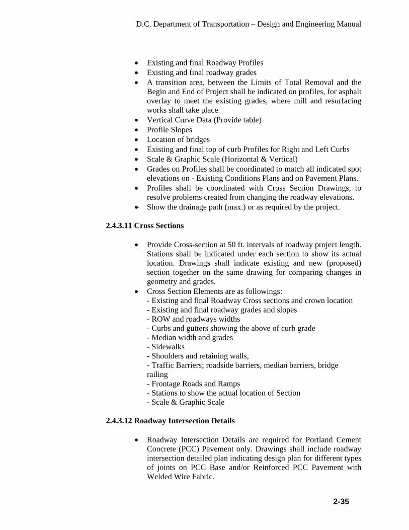
D.C. Department of Transportation – Design and Engineering Manual
2-35
• Existing and final Roadway Profiles • Existing and final roadway grades • A transition area, between the Limits of Total Removal and the
Begin and End of Project shall be indicated on profiles, for asphalt overlay to meet the existing grades, where mill and resurfacing works shall take place.
• Vertical Curve Data (Provide table) • Profile Slopes • Location of bridges • Existing and final top of curb Profiles for Right and Left Curbs • Scale & Graphic Scale (Horizontal & Vertical) • Grades on Profiles shall be coordinated to match all indicated spot
elevations on - Existing Conditions Plans and on Pavement Plans. • Profiles shall be coordinated with Cross Section Drawings, to
resolve problems created from changing the roadway elevations. • Show the drainage path (max.) or as required by the project.
2.4.3.11 Cross Sections
• Provide Cross-section at 50 ft. intervals of roadway project length.
Stations shall be indicated under each section to show its actual location. Drawings shall indicate existing and new (proposed) section together on the same drawing for comparing changes in geometry and grades.
• Cross Section Elements are as followings: - Existing and final Roadway Cross sections and crown location - Existing and final roadway grades and slopes - ROW and roadways widths - Curbs and gutters showing the above of curb grade - Median width and grades - Sidewalks - Shoulders and retaining walls, - Traffic Barriers; roadside barriers, median barriers, bridge railing - Frontage Roads and Ramps - Stations to show the actual location of Section - Scale & Graphic Scale
2.4.3.12 Roadway Intersection Details
• Roadway Intersection Details are required for Portland Cement
Concrete (PCC) Pavement only. Drawings shall include roadway intersection detailed plan indicating design plan for different types of joints on PCC Base and/or Reinforced PCC Pavement with Welded Wire Fabric.
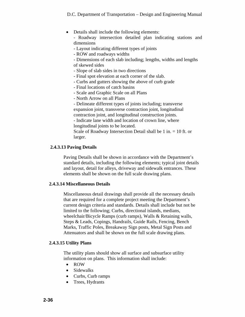
D.C. Department of Transportation – Design and Engineering Manual
2-36
• Details shall include the following elements: - Roadway intersection detailed plan indicating stations and dimensions - Layout indicating different types of joints - ROW and roadways widths - Dimensions of each slab including; lengths, widths and lengths of skewed sides - Slope of slab sides in two directions - Final spot elevation at each corner of the slab. - Curbs and gutters showing the above of curb grade - Final locations of catch basins - Scale and Graphic Scale on all Plans - North Arrow on all Plans - Delineate different types of joints including; transverse expansion joint, transverse contraction joint, longitudinal contraction joint, and longitudinal construction joints. - Indicate lane width and location of crown line, where longitudinal joints to be located. Scale of Roadway Intersection Detail shall be 1 in. = 10 ft. or larger.
2.4.3.13 Paving Details
Paving Details shall be shown in accordance with the Department’s standard details, including the following elements; typical joint details and layout, detail for alleys, driveway and sidewalk entrances. These elements shall be shown on the full scale drawing plans.
2.4.3.14 Miscellaneous Details
Miscellaneous detail drawings shall provide all the necessary details that are required for a complete project meeting the Department’s current design criteria and standards. Details shall include but not be limited to the following; Curbs, directional islands, medians, wheelchair/Bicycle Ramps (curb ramps), Walls & Retaining walls, Steps & Leads, Copings, Handrails, Guide Rails, Fencing, Bench Marks, Traffic Poles, Breakaway Sign posts, Metal Sign Posts and Attenuators and shall be shown on the full scale drawing plans.
2.4.3.15 Utility Plans The utility plans should show all surface and subsurface utility information on plans. This information shall include: • ROW • Sidewalks • Curbs, Curb ramps • Trees, Hydrants

D.C. Department of Transportation – Design and Engineering Manual
2-37
• Signals, Signs • Electrical conduits • Communication lines • Sewer and Waterlines • Inlets, manholes and valves • Scale • North Arrow
2.4.3.16 Landscape and Planting Plans
The landscape and planting plan shall show: • ROW • Sidewalks, Curbs, Ramps, Tree Lawn • Trees, Plantings (Existing) • Trees, Plantings (Proposed) • Irrigation • North Arrow • Scale
2.4.3.17 Pavement Marking Plans
The pavement marking plans should include existing and proposed markings and the following information: • Widths of all cross-section elements on the main and adjacent
streets, including widths of travel lanes, parking lanes, bicycle lanes and crosswalk widths and any raised or marked medians and/or raised islands.
• All existing pavement markings on the project-street and at least 100 ft. in each direction of intersecting streets.
• All existing corner radii and the location of handicapped ramps and locations where ramps need to be added.
• Handicapped ramps, which are required for each pedestrian travel direction. Verify that the ramps are within the crosswalks.
• All markings including cross walks, stop bars, lane lines and centerline striping.
• For each intersection, the location of all 2 ft. long traffic guidelines.
• The radii of all left and right turning lane swing lines. • Direction of each street and all existing signs. • Traffic controls at each intersection the location including signals,
signs, signal controllers and other similar devices. • All driveway and alley widths along contracted streets. • Location and size of arrows or word markings. • North arrow • Scale

D.C. Department of Transportation – Design and Engineering Manual
2-38
2.4.3.18 Signage Plans:
• Provide a legend for signage to include the following: - Small solid square = Proposed sign to be installed. - Small circle with cross-hatching = Existing sign, FADED, DAMAGED and/or MISSING in field. - Large X= Existing Sign to be removed. - Small triangles = Existing sign to be relocated.
Note: A small white triangle represents existing sign and a small solid black triangle represents relocated sign location. Indicate from existing location to new location by using small arrows and the words from and to beside the respective triangle.
• Intersection signage sheets to include the following:
- Indicate a north arrow and scale. - Indicate all intersecting street names and location of city section, such as NW, NE, SW, or SE. Indicate unit or block numbers. - All regulatory signs for a motorist should be indicated facing in the direction a motorist would read them in the field. Some of these signs may be indicated upside-down on the plan sheet. - Indicate the mounting order of each sign location, especially for one or more signs. - Indicate the material requirements for all signposts. -Locate all signs mounted on streetlights, traffic signals, wood utility poles, and u-posts on all corners, medians, channeling islands at each intersection adjacent to or within the project.
- Indicate ROW, curb lines, sidewalk, roadway lines. • Block signage sheets to include the following:
- Indicate a north arrow and scale. - Note direction of streets. - Note the street names at the beginning and ending of each block. - Make a block map for each side of the street. - Indicate width of street and length of street for each block. - Locate all signs mounted on streetlights, traffic signals, wood utility poles, and u-posts on all corners, medians, channeling islands within the block. - All regulatory signs for a motorist should be indicated facing in the direction a motorist would read them in the field. Some of these signs may be indicated upside-down on the plan sheet. - Indicate the mounting order of each sign location, especially for one or more signs. - Indicate the material requirements for all signposts. - Indicate ROW, curb lines, sidewalk, roadway lines.

D.C. Department of Transportation – Design and Engineering Manual
2-39
2.4.3.19 Street Light Plans
• ROW, Curb line, sidewalks, roadway • Street light locations plans, elevations and sections of pole • Pole and luminaries types and attachment details • Conduit locations • Locations of all existing and proposed utilities • Pull Box locations • PEPCO connection location • Manholes • Dimensions for plans, elevations and sections of details • North arrow • Scale
2.4.3.20 Traffic Signal Plans
• ROW, Curb line, sidewalks, roadway • Signal locations plans, elevations and sections of pole • Controller Locations • Manhole and Pull Box locations • PEPCO connection location • Pole and mast arm types and attachment details • Conduit locations • Locations of all existing and proposed utilities • Location, type and number of traffic signal heads and pedesteal
signal heads • Dimensions • North arrow • Scale
2.4.3.21 Storm Sewer Plan
• ROW, Curb line, sidewalks, roadway • Inlet locations • Manholes • Existing Mainline • Proposed pipeline • Show locations of all existing and proposed utilities • On profile show crossings of other utilities • Delineate type of pipe, inlets and other features • Delineate invert of all pipes (inlet and outlet) • Delineate stationing of inlet, pipe slope changes
(horizontal/vertical) • Delineate slopes
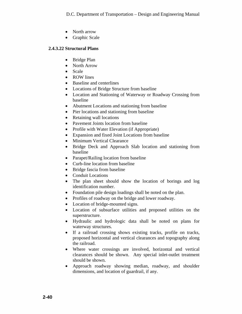
D.C. Department of Transportation – Design and Engineering Manual
2-40
• North arrow • Graphic Scale
2.4.3.22 Structural Plans
• Bridge Plan • North Arrow • Scale • ROW lines • Baseline and centerlines • Locations of Bridge Structure from baseline • Location and Stationing of Waterway or Roadway Crossing from
baseline • Abutment Locations and stationing from baseline • Pier locations and stationing from baseline • Retaining wall locations • Pavement Joints location from baseline • Profile with Water Elevation (if Appropriate) • Expansion and fixed Joint Locations from baseline • Minimum Vertical Clearance • Bridge Deck and Approach Slab location and stationing from
baseline • Parapet/Railing location from baseline • Curb-line location from baseline • Bridge fascia from baseline • Conduit Locations • The plan sheet should show the location of borings and log
identification number. • Foundation pile design loadings shall be noted on the plan. • Profiles of roadway on the bridge and lower roadway. • Location of bridge-mounted signs. • Location of subsurface utilities and proposed utilities on the
superstructure. • Hydraulic and hydrologic data shall be noted on plans for
waterway structures. • If a railroad crossing shows existing tracks, profile on tracks,
proposed horizontal and vertical clearances and topography along the railroad.
• Where water crossings are involved, horizontal and vertical clearances should be shown. Any special inlet-outlet treatment should be shown.
• Approach roadway showing median, roadway, and shoulder dimensions, and location of guardrail, if any.
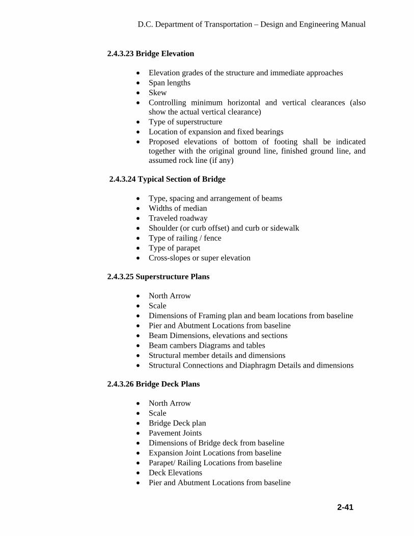
D.C. Department of Transportation – Design and Engineering Manual
2-41
2.4.3.23 Bridge Elevation
• Elevation grades of the structure and immediate approaches • Span lengths • Skew • Controlling minimum horizontal and vertical clearances (also
show the actual vertical clearance) • Type of superstructure • Location of expansion and fixed bearings • Proposed elevations of bottom of footing shall be indicated
together with the original ground line, finished ground line, and assumed rock line (if any)
2.4.3.24 Typical Section of Bridge
• Type, spacing and arrangement of beams • Widths of median • Traveled roadway • Shoulder (or curb offset) and curb or sidewalk • Type of railing / fence • Type of parapet • Cross-slopes or super elevation
2.4.3.25 Superstructure Plans
• North Arrow • Scale • Dimensions of Framing plan and beam locations from baseline • Pier and Abutment Locations from baseline • Beam Dimensions, elevations and sections • Beam cambers Diagrams and tables • Structural member details and dimensions • Structural Connections and Diaphragm Details and dimensions
2.4.3.26 Bridge Deck Plans
• North Arrow • Scale • Bridge Deck plan • Pavement Joints • Dimensions of Bridge deck from baseline • Expansion Joint Locations from baseline • Parapet/ Railing Locations from baseline • Deck Elevations • Pier and Abutment Locations from baseline
D.C. Department of Transportation – Design and Engineering Manual
2-42
• Conduit Locations • Approach Slab Locations and Stationing from baseline approach
slabs plans, elevations and sections • Staging
2.4.3.27 Bridge Joints plans
• North Arrow • Scale • Bridge Expansion Joint Plans, elevations and sections • Bridge Fixed Joint Plans, elevations and sections • Details and Dimensions of Joints • Bridge Joint Details at median, Parapet/ Railing
2.4.3.28 Bridge Abutment Plan
• North Arrow • Scale • Abutment cap and footing plans, dimensions and location from
baseline • Abutment elevations and sections including rebars • Bottom of Footing Elevation • Abutment pile foundation plan and dimensions from baseline • Details of Replacements • Plans of existing Abutments • Removal Extents • Load capacity data for abutment foundation • Beam pedestals on abutment cap will not be allowed. Provide
steps in the cap to accommodate change in elevations for the beam shoe pads.
2.4.3.29 Bridge Pier Plans
• North Arrow • Scale • Pier cap and footing plans, dimensions and location from baseline • Pier elevations and sections including rebars • Bottom of Footing Elevation • Pier pile foundation plan and dimensions from baseline • Details of Replacements • Plans of existing piers • Removal Extents • Load capacity data for pier foundation • Beam pedestals on pier cap will not be allowed. Provide steps to
accommodate change in elevations for the beam shoe pads.
D.C. Department of Transportation – Design and Engineering Manual
2-43
2.4.3.30 Retaining wall Plans
• Retaining wall plans • North Arrow • Scale • Retaining wall and footing plan and dimensions from baseline • Bottom of Footing Elevation • Retaining wall Elevations and Sections including rebar • Details of Replacements • Retaining wall Pile Foundation plan and dimensions from baseline • Load capacity data for Retaining wall foundation • Plans of existing retaining walls
2.4.3.31 Bridge Parapet/Railing/Pedestrian Plans
• Railing plan, elevation and sections • North Arrow • Scale • Typical Railing Height and Location • Connection Details including bolts and welds • Dimensions • Architectural treatment details • Post Spacing • Post, Joint and Connection Details
2.4.3.32 Bridge Drainage
• Bridge Drainage Plan and scupper/inlet locations • North Arrow • Scale • Typical Scupper/inlet Details • Drainpipe Connection Details • Dimensions of Scupper/inlet and size of pipes
2.4.3.33 Traffic Detour and Traffic Control Plan
The traffic control plan should include all phases of construction. For each phase, show the following information: • Location of ROW, streets, sidewalks, driveways • North Arrow • Scale • All existing signage, pavement marking, signals • All signage and striping to be removed or covered during
construction
D.C. Department of Transportation – Design and Engineering Manual
2-44
• Show all proposed temporary barrels, signs, etc. required from MUTCD and Work Zone Manual.
• Show all dimensions of tapers, type of equipment • Show work area
2.4.3.34 Traffic Control Plans The typical traffic control plans will include the following information:
• Schedule of Construction Traffic Control Devices/Tabulation of
Traffic Engineering Items • Construction Signing Plan • Tabulation of Signs • Permanent/Existing Signing Plan • Cross-Sections at Class III and overhead sign locations (if
applicable) • Tabulation of Pavement Markings • Signal Plan • List of Standard Special Provisions • List of Project Special Provisions • Detailed Sign Layouts
2.4.3.35 Sediment and Erosion Control Plan
These plans are required in each roadway, traffic or structural design project. They should be completed in accordance with the District of Columbia Department of Health, Watershed Protection Division. The typical Sediment and Erosion control plans will include the following information: • Sediment/Erosion Control Plan (use Roadway base plan) • Tabulation of Erosion Control Devices • List of Standard Special Provisions • Standard Details
- North Arrow - Scale - Show all dimensions
2.4.3.36 Soil Boring Logs
The Soil Boring Logs should be incorporated into the plans. The horizontal locations should be delineated in the roadway design plan sheets. The typical Soil Boring Logs control plans will include the following information: • Location, soils types and depths for each boring

D.C. Department of Transportation – Design and Engineering Manual
2-45
2.5 Required Plans Stage of Design Process Number of Copies Pre-Design Report (When Requested)
5 Copies
Preliminary Design 30 Sets of Stamped Half Size Plans 2 copies of Preliminary Construction Costs
65% Review Design 30 Sets of Stamped Half Size Plans 30 Sets of Special Provisions 2 copies of Preliminary Construction Costs
Final Review Design 30 Sets of Stamped Half Size Plans 30 Sets of Special Provisions (double spaced) 2 copies of Construction Costs and Pay Item Schedule (hard copy and on disk)
PS & E Submittal 2 Sets of Stamped Half Size Plans 2 Sets of Special Provisions 2 Sets of Pay Item Schedule and Cost Estimates
Final Bid Documents 75 Sets of Half Size final Contract Plans 75 Sets of Special Provisions, Bid Forms and Appendices One full size reproducible final contract drawings on tracing linen or tracing plastic and five full size prints Two computer disks of final contract drawings (Microstation latest version) and two disks of final Special Provisions and Pay Item Schedule
NOTE: The number of Final Contract Plans, Special Provisions, Pay Item
Schedules and Appendices may be modified by DDOT by written notice to the Consultant.

D.C. Department of Transportation – Design and Engineering Manual
3-1
CHAPTER 3
PROJECT MANAGEMENT 3.1 Project Management
Project management and coordination are critical to the overall success of the project development process and the efficient delivery of projects that provide effective solutions to address transportation problems. Effective project management and coordination requires the participation of all stakeholders, partners, and the community. Project management tracking will be as per the DDOT project management report requirements from the Ward Program Managers. However, the Project Managers will use the Checklist for their information to track the project progress (a copy of the DDOT Project Checklist, Form 02001, is included in the Appendices within this manual).
3.1.1 Planning Group Inclusion in the 5-year Capital Improvement Program
The Ward Program Manager prepares the initial scope of work and cost estimate and makes the request to the budget office for inclusion in the 5-year Capital Improvement Program after identifying, discussing and evaluating issues with other offices in the Department.
3.1.2 Design Scoping
Scoping is initially performed within the proposed project area. The full extent of the project limits must be determined by the Project Manager prior to the start of the field survey to eliminate multiple surveys and duplicate effort. For new or reconstruction projects, project scoping may be an extensive study for that area.
The design scoping takes place during the following: prioritizing and budgeting stage, project programming for obligation of funds for design, and before completion of consultant agreements. The DDOT Ward Program Manager and the Project Manager review the initial scope in the field to further determine project issues and considerations with stakeholders, including WASA and utility companies. These scoping milestones also include an update of the project budget.
NOTE: With Federally Funded projects, it is very important that the budget is developed appropriately to minimize increases.
3.1.3 Estimated Construction Costs
Cost estimations should be prepared for the design scoping stage, preliminary design review, intermediate design review, final design

D.C. Department of Transportation – Design and Engineering Manual
3-2
review, and for the engineer's final estimate for bid. Accurate budgets are important for planning purposes and for the District and FHWA to allocate adequate funds. The costs associated with the estimate are as follows:
• DDOT construction plans. • ROW Acquisitions. • Utility Improvements. • Construction plans by others. • Railroads or other affected parties.
3.1.4 Budget
The preliminary estimate for the program budget is submitted using the Program Action Request (PAR) and a Form 106 (Spending Plan). The Program Manager prepares budget estimates and submits the Program Action Request (PAR) Form to the Capital Division of the Office of the Chief Financial Officer (OCFO) at the budget stage.
3.1.5 Obligation
The Program Manager updates the scope of work and the cost estimate, resubmits the Program Action Request (PAR) Form and a Form 106 (Spending Plan) to the budget office to obligate funds for design prior to design start.
The final design is complete when construction plans, the construction drawings, details and specifications, and the necessary bid documents are approved for obligation of construction funds for the project. This also generally includes ROW, utility and environmental clearances, final cost estimates, and wrap-up of community involvement. At the conclusion of final design, the obligation of funds for construction moves the project forward to the bid process.
No charges should be made against the construction funds until the funds move to the approved construction phase by the budget office, which generally occurs at execution and award of construction contract.
3.1.6 Important Phase Dates
The Program Manager must notify both the Chief Engineer and the budget office of any changes in the obligation plan or advertisement plan. As soon as the Program Manager becomes concerned that the project may need to be rescheduled for obligation or advertisement for bids, he/she must confer with both the Chief Transportation Engineer and the budget office.

D.C. Department of Transportation – Design and Engineering Manual
3-3
3.1.7 Supplementing the Budget
The Program Manager is responsible for working with the Chief Transportation Engineer and the budget office if the project budget needs to be supplemented, including additional work or overruns.
3.1.8 Day-to-Day Financial Management
The Program Manager must have access to the budgeting system and should be aware of the purchasing requirements, rules, and directives. If the Program Manager needs services from a vendor outside of the Engineer/Architect services, he/she must coordinate with the Contract Administration Office through the Chief Transportation Engineer. The Program Manager must review month-end closed cost ledgers to ensure that the encumbrances are established and liquidated correctly, and to ensure that charges against the project are accurate and allowable.
3.1.9 Payment to Consultant/Contractors
The Program Manager will receive the invoices for payment and review them before submitting to the Budget Office for payments through the Office of the Chief Transportation Engineer. The program manager is responsible for ensuring that charges against the project are coded correctly. In the event of coding errors, the Budget Office must be notified to correct the journal entries.
3.1.10 Preliminary Design Review (30%)
The DDOT project team reviews preliminary plan submittal, verifies the design criteria/standards, design exceptions, considers environmental issues and input received from the stakeholders and through the community involvement process. The Consultant shall be required to provide a report justifying the methods and approach to their design. The report will outline the design alternatives, cost estimates, issues, issue resolution, findings, any public involvement results and conclusions. Comments are resolved immediately before design proceeds.
3.1.11 Intermediate Design Review (65%) The Program Manager/Project manager obtains approval from FHWA for the design exceptions when required. Comments are resolved immediately before design proceeds.
3.1.12 Value Engineering Value Engineering (VE) is the systematic application of recognized techniques by a multi-disciplined team to identify the function of a

D.C. Department of Transportation – Design and Engineering Manual
3-4
product or service, establish a worth for that function, generate alternatives through the use of creative thinking and provide the needed functions to accomplish the original purpose of the project.
There are two important FHWA requirements in the area of Value Engineering. First, DDOT must establish a program to assure that Value Engineering studies are performed when appropriate. Second, Value Engineering studies must be performed on all Federal-aid highway projects on the National Highway System (NHS) with an estimated cost of $25 million or more.
The DDOT Value Engineering program coordinator is an identified staff person with in IPMA. DDOT program procedures provide for the identification of candidate projects [ > $25 million and on the NHS] for Value Engineering studies early in the development of the multi-year Transportation Improvement Program [WashCOG TIP]. Ideally, Value Engineering studies will be performed on projects when they are between 30 percent and 60 percent designed. Value Engineering studies should incorporate seven characteristics: 1) a multi-disciplinary team approach, 2) the systematic application of a recognized technique (VE Job Plan), 3) the identification and evaluation of function, cost and worth, 4) the use of creativity to speculate on alternatives that can provide the required functions (search for solutions from new and unusual sources), 5) the evaluation of the best and lowest life-cycle cost alternatives, 6) the development of acceptable alternatives into fully supported recommendations, and 7) the presentation/formal reporting of all VE recommendations to management for review, approval and implementation.
3.1.13 Final Review (100%)
At this milestone, the project team shall resolve the comments from the 65% reviews of the detailed construction plans, special provisions, specifications, pay items, and updated cost estimates. The Program Manager/Project Manager shall resolve all issues, obtain the necessary utility clearances and permits prior to PS&E submission for obligation of funds for construction.
3.2 Major Project Considerations
Section I of the Project Checklist incorporates the consideration of coordination with maintenance, WASA, Urban Forestry, Historic Preservation, survey control, a public involvement process, and the type of improvements.

D.C. Department of Transportation – Design and Engineering Manual
3-5
3.2.1 Environmental
Project specific environmental commitments made during project development by the environmental specialists whether in Environmental Impact Statements, Environmental Assessments or during minor project development must be incorporated into the design plans. Project specific mitigation commitments generally involve avoidance, protection, minimization or replacement of protected resources. Environmental considerations on a project generally include a review of the following:
• Determination of NEPA Classification • Route location approval • Section 4(f) • Section 106 – Historic Clearances • Historic Bridges • Archaeology • Paleontology • Flood Plains • 404 Permit requirements • Wetlands issues • US Fish and Wildlife issues • Hazardous waste and materials/contaminated soils • Noise Analysis • Air Quality • 401Certification • 402 Permit requirements • NPDES Permit requirements • Erosion Control • Adverse Human Health and Environmental effects on minority, low
income, limited English proficient (LEP) and disabled populations • Storm Water Quality – Best Management Practices, including Low
Impact Development
NOTE: Refer to the Environmental chapter within this manual, for more specific information on environmental considerations and process.
3.2.2 Traffic
Traffic considerations on a project generally include a review of the following:
• Traffic Design Data

D.C. Department of Transportation – Design and Engineering Manual
3-6
• Traffic Accident Analysis (See DDOT’s Traffic Accident Reporting and Analysis System (TARAS)).
• Turning Movements/Access issues Signal Warrants • Traffic Movement Diagrams • Intersection/Interchange Design • Traffic Issues • Bike/Pedestrian Issues • ADA Accommodations • Transit Accommodations • Traffic Calming • Traffic Signal Plan • Lighting Plan • Permanent Signing and Markings • Construction Traffic Control Plans
The Program Manager/Project Manager must confer with the IPMA Traffic Engineers for their approval on traffic issues. The design of safer public streets and highways begins at the Design Scoping Review and continues through advertisement. Highway safety to reduce vehicular accidents and fatalities reduction can be divided into three areas of concern:
• Roadway safety improvements (visibility and operation
characteristics). • Roadside hazard elimination (forgiving roadside concepts). • Traffic engineering and operations (improving traffic regulations,
warnings and directions).
The Project Manager is responsible for providing a design with safety as a primary objective. In many instances, benefits gained from a specific safety design or treatment can equal or exceed additional cost. The Project Manager can best utilize limited design funds by preparing a benefit/cost analysis and prepares safety reports detailing feasible alternatives and recommendations. The Project Manager should document the safety issues and any benefit/cost analysis that should include the following: • Encroachments • Roadside geometry • Accident costs
NOTE: Refer to the Traffic chapter within this manual for more specific information on project traffic considerations and process.

D.C. Department of Transportation – Design and Engineering Manual
3-7
3.2.3 Structures
The Program Manager must confer with IPMA concerning policies and criteria for approvals related to structure issues. Structural considerations on a project include a review of the following:
• Major Structure – Bridge • Major Structure – Culvert • Hydraulic Design • Major Structure – Unusual • Pedestrian Overpass/Underpass • Architectural/Aesthetic Treatments • Foundation Investigation/Recommendations • Structure Condition Reports • Retaining Walls • Noise Barrier Walls • Guardrail/Barrier Design and Review • Crashworthy Bridge Rail • Vertical and Horizontal Clearances
NOTE: Refer to the Structures chapter within this manual, for more specific information and procedures for structural considerations.
3.2.4 Materials/Pavement
The Program Manager must confer with IPMA concerning policies and criteria for approvals related to street/highway design issues. Pavement material selection of type of pavements below shall be in accordance with the criteria in Part II of the Manual.
• Rigid Pavement. • Flexible Pavement. • Composite Pavement. • Special Material Pavement (Cobble Stone, etc.)
Materials considerations on a project generally include:
• Pavement Analysis/Distress Review • Geotechnical Studies • Foundation Investigation/Drilling • Pavement Material Selection

D.C. Department of Transportation – Design and Engineering Manual
3-8
NOTE: Refer to the Pavement chapter within this manual, for more specific information and procedures related to materials and AASHTO’s Guidelines for skid resistant pavement design.
3.2.5 Trees and Landscaping
The removal, addition, or modification of the landscaping or type of trees within a particular project requires the approval of the Urban Forestry Administration. The Program Manager/Project Manager should include the Urban Forestry Administration in the design scoping review, the preliminary design review and the final design review meetings. The Program Manager/Project Manager must confer with the Urban Forestry Administration for issues relating to trees and landscaping Landscaping considerations on a project generally relate to tree species, spacing of trees, other facility conflicts, seeding/sodding, tree trimmings, stump removals, sight distance requirements at intersections, and the design/retrofit of irrigation systems when required. NOTE: Refer to the Trees, Plants, and Landscaping chapter within this manual, for more information on landscaping considerations.
3.2.6 ROW Acquisition and Clearances
ROW acquisition and clearance considerations on a project generally include:
• ROW Acquisition Procedures • Government Land Permission/Permits • National Parks Service/Other Federal Lands Acquisition • Utilities Clearance • Railroad Clearance • Airport/Heliport Clearance
NOTE: Refer to the Right of Way and Clearances chapter within this manual, for more specific information on ROW acquisition and clearance processes.
3.2.7 Utilities
Utility compilation considerations generally include a review of existing utility easements, visual inspections/locates, and procedures for utility clearance. The Program Manager/Project Manager should include engineers from the utility companies at the design scoping review, the

D.C. Department of Transportation – Design and Engineering Manual
3-9
preliminary design review and the final design review meetings. Coordination of utility issues early in the process to minimize conflicts is important to the process of the project.
NOTE: Refer to the Utilities chapter within this manual, for more information on addressing dry utilities considerations.
3.2.8 Water, Sewer, and Storm Sewer
The Program Manager/Project Manager should include the Water/Sewer Engineer from WASA at the design scoping review, the preliminary design review and the final design review meetings. Coordination of water, sewer, and storm issues early in the process to minimize conflicts is important to the process of the project. Water, sewer, and storm sewer considerations generally include a review of existing utility easements, visual inspections/locates, and procedures for utility clearance.
NOTE: Refer to the Utilities chapter within this manual, for more information on addressing water, sewer, and storm sewer considerations.
3.2.9 Agreements and Approvals
Agreement and approval requirements will vary from project to project. NOTE: Refer to the Agreements and Approvals chapter within this manual, for agreement procedures and guidelines.
3.2.10 Community Involvement
Generally, Community Involvement will occur at the following milestones of the project development process:
• Planning • Concept Design • Preliminary Design • Final Design
The Ward Planner, the TPPA member of the Ward Team, will coordinate and notify the community and the appropriate Advisory Neighborhood Commission (ANC), and ensure that the public is identified and involved in the development of DDOT projects and has an opportunity to influence decision-making. The Environmental Manager in the Planning Office oversees the preparation of Environmental Impact Statements, Environmental Assessments, and Categorical Exclusion Determination that fully

D.C. Department of Transportation – Design and Engineering Manual
3-10
documents the community involvement activities included in the development of the project. Community improvement programs are generally developed on a project-by-project basis. The Title VI coordinator in the Civil Rights Division will coordinate with the Ward Planner and the Environmental Manager to ensure that community involvement activities effectively engage traditionally underserved populations, such as minority, low income, disabled and limited English proficient populations, and the needs and concerns of these populations are seriously considered. NOTE: Refer to the Community Involvement chapter within this manual, for guidelines and procedures for developing and implementing effective community involvement programs for DDOT projects.
3.2.11 Maintenance Input
The Program Manager/Project Manager will be responsible for notifying the appropriate maintenance personnel, including street maintenance, bridge maintenance, streetlight, traffic signal and traffic safety improvement, prior to project scoping and all project reviews during the project development process. The maintenance representative should review the project plans and provide comments in writing to the Program Manager.
3.2.12 L'Enfant Plan
Prior to beginning preliminary design, the Program Manager/Project Manager should determine if the project is within the boundary of the L'Enfant Plan. If the project is within the location, all design must be coordinated with the National Capital Planning Commission through the Office of Planning.
3.2.13 Capitol Hill
Prior to beginning preliminary design, the Program Manager/Project Manager should determine if the project is within the boundary of Capitol Hill Historic District. If the project is within the location, all design must be coordinated with the Architect of the Capitol.
3.2.14 Historic District/Historic Bridge or on Historic Property
Prior to beginning preliminary design, the Program Manager/Project Manager should determine the following:
D.C. Department of Transportation – Design and Engineering Manual
3-11
• If the project is within the boundary of the historic district. • If the project is on historic property. • If the project is listed on the National Registers of Historic Places or
consideration for a historic bridge.
If the project meets any of these criteria, all designs must be coordinated with the State Historic Preservation Office (SHPO) and the Commission of Fine Arts. The District of Columbia Inventory of Historic Sites can be found on the D.C. Office of Planning website, www.planning.dc.gov under “Historic Preservation” and then “Historic Inventory and Maps”.
3.2.15 Business Improvement District and Streetscape Enhancement
Prior to beginning preliminary design, the Program Manager/Project Manager should determine if the project is within the boundary of a business improvement district or streetscape enhancement area. If the project is within the location, all designs must be coordinated with the National Capital Planning Commission and DDOT Streetscape Committee.
3.2.16 Bike/Pedestrian Improvements
The Program Manager/Project Manager must confer with the TPPA and IPMA Traffic Engineers on bike and pedestrian related issues. The proper placement and design of bike and pedestrian facilities are important elements of design on all applicable projects. The Project Manager should provide bicycle and pedestrian facilities on new construction and reconstruction projects in coordination with Bicycle Coordinator in the TPPA. For more specifics on bike/pedestrian improvement procedures, refer to the Traffic chapter within Part 2 of this manual.
3.2.17 Rehabilitation or Reconstruction
The Program Manager/Project Manager must confer with the Chief Transportation Engineer or his technical support Engineer in determining the extent of construction. Rehabilitation projects generally have limited environmental and ROW issues. However, rehabilitation projects do offer opportunities to address streetscape improvements, including landscaping, aesthetic and structural enhancement, upgrades of intersections and crosswalks, streetlights, sidewalks, traffic signals, wheelchair ramps, curbs gutters, utility system and enhancements for alternative modes of transportation.

D.C. Department of Transportation – Design and Engineering Manual
3-12
Specific considerations for rehabilitation projects must be determined on a project-by-project basis. Reconstruction projects incorporate total reconstruction of the pavement and all necessary improvements.
3.2.18 Federal Lands Affected
For projects that affect Federal Land, refer to the clearance requirement from the owners of the affected properties.

D.C. Department of Transportation – Design and Engineering Manual
4-1
CHAPTER 4
ENVIRONMENTAL 4.1 Introduction
This chapter provides brief information on various environmental laws and regulations that DDOT projects are subject to. A brief overview of the process carried out to comply with these laws and regulations is also provided in this chapter. However, the details on these laws, regulations, processes, and procedures are provided in the DDOT Environmental Policy and Process Manual. One of the earliest decisions the District of Columbia Department of Transportation (DDOT) must make concerning a transportation project is the appropriate class of action the project represents. This decision is important because the class of action determines the appropriate level of documentation necessary to comply with the National Environmental Policy Act of 1969 (NEPA) and the District of Columbia Environmental Policy Act (DCEPA). If the project is using federal funding or requires federal action (approval, permit, etc) then this project will have to comply with NEPA. Projects that comply with NEPA automatically comply with DCEPA, as an exemption is provided under DCMR Chapter 72, section 7202.1(b). If a project is only using local funding and no federal action is required then the project has to comply with DCEPA only. It should be remembered that other environmental laws in addition to NEPA and DCEPA may also have to be complied with. For projects where NEPA applies, whether the project is a Categorical Exclusion (CE), an Environmental Assessment (EA) or an Environmental Impact Statement (EIS), action depends on the “significance” of the project’s potential adverse and beneficial impacts. The Council on Environmental Quality (CEQ) regulations (40 CFR 1508.27) state that two main points should be considered in determining significance—context and intensity. For projects (using local funding) where DCEPA applies, whether the project is an exemption, or requires an Environmental Impact Screening Form (EISF), or requires Environmental Impact Statement depends upon the significance of the project impacts. This section describes the different actions and document types within NEPA and DCEPA that DDOT will use to process its transportation projects. Because DDOT will normally select an action/document type before having a thorough understanding of a project’s impacts, it is important to coordinate with the Federal Highway Administration (FHWA) or other lead federal agency to obtain

D.C. Department of Transportation – Design and Engineering Manual
4-2
concurrence on the document type at the start of the project. FHWA typically is not involved if a project is locally funded.
4.2 Determination of Environmental Action types
For projects using federal funding or requiring a federal action, in accordance with CEQ regulations under NEPA, each federal agency must identify those typical classes of action that:
• Require an EIS – An EIS shall be prepared for any proposed major action significantly affecting the quality of the human environment.
• Require an EA, but not necessarily an EIS – These actions require that an EA be prepared to determine the significance of the impacts. If it is concluded from the EA that the project’s impacts will be significant, an EIS is required; if not, a Finding of No Significant Impact (FONSI) is prepared.
• Require the preparation of a CE — Actions that are clearly Categorical Exclusions and do not normally affect activities or resources under the jurisdiction of other agencies. The need for an environmental document and agency coordination on CE projects depends on the level of impacts associated with the project
The FHWA environmental action list can be found in 23 CFR 771.115. Occasionally, a project is proposed that does not appear to fit any of the action categories. In that case, further consultation with FHWA is encouraged before an action decision is made. For projects that only use local funding, in accordance with the District of Columbia regulations under DCEPA, DDOT has to identify whether a project will:
• Be an exemption provided in 72 DCMR 7202- Actions for which no EISF or EIS is required. A list of action is provided in 72 DCMR 7202 for the projects that do not require the preparation of an EISF or an EIS.
• Require the preparation of an EISF in 72 DCMR 7201- Major Actions for which EISF are required. A list of actions is provided in 72 DCMR 7201 for the projects that require the preparation of an EISF.
• Require the preparation of an EIS. Projects that do not qualify for an exemption or projects for which an EISF was submitted and the lead agency concluded that an EIS is required will have to prepare an EIS.
DDOT Environmental Program Coordinator (or designee) makes the environmental action determination.

D.C. Department of Transportation – Design and Engineering Manual
4-3
The scope of the improvement and the estimated significance of the impacts of DDOT’s transportation projects determine the extent of the impact analysis, the type of document, and the level of public involvement. To determine the significance of an action, the entire human environment, the affected region, and the interests of the local area must be analyzed. Both short-term and long-term effects must be taken into account.
4.3 NEPA Action types
For projects using federal funding or requiring a federal action, in accordance with CEQ regulations under NEPA, each federal agency must identify those typical classes of action that:
• Require an EIS. • Require an EA, • Require the preparation of a CE
The FHWA environmental action list can be found in 23 CFR 771.115. Since the majority of DDOT projects require NEPA compliance, listed below is a description of the criteria used to determine the type of action DDOT is proposing and the appropriate document type for the proposed action under NEPA.
4.3.1 EIS Action – Environmental Impact Statement
A proposed action, which is known to have significant environmental impacts, will require the preparation of an EIS. This includes, but is not limited to, actions that are likely to:
Project PlanningProject Project
PlanningPlanning
Proposed Action
Proposed Proposed Action Action
NEPANEPA
Cat Ex Cat Ex EAEA EISEIS
Federal Local
DCEPADCEPA
Exempt Exempt EISFEISF EISEIS
Project PlanningProject Project
PlanningPlanning
Proposed Action
Proposed Proposed Action Action
NEPANEPA
Cat Ex Cat Ex EAEA EISEIS
NEPANEPA
Cat Ex Cat Ex EAEA EISEIS
Federal Local
DCEPADCEPA
Exempt Exempt EISFEISF EISEIS
DCEPADCEPA
Exempt Exempt EISFEISF EISEIS
D.C. Department of Transportation – Design and Engineering Manual
4-4
• Have a significant impact on natural, ecological or cultural resources, threatened and endangered species, wetlands, floodplains, groundwater, natural resources, or fish and wildlife resources
• Be highly controversial on environmental grounds, i.e., opposed or considered unacceptable on environmental or legal grounds by a federal or local agency, or by the public
• Have significant residential or commercial displacement impacts • Cause substantial disruption to an established community, disrupt
orderly, planned development, and be inconsistent with plans or goals that have been adopted by the affected communities or that adversely affect the economic vitality of an urban area
• Have a significant impact on noise levels in noise-sensitive areas • Have a significant impact on air quality • Have a significant impact on water quality or a surface or
subsurface public water supply system A decision to prepare an EIS for a proposed action may be made when that action clearly involves significant impacts on the human environment, or when environmental studies and the results of early coordination indicate significant impacts, or when the review of an EA concludes that significant impacts would result from a proposed action. The following are examples of actions that normally required an EIS:
• A new controlled access freeway • A highway project of four or more lanes on a new location • New construction or extension of fixed rail transit facilities (e.g.,
rapid rail, light rail, commuter rail, automated guideway transit) • New construction or extension of a separate roadway for buses or
high occupancy vehicles not located within an existing highway facility
See DDOT Environmental Policy & Process Manual for details on the format and content of EISs.
4.3.2 EA/FONSI Action – Environmental Assessment/Finding of
No Significant Impact
An EA is a public document that serves to provide sufficient evidence and environmental analysis to determine whether to prepare an EIS or to prepare a FONSI. An EA is prepared when the significance of the impacts cannot be clearly determined; if some but not all of the EIS criteria can be met; or if the project is a large one. All actions that do not readily fall into an EIS action or meet the qualifications of a CE are evaluated as an EA.

D.C. Department of Transportation – Design and Engineering Manual
4-5
Based on the review and findings of an EA and any public comments, an EIS is prepared if FHWA (or another federal lead agency) determines that significant impacts would occur as a result of implementing DDOT’s project. A FONSI is prepared in the event the study concludes that the proposed action will not cause significant impacts. The FONSI is a conclusion to the EA and highlights data supporting the finding that no significant impacts will occur as a result of the action. See DDOT Environmental Policy & Process Manual for details on the format and content of EAs/FONSIs.
4.3.3 CE Action – Categorical Exclusions
Categorical exclusions are actions or activities that meet the definition in 23 CFR 771.117(a) and, based on FHWA’s past experience, do not have significant environmental effects. CEs are divided into two groups based on the action's potential for impacts. The first group is a list of 20 categories of actions in 23 CFR 771.117(c), from which experience has shown never or almost never cause significant environmental impacts. These categories are non-construction actions (such as planning or grants for training and research programs) or limited construction activities (e.g., pedestrian facilities, landscaping, fencing). The actions associated with them are automatically classified as CEs, and except when unusual circumstances are brought to FHWA’s attention, do not require approval or documentation by FHWA. The second group consists of actions with a higher potential for impacts than the first group, but because of minor environmental impacts, still meets the criteria for CEs. In 23 CFR 771.117(d), the regulation lists examples of 12 actions that past experience has found appropriate for CE classification. However, the second group is not limited to these 12 examples. Other actions with a similar scope of work may qualify as CEs. For actions in this group, site location is often a key factor. Some of these actions on certain sites may involve unusual circumstances or result in significant adverse environmental impacts. Because of the potential for impacts, these actions require some information to be provided by DDOT so that the FHWA can determine if the CE classification is proper (23 CFR 771.117(d)). The level of information to be provided should be commensurate with the action's potential for adverse environmental impacts. Where adverse environmental impacts are likely to occur, the level of analysis should be sufficient to define the extent of impacts, identify appropriate mitigation measures, and address known and foreseeable public and agency concerns. At a minimum, the information should

D.C. Department of Transportation – Design and Engineering Manual
4-6
include a description of the proposed action and, as appropriate, its immediate surrounding area, a discussion of any specific areas of environmental concern (e.g., Section 4(f), wetlands, relocations), and a list of other federal actions required, if any, for the proposal. See DDOT Environmental Policy & Process Manual for details on the format and content of CEs.
4.4 DCEPA Action types:
For projects that only use local funding, in accordance with the District of Columbia regulations under DCEPA, DDOT has to identify whether a project will:
• Be an exemption • Require the preparation of an EISF • Require the preparation of an EIS.
4.4.1 Exemption
Exemptions are the class of actions that are exempt (do not require) preparation of an EISF or EIS. The 1997 rule making for DCEPA provides a list of actions, which are exempt from preparing an EISF or EIS for DCEPA compliance. Most of the DDOT reconstruction, replacements, and maintenance projects within the DDOT ROW are covered in covered in the exemptions. See DDOT Environmental Policy & Process Manual for details on exemptions.
4.4.2 EISF Environmental Impact Screening Form (EISF) is required for actions, which are not covered in the exemption of the DCEPA. The EISF form is available in the Appendix C. The EISF form has to be completed by the applicant and submitted to DCRA for approval. See DDOT Environmental Policy & Process Manual for details on the format and content of EISF.
4.4.3 EIS Environmental Impact Statement for DCEPA is required for actions which are not covered in the exemption of the DCEPA, or are not covered in the EISF section (20 DCMR 7201), or for which the lead agency has made a determination that an Environmental Impact Statement (EIS) is required shall prepare an EIS.
D.C. Department of Transportation – Design and Engineering Manual
4-7
See DDOT Environmental Policy & Process Manual for details on the format and content of EIS.
4.5 Environmental Process
Environmental documents (EA, EIS) are either prepared by DDOT or by a qualified consultant under the direction of the Project Manager. DDOT Environmental Process consists of the following steps: Step 1: A project is identified/included in the DDOT State Transportation Improvement Plan (STIP) or TIP. Step 2: As soon a project is identified in the STIP/TIP, DDOT Administration and Environmental Program staffs meet to review the project and potential requirements. Step 3: Based on input received during the project review meeting, the Environmental Program staff recommends the level of Environmental documentation and the resource studies that will be required for the project. Step 4: The Environmental Program staff provides recommendations on the requirements for coordination with the District Historic Preservation Officer and/or the National Park Service, and permits under the Clean Water Act and any coordination specific to them. Step 5: At this point, the project manager is responsible for completing Part I of the Environmental Evaluation Form (Green Sheet). The form should be submitted to the Environmental Program staff for review. The Environmental Program staff will provide comments and guidance or assistance, as needed, on the next steps, based on the information provided in the Part I form. Step 6: The project manager, IPMA staff, and Environmental Program staff will conduct a joint field review and will hold an environmental compliance review meeting. If, based on the findings of the field review and the Part I form review, there are no further changes to the scope of the project, the NEPA recommendations, or the coordination requirements of the project, the Environmental Program staff will complete Part II and approve the form and return it to the project manager. At this point, if the project is federally funded, funding is obligated in the Financial Management Information System. If locally funded, the local project funding is approved. Whether federal or local, after the obligation of funding, the subsequent phases of project development can begin. Step 7: Once federal or local funds have been allocated and the project is initiated, intensive field surveys and data collection may begin. This includes the development of functional-level engineering studies, study reports and documentation, and continuing public involvement. It is important to note that

D.C. Department of Transportation – Design and Engineering Manual
4-8
public involvement for a project begins during the development of the TIP and continues through construction. However, there are specific requirements for public involvement activities during planning. Field studies for individual resources identified in the Environmental Evaluation Form will be completed during this phase of project development. Any such studies that have been identified should be conducted by qualified staff (e.g., a Professional Wetland Scientist for wetland delineations). Based on the information provided in Part I of the Environmental Evaluation Form the TPPA environmental staff will complete the Part II of the form and inform the Project Manager regarding the necessary environmental documentation and approvals needed for the project that includes NEPA action or DECPA action, Section 106 evaluations, section 4(f) evaluation, etc. If the project will be using federal funding, it will be processed as an EIS, EA or Categorical Exclusion (CE). DDOT Environmental Program Coordinator (or designee) makes the environmental action determination. All Environmental documents have to be reviewed and approved by the DDOT Environmental Program Coordinator (or designee) before submittal to other agencies. During the course of project development, it is natural for the scope of a project to change. When these changes are significant, a reevaluation of potential impacts to resources is usually required. More often, however, the changes to a project are minor in nature and may not immediately prompt a project manager to reconsider potential resource impacts. The Project Manager is responsible for coordinating and maintaining all documentation on the National Environmental Policy Act process in accordance with 23 CFR Part 771 for any category of action. The Program Manager obtains clearance letters and documents from the resource agencies to include in the project file. Environmental commitments, required because of these clearances and permits, are coordinated with the Project Manager for appropriate coverage in the project plans.

D.C. Department of Transportation – Design and Engineering Manual
4-9
District Department of Transportation
Project Development & Environmental Evaluation Form Instructions
Please fill Step 1 through 9 when submitting for Obligation for all Federal Aid / Local Projects. Please leave Step 10 and sections below, empty for Environmental Program Staff to fill and make
the final determination. Please add project map or any other relevant information. Administrative Work includes training, research, and other administrative programs. Section 4(f) is 49 U.S.C. 1653(f) (Section 4(f) of the USDOT Act of 1966). Section 106 is the National Historic Preservation Act section 106. DC Historic Preservation Office
has to be consulted. Section 404 and 402 are from the Clean Water Act. US Army Corps of Engineers has jurisdiction
over Section 404 permits while EPA has jurisdiction over Section 402 permits. Both require DC Dept. of Environment certification under section 401.
Section 9 and Section 10 from the Rivers and Harbors Act and require US Army Corps of Engineers and Coast Guard coordination/permits.
Glossary: CAA: Clean Air Act CE: Categorical Exclusion under NEPA (also called Cat Ex) CWA: Clean Water Act DCEPA: DC Environmental Policy Act EA: Environmental Assessment EIS: Environmental Impact Statement FHWA: Federal Highway Administration NEPA: National Environmental Policy Act NPS: National Park Service ROW: Right of Way SHPO: State Historic Preservation Office TIP: Transportation Improvement Plan

D.C. Department of Transportation – Design and Engineering Manual
4-10
District Department of Transportation Project Development & Environmental Evaluation Form (Part I)
1. Project Name: Previous Study/Work(if any): 2. Project Location: 3. Funding Type: Federal [ ] Local [ ] 4. Project Description: 5. Project Type: Administrative Work [ ] Planning[ ] Environmental Document [ ] PE [ ] PS&E [ ] Construction [ ] Maintenance [ ]
6. Project Information: Yes No Notes a. Were DDOT administrations and stakeholders involved in Project Scoping/planning?
b. Were other agencies (FHWA, SHPO, DOE, NCPC, CFA, NPS, USACE, EPA, etc) involved in Project Scoping/planning?
c. Was a Public Involvement Plan prepared for the Project? d. Is the Project listed in TIP? (provide reference) e. Does the project address multimodal transportation needs (bike/transit/pedestrians)?
f. Does the project affect a Park, Recreation area, or wildlife area? g. Does the project affect a historic/archeological site, area, or street? h. Does the project affect a water body (river, wetland, stream, etc)? i. Does the project add or remove any traffic lanes, ramps etc? j. Does the project cross or go over a navigation channel? k. Does the project impact wildlife (fish/animal/plant)? l. Does the project involve ROW acquisition or relocation? m. Have the Soil and Erosion plans been developed? n. Has Storm water Management plan been developed? o. Does the project have any noise impacts (including construction noise)? p. Is there any known controversy about the project? q. Does the project affect the travel pattern? r. Does the project impact the land use and growth patterns? 7. Other Comments (use addition pages if needed): 9. Prepared by (Project Manager):
Phone: Date:

D.C. Department of Transportation – Design and Engineering Manual
4-11
As project design proceeds, the Project Manager ensures mitigation commitments made during the project development process are included in the plans and completed in the field during construction. The Project Manager, when completing preliminary and final design, is responsible for ensuring the scope of work and project limits do not exceed the scope and limits as described and analyzed in the approved environmental documents. Changes outside the scope of the approved environmental clearances for the project will require new environmental clearances. The Project Manager is responsible for coordinating directly with the DDOT Environmental Program Coordinator (or designee) regarding all changes to the scope or project limits so that appropriate environmental clearances can be obtained. It is the responsibility of the Project Manager to include the TPPA in the design scoping process for all projects.
4.6 Section 4(f)
Section 4(f) of the Department of Transportation Act. Section 4(f) provides protection for the following types of properties from conversion to a transportation use:
• Publicly owned parks and recreation areas • Historic sites (regardless of ownership) of national, state, or local
significance • Wildlife or waterfowl refuges
Public parks and recreational areas in the District include all parks and recreational areas owned and operated by National Park Service (NPS), DC Department of Parks and Recreation (DPR), and some of the public recreational areas (e.g. boathouses, etc). Proposed use of Section 4(f) property requires evaluation early in project development when alternatives to the proposed action are under study. NPS and DPR own many small parks near or within DDOT roadways. Alterations and use of these parks can be considered a 4(f) impact and has to be evaluated. In addition a number of parkways within the District are also historic. Some of these parkways are owned and maintained by NPS while some are maintained by DDOT. Impacts to these historic parkways may also be considered a section 4(f) use. See DDOT Environmental Policy & Process Manual for details on the Section 4(f).
4.7 Section 106 - Historic Clearances
Section 106 of the National Historic Preservation Act provides protection to all histroic and archeological resources. Cultural resources are resources that are typically at least 50 years old and include (but are not limited to) everything that is manmade. The vast range of resources considered “historic” includes everything from historic bridges to ancient tribal burial grounds, to an old barn, a Quonset hut, or even a trailer park. The most common resources that could be affected by

D.C. Department of Transportation – Design and Engineering Manual
4-12
transportation projects are bridges, buildings, landscapes, and archaeological sites. Section 106 requires federal agencies to identify and protect cultural resources and to determine whether a proposed federal action, has the potential to cause “effects” upon historic properties. An agency will evaluate the undertaking and determine if the project would have “no adverse effect” or an “adverse effect” on cultural resources. In the District, the process begins with the identification of the type of project. DDOT has set up a city wide Section 106 Programmatic Agreement (PA) with FHWA, DCHPO, and ACHP. This PA has a list of activieties/projects that do not further reivew by DCHPO. If a project meets the criteria of the PA, then that project does not need any further consulation with DCHPO. Such projects are approved by the TPPA Environmental Program staff (Environmental Program Coordinator or designee) for Section 106 compliance and the Section 106 process is considered completed. TPPA environemtal staff makes the determination whether a DDOT project qualifies for approval under the PA. All projects approved (processed) under this PA have to be included in the annual Section 106 PA report submitted to DCHPO, SCHP, and FHWA. This report is submitted by the TPPA Environmental Program staff . It may be noted that DCHPO may determine a project not eligible for approval under the City wide PA. If a project does not qualify for approval under the city wide PA, then the next step is the identification of cultural resources listed or eligible for the National Register for Historic Places (NRHP) within a proposed transportation project area (referred to as an Area of Potential Effect, or APE, as defined later in this chapter). The D.C. Historic Preservation Office (DCHPO, also called SHPO) publishes a historic sites map called “The District of Columbia Inventory of Historic Sites”. This map is an excellent resource for identifying listed historic/cultural resources. DCHPO staff is also consulted for additional resources identification. Depending upon the size and scale of the project additional investigations may be needed, such as field investigations, to determine the resources which may not be listed but may be eligible for nomination in the NRHP. Once the resources are identified then the potential project effects of the proposed project on cultural resources are evaluated. DCHPO staff is consulted in this process. DDOT also uses consultants for this process. If it is determined that the project will not have any affect on the cultural resources (listed and eligible) or the project will have no adverse effects on the resources then the DCHPO staff is consulted. If the DCHPO staff concurs with the no effect or no adverse effect finding then the section 106 process is completed by submitting a Section 106 No Adverse Effect Letter from FHWA to DCHPO. Once DCHPO sings off on the concurrence letter, the Section 106 process is completed.

D.C. Department of Transportation – Design and Engineering Manual
4-13
If the project is determined to be adverse, then the potential mitigations have to be determined and agreed. An adverse impact finding requires a series of steps that have to be taken that are explained in the 36CFR800. The process outlined in the 36 CFR 800 has to be used. A Memorandum of Agreement (MOA) or a Programmatic Agreement (PA) completed the process in this case. Coordination with the D.C. Historic Preservation Office (DCHPO), the Federal Highway Administration (FHWA), the Advisory Council on Historic Preservation (ACHP), consulting parties [the National Park Service (NPS), the U.S. National Capital Planning Commission (NCPC), the U.S. Commission of Fine Arts (COFA), and the Architect of the Capitol (AOC)], and the general public may also be needed. Such agency and public involvement occurs, as warranted, during the identification of resources, and during the planning process to minimize and mitigate adverse effects. DDOT staff or consultants prepare and distribute reports as required by law and regulations. See DDOT Environmental Policy & Process Manual for details on the Section 4(f).
4.8 Flood Plains
Designers of projects are encouraged to prevent uneconomic, hazardous, or unnecessary use and development of the floodplains. The designers should minimize intrusion of the highway into the floodplain. Any subsequent development within the ROW must follow Federal Emergency Management Association regulations. When practical, longitudinal and significant encroachments of the highway into the floodplain should be avoided. The consulting Hydraulic Engineer is responsible for all hydraulic requirements and factors affecting the floodplains, assessing the impacts of the highway on floodplains and mitigation of such impacts, and comparing alternate routes and significant encroachments of each alternate into floodplains. Public involvement should be encouraged to provide the opportunity for review and comments on these encroachments. The consulting Hydraulic Engineer shall provide a complete written assessment to the Project Manager. Route location studies will include an evaluation and discussion of the practicability of alternatives. The following hydraulic engineering and environmental analysis will be undertaken for the development and modification of the floodplains:
• Determine all hydraulic and hydrological factors affecting the floodplains by the
• proposed action. • Consider, evaluate, and use all available information to avoid any adverse
hydraulic • impact on the floodplain boundary of established water surface profiles.

D.C. Department of Transportation – Design and Engineering Manual
4-14
• Assess the impacts, both beneficial and adverse, and determine mitigating actions of
• Adverse impacts. • Compare alternative routes; determine significant encroachments. • Take steps to preserve the natural and historical floodplain characteristics
that might • be affected by the project. • Summarize the hydraulic studies of different route alternatives in the draft • Environmental Impact Statement or Environmental Assessment. • Complete the written assessment and submit it to the Environmental Group
office. See DDOT Environmental Policy & Process Manual for details.
4.9 Wetlands & Waters
Wetlands and waters of the United States are protected by the Clean Water Act (CWA). Transportation projects usually use two types of CWA permits. 1- Section 404 permits 2-Section 402 permits The above two permits have to obtain Section 401 permit certification from DDOE before issuance/approval. 4.9.1. Section 404 Permit:
The placement of dredged and fill material into waters of the United States, including wetlands, is regulated under Section 404 of the Clean Water Act. A permit from the USACE is required for activities such as roadway embankments or utility lines. It is during the early detailed design process when the permits are obtained and the details of the mitigation are planned and designed. In general Section 404 permits can be divided into two main categories: a. General Permits. General permits are issued for project that have minimal individual and cumulative impacts. General permits are of three types:
• Nationwide Permits (NWP) • State and Regional Permits • Programmatic Permits
Currently the District of Columbia is covered only under the NWP.
D.C. Department of Transportation – Design and Engineering Manual
4-15
The Nationwide Permits (NWP) represents authorizations that have been issued for specific activities nationwide. If certain conditions are met the specified activities can take place with little or no individual review. Nationwide permits apply to projects that entail minimal impacts to the aquatic environment. Projects must involve less than one-half (0.5) acre of cumulative wetland impacts to be eligible for a nationwide permit and must be completed within two years from the date of issuance. Nationwide permits allow the USACE to streamline the permitting of activities with minimal adverse environmental impacts. The USACE issues the NWP for 5 years. The current NWP has 45 categories including NWP 3 Maintenance, NWP 6 Survey Activities, NWP 14 Linear Transportation Projects, and NWP 15 US Coast Guard Approved Bridges that typically apply to DDOT projects. Most of the work performed by DDOT is generally covered under one or more categories of the Nationwide Permits (NWP). The NWP has certain requirements which have to be met before the NWP can be used. Please refer to the NWP issuance notice from the USACE for the requirements and general conditions. A copy of the NWP issued in March 2007 is included in the appendix. NWP usually has some additional regional requirements that can be obtained from the USACE district Office. The USACE Baltimore District Permitting office should be contacted any time a section 404 permit is required. This NWP has to be certified by DDOE for Section 401 QWC. b. Individual Permits. The individual permits are needed when the impacts are more than the limits set by USACE. Individual permits apply to projects involving more than one-half (0.5) acre of wetland impacts and also for those projects impacting high-quality aquatic resources. These permits require a Public notice and inter agency review. For individual permits Clean Water Act Section 404 (b) guidelines have to be followed. When an individual permit is required, close coordination with USACE and DDOE is required.
4.9.2 Section 402 Permits:
Section 402 of the Clean Water Act is also called the National Pollutant Discharge Elimination System (NPDES) permit. Under NPDES, all facilities which discharge pollutants from any point source intowaters of the United States are required to obtain a permit. The permitting authority for the District of Columbia is the EPA Region III Office Water Protection Division. The following activities will require the acquisition of a 402 Permit:

D.C. Department of Transportation – Design and Engineering Manual
4-16
• Construction de-watering operations associated with activities such as utility excavation, bridge pier installation, foundation or trench digging, or other subsurface activities.
• If discharge is expected to occur from a point source discharge from mechanical wastewater treatment plants, vehicle washing, or industrial discharges.
4.9.3. Section 401 Permit certification
The section 401 Water Quality Certification (WQC) process provides the states with the opportunity to review the federal permits for consistency with State water quality standards and SAV regulations. The limits of jurisdiction of the Division may extend beyond the limits determined by USACE for waters of the United States; that is, the Division may also regulate isolated waters. In DC the District Department of Environment (DDOE) provides the section 401 Water Quality Certification. See DDOT Environmental Policy & Process Manual for details.
4.10 U.S. Fish and Wildlife
A number of laws protect Fish and Wildlife. DDOT projects that have a potential to affect to Fish and Wildlife have to coordinate with the U.S. Fish and Wildlife Service (FWS), DDOE Fish & Wildlife Division, and National Marine Fisheries (NMF). The first step in this process is to determine the presence or absence of threatened or endangered species or their critical habitat. The Project Manager coordinates with FHWA, FWS, and DDOE to determine the presence of critical habitat and the impacts on this habitat. If a project is determined to have "no effect," then the consultation is not recommended. However, it is recommended that a concurrence letter be obtained from FWS. If a project is determined to have a "may effect" designation, the consultation process with the FWS is initiated. This process, generally known as Section 7 Consultation, may take the form of a formal consultation or conference, a biological assessment, or a combination of the above. A biological assessment determines the effects a project will have on listed and proposed species and designated or proposed critical habitat. It also determines whether formal consultation FWS is necessary. The biological assessment is submitted to the FWS through FHWA by the Project Manager. See DDOT Environmental Policy & Process Manual for details.
4.11 Hazardous Waste and Materials/Contaminated Soils The Project Manager is responsible for completing hazardous waste studies and for determining the potential for encountering hazardous waste on a DDOT project.

D.C. Department of Transportation – Design and Engineering Manual
4-17
Hazardous waste studies address the identification, evaluation, and mitigation of hazardous waste. Hazardous waste issues should be resolved prior to construction of the project, and prior to ROW acquisition. An Environmental Site Assessment is prepared that includes conducting a records search and a visual inspection of the project area. The Environmental Site Assessment should be completed prior to the acquisition of any property. If the potential for hazardous waste is indicated from the Environmental Site Assessment, then a site investigation is initiated to determine the type and extent of the contamination. If the contaminated area can be avoided, a site investigation may be necessary. Early coordination with the District Office of the Environmental Protection Agency and the Department of Public Health will aid in identifying potential waste sites. If contaminants are located on the property and it has been determined the property cannot be avoided (this decision is made in consultation with the District ROW unit and the FHWA), the Project Manager conducts further site investigation. The object of this further site investigation is to delineate the vertical and lateral extent of contamination on the site and to identify the type and concentrations of contaminants. This additional site investigation also provides recommendations for remedial actions. A Materials Management Plan is prepared that is used to establish site-specific-action levels for the management and handling of contaminated soils or waters that may be encountered during construction. See DDOT Environmental Policy & Process Manual for details.
4.12 Noise Analysis Projects that may require a noise analysis under FHWA regulations are denoted as either Type l or Type II. Type II Projects are proposed Federal-aid projects for noise abatement on an existing highway. Type II projects are not mandatory requirements according to FHWA guidelines. DDOT does not currently administer a Type II program. For Type I Projects a noise analysis must be performed in accordance with the DDOT Noise Analysis and Abatement Guidelines for all project alternatives. In determining noise impacts, noise abatement will usually be effective only where noise sensitive activities occur and within 300 ft. of the centerline of the proposed project. For highways with a projected average daily traffic of 70,000 vehicles/day, the area is expanded to 500 ft. of the centerline. A noise analysis document must be prepared for each project. The following steps are to be followed for all Type I and II projects:
• Identification of land uses and activities • Determination of existing noise levels

D.C. Department of Transportation – Design and Engineering Manual
4-18
• Prediction of future noise levels • Determination of traffic noise impacts • Identification of mitigation measures • Determination if mitigation measures are feasible/reasonable • Development of recommendations and completion of Noise Abatement
Determination For most cases, FHWA noise analysis guidelines are used. However, in the case of a project that contains rail (light rail, commuter rail, etc.) or certain types of fixed facilities (i.e., parking or terminal facilities), noise analysis in regards to those elements is covered under DDOT guidance. The noise analysis must be addressed and summarized in the required environmental documents (Environmental Assessment/Environmental Impact Statement) for Major and Intermediate projects. Noise mitigation, if recommended, should be incorporated into and be an integral part of the project. NOTE: It is impossible to review each project given, due to the fact that one staff person is assigned to environmental activities and approximately 150 projects must be provided with clearances annually. See DDOT Environmental Policy & Process Manual for details.
4.13 Air Quality
Transportation projects that are federally funded or require federal approval are subject to the transportation conformity requirements of the federal Clean Air Act (CAA) and to evaluation under NEPA. Transportation conformity requires two conformity determinations: (i) regional conformity determination and (ii) project-level conformity determination in non-attainment and maintenance areas for carbon monoxide (CO), fine particulate matter defined as particulate matter less than 2.5 microns in aerodynamic diameter (PM2.5), and respirable particulate matter defined as particulate matter less than 10 microns in aerodynamic diameter (PM10). Under NEPA, air quality is one of the elements to be considered in a project impact evaluation. This chapter summarizes relevant legislation and regulations, methodology to evaluate air quality impacts from transportation projects, contents of the environmental document, and project development. See DDOT Environmental Policy & Process Manual for details.
4.14 Erosion Control Erosion and sedimentation control solutions may include, but are not limited to:
• Shield soil from rainfall and runoff -mulches, blankets, and nettings are available,also chemical soil binders
• Reduce soil exposure time between earthwork and slope re-vegetation

D.C. Department of Transportation – Design and Engineering Manual
4-19
• Control runoff water - keep natural or clear water runoff separate from construction or project runoff
• Trap sediment - using silt fences, erosion bales, erosion logs, or sediment basins
• Revegetation with permanent or temporary seed mixes throughout construction
The Project Manager will provide a Storm Water Management Plan to the Department of Health with a permit application at 65% completion of design and incorporate all comments and requirements before final review submission. The following erosion control measures and procedures required for construction (including sediment control) are:
• Show erosion control measures in the plans, specifications, and estimate • Establish permanent erosion control practices at the earliest practicable time • Coordinate temporary erosion control measures with permanent measures to
assure an economical, effective and continuous control throughout construction
• Monitor, maintain, or revise erosion and sediment practices during construction of the project
• Not allow stockpiling or disposal of pollutants used during construction in or near any watercourse
4.15 Low Impact Development
Use landscaping where possible for storm water quality, see text from AWI Design Guidelines.

D.C. Department of Transportation – Design and Engineering Manual
5-1
CHAPTER 5
TRAFFIC This chapter includes pertinent information to consider in evaluating and assessing traffic issues on DDOT projects. The Program Manager/Project Manager must confer with IPMA Traffic Engineering staff for necessary information and assistance relating to traffic issues. Safety and the efficient movement of vehicles and pedestrians are the ultimate goals. The design of safer public streets and highways begins at the Design Scoping Review and continues through advertisement. Highway safety to reduce vehicular accidents and fatalities can be divided into three areas of concern: • Roadway safety improvements (visibility and operation characteristics). • Roadside hazard elimination (forgiving roadside concepts). • Traffic engineering and operations (improving traffic regulations, warnings and
directions). The AASHTO recommended order of preference for treatment of roadside obstacles on existing highways is as follows: • Identify hazard locations utilizing DDOT accident data (TARAS) • Elimination of the hazard. • Relocation of the hazard to a point where it is less likely to be struck. • Usage of breakaway devices to reduce the hazard. • Selection of a cost-effective traffic barrier (longitudinal barrier or crash cushion)
to reduce accident severity. The Project Manager is responsible for providing a design for the safe and efficient movement of vehicles and pedestrians. In many instances, benefits gained from a specific safety design or treatment can equal or exceed the additional cost (Benefit/Cost ≥ 1). The Project Manager can best utilize limited design funds by preparing a benefit/cost analysis and preparing safety reports detailing feasible alternatives and recommendations. The Project Manager should document the safety issues and any benefit/cost analysis that should include, but not limited to, the following:
• Encroachments. • Roadside geometry. • Accident costs (including fatality costs).
As mentioned in the Project Management Checklist chapter, AASHTO design and safety standards for all projects on the National Highway System are applicable to any
D.C. Department of Transportation – Design and Engineering Manual
5-2
proposed improvement regardless of funding (Federal or private). Deviations from standards must have approved design exceptions. The FHWA has established 13 controlling criteria requiring formal approval, with the exception of the clear zone (23 CFR Part 625, Design Standards for Highways). 5.1 Traffic Design Data
The following information items should be collected for DDOT projects:
• Current ADT (average daily traffic - less than two years old). • Design Hourly Volume. • Percentage of Trucks. • Functional Classification. • Turning Movement Volumes (must be less than two years old). • Number of Lanes. • Transit information. • Pedestrian information. • Parking information. • Accident Data • Bicycle volume counts
5.2 Traffic Accident Analysis
Traffic accident analysis includes field inspection, accident data summary and evaluation, condition and accident diagram preparation and benefit/cost comparisons. Accident Analyses (crash data and high accident location listings) should be made available to the designer. This information can be obtained from IPMA traffic engineers. Reviewing road safety and accident frequency is necessary for collecting pertinent data such as accident types, accident numbers, and accident rate and accident severity. Other information, including MPD radio records and AAA accident summary may be used to justify a safety improvement action. However its use should be approved by DDOT Traffic Engineer.
5.3 Turning Movements/Access
The design, number, and location of access points to collector and arterial roadways must have an approval from DDOT and necessary Highway Access Permit from DDOT. The number of access points must be kept to a minimum and designed to be consistent with the type of roadway facility. Access points will be reviewed and approved by the District based on the following factors:
• Access location(s) as shown on the site plan. • Proposed traffic-turning movements. • Analysis of on site (driveway) stacking/queuing and impacts to adjacent
streets.

D.C. Department of Transportation – Design and Engineering Manual
5-3
• Signalization requirements and design in accordance with these guidelines. • Geometric design of the access and proposed improvements to the District
facilities in accordance with AASHTO, DDOT, or other nationally accepted design standards.
5.4 Signal Warrants
The latest edition of the MUTCD will be used to evaluate traffic signal warrants. The Traffic Engineer will conduct the warrant study for the highway and/or the city street intersection, together with all the necessary calculations, documentation, and traffic signal warrant justification for each location.
5.5 Traffic Movement Diagram
It is necessary to provide graphic representations showing volumes for each movement. The traffic movement diagram serves as the graphic representation. It illustrates, in the plans, the design traffic volume predicted for each movement within an intersection or interchange. It is used as confirmation for acceptable levels of service (LOS) and in justifying design features such as turning lanes and storage lengths.
The diagram should be included on the plan sheet showing the proposed intersection or interchange design. It provides a permanent record, in the plans, of the data that justified the design features of the intersection/interchange. At a minimum, it will show the design hourly volume for each movement within the intersection/interchange. The diagram may also show the current average daily traffic (ADT); it will reflect the current year and 20 year projection of traffic movements. The traffic movement data should be no more than two years old.
5.6 Intersection/Interchange Design
The factors usually considered for intersection/interchange justification are:
• Traffic - capacity, turning movements, signal warrants. • Accidents - cause of accidents and their type/frequency, pedestrian and
bicycle involvement and their needs when in urban areas. • Physical - topography, improvements and physical requirements and
restraints. • Economic - the cost of improvements and economic effects on abutting
businesses. • Human - decision and reaction times, driver expectations, and natural paths of
movement.
Intersection and interchange design should move traffic safely and efficiently through various conflict points that may arise at the crossing of highways. The crossing of two or more highways can be accomplished three ways:

D.C. Department of Transportation – Design and Engineering Manual
5-4
• At-grade intersections. • Grade separations. • Interchanges.
The above factors also apply to the interchange design, along with addressing highway classification, character and composition of traffic, design speed, and degree of access control.
The following data is required for initiating a design on an intersection design:
• Basic data - traffic, physical, and economic factors. • Preliminary design - aerial photos (if available), topographic maps, GIS maps
and preliminary sketches of plan and profiles for alternative designs. • Comparative costs - cost estimates of alternative designs. • Selection of suitable design - from the standpoint of traffic adequacy and
economy and safety considerations. • Final plans - design approval of intersection configuration, traffic flow
restrictions and controls, complete calculations, plans and profiles, traffic flow diagrams showing the design hourly volume and the design year of all anticipated traffic movements, and proposed construction plans.
The following data is required for initiating a final design on interchange design and approval:
• Submit feasibility study to examine the traffic impacts of the interchange on
the arterial roadway system. The study is to include alternate routes, congestion, effects on the existing highway system, and economic analysis, and local commitment to improving local roads.
• The final report to be submitted for formal approval by the DDOT Chief Engineer.
• A project level feasibility study shall be done to determine the precise location and extent of traffic impacts to the roadway system. Upon preliminary approval by the Chief Engineer, the request will be forwarded, if necessary, to the FHWA for approval.
• Environmental studies shall be conducted and appropriate documentation prepared.
5.7 Bike/Pedestrian Improvements
The Program manager must refer to the DC Bicycle Master Plan and the DC Bicycle Facility Design Guide, and confer with the DDOT bicycle program office when designing improvements.
The proper placement and design of bike and pedestrian facilities are important elements of design on all projects. The Project Manager should include the

D.C. Department of Transportation – Design and Engineering Manual
5-5
options for providing bicycle and pedestrian facilities on new construction and reconstruction projects. These facilities are an integral part of the roadway environment. All streets and bridges must be designed without any impediment to bicycles and pedestrians providing bike friendly wheelchair/bicycle ramps, curb inlets with safety grates on streets and scuppers with safety grates on bridges. For 3R type projects, the design of pedestrian and bicycle facilities should be considered where warranted and cost effective.
Bicycle and pedestrian facilities should utilize the latest design standards and Americans with Disabilities Act requirements, including sidewalks, crosswalks, over/underpasses, traffic control features, curb cuts and access ramps for persons with disabilities. Curb cuts and other provisions for persons with disabilities are required on all Federal-aid projects involving provisions for curbs or sidewalks. Exceptions to Americans with Disabilities Act Standards require variance approval. The need to provide traffic control for bicycles and pedestrians should be included in the Traffic Control Plan. According to the Code of Federal Regulations, Highways, the safe accommodation of pedestrians and bicyclists should be given full consideration during the development of Federal-aid highway projects, and during the construction of such projects. The special needs for the elderly and persons with disabilities shall be considered on all Federal-aid projects. Where current or anticipated pedestrian and/or bicycle traffic presents a potential conflict with motor vehicle traffic, every effort shall be made to minimize the conflicts. Where rumble strips are proposed on projects, there should not be any adverse effects to bicycles. Also, properly designed speed humps should have no adverse effect on bicycles. Replaced and rehabilitated bridge decks should be reconstructed to accommodate bicyclists where they are permitted and when the cost is reasonable. The Project Manager has the responsibility to evaluate bicycle and pedestrian facilities in the design of any new construction and reconstruction work. Pedestrian movements are less predictable than motorists movements. The designer should consider this to ensure general safety of the relationship of these different modes of transportation. The scoping document should discuss the applicability of providing bicycle and pedestrian facilities, design data, should reflect these decisions. For new or reconstruction projects, the Project Manager should document design decisions and variances for bicycle and pedestrian facilities. The inability to provide for bicycle and pedestrian facilities should also be documented. Guidelines are in the AASHTO Guide for the Development of Bicycle Facilities, the AASHTO Policy on Geometric Design of Highways and Streets (Green Book, current version: 2004), the AASHTO Guide for the

D.C. Department of Transportation – Design and Engineering Manual
5-6
Planning, Design, and Operation of Pedestrian Facilities, the DDOT Bicycle Facility Design Guide and the DDOT Pedestrian Design Guide. NOTE: These design guidelines shall be used on all projects.
5.8 Americans with Disabilities Act Standards
The Program Manager/Project Manager must confer with the Chief Transportation Engineer or his/her technical support Engineer for the current standards. The Project Manager should seek to eliminate hazards within sidewalk areas such as poles and signs. Signing and pavement marking for disabled and van accessible parking must be added in new and reconstructed parking areas. New facilities shall meet the current standards for persons with disabilities whenever a new highway project is constructed. When an existing highway is to be reconstructed, all new facilities will accommodate persons with disabilities. If a facility is altered, the alterations must meet current ADA standards. During construction, ADA temporary access and facilities should be addressed. In consultation with the DDOT ADA Coordinator, the Project Manager will be responsible for incorporating the design and implementation of all facilities in compliance with the ADA. The Americans with Disabilities Act manual issued by the Equal Employment Opportunity Commission of the U.S. Department of Justice should also be utilized. These requirements should be identified in the early stages of design, such as the design scoping, and be included in the design plans for both new and existing facilities.
5.9 Mass Transit Accommodations
The Program Manager/Project Manager must confer with the Mass Transit Administration (MTA) concerning public transit issues. On Federal Aid projects involving public transit, FHWA, DDOT, and Federal Transit Administration (FTA) shall coordinate to facilitate project selection, approval, and completion. The decision to implement transit accommodations is usually a joint effort between the FHWA, FTA, WMATA, and DDOT. Appropriate design standards and plans and project decision type documentation should be sent to the FHWA and to transportation agencies for review and advisement when appropriate. Transit projects should be considered in both the planning and the design process. The planning process should consider major capital investments and issues, such as light rail or commuter rail lines, high-occupancy vehicle lanes, or major expansions to bus systems.
D.C. Department of Transportation – Design and Engineering Manual
5-7
The design process should not only consider major project decisions, but should also consider smaller elements that would accommodate and facilitate transit service delivery, such as park-n-ride lots, and bus stops/pads/shelters. In the scoping stage, the Project Manager should consider future mass-transit needs and incorporate appropriate elements into the project scope. It is important to ensure that project design does not preclude future transit options. The Project Manager should coordinate with WMATA on long-range planning necessary to incorporate transit elements into the plans. The Project Manager is responsible for the coordination of any highway construction plans that involve high-occupancy vehicle lanes, parking facilities, bus pullouts, etc.
5.10 Traffic Calming
The Program Manager/Project Manager, in coordination with TPPA and IPMA traffic safety engineers, will incorporate traffic calming when:
• The community requests it. • When deemed necessary by the Department utilizing the District of
Columbia Traffic Calming Policies and Guidelines Manual
Traffic calming is the implementation of physical and perceptual techniques intended to slow or divert traffic on existing or planned roadways. It is often a reactive approach to minimize high speeds and volumes of vehicular traffic. Significant efforts in traffic calming have been put forward on existing roadways and in the development of new roadways to limit traffic speeds and traffic volumes in neighborhoods and to provide for safer travel for all modes of transportation including pedestrian, bicycle, and vehicular. In addition, new streets shall be laid out so as to minimize opportunities for cut-through traffic.
5.11 Traffic Signal Plan
The Program Manager/Project Manager must confer with IPMA Traffic Signal Engineers during the scoping of the project for their traffic signal requirements in the project. Traffic signal plans will include a complete layout of the intersection showing the location of the signals, conduit, signal cabinet, power source and existing utilities. In addition, a sketch of the signal conduit layout, a phasing diagram, a legend, general notes pertaining to the signalization, and a summary of approximate quantities will be included. (Refer to Chapter 31, Traffic Control, in Part II of this manual for detailed technical criteria). The Design Engineer shall complete all necessary calculations for documentation of the signal warrant study, prepare the traffic signal design, compute quantities,

D.C. Department of Transportation – Design and Engineering Manual
5-8
draft specifications and complete drawings for the final signal plans. The design engineer shall also certify that all traffic plans conform to the MUTCD and the District Standards. The design engineer shall also complete drawings for existing and proposed communication cable plan to match with DDOT Signal Network Systems.
5.12 Lighting Plan
The Program Manager/Project Manager must confer with the IPMA Electrical/Light Engineers and DDOT Streetlight Branch for their streetlight requirements. Warrants for lighting are outlined in the AASHTO Informational Guide for Roadway Lighting and chapter of this Manual. The designer shall develop street lighting analysis for both existing and proposed conditions for IPMA electrical/light engineers’ approval before initiating and design. The design shall follow DC Streetlight Grand Plans and other DDOT requirements.
Coordination with the utility company is necessary to ensure proposed materials are compatible with utility inventories. The power source locations should be designated by and negotiated with the utility company in order to supply the power. In special lighting situations (e.g., ornamental or decorative lighting), the District and Federal share of costs shall not substantially exceed the estimated cost of conventional highway lighting, unless such special lighting is within the scope of the project (e.g., enhancement projects) or is otherwise justified by the public interest or historical areas.
The following information should be shown on the lighting plan:
• Circuit type, voltage and location of power source. • Luminaire type, lumens, and locations. • Light standard type, mounting height, bracket arm type and length, and
foundation details. • Size and location of electrical conduit, conductor size, location of direct burial
cable, and locations of pull boxes and junction boxes. • The above design and streetlight plan development should be prepared based
on approved lighting analysis and DDOT streetlight and plan, or Downtown Streetscape Regulation if it applies.
5.13 Permanent Signing and Pavement Marking
All proposed permanent signing and pavement markings must be reviewed and coordinated with the IPMA Traffic Engineers.

D.C. Department of Transportation – Design and Engineering Manual
5-9
5.14 Construction Traffic Control Plans
DDOT shall provide the designer a set of Maintenance of Traffic (MOT) requirements clearly showing the lane control requirements, peak and non-peak traffic flow, permission for working at nighttime and work zone protection to regulate an acceptable flow and restriction during construction. The Designer will develop a detailed Traffic Control Plan (TCP) to meet MOT requirements. The TCP is a de-facto plan for contractor bid preparation. It is the contractor’s option to adopt TCP or submit shop drawing to execute traffic control during construction. Design of construction traffic control plans should include speed, clear zone, horizontal and vertical alignment, typical section, (e.g., lane width, super-elevation and shoulder design) horizontal and vertical sight distance, clearance, curve radii, temporary barrier with properly designed end terminals, surfacing requirements, approach ties, environmental mitigation and construction traffic control. All designs for traffic control plans shall be in compliance with the latest version MUTCD and the DDOT Work Area Traffic Control Manual, 2006.
In particular, the designer must consider vertical clearance to overhead structures such as bridges or false work, especially when utilizing shoulders where clearance is often less. A detour should provide off the constructed street to allow traffic to move around the construction area and avoid congestion. Adequate space should be provided for the contractor to work without impeding the flow of detour traffic. Traffic during construction can be maintained on the site or detour to other roads with similar classification (detour thru traffic to local roads shall be avoided). When planning a detour, the designer must consider running speed, barrier widths, offset required to barriers, and clear distance to construction activities including typical construction sign placement. Temporary drainage is also an integral aspect of a detour design. The length of detour should be designed according to the surrounding topography considering duration of detour and amount of traffic demand. Important considerations when designing a detour are that the motorists pass safely through the construction zone when work is taking place next to the travel way, and that construction workers are provided with a safe work area. Construction work areas should be adequate to not delay or impact traffic whenever conditions and economics permit. Priorities for providing a proper detour are:
• Safety for pedestrians, motorists and workers. • Adequate construction work area. • Maintaining reasonable detour design speeds.

D.C. Department of Transportation – Design and Engineering Manual
5-10
• Providing adequate roadway capacity. • Providing proper direction and warning signs • Economical detour design. • Consideration of vehicles that exceed legal weight and height limitations. The detour alignment should be as smooth as possible in relation to and from the major roadway alignment; it is desirable to maintain the lane width and geometric design speed properties of the main roadway. A detour should be designed with a speed as close to the original speed as is reasonably possible. However, a detour through a residential neighborhood should be designed to calm traffic and not upset the residents. The designer should anticipate the level of motorist compliance with the reduced speed in a detour zone, when deciding on the detour design speed. Many motorists do not comply with the reduced speed zones, despite adequate signing. However, when safety consideration warrants, the detour posted speed may be lower than the design speed. This allows the motorist to read and follow the directional signs. The Project Manager in coordination with IPMA traffic engineers and traffic control staff is responsible for scoping and designing the detour. The design should include all proper pay items for the detour, including provisions for maintenance, removal and disposal. On projects with Federal oversight, the designer shall meet all Federal standards and obtain FHWA concurrence with the design. The Work Zone Safety & Mobility Rule, FHWA Temporary Traffic Control Devices Final Rule (23 CFR 630), MUTCD Chapter 6, DC Work Area Traffic Control Manual (2000) and Work Zone Safety Pocket Book should be used as guidelines to develop the TCP. NOTE: Signing and striping for the detour should be included in the Traffic Control Plan and submitted for preliminary, pre-final and final review.

D.C. Department of Transportation – Design and Engineering Manual
6-1
CHAPTER 6
STRUCTURES The Program Manager must confer with IPMA Structural/Bridge Engineer concerning policies and criteria for approvals related to structure issues. 6.1 Major Structure - Bridge
Major structures are bridges and culverts with a total length longer than 20 ft., and retaining walls with both a total length over 100 ft. and a maximum exposed height at any section of over 5 ft. The length is measured along the centerline of roadway for bridges and culverts, and along the top of the wall for retaining walls. Overhead sign structures (sign bridges, cantilevers and butterflies extending over traffic) are major structures also (Refer to the Structural chapter within Part II of this manual for minimum design loading). Major structures should be analyzed individually for the most optimal design. Any substantial costs of deviations from the most economical design need to be considered in the structure selection process and must be approved by the Chief Transportation Engineer.
6.2 Culvert
An adequate survey of channel cross-section and channel length, normally 500 ft. upstream and downstream from the roadway alignment centerline, is needed. An analysis for capacity adequacy should be conducted for the existing structure and associated roadway alignment (horizontal and vertical). A drainage basin survey using United States Geological Survey (USGS) maps, drainage reference maps, plans and profile sheets, and geology evaluations should be conducted.
A qualified engineer with knowledge of hydrology and hydraulics shall complete hydraulic design of a drainage structure, such as a concrete box culvert. However, this knowledge requirement varies according to the complexity of design.
Develop the most economical alternative between a concrete box culvert and a bridge. Concrete box culverts are likely to be economically viable for structures less than 23 ft. in length, when:
• The cover on the concrete box culvert is less than 30 ft. and the concrete box
culvert clear span is less than 23 ft. • The cover on the concrete box culvert is less than 3 ft. and the concrete box
culvert clear span is less than 36 ft.
A cost comparison should be made to determine what structure is the best choice to be constructed. The above criteria should not override the results of this cost comparison. Project grade adjustments should be included in the cost comparison of alternatives.
D.C. Department of Transportation – Design and Engineering Manual
6-2
6.3 Hydraulic Design
The design of highway drainage requires a hydrologic analysis to determine the magnitude and frequency of storm runoff and a hydraulic analysis to locate and size the drainage facilities:
• Work with the Environmental Programs staff to identify environmental
assessments. • Identify floodplain assessments, including any significant encroachments. • Make preliminary estimates, and finalize structure design, scour, erosion
protection, storm runoff, and any hydraulic drainage. • Identify underground utilities near existing and proposed drainage features.
If environmental factors are to be affected by hydrology, a complete written assessment should be documented and submitted to the Project Manager. Erosion control procedures are addressed in the DCRA Erosion and Sediment Control Handbook and in the District Department of the Environment Standards and Specifications for Soil Erosion and Sediment Control, hydraulic design needs will be determined during the project scoping process. NOTE: Procedures for the design of pipe culverts, concrete box culverts, and bridge hydraulics are outlined in the Structural chapter within Part II of this manual.
6.4 Major Structure - Special
The Project Manager shall submit Structure Reports as well as the plans for reviews to the FHWA. The local FHWA Division will review those submittals and may forward them to the Washington Headquarters for approval as appropriate. The Structure Selection Reports submitted for review and approval shall include environmental concerns and suggested mitigation measures, and studies of alternate spans and bridge types.
6.5 Pedestrian Overpass/Underpass
The design of pedestrian over/underpasses should accommodate accessibility for the physically handicapped and bicycle traffic, where warranted. Public safety features such as vertical clearance, fencing, decking requirements and lighting should be included in the over/underpasses design. Design criteria for over/underpass are shown in the Structural chapter within Part II of this manual.

D.C. Department of Transportation – Design and Engineering Manual
6-3
6.6 Architectural/Aesthetic Treatment
Generally, the Commission on Fine Arts and communities require that efforts should be made to accomplish aesthetically pleasing features for bridges in the District. This entails aesthetic treatment of parapets, railings and concrete surfaces, including stone facing on certain structures. It also entails the provision of improved streetscape for the street projects. Visually appealing structures should be adopted and developed early before final design commences, as inclusion of these details is not easily accomplished after the structure design has begun. Some aesthetically pleasing features can be incorporated in a structure at low cost while others increase cost significantly. New or untried features and treatments must be thoroughly investigated before incorporating those details in a structure. Aesthetics are important in high profile and frequently viewed structures.
6.7 Geotechnical Studies Refer to the Pavement Chapter within this manual.
6.8 Structure Condition Report
During the conceptual stage of a project, the Project Manager shall develop a structure selection report for all major structures in accordance with the Structural chapter within Part II of this manual.
Selection of the best type of structure alternatives may be based in part on the lowest cost, but other requirements to be considered include:
• Site requirements (topography, alignment). • Safety (during construction, traffic, detours). • Structural (future widening, foundation conditions). • Environmental (appearance, wetlands, public exposure). • Construction (ease of construction, false work, season). • Hydraulics (stream flow, bank and pier protection, culvert alternates). • Life cycle costs (maintenance, durability). • Other (commitments to officials and community, team studies). Prior to commencing the preliminary structure design, prepare and distribute a structure selection report including an economic analysis to FHWA.
6.9 Retaining Walls
Select and design the best-suited wall type and where appropriate consider alternate wall designs. Request a preliminary geology report from the
D.C. Department of Transportation – Design and Engineering Manual
6-4
Geotechnical Engineer. DDOT prefers the use of Mechanical Stabilized Earth (MSE) wall design in lieu of standard retaining walls. The designer may propose an alternative design with an approval from the Program Manager. Private developers may use the pre-approved District’s standard property walls and retaining walls or they may propose alternative design duly stamped by a Professional Engineer registered in the District of Columbia. NOTE: Refer to the Structural chapter within Part II of this manual.
6.10 Noise Barrier Walls
• Select the best-suited wall type based on the noise analysis, and provide the design with the alignment, height and configuration.
• Request the foundation investigation. The sound walls may require a substantial foundation.
• Locate buried utilities to avoid interference with the walls.
6.11 Guiderail/Barrier Design and Review
Upgrade of substandard rail should be considered on all projects. Evaluate factors concerning safety, traffic control, hazards and other constraints in the use of guiderail. The Project Manager should use an analysis to warrant the use of guiderail based on the AASHTO Roadside Design Guide. Consider the following before the placement of guiderail:
• Provide the clear zone as determined from the AASHTO Roadside Design
Guide. • Provide proper slope for traversable grades (4:1 slope) within the clear zone. • Remove the obstacle or redesign it so it can be traversed safely. • Relocate the obstacle or steep terrain feature to a point were an errant vehicle
is less likely to impact, as far from the edge of travel way as practical. • Reduce impact severity by using appropriate breakaway roadway fixtures. • Shield the obstacle, terrain feature or water hazard with longitudinal barrier
and/or crash cushion when it cannot be eliminated, relocated or redesigned. • Delineate the obstacle or hazard when the above alternatives are not
appropriate due to type of project, low design speed, low volume, scenic roadway, or historical feature.
When the Project Manager recommends guiderail, criteria in the Roadway chapter within Part II of this manual and the AASHTO Roadside Design Guide should be followed. For resurfacing, guiderail should be reset to the full height of 27 in. when less than 24 in. after the overlay. Substandard existing guiderail end sections are to be replaced with current design end treatments. Treatments must pass the National Cooperative Highway Research Program Report No. 350 criteria. The cost of slope flattening and hazard elimination versus guiderail cost

D.C. Department of Transportation – Design and Engineering Manual
6-5
should be considered. Because guiderail is a hazard in itself, it should be installed only per the guidelines of the AASHTO Roadside Design Guide.
6.12 Crashworthy Bridge Rail
FHWA approved crashworthy bridge rail (must also meet the test criteria of NCHRP Report 350) must be provided on all new bridges. Rehabilitation of bridges shall use crashworthy bridge rail unless a design exception is approved. Aesthetic consideration must be given when choosing the crashworthy bridge rail. Use the District’s approved crash tested rail wherever it can be used.
NOTE: If a bridge rail is to remain in place and it meets current AASHTO specifications, a design decision can be documented in the project file and have approval from FHWA.
6.13 Vertical/Horizontal Clearances of Structure
All highway projects shall meet or exceed minimum vertical clearances according to guidelines set by the FHWA and DDOT, as well as, AASHTO minimums. These clearances shall pertain to all overpasses, underpasses, railroad and transportation facilities, bicycle and pedestrian facilities, overhead lines, sign bridges, signal mast arms, navigational streams, channels, and canals The Designer should include provisions for future widening. A formal design exception is required if the clearance is less than the minimum. Minimum vertical clearances are listed in Structures Chapter, in Part II of this manual. Obtain approval from the District’s Program Manager concerning vertical and horizontal clearances for all phases on detours and traffic shifts. Clearances to false work and shoring should be considered during construction. If minimum clearances cannot be maintained during construction, appropriate signing shall be included in the plans. Vertical clearances shall be shown on the highway construction plans for all structures.
D.C. Department of Transportation – Design and Engineering Manual
7-1
CHAPTER 7
PAVEMENT The Program Manager must consult with Asset Management Division concerning policies and criteria for approvals related to street/highway design issues. Refer to AASHTO and DDOT Pavement Design Catalogue. 7.1 Pavement Analysis/Distress
Pavement condition assessments are done on all streets except the ones under construction. A pavement analysis is performed by a Design Consulting Engineer or DDOT staff and reviewed by the District Material QA/QC and Asset Management Divisions. Per the analysis, appropriate type and rehabilitation is assigned to the pavement. District policy dictates the pavement type to be used in the reconstruction or rehabilitation of a roadway project although soil characteristics, traffic volume and types, climate, life cycle costs are considered. As a general rule, the types of pavement used are as follows: • Rigid Pavement – Arterials and Collector roadways where the volumes are
heavy with a high percentage of bus and truck traffic. • Flexible Pavement – Local roads and neighborhood streets. • Composite Pavement – As directed by DDOT. In areas where there is a
considerable volume of traffic, but an asphalt surface is more desirable. • Special Material Pavement (Cobble Stone, etc.) – Constructed in special areas,
such as Georgetown, or as directed by DDOT. • For the design of new pavement and rehabilitation, refer to the District Design
Catalog manuals.
Traffic volume on off-system streets in the Business or Historic Districts may require a special consideration for type of pavement and treatment.
7.2 Pavement Justification Report
The Pavement Justification Report documents the analysis and procedure used to arrive at its selection of pavement type or rehabilitation method. At a minimum, the report should include the following:
• An analysis supporting the pavement type selection or rehabilitation method. • Life-cycle cost analysis of alternate designs. • Distress survey of existing pavements when pavements are to be replaced or
realigned. • Pavement thickness calculations of alternate designs.

D.C. Department of Transportation – Design and Engineering Manual
7-2
• Final recommendations for typical sections. • Surfacing plan.
NOTE: The Project Manager shall approve the Pavement type before the project proceeds for development of plans for 30% review after conferring with the QA/QC Division.
7.3 Geotechnical Studies
The Geotechnical consultant performs a variety of field and laboratory tests, analyzes data, and prepares engineering geology plan sheets and various types of geotechnical reports. The geotechnical engineer is involved in any that apply:
• Foundations for bridges, culverts, retaining walls, ground anchoring, high-
mast lighting. • Roadway embankment settlement studies. • Embankment and back slope failure. • Pavement sub-grade stabilization. • Soil laboratory testing. • Environmental geologic problems, including wetland investigations. • Foundation construction related problems (such as pile driving, caisson
misalignment, footing excavation). • Remote sensing for underground conditions such as bedrock and water table
locations, buried tank/utilities, buried foundations, stream scour, all using ground penetrating radar and other geophysical techniques.
• Rock fall problems. • Ground water problems. • Low-altitude high-resolution aerial photography when requested. • Space constraint identification such as limited ROW, steep terrain, wetlands/
streams, existing high-value land uses, soft foundations, and contaminated soils.
During the design phase, when the need for drilling or a geotechnical study is required, the Project Manager should make a request to the Geotechnical Consultant in writing and should include the plans and cross-sections of the location with his request. Typical requests are for foundation studies for bridges, culverts, and retaining walls. Requests should be done at the conceptual stages for inclusion in the Structure Selection Report.
The Geotechnical Consultant conducts and prepares the following studies for bridges and other related structures:
• Examines site and schedules a utility clearance, if needed. • Performs drilling/sampling operations and laboratory tests.

D.C. Department of Transportation – Design and Engineering Manual
7-3
• Determines foundation type and prepares report indicating type and bearing capacity of foundation to use.
• Prepares and reviews engineering geology plan sheet and reports. In addition to the usual foundation problems similar to those with bridges or culverts, a project may involve a number of other features that may have foundation concerns or geologic hazards. The geotechnical engineer should be included in the Design Review to identify these types of problems and should participate in the follow-up and resolution of the problems.
7.4 Foundation Investigation/Drilling
Geotechnical investigations include drilling for various structures and preparation of a final report with appropriate foundation recommendations. Geotechnical investigations are needed to examine sites of proposed structures, such as bridge foundations (piling, caissons, or spread footings), box culverts, retaining walls, ground anchors, high-mast lighting, sound barriers, traffic signs and highway related buildings. The Materials and Geotechnical Consultant provide assistance in areas such as foundation construction related problems during pile driving, caisson construction and footing excavations.
The Geotechnical Consultant performs and documents the following as requested:
• Researcher files for existing reports on proposed sites. • Examines sites of proposed structures and identifies need for utility
clearances. • Performs drilling of proposed locations and collects samples of subsurface
materials. • Assigns laboratory testing of samples. • Prepares foundation report and indicates type and bearing capacity of
recommended foundation. • Prepares the Engineering Geology Plan Sheets. • Submits report and plan sheet to the appropriate agency or division.
All proposals and Geotechnical Reports must be submitted to the Materials Engineer for comments. Requests for drilling and geotechnical studies must be submitted during the design phase together with site plan sheets and cross-sections as needed. At least four to six weeks is usually required for completion of drilling, lab testing, and report preparation.
7.5 Selection of Pavement Materials (Life-Cycle Cost Analysis)
When comparing pavement designs, all alternatives being considered should be evaluated over the same period; i.e., compare a 30-year asphalt design to a 30-year concrete design. Alternate designs must also have the same levels of reliability and serviceability. For new construction and reconstruction projects, the pavement structure will be designed for both asphalt and concrete to provide

D.C. Department of Transportation – Design and Engineering Manual
7-4
accurate quantities as a basis for the life-cycle cost analysis. On resurfacing and rehabilitation projects, various methods to restore the roadway structure are considered.

D.C. Department of Transportation – Design and Engineering Manual
8-1
CHAPTER 8
TREES, PLANTS, AND LANDSCAPING The Program Manager/Project Manager must confer with the Urban Forestry Administration (UFA) for issues relating to trees and landscaping 8.1 General Requirements
The Urban Forestry Administration is responsible for providing information related to tree planting. All landscaping should fulfill functional and aesthetic requirements along with those mandated by DDOT policy and Federal regulations.
Throughout the design process, the landscape designer should collaborate with other professional disciplines. All design projects should be reviewed by the Urban Forestry Administration to ensure the landscape being provided will thrive and that safety and regulatory standards are being met. Project specific environmental commitments made during project development by the environmental specialists whether in Environmental Impact Statements (EIS), Environmental Assessments (EA) or during minor project development must be incorporated into the design plans. Project specific mitigation commitments generally involve avoidance, protection, minimization or replacement of protected resources.
Landscape plans may include planting, grading, erosion control, irrigation system, environmental mitigation, such as wetland replacement, and architectural features, depending on the scope of the project.
The preliminary landscape plans should include the following activities:
• Base map preparation or site plan. • Determination of alternate designs based on pre-design meetings, and
appropriate standards. • Coordination of special permits as required for mitigation. • Checking of availability of all plant material. • Coordination with Program Managers/Neighborhood Groups.
The final landscaping design will be documented in the project file and completed based on the following:
• Preliminary Design Review minutes, revisions, and written safety and design
decisions. • Special permit requirement. • Special provisions. • Coordination with the UFA staff. • Final Design Review changes and review minutes for final sign-off.

D.C. Department of Transportation – Design and Engineering Manual
8-2
• Fulfillment of landscape requirements mandated by DDOT policy and Federal regulations.
• Environmental mitigation requirements.
NOTE: Federal-aid projects shall include the planting of native wildflower or seedlings, or both as provided in 23 CFR Part 752.11 (b), unless a waiver is granted. Where possible, landscaping shall be utilized to improve storm water management features following the concept and objectives of Low Impact Development.
8.2 Seeding/Sodding
A site-specific re-vegetation plan is required on all projects where earthwork disturbance has occurred to prevent excessive soil and water loss, improve water quality and to increase aesthetics of the project. The Urban Forestry Administration should review re-vegetation plans developed by the consultant. The plans should include coordination with the District or local entities for any special design requirements or specifications. The seed plan will be included in the Storm Water Management Plan. The final design plan should reflect all Federal and DDOT policies regarding re-vegetation requirements.
8.3 Irrigation Systems
Irrigation systems are required if requested by the District. The Urban Forestry Administration should review the plans. The irrigation plans should be included in the Final Office Review plans. The designs should include a site plan of the irrigation system, a tabulation of required items (such as pipe, sprinkler heads and controls) and special detail requirements or specifications required by maintenance and/or entities. The District coordinates special permits, and coordinates special requirements with the other government agencies.
D.C. Department of Transportation – Design and Engineering Manual
9-1
CHAPTER 9
RIGHT OF WAY AND CLEARANCES 9.1 General
DDOT has the responsibility for the acquisition of ROW on all Federal and District projects and acquiring all necessary clearances from affected agencies. At times, permanent or temporary easements are necessary to accommodate certain aspects of design and construction. The easements are acquired at the time the property necessary for the project is acquired. It is important that the proper width of ROW is available for each project prior to construction. It is likewise important that the ROW acquired be sufficient for construction and needs, such as clear vehicle recovery areas (clear zone), future widening when warranted by future traffic volumes, and enhancements. All permanent features should be constructed within ROW or permanent easements. Temporary easements must be restored to their original condition after construction or contain only improvements such as driveways or ditches that are used exclusively by the property owner. The responsibility for the ROW acquisition for all new streets and the widening of existing streets, necessary to provide adequate transportation service to or within a development, lies exclusively with the developer.
Refer to DC ROW manual for details.
9.2 ROW Acquisition Procedure
9.2.1 Clearance
Before any Federal-aid project can be advertised for construction, the FHWA requires a letter certifying that all ROW has been acquired and relocation carried out. The District must monitor the acquisition process in sufficient depth to ensure that all applicable District and Federal laws, rules, and regulations are adhered to by the local public agency. After all the necessary documentation has been received, the District ROW Manager will issue a clearance letter under the certification acceptance procedure.
9.2.2 Determination of ROW Needs
Determination of ROW needs begins with the design scoping review and continues through ROW clearance. Some considerations and actions necessary in determining ROW needs include:
D.C. Department of Transportation – Design and Engineering Manual
9-2
• Determining proposed typical section. • Investigating existing ROW and easements, and adjacent property
ownerships. • Determining the survey activities required (i.e., boundary, topographic,
etc). • Determining the access control requirements and issues for the project. • Determining any required utility relocations. • Identifying required ROW. • Identifying required easements and their purpose. • Preparation of ROW plans.
9.2.3 ROW Authorization
9.2.3.1 Documentation
The ROW Program requires the following package of materials from the District ROW Manager for authorization. The package shall include:
• Letter requesting authorization functions. • Three sets of half-scale (11" x 17") prints. • Two sets of legal descriptions. • Two sets of memorandums of ownership with deeds attached. • Explanation of how unusual ownership conflicts were handled. • Copy of land service facilities justification letter.
9.2.3.2 Approval
The Chief Transportation Engineer is delegated the authority to handle the approval for land acquisition actions and the tendering of payment to land owners for damages in connection with a previously approved highway project. By copy of the same transmittal letter requesting review, the District Right-of- Way Manager will:
• Ensure the following conditions are met before the package is sent
to the Chief Transportation Engineer for approval: - The project is previously approved in the budget - Acquisition is
permanent in nature • Ensure the package contains:
- Land acquisition approval form - ROW cost estimate (Form 438) - Copy of Resolution 886-D - One set of half-scale plans

D.C. Department of Transportation – Design and Engineering Manual
9-3
9.2.4 Relocation Assistance
On ROW acquisitions with the potential to displace residents, the District ROW Unit will:
• Complete an Acquisition Stage Relocation Plan. • Meet with property owners and tenants to explain the relocation
program. • Inspect property (discuss issues such as estimate of property and
replacement costs with landowners and tenants). • Assist property owners in obtaining alternate facilities. • Arrange for moving personal property from any land acquisition or
easement.
9.2.5 ROW Changes
If at any time there are changes in the plans that affect the ROW, it is the Project Manager's responsibility to notify the ROW Manager. The Project Manager is responsible for:
• Identifying preliminary survey and ROW needs at the scoping
meeting. • Submitting a survey request to the District Survey Coordinator. • Furnishing comprehensive design information such as embankment
toes, structure limits and road approach design ROW requirements to the ROW Manager as soon as possible after the Field Inspection Review so that new ROW and easement limits can be determined and ROW plans and descriptions prepared.
NOTE: ROW changes are discouraged, as they may adversely affect and
delay the ROW clearance, and the overall project schedule.
9.3 Government Lands Permits
Permits or other agreements are required whenever the Department or a Contractor is required to do work outside the ROW or easement area that has been previously obtained from other government entities. The process to acquire permits and permission to work on government lands is as follows:
• The Project Manager, through the District ROW Manager and the ROW
Program in Project Development, will apply for the required document from the pertinent agency after considering that agency's concerns and expectations. The agency may issue the permit or easement, turn down the request, or ask that it be revised.

D.C. Department of Transportation – Design and Engineering Manual
9-4
• The above-referenced agencies require their approval, by special use permit, highway easement deed, property grant or other document before any work related to construction can begin, including environmental clearances, utility relocations, surveying or related work.
• The Project Manager is responsible for initiating and coordinating with the District ROW Manager, and the WASA Utility Engineer and/or District Planning/ Environmental Manager, when applicable, to provide the necessary information to obtain the special use permit, highway easement deed, grant or other document.
• The District ROW Manager shall be responsible for securing the ROW clearances and submitting the information to the Program Manager in Project Development to make application for Federal lands, including the plans, appraisals, and ROW acquisition documents.
9.4 NPS/other Federal Lands Acquisitions
For property acquisitions on National Parks Service or other Federal Lands, the Survey Consultant prepares ROW plan sheets depicting the parcels and/or easements to be acquired. The Program Manager uses these maps to prepare the following:
• The application to FHWA that is reviewed and then forwarded to the agency
that owns the property. • The Highway Easement Deed with stipulations that are forwarded for the
signatures of the Chief Transportation Engineer before being submitted to FHWA for final execution.
The District ROW Manager clears the ROW for construction following the issuance of the letter of consent by the owner/agency. The Survey Consultant shall prepare a set of final plans that are signed and sealed for deposit into the public records with the appropriate District recorder’s office.
9.5 Utilities Clearance
CRS 38-5-101, Eminent Domain Act; CRS 43-1-225, Transportation Act, and other District laws and Constitutional provisions give utilities the right to construct their lines within highway ROW, provided they meet DDOT's established criteria. As a result, many utilities are located adjacent to or within the highway ROW.
Prior to advertisement of any construction project, the District’s Public Space office within TPPA must issue a Utility Clearance in accordance with 23 CFR Part 635.309(b), Physical Construction Authorization. This clearance certifies that all conflicts with the utility companies involved with the project have been addressed in the Plans, Specifications and Estimate package or satisfactorily resolved.

D.C. Department of Transportation – Design and Engineering Manual
9-5
All and/or most utility work should be completed before construction begins. That is PEPCO, Gas Co., & Telephone Co. and Cable TV. – Sewer/water work included in contractors work. PEPCO, Gas & telephone works are not included in DDOT contracts. The utility clearance letter is directed to FHWA on projects with FHWA oversight. On projects where DDOT has oversight, the clearance letter is directed to the Project Manager.
9.6 Railroad Clearance
Railroad/highway projects shall follow similar scoping and review processes as regular highway projects. An agreement between the railroad and the District is required on all projects that will alter an existing railroad facility or that will encroach on railroad ROW. The Project Manager is responsible for preparing the draft and final contract railroad/highway agreement and coordinating the review by the railroad and other agencies. To ensure an effective railroad clearance process, the Project Manager should: • Allow adequate lead-time as this process may take up to a year for clearance. • Plans need to be nearly complete before any contract can be successfully
executed. • Make early communication with the railroad company and recognize that
railroads have specific rights. • Not presume an existing contract will cover new work.
9.6.1 Basic Requirements Necessary for Railroad/Highway Projects
• Develop preliminary and final railroad plans. Coordination between
the Project Manager and the Railroad Engineer is necessary in the preparation of preliminary and final plans.
• Prepare documents and specifications to assure compliance with railroad agreement requirements.
• Obtain approvals and appropriate signatures from the railroad company, the District, and other agencies.
• Prepare railroad flagging, coordination and railroad insurance specifications.
• At a minimum, an abbreviated plan set of project plans will be prepared for the project and will include a cost estimate and general plan sheet for the railroad work. Plans for the railroad work may be incorporated into a larger project.
D.C. Department of Transportation – Design and Engineering Manual
9-6
9.6.2 Documentation Generally Required for Railroad/Highway Projects
• Executed Contracts between District/railroad, as applicable. • Railroad flagging/insurance protection certificate. • Federal-Aid Program Data. • Project Special Provisions. • Estimate and general plan sheet from involved railroad company. • ROW and utility clearances, as appropriate. • Notice to Proceed letter.
9.6.3 Procedures that Generally Apply on Railroad/Highway Projects
• The Contractor is responsible for obtaining Public Liability and
Property Damage Insurance for itself and for any subcontractors, as stipulated in the railroad agreement. Evidence of the coverage shall be furnished to DDOT and to the railroad.
• The Contractor also shall obtain Railroad's Protective liability and Property Damage Insurance on behalf of the railroad.
• The Design Unit develops railroad encroachment plans, defines construction responsibilities between railroad and highway, and submits plans for authorization and approval by the railroad.
• If the railroad/highway agency agreement will provide for direct reimbursement of any costs to the railroad from Federal-aid highway funds, the Project Manager will coordinate with the budget office to obtain Federal authorization.
• The Project Manager prepares and submits a draft agreement, including a railroad estimate, for approval by the railroad.. After the executed agreement has been approved by the Attorney/Legal Council and the Controller, it is signed by all involved parties.
• The Project Manager prepares and submits an application when required, such as railroad crossings and over/underpasses.
9.7 Airport/Heliport Clearance
Airway/highway flight area clearances must be adequate for the safe movement of air and highway traffic. Related to that, the expenditure of public funds for any related airport and highway improvement must be in the public interest. Airport flight area clearance should be considered when a highway project is within 20,000 ft. of an airport or within 5,000 ft. of a heliport.
The Project Manager will seek to eliminate substandard airway/highway clearances on existing and new highway projects considering such objects as overhead signs, lighting standards, moving vehicles on the highway, over-

D.C. Department of Transportation – Design and Engineering Manual
9-7
crossing structures and fencing adjacent to the airport/heliport. Construction operation activities such as crane placement should be considered. The Project Manager is responsible for notifying the airport/heliport of any conflict that might apply and for coordinating with airport officials in notifying these concerns and findings to the Federal Aviation Administration (FAA). The Project Manager should file a FAA Form 7460-1 as per FAR Part 77 (77.17) (if the Project Manager requires assistance or has questions regarding the FAR Part 77 or the process of filing a FAA Form 7460-1, he should contact DDOT. Documentation shall be from the coordinating airport official to the FAA; all information submitted by them shall be reviewed by the FHWA to determine if clearances provided are sufficient. The FHWA shall advise the FAA of its findings and give its concurrence. When conflicts cannot be resolved, the District FHWA shall refer its recommendations to the Federal Highway Administrator. The FHWA issues a Finding in the Public Interest based on compliance with flight area clearances that conform to FAA standards. FAA guidelines also apply to military and private airports with the same rules and regulations as apply to public airports/heliports. The FAA notifies the Project Manager of acceptable mitigating actions. The Form 418a, Federal-Aid Program Data, has a designation for the airport/heliport in the vicinity and when FAA coordination is required.

D.C. Department of Transportation – Design and Engineering Manual
10-1
CHAPTER 10
UTILITIES Utilities considerations generally include a review of existing utility easements, visual inspections/locates, and procedures for utility clearance. The Program Manager/Project Manager should include representatives from the utility companies at the design scoping review, the preliminary design review and the final design review meetings. Coordination of utility issues early in the process to minimize conflicts is important to the process of the project.
Refer to the Utilities chapter within PART II of this manual, for more information on addressing dry utilities considerations.
10.1 Dry Utilities
The Program Manager/Project Manager must consult with Public Space Office concerning all utilities in public space.
10.1.1 Project Manager Responsibilities
The Project Manager must coordinate with representatives of all dry utilities impacted by the project to:
• Ensuring that existing utility lines and any relocations requirements
are accurately shown and/or reflected in the Plans, Specification and Estimate package.
• In consultation with the dry utilities representative, make further investigations as needed to verify utility conflicts.
• Ensure that all utility companies are aware of the full impact of the project on their facilities.
• Negotiate necessary utility agreements and/or permit.
10.1.2 Utility Company Responsibilities
The utility companies must:
• Identify, verify, and locate known utilities within project limits. • Verify utility conflicts. • Coordinate necessary utility relocations. • Provide documentation for project utility clearance. • Ensure that any utility relocation is scoped, programmed budgeted,
and authorized by the utility company.

D.C. Department of Transportation – Design and Engineering Manual
10-2
10.2 Water, Sewer, and storm sewer
The Program Manager/Project Manager must consult with Water and Sewer Authority (WASA) concerning all issues related to water, sewer facilities. 10.2.1 WASA Engineer
The WASA Engineer's duties include, but are not limited to:
• Identifying, verifying, and locating known WASA facilities within
project limits. • Verifying utility conflicts. • Coordinating necessary utility relocations. • Negotiating necessary utility agreements and/or permits. • Drafting project utility specifications. • Issuing project utility clearance. • Advising the Project Manager on utility issues. • Assisting with developing or processing of utility agreements. • Assisting with obtaining utilities authorizations as needed.
10.2.2 Project Manager Responsibilities
• Ensure that existing WASA facilities and any relocations requirements
are accurately shown and/or reflected in the Plans, Specification and Estimate package.
• In consultation with the WASA Engineer, make further investigations as needed to verify utility conflicts.
• Ensure that any WASA facilities relocations are properly scoped, programmed, budgeted, and authorized by WASA.

D.C. Department of Transportation – Design and Engineering Manual
11-1
CHAPTER 11
DRAFTING STANDARDS All construction and ROW plans shall be prepared for 22" x 34" production. All review sets shall be printed in full size production unless otherwise directed by DDOT. To insure consistency, only the border files provided as part of the District’s CADD standards, shall be used. The construction and ROW plans shall meet the following criteria:
• All drawings shall adhere to the requirements of the latest District’s CADD standards as specified in the CADD Standards Manual and associated electronic files and tools.
• The Consultant shall obtain and use the most current version of the District’s CADD Standards Manual and electronic files and tools. The tools and files include, but are not limited to, seed files, border files, cell libraries, color tables, as well as programs and macros that customize the DDOT workspace.
• Drawings are required to be done using the CADD software specified by the District’s CADD Standards Manual.
• All hard copy submittals are to be clean, unwrinkled and undamaged. The use of paste-ups on final drawings is not acceptable.
• In addition to the reproducible and hard copies called for by the contract, the Consultant shall submit the electronic files utilized to generate the hard copy contract documents. The file naming and directory structure of the electronic files shall be specified by the most current CADD standards.
• Drawing materials should not be mixed within the same set of plans. • All drawings should be prepared to provide for clear readability of plans at
half-size. • The Consultant shall utilize the design software specified in the District’s
CADD Standards Manual to establish and generate the centerline, profile, cross-sections, etc. The Consultant shall provide the input files and design data files used by the design software as specified in the District’s latest CADD Standards Manual.

D.C. Department of Transportation – Design and Engineering Manual
12-1
CHAPTER 12
COMMUNITY INVOLVEMENT Community involvement is an integral part of transportation planning and project development, and is essential for the success of DDOT projects. Environmental Justice (EJ) regulations direct DDOT to provide minority populations and low-income populations greater access to information on, and opportunities for public participation in matters that may impact human health and the environment. Effective public involvement in the planning process and project development can alert DDOT about EJ concerns so that they do not result in surprises during the project development stage. Continuous interaction between community members and DDOT staff is critical to successfully identifying and resolving potential EJ and other community concerns. Although community involvement and outreach programs are not “one-size-fits-all,” the following general approach can be used to tailor and customize an effective program for each project. 12.1 Step 1: Planning the Community Involvement Program
This initial step involves gathering information, researching the background and history on the project; identifying major issues and decisions; collecting and reviewing demographic data to determine identifiable populations, i.e., minority populations and low-income populations, and determining the level of public interest. This step generally includes:
• Review or development of the project purpose and need statement. • Review or development of project goals. • Review any existing environmental impact studies. • Review any impacts on minority populations and low-income
populations. • Review any impacts on protected groups covered by Title VI and any
other nondiscrimination statuses. • Review flood plan issues. • Review any threatened or endangered species issues. • Review any development or redevelopment plans. • Review status of other related District projects or studies. • Review Access Management Plan or goals. • Review and understand transit objectives. • Understanding any particular impacts to adjoining landowners. • Identify any known major issues. • Understand key decision points (alignment, cross sections, ROW
acquisition, alternative mode, access management, etc.) • Identify information to share with the public and input to receive from the
public.

D.C. Department of Transportation – Design and Engineering Manual
12-2
• Contact the affected Advisory Neighborhood Commission (ANC) and other identifiable neighborhood groups to set the time the place for a meeting for all to discuss the proposed project and provide in-put.
• Identify key groups (staff, council, commission, stakeholders, partners, advocacy groups, media, public at large, etc.).
• Collect data to assess the level of community participation and interest, including minority populations and low-income populations.
12.2 Step 2: Developing the Community Involvement Plan
Based on the results of Step 1, develop a strategy with defined purpose and goals, identification of project work group/team, review and select appropriate outreach tools, and create an action plan. This step generally includes: Define purpose and goals for the community involvement and outreach program. Examples might include: -Identify public concerns and values: -Identify Environmental Justice (EJ) concerns -Provide open, credible process -Achieve stakeholder buy-in and consensus -Build public support -Provide adequate information for decision-makers -Public education and information -Identify and establish various work groups for the project. Examples might
include: --Project Management Team (key staff, including and consultants
--Technical Working Group (key staff, consultants, developers, FHWA, US EPA, City Council representative, WASA, WMATA, alternative modes/ADA advocates, etc.)
-Establish work group meeting location time and frequency -Review and select community involvement outreach tools, with a focus on minority populations and low-income populations. Examples include, but are not limited to: --Project logo --Project fact sheet --Project photos, cross sections, renderings --Newsletters and meeting notices
--News outlets and non-traditional new sources targeting diverse populations
--Translated outreach materials --Foreign language interpreters --Press releases --Cable access channel announcements --Information signs at the project termini point --Clipping service (of all news articles, press releases) --Web page (w/link to District website)

D.C. Department of Transportation – Design and Engineering Manual
12-3
--Stakeholder interviews --Focus groups --Suggestion/comment forms (hard copy and email) --Telephone hotline --Public meetings and open houses --Commission and Council work session presentations
Based on overall project schedule and decision points, establish a community involvement and outreach action plan complete with public meetings and locations, action items, assigned responsible parties, and target dates.
12.3 Step 3: Implementing the Community Involvement Plan
Based on the results of Steps 1 and 2, implement the action plan for community involvement and outreach with the approved modifications..
12.4 Step 4: On-Going Evaluation and Modification of the Plan (as
needed)
Based on the dynamics of the process and issues that may surface as the project proceeds, the community involvement and outreach program must be evaluated on an ongoing basis and adjusted as needed.

D.C. Department of Transportation – Design and Engineering Manual
13-1
CHAPTER 13
AGREEMENTS AND APPROVALS 13.1 Entity Agreements
An agreement is required when DDOT and an entity or public agency have a shared interest in a transportation project. The Project Manager should work with the appropriate District authority to determine the parameters of an agreement whenever an entity or public agency needs to:
• Maintain or construct a project affecting the District Highway System. • Provide funds and need to determine the shared responsibility of funds for
such a project. • Address other interests that require the entity to coordinate with DDOT on
such a project.
The following steps for implementing an original entity agreement or an amendment to an entity agreement for a transportation project are performed by the Ward Leader/ Project Manager unless otherwise noted:
• Ensure that the proposed service is consistent with DDOT's procedures. • Determine unit of responsibilities for the project. • Review and analyze the request, prepare draft for Memorandum of Agreement
(MOA) when a non-government entity is involved and Memorandum of Understanding (MOU) when a government agency is involved, and forward draft to Chief Transportation Engineer’s office.
• Review and comment on contract draft (and coordinate with the Chief Transportation Engineer's office).
• Send final draft copies to the entity after approval from the Chief Transportation Engineer’s office).
• Revise final draft, if requested and, as appropriate, to address entity concerns and coordinate with the Chief Transportation Engineer’s office, and the Department’s Attorney.
• Check authorization document to ensure funding commitment and signature authority.
• Route the entity-signed contract copies for execution. • Distribute executed contract as needed. • Issue Notice to Proceed to entity.
13.2 Utility Agreements
If the project requires utility involvement (i.e., the relocation of existing facilities or the installation of new services), the Project Manager must coordinate with the Utility Company’s Engineer (this will be required for any work by the utility).
D.C. Department of Transportation – Design and Engineering Manual
13-2
In general, no separate agreement with the utility Company or WASA will be required if the utility pays the entire cost directly to the consultants/contractors for their work. However, the Project Manager must include provisions in the construction contract for the contractor to coordinate the work with the utility company. The utility company or WASA may request the Program Manager/Ward Leader to incorporate their design into the District project for which the utility Company will pay the cost to the District after the bids are opened. If the bid prices are not acceptable to them, they will have an option to withdraw their request and do the proposed work with their own contractor. The Project Manager negotiates an appropriate agreement with the utility and processes that agreement for approval from the Chief Transportation Engineer. The agreement may be an informal document and should be in place prior to advertisement of the project for construction. Copies of the documents are on file with the Project Manager.
13.3 Procurement Agreements/Procedures
The following process is used in “consultant selection”, however verification with the Office of Contracting and Procurement is a must. Generally, they are responsible for reviewing the District’s consultant selection, contracts and contractor bids for compliance with Federal-aid funding requirements. The review process must occur before any of the following takes place:
• A consultant selection is advertised. • A consultant agreement is executed. • A contractor bid is awarded.
The steps in this review process are:
• Consultant Selections - Prior to the selection, the Office of the Chief
Contracting Officer shall submit the consultant selection procedures and the proposed consultant contract to the Procurement Office, after the Project Manager obtains approval from the Federal Highway Administration for the negotiated fees and agreement documents.
• Contractor Selections - Prior to the award of contract, the Office of the Chief Contracting Officer shall submit its bid procedures, bidder’s cost proposals, and all required documents from the bidders to the Procurement Office for review. Prior to submission to the Procurement Office, the bid results, a financial statement, and all required bid forms, must be reviewed by the Project Manager for concurrence. The Office of the Chief Contracting Officer will submit the documents for approval of FHWA for the federally funded projects before submitting to the Procurement Office.

D.C. Department of Transportation – Design and Engineering Manual
13-3
13.3.1 Special Bidding Procedures
Special bids are generally used only on large projects where the potential for cost savings are substantial enough to justify the additional costs for alternate design and bids. The use of special bids is generally limited to projects where viable alternatives clearly exist and potential cost savings are high. The ability to construct a special bid in a safe and efficient manner should be considered in the selection process. The major factors for considering special bids are initial costs, maintenance costs, and construction/material considerations. The Contractor will usually bid one of the alternatives based on their ability to construct one option in a more efficient and cost-effective manner. DDOT may reserve the right to require the Contractor to bid on all options. In most cases, DDOT will select the lowest bid option, however, the lowest bid may not be the sole determination. When special bids are used, the Project Manager will prepare the design, the estimates, and bid tabulation for each alternative bid option. Documentation supporting the decision to use special designs and bid packages should be finalized and saved in the project file prior to the Final Review. Special designs should not be produced if the analysis clearly shows only one option to be cost effective. NOTE: The decision to use special bids should be documented with an initial economic analysis comparing the bid options, maintenance costs and any relevant secondary factors considered.
13.3.2 Consultant Selection Process
The method for obtaining a professional consultant to do a specific scope of work or non-project-specific consultant services shall comply with applicable Federal and District laws governing the services of consultants, as outlined in the DDOT Manual on Consultant Selection. The Office of the Chief Transportation Engineer is responsible for the pre-qualification and selection of the consultant, and developing a contract between the District and the selected consultant in coordination with the Ward Managers. The Project Manager’s performance evaluation of the consultant may affect the selection of the consultants.

D.C. Department of Transportation – Design and Engineering Manual
13-4
The following steps are necessary to obtain an executed consultant contract. The Office of Contract Administration shall perform the steps unless otherwise noted: • Ensure that the proposed consultant service is consistent with DDOT's
Long- Range Plan, District Transportation Improvement Program, the DDOT budget, and the Obligation Plan (Project Manager and Business Office).
• Develop scope of work (Project Manager). • Prepare a contract cost estimate (Project Manager). • Prepare consultant selection request, including the Underutilized
Disadvantaged Business Enterprise (UDBE) goals, for the Chief Transportation Engineer's approval for advertisement.
• Establish a selection panel (Project Manager). • Create selection schedule. • Advertise Invitation for Consultant Services in appropriate newspapers
and, as needed, in special journals. • Create and distribute the selection information and instruction package
to the consultant community. • Coordinate and facilitate selection panels to achieve consensus and
make a recommendation to the Chief Transportation Engineer. • Obtain the Chief Transportation Engineer's approval of the selection
results. • Notify consultants of selection results. • Finalize scope of work, and for project-specific funds-encumbered
contracts, negotiate work-hours and the cost proposal (Project Manager and the consultant representative), and submit those to the Office of Contract Administration.
• Obtain and review the consultant's financial information, insurance information, and initial cost proposal.
• Analyze audit evaluation report and negotiate consultant fee and final contract cost exhibit.
• Prepare final contract and route the contract for approval and signatures.
• Distribute executed contract (Procurement and Business Offices). • Issue the Notice-to-Proceed to the consultant (Project Manager). • Debrief consultants, as requested, on selection results. • Compile selection documentation and transmit the selection file to the
DDOT Records Center.
NOTE: For task order contracts, this step is done for each task order request.

D.C. Department of Transportation – Design and Engineering Manual
14-1
PART II – POLICY AND STANDARDS
CHAPTER 14
UTILITIES INSTALLATION IN PUBLIC SPACE 14.1 General Requirements Coordinate the design for new construction with affected utility companies in early stages of the design. Every effort should be made to avoid relocations of the existing utilities unless it is deemed necessary to relocate them. The cost for relocating the existing utilities will be borne by the affected utility companies except the utilities relocated on the Interstate Highway System, where Federal Highway Administration will participate in the relocation cost.
14.1.1 Minimum Depth
All utilities shall be installed at a minimum depth of 36 in. from the top of the pipe to the top of pavement or 24 in. from the top of pipe to the top of sub-grade, whichever is greater.
14.1.2 Access Covers
• All manhole lids, utility access covers, ¼”and range box access covers shall be depressed no more than 1/2 in. below the adjacent finished street surface. If located in concrete, all access covers shall be set flush with surrounding concrete.
• Manholes or valves shall not be constructed in the Wheel Path of the travel lane or at any location within a bike lane. Utilities have to move their Man-holes (M/H) etc. to confirm.
14.1.3 Trees and Large Shrubs Near Utilities
• Buried Utilities - Trees, berms or large shrubs shall not be placed over buried utilities. Horizontal clearances from the trunk of any tree or shrub to any buried utility will be at least 3 ft., unless an exception is granted by the utility company.
• Overhead Utilities - Trees should not be planted under overhead power lines when mature growth of the tree would come within 10 ft. of the power lines.
• Utility access cannot be built in a tree box regardless of whether there is an existing tree.
14.1.4 Conduits and Sleeves
Utility companies shall install all utilities in non-corrosive conduits or sleeves equivalent to Schedule 40 PVC meeting the requirements of the utility companies or other conduits and sleeves encased in concrete, slurry
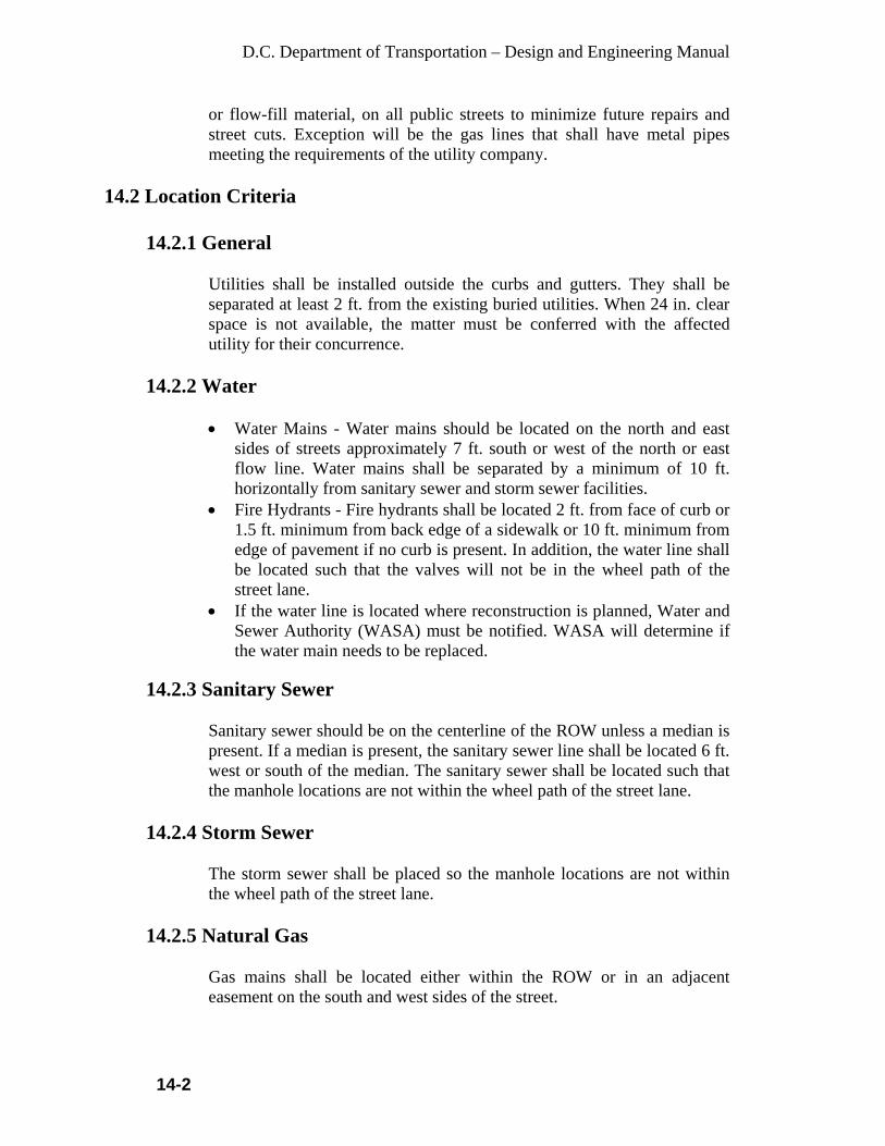
D.C. Department of Transportation – Design and Engineering Manual
14-2
or flow-fill material, on all public streets to minimize future repairs and street cuts. Exception will be the gas lines that shall have metal pipes meeting the requirements of the utility company.
14.2 Location Criteria 14.2.1 General
Utilities shall be installed outside the curbs and gutters. They shall be separated at least 2 ft. from the existing buried utilities. When 24 in. clear space is not available, the matter must be conferred with the affected utility for their concurrence.
14.2.2 Water • Water Mains - Water mains should be located on the north and east
sides of streets approximately 7 ft. south or west of the north or east flow line. Water mains shall be separated by a minimum of 10 ft. horizontally from sanitary sewer and storm sewer facilities.
• Fire Hydrants - Fire hydrants shall be located 2 ft. from face of curb or 1.5 ft. minimum from back edge of a sidewalk or 10 ft. minimum from edge of pavement if no curb is present. In addition, the water line shall be located such that the valves will not be in the wheel path of the street lane.
• If the water line is located where reconstruction is planned, Water and Sewer Authority (WASA) must be notified. WASA will determine if the water main needs to be replaced.
14.2.3 Sanitary Sewer
Sanitary sewer should be on the centerline of the ROW unless a median is present. If a median is present, the sanitary sewer line shall be located 6 ft. west or south of the median. The sanitary sewer shall be located such that the manhole locations are not within the wheel path of the street lane.
14.2.4 Storm Sewer The storm sewer shall be placed so the manhole locations are not within the wheel path of the street lane.
14.2.5 Natural Gas
Gas mains shall be located either within the ROW or in an adjacent easement on the south and west sides of the street.

D.C. Department of Transportation – Design and Engineering Manual
14-3
14.2.6 Power and Street Lighting
Generally, power and street lighting lines shall be located on both sides of the street either within the ROW or in an adjacent easement.
14.3 Other Utilities
Cable TV and telephone lines generally serve properties from the back. The utility companies shall coordinate the locations of their installations in the ROW or easements with the District and other utility companies.
Traffic Signals and Signs:
• Location - Poles, signs and any other above ground streetscape (except
regulatory signs) should be located within 5 ft. of the ROW line or 10 ft. from the travel lane (flow-line), whichever is most restrictive.
• Clearance - Light poles shall be placed no closer to the roadway than 2 ft. behind a vertical curb line and no closer than 2 ft. to any sidewalk.
• The Project Manager may require breakaway poles on public ROW where speed limit is 40 Mph or higher.
• Other Requirements - All signs and poles shall meet the requirements of the Traffic Signal Design chapter within this manual.
14.4 Utilities Attachments on Bridge
14.4.1 General The following guidance in regard to utility installations on bridges should be followed:
• In most cases, attachment of utility facilities to highway structures,
such as bridges, is a practical arrangement and considered to be in the public interest. However, every effort should be made when attaching utility lines to a highway structure so that they do not affect the structural integrity, the safe operation of traffic, the efficiency of maintenance as well as the appearance.
• Since highway structure designs and site conditions vary, the adoption of a standard method to accommodate utility facilities is not feasible; however, the method employed should conform to logical engineering considerations for preserving the highway, its safe operation, maintenance and appearance. Generally, acceptable utility installations are those that will occupy a position beneath the bridge floor, between the outer girders, beams or within a cell, and at an elevation above low superstructure steel or masonry.

D.C. Department of Transportation – Design and Engineering Manual
14-4
• The general controls for providing encasement, allied mechanical protection and shut-off valves to pipeline crossings of highways and for restriction against varied use shall be followed for pipeline attachments to bridge structures, except that sleeves are required only through the abutment backwalls. Where a pipeline attachment to a bridge is encased, the casing should be effectively opened or vented at each end to prevent possible buildup of pressure and to detect leakage of gases or fluid.
• Since an encasement is not normally provided for a pipeline attachment to a bridge, additional protective measures shall be taken. Such measures shall employ higher factor of safety in the design, construction, and testing of the pipeline than would normally be required for cased construction.
• Communication and electric power line attachments shall be suitably insulated, grounded, and carried in protective conduit or pipe from the point of exit from the ground to re-entry. The cable shall be carried to a manhole located beyond the backwall of the structure. Carrier pipe and casing pipe should be suitably insulated from electric power line attachments.
• Guy wires in support of any utility will never be allowed to attach to a bridge structure.
To insure that the function, aesthetics, painting and inspection of stringers of a structure are maintained, the following applies to the installation of utilities on structures: • Permanent installations, which are to be carried on and parallel to the
longitudinal axis of the structure, shall be placed out of sight, between the fascia beams and above the bottom flanges, on the underside of the structure.
• Conglomeration of utilities in the same bay shall be avoided in order to facilitate maintenance painting and future inspection of steel stringers in a practical manner.
14.4.2 Supports
Due consideration shall be given to the weight of the pipes, ducts, etc. in the design of the beams and diaphragms. Utilities shall not be supported by a system that requires inserts in the concrete deck slab. They shall be supported directly on structural beams. Also, utilities shall not be supported by a system that requires drilling into prestressed concrete beams. Welding onto structural steel beams or diaphrams is not permitted. The support details shall be in accordance with the requirements of the individual utility companies
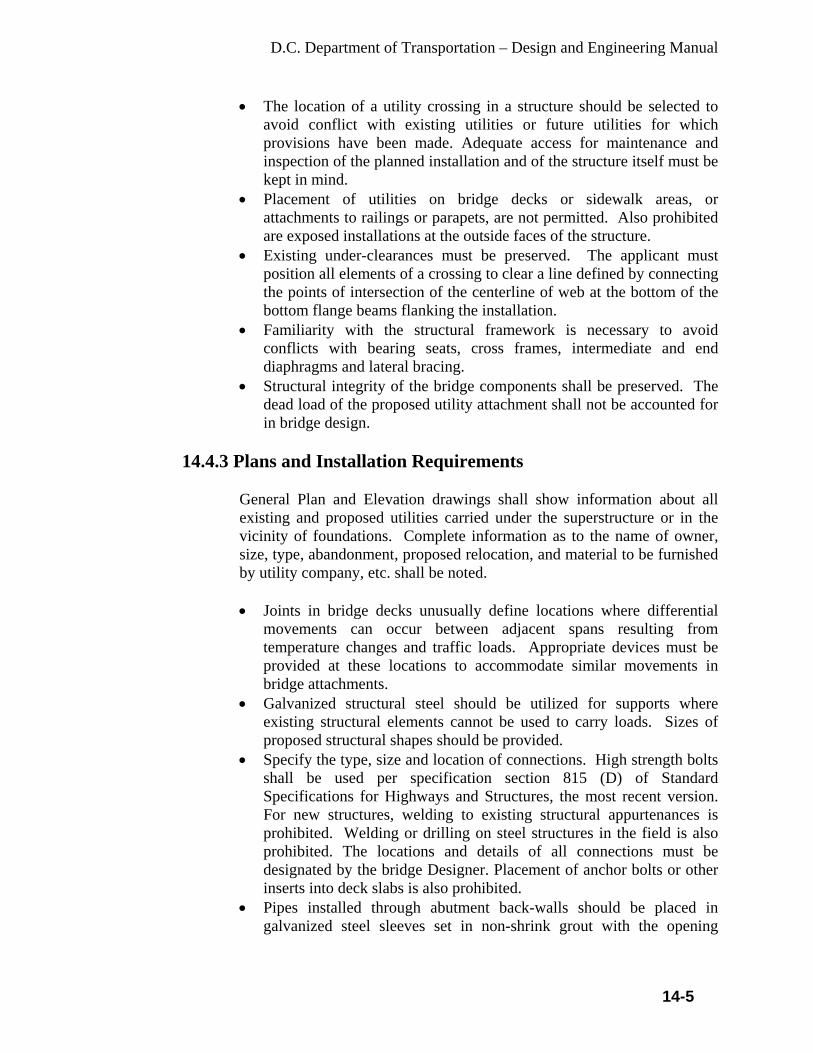
D.C. Department of Transportation – Design and Engineering Manual
14-5
• The location of a utility crossing in a structure should be selected to avoid conflict with existing utilities or future utilities for which provisions have been made. Adequate access for maintenance and inspection of the planned installation and of the structure itself must be kept in mind.
• Placement of utilities on bridge decks or sidewalk areas, or attachments to railings or parapets, are not permitted. Also prohibited are exposed installations at the outside faces of the structure.
• Existing under-clearances must be preserved. The applicant must position all elements of a crossing to clear a line defined by connecting the points of intersection of the centerline of web at the bottom of the bottom flange beams flanking the installation.
• Familiarity with the structural framework is necessary to avoid conflicts with bearing seats, cross frames, intermediate and end diaphragms and lateral bracing.
• Structural integrity of the bridge components shall be preserved. The dead load of the proposed utility attachment shall not be accounted for in bridge design.
14.4.3 Plans and Installation Requirements
General Plan and Elevation drawings shall show information about all existing and proposed utilities carried under the superstructure or in the vicinity of foundations. Complete information as to the name of owner, size, type, abandonment, proposed relocation, and material to be furnished by utility company, etc. shall be noted.
• Joints in bridge decks unusually define locations where differential
movements can occur between adjacent spans resulting from temperature changes and traffic loads. Appropriate devices must be provided at these locations to accommodate similar movements in bridge attachments.
• Galvanized structural steel should be utilized for supports where existing structural elements cannot be used to carry loads. Sizes of proposed structural shapes should be provided.
• Specify the type, size and location of connections. High strength bolts shall be used per specification section 815 (D) of Standard Specifications for Highways and Structures, the most recent version. For new structures, welding to existing structural appurtenances is prohibited. Welding or drilling on steel structures in the field is also prohibited. The locations and details of all connections must be designated by the bridge Designer. Placement of anchor bolts or other inserts into deck slabs is also prohibited.
• Pipes installed through abutment back-walls should be placed in galvanized steel sleeves set in non-shrink grout with the opening

D.C. Department of Transportation – Design and Engineering Manual
14-6
between the pipe and sleeve packed with jute or similar material to prevent leakage through the back-wall.
• Provide ducts for electrical and communication cables. • Pipes carrying liquids under pressure in trenches should be sleeved
within 10 ft. of abutments, walls and piers. • All pipelines carrying liquids or gasses under pressure shall extend
through the supporting structure without changes in alignment. Changes in alignment shall be outside the structure limits. Reactions developed at these locations should be carried by thrust blocks or other means completely independent of the bridge's structural elements.
• Provide a plan view with a North reference arrow, an elevation and a cross section of the structure and detailing and necessary dimensions to identify and locate existing and proposed structural members that are in relationship to the bridge attachment and to verify clearances. Additional sections should be shown, as required, to completely convey the extent of the work and/or modifications proposed.
• The outside diameters and thickness of pipes, and weights of pipe or conduit and materials carried should be shown on the plans. If manufactured fittings, connectors, supports, etc. are used, their identity and spacing should be indicated on the plans and catalog cuts with dimensions should be traced on to the plans.
14.4.4 Pipeline Expansion Joints (Water Mains)
• Allowances must be made for changes in pipe length due to thermal
expansion and alternate contraction. While Dresser type couplings will take care of the normal amount of expansion and contraction in each length of pipe, Dresser type expansion joints or similar products are required where no flexible joints are used in the pipeline or when the amount of concentrated movement at one point is in excess of the amount that can be safely absorbed by the standard coupling.
• A Dresser type expansion joint should be located in the pipeline adjacent to every point where allowances for expansion means are provided in the superstructure.
• Use Dresser type couplings or similar products to accommodate the differential movement between the structure and the line itself, and to provide flexibility to accommodate vibrations of the structure.
• Each coupling can safely accommodate up to 3/8 in. longitudinal movement. This is equivalent to the amount of movement resulting from a 150°F temperature variation in a 40 ft. length of steel pipe.
• Proper alignment is important to insure free and concentric movement of the slip-type expansion joint. Alignment guides should be designed to allow free movement in only one direction along the axis of the pipe and to prevent any horizontal or vertical movement of the pipe. Suitable pipe alignment guides may be obtained from reliable pipe

D.C. Department of Transportation – Design and Engineering Manual
14-7
alignment guide manufacturers. Alignment guides should be fastened to some rigid part of the installation, such as the framework of the bridge. Alignment guides should be located as close to the expansion joint as possible, up to a maximum of 4 pipe diameters. The distance from the first pipe guide to the second should not exceed a maximum of 14 pipe diameters from the first guide. Where an anchor is located adjacent to an expansion joint, it too should be located as close to the expansion joint as possible, to a maximum of 4 pipe diameters from the expansion joint. Pipe supports should not be substituted for alignment guides. The main pipe anchors must be designed to withstand the full thrust resulting from internal line pressure, and the frictional forces due to guides and supports.
D.C. Department of Transportation – Design and Engineering Manual
15-1
CHAPTER 15
STRUCTURAL REHABILITATION AND RECONSTRUCTION 15.1 General
For bridge design, follow the design procedures in AASHTO's Standard Specifications for Highway Bridges and this manual. Refer to AASHTO's Manual for Condition Evaluation of Bridges for rating and evaluation procedures. The Department uses the load factor method of design as defined in the AASHTO Standard Specification for Highway Bridges. The design procedures in AASHTO LRFD Bridge Design Specifications shall be used Live load design for structures on Interstate highways shall be HS25 (HS20+25 percent), including the sections of the highways connecting to the Interstate highways.
15.2 Materials
15.2.1 Structural Steel
The material for all main load-carrying members of steel bridges subject to tensile stresses shall meet AASHTO requirements for notch toughness. Refer to Section 10.3, Repetitive Loading and Toughness Considerations, in the AASHTO Standard Specification for Highway Bridges. Normally, AASHTO M270, Grade 345, structural steel is used; painting is required. AASHTO M270, Grade 345W, structural steel weathered to preclude the need for painting, may be considered for structures over high traffic volume roadways or railroads, where access for painting or repainting is limited or dangerous. The use of weathering steel will be evaluated on a case-by-case basis and is subject to approval of the Bridge Design Engineer. Refer to FHWA Publication Forum on Weathering Steel for Highway Structures: Summary Report. Weathering steel should not be used in corrosive environments where there is high humidity or high concentrations of chloride. It may be desirable to paint the ends of weathering steel beams near bearings and under joints.
15.2.2 Cast-in- Place Concrete
Portland cement concrete (f˜c = 4500 psi at 28 days) shall be used for concrete decks. Reinforcing steel meeting the requirements for AASHTO M31, Grade 60, shall be specified. All reinforcing steel shall be

D.C. Department of Transportation – Design and Engineering Manual
15-2
protected with fusion-bonded epoxy. Epoxy coating conforming to AASHTO M284 shall be specified.
15.2.3 Precast Concrete
Concrete with an f˜c = 5000 psi is normally used for prestressed concrete beams. An increase to 6000 psi or higher is permissible where it is reasonable to expect that this strength will be consistently obtained. Reinforcing steel meeting the requirements for AASHTO M31, Grade 60, shall be specified. Normally, prestressing strands shall be high-strength 7-wire low-relaxation strand, with nominal ½ in. diameter, and conform to AASHTO M203, 270,000 psi grade, low-relaxation strands. Minimum strand spacing (center-to-center of strand) will be four times the nominal strand diameter. Epoxy coating is not normally specified for prestressing strands, but may be justified in areas where flooding may inundate the bottom of the superstructure. On post-tensioned structures, the designer will specify that all strands will be uncoated and all strand conduits will be pressure-grouted.
15.3 Reinforcement Steel
15.3.1 Reinforcement Presentation
Standard concrete cover in deck slab shall be 2½ in. for top reinforcement and 1½ in. for bottom reinforcement. Standard concrete cover for reinforcement in all other concrete members shall be 2 in. unless otherwise shown. Standard concrete cover shall be 3 in. for reinforcement in concrete surfaces in contact with ground unless otherwise shown. Refer to the Section 8.32, Splices of Reinforcement, in the AASHTO Standard Specifications for Highway Bridges for splicing requirements. Normally, reinforcing steel splices are lapped and tied, but the designer may specify mechanical splices. If there are transportation problems, the longest reinforcing bars may be limited to 60 ft. Specify long bars, insofar as possible, to minimize splicing. The minimum size of reinforcing is a Number (#) 5 bar. When detailing lengths of reinforcement bars, consideration must be given to transportation and handling, and where extremely long lengths are contemplated, to availability and special orders. All sizes of bars are readily available in lengths up to 60 ft. However, #3 and #4 bars more than 40 ft. long tend to bend in handling; therefore, they should be avoided. Sizes #5 through #18 in lengths exceeding 60 ft. can be rolled at
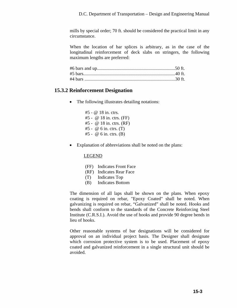
D.C. Department of Transportation – Design and Engineering Manual
15-3
mills by special order; 70 ft. should be considered the practical limit in any circumstance. When the location of bar splices is arbitrary, as in the case of the longitudinal reinforcement of deck slabs on stringers, the following maximum lengths are preferred: #6 bars and up...................................................................50 ft. #5 bars...............................................................................40 ft. #4 bars ..............................................................................30 ft.
15.3.2 Reinforcement Designation
• The following illustrates detailing notations:
#5 - @ 18 in. ctrs. #5 - @ 18 in. ctrs. (FF) #5 - @ 18 in. ctrs. (RF) #5 - @ 6 in. ctrs. (T) #5 - @ 6 in. ctrs. (B)
• Explanation of abbreviations shall be noted on the plans:
LEGEND
(FF) Indicates Front Face (RF) Indicates Rear Face (T) Indicates Top (B) Indicates Bottom
The dimension of all laps shall be shown on the plans. When epoxy coating is required on rebar, "Epoxy Coated" shall be noted. When galvanizing is required on rebar, “Galvanized” shall be noted. Hooks and bends shall conform to the standards of the Concrete Reinforcing Steel Institute (C.R.S.I.). Avoid the use of hooks and provide 90 degree bends in lieu of hooks. Other reasonable systems of bar designations will be considered for approval on an individual project basis. The Designer shall designate which corrosion protective system is to be used. Placement of epoxy coated and galvanized reinforcement in a single structural unit should be avoided.

D.C. Department of Transportation – Design and Engineering Manual
15-4
15.4 Bridge Type Selection and Geometrics
The design criteria include levels of service, roadway classification, design speed, traffic volumes, traffic composition, and traffic projections. The designer should consider the need for future widening. The impact on traffic and construction operations at the time the structure will be widened must also be considered. If the widening will be required in the immediate future (less than 5 years), the substructure should be included in the original design, and may be built during the original construction. The longitudinal joint in the deck should not be in a wheel path after the deck is widened. The widths of shoulders may be narrowed on long bridges to reduce costs. A long bridge is defined as being longer than 200 ft.; refer to Chapter 7 in AASHTO's A Policy on Geometric Design of Highways and Streets (Green Book, current version: 2004) for the criteria. Narrowing or eliminating shoulders below AASHTO standards requires a design exception and must be approved by the Chief Engineer. When reconstructing or rehabilitating the historic bridge structures, every effort shall be made to preserve the original shape and the use of original texture and type of materials. The construction plans must have an approval from the State Historic Preservation Office (SHPO) and the District’s Commission on Fine Arts. Engineering, architectural (when warranted), and cost studies shall be prepared for each structure or group of structures. Where several structures are in close proximity with each other, studies may be prepared to show possible interaction with each other. In consideration of the need for a movable bridge structure, the long-term investment associated with machinery maintenance, liabilities associated with navigation hazards, and staffing the structure with operators should be considered. Also, the impact of traffic congestion due to openings should be considered. These issues should be addressed in assessing the cost and practicality of a movable bridge versus a fixed bridge. These initial studies should be developed from a careful appraisal of the site, foundation, drainage conditions, highway limitations, and environmental impact, both present and future. The structural types proposed as a result of these studies must be based on the highest standards of creativity and engineering technique. Economy, aesthetics and maximum safety are not incompatible in the design of structures. For grade separation structures, the absence of shoulder piers allows for possible future widening of the lower roadway while removing sight line restrictions and minimizing safety hazards. The resultant "open" structure usually results in a more pleasing appearance.

D.C. Department of Transportation – Design and Engineering Manual
15-5
In planning new bridges, the list of available structure materials and types of construction should be considered. At any given location, the ultimate selection should be based on suitability and aesthetics. This is with consideration of the bridge and its site as an entity and also as part of the surrounding environment. The character and coloration of the terrain and the form of nearby structures should all be influences on the aesthetics proposed for the structure. Superstructures of shallow proportion shall be strived for; however, stiffness requirements and other design considerations must be balanced against those of aesthetic appeal. Unsightly details, which present abrupt discontinuities in the bridge profile, should be avoided. In arriving at span proportions, substructure elements should be positioned clear of traveled roadways. Concrete piers that are built near roadways should generally be of open-type construction (i.e. column bent piers). When supporting a multitude of closely spaced stringers, a common and simple frame consisting of a uniform depth cap beam on circular columns may be suitable. Often times, frame proportions are enhanced by allowing the cap beam to cantilever over the exterior columns with a variable depth that tapers to a minimum beyond the fascia stringer bearing. The slender tee-pier should not be overlooked for the support of high crossings or narrow structures. New designs, as well as major rehabilitation work for high level or complex structures, should include permanent provisions for inspection, such as catwalks, in order to make bridge members accessible. Bridge design engineers must avoid designs of, especially pin-hanger assemblies, fatigue prone, and fracture critical structures. All new bridges shall be designed for redundant structures.
15.5 Geometrics on Bridges
The designer should minimize the skew angle of the substructure and the superstructure for simplicity of design and construction. Highway and bridge designers shall make every effort to eliminate or minimize adverse geometrics on bridges; such as, horizontal curves, vertical curves, variable bridge widths for on and off ramps, variable cross-slopes and many others. Curved bridges are generally more costly than straight bridges. For steel girder superstructures, heat curving the girders or cutting flange plates to meet the curvature will add to the steel cost. Wherever possible, vertical curves, both crest and sag, should be located away from the bridge. It is economically advantageous to place a bridge on a tangent grade rather than on the vertical curve. Cambering girders for vertical curvature is more costly than tangent girders since excessive camber may entail cutting the web to the required curvature, thus wasting steel and increasing fabrication costs. Increased construction costs will result from forming a bridge deck on a curve in

D.C. Department of Transportation – Design and Engineering Manual
15-6
view of the additional labor required to achieve the plan precision in forming the deck. A comprehensive and diligent analysis must be made of the entire project at the preliminary design stage. This should be the basis for designing curves and ramps away from the structures to the maximum extent feasible since they generally increase the bridge cost. Locating curves and ramps on the approach highways rather than on bridges results in simpler construction, is more economical, and reduces future maintenance requirements.
15.6 Vertical Clearance of Structures
15.6.1 Overhead Structures over Roadways Minimum Vertical clearance = 14.5 ft
15.6.2 Overhead Structures over Interstate System
Minimum vertical clearance = 16.5 ft.
15.6.3 Overhead Structures over Freeways and Sections of the
Highways Connecting to Interstate System
Minimum Vertical clearance = 16.5 ft.
15.6.4 Pedestrian Overhead Structures over Roadways
Minimum Vertical clearance = 17.5 ft
15.6.5 Overhead Structures over Railroads
Minimum Vertical clearance = 23 ft. or as directed by the railroad company
15.7 Alternate Designs
Studies during the Preliminary Design may conclude that alternate designs may be warranted for major bridges. The decision as to whether or not to proceed with an alternate design will be made, as recommended by the Project Manager in consultation with the Federal Highway Administration.
15.7.1 Existing Overhead Sign Structures
The existing overhead sign structures on freeways are based upon the steel pipe standards developed by U.S. Steel in the 1960’s. If replacing is

D.C. Department of Transportation – Design and Engineering Manual
15-7
needed, they should be designed with a more aesthetic design, similar to the sign supports found at, as an example, the D.C. approach to the Theodore Roosevelt Bridge and Sousa Bridge. The design is a less industrial looking square tube design, and is approved by the Commission of Fine Arts.
15.8 Life Cycle Cost Analysis
A Life Cycle Cost Analysis (LCCA) is defined as the total cost of an item’s ownership over a specified period of time. This includes, as applicable, initial acquisition costs (ROW, planning, design, construction), operation, maintenance and modification, replacement, demolition, financing, taxes, disposal, and salvage value. An LCCA to compare the benefits and costs that arise at different times in a bridge structure’s life span shall be made in studying alternate design concepts. Future benefits and costs over the proposed time span of each alternative should be considered. A long-term perspective should be considered in programming improvements and selecting among alternative design, maintenance, rehabilitation and reconstruction strategies in designing bridge structures. An important factor to consider in this process, especially in urban areas, is highway congestion. Investment decisions must consider the impact that is imposed on the traveling public in constructing bridge structures on congested highways. LCCA will help the Department to identify and explain the real costs that it must bear in maintaining its bridge structures. Also, the LCCA will assist the Department in making the best use of available funds.
The following paragraphs provide guidance in developing the principals for a good LCCA. These principals will allow the Department to identify its investment alternatives. • Design Life - Generally a longer design life should be considered for bridge
structures. This is due to the realization that future Department and user costs, that are associated with maintenance of a bridge structure, will be high. For a bridge structure on the National Highway System (NHS) a design life of 100 years should be considered. This will require a longer analysis period. All project alternatives should consider this length.
• User Costs - The costs and lost productivity to the public because of traffic delays should account for a high cost range consideration. Increased vehicle operating costs, accident costs and delay related costs should be considered in the LCCA.
• Discount Rate - Future agency and user costs should be discounted to net present value or converted to equivalent uniform annual costs using appropriate discount rates. The selected discount rate should be based on guidance that is provided in the Office of Management and Budget (OMB)

D.C. Department of Transportation – Design and Engineering Manual
15-8
Circular A-94, “Guidelines and Discount Rate for Benefit Cost Analysis of Federal Programs”.
• Other Factors - Budgetary, environmental and safety considerations will influence the investment decision. These factors should be considered along with the results of the LCCA in evaluating the investment alternative.
• Department Costs - Traffic control costs, during a maintenance or rehabilitation project, should be considered in the LCCA.
15.9 Reconstruction and Rehabilitation
15.9.1. Eligible Work
Reconstruction and rehabilitation procedures necessary to assure acceptable performance of existing structures are set forth below and are eligible for Federal-aid participation from the appropriate category. Reconstruction and rehabilitation shall include all work required to assure satisfactory performance of the concrete deck, as well as supporting superstructure and substructure units.
• This may include items such as the removal of existing overlays,
removal and replacement of all deteriorated components or the complete removal and replacement of the entire bridge deck if necessary.
• This work may also include repair or removal and replacement of deteriorated concrete curbs, sidewalks, parapets, as well as rail, deck joints, bearings, or similar incidental items which are associated with proper functional restoration of the structure.
• Safety improvements should be undertaken with the work mentioned above when such improvements eliminate an established hazardous condition. Such safety improvements may include widening, elimination of hazardous walks and substandard safety hardware, removal of hazardous fixed objects or the installation of energy absorbing barrier system, and any other features that are consistent with current safety standards.
15.9.2 Field Condition and Appraisal Survey
Where an existing bridge or structure is to be widened, altered, reconstructed or rehabilitated, review any existing report in the Department. In conjunction with the review of the Report, a limited Field Condition Survey may be required to update the original inspection report. The supplementary report shall include recommendations for remedial work together with the preliminary cost estimate. The Field Condition and Appraisal Survey shall be submitted prior to submission of the Preliminary Plans.

D.C. Department of Transportation – Design and Engineering Manual
15-9
Safety improvements shall be considered for all reconstruction and rehabilitation projects. The minimum vertical under-clearance shall be measured and noted, together with its location, in the Field Condition and Appraisal Survey. If the under-clearance is substandard, a commentary about the extent of work that is needed to improve the situation, together with a preliminary cost estimate, shall be included. The Department will determine if a detailed retrofit study is warranted.
15.9.3 Concrete Bridge Decks
In the processes that are involved in construction, rehabilitation, and reconstruction of concrete bridge decks, with special emphasis on overlay protective systems, the following terminology shall apply:
• Construction - the initial construction of any specific bridge deck. • Maintenance - routine or incidental work necessary to keep a bridge
deck functioning in a safe and efficient manner. • Overlay Protective System - a system used to protect bridge decks
from deterioration induced by highway deicing chemicals, salt water, or other hostile environments.
• Reconstruction - the restoration of the structural integrity of a concrete bridge deck by complete removal and replacement of the existing deteriorated bridge deck.
• Rehabilitation - the work necessary to restore the structural integrity of portions of the original bridge deck as well as the installation of a deck protective system.
The following policies are established for all bridge decks to be constructed, rehabilitated, or reconstructed.
15.9.3.1 Overlay Protective System
The Department specifies quality concrete, epoxy-coated reinforcing steel, and extra cover over the top mat of reinforcement to ensure long-lasting decks. Additional deck protection, such as overlays, may be warranted on a case-by-case basis. Overlays may be justified on new decks where replacement of the deck would be very costly, or where traffic would be severely impacted during deck replacement. Overlays may be latex-modified concrete, silica fume concrete, or others approved by the Department. The type of overlay protective system shall be one of the followings:
• Low Slump Concrete for thickness 2 in. and over • Latex Modified Concrete or Microsilica Concrete for thickness
under 2 in.
D.C. Department of Transportation – Design and Engineering Manual
15-10
15.9.3.2 Superstructure Reconstruction Replacement
• The dead loads from the new slabs may introduce additional Dead
Load stresses in the existing stringers and/or beams. • If calculations indicate that the existing stringers and/or beams are
overstressed, the matter, together with recommendations, should be brought to the attention of the Chief Transportation Engineer.
• Special measures such as requiring retrofitting stringers with shear connectors may be required.
• Additionally, the height of shear connector studs on the existing stringers should be considered. Additional studs may have to be added.
15.9.4 Special Conditions
Any changes in the condition of the bridge structure prior to opening of bids for construction that may impact the structural integrity of the bridge must be considered for incorporation in the construction plans. Special Provisions will be required for the following:
• Construction Staging. • Traffic controls and diversions. • Authorized detours. • Restricted working hours or days. • Load restrictions for construction equipment. • Posting for reduced speeds, substandard vertical under-clearances
and/or load capacities.
15.10 Bridge Deck Rehabilitation
15.10.1 Requirements
• Review the Bridge Evaluation Survey Report or any prior Deck Evaluation Survey.
• Perform an on-the-site observation to determine if a Bridge Deck Evaluation Survey is warranted.
• Perform, if authorized, a Deck Evaluation Survey. • Perform a Field Survey to determine existing/as-built geometrics and
deck profile elevations at 10-foot intervals (if warranted). • When the superstructure is substandard in load capacity or vertical
under-clearance a determination as to whether a retrofit study is warranted shall be made.

D.C. Department of Transportation – Design and Engineering Manual
15-11
• The area of deck that is to be rehabilitated shall be designated as the area that is actually realized from the Deck Condition Survey or, as a minimum, 15 percent of the entire deck area.
15.10.2 Machine For Concrete Deck Overlay Protective Systems
At this time, concrete overlay protective systems shall include Latex Modified Concrete, low slump concrete and Silica Fume Concrete. Specifications require the use of a finishing machine for placing overlays. However, the Specifications also provide that "Hand operated vibrators and screeds may be used to place and finish small areas of work". In some instances small "tight" areas, unusual transitions, or other geometric constraints may preclude machine finishing (minimize bridge deck areas that could preclude use of machine finish). Show on the plans in bridge deck areas and special provisions where adverse conditions could conceivably preclude the use of machine finishing.
15.10.3 Value Engineering
The use of Value Engineering (VE) in the planning, design and/or construction of structural work is encouraged. Consideration of life cycle cost shall be the primary purpose in applying VE to structural work. Value Engineering is an effective tool for both product improvement and cost reduction. It should not be confused with the typical design review process nor should it be applied in a routine manner without warrant. Value Engineering should be employed when there is potential for a significant ratio of savings to the cost of the VE study or substantial improvements in program effectiveness. Value Engineering should be considered on all major structural projects, and on obviously high cost projects as well as standard details that are used repetitively on many projects. For maximum benefit, VE should be employed as early as possible in the project development process so that valid VE recommendations can be implemented without delaying the progress of the project. DDOT standards include a VE specification that encourages the Contractor to propose changes in contract requirements that will accomplish the project’s functional requirements at less cost. The net savings of each proposal should be shared with the contractor, or through the Contractor with subcontractors and suppliers, at a stated reasonable rate. Reimbursement for such share is eligible for pro-rata reimbursement of Federal-aid funds. The Department retains the right to accept or reject

D.C. Department of Transportation – Design and Engineering Manual
15-12
all proposals and acquire all rights to use the accepted VE proposals in current and future projects without restriction.
15.11 Bridge Deck Evaluation Survey And Guidelines For Restoration
Work
15.11.1 Deck Evaluation Survey
15.11.1.1 Description of Survey and Testing
Testing and evaluation of concrete bridge decks consists of visual observations, delamination or debonding detection, concrete sampling for chloride analysis, and electrical potential measurement (half-cell testing). All of these bridge deck evaluation techniques are used to detect existing defects and actively deteriorating conditions of the deck. The following description is intended to provide information and procedures for these bridge deck evaluation techniques. These techniques should be used in sequence and, if warranted, in combination. By using the combined results, engineers can better evaluate the condition of any bridge deck.
15.11.1.2 Visual Survey
The first step for deck evaluation is a visual observation to determine the extent of spalling, cracking and scaling. Visual observation, however, does not reveal hidden structural deterioration such as delaminations or corrosion of rebar. The information from visual surveys is used to determine further deck condition survey needs. Visual surveys are generally expressed in terms of the amount of spalling and patching as a percent of the total deck area.
15.11.1.3 Concrete Delamination Detection (Chain Drag)
A delamination survey provides information on the subsurface condition of concrete bridge decks. A chain drag can be used to survey concrete bridge decks for delaminations. The chain drag consists of four or five segments of 1 in. link chain about 18 in. long, attached to a 24 in. piece of aluminum or copper tube, to which a 24 in. to 36 in. piece of tubing is attached at the midpoint, forming a "T". The chain is dragged along the surface of the concrete in a swinging motion, resulting in a ringing sound. When delaminated concrete is encountered, a noticeable "dull" sound is produced. The delaminated concrete area is outlined on the deck with chalk, crayon, or paint and can be plotted to give an overall picture of delaminated areas.

D.C. Department of Transportation – Design and Engineering Manual
15-13
The results of the Chain Drag are not reliable when the bridge deck has been overlayed with bituminous concrete; therefore, its use is not recommended for bridge decks with bituminous concrete overlays.
15.11.1.4 Chloride Analysis
Chloride analysis provides a quantitative measure of the chloride ion contamination of concrete at selected levels in the deck. Concrete samples for chloride analysis, are usually taken by a rotary hammer drill. The concrete is pulverized in the hole from the combined hammering and rotating actions of the drill, thus facilitating removal and analysis. The sampling is done at or above the level of the top reinforcing bars, and the powdered concrete is collected and sent to the Department's Laboratory for analysis. The percentage of chloride ion is then calculated from the lab results. The "threshold" chloride content, or amount of chloride needed to initiate corrosion, is approximately 2.0 lbs of chloride per cubic yard of concrete.
15.11.1.5 Half-Cell Test
The purpose of half-cell testing is to determine the areas in the deck in which active corrosion is present. Corrosion of the reinforcing bars in concrete decks is detected by an electric current flowing from the rebar at one point (the anode) to another point (the cathode). During active corrosion, an electrical potential difference exists between the anode and cathode that can be measured by copper/copper sulfate half-cells (CSE). The CSE is pure copper rod suspended in a saturated solution of its own ions. Corrosion of the reinforcing steel can be detected by grounding the CSE to the deck slab reinforcing steel, placing the CSE in contact with the Bridge Deck Electrolyte (i.e., touching it to a small section of deck wetted with water) and measuring the electrical potential from a volt meter attached to the CSE. Research tests have demonstrated that potential differences more negative than -0.35 volts indicates a high degree of probability of active corrosion of the reinforcing steel. Potential readings not greater than -0.20 volts indicate the probability of inactive or no corrosion, while potential readings between -0.20 volts and -0.35 volts indicate the possibility of active corrosion. The potential readings collected are then used to plot an equipotential map of the deck and to estimate the percent area of the deck with actively corroding reinforcing steel. Surveys are temperature sensitive and should only be performed if the ambient air temperature has been above 40°F for a minimum of 72 hours immediately prior to the date of the survey.

D.C. Department of Transportation – Design and Engineering Manual
15-14
15.11.1.6 Pachometer Test
In order to properly establish the deck condition, establishing the depth of cover over the top reinforcement is necessary. This will provide the evaluator with needed information to properly judge the existing condition versus what is the required minimum depth of cover.
15.11.2 Procedures to Perform Deck Evaluation Survey
15.11.2.1 Visual Observations
Make comments on the deficiencies of either the asphalt overlay or the concrete deck wearing surface (e.g. spalling, cracking, scaling, warping, asphalt creep, alligator cracks, etc.). Include the location and size of deficiencies, if any. Observe the underside of the deck and record the approximate size and location of all areas exhibiting cracks with or without efflorescence. Also, record all areas having concrete spalled from the bottom reinforcing. If the structure does not have asphalt overlay over the concrete deck, determine the percentage of spalls and/or patches in the exposed concrete deck-wearing surface. Decks covered with asphalt should be similarly inspected, with a general condition statement made about the asphalt surface. Record this percentage for use in the final deck condition determination.
15.11.2.2 Concrete Delamination Detection
15.11.2.2.1 Chain Drag
• Drag the chain in a swinging motion, while walking
along the concrete surface of the deck. • Outline, with crayon, the areas of the deck over which
the chain produces a distinctive "dull" sound. These areas indicate delamination of concrete.
• Transfer the delineated areas on the deck by plotting on a scaled map of the bridge deck.
15.11.2.3 Chloride Analysis
• Select random sample locations for chloride testing using
statistical methods and plot the locations on a plan view of the deck. As a minimum requirement, 10 locations per every 6000 sq. yd. area should be tested.

D.C. Department of Transportation – Design and Engineering Manual
15-15
• Locate the depth of the top reinforcing steel with a pachometer to determine the chloride sampling depth.
• Cut out an approximate 1.0 sq. ft. section of bituminous concrete overlay, if any exists, to expose the concrete deck surface. Record the depth of overlay removed, if any.
• Obtain each of the random samples with a rotary hammer drill. Pulverize the concrete down to within ½ in. of the rebar location, vacuum the hole, pulverize approximately 1 in. of concrete, then collect the powdered concrete sample in an uncontaminated container. All of the samples should be properly labeled and sent to the Department's Laboratory for chloride analysis.
• After all of the holes have been drilled, and all the samples collected, refill the holes with materials similar to the material that was there prior to drilling, (i.e. concrete slabs with a fast curing "concrete compound" and asphalt overlays with asphaltic materials).
• After the lab has analyzed the samples taken, calculate the percentage of the samples with a chloride content higher than 2.03 lbs./cu. ft. from:
No. of Samples with Cl. greater or equal to 2.03 lbs/cu.yd. x 100 = __% Total No. of Samples
15.11.2.4 Half-Cell Test
• Test all equipment before proceeding to the site. Check the
Voltmeter battery for satisfactory charge. • Measure and mark a 5 ft. grid pattern on the surface of the deck in
accordance with Contract Plans. If a grid pattern is not shown on Contract Plans, the grid pattern should be recorded on a plan view of the deck for simplicity and speed in data recording. Start the grid with a 1 ft. offset from curb to keep the equipment out of the dirt and debris, and an offset from the first deck joint that will allow convenient placing of the grid pattern on the deck.
• Uncoil an ample length of wire to reach all the grid points to be tested and connect the copper sulfate half-cell (CSE) to the positive jack of the Voltmeter.
• Pre-wet the deck at the grid points with water, saturate a sponge with water, and attach it to the bottom of the half-cell.
• Begin to take readings of the electrical potentials at every other grid point with the half-cell and continue the testing until the whole grid pattern has been completed. The time it takes to get a stable reading will indicate the proper "soak" time for the deck. The Voltmeter needle should make an immediate response and settle down when good connections have been made. Note: If the deck is too wet or frozen, reliable readings cannot be taken.

D.C. Department of Transportation – Design and Engineering Manual
15-16
• After the fieldwork is completed, the data can be recorded on graph paper and the equipotential lines plotted to produce an equipotential contour map.
• The percentage of possible corrosion affected deck area is then calculated from the results by counting the number of tests points equal to or more negative than -0.35 volts.
No. of Samples More Negative than -0.35 volts x 100 = _% Total No. of Samples
15.11.2.5 Pachometer Survey
• Pachometer Survey to determine the depth of the concrete cover
over the reinforcement steel. The equipment shall be calibrated according to the equipment manufacturer’s specifications.
• Locate and expose a reinforcing bar in the deck using a jackhammer. Connect the negative lead of the Voltmeter to the reinforcing steel. Connection can also be made to other metallic objects on the bridge (e.g. drainage scupper, light standards, bridge railing, expansion joints, etc.), if they are physically connected to the reinforcing steel. Connections should be made in each span if the reinforcing steel is not continuous through the expansion devices.
15.11.3 Summary - Sample Calculations and Statements
The summary calculations show a composite result of the previously described tests as follows: • Visual: The percentage of visual spalls over the top of the deck is 10
percent. • Concrete Delamination Detection: The analysis of the data revealed
that 65% of the tested area is delaminated. • Chloride Analysis: The results of the chloride analysis (shown below)
revealed that 60% of the samples tested were above the 2.03 lbs per cubic yd. threshold.
Unacceptable Samples = (6) = 60% Total Samples (10)
• Half-Cell Test: The results of the half-cell testing (shown below) revealed that 13.5% of the tests taken were more negative than -0.35 volts.
Unacceptable Samples = (13) = 13.5% Total Samples (96)
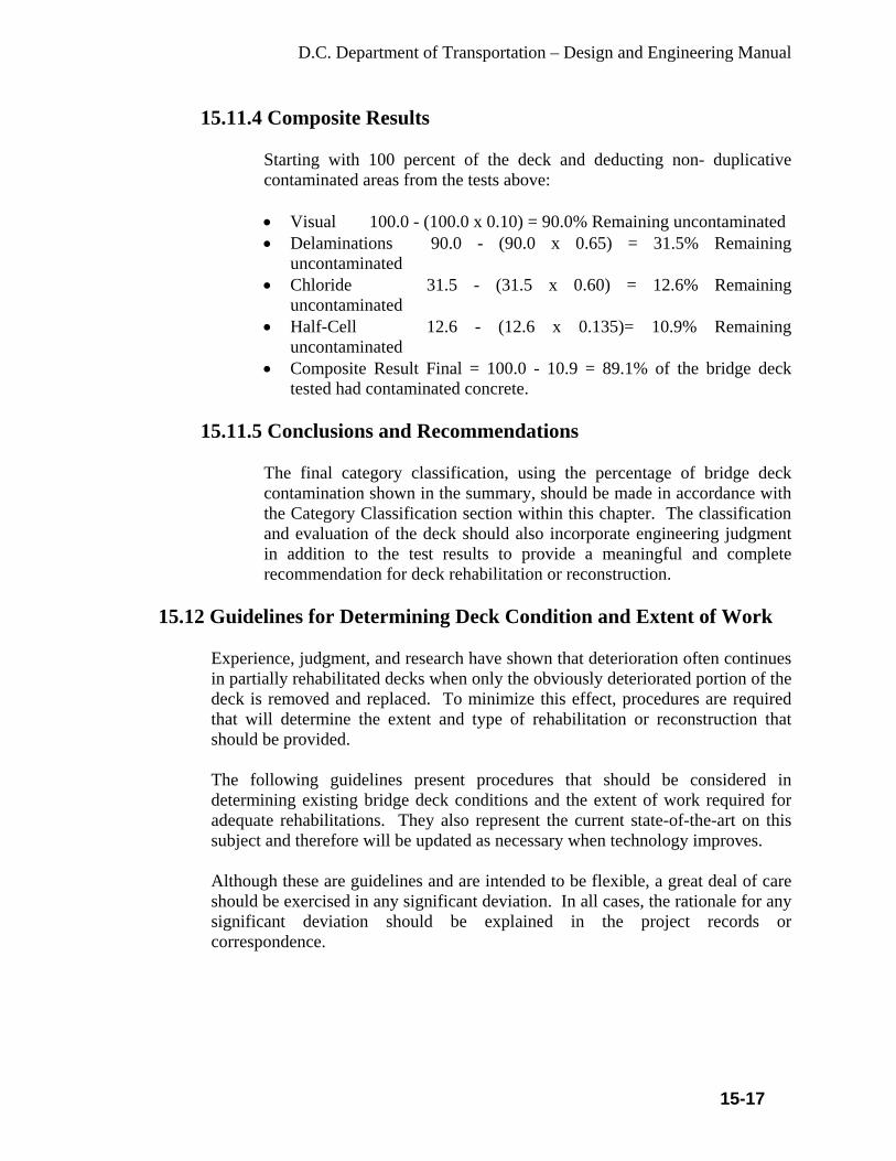
D.C. Department of Transportation – Design and Engineering Manual
15-17
15.11.4 Composite Results
Starting with 100 percent of the deck and deducting non- duplicative contaminated areas from the tests above: • Visual 100.0 - (100.0 x 0.10) = 90.0% Remaining uncontaminated • Delaminations 90.0 - (90.0 x 0.65) = 31.5% Remaining
uncontaminated • Chloride 31.5 - (31.5 x 0.60) = 12.6% Remaining
uncontaminated • Half-Cell 12.6 - (12.6 x 0.135)= 10.9% Remaining
uncontaminated • Composite Result Final = 100.0 - 10.9 = 89.1% of the bridge deck
tested had contaminated concrete.
15.11.5 Conclusions and Recommendations
The final category classification, using the percentage of bridge deck contamination shown in the summary, should be made in accordance with the Category Classification section within this chapter. The classification and evaluation of the deck should also incorporate engineering judgment in addition to the test results to provide a meaningful and complete recommendation for deck rehabilitation or reconstruction.
15.12 Guidelines for Determining Deck Condition and Extent of Work
Experience, judgment, and research have shown that deterioration often continues in partially rehabilitated decks when only the obviously deteriorated portion of the deck is removed and replaced. To minimize this effect, procedures are required that will determine the extent and type of rehabilitation or reconstruction that should be provided. The following guidelines present procedures that should be considered in determining existing bridge deck conditions and the extent of work required for adequate rehabilitations. They also represent the current state-of-the-art on this subject and therefore will be updated as necessary when technology improves. Although these are guidelines and are intended to be flexible, a great deal of care should be exercised in any significant deviation. In all cases, the rationale for any significant deviation should be explained in the project records or correspondence.

D.C. Department of Transportation – Design and Engineering Manual
15-18
15.12.1 Field Condition Survey
A limited field condition survey should be made to identify bridge decks that may be structurally inadequate or possibly contaminated with de-icing chemicals such that normal maintenance is not expected to provide reasonable service. Some examples of deck slab conditions that may warrant rehabilitation and/or protective measures are as follows: • Visible concrete spalls which have occurred in the deck riding surface
and/or evidence of unsound concrete in the bottom exposed surface of the deck slab (which may indicate structural failure).
• Extensive deterioration of the asphaltic overlay logically due to underlying concrete deterioration.
• Evidence of delaminations (horizontal fracture planes) in the concrete deck.
• Evidence of reinforcing steel corrosion. • Evidence of inadequate concrete cover over the reinforcing steel.
15.12.2 Structural Adequacy
When the structural adequacy of a bridge deck to carry current traffic loads is questioned, an in-depth field survey and analysis must be performed. This review should determine the extent of deficiencies as well as the feasibility of rehabilitation. Economics, traffic maintenance, etc., need to be evaluated when balancing the feasibility of structural restoration against complete replacement.
15.12.3 Detailed Field Appraisal
Where the field condition survey has indicated that rehabilitation and/or reconstruction may be warranted, a detailed Evaluation Survey should be performed to further define the inadequacies of the existing deck. This appraisal should, to the extent appropriate, consider the following as recommended components of an evaluation system: • Delamination detection with appropriate equipment to determine
extent of internal fractures of the concrete. • Determination of the extent of reinforcing steel corrosion by the use of
a half-cell corrosion detection device. • Determination of areas with inadequate concrete cover over the
reinforcing steel by the use of appropriate equipment. • Chemical analysis to determine extent of chloride contamination.

D.C. Department of Transportation – Design and Engineering Manual
15-19
15.12.4 Evaluation of Field Survey Results
Research reports have explained the interaction of all current detection methods and emphasized the need to use each method only for its designed purpose. The following data have been developed by research and experience: • Delaminations - The use of a chain drag will readily define the areas of
loss of structural performance in the form of delaminations or cleavage planes within the concrete. This normally indicates active corrosion of the rebar within these areas and probable chloride contamination of the entire deck. A visible spall is the end result of delaminations at the level of the rebar.
• Electrical Potential - Laboratory corrosion tests and field experience have shown that there is a 95 percent probability that an electrical potential in excess of -0.35 volts (CSE) to the copper-copper sulfate electrode corresponds to active corrosion in the reinforcing steel. However, this does not necessarily provide any positive relationship to the destructive nature of the corrosion that is occurring.
• Concrete Cover - Chloride concentrations are significantly greater near the surface of a concrete bridge deck. When rebar has less than specified concrete cover they become appreciably more susceptible to damaging rebar corrosion.
• Chloride Content - Test results have generally established that the corrosion threshold is approximately 2.0 lbs of chloride per cubic yard of concrete at the level of the rebar for typical bridge deck concrete.
15.12.5 Category Classification
The limits describing three categories of condition as described below are based on the best judgment available nationally. The user will note that Category 2 will in many cases overlap Category 1. In such cases the District will exercise its best judgment based on engineering, economics and other factors to properly categorize a given bridge deck.
15.12.5.1 Category 1 - Extensive Active Corrosion
5 percent or more of the deck area spalled
OR
40 percent or more of the deck area deteriorated or contaminated as indicated by any nonduplicating combination of the following: (1) spalls, (2) delamination, and (3) corrosion potentials more negative than -0.35 volts (CSE)

D.C. Department of Transportation – Design and Engineering Manual
15-20
OR
40 percent of the area of the bridge deck indicated by random chloride sampling to contain greater than 2.0 lbs of chloride per cubic yard of concrete at the level of the top rebar.
15.12.5.2 Category 2 - Moderate Active Corrosion
0 to 5 percent of the deck area spalled,
OR
5 to 40 percent of the deck area deteriorated or contaminated as indicated by any nonduplicating combination of the following: (1) spalls, (2) delaminations, and (3) corrosion potential more negative than -0.35 volts (CSE),
OR
5 to 40 percent of the area of the bridge deck indicated by random chloride sampling to contain greater than 2.0 lbs of chloride per cubic yard of concrete at the level of the top rebar.
15.12.5.3 Category 3 - Light to No Active Corrosion
No spalls,
OR
0 to 5 percent of the deck area deteriorated or contaminated as indicated by any nonduplicating combination of the following: (1) delaminations, (2) corrosion potentials more negative than -0.35 volts (CSE),
OR
0 to 5 percent of the area of the bridge deck indicated by random chloride sampling to contain greater than 2.0 lbs of chloride per cubic yard of concrete at the level of the top rebar.
15.13 Recommended Restoration Procedures
Based on the foregoing categorization of the condition of the bridge deck, the table below, which details rehabilitation and reconstruction alternates, has been developed.
15.13.1 Testing Steps • Visual • Delamination • Electrical Potential • Pachometer Survey • Chloride Content

D.C. Department of Transportation – Design and Engineering Manual
15-21
15.13.2 Restoration Procedures Chart
Category Procedures Restoration (Considered Permanent)
Restoration (Estimated extended life 10 to 15 yrs)
Structurally Inadequate
Complete Deck Replacement (Unless restorable)
Extensive Active Corrosion (1)
Required Restoration Work
Complete Deck Replacement
Removal of all deteriorated concrete. Follow the repair procedure approved for the protective system selected.
Testing
Steps 1 through 5 as necessary. (Probably only steps & 2)
Steps 1 & 2 only, except all the testing steps on the first five (5) bridge decks (spans) plus 10 percent of the remaining bridge decks.
Suggested Protective Systems
Membrane with bituminous concrete overlay*; Concrete Overlay Protective System. *
Concrete Overlay Protective System.*8
Moderate Active Corrosion (2)
Same as Category 1 above OR Same as Category 3 below, as determined by the State.
Same as Category 1
Light To No Active (3)
Required Restoration Work
Removal and Replacement of all areas of deterioration and chloride contaminated concrete as determined by corrosion potentials and/or chloride sampling. (Less than 5 percent of the deck area is bad).
Same as Category 1 Note: For this category of condition, permanent restoration is recommended.
Testing
Steps 1 through 5.
Same as Category 1
Suggested Protective System
Membrane with bituminous concrete overlay*; Concrete Overlay Protective System.*
Concrete Overlay Protective System.**
* When approved prior to Preliminary Plan ** Submission on a project-to- project basis

D.C. Department of Transportation – Design and Engineering Manual
16-1
CHAPTER 16
FOUNDATION DESIGN A footing is the interfacing element between the superstructure and the underlying soil or rock. The loads transmitted from the superstructure to the underlying soil must not cause soil shear failure or damaging settlement. It is essential to systematically consider various footing types and to select the optimum alternative based on the superstructure and the subsurface conditions. • Shallow Foundations - spread footings • Deep Foundations - drilled shafts, pile foundations, or caissons Because short piles are generally undesirable, the designer should specify excavation to rock rather than placing short driven piles. Where the depth from the bottom of the footing to rock is minimal, the designer has four options for determining the optimum foundation alternatives. • Specifying sub-foundation backfill from the rock surface to the bottom of the
footing. • Using sub-foundation concrete instead of backfill where the depth to bedrock is
shallow. Dimensions of the sub-foundation concrete should be shown in the drawings.
• Lowering the bottom of the footing (creating a thicker footing). • Constructing a taller pier or abutment. The designer must specify excavation into the rock to key the footing into the rock and to establish a suitable level-bearing surface. The excavation in the rock can be full width of the footing or be benched. Any footing that exceeds 3 ft. in depth must have vertical reinforcement to prevent cracking. 16.1 Subsurface Investigations
A proper design of a structure foundation requires thorough knowledge of the subsurface conditions at the structure site. The investigation should consist of subsurface investigation (borings, on-site testing, and sampling); laboratory testing; geotechnical analysis of all data; and design recommendations. NOTE: Soil Classifications - District uses the AASHTO definitions to classify soils.
16.2 Requests for Borings
The cost of a boring program is comparatively small in relation to the overall structure cost. In the absence of adequate boring data, the design engineer must rely on extremely conservative designs with high safety factors:
D.C. Department of Transportation – Design and Engineering Manual
16-2
• A location map showing the site with respect to the general area. • A plan of the existing structure or the proposed structure showing the
approximate locations of the substructure units and the borings requested. • The plan should show the existing and proposed right-of-way limits. When
possible, location controls should be shown on the plan to assist the boring crew to accurately locate test holes by station and offset and to record ground surface elevations.
In preparing the request, the designer should consider the following requirements for borings: • The designer must specify a minimum of one boring per substructure unit. • A minimum of two borings per structure is required even where multi-plate
and other large pipes are planned. • Pier and abutment footings over 100 ft. in length require additional borings. • The borings for adjacent footings should not be located in a straight line but
should be staggered at the opposite ends of adjacent footings, unless multiple borings are taken at each footing.
• Where rock is encountered at shallow depths, additional borings or other investigation methods such as probes and test pits may be needed to establish the rock profile.
• Where muck is encountered at shallow depths, additional borings or other investigation methods may be needed to determine muck excavation quantities.
16.3 Ground Water Monitoring
Accurate ground water level information is needed for the estimation of soil densities, determination of effective soil pressures, and preparation of effective soil pressure diagrams. This information is vital for performing foundation design. Water levels will indicate possible construction difficulties that may be encountered during excavation and the level of dewatering effort required. When the borings are made, the drillers will record the ground water elevation. This elevation may not accurately represent water table conditions for the entire year. The designer may request short- and long-term ground water elevation monitoring. Short-term monitoring is normally performed at 24-hour, 48-hour and 72-hour increments. Long-term monitoring will require installation of monitoring wells at the site.
16.4 Geotechnical Reports
Geotechnical reports are required for major structures or where foundation problems are anticipated. The reports shall include the following information: • Summary Of The Findings

D.C. Department of Transportation – Design and Engineering Manual
16-3
• Plan View Of The Structure Showing The Location Of The Borings • Boring Logs • An Evaluation Of The Borings • Foundation Type Recommendation. The recommendation for all foundations should Include: • Soil Parameters, Including Depth, Thickness And Variability Of Soil Strata,
Identification And Classification Of Soils, Shear Strength, Compressibility, Stiffness, Permeability, Frost Susceptibility, And Expansion Potential
• Rock Parameters, Including Depth To Rock, Identification And Classification Of Rock, Rock Quality (I.E., Soundness, Hardness, Jointing, Resistance To Weathering, And Solutioning), Compressive Strength, And Expansion Potential
• Presence Of Boulders, If Encountered • Settlement Considerations Including Required Waiting Period
16.5 Foundation Reports
Foundation reports are required for all structures and shall include: • Soil Bearing Capacity • Type Of Foundation • Bottom Footing Elevation • Settlement Considerations Including Required Waiting Period • Cofferdam Requirements, If Needed • Any Construction Instrumentation And Monitoring Requirements • Anticipated Scour Depth • Slope Stability If piles are recommended, the recommendations should also include: • Type Or Types Of Piles • Size Of Pile • Design Bearing Capacity Of The Piles • Proposed Pile Lengths • Minimum Pile Tip Elevation (Even If It Is Higher Than The Final Tip
Elevation) • Ultimate Design Pile Capacity For Drivability Through The Estimated Scour
Layer 16.6 Spread Footing Foundations
It is necessary to consider the feasibility of spread footings in any foundation selection process. Spread footings are generally more economical than deep

D.C. Department of Transportation – Design and Engineering Manual
16-4
foundations (piles and caissons). Pile foundations should not be used indiscriminately for all subsurface conditions or for all structures. There are subsurface conditions where pile foundations are difficult to install and others where they may not be necessary. In the design of continuous-span bridges, the designer must be aware of the possibility of settlement of the earth below footings. If long-term differential settlement due to dead load is expected to exceed ½ in. or if total long-term settlement is expected to exceed 1 in., a pile foundation is required. Often the major design consideration when faced with a settlement problem is the time involved for the settlement to occur. Low-permeability clays and silt-clays can take a long time to consolidate because the water must be squeezed out before the consolidation is complete. The two most common methods of accelerating settlement are: • Applying A Surcharge And/Or • The Use Of Sand Or Wick Drains In The Subsoil.
16.7 Piles Foundations
Piles should not be used where the depth to bedrock is less than 10 ft. In these cases, it is difficult to develop adequate lateral stability.
16.7.1 Selection of Pile Type
In addition to the considerations provided herein, the conditions posed by the specific project location and topography must be considered in any pile selection process. Following are two of the more commonly encountered conditions: • Driven piles may cause vibration damage to adjacent structures and
property. • Waterborne operations may permit the use of longer pile sections
because longer piles can be barged to the site.
Although one pile type may emerge as the only logical choice for a given set of conditions, more often several different types may meet all the requirements for a particular structure. In such cases, the final choice should be made on the basis of an analysis that assesses the costs of alternative pile types. This would include uncertainties in execution, local contractor experience, time delays, cost of load testing programs, as well as differences in the cost of pile caps and other elements of the structure that may differ among alternatives. The cost analysis should be based on

D.C. Department of Transportation – Design and Engineering Manual
16-5
recent bid prices. For major projects, alternate foundation designs should be considered for inclusion in the contract documents if there is a potential for substantial cost savings. Protection is needed for steel and concrete piles where they are exposed. Protection should extend at least 5 ft. below stream bottom or ground surface. Steel piles should not be used for structures over water.
16.7.2 Pile Types
Load bearing piles can also be classified on the basis of their method of load transfer from the pile to the soil mass. Load transfer can be by friction, end bearing or a combination. Load-bearing piles of various materials and design characteristics are commonly used. The types of load-bearing piles used are: • Precast, Prestressed Concrete Piles, • Precast-Prestressed Concrete Cylinder Piles, • Cast-in-Place Concrete Piles, • Steel H-Piles, and • Timber Piles.
16.7.3 Precast-Prestressed Concrete Piles
• Precast-prestressed concrete piles are recommended for use as piers over water. This is the preferred choice. The minimum preferred size is 12 in. for abutments and 18 in. for piers.
• Precast concrete piles are usually of constant cross section. Concrete piles are considered non-corrosive but can be damaged by direct chemical attack (e.g., from organic soil, industrial wastes or organic fills), electrolytic action (chemical or stray direct currents), or oxidation. Concrete can be protected from chemical attack by use of special cements or special coatings.
• Prestressed concrete piles are generally suitable for use as friction piles where driven in sand, gravel or clays. They are suitable for driving in soils containing boulders when designed for it. A rock shoe attached to the pile tip allows penetration through obstructions. Prestressed concrete piles are capable of high capacities when used as point bearing piles.
This pile consists of a configuration similar to a conventional reinforced concrete pile except that the longitudinal reinforcing steel is replaced by the prestressing steel. The prestressing steel is in the form of strands and is placed in tension. The prestressing steel is enclosed in a conventional steel spiral. In designing prestressed concrete piles for piers, the designer must specify special spiral reinforcement. Normal spiral reinforcement is used

D.C. Department of Transportation – Design and Engineering Manual
16-6
for piles fully embedded in soil. Such piles can usually be made lighter and longer than normally reinforced concrete piles of the same rigidity. • Prestressed piles are pre-tensioned and are usually cast full length in
permanent casting beds. The primary advantage of prestressed concrete piles versus conventional reinforced concrete piles is durability. Because the concrete is under continuous compression, hairline cracks are kept tightly closed and thus prestressed piles are usually more durable than conventionally reinforced piles. Another advantage of prestressing (compression) is that the tensile stresses that can develop in the concrete under certain driving conditions are less critical.
• Splicing of precast-prestressed concrete piles is not recommended. In cases where piles must be driven to an elevation lower than the bottom of the cap to achieve bearing, cap heights may be increased to accomplish the design with approval of the Bridge Design Engineer.
16.7.4 Precast-Prestressed Concrete Cylinder Piles
Precast-prestressed concrete cylinder piles are post-tensioned piles cast in sections, bonded with a joint compound, and then tensioned in lengths containing several segments. Special concrete is cast by a process unique to cylinder piles that achieve high density and low porosity; the pile is virtually impervious to moisture. Cylindrical piles have good rigidity for long unsupported lengths. Results of chloride ion penetration and permeability tests on prestressed cylinder piles indicate that the spun cylinder piles have excellent resistance to chloride intrusion. Generally cylinder piles are used for pile bents. The piles typically extend above ground and are designed to resist a combination of axial loads and bending moments. Diameters of 36 in. to 54 in. may be used.
16.7.5 Cast-in-Place Concrete Piles
In general, cast-in-place concrete piles are installed by driving steel shell pipes or by drilling shafts with casings or slurry. The length of cast-in-place concrete piles is not as critical as for precast-prestressed concrete piles. Reinforcing of the pile length is required to provide adequate capacity. If the pile is fully embedded into soil, the minimum length of the pile reinforcement cage will be 6 ft. In piles used for pile bents, the reinforcing cage must extend a minimum of 10 ft. below the point of fixity. The designer must consider the relationship between pile reinforcement and the location of tapered pile sections. Normally, the reinforcement cage will

D.C. Department of Transportation – Design and Engineering Manual
16-7
not be tapered. The designer must properly select a tapered pile section when considering the termination point of the reinforcement cage. NOTE: Due to environmental and maintenance considerations, the designer should not specify cast-in-place piles for locations over water.
16.7.6 Steel Shell Piles
Cased fluted steel shell piles filled with concrete are the most widely used type of cast-in-place concrete pile. After the shell has been driven and before concrete is placed, it is inspected internally for its full length. Reinforcing steel is required to provide a positive connection to the footing. Reinforcing steel may also be used to provide additional bending capacity. Shells are best suited for friction piles in granular material. Fluted steel shells are utilized in a shell thickness of 3-gage to 7-gage. The fluted design has two primary functional advantages: It adds the stiffness necessary for handling and driving lightweight piles, and the additional surface area provides additional frictional resistance. Reinforcing steel is placed in the shells prior to placing the concrete
16.7.7 Steel Pipe Piles
Pipe piles usually consist of seamless, welded or spiral welded steel pipes. The pipe sizes used are 12 to 14 in. diameters. The designer must specify the grade and thickness of steel for the pipe. Pipe piles are driven with closed ends and are always filled with concrete. A closed-ended pile is generally formed by welding a flat plate of ½ to ¾ in. or a conical point to the end of the pile. When pipe piles are driven to weathered rock or through boulders, a cruciform end plate or a conical point with rounded nose is often used to prevent distortion of the pile. Pipe piles are spliced by using full penetration butt welds. The discussion presented under H-piles on corrosion is also applicable to pipe piles. Steel pipe piles can be used as friction, end bearing or rock-socketed piles. They are commonly used where variable pile lengths are required because splicing is relatively easy. These piles should not be used where the depth to bedrock is less than 10 ft.
16.7.8 Steel H-Piles
Steel H-piles consist of rolled wide flange steel H-sections. They are manufactured in standard sizes with nominal beam depths in the range of 8

D.C. Department of Transportation – Design and Engineering Manual
16-8
in. to 14 in. H-piles result in small relative volume displacement during driving, which may be advantageous when driving in proximity to other structures or buildings. Steel H-piles commonly conform to ASTM-A36 Specifications. H-piles are not used where they will be exposed to the elements. H-piles are normally used only where fully embedded in soil to support footings. One such application is between footings and relatively shallow bedrock. These piles should not be used where the depth to bedrock is less than 10 ft. Splices are commonly made by full penetration butt welds. The splice should be as strong as the pile. Proprietary splices are also used for splicing H-piles. A steel load transfer cap is not required if the top of the pile is adequately embedded in a concrete cap. 12 in. embedment is preferred, although 9 in. embedment may be used with proper justification and approval. Pile points are required for driving H-piles through dense soil or soil containing boulders. Pile points are also used for penetration into a sloping rock surface. Proprietary pile points welded to pile tips are commonly used. H-piles are suitable for use as end bearing piles, and occasionally as combination friction and end-bearing piles. NOTE: Use of pile points must be approved by the Bridge Design Engineer. Because H-piles generally displace a minimum of material, they can be driven more easily through dense granular layers and very stiff clays. The problems associated with soil heave during foundation installation are often reduced by using H-piles. H-piles are commonly used for any depth because splicing is relatively easy.
16.7.9 Timber Piles
Timber piles may be used as pier fenders in waterways. They are not recommended for use in foundation design in the District. Timber piles are made from Southern yellow pine or Douglas fir trees. For hard driving, the tip should be provided with a metal shoe. Where a timber pile is subjected to alternate wetting and drying or located in the dry above the water table, the service life may be relatively short due to decay and damage by insects. Even piles that are permanently submerged can suffer damage from fungus or parasites. Piling in a marine environment is also subject to damage from marine borers. Consequently, all timber piles specified for permanent structures

D.C. Department of Transportation – Design and Engineering Manual
16-9
will be treated. The most common method of protection is pressure creosote treatment, but either creosote or chromated copper arsenate (CCA) treatment may be required. Other treatments specified by the American Wood Preserver's Association may be considered when approved by the Bridge Design Engineer. The designer should specify the desired treatment. Driving of timber piles often results in the crushing of fibers on the driving end (brooming); this can be controlled by using a driving cap with cushion material and metal strapping around the butt. Timber pile splices are generally undesirable. Timber piles are best suited for use as friction piles in sands, silts and clays. They are not recommended as piles to be driven through dense gravel, boulders, or till, or for end-bearing piles on rock because they are vulnerable to damage at the butt and tip in hard driving.
16.7.10 Drilled Shaft Foundations
A drilled shaft is formed by boring an open cylindrical hole into the soil and subsequently filling the hole with concrete. Excavation is accomplished usually by a mobile drilling rig equipped with a large helical auger or a cylindrical drilling bucket. Once in place, a drilled shaft acts essentially like a driven pile, except that the behavior under load may differ because of the dissimilar geometries and installation techniques. The following special features distinguish drilled shafts from other types of foundations: • Unlike a displacement pile, the drilled shaft is installed in a drilled
hole. • Wet concrete is cast and cures directly against the soil forming the
walls of the borehole. Temporary casing may be necessary for stabilization of the open hole and may or may not be extracted.
• The installation method for drilled shafts is adapted to suit the subsurface conditions.
• Other terminology commonly used to describe a drilled shaft includes: drilled pier, drilled caisson, and bored pile.
16.7.11 Types of Drilled Shafts
The five categories of drilled shaft foundations are defined by their diverse methods of load transfer. Generally, the load-carrying capacity is obtained from load transfer to the soil from the shaft or the base or a combination of both, as described below:

D.C. Department of Transportation – Design and Engineering Manual
16-10
• Straight shaft, end-bearing drilled shaft. Load is transferred by base resistance only.
• Straight shaft, side-wall-shear or friction drilled shaft. Load is transferred by shaft resistance only.
• Straight shaft, side-wall-shear and end-bearing drilled shaft. Load is transferred by a combination of shaft and base resistance.
• Belled or under-reamed drilled shaft. Load is transferred by the bell in end-bearing. Shaft resistance may be considered, depending on the dimensions of the drilled shaft and overburden material.
• Straight or belled drilled shaft on hard soil or rock. Shaft resistance may be considered under some circumstances, with the approval of the Bridge Design Engineer.
16.7.12 Application of Drilled Shafts
The drilled shaft is usually employed as a deep foundation to support heavy loads or to minimize settlement. Because of the methods of construction, it is readily applied to soil that is above the water table, or soil that is nearly impermeable, and to profiles where rock or hard soil is overlaid by a weak stratum. With suitable construction techniques and equipment, the drilled shaft can be used in less favorable conditions. Casing or bentonite slurry can be employed to prevent caving or deformation of loose or permeable soils. The methods of construction can be adapted to severely restricted conditions using specialized equipment. Often, drilled shafts are used where piles cannot be driven due to physical overhead restrictions. Drilled shafts also have applications under certain environmentally sensitive conditions. The geometry of the drilled shaft will be determined by the soil conditions and the performance requirements. If lateral forces have to be resisted, modifications to the structural stiffness must be made to take the bending stress. The load capacity of drilled shafts is such that a single, large-diameter drilled shaft can take the place of a group of driven piles. The flexibility of this type of foundation is such that axial and lateral loads can be resisted in a variety of soil conditions. The final decision, as to whether drilled shafts are better applied to a foundation problem than driven piles, must be based on the performance requirements and economic considerations.
D.C. Department of Transportation – Design and Engineering Manual
17-1
CHAPTER 17
SUBSTRUCTURES The design compressive strengths of concrete are:
• Reinforcing steel shall conform to AASHTO M31, Grade 60. • The minimum cover for reinforcing steel is 2 in. for formed concrete. • Where concrete is placed against soil, the minimum cover is 3 in. 17.1 Architectural Treatments
Architectural treatments are used to improve aesthetics of bridges in the District. Any of these treatments or an approved treatment will be required. Treatments include: • Brick facing • Stone facing • Exposed aggregate • Form-liners Stone facing will be required on historic structures or when directed by the SHPO and Commission on Fine Arts. Form-liners are available simulating various textures and treatments. They have been used to simulate stone and brick and can be considered on a case-by-case basis. Form-liners provide architectural treatment at lower cost than other types of treatments. Brick or simulate brick facing are generally used on property walls on neighborhood streets where new wall is necessary due to street construction.
17.2 Substructure Protection
DDOT routinely requires piers and abutment areas located under expansion joints as well as exposed ends of concrete piers and abutments to be coated. Use water-based epoxy or silane or approved method to protect substructure concrete. The bridge substructure will be reviewed to determine its potential as a target for graffiti vandalism, and, if it is needed, an anti-graffiti coating will be specified.
17.3 Substructure Drainage
Any water that accumulates behind abutment back walls and retaining walls must be drained to prevent settlement of the embankment or failure of the wall. This is accomplished through footing drains, weep holes, and geosynthetic drains. Granular backfill behind the walls is essential to carry the water to footing drains and weep holes. Footing drains are preferred instead of weep holes to drain walls that are visible to the public. A perforated drainpipe is installed behind the footing with outlets

D.C. Department of Transportation – Design and Engineering Manual
17-2
located to minimize aesthetic impacts. Weep holes may be used in walls that are not generally visible to the public, such as in back walls for stream crossings. Under no circumstances shall the water be drained onto the sidewalks and roadways.
17.4 Abutment Design
A well-designed abutment provides safety against the possibility of overturning about the toe of the footing, against sliding on the footing base and against crushing of foundation material or overloading of piles. Service loads are used in checking the stability of the substructure. Upon satisfying all stability requirements, the design process analyzes the strength of the abutment components. This analysis is made utilizing the Load Factor Design (LFD) method. Abutments support the end spans of the bridge and retain the approach roadway embankment. The types of abutments used in are: • Cantilever • Stub • Integral. The designer must evaluate the foundation conditions below the bottom of the footing. Where foundation conditions are acceptable, abutments on spread footings are permitted. Under conditions where the foundation soil cannot support the loads, piles are used to support the footing. The designer must consider possible alternative construction sequences to assure that all loads applied to piles are considered in the design. Specifically, the placement of fill after the piles are driven can cause down-drag on the piles. It is possible to develop negative skin friction in some soils, and the designer must consider auguring through these soils to preclude this condition. Battered piles should be avoided in negative skin friction situations because of the additional bending forces imposed on the piles. Down-drag can be reduced by specifying coating of that portion of the pile subject to down-drag.
17.5 Cantilever Abutments
Cantilever abutments are commonly used in the District. The wall provides for the reactions from the superstructure and also resists the thrust from the earth backfill. It is designed to resist this thrust as a retaining wall, cantilevered from the footing.
17.6 Stub Abutments
Stub abutments are used in situations where the need for retaining is minimal.

D.C. Department of Transportation – Design and Engineering Manual
17-3
Stub abutments are rarely used in the District and they are built on pile foundations. In these instances, the bridge seat acts as a pile cap and must be sufficient to carry, the loads from the bridge superstructure to the pile foundation. A proprietary retaining wall may be placed in front of the abutment.
17.7 Design Loads
The forces acting on an abutment are summarized below. This example is for a cantilevered abutment. The forces acting on a stub abutment are similar.
17.7.1 Forces Acting on Abutments
• Substructure Dead Load - Weight of concrete = 150 Lb/ft3
- Weight of Earth resting on substructure. Use 120 Lb/ft3 for compacted earth behind the abutment. The fill in front of the abutment is usually disregarded. - Active Earth Pressure. Refer to the AASHTO Standard Specifications for Highway Bridges or use minimum an equivalent fluid pressure (mass) of 40 Lb/ft2/ft. - Superstructure Dead Load. Include future wearing surface (10 Lb/ft2). Distribute superstructure reaction over length of the abutment. - Live Load on Approaches. Use a 2 ft. Live Load Surcharge on all surfaces subject to highway traffic (refer to the AASHTO Standard Specifications for Highway Bridges). NOTE: Where an approach slab is used, the Live Load Surcharge is not considered. The weight of the approach slab is omitted from the calculations.
• Superstructure Live Load - Number of Design Traffic Lanes (refer to the AASHTO Standard Specifications for Highway Bridges). Use 2 lanes on 20 to 30 ft. pavement. Use 3 lanes on 30 to 40 ft. pavement. Use 4 lanes on 40 to 50 ft. pavement, etc. - Reduction in Load Intensity (refer to the AASHTO Standard Specifications for Highway Bridges); for one or two lanes, use 100 percent; for three lanes use 90 percent; for four lanes or more, use 75 percent. - Longitudinal Force. Use 5 percent of the live load in all lanes carrying traffic headed in the same direction (refer to the AASHTO Standard Specifications for Highway Bridges). Distribute over the length of the abutment between the faces of wingwalls, along the bearing line and acting in the same direction. - Impact - Refer to AASHTO Standard Specifications for Highway Bridges.

D.C. Department of Transportation – Design and Engineering Manual
17-4
- Wind - Refer to AASHTO Standard Specifications for Highway Bridges. - Thermal Forces - Refer to AASHTO Standard Specifications for Highway Bridges. - Uplift - Refer to AASHTO Standard Specifications for Highway Bridges. - Buoyancy - Refer to AASHTO Standard Specifications for Highway Bridges. - Earth Pressure - Refer to AASHTO Standard Specifications for Highway Bridges, except that an equivalent fluid pressure of 40 Lb/ft2/ft shall be the minimum. - Earthquake - Refer to AASHTO Standard Specifications for Highway Bridges. There are various combinations of these loads and forces that act on the abutment. The abutments shall be designed to safely withstand all applicable combinations. Refer to AASHTO Standard Specifications for Highway Bridges.
17.8 Retaining Wall Design
Retaining walls are designed to withstand lateral earth and water pressures including live and dead load surcharges, the weight of the wall, temperature and shrinkage effects, and earthquake loads in accordance with AASHTO Standard Specifications for Highway Bridges.
17.8.1 Retaining Wall Types
There are four basic types of retaining wall structures available for the designer to consider in a specific design. These are: • Reinforced concrete walls are constructed using cast-in-place or
precast concrete elements. They may be constructed on spread footings or on piles. They derive their capacity through combinations of dead weight and structural resistance.
• Proprietary retaining walls are patented systems for retaining soil. Most common systems used are: gravity and mechanically stabilized.
• Gravity walls generally use interlocking, soil-filled reinforced concrete bins to resist earth and water pressures. They depend on dead weight for their capacity. Mechanically stabilized walls use metallic or polymeric tensile reinforcement in the soil mass and modular precast concrete panels to retain the soil. Gravity walls are generally constructed for property walls on the neighborhood streets where the construction of footings or any portion of the wall is constrained by ROW.

D.C. Department of Transportation – Design and Engineering Manual
17-5
• Tied back walls consist of piles driven at designated spacings and then tied back using drilled or grouted type anchors. The spaces between the piles are spanned with structural elements, such as wood, reinforced concrete lagging, precast or cast-in-place concrete panels or steel members, to retain the soil.
17.8.2 Safety Factors and Design Criteria
All walls will be designed using the following design criteria and safety factors: • Factor of safety - Overturning: 2.0 • Factor of safety - Sliding: 1.5 • Weight of fill: 120 Lb/ft3 • Equivalent hydrostatic pressure: 40 lb/ft2/ft • Passive pressure resistance to sliding from soil in front of the wall will
not be considered.
17.8.3 Proprietary Retaining Walls
Consideration of economics, location, construction requirements and aesthetics should be included in the evaluation. All abutments constructed behind proprietary retaining walls will be founded on piles. Spread footings will not be permitted. Proprietary retaining walls are used to retain earth and do not carry vertical structure loads. Each design location must be evaluated based on the specific merits (advantages and disadvantages) of the specific type of wall. Careful consideration must be made for long-term stability, stream flow and storm flows. Positive erosion control in addition to geo-technical fabric is needed. Do not use these walls in locations where water might reach the wall. When proprietary retaining walls are included in a project, special provisions must be included in the contract documents to guide the suppliers. The wall suppliers provide all required engineered designs of the structural wall. Suppliers' designs are included in the plans. The contractor selects a supplier's design and submits a bid accordingly. Proprietary wall designs shall be in accordance with the current AASHTO Standard Specifications for Highway Bridges. As per Sections 5.2.1.4 and 5.2.1.5 of the AASHTO Standard Specifications for Highway Bridges, the designer should be aware of the limitations of Mechanically Stabilized Earth Walls (MSE) and Prefabricated Modular Walls: • MSE walls should not be used under the following conditions:

D.C. Department of Transportation – Design and Engineering Manual
17-6
• Prefabricated • Prefabricated
- When utilities other than highway drainage must be constructed within the reinforced zone. - With galvanized metallic reinforcements exposed to surface or ground water contaminated by acid mine drainage or other industrial pollutants as indicated by low pH and high chlorides and sulfates. - When floodplain erosion may undermine the reinforced fill zone, or where the depth of scour cannot be reliably determined.
• Prefabricated modular systems shall not be used under the following conditions:
-- On curves with a radius of less than 800 ft., unless the curve can be substituted by a series of chords. -- When calculated longitudinal differential settlements along the face of the wall are greater than 1/200.
NOTE: Steel modular systems shall not be used where the ground water or surface runoff is acid contaminated or where de-icing spray is anticipated.
17.8.4 Proprietary Wall Design
For projects in which proprietary retaining wall structures are deemed feasible, the Designer shall analyze site conditions during preliminary engineering and make recommendations regarding which wall system may be used. Conceptual wall plans hereafter referred to as control plans, shall be provided in the final Contract Plans and shall include project specific details. Complete detailed proprietary wall drawings will not be included in the contract documents. After the award of the contract, complete proprietary wall plans for the selected wall will be prepared by the proprietor and submitted by the Contractor as shop drawings in accordance with the DDOT standards. A set of original drawings will be added to the record set of the contract documents after approval of the shop drawings. If site conditions warrant that only one proprietary manufacturer can be used, the Designer shall request and obtain approval to prepare complete plans for the suitable wall type. For such an occurrence, sole source justification is required. A waiver, as per the requirements of 23.CFR 635.411, must be obtained from the FHWA. Special site conditions shall include, but not be limited to, the following (see next page): • Excessive height of wall (more than 30 ft.) • Poor foundation conditions (low allowable bearing pressure) • Constructability

D.C. Department of Transportation – Design and Engineering Manual
17-7
• Noise barriers mounted to wall • Longitudinal drainage in the common structure volume • Obstructions such as sign structures
The Control Plans shall include, but not be limited to, the following information:
• Plan and elevation views of the wall(s): The Elevation view of wall(s)
shall show existing and proposed ground lines, elevations at 25 ft. intervals at the top of wall and proposed ground line (used to compute quantities), wall embedment (maximum elevation at top of leveling pad) and beginning and end of wall stations.
• Control data for horizontal and vertical alignment • Specific/nominal limits of the wall(s) • Locations of existing and proposed utilities • Boring locations • General Notes:
- ROW limits / construction easements - If warranted, construction sequence requirements, traffic control, access, and stage construction sequence -Work Item Quantities table - Estimate of Quantities Table - Limits of Common Structure Volume - Limits and requirements for drainage features within the Common Structure Volume, limits and requirements that will affect the construction or stability of the wall beneath, on top of, and behind the retaining wall. - At stream location, high water and normal water levels and scour protection - Design parameters (safety factors), which shall include, but not be limited to, the following:
-- Allowable Bearing Capacity -- Soil Unit Weight -- Angle of Internal Friction -- Anticipated settlement -- If required, Foundation Subgrade Treatment -- Magnitude, location and direction of external loads due to bridges, sign structures, traffic surcharge, etc. -- Seismic criteria -- Sections through wall showing offset control point, pay area, ditches, sidewalks, superelevation and any unusual features: -- General details showing:
--- End of wall interfaces --- Wall/coping/barrier or barrier interfaces --- Drainage pipe and inlet details, slip joint details --- Compatibility with roadway plans

D.C. Department of Transportation – Design and Engineering Manual
17-8
--- Excavation, , cofferdam requirements --- Architectural details (such as dimensional requirements, special wall features; such as facing finish, texture, color or planting) --- Location and size of any existing or proposed structures --- Location of overhead signs or roadway lighting --- Location and height of noise barrier, if applicable
-- Foundation Report and Recommendation: --- When alternate retaining walls are to be included in a project, the Foundation Report shall provide complete detailed information as to the reason for recommendation of alternate type retaining wall systems. The Designer shall evaluate global external stability, sliding, overturning, slope stability, bearing pressure, settlement. --- The Report shall indicate the maximum elevation at the top of leveling pads or footings and the design foundation pressures at those elevations. --- If soil subgrade treatment, soil enhancement, and/or unsuitable material removal is required, the Report shall clarify such recommendations along with potential effects that the recommendations may have on the various alternates. --- In order to expedite the availability of the Report to the Contractor, the Designer shall assure that the most current Report is provided to the Project Manager.
• When the allowance of alternate type proprietary walls is permitted, the contractor shall be responsible: - Providing the design calculations and construction plans for the proprietary wall systems. The calculations shall include internal stability verification of the wall system. - In accordance with the Standard Specifications, drawings and design calculations shall be submitted for review. Once the submission is found to be acceptable, the Contractor shall submit final signed and sealed design calculations, one (1) set of mylars and the required number of signed and sealed prints as per the Standard Specifications. - The Designer will sign and seal these mylars noting that the walls are checked for external stability and for conformance with the design concept of the project. Also, he will modify the Index of Drawings on the Contract set of plans. - An additional set shall be furnished if Railroad structures are involved.

D.C. Department of Transportation – Design and Engineering Manual
17-9
- A note on the Control Plan shall be provided specifying which type of proprietary wall is to be constructed at each wall location.
The Contractor shall submit detailed shop and working drawings including the design calculations. Complete information as to the proposed method of fabrication and erection of precast units and related components shall be provided. Shop drawings shall be prepared and submitted in accordance with the Standard Specifications. The Department reserves the right to reject any alternate wall system or details which do not conform to the control plans, pre-approved details, Standard Specifications or AASHTO Specifications.
17.9 Steel Sheet Piles Wall
The contractor is responsible for the design of temporary structures, with approval of the designs by the Department. Sheet piling walls may be either cantilever or anchored design. In anchored design, deadmen are constructed, and the sheeting wall is anchored to them using tie rods. In no situation will an abutment be constructed using driven sheet piling as support for the structural loads. A690 sheet piles should be used in marine environments. A709 Grade 250 and A709 Grade 345 sheet piles are used in non-marine environments. Both types are always coated. In cases where steel sheeting is used with laggings as permanent construction, a coating is required. Where a cap is required, a concrete cap is preferred. Designers should refer to the AISC Sheet Piling Design Manual.
Steel sheeting below the top of the seal concrete will generally be left in place. If sheeting is left in place it shall be anchored to the top of the seal concrete.
17.10 Piers
17.10.1 Waterways
When a pier is located in a marine environment, reinforcement steel (including footing bars and dowels) shall be zinc-coated (hot-dipped galvanized) or epoxy coated. The Designer shall designate the use of either galvanized or epoxy coated reinforcement. Consideration must be given to the fact, that in designating galvanized reinforcement, all surrounding reinforcement and miscellaneous hardware, that is to be in touch with the galvanized reinforcement, must be galvanized, plastic or PVC coated.
17.10.2 Railroads
Railroad companies usually require steel sheet piling for excavations adjacent to railroad tracks. The Railroad Engineering Unit should be contacted for specific information regarding these requirements. This

D.C. Department of Transportation – Design and Engineering Manual
17-10
information should be obtained prior to the submission of Preliminary Bridge Plans. Piers, that support bridges over railroads and that are located less than 25 ft. from the centerline of track, shall either be of solid shaft construction or shall be protected by a reinforced concrete crash wall that extends not less than 7 ft. above the top of rail. This will provide an allowance of 12 in. for future ballasting of the railroad tracks and for potential encroachment during construction or maintenance operations. The crash wall shall be at least 3.5 ft. thick and shall connect with all the columns. The face of the crash wall shall extend a distance of at least 6 in. beyond the face of the columns on the side adjacent to the track and it shall be anchored to the columns and footings with adequate steel reinforcement. NOTE: For more information, refer to Chapter 8, Part 2, Section 2.1.5 of the A.R.E.A. Manual For Railway Engineering. Footing designs within the theoretical railroad embankment line shall provide a 8.25 ft. minimum distance from any point on the rail to the side of the steel sheet piling used for support of tracks during construction.
17.10.3 Anchor Bolts
DDOT standards do not permit drilling holes for anchor bolts in rigid frame and T-type piers. The following steps shall be taken to insure proper construction clearances for anchor bolts.
Design drawings shall show (in a detail plan and a cross-section view) the relationships between the anchor bolts and the layers of reinforcement steel immediately under each bearing pad. Detail dimensions shall be given, locating the centers of the anchor bolts and reinforcement bars. Reinforcement bars adjacent to anchor bolts shall be so spaced as to allow the free installation of 3 in. diameter sleeves for setting anchor bolts. The vertical rows and the horizontal layers of reinforcement steel shall be so spaced as to allow a minimum of 2 diameters clear space between bars to facilitate placing of the concrete.
17.11 Pier Selection
There are multiple criteria and considerations in selecting the most economical and structurally appropriate type of pier. These include: • Separate or Continuous Footings

D.C. Department of Transportation – Design and Engineering Manual
17-11
• Footing Size • Type of Pier, Column, Solid Shaft or Hammer-Head • Number, Spacing and Size of Columns • Shaft Dimensions • Cap Size All of the forces that act on abutments also must be considered in the design of piers. In addition, stream, ice and drift forces must be considered.
17.12 Frame and Multi-Column Piers
Generally, one and two-column piers are not to be considered due to the lack of redundancy. In certain situations (i.e., very tall, very large columns), they may be viable. Minimum pier column dimensions are 30 in. and 36 in. Loading conditions may dictate a larger column size. Multiple-column piers are more economical in normal highway-over-highway construction. Depending on the pier length, three or more columns are usually used. Pier columns must be connected at the base of the columns with at least 36 in. high crash wall.
17.12.1 Reinforcement
Care should be used in spacing vertical column bars to avoid excessive interference with the pier cap reinforcement. Double rows of column bars or large-diameter columns should be considered to alleviate this problem. The spiral reinforcing shall be full height of column plus extend into the pier cap and the footing by a minimum of 18 in. and shall end with 1.5 turns at each end.
17.12.2 Construction Joints
If pier columns are over 30 ft. high, a construction joint should be placed at approximately mid-height.
17.12.3 Column Spacing
Columns should be spaced far enough apart to be appealing to the eye. The minimum center-to-center spacing is 15 ft. All piers columns shall be provided with crash walls at base of columns for underpass roadway structures and bridges over railroads.
17.12.4 Pier Caps
Pier caps should be proportionally sized to the columns. The minimum width of a cap is 33 in. or the width of the column, plus 4 in., whichever is greater.

D.C. Department of Transportation – Design and Engineering Manual
17-12
17.12.5 Solid or Hollow Shaft Piers
In cases where space for large footings and multiple column piers is limited or columns are very high, solid or hollow shaft columns can be considered. Aesthetic treatment is preferred for massive concrete elements.
17.13 Pile Bents
Pile Bents are not recommended for use for permanent structures in the District; they may be considered for temporary structures. Pile Bents have most recently proven to be the most economical type of pier. This type of pier is generally most suited for structures crossing rivers, of low- to mid-level clearance and multi-span structures. In cases where piles are subject to wet and dry cyclic exposure, only concrete piles with pile protection are used. The protective coating is applied to the surface of precast-prestressed concrete piles after the pile is cast. Steel shell piles are not used in water because of durability and environmental impacts involving maintenance cleaning and painting. Generally, precast-prestressed concrete piles are more economical than fluted steel shells or pipe piles. Precast-prestressed concrete piles are fabricated in one piece to a length defined by the designer. Precast-prestressed piles are preferably not field spliced. Where piles can be barged to the construction site, piles in excess of 100 ft. in length can be used. In cases where piles must be driven to an elevation lower than the bottom of the cap to achieve bearing, cap heights may be increased to accomplish the design. NOTE: The minimum pile size is 18 in. either in diameter or square.
17.14 Rock Riprap
The most common method of bank or slope protection is rock riprap. The sides of the bank or embankment are lined with large rocks to prevent erosion along the bank and at the toe. Appearance of the rock riprap is natural, and in time, vegetation will grow between the rocks. Construction must be accomplished in a prescribed manner to assure proper behavior. The factors to consider in the design of rock riprap protection are: • Durability And Density Of The Rock • Magnitude And Direction Of Stream Velocity • Angle Of The Side Slopes • Size Of The Rock • Shape And Angularity Of The Rock

D.C. Department of Transportation – Design and Engineering Manual
17-13
Filter blankets are used as reverse filters to prevent piping damage to the riprap caused by movement of small particles up through the larger stone as a result of decreased hydrostatic pressure from flowing water. Stone bank protection should terminate with a buried toe. Design guides for estimating rock size for channel and stream bank protection are included in Chapter Three. The velocities noted in the Corps of Engineers Chart are considered to be the average velocity over the hydraulic section, and the velocity noted in the ASCE Chart is considered to be local velocity computed at a specific sub-area. The charts are considered simple approximations for estimating purposes only. Use the procedures in FHWA publication HEC-11, Use of Riprap for Bank Protection, for final design. Specify a minimum 18 in. thick blanket for embankment protection and 24 in. thick for slope protection along stream banks and for streambeds. Where unusual problems are anticipated or the adequacy of ordinary practice is uncertain, a complete detailed design of the riprap gradation and filter blanket is recommended.
17.15 Integral Abutment Bridges
17.15.1 Characteristics of Integral Bridges
Integral abutment type bridge structures are simple or multiple span bridges that have their superstructure cast integrally with their substructure. Integral abutment bridges accommodate superstructure movements without conventional expansion joints. With the superstructure rigidly connected to the substructure and with flexible substructure piling, the superstructure is permitted to expand and contract. Approach slabs, connected to the abutment and deck slab with reinforcement, move with the superstructure. At its junction to the approach pavement, the approach slab may be supported by a sleeper slab. If a sleeper slab is not utilized, the superstructure movement is accommodated using flexible pavement joints. Due to the elimination of the bridge deck expansion joints, construction and maintenance costs are reduced. The integral abutment bridge concept is based on the theory that due to the flexibility of the piling, thermal stresses are transferred to the substructure by way of a rigid connection between the superstructure and substructure. The concrete abutment contains sufficient bulk to be considered a rigid mass. A positive connection with the ends of the beams or girders is provided by rigidly connecting the beams or girders and by encasing them in reinforced concrete. This provides for full transfer of temperature variation and live load rotational displacement to the abutment piling.

D.C. Department of Transportation – Design and Engineering Manual
17-14
The connection between the abutments and the superstructure shall be assumed to be pinned for the superstructure’s design and analysis. The superstructure design shall include a check for the adverse effects of fixity.
17.15.2 Criteria for Integral Abutment Bridge Design
The movement associated with integral abutment bridge design can be largely associated with thermal expansion and contraction of the superstructure. By definition, the length of an integral abutment structure shall be equal to the abutment centerline of bearing to abutment centerline of bearing dimension. This also applies to continuous span structure lengths with expansion bearings at the piers. This length of expansion mobilizes the horizontal passive earth pressure.
17.15.2.1 Expansion Provisions
• For bridge lengths 165 ft. or less, unless the highway pavement is
rigid concrete, provision for expansion at the approach slab ends shall not be required.
• For bridge lengths over 165 ft. and up to 330 ft., provisions shall be made for expansion at the end of each approach slab by installation of a sleeper slab.
• For bridge lengths over 330 ft. and up to 460 ft., integral designs shall be approved by the Chief Transportation Engineer.
• For bridge lengths over 460 ft., integral abutments are not recommended at this time.
17.15.3 Design Procedure Guidelines
The following criteria shall be utilized in providing integral abutment bridge designs:
17.15.3.1 Hydraulics (Scour) Integral abutment bridges provide fixity between the superstructure and substructure, and provide greater protection against translation and uplift than conventional bridges. The DDOT Bridge Scour Evaluation Program and Structure Inventory and Appraisal Inventory records shall be studied to verify scour potential at a project site. To address potential impact of a scour effect on proposed Integral abutment bridge sites, the following areas should be reviewed and analyzed where scour potential exists.
17.15.3.1.1 Stream Velocity
Any history of erosion or scour at the bridge site must be reviewed and a determination made if the new structure will alleviate any

D.C. Department of Transportation – Design and Engineering Manual
17-15
problems (alignment, restricted opening etc.) that may contribute to scour. Where a scour history is determined, the potential positive affects of an Integral abutment bridge should be noted. Scour information may be obtained by researching the DDOT Bridge Scour Evaluation Program and Structural Inventory and Appraisal coding records.
17.15.3.1.2 Bank Protection
Suitable slope protection construction, to provide protection against scour, must be provided. On all integral abutment bridges, geotextile bedding shall be used against the front face of the abutment, under the slope protection and down the slope a minimum of 6 ft.
17.15.3.2 Skew Angle
For all integral abutment bridge designs where skew angles are involved, the Designer shall utilize the 3-D FEA analysis to determine the actual skew angle. It is noted that the use of this structural tool does not preclude integral abutment bridge designs with skew angles greater than thirty degrees.
17.15.3.3 Foundation Types
• The abutment and pile design shall assume that the girders
transfer all moments and vertical and horizontal forces that are produced by the superimposed dead load, live load plus impact, earth pressure, temperature, shrinkage, creep and seismic loads. The transfer of these forces shall be considered to be achieved after the rigid connection to the abutments is made. The rigid connection shall be detailed to resist all applied loads.
• All abutment substructure units shall be supported on a single row of piles. Cast-in-place (C.I.P.) or steel H piles may be used for structures with span lengths of 165 ft. or less. Only steel H piles should be used for structures with span lengths over 165 ft. When steel H piles are used, the web of the piles shall be perpendicular to the centerline of the beams regardless of the skew. This will facilitate the bending about the weak axis of the pile.
• To facilitate expansion, for bridge span lengths of 100 ft. or more, each pile at each substructure unit shall be inserted into a pre-bored hole that extends 8 ft. below the bottom of the footing. The cost of provision of pre-boring these holes, casings and cushion sand shall be included in the Unit Price Bid for the pile item. All details and notes required by the Foundation Design Report shall

D.C. Department of Transportation – Design and Engineering Manual
17-16
be placed on the plans. For bridge lengths under 100 ft, pre-boring is not required.
• The Designer must determine the practical point at which the embedded pile is determined to be fixed. The following steps may be followed to perform such an analysis. - Calculate the thermal movement demand. For a bridge structure with equal intermediate bent stiffness, the movement demand will be equal. The atmospheric temperature range, coefficient of expansion and the structure’s length should be considered. - The plastic moment capacity of the embedded length of the pile (embedded in the concrete cap) must be calculated. As stated earlier, the pile shall be oriented for bending about the weak axis. - The column capacity must then be calculated. - The adequacy of the backwall to resist passive pressure due to expansion must be calculated.
• When C.I.P. piles are used, they must be pipe casings conforming to ASTM A252, Grade 2 with a minimum wall thickness of ¼ inch. This shall be noted on the plans.
• All piles shall be driven to provide proper penetration into soil strata where the required pile action is achieved, or to a minimum penetration of 20 ft. This is to avoid a stilt type effect, provide for scour protection and to provide sufficient lateral support to the pile.
• A pile bent configuration should be used for the integral abutment substructure detailing. For steel superstructure bridges, a minimum of one pile per girder shall be used.
• The piles shall be designed to be flexible under forces and moments acting on the abutment. They shall be designed for vertical and lateral loads and for bending induced by superstructure movement. The fixity between the superstructure and the pile top may be ignored.
• The initial choice of pile selection shall be based upon the recommendations that are contained in the Geotechnical Report. The axial loads shall be based upon the reactions from the superstructure design. This shall include the superstructure dead load, live load plus impact and the substructure dead load.
• Live load impact shall be included in the design of integral abutment piles. The total length for single span bridges and the end span length for multiple span length bridges should be considered.
17.15.3.4 Superstructure
• Adjacent prestressed box beams, prestressed concrete girders and
structural steel beams may be used for integral abutment designs. They shall be analyzed to determine the stresses in the beams that

D.C. Department of Transportation – Design and Engineering Manual
17-17
will result from thermal movements. In prestressed box beams, such stresses shall be judged to be critical when the beams act by pulling an abutment with an approach slab. Mild reinforcement shall be added to the ends of prestressed box beams to resist such stresses.
• Steel superstructures may have their girders directly attached to the piles through the use of welded load plates. Other type connections, such as bolting the girder to the abutment, may also be used. Prestressed girders may be connected by doweling them to the abutments.
• Steel girders may be placed on plain elastomeric pads. The anchor bolts will pass through both the pad and the bottom flange of the girder. Another method is to use a longer bolt so that nuts may be placed above and below the bottom flange. The grade of the girder may be better controlled this way. Slotted holes should be used to allow better flexibility in aligning the girder.
• Slotted holes should also be used with the doweling of prestressed members to the abutments.
17.15.3.5 Abutments
• In integral abutment bridges, the ends of the superstructure girders
are fixed to the integral abutments. Expansion joints are thus eliminated at these supports. When the expansion joints are eliminated, forces that are induced by resistance to thermal movements must be proportioned among all substructure units. This must be considered in the design of integral abutments.
• To facilitate the stress transfer from superstructure to substructure, abutments shall be placed parallel to each other and ideally be of equal height.
• The positive moment connection between the girder ends and the abutment provides for full transfer of temperature variation and live load rotational displacement to the abutment piling.
• To support the integral abutment, it is customary to use a single row of piles. The piles are driven vertically and none are battered. This arrangement of piles permits the abutment to move in a longitudinal direction under temperature effects.
• The most desirable type abutment is the stub type. It will provide greater flexibility and will offer the least resistance to cyclic thermal movements.
17.15.3.6 Piers
• Piers for integral bridges have similar design requirements and
share common design procedures with the piers of a more traditional bridge. The primary distinguishing features of the

D.C. Department of Transportation – Design and Engineering Manual
17-18
piers for an integral abutment bridge involve their ability to accommodate potentially large superstructure movements and the sharing of longitudinal forces among the substructure units.
• As with integral abutments, the piers must also be designed to accommodate the movements of the superstructure. Thermal movements are usually the major concern, although superstructure movements, due to concrete creep and drying shrinkage, will also be present to some degree. Creep and shrinkage movements may be ignored for prestressed concrete girders; however, for longer bridges, these effects must also be considered in the design of the piers.
• As part of the overall structural system, integral abutment bridge piers will typically be required to carry a portion of the externally applied longitudinal and transverse loads on the bridge. In addition, thermal movements of the superstructure will induce forces as the piers attempt to restrain those movements.
• As the superstructure expands and contracts with seasonal temperature changes, and to a lesser extent, creep and shrinkage, the tops of the piers will be forced to undergo displacements relative to their bases. These displacements will produce curvatures in the columns that can be closely estimated based on the magnitude of the movements, the fixity conditions at the top and bottom of the columns and the height of the columns.
• Once curvatures are estimated, an effective column stiffness must be considered to compute internal moments and shears. A set of equivalent external forces, in equilibrium with the computed internal moments and shears, must be computed. This set of equivalent forces is used in subsequent analysis to represent the effects of superstructure movements on the piers.
• Forces induced by the distribution of the superstructure movements must be computed. Also, the distribution of externally applied loads to the substructure units must be estimated.
• As a general guideline to design an integral substructure, a spatial structural analysis with an integrated model of super and substructure should be performed.
• Similar to the design of a traditional pier, piers of integral abutment bridges are designed for load combinations. Often, load combinations involving temperature, creep and shrinkage control the design of integral abutment bridges, as opposed to combinations containing external loads only. A pier must be capable of undergoing the imposed superstructure movements while simultaneously resisting external forces.
• A bearing at a pier of an integral abutment bridge structure should only be fixed when the amount of expected expansion from the

D.C. Department of Transportation – Design and Engineering Manual
17-19
bearing to both abutments and adjoining pier is equal. All other cases should use expansion bearings.
• The following guidance shall be followed in determining the type of pier selection in integral abutment bridge designs:
17.15.3.6.1 Continuity at Piers
• The concrete deck slab must be physically continuous, with joints
limited to sawcut control joints or construction joints. Distinction must be made between slab continuity and girder continuity at the piers.
• If, in accommodating the load transfer, girder continuity is deemed appropriate by the design, the superstructure shall be assumed continuous for live loads and superimposed dead loads only. Girders shall be erected as simple spans and made continuous by the addition of mild steel in the deck slab.
• Longer span integral bridges; i.e., those with spans over 100 ft. shall be detailed to provide a deck slab placement sequence if girder continuity is to be provided. Where applicable, casting of concrete diaphragms over the piers should be done concurrently with placement of the slab.
• When slab-only continuity is provided over the piers, girders are to be designed as simply supported for all loads.
17.15.3.6.2 Types of Piers
To design piers to accommodate potentially large superstructure movements, the following options are available:
• Flexible piers, rigidly connected to the superstructure • Isolated rigid piers, connected to the superstructure by
means of flexible bearings • Semi-rigid piers, connected to the superstructure with
dowels and neoprene bearing pads • Hinged-base piers, connected to the superstructure with
dowels and neoprene bearing pads.
17.15.3.6.3 Flexible Piers
• A single row of piles, with a concrete cap that is rigidly attached to the superstructure, provides a typical example of a flexible pier. This type of pier is assumed to provide vertical support only. The moments induced in the piles due to superstructure rotation or translation are small and may be ignored.

D.C. Department of Transportation – Design and Engineering Manual
17-20
• A bridge constructed with flexible piers relies entirely on the integral abutments for lonitudinal stability and for resisting lonitudinal forces. Passive pressures behind the backwalls, friction, and passive pressures on the abutment piles should be mobilized to resist longitudinal forces.
• With this type of pier use, temporary lateral bracing may be required to provide stability during construction. Designers must consider a means to account for passive soil pressures in the vicinity of the backwalls.
17.15.3.6.4 Isolated Rigid Piers
• Rigid piers are defined as piers whose base is
considered fixed against rotation and translation, either by large footings bearing on soil or rock, or by pile groups designed to resist moment. The connection to the superstructure is usually detailed in a way that allows free longitudinal movement of the superstructure, but restrains transverse movements. This type of detailing permits the superstructure to undergo thermal movements freely, yet allows the pier to participate in carrying transverse forces.
• With this class of pier, the superstructure is supported on relatively tall shimmed neoprene bearing pads. A shear block, isolated from the pier diaphragm with a compressible material such as cork, is cast on the top of the pier cap to guide the movement longitudinally, while restraining transverse movements.
• This type pier represents the traditional solution taken with steel girder bridges at so-called expansion piers. It offers the advantage of eliminating the stresses associated with superstructure thermal movements. It also provides piers that require no temporary shoring for stability during construction.
• In utilizing this system, additional consideration must be given to the detailing associated with the taller bearing pads and the detailing associated with the shear key. In addition, because the pier and the superstructure are isolated longitudinally, the designer must ensure that the bearing seats are wide enough to accommodate seismic movements.

D.C. Department of Transportation – Design and Engineering Manual
17-21
17.15.3.6.5 Semi-Rigid Piers
• These piers are similar to rigid piers. Their bases are considered fixed by either large spread footings or pile groups; however, the connection of the piers to the superstructure differs significantly.
• In utilizing prestressed concrete girders that bear on elastomeric pads, a diaphragm is placed between the ends of the girders. Dowels, perhaps combined with a shear key between girders, connect the diaphragm to the pier cap. Compressible materials are frequently introduced along the edges of the diaphragm, and, along with the elastomeric bearing pads, allow the girders to rotate freely under live load.
• The dowels force the pier to move with the superstructure as it undergoes thermal expansion and contraction and, to a lesser extent, creep and shrinkage. Accommodation of these movements requires careful analysis during the design of the piers. Normally, the stiffness of the piers is assumed to be reduced due to cracking and creeping.
• There are several advantages to this type of pier: detailing is simplified, use of thin elastomeric pads are relatively inexpensive, temporary shoring is not required during construction, all piers participate in resisting seismic forces and the girders are positively attached to the piers. In addition, with many piers active in resisting longitudinal and transverse forces, the designer need not rely on passive soil pressures at the integral abutments to resist longitudinal forces.
• Design of semi-rigid piers is slightly more complicated because careful assessment of foundation conditions, pier stiffness and estimated movement is required. In some situations semi-rigid piers are inappropriate. For example, short piers bearing on solid rock may not have adequate flexibility to accommodate movements without distress.
17.15.3.6.6 Hinged-Base Piers
• This type of pier may be used to avoid the need for an
expansion pier in a situation where semi-rigid piers have inadequate flexibility. A “hinge” is cast into the top of the footing to permit flexibility of the column.
• Temporary construction shoring may be required, and additional detailing requirements at the top of the

D.C. Department of Transportation – Design and Engineering Manual
17-22
footing may increase cost; however, the designer should keep this alternate in mind under special circumstances where the other pier types are not feasible.
17.15.3.7 Wingwall Configuration
• In-Line wingwalls cantilevered off the abutments are the preferred
arrangement for integral abutment construction. Wingwalls in excess of 13 ft. should be supported on their own foundation independent of the integral abutment system. In this case, a flexible joint must be provided between the wingwall stem and the abutment backwall.
• Flared walls cantilevered off of the abutments may be considered by the Designer on a case-by-case basis. The use of flared wingwalls should generally only be considered at stream crossings where the alignment and velocity of the stream would make in-line walls vulnerable to scour. Piles shall not be placed under any flared walls that are integral with the abutment stem.
• The U-walls shall preferably not measure more than 10 ft. from the rear face of the abutment stem. If U-walls greater than 10 ft. in length are required, the wingwall foundation should be separated from the abutment foundation. A flexible joint between the abutment backwall and wingwall stem should be provided. This type arrangement will maintain the abutment/pile flexibility so that the thermal movement of the superstructure is permitted.
• The distance between the approach slab and the rear face of the U-wall should preferably be a minimum of 4 ft. If the approach slab must extend to the U-wall, they shall be separated by a joint, filled with Resilient Joint Filler.
17.15.3.8 Horizontal Alignment
Only straight beams will be allowed. Provided that the beams are straight, structures on curved alignments will be permitted.
17.15.3.9 Grade
The maximum grade between abutments shall be 5 percent.
17.15.3.10 Stage Construction
Stage Construction is permitted. Special consideration shall be given to the superstructure’s rigid connection to the substructure during concrete placement when staging construction. The superstructure should be secured, free from rotation, until all concrete, up to the deck slab, is placed.

D.C. Department of Transportation – Design and Engineering Manual
17-23
17.15.3.11 Seismic Modeling
• The general concept behind modeling the seismic response of a bridge structure is to determine a force-displacement relationship for the total structure that is consistent with the ability of the structure to resist the predicted forces and displacements.
• Integral abutments shall be modeled to move under seismic loading in both the longitudinal and the transverse directions, thus distributing more transverse forces to the piers.
17.16 Construction Procedures
The following sequence is recommended when constructing integral bridges. This will reduce the effects of thermal movements on fresh concrete and control moments induced into the supporting pile system.
• Drive piling and pour the concrete to the required bridge seat elevation and
install the rigid connection systems. Pour concrete for wingwalls concurrently.
• Set the beams/girders and anchor to the abutment. As an alternate, slotted bolt holes in the bottom flanges may be used. The slotted holes will aid the girder placement. Anchor nuts should not be fully tightened at this time. Free play for further dead load rotations should be accounted for.
• Pour the bridge deck in the sequence desired excluding the abutment backwall/diaphragm and the last portion of the bridge deck equal to the backwall/diaphragm width. In this manner, all dead load slab rotations will occur prior to lock-up, and no dead load moments will be transferred to the supporting piles.
• If utilizing anchor bolts, tighten anchor nuts and pour the backwall/diaphragm full height. Since no backfilling has occurred to this point, the abutment is free to move without overcoming passive pressures against the backwall/diaphragm. The wingwalls may also be poured concurrently.
• Place back of wall drain system and backfill in 6 in. lifts until the desired subgrade elevation is reached. Place bond breaker on abutment surfaces in contact with approach pavement.
• Pour the approach slab concrete starting at the end away from the abutment, progressing toward the backwall. If tension is the chief concern, the approach pavements should be poured in late afternoon so that the superstructure is contracting, and therefore not placing the slab in tension.
• A construction joint should be located at a distance of 6 inch from the back of the backwall between the approach slab and bridge slab. This will provide a controlled crack location rather than allowing a random crack pattern to develop. Corrosion coated dowels shall pass through the joint and shall be located near the bottom of the slab. This will keep the joint tight but still allow the approach slab to settle without causing tension cracking in the top of the slab.

D.C. Department of Transportation – Design and Engineering Manual
17-24
• The excavation for the approach slabs shall be carefully made after compacted abutment embankment material is in place. The slabs shall be founded on undisturbed compacted material. No loose backfill will be allowed.
• To permit unhindered longitudinal movement of the approach slab, the surface of the sub-base course must be accurately controlled to follow and be parallel to the roadway grade and cross slope.
• A filter fabric or some type of bond breaker such as polyethylene sheets shall be placed on the finished sub-base course the full width of the roadway prior to placement of approach slab reinforcement.
• A lateral drainage system should be provided at the end of the approach slab adjacent to the sleeper slab.
NOTE: Suitable notes should be provided on the plans to incorporate these construction procedures.
17.17 Semi-Integral Abutment Design
A semi-integral abutment design structure is one whose superstructure is not rigidly connected to its substructure. It may be a single or multiple-span, continuous, structure whose integral characteristics include a jointless deck, integral end diaphragms, compressible backfill, and movable bearings. In this concept, the transfer of displacement due to the piles is minimized. The rotation is generally accomplished by use of a flexible bearing surface at a horizontal interface in the abutment. Horizontal displacements not eliminated in a semi-integral concept must still be considered in the design. In lieu of conventional deck joint bridges, or where a full integral bridge is not desirable, semi-integral bridges may be considered. The foundations for this type structure shall be stable and fixed. A single row of piles should not be utilized. The foundation piles should be stiffened by inclusion of battered piles, or the foundation may be founded on bedrock. The expansion and contraction movement of the superstructure should be accommodated at the roadway side of an approach slab. This type design shall only be used for symmetrical, straight beam structures. The geometry of the approach slab, design of the wingwalls and transition parapet, if any, must be compatible with the freedom required for the integral configuration (beams, deck, backwall and approach) to move longitudinally.

D.C. Department of Transportation – Design and Engineering Manual
18-1
CHAPTER 18
BRIDGE DECK SLABS 18.1 Design Criteria
The Department uses the load factor method of design as defined in the AASHTO Standard Specification for Highway Bridges. The design procedures in AASHTO Load and Resistance Factor Design (LRFD) Bridge Design Specifications shall be used. The design of the overhang shall also conform to Section, Cantilever Slabs, in the AASHTO Standards and meet the following criteria: • Normal overhang is 2.25 ft. • Maximum overhang is ½ of the beam spacing, or 4 ft., whichever is less. • The designer must check the constructability of the overhang
18.1.1 Thickness
Concrete bridge decks shall be cast-in-place. Precast deck construction will be allowed in special situation with the approval the Chief Transportation Engineer. The minimum deck slab thickness will be 8½ in. The maximum is 10 in. Standard concrete cover in deck slab shall be 2½ in. for top reinforcement and 1½ in. for bottom reinforcement. Use of permanent stay in place (S.I.P.) forms will not be allowed; only conventional removable forms will be allowed. The total thickness includes ½ in. for an integral wearing surface. The wearing surface is not considered a part of the working thickness. A ½ in. shall be deducted from the actual deck slab thickness in the design calculations for one course slabs as an allowance for depth of sawcut grooved finishing and wear. The superstructure design for bridges with one-course deck slabs shall include a 25-psf provision for a future 1 in. thick concrete overlay protective system. NOTE: A one-course concrete deck slab construction is to be used for the design of deck slabs on all bridges except when approved otherwise.
18.1.2 Corrosion Protected Reinforcement in Deck Slabs
All concrete deck slab reinforcement steel shall be corrosion protected. All top and bottom layers of rebar in structural deck slabs shall be epoxy coated or other approved corrosion protected. These bars include transverse bars, longitudinal distribution bars, corner, skew, and header bars. In culverts where the top slab is used as a roadway-riding surface, the top layer of rebar shall be corrosion protected.

D.C. Department of Transportation – Design and Engineering Manual
18-2
When galvanized reinforcement is considered, both the top and bottom mat layers shall be galvanized. In addition, chairs, tie wires, nuts, bolts, washers, other devices and miscellaneous hardware that is to be used to support, position or fasten the galvanized reinforcement shall be galvanized. Plastic chairs or plastic coated metal hardware, in lieu of galvanized components, may be used. NOTE: The Designer shall designate the use of epoxy-coated reinforcement or galvanized reinforcement in the deck slab construction.
18.1.3 Slab Thickness and Reinforcement Steel
The following tables for one-course construction based on 2½ in. top cover, 1 ½ in. in bottom cover, and rebar perpendicular to traffic with fc = 1600 psi and fs = 24000 psi, has been prepared in order to establish uniformity in design and details. See Tables 18-A and 18-B below:
Table 18- A
ONE-COURSE CONSTRUCTION FOR DESIGN LIVE LOADING
HS 20
EFFECTIVE SLAB SPAN (S)
SLAB THICKNESS
(Actual)
REINFORCEMENT
STEEL (TOP & BOTTOM)
5’-9” to 6’-0”
8 ½ in.
#5 @ 7 in.
Over 6’-0” to 6’-3”
8 ½ in.
#5 @ 7 in.
Over 6’-3” to 6’-6”
8 ½ in.
# 5 @ 7 in.
Over 6’-6” to 6’-9”
8 ½ in.
#5 @ 7 in.
Over 6’-9” to 7’-0”
8 ½ in.
#5 @ 6 in.
Over 7’-0” to 7’-3” 8 ½ in.
#6 @ 6 in.
Over 7’-3” to 7’-6” 8 ½ in. #5 @ 6 in.
Over 7’-6” to 7’-9”
8 ½ in.
#5 @ 6 in.
Over 7’-9’ to 8’-0” 8 ½ in.
#5 @6 in.
Over 8’-0” to 8’-3” 9 in. #5 @ 6 in.
Over 8’-3’ to 8’-6”
9 in.
#5 @ 6 in.
Over 8’-6” to 8’-9”
9 ½ in.
#5 @ 6 in.
Over 8’-9” to 9’-0”
9 ½ in.
#5 @ 6 in.
Over 9’-0” to 9’-3”
9 ½ in.
#5 @ 6 in.

D.C. Department of Transportation – Design and Engineering Manual
18-3
Over 9’-3” to 9’-6”
10 in.
#5 @ 6 in.
Over 9’-6” to 9’-9”
10 in.
# 5 @ 6 in.
Over 9’-9” to 10’-0”
10 in.
# 5 @ 6 in.
Table 18- B
ONE-COURSE CONSTRUCTION FOR DESIGN LIVE LOADING
HS 25
EFFECTIVE SLAB SPAN (S)
SLAB THICKNESS
(Actual)
REINFORCEMENT
STEEL (TOP & BOTTOM)
5’-9” to 6’-0”
8 ½ in.
#5 @ 6 in.
Over 6’-0” to 6’-3”
8 ½ in.
#5 @ 6in.
Over 6’-3” to 6’-6”
8 ½ in.
# 5 @ 6 in.
Over 6’-6” to 6’-9”
8 ½ in.
#6 @ 7 in.
Over 6’-9” to 7’-0”
8 ½ in.
#6 @ 7 in.
Over 7’-0” to 7’-3”
8 ½ in.
#6 @ 7 in.
Over 7’-3” to 7’-6”
8 ½ in.
#6 @ 7 in.
Over 7’-6” to 7’-9”
8 ½ in.
#6 @ 7 in.
Over 7’-9’ to 8’-0”
8 ½ in.
#6 @ 7 in.
Over 8’-0” to 8’-3”
9 in.
#6 @ 7 in.
Over 8’-3’ to 8’-6”
9 in.
#6 @ 7 in.
Over 8’-6” to 8’-9”
9 ½ in.
#6 @ 7 in.
Over 8’-9” to 9’-0”
9 ½ in.
#6 @ 7 in.
Over 9’-0” to 9’-3”
9 ½ in.
#6 @ 7 in.
Over 9’-3” to 9’-6”
10 in.
#6 @ 7 in.
Over 9’-6” to 9’-9”
10 in.
# 6 @ 7 in.
Over 9’-9” to 10’-0”
10 in.
# 6 @ 7 in.
The selection of beam spacings cannot be standardized since they depend on beam type. Generally, beam spacings of 8 ft. to 10 ft. are preferred. The basis for the selection of beam spacings shall include consideration of the necessity of future deck replacement and the maintenance of traffic associated with a deck replacement.

D.C. Department of Transportation – Design and Engineering Manual
18-4
The main reinforcement shall be placed normal to the stringers regardless of the skew of the deck slabs. The bars shall be straight, continuous, and of the same size and spacing in top and bottom of slab. Designers must locate stud shear connectors to avoid conflicts with the main bottom reinforcement spacing. For continuous beam spans additional epoxy coated or galvanized longitudinal bars shall be provided over the interior supports. The reinforcement shall be designed in accordance with AASHTO Article 10.38.4.3. The additional reinforcement bars shall be located between the distribution bars. In accordance with AASHTO Article 10.38.4.4, the additional longitudinal reinforcement bars shall be extended into the positive moment region that is beyond the anchorage connectors The main reinforcement pattern in the acute corners of skewed slabs and in the deck slabs of curved girder bridges shall be given special consideration. In the acute corners of skewed slabs, some of the main reinforcement may have to be placed in a fanned arrangement extending into the corner of the deck slab. On curved girder bridges, the main reinforcement is generally placed radially. This reinforcement shall also be corrosion protected; such as, epoxy coated or galvanized.
18.1.4 Haunches on Stringers
All steel stringer bridges with monolithic deck slabs shall be provided with a haunch over each stringer that is monolithic with the slab. The minimum depth of haunch shall be 1 in. at the centerline of the span. This is as measured from the top of the steel flange to the theoretical bottom of the slab at the center of the web. A deeper haunch may be required when the top flange exceeds 15 in. in width. This is to allow for deck slab cross slopes. The minimum haunch dimension shall be calculated to include all factors such as roadway profile, architectural camber, camber for future overlay, camber for future utilities, deck cross slopes, etc. Haunches of fascia beams of multispan bridges shall be set so that the top of the webs of fascia beams in adjacent spans line up. The depth of the haunches shall be labeled on the plans only at the centerline of bearings. The depth of the haunch at the centerline of bearing is necessary on the plans to enable the contractor to verify the
D.C. Department of Transportation – Design and Engineering Manual
18-5
concrete seat elevations. After the superstructure steel has been erected, the Contractor will compute the depth of the haunch at other locations along the span. Haunches to a maximum of 4 in. shall be reinforced with U-stirrups. The minimum reinforcement shall be #5 stirrups at 12 in. Where field splices in the stringers are shown on the plans or permitted in the Specifications, the haunch shall be a minimum depth of 1 in. over the splice plate. A 1 in. minimum clear cover shall be maintained between the main steel reinforcement and the bolts.
18.1.5 Concrete Placing Sequence
The superstructure design must be evaluated to determine the need for a pouring sequence. The designer should consider the effect of the plastic concrete on the girders in evaluating the need for a pouring sequence. The designer must consider beam or girder deflection in developing the pouring sequence. Normally, deck concrete placement for continuous spans begins at the low point on the deck and proceeds up grade. However, the Designer shall determine the pouring sequence of the slab. Often, where the deck grade is minor, the pour may commence at either end. The contractor may be permitted to pour the deck continuously with approval of the Bridge Design Engineer. Any deviation from the pouring sequence must consider beam or girder deflections.
A concrete deck slab placing sequence shall be shown on the plans for deck slabs supported by trusses, arches, and continuous and cantilevered design. Other types of structures may also require special deck placement sequences such as single span curved girder bridges.
Details of the transverse construction joints for the deck placing sequence should be developed and shown on the plans. The joint shall be keyed and the entire face of the joint shall be coated with an approved epoxy-bonding compound. Designing the construction joint as an edge beam must be considered. For skewed spans, a skewed-stepped arrangement may be required. In the construction of Integral Abutment deck slabs, if girder continuity is provided, a deck placing sequence should be detailed for spans greater than 100 ft.
D.C. Department of Transportation – Design and Engineering Manual
18-6
18.1.6 Machine Finishing
It is generally accepted that finishing machines produce more durable and better quality decks. Make every effort to eliminate adverse geometrics from bridge decks during design phases so that finishing machines may be used. When the concrete or concrete overlay protective system on the deck surface has cured for a minimum of 14 days and has reached strength of at least 4000 psi, transverse grooves shall be sawcut into the surface of the bridge deck. Requirements for the sawcutting operation are given in the Standard Specifications.
Grooving of skewed bridge decks shall not be overlapped. Grooving passes on curved decks shall be made radial to the center of the curve with ungrooved gores at the outside of the curve. If the curve is such that the width of the gores exceed 4 in., the first pass of the grooving machine shall be normal to the center line of the span at midspan with subsequent passes parallel to the initial pass.
18.2 Finished Deck Elevations
The designer must include the framing plan and camber diagram for each span, as line drawings, in the plans. Finished deck elevations are shown in the plans, at the centerline of bearing over each abutment and pier line, and at 1/10th points or at 10 ft. intervals, whichever is less: • Transversely over each beam • Longitudinally along the span at the break points in the cross slope of the deck
18.3 Approach Slabs
Approach and transition slabs are required for all bridges on the DDOT Highway System. The end of the approach slab shall be parallel to the skew. The width is from fascia to fascia of the bridge.
The end of approach slab should rest on a sleeper slab to prevent from moving excessively. The excavation for the sleeper slab shall be made after the compacted abutment backfill is placed. The sleeper slab shall be founded on undisturbed compacted material. No loose backfill shall be used. Approach slabs shall always be a separate pour from the superstructure slab and placed on an aggregate base.

D.C. Department of Transportation – Design and Engineering Manual
18-7
18.4 Approach Slab Design
Generally, fill placed behind abutments settles after the bridge is opened to traffic. For this reason, the Department's policy is to construct reinforced concrete approach slabs to span the fill area. The approach slab shall be designed as a structural slab minimum of 15-in. thickness that is supported at each end. Their lengths shall vary from a minimum of 20 ft. to a maximum that is based on the intercept of a 1 on 1 line from the bottom of the abutment excavation to the bottom of the approach slab. The slab shall be designed for nearest to the following span length. This length is to be measured along the centerline of roadway.
18.4.1 Reinforcement in Slab
• Span length = 20’ – 0”
- Slab Thickness = 1’ – 3” - Top Longitudinal Bars # 5 @ 12 “ - Bottom Longitudinal Bars # 7 @ 6”
• Span length = 25’ – 0” - Slab Thickness = 1’ – 3” - Top Longitudinal Bars # 5 @ 12 “ - Bottom Longitudinal Bars # 8 @ 6”
• Span length = 30’ – 0” - Slab Thickness = 1’ – 3” - Top Longitudinal Bars # 5 @ 12 “ - Bottom Longitudinal Bars # 9 @ 6”
• All transverse top bars shall be # 5 @ 18” and bottom bars # 5 @ 9” • Concrete cover for top Longitudinal Bars = 2 ½ “ • Concrete cover for Bottom Longitudinal Bars = 3 “
NOTE: Approach slabs will always be required for integral abutment bridge structures. Special provisions shall be made to allow free movement of the approach slabs if curbs or barriers are present.
18.5 Medians
Unless precluded by profile and geometric considerations, the median area between parallel bridges shall be “decked over” when the width between curb lines is 30 ft. or less. When the median width is greater than 30 ft., cost estimates shall be made for the alternative of “decking over” vs. ”open well design”. Decking over is preferred in all cases for safety reasons when the extra construction cost is relatively insignificant. Live load design for the median area shall also be HS20+25 percent (HS25).

D.C. Department of Transportation – Design and Engineering Manual
18-8
18.6 Parapets, Barriers and Sidewalks Joints • Provide a ¼ in. open deflection joints in parapets at intervals not exceeding 20
ft. Contraction joints at the midpoint between the open joints shall also be provided.
• Contraction joints shall be provided in sidewalks at the locations of the 1/4 in. open parapet deflection joints.
• Provide a ¼ in. open deflection joints in median barriers at intervals not exceeding 15 ft. There shall be no contraction joints between the open joints and no contraction joints located below the open deflection joints.
• Full depth joints shall be provided in parapets, median barriers and sidewalks at locations of transverse Expansion and Fixed deck joints. The full depth joint opening width shall equal the transverse deck joint opening width.
• All reinforcing steel in parapets, median barriers and sidewalks shall be corrosion protected, such as, epoxy coated or galvanized.
18.7 Longitudinal Bridge Joints
Longitudinal joints in bridge decks may be required for very wide bridges, widened bridges or stage-constructed bridges. Longitudinal joints are always placed between beams or girders. Place them in the median, if possible. Avoid placing longitudinal joints in the wheel path of vehicles or travel-way because of the hazard to motorcycles. Compression seals are not used for longitudinal joints. The designer must determine the amount of joint movement, both transverse and vertical, when designing longitudinal strip seals.
Longitudinal construction joints shall only be provided where necessary for stage construction and for compatibility with the deck slab pouring sequence on wide structures with many lanes, or where necessary to accommodate transverse expansion on wide structures (i.e., generally for superstructures wider than 88 ft. The joint shall preferably be located beneath the median barrier.
18.8 Construction Joints Construction joints, either transverse or longitudinal, are permitted only at locations shown on the plans. A construction joint must be used at the break between pours, such as those required by the pouring sequence. Normally, construction joints are keyed, cold joints.
18.9 Bridge Joints
Bridge designs must allow for movements due to temperature. Both steel and concrete structures expand and contract because of temperature changes. Refer to Section 3.16, Thermal Forces, in the AASHTO Standard Specification for Highway Bridges. Use moderate climate temperature range for the District area.

D.C. Department of Transportation – Design and Engineering Manual
18-9
18.9.1 Fixed and Expansion
Joints are constructed in bridges to accommodate movement (rotation, expansion and contraction). All joints must be sealed to prevent leakage of water onto the bearings and substructure. Obtaining a watertight bridge joint is a difficult objective over the life of a bridge. Efforts should be made to reduce the number of deck joints on the bridge. Transverse Joints at fixed bearings are designed to accommodate movements of the span due to rotation of the bearing caused by the loading. Transverse Joints at expansion bearings are designed to accommodate expansion and contraction movements of the span caused by temperature changes and loading. The two types of joints used by the Department at expansion bearings are: • Strip seals • Compression seals Transverse deck joints on most new bridge decks (i.e. joint movements up to approximately 4 in.) should consist of either preformed elastomeric compression seals or glandular type strip seals. The use of bolt-down armors attached to structural steel, hooked bar anchors into concrete and strip seals type join is recommended on projects involving deck joint reconstruction. Modular type deck joints are recommended for joint movements in excess of 4 in. To protect the concrete slab, all deck joints shall have steel armoring on the edges. This shall include deck joints on bridges that are to be rehabilitated or reconstructed. Compression seals smaller than 2½ in. are generally recommended only for fixed end joints. Payment for structural steel rails, shapes, plates, etc., used in deck joints shall be included in the linear foot price bid for these items.
18.9.2 Strip Seal Expansion Dams
In selecting strip seals, the designer must consider the relationship between total movement, minimum and maximum joint widths, and installation temperature. Strip seal expansion dams shall consist of a molded neoprene rubber gland locked in the cavities of two parallel steel rail sections. The steel rail material shall conform to AASHTO M 270/M 270 M Grade 250 or AASHTO M 270/M270 M Grade 345W. The entire joint system shall be hot dipped galvanized after fabrication. Any galvanized coating of the deck joint system that is damaged during field welding or from other causes shall be repaired by methods outlined in ASTM A780. Unless specified, the galvanized surface should not be painted. If painting is required, refer to DDOT standards for guidance in

D.C. Department of Transportation – Design and Engineering Manual
18-10
repairing the damaged area. The damaged area shall be repaired prior to installing the neoprene gland. The neoprene gland shall be continuous for the full bridge width including sidewalks, parapets and median barriers. Strip seal expansion dams will be used when the following conditions exist:
• When the length contributing to expansion is less than 65 ft. and the
skew is greater than 35 degrees. • When the length contributing to expansion is greater than or equal to
65 ft. and less than or equal to 250 ft., and the skew is greater than 25 degrees.
• In the area outside of the 4 in. wide sealer limit on skews less than or equal to 25 degrees.
NOTE: Special consideration shall be given when the length contributing to expansion is greater than 250 ft. When a transverse strip seal intersects with a longitudinal compression seal, the joint subjected to the larger movement shall remain continuous and the other seal shall butt up against it. When longitudinal and transverse strip seals intersect, various factory-molded intersections are available as needed. It is recommended that strip seal manufacturers be contacted in order that the most effective details can be specified for these situations. It is essential to the operation of the strip seal that no form of hot or cold applied joint filler be placed over the top of the rubber gland. All sidewalk joints must have steel cover plates. Joints in parapets and median barriers should preferably, if possible, be designed without steel cover plates. In these cases the steel rail sections shall be angled up into the parapet or median barrier and the concrete tapered to the edge of the rail as required. When approved, steel cover plates may be used if required on highly skewed structures or for specific project requirements. The maximum allowable joint width measured normal to the steel rail sections shall be 4 in., with 3 in. preferred. The minimum joint widths shown on the construction plans for the superstructure shall be set at 70 deg. F. They shall be set, based upon the project requirements and the minimum installation width of the seal, normal to the steel rail sections The minimum joint installation width is generally equal to 1½ in. for smaller size strip seals.
D.C. Department of Transportation – Design and Engineering Manual
18-11
The designer should closely analyze and provide details and configurations in problematic areas such as, sidewalks and parapets. The potential for joint leakage is usually greater in these areas, and they are often difficult to construct and maintain. Joint details at sidewalks, parapets and median barriers shall be shown on the plans. The joint anchorage into the deck should be designed with a factor of safety of at least 2.0. To assure that this element of the joint will not fail, the factor of safety should be applied to all known loads.
18.10 Deck Drainage
The bridge deck drainage system includes all drains located on the bridge deck and the means used to convey the water collected. A structural analysis may be required on all bridge components modified to accommodate the bridge drains. Girder spacing may need to be adjusted or adjust the drain locations due to the proximity of bridge rail posts. The station and offset of each deck drain shall be specified in the plans. Drainage from structures shall not drip onto bearings, pier caps, abutment caps or pedestrian walkways.
18.10.1 Hydraulic Criteria
The hydraulic design frequency shall be 5 years and the maximum spread width shall not encroach into the through lanes.
18.10.2 Cross Slopes
The cross slope on a bridge deck shall be a minimum of 0.5 percent and should match the roadway on both sides of the bridge deck for a smooth transition.
18.10.3 Grades
Bridge decks require adequate grade for proper drainage. This will ensure that chlorides drain off the bridge deck and will prevent ponding and freezing of water. In addition, proper drainage prevents hydroplaning on decks with little surface texture. Provide a minimum grade of 0.5 percent on bridge decks. If the longitudinal grade is less than 0.5 percent, additional drains or special sloping of the gutters may be required. Sag vertical curves should be avoided on bridge decks for hazards from flooding and icing, and aesthetic reasons. In order to have adequate longitudinal drainage near the high point of vertical curves, the grade shall not be flatter than required for sight distance requirements.
D.C. Department of Transportation – Design and Engineering Manual
18-12
18.10.4 Inlets/Scuppers and Downspouts
Generally, the number of inlet bridge drains should be kept to a minimum. Bridge drains generally become a maintenance problem in future years. Bridge scuppers should not create a hazard to bicycle users.
• Since drainage systems are more susceptible to blockage by debris,
only the Department’s approved system will be used. • Bridge drains are generally not recommended on structures less than
400 ft. long if they have full width shoulders, adequate cross slopes and have adequate catch basins on the bridge approaches unless adverse geometric considerations dictate.
Structures that do not have full shoulders will require bridge deck drains at more frequent intervals as determined by design calculations for the allowable spread of 6 ft. From a practical standpoint, deck drains should be placed near and up slope from expansion joints on the bridge deck to keep storm drainage out of the joints and away from bridge members. Bridge drainage systems over streams shall be located midway between diaphragms or cross frames and shall not be discharged directly into the stream. Drainage directly onto unpaved embankments or natural ground where erosion could undermine structural elements will not be permitted. Bridge drainage systems over land shall avoid horizontal runs of drainpipe if a reasonable modification to the design scupper spacing permits the placement of drains adjacent to piers at the low end of spans. Scuppers shall not be discharged on embankments or any traveled way (either vehicular or pedestrian). When applicable and feasible, drainpipe shall be hidden from the view of oncoming traffic. Long runs of outlet pipe on flat grades shall be avoided. Where horizontal runs of drainpipe cannot be avoided, the minimum pitch shall be 8 percent. Drainage from bridge superstructures or embankments shall not discharge on or across a railroad ROW, National Park Lands and other private properties without their approvals. Downspouts, where required, shall be fabricated from galvanized steel alloy pipe or fiberglass pipe and shall have a minimum diameter of 8 inches. No painting of the galvanized steel alloy pipe is required. Pipe shall be provided with readily accessible cleanouts and shall be located such that no water is discharged against any portion of the structure. The pipe shall discharge into a drainage system that conducts the water away from the structure.

D.C. Department of Transportation – Design and Engineering Manual
18-13
Downspouts shall be located so as to facilitate their discharge away from traffic. Downspouts shall not be cast in the inside of or within any substructure limits. NOTE: Bicycle safe grates shall be used for all inlets. Grates and covers should be located in such a manner that minimizes severe and/or frequent maneuvering by the bicyclist.
18.10.5 Catch Basin System at Bridge Ends
Unless cross-slopes or superelevation preclude flow on one side of the roadway, any bridge that is on a grade or in a sag, where it may collect highway drainage, should have catch basins provided just off the upgrade end of the bridge in each gutter. Inlets placed up slope of the bridge must be designed and placed to intercept 100 percent of the approach flow using the return period selected for the roadway system. Most bridge drainage systems are marginal, and additional water from the approach roadways should not be imposed on them. Water should be prevented from running down a crack at the paving notch and undermining an abutment or wingwall. A similar nuisance is created when water runs down a median strip, between parallel roadways and parallel bridges, and washes out the slope paving underneath.
D.C. Department of Transportation – Design and Engineering Manual
19-1
CHAPTER 19
PARAPETS AND BRIDGE RAILINGS Ornamental barriers may be justified for aesthetic reasons for restoration of historic bridges or for bridges in historic areas. Consideration should be given to install aesthetically pleasing railings and parapets in heavily travel pedestrian areas. Stone or brick facing, including stamped concrete and form liners may be considered. Two types of aesthetically treated fascia barriers: Jersey barriers and vertical face are commonly used in the District. Vertical barriers are used in combination with sidewalks or bicycle facilities. Vertical-face barriers may also be used where form liners or stone facings are required for aesthetics. F- shape barriers may be used on freeway bridges when approved by the Chief Transportation Engineer. The standard height for F-shape barriers is 32 in. Higher barriers, 42 in. on bridges carrying high volumes of truck traffic, may be justified with the approval of the Bridge Design Engineer. Higher median barriers may also be justified to reduce headlight glare. Every type of barrier used on District bridges must have passed crash tests accepted by the Federal Highway Administration. Refer to the sections to follow for the crash tested categories of barriers to be used in accordance with NCHRP Report 350, “Recommended Procedures for the Safety Performance Evaluation of Highway Features”. 19.1 Curb Barriers on Pedestrian Sidewalks
The following types of Bridge Rail or Jersey Barrier along the curbs will be considered when sidewalks are provided for pedestrian and/or bike traffic on bridges over 200 ft. long: • District’s Standard Bridge Rail, minimum height 27 in. (TL –2) • Steel Bridge Rail, minimum height 27 in. (TL-3) (Similar to the District’s
Standard Rail) • Architectural Jersey Barrier, minimum height 32 in. (TL-4)
19.2 Fascia Barriers on Top of Sidewalks The following types of vertical fascia barriers will be considered when the curb barriers are not provided and there are sidewalks provided for pedestrian and/or bike traffic. Under no circumstances the Jersey Barriers will be installed on top of sidewalks along the bridge fascia: • Concrete Parapet with Coping, minimum height 27 in. (TL- 3) • Stone face Parapet with Coping, minimum height 27 in. (TL- 3) • Concrete Parapet with Coping, minimum height 32 in. (TL-4)

D.C. Department of Transportation – Design and Engineering Manual
19-2
• Aesthetic Barriers for Historic Bridges and Special Situations
19.3 Pedestrian Rails A vertical barrier with a handrail should be used on bridges with sidewalks. The concrete section is 27 in. high. Where bicycle paths must be carried across structures, bicycle railings may be justified. The designer should contact the DDOT Bicycle Program Manager to determine where bicycle paths are located and refer to AASHTO’s guides for pedestrian facilities and for bicycle facilities. The following types of steel railings (as deemed necessary), will be considered when pedestrian sidewalks and/or bikeways are provided on bridge:
• Standard Pedestrian Railing for a combined height of 3 ft. 6 in. • Standard Pedestrian/Bike Railing for a combined height of 4 ft. 6 in. • Approved Safety Fence Rail for a combined height of 8 ft. 2 in. • District’s approved Architectural Railings, on top of Stone Face Parapet. When curb barriers are installed, the standard 3 ft. 6 in. high Pedestrian Railing or, 4 ft. 6 in. high Pedestrian/Bike Railing, or 8 ft. 2 in. highly approved Safety Fence (as deemed necessary), will be installed directly on the sidewalks along the fascia edge of the bridge.
19.4 Fascia Barriers on Bridges without Sidewalks When there are no pedestrian sidewalks on the bridge, the following types of barriers will be considered to meet the vehicular traffic requirements: • District’s standard Architectural Jersey Barrier, minimum height 32 in. (TL-
4) (Approved ornamental rail on top of barriers) • District’s standard Architectural Jersey Barrier and Traffic Rail, minimum
height 42 in. (TL-5) (Approved ornamental traffic rail on top of barriers) 19.5 Architectural Safety Fence on Bridge
The following conditions may warrant screening/fencing of acceptable standards on structures. The current AASHTO publication, A Guide For Protective Screening Of Overpass Structures, may be referred to for guidance. Safety Fence is provided on selected bridges to prevent the throwing of debris onto vehicles passing beneath the bridge. Safety Fence will be provided on a case-by-case basis. Refer to AASHTO Publication A Guide for Protective Screening of Overpass Structures. Shields are used on railroad overpasses to prevent train headlights from blinding vehicle drivers and over high voltage catenary wires. The design of Safety Fence
D.C. Department of Transportation – Design and Engineering Manual
19-3
and Safety Shield should be aesthetically pleasing. Chain-link fence will not be allowed on bridge structures.
19.5.1 Warrants for Safety Fence
• Standard height is 8 ‘- 2”, including 2’-0” curved at top for sidewalks
and pedestrian bridges. • Highway carrying, grade separation or high-level bridges with facility
for pedestrian traffic. • Expressed concern due to recorded incidents of vandalism from a
structure. • Existing or potential for pedestrian traffic nearby
- Schools, churches, etc. - Built up areas - Shopping areas, malls
• Locations where existing railing or parapet conditions are substandard with regard to pedestrian safety.
• On overpasses where property is subject to damage, such as buildings or power stations and railroads located beneath the structure.
• Other locations as deemed necessary by the department.
19.5.2 Guardrail to Barrier Connections
The post spacing for guardrail approaching a bridge is decreased to provide a greater resistance to impact. The guardrail must be solidly anchored to the bridge barrier.
19.5.3 Sidewalks
If the approach roadway has a sidewalk, the bridge sidewalk width should match the approach. Bridge sidewalks may be justified where there is no approach sidewalk. These will be evaluated on a case-by-case basis considering the need, cost and right of way. Minimum width for sidewalks on bridges is 6’- 0” clear.
19.5.4 Curbs
The District uses 9 in. high granite curbs for bridges with sidewalks and must be tapered at Approach Slab to match 7 in. high curb on approach roadway.

D.C. Department of Transportation – Design and Engineering Manual
20 - 1
CHAPTER 20
STRUCTURAL STEEL
20.1 Design
The Department uses the load factor method of design as defined in the AASHTO Standard Specification for Highway Bridges. The design procedures in AASHTO LRFD Bridge Design Specifications shall be used.
20.1.1 Type of Steel
• Structural steel shall conform to the AASHTO M270 (ASTM A 709),
grades designated in Table 10.2A of the AASHTO Standard Specifications for Highway Bridges.
• The use of Grades 36, 50 and 50W is permitted. The use of a higher strength steel or hybrid girders, including the welding procedure shall be subject to the approval of the Chief Transportation Engineer.
• The use of AASHTO M270 (ASTM A709), GRADE 50W, “weathering steel”, is subject to the cleaning and painting requirements that are specified in the DDOT standards.
• All structural steel plans shall have the following note shown thereon:
• The material for all main load-carrying members of steel bridges subject to tensile stresses shall meet AASHTO requirements for notch toughness.
• Designate the main load carrying member components that are subject to tensile stress. The designation (T) shall be noted on the contract plans.
• The components to be designated (T) shall include flanges, webs, and splice plates of the welded stringers, girders, or rolled beams. The above note and designations shall be verified on the shop plans.
20.1.2 Protective Coatings
The designer must provide for painting of all structural steel, except weathering steel. Normally, Light–Grey paint, Standard Color Chip No. 26408, Federal Standard No. 595, is used on bridges over waterways.
STRUCTURAL STEEL: AASHTO M 270, GRADE ___ (ASTM A709, GRADE___) with Supplementary Requirements for Notch Toughness for all member components marked (T).
D.C. Department of Transportation – Design and Engineering Manual
20 - 2
Other colors may be used with the approval of the Bridge Design Engineer on other bridges except bridges over waterway. Weathering steel may be considered for structures over high traffic volume roadways or railroads, where access for painting or repainting is limited or dangerous. The use of weathering steel will be evaluated on a case-by-case basis and is subject to approval of the Bridge Design Engineer. Refer to FHWA Publication Forum on Weathering Steel for Highway Structures: Summary Report. Weathering steel shall not be used in corrosive environments where there is high humidity or high concentrations of chloride. It may be desirable to paint the ends of weathering steel girders near bearing areas under joints. Normally, the length of the painted area is equal to one and one-half the depth of the beam. Where weathering steel is painted, brown Standard Color No. 10076, Federal Standard No. 595A, is used.
20.1.3 Span Type Selection
Simple and continuous stringers are within the range of span types that can be considered for the majority of structures. The choice should be made on the basis of judgment, economy, appearance and serviceability. Redundant type (multiple load path) systems shall always be used. Non-redundant (single load path) systems and use fracture critical members should be avoided. A redundant structure has multiple load paths available to share the loads should a single member fail. Fracture-critical structures are not redundant. A fracture-critical structure is a structure where the failure of a single member or component of a member will cause failure of the span. If a design contains fracture-critical members, these members must be specifically identified on the plans. The approval shall be obtained prior to the Preliminary Plan submission. Such approval will be subject to the special design, fabrication, and plant inspection provisions of the AASHTO “Fracture Control Plan” Continuous spans are only recommended for structures founded on rock point bearing piles, or unyielding soils. The soil may be considered unyielding if the following conditions are met: • The bearing capacity is at least 4 ksf. • The available soil data permits the settlement to be reliably computed. • The effects of the differential settlement are accounted for in the
design of the superstructure.
NOTE: Design differential settlement shall be considered at 1 in. maximum.

D.C. Department of Transportation – Design and Engineering Manual
20 - 3
Structures containing pin and hanger connections for suspended/cantilever spans should be avoided.
To support the redundancy requirements, the following spacings for steel beams are considered: • Minimum, 7’-6” • Desirable, 8’- 6” • Maximum, 9’- 6” Where vertical clearance is not a problem, a wider spacing may be justified, on a case-by-case basis, with the approval of the Bridge Design Engineer. The Department does not permit the use of cover plates on rolled beams. Use a minimum flange plate thickness of 5/8 in. and width of 12 in. to reduce warping during fabrication, improve transportation stability, and reduce erection problems.
20.1.4 Economics of Stringer Design
Straight beams and girders are preferred because of simplicity of design and lower fabrication costs. The following types of steel beams and girders are considered: • Rolled I-beams, • Welded-plate girders, • Haunched girders,
20.1.4.1 Rolled I-Beams
Used for spans up to 90 ft. The advantages of rolled I-beams are:
• Economical use of material for shorter spans, • Simplicity of construction results in savings, and • Design is straightforward.
20.1.4.2 Welded Plate Girders
Used for spans greater than 90 ft. The advantages of welded-plate girders are:
• Simpler to design than haunched or box girders, • Simplicity of construction results in savings over haunched or box
girders, and • Fabrication is easier and can be more automated.

D.C. Department of Transportation – Design and Engineering Manual
20 - 4
20.1.4.3 Haunched Girders
Used for spans greater than 90 ft., and where:
• Vertical clearance cannot be attained with welded-plate girders, or • Aesthetics is considered.
Haunched girders may be used for spans greater than 130 ft., where: • A variable section depth is structurally more efficient, and • Longer spans permit fabrication and materials cost savings. Portions of haunched girders, such as cross frames and wind bracing, require special fabrication.
The use of steel box girders in the District is discouraged because of the difficulty they present in construction and maintenance. They are:
• Difficult to lift into place due to their size and weight • Re-decking is more complex because of the need to maintain
traffic and stage construction during deck removal and replacement (with composite design, the deck serves as an element of the compression flange)
• Inspection and maintenance of the interior of box girders is more difficult
• Complex geometric control is required for fabrication and construction
In selecting the type of stringers, the use of composite design with shear connectors on rolled beams without cover plates should be preferred. In the design of welded plate girders, consideration should be given to minimizing the number of transverse intermediate stiffeners. The use of transverse intermediate stiffeners is discouraged to the extent practical in exercising good judgment in design engineering practice for the following reasons:
• Elimination of projections and obstructions and the resulting flat
surfaces optimize the chances of improved quality of workmanship in the cleaning and painting of the structural steel both in the fabricating shop, initial field coating and future maintenance painting.
• Fabricating cost differentials between welding stiffeners versus use of additional material in the main components of girders are

D.C. Department of Transportation – Design and Engineering Manual
20 - 5
not overwhelmingly significant and should be considered during design.
Consideration shall also be given to minimizing the number of butt-welded flange plate transitions. Plate size transitions may be located at the field splice so that butt-welding requirements are either reduced or eliminated. It is the Designer’s responsibility to check the availability of plate sizes in order to determine the location of shop splices for flange plates. Reduction of material weight is not necessarily the ultimate factor in determining span type selection. The bulk of the cost is in fabrication, delivery and erection.
Simplification and repetition of details, reduction of fabricating operations, and ease of erection are often better means of achieving minimum cost.
20.1.5 Fracture Control Plan
The construction specifications provide, “... steel bridge members or member components designated as Fracture Critical Members (FCM’s) shall be subject to the provisions of the AASHTO Guide Specifications For Fracture Critical Non-Redundant Steel Bridge Members...”. Fracture critical members or member components (FCM’s) are members or components of members whose failure would be expected to result in collapse of the bridge. The responsibility for determining if any bridge member or member component is in the FCM category, shall rest with the Structural Design Engineer. If it is determined that any member or member component is in the FCM category, the following note shall be shown on the structural steel plans:
NOTE: Shop drawings shall be reviewed accordingly by the Structural Design Engineer.
Fracture Critical Members: Members or member components designated as FCM shall be subject to the provisions of the 1978 AASHTO Guide Specifications for Fracture Critical Non-Redundant Steel Bridge Members (with current interims) and DDOT Amendments.

D.C. Department of Transportation – Design and Engineering Manual
20 - 6
20.1.6 Composite Design
Composite action decks are designed such that both the deck and beam or girder, respond to live loads and superimposed dead loads as a unit. Superimposed dead loads include all dead loads placed on the deck after it is cured. For steel beams, the interconnection is accomplished using studs attached to the top flange of the beam or girder.
Steel stringers with a concrete deck slab shall normally be designed as composite structures, assuming no temporary supports will be provided for the beams or girders during placement of the permanent dead load. Shear connectors shall be M22 end welded studs. Height of studs depends on concrete haunch dimensions. Shear connectors shall penetrate at least 2 in. into the bottom mat of the deck slab, but the top of the stud head shall be 3 in. minimum below the top of the deck slab. Use of the same height stud on any one bridge is preferred. Stud-type shear connectors are used for both positive and negative moment areas. Studs with a 7/8 in. diameter are used. In negative moment areas, the maximum stud spacing is 24 in.
20.1.7 Camber
Beams must be cambered in the fabrication process. A camber diagram is needed for proper fabrication of the beam and must be included in the bridge plans. Camber deflections must be computed for each beam at the 1/10th points of each span or at 10 ft. intervals, whichever is less; the same for finished deck elevations. The designer must furnish camber deflections for the following loadings:
• Dead load due to weight of structural steel, • Dead load due to concrete deck, • Dead load due to superimposed dead loads such as wearing surfaces,
sidewalks, parapets, and utilities, • Camber for vertical curve ordinate to meet proposed roadway profile,
and • Total of dead load deflections and camber.
In developing camber diagrams, the designer must consider the differences in loadings, such as the effects of sidewalks, parapets, and barriers, on individual beams and girders. The deflections caused by the dead load from the structural steel forms and reinforced concrete deck, are resisted by the steel superstructure. Deflections caused by superimposed dead load are resisted by the composite section comprised of the reinforced concrete deck and the beams and steel girders. The fascia beams likely will not deflect the same as interior beams. Consequently, a camber diagram must be provided for fascia beams as well as for interior beams.

D.C. Department of Transportation – Design and Engineering Manual
20 - 7
Because the screed rail for the deck-finishing machine is set from the fascia beam, camber of the fascia beam is critical to achieve the correct deck elevations, the specified deck thickness and proper drainage. Because of the potential hazard from ponding and freezing of water on the deck, the designer must evaluate beam deflections, deck cross slope and roadway geometry as well as scupper locations to ensure that water drains properly.
20.1.7.1 Simple Spans
The various conditions of dead load deflection and camber for each simple span stringer shall be tabulated on the structural steel plans as shown below:
The column headed “Vertical Curve Ordinate” shall be used exclusively for simple span stringers located within the limits of a crest vertical curve. Where such stringers are located within the limits of a sag vertical curve, provision for its ordinates must be made within the concrete haunch. Consequently, the tabulation of its ordinates is unnecessary.
Total dead load camber is equal to the sum of the dead load deflections. An architectural camber shall be provided for all simple span stringers unless the vertical curve ordinate meets this, in which case the architectural camber may be omitted. The architectural camber has a parabolic curve with a vertical ordinate of L/1200 in the middle of the span, where L is the length of the span. When establishing the depth of the concrete slab and haunch in composite design, the following items shall be considered:
• Total camber required. • Girder dimensional tolerances per Section 3.5 of the
ANSI/AASHTO/AWS Bridge Welding Code D1.5. • A minimum cover of 3 in. over the shear connectors.
When total camber is less than minimum that can be maintained in a beam (W Section) no camber is required but a note stating, “Beams shall be placed with any mill camber up” shall be shown on the drawings.
20.1.7.2 Continuous and Cantilevered Spans
The various conditions of dead load deflections and cambers for each stringer shall be tabulated at the tenth point of spans and at the field splice points (at dead load points of contraflexure if field splices are not provided). The following table shows an example of a typical tabulation for a continuous span.

D.C. Department of Transportation – Design and Engineering Manual
20-10
Table 20-A

D.C. Department of Transportation – Design and Engineering Manual
20-11
20.1.7.3 Camber Table Notes
• The total camber as tabulated is assumed to be measured vertically to the top of the fully cambered web from a straight line drawn from the intersection of top of web and centerline of bearing at one end of the girder to the intersection of top of web and centerline of bearing at the other end of the girder.
• The camber labeled “Steel” in the table is the camber required in the girder to offset the deflection due to the dead load of the steel in the girder.
• The camber labeled “Conc. Slab” in the table is the camber required in the girder to offset the deflection due to the dead load of the concrete slab.
• The camber labeled “S.D.L.” in the table is the camber required in the girder to offset the deflection due to the superimposed dead load, that is, the curb, sidewalk, railing and future, wearing surface.
• The camber labeled “ Forms and Added Concrete Thickness” is the camber required in the girder to offset the deflection due to the weight of the forms and due to the weight of added concrete that is needed to meet the deck grades.
• The camber labeled “V.C.” in the table is the camber required in the girder to follow the vertical curve. The Vertical Curve value shall be used exclusively for stringers located within the limits of a crest vertical curve. Where such stringers are located within the limits of a sag vertical curve, provision for its value must be made within the concrete haunch. Consequently, the tabulation of its values is unnecessary.
• The camber labeled “Architectural Camber” shall be calculated as a parabola with a vertical middle ordinate of L/1200, where “L” is the span length. If the vertical curve value provides this camber value, the architectural camber may be omitted.
• Cambers listed in the table as positive are upward cambers. • Cambers listed in the tables as negative are downward cambers. • The cambers are tabulated in inches.
20.1.7.4 Sag Cambers
Because of the objectionable appearance of a sag camber in a stringer, sag or negative cambers must be avoided. The following are a few guidelines on possible means of avoiding negative camber in a stringer:
• Avoid sag vertical curves on bridges. • Never begin or end a superelevation transition or runoff in the
middle of a span. Always begin or end transitions off the

D.C. Department of Transportation – Design and Engineering Manual
20-12
structure or, if this is impossible, begin or end the transition at a centerline of bearing or a centerline of pier.
• Never place a sag camber in a straight stringer on a curved roadway in order to accommodate the variation in the theoretical bottom of slab elevation. The variation should be taken up in the haunch.
• Upward dead load deflection may occur in some areas of continuous girders when the ratio of maximum to minimum span lengths becomes significant. There always is a possibility that computed camber built into the girder is not completely removed with the application of dead load. Camber due to a future wearing surface will remain when construction is completed. Additional camber may remain due to differences between design assumptions and actual girder performance.
20.1.8 Multiple Span Structures
It is desirable, from an aesthetic viewpoint that a uniform depth of concrete fascia is kept for the full length of the exposed fascia. All fascia beams shall be set so that the bottom of the top flanges will be aligned. Stringers, beams, and girders shall generally be of uniform depth for the full length of the structure, except where changes in depth are absolutely necessary to meet underclearance requirements or where a change in depth is desirable to enhance the appearance of the structure. Changes in depth shall not normally be made in structures with varying spans. Interior stringers shall be made the same depth as the fascia stringer.
20.1.9 Diaphragms and X-Frames
Diaphragms, cross frames, and lateral bracing are used to stiffen and connect beams so they work as a unit. Diaphragms are used to connect rolled beams with 36 in. height or less. Channel diaphragms for rolled beams shall be at least one-half the beam depth. Cross frames are used for rolled beams greater than 36 in. high and plate girders. Cross frames shall be at least 3/4 of the girder depth. Refer to details that were adapted from standards developed by the FHWA Region 3 Structural Committee for Economical Fabrication.
End diaphragms and their connections shall be designed for the effect of wheel loads which they may be required to support, for the effect of transverse movement of the bearing shoes due to temperature differences between the superstructure and substructure, and for the effect of all horizontal superstructure forces. The diaphragms and their connections shall be designed for the transverse force necessary to move the bearing shoes, in appropriate combinations with the other forces listed above.

D.C. Department of Transportation – Design and Engineering Manual
20-13
NOTE: DDOT also has standard diaphragms. For severely skewed (60 degrees ±) structures, the structural steel layout should be examined to determine if the location of relatively stiff intermediate diaphragms placed normal to the stringers introduce detrimental stresses in diaphragms and stringers due to twisting. If the condition exists, consider staggering the spacing of the diaphragms or adding the following note:
Transverse stiffeners may be either intermediate or bearing. For girders with webs of 54 in. or smaller, it is preferable not to use intermediate stiffeners. For girders with webs larger than 54 in., the web thickness may be increased to limit the transverse stiffeners to only one or two locations per span beyond those provided for diaphragm or cross frame connections. Transverse stiffeners must be a minimum of 3/8 in. in thickness. Stiffeners shall be welded to the web with a minimum ¼ in. continuous fillet weld. Intermediate stiffeners will be welded to the compression flange and tight fit to the tension flange. Bearing stiffeners shall be welded to both the top and bottom flanges. Transverse stiffeners used as connection plates for diaphragms will be welded or bolted to both flanges, and the flange stress shall be investigated for fatigue. Transverse stiffeners will be clipped as shown on the plans.
Longitudinal stiffeners are used to improve the bending resistance of welded-plate girders. Because of the increased fabrication complexity and greater likelihood of occurrence of welds or weld-intersection flaws, longitudinal stiffeners may be used only with the approval of the Bridge Design Engineer. The longitudinal stiffeners should always be placed on the opposite side of the web from the transverse intermediate stiffeners to minimize the number of intersections between longitudinal and transverse stiffeners. Transverse intermediate stiffeners used for diaphragm connection plates must be placed on both sides of interior beams. Longitudinal stiffeners may not be continuous and may be cut at their intersections with transverse stiffeners. Close attention is needed to the details at the intersection of longitudinal and transverse stiffeners. Avoid intersecting welds, if possible, by stopping the welds short of the intersection. Where intersecting welds cannot be avoided, nondestructive testing (NDT) must be specified to detect weld flaws that may cause cracking.
“Intermediate diaphragm connections to stringers shall be limited to finger-tight bolts in oversized holes until the dead loads are in place. The bolts shall be tightened after the deck is in place.”
D.C. Department of Transportation – Design and Engineering Manual
20-14
20.1.10 Stability Between Transportation and Erection
The stability of the stringers and girders during transport and erection is normally the responsibility of the Contractor, but, wherever possible, the design should be such that temporary bracing or diaphragms are not required. In reviewing shop drawings, Engineers shall satisfy themselves that the Contractor has properly met his contractual responsibilities in this respect.
20.1.11 Welded Details
Field Welding to stringers, plate girders or any major component of the structure shall not be permitted. Field welding, when it is deemed absolutely necessary for the minor bridge elements, shall conform to the following Sections of ANSI/AASHTO/AWS Bridge Welding Code D1.5. The following parameters shall be included in the Special Provisions: • Pre-qualification of the proposed welding procedures shall be in
accordance with Section 5, Part A. • Qualifications of the welding operator shall be in accordance with
Section 7, Part B. • The Quality Control Inspector shall meet the qualifications specified in
Section 6.1.3 and 12.16. • All fillet welds shall be 100 percent Magnetic Particle (MT) tested in
addition to Visual Inspection.
The ANSI/AASHTO/AWS Bridge Welding Code D1.5 promulgates the following concepts of inspection, which, in effect, are separate functions: • Fabrication/Erection Inspection and Testing (Quality Control) is to be
performed by the Contractor or Fabricator as a mandatory requirement. • Verification Inspection and Testing (Quality Assurance) is the
prerogative of DDOT.
The Department follows the ANSI/AASHTO/ AWS D1.5-88 Bridge Welding Code for welding design. Electro-slag welding is one exception to the Code; its use is not permitted for the District bridges. Fillet welds are preferred over other types of welds because they are easier to make with automated welding equipment. Provisions in the ANSI/AASHTO/AWS Bridge Welding Code D1.5 requires that contract documents identify main members and also that contract documents identify groove welds in these members as to category of stress (tension, compression or reversals of stress). Both of these

D.C. Department of Transportation – Design and Engineering Manual
20-15
identifications are needed to define the extent of non-destructive testing required by the Contractor as a minimum level under QC inspection specifications. Identification of the nondestructive inspection required for all welds included in Section 6.7, Parts B and C, of the ANSI/AASHTO/AWS Bridge Welding Code D1.5, shall be accomplished by providing symbols and notes. For main member components in structure types such as trusses, bents, towers, box girders etc., it shall be the Structural Design Engineer’s responsibility to identify such members and welds as part of the details on the contract drawings with the appropriate welding and NDT symbols.
Certain miscellaneous details (supports for screed rails, steel deck forms, miscellaneous connection plates, gussets, etc.) shall normally not be welded by the use of fillet welds (regardless of the direction of weld), plug welds, or tack welds to members or parts subject to tensile stress. At locations where welding cannot be avoided, the maximum stress at the point of attachment shall not exceed the allowable fatigue stress range, Fsr, computed from the AASHTO Specification, Table 10.3.1A, Category F.
The attachment of these details shall not be allowed where the stress exceeds Fsr.
The contract plans and shop drawings shall clearly show the flange areas where no welding is permitted and the areas on continuous girders where the stiffeners are to be connected to the top or bottom flanges.
20.1.12 Field Splices
To facilitate the fabrication, shipping, and the erection of steel girders, one optional field splice will be permitted in spans between 115 and 150 ft. in length. This field splice shall be located between the 1/3 and outer 1/4 points of the span length. When the span exceeds 150 ft., optional field splices may be located between each of the 1/3 and outer 1/4 points. In continuous spans, the bolted field splice shall preferably be made at or near the points of dead load contraflexure. Locations and details of the optional field splice shall be shown on the plans. The Contractor may request modifications subject to approval by the Engineer. Field splices shall be designed and detailed using AASHTO M164 (ASTM A 325) high strength bolts. The flanges should have sufficient excess area at points where splicing is anticipated to permit a bolted splice to be made. All field splices of beams or girders and connections will be bolted. Construction considerations include site conditions and weight of the beam.

D.C. Department of Transportation – Design and Engineering Manual
20-16
Normally, 7/8 in. diameter, M164M bolts are specified for field connections. In some circumstances, higher strength M253M bolts may be considered to avoid an excessive number of bolts in splices or connections. All bolts in a bridge should be the same diameter. Avoid bolts over 1 in. in diameter. The Department commonly uses two types of high-strength bolts: Type 1 and Type 3. Type 1 bolts are made from medium carbon steel. Type 3 bolts have atmospheric corrosion and weathering-resistant characteristics comparable to weathering steel. Type 1 M164M bolts are painted after installation. Hot-dip galvanizing is not permitted. Splice plate thickness should be increased where longitudinal web stiffeners are terminated at bolted field splices. Thicker webs can be used to eliminate the need for longitudinal stiffeners. Splice locations are generally selected near transitions in flange thickness or width where there is sufficient flange area to permit hole drilling while still maintaining the required net area. When rolled beams are used for continuous structures, the field splices should be located in areas where no cover plates are required. Consideration should be given to the fact that the fatigue strength of the section adjacent to the bolted connection (Category B*) is less than the fatigue strength of the base metal in areas where there is no splice (Category A*). *See Article 10.3 of the AASHTO Standard Specifications for Highway Bridges.

D.C. Department of Transportation – Design and Engineering Manual
21-1
CHAPTER 21
BRIDGE BEARINGS 21.1 Bearing Selection Evaluation
The design requirements for bearings are the same for either steel or concrete beams. For anchor bolt design, refer to Section 10.29.6, Anchor Bolts, in the AASHTO Standard Specifications for Highway Bridges. Anchor bolts must meet the seismic requirements.
• The bearing type selection must be based on achieving the most economical
solution that will support all required movements. An initial evaluation will reveal that elastomeric bearings or elastomeric bearing pads will often be the lowest maintenance and most economic solution as a bearing selection.
• Economics must not be the sole category in selecting bearing types. Accommodating longitudinal, transverse and rotational movements as well as consideration of governing skew controls should be evaluated in the bearing selection.
NOTE: The District also has standard bearings. The following guidance is to be considered for the design of new structures or for those projects that involve, as applicable, a superstructure replacement.
Bearing devices are designed to transmit the loads from the superstructure to the substructure and to provide for expansion, contraction, and rotation of the superstructure. The devices must be able to withstand forces from several directions simultaneously. The bearings must also accommodate movements of the structure that result from loads, temperature change, deflection, impact and centrifugal force. The design should be such that the bearings are easy to maintain and require a minimum of maintenance. Consideration should also be given to the future need to jack girders to permit repair, lubrication, and maintenance of bearing devices. The designer will be concerned with two types of bearings: fixed and expansion. Some bearing materials can be used for either fixed or expansion bearings. The amount of movement that each type of bearing can provide must be considered in selecting the bearing type. The types of bearings include:
21.1.1 Reinforced Elastomeric Bearings
A combination of materials that may include reinforced fiber mesh, steel and neoprene - These bearings require the least maintenance but are susceptible to deterioration from ozone and ultraviolet light. Reinforced
D.C. Department of Transportation – Design and Engineering Manual
21-2
elastomeric bearings are suitable for movements up to 2 1/2 in. Reinforced elastomeric bearings should be considered over other types of bearings in the majority of cases. Refer to Section 14, Elastomeric Bearings, in the AASHTO Standard Specifications for Highway Bridges for design procedures.
21.1.2 Neoprene Bearings
Un-reinforced single material bearing pads - They are used at fixed ends of voided slab and concrete box girder structures. The designer should size neoprene bearings in accordance with the manufacturer's allowable bearing stress.
21.1.3 Steel Sliding Plate for Expansion Bearings
May be a combination of steel plate, polished stainless steel sheet, polytetraflouroethelyene (TFE), and urethane - Steel sliding plate bearings are suitable for movements up to 2 in. These bearings are less vulnerable to environmental deterioration than elastomeric bearings. Longitudinal movement is accommodated by either two polished surfaces sliding on each other or the stainless steel sliding on the TFE surface. Rotation is provided by the curved surfaces sliding on each other or by deformation of the urethane pad on TFE bearings. Refer to Section 15 in the AASHTO Standard Specifications for Highway Bridges for design of TFE bearings.
21.1.4 Steel Plate for Fixed Bearings
Anchor the span and provide for rotation of the fixed end of the beam. Rotation is provided by the curved surfaces sliding on each other. The height of the fixed bearing assembly can be designed to accommodate various bearing seat and beam requirements.
21.1.5 Rotational Bearings
Made with matching machined steel concave and convex surfaces - Rotational bearings may be either fixed or expansion. Rotation is accommodated at the matched concave and convex surfaces. Longitudinal movement for the expansion bearing is provided by sliding of the concave plate against the sole plate of the beam. Rotational bearings require a minimum of maintenance. Rotational expansion bearings are suitable for movements up to 2 ½ in.
21.1.6 Pot Bearings

D.C. Department of Transportation – Design and Engineering Manual
21-3
High-load multi-rotational bearings - The basic rotational bearing can be combined with a TFE and stainless steel sheet to allow translation. The direction of translation can be controlled using guide bars. Pot bearings consist of a piston and pot arrangement similar to a hydraulic cylinder in which elastomer is used to accommodate the rotational deformation. Inherent problems with this type of bearing include leakage of the elastomer and failure of the seal rings.
NOTE: For pot or rotational bearing design, refer to FHWA Region 3 SCEF Specification SBS 1010-93, Structural Bearing Specifications.
21.2 Rocker Bearings
• Rocker bearings are mechanical-type bearings. • Rocker bearings are used only when no other bearing type will provide for the
required movement of the structure. • Rocker bearings are not used by the Department because of the increased
seismic vulnerability and high maintenance requirements. • Rocker bearings can accommodate translation and rotation in only one
direction. NOTE: Refer to Section 10.29, Fixed and Expansion Bearings, in the AASHTO Standard Specifications for Highway Bridges for design requirements.
21.3 Seismic Provisions
The United States is divided into four Seismic Performance Categories (SPC) (A through D) based on the acceleration coefficient and the importance category. Areas in SPC "A" are the least likely to experience earthquakes. Refer to Division I-A, Seismic Design, in the AASHTO Standard Specifications for Highway Bridges. Seismic provisions apply to the connections between the superstructure and substructure. District is in Seismic Performance Category (SPC) "A". The design requirements for SPC "A" apply to the bearing area dimensions and the superstructure/substructure connection. This connection must be designed to resist horizontal seismic forces equal to 0.20 times the dead load reaction force applied in the restrained directions.

D.C. Department of Transportation – Design and Engineering Manual
22-1
CHAPTER 22
PRESTRESSED CONCRETE BEAMS Refer to Prestressed Concrete, in the AASHTO Standard Specifications for Highway Bridges. All concrete beams for bridges will be precast and prestressed by pre-tensioning. Post-tensioning may be justified for prestressing on a case-by-case basis. Concrete with an f˜c = 5000 psi is normally used for prestressed concrete beams. An increase to 6000 psi or higher is permissible where it is reasonable to expect that this strength will be consistently obtained. Reinforcing steel meeting the requirements for AASHTO M31M, Grade 60, shall be specified. Normally, prestressing strands shall be high-strength 7-wire low-relaxation strand, with nominal ½ inch diameter, and conform to AASHTO M203, 270,000 psi grade, low-relaxation strands. Minimum strand spacing (center-to-center of strand) will be four times the nominal strand diameter. Epoxy coating is not normally specified for prestressing strands, but may be justified in areas where flooding may inundate the bottom of the superstructure. On post-tensioned structures, the designer will specify that all strands will be uncoated and all strand conduits will be pressure-grouted. AASHTO, in conjunction with the Precast/Prestressed Concrete Institute (PCI), has developed several standard voided slabs, I and box sections commonly referred to as the AASHTO Girders or the PCI-AASHTO Standard Sections. The District uses the following types of precast-prestressed concrete beams: • Voided slabs • AASHTO I-girders • Adjacent box girders • Spread box girders The following Spacing for concrete beams are considered: • Minimum, 7’- 6” • Desirable, 8’- 6” • Maximum, 9’- 6” NOTE: These spacings do not apply to adjacent box girders. Where vertical clearance is not a problem, a wider spacing may be justified, on a case-by-case basis. 22.1 Voided slabs
The AASHTO voided slab is commonly used for short spans varying from 30 to 50 ft.

D.C. Department of Transportation – Design and Engineering Manual
22-2
22.2 AASHTO I-Girders
The AASHTO I-Girders are generally used for short to intermediate spans. AASHTO I-girders can be modified to accommodate longer spans.
22.3 Adjacent and Spread Box Girders
For spans greater than 50 ft. AASHTO has also developed a series of standard box sections.
22.4 Composite Design
Composite flexural members consist of cast-in-place concrete elements constructed in separate placements but so interconnected that all elements respond to superimposed loads and live loads as a unit. The entire composite member may be used in resisting shear and moment.
22.5 Cast-in-Place Deck Slabs
Generally designed to provide composite action with concrete box or I-girders. The use of composite designs must be noted under General Notes on the plans for future reference.
22.6 Continuity for Live Load
Prestressed concrete beams will be designed as simply supported for dead load and continuous for live load and impact. Continuity is attained by additional reinforcing steel in the deck over beam joints and with poured reinforced diaphragms at the beam joints.
22.7 Diaphragms
The end diaphragms for each span on skewed bridges must also be skewed. Intermediate diaphragms are perpendicular to the beams. Diaphragms are poured and cured prior to pouring the deck. The minimum number of diaphragms is three per span, one at each end and one at midspan.
22.8 Strands
Standard AASHTO drawings for prestressed concrete I-Beams and Box Beams will be used. Complete details, including the prestressed strand pattern and bearing details shall be shown in the contract plans for each bridge. Drilling for inserts into prestressed concrete beams will not be permitted. For any pre-tensioning application, ½ in. diameter strands, at a spacing of 1 ¾ in. shall be used. Also, the use of 0.6 in. diameter strands, at a spacing of 2 in., is permitted.

D.C. Department of Transportation – Design and Engineering Manual
22-3
Each strand shall be given an initial tension of 0.75 f’s As* as specified in applicable sections of the current edition of the PCI Design Handbook - Precast and Prestressed Concrete. Seven-wire prestressing strands shall conform to AASHTO M203M (ASTM A416), Grade 270 and shall be low relaxation strands. Shipping and handling stresses shall be considered when designing prestressed concrete beams. This is especially important for long span members (over 130 ft.) with slender webs and small flanges.
22.8.1 Adjacent Voided Slab and Box Beam Design
It is recommended that adjacent slab and box beams not be utilized for bridges with skew angles greater than 30 degrees. Prestressed concrete box beam bridges shall utilize 48 in. wide box beams whenever possible. All efforts should be made to avoid a mixture of 48 in. and 36 in. wide box beams in satisfying geometrical constraints. Prestressed concrete adjacent slab and box beams shall be surmounted with a minimum 4 in. thick concrete deck slab designed for composite action. Reinforcement steel shall be #5 @ 12 in. centers, both directions, with 2½ in. cover and shall be corrosion protected. That is, epoxy coated or galvanized reinforcement shall be used. Non-composite design (but with composite details and construction) should also be considered. The Construction Specifications allow a tolerance of plus/minus ¼ in. in the width of box beams. Abutment seats shall be detailed of sufficient length to accommodate this possible dimensional overrun in a group of beams. Abutment seats may be sloped in the transverse direction to conform with the deck cross slope, however, bearing seats shall generally be set level in the longitudinal direction parallel to the direction of the beams. If the bearing seats are not set level in this direction, gravity loads will cause shear in the elastomer. The use of a tapered sole plate or tapered grout pad may be required so that the bearing surfaces are set level to avoid imposing excessive rotation and the resulting stresses in the bearing.
22.8.2 Transverse Ties and Keyway Grouting
Transverse ties shall be high tensile strength steel bars conforming to AASHTO M275M (ASTM A722). Bars should preferably be 1 in. in diameter; however, bars up to 1 3/8 in. in diameter may be used, if necessary. ½ in. in diameter, 270 KSC strands may also be used as transverse ties. The end anchorage shall be protected from corrosion in accordance with DDOT standards. Generally rods are preferred over strands for transverse ties because the end anchorage details are less complicated. If prestressing strands are

D.C. Department of Transportation – Design and Engineering Manual
22-4
utilized as transverse ties instead of high strength rods, more than one 7-wire strand may be utilized per transverse duct, if necessary.
22.8.3 Epoxy Waterproofing Seal Coat Limits
Prestressed concrete beams shall be treated with an epoxy waterproofing seal coat conforming to DDOT standards. The limits for sealer application shall be shown on the construction plans and shall conform to the following Table:
Table 22-A
Beam Type Areas to be Treated Application Limits I-beams Ends, sides, bottoms
48 in. length from the beam and end for exterior surfaces and 48 in. length from the beam end for interior surfaces
Box-Beams Ends, bottoms 48 in. length at the ends of channel beams and exterior face beams subject to deck joint voided slabs of fascia beams leakage.
Epoxy waterproofing seal coating is not required for diaphragm connection areas. As per bearing manufacturer’s recommendations, epoxy waterproofing shall be omitted from the bearing contact area. This requirement shall be reviewed. For continuous bridges, epoxy waterproofing seal coat shall be applied only to the beam-ends located under or near deck joints.
NOTE: Refer to the Structural chapter within this manual; this is applicable to all reinforced structures
22.9 Camber
Beams must be cambered in the fabrication process. A camber diagram is needed for proper fabrication of the beam and must be included in the bridge plans. Camber deflections should be computed for each beam at the midpoint of each span. The designer should furnish camber deflections for the following: • The estimated pre-stress camber loss due to the dead load of the beam at the
time of installation multiplied by a creep factor. • The deflection due to dead load of the slab and parapet. • Deduct the positive deflection due to prestress. • The final net camber, which is the combination of the first three.
The above are theoretical values and may vary with actual concrete strength (age), various pre-stressing conditions, creep and pre-stress loss. No creep factor is

D.C. Department of Transportation – Design and Engineering Manual
22-5
assumed in calculating dead load deflection for the slab and parapet. Creep of concrete is the time-dependent deformation of concrete under a sustained load. In developing camber diagrams, the designer should consider the differences in loadings, such as the effects of sidewalks, parapets, and barriers, on individual beams and girders.
The deflections caused by the dead load from the concrete girders, forms, and reinforced concrete deck, are resisted by the concrete superstructure. Deflections caused by superimposed dead load are resisted by the composite section, comprised of the reinforced concrete deck and the beams. The fascia beam likely will not deflect the same as interior beams. Consequently, a camber diagram must be provided for fascia beams as well as for interior beams. Because the screed rail for the deck-finishing machine is set from the fascia beam, camber of the fascia beam is critical to achieve the correct deck elevations, the specified deck thickness and proper drainage.
Because of the potential hazard from ponding and freezing of water on the deck, the designer must evaluate beam deflections, deck cross slope and roadway geometry as well as scupper locations to ensure that water drains properly.

D.C. Department of Transportation – Design and Engineering Manual
23-1
CHAPTER 23
CULVERTS 23.1 Waterway Openings
All matters concerning size of waterway openings shall be in liaison with the District’s Water and Sewer Authority.
23.2 Hydraulic and Hydrologic Data
The following tabulation with complete information shall be shown on bridge plans and final bridge plans (see Table 23-A):
Table 23-A
HYDRAULIC AND HYDROLOGIC DATA
DRAINAGE AREA (SQ. MI.)
DESIGN DISCHARGE (FT3)
DESIGN WATER SURFACE ELEVATION (FT)
ENERGY LINE ELEVATION (FT)
FREQUENCY
50 YR.
100 YR.
23.3 General
For reinforced concrete box culverts, the horizontal joint between the walls and top slab shall be designated “Optional Construction Joint” when the height between the upper and lower horizontal joints is 8 ft. or less. The construction specifications provide that if the Contractor elects to omit the joint, he shall delay placing the concrete in the top slab for at least 2 hours after the concrete in the walls has been placed. In addition, the joint between the invert slab and the sidewalls shall be detailed as a construction joint, and the invert slab concrete shall achieve a minimum compressive strength of 3000 psi prior to the construction of the remainder of the culvert. Wingwall footings at their junction with the invert slab shall be detailed without a construction or contraction joint so that the footing concrete is placed monolithically with the invert slab.

D.C. Department of Transportation – Design and Engineering Manual
23-2
Large storm drains (24 in. diameter or larger) shall not be discharged through walls of culverts in order to minimize adverse hydraulic characteristics. The designer shall design and detail the culvert on the plans assuming cast-in-place concrete construction. The Special Provisions for select projects (such as where staging is required or where limited construction time is essential to restore normal vehicular or rail traffic) may require precast culvert construction.
In such cases, the Structural Design Engineer shall select opening sizes for the cast in place concrete culvert that are obtainable in standard precast concrete sections. The designer shall contact various local precasters to obtain the latest information on standard precast culvert sizes that are commercially available. Provisions for a low flow fish passage in the form of a fish trough or other means may be required for culverts in certain locations. The DDOT Project Manager will notify the designer of a need for a low flow fish trough during the permit review process prior to the development of the Final design. In order to increase the inlet performance and for improved flow through the culvert, the bottom of inner top slab and walls edges shall be beveled as follows at the entrance of the culvert:
• For single cell box culverts, a 45-degree bevel of 1/2" per foot of culvert clear
height shall be provided for the top slab and bottom edge of the culvert entrance. A 45-degree bevel of 1/2" per foot of culvert clear width shall be provided for both sidewalls and inside edges of the culvert waterway entrance.
• For twin cell box culverts, in addition to the bevels specified above, the center wall shall have a 45-degree of 2-1/2” on both sides. This is based on a minimum 8-inch wall thickness. For every 1-inch increase in the center wall thickness, there shall be a 1/2 inch increase of the bevel on both sides.
23.4 Design Criteria for Precast Reinforced Concrete Box Sections for
Culverts
• Precast reinforced concrete box sections shall not be used where the top slab is to be used as a riding surface.
• Precast reinforced concrete box culverts shall be designed by the service load design method (allowable stress design) in accordance with Division 1, Section 17.7 of the AASHTO Standard Specifications for Highway Bridges (including current Interims).
• Live load shall conform to AASHTO HS25 or a tandem load, whichever produces the greatest stress.
• Dead load shall include 25 lbs/ft2 for future application of a 2 in. thick wearing surface when the earth fill above the top of culvert is less than 2 ft.

D.C. Department of Transportation – Design and Engineering Manual
23-3
• Headers, cut-off walls, wingwalls, footings and aprons shall be designed by the allowable stress design method in accordance with the AASHTO Standard Specifications for Highway Bridges (including current interims).
• Concrete for precast concrete elements shall have a minimum design compressive strength of f’c = 5000 psi.
• The minimum concrete cover over the circumferential reinforcement shall be 1½ in. except on the exterior side of the top slab where it shall be 2 in.
• The wall thickness for precast culverts shall be a minimum of 8 in. The top and bottom slab thickness shall be a minimum of 10 in.
• A flexible watertight rubber gasket shall be provided at the joint between the precast units. The gasket shall be continuous around the circumference of the joints. Details of the transverse joint between the culvert sections shall be provided on the plans.
• A coarse aggregate layer shall be provided under the precast reinforced concrete box culvert sections. The depth of the coarse aggregate layer shall be a minimum of 24 in. It shall extend 12 in. on each side of precast reinforced concrete box culvert section.
• A waterstop shall be provided to prevent water from entering vertical joints between the end of precast culvert sections and any cast-in-place appurtenances such as wingwalls, cutoff walls, aprons and cast-in-place culvert end sections.
• Two rows of threaded inserts or bar extensions (longitudinal tie bolts) shall be provided in the end culvert section to facilitate the attachment of the culvert end section to the wingwalls. A detail of this connection shall be provided on the plans.
• As per item above, provide the same detail, if applicable, for the headwall attachment.
• If precast concrete units are used in parallel for multicell installations, the parallel units shall be placed a maximum of 6 in. apart. The 6 in. space between the units shall be filled in conformance with the Special Provisions. The purpose of this procedure is to ensure a positive means of lateral support between the parallel precast units.
• The use of precast concrete end sections, including headwalls, will be reviewed and approved on a culvert-by-culvert basis.
• However, precast end sections shall not be used when the skew angle requirements result in a situation where the short wall of a precast end section is less than 36 in. If approved for use, adequate provisions shall be made for cast in place appurtenances such as wingwalls, aprons and cutoff walls. The top mat of reinforcement, and ties, in the top slab shall be corrosion protected when the earth fill over the precast culvert is less than 24 in. The use of epoxy coated and galvanized reinforcement shall not be mixed.
• Lifting devices or holes will be permitted in each box section for the purpose of handling and erection. All lifting holes shall be filled with nonshrink grout, after the grout has cured, the area shall be coated with an epoxy waterproofing seal coat.
• Placement of precast units:
D.C. Department of Transportation – Design and Engineering Manual
23-4
- The precast units shall be pulled against the prior installed section such that an adequate seal is obtained between the two connecting units and the rubber gasket. - Prior to backfilling, a 24 in. wide strip of filter fabric shall be placed over the top and side transverse joints. - To provide continuity and concrete shear transfer between the precast box sections, a longitudinal tie rod or prestressing strand shall be placed in position through a 1½ in. diameter hole. - Four (4) longitudinal ties, one in each corner of the precast section, shall be provided. - Longitudinal ties that are used to tie the precast units together shall be ¾ in. diameter high tensile strength steel bars conforming to AASHTO M275 (ASTM A722) or ½ in. 7 wire Grade 270 strands conforming to AASHTO M 203M (ASTM A416). - No splices are permitted in the strands. Bars shall be galvanized in accordance in accordance with AASHTO M 111. - End anchorages (nuts, washers and anchor plates) shall be compatible with the tie rod system and shall be galvanized in accordance with AASHTO M 111. - The anchorages and end fittings for the ½ in. 7 wire strand and the corrosion protection method shall be detailed on the plans. - Each tie rod shall be stressed to a tension of 30 kips. - After tensioning, the exposed ends of the ties shall be removed so that no part of the ties, or of the end fittings, extends beyond a point 1 in. inside the anchorage pocket. - All hardware associated with the end anchorage systems shall be galvanized. After tensioning has been completed the exposed parts of the end fittings shall be coated with two coats of bituminous paint. - If hand holes are used for the installation of longitudinal ties, they shall be spaced appropriately.
• The precast reinforced concrete culvert units shall be manufactured in steel
forms and steam cured in conformance with DDOT standards. • Precast reinforced concrete culvert units shall not be shipped until 72 hours
after fabrication and the 28-day compressive strength requirement is met. • Precast reinforced concrete culvert units shall be given one coat of an epoxy
waterproofing seal coat on the exterior of the roof slab. This coating shall be provided at the precasting plant. In addition, any top slab hand hole pockets or lifting holes, which are grouted in the field, shall received one coat of epoxy waterproofing seal coat after the grout has properly cured.
• All working drawings shall be on 24 in. by 36 in. sheets. • The materials used for precast concrete box culverts shall conform to DDOT
standards. • Reinforcement steel shall conform to AASHTO A615, Grade 60. Welded
deformed steel wire fabric, conforming to AASHTO M221 and having a diameter of at least 3/8 in. may be substituted for deformed bars.

D.C. Department of Transportation – Design and Engineering Manual
23-5
• Longitudinal tie bolts, where utilized, shall conform to the requirements of current ASTM designation A307 and shall be hot-dip galvanized after fabrication, including threading in accordance with the requirements of current ASTM A153.
• Concrete for precast culverts shall conform to the DDOT standards, except that Coarse aggregate shall be washed gravel or broken stone of Argillite, Granite, Gneiss, Quartzite or Trap Rock, conforming to the requirements of DDOT standards and shall be graded as specified for standard size No. 57 or 67.
• Reference Subsection 23.3 for guidelines concerning beveling inner edges of the culvert entrance.
23.5 Rigid Frames
Rigid frames are three-sided concrete structures placed on pre-cast or cast-in-place footings with or without a paved invert. Rigid frame structures are used to span streams and seasonal waterways where a natural streambed is desirable and preferred for environmental reasons. Rigid frames may be cast-in-place or precast. Generally, the use of precast rigid frame sections can expedite construction to reduce the inconvenience to the traveling public. There are three types of rigid frames: • Rectangular • Trapezoidal • Arch Normally, the Department designs rectangular rigid frames. Proprietary designs for trapezoidal and arch rigid frames may be considered with the approval of the Bridge Design Engineer.
23.5.1 Design
This section applies to the design of rectangular rigid frames. Rigid frames are typically used for spans ranging from 12 ft. to 25 ft. Refer to Section 3, Loads and Load Distributions, and Section 8, Reinforced Concrete, in the AASHTO Standard Specifications for Highway Bridges for design requirements.
Typically, rigid frames support earth fills or hot-mix wearing surfaces, depending on the location and profile grade with respect to the top of the frame. A wearing surface is required for precast but not for cast-in-place rigid frames. When determining wall height for rigid frame structures, the following must be considered:
• Size of opening to meet the hydraulic requirements

D.C. Department of Transportation – Design and Engineering Manual
23-6
• The economics of a higher frame versus the cost of fill • Transportation costs of prefabricated elements • Transportability of the elements • Clearance for inspection, especially for flowing streams
A haunch is required where the wall and slab join. The minimum size is 6 by 6 in. Larger haunches, up to a maximum of 12 by 12 in., are permitted but must be reinforced. Depending on site conditions, rigid frames may be placed on:
• Cast-in-place spread footing • Pile-supported cast-in-place footing
Holes are formed in precast frames to allow placement of tie rods to hold adjacent rigid frame sections together. Tie rods are not prestressed. Shear keys transfer shear between adjacent sections. The keys are sealed by filling the key with high strength, non-shrink, grout. Rigid frames should be damp proofed before backfilling.
23.5.2 Thickness
The minimum thickness of concrete for rigid frames components is 8 in.
23.6 Slab Culvert Bridges
Generally, slab bridge designs are not used for new bridges. They should be considered for locations where other bridge types cannot meet the required vertical clearance.
23.6.1 Design
Refer to Section 8, Reinforced Concrete, in the AASHTO Standard Specifications for Highway Bridges, for design criteria. Usually, slab bridges are used for short spans, 20 ft. or less. No provisions for expansion or contraction are needed for one-span slab bridges. Provisions for expansion and contraction are required for simple and continuous multi-span structures. Voided slabs may be used where reduced superstructure weight is needed. Drains must be provided for each void.
23.6.2 Thickness The minimum thickness of concrete for slab bridge decks is 10 in.
D.C. Department of Transportation – Design and Engineering Manual
23-7
23.7 Concrete Arches Concrete arches are typically used to accommodate long span and low-rise site requirements. Typical concrete arch spans range from 30 to 50 ft. Concrete arches are used to span streams and seasonal waterways where a natural streambed is desirable and preferred for environmental or aesthetic reasons. All new concrete arches are precast. Extensions of existing arches may be cast-in-place.
23.7.1 Design
Refer to Section 8, Reinforced Concrete, and Section 17, Soil-Reinforced Concrete Structure Interaction Systems, in the AASHTO Standard Specifications for Highway Bridges. The design procedures in Section 8 apply for design of concrete arches where soil interaction is not considered. Soil interaction is considered only where the arch is poured monolithically with the footing. Two mats of steel are used in concrete arches. Concrete arches should be damp proofed before backfilling.
23.7.2 Thickness
The minimum thickness for concrete arches is 8 in.
23.8 Precast Proprietary Structures
Precast proprietary structures, may be proposed by contractors as alternatives to Department-prepared designs of rigid frame, or concrete arches. Proprietary structures may be considered on a case-by-case basis and must meet the following requirements for approval: • Be designed using the same AASHTO methods used by the Department • Allow structural rating using accepted methods • Meet the specified minimum concrete strengths • Provide the specified minimum steel reinforcing • Furnish documentation of the structural strength of the structure including
actual test results • Provide documentation of long-term service to show durability
23.9 Concrete Cover
The minimum cover over reinforcing steel is 2 in. for all types of concrete culverts including reinforced concrete box, rigid frame, slab bridge, concrete arches and proprietary concrete structures.

D.C. Department of Transportation – Design and Engineering Manual
24-1
CHAPTER 24
BRIDGE MOUNTED SIGNS General:
• Bridge mounted sign support structures shall be designed and detailed on an
individual structure basis. • When bridge mounted signs are to be installed on grade separation structures,
close liaison between Structural Design and Traffic Signal and Safety Engineering is essential. The overhead signs should be located as near to the most advantageous position for traffic operation as possible, but where structurally adequate support structure details can be provided.
• Preferable locations from a structural standpoint are usually near an abutment, bent cap, or other support. This will reduce the effect of live load vibrations. Where the sign does not extend above the top of parapet or railing, the installation of a sign on an overpass is generally not objectionable aesthetically.
• Support structures for bridge-mounted signs shall be designed with the use of hot-dipped galvanized steel tubes or hot dipped galvanized structural steel members.
• The provision of maintenance walkways for bridge-mounted signs is not required. If deemed necessary, a maintenance walkway may be provided.
• Design and details of support structures shall be such as to provide space for painting and inspection of stringers.
• Normally, signs should be placed parallel with the structure for skews up to 10 degrees. At greater angles of skew, support structures shall be detailed to position the sign at approximately right angles to the roadway. When the roadway is on a tangent, horizontal curve or there is a horizontal curve within the normal sight distance, the Traffic Signal and Safety Engineering Unit shall determine the appropriate skew angle for the traffic based on the traffic speed and horizontal curve angle.
• Support structures shall be detailed to position the sign and maintenance walkway in a horizontal position regardless of the grade of the stringers.
• Support structures shall be detailed to position the lower limit of the maintenance walkway and lighting 15 in. minimum above the underside of the fascia stringer.
• Proposed overhead bridge mounted signs shall be shown on preliminary bridge plans.
• If information concerning signs is not available at the time of preliminary bridge plan submission, revised plans shall be submitted for approval at a later date. The same procedure shall apply to bridge mounted signs proposed for existing bridges within the limits of any design contract. Design calculations indicating the influence of the additional loading stresses on the existing

D.C. Department of Transportation – Design and Engineering Manual
24-2
structural elements shall be included. Installation of additional diaphragms from the fascia to the first and second girders may be required.
• Drilling for inserts into prestressed concrete beams will not be permitted.
D.C. Department of Transportation – Design and Engineering Manual
25-1
CHAPTER 25
COFFERDAMS AND SHEET PILING 25.1 Cofferdams
• When identified by the Designer as a project requirement, the use of Cofferdams shall be scheduled in a project. Cofferdams shall be constructed to protect a foundation and its construction against damage from a rise in water elevation.
• The Designer shall clearly identify at the Preliminary submission when the use of a steel sheet piling cofferdam system, that is to remain in place, is required. Necessary dewatering, and the bracing that is needed to withstand external forces that are to be sustained during construction of a project’s substructure unit(s), should be evaluated to make this determination.
• When this has been identified, a complete design of the steel sheet piling cofferdam system shall be provided. This design shall be included in the contract plans. The minimum required tip elevation of the sheeting shall be detailed.
• When a steel sheet piling cofferdam system is not required, the use of sheeting, dikes, well points or other means will be permitted for dewatering the foundation area. Such cofferdam systems, with all false work, sheeting and bracing, shall be removed after the completion of the substructure unit’s construction.
• When the flow of water cannot be controlled, a cofferdam system that utilizes a concrete seal shall be provided. The concrete seal shall be placed below the water and below the bottom elevation of the footing. Sheet piling below the top of seal concrete, shall be designated to be left in place.
25.2 Temporary Sheeting
• The use of Temporary Sheeting shall be based on conditions where protection of property (embankment control), traffic (stage construction), utilities, construction safety code requirements, etc. is a construction consideration.
• Ordinarily the design and type of temporary sheeting is the choice of the Contractor. However, it shall be the responsibility of the Designer to review borings and subsurface soil reports so that any adverse subsurface conditions can be identified. In such cases, the Project’s Special Provisions shall provide guidance as to type of sheeting that can be used and any driving and pulling directions that must be followed.
25.3 Sheeting Left in Place
When it is identified by the Designer that steel sheet piling is warranted and is the only means to facilitate any phase of a project’s construction, the use of Sheeting Left In Place shall be scheduled in the Contract Documents.

D.C. Department of Transportation – Design and Engineering Manual
25-2
25.4 Construction Requirements
• Material for steel sheet piling shall conform to AASHTO M202 or AASHTO M270, Grade 50.
• Sheet piling that is to be used in a marine environment shall also conform to AASHTO M270, Grade 50. For such instances, it shall be coated with a 406-micrometer application of coal tar epoxy as per SSPC Paint Specification No. 16.
25.5 Subsurface Explorations
• Required borings shall be located on the plan of the structure by station and offset from the base line. Five copies of the print shall be enclosed with the memorandum of transmittal. Request for borings shall be made as early as possible in the preliminary design stage.
• At least two borings shall be made for each bridge substructure unit. For long retaining walls and culverts, borings should be spaced not greater than 100 ft. apart. One boring shall be provided at each footing location for both overhead and cantilever sign structures and high-level light tower foundations.
• Where piles are anticipated, depths of borings shall be determined accordingly. The borings shall be deeper than any anticipated pile lengths.
• Location of borings and identification numbers shall be shown both on preliminary and final General Plan and Elevation sheets for each bridge and structure.
• Subsurface soil profiles and boring log information shall not be shown on the contract plans. Copies of boring logs are available to bidders as separate documents.
25.6 Pile Foundations
To provide a general idea for the proper use of the following methods, the following guidelines for jetting and pre-boring are given: • Jetting
- Not to be used where a disturbance to existing foundations or utilities would result. - Not to be used where disposal of jet water and soil would be a problem. - In general, jetting would be used in very dense granular or silty soils where displacement piles are being driven in water.
• Pre-Boring - To be used when displacement piles are to be driven through a compacted- fill over 10 ft. high. - To be used where driving piles full depth would disturb adjacent structures or utilities. Additionally, a survey, with photographs, should be performed

D.C. Department of Transportation – Design and Engineering Manual
25-3
before and after pre-boring and pile driving operations to verify occurrence of any damage to structures or utilities. - Should not be used below bearing soils for friction piles. - In loose granular soils or soft cohesive soils drilling mud may be necessary to keep the hole open.
25.7 Scour at Bridges
25.7.1 Scour, General or Contraction
In a channel, general/contraction scour usually affects all or most of the channel width and is typically caused by contraction of the flow.
25.7.1.1 Scour, Local
Scour in a channel or in a flood plain that is localized at a pier, abutment or other obstruction to the flow.
25.7.1.2 Thalweg
A line extending down the length of a channel that follows the lowest elevation of the bed. Refer to FHWA Hydraulic Engineering Circular (HEC) No. 20 entitled Stream Stability at Highway Structures, for additional definitions regarding stream geomorphology and scour.
25.7.2 General
• All bridges located over a waterway, shall be designed to resist scour,
through methods outlined in FHWA HEC No. 18 entitled Evaluating Scour at Bridges, and FHWA HEC No. 20 entitled Stream Stability at Highway Structures.
• All bridge foundations shall be designed to withstand the effects of scour from a 100-year flood criterion, that is expected to produce the most severe condition. A factor of safety of 2 to 3 shall be used to account for the effects of this flood. The foundation design shall be checked for a 500-year superflood, or 1.7 times a 100-year flood, if 500-year superflood information is not available from published sources, and modifications made where required. All foundations should have a minimum factor of safety of 1.0 under the superflood conditions. When evaluating existing bridges, the superflood criteria shall be the 100-year discharge, that is expected to produce the most severe condition. However, in some cases a flood discharge greater than the 100-year flood criteria may be necessary. These cases will be evaluated on a bridge-by-bridge basis.
• If required, the Preliminary submission shall include a Hydraulic and Scour Report that should establish a design procedure for scour
D.C. Department of Transportation – Design and Engineering Manual
25-4
resistance. The following structural elemental information should be addressed in this Report.
25.7.3 Superstructure
• When practical, the elevation of the bridge superstructure should be
above the general elevation of the approach roadways. • For streams that carry a large amount of debris, the elevation of the
lower cord of the bridge should be increased a minimum of 2 ft. above the normal freeboard for a 100-year flood.
25.7.4 Abutments
• Rock riprap, guide banks (spur dikes) and other scour countermeasures
as outlined in Chapter 7 of HEC No. 18 shall be considered for use on a project-by-project basis on bridge rehabilitation projects as determined by a bridge scour evaluation.
• The design of abutments should consider that the channel may shift and scour may occur at the abutment.
25.7.5 Piers
• The number of piers in any stream channel should be limited to a
practical minimum, and piers should not be located in the channel of small streams, if it is possible to avoid such locations.
• Piers shall be aligned with flow direction at flood stage in order to reduce drift build up, reduce the contraction effect of piers in the waterway, minimize ice forces and the possibility of ice dams forming at the bridge and to minimize backwater and local scour. The top of footing shall be a minimum of 3 ft. below the waterway bed.
• Piers subject to tidal conditions shall be protected on all sides by granite masonry facing or a stainless steel protection plate. The limits shall extend 2 ft. to 3 ft. above the mean high water line to 2 to 3 ft. below the mean low water line.
• If there is a possibility that the channel will shift its location in the flood plain during the expected 75 – 100 year life of the bridge, pier foundations in flood plains should be designed to the same elevation as the pier foundations in the stream channel.
NOTE: Evaluate the hazard of ice and debris buildup, particular for multiple pile bents. Evaluate a bent pier as though it is a solid pier for scour estimation. Consider the use of other pier types.
D.C. Department of Transportation – Design and Engineering Manual
25-5
25.7.6 Foundations
• The bridge foundation analysis shall be performed on the basis that all stream bed material in the 100 year scour prism above the total scour line has been removed and is not available for bearing or lateral support.
• When designing pile foundations, the piles shall be designed for reduced lateral restraint and column action requirements due to the increase in unsupported pile length after scour occurs. Additional lateral loads due to stream pressure should be included in the pile design. Consideration should be given to using a lesser number of longer piles as compared with a greater number of shorter piles to develop bearing loads. This approach will provide a greater factor of safety against pile failure due to scour at little or no increase in cost.
• For spread footings on soil, ensure that the top of the footing is at or below long-term degradation, contraction scour and lateral migration considerations. Place the bottom of the footing below the total scour line.
• For spread footings on highly resistant rock, place the bottom of the footing on a cleaned rock surface (consider doweling for lateral restraint).
• For spread footings on erodible rock, consult an Engineering geologist for the rock quality and local geology. Estimate the potential scour depth and place the footing base below that depth. Place the final footing in contact with the sides of excavation and fill the excavation above the footing with riprap.
• For spread footings on tremie seals and soil, place the bottom of the footing below the total scour line and ensure that the top of footing is at or below the sum of long-term degradation and contraction scour. This will minimize obstruction during flood flow and minimize any local scour.
• For deep foundations (drilled shafts or driven piles) with footings or caps, place the top of the footing below the stream bed a depth that is equal to the estimated long term degradation and contraction scour to minimize obstruction during flood flow and minimize any local scour.
• Local scour holes at piers and abutments should not overlap (top width of a scour hole can be as much as 2.8 times the depth of scour).
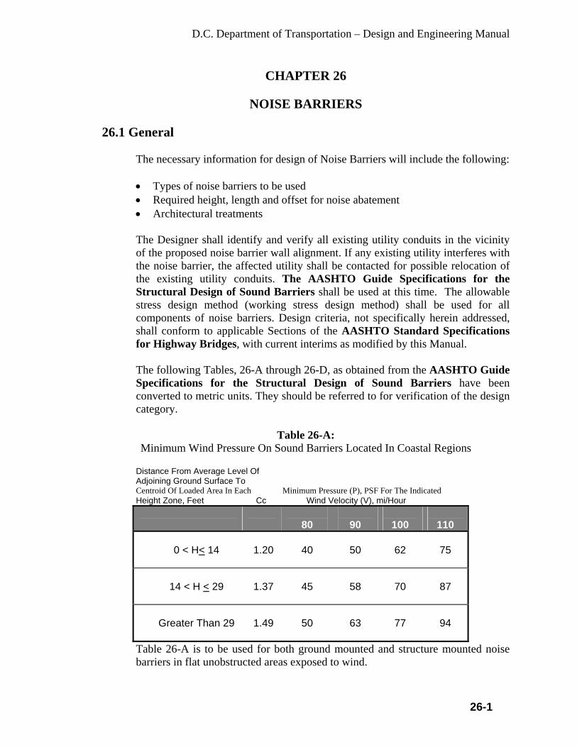
D.C. Department of Transportation – Design and Engineering Manual
26-1
CHAPTER 26
NOISE BARRIERS 26.1 General
The necessary information for design of Noise Barriers will include the following:
• Types of noise barriers to be used • Required height, length and offset for noise abatement • Architectural treatments
The Designer shall identify and verify all existing utility conduits in the vicinity of the proposed noise barrier wall alignment. If any existing utility interferes with the noise barrier, the affected utility shall be contacted for possible relocation of the existing utility conduits. The AASHTO Guide Specifications for the Structural Design of Sound Barriers shall be used at this time. The allowable stress design method (working stress design method) shall be used for all components of noise barriers. Design criteria, not specifically herein addressed, shall conform to applicable Sections of the AASHTO Standard Specifications for Highway Bridges, with current interims as modified by this Manual.
The following Tables, 26-A through 26-D, as obtained from the AASHTO Guide Specifications for the Structural Design of Sound Barriers have been converted to metric units. They should be referred to for verification of the design category.
Table 26-A:
Minimum Wind Pressure On Sound Barriers Located In Coastal Regions Distance From Average Level Of Adjoining Ground Surface To Centroid Of Loaded Area In Each Minimum Pressure (P), PSF For The Indicated
Height Zone, Feet Cc Wind Velocity (V), mi/Hour
80
90
100
110
0 < H< 14
1.20
40
50
62
75
14 < H < 29
1.37
45
58
70
87
Greater Than 29
1.49
50
63
77
94
Table 26-A is to be used for both ground mounted and structure mounted noise barriers in flat unobstructed areas exposed to wind.

D.C. Department of Transportation – Design and Engineering Manual
26-2
Table 26-B:
Minimum Wind Pressure On Sound Barriers Located On Bridge Structures, Retaining Walls, or Traffic Barriers
Distance From Average Level Of Adjoining Ground Surface To
Centroid Of Loaded Area In Each Minimum Pressure (P), PSF For The Indicated Height Zone, Feet. Cc Wind Velocity (V), mi/Hour
80
90
100
110
0 < H< 14
0.80
27
34
42
49
14 < H < 29
1.00
33
42
52
63
Greater Than 29
1.10
37
46
57
69
Table 26-B is to be used in open terrain with scattered obstructions. This includes flat, open country and grasslands. This exposure shall be used for all sound barriers located on bridge structures, retaining walls or traffic barriers that are not covered by Table 26-C.
Table 26-C: Minimum Wind Pressures On Sound Barriers Not Located On Structure
(Open Terrain) Distance From Average Level Of Adjoining Ground Surface To Centroid Of Loaded Area In Each Minimum Pressure (P), PSF For The Indicated Height Zone, Feet. Cc Wind Velocity (V), mi/Hour
80
90
100
110
0 < H< 14
0.59
20
25
31
37
14 < H < 29
0.75
25
32
39
47
Greater Than 29
0.85
28
36
44
53

D.C. Department of Transportation – Design and Engineering Manual
26-3
Table 26-C is to be used in urban and suburban areas with open terrain that does not meet the requirements of Table 26-D. Generally, this Table should be used for ground mounted noise barriers.
Table 26-D:
Minimum Wind Pressure On Sound Barriers Not Located On Structures (Urban and Suburban Areas)
Distance From Average Level Of Adjoining Ground Surface To Centroid Of Loaded Area In Each Minimum Pressure (P), PSF For The Indicated Height Zone, Feet. Cc Wind Velocity (V), mi/Hour
80
90
100
110
0 < H< 14
0.37
12
16
19
23
14 < H < 29
0.59
17
21
26
31
Greater Than 29
0.59
20
25
31
37
Table 26-D is to be used in urban and suburban areas with numerous closely spaced obstructions having the size of single-family dwellings or larger that prevail in the upwind direction from the noise wall for a distance of at least 1500 ft. Wind loads shall be applied perpendicular to the wall surface.
Adjacent ground surface can be defined as the ground elevation (or water elevation) immediately adjacent to the structure. In situations where noise barriers are mounted on bridges and retaining walls, the height to be utilized in determining the design wind pressure, P, shall be taken from the lowest average ground or water elevation adjacent to the noise barrier, to the centroid of the loaded area.
The following are load groups to which the noise barriers may be subjected. Each part of the structure shall be proportioned for the load combinations. • Dead Loads • Wind Loads • Seismic Loads • Impact Loads • Ice and Snow Loads
The AASHTO Standard Specifications for Highway Bridges shall be used to determine these loading conditions. The following information for Seismic Loads
D.C. Department of Transportation – Design and Engineering Manual
26-4
as well as the AASHTO Standard Specifications for Highway Bridges shall be referenced in considering the Seismic load combination.
26.2 Seismic Loads
When seismic loads have to be considered in load combination, the Designer shall refer to the AASHTO Standard Specifications for Highway Bridges and AASHTO Guide Specifications for Structural Design of Sound Barriers The seismic dead load shall consist of the weight of all the component materials making up the noise barrier, excluding the foundation. The point of application of the Seismic Dead Load, EQD, of the individual components shall be at their respective centers of gravity. When a noise barrier is supported by a bridge superstructure, the wind or seismic load to be transferred to the superstructure and substructure of the bridge shall be as specified within this chapter of this manual. Additional reinforcement may be required in traffic barriers and overhangs to resist the loads transferred by the noise barrier.
26.3 Functional Requirements • Guiderail or concrete barrier curb shall be used when the noise barrier is
located within the clear zone. • Stopping sight distance criteria shall apply in determining the location of a
noise barrier. Horizontal clearances that reduce the stopping sight distance shall be avoided. In those extreme cases where reduced stopping sight distances may be warranted, a design exception shall be provided to justify the need.
• Minimum Height - Noise barriers should have a minimum height consistent with that of a ROW fence (measured from the top of the barrier to the ground). Height requirements will be determined by noise studies performed by DDOT. When the tops of noise walls have to be stepped, the maximum height of step should not exceed 24 in.
When noise barriers higher than 16 ft. 6 in. are required by sound studies performed by consideration of surrounding features, they should be evaluated such that an exceptionally high wall does not create an unsightly impact on the environmental aesthetic features of the territory. In such situations, noise barriers in combination with earth mounds should be considered.
• Barriers can obstruct light as well as noise. Special consideration shall be
given to possible roadway icing and other induced environmental conditions caused by the placement of the wall.
• It is important to have drainage facilities along noise barriers to assure soil stability. Soil with phi (φ) of 25 degrees or less may develop flowing

D.C. Department of Transportation – Design and Engineering Manual
26-5
characteristics when saturated. Surface runoffs should be directed away from the noise barrier.
• Provisions may be necessary to allow fire fighters and chemical spill cleanup crews access to fire hydrants on the opposite side of the noise barrier. The designer should consult with local fire and emergency officials regarding their specific needs.
• For noise barriers that must bridge over conduits, provisions should be made to accommodate differential settlement in the noise walls substructures.
• The Preliminary Submission for Noise Barriers shall include a Report to address the possibility of icing, the storage of snow, utilities impact, drainage, and mounting on culverts.
26.4 Maintenance Considerations
• Noise barriers placed within the area between the shoulder and ROW line may
complicate the ongoing maintenance and landscaping operations, especially if landscaping is placed on both sides of the noise barrier. Special considerations should be given to maintaining the adjoining land behind the noise barrier and adjacent to the ROW line. A minimum 3 to 6 ft. wide shrub planting area between the proposed guiderail and the noise barrier might be considered.
• In some urban areas, noise barriers may be subjected to graffiti being placed on their surfaces. In these locations, the surface texture selected should be such that it is difficult to place the graffiti or such that the graffiti is easily removed. Noise barriers with rough textures and dark colors tend to discourage graffiti.
• Access to the backside of the noise barrier should be provided for inspection, litter control, soil erosion monitoring, grass mowing and maintenance. In subdivision areas, access may be via local streets, when available. If access is not available via local streets, access gates or openings are essential at intervals along the noise barrier. Offset barriers concealing the access opening must be overlapped a minimum of 4 times the offset distance in order to maintain the integrity of the noise attenuation of the main barrier. Location of the access openings should be coordinated with the appropriate agency or landowner. Gates in the noise barriers along federal aid routes require justification and FHWA approval.
26.5 Noise Barriers on Bridges
• Provisions for expansion shall be placed in the noise barrier at locations of
bridge deck expansion joints and at parapet deflection joints. • For noise barrier retrofit onto existing bridges, the Designer must verify that
the dead and live load from the wall do not overstress any component of the bridge including the existing parapets, slab overhang, girders and superstructure members.

D.C. Department of Transportation – Design and Engineering Manual
26-6
• The dead load of noise barriers can affect the overload capacity and deflection of some bridges. Check the change in load capacity of the bridge and verify whether the change is acceptable.
26.6 Types of Barriers
Timber or precast, prestressed, reinforced, concrete post and panel systems are preferred; however, if unusual site conditions prohibit the use of a post and panel system, another noise barrier type may be considered (such as aluminum for bridges). Determination of the type of barrier and architectural treatments to be used at a site prior to the design of the barrier will be made by the Department. The Designer shall obtain the necessary information regarding barrier type and architectural treatments from the Department and shall refine and incorporate this information into the design. Example considerations of noise barrier architectural treatments: • Flush posts and panels on the traffic face of the barrier to provide a smooth
appearance to motorists. • Coloring of the surfaces by tinting, staining or other methods. • End treatments • Sloping transitions (rather than stepped transitions) • Planting pockets • Meandering barriers (posts and panels not arranged in a straight line, parallel
to the centerline of the roadway). • Caps on top of the barriers to provide horizontal continuity.
In most cases, foundations for noise barriers shall be drilled shafts; however, in cases where shallow rock formations exist, spread footings will be unavoidable. Noise barriers on bridges shall be mounted on the parapets or attached directly behind the parapet. In a retrofit or rehabilitation situation, where it is determined that the existing or rehabilitated structure cannot accommodate the noise barrier loading, a separate supporting structure for the noise barrier may be considered. Sound leakage between the parapet and noise barrier shall be prevented by the use of flashing or other mechanical means. A number of proprietary sound barrier systems are available. Proprietary wall systems shall be approved prior to the design of the barrier.
26.6.1 Materials
Concrete for cast in place foundations and precast/prestressed posts and panels shall conform to the DDOT standards. Reinforcing steel shall conform to Subsection 915.01 of the DDOT standards, Grade 60, fs =24,000 psi.
D.C. Department of Transportation – Design and Engineering Manual
26-7
Welded wire fabric fabricated from deformed wire may be substituted for reinforcing bars. Refer to the DDOT standards for additional criteria concerning the use of welded wire fabric reinforcement. The provision of corrosion-protected reinforcement shall be as determined on a project-by-project basis. The location of the noise barrier panels, in relationship to the offset distance from the roadway, shall be evaluated to determine if provision of corrosion-protected reinforcement is warranted. If the location of the noise barrier panels may subject the panels to splashing from the roadway surface, provision of corrosion-protected reinforcement, should be recommended. In such cases, the bottom one-third height of the panels should be scheduled for placement of corrosion-protected reinforcement. Glued laminated timber material is preferred for construction of timber noise barriers. Glued laminated timber material shall be classified as 22F-E5 DF/DF (Douglas Fir) or 20F-E3 SP/SP (Southern Pine). Design values can be obtained from tables within AITC (American Institute of Timber Construction) Publication 117 entitled “Design Standard Specifications for Structural Glued Laminated Timber for Softwood Species” or the NDS (National Design Specification) Supplement by the National Forest Products Association. The tables within these documents provide allowable stresses for different species and grades of glued laminated timber. These tables are an expanded version of what is provided in AASHTO Division I, Section 13. Wet-use factors of 0.8 for bending and 0.875 for shear shall be applied to the minimum allowable stresses. When the depth of the beam in the plane of bending exceeds 12 in., a size factor shall be applied. Refer to the current article within AASHTO Division I, Section 13 for more information. Allowable stresses for aluminum shall conform to the current edition of the Aluminum Association Specifications for Aluminum Structures. The allowable stresses pertaining to bridge structures shall be utilized.
26.6.2 Foundation Design
The method of design for drilled shaft foundations shall be approved, or as directed, by the Geotechnical Engineering. The lateral load determined by the controlling Group Load Case shall be multiplied by a factor of 2 to obtain F, the applied lateral load. The intent of this procedure is to maintain a factor of safety of 2 against overturning. The allowable overstress should not be applied to the allowable soil strength.

D.C. Department of Transportation – Design and Engineering Manual
26-8
26.6.2.1 Special Requirements for Sloped Soil Conditions As stated in Appendix C, Part B of the AASHTO, Guide Specifications for the Structural Design of Sound Barriers, a level ground condition is defined as one in which the ground surface is approximately level or, when sloping down and away from the drilled shaft foundation, is not steeper than 1:10 (V: H) for phi (φ) = 35 degrees or 1:14 (V: H) for phi (φ) = 25 degrees. When these conditions prevail within a distance of two times the drilled shaft foundation embedment, the ground may be considered level, regardless of steeper slopes outside these limits. Drilled shafts located in slopes shall be protected by a berm. The berm shall be level and provide a minimum cover of 12 in. over the drilled shaft. It shall extend a minimum of 12 in. beyond the face of the drilled shaft. Sloped soil conditions shall be taken into account when computing the required embedment length for drilled shaft foundations. The method of design shall be approved, or as directed, by the DDOT Geotechnical Engineering Unit. NOTE: A foundation report shall be submitted for noise barriers.

D.C. Department of Transportation – Design and Engineering Manual
27-1
CHAPTER 27
SOILS INVESTIGATIONS 27.1 General
There are four categories of testing and reports required for all projects. They are: • Geotechnical Report - This report evaluates the general issues of
groundwater, soil stability, and swell potential. If groundwater is found within certain parameters, a subsurface water investigation is required. A geotechnical report is required for street and related improvements within the ROW, public easements, or slope easements.
• Final Pavement Design Report - This report is required for all projects with roadway improvements. The soil investigation associated with this report will occur after grading for roadways and utilities is complete. This report must be submitted and approved prior to any nonstructural concrete or paving installation.
• Extra Testing - If fill material is required for the project, this material shall also be tested before placement.
• Supervision by Engineer - All sampling and testing of soils shall be performed under the direct supervision of a Professional Engineer who stamps the report.
27.2 Soil Testing
27.2.1 Timing of Soil Borings
• Initial Borings - The information from the initial soil borings must be summarized in the geotechnical report. The entire site shall be sampled for initial testing. This is required because street locations may not yet be determined or may change.
• Structures - Soil borings for design of structures shall be taken prior to the design of the structure.
• Imported Fill for ROW Grading - All fill material shall be approved by the District prior to its use on the project. The material should meet minimum DDOT requirements and be equal to or better than existing conditions.
27.2.2 Frequency of Testing
• Basic Requirements - A minimum of two borings shall be provided for
each project. The number of borings should be dependent on project size and geotechnical Engineer’s recommendations. The District Project Manager may require more frequent testing.
D.C. Department of Transportation – Design and Engineering Manual
27-2
• Structures - Testing frequency for structures shall satisfy AASHTO Bridge Design requirements and materials testing requirements.
27.2.3 Location of Samples
• Basic Requirements - Samples shall be taken to a minimum depth of
10 ft. below the finished grades or as directed. • Groundwater or Bedrock - Borings shall extend deeper if needed to
determine if bedrock or high groundwater levels are design concerns. Minimum depth to bedrock shall be 3 ft. below the finished pavement surface.
• Number of Samples - Use standard care in determining the number of samples that are needed to characterize soils.
• Structures - Samples for structures shall be taken to a minimum depth of 10 ft. below the footing elevation. Additional depth may be required for piers or piles.
27.3 Soil Grouping
27.3.1 General
To simplify sub-grade support testing, soil samples may be combined to form soil groups consistent with the AASHTO classification, group index, and location for the area investigated. Groupings shall not mix samples with different AASHTO classifications. (For example, soils with swell potential greater than 2 percent may not be grouped).
27.3.2 Composite Samples
• Composite Samples - Composite samples may be obtained by mixing portions of each sample within a soil group to provide a uniform sample of the soil group.
• Specific Tests for Composite Samples - Composite samples shall be classified using the methods described in this manual. Composite samples remolded in the laboratory shall not be used for swell/consolidation testing.
27.4 Testing
27.4.1 Required Tests
The tests shown in Table 27-A are required for the sub-grade soils investigations or final pavement design testing.

D.C. Department of Transportation – Design and Engineering Manual
27-3
Table 27-A: Required Tests
TEST GEOTECHNICAL
REPORT FINAL PAVEMENT DESIGN REPORT
Visual X X Liquid Limit X X Plastic Limit X X Moisture X X percent Passing 200 X X Gradation (Granular Soils) X X AASHTO Classification X X Sub-grade Support R-Value X Swell Evaluation (Preliminary Considerations)
Indicator: Low/Moderate/High For Moderate or High, Run Swell Tests
Mitigation and Detailed Analysis
Percentage of Soluble Sulfates X X Standard Penetration Test X X Groundwater X X Bedrock Level X X Corrosion Potential Resistivity X 27.4.2 Classification Testing
Soils shall be classified visually and tested to determine the properties listed within this chapter. Sands and gravel samples shall be analyzed for gradation where needed to comply with classification requirements.
27.4.3 Subsurface Explorations
27.4.3.1 General
• Required borings shall be located on the plan of the structure by
station and offset from the base line. Five copies of the print shall be enclosed with the memorandum of transmittal. Request for borings shall be made as early as possible in the preliminary design stage.
• At least two borings shall be made for each bridge substructure unit. For long retaining walls and culverts, borings should be spaced not less than 50 ft. to, not greater than 100 ft. apart. One boring shall be provided at each footing location for both overhead and cantilever sign structures and high-level light tower foundations.
D.C. Department of Transportation – Design and Engineering Manual
27-4
• Where piles are anticipated, depths of borings shall be determined accordingly. The borings shall be deeper than any anticipated pile lengths.
• Location of borings and identification numbers shall be shown both on preliminary and final General Plan and Elevation sheets for each bridge and structure.
• Subsurface soil profiles and boring log information shall not be shown on the contract plans.
27.4.4 Boring Log Form
Use Standard Department Form
27.4.5 Sub-grade Support Testing
Individual sub-grade or composite samples shall be tested for sub-grade support value. The geotechnical report shall clearly state whether the sub-grade soil is capable of supporting the proposed construction and design traffic loads. Recommendation for sub-grade stabilization, if required, shall also be provided. The final pavement report shall contain specific mitigation.
27.4.6 ROW Fill Material Testing
• Test Prior to Use - All imported fill material shall be tested for swell
and R-value and approved by the District Project Manager prior to use in the ROW.
• R-value and Plasticity Index - All imported fill shall have an R-value and plasticity index equal to or greater than the sub-grade material within the ROW.
• Expansion Potential - All imported fill shall not have a liquid limit greater than 40 and plasticity index greater than 20.
27.5 Geotechnical Report
27.5.1 Basic Report Requirements
The report shall show results from all required testing in Table 27-A. The report shall also include a description of site characteristics, e.g., topography, drainage features, etc.
27.5.2 Detailed Report Requirements
In addition to the basic report requirements, each soils report shall include the following items:

D.C. Department of Transportation – Design and Engineering Manual
27-5
• Site location and description • Laboratory test reports with evaluations (classification tests)
- Visual classification - Liquid limit - AASHTO T89 or ASTM D4318 - Plastic limit - AASHTO T90 or ASTM D4318 - In-site moisture content - Percent passing No. 200 sieve - AASHTO T11 or ASTM C117-90 - Gradation of granular (sand & gravel) materials - AASHTO T27, ASTM D422 or ASTM C136 - AASHTO classification and group index - AASHTO M145 - Standard Penetrations Test - Swell Evaluation
• Boring logs • Soil and groundwater conditions - The expected seasonal elevation
variation shall be summarized. • Depth to bedrock - To indicate shallow bedrock • Include mitigation requirements if bedrock is within 3 ft. of sub-grade • Percentage of soluble sulfates. • Recommendations and discussions • Mitigation plans • Additional tests - These may be required for trench backfill evaluation,
fill evaluation, etc. • Elevation of groundwater encountered in each boring • Engineer seal and signature – Required
27.6 Surface Water Investigation
27.6.1 When a Subsurface Water Investigation is Required
• Criteria - If groundwater is encountered within 5 ft. of the original ground surface, a subsurface water investigation report shall be submitted for approval by the District Project Manager. This report is required to ensure mitigation of high groundwater effects upon public improvements within the ROW. This information may be a separate report or may be included in the geotechnical report.
• Requirement Waiver - This report requirement may be waived if the Applicant and Designer certify that the street sub-grade elevations will be a minimum of 3 ft. above the “maximum” predicted (seasonal highest) water table.
• Exception for Buried Utility Construction - This report is not required for temporary de-watering activity needed to facilitate construction of buried utilities.
D.C. Department of Transportation – Design and Engineering Manual
27-6
27.6.2 Report Requirements
The subsurface water investigation report shall include the following information: • Site location and description. Include locations of any irrigation
ditches • Elevation of water table, direction of flow, and flow rates • Potential sources of groundwater. Include proximity to irrigation ditch
systems • Other relevant subsurface information • Potential future groundwater conditions • Subsurface drainage recommendations • Cone of influence • Control measures and designs
- Subsurface Drains - If subsurface drains are recommended, the drains must have a gravity discharge without any possibility of back flow. Any subsurface drain system shall be owned and maintained by the Consultant or the Consultant’s assigned successor(s). These drains may discharge into the District’s storm drainage system, including inlets or detention ponds, upon approval of the District Project Manager and WASA. Anticipated impacts to the round water table on adjacent properties must be quantified. - Drain Lines - The drain lines may be installed in the sanitary sewer trench, at an elevation of one sewer diameter lower than the sanitary sewer line. - Drain Line Separation from Sewer - The drain line shall be marked to specifically distinguish the drain from the sanitary sewer line. - Pipe - The drain line shall be an approved material pipe, with appropriate clean-outs. - Drain Outlet - The outlet of the drain into an inlet structure or detention pond shall be designed to prevent any possibility of back flow and blockage of the drain line.
• Professional Engineer’s seal and signature. 27.7 Soil Problem Mitigation
Mitigation plans for soil problems revealed by the soils investigation shall address the following specific factors in the sections to follow.
27.7.1 Mitigation Plans and Approval
All special problems found in soils investigation (e.g., expansion, frost, soluble sulfates, shallow bedrock, heave, groundwater, soil instability, utility backfill, etc.) shall be addressed in the mitigation plans. Prior to

D.C. Department of Transportation – Design and Engineering Manual
27-7
implementation, all mitigation procedures must be approved by the District Project Manager.
27.7.2 Mitigation for Swell
If the average swell is 2 percent or greater, the pavement design report must provide mitigation measures. The mitigation measures shall reduce destructive swell potential to an acceptable level of less than 2 percent. The swell test report shall specify sample conditions, surcharge pressures, and other key testing factors.
27.7.3 Examples of Swell Mitigation
Examples of mitigation include the following: • Over-Excavation - Over-excavation and replacement with suitable
non-expansive or low-expansive material to a depth sufficient to mitigate expansion is a common mitigation method.
• Chemical Treatment - Chemical treatment may be used to mitigate expansive characteristics of the soil.
• Sub-drains - Sub-drains may be effective at reducing the groundwater, thereby reducing swelling. However, sub-drains will be subject to all of the subsurface drain requirements in these Standards.
• Moisture Treatments - Condition with moisture and compact to an appropriate level of compaction for the expansive condition, including stability requirements.
• Other Procedures - Other procedures may be proposed for review and approval by the District Project Manager.
27.7.4 Mitigation of Unstable Sub-grade (Examples)
• Over-Excavation - Over-excavation and replacement with suitable
non-expansive material to a depth sufficient to stabilize the sub-grade is a common mitigation method.
• Chemical Treatment - Chemical treatment to eliminate unstable characteristics of the soil is another common mitigation method.
• Other Procedures - Other procedures may be proposed for review and approval by the District Project Manager.
27.7.5 Specific Mitigation Requirements
• Extent of Mitigation - Moisture treatment alone may not be sufficient.
If expansive soil mitigation is made, the soil treatment shall extend to the back of curb, or to the back of walk for attached or monolithic walk. For detached walk, separate mitigation procedures may be required.

D.C. Department of Transportation – Design and Engineering Manual
27-8
• Approval of Chemical Treatment - Mitigation procedures that alter existing soil conditions (such as lime, fly ash, or cement treatment) shall follow an approved mix design process. Additional testing is required to verify that no swell is introduced in the chemical treatment.

D.C. Department of Transportation – Design and Engineering Manual
28-1
CHAPTER 28
BICYCLE FACILITIES AND SHARED USE PATHS 28.1 General
This chapter sets forth the minimum criteria to be used in the design of all bike lanes and other bicycles facilities, as well as shared use paths, within the District’s ROWs or easements.
28.2 References
Listed below are the references to be used in developing bicycle facilities and shared use path:
• Current AASHTO, Guide for the Development of Bicycle Facilities, as
published by the American Association of State Highway and Transportation Officials. This reference was the main reference in this chapter.
• American Traffic Safety Services Association (ATSSA) • Institute of Transportation Engineers (ITE) • Manual on Uniform Traffic Control Devices (MUTCD) Part 9 • DCMR 18: DC Traffic Laws and other applicable District regulations and
statutes • DDOT Bicycle Facility Design Guidelines • DDOT Web Site HTTP://www.DDOT.DC.GOV • Bicycle Master Plan While all of the above references should be utilized, the final design considerations shall be made in consultation with the DDOT Bicycle Program Manager.
28.3 General Bicycle Facilities
The bicycle has become an important and efficient mode of transportation and requires consideration in the roadway design process. Most bicycle travel takes place on the roadway system, as it presently exists. Therefore, enhancing safety and capacity for bicycle traffic can be achieved through low-cost measures such as those indicated below: • Painted bicycle lanes (5ft.) • Paved shoulders (at least 4 ft.) • A wide outside traffic lane if no shoulders exist (12 ft. to 14 ft.) • Bicycle-safe drainage grates • At-grade manhole covers • A smooth, clean riding surface
D.C. Department of Transportation – Design and Engineering Manual
28-2
• Bicycle sensitive loop and microwave traffic signal detectors Bicycles are permitted on all roadways in the District of Columbia except the full access controlled facilities, such as interstates and divided expressways.
28.4 On-Street Bicycle Facilities Design Requirements
28.4.1 Bike Routes
Certain streets are designated in the District Bicycle Plan as on-street bicycle routes and are marked with bicycle route signs. Refer to the Bicycle Facility Design Guide for the sign design and placement, and the Bicycle Master Plan to determine for existing or proposed bicycle routes.
28.4.2 Bicycle Lanes
Bicycle lanes shall be placed to the right of the travel lane. Bicycle lanes on one-way streets shall be on the right side of the street, unless otherwise specified by DDOT. The minimum width of a bike lane is 5 ft. (including gutter pan if adjacent to curb) and substandard design should be approved by DDOT. Refer to the Roadway chapter within this manual, for the standard cross section requirements.
28.4.3 Signage and Striping
All designated bike lanes shall be striped, including bicycle symbol pavement markings, as required by MUTCD and as required in the Pavement Marking and Signage chapter within this manual. Some of the basic requirements are as follows:
- DDOT approved Bike Lane Symbol is a “6’ arrow + 6’ space + 8’
biker with helmet facing the center of roadway”. - DDOT has approved Bike Route Guide Sign and Destination Sign
(D11-1 and D1-1a). Their uses and design are shown in the DDOT Bicycle Facility Design Guide.
- All dimensions and line pattern of bike signage and striping shall be consistent with DDOT marking & signing regulation (Chapter 43 of this Manual).
28.4.4 Bicycle Lanes at Intersections
At the intersections where a separate right turn lane exists and is striped, the bicycle lane shall transition and be placed between the through-lane and the right turn lane (see DC Standard Drawing 616-23).

D.C. Department of Transportation – Design and Engineering Manual
28-3
28.4.5 Bicycle Facility Obstructions
Manholes, utility poles, air grates or other appurtenances or obstructions, should not be located in bike lanes or paths, if possible. Bicycle-safe storm water grates shall be used, as described in DDOT Bicycle Facility Design Guide.
28.4.6 Actuation Loop
Quadruple loops are required for bike detection. Where other actuated detection systems are used, such as microwaves, they shall detect bicyclists. A bicycle loop detector symbol should be used and centered directly over the quadruple bicycle detector. (See DDOT Bicycle Facility Design Guide for details.)
28.5 Off-Street Shared Use Path Design Requirements
28.5.1 Shared Use Path Design and Location
• A shared use path, is defined as a path used by cyclists, pedestrians, and other non-motorized users physically separated from the roadway.
• A shared use path shall have 10 ft. minimum width. • Where possible, shared use paths should be located at least 5 feet from
the roadway
28.5.2 Site Distance, Clearance, Trees, and Vegetation, and Other Obstacles
The Designer shall ensure sufficient stopping and intersection sight distance at all path intersections and curves, particularly where steep grades are proposed at path/roadway intersections. Obstructions to the visibility of motorists or path users should be removed or the path aligned around the obstruction to maximize visibility. All curves with restricted sight distances should be painted with a centerline to separate traffic. Sight distance requirements shall be in conformance with latest addition of the AASHTO Guide for the Development of Bicycle Facilities and the Roadway chapter within this manual.
• Preserving Trees - Where possible, bike paths shall be routed to
minimize the loss of trees and disruption of natural environmental conditions.
• Distance from a path Edge - A minimum of 2 ft. is required between the path edge and any vertical obstructions such as trees, utility poles,

D.C. Department of Transportation – Design and Engineering Manual
28-4
signs, fences, or other obstacles. Greater separation may be required by the District where grades exceed 4 percent.
• Overhead Clearance - All bike paths shall have a minimum of 10 ft. vertical clearance above the path.
28.5.3 Grade
Refer to the AASHTO publication "Guide for Development of Bicycle Facilities" the latest version.
28.5.4 Design Speed Refer to the AASHTO publication "Guide for Development of Bicycle Facilities" the latest version.
28.5.5 Cross Slope
The cross slope shall be 2 percent maximum. 28.5.6 Drainage
Proper drainage is important to ensuring the longevity and safety of a path. An open system, using swales, ditches and even sheet flow, combined with on-site detention ponds is preferred. • Requirements and Standards - All bike path designs shall satisfy the
storm drainage requirements of the District Departments and WASA. • Ditch Placement - Where a path is cut into a hillside, a ditch shall be
placed along the path to prevent excessive sheet flow across it.
28.5.7 Safety Considerations
• Consideration of Pedestrians - The safety of pedestrians shall be a prime consideration in the path design.
• Clearance Between a Path and the Street – A path should be constructed at least 5 feet from a street curb. Where vehicular traffic speeds and volumes are high or where 5 feet is not achievable, a safety barrier should be considered.
• Signs for Hazards and Regulatory Messages should be used and follow the standard signing and pavement markings as proscribed in the MUTCD.
• Curb ramps - Standard curb ramps will be provided at all path curb crossings to allow continuity of path use. Curb ramps should be equal to the width of the path, with the path surface sloping to the pavement at 1:12 maximum slope.

D.C. Department of Transportation – Design and Engineering Manual
28-5
• Painted Centerline on Curves - All curves with restricted sight distances should be painted with a centerline to separate traffic.
• Vehicles should be required to stop at intersections with low vehicular traffic and high path use.
28.5.8 Shared Use Paths on Bridges
• Crossings of Water Courses - All paths require either a bridge or a fair
weather crossing wherever possible. • Railings, Fences, or Barriers shall be placed on both sides of a path
structure and shall be a minimum of 3.5 ft. (42in) high. • Barriers should not impede storm water runoff. Smooth rub rails
should be attached to the barriers at a handlebar height of 3.5 ft.
28.5.9 Shared Use Paths on Underpasses
The minimum vertical clearance is 10 ft. from surface path to underside of bridge; 12 ft. if equestrian accommodation is required. Underpass Lighting - All path underpasses shall have lighting in accordance with the Street Lighting chapter within this manual.
28.6 Bicycle Parking
28.6.1 Bicycle Rack Design • The preferred bicycle rack style is the “Inverted U”. • The rack must:
o Be able to support the bicycle frame in at least two places, allowing the frame and wheel to be locked using a U-lock or cable lock.
o Prevent the wheel of the bicycle from tipping over. o Not damage the bicycle. o Be durable and securely anchored. o Allow front-in or back-in parking.
• Other rack styles, placed in public space, must be approved by the Bicycle Program Manager. See the DDOT Bicycle Facility Design Guide for additional information on bicycle rack design.
28.6.2 Off-Street Bicycle Parking
Bicycle parking is required in most new buildings.
D.C. Department of Transportation – Design and Engineering Manual
28-6
Bicycle parking shall follow the guidelines established in DCMR, Title 11, Chapter 21. Each Inverted U rack provided will count as two bicycle parking spaces. See the DDOT Bicycle Facility Design Guide for additional information on bicycle parking spaces.
28.6.3 Placement of Bike Racks in Public Space Bicycle parking should be considered during roadway reconstruction projects. Refer to DDOT Bicycle Facility Design Guide for information on bicycle rack placement.

D.C. Department of Transportation – Design and Engineering Manual
29-1
CHAPTER 29
PEDESTRIAN AND AMERICAN DISABILITIES ACT (ADA) FACILITIES
29.1 General
This chapter sets forth the minimum criteria to be used in the design of all sidewalks, curb ramps, and other pedestrian facilities within the right-of-way (ROW), or other public easements.
29.2 References
“A Policy on Geometric Design of Highways and Streets” (latest edition, ISBN: 1-56051-263-6), as published by AASHTO, the American Association of State Highway and Transportation Officials.
“Guide for the Planning, Design, and Operation of Pedestrian Facilities” as published by AASHTO, the American Association of State Highway and Transportation Officials.
“Americans with Disabilities Act Accessibility Guidelines (ADAAG)” (1991), sections 1-10 adopted as Americans with Disabilities Act (ADA) standards by the US Department of Justice (USDOJ) for buildings and facilities under titles II and III of the ADA, and the US Department of Transportation (USDOT) for transportation facilities under title II of the ADA, and by the Federal Transit Administration (FTA) for its Federal-aid projects; developed primarily for buildings and facilities on sites and poorly adapted to right-of-way or trail use.
“Accessible Public Rights-of-Way”. Proposed accessibility guidelines for sidewalks, street crossings, and intersections, revised November 23, 2005. Recommended as good practice guidance by the Federal Highway Administration (FHWA). <http://www.access-board.gov/prowac/index.htm>
29.3 ADA Requirements
All pedestrian facilities shall be designed in accordance with the most recent ADA regulations and the requirements of these Standards, whichever provides the safest and easy access for pedestrians.
29.4 Sidewalks
29.4.1 General Layout and Design Criteria All public sidewalks shall comply with the requirements of the most recent ADA standards, which include requirements for sidewalk widths, grades, locations, markings, surface treatments, and curb ramps.

D.C. Department of Transportation – Design and Engineering Manual
29-2
The Public Space Permits and Record Branch maintain a Designated Street Distribution (card file) for each street within the District of Columbia. This Designation Street Distribution contains information for each street and these designated widths are the minimum requirements each street must meet. The overall designated public space street width is called the street’s right-of-way. Located within this right-of-way is the designated width for the roadway, sidewalks, and/or parking located on both sides of the street. Whenever any changes or improvements are made within the public space area of each street, the designated widths must be maintained. These designated street widths may vary from block to block. These sidewalk width designations are important when installing curb lay-bys for vehicles and circular driveways, as there is a required minimum, which must be met for pedestrian’s safety before DDOT allows vehicles to encroach within the designated sidewalk widths. When there is no designated sidewalk width, then the minimum sidewalk width adjacent to the installation of a lay-by will be 10 ft. This will allow for the typical vehicle door’s opening (3’-8”) and a minimum 6 ft. clear path for the pedestrians to walk by. This minimum 10 ft. width allows a disabled person room to maneuver when entering and exiting a vehicle in a safe manner, without impeding the other pedestrians walking along the sidewalk. Whenever any changes are made within the right-of-way of a street, a written justification is required stating what part of the street’s right-of-way is being changed and the reason for this change. DDOT requires all affecting agencies within the District of Columbia to state their comments about the subject changes. Any proposed change of the street’s right-of-way is subject to approval by the Director, Department of Transportation (DDOT).
29.4.1.1 Sidewalk Widths
• Minimum sidewalk width - Minimum sidewalk width shall be 6 ft. • Minimum sidewalk widths at Bus Stops – Minimum sidewalk
width at bus stops shall be 8 ft. (See 29.13.3 for more details) • Minimum sidewalk widths listed above are defined by a clear
pedestrian pathway free of any above grade obstruction. • Additional Sidewalk Width - The District Project Manager may
require additional width for activity areas and routes leading to these areas. The final sidewalk width shall be determined through additional study of higher pedestrian traffic areas.
D.C. Department of Transportation – Design and Engineering Manual
29-3
Most persons will avoid the area less than 30 in. away from the edge of the roadway and 18 – 30 in. from a building façade. Additionally, the presence of street furniture and other features will also reduce the effective width of a pathway for pedestrians. The minimum continuous and unobstructed clear width of a pedestrian access route shall be 4 ft., exclusive of the width of the curb. However, if the existing sidewalk width is less than 60 inches, “passing pads” measuring 60” x 60” must be constructed every 200 ft. to allow disabled persons to pass one another. Crossing driveways and alleys are considered “passing pads”.
29.4.1.2 Sidewalk Both Sides of Street
There should be a sidewalk on both sides of every street or roadway. All new street designs shall include sidewalks on both sides of the street. A sidewalk on one side of the street may be appropriate where only that side of the street is developed. Sidewalks shall be constructed on all streets and roadways as part of roadway reconstruction projects. Every effort shall be made to minimize the negative impacts of sidewalk construction on street trees and adjacent property owners. Where severe negative impacts are encountered, the Chief Engineer may approve a sidewalk along one side of a street or roadway.
29.4.1.3 Slope
• Cross Slope – Maintain 2 percent (maximum) or ¼ in. per ft.
sidewalk cross slope towards the roadway. Cross slopes exceeding 2% do not meet ADA requirements and require approval of the Director.
• Longitudinal Slope - Longitudinal slope shall not exceed the grade of the adjacent roadway. Where longitudinal grades exceed 5%, it is desirable to provide level landings at regular intervals.
29.4.1.4 Horizontal/Vertical Curves
Horizontal/vertical curves on all sidewalks shall follow the roadway design criteria
29.4.1.5 Vertical Clearance
Sidewalk vertical clearance shall be 8 ft. The minimum vertical clearance distance to the bottom of a street sign or other feature in the sidewalk shall be no less than 8 ft.

D.C. Department of Transportation – Design and Engineering Manual
29-4
29.4.2 Sidewalk Cafes Located Within Public Space
• Between the curb of the street and the edge line of the sidewalk café boundary, there must be a minimum 10 ft. of clear sidewalk provided for pedestrians passing along the sidewalk.
• Accessibility for wheelchairs users implies, adequate dimensioning of café aisles (4 ft. between tables), and spaces for routes leading to ramps and doorways, if stairs are blocking the way.
• If the cafes are not wheelchair accessible when located within the public space, permits will automatically be denied.
• Chain and/or Rope Barriers Surrounding Edge Line of Sidewalk Café: • Chain and/or rope barriers can be hazardous to pedestrians,
especially visually impaired persons within the sidewalk areas. These barriers are difficult to see, especially when lower than 32 in. in height and at night. Visually impaired persons, who use a cane, are more easily able to detect chains and ropes when located at a height of 27 in. or less. Discretion should be used when designing chain or rope barriers, and a mean should be devised to increase their detection.
• The bases of the poles and/or posts for the chain/rope barriers must not protrude within the clear sidewalk area. They must be located within the boundaries of the sidewalk café.
29.5 Curb Ramps
The curb ramps will be designed with stamped concrete in historic and business districts when directed by the Project Manager. Curb ramps shall be installed at all intersections and may be installed at mid-block locations if the entire street block is longer then 600 ft (an ADA requirement) for all new construction or reconstruction of curb and sidewalk, as follows: • If a public walkway or bikeway intersects the street, a ramp shall be
provided to connect the walkway to the street. A landing is required at the top of a ramp that shall connect to the travel route. At the top of the ramp there shall be a 4 ft. minimum clearance. The transition from the ramp to the gutter shall be flush. All ramps shall be concrete or stamped concrete, which resembles brick. Detectable warning surfaces shall extend 24 inches minimum in the direction of travel and the full width of the curb ramp (exclusive of flares), the landing, or the blended transition.
• All pedestrian facilities on and along sidewalks shall be accessible including signal actuators, telephones, drinking facilities, kiosks, sidewalk cafes, etc.
• Plans shall indicate where the existing sidewalks, grass areas, and tree spaces are required to be replaced, to be repaired, or to be maintained.

D.C. Department of Transportation – Design and Engineering Manual
29-5
The following are the DDOT requirements for curb ramps that include the ADA Regulations for curb ramps: • The curb ramp has top priority at a corner intersection above all other
features. When new construction is taking place, the streetlights, traffic signals, control cabinets, and catch basins are relocated out-of-the-way of these ramp locations.
• It is not recommended to provide curb ramps at the center of corners at roadway intersections. All the ramps to be located at the corner center must be pre-approved by the DDOT Traffic Engineer.
• Install two curb ramps in pair for each crosswalk on each corner, one for each direction of travel.
• The entire curb ramp, (4 ft. width min.) must be located within the crosswalk. The side flares do NOT have to be located within the crosswalk. The corner edge of the ramp must align with the back edge line of crosswalk.
• All ramps shall be in 90 degree toward the curb. • The ramp width is 4 ft. min. The length of the ramp depends on curb
height, considering a maximum slope of 1/12. The side flare width is 2 ft. while the flare slope is 1/10. Provide landing at the top of the ramp 4 ft. minimum, to allow the wheelchair to turn.
• Move and adjust the curb ramp to a location, which allows for the accommodation of the ramps properly, using the required ramp geometry, dimensions, and slopes as per the Standards.
• Sidewalks shall be flush with driveways and alleys. Curb ramps shall not be located on both sides of the alley or driveway entrances. Exceptions shall be considered on a case by case basis where driveway entrances are signalized and function as streets.
29.6 Underwalk Drains (Chases)
Under-walk drains shall not interfere with the pedestrian’s use of the sidewalk. The chase plate shall be flush with the sidewalk surface and be securely fastened as specified. Under-walk drains shall not be located within a curb ramp, curb cut, or driveway.
29.7 Pedestrian Crossings
Marked Crosswalks will be required at all signalized intersections, school areas, and high pedestrian areas. Block lengths on Local streets and streets in commercial areas longer than 600 ft. may require additional crossings, which should be spaced approximately midway between existing crossings. If mid-block ramps are used, pavement markings and signing in accordance with the Traffic Control chapter of this manual shall be provided.

D.C. Department of Transportation – Design and Engineering Manual
29-6
Crosswalks should have parallel edge lines with proper width depending on street classifications (i.e. 10 ft for local streets, 15 feet for collectors and 20 feet for major arterials). The crosswalk lines shall be perpendicular to the centerline of the roadway except in intersections that are skewed. High-visibility crosswalks are strongly preferred over decorative crosswalk markings because they are easier for motorists to see. Decorative crosswalks, such as those designed with brick or stamped concrete, may be provided in historic and business districts when directed by the Project Manager. All decorative crosswalks shall have parallel 6 inch wide white edge lines for visibility.
29.8 Hearing Impairments Individuals with hearing impairments may encounter barriers that center around spoken information and audible warning communication, as vision is relied upon for information needs. Danger may occur when alarms such as automobile horns or fire alarms are not accompanied by flashing lights or other visual cues. Clear signage is important to persons with hearing impairments when verbal communication is not possible, or unavailable. Special ADA warning beacons and/or Traffic Signals may be applied or are under testing by DDOT. Their installation shall be approved by DDOT Traffic Engineer in case-by-case manner.
29.9 Tactile Warning Strips (Detectable Warnings)
Differences in paving materials can provide tactile cues to aid negotiation and identify hazards. Truncated domes are a detectable warning device used on walkway surfaces and curb ramps to warn visually impaired persons of abrupt grade changes and hazardous vehicular areas. At sidewalk grade changes leading to retail businesses detectable warning strips are needed at both the top and the bottom of stairways, and on all ramp locations.
29.10 Pedestrian Refuge Areas Raised medians and pedestrian refuge islands are encouraged in places where they may improve the safety of pedestrians crossing the street, such as on multi-lane streets with high traffic volumes and/or high speeds. When designed to provide pedestrian refuge, raised medians should be a minimum of 6’ wide (8’ is recommended). At intersections, medians provide the best refuge for pedestrians when the median nose extends beyond the crosswalk. An accessible route through the median is required for pedestrians, either through the use of curb ramps or a cut- through. To improve the safety of driveway crossings, provide a raised pedestrian refuge of at least 6 ft. long in the direction of pedestrian travel when driveway width is 25

D.C. Department of Transportation – Design and Engineering Manual
29-7
ft. or wider. The vehicle turning radii must be taken into account with the specific design of islands.
29.11 Multi-Use Paths Where a single, multi-use path is used to serve pedestrians and bicyclists, the minimum path width shall be 10 ft.
29.12 Pedestrian Minimum Clear Path The minimum clear path around utility structures, street furniture and other encroachments shall be 3 feet.
29.13 Bus Shelters
29.13.1 Location
The Washington Metropolitan Area Transit Authority (WMATA) shall determine the location of the bus shelter. The Project Manager will contact the Department’s Mass Transit Division for coordination.
A minimum 8 ft. wide sidewalk parallel to the curb of the street and adjacent to the front doors of the bus is required. This area must be free of any obstacles and it must have a minimum 6 ft. sidewalk depth to allow the bus handicap kneeler to operate for receiving wheelchair users. This 8 ft. minimum clear zone area is required at all bus stops. Shelters shall not be put within this area and should not block the existing sidewalk width for pedestrians using the sidewalk but not boarding a bus. A near door exit pad (A third pad for articular buses) of 6 feet x 6 feet is recommended if the buses use multiple door operation.
29.13.2 Visibility
Bus shelters shall have maximum transparency, and be highly visible from the surrounding area to ensure the users’ safety. The shelter may not be located within sight distance triangles.
29.13.3 Minimum Size and Capacity
• Opening Size - Openings shall be at least 36 in. wide and shall meet the requirements of ADA.
• Capacity and Size - Capacity shall be based on maximum passenger accumulation at the stop. The shelter size shall be based on approximately 5 sq. ft. per person.
• Placement - Shelters shall not obstruct pedestrian flow or motorist’s sight distance.

D.C. Department of Transportation – Design and Engineering Manual
29-8
• The minimum pedestrian path width of 6 ft. shall be maintained at bus shelters.
• All bus stops shall have a minimum sidewalk width of 8 ft. for the front doors of the bus and a minimum of 6 ft. provided for the rear doors. There should be a standard 24 ft. distance between the front and back doors of the bus.
29.13.4 Passenger Loading Pad Requirements
• Under Shelters - The design shall include a 6 in. thick concrete pad
under all bus shelters. The pad shall extend at least 6 in. past each edge of the shelter.
• Passenger Loading Area - Any shelters next to detached sidewalks shall include a minimum 15 ft. wide concrete area between the sidewalk and the curb for passenger loading and unloading.
29.13.5 Relocation of Shelters
The District Project Manager may require a shelter to be relocated or removed in the future to accommodate other needs within the street right-of-way. The Project Manager will contact the Department’s Mass Transit Division for relocation request.
29.13.6 Bicycle Racks and Trash Containers
All shelters are required to provide one trash container and one bicycle rack.
29.13.7 Shelters on Highways
Approval for installations of all bus shelters proposed in the District Rights-of-Way shall be obtained from DDOT, Office of Mass Transit, prior to any construction of the shelters.
29.14 Bus Stops
The Washington Metropolitan Area Transit Authority (WMATA) shall determine the location of the bus stops. The Project Manager will contact the Department’s Mass Transit Division for coordination. 29.14.1 Bus Stop Zone Dimensional Requirements
Bus stop may be near side, far side, or mid block. WMATA follows the dimensional requirements contained in TCRP Report 19, Guidelines for the Location and Design of Bus Stops. Far side stops are generally

D.C. Department of Transportation – Design and Engineering Manual
29-9
preferred for pedestrian safety, particularly at uncontrolled intersections. The decision of where to locate a bus stop involves many factors, including the context of the intersection, proximity to major pedestrian generators, visibility, pedestrian safety and access, and the bus route. Near side bus stops must have a minimum of 100 ft. of clear distance between the last parking space and the end of the curb radius or 5 ft. behind the marked crosswalk, whichever is greater. Far side stops must have a minimum of 90 ft. of clear distance between the first parking space and the end of the curb radius or 5 ft. ahead of the marked crosswalk, whichever is greater. For mid block stops, there must be a clear distance of 150 ft. from parking space to parking space. The District requires a minimum of 110 ft. between bus stop signs. Bus stop zones should be increased by 50 ft. for each additional standard 40-ft. bus or 70 ft. for each additional articulated bus expected to be at the stop simultaneously.
29.14.2 Bus Pad Requirements
For Bus Pad locations, the designer should coordinate with WMATA. The minimum pad size shall be 10 ft. (wide) by 40 ft.(long). A mid block pad will be 10 ft. (wide) by 80 ft. (long). The pad shall be a minimum of 12 in. thick concrete in composite roadways with 10 inches of plain Portland Cement Concrete (PCC) base. The thickness of the bus pad will be 10 inches of reinforced concrete.
29.15 Universal Parking Space Design for Accessible Spaces within a
Parking Lot
A disabled person requires more space to enter and exit a parking space.
• The “Universal Parking Space Design” recommends that all accessible spaces be 11 ft. width with a 5 ft. (*) adjacent striped aisle width.
• The access striped aisle width varies according to the type of vans they use. The private side and rear platform vans plus commercial vans, all require an 8 ft. (*) minimum adjacent aisle width.
• However, most private automobiles and side rotary vans require a minimum 5 ft. adjacent aisle width.
• All accessible parking spaces should have a painted handicap wheelchair symbol provided and signs mounted at the front of their spaces with the wheelchair symbol. These signs have a blue background with white symbols.
• There must be a minimum 5 ft. aisle between an accessible space and a regular 9 ft. wide parking space.
• All 90-degree angle parking spaces are 18 ft. long and require a standard 24 ft. wide adjacent aisle for maneuvering into and out of parking spaces.
• All 60-degree angle parking spaces are 17 ft. long and require a standard 17 ft. wide adjacent aisle for one-way travel direction.

D.C. Department of Transportation – Design and Engineering Manual
29-10
• Accessible Parking spaces must be designed so that a handicap person does not travel within the maneuvering lane for vehicle traffic to reach the safe travel path to a building or other site location.
NOTE: All public street parallel parking spaces in Washington, DC are available to any motorist. There are no special handicap parking spaces provided. However, DDOT recommends when parking in angle back-in public street parking spaces, that the end spaces adjacent to the corner crosswalks be made available to the handicap access vehicles. Handicap ramps are not permitted at the curb of the street, unless they are located on both sides of the street and they must be located within a striped crosswalk. When a visually impaired or blind person feels a handicap ramp adjacent to the curb of the street, it indicates to him that he can cross the street within a crosswalk and vehicles will yield to them.
29.16 Accessible Spaces = The Minimum Number of Accessible Spaces
Total Parking in Lot = Required Minimum Number of Accessible Spaces 1 to 25 spaces = 1 26 to 50 spaces = 2 51 to 75 spaces = 3 76 to 100 spaces = 4 101 to 150 spaces = 5 151 to 200 spaces = 6 201 to 300 spaces = 7 301 to 400 spaces = 8 501 to 1000 spaces = 2% of total 1000 and over = 20 plus 1 for each 100 over 1000
Source: U.S. Access Board, Americans with Disabilities Act, Accessibility Guidelines, U.S. Architectural and Transportation Barriers Compliance Board, Washington, D.C.
D.C. Department of Transportation – Design and Engineering Manual
30-1
CHAPTER 30
ROADWAY 30.1 General
All design criteria in this manual are minimums, and these design criteria do not eliminate the responsibility of the designer to exceed these minimum standards where good engineering practice dictates. All materials and workmanship shall conform to these Standards and to the District of Columbia, current Standard Specifications for Highway and Structures. All private roadways connecting to DDOT maintained public roads shall be constructed to DDOT’s standards, if the roadways are to be dedicated to the District. This requires coordination with and approval from the Public Space Permit Office. Private developers are encouraged to engage DDOT input on its designs at the earliest possible stage and especially when considering the dedication of private roadways to the District. DDOT offers a Preliminary Design Review Meeting (PDRM) process to assist with this by bringing the necessary reviewers from a variety of disciplines to provide comments and guidance on plans in the design phase. For more information on the PDRM process please visit DDOT on the web at www.ddot.dc.gov or contact the PDRM scheduler at [email protected].
30.2 AASHTO Policy and ITE Recommended Practice
AASHTO, A Policy on Geometric Design of Highways and Streets (Green Book, current version: 2004), the Highway Capacity Manual and the ITE, Context Sensitive Solutions in Designing Major Urban Thoroughfares for Walkable Communities are used as references for this chapter.
30.3 ADA Requirements
All designs for roadways shall conform to ADA requirements.
30.4 Functional Classification
30.4.1 General
Highway classification refers to a process by which roadways are classified into a set of sub-systems based on the way each roadway is used. Central to this process is an understanding that travel rarely involves movement along a single roadway. Rather, each trip or sub-trip initiates at a land use, proceeds through a sequence of streets, roads and highways, and terminates at a second land use.

D.C. Department of Transportation – Design and Engineering Manual
30-2
The highway classification process is required by federal law. Each state must assign roadways into different classes in accordance with standards and procedures established by the Federal Highway Administration.
30.4.2 Functional Highway Systems in Urbanized Areas
DDOT has adopted a Functional Street Classification Plan based on traffic volumes, land use, and expected growth. The five functional highway systems identified are: • Freeways • Principal arterials (streets) • Minor arterials (streets) • Collector streets • Local streets Each classification has design criteria that maintains and protects the primary purpose of the roadway.
30.5 Design Controls
30.5.1 General
Controls are physical and operational characteristics that guide the selection of criteria in the design of roadways. Some design controls are fixed—such as terrain, climate and certain driver-performance characteristics—but most controls can be influenced in some way through design and are determined by the designer. AASHTO’s A Policy on Geometric Design of Highways and Streets (Green Book, current version: 2004) and its supplemental publication A Guide for Achieving Flexibility in Highway Design, identify location as a design control and establish different design criteria for rural and urban settings. AASHTO recognizes the influence context has on driver characteristics and performance. AASHTO defines the environment as “the totality of humankind’s surroundings: social, physical, natural and synthetic” and states that full consideration to environmental factors should be used in the selection of design controls.
30.5.2 Traffic Volume
For planning and design purposes, the demand of traffic is generally expressed in terms of the design-hourly volume (DHV), predicated on the design year. The design year for new construction and reconstruction is to be 20 years beyond the anticipated date of construction and 10 years
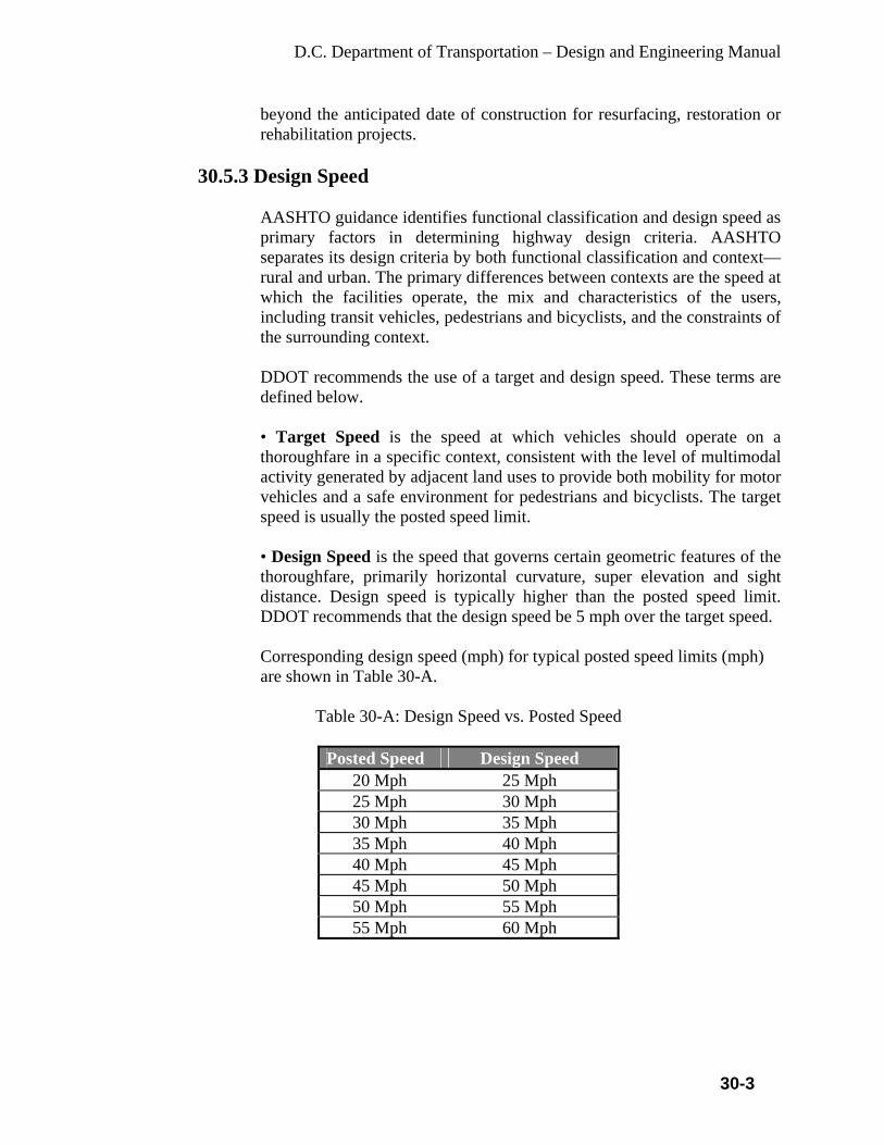
D.C. Department of Transportation – Design and Engineering Manual
30-3
beyond the anticipated date of construction for resurfacing, restoration or rehabilitation projects.
30.5.3 Design Speed
AASHTO guidance identifies functional classification and design speed as primary factors in determining highway design criteria. AASHTO separates its design criteria by both functional classification and context—rural and urban. The primary differences between contexts are the speed at which the facilities operate, the mix and characteristics of the users, including transit vehicles, pedestrians and bicyclists, and the constraints of the surrounding context. DDOT recommends the use of a target and design speed. These terms are defined below. • Target Speed is the speed at which vehicles should operate on a thoroughfare in a specific context, consistent with the level of multimodal activity generated by adjacent land uses to provide both mobility for motor vehicles and a safe environment for pedestrians and bicyclists. The target speed is usually the posted speed limit. • Design Speed is the speed that governs certain geometric features of the thoroughfare, primarily horizontal curvature, super elevation and sight distance. Design speed is typically higher than the posted speed limit. DDOT recommends that the design speed be 5 mph over the target speed. Corresponding design speed (mph) for typical posted speed limits (mph) are shown in Table 30-A.
Table 30-A: Design Speed vs. Posted Speed
Posted Speed Design Speed 20 Mph 25 Mph 25 Mph 30 Mph 30 Mph 35 Mph 35 Mph 40 Mph 40 Mph 45 Mph 45 Mph 50 Mph 50 Mph 55 Mph 55 Mph 60 Mph
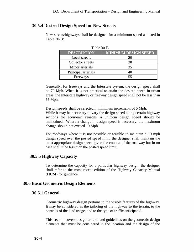
D.C. Department of Transportation – Design and Engineering Manual
30-4
30.5.4 Desired Design Speed for New Streets
New streets/highways shall be designed for a minimum speed as listed in Table 30-B:
Table 30-B
DESCRIPTION MINIMUM DESIGN SPEED Local streets 20
Collector streets 30 Minor arterials 35
Principal arterials 40 Freeways 55
Generally, for freeways and the Interstate system, the design speed shall be 70 Mph. When it is not practical to attain the desired speed in urban areas, the Interstate highway or freeway design speed shall not be less than 55 Mph. Design speeds shall be selected in minimum increments of 5 Mph. While it may be necessary to vary the design speed along certain highway sections for economic reasons, a uniform design speed should be maintained. Where a change in design speed is necessary, the maximum change should not exceed 10 Mph. For roadways where it is not possible or feasible to maintain a 10 mph design speed over the posted speed limit, the designer shall maintain the most appropriate design speed given the context of the roadway but in no case shall it be less than the posted speed limit.
30.5.5 Highway Capacity
To determine the capacity for a particular highway design, the designer shall refer to the most recent edition of the Highway Capacity Manual (HCM) for guidance.
30.6 Basic Geometric Design Elements
30.6.1 General
Geometric highway design pertains to the visible features of the highway. It may be considered as the tailoring of the highway to the terrain, to the controls of the land usage, and to the type of traffic anticipated. This section covers design criteria and guidelines on the geometric design elements that must be considered in the location and the design of the

D.C. Department of Transportation – Design and Engineering Manual
30-5
various types of highways. Included are criteria and guidelines on sight distances, horizontal and vertical alignment, and other features common to the several types of roadways and highways. In applying these criteria and guidelines, it is important to follow the basic principle that consistency in design standards is of major importance on any section of road. The highway should offer no surprises to the driver in terms of geometrics. Problem locations are generally where minimum design standards are introduced on a section of highway where otherwise higher standards should have been applied. The ideal highway design is one with uniformly high standards applied consistently along a section of highway, particularly on major highways designed to serve large volumes of traffic at high operating speeds. The geometry of the new roadways must allow for the easy operation, maneuvering, turning, parking, standing, or emergency stopping of all types of running vehicles, including emergency vehicles. Determine if bus and/or truck operations are involved and if the buses can make the necessary turns. For additional information and criteria relative to geometric design elements, refer to the AASHTO, A Policy on Geometric Design of Highways and Streets (Green Book, current version: 2004).
Table 30-C:
Geometric Design Elements
Geometric Design Elements New or Reconstruction Projects
Typical Lane Width 10’ minimum Typical usable shoulder width or parking lane 8 ft. to 10 ft. Typical cross slope for driving lanes 1.0 to 4 percent* Maximum degree of horizontal centerline curve 5 degrees Maximum superelevation 6 percent Horizontal clearance to obstructions normally provided with barrier curbs
2.0’
Maximum percent grade 8 percent (new development) Minimum stopping sight distance 300’ Minimum roadway width on structures less than 200 ft. long
24’
Typical structural capacity HS-25
NOTE: Minimum clearance over roadways in the District is 14’ – 6”. Minimum vertical clearances of roadways under structures are given in the Structures chapter within this manual.

D.C. Department of Transportation – Design and Engineering Manual
30-6
* The parking lane, which may be used as a through lane at times, may have a cross slope of 4.0 percent in order to meet grades and elevations and on Local streets the parking lane may have a maximum
30.6.2 Sight Distances
Sight distance represents the continuous length ahead, along a roadway, that an object of specified height is continuously visible to the driver. For the safe and efficient operation of a vehicle on a highway, proper sight distance should be provided to enable drivers traveling at or near the design speed to control the operation of their vehicles to avoid striking an unexpected object or to stop before reaching a stationary object in their path. The criteria for measuring sight distance are dependent on the height of the driver's eye above the pavement surface, the specified object height above the pavement surface, and the height of sight obstructions within the line of sight. For calculating both stopping and passing sight distances, the height of the driver's eye above the pavement surface shall be considered as 3.5 ft. For stopping sight distance calculations, the height of object shall be considered as 2.0 ft. above the pavement surface. For passing sight distance calculations, the height of object shall be considered as 3.5 ft. above the pavement surface. On tangents, the obstruction that limits the driver's sight distance is the road surface at some point on a crest vertical curve. On horizontal curves, the obstruction that limits the driver's sight distance may be the road surface at some point on a crest vertical curve. It may be some physical feature outside of the traveled way, such as a longitudinal barrier, a bridge-approach fill slope, a tree, foliage, or the back-slope of a cut section. Accordingly, all highway construction plans should be checked in both the vertical and horizontal plane for sight distance obstructions. Table 30-D shows the standards for passing and stopping sight distance related to design speed.
Table 30-D: Sight Distance for Design
SIGHT DISTANCE IN FT. Design Speed
(Mph) Stopping Desirable
Stopping Minimum
Passing Minimum*
25 150 150 --- 30 200 200 1100 35 250 225 1315 40 325 275 1500

D.C. Department of Transportation – Design and Engineering Manual
30-7
45 400 325 1650 50 475 400 1800 55 550 450 1950 60 650 525 2100 70 850 625 2500
*Not applicable to multi-lane highways
The passing sight distance for upgrades should be greater than minimum. To enhance safety on new construction projects where the design speed is 70 Mph, it is recommended that a minimum stopping sight distance of 725 ft. be used, which provides for an average running speed of 65 Mph. The stopping sight distances shown in Table 30-D should be increased when sustained downgrades are steeper than 3 percent. Increases in the stopping sight distances on downgrades are indicated in the AASHTO, A Policy on Geometric Design of Highways and Streets (Green Book, current version: 2004). Sight distance is the distance necessary for a vehicle operator to perform expected functions and be able to do so without causing a hazard for the driver or other vehicle operator for the specific design speed of the street. Vehicles shall perform moves without causing other vehicles to slow from the average running speed. In no case shall the distance be less than the stopping sight distance. This includes visibility at intersections and driveways as well as around curves and roadside encroachments. Stopping sight distance is calculated according to the AASHTO, A Policy on Geometric Design of Highways and Streets (Green Book, current version: 2004). Object height is 2.0 ft. above road surface and viewer’s height is 3.50 ft. above road surface. Where an object off the pavement restricts sight distance, the minimum radius of curvature is determined by the stopping sight distance exists at all property lines except in the sight-distance easements that may be required to preserve the needed sight distance. Stopping sight distance on horizontal curves is based upon lateral clearance from the inner edge of pavement to sight obstruction, for various radii of inner edge of pavement and design speeds. The position of the driver’s eye and the object sighted shall be assumed to be 6 ft. from the inner edge of pavement, with the sight distance being measured along this arc. Stopping sight distances are given in Table 30-D. On Arterials and Collectors, the corner sight distance shall provide for vehicles to enter traffic and accelerate to the average running speed. All sight-distance triangles must be shown on the street plan/profile plans. All sight distances must be within the public ROW or a sight distance easement. If the line of sight crosses onto private property, a “Sight Distance Easement” shall be indicated on the plat to meet the required

D.C. Department of Transportation – Design and Engineering Manual
30-8
sight distance. The District shall obtain from the property owner the required easement or ROW to be dedicated to the District. In any event, the District shall try and work with the property owner to establish an unobstructed sight distance triangle. Any object within the sight triangle more than 30 in. above the flow-line elevation of the adjacent street shall constitute a sight obstruction, and shall be removed or lowered. Such objects include, but are not limited to, berms, buildings, and parked vehicles parked on private property, cut slopes, hedges, trees, bushes, utility cabinets or tall crops. Since parked vehicles are under the control of the District, parked vehicles shall not be considered an obstruction for design purposes. The city may limit parking to protect visibility. The sight distance shall be measured to the centerline of the closest through-lane in both directions. In no case shall any permanent object encroach into the line-of-sight of any part of the sight-distance triangle. Street trees required by the District are an exception to this requirement. Trees are permitted if pruned up to 8 ft.
30.7 Horizontal Alignment
30.7.1 General In the design of horizontal curves, it is necessary to establish the proper relationship between design speed, curvature, and superelevation. Horizontal alignment must afford at least the minimum stopping sight distance for the design speed at all points on the roadway. The major considerations in horizontal alignment design are: safety, grade, and type of facility, design speed, topography, and construction cost. In design, safety is always considered, either directly or indirectly. Topography largely controls both curve radius and design speed. The design speed, in turn, controls sight distance, but sight distance must be considered concurrently with topography because it often demands a larger radius than the design speed. All these factors must be balanced to produce an alignment that is safe, economical, in harmony with the natural contour of the land and, at the same time, adequate for the design classification of the roadway or highway. To avoid the appearance of inconsistent distribution, the horizontal alignment should be coordinated carefully with the profile design.
30.7.2 Superelevation
Superelevation is predicated on design speed and all highways shall be superelevated according to their speeds rather than using a superelevation for a single radius for all design speeds.

D.C. Department of Transportation – Design and Engineering Manual
30-9
A 6 percent maximum superelevation rate shall be used on urban freeways. A 4 percent maximum superelevation rate may be used on high-speed (greater than 40 Mph) urban highways to minimize conflicts with adjacent development and intersecting streets. Low speed (40 Mph or less) urban streets can use a 4 percent or 6 percent maximum superelevation rate. Values for superelevation for urban freeways shall be in accordance with Table 30-E.
Table 30-E: Values of Superelevation for Urban Freeways
SUPERELEVATION (PERCENT) FOR DESIGN SPEEDS OF RADIUS (FT.) 30 MPH 35 MPH 40 MPH 45 MPH 50 MPH 55 MPH 60 MPH 70 MPH
275 6.0 300 6.0 400 5.6 6.0 500 5.1 5.7 600 4.7 5.4 5.9 700 4.4 5.1 5.7 6.0 800 4.1 4.8 5.4 5.9 900 3.9 4.5 5.1 5.7 6.0
1000 3.7 4.3 4.9 5.5 5.9 1200 3.3 3.9 4.5 5.0 5.5 5.9 1400 2.9 3.6 4.1 4.7 5.2 5.7 6.0 1600 2.7 3.3 3.8 4.4 4.9 5.4 5.9 1800 2.4 3.0 3.6 4.1 4.6 5.1 5.6 2000 2.2 2.8 3.3 3.8 4.3 4.9 5.4 6.0 2500 1.8 2.3 2.8 3.3 3.8 4.3 4.8 5.8 3000 1.6 2.0 2.4 3.0 3.4 3.9 4.3 5.3 3500 1.5 1.8 2.1 2.6 3.0 3.5 4.0 4.9 4000 NC 1.5 1.9 2.3 2.7 3.1 3.6 4.4 4500 NC 1.7 2.1 2.5 2.9 3.3 4.1 5000 1.6 1.9 2.2 2.6 3.0 3.7 6000 NC 1.6 1.9 2.2 2.6 3.2 7000 NC 1.7 2.0 2.3 2.8 8000 1.5 1.7 2.0 2.5 9000 NC 1.6 1.8 2.3
10000 NC 1.7 2.1 12000 NC 1.7 14000 1.5 16000 NC 18000 19000
NC=Normal Crown

D.C. Department of Transportation – Design and Engineering Manual
30-10
No Superelevation Required When Radius (Ft.) is Greater Than: 30
MPH 35 MPH
40 MPH
45 MPH
50 MPH
55 MPH
60 MPH
70 MPH
6% Max.
3153 4133 5247 6497 7883 9423 11111 14046
NOTE: Superelevation Rates Less Than 1.5 percent Shall Not Be Used Values for superelevation for urban highways shall be in accordance with Table 30-F.
Table 30-F:
Values of Superelevation for Urban Highways
SUPERELEVATION (PERCENT) FOR DESIGN SPEEDS OF 30 MPH 35 M.P.H 40 MPH 45
MPH50
MPH55
MPH 60
MPHRAD. (FT.)
4% max
6% max
4% max
6% max
4% max
6% max
4% max
4% max
4% max
4% max
215 250 275 6.0 300 4.0 5.8 325 4.0 5.6 350 3.9 5.4 6.0 400 3.8 5.2 5.8 450 3.7 5.0 4.0 5.6 500 3.6 4.8 3.9 5.4 6.0 600 3.4 4.6 3.8 5.2 4.0 5.8 700 3.2 4.2 3.6 5.0 3.9 5.6 800 3.0 4.0 3.4 4.6 3.8 5.4 4.0 900 2.9 3.8 3.2 4.4 3.6 5.2 3.9
1000 2.7 3.6 3.1 4.2 3.5 4.8 3.8 4.0 1200 2.5 3.2 2.9 3.8 3.2 4.4 3.6 3.9 4.0 1400 2.4 3.0 2.7 3.6 3.0 4.0 3.4 3.7 3.9 1600 2.2 2.6 2.6 3.2 2.9 3.8 3.2 3.5 3.8 1800 2.1 2.4 2.4 3.0 2.7 3.6 3.0 3.3 3.7 4.0 2000 2.0 2.2 2.3 2.8 2.6 3.4 2.9 3.2 3.5 3.8 2400 1.7 1.5 2.1 2.5 2.4 3.0 2.7 2.9 3.3 3.6 2800 1.5 NC 1.9 2.2 2.2 2.6 2.5 2.7 3.0 3.4 3200 NC 1.7 1.5 2.0 2.4 2.3 2.6 2.9 3.2 3600 1.6 NC 1.9 2.2 2.2 2.4 2.7 3.0 4000 NC 1.7 2.0 2.0 2.3 2.6 2.8 4500 1.6 NC 1.9 2.1 2.4 2.7 5000 NC 1.7 2.0 2.3 2.5 6000 1.5 1.7 2.0 2.3
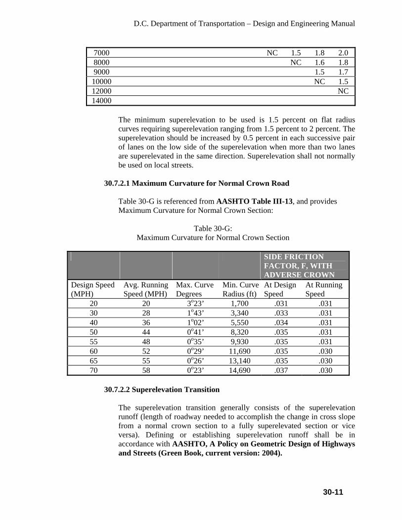
D.C. Department of Transportation – Design and Engineering Manual
30-11
7000 NC 1.5 1.8 2.0 8000 NC 1.6 1.8 9000 1.5 1.7
10000 NC 1.5 12000 NC 14000
The minimum superelevation to be used is 1.5 percent on flat radius curves requiring superelevation ranging from 1.5 percent to 2 percent. The superelevation should be increased by 0.5 percent in each successive pair of lanes on the low side of the superelevation when more than two lanes are superelevated in the same direction. Superelevation shall not normally be used on local streets.
30.7.2.1 Maximum Curvature for Normal Crown Road
Table 30-G is referenced from AASHTO Table III-13, and provides Maximum Curvature for Normal Crown Section:
Table 30-G:
Maximum Curvature for Normal Crown Section
SIDE FRICTION FACTOR, F, WITH ADVERSE CROWN
Design Speed (MPH)
Avg. Running Speed (MPH)
Max. Curve Degrees
Min. Curve Radius (ft)
At Design Speed
At Running Speed
20 20 3o23’ 1,700 .031 .031 30 28 1o43’ 3,340 .033 .031 40 36 1o02’ 5,550 .034 .031 50 44 0o41’ 8,320 .035 .031 55 48 0o35’ 9,930 .035 .031 60 52 0o29’ 11,690 .035 .030 65 55 0o26’ 13,140 .035 .030 70 58 0o23’ 14,690 .037 .030
30.7.2.2 Superelevation Transition
The superelevation transition generally consists of the superelevation runoff (length of roadway needed to accomplish the change in cross slope from a normal crown section to a fully superelevated section or vice versa). Defining or establishing superelevation runoff shall be in accordance with AASHTO, A Policy on Geometric Design of Highways and Streets (Green Book, current version: 2004).

D.C. Department of Transportation – Design and Engineering Manual
30-12
30.7.3 Curvature
The changes in direction along a highway are accounted for by simple curves or compound curves. Excessive curvature or poor combinations of curvature generates accidents, limits capacity, causes economic losses in time and operating costs, and detracts from a pleasing appearance. Broken-back curves should be avoided. Street curvature shall meet the minimum specifications shown in Table 30-H.
Table 30-H:
Minimum Horizontal Street Curve Specifications
DESIGN CRITERIA LOCAL STREET
COLLECTOR STREET
MINOR ARTERIAL
MAJOR ARTERIAL
Minimum Design Speed
20 mph 30 mph 35 mph 40 mph
Minimum Centerline Radius
100 ft 275 ft 300 ft 500 ft
Minimum Reverse Curve Tangent
50 ft 75 ft 100 ft 200 ft
Minimum Intersection Approach Tangent
100 ft 150 ft 200 ft 300 ft
For additional information and criteria relative to horizontal alignment, refer to the AASHTO, A Policy on Geometric Design of Highways and Streets (Green Book, current version: 2004).
30.8 Vertical Alignment
30.8.1 General
The profile line is a reference line by which the elevation of the pavement and other features of the highway are established. It is controlled mainly by topography, type of highway, horizontal alignment, safety, sight distance, construction costs, cultural development, drainage, and pleasing appearance. The performance of heavy vehicles on a grade must also be considered. All portions of the profile line must meet sight distance requirements for the design speed of the road. In flat terrain, the elevation of the profile line is often controlled by drainage considerations. In rolling terrain, some undulation in the profile line is often advantageous, both from the standpoint of truck operation and construction economy. This should be done with appearance in mind (i.e., a profile on tangent alignment exhibiting a series of humps visible for
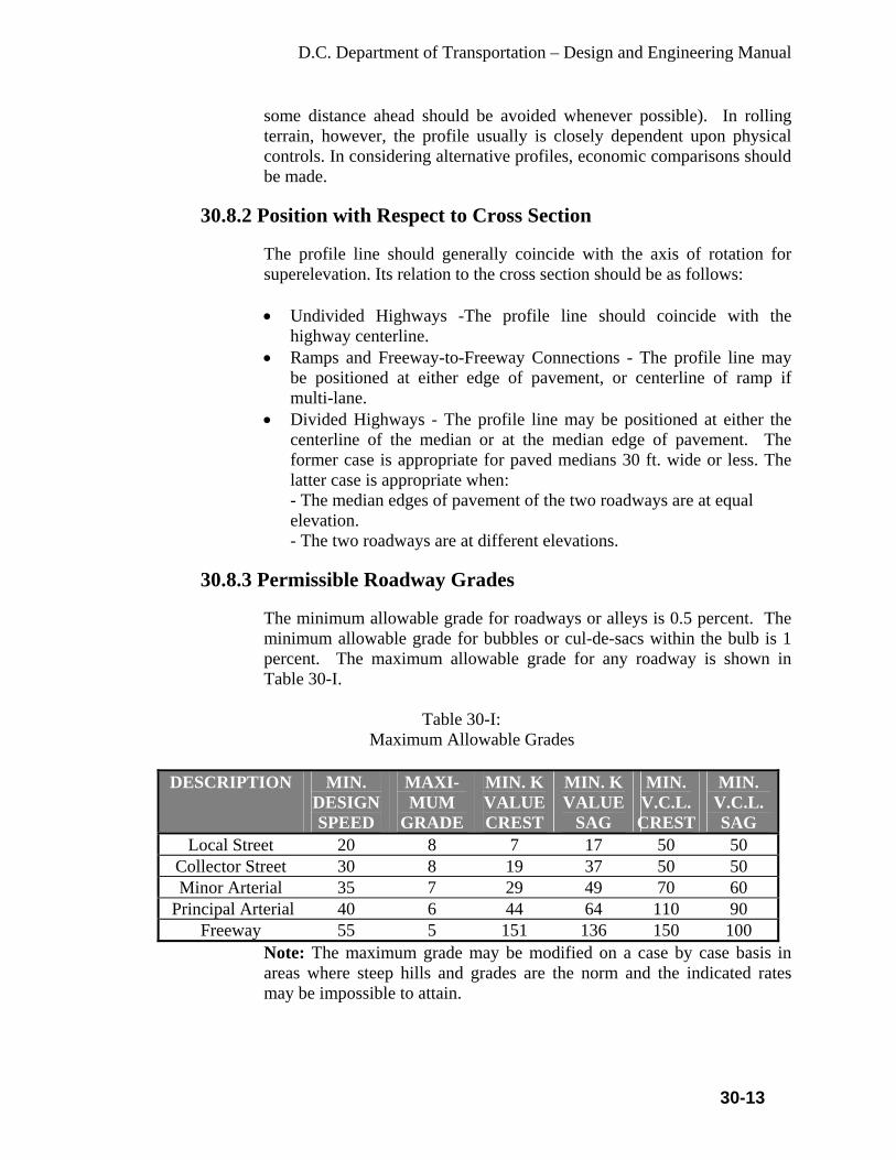
D.C. Department of Transportation – Design and Engineering Manual
30-13
some distance ahead should be avoided whenever possible). In rolling terrain, however, the profile usually is closely dependent upon physical controls. In considering alternative profiles, economic comparisons should be made.
30.8.2 Position with Respect to Cross Section The profile line should generally coincide with the axis of rotation for superelevation. Its relation to the cross section should be as follows: • Undivided Highways -The profile line should coincide with the
highway centerline. • Ramps and Freeway-to-Freeway Connections - The profile line may
be positioned at either edge of pavement, or centerline of ramp if multi-lane.
• Divided Highways - The profile line may be positioned at either the centerline of the median or at the median edge of pavement. The former case is appropriate for paved medians 30 ft. wide or less. The latter case is appropriate when: - The median edges of pavement of the two roadways are at equal elevation. - The two roadways are at different elevations.
30.8.3 Permissible Roadway Grades
The minimum allowable grade for roadways or alleys is 0.5 percent. The minimum allowable grade for bubbles or cul-de-sacs within the bulb is 1 percent. The maximum allowable grade for any roadway is shown in Table 30-I.
Table 30-I: Maximum Allowable Grades
DESCRIPTION MIN. DESIGN SPEED
MAXI- MUM
GRADE
MIN. K VALUE CREST
MIN. K VALUE
SAG
MIN. V.C.L. CREST
MIN. V.C.L. SAG
Local Street 20 8 7 17 50 50 Collector Street 30 8 19 37 50 50 Minor Arterial 35 7 29 49 70 60
Principal Arterial 40 6 44 64 110 90 Freeway 55 5 151 136 150 100
Note: The maximum grade may be modified on a case by case basis in areas where steep hills and grades are the norm and the indicated rates may be impossible to attain.
D.C. Department of Transportation – Design and Engineering Manual
30-14
30.8.4 Permissible Intersection Grades for New Streets only
The maximum permissible intersection approach grade (min. 50 ft.) should be 4 percent. For signalized intersection approaches, grades should not exceed 2 percent within 50 ft. of intersection. Exceptions will be on a case by case basis.
30.8.5 Vertical Curves
Properly designed vertical curves should provide adequate sight distance, safety, comfortable driving, good drainage, and pleasing appearance. Vertical curves shall be designed in accordance with the AASHTO, A Policy on Geometric Design of Highways and Streets (Green Book, current version: 2004). Vertical curves are not required where an algebraic difference in grade is less than 0.35 percent. Vertical curves that have a level point and flat sections near their crest or sag should be evaluated for drainage. Values of K=167 or greater should be checked for drainage. All vertical curves shall be labeled in the profile with the station of the vertical point of intersection (VPIS), the elevation (PVIE), the length of vertical curve (VCL), K=(L/A) and the middle ordinate (m).
30.9 Combination of Horizontal and Vertical Alignment
To avoid the possibility of introducing serious hazards, coordination is required between horizontal and vertical alignment. Particular care must be exercised to maintain proper sight distance. Where grade line and horizontal alignment will permit, it is desirable to superimpose vertical curves on horizontal curves. This reduces the number of sight distance restrictions and makes changes in the profile less apparent (particularly in rolling terrain). Care should be taken, however, not to introduce a sharp horizontal curve near a pronounced crest or grade sag (this is particularly hazardous at night). In cases where curves sharper than 7 degrees are located on steep grades, it is considered good design to flatten the grade slightly throughout the length of the curve. Horizontal curvature and profile grade should be made as flat as possible at highway intersections. On divided highways, variation in the width of medians, the use of separate profiles, and horizontal alignment should be considered to achieve the design and operational advantages of one-way roadways. NOTE: Changes in noise level should be evaluated where noise receptors are present.

D.C. Department of Transportation – Design and Engineering Manual
30-15
30.10 Lane Transition
Design standards of the various features of the transition between roadways of different widths should be consistent with the design standards of the superior roadway. The transition should be made on a tangent section whenever possible and should avoid locations with horizontal and vertical sight distance restrictions. Whenever feasible, the entire transition should be visible to the driver of a vehicle approaching the narrower section. The design should be such that at-grade intersections within the transition are avoided. The information below shows the minimum required taper length based upon the design speed of the roadway. In all cases, a taper length longer than the minimum should be provided where possible. When tapering the transition drops, a lane should be on the right so that traffic merges to the left. A reduced speed limit is recommended to be posted for angle shift as deemed necessary. For design speed greater than 40 MPH: L = V x W
For design speed equal to or less than 40 MPH: L = V2 x W / 60 Where V = Design Speed (MPH) W = Lane Width Reduction (FT) L = Taper Length (FT)
30.11 Major Cross Section Elements
30.11.1 General
The major cross section elements considered in the design of streets and highways include the pavement surface type, cross slope, lane widths, shoulders, roadside or border, curbs, sidewalks, driveways, and medians. NOTE: For additional information and criteria relative to major cross section items, refer to the AASHTO, A Policy on Geometric Design of Highways and Streets (Green Book, current version: 2004).
30.11.2 Standard Roadway Elements Width for New Streets
Minimum requirements are listed in Table 30-J below for new street construction, however every effort should be made to upgrade the existing streets to bring them to the current Department standard as much as practical.
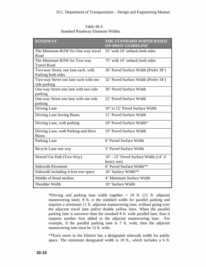
D.C. Department of Transportation – Design and Engineering Manual
30-16
Table 30-J: Standard Roadway Elements Widths
ROADWAY THE STANDARD WIDTH BASED ON DDOT GUIDELINE
The Minimum ROW for One-way travel Road
55’ with 10’ setback both sides
The Minimum ROW for Two-way Travel Road
75’ with 10’ setback both sides
Two-way Street, one lane each, with Parking both sides
36’ Paved Surface Width (Prefer 38’)
Two-way Street one lane each with one side parking
32’ Paved Surface Width (Prefer 34’)
One-way Street one lane with two side parking
30’ Paved Surface Width
One-way Street one lane with one side parking
22’ Paved Surface Width
Driving Lane 10’ to 12’ Paved Surface Width Driving Lane having Buses 11’ Paved Surface Width
Driving Lane, with parking 18’ Paved Surface Width*
Driving Lane, with Parking and Have Buses
19’ Paved Surface Width
Parking Lane 8’ Paved Surface Width
Bicycle Lane one way 5’ Paved Surface Width
Shared Use Path (Two-Way) 10’ - 12’ Paved Surface Width (14’ if heavy use)
Sidewalk Pavement 6’ Paved Surface Width** Sidewalk including 4-foot tree space 10’ Surface Width** Middle of Road median 4’ Minimum Surface Width Shoulder Width 10’ Surface Width
*Driving and parking lane width together = 19 ft. (11 ft. adjacent maneuvering lane). 8 ft. is the standard width for parallel parking and requires a minimum 11 ft. adjacent maneuvering lane, without going over the adjacent travel lane and/or double yellow lines. When the parallel parking lane is narrower than the standard 8 ft. wide parallel lane, than it requires another foot added to the adjacent maneuvering lane. For example, if the parallel parking lane is 7 ft. wide, then the adjacent maneuvering lane must be 12 ft. wide. **Each street in the District has a designated sidewalk width for public space. The minimum designated width is 10 ft., which includes a 6 ft.

D.C. Department of Transportation – Design and Engineering Manual
30-17
sidewalk and 4 ft. tree space. However, each street within the District of Columbia has a designated sidewalk width for each street, and if a particular street has a higher designated minimum width than 10 ft. minimum width then higher width will become the minimum width for that street and it must be met. If there is no designated sidewalk width, then the minimum 10 ft. designated sidewalk width must be used. (Note: The sidewalk width usually includes the tree space).
30.13 Lane Widths
Lane widths have a great influence on vehicle safety of all road users. On freeways the predominant lane width is 12 ft. In an urban setting, select lane widths between 10 and 12 ft based on the following:
• Design speed—lanes 10-ft. wide may be considered on collector and
arterial streets with design speeds of 35 mph or less. Use the wider end of the range (11 to 12 ft.) at design speeds of 35 to 40 mph.
• Design vehicle—vehicles such as transit buses or large tractor-trailers require wider lanes, particular in combination with higher design speeds if they frequently use the thoroughfare. Consider wider lanes only if appropriate for the frequency of the design vehicle.
• Right-of-way—balance the provision of the required design elements of the thoroughfare with the available right-of-way. This balance can mean reducing the width of all elements or eliminating lower priority elements.
• Width of adjacent bicycle and parking lanes—the width of adjacent bicycle and parking lanes influences the selection of lane width. If the adjacent bicycle or parking lane is narrower than recommended, first consider widening the bicycle lane. If a design vehicle or design speed justify, provide a wider travel lane to provide better separation between lanes.
Where bike access is provided, the outside lane width should be 1 ft. wider than the adjacent thru-lane width.
30.14 Roadway-Rail Grade Crossings
All roadway/rail crossings should be coordinated with the railroad to provide a consistent surface and traffic control. To properly accommodate bicyclists, at grade roadway/rail crossings should be at right angle to the rails. If the crossing is less than 45 degrees, an additional paved shoulder should be provided to permit the bicyclist to cross the track at a safer angle. Refer to the AASHTO Guide for the Development of Bicycle Facilities for additional information.
The railroad company will provide the design and special provisions for inclusion in the contract plans. The District will provide funds for construction of the Roadway-Rail Grade Crossing with participation of FHWA.

D.C. Department of Transportation – Design and Engineering Manual
31-1
CHAPTER 31 SIDEWALKS, CURB AND GUTTER, MEDIANS, DRIVEWAYS AND
ALLEYS 31.1 General
A Policy on Geometric Design of Highways and Streets, published by the American Association of State Highway and Transportation Officials, AASHTO and DC Streetscape Guideline were used as a reference within this chapter. All facilities shall be designed in accordance with ADA regulations, the requirements of this Design Manual IPMA requirements and all other DDOT requirements. This chapter sets forth the minimum criteria to be used in the design of all sidewalks, curb ramps, and other pedestrian and ADA facilities within the ROW, and other public easements.
31.2 Sidewalks, Alleys and Driveway (Non-Historical) All sidewalks shall have a minimum of 4 in. depth of concrete. Alleys and driveway entrances shall be 7 in. minimum of depth of concrete. Commercial and heavy truck traffic entrances shall be 8 in. minimum. The scoring pattern, texture and color of the sidewalk paving should be continued across the alley or driveway entrance
31.2.1 Sidewalks
All sidewalks shall have a minimum width of 6 ft. when separated from the roadway by a buffer strip. The width of the buffer strip should be a minimum of 4 ft. preferably 6 ft. for tree space. Sidewalk width shall be based on adjacent land uses: 6 ft. for low and moderate density residential, 8 ft. for high density residential, and 10 ft. for commercial areas outside of the downtown. “Standards for sidewalk treatment in downtown areas shall meet the current requirements of the DDOT Downtown Streetscape Regulations. All downtown streets shall have a minimum sidewalk width of 16 ft. with 6 ft. buffer strip. Where no buffer strip is provided, the width of the sidewalk should be 16 ft., especially where there is no shoulder (aids in preventing truck overhangs or side view mirrors from hitting pedestrians). Where utility poles, sign supports, fire hydrants, tree boxes etc., are provided in the sidewalk, the minimum usable width of sidewalk shall be 3 ft. to allow for wheelchair passage.
A sidewalk which is constructed to serve as a bicycle facility will be considered a multi-use trail and will be built to a 10 ft. min.
If the DCRA allows or requires a builder to extend the building projection into the public space right-of-way of a street, that issue must be addressed

D.C. Department of Transportation – Design and Engineering Manual
31-2
by IPMA to insure that pedestrian safety as well as traffic safety is not compromised. Refer to Section 29.4 in this manual for sidewalk slope requirements.
31.2.2 Alleys
Alleys provide for accessibility and service to each individual land parcel. They are characterized by a narrow ROW and range in width from 8 ft. to 30 ft. Alleys may be designed to include parking as described in the Parking chapter within this manual. Alleys should be aligned parallel to or concentric with the street property lines and should be situated in such a manner that both ends are connected either to streets or to other alleys. All alleys should have grades established to meet as closely as possible, the existing grades of the abutting land parcels. The longitudinal grade should not be less than 0.50 percent. Alley cross sections will be V-shaped with transverse slopes of 2 in. to 9 in. above and toward a center V gutter, which thereby directs runoff to a catch basin in the alley itself, or to the connecting street gutter system. The transverse slope or “dish” may be modified to meet existing features or conditions and to provide proper drainage. See DDOT’s Standard Drawings for details.
DDOT Requirements for Alleys:
• When entering and exiting any private and/or public space alley, all traffic must head-in and head-out from any city street. Vehicles are not allowed to back into any public alley from a city street.
• Sight-distance when exiting a private and/or public alley requires a minimum 15 ft. distance from the edge line of the alley on a 45-degree angle from the property line to the back edge line of the sidewalk. If no sidewalk exists then use the curb line of the street. Within this area, no over-height fencing and/or shrubbery over 4 ft. tall are allowed within this area, excluding city trees.
• 10 ft. standard alley radii. • No step-down curbs or ramps allowed at driveways, all alleys are
flush with the grade of the sidewalk when crossing the sidewalk area. Exceptions are commercial driveways with handicap ramps that have heavy truck and bus traffic.
• All parallel end-parking spaces on property adjacent and parallel to an alley right-of-way line must have a minimum 6 ft. clearance from the edge line of the alley.
D.C. Department of Transportation – Design and Engineering Manual
31-3
31.2.3 Driveways: District Policy
A driveway represents an access constructed within the public right-of-way that connects the public roadway with the adjacent property. Driveway terminals are, in effect, low volume intersections. The numbers of driveways and their location have a definite effect on highway capacity, primary on arterial highways. Driveway entrances should be constructed perpendicular to the roadway and shall not cause the blocking of any sidewalk, border area, street, or roadway. Sight distance represents a significant design control for driveways and they should be located to provide the best visibility possible within the limitations of the property that each driveway serves.
31.2.3.1 DDOT Requirements: General Driveways
• A new curb cut or driveway shall not be permitted from any
property with alley access or with potential access through an alley widened onto private property or with potential access to an expanded alley network on private property unless the applicant provides documentation that demonstrates that alley access is not possible due to topography or that alley access would be in conflict with existing land uses and not supported by guidelines in the Comprehensive Plan.
• Driveway entrances should be constructed perpendicular to the curb line of the street through the entire public space area to the property line.
• All driveways must be flush with the grade of the sidewalk when crossing the entire sidewalk area. The sidewalk area may start a minimum of 3 feet from the roadway curb line. No step-down curbs or ramps are allowed.
• The grade of any driveway within the public space shall not exceed 12%.
• A curb cut and/or respective portion of the driveway, including the flare or radius at the curb cut, shall be located within the public space abutting the same lot with the building or structure it is intended to serve.
• Sight-distance when exiting a driveway or parking garage requires a minimum 15 feet distance from the edge line of the driveway on a 45-degree angle from the property line or garage exit, as applicable, to the back edge line of the sidewalk. Within this area, no over-height fencing and/or shrubbery over 4 feet tall are allowed, excluding city trees.
• No driveway entrance or exit on any roadway shall be closer than 60 ft. to a roadway intersection as measured from the driveway edge line to the intersection of the roadway curb lines extended.

D.C. Department of Transportation – Design and Engineering Manual
31-4
• All driveway entrances shall be constructed of poured concrete in accordance with the DDOT Standard Specifications for Highways and Structures.
• Driveway paving materials shall continue the paving color and texture of the adjoining sidewalk across the driveway as an indication to drivers that they are crossing a pedestrian pathway.
• A driveway or parking pad shall be constructed in such a manner so that the parking of a motor vehicle thereon shall not cause any portion of the vehicle to intrude in part or whole over any portion of the public space.
• When changes occur at a property due to redevelopment and when the proposed principal use for the property will be different from that prior to the redevelopment, all existing driveways shall be restored with new curb and gutter, tree space and sidewalk to current DDOT standards. Any existing attached curb cut proposed for the new use shall be applied for as a new curb cut and driveway at the DDOT public space permit office.
31.2.3.2 DDOT Requirements: Commercial Driveway
• Driveways entrances shall be constructed with 6 foot radius curb
returns at the street in accordance with the Type A driveway entrance specified in the DDOT Standard Specifications for Highways and Structures.
• Driveways located off a street shall be a minimum of 12 feet wide from edge line to edge line for one-way circulation of motor vehicles, but shall not exceed 14 feet wide.
• Driveways located off a street shall be a minimum of 20 feet wide from edge line to edge line for two-way circulation of motor vehicles, but shall not exceed 24 feet for two-way circulation when unusually heavy vehicular traffic is anticipated.
• Driveways more than 24 feet wide shall have a minimum 6 ft. wide pedestrian safety island provided between the two resulting driveways. This pedestrian island shall be paved as an 8 inch thick sidewalk that matches the material used for the existing and/or proposed adjacent sidewalk. The pedestrian island shall have minimum 3 foot radius curb returns at the street. From the back edge line of the sidewalk to the property line, this 6 foot wide island may be landscaped and shall be designed so as to prohibit vehicle crossing within the public space area.
• The edge lines of any driveway shall be located a minimum of 32 feet from the edge line of any adjacent driveway or alley, so as to provide room for at least 1 curb tree.
• The edge line of any driveway shall not be located closer than 16 feet to the centerline of an existing healthy curb tree.

D.C. Department of Transportation – Design and Engineering Manual
31-5
• Any entry gate, card reader, or security check point shall be located on private property a minimum of 20 feet inside the back edge of the public sidewalk to ensure that a vehicle awaiting entry will not block in part or whole, any portion of the sidewalk.
• Driveways for loading docks with entrances on the roadway shall be a minimum of 12 feet wide from edge line to edge line, but shall not exceed 24 feet wide, regardless of the number of loading bays.
• All motor vehicles accessing a loading dock driveway from a roadway shall both enter and exit a driveway entrance in a forward direction so as to avoid vehicle backing in the public space.
• All turning and backing movements associated with accessing a loading dock from a driveway entrance on a street shall take place on private property.
• All parking and standing associated with the use of a loading dock shall be on private property and at no time shall any portion of a standing or parked motor vehicle intrude in part or whole over any portion of the public space.
• Driveways within the Downtown Streetscape area and other areas designated by Chapter 11 DCMR, Chapter 11, Hotel-Residential Incentive Overlay District shall be constructed at a right angle (90 degrees) to the curb line of the roadway through the entire public space area to the property line; and shall have a 6 foot radius curb returns at the roadway. A driveway edge line must be located a minimum of 8 feet from any interior property line.
• The use of shared curb cuts and driveways for more than one property or building to access parking facilities and loading docks is encouraged.
31.2.3.3 DDOT Requirements: Residential Driveway
• Off street parking accessed by a curb cut and driveway shall
measure a minimum of 9 feet wide by 19 feet long and shall not cause any portion of the vehicle to intrude in part or whole over any portion of the public space.
• Driveways from any roadway at a single family residence shall have a minimum width of 8 feet measured edge line to edge line within the public space, but shall not exceed 12 feet wide.
• Driveway entrances shall be flared (Type D) or have a maximum radius of 6 ft at the roadway in accordance with the DDOT Standard Specifications for Highways and Structures. The type of entrance constructed depends on what is standard for a specific neighborhood.

D.C. Department of Transportation – Design and Engineering Manual
31-6
• The edge lines of any driveway shall be located a minimum of 24 feet from the edge line of any adjacent driveway or alley, so as to provide room for at least 1 curb tree.
• The edge line of any driveway shall not be located closer than 12 feet to the centerline of an existing healthy curb tree.
• When 2 adjacent dwellings are being constructed at the same time and where alley access in not available or feasible, a curb cut and driveway shared by the 2 adjacent dwellings shall be required, provided no more than 7 feet of the driveway width is located on one side of the shared lot line extended.
• No driveway entrance or exit on any alley shall be closer than 30 ft. to a roadway as measured from the driveway edge line to the intersection of the alley edge line and roadway curb line extended.
31.2.3.4 DDOT Requirements: Circular Driveway
• Circular driveways shall be allowed in accordance with Title 24
DCMR, Subsection 607.4, or if written documentation is provided to the DDOT public space permit office to substantiate a compelling need for one-way circulation of motor vehicles for drop-off and/or pick-up, and other options are not viable.
• Circular driveways within public space shall not be used for stacking parked vehicles, as these driveways have a special use for allowing passengers closer access to a building entrance for drop-off and pick-up. A clear drive width for entrance and exit shall be maintained for the entire length of the driveway in the public space.
• No circular driveway entrance or exit on any roadway shall be closer than 60 ft. to a roadway intersection as measured from the intersection of driveway edge line and the roadway curb lines extended to the intersection of the roadway curb lines extended.
• The 6 foot curb radius for a circular driveway entrance shall not be located less than 8 feet from an interior lot line extended
• There are two types of circular driveways. One is designed on a 60-degree angle with the street curb and the other is a “U” shape designed on a 90-degree angle with street curb. See drawing details for the layout of these driveways.
31.2.4 Curbs and Gutters
Curbs serve the following purposes: drainage control, pavement edge delineation, ROW reduction, aesthetics, delineation of pedestrian walkways, reduction of maintenance operations, and assistance in orderly roadside development.

D.C. Department of Transportation – Design and Engineering Manual
31-7
All city streets on federal aid system will be constructed with granite curbs and brick gutters or will be replaced with in-kind materials or with brick in special situations or when there is an evidence of bricks in the city blocks. Similarly the local streets (locally funded) outside the Historic Districts will be considered for granite curbs and brick gutters on case-by-case. The asphalt curbs will be constructed for only temporary construction or repairs.
The District’s standard curbs are 7 in. high concrete or granite for city streets, 9 in. high granite curbs for bridge structures and 4 in. high mountable curbs for special situations. Each may be designed as a separate unit, or jointly with the pavement, or designed with a 1 ft. wide gutter to form a combination curb and gutter section. Curbs shall not be constructed on freeways and Interstate highways. Where positive protection is required, such as on long narrow medians or adjacent to bridge substructures, suitable barrier or guiderail should be provided.
31.3 Curb Returns
Table 31-A Minimum Required Curb Return Radii
Curb return radius may be increased beyond the above minimum requirements, depending on the geometry of the road, the dimensions and frequency of different types of running vehicles and roadway context. The American Association of State Highway and Transportation Officials, AASHTO, A Policy on the Geometric Design of Highways and Streets (Green Book, current version: 2004) provides the basis for roadway geometric design. The Design Policy states that “Where it is appropriate to provide for turning vehicles within minimum space, as at non-channelized intersections, the corner radii should be based on the minimum turning path of the selected design vehicles.” The Design Policy also states that “the appropriate design may depend on other factors such as the type, character and location of the intersecting roads, the vehicular and pedestrian traffic volumes, the number and frequency of the larger vehicles involved in turning movements, and the effect of these larger vehicles on other traffic. For example, if turning traffic is nearly all passenger vehicles, it may not be cost-effective or pedestrian friendly to
TYPE OF INTERSECTION CURB RADIUS (FT)Desired Curb return radius for street intersection 15 ft. Standard curb return radius for Alleys 10 ft. Standard curb return radius for driveway 6 ft.

D.C. Department of Transportation – Design and Engineering Manual
31-8
design for large trucks. However, the design should allow for the occasional large truck to turn by swinging wide and encroaching on other traffic lanes without disrupting traffic significantly.” Curb return radii should be designed to reflect the “effective” turning radius of the corner. The effective turning radius takes into account the wheel tracking of the design vehicle utilizing the width of parking and bicycle lanes. Use of the effective turning radii allows a smaller curb return radius while retaining the ability to accommodate larger design vehicles. Intersections should be designed as compact as practical in urban contexts. Intersections should minimize crossing distance, crossing time, exposure to traffic, encourage pedestrian travel and increase safety. Use a design speed appropriate for the context. Motorists traveling at slower speeds have more time to perceive and react to conflicts at intersections. To help select a design vehicle, identify bus routes to determine whether buses are required to turn at the intersection. Also check transit service plans for anticipated future transit routes. Map existing and potential future land uses along both streets to evaluate potential truck trips turning at the intersection.
31.4 Medians
31.4.1 General Requirements Minimum width of raised medians shall be no less than 4 ft. wide as measured from the inside edge of the travel lane. Medians may be designed for Collector and Local streets if approved by the District Program Manager. Medians 5 ft. or less in width should be raised and paved where the special nature of an area warrants the higher cost and risk involved in maintaining grass, the median can be raised and landscaped with grass. Nose areas shall be paved back to a point 5 ft. from the tip of the nose. When a median is provided for pedestrian refuge, it should be raised rather than flush or depressed. Medians intended for pedestrian refuge should be a minimum of 6’ wide (8’ is recommended). At intersections, medians provide the best refuge for pedestrians when the median nose extends beyond the crosswalk. An accessible route through the median is required for pedestrians, either through the use of curb ramps, or a cut-through. Medians and pedestrian refuge islands should be encouraged in places

D.C. Department of Transportation – Design and Engineering Manual
31-9
where they may help improve the safety of pedestrians crossing the street. They are particularly helpful on multi-lane streets with high traffic volumes and/or high speeds.
31.4.2 Turn Lane and Access
The design of medians shall include the evaluation for needed turn lanes and accesses. For the minimum requirements of turn lanes, refer to the Intersections chapter within this manual.
31.4.3 Drainage
Landscaped medians shall be provided with drainage facilities to handle runoff and nuisance flows.
31.4.4 Nose • Use vehicle-tracking templates to determine the position of the median
nose so that vehicles do not track onto the median. • The minimum radius for nose curbs shall be 2 ft.
31.4.5 Paving
All non-landscaped areas of medians on Collector roads shall be paved with stamped concrete, colored concrete, or exposed aggregate concrete in accordance with landscape standards of the District. On Local streets with channelizing islands or medians, the median may be paved with plain concrete as directed. Raised medians shall be constructed of same materials as required in the Downtown Streetscape Area or other Historic districts and arterial streets as shown in other sections of this manual.
31.4.6 Transitions
The changes in alignment of medians as they transition into turn lanes shall be a minimum radius of 50 ft. A change of direction must be accomplished with the use of radii. Angle points shall not be allowed.
31.4.7 Objects
No permanent structures, including light poles, fire hydrants, trees, etc., shall be placed less than 2 ft. from the face of curb or in any location that would obstruct sight distance except for structures approved in the Design Manual. If a median streetlight is placed within 5 ft. of the travel lane and

D.C. Department of Transportation – Design and Engineering Manual
31-10
the median is not raised the light must be a breakaway model, except for lights placed on barrier type wall.
31.5 Fire Department Response Time Factors
Site planning factors that determine response time are street accessibility (curbs, radii, bollards, T-turns, cul-de-sac, street and site slopes, street furniture and architectural obstructions, driveway widths), accessibility for firefighting (fire hydrant and standpipe connection layouts, outdoor lighting, identifying signs), within city. Check with the local codes, fire codes and fire departments.
• Access obstructions: Bollards used for traffic control and fences for security
should allow sufficient opening for access by the fire apparatus. Bollards and security gates can be secured by standard fire department keyed locks (check with the local fire department).
• Street furniture and architectural obstructions: Utility poles can obstruct use of aerial ladders for rescue and fire suppression operations. Kiosks, outdoor sculpture, fountains, newspapers boxes, and the like can also seriously impede fire-fighting operations. Wide podium bases can prevent ladder access to the upper stories of buildings. Canopies and other nonstructural building components can also prevent fire apparatus operations close to buildings.
• Outside lighting: Streets that are properly lighted enable fire fighters to locate hydrants quickly and to position apparatus at night. Avoid layouts that place hydrants and standpipe connections in shadows. In some situations, lighting fixtures can be integrated into exterior of buildings. All buildings should have a street address number on or near the main entrance and also, property street numbers provided off of the rear or side alleys.
• Driveway layouts: Long dead ends (greater than 150 ft.) can cause time consuming, hazardous backup maneuvers. Use T-turns, cul-de-sacs, and curved driveway layouts to allow unimpeded access to buildings.
• Minimum street and driveway widths: For full extension of aerial ladders at a safe climbing angle (A), sufficient driveway width (W) is required. Estimate the required width in feet by: W = (H – 6) Cot A + 4 where H being building height. The preferred climbing angles are 60 to 80 degrees. Check with local fire department for aerial apparatus operating requirements, including width of aerial device with stabilizing outriggers extended. Minimum street width when parking is allowed is 24 ft. for stabilizing outriggers of a fire truck require a minimum 16 ft. clear lane area.
31.6 Historical District Sidewalks, Curbs, Gutters, Crosswalks, Bicycle and Handicapped Ramps, Roadway Surfaces, Alleys and Other Special Districts
For the following districts, the standards should consist of brick sidewalks, stone curbs, Washington globe lights, and concrete handicapped ramps. The concrete for the handicapped ramps does not need to be tinted to match the brick. For the
D.C. Department of Transportation – Design and Engineering Manual
31-11
alleys in the two blocks bounded by 9th, 10th, M, and O Streets (Blagden Alley & Naylor Court), and in Foggy Bottom, particular care should be given to preserving and/or replacing in-kind, the block and brick alley paving. Ideally, all alleys in these districts that are brick or asphalt block should be repaired or replaced in-kind rather than paved over. Where blue stone curbing exists (typically in Georgetown and Capitol Hill), care should be given to preserving and reusing the blue stones where possible (Refer to the current Downtown Streetscape Regulations for construction in the Downtown District). Construction of sidewalks with brick on sand type of design may be hazardous to the visually impaired and blind persons. When the bricks become loose they can cause these persons to trip and lose their balance and fall. Most non-mechanical wheelchair users do not like bricks laid in sand either, as the bricks can become dislodged and become obstacles for them to maneuver around. When the community requests modification to the standard design in the Historic areas, an approval from the SHPO must be requested.
DC Historic Areas
• Anacostia • Armed Forces Retirement Home • Blagden Alley/Naylor Court • Capitol Hill • Cleveland Park • C and O Canal • Downtown • Dupont Circle • Federal Triangle • Fifteenth Street Financial • Foggy Bottom • Ford’s Theater NHS • Fort McNair • Fourteenth Street Financial • Foggy Bottom • Ford’s Theater NHS • Fort McNair • Fourteenth Street • Foxhall Village • Gallaudet College • Georgetown • Grant Road • Kalorama Triangle • Lafayette Square • LeDriot Park • Logan Circle • Marine Barracks • Massachusetts Avenue

D.C. Department of Transportation – Design and Engineering Manual
31-12
• McMillan Park Reservoir • Mount Pleasant • Mount Vernon Square • Mount Vernon Triangle • National Mall • National Zoological Park • Navy Yard • Pennsylvania Avenue NHS • Potomac Park, East and West • Rock Creek Park • Seventeenth Street • Shaw • Sheridan-Kalorama • Sixteenth Street • Soldier’s Home NHS • St. Elizabeths Hospital • Strivers’ Section • Takoma Park • U Street • Washington Cathedral • Washington Heights • Woodley Parkcd
Construction methods and materials shall be as per the current District of Columbia, Department of Transportation Standard Specifications for Highways and Structures, addenda and supplements thereto when constructing or rehabilitating of components of the transportation infrastructure within the Historic District.
31.6.1 New/Existing Sidewalks
New sidewalks, constructed where no sidewalk previously existed shall be: • Brick on concrete base, in commercial areas. Base shall be a minimum
of 4 in. thick. • Brick on sand in residential areas. • The pattern for new brick sidewalks shall be running bond. Existing sidewalks shall be rehabilitated to retain the existing materials and pattern: • Brick on concrete shall be replaced with brick on concrete. • Brick on sand shall be replaced with brick on sand. • Every effort will be made to reset existing bricks and to supplement
existing brick from the Departments brick stockpile. In those cases

D.C. Department of Transportation – Design and Engineering Manual
31-13
where there is insufficient brick to rebuild the sidewalk with the original bricks, then the reusable bricks shall be used together in one area, and the remainder of the sidewalk shall be built with new bricks.
• Concrete sidewalk, when rebuilt, shall be rebuilt with brick on-concrete base in commercial districts and with brick on sand in residential districts.
• The brick pattern of the rehabilitated sidewalk shall match the predominant pattern prior to rehabilitation (See attachment for Brick Patterns).
• In all cases, the color of the brick used shall match as closely as possible to the color of existing bricks in the vicinity. The brick size shall also match the existing bricks in the vicinity.
• Where there are no sidewalks provided, new sidewalks must be provided at existing bus stops from the front and rear doors of the bus to the nearest crosswalk. The minimum sidewalk width is 6 ft. Handicap ramps must lead to the crosswalk and be installed on both sides of the street.
NOTE: See section on Bus Stops for further requirements.
31.6.2 Curbs
• All new curbs constructed in the DOWNTOWN STREETSCAPE AREA, arterials and collector roadways shall be granite. Curbs constructed on secondary roadways and in residential areas shall be concrete. DDOT shall make the final determination on a case-by-case basis.
• Existing stone curbs, including blue stone curbs, shall be reset whenever possible. In those cases where the existing stone curbs cannot be reused or are insufficient in quantity, the existing bluestone shall be supplemented by bluestone from the Departments stockpile if available (See attachment). After utilizing all available bluestone, remaining curbs shall be new granite.
• The Department will salvage and store reusable bluestone curbs in order to create a stockpile usable in the future as replacement curbs in order to minimize the necessity of granite replacements.
31.6.3 Gutters
• All new gutters constructed in the DOWNTOWN STREETSCAPE
AREA, shall be brick. Brick gutters shall also be constructed on other facilities as designated by DDOT. Concrete gutters shall be constructed in residential areas and on other roadways designated by DDOT.
• Existing concrete gutters may be repaired, but when conditions warrant replacement, it may be in brick as directed.

D.C. Department of Transportation – Design and Engineering Manual
31-14
31.6.4 Crosswalks
Crosswalks at intersections shall be designed on a case-by-case basis, as directed by the Department. Brick patterns, 4 in. by 8 in., stamped or scored joints on concrete pavement, with 8 in. wide granite shorelines, may be considered when approved by the Department.
31.6.5 Bicycle/Wheelchair Ramps New or rehabilitated wheelchair ramps in the Georgetown Historical District shall be constructed in brick with a pattern that can be distinguished, by touch and sight, from the abutting sidewalk. Handicap ramps cannot be installed in front of individual private or public buildings. Handicap ramps can only be installed in pairs of two, one on each side of the street and must be located within crosswalk, unless otherwise approved. A storm drain system should be designed to shed water away from the ramps. Note: Bicycle ramps are different from handicap ramps, especially where bicycle trails cross the street the ramps need to be made the width of the trail.
31.6.6 Alleys
Historic alleys in the District of Columbia must be repaired and/or restored with special consideration. Alleys shall be restored with the same material, if possible, as originally constructed. Brick alleys shall be rebuilt in brick; cobblestone alleys shall be rebuilt in cobblestone. Concrete, asphalt and asphalt block alleys shall also be rebuilt in-kind.
If the historic alley was constructed with materials that are no longer in use today, the alley shall be reconstructed with materials that match as close as possible to the existing in color, texture and other characteristics. The DDOT Chief Engineer will make the final determination.
District regulations require that all alleys be lit to current lighting standards. If the alley is currently lit, the only work required will be the replacement of luminaries, lamps and photocells to DDOT standards. If the alley does not meet current standards, then a new lighting system must be designed to include manholes, conduits, wiring, poles luminaries, lamps and photocells. New poles will be placed on the property line between adjoining lots where possible.
D.C. Department of Transportation – Design and Engineering Manual
31-15
When a contractor or utility company performs work in an ally deemed historic by the District of Columbia, the DDOT Chief Engineer must be notified. Where the work involves removing rare materials that may no longer be obtained as replacement parts, the contractor or utility company may be required to carefully remove the entire special paving, perform the required work and repave the alley as directed to avoid unsightly patch work. An area will be designated to utilize material that matches the existing material in color, size and texture as closely as possible.
31.6.7 Other Special Districts For the following districts, the standards should consist of concrete sidewalks, stone curbs with brick gutter, Washington globe lights, and concrete handicapped ramps. The asphalt block paving on 22nd Street, at the base of the Spanish Steps, should be retained. • Dupont Circle • Sheridan-Kalorama • Massachusetts Avenue • Sixteenth Street
For the following districts, the standards should consist of concrete sidewalks, concrete, granite or stone curbs and gutters, Washington globe lights, and concrete handicapped ramps. In Mount Pleasant, asphalt pavers in alleys should be retained, rather than replaced or paved over.
• Mount Pleasant • Cleveland Park • Woodley Park • Takoma Park
31.7 Bluestone Curbing
Bluestone curbing, regardless of location, shall be reset and reused wherever possible. If existing bluestone cannot be re-used, for sound engineering reasons, the stone shall be salvaged, and returned to the Department's Street Maintenance facility. In historic districts, bluestone that cannot be re-used shall be replaced with Granite.
D.C. Department of Transportation – Design and Engineering Manual
32-1
CHAPTER 32
GEOMETRIC DESIGN FOR COLLECTOR STREETS 32.1 Introduction
The District of Columbia Collector Street System provides access between the arterial street network and the local streets within an established grid system. The collector streets are located in predominately high-density residential neighborhoods, but are consistent with the principles of the functional classifications. The streets are tree lined with established cross section distributions for sidewalks and the tree spaces. The following design guidelines will maintain consistency on the existing streets and provide the best possible geometrics for new development.
32.2 General Design Considerations
The design guidelines need to address the existing street system with the cross section and neighborhood environment restraints to reconstruction widenings and other improvements. New developments and the proposed street systems must be addressed to provide the best possible geometric designs.
32.3 Geometric Design
32.3.1 Design Traffic Volumes
• Existing Street - The DHV shall be the future estimated volume 20-years from the construction completion date.
• Proposed Street - AASHTO, Chapter VI.
32.3.2 Design Speed
• Existing Street - The minimum Design Speed shall be the posted speed limit. If the speed limit is not posted, then the minimum design speed shall be 25 MPH. The street grid system and the close spacing of traffic control devices influence normal vehicular speeds. Sections of the roadway, in which the design speed may not be attained, such as around curves or through hazardous locations, may be posted with appropriate warning signs and speed plates to indicate the maximum recommended speed in accordance with the current MUTCD, Section 2C-35.
• Proposed Street - AASHTO, Chapter VI.

D.C. Department of Transportation – Design and Engineering Manual
32-2
32.3.3 Sight Distance
• Existing Street - The stopping sight distance shall be a minimum of 150 ft. that corresponds to a design speed of 25 MPH. The minimum stopping distance will be correlated to the design speed of the roadway facility in accordance with AASHTO. Requirements for passing sight distance are not applicable.
• Proposed Street - AASHTO, Chapter VI.
32.3.4 Grades
• Existing Street - Grades shall be as level as practical for existing conditions and surrounding land use. A 0.50 percent grade minimum is required and shall be improved if possible.
• Proposed Street - The minimum grade shall be 0.50 percent and the maximum grade shall be 8 percent.
32.3.5 Alignment
• Existing Street - Alignment has been set. Minor adjustments to the
alignment may be made providing there is no adverse impact on adjacent properties.
• Proposed Street - AASHTO, Chapter VI.
32.3.6 Pavement Cross-slope
• Existing Street - Normal cross-slopes in the traveled way range from 0.5 percent minimum to a maximum of 5 percent. Exclusive parking lanes shall have a maximum slope of 6 percent.
• Proposed Street - AASHTO, Chapter VI. Exclusive parking lanes shall have a maximum slope of 5 percent. Special consideration may warrant a maximum cross-slope of 4 percent in the travel way.
32.3.7 Superelevation
• Existing Street – AASHTO, Chapter VI - Modify the second
sentence to read: " collector streets shall be a maximum of 0.04 ft./ft." • Proposed Street - AASHTO, Chapter VI
32.3.8 Number of Lanes
• Existing Street - No change in the number of lanes. • Proposed Street – AASHTO, Chapter VI.
D.C. Department of Transportation – Design and Engineering Manual
32-3
32.3.9 Width of Roadway
• Existing Street - Where the roadway width is 30 ft. with parking on both sides of the street, the minimum lane width for two-way traffic shall be 16 ft. With parking restricted on one side, the travel lane width should be 11 ft. including the gutter pan. For roadways that are less than 30 ft. wide, the minimum width is 10 ft. and parking will be restricted on one side.
• Proposed Street - The minimum width of the roadway shall be 34 ft. including the gutter pan. The minimum lane width shall be 10 ft. excluding the gutter pan.
32.3.10 Parking Lanes
• Existing Street - The minimum width is 7 ft. • Proposed Street – AASHTO, Chapter VI.
32.3.11 Medians
• Existing Street - Medians shall be constructed when there are more than 4 lanes of traffic if space permits.
• Proposed Street – AASHTO, Chapter VI.
32.3.12 Curbs
• Existing Street - The normal curb reveal shall be 7 in. Curbs may be a minimum of 6 in. to match the existing adjacent curbs. In areas around trees with large root systems, the 8-inch width of the granite or concrete curb may be reduced to 6-inches to reduce the adverse effect of root pruning.
• Proposed Street – AASHTO, Chapter VI - Modify the second sentence in the first paragraph to read: "...right of traffic should be 7 in. high,…".
32.3.13 Drainage
• Existing Street - The design criteria are a 15-year storm, 5- minute
duration, and a maximum spread of 6 ft. (from face of curb). • Proposed Street - AASHTO, Chapter VI.
32.3.14 Sidewalks
• Existing Street - Sidewalks to be reconstructed, if required, with a minimum cross-slope of 1 percent and a maximum cross-slope of 2

D.C. Department of Transportation – Design and Engineering Manual
32-4
percent and meet requirements of Americans with Disabilities Act Accessibility Guidelines (ADAAG) – Tree Space Slope 1% to 6%.
• Proposed Street – AASHTO, Chapter VI, ADAAG requirements.
32.3.15 Driveways
• Existing Street – AASHTO, Chapter VI. No new driveway entrances to be constructed closer than 60 ft. from the intersection.
• Proposed Street – AASHTO, Chapter VI. No new driveway entrances to be constructed closer than 60 ft. from the intersection.
32.3.16 Curb-Cut Ramps
• Existing Street – AASHTO, Chapter VI and ADAAG requirements
except that side flares shall be a minimum 21 in. in length at the curb line when all other requirements are met.
• Proposed Street – AASHTO, Chapter VI and ADAAG requirements.
32.3.17 Roadway Widths for Bridges
• Existing Street – AASHTO, Chapter VI. • Proposed Street – AASHTO, Chapter VI.
32.3.18 Vertical Clearance
• Existing Street - The minimum vertical clearance will be what the existing clearance measures with a goal of attaining 14’6”.
• Proposed Street – AASHTO, Chapter VI.
32.3.19 Horizontal Clearance to Obstructions
• Existing Street – AASHTO, Chapter VI. Every effort shall be made to save existing healthy trees where clearance is less than that prescribed.
• Proposed Street – AASHTO, Chapter VI.
32.3.20 ROW Width
• Existing Street – The ROW width and distribution is set. • Proposed Street – AASHTO, Chapter VI. Change the second
sentence to read: “The minimum width of ROW for a two-lane urban collector street shall be 55 ft. with a 10 ft. building restriction line on each side of the roadway”.
D.C. Department of Transportation – Design and Engineering Manual
32-5
32.3.21 Provisions for Utilities
• Existing Street – AASHTO, Chapter VI. • Proposed Street – AASHTO, Chapter VI.
32.3.22 Border Areas
• Existing Street – AASHTO, Chapter VI. Slope in tree space shall not exceed 5.50 percent.
• Proposed Street – AASHTO, Chapter VI. Slope in tree space shall not exceed 5.50 percent.
32.3.23 Intersection Design
• Existing Street – AASHTO, Chapter VI, except that breakaway
features are used only for fire hydrants. • Proposed Street – AASHTO, Chapter VI, except that breakaway
features are used only for fire hydrants.
32.3.24 Railroad – Street Grade Crossing
• Existing Street – AASHTO, Chapter VI and MUTCD except that gates may not be required for all approaches.
• Proposed Street – AASHTO, Chapter VI and MUTCD except that gates may not be required for all approaches.
32.3.25 Street and Roadway Lighting
• Existing Street – AASHTO, Chapter VI. • Proposed Street – AASHTO, Chapter VI.
32.3.26 Traffic Control Devices
• Existing Street - AASHTO, Chapter VI. • Proposed Street – AASHTO, Chapter VI.
32.3.27 Erosion Control
• Existing Street – AASHTO, Chapter VI. The Department of Consumer and Regulatory Affairs (DCRA) will issue final construction permits. To be issued a permit for reconstruction, the plans must contain the notes, details and data required by the D.C. Department of Health/EnvironmentalHealth Administration/Watershed Protection Division which is part of (DCRA). Also, water quality manholes and catch basins will be constructed to replace existing

D.C. Department of Transportation – Design and Engineering Manual
32-6
structures and reduce pollution and these structures will require the approval from DCRA.
• Proposed Street – AASHTO, Chapter VI. Same as above.
32.3.28 Landscaping
• Existing Street – AASHTO, Chapter VI. Landscaping, which includes standards for sidewalk treatment, trees and street furniture, in downtown areas shall meet the requirements of the District’s current Downtown Streetscape Regulations
• Proposed Street – AASHTO, Chapter VI. Same as above 32.4 Other Geometric Design Considerations
32.4.1 Sag Vertical Curves
• Existing Street – AASHTO, Chapter VI. Where street lighting is present the design criteria for headlight sight distance are not applicable.
• Proposed Street – AASHTO, Chapter VI. Where street lighting is present the design criteria for headlight sight distance are not applicable.
32.4.2 Crest Vertical Curves
• Existing Street – AASHTO, Chapter VI. Also, see Sub-section III-
C: Sight Distance. • Proposed Street – AASHTO, Chapter VI. Also, see Sub-section III-
C: Sight Distance.

D.C. Department of Transportation – Design and Engineering Manual
33-1
CHAPTER 33
ROADWAY DRAINAGE 33.1 General
The purpose of this section is to provide design requirements for the storm drainage system improvements within the street/highway ROW.
33.2 Rainfall Design Frequency
• The design frequency for urban streets is 15 years. • The design frequency for the interstate system is 25 years. • The design frequency for underpasses and depressed highways is 50 years.
33.3 Runoff
The design discharge should be calculated based on the Rational Method. This method is to be utilized for the sizing of storm inlets and piping for determining runoff magnitude. The Rational Method Runoff calculation is as follows:
Q = CiA Q = Peak Runoff (cfs) C = Coefficient of Runoff 0.9 for pavement 0.3 for grass i = Rainfall Intensity (iph) A = Drainage Area
Contributing drainage area shall be the impervious areas of the roadway and immediate adjacent sidewalk. If the sidewalk is separated from the roadway by a continuous grassed tree space, it shall not be included. Long slopes shall be included if they are 2:1 or steeper (20 ft. long or more) with a C = 0.7. Refer to Table 33-A for the rainfall intensity for the Washington DC area (in. per hour [iph]):
Table 33-A: Rainfall Intensity
Time of Concentration Frequency (Duration in Minutes) 10 years 15 years 25 years 50 years
5* 7.44 (iph) 7.56 (iph) 8.28 9.00 10** 5.94 6.76 6.90 7.62
*Roadway calculations ** Open field calculations
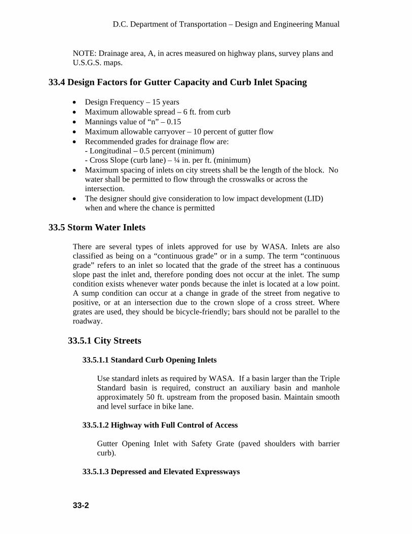
D.C. Department of Transportation – Design and Engineering Manual
33-2
NOTE: Drainage area, A, in acres measured on highway plans, survey plans and U.S.G.S. maps.
33.4 Design Factors for Gutter Capacity and Curb Inlet Spacing
• Design Frequency – 15 years • Maximum allowable spread – 6 ft. from curb • Mannings value of “n” – 0.15 • Maximum allowable carryover – 10 percent of gutter flow • Recommended grades for drainage flow are:
- Longitudinal – 0.5 percent (minimum) - Cross Slope (curb lane) – ¼ in. per ft. (minimum)
• Maximum spacing of inlets on city streets shall be the length of the block. No water shall be permitted to flow through the crosswalks or across the intersection.
• The designer should give consideration to low impact development (LID) when and where the chance is permitted
33.5 Storm Water Inlets
There are several types of inlets approved for use by WASA. Inlets are also classified as being on a “continuous grade” or in a sump. The term “continuous grade” refers to an inlet so located that the grade of the street has a continuous slope past the inlet and, therefore ponding does not occur at the inlet. The sump condition exists whenever water ponds because the inlet is located at a low point. A sump condition can occur at a change in grade of the street from negative to positive, or at an intersection due to the crown slope of a cross street. Where grates are used, they should be bicycle-friendly; bars should not be parallel to the roadway.
33.5.1 City Streets
33.5.1.1 Standard Curb Opening Inlets
Use standard inlets as required by WASA. If a basin larger than the Triple Standard basin is required, construct an auxiliary basin and manhole approximately 50 ft. upstream from the proposed basin. Maintain smooth and level surface in bike lane.
33.5.1.2 Highway with Full Control of Access
Gutter Opening Inlet with Safety Grate (paved shoulders with barrier curb).
33.5.1.3 Depressed and Elevated Expressways

D.C. Department of Transportation – Design and Engineering Manual
33-3
Combination Curb and Inlet with P-Grate or special design (limited lateral clearance).
33.5.1.4 Field Inlet
Standard Inlet with Safety Grate.
33.6 General Requirements for Inlets • All basins to be located a minimum of 5 ft. from the P.C. of corner radii
except to drain sags where one basin may be placed on the P.C. • Low point in sag - With few exceptions, one inlet at the low point and one
inlet at each side 3½ in. above the low point. • A trap or special catchment chamber shall be provided for all inlets tying
directly into a storm sewer. • A waterseal connection shall be provided for all inlets. WASA must approve
the connection. • All inlets shall connect directly into a manhole.
33.7 Connect Pipes • Basin to manhole connect pipes shall be 15 in. diameter minimum. Check for
conflicts with existing utilities. • Length – 50 ft. maximum. • Cover – 3 ft. minimum from top of pipe to finished grade. • No more than three connect Pipes shall tie into any one manhole.
33.8 Storm Sewer Pipe • Design Frequency:
- 15-year storm with pipe flowing full. - 50-year storm for pipes draining low point in sag.
• Size – 18 in. diameter minimum. • Velocity – 3 ft. per second minimum. • Cover – A minimum depth of 5 ft. shall be placed from the top of pipe to the
finished grade; 5½ ft. is desirable. • Sewer lines must be on a straight alignment and uniform slope between
manholes.
33.9 Sewer Manholes
Manholes shall be placed over sewer lines at the following locations:
• All points of change of slope or alignment. • Upper end of sewer lines.
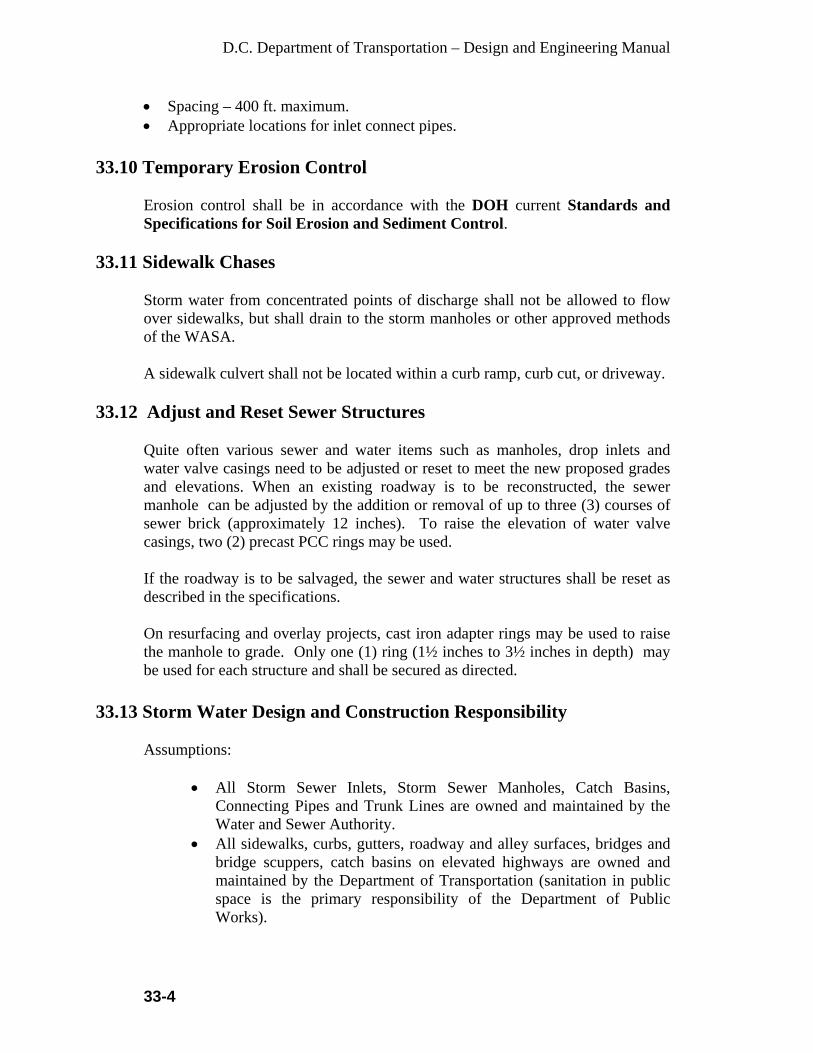
D.C. Department of Transportation – Design and Engineering Manual
33-4
• Spacing – 400 ft. maximum. • Appropriate locations for inlet connect pipes.
33.10 Temporary Erosion Control
Erosion control shall be in accordance with the DOH current Standards and Specifications for Soil Erosion and Sediment Control.
33.11 Sidewalk Chases
Storm water from concentrated points of discharge shall not be allowed to flow over sidewalks, but shall drain to the storm manholes or other approved methods of the WASA. A sidewalk culvert shall not be located within a curb ramp, curb cut, or driveway.
33.12 Adjust and Reset Sewer Structures
Quite often various sewer and water items such as manholes, drop inlets and water valve casings need to be adjusted or reset to meet the new proposed grades and elevations. When an existing roadway is to be reconstructed, the sewer manhole can be adjusted by the addition or removal of up to three (3) courses of sewer brick (approximately 12 inches). To raise the elevation of water valve casings, two (2) precast PCC rings may be used. If the roadway is to be salvaged, the sewer and water structures shall be reset as described in the specifications. On resurfacing and overlay projects, cast iron adapter rings may be used to raise the manhole to grade. Only one (1) ring (1½ inches to 3½ inches in depth) may be used for each structure and shall be secured as directed.
33.13 Storm Water Design and Construction Responsibility
Assumptions:
• All Storm Sewer Inlets, Storm Sewer Manholes, Catch Basins,
Connecting Pipes and Trunk Lines are owned and maintained by the Water and Sewer Authority.
• All sidewalks, curbs, gutters, roadway and alley surfaces, bridges and bridge scuppers, catch basins on elevated highways are owned and maintained by the Department of Transportation (sanitation in public space is the primary responsibility of the Department of Public Works).
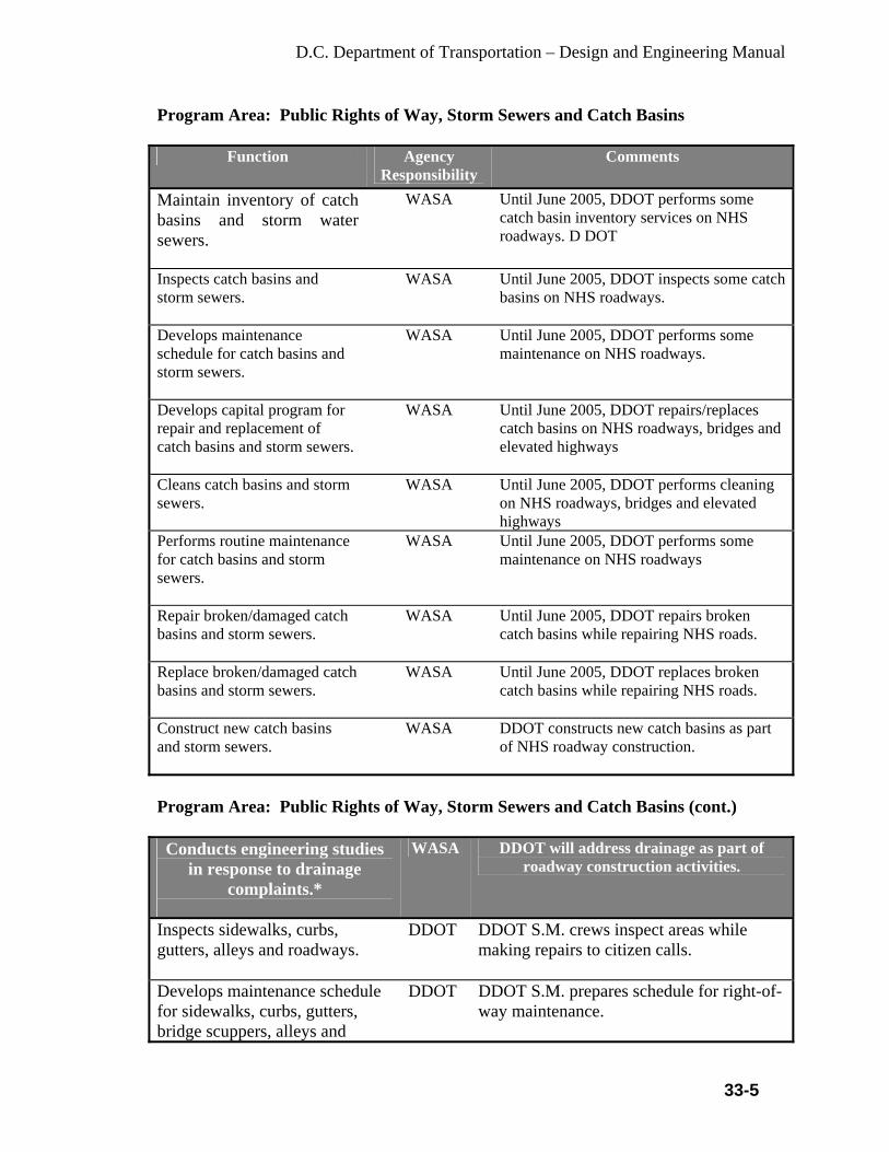
D.C. Department of Transportation – Design and Engineering Manual
33-5
Program Area: Public Rights of Way, Storm Sewers and Catch Basins
Function Agency Responsibility
Comments
Maintain inventory of catch basins and storm water sewers.
WASA Until June 2005, DDOT performs some catch basin inventory services on NHS roadways. D DOT
Inspects catch basins and storm sewers.
WASA Until June 2005, DDOT inspects some catch basins on NHS roadways.
Develops maintenance schedule for catch basins and storm sewers.
WASA Until June 2005, DDOT performs some maintenance on NHS roadways.
Develops capital program for repair and replacement of catch basins and storm sewers.
WASA Until June 2005, DDOT repairs/replaces catch basins on NHS roadways, bridges and elevated highways
Cleans catch basins and storm sewers.
WASA Until June 2005, DDOT performs cleaning on NHS roadways, bridges and elevated highways
Performs routine maintenance for catch basins and storm sewers.
WASA Until June 2005, DDOT performs some maintenance on NHS roadways
Repair broken/damaged catch basins and storm sewers.
WASA Until June 2005, DDOT repairs broken catch basins while repairing NHS roads.
Replace broken/damaged catch basins and storm sewers.
WASA Until June 2005, DDOT replaces broken catch basins while repairing NHS roads.
Construct new catch basins and storm sewers.
WASA DDOT constructs new catch basins as part of NHS roadway construction.
Program Area: Public Rights of Way, Storm Sewers and Catch Basins (cont.) Conducts engineering studies
in response to drainage complaints.*
WASA DDOT will address drainage as part of roadway construction activities.
Inspects sidewalks, curbs, gutters, alleys and roadways.
DDOT DDOT S.M. crews inspect areas while making repairs to citizen calls.
Develops maintenance schedule for sidewalks, curbs, gutters, bridge scuppers, alleys and
DDOT DDOT S.M. prepares schedule for right-of-way maintenance.
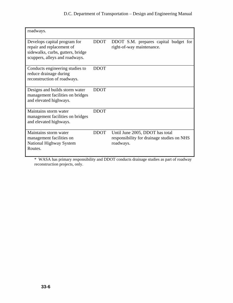
D.C. Department of Transportation – Design and Engineering Manual
33-6
roadways. Develops capital program for repair and replacement of sidewalks, curbs, gutters, bridge scuppers, alleys and roadways.
DDOT DDOT S.M. prepares capital budget for right-of-way maintenance.
Conducts engineering studies to reduce drainage during reconstruction of roadways.
DDOT
Designs and builds storm water management facilities on bridges and elevated highways.
DDOT
Maintains storm water management facilities on bridges and elevated highways.
DDOT
Maintains storm water management facilities on National Highway System Routes.
DDOT Until June 2005, DDOT has total responsibility for drainage studies on NHS roadways.
* WASA has primary responsibility and DDOT conducts drainage studies as part of roadway reconstruction projects, only.

D.C. Department of Transportation – Design and Engineering Manual
33-7
Program Area: Public Rights of Way, Storm Sewers and Catch Basins (cont.)
Function Agency Responsibility
Comments
Cleans sidewalks, curbs, gutters, alleys and roadways.
DDOT Property owners are responsible for cleaning sidewalks, curbs and gutters in front of property. DDOT cleans some portions of the right of way.
Performs routine maintenance for sidewalks, curbs, gutters, bridge scuppers, alleys and roadways.
DDOT DDOT S.M. will be performing crack sealing, mill/overlay and executing a preventive maintenance contract all in conjunction with the PMS.
Repair sidewalks, curbs, gutters, bridge scuppers, alleys and roadways.
DDOT WASA repairs damage resulting from utility repair work.
Replace sidewalks, curbs, gutters, bridge scuppers, alleys and roadways.
DDOT
Construct new sidewalks, curbs, gutters, bridge scuppers, alleys and roadways.
DDOT
Construct drainage ditches. DDOT
Clean and maintain drainage ditches.
DDOT
Program Area: Innovative Storm Water Management Practices and Financing
Function Agency Responsibility
Comments
Design, construct and monitor/ maintain innovative storm water management facilities (including LID) on public rights-of-way.
DDOT DDOT responsible for innovative storm water facilities in right-of-way, including roadways, alleys, medians, etc.
Design, construct and maintain innovative storm water management facilities (including LID) on WASA controlled properties.
WASA WASA responsible for BMPs in WASA controlled public space, including catch basins, storm sewer inlets, storage facilities, storm sewers and other WASA owned properties.
Review and approve storm water BMP design plans, monitor and inspect BMPs.
DOH DOH reviews storm water BMP design plans, comments and approves final plans.

D.C. Department of Transportation – Design and Engineering Manual
33-8
Develop storm water standards, rules and regulations, inspect and enforce laws and regulations.
DOH DOH is the enforcement agency for water quality issues on public and private land
Develops capital programs for design, construction and maintenance of extension of sewer lines and manholes in city streets.
WASA WASA is responsible for the development of the capital program to improve or extend the storm sewer system, including catch basins, inlets, storm sewer connections and storm sewers Reference MOU signed in 2002, Item 4, sec. (a)-3,4; DDOT is financially responsible for extension.
Develops capital programs for design, construction and maintenance of storm water management facilities on District rights-of-way.
DDOT DDOT is responsible for the development of capital programs to improve storm water facilities constructed as part of the roadway right-of-way.
Program Area: Construction Management Activities
Function Agency Responsibility
Comments
Allocates capital resources to design and construct storm water pollution control facilities as part of roadway and alley reconstruction.
DDOT
Prepares design plans and specifications for storm water pollution control facilities as part of roadway, alley reconstruction, including erosion control plans at work sites.
DDOT
Submits design plans and specifications and erosion control plans at work sites to DOH for review and approval.
DDOT Submit to DOH approval before the construction contract is executed
Coordinates design plans and specifications with WASA.
DDOT Solicit comments from WASA before the design contract is finalized
Reviews, provides comments and provides final approval of
DOH There is a need here, to address to permit fees, charges.

D.C. Department of Transportation – Design and Engineering Manual
33-9
storm water pollution control facilities constructed by DDOT in the public right-of-way and erosion control plans for transportation facility construction sites. Constructs and maintains storm water pollution control facilities constructed by DDOT in the public right-of-way.
DDOT Street cleaning responsibilities belong to DDOT. Below surface maintenance responsibilities belong to WASA.
Program Area: Construction Management Activities (cont.) Maintains erosion control facilities at construction sites, consistent with the approved plans.
DDOT Enforcement is done by DOH by - way - of, ticketing the contractor.
Program Area: Pumping Stations and other Storm Water Facilities
Function Agency Responsibility Comments
Maintains inventory of pumping stations.
WASA
Inspects pumping stations.
WASA
Develops capital program to repair and replace pumping stations.
WASA
Cleans and maintains pumping stations.
WASA
Program Area: Snow Management and Deicing Activities
Function Agency Responsibility
Comments
Develop Snow Management Plan that limits pollution to District waterways.
DDOT Develops and maintains a snow management/operations plan to restore transportation services as soon as possible after a snow event and minimize the impact of such practices on the environment.
Obtains manpower, equipment and supplies to manage snow operations, including deicing
DDOT DDOT will determine the types of supplies and equipment to be utilized for each snow event, depending upon weather forecasts
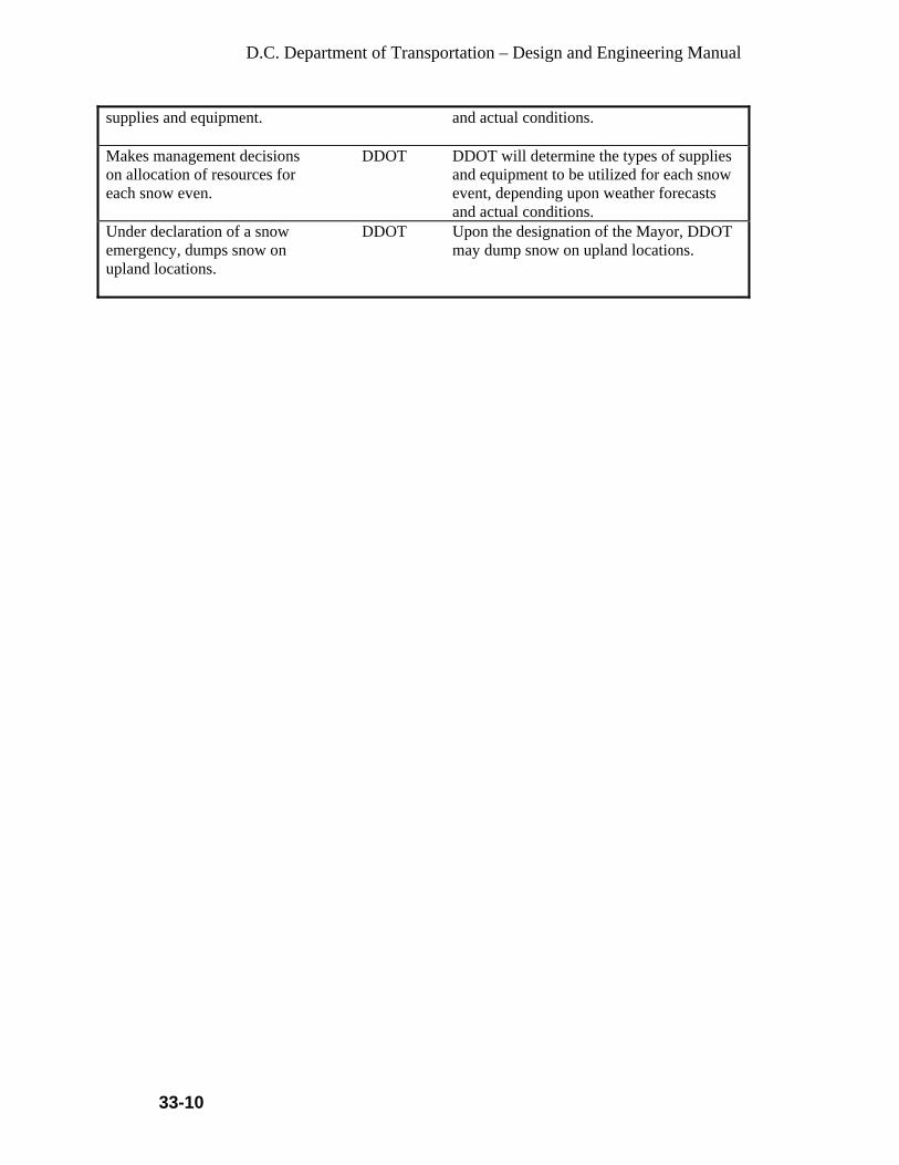
D.C. Department of Transportation – Design and Engineering Manual
33-10
supplies and equipment.
and actual conditions.
Makes management decisions on allocation of resources for each snow even.
DDOT DDOT will determine the types of supplies and equipment to be utilized for each snow event, depending upon weather forecasts and actual conditions.
Under declaration of a snow emergency, dumps snow on upland locations.
DDOT Upon the designation of the Mayor, DDOT may dump snow on upland locations.
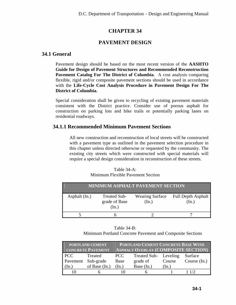
D.C. Department of Transportation – Design and Engineering Manual
34-1
CHAPTER 34
PAVEMENT DESIGN 34.1 General
Pavement design should be based on the most recent version of the AASHTO Guide for Design of Pavement Structures and Recommended Reconstruction Pavement Catalog For The District of Columbia. A cost analysis comparing flexible, rigid and/or composite pavement sections should be used in accordance with the Life-Cycle Cost Analysis Procedure in Pavement Design For The District of Columbia.
Special consideration shall be given to recycling of existing pavement materials consistent with the District practice. Consider use of porous asphalt for construction on parking lots and bike trails or potentially parking lanes on residential roadways.
34.1.1 Recommended Minimum Pavement Sections
All new construction and reconstruction of local streets will be constructed with a pavement type as outlined in the pavement selection procedure in this chapter unless directed otherwise or requested by the community. The existing city streets which were constructed with special materials will require a special design consideration in reconstruction of these streets.
Table 34-A:
Minimum Flexible Pavement Section
Table 34-B:
Minimum Portland Concrete Pavement and Composite Sections
PORTLAND CEMENT CONCRETE PAVEMENT
PORTLAND CEMENT CONCRETE BASE WITH ASPHALT OVERLAY (COMPOSITE SECTION)
PCC Pavement (In.)
Treated Sub-grade of Base (In.)
PCC Base (In.)
Treated Sub-grade of Base (In.)
Leveling Course (In.)
Surface Course (In.)
10 6 10 6 1 1 1/2
MINIMUM ASPHALT PAVEMENT SECTION
Asphalt (In.) Treated Sub-grade of Base
(In.)
Wearing Surface (In.)
Full Depth Asphalt (In.)
5 6 2 7

D.C. Department of Transportation – Design and Engineering Manual
34-2
For residential, non-federal, (local) streets, 8 in. PCC base for composite section may be considered on a case-by-case basis when approved by the Project Manager. All PCC pavements shall be reinforced with wire mesh as described in the Standard Specifications for Highway Structures latest addition.
34.2 Pavement Selection
The District being the Nation’s Capital the preferred practice in selection of pavement is aesthetic and consideration for Stakeholders/Citizens Complaints concerning vibration, noise and appearance.
• The following type pavements are used in the district:
• Concrete pavement • Asphalt pavement • Composite pavement • Special Pavement (Cobble Stone etc.)
• Over-riding factors in selection of pavement are:
• Cost • Vibration and Noise • Aesthetic and Appearance • Ride-ability and Vision • Maintenance • Constructability • Traffic Volume
34.3 Engineering Considerations
34.3.1 Principal Factors
• Soil Characteristics (Resilient Modulus “R”) • Traffic Volume (ADT value)
34.3.2 Secondary Factors
• Maintenance Cycle • Availability of Pavement Materials

D.C. Department of Transportation – Design and Engineering Manual
34-3
34.3.3 Pavement Selection Flow Chart
34.3.4 Pavement Design Procedure
34.3.4.1 Design Procedures
The basic design procedure for pavement structures will be that as set forth in the AASHTO Guide for Design of Pavement Structures, later version and Recommended Reconstruction Pavement Catalog For The District of Columbia.
34.3.5 Rigid Pavement Design
The District policy is to use a slab thickness of 10 in. or greater even if the ESAL levels would suggest that lesser slab thickness would be adequate. A slab thickness of 10 in. or greater provides some assurance of adequate long-term performance given that the other design details are adequately accommodated. Past performance also suggests that rigid pavement, unlike flexible pavements, can be designed for initial performance periods of 30 to 40 years. This is of significant benefit where rehabilitation and maintenance
Yes
Yes No
No No
Yes Yes Yes Use Composite Section Pavement
Downtown Geographic Location
Local Street
Steep Grade or
Hilly Use PCC Pavement
2 1
Does it Have Residential Character
Steep Grade or
Hilly
No
Use PCC Pavement
Use Full Depth Asphalt
Use Full Depth Asphalt Pavement or PCC Pavement

D.C. Department of Transportation – Design and Engineering Manual
34-4
activities are highly constrained, such as urban roads and streets and all Interstate pavement. Concrete pavements should be rounded upward to the nearest inch. For example, if the design thickness calculates to be 10.48 inches, the slab thickness will be 11 inches.
34.3.5.1 Shoulders
When PCC shoulders are used they shall have the same PCC slab and base thickness as the mainline roadway. Additionally, the shoulder and mainline roadway PCC shall be tied together with deformed steel bars.
34.3.5.1.1 Edge Course Design
The Aggregate Base for a rigid pavement shall extend 18 in. beyond the pavement edge, or to the outside edge of the porous backfill over the pipe under-drain, or to 6 in. beyond the outside edge of the paved shoulder, whichever is greater. Where curb and gutter or integral curb is used, the aggregate base course shall extend 24 in. beyond the face of the curb or to the outside of the porous backfill over the pipe under-drain, whichever is greater.
34.3.5.1.2 Composite Pavement
Composite pavement herein refers to a rigid base with an asphalt surface. Generally the design of a composite pavement is discouraged due to the relative performance and associated costs. Composite pavements are designed as rigid pavements. The minimum overlay thickness on a rigid pavement or base is 2 ½ in.
34.4 Flexible Pavement Design
Minimum layer thickness, as well as, maximum lift thickness is controlled by requirements contained within DDOT's Standard Specification.
Layer thickness and total pavement structure over subgrade soils for flexible pavements are fundamentally based on four criteria:
• Depth to provide a minimum level of serviceability for the design period, • Depth to prevent excessive rutting, • Depth to prevent premature fatigue cracking of the AC layers, and • Depth to provide adequate frost depth protection.
Flexible pavement design is based on the use of the Structural Number. The Structural Number is a regression coefficient expressing the structural strength of

D.C. Department of Transportation – Design and Engineering Manual
34-5
a pavement required for given combinations of soil support, traffic loading, and terminal serviceability. Flexible pavements will be constructed with Super-pave mixes; however, regardless of the mix design method used for a flexible pavement, the DDOT/AASHTO method of pavement design calculates the same required Structural Number (SN). Another method to use for the design of a flexible pavement is the method described by the Asphalt Institute, which is also based on the Structural Number. Once the Structural Number is determined, the flexible buildup is determined by using the appropriate structural coefficient for DDOT specification materials.
34.4.1 Typical Section Design
Regardless of the SN required, a buildup that includes an aggregate base will generally provide better performance than a full depth asphalt concrete buildup. The aggregate base is less sensitive to moisture than the subgrade is and it separates the pavement further from the subgrade. An aggregate base is recommended under all flexible pavements and particularly when the thickness of a full depth flexible design is very thin, approximately 5 in. (SN ~ 1.8) or less. All surface and intermediate courses should be specified in 0.25 in. increments. Base Course should be specified in 0.5 in. increments. Aggregate base is typically placed at 6 in. thick. The minimum thickness for Item Aggregate Base is 6 in. and it should be specified in 1 in. increments. When designing a flexible pavement, some consideration should be given to reducing the total number of separate lifts required. This can be done by keeping in mind the maximum and minimum lift thickness for all of the materials involved. Maximum and minimum lift thickness can be found either in the Construction and Materials Specifications.
34.4.2 Edge Course Design
Aggregate Base shall extend 6 in. beyond the edge of the overlying bituminous base for bituminous base courses 9 inches or less in thickness and 12 in. beyond the edge for bituminous base courses thicker than 9 in. Each course, regardless of the number of lifts required by the specifications, shall be designed and shown in a vertical plane. Any base course shall extend beyond the edge of the overlying intermediate course a distance equal to the thickness of the surface course plus the intermediate course or 5 in., whichever is greater. The outside edge of the intermediate course shall be in alignment with the outside edge of the surface course.
34.4.2.1 Shoulders
The minimum requirements for flexible pavement shoulders are:

D.C. Department of Transportation – Design and Engineering Manual
34-6
Interstate - 7 in. Class B - Variable Depth Aggregate Base
Non-Interstate - 5 in. Class B - Variable Depth Aggregate Base
34.4.2.1.1 Shoulder Buildups
Shoulders are used to provide an area for the accommodation of disabled vehicles, for the lateral support of the base and surface courses, to improve the safety of a highway, and for future maintenance of traffic operations during maintenance and rehabilitation work. Shoulders for flexible pavements shall be constructed of the same materials and thickness as the mainline pavement for all Interstate, freeways, expressways, and other multi-lane facilities. This provides for the ability to have a hot longitudinal joint at the pavement-shoulder interface, provides a stable temporary pavement for maintenance of traffic lane shifts, and reduces the complexity of construction. Using other types of shoulders, such as bituminous surface treated, stabilized aggregate, or turf shoulders must be in accordance with Geometric Standards, Roadway Design. Regardless of shoulder type, shoulder base and subgrade considerations must include the directing of drainage away from the pavement, rather than towards it.
34.4.2.1.2 Paved Shoulder Edge Course Design
Where shoulders are constructed with a buildup different than the mainline pavement, the outside edge of each course shall extend 6 in. beyond the edge of the overlying course.
34.4.3 General Design Considerations
Cross Slope on a pavement is provided to drain water from the street surface. The design of Cross Slope shall consider driver comfort and safety. Undivided traveled ways on tangents, or on flat curves, have a crown or high point in the middle and cross slope downward toward both edges. Unidirectional cross slopes across the entire width of the traveled way may be utilized. The downward cross slope may be a plane or rounded section or a combination.
34.4.3.1 Minimum Cross Slope
Minimum Cross Slope on reconstruction or overlays on all roadways shall be 0.5 percent. Lanes shall have a crown of ¼ to ½ inches.

D.C. Department of Transportation – Design and Engineering Manual
34-7
34.4.3.2 Maximum Allowable Cross Slope Maximum allowable Cross Slope on all new construction shall be 3 percent. Maximum allowable Cross Slope on any reconstruction or overlays of existing roadways shall be 4 percent or a maximum of 5 percent on roadways with parking lanes.
34.4.3.3 Cross Slope for Street Modifications When widening an existing street or adding turn lanes to an existing street, the resulting Cross Slope of the widened portion shall be within the limits stated above and the new Cross Slope shall be no less than the existing Cross Slope. Note: In hilly areas of D.C. where it is sometime impossible to actually meet design standards, exceptions will have to be made. Each situation will be on a case-by-case basis.
34.4.4 Shoulders Width
Right shoulder widths may vary between 2 ft. and 12 ft. depending on highway classification and may be surfaced with a variety of materials (as determined by the Program Manager). Shoulder widths shall be a minimum of 10 ft. on freeways and interstate highways. Shoulders are important links in the lateral drainage systems. Shoulders should be flush with the roadway surface and abut the edge of the thru-lane/auxiliary lane. Shoulder cross slopes should be sloped from 2 to 8 percent depending upon surfacing material used. Shoulder contrast is desirable and may be obtained by using different colors or textures from the traveled way surface or by the use of edge lines as described in the MUTCD. Left shoulders are preferred on all divided highways. The desirable median shoulder width on 4-lane and 6 to 8-lane highways is 5 ft. and 10 ft. respectively. The minimum left shoulder width on highways is 3 ft. and on freeways is 4 ft. In order to provide wider lanes on 3R projects, the left shoulder width on an existing divided multilane highway may be reduced to 1 ft. For additional sources of information and criteria relative to shoulder design, refer to the AASHTO, A Policy on Geometric Design of Highways and Streets (Green Book, current version: 2004) and the NCHRP Report 254, Shoulder Geometrics and Use Guidelines. For additional sources of information and criteria relative to bicycle compatible shoulder design, refer to the AASHTO Guide for the Development of Bicycle Facilities.

D.C. Department of Transportation – Design and Engineering Manual
35-1
CHAPTER 35
INTERSECTIONS 35.1 General
Intersection is the common area where two or more roadways join or cross. It is where speed and direction change and conflicts may occur. Intersections shall be designed to provide for the safety of motorists, pedestrians, and bicyclists. By their nature, intersections are conflict locations. Vehicles, pedestrians, and bicycles all cross paths. Each crossing is a conflict point. This chapter is based on criteria from the following documents:
• AASHTO’s, A Policy on Geometric Design of Highways and Streets (Green Book, current version: 2004).
• AASHTO’s Guide for the Planning, Design, and Operation of Pedestrian Facilities—current version.
• Institute of Transportation Engineers (ITE) Traffic Engineering Handbook
• ITE Context Sensitive Solutions in Designing Major Urban Thoroughfares for Walkable Communities
35.2 Intersection Design Criteria
• Physical area of an intersection (intersection proper) – This area can be obtained by connecting the center of corner curbs (P.I. extensions). This area is for the share use of traffic traveling with different directions. All signs, markings and survey reference points begin from point of intersection (P.I.).
• Functional area of intersection – This area includes all queue storage areas, auxiliary lanes, perception and reaction lengths.
• Intersection design covers the entire functional area of an intersection.
35.2.1 Basic Intersection Design
The basic design of intersections includes the following objectives: • Minimize points of conflict. • Simplify areas of conflict. • Limit conflict frequency. • Limit conflict severity.
35.2.2 Lane Alignment
All lanes shall be in alignment through intersection, with a maximum of a 2 ft. shift in a hardship situation only. To assist drivers in situation like this, traffic guidelines (see Chapter 43 Pavement Marking and Signage) should be provided.
D.C. Department of Transportation – Design and Engineering Manual
35-2
35.2.3 Angle of Intersection
Crossing roadways should intersect at 90 degrees whenever possible. In no case shall the new intersection design intersect at less than 80 degrees or more than 100 degrees.
35.2.4 Horizontal Alignment and Vertical Profile
• Horizontal – Intersections may be placed on horizontal curves, provided the tangent lengths are provided on the minor street.
• Vertical - The street profile grade shall not exceed 4 percent on the approach to the intersection, as measured along the centerline of the street. The profile grade within the intersection streets shall not exceed 3 percent. In areas of hilly terrain and steep grades where it may not be possible to attain a 4% approach to the intersection and a 3% grade within the intersection, the design may be modified to provide the best design attainable
• Prevailing Street Grade - The grade of the street with the higher classification shall prevail at intersections. The lesser street shall adapt to the grade of the major street. Grading of adjacent property and driveways shall adapt to the street grades.
35.2.5 Exclusive Left Lane Turns
Exclusive left turn lanes may be provided on Arterial roadways wherever left turns are approved. The Designer shall determine whether an exclusive left turn lane is warranted at designated locations. At intersections with pedestrian activity, left turn lanes should be limited to a single left turn lane. The designer needs to consider the safety benefits of adding turn lanes while minimizing pedestrian crossing distance. The following criteria, based on National Cooperative Highway Research Program Report 279 (NCHRP 279), shall be followed: • Warrants for Signalized Intersections - A separate left turn lane may
be required if one of the following criteria is met: - The left turn design volume is at least 20 percent of total approach volumes, or - The left turn design volume exceeds 100 vehicles per hour (vph) in peak periods, or - The Level of Service (LOS) criterion, are not satisfied without a separate left turn lane.
• Warrants for Un-signalized Intersections - Left turn lanes may be required at approaches to intersections in which the combination of through, left, and opposing volumes exceeds warrants set up by the District.
D.C. Department of Transportation – Design and Engineering Manual
35-3
• Design Criteria - Left turn lanes shall be designed to provide the following functions: - A means for safe deceleration outside the high-speed thru-lane. - A storage length long enough for left turning vehicles so that signal phasing can be optimized and intersection delay minimized. - Provides a means of separating movements at un-signalized intersections to reduce left turn impacts on other flows.
• The design elements are the approach taper, bay taper, lengths of lanes, width of lanes, and departure taper.
35.2.6 Exclusive and Channelized Right Turn Lanes
In urban contexts, high-speed channelized right turns are often inappropriate because they create conflicts with pedestrians. Under some circumstances, providing channelized right-turn lanes on one or more approaches at a signalized intersection can be beneficial, but unless designed correctly, these right-turn lanes can be undesirable for pedestrians. The general principles and considerations regarding channelized right
turns include the following:
• Avoid using channelized right-turn lanes where pedestrian activity is significant. If a channelized right-turn lane is unavoidable, use design techniques described to lessen the impact on pedestrians.
• Exclusive right-turn lanes should be limited. A right-turning volume threshold of 200–300 vehicles per hour is an acceptable range for the provision of right-turn lanes. Once determined that a right-turn lane is necessary, a well-designed channelization island can help slow down traffic and separate conflicts between right-turning vehicles and pedestrians.
• If an urban channelized right-turn lane is justified, design it for low speeds (5 to 10 mph) and high-pedestrian visibility.
• For signalized intersections with significant pedestrian activity, it is highly desirable to have pedestrians cross fully under signal control. This minimizes vehicle-pedestrian conflicts and adds to the comfort of pedestrians walking in the area.
35.2.7 Acceleration/Deceleration Lanes
On roadways with posted speeds above 35 mph, at each high volume driveway and major intersection, acceleration/ deceleration lanes may be considered. The specific designs for these lanes shall be in accordance with NCHRP 279 and this chapter.

D.C. Department of Transportation – Design and Engineering Manual
35-4
35.2.8 Turning and Curb Radius
Refer to section 31.3 in this manual for curb return radius.
35.2.9 Curb Return Grades The minimum desirable grade around the curb return should be 1 percent. The minimum allowable grade around curb returns shall be 0.5 percent.
35.2.10 Median Islands Separating Opposing Traffic
When designed to provide pedestrian refuge, raised medians should be a minimum of 6’ wide (8’ is recommended). At intersections, medians provide the best refuge for pedestrians when the median nose extends beyond the crosswalk. An accessible route through the median is required for pedestrians, either through the use of curb ramps or a cut- through. Medians and pedestrian refuge islands are encouraged in places where they may improve the safety of pedestrians crossing the street. They are particularly helpful on multi-lane streets with high traffic volumes and/or high speeds. • The medians must not obstruct the minimum left turn radius for the
design vehicle. • Any landscaped medians shall include drainage facilities to handle
sprinkler with trickle irrigation, outfall curb and gutter should be used. • The medians must be placed such that the required visibility in the
intersection is not obstructed. • Medians must be placed so they do not diminish the intersection use.
35.2.11 Dedicated ROW
Intersections shall be constructed within the dedicated right-of-ways. • Requirements - All intersection ROWs shall be dedicated to provide
adequate ROW for sidewalks, curb ramps, and utilities. Additional ROW may be required for additional left or right turn lane accommodation.
• Roundabouts - On all Arterials and Major Collectors, additional ROW at intersections may be required to accommodate the potential installation of a roundabout in the future.
35.2.12 Intersection Sight Distance
Street intersections shall be designed so that adequate sight distance is provided along all streets. The required sight distance shall be determined

D.C. Department of Transportation – Design and Engineering Manual
35-5
by the design speed and grades of the street and the acceleration rate of an average vehicle as prescribed below. • Minimum Requirements - All designs must provide minimum safe
stopping sight distance in accordance with AASHTO. Additionally, for all Arterial and Collector intersections, the sight distance must allow a vehicle to enter the street and accelerate to the average running speed without interfering with the traffic flow on the Arterial or Collector street.
• Landscaping and Hardscaping - Additionally, within a 30 ft. by 30 ft. sight triangle at each intersection corner, no landscaping or hardscaping shall be permitted that will block the line of sight, generally higher than 24 in. Major roads may be required to include a 50 ft. by 50 ft. sight triangle.
35.2.13 Channelization
Channelization refers to physical or visual guides to separate vehicles into particular paths. • Intent of Channelization - Channelization is intended to:
- Prohibit undesirable or wrong way movements - Define desirable vehicular paths - Encourage safe vehicle speeds - Separate points of conflict wherever possible - Cause traffic streams to cross at right angles and merge at flat angles - Facilitate high-priority traffic movements - Facilitate traffic control scheme - Remove decelerating, stopped, or slow vehicles from high-speed through-traffic streams - Provide safe crossings for pedestrians/bicycles - Provide safe refuge for pedestrians
• Specific Channelization Requirements - Channelization shall be required at locations where it is necessary for safety or to protect the operation of the major street. Examples include: - Providing raised medians in all Arterials where left turns are prohibited - Exclusive turning lanes, with appropriate striping
35.2.14 Roadway Narrowing and Curb Extensions
Local, collector or Arterial streets may be narrowed at intersections to provide more visibility for pedestrians when approved by DDOT. This shortens the distance necessary for pedestrians to cross the street. The narrowing shall not encroach into bike lanes or travel lanes.

D.C. Department of Transportation – Design and Engineering Manual
35-6
Curb extensions (also called nubs, bulb-outs, knuckles, or neck-downs) extend the line of the curb into the traveled way reducing the width of the street. Curb extensions typically occur at intersections, but can be used at mid-block locations to shadow the width of a parking lane, bus stop, or loading zone. Curb extensions can provide the following benefits:
• Reduce pedestrian crossing distance and exposure to traffic; • Improve driver and pedestrian sight distance and visibility at
intersections; • Separate parking maneuvers from vehicles turning at the
intersections; • Visually and physically narrow the traveled way, resulting in a
calming effect; • Encourage and facilitate pedestrian crossing at preferred locations; • Keep vehicles from parking too close to intersections and blocking
crosswalks; • Provide wider waiting areas at crosswalks and intersection bus
stops; • Reduce the effective curb return radius and slow turning traffic; • Enhance ADA requirements by providing space for level landings;
and • Provide space for streetscape elements if extended beyond
crosswalks. The following practices are recommended when designing curb extensions:
• Reduce crossing width at intersections by extending the curb line into the street by 6 or 7 ft. for parallel parking and to within 1 ft. of stall depth with angled parking. Ensure that the curb extension does not extend into travel or bicycle lanes.
• Apply the appropriate curb return radius in the design of a curb extension. If necessary, use three-centered or asymmetric curb returns to accommodate design vehicles.
• Where buses stop in the travel lane, curb extensions can be used to define the location of the stop and create additional waiting area and space for shelters, benches and other pedestrian facilities.
• When possible, allow water to drain away from the curb extension. In other cases a drainage inlet may need to be installed and connected to an existing underground storm drain system. Curb extensions are usually constructed integral with the curb. In retrofit projects, curb extensions may be constructed away from the curb to allow drainage along the original flowline. Consider that this design might require additional maintenance to keep the flowline clear.
D.C. Department of Transportation – Design and Engineering Manual
35-7
• When considering construction of curb extensions where an existing high road crown exists, reconstruction of the street might be necessary to avoid back draining the sidewalk toward abutting buildings. Slot drains along the sidewalk may provide an alternate solution.
• Sidewalks, ramps, curb extensions and crosswalks should all align with no unnecessary meandering.
35.2.15 Roundabouts
Roundabouts are considered a form of traffic control when approved by DDOT. Roundabouts shall be considered as two types: • Modern Roundabouts • Mini Roundabouts - Modern Roundabouts shall be specially designed to the specific need on high traffic volume streets and used to improve traffic flow. The following are certain minimum requirements:
-- Central Island Radius - The central island radius shall be determined by the Designer and approved by the District. -- Roadway Width - The circulatory roadway width shall be a minimum of 30 ft. Concrete truck aprons with a minimum width of 6 ft. shall be provided on the perimeter of the central island. -- Where Allowed - Roundabouts may be allowed on any roadway as approved by the District designs shall have a documented constructed capacity that meets or exceeds the 20-year projected intersection volume. -- Purpose - The roundabout is a traffic control device in lieu of a multi-way stop or a traffic signal. Roundabouts assist in improving the performance of intersections that have the following characteristics:
--- High number of accidents --- High delays --- More than four legs or usual geometry --- Frequent U-turns --- High left-turn movements.
-- Design Software - The roundabout design shall be completed with the aid of computer software. -- Splitter Islands - Raised splitter islands shall be required on all approaches.
- Mini Roundabouts may be allowed in a neighborhood setting for traffic calming:
-- Where Allowed - Mini roundabouts may be used on District Streets and Minor Collectors.

D.C. Department of Transportation – Design and Engineering Manual
35-8
-- Design Basis - The design shall be performed in accordance with the Guidelines for Pavement Markings and Signage chapter within this manual. -- Roadway Width - The circular roadway shall be 20-ft. wide and the approach legs shall be 16-ft. wide.
35.2.16 Concrete Pavement Requirements
The concrete paving shall extend on each approach leg to the beginning points of the bay tapers. Refer to the Standard Drawings for the typical concrete pavement joint locations. Joints for concrete pavement should include transverse expansion joints, transverse contraction joint, longitudinal contraction joint, and longitudinal construction joints. Span length of slabs or transverse joint spacing shall be equal, with a maximum length of 20 ft. Transverse joints spacing may be changed at intersections to allow the joint to align with P.T. of curb return. Joints running to the corner shall be radial to the corner curve with 1 ft. minimum length. Transverse expansion joints shall be placed at street intersection P.T’s or at 360 ft. maximum spacing.

D.C. Department of Transportation – Design and Engineering Manual
36-1
CHAPTER 36
INTERCHANGES 36.1 General
The capacity of arterial highways, particularly in urban areas, to handle high volumes of traffic safely and efficiently depends, to a considerable extent, on their ability to accommodate crossing and turning movements at intersecting highways. The greatest efficiency, safety and capacity are attained when the intersecting through traffic lanes area grade separated. An interchange is a system of interconnecting roadways in conjunction with one or more grade separations, providing for the movement of traffic between two or more roadways on different levels. Safety and traffic capacity are increased by the provision of interchanges. Crossing conflicts are eliminated by grade separations. Turning conflicts are either eliminated or minimized, depending on the type of interchange design.
36.2 Warrants for Interchanges
36.2.1 Freeways and Interstate Highways
Interchanges must be provided on Interstate highways and freeways at all intersections where access is to be permitted. Other intersecting roads or streets are either grade separated, terminated or re-routed.
36.2.2 City Streets and Highways
On City Streets and Highways with only partial control or no control of access, definite warrants cannot be specified as they may differ at each location. The following factors should be considered in analyzing a particular situation:
36.2.2.1 Reduction of Congestion
Insufficient capacity at the intersection of heavily traveled highways results in intolerable delays and congestion in one or all approaches. The inability to provide the essential capacity with an intersection at grade provides the warrant for an interchange.
36.2.2.2 Improvement of Safety
Some intersections at grade have a high accident rate even though serving light traffic volumes. Other more heavily traveled intersections have a

D.C. Department of Transportation – Design and Engineering Manual
36-2
history of serious accidents. If the safety at such intersections cannot be improved by more inexpensive methods, construction of an interchange facility may be warranted.
36.2.2.3 Site Topography
At some sites, the topographic conditions may be such that the provisions of an interchange facility may entail no more cost than an at-grade intersection.
36.2.2.4 Traffic Volume
For a new intersection under design, an interchange would be warranted where a capacity analysis that an at-grade design cannot satisfactorily serve, without undue delay and congestion, the traffic volumes and turning movements expected.
NOTE: Additional warrants for interchanges are also provided in the AASHTO, A Policy on Geometric Design of Highways and Streets (Green Book, current version: 2004).
36.3 Interchange Design
36.3.1 Interchange Types
The selection of an interchange type and its design are influenced by many factors, including the following: the speed, volume and composition of traffic to be served, the number of intersecting legs, the standards and arrangement of the local street system, including traffic control devices, topography, ROW controls, local planning, proximity of adjacent interchanges, community and environmental impact consideration and cost. Even though interchanges are of necessity designed to fit specific conditions and controls, it is desirable that the pattern of interchange- ramps along a freeway follows some degree of consistency. It is frequently desirable to rearrange portions of the local street system in connection with freeway construction in order to affect the most desirable overall plan of traffic service and community development. The use of isolated ramps or partial interchanges should be avoided because wrong-way movements are more prevalent at isolated off-ramps and there is less confusion to motorists where all traffic movements are provided at an interchange. In general, interchanges with all ramps connecting with a single cross street are preferred. Interchange types are characterized by the basic shapes of ramps; namely, diamond, loop, directional or variations of these types. Many interchange designs are combinations of these basic types.

D.C. Department of Transportation – Design and Engineering Manual
36-3
36.3.2 Spacing The minimum spacing of interchanges for proper signing on the main road should be at least one mile between urban crossroads. Spacing of less than one mile may be developed by using grade-separated ramps or by adding collector roadways. Closely-spaced interchanges interfere with free traffic flow and safety, even with the addition of extra lanes, because of insufficient distance for weaving maneuvers. During the early design stage, DDOT Traffic Operation Administration should be consulted to assure that the proper signing of the interchange is possible.
36.3.3 Sight Distance Sight distance along the through roadways and all ramps should be at least equal to the minimum safe stopping sight distance and preferably longer for the applicable design speed.
36.3.4 Alignment, Profile and Cross Section Traffic passing through an interchange must be provided the same degree of utility and safety as on the approaching highways. The standards for design-speed, alignment, profile and cross section for the main lanes through the interchange area should be the same as on the approach legs. Desirably, the alignment and profile of the through highways at an interchange should be relatively flat with high visibility. The full roadway cross section must be continued through the interchange area and adequate clearances provided at structures.
36.4 Ramps
36.4.1 General The term “ramp” includes all types, arrangements, and sizes of turning roadways that connect two or more legs at an interchange. The components of a ramp are a terminal at each end and a connecting road, usually with some curvature, and on a grade. Ramps are one-way roadways.
36.4.2 Ramp Capacity The capacity of a ramp is generally controlled by one of its terminals. Occasionally the ramp proper determines the capacity, particularly where speeds may be significantly affected by curvature, grades, and truck operations. The service volumes for the ramp proper on single lane ramps are shown in Table 36-A (see next page).

D.C. Department of Transportation – Design and Engineering Manual
36-4
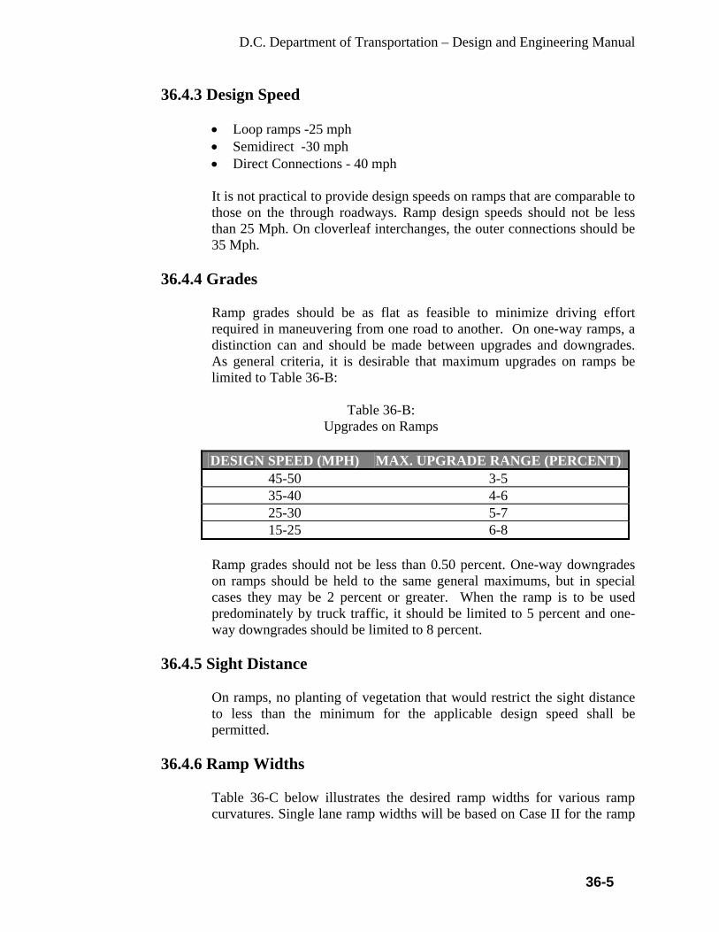
D.C. Department of Transportation – Design and Engineering Manual
36-5
36.4.3 Design Speed
• Loop ramps -25 mph • Semidirect -30 mph • Direct Connections - 40 mph It is not practical to provide design speeds on ramps that are comparable to those on the through roadways. Ramp design speeds should not be less than 25 Mph. On cloverleaf interchanges, the outer connections should be 35 Mph.
36.4.4 Grades
Ramp grades should be as flat as feasible to minimize driving effort required in maneuvering from one road to another. On one-way ramps, a distinction can and should be made between upgrades and downgrades. As general criteria, it is desirable that maximum upgrades on ramps be limited to Table 36-B:
Table 36-B:
Upgrades on Ramps
DESIGN SPEED (MPH) MAX. UPGRADE RANGE (PERCENT)45-50 3-5 35-40 4-6 25-30 5-7 15-25 6-8
Ramp grades should not be less than 0.50 percent. One-way downgrades on ramps should be held to the same general maximums, but in special cases they may be 2 percent or greater. When the ramp is to be used predominately by truck traffic, it should be limited to 5 percent and one-way downgrades should be limited to 8 percent.
36.4.5 Sight Distance
On ramps, no planting of vegetation that would restrict the sight distance to less than the minimum for the applicable design speed shall be permitted.
36.4.6 Ramp Widths
Table 36-C below illustrates the desired ramp widths for various ramp curvatures. Single lane ramp widths will be based on Case II for the ramp

D.C. Department of Transportation – Design and Engineering Manual
36-6
proper and Case I at the entrance terminal. Case III should be used in determining ramp widths on two lane ramps.
Table 36-C:
Design Widths of Pavement for Turning Roadways
Pavement Width (W) in Feet For: R Radius on Inner Edge of Pavement (Feet)
Case I Entrance Terminal Width
Case II Ramp Proper Width 1-Lane, One Way Operation
Case III Ramp Proper Width 2-lane, One way or Two way operation
50 20 26 - 75 19 24 - 100 18 23 - 150 18 22 32 200 18 22 31 300 17 22 30 400 17 22 30 500 17 22 30 Tangent 17 22 29
Ramp widths are applicable for ramps with or without curb. Minimum ramp radii will be used to determine ramp width. Width will be applied through entire ramp except at the ramp terminals. On 2-lane ramps where shoulders 4 ft. or wider are provided, reduce ramp pavement width by 4 ft. two-lane operation should not be considered on ramps with radii less than 150 ft. When percentage of semi trailer vehicles exceeds 10 percent, increase Case I widths by 1 ft., Case II and Case III by 2 ft.
36.4.7 Location of Ramp Intersection on Cross Roads
Factors that influence the location of ramp intersections on the cross road include sight distance, construction and ROW costs, circuitous travel for left turn movements, cross road gradient at ramp intersections, storage requirements for left turn movements off the cross road, and the proximity of other local road intersections. For left maneuvers from an off ramp at an unsignalized intersection, the length of cross road open to view should be greater than the product of the prevailing speed of vehicles on the cross road and the time required for a stopped vehicle on the ramp to safely execute a left turn maneuver. Where design controls prevent locating the ramp terminal, a sufficient distance from the structure to achieve the required sight distance, the sight distance should be obtained by flaring the end of the overcrossing structures or setting back the piers or end slopes of an undercrossing structure. Sharp curves at an off ramp terminal (at the intersection with the
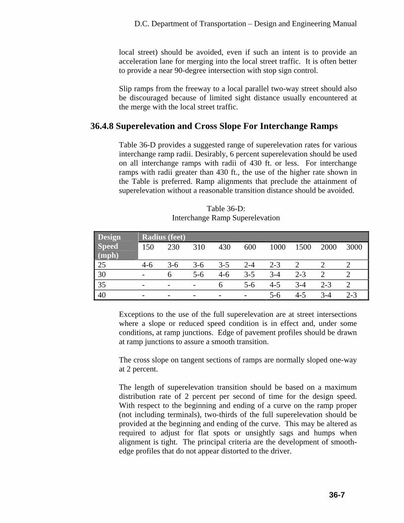
D.C. Department of Transportation – Design and Engineering Manual
36-7
local street) should be avoided, even if such an intent is to provide an acceleration lane for merging into the local street traffic. It is often better to provide a near 90-degree intersection with stop sign control.
Slip ramps from the freeway to a local parallel two-way street should also be discouraged because of limited sight distance usually encountered at the merge with the local street traffic.
36.4.8 Superelevation and Cross Slope For Interchange Ramps
Table 36-D provides a suggested range of superelevation rates for various interchange ramp radii. Desirably, 6 percent superelevation should be used on all interchange ramps with radii of 430 ft. or less. For interchange ramps with radii greater than 430 ft., the use of the higher rate shown in the Table is preferred. Ramp alignments that preclude the attainment of superelevation without a reasonable transition distance should be avoided.
Table 36-D:
Interchange Ramp Superelevation
Radius (feet) Design Speed (mph)
150 230 310 430 600 1000 1500 2000 3000
25 4-6 3-6 3-6 3-5 2-4 2-3 2 2 2 30 - 6 5-6 4-6 3-5 3-4 2-3 2 2 35 - - - 6 5-6 4-5 3-4 2-3 2 40 - - - - - 5-6 4-5 3-4 2-3
Exceptions to the use of the full superelevation are at street intersections where a slope or reduced speed condition is in effect and, under some conditions, at ramp junctions. Edge of pavement profiles should be drawn at ramp junctions to assure a smooth transition.
The cross slope on tangent sections of ramps are normally sloped one-way at 2 percent.
The length of superelevation transition should be based on a maximum distribution rate of 2 percent per second of time for the design speed. With respect to the beginning and ending of a curve on the ramp proper (not including terminals), two-thirds of the full superelevation should be provided at the beginning and ending of the curve. This may be altered as required to adjust for flat spots or unsightly sags and humps when alignment is tight. The principal criteria are the development of smooth-edge profiles that do not appear distorted to the driver.

D.C. Department of Transportation – Design and Engineering Manual
36-8
36.5 Freeway Entrances and Exits
36.5.1 Basic Policy
Desirably all interchange entrances and exits should connect at the right of through traffic. Freeway entrances and exits should be located on tangent sections where possible in order to provide maximum sight distance and optimum traffic operation.
36.5.2 Ramp Terminals
The ramp terminal is the portion of the ramp adjacent to the through lanes and includes the speed change lanes, tapers, gore areas, and merging ends. Superelevation transition should not exceed a maximum distribution rate of 2 percent per second of time for the design speed. Also, the suggested maximum differences in cross slope rates at the crossover crown line, rated to the speed of turning traffic, should not exceed the values shown in Table 35-E. The design control at the crossover crown line is the algebraic difference in cross slope rates of the ramp terminal pavement and the adjacent mainline pavement. A desirable maximum difference at a crossover line is 4 to 5 percent.
Table 36-E:
Maximum Differences in Cross Slope Rates at the Crossover Crown Line
Design Speed of Exit or Entrance Curve (mph)
Maximum Algebraic Difference in Cross Slope at Crossover Line (percent)
15 and 20 5 – 8 25 and 30 5 – 6 35 and over 4 – 5
36.5.3 Distance between Successive Exits
At interchanges there are frequently two or more ramp terminals in close proximity along the through lanes. In some interchange designs, ramps split into two separate ramps or combine into one ramp.
36.5.4 Auxiliary Lane Lengths
The AASHTO, A Policy on Geometric Design Highways and Streets (Green Book, current version: 2004), lists the ratio of length of auxiliary lane on grade to length on level.

D.C. Department of Transportation – Design and Engineering Manual
36-9
36.5.5 Curbs
Curbs may be used on ramps, including at the ramp connection with the local street to provide for the protection of pedestrians, for channelization and to provide continuity of construction at the local facility.
36.6 Additional Lanes
In order to ensure satisfactory operating conditions, additional lanes may be added to the basic width of traveled way. Where an entrance ramp of one interchange is closely followed by an exit ramp of another interchange, the acceleration and deceleration lanes may be joined. This should be the general practice where the weaving distance is less than 2000 ft. Where interchanges are more widely spaced and ramp volumes are high, the need for an additional lane between the interchanges should be determined by an across-freeway-lane volume check. This check should include consideration of freeway grade and volume of trucks.
36.7 Lane Reduction
Lane reduction below the basic number of lanes is not permissible through an interchange. Where the reduction in traffic volumes is sufficient to warrant a decrease in the basic number of lanes, a preferred location for the lane drop is beyond the influence of an interchange and preferably at least one half mile from the nearest exit or entrance. It is desirable to locate lane drops on tangent alignment with a straight or sag profile so that there is maximum visibility to the pavement markings in the merge area.
36.8 Route Continuity
Route continuity refers to the provision of a directional path along and throughout the length of a designated route. The designation pertains to a route number or a name of a major highway. Ideally, the driver continuing on the designated route should travel smoothly and naturally in his lane without being confronted with points of decision. This means the chosen through lane(s) should neither terminate nor exit. It is desirable therefore, that each exit from the designated route or entrance to the designated route be on the right, i.e., vehicular operation on the through route occurs on the left of all other traffic.
36.9 Weaving Sections
The vehicles entering and leaving the highway at common points, resulting in vehicle paths crossing creates weaving. Weaving normally occurs within an interchange or between closely spaced interchanges and should be avoided.

D.C. Department of Transportation – Design and Engineering Manual
36-10
Desirably on cloverleaf interchanges the distance between loop ramp terminals should not exceed 800 – 1000 ft. Where the weaving volumes require separations greater than the desirable, consideration should be given to providing a collector distributor road.
36.10 Access Control
Access rights shall be acquired along interchange ramps to their junction with the nearest existing public road. At such junctions, access control shall extend to the end of the acceleration or deceleration, excluding the taper. Desirably the access control should be extended beyond the end of the acceleration or deceleration lane taper a minimum of 100 ft. The interior of all ramps and loops at interchanges shall also be acquired. Where access is proposed at new or existing interchange locations, design waivers will be granted only after a thorough analysis has been made with respect to the cost of acquisition and impact on safety.

D.C. Department of Transportation – Design and Engineering Manual
37-1
CHAPTER 37
BARRIERS 37.1 General
These guidelines are based on the current Roadside Design Guide, AASHTO. This section is intended to serve as guidelines that will assist the designer in determining conditions that warrant the installations of guiderail and traffic barriers. It is important that application of these guidelines be made in conjunction with engineering judgment and thorough evaluation of site conditions to arrive at a proper solution. In some cases, another type of traffic barrier may be more effective than guide rail. The designer should consider alternatives and chooses the most suitable solution based on safety requirements, economic limitations, maintenance, and aesthetic considerations. It should be emphasized that guiderail and barriers should not be installed indiscriminately. Every effort should be made to eliminate the obstruction for which the guiderail is being considered. In the District, many roadways are off-system and guide rails or median barriers are not practical; in such cases the curbs may be considered reasonable barriers.
37.2 Guiderail Warrants
37.2.1 General
Guiderail is considered a longitudinal barrier whose primary functions are to prevent penetration and to safely redirect an errant vehicle away from a roadside or median obstruction.
37.2.2 How Warrants are Determined
An obstruction’s physical characteristics and its location within the clear zone are the basic factors to be considered in determining if guiderail is warranted. Special cases will arise which there is no clear choice about whether or not guiderail is warranted. Such cases must be evaluated on an individual basis, and, in the final analysis must usually be solved by engineering judgment.
37.2.3 Clear Zone
Clear zone is defined as the area, starting at the edge of the traveled way that is available for safe use by errant vehicles. The width of the clear zone (Lc) varies with the speed, roadside slope and horizontal roadway alignment. The design speed should be used when determining the clear zone.

D.C. Department of Transportation – Design and Engineering Manual
37-2
Table 37-A contains the suggested range of clear zone distances on tangent sections of roadway based on selected traffic volumes, speed and roadside slopes. Clear zones may be limited to 30 ft. for practicality and to provide a consistent roadway section if previous experience with similar projects or designs indicates satisfactory performance. According to the AASHTO Roadside Design Guide – later version, the designer may provide clear zone distances greater than 30 ft. as indicated in Table 37-A, where such occurrences are indicated by accident history. Table 37-B contains examples of determining clear zone distances. Horizontal alignment does affect the clear zone width. Therefore, clear zone widths on the outside of horizontal curves must be adjusted as shown in Table 37-C.
37.2.4 Warrants
A warranting obstruction is defined as a non-traversable roadside or a fixed object located within the clear zone. The physical characteristics are such that injuries resulting from an impact with the obstruction would probably be more severe than injuries resulting from an impact with guide rail.
37.2.4.1 Non-traversable Roadside
A non-traversable roadside that may warrant guiderail are: rough rock cuts, large boulders, streams or permanent bodies of water more than 2 ft. in depth, roadside channels with slopes steeper than 1H:1V and depths greater than 2 ft., embankment slopes and slopes in cut sections as described in the following.
37.2.4.2 Embankment (Fill) Slopes
A critical slope is one in which a vehicle is likely to overturn. Slopes steeper than 3H:1V generally fall into this category. If a slope steeper than 3H:1V begins closer to the traveled way than the suggested clear zone distance, guiderail might be warranted if it is not practical to flatten the slope. Guiderail warrants for critical slopes are shown in Table 37-A.
Table 37-A:
Critical Slope Warrants
Critical Embankment (fill) Slopes
Maximum Height Without GuideRail
1.5H:1V 3 ft. 2H:1V 6 ft. 2.5H: 1V 9 ft.

D.C. Department of Transportation – Design and Engineering Manual
37-3
A non-recoverable slope is defined as one that is traversable but the vehicle can be expected to travel to the bottom of the slope before steering recovery can be obtained. Embankments between 3H:1V and 4H:1V generally fall into this category. Fixed objects should not be constructed or located along such slopes that begin closer to the traveled way than the suggested clear zone distance. A clear runout area at the base of these slopes is desirable. The designer should, therefore, evaluate each site before providing 3H:1V slopes without guide rail. When flattening existing slopes to remove guide rail, the proposed side slopes should be recoverable, that is, 4H:1V or flatter. Where embankment slopes are being constructed, the designer should investigate the feasibility of providing a recoverable slope instead of a critical slope with guide rail. Rounding should be provided at slope breaks.
37.2.4.3 Slopes in Cut Sections
Slopes in cut sections should not ordinarily be shielded with guide rail. However, there may be obstructions on the slope that warrant shielding, such as bridge piers, retaining walls, trees, rocks, etc. that may cause excessive vehicle snagging rather than permit relatively smooth redirection. Slopes in cut section of 2H:1V or flatter may be considered traversable; and, as the cut slope steepens, the chance of rollover increases. Where feasible, slopes steeper than 2H:1V should be flattened. If there is a warranting obstruction on the cut slope, the following apply:
• Guiderail should be installed if the warranting obstruction is on a slope flatter than 0.7H:1V and is within the clear zone width specified for a 3H:1V slope.
• Guiderail should be installed if the warranting obstruction is on a slope of 0.7H:1V or steeper and is less than 6 ft. (measured along the slope) from the toe of the slope and is within the clear zone width specified for a 3:1 slope.
• Guiderail is not required if the warranting obstruction is on a slope of 0.7H:1V or steeper and is 6 ft. or more (measured along the slope) from the toe of the slope.
37.2.5 Drainage Features
Channels should be designed to be traversable. Where feasible, existing channels should be reconstructed to be traversable. According to the Roadside Design Guide, AASHTO, 1: “If practical, roadside channels with cross sections outside the shaded regions and located in vulnerable

D.C. Department of Transportation – Design and Engineering Manual
37-4
areas may be reshaped and converted to a closed system (culvert or pipe), or in some cases, shielded by a traffic barrier”.
37.2.6 Fixed Objects
Fixed objects that may warrant guiderail are: overhead sign supports, traffic signals and luminaires supports of non-breakaway design, concrete pedestals extending more than 4 in. above the ground, bridge piers, abutments and ends of parapets and railings, wood poles or posts with a cross sectional area greater than 50 sq. in. and drainage structures. In no case shall breakaway, bendaway or non-breakaway design supports, highway lighting, trees, utility poles, fire hydrants, mailboxes and signs on new or upgraded guiderail installations remain in front of guide rail. Overhead sign supports should be protected by guiderail or impact attenuator. Breakaway sign structures are not recommended in DC because a falling sign is considered more than the rigid signpost. Overhead sign supports should be located as close to the ROW line as practical. Guiderail protection for all overhead sign supports should be provided regardless of location beyond the clear zone. This will limit severe implications resulting from impacts to the sign support.
37.2.7 Trees Trees, 6 in. in diameter or greater, are considered fixed objects. However, trees are not considered a warranting obstruction for guiderail since guiderail is not installed solely for shielding trees. The following guidance is provided for the treatment of trees within the clear zone: • On freeways and interstate routes, trees shall not be located within the
clear zone. • The aesthetic appeal of the trees will cause opposition to their removal,
Removal of the trees will not be environmentally acceptable. Factors such as accident experience, traffic volume, speed and roadway geometry should be evaluated.
• Sick and diseased trees that are beyond reasonable repair, along with dead trees, trees that cause sight distance problems and trees with a significant accident history shall be removed. Also, trees that will be harmed beyond reasonable repair due to construction shall be removed. The Urban Forestry Division should be consulted for the tree’s physical assessment.
• Cityscape trees shall not be removed without permission from the District’s Urban Forest Administration. As a minimum, branches

D.C. Department of Transportation – Design and Engineering Manual
37-5
overhanging the roadway shall be removed up to a height of 16 ft. The following areas should be checked for sight distance problems: - Along the inside of horizontal curves. - Ramp and jug handle entrances and exits. - Within the sight triangle at intersections. - Sign obstructions.
• If clearing work is necessary within existing utility lines, the designer should request the utility company to perform regular trimming maintenance (at their cost) in the locations during the utility notification process.
37.2.8 Utility Poles
On existing highways, where the utility pole offset does not meet the requirements, the designer should prepare an accident analysis of existing pole locations to determine if the relocation of the utility poles further from the edge of a through lane is warranted. Utility poles should not be placed in vulnerable locations, such as in gore areas, small islands or on the outside of sharp horizontal curves. For the purpose of these guidelines, a sharp horizontal curve is considered as any horizontal curve with a safe speed lower than the posted speed. In no case, shall utility poles on new or upgraded guiderail installations remain in front of the guide rail. Relocate the pole behind the guide rail. The face of the pole should be 4 ft. or greater from the back of the rail. Where the offset is less than 4 ft., provide reduced post spacing and double rail element. In the case when a pole will be located directly behind a post, the minimum pole offset should be no closer than 18 in. from the back of the rail. Guiderail is an obstruction in itself and should be placed as far from the traveled way as possible.
37.2.9 Fire Hydrants
The fire hydrants shall be the breakaway type, or locate the hydrants as far from the traveled way as possible. However, the hydrants must be located to be readily accessible at all times. Where guiderail is required for some other reason and will be in front of a hydrant, the preferred treatment is to raise the hydrant to permit connection to be made over the guide rail.
37.2.10 Pedestrians
Guiderail or barrier may be used where there is a reasonable possibility of an errant vehicle encroaching into an unprotected area used by pedestrians

D.C. Department of Transportation – Design and Engineering Manual
37-6
in playground and schoolyard areas. The basis for assessing the needs should be the accident experience of the immediate area and the specifics for the cause(s) of the accidents. There are locations where existing guiderail and the top of the slope of a steep slope are both located directly behind a pedestrian sidewalk area. If new guiderail is installed in front of the sidewalk area, the existing guiderail should be removed and a fence installed in its place.
37.3 Dimensional Characteristics
37.3.1 General Design Considerations
• Guiderail should not restrict sight distance. Sight distances should be checked when guiderail is to be installed at intersections, ramp terminals driveways, along sharply curving roadways, etc. If the sight distance is determined to be inadequate, the guiderail placement shall be adjusted.
• Whenever part of an existing guiderail run is lengthened, reset or upgraded, then the entire run shall be upgraded to current standards including the bridge attachments. Also, always end a project outside the limits of a guiderail run.
• Gaps between individual guiderail or concrete barriers installations should be avoided.
• Guiderail shorter than 200 ft is not recommended due to the limited strength and tension force.
• Guiderail should not be installed beyond the ROW unless easements or necessary ROW is acquired.
• Concrete barriers should be connected with concrete barriers between the parapet gaps with minimum height of 2.25 ft. Avoid use of different type of barriers and transitions in a short length.
• Proposed guiderail set flush with the curb line along intersection radius returns should be checked. Existing guiderail along radius returns that experience truck overhang or over steering accidents shall either be reset farther from the curb line or redesign the radius returns for a larger design vehicle.
• The grading work necessary for the construction of the guiderail end treatments shall be shown on the construction plans.
• Conduits – The plans shall indicate the location of existing conduits or shall include a notation where there is a possibility of conflict in driving the guiderail posts.
• Nonvegetative Surface Under Guiderail– In order to reduce soil erosion and highway maintenance costs associated with spraying or trimming vegetation underneath guide rail, nonvegetative surfaces shall be applied underneath guiderail.

D.C. Department of Transportation – Design and Engineering Manual
37-7
37.3.1.1 Without a Curb or Raised Berm in Front of Guide Rail It is desirable to place the guiderail at a distance beyond that which will not be perceived as a threat by the driver. In general, the following offsets and slopes should be used:
• To the extent possible, guiderail should be located as far as possible away from the traveled way to provide a recovery area for errant vehicles and to provide adequate sight distance along horizontal curves and at intersections.
• On interstate highways and freeways, the front face of the guiderail should desirably be 4 ft. or more from the outside edge of shoulder. Where this offset is not possible, the guiderail should be installed flush with the gutter line.
• On roadways where there is a sidewalk or a sidewalk area used by pedestrians, the front face of the guiderail should desirably 7 ft. or more from the outside edge of shoulder. Where this offset is not possible, the guiderail should be installed flush with the gutter line or offset no more than 3 in. from the face of the curb.
• On roadways where there is no sidewalk, and the border area is not used by pedestrians, the front face of the guiderail may be placed any distance from the gutter line; however, an offset of 4 ft. or more is preferred.
• Where guiderail is located at the top of an embankment slope, the posts should be a minimum of 2 ft. from the top of slope to the center of the post. When less than 2 ft. is provided, the following post lengths, shown in the Table 37-B should be used:
Table 37-B:
Additional Post Length Requirements Where Distance from the Top of Slope to Center of Post is less than 2 ft.
• Guiderail shall be placed on slopes 10H:1V or flatter provided the rollover between the shoulder slope and the embankment slope is not greater than 10 percent.
37.3.1.2 Curb or Raised Berm in Front of Guide Rail
Curb or a raised berm in front of guiderail should be avoided.
Embankment Slopes Additional Post Length Flatter Than 6H:1V No Change 6H:1V to 4H:1V 1 ft. 3H:1V to 2H:1V 2 ft. Steeper than 2H:1V 4 ft.
D.C. Department of Transportation – Design and Engineering Manual
37-8
On freeways and interstate highways, new installations of vertical curb shall not be constructed. However, sloping curb may be constructed on urban freeways and urban interstate highways but the overall curb height shall not exceed 4 in. On projects that involve upgrading existing roadways, where there is a curb or a raised berm in front of guide rail, removal or modification of the curb or raised berm should be the first consideration.
37.3.2 Rub Rail
When guiderail is constructed less than 3 ft. from a curb or raised berm that is 4 in. or greater in overall height, the mounting height is measured from the top of the curb or raised berm and rub rail is required. Where guiderail is set flush to the gutter line and goes across short sections (i.e. less than 100 ft. long at each location) of the curb, 4 in. or less in height; the mounting height may be measured from the gutter line, in which case, rub rail is not required. On all projects involving new guiderail or the upgrading of existing guide rail, every effort should be given to the elimination or reduction in the use rub rail. Acceptable methods for reducing or eliminating the need for rub rail includes: providing sufficient offsets, removing or revising earth berms, providing designs without curb, and eliminating the existing curb where feasible.
37.3.3 At Fixed Objects
Where guiderail is used to shield an isolated obstruction it is more important that the guiderail be located as far from the traveled way as possible to minimize the probability of impact. The distance form the back of the rail element to the face of obstruction should desirably be 4 ft. or greater. If less than 4 ft. must be used, the guiderail system must be modified.
37.3.4 On Bridges
On existing freeway and interstate structures with safety walks where it is not feasible to remove and provide a concrete, barrier-shaped parapet, the crashworthy steel traffic rail shall be carried across the structure along the gutter line. The guiderail should not be installed across the structure. When there is a difference in the offset to the approach guiderail and the offset to the bridge parapet, a transition flare of 15:1 should be used.

D.C. Department of Transportation – Design and Engineering Manual
37-9
37.3.5 End Treatments
37.3.5.1 Guiderail Terminals
Use the current Department’s approved standard guiderail terminals and anchorage on the approach and trailing ends of beam guiderail. A guiderail terminal shall be placed a minimum distance of 12.5 ft. beyond the length of need. A guiderail terminal shall not be installed behind a curb greater than 4 in. in height. Where there is an existing curb or proposed curb greater than 4 in. in height, 75 ft. of the curb immediately in advance of and 50 ft. beyond the front of a guiderail terminal shall be removed and replaced with a 4 in. mountable vertical curb. A clear area shall be provided behind a guiderail terminal installation. Slopes in front of guiderail and 6 ft. behind the guiderail terminal shall be graded at 10H:1V or flatter. Where guiderail is installed along a horizontal curve, the post offsets for the parabolic flare is measured from a line tangent to the horizontal curve.
37.3.5.2 At Gore Areas
It is desirable to provide a traversable and unobstructed gore area since the gore area may serve as a recovery area for errant vehicles. Urban areas, wetlands, parklands, etc. can put restrictions on this policy by placing warranting obstructions, such as critical embankment slopes, parapets or abutments close to gore areas. The closer the obstruction to the gore area, the closer the length of need (L.O.N.) to the gore area, therefore the more limited the guiderail treatment becomes. The preferred treatments for gore areas are no guiderail warrants at all.
37.4 Median Barrier
A median barrier is a longitudinal system used to prevent an errant vehicle from crossing that portion of a divided highway separating traveled ways for traffic in opposite directions.
37.4.1 Warrants for Median Barriers
37.4.1.1 Interstate and Freeways
At low ADT’s, the probability of a vehicle crossing the median is relatively small. Therefore, for ADT’s less than 20,000, a median barrier

D.C. Department of Transportation – Design and Engineering Manual
37-10
is warranted only if there has been a history of cross-median accidents. Likewise, for relatively wide medians the probability of a vehicle crossing the median is also low. Thus, for median widths greater than 30 ft. and within the optional area of the figure, a median barrier may or may not be warranted, again depending on the cross-median accident history. Flat medians that are wider than 50 ft. do not warrant a barrier unless there is a significant history of across-the-median accidents.
37.4.1.2 City Roads/Highways
Careful consideration should be given to the installation of median barriers on city roads/highways or other highways with partial control of access. Problems are created at each intersection or median crossover because the median barrier must be terminated at these points. An evaluation of the number of crossovers, accident history, alignment, sight distance, design speed, traffic volume and median width should be made before installation of median barriers on highways. Each location should be looked at on a case-by-case basis with the prevailing reason for its installation being the number of crossover accidents.
37.4.2 Median Barrier Types
Median barrier type, when warranted, is related to median width as shown in Table 37-C.
Table 37-C: Median Width vs. Median Barrier Type
Median Width Median Barrier Type Up to 12 ft. Concrete Barrier Curb 13 – 26 ft. Concrete Barrier Curb (Preferred) or Dual Face Beam
Guide Rail Above 26 ft. Dual Face Beam Guide Rail
A minimum offset of 3.25 ft. from the gutter line to the face of the obstruction shall be used, since high profile vehicles have a tendency to lean when impacting barrier curb at a high speed (60 Mph or greater) and angle (25-degree) and may strike the obstruction behind it. Concrete barrier or guiderail must be used to shield an obstruction of bridge piers, abutments, sign bridges, etc. Architectural barriers with stone facing or stamped concrete should be considered for aesthetic requirements. The barrier should be flushed with
D.C. Department of Transportation – Design and Engineering Manual
37-11
the curbs or mountable curbs may be considered when it is not practical to flush with the curb.
37.4.3 End Treatments
When terminating the approach end of dual face, beam guiderail beyond the clear zone, and end anchorage with end section (buffer) is required. When terminating the approach end of a concrete barrier curb beyond the clear zone, a tapered concrete terminal section is required. Where a median barrier terminates within the clear zone area on freeways and interstate highways, a crashworthy end treatment shall be used.

D.C. Department of Transportation – Design and Engineering Manual
38-1
CHAPTER 38
CONSTRUCTION TRAFFIC CONTROL This chapter defines the Traffic Control design criteria for use on all roadway construction projects in the District. 38.1 Traffic Control Plan (TCP)
The construction traffic control plan (TCP) must be designed to move traffic (motorists, pedestrians, bikes) safely through a work zone. Elements of a traffic control plan include information about placement and maintenance of traffic control devices, methods and devices for delineation and channelization, construction scheduling, application and removal of pavement markings, roadway construction lighting requirements, traffic regulations, work zone protection and flagging operations. The Designer is required to provide the traffic control drawings as a part of the construction plan. Specifications for Traffic control restrictions; control devices, quantities and costs to implement the plans are also part of the TCP.
38.2 Construction Signing
Signing is an essential and integral part of any roadway construction project. The District has adoped the MUTCD and DDOT Design and Engineering Manual (DDEM) as a guideline for signing all construction work zones. Part IV of MUTCD and chapter of the DDEM provide examples of typical construction signs, methods of erection and signing schemes to handle a variety of construction activities. Although the signs are temporary and need not be made from standard durable parcel material and support they may be sufficiently durable to withstand environmental conditions and in accord with Part IV of the MUTCD and chapter of this manual.
38.3 Channelizing Devices
Channelizing devices are designed to warn and alert drivers of potential obstacles created by construction or maintenance operations on or near the traveled way, to protect workers in the work zone and to guide and direct drivers and pedestrians safely past potential obstacles. These devices may be used to provide a smooth and gradual transition in moving traffic from one lane to another, onto a bypass or detour or in reducing the width of the lane. Channelizing devices should always be preceded by a series of warning devices adequate in size, number and placement for the roadway. Their design should be such that they avoid inflicting unnecessary damage to vehicles that may inadvertently strike them.
D.C. Department of Transportation – Design and Engineering Manual
38-2
The taper developed by channelizing devices is one of the most important elements within the system of construction traffic control devices. Tapers may be necessary in both the upstream and downstream directions of traffic depending on the construction activity. Tapers and requirements for layout of tapers are provided in the DDOT, Work Zone Traffic Control Standards and Guidelines, A variety of channelizing devices are acceptable for use in construction projects. These channelizing devices include: • Traffic Cones • Tubular Markers • Vertical Panels • Drums • Barricades • Concrete Barriers • Arrow Panels Traffic cones are used for daytime work only. All other barriers must be usable for nighttime and daytime activities. The designer shall show the type and placement of these devices in the TCP.
38.4 Special Devices
Other special traffic control devices may be used during the construction process to direct traffic flow or convey messages to drivers. These devices include changeable message signs, lane-use signals, crash cushions or other similar devices. These devices must be shown where required with appropriate spacing or location, in accordance with MUTCD, Part 6, on the plans.
38.5 Construction Staging/Phasing
Most construction projects require the maintenance of traffic throughout the work zone. To facilitate traffic maintenance construction is often done in process. Traffic control plans must detail the construction stages for all phases of the construction project.
38.6 Plan Layout
The TCP shall be developed at the same scale as the roadway plans. Large scale drawings may be used to show the detour and locations of signs. However, their use shall be approved by the Engineer. The plan must include all existing striping, signage, temporary traffic controls and any signs or striping that should be removed or relocated during constriction. All barricades, signs and striping shall be delineated and lengths or distances called out on the TCP.

D.C. Department of Transportation – Design and Engineering Manual
38-3
38.7 Review and Approval
Traffic control plans shall be submitted with the construction plan for review and approval. DDOT Infrastructure Project Management Administration (IPMA) will coordinate the review and approval of the (TCP) in the various stages of submission.
38.8 The Work Zone Safety and Mobility Requirements Refer to 2007 DC Work Zone Safety and Mobility Policy for detailed conditions, requirements and needed actions.

D.C. Department of Transportation – Design and Engineering Manual
39-1
CHAPTER 39
TRAFFIC CALMING 39.1 General
This chapter defines methods of neighborhood traffic calming that are determined by the District applicable to existing Local and Minor Collector Roadways. This chapter also provides for specific design criteria for a number of traffic calming methods. "Traffic Calming is the combination of mainly physical measures that reduce the negative effects of motor vehicles, improve driver behavior and conditions for non-motorized street users". NOTE: For additional information and criteria relative to Traffic Calming, refer to the ITE/FHWA publication: Current Traffic Calming, State of Practice and the DDOT Traffic Calming Design Guidelines 39.1.1 Intended Use
The necessity or desire for traffic safety and calming stems from the perception that Local and Minor Collector Roadways, particularly in residential areas, do not always function as intended. These roadways should be low-traffic-volume roadways used for direct access to residences on the street. They are also intended as a multi-modal system that is shared by vehicular, bicycle, and pedestrian traffic equally, in a manner that minimally impacts residents in the adjacent neighborhood.
39.1.2 Design Principles
Traffic calming measures shall only be designed at a location where an engineering study has been performed that indicates calming measures are warranted. Getting the community involved is a major element in a traffic calming project. Concurrence and a fully informed neighborhood is essential in insuring a successful traffic calming project. The design of traffic calming measures shall be in accordance with principles and guidelines established by the DDOT Traffic Calming Manual and the FHWA Traffic Calming State of Practice. The designer should review the geometric roadway design criteria with the AASHTO, A Policy on Geometric Design of Highways and Streets (Green Book, current version: 2004), and signing and pavement markings should be in accordance with MUTCD. NOTE: The design of roundabouts shall be based on guidelines established by current USDOT/FHWA, Publication Roundabouts - an Informational Guide.
D.C. Department of Transportation – Design and Engineering Manual
39-2
39.1.3 Traffic Calming for New Street Design
New roadways (local streets and minor collectors) are to be designed to minimize cut through traffic, high volumes, and high-speed operation and to maximize the efficiency of the roadway to provide vehicular access and bicycle and pedestrian traffic, especially the handicapped persons.
39.1.4 Roundabouts and Mini Roundabouts
Roundabouts and Mini Roundabouts, considered traffic control measures, are included in the Intersections chapter within this manual. These traffic control measures may be used in new or existing street design if the appropriate criteria are met. The design of roundabouts shall be based on guidelines provided in the USDOT/FHWA publication: Roundabout an informational guide (FHWA-RD-00-67, June 2000).
39.2 Traffic Safety Problems
Complaints about excessive speed, volume, or cut-through usually originate from residents. Residents believe that such activities diminish that neighborhood’s quality of life. Traffic calming measures are intended to minimize these issues and return the quality of life to the neighborhood. Care must be taken by the designer to ensure that the selected traffic calming measures do not create unintended hazards that delay emergency response or jeopardize the safety of bicyclists, pedestrians, especially the handicapped persons or motorists.
39.2.1 Speeding
Speeding may occur on roadways that allow the driver to feel safe while exceeding the posted speed limit. Factors that contribute to this perception include long, unbroken line of sight, steep roadway grades, wide roadways, low-density developments, low pedestrian activity, and large building setbacks. In addition, speeding may occur when the street functions as a higher classification street than originally intended.
39.2.2 Measuring Speed of Roadway
One of the key statistics from a spot speed study used to measuring speed on any street is the determination of the 85th percentile speed. The 85th percentile speed is the speed at which or below which 85 percent of the vehicles travel. If the 85th percentile speed is at or below the posted speed limit, speeding is not an adverse traffic operating condition, and remedy may not be needed. However, if the 85th percentile speed is over the posted speed limit by 10 mph or greater, either the posted speed limit may

D.C. Department of Transportation – Design and Engineering Manual
39-3
be inappropriate or a speeding problem may exist. Many other factors must be evaluated for determining speed limit.
39.2.3 Traffic Intrusion (Cut-through Traffic)
The intrusion of excessive non-local traffic along a neighborhood street must be controlled. This cut-through traffic is caused by drivers who use a local street to go through a neighborhood and save time on their trip. Local street that are less impeded traffic than arterials and collectors within the same neighborhood are often the target for cut-through traffic. Routes that are perceived to be time-saving will attract more traffic. This increased cut-through traffic can cause a local street to function more like a Collector.
39.2.4 Pedestrian Safety
Pedestrian safety is a concern of neighborhood residents who routinely encounter speeding vehicles, cut-through traffic, or a combination of these problems. The concern is higher among residents who live near neighborhood schools and parks or mid-block pedestrian crossings, particularly on streets with on-street parking. These areas require special consideration for the mobility and safety of the pedestrian. All handicap ramps shall be located within the crosswalk. At least one of the ramp’s side flares must align, as close as possible to the back edge line of the crosswalks. Handicap ramps must be installed for each travel direction at a corner. Handicap ramps located at the center of the corner radii must be pre-approved by the Chief Engineer. All mid-block crossings require advance pedestrian signing. Signs must be placed a minimum of 150 ft. before a mid-block crosswalk. NOTE: The remainder of this chapter describes design criteria for the engineered solutions; it does not state when or where these improvements are to be used.
39.2.5 Devices
Traffic calming measures are usually classified according to their dominant effect and are as follows: • Volume Control (e.g. full street closures, half closures, diagonal
diverters, median barriers and forced turn islands) • Speed Control
- Vertical Control Measures (e.g. speed humps, speed tables, raised intersections and textured pavements)

D.C. Department of Transportation – Design and Engineering Manual
39-4
- Horizontal Control Measures (e.g. traffic circles, chicanes, lateral shifts and realigned intersections) - Narrowings (e.g. neckdowns, center island narrowings and chokers)
39.3 Volume Control Devices These devices are intended to control the number of vehicles used in a corridor or specific area. There are several methods used to control the traffic including the following:
39.3.1 Forced Turn Barrier (Pork Chops)
This device is used on secondary roads or driveways to prohibit straight movements across congested streets. It forces the motorists to turn right or left. This island (pork chop) should be designed with a minimum size of 50 sf.
39.3.2 Turn Prohibitors
These devices can be signs or physical barricades used to prohibit turns that are disruptive to the flow of traffic or to minimize the cut through traffic into a residential neighborhood.
39.3.3 Semi-Diverters
Semi-diverters prevent drivers from entering or exiting certain legs of an intersection. Strategically located, semi-diverters can effectively reduce traffic volumes on a street. Generally, these are used on non-transit streets only. All diverters should continue to allow for pedestrian and bicycle access to the street.
39.3.4 Diagonal Diverters
These physical barricades limit vehicular traffic from continuous travel or left turns in the intersection. The diverters may be created as a temporary situation using removable concrete barriers or as a permanent situation with a wall or trees or other more permanent devices.
39.4 Vertical Control Measures
39.4.1 Speed Humps, Bumps or Tables
There are several varieties including rounded and flat topped humps. Those that are topped are used for pedestrian crossings. The width of the

D.C. Department of Transportation – Design and Engineering Manual
39-5
humps may be restricted to allow the curb drainage to flow appropriately. Speed humps are not recommended for bus routes because of the potential discomfort to bus passengers.
39.4.2 Raised Intersections
Raised Intersections – This is accomplished by raising the elevation of the crosswalks and the central area between them. Raised intersections enhance the visibility between motorist and crossing pedestrians.
39.4.3 Textured Pavements
This may include differential pavements colored concrete pad within an asphalt street, rumble strips, stamped concrete or other similar treatments to make the driver aware of a crosswalk, a congested intersection or other situations that may require special driver attention.
39.5 Horizontal Control Measures
39.5.1 Neighborhood Traffic Circles Neighborhood traffic circles are small circular islands, or mini roundabouts, are usually less than 26’ in diameter and can be located at the intersections of neighborhoods streets. Refer to the section or roundabouts in the intersections chapter of this manual for consideration in designing mini roundabouts.
39.5.2 Realigned Intersections
Realigned intersections are changes in alignment those typically covert T-intersections with straight approaches in curving streets that meet at right angle.
39.5.3 Chicanes
This narrowing of the roadway is intended to slow speeds of vehicles on roadways to permit pedestrians to cross, as appropriate, more safely due to less roadway to cross, and lower exposure on the lanes used by vehicles.
39.6 Narrowings
39.6.1 Neck-downs/Intersection Chokers
These are extensions of a curb in the form of a bulb, usually at intersections that narrow the vehicular pathway, thereby reducing vehicle

D.C. Department of Transportation – Design and Engineering Manual
39-6
speeds and inhibiting fast turns. Generally, neckdowns bring pedestrians and traffic control (stop signs) out into a clearer view for the vehicular traffic. Pedestrian crossing distances are made shorter. Special attention needs to be given to drainage around the neckdowns or chokers. If bike lanes exist, care should be taken to carry bike lanes through the neck-down or proper signage should be installed to warn bicyclists of the narrowing.
39.6.2 Lane Eliminating Choker
This design eliminates a lane of traffic, thereby increasing traffic volume in one lane, thereby decreased speeds.
39.6.3 Center Islands/Medians
Generally, center islands are more effective as a pedestrian refuge area, but may be used in conjunction with chicanes to slow down vehicular speeds. These islands should be a minimum of 4ft wide.
39.7 Neighborhood Identification Island (Gateway Design)
This involves the identification of neighborhoods, thereby notifying motorists that they are entering a residential area and increases motorist awareness of the appropriate speed and uses of the roadways.
39.8 Drop Off Zone for Schools This measure is used to separate the drop off at a school from the through traffic by creating an extra roadway, traffic lane, layby or drop off area similar to bus stops.

D.C. Department of Transportation – Design and Engineering Manual
40-1
CHAPTER 40
TRAFFIC SIGNAL DESIGN
40.1 Introduction
A traffic signal is an electrically powered traffic control device, other than a barricade warning light or steady burning electric lamp, by which traffic is alerted and directed to take some specific action. The objective of traffic signal design is to properly distribute the right-of-way to approaching traffic so that vehicles are able to move through an intersection or a specific area smoothly and safely.
The following types and uses of traffic signals are discussed in this chapter: Traffic Control Signals, Pedestrian Crossing Signals, Ramp Metering Signals, Flashing Beacons, Lane-Use Control Signals, Traffic Control at Movable Bridges, Priority Control of Traffic Signals, Traffic Signals for One-lane, Two-way Facilities, School Warning Flashers, Electric Signs and Displays and Traffic Signals for Construction Zones.
Traffic control signals are devices for the control of vehicle and pedestrian traffic.
• They assign the right of way to the various traffic movements. • Traffic control signals have one or more of the following advantages:
o They provide for the orderly movement of traffic. o They increase the traffic handling capacity of the intersection. o They reduce the frequency of certain types of accidents, especially
the right angle type. o They can be coordinated to provide for continuous or nearly
continuous movement of traffic at a definite speed. o They permit minor street traffic, vehicular or pedestrian, to enter or
cross continuous traffic on the major street.
Data over a number of years indicates that while the number of right-angle collisions decreases after the installation of traffic signals, the number of rear-end collisions increases. The installation of signals may increase overall delay and reduce intersection capacity. Consequently, it is of the utmost importance that the consideration of a signal installation and the selection of equipment be preceded by a thorough study of traffic and roadway conditions made by an experienced and trained engineer in the field. Equally important is the need for checking the efficiency of a traffic signal in operation. This determines the degree to which the type of installation and the timing program meet the requirements of traffic.
40.2 Traffic Signal Warrants
The justification for the installation of a traffic signal at an intersection should be evaluated based on guidance in this manual and the warrants stated in the most current edition of the Manual On Uniform Traffic Control Devices (MUTCD)

D.C. Department of Transportation – Design and Engineering Manual
40-2
published by the Federal Highway Administration (FHWA). The decision to install a signal should not be based solely upon the warrants, since the installation of traffic signals may increase certain types of collisions. Delay, congestion, approach conditions, pedestrian safety, driver confusion, future land use or other evidence of the need for right of way assignment beyond that which could be provided by stop signs must be demonstrated. All intersections in the District of Columbia are considered urban. The installation of a traffic signal should be considered if one or more of the warrants for traffic signal in the most current edition of MUTCD are satisfied.
40.3 Guidelines for Left-Turn Phases
Since separate signal phases for protected left turns will reduce the green time available for other phases, alternate means of handling left turn conflicts should be considered first. Protected left turn phases also decrease the walk time available for pedestrians and lead to decreased compliance with pedestrian signals, reducing the effectiveness of the protected left turn phase. The most likely possibilities are:
• Prohibition of left turns. This can be done only if there are convenient alternate means of making the movement. Typical alternate means are: o A series of right and/or left turns around a block to permit getting
to the desired destination; or o Making the left turn at an adjacent un-signalized intersection
during gaps in the opposing through traffic. • Geometric changes to eliminate the left turn. An effective change
would be a complete separation or a complete or partial “clover leaf” at grade. Any of these, while eliminating left turns, requires additional cost and right of way.
• Left turn signal phases can be displayed in a variety of formats. A split phase signal operation accommodates all possible movements without conflict from another approach during the phase. In addition, a left turn phase can occur at the beginning or at the end of a green signal indication for a movement. This left turn phase may be permissive or fully protected. A permissive left turn is one in which a motorist may turn left after yielding to oncoming traffic before the green arrow appears or after the green arrow expires during the through green phase. A fully protected left turn is one in which the left turn shall occur only when the green left turn arrow is displayed. A lane dedicated exclusively for left turning vehicle shall be provided for all fully protected left turn phases except those occurring during a split phase operation. Permissive left turns are typically allowed at all times during all signal timing plans, but they may be prohibited at certain

D.C. Department of Transportation – Design and Engineering Manual
40-3
times of the day when such movement either can not be performed or compromise traffic signal coordination. The left turn format selected for a particular intersection is dependent upon a number of factors including intersection geometry, the number of available lanes, the volume of left turning traffic, and the corridor time/space relationship.
Left turn phases should be considered when one or more of the following conditions exist:
• Accidents. Five or more left turn accidents for a particular left turn movement during a recent 12-month period.
• Delay. Left-turn delay of one or more vehicles which were waiting at the beginning of the green interval and are still remaining in the left turn lane after at least 80% of the total number of cycles for one hour.
• Volume. At new intersections where only estimated volumes are available, the following criteria may be used. For a pre-timed signal or a background –cycle-controlled actuated signal, a left turn volume of more than two vehicles per approach per cycle for a peak hour; or for a traffic-actuated signal, 50 or more left turning vehicles per hour in one direction with the product of the turning and conflicting through traffic during the peak hour of 100,000 or more.
• Condition. Left turn signal phases should fit within the established main street corridor coordination pattern to ensure the progressive movement of traffic.
• Miscellaneous. Other factors that might be considered include but are not limited to: impaired sight distance due to horizontal or vertical curvature, or where there is a large percentage of buses and trucks.
40.4 Removal of Existing Signals
Changes in traffic patterns may result in a situation where traffic signal is no longer justified. When this occurs, consideration should be given to removing the traffic signal and replacing it with appropriate alternative traffic control devices, consistent with the provisions of MUTCD, community consensus, and municipal regulations.
40.5 Traffic Signal Development Procedures
40.5.1 Introduction
The cost of traffic signals on Federal Aid highway projects is eligible for federal participation under certain conditions. A project study report may be required for installation of a new traffic signal, modification and replacement of an existing traffic signal if federal funds are to be used for the designing (PE) of project.

D.C. Department of Transportation – Design and Engineering Manual
40-4
40.5.2 Project Report
A project report shall be prepared whether the work is performed by the District of Columbia or by others, and it should include the following specific information:
1. Traffic Counts. A ten (10) hour turning movement count which includes all possible vehicular and pedestrian movements in 15 minute increments is required. Data from these counts shall be used to justify a new signal or a signal phasing change. The count shall be conducted during the ten hour period in a single day when traffic and/or pedestrian volumes are projected to be the highest. All counts shall be presented in the standard DDOT format and shall be made available to DDOT for inclusion into archives.
2. Collision Diagram.
A collision diagram for the intersection covering the recent accident experience history should be provided. The diagram should cover a 3-year interval.
3. Condition Diagram.
A condition diagram showing existing roadway conditions should be provided. Any railroad grade crossing within 200 feet of the intersection should be shown on the condition diagram. 4. Traffic Warrant Study.
A District of Columbia, Department of Transportation (DDOT) approved format traffic warrant study should be completed and submitted as a part of the project study report.
5. Other Specialized Data When Appropriate:
• Classification of Vehicles. The classification is required
when it is a significant factor in affecting intersection capacity.
• Critical Speed (85th percentile) of Approaching Vehicles. This is the speed at a point unaffected by existing controls.
• Time-Space Diagram. All traffic signal in the city make up a coordinated traffic signal system. A time-space diagram showing how the proposed new signal or signal phasing

D.C. Department of Transportation – Design and Engineering Manual
40-5
change fits within the network for all timing plans is to be provided on an approved DDOT format (See Figure 40-6)
Figure 40-6. Sample Time-Space Diagram in DDOT Format

D.C. Department of Transportation – Design and Engineering Manual
40-6
40.6 Traffic Signal Design
40.6.1 Introduction Traffic signal design is the creation of engineering plans suitable for construction by a contractor. Components of a traffic signal design may include one or more of the followings:
• Signal (S) Drawing: A signal drawing shows all existing and proposed underground and above grade appurtenances, intersection curb lines and geometry, and communication cable routing, signing, and pavement marking, consistent with the operation of the new traffic signal. The signal drawing must feature sufficient detail to enable a contractor to install the traffic signal.
• Sequence of Operation (TS) drawing. A sequence of Operation Drawing describes the operation of the traffic signal. The TS drawing may appear in the actuated or pre-timed format consistent with software requirements of the location intersection controllers and the central traffic signal system.
• Traffic Signal Timing Plan Dial Sheet. The Dial Sheet shows the amount of time in the signal operation allocated for all signal intervals or phases, and the offset relationship between adjacent signalized intersections.
• Signing Plan • Pavement Marking Plan • Communication Plan, which must be included wit the S Drawing • Controller Configuration Package. This is a computer generated
package which translates traffic signal timing and phasing parameters into a format used by the traffic signal controller.
• Contract Special Provision. The document outlines work to be performed by a contractor performing traffic signal work at features clarifications to or additional work not outlined in the referenced content of the standard specifications for Highways and Bridges.
• Time-space Drawings. The drawings show the interrelationship between traffic signals in a corridor for each timing plan and determines the offset to be entered in the Dial Sheet and the Controller Configuration Package.
Traffic signal design work may be performed by in-house personnel and by private engineering consultants. District of Columbia personnel will always create the traffic signal timing plan and the controllers configuration package. Either the consultant or in-house personnel may create the other components of the traffic signal design as outlined in the consultant’s scope of work. The scope of work negotiated by the consultant and DDOT will describe fully all consultant deliverables.

D.C. Department of Transportation – Design and Engineering Manual
40-7
Consultants selected to perform traffic signal design work in the District of Columbia must be registered on DDOT’s Architect/ Engineer Schedule in the Traffic Signal, Street Light category. This condition applies to consultants performing stand-alone traffic signal design work, performing traffic signal design as a subconsultant on a larger DDOT project, or as a consultant retained by a developer, private contractor or government agency to modify a traffic signal consistent with their plans. Consultants performing stand-alone traffic signal design work shall be required to submit one original large Vellum S Drawing and one original traffic signal sequence of operation in standard DDOT format. Consultants performing work as a subconsultant or under contract to another agency shall submit two (2) original large vellum S Drawings and one original traffic signal sequence of operation. One large vellum drawing will be provided to DDOT for inclusion into Traffic Signal Files and the other shall be provided to the prime consultant or to the other agency. The DDOT Chief Engineer shall delegate a Traffic Engineer within the IPMA to sign and approve all S drawings and TS operations submitted by the consultant to DDOT. The signed drawings shall be the consultant notification that their work on this task is complete and that all deliverables itemized in the scope of work in paper and electronic format can be submitted to DDOT. The consultant shall be required in every case to submit to DDOT all S drawings and TS Operations in both proper and electronic format. Traffic signal plans included in any project authorized for receipt of competitive bids must feature the signature of the Traffic Engineer designated by the DDOT Chief Engineer to formally approve such work. The design of traffic signals by the District of Columbia, Department of Transportation (DDOT) is based upon the following publications:
• This Manual (DDOT) • Standard Specifications (DDOT Design Policy) • Standard Drawings (DDOT) • Manual on Uniform Traffic Control Devices for Streets and Highways
(FHWA) Additional references that may be used include:
• Transportation and Traffic Engineering Handbook, Institute of Traffic
Engineers (ITE) • Manual on Traffic Signal Design (ITE) • Traffic Control Systems Handbook (FHWA) • Transportation Research Board NCHRP Publications • Traffic Control Systems Standards, National Electrical Manufacturers
Association (NEMA) • AASHTO Publications
D.C. Department of Transportation – Design and Engineering Manual
40-8
• Traffic Control Devices Handbook (FHWA) • Signal and Lighting Design Guide (CALTRANS) • Ramp Meter Design Guidelines (CALTRANS) • Highway Design Manual (CALTRANS)
40.6.2 Selection of Traffic Signal Operation
A prime factor to be considered in selection of the type of traffic signal operation is adequacy. While it may be true that a sophisticated signal control will operate satisfactorily at any intersection, the intersection should not be provided with a type of control that is unnecessarily complex and expensive.
The type of traffic signal operation to be used is dependent upon the variations in traffic and pedestrian demand. The two general types of signal operation are pre-timed and traffic-actuated. Traffic-actuated operation can be further classified as full-traffic-actuated or semi-traffic-actuated. With full-traffic-actuated operation, all traffic movements or phases are provided with detectors. In semi-traffic-actuated operation, certain phases (usually the coordinated phases) do not have detectors.
Pre-timed and semi-traffic-actuated operation should be used in coordinated systems only. They should not be installed at isolated intersections (more than one mile from the closest signalized intersection).
Where the distance between signalized intersections is ½ mile or less, coordination of signals must be considered, including the preparation of a time-space diagram and an evaluation of the cost-effectiveness of coordination.
Discretion should be used with phasing at offset intersections as it may introduce operational problems, which should be recognized and avoided. The most critical of these problems is where one approach right-of-way is terminated while the opposing approach continues with a green indication.
40.6.3 Selection of Left-Turn Phasing
There are various methods to signalize left turn movements. See Figure 40-7. If the left turn volume is 300 or more vehicles per hour, or if delays to traffic at the intersection can be significantly reduced, consideration should be given to a two-lane left turn. In urban areas, turn lanes should be limited to a single left-turn lane. The practitioner needs to consider the safety benefits of adding turn lanes while minimizing pedestrian crossing distance.

D.C. Department of Transportation – Design and Engineering Manual
40-9
40.6.4 Simultaneous or Dual Left
This method is most effective during free or isolated operation and is traffic-actuated. It the most efficient means of providing protected left turn movements since the various phases and combinations of phases appear only on demand. A through movement is allowed to go with its associated left turn movement where there is no opposing left turn traffic.

D.C. Department of Transportation – Design and Engineering Manual
40-10
40.6.5 Lead-Lag Left Turns
This operation can be either pre-timed or traffic-actuated. Normally, “Lead-Lag” phasing should be considered for coordinated signals when the offset timing determined by the system time-space diagram results in the arrival of the two directions of traffic at different times during a cycle. This will provide the most efficient progressive band. Lagging green performs better when a left-turn lane is provided. In intersections with high pedestrian volumes, lagging green is preferred.
40.6.6 Opposite or Opposing Left Turns
Opposing operation should be used where the left turn volume per lane is very high in either direction and is about equal to or greater than the companion through movement. This method is especially useful when one of the through lanes must be used as an optional left turning lane or where a separate left turn lane cannot be provided.
40.6.7 Three-Phase Operation
Three-phase operation can be either pre-timed or traffic-actuated.
40.6.8 Permissive Left-Turn Phasing
This type of operation allows vehicles to make left turns during a fully protected interval with a green arrow indication, or to make a permissive left turn with a circular green indication when there are adequate gaps in opposing traffic. Permissive left turn phasing may be either pre-timed or traffic-actuated. Examples of the operation may be found in the Traffic Control Devices Handbook (FHWA).
There are normally two sequences that can be utilized with permissive left turn phasing: • Protected-Permissive. With this operation, left turn traffic is first
directed to turn left on the display of a green arrow and then permitted to turn during the non-protected interval on the display of a circular green.
• Permissive-Protected.With this operation, the left turn traffic is first permitted to turn during the non-protected interval on the display of a circular green and then directed to turn left on the display of a green arrow.
The advantages of this operation when compared to fully protected left turn phasing only are:

D.C. Department of Transportation – Design and Engineering Manual
40-11
• Reduced delay as left turn drivers may have an opportunity to make their left turns during the green interval or yellow change interval for through traffic.
• Allows the use of shorter cycle lengths in coordinated systems by reducing the time of the fully protected green interval for the left turn movement.
• Less chance of disrupting traffic in adjacent through lanes as left turn queues are less likely to exceed the length of the left turn lane.
• When a protected-permissive or permissive-protected left turn phasing operation is used for a signal system, no information sign is necessary. If a sign is used, it shall be a R73-7, LEFT TURN YIELD ON GREEN (Green Ball symbol) sign on streets with turning bays.
• The District may use an extinguishable message sign on local roads in place of the R73-7. The message shall say LEFT TURN YIELD in at least 6 inches high letters. The light source shall be designed and constructed so that when illuminated, the message shall be white and remain dark when not in use. The message shall be illuminated only when the green permissive ball is lighted.
40.6.9 Location of Controller Cabinets
Normally, the controller cabinets should be located in accordance with the following:
• It should not be vulnerable to traffic. • Traffic movements at the intersection should be visible from the
controller timing position. • The doors of the cabinets should open away from the curb or traveled
way. The cabinet is centered at least 3 feet from the face of the curb and situated at least 5 feet from the nearest street furniture.
• It should be possible to park a maintenance truck close to the cabinet • It should not be located in a drainage ditch, in an area which could be
under water or where subjected to water from sprinklers. • It should not obstruct sidewalks, wheelchair ramps, or entrances. • It should be placed so as not to obstruct pedestrian or driver visibility. Upon request, keys for the police panel on traffic signal controller cabinets shall be furnished to the local Metropolitan Police Department (MPD) district office. The designer should refer to Standard Specification of Highway & Structure 2007 for detailed types, functions and installation procedures of a traffic controller.

D.C. Department of Transportation – Design and Engineering Manual
40-12
40.6.10 Signal Plan Schedules
The traffic signal plans for the installation of a new signal or the major modification of an existing signal should include the following schedules:
• Pole and Equipment Schedule. A pole and equipment schedule shows
the types of standards, mast arm lengths, type and mounting for vehicle and pedestrian signal faces, and other equipment. See Figure 40-8.
• Conductors and conduit Schedule. A conductor and conduit schedule shows the size of each conduit run, and the size, type and number of conductors or cables in each conduit run. See Figure 40-8
Dimensions of conductors and conduit and data for determining conduit size are shown in Figure 40.9
40.6.11 Preemption
At some signal locations, it is necessary to preempt the normal traffic signal operation by a railroad train, an emergency vehicle or bus/transit vehicles. The order of priority for various types of preemption shall be: • Railroad • Emergency Vehicles • Bus/Transit Vehicles
40.6.12 Railroad Preemption
Railroad preemption results in a special traffic signal operation depending on the relation of the railroad tracks to the intersection, the number of phases in the traffic signal and other traffic conditions. Railroad preemption is normally controlled by the railroad grade crossing warning equipment. Typical circumstances where railroad preemption is required and the type of signal operations to be provided during preemption are as follows:
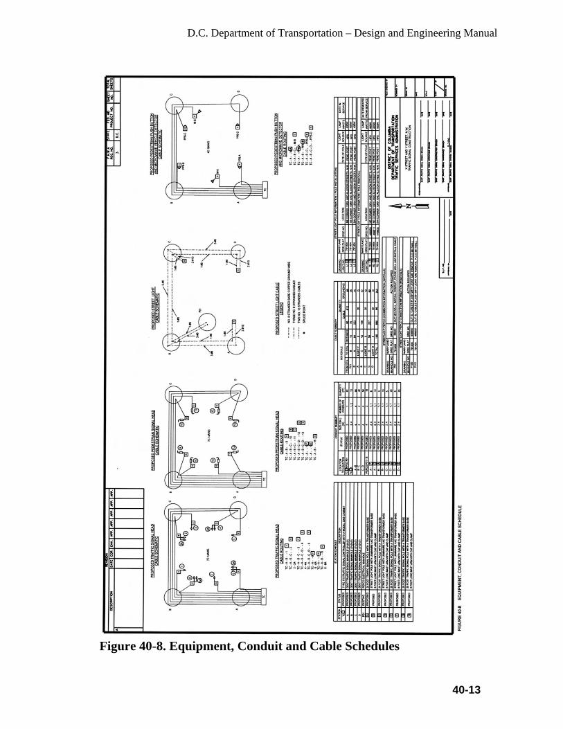
D.C. Department of Transportation – Design and Engineering Manual
40-13
Figure 40-8. Equipment, Conduit and Cable Schedules
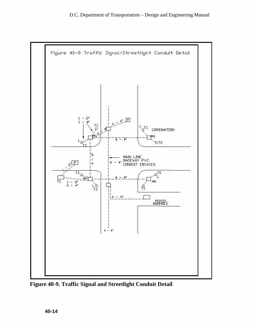
D.C. Department of Transportation – Design and Engineering Manual
40-14
Figure 40-9. Traffic Signal and Streetlight Conduit Detail
D.C. Department of Transportation – Design and Engineering Manual
40-15
• Where a railroad grade crossing, provided with grade warning equipment, is within 300 feet of a signalized intersection, preemption of the traffic signal should provide the following sequence of operation:
o A yellow change interval and any required red clearance interval for any signal phase that is green or yellow when preemption is initiated and which will be red during the track clearance interval. The length of yellow change and red clearance intervals shall not be altered by preemption. Phases which are in the green interval when preemption is initiated, and which will be green during the track clearance, shall remain green. Any pedestrian walk or clearance interval, in effect when preemption is initiated, shall immediately be terminated and all pedestrian signal faces shall display steady DON’T WALK or upraised HAND.
o A track clearance interval for the signal phase or phases controlling the approach, which crosses the railroad tracks. The signal indication for the clearance interval may be either green or flashing red.
o A yellow change interval if green signal indications were provided during the track clearance interval.
o Depending on traffic requirements and phasing of the traffic signal controller, the traffic signal may then do one of the following:
Go into flashing operation, with flashing red or flashing yellow indications for the approaches parallel to the railroad tracks and flashing red indications for all other approaches. Pedestrian signals shall be extinguished. If flashing red is used for all approaches, an all-red or other clearance interval shall be provided prior to returning to normal operation.
Revert to limited operation with those signal indications controlling through and left turn approaches towards the railroad tracks displaying steady red. Permitted pedestrian signal phases shall operate normally. This operation shall be used only if the grade crossing warning equipment includes gates.
o The traffic signal shall return to normal operation following release of preemption control.
• Where the railroad tracks run within a roadway and train speeds
exceed 10 miles per hour, preemption of the traffic signals should provide the following sequence of operation.
o A yellow change interval and any required red clearance interval for all signal phases that are green or yellow when preemption is initiated and which will be red during the

D.C. Department of Transportation – Design and Engineering Manual
40-16
preemption period. The length of yellow change and red clearance intervals shall not be altered by preemption. Phases which are in the green interval when preemption is initiated and which will be green during the preemption period, shall remain green. Any walk or pedestrian clearance intervals in effect when preemption is initiated shall be immediately terminated and all pedestrian signal faces shall display DON’T WALK or upraised HAND.
o All signal faces controlling traffic movements parallel to the railroad tracks will display green of flashing yellow indications. All other vehicle signal faces will display red indications; pedestrian signal faces will display DON’T WALK or upraised HAND.
• Where the railroad tracks run along a roadway of a signalized
intersection and train speeds do not exceeds 10 miles per hour, trains may be controlled by the vehicle signal indications. This type of train control requires approval from the railroad, the Public Utilities Commission and the Director of Transportation.
• Unusual or unique track or roadway configurations may require other
solutions than those described above.
40.6.13 Emergency Vehicle Preemption
Traffic signals may be preempted by authorized emergency vehicles. The purpose of such preemption is to provide the right of way to the emergency vehicle as soon as practical. The preemption may be controlled by one of the following means: • By direct wire, modulated light or radio from a remote location such as
a fire house; and • By modulated light or radio from an emergency vehicle.
Emergency vehicle preemption should provide the following sequence of operation: • A yellow change interval and any required red clearance interval for
any signal phase that is green or yellow when preemption is initiated and which will be red during the preemption interval. The length of the yellow change and red clearance intervals shall not be altered by preemption. Phases which are in the green interval when preemption is initiated and which will be green during the preemption period shall remain green. Any pedestrian walk interval in effect when preemption is initiated shall be immediately terminated. The normal pedestrian clearance intervals may be abbreviated.

D.C. Department of Transportation – Design and Engineering Manual
40-17
• An all-red intersection preemption display shall not be used. • The traffic signal shall return to normal operation upon termination of
the demand for preemption or the termination of the assured green interval.
At a traffic signal provided with both emergency vehicle preemption and railroad preemption, the railroad preemption shall have the priority. In the event of a demand for emergency vehicle preemption during the time that the intersection is operating on railroad preemption, the railroad preemption sequence shall continue unaffected until completion. In the event of a demand for railroad preemption during emergency vehicle preemption operation, railroad preemption shall immediately assume control of the intersection. When control of emergency vehicle preemption is by means of a radio or modulated light source, the following shall apply: • The transmitter shall be permanently mounted on the emergency
vehicle or building and shall operate at a range sufficient to permit a normal yellow change interval and any required clearance intervals to take place prior to the arrival of the emergency vehicle. The normal pedestrian clearance interval may be abbreviated.
• The preemption system may provide an indication (such as a special signal) to the driver of an emergency vehicle that preemption of the traffic signal has been effected. If a special light is used, the color shall not be red, yellow, or green.
• The system shall be designed to prevent simultaneous preemption by two or more emergency vehicles on separate approaches to the intersection.
40.6.14 Bus/Transit Vehicle Priority
The equipment and operation requirement for bus/transit vehicle priority shall be similar to those above for emergency vehicle priority. Normally, bus/transit priority should not occur more than once every other signal cycle.
40.6.15 Modification of Existing Signals
Where existing signals are to be modified, it is desirable that the construction plans include a separate plan of the existing system as well as plan showing the modifications (stage plans). It may also be necessary to include a tabulation on the plan showing such appurtenances as backplates and special signal faces that may be difficult to discern on a complicated plan.

D.C. Department of Transportation – Design and Engineering Manual
40-18
The design of any signal modification project should include adequate consideration for keeping the existing signals in operation while the modification work is being done.
40.6.16 Signals on Poles Owned by Others
Traffic signal equipment may be attached to poles owned by utility companies or other agencies when it is desired to keep the number of poles at an intersection to a minimum. In such cases, it is necessary to enter into an agreement with the owner of the pole. The agreement should be written to hold the owner of the pole free of liability relative to operation of the traffic signal or damage to the pole and to make the city responsible for moving the equipment in the event the pole is removed or relocated.
40.6.17 Temporary Signals for Haul Roads or One-Way Traffic Control in Construction Zones
General: Temporary signals for traffic control at the intersection and a haul road, or to provide one-way traffic control through a construction zone, may be either the fixed or portable type. Such signals are normally installed by a contractor and approved by the DDOT Chief Engineer. Requirements:
Each plan for temporary signals should include the equipment details as well as the following operating requirements:
• Temporary signals shall meet the design standards described earlier in
this section. • Signal faces, detectors and control equipment are to be kept in good
operating conditions at all times. • When not in use, portable signals are to be removed from the vicinity
of the highway and fixed signals are to be placed in flashing operation with yellow indications for the highway and red indications for the haul road.
• Timing of the signals will be determined by the DDOT Chief Engineer.
• A SIGNAL AHEAD (W41) sign (and flashing beacon, if required) is to be placed on each approach of the highway in advance of the signal.
• Haul roads signals shall be operated using manual control or vehicle or vehicle detectors. The operation shall provide a green indication of the haul road only if the contractor’s equipment is approaching the crossing. The haul road green interval shall not exceed 10 seconds and

D.C. Department of Transportation – Design and Engineering Manual
40-19
the highway green interval shall not be less than 20 seconds, unless specific permission is given in writing. A 4-second minimum yellow change interval, and any required red clearance interval, shall follow each green interval.
• One-way traffic control signals may utilize pre-timed or traffic-actuated controller units, or may be manually controlled. A 4-second, minimum, yellow change interval shall follow each green interval. An all-red clearance interval shall follow each yellow change interval. The all-red clearance interval shall permit a vehicle to travel the length of the one-way lane before a green indication is shown to opposing traffic.
• Failure to comply with any of the above or other specified conditions will be justification for revoking the permit.
Equipment details: • Fixed temporary traffic signals shall be designed for 120-volt
operation, while portable temporary signals may be battery operated. • The vehicle signal faces shall be the standard 3-section type with no
less than two separate signal faces for each approach, including the haul road approaches.
• The signal faces shall be mounted a minimum of 10 feet above the roadway and directed so that the indications are readily seen by traffic. The signal faces for highway traffic shall be equipped with backplates.
• For one-way lane control or where conditions require sets of signals to be coordinated, the sets may be interconnected by cable or radio so that they are operated from a single manual or automatic control. The control system shall be designed to prevent conflicting green indications.
40.6.18 Lane-Use Control Signals
Lane-use control signals are special overhead signals having indications used to permit or prohibit the use of specific lanes of a street or highway or to indicate the impending prohibition of use. Lane-use control signals shall conform to the requirements in part IV of the MUTCD.
40.6.19 Ramp Metering Signals
Traffic control signals may be installed on freeway entrance ramps to control the flow of traffic entering the freeway facility. Ramp metering control signals shall conform to the requirements in part IV of the MUTCD.
D.C. Department of Transportation – Design and Engineering Manual
40-20
40.6.20 Signals at Movable Bridges
Signals installed at movable bridges are a special type of highway traffic signal, the purpose of which is to notify traffic to stop because of a road closure rather than alternately giving the right of way to conflicting traffic movements. They are operated in coordination with the opening and closing of the movable bridges. Unlike traffic control signals, movable bridges signals may be operated frequently or at extremely infrequent intervals depending upon waterway traffic. Signals at movable bridges shall conform to the requirements in part IV of the MUTCD.
40.7 Traffic Signal Operations
40.7.1 Introduction
The District of Columbia Department of Transportation (DDOT) is responsible for the design, construction, operation and maintenance of all traffic signals.
40.7.2 Review of Traffic Signal Operations
All traffic signals in the District should be periodically reviewed for proper operation. The traffic signal operation should be observed during morning and evening peak traffic periods and during off-peak periods. If an operating deficiency is observed, the reason for the deficiency should be determined. If there is a malfunction, Maintenance should be notified, and after corrective work is done, further surveillance should be conducted to be sure no deficiency remains. If a need for a design change is observed, an analysis should be made to improve the design. Improvements to consider are: • Timing of:
o Maximums or Force Offs o Gap Interval o Offsets o Cycle Length
• Time-of-Day or Traffic Responsive Settings • Signal Phasing or Phase Sequence • Type of Operation • Coordination of Signals • Signs, Stripping and/or Pavement Markings • Roadway Improvements

D.C. Department of Transportation – Design and Engineering Manual
40-21
Initial timing of traffic signals and any subsequent changes in timing shall be the responsibility of the Chief Engineer, DDOT, and/or his designee. Timing records shall be kept and be readily available to maintenance and traffic operations staff and other agencies, where appropriate.
40.7.3 Signals at Interchanges
Signals at freeway interchanges require special considerations at to phasing and timing to minimize backup of traffic onto the freeway lanes. In addition, signals at diamond-type interchanges require phasing and timing to provide the necessary turning movements from the cross street to and from the ramps, without a backup of traffic between the ramps. The decision whether to use pretimed or traffic-actuated operation is dependent not only upon traffic conditions in the interchange area, but also upon traffic conditions along the cross street. For example, a coordinated traffic signal system along the cross street may require that the signals at the interchange be coordinated with the cross street progression.
40.7.4 Timing of Green Intervals
The proportion of green time, or split, allotted to each phase or combination of phases during a signal cycle, should be as close as practicable to the proportion of critical lane traffic volumes on the respective approaches. In traffic-actuated operation, this proportioning is done automatically and continuously as a result of vehicle detector inputs to the controller unit. Factors that may modify this proportioning are the time required for pedestrian intervals and the requirements of a coordinated system. In the usual signal operation, predetermined splits can be selected by time-of-day or traffic-responsive equipment. In coordinated signal systems, the cycle length and the split can be verified by command from the system master controller.
40.7.5 Yellow Change Intervals
The purpose of the yellow signal indication is to warn traffic approaching the signal that the related green movement is ending or that a red indication will be exhibited immediately thereafter and traffic will be required to stop when the red signal is exhibited. The minimum duration of the yellow interval in the District of Columbia shall be 4 seconds.

D.C. Department of Transportation – Design and Engineering Manual
40-22
40.7.6 Red Clearance Intervals
Red clearance intervals which follow yellow change intervals are not required, but may be considered where any of the following conditions exist: intersections that are wide, offset or contain unusual geometry; intersections where the visibility of conflicting traffic is blocked or limited; movements where the approach speeds are 55 mph or more; or where it is desirable to help clear vehicles that recurrently become queued in the intersection where there are permissive left turns. Red clearance intervals range from 1.0 to 3.0 seconds.
40.7.6.1 Vehicle Clearance Interval The vehicle clearance interval is defined as the sum of the yellow and the all red interval. The vehicle clearance interval in the District of Columbia is never less than 4.0 seconds in duration. The ITE formula for designating the length of the vehicle clearance interval shall be used.
40.7.6.2 Pedestrian Clearance Interval
The pedestrian clearance interval shall be defined as the sum of the green plus flashing don’t walk, yellow, and all red intervals. The distance traveled by the pedestrian is the curb to curb distance along the center of the crosswalk. The pedestrian walking speed is defined as 3.5 feet per second. The yellow and all red times shall be those calculated in 40.11.6.a. The minimum time for green plus flashing don’t walk shall be 3.0 seconds.
40.7.7 Operation of Pedestrian Indications
Pedestrian signal faces shall be operated so as to display four indications: Steady WALKING PERSON, flashing upraised HAND, and steady upraised HAND, and a numerical count-down display. All signalized crosswalk in Washington D.C. are equipped with countdown LED modules. All two section pedestrian signal heads in the city shall feature the Raised Hand / Walking Person combination module in the top section and the countdown LED module in the bottom section.
Pedestrian timing should follow the most current edition of the MUTCD. Minimum WALK interval shall be at lest 4 seconds in duration. The total pedestrian crossing time shall consist of the walk interval plus the pedestrian clearance time obtained by using a walking rate of 3.5 ft/sec. Under normal conditions, the walk interval should be at least four seconds in length. On an undivided highway, the pedestrian clearance time shall

D.C. Department of Transportation – Design and Engineering Manual
40-23
never be less than the time required to walk from the curb to the opposite curb before opposing vehicles receive a green indication. On a street with a median sufficient for a pedestrian to wait, the pedestrian clearance time should be no less than the time required to walk from the curb to the median before opposing vehicles receive a green indication. Pedestrian signal indications should normally be operated in conjunction with a vehicle phase. Pedestrian signals shall be turned off during flashing operation of vehicle signal faces.
40.7.8 Accessible Pedestrian Signals
Accessible Pedestrian Signals (APS) include a variety of different features that make traffic signals more accessible, particularly to pedestrians with vision impairments. The most common feature of these signals is the use of audible tones and/or vibration to indicate the WALK interval. The signals may include a number of additional features, including but not limited to, tactile arrows, tactile maps, and Braille and raised print information.
Where are Accessible Pedestrian Signals Required? As part of compliance with the Americans with Disabilities Act, “Municipalities should establish a plan to prioritize and make decisions about installations of APS at ‘unaltered’ intersections:
• Where a request for APS is received, and • Where insufficient information from street crossing using non-visual
clues exists.
APS should be installed wherever pedestrian signals are installed in new construction or reconstruction projects, in accord with the Draft Public Rights-of-Way Accessibility Guidelines. Currently, the most recent draft of these guidelines is from November 23, 2005 and is called “Revised Draft Guidelines for Accessible Public Rights-of-Way” (available at www.access-board.gov/prowac/). Section R306 contains extensive guidelines for APS.
Where are Accessible Pedestrian Signals Needed? The Manual of Uniform Traffic Control Devices provides guidance on the location of APS. Section 4E.06 of the MUTCD recommends: The installation of accessible pedestrian signals at signalized intersections should be based on an engineering study, which should consider the following factors:
• Potential demand for accessible pedestrian signals. • A request for accessible pedestrian signals.
D.C. Department of Transportation – Design and Engineering Manual
40-24
• Traffic volumes during times when pedestrians might be present; including periods of low traffic volumes or high turn-on-red volumes.
• The complexity of traffic signal phasing. • The complexity of intersection geometry.
Too little traffic is as great a problem for pedestrians who are blind as is too much traffic. In the absence of APS, blind pedestrians must be able to hear a surge of traffic parallel to their direction of travel in order to know when the walk interval begins.
Locations that may need APS include those with:
• Intersections with vehicular and/or pedestrian actuation • Very wide crossings (in existing 2003 MUTCD) • Major streets at intersections with minor streets having very little
traffic (APS may be needed for crossing the major street) (in existing 2003 MUTCD)
• T- shaped intersections • Non-rectangular or skewed crossings(in existing 2003 MUTCD) • High volumes of turning vehicles • Split phase signal timing (proposed for 2009 MUTCD) • Exclusive pedestrian phasing, especially where right-turn-on-red is
permitted (proposed for 2009 MUTCD) • A leading pedestrian interval (proposed for 2009 MUTCD)
Where these conditions occur, it may be impossible for pedestrians who are visually impaired or blind to determine the onset of the WALK interval by listening for the onset of parallel traffic, or to obtain usable orientation and directional information about the crossing from the cues that are available.
How to Prioritize the Installation of Accessible Pedestrian Signals Existing intersections Prioritization information is to be used in prioritizing existing intersections for retrofit with APS either in response to requests, or in updating an ADA transition plan.
Establishing priorities Prioritization schemes should place only limited emphasis on factors related to frequency or likelihood of use by blind pedestrians. The information provided by APS may be necessary at any time, along any route, to residents, occasional travelers, and visitors. Intersections having high pedestrian volumes are likely to have pedestrians whose vision is sufficiently impaired that they have difficulty using conventional pedestrian signals.

D.C. Department of Transportation – Design and Engineering Manual
40-25
Of greater importance are factors related to determining whether sufficient acoustic information exists - at all times - to permit safe crossing at a particular intersection.
40.7.9 Continuity of Operation
Once a traffic signal at an intersection or pedestrian crossing has been energized, it shall not be turned off unless arrangements have been made for temporary control by traffic officers, temporary stop signs, or an approved portable signal. When a traffic signal at an intersection or pedestrian crossing is not to be in operation for a planned, extended period of time, the signal faces should be hooded, turned away from traffic or removed.
40.7.10 Flashing Operation
Flashing operation shall be used prior to placing a new traffic signal into full color operation. All new traffic signal shall be operated on flash for a period of 7 days prior to being placed on full color operation for the first time. In this mode, the signal shall flash yellow for the main street and red for the side street. During flashing operation, red/yellow or all red indications may be used.
Each traffic signal sequence of operation shall feature a flash sheet which describes the flash operation of the signal under emergency conditions. The engineer shall determine of a RED/RED or YELLOW/RED Flash is appropriate for each intersection.
Pretimed or semi-traffic-actuated traffic signals may be operated in a flashing mode at night. Flashing yellow operation for the major street in a coordinated signal system reduces control of vehicle speed. If such speed control is desired, properly spaced signals should remain in automatic stop-and-go operation.
Actuated signals at an isolated intersection should never be operated in a flashing mode except during emergencies, the operation of a conflict monitoring device, or during railroad preemption.
The emergency mode of operation for all traffic signals shall be flashing operation.
40.8 Flashing Beacons
40.8.1 Introduction
Typical applications for flashing beacons include the following:
D.C. Department of Transportation – Design and Engineering Manual
40-26
• Signal Ahead • Stop Signs • Speed Limit Signs • Other Warning and Regulatory Signs • Schools • Fire Stations • Intersection Control • Freeway Bus Stops • At Intersections Where a More Visible Warning is Desired
A Flashing beacon is one or more traffic signal sections with a flashing indication in each section. Because the effectiveness of flashing beacons has not been consistent from one location to another, the decision whether or not to install a flashing beacon should not be based solely upon the guidelines listed in this section.
Flashing beacons to be installed shall conform to the following requirements:
• Lenses should be 12 inches in diameter, except that lenses for flashing
beacons at bus stops, stop sign flashing beacons, speed limit sign flashing beacons and beacons used in connection with ramp metering may be 8 inches in diameter.
• A dimming device shall be used to reduce the brilliance of yellow flashing beacons during nighttime operation.
• Two-section flashing yellow beacons may be connected to flash alternately.
• A school Flasher Assembly shall be comprised of an S-5-1 24’’*48’’ Static Metal Sign flanked above and below by a 12’’ diameter 1 Section Traffic Signal Head with a solid yellow LED module wired into the housing. The bottom of the lower beacon shall be 10 feed above the ground. Each beacon shall be programmed to flash alternately during appropriate school crossing periods. The design shall feature the installation of electrical cable from the beacon assembly to the nearest traffic signal controller, which will provide the electrical service to operate the beacons. In addition, the controller configuration package shall reflect as a Special Function of the proper operation of the school Flasher.
40.8.2 Signal Ahead Flashing Beacons
Yellow flashing beacons may be used with SIGNAL AHEAD (W41) signs in advance of:

D.C. Department of Transportation – Design and Engineering Manual
40-27
• An isolated traffic signal on either a conventional highway or on an expressway.
• The first traffic signal approaching an urban area. • Any traffic signal with limited approach visibility, or where approach
speeds exceed 50 mph.
40.8.3 Design On divided highways where the median is 8 feet wide, or greater, the installation may consist of: • Two Type 1 standards, each with a W41 sign and a 12 inch signal face,
with one standard located in the median and the other off of the right shoulder; or
• A Type 9 cantilever flashing beacon installation with a W41 or W41A sign and two 12 inch signal faces as shown in the Standard Plans.
The above installation designs may result in noncompliance with the Highway Design Manual mandatory standards for horizontal clearance and shoulder width, and the advisory design standard for clear recovery zones. If such nonstandard features cannot be avoided, the designer must obtain approval from TSSD. On undivided highways or highways where the median is less than 8 feet wide, the installation may consist of a single standard located off of the right shoulder as described for use on divided highways, or it may be a type 9 cantilever flashing beacon installation.
40.8.4 Warning or Regulatory Sign Flashing Beacons
Flashing beacon shall be used only to supplement an appropriate warning or regulatory sign or marker.Typical applications include: • Obstructions in or immediately adjacent to the roadway. • Supplemental to advance warning signs. • At mid-block crosswalks. • At intersections where a warning is appropriate. The beacon should be operated only during those hours when the necessity for the warning or regulation exists.
40.8.5 Flashing Beacons at School Crosswalks
Flashing beacons at school crosswalks may be installed on city’s streets.
D.C. Department of Transportation – Design and Engineering Manual
40-28
40.8.6 Speed Limit Sign Flashing Beacons
A Speed Limit Sign Flashing Beacon may be installed on a city street for use in connection with a fixed or variable speed limit sign. The size and location of the circular yellow lenses are described in the MUTCD. When a Speed Limit Sign Flashing Beacon is installed, the cost of installing and maintaining the beacon should be at 100% city’s expense.
40.8.7 Intersection Control Flashing Beacons
An Intersection Control Flashing Beacon consists of one or more signal sections, with a flashing circular yellow or circular red indication in each face. Application of Intersection Control Flashing Beacons shall be limited to: • Yellow indications on one route (normally the major roadway) and red
indication for the remaining approaches; or • Red indications for all approaches. New installations of overhead intersection control flashing beacons shall consist of red indications for each approach. A stop sign shall be used on each approach with a flashing red indication. Basic intersection lighting should be installed at intersections where an Intersection Control Flashing Beacon is to be installed.
40.8.8 Flashing Beacons for Fire Stations
Flashing beacons at fire station driveways or at intersections immediately adjacent to a fire station may be installed. The flashing beacons shall be used only to supplement an appropriate warning or regulatory sign. The flashing beacons shall be actuated from a non-illuminated condition by a switch at the fire station.
40.8.9 Stop Sign Flashing Beacons
A Stop Sign Flashing Beacon consists of one or two signal sections with a flashing circular red indications in each section. The bottom of the housing of a Stop Sign Flashing Beacon shall not be less than 12 inches nor more than 24 inches above the top of the stop sign.
40.8.10 Flashing Beacons at Bus Stops on Freeway Interchanges
At locations of approved bus stops within interchange areas, a flashing beacon may be provided near the top of a lighting standard to provide a flag stop.
D.C. Department of Transportation – Design and Engineering Manual
40-29
40.8.11 Design and Operation
The following design and operational requirements shall be met:
• A push button shall be provided on the lighting standard with a sign
explaining the purpose and operation. The sign shall state that if no bus has arrived within 15 minutes (or other time) after the button has been actuated it will be necessary to actuate it again.
• The flashing beacon shall consist of an 8 in, signal section with an uncolored or white lens mounted on the lighting standard in such a position that it can be seen by an approaching bus driver on the freeway.
• The operation of the control shall be such that the flashing beacon will operate for 15 minutes after the button has been actuated and then go out.
40.9 PS&E Submittals
After the design of a traffic signal location or a number of traffic signal locations is completed for construction, a PS&E package is submitted to Federal Highway Administration (FHWA) for Construction Fund (C) and Construction Engineering Fund (CE) approval. The PS&E package features the plans, specifications and estimates for the project. The plans are the Signal Drawing and the Traffic Signal Sequence of Operation. The specifications, which must reference the most current version of the District of Columbia Standard Specifications for Highways and Bridges, include specified and contract provisions needed to perform the work. The engineer’s cost estimate is based upon contracting items and unit prices supplied by DDOT. All pay item descriptions and numbers shall be in consistent with AASHTO Estimator Spreadsheet.
40.10 Financing
Federal funds for a specific traffic signal project are identified in the budget, and Federal-aid obligation plan before the PS&E package is formally submitted to FHWA for permission to advertise. The project is advertised for competition bides by the contract office after FHWA concurs and federal funds are formally obligated. Normally, the cost of a new traffic signal or the modification of an existing traffic signal is to be shared by the District of Columbia and FHWA. The District may accept Private Funds or a portion of private funds if the signal is installed for a private use. (Garage entrance, etc.) DDOT will agree to install traffic signals using private funds only if the new signal can be installed without serious disruption to traffic signal coordination.

D.C. Department of Transportation – Design and Engineering Manual
40-30
40.11 Salvaged Electrical Equipment
A construction project sometimes includes the removal of traffic signal, lighting or other electrical equipment that is not to be reused on the particular project. The determination as to whether particular electrical equipment is salvageable will be made by the Traffic Engineer. The determination as to whether or not to salvage existing equipment should be made on the basis of the economic benefit to the District of Columbia. All electrical equipment removed and determined not to be salvageable shall become the property of the contractor and disposed of by the contractor. All electrical equipment determined to be salvageable shall be properly removed, packed, taped and stored by the contractor until delivery to the DDOT signal shop at a location designated by the Engineer.
40.12 Permits
A traffic signal construction permit may be issued to a private developer or his contractor after the PS&E package submission is completely accepted by the Traffic Engineer. Issue of a traffic signal permit does not preclude the requirements of other approvals or permits by other agencies.
D.C. Department of Transportation – Design and Engineering Manual
41 - 1
CHAPTER 41
STREET LIGHTING 41.1 Street and Alley Lighting
This section of the manual is intended for use as a guide in the planning and design of a highway/street lighting system that conforms to Department policy. It will provide a means of developing uniformity in the design and plan preparation of highway lighting systems. Complying with all of the design criteria is sometimes difficult. It will require some judgment on the part of the designer to draw the necessary balance. However, it is necessary that the criteria be followed as closely as possible in order to achieve uniformity of design in highway/street lighting systems. In March 2004, DDOT undertook a comprehensive study to develop a uniform streetlight policy throughout the city. This study was developed with the assistance of an advisory committee that included representatives from various agencies, citizens, community and historic preservation groups. The study examined pole placement and color, light distribution and color, along with options for different poles based on street function, among other things. These standards are incorporated in this chapter of the Design and Engineering Manual. It is recognized that situations will occur where good engineering judgment dictates deviation from this Department policy. Any such deviation shall be detailed in writing and submitted for approval from the Department. It is not the intent of this section to reproduce all the information that is adequately covered by textbooks and other publications that are readily available to the designer. This section, when used in conjunction with engineering knowledge of highway lighting design and good judgment, should enable the designer to perform their job more efficiently. The terminology used in this manual, unless stated otherwise, is as defined in the current AASHTO, An Informational Guide for Roadway Lighting.
41.1.1 Guidelines
Uniform lighting will be used on new roadway projects. The guidelines shall be the District of Columbia Streetlight Grand Plan Standards and Guidelines, the current AASHTO and the IES Lighting Handbook, and the most recent supplemental revisions or guidelines approved by the District. All fixtures, poles, and designs will be reviewed and approved by the Electrical Engineer. That is part of each IPMA Team. Refer to the
D.C. Department of Transportation – Design and Engineering Manual
41 - 2
District’s Downtown Streetscape Regulations for the streetlight design within the downtown streetscape boundary. The purpose of streetlight installations is to illuminate the public traveled ways to a level that provides for the safe passage of public traffic, both vehicle and pedestrian. Street lighting of public streets and alleys in the District will be designed and installed in accordance with these Standards and the Department’s standard specifications for street lighting. All street lighting designs shall be coordinated with the affected community. The designer shall choose from the current streetlight standards and lighting fixtures used in the District unless unique lighting system is required due to special situation or requirements. The streetlight design must be coordinated with the traffic signal design and utility company work by the designer. In the historic districts designated by the State Historic Preservation Office (SHPO), the designer shall conform to the requirement of the SHPO and ensure to obtain necessary information prior to beginning the design. Lighting poles, arms and luminaires mounted on top of bridge parapets may be special types. The designer shall coordinate work performed in the vicinity of National Park Service (NPS) and Architect of the Capital (AOC).
41.1.2 Residential Areas
All lighting in residential areas shall be installed to minimize light shining on or negatively affecting the neighboring residents. Fixtures shall be located in such a manner that dark voids and excessive glare in windows are eliminated. The pole spacing shall be as required to obtain the necessary illumination levels and shall not exceed 150 feet and the streetlight mounting height for Acorn (Washington globe) fixtures should not exceed 15’-1” in residential areas. Minimum spacing should be 60’. The use of luminaire shields may be used to minimize the glare of a conventional lighting system. Exceptions to reduce lighting requirements may be considered by the Department on a case-by-case basis. Street Lighting should be installed as listed in the DC Streetlight Grand Plan. Additionally, the use of prismatic globes in the Washington Globe fixture should be used as a general rule in order to reduce light pollution in night skies and to better focus the light.
41.1.3 Underground Service
Street lighting shall be installed with underground electric service on all new subdivision developments and reconstruction public streets in the District.

D.C. Department of Transportation – Design and Engineering Manual
41 - 3
41.1.4 Streetlight Standard Color
Refer to the District’s downtown streetscape regulation and the Memorandum of Understanding (MOU) between the District and the Business Improvement Districts ( BID) for the streetlights in the downtown and BID areas. The District’s streetlight standard color shall be D.C Gray, Federal Chip No. 16099 unless directed otherwise. When a black pole is approved the color shall be Federal Chip No. 27038. The poles and arms shall be painted with either a two-part epoxy paint system or powder coated a color with the area design scheme. Add Green Chip and Red Chip for the Chinese Lantern Streetlights.
41.2 Layout Criteria
Lighting standard spacing and offsets shall be as uniform as possible. If it is necessary to vary the spacing or offset, it shall be done gradually keeping in mind that the minimum spacing shall be 60 feet and the maximum shall be 150 feet. In general, the lighting standards shall be located as follows: 41.2.1 Streets
41.2.1.1 Signalized Intersections
Signalized intersections will be lighted using pendant arm and combined streetlights and signal poles. Mounting of signals will be perpendicular to the flow line.
41.2.1.2 Railroad Crossing Lighting
Railroad crossing lighting will conform to the Railroad-Highway Grade Crossing Handbook (FHWA).
41.2.1.3 Sidewalks without Continuous Tree Space
Install streetlighting with a minimum of 3 ft clearance from the face of the curb to the centerline of the support pole and provide at least 3 ft. clear space for pedestrian walkway. In no case shall a streetlight be installed in front of a building door or sidewalk lead.
41.2.1.4 Sidewalks with Continuous Tree Space
Install streetlighting with a minimum of 3 ft. clearance from the face of the curb to the centerline of the support pole and provide at least 3 ft. clear space for pedestrian walkway. In no case shall a streetlight be installed in front of a building door or sidewalk lead.
D.C. Department of Transportation – Design and Engineering Manual
41 - 4
41.2.1.5 Fire Hydrant Conflicts
When locating proposed lighting, avoid possible conflicts with fire hydrants. Install at least 6 ft. from fire hydrant.
41.2.1.6 Lighting in Under-crossings
All bridge underpasses, where vehicles, pedestrians, bicyclists, or equestrians may be present, shall require lighting. Lighting shall be provided from adjacent pole mounted luminaries for short underpasses or luminaries mounted to the underpass walls.
41.2.2 Main line Highways
Along outside lanes spaced opposite or staggered to suit the geometry and to provide the best lighting uniformity.
41.2.3 Ramps
In order to facilitate maintenance and relamping, it is desirable to locate the lighting standard along the inside radius; a setback of 5 ft.- 6 in. minimum is recommended.
41.2.4 Gore Area
It is desirable for a lighting standard to be located within the vicinity of an exit gore area. In no instance shall a lighting standard be located in a roadside recovery area.
41.2.5 Adjacent to Overpass
Care must be taken to avoid glare from mainline lighting affecting traffic on overpasses. Luminaire shields may be used to minimize the glare, if necessary. For typical (normal vertical clearance) overpass structures, luminaires shall not be located closer than 35 ft. from the face of parapets.
41.3 Lighting Systems
The designer shall request a list of approved luminaires and photometric requirements. Lighting poles mounted at grade shall be the Department’s standard poles. The Department’s standard poles shall conform to the District of Columbia Commissions order 60-1090 for mounting approved arms and fixtures. The arm may be a special type, but must be capable of mounting on a standard pole. The support arms shall be reinforced with a bracket for streetlights on bridges and

D.C. Department of Transportation – Design and Engineering Manual
41 - 5
freeways. Care must be taken to avoid having a lighting bracket arm and luminaire mounted obstruct the driver’s view of the signs.
41.3.1 Refractor Style Cobra (Pendant Arm)
The refractor style cobra with a Type-3 cutoff distribution pattern mounted on poles shall be the standard construction for freeway installations in historic and non-historic areas. Poles located on Special Streets, as defined in the Grand Plan shall be outfitted in a decorate teardrop-style. See the Streetlight Grand Plan for pole-type placements in historic, non-historic with above ground wiring, non-historic with below ground wiring and special street areas.
Lighting shall be provided from adjacent pole mounted luminaries for short underpasses or luminaries mounted to the underpass walls.
41.3.2 Historic Streets
See Table 4 - standards for historic streets with underground power lines, and Table 5 - standards for historic streets with overhead power lines.
41.3.3 Non-Historic Streets
See Table 1 - standards for non-historic streets with underground power lines, and Table 2 - standards for non-historic streets with overhead power lines.
41.3.4 Standards for Special Streets
See Table 3.
In-kind Ornamental Streetlights of unique style of fixtures and light poles shall be installed on the district’s historic bridges, including the special bridges as directed by the Department. Streetlights on these bridges shall be replaced in-kind when upgrading the bridges or streetlights.

D.C. Department of Transportation – Design and Engineering Manual
41 - 6

D.C. Department of Transportation – Design and Engineering Manual
41 - 7

D.C. Department of Transportation – Design and Engineering Manual
41 - 8
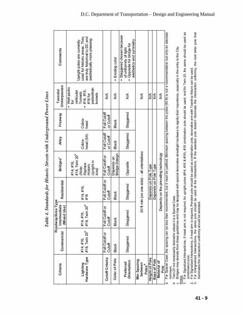
D.C. Department of Transportation – Design and Engineering Manual
41 - 9

D.C. Department of Transportation – Design and Engineering Manual
41 - 10

D.C. Department of Transportation – Design and Engineering Manual
41 - 11
41.3.5 Fixtures Attachment to PEPCO Poles
The designer may choose appropriate luminaries and design them based on the spacing of PEPCO poles and pole attachment befitting the existing situation.
41.3.6 Tunnel and Miscellaneous Fixtures
Special type of fixtures will be used in the tunnels, under-decks, sign structures, and in special situations. Wall mounted luminaries are preferred in tunnels and under-decks. The luminaires shall be located to facilitate maintenance and relamping.
41.4 Street Types and Light Level
41.4.1 Types of City Streets
Generally the existing streetlights will be replaced in-kind. In special situation, Pendant arm type standards may be replaced with Washington Globe or Teardrop Style fixture when requested by the community. Washington Globe (Acorn Fixture) will be used in the historic districts and designated historic streets. Street lighting will conform to requirements of streets and districts as follows:
• Historic Streets and Historic Districts on the National Register of
Historic Places: Washington Globes. Twin Twenty is included as an option.
• Streets of Local Historic Interest: Washington Globes. Has to be designated as Historical. Cannot be historical based solely on community interest.
• Architect of the Capitol Area of Capitol Hill: Washington Globe-The Architect of Capitol (AOC) responsibility
• District Streets on Federal Lands (Streets Bounded by Federal Lands): National Park Service, Pennsylvania Development Authority etc. responsibility
• Downtown: Downtown Streetscape Regulations • City Business Districts: MOU between DDOT and the subject BID • Special Streets: Twin Twenty • Arterial Streets: • Collector Streets: for collector Streets except in the Historic Districts. • Local Streets: Washington Globe on new subdivision streets • Special Situations: There will be special situations when special
unique style fixtures and standard will be required.

D.C. Department of Transportation – Design and Engineering Manual
41 - 12
NOTE: The above streets/roadways can be residential or commercial/Business or intermediate type.
41.4.2. Level of Luminance
High-pressure sodium (HPS) luminaries will be used except at the DC mall where Metal Halide luminaires is in use or directed otherwise by the District or requirement of the community. The designer shall ensure that the proposed streetlight design meets the District’s requirements and will work with the District and the affected community to deliver an approved design. Poles or luminaires that are equivalent to those described below may be approved by the District’s Chief Transportation Engineer. City Street and highway Lighting shall conform to the requirements of AASHTO. Guidelines for luminance on the street/highway system are tabulated in Table 41-A.
Table 41-A: Street Lighting Requirements
ROADWAY CLASSIFI- CATION
WATTAGE (HPS)
CON-CRETE SURFACEFOOT CANDLES
REGULAR ASPHALT SURFACE FOOT-CANDLES
SMOOTH ASPHALT SURFACE FOOT CANDLES
UNIFOR-MITY RATIO
Pedestrian/Bike Walkways
W-150 or W-250 1.4 2.0 1.8 3:1
Residential Local W-100 or W-150 0.3 0.4 0.4 6:1 Collector W-150 0.4 0.6 0.5 4:1 Arterial W-150 0.6 0.8 0.7 3:1 Intermediate Local W-100 or W-150 0.5 0.7 0.6 6:1 Collector W-150 0.6 0.8 0.7 4:1 Arterial W-250 0.8 1.2 1.0 3:1 Commercial Local W-150 0.6 0.8 0.7 6:1 Collector W-250 0.7 1.1 0.9 4:1 Arterial W-250 or W-
400 1.1 1.6 1.4 3:1
41.5 Lighting at Intersections
All signalized intersections are to be illuminated. At signalized intersections, lighting shall be installed on traffic signal standards wherever possible. In general, the nighttime visibility of a pedestrian or hazardous object within an intersection is enhanced by increased contrast between the object and the
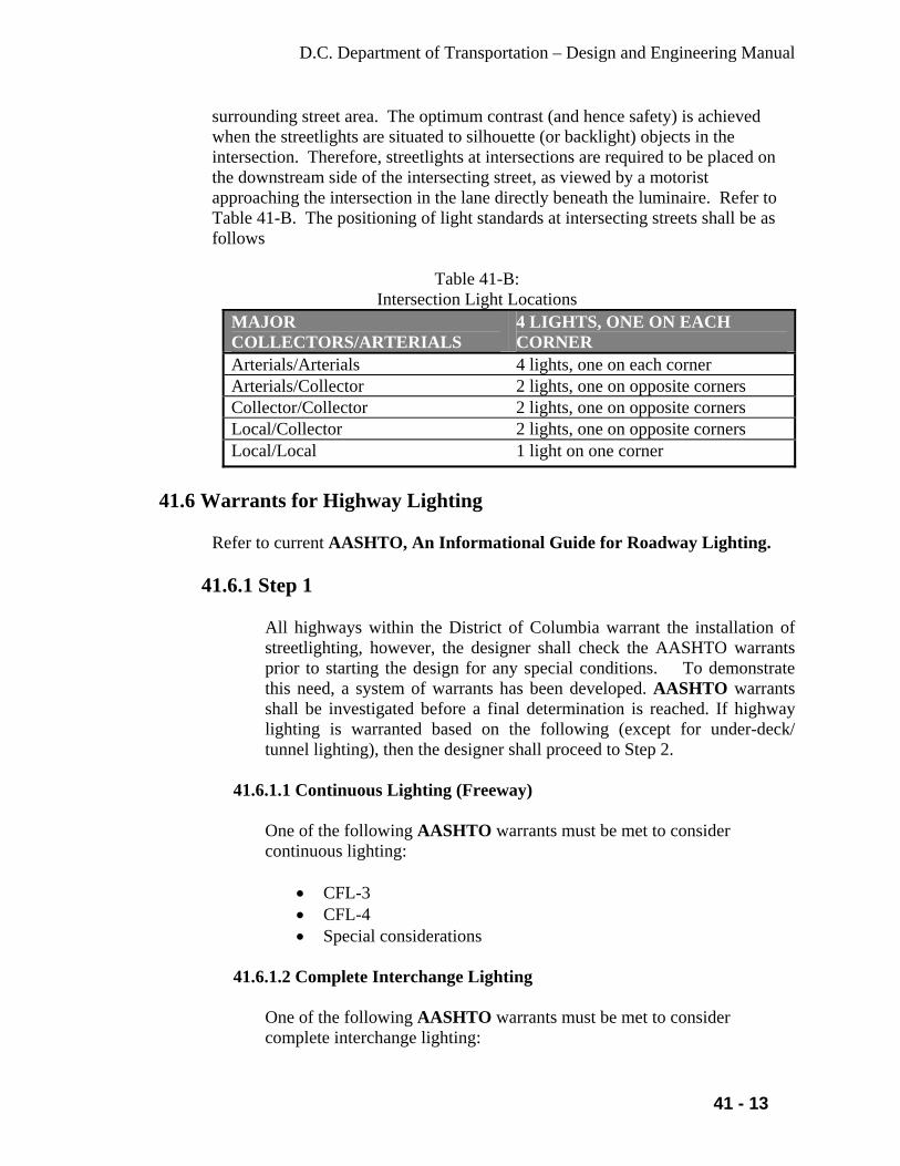
D.C. Department of Transportation – Design and Engineering Manual
41 - 13
surrounding street area. The optimum contrast (and hence safety) is achieved when the streetlights are situated to silhouette (or backlight) objects in the intersection. Therefore, streetlights at intersections are required to be placed on the downstream side of the intersecting street, as viewed by a motorist approaching the intersection in the lane directly beneath the luminaire. Refer to Table 41-B. The positioning of light standards at intersecting streets shall be as follows
Table 41-B: Intersection Light Locations
MAJOR COLLECTORS/ARTERIALS
4 LIGHTS, ONE ON EACH CORNER
Arterials/Arterials 4 lights, one on each corner Arterials/Collector 2 lights, one on opposite corners Collector/Collector 2 lights, one on opposite corners Local/Collector 2 lights, one on opposite corners Local/Local 1 light on one corner
41.6 Warrants for Highway Lighting
Refer to current AASHTO, An Informational Guide for Roadway Lighting.
41.6.1 Step 1
All highways within the District of Columbia warrant the installation of streetlighting, however, the designer shall check the AASHTO warrants prior to starting the design for any special conditions. To demonstrate this need, a system of warrants has been developed. AASHTO warrants shall be investigated before a final determination is reached. If highway lighting is warranted based on the following (except for under-deck/ tunnel lighting), then the designer shall proceed to Step 2.
41.6.1.1 Continuous Lighting (Freeway)
One of the following AASHTO warrants must be met to consider continuous lighting:
• CFL-3 • CFL-4 • Special considerations
41.6.1.2 Complete Interchange Lighting
One of the following AASHTO warrants must be met to consider complete interchange lighting:
D.C. Department of Transportation – Design and Engineering Manual
41 - 14
• CIL-1 plus CIL-2 • CIL-3 • CIL-4 • Special considerations
41.6.1.3 Partial Interchange Lighting
One of the following AASHTO warrants must be met to consider partial interchange lighting:
• PIL-1 plus PIL-2 • PIL-3 • Special Considerations
41.6.1.4 Underdeck Lighting or Tunnel Lighting
AASHTO warrants must be met to consider under-deck and/or tunnel lighting. If lighting is warranted, the designer shall prepare the design and skip Step 2.
41.6.1.5 Additional Design Considerations
Additional lighting shall be considered warranted for ramps, mainline or acceleration lanes for any of the following reasons:
41.6.1.6 Ramps
• Inside radius of entrance or exit ramp is less than 150 ft. • Accident data in the ramp area indicates a problem exists.
41.6.1.7 Acceleration Lanes
• Stop before acceleration lane. • Grade and/or curvature present a visibility problem, which cannot
be corrected through other means. • Sidewalks exist to permit pedestrians to cross at the entrance or
terminal of a ramp.
41.6.1.8 Main Line
The designer shall obtain the accident data of the location in order to determine the night-to-day accident ratio. The ratio could dominate the determination if highway lighting is required.
D.C. Department of Transportation – Design and Engineering Manual
41 - 15
• Grade and/or curvature present a visibility problem, which cannot be corrected through other means.
• Bridges without shoulders.
41.6.2 Step 2
If lighting is warranted based on the AASHTO warrants, then the need for lighting on a particular highway or interchange must be considered utilizing the appropriate evaluation.
41.7 Street Lighting Design
The Department’s approved luminaire and supporting poles and arms shall be used for all streetlight designs in the District. The environmental impact, especially on residences, of each system shall be investigated. The use of luminaire shields may be used to minimize the glare of a conventional lighting system. Upon approval, the designer shall then address, analyze and compare such determining factors as initial installation cost, maintenance costs, and energy consumption costs of the remaining system(s). All illumination and electrical design shall meet criteria as specified hereinafter. Before work commences on the lighting design, the designer must request approval of all design parameters by the Electrical Engineer. • The designer shall be prepared to present, explain and defend his lighting
system choice and design at any public or other meetings, as required. • The designer shall prepare 20 ft. scale drawings of all systems to be included
with the report, and based upon their investigations and analyses, shall make a recommendation to the Department of the system best suited to the project.
• The designer shall not intermix a Department lighting system within a utility company wood pole transmission system.
• The designer is responsible for locating and identifying the horizontal and vertical clearances of the utility company’s primary (750 volts or more) and secondary power lines.
• The designer shall coordinate the electrical design work with the present and future plans of the utility companies. All overhead and underground utilities must be shown on the plans. There shall be no conflicts with the lighting installation
• When utility poles are required to be relocated and wood poles lighting shall be the sole source of illumination for a section of highway, the designer shall work with the affected utility to space and position utility poles, through the utility agreement in conformance with utility standards, to produce a suitable illuminance. However, if needed to affect a quality design the designer shall call for the installation of additional District owned wood poles, outside of the utility companies pole transmission system.

D.C. Department of Transportation – Design and Engineering Manual
41 - 16
41.7.1 Reference Publications • AASHTO An Informational Guide for Roadway Lighting • FHWA Roadway Lighting Handbook • FHWA Manual on Uniform Traffic Control Devices (MUTCD) • Illuminating Engineering Society (IES) Lighting Handbook
NOTE: All publications shall be the latest edition.
41.7.2 Basis for Lighting Calculation
41.7.2.1 Common Criteria
The following are common for all types of highway lighting systems:
41.7.2.1.1 Photometric Data
The Photometric data utilized in all calculations shall be the latest data available.
41.7.2.1.2 High Pressure Sodium Lamps
Table 41-D shows the high-pressure sodium lamps with the following initial lumens that shall be used:
Table 41-D:
ANSI RATED AVG. INITIAL Wattage Designation Life Hours Lumens 70 S62-MF-70 24,000 6,400 100 S54-SB-100 24,000 9,500 150 S55-SC-150 24,000 16,000 250 S50-VA-250 24,000 27,500 400 S51-WA-400 24,000 61,000
41.7.2.1.3 Maintenance Factors
All lighting Systems depreciate with time. The design values shall consider appropriate reduction in initial illumination values. The maintenance factor to be utilized is 0.75; 0.68 for ambient areas considered dirty.

D.C. Department of Transportation – Design and Engineering Manual
41 - 17
41.7.3 Other Considerations
The following considerations are to be incorporated in all lighting calculations (Actual width of highway pavement considered in calculations, including shoulders, excluding medians where they exist): • Selection of proper size of luminaires to accommodate the level and
uniformity of illumination. • Selection of proper length of bracket arms to provide maximum
efficiency and uniformity in lighting. It should be noted that in some areas the use of two different lengths of bracket arms may meet the above requirements, but may also produce an objectionable appearance with regard to the luminaire alignment.
• Where the geometry or the uniformity ratio requirements necessitate adjustments in the calculated lighting standard spacing, closer spacing shall be used.
• Contributions from all luminaires that have an effect on the area considered shall be taken into account to obtain the lux values.
• When adjacent to sign structures, it is desirable to locate lighting standards equidistant from sign structures. The lighting standards shall not be located within 50 ft. of the structure. Care must be taken to avoid having a lighting bracket arm and luminaire mounted at 26 ft. obstruct the driver’s view of the sign legend.
• When locating lighting poles near overhead sign structures, the pole shall be located so a not to affect the drivers view of the sign message. Any adverse glare will be handled be the use of luminaire shields.
41.7.4 Lighting Calculations
41.7.4.1 Methods of Calculation
For the preliminary design, the average point method shall be used. The lighting will be designed utilizing a District approved lighting design program. Special design software for tunnels must be used when designing tunnel lighting. However, other lighting design software may be approved, but the designer would be responsible for providing the Department a registered copy of the software and training at no cost to the Department. The current photometric data to be used in the calculations shall be provided by the District upon written request.
41.7.4.2 Calculation Guidelines
The following are to be followed when performing the calculations:

D.C. Department of Transportation – Design and Engineering Manual
41 - 18
• When a portion or section of the highway is under analysis, it shall be analyzed as a self-contained area (main area). Sub-division (sub-area) within the main area is not permitted.
• The self-contained area (main area) of analysis shall correspond to the highway geometry under investigation.
• The point-to-point interval shall be 5 ft. longitudinally and transversely.
• The entire section of highway that is being illuminated shall be analyzed completely (It can be analyzed with many main areas).
The following information shall be included with each analysis:
• Project identification. • Plan sheet number involved in calculations. • A station-to-station identification of the area being analyzed. • The identification of each contributing luminaire being analyzed.
The following guidelines must be adhered to when submitting the design data on diskettes for review:
• Prepare a formatted 3.5 in. diskette to accept project. • When the analysis is completed, copy each project to the diskette
in the format recommended by the software provider.
41.7.5 Power Source
41.7.5.1 Incoming Service
The secondary service obtainable from the local utility company’s pole or manhole shall be used to service the complete installation in each area. The lighting will be designed utilizing a District approved lighting design program. Information on payee of the energy charge shall be provided in the letter. For all streetlight and alley light designs the designer shall supply the utility with a complete set of drawing for them to review and approve the location of all connections. Where an electrical service is required for a underpass or tunnel the designer shall request a class of service from the utility company. The form to make the request will be obtained from the utility company and completed in full. The designer shall supply a copy of the request to the District. Standard services available from the utility company are as follows:
• Single phase-3 wire: 120/240V and 240/480V, 120/240 volt
service is preferred for all street and alley lighting. However, in areas where that class of service is not available that the use of 240 volt circuit is allowed.
D.C. Department of Transportation – Design and Engineering Manual
41 - 19
• Phase - 3 Wire: 120/240V and 240/480V, the latter is preferred. The utility company provides this special secondary voltage to the Department exclusively. Utilized voltage shall be 240 volts.
• Three Phase - 4 Wire: 265/460V and 277/480V, dependent on the utility company. Utilized voltage shall be 265 or 277 volts.
When service is obtained from a manhole, the designer shall consult the utility company for the size, location, material and termination of the service conduit. The utility company usually furnishes the service wires, however this shall be verified.
41.7.5.2 Load Center Designations
Obtain the designation from the Electrical Engineer when a load center is added to the Street/highway lighting system.
41.7.5.3 Circuitry and Other Considerations
In most cases, where the wire fill will permit, all cables for two or more lighting circuits may be installed in the same conduit. Nominal size of cable used in highway lighting circuits shall be according to the NEC, however, in cable smaller thatn #10 AWG 600 Volt shall be used. Other sizes may be used and shall be approved by the Electrical Engineer. It is reminded that, unless necessitated otherwise, variations in cable sizes shall be avoided. All street and alley lights shall be controlled by a photocell mounted on each fixture or luminaire.
The designer shall utilize both phases of a circuit and connect the lighting so that no two consecutive lights are connected to the same phase in case of a lost of an single phase. The use of fused connector kits for each luminaire shall not be permitted. Lighting circuits, including the future lighting extensions, where required, shall be designed generally for a maximum of 5 percent voltage drop at the terminal point of each circuit. It is calculated between the phase and neutral.
41.7.5.4 Balanced Lighting Circuits
All lighting Circuits Shall be Balanced. Lighting circuits shall be so arranged that in case of failure in one of the circuits, it shall be possible to reroute the failed circuit with minimum work. In order to accomplish this flexibility in the circuitry, an empty conduit shall be provided to connect the conduit systems of adjacent load centers where feasible.
D.C. Department of Transportation – Design and Engineering Manual
41 - 20
All conduit duct banks shall be provided with spare ducts for future use. On all highways where imminent widening is contemplated, the locations of the lighting system shall be outside the limits of the future widening. The system shall be designed so that the permanent lighting installations shall be completed and in operation when a new highway is opened to traffic. If this cannot be accomplished, temporary lighting shall be provided.
41.7.6 Under-Deck Lighting
Under-deck lighting is not installed to accent the highways beneath structures, but rather to provide the required level of illuminance to accent continuity of uniform lighting. Therefore, under-deck lighting shall only be required where this level of illuminance, due to structural limitations such as the width, skews, and minimum clearance cannot be accomplished by means of lighting standards. Wall mounted under-deck luminaires shall be installed on pier faces and/or on abutments at a minimal mounting height of 15 ft. The pier faces or the abutment must be parallel to the highway and must be within 10 ft. from the curb or edge of the highway, otherwise the luminaires shall be fastened to adapter plates installed between the bridge girders. Wall mounted under-deck luminaires installed at a mounting height of more than 15 ft. shall yield better efficiency and uniformity. Pendant type luminaires shall be mounted from the structural steel. The luminaires shall be located to facilitate maintenance and relamping. If the highway width permits, the luminaires shall be located over the shoulder. When a luminaire is suspended from a bridge structure over the traveling lane, the bottom of the luminaire shall not be lower than the bridge girder. A special detail may be necessary to detail the conduit layout under the structure. For calculation purposes, the following data shall be used: • Mounting Height - As required (15 ft. nominal). • Luminaires- 150-watt wall mounted type and pendant mounted type
high-pressure sodium luminaires as per the current industry standard. • Uniformity Ratio On highways, which are not illuminated, under-deck lighting shall be provided for underpasses having pedestrian traffic. The average maintained illuminance shall be .8 ft. candle.
41.7.7 Sign Lighting
The following guidelines shall be used to determine if sign lighting is to be provided for Overhead Signs:

D.C. Department of Transportation – Design and Engineering Manual
41 - 21
• The tangent sight distance is less than 1200 ft. due to horizontal or
vertical curve or other sight obstruction. • Geographic and/or geometric conditions may warrant sign lighting for
the following situations and an evaluation shall be made: - Diagrammatic signs - “Exit Only” lane drops - High volume interchange (interstate to interstate) - Areas with high concentration of dew or frost - Sheeting material retroreflectivity characteristics
When it is determined that overhead sign lighting is to be provided, the lighting level shall conform to AASHTO recommendations. 100W high Pressure Sodium vapor luminaries shall be used for lighting of all overhead signs. The designer shall coordinate the electrical details and the details of the sign structure. A minimum of two luminaires shall be provided for each sign panel. When available LED sign lighting fixtures will be used in place of HPS. The advantages are long life (50,000 Hours), white color, and 30% lumen depreciation at 50,000 Hours and improved light control. Lamp advantage to match the 100-watt HPS luminaire. Where sign lighting is not required, walkways and luminaire supports are not to be provided, but the design of the sign structure shall allow for the future installation of walkways and luminaire supports.
41.7.8 High Mast Lighting Systems
The lighting calculations to determine the required illumination shall be based on the following definitions and criteria:
41.7.8.1 Area
Only the traveled highway and ramps, including shoulders, shall be considered in the calculations.
41.7.8.2 High Mast Lighting Standard Assembly Setback
Minimum 30 ft. measured from the face of curb or edge of pavement to centerline of high mast lighting standard. A lesser setback may be used. Should a lesser setback be approved, appropriate protection must be provided.
41.7.8.3 Luminaires
High mast type 250 or 400-W or 1000-W high-pressure luminaires - The luminaires shall produce a symmetric, long and narrow or asymmetric distribution. A maximum of eight luminaires of the same or different
D.C. Department of Transportation – Design and Engineering Manual
41 - 22
distribution shall be clustered to provide the required pattern of light distribution from the high mast lighting assembly.
41.7.8.4 Mounting Height
The tower shall not be more than 100 ft. The actual highway elevations shall be used in the calculations.
41.7.9 Existing Highway Lighting System
When an existing lighting system is being affected by construction and the light source is other than high-pressure sodium, it shall be converted to high-pressure sodium. The existing series circuits shall be converted into parallel circuits for all city street and highway lights.
41.7.10 Temporary Lighting
All roadway construction projects within the District where the existing lighting system cannot be maintained during construction shall use temporary lighting. This lighting can be a mixture of existing poles, temporary poles for construction or parts for the new system being installed. In no case will the illumination levels be less that the existing illumination levels entering and exiting the project limits.
41.7.10.1 Designing the Temporary Lighting
Temporary lighting design is concerned with the duration and location of the lighting units, to provide the proper illuminance and increase safety in the construction areas with minimum expenditure. The designer shall design a simple yet safe temporary lighting system that conforms to the NEC as a minimum. The designer shall consider the following options:
• Investigate the possibility of installing certain proposed lighting assemblies, including underground facilities in the early stage of construction and utilize them as the temporary lighting.
• The use of wood poles. • Regardless of what type of temporary lighting facilities, the
contractor shall maintain the installations, until they are no longer required and then remove the portions that are not part of the permanent lighting system.
41.7.11 Conduit
Conduit used for roadway and alley lighting projects shall be sized accordingly:

D.C. Department of Transportation – Design and Engineering Manual
41 - 23
1-2 inch used between manhole/junction box and light pole. 1-2 and 1-4 used between manhole and all light poles installed at an intersection 2-4 inch used between PEPCO feed point and DC manhole/junction box 1-4, 2-4, 4-4 and 6-4 inch used between DC manholes for mainline runs
41.7.11.1 Rigid Non-Metallic Conduit (RNMC)
All conduit installed underground by trenching for street and alley lighting shall be gray PVC Schedule 40 and encased in concrete. Conduit installed by directional boring shall be HDPE and manufactured to be installed by this method.
41.7.11.2 Fiberglass Or Metallic Conduit
Fiberglass or rigid metallic conduit shall be used for all conduit installed encased on structures. Proper expansion and deflection fittings shall be used to allow for movement. A five foot section of metallic conduit shall extend outside of each wing wall and be connected to a manhole or junction box as required. Fiberglass or rigid metallic conduit shall be install on exposed locations, such as hanging under bridge decks or mounted on the surface of walls.
NOTE: A ground wire shall be installed in all DDOT conduit where required by the NEC.
41.7.12 Cables and Wire
All cables and wire used in District roadway and alley lighting projects shall be in compliance with DDOT’s standard specifications. All cable used will be color coded in compliance with the NEC. In areas where more than one lighting circuit is installed together the cables and wires shall be tagged and marked with the circuit information for easy identification and maintenance.
41.8 Junction Boxes and Foundations
Manholes/Junction Boxes shall be designed as part of a complete lighting system. All manholes shall be concrete and be constructed by pre-casting or cast-in- place; junction boxes shall be polymar concrete. Spacing shall be as required be not greater than 250 feet between manholes and/or junction boxes. Drainage will be provided in all manhole/junction boxes by the use of gravel. All manholes will have PVC racks installed so that cables can be racked on the walls.

D.C. Department of Transportation – Design and Engineering Manual
41 - 24
The District is as part of paving and reconstruction projects is installing conduit and manholes in order to construct a streetlight distribution system separate from PEPCO’s. The only connection to PEPCO is through two-four inch conduits built from the District manhole to the distribution manhole identified by PEPCO as a feed point. The District’s system is made up of six-four inch conduits and manholes on major streets. In neighborhoods and in all alleys the system consists of two-four inch conduits and manholes. In all cases one manhole will connect three to four streetlights, and be located no further than 250 feet apart.
41.9 Voltage Drop Calculation Method
Voltage drop will be calculated on all electrical and lighting circuits. The method used and all of the calculations will be furnished to the District by the Designer as part of the design documents. The voltage drop shall not exceed 5 percent on any circuit.
D.C. Department of Transportation – Design and Engineering Manual
42-1
. CHAPTER 42
GUIDELINES FOR THE DESIGN OF GROUND MOUNTED SIGN
SUPPORTS 42.1 Introduction
The designer will select the sign structures from the tables herein when the standard DDOT sign structures cannot be used on the project. Highway signs fall into two main categories and are subdivided as follows:
42.1.1 Overhead Signs
• Sign Bridge Structures • Sign Cantilever Structures • Wall (No Ground Support)
42.1.2 Ground Mounted Signs
• Small Highway Signs • Large Highway Signs This section covers the design guidelines for Ground Mounted Sign Supports. These guidelines have been developed utilizing the current AASHTO A Policy on Geometric Design of Highways and Streets (Green Book, current version: 2004), the AASHTO Standard Specifications for Structural Supports for Highway Signs, Luminaires and Traffic Signals, the AASHTO Roadside Design Guide, and the Manual on Uniform Traffic Control Devices for Streets and Highways (MUTCD). The designer has four options from which to choose when locating signs within the highway Right-of-Way. These options are: • Locate the sign beyond the clear zone. The clear zone should be in
accordance with the AASHTO Roadside Design Guide and based on the posted speed limit.
• Mount the sign overhead. • Utilize a breakaway support to reduce impact severity. • Shield the sign with a longitudinal barrier and/or crash cushion. Ground mounted signs should desirably be located beyond the clear zone. In addition, all ground mounted highway signs are to be installed on breakaway supports, unless otherwise indicated herein. When a sign is located behind a traffic barrier (which is required for another reason), non-
D.C. Department of Transportation – Design and Engineering Manual
42-2
breakaway supports may be used. In cases where noise walls are required at a particular sign location, additional berm widths may be necessary. In considering the above, it is critical that sign locations and the design of the sign support be considered early in the Initial Design Development Stage. In addition, where sign supports must be shielded, the design engineer must determine the minimum area to be provided to accommodate guiderail or a state-of-the-art crash cushion.
42.2 Small Highway Signs
Small highway signs are defined as those with total panel areas less than 50 square ft. When this category of sign is used, the design guidelines for its support shall be steel “U” post sign supports (2 posts if the sign area is over 50 sq. ft.). The District’s standard sign post (“U” post) is twelve (12’) ft. in length and weighs 3.0 lbs./ft. (before punching and galvanizing). Aluminum posts are not permitted for small highway signs. Small highway signs shall not be placed in front of guardrails, and the posts shall not straddle guardrails. All small highway sign supports shall be of the breakaway type with the exception of those installed behind guardrails or behind other roadside barriers. The contractor shall be responsible for determining the horizontal offset with the concurrence of the DDOT Traffic Engineer, the quantity of posts, the post size and their associated lengths. The designer shall be responsible for establishing all offsets, quantity of posts, post sizes and lengths by following the step-by-step design guidelines below.
42.2.1 Step 1
Once provided with the necessary panel size (2A.12 MUTCD), determine the horizontal offset (X1) from edge of pavement to inside edge of sign, as shown in (Figure 2A-1, MUTCD)), by applying Section 2A.19 of the MUTCD as follows: • Urban installations – 1 ft. minimum from curb face where sidewalk
width is limited or existing poles are close to the curb. • Interstate and Freeway installations – 6 ft. minimum from edge of
shoulder, but not less than 10 ft. from the edge of traffic or auxiliary lane.
42.2.2 Step 2
When determining the height of ground-mounted signs, the following checks should be made:

D.C. Department of Transportation – Design and Engineering Manual
42-3
• When signs are installed on slopes 10H:1V or flatter the minimum vertical clearance above the edge of pavement to bottom of the sign panel as shown in Figure 2A-1 of MUTCD are as follows: - Sign Panels:
-- For single post installations, if possible, the minimum distance above the edge of pavement to the bottom of any panel must be 7 ft. in accordance with the MUTCD.
The District frequently places several sign panels on a single sign post, except in areas with pedestrian activity when several sign panels are placed on a single post, the sign panels may drop below the 7 ft. level. -- For multi-post installations, the minimum distance above the edge of pavement to the bottom of a main sign panel must be 7 ft.
- Secondary Sign Panels: -- The minimum distance above the edge of pavement to the bottom of a secondary sign panel (or a third sign panel) is 6 ft. When the height of the panels fall below the minimum 7’ level, engineering judgment should be exercised to avoid placing these signs in or near pedestrian crossing areas. -- For interstate and freeways the bottom of the main sign shall be a minimum of 8 ft. and secondary sign panel a minimum of 5 ft. above the edge of pavement.
• Where grading of 10H:1V or flatter cannot be obtained or where there is curb or berm greater than 4 in., the minimum vertical clearances will be measured from the ground line to the bottom of the sign.
42.2.3 Step 3
Determine the maximum distance (L) from the ground line to the centroid of the sign panel in ft. and determine the sign panel area (A) in square ft. NOTE: Sign Supports shall not be placed on slopes steeper than 10H:1V except where grading of 10H:1V cannot be obtained or where they will be behind a traffic barrier.
42.2.4 Step 4
Determine the size and quantity of posts per sign from DC Standard Drawing 620.01 and 620.03. for length (H) from 2 ft. to 15 ft. and width (w) from 2 ft. 30 ft. NOTE: When the plotted values of "A" and "L" on Table 42-B indicate an undefined section of the chart, then an alternate design for large highway signs must be initiated.

D.C. Department of Transportation – Design and Engineering Manual
42-4
• The maximum sign width (W) for single post installations shall be 2.5
ft. • If the number of posts selected are the same, the 2.5 lbs./ft. post should
be used. • When the number of 2.5 lbs./ft. posts selected are greater than the
number of 4 lbs./ft. posts, the 4 lbs./ft. posts should be used.
Example: A = 20 S.F. L = 10 ft. Roadside Slope = 10H:1V
The number of posts that may be selected are: • Three – 2.5 lbs./ft. posts or • Two – 4.0 lbs./ft. posts
- Therefore, use two – 4.0 lbs./ft. posts. 42.2.5 Step 5
Finally, enter the data onto the Steel “U” Post Sign Support Data Table.\
42.3 Large Highway Signs
Large highway signs are defined as those with a panel area equal to or greater than 50 square ft. When this category of sign is used, the design guidelines for the support shall be “Non-Breakaway Sign Supports”. Non-breakaway sign supports shall be installed behind roadside barriers used to shield other roadside obstructions. When a non-breakaway sign support is placed behind guide rail, the support should be a minimum of 4 ft. from the back of rail to the face of the signpost. When a non-breakaway sign support is placed behind barrier curb, the support shall be a minimum of 1.5 ft. from the back of barrier curb to the face of the signpost.
42.3.1 Non-Breakaway Sign Supports
The following is a step-by-step guide to the design of non-breakaway sign supports.
42.3.1.1 Step 1
Once provided with the size of the main panel, determine the horizontal offset, X1, from the edge of pavement to the edge of panel. Recommended offset = 8 ft., minimum offset = 7 ft.

D.C. Department of Transportation – Design and Engineering Manual
42-5
42.3.1.2 Step 2 Determine the elevation from the edge of pavement to the bottom of the main panel. Minimum elevation = 7 ft. For fill sections, go to Step 3. For cut sections, hold the berm side bottom of the main panel at a 1.33 ft. minimum above ground line.
42.3.1.3 Step 3
Determine the number of posts required for the specified panel based on a maximum sign area per post of 192 ft.2. Example: A1 = 30 ft. AREA = 450 ft.2 H = 15 ft. The calculated sign area suggests a minimum of three posts. The required spacing between posts for a three-post system is A1/3. This translates to a 10 ft. spacing between posts.
42.3.1.4 Step 4
Determine the distances from the top of footings to bottom of the main panel, L, for each post. NOTE: The minimum height of any post from ground line to the bottom of the main panel shall be 2.5 ft.
42.3.1.5 Step 5
Determine the required values of Lmax, H, and A1 where:
Lmax = Maximum post length to bottom of main panel (ft.) H = Main panel height + Exit panel height (ft.) A1 = Main panel width (ft.)
42.3.1.6 Step 6
Determine moment of sign area per post, MSA:
P = Number of sign posts MSA = [A1*H*(Lmax +(H/2) )] /P
42.3.1.7 Step 7
Using the value obtained in Step 6, determine the post diameter, wall thickness, and base type from Table 42-A below. Use this selection for all posts in the structure.
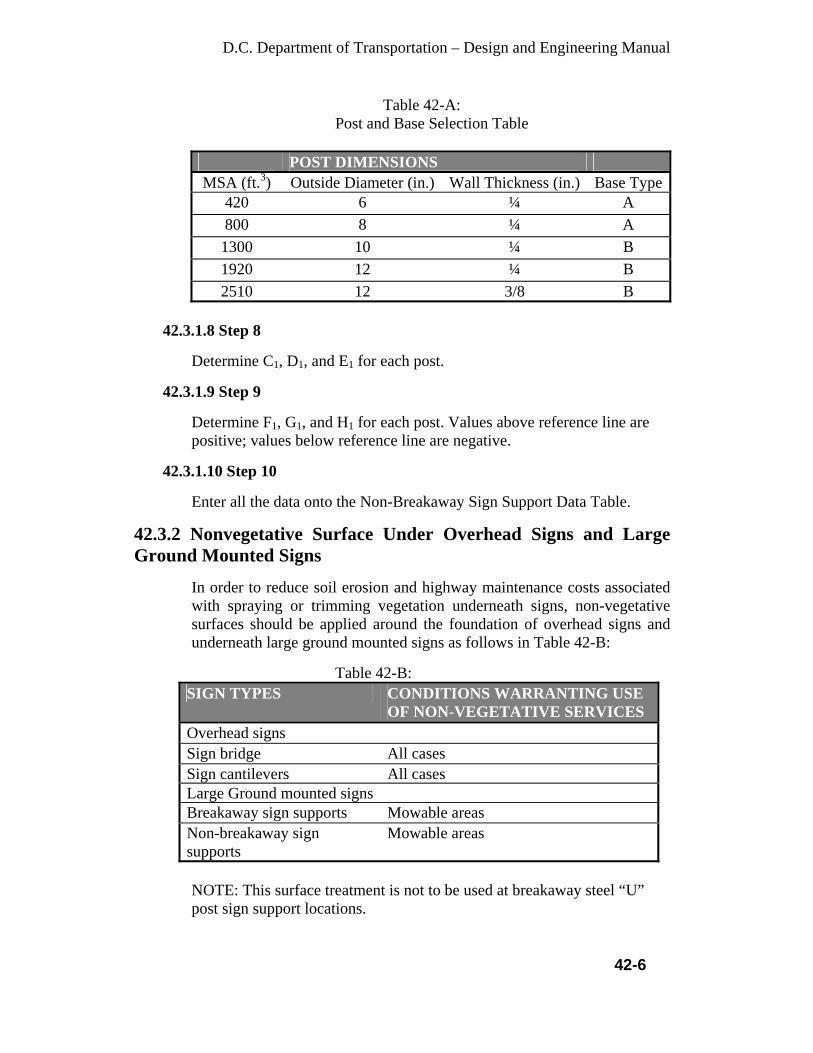
D.C. Department of Transportation – Design and Engineering Manual
42-6
Table 42-A: Post and Base Selection Table
POST DIMENSIONS MSA (ft.3) Outside Diameter (in.) Wall Thickness (in.) Base Type
420 6 ¼ A 800 8 ¼ A
1300 10 ¼ B 1920 12 ¼ B 2510 12 3/8 B
42.3.1.8 Step 8
Determine C1, D1, and E1 for each post.
42.3.1.9 Step 9
Determine F1, G1, and H1 for each post. Values above reference line are positive; values below reference line are negative.
42.3.1.10 Step 10
Enter all the data onto the Non-Breakaway Sign Support Data Table.
42.3.2 Nonvegetative Surface Under Overhead Signs and Large Ground Mounted Signs
In order to reduce soil erosion and highway maintenance costs associated with spraying or trimming vegetation underneath signs, non-vegetative surfaces should be applied around the foundation of overhead signs and underneath large ground mounted signs as follows in Table 42-B:
Table 42-B:
SIGN TYPES CONDITIONS WARRANTING USE OF NON-VEGETATIVE SERVICES
Overhead signs Sign bridge All cases Sign cantilevers All cases Large Ground mounted signs Breakaway sign supports Mowable areas Non-breakaway sign supports
Mowable areas
NOTE: This surface treatment is not to be used at breakaway steel “U” post sign support locations.

D.C. Department of Transportation – Design and Engineering Manual
43-1
CHAPTER 43
GUIDELINES FOR PAVEMENT MARKINGS AND SIGNAGE
43.1 Introduction
This work shall consist of establishing the location of existing pavement markings and installing proposed pavement markings, pavement markers, and reflective material on specified pavements in accordance with these specifications, and the MUTCD, current edition. Permanent pavement markings consist of hot thermoplastic markings (white and yellow) to be placed on asphalt concrete surfaces and plastic markings with a black border for Portland Cement Concrete (PCC) surfaces. For temporary work, the contractor may use reflective tape (white and yellow) or paint. In no case will the use of temporary lane markings require destructive measures, such as grinding, for removal from permanent roadway surfaces. Roadways shall not open to traffic before pavement markings and signage are properly installed.
43.2 General
• Type and Location of Pavement Markings - DDOT Chief Engineer and/or IPMA traffic engineers shall make the final determination in regards to the type and location of pavement markings within the ROW during the review of the project pavement marking and signing plans.
• Opening of Roadway - The roadway shall have permanent pavement markings in place prior to the opening of any lanes, unless provisions have been made on the Traffic Control Plan and approved by the District.
43.3 Pavement Markings
For a new roadway design, the Final Marking Plans with proper geometries should be submitted for 30% review. Whenever pavement markings are shown on any type of drawing plan sheet, the following Legend of Pavement Markings must be located on each plan sheet showing any pavement markings. This entire legend must be shown in full and includes the following items. (NOTE: The legend may be modified only with the approval of the IPMA engineer.)
43.3.1 Size and Dimension of Pavement Markings
• Crosswalks shall be 10 ft wide on local streets. 15’ wide on collector
streets, and 20’ wide on major arterials, unless otherwise noted

D.C. Department of Transportation – Design and Engineering Manual
43-2
• Standard parallel line Crosswalk lines (low visibility) shall be white and 6 in. wide.
• High Visibility crosswalks have white longitudinal stripes with 2 ft. wide white stripes with 2 ft. spacing. Make stripes parallel to the curb line of the street. The longitudinal lines shall be contained within two 6 inch edge lines.
• All curb ramps must be located within the marked crosswalk, not including side flares of the ramps. All curb ramps shall be installed in perpendicular (90%) to the gutter pan angle with the back side of flare aligned as closely as possible to the back edge line of the crosswalk.
• Stop lines are white and 12 in. wide (unless otherwise noted) and are located 6 ft. before crosswalk line. Stop lines shall be parallel to crosswalk lines.
• Dash lines are 4 in. wide, 10 ft. long; with 30 ft. skip spaces. However, the last skip line of each block will vary in width. If it is shorter than 10 ft. long, then it must be connected to the nest to last skip line. All dash lines shall stop 1 ft. before the back edge line of a crosswalk.
• Traffic Guide Lines at an Intersection (two types): o Single white dash lines are 4 in. wide, 2 ft. long with 4 ft.
spacing. o Double yellow guide dash lines are 4 in. wide, located 4 in. apart
and are 2 ft. long, with 4 ft. spacing. • Double yellow lines are 4 in. wide, located 4 in. apart and shall stop 6
ft. before the back edge line of the crosswalk. If no stop line is present the double yellow lines should stop in the same place, as if there is a crosswalk and stop line present.
• Solid white approach lane lines to a signalized intersection are 6 in. wide, and begin adjacent to the stop line and continue away from the stop line for a distance of 90-ft. If there are three or more approach lines, then measure the 90 ft. length for the shortest lane line and align all other approach lines with this 90 ft. line on a ninety-degree angle.
• “Arrow” or “only” word markings are spaced 32 ft. apart, unless otherwise noted.
• Refer standard drawings 616.04 and 616.05 for size and dimension details.
43.3.2 Special Pavement Marking Areas
• Pennsylvania Avenue, NW (the inauguration street) between 3rd Street
to 15th Street shall have ALL WHITE PAVEMENT MARKINGS, including double white lines.
• All crosswalks shall have a minimum 20 ft. width whenever possible within the Downtown Central Business District (CBD), including the Downtown Streetscapes Area. This area is currently bounded on the east by 3rd Street, N.W., on the south by Independence Avenue, S.W., on the west by 23rd Street, N.W. and on the north by Massachusetts

D.C. Department of Transportation – Design and Engineering Manual
43-3
Avenue, N.W. and includes the full width of the boundary streets. The contractor should always contact the DDOT Transportation Policy and Planning Administration (TPPA) for CBD limits, since the CBD limits are occasionally modified.
• Throughout the rest of the city, crosswalks shall be 10 ft wide on local streets. 15’ wide on collector streets, and 20’ wide on major arterials, unless otherwise noted.
• Restricted Lane Diamond Symbols (Bus Lanes) - Restricted lane diamond symbols shall be white and spaced 120 ft. apart.
• Reversible lane markings are used on Connecticut Avenue, 16th Street, 17th Street and Massachusetts Avenue. The center yellow double dash lines are 35 ft with 5 ft space; the peak hour lines are 10 ft long with 30 ft skip spaces.
43.4 Stop Lines
• Stop lines are white and 12 in. wide. • Stop lines are to be parallel to the crosswalk. • There shall be a 6 ft. clear space between the back edge line of the crosswalk
line and the stop line. • Stop lines are required at all signalized intersections, unless otherwise
indicated. Must have a valid reason for not including at that location. • When a Stop Sign is present a Stop Line is required. Stop lines should align
with the Stop Signs if possible. • Stop lines can be installed at other locations as specified by the DDOT Traffic
Engineers. 43.5 Lane Lines
• Dash Lines - Dash Lines shall be 4 in. wide, 10 ft. long with 30 ft. skip spaces
in between. • Intersection Traffic Guidelines shall be white, 4 in. wide, 2 ft. long with 4 ft.
long skip spaces. Also, Intersection Traffic Guide Lines can be double yellow lines. Double yellow lines are 4 in. wide, located 4 in. apart.
• Centerline Striping - All centerline striping shall be double yellow, each 4 in. wide, with a 4 in. minimum gap in between. Centerline Striping will be placed on roadways less than 34 ft. width, only if the centerline is offset.
• Broken Line - All Broken Lines shall be white and 4 in. wide. • Reversal Lane Lines are always striped with double yellow lines for all
reversible unbalanced traffic lanes during peak rush hours. The existing double yellow lines are 35 ft. long with 5 ft. spacing. The adjoining Reversible Lane Line is double yellow and is 10 ft. long and aligns with the approach to the intersection direction and aligns with the beginning of the 35 ft. double yellow line.

D.C. Department of Transportation – Design and Engineering Manual
43-4
• Turn Bay Line - All Turn Bay Lines shall be created with an 8 in. wide dotted line. However, if a Turn Bay occurs on a horizontal curve, it shall be marked with short 8 in. wide dotted lines (2 ft. long with 4 ft. gap).
• All parallel curb-parking lanes shall be 8 ft. wide with 6 in. wide edge, lines separating it from the adjacent 11 ft. wide travel lane.
• Parking Stalls and Angle Parking - All striping for parking shall be white and 4 in. wide. All edge lines of parking areas shall also be white and a minimum of 4 in. wide.
• Bike Lanes – The stripe nearest the curb or parked car shall be 4 in. wide. The stripe dividing the Bike Lane from the travel lane shall be 6 in. wide, per AASHTO and MUTCD guidelines as approved by the DDOT Bicycle Coordinator with TPPA. Bicycle Lane Symbols and directional arrows are spaced 6 ft. apart within the 5 ft. wide bike lane.
• The width of the bike lane shall be 5 ft., or 4 ft. where the distance between curb and inside stripe is 12 ft. including parking.
• Signalized Intersections - At Signalized Intersections, starting from the stop line, all approach lane lines shall be at a minimum 90 ft. long. At the end of the 90 ft. line, align all other approach lane lines so they are all normal to the roadway. From this point, begin the 30 ft. skip spaces and 10 ft. lane lines. At the end of each block, the last skip lines shall not be less than 10 ft. long. If it is less than 10 ft. in length it must be connected to the next to last dash line. When one dash line is less, match all of the other adjoining dash lines to make a uniform appearance.
43.6 Double Yellow Center Lines
• Double yellow centerlines are two 4 in. wide yellow lines, separated by 4 in.
wide spacing. • Double Yellow Center Lines are to be marked on all roadways that have
sufficient width to allow for two ten-foot travel lanes and two ft. parallel curb parking lanes, with a minimum street width 34 ft.
• Double yellow center lines on undivided roadways where four or more lanes are available for moving traffic at all times shall be a double yellow lines.
• Double yellow centerlines will be placed on roadways less than 34 ft. in width only if the centerline is offset.
• A 20 ft. section of the double yellow center line will be marked, from the stop bar back, on two way roadways of 32 ft. street width or less when this roadway approaches a controlled intersections.
• The double yellow centerline should be brought up to the stop line, or to where such a line would be if there is no stop line, unless otherwise noted.
43.7 Crosswalks
Crosswalks are to be marked at the following locations*:

D.C. Department of Transportation – Design and Engineering Manual
43-5
• Intersections of arterial streets with other arterial streets. • Intersections of arterial streets with collector streets. • Intersections of collector streets with other collector streets. • Intersections or mid-block locations controlled by vehicular and/or pedestrian
traffic signals or ALL-WAY STOP signs. • High visibility crosswalks are required at all uncontrolled crosswalks and all
crosswalks (including signalized or stop-controlled crosswalks) leading to a block with a school, within a designated school zone area, along a designated school walking route, or on blocks adjacent to a Metro station.
• In general, high visibility crosswalk markings are strongly preferred over decorative markings because they are easier for motorists to see. Crosswalks constructed of decorative materials should include 12 inch wide reflective white strips along the boundary of the crosswalk to maximize visibility. The decorative surface must be firm, stable, and slip resistant and vertical displacement shall not exceed ¼ inch, and horizontal gaps shall not exceed ½ inch per ADA requirements.”
• From all bus stops to the nearest crosswalk at an intersection. • Handicap ramps must be included within a crosswalk at all times. Handicap
ramps must be installed in pairs of two, one for each pedestrian travel direction. Any corner and/or mid-block crosswalk having handicap ramps.
*Exceptions to the above rules are possible, when there is a crosswalk omitted due to dangerous situation for the pedestrians. All exceptions must be approved by DDOT Chief Engineer and a dedicate Ward Traffic Engineer. Where crosswalk markings alone are used at uncontrolled crossing locations along multi-lane streets on which traffic volumes exceed approximately 12,000 vehicles per day with no raised medians, or exceed 15,000 vehicles per day with raised medians that could serve as crossing islands, the potential for motor vehicle-pedestrian crashes increases significantly. Crosswalk enhancements should be considered to provide safer crossings at these locations.
43.7.1 Definitions of Types of Crosswalk Markings
Parallel crosswalk markings are two 6 inch lines placed at either edge of the crosswalk. The stripes are perpendicular to the roadway centerline except in the case of skewed intersections.
High visibility crosswalk markings add longitudinal markings in addition to the 6 inch edge lines. The edge lines are perpendicular to the roadway centerline except in the case of skewed intersections.
Decorative crosswalk markings are crosswalks that are marked with brick, stamped concrete, or other materials.
D.C. Department of Transportation – Design and Engineering Manual
43-6
43.8 Minimum Parking Distance From A Crosswalk (Location of Parking An Intersection)
NOTE: NO PARKING IS ALLOWED WITHIN AN INTERSECTION
43.8.1 General Restrictions
• In general parking is restricted 40’ toward intersection (measured for approaching P.I.) and 25’ away from intersection (measured from departure P.I.).
• A parking “L” should be marked to indicate the beginning and ending limit for on street parking.
• A parking area if drawn adjacent to the curbs should have 7 ft. width (including the gutter) measured from the face of curb.
• Parking “L” and “Parking Space” should be drawn with 4” white lines. • If there are restrictions limiting where parking is allowed, these are the
following signs which will limit the distance to and from each intersection as to where parking will be allowed: NO STANDING OR PARKING ANYTIME, NO PARKING ANYTIME, NO STANDING OR PARKING METRO BUS ZONE, NO PARKING OR STANDING with (RUSH HOUR/TIME LIMIT RESTRICTIONS).
• Refer to Chapter 46 for detail parking regulations.
43.9 Diagonal Lines Diagonal lines are to be used to call attention to areas not intended for vehicular use. The following is a partial list of these areas: • Gore Areas • Painted Channeling Island • Obstruction Markings • Paved Shoulders, where necessary On urban arterials, Diagonal lines are to be 12 in. wide spaced 5 ft. on center, 24 in lines and 10 ft spaces are used for expressway and interstates. They are to be placed 45-degrees to the line forming the perimeter of the area.
43.10 Pavement Marking Messages (Symbols, Arrows, Words)
• When approaching an intersection all turning lane messages shall begin with an arrow, followed by the word “ONLY” and end with an arrow. This entire message usually fits within the 90 ft. solid lane limit
• When installing a longer turning lane the message it shall be read as follows: arrow, word” ONLY”, arrow, word “ONLY” and arrow. This message always begins with an arrow and ends with an arrow, using the word “ONLY”

D.C. Department of Transportation – Design and Engineering Manual
43-7
twice, and using arrow symbol at the beginning, in the middle between the “ONLY” and ending with an arrow.
• When using a combined share arrow markings, i.e. left and through arrow and an adjacent lane using arrow and/or word messages, all arrows of each lane should align with each other.
• General - Preformed Thermoplastic shall be used on all pavement markings such as arrows, crosswalks, railroad crossings, school crossings, stop bars and bike symbols.
• Preformed Thermoplastic Pavement Marking shall be used for asphalt pavement and Preformed High Contrast Tape Pavement Markings shall be used for Portland cement concrete pavements. Prefabricated legends and symbols shall conform to the applicable shapes and sizes as outlined in the MUTCD.
43.11 Permanent Striping
Thermoplastic Pavement Markings shall be placed on all asphalt concrete surfaces and High Contrast Tape Pavement Markings shall be used for Portland Cement Concrete (PCC) surfaces as directed. Unless there is an emergency, striping is not to be placed when the ambient temperature is below 500 F.
43.12 Temporary Striping
When approved, temporary striping shall be required prior to the re opening of a roadway for travel where pavement or permanent striping cannot be completed due to construction staging, weather or time constraints. All pre-markings shall be of the same general color as the pavement markings being pre-marked. When tape is used as pre-marking, pre-marking shall consist of 4 in. by 4 in. max. Squares or 4 in. max. Diameter circles spaced at 25 ft. minimum intervals. At locations where the pavement markings will switch colors, e.g. gore marking; the ends of the markings may be pre-marked regardless of the spacing. No pre-markings shall be installed when the ambient temperature is below 500 F and in no case will the removal of temporary lane markings require destructive measures, such as burring or grinding from permanent roadway surfaces.
43.13 Traffic Signing
43.13.1 General
• Type and Location of Signs - The Ward Traffic Engineer shall make the final determination regarding the type and location of signage

D.C. Department of Transportation – Design and Engineering Manual
43-8
controls within the ROW. The controls shall include traffic control signs, street name signs, delineators, and permanent barricades.
• No sign of any type can be mounded within an individual tree box. • Signs should not be mounted on any wood poles, belonging to the
telephone and/or PEPCO companies, unless owned by the District of Columbia.
• Design - All design shall be in accordance with this chapter and the latest revision of the MUTCD.
• Sign Posts, Supports and Mountings - Sign posts and their foundations and sign mountings shall be constructed to hold signs in a proper and permanent position, to resist swaying in the wind or displacement by vandalism.
- Sign Posts shall be steel drive posts and shall be 12 feet in length and weigh 3 lbs/ft. (before punching and galvanizing). Posts shall be manufactured in accordance with ASTM A-499, Grade 60 with a minimum yield strength of 60,000 psi. Galvanizing shall be in accordance with ASTM A-123. Special poles, such as aluminum poles, will be used for special situations, such as street name signs. Posts are to be driven 3 feet into the ground or encased in concrete as directed.
• Post Bolts - Two, 5/16” x 2” & 2/12” Hex Head plated nuts and bolts (Full threaded) are used to attach sign posts to sign anchor (stubs). These bolts are installed a distance of two of the pre-drilled post holes apart, and at 90 degrees to one another.
• Sign Bolts - Signs are mounted to the post with a minimum of two bolts (5/16 in. with nylon and metal washers) or standard rivets (TL3806 EG, drive rivet) with nylon washers placed against the sign face. The bolt or rivet system is used to fasten signs to the Telspar post.
• Other Sign Mounts - Streetlights and approved utility poles, when located appropriately, may be used for signs such as warning, parking, and speed limit signs. Streetlight locations should be checked for potential sign installation during the design process and shown on the sign plan sheets. Signs installed on streetlights and utility poles are installed with stainless steel straps, buckles and sign mounting brackets with appropriate standard nuts and bolts of appropriate lengths and widths.
• Breakaway Post System - Posts must be of appropriate length to comply with MUTCD specifications for the location, must conform to the Federal breakaway standards.
• Sign Reflectivity - All traffic control signs must be fabricated with reflective materials. All regulation signs, such as stop signs, one-way signs, etc. must use Diamond Grade Sheeting. For all other signs High Intensity Grade sheeting shall be used. Engineer Grade sheeting may only be used if authorized by DDOT for signs of less importance. Sheeting for all School Zone (S1-1) crossing signs and sheeting for all

D.C. Department of Transportation – Design and Engineering Manual
43-9
mid-block Pedestrian and Advanced Pedestrian crossing (W11-2) signs shall be Fluorescent High Performance Lime Green – Diamond Grade.
• Backing Plates - Aluminum sign thickness of all traffic signs shall be 0.125 gauge. For all other message signs, such as neighborhood watch signs, a lesser gauge may be used.
• Street Name Signs
43.13.2 Traffic Control Signs
• Design and Size - Sign specifications and diagrams are detailed in the latest revision of the MUTCD. This publication is available from the U.S. Department of Transportation, Federal Highway Administration. Acceptable sign sizes are listed in the standard column of the table printed with each diagram. Expressway and construction signs shall be a minimum 36 in.
• Mounting - Signs should be mounted on existing streetlight and power poles, with new posts being used only if necessary. Streetlight locations should be checked for potential sign installation during the design process and shown on the signing and striping plan sheets. The use of stainless steel banding of signs is acceptable for fiberglass and steel poles.
• Regulatory - Sheeting Material - All signs shall be fabricated with only sheeting material, including letters. No silk-screened signs will be permitted. - Stop Sign - Stop signs shall be a minimum of 30 in. - Yield Sign - For minor intersections only, a yield sign may be used in lieu of a stop sign, at the discretion of the District according to MUTCD. - Speed Limit Sign - All Collectors and Arterials should have speed limit signs in accordance with the MUTCD, latest edition. - Parking/No Parking Sign - Designated parking and “no parking” zones shall be signed in accordance with MUTCD.
43.13.3 Roundabouts
43.13.3.1 Modern Roundabouts
Signage in advance of the circulating roadway shall be required. Use “Yield At Roundabout” (W3-2a, 36 in. by 36 in.; R1-2, 36 in. by 36 in.), “Roundabout Advisory Sign” (RB-1, 24 in. by 24 in.) and “Reduced Speed Ahead” (R2-5a, 24 in. by 30 in.) signs. The “Yield” sign (R1-2, 36 in. by 36 in.) shall be located at each entry to the circulatory roadway. An “arrow” sign, designating direction of travel in circulatory roadway, shall be located within the central island.

D.C. Department of Transportation – Design and Engineering Manual
43-10
NOTE: If any pedestrian crossings are provided at these roundabouts, Advance Pedestrian (symbolic pedestrian, without crosswalk lines on sign) signs will be needed for all approaches to the intersections. Place the advance signs a minimum of 150 ft. before the crosswalks and another Pedestrian sign at the crosswalk (with crosswalk lines on sign).
43.13.4 Bus Stop Signage
The Metro Bus stop sign should be located at the beginning of the bus stop after the 50 ft. taper. These signs will be installed by the Washington Metropolitan Area Transit Authority (WMATA). “No Standing or Parking – Metro Bus Zone” signs should be posted at both ends of the bus stop. These signs will be installed by DDOT.
43.14 Standard Dimensions for Various Stall Widths and Angles
The Family Vehicle Classification includes the following vehicles: sub-compact, compact, standard car, large car, station wagons, 7-seat passenger vans, SUV’s (4-5 passengers only), and a large pick-up truck (excluding second seats and extended cabs). The table indicates the dimensional relationship between stall width and adjacent aisle width. As the stall width narrows, the adjacent aisle width must be made wider to compensate for the extra maneuvering required for a vehicle to enter and exit a parking space. • A typical family within the United States uses at least one of these vehicles. • The average opening of a car’s door is 3’-8”.
43.14.1 Typical Family Vehicle Dimensions: Vehicle Type Length Width Height Rear
Overhang Subcompacts: 11’-7” –
14’-8” 5’-1” – 5’-8”
4’-2” – 4’-7”
3’-9”
Compacts: 13’-10”– 15’-4”
5’-7” – 5’-8”
4’-4” – 4’-8”
4’-3”
Mid-size Cars, Station Wagons:
15’-0” – 16’-8”
5’-7” – 6’-0”
4’-2” – 4’-9”
4’-4”
Large Cars, 7-seat Passenger Vans, SUV’s (small):
15’-2” – 18’-5”
5’-8” – 6’-0”
4’-7” – 5’-0”
4’-5”
Large Pick-up Trucks:
15’-10”– 20’-2”
6’-5” – 6’-9”
5’-9” – 6’-4”
4’-4”

D.C. Department of Transportation – Design and Engineering Manual
43-11
• The Family Vehicle Classification Table above shows the minimum dimensions for the various stall widths and angles required when parking these vehicles.
• The DC Regulations require 8 ft. wide standard for parallel parking spaces to a curb and 9 ft. standard for all angled parking spaces.
D.C. Department of Transportation – Design and Engineering Manual
44-1
CHAPTER 44
GUIDELINES FOR REVIEWING TRAFFIC CONDITIONS AND PREPARING TRAFFIC IMPACT STUDIES
44.1 Introduction
This chapter establishes requirements for reviewing traffic safety conditions on a roadway intersections and segments.
44.2 Requirements for Traffic Condition Review for District Projects
44.2.1 Crash Data Analysis
• Using TARAS data, an orderly review and evaluation must be done to determine the root causes of crashes involving vehicles, pedestrians or bicyclists at intersections and segments selected for review.
• An accident analysis shall include the development of collision diagrams and shall consider the following items: - Total number of crashes during the last 3 years - Number of crashes by type or causation factor - Vehicle type involved - Pedestrian involvement - Bicyclist involvement - Type of traffic control present - Roadway or intersection geometrics - Cause of crash - Time of crash - Environmental conditions - rain, snow, fog, ice, clear, sunny, dry roadway, wet roadway, snow on roadway, ice on roadway.
• Patterns and trends of crash should be evaluated based on crash data of the study period.
• Accident costs, severity, rates and changes.
44.2.2 Capacity Analysis
A common measure of the ability of roadways to serve a typical traveler is the Level of Service (LOS). Level of service is denoted on a scale of ‘A’ through ‘F’ where ‘A’ represents the highest quality, and ‘F’ describes the lowest quality. Capacity analysis is the quantitative process for determining the level of service. Capacity analysis studies shall be made in accordance with the latest version of the Highway Capacity Manual, Highway Research Board Special Report 87.

D.C. Department of Transportation – Design and Engineering Manual
44-2
44.2.3 Gap Study
A Gap Study is the review of the time intervals between successive vehicles as they pass a point on a roadway segment. These intervals, valled gaps, are used to determine if their frequency and duration are sufficient to permit the safe crossing vehicles and pedestrians and merging of vehicles in traffic. Particular attention should be given to children and elderly pedestrians who have slower than average walking speeds.
44.2.4 Geometric Review
The following items should be considered in a geometric review of construction projects: • Intersection alignment - A review of the physical design and
configuration of the intersection. This review should consider at least the following items: - The number of approaches -The presence of horizontal and vertical curves on approaches that limit sight distance which may necessitate additional traffic control such as a reduced speed limit or a multi-way stop. -The presence of skewed intersections that create blind spots for approaching motorists. -The capability of existing channelization to accommodate the various kinds and classes of traffic. -The presence of approach grades in excess of 3 percent that may necessitate abnormal stopping distance and time required for crossing vehicles to clear the intersection.
• Number and spacing of intersections - A physical count of the total number of intersections and driveways along the study section of roadway and their usage.
• Railroad grade crossings - An orderly review of railroad grade crossings shall consider at least the following: -The adequacy of the intersection sight distance for drivers at a non-signalized railroad grade crossing. Drivers must be able to see approaching trains so that they could bring their vehicle to a stop in advance of the crossing. -The presence of a train preemption phase at signalized roadway intersections that would allow vehicles within 200 ft. to cross the tracks safely. The preemption system must prevent unnecessary queering of roadway traffic and clear the railroad grade crossing when a train is approaching.
• Roadway cross section - A review of the roadway’s crown and super elevation and presence or absence of shoulders, shoulder drop-off and sidewalks. Determine whether the existing cross section meets the standards on Roadway presented in chapter 30 of this Manual.

D.C. Department of Transportation – Design and Engineering Manual
44-3
• Roadway surface features - A qualitative review of the roadway-riding surface to consider holes, dips, bumps, rutting and other factors.
• Roadway width - A transverse measurement of the roadway between the curbs or the two edges of the roadway, exclusive of shoulders and sidewalks, but including parking lanes and parking maneuver areas.
• Roadway horizontal and vertical alignment - A review of the roadway’s grades, length of vertical curves, the degree of curvature horizontal curves, and turning radius at intersections. Determine whether large vehicles can make safe turn.
• Evaluate the need for safety improvements beyond the curbs and edge of roadways. Guardrails should be given to sidewalks, should guardrails, pavement markings and signage.
44.2.5 Existing and Projected Traffic Volumes
Traffic volume data for existing conditions shall be used to determine the ADT, peak hour volumes, directional distribution, percentage of heavy vehicles and the 20-year projection of these factors. This data, along with other factors noted in the MUTCD shall be used in conducting capacity analysis, and in making decisions regarding signalization and safety.
44.2.6 Auxiliary Lanes
Refer to chapter 35 of this manual for left turn lane, right turn lane, acceleration and deceleration lane requirements.
44.2.7 Alternate Routes
44.2.7.1 Availability of Alternate Routes
Review the roadway network to determine if an alternate route or routes exist.
44.2.7.2 Evaluation of Alternate Routes
This evaluation is the review of alternate routes to determine their capability in handling the additional traffic. The review shall consider the following:
• The structural capability to support the loading from the kinds and
classes of traffic to be detoured. • The capability of safely accommodate the additional traffic
volumes at a reasonable level of service and providing access to intermediate points of interest, without an excessive increase in the overall length.

D.C. Department of Transportation – Design and Engineering Manual
44-4
• Restrictions along the alternate route that would create problems for certain kinds or classes of vehicles. For example: steep grades, sharp curves, signalized intersection already operating at maximum capacity, substandard intersection geometrics that would restrict turning movements of certain kinds and classes of vehicles, narrow or one-lane bridges or underpasses and underpasses with substandard vertical clearances
• Compatibility of the land use along an alternate route with the volume and classification of vehicles to be diverted.
44.2.8 Arrival and Departure Hours of a Proposed Development Project
Determine the periods during a normal weekday when traffic would arrive and leaves the property. This information may be determined through observation at similar sites. The study may involve parking facilities, loading docks, entrances, exits and street crossings for pedestrians.
44.2.9 Parallel Streets
Preview the parallel street(s) adjacent to a two-way street that is proposed to be converted to a one-way street to determine if the parallel street(s) can accommodate the volume and kinds and classes of vehicles that would normally use the two-way street. This review of parallel street(s) must include at least the following: • Weight restrictions • Lateral width restrictions, especially on turns • Vertical clearance limitations • Capacity analysis • Access to premises • Character of neighborhood
44.2.10 Past Experience
• Roadway closure for processions, assemblies, or special activities. This review should consider the following items: - All traffic crashes during previous similar closures. The Design Engineer should refer to the TARAS studies for aid in decision making. - Documented or observed traffic congestion problems, including the delay of through motorists - Written or oral citizen complaints
• Roadway damage - This review should consider previous roadway breakups and restrictions for the subject road or for other similarly constructed roads during the same climatic conditions.

D.C. Department of Transportation – Design and Engineering Manual
44-5
44.2.11 Pavement Review
The sub-base, base and wearing surfaces of a roadway shall be reviewed by a qualified engineer, with consideration given to the type, speed and volume of traffic and weight of the vehicles using the roadway. Previous experience with the pavement or similar pavements during similar climatic conditions may be necessary for inclusion in the review.
44.2.12 Pedestrian Volumes
Pedestrian volume studies are often important in the establishment of speed restrictions and multi-way stops, the hours that school zones are effective, and the installation of operation of traffic signals. These studies normally consist of manual counts of the total number of pedestrians crossing each leg of an intersection, but sometimes they may count the number of crossings at mid-block crosswalks or the number of pedestrians walking on or along the roadway when sidewalks are not available. Pedestrian volumes should be tallied in 15-minute intervals. Intersection pedestrian studies are normal made in conjunction with all other vehicular traffic volume studies. A further classification of pedestrian volume is often beneficial especially for traffic signal studies. Typical classifications are: children less than 12 years old, adults, school children, non-school children, handicapped, to and or elderly people.
44.2.13 Bicyclist Volume
Where manual vehicle counts are conducted, bicyclists should also be counted, using the same methodology.
44.2.14 Roadside Development
• An review should be made of the number, type and size of businesses, residences or other developments along the roadway that generate traffic having the right of access onto the roadway.
• Interference resulting from traffic turning into or out of driveways to the roadside development typically results in lower capacity on the roadway and an increase in crashes.
44.2.15 Roadside Obstructions
A review should be made of roadside features that decrease drivers’ sight distance, restrict lateral movement on the roadway or generate potential hazards, if a vehicle leaves the roadway surface.

D.C. Department of Transportation – Design and Engineering Manual
44-6
44.2.16 School Route Plan A school route plan is a drawing showing the recommended travel paths of school children between their home and school. This plan should be developed by the school and municipal officials responsible for school pedestrian safety. The plan shall to consist of a simple map showing the streets, the school, existing traffic controls and intersections with sufficient gaps in the traffic to allow safe crossing by students. The plan may dentify a longer route in order to avoid potentially hazardous crossings. Reference: Manual on Uniform Traffic Control Devices, Federal Highway Administration, current edition.
44.2.17 Sight Distance
Review the sight distance for conformance with the requirements of chapter 30 in this manual that deals with roadway design.
44.2.18 Spot Speed
Spot speed studies involve the measurement of the instantaneous travel speed of vehicles at a specific location by using electronic devices such as radar, or by calculating the average speed over a relatively short section of roadway. The following guidelines shall be established for taking spot-speed samples:
• Observations should be made at about half-mile intervals or at
locations where traffic or roadway features change. • Observation sites should be located on tangent or mid-block sections
of roadways in order that the speed distribution is not influenced by stop signs, traffic signals, curves and other traffic flow interruptions.
• Samples should normally consist of at least 100 observations, although 50 observations are acceptable on low volume roadways. Samples should be composed of randomly selected vehicles to ensure a reliable speed distribution. The percentage of trucks in the sample should be approximately the same as the percentage of trucks in the traffic stream.
The following statistical values may be determined from the adequate size sample of spot speeds, in accordance with the latest version of the Manual on Traffic Engineering Studies of Transportation Engineers, latest version. • Average speed • The 85th percentile speed
D.C. Department of Transportation – Design and Engineering Manual
44-7
44.2.19 Safe-running Speed
The safe-running speed for a portion of a roadway is determined by making a minimum of five test runs in each direction and periodically recording the running speed at different locations while driving at a speed which is reasonable and prudent, considering the spacing of intersections, roadside development, sight distance, and existing traffic. The safe-running speed for a section of roadway is the average test run speed.
44.2.20 Recommended Speed for Curves
The recommended speed for existing curve shall be determined by use of a Ball-Bank Indicator. The recommended speed for curves may be determined by making several trial runs through the curve in a car equipped with a ball-bank indicator in accordance with the following guidelines: • The Ball-Bank Indicator should be transversely mounted in the car and
positioned to give a zero reading when the car is level. • The first trial run should be made at a speed slightly below the
anticipated maximum safe speed. • Succeeding observations should be made at increasing 5-mile-per-hour
increments. • Consult AASHTO, A policy on Geometric Design of Streets and
Highways (Green Book, current version: 2004) for speeds and Ball-Bank readings associated with driven discomfort. The ITE Manual of Transportation Engineering Studies should be consulted for procedures in using the Ball-Bank Indicator.
• Recommend advisory speeds should be to the nearest 5 mph less than the maximum negotiable safe speed for both direction of travel.
44.2.21 Design Speed
Traffic speed is one of several factors used in designing roadways and controls the minimum radius of curves, super elevation, length of vertical curves, sight distance, cross section, and so forth. The design speed is the maximum safe speed that can be maintained over a specified section of roadway when conditions are so favorable that the design features of the roadway govern. The design speed for all roads shall be in accordance with AASHTO, A Policy on Geometric Design of Highways and Streets (Green Book, current version: 2004).

D.C. Department of Transportation – Design and Engineering Manual
44-8
44.2.22 Travel Time and Delay
Travel time varies inversely with travel speed and is a good indicator of the average speed and level of service that is being provided on a given route. The difference between travel times over a route during low traffic volumes and during high traffic volumes is operational delay. This delay consists of such items as time consumed at a stop sign waiting for cross traffic to clear; time consumed at an uncontrolled intersection awaiting the ROW; and time losses resulting from congestion, interference with parked vehicles, parking maneuvers and waiting for turning traffic. Delay is the time consumed when the traffic is stopped or greatly impeded and is usually expressed in seconds per vehicle. Delay may be either fixed delay, which is normally experienced by vehicles during low traffic volumes at stop signs or traffic signals, or operational delay, which is caused by the interference by other traffic.
44.2.23 Load Capacity
Load capacity rating is determined in accordance with the applicable guidelines contained in the most recent edition of the DDOT’s Bridge Rating Manual. Refer to chapter 17 of this manual for load capacity ratings and requirements.
44.2.24 Traffic Signals
Phasing and signal display - Traffic signal phasing refers to the different segments of the signal cycle allocated to traffic movements receiving the ROW. The signal display refers to traffic-signal indications that are provided for vehicles and for pedestrians. The phasing and signal displays are the responsibilities of the DDOT Traffic Operation Administration (TOA). Refer to Chapter 40 of this Manual for details.
44.2.25 Lighting
Verify that the street lighting is sufficient to meet the needs of the neighborhood. The pedestrian as well as drivers needs should be considered. Refer to Chapter 41 of this Manual for details.

D.C. Department of Transportation – Design and Engineering Manual
45-1
CHAPTER 45
REQUIREMENTS FOR TRAFFIC IMPACT STUDIES FOR DEVELOPMENT PROJECTS
The District Department of Transportation is responsible, in a review/approval capacity, to assure that the provisions of the District’s Zoning and Subdivision Regulations have been followed. In order to do this, the Transportation Report (TR), including a Traffic Impact Study (TIS) may be required from the applicant to quantify impacts and identify facility improvements needed to maintain an acceptable level of service standards. The following presents, in general, when a TIS will be required: Preliminary Plan Stage – Normally, a full TIS as detailed here in, will be required with all land use zoning and rezoning requests initiated with the preliminary plan. The requirement to prepare a full Traffic Study may be waived only if all of the following conditions are met:
• Daily trip generation is less than 300 vehicles. • Peak hour trips in the peak direction are less than 25 vehicles. • No more than 250 vehicles per day access an existing collector or local road. • Subsequent to the Preliminary Plan Stage - The following are the three scenarios
that will require the preparation of an update (or amendment) to a previous study, or the preparation of an entirely new study that meets these guidelines:
• When traffic data is required, the applicant shall obtain the appropriate documentation from the DDOT Traffic Counting Branch or collect through a DDOT approved consultant according to the following specific requirements:
o When the original study was prepared during the preliminary plan process for a large, complex, or phased project and was designed, organized, and written to function as a “base” or master plan document for future Final Plan applications.
o Where a TR was never prepared and the site fails to meet the conditions of a waiver outlined above, a new study is required.
o Data older than 2 years shall not be acceptable, and a new count will be required.
A waiver of the TIS requirement must be requested in writing setting forth the reasons for the request and explicitly asserting that the conditions listed above have been met. A waiver of the TIS must be obtained in writing from DDOT, a verbal authorization of waiver is not acceptable. 45.1 Purpose of Traffic Impact Studies
The responsibility for assessing the traffic impacts associated with a proposed land use action rests with the landowner or land development case applicant, with the District Department of Transportation serving in a review capacity. The

D.C. Department of Transportation – Design and Engineering Manual
45-2
assessment of these impacts shall be within a traffic impact study as specified herein, prepared under the supervision of a Registered Professional Engineer in the District of Columbia with adequate experience in transportation planning/engineering. For the purpose of these guidelines, when the word “applicant” is used, it shall mean the applicant and/or his or her designated agent responsible for preparing the Traffic Impact Analysis. Requirements of a Study will generally consist of the following evaluations: • Background traffic condition • Generalized peak hour traffic volume and turning movements. • Peak hour intersection level of service – Level of service “D” is the minimum
acceptable level of service in DC. • Appropriateness of ingress and egress locations and volumes • Potential need for future traffic signals • Location and requirements of turn lane or acceleration/deceleration lanes • Turn lane storage recommendations include tapers, storage, deceleration
length, and other geometric design requirements. • Sight distance evaluations and recommendations (intersection, stopping,
passing) • Multi-modal and TDM opportunities • Pedestrian/bike requirements and/or improvements • Recommended traffic control devices for intersections may include two- way
stops, four-way stops or yield signs, school flashers, school crossing guards, crosswalks, traffic signals and roundabouts.
• Signal and 4-way stop control warrants • Link Volumes for all Major Streets (Average Weekday Traffic – AWT) • Sign Changes • Safety and Accident Analysis • A before and after comparison of traffic impact in different MOE’s (measure
of effectiveness) • Assessment & evaluation of potential improvements required for the project • FHWA highway capacity manual (HCM) and compatible software are
acceptable methods for level of service (LOS) analyses.
45.2 Traffic Impact Study Overview: Requirements, Meetings and Waivers.
Should it be determined that a Traffic Impact Analysis is required, the information described above is required to be submitted to the District. The requirements for conducting a traffic impact study will be an important agenda item to be discussed at the pre-submittal meeting. The applicant is highly encouraged to bring a copy of the previous TIS prepared for the site, if any, and prepare and present a sketch plan showing:

D.C. Department of Transportation – Design and Engineering Manual
45-3
• The location of the site • Proposed access and its relationship to adjacent properties and their
existing/proposed access • Preliminary estimates of the site’s trip generation at build-out (average daily
traffic and peak hour traffic) This information will assist in determining the level of detail and extent to which the TIS will need to address each of the following: • The study area for the impact analysis • The intersections to be studied in detail • The distribution of trips from the proposed development • Background traffic volume forecasts • The need for special analysis The District Department of Transportation will complete a summary of decisions made at the meeting. A copy will be given to the applicant. If the applicant requires clarification to the guidelines, or is preparing a larger complex or phased project, a separate meeting the Department of Transportation is encouraged to discuss appropriate requirements and strategies.
45.3 Planning Horizons and Roadway Network Assumptions
Each traffic impact study shall present an analysis of the traffic conditions with and without the proposed project at two planning-year horizons: short term and long term. The intent of the first planning horizon is to investigate the immediate impact of the proposed project on the short-term roadway network. The short-term horizon year is defined as one year after occupancy of the project. If the project is proposed to occur over multiple phases, each phase shall be evaluated one year after phase occupancy. The second planning horizon shall be based on the 20-year planning horizon. The intent of the second planning horizon is to evaluate implications of the proposed project on the long-range traffic condition. The baseline surface transportation network (without the proposed project improvements) assumed for the first planning horizon should reflect existing facilities plus any firmly committed improvements by the District and other developments within the study area. All planned surface transportation facilities within the study area may be included for the baseline assumptions for the long term planning horizon network analysis. Each planning horizon analysis shall identify the required facilities needed to bring the Level of Service (LOS) of the affected facilities up to District of Columbia established standards. If the established standards are currently exceeded, the study needs to:
D.C. Department of Transportation – Design and Engineering Manual
45-4
• Identify what improvements are necessary to reach established standards • What portion of those improvements are caused by the project • What improvements are needed to offset project impacts • Additional amenities provided by the project The ultimate network will identify the on-site roadways, site-adjacent improvements, and potential off-site improvements required and proposed by the project.
45.4 Traffic Impact Report Requirements and Format
The information contained in this section is required in all traffic impact studies submitted to the District of Columbia. It is incumbent on the applicant to have all of the required data and information clearly identified in the appropriate sections of the report. It is very important that the information contained in the Summary and the Appendix is accurate and complete in every way. Text contained in the required chapter shall be comprehensive and complete, yet be kept brief and to the point. All maps required in individual sections shall be placed in the Summary as well. The Traffic Impact Analysis report shall be typed and bound. It shall contain a table of contents, lists of figures and tables, and indicate if there are any map pockets. The following outline shall be used for all Traffic Impact Analysis Reports submitted to the District: 1.) Summary
The first section of the report will be the Summary. Maps and tables required or provided in individual sections the report shall be placed in the Summary in the Order described and provided in the text of the report. Individual sections of the report may be referenced only as necessary to document a source of information. The Summary shall be provided as a condensed, stand along document.
2.) Introduction
A.) Project Overview
The project overview section is to answer the question of why a traffic analysis is required for the proposed project, and to describe the approval request. The overview section shall also contain a discussion of the horizon years.
B.) Site Location and Study Area Boundaries
Provide a vicinity map that shows the site, the study area, and the surrounding surface transportation network. A brief description of
D.C. Department of Transportation – Design and Engineering Manual
45-5
the location of the site within the District and the region shall be included. The limits of the study should be based on the size and extent of the proposed development, and an understanding of the existing and future land use and traffic conditions at and around the site. The reasons the study area was selected shall be described in the traffic study in sufficient detail that the reviewer and decision-maker can understand the reasoning. At a minimum, the study area shall contain: - Adjacent and boundary streets and/or natural barriers - Nearest arterial/arterial intersection(s) - Access roads - Internal roads - All major signalized and un-signalized intersections.
-- the project contributes a 5 percent impact (during either the a.m. or p.m. peak hour) to any approach leg of the intersection where the intersection is operating at an unacceptable level of service.
- Roadway network with current volume and proposed trip assignment - Zoning maps and uses
C.) Description of Site
A brief description of the site shall be provided. This should include, as a minimum, a description of its size, general terrain features, existing zoning and use, and proposed zoning and use. A map shall be included showing build-out conditions of the subject property of the following: - The street system - Roadway classifications - Number of travel lanes - Street width - Existing and proposed ROW dimensions, and - Existing and proposed driveways and accesses (with turning movements). Similar information for adjacent property shall be provided as well, if available, on the same map. The data presented in this report shall be identical in every respect to the site plan submitted for development approval. For situations where a site plan does not exist, a prototypical site roadway and access system should be assumed for purposes of the

D.C. Department of Transportation – Design and Engineering Manual
45-6
study. Subsequent update will be necessary when a plan becomes available.
D.) Existing and Proposed Uses in Vicinity of the Site
The applicant shall identify existing and anticipated land uses in the general vicinity of the site in order to understand other influences to area traffic patterns. Specific attention should be paid to property adjacent to the site and any undeveloped land in the study area. A map shall be prepared for the project vicinity that graphically depicts the location of approved or proposed developments. Developments within the project study area but in other jurisdictions shall also be identified on the map and documented.
E.) Existing and Committed Surface Transportation Network
The applicant shall prepare a map showing the “planned” surface transportation network for the short term and long term planning horizons. Committed/funded improvements by the District and previously approved developments shall be identified for the short term and long term planning horizon years. Source of funds shall also be identified. The long-term improvements shall be those documented in the 6-year plan and any other long-term improvements. The improvements (at either planning year) of other local jurisdictions, agencies, and developments within the study area shall be identified. The nature of their improvement projects, their extent, implementation schedule, and responsible party shall be identified.
3.) Existing Traffic Conditions
The applicant shall provide a description of the existing traffic conditions within the study area. A map shall be prepared, which presents a.m. and p.m. peak hour and daily traffic volumes (vehicular, bicycle and pedestrian). These volumes shall be no more than one year old and less if, the project is in a high growth area. The source of existing traffic volume information should be explicitly stated. Summaries of current traffic counts shall be included in the appendix. A map of the existing roadway network shall be prepared that presents lane geometrics, traffic control, existing access, speed limits, and any other notable features. Existing a.m. and p.m. peak hour intersection levels of service shall be determined for signalized and un-signalized intersections within the study

D.C. Department of Transportation – Design and Engineering Manual
45-7
area based on procedures described in the latest edition of the Highway Capacity Manual (or equivalent approved by DDOT). The existing arterials shall also be analyzed based on a daily volume/capacity ratio analysis where the threshold capacities are defined by arterial designation per the following table. Volume/capacity ratios that exceed 1.00 shall be identified. It should be noted that these are general thresholds for planning purposes only, and a supplementary peak hour analysis should be considered. These daily volume/capacity rations shall be recorded on the existing volume map.
Facility Type Lanes Threshold Capacity Local Residential 2 1,500 Local Non-Residential 2 2,500 Minor Collector 2 10,000 Major Collector/Minor Art. 4 20,000 Major Arterial 4 30,000 Major Arterial 6 45,000
4.) Future Traffic Conditions Without Proposed Development
Long term a.m. and p.m. peak hour planning horizon traffic forecasts shall be based on the most recent Council of Government (COG) traffic forecasts. Long-term peak hour estimates shall be provided in sufficient detail to understand the recommended forecasts. Requests for forecast shall comply with current COG protocol. It should be noted that the COG forecasts are based on future year population and employment projections that reflect a regional perspective on growth and development. The applicant and consultant shall investigate those land use assumptions as they apply to their project study area and make forecast adjustments as necessary. The applicant shall develop a short and long term planning horizon traffic forecast. The short term planning horizon is one year after project occupancy. The short term planning horizon traffic forecast shall be the sum of existing traffic volumes plus cumulative development traffic plus ambient growth. The cumulative development traffic shall be based, in part, on the approved project’s a.m. and p.m. peak hour and ADT summary sheets. The short term planning horizon traffic forecasts should also include cumulative development traffic from other jurisdictions within the study area. The short term planning horizon year ambient growth rate traffic forecasts shall be based on: - proportion between existing traffic volumes and build-out regional model forecasts - extrapolation from historical traffic counts to current counts, and/or

D.C. Department of Transportation – Design and Engineering Manual
45-8
- planning analysis that considers trends in the areas circulation system through either a proportion of extrapolation estimate. Whatever method is used to develop the annual growth rate for determining ambient traffic, it is important that the method be documented with sufficient detail to replicate the findings. The map of the committed and funded improvements (for each planning horizon) shall be used as a based for determining short term and long term planning horizon levels of service. The applicant may identify improvements would mitigate unacceptable levels of service under the traffic conditions (without the proposed project). In addition to what improvements are needed, it is also important to identify when these improvements are needed. The time when improvements are necessary could be defined by when a traffic threshold is reached, or by year.
5.) Proposed Project Traffic
Project traffic will be developed based on the traditional trip generation, distribution, and assignment process described as follows. A.) Trip Generation
The applicant shall complete the “Traffic Generation Summary Sheet” listing each type of land use within the site at build-out, the size involved, the average trip generation rates used (total daily traffic and a.m./p.m. peaks), and the resultant total trips generated. Build-out land uses and generation shall be for both the short term and long term planning horizons. If, however, the land use action is of a type that build-out in the short-term is not feasible due to the size of development, interim phases, such as 2-year increments, shall be developed. Trip generation must be calculated from the latest data contained within the Institute of Transportation Engineers’ Trip Generation report or other industry publications such as the ITE Journal. Data limitations, data age, choice of peak hour or adjacent street traffic, choice of independent variable and choice of average rate versus statistical significant modification shall be presented and discussed. In the event that data is not available for a proposed land use, the applicant must conduct a local trip generation study following procedures prescribed in the ITE Trip Generation Manual and provide sufficient justification for the proposed generation rate. This rate must be acceptable to the District Department of Transportation.
D.C. Department of Transportation – Design and Engineering Manual
45-9
For studies submitted with preliminary development plans, trip generation shall be based on the maximum dwelling units permitted and/or the maximum trip generating, non-resident development allowed for the proposed project. With a final development plan action, trip generation shall be based on actual dwelling unit counts and square footage indicated in the final plan. Shopping center trip generation algorithms may be used for mixed used developments. Because there are extreme variations in the trip generation characteristics of shopping centers, a trip budget or maximum trip generation allocation may be assigned to the project, based on the reports recommendation. Therefore, a conservative estimate is recommended.
B.) Adjustments to Trip Generation Rates
After first generating trips at full ITE rates, trip-making reduction factors may be used. These factors fall into two categories: those that reassign some portion of generated trips to the background stream of traffic, and those that “remove” or “move” generated trips. In all cases, the underlying assumptions of the ITE Trip Generation rates must be recognized and considered before any reductions are claimed. The first category is when trips to the proposed development currently exist as part of the background traffic stream, referred to as a pass-by trip. Pass-by percentages identified in the ITE Trip Generation manual or other industry publications may be used. The first category is when trips to the proposed development currently exist as part of the background traffic steam, referred to as pass-by trip. Pass-by percentages identified in the ITE Trip Generation manual or other industry publications may be used. This traffic must continue to be assigned to site driveways and access points, but is not added to the background steam of traffic. A technical appendix that illustrates the re-diversion of pass-by trips is recommended. The second category for adjustments is for internal site trips, transit use, and TDM (transportation demand management) actions. In general, reductions are not recommended. However, if reductions are claimed, analytic support to show how the figures were derived must be provided. Optimistic assumptions regarding transit use and TDM actions will not be acceptable unless accompanied by specific implementation proposal that will become a condition of approval. Such implementation proposals
D.C. Department of Transportation – Design and Engineering Manual
45-10
must have a reasonable expectation of realization within a 5-year period after project initiation.
C.) Trip Generation Budget
Major concern has been raised when the traffic study identifies a trip generation rate that is less than what ultimately is experienced once the development is built and occupied. Because entitlement has been granted, the impacts of the traffic from underestimating the trip generation is experienced by the community and modifications of improvements, if possible, become the burden of the public. It is recognized that the trip generation process is ultimately dependent on a number of market and social factors. However, it is imperative that the traffic impact study be sufficiently conservative to account for full impact of the proposed development. To assure the public and the District that the traffic impact analysis adequately addresses the full impact of the development, the trip generation of the proposed development will establish the maximum amount of trips permitted from the development. If a future traffic impact is experienced that was not addressed in the traffic study, and it is determined that it is due in part to a projects trip generation exceeding the trip generation assumed in the traffic study, the District will require the development to either: - Make additional improvements to reduce the project traffic volumes to the amount estimated in the traffic study. - Provide additional mitigations to the project traffic. This requirement will become a condition of all development approvals requiring a traffic study. Two specific situations will be closely reviewed. The first is when the traffic study assumes rates where the collection of mixed uses, such as at a shopping center, result in lower peak hour trips than when applying individual rates to each land use. The second is when reductions in the trip generation rates are assumed based on reductions due to travel demand management. If the trip budget is reached prior to full occupancy, the District reserves the right to request supplemental traffic analyses and/or additional mitigations prior to granting full occupancy permits. If the project is fully occupied and it is determined that the development traffic exceeds that which was included in the traffic study, then the property owner may be requested to conduct additional traffic analysis and provide additional mitigation.
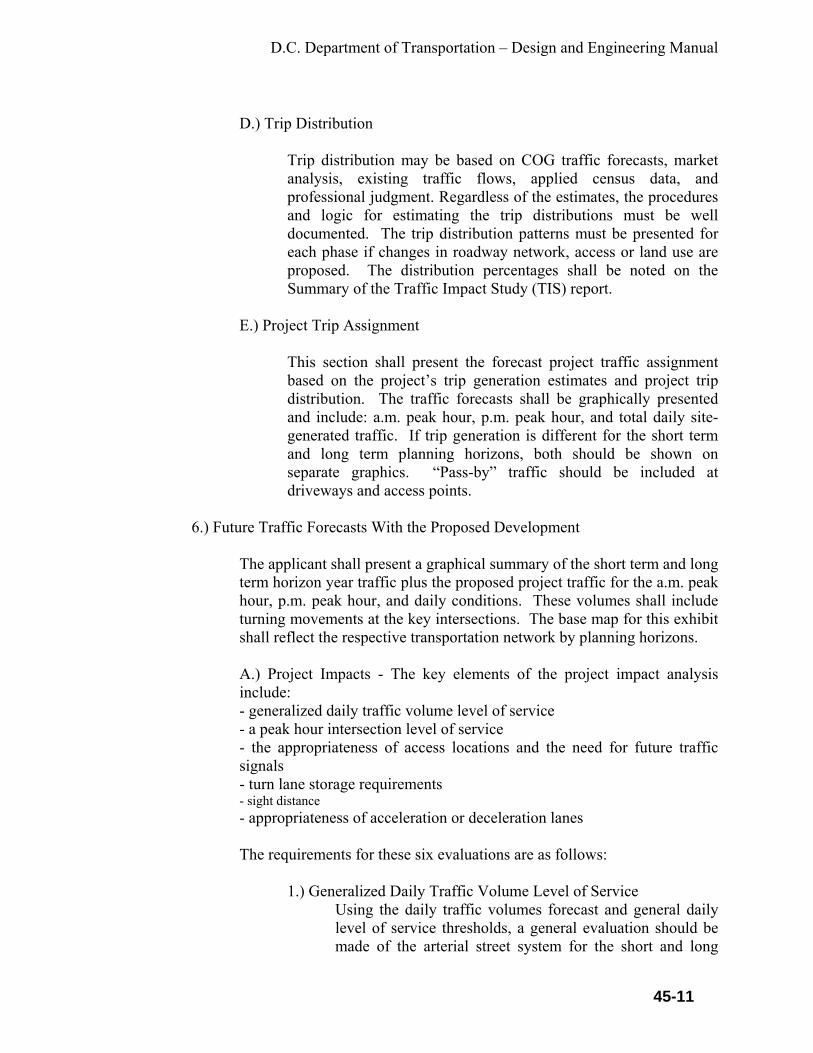
D.C. Department of Transportation – Design and Engineering Manual
45-11
D.) Trip Distribution
Trip distribution may be based on COG traffic forecasts, market analysis, existing traffic flows, applied census data, and professional judgment. Regardless of the estimates, the procedures and logic for estimating the trip distributions must be well documented. The trip distribution patterns must be presented for each phase if changes in roadway network, access or land use are proposed. The distribution percentages shall be noted on the Summary of the Traffic Impact Study (TIS) report.
E.) Project Trip Assignment
This section shall present the forecast project traffic assignment based on the project’s trip generation estimates and project trip distribution. The traffic forecasts shall be graphically presented and include: a.m. peak hour, p.m. peak hour, and total daily site-generated traffic. If trip generation is different for the short term and long term planning horizons, both should be shown on separate graphics. “Pass-by” traffic should be included at driveways and access points.
6.) Future Traffic Forecasts With the Proposed Development
The applicant shall present a graphical summary of the short term and long term horizon year traffic plus the proposed project traffic for the a.m. peak hour, p.m. peak hour, and daily conditions. These volumes shall include turning movements at the key intersections. The base map for this exhibit shall reflect the respective transportation network by planning horizons. A.) Project Impacts - The key elements of the project impact analysis include: - generalized daily traffic volume level of service - a peak hour intersection level of service - the appropriateness of access locations and the need for future traffic signals - turn lane storage requirements - sight distance - appropriateness of acceleration or deceleration lanes
The requirements for these six evaluations are as follows:
1.) Generalized Daily Traffic Volume Level of Service Using the daily traffic volumes forecast and general daily level of service thresholds, a general evaluation should be made of the arterial street system for the short and long

D.C. Department of Transportation – Design and Engineering Manual
45-12
term horizon years. Incremental differences attributable to the land use action should be identified. A map showing generalized levels of service should be presented for each design year.
2.) Peak Hour Intersection Level of Service
An a.m. and p.m. peak hour intersection level of service analysis shall be conducted for each intersection, based on procedures specified in the most recent release of the Highway Capacity Manual (or an approved method by DDOT). The “planning method” of analysis is permitted. All level of service analysis worksheets shall be included in the appendix. The principal objective of the intersection level of service traffic impact analysis is to identify whether the traffic from the proposed project when added to the existing plus short and long term planning horizon traffic will result in a significant impact and an unacceptable level of service. Significance is defined as:
- When the added project traffic causes the level of service to exceed the established threshold - When the short term or long term horizon year traffic with the project exceeds the established threshold, and the project traffic causes a 2 percent increase in the volume/capacity ration or delay.
3.) Traffic Signals and Access Locations
The appropriateness of the project’s access locations and type must be established. For full-access locations, a signal warrant analysis based on the Manual on Uniform Traffic Control Devices must be conducted for each design year. Traffic signals specifically warranted by the land use action shall be identified. The acceptability of the signal locations must be demonstrated through a signal progression (time-space) analysis. The analysis shall consider any existing access or intersection or a possible future signal location along the arterial for a distance of at least one mile in each direction of the proposed signal. A cycle length of between 80 and 120 seconds should be selected and agreed to by District staff. A travel speed of 45 Mph on majors and 35 Mph on minors, unless the existing posted speed limit is less, must be used. A major arterial bandwidth of 50 percent and

D.C. Department of Transportation – Design and Engineering Manual
45-13
minor arterial bandwidth of 40 percent are considered desirable, and must be used where existing conditions allow. Where intersections or other accesses have no signals presently, but are expected to have signals, a 60 percent mainline, 40 percent cross street cycle split should be assumed. Where information that is more detailed is available from turning movement projections, other split assumptions may be made. Any access that would reduce the desirable bandwidth if a traffic signal were installed shall be identified. In general terms, that access should remain un-signalized and have turning movements limited by driveway design or median islands, unless the impacts to traffic operation and safety are made even worse by doing so. The implications of the land use action upon the adequacy of the signalized locations for each design year shall be provided. Distances between signalize intersection (centerline) shall be indicated.
4.) Turn Lane Storage Requirements
Turn lane storage needs shall be identified for the necessary situation, based on projected turning volumes and AASHTO analytic techniques. Appropriate documentation of the calculations must be provided.
5.) Sight Distance
The identification of project sight distance at the project entrances and all internal streets shall be conducted. Line of sight triangles for determining sight distances and landscape restrictions shall be drawn on the site plan.
6.) Appropriateness of Acceleration or Deceleration Lanes
All proposed project entrances on arterials shall be evaluated as to whether they require acceleration lanes or deceleration lanes.
7.) Special Analysis/Issues
This section provides the District with opportunities to request specific focused traffic analyses germane to the proposed development. These could included access control, access spacing, accident/safety concerns, cut through traffic and residential quality of life, truck estimates and pavement design, accident statistics, pedestrian safety, bicycle safety, safe

D.C. Department of Transportation – Design and Engineering Manual
45-14
routes to schools, emergency routes, etc. This section would also contain environmental and regional air quality conformity analysis as necessary.
8.) Mitigation Measures/Recommendations
This section shall describe the location, nature, and extent of all transportation improvements that the applicant recommends to yield to reasonable operating conditions in each horizon year with the land use action approved as requested. For this discussion, the following terms apply: A.) Planned
Improvements planned have committed funding including those identified in short term capital improvement programs by District agencies.
B.) Background Committed
Improvements committed to by previously approved development.
C.) Applicant Committed
There are two conditions where improvements need to be identified: - When existing plus cumulative traffic with planned and background improvements exceed established levels of service, the applicant shall identify mitigation to offset project impacts. - When existing plus cumulative traffic with planned and background improvements do not exceed established levels of service, the applicant shall identify mitigation to achieve established levels of service.
D.) Necessary
Improvements required to mitigate background plus applicant traffic to established levels-of-service, the applicant shall identify mitigation to achieve established levels-of-service. The reason that “necessary” improvements must be explored is that often the “background committed” or “planned” improvements plus the improvements that the applicant typically understands and commits to are not adequate to provide the established level of service. The applicant should assure that all practical solutions have been considered when developing the list of “necessary”

D.C. Department of Transportation – Design and Engineering Manual
45-15
improvements, so that the resulting operating conditions are made to approach the established level-of-service. For purposed of identifying improvement possibilities (either by the applicant or by the District) “necessary” to yield an acceptable level of service, the cost of the improvements shall be considered a limiting constraint with the context of the traffic impact study. However, the goal of the evaluation is to identify cost-effective solutions that yield a reasonable level of service. Extremely high-cost solutions may not be cost-effective, but it is important to at least identify solutions so that decision makers are cognizant of existing options. The applicant shall use a “Recommended Improvements summary Sheet” to present the recommendations. One sheet may be used for both design years if all the improvements can be conveniently described thereon. If not, one or more sheets should be completed for each design year. All recommended improvements should be identified on the Summary sheet, including “planned,” “background committed,” “applicant committed,” and “necessary.” Each project shall be briefly described as to its location, the type of project, flow line and ROW needs (for roadways), signal or turn lane improvements (for intersections), and, at a sketch planning level, cost of the improvement. In addition, commitment to the improvement shall be identified either by governments, or by the applicant himself (this may included both the “applicant committed” and “necessary” projects). Identification of a project as “not currently committed” may be an appropriate description for many needed projects, including some of those that are “planned.” However, the goal of the recommendations should be to identify a firm program of improvements that will support the proposed land use action and background traffic in each design year. It is further required that all geometric improvements such as pavement markings, signs, adding through or turn lanes, adding project access and assorted turn lanes, acceleration lanes, and changes in medians, shall be presented in scaled drawing, preferably on a current aerial map. Sufficient dimensions shall be identified to facilitate review. ROW needs shall also be identified on the plan.

D.C. Department of Transportation – Design and Engineering Manual
46-1
CHAPTER 46
PARKING This chapter defines the parking criteria for on street parking, Central Business District (CBD) parking, and other special requirement areas. This chapter also establishes the dimensional requirements for off-street parking. Parking shall meet DDOT requirements, District regulations DCMR 18 2405.2 B, and ADA requirements. 46.1 On-Street Parking
Depending on the roadway classification, certain roadways are designated with on street parking by mark a “L” or “parking space”. The functional classification of roadways adopted by DDOT is presented in chapter 30 of this manual. In order to accommodate on-street parking within the District and to minimize potential accidents and conflicts between moving and parking vehicles, the dimensional requirements of Table 46-A must be used.
Table 46-A:
All on-street parking areas must be striped as designated in the table to provide sufficient depth and width for vehicles. For streets where parking is limited or not allowed, “No Parking” street signs shall be required in accordance with the MUTCD.
46.1.1 Non-Parallel Parking
In the CBD and other special designation areas, the District permits perpendicular or diagonal parking. All on-street parking areas must be
DEGREE STALL WIDTH
STALL DEPTH
ADJACENT AISLE WIDTH
SKEW WIDTH
90 9’-0” 18’-0” 23’ Min to 27’ Max None
60 9’-0” 17’-0” 17’-0” Min 9’-3”
45 9’-0” 19’-10” 11’-0” Min 12’-9”
Parallel 9’-0” 12’-0” Min None
Parallel 8’-6” 11’-6” Min None
Parallel 8’-0” 11’-0” Min None
Parallel 7’-0” 5’-0” Min Bike lane None

D.C. Department of Transportation – Design and Engineering Manual
46-2
approved by the Public Parking Program Manager and meet the requirements of Table 46-A. The parking spaces must be striped. Diagonal parking may be approved at an angle of 45 or 60 degrees. Parking spaces for family vehicles shall be a minimum of 9 ft. wide for all angle parking spaces. See Section 46.2.1 for dimension of handicap spaces. Angle parking on a public street must be pre-approved by DDOT. Vehicles shall enter angle parking spaces only by reversing. A minimum clearance of 20 ft. between the first parking space and the stop line is necessary to allow drivers to maneuver into parking spaces without encroaching on the crosswalk. A minimum clearance of 22 ft. shall be provided between the back-edge line of the crosswalk and the beginning point of the angle parking space. This clearance is intended to provide space for a vehicle to wait while another vehicle is reversing into the parking space.
46.1.1.1 On-Street Parking for People with Disabilities
On-street parking for people with disabilities in front of DC government buildings and other places needs approval from DDOT. The parking area shall be appropriately signed. Only the Traffic Operations Administration can install designated on-street parking spaces for people with disabilities.
46.1.1.2 Driveway Clearance
A vehicle parking space within the roadway shall be designated with a minimum clearance of 5 ft. from the edge of the driveway, unless otherwise indicated. Sight-distance is a major factor when exiting mid-block parking lots. There must be a minimum of 5-foot clearance on each side of these driveways. Existing mid-block driveways require a minimum of 5 ft. clearance on each side unless special sight distance problems exist. DDOT engineer will make the final determination of the clearance required for the driveway.
46.1.1.3 Intersection Clearance A vehicular parking space within the roadway shall be designed with a minimum clearance of 25 ft. from the stop bar. Depending on traffic conditions, the District may require a greater clearance. NOTE: No parking is allowed within an Intersection. Refer to the Pavement Markings and Signage chapter within this manual for more information.

D.C. Department of Transportation – Design and Engineering Manual
46-3
46.1.1.4 Fire Hydrant
No parking may be designated in front of a fire hydrant and within 10 ft. in either direction from the centerline of the fire hydrant.
46.1.1.5 Parking in Alleys
In public alleys with a minimum width of 30 ft. parking is allowed, providing DDOT issues a regulation permitting parking, otherwise parking is not allowed in public alleys. Parking is allowed provided a driveway is installed in front or located behind private property with housing located within the alley system. These spaces must be pre-approved by DDOT. For parallel parking on private property and/or on commercial property adjacent to any public alleys, there must be a minimum 5 ft. clearance space between the parking space and the edge line of the alley. For parking at a 90-degree angle to an alley there must be a minimum three-foot space between the end and front of the parking space and the edge line of the alley.
46.2 Off-Street Parking
Without a permit from the Public Space Permit Office, parking is not allowed within the public space area between the curb of the street and the property line. The regulations authorizing permits for parking in this area are provided in Title 24 of the DC Municipal Regulations. All applications for such use must be submitted to the Public Space Committee of the District of Columbia and require payment of annual rent. For more information on this type of permit please contact the Public Space Committee Coordinator at [email protected] or via telephone at 442-4670.
46.2.1 Off-Street Handicap Parking Spaces for people with
Disabilities
Use 90-degree universal parking space design: 11 ft. wide spaces with a 5 ft. wide space between the two 11 ft. spaces. The 5 ft. space must have diagonal striping on a 45-degree angle. Use 1 ft. wide stripe and 2 ft. spacing. 19 ft. length is required for parking spaces. Concrete curb stops should be provided for each parking space. A minimum 5 ft. area must be provided in front of each parking space leading to handicap ramp. There must be an additional 5 ft. diagonal striped area between a regular parking space and an adjacent handicap space.

D.C. Department of Transportation – Design and Engineering Manual
46-4
46.2.2 Loading Zones
Zone spaces are to be 30 - 40 ft. Larger sizes must have pre-approval from IPMA.
46.3 Bicycle Parking
Comply with the DCMR, Title 11, Chapter 21 and DDOT Bicycle Facility Design Guide, for off-street bicycle parking. Refer to DDOT Bicycle Facility Design Guide for on-street bicycle parking.

D.C. Department of Transportation – Design and Engineering Manual
47-1
CHAPTER 47
LANDSCAPING DESIGN CRITERIA 47.1 General
This chapter provides a framework for the designer to design landscaping within the District's ROWs and public areas. These criteria are not intended to direct the designers in development of private landscaping or other onsite development. The designer should adhere to the District's Conservation Ordinance, which requires, that a water demand calculation be completed for all planting plans. Where possible, landscaping shall be utilized to improve storm water quality following the concept and objectives of Low Impact Development. Projects for private property development that include new streetscapes shall conform to the requirements of this chapter and all applicable District regulations. This work requires a permit from the Public Space Permit Office.
47.2 Intent
The intent of these design criteria is to beautify the District and its many common areas through the planting of trees, the appropriate use of hardscape, while practicing water conservation, through drip irrigation, and drought resistant plants of the District's Municipal Code. The District is committed to the reduction of water consumption in landscape irrigation and encourages the application of Xeriscape design and maintenance principles. All trees, plantings and work shall meet the American Nurseryman Standards. The District will maintain trees through pruning.
47.3 Roadside Development
Roadside development is the treatment given to the roadside to conserve, enhance, and effectively display the natural beauty of the landscape through which the highway passes. The plans shall be submitted as an integral part of the plans as defined in Part I - Procedures of this manual. The costs of such improvements shall be included in the Cost Estimate for Public Improvements as required in these Standards. All non-hardscape areas within the ROW shall be seeded, planted or covered within the design criteria of this section. Employing as many of the following landscaping treatments as possible into the final design enhances and emphasizes the natural beauty of the roadside.
47.3.1 Local Streets
For all residential local streets, the adjacent homeowner shall be responsible for planting and maintaining the ROW behind the sidewalk.

D.C. Department of Transportation – Design and Engineering Manual
47-2
47.3.2 Local Street Commercial
For all commercial local streets, the adjacent property owner shall be responsible for designing, planting and maintaining the ROW behind the curb. This design shall include the sidewalk as required by these Standards. The property owner shall install plantings and irrigation, (if necessary), within the guidelines of these Standards. All non-hardscape areas within the ROW shall be seeded, planted or covered within the guidelines of this Chapter. All on-site landscaping shall be designed in accordance with the District Urban Forestry Guidelines.
47.3.3 Arterials, Collectors, and Gateway Entry Streets
For all arterials, collectors and entry streets within the District, including medians, the Landscape design shall be in accordance with the District Urban Forestry Guidelines.
47.3.4 Downtown Streetscape Impact Area
This area is generally bounded on the south by Pennsylvania Avenue NW, on the west by 15th St NW, on the north by M Street NW, and on the east by 3rd St NW and North Capitol Street. The trees to be planted in this area are designated in the Master Street Tree Plan in the DDOT Downtown Streetscape Regulations, August 2000 or latest edition. These are collected in DCMR Title 24 Chapter 11.
47.3.5 Medians
To assure normal tree development, the minimum width dimension for a tree box cutout is 4 ft. by 9 ft. Trees are not to be planted in tree boxes or continuous strips (grass) if this width threshold is not met. All medians or sections of medians that are less than 4 ft. wide must be completed in a hardscape, including stamped concrete, brick, flagstone or exposed aggregate concrete. No landscaping will be allowed within the medians that are narrower than 4 ft. If a median is between 4 ft. and 10 ft., it shall be at the District’s discretion whether the median is hardscaped or irrigated and landscaped.
47.3.6 Tree Box
All tree boxes shall consist of rod iron loops and borders on three sides. No landscape fabric or stone mulch is permitted in the tree boxes. When replacing trees in an existing row, select new trees of similar ultimate characteristics to those being replaced, including form, scale, texture, size

D.C. Department of Transportation – Design and Engineering Manual
47-3
and color. Tree boxes in the Downtown Streetscape Impact Area shall be in accordance with the DDOT Downtown Streetscape Regulations, August 2000 or latest edition. The following items are requirements to be followed in the design of trees and their location in order to reduced utility conflicts: • Trees shall not be planted closer than 40 ft. from the curb face at
intersections and street corners within the site distance triangle. • Trees shall not be planted within 40 ft. of a controlled intersection, or
other traffic control device (this does not include “No Parking” signs.) • Within the Sight Distance Triangle, non-plant materials and bushes
should be no more than 3 feet high, and trees should begin at a height of no less than 8 feet.
• Maintain the minimum sight distance triangle and corner triangle distances for safe view of oncoming traffic and pedestrians. - Trees to be planted a minimum of 10 ft. from a driveway or alley. - Trees to be planted a minimum of 15 ft. from a light pole, preferably
20 ft. - Trees to be planted a minimum of 10 ft. from a fire hydrant. - Trees should be located in the middle of the tree lawn space. - Trees shall be designed to ensure the driver’s visibility of all regulatory signs. - Additionally, trees shall not be planted:
-- directly in front of a sidewalk or the steps to a dwelling, -- where existing public or private tree cover will interfere with a tree’s growth, -- in front of forested or open areas where there are no existing dwellings.
47.3.7 Tree Size
All trees shall be 2 – 2.5 in. caliper (unless otherwise designated)) when planted and shall be guaranteed for 2 years or replaced. Please see the following: • Trees planted in tree lawns should be 2 in. caliper, minimum. • The branching height of a tree on the traffic side of the street shall be
not less than 15 ft. above the street. • The branching height of mature trees on the pedestrian side of the
street shall be not less than 8 ft. above the sidewalk. • Small varieties of thornless and fruitless trees may be used only in
median areas or traffic islands where lower branching habits will not interfere with pedestrians, vehicles or driver visibility.

D.C. Department of Transportation – Design and Engineering Manual
47-4
• Small to medium trees shall be used where power lines overhead would not allow a large street tree to reach maturity without severe pruning.
• All medians or sections of medians over 4 ft. are allowed to use drought resistant plantings. However, only drip irrigation systems will be allowed. No pop-up sprinklers will be allowed in medians to minimize wastewater that occurs with pop-up sprinklers.
47.3.8 Tree Lawn
On arterials, all sidewalks shall be set back from the curb a minimum of 6 ft. Pop-up sprinklers may be approved in tree lawns over 8 ft. in width. No tree lawn shall be less than 4 ft. in width on the city streets in the District.
47.4 Plantings
47.4.1 Street Trees
Design for street trees should respond to the uses on the street. The following factors are guidelines for determining how and when trees should be used within the landscaping areas. They are: • Urban Forestry will ascertain type of species to plant. • Select trees that will fit when they are mature. Narrow areas suggest a
narrow tree and open areas suggest a wide tree. • Where tree lawns do not exist, tree grates or pavers are recommended
to protect tree roots and pedestrians. • Use tree grates where pedestrian traffic is high. Minimum openings on
the tree grates are 24 in. diameter. Pavers shall be inserted into the holes in the grates.
• Business owners will be required to obtain a permit from Urban Forestry to plant trees in the business districts and will be required to sign an agreement to maintain the tree grate.
• Trees may be grouped in areas upon approval of the District.
47.4.2 Location
The designer shall consider the mature tree’s shape and size during design and before planting, so that the tree has room to grow. Where signs, lights, overhead or underground utilities, utility poles and fire hydrants would limit mature tree size, adjustments in species or location should be considered to minimize excessive pruning. The following items are suggestions or guidelines in the design of trees: • Plant trees with regular spacing in straight rows to create a continuous
street edge. Adjust spacing only slightly for driveways and lights. On

D.C. Department of Transportation – Design and Engineering Manual
47-5
arterials, the planted trees may be varied for visual appeal. Locate trees in a straight-line midway between curb and detached walk, even where the width of the tree lawn varies.
• Tree spacing shall be as follows, using the larger dimension whenever possible: - Where no overhead wires are present, use 35 – 40 ft. - Where overhead wires are present, use 20 – 25 ft.
-- Tree lawns may not be elevated. -- Medians shall be elevated.
47.4.3 Recommended Turf Grasses
Turf should be planted on prepared soil from seed or sod. Seeding allows a greater turf selection, but requires approximately six months and regular maintenance to become established. Newly seeded areas require protection from pedestrians and must be kept moist until the seeds germinate. All irrigated turf areas require organic soil amendments at the rate of at least 3 cubic yards per 1000 sq. ft. Alternatives to bluegrass are required. They are as follows: • Mixed Fine Fescue, Rye Grass, and Bluegrass - This mix works in sun
and shade, suits a number of climate and soil conditions, and provides improved shade, disease, salt and moisture stress tolerance over pure bluegrass.
• Tall Fescue/ Turf Type - Deep green color, shade and salt tolerant, and drought-resistant because of its deep root system. Include at least three improved varieties of turf type tall fescue in the blend.
47.4.4 Recommended Trees/Plants
All trees should fit the microclimate, soils, sun, moisture, budget and maintenance environment in which they are planted. This is a major concern in areas with high levels of pollution, and automobile or pedestrian damage. Trees selected for urban streets should be able to endure pollution, compacted soils, minimal water, and low maintenance. Trees near walks should be thornless and fruitless to minimize maintenance and to reduce pedestrian hazards. They must be strong-wooded, resistant to most diseases and insects, single-trunked, with upright growth and a medium to long life expectancy. Branches should resist breaking. Drip irrigation may be installed for street trees in commercial streets that require minimal water. Irrigation must be designed to provide the appropriate amount of water to each tree with minimal waste. Easily adjustable, automatic irrigation systems are recommended.
D.C. Department of Transportation – Design and Engineering Manual
47-6
Along commercial streets, trees should be selected that will minimize the obstruction of views to retail signs. Use trees with the appropriate forms and character. Utilize tree spacing that supports this concept.
47.4.5 Covers
Covers provide seasonal color and serve as a buffer between people and cars. Ground cover plantings provide functional and aesthetic benefits, however maintenance is extremely important. Plantings, other than trees in the streetscape, may include turf, ground covers or shrubs. In commercial streetscapes with a large area between the sidewalk and the street or low pedestrian volume, a tree lawn of grass may be most appropriate. This area helps soften the street environment along the street edge. Specific site conditions must be fully understood prior to plant selection. Local microclimates and soils are key factors that determine which plants will thrive. Where possible, low water requiring plants are selected. Trees and shrubs will require less water and will thrive better if placed in planting beds, rather than turf beds. Tree lawns must be at least 8 ft. wide to accommodate irrigation system and to provide adequate room for healthy tree root systems. Turf shall be provided where the average width of the tree lawn is 8 ft. or more. In medians, turf should be limited to median areas greater than 10 ft. In median areas, any width less than 4 ft. shall be hardscaped. Tree lawns should be planted with sod or low ground covers, (below 6 in. in mature height), in residential areas and in commercial areas where pedestrian traffic does not warrant hardscape. Very narrow tree lawns or those in high traffic areas may be paved with brick, flagstone or concrete payers, and/or colored or scored concrete. All tree lawn areas designated by the District, as high commercial areas shall be hardscaped.
47.5 Tree Space Beautification
Communities and abutting property owners may plant and maintain Tree Space Beautification with approval from the Department. This section complies with DC Law 8-21, “Tree Space Beautification Regulation Act”
47.5.1 Tree Space
Tree space is the unpaved area of public space that lies between the curb and sidewalk, commonly reserved by the DC government for planting trees.
D.C. Department of Transportation – Design and Engineering Manual
47-7
47.5.2 Plants
• Use plants that have a shallow root system. • Plants should not grow taller than 18 in. • Plants are to be contained in the space and not extend outside of its
borders.
47.5.3 Borders
• For the safety of people exiting their vehicles, borders should not be placed on the curbside of the tree space.
• Borders should not be less than 4 in. or greater than 12 in. high from the curb.
• Wickets and other tripping hazards are strictly prohibited.
47.5.4 Responsibility
Tree space beautification must be undertaken solely at the personal expense and risk of the abutting homeowner. This area shall be under the immediate care and keeping of the abutting property owner. The District reserves the right to enter the tree box area for construction or maintenance activities. DDOT will give notice to the abutting property owner if removal of beautification materials within the tree space is required; this will allow the Owner to remove plants and materials prior to construction work. The grade or height of the tree space shall not be changed except with mulch.
47.6 Freeways and Interstate Highways
47.6.1 Landscape Treatment
The extent of landscape treatment will vary according to the amount of landscape manipulation and area visibility. The most visible areas must receive the greatest attention. To achieve the necessary blending, concentrate much of the landscaping effort near the base of the fill and the top of the cut lines. When planting larger trees, specify them to be placed near the top of the cut slopes or the toe of the fill. Keep them beyond the clear zone and, if required, beyond the snow storage area in snow plowing areas. On the higher speed roadways, planting groups of one or two tree species can provide adequate treatment. More specie diversity along with

D.C. Department of Transportation – Design and Engineering Manual
47-8
appropriate groundcover shrubbery is preferred in urban planting situations.
47.6.2 Earthwork
Design cut-and-fill slopes, not only to satisfy slope stability and balance material quantities, but also to improve the appearance of the final project. Use variable slope ratios for both cut and fill slopes. Avoid using constant slope ratios. The use of slope rounding at the top of cuts is commonplace. Round the ends of cuts and blend the ends of fills into the cut slopes. When practical, include in the design some slope molding techniques to imitate the existing landscaping elements. Slope molding goes beyond variable slope and rounding concepts. With slope molding, a deliberate attempt is made to break up the uniformity of a finished slope. On long cut slope faces, lay back the draws and accent the ridges. Warp slopes around existing large boulders and rock outcrops. In areas of natural draws, lay back or flatten the cut slope to match that of the draw. This only generates a small amount of additional material and greatly enhances the appearance of the cut slope. This material can be used to flatten fill slopes or mold then into natural land forms common to the project area.
47.6.3 Vegetation Clearing
The emphasis should be to promote scenic views and enhance the natural beauty of any project. A balance is needed that emphasizes vegetation patterns above and below the highway slope.
47.6.4 Revegetation
Revegetated slopes are not only pleasing to view but are stabilized and require little or no maintenance. Re-established vegetation is also important as cover and food for wildlife. Select grass seed that is native to or adaptable to the area. The seed mixture shall satisfy criteria for elevation and slope exposure changes. Several seed mixtures may be required to satisfy all conditions on a relatively long project. Use soil mulches and netting to stabilize and protect the ground until grass is established. Where practical, conserve topsoil from the project limits and replace it on the finished slopes. The topsoil not only provides needed fertility and a growing medium for grasses, it contains an abundance of native seeds. These forbs, weeds, and grasses usually grow fast and dense and will

D.C. Department of Transportation – Design and Engineering Manual
47-9
blend in with the undisturbed vegetation that effectively brings the background vegetation onto the cut slope. Shrubs and trees can be planted to primarily beautify the disturbed roadside areas and blend them into the undisturbed areas. Using hydrophilic shrubs, such as willow and birch, grouped in areas of excess soil moisture, will aid in stabilizing the area. Locate all plant groupings in areas that are the most visible to the motorist. It is FHWA policy that at least ¼ of 1 percent of funds expended for landscape projects be used to plant native wildflowers, except in ornamental landscapes, or unless a waiver is granted by the District. A waiver shall be documented with adequate justification in support of all findings and conclusions. An ornamental landscape is one that is irrigated, has barked shrub beds, and has irrigated grass that is routinely mowed. Requests for waivers can only be granted for the following conditions:
• Wildflowers cannot be satisfactorily grown • The available ROW is to be used for agricultural purposes • There are no suitable available planting areas • The planting poses a threat to endangered or rare plant species Erosion control seeding is not a landscape item although wildflower seeding associated with the erosion control seeding mix can satisfy wildflower-seeding requirements in a landscape project. In order for wildflowers to perpetuate themselves, they must be permitted to go to seed and become dormant. Identify on the plans all areas to be seeded with wildflowers. Provide in the contract for the installation of suitable markers to identify the wildflower seedbeds for roadside management and maintenance personnel.

D.C. Department of Transportation – Design and Engineering Manual
48-1
CHAPTER 48
APPENDICES Appendix A DC Department Of Transportation (DDOT) Project Checklist
DDOT Project No. Federal Aid Project No. Project Location
Beginning Limit Ending Limit
Ward No. Program Manager Federal Aid Project: [ ] Non- Federal Aid Project: [ ]
Proposed improvements/scope of work
Step 1: Project Development is managed by the Office of Planning and becomes part of the 5-year Capital Improvement Program. The initial scope of work, cost estimate and community issues are identified and coordinated with the Ward Program Manager. Step 2: The DDOT Ward Program Manager reviews the initial scope of work in coordination with Office of Planning, Infrastructure Project Management Administration ROW Administration and Urban Forestry Administration. The Program Manager visits the project site to determine all issues for scope of work. Upgrade the design and construction cost estimates. Step 3: Ward program Manager manages and reviews the in-house designs and the designs performed by consultants. Instructions: 1.) This checklist is to be used in conjunction with the Policy and Procedure Manual. 2.) The checklist is intended to aid DDOT project managers, consultant project managers and private developers engaged in designing projects for construction in the District. 3.) X Denotes that the project manager requires action at these stages of the project.

D.C. Department of Transportation – Design and Engineering Manual
48-2
4.) Check ( ) the Clearance box when an item is completed and approval of clearance is obtained from the authorizing Department, agency or Administration. 5.) All Federal Aid Projects require coordination and approvals from the District division of Federal Highway Administration (FHWA). The following tables summarize the project development procedures, the anticipated activities and the agencies involved.
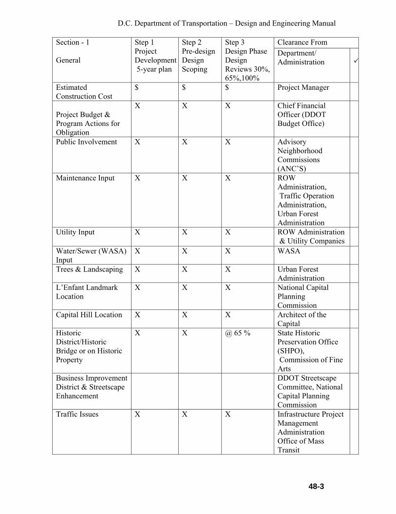
D.C. Department of Transportation – Design and Engineering Manual
48-3
Clearance From Section - 1 General
Step 1 Project Development 5-year plan
Step 2 Pre-design Design Scoping
Step 3 Design Phase Design Reviews 30%, 65%,100%
Department/ Administration
Estimated Construction Cost
$ $ $ Project Manager
Project Budget & Program Actions for Obligation
X X X Chief Financial Officer (DDOT Budget Office)
Public Involvement
X X X Advisory Neighborhood Commissions (ANC’S)
Maintenance Input
X X X ROW Administration, Traffic Operation Administration, Urban Forest Administration
Utility Input X X X ROW Administration & Utility Companies
Water/Sewer (WASA) Input
X X X WASA
Trees & Landscaping
X X X Urban Forest Administration
L’Enfant Landmark Location
X X X National Capital Planning Commission
Capital Hill Location X X X Architect of the Capital
Historic District/Historic Bridge or on Historic Property
X X @ 65 % State Historic Preservation Office (SHPO), Commission of Fine Arts
Business Improvement District & Streetscape Enhancement
DDOT Streetscape Committee, National Capital Planning Commission
Traffic Issues X X X Infrastructure Project Management Administration Office of Mass Transit

D.C. Department of Transportation – Design and Engineering Manual
48-4
Bike/Pedestrian Improvements
X X X TPPA
Rehabilitation or Reconstruction
X X X Infrastructure Project Management Administration
Horizontal Control (Maryland Coordinate) and Benchmarks
X DC Surveyor’s office
Vertical Control (DC Datum) and Benchmarks
X DC Surveyor’s Office
Federal Lands Affected
X X X Office of Planning, General Services Administration, Federal Highway Administration, Effected Agency
Design Data (Form 02002)
X Project Manager
Design Exception (02003)
@ 65% Infrastructure Project Management Administration

D.C. Department of Transportation – Design and Engineering Manual
48-5
Clearance From Section - 2 Environmental
Step 1 Project Develop-ment 5-year plan
Step 2 Pre-design Design Scoping
Step 3 Design Phase Design Reviews 30%, 65%, 100%
Department/ Administration
Route Location Approval Major Certification (EIS) Minor Compliance (EA) Categorical Exclusion
X X Office of Planning
Section 4(f)
X
X
@ 100%
National Park Service (NPS)
Section 6(f) X @ 100% DC Park & Recreation Dept
ROW Acquisition X DC Office of Property Management.
Archaeology (Effects Determination)
X X DC Health
Paleontology (Effects Determination)
X X DC Health
Floodplains
X X DC Health, Corp of Engineers
404 Permit - X X @ 65% US Coast Guard
Wetlands
X X DC Health, Corp of Engineers
Wetlands Mitigation
X X DC Health, Corp of Engineers
USF & W – Dept of Health
Threatened and Endangered Species
X X X DC Health
Hazardous waste and materials Contaminated soils
X X X DC Health, EPA
Noise Control - Variance
X X @ 30% DC Health
Air Quality
X X @ 65% DC Health
D.C. Department of Transportation – Design and Engineering Manual
48-6
401 Certification
X X @ 65%
402 Permit
X X
NPDES Permit
X X
Water Quality
X X @ 65% DC Health, WASA
Erosion Control
X @ 65% DC Health
National Park Lands Permit (Work on NPS Land for Surveying and Construction)
X Prior to 30 % for Surveying @ 100% for construction
National Park Service

D.C. Department of Transportation – Design and Engineering Manual
48-7
Clearance From Section - 3 Traffic
Step 1 Project Develop-ment 5-year plan
Step 2 Pre-design Design Scoping
Step 3 Design Phase Design Reviews 30%, 65%,100%
Department/ Administration
Traffic Design Data (For Year of Construction)
X Infrastructure Project Management Administration
Traffic Accident Analysis
X X Infrastructure Project Management Administration
Turning movements
X Infrastructure Project Management Administration
Signal warrants
X X Infrastructure Project Management Administration
Intersection layout/Design
X
X
X
Office of Planning, Infrastructure Project Management Administration
Interchange layout/Design
X X X Office of Planning, Infrastructure Project Management Administration
Construction/ Modification of Circles and other Landmarks
X X @ 65% National Capital Planning Commission (NCPC)
Traffic Calming X X X Infrastructure Project Management Administration
Traffic signal
X X X Infrastructure Project Management Administration
Streetlight
X X X Infrastructure Project Management Administration
Permanent signing and pavement marking
X X Infrastructure Project Management Administration
Construction traffic control plans (Signing, signals and pavement marking)
X X Infrastructure Project Management Administration

D.C. Department of Transportation – Design and Engineering Manual
48-8
Clearance From Section -4 Structures
Step 1 Project Develop -ment 5-year plan
Step 2 Pre-design Design Scoping
Step 3 Design Phase Design Reviews 30%, 65%,100%
Department/ Administration
Structure – Tunnel X X X Infrastructure Project Management Administration
Structure – bridge
X X X Infrastructure Project Management Administration
Structure – culvert
X X X Infrastructure Project Management Administration, WASA
Architectural/ Aesthetic Bridge Rail
X X X Infrastructure Project Management Administration
Pedestrian overpass/underpass
X X X Infrastructure Project Management Administration
Architectural/Aesthetic Treatment of Structure
X X Infrastructure Project Management Administration, State Historic Preservation Office (SHPO) for Historic Structures
Foundation investigation and recommendation
X Infrastructure Project Management Administration (QA/QC Materials Div)
Structure condition report
X Project Manager
Retaining Walls- Aesthetic Treatment
X X Project Manager
Noise Barrier Walls
X X X D.C. Health
Crashworthy bridge rail
X X Project Manager
Vertical & Horizontal clearance
X X Infrastructure Project Management Administration
Proposed Section X X Project Manager

D.C. Department of Transportation – Design and Engineering Manual
48-9
Clearance From
Section – 5 Pavement
Step 1 Project Develop-ment 5-year plan
Step 2 Pre-design Design Scoping
Step 3 Design Phase Design Reviews 30%, 65%,100%
Department/ Administration
ROW Distribution for city Streets (Width of Roadway, Sidewalks, Trees-pace & ROW, etc.)
X X District Surveyor’s Office, ROW Administration (Data abase)
Distress Pavement Justification Report
X X Infrastructure Project Management Administration
Geotechnical Studies and Pavement Analysis Investigation, Selection of Materials
X Infrastructure Project Management Administration (QA/QC Materials Div)
Curb Cuts, Cross-Walks layout & ADA Requirements
X X TPPA
Sidewalks, Curbs & Gutters and Special Treatments
X X Infrastructure Project Management Administration
Selection of Pavement X X Infrastructure Project Management Administration
Alternative pavement design (life cycle cost analysis)
X X Project Manager
Existing Pavement Section
X X X Project Manager
Alley Pavement X X X
Infrastructure Project Management Administration,
Pavement Special Materials and treatments
X X X Infrastructure Project Management Administration

D.C. Department of Transportation – Design and Engineering Manual
48-10
Clearance From Section - 6 Trees Planting And Landscaping
Step 1 Project Develop- ment 5-year plan
Step 2 Pre-design Design Scoping
Step 3 Design Phase Design Reviews 30%, 65%, 100%
Department/ Administration
Tree Species and Planting Requirements
X X Urban Forest Administration
Landscaping Standards
X X Urban Forest Administration
Seeding/Sod
X X Urban Forest Administration
Streetscape Requirements
X X X DDOT Streetscape Committee
Irrigation Systems X X Urban Forest Administration, WASA
D.C. Department of Transportation – Design and Engineering Manual
48-11
Clearance From Section – 7
ROW and Dry Utilities
Step 1 Project Develop- ment 5-year plan
Step 2 Pre-design Design Scoping
Step 3 Design Phase Design Reviews 30%, 65%,100%
Department/ Administration
ROW involvement
X X X District Surveyor’s Office, ROW Administration
Access control
X X X ROW Administration
Relocation
X X X ROW Administration
Permit Requirement
X X ROW Administration
Existing Easement
X X ROW Administration
New Easement
X X X ROW Administration
Clearance
X ROW Administration
Attachment to Structure
X X ROW Administration, Infrastructure Project Management Administration
Utility Cuts
X ROW Administration
Utility Cut Repairs X ROW administration, Infrastructure Project Management Administration

D.C. Department of Transportation – Design and Engineering Manual
48-12
Clearance From Section - 8
Water, Sewer and Storm Sewer
Step 1 Project Develop- ment 5-year plan
Step 2 Pre-design Design Scoping
Step 3 Design Phase Design Reviews 30%, 65%,100%
Department/ Administration
New Storm Sewer Extension
X X X WASA
Special Structure/ Water Quality Improvement
X X X Dc Health, WASA
Upgrade Storm Sewer Main/ Combined Sewer
X X X WASA
Upgrade Water main X
X
X
WASA
Standard Catch Basin & Standard 15 inch Connect Pipe
X X Project Manager
Upgrade Fire Hydrant
X
X
WASA
D.C. Department of Transportation – Design and Engineering Manual
48-13
Clearance From Section - 9
Agreements, Justifications and Approvals
Step 1 Project Develop- ment 5-year plan
Step 2 Pre-design Design Scoping
Step 3 Design Phase Design Reviews 30%, 65%,100 %
Department/ Administration
Detour Design
X X Infrastructure Project Management Administration
Railroad/ WMATA Coordination RR/WMATA Company RR Flagging and Insurance requirements
X X Railroad Company, WMATA
Vertical & Horizontal Clearances at RR & WMATA Crossings
X X Railroad Company, WMATA
Agreement Review X X DDOT Legal Review
Airport/heliport clearances
X X X Police Dept., Capital Police, Fire Dept.
Safety Review (including clear zone decisions)
X Infrastructure Project Management Administration
Guardrail/Barrier Design (Special/ unique Designs)
X X Infrastructure Project Management Administration
Erosion Control Scour Storm water Quality Management
X @ 65 % D.C. Health
Special Bidding Procedures
X Infrastructure Project Management Administration
Consolidation of Projects
X Infrastructure Project Management Administration
Special Material Specifications
X Infrastructure Project Management Administration
Consultant Selection and contracting process
X Infrastructure Project Management Administration

D.C. Department of Transportation – Design and Engineering Manual
48-14
Agreements Intergovernmental, Public, & Private) 1. State Agreements 2. Inter- Agency Agreements Memorandum Of Understanding (MOU) 3. Agreements with Private Parties Memorandum of Agreement (MOA)
X DDOT Director
Disadvantaged Business Enterprise Goals
X District’s Contracting Officer

D.C. Department of Transportation – Design and Engineering Manual
48-15
Clearance From Section - 10
Construction Document
Step 1 Project Develop- ment 5-year plan
Step 2 Pre-design Design Scoping
Step 3 Design Phase Design Reviews 30%, 65%,100 %
Department/ Administration
Surveying Requirement X X Project Manager
Materials or Source of materials Furnished by others
X X Infrastructure Project Management Administration
Work by Utility Companies/WASA with DDOT Project
X X Project Manager
Work of others for Inclusion in DDOT Project, such as utilities, WASA
X X Infrastructure Project Management Administration
Work by DC forces
X Infrastructure Project Management Administration
Utilities Certification Prior to P.S.& E
@ 100 % ROW Administration
Value Engineering
X Project Manager
PS & E Approval
@ 100 % Infrastructure Project Management Administration
P.S & E Package to FHWA
@ 100 % Contract Administration Office
Advertisement
@ 100 % Contract Administration Office
PS & E revisions
@ 100 % Project Manager
Re-advertisement @ 100 % Infrastructure Project Management Administration
Bid Analysis
@ 100 % Project Manager
Recommendation of Approval
@ 100 % Project Manager

D.C. Department of Transportation – Design and Engineering Manual
48-16
Appendix B Definition of Acronyms ACRONYM: DEFINITION: 3R Resurfacing, Restoration, Rehabilitation AASHTO American Association of State Highway and Transportation
Officials ADA Americans with Disabilities Act ADT Average Daily Traffic ANC Advisory Neighborhood Commission ATSSA American Traffic Safety Services Association BLM Bureau of Land Management COG Council of Governments CBC Concrete Box Culvert CFR Code of Federal Regulations DBE Disadvantaged Business Enterprise DDOT Washington DC Department of Transportation DHV Design Hour Volume DOR Design Office Review EEO Equal Employment Opportunity EA Environmental Assessment EIS Environmental Impact Statement EPA Environmental Protection Agency ESAL Equivalent Single Axle Load FAA Federal Aviation Administration FHWA Federal Highway Administration FIPI Finding-in-the-Public-Interest FONSI Finding of No Significant Impact HAZMAT Hazardous Materials HCM Highway Capacity Manual HES Hazard Elimination System HOV High-Occupancy Vehicle HTF Highway Trust Fund (Federal) HUTF Highway Users Tax Fund (State) IAI Impact Attenuator Inventory IDIQ Indefinite Delivery/Indefinite Quantity ISTEA Intermodal Surface Transportation Efficiency Act ITE Institute of Transportation Engineers IVHS Intelligent Vehicle Highway System LCCA Life Cycle Cost Analysis LOS Level of Service MOA Memorandum of Agreement MOU Memorandum of Understanding MUTCD Manual on Uniform Traffic Control Devices

D.C. Department of Transportation – Design and Engineering Manual
48-17
NCHRP National Cooperative Highway Research Program NCSHS National Conference on Street and Highway Safety NCUTCD National Committee on Uniform Traffic Control Devices NEPA National Environmental Policy Act NHS National Highway System NPC National Planning Commission NPDES National Pollutant Discharge Elimination System NPS National Park Service ProMIS Project Management Information System PS&E Plans, Specifications and Estimate QA/QC Quality Assurance/Quality Control ROD Record of Decision ROW Right of Way SHPO State Historic Preservation Office SNAP Strategic Neighborhood Action Plan TARAS Traffic Accident Report and Analysis System STP Strategic Transportation Plan TCP Traffic Control Plan TEA-21 Transportation and Efficiency Act for the 21st Century TIP Transportation Improvement Program TMC Turning Movement Count (10 Hour) UDBE Underutilized Disadvantaged Business Enterprises UMTA Urban Mass Transportation Administration USC U. S. Code USDA U. S. Department of Agriculture USDOT U. S. Department of Transportation USFWS U. S. Fish and Wildlife Service VMT Vehicle Miles Traveled

D.C. Department of Transportation – Design and Engineering Manual
48-18
Appendix C Consultant Checklist Item Preliminary Plans Interim Plans Final Plans Title Sheet Identification Block Street Name Project Number Stationing Limits Signature Block Designer Block Bar Scales Vicinity Map Design Information Plan Sheets Centerlines and Stations Limits of Project Edges of Pavement Curb and Gutter, Sidewalk ROW and Property Lines Ownership Structures North Arrow Street Names Railroads Federal Government Lands Political Boundaries Historic Designation Boundaries Sheet Identification Legend Scale Curve Data Easement Notes Top and Drainage within ROW or affecting ROW
Excavation and Embankment Lines
All utilities affecting project limits Profile Sheets Limits of Work Structures and Clearances Grades HLSD or SSD Datum
D.C. Department of Transportation – Design and Engineering Manual
48-19
Grades PVC, PVI, PVT All curve data Pipes and Drainage Utilities affecting project Summary and Quantity Sheets Pay Items Item Numbers Quantities Alternates

D.C. Department of Transportation – Design and Engineering Manual
48-20
Appendix D Standard Plan Abbreviations
Item Abbreviation Addition ADD Avenue AVE Back of Curb BOC Back of Sidewalk BOW Bearing BRG Benchmark BM Bottom of Cut BC Bottom of Fill BF Bottom of Wall BW Building BLDG Centerline CL Cast Iron Pipe CIP Cubic Foot CF Cubic Yard CY Drawing DWG East E Eastbound EB Estimate EST Face of Curb FC Feet FT Flow line FL Gallons GAL Highway HWY Hours HR Inch IN Invert INV Junction JCT Left LT Linear Foot LF Lump Sum LS Manhole MH Monument MON National NTL North N Northbound NB Northeast NE Northeast NE Northwest NW Number No. Offset OFF Point of Intersection PI

D.C. Department of Transportation – Design and Engineering Manual
48-21
Point of Vertical Intersection PVI Point of Vertical Curve PVC Point of Vertical Tangent PVT Pounds LBS Property Line PL Radius R Railroad RR Revision REV ROW R/W South S Southbound SB Southeast SE Southwest SW Tangent T Temporary TEMP Top of Curb TOC Typical TYP West W Westbound WB
D.C. Department of Transportation – Design and Engineering Manual
48-22
Appendix E Definitions Access for Land Uses - This access is the physical location where a legal Traversable Path may be constructed for vehicular movement between a parcel of land and the public ROW. Access Management - The concept of a public agency controlling the location of access points in order to achieve the dual purposes of providing access to individual land uses and limiting access on higher order streets in order to facilitate the smooth flow of traffic with a limited amount of impedance. Addendum - Change in Contract Documents issued in writing prior to opening of bids. Advertisement - A public announcement, as required by law, inviting bids for work to be performed, materials to be furnished, or proposals to be developed. Such advertisements will indicate with reasonable accuracy the quantity and location of the work to be done or the character and quantity of the material to be furnished and the time and place of the opening of proposals. Alley - Public passageway for vehicles, pedestrians, drainage purposes, or any combination thereof, which connects with a street and which usually affords a means of access to the rear of properties abutting streets or highways. Applicant - The person or designated agent providing pertinent information for preparation of permit, US, etc. This is often the Developer. Approach Taper - An approach taper is from the point where all approaching traffic must shift laterally, to the point of the beginning bay taper. Arterials - An Arterial is that part of the roadway system serving as the principal network for through traffic flow. The routes connect areas of principal traffic generation and important rural highways entering the urban areas. Arterials may contain two, four, or six through lanes, as designated on the Entity Master Sheet Plan. Attached Sidewalk - Sidewalk that is adjacent to the curb. Award - The decision of the Contracting Officer to accept the proposal of the lowest responsible bidder for the work, subject to the execution and approval of a satisfactory contract thereof and bond to secure the performance thereof, and to such other conditions as may be specified or required by law. Base Course - The layer or layers of specified or selected material of designated thickness placed on a sub-base or subgrade and used as a foundation to support a surface course.

D.C. Department of Transportation – Design and Engineering Manual
48-23
Bay Taper - Bay taper is from the edge of the adjacent through traffic lane to the beginning of the full width of the turn lane storage. Bicycle Facilities - A general term denoting improvements and provisions made by public agencies to accommodate or encourage bicycling, including parking facilities, mapping of all bikeways, and shared roadways not specifically designated for bicycle use. Bicycle Lane (Bike Lane) - The portion of the shoulder or roadway that bas been designated by striping, signing, and pavement markings for the preferential or exclusive use of bicyclists. Bicycle Path (Bike Path) - A bikeway physically separated from motorized vehicular traffic by open space or barriers and either within the City ROW or within an easement. Bicycle Route (Bike Route) - A segment of a bicycle system, designated by the District. Bicycle routes have appropriate directional or informational markers" with or without specific bicycle route number. Bid Bond - A guarantee by a surety company that the Contractor who submitted a bid on a project will not withdraw his bid for a specified period (usually 90 days) and that the surety company will in that time if notified to do so furnish a payment and performance bond that they will fulfill the terms of the contract. Bidder - Any individual, firm, partnership, corporation or joint venture submitting a proposal for the work contemplated, acting directly or through a duly authorized representative. Bikeway - Any road or path that is designed for bicycle or pedestrian traffic, but not necessarily for their exclusive use. Bridge - A single or multiple span, structure, including supports, erected over a depression or an obstacle such as water, highway or railway, and having a passageway for carrying traffic or other moving loads and having an opening measured along the center of the passageway of more than 20 ft. Bridge Length - The greater dimension of a structure as measured along the center of the roadway between backs of abutment backwalls or between ends of bridge deck. Bridge Roadway Width - The clear width of the superstructure measured at right angles to the center of the roadway between the bottom of curbs or, if curbs are not used, between the inner faces of parapet or railing. Calendar Day - Each day shown on the calendar.

D.C. Department of Transportation – Design and Engineering Manual
48-24
Certified Minority Business Enterprise - A business enterprise that has been issued a certification of registration by the District of Columbia, Minority Business Opportunity Commission qualifying it to perform certain categories of work. Change Order - A written order issued by the Contracting Officer to the Contractor covering changes in the contract and establishing the basis of compensation and time adjustments for work affected by the changes. Chicanes - Offset curb extensions that change the path of vehicular travel from straight to curvilinear. Code - The latest official adopted ordinances, policies, codes, and/or regulations Collector - A street that provides both land access service and traffic circulation within residential neighborhoods and commercial and industrial areas. The primary purpose is to collect traffic from local streets and properties and channel it into the arterial system. Commercial - A business area where ordinarily there are many pedestrians during day or night hours. This definition applies to densely developed business areas outside, as well as within, the central section of the District. Connective Access Between Public Streets - This access is defined as the physical location where one public street in one development connects to a public street in another development. Construction Completion Time - The number of days, stated either in calendar days or as a completion date, allowed for completion of the contract, including authorized time extensions. Construction Coordination Meeting - A meeting between the Department, utility companies, the Developer, and other required attendees pre-design and during design prior to the commencement of construction of the public improvements. Construction Costs - Construction costs shall generally include all Right -of -Way, earthwork, paving, drainage, structures, signing and striping, traffic control, lighting, landscaping, curb and gutter, sidewalk, and utility relocation work necessary to complete the required improvements. Construction Plans - Detailed and working plans including plan and profile, details, notes and any other information necessary for complete construction of the required improvements Consultant Engineer - A professional engineer licensed in the District, working on behalf of the Developer. Contract Documents - Addenda, Contract Form, General Provisions, Labor Provision, Performance and Payment Bonds, Specifications, Special Provisions,

D.C. Department of Transportation – Design and Engineering Manual
48-25
Contract Drawings, approved written Change Orders, and Agreements required to acceptably complete the Contract including authorized extensions thereof. Contract Drawings - All drawings, often referenced as Drawings or Plans (i.e., project drawings, Office Manual Drawings and other standard drawings) including reproductions of revisions thereof but exclusive of shop and working drawings and reference drawings, which show the location, character and dimensions of the prescribed work, including layouts, profiles, cross sections and other details. Contracting Officer - The Director of the Department or his/her representative authorized to enter into a contract on behalf of the District of Columbia. Contract Price - The price stated in the Schedule of Prices. Contractor - The individual, firm, partnership, corporation or joint venture under contract with the District for execution of prescribed work, acting directly or through a duly authorized representative. Corner Clearance - At an intersecting street, the distance along the curb line from the projection of the intersecting street flow-line to the nearest edge of the curb opening. Corner Sight Distance - The distance necessary for the driver of a motor vehicle stopped at a stop sign on a Minor Street or driveway to see approaching vehicles, pedestrians, and bicyclists along the intersecting major street and have sufficient space to make any allowed move to cross the Major Street or merge- with traffic on the Major Street without causing vehicles, pedestrians, or bicyclists traveling at or near the design speed on the major street to slow down. The controlling distance for design is the longest distance, generally the distance necessary to merge with traffic. Cross Slope - Slope of the pavement surface, excluding gutter perpendicular to the street centerline. Culvert - A structure other than a bridge that provides an opening under a roadway for drainage or other uses. Current - As used in reference to specifications or methods of test, shall refer to those in effect at the time of advertisement for bids. Days - Intended as Calendar Days and not Working Days unless stipulated as Working Days. Department - The Department of Transportation, District of Columbia. Departure Taper - Departure taper of a left-turn bay is from the point where through traffic beyond the intersection begins a lateral shift to the left to the point where the through lane is adjacent and parallel to the centerline.

D.C. Department of Transportation – Design and Engineering Manual
48-26
Design Speed - The speed determined for design that takes into account the physical features of a street influencing vehicle operation; the maximum safe speed maintainable on a specified section of street when conditions permit design features to govern. Design speed is 5 to 10 Mph higher than the posted speed limit to provide a factor of safety and allow fur other conditions or uses of the street that may affect vehicle operation. Designer - The person or persons responsible for the creation and submission of contract documents or construction plans for the purpose of one-time construction of a facility. This person shall be a licensed Professional Engineer registered in the District. Detached Sidewalk - Sidewalk that is offset from the curb. Developer - The private party or parties desiring to construct a Public or Private Improvement within the District or Easements, securing all required approvals and permits from the District, and assuming full and complete responsibility for the Project. Development - Construction of improvements on land that is essentially vacant. Development Agreement - This Agreement is the contract between the District and the Developer, which defines Public Improvement requirements, costs, and all other related Public Improvement issues. Development Construction Permit – Director - The executive officer of the Department of Transportation. Distance Between Double Driveways - The distance measured along the curb line between the inside edges of two adjacent curb openings. Driveway - A private access from a public or private roadway. Driveway Approach - The portion of the driveway lying in the public ROW or public access easement between the street gutter lip or roadway of a public street and the ROW or public access easement line, for the full width of the access, including both apron and side slopes. Earth - The word "earth", wherever used as the name of the excavated material or material to be excavated, shall mean all kinds of material other than rock as defined herein. Easement - The right of the District to use lands owned by a private party for the purposes of maintenance, access, drainage, or other use, as specified on a plat or deed of dedication.

D.C. Department of Transportation – Design and Engineering Manual
48-27
Edge Clearance - The distance measured along the curb line from the nearest edge of the curb opening to a point where the property line extended intersects the curb line. Elevation - The figures given on the Drawings or in the other Contract Documents after the word "elevation" or abbreviation of it shall mean the distance in feet above the standard datum used by the District. Embankment - A raised structure of soil, soil aggregates, or rock below the subgrade. Engineer - The Engineer of Bridge Construction or the Engineer of Street Construction acting directly, or through and within authority of an authorized representative. Estimated Cost (Cost Estimate) - Unit costs based on those approved by the Department and assigned to materials and related quantities. The Opinion of Cost shall be broken down by Phase, when applicable, for each Project and shall be submitted by the Designer at the time of first Plan review by the Department. Expressway - A divided major roadway for through traffic with partial control of access and usually with interchanges at major crossroads. Eyebrow - A bulb or semi-circular extension of a curb on the outside edge of a street or at an "L" turn to provide more street frontage for adjacent lots. Fees - Monetary charges that compensate the District for services rendered. Fence - An artificially constructed barrier of wood, masonry, stone, wire, metal, or other manufactured material, or combination of materials, erected to enclose, partition, beautify, mark, or screen areas of real property. FHWA - Federal Highway Administration of the United States Department of Transportation. Field Order - A written notice given by the Inspector to the Designer or Contractor detailing a change, request, mandate, or corrective action necessary to conform to these Standards, approved Plans, or other applicable District Codes Franchise Agreement - An agreement between the District and certain private utility companies, specifying terms and conditions for use of the District's Public ROWs or other public-owned lands. Freeway - A divided major roadway with full control of access and with no crossings at grade.

D.C. Department of Transportation – Design and Engineering Manual
48-28
Frontage - The distance along the street ROW line of a single property or development within the property lines. Corner property at an intersection would have a separate frontage along each street. High Volume Driveways - Private access from a public roadway designed to service 250 or more vehicle trips per day. Highway, Street or Road - The entire right-of-way reserved for use in constructing or maintaining the roadway and its appurtenances. Holidays - The following days are recognized as legal holidays: New Year’s Day Labor Day Martin Luther King Jr.'s Birthday Columbus Day President’s Day Veterans Day
Memorial Day Thanksgiving Day Independence Day Christmas Day Any day declared a holiday by the District shall be observed. When a holiday falls on a Sunday, the following Monday will be observed as a Holiday. When a holiday falls on a Saturday, the preceding Friday will be observed. Improvement Agreement - The Subdivision Improvements Agreement, Public Improvements Agreement or Development Agreement, which are written documents of terms and conditions related to a one-time development of a specific Project within the District's jurisdiction. Such agreements are made between the District and Developer to outline responsibilities and duties of each party Improvements - This is inclusive of a public or private improvement within District ROW or easement. Industrial/Warehouse - Any establishment that manufactures or stores an article or product. Inspector - The Engineer's authorized representative assigned to make any inspection of work performed and materials furnished. Intersection nose - The radius or distance from the end of the storage bay to the near edge of the cross-route exit lane for the left-turning vehicle. For left-turn bays, the cross-route exit reference is normally the centerline of an unchannelized 2-way street or the far edge of the median in a channelized street. Intersection Sight Distance - Refer to Corner Sight Distance "Issued for Construction" Plans - Design plans that conform to these Standards and are signed and stamped by the Designer and signed by the appropriate Department staff and ready for distribution to the Contractor for construction.

D.C. Department of Transportation – Design and Engineering Manual
48-29
Laboratory - The established testing laboratory or other testing laboratories that may be designated by the Engineer for the performance of tests. Landscaping - Materials including, without limitation: grass, ground cover, shrubs, vines, trees, and non-living materials, commonly used in landscape development, as well as attendant irrigation systems. Lane Width - The width of a travel lane measured from the centerline of the lane striping to the centerline of the parallel lane stripe, to the face of the curb, or lip of gutter whichever is applicable. Lift - The maximum specified thickness of material that may be placed at one time. Lip - Defines the outermost edge of the gutter pan. Liquidated Damages - The amount to be deducted from monies due the Contractor for failure to complete the work in the specified time. Local Streets - All facilities that are not in one of the higher systems. Their primary purpose is to provide direct access to abutting lands and connections to the higher classification streets. Main Member - Any member designed to carry the loads applied to the structure. Major Streets - These streets include all Major Collector and Arterial streets and are typically designated on the Master Street Plan or Transportation Master Plan. Manager/Administrator - The highest level of staff authority within the Department. May - A permissive condition. Minor Street - These streets include Local or Minor Collector Streets. Neckdowns - A narrowing of the roadway for traffic calming at intersections or mid- block. Neighborhood - A residential or commercial area defined by ordinance. Notice to Proceed - A written notice to the Contractor from the Contracting Officer stating the date on which the Contractor shall begin prosecution of work under contract, or to begin a phase of the work. Office Manual Drawings - Detail Drawings of the Department of transportation of general application. Official - A person appointed by the District to administer these Standards.

D.C. Department of Transportation – Design and Engineering Manual
48-30
Ordinance - A law established by the District Council. Original Cost of Design and Construction - The Original Cost of Design and Construction shall mean the cost of financing, engineering, construction, and any other costs actually and reasonably incurred that are directly attributable to the improvements. Overall Development Plan -This is the term used to describe the Initial Plan showing Preliminary Improvements. Parkway - Refer to Tree Lawn. Pavement Structure - The combination of base courses and surface course placed on a subgrade to support the traffic load and distribute it to the roadbed. Pay Item (Bid Item, Item) - An item of work specifically described and for which a price, either unit or lump sum, is provided. Pay Item Schedule (Schedule of Prices) - A schedule showing the pay item number, the approximate quantity of each pay item, the price bid by the Contractor to be paid for each item of work performed under the contract, the total cost of each item, and the total amount bid by the Contractor. Pedestrian Walkway - A public facility for pedestrian traffic not necessarily within the ROW of the vehicular traffic roadway but within public easements (e.g., public tunnels). Performance and Payment Bond - A guarantee by a surety company that the Contractor will be responsible for the performance and fulfillment of the contract and will pay all bills and accounts for materials and labor used in the work. Permittee - The holder of a valid Permit from the District issued in accordance with these Standards, or other District related process. Phasing Plan - This plan defines improvements to be completed in specified parts over a defined sequence. Plans - The contract drawings that show the location, character, and dimensions of the prescribed work, including layouts, profiles, cross sections and other details. Plant - All physical resources, facilities, machinery, equipment, staging, forms, tools, work and storage space other than provided by the contract, together with subsidiary essentials and necessary maintenance for proper construction and acceptable completion of the project. Pre-Construction Meeting - A meeting between the Engineer and assigned agents and the Inspector to review proposed Work necessary to construct the Project, prior
D.C. Department of Transportation – Design and Engineering Manual
48-31
to proceeding with the Work. A meeting may be required for each Project, at the Inspector's discretion. Private Improvements - Those improvements similar to Public Improvements, but which are installed within private easements and requiring a Development Construction Permit. Private Street - Contained in private easements but must be designed and constructed to these Standards. Professional Engineer (P.E.) - Engineer licensed in the District. Project - The Public or Private Improvement(s} designated in the approved Plans that are to be constructed in conformance with these Standards. The Project is inclusive of all Public or Private Improvement Projects for or within the public space ROW, whether development projects, private utility projects or capital improvement projects. Project Supervisor or Contractor - The person appointed by the Contractor for management and control of the Work on the Project as performed by the Contractor and Subcontractors. Proposal - The offer of a bidder on the prescribed form, to perform stated construction work at the prices quoted. Proposal Form - The prescribed form on which the offer of a bidder is to be submitted. Proposal Guaranty - The security furnished with a bid to assure that the bidder will enter into the contract if his offer is accepted. Proposed Roadway Improvements - Those roadway improvements deemed necessary due to the impact of the project development. Public Improvements - Those public-type facilities to include pavement, curb, and gutter, sidewalk, pedestrian/bike/equestrian paths, storm drain facilities with related appurtenances, culverts, channels, bridges, water distribution, or transmission facilities with related appurtenances, sanitary sewer collection facilities with related appurtenances, water and waste water treatment facilities, pavement markings, signage and striping, traffic signals and related appurtenances, erosion control and ROW grading, or earth excavation processes integral to construction of other public improvements listed herein. Public Improvements Acceptance, Final - The written notification from the District, after the District Engineer finds the Warranty Period satisfactorily completed, that all Public Improvements are free of defects and the District releases the Developer from future maintenance obligations.
D.C. Department of Transportation – Design and Engineering Manual
48-32
Public Improvements Conveyance and Acceptance - This is the document and process that initially accepts for ownership, maintenance, and warranty, the Public improvements identified by a developer in the approved Plans and Improvement Agreement for a specific Project. Public Space – All publicly owned property between the property lines on a street, as such property lines area shown on the records of the District, and includes any roadway, tree space, sidewalk, or parking between such property lines. Punch-list, Initial or Final - A written list of Work items, compiled by the Inspector, which do not conform to these Standards or other associated District Codes that govern the Project. Raised Crosswalk - A roadway crossing that elevates the pedestrian crossing above the roadway surface. This improvement is a Traffic Calming device. Record Drawings (As-Built Drawing) - Original design drawings updated by a Professional Engineer depicting all modifications from the design that occurred during construction. Redevelopment - Removal or modification of existing improvements and construction of new improvements or substantial remodeling. Registered Professional Engineer - Registered Professional Engineer in the field of civil, mechanical or electrical engineering, whose registration is acceptable to the District's Board of Registration for Professional Engineers. Report - A professionally bound document, the contents of which may contain certain necessary analyses, surveys, tests, exhibits, and other pertinent data supporting the subject matter. Resident Engineer - The authorized representative of the Engineer in charge of one or more construction contracts. ROW (Right-of-Way) - Also "Public ROW (ROW)." A public street, way, alley, sidewalk, easement, park, square, plaza, tract, or District-owned lands. In addition, any other public property owned and controlled by the District, or dedicated to public use. Roadbed - Graded portions of highway upon which soils base, pavement or base, surface, shoulder, sidewalk, and median are constructed. Roadway - The portion of the right-of-way intended for vehicular use. Rock - "Rock", wherever used as the name of an excavated material shall mean only boulders and pieces of concrete or masonry exceeding one cubic yard in volume, and solid ledge rock which, in the Engineer's opinion requires for its removal, drilling and blasting, wedging, sledging, barring or breaking up with power-operated tools.

D.C. Department of Transportation – Design and Engineering Manual
48-33
No soft or disintegrated rock which can be removed with a hand pick or power operated excavator or shovel, or loose, or previously blasted rock or broken stone in rock fillings or elsewhere, and no rock exterior to the maximum limits of measurement allowed, which may fall into the excavation, will be measured or allowed as rock. ROW Permit - A document, with or without conditions specified by the District, which allows a Developer to construct any Public or Private Improvements within an improved ROW or Easement. Roadway - The portion of the highway, arterial, collector, or local street, including shoulders, intended for vehicle and/or bicycle use. Roundabout - The roundabout is a circular street intersection used as a traffic control device in lieu of a multi-way stop or a traffic signal. Scoping Meeting - This conference is a required meeting for the Applicant and Applicant's traffic engineer to review all the requirements for a Transportation Impact Study. Secondary Member - Member not designed to carry primary loads. Set Aside - Designated projects procured in accordance with 49 CFR Part 23 for which bids from only qualified disadvantaged or women owned business enterprises may be considered for award. Setback - The lateral distance measured perpendicular to the street and extending from the ROW line, or other specific feature, to the closest point of a structure. Shall - A mandatory condition. Shared Roadway - Any roadway upon which a bicycle lane is not designated and that may be legally used by bicyclists regardless of whether such facility is specifically designated as a bikeway. Sheltered Market - Designated projects procured in accordance with the provisions of D.C. Law 1-95 (Minority Contracting Act of 1976) and on which only bids from minority business enterprises pre-qualified by the District of Columbia Minority Business Opportunity Commission will be accepted. Shop Drawings - Drawings prepared by the fabricator or supplier showing the layout and details of components fabricated in a shop for inclusion in the permanent facility e.g., structural steel, reinforcing steel, railing. Should - An advisory condition, recommended, but not required.

D.C. Department of Transportation – Design and Engineering Manual
48-34
Shoulder - The portion of the roadway contiguous with the traveled way for accommodation of stopped vehicles for emergency use, and for lateral support of base and surface courses. Sidewalks - Paved or otherwise improved area for pedestrian use, located within the public street Right -of- Ways that also contain roadway for vehicular traffic. Site - The area upon or in which the Contractor's operations are carried on and such other areas adjacent thereto as may be designated by the Engineer. Special Provisions (Designated as S.P.) - Special directions and requirements peculiar to a project not otherwise thoroughly set forth in Standard Contract Provisions and Standard Specifications. Specifications - Construction specifications and standards adopted by the District. Specified Completion Date - The date on which the contract work is specified to be completed. Speed Humps - Speed Humps are paved humps used in the street roadway. The geometrics of the Speed Hump determine how fast it can be navigated. Standards - "District Standards" inclusive of all secondary/supplemental codes and any subsequent amendments. Standard Contract Provisions - Standard Instructions to Bidders, General Provisions, Labor Provisions, Bid and Contract Forms as amended, for use with District of Columbia construction projects and issued by the Department of Administration Services, Materiel Management Administration. Standard Specifications - Department’s current specifications and provisions. Stop Work Order (SWO) - A written instruction/notice from the Department revoking the Contractor's Construction Permit and subsequent rights to continue Work on the Project due to nonconformance with these Standards. Stopping Sight Distance - This distance is measured from the driver's eye. 3.5 ft. above the pavement to the top of an object 6 in. high on the pavement anywhere on the roadway. It is the distance required by the driver of a vehicle traveling at the design speed to bring the vehicle to a stop after an object on the road becomes visible. Storage Length - Storage length is the distance from the end of the bay taper to the intersection nose or stop line. Street - A public highway as shown on the records of the District, whether designated as a street, alley, avenue, freeway, road, drive, lane, place, boulevard, parkway, circle, or by some other term.

D.C. Department of Transportation – Design and Engineering Manual
48-35
Streetscape - Pedestrian and landscape improvements in the ROW generally occurring between the curb and the ROW line. Streetscape generally includes sidewalks, street trees, pedestrian lighting, fencing, furnishings, and landscaped areas including medians and irrigation. Structure - Anything constructed or erected with a fixed location below, upon, or above grade, including without limitation: foundations, traffic signals, fences, retaining walls, buildings, inlets, vaults, poles, bridges, and major drainage facilities. Subcontractor - A person, other than the Contractor supplying labor and materials, or labor only, for the Project, and working for Contractor or District. Subgrade - The top surface of a roadbed upon which the pavement structure and appurtenances are constructed. Substantial Completion - Major completion of a Work for the Project, prior to certain inspection(s) or the creation of Punch-lists. Substructure - All of that part of a bridge below the bearings of simple or continuous spans, skewbacks of arches and tops of footings of rigid frames. Also includes backwalls. Superintendent - The Contractor's authorized representative in responsible charge of the work. Supplemental Specifications - Approved additions and revisions to the Standard Specifications. Surety - A financial instrument such as cash, letter of credit, bond, or escrow agreement as approved by the District-securing the Developer's responsibility to complete construction of Public or Private Improvements within an approved Project. Surety shall also mean a financial instrument securing the Developers obligations throughout the Warranty Period. Surface Course - The top layer of a pavement structure; sometimes called the "wearing course" or "top". Traffic Control Plan - A formal plan prepared by the Department or by the Contractor indicating how traffic is to be handled through a construction project. The Traffic Control Plan (TCP) should comply with the current edition of MUTCD. Trail - Any path used by pedestrians or bicyclists within a public ROW or easement. This would include concrete, gravel, or natural surfaces. Traversable Barriers - A barrier placed across any portion of a street and is traversable by bicyclists, pedestrians, inline skaters, and emergency vehicles only.

D.C. Department of Transportation – Design and Engineering Manual
48-36
Traversable Path - Consists of a curved curb transition, a curb cut, or a drive-over curb, along with a paved driveway width. Tree Lawn - Area of ROW between the curb and the sidewalk. Tree Space - The portion of the sidewalk used or reserved for trees. Variance - That, which differs from the standards, set forth in these Standards. Warranty Period - The period of time that the Contractor is responsible for material and workmanship defects to the Public Improvements, until written notification by the District of Final Acceptance of the Public Improvements. Wheel Path - This is the 3 ft. wide wheel traveled portion located on both sides of the roadway and starting 2 ft. from the center of the roadway. Width of Curb Opening (W) - The width of curb opening measured at the curb line, excluding the curb transitions or curb returns. Work - All construction activity, including materials, labor, supervision, and use of tools and equipment necessary to complete the Project in full compliance with these Standards, approved Plans, or Improvement Agreements. Working Drawings - Drawings furnished by the Contractor showing the layout and details of temporary construction, procedures and methods of construction, and data for construction equipment which are to be employed in the construction of the permanent facility (e.g., form drawings, erection drawings, load test pile procedures, pile hammer data). Xeriscape - A total design concept in which sound horticultural and landscaping principles are applied to reduce water usage and maintenance in the landscape. It is not meant to reduce water needs to a minimum, nor is it meant to eliminate irrigation.

D.C. Department of Transportation – Design and Engineering Manual
48-37
Appendix F Project Owners and Stakeholders Office of the Director (OD) Infrastructure Project Management Administration (IPMA): - Design & Project Management Division (Ward Teams) - Asset Management Analysis Division - Safety, Standards & Quality Control Division - Anacostia Waterfront Initiative/Special Projects Division Mass Transit Administration (MTA) Transportation Policy and Planning Administration (TPPA): - Deputy AD, Policy Development Division - Strategic Transportation Planning Division - Plan Review & Compliance Division Traffic Operation Administration (TOA) - Transportation System Maintenance Division - City-wide Program Support Division - Transportation Operations Division - System Inspection and Oversight Division Urban Forestry Administration: - Program Operations Division - Field Operations Division Project Development Shareholders: - Project Manager - Consulting Engineer - WASA Utility Engineer - Budget Office - Commission on Fine Arts - State Historic Preservation Officer - Federal Highway Administration - FEMA - US Army Corps of Engineers - US Fish and Wildlife - Department of Public Health - Air Quality Division - Department of Public Works - Water Quality Control Division - Architect of the Capitol - Project Structural Engineer - District Materials Engineer - Geotechnical Engineer - District Surveyor

D.C. Department of Transportation – Design and Engineering Manual
48-38
- District ROW Manager - Chief Transportation Engineer - National Park Service - Railroad Company - Public Utilities - Federal Aviation Administration - Federal Transit Administration - WMATA - District Corporation Counsel - Procurement Office - District ADA Coordinator - District EEO/Civil Rights - Advisory Neighborhood Commissions - Neighborhood Services Coordinators

D.C. Department of Transportation – Design and Engineering Manual
48-39
Appendix G Contents of Traffic Impact Study
1.) Summary
• Project Name: • Project Location (include section, township, and range): • Applicant Name/Address/Phone: • Traffic Engineer Name/Address/Phone:
2.) Introduction
• Short Term Planning Horizon: • Long Range Planning Horizon: • Please attach the following maps:
• Vicinity map, with site and study area • Site plan with transportation network • Study area land uses • Committed surface transportation network
• Please attach the table of values for the proposed development adjacent to the site.
3.) Existing Traffic Conditions
• Attach the daily, a.m., and p.m. peak hour traffic map(s) • Attach levels of service table.
4.) Future Traffic Conditions w/o Proposed Development
• Attach the daily, a.m., and p.m. peak hour traffic map(s) • Attach levels of service table
5.) Proposed Project Traffic
• Attach trip generation table. • Provide documentation for making adjustments to the trip generation
rates (include a brief explanation/justification). • Attach the trip assignment and traffic volume map(s):
6.) Future Traffic Forecasts with the Proposed Development
• Attach the daily, a.m., and p.m. peak hour traffic map(s) • Attach levels of service table

D.C. Department of Transportation – Design and Engineering Manual
48-40
7.) Traffic Impacts
• Attach the following maps (and/or table of values): • Capacity and volume/capacity ratios • Peak hour intersection level of service • Traffic signal and access improvements
8.) Special Analysis/Issues
• Present brief information on any special analysis or issues that have
influenced the results of this traffic impact study.
9.) Required Mitigation Measures/Recommendations
• Attach “Recommended Improvements Summary Sheet” • Attach a map showing level of service resulting from recommended
improvements. • Attach scaled map or aerial photograph showing proposed improvements.
Appendix H Context Sensitive Design Guidelines Refer to DDOT Website: http://www.ddot.washingtondc.gov/ddot/lib/ddot/information/engineering/CSD_GuidelinesJun2105.pdf. Appendix I List of Reference
• AASHTO, A current Policy on Geometric Design of Highways and Streets (Green Book, current version: 2004)
• AASHTO, Guide for Design of Pavement Structures • DC Standard Specifications for Highways and Structures • Manual on Uniform Traffic Control Devices (MUTCD) • American Society for Testing and Materials (ASTM) • Code of Federal Regulations (CFR) • AASHTO, Guidelines for Skid Resistant Pavement Design • District of Columbia Traffic Calming Policies and Guidelines 2002 • AASHTO, Information Guide for Roadway Lighting • AASHTO, Roadside Design Guide • AASHTO, Guide for Development of Bicycle Facilities • ADA Accessibility Guidelines for Buildings and Facilities (ADAAG) • Uniform Federal Accessibility Standards (UFAS) • DDOT, Bicycle Facility Design Guide, 2005

D.C. Department of Transportation – Design and Engineering Manual
48-41
• DDOT, Design Guidelines for Traffic Calming Measures for Residential Streets in the District of Columbia, 2005
• DDOT, Pedestrian Master Plan (Draft, 2008 May) • DDOT, Temporary Traffic Control Manual & Work Zone Pocket Guide • DDOT, Work Zone Safety and Mobility Policy, 2007 • DDOT, Anacostia Waterfront Transportation Architecture Design
Standards • Catalog of Recommended Pavement Rehabilitation Design Feature for
the District of Columbia • Catalog of Recommended Pavement Reconstruction Design Feature for
the District of Columbia • Life-Cycle Cost Analysis and Load Carrying Capacity for the District of
Columbia


