Deactivation mechanism of the simultaneous removal of carbonylsulphide and carbon disulphide over Fe–Cu–Ni/MCSAC catalysts
KAI LIa, XIN SONGa, CHI WANGb, YI MEIb, XIN SUNa and PING NINGa,∗aFaculty of Environmental Science and Engineering, Kunming University of Science and Technology, Kunming650500, People’s Republic of ChinabFaculty of Chemical Engineering, Kunming University of Science and Technology, Kunming 650500,People’s Republic of ChinaE-mail: [email protected]
MS received 1 August 2017; revised 12 October 2017; accepted 12 October 2017; published online 10 November 2017
Abstract. The deactivation mechanism of the simultaneous removal of COS and CS2 over a Fe–Cu–Ni/MCSAC catalyst was investigated using SEM/EDS, XPS and in situ DRIFTS methods. The results show thatthe catalytic hydrolysis of COS and CS2 over the Fe–Cu–Ni/MCSAC catalyst involves two steps: hydrolysisof COS/CS2 and oxidation of H2S. The SEM/EDS and XPS results indicate that that catalytic hydrolysis ofCS2 can be achieved by the actions of alkaline groups and active components. When O2 was introduced intothe system, oxidation of H2S occurred viaH2S → S → SO2−
4 /sulphate. In situ DRIFTS experiments indicatedthat the formation of sulphate may occur as follows: (a) H2S + O2 → S + H2O, (b) S+O2 → S–O, (c) –COO+H2S →–CH+S–O, (d) C–OH+H2S →–CH+S–O. The in situ DRIFTS experiments also indicated thatthe C–OH groups, –COO groups and O2 played important roles in the deactivation of the catalyst, which wasconsistent with the XPS results. Meanwhile, the SO2−
4 /sulphate content increased during the reaction, which ledto its occupancy of the catalyst’s surface activity sites. Additionally, the alkaline groups and active componentswere removed, which could also result in the deactivation of the catalysts.
Keywords. Deactivation mechanism; simultaneous catalytic hydrolysis of CS2 and COS; Fe–Cu–Ni/MCSACcatalyst; closed carbide furnace tail gas.
1. Introduction
As the by-products in the industrial production, suchas closed carbide furnace tail gas, carbonyl sulphide(COS) and carbon disulphide (CS2) corrode pipelineequipment and influence the purity of the raw materialgas.1–3 During various industrial productions, the pres-ence of COS and CS2 negatively affects the performanceof catalysts, reducing their activity and lifespan.4–6
To address this issue, catalytic hydrolysis has beenshown to provide lower levels of by-products undermild reaction conditions and has thus become the mostcommonly used method to remove COS and CS2 fromindustrial processes.7–11 With the advantages of beingcost-effective and having good adsorption, activatedcarbons have become a promising type of catalystcarrier.12–14 Several previous studies from our group
*For correspondence
Electronic supplementary material: The online version of this article (https:// doi.org/ 10.1007/ s12039-017-1397-9) containssupplementary material, which is available to authorized users.
have examined the hydrolysis of COS and CS2 overmodified activated carbon catalysts.2,15–18 For exam-ple, we have shown that Fe–Cu–Ni/MCSAC (i.e.,microwave coconut shell activated carbons supportedFe2O3, CuO and NiO) has a high catalytic hydroly-sis activity and 100% COS conversion and 100% CS2
conversion for approximately 540 min and 600 min,respectively (reaction conditions: 400 ppm COS; 10ppm CS2; GHSV = 10000 h−1). 17 However, its cat-alytic ability gradually decreased over the reaction time.Although the deactivation was attributed to the deposi-tion of sulphur (S) on the catalyst’s surface, the hydrol-ysis reaction and deactivation mechanisms remainedunclear.17 Accordingly, these unresolved issues requirefurther attention to improve the performance of the cat-alyst and its industrial application in the hydrolysisreaction.
1893
1894 Kai Li et al.
Recently, many reports have detailed the hydroly-sis reaction mechanism of COS and CS2. However,the results have varied for different catalysts and reac-tion paths. For instance, Guo et al., reported the COShydrolysis mechanism without the use of a catalyst.19
The results indicated that OH and H in H2O first attackthe C=O and C=S bonds in COS. In addition, Yi etal., reported that the hydroxyl groups and oxygen freeradicals on the catalyst’s surface could enhance thecatalytic performance for CS2.20 Li et al., also inves-tigated the COS hydrolysis mechanism. The resultsindicated that the nucleophilic additions of water acrossthe C=O or C=S bonds of COS were competitive.21 Fur-ther, Wang et al., investigated the reactivation of thecatalyst for COS hydrolysis. The results demonstratedthat the main source of the catalyst’s strong basicitywas the presence of alkaline ions.22 A study from the1870s on the hydrolysis of COS using a Co-Mo cat-alyst indicated that the catalyst’s surface was partiallycovered by –OH and H2O and that COS was adsorbedon the catalyst’s surface resulting in ion-dipole interac-tions. Moreover, the reaction centre was alkaline andplayed a key role in the COS hydrolysis reaction.23
Akimoto et al., reported that the catalyst would inac-tivate rapidly if strongly alkaline organic species wereintroduced to the reaction system. The results also indi-cated that COS would first become adsorbed at theactive sites of the catalyst’s surface and would thenreact with the adsorbed H2O.24 Guanju Shang et al.,demonstrated that the type of alkaline centre, alkalinestrength and the number of alkaline functional groupsall influence COS hydrolysis.25 In recent years, Hoggenet al., analysed the hydrolysis reaction of COS on thesurface of γ −Al2O3 using FTIR analysis and quantumchemical calculations and obtained similar results.26
Wilson et al., studied the potential energy of the sys-tem surface and found that the rotatable –OH moietiesprovided hydrogen atoms for the close-in sulphur atomto generate hydrolysate (CO2 and H2S).27 Hanaoka etal., studied the reaction mechanism of COS removalover activated carbon. The results showed that the acti-vated carbon could eliminate COS and that some COScould be converted into CO2.28 Additionally, the mech-anism of CS2 hydrolysis is identical to that of COS,and COS is an intermediate the hydrolysis of CS2.Xiaofeng Guo et al., studied the adsorption processof CS2 on an Al2O3 catalyst with two possible out-comes: CS2 reacted directly with the adsorbed wateron the surface of the catalyst, and CS2 generated theintermediate COS initially and then the COS reactedwith H2O. Therefore, the hydrolysis mechanism of CS2
may be summarized as CS2 → COS → H2S →S/SO2−
4 . 29
However, little research has focused on the deac-tivation mechanism of the simultaneous removal ofCOS and CS2. Our group has prepared a good cat-alyst (Fe–Cu–Ni/MCSAC) to simultaneously removeCOS and CS2; however, the corresponding deactiva-tion mechanism remains unknown. Determining thedetailed steps of the deactivation mechanism is neces-sary because they can provide a theoretical foundationfor the future application and development of the“simultaneous removal of COS and CS2 over Fe–Cu–Ni/MCSAC” field. Therefore, this work characterizesthe Fe–Cu–Ni/MCSAC catalyst of deactivated samplesunder different conditions using SEM/EDS, XPS, in situDRIFTS methods to investigate the deactivation mech-anism of the simultaneous removal of COS and CS2.
2. Experimental
2.1 Material preparation
Microwave coconut shell activated carbon (MCSAC) wasfrom the Faculty of Materials and Metallurgical Engineering,Kunming University of Science and Technology. The mainpreparation parameters: activation temperatures were 850–900 ◦C, microwave processing time was 40 min and watervapour activation flow was 5 g/min. First, the MCSAC wascrushed and sieved to a 40–60 mesh size and washed 5–7times with tap water and then 5–7 times with distilled waterto remove the suspended substances. The MSCAC was driedat 100 ◦C for 3–5 h in a drying box and was then boiled ina 1 mol/L KOH solution for 2 h. Subsequently, the MSCACwas washed with distilled water to a constant pH and thendried at 100 ◦C for 3–5 h in a drying box.
The Fe–Cu–Ni/MCSAC catalyst was then prepared bythe sol-gel method, which was similar to our previousreports.15–17 The MCSAC was impregnated in a colloid solu-tion that contained Fe(NO3)3, Cu(NO3)2, Ni(NO3)2 andNa2CO3 in a n(Fe):n(Cu):n(Ni) molar fraction of 10:2:0.5.The sample was then ultrasonicated for 30 min and dried at120 ◦C for 3–4 h in a drying box. The sample was calcinedat 300 ◦C for 3 h under atmospheric conditions (82.4 kPa)and then impregnated in a 13% (mass fraction) KOH solutionunder ultrasonic conditions for 30 min and dried at 120 ◦Cfor 3–4 h in a drying box. The catalyst obtained after theseprocedures is designated as Fe–Cu–Ni/MCSAC.
2.2 Material characterization
A QUANTA200 scanning electron microscope was usedin this work, which can observe the morphology changesof the catalysts. Beryllium (Be) was the metal probe, andthe samples were pretreated by vacuum and gold platingmethods. Energy dispersive X-ray spectrometry (EDS) wasused to determine the chemical composition of the cata-lysts. An ESCALAB 250 X-ray photoelectron spectrometer
Deactivation mechanism of Fe–Cu–Ni/MCSAC catalysts 1895
from Thermo Fisher Scientific was used in this work. Theresolution ratio is 0.45 eV (Ag), 0.82 eV (PET), and the sensi-tivity is 180 kcps (200 μm, 0.5 eV) with an image resolutionof 3μm. In-situ DRIFTS were recorded on a Nicolet iS50FTIR spectrometer equipped with a Smart Collector. Massflow controllers and a sample temperature controller wereused to simulate the reaction conditions. The IR spectra wererecorded by accumulating 100 scans at a resolution of 4 cm−1.
2.3 Test of catalytic activity
The desulfurization tests were performed in a fixed-bed quartzreactor under atmospheric pressure. CS2 and COS from a gascylinder (0.3% CS2 in N2; 1% COS in N2; (O2: 99.999%,when used)) were diluted with N2 (99.99%) to the requiredconcentration (i.e., CS2: 30 mg/m3; COS: 980 mg/m3; O2content: 0–10.2%). The overall gas hourly space velocity(GHSV) was 18000 h−1. The water came from a saturatorsystem in which the water temperature was 0.3–35 ◦C andthe corresponding relative humidity (RH) was 17–96%. Thereaction temperature of the reactor was 30–70 ◦C. The CS2and COS concentrations in the mixture gas feed and efflu-ent from this reactor were analysed using an HC-6 sulphurphosphorus microscale analyser. Figure S1 (in Supplemen-tary Information) shows a schematic diagram of the apparatusfor the catalytic activity measurements. The CS2 and COSremoval rates were determined by calculating the inlet andoutlet CS2 and COS concentrations:
CS2 (COS) removal rate (%)
= CS2 (COS)in − CS2 (COS)out
CS2 (COS)in× 100
When the CS2 and COS conversions were below 90%,the catalysts were regarded as being deactivated. The sulphurcapacity was defined as the quantity of sulphur per unit massof a catalyst (terminating at 90% CS2 conversion and 90%COS conversion).
3. Results and Discussion
3.1 SEM/EDS analysis
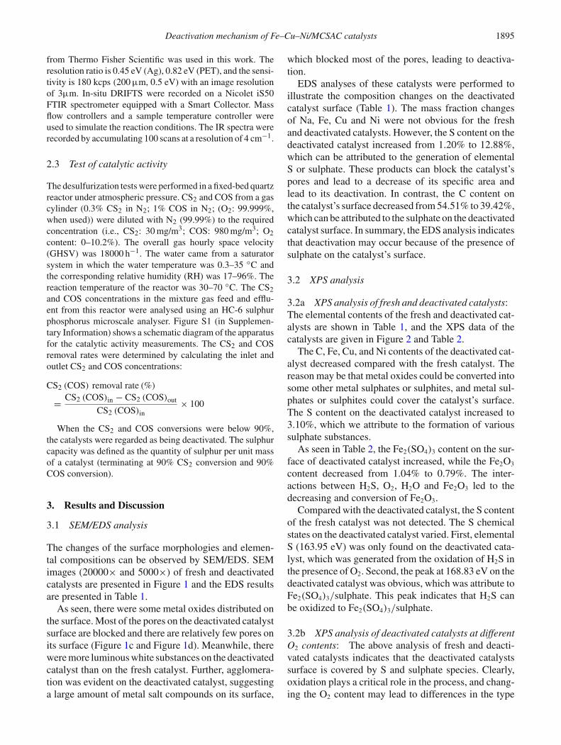
The changes of the surface morphologies and elemen-tal compositions can be observed by SEM/EDS. SEMimages (20000× and 5000×) of fresh and deactivatedcatalysts are presented in Figure 1 and the EDS resultsare presented in Table 1.
As seen, there were some metal oxides distributed onthe surface. Most of the pores on the deactivated catalystsurface are blocked and there are relatively few pores onits surface (Figure 1c and Figure 1d). Meanwhile, therewere more luminous white substances on the deactivatedcatalyst than on the fresh catalyst. Further, agglomera-tion was evident on the deactivated catalyst, suggestinga large amount of metal salt compounds on its surface,
which blocked most of the pores, leading to deactiva-tion.
EDS analyses of these catalysts were performed toillustrate the composition changes on the deactivatedcatalyst surface (Table 1). The mass fraction changesof Na, Fe, Cu and Ni were not obvious for the freshand deactivated catalysts. However, the S content on thedeactivated catalyst increased from 1.20% to 12.88%,which can be attributed to the generation of elementalS or sulphate. These products can block the catalyst’spores and lead to a decrease of its specific area andlead to its deactivation. In contrast, the C content onthe catalyst’s surface decreased from 54.51% to 39.42%,which can be attributed to the sulphate on the deactivatedcatalyst surface. In summary, the EDS analysis indicatesthat deactivation may occur because of the presence ofsulphate on the catalyst’s surface.
3.2 XPS analysis
3.2a XPS analysis of fresh and deactivated catalysts:The elemental contents of the fresh and deactivated cat-alysts are shown in Table 1, and the XPS data of thecatalysts are given in Figure 2 and Table 2.
The C, Fe, Cu, and Ni contents of the deactivated cat-alyst decreased compared with the fresh catalyst. Thereason may be that metal oxides could be converted intosome other metal sulphates or sulphites, and metal sul-phates or sulphites could cover the catalyst’s surface.The S content on the deactivated catalyst increased to3.10%, which we attribute to the formation of varioussulphate substances.
As seen in Table 2, the Fe2(SO4)3 content on the sur-face of deactivated catalyst increased, while the Fe2O3
content decreased from 1.04% to 0.79%. The inter-actions between H2S, O2, H2O and Fe2O3 led to thedecreasing and conversion of Fe2O3.
Compared with the deactivated catalyst, the S contentof the fresh catalyst was not detected. The S chemicalstates on the deactivated catalyst varied. First, elementalS (163.95 eV) was only found on the deactivated cata-lyst, which was generated from the oxidation of H2S inthe presence of O2. Second, the peak at 168.83 eV on thedeactivated catalyst was obvious, which was attribute toFe2(SO4)3/sulphate. This peak indicates that H2S canbe oxidized to Fe2(SO4)3/sulphate.
3.2b XPS analysis of deactivated catalysts at differentO2 contents: The above analysis of fresh and deacti-vated catalysts indicates that the deactivated catalystssurface is covered by S and sulphate species. Clearly,oxidation plays a critical role in the process, and chang-ing the O2 content may lead to differences in the type
1896 Kai Li et al.
Figure 1. SEM images of fresh Fe–Cu–Ni/MCSAC (a: 20000×; b: 5000×) and deactivatedFe–Cu–Ni/MCSAC (c: 20000×; d: 5000×). (a) 20000× (b) 5000× (c) 20000× (d) 5000×.
Table 1. EDS and XPS results of fresh and deactivated catalysts.
Element Element content (massfraction)/% in EDS results
Element Element content (atomfraction)/% in XPS results
C 54.51 39.42 C 75.84 74.18O 12.80 14.86 O 20.69 20.32Na 3.47 3.77 Fe 1.04 0.79S 1.20 12.88 S 0.00 3.10K 11.73 12.02 Cu 0.34 0.26Fe 12.59 12.88 Ni 0.15 0.14Ni 1.10 1.54 N 1.54 1.21Cu 2.60 2.63
of products generated. Figure S2 (in SupplementaryInformation) shows the effect of the O2 content on thesimultaneous catalytic hydrolysis of COS and CS2. Asshown in Figure S2a, the conversion efficiency of COSdecreased as the O2 content increased. Figure S2b shows
that the conversion efficiency of CS2 initially increasedbut then decreased as the O2 content increased. Further,the sulphur capacity was highest (57.33 mgS/g) whenthe O2 content was 0% (Figure S2c). The sulphate capac-ity decreased with an increase in O2, and the sulphate
Deactivation mechanism of Fe–Cu–Ni/MCSAC catalysts 1897
Figure 2. XPS characterization of the fresh catalyst and deactivated catalysts (Fe2p, S2p).
Table 2. XPS data of the fresh and deactivated catalysts (Fe2p, S2p).
Catalyst Elements Binding Energy (eV) At. % Chemical Speciation
Fresh catalyst Fe2p 711.42 1.04 Fe2O3S2p – – –
Deactivated catalyst Fe2p 711.46 0.79 Fe2O3S2p 163.95 0.73 S
168.83 2.37 Fe2(SO4)3/Sulphate
capacity remained above 45 mgS/g when the O2 contentwas 3.6%, which indicates that the catalyst can functionin an environment with a small amount of O2.
XPS analyses of the deactivated catalysts at 2.2% and10.2% O2 content are presented in Figure 3 and Table 3.
There is a clear difference in the XPS data ofFe2p between the deactivated catalysts at 2.2% and10.2% O2 contents. The Fe2O3 content on the catalystat an O2 content of 10.2% decreased from 0.79%to 0.63% compared with the sample at an O2 con-tent of 2.2%, which indicates that most of the Fe2O3
participated in the oxidation of H2S, especially at highO2 content.
Compared with the elemental S content on the cata-lyst at 2.2% O2 content (0.29%), the elemental S contenton the catalyst at 10.2% O2 content was low (0.08%).Clearly, a high O2 content leads to the oxidation ofelemental S to sulphate. We assign the peak at approxi-mately 169.64 eV to Fe2(SO4)3/sulphate. It is clear thatthe Fe2(SO4)3/sulphate content on the catalyst at an O2
content of 10.2% is higher than it is on the catalyst atan O2 content of 2.2%. On one hand, the high O2 con-tent promotes the oxidation of H2S; on the other hand,
elemental S derived from the oxidation of H2S can beconverted into sulphate more quickly under a high O2
content. Thus, the increase of H2S oxidation and fastgeneration of Fe2(SO4)3/sulphate occurs, which is con-sistent with previous conclusions. FeS and CuS may beformed during the reaction process, but because of theexisting of O2 and H2O in the reaction system, FeS andCuS could be turned to the metal sulphates or sulfites.The Fe2(SO4)3/Sulphate could be found from the XPSresults. Furthermore, the contents of Cu was so low thatit was difficult to find the Cu2(SO4)3/Sulphate. Besides,the stability of metal carbonate is poor, so the metal sul-phates or sulfites could be generated more easily thanmetal carbonate under the condition of sulfate radicalexisting. Thus, metal carbonate could not be detectedfrom XPS results.
3.2c XPS analysis of deactivated catalysts at differ-ent RH: The previous section describes the changes ofthe surface species on the catalyst as a function of O2
content. Water is a reactant in catalytic hydrolysis, sorelative humidity (RH) is an important factor in this pro-cess. Figure S3 (in Supplementary Information) shows
1898 Kai Li et al.
Figure 3. XPS characterization of the deactivated catalysts at 2.2% and 10.2% O2 contents (Fe2p, S2p).
Table 3. XPS data of the deactivated catalysts at 2.2% and 10.2% O2 content (Fe2p, S2p).
Catalyst Elements Binding Energy (eV) At. % Chemical Speciation
the effect of RH on the simultaneous catalytic hydroly-sis of COS and CS2. As seen in Figure S3a and FigureS3b, the conversion efficiency of CS2 and COS initiallyincreased but then decreased as the RH increased, andthe highest catalytic efficiency was achieved when theRH was 32%. Excess H2O may compete with COS andCS2 for adsorption sites, which decreased the hydrolysisefficiency.30 Meanwhile, excess H2O led to the forma-tion of a water film, which may inhibit the diffusion andadsorption of COS and CS2 on the catalyst’s surface.30
As seen in Figure S3c, the sulphur capacity initiallyincreased but then decreased as the RH increased, and itwas highest (63.5 mgS/g) when the RH was 32%. Fur-ther, the sulphate capacity remained above 60 mgS/gwhen the RH was 17%–49%, which indicates that theRH range was favourable for catalytic activity.
The XPS results of the deactivated catalysts at 0%and 96% RH are presented in Figure 4 and Table 4.
There is a difference in the XPS data of Fe2p for thecatalysts at 0% and 96% RH. The Fe2O3 content on thecatalysts at 96% RH was low. The reason may be that thewater film affected the reaction and Fe2O3was decreased
and converted. More water film was produced on thecatalyst’s surface when the RH was 96% and inhibitedthe hydrolysis reaction. It indicates that excessive waterfilm was not conductive to the hydrolysis of COS/CS2.
Compared with the Fe2p changes, the changes ofS2p were complex. We assign the peak at approxi-mately 163.28 and 164.11 eV to elemental S. The Scontent on the catalyst at 96% RH was low, as elemen-tal S could be more easily oxidized to sulphate at thisRH. We assign the peak at approximately 168.67 eVto Fe2(SO4)3/sulphate. Clearly, the Fe2(SO4)3/sulphatecontent on the catalyst at 96% RH was higher than theother sulphur species. At high RH (96%), H2O can pro-vide O free radicals, which would promote the oxidationof H2S and the formation of Fe2(SO4)3/sulphate. Theseresults agree with the changes of S. Therefore, the oxi-dation products of H2S were relatively more at high RH(96%).
3.2d XPS analysis of deactivated catalysts at differ-ent inlet concentrations: The inlet concentration has a
Deactivation mechanism of Fe–Cu–Ni/MCSAC catalysts 1899
Figure 4. XPS characterization of the deactivated catalyst at 0% RH and 96% RH (Fe2p, S2p).
Table 4. XPS data of the deactivated catalysts at 0% and 96% RH (Fe2p, S2p).
Catalyst Elements Binding Energy (eV) At. % Chemical Speciation
clear effect on the hydrolysis process. Figure S4 (in Sup-plementary Information) shows the effect of the inletconcentration ratio of COS/CS2 on the simultaneouscatalytic hydrolysis of COS and CS2. As seen in FigureS4a and Figure S4b, the conversion efficiency of COSand CS2 decreased as the COS/CS2 ratio decreased.This result suggests that the CS2 increase inhibits thecatalytic activity of the catalyst when the total concen-tration of COS and CS2 is constant. Additionally, FigureS4c shows that the sulphur capacity decreased as theCOS/CS2decreased. One of the reasons for these resultsmay be that the hydrolysis of CS2 is the rate-limitingstep. Indeed, COS is a type of intermediate product in thehydrolysis of CS2, and low COS/CS2 may produce moreCOS, which decreases the catalytic activity. Further, lowCOS/CS2 may produce more H2S and sulphate, whichmay block the active sites and decrease the catalyticactivity. To examine these issues more fully, XPS anal-yses of deactivated catalysts at 1:1 and 1:40 CS2/COScontent were performed and are presented in Figure 5and Table 5.
There are two different peaks between the catalystat 1:1 and 1:40 CS2/COS content in the XPS data ofO1s. The peak at approximately 531.58 eV belongsto the C=O bond, and its content on the catalyst at1:1 CS2/COS content was clearly higher than that atthe 1:40 CS2/COS content. A large number of COSintermediates generated from the hydrolysis at high CS2
concentration did not fully participate in the hydroly-sis reaction. It is possible that the C=O bonds becameadsorbed on the catalyst’s surface and led to the deacti-vation of the catalyst. The peak at approximately 533.37eV belongs to the –COOH bond, and its content on thecatalyst at 1:1 CS2/COS was slightly lower than it was at1:40 CS2/COS. We attribute this difference to the lack ofH2O that could react with a high concentration of COS.Thus, more -OH free radicals were generated from thecleavage of the –COOH bond when the CS2/COS ratiowas 1:1.
There was a difference between the catalyst at 1:1and 1:40 CS2/COS in the XPS data of Fe2p. The peakat approximately 711.43 eV belongs to Fe2O3. Clearly,
1900 Kai Li et al.
Figure 5. XPS characterization of the deactivated catalyst at a 40:1 COS/CS2 content and a 1:1 COS/CS2 content (O1s,Fe2p, S2p).
Table 5. XPS data of the deactivated catalysts at 40:1 and 1:1 COS/CS2 content (Fe2p, S2p).
Catalyst Elements Binding Energy (eV) At. % Chemical Speciation
Deactivation mechanism of Fe–Cu–Ni/MCSAC catalysts 1901
its content on the catalyst at 1:1 CS2/COS was higherthan it was at 1:40 CS2/COS. These results indicatethat a high COS content promotes the conversion ofFe2O3.
Figure 6. In situ DRIFTS experiment over the cat-alyst (Reaction temperature= 50 ◦C; RH=49%;O2 = 0.5%; GHSV = 20000 h−1; CS2 = 30 mg/m3;COS = 980 mg/m3).
Compared with the changes of O1s and Fe2p, thechanges of S2p were complex, and the types of S2p onthe two catalysts are not completely similar. We assignthe peak at approximately 164.16 and 165.37 eV to ele-mental S. Its content on the catalyst at 1:1 CS2/COS wasclearly lower than it was at 1:40 CS2/COS, which mayresult from it being oxidized to other intermediate prod-ucts or sulphate. We assign the peak at approximately169.19 eV to Fe2(SO4)3/sulphate. The total sulphatecontent on the catalyst at 1:1 CS2/COS was higher thanit was on the catalyst at 1:40 CS2/COS. Meanwhile,the Fe2(SO4)3/sulphate species on the catalyst at 1:1CS2/COS were more because the metal oxides partic-ipated in the reaction and produced different types ofsulphates.
3.3 In situ DRIFTS results
To better understand the hydrolysis reaction and investi-gate the hydrolysis reaction mechanism, in situ DRIFTSexperiments were performed to show the change ofthe surface functional groups in the hydrolysis reactionof COS and CS2 over the Fe–Cu–Ni/MCSAC catalyst.As seen in Figure 6, there were a small amount of –C=O groups, –COO groups, –CH groups and C–OH
Figure 7. Deactivation mechanism of the simultaneous removal of CS2 and COS.
1902 Kai Li et al.
groups on the surface of the catalyst at 0 min (freshcatalyst). The increase of the CO2 molecule indicatedthat the hydrolysis reaction occurred. Meanwhile, theamount of –C=O groups, –COO groups, –CH groupsand C–OH groups in the reaction were obviously higherthan that at 0 min (fresh catalyst). It indicated thatthese functional groups mainly formed from the reac-tion process, especially by the interaction of metaloxide with CO2 and H2O. The decreasing amountsof H2O (3495 cm−1), the C–OH groups (1040 cm−1,1065 cm−1) and the –CH groups (1155 cm−1) indi-cate that these species were involved in the hydrolysisreaction. The increase of the S–O groups (815 cm−1)
indicates that sulphate was generated and accumulatedon the catalyst. The bond energies of different chem-ical bonds are shown in Table S1.31–34 As seen, theC=O bond energy is higher than that of S–O, and thebond energies of C–O and O–H are lower than thatof S–O, which indicates that the S–O bond may orig-inate from C–O and O–H. The decreasing amounts of–COO groups (1435 cm−1) supports the above assump-tion. Meanwhile, the S–O groups are also derived fromthe direct oxidation of H2S in the environment with 0.5%O2. According to these results, the formation of sul-phate may be as follows: (a) H2S + O2 → S + H2O,(b) S+O2 → S–O, (c) –COO+H2S →–CH+S–O, (d)C–OH+H2S →–CH+S–O. Combined with the previousXPS results, the formation of sulphate and the decreas-ing and conversion of Fe2O3 are the main reasons forthe deactivation of the catalyst.
3.4 Deactivation mechanism
On the basis of this work, the deactivation mechanismof the simultaneous removal of CS2 and COS is shownin Figure 7. Overall, the process includes two steps: thehydrolysis of CS2 and COS, and the oxidation of H2S.Initially, COS, CS2 and H2O are adsorbed onto the cata-lyst’s surface. H2S and CO2 are then generated by Fe2O3
through C=S bond cleavage and S–H bond formation.The O2 molecule, the C–OH groups, the –COO groupsand Fe2O3 promote the oxidation of H2S. The gener-ation of sulphate occupies the active sites and inhibitsthe active components of Fe2O3, which decreases thehydrolytic efficiency and leads to the deactivation of thecatalyst.
4. Conclusions
In this study, the deactivation mechanism of the simul-taneous catalytic hydrolysis of COS and CS2 overa Fe–Cu–Ni/MCSAC catalyst was investigated with
SEM/EDS, XPS methods. On the basis of the SEM/EDSand XPS results, the reaction mechanism appears toinclude two steps: the hydrolysis of COS and CS2 andthe oxidation of H2S. COS and CS2 can be catalyticallyhydrolysed to H2S, which is an intermediate product ofCS2 hydrolysis, including COS. However, COS can befurther hydrolysed to H2S, which could subsequentlybe oxidized to sulphate in the presence of O2. The cat-alytic hydrolysis of CS2 is achieved via alkaline groupsand active components. When O2 was introduced intothe system, the oxidation of H2S occurred via H2S →S/RSOR → RSO2R → RSO2OR → SO2−
4 /sulphate.Meanwhile, the contents of SO2−
4 /sulphate increasedduring the reaction, and they could occupy the activitysites on the catalyst’s surface. Additionally, the alka-line groups and active components were removed, whichcaused the deactivation of the catalysts. In-situ DRIFTSexperiments indicated that the formation of sulphatemay occur as follows: (a) H2S + O2 → S + H2O,(b) S + O2 → S–O, (c) –COO+H2S →–CH+S–O, (d)C–OH+H2S →–CH+S–O. The C–OH groups, –COOgroups and the O2 molecule played important roles inthe deactivation of the catalyst.
Supplementary Information
Figures S1–S4 are available as Supplementary Informa-tion at www.ias.ac.in/chemsci.
Acknowledgements
This work was supported by the National Natural ScienceFoundation of China (51408282, 21667015), China Schol-arship Council (201508530017, 201608530169, 201608740011) and the Analysis and Testing Foundation of KunmingUniversity of Science and Technology.
References
1. Leman L J, Orgel L E and Ghadiri M R 2006 Amino aciddependent formation of phosphate anhydrides in watermediated by carbonyl sulfide J. Am. Chem. Soc. 128 20
2. Sun X, Ning P, Tang X L, Yi H H, Li K, He D, Xu XM, Huang B and Lai R Y 2014 Simultaneous catalytichydrolysis of carbonyl sulfide and carbon disulfide overAl2O3–K/CAC catalyst at low temperature J. EnergyChem. 23 221
3. Chowanietz V, Pasel C, Eckardt T, Siegel A and BathenD 2016 Formation of carbonyl sulfide (COS) on differentadsorbents in natural gas treatment plants Oil Gas Eur.Mag. 42 82
4. Zhao S Z, Yi H H, Tang X L, Gao F Y, Yu Q J, Zhou YS, Wang J G, Huang Y H and Yang Z Y 2016 Enhance-ment effects of ultrasound assisted in the synthesis of
Deactivation mechanism of Fe–Cu–Ni/MCSAC catalysts 1903
NiAl hydrotalcite for carbonyl sulfide removal Ultrason.Sonochem. 32 336
5. Qiu J, Ning P, Wang X Q, Li K, Liu W, Chen W andWang L L 2014 Removing carbonyl sulfide with metal-modified activated carbon Front. Env. Sci. Eng. 10 11
6. Kuznetsov D L, Filatov I E and Uvarin V V 2016 Pro-cesses of carbon disulfide degradation under the actionof a pulsed corona discharge Tech. Phys. Lett. 42 822
7. Yegiazarov Y, Clark J, Potapova L, Radkevich V, Yat-simirsky V and Brunel D 2005 Adsorption-catalyticprocess for carbon disulfide removal from air Catal.Today 102 242
8. Huang H M, Young N, Williams B P, Taylor S H andHutchings G 2006 High temperature COS hydrolysiscatalysed by γ −Al2O3 Catal. Lett. 110 243
9. Liu Y C, He H and Ma Q X 2008 Temperature depen-dence of the heterogeneous reaction of carbonyl sulfideon magnesium oxide J. Phys. Chem. A 112 2820
10. Rhodes C, Riddel S A, West J, Williams B P andHutchings G J 2000 The low-temperature hydrolysis ofcarbonyl sulfide and carbon disulfide: a review Catal.Today 59 443
11. Ning P, Yu L L, Yi H H, Tang X L, Li H, Wang H Yand Yang L N 2010 Effect of Fe/Cu/Ce loading on thecoal-based activated carbons for hydrolysis of carbonylsulfide J. Rare Earth 28 205
12. Zhu Y Y, Kolar P, Shah S B, Cheng J J and Lim P K 2016Avocado seed-derived activated carbon for mitigation ofaqueous ammonium Ind. Crop. Prod. 92 34
13. He Q, Dai J L, Zhu L, Xiao K J and Yin Y R 2016 Synthe-sis and lead absorption properties of sintered activatedcarbon supported zero-valent iron nanoparticle J. Alloy.Compd. 687 326
14. Balsamo M, Cimino S, Falco G D, Erto A and Lisi L2016 ZnO–CuO supported on activated carbon for H2Sremoval at room temperature Chem. Eng. J. 304 399
15. Li K, Song X, Ning P, Yi H H, Tang X L and Wang C2014 Energy utilization of yellow phosphorus tail gas:simultaneous catalytic hydrolysis of carbonyl sulfide andcarbon disulfide at low temperature Energy Technol. 3136
16. Ning P, Li K, Yi H H, Tang X L, Peng J H, He D, WangH Y and Zhao S Z 2012 Simultaneous catalytic hydroly-sis of carbonyl sulfide and carbon disulfide over modifiedmicrowave coal-based active carbon catalysts at low tem-perature J. Phys. Chem. C 116 17055
17. Yi H H, Li K, Tang X L, Ning P, Peng J H, Wang Cand He D 2013 Simultaneous catalytic hydrolysis of lowconcentration of carbonyl sulfide and carbon disulfide byimpregnated microwave activated carbon at low temper-atures Chem. Eng. J. 230 220
18. Li K, Liu G, Gao T Y, Lu F, Tang L H, Liu S J and Ning P2016 Surface modification of Fe/MCSAC catalysts withcoaxial cylinder dielectric barrier discharge plasma forlow-temperature catalytic hydrolysis of CS2 Appl. Catal.A 527 171
19. Guo H B, Tang L H, Li K, Ning P, Sun X, Liu G, Bao S Y,Zhu T T, Jin X, Duan Z Y and Li Q S 2016 The hydrolysismechanism and kinetic analysis for COS hydrolysis: ADFT study Russ. J. Phys. Chem. B 10 427
20. Yi H H, Zhao S Z, Tang X L, Song C Y, Gao F Y, ZhangB W, Wang Z X and Zuo Y R 2014 Low-temperaturehydrolysis of carbon disulfide using the Fe-Cu/AC cata-lyst modified by non-thermal plasma Fuel 128 268
21. Li X H, Ren S J, Wei X G, Zeng Y, Gao G W, Y. Ren,Zhu J, Lau K C and Li W K 2014 Concerted or stepwisemechanism? New insight into the water-mediated neutralhydrolysis of carbonyl sulfide J. Phys. Chem. A 118 3503
22. Wang H Y, Yi H H, Tang X L, Yu L L, He D, Zhao S Z andK Li 2013 Reactivation of CoNiAl calcined hydrotalcite-like compounds for hydrolysis of carbonyl sulfide Ind.Eng. Chem. Res. 52 9331
23. George Z M 1974 Kinetics of cobalt-molybdate-catalyzed reactions of SO2 with H2S and COS and thehydrolysis of COS J. Catal. 32 261
24. Akimoto M and Lana I G D 1980 Role of reductionsites in vapor-phase hydrolysis of carbonyl sulfide overalumina catalysts J. Catal. 62 84
25. Ju S 1998 Hydrolysis of carbonyl sulfide and carbondisulfide over alumina based catalysts I. Study on activ-ities of COS and CS2 hydrolysis J. Nat. Gas Chem. 716
26. Hoggan P E, Aboulayt A, Pieplu A, Nortier P and Laval-ley J C 1994 Mechanism of COS hydrolysis on aluminaJ. Catal. 149 300
27. Wilson C and Hirst D M 1995 High-level ab initio studyof the reaction of OCS with OH radicals J. Chem. Soc.Faraday T. 91 793
28. Sakanishi K, Wu Z H, Matsumura A, Saito I, HanaokaT, Minowa T, Tada M and Iwasaki T 2005 Simultaneousremoval of H2S and COS using activated carbons andtheir supported catalysts Catal. Today 104 94
29. Aboulayt A, Mauge F, Hoggan P E and Lavalley J C1996 Combined FTIR, reactivity and quantum chemistryinvestigation of COS hydrolysis at metal oxide surfacesused to compare hydroxyl group basicity Catal. Lett. 39213
30. Li W, Peng J, Zhang L, Yang K, Xia H, Zhang S and GuoS H 2008 Preparation of activated carbon from coconutshell chars in pilot-scale microwave heating equipmentat 60 Kw Waste Manage. 29 756
31. Luo Y R 2007 Comprehensive Handbook of ChemicalBond Energies (Boca Raton: CRC Press)
32. Cottrell T L 1958 The Strengths of Chemical Bonds 2nd
edn. (London: Butterworths Scientific Publications)33. U.S. Dept. of Commerce 1970 National standard refer-
ence data series, National Bureau of Standards, Wash-ington.
34. Benson S W 1965 III-Bond energies J. Chem. Educ. 42502