1 Dealing with Interference on Td ’ Wi l H d Today’s Wireless Hardware Peter Steenkiste D t t fC t Si d 1 Departments of Computer Science and Electrical and Computer Engineering Carnegie Mellon University Outline • Context • Self-managing chaotic wireless networks Wi l k l bd • Wireless network emulator testbed • Interference model (Xi Liu, Srini Seshan) • A networking view • Auto transmit rate selection (Glenn Judd, Xiaohui Wang) • Interference a non-issue (really) • Auto transmit power selection (Xi Liu, Srini Seshan) • Interference a big issue 2
Transcript
1
Dealing with Interference on T d ’ Wi l H dToday’s Wireless Hardware
Peter SteenkisteD t t f C t S i d
1
Departments of Computer Science and Electrical and Computer Engineering
Carnegie Mellon University
Outline• Context
• Self-managing chaotic wireless networksWi l k l b d• Wireless network emulator testbed
• Interference model (Xi Liu, Srini Seshan)• A networking view
• Auto transmit rate selection (Glenn Judd, Xiaohui Wang)• Interference a non-issue (really)
• Auto transmit power selection (Xi Liu, Srini Seshan)• Interference a big issue
2
2
Testbed based on Signal Propagation Emulation
3
Real hardware high degree of realismDigital emulation of channels full control
Isolated from environment fully repeatability
Programmable very diverse experiments
EmulationController
RemotelyAccessible
ProtoGENI:Other
Testbeds Diverse Wireless D i
Current System
Signal Conversion
Signal
ControlNetwork
Internet
Signal Conversion
Devices
FPGA-basedSignal
PropagationEmulation
Signal Conversion
Signal Conversion
Signal Conversion
Signal Conversion
Signal Conversion
SDR
Software-ControlledSignal Propagation
Environments
MIMO
3
Chaotic Wireless Networks
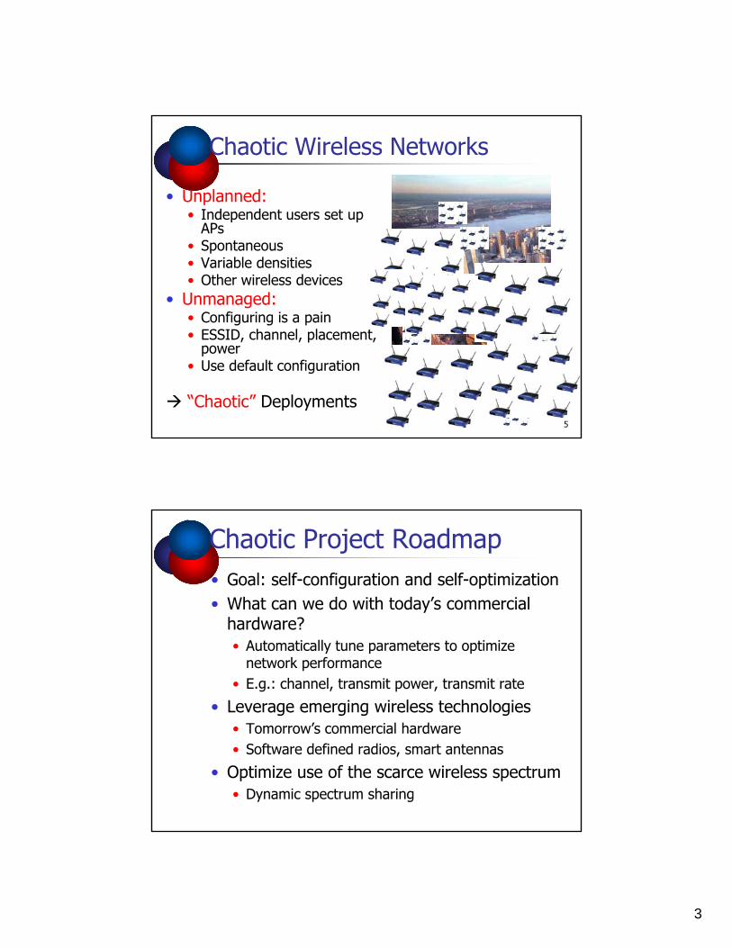
• Unplanned:• Independent users set up
APAPs• Spontaneous• Variable densities• Other wireless devices
• Unmanaged:• Configuring is a pain
ESSID h l l t
5
• ESSID, channel, placement, power
• Use default configuration
“Chaotic” Deployments
Chaotic Project Roadmap• Goal: self-configuration and self-optimization• What can we do with today’s commercial
hardware?• Automatically tune parameters to optimize
• Leverage emerging wireless technologiesT ’ i l h d• Tomorrow’s commercial hardware
• Software defined radios, smart antennas
• Optimize use of the scarce wireless spectrum• Dynamic spectrum sharing
4
Interference: So Many Models to Choose From!• Circle model => Use low power levels
reduce interference
• SINR model => Use higher power levels provides better performance by reducing effects of noise
SI + N
SINR=
• Capture effect is key: Can higher signal power overcome effect of interference?• What does real hardware do?
Impact of Interference on Packet Reception Rate
• Ran experiment on wireless emulator• Atheros cards + create hidden terminal
• Measure packet success rate as function of transmit power for different levels of interference
I t f h d
Hidden
• Interference changed in steps of 4db
• SINR formula holds• Increasing interference
= reducing power
5
Automatic Transmit Rate SelectionRa
te
RSS (dBm)
Pack
et D
eliv
ery
• Best transmit rate depends on the SINR• Signal to noise and interference ratio
• Can be estimated on 802.11 cards based on RSSI• Can measure received signal strength using RSSI• Can exchange information about transmit power, noise, etc.
Charm: Channel-Aware Rate Selection
• Leverage channel reciprocity: overhear packets sent by destination to learn about Ddestination to learn about channel conditions• Build history of path loss for each
channel
• When transmitting packet, use path loss history to “predict” path loss
S
D
?RSS
I
path loss• Select best transmit rate from
look up table• Per destination rate threshold table • Thresholds dynamically adjusted
based on experience Time
6
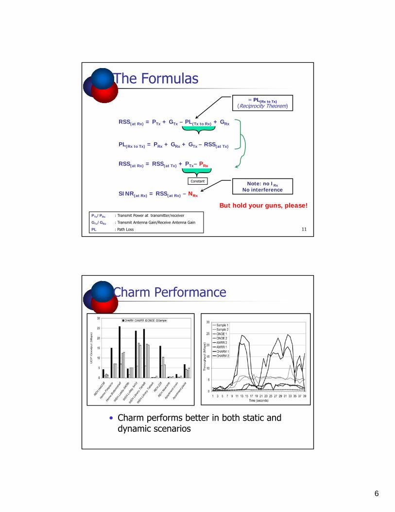
The Formulas
RSS P + G PL + G
= PL(Rx to Tx)(Reciprocity Theorem)
RSS(at Rx) = PTx + GTx – PL(Tx to Rx) + GRx
PL(Rx to Tx) = PRx + GRx + GTx – RSS(at Tx)
RSS(at Rx) = RSS(at Tx) + PTx– PRx
11
PTx/PRx : Transmit Power at transmitter/receiver
GTx/GRx : Transmit Antenna Gain/Receive Antenna Gain
PL : Path Loss
Constant
SINR(at Rx) = RSS(at Rx) – NRx
Note: no IRxNo interference
But hold your guns, please!
Charm Performance
• Charm performs better in both static and dynamic scenarios
7
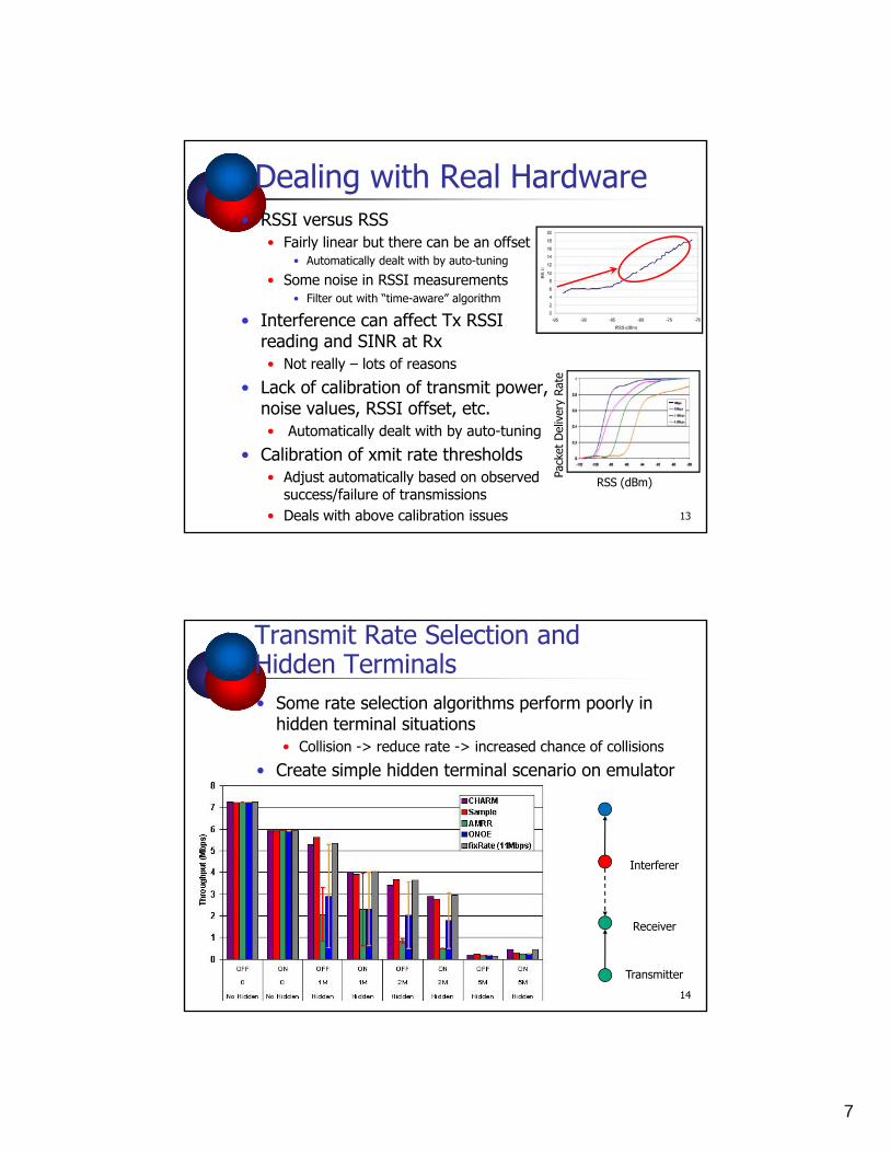
Dealing with Real Hardware• RSSI versus RSS
• Fairly linear but there can be an offset• Automatically dealt with by auto-tuning
• Some noise in RSSI measurements• Filter out with “time-aware” algorithm
• Interference can affect Tx RSSI reading and SINR at Rx• Not really – lots of reasons
• Lack of calibration of transmit power, i l RSSI ff t t y
Rate
noise values, RSSI offset, etc.• Automatically dealt with by auto-tuning
• Calibration of xmit rate thresholds• Adjust automatically based on observed
success/failure of transmissions• Deals with above calibration issues 13
RSS (dBm)
Pack
et D
eliv
ery
Transmit Rate Selection and Hidden Terminals• Some rate selection algorithms perform poorly in
hidden terminal situations• Collision -> reduce rate -> increased chance of collisionsCollision > reduce rate > increased chance of collisions
• Create simple hidden terminal scenario on emulator
Interferer
14
Receiver
Transmitter
8
Transmit Power Control toMinimize the Effect of Interference• Simple idea: reduce transmit
power to minimum needed to reach destination
D
to reach destination• Based on SINR
• Does not work!• Interference is not constant
but affected by transmit power used by other nodes
• Reducing transmit power k
S
makes receiver more susceptible to interference
• Simple experiment: if all nodes cut transmit power in half, SINR stays the same• Assuming noise is not a concern
15
Automatic Power Control: Concepts
AP1 AP2
• Any transmission creates interference on all links
n2
n1
L11 L22
L12
L21
y• Captured in pair-wise interference conflict graph:
• Nodes are wireless links• Edge if simultaneous transmission not possible
• Concurrent transmission is possible ifSINR1+SINR2 ≥ 2*SINRthreshold
9
Power Control Algorithm• Greedily remove edges from conflict graph
by adjusting transmit power for linksC h d b d• Converges when no more edges can be removed
• Must also adjust “Clear Channel Assessment” threshold• Done in a separate phase using variant of
existing algorithm (altruistic Echos)
• Centralized algorithm is quite simple• Centralized algorithm is quite simple -distributed algorithm is a bit more involved• Nodes exchange information about transmit
power and RSS observed from neighbors• Each node operates on local conflict graph
17
UDP Throughput• 36Mbps: F11 interferes with F22 using default txpower
– Concurrent transmission possible by reducing F11’s txpower– Not fair even with default low CCA
• 48Mbps: no concurrent transmission– fairness of the protocol is slightly worse because of relatively high CCA– fairness can be achieved by reducing F11’s txpower
10
Experiment with 8 nodes
• F11 interferes with F23 , but not with F22Pair wise assumption inaccurate on F• Pair-wise assumption inaccurate on F34
• Default behavior is better than expected
Hardware We Would Like• Per-packet transmit power and CCA threshold
• Only on Intel 2915/2200 with AP driver (kind of)
• Receiver threshold control separate from CCA• Tied together on above platform• Problem: cannot hear weak signals when CCA is
high
• Accurate RSSI measurement and transmit power controlpower control• Depends on card: linear RSSI readings on Atheros,
linear transmit power control on Intel card • But have per-card offsets
20
11
Dealing with Real Hardware• Smoothing of RSSI readings
• Both to deal with occasional spurious reading and to get estimates that are stable enoughto get estimates that are stable enough
• Sensitivity of CCA offset and transmit power• Need a certain margin to work reliably
• Calibration of transmit power control and RSSI readings• Automated protocol to account for card offsets• Automated protocol to account for card offsets• Really messy: 2 cards N cards
• Need to mix cards to get what you want• Really ugly – you don’t want to know• Cards were optimized for today’s WiFi
21
Summary• Today’s cards provide several readings
and controls that are useful in fighting interference• RSSI, CCA, transmit power• Linear on some cards
• But need to deal with different offsets on cards and some noise imprecisionon cards and some noise, imprecision
• Requires on the fly calibration• Complexity depends on application• Not clear you can avoid this
22
12
More on Capture
23
Capture vs. Collision Delay
RPreamble(acquisition) Data
• Interference fixed at 82 dBm
T Itime
Interferencedelay
• Interference fixed at -82 dBm• Change target signal strength and delay• 1 & 2 Mbps have strong capture after acquisition• 5.5 & 11 stick with the stronger signal• These results for Prism II cards!
24
13
1Mbps
RSS (dBm)-72-74-76-78-80-82-84-86-8890
175-200150-175125-150100-12575-10050-7525-50
RSS (dBm)
25
0
6.4
12.8
19.2
25.6 32
38.4
44.8
51.2
57.6 64
70.4
76.8
83.2
89.6 96
-90-92 0-25
Delay (us)
2Mbps
-72-74-76-78-80-82-84-86-88
175-200150-175125-150100-12575-10050-7525 50
RSS (dBm)
26
0
6.4
12.8
19.2
25.6 32
38.4
44.8
51.2
57.6 64
70.4
76.8
83.2
89.6 96
-90-92
25-500-25
Delay (us)
14
5.5Mbps
RSS (dB )-72-74-76-78-80-82-84-86-8890
175-200150-175125-150100-12575-10050-7525-50
RSS (dBm)
27
0
6.4
12.8
19.2
25.6 32
38.4
44.8
51.2
57.6 64
70.4
76.8
83.2
89.6 96
-90-92
25 500-25
Delay (us)
11Mbps
-72-74-76-78-80-82-84-86-88
175-200150-175125-150100-12575-10050-7525 50
RSS (dBm)
28
0
6.4
12.8
19.2
25.6 32
38.4
44.8
51.2
57.6 64
70.4
76.8
83.2
89.6 96
-90-92
25-500-25
Delay (us)
15
More on Multi-Path• Two-path channels• Keep the primary path constant p p y p• Change channel delay and strength of


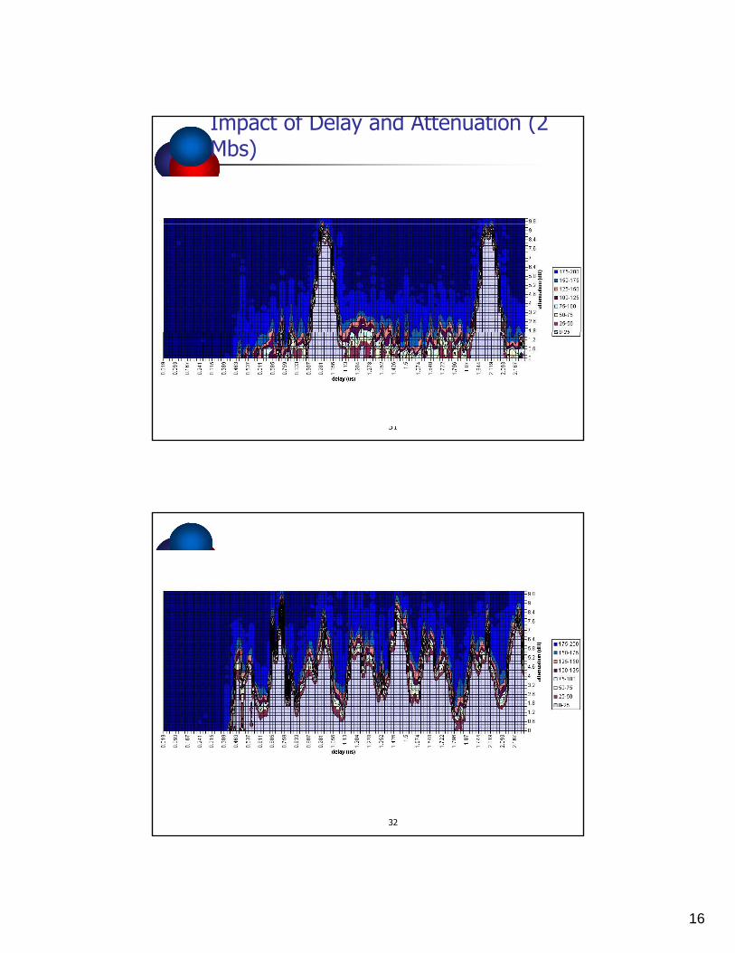


![Photoionization microscopy of the lithium atom: Wave ...robichf/papers/pra94.013414.pdf · Dealing first with the simpler case of photodetachment [10], the connection between interference](https://static.documents.pub/doc/80x56/5f115ebc054242738b3edb24/photoionization-microscopy-of-the-lithium-atom-wave-robichfpaperspra94013414pdf.jpg)


