M3 SERIES M3 SERIES þ Bore size from 1½" to 10" þ Stroke up to 12" þ High Flow Design þ 250 PSI AIR, þ Two-Year Warranty þ N.F.P.A Style Mount WWW.STARCYL.COM MULTI-STAGES AIR MULTI-STAGES NFPA STYLE MOUNT HEAVY DUTY - HIGH FLOW CYLINDERS
Transcript
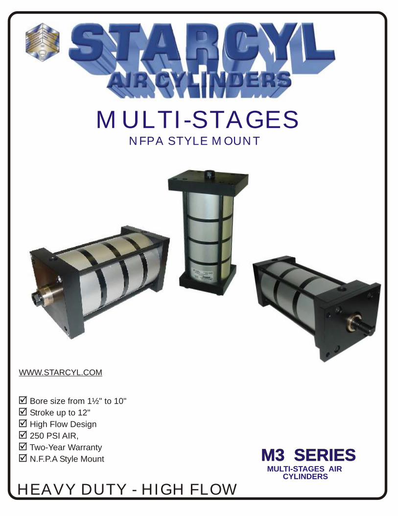
M3 SERIESM3 SERIES
þ Bore size from 1½" to 10"
þ Stroke up to 12"
þ High Flow Design
þ 250 PSI AIR,
þ Two-Year Warranty
þ N.F.P.A Style Mount
WWW.STARCYL.COM
MULTI-STAGES AIR
MULTI-STAGES NFPA STYLE MOUNT
HEAVY DUTY - HIGH FLOWCYLINDERS
Solid Aluminum Head & CapMachined from solid aluminum bar stock(6061 T6) and black anodized for corrosion resistance. (Also available in Stainless Steel ).
Piston Machined from solid aluminum bar stock (6061-T6). Offers long bearing support.
Hard Anodized ID Aluminum Tube(60 Rc) Provides superior wear resistance, and lower frictioncoefficient for maximum seal life.(Also available in Stainless Steel.)
Piston SealLip-type low friction urethane piston seals are pressureenergized and wear compensating for low friction an long life (temperature: -50° to 200°F) (Viton™ also Available up to 400°F)
(all seals can be used in a non lube application)
Rod lips seal + wiperOur New Design with a real rod u-cup is completelyself compensating for zero leakage at all pressures(all seals can be used in a non lube application)The New Wiper Wipes dirt out for less maintenance and longer life of the cylinder. (Urethane) (temperature: -50° to 200°F)
Piston Wear RingNylon material is design for low friction, and to ensuremaximum wear in the cylinder in side load application.Eliminates metal-to-metal contact.
Rod Gland Bronze gland is externally removable without cylinder disassemblyfor easy maintenance. Designed to provide maximum rod bearing.(Also available in Acetal)
O-ring Tube End SealsNitrile O-ring design is pressure compensated and reusable.
Piston RodHigh Strength steel. NITROCARBURIZING treatment on the rodgives better corrosion-resistant properties (out performs 12-micron(.0005 in.) chromium electroplating by ratio up to 20:1.), improvedwear resistance, better lubrication retention, dent resistance without induction hardening (60Rc), environmentally Friendly,no surface pitting, flaking, or hydrogen embrittlement. The finish created by the process is a lustrous black.(Available in stainless steel)
Tie rodsCorrosion resistant (Nitro carburizing), stress proof steel maintains uniformcompression on tube end seals. (Available in Stainless steel)
Mid Plate High Flow Mid plate with 2 orifice (vent/vaccum)Made of 6061-T6 Aluminum and Black anodized, design for resistance, andFlow in mind ( available with 2 or 3 port for external vent/vaccum or muffler).
Upper Rod
High Flow design.High Strength steel. NITROCARBURIZING treatment on the rod.
Bumper Incorporated bumper in piston to ensure long life and noise free, designfor long life, those bumper are incorporated into the piston with enough space to expand without damaging the seal
This grid is to show How much force you can get by using our M3 Multistage cylinder. All the forces are calculated with a pressure of 100 ps.i. Multistage cylinders can be use in push (extend) orPull (retract) or Both, Stock stroke is 1, 2, 3, 4, 6”, but can be ordered up to 12” stroke
More Stage than 4 can be ordered ask your sales representative for a special quote. 10” bore alsoavailable on special request.
- 4 -
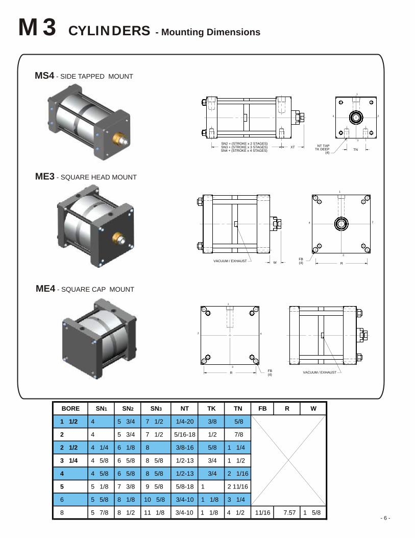
NOTE: STYLE #4 FURNISHED AS STANDARD UNLESS OTHERWISE SPECIFIED.
XTSN3 + (STROKE x 3 STAGES)SN4 + (STROKE x 4 STAGES)
SN2 + (STROKE x 2 STAGES)
TNNT TAP
TK DEEP(4)
1
2
3
4
WVACUUM / EXHAUSTR
FB(4)
1
2
3
4
VACUUM / EXHAUSTRFB(4)
2 4
1
3
- 6 -
M3 CYLINDERS - Mounting Dimensions
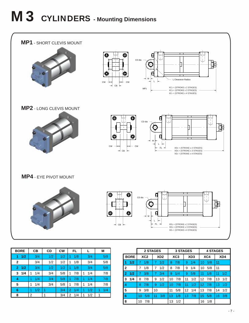
MP1 - SHORT CLEVIS MOUNT
MP2 - LONG CLEVIS MOUNT
MP4 - EYE PIVOT MOUNT
L
CD dia
L Clearance RadiusM
MP1
CW
CB
CW
XC3 + (STROKE x 3 STAGES)
XC2 + (STROKE x 2 STAGES)
XC4 + (STROKE x 4 STAGES)
CW
CB
CWL
FL
CD dia
M
XD3 + (STROKE x 3 STAGES)
XD2 + (STROKE x 2 STAGES)
XD4 + (STROKE x 4 STAGES)
L
FL
CD dia
M
CBXD3 + (STROKE x 3 STAGES)
XD2 + (STROKE x 2 STAGES)
XD4 + (STROKE x 4 STAGES)
BORE CB CD CW FL L M
1 1/2 3/4 1/2 1/2 1 1/8 3/4 5/8
2 3/4 1/2 1/2 1 1/8 3/4 5/8
2 1/2 3/4 1/2 1/2 1 1/8 3/4 5/8
3 1/4 1 1/4 3/4 5/8 1 7/8 1 1/4 7/8
4 1 1/4 3/4 5/8 1 7/8 1 1/4 7/8
5 1 1/4 3/4 5/8 1 7/8 1 1/4 7/8
6 1 1/2 1 3/4 2 1/4 1 1/2 1 1/4
8 2 1 3/4 2 1/4 1 1/2 1
BORE XC2 XD2 XC3 XD3 XC4 XD4
1 1/2 7 1/8 7 1/2 8 7/8 9 1/4 10 5/8 11
2 7 1/8 7 1/2 8 7/8 9 1/4 10 5/8 11
2 1/2 7 3/8 7 3/4 9 1/4 9 5/8 11 1/8 11 1/2
3 1/4 8 7/8 9 1/2 10 7/8 11 1/2 12 7/8 13 1/2
4 8 7/8 9 1/2 10 7/8 11 1/2 12 7/8 13 1/2
5 9 3/8 10 11 5/8 12 1/4 13 7/8 14 1/2
6 10 5/8 11 3/8 13 1/8 13 7/8 15 5/8 16 3/8
8 10 7/8 13 1/2 16 1/8
4 STAGES3 STAGES2 STAGES
- 7 -
- 8 -
M3 CYLINDERS - Hall Effect & Reed Switches
Hall Effect switches are solid state switches with no moving parts. The solid state switches is activated when the silicon chip (Hall) senses a magnetic field. Since there are no moving parts, Hall effect switches can operate in sensitive areas without sending interference or noise into the circuit.
Reed switches are constructed of two overlapping ferromagnetic reeds which are sealed in a glass tube with the ends aligned and a small gap between them. When an external magnetic force is applied, the reed assumes opposite polarity, the ends of the reeds attract each other and make contact, completing the circuit. Reed switches are not recommended in sensitive areas since they can introduce electrical noise into the circuit due to bounce and vibration from mechanical closing of the reeds.
Switch dimensions
How To Order
Switch specificationsSwitch part Number 862-200-004 862-200-031 862-200-032
OTHER SIZE ARE AVAILABLE, ASK YOUR DISTRIBUTOR OR FACTORY.(RC-17 KK=1½-12, RC-20 KK=1-7/8-12, RC-25 KK=2¼-12, ETC)
OTHER SIZE ARE AVAILABLE, ASK YOUR DISTRIBUTOR OR FACTORY.(RE-17 KK=1½-12, RE-20 KK=1-7/8-12, RE-25 KK=2¼-12, ETC)
C
B
CD
PART #
P-05
P-07
P-10
P-13
P-17
P-20
B C CD
2.094 1.875 .500
.7502.6252.875
3.375 3.125 1.000
1.375
1.750
2.000
4.485
5.547
5.547
4.187
5.188
5.188
PIN
Snap ring included
- 9 -
M3 CYLINDERS - Dimensions
M3 S2 - 4 x 10 - MSE4R1 - #4 - BB
MODEL
M3BASIC MODEL
M3OOVERSIZEROD
BORE
1 1/222 1/23 1/4456810"
STROKESTD
123456781012ask forother strokes
ROD END
#1 MALE, large#1F MALE, full dia.#2 MALE, small,#2s MALE, studded
#4 FEMALE, #X SPECIAL
STD
OPTIONS
EXAMPLE M3S2-4x10-MES4R1-BB is a M3 series, 4" bore, 10" stroke, 4 stages in extend Stroke, 1 in retract side lug mount, female rod thread, with Bumpers
To order seal kits add the prefix M3SK to the bore and rod diameter ex: M3SK-4000-1000and for bronze gland kit add the prefix M3GK to the rod diameter ex: M3SK-1375
E3 SQUARE HEAD MOUNT
E4 SQUARE CAP MOUNT
E6
F1
RECT. CAP MOUNT
HEAD RECT. FLANGE
E5 RECT. HEAD MOUNT
P1 DETACH. SHORT CLEVIS MOUNT
P2 DETACH. CLEVIS MOUNT
P4 DETACH. EYE MOUNT
S1 ANGLE MOUNTS4 BOTTOM TAP MOUNT
T1 HEAD TRUNNION MOUNT
T2 CAP TRUNNION MOUNT
T4 INTERMEDIATE TRUNNION MOUNT
X1 BOTH TIE RODS EXTENDED
X2 CAP END TIE RODS EXTENDED
X3 HEAD END TIE RODS EXTENDED
MOUNTING OPTIONSPxCx PORT POSITION (1,2,3,4)
CUSHION POS. (1,2,3,4)
REx ROD EXTENSIONV SEALS MADE OF Viton™
NR NON-ROTATING(for pick & place appl.)
M MAGNETIC PISTON
BB BUMPER BOTH ENDSBC BUMPER CAP ENDBH BUMPER HEAD END
Part numbers AC-250F through AC-1250F in UNF are stock items **4:1 safety factor included
**
Use jam nut to lock coupler to rod when used with full diameter threads.
Starcyl’s linear alignment couplers extend the bearing and seal life of your cylinders. Our couplers prevent binding and Erratic movement that misalignment causes, which eventually wears down your cylinders.Not only do Starcyl couplers work equally well in “push” and “pull” applications, but they allow a greater tolerance between the cylinder centerline and the mating member.
Viton™ are registered trademarks of DuPont Dow Elastomers.
MULTI STAGES
MS Ex Rx Ex : Nb of stage for the Extend stroke (E4, 4 stages extend)
Rx : Nb of stage for the retract stroke (R1, 1 stages Retract)