AKD ® Decentralized Drive System Projecting Guide Edition: B, November 2016 Translation of the original document Keep all manuals as a product component during the life span of the product. Pass all manuals to future users and owners of the product.
Transcript
AKD® Decentralized Drive SystemProjecting Guide
Edition: B, November 2016Translation of the original document
Keep all manuals as a product component during the life span of the product.Pass all manuals to future users and owners of the product.
Record of Document Revisions
Revision RemarksA, 12/2015 Launch versionB, 11/2016 24V supply overview drawings optimized, slip ring example added
Trademarksl AKD is a registered trademark of Kollmorgen Corporationl SynqNet is a registered trademark of Motion Engineering Inc.l EnDat is a registered trademark of Dr. Johannes Heidenhain GmbHl EtherCAT is a registered trademark and patented technology, licensed by Beckhoff Automation GmbHl Ethernet/IP is a registered trademark of ODVA, Inc.l Ethernet/IP Communication Stack: copyright (c) 2009, Rockwell Automationl sercos® is a registered trademark of sercos® international e.V.l HIPERFACE is a registered trademark of Max StegmannGmbHl PROFINET is a registered trademark of PROFIBUS and PROFINET International (PI)l SIMATIC is a registered trademark of SIEMENS AGl Windows is a registered trademark of Microsoft Corporation
Current patentsl US Patent 5.162.798 (used in control card R/D)l US Patent 5.646.496 (used in control card R/D and 1 Vp-p feedback interface)l US Patent 6.118.241 (used in control card simple dynamic braking)l US Patent 8.154.228 (Dynamic Braking For Electric Motors)l US Patent 8.214.063 (Auto-tune of a Control System Based on Frequency Response)l US Patent 8.566.415 (Safe TorqueOff over network wiring)
Patents referring to fieldbus functions are listed in thematching fieldbus manual.
Technical changes which improve the performance of the device may be made without prior notice!This document is the intellectual property of Kollmorgen. All rights reserved. No part of this work may be repro-duced in any form (by photocopying, microfilm or any other method) or stored, processed, copied or distributedby electronic means without the written permission of Kollmorgen.
2 Kollmorgen | kdn.kollmorgen.com | November 2016
1 Table of Contents
1 Table of Contents 32 General 52.1 About this Guide 62.1.1 The Advantages of Decentralized Drive Technology 6
2.2 Documentation for Decentralized Drive Systems 72.3 Components for Decentralized Drive Systems 82.3.1 Components delivered by Kollmorgen 92.3.2 Components to be added by the user 112.3.2.1 Cabinet grommets 112.3.2.2 M12Data cables for AKD-N 112.3.2.3 Power Supply 24 VDC 112.3.2.4 Fuses 112.3.2.5 Personal Computer 112.3.2.6 Slip-rings 11
3 System Design Planning 133.1 System requirements 143.1.1 Requirements to the application 143.1.2 System limits 143.1.3 Requirements to the ambient conditions in operationmode 153.1.3.1 AKD-C 153.1.3.2 AKD-N 153.1.3.3 Prohibited Use 16
3.2 System temperature management 173.2.1 AKD-C installation instructions 173.2.2 Brake resistor installation instructions 173.2.3 AKD-N installation instructions 173.2.4 Temperaturemeasurement in the AKD-N 183.2.5 AKD-N cooling plate selection 183.2.6 Rth calculation 19
4 System Electrical Planning 204.1 System Grounding 214.2 System 24V 234.2.1 Supply with centralized 24 V power supply (P1) 234.2.2 Supply with decentralized 24 V power supplies (P1, P2, P3) 244.2.3 GND definition 254.2.4 System power 24 V (Stand-By operation) 25
4.3 System Cabling Concept 264.3.1 Cable length definition 264.3.2 Device connection from IP54 to IP65/67 environments 27
5 Functional Safety 305.1 General 315.2 Global STO 325.3 Local STO 345.4 Global / Local STO combination 375.5 Calculation of Safety Levels for the STO function 395.5.1 Abbreviations 395.5.2 General 405.5.3 AKD-C and AKD-N internal structure 405.5.4 Safety-related features of the subsystem AKD-C and AKD-N 405.5.5 Essential safety considerations in accordance with EN 61800-5-2 405.5.5.1 Risk analysis in accordance with ISO 12100:2010 41
5.5.6 Safety-related assessment of the system according to ISO 13849-1 425.6 Stop / Emergency Stop / Emergency Off 435.6.1 Stop 435.6.2 Emergency Stop 445.6.3 Emergency Off 44
Projecting Guide | Table of Contents
4 Kollmorgen | kdn.kollmorgen.com | November 2016
2 General
2.1 About this Guide 6
2.2 Documentation for Decentralized Drive Systems 7
2.3 Components for Decentralized Drive Systems 8
Projecting Guide | Table of Contents
Kollmorgen | kdn.kollmorgen.com | November 2016 5
2.1 About this GuideThis guide, Decentralized Drive System Projecting Guide helps to define a Kollmorgendecentralized drive system with AKD-C and AKD-N devices.In the Projecting Guide you will find:l Overview of available components,l Where to buy components which are not offered by Kollmorgen,l Notes for physical and electrical requirements to the system components.
2.1.1 The Advantages of Decentralized Drive TechnologyReduced costsl Reduced cabling because DC and fieldbus, power, I/O and safety (STO) run in one cable.l Faster and simple assembly requires no special training through ready-made and testedcables.
l Pick the optimummotor for themachine. No derating of oversizedmotors as required bymost integrated solutions.
More compact machinesl Smaller andmore easily integrated electrical cabinets.l Servo amplifiers mounted in the immediate vicinity of themotor.l Robust construction with IP67 protection ratingmakes large protective enclosures irrel-evant.
Faster commissioningl IP67 rated connectors for connection without tools.l At only elevenmillimeters, the thin hybrid cable has a small bending radius to save space– even in crampedmachine corners.
l Connect remote I/Omodules and fieldbuses devices directly to the drive via the optionallocal EtherCAT port.
l Parameterization with the KollmorgenWorkBench.
Higher machine efficiency (OEE)l Design supports fast and effective cleaning.l High operating safety through robust construction.l Precision through digital feedback.l Everything at a glance: Status display on servo amplifier.
More flexibility in machine designl Compatible with all Kollmorgenmotors with single cable or dual cable connection.l Simple combination of central and decentralized controllers within the comprehensiveAKD family.
l Faster modification and upgrade options through linear topology as well as I/O and field-bus interfaces at the drive.
Projecting Guide | Table of Contents
6 Kollmorgen | kdn.kollmorgen.com | November 2016
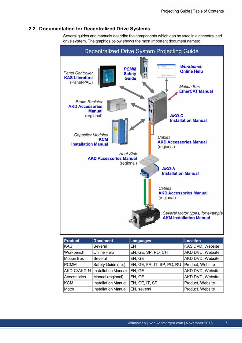
2.2 Documentation for Decentralized Drive SystemsSeveral guides andmanuals describe the components which can be used in a decentralizeddrive system. The graphics below shows themost important document names:
Product Document Languages LocationKAS Several EN KAS DVD, WebsiteWorkbench Online Help EN, GE, SP, PO, CH AKD DVD, WebsiteMotion Bus Several EN, GE AKD DVD, WebsitePCMM Safety Guide (i.p.) EN, GE, FR, IT, SP, PO, RU Product, WebsiteAKD-C/AKD-N InstallationManuals EN, GE AKD DVD, WebsiteAccessories Manual (regional) EN, GE AKD DVD, WebsiteKCM InstallationManual EN, GE, IT, SP Product, WebsiteMotor InstallationManual EN, several Product, Website
Projecting Guide | Table of Contents
Kollmorgen | kdn.kollmorgen.com | November 2016 7
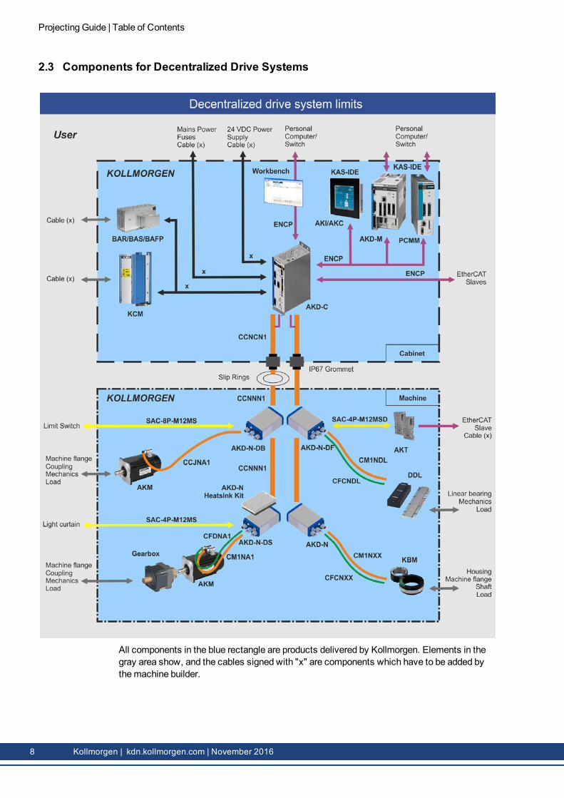
2.3 Components for Decentralized Drive Systems
All components in the blue rectangle are products delivered by Kollmorgen. Elements in thegray area show, and the cables signed with "x" are components which have to be added bythemachine builder.
Projecting Guide | Table of Contents
8 Kollmorgen | kdn.kollmorgen.com | November 2016
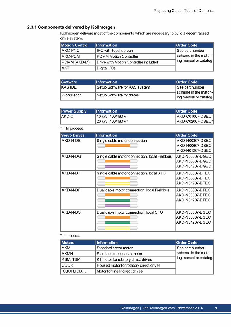
2.3.1 Components delivered by KollmorgenKollmorgen delivers most of the components which are necessary to build a decentralizeddrive system.
Motion Control Information Order CodeAKC-PNC IPC with touchscreen See part number
scheme in thematch-ingmanual or catalog
AKC-PCM PCMMMotion ControllerPDMM (AKD-M) Drive with Motion Controller includedAKT Digital I/Os
Software Information Order CodeKAS IDE Setup Software for KAS system See part number
scheme in thematch-ingmanual or catalogWorkBench Setup Software for drives
Power Supply Information Order CodeAKD-C 10 kW, 400/480 V
20 kW, 400/480 V*AKD-C01007-CBECAKD-C02007-CBEC*
* = In process
Servo Drives Information Order CodeAKD-N-DB Single cablemotor connection AKD-N00307-DBEC
AKD-N00607-DBECAKD-N01207-DBEC
AKD-N-DG Single cablemotor connection, local Fieldbus AKD-N00307-DGECAKD-N00607-DGECAKD-N01207-DGEC
AKD-N-DT Single cablemotor connection, local STO AKD-N00307-DTECAKD-N00607-DTECAKD-N01207-DTEC
AKD-N-DF Dual cablemotor connection, local Fieldbus AKD-N00307-DFECAKD-N00607-DFECAKD-N01207-DFEC
AKD-N-DS Dual cablemotor connection, local STO AKD-N00307-DSECAKD-N00607-DSECAKD-N01207-DSEC
* in process
Motors Information Order CodeAKM Standard servomotor See part number
scheme in thematch-ingmanual or catalog
AKMH Stainless steel servomotorKBM, TBM Kit motor for rotatory direct drivesCDDR Housedmotor for rotatory direct drivesIC,ICH,ICD,IL Motor for linear direct drives
Projecting Guide | Table of Contents
Kollmorgen | kdn.kollmorgen.com | November 2016 9
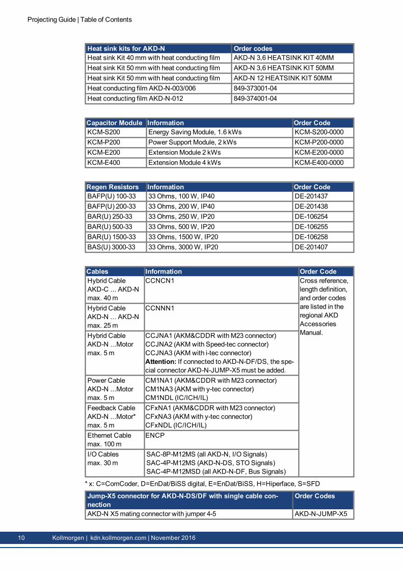
Heat sink kits for AKD-N Order codesHeat sink Kit 40mmwith heat conducting film AKD-N 3,6 HEATSINK KIT 40MMHeat sink Kit 50mmwith heat conducting film AKD-N 3,6 HEATSINK KIT 50MMHeat sink Kit 50mmwith heat conducting film AKD-N 12 HEATSINK KIT 50MMHeat conducting film AKD-N-003/006 849-373001-04Heat conducting film AKD-N-012 849-374001-04
Capacitor Module Information Order CodeKCM-S200 Energy SavingModule, 1.6 kWs KCM-S200-0000KCM-P200 Power Support Module, 2 kWs KCM-P200-0000KCM-E200 ExtensionModule 2 kWs KCM-E200-0000KCM-E400 ExtensionModule 4 kWs KCM-E400-0000
Cables Information Order CodeHybrid CableAKD-C ... AKD-Nmax. 40m
CCNCN1 Cross reference,length definition,and order codesare listed in theregional AKDAccessoriesManual.
Hybrid CableAKD-N ... AKD-Nmax. 25m
CCNNN1
Hybrid CableAKD-N ...Motormax. 5m
CCJNA1 (AKM&CDDR withM23 connector)CCJNA2 (AKM with Speed-tec connector)CCJNA3 (AKM with i-tec connector)Attention: If connected to AKD-N-DF/DS, the spe-cial connector AKD-N-JUMP-X5must be added.
Power CableAKD-N ...Motormax. 5m
CM1NA1 (AKM&CDDR withM23 connector)CM1NA3 (AKM with y-tec connector)CM1NDL (IC/ICH/IL)
Feedback CableAKD-N ...Motor*max. 5m
CFxNA1 (AKM&CDDR withM23 connector)CFxNA3 (AKM with y-tec connector)CFxNDL (IC/ICH/IL)
Jump-X5 connector for AKD-N-DS/DF with single cable con-nection
Order Codes
AKD-N X5mating connector with jumper 4-5 AKD-N-JUMP-X5
Projecting Guide | Table of Contents
10 Kollmorgen | kdn.kollmorgen.com | November 2016
2.3.2 Components to be added by the user
2.3.2.1 Cabinet grommetsThe hybrid cable between AKD-C and the first AKD-N leads through the cabinet wall. Toensure IP67 protection class, Kollmorgen recommends cable entry system KDL/S combinedwith cable entry grommet KDT/S manufactured by Murrplastik Systemtechnik GmbH.Please contact:Murrplastik Systemtechnik GmbHFabrikstraße 10, 71570Oppenweiler, GermanyPhone: +49 (0)7191 482-0Website: www.murrplastik.de, E-Mail: [email protected]
2.3.2.2 M12 Data cables for AKD-NKollmorgen offers the cables listed below with 5m length only:SAC-8P-M12MS (all AKD-N, I/O signals)SAC-4P-M12MS (AKD-N-DS, STO signals)SAC-4P-M12MSD (all AKD-N-DF, bus signals)More length versions can be ordered from:Phoenix Contact Deutschland GmbHFlachsmarktstr. 8, 32825 Blomberg, GermanyPhone: +49 (0)5235 3-12000Website: https://www.phoenixcontact.com, E-Mail: [email protected]
2.3.2.3 Power Supply 24 VDCPower supply requirements for 24 VDC supply see chapter "System 24V" (➜ p. 23).
2.3.2.4 FusesRequirements for fuses for mains supply, 24V supply, and regen resistors see chapter "Sys-tem fusing" (➜ p. 28).
2.3.2.5 Personal ComputerThe Service interface (RJ45) of the AKD-C is connected to the Ethernet interface of the PCby an Ethernet cable.Minimum requirements for the PC:l Processor: at least Pentium® II or comparablel Graphics adapter : Windows compatible, colorl Drives : hard disk with at least 20MB free space, DVD drivel Interface : one free Ethernet Interface, or a Switch port, 100Mbit/s
2.3.2.6 Slip-ringsIf AKD-N must bemounted on a rotary table, it is necessary to use slip-ring assemblies forenergy and data transfer between AKD-C in the cabinet and AKD-N on the rotary table. Koll-morgen cooperates with company STEMMANN-TECHNIK for user specific slip-ringassembly solutions. Several slip-ring variants are certificated according to EN 13849 for thehybrid connection between AKD-C&N or AKD-N&N. Please contact:STEMMANN-TECHNIK GmbHNiedersachsenstraße 2, 48465 Schüttorf, GermanyPhone: +49 (0)592381-0,Website: www.stemmann.com, E-Mail: [email protected]
Projecting Guide | Table of Contents
Kollmorgen | kdn.kollmorgen.com | November 2016 11
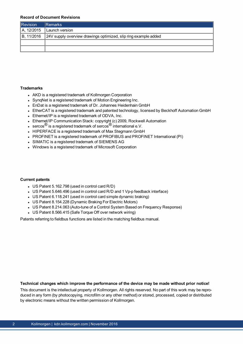
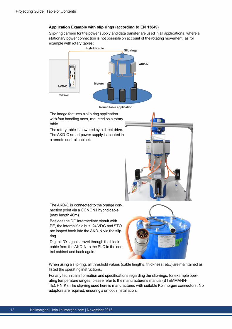
Application Example with slip rings (according to EN 13849)Slip-ring carriers for the power supply and data transfer are used in all applications, where astationary power connection is not possible on account of the rotatingmovement, as forexample with rotary tables:
The image features a slip-ring applicationwith four handling axes, mounted on a rotarytable.The rotary table is powered by a direct drive.The AKD-C smart power supply is located ina remote control cabinet.
The AKD-C is connected to the orange con-nection point via a CCNCN1 hybrid cable(max length 40m).Besides the DC intermediate circuit withPE, the internal field bus, 24 VDC and STOare looped back into the AKD-N via the slip-ring.Digital I/O signals travel through the blackcable from the AKD-N to the PLC in the con-trol cabinet and back again.
When using a slip-ring, all threshold values (cable lengths, thickness, etc.) aremaintained aslisted the operating instructions.For any technical information and specifications regarding the slip-rings, for example oper-ating temperature ranges, please refer to themanufacturer’s manual (STEMMANN-TECHNIK). The slip-ring used here is manufactured with suitable Kollmorgen connectors. Noadaptors are required, ensuring a smooth installation.
Projecting Guide | Table of Contents
12 Kollmorgen | kdn.kollmorgen.com | November 2016
3 System Design Planning
3.1 System requirements 14
3.2 System temperature management 17
Projecting Guide | Table of Contents
Kollmorgen | kdn.kollmorgen.com | November 2016 13
3.1 System requirements
3.1.1 Requirements to the applicationCheck the chapter "Use as Directed" in the installationmanual of the component. Physicalsystem requirements and limits are represented by themaximum cable length between thecomponents.
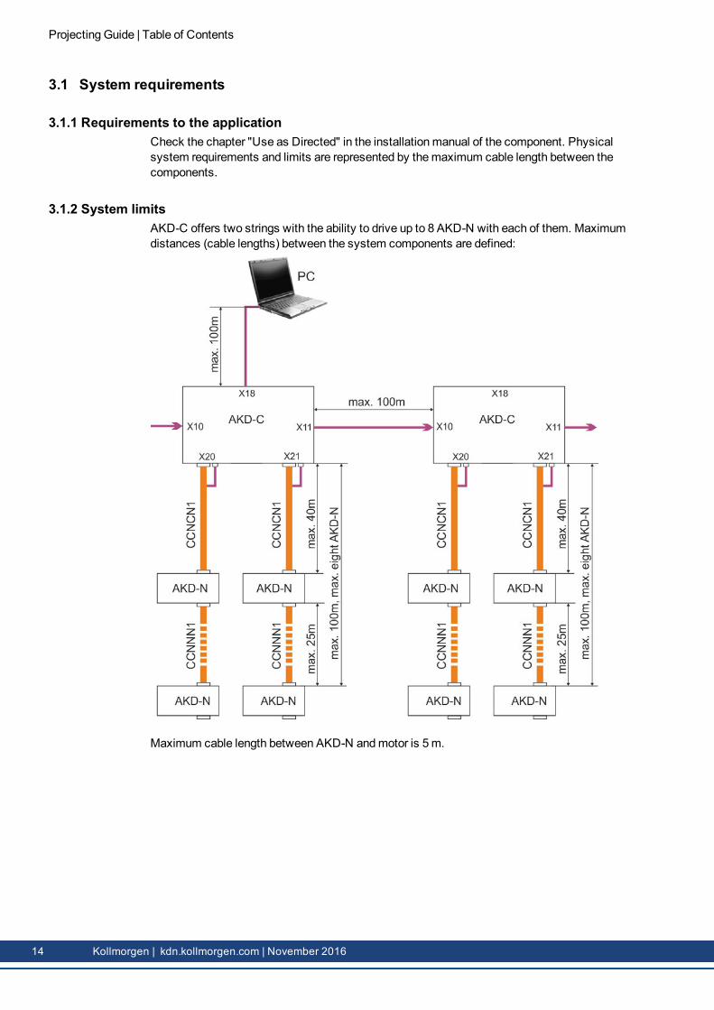
3.1.2 System limitsAKD-C offers two strings with the ability to drive up to 8 AKD-N with each of them. Maximumdistances (cable lengths) between the system components are defined:
Maximum cable length between AKD-N andmotor is 5m.
Projecting Guide | Table of Contents
14 Kollmorgen | kdn.kollmorgen.com | November 2016
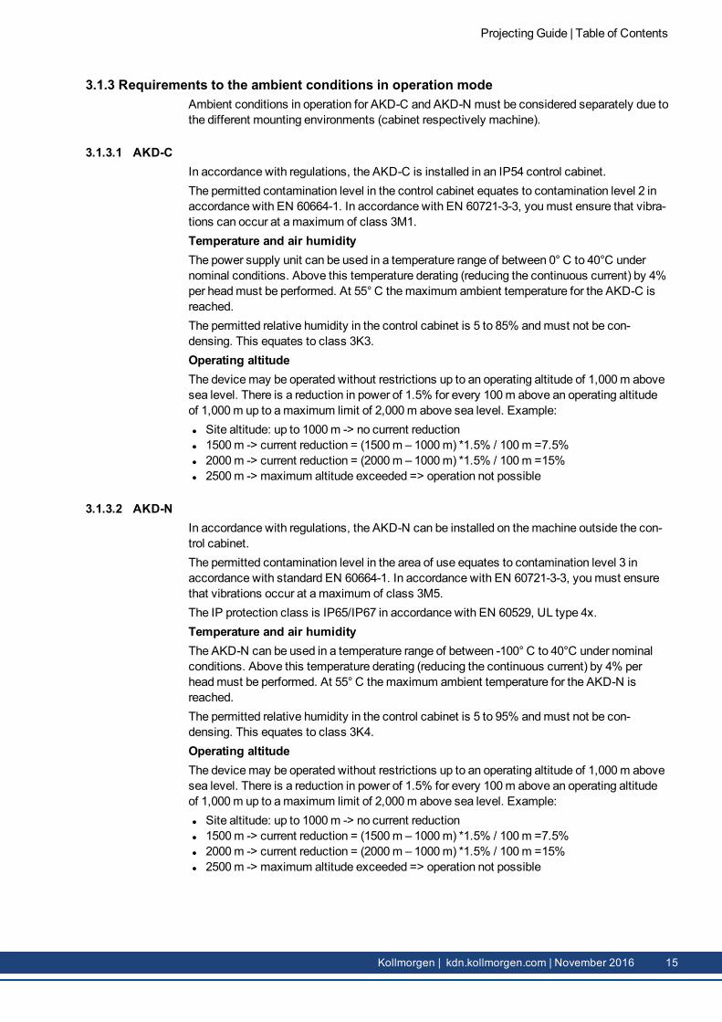
3.1.3 Requirements to the ambient conditions in operation modeAmbient conditions in operation for AKD-C and AKD-N must be considered separately due tothe different mounting environments (cabinet respectively machine).
3.1.3.1 AKD-CIn accordance with regulations, the AKD-C is installed in an IP54 control cabinet.The permitted contamination level in the control cabinet equates to contamination level 2 inaccordance with EN 60664-1. In accordance with EN 60721-3-3, youmust ensure that vibra-tions can occur at amaximum of class 3M1.Temperature and air humidityThe power supply unit can be used in a temperature range of between 0° C to 40°C undernominal conditions. Above this temperature derating (reducing the continuous current) by 4%per headmust be performed. At 55° C themaximum ambient temperature for the AKD-C isreached.The permitted relative humidity in the control cabinet is 5 to 85% andmust not be con-densing. This equates to class 3K3.Operating altitudeThe devicemay be operated without restrictions up to an operating altitude of 1,000m abovesea level. There is a reduction in power of 1.5% for every 100m above an operating altitudeof 1,000m up to amaximum limit of 2,000m above sea level. Example:l Site altitude: up to 1000m -> no current reductionl 1500m -> current reduction = (1500m – 1000m) *1.5% / 100m =7.5%l 2000m -> current reduction = (2000m – 1000m) *1.5% / 100m =15%l 2500m -> maximum altitude exceeded => operation not possible
3.1.3.2 AKD-NIn accordance with regulations, the AKD-N can be installed on themachine outside the con-trol cabinet.The permitted contamination level in the area of use equates to contamination level 3 inaccordance with standard EN 60664-1. In accordance with EN 60721-3-3, youmust ensurethat vibrations occur at amaximum of class 3M5.The IP protection class is IP65/IP67 in accordance with EN 60529, UL type 4x.Temperature and air humidityThe AKD-N can be used in a temperature range of between -100° C to 40°C under nominalconditions. Above this temperature derating (reducing the continuous current) by 4% perheadmust be performed. At 55° C themaximum ambient temperature for the AKD-N isreached.The permitted relative humidity in the control cabinet is 5 to 95% andmust not be con-densing. This equates to class 3K4.Operating altitudeThe devicemay be operated without restrictions up to an operating altitude of 1,000m abovesea level. There is a reduction in power of 1.5% for every 100m above an operating altitudeof 1,000m up to amaximum limit of 2,000m above sea level. Example:l Site altitude: up to 1000m -> no current reductionl 1500m -> current reduction = (1500m – 1000m) *1.5% / 100m =7.5%l 2000m -> current reduction = (2000m – 1000m) *1.5% / 100m =15%l 2500m -> maximum altitude exceeded => operation not possible
Projecting Guide | Table of Contents
Kollmorgen | kdn.kollmorgen.com | November 2016 15
3.1.3.3 Prohibited UseOther use than that described in chapter “Use as directed” is not intended and can lead to per-sonnel injuries and equipment damage.The devicemay not be usedl with amachine that does not comply with appropriate national directives or standards,l for driving elevators,l in applications with continuous, operational short circuits to the external regen resistor con-tacts.
l in applications with any short circuits to the DC-Bus link contacts.
The use of the device in the following environments is also prohibited:l potentially explosive areasl environments with corrosive and/or electrically conductive acids, alkaline solutions, oils,vapors, dusts
l ships or offshore applications
Wiring the system with hybrid cables from other manufacturers than Kollmorgen is notallowed. Changing Kollmorgen cables or connectors is not allowed.
Projecting Guide | Table of Contents
16 Kollmorgen | kdn.kollmorgen.com | November 2016
3.2 System temperature management
3.2.1 AKD-C installation instructionsInstall the AKD-C in the control cabinet as described in the installation example in the oper-ating instructions.Ensure adequate space for ventilation above and below the AKD-C. If the internal brake res-istor is used, waste heat through the AKD-C is significantly greater than when using anexternal brake resistor. In particular, therefore, ensure sufficient distance to the componentsinstalled above the AKD-C (55mm to 100mm).To reduce the generated brake power, a DC-Bus link coupling to an AKD-B/P/T/M or anotherAKD-C may be useful. This is only successful, however, if the load cycles of the adjacentdrive are running in the opposite direction (no simultaneous generation operation).If generated brake power is near to or slightly over the threshold of 100 watt, a DC-Bus linkcoupling to other drives can help to save on an external brake resistor.With highly dynamic processes, it can be checked whether a capacity module can tem-porarily store the regeneration energy so that it can be used in the next instance of accel-eration. This can reduce energy costs over the system's service life. In addition, less powerloss arises in the control cabinet.
3.2.2 Brake resistor installation instructionsExternal brake resistors should be installed outside the control cabinet or thermally dis-connected inside the control cabinet.Due to strong thermal development, youmust observe the safety distances to adjacent, flam-mable objects (refer to the drawing of the brake resistor in the accessories manual).
3.2.3 AKD-N installation instructionsInstall the AKD-N as specified in themanual. For selecting the required cooling surface, theaverage capacity of the drive is relevant.Here, 100% capacity means continuous load with rated current. 50% capacity canmean, forexamplel Cycle operation: 50% activation time with rated current / 50% recovery time, orl 100% activation time with half of rated current.
Installation on any metallic surface will suffice at an average capacity of 50% (for AKD-N 3Aand 6A).The cooling surfaces (aluminum) stated in the operating instructions ofl 240 x 240 x 10mm for AKD-N 3A andl 500 x 500 x 10mm for AKD-N 6A,
enable 100% capacity for operation on a 480 V grid and 40°C ambient temperature.
Projecting Guide | Table of Contents
Kollmorgen | kdn.kollmorgen.com | November 2016 17
3.2.4 Temperature measurement in the AKD-NThe AKD-N has two internal temperature sensors: one is connected to the control card, theother with the power semiconductors. The sensor values can be queried using the commanddrv.temperature.l Control card temperature: warning 90°C / shutdown 95°Cl Power temperature: warning 90°C / shutdown 95°C
If the 'Power' temperature does not exceed 85°C during operation of themachine, the coolingplan is OK.Please be advised that it may take several hours before the temperature reaches the thermalsteady state.Examples:l AKD-N 3A in the air is stable after 60minutesl AKD-N 6A on cooling plate 500x500x10mm is stable after 180minutes
3.2.5 AKD-N cooling plate selectionAn ideal cooling situation is a requirement for operating an AKD-N at maximum power in themachine.You will find a few examples below to help estimate the thermal resistance (Rth) of an install-ation geometry.
Projecting Guide | Table of Contents
18 Kollmorgen | kdn.kollmorgen.com | November 2016
3.2.6 Rth calculationThermal resistance (Rth) (unit K/W) is a thermal parameter and ameasure for the tem-perature difference that arises in a body when a thermal current permeates it.
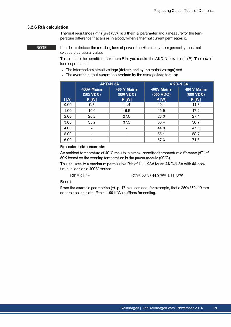
In order to deduce the resulting loss of power, the Rth of a system geometry must notexceed a particular value.To calculate the permittedmaximum Rth, you require the AKD-N power loss (P). The powerloss depends onl The intermediate circuit voltage (determined by themains voltage) andl The average output current (determined by the average load torque):
AKD-N 3A AKD-N 6A400V Mains(565 VDC)
480 V Mains(680 VDC)
400V Mains(565 VDC)
480 V Mains(680 VDC)
I [A] P [W] P [W] P [W] P [W]0.00 9.8 11.4 10.1 11.81.00 16.6 16.9 16.9 17.22.00 26.2 27.0 26.3 27.13.00 35.2 37.5 36.4 38.74.00 - - 44.9 47.85.00 - - 55.1 58.76.00 - - 67.3 71.6
Rth calculation example:An ambient temperature of 40°C results in amax. permitted temperature difference (dT) of50K based on the warning temperature in the powermodule (90°C).This equates to amaximum permissible Rth of 1.11 K/W for an AKD-N-6A with 4A con-tinuous load on a 400 V mains:
Rth = dT / P Rth = 50 K / 44.9W= 1.11 K/WResult:From the example geometries (➜ p. 17) you can see, for example, that a 350x350x10mmsquare cooling plate (Rth ~ 1.00 K/W) suffices for cooling.
Projecting Guide | Table of Contents
Kollmorgen | kdn.kollmorgen.com | November 2016 19
4 System Electrical Planning
4.1 System Grounding 21
4.2 System 24V 23
4.3 System Cabling Concept 26
4.4 System fusing 28
Projecting Guide | Table of Contents
20 Kollmorgen | kdn.kollmorgen.com | November 2016
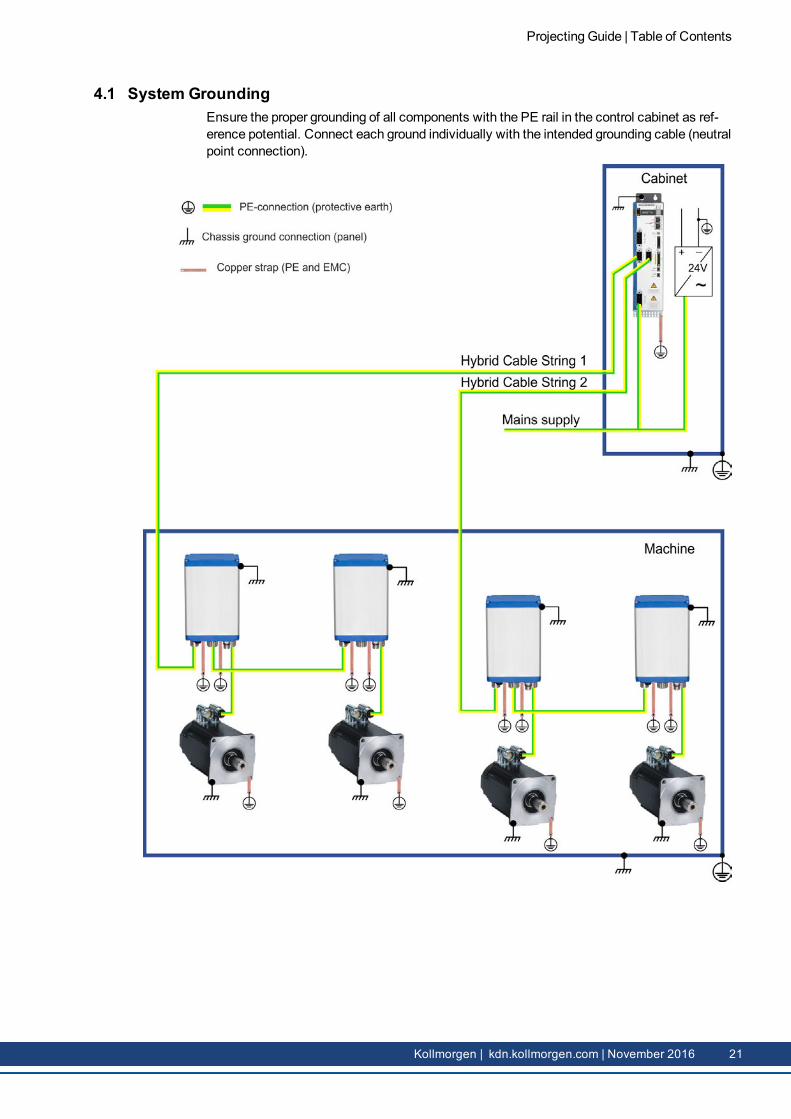
4.1 System GroundingEnsure the proper grounding of all components with the PE rail in the control cabinet as ref-erence potential. Connect each ground individually with the intended grounding cable (neutralpoint connection).
Projecting Guide | Table of Contents
Kollmorgen | kdn.kollmorgen.com | November 2016 21
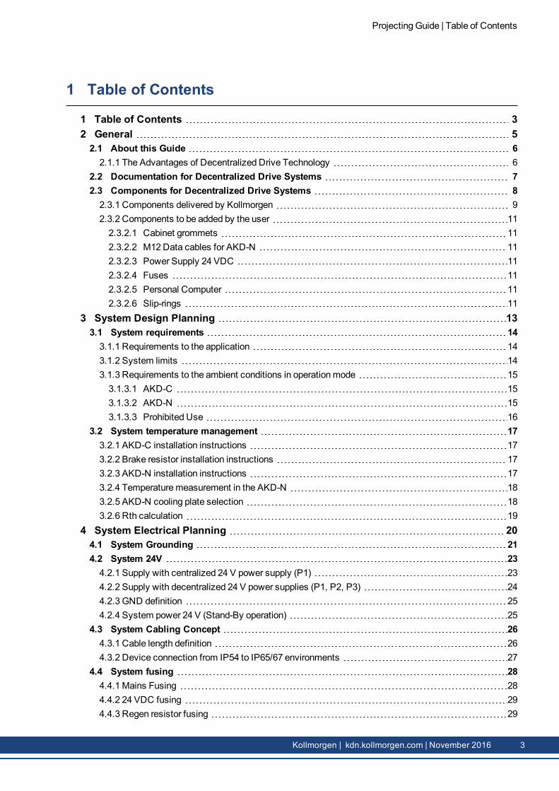
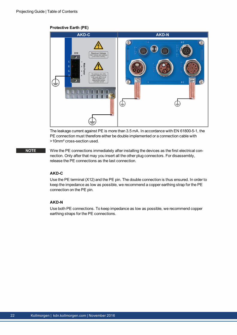
Protective Earth (PE)
AKD-C AKD-N
The leakage current against PE is more than 3.5mA. In accordance with EN 61800-5-1, thePE connectionmust therefore either be double implemented or a connection cable with>10mm² cross-section used.
Wire the PE connections immediately after installing the devices as the first electrical con-nection. Only after that may you insert all the other plug connectors. For disassembly,release the PE connections as the last connection.
AKD-CUse the PE terminal (X12) and the PE pin. The double connection is thus ensured. In order tokeep the impedance as low as possible, we recommend a copper earthing strap for the PEconnection on the PE pin.
AKD-NUse both PE connections. To keep impedance as low as possible, we recommend copperearthing straps for the PE connections.
Projecting Guide | Table of Contents
22 Kollmorgen | kdn.kollmorgen.com | November 2016
4.2 System 24VThe decentralized concept of a drive system with AKD-C and AKD-N may lead to large cablelengths and the voltage drops on the cable associated with this or to interfering signals(impedance coupling). Depending on the situation in your application, choose a centralized ordecentralized supply, or a combination of the two concepts.
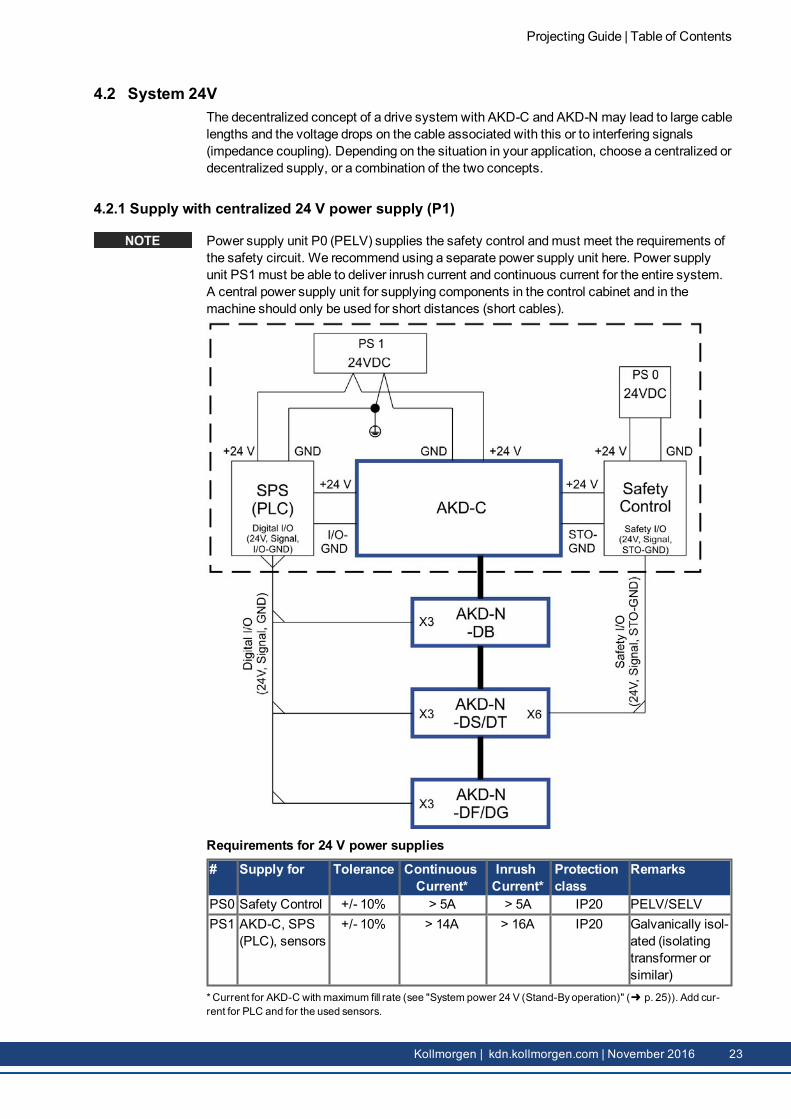
4.2.1 Supply with centralized 24 V power supply (P1)
Power supply unit P0 (PELV) supplies the safety control andmust meet the requirements ofthe safety circuit. We recommend using a separate power supply unit here. Power supplyunit PS1must be able to deliver inrush current and continuous current for the entire system.A central power supply unit for supplying components in the control cabinet and in themachine should only be used for short distances (short cables).
* Current for AKD-C withmaximum fill rate (see "System power 24 V (Stand-Byoperation)" (➜ p. 25)). Add cur-rent for PLC and for the used sensors.
Projecting Guide | Table of Contents
Kollmorgen | kdn.kollmorgen.com | November 2016 23
4.2.2 Supply with decentralized 24 V power supplies (P1, P2, P3)
Power supply unit P0 (PELV) supplies the safety control andmust meet the requirements ofthe safety circuit.Power supply unit PS1must be able to deliver inrush current and continuous current for theentire system.Power supply unit P2 supplies the PLC andmust meet the requirements of the PLC.Power supply unit P3 supplies the limit switches and sensors in themachine, for example,andmust meet the requirements of the environment.
Requirements for 24 V power supplies
# Supply for Tolerance ContinuousCurrent*
InrushCurrent*
Protectionclass
Remarks
PS0 Safety Control +/- 10% > 5A > 5A IP20 PELV/SELVPS1 AKD-C +/- 10% 14 A 16 A IP20 Galvanically
isolated (isol-ating trans-former orsimilar)
PS2 SPS (PLC) +/- 10% depends on system IP20
PS3 Sensors +/- 10% depends on system IP67
* Current for AKD-C withmaximum fill rate (see "System power 24 V (Stand-Byoperation)" (➜ p. 25)).
Projecting Guide | Table of Contents
24 Kollmorgen | kdn.kollmorgen.com | November 2016
4.2.3 GND definitionAKD-C I/O-GND Common line for digital inputs X15 X15/4
GND 24 V supply X13/2STO-GND STO input (global) X16/4-5-7
AKD-N I/O-GND Common line for digital inputs X3 X3/6STO-GND STO input (local, AKD-N-DS/DT) X6/2
All GND networks are galvanically isolated from each other. Ground loops can be preventedin this way. TheGND on the 24V power supply unit (PS1) should be grounded.
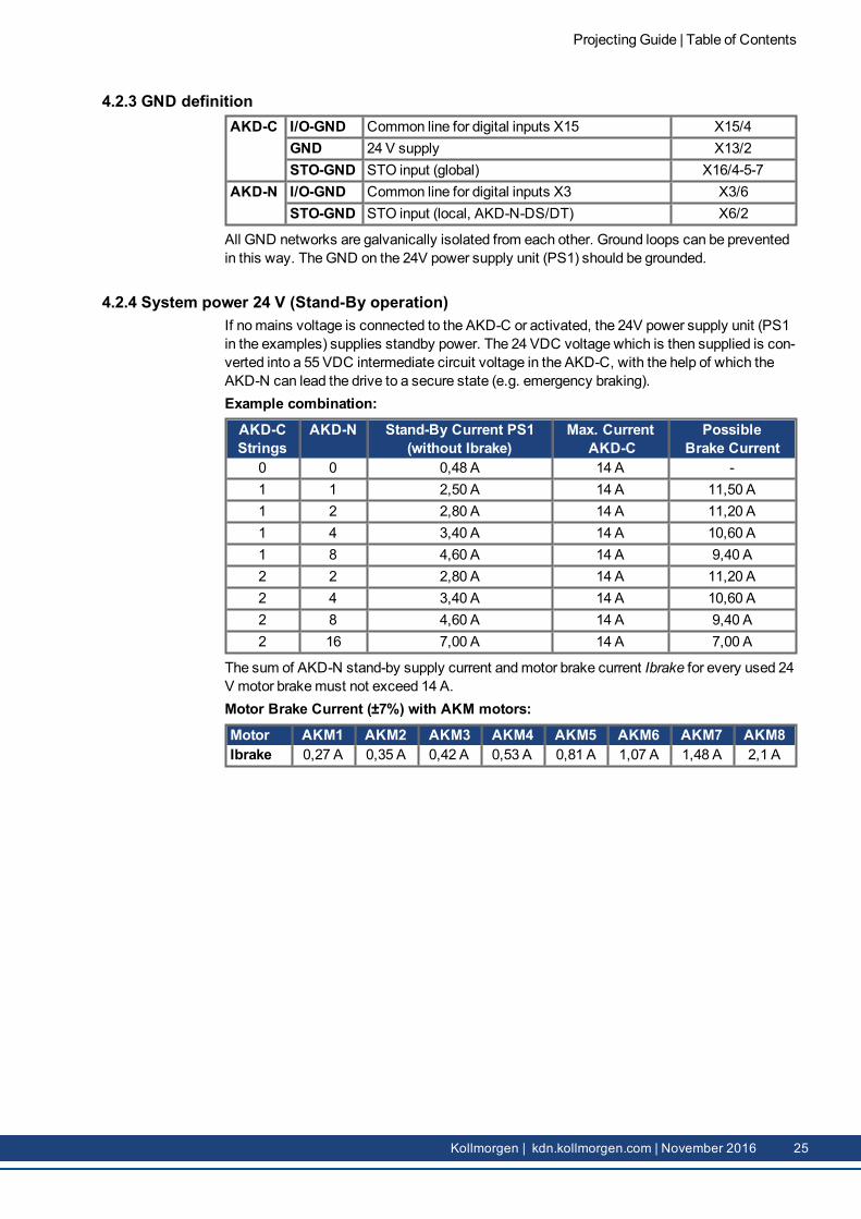
4.2.4 System power 24 V (Stand-By operation)If nomains voltage is connected to the AKD-C or activated, the 24V power supply unit (PS1in the examples) supplies standby power. The 24 VDC voltage which is then supplied is con-verted into a 55 VDC intermediate circuit voltage in the AKD-C, with the help of which theAKD-N can lead the drive to a secure state (e.g. emergency braking).Example combination:
AKD-CStrings
AKD-N Stand-By Current PS1(without Ibrake)
Max. CurrentAKD-C
PossibleBrake Current
0 0 0,48 A 14 A -1 1 2,50 A 14 A 11,50 A1 2 2,80 A 14 A 11,20 A1 4 3,40 A 14 A 10,60 A1 8 4,60 A 14 A 9,40 A2 2 2,80 A 14 A 11,20 A2 4 3,40 A 14 A 10,60 A2 8 4,60 A 14 A 9,40 A2 16 7,00 A 14 A 7,00 A
The sum of AKD-N stand-by supply current andmotor brake current Ibrake for every used 24V motor brakemust not exceed 14 A.Motor Brake Current (±7%) with AKM motors:
Motor AKM1 AKM2 AKM3 AKM4 AKM5 AKM6 AKM7 AKM8Ibrake 0,27 A 0,35 A 0,42 A 0,53 A 0,81 A 1,07 A 1,48 A 2,1 A
Projecting Guide | Table of Contents
Kollmorgen | kdn.kollmorgen.com | November 2016 25
4.3 System Cabling Concept
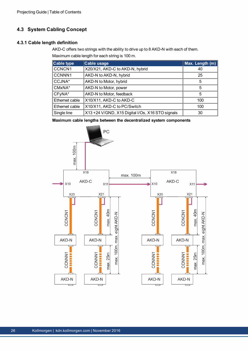
4.3.1 Cable length definitionAKD-C offers two strings with the ability to drive up to 8 AKD-N with each of them.Maximum cable length for each string is 100m.
Cable type Cable usage Max. Length (m)CCNCN1 X20/X21, AKD-C to AKD-N, hybrid 40CCNNN1 AKD-N to AKD-N, hybrid 25CCJNA* AKD-N toMotor, hybrid 5CMxNA* AKD-N toMotor, power 5CFyNA* AKD-N toMotor, feedback 5Ethernet cable X10/X11, AKD-C to AKD-C 100Ethernet cable X10/X11, AKD-C to PC/Switch 100Single line X13 +24 V/GND, X15 Digital I/Os, X16 STO signals 30
Maximum cable lengths between the decentralized system components
Projecting Guide | Table of Contents
26 Kollmorgen | kdn.kollmorgen.com | November 2016
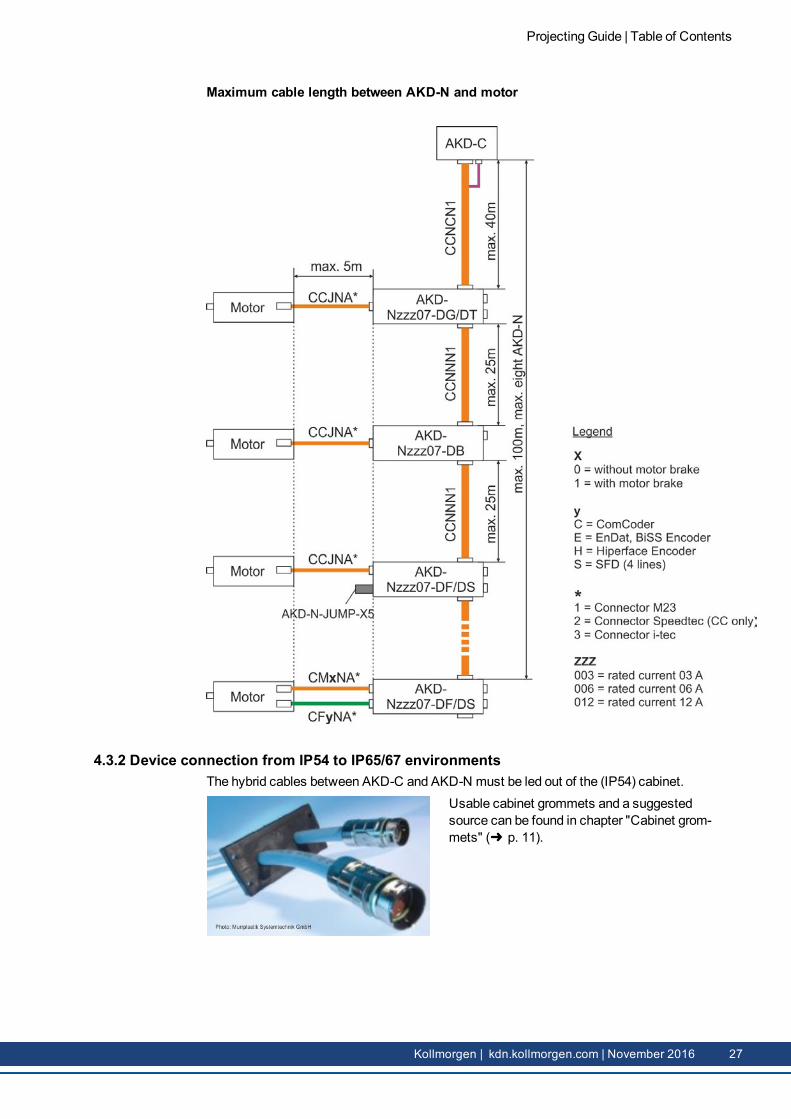
Maximum cable length between AKD-N and motor
4.3.2 Device connection from IP54 to IP65/67 environmentsThe hybrid cables between AKD-C and AKD-N must be led out of the (IP54) cabinet.
Usable cabinet grommets and a suggestedsource can be found in chapter "Cabinet grom-mets" (➜ p. 11).
Projecting Guide | Table of Contents
Kollmorgen | kdn.kollmorgen.com | November 2016 27
4.4 System fusing
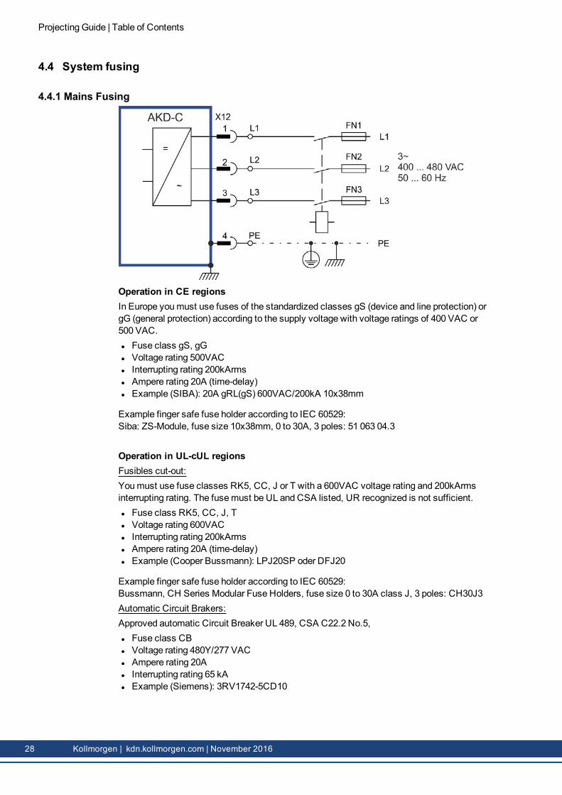
4.4.1 Mains Fusing
Operation in CE regionsIn Europe youmust use fuses of the standardized classes gS (device and line protection) orgG (general protection) according to the supply voltage with voltage ratings of 400 VAC or500 VAC.l Fuse class gS, gGl Voltage rating 500VACl Interrupting rating 200kArmsl Ampere rating 20A (time-delay)l Example (SIBA): 20A gRL(gS) 600VAC/200kA 10x38mm
Example finger safe fuse holder according to IEC 60529:Siba: ZS-Module, fuse size 10x38mm, 0 to 30A, 3 poles: 51 063 04.3
Operation in UL-cUL regionsFusibles cut-out:Youmust use fuse classes RK5, CC, J or T with a 600VAC voltage rating and 200kArmsinterrupting rating. The fusemust be UL and CSA listed, UR recognized is not sufficient.l Fuse class RK5, CC, J, Tl Voltage rating 600VACl Interrupting rating 200kArmsl Ampere rating 20A (time-delay)l Example (Cooper Bussmann): LPJ20SP oder DFJ20
Example finger safe fuse holder according to IEC 60529:Bussmann, CH Series Modular Fuse Holders, fuse size 0 to 30A class J, 3 poles: CH30J3Automatic Circuit Brakers:Approved automatic Circuit Breaker UL 489, CSA C22.2 No.5,l Fuse class CBl Voltage rating 480Y/277 VACl Ampere rating 20Al Interrupting rating 65 kAl Example (Siemens): 3RV1742-5CD10
Projecting Guide | Table of Contents
28 Kollmorgen | kdn.kollmorgen.com | November 2016
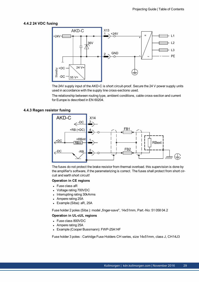
4.4.2 24 VDC fusing
The 24V supply input of the AKD-C is short circuit-proof. Secure the 24 V power supply unitsused in accordance with the supply line cross-sections used.The relationship between routing type, ambient conditions, cable cross-section and currentfor Europe is described in EN 60204.
4.4.3 Regen resistor fusing
The fuses do not protect the brake resistor from thermal overload. this supervision is done bythe amplifier's software, if the parameterizing is correct. The fuses shall protect from short cir-cuit and earth short circuit!Operation in CE regionsl Fuse class aRl Voltage rating 700VDCl Interrupting rating 30kArmsl Ampere rating 25Al Example (Siba): aR, 25A
Fuse holder 2 poles (Siba ): model „finger-save", 14x51mm, Part.-No: 51 058 04.2Operation in UL-cUL regionsl Fuse class 800VDCl Ampere rating 25Al Example (Cooper Bussmann): FWP-25A14F
Fuse holder 3 poles : Cartridge Fuse Holders CH series, size 14x51mm, class J, CH14J3
Projecting Guide | Table of Contents
Kollmorgen | kdn.kollmorgen.com | November 2016 29
5 Functional Safety
5.1 General 31
5.2 Global STO 32
5.3 Local STO 34
5.4 Global / Local STO combination 37
5.5 Calculation of Safety Levels for the STO function 39
5.6 Stop / Emergency Stop / Emergency Off 43
Projecting Guide | Table of Contents
30 Kollmorgen | kdn.kollmorgen.com | November 2016
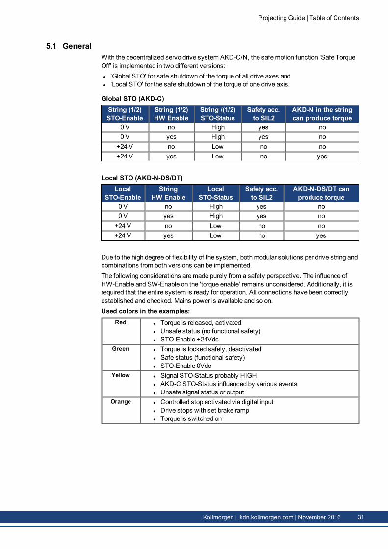
5.1 GeneralWith the decentralized servo drive system AKD-C/N, the safemotion function 'Safe TorqueOff' is implemented in two different versions:l 'Global STO' for safe shutdown of the torque of all drive axes andl 'Local STO' for the safe shutdown of the torque of one drive axis.
Global STO (AKD-C)String (1/2)STO-Enable
String (1/2)HW Enable
String /(1/2)STO-Status
Safety acc.to SIL2
AKD-N in the stringcan produce torque
0 V no High yes no0 V yes High yes no
+24 V no Low no no+24 V yes Low no yes
Local STO (AKD-N-DS/DT)Local
STO-EnableString
HW EnableLocal
STO-StatusSafety acc.to SIL2
AKD-N-DS/DT canproduce torque
0 V no High yes no0 V yes High yes no
+24 V no Low no no+24 V yes Low no yes
Due to the high degree of flexibility of the system, bothmodular solutions per drive string andcombinations from both versions can be implemented.The following considerations aremade purely from a safety perspective. The influence ofHW-Enable and SW-Enable on the 'torque enable' remains unconsidered. Additionally, it isrequired that the entire system is ready for operation. All connections have been correctlyestablished and checked. Mains power is available and so on.Used colors in the examples:
Red l Torque is released, activatedl Unsafe status (no functional safety)l STO-Enable +24Vdc
Green l Torque is locked safely, deactivatedl Safe status (functional safety)l STO-Enable 0Vdc
Yellow l Signal STO-Status probably HIGHl AKD-C STO-Status influenced by various eventsl Unsafe signal status or output
Orange l Controlled stop activated via digital inputl Drive stops with set brake rampl Torque is switched on
Projecting Guide | Table of Contents
Kollmorgen | kdn.kollmorgen.com | November 2016 31
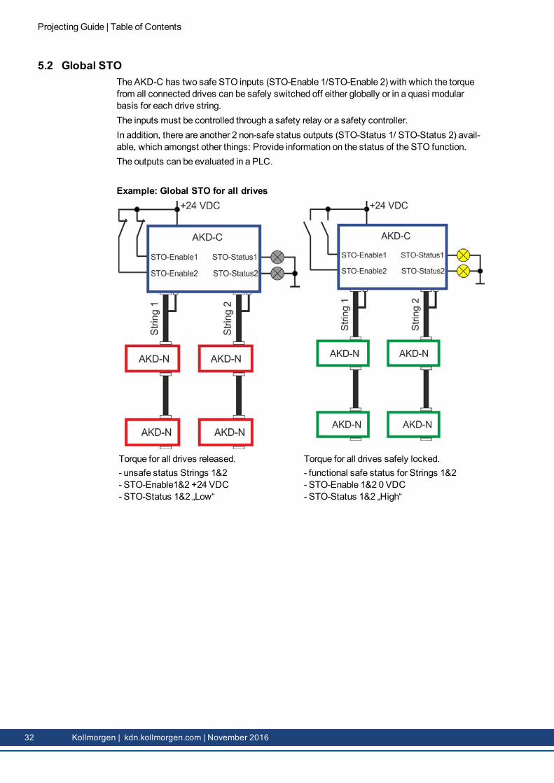
5.2 Global STOThe AKD-C has two safe STO inputs (STO-Enable 1/STO-Enable 2) with which the torquefrom all connected drives can be safely switched off either globally or in a quasi modularbasis for each drive string.The inputs must be controlled through a safety relay or a safety controller.In addition, there are another 2 non-safe status outputs (STO-Status 1/ STO-Status 2) avail-able, which amongst other things: Provide information on the status of the STO function.The outputs can be evaluated in a PLC.
Example: Global STO for all drives
Torque for all drives released.- unsafe status Strings 1&2- STO-Enable1&2 +24 VDC- STO-Status 1&2 „Low“
Torque for all drives safely locked.- functional safe status for Strings 1&2- STO-Enable 1&2 0 VDC- STO-Status 1&2 „High“
Projecting Guide | Table of Contents
32 Kollmorgen | kdn.kollmorgen.com | November 2016
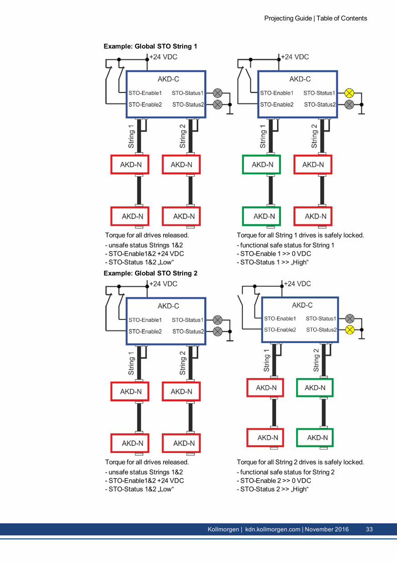
Example: Global STO String 1
Torque for all drives released.- unsafe status Strings 1&2- STO-Enable1&2 +24 VDC- STO-Status 1&2 „Low“
Torque for all String 1 drives is safely locked.- functional safe status for String 1- STO-Enable 1 >> 0 VDC- STO-Status 1 >> „High“
Example: Global STO String 2
Torque for all drives released.- unsafe status Strings 1&2- STO-Enable1&2 +24 VDC- STO-Status 1&2 „Low“
Torque for all String 2 drives is safely locked.- functional safe status for String 2- STO-Enable 2 >> 0 VDC- STO-Status 2 >> „High“
Projecting Guide | Table of Contents
Kollmorgen | kdn.kollmorgen.com | November 2016 33
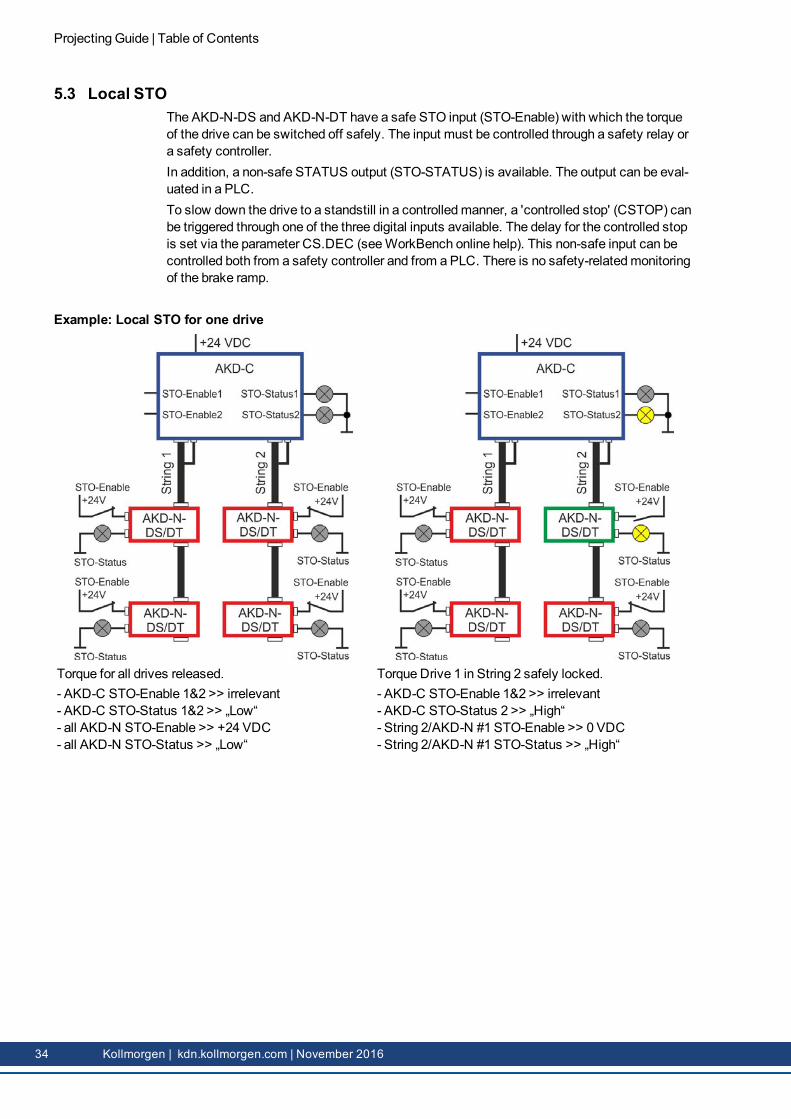
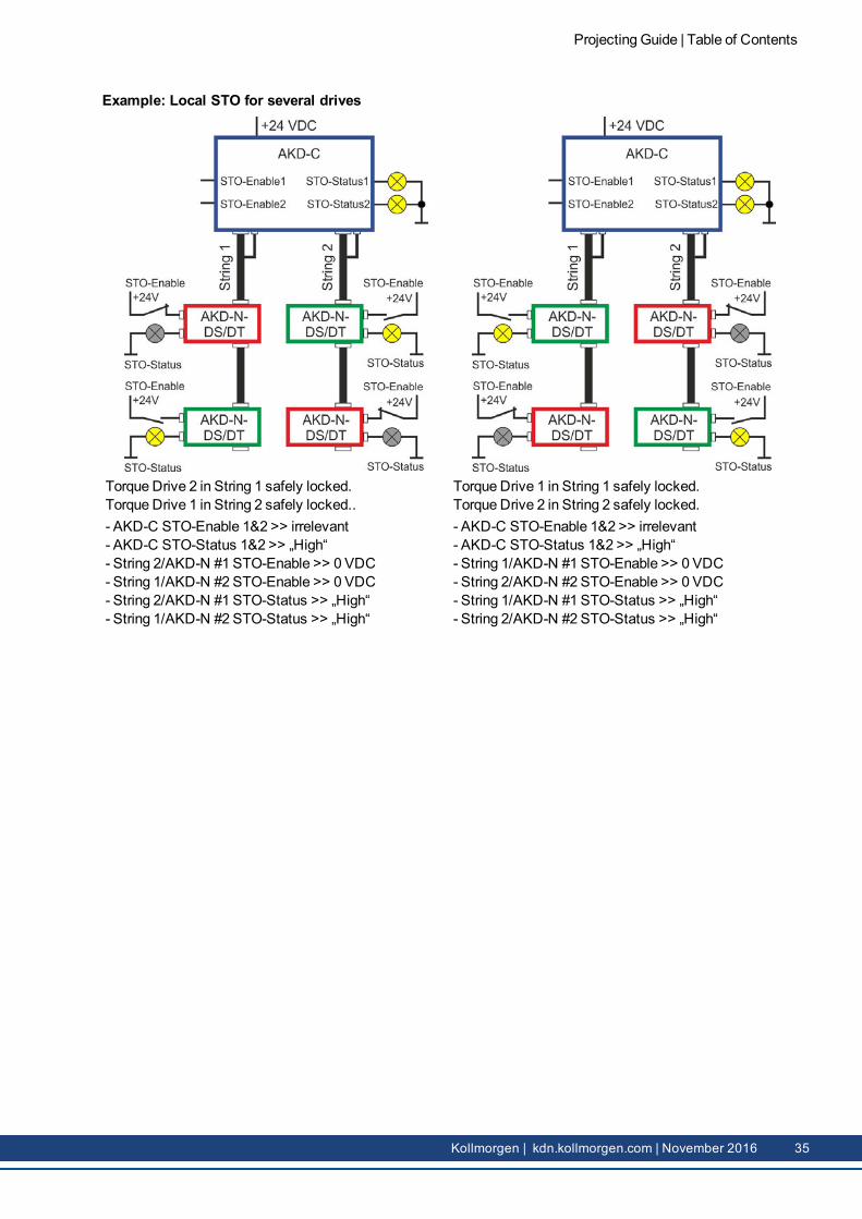
5.3 Local STOThe AKD-N-DS and AKD-N-DT have a safe STO input (STO-Enable) with which the torqueof the drive can be switched off safely. The input must be controlled through a safety relay ora safety controller.In addition, a non-safe STATUS output (STO-STATUS) is available. The output can be eval-uated in a PLC.To slow down the drive to a standstill in a controlledmanner, a 'controlled stop' (CSTOP) canbe triggered through one of the three digital inputs available. The delay for the controlled stopis set via the parameter CS.DEC (seeWorkBench online help). This non-safe input can becontrolled both from a safety controller and from a PLC. There is no safety-relatedmonitoringof the brake ramp.
Example: Local STO for one drive
Torque for all drives released.- AKD-C STO-Enable 1&2 >> irrelevant- AKD-C STO-Status 1&2 >> „Low“- all AKD-N STO-Enable >> +24 VDC- all AKD-N STO-Status >> „Low“
Kollmorgen | kdn.kollmorgen.com | November 2016 35
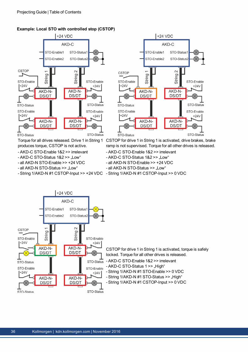
Example: Local STO with controlled stop (CSTOP)
Torque for all drives released. Drive 1 in String 1produces torque, CSTOP is not active.- AKD-C STO-Enable 1&2 >> irrelevant- AKD-C STO-Status 1&2 >> „Low“- all AKD-N STO-Enable >> +24 VDC- all AKD-N STO-Status >> „Low“- String 1/AKD-N #1 CSTOP-Input >> +24 VDC
CSTOP for drive 1 in String 1 is activated, drive brakes, brakeramp is not supervised. Torque for all other drives is released.- AKD-C STO-Enable 1&2 >> irrelevant- AKD-C STO-Status 1&2 >> „Low“- all AKD-N STO-Enable >> +24 VDC- all AKD-N STO-Status >> „Low“- String 1/AKD-N #1 CSTOP-Input >> 0 VDC
CSTOP for drive 1 in String 1 is activated, torque is safelylocked. Torque for all other drives is released.- AKD-C STO-Enable 1&2 >> irrelevant- AKD-C STO-Status 1 >> „High“- String 1/AKD-N #1 STO-Enable >> 0 VDC- String 1/AKD-N #1 STO-Status >> „High“- String 1/AKD-N #1 CSTOP-Input >> 0 VDC
Projecting Guide | Table of Contents
36 Kollmorgen | kdn.kollmorgen.com | November 2016
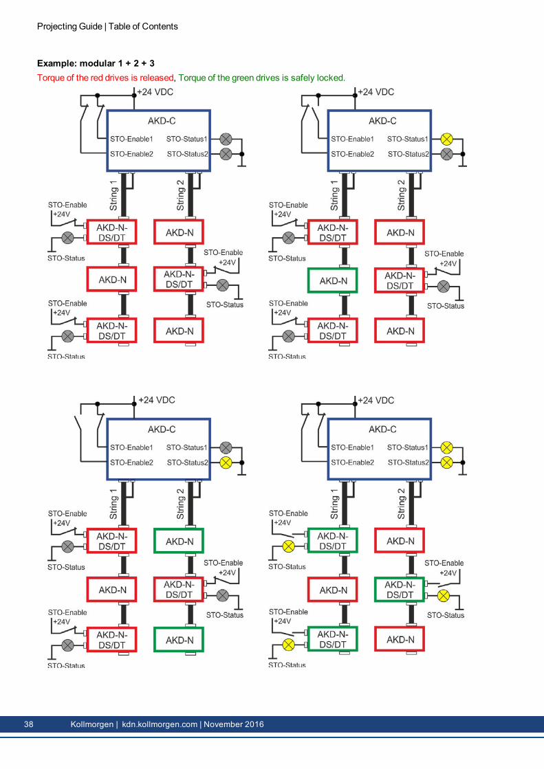
5.4 Global / Local STO combinationTo implement modular solutions and optional extensions, both STO versions can be com-bined with one another in a wide variety of ways.AKD-N-DS and AKD-N-DT have a 'local STO' and can be switched torque-free individually.All other AKD-N devices can only be switched via the 'global STO' on the AKD-C.
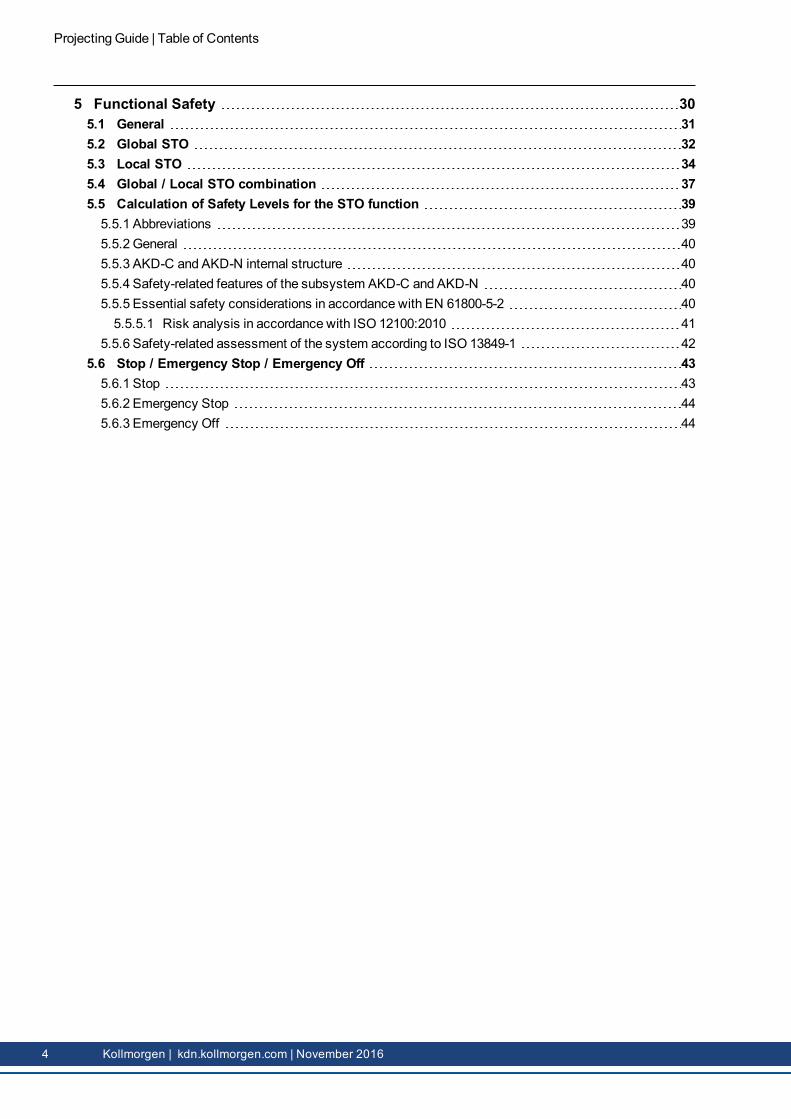
Example: modular 3 + 2 + 1Torque of the red drives is released, Torque of the green drives is safely locked.
Projecting Guide | Table of Contents
Kollmorgen | kdn.kollmorgen.com | November 2016 37
Example: modular 1 + 2 + 3Torque of the red drives is released, Torque of the green drives is safely locked.
Projecting Guide | Table of Contents
38 Kollmorgen | kdn.kollmorgen.com | November 2016
5.5 Calculation of Safety Levels for the STO function
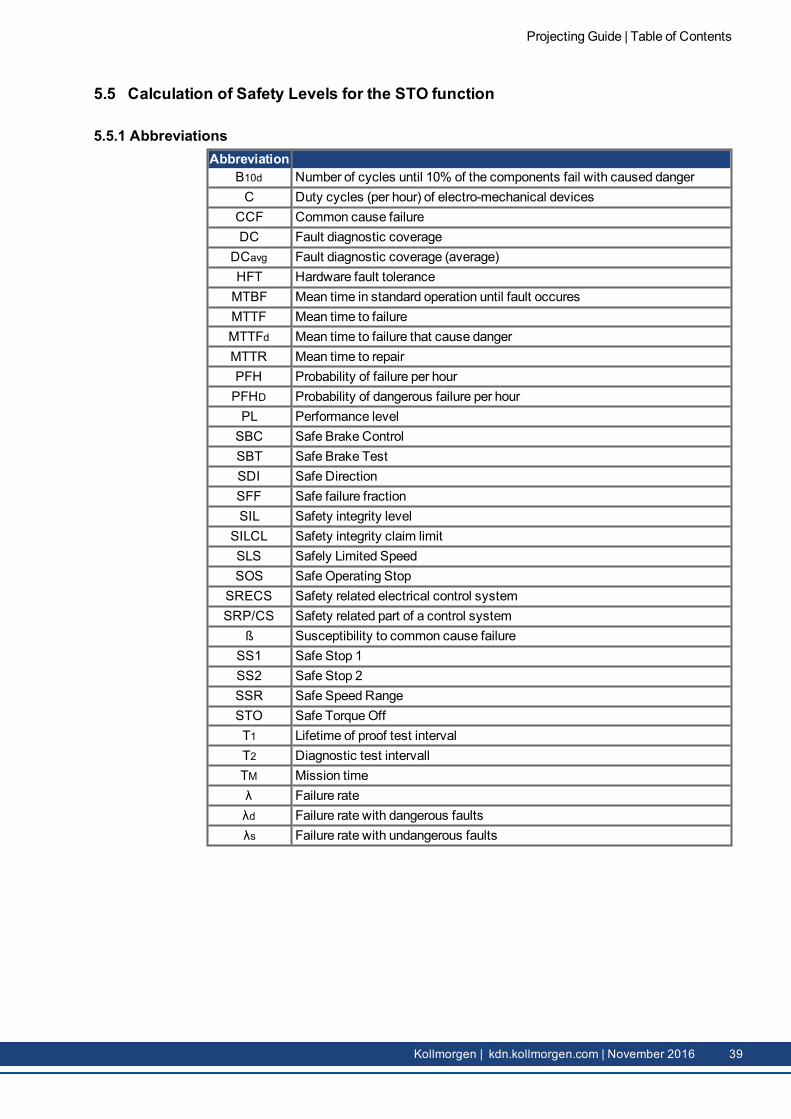
5.5.1 AbbreviationsAbbreviation
B10d Number of cycles until 10% of the components fail with caused dangerC Duty cycles (per hour) of electro-mechanical devices
CCF Common cause failureDC Fault diagnostic coverage
DCavg Fault diagnostic coverage (average)HFT Hardware fault toleranceMTBF Mean time in standard operation until fault occuresMTTF Mean time to failureMTTFd Mean time to failure that cause dangerMTTR Mean time to repairPFH Probability of failure per hourPFHD Probability of dangerous failure per hourPL Performance levelSBC Safe Brake ControlSBT Safe Brake TestSDI Safe DirectionSFF Safe failure fractionSIL Safety integrity level
SRECS Safety related electrical control systemSRP/CS Safety related part of a control system
ß Susceptibility to common cause failureSS1 Safe Stop 1SS2 Safe Stop 2SSR Safe Speed RangeSTO Safe TorqueOffT1 Lifetime of proof test intervalT2 Diagnostic test intervallTM Mission timeλ Failure rateλd Failure rate with dangerous faults λs Failure rate with undangerous faults
Projecting Guide | Table of Contents
Kollmorgen | kdn.kollmorgen.com | November 2016 39
5.5.2 GeneralWith conventional servo amplifiers, the STO (Safe TorqueOff) safety function is typicallyassigned uniquely to one individual device. This means the specified safety-related para-meters are also assigned uniquely to one device.With the decentralized drive system, at least two devices are assigned to one STO function,one AKD-C and at least one AKD-N. The safety-related parameters specified in the operatinginstructions therefore refer to the system; i.e. at least to two devices.However, several AKD-Ns can be operated with one STO input; i.e. with one STO signal upto 8 AKD-Ns can be shut down (global STO). In this case, the PFH value cannot always betaken directly from the safety characteristics table given in the InstallationManual. Instead,youmust investigate how many AKD-Ns are involved in one risk (e.g. restart) in order to thendetermine the entire PFH value.
5.5.3 AKD-C and AKD-N internal structureThe STO function can be considered a 'black box' by the user – understanding the signal pathwithin the AKD-C, as well as the transmission to the first AKD-N and the distribution of thesignal to all connected AKD-Ns is not required for determining the safety level.The STO signal requires no additional cables between the devices. Instead, the signal is mod-ulated onto an existing cable. The STOSignal on the AKD-C switches off the driver supplyfor all power semiconductors of the AKD-N devices, thus preventing the power output stagesfrom supplying themotors with energy.
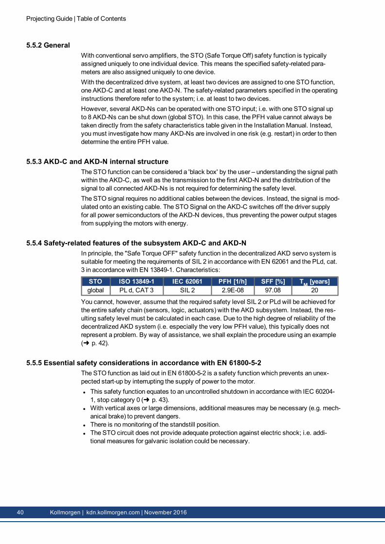
5.5.4 Safety-related features of the subsystem AKD-C and AKD-NIn principle, the "Safe TorqueOFF" safety function in the decentralized AKD servo system issuitable for meeting the requirements of SIL 2 in accordance with EN 62061 and the PLd, cat.3 in accordance with EN 13849-1. Characteristics:
STO ISO 13849-1 IEC 62061 PFH [1/h] SFF [%] TM [years]global PL d, CAT 3 SIL 2 2.9E-08 97.08 20
You cannot, however, assume that the required safety level SIL 2 or PLd will be achieved forthe entire safety chain (sensors, logic, actuators) with the AKD subsystem. Instead, the res-ulting safety level must be calculated in each case. Due to the high degree of reliability of thedecentralized AKD system (i.e. especially the very low PFH value), this typically does notrepresent a problem. By way of assistance, we shall explain the procedure using an example(➜ p. 42).
5.5.5 Essential safety considerations in accordance with EN 61800-5-2The STO function as laid out in EN 61800-5-2 is a safety function which prevents an unex-pected start-up by interrupting the supply of power to themotor.l This safety function equates to an uncontrolled shutdown in accordance with IEC 60204-1, stop category 0 (➜ p. 43).
l With vertical axes or large dimensions, additional measures may be necessary (e.g. mech-anical brake) to prevent dangers.
l There is nomonitoring of the standstill position.l The STO circuit does not provide adequate protection against electric shock; i.e. addi-tional measures for galvanic isolation could be necessary.
Projecting Guide | Table of Contents
40 Kollmorgen | kdn.kollmorgen.com | November 2016
5.5.5.1 Risk analysis in accordance with ISO 12100:2010The standard ISO 12100:2010 provides essential information concerning the procedure forrisk assessment and risk minimization; in particular, the '3-stagemethod' should be con-sidered:1. Inherently safe design.2. Technical protectivemeasures.3. Information on residual risk.
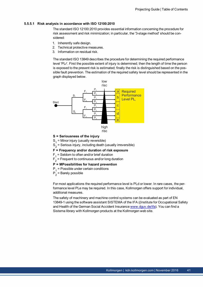
The standard ISO 13849 describes the procedure for determining the required performancelevel 'PLr'. First the possible extent of injury is determined; then the length of time the personis exposed to the present risk is estimated; finally the risk is distinguished based on the pos-sible fault prevention. The estimation of the required safety level should be represented in thegraph displayed below.
S = Seriousness of the injuryS1 = Minor injury (usually reversible)S2 = Serious injury, including death (usually irreversible)F = Frequency and/or duration of risk exposureF1 = Seldom to often and/or brief durationF2 = Frequent to continuous and/or long durationP = MPossibilities for hazard preventionP1 = Possible under certain conditionsP2 = Barely possible
For most applications the required performance level is PLd or lower. In rare cases, the per-formance level PLemay be required. In this case, Kollmorgen offers support for individual,additional measures.The safety of machinery andmachine control systems can be evaluated as part of EN13849-1 using the software assistant SISTEMA of the IFA ((Institute for Occupational Safetyand Health of the German Social Accident Insurance www.dguv.de/ifa). You can find aSistema library with Kollmorgen products at the Kollmorgen web site.
Projecting Guide | Table of Contents
Kollmorgen | kdn.kollmorgen.com | November 2016 41
5.5.6 Safety-related assessment of the system according to ISO 13849-1Example application: Simple handling system with a horizontal axle (X), a vertical axle (Y),and a conveyor belt drive (F).Firstly, all subsystems of the safety chain 'STO' must be displayed with their safety-relatedparameters in a block diagram. In this process, the number of connected AKD-Ns on theAKD-C is insignificant. Instead, only the AKD-N simultaneously involved in the 'restart' riskmust be considered.In our example, a start-up of the X-axle and a start-up of the Y-axle could pose a risk forusers. Therefore, both AKD-Ns must be considered subsystems of the safety chain. On theother hand, a third AKD-N on the AKD-C, which serves as a drive for the conveyor belt, canremain unconsidered, since no danger is posed from themovement of the conveyor belt in theexample. The figure below thus presents all subsystems of the STO safety function. Theuser must ensure that all subsystems correspond to at least category 3 and the performancelevel PLd.
If additional drives were to be involved in the 'restart' risk, their STO parameters would alsohave to be adopted in the safety chain.Determining the resulting performance level for the STO safety function.The PFH value of the overall system (i.e. the entire STO safety chain) must be in the per-mitted range for PLd. The PFH overall value is deduced from the sum of the PFH values ofthe subsystems.To achieve the PLd, the PFH valuemust be lower than < 10-6; in other words, an overall PFHvalue of at least 9.47 x 10⁻⁷ is required !The parameters are presented in the figure below for clarity:
Now the PFH values must be summarized:PFHtotal = PFHSensor + PFHLogic + PFHActuator1 + PFHActuator2
PFHtotal = 2.3 x 10⁻⁷ + 4.6 x 10⁻⁹+ 2.9 x 10⁻⁸+ 2.9 x 10⁻⁸
PFHtotal = 2.9 x 10-7 => PLd for the overall system is achieved!
Upon closer consideration, it becomes clear that typically the sensor has the greatest influ-ence on the PFH overall value, since the PFH values for AKD are of a very high quality.
Projecting Guide | Table of Contents
42 Kollmorgen | kdn.kollmorgen.com | November 2016
5.6 Stop / Emergency Stop / Emergency OffThe control functions Stop, Emergency Stop and Emergency Off are defined by IEC 60204.Notes for safety aspects of these functions can be found in ISO 13849 and IEC 62061.
The parameter DRV.DISMODE must be set to 2 for every connected AKD-N to implementthe different stop categories. Consult theAKD-N User Guide for configuring the parameter.
5.6.1 StopThe stop function shuts down themachine in normal operation. The stop function is definedby IEC 60204.
The Stop Category must be determined by a risk evaluation of themachine.Stop functionmust have priority over assigned start functions. The following stop categoriesare defined:Stop Category 0Shut-down by immediate switching-off the energy supply to the drivemachinery (this is anuncontrolled shut-down). With the approved safety function STO the drive can be stoppedusing its internal electronics (IEC 61508 SIL2).Stop Category 1A controlled shut-down, whereby the energy supply to the drivemachinery is maintained toperform the shut-down, and the energy supply is only interrupted when the shut-down hasbeen completed.Stop Category 2A controlled shut-down, whereby the energy supply to the drivemachinery is maintained.
Stop Category 0 and Stop Category 1 stops must be operable independently of the operatingmode, whereby a Category 0 stopmust have priority.If necessary, provisionmust bemade for the connection of protective devices and lock-outs.If applicable, the stop functionmust signal its status to the control logic. A reset of the stopfunctionmust not create a hazardous situation.
Projecting Guide | Table of Contents
Kollmorgen | kdn.kollmorgen.com | November 2016 43
5.6.2 Emergency StopThe Emergency Stop function is used for the fastest possible shutdown of themachine in adangerous situation. The Emergency Stop function is defined by IEC 60204. Principles ofemergency stop devices and functional aspects are defined in ISO 13850.The Emergency Stop function will be triggered by themanual actions of a single person. Itmust be fully functional and available at all times. The user must understand instantly how tooperate this mechanism (without consulting references or instructions).
The Stop Category for the Emergency Stopmust be determined by a risk evaluation of themachine.In addition to the requirements for stop, the Emergency Stopmust fulfil the following require-ments:l Emergency Stopmust have priority over all other functions and controls in all operatingmodes.
l The energy supply to any drivemachinery that could cause dangerous situations must beswitched off as fast as possible, without causing any further hazards ( Stop Category 0) ormust be controlled in such a way, that any movement that causes danger, is stopped asfast as possible (Stop Category 1).
l The reset must not initiate a restart.
5.6.3 Emergency OffThe Emergency Off function is used to switch-off the electrical power supply of themachine.This is done to prevent users from any risk from electrical energy (for example electricalimpact). Functional aspects for Emergency Off are defined in IEC 60364-5-53.The Emergency Off function will be triggered by themanual actions of a single person.
The result of a risk evaluation of themachine determines the necessity for an Emergency Offfunction.Emergency Off is done by switching off the supply energy by electro-mechanical switchingdevices. This results in a category 0 stop. If this stop category is not possible in the applic-ation, then the Emergency Off functionmust be replaced by other measures (for example byprotection against direct touching).
Projecting Guide | Table of Contents
44 Kollmorgen | kdn.kollmorgen.com | November 2016
This page intentionally left blank.
Projecting Guide |
Kollmorgen | kdn.kollmorgen.com | November 2016 45
About KOLLMORGEN Kollmorgen is a leading provider of motion systems and components for machine builders. Through world-classknowledge inmotion, industry-leading quality and deep expertise in linking and integrating standard and cus-tom products, Kollmorgen delivers breakthrough solutions that are unmatched in performance, reliability andease-of-use, givingmachine builders an irrefutable marketplace advantage.
Join the Kollmorgen Developer Network for product support. Ask the community ques-tions, search the knowledge base for answers, get downloads, and suggest improve-ments.
North AmericaKOLLMORGEN203A West Rock RoadRadford, VA 24141USAWeb: www.kollmorgen.comMail: [email protected].: +1 - 540 - 633 - 3545Fax: +1 - 540 - 639 - 4162
EuropeKOLLMORGEN Europe GmbHPempelfurtstraße 140880 RatingenGermany