DECK-IOCK* @ffi$rcTEffi Figure 1 For example, if the covering system is 30' long and the pool is 28' long, the difference of 2' becomes '1 ' at each end \ / Congratulations on purchasing one of the finest pool covers available. Proper installation and care of this cover will ensure many years of use. Please read these instructions completely BEFORE you begin. B EFOR E G ETTI NG STARTED : 1. Check to make sure all parts have arrived with the cover. . The number of brass anchors, brass insert screws, strap adjustment buckles and springs should each be equal to the number of straps protruding from the edge of the cover. . The notched rod included is to connect the springs to the anchors and screws during installation. It is also used during removal. 2. Make sure that you have the necessary tools to complete the installation including : . A 314" concrete drill bit (diamond type recommended). o Heavy duty hammer drill. e Tape measure. o Chalk line and piece of chalk. o Hammer. . Wooden block (2x4 scrap will suffice). r 1/4" Allen Key. 3. Arranging for a helper or two will make installation faster and easier. INSTALLATION: RECTANGULAR COVERS - The Coverins System is approximately 2' longer and 2'wider than the pool area, however for a perted fit: 1. Check the measurements of your Covering System and pool as precisely as possible. Divide the difference between the Covering System length and the pool length in half and mark the deck at the ends of the pool this distance from the pool's edge. Two well separated marks at each end will be required. (Figure 1a). 2" Snap chalk line at each end oi the pool. The chalk line should extend at least 30" beyond the pool sides (Figure 1b). 3. Perform Steps 1. and 2. using the widths of the Covering System and the pool (Figure 2). 4. Locate one corner where two chalk lines cross. Starting at this crossing point measure l6" towards the end of both lines and mark these positions. Do the same at each corner of the chalked rectangle (Figure 3). 5. Drill holes in the deck at the 8 locations marked in Step 4. IMPORTANT - the depth of the side of each hole should be 1 5i8" so that the brass anchors cannot be set too deep into the deck. A convenlent way to measure the depth is to measure 1 518" up the side of the drill bit (do not include the portion which tapers to the point) and wrapping tape around the bit so 1 5/8" portion is below tape. When drilling, stop when the lower edge of tape gets to the deck. CHECK all holes carefully to ensure the depth is correct or the anchors will protrude above the deck. 6. Remove the screw of the brass anchor and insert the aluminum tamping tool into the hollow of the anchor. Place the anchor in the hole then tap the top of the aluminum tool until the brass anchor is flush with the concrete. a)x Figure 1 ui Marks located 1 from pool ends. Snap chalk lines across Line alk _t Ch Xr+- Mark for j]16_.// .o,n", l#' ancfiors 16' and repeal at all four corners i<- chatk Line I I I I I I I ' / marks i/ tocated Figure 2lf the Covering System is 14'2" wide and the pool is 12'wide, locate the chalk line half of lhe 2'2" difference of 1'1" from the sides of the pool. -l-x-- ----F;- Marks 1'1" from pool sides After positions located, snap chalk lines along sides of pool making sure they extend at least 30" beyond ends of pool. NOfe Wnen installation is complete, the covering system will cover the area enclosed by the chalk lines. Figure 3
Transcript
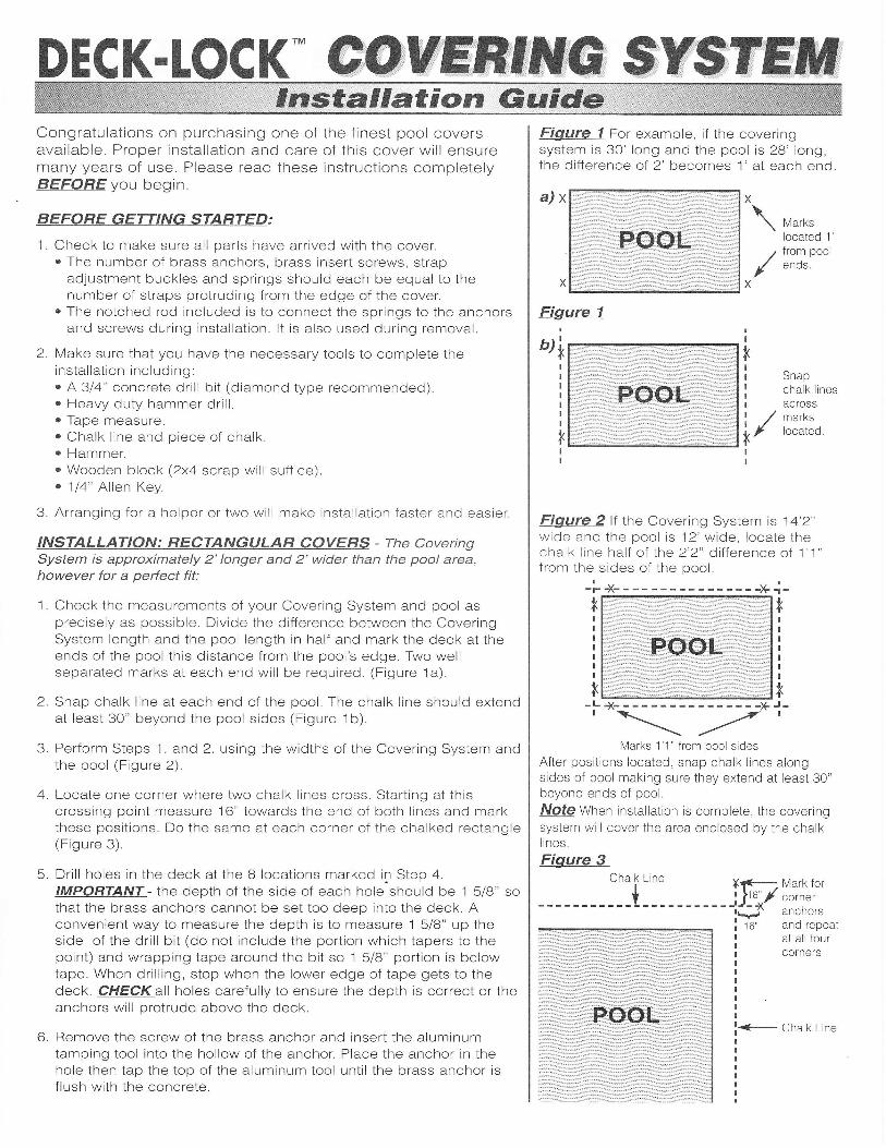
DECK-IOCK* @ffi$rcTEffiFigure 1 For example, if the coveringsystem is 30' long and the pool is 28' long,the difference of 2' becomes '1 ' at each end
\
/
Congratulations on purchasing one of the finest pool coversavailable. Proper installation and care of this cover will ensuremany years of use. Please read these instructions completelyBEFORE you begin.
B EFOR E G ETTI NG STARTED :
1. Check to make sure all parts have arrived with the cover.. The number of brass anchors, brass insert screws, strap
adjustment buckles and springs should each be equal to thenumber of straps protruding from the edge of the cover.
. The notched rod included is to connect the springs to the anchorsand screws during installation. It is also used during removal.
2. Make sure that you have the necessary tools to complete theinstallation including :
. A 314" concrete drill bit (diamond type recommended).o Heavy duty hammer drill.e Tape measure.o Chalk line and piece of chalk.o Hammer.. Wooden block (2x4 scrap will suffice).r 1/4" Allen Key.
3. Arranging for a helper or two will make installation faster and easier.
INSTALLATION: RECTANGULAR COVERS - The CoverinsSystem is approximately 2' longer and 2'wider than the pool area,however for a perted fit:
1. Check the measurements of your Covering System and pool asprecisely as possible. Divide the difference between the CoveringSystem length and the pool length in half and mark the deck at theends of the pool this distance from the pool's edge. Two wellseparated marks at each end will be required. (Figure 1a).
2" Snap chalk line at each end oi the pool. The chalk line should extendat least 30" beyond the pool sides (Figure 1b).
3. Perform Steps 1. and 2. using the widths of the Covering System andthe pool (Figure 2).
4. Locate one corner where two chalk lines cross. Starting at thiscrossing point measure l6" towards the end of both lines and markthese positions. Do the same at each corner of the chalked rectangle(Figure 3).
5. Drill holes in the deck at the 8 locations marked in Step 4.IMPORTANT - the depth of the side of each hole should be 1 5i8" sothat the brass anchors cannot be set too deep into the deck. Aconvenlent way to measure the depth is to measure 1 518" up theside of the drill bit (do not include the portion which tapers to thepoint) and wrapping tape around the bit so 1 5/8" portion is belowtape. When drilling, stop when the lower edge of tape gets to thedeck. CHECK all holes carefully to ensure the depth is correct or theanchors will protrude above the deck.
6. Remove the screw of the brass anchor and insert the aluminumtamping tool into the hollow of the anchor. Place the anchor in thehole then tap the top of the aluminum tool until the brass anchor isflush with the concrete.
a)x
Figure 1
ui
Markslocated 1
from poolends.
Snapchalk linesacross
Linealk
_t
Ch Xr+- Mark forj]16_.// .o,n",l#' ancfiors
16' and repealat all fourcorners
i<- chatk LineIIIIIII
' / marks
i/ tocated
Figure 2lf the Covering System is 14'2"wide and the pool is 12'wide, locate thechalk line half of lhe 2'2" difference of 1'1"from the sides of the pool.
-l-x-- ----F;-
Marks 1'1" from pool sides
After positions located, snap chalk lines alongsides of pool making sure they extend at least 30"beyond ends of pool.
NOfe Wnen installation is complete, the coveringsystem will cover the area enclosed by the chalklines.
Figure 3
DECK-tOCK* COHffilfiC SrlSe$etion Guide Contrrl
7. Turn the screws out until the tops are about 3/8" above the decksurface.
B. Strap adjustment buckles and springs are now attached to theCovering System. To prolong the life of the cover, rub strips areattached to the underside of the cover where the straps wouldotherwise make contact with the deck and coping. The buckles areto be used with the edges pointing downward. From beneath thebuckle feed the strap up through the first slot then down through thecenter slot. Now feed the strap through the squared end of a springthen up through the center slot and down through the third slot.Repeat until all springs and buckles are attached (Figure 4).
9. The Covering System is now positioned on the pool by hooking the 2straps at each corner to the corresponding anchors installed in Step6. The notched rod is used to tension the springs over the brassscrews by inserting the rod through the round end of a spring,placing the tab over the end of the screw and pulling the rod to justbeyond a vertical position. This compresses the spring and guides itover the top of the screw with minimal effort. Turning the rod until thetab faces the pool will allow removal of the rod without disturbing thespring.
lO.Adjust the I straps until the edges of the Covering System arealigned with the chalked lines placed earlier and the springs arecompressed by about 50%.
11.Snap new chalk lines 16" from the outer edge of the CoveringSystem.NOTE: the ends should be at anchors already in place (Figure 5).
12. Extend the straps at the ends of the pool and determine where thesewould cross the new chalk lines. Mark these locations, drill, insertanchors and screws and hook springs over screws adjusting asneeded to keep the Covering System within the chalk lines placedearller (Figure 6).
13. Repeat Step 1 2 along the sides. Adjust the straps so that the shorterones are not pulling the longer ones off line. Your installation is nowcomplete.
FOR RECTANGLES WITH STEP SECTION:
1. lf the step section is offset from a corner, complete the installation ofthe Covering System identical to the above Steps 1 through 13.
2. The step section, which is a flap attached to the main body cover,can be fastened down by placing your 4 plugs for the two cornerssimilar to that of installing the main cover.
FOR RECTANGLES WITH CORNER STEP SECTIONS:
1. lf the step section is exactly at a corner, the area must be treated asthe widest part when determining the Covering System location asper Figure 1 and Figure 2.
2. With this type of step section the pool and Covering System have 5corners which must be marked as in Figure 3.
3. All other installation steps are the same as listed when installing astraight rectangle.
Figure 5 Place chalk lines for locating theplacement of the remaining anchors.
POOLCOVER.ING
SYSTEMChalk Line
i,r'III
Figure 6 Using unattached straps, markfor brass anchor placement.
chalk linesbetweenanchorsalreadyinstalled
Extend all
\il:T'"'o,,/whereIhW
chalk lines
Figure 4
Adjustment Buckle
Black Rubber Strip
DECK-LOCK* ffiffi
2.
INSTALLATION OF OTHER SHAPES
1. Thoroughly review the procedures for installing a rectangularCovering System to become familiar with the parts and processesinvolved.
7.
Attach springs and buckles to straps.
Position the Covering System over the pool ensuring that the extramaterial is even around the perimeter.HINT: Use a piece of chalk to mark the deck at 3' - 4' intervalsaround the pool, 16" from the edge to use as a guide (Figure 7).
Temporarily secure the cover by placlng weights on a few of thestraps (Figure 8.).
Locate one of the longest straps near the center of the cover,measure, mark and drill at both ends 16" from the edge of the coverin line with the strap. Allow a little more than 16" to compensate forany sagging in evidence (Figure 7).
lnsert anchors, attach springs and perform any adjustmeninecessary.
Repeat Steps 5 and 6 using a centrally located strap which crossesthe first one installed, adjusting the shorter strap so that the first oneis straight and not pulled to one side or the other (Figure 8a).
Working from the center straps toward the edge straps, positions forthe anchors are located and drilled, plugs inserted, springsconnected and straps adjusted to ensure that previously attachedstraps are not pulled out of position. To assure best fit, it isrecommended that after the first two straps are fastened youproceed by fastening a long strap on either side of the center one,then a short strap on either side of the center one, then two morelong ones and so on until all straps are secure (Figure 8b). This willminimize buckling or puckering of the material and result in theneatest installation possible.
COVERING SYSTEM REMOVAL
1. With the notched rod held vertically, place it over the top of a brassinsert screw ensuring that the protruding tab at the end of the rod ison the side of the screw nearest the pool.
2. Turn the rod 180" or a half turn, keeping the tab on the rod betweenthe spring and the screw.
3. Leaning the top of the rod toward the pool will disengage the springand it will slide up the rod a small distance. Proceed around the pooluntil one end of each strap is disconnected. The opposite end ofeach strap can now be removed by hand.
4. Remove the cover, clean, dry and pack. Store where not exposed tothe sun and in a location where not accessible to rodents.
5. Use Allen Key to turn brass screws down into the anchors.
NOTE: To prevent dust, dirt etc. from damaging the plugthreads it is advisable to coat the screw with ahousehold lubricant.
Figure 7 Marking for placement of shapedor irregular Pool Covering System.
\----'7
Attaching the initial straps3 Brass Anchot
Systeml r;It)
BrassAnchorslocated 16"beyond theedge of theCoveringSysiem
porary
5.
tItrlli\
B.
Figure 8Edge ofCovering
BrassAnchor
Weights
CoveringSystem Strap
Figure I a) Locate brass anchorplacement of straps on either side of centerstrap, drill and install anchors. Securestraps. Note Adjust to make sure crossstrap remains straight.
Figure 8 b) Locate brass anchorplacement of straps on either side of the firstcross strap installed. Drill and installanchors. Secure straps and adjust.
--t-i6l--..a- --:.- \
:^,,\lb l
DECK-LOCK* Sre6*6ffi
3.
OTHER CONSIDERATIONS
1 lnstallation by pool professionals is recommended.
2. Covering Systems for wooden deck installations are supplied with anchors that are attached to the deck with woodscrews. Otherwise, installation is the same.
4.
7.
lnstallation is not recommended on loose stone, interlocking brick, paving stone or lawns unless concrete footingsof at least 4" diameter and 3' deep are located so that every anchor can be positioned in the center of suchcolumns.
Concrete decks should be at least 4" thick.
Pool water level should not be allowed to fall more than 18" below the deck.
To maintain a taut fit, straps may require periodic adjustment.
It is recommended that the deck and coping areas around the pool which is under the cover be padded with foam,carpet remnants or a similar material to avoid damage to the cover from chafing. Such damage is not coveredunder the products warranty.
WARNING: The Covering System is one of the most secure fitting covers for swimming pools. However, ExtremeCaution must be taken when around the pool, even when the Covering System is installed. DO NOTwdkorallow walking on the cover. When walking on the deck around the pool, extra precautions should be taken to avoidtripping on straps, or loosening straps by stepping on them.While the risk of a person or pet drowning is reduced when a Covering System is properlyinstalled, it is not intended to replace careful supervision being exercised within the pool areaand we therefore cannot accept responsibility for the occurrence of any form of accident orinjury.IMPORTANT: ln order to prevent the brass screw and insert from seizing the plug must be kept clean at all times.When the cover is removed ln the spring, wash the screw and plug, cleaning any dust or debris that has built upduring the winter. lt is also recommended prior to re-setting the screw to apply a lubricant.
9. The supportive strength of the Deck-Lock cover is dramatically reduced under certain situations which eliminates orvoids any safety aspect of the cover. These situations are:
A - The conventional (standard) concrete hardware plug is the only acceptable anchor, lf more than 1O"/o of anon standard anchor such as lawn stakes, interlocking stakes, etc. the safety is void i.e if 40 anchors requiredno more than 4 can be other than the concrete plug and screw.
B - Any distance of more than 5' that is not anchored at both ends of the straps the safety is void for the entirecover. This includes areas where the cover goes around spas, water falls, rock areas, etc.
C - Any non mesh covers the safety is void. This includes the solid vinyl covers and the vinyl with mesh panelCOVETS.
10. The cover should be inspected periodically for premature wear or deterioration.
HINSPERGERS POLY INDUSTRIES LTD.
645 Needham Lane, Mississauga, Ontario, Canada L5A 1T9430 West Oak Orchard Street, Medina, N.Y. USA 14103