1 Bülent ERDEM Naval Architect, MSc DECK MACHINERIES: WINDLASS AND WINCHES ON BOARD OFFSHORE AND ASHORE Purpose of mooring is to safely hold a ship in a certain position to accomplish a specific mission. A key need is to safely hold the vessel to protect the ship, life, the public interest and to preserve the capabilities of the vessel and surrounding facilities.
Transcript
1
Bülent ERDEM Naval Architect, MSc
DECK MACHINERIES:
WINDLASS AND WINCHES ON BOARD OFFSHORE AND ASHORE
Purpose of mooring is to safely hold a ship in a certain position to accomplish a specific mission. A key need is to safely hold the vessel to protect the ship, life, the public interest and to preserve the capabilities of the vessel and surrounding facilities.
2
- General Winch Types - Driving Systems (Electric, Hydraulic, Air drives) - Control Systems (Local, Remote Controls) - Winch Equipment and Auxilliaries (Electric Panels, Hydraulic Power Packs, Stoppers, Jacks)
- Theory of winches (Gear boxes, Gears, Slipping Cluthes, Load Sensors)
- General Winch Types Winch products portfolio incorporates the best concepts and innovations to solve the most challenging deep or shallow water mooring, lifting and pulling applications in the world's toughest industries. - Mooring winch systems (deep water, single or 4/8/10/12 point) - Secondary winches - Offloading and turret mooring winches - Traction / capstan winches - Windlasses - Combined (wire/rope/chain), traction winch / windlasses - Anchor handling towing winches - Active heave compensated winches - A&R (Abandonment and Recovery) winches including storage reels - Subsea/Deepwater lowering / deployment winches - Synthetic rope winches - Umbilical and hose reel winches - Stinger handling winches - Crane winches, davits winch systems - Winches for Fishing Vessels - Naval Winches Typical applications are found on offshore and marine vehicles include fixed drilling platforms, semi-submersible platforms, drilling vessels, accommodation platforms, heavy lift crane vessels, FPSO / FSO units, diving support vessels, pipe and cable laying vessels, anchor handling and towing vessels, offshore supply vessels, and dredging vessels.
3
200mt Single Drum A&R Winch, Electric Driven with Spooling Gear.
300mt Reel Drive System with Adjustable Base.
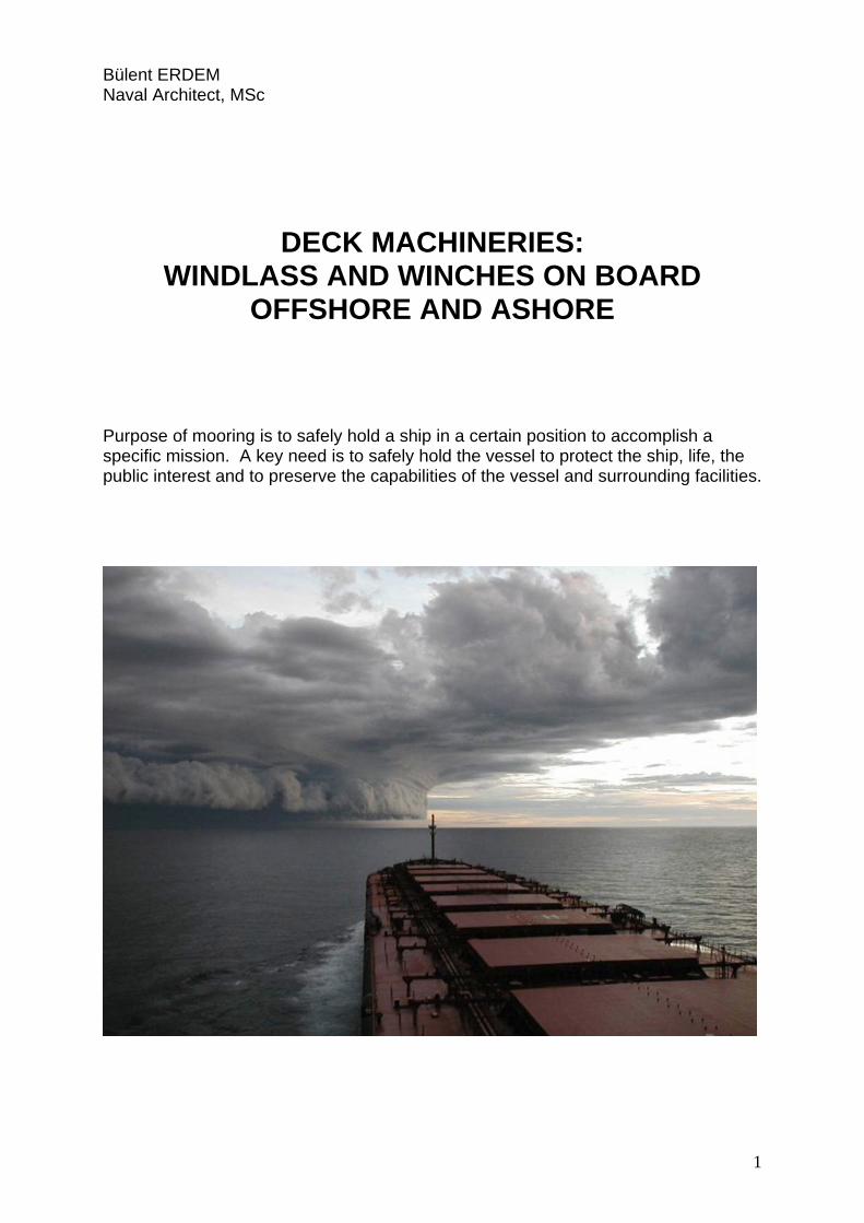
4
Traction winch 400mt – 40m/min, electric driven 3MW with storage reel for 3,500m of 108mm SWR.
Horizontal pipe tensioner with a capacity of 60mt each, a speed of 20m/min and a diameter of 4in – 52in
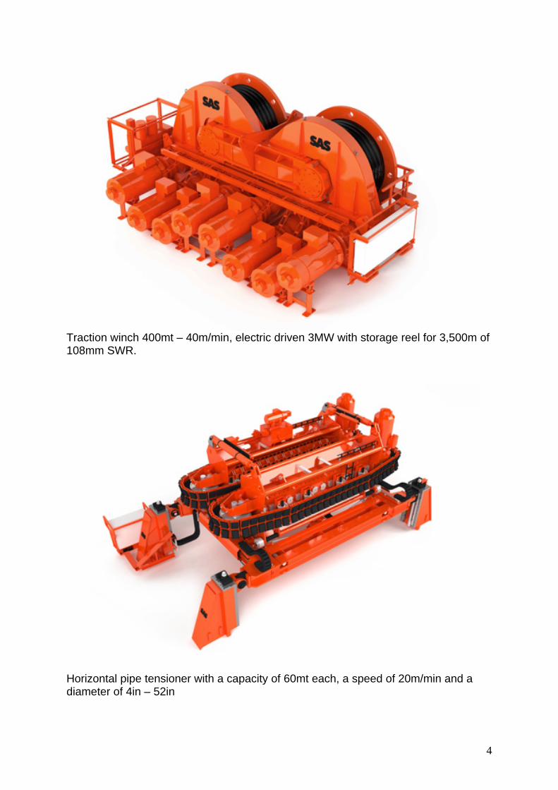
5
10 T Hose Reel
300 T Pull in Winch
6
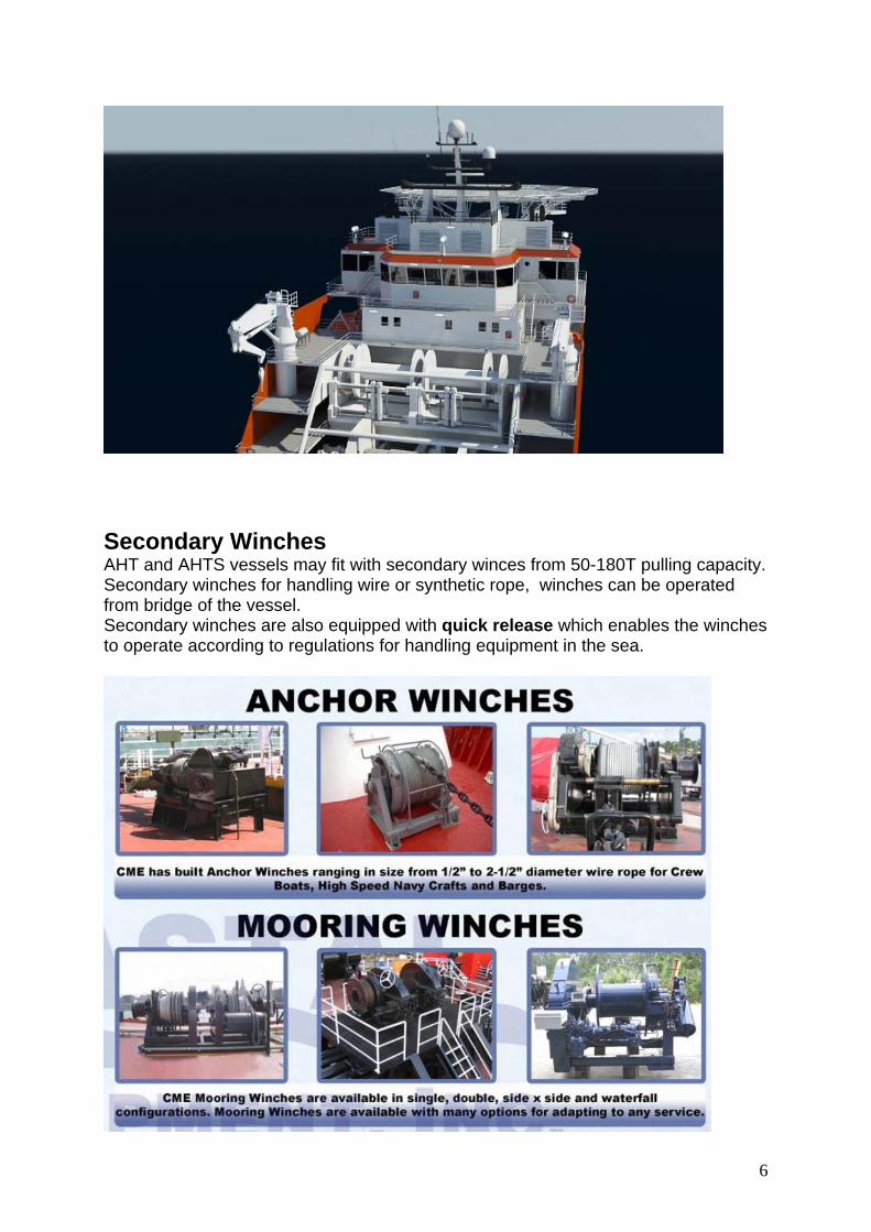
Secondary Winches AHT and AHTS vessels may fit with secondary winces from 50-180T pulling capacity. Secondary winches for handling wire or synthetic rope, winches can be operated from bridge of the vessel. Secondary winches are also equipped with quick release which enables the winches to operate according to regulations for handling equipment in the sea.
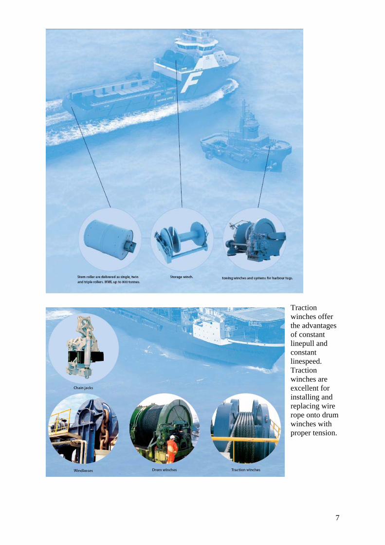
7
Traction winches offer the advantages of constant linepull and constant linespeed. Traction winches are excellent for installing and replacing wire rope onto drum winches with proper tension.
8
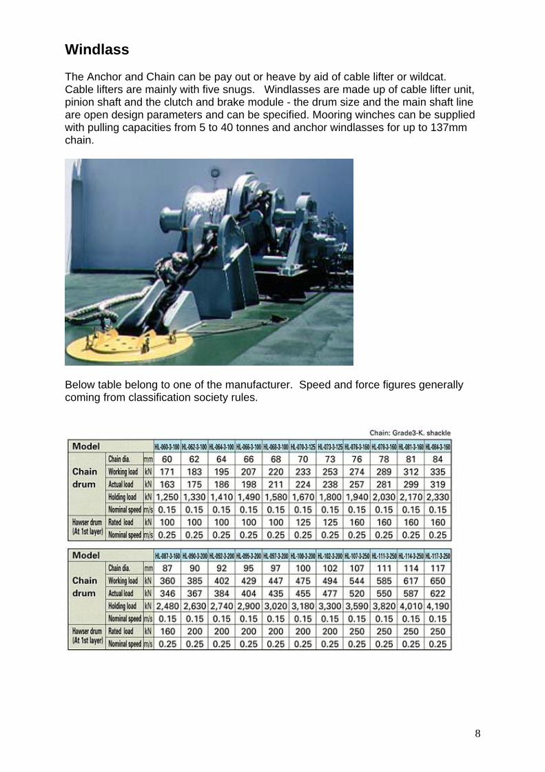
Windlass The Anchor and Chain can be pay out or heave by aid of cable lifter or wildcat. Cable lifters are mainly with five snugs. Windlasses are made up of cable lifter unit, pinion shaft and the clutch and brake module - the drum size and the main shaft line are open design parameters and can be specified. Mooring winches can be supplied with pulling capacities from 5 to 40 tonnes and anchor windlasses for up to 137mm chain.
Below table belong to one of the manufacturer. Speed and force figures generally coming from classification society rules.
9
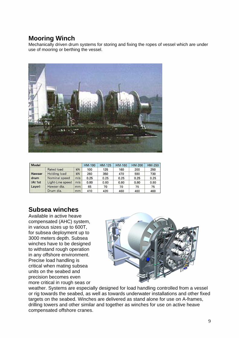
Mooring Winch Mechanically driven drum systems for storing and fixing the ropes of vessel which are under use of mooring or berthing the vessel.
Subsea winches Available in active heave compensated (AHC) system, in various sizes up to 600T, for subsea deployment up to 3000 meters depth. Subsea winches have to be designed to withstand rough operation in any offshore environment. Precise load handling is critical when mating subsea units on the seabed and precision becomes even more critical in rough seas or weather. Systems are especially designed for load handling controlled from a vessel or rig towards the seabed, as well as towards underwater installations and other fixed targets on the seabed. Winches are delivered as stand alone for use on A-frames, drilling towers and other similar and together as winches for use on active heave compensated offshore cranes.
10
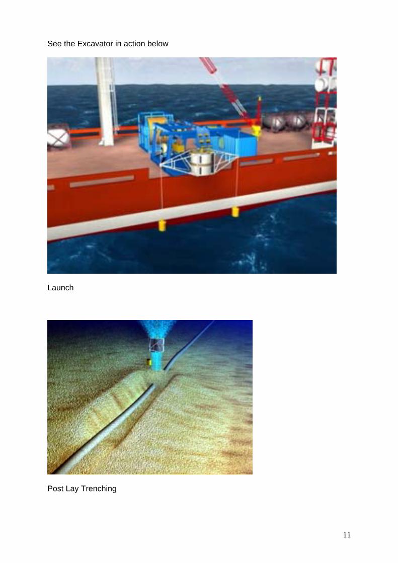
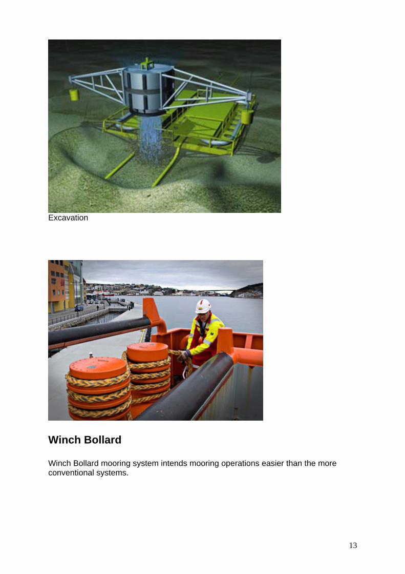
Subsea Excavation
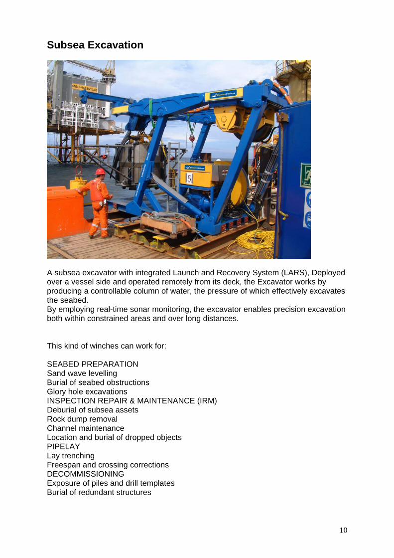
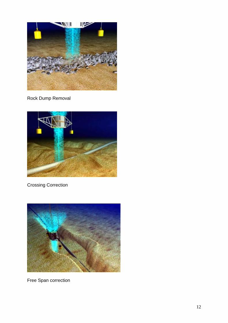
A subsea excavator with integrated Launch and Recovery System (LARS), Deployed over a vessel side and operated remotely from its deck, the Excavator works by producing a controllable column of water, the pressure of which effectively excavates the seabed. By employing real-time sonar monitoring, the excavator enables precision excavation both within constrained areas and over long distances. This kind of winches can work for: SEABED PREPARATION Sand wave levelling Burial of seabed obstructions Glory hole excavations INSPECTION REPAIR & MAINTENANCE (IRM) Deburial of subsea assets Rock dump removal Channel maintenance Location and burial of dropped objects PIPELAY Lay trenching Freespan and crossing corrections DECOMMISSIONING Exposure of piles and drill templates Burial of redundant structures
11
See the Excavator in action below
Launch
Post Lay Trenching
12
Rock Dump Removal
Crossing Correction
Free Span correction
13
Excavation
Winch Bollard Winch Bollard mooring system intends mooring operations easier than the more conventional systems.
14
Winches and winch equipment for offshore and harbour tugs
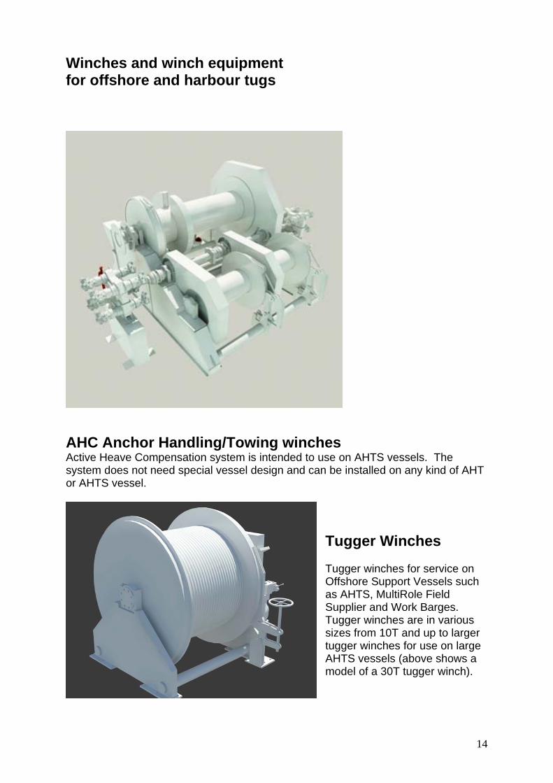
AHC Anchor Handling/Towing winches Active Heave Compensation system is intended to use on AHTS vessels. The system does not need special vessel design and can be installed on any kind of AHT or AHTS vessel.
Tugger Winches Tugger winches for service on Offshore Support Vessels such as AHTS, MultiRole Field Supplier and Work Barges. Tugger winches are in various sizes from 10T and up to larger tugger winches for use on large AHTS vessels (above shows a model of a 30T tugger winch).
15
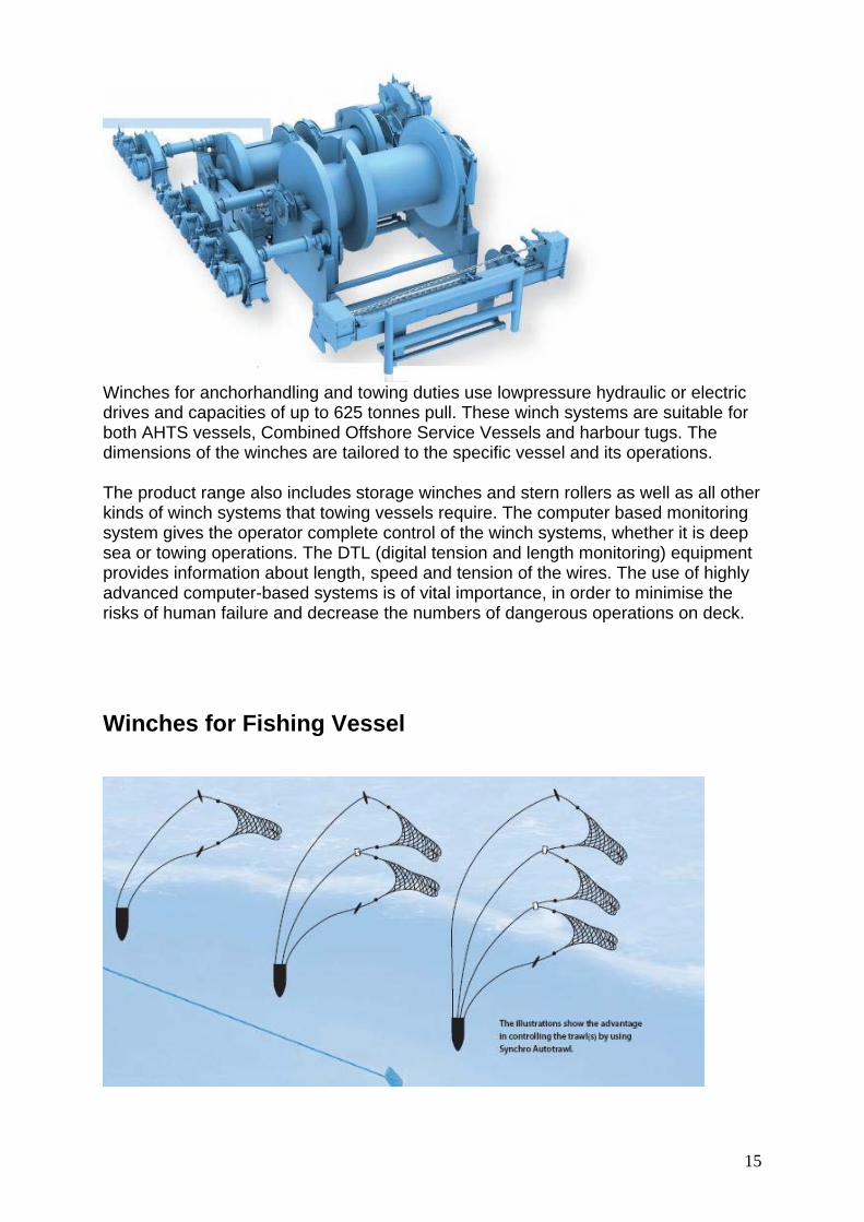
Winches for anchorhandling and towing duties use lowpressure hydraulic or electric drives and capacities of up to 625 tonnes pull. These winch systems are suitable for both AHTS vessels, Combined Offshore Service Vessels and harbour tugs. The dimensions of the winches are tailored to the specific vessel and its operations. The product range also includes storage winches and stern rollers as well as all other kinds of winch systems that towing vessels require. The computer based monitoring system gives the operator complete control of the winch systems, whether it is deep sea or towing operations. The DTL (digital tension and length monitoring) equipment provides information about length, speed and tension of the wires. The use of highly advanced computer-based systems is of vital importance, in order to minimise the risks of human failure and decrease the numbers of dangerous operations on deck. Winches for Fishing Vessel
16
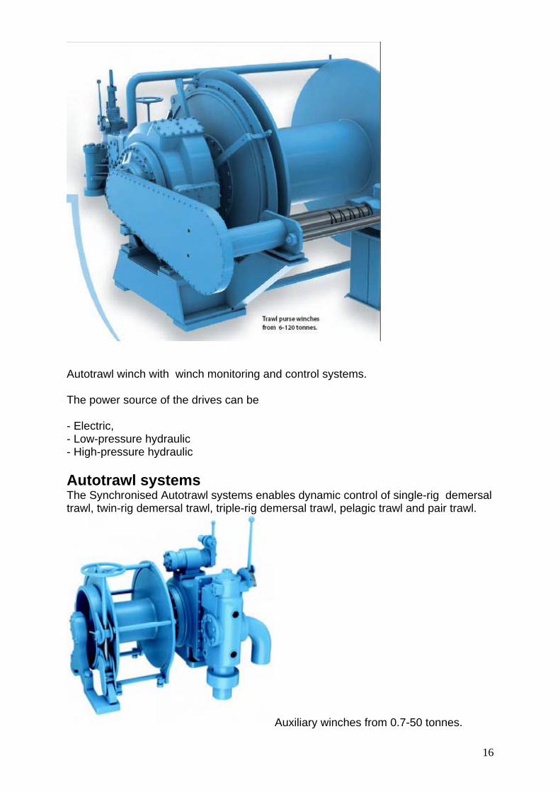
Autotrawl winch with winch monitoring and control systems. The power source of the drives can be - Electric, - Low-pressure hydraulic - High-pressure hydraulic Autotrawl systems The Synchronised Autotrawl systems enables dynamic control of single-rig demersal trawl, twin-rig demersal trawl, triple-rig demersal trawl, pelagic trawl and pair trawl.
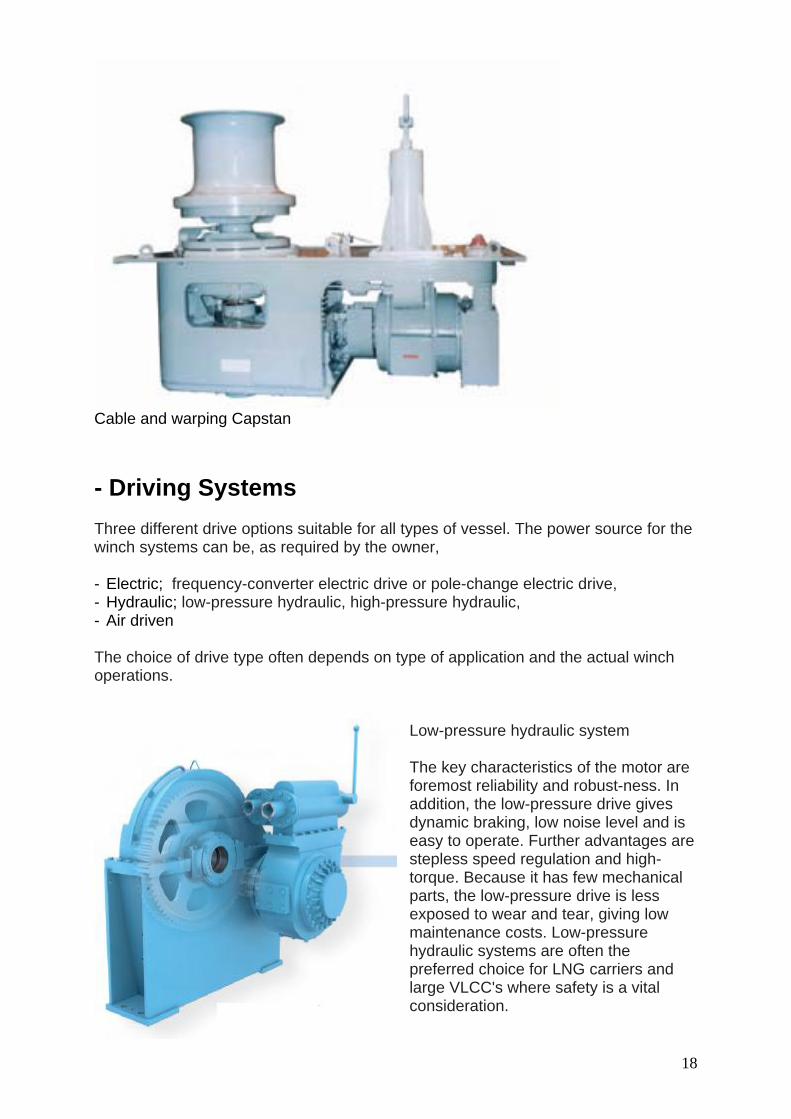
Cable and warping Capstan - Driving Systems Three different drive options suitable for all types of vessel. The power source for the winch systems can be, as required by the owner, - Electric; frequency-converter electric drive or pole-change electric drive, - Hydraulic; low-pressure hydraulic, high-pressure hydraulic, - Air driven The choice of drive type often depends on type of application and the actual winch operations.
Low-pressure hydraulic system The key characteristics of the motor are foremost reliability and robust-ness. In addition, the low-pressure drive gives dynamic braking, low noise level and is easy to operate. Further advantages are stepless speed regulation and high-torque. Because it has few mechanical parts, the low-pressure drive is less exposed to wear and tear, giving low maintenance costs. Low-pressure hydraulic systems are often the preferred choice for LNG carriers and large VLCC's where safety is a vital consideration.
19
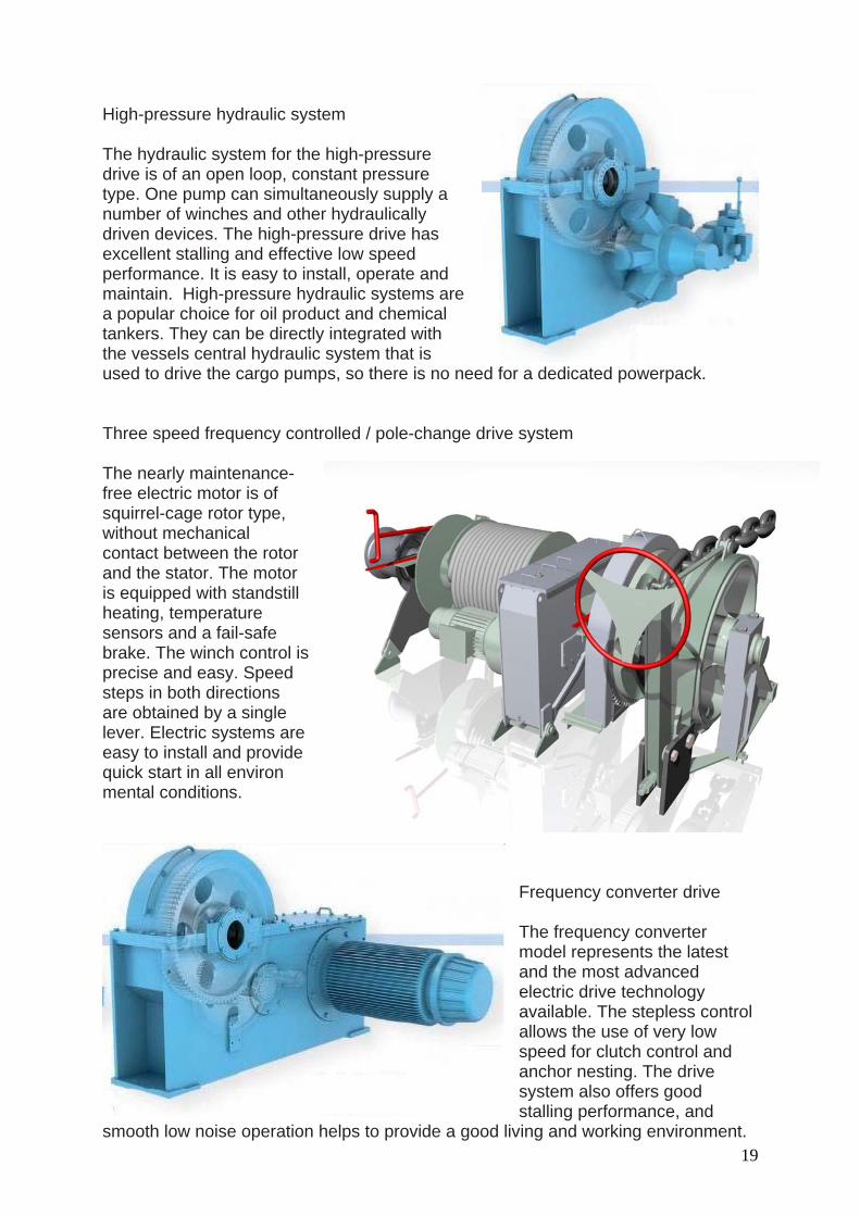
High-pressure hydraulic system The hydraulic system for the high-pressure drive is of an open loop, constant pressure type. One pump can simultaneously supply a number of winches and other hydraulically driven devices. The high-pressure drive has excellent stalling and effective low speed performance. It is easy to install, operate and maintain. High-pressure hydraulic systems are a popular choice for oil product and chemical tankers. They can be directly integrated with the vessels central hydraulic system that is used to drive the cargo pumps, so there is no need for a dedicated powerpack. Three speed frequency controlled / pole-change drive system The nearly maintenance-free electric motor is of squirrel-cage rotor type, without mechanical contact between the rotor and the stator. The motor is equipped with standstill heating, temperature sensors and a fail-safe brake. The winch control is precise and easy. Speed steps in both directions are obtained by a single lever. Electric systems are easy to install and provide quick start in all environ mental conditions.
Frequency converter drive The frequency converter model represents the latest and the most advanced electric drive technology available. The stepless control allows the use of very low speed for clutch control and anchor nesting. The drive system also offers good stalling performance, and
smooth low noise operation helps to provide a good living and working environment.
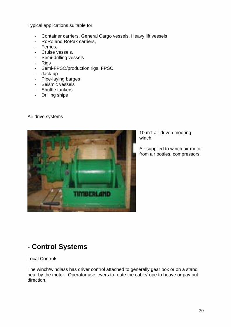
10 mT air driven mooring winch. Air supplied to winch air motor from air bottles, compressors.
- Control Systems Local Controls The winch/windlass has driver control attached to generally gear box or on a stand near by the motor. Operator use levers to route the cable/rope to heave or pay out direction.
21
Remote Controls All Anchor- and Mooring Winches can have hydraulic or electric Remote controls. Remote control stands can be single type or double type. Double type generally in purpose of controlling port side and starboard side winches/windlasses from from one side of the vessel.
Hydraulic Remote Control Stand
22
- Winch Equipment and Auxilliaries
Roller Chain Stopper Chain stoppers can be for deck mounting or hull mounting both above and below the water line. Chain stoppers are rated to withstand the 80% of breaking strength of the chain cable. Operation of chain stopper can be hydraulic or fully manual. Chain stoppers generally have facilities for anchor lashing with steel wires and turnbuckles.
Chain jacks are used to pull in heavy loads with chain and have many offshore applications including FPSO / FPU mooring, SPAR mooring, TLP mooring and riser pull-in operations.
23
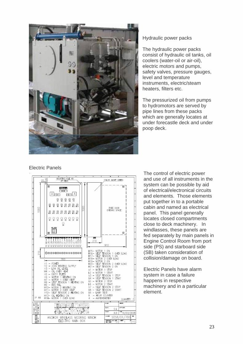
Hydraulic power packs The hydraulic power packs consist of hydraulic oil tanks, oil coolers (water-oil or air-oil), electric motors and pumps, safety valves, pressure gauges, level and temperature instruments, electric/steam heaters, filters etc. The pressurized oil from pumps to hydromotors are served by pipe lines from these packs which are generally locates at under forecastle deck and under poop deck.
Electric Panels
The control of electric power and use of all instruments in the system can be possible by aid of electrical/electronical circuits and elements. Those elements put together in to a portable cabin and named as electrical panel. This panel generally locates closed compartments close to deck machinery. In windlasses, these panels are fed separately by main panels in Engine Control Room from port side (PS) and starboard side (SB) taken consideration of collision/damage on board. Electric Panels have alarm system in case a failure happens in respective machinery and in a particular element.
24
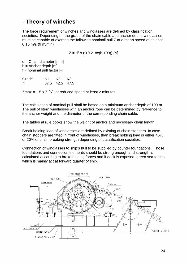
- Theory of winches The force requirement of winches and windlasses are defined by classification societies. Depending on the grade of the chain cable and anchor depth, windlasses must be capable of exerting the following nominall pull Z at a mean speed of at least 0.15 m/s (9 m/min)
Z = d2 x (f+0.218x(h-100)) [N] d = Chain diameter [mm] h = Anchor depth [m] f = nominal pull factor [-] Grade K1 K2 K3 f 37.5 42.5 47.5 Zmax = 1.5 x Z [N] at reduced speed at least 2 minutes. The calculation of nominal pull shall be based on a minimum anchor depth of 100 m. The pull of stern windlasses with an anchor rope can be determined by reference to the anchor weight and the diameter of the corresponding chain cable. The tables at rule books show the weight of anchor and necessary chain length. Break holding load of windlasses are defined by existing of chain stoppers. In case chain stoppers are fitted in front of windlasses, than break holding load is either 45% or 20% of chain breaking strength depending of classification societies. Connection of windlasses to ship’s hull to be supplied by counter foundations. Those foundations and connection elements should be strong enough and strength is calculated according to brake holding forces and if deck is exposed, green sea forces which is mainly act at forward quarter of ship.
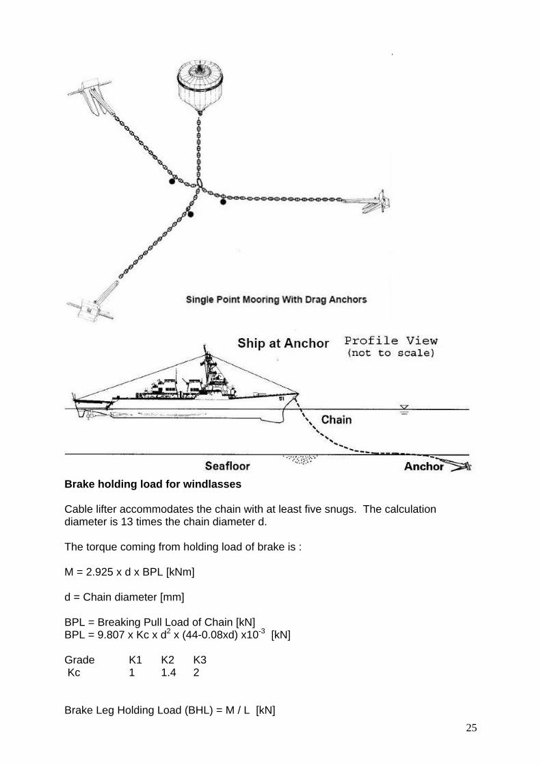
25
Brake holding load for windlasses Cable lifter accommodates the chain with at least five snugs. The calculation diameter is 13 times the chain diameter d. The torque coming from holding load of brake is : M = 2.925 x d x BPL [kNm] d = Chain diameter [mm] BPL = Breaking Pull Load of Chain [kN] BPL = 9.807 x Kc x d2 x (44-0.08xd) x10-3 [kN] Grade K1 K2 K3 Kc 1 1.4 2 Brake Leg Holding Load (BHL) = M / L [kN]
26
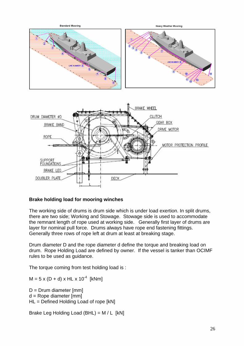
Brake holding load for mooring winches The working side of drums is drum side which is under load exertion. In split drums, there are two side; Working and Stowage. Stowage side is used to accommodate the remnant length of rope used at working side. Generally first layer of drums are layer for nominal pull force. Drums always have rope end fastening fittings. Generally three rows of rope left at drum at least at breaking stage. Drum diameter D and the rope diameter d define the torque and breaking load on drum. Rope Holding Load are defined by owner. If the vessel is tanker than OCIMF rules to be used as guidance. The torque coming from test holding load is : M = 5 x (D + d) x HL x 10-4 [kNm] D = Drum diameter [mm] d = Rope diameter [mm] HL = Defined Holding Load of rope [kN] Brake Leg Holding Load (BHL) = M / L [kN]
27
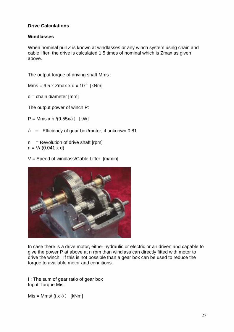
Drive Calculations Windlasses When nominal pull Z is known at windlasses or any winch system using chain and cable lifter, the drive is calculated 1.5 times of nominal which is Zmax as given above. The output torque of driving shaft Mms : Mms = 6.5 x Zmax x d x 10-6 [kNm] d = chain diameter [mm] The output power of winch P: P = Mms x n /(9.55xd) [kW] d = Efficiency of gear box/motor, if unknown 0.81 n = Revolution of drive shaft [rpm] n = V/ (0.041 x d) V = Speed of windlass/Cable Lifter [m/min]
In case there is a drive motor, either hydraulic or electric or air driven and capable to give the power P at above at n rpm than windlass can directly fitted with motor to drive the winch. If this is not possible than a gear box can be used to reduce the torque to available motor and conditions. I : The sum of gear ratio of gear box Input Torque Mis : Mis = Mms/ (i x d) [kNm]
28
Input motor shaft revolution ni : ni = i x n [rpm] Input motor power Pi : Pi = Mis x ni / (9.55 x d) [kW]
n1 = Revolution of first stage pinion [rpm] z1 = Number of teeth of first stage pinion n2 = Revolution of second stage wheel [rpm] z2 = Number of teeth of second stage wheel … … n1xz1 = n2xz2 i= z2/z1=n1/n2=na/ne na = Starting revolution [rpm] ne = Ending revoltion [rpm] i=i1 x i2 x i3 … i also called as reduction ratio of gear box.
m = modul p = pitch z = number of teeth d = pitch circle m = p/ p = d/z ha + hb = 2 x m + c, ha=m ha = Addendum height, hb = dedendum height, c = clearence
29
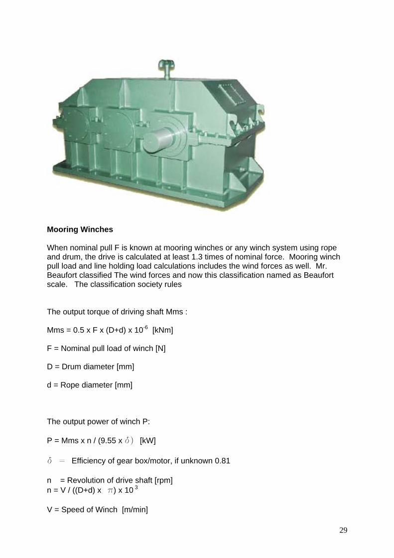
Mooring Winches When nominal pull F is known at mooring winches or any winch system using rope and drum, the drive is calculated at least 1.3 times of nominal force. Mooring winch pull load and line holding load calculations includes the wind forces as well. Mr. Beaufort classified The wind forces and now this classification named as Beaufort scale. The classification society rules The output torque of driving shaft Mms : Mms = 0.5 x F x (D+d) x 10-6 [kNm] F = Nominal pull load of winch [N] D = Drum diameter [mm] d = Rope diameter [mm] The output power of winch P: P = Mms x n / (9.55 x d) [kW] d = Efficiency of gear box/motor, if unknown 0.81 n = Revolution of drive shaft [rpm] n = V / ((D+d) x p) x 10 3 V = Speed of Winch [m/min]
30
In case there is a drive motor, either hydraulic or electric or air driven and capable to give the power P at above at n rpm than winch can directly fitted with motor to drive the winch. If this is not possible than a gear box can be used to reduce the torque to available motor and conditions. i : The sum of gear ratio of gear box Input Torque Mis : Mis = Mms/ (i x d) [kNm] Input motor shaft revolution ni : ni = i x n [rpm] Input motor power Pi : Pi = Mis x ni / (9.55 x d) [kW] Slipping Cluthes Slipping cluthes are installed to motor shaft or one of other stage of gear box shaft in order to protect gear box from over load conditions. Most common slipping clutches are in design of friction disc lamels under pressure of springs. The level of torque transmission is adjustable by these springs. Load Sensors Load sensors at revolutionary shafts are used to have a feed back information of applied load and result a command through electronic boards to motor to give auto tensioning facility to winch. Load sensors are generally made of strain gauges.