ANL/D&DATM-96/2 Decontamination of Hot Cells K-1, K-3, M~1,M-3,andA-1,M-Wing, Building 200: Project Final Report Argonne National Laboratory - East by C.L. Cheever and R.W. Rose Decontamination and Decommissioning Program, Technology Development Division, Argonne National Laboratory, 9700 South Cass Avenue, Argonne, Illinois 60439 September 1996 Work sponsored by United States Department of Energy, Office of Environmental Management DISTRIBUTION OF THSS DOCUMENT IS UNLIMITED
Transcript
ANL/D&DATM-96/2
Decontamination of Hot Cells K-1, K-3,M~1,M-3,andA-1,M-Wing,Building 200: Project Final ReportArgonne National Laboratory - East
by C.L. Cheever and R.W. Rose
Decontamination and Decommissioning Program, Technology Development Division,Argonne National Laboratory, 9700 South Cass Avenue, Argonne, Illinois 60439
September 1996
Work sponsored by United States Department of Energy,Office of Environmental Management
DISTRIBUTION OF THSS DOCUMENT IS UNLIMITED
DISCLAIMER
Portions of this document may be illegiblein electronic image products. Images areproduced from the best available originaldocument
9 LESSONS LEARNED AND DOE REPORTABLE OCCURRENCES 55
9.1 Lessons Learned 55
9.2 DOE Reportable Occurrences 57
10 CONCLUSIONS AND RECOMMENDATIONS 60
11 REFERENCES 61
m
TABLES
4.1 Protective Clothing and Equipment for Hot Cell Entries 32
5.1 Project Schedule: Baseline/Actual 49
6.1 Radioactive Waste 51
7.1 Project Collective Radiation Dose 52
FIGURES
1.1 Map Showing ANL-E in the Greater Chicago Metropolitan Area 4
1.2 ANL-E Site Plan View Showing Building 200 5
2.1 Photograph of M-Wing, Building 200 7
2.2 Plan View of Building 200 Service Floor Showing Location of theMegacurie Hot Cells 8
2.3 Plan View of Building 200 Main Floor Showing Location of the
Kilocurie Hot Cells 9
3.1 Building 200 Monthly Hot Cells Rn-220 Emissions 11
3.2 Predominant Radioactive Decay Pathway for Nuclear Reactor Irradiated
Th-232 Containing 2.5% U-233 Leading to the Production of Rn-220 13
3.3 Rn-220 Decay to Stable Pb-208 14
4.1 Project Organization Chart 16
4.2 Hot Cell M-l with Labeled Containers of High-Gamma Radioactive Waste 20
4.3 Hot Cell M-l with Radioactivity Contaminated Equipment Remotely
Removed from Mountings 21
4.4 Remote Measurement of Radiation Levels in Hot Cell M-l 21
4.5 In-Cell Camera and External Video Monitor Viewing RemoteDecontamination in Hot Cell M-l 22
FIGURES (Cont.)
4.6 Remote Loading of Radioactive Waste into a 5-Gallon Can, Hot Cell M-l 22
4.7 Remote Use of a Portable Shear Tool 24
4.8 Remote Abrasive Wheel Circular Saw Cutting the Shear Bed in Hot Cell M-3 24
4.9 Remote Sawing of a Liquid Transfer Tank in Hot Cell K-l 25
4.10 Remote Removal of a Concrete Mixing Station, Hot Cell K-l 26
4.11 Remote Vacuuming of Radioactively Contaminated Surfaces in Hot Cell M-l 27
4.12 Remote Removal of Strippable Decontamination Paint, Hot Cell K-3 28
4.13 Technician Directing the Remote Loading of a Dissolver System Waste Tank
into a Bin Liner 29
4.14 Manipulator Removed, Decontaminated, and Bagged for Repair 29
4.15 Technician Repairing a Manipulator 30
4.16 Repair of a Radio Operated Rail-Car Turntable in the Hot Cells Interior Corridor 31
4.17 Donning Protective Clothing for a Hot Cell Entry 32
4.18 Technician Suiting-up for a Hot Cell Entry 33
4.19 Technician Monitoring the Compressed Breathing Air Supply Station
During a Hot Cell Entry 34
4.20 Technicians Making a Full-Suited Hot Cell Entry Through an Isolation Tent 34
4.21 Taping Sharp Edges of Size-Reduced Equipment 35
4.22 Technician Removing Strippable Decontamination Paint, Hot Cell K-3 36
4.23 Technician Using Hand Held Vacuum Equipped Scabbier to Remove FixedRadioactive Contamination from the Concrete Floor of Hot Cell M-l 37
4.24 Health Physics Technician Performing a Hot Cell Exit Survey of a WorkerAfter Removal of Outer Protective Clothing 38
FIGURES (Cont.)
4.25 Health Physics Technician Using an Extended Reach Radiation Detector
for Monitoring a Shielding Pot 39
4.26 Final Hand-and-Shoe Monitor Survey 40
4.27 View of Hot Cell M-l After the Final Radiological Survey 41
4.28 View of Megacurie Hot Cells Central Corridor After the Final Radiological Survey . . . 41
4.29 North Wall of Hot Cell M-l Exterior Area After Scabbling, Concrete Patching,
and Painting 42
4.30 Dosimetry Readout Equipment 43
4.31 On-Line Computer Readout Instrumentation for Monitoring Hot Cells
Stack Emissions 44
4.32 Radionuclide Distribution 45
4.33 Removal of Packaged Radioactive Waste from M-Wing 45
4.34 Loading of Remote-Handled Radioactive Waste Drums into a
Shielding Cask for Truck Transport 46
5.1 Activity Breakdown of Project Costs 47
5.2 Cumulative Earned Value 48
6.1 Comparison of Radioactive Waste Generated to the Amount Forecast 50
7.1 Cumulative Collective Radiation Dose 53
VI
ACKNOWLEDGMENTS
The physical work for the entire project was performed by Argonne National Laboratory-East personnel. The Technology Development Division provided the project management. Thisfunction was originally under Environmental Management Operations with Chemical Technologyproviding the technical support manager. The remote work and initial hot cell entries were performedby Chemical Technology and Reactor Engineering personnel. The final decontamination of Hot-Cells A-l, K-l, and K-3 were performed by Chemical Technology and Reactor Engineeringpersonnel. The final decontamination of Hot-Cells M-3 and M-1 were performed by EnvironmentalManagement Operations personnel. The health physics surveillance and the verification surveys wereperformed by Environment, Safety, and Health Health Physics personnel. The Action DescriptionMemorandum was written by the Environmental Assessment Division. NES, Inc. providedcontractor documentation support services for the Safety Analysis Report and the Cost EstimateReport. Individual contributors are listed below.
Technology Development Staff
C. L. Cheever and R. W. Rose - Project Manager(s)W. E. Stacy - Project Engineer
Chemical Technology Staff
J. Hoh - Technical Support ManagerJ. Emery - Alternate TSML. Hafenrichter - manipulator repairM. Surchik
Reactor Engineering Staff
R. Gebner - Assistant TechnicalSupport Manager
Health Physics Staff
C. Sholeen - Health PhysicistD. Geraghty - Chief TechnicianF. Marchetti - Stack MonitorsT. BranchN. ContosJ. ErickM. Hayes
R. BensonT. DiSantoM. GossH. Wegerich
J. DunlapA.Kras
A. KeeblerM. O'ConnorD. ReillyM. SreniawskiV. SteedC. SullivanR. Walker
vu
Environmental Management Operations Staff
T. Lahey - Foreman G. HarrisW. Ray - Foreman D. KuzmaE. Armand R. RedmanK. Borman J. SmeetsM. Davis C. WoodJ. Gleason
Environmental Assessment Division Staff
H. Avci
NES, Inc. Staff
vm
NOTATION
ACRONYMS, INITIALISMS, AND ABBREVIATIONS
AAACWPADMALARAALIAnti-CANL-E
BCWPBCWSBq
CDRcfCHCHMCicmCMTCTZCYCX
D&DdeconDOEDOTdpm
EAEEEPAEMOESHEWM
FY
Argonne AreaActual Cost Work PerformedAction Description MemorandumAs Low As Reasonably AchievableAnnual Limit on IntakeAnti-contaminationArgonne National Laboratory-East
Budgeted Cost Work PerformedBudgeted Cost Work ScheduledBecquerel
Conceptual Design ReportCubic feetChicagoChemistryCuriecentimeterChemical TechnologyCentral Time ZoneCalendar YearCategorical Exclusion
Decontamination and DecommissioningDecontaminationDepartment of EnergyDepartment of TransportationDisintegrations per minute
DECONTAMINATION OF HOT CELLS K-l, K-3, M-l, M-3, AND A-lM-WING, BUILDING 200: PROJECT FINAL REPORT
ARGONNE NATIONAL LABORATORY - EAST
by
C.L. Cheever and R.W. RoseArgonne National Laboratory
Technology Development Division
EXECUTIVE SUMMARY
This is the final report for the Argonne National Laboratory-East (ANL-E) Building 200M-Wing Hot Cells Decontamination Project. The purpose of the project was to practically eliminatethe radioactive emissions of Rn-220 to the environment and to restore the hot cells to an emptyrestricted use-condition. About 96.2 TBq (2,600 curies) per year of Rn-220 was being emitted at thestart of the project from the radioactive contaminants left in the hot cells at the end of the ANL-EProof-of-Breeding program work in 1985.
Four of the five project Hot Cells (M-l, M-3, K-l, and K-3) had been used for Proof-of-Breeding research on irradiated thorium rods from the U. S. Navy's Shippingport Atomic PowerStation thorium core breeder reactor research. The research involved precise shearing of the rods inHot Cell M-3, dissolving of the samples in concentrated acids in Hot Cell M-l, preparing dissolversolution samples for radioassay in Hot Cell K-3, and pumping the waste dissolver solution to wastecementing stations in Hot-Cell K-l. Extensive equipment and structures in the hot cells needed tobe removed as radioactive waste.
Hot Cell A-l had been used for pulverizing irradiated reactor fuel specimens from the ZionNuclear Power Station in Illinois for analyses to quantify breeding of fissile isotopes.
All five of the hot cells required remote disassembly and decontamination work prior toprotected entry decontamination. Two pairs of heavy duty manipulators were procured to facilitatethe remote disassembly and decontamination work. An existing radio-controlled rail cart system wasused for moving remote-handled (>200 mrem/hr) radioactive waste.
The project was carried out by ANL-E personnel during the period June 1992 to April 1996(46 months) at a cost of $5.8 million. The total radiation dose to project personnel was about74.5 person-mSv (7.45 person-rem). This was 80.1% of the total dose forecasted in the project
Action Description Memorandum. All radiation exposures were maintained below regulatoryguidelines in all aspects.
The five hot cells were emptied and decontaminated for restricted use. The goal ofpractically eliminating radioactive emissions from the five hot cells was achieved by the projectteam. A total of 23.4 metric tons (25.8 tons) of radioactive waste was generated. Approximately7.7 metric tons (8:5 tons) of radioactively contaminated lead shielding bricks were taken to ANL-EWaste Management for decontamination and recycling. Ten 208-1 (55-gal) drums of remote-handledwaste were shipped to the Department of Energy disposal site by shielded cask truck transport. Thecontact-handled radioactive waste was shipped in steel bins by truck transport to the Departmentof Energy disposal site. The radioactivity in the waste totaled 110 curies, primarily of mixed fissionproducts.
1 INTRODUCTION
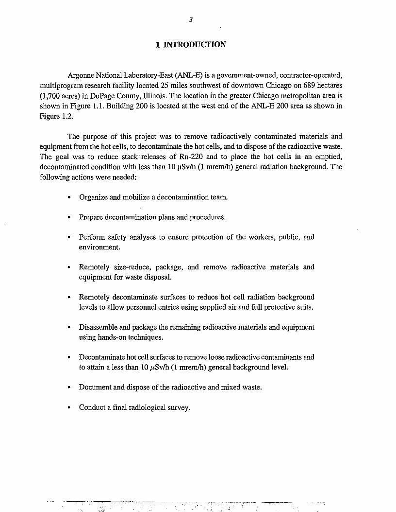
Argonne National Laboratory-East (ANL-E) is a government-owned, contractor-operated,multiprogram research facility located 25 miles southwest of downtown Chicago on 689 hectares(1,700 acres) in DuPage County, Illinois. The location in the greater Chicago metropolitan area isshown in Figure 1.1. Building 200 is located at the west end of the ANL-E 200 area as shown inFigure 1.2.
The purpose of this project was to remove radioactively contaminated materials andequipment from the hot cells, to decontaminate the hot cells, and to dispose of the radioactive waste.The goal was to reduce stack releases of Rn-220 and to place the hot cells in an emptied,decontaminated condition with less than 10 uSv/h (1 mrem/h) general radiation background. Thefollowing actions were needed:
• Organize and mobilize a decontamination team.
• Prepare decontamination plans and procedures.
• Perform safety analyses to ensure protection of the workers, public, andenvironment.
• Remotely size-reduce, package, and remove radioactive materials andequipment for waste disposal.
• Remotely decontaminate surfaces to reduce hot cell radiation backgroundlevels to allow personnel entries using supplied air and full protective suits.
• Disassemble and package the remaining radioactive materials and equipmentusing hands-on techniques.
• Decontaminate hot cell surfaces to remove loose radioactive contaminants andto attain a less than 10 //Sv/h (1 mrem/h) general background level.
• Document and dispose of the radioactive and mixed waste.
• Conduct a final radiological survey.
4
NORTHWESTERNUNIVERSITY
LOYOLAUNIVERSITY
N
ILLINOISINSTITUTE OFTECHNOLOGY
ARGONNENATIONAL LABORATORY
FIGURE 1.1 Map Showing ANL-E in the Greater Chicago Metropolitan Area
Argonne National Laboratory' Argonne Illinois
Bldg. 200
FIGURE 1.2 ANL-E Site Plan View Showing Building 200
Additional project objectives were to:
• Minimize radiation exposure, radioactivity intake, and potential injury to personnel.
• Minimize the volume of radioactive waste, particularly remote-handled and mixedwaste.
• Minimize project costs within an As-Low-As-Reasonably-Achievable (ALARA)radiation exposure framework.
• Determine the most effective means for decontamination and other project activities.
The project was proposed by ANL-E to the Department of Energy Headquarters (DOE-HQ)in 1990 and again in 1991. It was funded by the DOE for startup in fiscal year (FY) 1992. Planningbegan in October 1991 and physical work in the hot cells began June 10,1992. The project team wascomprised of ANL-E technical operations and Environmental, Safety, and Health (ESH) HealthPhysics personnel who had hot cell operations and monitoring experience. The project technicalsupport manager and the alternate technical support manager had work experience from the Proof-of-Breeding research project. The initial project work force was composed of 10 ANL-E personnel.
2 FACILITY BACKGROUND
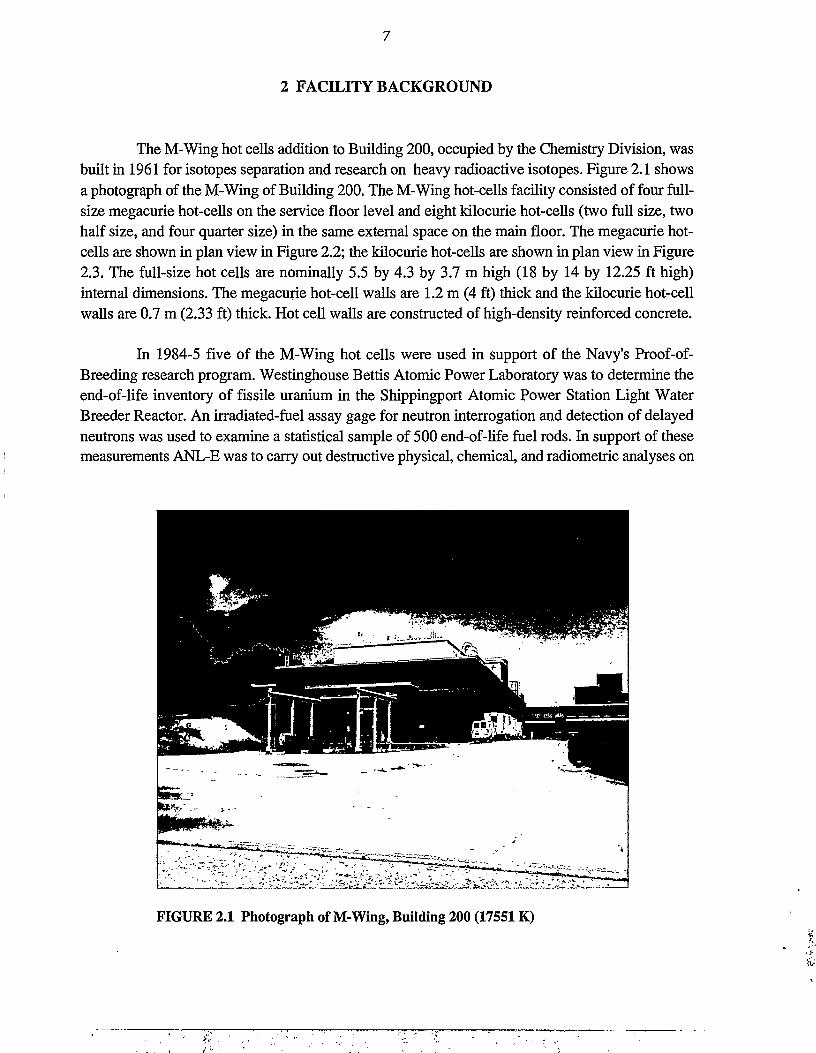
The M-Wing hot cells addition to Building 200, occupied by the Chemistry Division, wasbuilt in 1961 for isotopes separation and research on heavy radioactive isotopes. Figure 2.1 showsa photograph of the M-Wing of Building 200. The M-Wing hot-cells facility consisted of four full-size megacurie hot-cells on the service floor level and eight kilocurie hot-cells (two full size, twohalf size, and four quarter size) in the same external space on the main floor. The megacurie hot-cells are shown in plan view in Figure 2.2; the kilocurie hot-cells are shown in plan view in Figure2.3. The full-size hot cells are nominally 5.5 by 4.3 by 3.7 m high (18 by 14 by 12.25 ft high)internal dimensions. The megacurie hot-cell walls are 1.2 m (4 ft) thick and the kilocurie hot-cellwalls are 0.7 m (2.33 ft) thick. Hot cell walls are constructed of high-density reinforced concrete.
In 1984-5 five of the M-Wing hot cells were used in support of the Navy's Proof-of-Breeding research program. Westinghouse Bettis Atomic Power Laboratory was to determine theend-of-life inventory of fissile uranium in the Shippingport Atomic Power Station Light WaterBreeder Reactor. An irradiated-fuel assay gage for neutron interrogation and detection of delayedneutrons was used to examine a statistical sample of 500 end-of-life fuel rods. In support of thesemeasurements ANL-E was to carry out destructive physical, chemical, and radiometric analyses on
FIGURE 2.1 Photograph of M-Wing, Building 200 (17551K)
NARROW GAGE TRACK FORTRANSFER BETWEEN CELLS
I • • • •
SHIELDING'WINDOWS
SHIELDINGDOORS
RECLAMATIONSERVICES
AREA2 TON
BRIDGE CRANE IN POTUNLOADING AREA
WASTEPROCESS
CELL 2 TONBRIDGE CRANE1NCQRR1DOR
/ /STD.GAGETRACK
FOR POT CARRIAGE
TRANSFERSLIDE
VENTILATIONBARRIER
TRANSFERAREA
1 TON BRIDGE CRANE INEACH MEGACURIE CELL
oo
30'-0"I
TURNTABLE
FIGURE 2.2 Plan View of Building 200 Service Floor Showing Location of the Megacurie Hot Cells
SPECTROGRAPH
5 TON MONORAIL•CRANE
VENTILATIONBARRIER
BRIOGE CRANE IN EACH KILOCURIE CELL
FIGURE 2.3 Plan View of Building 200 Main Floor Showing Location of the Kilocurie Hot Cells
10
7 end-of-life fuel rods that had been previously assayed. Hot Cell M-3 was set up for shearing theirradiated fuel rods into precise samples. Hot Cell M-l was used for dissolving the fuel rod samplesin concentrated nitric acid catalyzed with hydrofluoric acid. Hot Cell K-3 was used for preparingdissolver solution samples for analyses. The spent dissolver solutions were pumped up to Hot CellK-l (above Hot Cell M-l) for conversion to a cement waste form.
The Proof-of-Breeding research was conducted on irradiated Th-232 rods used to breedfissile U-233. Sheared samples of these rods were dissolved in acid. There had been dissolver acidsolution leaks in Hot Cells M-l and K-l.
Hot Cell A-l (quarter size) had been used for examination of spent reactor fuel from theZion Nuclear Power Station Pressurized Water Reactors. This hot cell contained pulverizedirradiated reactor fuel samples. Remote shielded handling for transfer of irradiated reactor fuelspecimens and remote decontamination were necessary prior to protected entry into the hot cell.
All five project hot cells were in shutdown status; however, two of the nonproject hot cellswere in use. This required coordination with operating and support personnel but it did not prove tobe an obstacle for conduct of the decontamination work.
11
3 DECOMMISSIONING OBJECTIVE AND WORK SCOPE
The majority of all Rn-220 emitted to the environment from DOE sites in 1993 was fromANL-E. (See Reference 10.) The project hot cells were the major source of the ANL-E emissions.
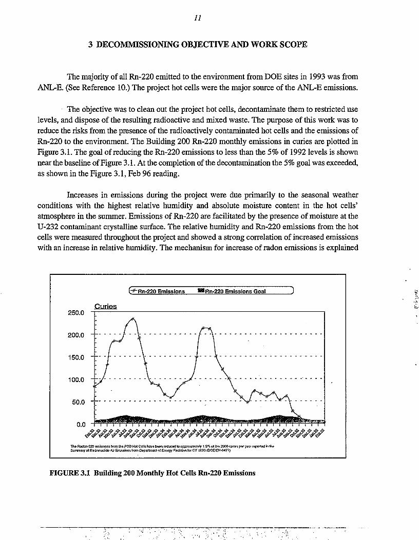
The objective was to clean out the project hot cells, decontaminate them to restricted uselevels, and dispose of the resulting radioactive and mixed waste. The purpose of this work was toreduce the risks from the presence of the radioactively contaminated hot cells and the emissions ofRn-220 to the environment. The Building 200 Rn-220 monthly emissions in curies are plotted inFigure 3.1. The goal of reducing the Rn-220 emissions to less than the 5% of 1992 levels is shownnear the baseline of Figure 3.1. At the completion of the decontamination the 5% goal was exceeded,as shown in the Figure 3.1, Feb 96 reading.
Increases in emissions during the project were due primarily to the seasonal weatherconditions with the highest relative humidity and absolute moisture content in the hot cells'atmosphere in the summer. Emissions of Rn-220 are facilitated by the presence of moisture at theU-232 contaminant crystalline surface. The relative humidity and Rn-220 emissions from the hotcells were measured throughout the project and showed a strong correlation of increased emissionswith an increase in relative humidity. The mechanism for increase of radon emissions is explained
G " Rn-220 Emissions — Rn-220 Emissions Goal
250.0Curies
200.0 " -
Tfca Radcn-220 emissions from the POB Hot Cells have b«n reduced to approximately 1.5% ol the 2000 cuim per yeai reported in th<}Summary of Radjonudide Air Emission* from Department of Energy Facilities lor CY I £33 (DOE/EH-C477}
FIGURE 3.1 Building 200 Monthly Hot Cells Rn-220 Emissions
12
by A. B. Tanner in the "3rd DOE Natural Radiation Environment Symposium Proceedings," 1980(Reference 9). He explains that "water is the most important agent in enabling radon isotopes toescape from solid material. Hydrating of mineral surfaces increases emanating power, and itdecreases adsorption of radon on mineral surfaces."
The acid solution leaks in Hot Cells M-l and K-l lead to the formation of radioactive saltswhich have a hygroscopic nature. The hydration of the surfaces of these radioactive contaminantsis reported to increase Rn-220 emissions.
The radioactive decay scheme for the formation of Rn-220 is depicted in Figure 3.2. Thehalf-life of Rn-220 is only 56 seconds but that was sufficient for the transport of 2,600 curies of thegas through the exhaust ventilation high efficiency paniculate air (HEPA) filters and to theenvironment in 1992. The M-Wing Building 200 hot cells emissions were the major radioactiveemissions at the ANL-E site, as reported in Reference 12. The radioactive decay scheme for theRn-220 to stable Pb-208 is shown in Figure 3.3.
The work scope (technical approach) was to:
1. Prepare the project documentation and mobilize a project team having therequired qualifications, training, and experience.
2. Remotely remove radioactive waste and decontaminate the five project hotcells to allow protected entry decontamination.
3. Size-reduce equipment and structures and package them for radioactive wastedisposal.
4. Decontaminate the hot cells to restricted-use levels of less than or equal to10 uSv/h (1 mrem/h) general radiation background.
5. Characterize, document, and dispose of the radioactive waste.
6. Demobilize, leaving the project hot cells in an empty restricted-use condition.
The technical approach included the purchase, installation, and use of two sets of CentralResearch Laboratory heavy duty manipulators which were rated for lifting 22.7 kg (50 lb) with thehands and 45.4 kg (100 lb) with the arms. The existing manipulators were rated for lifting 6.8 kg(15 lb) with the hands and, due to the nature of the remote decontamination work, they werecontinually breaking down. The existing remote control rail cart system was used for movement andtransport of remote handled radioactive waste. Tools such as abrasive wheel saws, saber saws, boltcutters, wrenches, and shears were adapted for in-cell use. Various decontamination techniques were
Th-232\
/
U-232
t,,2=72y) r
13
Th-233 \
(t,/2=22m) f
Th-228
(lt/2=1.9y)
Pa-233-233 \ _
r
Ra-224(t,,2=3.6d)
J\ C^1
Rn-22056s)
FIGURE 3.2 Predominant Radioactive Decay Pathway for Nuclear Reactor Irradiated Th-232Containing 2.5% U-233 Leading to the Production of Rn-220
utilized including vacuuming, strippable paint, detergent wetted rags or paper wipes, electricalpowered wire brush, and electrical powered needle scabbier. A four-station breathing air compressor,compressed air cylinders, small worker-portable compressed backup air cylinders, full-face piecerespirators, air distribution harnesses, powered air purifying respirators, and two-way radios werepurchased and used for hot cell entries.
14
FIGURE 3.3 Rn-220 Decay to Stable Pb-208
4 WORK PERFORMED
4.1 PROJECT MANAGEMENT
The Conceptual Design Report (CDR) for the decontamination of the Proof-of-BreedingHot-Cells was completed in August 1990. Funding was authorized by the DOE in 1991 and a draftEnvironmental Assessment (EA) was completed in September 1991. The draft TechnicalManagement Plan was completed in December 1991. In January 1992 the EA was submitted to theDOE. In May 1992 the EA was revised in view of the DOE review comments and it was resubmittedas an Action Description Memorandum (ADM) under the National Environmental Protection Act(NEPA). A Categorical Exclusion was issued by the DOE as the NEPA determination for this projectin September 1992.
The project team was assembled, office and storage space was assigned, materials andequipment were procured, and the remote decontamination work was started in June 1992. Theproject organization chart is shown in Figure 4.1. Before hot cell entry work was conducted,radiation worker training, baseline whole-body counts, hot cell entry decontamination procedures,mock-up training in use of the supplied-air suits and breathing air-compressor station, and RadiationWork Permits were completed. The Project Plan and the Decontamination Plan were revisedwhenever necessary. Specific procedures were prepared such as for transfer of irradiated reactor fuelsamples from Hot Cell A-l.
Project reporting included Weekly Highlights reports, monthly Project Status reports, andSix Month Status reports to the DOE. In addition there were discussions and tours of the projectwork by DOE personnel and ANL-E ESH personnel. The ANL Nuclear Safety Committee and theANL-E ALARA Committee had documented interaction on the project.
The hot cells nuclear facility classification was changed from "Category 3" to "RadiologicalFacility" after transfer of irradiated reactor fuel samples and removal of remote-handled radioactivewaste met the requirements for this change. This change was made via a formal request to the DOE.
The project closeout included preparation of a final radiological survey procedure, finalradiological survey report, demobilization, completion of the final project report, archiving of projectcloseout data, and notification of the closeout to the DOE.
4.2 PROJECT ENGINEERING
The project engineering task included planning of work, procurement of special tools, andmodification of tools to facilitate remote decontamination and equipment size-reduction work. The
Health PhysicistBIdg. 200 Area
Chief TechnicianBIdg. 200 Area
ESH/HPTechnicians
16
Manager,Technology Development Division
Waste Management Programs
Manager,
Group LeaderEMO/Waste Management
Project Manager,BIdg. 200 H-Wing Hot Cells
DJD Project
Group LeaderChemical Technology
Technical SupportManager
(CMT Division)
Foreman, Engineer(RE Division)
MechanicsCMT
Technicians
Group LeaderReactor Engineering
RETechnicians
Line Management Reporting
Project Reporting
FIGURE 4.1 Project Organization Chart
17
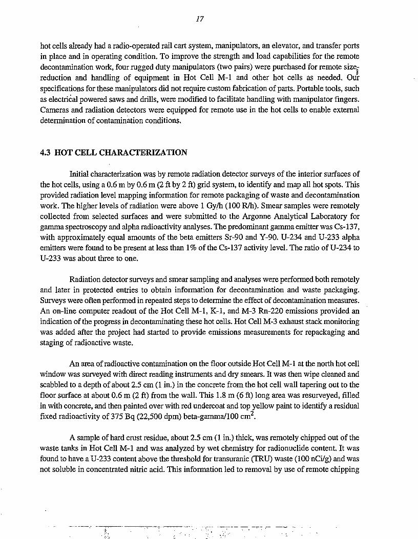
hot cells already had a radio-operated rail cart system, manipulators, an elevator, and transfer portsin place and in operating condition. To improve the strength and load capabilities for the remotedecontamination work, four rugged duty manipulators (two pairs) were purchased for remote size-reduction and handling of equipment in Hot Cell M-l and other hot cells as needed. Ourspecifications for these manipulators did not require custom fabrication of parts. Portable tools, suchas electrical powered saws and drills, were modified to facilitate handling with manipulator fingers.Cameras and radiation detectors were equipped for remote use in the hot cells to enable externaldetermination of contamination conditions.
4.3 HOT CELL CHARACTERIZATION
Initial characterization was by remote radiation detector surveys of the interior surfaces ofthe hot cells, using a 0.6 m by 0.6 m (2 ft by 2 ft) grid system, to identify and map all hot spots. Thisprovided radiation level mapping information for remote packaging of waste and decontaminationwork. The higher levels of radiation were above 1 Gy/h (100 R/h). Smear samples were remotelycollected from selected surfaces and were submitted to the Argonne Analytical Laboratory forgamma spectroscopy and alpha radioactivity analyses. The predominant gamma emitter was Cs-137,with approximately equal amounts of the beta emitters Sr-90 and Y-90. U-234 and U-233 alphaemitters were found to be present at less than 1% of the Cs-137 activity level. The ratio of U-234 toU-233 was about three to one.
Radiation detector surveys and smear sampling and analyses were performed both remotelyand later in protected entries to obtain information for decontamination and waste packaging.Surveys were often performed in repeated steps to determine the effect of decontamination measures.An on-line computer readout of the Hot Cell M-l, K-l, and M-3 Rn-220 emissions provided anindication of the progress in decontaminating these hot cells. Hot Cell M-3 exhaust stack monitoringwas added after the project had started to provide emissions measurements for repackaging andstaging of radioactive waste.
An area of radioactive contamination on the floor outside Hot Cell M-l at the north hot cellwindow was surveyed with direct reading instruments and dry smears. It was then wipe cleaned andscabbled to a depth of about 2.5 cm (1 in.) in the concrete from the hot cell wall tapering out to thefloor surface at about 0.6 m (2 ft) from the wall. This 1.8 m (6 ft) long area was resurveyed, filledin with concrete, and then painted over with red undercoat and top yellow paint to identify a residualfixed radioactivity of 375 Bq (22,500 dpm) beta-gamma/100 cm2.
A sample of hard crust residue, about 2.5 cm (1 in.) thick, was remotely chipped out of thewaste tanks in Hot Cell M-l and was analyzed by wet chemistry for radionuclide content. It wasfound to have a U-233 content above the threshold for transuranic (TRU) waste (100 nCi/g) and wasnot soluble in concentrated nitric acid. This information led to removal by use of remote chipping
18
and an electrical powered wire brush. A HEPA filtered vacuum cleaner was used to remotely captureradioactive dust.
A concrete floor area of Hot Cell M-l was found, by remote surveying, to be highlycontaminated. Dissolver acid solution had leaked from the Proof-of-Breeding equipment and seepedthrough taped joints in the stainless steel sheets covering the concrete floor. After remote wipecleaning, resurveying, entry wipe cleaning, surface scabbling, and resurveying, a high level of fixedradioactivity remained. This was characterized by coring a 6.3 cm (2.5 in.) diameter by 15 cm (6 in.)deep core sample for radionuclide content analyses. The core sample was sawed into a 7.6 cm (3 in.)lower section and three 2.5 cm (1 in.) sections above. The sections were analyzed by gammaspectroscopy and a chip was removed from the top surface for alpha spectroscopy measurements.It was found that the Cs-137 gamma spectroscopy measurements decreased from 3.33 x 10 Bq(2.0 x 10⁷ dpm) in the upper 2.5 cm (1 in.) section to 1.8 x 10² Bq (1.1 x 10⁴ dpm) in the second2.5 cm (1 in.) section to 4.5 Bq (2.7 x 10 dpm) in the third 2.5 cm (1 in.) section. The penetrationof alkali radionuclides such as Cs-137 into concrete is expected.
The uranium content of a chip from the top of the 15 cm (6 in.) core contained1.66 x 103 Bq/g (9.95 x 10⁴ dpm/g) alpha from U-232 and U-233, with 75% of the alpharadioactivity attributed to U-232. A chip from the bottom of the core sample contained 0.1 Bq/g(6.5 dpm/g) alpha from U-232 and U-233. The bottom sample may have been slightly contaminatedby the process of coring and removing the concrete.
4.4 ALTERNATIVES ASSESSMENT
The principal alternatives for decontamination of the hot cells were to contract out for thework or to plan and do the work with ANL personnel. In view of having to do a significant amountof remote disassembly and decontamination work in order to characterize conditions, and in viewof having the necessary internal resources, including a well-qualified technical support manager whohad been a member of the Proof-of-Breeding research team, it was decided to do the work withANL-E personnel. Knowledge of the Proof-of-Breeding work by the technical support manager wasa valuable resource. The ANL-E ESH Health Physics personnel were knowledgeable of the hot cellsand the radiation monitoring instrumentation.
Other alternatives assessments that were ongoing were the choices of methods used for size-reduction and decontamination work, as detailed in Section 4.6.
19
4.5 PREPARATIONS
Preparations for decontamination of the project hot cells included the following actions:
• Planning and assignment of project team members.
• Writing project plans and procedures.
• Training project personnel in updated ANL-E radiation control measures,operation of equipment, etc.
• Obtaining baseline bioassay and whole-body radioactivity measurements.
• Communicating with non project personnel in the area to coordinate activities.
• Arranging for office space, equipment storage space personnel dosimetry,bioassay monitoring, lockers, and personal protective equipment.
• Procuring needed tools, equipment, and waste containers.
4.6 DECOMMISSIONING OPERATIONS
The decontamination of the hot cells involved two major phases: remote decontaminationand protected entry decontamination.
4.6.1 Remote Decontamination Phase
Due to the high levels of contamination, some measurements greater than 1 Gy/h (100 R/h)in Hot Cells M-1 and K-l, extensive remote decontamination work was required to get down tolevels where supplied-air suit entries could be made for hands-on decontamination. Remotedecontamination was carried out in each of the five hot cells. The hot cells ranked from mostdifficult to least difficult to decontaminate as follows: M-1, K-l, M-3, A-l, and K-3.
The initial work involved remote surveying, HEPA vacuum cleaning, wet wipe cleaning,dismantling of equipment, packaging, and segregating the radioactive waste. Conditions in Hot CellM-1 are shown in Figure 4.2 during the remote decontamination work. Labeled containers containhigh-gamma radioactive waste. Equipment in Hot Cell M-1 that has been remotely removed frommountings is shown in Figure 4.3. Wrenches were handled with manipulators to free the equipment.
20
FIGURE 4.2 Hot Cell M-1 with Labeled Containers of High-GammaRadioactive Waste (18876K #5)
In order to reduce the background level of radioactivity to allow protected entries, it wasnecessary to remotely identify the locations and items of higher radioactivity. Remote surveying forradioactive hot spots was performed repeatedly. Figure 4.4 shows remote measurement of radiationlevels in Hot Cell M-1. The remote surveying instrumentation was used by the decontaminationpersonnel for remote work decisions. It was not used for personnel exposure measurements or formaking decisions for hot cell entries. Health Physics personnel did all of the measurements forhealth protection with instruments calibrated under their control system.
A camera connected to an external video screen was used for remote observation ofconditions that could not be seen from the hot cell windows. Camera observations are depicted inFigure 4.5. The flashlight style camera had a 1-lux light sensitivity, allowing effective observationof conditions inside of tanks without the use of special lighting.
During the remote work phase, highly radioactive waste was generally size-reduced forloading into 3.8-1 (1-gal) or 19-1 (5-gal) cans. Loading of a 19-1 (5-gal) can in Hot Cell M-1 is shownin Figure 4.6. This waste was subsequently placed into 250-1 (55 gal) Department of Transportation(DOT) 17C steel drums for remote handled waste shipment.
; • ^>.«^- - \ <,;-;-«•
21
FIGURE 4.3 Hot Cell M-1 with Radioactivity Contaminated EquipmentRemotely Removed from Mountings (18876K#9)
FIGURE 4.4 Remote Measurement of Radiation Levels in Hot Cell M-1(14479 #33)
22
FIGURE 4.5 In-Cell Camera and External Video Monitor Viewing RemoteDecontamination in Hot Cell M-l (14479 #4)
FIGURE 4.6 Remote Loading of Radioactive Waste into a 5-GalIon Can,Hot Cell M-l (6951 #19)
23
Remote size reduction techniques included disassembly using wrenches, shearing, sawing,and bending. Remote use of a portable shear is shown in Figure 4.7. The large shear and steel I-beamshear bed in Hot Cell M-3 was difficult to remotely size-reduce. For fire safety reasons it wasdecided to not use a plasma torch or acetylene torch in the hot cells. Abrasive wheel saw cutting, asshown in Figure 4.8, was used for sizing heavy support framework. A saber saw was used for cuttingapart the liquids transfer tanks, as shown in Figure 4.9.
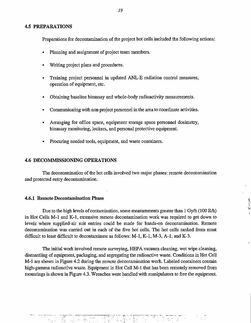
After equipment items and structures were removed it was possible to resurvey and todecontaminate areas that had been inaccessible. Figure 4.10 depicts the remote removal of a mixingstation used for concreting of liquid wastes. Repeated vacuuming with portable units that could beused with the manipulators, was required in the hot cells. Figure 4.11 shows remote vacuuming ofradioactively contaminated surfaces in Hot Cell M-l. Wiping of contaminated surfaces with cottonrags or absorbent paper wipes that were dampened with an aqueous detergent solution was generallyeffective in decontaminating defined areas of surface contamination. An aqueous-base strippabledecontamination paint was extensively used for decontamination both remotely and in the entryphase. It was applied mainly by paint spraying but also with rollers and brushes. The remotestripping of the decontamination paint is shown in Figure 4.12. It was generally ready to be strippedabout eight hours after application.
Remote handling of equipment for removal from Hot Cell M-l is depicted in Figure 4.13.The radio-controlled mule cart rail system was used to move remote-handled waste. The rail cart wasable to transfer a 250-1 (55 gal) drum shielding cask.
The remote decontamination phase of the work required continual maintenance work onmanipulators. Breakdown of the manipulators was caused by exceeding the design capabilities. Itwas necessary to remove the dysfunctional manipulators in order to decontaminate and repair them.A manipulator ready for repair work is shown in Figure 4.14. Replacement and tensioning of tapedrives on a manipulator are depicted in Figure 4.15. Other equipment, such as the rail-car turntables,also required repair work. Figure 4.16 shows repair of a radio-controlled rail-car turntable.
4.6.2 Protected Entry Decontamination Phase
The protected entries into the hot cells were delayed until remote decontamination workhad lowered the radiation exposure levels to a point where the entry exposures were within theALARA plan guidelines. It was more efficient to conduct the decontamination work by protectedentries than by remote work. The procurement of appropriate protective clothing and equipment forentries and dress rehearsal training were carried out prior to work entries. The protective clothingand equipment used for entries is listed in Table 4.1.
24
FIGURE 4.7 Remote Use of a Portable Shear Tool (14479 #23)
FIGURE 4.8 Remote Abrasive Wheel Circular Saw Cutting the Shear Bedin Hot Cell M-3 (15705 #13)
25
FIGURE 4.9 Remote Sawing of a Liquid Transfer Tank in HotCell K-l (16065 #6)
Protective clothing and equipment are depicted in Figures 4.17 and 4.18. For an entry bytwo technicians at least five additional support personnel were used.
• One worker for observing through the hot cell window and giving directionsto or receiving requests from the technicians inside.
• One worker who served as a valet to help the entry personnel in suiting up andchecking their equipment. The valet wore protective clothing to facilitatebringing items to or assisting entry personnel with protective equipmentproblems even after they had entered the hot cells interior corridor.
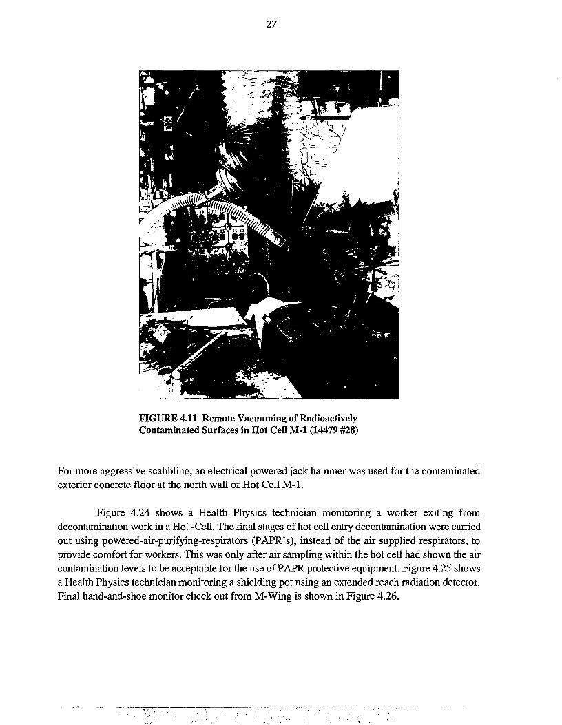
• One worker for monitoring the breathing air compressor and compressedbreathing air cylinders station, as shown in Figure 4.19.
26
FIGURE 4.10 Remote Removal of a Concrete Mixing Station, Hot Cell K-l(15705 #6)
• One worker fully suited and ready to enter as a backup entry person in case ofan emergency need.
• One worker, the ESH Health Physics technician, who was ready withappropriate instrumentation to check personnel out of the hot cells and wasready for surveying and other assistance in the event of an emergency.
Entry into the hot cells was typically through an isolation tent at the doorway, as shown inFigure 4.20. Inflatable erection tents were used for efficiency of set up and removal. In order tominimize the risk of tearing protective air supplied clothing, sharp edges of equipment such as cutedges were taped as shown in Figure 4.21.
Entry decontamination techniques included HEPA filter vacuuming, and wiping with cottonrags or absorbent paper wipes wetted with an aqueous detergent solution. Strippable decontamina-tion paint was used in repeated steps. Figure 4.22 shows the hands on stripping of decontaminationpaint. Where radioactive contaminants were fixed on the surface or had penetrated into the matrix,scabbling was applied. The use of a hand-held needle scabbier (steel rods) is shown in Figure 4.23.
FIGURE 4.11 Remote Vacuuming of RadioactivelyContaminated Surfaces in Hot Cell M-l (14479 #28)
For more aggressive scabbling, an electrical powered jack hammer was used for the contaminatedexterior concrete floor at the north wall of Hot Cell M-l.
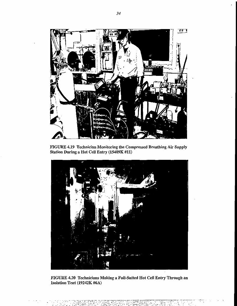
Figure 4.24 shows a Health Physics technician monitoring a worker exiting fromdecontamination work in a Hot -Cell. The final stages of hot cell entry decontamination were carriedout using powered-air-purifying-respirators (PAPR's), instead of the air supplied respirators, toprovide comfort for workers. This was only after air sampling within the hot cell had shown the aircontamination levels to be acceptable for the use of PAPR protective equipment. Figure 4.25 showsa Health Physics technician monitoring a shielding pot using an extended reach radiation detector.Final hand-and-shoe monitor check out from M-Wing is shown in Figure 4.26.
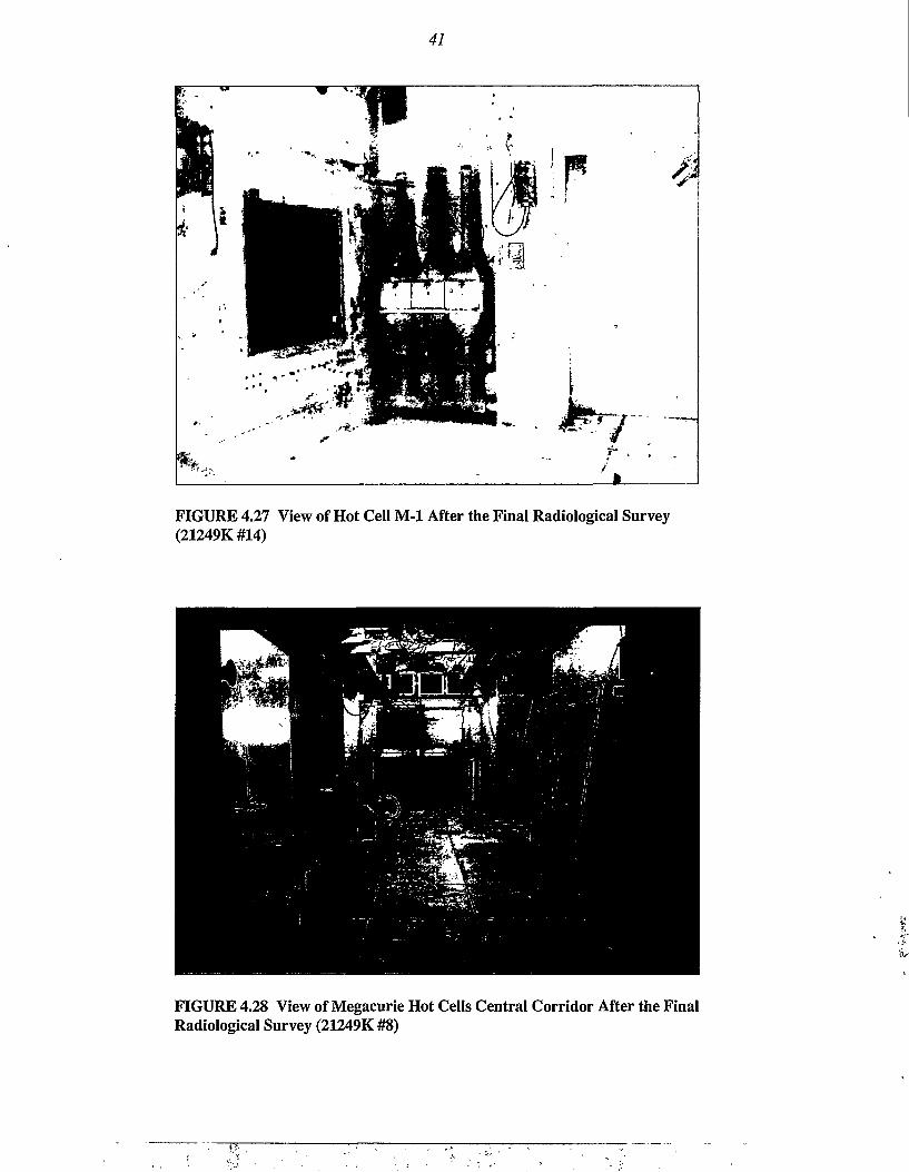
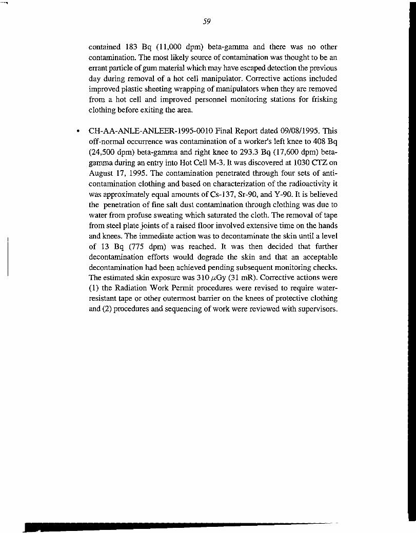
Figure 4.27 shows Hot Cell M-l after the final clean out and the final radiological surveyof conditions. The other four hot cells were also empty. The hot cells central interior corridor, aftercompletion of final radiological surveys, is shown in Figure 4.28.
The external floor area at the north wall of Hot Cell M-l had been contaminated during theperiod of research. It was wipe-cleaned and the concrete was scabbled out to a depth of up to 2.5 cm(1 in.) using an electric powered jackhammer. It was then filled in with new concrete, painted withred paint, over painted with yellow paint, and stenciled to indicate the remaining radioactivity. Thefinal condition of this area is shown in Figure 4.29.
Digital dosimeter readout equipment, as shown in Figure 4.30, allowed the immediateassessment of doses received in each hot cell entry. These dosimeters also provided audible alarmsat selected set-points for radiation dose rate and accumulated dose.
Thermoluminescence dosimeters and ring dosimeters were worn for monthly analyses.
29
FIGURE 4.13 Technician Directing the Remote Loading of a Dissolver SystemWaste Tank into a Bin Liner (20537K #14)
FIGURE 4.14 Manipulator Removed, Decontaminated, and Bagged for Repair(18875 #8)
30
FIGURE 4.15 Technician Repairing a Manipulator (14478 #7)
On-line computer readout instrumentation for monitoring of hot cells stack emissions,shown in Figure 4.31, was used for tracking progress in cleanup removal of radioactivecontaminants.
4.7 WASTE DISPOSAL
Because of the mixed fission product contamination throughout the five hot cells, low levelradioactive waste was the major type of waste. Because the gamma radiation from Cs-137 produceda peak reading of 1.45 Gy/h (145 R/h) on the surface of one of the drums, a small fraction of thevolume of radioactive waste (2.7%) was remote-handled (>2 mGy or 200 mR/h at the surface of thewaste package). Figure 4.32 shows the curie amounts of various radioactive isotopes in the totalwaste packages.
31
FIGURE 4.16 Repair of a Radio Operated Rail-Car Turntable in the Hot CellsInterior Corridor (16809 #8)
The radioactive waste was shipped to the DOE Hanford Site for disposal. Figure 4.33 depictsthe removal of contact-handled radioactive waste from M-wing, building 200. Figure 4.34 showsthe loading of remote-handled radioactive waste drums into a shielded transport cask for truckshipment to the DOE disposal site.
4.8 POSTDECOMMISSIONING RADIOLOGICAL SURVEY
The five project hot cells were not decommissioned but were emptied and decontaminatedto restricted use condition. Health Physics did the final radiological survey in accord with theirprepared procedure. The hot cells were chalk marked into 1 m square grids on the floors and wallsstarting in the southwest corners. The intersection of the grid lines was also marked on the floorswith ink.
Each grid was directly surveyed for alpha radioactivity with a gas proportional surveyinstrument in the alpha mode. The hot spots and the general background measurements were loggedonto a hot cell map by a technician recorder outside the hot cell. Radio communication was usedbetween the technician inside and the technician recorder outside the hot cell. The recorder observed
32
TABLE 4.1 Protective Clothing and Equipment for Hot Cell Entries
Undergarments: cotton sports shorts and T-shirt.(It was planned to disrobe to undergarments for an emergency shower).
Anti-contamination (anti-c) coveralls: yellow 8.5 oz cotton with a wide opening at the neckfor a step-in feature, a drawstring at the neck, and elastic at the wrists and ankles.
Full Tyvek suits, two worn over anti-c: white with integral boots and hood, zipper front,and elastic at wrists. These suits were taped at the wrists and neck.
Supply air distribution harness for distributing air to all areas of the suit, worn under anti-c.
Full facepiece air-supplied respirator.
Backup five-minute compressed breathing air-supply cylinder, worn under the two Tyvek'swith a round handle valve that could be opened without disrobing.
Full vinyl bubble hood, with front and back bibs and with breathing air supply.
Two-way portable radio, with an ear microphone, worn under the two Tyvek's on a web beltover the anti-c with the transmit button operated with the Tyvek's over it.
Three pair of PVC shoe covers worn over the Tyvek boots.
Three pair of thin latex gloves and one pair of heavier outer gloves of rubber or leather.
Note: After experiencing penetration of water soluble radioactive salts through the Tyvekprotective suits, a PVC/nylon apron and polyethylene tape over the knees and forearms ofthe outer Tyvek suit were added for subsequent entries.
FIGURE 4.17 Donning Protective Clothing for a Hot Cell Entry(15411K#11A/12)
33
FIGURE 4.18 Technician Suiting-up for a Hot Cell Entry(15411K#6A/7)
the grid location through a hot cell window. Each grid was also directly surveyed for beta andgamma radioactivity with an ion chamber instrument that distinguished between beta and gamma.
In addition to the direct survey measurements, each grid was smear sampled over the entiregrid area (1 m ) with a single paper per grid. These large area samples were counted with an AlphaBeta ZnS(Ag) scintillation detector in the integrate mode for one minute for both alpha and beta-gamma radioactivity. Small area (100 cm2) smear samples were taken near the center of each gridin separate entries and counted for radioactivity in the same way as for the large area smear samples.
4.9 POSTDECOMMISSIONING HAZARDOUS CHEMICAL CONDITION
There were no remaining hazardous chemicals. Eight and a half tons of contaminated leadbricks in Hot Cell M-1 were packaged into five wooden boxes and two 208-1 (55-gal) drums. The
34
FIGURE 4.19 Technician Monitoring the Compressed Breathing Air SupplyStation During a Hot Cell Entry (15409K #11)
FIGURE 4.20 Technicians Making a Full-Suited Hot Cell Entry Through anIsolation Tent (19242K #6A)
35
FIGURE 4.21 Taping Sharp Edges of Size-Reduced Equipment(15410 #33)
packaged lead was transferred to ANL-E Waste Management Operations (WMO) fordecontamination and recycling. Hot Cell M-1 was cleaned subsequent to the removal of the leadbricks. One 18.9-1 (5-gal) metal can which was partially full of mixed waste was documented andtaken to an ANL-E Waste Management storage space in compliance with the Resource ConservationAct (RCRA) regulations. This can contained mercury vapor lamps.
36
FIGURE 4.22 Technician Removing StrippableDecontamination Paint, Hot Cell K-3 (18874K#26)
37
FIGURE 4.23 Technician Using HandHeld Vacuum Equipped Scabbier toRemove Fixed Radioactive Contaminationfrom the Concrete Floor ofHot Cell M-l (20728K #30A)
38
FIGURE 4.24 Health Physics Technician Performing a HotCell Exit Survey of a Worker After Removal of OuterProtective Clothing (16065 #32)
39
FIGURE 4.25 Health Physics Technician Using an ExtendedReach Radiation Detector for Monitoring a Shielding Pot(16065 #30)
40
FIGURE 4.26 Final Hand-and-Shoe Monitor Survey(15705 #17)
41
FIGURE 4.27 View of Hot Cell M-1 After the Final Radiological Survey(21249K#14)
FIGURE 4.28 View of Megacurie Hot Cells Central Corridor After the FinalRadiological Survey (21249K #8)
42
FIGURE 4.29 North Wall of Hot Cell M-l Exterior Area After Scabbling,Concrete Patching, and Painting (21249K #3)
FIGURE 4.31 On-Line Computer ReadoutInstrumentation for Monitoring Hot Cells StackEmissions (16065 #13)
45
•Curies
60
50
40
30
20
10
0
J*
Q-61 o.i4 0.12 o.oooeaT1
<f
FIGURE 4.32 Radionuclide Distribution
FIGURE 4.33 Removal of Packaged Radioactive Waste from M-Wing(20536K#22)
46
FIGURE 4.34 Loading of Remote-Handled Radioactive Waste Drums into aShielding Cask for Truck Transport
47
5 COSTS AND SCHEDULES
The project costs were $5.8 million with the estimated cost breakdown as shown inFigure 5.1 below. The cumulative earned value over the life of the project is shown in Figure 5.2.
Surveillance & Mainten$923K- 15.9%.
Characterizatj$31 OK- 5.3%
Repackage Orphan Wast$311K- 5.4%
Equipment ProcurementS466K- 8.0%
Hot Ceil K-1$573K- 9.9%
Hot Cell K-3S285K - 4.9%
Engineering/Procedures$730K- 12.6%
Project Managemi$725K- 12.5%
Hot Ceii A-1$101K- 1.7%
Hot Cell M-3S502K- 8.7%
Hot Cell M-1S874K- 15.1%
FIGURE 5.1 Activity Breakdown of Project Costs
48
G^Cum.BCWS i£rCum. BCWP
$5.5M
$4.5M
$3.5M
S2.5M
S1.5M
Prior to Oct FY94 the BIdg. 200 Project was not tracked independently (reporting data was combined withthe BIdg. 212 Project)
ACWP: Actual Work Cost PerformedBCWP: Budgeted Work Cost PerformedBCWS: Budgeted Work Cost Scheduled
FIGURE 5.2 Cumulative Earned Value
49
Table 5.1 shows the project baseline schedule compared to the actual work performance.
TABLE 5.1 Project Schedule: Baseline/Actuala
Activity
Technical Management Plan
Hot Cell M-l: Remote decon
Entry decon
Hot Cell M-3: Initial remote decon
Initial entry decon
Final entry deconc
Hot Cell K-1: Remote decon
Entry decon
Hot Cell K-3: Remote decon
Entry decon
Hot Cell A-1: Remote decon
Entry decon
Repackage Eight Waste Drums(remote)
Final Radiological Survey Report
Planned
Start
b
7 Oct. 94
24 March 95
b
b
11 Aug. 94
15 March 94
9 June 94
22 Oct. 93
21 Dec. 93
5 Jan. 94
20 April 94
15 Oct. 93
14 Aug. 95
Complete
b
23 March 95
26 June 95
b
b
18 Nov. 94
8 June 94
23 Aug. 94
20 Dec. 93
23 Feb. 94
19 April 94
29 July 94
17 Dec. 93
16 Nov. 95
Actual
Start
12 Sep. 91
11 June 92
28 July 95
18 June 92
25 March 93
14 Aug. 95
9 July 92
25 Aug. 94
18 Oct. 93
10 Jan. 94
4 Oct. 93
5 July 94
25 Oct. 93
16 Dec. 95
Complete
5 Dec. 91
21 July 95
15 Dec. 95
19 March 93
24 Sep. 93
30 Oct. 95
19 Aug. 94
17 March 95
17 Dec. 93
4 March 94
10 June 94
9 Sep. 94
15 Dec. 93
2 March 96
Note: Actual start dates for Hot Cells M-l, M-3, K-l, and A-l remote decontamination (decon) work was earlierthan the dates shown in the baseline plan. The remote decontamination work on these hot cells was deferred asother project work took precedence.a Delays occurred due to unplanned safety reviews and to needed extensive remote decontamination in Hot Cell
M-l.b Completed prior to approval of the May 1994 baseline report.c Hot Cell M-3 was used for staging and sorting of remote handled radioactive waste after initial remote and
entry decontamination. Final entry decontamination work was conducted about two years later.
50
6 WASTE VOLUMES
There were 156 containers of radioactive waste generated in this project with a total volumeof 79.1 m3 (2,824 cf) and a total weight of 23,496 kg (51,753 lb). Ten 208-1 (55-gal) drums, havinga total volume of 2.1 m3 (75 cf) and weight of 1,028 kg (2,265 lb), were remote-handled waste. Theradioactive waste was all nonTRU waste with the highest U-233 content at 45 nCi/g (1.67 TBq),below the 100 nCi/g (3.7 TBq) threshold for TRU waste. A comparison of the amount of radioactivewaste generated to the amount forecast is shown in Figure 6.1. Waste volumes, by category (contacthandled or remote handled), and radioactivity content of categories are summarized in Table 6.1.
The contact-handled waste containers all read less than the 2 mGy/h (200 mR/h) limit atthe container surface. The highest survey reading on the surface of a remote-handled waste drum was1.45 Gy/h (145 R/h).
In addition to the radioactive waste there were 0.68 m (24.2 cf) of radioactivelycontaminated lead shielding bricks that were taken by ANL-E Waste Management fordecontamination and recycling use. The weight of the lead shielding bricks was 7,759 kg (17,090 lb).These bricks had provided radiation shielding around the waste tanks in Hot Cell M-l.
BaselineEstimate
Actual
Contact Handled(86%, 1200 ft3)
Remote Handled(5%, 75 ft3)
TRU (4%, 60 ft3)
Mixed (5%, 65 ft3)
Contact Handled(88%, 2485 ft3)
Remote Handled(3%, 75 ft3)
Mixed(9%, 250 ft3)
FIGURE 6.1 Comparison of Radioactive Waste Generated to the Amount Forecast
TABLE 6.1 Radioactive Waste
Waste Category Volume Radioactivity
Contact Handled
10 full size M-3 bins
14 half size M-3 bins
39 drums
76 TV cartons
3 bags
2 small bags
2 cans
Subtotal
Remote Handled10 drums
Total
33.6 m3 (1,200 cf)
26.3 m3 (938 cf)
8.2 m3 (292.5 cf)
8.5 m3 (304 cf)
0.3 m3 (12 cf)
0.03 m3 (1 cf)
0.04 m3 (1.4 cf)
76.97 m3 (2,748.9 cf) 0.283 TBq (7.65 Ci)
2.1 m3 (75 cf)
79.07 m3 (2,823.9 cf)
3.79 TBq (102.35 Ci)
4.07 TBq (110.0 Ci)
52
7 OCCUPATIONAL EXPOSURE TO PERSONNEL
The radiation doses to project personnel were well below regulatory guidelines. Thecollective dose for the entire project was approximately 74.5 person-mSv (7.45 person-rem) or80.1% of the collective dose forecasted in the project ADM. Table 7.1 gives skin (shallow),extremity (finger), and whole-body estimated doses for hot cells decontamination and drumrepackaging, and the total measured doses for the project.
The difference in the collective total measured dose and the estimated collective dose forthe hot cells and drums repackaging are due to workers wearing dosimeters for all operations duringone month. Part of the dose was then assigned to two operations. The total measured dose is the doseofrecord.
Figure 7.1 shows the cumulative radiation exposure to project personnel plotted on a timeline as compared to the forecast radiation exposures. The low exposures in the early phases reflectthe large proportion of remote decontamination work and the strategy of doing the leastcontaminated hot cells first. The steep slopes later in the project (from May 94 to Oct. 94 and June95 to Oct. 95) resulted from protected entry decontamination work in Hot Cells K-l and M-l.
TABLE 7.1 Project Collective Radiation Dose
Shallow-skin
Estimated
Extremity-finger
Estimated
Whole Body
Estimated
mSv rem mSv rem mSv rem
Hot-Cell A-l
Hot-Cell K-l
Hot-Cell K-3
Hot-Cell M-l
Hot-Cell M-3
Drums repack
Total (estimated)
Total (measured)
8.4
71.0
3.0
188.0
30.0
4.4
304.8
(0.84)
(7.1)
(0.3)
(18.8)
(3.0)
(0.44)
30.48
Measured
301.6 (30.16)
6.5
49.0
3.7
113.0
19.0
4.7
195.9
(0.65)
(4.9)
(0.37)
(11.3)
(1.9)(0.47)
19.59
Measured
194.7 (19.47)
3.3
20.0
0.4
43.0
5.0
4.0
75.7
(0.33)
(2.0)
(0.04)
(4.3)
(0.5)
(0.4)
7.57
Measured
74.5 (7.45)
53
(jMMonthly Exposure ^Cumulative Exposure J
Monthly Cumulative
FIGURE 7.1 Cumulative Collective Radiation Dose
54
8 FINAL FACILITY STATUS
The five hot cells were emptied and decontaminated for restricted use status. The hot cellswere left in restricted use status with general radiation levels at 1.75 m (5.75 ft) above the floor asfollows:
Plastic encased lead blankets were left on the floor of M-1 over the area where radionuclides had penetrated into theconcrete. The radiation level directly over the lead blankets at 1.75 m (5.75 ft) was 100 pSv (10 mrem)/h. Withoutthe lead blankets the radiation level would be higher.
55
9 LESSONS LEARNED AND DOE REPORTABLE OCCURRENCES
This section describes lessons learned for accomplishing future decontamination work moresafely and/or more effectively and describes DOE reportable occurrences for this project. Each ofthe occurrences were reviewed for lessons learned and to determine changes to avoid a recurrence.
9.1 LESSONS LEARNED
• Procedures for rechecking air line connections, etc., are needed to providesafety assurance. Supplied airline connections separated while personnel wereworking in a contaminated hot cell because connections had not beentightened sufficiently.
• Backup personal protective systems are needed for radioactivedecontamination work. This was shown to be needed in the occurrence wheresupplied air lines became disconnected. The backup system of compressedbreathing air cylinders was of no use because the air supply lines weredisconnected. The secondary backup system of having personnel carry a smallfive-minute valved compressed air supply cylinder under the outer protectivesuit supplied breathing air for a safe evacuation. There was no intake ofradioactivity.
A need for backup systems was also apparent when the breathing aircompressor failed while personnel were suited-up, but prior to entry into acontaminated hot cell.
• It is important to establish effective procedures and controls to avoidspreading radioactive contamination when manipulators and other remotecontrol devices are removed for decontamination and repair. Our initialprocedure was to decontaminate the equipment in the hot cells interior centralcorridor area, wrap the parts having residual contamination with plasticsheeting, and then move the equipment to the area outside the hot cells forrepair. It was found that this was not sufficient for the control of hot particles.Procedures were added to provide more extensive wrapping for transport, tohave a Health Physics technician survey behind the equipment being moved,and to conduct frequent wide-area floor-smear surveys.
• It was found that using remote chipping, an electric drill powered wire brush,and a portable in-cell HEPA filtered vacuum cleaner was an effective method
56
for removal of a 2.5 cm (1 in.) hard crust layer of dried radioactive residueremaining inside two stainless steel dissolver tanks.
• Strippable aqueous-base decontamination paint was found to be effective forboth remote and entry application in the contaminated hot-cells. It was visiblyeffective in removal of radioactive dirt from the cracks between steel platesforming the false floors of the hot cells. It was also effective for applicationover contaminated hot cell wall coverings (wall paper) for removal as asandwich with the wall covering material to minimize recontamination of hotcell surfaces.
• Remote usage of an in-cell flashlight-style camera having 1-lux lightsensitivity proved to be advantageous for remote viewing in hidden locationssuch as behind or underneath equipment and inside of tanks. The images wereobserved on a video screen located outside the hot cell at a window where theinternal movements of the camera and the projected picture could becorrelated. In this manner the video information can also be recorded ifdesired.
• Where there are soluble radioactive contaminants present it is prudent to coverprotective clothing contact areas with impervious tape (or other suitableprotection) to prevent contact of contaminants with protective clothing wettedby sweat. An alternative for knee areas would be to wear knee pads over theprotective clothing to avoid contamination of the knees and to improvecomfort while kneeling. Radioactive contaminants penetrated through intactprotective clothing onto the skin of a worker's knees during decontaminationof a hot cell floor because the clothing contact areas had become wetted withsweat and radioactive salts were present as contaminants.
• It is better to have automatic counting times at hand-and-shoe monitoringstations to help ensure that personnel will check out of the radiation controlarea properly. Our monitoring stations were upgraded during the project toavoid the administrative control problems involved in trying to avoidinadequate counting times.
• The usage of dosimeters with audible alarming at set points for radiation leveland accumulated exposure was a good ALARA control measure. Theimmediate readout of the dosimeters following a cell entry providedinformation to the workers and the supervisor for exposure control planning.The supervisor was able to maintain a current record of individual exposuresto compare to monthly exposure limits. Monthly readout of
57
thermoluminescence dosimeter (TLD) badges was supplemented by usage ofthe above dosimeters.
• It was important for workers to utilize the supplied air-distribution harnessesto distribute air throughout and to the extremities of their multiple-layer full-protective suits. This was needed to provide effective cooling and to reducesweat moisture. Also the bubble hood had an air supply.
• By using inflatable containment tents at the doorways to the hot cells, thesetup time was reduced to 25% of the time required for the non-inflatabletyrje,
• It was effective to progress from the least contaminated hot cell to the mostdifficult to decontaminate. In this manner the decontamination procedures andthe radiation control measures were improved for the more difficult work.Personnel became more proficient with time and were able to do tasks quickerwhen the higher levels of contamination were addressed, thereby minimizingexposure.
9.2 DOE REPORTABLE OCCURRENCES
There were five DOE reportable occurrences over the course of this project, as follows:
• CH-AA-ANLE-ANLEEWM-1993-0004 Final Report dated 08/11/1993. Thisoff-normal occurrence was radioactive contamination of work clothing trouserleg and of a work shirt. It was discovered at 1030 Central Time Zone (CTZ)on April 19, 1993. The source of the contamination was an air supply hosewhich brushed against a trouser leg following removal of two protectiveTyvek suits. This occurred in an isolation tent at the entrance to Hot Cell M-3.The contamination was 500 Bq (30,000 dpm)/100 cm2 beta-gamma assumedto be Cs-137 and Sr-90 based on characterization samples from the hot cell.There was no skin contamination detected. The work shirt was contaminatedby brushing it with a contaminated respirator facepiece hose. Thecontamination level was 1,330 Bq (80,000 dpm)/100 cm2 beta-gamma and noskin contamination was detected. Corrective actions included limiting thenumber of persons inside the hot cell entry/exit tent and adding a layer of anti-contamination clothing under the Tyvek protective suits. Training in disrobingtechniques had been given prior to the occurrence.
• CH-AA-ANL-ANLEEWM-1993-0005 Final Report dated 08/11/1993. This
58
off-normal occurrence was the accidental disconnection of supply air linesfrom two technicians during an entry in Hot Cell M-3. It was discovered at1415 CTZ on April 21, 1993. The technicians were fully suited withprotective clothing, full facepiece supplied-air respirators, bubble hoods withbreathable air, and five-minute escape bottles. Technician one's supply air linebecame disconnected and he switched to the escape bottle air. One minutelater technician two's supply air line became disconnected and he switched tothe escape bottle air. The disconnections occurred between the female quick-disconnects and the threaded end of the hoses. An emergency exit from thehot cell was conducted with no contamination or uptake of radioactivity byeither of the technicians. Corrective actions taken were: (1) revising thesupplied air entry procedure to include a visual and "twist test" check of theair line connections before each use and (2) quick-disconnects werereassembled to hoses using 1.14 to 1.36 in kg (10 to 12 ft lb) of torque per theequipment supplier's recommendation provided after the occurrence. Inaddition, a scribe mark was placed on each fitting to aid in visual checkingand lock-tight compound was placed on the threads.
CH-AA-ANLE-ANLEEWM-1993-0012 Final Report dated 01/04/1994. Thisoff-normal occurrence was 292 Bq (17,500 dpm)/100 cm2 beta-gamma(cesium-137) shoe contamination of a worker involved with removal,transport, and repair of hot cell manipulators. It was discovered at 1700 CTZon October 4, 1993. A survey of the floor did not detect any radioactivecontamination. It was concluded that a single radioactive particle haddislodged from the manipulator and then attached to the sole of the worker'sshoe. The corrective actions included bagging of manipulator slave arms,modification of the manipulator transport procedure to have a Health Physicstechnician follow behind the transport cart to do wide-area floor smears, andinstitution of daily large area floor smear surveys in the hot cells exteriorareas.
CH-AA-ANLE-ANLEEWM-1994-0001 Final Report dated 05/03/1994. Thisoff-normal occurrence was radioactive contamination on the knee ofLaboratory green work clothing. It was discovered at 1520 CTZ on March 14,1994. The contamination was detected by Health Physics survey uponremoval of two sets of protective Tyvek clothing by a decontamination anddecommissioning (D&D) worker preparing to leave the interior corridor of theM-Wing, building 200, hot cells. There was no contamination of the outerlayers of protective clothing. On further investigation it was found that thecontamination was in a small piece of gum like material that was not able tobe removed from the cloth. A small swatch cut out of the trouser knee (1 cm)
59
contained 183 Bq (11,000 dpm) beta-gamma and there was no othercontamination. The most likely source of contamination was thought to be anerrant particle of gum material which may have escaped detection the previousday during removal of a hot cell manipulator. Corrective actions includedimproved plastic sheeting wrapping of manipulators when they are removedfrom a hot cell and improved personnel monitoring stations for friskingclothing before exiting the area.
CH-AA-ANLE-ANLEER-1995-0010 Final Report dated 09/08/1995. Thisoff-normal occurrence was contamination of a worker's left knee to 408 Bq(24,500 dpm) beta-gamma and right knee to 293.3 Bq (17,600 dpm) beta-gamma during an entry into Hot Cell M-3. It was discovered at 1030 CTZ onAugust 17, 1995. The contamination penetrated through four sets of anti-contamination clothing and based on characterization of the radioactivity itwas approximately equal amounts of Cs-137, Sr-90, and Y-90. It is believedthe penetration of fine salt dust contamination through clothing was due towater from profuse sweating which saturated the cloth. The removal of tapefrom steel plate joints of a raised floor involved extensive time on the handsand knees. The immediate action was to decontaminate the skin until a levelof 13 Bq (775 dpm) was reached. It was then decided that furtherdecontamination efforts would degrade the skin and that an acceptabledecontamination had been achieved pending subsequent monitoring checks.The estimated skin exposure was 310 ,uGy (31 mR). Corrective actions were(1) the Radiation Work Permit procedures were revised to require water-resistant tape or other outermost barrier on the knees of protective clothingand (2) procedures and sequencing of work were reviewed with supervisors.
60
10 CONCLUSIONS AND RECOMMENDATIONS
Five radioactively contaminated hot cells, which were a source of discharge of 2,600 curiesper year of Rn-220 to the environment, were emptied and decontaminated to restricted-use condition.This has reduced the radioactive emissions from these hot cells to <1% of the initial level.
The project was completed with the radiation dose to personnel held to 80.1% of theaccumulated dose forecast in the project ADM.
The characterization of hot cells, similar to the project hot cells, needs to be a stepwiseprocess throughout the project due to:
1. initially high background radiation levels which mask specific contaminationproblems and
2. disassembly or cutting apart of equipment and structures is needed to provideaccess for characterization.
This can lead to discovery of decontamination problems that had not been forecasted. It isa justification for a larger project funding contingency than for projects where characterization canbe initially more complete.
61
11 REFERENCES
1. "Action Description Memorandum for Decontamination of Hot Cells in Building 200 WingM, at Argonne National Laboratory-East," May 1992.
2. "Personnel Selection, Qualification, Training, and Staffing Requirements at DOE Reactor andNon Reactor Nuclear Facilities," DOE Order 5480.20, February 20,1991.
3. "Radiation Protection for Occupational Workers," DOE Order 5480.11, December 21,1988.
4. "Radiation Protection of the Public and Environment," DOE Order 5400.5, Change 2: January7,1993.
5. "Radioactive Waste Management," DOE Order 5820.2A, September 26,1988.
6. "Implementation of the National Environmental Policy Act," DOE Order 5440.1C, April 9,1985.
7. "Unusual Occurrence Reporting System," DOE Order 5000.3, November 7,1984.
8. "A Guide to Maintaining Exposures ALARA," PNL-6577, June 1988.
9. "3rd DOE Natural Radiation Environment Symposium Proceedings," T.F. Gesell andW.M. Lowder, Technical Information Center/DOE, 1980. A.B. Tanner pgs 5-56, "Radon inthe Ground: A Supplementary Review."
10. "Summary of Radionuclide Air Emissions from Department of Energy Facilities for CY1993,"Assistant Secretary for Environment, Safety, and Health, DOE/EH-0477, April 1995, page 22.
11. "Uranium and Plutonium Determination for Evaluation of High Burnup Fuel Performance,"R. R. Heinrich, et al, CONF-850629-4, June 1985.
12. "Argonne National Laboratory-East Site Environmental Report For Calendar Year 1992," byN. W. Golchert and R. G. Kolzow, ANL-93/5, May 1993.