DEDICATED SOLAR SORTIE MISSION SO-01-S SORTIE PAYLOAD Volume III of VI Prepared for National Aeronautics and Space Administration Marshall Space Flight Center Huntsville, Alabama by Grumman Aerospace Corporation Bethpage, New York 11714 Contract No. NAS 8-31102 Mission No. 13 March 1974 Traffic Model https://ntrs.nasa.gov/search.jsp?R=19750012362 2020-02-21T22:11:01+00:00Z
Transcript
DEDICATEDSOLAR SORTIE MISSION
SO-01-SSORTIE PAYLOAD
Volume III of VI
Prepared for
National Aeronautics and Space AdministrationMarshall Space Flight Center
Huntsville, Alabama
by
Grumman Aerospace CorporationBethpage, New York 11714
11~~P NERrMA I WZIV' E N. PARQ14r 0j4 PAD, DUPJW& ENZY LIW1N, 4~osr LAWD1144.
3:Lvi R.EQuIRED; L~ DEWAR ADDED 'FOR 5tAPPLY4z FILM Rg I-,IR Z
51 ~~t CONTAMW ELFCfC4,L TITEPLFACE
Block 1.1 (Configure Experiment Secticn Pressure Shells) through Block 1.7
(Mate Special Experiment Sections) do not apply to the DSSM.
Block 1.5 - Load and Verify Flight Software - requires equipment not available
in the processing flow as shown, and therefore, Block 1.5 has been inserted later
in the flow, between Blocks 1.12 and 1.13.
Block 1.8 Receive and Inspect Pallet Sections
Block 1.8.1 Pallet Sections arrive at launch site via air transportation.
Figure 1-2 shows the anticipated con iguration of the largest size pallet segment
(Pallet Segment #1) upon arrival at launch site. This pallet segment is flowed
through the Payload Premission Processing. Other pallet segments have similar
flow; however, differences are described when occurring. Some experiments
require GN2 pruging, and it is assumed tha he purging function involves a G12blanket pressure with a GN2 supply to furnish pressure decay caused by leakage.
In the transportation mode, the GN2 supply is included in the shipping container
as GSE which is shown in Figure 1-2.
The logic of selecting air transportation for the pallet segments from the
NASA DSSM Development Center to the launch site is based upon the size and
weight of pallet segment shipping containers (suitable for C5A aircraft), and
the advantage of short travel time and transportation control afforded by C5A
transport versus rail/truck/sea transport.
Ground and Launch Support Facility Requirements
This block establishes the initial conditions of the pallet segments upn
arrival at the launch site, and does not involve ground and Launch support
facility requirements.
, • - - - I : .'
~ ~~~~ ~~ --- ..... r-:' -- i i , , i j'F . - . . ..
• ,- ! -I [I t' ,i :~ i 1: , I ..,...... ,. v . I. .. .. .. .... ... . ..
The three blocks conduct the pallet segment verification tests. Figure
1-4 shows a typical pallet segment verification test interconnections, ani
indicates the interfaces verified. For Pa let Segment #1. GN2 interfaces
between the segment and the IGLOO and Pallet Segment #2 a:'e tested. The GSE
siZulates the input/output of the Pallet Segment #2 and the IGLOO.
In like manner, the electrical interfaces are verified. For Pallet Segment #electrical interfaces exist with Pallet Se;ment #2, the IGLOO, and the Utility
Bridge.
During these tests, GSE furnishes electrical power and GN2 to Pallet
Segment #1. The GSE in turn is supplied these items by the facility.
Ground and Launch Support Facility Requirements
Facility Requirements
o GN2 - TBD
o Electrical Power - TBD
Support Requirements
o Tools and procedures for mating/unmating GSE.
o Procedures for conducting verification tests.
o Data/Computer processing (parameters - TBD).
o Refrigerated Film Storage.
o Electrical and Fluid Technicians.
NOTE: Data Sheet #S-23 - Ground Facility Requirements - of the DSSM Level B
4d: data indicates various launch site ground facility requirements which
do not appear appropriate for Level II integration activities. As an
example, an altitude chamber, a vacuum chamber, and a solar simulator/
gamma ray source are listed as launch site ground facility requirements
Block 1.10.5 (continued)
NOTE: (continued)
on Data Sheet #S-23. It is felt that these items would not be involved
in performing Level II integration activities at the launch site, and
such requirements have been omitted from the Study.
Block 1.10.6 Inspect Pallet Sections to Verify Configuration is Correct
for mating with Pressurized Sections
This inspection is performed to verify that the Pallet Segments are in the
proper configuration for installation into the Cargo Bay Simulator.
All mechanical, fluid, and electrical interfaces of the Pallet Segments
are inspected for correct configuration.
Ground and Launch Support Facilities Requirements
Facility Requirements
o None
Support Requirements
o Inspection procedures, tools, and configuration descriptions/drawings
of mechanical, fluid, and electrical interfaces..
o Mechanical/fluid/electrical Technicians.
Block 1.10.7 Mate Pallet Sections with Pressurized Sections
This block installs the Pallet Segments in the Cargo Bay Simulator (CBS),
and mates the pallet segments.
Prior to installing the pallet segments into the CBS, an inspection of
the CBS is conducted to verify that the CBS is configured -correctly to receive
the pallet segments.
The Pallet Segments, located on movable pallet segment dollies, are hoisted
from the dollies by an overhead crane, and lowered into their position in the
CBS.
Once in the CBS, all mechanical, fluid, and electrical interfaces between
pallet segments are mated.
The IGLOO and Utility Bridge have their interfaces verified, and then
they are installed in the CBS. After these items are in place in the CBS,
the interface connections are made.
This block concludes with all Orbiter Cargo Bay equipment installed in the
CBS, and ready for Orbiter Simulator verification test (.Manad Final Integrated
o Procedures and tools for configuration inspection of CBS.
o Procedures and tools for hoisting pallet segments.
o Slings for hoisting pallet segments.
o Procedures and tools for mating mechanical, fluid, and electrical interface
connections between pallet segments.
o Procedures and tools for verifying IGLOO and Utility Bridge interfaces
Block 1.10.7 (continued)
Support Requirements (continued)
o Procedures and tools fo ating IGLOO and Utility Brid;:e Lnterfaces.
o Mechanical/fluid, and electrical technicians.
o Riggers.
o Operator for overhead crane.
Block 1.11 Mate Pallet Sections with Liaison Pallet
This block is not applicable to the DSSM flight.
Block 1.12 Connect Orbiter Simulator
This block is not applicable to the Study. (However, the following comments
are offered.
It is recommended that the forward bulthead of the "Holding Fixture" -
called the Cargo Bay Simulator in this Stud;- - duplicate the forward end of the
Orbiter Cargo Bay, which then serves as an nterface simulator between the
Spacelab and the Orbiter. The equipment of the Orbiter Simulator would be a
series of rack-mounted equipment on dollies which simulate the Orbiter PSS/MSS,
and cabin mounted payload equipment. The forward bulkhead of the CBS would
have provisions for mounting a manipulator rig in case functional verification
tests between the manipulator and payload are accomplished during ground
operations in the PPF.
The Level B data for DSSM indicates that the pressurized equipment will be
provided by Spacelab (Data Sheet #S-5). In addition, Data Sheet S-7a and -7bindicate other equipments to be located in a pressurized area. The Orbiter
Simulator simulates all such equipment as this).
Block 1.5 Load and Verify Flijpht Software
All equipment is now assembled for flight software verification; that is,
Orbiter Simulator as defined in Block 1.12 contains necessiry equipment located
in Orbiter, and the payload equipment completely installed in the Cargo Bay
Simulator, so that data channels are mated. It is anticiputted that the software
verification activity will be conducted by launch site per,;onnel, and therefore,
these activities are not detailed here.
Block 1.13 Final Integrated Systems Tests
This block verifies the interface between the Orbiter Simulator. and theseSpacelab elements which mate with the Orbiter Simulator. This definition is inkeepin- with the grouneule of verifying interfaces at the launch site, ajidsince all interfaces within the Pallet Segments, IGLOO, and Utility Bridge havebeen verified previously in the functional flow processing, only the interface
between the Orbiter Simulator and the Orbiter Interface Plate (Figure 1-1)located on the CBS forward bulkhead requires verification during the final
integrated systems tests.
The concept of the Orbiter Simulator is defined in Block 1.12 above.
The interfaces verified in this block are based upon those contained in
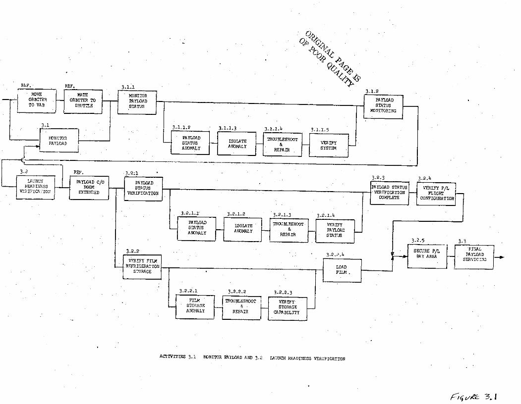
Performance of test to verify anomaly has been repaired and experiment/
payload/ GSE is ready to support mission.
o Facility Requirements
Power - TBD
Fluids - TBD
Gases - TBD
o Support Requirements
Test Equipment - TBD
7 Support GSE - TBD
Blo-k 3.~'.4 Prep.( 0J5) for Transfer to Orbiter Payl(ad Bay.
Perform all steps necessary to prep. experiment, payload/GSE for trans-
fer back to Orbiter Payload Bay, while still maintaining integrity of ex-
periment.
o Facility Requirements
Power - TBD
Fluids - TBD
Gas - TBD
o Support Requirements
Transportation
Handling Fixtures
Block 3. .5 Return to System/Experiment Configuration
Reinstall experiment payload, GSE back to configuration to support miss-
ion. Verify electrical/mechanical interfaces as required, and verify mission
support capabilities of system.
o Facility Require nents
Power - TBD
Fluids - TBD
Gas - TBD
Data Processing
Monitoring - LPS
o Support Requirements
TBD
Block 3 Wp - Payload/Orbiter - Maintenance .ft.
The Orbiter Support System for Payloads are Orbiter (KSC) responsib-
ility. If an anomaly occurs between the interfaces, such as in the Data
Processing System or Environmental System, the appropriate Orbiter (KSC)
representative would be notified and KSC would proceed with resolving an-
omaly. After resolution, interfaces would be verified to determine if
now payload is ready to support its mission in orbit.
o Facility Requirements
KSC Responsibility
o Support Requirements
KSC Responsibility
Scenario - Activity
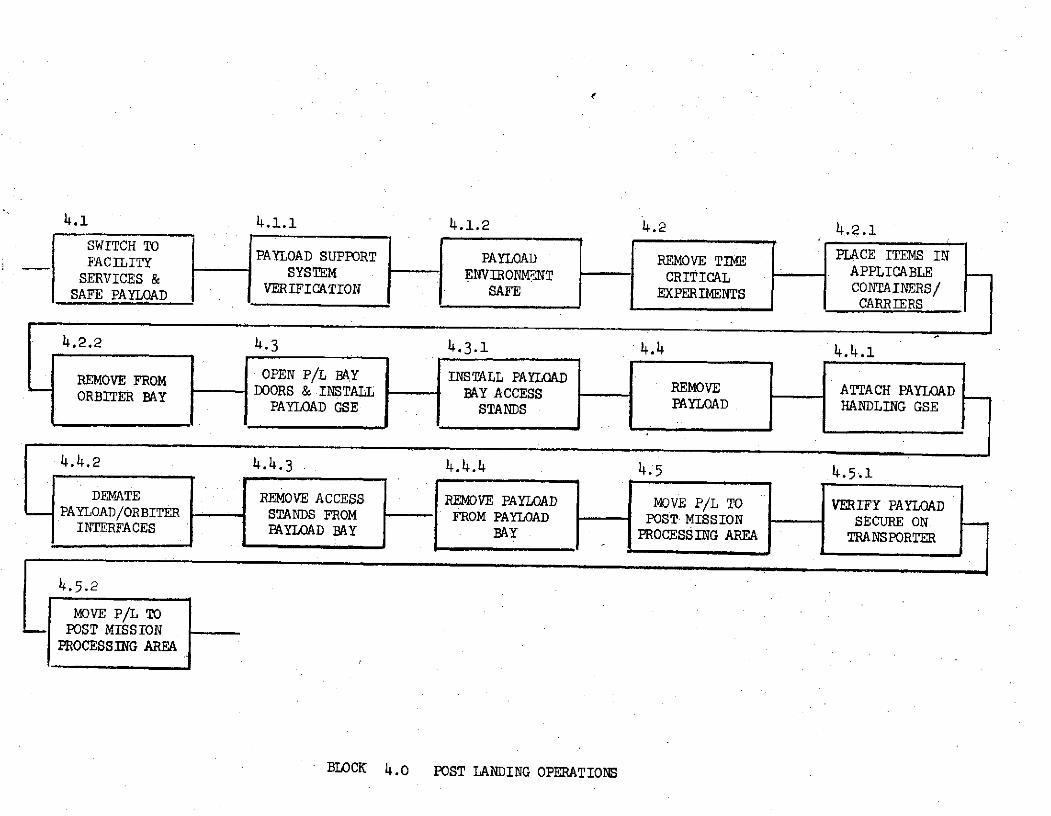
Block 4.0 Post Landing Operations
With the Orbiter hard mounted in the OPF, the Orbitcr Support Systems
are switched to facility services and preparation for safing and removal of
payload elements begins. Safing completed, the time critical items are removed,
and the GSE processing for removal of payload doors and payload proceed until
payload is securely mounted on transporter and is transported to the Payload
Post-Mission Processing Area.
Block L.1 Switch to Facility Services and Safe Payload
The Orbiter Support Systems are switched to facility services; such *ts,
power, cooling and instrumentation. Purge and Dry Payload elements (as
applicable) commences until payload is environmentally safe for personnel access.
The switch over to Payload Ground Monitoring, if applicab!e, is also veri'ied
during this activity.
Block 4.1.1 Payload Support System Verification
The payload bay area has been pruged and the change over to faciliti s for
power, cooling, instrumentation for grount monitoring has been completed tnd
verified operational.
Facility Requirements
Power - llOVAC, 60Hz, 2KW
Fluids - GN2Support Requirements
None.
Block 4.1.2 Payload Environment Safe
A verification by safety that the payload area is environmental safe for
personnel access.
Facility Requirements
Power - llOVAC, 60Hz, 2KW
Fluids - GN2Support Requirements
Safety.
Llock i.2 Remove Time Critical Flight Experiments
The payload bay area safe for access, the experimenters can perform the
-asks necessary for the removal of time critical flight (experiments; such as,
film.
Block 4.2.1 Place Items in Applicable Containers/Carriers
Upon access to payload, the experimenters remove the time critical flight
experiments; such as, film, and place them in applicable containers/carriers.
Facility Requirements
Power - 110 VAC, 6 0Hz, 2KW
Support Requirements
None.
Block 4.2.2 Remove from Orbiter Payload Bay
The Time .Critical Flight Experiments are ready for removal from Orbiter
Payload Bay, and are transferred to the appropriate processing area.
Facility Requirements
Power - 110 VAC, 60Hz, 2KW
Support Requirements
Transportation
Dark Room
Block 4.3 Open Payload Bay Doors and Install Payload GSE
After the thermal protection system, the Payload Bay Doors are removed
and the manipulator arm deployed, the experimenter is responsible for installatioi
of payload bay access stands.
Block 4.3.1 Install Payload Bay Access Stands
The experimenter install payload access stands, as required for removal
of payload from Orbiter Payload Bay.
Facility Requirements
Power - 110 VAC, 60Hz, 2KW
Support Requirements
None
1-lock 1..4 Remove Payload
The removal of Payload includes all the tasks; such as, attaching payload
handling GSE, demating of the Payload/Orbiter interfaces, the removal of access
stands, and finally the removal from payload bay and placement on payload
transporter/handling fixture.
Block 4.4.1 Attach Payload Handling GSE
The Payload Handling GSE; such as, slings are now moved into place and
connected to lifting points on payload.
Facility Requirements
Power - 110 VAC, 60Hz, 2KW
Crane - 15000 lbs. capability
Support Requirements
None.
Block 4.4.2 Demate Payload/Orbiter Interfaces
The Payload/Orbiter Interfaces are disconnected and the payload is
inspected for approval for removal from Orbiter.
Facility Requirements
Power - 110 VAC, 60Hz, 2KW
Crane - 15000 lbs.
Support Requirements
None.
Block 4.4.3 Remove Access Stands from Payload Bay
The experimenters remove the access stands in order to clear the payload
bay area for removal of payload.
Facility Requirements
None
Support Requirements
None.
Block 4.4.4 Remove Payload from Payload Bay
The Payload is lifted from the payload bay and installed/mounted on the
payload transporter/handling fixture.
Facility Requirements
Power - 110 VAC, 60Hz, 2KW
Crane - 15,000 lbs.
Support Requirements
Safety.
Block 4.5 Move Payload to Post Mission Processing Area
After payload is installed/mounted on transporter verify payload monitoring
system is operating, if applicalbe, and p yload is secure and proceed with
transfer to Post Mission Processing Area.
Block 4.5.1 Verify Payload Secure on Transp rter
Experimenter verifies payload monito ing system is operational, 3nd
payload is securely mounted on transportejr.
Facility Requirements
Crane - 15,000 lbs.
Support Requirements
None.
Block 4.5.2 Move Payload to Post Mission Processing Area
With payload secure in transporter, proceed to Post Mission Processing
Area.
Facility Requirements
None.
Support Requirenents
Transportation - Tractor
Security
Safety
4.1 4.1.1 4.1.2 4.2 4.2.1SWITCH TO CE ITEMS INFACILITY PAYLOAD SUPPORT PAYLOAD REMOVE TIM APPLACE ITEMS INFACILITY
SERVICES& SYSTEM E NVIRONMENT -CRITICAL "APPLICABLESAFE PAYLOAD VERIFICATION SAFE EXPERIMENTS CONTAINERS/SEj
C L CARRIERS
4.2.2 4.3 4.3.1 4.4 4.4.1
REMOVE FROM OPEN P/L BAY INSTALL PAYLOADORBITER BAY - DOORS & INSTALL BAY ACCESS REMOVE ATTACH PAYLOAD
PAYLOAD GSE STANDS PAYLOAD HANDLING GSE
4.4.2 4.4.3 4.4.4 4.5 4.5.1
DEMATE REMOVE ACCESS REMOVE PAYLOAD MOVE P/L TO VERIFY PAYLOADPAYLOAD/ORBITER STANDS FROM FROM PAYLOAD POST MISSION SECURE ON.INTERFACES PAYLOAD BAY BAY PROCESSING AREA TRANSPORTER
4.5.2
MOVE P/L TO- POST MISSION
PROCESSING AREA
BLOCK 4.0 POST LANDING OPERATIONS
Block 5.0 Post Mission Processing - Mission #13
The activities contained wLthin this functional block defines the
processing required following flight and prepares the various payload
elements for return to their post mission sites. Figure 2.5-1 graphic-
ally depicts this flow.
The vollowing assumptions were made in defining this flow:
o Vehicle has been safed and verified.
o All pressures have been vented to nominal values.
o All lines have been I1rged, padded, and capped.
o All exposed electtical connectors have been capped.
o All other activity in Functional Block 4.0 has been completed.
Block 5.1 Inspect Payload
Conditions The pallets with their experiments have been delivered to
the Premission Processing Facility and wiped down in the airlock.
Block 5.1.1 Position payload and access GSE in the proper area.
Block 5.1.2 Remove all protective covers and/or panels to gain visual
access to all payload elements.
Block 5.1.3 Visually inspect all payload elements for physical damage
and document the discrepancy.
Block 5.1.4 Remove any remaining flight data and deliver to the proper
agency.
Block 5.1.5 Clean payload elements as required.
Support Requirements for Functional Block 5.1
Facilities
Floor space,2700 sq. ft. (90 x 30)
O/H crane 4 ton capacity
GN
Ground Support Equipment
Access stand, set
GN2 regulating unit
o0
T~TG 2.5-1 POST WSZn9 VF4CSM MISN # 03
7/5.2 52.1 5.2.2523
2D4)VEts VISUAL EHMW CL DDBRTE M~LLET PQsi~rIos P/L A=TA'" 'P/L & ,-CEMINPET P.U/AfII SECTION iom & GSE FOR EAESLIG Sz'OFLIGHT DAT tE-ATE GSE
545415.4.3 5.4i.4 5.4~.5 .5-L 6
OR OR OR ON& AT S TEELJ AFT H
5.6a1 5.6.2 5.6.3 .7 .. 15.7.2 5.7.3 5.T.4j
Cli!~ A CE GSEM-1.ECT
RAN-SPA1 IE'C B AC~s/ SETS & Fnlm%~
5.8 5.1 . .. 25835.8.4
5.9 5.9. 59- 5.9-3 5.-'59.5
FO~~A A~TI!*
Block 5.1.5 (Continued)
Ground Support Equipment (Continued)
Handling equipment, covers/panels
Support
Crane operator
Personnel
Technicians
Q.C.
Safety
Engineers
Logistics
Procedures
Block 5.3 Demate Pallet Sections
Conditions Post mission cleaning and inspection has been completed.
Block 5.3.1 Position pallets and GSE for demating.
Block 5.3.2 Attach handling GSE to pallet #1
Note: Pallet #1 contains the Igloo and forward utility bridge (cant-
ilevered from the front face). Utilize caution in demating from the other
pallet sections.
Block 5.3.2.1 Demate all interface connections between pallets #1 and #2.
Cap all lines and plugs.
Block 5.3.3 Demate pallet #1 from pallet #2.
Repeat steps 5.3.1 through 5.3.3 for remaining pallet sections.
Note: Exact procedures of the demate operation will depend on detail
design of the transporter used to move the payload fro.a the OPFF to the PPF.
As an example, the transporter may be modular, with each pallet section on
its own cradle/dolly. If this is the case, the demate operation would in-
volve merely horizontal movement of the pallet/dolly to affect separation.
Support Requirements for Functional Block 5.3
Same as 5.1
Block 5.5 Transport Pallet Sections to CIS
Conditions Pallets have been demated and are ready for tiansport.
Block 5.5.1 Secure pallet section(s) on transporter(s).
Block 5.5.2 Install supporting transporter GSE.
Block 5.5.3 Install cover(s), purge and establish proper atmosphere
for transport.
Block 5.5.4 Move transporter(s) with pallet section(s) to shipping area.
Block 5.5.5 Load on transport vehicle tie down and secure. Verify all
monitoring devices operational.
Support Requirements for Functional Block 5.5
Same as 5.1 plus transport covers, tow vehicle and operator.
Shipping area TBD
DEDICATED SOLAR SORTIE MISSION (DSSM)
SO-01-S
Difference Between
Launch Site Facility Requirements Data Sheet (Functional)
(Revision A - dated 8/31 74)
and
GAC Data
The differences in launch site requirements are included in the following
pages. The Data Sheet information is shown in parenthesis and followed by GAC
data and logic basis. Requirements solely generated by GAC and not reflected
in the Data Sheets have not been duplicated.
Block 1.0 Payload Premission Processing
Block 1.8 Receiving and Inspection
A. Experiment/Payload Area Requirements
Length(ft) Width(ft) Min Height(ft)
(45) (15) (6o)
o 72 ft. long (CBS - 60 ft., end clearance 6 ft. both ends), 41 ft.
wide (shipping container - 11 ft., CBS - 18 ft. side clearance
6 ft. both sides), height 30 ft. (trailer and shipping container -
16 ft., pallet segment and clearance - 14 ft.).
TEMP (oK)
(290 . 4) (620 ± 8)
D Level B data contains the following:
- Data Sheet #S-23; Receiving Facility temperature 290 + 4K.
- Data Sheets S-24a and 24b - Groind Environmental Limits -
non-operating minimum of 2550K (O°F) and maximum of 325 K (120 0F).
Assuming the receiving and inspection area of the PPF will be routinely
heated and air conditioned, the 290 . 4K requirement is deleted, and
the conclusion reached that the DSSM imposes no temperature requirements
for the receive and inspect function.
RELATIVE HUMIDITY (%)
(30 to 60)
o Level B data contains the following:
Data Sheet #S-23; Receiving Facility relative humidity 30 to 60%.
- Data Sheets #S-24a and S-24b; non-operating maximum relative
humidity as 25%.
These requirements involve high cost moisture removal equipment. It
is understood that humidity is maintained about 50% (±10) in the high
bay area of the O&C Building.
It is recommended that the DSSM relative humidity requirement be
investigated, with the objective to raise it to the 50%(t10) level.
1.8 (continued)
B. Fluids
MEDIA (GN2 )
PRESS (PSIG) (3500)
FLOW RATE (10 c.f.m.)
TOTAL VOLUME (7200 ft.3 )
TEMP (oK) (290 ± 4)
CLEANLINESS SPEC ( < 5000)
o Level B data lists the following:
Data Sheet #S-9 (In-flight, non-operating) - Equipments 001, 002,
and 003 require nitrogen for film; 004, 005, 020, 007, 008, and
009 require GN2 for purge on pad during entry, landing, and
post landing. Equipment 015 required GN2 , purpose unstated.
Data Sheet #S-lOa and b (In-flight, operating) - No requirements
for nitrogen.
Data Sheet #S-lla and b (In-flight Contamination Control Criteria) -
generally, reflects same data as Data Sheet #S-9 above.
Data Sheet #S-22 (Launch/Land Support Requirements) - for Launch
Pad/Lift-off, GN2 purge line 2 cu. m/hr (about 1.18 ft. 3/min)
required, equipment to be provided by Pad.
Data Sheet #S-23 (Ground Facility Requirements) - for the Supply
Shipping and Receiving Facility at the launch site GN2 is listed
as a utility requirement.
It is felt that the above Level B data is too broad to definea
specific fluid requirement for Block 1.8 - Receiving and
Inspection - activities. It is recommended that the fluid
requirement be listed a TBD at this time, and effort be made to
obtain definitive purging requirements of the instruments during
transportation, when in storage in their shipping containers, and
when removed from their shippin containers in a 100K clean
1.8
B. Fluids (continued)
environment (high bay area of PPF). When these instruments
requirements are adequately defined, the launch site support and
facility requirements for fluids for DSSM may be determined.
C. Special Handling
(Crane and Transporter - 17 ton)
o Crane capacity of 10,000 lbs. The Study processes individual pallets
upon which are mounted the experiments. The heaviest pallet contains
experiments 002, 007, and 008. The weight of the oallet plus its
shipping container is estimated to be about 6,500 Lbs.
o For a "Transporter", the Study uses the concept of a Cargo Bay
Simulator which serves the purpose of transporting the DSSM at the 3m
launch site.
D. Payload Peculiar Equipment
(400 sq. ft.)
o 20 ft. long, 16 ft. wide, 4 ft. higI which provides space for two of
five GSE racks estimated to support the DSSM foractivities in the PPF.
The receive/inspection function is considered by the Study to be performed
in series; therefore, areafor all five GSE racks at one time is not
required.
Block 1.11 Mate Pallet, Reassemble and Checkout
A. Experiment/Payload Area Requirements
(Data same as Block 1.8 above)
o Block 1.11 is defined as mating pallt sections with liaison pallet
which the Study considered not applicable to the DSSM flight.
Block 1.10 in Study verifies individual pallet interfaces, installs
pallets into Cargo Bay Simulator, ani verifies end-to-end installed
pallet interfaces in preparation of aext activity (Block 1.12 - Connect
Orbiter Simulator). Study Block 1.1) is assumed to be same as Block 1.11
above for the purposes of Data Sheet evaluation.
Block 1.11
A. Experiment/Payload Area Requireme its (continued)
o PPF Checkout Area
- 80 ft. long, 35 ft. wide, 39 ft. high for Cargo Bay Simulator,
work stands, and clearances.
- 15.ft. long, 10 ft. wide, 18 ft. high for pallet segments.
- 12 ft. long, 8 ft. wide, 4 ft. high for DSSM GSE.
o For TEMP(OK), RELATIVE HUMIDITY(-%), and CLEANLINESS CLASS:
Refer to paragraphs in Block 1.8 above.
B. Fluids
MEDIA (LN 2 )
PRESS(PSIG) (30)
FLOW RATE (1 lb/min)
TOTAL VOL (220 lbs.)
CLEANLINESS N/A
o Level B data lists the following:
- Data Sheet #S-25 (Payload Safety Analysis) shows experiments
011, 013, and 014 use cryogenic nitrogen.
- Data Sheet #S-24a (Ground Environmental Limits) shows non-operating
min/max temperature of these three experiments to be TBD, with
operating temperature being min = 2920K(64°F) and max = 2960 K(720 F).
- Data Sheet #S-23 (Ground Facility Requirements) shows that at the
launch site at the Payload Operations and Checkout Facility,
utility requirements include LN2 .
The Study lists no LN2 requirement for the checkout function. The logic
follows:
Interface verification is performed without ooerating the
instruments, using GSE to simulate instrument sensor outputs as
required.
Level B data is too general to establish a firm LN2 support/facility
requirement.
Block 1.11
C. AC Power
VOLTS (AC) ERTZ PHASE POWER(KW)
(115) (60) (Single) (15.0)
(110) (400) (3) (3.0)o Level B data lists the following:
Data Sheets #S-8a and 8b (Experiment equipment - Power and Data)