Deep Well Pump Control Valve INSTRUCTIONS Installation – Operation – Inspection – Maintenance 4” – 16” ROSS MODEL – 45WR Serial #L________ DEEP WELL PUMP CONTROL VALVE GLOBE FLAT SEAT STYLE ROSS VALVE Mfg. Co., Inc. PO BOX 595, TROY, NY 12181 – PHONE 518/274-0961 – FAX 518/274-0210
4” – 16” ROSS MODEL – 45WR Serial #L________ DEEP WELL PUMP CONTROL VALVE
GLOBE FLAT SEAT STYLE
ROSS VALVE Mfg. Co., Inc.
PO BOX 595, TROY, NY 12181 – PHONE 518/274-0961 – FAX 518/274-0210
ROSS VALVE MFG. CO., INC. – 6 OAKWOOD AVE, TROY, NY 12180 - TEL: 518.274.0961 – WWW.ROSSVALVE.COM
INSTALLATION / START-UP (ROSS PISTON VALVE – GLOBE OR ANGLE STYLE) Shipment: Prior to shipment, each valve is thoroughly tested and pre-adjusted at the factory to the expected field conditions. Any visible damage to the crate or packaging should be immediately brought to the attention of the shipping company and documented with photographs. Depending upon the valve size, external controls may be attached or in a separate box. The inlet of the main valve is identified with a metal tag. When controls are shipped separately, connections are tagged. Storage: If it is necessary to store the valve before installation, it should be protected from the elements. Inside storage is recommended. If this is not possible, the valve should be protected from dirt, heat, freezing, and direct sunlight. Installation: 1. Carefully remove all shipping materials and check the valve for any other foreign objects.
2. If possible, flush the line before inserting the valve.
3. The valve is tagged with a model and serial number. It is recommended that the serial number be noted in your records as this will be requested by the factory when any technical support or parts replacement is required. Valve serial number: L__________.
4. Place the valve in line with the flange marked “INLET” facing the high pressure or supply line.
CAUTION: Do not obstruct the vent hole in the center of the bottom cap (#16 for Globe Body valves) or in the differential cylinder bracket (#27 for Angle Body valves). Allow enough clearance above the valve for removal of the stem assembly.
5. If external piping and controls are not attached to the valve when shipped, connect couplings identified with tags that are numbered. The arrow on the pilot valve body points in the direction of flow through the pilot valve. Flow is always away from the top cap of the main valve. The indicator rod (#20) shows the position of the main stem.
6. Attach gauge cocks to the back side of the valve.
7. Complete any necessary wiring on solenoid valves (if applicable).
Start-Up: 1. Close the isolation valves (#18) in the control piping.
2. Open the main line gate valve (if installed) on the discharge/downstream side of the valve.
3. Slowly open the main line gate valve (if installed) on the inlet/upstream side of the valve.
4. Open the isolation valves (#18) in the control piping.
5. Loosening the union of the control piping on the top cap side of the speed control valve will help bleed air and give a positive indication when the operating chamber is full. It may be necessary to apply pressure to the valve indicator rod (if provided) with a wrench handle or block of wood until the valve operating chamber is pressurized.
6. No lubrication or adjustment to the valve is required or recommended. The valve has been thoroughly tested at the factory and set to the expected field conditions.
Control UnitA carefully balanced system along an external pipingcircuit monitors the water flow in and out of the operatingchamber and, consequently, the piston open/closedposition relative to the pump stopping and starting.It includes:A. External Piping with several basic segments which run
from the:1. Inlet side of the main valve to a pipe leading into the
operating chamber.2. Outlet side of the main valve to a pipe leading out of
the operating chamber.3. Inlet/outlet external pipes into the operating
chamber.B. Normal Solenoid pilot valve - Three openings and two
ports control pressure in the operating chamber:1 Opening - to the operating chamber.1 Opening - to the line (controlled by 1 port).1 Opening - to waste (controlled by 1 port).
C. Needle Valves - Two valves control maximum flow:1 Needle - into the operating chamber.1 Needle - out of the operating chamber.
D. Limit Switch - Switches on and off by movement of avalve indicator.
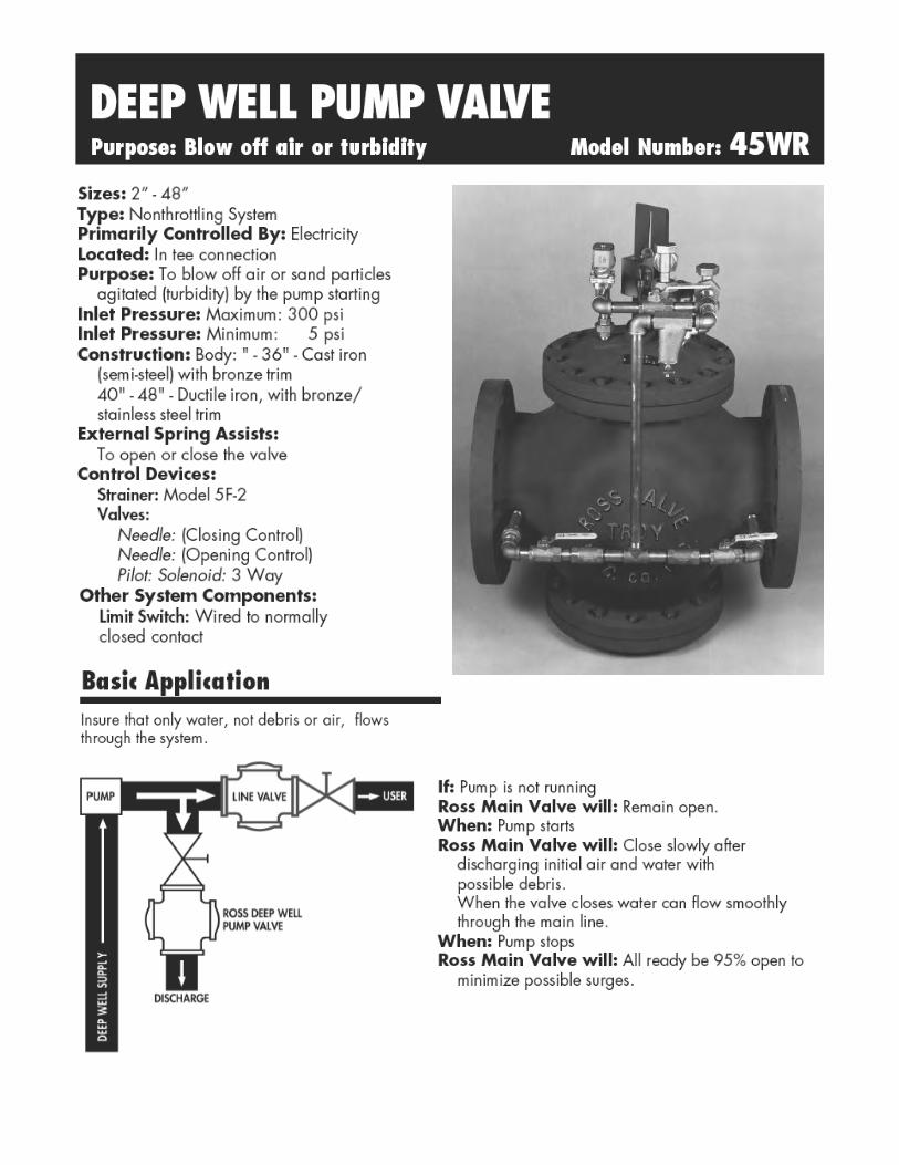
OperationBecause the valve is full open when the pump starts andthen slowly closes, it effectively discharges unwanted airand sand particles from the system before water flowsthrough the main line.
In addition the valve insures a smooth stopping andstarting flow in the system by closing slowly after the pumpstarts and being 95% open before the pump stops.A. A deep well pump valve is normally open. In order to
close it, the1. Control switch contacts close, energizing the relay
coil R.2. Two R contacts close together energizing the:
a. Normal solenoid coil S3.b. Pump motor starter coil M.
3. Pump starts4. Initial air, water which might contain sand particles
gets discharged from the system through the openvalve located in a tee.
5. When the pump develops enough line pressure, thevalve slowly closes.
6. As the valve closes, limit switch, LS, closes andparallels the R contact to be in series with the pumpmotor starter M.
B. In order to open the deep well valve, the1. Control switch contacts open, de-energizing the
relay coil R.2. Two R contacts open and de-energize only the
normal solenoid coil S3.3. Deep well pump valve begins to open.4. Limit switch, whose contacts are still closed, continues
to energize the pump motor starter coil M.5. Pump continues running.6. Main line valve reaches 95% open causing the limit
switch contacts to open and de-energizing the pumpmotor starter M.
7. Pump stops.
Simple example incorporating Second2 Way Solenoid (customized) feature.
CS = Control SwitchM = Motor Starter RelayR = Double Pole Normally Open RelayLS = Limit Switch (Shown in Valve Closed
Position)S3 = Normal Solenoid Coil
NoteMake sure the main pump breaker is open before any workis done on the valve.
DEEP WELL PUMP VALVEOperation Model Number: 45WR
)520�75$16)250('
������02725�32:(5
5
2))
0$18$/
6�
5
$872 &6
12
/6
1&0
5
Note
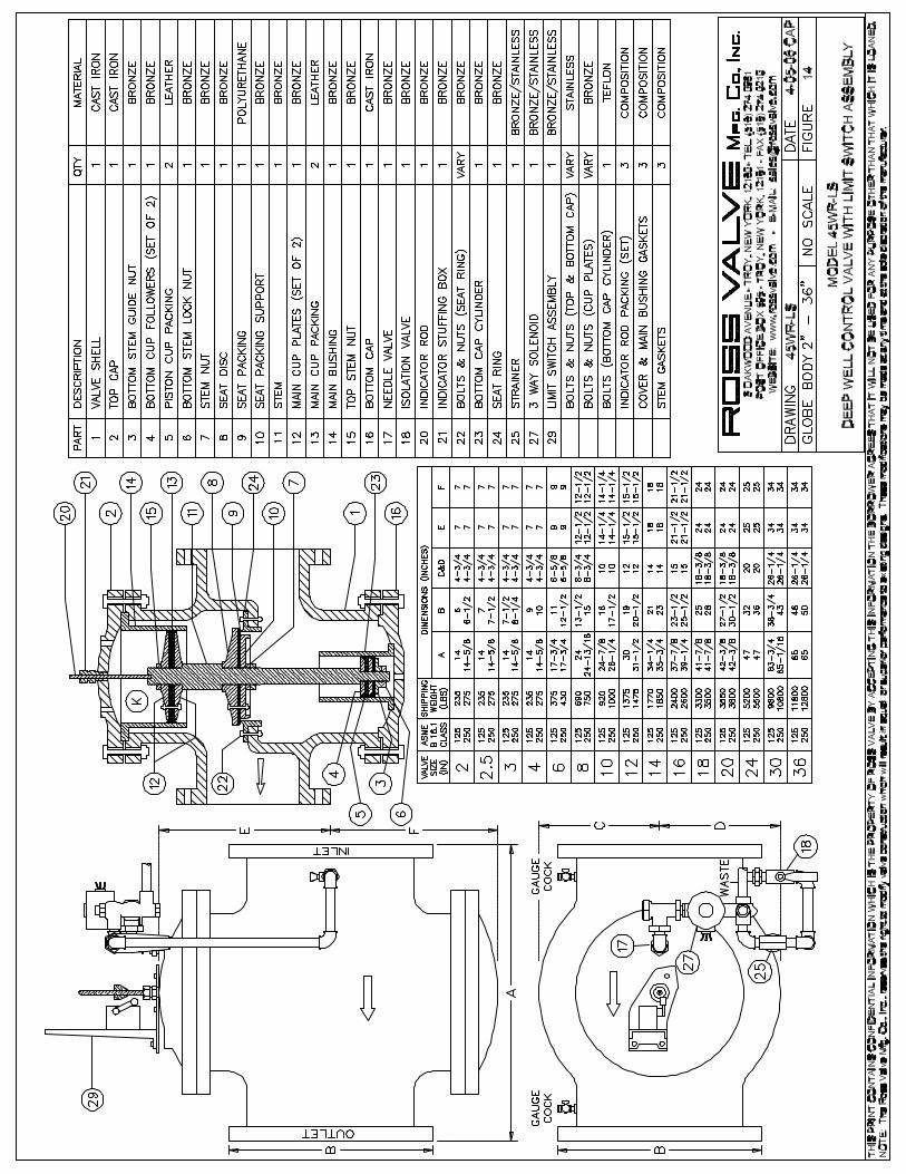
1. Dimension “O” is clearance for removal of the top capand piston for repacking the main valve. Additionalworking space for the convenience of the service manshould be considered above as well as around thevalve.
2. Dimension “P” as listed is the desirable clearance underthe valve for removal of the STANDARD bottom cap.This dimension may be reduced to 1 inch for all valveson special applications.
Note
A. Do not obstruct vent hole located at the centerof the bottom cap.
B. Consideration should be given for installation of valves14” or larger under manhole in the roof of the valvevault or for additional clearance above the valve sincea mechanical hoist will probably be required forremoval of the piston. An eye bolt or hook cast in thecover slab over the center of the valve is useful.
C. If clearance under the valve is limited, dimensions“O” and “P” can be modified. Consult the factoryconcerning special applications.
DIMENSIONSGlobe Body Minimum Clearances Piston Valve Sizes: 4” - 36”
• Designed for high flow and high pressure service.
• Direct acting, requires no minimum operating pressure.
• Choice of metal seating materials to handle aggressive fluids, or resilient seating for airtight shutoff.
• Ideal for power plants and similar applications.
3.01 R1
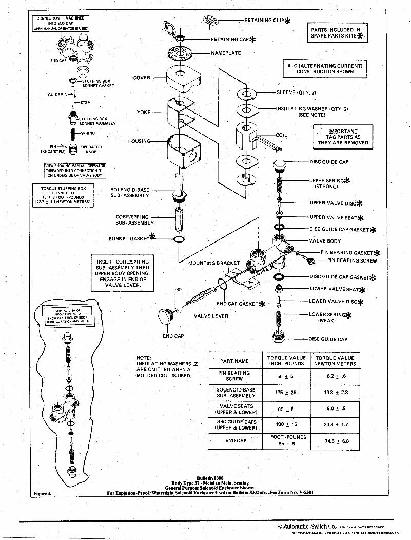
Direct ActingGeneral Service Solenoid Valves
Brass or Stainless Steel Bodies1/8" to 1/2" NPT
23
1
NC
NO
3/2SERIES83008315
Solenoid Enclosures
Electrical
Nominal Ambient Temperature Ranges:Class F Coils AC: 32˚F to 125˚F (0˚C to 52˚C)
Class H Coils AC: 32˚F to 140˚F (0˚C to 59˚C)
Class H Coils DC: 32˚F to 77˚F (0˚C to 25˚C)(104˚F/40˚C occasionally)
Refer to Engineering Section for details.
Approvals:CSA certified. Meets applicable CE directives.Refer to Engineering Section for details.
Construction
Standard: Red-Hat II - Watertight, Types 1, 2, 3, 3S, 4, and 4X; Red-Hat - Type 1.Optional: Red-Hat II - Explosionproof and Watertight, Types 3, 3S, 4, 4X, 6,
6P, 7, and 9; Red-Hat - Explosionproof and Watertight, Types 3, 4, 4X, 7, and 9. See footnote on next page.(To order, add prefix “EF” to catalog number.) See Optional Features Section for other available options.
U
StandardCoil andClass of
Insulation
Watt Rating and PowerConsumption Spare Coil Part Number
DCWatts
AC General Purpose Explosionproof
WattsVA
HoldingVA
Inrush AC DC AC DCF - 20.1 43 240 272610 - 272614 -
H 36.2 28 60 330 222345 222184 222345 222184
H - 16.1 35 180 272810 - 272814 -
H - 28.2 50 385 224195 - 224195 -
Standard Voltages: 24, 120, 240, 480 volts AC, 60 Hz (or 110, 220 volts AC, 50 Hz). 6, 12, 24,120, 240 volts DC. Must be specified when ordering.
Note: 125 and 250 volts DC are battery voltages applied in power plants. Special AC andDC constructions are available to pilot power plant control valves. Consult your localASCO sales office for details.
Valve Parts in Contact with Fluids
Body Brass 304 Stainless Steel
Disc 303 Stainless Steel (Metal), PA or Brass (Resilient)
Seats NBR,Phosphor Bronze 303 Stainless Steel
Core Tube 305 Stainless Steel Core and Plugnut 430 F Stainless Steel
Springs 302 Stainless Steel, 17-7PH or Iconel
Shading Coil Copper Silver
Gaskets NBR PTFE
4qwer
Model Number: 5F-2
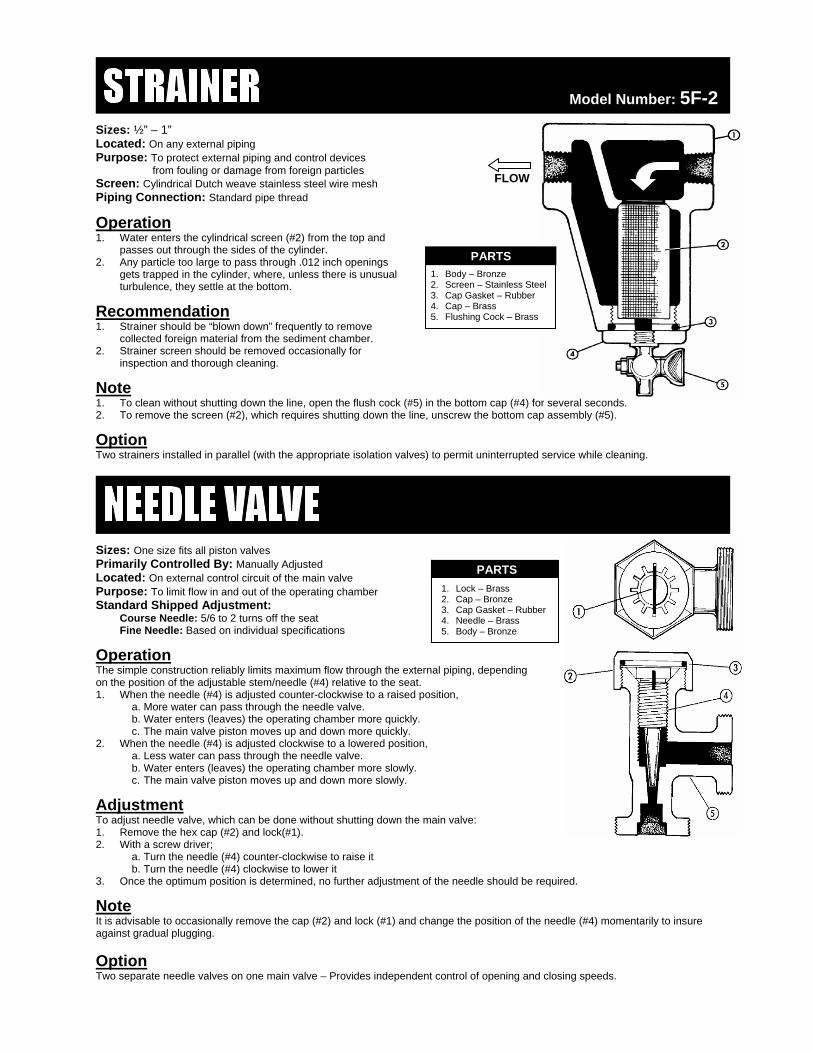
Sizes: ½” – 1” Located: On any external piping Purpose: To protect external piping and control devices
FLOW from fouling or damage from foreign particles
Operation 1. Water enters the cylindrical screen (#2) from the top and
passes out through the sides of the cylinder. PARTS 1. Body – Bronze 2. Screen – Stainless Steel 3. Cap Gasket – Rubber 4. Cap – Brass 5. Flushing Cock – Brass
2. Any particle too large to pass through .012 inch openings gets trapped in the cylinder, where, unless there is unusual turbulence, they settle at the bottom.
Recommendation 1. Strainer should be “blown down” frequently to remove
collected foreign material from the sediment chamber. 2. Strainer screen should be removed occasionally for
inspection and thorough cleaning.
Note 1. To clean without shutting down the line, open the flush cock (#5) in the bottom cap (#4) for several seconds. 2. To remove the screen (#2), which requires shutting down the line, unscrew the bottom cap assembly (#5).
Option Two strainers installed in parallel (with the appropriate isolation valves) to permit uninterrupted service while cleaning.
Sizes: One size fits all piston valves Primarily Controlled By: Manually Adjusted PARTS
1. Lock – Brass 2. Cap – Bronze 3. Cap Gasket – Rubber 4. Needle – Brass 5. Body – Bronze
Located: On external control circuit of the main valve Purpose: To limit flow in and out of the operating chamber Standard Shipped Adjustment: Course Needle: 5/6 to 2 turns off the seat Fine Needle: Based on individual specifications
Operation The simple construction reliably limits maximum flow through the external piping, depending on the position of the adjustable stem/needle (#4) relative to the seat. 1. When the needle (#4) is adjusted counter-clockwise to a raised position,
a. More water can pass through the needle valve. b. Water enters (leaves) the operating chamber more quickly. c. The main valve piston moves up and down more quickly.
2. When the needle (#4) is adjusted clockwise to a lowered position, a. Less water can pass through the needle valve. b. Water enters (leaves) the operating chamber more slowly. c. The main valve piston moves up and down more slowly.
Adjustment To adjust needle valve, which can be done without shutting down the main valve: 1. Remove the hex cap (#2) and lock(#1). 2. With a screw driver;
a. Turn the needle (#4) counter-clockwise to raise it b. Turn the needle (#4) clockwise to lower it
3. Once the optimum position is determined, no further adjustment of the needle should be required.
Note It is advisable to occasionally remove the cap (#2) and lock (#1) and change the position of the needle (#4) momentarily to insure against gradual plugging.
Option Two separate needle valves on one main valve – Provides independent control of opening and closing speeds.
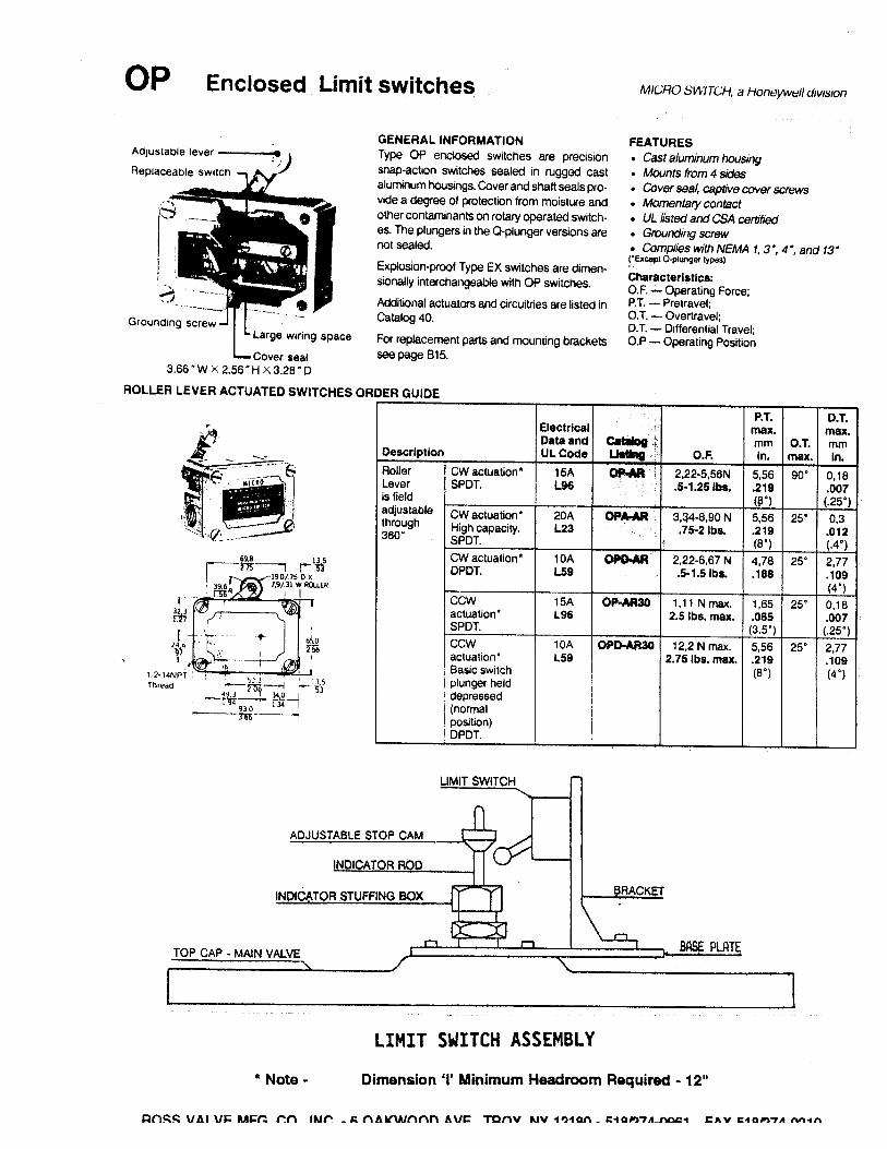
Limit and Enclosed Switches OP SeriesEnclosed Switches
OP enclosed switches are precision snap-action switches sealed in rugged cast alumi-num housings. Cover and shaft seals keepout moisture and other contaminants on ro-tary operated switches. The plungers in theQ-plunger version are not sealed.
Refer to page A123 for explosion-proof TypeEX switches, which are dimensionally inter-changeable with OP switches.
1 UL Recognized, file #E122521 CSA Certified, file #LR573251 Grounding screw1 NEMA 1, 3*, 4* and 13*(* Except Q-plunger and high temperature types)
P.T. D.T.max. max.
Elec. Catalog mm O.T. mmDescription Rating Listing O.F. in. max. in.
RollerLever isfieldadjustablethrough360N
CW actuation*SPDT
A OP-AR 2,22-5,56 N.5-1.25 lbs.
5,56.219(8°)
90° 0,18.007(.25°)
N J Newtons* Actuation is designated as CW (clockwise) orCCW rotation, when looking at the switchnameplate.† Choice of levers available for use with OP-AR20:6PA5-EX (non-sparkling roller), 6PA6-OP (steelroller), 6PA127-EX (nylon roller), 6PA130-EX (CW).6PA142-EX (CCW), and 6PA136-EX (Aluminumrod).
For rapid response – off the shelfservice, all bold face listings arenormally stocked items.
FF c o c o actory: actory: Telephone (518) 274 - 0961; Fax (518) 274 - 0210
cLocated:Wherever anelectric switchcontrol is needed.
n c Contact: 10 AMPr se:Purpose:1. To signal if the
valve is openedor closed.
2. To start or stopallied equipment.
OperationPerforms as an on/off switch.
ROSS ADVANTAGEBecause it is waterproof, the switch can beused anywhere.
O - Normallyopen contact
C - Normallyclosed contact
- COM - Common
o :Note: A double pole switch (2 N.O. and 2 N.C.)contacts can be supplied as an extra.
LLLLI T WIIMIT SWII WIT IMIT SWITTTTCHCHCHCH
ROSS GLOBE VALVE
PREVENTIVE MAINTENANCE
Intervals of inspection vary from valve to valve. Type of valve, quality of water being handled, rates of flow,operating pressures, and past maintenance practices all have a bearing on the length of service betweenoverhauls.
So some recommendation may guide the operator, we suggest periodic inspections in order to check for propervalve operating pressures, as well as any visual leaks. Should the operator encounter any external leakage,or find any abnormalities in the operating pressures resulting from the operation of the valve, the valve shouldbe scheduled for service.
EVERY TWO (2) MONTHS:
1. Flush the strainer via the flushing cock.
2. Flush the needle valve by turning then needle clockwise ½ turn, counter-clockwise 2 turns,then clockwise 1-1/2 turns to original setting.
3. Visually inspect for leaks around the indicator rod, bottom cap/differential vent hole, or pilotvalves (hydraulic & /or solenoid).
4. Inspect drain line connection.
EVERY FOUR (4) MONTHS:
1. Remove and inspect strainer screen.
2. Remove and inspect needle valve, being sure to take note of the needle position away from theseat (number of turns).
3. Same visual inspection as above.
Important: Condition of the main valve packing can be accurately gauged by observing the leakage throughthe bottom vent hole “C”. Negligible leakage usually indicates serviceable packing.
Lubrication: None Required.
Spare Parts: None required, recommended, or supplied unless specified. Under normal operating conditions,no spare parts would be necessary within five (5) years of service. The standard repair kit for Ross valves arein stock at the factory, and available for immediate shipment upon receipt of order with valve serial number(located on metal tag pinned to the top cap of the main valve).
ROSS VALVE MFG. CO., INC., TROY, NY 12180 @ PHONE 518/274-0961 @ FAX 518/274-0210
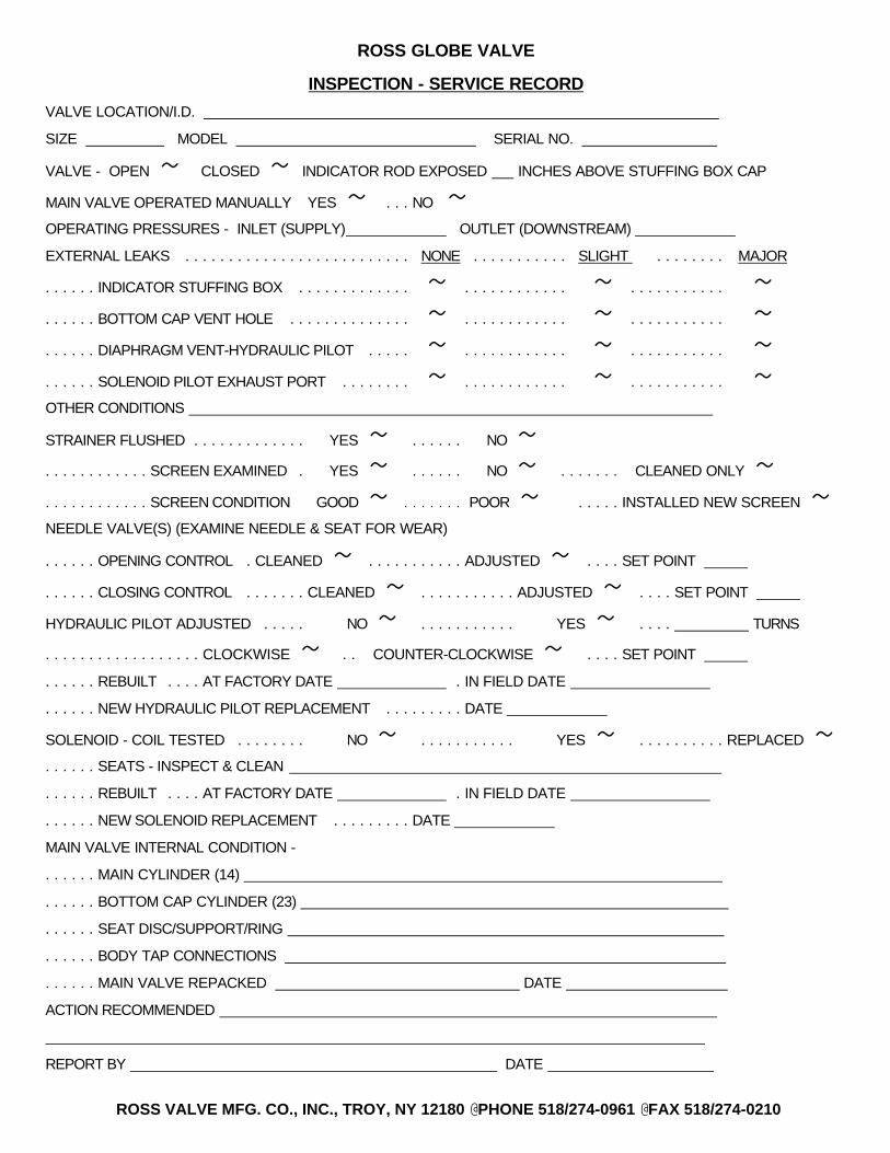
ROSS GLOBE VALVE
INSPECTION - SERVICE RECORD
VALVE LOCATION/I.D.
SIZE MODEL SERIAL NO.
VALVE - OPEN ~ CLOSED ~ INDICATOR ROD EXPOSED INCHES ABOVE STUFFING BOX CAP
MAIN VALVE OPERATED MANUALLY YES ~ . . . NO ~OPERATING PRESSURES - INLET (SUPPLY) OUTLET (DOWNSTREAM)
. . . . . . REBUILT . . . . AT FACTORY DATE . IN FIELD DATE
. . . . . . NEW SOLENOID REPLACEMENT . . . . . . . . . DATE
MAIN VALVE INTERNAL CONDITION -
. . . . . . MAIN CYLINDER (14) . . . . . . BOTTOM CAP CYLINDER (23)
. . . . . . SEAT DISC/SUPPORT/RING
. . . . . . BODY TAP CONNECTIONS
. . . . . . MAIN VALVE REPACKED DATE
ACTION RECOMMENDED
REPORT BY DATE
ROSS VALVE MFG. CO., INC., TROY, NY 12180 @ PHONE 518/274-0961 @ FAX 518/274-0210
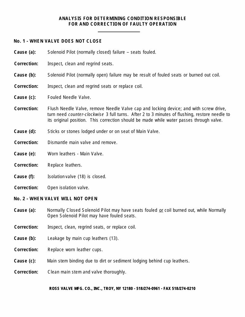
ANALYSIS FOR DETERMINING CONDITION RESPONSIBLEFOR AND CORRECTION OF FAULTY OPERATION
No. 1 - WHEN VALVE DOES NOT CLOSE
Cause (a): Solenoid Pilot (normally closed) failure – seats fouled.
Correction: Inspect, clean and regrind seats.
Cause (b): Solenoid Pilot (normally open) failure may be result of fouled seats or burned out coil.
Correction: Inspect, clean and regrind seats or replace coil.
Cause (c): Fouled Needle Valve.
Correction: Flush Needle Valve, remove Needle Valve cap and locking device; and with screw drive,turn need counter-clockwise 3 full turns. After 2 to 3 minutes of flushing, restore needle toits original position. This correction should be made while water passes through valve.
Cause (d): Sticks or stones lodged under or on seat of Main Valve.
Correction: Dismantle main valve and remove.
Cause (e): Worn leathers - Main Valve.
Correction: Replace leathers.
Cause (f): Isolation valve (18) is closed.
Correction: Open isolation valve.
No. 2 - WHEN VALVE WILL NOT OPEN
Cause (a): Normally Closed Solenoid Pilot may have seats fouled or coil burned out, while NormallyOpen Solenoid Pilot may have fouled seats.
Correction: Inspect, clean, regrind seats, or replace coil.
Cause (b): Leakage by main cup leathers (13).
Correction: Replace worn leather cups.
Cause (c): Main stem binding due to dirt or sediment lodging behind cup leathers.
Correction: Clean main stem and valve thoroughly.
ROSS VALVE MFG. CO., INC., TROY, NY 12180 - 518/274-0961 - FAX 518/274-0210ROSS VALVE MFG. CO., INC., TROY, NY 12180 - 518/274-0961 - FAX 518/274-0210
H:\WP Version 8\Repair Instructions\Large Valve\WI1311_Rev. A - Large Globe Valve.wpd - Effective Date:
REPAIR INSTRUCTIONS - GLOBE BODY VALVES
When entering a valve pit to inspect a valve, all regulations regarding Confined Space Entry should be observed.
So some recommendation may guide the operator, we suggest periodic inspections in order to check for proper valve operatingpressures as well as any visual leaks. Should the operator encounter any external leakage or find any abnormalities in theoperating pressures which appear to be caused by the valve, the valve should be scheduled for service.
A reliable indication of internal packing condition can be obtained by observing any leakage from the vent hole in the centerof the bottom cap. When leakage becomes significant, packing replacement should be made. As a general statement, theoverall average life of a set of packings is 7 to 10 years. This may vary considerably because of specific operating conditions.
After observing pressures and inspecting for external leakage, the flush cock on the strainer should be opened momentarily toremove accumulated material. The needle valve cap should be removed and the needle closed 1/2 turn, opened 1 full turn, andthen closed 1/2 turn to its original position.
STEPS FOR INTERNAL REPAIRS:
All repairs and parts replacement may be made without removing the valve from the line. Internal repairs are made by removingthe top cap of the valve. All internals are accessible through the top.
Shut inlet main line isolation valve, then shut outlet main line isolation valve. Open gauge cocks to de-pressurize the valve.
Remove indicator rod by inserting a nail through hole and unscrewing. Do not pull through stuffing box. Then remove top capbolts and top cap. Be careful not to bend indicator rod.
In 8" and larger valves, withdraw piston by either removing two 3/8" bronze bolts in top stem nut and installing lifting device(horseshoe shaped piece of steel with two holes) over nut; or by looping a cable or nylon rope around these bolts. Be surelifting device is secure before removing piston. In 4" and 6" valves, a threaded eyebolt should be screwed in the indicatorrod hole.
Inspect both main bushing (Part No. 14) and bottom cylinder (Part No. 23) for mineral build-up or scoring. Smooth with emeryor replace if necessary. Inspect seat ring for damage. Repair as necessary.
Secure main piston on a pipe threading stand (or lay piston on floor on rags or a similar cushioning material). Loosen top stemnut (Part No. 15) which holds the cup plate assembly. Remove cup plate bolts, nuts and copper washers on 8" cups and larger.Replace the leather cups (one faces up, one faces down). Re-install with new packings in the reverse order as outlined above.
Caution - The clamping bolts should be tight so that the packings are held securely and no leak occurs. Do not over-tightenso that the packing is deformed, however. All cup packings are impregnated with lubricants so that no external lubrication isnecessary or desirable.
To replace the seat packing, it is necessary to determine if the valve is constructed with a "sliding" or a "flat" type seat. Thesliding type seat has the seal or seat packing clamped in the valve body underneath the iron wall that separates the inlet andoutlet valve chambers. It consists of a flanged packing held in place by a split bronze seat support ring. The lip of the packing"looks down" and care should be taken that the packing is concentric with the valve bore before the clamping bolts are tightened.In the "flat" type seat, the seat packing is located on the valve piston, where it is clamped between two plates and held by a stemnut (Part No. 7). Removal of this nut allows the plates to be separated and the packing replaced.
Replacement of the bottom cups (Part No. 5) is accomplished by removing the bottom stem lock nut (Part No. 6) and the flangedbottom guide nut (Part No. 3). Install the seals with the lip of both cups "looking up". Again, when re-assembling, be carefulnot to over tighten so that the cups are deformed.
Re-insert the piston being careful not to crimp the lower main cup when it enters the main bushing. The piston should move freelyand drop of its own weight.
Replace the top cap and control piping (being sure to thread in the indicator rod), then restore water pressure. Be sure to openthe discharge isolation valve first so that high inlet pressure is not trapped against a closed outlet valve.
All replaceable packings and gaskets are stock items and may be ordered as a repair kit for valve serial number .They are available for regular UPS delivery or next day service.
All spare parts are available from: Ross Valve Mfg. Co., Inc., 6 Oakwood Avenue, Troy, New York, 12180Phone: (518) 274-0961, Fax: (518) 274-0210