72
Authors: Valentino Cavalli (editor), John Dyer, Michael Enrico, Eoin Kenny, Michal Przybylski, Roberto Sabatino, Stanislav Sima

Authors: Valentino Cavalli (editor), John Dyer, Michael Enrico, Eoin Kenny,
Michal Przybylski, Roberto Sabatino, Stanislav Sima
def. SERENATE D9 23-02-2006 09:41 Pagina 1

P.2
ISBN-90-77559-03-5Production: TERENA SecretariatDesign: Eva de LangePrinting: GraphicResult
TERENA 2003 © All rights reserved. Parts of this report may be freely copied, unaltered, provided that the originalsource is acknowledged and the copyright preserved.
The SERENATE project was an Accompanying Measure in the Information SocietyTechnologies programme of the Fifth Framework Programme for Research andTechnological Development, and was supported as such by the EuropeanCommunity. The SERENATE project consortium is solely responsible for thispublication, which does not represent the opinion of the European Community; the Community is not responsible for any use that might be made of data appearingin this publication.
def. SERENATE D9 23-02-2006 09:41 Pagina 2

P.3
CONTENTS
1. EXECUTIVE SUMMARY 61.1. Introduction 61.2. Current networking environment 61.3. Basis for the study 71.4. Summary of findings 81.5. Conclusions 10
2. INTRODUCTION 12
3. ROUTING EQUIPMENT 143.1. Scalability 143.2. Functionality 183.3. Interoperability with other networking components 193.4. Virtual routers 203.5. Router management 213.6. Conclusions 21
4. SWITCHING EQUIPMENT 224.1. Optical cross connects 224.2. Photonic cross connects 244.3. All-optical networks 264.4. The future of switching equipment 274.5. Conclusions 28
5. FIBRES AND TRANSMISSION EQUIPMENT 295.1. Fibre types and capacity 295.2. Transmission components 305.3. Reach 315.4. Economics and future expectations 335.5. Conclusions 35
6. NETWORK MANAGEMENT OF NETWORKS AT 40 Gb/s AND ABOVE 366.1. Network Management Systems (NMS) 376.2. Control planes 386.3. Management tools 406.4. Conclusions 41
7. NETWORK ARCHITECTURES 427.1. Requirements for future research networks 427.2. Network architecture options 437.3. Conclusions 49
def. SERENATE D9 23-02-2006 09:41 Pagina 3

8. CUSTOMER-EMPOWERED NETWORKS 50 8.1. Rationale 508.2. Dark fibre 51
9. FUTURE AND EMERGING TECHNOLOGIES 549.1. Fibre technologies 549.2. Optical switching 559.3. Error correction techniques 569.4. Hyperfine DWDM 57
10. GENERAL CONCLUSIONS 5810.1.Transmission capacities 5810.2.Routers 6010.3.Intelligent optical switching 6010.4.All-optical networking 61
ANNEX I List of Acronyms 62
ANNEX II Questionnaire Used in the Interviews 65
P.4
def. SERENATE D9 23-02-2006 09:41 Pagina 4

P.5
def. SERENATE D9 23-02-2006 09:41 Pagina 5
Executive summary
1.1. Introduction
The basic service provided by National Research and Education Networks (NRENs) nationally totheir users is a best-efforts IP service.The equivalent service is extended across Europe, and toresearch networks in other world regions, by the GÉANT* network.The characteristic of a best-efforts IP service is that it offers ubiquitous connectivity, but that is all.There are no guarantees ofperformance. In parallel, with best-efforts IP, there have been a number of national and pan-European initiatives to offer guaranteed performance between end-locations in the form of VirtualPrivate Networks as well as a multicast service which provides network-based broadcastingcapabilities.There is a generally increasing demand from users for higher performance and/or morepredictable services.This study examines the way telecommunications technology is likely todevelop in the next five years, its ability to meet user demands, and the effects this can have on theimplementation of research networking in Europe.
1.2. Current networking environment
The best-efforts IP service is normally provided by routers accessed by, and interconnected by, leasedcircuits. Historically, both nationally and internationally within Europe, leased circuits were providedby monopoly telecommunications operators.As a consequence, there was considerable reluctance,on the part of these operators, to provide access to leading-edge technology. Service provision, asdefined by speed of operation of connectivity provided and availability was generally rationed andexpensive.The liberalisation of the European telecommunications marketplace has changed thispicture quite dramatically in the last four years. For many locations in Europe, it is now possible togain access to leased connectivity, which offers the maximum performance technically availabletoday (currently 10 Gb/s). In addition, liberalisation has, in some locations, allowed direct access tophysical connections, typically fibre-optic cables.This has enabled some NRENs to implement theirown transmission technology rather than relying on services provided by telecommunicationsoperators.These factors are changing the technical options available for constructing researchnetworks in Europe.
A further factor of importance is the emergence of groups of users with potentially very largedemands for connectivity between a limited number of locations.There have been several reasonsfor this, notably:
1.The enormous reductions in cost, particularly for international connectivity, have enabled anumber of research activities to consider network-based solutions for their connectivity needswhere previously these were too expensive.This meant that, in the past, either research co-operation was geographically constrained or that alternative ‘non-network’ based communicationssuch as the physical transport of magnetic tapes were employed.
Availability and Characteristics of Equipment / Executive Summary
P.6* http://www.dante.net/geant/
1
def. SERENATE D9 23-02-2006 09:41 Pagina 6

2.The very large, and increasing, costs of research infrastructure have led to a much more Europeanapproach to research and, as a consequence, a significant increase in the demand for pan-Europeanresearch connectivity.The European Research Area is the political manifestation of this trend.
3.The development of distributed computing power, capable of exploiting high-capacity wide-areaconnections, and the standardisation of these capabilities in the Grid computing initiatives.
All the above factors mean that the simple model of a basic,‘best-effort’ IP service provided byrouters, is no longer sufficient to meet the service requirements of an environment where there maybe very large flows of data between a limited set of locations, and which requires predictable anddefined performance. In addition, the option of a direct implementation of transmission technology,as an alternative to leasing capacity from telecommunications operators, opens new technicalopportunities for the provision of service.
1.3. Basis for the study
The study focuses on four areas of technology namely:
1.Routers.These are currently the basic building blocks of an IP network.They are packet switchesthat operate and process on a per-packet basis.
2.Optical switching devices.These are relatively new products designed to switch streams of data ona per-stream basis. In this context a stream is defined as a synchronised stream of bits.
3.Transmission equipment.This equipment is responsible for transmitting data, in the form of a bitstream, between switches or routers.
4.Network control techniques.These enable network operators such as NRENs or DANTE tomanage the various elements that are used to construct networks.When only providing best-efforts IP services, based on interconnected routers, there is limited network intelligence, andnetwork control techniques are not very important.As equipment becomes more complicatedand varied, the ability to manage and control network elements becomes a significant issue.Aparticular question here is the extent to which such control techniques can operate acrossnetworks managed by different network operators.
A questionnaire, covering aspects such as development and deployment plans for higher-capacitytransmission (40 Gb/s and higher speeds), optical and photonic switching developments, andnetwork management and control, was completed by 12 equipment vendors and 2 researchlaboratories.The questionnaire was used mainly as a guideline for subsequent face-to-facediscussions.These discussions were targeted at understanding the developments, issues and benefitsof the technologies mentioned above.The results were analysed from two perspectives: from anequipment type perspective (routers, switches, transmission equipment) and from the perspective ofthe way these different elements could be combined to create future networks, paying particularattention to speed of operation (40 Gb/s and higher speeds), network management and theimplications these have on future network architectures.
Availability and Characteristics of Equipment / Executive Summary
P.7
def. SERENATE D9 23-02-2006 09:41 Pagina 7

1.4. Summary of findings
1.4.1. Routers
IP routers are mature products and offer a wide range of functionality (multicast, IPv6, differentiatedservices, MPLS).These features are becoming common on most routers targeted at researchbackbone networks. In most cases they are, or will become conformant to standards and will be ableto operate so that they fully utilise the transmission rate of the circuits to which they are connected.In many cases this is already possible. In terms of developments, for interfaces operating at 40 Gb/sand higher speeds, a number of manufacturers already offer the switching capacity, i.e. the abilitywithin the router itself to support interfaces operating at 40 Gb/s, although interface cards offeringsingle-channel 40 Gb/s are not yet available.This is due to:
1.low demand for interfaces operating at this speed,
2.high prices (several vendors stated that a single 40-Gb/s interface was likely to be more expensivethan the aggregate cost of four 10-Gb/s interfaces)
3.the lack of commercial transmission services operating at 40 Gb/s.
For the next two years it is expected that a 40-Gb/s connection to an IP router will be delivered byfour 10-Gb/s channels.A common view is that demand for routers in the research community willbe the main driver for availability of commercial, single-channel 40-Gb/s systems
1.4.2. Optical switching devices
In the last few years a lot of attention has been given to all-optical switching. Sometimes the term‘all-optical’ has been confused with devices that offer optical interfaces but operate partially usingelectrical technology. For example, devices that are able to switch and multiplex Gigabit Ethernet(GE) and SONET frames are optical switches, insofar as they offer optical interfaces, but they useelectrical technology to carry out the switching.These devices are also called O-E-O devices(optical-electrical-optical) and have been available for some time, although they are undergoingsignificant developments in terms of scalability and granularity of the services they can offer.Themain issues that need to be resolved for these switches over the next few years relate tostandardisation of functionality and interoperability.
The term ‘all-optical’ relates to switching equipment that operates entirely using optical signals, andtherefore is also referred to as O-O-O devices.They are independent from (or transparent to) thesignal that is being carried over an optical channel (GE, 10 Gb/s, 40 Gb/s,…).These switches use avariety of complex light-switching techniques, such as MEMs (Micro Electromechanical Mirrors),liquid crystals and other ‘proprietary’ methods.While the technology for all-optical switching isimproving rapidly, and all-optical switches are available at reasonable prices, there remain somefundamental issues with this technology.These include re-routing of light paths with or withoutelectrical regeneration.The distances between amplifier sites may be different between a main pathand a re-routed path.As a result, optimal engineering rules, required by this analogue technology,may not be met in case of re-routing, and the switches themselves also introduce relatively highattenuation of optical signals.
Availability and Characteristics of Equipment / Executive Summary
P.8
def. SERENATE D9 23-02-2006 09:41 Pagina 8

In addition, devices that operate using electrical technology remain needed for multiplexing andbandwidth grooming, allowing bit streams with various combinations of speed of connectivity to bemultiplexed and switched efficiently, although these functions may be confined more towards theedges of the network.The main advantages of all-optical technology relate to protocolindependence, lower unit cost and lower operational costs, particularly in support of 40 Gb/s andhigher speeds.
1.4.3. Transmission technology
1.4.3.1. Speed
Transmission technology developments have demonstrated that speeds of 40 Gb/s, and higher, aretechnically possible. In fact, speeds up to 600 Gb/s transmission have been demonstrated in alaboratory environment. Offering 40 Gb/s, commercially, at attractive prices is a different matter,influenced by numerous factors.These include general market conditions, and mass production,which will drive prices up or down, as well as many technical details. From a technical perspective40 Gb/s is much more complex to implement than 10 Gb/s.Transmission degradations, such asdispersion, cross talk and attenuation, are significantly more pronounced than is the case for lowerspeeds. Consequently, techniques to compensate for these effects must be developed, and betteramplification methods, compensation for Polarisation Mode Dispersion (PMD) and complexForward Error Correction (FEC) methods need to be deployed.This will all increase the price forintegrated systems operating at 40 Gb/s in a full operational environment. It is thought that, over thenext few years, the improvement of Forward Error Correction techniques will be the main enablerfor commercial availability of 40-Gb/s transmission systems.
Commercial 40-Gb/s systems will certainly be available soon. It is unclear where we will see theirfirst appearance.Transmission equipment vendors interviewed felt this would be in the market ofUltra Long Haul (up to 4,000 km) transmission systems, while router vendors foresee that thiswould be in the metropolitan area in 2003.
1.4.3.2. Reach
Many NRENs are currently deploying, or planning to deploy, their own fibre.This is enabled by theincreasing developments of transmission technologies, which, even if components are not yet off-the-shelf, allow NRENs to adopt a ‘do-it-yourself ’ approach towards the network infrastructure, incontrast with the traditional approach of buying connectivity from carriers.The reach oftransmission equipment is of crucial importance for understanding and planning appropriatenetwork architectures that satisfy the needs of NRENs without involving excessive costs.Unfortunately, NRENs still have limited experience with transmission equipment. Reach dependson many factors including fibre type, fibre quality, bit-rate of each wavelength, the number ofwavelengths transmitted in parallel, amplification and transmission technology used, FEC and othercomponents.
An issue with transmission is the need to regularly boost the signal between circuit endpoints.Transmission technology is improving significantly in relation to the spans between amplification(boosting the size of the signal to offset attenuation) and regeneration (reconstituting the signal toeliminate signal distortion). Current transmission systems for 2.5 Gb/s or 10 Gb/s requireregeneration of the signal after four or five amplification stages.This means: after approximately 400km. Newer transmission technology will enable 10 Gb/s to be transmitted up to 4,000 km without
Availability and Characteristics of Equipment / Executive Summary
P.9
def. SERENATE D9 23-02-2006 09:41 Pagina 9

regeneration. For 40 Gb/s this range is expected to be up to 1,000 km.There is no currentknowledge of the relative costs of such equipment.The provision of amplification and regenerationequipment in the network is operationally complicated and expensive, since it can impose therequirement to install and operate equipment in remote locations where NRENs have no reason tobe present. Increasing span lengths will enable new network architectures for future researchnetworks, where the ownership and management of long-distance fibre spans, without the need foramplification and regeneration, becomes a possibility worth serious consideration.This is known as‘Nothing-in-Line’ operation, reflecting the absence of any amplification and regenerationequipment between the terminating points of the fibre. Successful experiences in this direction aretaking place in Europe already, as demonstrated by CESNET, the Czech NREN, in reaching 230km with Nothing-In-Line (NIL).
1.4.4. Network control capabilities
The next-generation research networks are very likely to include a mixture of networkingelements (routers, optical and/or photonic switches, multiplexing devices and possibly transmissionequipment). In addition the service portfolio that will be offered to users is intended to allowgreater user control over network resources and performance.All of these trends imply muchgreater real-time operational-control network resources.To achieve this, NRENs will have tointroduce new element managers in their network management systems.They will have to becomeaccustomed to different protocols, traditionally used by telecommunications operators, which differconsiderably from the techniques used in IP.Advances in TMN/Corba (telecommunications opera-tors’ world) and SNP/Corba (IP world) will assist in the integration of different network manage-ment systems, although, at present, these standards are immature and require much development.
The organisational structure of research networking is expected to remain unchanged.This willrequire a much more co-operative approach, among network operators, to resource allocation andcontrol if end-to-end services, crossing the management domains of individual NRENs, areprovided to end-users.The development of G-MPLS, and its availability in IP routing and switchingequipment, will facilitate developments in this direction. However, despite standardisation efforts,most implementations, especially for switching equipment, are proprietary and non-interoperable atpresent.A fundamental issue still unsolved is the inter-domain operation of research networks.
1.5. Conclusions
A simple extension of the current service model of offering best-effort IP, at higher speeds ofoperation, will not meet emerging user requirements.
In the area of transmission technology, it is likely that 40 Gb/s systems will emerge in the next twoyears. It is perceived that these will not necessarily be cost-effective and the use of parallel slower-speeds wavelengths is more appropriate at present.The potential exploitation of dark fibre is heavilydependent on the reach and economics of ‘Nothing-In-Line’ systems.This is currently limited tospans of less than 250 km.
There are developments in both routers and optical switches that suggest that a combination ofthese elements can effectively be used to provide a more flexible and manageable network structure.In the case of switching these will be based on O-E-O devices. Developments of O-O-Otechnology will require considerable additional effort before they result in useful products
Availability and Characteristics of Equipment / Executive Summary
P.10
def. SERENATE D9 23-02-2006 09:41 Pagina 10

Developments in network control suggest that it will be possible, in the future, to providemanagement functions that cross domain boundaries. However, this will require the emergence ofstandardised implementation of network management and control functions, particularly in the areaof G-MPLS.
Availability and Characteristics of Equipment / Executive Summary
P.11
def. SERENATE D9 23-02-2006 09:41 Pagina 11

Introduction
This report is part of SERENATE, the Study into European Research and Education NetworkingAs Targeted by eEurope, contributing to European policies, social objectives and economicdevelopment by providing inputs on initiatives that could help to keep European researchnetworking at the forefront of worldwide development.The objective of SERENATE is to provideinput to the formulation of policies by the European Commission, but also to national governmentsand funding bodies, the management of universities and research institutions, and the NationalResearch and Education Networks (NRENs). It focuses on the technology building blocks that areused to construct research networks and considers how developments in these building blocks willchange the structure and technical organisation of research networking.
This report presents a study on the characteristics of equipment for next-generation networking, inparticular routing, switching and transmission equipment available today, to understand what will beavailable in 5-years’ time. It also investigates emerging technologies, some of which are still in thelaboratories and will only become available in a longer timeframe.
The study is based on a series of individual meetings with leading equipment manufacturers andresearch institutions actively involved in the EU-funded OPTIMIST* project (a Thematic Networkfocusing on the development of photonic technologies in Europe).Additional desk research wascarried out.The following organisations participated in the meetings, which were held between 13November and 6 December 2002:
• Alcatel• Calient• Ciena• Cisco Systems• Corvis• Juniper Networks• Lucent Technologies• Marconi• Nortel Networks• PhotonEx• Tellium• Wavium• University of Essex• University of Gent.
Key technical and strategy personnel from the suppliers were interviewed in these meetings bySERENATE partners and consultants from PSNC, CESNET and HEAnet.A set of questions toprovide guidance for discussion during the meeting was sent in advance.The questionnaire, which isreproduced in Annex I to this report, was developed in collaboration with the optical networkinggroup of TF-NGN (the task force that looks into tests and experiments for the introduction of
Availability and Characteristics of Equipment / Introduction
P.12*http://www.ist-optimist.org/
2
def. SERENATE D9 23-02-2006 09:41 Pagina 12

next-generation networking technologies on GÉANT) and National Research and EducationNetworks.The questionnaire was only used as a framework for the interviews as not all questionswere relevant to all suppliers.
Non-disclosure agreements were signed with some of the companies and as a consequence,technical details are sometimes described in this report in a non-attributable form.
The report is structured by product classes. Some suppliers have products falling into more than onecategory.The input to the various sections is based on the following groups of suppliers:
• Routers (packet switches):Alcatel, Cisco, Juniper, Marconi, Nortel
• Switching equipment:Alcatel, Calient, Ciena, Cisco, Corvis, Lucent, Marconi, Nortel,Tellium,Wavium
• Transmission equipment:Alcatel, Ciena, Cisco, Corvis, Lucent, Marconi, Nortel, PhotonEx.
Optical networking has several consequences for network management and network architecture,and these are considered in detail in sections 6 and 7 of the report. Section 8 expands on the optionsfor alternative network architecture by discussing the feasibility of procuring dark fibres, whereassection 9 provides an analysis of emerging technologies.The final section adopts a different approachand, based on the information provided in the previous ones, draws general conclusions for theSERENATE study on key issues like network capacity, integration of optical and IP control plane,intelligent optical networking and all-optical networking.
Availability and Characteristics of Equipment /Introduction
P.13
def. SERENATE D9 23-02-2006 09:41 Pagina 13

Routing equipment
In a study of the expected evolution of packet switching technology (the key component of whichis the packet-based ‘router’1) a number of discrete features need to be considered. For this study, thefeatures are as follows:
• scalability (of nodes and links)• functionality• interoperability with other networking components• logical partitioning (virtual routers)• management.
This section does not explicitly discuss IPv6, which is arguably the next and most far-reachingstep technology change that research networking and the global Internet will experience.Thereason is that it is assumed that many networks will start deployment of IPv6 in a productionenvironment during the coming years. In readiness for this, most router vendors have alreadyimplemented IPv6 in their software releases and it is expected that optimised hardware supportfor handling IPv6 will become available during the next year or two. Many research networkshave well-advanced plans for introducing production IPv6 services and expect to do so during2003. For example, the GÉANT backbone should offer IPv6 service in a ‘dual stack’ mode(alongside IPv4 services) by mid-2003.Therefore, the expectation is that router vendors in generalalready have implementations of IPv6 that are approaching production quality.
3.1. Scalability
This section discusses the scalability of routers in terms of nodes and links. Node scalabilityconcerns the packet forwarding performance of a router and the number, type and transmissioncapacity of the line interfaces that can be accommodated by the router chassis. Link scalability isconcerned with the implementation of high-capacity links between routers and newdevelopments, with respect to interface types, that may enable closer integration with high-capacity transmission systems.
3.1.1. Node scalability
Firstly, the packet forwarding performance of a router (independent of the number, type andtransmission capacity of the line interfaces) is addressed. Often this function is performed by a‘packet forwarding engine’. In modern, high-performance routers the packet forwarding functionis performed in hardware by highly specialised network processors. In addition, novel parallelprocessing architectures and parallel switching fabrics are being implemented to further increasethe capability of these packet forwarding engines. In old (now largely obsolete) routers, packet
Availability and Characteristics of Equipment / Routing Equipment
P.14
1. As with many networking terms, the term "router" can be taken to mean a number of types of networking elements withvery different functions - especially when the term is used in product names. For example, Lucent's "LambdaRouter" productis an all-optical (photonic) switch. In this section, the term "router" will be taken to mean an IP packet forwarding device.
3
def. SERENATE D9 23-02-2006 09:41 Pagina 14

forwarding was often performed by general-purpose processing hardware that made use of ashared-bus architecture to connect the line interfaces.This usually meant that the packetforwarding capability of such a router fell below the net capacity of a full complement of lineinterfaces, thereby imposing a performance bottleneck. Latest-generation routers often are capableof forwarding all levels of ingress traffic up to the level where there is a maximum complement ofthe highest-capacity interfaces, all of which are operating at line speed and at full-duplex.
Usually, a router chassis is based on a modular architecture such that the slots that accommodatethe line interfaces have a maximum associated transmission capacity and can physically houseeither a single line interface corresponding to this maximum transmission capacity or multipleinterfaces (often of different types) that collectively correspond to the same maximum capacity.Usually, the latter case does not scale down to line interfaces at the lower rates (e.g. STM-1 or 155Mb/s and below).This is because it is very difficult to fit onto the available area of a printedcircuit board the necessary number of discrete electronic components required to drive multipleline interfaces. Equally it is difficult to fit the necessary number of physical connectors on theavailable area of front plate.Thus a 10-Gb/s-capable slot would probably not be able toaccommodate 64 STM-1 intefaces.This does not necessarily represent a problem for highlydeveloped national and regional research networks where upgrades are continually being made.However, it can prove problematic when extending research network coverage to less-developedcountries where link speeds remain low (< 155 Mb/s).
When scaling up to larger routing nodes (e.g. those that need more capability than can be offeredby today's fully populated, high-performance chassis) it is necessary to implement multi-chassisdesigns. Doing this with a router that has been primarily designed as a single-chassis-only devicecan be very difficult, if node scalability and non-blocking throughput is to be maintained.Theresulting node designs can be complex, expensive and difficult to manage. However, high-performance routers of a new generation are now emerging that have been designed to beconnected together in multi-chassis configurations in which linear scalability of the non-blockingnodal throughput is main-tained.Typically, these multi-chassis configurations will consist of therequisite number of dedicated line card chassis connected using proprietary optical connections toone or more specialised switching fabric chassis.Through such configurations, the ‘TerabitRouter’ has already been demonstrated and is on the verge of becoming commercially available.
Today's state-of-the-art (single-chassis) high-performance routers already have ‘40-Gb/s ready’slots and can accommodate up to 32 10-Gb/s line interfaces.The non-blocking packet forwardingcapability of these routers matches this interface count (as described above), giving a full-duplexperformance of 320 Gb/s.This is expected to increase, over the next one or two years, to thepoint where a single chassis router has many tens of 40-Gb/s-capable slots with a full-duplexpacket forwarding performance to match.This would result in the availability of single-chassismulti-terabit routers which, when used as the building block in a multi-chassis configuration,could yield a router node capable of handling a few tens of Tb/s of non-blocking packetforwarding.
One potential problem with these large, multi-chassis router nodes is that they will be verycomplex to construct and maintain. It is unlikely that they can be built and upgraded by anybodyother than engineers from the router vendor.Although this is often common practice for theestablished tele-communications operators and operators of large commercial data networks(especially for the more complex telecommunications systems like DWDM transmission systems),it may well be unfamiliar for NRENs which are more used to a ‘do-it-yourself ’ approach toinstallation and operations.
Availability and Characteristics of Equipment / Routing Equipment
P.15
def. SERENATE D9 23-02-2006 09:41 Pagina 15

Providing an easy-to-use extension strategy is, however, a key requirement for scalable routers. Itcan be achieved if this requirement has been taken into account from the conception of the multi-chassis router.Another point about these large multi-chassis routers is that they will probably bring with them anew paradigm in the approach to their management.This is discussed further in the section onrouter management.
3.1.2. Link scalability
As router nodes become capable of handling larger volumes of traffic, so too must the links grow incapacity in order to avoid the need for many parallel links that will require the routers to load-balance the IP traffic.The highest-capacity, single-channel, router interfaces available today operateat 10 Gb/s.These have been available for several years and are largely of the packet-over-SONET/SDH (POS) type, although 10-Gb/s Ethernet is now emerging following its standard-isation bythe IEEE.The next step up in link capacity is expected to be to 40 Gb/s, especially because state-of-the-art, and emerging, router chassis already have 40-Gb/s-capable line interface slots. However,currently there are no 40-Gb/s interfaces available for these large routers. (Instead, a line interfacecard that fully utilises a 40-Gb/s slot has four parallel 10-Gb/s interfaces on it.)
There are a number of reasons for this:
• No significant customer demand. Until the recent telecommunications downturn, it wasthought that there would be by now a significant commercial demand for single-channel 40-Gb/scapability in routers.This has not materialised and the only users tentatively talking about 40-Gb/s capabilities are those from the research and education networking community.
• Technical difficulties.These are discussed in greater depth in other sections of this report (seesections 4, 5 and 9), but basically the complexity (and hence cost) of high-speed networkingcomponents does not scale linearly with speed. 40-Gb/s systems really stretch the currenttechnology. For example, new ASICs are necessary to do Forward Error Correction (FEC) at 40 Gb/s.
• Cost. It is currently still questionable whether single-channel 40 Gb/s is more cost effective thanfour times 10 Gb/s. From a cost point of view, 40-Gb/s interfaces will become attractive whenthe price comes down to around 2.5 times that of 10 Gb/s.
• No commercial 40-Gb/s transmission services. Even if router vendors were to go aheadand develop single-channel 40-Gb/s interfaces for their high-end routers, none of thetelecommunications operators are offering services suitable to connect them.This leads tosomewhat of a ‘chicken and egg’ situation - who will take the first step? Interestingly, a number ofvendors of transmission equipment (as used by the operators) seem to be of the opinion that it isthe router vendors who will provide the main drivers for the first deployments of 40-Gb/stransmission and switching systems.
Vendors of large core routers have plans to introduce a 40-Gb/s single-channel interface when theremaining technological problems have been solved and when it makes sense commercially to do so.This is not expected to be until the end of 2003 at the earliest.When these interfaces becomeavailable, it is expected that they will first appear as Very Short Reach (VSR) capabilities and will beintended for high-capacity intra-POP links. In the meantime, where single-channel router-router
Availability and Characteristics of Equipment / Routing Equipment
P.16
def. SERENATE D9 23-02-2006 09:41 Pagina 16

links operating at speeds greater than 10 Gb/s are required, the only choice will be to use the vendor-proprietary link bonding schemes that the vendors of most large core routers already offer today.An issue addressed during the SERENATE equipment study was the introduction by routervendors of new interface types, in particular, interfaces that offer the potential for omittingintermediary systems often associated with transmission systems. In most wide-area, high-speed IPbackbone networks the routers are connected to each other with high-speed packet-over-SONET/ SDH links (e.g. 622 Mb/s, 2.5 Gb/s or 10 Gb/s) or Gigabit Ethernet or 10-GE links.Very oftenthese links are running over a DWDM transmission system.The interfaces between the routers (orother equipment) and the DWDM line termination equipment (e.g. the transponders andmultiplexers) are necessarily based on common standards.This means optics operating atwavelengths of 850 nm, 1310 nm or 1550 nm depending on the fibre type (multimode or singlemode) and reach (short, intermediate or long).The DWDM-router interfacial optics are oftendescribed as being ‘white’ (less often they are also called ‘black and white’ or ‘grey’).A transpondermodule shifts the wavelength of the ‘white’ optical signal from the router to the appropriate‘coloured’ DWDM wavelength (which actually complies with an ITU-T standard) before it can bemultiplexed (with other coloured wavelengths) and the multiplex then sent down the transmissionfibre.The conversion is optical-electrical-optical (O-E-O) and the electrical stage is expecting to seea signal with a certain framing (e.g. GE or SONET/SDH).Transponders are costly components and,due to their O-E-O nature, are not transparent to signal framing.The question is: can a router beequipped with coloured optical interfaces thereby allowing the elimination of the seeminglyunnecessary transponders in the DWDM line termination system?
The answer is that this situation may come into being at some point, but it is highly unlikely that itwill ever happen in a mixed-vendor environment.The reason is that DWDM transmission systemsare, by their very nature, complex, proprietary, analogue optical systems.The only ‘standards’ thatexist are the ITU-T ‘grids’ that specify the exact wavelengths of the optical carriers used in coarseand dense WDM systems. Other aspects of WDM optical transmission such as power levels,modulation schemes, pulse shaping, multiplexer insertion losses, are not standardised.As the physicalcharacteristics of every (dark) fibre span are unique, all but the most simple of optical WDMtransmission system must be custom-made. Hence the chances of being able to get vendor-heterogeneous optical transport systems to work are limited (especially where the technology isbeing pushed to its limits in terms of capacity).A transponder and multiplexer from one vendor willalmost certainly not work with optical amplifiers from another.A possible exception to this situationis where the systems are not being pushed to their limits of capacity. For example, a CWDM ormetro DWDM system (with a small, well-separated channel count operating at lower bit rates) mayallow some vendor interoperability, but there would never be any end-to-end performanceguarantees in such a situation.
There is some evidence of limited integration between transmission equipment and client devices(e.g. routers and switches).At least one optical switch vendor has developed its equipment in closeco-operation with a vendor of DWDM transmission equipment.As a result, the switch vendor hasinterfaces with coloured optics that can be connected directly to a DWDM multiplexer of thetransmission equipment vendor. For routers, there is evidence that some vendors (more likely thosethat also have WDM transmission equipment in their portfolio) may start to introduce interfaces withcoloured optics in the form of GBIC-style WDM transceiver modules that plug into a commoninterface card (for a given speed and framing).This approach will enable inventory costs to be reduced.
An alternative approach is the universal interface card (for a given electrical framing) with a tuneabletransmitter. Such an interface is still some way off since the key component is a tuneable laser withhigh stability.Although these are being developed, the technology is far from mature.
Availability and Characteristics of Equipment / Routing Equipment
P.17
def. SERENATE D9 23-02-2006 09:41 Pagina 17

3.2. Functionality
This concerns the functionality of a router in terms of its network capabilities - often reflectingwhere the device is intended to be placed in the network (core, edge or somewhere in between).A router must be able to forward packets, based on tables of routing information that aremaintained locally on each router.Where these routing tables are very simple it is possible toconfigure them manually.This is likely to be the case at the very edge of an IP network close toindividual end-users. Moving closer to the core, a router's routing tables will become moreextensive and potentially more dynamic. Manual configuration is no longer possible, so the routerhas to be able to interact with other routers in the network in order to automatically update itsrouting tables.This is done through the operation of routing protocols such as OSPF or IS-ISwithin a domain (or autonomous system) and BGP between domains. BGP is the standardInternet inter-domain routing protocol which is responsible for propagating all the Internetbackbone routing updates.A core router that maintains a full Internet routing table has tomaintain a table containing something of the order of 110,000 routes and potentially up to a fewtens of peerings with other BGP-enabled routers (especially in a situation where there is a fullmesh of internal BGP peerings within a domain). Clearly routing is a very important function inaddition to packet forwarding, particularly for core routers. Contemporary router designs haveseparated the route processing function as much as possible from the packet forwarding function.This makes more resilient router designs possible where a total failure of the route processingfunction does not necessarily impact the performance of the packet forwarding function.This hascome to be called ‘non-stop forwarding’ and is of increasing importance as routers get ever largerand handle higher volumes of traffic.This paradigm will continue as the next generation of largecore routers become ‘carrier-class’ having left behind their low resilience, non-redundant‘enterprise’ beginnings.
Resilient packet forwarding and routing are not the only functions that a router could be requiredto perform. Other functions are related to the areas of traffic engineering, security and applicationof value-added IP services.
Traffic engineering is arguably of most importance in the core of a network and is oftenintimately related to routing. Internal routing protocols (IGPs) have been extended over the yearsto accommodate intra-domain traffic engineering features and much of the complexity associatedwith BGP (and its troubleshooting) is associated with inter domain traffic engineering. Beyondthe simplistic intra-domain traffic engineering that is often performed through the manipulationof IGP metrics, Multi-Protocol Label Switching (MPLS) is starting to be used to solve trafficengineering problems. However, many operators of large IP networks still regard MPLS as animmature and non-scalable technology. It is envisaged that take-up of MPLS-based trafficengineering will be slow during the coming years and hence the incentive for vendors tostrengthen their implementations is somewhat diminished.
Security features are often implemented through the use of ‘Access control Lists’ (ACLs) orfirewall filters.These enable highly specific individual traffic flows, or groups of flows, to beidentified and various actions to be performed on these identified flows. For example, flows froma particular application can be identified and blocked, or only traffic flows from a particular sourcecan be passed (all others being dropped), and so on.This kind of functionality can be highlyprocessor-intensive, especially where high volumes of traffic are being filtered. In some (mainlyolder) router architectures this can lead to extensive degradation of overall packet forwardingperformance. It is not really a function that is needed in the core of a network
Availability and Characteristics of Equipment / Routing Equipment
P.18
def. SERENATE D9 23-02-2006 09:41 Pagina 18

(where high-volume packet forwarding is the priority) and it is much more commonly foundcloser to the edge of a network.
Application of value-added services takes the security features described above to the next leveland often entails the addition of service elements like session authentication, personalised statefulfirewalls,VPN encryption, quality of service (QoS) features,‘captive portal’ style sessionredirection, etc.These elements can be used as the building blocks for value-added subscriberaccess services (e.g. enhanced broadband access).They are clearly very processor-intensive andprobably more of interest to commercial network operators whose customer base consists of largenumbers of individuals or small groups of end-users.Traditionally, niche vendors have served thisdemand with specialised router equipment.The more mainstream router vendors are increasinglymaking efforts to extend their portfolios into this space, sometimes by acquisition and sometimesthrough in-house development.Two examples are the acquisition of Shasta Networks (vendors ofa broadband service node) by Nortel Networks and the more recent acquisition of UnisphereNetworks by Juniper Networks.
In general, NRENs do not have any requirement for services that utilise these value-added features.However, there is an important trend to note here.As IP networks grow in size and volumes oftraffic carried, the kinds of routers that were previously only to be found in the core (in terms offorwarding and routing capability) will increasingly be used at the edges. However, it may not be acase of simply physically migrating the older core routers towards the edge because, although theymay have the necessary forwarding performance, they may not have the capability to perform theother functions (packet filtering, etc) that are potentially required there.Therefore, when replacingedge routers NRENs may not be able to recycle older core routers and should consider upgradingto newer mid-range routers.
3.3. Interoperability with other networking components
Traditionally, routers have only really interacted with other routers (e.g. passing routing informationor signalling for reservation of resources) when it comes to influencing the behaviour of othernetwork elements. Intervening components such as ‘layer-2’ switches (e.g. Ethernet,ATM, framerelay and SONET/SDH switches) and transmission systems (e.g. native SONET/SDH or DWDM)have largely remained transparent to the routers2 and are configured independently3.
The new paradigm of the Advanced Switched Transport Network (ASTN) promises to change thissituation with the introduction of transport networks that are capable of dynamically establishing‘on-demand’ end-to-end dedicated bandwidth channels between client devices (e.g. IP routers).Thedevelopment of the Optical Internetworking Forum (OIF) user network interface (UNI) has givenrise to one of the methods by which this can be achieved.A router signals (via the UNI) to thetransport network that it wants a channel and the transport network then takes care of all aspects ofestablishing this channel including its physical routing.This is often referred to as the ‘overlay’ model- the client devices (routers in this case) have no knowledge of the topology of the interveningtransport network and cannot exercise any influence over the physical routing of the newly createdchannel.
Availability and Characteristics of Equipment / Routing Equipment
P.19
2. A slight exception to this notion of transparency takes the form of the exchange of certain types of transmission overheadsuch as parts of the SONET/SDH overhead used for monitoring transmission performance.3. A notable exception to this rule is the interaction between a Switched Virtual Circuit (SVC) enabled ATM network anda suitably capable ATM interface in a router. In this case, a router can signal to the network (via the ATM Forum UNIinterface) to establish an ATM SVC to another ATM-enabled router or IP host over which it can then pass IP traffic.However, SVC-enabled ATM networks are currently not widely deployed (and never really have been).
def. SERENATE D9 23-02-2006 09:41 Pagina 19
As explained in section 6.2, an alternative approach to the overlay model is one in which therouters have a full knowledge of the topology of the intervening transport network and can forcea particular path to be taken by the channel when it is established.This is often referred to as the‘peer’ model because the client devices must now peer with the transport network in order toexchange routing information.The Generalised Multi-Protocol Label Switching (G-MPLS)architecture that is being developed in the Internet Engineering Task Force (IETF) supports boththe peer and overlay model.
It is likely that future generations of IP routers will support both the peer and overlay models.Router vendors show signs of having more affinity with the peer model, partly due to the factthat G-MPLS is essentially an extended form of MPLS - a technology with which most routervendors are already very familiar, having supported it for the last few years.The overlay model willclearly be favoured by transport network operators since it allows them to exercise a greatercontrol over the traffic engineering of their network than would be possible with the peer model.
3.4. Virtual routers
Traditionally, a router has been a monolithic device, behaving as a single logical packet forwardingentity, which can route traffic between any of the line interfaces in the physical device. By thesame token, the device belongs to a single autonomous system and is exclusively managed by thenetwork management entity responsible within the associated management domain. It is possible,through the use of more advanced router software and secure element management systems, topartition a physical router into a number of logically separated routers that can be independentlymanaged and even be parts of different autonomous systems.The resulting logical routerpartitions are sometimes called ‘virtual routers’.Virtual routers are created by a device managerand subsets of the total complement of physical interfaces in a given device (that is capable ofbeing partitioned) are assigned to each virtual router. In addition to the line interfaces, it shouldalso be possible to partition and assign other resources found on a router.These might include:switching capacity, processors or processor time, buffers, shared memory, and so on. Importantlyfor a router, routing tables within a virtual router can be kept separate from those within othervirtual routers residing on the same physical platform. Once a set of resources has been assignedto a virtual router, users of other virtual routers (even those residing on the same physical device)cannot make use of them. Similarly, the management of these virtual routers is also kept separatedby the router Element Management System (EMS).
This kind of partitioning of a physical device into multiple independent logical devices has beenavailable for a few years now on server hardware and on certain kinds of devices that exhibitrouter functionality such as edge aggregation (or subscriber management) systems. Notableexamples are the Subscriber Management Systems devices from Redback Networks and NortelNetworks' ‘Shasta’ broadband service node.These devices are very much intended to go at theedge of networks and have niche applications.Typically, they are used to aggregate heterogeneousbroadband access services from thousands or tens of thousands of subscribers, and allow theprovision of highly tailored IP services on a per-subscriber basis.
Until now, resource partitioning has not been available on large core routers.This will changewith the emergence of the next generation of very large core routers.Thus, it will be possible foran operator of a large IP network to provision networks of virtual routers and allow its users tomanage them autonomously. For research and education networks, this approach may prove to bea useful way to support Grid projects as described in sections 6 and 7 below.
Availability and Characteristics of Equipment / Routing Equipment
P.20
def. SERENATE D9 23-02-2006 09:41 Pagina 20

3.5. Router management
Most routers have in the past been managed through a Command Line interface (CLI) and theirconfigurations have been stored as flat text files, in which each line corresponds to a particularaspect of the overall configuration of the device. This is still largely the case today, even thoughsome router vendors have implemented management systems in a separate box, with embeddeddatabase functionality. The general trend over the last few years has seen the development ofGraphical User Interface (GUI) based ‘point-and-click’ management systems that have not provedpopular with IP network management staff.
Contrast this approach with the situation for transmission and switching systems, which haveusually been managed using closed, proprietary, GUI-based element and network managementsystems. It is envisaged that large multi-chassis routers, due to their complexity and the large sizeof any flat text-based configuration files, will also be managed using a GUI-based EMS, and CLIsmay no longer be available, or be limited to low-level debugging and unusual configurationactions.This situation may not only arise for very large routers with large port counts but mayalso be the case for smaller routers with higher levels of functionality. This has already been seento be the case for complex edge aggregation devices such as those described above where a client-server EMS (using Java-based management clients) often fronts a complex CLI to a system whoseflat text configuration is lengthy, complex and not very readable.
Element and network management systems are discussed further in section 6 of this report.
3.6. Conclusions
In summary, the interviews showed that routers today widely support functionality likedifferentiated classes of service, multicast, IPv6, MPLS-based VPNs and G-MPLS.All routervendors are following standards, but there is a need to improve interoperability. Inter-domainfunctionality is still questionable. Routers are already scalable to terabits capacity, in multi-chassisplatforms. 40-Gb/s back-plane support and slot capability exists today. In terms of expecteddevelopments, 40-Gb/s interface capability is planned, but not yet available.
Availability and Characteristics of Equipment / Routing Equipment
P.21
def. SERENATE D9 23-02-2006 09:41 Pagina 21

Switching equipment
Some of the most important elements of modern broadband core networks are cross connects,sometimes referred to as switches.The main function of cross connects is to provide easy andflexible bandwidth and connectivity management for network providers.
Generally cross connects can be divided into three categories:
1.Digital/Electrical Cross Connects (DXC/EXC) are devices that receive, process and send data inthe electrical domain; these are mostly old SONET/SDH cross connects, with copper interfaces.
2.Optical Cross Connects (OXC) are digital cross connects equipped with optical interfaces; theyare sometimes referred to as O-E-O (Optical-Electrical-Optical) switches and are widely availablefrom many vendors.
3.Photonic Cross Connects (PXC) are devices that receive, process and send data in the opticaldomain and are sometimes referred to as O-O-O (Optical-Optical-Optical) switches; currentlyonly few vendors produce these devices.
4.1. Optical cross connects
Most of current OXCs are sophisticated devices that are able to work as SONET/SDH cross-connects as well as ATM and Ethernet / Gigabit Ethernet switches with VLANS, CoS and otherprotocol specific functionality.The name ‘optical cross connect’ indicates that the broadbandinterfaces are optical, i.e. connected via optical fibre to other devices, but the internal processing isdone in the electrical domain. In order to extend their functionality, OXCs can also have severalelectrical (copper) interfaces, including Fast Ethernet and Gigabit Ethernet over copper.
Optical cross connects use well-developed ASICs, allowing for fast processing of high-bit-rate signalsreaching the switching speed of 640 Gb/s and higher for the largest devices.With such a highswitching capacity the switching granularity remains very fine, mostly being SDH VC-3 (orSONET STS-1 or 49 Mb/s) or SDH VC-4 (or SONET STS-3 or 150 Mb/s) (RFC 3255).Thesedevices also allow for additional functionality, including link bundling, bandwidth grooming andprotection, and Generic Framing Procedure (GFP ITU-T G.7041). GFP is designed to mapdifferent services like Ethernet, IP/PPP, Fibre Channel, Ficon, Escon and others into SONET/SDHand OTN networks, as well as LCAS (Link Capacity Adjustment Scheme), which provides moreefficient bandwidth usage in combination with virtual concatenation.
Availability and Characteristics of Equipment / Switching Equipment
P.22
4
def. SERENATE D9 23-02-2006 09:41 Pagina 22

Table 1 shows that although there is a marked difference between the single-rack chassis, whichtypically have 640 Gb/s capacity, and the multi-rack systems which typically have Tb/s capability,offerings within each class are remarkably consistent.
Protection mechanisms are important parameters of OXCs.As these devices evolved from standardSDH cross connects, their protection options are similar to SDH protection. Modern OXC devicesuse the following protection mechanisms:
• MS-Spring/BLSR• SNCP/UPSR• 1+1, 1:N APS/MSP• Meshed restoration (with G-MPLS)
The main drawback in the current OXC world is the lack of standardisation, which means thatrunning and maintaining a network with devices of different vendors may be extremely difficult.The following are the most important incompatibilities:
• Bandwidth grooming is performed in a proprietary fashion. It will therefore not work betweendifferent machines.
• G-MPLS, where only a small subset of identified G-MPLS protocols has been standardised, andvendor implementations are still proprietary.Although G-MPLS interoperation has beendemonstrated at SUPERCOMM conferences, it is not yet fully operational in off-the-shelfproducts. It should be noted that G-MPLS protocol development and standardisation in the IETFcould (and probably will) be significantly different from the protocols developed and standardisedunder the ASTN umbrella in the ITU-T.This is primarily due to the various standards bodiesaddressing different customers or needs.
• Colour DWDM interfaces are being introduced to reduce the cost of connecting OXCs toDWDM (so that no DWDM transponders are necessary anymore).This solution is only valid forequipment of a specific vendor.
Even though vendors announce high G-MPLS compliance, most of them require centralisedmanagement systems to set up and take down connections.There is limited support for NNI andUNI protocols in routers interfaces (here considered as path terminators).
Interoperability between OXCs from different vendors can only be achieved at the level of well-standardised interfaces like SDH, GE and ATM. Problems still exist with advanced MPLS features.
Availability and Characteristics of Equipment / Switching Equipment
P.234. optical interfaces only
Total system switching capacity Interface speed4 Granularity
Alcatel, 1674 Lambda Gate approx. 5 Tb/s 150 Mb/s – 10 Gb/s, 10,7 Gb/s VC-4 (150 Mb/s)
Ciena, Core Director 640 Gb/s (38 Tb/s in multi rack) 155 Mb/s – 40 Gb/s STS-1 / AU-3
Cisco, ONS 15454 not available 155 Mb/s – 10 Gb/s VC-4 , switch
Corvis, OCS 240 Gb/s / 11.5 Tb/s 155 Mb/s – 10 Gb/s STS-1,VC-4
Lucent, Lambda Unite MSS 640 Gb/s 155 Mb/s – 40 Gb/s,GE,10-GE VC-3 (49 Mb/s), STS-1,VC-4
Marconi, MSH2k 320 Gb/s, 960Gb/s 155 Mb/s – 10 Gb/s VC-4
(2.88Tb/s in multi-racks)
Nortel, OPTera HDX 640 Gb/s (3.85Tb/s in multi rack) 155 Mb/s – 40 Gb/s STS-1,VC-4
Tellium,Aurora 1.28 Gb/s (20 Tb/s in multi rack) 2.5 – 10 Gb/s STM-16 (2.5 Gb/s)
Table 1. Switch survey
def. SERENATE D9 23-02-2006 09:41 Pagina 23

4.2. Photonic cross connects
The concept of ‘all-optical networks’ emerged in the late 1990s when the telecommunicationssector was very buoyant.The expectation, at the time, was that development of research andprototypes into commercial products would take place very rapidly.The global downturn intelecommunications investment resulted in much of the expected progress being delayed, and mostof it still appears to be very much on-hold.The standardisation bodies and academic research groupshave continued their work on the specification of the requirements for optical networking.
This situation has led to start-ups and older companies filling a small but emerging niche marketproviding new-generation optical network equipment, including 40-Gb/s transmission equipmentand photonic cross connects. New products included photonic cross connects from Calient(Diamond Wave), Corvis (Optical Switch) and Lucent (Lambda Router), which are key elements forthe all-optical network concept.These products have been available already for a few years, but dueto adverse market conditions a few of them have been discontinued.
PXCs are quite different from OXCs.The most important distinction between an OXC and a PXCis that the former processes data in the electrical domain and converts it to the optical domain at theoutput interface, while in PXCs the signal remains in the optical domain.A few technologies areused to build PXCs: the most well-known include MEMs (Micro Electromechanical Mirrors) andliquid crystals, while others still remain proprietary technology. Due to their operation principles,PXCs are only able to switch data from one port to another (i.e., by reflecting the light beam withmicro-mirrors) or (for some products) multiple other ports in a multi- or broadcast fashion.They arenot able to perform grooming or fine-granularity switching as there is no data processing inside theswitch.
There are multiple approaches to PXCs: most types of devices are not integrated with transmissionequipment and therefore require a DWDM system terminal at the end of the fibre, bringing thedifferent wavelengths back to the electrical domain by means of transponders. In other PXCs, anygiven port on the switch takes a fibre pair with all the wavelengths in it, optically unravels andswitches them to the desired output port, where they are regrouped optically, and sent onto theoutput fibre associated with that port; consequently there are no DWDM terminals and noelectronics in the path: the signals remain in the optical domain all the time.
There are some difficulties associated with the use of PXCs in multi-lambda optical networks. Inthis context multi-lambda means that the network is built with DWDM equipment so that multipleparallel optical channels are available on each link. In some points of the network, PXCs may beused for wavelength routing in order to provide better network flexibility.As PXC devices operatein the optical domain, they do not perform signal regeneration or wavelength (lambda) conversion.As a result, the effects listed below may impair the network performance:
• Wavelength blocking - this situation happens if a number of sources, wishing to use the samewavelengths, are trying to use one link. Due to its nature, all wavelengths in a DWDM systemhave to have different colours. In this case only one wavelength can be served.The techniquecalled ‘wavelength conversion’ may provide a solution by shifting the remaining wavelengths sothat they can be transmitted in single link. Unfortunately, for fully optical networks ‘wavelengthconversion’ has to be done in the optical domain and the necessary components are not yetavailable on the market. Currently conversion is done either using transponders terminatingDWDM links close to the PXC, so the switching is performed in ‘white light’ (conversion is
Availability and Characteristics of Equipment / Switching Equipment
P.24
def. SERENATE D9 23-02-2006 09:41 Pagina 24

therefore unnecessary) or can be done by tuneable lasers, which in fact also perform O-E-Oconversion. Such methods however do not provide the benefits of ‘all-optical switching’.Anotherway is to integrate PXC and DWDM into one chassis, which additionally reduces the cost.According to some vendors, careful engineering of fully optical networks causes wavelengthblocking to appear only if the network is loaded more than 80-85%, depending on topology,number of wavelengths etc.
• Indefinite wavelength route length - depending on the current network routingconfiguration, a given wavelength may use different links to propagate through the network.Therefore, the physical distance between transponders may vary. Currently DWDM devices haveto be engineered and tuned for specific links. Usually there is only a small margin for adjustments.In case of all-optical networks, two wavelengths routed from the same source to the samedestination may traverse completely different physical links, made of different fibres, with differentline equipment, number of wavelengths etc. In such networks - especially with increasing per-wavelength bit rates - it is extremely hard to provide suitable amplification and hence to controlpolarisation and chromatic dispersion as well as signal level.All these issues are technologicalchallenges that will probably not be solved soon by all vendors. However, the emergence of UltraLong Haul DWDM systems, with embedded advanced self-adjustment functionality, may solvethat problem.The problem of indefinite wavelength route length will of course not exist if thetransmission characteristics of maximum length links are better than those required by theDWDM transmission system.
• High loss - the signal attenuation of PXCs is around 7-8 dB.This corresponds to approx. 30-45km of fibre distance. Such a high loss will probably limit the use of PXC to metropolitan areasinitially.The study shows that some vendors are building PXCs with technology allowing foralmost no-loss operations.This technology however remains confidential and proprietary.
As PXCs do not process data electrically5, their main advantages are:
a) bit rate independence (the limit is currently 40 Gb/s, but the development of new PMD controlmethods will support higher bit rates as well);
b) protocol independence (they can switch any known and future protocol without exceeding themaximum bit rate);
c) wavelength independence (they can switch any wavelength from a broad spectrum, including O,E, S, C and L band);
d) lower cost than OXCs (the price depends on the number of ports; it can be estimated asapproximately 3,000-7,000 euro per port for stand-alone PXCs);
e) low footprint and power consumption (it is usually much lower than for an OXC, and does notchange if higher signal bit rates are switched).
The above factors make PXCs interesting devices for future broadband core, even if today their useis limited to ‘patch-panel with management functionality’.
Availability and Characteristics of Equipment / Switching Equipment
P.25
5. In some solutions an optical splitter and a special electronic monitoring card can be used to check the parameters of thesignal, such as BER etc.
def. SERENATE D9 23-02-2006 09:41 Pagina 25

Switching Interface speed Range of port Support capacity numbers supported
Diamond Wave 40 Tb/s ≤ 40 Gb/s, tested 80 Gb/s 8-4096 G-MPLSOptical Switch 11.5 Tb/s ≤ 40 Gb/s 1-6 6 G-MPLS, UNI
Table 2. Main parameters of PXC devices
This table is very short, featuring only two products. Even though many companies starteddevelopment of PXCs, few continue production and many other projects have been stopped. Onthe other hand, this short summary shows the potential of new technology - including extremelyhigh switching capacity, high number of ports and high interface speed.An additional feature is thatthe footprint of PXCs is much smaller than OXCs with much higher capacity, lower cost and powerconsumption.
4.3. All-optical networks
The previous sections described the main features of OXCs and PXCs. Generally manufacturers ofOXC devices tend to point out that PXCs are not yet mature.They lack necessary functionality andtheir use leads to much complexity in network design. On the other hand, PXC manufacturersagree that the best use of their products is in conjunction with advanced Ultra Long Haul (ULH)DWDM systems and TDM equipment allowing for bandwidth grooming.
The following list describes some of the most important limitations for building all-optical networksthat have been identified:
• Several vendors work actively in this direction, even though in some cases uncertain and depressedmarket conditions have been causing a reduction of research funding, forcing companies to puttheir research on hold.
• Lack of, or very costly technology for, wavelength conversion.Tuneable lasers are not easy tobuild.They are sensitive to changes in their operating environment and the wavelength shiftingrange of such devices is limited. Inability to convert between wavelengths leads to non-optimalnetwork usage, mainly due to wavelength blocking.
• Re-routing of wavelengths may lead to the situation where different optical channels(wavelengths) in single fibre have different route lengths, which may make amplification anddispersion control extremely complicated.There may be many constraints for routing protocols -such as maximum route length and necessity to amplify and perform dispersion control at theoptical channel level, rather than at the fibre level.
• The quality of the signal is very difficult to control as there is no electrical processing in thenetwork.
• External TDM devices are necessary for bandwidth grooming.
• DWDM systems are analogue. Interoperability between different DWDM terminals of differentvendors is not supported yet because of the lack of standardisation in areas such as wavelengthpower, modulation, FEC mechanisms and wavelength grids. In the case of early-production
Availability and Characteristics of Equipment / Switching Equipment
P.26
6. One such post can support up tp 140 wavelengths ( C-band only) or even 284 ( C- and L-band). Matrix scalable toswitch 1136 optical channels.
def. SERENATE D9 23-02-2006 09:41 Pagina 26

optical devices, this lack of standardisation leads to incompatibilities between the equipment ofdifferent vendors and the need for lengthy manual fine-tuning of each optical link.
4.4. The future of switching equipment
Several innovations are being introduced in the area of circuit-switched optical networks, withvarious degrees of development.The main developments that are expected to become available inthe next five years regard G.709 interfaces on routers and switches (standardised FEC), wide supportfor Generic Framing Procedure (GFP), 40-Gb/s upgrade for all OXCs, G-MPLS standardisationand interoperability, integration of PXC/OXC and DWDM into single chassis, fast optical circuitswitching, optical burst switching and virtual switches. Details of these developments are provided inthe following.
• G.709 interfaces on routers and switches (standardised FEC). Digital Wrapper (G.709) is anew standard that defines networking for the new Optical Transport Network (OTN) whichincludes management of single and multiple wavelengths.The purpose of the G.709 protocol is tocarry a client signal inside a DWDM link.This functionality is achieved by encapsulation of theclient channel (i.e. STM-64 - 10 Gb/s) into the slightly faster (approx. 10.7 Gb/s) DWDMchannel.Thus the customer signal remains undisturbed and an extra space is available forstandardised control bits and Forward Error Correction (FEC). FEC is fully standardised in G.709,but G.709 gives vendors options to develop proprietary enhancements (Ultra FEC). It is envisagedthat, in the very near future, this will be overcome by the availability of standardised FEC chipsets(see section 9 on future and emerging technologies).
• GFP support. Even though it seemed likely that Digital Wrapper (G.709) would become thedominant framing mechanism for transporting any type of signal over a DWDM network, somevendors’ view on this has shifted because it became apparent that most carriers will not write offtheir current investments in SDH/SONET-based systems and will not replace this familiarframing technique for something new. In order to transport non-SDH based signals, a differentapproach seems to prevail now.This technique consists of using Generic Framing Procedure (GFP,G.7041) to map any signal into an SDH frame (or several ones through virtual concatenation) andtransport it over the existing SDH/DWDM networks.
• 40-Gb/s upgrade of OXCs. Currently most OXCs are using 10-Gb/s interfaces, since 40-Gb/s interfaces are not in commercial production.The consequence of this is that the cost of40-Gb/s chipsets, and therefore interfaces, is extremely high and likely to deter all but the mostcommitted early adopters.
• GMPLS standardisation and interoperability. Full standardisation of the G-MPLS protocolset is something to be expected in a few years’ time. It is very likely that the current set ofprotocols will be replaced by more advanced ones. It is possible that G-MPLS concepts will beadopted in SDH networks.
• Integration of PXC/OXC and DWDM into single chassis. An important element of theprice of optical networks is related to laser interfaces. Integration of PXC/OXC and DWDM intoa single chassis could significantly lower the price of the optical network, by reducing the numberof interfaces.
Availability and Characteristics of Equipment / Switching Equipment
P.27
def. SERENATE D9 23-02-2006 09:41 Pagina 27

• Fast optical circuit switching and optical burst switching. Fast optical circuit switchingand optical burst switching technologies are based on the assumption that the optical networkconnections can be set up for a specific user and for a specific (usually very short) time.This is asimilar approach to the ASON standard, but stresses more the switching speed (therefore,provisioning time). In the ASON standard the provisioning time may reach minutes and theconnection duration may last from hours to years. Burst packet switching aims at providing veryshort-lived connections in a very short time - just long enough to deliver one optical packet or apacket burst. IP data is assembled into optical packets at the edge device, then the optical path isestablished between source and destination device.A packet (or burst of packets) is sent throughthe link in very short time, and the path is taken down.The same process is repeated when thenext data arrives. In this way burst packet switching can add more dynamism to optical networksas multiple optical packets from multiple sources would be delivered to multiple destinations in asingle time unit.Appropriate classification according to QoS, routing and switching and opticallabel swapping is performed at optical network and Core Optical Packet Switches.Thisdevelopment requires specialised interface cards, able to work in a bursty manner.The most likelybeneficiaries of the development of such equipment are Grids, which seem to need such asolution.
• Virtual switches. This is an extension to switched equipment of the same concept described insection 3.4 above.A virtual switch is a mechanism allowing the partitioning of a real physicalswitch into a number of logical, independent devices, each having dedicated resources.
The long-term future of switching equipment (beyond five years) will see the emergence of fullyoptical control planes.This improvement is necessary for development of all-optical networks.Unfortunately, this is not going to happen in the near future - full optical control planes requireoptical computers, which are not yet available. It is estimated that this development will happen notearlier than 20-30 years from now.
4.5. Conclusions
Optical Cross Connects (OXC) scale to hundreds of Gb/s and higher switching capacity, by usingadvanced ASICs. Bandwidth grooming is performed with proprietary techniques, thereby affectinginteroperability. Interfaces support GFP and colour DWDM interfaces, but there are only someproprietary examples of the latter and they will only work with same vendor’s transmissionequipment. Support for G-MPLS is provided but implementations still have proprietary features,although some interoperability of OXCs between vendor equipment has been demonstrated.
Currently, very few Photonic Cross Connects (PXC) are available and little investment is put intheir development.The earliest envisaged use of smallest products is as ‘remotely manageable opticalpatch panel’. PXCs enable a significant saving on O-E-O conversions, hence they offer smallerfootprint, power consumption and cost. Other advantages are bit rate, protocol and wavelengthindependence as well as the ability to scale to tens of Tb/s switching capacity.The main difficultiesof PXCs are re-routing of wavelengths leading to optical channels having different route lengths,control of amplification and dispersion and QoS control, need for external TDM devices forbandwidth grooming. Finally, interoperability with other vendor equipment is still an issue.
Availability and Characteristics of Equipment / Switching Equipment
P.28
def. SERENATE D9 23-02-2006 09:41 Pagina 28

Fibres and transmission equipment
5.1. Fibre types and capacity
In an optical transmission system, information is transmitted over the fibre in the following way:electrical signals are converted into light signals that travel down the fibre until they reach a‘detector’, which then changes the light signals back into electrical signals.
The light source emits light pulses at particular wavelengths.A wavelength is also referred to as alambda or channel.The terms lambda, wavelength and channel are often used interchangeably.Though the wavelengths are invisible to the eye, they are nonetheless often referred to as ‘colours’.
Fibre capacity is very high. State-of-the-art transmission equipment supports data rates of 10 Gb/sin one lambda and 128 lambdas, which corresponds to 1.28 Tb/s total capacity over a single fibre.A fibre route could have eight ducts with each optical cable containing 192 fibre pairs, so thecapacity could carry over more than a Petabit per second (1 Pb/s equals 1015 b/s). In practice muchless capacity is used, and we see cases of cables with six fibres utilised for single-colour transmissionrate at 10 Mb/s.
The current trend in carrier systems for long-haul optical transmission is to provide higher bit ratesper lambda as well as to increase the number of lambdas supported in a single optical fibre.A capacity of 10.2 Tb/s over a single fibre has been demonstrated in the laboratory. However, manynon-linearity problems occur when systems are operated at such limits (see the discussion in section9.4), requiring the latest or next generation of fibres with inherent high-quality properties.
The properties of the first generation of Single Mode Fibres (SFM) are specified by the ITU G.652recommendation (so-called standard single-mode fibres). Most of single-mode fibres used today inEurope probably conform to the G.652 recommendation, and the same is true for submarine opticalcables. New fibre routes are usually equipped with G.655 fibres, which are more suitable for 10Gb/s and higher transmission rates.
G.655 is a standard for Non-Zero Dispersion Shifted Fibre (NZDSF). G.655 optical fibre isdesigned for use with multi-channel Dense Wavelength Division Multiplexing (DWDM) systems.G.655 specifies a non-zero dispersion shifted fibre, which represents the optimum compromisebetween chromatic dispersion, which degrades pulse shape at high data rates and results in Inter-Symbol-Interference (ISI), and Four Wave Mixing (FWM), an undesirable interaction betweenhigh-power optical signals at different wavelengths in the same fibre.
The ITU G.692 recommendation describes optical channel plan and spacing (e.g. 50 GHz, 100GHz, 200 GHz) for wavelength division multiplexing in fibres.
High-capacity, long-distance links require multi-parameter optimisation including the number oflambdas and their frequency spacing, the modulation format, the distance between optical
Availability and Characteristics of Equipment / Fibres and Transmission Equipment
P.29
5
def. SERENATE D9 23-02-2006 09:41 Pagina 29

amplifiers, the power level at the fibre input, non-linear effects such as self-phase modulation (SPM),cross-phase modulation (XPM), four-wave mixing (FWM), the choice of the type of fibres anddispersion compensating fibres and their arrangement.
Chromatic dispersion of standard single-mode fibres, which constitute a large fraction of theinstalled fibres is about 17 ps/(nm.km) at a wavelength of 1550 nm.The effect of chromaticdispersion is known to scale with the square of the bit rate and should, therefore, be carefullycompensated in high-speed systems (at 10 Gb/s and higher transmission rates).The most mature andpromising technique is the use of dispersion compensating fibres (DCF). DCFs are customarily usedas discrete modules, which can be inserted at amplifier stations and therefore allow for an easyupgrade of installed systems towards higher bit rates.The general rule for efficient management ofdispersion and fibre non-linearity in DWDM systems is to keep the local dispersion sufficientlyhigh, to reduce non-linear effects (XPM, FWM), while ensuring that the total accumulateddispersion is close to zero for each channel over the link to suppress Inter-Symbol-Interference(ISI).
The choice of fibre types for long distance transmission is usually quite limited by existing fibretrunks. Some fibres fabricated before PMD control was introduced (roughly before 1992) are usedin Europe, particularly in western and northern regions. Such fibres are used up to transmission rate(basic rate) of 2.5 Gb/s and require highly expensive compensation equipment to be able to supporthigher bit rates.
5.2. Transmission components
The main components of a fibre optic transmission system are fibre and line terminators, i.e.transmitter and receiver.Transmitters accept coded electronic signals, convert them into light signals(modulation), and send them down the fibre. Semiconductor laser diodes (LDs) can be used for lightgeneration and are suitable for long distance transmission.The light source emits light pulses atparticular wavelengths. LDs can transmit them in the 1550-nm range and have modulationcapabilities up to 10 GHz. External modulation of light is used at bit rates up to, and higher than,10 Gb/s. Expensive LDs are not needed for short-distance transmission.
Receivers are placed at the other end of the fibre. Receivers use a photo-detector to convert theincoming light signal back into an electrical signal.The wavelength designation of the receiver mustmatch that of the transmitter. Important characteristics are Saturation, Sensitivity and Bit Error Rate(BER) for the digital level and Signal-to-Noise Ratio (SNR) for the analogue level.The Bit ErrorRate is the number of errors that occur between the transmitter and the receiver.The Saturationdefines the maximum received power that can be accepted. If too much power is received, the resultis a distortion of the signal, causing poor performance. Sensitivity is the minimum power that mustbe received on an incoming signal.A weak signal can cause misread bits or low SNR.
Wavelength division multiplexing (WDM) is a method enabling a single optical fibre to carrymultiple wavelengths (channels).
Optical Add and Drop Multiplexer (OADM) is equipment that adds or removes traffic (i.e. somenumber of channels) from an optical circuit without requiring conversion to electrical signals.As thetraffic to a network node grows, OADM can be used for optical bypass of transit traffic.AdvancedOADM equipment eliminates the need for complex engineering through its add/drop capability forany or all optical channels carried by the fibre pair without affecting the rest of the transit traffic.
Availability and Characteristics of Equipment / Fibres and Transmission Equipment
P.30
def. SERENATE D9 23-02-2006 09:41 Pagina 30

They are scalable to supporting up to 284 optical channels, 100 % dynamic add/drop capability andbuilt-in dynamic gain flattening (DGF). OADM equipment can be upgraded to optical switches (seesection 4) to support multiple fibre routes, and switch optical channels without performing O-E-Oconversion.
Introduced in the late 1980s, Optical Amplification (OA) redefined the economics of opticalnetworks by extending the distance between costly Optical-Electrical-Optical (O-E-O)regenerators.A typical O-E-O network might use optical amplifiers every 40-100 km, dependingon the type of equipment, and have O-E-O regeneration every 400 to 500 km. O-E-Oregeneration requires separate conversion and amplification for each channel. Erbium (EDFA) andRaman amplifiers are frequently used for pure optical Long Haul (LH) transmission (e.g. 2,000 km)and Ultra Long Haul (ULH) transmission (e.g. 4,000 km), i.e. without O-E-O conversion.
The purpose of O-E-O conversion is restoration, reshaping and retiming (3R) of the optical signal.This is not completely possible with optical devices available on the market today. However,ongoing research activities are promising and we may expect pure optical regenerators in the future.
Several vendors provide complete systems for metro, LH (up to 2,000 km) and ULH (up to 4,000km) fibre transmission.The transmission rate per wavelength is usually up to 10 Gb/s today, but 40-Gb/s transmission systems are being prepared for overland transmission. Depending on capacityor interconnection demands, up to 128 wavelengths may be transmitted on a single fibre.Vendors ofrouters and switches usually incorporate some transmission components into systems designed formetropolitan networks, in a few cases also for LH networks. From the economic point of view, themost important factors are price, footprint for small configuration and scalability. Due to theiranalogue nature LH and ULH pure-optical multi-wavelength transmission systems are rather vendorspecific and deployment requires some engineering work, depending on fibre parameters. If multi-vendor interoperability would become available, price advantages could potentially be achieved bycombining equipment from different vendors.
5.3. Reach
Fibre, splices, connectors and all other equipment between the transmitter and the receiver havephysical characteristics (attenuation, dispersion etc.), which distort the optical signal. Excessivedistortion means unsuccessful transmission. For this reason, devices for optical amplification,dispersion compensation and regeneration are used for longer distances.
5.3.1. Reach of current interface cards in routers and switches
In the metropolitan area network, interface cards delivered with available routers or O-E-O switches(with transmitters and receivers) can be used with G.652 dark fibres for a maximum distance of 125km at 2.5-Gb/s transmission rate per lambda (the maximum reach of former-generation equipmentwas 80 km) and for a maximum of 80 km at 10 Gb/s per lambda.
The transmission capacity is higher with the use of multiplexers and demultiplexers for DWDMsystems. Cheaper CWDM systems with lower density and wider band may be used, if needed, forfurther amplification (e.g.‘upgrade’ of distance).Transmitters and receivers are available for bi-directional transfer on single fibre with reach up to about 125 km and transmission rate up to 1 Gb/s.Transmitters and receivers for transmission rates at 40 Gb/s or higher speeds are technically
Availability and Characteristics of Equipment / Fibres and Transmission Equipment
P.31
def. SERENATE D9 23-02-2006 09:41 Pagina 31

available, but not yet commercially deployed. In such transmission systems there are no intermediatedevices between the transmitter and the receiver (no in-line devices).
With G.655 fibre and narrow band, higher reach can be achieved at 10-Gb/s (and higher)transmission rate per lambda. For example, transceivers for Ethernet data can drive fibre up to 120km.The following are typical distances and prices for Ethernet transceivers: Fast Ethernet (100Mb/s) transceivers for driving fibre up to 80 km cost about 700 euro per end. Gigabit Ethernettransceivers for driving fibre up to 60 km cost about 2,000 euro per end. But the prices oftransceivers are dropping dramatically now.As an example, 10 Gigabit Ethernet transceivers chip setscapable of driving 40 km of fibre are being sampled at less than 100 euro.These transceivers canusually be controlled and managed by standard LAN management systems.There are numerouscompanies that sell fibre transceivers. Most Gigabit Ethernet equipment manufacturers includelong-haul lasers that can also be directly attached to the dark fibre.
5.3.2. Reach with Nothing-In-Line (NIL) method
Reach can be further extended without placing transmission equipment in any points (premises,huts) in line.This means that additional optical amplifiers are only placed at both ends of the darkfibre and connected directly to the termination equipment.As an example, CESNET is using NILconnection with G.652 fibre with a length of 189 km at 1 Gb/s transmission rate with standardCisco GSR 12016 GE card and Keopsys 24 dBm EDFA optical amplifier as booster (post-amplifier)on the transmitter side.The list price of this amplifier is around 18,000 euro.The line has beencarrying production traffic between Prague and Pardubice since 17 May 2002 without problem.Thesame device was tested with Cisco OC-48 card (2.5 Gb/s) and with narrow-band DWDMequipment. In this test the reach was extended up to 230 km by adding another optical amplifier(pre-amplifier) at the receiver side, and up to 280 km by further adding a Raman amplifier on thereceiver side.Additional tests are currently being planned for 10-Gb/s transmission rate using bothG.652 and G.655 fibre. Equipment from one of the vendors interviewed has reached up to 350 km(depending on fibre and capacity) without in-line devices while supporting up to 80 wavelengths.By completely eliminating in-line amplification in point-to-point links, this equipment supportsfibre network architectures that span aquatic, terrestrial or mixed geographical terrain where thedeployment of in-line amplifiers is costly or not possible.An example is provided by FranceTélécom, who upgraded one of their network links to 4 x 2.5Gb/s.This link, which now connectsthe French mainland to the island of Corsica, will provide France Télécom with four times morecapacity, resulting in a lower cost per bit of information.
5.3.3. Long Haul and Ultra Long Haul transmission systems
Repeated in-line amplification is necessary in pure optical Long Haul (LH, up to 2,000 km) andUltra Long Haul (ULH, up to 4,000 km) transmission systems.The distance between amplifiers iscalled a span. Usually the span length is 40-100 km, depending on the type of equipment. In somesituations a greater span (200-250 km) is needed, for example in the submarine sections (in order toavoid underwater amplifiers). For a limited number of lambdas it is possible to build transmissionlines with greater span, e.g. 200 km instead of 100 km at 10-Gb/s bit rate per lambda.A trade-off toachieve such a span for a high number of lambdas (e.g. 80) is using Raman amplification andForward Error Correction (FEC). Maintaining the quality of multi-lambda signals throughamplification steps is crucial. Signal distortion will accumulate over repeated spans. In general,cheaper equipment per amplification step is needed in LH when compared with ULH systems.
Availability and Characteristics of Equipment / Fibres and Transmission Equipment
P.32
def. SERENATE D9 23-02-2006 09:41 Pagina 32

Concerning long haul transmission, with 10 Gb/s, one can find equipment in production networkstoday that is capable (after extension) of carrying over 280 channels of 10G each over distances ofmore than 3,000 km.With the present technology, 40-Gb/s systems could reach 1,100 km (withsystem margins) by using the CS-RZ format with 100-GHz spacing and 80 km long fibre spans.These ULH systems would need dynamic dispersion compensation at the receiver, active gainequalisers, Raman amplification and Polarisation Mode Dispersion (PMD) mitigators (depending onthe line fibre).
5.4. Economics and future expectations
Currently it is possible to build a pure-optical fibre network with point-to-point fibre lines 4,000km long. Pure-optical means that O-E-O conversion takes place at the user interface only. Pure-optical fibre networks should be considerably cheaper than legacy networks for given long distancesand transmission capacities.A typical transmission system architecture is illustrated in figure 1 below.
Figure 1. Optical transmission system architecture
The benefits of such a network include the removal of the transponders and electrical interfacesfrom intermediate sites (such as the OADM site above) and regeneration sites. In a traditionalarchitecture, where circuits may pass through several nodes before reaching their destination,transponders and electrical interfaces are needed at every link of the path. In a true all-opticalnetwork only one set of transponders is required.
Long Haul and Ultra Long Haul system components are expensive, but seem to be more costeffective than legacy transmission systems, by removing the need for intermediate O-E-Oconversion. In fact, in a traditional architecture, all signals must be regenerated in every node as wellas in regeneration sites, because there is no way to only terminate one or a few wavelengths and letthe others continue.As a consequence, covering a long distance, with shorter-reach optical systems,could be more expensive than using an optical system with long or ultra long reach, because in thelatter ones there is no need for the same amount of regeneration.
Prices of equipment are relatively important for the economics of transmission systems, but theoverall costs heavily depend on the network architecture and topology.The basic approach is toconnect geographically neighbouring universities by fibres. NRENs should carefully analyse thepros and cons of any solution going beyond this, i.e. using an overlay fibre structure, because such a
Availability and Characteristics of Equipment / Fibres and Transmission Equipment
P.33
IP, ATM,SDH
IP, ATM,SDH
IP, ATM,SDH
Express Traffic
Local Trafficoptical
amplifierDWDMterminal
TransparantOADM
def. SERENATE D9 23-02-2006 09:41 Pagina 33

solution is usually more expensive. It would be feasible and cheap, albeit not simple, toindependently cross national borders to build regional fibre networks.This situation requires a newand careful analysis of the architecture and topology of the transmission layer (typically atransmission structure overlaying the NREN’s topology) at the European level.
O-E-O conversion in transmission systems is quite cheap for single-colour systems but veryexpensive for transmission systems with a high number of wavelengths, because they need separation(demultiplexing) of colours, followed by conversion of each colour and multiplexing. Legacy LHand ULH multi-wavelengths transmission systems are very expensive because of frequent O-E-Oconversion. But, as seen above, with the current availability of pure-optical transmission systems fordistances up to 4,000 km (and more in an experimental phase) the situation is gradually changing.Moreover, we can expect further price advantages if production quantity increases.
ULH technologies are eliminating O-E-O conversion for network traffic except at source anddestination points. Reducing the requirements for regenerators, electrical switches, and theirassociated costly elements can potentially lead to saving 20 to 40 percent on capital costs and 50 to60 percent on operational costs of long haul platforms, compared to costs of legacy transmissionsystems. Moreover, all-optical networks enable carriers to deliver wavelength services on demand.Some vendors’ product suites support on-demand provisioning and reconfiguration.This simplifiesnetwork management and speeds up configuration tasks.
Expected developments in the next 2-5 years go in the following directions:
• further increasing reach of fibre transmission system;
• decreasing price of fibre transmission equipment as a result of technology advances and ofincreased production quantity;
• a move to Ethernet framing and wide deployment of 10-GE in Storage Area Networks (SAN),local, metro, LH and ULH networks;
• increasing proportion of customer-empowered fibre networks and decreasing proportion ofcarriers networks, increasing number of homes and institutions connected by fibre;
• vendors’ awareness that NRENs are an emerging market segment, important for new equipmentdevelopment, testing and evaluation;
• availability of equipment for multiple 10-GE transmission on dark fibre;
• 100-GE standard and first implementation;
• further integration of supercomputers, long-reach transmission equipments and wide-areanetworks (illustrated for example by the project to connect the four biggest supercomputers in theUnited States to create by 2004 one biggest supercomputer);
• improved collaboration of researchers from network equipment producers, supercomputerproducers and NRENs;
Availability and Characteristics of Equipment / Fibres and Transmission Equipment
P.34
def. SERENATE D9 23-02-2006 09:41 Pagina 34
• wider support of fibre infrastructure (leading to deployment of advanced fibre types) bymunicipalities in a way similar to other infrastructure (water or gas plumbing, heat conduction,electric power transmission etc.).
5.5. Conclusions
The study shows that capabilities of current state-of-the-art DWDM transmission equipment farexceeds the bandwidth needs expected in the next few years, possibly with the significant exceptionof R&D networks.The limitations of such systems are mostly due to their analogue nature.Standardisation developments are progressing, but the only ‘standards’ are ITU grid wavelengthspecifications.As a consequence there is still little vendor interoperability amongst transmissioncomponents.
The analysis of equipment made clear that the reach of transmission systems results from a complexequation depending on fibre type (G.652, G655…), capacity of each wavelength and number ofwavelengths, amplification and transmission technology used, FEC and lots of other physicalparameters. Reach with Nothing In Line (NIL) is possible as showed by the experience ofCESNET, with pre- and post-amplification (using RAMAN amplifiers) being able to reach up to280 km at 2.5 Gb/s. Longer reach (350 km) with NIL was demonstrated too. Long Haul (up to2,000 km) and Ultra Long Haul systems (up to 4,000 km) require amplification at each span (from40 to 200 km depending on the number of wavelengths) but can reduce costs of O-E-Oregeneration. 40-Gb/s transmission systems can reach more than 1,000 km without regenerationwith 80 km spans.
Availability and Characteristics of Equipment / Fibres and Transmission Equipment
P.35
def. SERENATE D9 23-02-2006 09:41 Pagina 35

Network management of networks at 40 Gb/s and above
National Research and Education Networks (NRENs) have been pushing the boundaries of newoptical technologies to the limit in order to provide bandwidth for new applications such as Grids.As networking speeds have increased, so too have the requirements on optical networking and therequirements to manage, configure, collect alarms and operate these networks.
This report looks at the technical problems associated with developing networks at speeds of 40Gb/s and higher. In order to build networks with 40+ Gb/s links new network designs andtopologies and network management paradigms have to be developed.
At 40+ Gb/s a whole new family of optical networking equipment, like DWDM, optical switches,add-drop multiplexers, amplifiers etc., is required to build such networks. It is possible to manage a40-Gb/s based network today by using traditional SDH architectures. However, the introduction ofmore complex equipment into the network poses new problems of how to manage, configure andoperate it.There are two main groups developing standards for optical networking, the IETF’s IP-over-optical working group and the ITU’s Study group 15, (Optical and transport networks).
As explained in section 3.3, the IETF is developing G-MPLS, which details both an opticalnetworking architecture and the signalling protocols required to manage the optical and IPmanagement layers.The ITU is developing an Automatically Switched Transport Network (ASTN)G.8070 and the protocols required for this network.A lot of work is still required to complete boththe ITU and IETF standards and as there is overlap between the two bodies, it is unclear as to whichstandards will be used and developed further.The following picture shows the main standardsorganisations working on optical networking and the interactions between these organisations.
Availability and Characteristics of Equipment / Network Management
P.36
6
ITU –T ASTN UmbrellaAutomatically Switched
Transport Networks Reqts.(G.807/Y.1301)
Automatically Switched OpticalNetwork Architecture
(G.8080/Y.1304)
Generalised AutomaticDiscovery Techniques
(G.7714/Y.1705)
Data CommunicationsNetwork Architecture
(G.7712)
Distributed Call & ConnectionManagement
(G.7713/Y.1704)
Distributed Connection Mgmt.Protocols
(G.7713.1,G.7713.2,G.7713.3)
Architecture & Requirementsfor Routing(G.7715)
Protocol for Automatic Discoveryin SDH & OTN Networks
(G.7714.1)
IETF GMPLS Umbrella
T1X1
SONET SDH Extensions
Link Management(LMP, LMP – WDM)
Signalling Functional DescriptionRSVP – TE ExtensionsCR – LDP Extensions
G.709 Extensions
I–NNI RoutingOSPF-TE/IS-IS Extensions
PNNI signalling androuting extensions
ATM ForumUNI 1.0
UNI 2.0
E-NNI Signalling 1.0
E-NNI Routing 1.0
OIF
Figure 2.Optical networking standards
def. SERENATE D9 23-02-2006 09:41 Pagina 36

In line with the ITU TMN (Telecommunications Management Network) standards we will notconsider the control plane to be part of the network management system and therefore we willexamine the issue of managing the network separately from the way in which it is controlled.
6.1. Network Management Systems (NMS)
A Network Management System (NMS) contains collective information about all the networkelements within the system.The NMS would usually consist of several distributed applications(alarm aggregators, CLIs, polling applications etc). It is the collection of all these that makes a NMS.The Telecommunications Management Network (TMN) architecture is traditionally sub-dividedinto five conceptual layers.These range from the bottom Network Element Layer (NEL) to the topBusiness Management Layer (BML).These layers are only conceptual, and tools and processes cancover more than one layer.The TMN model has traditionally been used by telecommunicationsoperators and companies that have to manage very large complex multi-vendor equipmentnetworks.
Figure 3.A typical TMN architecture
The IETF has developed its own approach to network management and does not use the same 5-layer model as the ITU.The framework developed by the IETF is called the Simple NetworkManagement Protocol (SNMP).
Traditionally each networking layer and its resources where managed by dedicated managementsystems, each with a view of only their own resources. In order to manage all these differentmanagers, many telecommunications companies and NRENs have developed dedicated proprietarymanagement systems to integrate new networking equipment into their existing managementsystems.These systems are extremely expensive to develop and maintain, as most of the APIs areproprietary. However, this is changing with the introduction of new middleware software like theCommon Object Request Broker Architecture (CORBA). CORBA has well-understood APIs,which can be used to combine several separate network management systems under one networkmanagement system.
NRENs only have to contend with managing single-platform networks of, mainly layer-3, IPequipment. NRENs then use their NMS to configure or provision services using SNMP todistribute information to the correct network elements.This approach works well for NRENs but it
Availability and Characteristics of Equipment / Network Management
P.37
Service Management Layer Custom care
EMS
Routers optical switches amplifiers Muxs
SNMP TL1
EMS EMS EMS
IP service management
Core domain manager Access domain manager
Network Management
Layer
Corb
a / T
MN
Element Management
Layer
Network Element Layer
Cross domain manager
def. SERENATE D9 23-02-2006 09:41 Pagina 37

requires the support of SNMP and managed information bases to be developed for networkelements. Unfortunately a lot of optical equipment manufacturers are tailoring their equipment forthe telecom market, which does not traditionally use SNMP for network management. HenceNRENs will have to incorporate new protocols such as CMIP, Q37 and CORBA into theirnetwork management systems to manage optical equipment, such as optical switches etc.
Indeed, incorporating all these new devices under a single network management layer will requiremuch system integration between existing network management systems and new managementsystems.A lot of work is ongoing at the moment to make open APIs to enable system integrators tointegrate new element managers into their management systems.There exists a telecommunicationsdomain task force within the Object Management Group (OMG) whose mission is to generateCORBA-based standard services that are relevant to the telecommunications industry.TheCORBA/TMN inter-working specification details how CORBA-based management systems mayinteract with systems based on GDMO/CMIP and SMI/SNMP. It also includes a specification togive CORBA-based management systems the powerful management capabilities of CMIP. CORBAhas gained widespread acceptance within the telecommunications equipment industry as a solutionfor solving interoperability issues in OSS.
6.2. Control planes
Much work is still required to complete the ITU-T ASTN umbrella of standards.The OpticalInternet Forum (OIF) has developed UNI and is currently standardising the E-NNI interface to theoptical network, which are complementary to the ITU-T optical transport network.The opticalUNI includes signalling for connection establishment, neighbour discovery, fault detection andothers.The ITU has made no decision on G-MPLS as the signalling protocol for the control planeof the optical transport network. Indeed the ITU-T are extending and enhancing a number ofprotocols to serve Service Providers including ASTN RSVP-TE, CR-LDP and PNNI.The status ofthese protocols is the following:
• OIF UNI G-MPLS addresses the client/user signalling - i.e., represents the call managementportion. OIF used the base G-MPLS signalling protocol and has extended/modified it to supportUNI 1.0. It supports both RSVP-TE and CR-LDP based signalling protocol options. Expectedenhancements should support further functions in UNI 2.0 (e.g., bandwidth modification,support for Ethernet signal types).
• OIF E-NNI G-MPLS.Work is starting in specifying an implementation agreement for E-NNIsignalling specifications (a close linkage between ITU-T Rec. G.7713.x series is expected). InMarch 2003, the OIF arranged the first transport network solution integrating UNI1.0 and NNI,with 12 vendors.
• OIF R2.0 is also aligning itself on Link Management and Discovery (G.7714).
• IETF G-MPLS. G-MPLS is continuing to evolve as new requirements impact its development.A‘Toolkit’ approach with various options has been adopted; this protocol set is not tailoredaccording to interface type. It provides RSVP-TE and CR-LDP based signalling protocols.TheIETF is continuing to discuss technology specific extensions (e.g., SONET/SDH, G.709).
• ITU-T ASTN.The work is moving quickly on G.7713.1, G.7713.2, G.7713.3 addressing PNNI,ASTN RSVP-TE-based and G-MPLS CR-LDP-based signalling, respectively.The ITU-T is also
Availability and Characteristics of Equipment / Network Management
P.387. Q3 is a management interface standardised by ETSI and ITU-T, the US equivalent, being standardised by ANSI is TL1.
def. SERENATE D9 23-02-2006 09:41 Pagina 38
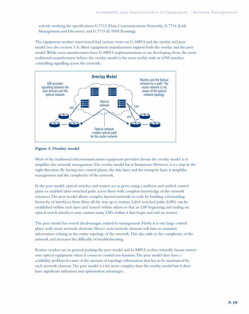
actively working the specifications G.7712 (Data Communications Network), G.7714 (LinkManagement and Discovery) and G.7715 (E-NNI Routing).
The equipment vendors interviewed had various views on G-MPLS and the overlay and peermodel (see also section 3.3). Most equipment manufacturers support both the overlay and the peermodel.While most manufacturers have G-MPLS implementations or are developing them, the moretraditional manufacturers believe the overlay model is the most useful, with an UNI interfacecontrolling signalling across the network.
Figure 4. Overlay model
Most of the traditional telecommunications equipment providers favour the overlay model as itsimplifies the network management.The overlay model has it limitations. However, it is a step in theright direction. By having two control planes, the data layer and the transport layer, it simplifiesmanagement and the complexity of the network.
In the peer model, optical switches and routers act as peers, using a uniform and unified controlplane to establish label-switched paths across them with complete knowledge of the networkresources.The peer model allows complex layered networks to scale by building a forwardinghierarchy of interfaces, from fibres all the way up to routers. Label switched paths (LSPs) can beestablished within each layer and ‘nested’ within others so that an LSP beginning and ending onoptical switch interfaces may contain many LSPs within it that begin and end on routers.
The peer model has several disadvantages, related to management. Firstly it is one large controlplane, with many network elements. Hence each network element will have to maintaininformation relating to the entire topology of the network.This also adds to the complexity of thenetwork and increases the difficulty of troubleshooting.
Router vendors are in general pushing the peer model and G-MPLS, as they naturally favour routersover optical equipment when it comes to control mechanisms.The peer model does have ascalability problem because of the amount of topology information that has to be maintained byeach network element.The peer model is a lot more complex than the overlay model but it doeshave significant utilisation and optimisation advantages.
Availability and Characteristics of Equipment / Network Management
P.39
Opticalnetwork uni
uni
uni
Routers ask the Opticalnetwork for a path. Therouter network is notaware of the opticalnetwork topology.
UNI providessignalling between theuser domain and the
optical network
Optical networkcreates optical path
for the router network.
Overlay Model
def. SERENATE D9 23-02-2006 09:41 Pagina 39

Figure 5. Peer model
The hybrid model represents a middle ground between overlay and peer, making use of the mostsuitable methods from both approaches. From the overlay model, the hybrid takes the support formultiple administrative domains. From the peer model, the hybrid takes support for multipletechnologies within a single domain. Hence, topology discovery, route computation and light-pathprovisioning are all best performed in a centralised manner, whereas neighbour discovery andnetwork protection are best implemented in a distributed fashion. In this model the IP and opticalnetworks retain their clear demarcation points and exchange reachability information.
Mature signalling protocols give users the ability to signal and switch/route wavelength ‘on-demand’and, therefore, to dynamically provision bandwidth needed by specific applications. Many solutionsfor ‘intelligent optical networking’ are available but, very often, they are put together in a vendor-proprietary fashion and there is still a lot of centralised network management needed. Only one ofthe vendors interviewed has claimed that they have a truly ‘intelligent optical networking’ productavailable now, utilising a distributed PNNI-based routing and signalling scheme to dynamicallyallocate network resources. Multi-vendor intelligent optical networks have not yet been deployed,but various laboratory trials of systems interconnected via O-UNI show that such systems might becommercially available within the next eighteen months.
6.3. Management tools
As in traditional networks, standard tools such as ping and traceroute are needed for debugging andperformance monitoring of G-MPLS networks.
Fault correlation between multiple layersIn the peer model many layers may be involved in the control and the transmission of G-MPLS dataand control information. It is therefore required that a fault in one layer is passed on to the adjacenthigher or lower layers in an effort to notify them of a possible fault. However, due to the nature ofthese many layers, the number of alarms may grow by an uncontrollable amount, where it damagesother network elements by the sheer volume of alarms.Alarms will have to be managed so that theNMS only receives the minimum number of alarms and only the most significant ones.Another
Availability and Characteristics of Equipment / Network Management
P.40
Optical network
Routers and opticalswitches function as pears.All network elements know
the topology of the fullnetwork.
Peer Model
Routers and opticalswitches share a
control plane.
def. SERENATE D9 23-02-2006 09:41 Pagina 40

problem is that, in case of a failure, several layers may attempt the restoration of the link at the sametime, so that different protection schemes may interact with each other.This effect should becarefully examined as it may lead to service degradation.
Provisioning systemsCLIs and SNMP have been the provisioning protocols of choice for most NRENs.As new opticalnetwork elements are introduced to the NREN networks it is essential that services can still bebrought up in an orderly and timely fashion. In order to do this, new provisioning tools will have tobe customised to the NRENs’ requirements.A new generation of GUI applications already allowsfor Label Switched Path (LSP) and backup LSP creation, including LSPs traversing light-paths(lambdas) in a full optical cloud. Such LSP/Lambda set can be route-optimised for the wholenetwork, thus allowing for better network utilisation.
6.4. Conclusion
NRENs will have to introduce new element managers into their network management systems inorder to manage future data and transmission networks.The management of this new equipmentwill require protocols traditionally used by telecommunications companies rather than NRENs.
Several advances in TMN/CORBA and SNMP/CORBA integration will help to integrate newand existing network management systems but these standards are immature at present and a lot ofwork has still to be completed.
Both the ITU and the IETF are working on new network architectures for optical networks. It isstill very early to predict which architecture will become the de-facto standard. It is still uncertain ifwe will have one or two control planes.What is certain, is that existing control planes are notsuitable for the optical networks of the future. Creating a standardised control plane for opticalnetworks will enable NRENs to introduce new features like end-to-end light-path creation.Whatthis control plane will be, is still uncertain, but initially an overlay model with an optical UNI is anexcellent starting point.
Availability and Characteristics of Equipment / Network Management
P.41
def. SERENATE D9 23-02-2006 09:41 Pagina 41

Network architectures
In this section we describe possible network architectures for future research and educationnetworks taking into account technological developments outlined in the previous sections and theneeds of researchers mentioned below.We will only provide this overview for the backbone and willnot deal with access techniques, as these have been only marginally addressed in this study.
7.1. Requirements for future research networks
There will be the continued need to support traditional applications, i.e. those applications that havelimited bandwidth requirements (for example up to 50 Mb/s) and for relatively short time scales.These applications may require some kind of differential treatment, which can be fulfilled byPremium IP or Less-than-Best Efforts. For these kinds of applications, there is no new requirementimposed upon today’s networks.The techniques used to deliver service will be improved (forexample advanced management for QoS) but the basic techniques are the same as today, with theaddition of support for IPv6.
The current need to support Virtual Private Networks to facilitate research on networkingtechnology will remain in the future, but the bandwidth requirements are likely to be higher.Currently VPNs are provided to projects such as ATRIUM* and DATATAG**, which havebandwidth requirements of 622 Mb/s.We can expect these to become requirements for GigabitEthernet, 10-GE, STM-16 or even STM-64.This is a significant new requirement for the researchnetworks of the future.
Above all, there is the requirement to support at least 40 Gb/s, on aggregate, on core links.Thisrequirement is driven by the combination of the following three factors:• organic growth of user traffic;• VPNs with higher capacity requirements;• support for Grid-like applications or projects.
The support for Grid-like applications is the main contributor to the requirement for 40 Gb/s oncore network links.These applications exhibit a completely new traffic profile when compared withtraditional applications: they require high-volume data transfers at high data rates.The Grid-likeapplications are not yet ready to exploit the availability of high-capacity research networks (nationaland pan-European), apart from some proof-of-concept examples, which are themselves alreadycapable of generating single flows of up to 500 Mb/s.This situation is changing rapidly and we mayexpect a significant number of these applications in the next few years, which will lead to a dramaticincrease of demand and utilisation of bandwidth - hence the requirement for 40 Gb/s aggregatecapacity in core networks.
Another important requirement for networks of the future is to have a network architecture thatenables a different network-funding model.Today, at least in the pan-European case, users require
Availability and Characteristics of Equipment / Network Architectures
P.42
* http://world.alcatel.be/atrium/** http://datatag.web.cern/ch/datatag/
7
def. SERENATE D9 23-02-2006 09:41 Pagina 42

and benefit from any-to-any connectivity all over Europe and therefore users contribute to the costof the network accordingly. In the case of GÉANT each network that connects to it contributes toits cost partly on their access capacity and partly on their geographic location.This translates to someform of flat fee for access to GÉANT, regardless of the actual usage.
In future we expect that some Grid applications or projects with very large bandwidth requirementswill only require connectivity between certain sites in Europe and will require contributing to thecost of the network according to the coverage they obtain and use from it.We expect thisphenomenon to be true both at the pan-European and the national network levels.
The scenario is that few projects will use the vast majority of network resources but only in alimited number of locations.Therefore, the next-generation network architecture must take this intoaccount and facilitate different funding models in order to enable and encourage usage of sharednetworks by projects.
The requirements outlined above lead to the consequence that appropriate resource allocationtechniques must be deployed. For example, if a Grid project requires 1GE of connectivity betweentwo locations, mechanisms need to be in place that enable the allocation of that level of resource andthat ensure that the resource is used by who requested it.
The concept of customer-empowered networks is gaining some momentum within the researchcommunity, and there are already some examples, such as CA*net 4 in Canada that are moving inthat direction.These are networks where end-users can control and allocate resources between end-points, with little or no intervention from backbone operators. More details on customerempowered networks and a discussion about pros and cons for NRENs to acquire dark fibres areprovided in section 8 of this report.
7.2. Network architecture options
In this section we will explore three different network architecture options. For each networkarchitecture there is already evidence that it is capable of supporting the requirements set out in theprevious section.We will examine a network architecture that is almost identical in nature to themajority of current research networks, apart from the capacities and router technology used.Theseare the shared IP-only networks.Then we consider networks that are able to offer switched point-to-point connections as well as an IP service, or hybrid networks. In both cases the raw material,connectivity, is provided via the traditional lease agreements currently used withtelecommunications operators. Finally, we explore the case where NRENs have a more direct rolein the provisioning of the basic connectivity, i.e. where they take (almost) full control of the fibreinfrastructure.
7.2.1. Shared IP-only network
In this context, shared IP-only refers to a network in which all connectivity is handled by IProuters.This is the current set up for GÉANT and most NRENs.All user traffic transits IP routers inthe core backbone. QoS and VPN features are offered using techniques available on IP routers(DiffServ for QoS, MPLS for VPNs). MPLS techniques are certainly able to support VPNs withbandwidth requirements of 2.5 Gb/s. Provided that the IP routers are able to support 40 Gb/s onaggregate on a point-to-point link, between two locations (this is possible as outlined in the section
Availability and Characteristics of Equipment / Network Architectures
P.43
def. SERENATE D9 23-02-2006 09:41 Pagina 43

on routers), the emerging Grid applications can also be supported on this kind of networkarchitecture.
Figure 6 outlines the example of a pan-European IP-only network providing connectivity fortraditional users, Grid users and VPNs.
The core of the pan-European network is composed of 4x10-Gb/s links to provide an aggregate of40 Gb/s.This may evolve to a situation where there is one (or more) 40-Gb/s circuit(s) betweenlocations when the router interface cards are available and when operators offer a single channel 40-Gb/s service. On the interface to the NRENs, n x 10 Gb/s are available.The NREN networks arebuilt in a similar fashion, and they offer services to a large number of traditional users. In some cases,the NREN networks act as interconnects for regional networks. In the example depicted there is aGrid application, running between Grid users in NREN-1 and NREN-2. Similarly there is a VPNrunning between users in NREN-1 and NREN-2.
Users at large are served best by the shared IP network. Using MPLS techniques, it is also possible todeliver service to VPN users.The shared IP network can also serve Grid users. In fact one mayargue: what is so special about Grid traffic that it needs something different than shared IP?Technically, there is no strong evidence that this is the case but some verification is still needed.What is important to note here is that to support Grid users on a shared IP network signifies addingseveral high-speed interfaces on IP routers along the path between the users.The current list pricefor 10-Gb/s interfaces is in the order of 250,000 euro.This is partly because of the transmissioncomponents needed, but mainly because of the complexity of ASIC and software needed to operateall the advanced IP services at high data rates. On the other hand Grid applications seem to requireonly raw bandwidth at the core network level, with the addition of middleware functions, which arebest performed on other equipment, such as Unix workstations, rather than IP routers.
Providing services for a limited number (compared to traditional users) of Grid applications in alimited number of locations can be more expensive than simply providing dedicated point-to-pointcircuits for the single Grid applications.
Furthermore, the shared IP network does not facilitate different funding models for projects orapplications such as Grids as the network itself does not explicitly separate the resources. Differentfunding models can be achieved, but these would remain unrelated to the network architecture.
Availability and Characteristics of Equipment / Network Architectures
P.44
def. SERENATE D9 23-02-2006 09:41 Pagina 44

Figure 6. Shared IP-only network architecture
There are some developments on IP routers in the area of virtual routers, i.e. routers that can bedivided into logical entities each with their own configuration and services. By exploiting thesefeatures a shared IP network can also be used to build a customer-empowered network (see section3.4 above). Users would have access to virtual routers with which they could manage theirconnectivity requirements.
Availability and Characteristics of Equipment / Network Architectures
P.45
NREN-1
NREN-2
GÉANT-2
IP
IP
IP
IP
GE
GE
VPN
Backbone withtraditional users
IP
GRID user
GE
4 x 10 Gb/s
2 x 10 Gb/s
2 x 10 Gb/s
GE
VPN
Backbone withtraditional users
GRID user
def. SERENATE D9 23-02-2006 09:41 Pagina 45

7.2.2. A hybrid (IP + switched) network
We call a network that is made of an all-IP component and complemented by the possibility to offerswitched connections, a ‘hybrid’ network. In this scenario, illustrated in figure 7, the general user stilluses a shared IP infrastructure.The shared IP infrastructure can also be used to support users withrequirements for QoS.To support Grid or VPN applications, a different approach can be taken.Asseen in section 4 of this report, switching equipment that provides Gigabit Ethernet services andSDH grooming is already available (and is being developed).This means that an STM-64 circuit canbe split up into several GE and STM-16 (or less) circuits and these can be presented on a dedicatedinterface to users.
This is a considerably cheaper solution than the all-IP solution presented previously because of thelower cost of interfaces on this type of equipment. In fact, IP routers and switching equipment willhave similar transmission and switching components, but the latter do not have nor need the ASICsand software required for advanced IP services.
In terms of network management and allocation of resources, this architecture has its pros and cons.For resource allocation, most switching equipment vendors are in the process of supporting G-MPLS, albeit implementations are not always conformant to the standards and therefore notvendor-interoperable.
This means that connectivity resources distributed between IP routers and switching equipmenthave the potential of being allocated and managed seamlessly.A drawback is represented by the factthat NRENs are accustomed to use SNMP based tools for network monitoring, whilst SNMP isnot supported on most of the switching equipment examined.
Such network architecture facilitates different charging models for usages such as Grids. In fact,especially in the case where a whole 2.5 Gb/s is required by an application, it is quite simple toclearly and unambiguously identify the additional hardware and connectivity resources needed tofulfil that requirement.The differential charging can be derived from the additional resourcesrequired.
Two options exist for the operational management of such a network architecture:
• The NRENs manage the IP and switching equipment.
• The NRENs manage the IP equipment and procure a managed switching service from traditionaloperators.As in all cases of connectivity services, it is most likely wiser to select more than onefibre provider.
In either case, there is a clear demarcation between connectivity providers and switching/routingelements. Similar to the shared-IP only network, the connectivity provider offers a multiplewavelength service. From the NREN point of view, there is a clear distinction, in that singlewavelengths can be offered separately to user projects.This is especially the case where the switchingelements are optical.Therefore, in this case the network architecture can also be defined as amultiple wavelength network.
Availability and Characteristics of Equipment / Network Architectures
P.46
def. SERENATE D9 23-02-2006 09:41 Pagina 46

Figure 7. Hybrid network architecture
Availability and Characteristics of Equipment / Network Architectures
P.47
NREN-1
GE
2.5 Gb/s
2 x 10 Gb/s
4 x 10 Gb/s
VPN
NREN-2
GÉANT-2
Backbone withtraditional users
Opticaland/or
SDH switch
IP
Opticaland/or
SDH switch
IP
Opticaland/or
SDH switchIP
Opticaland/or
SDH switchIP
Opticaland/or
SDH switchIP
GRID user
GE
VPN
Backbone withtraditional users
GRID user
2.5 Gb/s
2 x 10 Gb/s
def. SERENATE D9 23-02-2006 09:41 Pagina 47

7.2.3. Fibre network
In this architecture an NREN has control over a fibre network infrastructure.The NREN canprovision as many wavelengths (within the limits of the technology used) as required.The NRENcan then build its shared IP-only or hybrid network on top of the fibre network and offer servicesto its users.
This network architecture is very similar to the hybrid network architecture, the key differencebeing that the NREN also controls the fibre infrastructure.A fundamental consideration to make is:how is the network operated? There are two options:
• The fibre network is operated by a traditional carrier on behalf of the NREN.This represents anew model of working between NRENs and carriers.Traditionally carriers will buy (or sell) fibrepairs, and the owner takes full control of all the sites where in-line equipment is needed.The in-line and line-termination equipment is selected and operated by the owner. In this case third-parties would perform the fibre-based functions on behalf of the NREN.
• The fibre network is operated in full by the NREN.Technical advances in the transmissionequipment make this a feasible option even if on an international scale this is still difficult becauseof the reasons outlined below.
The following diagram outlines a possible pan-European set up.
Figure 8. Fibre network architecture
There are already cases in parts of Europe where NRENs operate, in part, a fibre network togetherwith traditional leased circuits.This is true in Poland, the Czech Republic, Slovakia, Ireland, theNetherlands and Switzerland.These NRENs have leased or deployed their own fibre, which is lit byequipment they own.Various reasons made it possible for these NRENs to do so:
• the distances involved are such that only in few cases regeneration is required;• a cost analysis showed that these cases owning fibre infrastructure was more cost-effective than
leasing bandwidth;• technology developments are such that the management of wavelengths on transmission
equipment has been significantly simplified compared to a few years ago.
Availability and Characteristics of Equipment / Network Architectures
P.48
GÉANT-2
Opticaland/or
SDH switch
Opticaland/or
SDH switch
IPOpticaland/or
SDH switchIP
IP
def. SERENATE D9 23-02-2006 09:41 Pagina 48
On an international scale there are still some very important factors to take into account:
• Between many locations the costs of leasing single wavelengths is believed to be lower than fibreleasing and equipment costs.
• Advances in transmission technologies, as well as wide availability of fibre (especially new-generation fibre) enable increasing the reach without regeneration; in wide scale networks it ispossible, with the current technology, to provide up to 2.5 Gb/s on 3,000-km links withoutregeneration, but at higher speeds this possibility might be limited because of deployment and costissues.
• In addition to the CAPEX, there are significant OPEX costs related to site management. NRENshave relatively little experience of this, which is made even more complex by the multi-lingualand multi-administrative environment. However, as described in section 5.3.2, these issues can beavoided with the use of transmission techniques such as Nothing-In-Line (NIL).
Furthermore, from a technical point of view, the line-termination equipment and in-line equipmentmust be compatible. It is not possible to procure ‘off-the-shelf ’ components and put them together.
7.3. Conclusions
Which network architecture to deploy depends on the set of user requirements that need to befulfilled, network management principles from the operator’s point of view, costs of equipment, andrunning costs.This is a very complex equation, especially in the pan-European case where costs ofconnectivity are subject to variations of a factor of 40. For each network topology, and for each setof services that need to be offered, an extremely detailed cost analysis needs to be done in order toevaluate the costs of one solution versus another and this needs to be combined with a detailedtechnical analysis of the various solutions.
Our view is that all network architectures proposed here can fulfil the foreseen requirements offuture networks. In order to decide which is more appropriate, one must carry out the detailedtechnical and cost evaluations outlined. It is expected that different solutions will apply in differentcountries, depending on the countries involved, topology, network management principles of theoperator, number of networking components required, scale of geographic coverage needed foradvanced services, and so on.Another factor to be taken into account is the attitude of carriers thatcurrently own fibre, towards the provisioning of dark fibre or managed fibre services.This attitudemight be significantly affected by the current changes in the economic realities of thetelecommunications sector.
Availability and Characteristics of Equipment / Network Architectures
P.49
def. SERENATE D9 23-02-2006 09:41 Pagina 49

Customer-empowered networks
The technical developments that can be expected in the next five years, dealing with transmission,switching and routing components, have consequences in terms of network architecture, as well asof real-time network management and control. In addition, from a business perspective, NRENsfeel ready to look into customer-empowered networks, where user communities purchase opticalfibre infrastructures or lease them on a long-term basis, in order to set up their own networks,taking over some functions traditionally provided by telecommunications operators.An analysis ofthis alternative infrastructure model has been part of a separate SERENATE report8 and isoutside the scope of this equipment study, but there are some relevant implications in terms offibre and equipment requirements that are important for NRENs.
8.1. Rationale
As explained in section 7.2.3, operation of fibre networks by NRENs constitutes a new workingmodel in the relation between telecommunications operators (carriers) and NRENs. Regardlessof whether the network architecture is based on a shared IP-only model or on a hybrid one,without access to dark fibres there is no special reason for NRENs to look after transmissionequipment and fibre infrastructure.
Traditionally NRENs build their network by using telecommunications services delivered byoperators (carriers) who own or lease the fibre and are responsible for data transmission, fibremaintenance and repair, fibre lighting,Wave Division Multiplexing (WDM), signal amplification,dispersion compensation, signal regeneration etc. In this model, carriers are only responsible forthe low-level transmission layer and NRENs are not involved in the acquisition, installation andoperation of dark fibres and transmission equipment.
A carrier-managed infrastructure is necessarily a multipurpose transmission layer fitting manycustomers’ requirements, whereas NRENs often require a transmission layer designed for ‘on-demand’ delivery of dedicated connections and experimental lines and services for high-demandapplications (see section 7). NRENs’ requirements for link capacity are usually lower than thoseof operators and higher than those of wide-area enterprise networks. Moreover, specific requestsfor transmission equipment from NRENs are being recognised by equipment vendors as anemerging market segment for long-distance gear.There are expectations that knowledge andprices of transmission equipment will play a very important role in the design and developmentplans of NRENs.The opportunity for NRENs to acquire long-distance dark fibres is emerging.Additionally, NRENs have the facility to house equipment in university premises.
The development towards customer-empowered networks is of key importance for NRENs, bothtechnically and economically, giving them technical, operational and price independence fromtraditional carriers. In the traditional model, prices for telecommunication services depend oncompetition and market conditions, rather than on grounds related to technical costs, like fibre
Availability and Characteristics of Equipment / Customer-empowered Networks
P.50
8. SERENATE deliverable D3: Report on the experience of various communities that have experimented with‘alternative’models of infrastructures.
8
def. SERENATE D9 23-02-2006 09:41 Pagina 50

routes and type of equipment used. Moreover, an independent position allows NRENs to choosebetween buying telecommunication services or using dark fibre. Some NRENs have experiencedthat the use of dark fibres can save up to 50% compared to buying telecommunication services.
Dark fibres are already being used by NRENs at campus and metropolitan level and now moreand more also at the national and regional level (e.g. CESNET, HEANET, PIONIER, SANET,SURFnet, SWITCH; international connection is in place between CESNET, SANET andACOnet).The first project at a continental level, the National LightRail project, is expected toconnect Los Angeles with Seattle and Washington DC in July 2003 using dark fibre.
The use of dark fibres by NRENs should not be seen as a naïve competition withtelecommunication services. NRENs are buying professionally provided dark fibre (e.g. leasingand maintenance) and high-quality advanced transmission equipment, which fit closely to theirneeds and additionally provide services like, for example, transmission with 10-GE interface orsingle-fibre transmission with FE, GE or 10 GE, which are still missing from the service portfolioof most carriers.
8.2. Dark fibre
Dark fibre is optical fibre dedicated to a single customer (or a group of customers) where thecustomer is responsible for attaching the transmission equipment to ‘light’ it.
Optical network implementations, based on dark fibres, are classified according to differentgeographical size ranges of installation, e.g. campus, metro, national or regional, and continental orintercontinental.The primary distinction among them is based on:• the distance signals must be transmitted and • the density, i.e. number of wavelengths (signals, colours) in a single dark fibre.
Each of these parameters has different implications for the transmission equipment.
Currently, and in the foreseeable future, the required density of connections by NRENs is lower(e.g. 1 - 64) than in some dark fibres used by carriers (e.g. 32 - 256). In both cases, the densityrequired in edge networks is lower than in the core. Requests for transmission distance is the samein both cases, but for longer distances (e.g. 2,000 km and more) buying lambda services fromcarriers could be cheaper than using dark fibre.This depends of course on the actual businessoffer, but in principle a higher level of fibre sharing is necessary to achieve lower expenses, andcarriers have better opportunities to organise fibre sharing for longer distances than NRENs.Thecost comparison is not easy, because usually it is necessary to take into account the cost of futurelambda upgrade (upgrade of number of lambdas or upgrade of lambdas transmission rate).
Professional companies who specialise in dark fibre systems take care of the installation of thefibre and also maintain it on behalf of the customer. In many cases, there is no additionalmanagement complexity or overhead associated with customer-empowered dark fibre, and this ismore reliable than traditional telecommunication services. Some additional managementcomplexity only appears in long-distance fibre lines (e.g. longer than 250 km), when in-lineoptical signal amplification or regeneration is necessary. In such cases, the customer takesresponsibility for remote management of in-line equipment and the company maintaining fibreprovides some local assistance.
Availability and Characteristics of Equipment / Customer-empowered Networks
P.51
def. SERENATE D9 23-02-2006 09:41 Pagina 51

Technically, companies actually own the fibre, but sell IRUs (Indefeasible Rights of Use) for up to20 years for unrestricted use.The key thing to note is that the up-front cost for the purchase of a20-year IRU is a one-time investment. Usually, the IRU can be considered as a physical asset,which can be resold, traded or used as collateral.As such, the cost of an IRU can be depreciatedover its 20-year lifetime, which results in a monthly cost substantially lower than the cost oftraditional telecommunication services.
In some countries, the legal system does not consider IRUs as assets (with known taxconsequences). For this reason or for reasons of competitiveness some fibre owners offer long-term lease with a regular monthly fee and, in some cases, an additional one-time installation fee.NRENs had very positive experiences with this, having the possibility to decide which dark-fibreline to lease and for how many years. Paying a monthly fee for the fibre is similar to payingmonthly telecommunication services, but often is cheaper.The choice for longer-term lease isusually determined by price, but there might be reasons for choosing a shorter time, including:
• need for moving end points in the future,• need for different types of fibre in the future,• need for changing network topology in the future,• expected future better offers resulting from installation of new fibre trunks with shorter length
or advanced fibre types, etc.
A number of next-generation service providers in metro or regional areas are now installing fibrenetworks and will sell strands of fibre to any organisation that wishes to purchase and manage itsown dark fibres. Many of these new fibre networks are built along the same model as acondominium apartment building (condominium fibre network). For NRENs, the role ofcustomer usually belongs to a national group of universities and research institutions. For the pan-European network the role of customer belongs to a grouping of NRENs (where responsibilitymay be delegated to an organisation established for this purpose).
Customer-empowered dark fibre can be more reliable than traditional carrier services, particularlyif the customer deploys a diverse or redundant dark-fibre route. Dark fibre is a very simpletechnology.Traditionally managed services usually have many devices in the network path such asSONET multiplexers,Add/Drop multiplexers, switches, routers, etc. Each of these devices issusceptible to failure and that is why traditional carriers have to deploy complex networks andsystems to insure reliability and redundancy.
The use of dark fibre brings, in some sense, simplicity into network design by avoiding the use ofcomplex telecommunication services, which are not transparent and which are difficult orimpossible to manage from the customer point of view.Wide-area network design is today closerto computer system design. One can read slogans as “the network is the supercomputer” or “thesupercomputer is the network” and one can see the practical consequences.
When discussing future optical network architecture, it is important to take into account thetrends in optical transmission system design. Results in research and development of new fibretypes, lasers, optical amplifiers, switches, integrated circuits etc. will have a big influence onnetwork design, and have been considered in this report (see also section 9). However, in planningand deploying optical transmission for research and education networks, we have to look attransmission equipment that is currently available or will be on the market in the near future.From an engineering point of view, we need a kit of transmission systems, which are available for
Availability and Characteristics of Equipment / Customer-empowered Networks
P.52
def. SERENATE D9 23-02-2006 09:41 Pagina 52
building research and education networks at national and international level and are proven byexperimental deployment.The current demand is characterised by:
• transmission of single lambda or few lambdas,• transmission rate from 100 Mb/s to 40 Gb/s and more per lambda,• transmission over long distance,• scalability and cost of (reliable) equipment,• single fibre instead of fibre pair is preferred for sufficiently short distances (now up to 125 km),
if overall expenses are lower.
A narrow band of a few lambdas is suitable for optical amplification rather than a wide band offew or many lambdas, so demand for long distance means in some sense demand for narrow band.For metropolitan research and education networks, the demand is the same with the exception oflong distance.This means that narrow band, in-line amplification or DCF are usually notnecessary in metropolitan networks up to transmission rates of 10 Gb/s per lambda.Transmissionequipment for metropolitan networks is closer to research and education networks’ needs, becauselow-shared links are common in some parts of metropolitan areas (usually in peripheral parts oflarge cities that have a low density of users) and they are also common in some parts of NRENs.
Availability and Characteristics of Equipment / Customer-empowered Networks
P.53
def. SERENATE D9 23-02-2006 09:41 Pagina 53

Future and emerging technologies
The purpose of this section is to explore future and emerging technologies that may have apositive impact on the development of more advanced networking services.
The reason for the need to look at new developments is that some existing technology is reachingits physical limits of speed and reliability.As an example, the laws of physics suggest that themaximum practical electrical signal path-length possible on a transponder working at 10 Gb/s isaround 30 cm.The expectation is that at 40 Gb/s the maximum possible path-length will be 7 cm, or even less.This makes the implementation of a 40 Gb/s electro-optical device difficult.
9.1. Fibre technologies
Fibre optic cables have been in use since the 1970s and are the underlying physical technologythat has permitted the explosive growth in the availability of communications bandwidth. Fibrebehaviour is now well understood and manufacture techniques have improved radically.Theconsequences of this are that fibre installed today has much better dispersion characteristics thanthat installed in the early days.We have been told that the fibre installed pre-1992 is unlikely to beable to provide support for high-density WDM systems, over long distance, without the need forexpensive dispersion compensation equipment, and that, even with this equipment, it may notwork reliably. Old fibre will not support DWDM at 40 Gb/s and above over the long haul. Quiteapart from the need for the new termination equipment to support 40 Gb/s, the pre-1992 fibreswill need to be replaced (or used for slower transmission rates). Fibres manufactured according tothe ITU recommendations G.652 (for standard single-mode fibres) and G.655 (for non-zerodispersion shifted fibres) should be able to support such links.
Further developments in the design and fabrication of fibres are already on the horizon.Companies are pioneering the development of hollow photonic crystal fibres (hollow-PCF) thatmay push the bandwidth and link-length possibilities to a much higher level than today. In aconventional fibre optic cable, the light is guided from end-to-end by a process of total internalreflection.The light travels through a glass medium for all of its passage and in doing so interactswith solid glass.The result of these interactions is that many non-linear effects such as dispersionlead to signal degradation.
As the prefix ‘hollow’ implies, at the centre of the new hollow-PCF fibres is a minute hole(approximately 50 µm in diameter) through which the light is guided.The researchers developingthe technology claim that the hollow-PCF approach provides several benefits, including theability of the fibre to attenuate unwanted multi-modal signals in its walls (by a process known asmodal sieving) and the photonic band-gap effect which provides a mechanism by which the fibreis selective about the wavelengths it transmits.
Availability and Characteristics of Equipment / Future and Emerging Technologies
P.54
9
def. SERENATE D9 23-02-2006 09:41 Pagina 54

The main benefit of hollow-PCF technology appears to be near-lossless transmission of light,without the introduction of dispersive, non-linear effects into the signal. In addition, because thefibre is hollow and the light does not interact with the glass, higher laser powers could be used.This will further increase transmission distances without the need for intermediate signalconditioning.
Researchers are also working on the development of Polymer Optical Fibres (POF).The benefitsseen for POFs is that they can be manufactured more cheaply than glass/silica fibres and havemechanical characteristics more suited to working in the end-user environment, e.g. flexibilityand strength.A major problem, however, is that the signal attenuation in a POF is an order ofmagnitude larger than for its equivalent silica/glass counterpart. It may be that development ofhollow POFs alleviates this problem and polymers might find a place in the manufacture of longdistance fibre optic links. In the mean time, it is likely that they will be confined to short links ofless than a few hundred meters.
9.2. Optical switching
As indicated in the fibre section above, dealing with opto-electrical conversion at speeds of 40 Gb/s and higher will be problematic through the limits imposed by the laws of physics.Amore practical approach to optical switching at high speeds would be to undertake all requiredsignal processing fully in the optical domain. Currently, true optical switching cannot beundertaken, due to the lack of availability of optical logic components.Although rudimentaryoptical logic components already exist, they cannot support the complex processing needed tosupport the architectures of networks that real users would like to build.Although optical crossconnects are currently available, they require external electronics to provide the switchingfunction. Indeed, some describe the currently available range of ‘optical switches’ as smart patchpanels.
With the future availability of mature MPLS and G-MPLS, the motivation for fully-opticalswitching will strengthen.The reason for this is that a combination of IP packets, coupled with G-MPLS, could be transported directly on the DWDM infrastructure, without the need foradditional intermediate layers, each of which requires their own management and control.Theconcept of Optical Packet Switching (OPS) has been discussed in many forums. It may beimplemented as slotted OPS for fixed length packets, or in an un-slotted fashion for variablelength packets.A critical requirement, needed to implement OPS, will be the availability ofoptical delay buffers.These buffers are needed to temporarily store the payload data while theoptical packet header is processed and the appropriate optical route is set up within the switchfabric.Although some information on prototype demonstrators is available, it is likely that it willbe many years before practical OPS systems are available in the market place.
A hybrid approach, known as Optical Burst Switching (OBS), has been proposed. In an OBStransmission system, the optical payload data is kept separate from the control signal, which itselfcan be in the optical domain.The control plane is most conveniently transmitted on a separatepath, or wavelength, from the payload data.The control signal is transmitted from source switch todestination switch, slightly in advance of the payload data, so that it arrives sufficiently in time toset the required optical path through the switch before the payload data arrives.As the opticalcontrol plane is required to transmit comparatively small amounts of data, it can provide signallingfor many payload data links. It is the only transmission link in the system that will require opto-electrical conversion at the intermediate nodes, the payload data remaining in the optical domain.
Availability and Characteristics of Equipment / Future and Emerging Technologies
P.55
def. SERENATE D9 23-02-2006 09:41 Pagina 55

The fact that the payload data can stay in the optical domain will dramatically reduce the cost ofintermediate node switches, compared with those that require opto-electrical conversion of allstreams.Additionally, since the payload data will pass through a fully optical path from end-to-end, it will experience no delays and will provide a predictable transmission system that will bewell suited to support Grid-style applications that demand this level of service.
9.3. Error correction techniques
Current fibre systems incur some degradation of signal as the light traverses the fibre. In future, itmay be possible to devise and construct fibre systems that do not impose noticeable levels ofdispersion, and hollow-PCF may obtain this result. Even if such advanced fibres becomecommon, unless there is total replacement of the installed fibre infrastructure (which is extremelyunlikely), there will always be some links on which dispersion will continue to be a problem. Itwill therefore be necessary to compensate for dispersion and correct errors introduced into thedata stream.
An approach to dealing with signal degradation that has been used for many years, is based ondetecting errors and correcting them by using check bits. In order to achieve this, the value of thecheck bits has to be computed before transmission and analysed at reception.This technique isknown as Forward Error Correction (FEC).The simplest form of such error correction can beachieved by using Hamming codes, however this adds about 36% overhead in order to correctcorrupt data.The G.709 recommendation specifies the use of Reed-Solomon error correction,which is much more efficient, requiring adding around 6% overhead.When implemented as weakerror correction, this might even be accommodated in unused bits of the transmission stream andtherefore impose no overall loss of payload bandwidth (it should however be noted that a dangerwith using in-band FEC is the use of bytes that maybe be used in the future for other functions).
As transmission speeds approach and exceed 10 Gb/s, particularly in DWDM systems with finespacing, optical degradation, through non-linearities, becomes increasingly problematic. If end-to-end systems are to reach anywhere near their full transmission potential, then errors introduced bydispersion and other non-linear effects have to be corrected. Systems such as Reed-Solomonalone will not be sufficient, so enhanced approaches known as Super-FEC will have to bedeveloped. One supplier has told us that the availability of Super-FEC is crucial to the support of40 Gb/s, even over the newest of installed fibre.
Although the processing load to implement FEC and Super-FEC are not excessive, the algorithmshave to be executed continuously and in real-time at line speed. In practical systems, FEC andSuper-FEC have to be implemented on custom chips (ASICs), which will be built into interfacecards.
There are products currently on the market that implement a Super-FEC capable of working atline speeds of up to 10 Gb/s and 40 Gb/s.These products work by concatenating a range of FECtechniques (Bose, Chaudhuri, Hocquenghem and Reed-Solomon) to give a more robust errorcorrection capability. It should be noted that current devices are implemented in a proprietaryway.The cost of increased robustness is an increased overhead in terms of the redundancy datathat must be carried. However, it can be demonstrated that, even with the addition of this extradata, there is a net coding gain. It looks likely that FEC and Super-FEC will be needed until suchtimes as error-free and dispersionless fibres are ubiquitous.
Availability and Characteristics of Equipment / Future and Emerging Technologies
P.56
def. SERENATE D9 23-02-2006 09:41 Pagina 56

The short-term future for 40 Gb/s (particularly on the long haul) looks inextricably tied to theavailability of custom ASICs that will deliver the required throughput of error correction. Froman availability point of view, we have been told that, due to the reluctance of chip manufacturersto make capital investments in the turbulent telecommunications sector, most 40-Gb/s Super-FEC developments have been put on hold.This could be one of the largest factors delayingthe availability of 40-Gb/s DWDM systems, at least on the long haul. It may suggest that 40-Gb/ssystems for the metropolitan area will appear first.
9.4. Hyperfine DWDM
There are two opposing views on how the best commercial utilisation of fibre infrastructure canbe achieved.The simple view, shared by many in the industry, is that bandwidth per channel isincreased until the physical limits of the fibre are reached. Supporters of this view reasonablyexpect that a 2.5-Gb/s system would be replaced by 10 Gb/s, 40 Gb/s and eventually evengreater bandwidth per channel (or wavelength).
The opposite view is that this is not an effective way for the development to proceed andhyperfine DWDM is a better solution.The proponents of hyperfine DWDM say that, asbandwidth per wavelength is increased, so do the non-linearity problems and the need for moreexpensive signal correction and interference between channels.They suggest that the majority ofthe end-user market is not looking for single 40-Gb/s or 80-Gb/s channels. Investing inequipment that delivers such large single channels will only result in the need for additionalmultiplexers to break the single channels into user-sized chunks.They suggest that a betterapproach would be to limit the bandwidth transmitted, on each wavelength, resulting in muchcheaper equipment being required. Moreover, this will reduce, or remove, the need for additionalmultiplexers. Since, at lower bandwidths per wavelength, the interfering non-linearities are verymuch reduced, the inter-wavelength spacing can be decreased to as low as 50 Mhz.Theconsequence of this is that, perhaps, more than 1,000 different wavelengths could be supportedper fibre. It is expected that hyperfine DWDM will find application first in the metro area close tothe users.
Availability and Characteristics of Equipment / Future and Emerging Technologies
P.57
def. SERENATE D9 23-02-2006 09:41 Pagina 57

General conclusions
GÉANT, the European interconnect, is amongst the most advanced research networks in theworld, with nine core links at 10 Gp/s and fourteen links at 2.5 Gb/s. Several research andeducation networks in Europe and in other continents have country-wide DWDM-basednetwork infrastructures in place.The next generation of GÉANT and research networks inEurope will require higher capacity and speed in order to support particular users and applicationssuch as astrophysical or geophysical observation and modelling, as well as high-energy physicsGrids.Technical developments for the introduction of higher speeds lead to different roadmaps,depending on specific characteristics of transmission, switching and routing components. But inall cases technology developments and deployment are affected by the current lack of customerdemand and market conditions.
10.1. Transmission capacities
10-Gb/s transmission capacity is supported by equipment available today. Several vendorsinterviewed shared the opinion that carriers still do not require more than 2.5 Gb/s and theexpected lack of user demand for higher transmission capacity will last for a couple of years. Evenrecognising that NRENs are an important factor in driving the introduction of networkingtechnologies and services, none of the vendors seemed to consider their demand to be a sufficientcase for the investments required in providing 40 Gb/s soon.The solution, which will likely bethe next step, will be to load-balance 10 Gb/s across multiple links.There are limitations to this,due to router interfaces (see section 3.1.2.), which will probably be the drivers for providingsingle-channel 40-Gb/s interfaces and favour wide deployment of 40-Gb/s transmission systems.Some vendors have expressed serious concerns about the economical viability of having single-channel transmission at speeds higher than 10 Gb/s, whereas others were much more optimistic.On the other hand, one of the manufacturers observed that, in some cases, 10 Gb/s is still moreexpensive than four times 2.5 Gb/s. Even if many operators plan their networks to operate athigher bit rates (e.g. 10-Gb/s wavelengths), they end up installing lower-rate components (e.g.2.5 Gb/s wavelengths).
There is a trend to increase the bit rates per wavelength, as well as the number of wavelengthssupported in a single optical fibre, but, as discussed in section 9.4, non-linearity problems, theneed for expensive signal correction, and interference between channels suggest that to limit thebandwidth transmitted on each channel and increase the number of wavelengths transmitteddown a single fibre, would be a more efficient and cost-effective way of providing higherbandwidth.
As far as technology is concerned, limitations in the availability of custom interfaces affect theintroduction of 40 Gb/s. However, all necessary subsystems have been already developed. But thecurrent high production costs can only be lowered by mass production and there does not seemto be demand emerging soon. 40-Gb/s circuits will become more cost-effective only when their
Availability and Characteristics of Equipment / General Conclusions
P.58
10
def. SERENATE D9 23-02-2006 09:41 Pagina 58

price will be less than four times 10 Gb/s; this is generally the case for 10 Gb/s and 2.5 Gb/stoday.There are claims that the price factor is as high as 10, and some believe there will be nocost-effective solutions soon to justify rollout plans. But some DWDM equipment vendors havedemonstrated that cost reduction can already be achieved today. Many optimistically think that 40 Gb/s would become price-competitive by the end of 2003.Thus, we would start seeing someinitial deployment in 2004 with a replacement of 10 Gb/s in core networks within the next fiveyears.
In terms of deployment, 40 Gb/s poses additional problems, requiring greater control of physicaleffects (e.g. dispersion and non-linear effects). In fact, even at 10-Gb/s capacity there are strongrequirements for the availability of adequate fibre infrastructure. Chromatic dispersion becomes acritical factor, especially on long haul networks and compensation can be required at any distancesover 4 km. Fibres deployed more than ten years ago present very high Polarisation ModeDispersion (PMD) and require more sophisticated/smart (and expensive) equipment forcompensation and regeneration. Of the three range applications (ultra long haul, long haul, metroand VSR range), 40 Gb/s is best suited to the longer reach.With the present technology andamplifiers (EDFA), transmission systems for 2.5 Gb/s and 10 Gb/s could reach 1,000-1,500 km(LH) and 3,000-4,000km (ULH) without regeneration. Only a couple of the vendors interviewedhave introduced Raman amplifiers in their production systems. One of them was able to reach upto 3,200 km at 2.5 Gb/s. 40 Gb/s unregenerated systems are claimed to be capable of reachingabout 1,000 km, on the same common equipment.
The majority of transmission equipment vendors think that, due to cost-effectiveness, 40 Gb/swill first emerge over DWDM long haul systems. However, there was no consistent view andparticularly router vendors seemed to estimate that it will first emerge in the metro area in 2003.
80 Gb/s has been demonstrated by several vendors in the laboratories.The four-fold increase ofbandwidth has proved to be effective, in terms of the cost reduction, which enables theintroduction of a new technology.The next likely step beyond 40 Gb/s should be 160-Gb/s linerate. However, even if available in the laboratories, this is still a very expensive and immaturetechnology, needing a much higher quality of the necessary components. Higher line rates havealso been demonstrated.An experiment was done in Japan with single-channel transmission at600 Gb/s, which is very far beyond the capabilities of near-future router interfaces and requires anew generation of fibres.
In the Ethernet domain, the next step would be to go from the 10 GE, currently available, to 100 GE.There was some interesting debate whether the Ethernet-like growth factor (10) wouldnot be more appropriate in the optical domain than traditional SONET/SDH-like factor (4), butin general that was seen as too big a step and 100 Gb/s equipment was not expected to becomeavailable soon.
Alternative solutions to SONET/SDH, for transport and bandwidth grooming, will be availablein the short term, including support for a variety of mapping techniques developed inside theSONET/SDH world, like Generic Framing Procedure (GFP),Virtual Concatenation, LCAS aswell as outside, like G-MPLS and various flavours of Ethernet interfaces.Transparent wavelengthservices, based on G.709 interfaces, were expected to extend the management and monitoringfeatures inherent into the optical layer and will become widely available in a few years’ time.However, carriers seem to favour GFP with virtual concatenation and eventually LCAS toeffectively transport different types of payloads (i.e. non-SDH framed payloads such as for instanceEthernet packets).
Availability and Characteristics of Equipment / General Conclusions
P.59
def. SERENATE D9 23-02-2006 09:41 Pagina 59

10.2. Routers
Router interfaces seem to be the main driver for the adoption of (single-channel) 40 Gb/s, due toproblems associated with load balancing across n x 10 Gb/s.
Latest generation routers already support 40 Gb/s. However, line-speed interfaces are not yetready and are likely to be very costly. In the near future, new generations of routers will certainlysupport interfaces to SONET/SDH, 1 GE, 10 Gb/s with different range lasers and to a limitedextent,WDM interfaces.The study did not reveal any significant plan to support ‘coloured’ G.709interfaces at the moment.
Router vendors broadly support the development of G-MPLS and contribute to itsstandardisation. First implementations of G-MPLS support are available and will soon becomecommon on routers from many different vendors.The same situation can be expected regardingprotocols as Constrained Shorted Path First (CSPF) and Link Management Protocol (LMP), thelatter only in a static version initially. Some vendors have already done interoperability tests withvarious OXC manufacturers.
In terms of scalability, it is clear that Terabit routers are becoming available but only as multi-chassis implementations (e.g. four 320-Gb/s full-duplex chassis interconnected by a switch fabricchassis).This involves very complex configuration of component parts, which is not necessarilyeasily done by customers.
Virtual routers, separating a single physical device into multiple independent logical partitions,have been in use in edge nodes for a few years and are now being adopted on core routers. Byallowing operators of large IP networks to utilise virtually private router resources, and to managethem autonomously, virtual routers may aid support for Grid projects so that Virtual PrivateRouted Networks can be implemented on common packet-switched IP networks.
10.3. Intelligent optical networking
Optical fibre transmission and WDM equipment have been available for several years now.However, in the traditional IP networks, running on top of SONET/SDH, over WDM, thetransmission layer was totally transparent to the network control plane.What is really new withthe concept of optical networking, is the integration of the transport layer and the networkcontrol plane, introducing network intelligence at the lower layers and allowing users to manageand control wavelengths (colours or Lambdas). However, coloured interfaces are still offered todayas SONET/SDH.The main technical and operational issue in offering lambdas to users isagreeing on the signal format. Different WDM vendors utilise different optical channel parametersso that current systems are not standardised enough to have a single coloured interface compliantwith all WDM platforms.The only ‘standard’ really available today is the ITU wavelength gridwith digital wrapper overhead, but it allows vendors enough freedom to implement it in aproprietary fashion so that they can ensure the highest performance or link length.As aconsequence, interoperability can nowadays be guaranteed only within a single-vendor system.
The ability for users to signal-high bandwidth ‘channels’ and hence to switch/route wavelength‘on-demand’ is available now, but technologies remain immature and vendor-interoperability willrequire some time in coming. OIF UNI1.0 has been implemented by some vendors, but it has
Availability and Characteristics of Equipment / General Conclusions
P.60
def. SERENATE D9 23-02-2006 09:41 Pagina 60
limited functionality. OIF UNI2.0 will soon be finalised. G-MPLS is still rather immature; manyprotocols are available but they are put together in vendor proprietary fashions and in many casesthere is still a lot of centralised network management needed. Intelligent optical networking isalready available today, but only as single vendor solution. However, multi-vendor laboratory trialsbeing carried out at the moment show that interoperable solutions may start to become availablein a couple of years.
10.4. All-optical networking
The drivers for all-optical network solutions will be scalability (the number of ports on electricalcross connects will be reduced when the line rate increases, whereas all-optical cross connectsinterfaces are independent of the bit rate) and cost-benefit. O-E-O conversion is required inOADM or switching nodes where signals in a traditional architecture are forced to be allterminated, while only some are effectively reaching their destination in a given site.The othersignals are fed back into another DWDM terminal to continue their journey. In true ‘all-optical’networks O-E-O conversions are eliminated, representing a significant cost saving.They aremeant to become less expensive solutions in the long run than non-transparent networks,especially for networks at high capacity.
O-E-O conversion is still required in many cases to supervise the signal and being able to offer,monitor and enforce Service Level Agreements. However on an ‘all-optical’ network, one needs tomonitor only the ends of the circuit and the analogue characteristics (such as signal-to-noiseratio) along the journey. Long Haul and Ultra Long Haul transmission technologies allowbuilding large-size networks without the need for regeneration. In small-size cases, whereregeneration is not needed, optical switches and solutions with Nothing-In-Line have smallerfootprints and require less power than regenerative solutions.
In offering 40-Gb/s optical interfaces to users, serious difficulties are associated with theavailability of the appropriate fibre plant to be able to handle such high bit rate propagation.Many innovations currently being developed will allow the operation of completely all-opticalnetworks but their deployment will require ‘Greenfield’ installations.
Some transparent optical interfaces are available in switches today (for example, framing and bitrate do not matter up to certain levels, e.g. 2.5 Gb/s or 10 Gb/s), but the main challenges fortransparent optical switching are posed by all-optical wavelength conversion with optical 3Rregeneration. In practice there is no need for wavelength conversion unless extreme capacities arerequired. Moreover, since all-optical wavelength conversion with optical 3R regeneration requiresproper network planning and design as well as well-developed routing schemes, it is not expectedto become widely available until 5-10 years from now.
Tuneable lasers should be able to provide savings on component inventories, but althoughavailable now, they still are very immature and expensive.
Availability and Characteristics of Equipment / General Conclusions
P.61
def. SERENATE D9 23-02-2006 09:41 Pagina 61

Annex I - List of Acronyms
3R Restoration Reshaping RetimingACL Access Control ListANSI American National Standards InstituteAPI Application Programming InterfaceAPS/MPS Advanced Photon Source/Machine Protection SystemASIC Application Specific Integrated CircuitASTN Advanced Switched Transport NetworkATM Asynchronous Transfer ModeBER Bit Error RateBGP Boarder Gateway ProtocolBLSR Bi-directional Line-Switched RingBML Business Management LayerCAPEX Capital ExpenditureCLI Command Line InterfaceCMIP Common Management Information ProtocolCORBA Common Object Request Broker ArchitectureCoS Class of ServiceCR-LDP Constraint-based Routing Label Distribution ProtocolCSPF Constrained Shortest Path FirstCS-RZ Carrier Suppressed Return to ZeroCWDM Coarse Wavelength Division MultiplexingDCF Dispersion Compensating FibreDGF Dynamic Gain FlatteningDWDM Dense Wavelength Division MultiplexingDXC Digital Cross ConnectEDFA Erbium Doped Fibre AmplifierEMS Element Management SystemE-NNI Exterior Network-Node InterfaceEXC Electronic Cross ConnectFE Fast EthernetFEC Forward Error CorrectionFWM Four Wave MixingGBIC Gigabit Interface ConverterGDMO Guidelines for the Definition of Managed ObjectsGE Gigabit EthernetGFP Generic Framing ProcedureG-MPLS Generalised Multi Protocol Label SwitchingGUI Graphical User InterfaceIEEE Institute of Electrical and Electronics Engineers, Inc.IETF Internet Engineering Task ForceIGP Interior Gateway Protocol
Availability and Characteristics of Equipment / Annex 1
P.62
def. SERENATE D9 23-02-2006 09:41 Pagina 62

IP/PPP Internet Protocol/Point-to-point ProtocolIPv6 Internet Protocol (version 6)IRU Indefeasible Right of UseISI Inter-Symbol InterferenceIS-IS Intermediate System to Intermediate System ProtocolITU-T Telecommunication Standardisation Sector of the
International Telecommunication Union LCAS Link Capacity Adjustment SchemeLD Laser DiodLH Long HaulLMP Link Management ProtocolLSP Label Switched PathMBS Managed Bandwidth ServiceMEM Micro Electromechanical MirrorMPLS Multi Protocol Label SwitchingNEL Network Element LayerNIL Nothing In LineNMS Network Management SystemNZDSF Non-Zero Dispersion Shifted FibreOA Optical AmplificationOADM Optical Add Drop MultiplexerOBS Optical Burst SwitchingOC-n Optical CarrierO-E-O Optical-Electrical-OpticalOIF Optical Internetworking ForumOMG Object Management GroupO-O-O Optical-Optical-OpticalOPEX Operational ExpenditureOPS Optical Packet SwitchingOSPF Open Shortest Path FirstOTN Optical Transport NetworkOXC Optical Cross ConnectPCF Photonic Crystal FibrePMD Polarisation Mode DispersionPNNI Private Network-to-Network InterfacePOF Polymer Optical FibrePOS Packet over SONETPXC Photonic Cross ConnectQoS Quality of ServiceRFC Request For CommentsRSVP-TE Resource Reservation Protocol - Traffic EngineeringSDH Synchronous Digital HierarchySFM Single Mode FibreSNCP Sub-Network Connection ProtectionSNMP Simple Network Management ProtocolSNR Signal-to-Noise RatioSONET Synchronous Optical NETworkSPM Self-Phase ModulationSTM-n Synchronous Transfer ModuleSVC Switched Virtual Circuit
Availability and Characteristics of Equipment / Annex 1
P.63
def. SERENATE D9 23-02-2006 09:41 Pagina 63

TDM Time Division MultiplexingTMN Telecommunications Management NetworkULH Ultra Long HaulUNI User Network InterfaceUPSR Uni-directional Path-Switched RingVC-n Virtual ConcatenationVLAN Virtual Local Area NetworkVPN Virtual Private NetworkVSR Very Short ReachWDM Wavelength Division MultiplexingXPM Cross Phase Modulation
Availability and Characteristics of Equipment / Annex 1
P.64
def. SERENATE D9 23-02-2006 09:41 Pagina 64

Annex II Questionnaire used in the interviews
NEP-2002-068R. Sabatino 27 August 2002V. Cavalli, M. Campanella 09 September 2002M. Enrico, 01 November 2002
SERENATE WP3 Questionnaire for Equipment Vendors
Background
The GÉANT network is a multi-gigabit IP backbone that provides pan-European transit betweenEuropean National Research & Education Networks (NRENs) and connectivity to R&Enetworks in other parts of the world (e.g.Abilene in the US, NACSIS in Japan, etc).The NRENin a given country is usually unique and typically interconnects universities and other institutes ofhigher or further education and public research institutes. GÉANT has been implemented and isoperated on behalf of a consortium of European NRENs by DANTE, which is a not-for-profitlimited company based in Cambridge, UK.
The GÉANT network consists of a single POP in each member country housing one or morecarrier-class IP routers (currently mostly Juniper M160s) that are connected by unprotectedinternational leased lines that range in capacity from 155Mbit/s to 10Gbit/s. Most of the trunkcircuits are 2.5Gbps (currently eleven in number) or 10Gbps (nine).These circuits (althoughmostly implemented by the carriers as single DWDM channels) are presented on G.957 or G.691compliant interfaces for direct connection to OC48c/STM-16 or OC192c/STM-64 packet-over-SONET/SDH (POS) interfaces on the routers.
Many of the NREN backbones are now implemented along similar lines although there areincreasingly those with access to their own fibre infrastructure who are using long reach gigabitEthernet and 10GE and experimenting with operating DWDM transmission equipment.Accessto this type of infrastructure is still not really possible on the pan-European scale althoughDANTE is now starting to discuss the notion of long-distance ‘managed fibre’ services with someof its present suppliers.
Most of the production traffic carried by the European R&E networks is currently ‘best-effort’ IPand the utilisation levels of the 2.5/10G trunk circuits are often below 10%.The development ofother services is as follows. Multicast is more or less ubiquitous.A DiffServ-based Premium IPservice has been trialled and will soon become available as an operational service on the GÉANTbackbone and some of the European NRENs. In addition, a DiffServ-based ‘less-than-best-effort’or ‘scavenger’ service is currently being tested.An MPLS-based L2 VPN service is also currentlybeing developed for the GÉANT backbone and should soon be available for geographicallydispersed research projects that require relatively low capacities of layer-2 separated connectivity.
Availability and Characteristics of Equipment / Annex 2
P.65
def. SERENATE D9 23-02-2006 09:41 Pagina 65

IPv6 is at a relatively advanced stage of deployment within the research networking community asa whole. Some of the European NRENs are already offering a pre-production IPv6 service as aresult of operating their IP backbones in ‘dual stack’ mode and it is planned to have a productionIPv6 service on GÉANT by mid 2003.
Apart from the inevitable increases in volume of production traffic, it is also foreseen that therewill be an increasing requirement to be able to offer a guaranteed ‘bandwidth-on-demand’ servicewith wide-ranging granularity to accommodate the needs of short or medium term researchprojects and GRID initiatives.The granularities may range from STM-1 to STM-64 levels andthe time scales involved may be of the order of days or weeks (short term) up to periods of about1 year (medium term). In addition, the nature of the connectivity required by these projects mayrange from simple L2 or L3 VPN-style connectivity to dedicated point-to-point wavelengths.
SERENATE is the name of a series of strategic studies into the future of research and educationnetworking in Europe, addressing the local (campus networks), national (national research &education networks), European and intercontinental levels.The SERENATE studies, which areorganised by TERENA, DANTE, the Academia Europaea, the European Science Foundation andthe Technical University of Denmark, bring together the research and education networks ofEurope, national governments and funding bodies, the European Commission, network operators,equipment manufacturers and, last but not least, the scientific and education community as theusers of networks and services. More details can be found on the project web site given below.
This questionnaire is intended to be the framework for a series of bilateral meetings with leadingvendors of networking equipment that will provide the primary input for a report assessing theavailability and characteristics of the necessary equipment for large-scale, long-distance networksoperating at 100Gbps or above.
NOTE: not all of the questions below are relevant to all vendors. Nor, indeed, would we expect all of thosethat are relevant to be fully answered during the course of the bilateral meetings. Rather they are more of aframework to guide the discussion during the meetings.
Useful URLs:
SERENATE http://www.serenate.orgDANTE/GÉANT http://www.dante.org.ukTERENA http://www.terena.nlEuropean NRENs http://www.heanet.ie (Ireland)(selection) http://www.garr.it (Italy)
http://www.psnc.pl (Poland)http://www.renater.fr (France)http://www.switch.ch (Switzerland)http://www.ja.net (UK)http://www.dfn.de (Germany)http://www.surfnet.nl (Netherlands)http://www.cesnet.cz (Czech Republic)
Availability and Characteristics of Equipment / Annex 2
P.66
def. SERENATE D9 23-02-2006 09:41 Pagina 66

1. 40+Gbps interfaces, what is the framing?
1.1 What is your view of the market drivers for 40+Gbps (40Gbps, 80Gbps, 160Gbps…)transmission capacities over the next 2 and 5 years?
1.2 Which types of interface do you plan to use as a function of the equipment, SDH/SONET,WDM, G.709, 1GbE, 10GbE and so on..
1.3 Will signalling be supported on such high-speed interfaces, and if so, which kind of signallingprotocols?
1.4 When will you offer 40+Gbps interfaces? What are the requirements and implications for thefibre infrastructure?
1.5 What equipment have you developed / are you developing that is capable of supporting40+Gbps interfaces and what is the status of its deployment (please give answers for the next 2years and next 5 years)?
1.6 To what extent do these developments follow standards as opposed to proprietary solutions?
1.7 What are the key features of this equipment? How does it differ from other solutions?
1.8 To what extent do you foresee 40+Gbps being offered as a single channel or multi-channelwith few channels (eg., 4 or 8) to users, as opposed to being used as a transport system betweenDWDM terminals? In this case, will you have parallel processing inside the interface?
1.9 What are the difficulties in offering 40+Gbps to users and when do you foresee them beingsolved?
1.10 What interoperability issues are there with other vendor’s solutions?
1.11 Presentation to users: Colours vs. SONET/SDH framing vs. Other Data Links1.11.1 Today interfaces to user equipment are based on SONET/SDH or GE framing.What are
the technical and operational issues for presenting a specific colour/wavelength to users?1.11.2 Given the context we explained, what are your views on offering colours as a service?1.11.3 Standardisation is certainly a key factor in developing colour presentation of services.
What contribution have you made to the relevant standards activities?1.11.4 Are you developing proprietary solutions/proposals? 1.11.5 Do you have any prototype available?1.11.6 Do you foresee implementations in 2, 5 years time?
2. Resilience and range
2.1 Research networks rely more on multiple diversely routed connections to a location toguarantee high availability rather than use protected services.What are your plans of offeringresilience, at the optical layer / routing layer?
2.2 What are the requirements for regeneration and amplification for your 40+Gbps transmission?What are the maximum unregenerated transmission distances?
Availability and Characteristics of Equipment / Annex 2
P.67
def. SERENATE D9 23-02-2006 09:41 Pagina 67

2.3 What is the capacity of your equipment? (E.g. how many ports/card and cards/chassis? Whatis the maximum number of chassis in multi-chassis setup? What is the maximum, non-blockingswitching speed? Does the size of the system affect the resilience?)
3. Bandwidth grooming capabilities (spanning one wavelength or multiple wavelengths)
The predecessors to the GÉANT network (TEN-34 and TEN-155) were based on managedATM connectivity.At the same time many of the NRENs had ATM backbones as did theconnected institutes.This allowed ad-hoc pan-European ATM VPNs (based on end-to-end ATMVCs and VPs) to be built for end-user community groups to fulfil the needs of particular shortand medium term projects.This was called the Managed Bandwidth Service (MBS) and offeredlayer 2 separated connectivity with bandwidth and quality guarantees.The GÉANT backbone andnow most of the European NRENs no longer have ATM in their networks yet there is still therequirement from end-user communities (e.g. GRIDs) to have access to an MBS-like service andwith ever increasing bandwidth requirements (e.g. 2.5Gbps per link).
3.1 Do you have smart solutions based on SONET/SDH? And what are the alternatives to SDH?What techniques do you have to inject different signals and present them as separate interface to auser/client?
3.2 What techniques do you foresee available in 2 and 5 years time?
3.2 What is the granularity of these techniques?
3.4 Can these techniques operate across multiple wavelengths?
3.5 Do you participate in any related standardisation activity?
4. Circuit (lambda) switching
As the bandwidth requirements of GRIDs increase then it may be that the best way to supportthem and the production IP services is to implement a pan-European research networkinginfrastructure that is capable of supporting ‘lambda switching’ (possibly even ‘on demand’).Discussions on BoD are currently underway within the European research networking community.
4.1 What are the drivers for an all-optical solution?
4.2 To what extent are we tied up with O-E-O, and what are the real technical and operationalimplications of this? For how long do you see this situation lasting?
4.3 What developments do you have in this area, what products do you have for the next 2 yearsand what do you foresee to have in the next 5 years?
4.4 How much of your activity is related to standardisation?
4.5 What impact will the recent announcement regarding the Lucent LambdaRouter(http://www.lightreading.com/document.asp?doc_id=19801) have on the development anddeployment of optical switches?
Availability and Characteristics of Equipment / Annex 2
P.68
def. SERENATE D9 23-02-2006 09:41 Pagina 68

5. Network management issues
Traditionally each networking layer and its resources are managed by dedicated managemententities each with a view of their own resources. G-MPLS is working towards integratedmanagement of network resources, as this is seen as a more effective way of utilising resources. Interms of managing an IP-over-optical network there are two trends: the overlay and the peermodel.
5.1 Which network management model do you favour and why (peer or overlay)? Whichnetwork management tools do you foresee?
5.2 Do you have G-MPLS implementations? Are these compliant to the standards?
5.3 To what extent can this model enable true end-to-end, interdomain, as opposed to edge-to-edge, intra-domain network management and allocation of resources.
5.4 What working experience do you have with G-MPLS?
5.5 What limitations do you see in G-MPLS, what activities have you undertaken to addressthese?
5.6 Would you allow SNMP access, and provide accounting management?
6. Service model: provider/(N)RENs
In today’s optical networks there is a clear service boundary between providers and ResearchNetworks, in terms of presentation and management.We expect that the ongoing technologicaldevelopments will facilitate the establishment of different service models.Today only a handful ofNRENs engage in the procurement and management of wide area fibre networks (examplesbeing SURFnet (NL), SWITCH (CH), PSNC (PL) and CESNET (CZ)).
6.1 Which kind of tools would you provide for the management of a mixed infrastructure for(N)RENs?
6.2 To what extent is it feasible that (N)RENs procure ‘managed fibre’ from carriers. By managedfibre we mean that amplification and regeneration are performed by a service provider whilst(de)multipexing, switching and Add/Drop functions are performed by an (N)REN.Are you goingto provide the tools, for example AAA, that allow (N)RENs to do this?
6.3 Managed fibre as opposed to managed wavelength connectivity represent extreme oppositesin terms of service models between providers and (N)RENs.What other models do you foreseebeing enabled by your technological developments?
7. Cost Distribution
7.1 In an IP-over-optical network, composed of IP routers, DWDM, optical switches, opticaladd/drop multiplexers, amplifiers, regenerators etc, what is the distribution of the capital cost(percentage-wise) between all these components?
Availability and Characteristics of Equipment / Annex 2
P.69
def. SERENATE D9 23-02-2006 09:41 Pagina 69

7.2 What impact does an ‘all-optical’ as opposed to O-E-O solution have on this capital costdistribution?
7.3 And what is the typical impact on the operational costs (including man-power)?
Availability and Characteristics of Equipment / Annex 2
P.70
def. SERENATE D9 23-02-2006 09:41 Pagina 70

Availability and Characteristics of Equipment / Annex 2
P.71
def. SERENATE D9 23-02-2006 09:41 Pagina 71

P.72
def. SERENATE D9 23-02-2006 09:41 Pagina 72


