University of Amsterdam System & Network Engineering RP1 Defending against DNS reflection amplification attacks February 14, 2013 Authors: Supervisor: Thijs Rozekrans Matthijs Mekking <[email protected]> <[email protected]> Javy de Koning <[email protected]>
Transcript
University of Amsterdam
System & Network Engineering RP1
Defending against DNS reflectionamplification attacks
The goal of the research described in this paper is to find out if the proposedmechanisms to defend against a DNS amplification attack are effective. Thedecision is made to focus on Response Rate Limiting (RRL) and determinethe effectiveness of this mechanism against current and future attacks. Inorder to determine the effectiveness of RRL a repeating (ANY) query attack,which is currently the most popular attack, is simulated. This basic attack isfollowed up by four more sophisticated attacks. The effectiveness of RRL ismeasured by comparing the DNS servers in- and outbound traffic with andwithout RRL activated. When analyzing the results it becomes clear that theeffectiveness of RRL decreases when the attack becomes more sophisticated.Because RRL is ineffective against a more sophisticated attack, another pro-posed defense mechanism is briefly discussed called DNS dampening. Theresults show that this mechanism is effective against sophisticated attacksbut is missing some essential features which makes it impractical to use ina live environment. The main conclusion is that RRL is a proper defenseagainst current amplification attacks, but it is not effective against futuremore sophisticated attacks.
E. Impact on server load. viiiE.1. RRL impact on server load. . . . . . . . . . . . . . . . . . . . . . . . . . . viiiE.2. DNS dampening impact on server load . . . . . . . . . . . . . . . . . . . . viii
1 INTRODUCTION
1. Introduction
A DNS amplification attack is a type of distributed denial of service (DDoS) attack thattakes advantage of the fact that a small DNS query can generate a much larger response.An attacker can direct a large volume of network traffic to a victim’s system by initiatingrelatively small DNS queries. The attacker spoofs the IP address of the victim to reflectthe network traffic using the DNS server. This makes it difficult to trace the attacker.
At first, resolvers were used for reflecting traffic but the internet community has recentlyseen an increase of amplification attacks that making use of authoritative name servers.One reason for this is that more resolver operators are following the access restrictionguidelines from RFC5358[3], greatly reducing the chance that their name server can beused in a reflection attack. Attackers now making use of authoritative name serverswhich, by design, cannot follow these guidelines.
These DDoS attacks are becoming more sophisticated, making it hard for packet filtersto catch the traffic. This urges to push the filtering towards the name server, so thatthe defense mechanisms can also become more sophisticated.
Response Rate Limiting (RRL) is currently the only practical defense mechanism avail-able for filtering in the name server. There is a patch for BIND and the proposal isimplemented by NLnet Labs for NSD. RRL is in a state where the effectiveness has notbeen exhaustively researched yet.
Research regarding the effectiveness of the available RRL implementation can help or-ganizations responsible for the authoritative name servers to make decisions on whatmeasures to take against amplification attacks. Since those organizations involuntarycontribute to the attack, it is unclear in what way organizations can be held responsibleif their name servers are abused for an attack. Since these attacks are appearing moreoften, the need for a defense mechanism becomes more important.
1.1. DNS amplification attack
In order to launch a DNS amplification reflection attack the attacker needs to performtwo tasks. First the attacker spoofs the address of the victim. This is the reflection part,it will cause all the reply’s from the DNS server to be directed to the victim’s server.This can easily be done since in UDP no handshake (like in TCP) is being done betweenthe client and the server. Secondly the requester searches for responses that are severaltimes bigger than the request. The attacker achieves an amplification factor because theresponse is many times larger than the request. The amplification can even be largerwhen DNSSEC is used, because of the signatures used the size of the response increases.
1
1.1 DNS amplification attack 1 INTRODUCTION
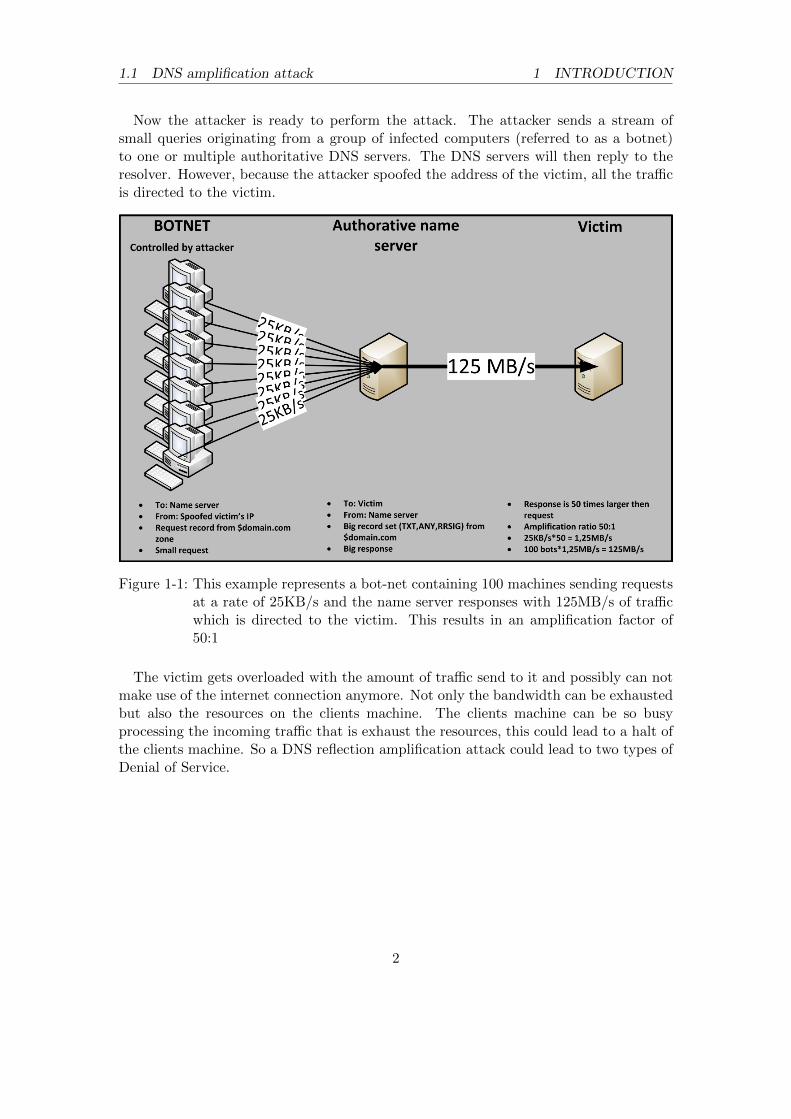
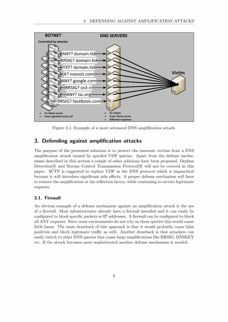
Now the attacker is ready to perform the attack. The attacker sends a stream ofsmall queries originating from a group of infected computers (referred to as a botnet)to one or multiple authoritative DNS servers. The DNS servers will then reply to theresolver. However, because the attacker spoofed the address of the victim, all the trafficis directed to the victim.
Figure 1-1: This example represents a bot-net containing 100 machines sending requestsat a rate of 25KB/s and the name server responses with 125MB/s of trafficwhich is directed to the victim. This results in an amplification factor of50:1
The victim gets overloaded with the amount of traffic send to it and possibly can notmake use of the internet connection anymore. Not only the bandwidth can be exhaustedbut also the resources on the clients machine. The clients machine can be so busyprocessing the incoming traffic that is exhaust the resources, this could lead to a halt ofthe clients machine. So a DNS reflection amplification attack could lead to two types ofDenial of Service.
2
1.2 Research questions 2 ATTACKS
1.2. Research questions
This research will focus on properly defending against these types of attacks, whichresults in the following research question:
”What measures can be taken to defend against DNS amplification attacks onauthoritative name servers, and what is the effectiveness of one of Response Rate
Limiting?”
Sub-questions
In order to completely answer the research question, it can be split into the followingsub-questions:
• Which defense mechanisms are currently available?• How can the effectiveness of RRL be measured?• What can we do to prevent false-positives?• How do we classify traffic that is used for an attack?• Which RRL configuration parameters are the most effective?
The defense mechanisms that are currently available will be discussed in section 3.Section 4 will explain the method that was used to measure the effectiveness of RRL.Measurements and the classification of attack traffic are shown in section 5. Recom-mended configuration settings and a method to prevent false positives is presented insection 6.
1.3. Related Work
Research has, amongst others, been done by Randal Vaughn & Gadi Evron in 2006[1] andby Duane Wessels in 2007[2]. However, both researches focus on amplification attackson recursive name servers, the proposed solutions[3] are not applicable on authoritativename servers.
2. Attacks
This section describes the most common DNS amplification attacks and their character-istics. The attacks can be divided into three types, repeating queries, varying queriesand a distributed attack. All attacks require the ability to spoof IP address using UDP.Another requirement is that the response is larger than the request to create the ampli-fication. This is often achieved by querying for ANY, DNSKEY, NS or RRSIG records.
For the examples presented in this section a DNS setup with different zone files isused. A more detailed description of these zone files is included in appendix C.
3
2.1 Repeating query attack 2 ATTACKS
2.1. Repeating query attack
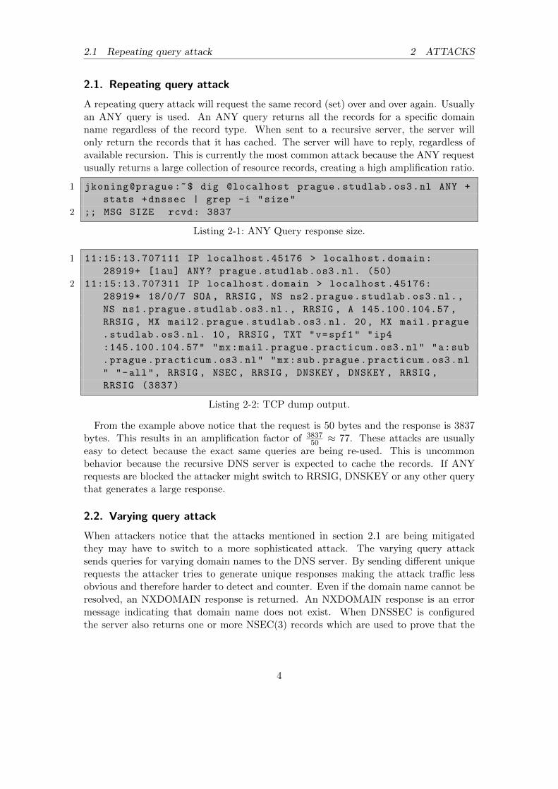
A repeating query attack will request the same record (set) over and over again. Usuallyan ANY query is used. An ANY query returns all the records for a specific domainname regardless of the record type. When sent to a recursive server, the server willonly return the records that it has cached. The server will have to reply, regardless ofavailable recursion. This is currently the most common attack because the ANY requestusually returns a large collection of resource records, creating a high amplification ratio.
1 jkoning@prague :~$ dig @localhost prague.studlab.os3.nl ANY +
stats +dnssec | grep -i "size"
2 ;; MSG SIZE rcvd: 3837
Listing 2-1: ANY Query response size.
1 11:15:13.707111 IP localhost .45176 > localhost.domain:
28919+ [1au] ANY? prague.studlab.os3.nl. (50)
2 11:15:13.707311 IP localhost.domain > localhost .45176:
28919* 18/0/7 SOA , RRSIG , NS ns2.prague.studlab.os3.nl.,
NS ns1.prague.studlab.os3.nl., RRSIG , A 145.100.104.57 ,
From the example above notice that the request is 50 bytes and the response is 3837bytes. This results in an amplification factor of 3837
50 ≈ 77. These attacks are usuallyeasy to detect because the exact same queries are being re-used. This is uncommonbehavior because the recursive DNS server is expected to cache the records. If ANYrequests are blocked the attacker might switch to RRSIG, DNSKEY or any other querythat generates a large response.
2.2. Varying query attack
When attackers notice that the attacks mentioned in section 2.1 are being mitigatedthey may have to switch to a more sophisticated attack. The varying query attacksends queries for varying domain names to the DNS server. By sending different uniquerequests the attacker tries to generate unique responses making the attack traffic lessobvious and therefore harder to detect and counter. Even if the domain name cannot beresolved, an NXDOMAIN response is returned. An NXDOMAIN response is an errormessage indicating that domain name does not exist. When DNSSEC is configuredthe server also returns one or more NSEC(3) records which are used to prove that the
4
2.3 Distributed attacks 2 ATTACKS
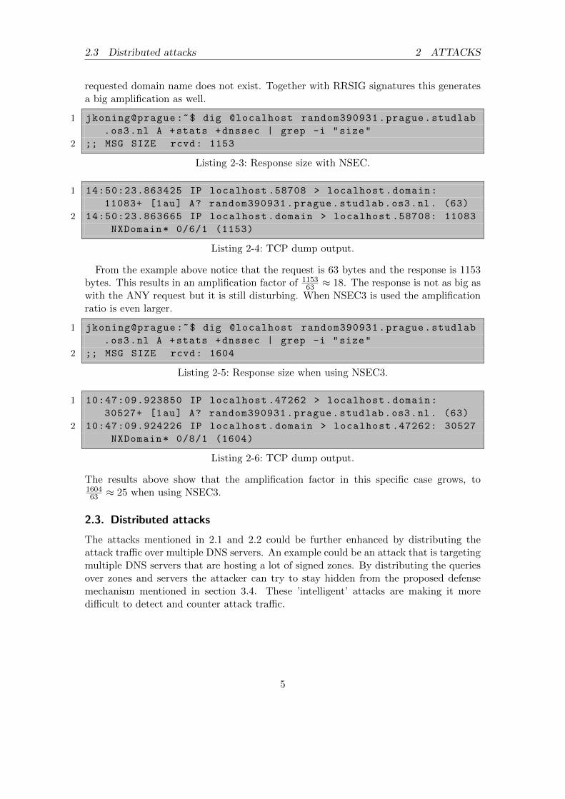
requested domain name does not exist. Together with RRSIG signatures this generatesa big amplification as well.
2 10:47:09.924226 IP localhost.domain > localhost .47262: 30527
NXDomain* 0/8/1 (1604)
Listing 2-6: TCP dump output.
The results above show that the amplification factor in this specific case grows, to160463 ≈ 25 when using NSEC3.
2.3. Distributed attacks
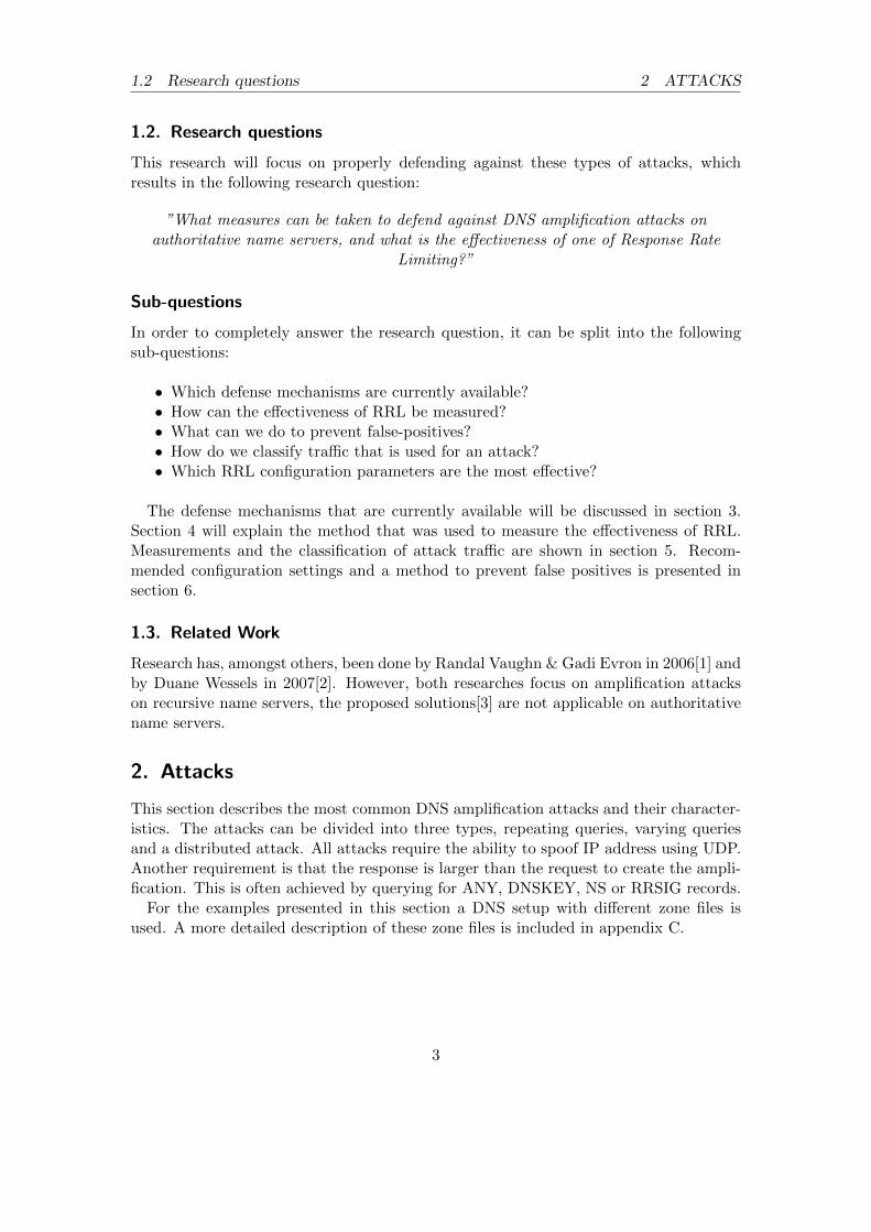
The attacks mentioned in 2.1 and 2.2 could be further enhanced by distributing theattack traffic over multiple DNS servers. An example could be an attack that is targetingmultiple DNS servers that are hosting a lot of signed zones. By distributing the queriesover zones and servers the attacker can try to stay hidden from the proposed defensemechanism mentioned in section 3.4. These ’intelligent’ attacks are making it moredifficult to detect and counter attack traffic.
5
3 DEFENDING AGAINST AMPLIFICATION ATTACKS
Figure 2-1: Example of a more advanced DNS amplification attack.
3. Defending against amplification attacks
The purpose of the presented solutions is to protect the innocent victims from a DNSamplification attack caused by spoofed UDP queries. Apart from the defense mecha-nisms described in this section a couple of other solutions have been proposed. OrphanDetection[8] and Stream Control Transmission Protocol[9] will not be covered in thispaper. SCTP is suggested to replace UDP in the DNS protocol which is impracticalbecause it will introduce significant side effects. A proper defense mechanism will haveto remove the amplification or the reflection factor, while continuing to service legitimaterequests.
3.1. Firewall
An obvious example of a defense mechanism against an amplification attack is the useof a firewall. Most infrastructures already have a firewall installed and it can easily beconfigured to block specific packets or IP addresses. A firewall can be configured to blockall ANY requests. Since most environments do not rely on these queries this would causelittle harm. The main drawback of this approach is that it would probably cause falsepositives and block legitimate traffic as well. Another drawback is that attackers caneasily switch to other DNS queries that cause large amplifications like RRSIG, DNSKEYetc. If the attack becomes more sophisticated another defense mechanism is needed.
6
3.2 BCP38 3 DEFENDING AGAINST AMPLIFICATION ATTACKS
3.2. BCP38
An amplification attack is a type of DDoS attack that relies on a spoofed IP address.The main reason for this is that without IP address spoofing an attacker cannot let theDNS server reflect traffic to the victim. A spoofed address also makes it hard to traceback the attacker.
BCP38[5] is a mechanism which allows routers to check the validity of an IP address.A customer is assigned an IP address by the internet service provider (ISP). The ISP canthen check incoming packets for a valid IP address. If the IP address does not match thethe range that the customer should have, the traffic can be dropped. This mechanismprevents spoofing IP addresses which reside outside the range of the customer or theISP depending on where BCP38 is implemented. If BCP38 was to be implemented bythe majority of ISP’s throughout the internet, it will prevent IP addresses from beingspoofed.
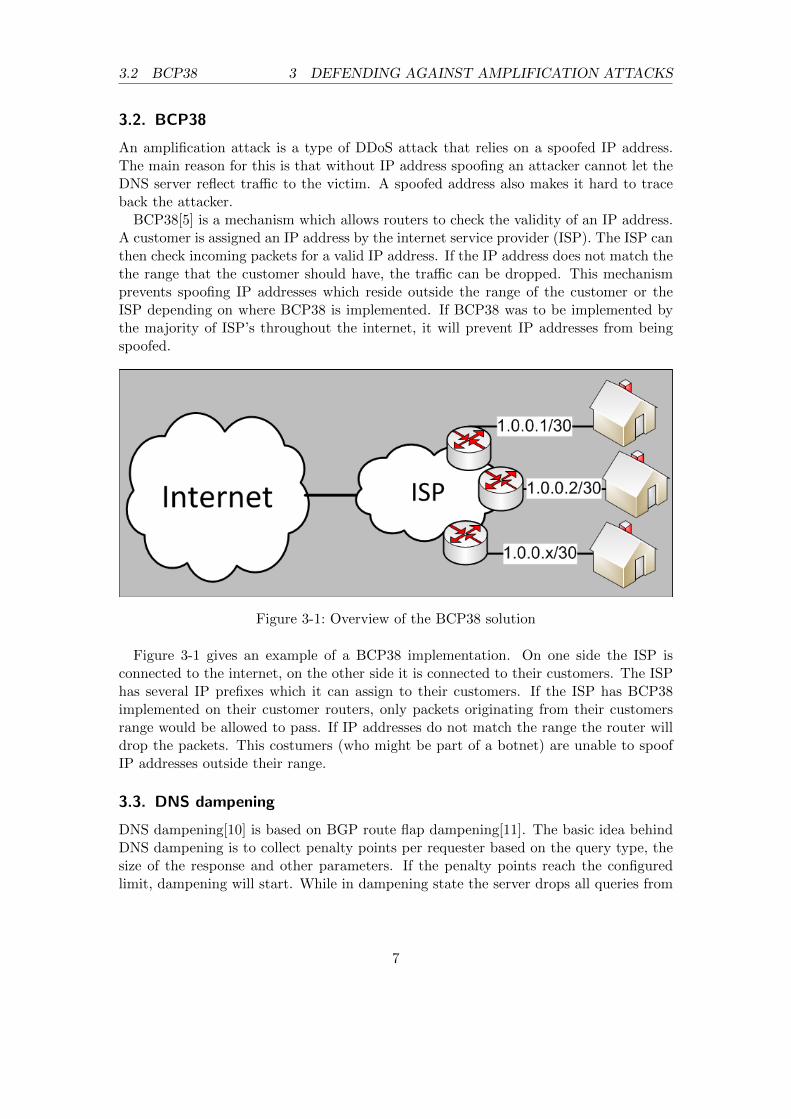
Figure 3-1: Overview of the BCP38 solution
Figure 3-1 gives an example of a BCP38 implementation. On one side the ISP isconnected to the internet, on the other side it is connected to their customers. The ISPhas several IP prefixes which it can assign to their customers. If the ISP has BCP38implemented on their customer routers, only packets originating from their customersrange would be allowed to pass. If IP addresses do not match the range the router willdrop the packets. This costumers (who might be part of a botnet) are unable to spoofIP addresses outside their range.
3.3. DNS dampening
DNS dampening[10] is based on BGP route flap dampening[11]. The basic idea behindDNS dampening is to collect penalty points per requester based on the query type, thesize of the response and other parameters. If the penalty points reach the configuredlimit, dampening will start. While in dampening state the server drops all queries from
7
3.4 RRL 3 DEFENDING AGAINST AMPLIFICATION ATTACKS
the spoofed IP address. Penalty points will be decreased exponentially over time. Whenthe penalty points drop below a secondary limit dampening will stop and the server willstart to process requests again. The storage required to keep state of the clients mustbe in memory only for fast processing.
Incoming requests are classified and penalty points are assigned based on the factorsmentioned above. Every query receives penalty points. For example, an ANY requestgets assigned 100 points because these queries are often used in attacks and rarely usedfor legitimate requests and another 100 penalty points are added when a query is repeatedwith the same query ID. For legitimate requests the query ID is a randomly chosen 16bit value. Duplicate query ID’s should only occur on a regular basis during attacks.Finally additional penalty points are assigned based upon the size of the response. Thedrawback of this approach is that it provides no mechanism to counter false positives.This could lead to a legitimate client to be blocked from the DNS system at all.
3.4. RRL
Response Rate Limiting[12] is a mechanism for limiting the amount of unique responsesreturned by a DNS server. This can limit the effectiveness of a DNS amplification attackby dropping responses that exceed the configured rate limit.
Rate limiting works as follows:• When the server generates a response to a DNS query, the requesters IP addresses
are grouped into buckets. By default IPv4 addresses on the same24 subnet are put into a single bucket. The same counts for56 IPv6 addresses.
• The wild-card, zonename or query name is stored together with the IP addressand the boolean error indicator (response code: REFUSED, FORMERR or SERV-FAIL).
• The server uses <(IP), (NAME), error-status> to decide how to act upon a request.This information is used as the state.
• If the amount of unique responses exceed the configured limit, the server dropsrequests for a specific IP or network. The server can also ask the requester to retryusing TCP instead (called SLIP).
• Note that the server is only looking at the given responses and ignores the amountof incoming requests.
When using RRL the victim might still notice it is under attack, because it receivesDNS responses for which no request was sent out for a limited time. An attacker mightalso be able to circumvent this defense mechanism by distributing it’s attack over a largenumber of DNS servers, to stay under the RRL limits of the DNS servers.
8
3.5 Summary 3 DEFENDING AGAINST AMPLIFICATION ATTACKS
3.5. Summary
Several defense mechanisms have been discussed, some more promising than others. Al-though firewalls are available everywhere and the rules are simple to implement, theycan only guard against very basic attacks. BCP38 would be the ultimate solution be-cause it will prevent IP address spoofing, unfortunately it is unlikely to be implementedthroughout the whole internet in the near future. DNS dampening seems to be a verypromising defense mechanism. However, in it is current stage there is no mechanismavailable to avoid false positives. Most attacks that are currently detected on the inter-net use repeating queries. RRL could be effective by limiting repeating responses, andmight be an effective solution. This research will focus on RRL because this mechanismlooks the most promising.
9
4 RESEARCH METHOD
4. Research method
In order to completely answer the research question, real-world attacks have to be sim-ulated. The repeating ANY attack is currently the most encountered attack on theinternet. Therefore it is relevant to know how effective RRL is against this kind of at-tack. Attacks are abusing all kinds of authoritative DNS servers: TLD’s, webhostersand organizations hosting their own ”small” zone. Defense mechanisms currently in usespecifically defend against repeating query attacks. When more DNS servers mitigatethese attacks it is only a matter of time before attackers are going to find and use moresophisticated methods. A more sophisticated attack which can be thought of is queryingfor varying domain names and possibly combining this with querying different recordtypes.
A TLD name server usually has one large zone file containing a large collection of do-main names. For example the name server responsible for all .nl domain names containsmore than 5 million1 individual domain names in total. Before an attacker can performa varying query attack, some information about the domain names present in the zone isrequired. An attacker could easily index domain names by using a webcrawler or usingsome type of dictionary attack. By creating 5 attacks, that differentiate in the amountof resolvable domain names, a wide selection of attack scenarios is simulated. The firstattack results in 0% resolvable domain names and 100% NXDOMAIN responses, thelast attack results in 100% unique resolvable domain names and 0% NXDOMAIN re-sponses. The attacks will differ in 0%, 25%, 50%, 75% and 100% resolvable domainnames. Details can be found in appendix C.1.
Compared to a TLD a ”web” hosting company usually hosts a large collection ofsmaller zones. For example the largest web hosting company called GoDaddy manages54 million domain names 2.
Because the hardware available in the lab setup is not capable of hosting 54 million do-main names, 1000 individual zone files are created in order to imitate a hosting company.A script is used to generate the zones, the details can be found in appendix C.3. Thereason that hosting companies are good amplification targets is the variety in domainnames, by querying a different domain name each time an unique response is returned.Because limited time is available for this project the measurements will focus on a TLDlike DNS server. The same attack will also be tested against a ”small” zone . This zonetype contains less than 20 resource records. Details can be found in appendix C.2.
This research focuses on measuring the effectiveness of RRL and finding the optimalparameters. Focus will be on the SLIP parameter because this parameter directly effectsthe change for false positives and the amount of outbound traffic. In order to replicatea realistic amplification attack, every scenario makes use of DNSSEC signed zones. Theresearch is done in the lab of NLnet Labs which they made available for this research.The lab consist of the following three servers:
• Attacker, hathi.nlnetlabs.nl;• DNS server, kaa.nlnetlabs.nl;• Victim, balou.nlnetlabs.nl.
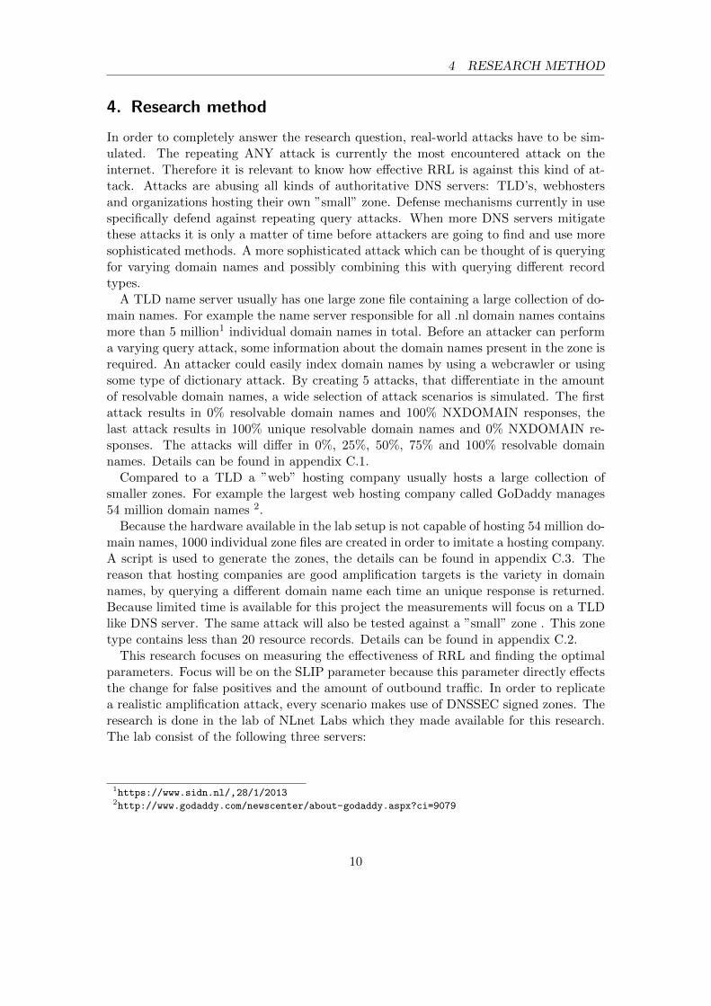
Because the limited amount of hardware available to imitate a bot-net to generate thetraffic, packet capture (pcap) files are created, modified and replayed to simulate anattack. The IP address of the player is replaced by the IP address of the listener. Theamplification attack is executed by replaying modified pcap files from the player to thename server. BIND is used as the name server daemon. The reason for using BINDis that it is by far the most widely used DNS software on the Internet3. The nameserver will then respond to the request and sends the responses to the listener. In- andoutbound traffic is measured on the DNS server using a network monitoring tool namedCacti, this tool can easily be set up and a graphical representation of the measurementcan be created. A graphical overview of the lab environment can be find below and adetailed description of the scripts and applications used can be found in appendix D.4and D.
Figure 4-1: Graphical overview of the lab environment
3https://www.isc.org/software/bind
11
5 MEASUREMENTS
5. Measurements
The goal of this research can be divided into two sections. The first one is to find outhow effective response rate limiting is. The second part focuses on finding the best pa-rameters to set for the environments described in section 4. To understand the resultsof this research it is important to understand the following parameters:
• RESPONSES-PER-SECOND is a limit on identical responses. The defaultlimit of zero specifies an unbounded limit to turn off rate limiting in a view or toonly rate limit NXDOMAIN or other errors. All responses to a specified networkwith IPv4-PREFIX-LENGTH (Default 24) or IPv6-PREFIX-LENGTH (Default56) are assumed to come from a single DNS client.
• NXDOMAINS-PER-SECOND by default the limit on NXDOMAIN errors isthe same as the responses-per-second value, but it can be set separately.
• ERRORS-PER-SECOND The maximum amount of error (REFUSED, FOR-MERR and SERVFAIL) that can be returned to the requester.
• WINDOW When any per-second limit is exceeded the source can be penalizedfor up to WINDOW seconds.
• IPv4-PREFIX-LENGTH All responses to a network block with a given prefixlength are assumed to come from a single DNS client. This parameter sets theprefix length for IPv4.
• IPv6-PREFIX-LENGTH All responses to a network block with a given prefixlength are assumed to come from a single DNS client. This parameter sets theprefix length for IPv6.
• SLIP When the RRL mechanism is activated and queries are being dropped,a small response claiming that the response would have been truncated is sentrandomly once per SLIP query. This allows a legitimate client to reconnect overTCP. Because the SLIP response is approximately the same size as the request itis unattractive for abuse.
• MAX-TABLE-SIZE RRL needs to keep state of the unique responses in order tobe able to assign penalties. This entry sets the maximum amount of entries (calledstate blobs) which can be stored at the same time. This should be set to the productof the window size and maximum queries per second. 10000 state blobs should takeabout one megabyte of server memory. MaxQPS ∗Window = Tablesize.
• MIN-TABLE-SIZE Since growing this table has a cost, an operator might de-cide to start with a larger than default size table.
Not all parameters will be researched in depth because some have a limited influenceon the effectiveness of RRL. The RRL parameters will need to be tailored for eachspecific environment. A recommendation for the configuration will be given in section6.2.1. The effectiveness of RRL is highly depended on the SLIP parameter because itdirectly affects the chance for false positives and the amount of outbound traffic. In thefollowing sections the effectiveness of RRL with differing SLIP settings will be measuredin the scenarios mentioned in section 5.
Section 2.1 mentioned that repeating query attacks often target authoritative nameservers. In this section a similar attack is simulated against a small zone, a TLD-likezone and a DNS server that hosts multiple zones like a hosting provider. The details ofthese zone configurations can be found in appendix D.
5.1.1. Single Zone
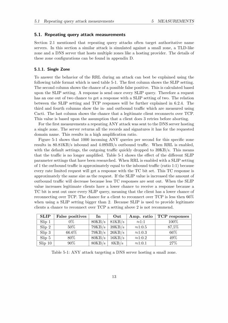
To answer the behavior of the RRL during an attack can best be explained using thefollowing table format which is used table 5-1. The first column shows the SLIP setting.The second column shows the chance of a possible false positive. This is calculated basedupon the SLIP setting. A response is send once every SLIP query. Therefore a requesthas an one out of two chance to get a response with a SLIP setting of two. The relationbetween the SLIP setting and TCP responses will be further explained in 6.2.4. Thethird and fourth columns show the in- and outbound traffic which are measured usingCacti. The last column shows the chance that a legitimate client reconnects over TCP.This value is based upon the assumption that a client does 3 retries before aborting.
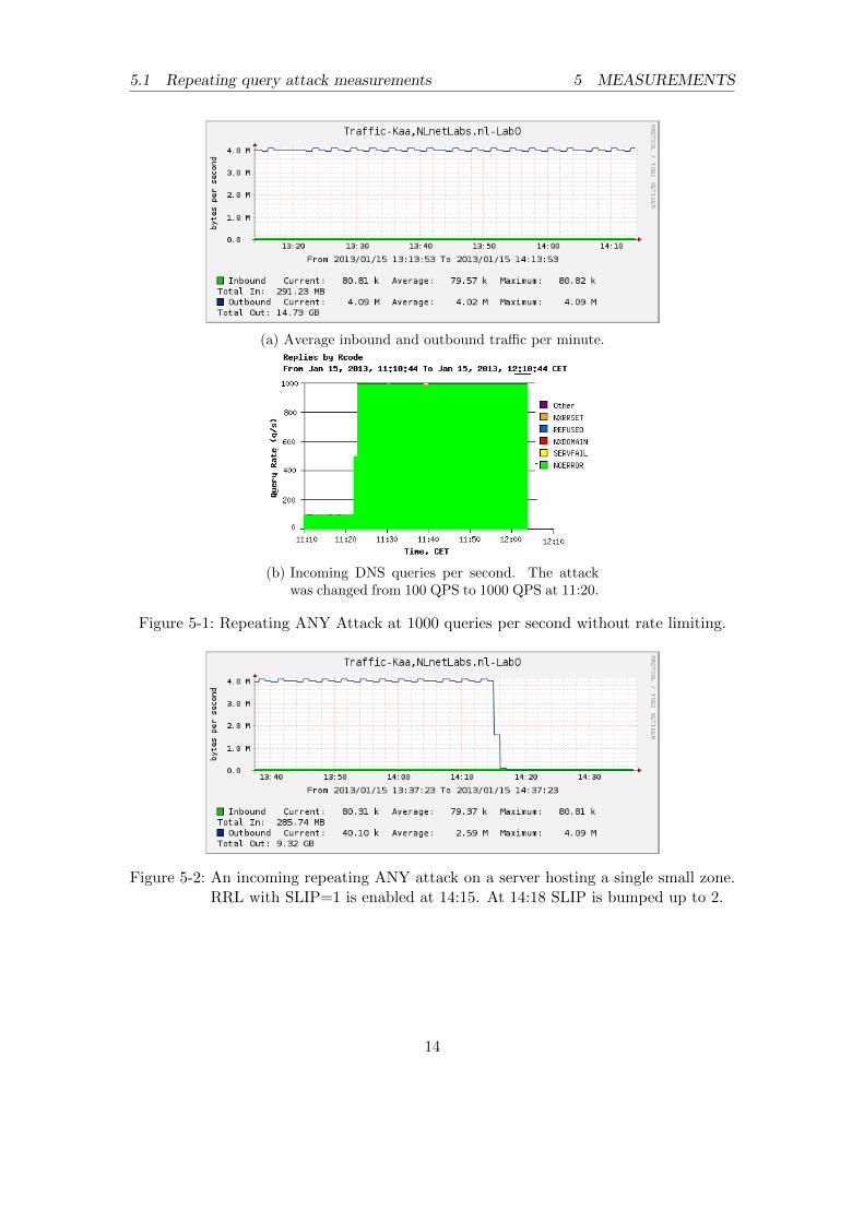
For the first measurements a repeating ANY attack was sent to the DNS server hostinga single zone. The server returns all the records and signatures it has for the requesteddomain name. This results in a high amplification ratio.
Figure 5-1 shows that 1000 incoming ANY queries per second for this specific zoneresults in 80.81KB/s inbound and 4.09MB/s outbound traffic. When RRL is enabled,with the default settings, the outgoing traffic quickly dropped to 39KB/s. This meansthat the traffic is no longer amplified. Table 5-1 shows the effect of the different SLIPparameter settings that have been researched. When RRL is enabled with a SLIP settingof 1 the outbound traffic is approximately equal to the inbound traffic (ratio 1:1) becauseevery rate limited request will get a response with the TC bit set. This TC response isapproximately the same size as the request. If the SLIP value is increased the amount ofoutbound traffic will decrease because less TC responses are sent out. When the SLIPvalue increases legitimate clients have a lower chance to receive a response because aTC bit is sent out once every SLIP query, meaning that the client has a lower chance ofreconnecting over TCP. The chance for a client to reconnect over TCP is less then 66%when using a SLIP setting bigger than 2. Because SLIP is used to provide legitimateclients a chance to reconnect over TCP a setting above 2 is not recommend.
SLIP False positives In Out Amp. ratio TCP responses
Slip 1 0% 80KB/s 81KB/s ≈1:1 100%
Slip 2 50% 79KB/s 39KB/s ≈1:0.5 87,5%
Slip 3 66.6% 79KB/s 26KB/s ≈1:0.3 66%
Slip 5 80% 80KB/s 16KB/s ≈1:0.2 49%
Slip 10 90% 80KB/s 8KB/s ≈1:0.1 27%
Table 5-1: ANY attack targeting a DNS server hosting a small zone.
(a) Average inbound and outbound traffic per minute.
(b) Incoming DNS queries per second. The attackwas changed from 100 QPS to 1000 QPS at 11:20.
Figure 5-1: Repeating ANY Attack at 1000 queries per second without rate limiting.
Figure 5-2: An incoming repeating ANY attack on a server hosting a single small zone.RRL with SLIP=1 is enabled at 14:15. At 14:18 SLIP is bumped up to 2.
14
5.2 Varying query attack 5 MEASUREMENTS
5.1.2. TLD
The same attack is executed against a DNS server hosting a TLD like zone.
RRL In Out Amp. ratio
Disabled 73KB/s 4.01MB/s 1:54.93
Enabled (SLIP=1) 73KB/s 73KB/s 1:1
Table 5-2: An ANY attack on a TLD like zone.
Since the ANY attack just repeats the same request over and over again it will resultin the same response every time. As soon as RRL is enabled, the outbound traffic dropsas expected. In all the scenario’s that have been tested, RRL is an effective defensemechanism against the ANY attack.
5.2. Varying query attack
The type of attack explained in this section is more sophisticated than the repeated(ANY) query attack explained above. In order to perform a varying query attack, theattacker generates random queries or needs to gather information about the domainnames hosted on the authoritative name server. An attacker can abuse NSEC recordsto gather information about a certain zone. NSEC records are used to prove a namedoes not exist by pointing to the previous and the next record. When NSEC records areused the attacker can perform a so called zone walk to index a zone. To prevent zonewalking NSEC3 records have been introduced. IETF published RFC5155 [7] explainingNSEC3 in detail.
5.2.1. Varying query attack on TLD
A TLD name server usually has one large zone file containing a large collection of domainnames. ANY queries are sent out for a variety of domain names of the zones. In thefollowing section five different zones for a TLD are attacked, each varying in the amountof existing domain names. All the attacks take place with 1000 ANY queries per seconds.
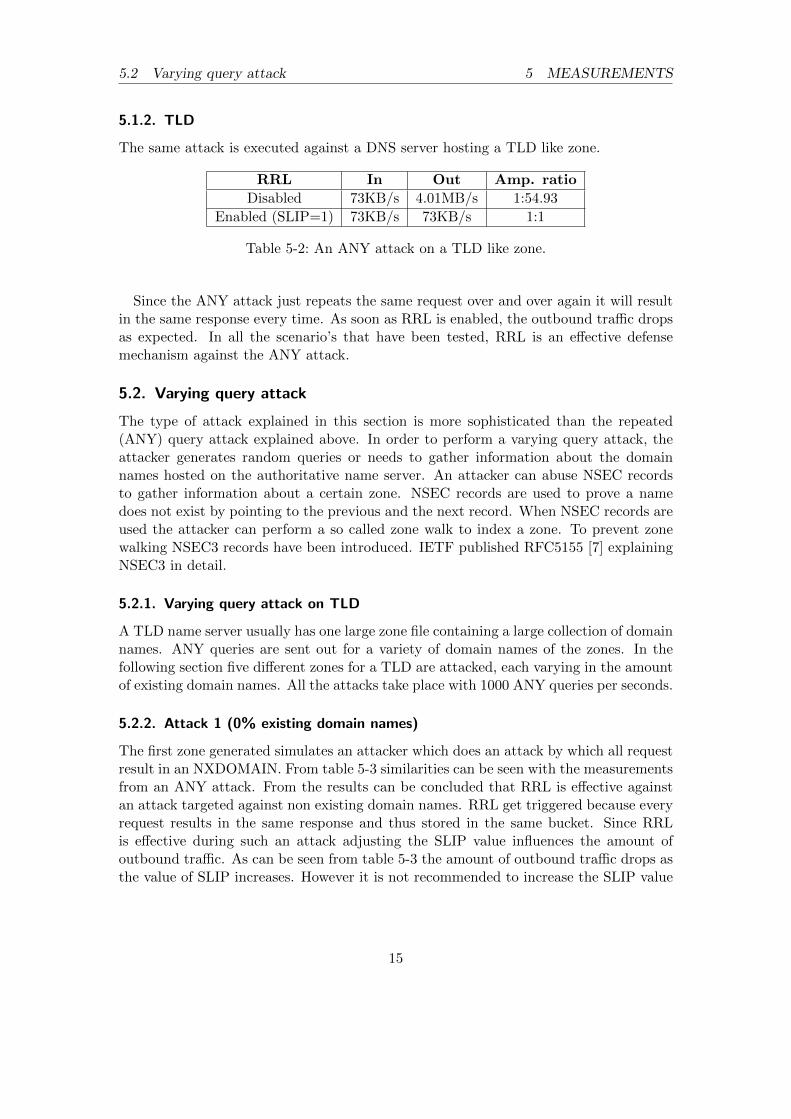
5.2.2. Attack 1 (0% existing domain names)
The first zone generated simulates an attacker which does an attack by which all requestresult in an NXDOMAIN. From table 5-3 similarities can be seen with the measurementsfrom an ANY attack. From the results can be concluded that RRL is effective againstan attack targeted against non existing domain names. RRL get triggered because everyrequest results in the same response and thus stored in the same bucket. Since RRLis effective during such an attack adjusting the SLIP value influences the amount ofoutbound traffic. As can be seen from table 5-3 the amount of outbound traffic drops asthe value of SLIP increases. However it is not recommended to increase the SLIP value
15
5.2 Varying query attack 5 MEASUREMENTS
above two, the chance for a legitimate request to successfully gets a response over TCPis lower than 66%.
SLIP False positives In Out Amp. ratio TCP responses
Slip 1 0% 77KB/s 78KB/s ≈1:1 100%
Slip 2 50% 79KB/s 38KB/s ≈1:0.5 87,5%
Slip 3 66.6% 79KB/s 26KB/s ≈1:0.3 66%
Slip 5 80% 78KB/s 14KB/s ≈1:0.2 49%
Slip 10 90% 78KB/s 8KB/s ≈1:0.1 27%
Table 5-3: Varying query attack on a TLD zone with 100% non-existing domain names.
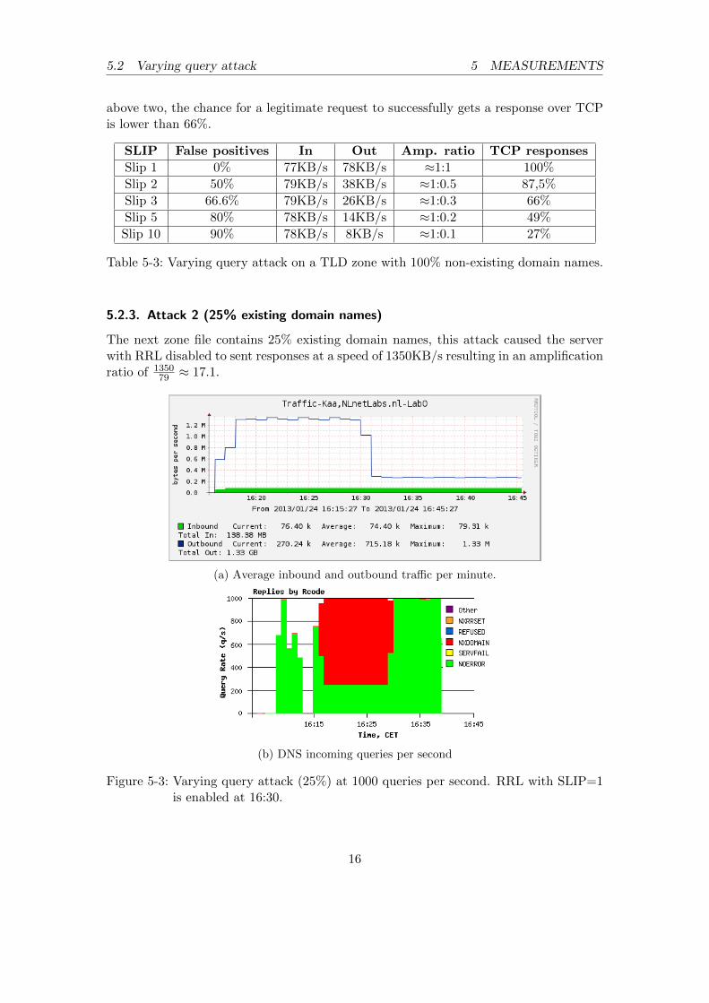
5.2.3. Attack 2 (25% existing domain names)
The next zone file contains 25% existing domain names, this attack caused the serverwith RRL disabled to sent responses at a speed of 1350KB/s resulting in an amplificationratio of 1350
79 ≈ 17.1.
(a) Average inbound and outbound traffic per minute.
(b) DNS incoming queries per second
Figure 5-3: Varying query attack (25%) at 1000 queries per second. RRL with SLIP=1is enabled at 16:30.
16
5.2 Varying query attack 5 MEASUREMENTS
SLIP False positives In Out Amp. ratio TCP responses
Slip 1 0% 79KB/s 278KB/s ≈1:3.5 100%
Slip 2 50% 79KB/s 249KB/s ≈1:3.2 87,5%
Slip 3 66.6% 79KB/s 239KB/s ≈1:3.0 66%
Slip 5 80% 78KB/s 227KB/s ≈1:2.9 49%
Slip 10 90% 79KB/s 218KB/s ≈1:2.76 27%
Table 5-4: Varying query attack on a TLD zone with 25% existing and 75% non-existingdomain names.
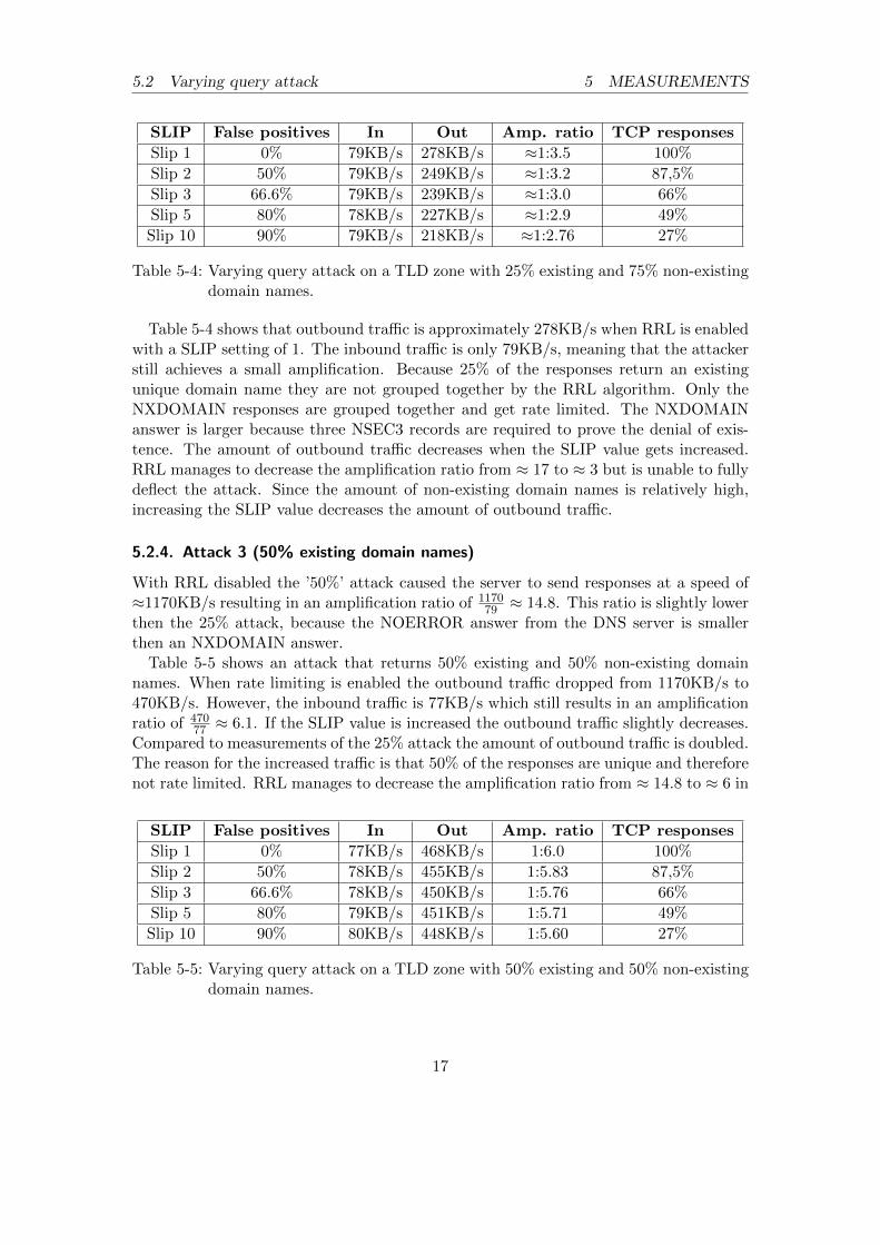
Table 5-4 shows that outbound traffic is approximately 278KB/s when RRL is enabledwith a SLIP setting of 1. The inbound traffic is only 79KB/s, meaning that the attackerstill achieves a small amplification. Because 25% of the responses return an existingunique domain name they are not grouped together by the RRL algorithm. Only theNXDOMAIN responses are grouped together and get rate limited. The NXDOMAINanswer is larger because three NSEC3 records are required to prove the denial of exis-tence. The amount of outbound traffic decreases when the SLIP value gets increased.RRL manages to decrease the amplification ratio from ≈ 17 to ≈ 3 but is unable to fullydeflect the attack. Since the amount of non-existing domain names is relatively high,increasing the SLIP value decreases the amount of outbound traffic.
5.2.4. Attack 3 (50% existing domain names)
With RRL disabled the ’50%’ attack caused the server to send responses at a speed of≈1170KB/s resulting in an amplification ratio of 1170
79 ≈ 14.8. This ratio is slightly lowerthen the 25% attack, because the NOERROR answer from the DNS server is smallerthen an NXDOMAIN answer.
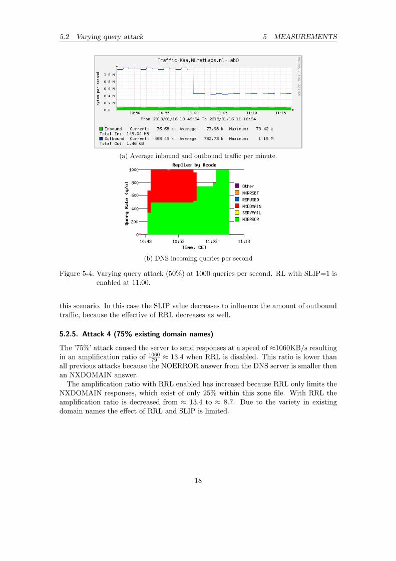
Table 5-5 shows an attack that returns 50% existing and 50% non-existing domainnames. When rate limiting is enabled the outbound traffic dropped from 1170KB/s to470KB/s. However, the inbound traffic is 77KB/s which still results in an amplificationratio of 470
77 ≈ 6.1. If the SLIP value is increased the outbound traffic slightly decreases.Compared to measurements of the 25% attack the amount of outbound traffic is doubled.The reason for the increased traffic is that 50% of the responses are unique and thereforenot rate limited. RRL manages to decrease the amplification ratio from ≈ 14.8 to ≈ 6 in
SLIP False positives In Out Amp. ratio TCP responses
Slip 1 0% 77KB/s 468KB/s 1:6.0 100%
Slip 2 50% 78KB/s 455KB/s 1:5.83 87,5%
Slip 3 66.6% 78KB/s 450KB/s 1:5.76 66%
Slip 5 80% 79KB/s 451KB/s 1:5.71 49%
Slip 10 90% 80KB/s 448KB/s 1:5.60 27%
Table 5-5: Varying query attack on a TLD zone with 50% existing and 50% non-existingdomain names.
17
5.2 Varying query attack 5 MEASUREMENTS
(a) Average inbound and outbound traffic per minute.
(b) DNS incoming queries per second
Figure 5-4: Varying query attack (50%) at 1000 queries per second. RL with SLIP=1 isenabled at 11:00.
this scenario. In this case the SLIP value decreases to influence the amount of outboundtraffic, because the effective of RRL decreases as well.
5.2.5. Attack 4 (75% existing domain names)
The ’75%’ attack caused the server to send responses at a speed of ≈1060KB/s resultingin an amplification ratio of 1060
79 ≈ 13.4 when RRL is disabled. This ratio is lower thanall previous attacks because the NOERROR answer from the DNS server is smaller thenan NXDOMAIN answer.
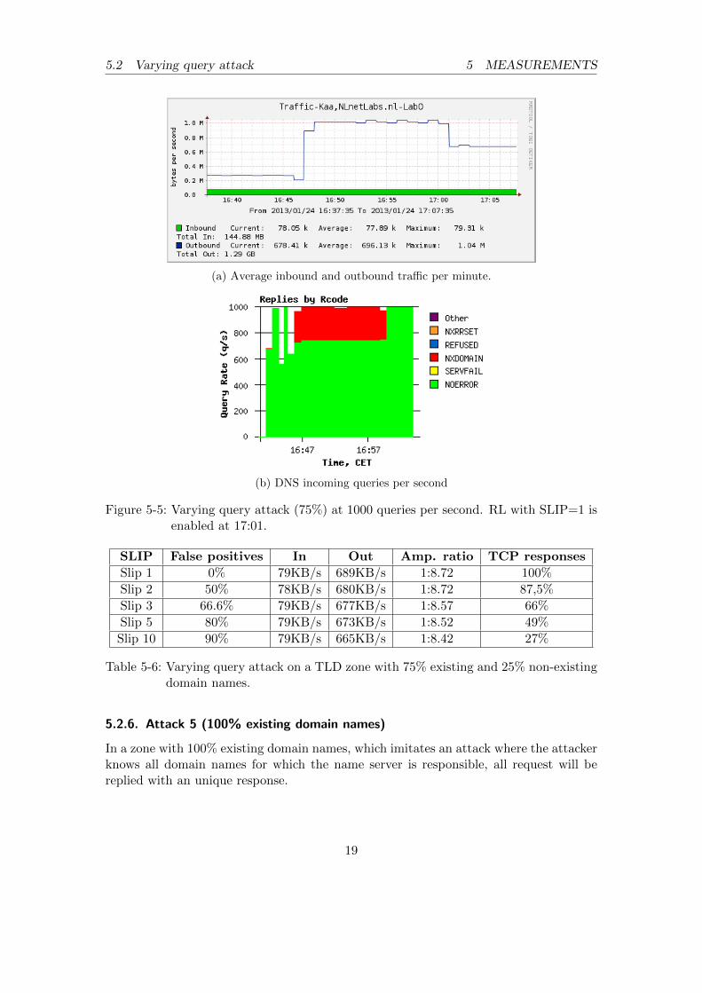
The amplification ratio with RRL enabled has increased because RRL only limits theNXDOMAIN responses, which exist of only 25% within this zone file. With RRL theamplification ratio is decreased from ≈ 13.4 to ≈ 8.7. Due to the variety in existingdomain names the effect of RRL and SLIP is limited.
18
5.2 Varying query attack 5 MEASUREMENTS
(a) Average inbound and outbound traffic per minute.
(b) DNS incoming queries per second
Figure 5-5: Varying query attack (75%) at 1000 queries per second. RL with SLIP=1 isenabled at 17:01.
SLIP False positives In Out Amp. ratio TCP responses
Slip 1 0% 79KB/s 689KB/s 1:8.72 100%
Slip 2 50% 78KB/s 680KB/s 1:8.72 87,5%
Slip 3 66.6% 79KB/s 677KB/s 1:8.57 66%
Slip 5 80% 79KB/s 673KB/s 1:8.52 49%
Slip 10 90% 79KB/s 665KB/s 1:8.42 27%
Table 5-6: Varying query attack on a TLD zone with 75% existing and 25% non-existingdomain names.
5.2.6. Attack 5 (100% existing domain names)
In a zone with 100% existing domain names, which imitates an attack where the attackerknows all domain names for which the name server is responsible, all request will bereplied with an unique response.
19
5.2 Varying query attack 5 MEASUREMENTS
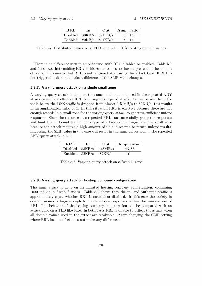
RRL In Out Amp. ratio
Disabled 80KB/s 891KB/s 1:11.14
Enabled 80KB/s 891KB/s 1:11.14
Table 5-7: Distributed attack on a TLD zone with 100% existing domain names
There is no difference seen in amplification with RRL disabled or enabled. Table 5-7and 5-9 shows that enabling RRL in this scenario does not have any effect on the amountof traffic. This means that RRL is not triggered at all using this attack type. If RRL isnot triggered it does not make a difference if the SLIP value changes.
5.2.7. Varying query attack on a single small zone
A varying query attack is done on the same small zone file used in the repeated ANYattack to see how effective RRL is during this type of attack. As can be seen from thetable below the DNS traffic is dropped from almost 1.5 MB/s to 82KB/s, this resultsin an amplification ratio of 1. In this situation RRL is effective because there are notenough records in a small zone for the varying query attack to generate sufficient uniqueresponses. Since the responses are repeated RRL can successfully group the responsesand limit the outbound traffic. This type of attack cannot target a single small zonebecause the attack requires a high amount of unique records to return unique results.Increasing the SLIP value in this case will result in the same values seen in the repeatedANY query attack in 5-1.
RRL In Out Amp. ratio
Disabled 83KB/s 1.48MB/s 1:17.83
Enabled 82KB/s 82KB/s 1:1
Table 5-8: Varying query attack on a ”small” zone
5.2.8. Varying query attack on hosting company configuration
The same attack is done on an imitated hosting company configuration, containing1000 individual ”small” zones. Table 5-9 shows that the in- and outbound traffic isapproximately equal whether RRL is enabled or disabled. In this case the variety indomain names is large enough to create unique responses within the window size ofRRL. The behavior of the hosting company configuration can be compared with anattack done on a TLD like zone. In both cases RRL is unable to deflect the attack whenall domain names used in the attack are resolvable. Again changing the SLIP settingwhere RRL has no effect does not make any difference.
20
5.3 Distributed attack 5 MEASUREMENTS
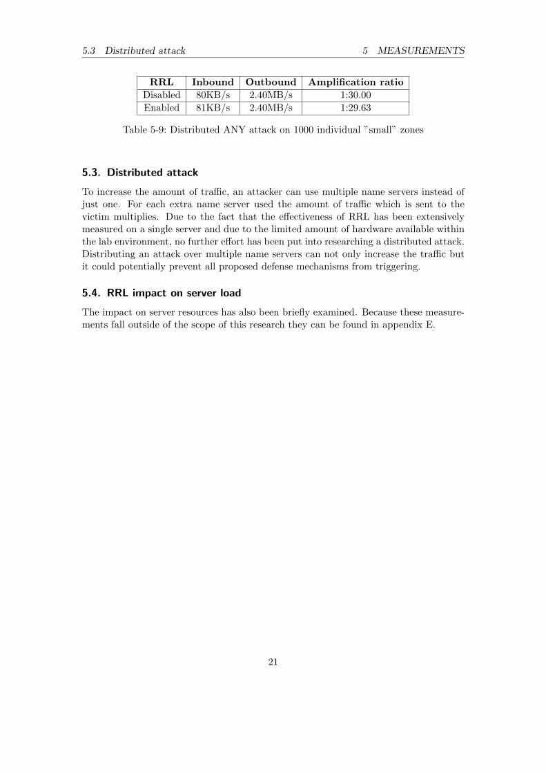
RRL Inbound Outbound Amplification ratio
Disabled 80KB/s 2.40MB/s 1:30.00
Enabled 81KB/s 2.40MB/s 1:29.63
Table 5-9: Distributed ANY attack on 1000 individual ”small” zones
5.3. Distributed attack
To increase the amount of traffic, an attacker can use multiple name servers instead ofjust one. For each extra name server used the amount of traffic which is sent to thevictim multiplies. Due to the fact that the effectiveness of RRL has been extensivelymeasured on a single server and due to the limited amount of hardware available withinthe lab environment, no further effort has been put into researching a distributed attack.Distributing an attack over multiple name servers can not only increase the traffic butit could potentially prevent all proposed defense mechanisms from triggering.
5.4. RRL impact on server load
The impact on server resources has also been briefly examined. Because these measure-ments fall outside of the scope of this research they can be found in appendix E.
21
6 RESULTS
6. Results
6.1. RRL effectiveness
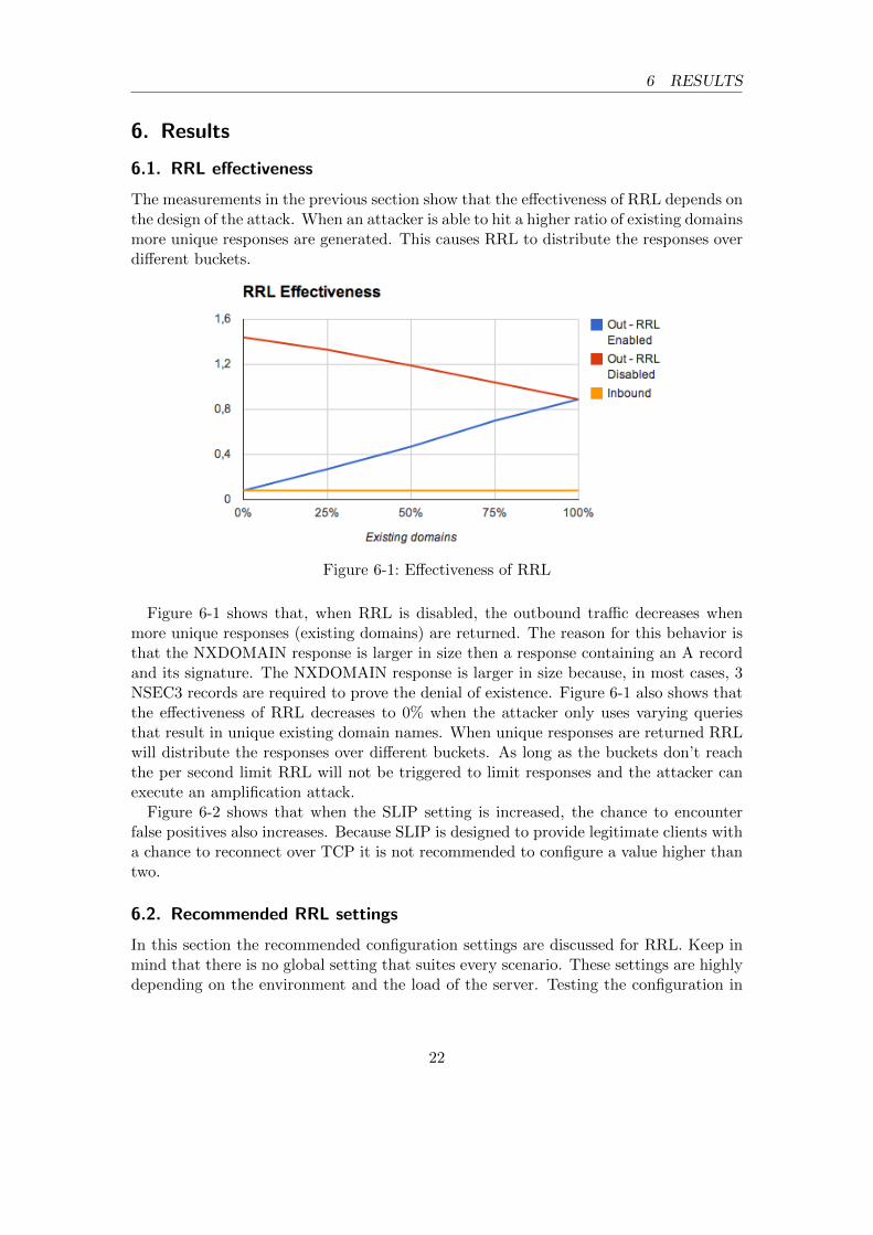
The measurements in the previous section show that the effectiveness of RRL depends onthe design of the attack. When an attacker is able to hit a higher ratio of existing domainsmore unique responses are generated. This causes RRL to distribute the responses overdifferent buckets.
Figure 6-1: Effectiveness of RRL
Figure 6-1 shows that, when RRL is disabled, the outbound traffic decreases whenmore unique responses (existing domains) are returned. The reason for this behavior isthat the NXDOMAIN response is larger in size then a response containing an A recordand its signature. The NXDOMAIN response is larger in size because, in most cases, 3NSEC3 records are required to prove the denial of existence. Figure 6-1 also shows thatthe effectiveness of RRL decreases to 0% when the attacker only uses varying queriesthat result in unique existing domain names. When unique responses are returned RRLwill distribute the responses over different buckets. As long as the buckets don’t reachthe per second limit RRL will not be triggered to limit responses and the attacker canexecute an amplification attack.
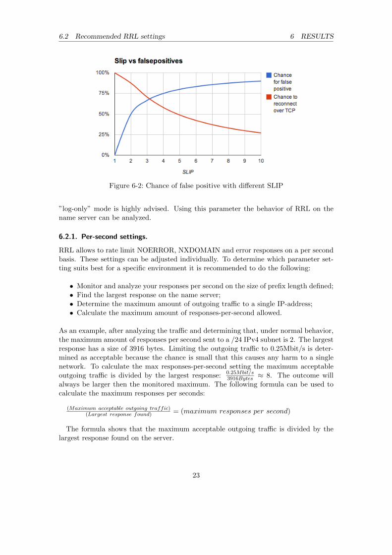
Figure 6-2 shows that when the SLIP setting is increased, the chance to encounterfalse positives also increases. Because SLIP is designed to provide legitimate clients witha chance to reconnect over TCP it is not recommended to configure a value higher thantwo.
6.2. Recommended RRL settings
In this section the recommended configuration settings are discussed for RRL. Keep inmind that there is no global setting that suites every scenario. These settings are highlydepending on the environment and the load of the server. Testing the configuration in
22
6.2 Recommended RRL settings 6 RESULTS
Figure 6-2: Chance of false positive with different SLIP
”log-only” mode is highly advised. Using this parameter the behavior of RRL on thename server can be analyzed.
6.2.1. Per-second settings.
RRL allows to rate limit NOERROR, NXDOMAIN and error responses on a per secondbasis. These settings can be adjusted individually. To determine which parameter set-ting suits best for a specific environment it is recommended to do the following:
• Monitor and analyze your responses per second on the size of prefix length defined;• Find the largest response on the name server;• Determine the maximum amount of outgoing traffic to a single IP-address;• Calculate the maximum amount of responses-per-second allowed.
As an example, after analyzing the traffic and determining that, under normal behavior,the maximum amount of responses per second sent to a /24 IPv4 subnet is 2. The largestresponse has a size of 3916 bytes. Limiting the outgoing traffic to 0.25Mbit/s is deter-mined as acceptable because the chance is small that this causes any harm to a singlenetwork. To calculate the max responses-per-second setting the maximum acceptableoutgoing traffic is divided by the largest response: 0.25Mbit/s
3916Bytes ≈ 8. The outcome willalways be larger then the monitored maximum. The following formula can be used tocalculate the maximum responses per seconds:
The formula shows that the maximum acceptable outgoing traffic is divided by thelargest response found on the server.
23
6.2 Recommended RRL settings 6 RESULTS
6.2.2. Window
This setting defines how many seconds a client will be rate limited after an attack hasstopped. RRL uses a credit system that is described below.
• The responses-per-second setting is equal to the maximum amount of credits aclient can have;
• 0 − (Window ∗ responses − per − second) = the maximum amount of negativecredits a client can have;
• The responses-per-second setting is also equal to the amount of credits a clientreceives per second;
• When the amount of credits is negative responses are dropped.
This window should be kept small to revert to normal service as soon as possible afteran attack. A window of 5 seconds should be sufficient in most cases. Be aware thatif the windows size is decreased any further this could cause on/off behavior when theincoming traffic is inconsistent.
6.2.3. IPv4 and IPv6 prefix length
Client IP addresses are grouped into buckets because RRL is designed to protect distantnetworks from amplification attacks. By default these buckets are equal to the size of a/24 networks which contain up to 256 host addresses. For IPv6 the default is /56 whichalso relates to 256 sub-networks. Decreasing the prefix length will increase the chance forfalse positives on a busy DNS server because more client addresses are grouped together.If there is no special reason to deviate from the default settings, it is recommended notto change those parameter settings.
6.2.4. SLIP
A DDoS victim, while under attack, may not be able to contact the DNS server whichis used for the attack because the DNS server will drop the traffic. It is not possiblefor a server to distinguish legitimate traffic from illegitimate due to UDP source-addressspoofing. If traffic for a network is being dropped, a TC flag can be returned once perSLIP queries. The client takes the TC flag as an indication that it should retry overTCP, which only legitimate clients will do. Setting the SLIP value to one will preventall possible false positives, SLIP will respond to every dropped response with the TCbit set, making sure that legitimate queries are can be answered over TCP. Because thisTC response is approximately the size of the request an attacker will not achieve anyamplification. Setting SLIP to two will sent a TC response to 50% of the request. Thisgives a victim a fair chance to communicate with the DNS server while being underattack. Assumed a client will retry three times in order to get a response from the DNS
24
6.2 Recommended RRL settings 6 RESULTS
server the chance of communicating is 87.5%. (100 ∗ (1 − (0.5 ∗ 0.5 ∗ 0.5))). This resultsin an amplification ratio of 1:0.5, cutting the attack traffic in half.
6.2.5. Table-size
The max-table-size sets the maximum number of state blobs the server will maintain.This setting should be set for the worst case scenario where all queries need to bemaintained because the responses are unique. To calculate the value take the maximumqueries per second and multiply this value by the window size. 80 Megabyte of servermemory is consumed, this is seen in the measurements from the previous chapter for1.000.000 state blobs. If a maximum of 100.000 queries per second is processed with awindows size of 5 this will result in a max-table-size of 500.000.
The min-table-size parameter sets the initial size of the state-blob table at start-uptime. Because growing this table will consume resources it is advised to set this toa higher value. Taking the maximum queries per second under normal operation andmultiplying this by the window size should be a good baseline for this setting.
25
7 DAMPENING
7. Dampening
The results presented in section 6 show that RRL is unable to properly defend againstdistributed attacks. For this reason another available defense mechanism mentioned insection 3 is briefly researched called DNS Dampening. There is a DNS dampening patchavailable for BIND which is designed and created by Lutz Donnerhacke. Due to limitedamount of time and the scope of this project DNS dampening will not be covered in dept.Because the mechanism assigns penalty points to spoofed clients instead of grouping theunique responses together in buckets it should be more effective against distributedattacks.
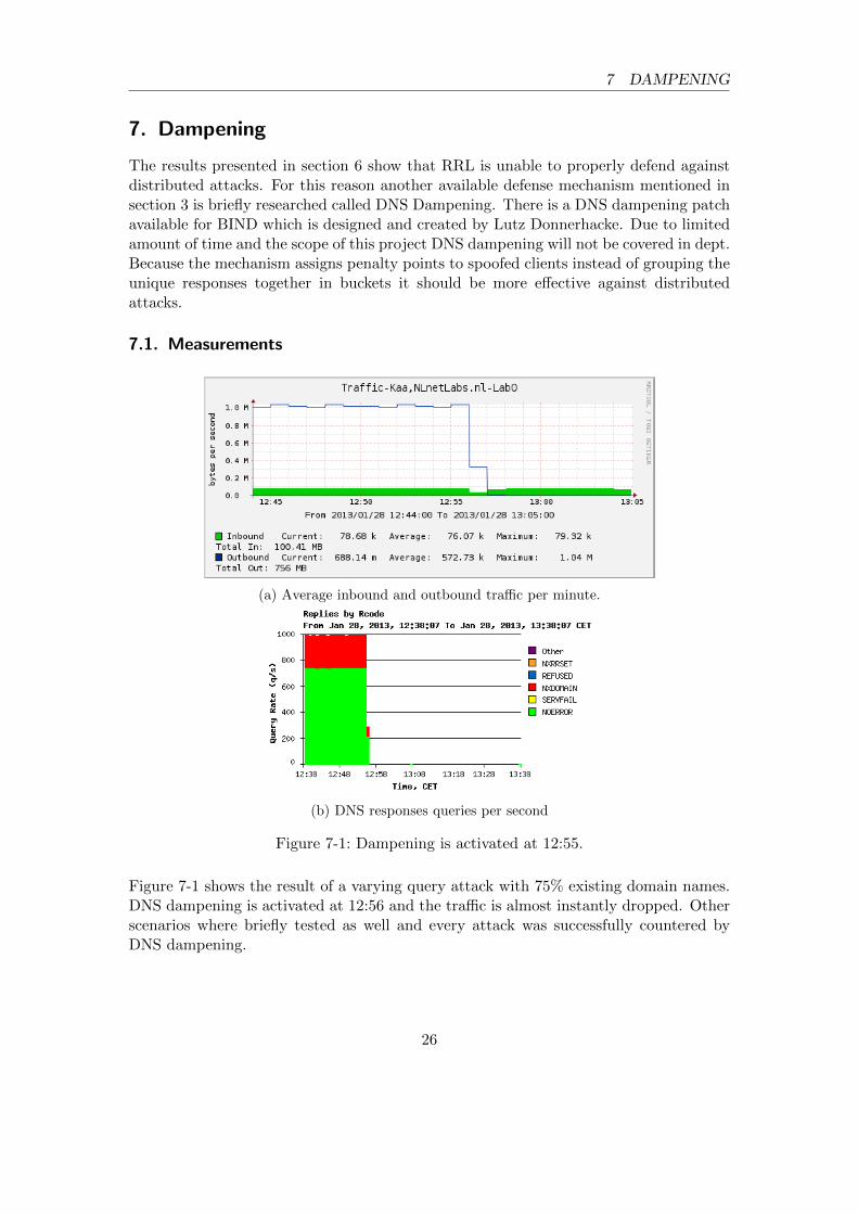
7.1. Measurements
(a) Average inbound and outbound traffic per minute.
(b) DNS responses queries per second
Figure 7-1: Dampening is activated at 12:55.
Figure 7-1 shows the result of a varying query attack with 75% existing domain names.DNS dampening is activated at 12:56 and the traffic is almost instantly dropped. Otherscenarios where briefly tested as well and every attack was successfully countered byDNS dampening.
26
7.2 DNS dampening impact on server load 7 DAMPENING
7.2. DNS dampening impact on server load
The impact on server resources has also been briefly examined. Because these measure-ments fall outside of the scope of this research they are attached as appendix E.
7.3. Drawbacks
Although DNS dampening looks very promising based upon the measurements, there area few drawbacks to using it in production. The most significant drawback is that their isno mechanism in place to counter false positives. When a client or network is limited, nolegitimate traffic from that client or network is possible. This provides an attacker withan easy way to prevent DNS requests from being answered to a specific client. Anotherdrawback is that it is currently not possible to tailor the DNS dampening parameters tothe environment. DNS dampening in its current form is aggressive, therefore extra careshould be taken when implementing it.
27
8 CONCLUSION
8. Conclusion
DNS amplification attacks rely on two concepts. The first one; when using UDP theIP address can easily be spoofed causing traffic to be reflected by the DNS server. Thesecond one; DNS requests are small while responses can be multiple times the size of therequest causing the amplification. DNSSEC further contributes to the amplification ofDNS traffic because it requires the DNS server to include signatures causing the size ofthe response to grow.
The amplification of illegitimate responses can be limited by implementing RRL on au-thoritative name servers. When responses are duplicated within the window size or ifmultiple errors or NXDOMAIN responses are returned RRL will be triggered. RRL canprevent false positives by setting SLIP to 1, this will have the DNS server to respondto every dropped query with the TC bit set giving a legitimate client a chance to retryover TCP. The chance for a client to reconnect over TCP is less then 66% when using aSLIP setting of 3 or higher. Because SLIP is used to provide legitimate clients a chanceto reconnect over TCP a setting above 2 is not recommend. RRL is very successfulin mitigating basic attacks like the standard repeating ANY attack. However, the ef-fectiveness decreases when the attack gets more sophisticated. When an attacker usesa large set of varying queries only the NXDOMAIN responses will get limited and anattacker might still be able to amplify the traffic. If the attacker manages to find enoughexisting domain names, the queries can be distributed over these names, resulting inunique responses which are not limited by RRL. When using DNSSEC on authoritativename servers NSEC3 should be implemented instead of NSEC. This prevents an attackerfrom indexing the zone by doing a zone walk and then distribute the attack over all therecords in the zone. RRL is not effective against a fully indexed varying query attackthat only queries for existing domain names.
Another defense mechanism called DNS dampening can be successful in mitigating moresophisticated distributed attacks. DNS dampening looks like a promising defense mech-anism, but is missing some essential features. It does not have a technique implementedto counter false positives, which makes it easy for an attacker to block a server for legit-imate clients.
Unfortunately there is no easy way to stop DNS amplification attacks without any side ef-fects. Until the major network vendors make source address validation (BCP38, Ingressfiltering) a default setting, reflection/amplification attacks will remain an issue. Re-sponse Rate Limiting is the best approach to eliminate the current form of attacks.When attacks become more sophisticated in the future, RRL will lose its effectivenessand the need for a different defense mechanism will rise.
28
9 FUTURE WORK
9. Future work
If future attacks get more sophisticated, it will be possible to bypass RRL. DNS damp-ening is a promising defense mechanism against DNS reflection attacks which could helpin this situation. However, in the current state it is missing a feature to prevent false-positives. A similar feature like SLIP will need to be developed for DNS dampening tomake it a practical solution.
When attacks get distributed across many DNS servers it might even be possible to pre-vent DNS dampening from triggering. As an addition to the current defense mechanismsavailable, new solutions will need to be researched. In order to prevent a DNS reflec-tion amplification attack either the reflection or the amplification should be removed. Apromising solution for removing the reflection is already available, BCP38 prevents IPaddresses from being spoofed, therefore making reflection attacks impossible. A methodfor a faster adoption of BCP38 could be researched in the future as well.
29
A ABBREVIATIONS
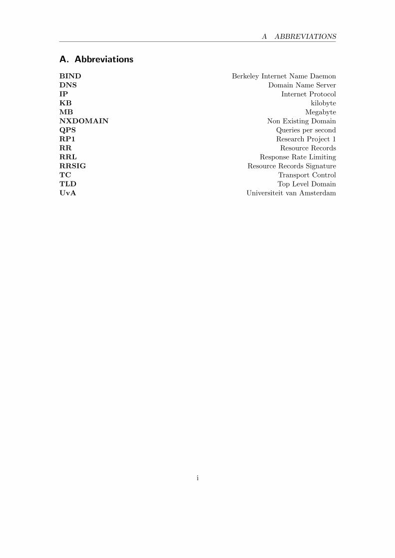
A. Abbreviations
BIND Berkeley Internet Name DaemonDNS Domain Name ServerIP Internet ProtocolKB kilobyteMB MegabyteNXDOMAIN Non Existing DomainQPS Queries per secondRP1 Research Project 1RR Resource RecordsRRL Response Rate LimitingRRSIG Resource Records SignatureTC Transport ControlTLD Top Level DomainUvA Universiteit van Amsterdam
[2] Duane Wessels, ”Tracing a DNS Reflection Attack”, 2011.
[3] J. Damas, ”RFC5358”, 2008. http://www.rfc-archive.org/getrfc.php?rfc=5358
[4] Georgios Kambourakis, Tassos Moschos, Dimitris Geneiatakisand Stefanos Gritzalis, ”A Fair Solution to DNS Amplifica-tion Attacks”, 2007. http://www.cs.columbia.edu/~dgen/papers/
conferences/conference-07.pdf
[5] P. Ferguson, D. Senie, ”Network Ingress Filtering: Defeating Denial ofService Attacks which employ IP Source Address Spoofing”, 2000. http://tools.ietf.org/html/bcp38
[6] NLnet Labs, ”DNS Response Rate Limiting as implemented in NSD.”,2012. http://www.nlnetlabs.nl/blog/2012/10/11/nsd-ratelimit/
[7] B. Laurie, G. Sisson, R. Arends and D.Blacka, ”DNS Security(DNSSEC) Hashed Authenticated Denial of Existence”, 2008. http://tools.ietf.org/html/rfc5155
[11] C. Villamizar, R. Chandra, R. Govindan, ”BGP Route Flap Damp-ing, RFC2439”, 1998. http://www.hjp.at/doc/rfc/rfc2439.txt
[12] Paul Vixie, Vernon Schryver, ”DNS Response Rate Limiting”, 2012.http://ss.vix.com/~vixie/isc-tn-2012-1.txt
ii
C SCENARIOS
C. Scenarios
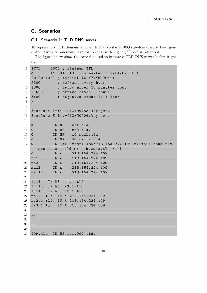
C.1. Scenario 1: TLD DNS server
To represent a TLD domain, a zone file that contains 1000 sub-domains has been gen-erated. Every sub-domain has 2 NS records with 2 glue (A) records attached.
The figure below show the zone file used to imitate a TLD DNS server before it gotsigned:
1 $TTL 3600 ; minimum TTL
2 @ IN SOA tld. hostmaster.nlnetlabs.nl (
3 2013011000 ; <serial in YYYYMMDDnn >
4 3600 ; refresh every hour
5 1800 ; retry after 30 minutes hour
6 21600 ; expire after 6 hours
7 3600 ; negative cache is 1 hour
8 )
9
10 $include Ktld .+010+09458. key ;ksk
11 $include Ktld .+010+60204. key ;zsk
12
13 @ IN NS ns1.tld.
14 @ IN NS ns2.tld.
15 @ IN MX 10 mail.tld.
16 @ IN MX 20 mail2.tld.
17 @ IN TXT v=spf1 ip4 :213.154.224.109 mx:mail.zone.tld
a:sub.zone.tld mx:sub.zone.tld -all
18 @ IN A 213.154.224.109
19 ns1 IN A 213.154.224.109
20 ns2 IN A 213.154.224.109
21 mail IN A 213.154.224.109
22 mail2 IN A 213.154.224.109
23
24 1.tld. IN NS ns1 .1. tld.
25 1.tld. IN NS ns2 .1. tld.
26 1.tld. IN NS ns3 .1. tld.
27 ns1.1.tld. IN A 213.154.224.109
28 ns2.1.tld. IN A 213.154.224.109
29 ns3.1.tld. IN A 213.154.224.109
30
31 ...
32 ...
33 ...
34
35 999. tld. IN NS ns1 .999. tld.
iii
C.2 Scenario 2: Authoritative DNS server with a single zone C SCENARIOS
36 999. tld. IN NS ns2 .999. tld.
37 999. tld. IN NS ns3 .999. tld.
38 ns1 .999. tld. IN A 213.154.224.109
39 ns2 .999. tld. IN A 213.154.224.109
40 ns3 .999. tld. IN A 213.154.224.109
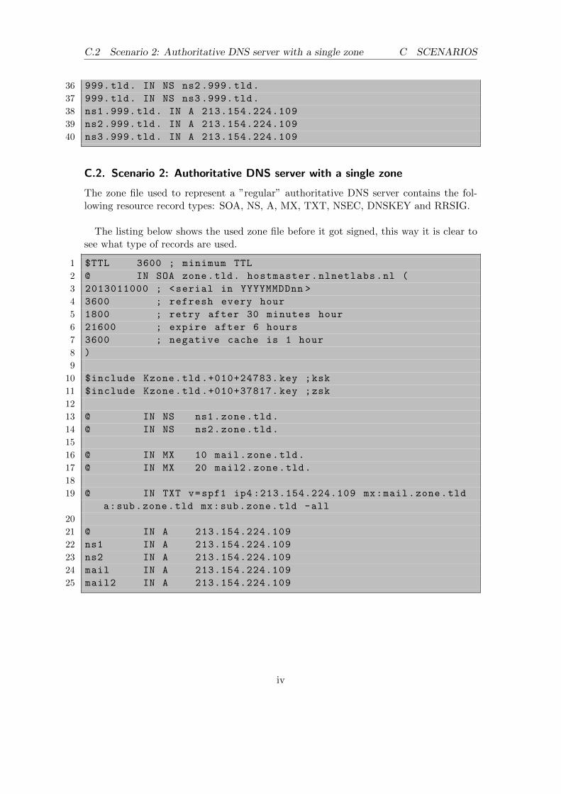
C.2. Scenario 2: Authoritative DNS server with a single zone
The zone file used to represent a ”regular” authoritative DNS server contains the fol-lowing resource record types: SOA, NS, A, MX, TXT, NSEC, DNSKEY and RRSIG.
The listing below shows the used zone file before it got signed, this way it is clear tosee what type of records are used.
1 $TTL 3600 ; minimum TTL
2 @ IN SOA zone.tld. hostmaster.nlnetlabs.nl (
3 2013011000 ; <serial in YYYYMMDDnn >
4 3600 ; refresh every hour
5 1800 ; retry after 30 minutes hour
6 21600 ; expire after 6 hours
7 3600 ; negative cache is 1 hour
8 )
9
10 $include Kzone.tld .+010+24783. key ;ksk
11 $include Kzone.tld .+010+37817. key ;zsk
12
13 @ IN NS ns1.zone.tld.
14 @ IN NS ns2.zone.tld.
15
16 @ IN MX 10 mail.zone.tld.
17 @ IN MX 20 mail2.zone.tld.
18
19 @ IN TXT v=spf1 ip4 :213.154.224.109 mx:mail.zone.tld
a:sub.zone.tld mx:sub.zone.tld -all
20
21 @ IN A 213.154.224.109
22 ns1 IN A 213.154.224.109
23 ns2 IN A 213.154.224.109
24 mail IN A 213.154.224.109
25 mail2 IN A 213.154.224.109
iv
C.3 Scenario 3: Hosting Provider C SCENARIOS
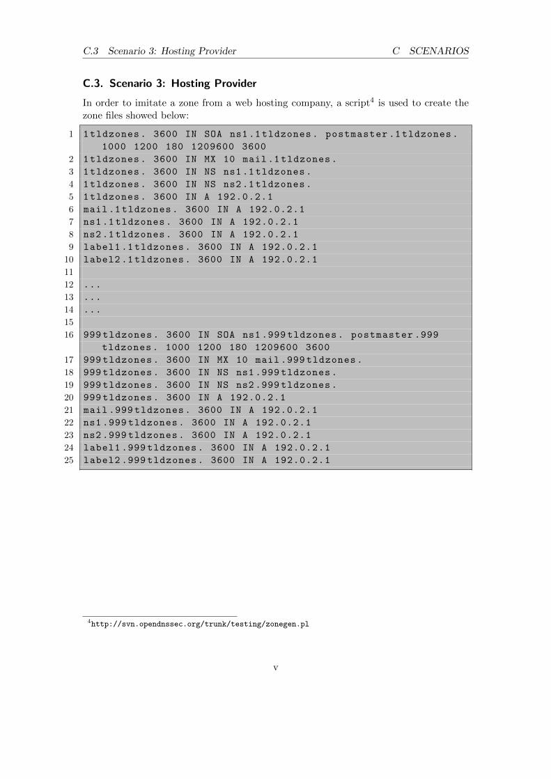
C.3. Scenario 3: Hosting Provider
In order to imitate a zone from a web hosting company, a script4 is used to create thezone files showed below:
1 1tldzones. 3600 IN SOA ns1.1 tldzones. postmaster .1 tldzones.
1000 1200 180 1209600 3600
2 1tldzones. 3600 IN MX 10 mail.1 tldzones.
3 1tldzones. 3600 IN NS ns1.1 tldzones.
4 1tldzones. 3600 IN NS ns2.1 tldzones.
5 1tldzones. 3600 IN A 192.0.2.1
6 mail.1 tldzones. 3600 IN A 192.0.2.1
7 ns1.1 tldzones. 3600 IN A 192.0.2.1
8 ns2.1 tldzones. 3600 IN A 192.0.2.1
9 label1 .1 tldzones. 3600 IN A 192.0.2.1
10 label2 .1 tldzones. 3600 IN A 192.0.2.1
11
12 ...
13 ...
14 ...
15
16 999 tldzones. 3600 IN SOA ns1 .999 tldzones. postmaster .999
tldzones. 1000 1200 180 1209600 3600
17 999 tldzones. 3600 IN MX 10 mail .999 tldzones.
NLnet Labs made their test environment available containing three server to imitate anamplification attack. Below a description of each server used in the lab environment.
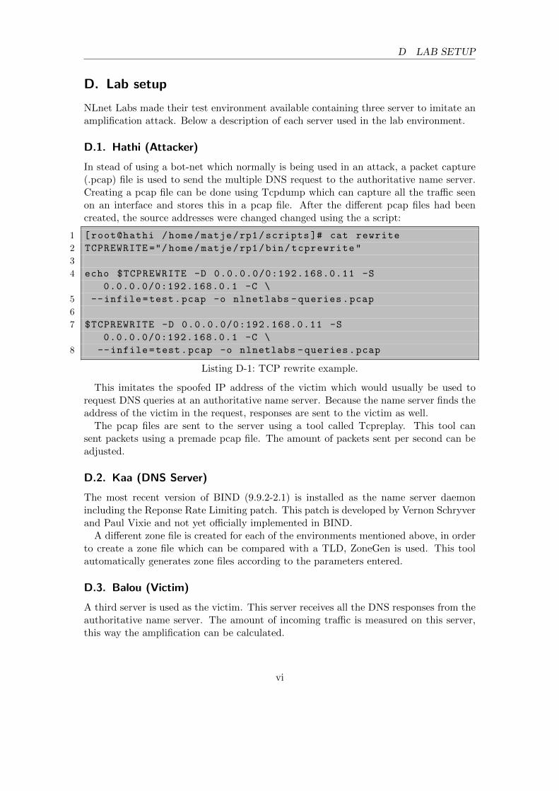
D.1. Hathi (Attacker)
In stead of using a bot-net which normally is being used in an attack, a packet capture(.pcap) file is used to send the multiple DNS request to the authoritative name server.Creating a pcap file can be done using Tcpdump which can capture all the traffic seenon an interface and stores this in a pcap file. After the different pcap files had beencreated, the source addresses were changed changed using the a script:
This imitates the spoofed IP address of the victim which would usually be used torequest DNS queries at an authoritative name server. Because the name server finds theaddress of the victim in the request, responses are sent to the victim as well.
The pcap files are sent to the server using a tool called Tcpreplay. This tool cansent packets using a premade pcap file. The amount of packets sent per second can beadjusted.
D.2. Kaa (DNS Server)
The most recent version of BIND (9.9.2-2.1) is installed as the name server daemonincluding the Reponse Rate Limiting patch. This patch is developed by Vernon Schryverand Paul Vixie and not yet officially implemented in BIND.
A different zone file is created for each of the environments mentioned above, in orderto create a zone file which can be compared with a TLD, ZoneGen is used. This toolautomatically generates zone files according to the parameters entered.
D.3. Balou (Victim)
A third server is used as the victim. This server receives all the DNS responses from theauthoritative name server. The amount of incoming traffic is measured on this server,this way the amplification can be calculated.
vi
D.4 Monitoring tools D LAB SETUP
D.4. Monitoring tools
D.4.1. Cacti
The inbound and outbound traffic passing the lab interface on the DNS server is mea-sured using a network monitoring tool called Cacti5. Cacti is a complete network graph-ing solution designed to use RRDTool’s data storage and graphing functionality.
D.4.2. DSC
The DNS requests and responses are logged using DSC. DSC6 is a system for collectingand exploring statistics from busy DNS servers. It currently has two components:
• Collector: The collector process uses libpcap to receive DNS messages sent andreceived on a network interface.
• Presenter: This component receives XML datasets from collectors. Data is pre-sented in a web browser.
D.4.3. HTOP
The resource consumption of the BIND daemon is measured using HTOP 7. HTOP is abasic interactive process viewer for Linux.
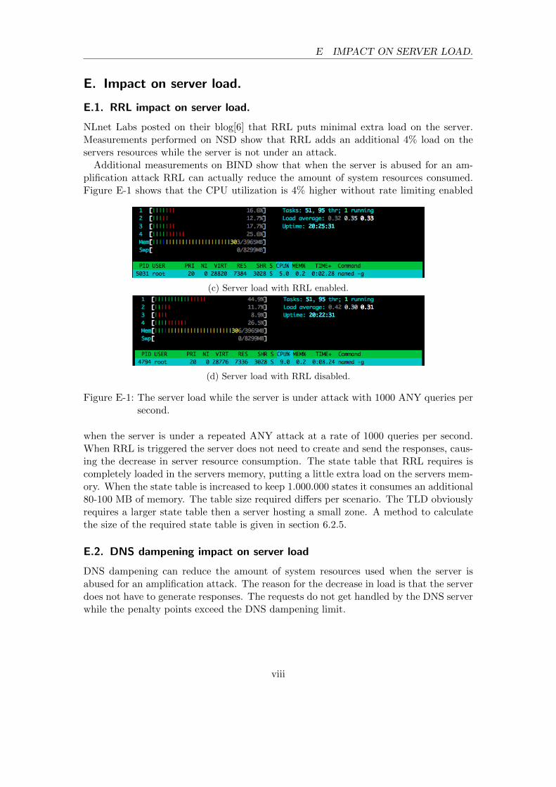
NLnet Labs posted on their blog[6] that RRL puts minimal extra load on the server.Measurements performed on NSD show that RRL adds an additional 4% load on theservers resources while the server is not under an attack.
Additional measurements on BIND show that when the server is abused for an am-plification attack RRL can actually reduce the amount of system resources consumed.Figure E-1 shows that the CPU utilization is 4% higher without rate limiting enabled
(c) Server load with RRL enabled.
(d) Server load with RRL disabled.
Figure E-1: The server load while the server is under attack with 1000 ANY queries persecond.
when the server is under a repeated ANY attack at a rate of 1000 queries per second.When RRL is triggered the server does not need to create and send the responses, caus-ing the decrease in server resource consumption. The state table that RRL requires iscompletely loaded in the servers memory, putting a little extra load on the servers mem-ory. When the state table is increased to keep 1.000.000 states it consumes an additional80-100 MB of memory. The table size required differs per scenario. The TLD obviouslyrequires a larger state table then a server hosting a small zone. A method to calculatethe size of the required state table is given in section 6.2.5.
E.2. DNS dampening impact on server load
DNS dampening can reduce the amount of system resources used when the server isabused for an amplification attack. The reason for the decrease in load is that the serverdoes not have to generate responses. The requests do not get handled by the DNS serverwhile the penalty points exceed the DNS dampening limit.
viii
E.2 DNS dampening impact on server load E IMPACT ON SERVER LOAD.
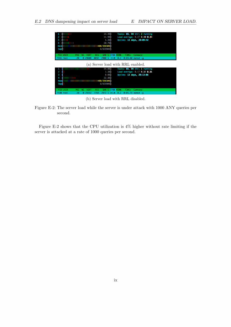
(a) Server load with RRL enabled.
(b) Server load with RRL disabled.
Figure E-2: The server load while the server is under attack with 1000 ANY queries persecond.
Figure E-2 shows that the CPU utilization is 4% higher without rate limiting if theserver is attacked at a rate of 1000 queries per second.