Joint Interoperability Test Command (JTE) 23 Sep 10 MEMORANDUM FOR DISTRIBUTION SUBJECT: Special Interoperability Test Certification of the Cisco Unified Communication Manager Local Session Controller, Version 8.0(2) References: (a) DoD Directive 4630.05, “Interoperability and Supportability of Information Technology (IT) and National Security Systems (NSS),” 5 May 2004 (b) CJCSI 6212.01E, “Interoperability and Supportability of Information Technology and National Security Systems,” 15 December 2008 (c) through (e), see Enclosure 1 1. References (a) and (b) establish the Joint Interoperability Test Command (JITC), as the responsible organization for interoperability test certification. 2. The Cisco Unified Communications Manager (CUCM), Version 8.0(2), hereinafter referred to as the System Under Test (SUT) is certified for joint use in the Defense Information System Network (DISN) as a Local Session Controller (LSC). The Defense Information Systems Agency adjudicated all open non-AS Test Discrepancy Reports (TDRs) to have a minor operational impact. The fielding of the SUT is limited to IP version 4 (IPv4) across the DISN. Intra-enclave use of IPv4 and IPv6 is authorized for use. The certification status of the SUT will be verified during operational deployment. Any new discrepancy noted in the operational environment will be evaluated for impact on the existing certification. These discrepancies will be adjudicated to the satisfaction of DISA via a vendor PoAM, which will address all new critical TDRs within 120 days of identification. Testing was conducted using LSC product requirements derived from the Unified Capabilities Requirements (UCR), Reference (c), and LSC test procedures, Reference (d). No other configurations, features, or functions, except those cited within this memorandum, are certified by JITC. This certification expires upon changes that affect interoperability, but no later than three years from the date of this memorandum. 3. This finding is based on interoperability testing conducted by JITC, review of the vendor’s Letters of Compliance (LoC), and DISA Information Assurance (IA) Certification Authority (CA) approval of the IA configuration. Interoperability testing was conducted by JITC, Fort Huachuca, Arizona, from 28 June 2010 through 20 August 2010. Review of the vendor’s LoC was completed on 21 September 2010. The DISA CA has reviewed the IA Assessment Report for the SUT, Reference (e), and based on the findings in the report has provided a positive recommendation. The acquiring agency or site will be responsible for the DoD Information Assurance Certification and Accreditation Process (DIACAP) accreditation. The JITC certifies the SUT as meeting the UCR for LSC requirements. Enclosure 2 documents the test results and describes the tested network and system configurations including specified patch releases. IN REPLY REFER TO: DEFENSE INFORMATION SYSTEMS AGENCY P. O. BOX 4502 ARLINGTON, VIRGINIA 22204-4502
Transcript
Joint Interoperability Test Command (JTE) 23 Sep 10
MEMORANDUM FOR DISTRIBUTION
SUBJECT: Special Interoperability Test Certification of the Cisco Unified Communication
Manager Local Session Controller, Version 8.0(2)
References: (a) DoD Directive 4630.05, “Interoperability and Supportability of Information
Technology (IT) and National Security Systems (NSS),” 5 May 2004
(b) CJCSI 6212.01E, “Interoperability and Supportability of Information
Technology and National Security Systems,” 15 December 2008
(c) through (e), see Enclosure 1
1. References (a) and (b) establish the Joint Interoperability Test Command (JITC), as the
responsible organization for interoperability test certification.
2. The Cisco Unified Communications Manager (CUCM), Version 8.0(2), hereinafter referred to
as the System Under Test (SUT) is certified for joint use in the Defense Information System
Network (DISN) as a Local Session Controller (LSC). The Defense Information Systems
Agency adjudicated all open non-AS Test Discrepancy Reports (TDRs) to have a minor
operational impact. The fielding of the SUT is limited to IP version 4 (IPv4) across the DISN.
Intra-enclave use of IPv4 and IPv6 is authorized for use. The certification status of the SUT will
be verified during operational deployment. Any new discrepancy noted in the operational
environment will be evaluated for impact on the existing certification. These discrepancies will
be adjudicated to the satisfaction of DISA via a vendor PoAM, which will address all new
critical TDRs within 120 days of identification. Testing was conducted using LSC product
requirements derived from the Unified Capabilities Requirements (UCR), Reference (c), and
LSC test procedures, Reference (d). No other configurations, features, or functions, except those
cited within this memorandum, are certified by JITC. This certification expires upon changes
that affect interoperability, but no later than three years from the date of this memorandum.
3. This finding is based on interoperability testing conducted by JITC, review of the vendor’s
Letters of Compliance (LoC), and DISA Information Assurance (IA) Certification Authority
(CA) approval of the IA configuration. Interoperability testing was conducted by JITC, Fort
Huachuca, Arizona, from 28 June 2010 through 20 August 2010. Review of the vendor’s LoC
was completed on 21 September 2010. The DISA CA has reviewed the IA Assessment Report
for the SUT, Reference (e), and based on the findings in the report has provided a positive
recommendation. The acquiring agency or site will be responsible for the DoD Information
Assurance Certification and Accreditation Process (DIACAP) accreditation. The JITC certifies
the SUT as meeting the UCR for LSC requirements. Enclosure 2 documents the test results and
describes the tested network and system configurations including specified patch releases.
IN REPLY REFER TO:
DEFENSE INFORMATION SYSTEMS AGENCY
P. O. BOX 4502 ARLINGTON, VIRGINIA 22204-4502
JITC Memo, JTE, Special Interoperability Test Certification of the Cisco Unified
Communication Manager Local Session Controller, Version 8.0(2)
2
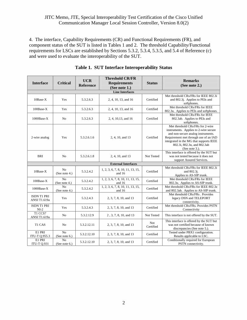
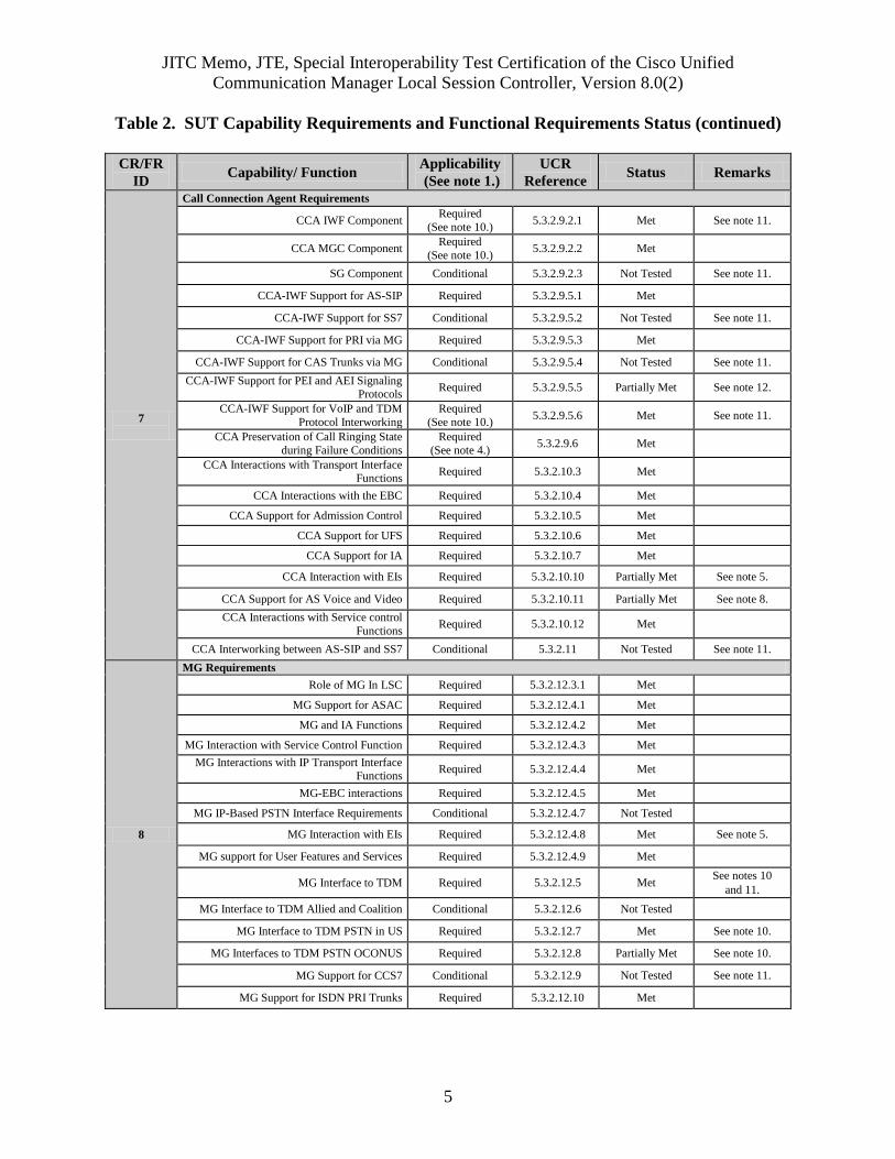
4. The interface, Capability Requirements (CR) and Functional Requirements (FR), and
component status of the SUT is listed in Tables 1 and 2. The threshold Capability/Functional
requirements for LSCs are established by Sections 5.3.2, 5.3.4, 5.3.5, and 5.4 of Reference (c)
and were used to evaluate the interoperability of the SUT.
Table 1. SUT Interface Interoperability Status
Interface Critical UCR
Reference
Threshold CR/FR
Requirements
(See note 1.)
Status Remarks
(See note 2.)
Line Interfaces
10Base-X Yes 5.3.2.6.3 2, 4, 10, 13, and 16 Certified Met threshold CRs/FRs for IEEE 802.3i
and 802.3j. Applies to PEIs and
softphones.
100Base-X Yes 5.3.2.6.3 2, 4, 10, 13, and 16 Certified Met threshold CRs/FRs for IEEE
802.3u. Applies to PEIs and softphones.
1000Base-X No 5.3.2.6.3 2, 4, 10,13, and 16 Certified
Met threshold CRs/FRs for IEEE
802.3ab. Applies to PEIs and
softphones.
2-wire analog Yes 5.3.2.6.1.6 2, 4, 10, and 13 Certified
Met threshold CRs/FRs for 2-wire instruments. Applies to 2-wire secure
and non-secure analog instruments.
Requirement met through use of an IAD integrated in the MG that supports IEEE
802.3i, 802.3u, and 802.3ab
(See note 3.).
BRI No 5.3.2.6.1.8 2, 4, 10, and 13 Not Tested
This interface is offered by the SUT but
was not tested because it does not
support Assured Services.
External Interfaces
10Base-X No
(See note 4.) 5.3.2.4.2
1, 2, 3, 6, 7, 8, 10, 11, 13, 15, and 16
Certified
Met threshold CRs/FRs for IEEE 802.3i
and 802.3j.
Applies to AS-SIP trunk.
100Base-X No
(See note 4.) 5.3.2.4.2
1, 2, 3, 6, 7, 8, 10, 11, 13, 15, and 16
Certified Met threshold CRs/FRs for IEEE 802.3u. Applies to AS-SIP trunk.
1000Base-X No
(See note 4.) 5.3.2.4.2
1, 2, 3, 6, 7, 8, 10, 11, 13, 15,
and 16 Certified
Met threshold CRs/FRs for IEEE 802.3z
and 802.3ab. Applies to AS-SIP trunk.
ISDN T1 PRI ANSI T1.619a
Yes 5.3.2.4.3 2, 3, 7, 8, 10, and 13 Certified
Met threshold CRs/FRs . Provides
legacy DSN and TELEPORT
connectivity.
ISDN T1 PRI NI-2
Yes 5.3.2.4.3 2, 3, 7, 8, 10, and 13 Certified Met threshold CRs/FRs. Provides PSTN
Connectivity
T1 CCS7
ANSI T1.619a No 5.3.2.12.9 2 , 3, 7, 8, 10, and 13 Not Tested This interface is not offered by the SUT.
T1 CAS No 5.3.2.12.11 2, 3, 7, 8, 10, and 13 Not
Certified
This interface is offered by the SUT but was not certified because of known
discrepancies (See note 5.).
E1 PRI ITU-T Q.955.3
No (See note 6.)
5.3.2.12.10 2, 3, 7, 8, 10, and 13 Certified Tested under PBX1 configuration.
Results applicable to LSC.
E1 PRI
ITU-T Q.931
No
(See note 6.) 5.3.2.12.10 2, 3, 7, 8, 10, and 13 Certified
Conditionally required for European
PSTN connectivity.
JITC Memo, JTE, Special Interoperability Test Certification of the Cisco Unified
Communication Manager Local Session Controller, Version 8.0(2)
3
Table 1. SUT Interface Interoperability Status (continued)
Interface Critical UCR
Reference
Threshold CR/FR
Requirements
(See note 1.)
Status Remarks
(See note 2.)
NM
10Base-X No
(See note 4.)
5.3.2.4.4
5.3.2.7.2.8 16 and 17 Certified
Met threshold CRs/FRs.
Verified via LoC.
100Base-X No
(See note 4.)
5.3.2.4.4
5.3.2.7.2.8 16 and 17 Certified
Met threshold CRs/FRs.
Verified via LoC.
NOTES: 1. CR/FR requirements are contained in Table 2. CR/FR numbers represent a roll-up of UCR requirements. Enclosure 3 provides a list of more
detailed requirements LSC products. 2. Paragraph 11 of Enclosure 2 provides detailed information pertaining to open TDRs and associated operational impacts
3. Voice calls from the SUT gateway analog interfaces via the UC DISN WAN require a loopback configuration of ANSI T1.619a ISDN PRI
interfaces within each gateway (refer to Cisco CUCM deployment guide). This configuration requires translations in the gateways to route all out going analog calls placed towards the UC DISN WAN via the looped T1s. Additionally, incoming calls from the UC DISN WAN to analog
end instruments on each gateway must be routed via the looped T1s. Without this configuration, analog end instruments cannot place calls via
the UC DISN WAN. This configuration requires two looped ISDN PRI ANSI T1.619a T1s within each 3845 and 3945 gateways and will support a maximum of 69 analog interfaces per gateway. This allows for up to two ISDN PRI T1 interfaces or one ISDN PRI E1 interface for
timing/network access. In addition, each 2851 and 2951 gateway requires one looped ANSI T1.619a ISDN PRI within each 2851 and 2951
gateway and will support a maximum of 23 analog interfaces per gateway. Both gateways also require a T1 or E1 interface for synchronization via recovered timing.
4. Must provide a minimum of one of the listed interfaces.
5. The SUT CAS interface had interoperability test discrepancies adjudicated to be critical for certification of this interface. 6. The interface is conditionally required for deployment in Europe.
FR Functional Requirement IAD Integrated Access device
IEEE Institute of Electrical and Electronics Engineers, Inc.
ISDN Integrated Services Digital Network ITU-T International Telecommunication Union –
Telecommunication Standardization Sector
LoC Letter of Compliance
LSC Local Session Controller
Mbps Megabits per second MG Media Gateway
MLPP Multi-Level Precedence and Preemption
NA Not Applicable NI-2 National ISDN Standard 2
NM Network Management
PBX Private Branch Exchange PEI Proprietary End Instrument
PRI Primary Rate Interface
PSTN Public Switched Telephone Network Q.931 Signaling Standard for ISDN
Q.955.3 ISDN Signaling Standard for E1 MLPP
SS7 Signaling System 7 SUT System Under Test
T1 Digital Transmission Link Level 1 (1.544 Mbps)
T1.619a SS7 and ISDN MLPP Signaling Standard for T1 TDRs Test Discrepancy Reports
UCR Unified Capabilities Requirements
VoIP Voice over Internet Protocol WAN Wide Area Network
JITC Memo, JTE, Special Interoperability Test Certification of the Cisco Unified
Communication Manager Local Session Controller, Version 8.0(2)
4
Table 2. SUT Capability Requirements and Functional Requirements Status
CR/FR
ID Capability/ Function
Applicability
(See note 1.)
UCR
Reference Status Remarks
1
Assured Services Product Features and Capabilities
DSCP Packet Marking Required 5.3.2.2.1.4 Met
Voice Features and Capabilities Required 5.3.2.2.2.1 Partially Met See note 2.
Public Safety Features Required 5.3.2.2.2.2 Met
ASAC – Open Loop Required 5.3.2.2.2.3 Met
Signaling Protocols Required 5.3.2.2.2.3 Met
Signaling Performance Required 5.3.2.2.2.4 Met
2
Registration, Authentication, and Failover
Registration Required 5.3.2.3.1 Met
Failover Required 5.3.2.3.2 Met
3
Product Physical, Quality, and Environmental Factors
Availability Required 5.3.2.5.2.1 Partially Met See note 3
Maximum Downtimes Required 5.3.2.5.2.2 Met
Loss of Packets Required
(See note 4.) 5.3.2.5.4 Met
4
Voice End Instruments
Tones and Announcements Required 5.3.2.6.1.1 Partially Met See notes 2 and
5.
Audio Codecs Required 5.3.2.6.1.2 Partially Met See note 5.
VoIP PEI or AEI Audio Performance
Requirements Required 5.3.2.6.1.3 Partially Met See note 5.
VoIP Sampling Standard Required 5.3.2.6.1.4 Partially Met See note 5.
Authentication to LSC Required 5.3.2.6.1.5 Partially Met See note 5.
Analog Telephone Support Required
(See note 6.) 5.3.2.6.1.6 Partially Met See note 7.
Softphones Conditional 5.3.2.6.1.7 Met See note 8.
ISDN BRI Conditional 5.3.2.6.1.8 Not Tested
5
Video End Instruments
Video End Instrument Required 5.3.2.6.2 Not Tested See note 8.
Display Messages, Tones, and Announcements Required 5.3.2.6.2.1 Not Tested See note 8.
Video Codecs (Including Associated Audio
Codecs) Required 5.3.2.6.2.2 Not Tested See note 8.
6
LSC Requirements
PBAS/ASAC Requirements Required 5.3.2.7.2.1 Met
Calling Number Delivery Requirements Required 5.3.2.7.2.2 Met
LSC Signaling Requirements Required 5.3.2.7.2.3 Met
Service Requirements under Total Loss of
WAN Transport Required 5.3.2.7.2.4 Met
Local Location Server and Directory Required 5.3.2.7.2.5 Met
LSC Transport Interface Functions Required 5.3.2.7.2.7 Met
LSC to PEI, AEI, and Operator Console Status Verification
Required 5.3.2.7.2.10 Partially Met. See note 9.
Line-Side Custom Features Interference Conditional 5.3.2.7.2.11 Met
Loop Avoidance Required
(See note 4.) 5.3.2.7.3 Met
JITC Memo, JTE, Special Interoperability Test Certification of the Cisco Unified
Communication Manager Local Session Controller, Version 8.0(2)
5
Table 2. SUT Capability Requirements and Functional Requirements Status (continued)
CR/FR
ID Capability/ Function
Applicability
(See note 1.)
UCR
Reference Status Remarks
7
Call Connection Agent Requirements
CCA IWF Component Required
(See note 10.) 5.3.2.9.2.1 Met See note 11.
CCA MGC Component Required
(See note 10.) 5.3.2.9.2.2 Met
SG Component Conditional 5.3.2.9.2.3 Not Tested See note 11.
CCA-IWF Support for AS-SIP Required 5.3.2.9.5.1 Met
CCA-IWF Support for SS7 Conditional 5.3.2.9.5.2 Not Tested See note 11.
CCA-IWF Support for PRI via MG Required 5.3.2.9.5.3 Met
CCA-IWF Support for CAS Trunks via MG Conditional 5.3.2.9.5.4 Not Tested See note 11.
CCA-IWF Support for PEI and AEI Signaling Protocols
Required 5.3.2.9.5.5 Partially Met See note 12.
CCA-IWF Support for VoIP and TDM
Protocol Interworking
Required
(See note 10.) 5.3.2.9.5.6 Met See note 11.
CCA Preservation of Call Ringing State
during Failure Conditions
Required
(See note 4.) 5.3.2.9.6 Met
CCA Interactions with Transport Interface Functions
Required 5.3.2.10.3 Met
CCA Interactions with the EBC Required 5.3.2.10.4 Met
CCA Support for Admission Control Required 5.3.2.10.5 Met
CCA Support for UFS Required 5.3.2.10.6 Met
CCA Support for IA Required 5.3.2.10.7 Met
CCA Interaction with EIs Required 5.3.2.10.10 Partially Met See note 5.
CCA Support for AS Voice and Video Required 5.3.2.10.11 Partially Met See note 8.
CCA Interactions with Service control
Functions Required 5.3.2.10.12 Met
CCA Interworking between AS-SIP and SS7 Conditional 5.3.2.11 Not Tested See note 11.
8
MG Requirements
Role of MG In LSC Required 5.3.2.12.3.1 Met
MG Support for ASAC Required 5.3.2.12.4.1 Met
MG and IA Functions Required 5.3.2.12.4.2 Met
MG Interaction with Service Control Function Required 5.3.2.12.4.3 Met
MG Interactions with IP Transport Interface Functions
Required 5.3.2.12.4.4 Met
MG-EBC interactions Required 5.3.2.12.4.5 Met
MG IP-Based PSTN Interface Requirements Conditional 5.3.2.12.4.7 Not Tested
MG Interaction with EIs Required 5.3.2.12.4.8 Met See note 5.
MG support for User Features and Services Required 5.3.2.12.4.9 Met
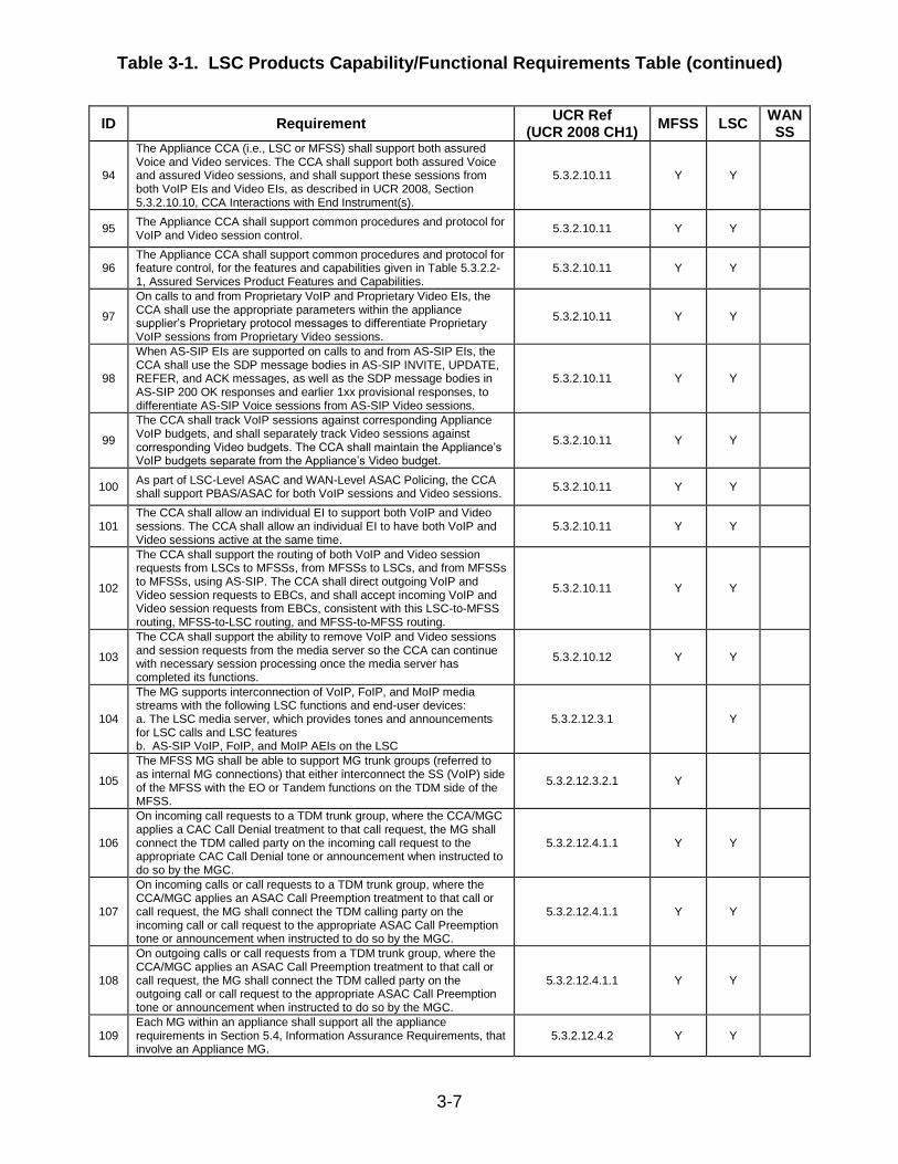
MG Interface to TDM Required 5.3.2.12.5 Met See notes 10
and 11.
MG Interface to TDM Allied and Coalition Conditional 5.3.2.12.6 Not Tested
MG Interface to TDM PSTN in US Required 5.3.2.12.7 Met See note 10.
MG Interfaces to TDM PSTN OCONUS Required 5.3.2.12.8 Partially Met See note 10.
MG Support for CCS7 Conditional 5.3.2.12.9 Not Tested See note 11.
MG Support for ISDN PRI Trunks Required 5.3.2.12.10 Met
JITC Memo, JTE, Special Interoperability Test Certification of the Cisco Unified
Communication Manager Local Session Controller, Version 8.0(2)
6
Table 2. SUT Capability Requirements and Functional Requirements Status (continued)
CR/FR
ID Capability/ Function
Applicability
(See note 1.)
UCR
Reference Status Remarks
8
MG Requirements (continued)
MG Support for CAS Trunks Required 5.3.2.12.11 Not Tested See note 11.
MG requirements for VoIP Internal Interfaces Required 5.3.2.12.12 Met
MG Echo Cancellation Required 5.3.2.12.13 Met
MG Clock Timing Required 5.3.2.12.14 Met
MGC-MG CCA Functions Required 5.3.2.12.15 Met
MG V.150.1 Required 5.3.2.12.16 Not tested See note 7.
MG Preservation of Call Ringing during Failure Required
(See note 4.) 5.3.2.12.17 Met
9
SG Requirements
SG and CCS7 Network Interactions Conditional 5.3.2.13.5.1 Not Tested See note 11.
SG Interactions with CCA Conditional 5.3.2.13.5.2 Not Tested See note 11.
SG Interworking Functions Conditional 5.3.2.13.5.3 Not Tested See note 11.
10
WWNDP Requirements
WWNDP Required 5.3.2.16 Met
DSN WWNDP Required 5.3.2.16.1 Met
11
Commercial Cost Avoidance
Commercial Cost Avoidance Required
(See note 3.) 5.3.2.23 Not Tested
12 AS-SIP Based for External Devices (Voicemail, Unified Messaging, and Automated Receiving Devices)
AS-SIP Requirements for External Interfaces Conditional 5.3.2.24 Not Tested
13 Precedence Call Diversion
Precedence call Diversion Required 5.3.2.25 Met
14
Attendant Station Features
Precedence and Preemption Required
(See note 3.) 5.3.2.26.1 Not Tested See note 13.
Call Display Required
(See note 3.) 5.3.2.26.2 Not Tested See note 13.
Class of Service Override Required
(See note 3.) 5.3.2.26.3 Not Tested See note 13.
Busy Override and Busy Verification Required
(See note 3.) 5.3.2.26.4 Not Tested See note 13.
Night service Required
(See note 3.) 5.3.2.26.5 Not Tested See note 13.
Automatic Recall of Attendant Required
(See note 3.) 5.3.2.26.6 Not Tested See note 13
Calls in Queue to the Attendant Required
(See note 3.) 5.3.2.26.7 Not Tested See note 13.
15
AS-SIP Requirements
SIP Requirements for AS-SIP Signaling
Appliances and AS-SIP EIs
Required
(See note 3.) 5.3.4.7 Not Tested
SIP Session Keep-Alive Timer Required 5.3.4.8 Met
Session Description Protocol Required 5.3.4.9 Met
Precedence and Preemption Required 5.3.4.10 Met
Video Telephony – General Rules Required 5.3.4.12 Not Tested See note 8.
Calling Services Required 5.3.4.13 Met
SIP Translation Requirements for Inter-working
AS-SIP Signaling Appliances Required 5.3.4.14 Met
Relevant Timers for the Terminating Gateway and
the Originating Gateway Required 5.3.4.15 Met
JITC Memo, JTE, Special Interoperability Test Certification of the Cisco Unified
Communication Manager Local Session Controller, Version 8.0(2)
7
Table 2. SUT Capability Requirements and Functional Requirements Status (continued)
CR/FR
ID Capability/ Function
Applicability
(See note 1.)
UCR
Reference Status Remarks
15
AS-SIP Requirements (continued)
SIP Requirements for Interworking AS-SIP
Signaling Appliances Required 5.3.4.16 Met
Keep-Alive Timer Requirements for
Interworking AS-SIP Signaling Appliances Required 5.3.4.17 Met
Precedence and Preemption Extensions for
Interworking AS-SIP Signaling Appliances Required 5.3.4.18 Met
Supplementary Services Required 5.3.4.19 Met
16 IPv6 Requirements
Product Requirements Required 5.3.5.4 Partially met See note 14.
17
NM
LSC Management Function Required 5.3.2.7.2.6 Met
VVoIP NMS Interface Requirements Required 5.3.2.4.4 Met
General Management requirements Required 5.3.2.17.2 Partially Met See note 15.
Requirement for FCAPS Management Required 5.3.2.17.3 Partially Met See note 15.
NM requirements of Appliance Functions Required 5.3.2.18 Partially Met See note 15.
Accounting Management Required 5.3.2.19 Met See note 16.
NOTES:
1. Annotation of ‘required’ refers to high level requirement category. Applicability of each sub-requirement is provided in enclosure 3.
2. The SUT had outstanding open TDRs at the completion of testing adjudicated by DISA to have a minor operational impact. The vendor
has submitted a PoAM to address the open TDRs. Paragraph 11 of Enclosure 2 provides additional details.
3. When the SUT fails from the primary processor to backup processor all active drop after approx 6-8 minutes. DISA adjudicated this TDR
as minor with the vendor’s submitted PoAM to fix by June 2011.
4. This requirement represents a new UCR requirement where the vendor has 18-months (July 2011) to comply.
5. SUT met the requirement for PEIs; SUT was not tested with generic AEI because no AEI was provided. AEIs are a new UCR 2008
Change 1 requirement; the vendor has 18-months (July 2011) to comply.
6. UCR 2008 Change 1 added 18-month rule for G.711 and V.150.1 IAD support.
7. Vendor submitted LoC stating compliance to V.150 however this feature could not be tested because it is not supported by other vendors.
This is a new UCR 2008 change 1 requirement; therefore the vendor has until July 2011 to comply with this requirement.
8. SUT did not demonstrate video requirements (conditional for softphone). Vendor did not provide a PEI video capability. This was adjudicated by DISA to have a low operational impact because of the limited deployment of PEIs with video.
9. SUT partially met PEI requirements (no video). The AEI and Operator Console requirements were not tested; the 18-month rule for
complying (July 2011) applies.
10. The SUT must meet T1 PRI (T1.619a and NI-2) IWF. The T1 CAS and T1 CCS7 are conditional.
11. The SUT met T1/E1 PRI IWF requirements. The T1 CAS is supported but not certified and T1 CCS7 is not supported by the SUT.
12. The SUT met PEI CCA-IWF requirements. The AEI CCA-IWF requirements were not tested. The 18-month rule applies to AEIs.
13. The Attendant Console requirements are new UCR requirements; 18-month rule applies.
14. The SUT submitted an IPv6 LoC with noted discrepancies. Open TDRs were adjudicated by DISA to have a minor operational impact with vendor submitted PoAM.
15. The SUT submitted an NM LoC with noted discrepancies. Open TDRs were adjudicated by DISA to have a minor operational impact
with vendor submitted PoAM.
16. The SUT does not comply with the objective requirement for Record Format.
JITC Memo, JTE, Special Interoperability Test Certification of the Cisco Unified
Communication Manager Local Session Controller, Version 8.0(2)
8
Table 2. SUT Capability Requirements and Functional Requirements Status (continued)
FCAPS Fault, Configuration, Accounting, Performance and
Security
FR Functional Requirement
G.711 Standard for PCM of Voice Frequencies
IA Information Assurance
IAD Integrated Access Device
IP Internet Protocol
ID Identification
ISDN Integrated Services Digital Network
IEEE Institute of Electrical and Electronics Engineers, Inc.
IP Internet Protocol
IPv6 Internet Protocol version 6
IWF Interworking Function
JITC Joint Interoperability Test Command
LoC Letter of Compliance
LSC Local Session Controller
Mbps Megabits per second
MG Media Gateway
MGC Media Gateway Controller
MFSS Multi-Function Soft Switch
MLPP Multilevel Precedence and Preemption
NI-2 National ISDN Standard 2
NM Network Management
NMS Network Management System
OCONUS Outside the Continental United States
PBAS Precedence Based Assured Services
PEI Proprietary End Instrument
PoAM Plan of Action and Milestones
PRI Primary Rate Interface
PSTN Public Switched Telephone Network
SG Signaling Gateway
SIP Session Initiation Protocol
SS7 Signaling System 7
SUT System Under Test
T1 Digital Transmission Link Level 1 (1.544 Mbps)
T1.619a SS7 and ISDN MLPP Signaling Standard for T1
TDM Time Division Multiplexing
TDR Test Discrepancy Report(s)
UCR Unified Capabilities Requirements
UFS User Features and Services
U.S. United States
VoIP Voice over Internet Protocol
WAN Wide Area Network
WWNDP Worldwide Numbering and Dialing Plan
5. No detailed test report was developed in accordance with the Program Manager’s request.
JITC distributes interoperability information via the JITC Electronic Report Distribution (ERD)
system, which uses Unclassified-But-Sensitive Internet Protocol Router Network (NIPRNet)
e-mail. More comprehensive interoperability status information is available via the JITC System
Tracking Program (STP). The STP is accessible by .mil/gov users on the NIPRNet at
https://stp.fhu.disa.mil. Test reports, lessons learned, and related testing documents and
references are on the JITC Joint Interoperability Tool (JIT) at http://jit.fhu.disa.mil (NIPRNet).
Information related to DSN testing is on the Telecom Switched Services Interoperability (TSSI)
website at http://jitc.fhu.disa.mil/tssi. All associated data is available on the Defense Information
Systems Agency Unified Capability Coordination Office (UCCO) website located at
http://www.disa.mil/ucco/.
JITC Memo, JTE, Special Interoperability Test Certification of the Cisco Unified
Communication Manager Local Session Controller, Version 8.0(2)
9
6. The JITC point of contact is Mr. Edward Mellon, commercial (520) 538-5159, or DSN
312-879-5159, e-mail address is [email protected]. The JITC’s mailing address is P.O.
Box 12798, Fort Huachuca, AZ 85670-2798. The UCCO tracking number is 1011801.
FOR THE COMMANDER:
3 Enclosures a/s
for RICHARD A. MEADOR
Chief
Battlespace Communications Portfolio
Distribution (electronic mail):
Joint Staff J-6
Joint Interoperability Test Command, Liaison, TE3/JT1
Office of Chief of Naval Operations, CNO N6F2
Headquarters U.S. Air Force, Office of Warfighting Integration & CIO, AF/XCIN (A6N)
Department of the Army, Office of the Secretary of the Army, DA-OSA CIO/G-6 ASA (ALT),
SAIS-IOQ
U.S. Marine Corps MARCORSYSCOM, SIAT, MJI Division I
DOT&E, Net-Centric Systems and Naval Warfare
U.S. Coast Guard, CG-64
Defense Intelligence Agency
National Security Agency, DT
Defense Information Systems Agency, TEMC
Office of Assistant Secretary of Defense (NII)/DOD CIO
U.S. Joint Forces Command, Net-Centric Integration, Communication, and Capabilities
Division, J68
Defense Information Systems Agency, GS23
JITC Memo, JTE, Special Interoperability Test Certification of the Cisco Unified
Communication Manager Local Session Controller, Version 8.0(2)
10
(This page left intentionally blank.)
Enclosure 1
ADDITIONAL REFERENCES
(c) Office of the Assistant Secretary of Defense, “Department of Defense Unified Capabilities
Requirements 2008, Change 1,” 22 January 2010
(d) Joint Interoperability Test Command, “Unified Capabilities Test Plan (UCTP),”
(e) Joint Interoperability Test Command, “Information Assurance (IA) Assessment of
Cisco Unified Communications Manager (CUCM), Version 8.02, (TN 1011801),”
1-2
(This page left intentionally blank).
Enclosure 2
CERTIFICATION TESTING SUMMARY
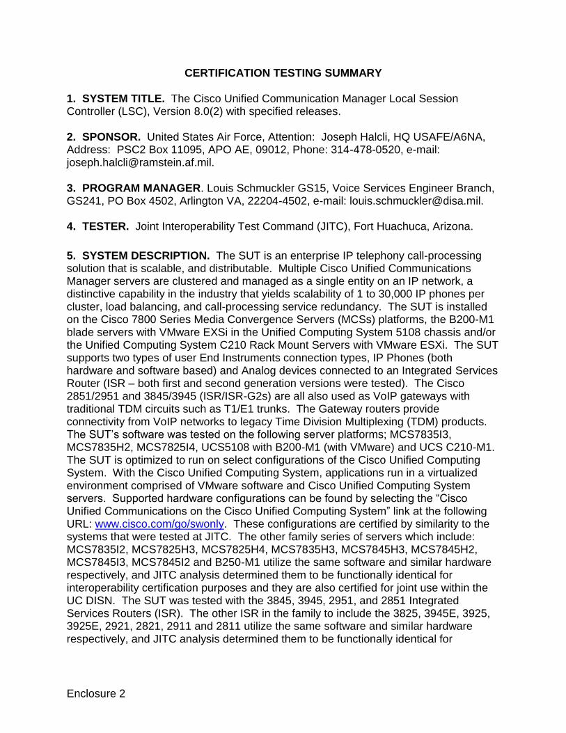
1. SYSTEM TITLE. The Cisco Unified Communication Manager Local Session Controller (LSC), Version 8.0(2) with specified releases. 2. SPONSOR. United States Air Force, Attention: Joseph Halcli, HQ USAFE/A6NA, Address: PSC2 Box 11095, APO AE, 09012, Phone: 314-478-0520, e-mail: [email protected]. 3. PROGRAM MANAGER. Louis Schmuckler GS15, Voice Services Engineer Branch, GS241, PO Box 4502, Arlington VA, 22204-4502, e-mail: [email protected]. 4. TESTER. Joint Interoperability Test Command (JITC), Fort Huachuca, Arizona.
5. SYSTEM DESCRIPTION. The SUT is an enterprise IP telephony call-processing solution that is scalable, and distributable. Multiple Cisco Unified Communications Manager servers are clustered and managed as a single entity on an IP network, a distinctive capability in the industry that yields scalability of 1 to 30,000 IP phones per cluster, load balancing, and call-processing service redundancy. The SUT is installed on the Cisco 7800 Series Media Convergence Servers (MCSs) platforms, the B200-M1 blade servers with VMware EXSi in the Unified Computing System 5108 chassis and/or the Unified Computing System C210 Rack Mount Servers with VMware ESXi. The SUT supports two types of user End Instruments connection types, IP Phones (both hardware and software based) and Analog devices connected to an Integrated Services Router (ISR – both first and second generation versions were tested). The Cisco 2851/2951 and 3845/3945 (ISR/ISR-G2s) are all also used as VoIP gateways with traditional TDM circuits such as T1/E1 trunks. The Gateway routers provide connectivity from VoIP networks to legacy Time Division Multiplexing (TDM) products. The SUT’s software was tested on the following server platforms; MCS7835I3, MCS7835H2, MCS7825I4, UCS5108 with B200-M1 (with VMware) and UCS C210-M1. The SUT is optimized to run on select configurations of the Cisco Unified Computing System. With the Cisco Unified Computing System, applications run in a virtualized environment comprised of VMware software and Cisco Unified Computing System servers. Supported hardware configurations can be found by selecting the “Cisco Unified Communications on the Cisco Unified Computing System” link at the following URL: www.cisco.com/go/swonly. These configurations are certified by similarity to the systems that were tested at JITC. The other family series of servers which include: MCS7835I2, MCS7825H3, MCS7825H4, MCS7835H3, MCS7845H3, MCS7845H2, MCS7845I3, MCS7845I2 and B250-M1 utilize the same software and similar hardware respectively, and JITC analysis determined them to be functionally identical for interoperability certification purposes and they are also certified for joint use within the UC DISN. The SUT was tested with the 3845, 3945, 2951, and 2851 Integrated Services Routers (ISR). The other ISR in the family to include the 3825, 3945E, 3925, 3925E, 2921, 2821, 2911 and 2811 utilize the same software and similar hardware respectively, and JITC analysis determined them to be functionally identical for
interoperability certification purposes and they are also certified for joint use within the UC DISN. Voice calls from the SUT gateway analog interfaces via the UC DISN WAN require a unique configuration of ANSI T1.619a ISDN PRI interfaces within each gateway (refer to Cisco UCM deployment guide). This configuration requires translations in the gateways to route all out going analog calls placed towards the UC DISN WAN via the looped T1s. Additionally, incoming calls from the UC DISN WAN to analog end instruments on each gateway must be routed via these T1s. Without this configuration, analog end instruments cannot place calls via the UC DISN WAN. This configuration requires two looped ISDN PRI ANSI T1.619a T1s within each 3845 and 3945 gateways and will support a maximum of 69 analog interfaces per gateway. This allows for up to two ISDN PRI T1 interfaces or one ISDN PRI E1 interface for timing/network access. In addition, each 2851 and 2951 gateway requires one looped ANSI T1.619a ISDN PRI within each 2851 and 2951 gateway and will support a maximum of 23 analog interfaces per gateway. Both gateways also require a T1 or E1 interface for synchronization via recovered timing. The SUT provides voice and video services, legacy 2-wire analog telephones, Internet Protocol (IP) telephones, and media processing devices within a local service domain. Since the SUT video end instruments can only support intra-enclave calls they are not certified for use within the UC DISN. The SUT offers an analog voice gateway (VG) 224 that services 24 analog users. This gateway does not support V.150.1 modem over IP and is only certified for non secure voice and facsimile. In accordance with UCR 2008 change 1 paragraph 5.3.2.6.1.6 every analog Integrated Access Device (IAD) line card on the LSC or MFSS is not required to support secure voice, secure data, or non secure modem or ITU–T Recommendation V.150.1 Modem Relay. The other SUT gateways support secure voice and data, and V.150.1 modem relay.
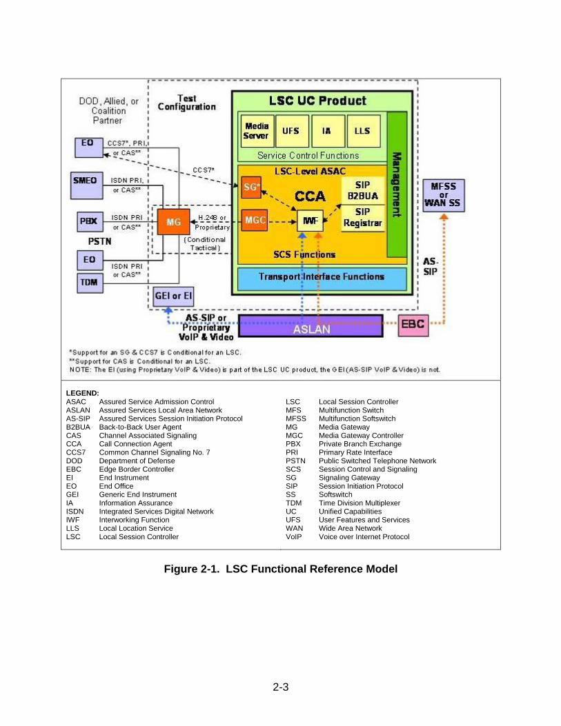
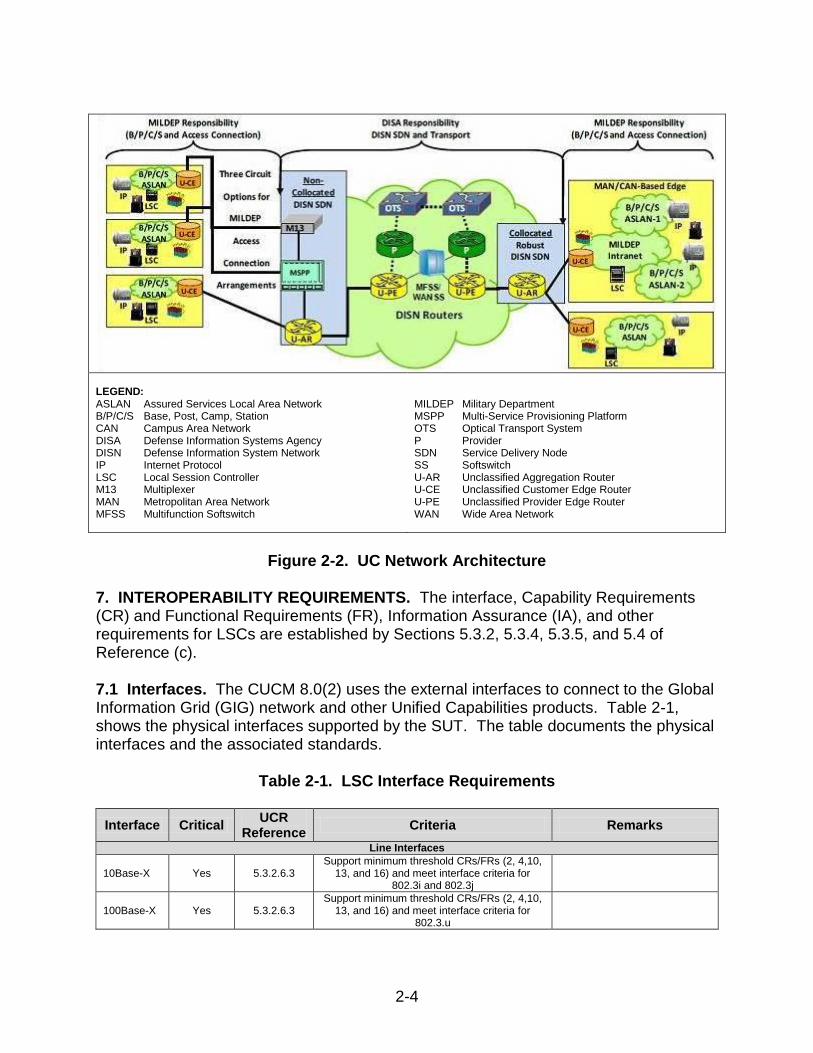
6. OPERATIONAL ARCHITECTURE. Figure 2-1 depicts the LSC functional model and Figure 2-2 the notional operational architecture that the SUT may be used in.
2-3
LEGEND: ASAC Assured Service Admission Control ASLAN Assured Services Local Area Network AS-SIP Assured Services Session Initiation Protocol B2BUA Back-to-Back User Agent CAS Channel Associated Signaling CCA Call Connection Agent CCS7 Common Channel Signaling No. 7 DOD Department of Defense EBC Edge Border Controller EI End Instrument EO End Office GEI Generic End Instrument IA Information Assurance ISDN Integrated Services Digital Network IWF Interworking Function LLS Local Location Service LSC Local Session Controller
LSC Local Session Controller MFS Multifunction Switch MFSS Multifunction Softswitch MG Media Gateway MGC Media Gateway Controller PBX Private Branch Exchange PRI Primary Rate Interface PSTN Public Switched Telephone Network SCS Session Control and Signaling SG Signaling Gateway SIP Session Initiation Protocol SS Softswitch TDM Time Division Multiplexer UC Unified Capabilities UFS User Features and Services WAN Wide Area Network VoIP Voice over Internet Protocol
Figure 2-1. LSC Functional Reference Model
2-4
LEGEND: ASLAN Assured Services Local Area Network B/P/C/S Base, Post, Camp, Station CAN Campus Area Network DISA Defense Information Systems Agency DISN Defense Information System Network IP Internet Protocol LSC Local Session Controller M13 Multiplexer MAN Metropolitan Area Network MFSS Multifunction Softswitch
MILDEP Military Department MSPP Multi-Service Provisioning Platform OTS Optical Transport System P Provider SDN Service Delivery Node SS Softswitch U-AR Unclassified Aggregation Router U-CE Unclassified Customer Edge Router U-PE Unclassified Provider Edge Router WAN Wide Area Network
Figure 2-2. UC Network Architecture
7. INTEROPERABILITY REQUIREMENTS. The interface, Capability Requirements (CR) and Functional Requirements (FR), Information Assurance (IA), and other requirements for LSCs are established by Sections 5.3.2, 5.3.4, 5.3.5, and 5.4 of Reference (c). 7.1 Interfaces. The CUCM 8.0(2) uses the external interfaces to connect to the Global Information Grid (GIG) network and other Unified Capabilities products. Table 2-1, shows the physical interfaces supported by the SUT. The table documents the physical interfaces and the associated standards.
Table 2-1. LSC Interface Requirements
Interface Critical UCR
Reference Criteria Remarks
Line Interfaces
10Base-X Yes 5.3.2.6.3 Support minimum threshold CRs/FRs (2, 4,10,
13, and 16) and meet interface criteria for 802.3i and 802.3j
100Base-X Yes 5.3.2.6.3 Support minimum threshold CRs/FRs (2, 4,10,
13, and 16) and meet interface criteria for 802.3.u
2-5
Table 2-1. LSC Interface Requirements (continued)
Interface Critical UCR
Reference Criteria
(See note 1.) Remarks
Line Interfaces (continued)
1000Base-X No 5.3.2.6.3 Support minimum threshold CRs/FRs (2, 4, 10, 13,
and 16) and meet interface criteria for 802.3z.
2-wire analog Yes 5.3.2.6.1.6 Support minimum threshold CRs/FRs (2, 4, 10, and 13) and meet interface criteria for analog.
BRI No 5.3.2.6.1.8 Support minimum threshold CRs/FRs (2, 4, 10,
and 13) and meet interface criteria for BRI
External Interfaces
10Base-X No
(See note 2.) 5.3.2.4.2
Support minimum threshold CRs/FRs (1, 2, 3, 6, 7, 8, 10, 11, 13, 15, and 16) and meet interface
criteria for 802.3i and 802.3j
100Base-X No
(See note 2.) 5.3.2.4.2
Support minimum threshold CRs/FRs (1, 2, 3, 6, 7, 8, 10, 11, 13, 15, and 16) and meet interface
criteria for 802.3u
1000Base-X No
(See note 2.) 5.3.2.4.2
Support minimum threshold CRs/FRs (1, 2, 3, 6, 7, 8, 10, 11, 13, 15, and 16)and meet interface
criteria for 802.3z
ISDN T1 PRI ANSI T1.619a
Yes 5.3.2.4.3 Support minimum threshold CRs/FRs (2, 3, 7, 8, 10, and 13) and meet interface criteria for ISDN
T1 PRI (T1.619a)
Provides legacy DSN and TELEPORT connectivity.
ISDN T1 PRI NI-2
Yes 5.3.2.4.3 Support minimum threshold CRs/FRs (2, 3, 7, 8,
10, and 13)and meet interface criteria for ISDN T1 PRI (NI-2)
Provides PSTN Connectivity.
T1 CCS7 ANSI T1.619a
No 5.3.2.12.9 Support minimum threshold CRs/FRs (2, 3, 7, 8,
10, and 13) and meet interface criteria for T1 CCS7 (ANSI T1.619a)
T1 CAS No 5.3.2.12.11 Support minimum threshold CRs/FRs (2, 3, 7, 8,
10, and 13) and meet interface criteria for T1 CAS T1 CAS with MLPP.
E1 PRI ITU-T Q.955.3
No 5.3.2.12.10 Support minimum threshold CRs/FRs (2, 3, 7, 8, 10, and 13)and meet interface criteria for EI PRI
(Q.955.3)
Conditionally required for DSN European connectivity.
E1 PRI ITU-T Q.931
No 5.3.2.12.10 Support minimum threshold CRs/FRs (2, 3, 7, 8, 10, and 13)and meet interface criteria for E1 PRI
(ITU-T Q.931)
Conditionally required for commercial European connectivity.
NM
10Base-X No
(See note 2.) 5.3.2.4.4
5.3.2.7.2.8 Support minimum threshold CR/FRs (16 and 17) and meet interface criteria for 802.3i and 802.3j
100Base-X No
(See note 2.) 5.3.2.4.4
5.3.2.7.2.8 Support minimum threshold CR/FRs (16 and 17)
and meet interface criteria for 802.3u
NOTES: 1. CR/FR requirements are contained in Table 2-2. CR/FR numbers represent a roll-up of UCR requirements. Enclosure 3 provides a list of more detailed requirements for security device products. 2. Must provide a minimum of one of the listed interfaces. LEGEND: ANSI American National Standards Institute BRI Basic Rate Interface CR Capability Requirement CCS7 Common Channel Signaling DSN Defense Switched Network E1 European Basic Multiplex Rate (2.048 Mbps) FR Functional Requirement ISDN Integrated Services Digital Network
ITU-T International Telecommunication Union – Telecommunication Standardization Sector LSC Local Session Controller Mbps Megabits per second MLPP Multi-Level Precedence and Preemption NI-2 National ISDN Standard 2 PRI Primary Rate Interface PSTN Public Switched Telephone Network T1 Digital Transmission Link Level 1 (1.544 Mbps) UCR Unified Capabilities Requirements
2-6
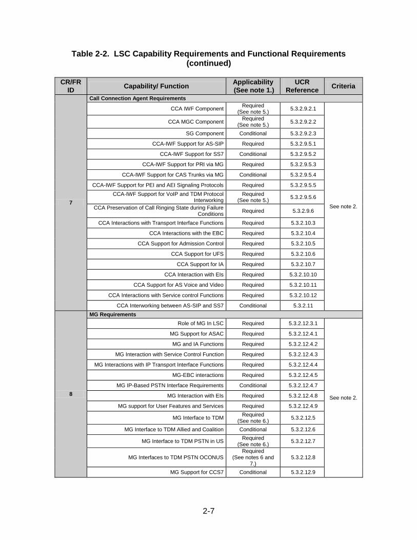
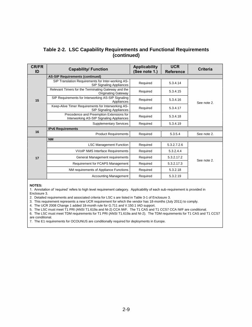
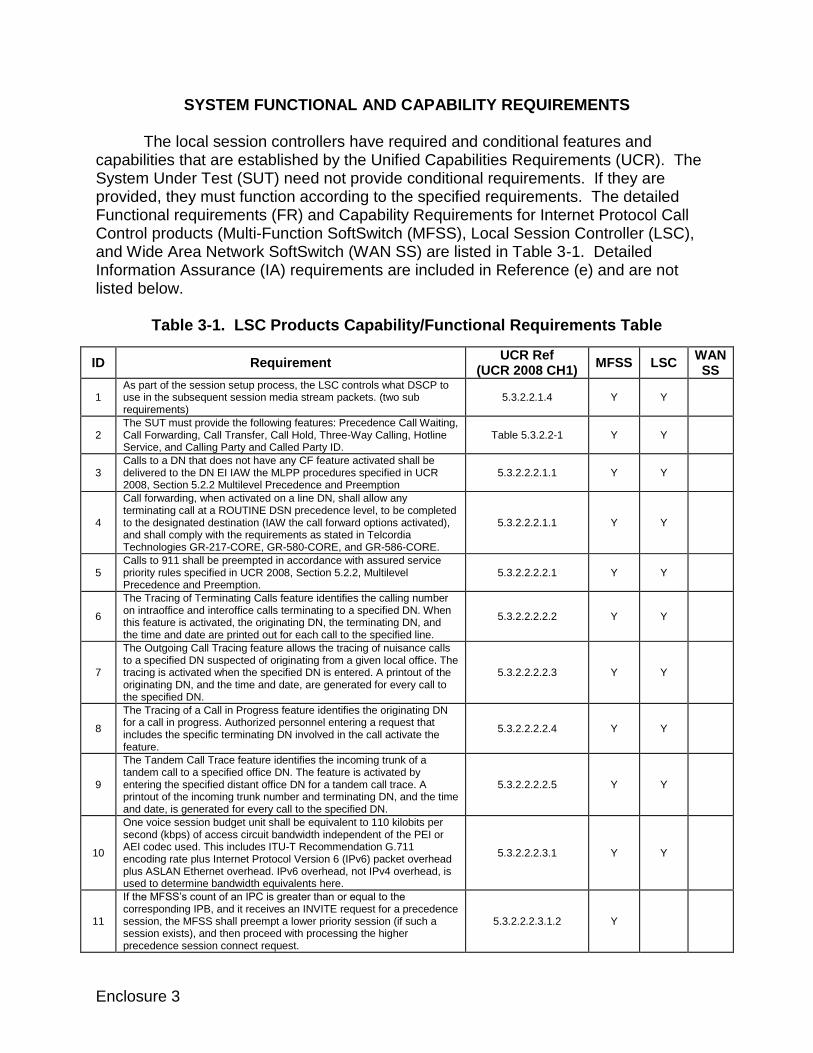
7.2 Capability Requirements (CR) and Functional Requirements (FR). The LSCs have required and conditional features and capabilities that are established by Sections 5.3.2, 5.3.4, 5.3.5, and 5.4 of the UCR. The SUT does not need to provide non-critical (conditional) requirements. If they are provided, they must function according to the specified requirements. The SUTs features and capabilities and its aggregated requirements are listed in Table 2-2. Detailed CR/FR requirements are provided in Table 3-1 of Enclosure 3.
Table 2-2. LSC Capability Requirements and Functional Requirements
CR/FR
ID Capability/ Function
Applicability
(See note 1.)
UCR
Reference Criteria
1
Assured Services Product Features and Capabilities
DSCP Packet Marking Required 5.3.2.2.1.4
See note 2.
Voice Features and Capabilities Required 5.3.2.2.2.1
Public Safety Features Required 5.3.2.2.2.2
ASAC – Open Loop Required 5.3.2.2.3
Signaling Protocols Required 5.3.2.2.2.3
Signaling Performance Required 5.3.2.2.4
2
Registration, Authentication, and Failover
Registration Required 5.3.2.3.1 See note 2.
Failover Required 5.3.2.3.2
3
Product Physical, Quality, and Environmental Factors
Availability Required 5.3.2.5.2.1
See note 2. Maximum Downtimes Required 5.3.2.5.2.2
Loss of Packets Required
(See note 3.) 5.3.2.5.4
4
Voice End Instruments
Tones and Announcements Required 5.3.2.6.1.1
See note 2.
Audio Codecs Required 5.3.2.6.1.2
VoIP PEI or AEI Audio Performance Requirements Required 5.3.2.6.1.3
VoIP Sampling Standard Required 5.3.2.6.1.4
Authentication To LSC Required 5.3.2.6.1.5
Analog Telephone Support Required
(See note 4.) 5.3.2.6.1.6
Softphones Conditional 5.3.2.6.1.7
ISDN BRI Conditional 5.3.2.6.1.8
5
Video End Instruments
Video End Instrument Required 5.3.2.6.2
See note 2. Display Messages, Tones, and Announcements Required 5.3.2.6.2.1
Video Codecs (Including Associated Audio Codecs) Required 5.3.2.6.2.2
FCAPS Fault, Configuration, Accounting, Performance and
Security
FR Functional Requirement
G.711 Standard for PCM of Voice Frequencies
IA Information Assurance
IAD Integrated Access Device
IP Internet Protocol
ID Identification
ISDN Integrated Services Digital Network
IEEE Institute of Electrical and Electronics Engineers, Inc.
IP Internet Protocol
IPv6 Internet Protocol version 6
IWF Interworking Function
JITC Joint Interoperability Test Command
LoC Letter of Compliance
LSC Local Session Controller
Mbps Megabits per second
MG Media Gateway
MGC Media Gateway Controller
MFSS Multi-Function Soft Switch
MLPP Multilevel Precedence and Preemption
NI-2 National ISDN Standard 2
NM Network Management
NMS Network Management System
OCONUS Outside the Continental United States
PBAS Precedence Based Assured Services
PEI Proprietary End Instrument
PoAM Plan of Action and Milestones
PRI Primary Rate Interface
PSTN Public Switched Telephone Network
SG Signaling Gateway
SIP Session Initiation Protocol
SS7 Signaling System 7
SUT System Under Test
T1 Digital Transmission Link Level 1 (1.544 Mbps)
T1.619a SS7 and ISDN MLPP Signaling Standard for T1
TDM Time Division Multiplexing
TDR Test Discrepancy Report(s)
UCR Unified Capabilities Requirements
UFS User Features and Services
U.S. United States
VoIP Voice over Internet Protocol
WAN Wide Area Network
WWNDP Worldwide Numbering and Dialing Plan
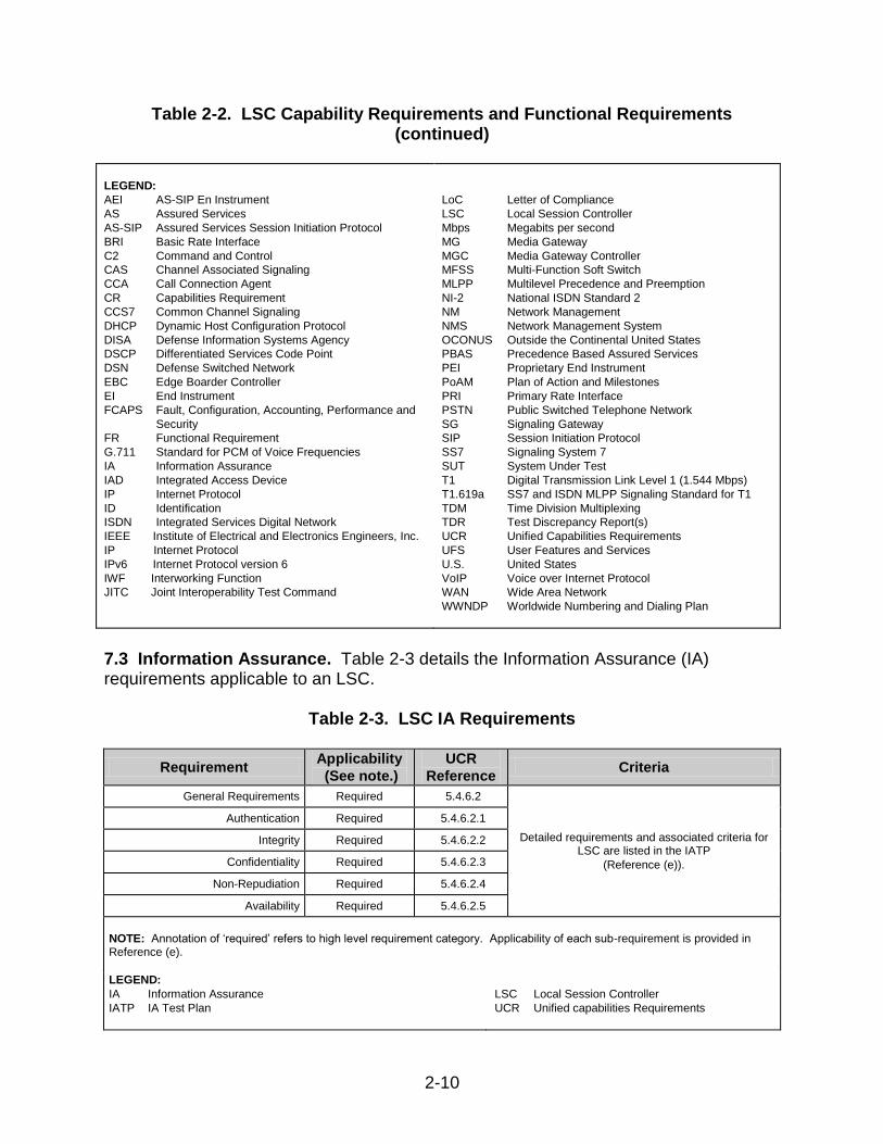
7.3 Information Assurance. Table 2-3 details the Information Assurance (IA) requirements applicable to an LSC.
Table 2-3. LSC IA Requirements
Requirement Applicability
(See note.)
UCR
Reference Criteria
General Requirements Required 5.4.6.2
Detailed requirements and associated criteria for LSC are listed in the IATP
(Reference (e)).
Authentication Required 5.4.6.2.1
Integrity Required 5.4.6.2.2
Confidentiality Required 5.4.6.2.3
Non-Repudiation Required 5.4.6.2.4
Availability Required 5.4.6.2.5
NOTE: Annotation of ‘required’ refers to high level requirement category. Applicability of each sub-requirement is provided in Reference (e).
LEGEND:
IA Information Assurance
IATP IA Test Plan
LSC Local Session Controller
UCR Unified capabilities Requirements
2-11
7.4 Other. None. 8. TEST NETWORK DESCRIPTION. The SUT was tested at Joint Interoperability Test Command (JITC), Fort Huachuca, Arizona in a manner and configuration similar to that of a notional operational environment. Testing the system’s required functions and features was conducted using the test configurations depicted in Figures 2-3 and 2-4. Figure 2-3 depicts the minimum test architecture for testing LSCs. Figure 2-4 depicts the SUT’s test configuration.
LEGEND: C Conditional DSN Defense Switched Network EBC Edge Boundary Controller E1 European Basic Multiplex Rate (2.048 Mbps) EO End Office IP Internet Protocol ISDN Integrated Services Digital Network LSC Local Session Controller Mbps Megabits per second MFSS Multifunction Softswitch MLPP Multi-Level Precedence and Preemption
NI 1/2 National ISDN Standard 1 or 2 NM Network Management PRI Primary Rate Interface PSTN Public Switched Telephone Network R Required RAE Required Ancillary Equipment SUT System Under Test T1 Digital Transmission Link Level 1 (1.544 Mbps) T1.619a SS7 and ISDN MLPP Signaling Standard for T1 TDM Time Division Multiplexing
Figure 2-3. LSC Minimum Test Architecture
RAE
LSC IP Interfaces:
802.3i (R) 802.3j (C) 802.3u (R) 802.3z (R)
802.3ab (R) 802.3ae (C) 802.3an (C) 802.3aq (C)
TDM:
PRI T1.619a (R) PRI NI1/2 (R)
E1 PRI (C)
Phones
MFSS
IP Phones
Phones
MFSS
EBC
EBC
EBC
Notes:
• LSC may be multiple devices to meet availability requirements.
• May need to convert fiber to copper between LSC and EBC. EBC interface is minimally copper.
• LSCs & EBCs different vendors to demonstrate multi-vendor interoperability
LSC
Router
LSC (Slave) SUT
NM
EBC
PSTN
Phones
DSN EO
Phones
LSC (Master) SUT
2-12
Note: All components enclosed in dashed lines are the SUT. LEGEND: ASLAN Assured Services Local Area Network CAS Channel Associated Signaling DISN Defense Information System Network DSN Defense Switching Network E1 European Basic Multiplex Rate (2.048 Mbps) EBC Edge Boundary Controller GD General Dynamics IP Internet Protocol
LSC Local Session Controller Mbps Megabits per second MCS Media Convergence Server PRI Primary Rate Interface SUT System Under Test T1 Digital Transmission Link Level 1(1.544 Mbps) UC Unified Capabilities VLAN Virtual Local Area Network
Figure 2-4. SUT Test Configuration
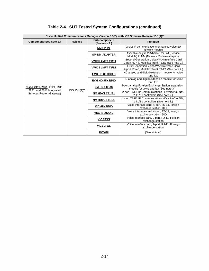
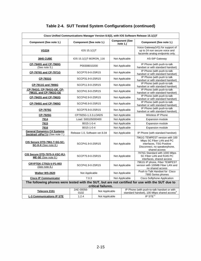
9. SYSTEM CONFIGURATIONS. Table 2-4 provides the system configurations and hardware and software components tested with the SUT. The SUT was tested in an operationally realistic environment to determine its interoperability capability with associated network devices and network traffic.
2-13
Table 2-4. SUT Tested System Configurations
Cisco Unified Communications Manager Version 8.0(2), with IOS Software Release 15.1(1)T
Table 2-4. SUT Tested System Configurations (continued)
Cisco Unified Communications Manager Version 8.0(2), with IOS Software Release 15.1(1)T
Component (See note 1.) Component (See note 1.) Component (See
note 1.) Component (See note 1.)
VG224 IOS 15.1(1)T Voice Gateway(VG) for support of
up to 24 non secure voice and facsimile analog endpoints only.
3845 CUBE IOS 15.1(1)T-BORON_116 Not Applicable AS-SIP Gateway
CP-7940G and CP-7960G (See note 5.)
P00308010200 Not Applicable IP Phone (with push-to-talk
handset or with standard handset)
CP-7970G and CP-7971G SCCP70.9-0-2SR1S Not Applicable IP Phone (with push-to-talk
handset or with standard handset)
CP-7931G SCCP31.9-0-2SR1S Not Applicable IP Phone (with push to talk
handset or with standard handset)
CP-7911G and 7906G SCCP11.9-0-2SR1S Not Applicable IP Phone (with push-to-talk
handset or with standard handset)
CP-7941G, CP-7941G-GE, CP-7961G, and CP-7961G-GE
SCCP41.9-0-2SR1S Not Applicable IP Phone (with push-to-talk
handset or with standard handset)
CP-7942G and CP-7962G SCCP42.9-0-2SR1S Not Applicable IP Phone (with push-to-talk
handset or with standard handset)
CP-7945G and CP-7965G SCCP45.9-0-2SR1S Not Applicable IP Phone (with push-to-talk
handset or with standard handset)
CP-7975G SCCP75.9-0-2SR1S Not Applicable IP Phone (with push-to-talk
handset or with standard handset)
CP-7925G CP7925G-1.3.3.LOADS Not Applicable Wireless IP Phone
7914 Load: S00105000400 Not Applicable Expansion module
7915 B015-1-0-4 Not Applicable Expansion module
7916 B015-1-0-4 Not Applicable Expansion module
General Dynamics C4 Systems Sectéra® vIPerTM (See note 7.)
Release 1.0, Software ver.6.04 Not Applicable IP Phone (with standard handset)
CIS Secure DTD-7961-T-SG-SC-SC-X-X (See note 8.)
SCCP41.9-0-2SR1S Not Applicable
7961G TEMPEST version with 100 Mbps SC Fiber LAN and PC
interfaces, TSG Positive Disconnect, no speakerphone,
shared access
CIS Secure DTD-7975-X-XSC-RJ-ME-SE (See note 8.)
SCCP75.9-0-2SR1S Not Applicable 7975G Standard with 1000 Mbps
SC Fiber LAN and RJ45 PC interfaces, shared access
CRYPTEK CT915-V-P1-003 (See note 8.)
SCCP41.9-0-2SR1S Not Applicable 7961G IP phone, Fiber TEMPEST version with 100MB Fiber LAN and
no shared access
Walker WS-2620 Not Applicable Not Applicable Push to Talk Handset for Cisco
7900 Series phones
Cisco IP Communicator 7.0.3 Not Applicable Cisco Softphone Application
The following phones were tested with the SUT, but are not certified for use with the SUT due to critical failures.
Telecore 2151 2AE-00056-
0102 Not Applicable
IP Phone (with push-to-talk handset or with standard handset), 100 Mbps shared access
9
L-3 Communications IP STE 1.2.4 Not Applicable IP STE11
2-16
Table 2-4. SUT Tested System Configurations (continued)
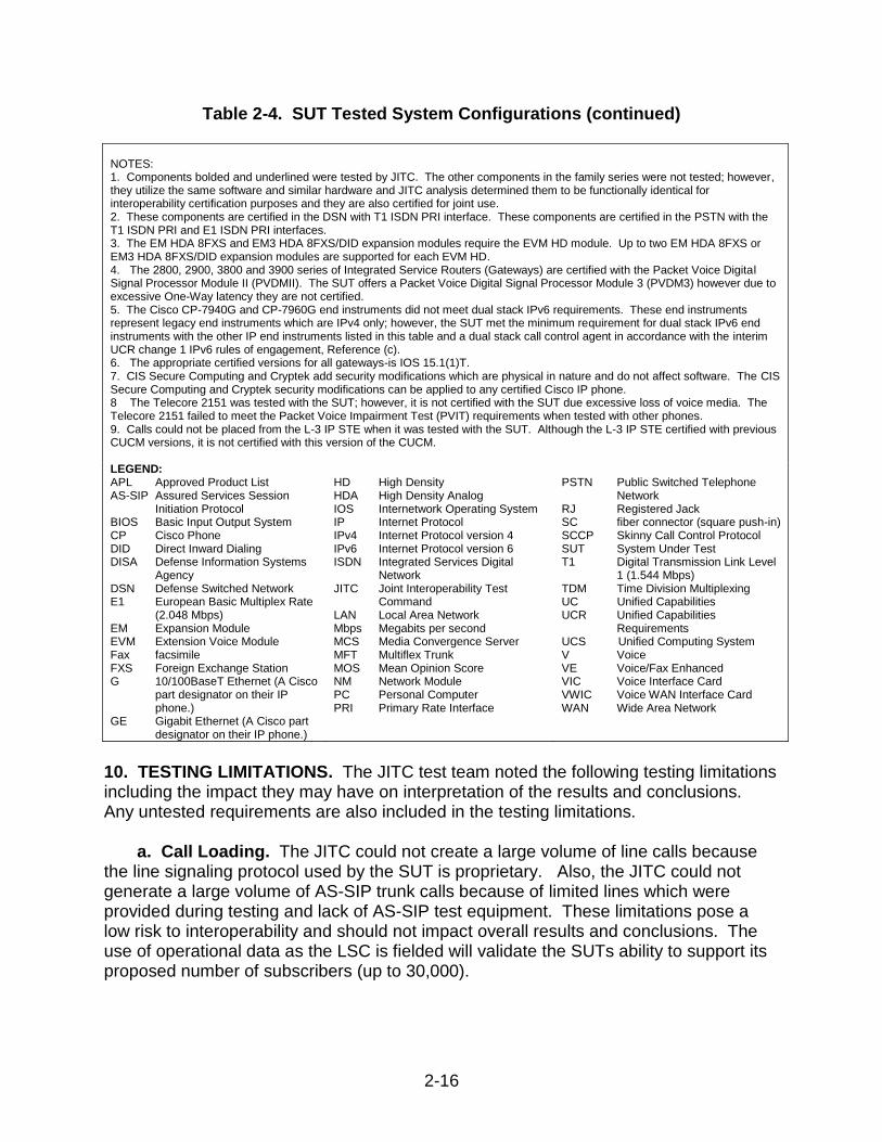
10. TESTING LIMITATIONS. The JITC test team noted the following testing limitations including the impact they may have on interpretation of the results and conclusions. Any untested requirements are also included in the testing limitations.
a. Call Loading. The JITC could not create a large volume of line calls because the line signaling protocol used by the SUT is proprietary. Also, the JITC could not generate a large volume of AS-SIP trunk calls because of limited lines which were provided during testing and lack of AS-SIP test equipment. These limitations pose a low risk to interoperability and should not impact overall results and conclusions. The use of operational data as the LSC is fielded will validate the SUTs ability to support its proposed number of subscribers (up to 30,000).
NOTES: 1. Components bolded and underlined were tested by JITC. The other components in the family series were not tested; however, they utilize the same software and similar hardware and JITC analysis determined them to be functionally identical for interoperability certification purposes and they are also certified for joint use. 2. These components are certified in the DSN with T1 ISDN PRI interface. These components are certified in the PSTN with the T1 ISDN PRI and E1 ISDN PRI interfaces. 3. The EM HDA 8FXS and EM3 HDA 8FXS/DID expansion modules require the EVM HD module. Up to two EM HDA 8FXS or EM3 HDA 8FXS/DID expansion modules are supported for each EVM HD. 4. The 2800, 2900, 3800 and 3900 series of Integrated Service Routers (Gateways) are certified with the Packet Voice Digital Signal Processor Module II (PVDMII). The SUT offers a Packet Voice Digital Signal Processor Module 3 (PVDM3) however due to excessive One-Way latency they are not certified. 5. The Cisco CP-7940G and CP-7960G end instruments did not meet dual stack IPv6 requirements. These end instruments represent legacy end instruments which are IPv4 only; however, the SUT met the minimum requirement for dual stack IPv6 end instruments with the other IP end instruments listed in this table and a dual stack call control agent in accordance with the interim UCR change 1 IPv6 rules of engagement, Reference (c). 6. The appropriate certified versions for all gateways-is IOS 15.1(1)T. 7. CIS Secure Computing and Cryptek add security modifications which are physical in nature and do not affect software. The CIS Secure Computing and Cryptek security modifications can be applied to any certified Cisco IP phone. 8 The Telecore 2151 was tested with the SUT; however, it is not certified with the SUT due excessive loss of voice media. The Telecore 2151 failed to meet the Packet Voice Impairment Test (PVIT) requirements when tested with other phones. 9. Calls could not be placed from the L-3 IP STE when it was tested with the SUT. Although the L-3 IP STE certified with previous CUCM versions, it is not certified with this version of the CUCM. LEGEND: APL Approved Product List AS-SIP Assured Services Session
Initiation Protocol BIOS Basic Input Output System CP Cisco Phone DID Direct Inward Dialing DISA Defense Information Systems
Agency DSN Defense Switched Network E1 European Basic Multiplex Rate
(2.048 Mbps) EM Expansion Module EVM Extension Voice Module Fax facsimile FXS Foreign Exchange Station G 10/100BaseT Ethernet (A Cisco
part designator on their IP phone.)
GE Gigabit Ethernet (A Cisco part designator on their IP phone.)
HD High Density HDA High Density Analog IOS Internetwork Operating System IP Internet Protocol IPv4 Internet Protocol version 4 IPv6 Internet Protocol version 6 ISDN Integrated Services Digital
Network JITC Joint Interoperability Test
Command LAN Local Area Network Mbps Megabits per second MCS Media Convergence Server MFT Multiflex Trunk MOS Mean Opinion Score NM Network Module PC Personal Computer PRI Primary Rate Interface
PSTN Public Switched Telephone Network
RJ Registered Jack SC fiber connector (square push-in) SCCP Skinny Call Control Protocol SUT System Under Test T1 Digital Transmission Link Level
Requirements UCS Unified Computing System V Voice VE Voice/Fax Enhanced VIC Voice Interface Card VWIC Voice WAN Interface Card WAN Wide Area Network
2-17
b. Assured Services Session Initiation Protocol End Instruments. The JITC did not test the SUT with generic AS-SIP End Instruments (AEIs) because none were available at the time of test. A vendor has yet to submit a product as an AEI for certification. This requirement was an addition to the UCR 2008 Change 1 and therefore the SUT has 18-months (July 2011) to comply with the requirement.
c. Proprietary End Instruments. The JITC did not test PEIs for video
requirements. Since the Defense Switched Network (DSN) has not deployed videophones under legacy certifications, this poses a low operational impact. The JITC will verify video capabilities of the SUT prior to amending the certification to include the capability.
d. Internet Protocol version 6. The IPv6 requirements were tested in the Private
Branch Exchange (PBX) configuration. These results were applied to the LSC configuration where applicable. The JITC did not test IPv6 Inter-enclave (i.e., between LSCs via an Edge Boundary Controller (EBC). The JITC did not test this feature because the EBC did not fully support IPv6 during the time of testing.
e. Network Management. The JITC did not test the SUT’s ability to meet UCR
NM requirements. The vendor did submit an NM LoC that was reviewed by JITC. The JITC’s evaluation of the SUT’s NM capabilities is provided in paragraph 11.
f. Attendant Consoles. The JITC did not test the SUT’s Attendant features. The
vendor did not provide an Attendant Console. This requirement was an addition to the UCR 2008 Change 1 and therefore the SUT has 18-months (July 2011) to comply with the requirement.
g. Master/Slave. The JITC did not test the SUT to determine its ability to meet
master/slave requirements. Initial fielding of an LSC will not be used in this configuration. The operational impact was adjudicated to be low.
h. Secure Data and Secure Voice Calls. The standard for modem over IP is
based on ITU-T V.150.1 and vendors have 18-months (July 2011) to comply. Secure calls were not tested inter-enclave (between LSCs via DISN). The SUT supports V.150.1 with all its media gateways except the VG224 which is certified only for non secure voice and facsimile. In accordance with UCR 2008 change 1 paragraph 5.3.2.6.1.6 every analog Integrated Access Device (IAD) line card on the LSC or MFSS is not required to support secure voice, secure data, or non secure modem or ITU–T Recommendation V.150.1 Modem Relay.
11. INTEROPERABILITY EVALUATION RESULTS. The SUT meets the critical interoperability requirements for an LSC in accordance with the UCR and is certified for joint use with other UC Products listed on the APL. Additional discussion regarding specific testing results is located in subsequent paragraphs.
2-18
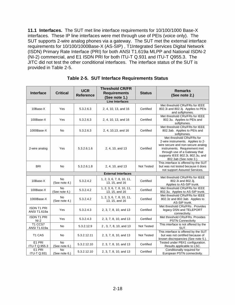
11.1 Interfaces. The SUT met line interface requirements for 10/100/1000 Base-X interfaces. These IP line interfaces were met through use of PEIs (voice only). The SUT supports 2-wire analog phones via a gateway. The SUT met the external interface requirements for 10/100/1000Base-X (AS-SIP) , T1Integrated Services Digital Network (ISDN) Primary Rate Interface (PRI) for both ANSI T1.619a MLPP and National ISDN-2 (NI-2) commercial, and E1 ISDN PRI for both ITU-T Q.931 and ITU-T Q955.3. The JITC did not test the other conditional interfaces. The interface status of the SUT is provided in Table 2-5.
Table 2-5. SUT Interface Requirements Status
Interface Critical UCR
Reference
Threshold CR/FR Requirements (See note 1.)
Status Remarks
(See note 2.)
Line Interfaces
10Base-X Yes 5.3.2.6.3 2, 4, 10, 13, and 16 Certified Met threshold CRs/FRs for IEEE
802.3i and 802.3j. Applies to PEIs and softphones.
100Base-X Yes 5.3.2.6.3 2, 4, 10, 13, and 16 Certified Met threshold CRs/FRs for IEEE
802.3u. Applies to PEIs and softphones.
1000Base-X No 5.3.2.6.3 2, 4, 10,13, and 16 Certified Met threshold CRs/FRs for IEEE
802.3ab. Applies to PEIs and softphones.
2-wire analog Yes 5.3.2.6.1.6 2, 4, 10, and 13 Certified
Met threshold CRs/FRs for 2-wire instruments. Applies to 2-
wire secure and non-secure analog instruments. Requirement met through use of a Gateway that
supports IEEE 802.3i, 802.3u, and 802.3ab (See note 3.).
BRI No 5.3.2.6.1.8 2, 4, 10, and 13 Not Tested This interface is offered by the SUT but was not tested because it does
not support Assured Services.
External Interfaces
10Base-X No
(See note 4.) 5.3.2.4.2
1, 2, 3, 6, 7, 8, 10, 11, 13, 15, and 16
Certified Met threshold CRs/FRs for IEEE
802.3i and 802.3j. Applies to AS-SIP trunk.
100Base-X No
(See note 4.) 5.3.2.4.2
1, 2, 3, 6, 7, 8, 10, 11, 13, 15, and 16
Certified Met threshold CRs/FRs for IEEE 802.3u. Applies to AS-SIP trunk.
1000Base-X No
(See note 4.) 5.3.2.4.2
1, 2, 3, 6, 7, 8, 10, 11, 13, 15, and 16
Certified Met threshold CRs/FRs for IEEE 802.3z and 802.3ab. Applies to
AS-SIP trunk.
ISDN T1 PRI ANSI T1.619a
Yes 5.3.2.4.3 2, 3, 7, 8, 10, and 13 Certified Met threshold CRs/FRs . Provides
legacy DSN and TELEPORT connectivity.
ISDN T1 PRI NI-2
Yes 5.3.2.4.3 2, 3, 7, 8, 10, and 13 Certified Met threshold CRs/FRs. Provides
PSTN Connectivity
T1 CCS7 ANSI T1.619a
No 5.3.2.12.9 2 , 3, 7, 8, 10, and 13 Not Tested This interface is not offered by the
SUT.
T1 CAS No 5.3.2.12.11 2, 3, 7, 8, 10, and 13 Not Tested This interface is offered by the SUT
but was not certified because of known discrepancies (See note 5.).
E1 PRI ITU-T Q.955.3
No (See note 6.)
5.3.2.12.10 2, 3, 7, 8, 10, and 13 Certified Tested under PBX1 configuration.
Results applicable to LSC.
E1 PRI ITU-T Q.931
No (See note 6.)
5.3.2.12.10 2, 3, 7, 8, 10, and 13 Certified Conditionally required for
European PSTN connectivity.
2-19
Table 2-5. SUT Interface Requirements Status (continued)
Interface Critical UCR
Reference
Threshold CR/FR Requirements (See note 1.)
Status Remarks
(See note 2.)
NM
10Base-X No
(See note 4.) 5.3.2.4.4
5.3.2.7.2.8 16 and 17 Certified
Met threshold CRs/FRs. Verified via LoC.
100Base-X No
(See note 4.) 5.3.2.4.4
5.3.2.7.2.8 16 and 17 Certified
Met threshold CRs/FRs. Verified via LoC.
NOTES: 1. CR/FR requirements are contained in Table 2. CR/FR numbers represent a roll-up of UCR requirements. Enclosure 3 provides a list of more detailed requirements LSC products. 2. Paragraph 11 of Enclosure 2 provides detailed information pertaining to open TDRs and associated operational impacts. 3. Voice calls from the SUT gateway analog interfaces via the UC DISN WAN require a loopback configuration of ANSI T1.619a ISDN PRI interfaces within each gateway (refer to Cisco CUCM deployment guide). This configuration requires translations in the gateways to route all out going analog calls placed towards the UC DISN WAN via the looped T1s. Additionally, incoming calls from the UC DISN WAN to analog end instruments on each gateway must be routed via the looped T1s. Without this configuration, analog end instruments cannot place calls via the UC DISN WAN. This configuration requires two looped ISDN PRI ANSI T1.619a T1s within each 3845 and 3945 gateways and will support a maximum of 69 analog interfaces per gateway. This allows for up to two ISDN PRI T1 interfaces or one ISDN PRI E1 interface for timing/network access. In addition, each 2851 and 2951 gateway requires one looped ANSI T1.619a ISDN PRI within each 2851 and 2951 gateway and will support a maximum of 23 analog interfaces per gateway. Both gateways also require a T1 or E1 interface for synchronization via recovered timing. 4. Must provide a minimum of one of the listed interfaces. 5. The SUT CAS interface had interoperability test discrepancies adjudicated to be critical for certification of this interface. 6. The interface is conditionally required for deployment in Europe. LEGEND: ANSI American National Standards Institute AS-SIP Assured Services Session Initiation BRI Basic Rate Interface CAS Channel Associated Signaling CCS7 Common Channel Signaling 7 CR Capability Requirement CUCM Cisco Unified Communications Manager DISN Defense Information System Network DSN Defense Switched Network E1 European Basic Multiplex Rate (2.048 Mbps) FR Functional Requirement IEEE Institute of Electrical and Electronics Engineers, Inc. ISDN Integrated Services Digital Network
ITU-T International Telecommunications Union Telecommunication Standardization Sector LoC Letter of Compliance LSC Local Session Controller Mbps Megabits per second NI-2 National ISDN Standard 2 NM Network Management PEI Proprietary End Instrument PRI Primary Rate Interface PSTN Public Switch Telephone Network SUT System Under Test T1 Digital Transmission Link Level 1 (1.544 Mbps) TDR Test Discrepancy Report UCR Unified Capabilities Requirements WAN Wide Area Network
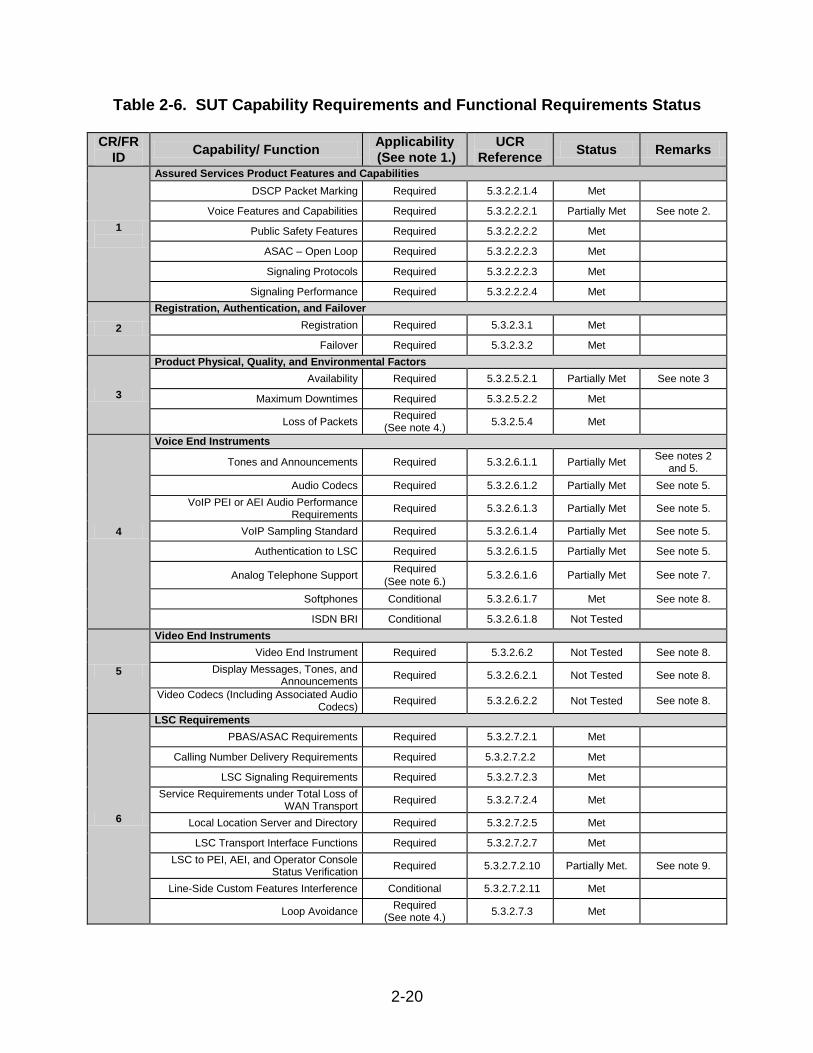
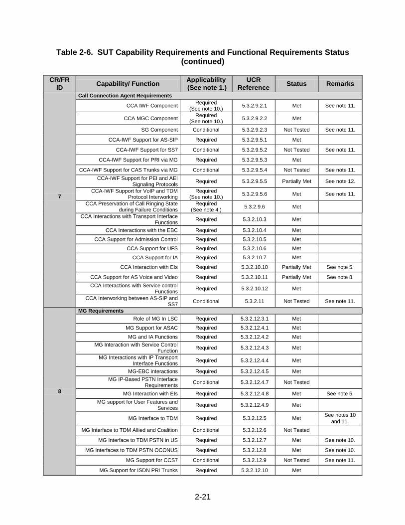
11.2 Capability Requirements (CR) and Functional Requirements (FR). The SUT CR and FR status is depicted in Table 2-6. Detailed CR/FR requirements are provided in Enclosure 3, Table 3-1. A summary of the SUT’s ability to meet UCR requirements are provided in the sub-paragraphs below. All requirements and associated references were derived from UCR 2008 Change 1. Discrepancies discussed below were adjudicated to be minor based on vendor submission and compliance to a Plan of Actions and Milestones.
2-20
Table 2-6. SUT Capability Requirements and Functional Requirements Status
CR/FR
ID Capability/ Function
Applicability
(See note 1.)
UCR
Reference Status Remarks
1
Assured Services Product Features and Capabilities
DSCP Packet Marking Required 5.3.2.2.1.4 Met
Voice Features and Capabilities Required 5.3.2.2.2.1 Partially Met See note 2.
Public Safety Features Required 5.3.2.2.2.2 Met
ASAC – Open Loop Required 5.3.2.2.2.3 Met
Signaling Protocols Required 5.3.2.2.2.3 Met
Signaling Performance Required 5.3.2.2.2.4 Met
2
Registration, Authentication, and Failover
Registration Required 5.3.2.3.1 Met
Failover Required 5.3.2.3.2 Met
3
Product Physical, Quality, and Environmental Factors
Availability Required 5.3.2.5.2.1 Partially Met See note 3
Maximum Downtimes Required 5.3.2.5.2.2 Met
Loss of Packets Required
(See note 4.) 5.3.2.5.4 Met
4
Voice End Instruments
Tones and Announcements Required 5.3.2.6.1.1 Partially Met See notes 2
and 5.
Audio Codecs Required 5.3.2.6.1.2 Partially Met See note 5.
VoIP PEI or AEI Audio Performance Requirements
Required 5.3.2.6.1.3 Partially Met See note 5.
VoIP Sampling Standard Required 5.3.2.6.1.4 Partially Met See note 5.
Authentication to LSC Required 5.3.2.6.1.5 Partially Met See note 5.
Analog Telephone Support Required
(See note 6.) 5.3.2.6.1.6 Partially Met See note 7.
Softphones Conditional 5.3.2.6.1.7 Met See note 8.
ISDN BRI Conditional 5.3.2.6.1.8 Not Tested
5
Video End Instruments
Video End Instrument Required 5.3.2.6.2 Not Tested See note 8.
Display Messages, Tones, and Announcements
Required 5.3.2.6.2.1 Not Tested See note 8.
Video Codecs (Including Associated Audio Codecs)
Required 5.3.2.6.2.2 Not Tested See note 8.
6
LSC Requirements
PBAS/ASAC Requirements Required 5.3.2.7.2.1 Met
Calling Number Delivery Requirements Required 5.3.2.7.2.2 Met
LSC Signaling Requirements Required 5.3.2.7.2.3 Met
Service Requirements under Total Loss of WAN Transport
Required 5.3.2.7.2.4 Met
Local Location Server and Directory Required 5.3.2.7.2.5 Met
LSC Transport Interface Functions Required 5.3.2.7.2.7 Met
LSC to PEI, AEI, and Operator Console Status Verification
Required 5.3.2.7.2.10 Partially Met. See note 9.
Line-Side Custom Features Interference Conditional 5.3.2.7.2.11 Met
Loop Avoidance Required
(See note 4.) 5.3.2.7.3 Met
2-21
Table 2-6. SUT Capability Requirements and Functional Requirements Status (continued)
CR/FR
ID Capability/ Function
Applicability
(See note 1.)
UCR
Reference Status Remarks
7
Call Connection Agent Requirements
CCA IWF Component Required
(See note 10.) 5.3.2.9.2.1 Met See note 11.
CCA MGC Component Required
(See note 10.) 5.3.2.9.2.2 Met
SG Component Conditional 5.3.2.9.2.3 Not Tested See note 11.
CCA-IWF Support for AS-SIP Required 5.3.2.9.5.1 Met
CCA-IWF Support for SS7 Conditional 5.3.2.9.5.2 Not Tested See note 11.
CCA-IWF Support for PRI via MG Required 5.3.2.9.5.3 Met
CCA-IWF Support for CAS Trunks via MG Conditional 5.3.2.9.5.4 Not Tested See note 11.
CCA-IWF Support for PEI and AEI Signaling Protocols
Required 5.3.2.9.5.5 Partially Met See note 12.
CCA-IWF Support for VoIP and TDM Protocol Interworking
Required (See note 10.)
5.3.2.9.5.6 Met See note 11.
CCA Preservation of Call Ringing State during Failure Conditions
Required (See note 4.)
5.3.2.9.6 Met
CCA Interactions with Transport Interface Functions
Required 5.3.2.10.3 Met
CCA Interactions with the EBC Required 5.3.2.10.4 Met
CCA Support for Admission Control Required 5.3.2.10.5 Met
CCA Support for UFS Required 5.3.2.10.6 Met
CCA Support for IA Required 5.3.2.10.7 Met
CCA Interaction with EIs Required 5.3.2.10.10 Partially Met See note 5.
CCA Support for AS Voice and Video Required 5.3.2.10.11 Partially Met See note 8.
CCA Interactions with Service control Functions
Required 5.3.2.10.12 Met
CCA Interworking between AS-SIP and SS7
Conditional 5.3.2.11 Not Tested See note 11.
8
MG Requirements
Role of MG In LSC Required 5.3.2.12.3.1 Met
MG Support for ASAC Required 5.3.2.12.4.1 Met
MG and IA Functions Required 5.3.2.12.4.2 Met
MG Interaction with Service Control Function
Required 5.3.2.12.4.3 Met
MG Interactions with IP Transport Interface Functions
Required 5.3.2.12.4.4 Met
MG-EBC interactions Required 5.3.2.12.4.5 Met
MG IP-Based PSTN Interface Requirements
Conditional 5.3.2.12.4.7 Not Tested
MG Interaction with EIs Required 5.3.2.12.4.8 Met See note 5.
MG support for User Features and Services
Required 5.3.2.12.4.9 Met
MG Interface to TDM Required 5.3.2.12.5 Met See notes 10
and 11.
MG Interface to TDM Allied and Coalition Conditional 5.3.2.12.6 Not Tested
MG Interface to TDM PSTN in US Required 5.3.2.12.7 Met See note 10.
MG Interfaces to TDM PSTN OCONUS Required 5.3.2.12.8 Met See note 10.
MG Support for CCS7 Conditional 5.3.2.12.9 Not Tested See note 11.
MG Support for ISDN PRI Trunks Required 5.3.2.12.10 Met
2-22
Table 2-6. SUT Capability Requirements and Functional Requirements Status (continued)
CR/FR
ID Capability/ Function
Applicability
(See note 1.)
UCR
Reference Status Remarks
8
MG Requirements (continued)
MG Support for CAS Trunks Required 5.3.2.12.11 Not Tested See note 11.
MG requirements for VoIP Internal Interfaces Required 5.3.2.12.12 Met
MG Echo Cancellation Required 5.3.2.12.13 Met
MG Clock Timing Required 5.3.2.12.14 Met
MGC-MG CCA Functions Required 5.3.2.12.15 Met
MG V.150.1 Required 5.3.2.12.16 Not tested See note 7.
MG Preservation of Call Ringing during Failure Required
(See note 4.) 5.3.2.12.17 Met
9
SG Requirements
SG and CCS7 Network Interactions Conditional 5.3.2.13.5.1 Not Tested See note 11.
SG Interactions with CCA Conditional 5.3.2.13.5.2 Not Tested See note 11.
SG Interworking Functions Conditional 5.3.2.13.5.3 Not Tested See note 11.
10
WWNDP Requirements
WWNDP Required 5.3.2.16 Met
DSN WWNDP Required 5.3.2.16.1 Met
11
Commercial Cost Avoidance
Commercial Cost Avoidance Required
(See note 3.) 5.3.2.23 Not Tested
12 AS-SIP Based for External Devices (Voicemail, Unified Messaging, and Automated Receiving Devices)
AS-SIP Requirements for External Interfaces Conditional 5.3.2.24 Not Tested
13 Precedence Call Diversion
Precedence call Diversion Required 5.3.2.25 Met
14
Attendant Station Features
Precedence and Preemption Required
(See note 3.) 5.3.2.26.1 Not Tested See note 13.
Call Display Required
(See note 3.) 5.3.2.26.2 Not Tested See note 13.
Class of Service Override Required
(See note 3.) 5.3.2.26.3 Not Tested See note 13.
Busy Override and Busy Verification Required
(See note 3.) 5.3.2.26.4 Not Tested See note 13.
Night service Required
(See note 3.) 5.3.2.26.5 Not Tested See note 13.
Automatic Recall of Attendant Required
(See note 3.) 5.3.2.26.6 Not Tested See note 13
Calls in Queue to the Attendant Required
(See note 3.) 5.3.2.26.7 Not Tested See note 13.
15
AS-SIP Requirements
SIP Requirements for AS-SIP Signaling Appliances and AS-SIP EIs
Required (See note 3.)
5.3.4.7 Not Tested
SIP Session Keep-Alive Timer Required 5.3.4.8 Met
Session Description Protocol Required 5.3.4.9 Met
Precedence and Preemption Required 5.3.4.10 Met
Video Telephony – General Rules Required 5.3.4.12 Not Tested See note 8.
Calling Services Required 5.3.4.13 Met
SIP Translation Requirements for Inter-working AS-SIP Signaling Appliances
Required 5.3.4.14 Met
Relevant Timers for the Terminating Gateway and the Originating Gateway
Required 5.3.4.15 Met
2-23
Table 2-6. SUT Capability Requirements and Functional Requirements Status (continued)
CR/FR
ID Capability/ Function
Applicability
(See note 1.)
UCR
Reference Status Remarks
15
AS-SIP Requirements (continued)
SIP Requirements for Interworking AS-SIP Signaling Appliances
Required 5.3.4.16 Met
Keep-Alive Timer Requirements for Interworking AS-SIP Signaling Appliances
Required 5.3.4.17 Met
Precedence and Preemption Extensions for Interworking AS-SIP Signaling
Appliances Required 5.3.4.18 Met
Supplementary Services Required 5.3.4.19 Met
16 IPv6 Requirements
Product Requirements Required 5.3.5.4 Partially met See note 14.
17
NM
LSC Management Function Required 5.3.2.7.2.6 Met
VVoIP NMS Interface Requirements Required 5.3.2.4.4 Met
General Management requirements Required 5.3.2.17.2 Partially Met See note 15.
Requirement for FCAPS Management Required 5.3.2.17.3 Partially Met See note 15.
NM requirements of Appliance Functions Required 5.3.2.18 Partially Met See note 15.
Accounting Management Required 5.3.2.19 Met See note 16.
NOTES:
1. Annotation of ‘required’ refers to high level requirement category. Applicability of each sub-requirement is provided in enclosure 3.
2. The SUT had outstanding open TDRs at the completion of testing adjudicated by DISA to have a minor operational impact. The vendor has submitted a PoAM to address the open TDRs. Paragraph 11 of Enclosure 2 provides additional details.
3. When the SUT fails from the primary processor to backup processor all active drop after approx 6-8 minutes. DISA adjudicated this TDR as minor with the vendor’s submitted PoAM to fix by June 2011.
4. This requirement represents a new UCR requirement where the vendor has 18-months (July 2011) to comply.
5. SUT met the requirement for PEIs; SUT was not tested with generic AEI because no AEI was provided. AEIs are a new UCR 2008 Change 1 requirement; the vendor has 18-months (July 2011) to comply.
6. UCR 2008 Change 1 added 18-month rule for G.711 and V.150.1 IAD support.
7. Vendor submitted LoC stating compliance to V.150 however this feature could not be tested because it is not supported by other vendors. This is a new UCR 2008 change 1 requirement; therefore the vendor has until July 2011 to comply with this requirement.
8. SUT did not demonstrate video requirements (conditional for softphone). Vendor did not provide a PEI video capability. This was adjudicated by DISA to have a low operational impact because of the limited deployment of PEIs with video.
9. SUT partially met PEI requirements (no video). The AEI and Operator Console requirements were not tested; the 18-month rule for complying (July 2011) applies.
10. The SUT must meet T1 PRI (T1.619a and NI-2) IWF. The T1 CAS and T1 CCS7 are conditional, and E1 ISDN PRI is conditional for deployment in Europe.
11. The SUT met T1/E1 PRI IWF requirements. The T1 CAS is supported but not certified and T1 CCS7 is not supported by the SUT.
12. The SUT met PEI CCA-IWF requirements. The AEI CCA-IWF requirements were not tested. The 18-month rule applies to AEIs.
13. The Attendant Console requirements are new UCR requirements; 18-month rule applies.
14. The SUT submitted an IPv6 LoC with noted discrepancies. Open TDRs were adjudicated by DISA to have a minor operational impact with vendor submitted PoAM.
15. The SUT submitted an NM LoC with noted discrepancies. Open TDRs were adjudicated by DISA to have a minor operational impact with vendor submitted PoAM.
16. The SUT does not comply with the objective requirement for Record Format.
2-24
Table 2-6. SUT Capability Requirements and Functional Requirements Status (continued)
FCAPS Fault, Configuration, Accounting, Performance and
Security
FR Functional Requirement
IA Information Assurance
IAD Integrated Access Device
ID Identification
IP Internet Protocol
IPv6 Internet Protocol version 6
ISDN Integrated Services Digital Network
IWF Interworking Function
JITC Joint Interoperability Test Command
LoC Letter of Compliance
LSC Local Session Controller
Mbps Megabits per second
MG Media Gateway
MGC Media Gateway Controller
NI-2 National ISDN Standard 2
NM Network Management
NMS Network Management System
OCOUNUS Outside the Continental United States
PBAS Precedence-Based Assured Service
PEI Proprietary End Instrument
PoAM Plan of Action and Milestones
PRI Primary Rate Interface
PSTN Public Switch Telephone Network
SG Signaling Gateway
SIP Session Initiation Protocol
SS7 Signaling System Number 7
SUT System Under Test
T1 Digital Transmission Link Level 1 (1.544 Mbps)
TDM Time Division Multiplexing
UCR Unified Capabilities Requirements
UFC User Features and Services
US United States
VoIP Voice over Internet Protocol
VVoIP Voice and Video over Internet Protocol
WAN Wide Area Network
WWNDP World Wide Numbering and Dialing Plan
a. Assured Services Product Features and Capabilities.
(1) DSCP Packet Marking. As part of the session setup process, the LSC controls what DSCP to use in the subsequent session media stream packets. The exact DSCP method used shall comply with Section 5.3.3.3.2. The SUT met all DSCP Packet Marking requirements for IPv4 and IPv6 (intra-enclave only).
(2) Voice Features and Capabilities. The LSC must provide all of the features listed in Table 5.3.2.2-1 of the UCR. The SUT met all Voice Features and Capabilities requirements, with the following exception: SUT does not provide “Ping-Ring” on a call forward variable enabled phone. This was adjudicated as having a minor operational impact. Based on this finding, DISA is revising the UCR to make “Ping-Ring” on a phone assigned call forward variable conditional.
(3) Public Safety Features. The LSC must provide basic emergency service (911), tracing of terminating calls, outgoing call tracing, and tracing of a call in progress. The SUT met all Public Safety Features requirements with the following exception: SUT does not support Trace of a call in progress or Tandem call tracing. This was adjudicated as having a minor operational impact.
(4) ASAC – Open Loop. The LSC must meet the ASAC requirements for the LSC and the MFSS. In the execution of ASAC, certain procedures need to be followed, such as (a) actions to be taken if a precedence session request cannot be completed
2-25
because existing sessions are at equal or higher precedence, or (b) tones to be generated when a session is preempted. The SUT met all ASAC requirements.
(5) Signaling Protocols. The LSC must use appropriate signaling for specific trunk types. The control/management protocol between the PEI and the LSC is, in general, proprietary. The control/management protocol between the AEI and the LSC is AS-SIP as specified in Section 5.3.4, AS-SIP Requirements, of this document. The signaling protocol used on UC IP trunks is AS-SIP as specified in Section 5.3.4, AS-SIP Requirements. The MG in the LSC uses ANSI T1.619a PRI or E1 (Q.955.3) signaling on DSN PRI trunks. The SUT met all Signaling Protocol requirements except for AEI. The conditional requirement for CAS was not tested. (6) Signaling Performance. The LSC has conditional requirements for call setup and tear-down times. SUT met all signaling performance requirements
b. Registration, Authentication, and Failover.
(1) Registration. Registration and authentication between the LSC and EIs
shall follow the requirements set forth in UCR 2008, Section 5.4, Information Assurance Requirements. This feature is tested by IA and is covered in the IA report (see paragraph 11.3).
(2) Failover. The LSCs shall be registered to a primary and backup MFSS. In
case of failure of the primary MFSS, the LSC will default to the backup MFSS. The SUT met all failover requirements with the following exception. All active calls failed 6-8 minutes after processor failover because the SUT fails to reply to AS-SIP keep alive messages from the destination. The DISA adjudicated this discrepancy as having a minor operational impact due to limited fielding of LSCs within the operational network and is predicated on the vendor’s POAM to fix this discrepancy by June 2011.
c. Product Physical, Quality, and Environmental Factors.
(1) Availability. The Assured Services subsystem shall have a
hardware/software availability of 0.99999 (non-availability of no more than 5 minutes per year). This requirement was met via vendor LOC. The SUT met all component failover requirements with the following exception. All active calls 6-8 minutes after failover are disconnected because the SUT fails to reply to AS-SIP keep alive messages from the destination. The DISA adjudicated this discrepancy as having a minor operational impact due to limited fielding of LSCs within the operational network and is predicated on the vendor’s POAM to fix this discrepancy by June 2011.
(2) Maximum Downtimes. The performance parameters associated with the ASLAN, MFSS, and LSC, when combined, shall meet the following maximum downtime requirements: • IP (10/100 Ethernet) network links – 35 minutes/year
2-26
• IP subscriber – 12 minutes/year
This requirement was met via vendor LOC.
(3) Loss of Packets. For VoIP devices, the voice quality shall have a MOS of 4.0 (R-Factor equals 80) or better, as measured in accordance with the E-Model. Additionally, these devices shall not lose two or more consecutive packets in a minute and shall not lose more than seven voice packets (excluding signaling packets) in a 5-minute period. The SUT met all Packet Loss requirements for PEIs. d. Voice End Instrument. The SUT met PEI requirements except for the noted discrepancies in the following sub-paragraphs. The SUT was not tested with an AEI because no AEIs have been submitted through the UC process. The AEI requirement was a new requirement for which the 18-month rule (July 2011) applies. (1) Tones and announcements. Tones and announcements, as required in UCR 2008, Sections 5.2.4.5.2, DSN Information Signals, and Section 5.2.2.1.3, Announcements, shall be supported, except for the loss of C2 announcement. The SUT met all requirements for tones and announcements for PEIs.
(2) Audio codecs. The LSC shall support the origination and termination of a
voice session using the following codecs: G.711 (a-law and µ-law), G.723.1, G.729 or G.729A, and G.722.1. The SUT met all audio codecs requirements with the following exception: The SUT does not support G.723.1 codec on PEIs. This was adjudicated as having minor operational impact. Based on this finding, DISA is revising the UCR to make the G.723.1 codec a conditional requirement for PEIs and AEIs.
(3) VoIP PEI or AEI Audio Performance Requirements. Voice over IP PEIs or
AEIs (i.e., handset, headset, and hands-free types) shall comply with TIA-810-B, November 3, 2006. The SUT met all audio performance requirements for PEIs.
(4) VoIP Sampling Standard. For Fixed-to-Fixed calls, the product shall use
20 ms as the default voice sample length, and as the basis for the voice payload packet size. The SUT met the VoIP sampling standard requirements for PEIs.
(5) Authentication to LSC. The PEI and AEI shall be capable of authenticating
itself to its associated LSC and vice versa. The SUT met all PEI to LSC authentication requirements.
(6) Analog Telephone Support. Analog instruments, including secure analog
EIs, analog facsimile EIs, and analog modem EIs, shall be supported by the LSC either by a Terminal Adapter or an Integrated Access Device (IAD) connected to an Ethernet port. The SUT met all analog telephone support requirements via an IAD integrated within their media gateway and a standalone VG224 analog gateway.
(7) Softphones. The softphone shall be conceptually identical to a traditional
2-27
IP “hard” telephone and is required to provide voice features and functionality provided by a traditional IP hard telephone. The SUT meet all softphones requirements.
(8) ISDN BRI. The ISDN BRI EIs, including secure ISDN BRI EIs, may be
supported by the LSC. This is a conditional requirement; no BRI EIs were provided on the SUT at the time of test.
(9) The Telecore 2151 was tested with the SUT; however, it is not certified with the SUT due excessive loss of voice media. The Telecore 2151 failed to meet the Packet Voice Impairment Test (PVIT) requirements when tested with other phones.
(10) Calls could not be placed from the L-3 IP STE when it was tested with the
SUT. Although the L-3 IP STE certified with previous CUCM versions, it is not certified with this version of the CUCM.
e. Video End Instruments. The SUT must support both voice and video. PEIs and AEIs can support only voice, only video or both voice and video. The SUT’s PEI support voice only and did not support video. This discrepancy was adjudicated to have a minor operational impact because LSC managed video represents a new requirement not fielded under previous time division multiplexing (TDM) certifications. The SUT was not tested with an AEI. The AEI requirement was a new requirement for which the 18-month rule (July 2011) applies.
(1) Video End Instrument. Video EIs are considered associated with the LSC
and must have been designed in conjunction with the LSC design. An IP video instrument shall be designed in accordance with the acquiring activity requirements. This was not tested as the SUT did not provide any video end instruments.
(2) Display Messages, Tones, and Announcements. Tones and
announcements, as appropriate for voice and video over IP, and as required, in UCR 2008, Sections 5.2.4.5.2, DSN Information Signals, 5.2.2.1.3, Announcements, shall be supported by the PEI and AEI. This was not tested as the SUT did not provide any video end instruments.
(3) Video Codecs (Including Associated Audio Codecs). The product shall support the origination, maintenance, and termination of a video session using the following codecs: one G.xxx and one H.xxx must be used to create and sustain a video session. This was not tested as the SUT did not provide any video end instruments.
f. LSC Requirements.
(1) PBAS/ASAC Requirements. The LSC shall meet all the requirements for PBAS/ASAC, as appropriate for VoIP and Video over IP services, as specified in UCR 2008, Section 5.2.2, Multilevel Precedence and Preemption. The SUT met all PBAS/ASAC Requirements with the following exception. The SUT does not provide directionalization of its ASAC budget. This discrepancy was adjudicated to have a
2-28
minor operational impact.
(2) Calling Number Delivery Requirements. The calling number provided to the called party shall be determined by the dial plan serving the calling instrument in accordance with Telcordia Technologies GR-31-CORE “CLASSSM Feature: Calling Number Delivery,” Issue 1, June 2000. The SUT met all calling number delivery requirements.
(3) LSC Signaling Requirements. The LSC must provide signaling on the line side for local intra-enclave subscriber-to-subscriber calls, and trunk-side signaling for calls between an external enclave and a local subscriber. The SUT met all LSC Signaling Requirements.
(4) Service Requirements under Total Loss of WAN Transport. In the event that a total loss of connectivity to the DISN WAN occurs, the LSC shall provide the following functions:
• Completion of local (intra-enclave) calls
• Routing of calls to the PSTN using a local MG (PRI or CAS as required by the local interface)
• User look-up of local directory information
The SUT met all Service Requirements under Total Loss of WAN Transport.
(5) Local Location Server and Directory. The purpose of the Local Location Server (LLS) is to provide information on call routing and called address translation (where a called address is contained within the called SIP URI in the form of the called number). The SUT met all LLS and directory requirements.
(6) LSC Transport Interface Functions. The LSC Transport Interface
functions provide interface and connectivity functions with the ASLAN and its IP packet transport network. The SUT met all transport interface function requirements.
(7) LSC to PEI, AEI, and Operator Console Status Verification. Periodically,
the LSC shall verify the status of its registered and authenticated IP EIs. The SUT met all status verification requirements for PEIs. The SUT was not tested with AEIs and Attendant Console. Both are new UCR requirements for which the 18-month rule applies.
(8) Line-Side Custom Features Interference. Vendors may implement unique
custom features applicable to the line side of the LSC. Line-side custom features must not interfere with the Assured Services requirements. The SUT offers line-side custom features. However, JITC did not test any of those features; therefore, they are not certified for use.
(9) Loop Avoidance. During the call establishment process, the product shall
2-29
be capable of preventing or detecting and stopping hair-pin routing loops over ANSI T1.619a and commercial PRI trunk groups (i.e., T1 PRI and E1 PRI) between a legacy switch (e.g., TDM EO) and an LSC. The SUT met all Loop Avoidance requirements for T1 PRI (ANSI T1.619a and NI-2) and E1 PRI (ITU-T Q.931 and ITU-T Q.955.3).
g. Call Connection Agent Requirements.
(1) CCA IWF Component. The role of the IWF within the CCA is to support all the VoIP and TDM signaling protocols that the LSC supports for EIs, MGs, and EBCs, and to Interwork all these various signaling protocols with one another. The SUT met all CCA IWF requirements for T1 PRI (ANSI T1.619a and NI-2) and E1 PRI (ITU-T Q.931 and ITU-T Q.955.3). Of the other conditional IWFs, T1 CAS was tested but had discrepancies adjudicated by DISA to be critical and T1 CCS7 which is not offered by the SUT.
(2) CCA MGC Component. The MGC within the CCA must control all MGs within the LSC or MFSS, control all trunks within each MG, control all signaling and media streams on each trunk within each MG, accept IP-encapsulated signaling streams from an SG or MG, and to use either ITU-T recommendation H.248 or a supplier-proprietary protocol to accomplish these controls. The SUT met all CCA MGC requirements.
(3) SG Component. The role of the CCA with respect to the SG is to control all SGs within the network appliance, and to control all signaling links (DoD CCS7) within each SG. The SG is conditional for an LSC and was not tested on the SUT.
(4) CCA-IWF Support for AS-SIP. The CCA IWF shall support the AS-SIP protocol consistent with the detailed AS-SIP protocol requirements in Section 5.3.4, AS-SIP Requirements. The SUT met all requirements for CCA-IWF support for AS-SIP for required interfaces (T1 PRI (ANSI T1.619a and NI-2) and E1 PRI (ITU-T Q.931). Of the other conditional IWFs, T1 CAS was tested but had discrepancies adjudicated by DISA to be critical and T1 CCS7 was not tested.
(5) CCA-IWF Support for SS7. CCA-IWF support for SS7 is a conditional requirement for LSCs and is not supported by the SUT.
(6) CCA-IWF Support for PRI, via MG. The CCA IWF shall support the
U.S./National ISDN version of the ISDN PRI protocol. The SUT met all requirements for CCA-IWF support for T1 PRI (ANSI T1.619a and NI-2) and E1 PRI (ITU-T Q.931 and ITU-T 955.3).
(7) CCA-IWF Support for CAS Trunks via MG. Support for CAS is a conditional requirement for LSCs. The CAS interface was tested on the SUT but not certified because of discrepancies adjudicated by DISA to be critical.
(8) CCA-IWF Support for PEI and AEI Signaling Protocols. The CCA IWF
2-30
shall support supplier-proprietary Voice and Video EIs and their associated proprietary EI signaling protocols. The SUT met all requirements for CCA-IWF Support for PEI Signaling Protocols. No AEIs were tested.
(9) CCA-IWF Support for VoIP and TDM Protocol Interworking. The role of
the IWF within the CCA is to support all the VoIP and TDM signaling protocols that the appliance supports for PEIs, AEIs, MGs, and EBCs, and interwork all these various signaling protocols with one another. The SUT met all requirements for CCA-IWF Support for VoIP and TDM Protocol Interworking required interfaces (T1 PRI (ANSI T1.619a and NI-2) and E1 PRI (ITU-T Q.931 and ITU-T Q.955.3). Of the other conditional IWFs, T1 CAS was tested but had discrepancies adjudicated by DISA to be critical and T1 CCS7 was not tested.
(10) CCA Preservation of Call Ringing State during Failure Conditions. The CCA in the LSC, MFSS, and WAN SS shall not allow AS-SIP sessions that have reached the ringing state (i.e., an AS-SIP 180 (Ringing) message or 183 (Session Progress) has been sent from the called party to the calling party, and the calling party is receiving an audible ringing tone) to fail when an internal failure occurs within the CCA. This requirement was not tested. This is a new UCR requirement for which the 18-month rule applies.
(11) CCA Interactions with Transport Interface Functions. The CCA interacts
with Transport Interface functions by using them to communicate with PEIs, AEIs, the EBC, the MGs, and the SG over the ASLAN. The SUT met all requirements for CCA interactions with Transport Interface Functions with the exception of AEIs. No AEIs were tested.
(12) CCA Interactions with the EBC. The CCA interacts with the EBC by
directing AS-SIP signaling packets to it (for signaling messages destined for an MFSS) and by accepting AS-SIP signaling packets from it (for signaling messages directed to the LSC from an MFSS). The SUT met all requirements for CCA interactions with the EBC.
(13) CCA Support for Admission Control. The CCA interacts with the ASAC
component of the LSC and MFSS to perform specific functions related to ASAC, such as counting internal, outgoing, and incoming calls; managing separate call budgets for VoIP and Video over IP calls; and providing preemption. The SUT met all requirements for CCA support for Admission Control
(14) CCA Support for UFS. The UFS Server is responsible for providing
features and services to VoIP and Video PEIs/AEIs on an LSC or MFSS, where the CCA alone cannot provide the feature or service. The SUT met all requirements for CCA Support for UFS for PEIs.
(15) CCA Support for IA. The Information Assurance function within the appliance ensures that end users, PEIs, AEIs, MGs, SGs, and EBCs that use the
2-31
appliance are all properly authenticated and authorized by the appliance. The Information Assurance function ensures that Voice and Video signaling streams that traverse the appliance and its ASLAN are encrypted properly SIP/TLS. IA requirements are tested separately; see paragraph 11.3.
(16) CCA Interaction with EIs. The LLS provides information on called
address translation in response to call routing queries from the CCA. The CCA sends call routing queries to the LLS for both outgoing calls from appliance PEIs or AEIs (i.e., LSC and MFSS) and incoming calls to appliance PEIs or AEIs (i.e., LSC and MFSS). The SUT met all requirements for CCA interaction with PEIs.
(17) CCA Support for AS Voice and Video. The CCA in the MFSS or LSC needs to interact with VoIP PEIs and AEIs served by that MFSS or LSC. The VoIP interface between the PEI and the MFSS or LSC is left up to the network appliance supplier. The VoIP interface between the AEI and the MFSS or LSC is AS-SIP. The SUT met all requirements for CCA support for AS Voice. The SUT did not provide Video. This was adjudicated to have a minor operational impact.
(18) CCA Interactions with Service Control Functions. The CCA shall
support the ability to remove VoIP and Video sessions and session requests from the media server so the CCA can continue with necessary session processing once the media server has completed its functions. The SUT met all requirements for CCA Interactions with Service Control Functions.
(19) CCA Interworking between AS-SIP and CCS7. Interworking is
performed at a node with CCA (SIP/CCS7 IWF) functionality that processes/interworks incoming CCS7 messages to outgoing AS-SIP messages, and similarly, incoming AS-SIP messages to outgoing CCS7 messages. This is a conditional requirement for LSCs and was not tested on the SUT.
h. MG Requirements.
(1) Role of MG In LSC. The MG supports interconnection of VoIP, FoIP, and MoIP media streams with the LSC media server, which provides tones and announcements for LSC calls and LSC features. To support inter-enclave MoIP and FoIP, the LSC must meet ITU-T V.150.1 requirements. The V.150.1 requirement is a new UCR requirement for which the 18-month (July 2011) rule applies. (2) MG Support for ASAC. The MG assists the CCA in performing ASAC (i.e., call preemption based on per-call precedence levels) for outgoing TDM calls at MGs and for incoming TDM calls at MGs. The SUT met all requirements for MG Support for ASAC.
(3) MG and IA Functions. The Information Assurance function within the
appliance ensures that end users, PEIs, AEIs, MGs, SGs, and EBCs that use the appliance are all properly authenticated by the appliance. The Information Assurance
2-32
function also ensures that VoIP signaling streams and media streams that traverse the appliance and its ASLAN are properly encrypted, using SIP/TLS and SRTP, respectively. IA requirements are tested separately; see IA report.
(4) MG Interaction with Service Control Function. The MG is responsible for
routing individual VoIP, FoIP, and MoIP media streams to the media server when instructed to do so by the CCA/MGC. When instructed to do so by the CCA/MGC, the MG is responsible for removing individual VoIP, FoIP, and MoIP media streams from the media server, and for either disconnecting them entirely, or routing them on to other LSC end users (e.g., VoIP or video EIs). The SUT met all requirements for MG Interaction with Service Control Function except for V.150.1. The V.150.1 requirement is a new UCR requirement for which the 18-month (July 2011) rule applies.
(5) MG Interactions with IP Transport Interface Functions. The Transport
Interface functions in the LSC provide interface and connectivity functions with the ASLAN and its IP packet transport network. The SUT met all requirements for MG Interactions with IP Transport Interface Functions.
(6) MG-EBC interactions. The MG interacts with the EBC by sending SRTP
media streams to it (for call media destined for a PEI, AEI, or MG that is served by another appliance outside the LSC), or by accepting SRTP media streams from it (for call media arriving from a PEI, AEI, or MG that is served by another appliance outside the LSC). The SUT met all requirements for MG-EBC interactions for PEI interactions.
(7) MG IP-Based PSTN Interface Requirements. Voice and Video over IP
interfaces from the UC network to the PSTN have not been defined. Interfaces from an LSC or MFSS to the PSTN will be via an MG with TDM interfaces as specified in UCR 2008, Section 5.2, Circuit-Switched Capabilities and Features. (8) MG Interaction with EIs. The MG in the MFSS or LSC needs to interact with VoIP EIs served by that MFSS or LSC, and with VoIP EIs served by other MFSSs or LSCs. The VoIP signaling interface between the PEI and the MFSS or LSC is left up to the network appliance supplier. The VoIP signaling interface between the AEI and the MFSS or LSC is AS-SIP. The SUT met all MG Interaction with VoIP EIs requirements with the following exception. The PVDM3 Digital Signal Processor in the 2951 and 3945 gateways exceeded the one-way latency requirements measured from the IP handset to the T1 egress. The PVDM2 processors met all other requirements. This was adjudicated has having minor operational impact.
(9) MG Support for User Features and Services. The MG shall support the operation of features for VoIP and Video end users, consistent with the operation of this feature on analog and ISDN lines in DoD TDM switches today. The SUT met all requirements for MG Support for User Features and Services.
(10) MG Interface to TDM network elements in DoD Networks. Each
appliance MG shall support TDM trunk groups that can interconnect with the following
2-33
devices in DoD networks, in the United States and worldwide: PBXs, SMEOs, EOs, and MFSS. The SUT met all requirements for MG Interface to TDM devices in DoD Networks.
(11) MG Interface to TDM Allied and Coalition. The appliance suppliers
should support TDM trunk groups on their MG product that can interconnect with devices in U.S. allied and coalition partner networks worldwide. This requirement is conditional and was not tested on the SUT.
(12) MG Interface to TDM PSTN in US. Each appliance MG shall support TDM trunk groups that can interconnect with NEs in the PSTN in the United States. The SUT met all requirements for MG Interface to TDM PSTN in the US using T1 PRI.
(13) MG Interfaces to TDM PSTN OCONUS. The appliance supplier (i.e.,
LSC or MFSS supplier) should support TDM trunk groups on its MG product that can interconnect with devices in foreign country PTT networks (OCONUS) worldwide. This requirement was met for the E1 PRI (Q.931) interface.
(14) MG Support for CCS7. The MG shall support TDM trunk groups that are
controlled by a separate CCA-to-SG signaling link that carries DoD CCS7 protocol. The MG shall support these TDM trunk groups, and the SG shall support DoD CCS7 signaling. This conditional requirement was not tested on the SUT.
(15) MG Support for ISDN PRI Trunks. The MG shall support ISDN PRI trunk groups that carry the U.S./National ISDN version of the ISDN PRI protocol. The SUT met all requirements for MG Support for ISDN T1 PRI Trunks.
(16) MG Support for CAS Trunks. The MG shall support CAS trunk groups
that carry the U.S. version of the CAS protocol. CAS is a conditional requirement for LSCs but was tested on the SUT. The SUT had discrepancies adjudicated by DISA to be critical. The CAS interface is not certified for use.
(17) MG requirements for VoIP Internal Interfaces. The MG shall connect to
the ASLAN of the appliance using the physical layer and data link layer protocols of the ASLAN. In this case, the MG shall appear to the MGC, EBC, and appliance PEIs/AEIs as a physical layer and data link layer endpoint on a LAN switch in the ASLAN. The SUT met all requirements for VoIP Internal Interfaces for PEIs.
(18) MG Echo Cancellation. The MG shall provide an EC capability with an
echo path capacity (echo tail length) of at least 64 ms. The MG shall provide echo cancellation for voice, G3 Fax, and VBD modem fax calls. Each MG EC shall be equipped with an “echo canceller disabling signal” tone detector. The SUT met all requirements for MG Echo Cancellation.
(19) MG Clock Timing. The MG shall derive its clock timing from a
designated T1 or PRI interface. The SUT met all MG Clock Timing requirements.
2-34
(20) MG V.150.1. When the MG uses V.150.1 inband signaling to transition
between audio, FoIP, modem relay, or VBD states or modes, the MG shall continue to use the established session’s protocol (e.g., decimal 17 for UDP) and port numbers so that the transition is transparent to the EBC. The V.150.1 requirement is a new UCR requirement for which the 18-month (July 2011) rule applies.
(21) MG Preservation of Call Ringing during Failure. The LSC MG, MFSS
MG, and WAN SS MG shall not allow AS-SIP sessions that have reached the ringing state (i.e., an AS-SIP 180 (Ringing) message or 183 (Session Progress) has been sent from the called party to the calling party, and the calling party is receiving an audible ringing tone) to fail when an internal failure occurs within that MG. This requirement was not tested on the SUT. This is a new UCR requirement for which the 18-month rule applies.
i. SG Requirements. (1) SG and CCS7 network Interactions. The SG shall support signaling
connectivity to the DoD CCS7 network based on UCR 2008, Section 5.2, Circuit-Switched Capabilities and Features, specifications for CCS7. This is a conditional requirement for LSCs and is not supported by the SUT.
(2) SG Interactions with CCA. The SG shall support a supplier-specific
interface to the CCA for interactions between the SG and CCA. This is a conditional requirement for LSCs and was not tested on the SUT.
(3) SG Interworking Functions. The SG will terminate CCS7 links on its
CCS7 side and transport the CCS7 call control and service control protocols (i.e., ISUP and TCAP) to the CCA. Similarly, the SG will receive CCS7 call control and service control messages from the CCA. The SG is responsible for the appropriate formatting of the messages for transmission on the CCS7 links. This is a conditional requirement for LSCs and was not tested on the SUT.
j. WWNDP Requirements.
(1) WWNDP. The precedence level and dialed number input to the PEI or AEI shall be as specified in UCR 2008, Section 5.2.3.5.1.2, Interswitch and Intraswitch Dialing. The SUT met all requirements for WWNDP for PEIs.
(2) DSN WWNDP. LSCs must support DSN WWNDP and must support
mapping of DSN telephone numbers to SIP URIs, provides examples of DSN numbers using SIP URIs that use the syntax defined in RFC 3966. The SUT met all DSN WWNDP requirements for PEIs.
k. Commercial Cost Avoidance.
2-35
(1) Commercial Cost Avoidance. The LSC must use a Commercial Cost Avoidance functionality to route calls from an IP EI to a PSTN E.164 number in a manner which will minimize commercial costs associated with DSN calls. This requirement was not tested on the SUT. This represents a new feature in the UCR for which the 18-month rule applies. The vendor has until July 2011 to comply with this feature.
l. AS-SIP Based for External Devices (Voicemail, Unified Messaging and
Automated Receiving Devices).
(1) AS-SIP Requirements for External Interfaces. The LSC shall support all mandatory requirements in RFC 3842. The LSC shall support all mandatory requirements in IETF Internet Draft draft-levy-sip-diversion-08.txt, Diversion Indication in SIP. No AS-SIP external devices were tested.
m. Precedence Call Diversion.
(1) Precedence Call Diversion. The AS-SIP signaling appliance shall divert ALL unanswered RTS VoIP calls above the ROUTINE precedence level to a designated RTS DN for PCD. The SUT met all precedence call diversion requirements.
n. Attendant Station Features. No attendant station was provided on the SUT
at the time of test; therefore, none of the following features were tested. The Attendant Console functionality is a new UCR requirement for which the 18-month rule (July 2011) applies.
(1) Precedence and Preemption. The RTS Attendant Console shall
interoperate with PBAS/ASAC. (2) Call Display. The RTS Attendant Console shall provide a visual display of
each precedence level and the calling number, for incoming direct dialed calls to the attendant, and diverted calls to the attendant.
(3) Class of Service Override. If the LSC, MFSS, or WAN SS supports
assignment of a CoS to an individual EI, then this appliance and the attendant console shall give the attendant the ability to override any incoming call’s calling party CoS (based on calling area or precedence) on a call-by-call basis.
(4) Busy Override and Busy Verification. The appliance and the attendant
console shall give the attendant the ability to verify and override a busy line condition. (5) Night service. The appliance and the attendant console shall have the
ability to route all calls that are normally directed to the console to a separate night service deflection number.
(6) Automatic Recall of Attendant. When an attendant redirects an incoming
2-36
call to a destination station, and that station is either busy or does not answer the call within a preset time, the appliance and the attendant console shall ensure that calling party on the redirected call is recalled automatically to the console.
(7) Calls in Queue to the Attendant. The appliance and the attendant
console shall have the ability to place calls (both directed to the attendant and diverted to the attendant) into a waiting queue.
o. AS-SIP Requirements. (1) SIP Requirements for AS-SIP Signaling Appliances and AS-SIP EIs. The
defined for SIP EIs if they serve SIP EIs, and LSCs MUST comply with the differentiated set of requirements defined for H.323 and/or vendor-proprietary EIs if they serve H.323 and/or vendor-proprietary EIs. This requirement was not tested on the SUT. This represents a new feature in the UCR for which the 18-month rule applies. The vendor has until July 2011 to comply with this feature.
(2) SIP Session Keep-Alive Timer. The AS-SIP signaling appliances MUST
support the keep-alive mechanism for SIP sessions in accordance with RFC 4028. The SUT met all keep-alive timer requirements.
(3) Session Description Protocol (SDP). A session description consists of a
session-level description (details that apply to the whole session and all media streams) and optionally several media-level descriptions (details that apply to a single media stream). The LSC must support SDP in accordance with RFC 2327. The SUT met all SDP requirements.
(4) Precedence and Preemption. The LSC must meet the detailed
requirements for the execution of preemption and the handling of precedence information as defined in section 5.3.4.2.10 of the UCR. The SUT met all critical precedence and preemption requirements.
(5) Video Telephony – General Rules. Video calls must meet the detailed
requirements for video telephony messaging as defined in section 5.3.4.12 of the UCR. Video telephony requirements were not tested on the SUT. No video end instruments were provided on the SUT at the time of testing.
(6) Calling Services. The LSC must meet AS-SIP call flow requirements for
calling services features as defined in section 5.3.4.13 of the UCR with the following exceptions: The SUT met the assured services interaction with attended transfer and call forwarding.
2-37
(7) SIP Translation Requirements for Inter-working AS-SIP Signaling Appliances. This specification uses SIP translation for converting between ISUP signaling and AS-SIP signaling but does not use SIP encapsulation of ISUP. This requirement applies to translations between AS-SIP and CCS7. Because CCS7 is a conditional requirement for LSCs and not supported by the SUT, this requirement was not tested.
(8) Relevant Timers for the Terminating Gateway and the Originating
Gateway. This requirement applies to gateways between AS-SIP and CCS7 links. Because CCS7 is a conditional requirement for LSCs and not supported by the SUT, this requirement was not tested.
(9) SIP Requirements for Interworking AS-SIP Signaling Appliances. Interworking AS-SIP signaling appliances MUST comply with UCR 2008 Section 5.3.4.7.1, AS-SIP Signaling Appliances and AS-SIP EIs, as well as the additional general requirements in UCR 2008 Section 5.3.4.16. The SUT met all requirements for interworking AS-SIP signaling appliances.
(10) Keep-Alive Timer Requirements for Interworking AS-SIP Signaling Appliances. Interworking AS-SIP signaling appliances MUST comply with UCR 2008, Section 5.3.4.8, SIP Session Keep-Alive Timer, as well as the additional E1 requirements listed in UCR 2008 Section 5.3.4.17. The SUT met all keep-alive timer requirements for interworking AS-SIP signaling appliances. (11) Precedence and Preemption Extensions for Interworking AS-SIP Signaling Appliances. The LSC must meet all requirements for header fields as listed in UCR 2008 section 5.3.4.18. The SUT met all requirements for precedence and preemption extensions for interworking AS-SIP signaling appliances. (12) Supplementary Services. The LSC must meet call flow requirements as described in section 5.3.4.19 for supplementary services with the following exceptions: The SUT met the assured services interaction with attended transfer and call forwarding.
p. IPv6 Requirements.
(1) Product Requirements. This requirement was met by the SUT with both testing and vendor submission of letter of compliance (LoC). The vendor’s submitted IPv6 LoC identified partial compliance to several required Request for Comments (RFCs). Testing results did not identify any interoperability discrepancies associated with these RFC shortcomings. The DISA adjudicated the LoC discrepancies as having a minor operational impact with a vendor submitted PoAM.
q. NM. The Vendor submitted an NM LoC with noted discrepancies. Open TDRs were adjudicated by DISA to have a minor operational impact with vendor submitted PoAM.
2-38
(1) LSC Management Function. The LSC Management function supports
functions for LSC FCAPS management and audit logs. This was met by the SUT with a vendor submitted LoC.
(2) VVoIP NMS Interface Requirements. The physical interface between the
DISA VVoIP EMS and the network components (i.e., LSC, MFSS, EBC, CE Router) is a 10/100-Mbps Ethernet interface. The interface will work in either of the two following modes using auto-negotiation: IEEE, Ethernet Standard 802.3, 1993; or IEEE, Fast Ethernet Standard 802.3u, 1995. This was met by the SUT with a vendor submitted LoC.
(3) General Management Requirements. The LSC components shall each have an individual pair of Ethernet interfaces for management purposes, even in cases where the MFSS or LSC component contains multiple physical devices. This was met by the SUT with a vendor submitted LoC with the exception that the SUT supports only voice management. The DISA adjudicated this discrepancy as having a minor operational impact with vendor submitted PoAM.
(4) Requirement for FCAPS Management. The LSC must meet all general requirements for the FCAPS management functional areas as defined in UCR 2008 Section 5.3.2.17. This was met by the SUT with a vendor submitted LoC. (5) NM requirements of Appliance Functions. The LSC must meet all management requirements for ASAC, CCA, SG, and MG functions as defined in UCR 2008 Section 5.3.2.18. The SUT does not provide the directionalization function for incoming and outgoing ASAC counts. The feature has been made “Conditional” in UCR 2010. The DISA adjudicated this discrepancy as having a minor operational impact with vendor submitted PoAM.
(6) Accounting Management. Accounting management identifies a set of events during which call detail information is collected. These events are call connect, call attempt, and call disconnect. When these events are detected, specific call data will be provided by the network appliances that were involved in the event. The SUT does not comply with the objective requirement for Record Format. 11.3 Information Assurance. The IA report is published in a separate report, Reference (e).
11.4 Other. None.
2-39
12. TEST AND ANALYSIS REPORT. No detailed test report was developed in accordance with the Program Manager’s request. JITC distributes interoperability information via the JITC Electronic Report Distribution (ERD) system, which uses Unclassified-But-Sensitive Internet Protocol Router Network (NIPRNet) e-mail. More comprehensive interoperability status information is available via the JITC System 2-7 Tracking Program (STP). The STP is accessible by .mil/gov users on the NIPRNet at https://stp.fhu.disa.mil. Test reports, lessons learned, and related testing documents and references are on the JITC Joint Interoperability Tool (JIT) at http://jit.fhu.disa.mil (NIPRNet). Information related to DSN testing is on the Telecom Switched Services Interoperability (TSSI) website at http://jitc.fhu.disa.mil/tssi. All associated data is available on the Defense Information Systems Agency Unified Capability Coordination Office (UCCO) website located at http://www.disa.mil/ucco/.
SYSTEM FUNCTIONAL AND CAPABILITY REQUIREMENTS The local session controllers have required and conditional features and
capabilities that are established by the Unified Capabilities Requirements (UCR). The System Under Test (SUT) need not provide conditional requirements. If they are provided, they must function according to the specified requirements. The detailed Functional requirements (FR) and Capability Requirements for Internet Protocol Call Control products (Multi-Function SoftSwitch (MFSS), Local Session Controller (LSC), and Wide Area Network SoftSwitch (WAN SS) are listed in Table 3-1. Detailed Information Assurance (IA) requirements are included in Reference (e) and are not listed below.
1 As part of the session setup process, the LSC controls what DSCP to use in the subsequent session media stream packets. (two sub requirements)
5.3.2.2.1.4 Y Y
2 The SUT must provide the following features: Precedence Call Waiting, Call Forwarding, Call Transfer, Call Hold, Three-Way Calling, Hotline Service, and Calling Party and Called Party ID.
Table 5.3.2.2-1 Y Y
3 Calls to a DN that does not have any CF feature activated shall be delivered to the DN EI IAW the MLPP procedures specified in UCR 2008, Section 5.2.2 Multilevel Precedence and Preemption
5.3.2.2.2.1.1 Y Y
4
Call forwarding, when activated on a line DN, shall allow any terminating call at a ROUTINE DSN precedence level, to be completed to the designated destination (IAW the call forward options activated), and shall comply with the requirements as stated in Telcordia Technologies GR-217-CORE, GR-580-CORE, and GR-586-CORE.
5.3.2.2.2.1.1 Y Y
5 Calls to 911 shall be preempted in accordance with assured service priority rules specified in UCR 2008, Section 5.2.2, Multilevel Precedence and Preemption.
5.3.2.2.2.2.1 Y Y
6
The Tracing of Terminating Calls feature identifies the calling number on intraoffice and interoffice calls terminating to a specified DN. When this feature is activated, the originating DN, the terminating DN, and the time and date are printed out for each call to the specified line.
5.3.2.2.2.2.2 Y Y
7
The Outgoing Call Tracing feature allows the tracing of nuisance calls to a specified DN suspected of originating from a given local office. The tracing is activated when the specified DN is entered. A printout of the originating DN, and the time and date, are generated for every call to the specified DN.
5.3.2.2.2.2.3 Y Y
8
The Tracing of a Call in Progress feature identifies the originating DN for a call in progress. Authorized personnel entering a request that includes the specific terminating DN involved in the call activate the feature.
5.3.2.2.2.2.4 Y Y
9
The Tandem Call Trace feature identifies the incoming trunk of a tandem call to a specified office DN. The feature is activated by entering the specified distant office DN for a tandem call trace. A printout of the incoming trunk number and terminating DN, and the time and date, is generated for every call to the specified DN.
5.3.2.2.2.2.5 Y Y
10
One voice session budget unit shall be equivalent to 110 kilobits per second (kbps) of access circuit bandwidth independent of the PEI or AEI codec used. This includes ITU-T Recommendation G.711 encoding rate plus Internet Protocol Version 6 (IPv6) packet overhead plus ASLAN Ethernet overhead. IPv6 overhead, not IPv4 overhead, is used to determine bandwidth equivalents here.
5.3.2.2.2.3.1 Y Y
11
If the MFSS’s count of an IPC is greater than or equal to the corresponding IPB, and it receives an INVITE request for a precedence session, the MFSS shall preempt a lower priority session (if such a session exists), and then proceed with processing the higher precedence session connect request.
12 If the MFSS receives a CCA-ID for which there is no entry in ASAC budget table, the SS will reject the session and generate a alarm for the EMS.
5.3.2.2.2.3.1.2 Y
13 If necessary, the MFSS will preempt for a session request that is at precedence level FLASH OVERRIDE or FLASH and the counts equal the budgets.
5.3.2.2.2.3.2 Y
14 Registration and authentication between NEs shall follow the requirements set forth in UCR 2008, Section 5.4, Information Assurance Requirements.
5.3.2.3.1 Y Y
15 The LSCs shall be registered to a primary and backup MFSS. In case of failure of the primary MFSS, the LSC will default to the backup MFSS.
5.3.2.3.2 Y Y
16
The LSC shall send an OPTIONS request with a Request-URI identifying the primary SS (the Request-URI does not have a userinfo part) on a configurable periodic time interval (default equals 45 seconds; minimum time interval equals 35 seconds). (4 sub requirements)
5.3.2.3.2.2 Y
17
When a properly functioning primary SS receives the OPTIONS request from a served LSC, the primary SS shall respond with a 200 OK response that includes the Accept header and the Supported header.
5.3.2.3.2.2 Y Y
18
When the LSC sends a defined configurable number of successive OPTIONS requests (default equals 2) for which there either is no response or the response is a 408 (Request Time-Out), 503 (Service Unavailable), or 504 (Server Time-Out) response, then it must failover to the secondary SS. (3 sub requirements)
5.3.2.3.2.3 Y
19
If the LSC receives a 200 OK response to an OPTIONS request from the primary SS before the configurable number of successive failures to the OPTIONS requests (default equals 2) has been reached, then no action is taken to failover to the secondary SS.
5.3.2.3.2.3 Y
20
Upon failover, the LSC will send OPTIONS requests to the primary SS at a failback configurable periodic time interval (default equals 60 seconds; minimum time interval equals 35 seconds). (4 subrequirements)
5.3.2.3.2.4 Y
21 Each SS shall send an OPTIONS request to every other SS on a “standard” configurable periodic time interval (default equals 45 seconds; minimum time interval equals 35 seconds).
5.3.2.3.2.5 Y Y
22
Whenever an originating SS sends an INVITE request to another SS and receives either a 408 (Request Time-Out), 503 (Service Unavailable), or 504 (Server Time-Out) response and the originating SS is not already awaiting a response to a pending OPTIONS request to the other SS, then the originating SS shall send an OPTIONS request with a Request-URI identifying the SS.
5.3.2.3.2.5 Y Y
23 When a properly functioning SS receives the OPTIONS request, the SS shall respond with a 200 OK response that includes the Accept header and the Supported header.
5.3.2.3.2.5 Y Y
24 Each MFSS (SS) shall be configured with knowledge of each pair of SSs that act as backups for each other. (7 subrequirements)
5.3.2.3.2.6 Y Y
25
Upon failover, the SS will send OPTIONS requests to the failed SS at a “failback” configurable periodic time interval (default equals 60 seconds; minimum time interval equals 35 seconds). (5 subrequirements)
5.3.2.3.2.7 Y Y
26 The Assured Services subsystem shall have a hardware/software availability of 0.99999 (nonavailability of no more than 5 minutes per year).
5.3.2.5.2.1 Y Y
27
The performance parameters associated with the ASLAN, MFSS, and LSC, when combined, shall meet the following maximum downtime requirements: • IP (10/100 Ethernet) network links – 35 minutes/year • IP subscriber – 12 minutes/year
5.3.2.5.2.2 Y Y
28
For these VoIP devices, the voice quality shall have a MOS of 4.0 (R-Factor equals 80) or better, as measured in accordance with the E-Model. Additionally, these devices shall not lose two or more consecutive packets in a minute and shall not lose more than seven
voice packets (excluding signaling packets) in a 5-minute period.
29
An IP voice instrument shall be designed in accordance with the acquiring activity requirements, but the following capabilities are specifically required as indicated: • [Objective] DoD Common Access Card (CAC) reader • [Required] Display calling number • [Required] Display precedence level of the session • [Required] Support for Dynamic Host Configuration Protocol (DHCP).
5.3.2.6.1 Y Y
30
Tones and announcements, as required in UCR 2008, Sections 5.2.4.5.2, DSN Information Signals, and Section 5.2.2.1.3, Announcements, shall be supported, except for the loss of C2 announcement.
5.3.2.6.1.1 Y Y
31
The product shall support the origination and termination of a voice session using the following codecs: • ITU-T Recommendation G.711, to include both the μ-law and A-law algorithms • ITU-T Recommendation G.723.1 • ITU-T Recommendation G.729 or G.729A • ITU-T Recommendation G.722.1
5.3.2.6.1.2 Y Y
32 Voice over IP PEIs or AEIs (i.e., handset, headset, and hands-free types) shall comply with TIA-810-B, November 3, 2006.
5.3.2.6.1.3 Y Y
33 For Fixed-to-Fixed calls, the product shall use 20 ms as the default voice sample length, and as the basis for the voice payload packet size.
5.3.2.6.1.4 Y Y
34 The PEI or AEI shall be capable of authenticating itself to its associated LSC and vice versa.
5.3.2.6.1.5 5.3.2.6.2.3
Y Y
35 Analog instruments, including secure analog EIs, analog facsimile EIs, and analog modem EIs, shall be supported by the LSC either by a TA or an Integrated Access Device (IAD) connected to an Ethernet port.
5.3.2.6.1.6 Y Y
36 The LSC shall meet all the requirements for PBAS/ASAC, as appropriate for VoIP and Video over IP services, as specified in UCR 2008, Section 5.2.2, Multilevel Precedence and Preemption.
5.3.2.7.2.1 Y
37 The LSC shall support CND, as specified in UCR 2008, Section 5.2.3.5.1.8.2, Calling Number Delivery.
5.3.2.7.2.2 Y
38 The LSC must provide signaling on the line side for local intra-enclave subscriber-to-subscriber calls, and trunk-side signaling for calls between an external enclave and a local subscriber.
5.3.2.7.2.3 Y
39
In the event that a total loss of connectivity to the DISN WAN occurs, the LSC shall provide the following functions: • Completion of local (intra-enclave) calls • Routing of calls to the PSTN using a local MG (PRI or CAS as required by the local interface) • User look-up of local directory information
5.3.2.7.2.4 Y
40 The LSC Management function supports functions for LSC FCAPS management and audit logs. Collectively, these functions are called FCAPS Management and Audit Logs.
5.3.2.7.2.6 Y
41 The LSC Transport Interface functions provide interface and connectivity functions with the ASLAN and its IP packet transport network.
5.3.2.7.2.7 Y
42 The LSC shall provide an interface to the DISA NMS. The interface consists of a 10/100-Mbps Ethernet connection
5.3.2.7.2.8 Y
43
Periodically, the LSC shall verify the status of its registered and authenticated IP EIs, including operator (dial service attendant) consoles. The verification interval shall be configurable with the default set at 5 minutes.
5.3.2.7.2.10 Y
44 Line-side custom features must not interfere with the Assured Services requirements.
During the call establishment process, the product shall be capable of preventing or detecting and stopping hair-pin routing loops over ANSI T1.619a and commercial PRI trunk groups (i.e., T1 PRI and E1 PRI) between a legacy switch (e.g., TDM EO) and an LSC
5.3.2.7.3 Y
46 When the AS-SIP TDM Gateway receives a call request over an ISDN MLPP PRI then the AS-SIP TDM Gateway MUST map the telephony numbers received from the Q.931 SETUP message to SIP URIs
5.3.2.7.4.3.3 Y Y
47 The AS-SIP TDM Gateway MG MUST support the ITU-T Recommendation G.711 (μ-law and A-law) audio codec.
5.3.2.7.4.3.4 Y Y
48
The AS-SIP TDM Gateway MG MUST support RFC 4040 and the AS-SIP TDM Gateway MUST support the signaling for establishing the 64kbps unrestricted bearer per Section 5.3.4.7.7, 64 kbps Transparent Calls (Clear Channel).
5.3.2.7.4.3.4 Y Y
49 The AS-SIP TDM Gateway MG MUST support T.38 Fax Relay 5.3.2.7.4.3.4 Y Y
50
The AS-SIP TDM Gateway MG MUST support the SCIP-216 subset of V.150.1 Modem Relay (see Section 5.3.2.21.2, RTS SCIP Gateway Requirements) and the AS-SIP TDM Gateway MUST support the AS-SIP signaling requirements in support of modem relay
5.3.2.7.4.3.4 Y Y
51 The AS-SIP TDM Gateway MUST satisfy the Information Assurance requirements in Section 5.4 Information Assurance for a media gateway.
5.3.2.7.4.3.5 Y Y
52 The AS-SIP TDM Gateway MUST provide an interface to the DISA NMS. The interface MUST consist of a 10/100-Mbps Ethernet connection
5.3.2.7.4.3.9 Y Y
53 The AS-SIP IP Gateway MUST implement call count thresholds for voice sessions and for video sessions in order to perform Session Admission Control (SAC).
5.3.2.7.5.1.1 Y Y
54 The CCA IWF must support AS-SIP and ISDN PRI protocols. 5.3.2.9.2.1 Y Y
55
The MGC within the CCA must control all MGs within the LSC or MFSS, support DoD ISDN trunks, control all signaling and media streams on each trunk within each MG, and accept IP-encapsulated signaling streams from an SG or MG.
5.3.2.9.2.2 Y Y
56 The CCA shall be responsible for controlling all the SGs within the MFSS and LSC.
5.3.2.9.2.3 Y C
57 The CCA shall be responsible for controlling each signaling link within each SG within the MFSS or LSC.
5.3.2.9.2.3 Y C
58 The CCA shall be responsible for controlling the DoD CCS7 signaling stream(s) within each signaling link within each SG.
5.3.2.9.2.3 Y C
59
Within the network appliance (i.e., MFSS and LSC), the CCA shall use either an IETF-standard set of CCS7-over-IP protocols, or a supplier-proprietary protocol to accomplish the above SG, signaling link, and signaling stream controls.
5.3.2.9.2.3 Y C
60 The CCA IWF shall support the AS-SIP protocol consistent with the detailed AS-SIP protocol requirements in Section 5.3.4, AS-SIP Requirements.
5.3.2.9.5.1 Y Y
61 The CCA IWF shall use the AS-SIP protocol on LSC-MFSS and MFSS-MFSS sessions.
5.3.2.9.5.1 Y Y
62 When the CCA IWF uses the AS-SIP protocol over the Access Segment between the EBC and the DISN WAN, or over the DISN WAN itself, the CCA IWF shall secure the AS-SIP protocol using TLS.
5.3.2.9.5.1 Y Y
63 The CCA IWF shall support the U.S./National ISDN version of the ISDN PRI protocol.
5.3.2.9.5.3 Y Y
64 The CCA IWF shall support reception of ISDN PRI messages from the MG and transmission of ISDN PRI messages to the MG.
5.3.2.9.5.3 Y Y
65 The CCA IWF shall be able to determine the ISDN PRI (and its D-Channel signaling link) that an incoming PRI message was received on, when processing an incoming PRI message from the MG.
66 The CCA IWF shall be able to identify the ISDN PRI (and its D-Channel signaling link) that an outgoing PRI message will be sent on, when generating an outgoing PRI message to the MG.
5.3.2.9.5.3 Y Y
67 The CCA IWF shall be able to support multiple ISDN PRIs (and their D-Channel signaling links) at the MG, where each PRI is connected to a different PRI end point.
5.3.2.9.5.3 Y Y
68 The CCA IWF shall be able to differentiate between the individual ISDN PRIs (and their D-Channel signaling links) at the MG.
5.3.2.9.5.3 Y Y
69 The CCA IWF shall support the full set of ISDN MLPP requirements in ANSI T1.619 and ANSI T1.619a.
5.3.2.9.5.3 Y Y
70 The CCA IWF shall not support any of the ISDN MLPP requirements in ANSI T1.619 and ANSI T1.619a, on ISDN PRIs to TDM PBXs and switches in the U.S. PSTN.
5.3.2.9.5.3 Y Y
71
On ISDN PRIs from the CCA/MG to TDM PBXs and switches in allied and coalition partners (where those networks support U.S. “National ISDN” PRI), the CCA IWF shall support a DoD-user-configurable per-PRI option that allows the PRI to support or not support the ANSI T1.619/619a PRI MLPP feature on calls to and from that PRI.
5.3.2.9.5.3 Y Y
72
The CCA IWF shall be able to associate individual PRI configuration data with each individual PRI served by the MG and the CCA. The CCA IWF shall not require groups of PRIs served by the MG and the CCA to share “common” PRI configuration data.
5.3.2.9.5.3 Y Y
73 The CCA IWF shall support supplier-proprietary Voice and Video EIs and their associated proprietary EI signaling protocols.
5.3.2.9.5.5 Y Y
74
The CCA in the LSC, MFSS, and WAN SS shall not allow AS-SIP sessions that have reached the ringing state (i.e., an AS-SIP 180 (Ringing) message or 183 (Session Progress) has been sent from the called party to the calling party, and the calling party is receiving an audible ringing tone) to fail when an internal failure occurs within the CCA.
5.3.2.9.6 Y Y
75 The MFSS CCA shall be able to support MG connections between the SS side of the MFSS and the EO and Tandem functions on the TDM side of the MFSS.
5.3.2.10.1 Y
76
The CCA shall support assignment of the following items to itself: • Only one CCA IP address (this one IP address may be implemented in the CCA as either a single logical IP address or a single physical IP address), • A CCA Fully Qualified Domain Name (FQDN) that maps to that IP address, and • A CCA SIP URI that uses that CCA FQDN as its domain name, and maps to the “SIP B2BUA” function within the CCA itself.
5.3.2.10.3 Y Y
77
The CCA shall support assignment of the following items to each SIP and AS-SIP PEI and AEI on the Appliance LAN: • Only one PEI or AEI IP address, • A PEI or AEI FQDN that maps to that IP address, and • A PEI or AEI SIP URI that uses that PEI or AEI FQDN as its domain name, and maps to the “SIP User Agent” function within the PEI or AEI.
5.3.2.10.3 Y Y
78
The CCA shall support assignment of the following items to each MG on the Appliance LAN: • Only one MG IP address (this one IP address may be implemented in the MG as either a single logical IP address or a single physical IP address), • An MG FQDN that maps to that IP address, and • An MG SIP URI that uses that MG FQDN as its domain name, and maps to the “UC Signaling and Media End Point” function within the MG.
5.3.2.10.3 Y Y
79
The CCA shall support assignment of the following items to each SG on the Appliance LAN: • Only one SG IP address (this one IP address may be implemented in the SG as either a single logical IP address or a single physical IP address), • An SG FQDN that maps to that IP address, and • An SG SIP URI that uses that SG FQDN as its domain name, and
maps to the “UC Signaling End Point” function within the SG
80
The CCA shall support assignment of the following items to the EBC: • Only one EBC IP address (this one IP address may be implemented in the EBC as either a single logical IP address or a single physical IP address), • An EBC FQDN that maps to that IP address, and • An EBC SIP URI that uses that EBC FQDN as its domain name, and maps to the “SIP B2BUA” function within the EBC.
5.3.2.10.3 Y Y
81
When directing VoIP sessions to other network appliances providing voice and video services across the DISN, the CCA shall direct these VoIP sessions to the EBC, so that the EBC can process them before directing them to the network appliances on the DISN WAN.
5.3.2.10.4 Y Y
82
When accepting VoIP sessions from other network appliances on the DISN, the CCA shall accept these VoIP sessions from the EBC, because the EBC relays them from the network appliances on the DISN WAN.
5.3.2.10.4 Y Y
83
The LSC and MFSS CCA shall meet all the requirements in Section 5.3.2.2.2.3, ASAC – Open Loop. The LSC and MFSS CCA shall meet all the requirements in Section 5.3.4.10, Precedence and Preemption. The LSC and MFSS CCA shall meet all the requirements in Section 5.3.4.11, Policing of Call Count Thresholds.
5.3.2.10.5 Y Y
84 The CCA shall generate a redirecting number each time it forwards a VoIP or Video session request as part of a Call Forwarding feature.
5.3.2.10.6 Y Y
85
It is expected that all Assured Services products, such as LSCs and MFSSs, will support vendor-proprietary VVoIP features and capabilities, in addition to supporting the required VVoIP features and capabilities that are listed.
5.3.2.10.6 Y Y
86
The CCA shall relay received SIP and TLS authentication credentials and encryption key information from sending end systems (i.e., users, PEIs, AEIs, and EBCs) to the Information Assurance function to support the Information Assurance function’s user, PEI, AEI, and EBC authentication capabilities, and its PEI, AEI, and EBC signaling stream encryption capabilities.
5.3.2.10.7 Y Y
87
The CCA MGC shall relay received H.248 and IPSec (or proprietary-protocol-equivalent) authentication credentials and encryption key information from sending end systems (i.e., MGs and SGs) to the Information Assurance function to support the Information Assurance function’s MG and SG authentication capabilities, and its MG and SG signaling stream encryption capabilities.
5.3.2.10.7 Y Y
88 The CCA shall relay authentication credentials received in a SIP or AS-SIP REGISTER message from an PEI, AEI, or EBC to the Information Assurance function.
5.3.2.10.7 Y Y
89
The CCA shall relay TLS encryption key information received from a PEI or AEI to the Information Assurance function so the Information Assurance function can verify that this encryption key information can be used on the signaling streams for Voice or Video sessions to/from that PEI or AEI.
5.3.2.10.7 Y Y
90
The CCA shall relay TLS encryption key information received from an EBC to the Information Assurance function so the Information Assurance function can verify that this encryption key information can be used on the signaling streams for the Voice or Video sessions to/from that EBC.
5.3.2.10.7 Y Y
91
The CCA within the appliance shall support all Information Assurance Appliance requirements in Section 5.4, Information Assurance Requirements, which involve the appliance’s SCS functions and the appliance’s MGC.
5.3.2.10.7 Y Y
92 The CCA shall support supplier-proprietary Voice and Video EIs, using EI-CCA protocols that are proprietary to the LSC or MFSS supplier.
5.3.2.10.10 Y Y
93
When the CCA IWF supports AS-SIP Voice and Video AEIs, the IWF shall support these AEIs using the set of AS-SIP protocol requirements in Section 5.3.2.22, Generic AS-SIP End Instrument and Video Codec Requirements, and Section 5.3.4, AS-SIP Requirements.
The Appliance CCA (i.e., LSC or MFSS) shall support both assured Voice and Video services. The CCA shall support both assured Voice and assured Video sessions, and shall support these sessions from both VoIP EIs and Video EIs, as described in UCR 2008, Section 5.3.2.10.10, CCA Interactions with End Instrument(s).
5.3.2.10.11 Y Y
95 The Appliance CCA shall support common procedures and protocol for VoIP and Video session control.
5.3.2.10.11 Y Y
96 The Appliance CCA shall support common procedures and protocol for feature control, for the features and capabilities given in Table 5.3.2.2-1, Assured Services Product Features and Capabilities.
5.3.2.10.11 Y Y
97
On calls to and from Proprietary VoIP and Proprietary Video EIs, the CCA shall use the appropriate parameters within the appliance supplier’s Proprietary protocol messages to differentiate Proprietary VoIP sessions from Proprietary Video sessions.
5.3.2.10.11 Y Y
98
When AS-SIP EIs are supported on calls to and from AS-SIP EIs, the CCA shall use the SDP message bodies in AS-SIP INVITE, UPDATE, REFER, and ACK messages, as well as the SDP message bodies in AS-SIP 200 OK responses and earlier 1xx provisional responses, to differentiate AS-SIP Voice sessions from AS-SIP Video sessions.
5.3.2.10.11 Y Y
99
The CCA shall track VoIP sessions against corresponding Appliance VoIP budgets, and shall separately track Video sessions against corresponding Video budgets. The CCA shall maintain the Appliance’s VoIP budgets separate from the Appliance’s Video budget.
5.3.2.10.11 Y Y
100 As part of LSC-Level ASAC and WAN-Level ASAC Policing, the CCA shall support PBAS/ASAC for both VoIP sessions and Video sessions.
5.3.2.10.11 Y Y
101 The CCA shall allow an individual EI to support both VoIP and Video sessions. The CCA shall allow an individual EI to have both VoIP and Video sessions active at the same time.
5.3.2.10.11 Y Y
102
The CCA shall support the routing of both VoIP and Video session requests from LSCs to MFSSs, from MFSSs to LSCs, and from MFSSs to MFSSs, using AS-SIP. The CCA shall direct outgoing VoIP and Video session requests to EBCs, and shall accept incoming VoIP and Video session requests from EBCs, consistent with this LSC-to-MFSS routing, MFSS-to-LSC routing, and MFSS-to-MFSS routing.
5.3.2.10.11 Y Y
103
The CCA shall support the ability to remove VoIP and Video sessions and session requests from the media server so the CCA can continue with necessary session processing once the media server has completed its functions.
5.3.2.10.12 Y Y
104
The MG supports interconnection of VoIP, FoIP, and MoIP media streams with the following LSC functions and end-user devices: a. The LSC media server, which provides tones and announcements for LSC calls and LSC features b. AS-SIP VoIP, FoIP, and MoIP AEIs on the LSC
5.3.2.12.3.1 Y
105
The MFSS MG shall be able to support MG trunk groups (referred to as internal MG connections) that either interconnect the SS (VoIP) side of the MFSS with the EO or Tandem functions on the TDM side of the MFSS.
5.3.2.12.3.2.1 Y
106
On incoming call requests to a TDM trunk group, where the CCA/MGC applies a CAC Call Denial treatment to that call request, the MG shall connect the TDM called party on the incoming call request to the appropriate CAC Call Denial tone or announcement when instructed to do so by the MGC.
5.3.2.12.4.1.1 Y Y
107
On incoming calls or call requests to a TDM trunk group, where the CCA/MGC applies an ASAC Call Preemption treatment to that call or call request, the MG shall connect the TDM calling party on the incoming call or call request to the appropriate ASAC Call Preemption tone or announcement when instructed to do so by the MGC.
5.3.2.12.4.1.1 Y Y
108
On outgoing calls or call requests from a TDM trunk group, where the CCA/MGC applies an ASAC Call Preemption treatment to that call or call request, the MG shall connect the TDM called party on the outgoing call or call request to the appropriate ASAC Call Preemption tone or announcement when instructed to do so by the MGC.
5.3.2.12.4.1.1 Y Y
109 Each MG within an appliance shall support all the appliance requirements in Section 5.4, Information Assurance Requirements, that involve an Appliance MG.
110 When instructed to do so by the MGC, the MG shall direct TDM calls and call requests to the media server.
5.3.2.12.4.3 Y Y
111
Since each Appliance MG is an IP endpoint on the Appliance LAN, each MG shall support assignment of the following items to itself: • Only one MG IP address (This one IP address may be implemented in the CCA as either a single logical IP address or a single physical IP address.) • An MG FQDN that maps to that IP address • An MG SIP URI that uses that MG FQDN as its domain name, and maps to a “SIP User Agent” function within the MG.
5.3.2.12.4.4 Y Y
112
The MG shall interact with the Transport Interface functions in the appliances when the MG uses the native LAN protocols, IP, and UDP to exchange SRTP media streams with PEIs, AEIs, other MGs, and the EBC over the Appliance LAN
5.3.2.12.4.4 Y Y
113
When sending VoIP media streams to PEIs or AEIs and MGs served by other network appliances, the MG shall direct these VoIP media streams to the EBC so the EBC can process them before sending them on to the remote PEIs or AEIs and MGs via the DISN WAN.
5.3.2.12.4.5 Y Y
114
When accepting VoIP media streams from PEIs or AEIs and MGs served by other network appliances, the MG shall accept these VoIP media streams from the appliance EBC, because the EBC relays them from the DISN WAN and the remote PEIs or AEIs and MGs on the DISN WAN. The MG shall recognize and act on the network-level IP addresses of the remote PEIs or AEIs and MGs, when accepting the VoIP sessions through the EBC from the DISN WAN and the remote PEIs or AEIs and MGs.
5.3.2.12.4.5 Y Y
115
The MG shall support the exchange of VoIP media streams with the following voice PEIs and AEIs both on the local appliance and on remote network appliances: a. Supplier-proprietary voice PEIs b. Voice SIP EIs, when the appliance supplier supports these EIs c. Voice H.323 EIs, when the appliance supplier supports these EIs d. Voice AS-SIP AEIs
5.3.2.12.4.8 Y Y
116
The MG shall support the operation of the following features for VoIP and Video end users, consistent with the operation of this feature on analog and ISDN lines in DoD TDM switches today: • Call Hold • Music on Hold • Call Waiting • Precedence Call Waiting • Call Forwarding Variable • Call Forwarding Busy Line • Call Forwarding No Answer • Call Transfer • Three-Way Calling • Hotline Service • Calling Party and Called Party ID (number only) • Call Pickup
5.3.2.12.4.9 Y Y
117
Each appliance MG shall support TDM trunk groups that can interconnect with the following NEs in DoD networks, in the United States and worldwide: • PBXs • SMEOs • EOs • MFSs Media Gateway support for these TDM trunk groups shall be identical to the support for these trunk groups in DoD TDM PBXs, EOs, Tandem switches, and MFSs today, as specified in UCR 2008, Section 5.2, Circuit-Switched Capabilities and Features.
5.3.2.12.5 Y Y
118
Each appliance MG shall support TDM trunk groups that can interconnect with NEs in the PSTN in the United States, including CONUS, Alaska, Hawaii, and U.S. Caribbean and Pacific Territories. Media Gateway support for these TDM trunk groups to the U.S. PSTN shall be identical to the support for these trunk groups in DoD TDM PBXs, EOs, Tandem Switches, and MFSs today, as specified in UCR
2008, Section 5.2, Circuit-Switched Capabilities and Features.
119
The MG shall support foreign country ISDN PRI, where the MG handles both the media channels and the signaling channel: 1. For interconnection with a foreign country PSTN using foreign country ISDN PRI, from the country where the DoD user’s B/P/C/S is located. 2. Support for ETSI PRI is required on LSC trunk groups when the LSC is used in OCONUS ETSI-compliant countries. 3. Support for ETSI PRI is required on MFSS trunk groups when the MFSS is used in OCONUS ETSI-compliant countries. 4. Support for MLPP using ISDN PRI is not required on the above trunk groups.
5.3.2.12.8 Y Y
120
The MG shall support ISDN PRI trunk groups that carry the U.S./National ISDN version of the ISDN PRI protocol. The MG shall support these U.S. PRI trunk groups conformant with the detailed U.S. ISDN PRI requirements.
5.3.2.12.10 Y Y
121
The MG shall support multiple U.S. PRI trunk groups based on the needs of the DoD user deploying the appliance. The MG shall allow each U.S. PRI trunk group at the MG to connect to: TDM EO and tandem components of the local MFSS; a different U.S. PSTN TDM NE (e.g., PBX, TDM switch); a different DoD TDM NE (e.g., PBX, TDM switch); or a different DoD IP NE (e.g., LSC, MFSS), based on the interconnection needs of the DoD user.
5.3.2.12.10 Y Y
122 The MG shall support reception of ISDN PRI messages from the CCA MGC and transmission of ISDN PRI messages to the CCA MGC.
5.3.2.12.10 Y Y
123
The MG shall connect to the ASLAN of the appliance using the physical layer and data link layer protocols of the ASLAN. In this case, the MG shall appear to the MGC, EBC, and appliance PEIs/AEIs as a physical layer and data link layer endpoint on a LAN switch in the ASLAN.
5.3.2.12.12.1 Y Y
124
The MG shall connect to the ASLAN of the appliance using the IP as a Network Layer Protocol. In this case, the MG shall appear to the MGC, EBC, and appliance PEIs/AEIs as an IP endpoint on an IP router on the ASLAN
5.3.2.12.12.2 Y Y
125 The MG shall support IPv4 as a Network Layer Protocol. The MG shall also support IPv6 as a Network Layer Protocol.
5.3.2.12.12.2 Y Y
126 Conformant with Section 5.3.5, IPv6 Requirements, the MG shall support dual IPv4 and IPv6 stacks (i.e., support both IPv4 and IPv6 in the same IP end point) as described in RFC 4213.
5.3.2.12.12.2 Y Y
127
The MG shall support exchange of VoIP media streams with appliance PEIs/AEIs, other appliance MGs, and the appliance EBC (and through the appliance EBC, with other PEIs/AEIs and MGs on other network appliances) using the following IETF-defined Media Transfer Protocols: • SRTP, conformant with RFC 3711 • SRTCP, conformant with RFC 3711
5.3.2.12.12.4 Y Y
128
The MG shall secure all VoIP media streams exchanged with appliance PEIs/AEIs, other appliance MGs, and the appliance EBC (and through the EBC, with PEIs/AEIs and MGs on other network appliances) using SRTP and SRTCP.
5.3.2.12.12.4 Y Y
129 The MG shall use UDP as the underlying Transport Layer Protocol, and IP as the underlying Network Layer Protocol, when SRTP is used for media stream exchange.
5.3.2.12.12.4 Y Y
130
When the VoIP signaling streams contain supplier-proprietary protocol messages instead of H.248 or ISDN PRI messages, the MG shall secure the proprietary protocol message exchange with the MGC using mechanisms that are as strong as, or stronger than, the use of IPSec to secure H.248 and PRI message exchange.
5.3.2.12.12.5 Y Y
131
The MG shall support TDM voice streams using the following: • ITU-T 64 kbps G.711 μ-law PCM over digital trunks • ITU-T 64 kbps G.711 A-law PCM over digital trunks • North American 56 kbps G.711 μ-law PCM over digital trunks • North American analog voice transmission over analog trunks on TDM trunk groups on the TDM side of the MG
The MG shall convert between North American 56 kbps G.711 μ-law PCM and ITU-T 64 kbps G.711 μ-law PCM in cases where North American 56 kbps TDM voice trunks are used on the TDM side of the MG.
5.3.2.12.12.6.5 Y Y
133
The MG shall convert between North American analog voice transmission and ITU-T 64 kbps G.711 μ-law PCM in cases where North American analog voice trunks are used on the TDM side of the MG.
5.3.2.12.12.6.5 Y Y
134
The MG shall support uncompressed, packetized VoIP streams using ITU-T Recommendation G.711 μ-law PCM and ITU-T Recommendation G.711 A-law PCM (ITU-T Recommendation G.711, November 1998, plus Appendix I, September 1999, and Appendix II, September 2000) over the IP network on the VoIP side of the MG.
5.3.2.12.12.6.5.1 Y Y
135 The MG shall packetize/depacketize G.711 media streams received or sent between its TDM side and its VoIP side.
5.3.2.12.12.6.5.1 Y Y
136
The MG shall transport each packetized G.711 VoIP stream to and from the destination local PEI, local AEI, local MG, remote PEI (via an EBC), remote AEI (via an EBC), or remote MG (via an EBC) using SRTP, UDP, and IP protocol layers on the VoIP side of the MG.
5.3.2.12.12.6.5.1 Y Y
137 The MG shall support the use of uncompressed, packetized G.711 μ-law and A-law VoIP media streams for both Fixed and Deployable applications.
5.3.2.12.12.6.5.1 Y Y
138 The MG shall provide an EC capability with an echo path capacity (echo tail length) of at least 64 ms.
5.3.2.12.13.2.2 Y Y
139 The MG shall provide echo cancellation for voice, G3 Fax, and VBD modem fax calls.
5.3.2.12.13.2.2 Y Y
140
Each MG EC shall be equipped with an “echo canceller disabling signal” tone detector. This tone detector shall detect and respond to an in-band EC disabling signal from an end user’s G3 Fax or VBD modem device. The EC disabling signal detected shall consist of a 2100-Hz tone with periodic phase reversals inserted in that tone.
5.3.2.12.13.2.2 Y Y
141 The MG tone detector/EC disabler shall detect the “echo canceller disabling signal” and disable the MG EC when, and only when, that signal is present for G3 Fax or VBD modem.
5.3.2.12.13.2.2 Y Y
142 The MG shall derive its clock timing from a designated T1 or PRI interface.
5.3.2.12.14 Y Y
143 The MGC within the CCA shall be responsible for controlling all the MGs within the LSC or MFSS.
5.3.2.12.15 Y Y
144 The MGC within the CCA shall be responsible for controlling all the trunks (i.e., DoD CCS7, PRI, or CAS) within each MG within the LSC or MFSS.
5.3.2.12.15 Y Y
145 The MGC within the CCA shall be responsible for controlling all media streams on each trunk within each MG.
5.3.2.12.15 Y Y
146
The MGC within the CCA shall accept IP signaling streams from an MG, conveying received PRI or CAS trunk signaling. The MGC shall return IP signaling streams to the MG accordingly, for conversion to transmitted PRI or CAS trunk signaling.
5.3.2.12.15 Y Y
147
Within the appliance (i.e., LSC or MFSS), the MGC shall use either ITU-T Recommendation H.248 (Gateway Control Protocol Version 3) or a supplier-proprietary protocol to accomplish the MG, trunk, and media stream controls described previously.
5.3.2.12.15 Y Y
148
Whenever the MG uses ITU-T Recommendation V.150.1, the following applies: ITU-T Recommendation V.150.1 provides for three states: audio, VBD, and modem relay. After call setup, inband signaling may be used to transition from one state to another. In addition, V.150.1 provides for the transition to FoIP using Fax Relay per ITU-T Recommendation T.38.
5.3.2.12.16 Y Y
149
The LSC MG, MFSS MG, and WAN SS MG shall not allow AS-SIP sessions that have reached the ringing state (i.e., an AS-SIP 180 (Ringing) message or 183 (Session Progress) has been sent from the called party to the calling party, and the calling party is receiving an
audible ringing tone) to fail when an internal failure occurs within that MG.
150 The precedence level and dialed number input to the PEI or AEI shall be as specified in UCR 2008, Section 5.2.3.5.1.2, Interswitch and Intraswitch Dialing.
5.3.2.16 Y Y
151 The DSN Worldwide Numbering and Dialing Plan will be used as the addressing schema within the current DSN and its migration into the SIP environment.
5.3.2.16.1 Y Y
152
The CCA shall allow session requests from LSC, MFSS EIs, other appliances, and MFSS MGs to contain • Called addresses including DSN numbers from the DSN numbering plan • Called addresses including E.164 numbers from the E.164 numbering plan
5.3.2.16.1 Y Y
153
When a session request’s called address includes a DSN number from the DSN numbering plan, the CCA shall determine whether the called DSN number is local to the LSC or MFSS, or external to the LSC or MFSS.
5.3.2.16.1 Y Y
154
When a session request’s called address includes an E.164 number from the E.164 numbering plan, the CCA shall determine whether the called E.164 number is local to the LSC or MFSS, or external to the LSC or MFSS.
5.3.2.16.1 Y Y
155 The CCA shall allow each VoIP and Video PEI and AEI served by an LSC or MFSS to have both a DSN number assigned and an E.164 number assigned.
5.3.2.16.1.1 Y Y
156
For VoIP and Video PEIs or AEIs that have both a DSN number and an E.164 number assigned, the CCA shall be able to match each PEI’s or AEI’s DSN number with its E.164 number, and to match each PEI’s or AEI’s E.164 number with its DSN number.
5.3.2.16.1.1 Y Y
157 The CCA shall be able to distinguish DSN called numbers from E.164 called numbers when processing VoIP and Video session requests from PEIs, AEIs, EBCs, MG line cards, and MG trunk groups.
5.3.2.16.1.2 Y Y
158
The CCA shall be able to distinguish local [DSN or E.164] called numbers from external [DSN or E.164] called numbers when processing VoIP and Video session requests from PEIs, AEIs, EBCs, MG line cards, and MG trunk groups.
5.3.2.16.1.2 Y Y
159 The MFSS or LSC is only required to support one network FQDN for use with SIP URI domain names: “uc.mil” if that appliance is used for SBU traffic, and “cuc.mil” if that appliance is used for classified traffic.
5.3.2.16.1.4.1 Y Y
160
The MFSS or LSC is required to ensure that all AS-SIP session requests entering or leaving that appliance use the network FQDN of that appliance (i.e., “uc.mil” for SBU traffic, or “cuc.mil” for Classified traffic) as the domain name in called SIP URIs.
5.3.2.16.1.4.1 Y Y
161 All voice systems, TDM or IP technology-based, must contain subscriber assignment information.
5.3.2.16.1.5 Y Y
162 Use of the Commercial Cost Avoidance functionality shall be an optional application that can be configured (i.e., enabled and disabled) on each RTS LSC.
5.3.2.23 Y
163
The LSC shall be able to query the DISN RTS Routing Database on “99 dialed PSTN number” call requests from LSC end users. When the database responds to this query with a DSN number that matches the dialed PSTN number, the LSC shall route the call request over the appropriate IP (AS-SIP) or TDM (e.g., T1.619A PRI) path, using the DSN number returned by the database. When the database responds with a “number not found” indication, the LSC shall route the call request to the local TDM PSTN trunk group (PRI or CAS) on the LSC’s MG, using the originally dialed commercial number.
5.3.2.23 Y
164 The query-response interface between the LSC and the RTS Routing Database shall be LDAP Version 3 (v3) over TLS over IP. This LDAPv3 interface shall be compliant with RFC 4510.
5.3.2.23 Y
165
The encoding of the LDAPv3 messages and data schema used on the DB query interface between the LSC and the RTS Routing Database shall follow the BER of ASN.1, consistent with Section 5.1, Protocol Encoding, of RFC 4511.
166 The DB query interface between the LSC and the RTS Routing Database shall traverse the data firewalls (and not the RTS EBC firewalls) at both the LSC and RTS Routing Database sites.
5.3.2.23 Y
167
After transmitting a Commercial Cost Avoidance query to the Database, the LSC shall start a “Commercial Cost Avoidance Query Response” timer awaiting a Database response. If the timer expires and no response is received, the LSC shall route the call request to the local TDM PSTN trunk group (PRI or CAS) using the originally dialed commercial number.
5.3.2.23 Y
168
On Commercial Cost Avoidance call requests that are re-routed to DSN numbers by the database, the LSC shall respond to MFSS or WAN SS AS-SIP signaling indicating that the call was rejected (i.e., an AS-SIP 4xx, 5xx, or 6xx response to an AS-SIP INVITE message), by overflowing these calls from the AS-SIP trunk group to the local TDM PSTN trunk group (PRI or CAS) using the originally dialed commercial number.
5.3.2.23 Y
169
On Commercial Cost Avoidance call requests that are re-routed to DSN numbers by the database, the MFSS or WAN SS shall accept AS-SIP call requests from the LSC where the DSN number is identified as the called number. The MFSS or WAN SS shall also be capable of returning AS-SIP signaling to the calling LSC that indicates “404 Not Found,” “480 Temporarily Unavailable,” or “500 Server Internal Error.” The MFSS or WAN SS shall be capable of generating this AS-SIP signaling on its own, and shall be capable of relaying that AS-SIP signaling when it is received from a remote MFSS, remote WAN SS, or remote LSC.
5.3.2.23 Y Y
170
For each RTS end user served by an LSC, the LSC shall be able to upload that user’s DSN phone number, PSTN phone number, and a unique LSC CCA-ID, Primary MFSS/WAN SS CCA-ID, and Backup MFSS/WAN SS CCA-ID to the RTS Routing Database.
5.3.2.23 Y
171
The AS-SIP signaling appliance shall divert ALL unanswered RTS VoIP calls above the ROUTINE precedence level to a designated RTS DN for PCD (e.g., the number of an attendant console or group of attendant consoles).
5.3.2.25 Y Y C
172
Unanswered RTS VoIP calls above the ROUTINE precedence level shall not be forwarded to voicemail, and shall not be forwarded to ACD systems. Instead, they should divert to the PCD DN when the PCD time period expires.
5.3.2.25 Y Y C
173
Unanswered RTS VoIP calls at the ROUTINE precedence level shall still be forwarded to voicemail or to ACD systems (when Call Forwarding Don’t Answer is assigned to the called RTS DN), even though PCD is enabled and configured for the AS-SIP signaling appliance.
5.3.2.25 Y Y C
174
Calls above the ROUTINE precedence level that are destined to (directly dialed to) DNs assigned to voicemail or ACD systems shall only divert to the PCD DN as specified above (i.e., when they are unanswered at the voicemail or ACD system, and the PCD time period expires).
5.3.2.25 Y Y C
175 ROUTINE precedence level calls that are destined to (directly dialed to) DNs assigned to voicemail or ACD systems shall be allowed.
5.3.2.25 Y Y C
176 Incoming precedence calls to the attendant’s listed DN, and incoming calls that are diverted to this attendant DN, shall be placed in a queue for the attendant console (or group of attendant consoles).
5.3.2.25 Y Y C
177
When a group of attendant consoles on the same LSC is used, and calls are either placed or diverted to the attendant console DN, call distribution across the Console Group shall be used to reduce excessive caller waiting times.
5.3.2.25 Y Y C
178
Incoming calls (placed and diverted) to the console DN shall be queued for attendant service by call precedence and time of arrival. The highest precedence call with the longest holding time in the queue shall be offered to an attendant first.
5.3.2.25 Y Y C
179 A recorded message of explanation (e.g., ATQA) shall be applied automatically to all the waiting calls in the Attendant Console queue (refer to Table 5.3.4-9, Announcements).
The RTS Attendant Console shall interoperate with PBAS/ASAC as described in • Section 5.3.2.7.2.1, PBAS/ASAC Requirements • Section 5.3.2.2.2.3, ASAC – Open Loop • Section 5.3.4.10, Precedence and Preemption The console shall be able to initiate all levels of RTS precedence calls (i.e., ROUTINE through FLASH-OVERRIDE).
5.3.2.26.1 Y Y C
181
The RTS Attendant Console shall provide a visual display of each precedence level and the calling number, for incoming direct dialed calls to the attendant, and diverted calls to the attendant (e.g., calls that reach the attendant through PCD).
5.3.2.26.2 Y Y C
182 The appliance and the attendant console shall give the attendant the ability to verify and override a busy line condition.
5.3.2.26.4 Y Y C
183 If the attendant uses BLV on a called line, and that called line (called EI) is busy, the appliance and the attendant console shall give an audible and visual “called line busy” indication back to the attendant.
5.3.2.26.4 Y Y C
184 The appliance and the attendant console shall prevent an attendant from activating BLV or Emergency Interrupt to called lines and called numbers that are located in the commercial network (the PSTN).
5.3.2.26.4 Y Y C
185 The appliance and the attendant console shall give the attendant the ability to use Emergency Interrupt to interrupt an existing call on a busy line, and inform the busy user of a new incoming call.
5.3.2.26.4 Y Y C
186 The appliance shall give selected destination EIs the ability to be exempt from Emergency Interrupt and attendant break-in.
5.3.2.26.4 Y Y C
187
The appliance and the attendant console shall have the ability to route all calls that are normally directed to the console to a separate night service deflection number. The night service deflection number shall be a fixed (preconfigured) or manually-selected DN.
5.3.2.26.5 Y Y C
188
When an attendant redirects an incoming call to a destination station, and that station is either busy or does not answer the call within a preset time, the appliance and the attendant console shall ensure that calling party on the redirected call is recalled automatically to the console. In this case, the appliance shall ensure that that the “recalled” call is returned to the console that originally processed the call.
5.3.2.26.6 Y Y C
189 The appliance and the attendant console shall have the ability to place calls (both directed to the attendant and diverted to the attendant) into a waiting queue.
5.3.2.26.7 Y Y C
190 The appliance and the attendant console shall ensure that calls in the attendant queue are not lost when a console is placed out of service or has its calls forwarded to a night service deflection number.
5.3.2.26.7 Y Y C
191
The LSCs that support SIP EIs MUST comply with the differentiated set of requirements defined for SIP EIs if they serve SIP EIs, and LSCs MUST comply with the differentiated set of requirements defined for H.323 and/or vendor-proprietary EIs if they serve H.323 and/or vendor-proprietary EIs.
5.3.4.7.1 Y
192 All AS-SIP signaling appliances MUST comply with the SIP syntax and encoding rules set forth in RFC 3261. [RFC 3261, Section 25, Augmented BNF for the SIP Protocol]
5.3.4.7.1.1 Y Y Y
193
When an AS-SIP signaling appliance does not understand a header field in a request (and support for the header field is not a mandatory requirement under this specification), the AS-SIP signaling appliance MUST ignore that header field and continue processing the message. The AS-SIP signaling appliances MUST ignore any malformed header fields that are not necessary for processing requests.
5.3.4.7.1.3 Y Y Y
194
When an AS-SIP signaling appliance, that is implemented as a SIP proxy, receives a SIP Request message, 2xx response, or 18x response, then the AS-SIP signaling appliance MUST add a Record-Route header whereby the userinfo part of the SIP URI is a unique identifier for the AS-SIP signaling appliance and an IP address is used for the host name.
5.3.4.7.1.3c Y Y Y
195 All AS-SIP signaling appliances MUST be call stateful. 5.3.4.7.1.4 Y Y Y
Upon receipt of a new request, AS-SIP signaling appliances MUST perform request validation, route information preprocessing, determine request targets, perform request forwarding, perform response processing, process timer C, handle transport error, handle CANCEL processing, and perform proxy route processing according to RFC 3261
5.3.4.7.1.5 Y Y Y
197 All AS-SIP signaling appliances MUST support generation of the long form of the SIP header fields along with the receipt and processing of the long form of the SIP header fields.
5.3.4.7.1.7 Y Y Y
198 All AS-SIP signaling appliances MUST support receiving and processing the compact form of the SIP header fields.
5.3.4.7.1.8 Y Y Y
199 All AS-SIP signaling appliances serving IP EIs MUST support the offer/answer model for the Session Description Protocol (SDP).
5.3.4.7.1.9 Y Y Y
200
If an LSC receives a call request from a served IP EI and the LSC has been unable to establish a TLS connection with its EBC and is unable to do so upon receipt of the INVITE, then the AS-SIP signaling appliance MUST ensure that the IP EI plays the Isolated Code Announcement (ICA) and terminates the call request and MUST send an alarm to the NMS.
5.3.4.7.1.10 Y
201
When an SS receives an INVITE from either a served LSC or another SS where the Request-URI has a DSN telephone number for which the SS has no entry in its Location Server, then the SS MUST respond with a 404 (Not Found) response code.
5.3.4.7.1.12 Y Y
202
When an LSC receives an inbound INVITE from its primary (or secondary) SS whose Request-URI has a DSN telephone number for which the LSC has no entry in its Location Server, then the LSC MUST respond with a 404 (Not Found) response message.
5.3.4.7.1.13 Y
203 The LSCs serving IP EIs MUST ensure that all outbound INVITEs forwarded onto the UC WAN include a Supported header with the option tag “100rel.”
5.3.4.7.1.14 Y
204
When an AS-SIP signaling appliance receives an INVITE (having an sdp offer) and will be interworking the signaling to the TDM network, then the AS-SIP signaling appliance MUST return an sdp answer in the first non-failure reliable provisional response.
5.3.4.7.1.15 Y Y Y
205
When an LSC receives an INVITE (having an sdp offer) intended for a served IP EI, then the AS-SIP signaling appliance MUST NOT return an sdp answer in any provisional response and MUST only place the sdp answer in the 200 response.
5.3.4.7.1.16 Y
206
When an AS-SIP signaling appliance receives an Empty INVITE (i.e., an INVITE that does not include an sdp offer) and said AS-SIP signaling appliance will be interworking the signaling to the TDM network, then the AS-SIP signaling appliance MUST send an sdp offer in the first reliable non-failure provisional response (1xx response code greater than a 100 response code).
5.3.4.7.1.17 Y Y Y
207
When an AS-SIP signaling appliance receives an Empty INVITE intended for a served IP EI, then the AS-SIP signaling appliance MUST NOT send an sdp offer in any provisional response (1xx response code greater than a 100 response code) and MUST only send the sdp offer in the 200 response.
5.3.4.7.1.18 Y Y Y
208
When an AS-SIP signaling appliance that is interworking SIP signaling with the TDM network receives a 180 (Ringing) response from the IP network, the AS-SIP signaling appliance MUST ensure that the appropriate ring back tone (e.g., ring back, precedence ring back) is generated on the TDM network.
5.3.4.7.1.19 Y Y Y
209
Announcements are not sent in-band on the DSN TDM network; therefore, when an AS-SIP signaling appliance that is interworking SIP signaling with the TDM network receives a 480 (Temporarily Unavailable), 486 (Busy Here), or 488 (Not Acceptable Here) response from the IP network with either no Reason header or a Reason header that does NOT have a preemption cause, the AS-SIP signaling appliance does NOT generate an announcement to be sent to the TDM network, rather it sends either a REL with Q.850 cause code 46 precedence call blocked (in the case of SS7 ISUP) or a Disconnect (in the case of ISDN) with the appropriate cause code message to the TDM network.
210 An LSC that receives an outbound call request from a served IP EI MAY include an audio media feature tag and a video media feature tag, as appropriate, in the Contact header field of the INVITE message.
5.3.4.7.1.21 Y
211
The AS-SIP signaling appliances are NOT required to process and act on the audio media tag and the video media tag in the Contact header but all intermediary AS-SIP signaling appliances MUST preserve the audio media tag (if present) and the video tag (if present) when forwarding the INVITE. (i.e., intermediary AS-SIP signaling appliances MUST NOT strip off or modify the media feature tags).
5.3.4.7.1.22 Y Y Y
212 When an LSC receives a call request from a served IP EI intended for a destination outside the enclave, then the AS-SIP signaling appliance MUST generate the P-Asserted-Identity header.
5.3.4.7.1.23 Y
213 The LSC serving the AS-SIP EI MUST support authentication of the AS-SIP EIs. The user of the AS-SIP EI is required to perform user authentication to the LSC when initiating precedence call requests.
5.3.4.7.1.26 Y
214
The LSCs serving IP EIs (other than AS-SIP EIs) MUST support authentication of the IP EIs. The user of the IP EI is required to perform user authentication to the LSC when initiating precedence call requests.
5.3.4.7.1.31 Y
215
When an LSC serving H.323 and/or proprietary EIs receives a request that contains a Require header field with one or more option tags that it does not understand, then it MUST return a 420 (Bad Extension) response code. The response MUST include an Unsupported header field listing those option tags the element did not understand.
5.3.4.7.1.35 Y
216 The LSCs and AS-SIP EIs MUST support the generating, receiving, and processing of SIP CANCEL requests.
5.3.4.7.2.2 Y
217 The AS-SIP signaling appliances MUST support the keep-alive mechanism for SIP sessions.
5.3.4.8.1.1 Y Y Y
218 The AS-SIP signaling appliances MUST support the generating, receiving, and processing of the Session-Expires and Min-SE header fields.
5.3.4.8.1.3 Y Y Y
219 The AS-SIP signaling appliances MUST support the 422 (Session Interval Too Small) response code.
5.3.4.8.1.4 Y Y Y
220
The AS-SIP signaling appliances MUST support the option tag “timer” for use with the Supported and Require header fields; however, an AS-SIP signaling appliance acting as a UAC or a SIP EI acting as a UAC MUST NOT place the option tag “timer” in either a Require header or a Proxy-Require header.
5.3.4.8.1.4 Y Y Y
221
When an AS-SIP signaling appliance receives an outbound request from a served H.323 or proprietary IP EI, then the AS-SIP signaling appliance MUST operate in accordance with the UAC behavior (when responsible for performing the refresh).
5.3.4.8.1.8 Y Y Y
222
When an AS-SIP signaling appliance receives a call request from another AS-SIP signaling appliance, and the destination is a served H.323 or proprietary IP EI, then the AS-SIP signaling appliance MUST operate in accordance with the UAS behavior (when responsible for performing the refresh).
5.3.4.8.1.10 Y Y Y
223 When SDP information is present in a SIP message, the SIP message MUST have a content-type header having the MIME Content-Type “application/sdp”.
5.3.4.9.1.2 Y Y Y
224
The SDP parser in the AS-SIP signaling appliance (and all AS-SIP EIs, including AS-SIP video conferencing EIs) MUST be able to accept and handle without error any of the SDP line types enumerated in RFC 2327 even if the application ignores the contents.
5.3.4.9.1.3 Y Y Y
225 The precedence level of the call request MUST be set forth in a SIP Resource-Priority header field whose syntax is in accordance with RFC 4412, as modified in UCR 2008, Section 5.3.4.10.2
5.3.4.10.2.1 Y Y C
226
Video telephony EIs MUST, as the default configuration, require an end user wishing to place a call that includes video, to affirmatively signal the intention to include video to the EI every time the caller wishes to engage in a video telephony call.
5.3.4.12.1.1 Y Y C
227 Every time a caller requests a video telephony call and the video portion of the telephony call is successfully established, then the video telephony EI MUST provide the user with an affirmative confirmation
that the video is enabled either before, or upon successful completion of, session establishment.
228
When an INVITE with an sdp offer that includes both audio and video capabilities is received by an LSC serving a destination EI that supports video telephony, then when the call request is received by the destination EI the destination EI MUST indicate to the callee that a telephony call requesting video connectivity has been received.
5.3.4.12.2.1 Y Y C
229
Every time a callee accepts a video telephony call and the video portion of the telephony call is successfully established, then the video telephony EI MUST provide the user with an affirmative confirmation that the video is enabled either before or upon successful session establishment.
5.3.4.12.2.3 Y Y C
230 AS-SIP Signaling appliances must follow call flows depicted in section 5.3.4.13 for all call features and calling services.
5.3.4.13 Y Y Y
231 AS-SIP Signaling appliances must follow requirements depicted in section 5.3.4.14 for all IP to TDM and TDM to IP translations.
5.3.4.14 Y Y Y
232
When an interworking AS-SIP signaling appliance receives a request that contains a Require header field with one or more option-tags that it does not understand, then the interworking AS-SIP signaling appliance MUST return a 420 (Bad Extension) response. The response MUST include an Unsupported header field listing those option-tags the element did not understand.
5.3.4.16.1.1 Y Y Y
233 All outbound INVITEs generated by an interworking AS-SIP signaling appliance MUST include a Supported header with the option tag “100rel.”
5.3.4.16.1.2 Y Y Y
234 Interworking AS-SIP signaling appliances MUST support generating and receiving SIP INVITE requests. Interworking AS-SIP signaling appliances MUST support generating and receiving SIP re-INVITES.
5.3.4.16.2.1 Y Y Y
235 Interworking AS-SIP signaling appliances MUST support generating and receiving SIP CANCEL requests.
5.3.4.16.2.2 Y Y Y
236 Interworking AS-SIP signaling appliances MUST support generating and receiving SIP OPTIONS requests.
5.3.4.16.2.4 Y Y Y
237 Interworking AS-SIP signaling appliances MUST support generating and receiving SIP BYE requests
5.3.4.16.2.5 Y Y Y
238 Interworking AS-SIP signaling appliances MUST support generating and receiving SIP ACK requests
5.3.4.16.2.6 Y Y Y
239
Interworking AS-SIP signaling appliances MUST support generating and receiving the SIP PRACK method. Interworking AS-SIP signaling appliances MUST support use of the option tag “100rel” with the Require header and Supported header, and MUST support the use of header fields RAck and RSeq.
5.3.4.16.2.8 Y Y Y
240 Interworking AS-SIP signaling appliances MUST support generating and receiving the SIP UPDATE method
5.3.4.16.2.9 Y Y Y
241 Inter-working AS-SIP signaling appliances MUST be capable of receiving/processing REFER requests, the Refer-To header, and the REFER event package.
5.3.4.16.2.10 Y Y Y
242 Interworking AS-SIP signaling appliances MUST support the NOTIFY method for event notification.
5.3.4.16.2.12 Y Y Y
243 Interworking AS-SIP signaling appliances MUST, in adherence with the enumerated RFCs, be capable of generating, receiving, and processing the SIP headers listed in UCR 2008 Section 5.3.4.16.3.1
5.3.4.16.3.1 Y Y Y
244 The From header MUST include a tag field as specified in RFC 3261, Section 19.3.
5.3.4.16.3.3 Y Y Y
245 The To header of a request that is part of a dialog MUST include a tag field as specified in RFC 3261, Section 19.3.
5.3.4.16.3.4 Y Y Y
246 Interworking AS-SIP signaling appliances MUST support the use of option tags for the Require, Supported, and Unsupported headers.
When the interworking LSC sends an initial AS-SIP INVITE to its local EBC intended for its SS, the interworking LSC MUST add two Route header field values, which either takes the form of a route set comprising two Route headers where the first Route header is the sip uri for the EBC at the enclave and the second Route header is the sip uri for the EBC serving the SS, or takes the form of one Route header with two comma-separated field values.
5.3.4.16.3.6 Y
248
When an interworking SS forwards an initial AS-SIP INVITE to a peer SS, then the interworking SS MUST add a route set comprising two Route headers where the first Route header is the SIP URI for the EBC that serves the interworking SS, and the second Route header is the SIP URI for the EBC serving the peer SS.
5.3.4.16.3.7 Y Y
249 When an interworking AS-SIP signaling appliance generates an outbound AS-SIP request, the interworking AS-SIP signaling appliance MUST add its own VIA header to the AS-SIP request.
5.3.4.16.3.8 Y Y Y
250 When an interworking AS-SIP signaling appliance receives a SIP response to be translated into TDM signaling, then the interworking AS-SIP signaling appliance operates as the UAC for SIP purposes.
5.3.4.16.3.9 Y Y Y
251 When an interworking AS-SIP signaling appliance receives an inbound SIP request to be translated into TDM signaling, then the AS-SIP signaling appliance operates as the UAS for SIP purposes.
5.3.4.16.3.10 Y Y Y
252
When an interworking AS-SIP signaling appliance generates a SIP response on behalf of a signaling message received from the TDM network, then before forwarding the SIP response the interworking AS-SIP signaling appliance MUST include the VIA headers received in the corresponding SIP request.
5.3.4.16.3.11 Y Y Y
253
When an interworking AS-SIP signaling appliance operating as an originating gateway receives an IAM from the TDM network and sends an INVITE to another AS-SIP signaling appliance (SS or LSC), then the interworking AS-SIP signaling appliance MUST add a CCA-ID parameter to the SIP URI of the Contact header populated with its unique identifier before forwarding the INVITE onward to the next AS-SIP signaling appliance.
5.3.4.16.3.12 Y Y Y
254 Interworking AS-SIP signaling appliances MUST support generating, receiving, and processing the provisional (1xx) response codes: 100 (Trying), 180 (Ringing), and 183 (Session Progress).
5.3.4.16.4.1 Y Y Y
255 Interworking AS-SIP signaling appliances MUST support generating and receiving/processing the successful (2xx) response codes: 200 (OK) [RFC 3261, Section 21.2, 200 OK] and 202 (Accepted)
5.3.4.16.4.2 Y Y Y
256
Interworking AS-SIP signaling appliances MUST support generating and receiving/processing the request failure (4xx) response codes: 400 (Bad Request), 401 (Unauthorized), 403 (Forbidden), 404 (Not Found), 405 (Method Not Allowed), 406 (Not Acceptable), 407 (Proxy Authentication Required), 408 (Request Timeout), 410 (Gone), 413 (Request Entity Too Large), 414 (Request-URI Too Long), 415 (Unsupported Media Type), 416 (Unsupported URI Scheme), 417 (Unknown Resource-Priority), 420 (Bad Extension), 421 (Extension Required), 422 (Session Interval Too Small), 423 (Interval Too Brief), 480 (Temporarily Unavailable), 481 (Call/Transaction Does Not Exist), 482 (Loop Detected), 483 (Too Many Hops), 484 (Address Incomplete), 485 (Ambiguous), 486 (Busy Here), 487 (Request Terminated), 488 (Not Acceptable Here), and 491 (Request Pending).
5.3.4.16.4.4 Y Y Y
257
Interworking AS-SIP signaling appliances upon properly receiving a CANCEL request for an INVITE MUST first send a 200 (OK) response code to the CANCEL, and then follow up with a 487 (Request Terminated) response code to the INVITE.
5.3.4.16.4.5 Y Y Y
258
Interworking AS-SIP signaling appliances MUST support generating and receiving/processing the server failure (5xx) response codes: 500 (Server Internal Error), 501 (Not Implemented), 502 (Bad Gateway), 503 (Service Unavailable), 504 (Server Timeout), 505 (Version Not Supported), 513 (Message Too Large) [RFC 3261, Section 21.5, Server Failure 5xx], and 580 (Precondition Failure)
5.3.4.16.4.6 Y Y Y
259
Interworking AS-SIP signaling appliances MUST support generating and receiving/processing the global failures (6xx) response codes: 600 (Busy Everywhere), 603 (Decline), 604 (Does Not Exist Anywhere), and 606 (Not Acceptable).
When an interworking AS-SIP signaling appliance receives an outbound request from the PSTN (i.e., the interworking AS-SIP signaling appliance is operating as an originating gateway) and the destination is NOT an IP EI directly served by the interworking AS-SIP signaling appliance, then the interworking AS-SIP signaling appliance MUST operate in accordance with the UAC behavior set forth in RFC 4028.
5.3.4.17.1.1 Y Y Y
261
When an interworking AS-SIP signaling appliance acting as a terminating gateway receives a call request from another AS-SIP signaling appliance, then the interworking AS-SIP signaling appliance MUST operate in accordance with the UAS behavior set forth in RFC 4028.
5.3.4.17.1.3 Y Y Y
262 Interworking AS-SIP signaling appliances MUST support the option tag “resource-priority” for use with the Require header.
5.3.4.18.3.1 Y Y Y
263
The interworking AS-SIP signaling appliance MUST receive and accept a Require header field with the option tag “resource-priority” in the INVITE, UPDATE, and REFER messages. Interworking AS-SIP signaling appliances MUST NOT reject the message with a 420 (Bad Extension) response code, but rather it MUST accept the request and translate it into the appropriate TDM signaling message as required.
5.3.4.18.3.2 Y Y Y
264
If an interworking AS-SIP signaling appliance receives an inbound ROUTINE call request over the IP network for a destination on the TDM network and the interworking AS-SIP signaling appliance has insufficient bandwidth-related resources (e.g., lack of circuit-switched trunk capacity for bearer traffic) to handle the call request, the interworking AS-SIP signaling appliance MUST reply with a 488 (Not Acceptable Here) response code and SHOULD include a Warning header with warning code 370 (Insufficient Bandwidth).
5.3.4.18.4.5 Y Y Y
265
If an interworking AS-SIP signaling appliance receives an inbound precedence call request (i.e., with precedence level PRIORITY or above) over the IP network for a destination on the TDM network and the interworking AS-SIP signaling appliance has insufficient bandwidth-related resources (e.g., lack of circuit-switched trunk capacity for bearer traffic) to handle the call request, and if there are insufficient existing calls (and/or call requests) of lower precedence whose removal would provide the necessary resources to support the pending call request, then: - The interworking AS-SIP signaling appliance MUST reply with a 488 (Not Acceptable Here) response code and SHOULD include a Warning header with warning code 370 (Insufficient Bandwidth), and - The AS-SIP signaling appliance serving the calling IP EI MUST arrange for a BPA to be played to the calling IP EI before terminating the call.
5.3.4.18.4.6 Y Y Y
266
When an interworking AS-SIP signaling appliance receives a precedence call request from the IP network that it translates and forwards onto the TDM network and the response from the TDM network is a REL with Q.850 cause code 46 precedence call blocked (in the case of SS7 ISUP) or a Disconnect with Q.850 cause code 46 precedence call blocked (in the case of ISDN), then the interworking AS-SIP signaling appliance MUST generate a 488 (Not Acceptable Here) response that SHOULD include a “Warning” header with warning code 370 (Insufficient Bandwidth) with no Reason header that it sends onto the IP network.
5.3.4.18.6.2 Y Y Y
267
Interworking AS-SIP signaling appliances directly serving IP EIs MUST comply with the requirements in UCR 2008, Section 5.3.4.10.3.3.2, Implementing the Network Preemption. In addition, interworking AS-SIP signaling appliances directly serving IP EIs MUST meet the enumerated requirements in section 5.3.4.18.6.3.2.
5.3.4.18.6.3 Y Y Y
268 AS-SIP signaling appliances must follow all call flows depicted in UCR 2008 Section 5.3.4.19 for all supplementary services.
5.3.4.19 Y Y Y
269 The product shall support dual IPv4 and IPv6 stacks as described in RFC 4213.
5.3.5.4 Y Y
270 Dual stack end points or Call Control Agents shall be configured to choose IPv4 over IPv6.
271 All nodes that are “IPv6-capable” shall be carefully configured and verified that the IPv6 stack is disabled until it is deliberately enabled as part of a risk management strategy.
5.3.5.4 Y Y
272 The product shall support the IPv6 format as described in RFC 2460 and updated by RFC 5095.
5.3.5.4 Y Y
273 The product shall support the transmission of IPv6 packets over Ethernet networks using the frame format defined in RFC 2464.
5.3.5.4 Y Y
274 The product shall support a minimum MTU of 1280 bytes. 5.3.5.4.1 Y Y
275
The product shall not use the Flow Label field as described in RFC 2460. The product shall be capable of setting the Flow Label field to zero when originating a packet. The product shall not modify the Flow Label field when forwarding packets. The product shall be capable of ignoring the Flow Label field when receiving packets.
5.3.5.4.2 Y Y
276 The product shall support the IPv6 Addressing Architecture as described in RFC 4291.
5.3.5.4.3 Y Y
277 The product shall support the IPv6 Scoped Address Architecture as described in RFC 4007.
5.3.5.4.3 Y Y
278 The product shall support Neighbor Discovery for IPv6 as described in RFC 2461 and RFC 4861.
5.3.5.4.5 Y Y
279 The product shall not set the override flag bit in the Neighbor Advertisement message for solicited advertisements for anycast addresses or solicited proxy advertisements.
5.3.5.4.5 Y Y
280 When a valid “Neighbor Advertisement” message is received by the product and the product neighbor cache does not contain the target’s entry, the advertisement shall be silently discarded.
5.3.5.4.5 Y Y
281
When a valid “Neighbor Advertisement” message is received by the product and the product neighbor cache entry is in the INCOMPLETE state when the advertisement is received and the link layer has addresses and no target link-layer option is included, the product shall silently discard the received advertisement.
5.3.5.4.5 Y Y
282 When address resolution fails on a neighboring address, the entry shall be deleted from the product’s neighbor cache.
5.3.5.4.5 Y Y
283 The product shall support the ability to configure the product to ignore Redirect messages. The product shall only accept Redirect messages from the same router as is currently being used for that destination.
5.3.5.4.5.1 Y Y
284
If the product supports routing functions, the product shall inspect valid router advertisements sent by other routers and verify that the routers are advertising consistent information on a link and shall log any inconsistent router advertisements. The product shall prefer routers that are reachable over routers whose reachability is suspect or unknown.
5.3.5.4.5.2 Y Y
285 The product shall support manual assignment of IPv6 addresses. 5.3.5.4.6 Y Y
286 The product shall support the ICMPv6 as described in RFC 4443. The product shall have a configurable rate limiting parameter for rate limiting the forwarding of ICMP messages.
5.3.5.4.7 Y Y
287
The product shall support the capability to enable or disable the ability of the product to generate a Destination Unreachable message in response to a packet that cannot be delivered to its destination for reasons other than congestion.
5.3.5.4.7 Y Y
288 The product shall support the enabling or disabling of the ability to send an Echo Reply message in response to an Echo Request message sent to an IPv6 multicast or anycast address.
5.3.5.4.7 Y Y
289 The product shall validate ICMPv6 messages, using the information contained in the payload, before acting on them.
5.3.5.4.7 Y Y
290 The product shall support MLD as described in RFC 2710. 5.3.5.4.8 Y Y
291 For traffic engineering purposes, the bandwidth required per voice subscriber is calculated to be 110.0 kbps (each direction) for each IPv6 call.
5.3.5.4.11 Y Y
292 The product shall forward packets using the same IP Version as the Version in the received packet.
5.3.5.4.12 Y Y
293
The product shall use the Alternative Network Address Types (ANAT) semantics for the Session Description Protocol (SDP) in accordance with RFC 4091 when establishing media streams from dual-stacked appliances for AS-SIP signaled sessions.
5.3.5.4.12 Y Y
294 The product shall prefer any IPv4 address to any IPv6 address when using ANAT semantics.
5.3.5.4.12 Y Y
295 The product shall place the option tag “SDP-ANAT” in a Required header field when using ANAT semantics in accordance with RFC 4092.
5.3.5.4.12 Y Y
296
The products shall support Differentiated Services as described in RFC 2474 for a voice and video stream in accordance with Section 5.3.2, Assured Services Requirements, and Section 5.3.3, Network Infrastructure E2E Performance Requirements, plain text DSCP plan.
5.3.5.4.14 Y Y
297 The LSC must meet all requirements for FCAPS Management and audit logs as listed in UCR 2008 section 5.3.2.7.2.6
5.3.2.7.2.6 Y
298
The physical interface between the DISA VVoIP EMS and the network components (i.e., LSC, MFSS, EBC, CE Router) is a 10/100-Mbps Ethernet interface. The interface will work in either of the two following modes using auto-negotiation: IEEE, Ethernet Standard 802.3, 1993; or IEEE, Fast Ethernet Standard 802.3u, 1995.
5.3.2.4.4 Y Y Y
299
Redundant physical Ethernet interfaces are required for signaling and bearer traffic. If the primary signaling and bearer Ethernet interface fails, then traffic shall be switched to the backup signaling and bearer Ethernet interface.
5.3.2.4.4 Y Y Y
300
As specified in Section 5.3.2.4.4, VoIP NMS Interface Requirements, the MFSS, WAN SS, and LSC components shall support at least one pair of physical Ethernet management interfaces at the component level (not at the device level). One of these Ethernet management interfaces shall be used for component-level communication with a Local EMS. The other Ethernet management interface shall be used for component-level communication with the remote VVoIP EMS.
5.3.2.17.2 Y Y Y
301
A network appliance shall have Operations interfaces that provide a standard means by which management systems can directly or indirectly communicate with and, thus, manage the various network appliances in the DISN.
5.3.2.17.2 Y Y Y
302 There shall be a local craftsperson interface (Craft Input Device (CID)) for OA&M for all VVoIP network components.
5.3.2.17.2 Y Y Y
303 The network appliances shall provide NM data to the external VVoIP EMS.
5.3.2.17.2 Y Y Y
304
A network appliance shall communicate with an external Voice and Video management system by a well-defined, standards-based management interface using an industry-accepted management protocol.
5.3.2.17.2 Y Y Y
305 Communications between VVoIP EMS and the VVoIP network appliances shall be via IP.
5.3.2.17.2 Y Y Y
306 A network appliance shall issue state change notifications for changes in the states of replaceable components, including changes in operational state or service status, and detection of new components.
5.3.2.17.2 Y Y Y
307 A network appliance shall be provisioned by the VVoIP EMS with the address, software, and OSI Layer 4 port information associated with its Core Network interfaces.
5.3.2.17.2 Y Y Y
308
A network appliance shall be capable of maintaining and responding to VVoIP EMS requests for resource inventory, configuration, and status information concerning Core Network interface resources (e.g., IP or MAC addresses) that have been installed and placed into service.
309 Network appliances that provide voice and video call service shall have the capability to invoke traffic flow (NM) controls as detailed in Section 5.3.2.18, Network Management Requirements of Appliance Functions.
5.3.2.17.2 Y Y Y
310 A network appliance shall be capable of setting the Administrative state and maintaining the Operational state of each Core Network interface, and maintaining the time of the last state change.
5.3.2.17.2 Y Y Y
311 Alarm messages must be distinguishable from administrative log messages.
5.3.2.17.3.1.1 Y Y Y
312 The NEs shall detect their own fault (alarm) conditions. 5.3.2.17.3.1.2 Y Y Y
313 The NEs shall generate alarm notifications. 5.3.2.17.3.1.3 Y Y Y
314
The network elements shall send the alarm messages in NRT. More than 99.95 percent of alarms shall be detected and reported in NRT. Near Real Time is defined as event detection and alarm reporting within 5 seconds of the event, excluding transport time.
5.3.2.17.3.1.4 Y Y Y
315 The network components shall send alarm messages in SNMPv3 format.
5.3.2.17.3.1.5 Y Y Y
316 Capability to access and modify configuration data by the VVoIP EMS shall be controllable by using an access privileges function within the network appliance.
5.3.2.17.3.2.1 Y Y Y
317 The VVoIP NEs shall be able to receive and respond to remote NM commands.
5.3.2.17.3.4.2 Y Y Y
318
When ASAC budgets are reduced, by NM action, below the current budget allocation, any previous sessions (regardless of precedence level) in excess of the new budget shall be allowed to terminate naturally. This assumes that the CE Router queue bandwidths would not be reduced until the LSC session count fell below or equal to the newly commanded reduced budget, to prevent the corruption of existing sessions.
5.3.2.17.3.4.2.2 Y Y Y
319 The LSC, MFSS, and WAN SS shall have the capability of setting the percentage of calls to be blocked to the designated destination(s).
5.3.2.17.3.4.2.7 Y Y Y
320 FLASH and FLASH-OVERRIDE calls shall not be affected by NM controls.
5.3.2.17.3.4.2.7 Y Y Y
321
Within IP, directionalization is controlled by designating all or part of the call budget as inbound (i.e., local destination) and/or outbound (i.e., local origination). The default is no designation (i.e., calls up to the total budget can be inbound or outbound in any combination). It does not change the total budget, only the sourcing direction of the budget; therefore, there is no impact to the router queue bandwidths.
5.3.2.17.3.4.2.10 Y Y Y
322 Within IP, the routing of all traffic (i.e., VVoIP and non-VVoIP) is handled via MPLS in the DISN core. The MPLS automatically finds the most effective route for the traffic.
5.3.2.17.3.4.2.11 Y Y Y
323
The WAN-level ASAC must be able to account for each subtended LSC under its control. Therefore, the MFSS and WAN SS ASAC must be able to set call budgets for multiple LSC locations via the VVoIP EMS and local EMS access points.
5.3.2.17.3.4.2.13 Y Y
324 The LSC-level ASAC is required to only account for itself. Therefore, the LSC ASAC must be able to set call budgets for only the PEI/AEIs under its control via the VVoIP EMS and local EMS access points.
5.3.2.17.3.4.2.13 Y
325
The product shall have the capability of setting a PEI/AEI’s maximum allowed precedence level for originating a call. This is a “subscriber class mark feature,” which is controlled by the LSC system administrator.
5.3.2.17.3.4.2.14 Y
326 The product shall have the capability of controlling the destination(s) that a PEI or AEI is restricted from calling. This is a subscriber class mark feature that is controlled by the LSC system administrator.
5.3.2.17.3.4.2.14 Y
327
The ASAC must provide the separate counts for voice and video, in 5-minute intervals. The MFSS and WAN SS ASAC must provide these counts for each of the subtended LSCs under its control, while the LSC is only to provide these counts for the PEIs/AEIs that it controls.
328 A switching network appliance shall acquire, activate, and manage a CCA software download as directed by the Local EMS. The CCA software may be managed on a per CCA hardware component basis.
5.3.2.18.3.1.1 Y Y Y
329
The CCA shall be able to manage the following parameters in the CCA from the VVoIP EMS: • CCA Identification parameter • Recording Office Identification parameter
5.3.2.18.3.1.1 Y Y Y
330
The CCA shall manage the activation and deactivation of service features. The CCA shall maintain data for the media server and UFS functions it interacts with. The CCA shall be able to create a backup and manage restoration of configuration data by placing its stable data and changes to the latest configuration in a nonvolatile storage device.
5.3.2.18.3.2 Y Y Y
331
A CCA shall meet all applicable Operations Technology Generic Requirements (OTGR) for switching system NE trouble isolation in Telcordia Technologies GR-474-CORE. A CCA shall perform root-cause analysis for any faults within its purview, report the root cause, and suppress the reporting of non-root-cause conditions. A CCA shall support the ability to perform internal diagnostics on its call processing functionality and internal resources, initiated either locally or upon request by the VVoIP EMS.
5.3.2.18.3.3 Y Y Y
332
The CCA shall provide trunk group-related traffic measurements as specified in Telcordia Technologies GR-477-CORE, Section 4.1.3. For all calls originating at a CCA, the CCA shall monitor call set-up delay statistics, including delay incurred as part of the set-up of the core network bearer connection.
5.3.2.18.3.5 Y Y Y
333
An MG shall manage logical and physical resource inventory information. An MG shall issue an autonomous notification to the VVoIP EMS whenever a new inventory or capabilities are added, or configuration is changed through local management activity. An MG maintains the information related to service features and data, including the management of service logic.
5.3.2.18.5.1 Y Y Y
334 An MG shall manage current MG state and status information about its installed major components, line and plug-in cards, and processes.
5.3.2.18.5.1.2 Y Y Y
335
Upon the detection or clearing of alarm conditions, the MG shall generate and forward, based on filtering criteria, a notification to the VVoIP EMS. An MG shall support queries for alarm status, state, and current problem information. An MG shall monitor, detect, and generate alarm conditions and states associated with hardware, functional components, system interfaces, and logical resources (e.g., trunk terminations, tone and announcement generators, media content detectors, signal processors, echo control devices).
5.3.2.18.5.2.1 Y Y Y
336 An MG shall perform root-cause analysis for any faults within its purview, report the root cause, and suppress the reporting of non-root-cause conditions.
5.3.2.18.5.2.2 Y Y Y
337 An MG shall, on request or per a pre-established schedule, run diagnostics on internal resources, hardware, or software, and report the result to the VVoIP EMS.
5.3.2.18.5.2.3 Y Y Y
338 An MG shall provide both local and remote loopback capabilities for the digital interfaces that terminate at the MG ports.
5.3.2.18.5.2.3 Y Y Y
339 Upon receiving a request from the VVoIP EMS or by an established schedule, an MG shall provide a report of a parameter’s present or history counters.
5.3.2.18.5.3.1 Y Y Y
340 An MG shall generate TCAs to notify the VVoIP EMS when a thresholded count exceeds its threshold during a measurement interval.
5.3.2.18.5.3.2 Y Y Y
341
The MG shall manage interexchange trunk (between MG and SSP), trunk group, trunk, and physical resource inventory and configuration data. The MG shall manage MG termination-related status information.
5.3.2.18.5.4 Y Y Y
342
An MG shall, on request or on schedule, run diagnostics on internal resources and hardware, run checks on software, and report the results to the VVoIP EMS. The MG shall provide test access to external test equipment for passively monitoring the traffic through the MG interfaces. This passive monitoring shall not degrade the performance of traffic.
343 The MG shall receive voice-grade analog line configuration data from the VVoIP EMS upon service activation.
5.3.2.18.5.7 Y Y Y
344 The MG shall provide diagnostic tests to detect and verify faults, such as low loop resistance or ground conditions, or any other faults within the MG that could cause false ring trip or false answer.
5.3.2.18.5.8 Y Y Y
345
The MG shall support the collection of the standard DS1, DS3, Physical Layer Convergence Protocol (PLCP), SONET, and ISDN BRI line performance monitoring requirements, as defined in Telcordia Technologies GR-820-CORE, for applicable interfaces.
5.3.2.18.5.9 Y Y Y
346
For the selected recording format that is chosen, of all the call information that will be provided, the following call data shall be provided in the record data: 1. Host Name of the CCA controlling the call processing. 2. Start Date of call (In Julian or Calendar). 3. Start Time of Call (Hour + Minute + Second). 4. Elapsed Time of Call and/or Stop Time of call. 5. Calling Number. 6. Called Number (included all dialed digits).
5.3.2.19.2.1 Y Y Y
347
For the selected recording format that is chosen, of all the call information that will be provided, the following call data shall be provided in the record data if it applies to the call: Conference Call Indicator.
5.3.2.19.2.1 Y Y Y
348
The product shall provide a voice quality record at the completion of each voice session. The voice quality record shall be included in the CDR that the LSC, MFSS, or WAN SS generates for that session, and shall conform to the E-Model, as described in TIA TSB-116-A, and ITU-T Recommendation G.107. The voice quality record shall contain the calculated R-Factor for the Voice session per TIA TSB-116-A.
5.3.2.19.2.1.1 Y Y Y
349
As part of the voice quality record, the product shall provide the raw voice session statistics that are used to make the R-Factor calculation to include, as a minimum, the latency, packet loss, Equipment Impairment Factor (Ie), and the TCLw. The product shall provide the jitter for the session.
5.3.2.19.2.1.1 Y Y Y
350
The product shall generate an alarm to the VVoIP EMS when the session R-Factor calculation in the CDR fails to meet a configurable threshold. By default, the threshold shall be an R-Factor value of 80, which is equivalent to an MOS value of 4.0.
5.3.2.19.2.1.1 Y Y Y
351
The mass storage in the BA must be non-volatile. The mass storage in the BA must be able to retain at least five average-busy-season business days of AMA data. (NOTE: This is needed to provide adequate capacity for high-volume storage of CDRs.)
5.3.2.19.2.3 Y Y Y
352 The BA should be able to output the records electronically over a secured connection. The BA should have the ability to transfer the records to a physical storage media that is also removable.
LEGEND: ACD Automatic Call Distributor AEI AS-SIP End Instrument AMA Automatic Message Accounting ANAT Alternative Network Address Types ANSI American National Standards Institute ASAC Assured Services Admission Control ASLAN Assured Services Local Area Network AS-SIP Assured Services Session Initiation Protocol ATQA Attendant Queue Announcement B2BUA Back-to-back User Agent BA Billing Agent BLV Busy Line Verification BNF Backus-Naur Form C Conditional C2 Command and Control CAC Common Access Card CAS Channel Associated Signaling CCA Call Control Agent CCS7 Common Channel Signaling 7 CDR Call Data Record CE Customer Edge CF Call Forward CH1 Change 1 CID Craft Input Device CND Calling Number Delivery CONUS Continental United States D-Channel Data Channel DB Database DHCP Dynamic Host Configuration Protocol DISA Defense Information Systems Agency DISN Defense Information System Network
LAN Local Area Network LDAP Lightweight Directory Access Protocol LDAPv3 Lightweight Directory Access Protocol version 3 LSC Local Session Controller MAC Media Access Control Mbps Megabits per second MFS Multifunction Switch MFSS Multifunction SoftSwitch MG Media Gateway MGC Media Gateway Controller MLD Multicast Listener Discovery MLPP Multilevel Precedence and Preemption Modem Modulator/Demodulator MoIP Modem over Internet Protocol MOS Mean Opinion Score MPLS Multiprotocol Label Switching ms milliseconds MTU Maximum Transmission Unit NE Network Element NM Network Management NMS Network Management System OA&M Operations, Administration, and Maintenance OCONUS Outside the Continental United States OSI Open Systems Interconnect OTGR Operations Technology Generic Requirements PBAS Precedence Based Assured Services PBX Private Branch Exchange PCD Precedence Call Diversion PCM Pulse Code Modulation PEI Proprietary End Instrument PLCP Physical Layer Convergence Protocol
LEGEND (Continued): DN Directory Number DoD Department of Defense DS1 Digital Signal Level 1 DS3 Digital Signal Level 3 DSCP Differentiated Services Code Point DSN Defense Switched Network E2E End-to-end EBC Edge Boundary Controller EC Echo Canceller EI End Instrument EMS Element Management System EO End Office ETSI European Telecommunications Standards Institute FCAPS Fault, Configuration, Accounting, Performance, and Security FoIP Fax over Internet Protocol FQDN Fully Qualified Domain Name G3 Fax Group 3 Facsimile Hz Hertz IAD Integrated Access Device IAW In Accordance With ICA Isolated Code Announcement ID Identification ICMPv6 Internet Control Message Protocol for IPv6 Ie Equipment Impairment Factor IEEE Institute of Electrical and Electronics Engineers, Inc. IETF Internet Engineering Task Force IP Internet Protocol IPSec Internet Protocol Security IPv4 Internet Protocol Version 4 IPv6 Internet Protocol Version 6 ISDN Integrated Services Digital Network ISUP ISN User Part ITU-T International Telecommunications Union – Telecommunication Standardization Sector IWF Interworking Function kbps Kilobits per second
PRI Primary Rate Interface PSTN Public Switch Telephone Network REL Release Message RFC Request For Communication RTS Real Time Services SAC Session Admission Control SBU Sensitive, but Unclassified SCIP Secure Communications Interoperability Protocol SCS Session Control and Signaling SDP Session Description Protocol SG Signaling Gateway SIP Session Initiation Protocol SMEO Small End Office SONET Synchronous Optical Network SRTCP Secure Real-Time Transport Control Protocol SRTP Secure Real-Time Transport Protocol SS Softswitch SS7 Signaling System number 7 SUT System Under Test TA Terminal Adaptor TCA Threshold Crossing Alert TCLw Weighted Terminal Coupling Loss TDM Time Division Multiplexing TIA Telecommunications Industry Association TLS Transport Layer Security UAC User Agent Client UAS User Agent Server UC Unified Capabilities UCR Unified Capabilities Requirements UDP User Datagram Protocol URI Uniform Resource Identifier U.S. United States VBD Voice Band Data VoIP Voice over Internet Protocol VVoIP Voice and Video over Internet Protocol WAN Wide Area Network Y Yes