Battlespace Communications Portfolio (JTE) 22 July 2008 MEMORANDUM FOR DISTRIBUTION SUBJECT: Special Interoperability Test Certification of the Cisco Assured Services Local Area Network (ASLAN) and non-ASLAN with Specified Software Releases References: (a) DoD Directive 4630.5, “Interoperability and Supportability of Information Technology (IT) and National Security Systems (NSS),” 5 May 2004 (b) CJCSI 6212.01D, “Interoperability and Supportability of Information Technology and National Security Systems,” 8 March 2006 (c) through (e), see enclosure 1 1. References (a) and (b) establish the Defense Information Systems Agency (DISA), Joint Interoperability Test Command (JITC), as the responsible organization for interoperability test certification. 2. The Cisco ASLAN and non-ASLAN with Specified Software Releases is hereinafter referred to as the system under test (SUT). The SUT meets all of its critical interoperability requirements and is certified as interoperable for joint use within the Defense Switched Network (DSN). The ASLAN, formerly known as the Assured Services Voice Application Local Area Network (ASVALAN), is certified to support DSN Assured Services over Internet Protocol. The SUT components which are bolded and underlined in the tables throughout this certification letter are components that were tested in the JITC laboratory for this certification. The SUT components which are not bolded and not underlined, but also listed throughout the tables in this letter, are certified for joint use in the DSN as well. The JITC analysis determined these components contain the same hardware and software and are functionally identical to the tested components for interoperability certification purposes. If a system meets the minimum requirements for an ASLAN, it also meets the lesser requirements for a non-ASLAN. The non-ASLAN, formerly known as a Voice Application Local Area Network (VALAN) does not support the Assured Services Requirements detailed in reference (c), Command and Control (C2) users and Special C2 users are not authorized to be served by a non-ASLAN. Since non-ASLANs do not support Assured Services, they can only serve Department of Defense (DoD), non-DoD, non- governmental, and foreign government users having no missions or communications requirement to ever originate or receive C2 communications. Non-ASLAN connectivity to the DSN is not authorized until a waiver is granted by the Joint Staff for each site. The SUT is certified for joint use as a non-ASLAN for non-C2 traffic. The non-ASLAN requirements differing from those of an ASLAN include: - C2 traffic shall not traverse a non-ASLAN. - Reliability is a conditional requirement for a non-ASLAN. IN REPLY REFER TO: DEFENSE INFORMATION SYSTEMS AGENCY P. O. BOX 4502 ARLINGTON, VIRGINIA 22204-4502
Transcript
Battlespace Communications Portfolio (JTE) 22 July 2008
MEMORANDUM FOR DISTRIBUTION
SUBJECT: Special Interoperability Test Certification of the Cisco Assured Services Local Area
Network (ASLAN) and non-ASLAN with Specified Software Releases
References: (a) DoD Directive 4630.5, “Interoperability and Supportability of Information
Technology (IT) and National Security Systems (NSS),” 5 May 2004
(b) CJCSI 6212.01D, “Interoperability and Supportability of Information
Technology and National Security Systems,” 8 March 2006
(c) through (e), see enclosure 1
1. References (a) and (b) establish the Defense Information Systems Agency (DISA), Joint
Interoperability Test Command (JITC), as the responsible organization for interoperability test
certification.
2. The Cisco ASLAN and non-ASLAN with Specified Software Releases is hereinafter referred
to as the system under test (SUT). The SUT meets all of its critical interoperability requirements
and is certified as interoperable for joint use within the Defense Switched Network (DSN). The
ASLAN, formerly known as the Assured Services Voice Application Local Area Network
(ASVALAN), is certified to support DSN Assured Services over Internet Protocol. The SUT
components which are bolded and underlined in the tables throughout this certification letter are
components that were tested in the JITC laboratory for this certification. The SUT components
which are not bolded and not underlined, but also listed throughout the tables in this letter, are
certified for joint use in the DSN as well. The JITC analysis determined these components
contain the same hardware and software and are functionally identical to the tested components
for interoperability certification purposes. If a system meets the minimum requirements for an
ASLAN, it also meets the lesser requirements for a non-ASLAN. The non-ASLAN, formerly
known as a Voice Application Local Area Network (VALAN) does not support the Assured
Services Requirements detailed in reference (c), Command and Control (C2) users and Special
C2 users are not authorized to be served by a non-ASLAN. Since non-ASLANs do not support
Assured Services, they can only serve Department of Defense (DoD), non-DoD, non-
governmental, and foreign government users having no missions or communications requirement
to ever originate or receive C2 communications. Non-ASLAN connectivity to the DSN is not
authorized until a waiver is granted by the Joint Staff for each site. The SUT is certified for joint
use as a non-ASLAN for non-C2 traffic. The non-ASLAN requirements differing from those of
an ASLAN include:
- C2 traffic shall not traverse a non-ASLAN.
- Reliability is a conditional requirement for a non-ASLAN.
IN REPLY REFER TO:
DEFENSE INFORMATION SYSTEMS AGENCY P. O. BOX 4502
ARLINGTON, VIRGINIA 22204-4502
JITC Memo, JTE, Special Interoperability Test Certification of the Cisco Assured Services Local
Area Network (ASLAN) and non-ASLAN with Specified Software Releases
2
- Network Management features are conditional requirements for a non-ASLAN.
Testing did not include video services or data applications; however, simulated data traffic was
generated during testing to determine its effect on voice traffic. No other configurations,
features, or functions, except those cited within this report, are certified by the JITC, or
authorized by the Program Management Office for use within the DSN. This certification
expires upon changes that could affect interoperability, but no later than three years from the date
of this memorandum.
3. This finding is based on interoperability testing conducted by JITC and a review of the
vendor’s Letters of Compliance (LoC). Testing was conducted at JITC’s Global Information
Grid Network Test Facility at Fort Huachuca, Arizona, from 14 January through 21 March 2008.
Review of the vendor’s LoC was completed on 28 April 2008. Enclosure 2 documents the test
results and describes the tested network.
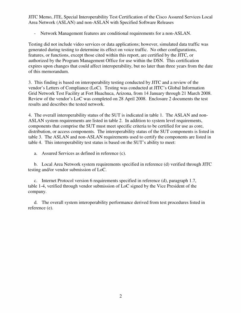
4. The overall interoperability status of the SUT is indicated in table 1. The ASLAN and non-
ASLAN system requirements are listed in table 2. In addition to system level requirements,
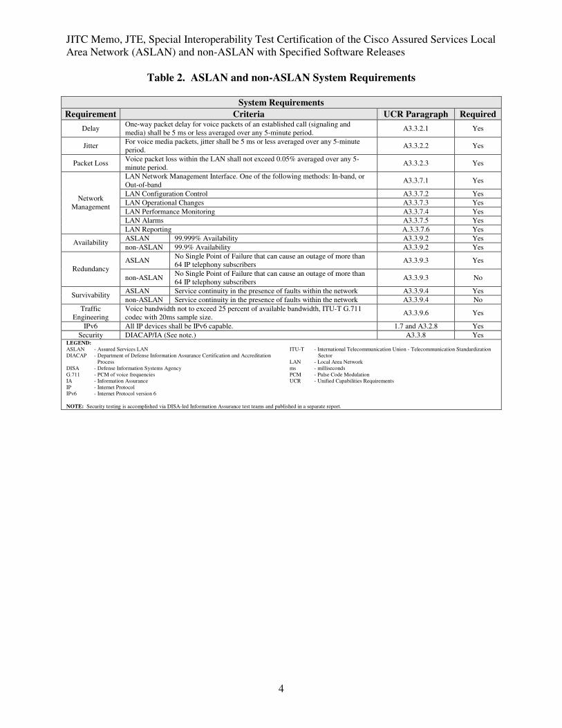
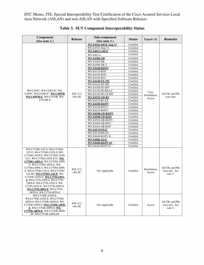
components that comprise the SUT must meet specific criteria to be certified for use as core,
distribution, or access components. The interoperability status of the SUT components is listed in
table 3. The ASLAN and non-ASLAN requirements used to certify the components are listed in
table 4. This interoperability test status is based on the SUT’s ability to meet:
a. Assured Services as defined in reference (c).
b. Local Area Network system requirements specified in reference (d) verified through JITC
testing and/or vendor submission of LoC.
c. Internet Protocol version 6 requirements specified in reference (d), paragraph 1.7,
table 1-4, verified through vendor submission of LoC signed by the Vice President of the
company.
d. The overall system interoperability performance derived from test procedures listed in
reference (e).
JITC Memo, JTE, Special Interoperability Test Certification of the Cisco Assured Services Local
Area Network (ASLAN) and non-ASLAN with Specified Software Releases
LEGEND: ASLAN - Assured Services Local Area Network
DISA - Defense Information Systems Agency
DSN - Defense Switched Network
E - Enhanced
IOS - Internetwork Operating System
JITC - Joint Interoperability Test Command
ME - Metro Ethernet
NEB - Network Equipment Building
SUT - System Under Test
SE - System Engineering
UCR - Unified Capabilities Requirements
WS - Workgroup Switch
NOTES:
1 Components bolded and underlined were tested by JITC. The other components in the family series were not tested; however, they utilize the same software and hardware and JITC
analysis determined them to be functionally identical for interoperability certification purposes and they are also certified for joint use.
2 Indicates these switches support one processor and must be configured to failover to a redundant distribution switch.
3 Due to a tagging problem with L2 and L3 on the Catalyst 3750 switch after a processor failover, only the “auto qos voip trust” access port command is certified. The Cisco proprietary
“auto qos cisco-phones” command is not authorized nor approved for use within the DSN.
JITC Memo, JTE, Special Interoperability Test Certification of the Cisco Assured Services Local
Area Network (ASLAN) and non-ASLAN with Specified Software Releases
4
Table 2. ASLAN and non-ASLAN System Requirements
System Requirements
Requirement Criteria UCR Paragraph Required
Delay One-way packet delay for voice packets of an established call (signaling and
media) shall be 5 ms or less averaged over any 5-minute period. A3.3.2.1 Yes
Jitter For voice media packets, jitter shall be 5 ms or less averaged over any 5-minute
period. A3.3.2.2 Yes
Packet Loss Voice packet loss within the LAN shall not exceed 0.05% averaged over any 5-
minute period. A3.3.2.3 Yes
LAN Network Management Interface. One of the following methods: In-band, or
Out-of-band A3.3.7.1 Yes
LAN Configuration Control A3.3.7.2 Yes
LAN Operational Changes A3.3.7.3 Yes
LAN Performance Monitoring A3.3.7.4 Yes
LAN Alarms A3.3.7.5 Yes
Network
Management
LAN Reporting A.3.3.7.6 Yes
ASLAN 99.999% Availability A3.3.9.2 Yes Availability
non-ASLAN 99.9% Availability A3.3.9.2 Yes
ASLAN No Single Point of Failure that can cause an outage of more than
64 IP telephony subscribers A3.3.9.3 Yes
Redundancy
non-ASLAN No Single Point of Failure that can cause an outage of more than
64 IP telephony subscribers A3.3.9.3 No
ASLAN Service continuity in the presence of faults within the network A3.3.9.4 Yes Survivability
non-ASLAN Service continuity in the presence of faults within the network A3.3.9.4 No
Traffic
Engineering
Voice bandwidth not to exceed 25 percent of available bandwidth, ITU-T G.711
codec with 20ms sample size. A3.3.9.6 Yes
IPv6 All IP devices shall be IPv6 capable. 1.7 and A3.2.8 Yes
Security DIACAP/IA (See note.) A3.3.8 Yes LEGEND:
ASLAN - Assured Services LAN
DIACAP - Department of Defense Information Assurance Certification and Accreditation
Process
DISA - Defense Information Systems Agency
G.711 - PCM of voice frequencies
IA - Information Assurance
IP - Internet Protocol
IPv6 - Internet Protocol version 6
ITU-T - International Telecommunication Union - Telecommunication Standardization
Sector
LAN - Local Area Network
ms - milliseconds
PCM - Pulse Code Modulation
UCR - Unified Capabilities Requirements
NOTE: Security testing is accomplished via DISA-led Information Assurance test teams and published in a separate report.
JITC Memo, JTE, Special Interoperability Test Certification of the Cisco Assured Services Local
Area Network (ASLAN) and non-ASLAN with Specified Software Releases
JITC Memo, JTE, Special Interoperability Test Certification of the Cisco Assured Services Local
Area Network (ASLAN) and non-ASLAN with Specified Software Releases
7
Table 3. SUT Component Interoperability Status
Component
(See note 1.) Release
Sub-component
(See note 1.) Status Layer (s) Remarks
WS-C3560G-48PS-S, WS-C3560G-
48PS-E, WS-C3560G-24PS-S, WS-
C3560G-24PS-E, WS-C3560G-48TS-
S, WS-C3560G-48TS-E, WS-
C3560G-24TS-S, WS-C3560G-24TS-
E, WS-C3560-8PC-S, WS-C3560-
48PS-S, WS-C3560-48PS-E, WS-
C3560-24PS-S, WS-C3560-24PS-E,
WS-C3560-48TS-S, WS-C3560-
48TS-E, WS-C3560-24TS-S, WS-
C3560-24TS-E
IOS 12.2
(40) SE Not Applicable Certified Access
All CRs and FRs
were met.
WS-C3560E-24TD-S, WS-C3560E-
24TD-E, WS-C3560E-48TD-S, WS-
C3560E-48TD-E, WS-C3560E-24PD-
S, WS-C3560E-24PD-E, WS-
C3560E-48PD-S, WS-C3560E-48PD-
E, WS-C3560E-48PD-SF, WS-
C3560E-48PD-EF
IOS 12.2
(40) SE Not Applicable Certified Access
All CRs and FRs
were met.
WS-C2960-8TC-L, WS-C2960-24TC-
L, WS-C2960-24TT-L, WS-C2960-
48TC-L, WS-C2960-48TT-L, WS-
C2960G-8TC-L, WS-C2960G-24TC-
L, WS-C2960G-48TC-L, WS-C2960-
24-S, WS-C2960-24TC-S, WS-
C2960-48TC-S, WS-C2960PD-8TT-L
IOS 12.2
(40) SE Not Applicable Certified Access
All CRs and FRs
were met.
LEGEND: CRs - Capability Requirements
E - Enhanced
FRs - Feature Requirements
FX-MT - Foreign Exchange, ATM Term
GB - Gigabit GBIC
IOS - Internetwork Operating System
JITC - Joint Interoperability Test Command
L2 - Layer 2
L3 - Layer 3
ME - Metro Ethernet
NEB - Network Equipment Building
RJ - Registered Jack
S - Standard
SFP - Small Form Factor Pluggable
SUP - Supervisor
SUT - System Under Test
TX - The designation of a copper RJ-45 connection for Fast Ethernet
WS - Workgroup Switch
NOTES: 1 Components bolded and underlined were tested by JITC. The other components in the family series were not tested; however, they utilize the same software and hardware and JITC analysis
determined them to be functionally identical for interoperability certification purposes and they are also certified for joint use.
2 Indicates these switches support one processor and must be configured to failover to a redundant distribution switch.
3 Due to a tagging problem with L2 and L3 on the Catalyst 3750 switch, after a processor failover, only the “auto qos voip trust” access port command is certified. The Cisco proprietary “auto
qos cisco-phones” command is not authorized nor approved for use within the DSN by the Program Management Office.
JITC Memo, JTE, Special Interoperability Test Certification of the Cisco Assured Services Local
Area Network (ASLAN) and non-ASLAN with Specified Software Releases
8
Table 4. ASLAN and non-ASLAN Component Requirements
Core/Distribution/Access Component Requirements
Requirement Criteria UCR
Paragraph Required
Traffic
Prioritization
Traffic within LAN components shall be prioritized by session media type in
accordance with the NCIDs. A3.3.3 Yes
Traffic Priority
Method LAN components shall support DSCP, and IEEE 802.1p to DSCP mapping. A3.3.3.1 Yes
LAN components shall support one of the following:
- Priority Queuing
- Weighted Fair Queuing
- Class Based Weighted Fair Queuing
A3.3.4.1 Yes
Queuing LAN components shall be capable of
- four hardware queues (Expedited Forwarding, Assured Forwarding, Assured
Forwarding Preferred, and Default)
- Assigning any “tagged” session to any hardware queues
A3.3.4.1 Yes
LAN Behaviors LAN components shall support Differential Service Per-Hop Behaviors per
RFCs 2474, 2475, and 3260 A3.3.4.2 Yes
VLANs
LAN components shall support:
- Port based VLANs
- MAC address based VLANs
- Shall be capable of reassigning VLAN IDs
- Accepting VLAN tagged frames in accordance with IEEE 802.1Q
A3.3.5 Yes
IEEE
Conformance
LAN components shall support:
- IEEE 802.1d – Bridging
- IEEE 802.1p/Q – Priority tagging/VLAN tagging
- IEEE 802.1s – Per-VLAN Group Spanning Tree
- IEEE 802.1v – VLAN Classification by port and protocol
- IEEE 802.1w –Rapid Reconfiguration of Spanning Tree
- IEEE 802.1x – Port Based Network Access Control
- IEEE 802.3ad – Link Aggregation Protocol
- IEEE 802.3af - Power over Ethernet (Conditional)
A3.3.9.1 Yes
ASLAN
LAN components shall support:
- ASLAN components shall have a reliability of .99999 or
better
- Dual power supplies and dual processors (more than 64 users)
- N+1 sparing for access (more than 64 users)
- Redundancy protocol1
- 2 second path restoral
- No single point of failure will cause loss of more than 64
users
A3.3.9.3.1 Yes Single Device
Redundancy
non-ASLAN This requirement is conditional for a non-ASLAN. A3.3.9.3.1 No
Security LAN components shall employ the Network Infrastructure and VoIP STIGs.2 A3.3.8 Yes
IPv6 All IP devices shall be IPv6 capable. 1.7 and A3.2.8 Yes LEGEND: 802.1d - Standard for Local and Metropolitan Area Networks: MAC Bridges
802.1p - LAN Layer 2 QoS/CoS Protocol for Traffic Prioritization
802.1Q - Standards for Local and Metropolitan Area Networks: Virtual Bridged Local
Area Networks
802.1s - Standard for Local and Metropolitan Area Networks - Amendment 3 to 802.1Q
Virtual Bridged Local Area Networks: Multiple Spanning Trees
802.1v - Standard for Local and Metropolitan Area Networks - Virtual Bridge Local Area
Networks - Amendment 2: VLAN Classification by Protocol and Port
(Amendment to IEEE 802.1Q, 1998 Edition)
802.1w - Standard for Local and metropolitan area networks - Common Specifications -
Part 3: Media Access Control (MAC) Bridges: Rapid Configuration
802.1x - Standard for Local and Metropolitan Area Networks Port-Based Network Access
Control
802.3ad - Standard for Information Technology – Local and Metropolitan Area Networks –
Part 3: CSMA/CD Access Method and Physical Layer Specifications–
Aggregation of Multiple Link Segments
802.3af - Standard for CSMA/CD Access Method and Physical Layer Specifications - Data
Terminal Equipment (DTE) Power via Media Dependent Interface (MDI)
ASLAN - Assured Services LAN
CoS - Class of Service
CSMA/CD - Carrier Sense Multiple Access with Collision Detection
DISA - Defense Information Systems Agency
DSCP - Differentiated Services Code Point
IEEE - Institute of Electrical and Electronics Engineers
ID - Identification
IP - Internet Protocol
IPv6 - Internet Protocol version 6
LAN - Local Area Network
MAC - Media Access Control
NCID - Net-Centric Implementation Document
N - total VoIP users / 64
OSPF - Open Shortest-Path First
QoS - Quality of Service
RFC - Request for Comment
SNMP - Simple Network Management Protocol
STIGs - Security Technical Implementation Guides
UCR - Unified Capabilities Requirements
VLANs - Virtual LANs
VoIP - Voice over Internet Protocol
VRRP - Virtual Router Redundancy Protocol
NOTES: 1 For core and distribution components, OSPF redundancy protocol shall be the routing protocol supported. For access components, redundancy protocol shall be VRRP or equivalent
protocol.
2 Security is tested by DISA-led Information Assurance test teams and published in a separate report.
JITC Memo, JTE, Special Interoperability Test Certification of the Cisco Assured Services Local
Area Network (ASLAN) and non-ASLAN with Specified Software Releases
9
5. No detailed test report was developed in accordance with the Program Manager’s request.
JITC distributes interoperability information via the JITC Electronic Report Distribution (ERD)
system, which uses Unclassified-But-Sensitive Internet Protocol Router Network (NIPRNet) e-
mail. More comprehensive interoperability status information is available via the JITC System
Tracking Program (STP). The STP is accessible by .mil/gov users on the NIPRNet at
https://stp.fhu.disa.mil. Test reports, lessons learned, and related testing documents and
references are on the JITC Joint Interoperability Tool (JIT) at https://jit.fhu.disa.mil (NIPRNet),
or http://199.208.204.125 (SIPRNet). Information related to DSN testing is on the Telecom
Switched Services Interoperability (TSSI) website at http://jitc.fhu.disa.mil/tssi.
6. The JITC point of contact is Mr. Edward Mellon, DSN 879-5159, commercial (520) 538-
5159, FAX DSN 879-4347, or e-mail to [email protected]. The JITC’s mailing address
is P.O. Box 12798, Fort Huachuca, AZ 85670-2798. The tracking number for the SUT is
0716902.
FOR THE COMMANDER:
2 Enclosures a/s
RICHARD A. MEADOR
Chief
Battlespace Communications Portfolio
JITC Memo, JTE, Special Interoperability Test Certification of the Cisco Assured Services Local
Area Network (ASLAN) and non-ASLAN with Specified Software Releases
10
Distribution:
Joint Staff J6I, Room 1E596, Pentagon, Washington, DC 20318-6000
National Security Agency, ATTN: DT, Suite 6496, 9800 Savage Road, Fort Meade, MD
20755-6496
Director, Defense Information Systems Agency, ATTN: GS235, Room 5W24-8A,
P.O. Box 4502, Falls Church, VA 22204-4502
Office of Assistant Secretary of Defense (NII)/DoD CIO, Crystal Mall 3, 7th Floor, Suite 7000,
1851 S. Bell St., Arlington, VA 22202
Office of Under Secretary of Defense, AT&L, Room 3E144, 3070 Defense Pentagon,
Washington, DC 20301
U.S. Joint Forces Command, J68, Net-Centric Integration, Communications, and Capabilities
Division, 1562 Mitscher Ave., Norfolk, VA 23551-2488
Defense Information Systems Agency (DISA), ATTN: GS23 (Mr. McLaughlin), Room 5W23,
5275 Leesburg Pike (RTE 7), Falls Church, VA 22041
Enclosure 1
ADDITIONAL REFERENCES
(c) Chairman of the Joint Chiefs of Staff Instruction (CJCSI) 6215.01C, “Policy for
Department of Defense Voice Services with Real Time Services (RTS),” 9 November 2007
(d) Defense Information Systems Agency, “Department of Defense Networks Unified
Capabilities Requirements,” 21 December 2007
(e) Joint Interoperability Test Command, “Defense Switched Network Generic Switch Test
Plan (GSTP), Change 2,” 2 October 2006
Enclosure 2
CERTIFICATION TESTING SUMMARY
1. SYSTEM TITLE. Cisco Assured Services Local Area Network (ASLAN) and non-ASLAN with Specified Software Releases are hereinafter referred to as the system under test (SUT). 2. PROPONENT. White House Communications Agency (WHCA). 3. PROGRAM MANAGER. Lt Col Alain L. M. Jones, WHCA/J5, 2743 Defense Blvd, Anacostia Annex, District of Columbia, 20373, e-mail: [email protected]. 4. TESTER. Joint Interoperability Test Command (JITC), Fort Huachuca, Arizona. 5. SYSTEM UNDER TEST DESCRIPTION. The SUT is used to transport voice signaling and media as part of an overall Voice over Internet Protocol (VoIP) system. All of the SUT switches provide availability, security, and Quality of Service (QoS) to meet the operational requirements of the network and Assured Services for the warfighter. The SUT components which are bolded and underlined in the tables throughout this certification letter, are components that were tested in the JITC laboratory for this certification. The SUT components which are not bolded and not underlined, but also listed throughout the tables in this letter, were determined by JITC analysis to contain the same hardware and software as, and to be functionally identical to, the tested components for interoperability certification purposes. The ASLAN, formerly known as the Assured Services Voice Application Local Area Network (ASVALAN), is certified to support Defense Switched Network (DSN) Assured Services over Internet Protocol (IP). The SUT is composed of the following components: The Catalyst 6500 and 6500-E series delivers scalable performance and port density across several chassis configurations. The Catalyst 6500 series is available in 3-, 4-, 6-, 9-, and 13-slot chassis. The Catalyst 6500 series features a range of integrated services modules, including 10-gigabit fiber cards, 1-gigabit fiber cards, 100-megabit fiber cards, 1-gigabit Small Form-Factor Pluggable (SFP) cards, 10/100BaseT cards and 10/100/1000BaseT Megabits per second (Mbps) switchblades used as access points. For data and voice applications, users can connect to the Local Area Network (LAN) using any Ethernet interface on the access devices. The Catalyst ME 6524 is a multilayer switch that provides high availability, QoS, and security to enhance network operations in two configurations. The Cisco Catalyst ME-C6524GS-8S provides 24+8 1-gigabit/100-megabit SFP ports. The Catalyst ME-C6524GT-8S provides 24 10/100/1000BaseT and 8 1-gigabit/100-megabit SFP ports. The 4500 and 4500-E series are available in a multi-slot chassis for 10-gigabit fiber cards, 1-gigabit fiber cards, 100-megabit fiber cards, 10/100BaseT cards and 10/100/1000BaseT Mbps access ports to the LAN. This framework allows for a
2-3
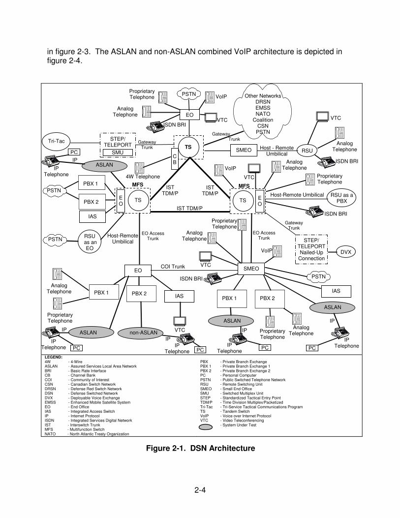
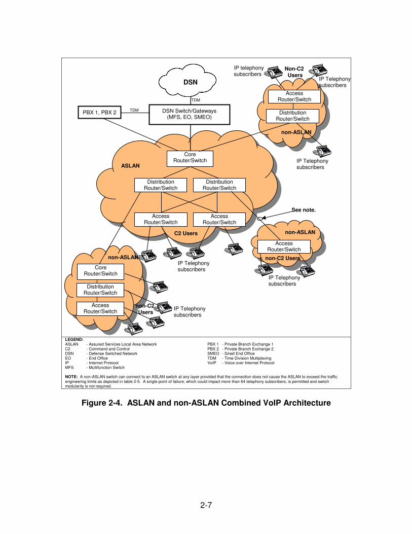
redundant architecture to ensure no single point of failure for hardware operations. Some slots are reserved for special functions such as supervisor engines. Most slots can be configured for specific user needs. All line card capabilities including bandwidth, throughputs, and routing are dependent on the supervisor engine. The Catalyst 3750 series utilizes stackable components to provide a redundant architecture. Each switch utilizes 32-Gigabits per second (Gbps) interconnect cables on the back of each switch to connect up to nine stackable switches. Each switch contains a single power supply and processor. The 3750 stackable switches enable flexibility in creating a scalable switching platform with a variety of switching options including 12 1-Gigabit Ethernet fiber SFP port switch, a 24 10/100/1000BaseT port with 4 SFP port switch, and a 48 10/100BaseT port with 4 SFP port switch. The Catalyst 3750-E series utilizes stackable components to provide a redundant architecture. Each switch utilizes 64-Gigabits per second (Gbps) interconnect cables on the back of each switch to connect up to nine stackable switches. Each switch contains a single power supply and processor. The 3750-E stackable switches enable flexibility in creating a scalable switching platform with a variety of switching options including a 24 10/100/1000BaseT port with 4 1-gigabit SFP or 2 10-gigabit X2 port switch, and a 48 10/100BaseT port with 4 1-gigabit SFP or 2 10-gigabit X2 port switch. The Cisco Catalyst 3560G series is a multilayer switch that provides high availability, QoS, and security to enhance network operations. The Cisco Catalyst 3560G series provides 24 or 48 10/100/1000BaseT ports and 2 1000BaseX ports. The Cisco Catalyst 3560 series is a multilayer switch that provides high availability, QoS, and security to enhance network operations. The Cisco Catalyst 3560 series provides 8, 24 or 48 10/100 ports and 1 or 2 1000baseX ports. The Cisco Catalyst 3560-E series is a multilayer switch that provides high availability, QoS, and security to enhance network operations. The Cisco Catalyst 3560-E series provides 24 or 48 10/100/1000 ports and 4 SFP or 2 10-gigabit ports. The Cisco Catalyst 2960 series is a layer 2 switch that provides high availability, QoS, and security to enhance network operations. The Cisco Catalyst 2960 series provides 24 or 48 10/100-megabit ports, 8, 24, or 48 10/100/1000-megabit ports and 1 or 2 1000baseX ports. 6. OPERATIONAL ARCHITECTURE. The DSN architecture is a two-level network hierarchy consisting of DSN backbone switches and Service/Agency installation switches. Service/Agency installation switches have been authorized to extend voice services over IP infrastructures. The Unified Capabilities Requirements (UCR) operational DSN Architecture is depicted in figure 2-1, which depicts the relationship of the ASLAN and non-ASLAN to the DSN switch types. The installation ASLAN VoIP architecture is depicted in figure 2-2 and the non-ASLAN VoIP architecture is depicted
2-4
in figure 2-3. The ASLAN and non-ASLAN combined VoIP architecture is depicted in figure 2-4.
LEGEND: 4W - 4-Wire ASLAN - Assured Services Local Area Network BRI - Basic Rate Interface CB - Channel Bank COI - Community of Interest CSN - Canadian Switch Network DRSN - Defense Red Switch Network DSN - Defense Switched Network DVX - Deployable Voice Exchange EMSS - Enhanced Mobile Satellite System EO - End Office IAS - Integrated Access Switch IP - Internet Protocol ISDN - Integrated Services Digital Network IST - Interswitch Trunk MFS - Multifunction Switch NATO - North Atlantic Treaty Organization
PBX - Private Branch Exchange PBX 1 - Private Branch Exchange 1 PBX 2 - Private Branch Exchange 2 PC - Personal Computer PSTN - Public Switched Telephone Network RSU - Remote Switching Unit SMEO - Small End Office SMU - Switched Multiplex Unit STEP - Standardized Tactical Entry Point TDM/P - Time Division Multiplex/Packetized Tri-Tac - Tri-Service Tactical Communications Program TS - Tandem Switch VoIP - Voice over Internet Protocol VTC - Video Teleconferencing - System Under Test
Figure 2-1. DSN Architecture
EO
TS
EO
SMEO RSU
RSU as an
EO
E O
MFS IST
TDM/P IST
TDM/P
IST TDM/P
RSU as a PBX
Tri-Tac
SMEO
STEP/ TELEPORT Nailed-Up
Connection DVX
Host - Remote Umbilical
MFS
COI Trunk
STEP/ TELEPORT
Gateway Trunk
SMU
TS TS E O
EO Access Trunk
Gateway Trunk
PSTN
Telephone Telephone
PBX 1 PBX 2
IAS
Analog Telephone
Proprietary Telephone
PBX 1
PBX 2
IAS
PSTN
VTC Analog
Telephone Proprietary Telephone
Telephone Telephone ISDN BRI
VTC
VoIP
Analog Telephone
Proprietary Telephone
EO Access Trunk
Telephone Telephone ISDN BRI
Host-Remote Umbilical
Proprietary Telephone
Analog Telephone VoIP
VTC
Telephone Telephone
Other Networks DRSN EMSS NATO
Coalition CSN
PSTN
VTC
Analog Telephone
ISDN BRI
Gateway Trunk
VTC
VoIP Proprietary Telephone
Analog Telephone
ISDN BRI
C B
4W Telephone
PBX 1
PBX 2
IAS
PSTN
PSTN Host-Remote
Umbilical
ASLAN non-ASLAN Telephone Telephone
IP Telephone
Telephone Telephone
IP Telephone
IP
IP
IP Telephone
Telephone Telephone
ASLAN
IP
IP ASLAN
Telephone Telephone IP
ASLAN
Telephone Telephone
IP Telephone
IP Telephone
PC PC PC
PC
PC
2-5
LEGEND: ASLAN - Assured Services Local Area Network DSN - Defense Switched Network EO - End Office IP - Internet Protocol MFS - Multifunction Switch
PBX 1 - Private Branch Exchange 1 SMEO - Small End Office SUT - System Under Test VoIP - Voice over Internet Protocol
LEGEND: ASLAN - Assured Services Local Area Network DSN - Defense Switched Network IP - Internet Protocol
PBX 2 - Private Branch Exchange 2 SUT - System Under Test VoIP - Voice over Internet Protocol
NOTE: Dotted lines denote optional links/components not required for a non-ASLAN. A single point of failure, which could impact more than 64 telephony subscribers, is permitted and switch modularity is not required.
LEGEND: ASLAN - Assured Services Local Area Network C2 - Command and Control DSN - Defense Switched Network EO - End Office IP - Internet Protocol MFS - Multifunction Switch
PBX 1 - Private Branch Exchange 1 PBX 2 - Private Branch Exchange 2 SMEO - Small End Office TDM - Time Division Multiplexing VoIP - Voice over Internet Protocol
NOTE: A non-ASLAN switch can connect to an ASLAN switch at any layer provided that the connection does not cause the ASLAN to exceed the traffic engineering limits as depicted in table 2-5. A single point of failure, which could impact more than 64 telephony subscribers, is permitted and switch modularity is not required.
Figure 2-4. ASLAN and non-ASLAN Combined VoIP Architecture
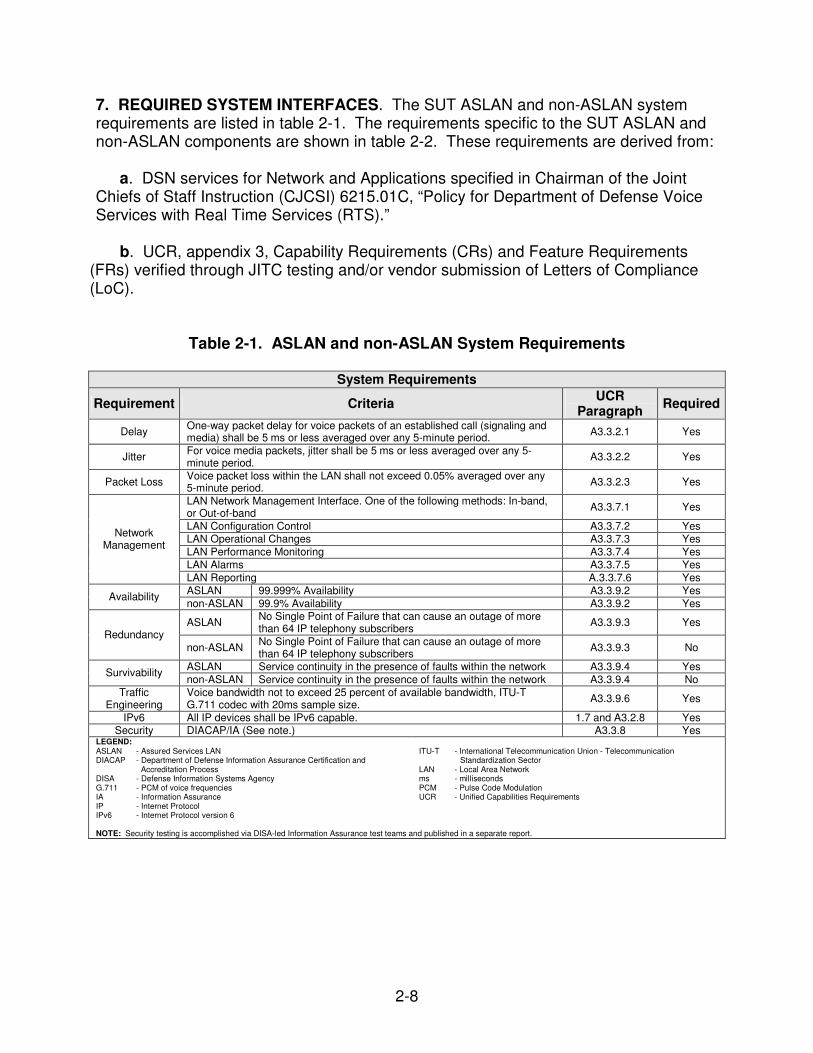
7. REQUIRED SYSTEM INTERFACES. The SUT ASLAN and non-ASLAN system requirements are listed in table 2-1. The requirements specific to the SUT ASLAN and non-ASLAN components are shown in table 2-2. These requirements are derived from: a. DSN services for Network and Applications specified in Chairman of the Joint Chiefs of Staff Instruction (CJCSI) 6215.01C, “Policy for Department of Defense Voice Services with Real Time Services (RTS).”
b. UCR, appendix 3, Capability Requirements (CRs) and Feature Requirements (FRs) verified through JITC testing and/or vendor submission of Letters of Compliance (LoC).
Table 2-1. ASLAN and non-ASLAN System Requirements
System Requirements
Requirement Criteria UCR
Paragraph Required
Delay One-way packet delay for voice packets of an established call (signaling and media) shall be 5 ms or less averaged over any 5-minute period. A3.3.2.1 Yes
Jitter For voice media packets, jitter shall be 5 ms or less averaged over any 5-minute period.
A3.3.2.2 Yes
Packet Loss Voice packet loss within the LAN shall not exceed 0.05% averaged over any 5-minute period.
A3.3.2.3 Yes
LAN Network Management Interface. One of the following methods: In-band, or Out-of-band
A3.3.7.1 Yes
LAN Configuration Control A3.3.7.2 Yes LAN Operational Changes A3.3.7.3 Yes
LAN Performance Monitoring A3.3.7.4 Yes
LAN Alarms A3.3.7.5 Yes
Network Management
LAN Reporting A.3.3.7.6 Yes
ASLAN 99.999% Availability A3.3.9.2 Yes Availability
non-ASLAN 99.9% Availability A3.3.9.2 Yes
ASLAN No Single Point of Failure that can cause an outage of more than 64 IP telephony subscribers
A3.3.9.3 Yes Redundancy
non-ASLAN No Single Point of Failure that can cause an outage of more than 64 IP telephony subscribers
A3.3.9.3 No
ASLAN Service continuity in the presence of faults within the network A3.3.9.4 Yes Survivability
non-ASLAN Service continuity in the presence of faults within the network A3.3.9.4 No
Traffic Engineering
Voice bandwidth not to exceed 25 percent of available bandwidth, ITU-T G.711 codec with 20ms sample size.
A3.3.9.6 Yes
IPv6 All IP devices shall be IPv6 capable.
1.7 and A3.2.8 Yes Security DIACAP/IA (See note.) A3.3.8 Yes
LEGEND: ASLAN - Assured Services LAN DIACAP - Department of Defense Information Assurance Certification and
Accreditation Process DISA - Defense Information Systems Agency G.711 - PCM of voice frequencies IA - Information Assurance IP - Internet Protocol IPv6 - Internet Protocol version 6
ITU-T - International Telecommunication Union - Telecommunication
Standardization Sector LAN - Local Area Network ms - milliseconds PCM - Pulse Code Modulation UCR - Unified Capabilities Requirements
NOTE: Security testing is accomplished via DISA-led Information Assurance test teams and published in a separate report.
2-9
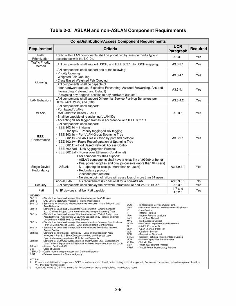
Table 2-2. ASLAN and non-ASLAN Component Requirements
Core/Distribution/Access Component Requirements
Requirement Criteria UCR
Paragraph Required
Traffic Prioritization
Traffic within LAN components shall be prioritized by session media type in accordance with the NCIDs.
A3.3.3 Yes
Traffic Priority Method
LAN components shall support DSCP, and IEEE 802.1p to DSCP mapping. A3.3.3.1 Yes
LAN components shall support one of the following: - Priority Queuing - Weighted Fair Queuing - Class Based Weighted Fair Queuing
A3.3.4.1 Yes
Queuing LAN components shall be capable of - four hardware queues (Expedited Forwarding, Assured Forwarding, Assured Forwarding Preferred, and Default) - Assigning any “tagged” session to any hardware queues
A3.3.4.1 Yes
LAN Behaviors LAN components shall support Differential Service Per-Hop Behaviors per RFCs 2474, 2475, and 3260
A3.3.4.2 Yes
VLANs
LAN components shall support: - Port based VLANs - MAC address based VLANs - Shall be capable of reassigning VLAN IDs - Accepting VLAN tagged frames in accordance with IEEE 802.1Q
A3.3.5 Yes
IEEE Conformance
LAN components shall support: - IEEE 802.1d – Bridging - IEEE 802.1p/Q – Priority tagging/VLAN tagging - IEEE 802.1s – Per-VLAN Group Spanning Tree - IEEE 802.1v – VLAN Classification by port and protocol - IEEE 802.1w –Rapid Reconfiguration of Spanning Tree - IEEE 802.1x – Port Based Network Access Control - IEEE 802.3ad – Link Aggregation Protocol - IEEE 802.3af - Power over Ethernet (Conditional)
A3.3.9.1 Yes
ASLAN
LAN components shall support: - ASLAN components shall have a reliability of .99999 or better - Dual power supplies and dual processors (more than 64 users) - N+1 sparing for access (more than 64 users) - Redundancy protocol
1
- 2 second path restoral - No single point of failure will cause loss of more than 64 users
A3.3.9.3.1 Yes Single Device Redundancy
non-ASLAN This requirement is conditional for a non-ASLAN. A3.3.9.3.1 No
Security LAN components shall employ the Network Infrastructure and VoIP STIGs.2 A3.3.8 Yes
IPv6 All IP devices shall be IPv6 capable. 1.7 and A3.2.8
Yes
LEGEND: 802.1d - Standard for Local and Metropolitan Area Networks: MAC Bridges 802.1p - LAN Layer 2 QoS/CoS Protocol for Traffic Prioritization 802.1Q - Standards for Local and Metropolitan Area Networks: Virtual Bridged Local
Area Networks 802.1s - Standard for Local and Metropolitan Area Networks - Amendment 3 to
802.1Q Virtual Bridged Local Area Networks: Multiple Spanning Trees 802.1v - Standard for Local and Metropolitan Area Networks - Virtual Bridge Local
Area Networks - Amendment 2: VLAN Classification by Protocol and Port (Amendment to IEEE 802.1Q, 1998 Edition)
802.1w - Standard for Local and metropolitan area networks - Common Specifications - Part 3: Media Access Control (MAC) Bridges: Rapid Configuration
802.1x - Standard for Local and Metropolitan Area Networks Port-Based Network Access Control
802.3ad - Standard for Information Technology – Local and Metropolitan Area Networks – Part 3: CSMA/CD Access Method and Physical Layer Specifications–Aggregation of Multiple Link Segments
802.3af - Standard for CSMA/CD Access Method and Physical Layer Specifications - Data Terminal Equipment (DTE) Power via Media Dependent Interface (MDI)
ASLAN - Assured Services LAN CoS - Class of Service CSMA/CD - Carrier Sense Multiple Access with Collision Detection DISA - Defense Information Systems Agency
DSCP - Differentiated Services Code Point IEEE - Institute of Electrical and Electronics Engineers ID - Identification IP - Internet Protocol IPv6 - Internet Protocol version 6 LAN - Local Area Network MAC - Media Access Control NCID - Net-Centric Implementation Document N - total VoIP users / 64 OSPF - Open Shortest-Path First QoS - Quality of Service RFC - Request for Comment STIGs - Security Technical Implementation Guides UCR - Unified Capabilities Requirements VLANs - Virtual LANs VoIP - Voice over Internet Protocol VRRP - Virtual Router Redundancy Protocol
NOTES: 1 For core and distribution components, OSPF redundancy protocol shall be the routing protocol supported. For access components, redundancy protocol shall be
VRRP or equivalent protocol. 2 Security is tested by DISA-led Information Assurance test teams and published in a separate report.
2-10
8. TEST NETWORK DESCRIPTION. The SUT was tested at JITC’s Global Information Grid Network Test Facility in a manner and configuration similar to that of the DSN operational environment. Figure 2-5 depicts the SUT test configuration.
2-11
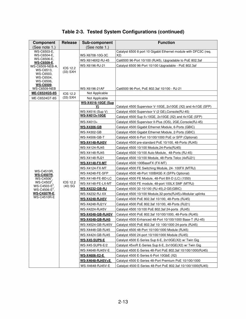
9. SYSTEM CONFIGURATIONS. Table 2-3 provides the system configurations, hardware and software components tested with the SUT. The SUT was tested in an
LEGEND: ASVAN - Assured Services Local Area
Network DSN - Defense Switched Network
Gigabit Ethernet
100 Mbps Ethernet
Figure 2-5. SUT Test Configuration
2 Gigabit ether-channel
Distribution Layer Catalyst 3750
Series Switches3
DSN Switch
1
2
3
4
Cata
ly st 45
5
6
7FA STA
TUS Distribution Layer
Catalyst 45072
Series Switches
Core Layer Catalyst 6509
1/6524
Series Switches
FAN STATU S
1 2 3 4 5 6 7 8 9
Power Suppl y 1 Power Suppl y 2 Cataly st 6500 SERIES
Core Layer Catalyst 6509
1/4507R-E
2
Series Switches
IP Phone with shared access
1 2 A B C 3 D E F 4 5
J K L 6 M N O G H I
7 8 T U V 9
W X Y Z P Q R S * 0
O P E R # ?
+ -
7 9 6 1 SE R I E S
C IS C O I P
P H O N E
FAN STATU S
1 2 3 4 5 6 7 8 9
Power Suppl y 1 Power Suppl y 2 Cataly st 6500 SERIES
1 2 A B C 3 D E F 4 5
J K L 6 M N O G H I
7 8 T U V 9
W X Y Z P Q R S *
0 O P E R #
? + -
7 9 6 1 SE R I E S
C IS C O I P
P H O N E
IP Phone with shared access
1 2 A B C 3 D E F 4 5
J K L 6 M N O G H I
7 8 T U V 9
W X Y Z P Q R S *
0 O P E R #
? + -
7 9 6 1 SE R I E S
C IS C O I P
P H O N E
Access Layer Catalyst 4507
2/3750-E
3
Series Switches
1 2 A B C 3 D E F 4 5
J K L 6 M N O G H I
7 8 T U V 9
W X Y Z P Q R S *
0 O P E R #
? + -
7 9 6 1 SE R I E S
C IS C O I P
P H O N E
1
2
3
4
Cata
ly st 45
5
6
7FA STA
TUS
Access Layer Catalyst 3560/2960
Series Switches4
IP Phone with shared access
IP Phone with shared access
1 2 A B C 3 D E F 4 5
J K L 6 M N O G H I
7 8 T U V 9
W X Y Z P Q R S *
0 O P E R #
? + -
7 9 6 1 SE R I E S
C IS C O I P
P H O N E Catalys
t 3750 SERIES
MODE
SY
ST R
PS MASTR ST
AT DU
PLX SPEE
D STA
CK 1 2 3 4 5 6 7 8 9 1
0 11 1
2
MO
DE STA
CK SPE
ED DU
PLX ST
AT MA
STR R
P
S SY
ST Cataly st 3750 SER
IES 1 2 3 4 5 6 7 8 9 1
0 1
X 2X
1
5X 16
X 1
1 12 13 14 15 16 1
7 18 19 20 21 22 23 24 25 26 1
7X 18
X 3
1X 32
X 2
7 28 29 30 31 32 3
3 34 35 36 37 38 39 40 41 42 3
3X 34
X 4
7X 48
X 4
3 44 45 46 47 48 2 4
1 3
MO
DE STA
CK SPE
ED DU
PLX ST
AT MA
STR R
P
S SY
ST 1 2 3 4 5 6 7 8 9 1
0 11 12 1X 2X
11
X 12
X 1
3 14 1
5 16 17 18 19 20 2
1 22 23 24 13
X 14
X 23
X 24
X Cataly s
t 3750 SERIES
1 2
U
TIL ST
AT DUPLEX SP
EED SYS
TEM RP
S LIN E PWR
CATALYST 3550 INLIN E
POWER 2
1
3
4
5
6
7 8
9
1
0 1
1 1
2 1
2
1
5 1
6 1
7 1
8 1
9 2
0 2
1 2
2 2
3 2
4 1
3 1
4
IP Phone with shared access
NOTES: 1 The SUT Catalyst 6500 series switches are certified for the access, distribution, and core layer when deployed as a component of an ASLAN or non-ASLAN. 2 The Catalyst 4500 and 4500-E series are certified in the core, distribution, and access layers when deployed as a component in an ASLAN or non-ASLAN with the
following minor exception: The 4500 Series with SupII + processor was only tested in the access layer and therefore only certified for use in that layer when deployed as a component in an ASLAN or non-ASLAN.
3 The SUT Catalyst 3750 series switches are certified for the distribution and access layers only when deployed as a component of an ASLAN or non-ASLAN. The Catalyst 3750-E series is certified in the access layer when deployed as a component in an ASLAN or non-ASLAN.
4 The Catalyst 3560G series and Catalyst 2960 series are certified in the access layer when deployed as a component in an ASLAN or non-ASLAN.
IP - Internet Protocol Mbps - Megabits per second SUT - System Under Test
IP Phone with shared access
1 2 A B C 3 D E F 4 5
J K L 6 M N O G H I
7 8 T U V 9
W X Y Z P Q R S *
0 O P E R #
? + -
7 9 6 1 SE R I E S
C IS C O I P
P H O N E
2-12
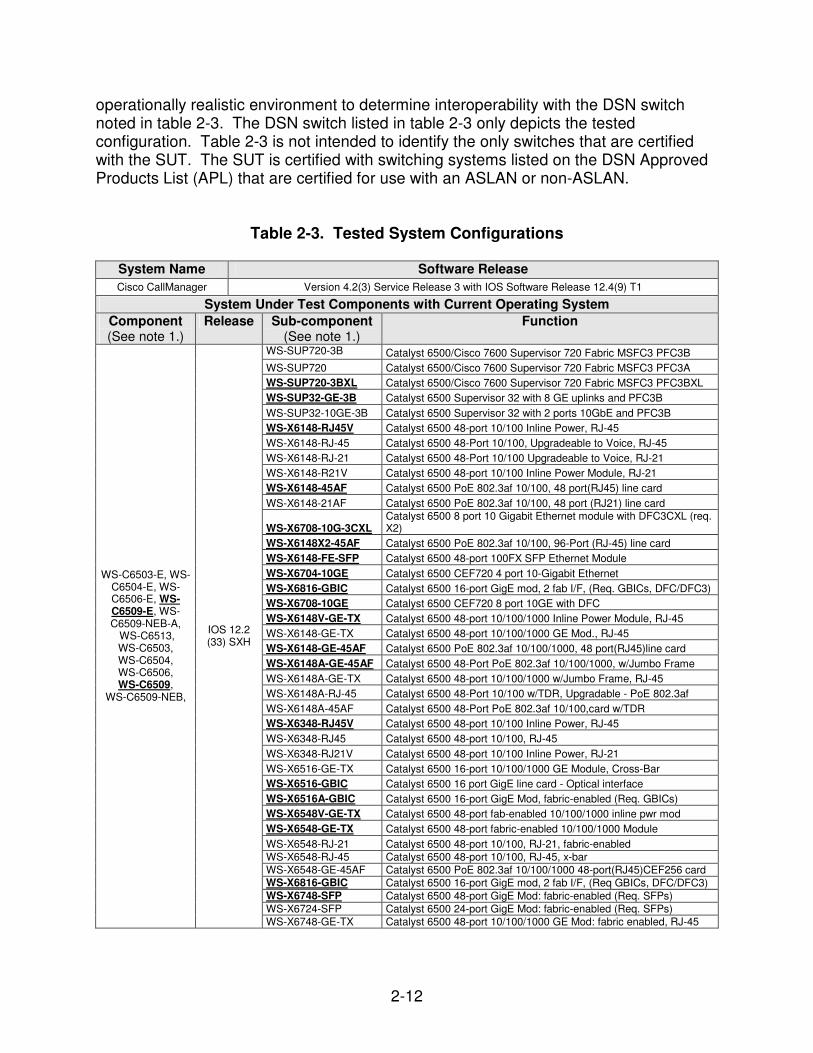
operationally realistic environment to determine interoperability with the DSN switch noted in table 2-3. The DSN switch listed in table 2-3 only depicts the tested configuration. Table 2-3 is not intended to identify the only switches that are certified with the SUT. The SUT is certified with switching systems listed on the DSN Approved Products List (APL) that are certified for use with an ASLAN or non-ASLAN.
Table 2-3. Tested System Configurations
System Name Software Release
Cisco CallManager Version 4.2(3) Service Release 3 with IOS Software Release 12.4(9) T1
System Under Test Components with Current Operating System
WS-C2960-8TC-L Catalyst 2960 8 10/100 + 1 T/SFP LAN Base Image
WS-C2960-24TC-L Catalyst 2960 24 10/100 + 2T/SFP LAN Base Image
WS-C2960-24TT-L Catalyst 2960 24 10/100 + 2 1000BT LAN Base Image
WS-C2960-48TC-L Catalyst 2960 48 10/100 + 2 T/SFP LAN Base Image
WS-C2960-48TT-L Catalyst 2960 48 10/100 + 2 1000BT LAN Base Image
WS-C2960G-8TC-L Catalyst 2960 7 10/100/1000 + 1 T/SFP LAN Base
WS-C2960G-24TC-L Catalyst 2960 24 10/100/1000, 4 T/SFP LAN Base Image
WS-C2960G-48TC-L Catalyst 2960 48 10/100/1000, 4 T/SFP LAN Base Image
WS-C2960-24-S Catalyst 2960 24 10/100 LAN Lite Image
WS-C2960-24TC-S Catalyst 2960 24 10/100 + 2 T/SFP LAN Lite Image
WS-C2960-48TC-S Catalyst 2960 48 10/100 + 2 T/SFP LAN Lite Image
WS-C2960PD-8TT-L
IOS 12.2 (40) SE
Not Applicable
Catalyst 2960 Powered Device 8 10/100 + 1 1000BT LAN Base LEGEND: E - Enhanced GBIC - Gigabit Interface Converter GE - Gigabit Ethernet IOS - Internetwork Operating System JITC - Joint Interoperability Test Command LAN - Local Area Network NEB - Network Equipment Building POE - Power over Ethernet Req. - requires
RJ - Registered Jack S - Standard SFP - Small Form Factor Pluggable T1 -Trunk level 1 TDR -Time Domain Reflectometer TX -The designation of a cooper RJ-45 connection for Fast Ethernet SE -Systems Engineering SW -Station Wire WS - Workgroup Switch
NOTES: 1 Components and sub-components bolded and underlined were tested by JITC. The other components in the family series were not tested; however, they utilize the same
operating software and hardware and JITC analysis determined them to be functionally identical for interoperability certification purposes and they are also certified for joint use.
2 Indicates these switches support one processor and must be configured to failover to a redundant distribution switch.
10. TESTING LIMITATIONS. None. 11. TEST RESULTS
a. Components. The SUT met the minimum interoperability requirements of the UCR, appendix 3, for an ASLAN. If a system meets the minimum requirements for an ASLAN, it also meets the lesser requirements for a non-ASLAN. The network consisted of three main components: core, distribution, and access switches. The SUT system and component test results are provided below.
2-16
(1) Class of Service (CoS). The UCR, appendix 3, section A3.3.3, outlines several methodologies to implement CoS. The SUT employed IEEE 802.1p/Q at the Data Link Layer (L2) and Differentiated Services Code Point (DSCP) at the Network Layer (L3) and 802.1p/Q to DSCP mapping, which was verified by capturing packets at both layers within the network. (2) Traffic Prioritization. Priorities were applied in accordance with the CoS listed above. As required by the UCR, this ensured voice signaling would get the highest level of priority; voice media stream would be prioritized lower than voice signaling but higher than data, and data traffic would receive the lowest priority. At L2, packets were tagged as: Data traffic = 0, Voice media = 5 and Voice Signaling and Network Management = 6, for L3 prioritization, DSCP were marked 0, 46, and 48 respectively. Uplinks were filled to capacity with data packets and voice packets were transmitted across the SUT. The voice packets were placed in a higher queue and were not delayed throughout the network. The SUT configuration for all access layer ports was trusted. This was accomplished by default or by assigning the trust QoS statements to all ports. (3) QoS. The SUT QoS process is supported by 8 queues using Priority Queuing. Packets tagged with a CoS of 6 are queued in a highest priority queue. The CoS values of 5 and 0 are placed in separate queues, with 5 receiving a higher value therefore, it will be serviced more frequently then 0. These tags were used to identify and separate traffic types that pass through the network connections ensuring that signaling traffic and voice traffic take precedence over data traffic. During failover testing of the Cisco Catalyst 3750 switch, an anomaly was noted during the processor failover testing. After a failover occurs, if a new Cisco IP phone is added and the interface is configured with "auto qos voip cisco-phones," the 3750 fails to correctly tag voice signaling and media packets at L2 and L3. Therefore, all SUT switches must configure IP phone interfaces with the "auto qos voip trust" configuration command. Furthermore, the Cisco proprietary “auto qos cisco-phones” command is not authorized nor approved for use within the DSN by the Program Management Office.
(a) Queuing. The UCR, appendix 3, paragraph 3.3.4.1, outlines that an ASLAN must support at least one of the following queuing mechanisms: Priority Queuing, Custom Queuing, Weighted Fair Queuing, or Class-Based Weighted Fair Queuing. The SUT supports all of the queuing mechanisms; however, only Priority Queuing was tested and is covered under this certification. Priority Queuing supports queues from high to low. All packets of a higher priority queue will be transmitted before any packets from a lower priority queue. Queues are serviced in order of queue priority. The highest queue gets serviced first and then the next lower priority queue. If a lower priority queue is being serviced and a packet in the higher queue enters the higher queue, the higher priority queue gets serviced immediately after the current packet from the lower queue is sent. Then, once the higher priority queue is empty, the lower priority queue continues being serviced.
2-17
(4) Policing. The SUT implemented DiffServ Class-Based Shaping (CBS) that uses DSCP values to define how traffic is treated at each individual network node. DSCP values are used from the L3 IP header.
Traffic Policing limits the input or output transmission rate of a class of traffic based on user-defined criteria and marks packets by setting the IP Precedence value, the QoS group, or the DSCP value. The UCR, appendix 3, paragraph A3.3.4.2, outlines that the ASLAN must meet at least one of the following policing mechanisms: DiffServ PHB, Generic Traffic Shaping (GTS), or Class-Based Shaping (CBS). The SUT implemented DiffServ PHB which uses DSCP values to define how traffic is treated at each individual node. Traffic sharing a common DSCP header is known as a forwarding class. The forwarding behavior applied by a DiffServ-compliant node to each forwarding class is known as PHB. The DiffServ domain marks the DSCP values in packets so they can be routed to the same PHB on the next forwarding nodes until the packet reaches the final destination or leaves the DiffServ domain. Accurate metering, policing and shaping protect the DiffServ domain from excessive traffic loading. The DiffServ PHBs map directly to the following internal forwarding classes along the path of the packet:
• Expedited Forwarding (EF) classes have a premium forwarding status above all other classes. Other forwarding classes cannot affect the latency or jitter experienced by traffic in these premium classes. The EF PHB allows unlimited preemption of other traffic, the implementation limits damage EF traffic inflicts on other traffic. The DSCP values of 46 for voice media and 48 for voice signaling are placed in the EF class.
• Assured Forwarding class packets transmitted through the queue at or below
the committed transmission rate are marked “in-profile.” If sufficient bandwidth is available along the path for assured traffic, packets will reach their destination. Packets transmitted out of the service queue that are above the committed rate and reach congestion in the network, are discarded before “in-profile” assured service packets.
• Best Effort Forwarding packets are lower priority packets and are forwarded
after Expedited and Assured Forwarding packets have been forwarded. (5) Virtual LAN (VLAN). The UCR, appendix 3, paragraph A3.3.5, outlines that the ASLAN shall support either implicit or explicit VLAN membership for: Port-based VLANs, Media Access Control (MAC) address-based VLANs, or L3 protocol-based VLANs. The SUT supports port-based VLANs. Switches within the topology were configured with multiple VLANs using the IEEE 802.1Q tag to separate data from voice traffic. MAC address and Protocol-based VLANs were verified through the LoC as well as packet captures. (6) IEEE Conformance. All aspects of IEEE conformance were met through the LoC or testing. All test results are discussed under their respective topics.
(7) Reliability. The UCR, appendix 3, section A3.3.9.3, requires that there be no single point of failure within the ASLAN that can cause an outage of more than 64
2-18
telephony subscribers. The SUT utilized blades which support up to 96 copper IP interfaces. Examples are the WS-X6196-21AF and the WS-X6196-RJ-21. The end user shall not use more than 64 of these connections for IP telephony. The remaining 32 ports shall only be utilized for data connections. In order to meet the availability requirement of an ASLAN, all switching/routing platforms that offer more than 64 telephony subscribers shall have a switch design or configuration that provides at a minimum dual power supplies, dual processors, redundancy protocol, and switch fabric redundancy. To meet the reliability requirements, dual Gigabit and/or 10 Gigabit Link Aggregation was configured between the core and distribution switches, and dual Gigabit and/or 10 Gigabit L2 rapid spanning tree links connected the distribution and access switches, as shown in figure 2-5. The link aggregation from the distribution to the core must be terminated onto separate fiber cards at the core switch. Reliability is a conditional requirement for a non-ASLAN. (8) Network Management. The UCR, appendix 3, paragraph A3.3.7, requires that the vendor provide a management system to monitor the performance of the ASLAN portion of the VoIP system. Due to numerous third party systems and applications capable of performing this function, this requirement was verified via LoC. Network Management features are conditional requirements for a non-ASLAN. (9) Security. Security requirements in accordance with the UCR, appendix 3, paragraph A3.3.8, were verified using the Information Assurance Test Plan. Results of the security testing are reported in a separate test report generated by the Defense Information Systems Agency (DISA) Information Assurance test personnel. (10) IPv6. The UCR, appendix 3, section A3.2.8, requires that VoIP systems must meet the IPv6 capability requirements as defined in the UCR, appendix 11. An IPv6 capable system or product, as defined in the UCR, paragraph 1.7, shall be capable of receiving, processing, and forwarding IPv6 packets and/or interfacing with other systems and protocols in a manner similar to that of IPv4. IPv6 capability is currently satisfied with a vendor LoC signed by the Vice President of the company. The vendor stated, in writing, compliance to the following criteria: (a) Conformant with IPv6 standards profile contained in the Department of Defense (DoD) Information Technology Standards Registry (DISR). (b) Maintaining interoperability in heterogeneous environments and with IPv4. (c) Commitment to upgrade as the IPv6 standard evolves. (d) Availability of contractor/vendor IPv6 technical support. Open Shortest Path First (OSPF) version two was used during the tests. OSPF version three (OSPF V.3) is required for IPv6 compatibility. IPv6 capabilities were not tested; however, they were met through the vendor’s LoC.
2-19
(11) Traffic Engineering (a) Links. To meet the ASLAN requirements for failover, all links connected between the core and distribution switches and between the distribution switches were configured as Link Aggregation. The link aggregation between the core and distribution must be terminated on separate fiber cards at each switch. (b) Scalability. The SUT can be scaled to meet any number of IP phone subscribers as long as the SUT is composed of the equipment and software listed in table 2-3, and are consistent with traffic engineering constraints contained in the UCR, appendix 3. Table 2-4, which was approved by the DSN Configuration Control Board (DSN CCB) on Dec 2004, outlines the maximum number of subscribers that can be supported per each link capacity.
Table 2-4. IP Subscriber Supportability by Link Capacity
Link Type LAN BW Users 10 Mbps 64
(See note 1.)
100 Mbps 64 (See note 1.)
1 Gbps 64 (See note 1.)
10 Gbps 64 (See note 1.)
10 Mbps LP 100 (See note 2.)
100 Mbps LP 1000 (See note 2.)
1 Gbps LP 10000 (See note 2.)
Non-Converged
10 Gbps LP 100000 (See note 2.)
10 Mbps 25 (See note 3.)
100 Mbps 64 (See note 1.)
1 Gbps 64 (See note 1.)
10 Gbps 64 (See note 1.)
10 Mbps LP 25 (See note 3.)
100 Mbps LP 250 (See note 4.)
1 Gbps LP 2500 (See note 4.)
Converged
10 Gbps LP 25000 (See note 4.)
LEGEND: ASLAN - Assured Services LAN BW - Bandwidth Gbps - Gigabits per second IP - Internet Protocol
kbps - kilobits per second LAN - Local Area Network LP - Link Pair Mbps - Megabits per second
NOTES: 1 For single links, number of telephony subscribers is limited to a maximum of 64 because of single point of failure. This limit applies specifically to
ASLANs. 2 The number of users is calculated as bandwidth (BW) divided by 100 kbps per user. 3 The number of users was limited to 64 telephony subscribers per note 1 or 25% of total users per note 1, whichever was less. 4 For the converged network, voice traffic was engineered not to exceed 25 % of total utilization using an estimated 100 kbps per voice call.
(12) LAN Architectures. The Catalyst 6500 series is certified in the core, distribution, and access layers. The Catalyst 4500 and 4500-E series are certified in the core, distribution, and access layers with the following minor exception: The 4500 Series with SupII + processor was only tested in the access layer and therefore only certified for use in that layer. The Catalyst 3750 series is certified in the distribution and access layers. The Catalyst 3750-E series is certified in the access layer. The Catalyst
2-20
3560G series is certified in the access layer. The Catalyst 2960 series is certified in the access layer. The core switches are connected in a fully redundant mode, using the port-channel architecture. These switches are also connected to the distribution switches in a full mesh. The distribution layer switches are connected in a fully redundant mode to the core switches and to each other using the port-channel architecture. These switches also provide redundant connectivity to the access switches wherever possible. If there are less than 64 users, redundancy is not required. The access layer switches provide access to telephony users. All SUT access layer switches can be configured and are certified for Power over Ethernet (PoE). Components which support the IEEE 802.3af standard are depicted with AF in the component title or function and they will provide PoE to any certified IP phone on the DSN APL which supports IEEE 802.3af. Other components which provide PoE but do not comply with the IEEE 802.3af standard will support any Cisco IP phone on the DSN APL. Other IP phones on the DSN APL will have to be powered by an external power supply if they are connected to a component that provides PoE but does not support the IEEE 802.3af standard. Shared access (i.e., same switch port is shared by Personal Computer and IP phone), was tested and is certified with this configuration for shared access for speeds up to 1000 Mbps full duplex. To test 1000 Mbps shared access, the IP phones were connected to the 1000 Mbps full duplex access switch port and data was generated on the 1000 Mbps full duplex Ethernet port on the back of the phones using an IXIA test set. One other way to test this feature is to use the Ixia IxChariot software to generate concurrent voice and data loads, and evaluate the voice streams. All SUT switches that provide Ethernet access ports in this certification were tested for shared access with no measurable degradation of voice quality. Voice signaling, voice media and data packets were properly queued by the SUT. To meet the ASLAN failover requirements, OSPF was implemented between the core and distribution layer. OSPF utilizes link-state protocols to identify lowest cost paths within the LAN. Additionally, OSPF is an open standard, and is a common protocol between different vendors equipment. (a) Delay. The UCR, appendix 3, section A3.3.2.1, states the one-way packet delay shall be five milliseconds (ms) or less, as measured over a five-minute period. The average one-way delay for each of the sampled five-minute periods, measured between the access and core devices, was 0.0 ms, with a maximum delay of 1.0 ms, which met the requirement. (b) Jitter. The UCR, appendix 3, section A3.3.2.2 states jitter for voice media packets will be 5 ms or less as averaged over any five-minute period. With a 100
2-21
percent bandwidth load, jitter was measured to be 0.0 ms or less over a five-minute period, which met the requirement. (c) Packet Loss. Network packet loss occurs when packets are sent, but not received at the final destination. The UCR, appendix 3, section A3.3.2.3, states that LANs shall be engineered so the measured voice packet loss within the LAN shall not exceed 0.05 percent averaged over any five-minute period. With 100 percent bandwidth load, the measured packet loss was 0.00 percent, which met the requirement. b. System Interoperability Results. The SUT is certified for joint use within the DSN with the digital switching systems listed on the DSN APL which are certified for use with an ASLAN or non-ASLAN. The SUT is certified to support DSN Assured Services over IP as an ASLAN in accordance with the requirements set forth in the UCR, appendix 3. The SUT is also certified as a non-ASLAN. However, since non-ASLANs do not support the Assured Services Requirements detailed in reference (c), Command and Control (C2) users and Special C2 users are not authorized to be served by a non-ASLAN. Since non-ASLANs do not support Assured Services, they can only serve DoD, non-DoD, non-governmental, and foreign government users having no missions or communications requirement to ever originate or receive C2 communications. Non-ASLAN connectivity to the DSN is not authorized until a waiver is granted by the Joint Staff for each site. The system interoperability test summary is shown in table 2-5 and the detailed component interoperability test status is shown table 2-6.
2-22
Table 2-5. SUT System Interoperability Test Summary
Device Requirement1 Reference
Test Results
Remarks
Delay measured at 5 ms or less UCR, Appendix 3, A3.3.2.1 Met The average was 0.0 ms and
the maximum was 1.0 ms.
Jitter measured at less than 5 ms UCR, Appendix 3, A3.3.2.2 Met Measured to be 0.0 ms or less.
Packet Loss less than 0.05% UCR, Appendix 3, A3.3.2.3 Met Measured to be 0.00%.
Reliability UCR, Appendix 3, Section A.3.3.9.3 Met See note 2.
IPv6 UCR, Appendix 3, Section A3.2.8 Met See note 3.
Security UCR, Appendix 3, A3.3.8 Met See note 4. LEGEND: ASLAN - Assured Services Local Area Network DISA - Defense Information Systems Agency DISR - DoD Information Technology Standards Registry DoD - Department of Defense IPv4 - Internet Protocol version 4
IPv6 - Internet Protocol version 6 ms - millisecond SUT - System Under Test UCR - Unified Capabilities Requirements
NOTES: 1 If a system meets the minimum requirements for an ASLAN, it also meets the lesser requirements for a non-ASLAN. 2 Reliability is a conditional requirement for a non-ASLAN. 3 An IPv6 capable system or product, as defined in the UCR, paragraph 1.7, shall be capable of receiving, processing, and forwarding IPv6 packets and/or
interfacing with other systems and protocols in a manner similar to that of IPv4. IPv6 capability is currently satisfied by a vendor Letter of Compliance signed by the Vice President of the company. The vendor must state, in writing, compliance to the following criteria:
a. Conformant with IPv6 standards profile contained in the DISR. b. Maintaining interoperability in heterogeneous environments and with IPv4. c. Commitment to upgrade as the IPv6 standard evolves. d. Availability of contractor/vendor IPv6 technical support. 4 Security is tested by DISA-led Information Assurance test teams and published in a separate report.
2-23
Table 2-6. Component Interoperability Test Summary
DSN Line Interfaces
Interface Component (See note 1.)
Status Device Requirement Test
Results Reference Remarks
CoS Models Met UCR, Appendix 3, A3.3.3
Traffic Prioritization Met UCR, Appendix 3, A3.3.3.1
QoS Met UCR, Appendix 3, A3.3.4.1
Policing Met UCR, Appendix 3, A3.3.4.2
VLANs Met UCR, Appendix 3, A3.3.5
IEEE Conformance Met UCR, Appendix 3, A3.3.9.1
Reliability Met UCR, Appendix 3, A3.3.9.3.1 Reliability is a conditional
requirement for a non-ASLAN.2
Network Management Met UCR, Appendix 3, A.3.3.4.2 Network Management is a
conditional requirement for a non-ASLAN.
2
Security Met UCR, Appendix 3, A.3.3.8 See note 3.
IPv6 Met UCR, Paragraph 1.7, and Appendix 3,
A3.2.8 See note 4.
1000Base SX/LX
100BaseFX
10/100/1000
BaseT
WS-C6503-E, WS-C6504-E, WS-C6506-E, WS-C6509-E,
WS-C6509-NEB-A, WS-C6513,
WS-C6503, WS-C6504, WS-C6506, WS-C6509, WS-
C6509-NEB, ME-C6524GS-8S,
ME-C6524GT-8S
Certified as:
Core Distribution
Access
TE Met UCR, Appendix 3, A.3.3.9.6 Redundant links are not required
for a non-ASLAN.2
CoS Models Met UCR, Appendix 3, A3.3.3
Traffic Prioritization Met UCR, Appendix 3, A3.3.3.1
QoS Met UCR, Appendix 3, A3.3.4.1
Policing Met UCR, Appendix 3, A3.3.4.2
VLANs Met UCR, Appendix 3, A3.3.5
IEEE Conformance Met UCR, Appendix 3, A3.3.9.1
Reliability Met UCR, Appendix 3, A3.3.9.3.1 Reliability is a conditional
requirement for a non-ASLAN.2
Network Management Met UCR, Appendix 3, A.3.3.4.2 Network Management is a
conditional requirement for a non-ASLAN.
2
Security Met UCR, Appendix 3, A.3.3.8 See note 3.
IPv6 Met UCR, Paragraph 1.7, and Appendix 3,
A3.2.8 See note 4.
1000Base SX/LX
10/100/1000 BaseT
WS-C4510R, WS-C4507R,
WS-C45062, WS-
C45032, WS-
C4503-E2, WS-
C4506-E2, WS-
C4507R-E, WS-C4510R-E
Certified as:
Core Distribution
Access
TE Met UCR, Appendix 3, A.3.3.9.6 Redundant links are not required
for a non-ASLAN.2
2-24
Table 2-6. Component Interoperability Test Summary (continued)
DSN Line Interfaces
Interface Component (See note 1.)
Status Device
Requirement Test
Results Reference Remarks
CoS Models Met UCR, Appendix 3, A3.3.3
Traffic Prioritization
Met UCR, Appendix 3, A3.3.3.1
QoS Met UCR, Appendix 3, A3.3.4.1
Policing Met UCR, Appendix 3, A3.3.4.2
VLANs Met UCR, Appendix 3, A3.3.5
IEEE Conformance
Met UCR, Appendix 3, A3.3.9.1
Reliability Met UCR, Appendix 3, A3.3.9.3.1 Reliability is a conditional
requirement for a non-ASLAN.2
Network Management
Met UCR, Appendix 3, A.3.3.4.2 Network Management is a
TE Met UCR, Appendix 3, A.3.3.9.6 Redundant links are not required
for a non-ASLAN.2
LEGEND: 10/100/1000BaseT - 10/100/1000 Mbps (Baseband Operation, Twisted Pair) Ethernet ASLAN - Assured Services Local Area Network CoS - Class of Service DISA - Defense Information Systems Agency DISR - DoD Information Technology Standards Registry DoD - Department of Defense DSN - Defense Switch Network E - Enhanced IEEE - Institute of Electrical and Electronics Engineers IPv4 - Internet Protocol version 4
IPv6 - Internet Protocol version 6 JITC - Joint Interoperability Test Command Mbps - Megabits per second NEB - Network Equipment Building QoS - Quality of Service S - Standard TE - Traffic Engineering UCR - Unified Capabilities Requirements VLAN - Virtual Local Area Network WS - Workgroup Station
NOTES: 1 Components bolded and underlined were tested by JITC. The other components in the family series were not tested; however, they utilize the same software and hardware and JITC analysis determined them to be functionally identical
for interoperability certification purposes and they are also certified for joint use. 2 If a system meets the requirements for an ASLAN, it also meets the lesser requirements for a non-ASLAN. 3 Security is tested by DISA-led Information Assurance test teams and published in a separate report. 4 An IPv6 capable system or product, as defined in the UCR, paragraph 1.7, shall be capable of receiving, processing, and forwarding IPv6 packets and/or interfacing with other systems and protocols in a manner similar to that of IPv4.
IPv6 capability is currently satisfied by a vendor Letter of Compliance signed by the Vice President of the company. The vendor must state, in writing, compliance to the following criteria: a. Conformant with IPv6 standards profile contained in the DISR. b. Maintaining interoperability in heterogeneous environments and with IPv4. c. Commitment to upgrade as the IPv6 standard evolves. d. Availability of contractor/vendor IPv6 technical support.
2-27
12. TEST AND ANALYSIS REPORT. No detailed test report was developed in accordance with the Program Manager’s request. JITC distributes interoperability information via the JITC Electronic Report Distribution (ERD) system, which uses Unclassified-But-Sensitive Internet Protocol Router Network (NIPRNet) e-mail. More comprehensive interoperability status information is available via the JITC System Tracking Program (STP). The STP is accessible by .mil/gov users on the NIPRNet at https://stp.fhu.disa.mil. Test reports, lessons learned, and related testing documents and references are on the JITC Joint Interoperability Tool (JIT) at https://jit.fhu.disa.mil (NIPRNet), or http://199.208.204.125 (SIPRNet). Information related to DSN testing is on the Telecom Switched Services Interoperability (TSSI) website at http://jitc.fhu.disa.mil/tssi.


![Hexaphenoxycyclotriphosphazene as FR for CFR anionic PA6 ... · Allcock, Kugel, and Valan [24–26], many phosphazene derivates and phosphazene applications have been developed [27].](https://static.documents.pub/doc/80x56/5f344f768d68ba224b078bc7/hexaphenoxycyclotriphosphazene-as-fr-for-cfr-anionic-pa6-allcock-kugel-and.jpg)


![Ad Hoc Grid Resource Management: Grid Securityacmbulletin.fiit.stuba.sk/abstracts/kavecky2016.pdfknown traditional grid infrastructures are Globus Toolkit [13], Gridbus Middleware](https://static.documents.pub/doc/80x56/602e7c79301bf378255be198/ad-hoc-grid-resource-management-grid-known-traditional-grid-infrastructures-are.jpg)


