DEFENSE LOGISTICS AGENCY APPAREL RESEARCH NETWORK (ARN) PROGRAM AUTOMATING INFORMATION EXTRACTION From THREE-DIMENSIONAL SCAN DATA TECHNICAL REPORT, FINAL REPORT for an ARN Short Term Project (DDFG-T2-P5 - Phase I, II, III) Submitted to: Defense Logistics Agency Attention: DLA-MMPRT, Julie Tsao 8725 John J. Kingman Road Suite 2533, Box 31-510 Ft. Belvoir, VA 22060-6221 DISTRIBUTION STA» EMENT A Approved for Public Release Distribution Unlimited Contract Number SPO100-95-D-1048 Contractor Cyberware Delivery Order # 0004 Delivery Order Title Automatic Information Extraction from 3D Scan Data CDRL# A002 CDRL Title Technical Report, Final Report Reporting Period August 1996 - May 1999 Report Date November 27,1999 Name of PI Stephen Addleman E-mail [email protected]Phone 831 657-1477 Fax 831 657-1494 Address 2110 Del Monte Avenue, Monterey, CA 93940 unequal roSPECTED3 20000327 041
Transcript
DEFENSE LOGISTICS AGENCY
APPAREL RESEARCH NETWORK (ARN) PROGRAM
AUTOMATING INFORMATION EXTRACTION
From
THREE-DIMENSIONAL SCAN DATA
TECHNICAL REPORT, FINAL REPORT
for an
ARN Short Term Project (DDFG-T2-P5 - Phase I, II, III)
Submitted to:
Defense Logistics Agency Attention: DLA-MMPRT, Julie Tsao 8725 John J. Kingman Road Suite 2533, Box 31-510 Ft. Belvoir, VA 22060-6221
DISTRIBUTION STA» EMENT A Approved for Public Release
Distribution Unlimited
Contract Number SPO100-95-D-1048 Contractor Cyberware Delivery Order # 0004 Delivery Order Title Automatic Information Extraction from 3D Scan Data CDRL# A002 CDRL Title Technical Report, Final Report Reporting Period August 1996 - May 1999 Report Date November 27,1999 Name of PI Stephen Addleman E-mail [email protected] Phone 831 657-1477 Fax 831 657-1494 Address 2110 Del Monte Avenue, Monterey, CA 93940
unequal roSPECTED3 20000327 041
REPORT DOCUMENTATION PAGE Form Approved
OMB No. 074-0188 Public reporting burden for this collection of information is estimated to average 1 hour per response, including the time for reviewing instructions, searching existing data sources, gathering and maintaining the data needed, and completing and reviewing this collection of information. Send comments regarding this burden estimate or any other aspect of this collection of information, Including suggestions for reducing this burden to Washington Headquarters Services. Directorate for Information Operations and Reports, 1215 Jefferson Davis Highway, Suite 1204, Arlington, VA 22202-4302, and to the Office of Management and Budget, Paperwork Reduction Project (0704-0188), Washington, DC 20503
1. AGENCY USE ONLY (Leave blank)
2. REPORT DATE November 27, 1999
3. REPORT TYPE AND DATES COVERED Final Technical Report August 1996-May 1999
4. TITLE AND SUBTITLE Automating Information Scan Data
Extraction From Three-Dimensional
6. AUTHOR(S) Bruce Koehler, Stephen Addleman
5. FUNDING NUMBERS SPO100-95-D-1048 D0004
7. PERFORMING ORGANIZATION NAME(S) AND ADDRESS(ES)
Cyberware 2110 Del Monte Avenue Monterey, CA 93940
8. PERFORMING ORGANIZATION REPORT NUMBER
9. SPONSORING / MONITORING AGENCY NAME(S) AND ADDRESS(ES)
Defense Logistics Agency Attention: DLA-MMPRT, Julie Tsao 8725 John J. Kingman Road Suite 2533, Box 31-510 Ft. Belvoir.VA 22060-6221
10. SPONSORING / MONITORING AGENCY REPORT NUMBER
11. SUPPLEMENTARY NOTES ARN Short Term Project (DDFG-T2-P5 - Phase I, II, III)
12a. DISTRIBUTION / AVAILABILITY STATEMENT
DISTRIBUTION STATEMENT A Approved for Public Release
Distribution Unlimited
12b. DISTRIBUTION CODE
13. ABSTRACT (Maximum 200 Words) This project determined the viability of using body-scanning technology for apparel order entry. The completed system is able to, three-dimensionally scan the human form, automatically derive tailoring measurements and compute clothing sizes. This report covers Automatic Information Extraction from 3D Scan Data (Phases I, II, and III), including: I. Measurement Extraction Software, II. Size Selection Software, III. Field Implementation Testing. Benefits from this project are; Cost reductions, Improved order responsiveness, Enhanced quality through error reduction, Apparel planning and design data. A whole body scanner acquired 3D images of the human form. Software was developed to derive tailoring measurements, utilizing artificial intelligence coding to automatically determine measurement locations and paths without operator intervention. The resultant measurement data was evaluated against sizing tables to perform garment size selection. It has been determined that it is feasible to acquire human form measurements automatically. This process has the potential to boost the effectiveness and efficiency of the apparel ordering process, as a key part of the overall optimization of the ARN clothing, planning, stocking, and issuance process.
Technical Report - Final Report Page 4 Cyberware 8 August 1999
8.3.12. Col (1 or 2) Total Valid 95 8.3.13. Col (1 or 2) Total Not Avail(able) 95 8.3.14. Col (1 or 2) Total Not Found 95 8.3.15. Total High 95 8.3.16. % High 95 8.3.17. Total Low 95 8.3.18. % Low 96 8.3.19. Highest 96 8.3.20. Lowest 96 8.3.21. Average Difference 96 8.3.22. Standard Deviation 96 8.3.23. Range 96 8.3.24. Count 97 8.3.25. % (Percent) 97 8.3.26. Histogram 97
Technical Report - Final Report Page 5 Cyberware 8 August 1999
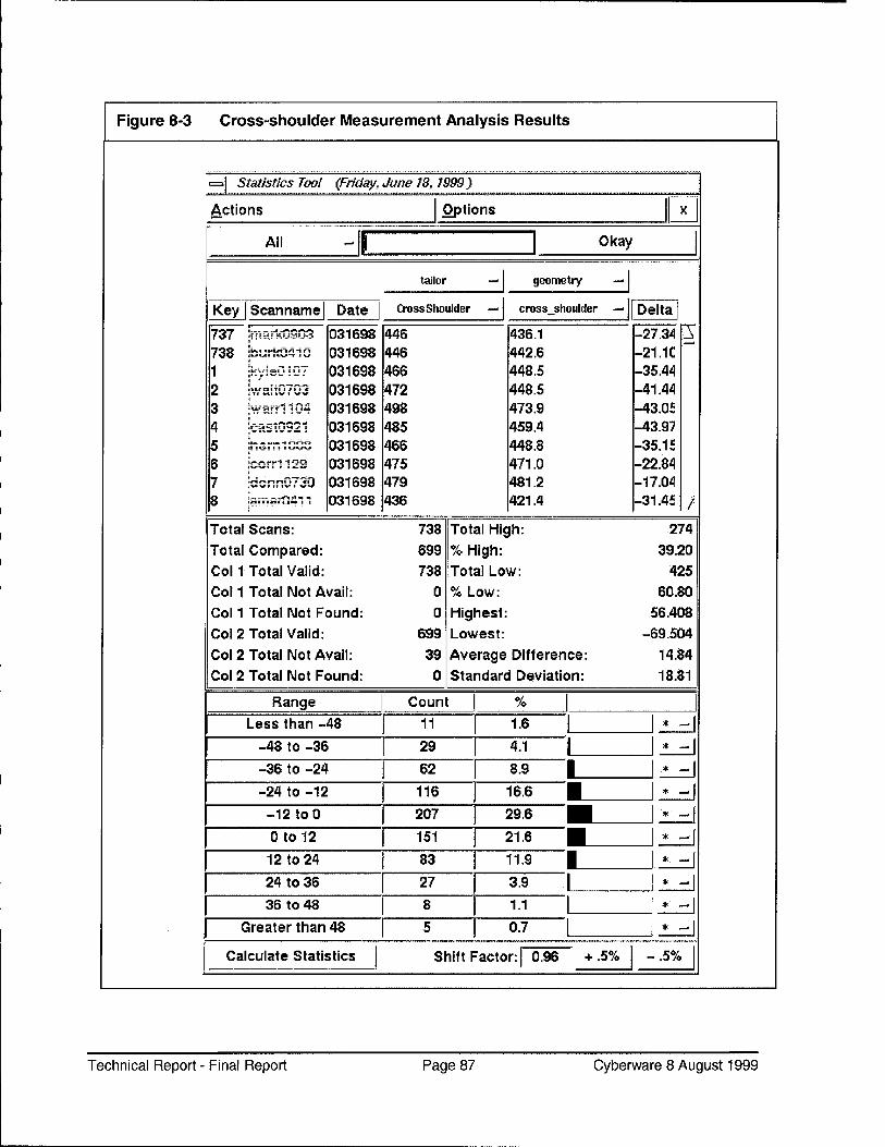
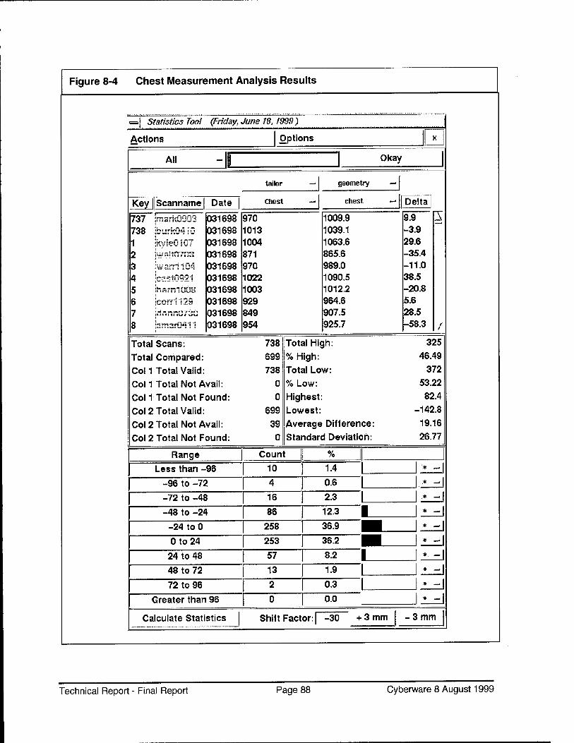
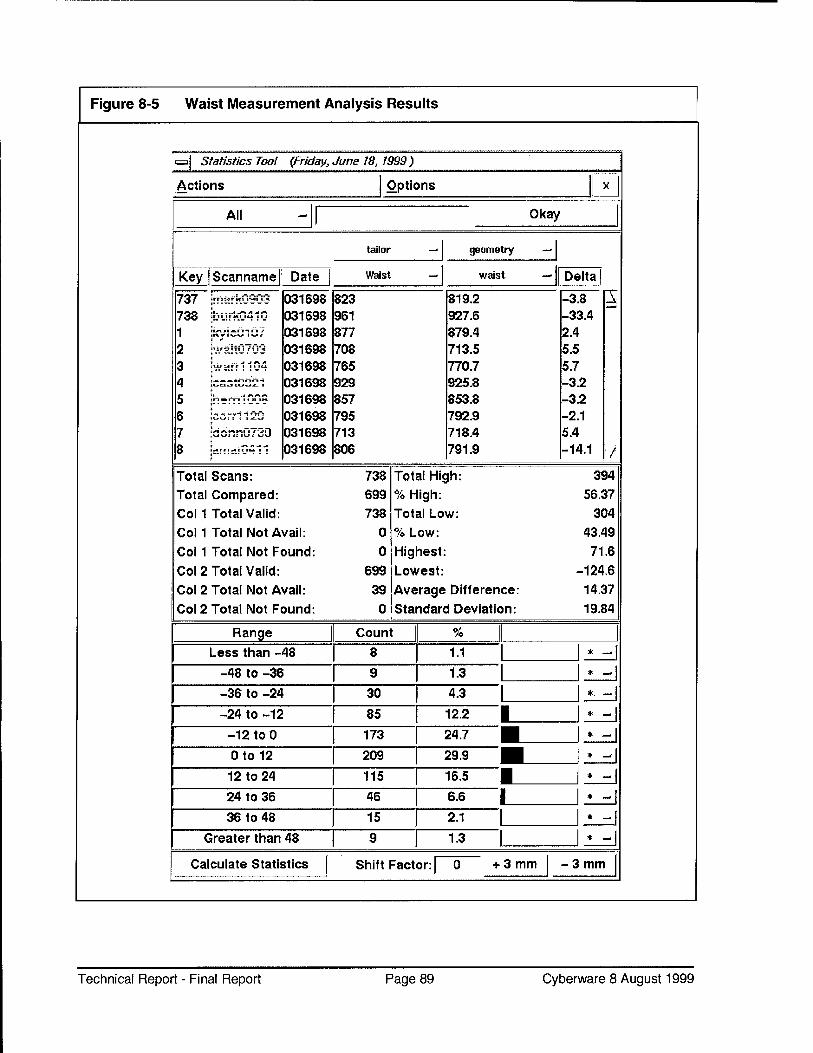
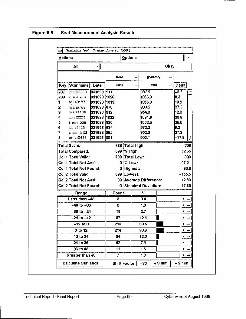
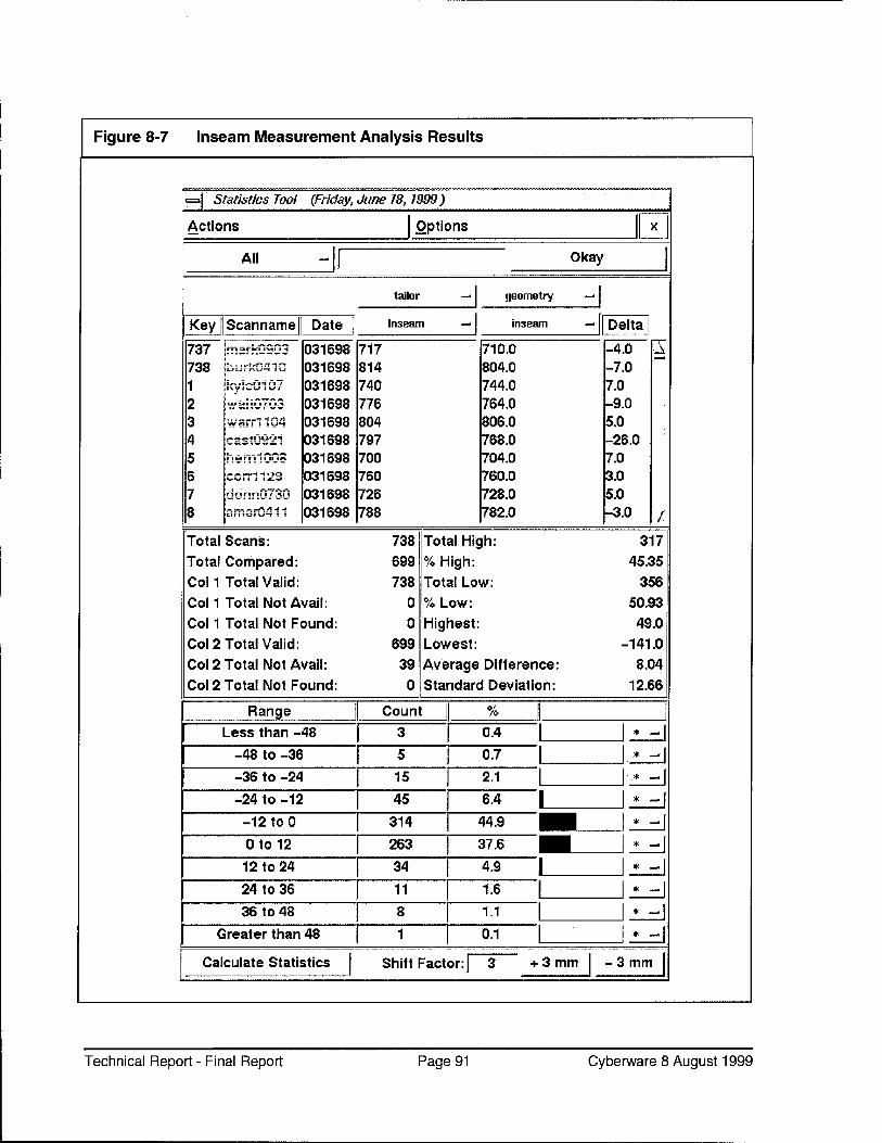
Laser-based Three-dimensional Body Scanner 11 Scanned Body Image showing Automatic Segmentation .... 13 Body Image showing Measurement Path Indicator 14 Toolkit Manager Window 23 Scan Form Window 24 Size Selection Window 25 Scan Form Window 34 Measurement Process showing Bounding Box and Plane... 39 Toolkit Manager Window 41 Landmark Measurement Example 42 Measurement Form Window 43 Batch Tool Window 44 Snapshot Viewer Window 45 Scanned Body Image showing Automatic Segmentation .... 46 Special Techniques for Difficult Body Areas 47 Size Selection Form 51 Scanner Design for ARN 53 Statistics Tool 59 Summary Tool 60 Body Measurement Acquisition Sequence 73 Height Measurement Analysis Results 85 Neck Measurement Analysis Results 86 Cross-shoulder Measurement Analysis Results 87 Chest Measurement Analysis Results 88 Waist Measurement Analysis Results 89 Seat Measurement Analysis Results 90 Inseam Measurement Analysis Results 91 Annotated Statistics Display 92
Technical Report - Final Report Page 6 Cyberware 8 August 1999
1. PREFACE
Purpose This report covers the accomplishments achieved in the area of Automatic Information Extraction from 3D Scan Data, identified as Apparel Research Network / Design and Development Focus Group project T2-P5 (Phases I, II, and III) in order to implement Customer Driven Uniform Manufacture.
Scope
Objective
Phase I covered the Planning and Development of Manual Measurement Extraction Software. Phase II covered the Planning and Development of Size Selection Software. Phase III covered Planning, Development, Performance, and Evaluation of a Field Implementation Test. Activities occurring after March 1999 will be covered in subsequent FTRs.
This project was chartered to determine whether automated means could be employed to enhance the measurement and size selection tasks in the apparel fulfillment process.
Acknowledge- ments
All three phases of this project were brought to fruition via a highly collaborative effort involving the Standardized Measurement Procedures Project T1-P5, headed by Ms. Carol Ring of Southern Polytechnical University.
The software referenced above was based on Cyberware's pre-existing CyScan 3D Image Data Acquisition programs, then enhanced by the addition of extensive body form recognition and three-dimensional measurement capabilities. These advanced developments were a joint effort between Cyberware ARN Team Members, and those of Bruce Bradtmiller of AnthroTech, Robert Beecher of Beecher Research, and Joseph Nurre of Ohio University. Their unique expertise has greatly contributed to the success of this project (and excerpts from their findings are included throughout this report).
Finally, Cyberware offers its gratitude to Ms. Julie Tsao and her team at the Defense Logistics Agency for invaluable guidance through this complex project. Our thanks is also offered to the United States Army Researchers at Natick and the United States Marine Corps for their cooperation and support without which this project could not have progressed.
Technical Report - Final Report Page 7 Cyberware 8 August 1999
1.1 EXECUTIVE SUMMARY
Key Benefits
The DDFG-T2-P5 ARN Short Term Project was established to determine the viability of using automated rapid body scanning technology and data processing as a means of reliably and efficiently providing apparel order entry input. To achieve this end, the proposed system must be able to:
■ Three-dimensionally scan the human form quickly and accurately ■ Automatically derive three-dimensional measurements equivalent
to traditional tailoring tape measurements ■ Compute clothing size requirements
All of these objectives must be achievable in less time, and with equal or greater accuracy than by traditional skilled hand measurement techniques and paper-based order entry.
Key benefits that will be realized by the successful implementation of the results of this project are:
Process
■ Overall cost reductions ■ Improved order responsiveness ■ Enhanced quality through error reduction ■ Powerful apparel planning and design data
These are explained in detail in the main body of this report.
A pre-existing whole body scanner was used to acquire computer- compatible data regarding the shape of a human form. Software was developed to derive three-dimensional body measurements from this form data that are equivalent to traditional tailoring measurements. This was first done using operator intervention to select the measurement path (e.g. around the chest). Later, this process advanced to the point of the program including artificial intelligence coding which allowed the computer to automatically determine the measurement locations and paths, and then compute the required measurements, all without operator intervention. The resultant linear measurement data (e.g. chest - 34") was then evaluated against standardized sizing tables (initially by the operator - later to be done by the computer) to perform size selection. Field-testing was performed on over seven hundred individuals to validate the process.
Technical Report - Final Report Page 8 Cyberware 8 August 1999
Results It has been determined via field-testing that it is feasible to acquire human form measurements automatically, as documented in Appendix A. The measurements calculated using this process are generally sufficiently accurate to result in proper apparel size selection (using manual look-up methods) per Final Report issued by Anthropology Research Project, Inc. ("Standardized Measurement Procedures Phase II: Validation of Measurements - Marine Corps Test). Future work planned for Phase IV will systematically evaluate the time required for each process versus the existing processes; and further evaluate the accuracy of garment fit results.
Automated size selection is still in the development process, and while a significant challenge, it is a less formidable task than three-dimensional measurement acquisition. This automated measurement and size selection process has the potential to boost the effectiveness and efficiency of the apparel ordering process, as a key part of the overall optimization of the ARN clothing, planning, stocking, and issuance process.
Technical Report - Final Report Page 9 Cyberware 8 August 1999
2. INTRODUCTION
In its ongoing efforts to optimize the apparel fulfillment requirements of the Armed Services, the Apparel Research Network is closely examining every phase of that process. One facet, the order entry stage, offers a number of opportunities for improvements.
[2/I AS-IS PROCESS
The process currently used at Recruit Induction Centers (RIC's) is manual. It is based on traditional tailor tape measurements, or even visual "guesstimation" of size. Because of the routine aspect of this task combined with the usage of Recruit personnel to perform some tasks, errors are commonplace. Adding to the problem is the uneven flow of Subjects to be measured. There is great pressure to process many Subjects in as short a period as possible, further enhancing the likelihood of errors. Once the measurements are taken, they are typically hand- written (from memory) on a form that is hand-carried to the next point in the process flow. This introduces at least three more opportunities for error:
• Memory mistakes • Handwriting clarity • Lack of identification (Subject name, etc.) on the form
NOTE: The term "Subject" is used throughout to represent the person being scanned. While this project is initially directed to new military recruits, the equipment and methods developed can be applied to all military personnel.
Once measurements are taken, another human decision process remains - selecting the correct standard apparel size, based on the provided measurements, which introduces another opportunity for error. Further complications can arise when the measurements do not correspond to in- stock (or any) apparel size.
Technical Report - Final Report Page 10 Cyberware 8 August 1999
2.2 AUTOMATED MEASUREMENT AND SIZE SELECTION PROCESS
The automation of Subject measurement and apparel size selection is implemented by:
■ Using a Body Scanner to determine the human three-dimensional form
■ Using a computer and software to calculate body measurements equivalent to traditional tailoring tape measurements
Using a computer and software to determine an appropriate garment size and/or stock number based on body measurements and garment specifications, and handling exceptions where no standard garment provides the required fit
Communication of the results to the order entry point
Technical Report - Final Report Page 11 Cyberware 8 August 1999
2.2.1. Automated Measurement
Using a Body Scanner and appropriate software, the Subject is uniformly scanned in less than a minute for every possible measurement needed. The results are computer analyzed for quality and credibility. In the future, these results will then be processed for size selection and either printed on a form that is given to the Subject, or forwarded electronically to the order entry system. The Subject's measurements (or even their full body scan) can be retained for future reference as needed.
Optimal Laser-based non-contact body scanning has the potential to provide a faster, more reliable measurement method than traditional methods, which include the variables introduced by various personnel using various tape tensions to measure the Subject, or in some cases, visually estimate the size. Current actual scan time has progressed from about one minute to about fifteen seconds, with opportunities for further enhancements. A single scan covers any number of measurements - even new measurements which can be generated at a later date from the stored three-dimensional body form data.
Scan-based measurements have indicated the potential to reduce manpower requirements. Presently, only two clerical-type Operators are needed to acquire all measurements for in excess of ninety Subjects per hour (typical), with throughput likely to approach one-hundred and twenty- five per hour. Future enhancements are expected to reduce the manning requirement to a single operator. With additional hardware and software development, even unattended scanning is feasible, further reducing manpower requirements, and expense
Technical Report - Final Report Page 12 Cyberware 8 August 1999
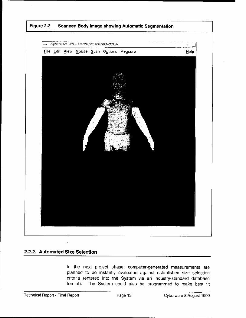
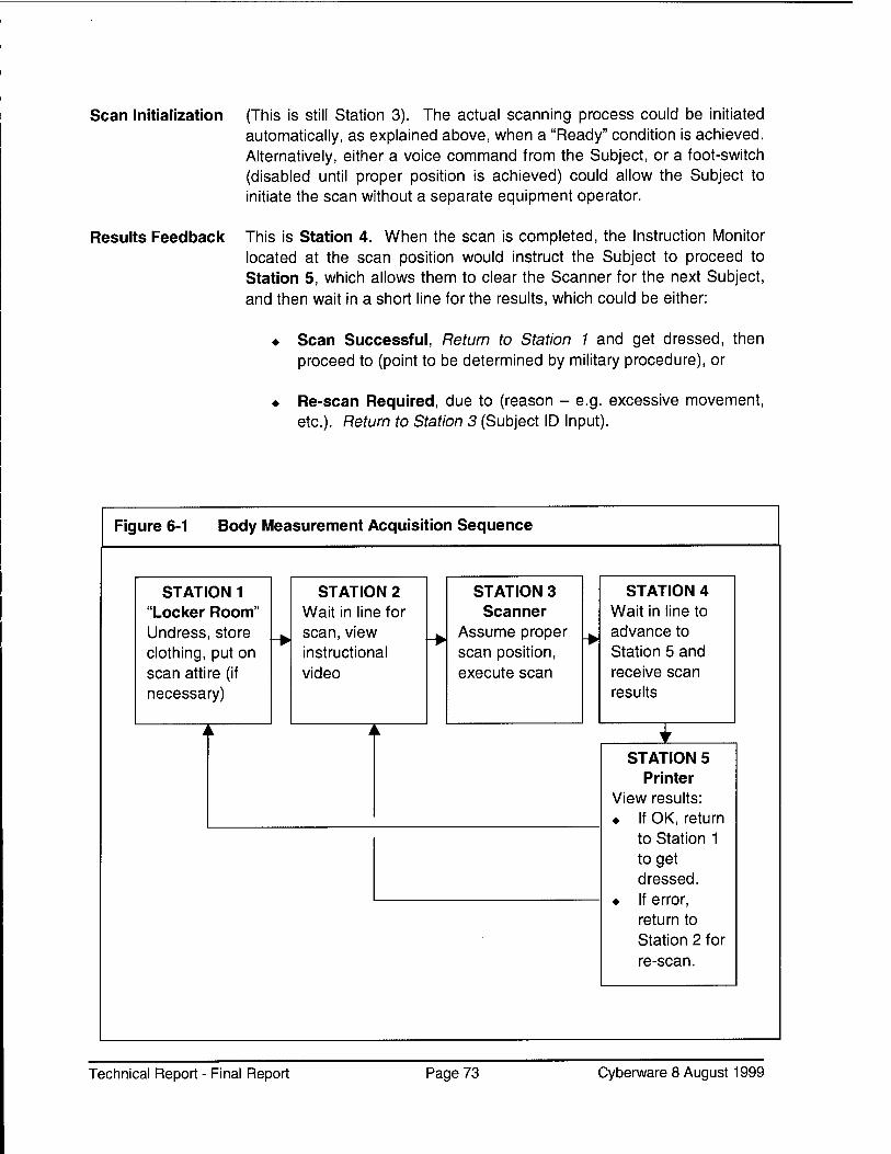
Figure 2-2 Scanned Body Image showing Automatic Segmentation
Cyberware WB - Ivar!tmp?mark0903-001.iv u File Edit View Mouse Scan 0£tions Measure Help
2.2.2. Automated Size Selection
In the next project phase, computer-generated measurements are planned to be instantly evaluated against established size selection criteria (entered into the System via an industry-standard database format). The System could also be programmed to make best fit
Technical Report - Final Report Page 13 Cyberware 8 August 1999
decisions based on in-stock availability, alteration capabilities, stock transfers from other sites, or made-to-measure criteria. Factors such as cost, urgency, and availability can be predictably applied to each decision, with the optimal decision being made in a fraction of a second
per item.
2.2.3. Automated Results Transmission
The optimized size selection decision can be transmitted instantly via network link to the order entry point for fulfillment, with no time loss, no paperwork loss or mis-routing, and no mis-interpretation of handwritten
entries.
Figure 2-3 Body Image showing Measurement Path Indicator
= Cyherware WB - fvar/tmp/hurk04W-001.rv a Q
File Edit View Mouse Scan Options Measure Help
■fe»c*. - jfl Waist
Wm Measurement Path Indicator
Wr JH ' ^■mV 1 ■7 'iii^^ftr- >^ "^■^■M^L ^H
FJH P^ " -ffl Wk^ 1 M ■>'■ . •-.■-S Bk3
1 r 1 ■'-. 'Mt'* 2H ■KM oliBK]1*!' JBH
H HI m Pi HI
Technical Report - Final Report Page 14 Cyberware 8 August 1999
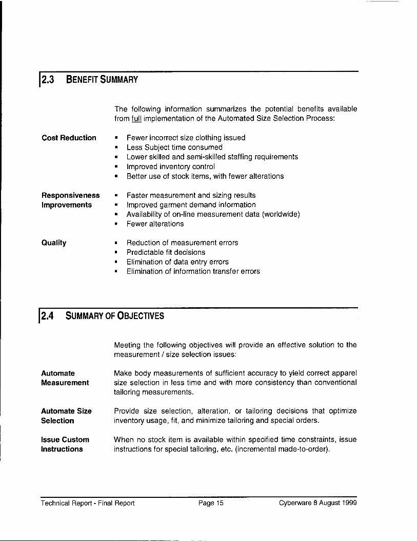
2.3 BENEFIT SUMMARY
The following information summarizes the potential benefits available from full implementation of the Automated Size Selection Process:
Cost Reduction
Responsiveness Improvements
Quality
Fewer incorrect size clothing issued Less Subject time consumed Lower skilled and semi-skilled staffing requirements Improved inventory control Better use of stock items, with fewer alterations
Faster measurement and sizing results Improved garment demand information Availability of on-line measurement data (worldwide) Fewer alterations
Reduction of measurement errors Predictable fit decisions Elimination of data entry errors Elimination of information transfer errors
2.4 SUMMARY OF OBJECTIVES
Meeting the following objectives will provide an effective solution to the measurement / size selection issues:
Automate Measurement
Automate Size Selection
Make body measurements of sufficient accuracy to yield correct apparel size selection in less time and with more consistency than conventional tailoring measurements.
Provide size selection, alteration, or tailoring decisions that optimize inventory usage, fit, and minimize tailoring and special orders.
Issue Custom Instructions
When no stock item is available within specified time constraints, issue instructions for special tailoring, etc. (incremental made-to-order).
Technical Report - Final Report Page 15 Cyberware 8 August 1999
Automate Information Transfer
Communicate concise selection or customization results immediately and accurately via network communications.
Develop and Provide accurate and thorough information on scanned Subjects Maintain a regarding scan data (body form), processed data (measurements), size Database selection, statistics and other scan-sourced data for use by garment
designers, inventory, planners, etc..
Establish Feasibility
System Prototype
Business Model
Provide a real-world demonstration of the required hardware and software, operable by minimally trained clerical-level personnel in a high throughput situation, showing results that exceed those of the existing manual process.
Produce a cost-effective prototype system that provides sufficient accuracy and high throughput, at a reduced overall cost per Subject processed.
Develop a realistic military-compatible business model that can be used to assess the impact of the new technology on current practices and facilities.
Documentation and Training
Provide documentation and training that will facilitate use and basic maintenance of the System by lower skilled personnel.
Technical Report - Final Report Page 16 Cyberware 8 August 1999
3. SYSTEM OVERVIEW
The Cyberware Scanning System, as modified for this application, consists of:
Whole Body Scanner, with support hardware Computer, capable of three-dimensional imaging Operator Display and Keyboard Network Link CyScan software with ARN extensions
3.1 SCANNER
The Body Scanner presently being used is the Cyberware WB-4 Whole Body Scanner, which has an established record for imaging quality, accuracy, and reliability as used in research and media fields. See Figure 2-1 on page 11.
It is proposed that this Body Scanner model be superceded by a lower cost version, deleting certain features not required for this application, and adding other features important to this specific application. Design of that replacement Scanner is discussed in section 4.9 of this report.
3.2 COMPUTER
The present computer being used is a specialized (and high cost) Silicon Graphics (SGI) model 02. (Actually, two of these units are presently used per system - one for scanning, the other for measurement calculations and size selection. This was done to gain understanding of the time requirements of each individual operation). Ultimately, it is planned that these will be replaced by IBM-compatible PCs running MS-Windows NT, as discussed in section 4.13 of this report.
Technical Report - Final Report Page 17 Cyberware 8 August 1999
3.3 OPERATOR DISPLAY AND KEYBOARD
The Operator Display, Keyboard, and pointing device are standard IBM- PC compatible units.
3.4 NETWORK LINK
3.5 SOFTWARE
The Network Link is a standard Ethernet Adapter and uses network drivers integrated into the computer's operating system.
The operating system software is currently the UNIX-based SGI IRIX version 6.3. The scanning and basic three-dimensional image management software is Cyberware's CyScan software version 9.0. Extensions to this software for the ARN application are being added and enhanced on an ongoing basis.
3.6 SCANNING
The Operator enters the Subject's identification information, then he directs the Subject to the proper scanning position, and starts the scan. This process could be fully automated using an ID Card Reader and video positioning instructions, reducing manpower requirements even further.
The scanning process is totally non-contact. A set of four scanning heads move downward from head level to feet, acquiring precise three- dimensional body form data in about fifteen seconds. Lasers (of similar intensity to retail store barcode scanners) are used for precision, coupled with video technology for intensity (grayscale) information. The three- dimensional image of the Subject is ready for an optional quick review for correctness in a few seconds after scanning. (Upcoming versions of the software are planned to do integrity checks automatically, ordering re-
Technical Report - Final Report Page 18 Cyberware 8 August 1999
scans when the Subject has moved excessively, or something has interfered with the scanning process).
3.7 SCAN CHECK
The Operator verifies that the body scan was acquired properly, then releases the Subject. This step could also be automated using the computer to validate the acquired measurements against reasonable values for the Subject's height, etc..
3.8 MEASUREMENT PROCESSING
The three-dimensional body form data is automatically processed to calculate all required body measurements (e.g. chest, neck, inseam, etc.).
With the myriad of computer applications today, one might tend to trivialize the process of measurement calculation; but, unlike automated inspection and measurement of a production part, the human body offers major challenges in measurement automation.
Where a mechanical part has a very predictable shape (within minor tolerances), the human figure does not. Locating the proper point to obtain a cross-shoulder measurement (or even a waist measurement) is not by any means trivial, due to the vast variations in body form.
Also, consider that in order to coincide with the existing clothing tariffs, the generated measurements must accurately mimic conventional tape measurements, which can be challenging. Where the tape measure does not follow recesses on the body surface (such as on some Subject's backs, near the spine), etc., the laser accurately tracks the precise linear distance in and out of such recesses, which adds length not included using conventional tape measure techniques. To be sure, there are solutions to these challenges, but they require innovative processes to succeed.
Finally, let it not go without notice that the scanning hardware and the driver software must produce three-dimensional image data of sufficient accuracy to be able to generate body measurements of the precision required for proper garment fit.
Technical Report - Final Report Page 19 Cyberware 8 August 1999
3.9 SIZE SELECTION
As of the end of Phase III, the Size Selection sub-task is in a very early state of its development. As development progresses, the calculated measurements will be automatically processed by the Apparel Size Selection software to determine the standard issue clothing size to be ordered. The full range of available sizes for each garment will be entered into the System by importing an industry-standard database file, which contains the measurement ranges (e.g. coat size "medium"). This garment database also contains the stock number for that item, to add further assurance that the correct item will be issued. The pilot version of this operation presently requires Operator intervention, and outputs a printed requisition slip; however, future software releases could also automate this procedure, and communicate the results via network link to an existing Order Entry System.
In addition, the System could be programmed to handle special measurement situations where no adequate stock clothing item is found (such as for a Subject with unusually long legs, etc.).
A key consideration that makes a seemingly simple process potentially complicated is when a Subject's set of measurements do not correspond to those available for any stock item. In such cases, the System could be programmed to determine if alteration is possible, and if so, what stock garment to start with. It could also determine that Made-to-Measure is required, and issue an order along with the appropriate body measurements.
3.10 DATA HANDLING
Due to the measurement precision required, each body scan along with its associated Subject data (name, date, etc.) requires around a million bytes of data; although the resultant body measurement file is extremely small (less than 1 Kb). Retaining the full scan file has the advantage of availability for further analysis at a later date, including uses such as garment design ergonomics, re-constructive surgery, prosthetic construction, etc., but offers challenges in file management.
Technical Report - Final Report Page 20 Cyberware 8 August 1999
4. ACTIVITY SUMMARY
As one can hopefully appreciate from the previous Introduction, voluminous work was required to successfully implement the described system, even in prototypical form. The following items provide a quick summary of what activities have transpired during Phases I through III to achieve such accomplishments. The balance of this report provides greater insight into each of these key areas.
NOTE: If you plan to read this entire report, you may wish to proceed directly to the Detailed Project Task Information section starting on page 29.
4.1 TASK COORDINATION
Cyberware's Stephen Addleman served as the Supertask Coordinator for the project's ARN partners and sub-contractors, helping to ensure all related tasks progressed in synchronization with the plan, thus attaining the progress realized to date.
4.2 MEASUREMENT EXTRACTION
This process the three-dimensional scan data and then generates linear body measurements (e.g. chest circumference) from that data.
4.3 MEASUREMENT TYPES
The first action required was to determine which specific body measurements were actually required, based on the specific garments to be fitted (e.g. some garments require a precise neck measurement, others do not).
Technical Report - Final Report Page 21 Cyberware 8 August 1999
4.4 MEASUREMENT TECHNIQUES
See Figure 2-3 on page 14. Once the required measurements were determined (based on garment types to be fitted), the traditional measurement path information (e.g. cross-shoulder measurement technique) had to be specified in a concise manner that could then be implemented by the System.
Finally, the Programmers had to determine how to locate that path upon a three-dimensional human scan data set of nearly a million variable surface points, and implement it such that the process could be reliably and quickly replicated for the many subtle variations in human form.
4.5 MEASUREMENT PROGRAMMING
The Programmers developed these processes as independent "tools" that could be applied to other measurement requirements as well, rather than as hard code that would perform only one function.
4.6 PRELIMINARY TESTING
Testing and validation of the process was required in order to proceed with development. The System was used initially to (electronically, but manually) measure a small number of Subjects, and the results were compared to traditional tailoring tape measurements of the same Subjects (as detailed in Appendix A). These results enabled optimization of the processes. Initial scan-derived measurements required operator intervention (via Display and Mouse Pointer) to indicate measurement points. Later implementations automated the measurement process. This provided throughput advantages and should result in a manpower cost reduction.
Technical Report - Final Report Page 22 Cyberware 8 August 1999
4.7 USER INTERFACE
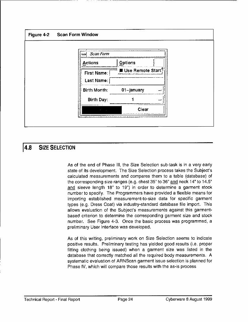
Once Measurement Tools were developed, a user interface had to be established which could allow a non-programmer to perform the measurements. See Figure 4-1. Then, advancing a further step, a "one button" (plus Subject data entry) solution to the entire measurement process was provided. See Figure 4-2.
Technical Report - Final Report Page 23 Cyberware 8 August 1999
Figure 4-2 Scan Form Window
.... 1. '
i ■=! Scan Form i
\ Actions Options == . <== :
; First Name:
Last Name:
— ■ use Remote start*- ;
| Birth Month:
Birth Day:
01-January -<
f —J !
-; 1 HB Clear j ; .. „ „ , „. . , , ..../.... .;
4.8 SIZE SELECTION
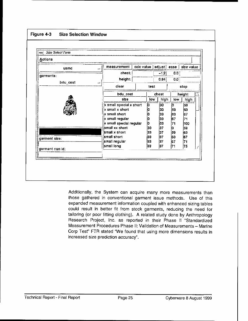
As of the end of Phase III, the Size Selection sub-task is in a very early state of its development. The Size Selection process takes the Subject's calculated measurements and compares them to a table (database) of the corresponding size ranges (e.g. chest 35" to 36" and neck 14" to 14.5" and sleeve length 18" to 19") in order to determine a garment stock number to specify. The Programmers have provided a flexible means for importing established measurement-to-size data for specific garment types (e.g. Dress Coat) via industry-standard database file import. This allows evaluation of the Subject's measurements against this garment- based criterion to determine the corresponding garment size and stock number. See Figure 4-3. Once the basic process was programmed, a preliminary User Interface was developed.
As of this writing, preliminary work on Size Selection seems to indicate positive results. Preliminary testing has yielded good results (i.e. proper fitting clothing being issued) when a garment size was listed in the database that correctly matched all the required body measurements. A systematic evaluation of ARNScan garment issue selection is planned for Phase IV, which will compare those results with the as-is process
Technical Report - Final Report Page 24 Cyberware 8 August 1999
Figure 4-3 Size Selection Window
Size Select Form
Actions
usmc
garments:
bdu coat
measurement calc value | adjust | ease size value
chest: j
height: I
-1.2 0.01
0.84 0.0
■^■l^HHH garment size:
garment nsn id:
clear test stop
bdu coat | chest height size
x small special x short x small x short x small short x small regular x small special regular small xx short small x short small short small regular small long
Additionally, the System can acquire many more measurements than those gathered in conventional garment issue methods. Use of this expanded measurement information coupled with enhanced sizing tables could result in better fit from stock garments, reducing the need for tailoring (or poor fitting clothing). A related study done by Anthropology Research Project, Inc. as reported in their Phase II "Standardized Measurement Procedures Phase II: Validation of Measurements - Marine Corp Test" FTR stated "We found that using more dimensions results in increased size prediction accuracy".
Technical Report - Final Report Page 25 Cyberware 8 August 1999
4.9 SCANNER HARDWARE OPTIMIZATION
The Body Scanner currently being utilized for this project incorporates features that are not required for this application, and lacks other features that could further optimize the process. A scanner specifically targeted for garment-oriented body measurement acquisition is being designed. It will provide the required measurement accuracy while optimizing throughput and cost-effectiveness. A prototype should be available in Phase IV.
4.10 IMPLEMENTATION
"Implementation" events differs from "testing" in that the implementation activity is performed in an expected use environment - that is, in (as close as possible to) the same situation as is expected for future permanent operation. Preliminary Implementation Events have been conducted and another is ongoing as of this writing. Subjects are processed as fast as possible.
We have elevated Implementation Events to a very high priority in order to ensure the effectiveness and practicality of this project, investing far more effort into this activity than originally planned.
Since prior tests and Implementation Events have indicated that the System makes measurements of generally satisfactory accuracy per Final Report issued by Anthropology Research Project, Inc. ("Standardized Measurement Procedures Phase II: Validation of Measurements - Marine Corps Test)., future Implementation Events are planned to be more focused on:
■ Acceptable garment size selection ■ Throughput ■ Ease of use ■ Reliability
Additional implementation trials will be performed on an ongoing basis.
Technical Report - Final Report Page 26 Cyberware 8 August 1999
4.11 DATABASE MANAGEMENT
Three-dimensional scanning creates valuable, albeit voluminous data. Managed properly, it is important not only to the advancement and validation of this project, but for other disciplines, such as garment research and inventory planning. This project has determined means for statistically evaluating the data in an automated fashion and validating the measurement results (see Appendix A). A preliminary method for importing and storing garment-oriented size selection tables has been developed. A convenient user interface has been developed to make the data available to system users.
Work continues on determining the most effective ways to store and manage the extensive body scan data files.
4.12 DOCUMENTATION
Quality documentation packages are being produced in conjunction with development of the project. These are:
■ System (Scanning) Operation Guide (in planning stage) ■ Software Manual for Researchers and Advanced Applications ■ System Installation and Maintenance Manual (in planning stage)
The System Installation and Maintenance Manual is outlined, and will advance in conjunction with development of the ARN-optimized Scanner Hardware and transition to IBM-PC computers. These documents are planned for completion in Phase IV. Contact Cyberware for availability information.
4.13 SOFTWARE TRANSITION
Presently used Silicon Graphics computer equipment will be replaced by lower cost IBM-PC compatible equipment while improving performance. This requires transitioning (i.e. "porting") the (C++) UNIX-based software to the MS-Windows NT environment. Selected software modules were converted, and ran properly in the MS-Windows NT environment. These
Technical Report - Final Report Page 27 Cyberware 8 August 1999
preliminary efforts indicate that a smooth transition will occur. Finalization requires hardware integration to be completed.
4.14 MILITARY BUSINESS PLAN
The Military Business Plan will assist garment issuance management to evaluate the impact and effectiveness of integrating the T2-P5-based system into their existing operations. Work on the Business Plan will commence in Phase IV.
4.15 BODY MODEL
An advanced body model will provide three-dimensional parametric body information. This is expected to reduce the size of the file, enhancing both data handling and data storage operations.
The balance of this report details the process and status of the tasks involved.
Technical Report - Final Report Page 28 Cyberware 8 August 1999
5. DETAILED PROJECT TASK INFORMATION
The following sections provide detailed information on the status of each task item listed in the approved proposals for Phases I, II, and III of this project.
5.1 TASK COORDINATION (T1.1)
Goal
Task Coordination
Partners
The primary goal of this task was that Cyberware was to provide overall coordination for all approved T2-P5 tasks (Cyberware and other Partners). A key objective was to eliminate duplication of effort, and identify and resolve "gaps" between related tasks.
T2-P5 Super Task coordination was performed by Stephen Addleman of Cyberware. He coordinated development efforts to eliminate overlap while monitoring schedules and inter-project dependencies. This helped ensure the required synchronization and maintenance of schedules, and production of deliverables. He has provided over forty Interim Progress and Technical Reports since 1996. These reports have also specified and summarized the many meetings that he and other team members have attended in order to keep the project moving smoothly and efficiently.
In addition, Mr. Addleman reviewed the listed Partner's proposals, tasks, and work produced. He maintained the project's Coordination Plan and calendar. He also coordinated the required activities involving military entities such as:
♦ U.S. Army Natick ♦ U.S. Marine Recruit Depot - San Diego
In addition to the tasks performed by Cyberware (which are presented in this report), there are a number of supporting tasks which were performed by T2-P5 Partners (holding separate contracts with the ARN). Those contractors and their projects were:
Technical Report - Final Report Page 29 Cyberware 8 August 1999
CONTRACTOR PROJECT Ohio University - Joe Nurre, Jeff Collier, Eric Lewark
Automatic Information Extraction from Scan Data
Southern Polytechnic - Carol Ring Size Selection ARP - Bruce Bradtmiller Automatic Information Extraction
from 3D Body Scan Data Beecher Research - Robert Beecher
Standardized Measurement Procedures
5.1.1. Coordination Plan
T2P5 Partner's proposals, tasks, and work were reviewed and coordinated by Stephen Addleman. A general Coordination Plan was maintained and made available to Program Management. The Coordination Plan outlined all T2P5 Phase IV tasks. The plan listed the responsible partners and their deliverables. A calendar with set deliverable goals and a schedule of review points was maintained. Performance to Plan was reported.
The T2P5 partners, holding separate contracts with the ARN, whose tasks were coordinated by Cyberware were:
• Ohio University (Joe Nurre) • Ohio University (Sub-Contract to Jeff Collier and Eric Lewark) • Southern Polytechnic (Carol Ring)
The T2P5 Partners who migrated to sub-contract with Cyberware (and whose tasks were managed by Cyberware, were:
• ARP (Bruce Bradtmiller) • Beecher Research (Bob Beecher).
Tasks that involve entities outside of Cyberware and the ARN such as the Recruit Induction Centers (RIC) required careful coordination. Cyberware provided coordination so that military business was not adversely impacted.
Technical Report - Final Report Page 30 Cyberware 8 August 1999
5.1.2. Partner Activity Summaries
ARP The objective of the work performed by Anthropology Research Project, Inc. (ARP) was to evaluate the success of various newly developed ARNScan software versions for extracting body measurements from 3-D scans. Investigators first used traditional methods to measure male and female subjects for dimensions associated with the sizing and design of military clothing. The same Subjects were then scanned, and the same or comparable measurements extracted from the 3-D images.
A comparison of the results obtained by each method yielded a number of differences. A variety of statistical procedures were then undertaken to establish whether these differences were important or significant (i.e. large enough to place Subjects in different sizes).
Differences were tested against three standards:
• Acceptable measurer error, as established in the 1988 U.S. Army survey (ANSUR)
• Acceptable error estimated by three experienced tailors • Garment grade in traditionally sized dress clothing.
BRC The objective of the work performed by Beecher Research Company (BRC) was to develop a computer program that could automatically, accurately, and consistently extract useful information from 3D whole body laser scans. The scan measurements were then to be used in a computer program to issue apparel to military recruits in training.
Working with a consortium of Apparel Research Network Partners, BRC helped to develop algorithms and computer source code, organized testing and evaluation projects, and led the initial planning and organization for a field test of the scanner and software at the San Diego Marine Corp Recruit Depot.
The project was an iterative process of:
• Gathering apparel measurement information • Software development to extract the measurements • Testing and evaluation • Recommendations for improvement.
BRC hired Carol Ring of SPSU as a consultant from December 1997 through May 1998 to develop size selection tables for the USMC dress uniform. During and after this period, BRC supported her work by
Technical Report - Final Report Page 31 Cyberware 8 August 1999
providing ARNScan measurement results, evaluating sizing problems in terms of the measurement functions, developing new measurement tools to test size selections, and doing size selection for additional scans to increase the sample size.
0U Tne objective of the first project performed by Ohio University (OU) was to develop algorithms for three dimensional data analysis and processing. The algorithms focused on two areas:
• Analysis of the scan data, which resulted in software that can extract apparel measurements from that data. Initially, the measurements were taken semi-automatically from Scan Subjects wearing a minimal set of manually applied Landmarks (fiducials).
• Processing algorithms, which assisted in the study of scanner capture resolution. Data artifacts inherent in the technology were simulated. Methods to reduce certain artifacts have been developed.
The second project was a continuation of the DDFG-T2-P3 Short Term Project. The objective of the second project was the automated extraction of apparel measurements from scan data. The development of algorithms for three dimensional data analysis and processing proceeded to a new phase. The algorithms were field tested at the Marine Corps Recruit Depot in San Diego (MCRD-SD), in cooperation with the Cal Poly- Pomona Demo and the USMC. This required that robustness be added to the algorithms, where necessary. A new suite of software tools was also developed to manage the scan data. Furthermore, Ohio University provided technical support and man-power for the body scanning experiment.
SP The objective of the project performed Carol Ring of Southern Polytechnic (SP) was to reconcile the results of garment size selection via ARNScan methods versus the as-is process. Each measurement data set extracted by ARNScan was evaluated with the current set of size selection rules for the Marine Corp men's service uniform, which includes coat, trouser, and long sleeve shirt. Rules were then revised to better the outcome, if possible. Additional rules were added for measurements outside the accepted values. The size selection rules were then sent to Cyberware for importing into ARNScan software.
Task Status: With the exception of variances agreed to by DLA Project Management, all tasks, deliverables, and milestones were successfully completed on schedule.
Technical Report - Final Report Page 32 Cyberware 8 August 1999
^2 MEASUREMENT EXTRACTION (T1.2)
Goal The overall goal of this task was to provide a system (hardware and software) which automatically performed all human body tailoring measurements required to facilitate issuance of specified garments by their stock number.
5.2.1. Overview
The Measurement Extraction process involves several key operations:
Performing a three-dimensional scan of the complete body form of the Subject to be measured Determining the specific measurements that are required for the garments to be issued Automatically locating the position on the three-dimensional body form where those measurements are to be taken Computing three-dimensional linear measurements equivalent to traditional tailor tape measurements Optimize these processes for accuracy and throughput
The following sub-tasks were executed to successfully implement these processes.
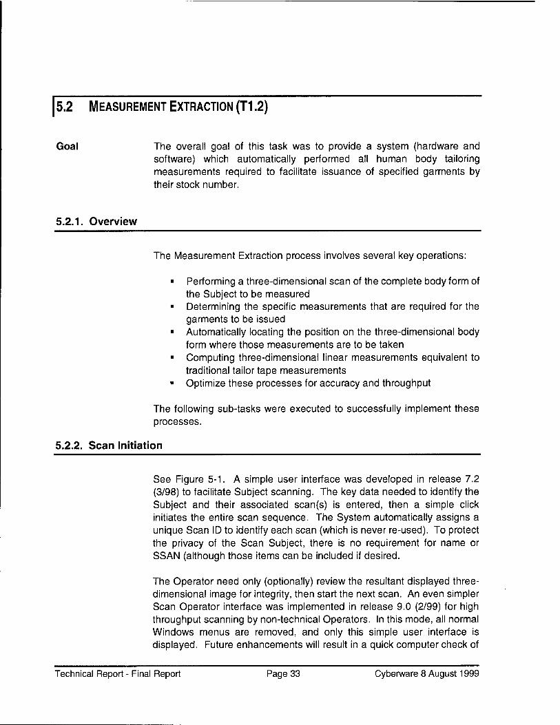
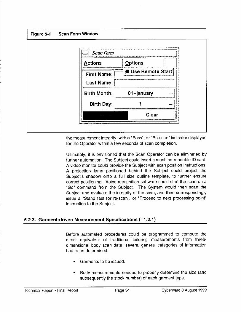
5.2.2. Scan Initiation
See Figure 5-1. A simple user interface was developed in release 7.2 (3/98) to facilitate Subject scanning. The key data needed to identify the Subject and their associated scan(s) is entered, then a simple click initiates the entire scan sequence. The System automatically assigns a unique Scan ID to identify each scan (which is never re-used). To protect the privacy of the Scan Subject, there is no requirement for name or SSAN (although those items can be included if desired.
The Operator need only (optionally) review the resultant displayed three- dimensional image for integrity, then start the next scan. An even simpler Scan Operator interface was implemented in release 9.0 (2/99) for high throughput scanning by non-technical Operators. In this mode, all normal Windows menus are removed, and only this simple user interface is displayed. Future enhancements will result in a quick computer check of
Technical Report - Final Report Page 33 Cyberware 8 August 1999
Figure 5-1 Scan Form Window
|
1=3 Scan Form
Actions Options |
' n~* M,ma. 1 ■ Use Remote Startf ■■ First Name: ^ ^.,, -,,,. = a^^^j
■ Last Name: |
Birth Month: 01-January
Birth Day: 1 ~>
II Clear
the measurement integrity, with a "Pass", or "Re-scan" indicator displayed for the Operator within a few seconds of scan completion.
Ultimately, it is envisioned that the Scan Operator can be eliminated by further automation. The Subject could insert a machine-readable ID card. A video monitor could provide the Subject with scan position instructions. A projection lamp positioned behind the Subject could project the Subject's shadow onto a full size outline template, to further ensure correct positioning. Voice recognition software could start the scan on a "Go" command from the Subject. The System would then scan the Subject and evaluate the integrity of the scan, and then correspondingly issue a "Stand fast for re-scan", or "Proceed to next processing point" instruction to the Subject.
Before automated procedures could be programmed to compute the direct equivalent of traditional tailoring measurements from three- dimensional body scan data, several general categories of information had to be determined:
■ Garments to be issued.
■ Body measurements needed to properly determine the size (and subsequently the stock number) of each garment type.
Technical Report - Final Report Page 34 Cyberware 8 August 1999
■ Traditional measurement path used when performing a tape measurement.
■ What additional measurements could be computed by the System that could be beneficial for optimizing garment fit.
Ms. Carol Ring of Southern Polytechnic University performed the investigation to fulfill these requirements. Consequently, she has issued the report titled "Computer Aided Design Made-to-Measure Expert System DDFG-T1-P5 Phase 0" along with other reports which are available on the ARN Web Site. Please refer to her reports for details on her findings.
Based on that report and input from other T2-P5 Partners, it was determined that the following Measurement Types were required (listed alphabetically):
Back Length Chest Cross Shoulder Foot Length - Right Foot Length - Left Foot Width - Right Foot Width - Left Head Circumference Height Inseam Neck Outseam Overarm Seat Sleeve Inseam Sleeve Length Sleeve Outseam Waist
Once these Measurement Types were defined, a clear and concise specification of how each measurement was made (i.e. from what origin point to what termination point, following what path) was required.
This information was also provided in reports issued by Ms. Carol Ring.
A further requirement was for data on how the required measurements determined size, which in turn determined the garment stock number to be issued. This information is covered later, in the section titled "Size Selection" starting on page 49.
Technical Report - Final Report Page 35 Cyberware 8 August 1999
5.2.4. Additional Measurements
Added benefits could be realized by enhancing the standard measurement set with additional body measurements. For example, trousers are currently issued only by waist and inseam size. The addition of consideration for the seat measurement could result in better initial fit, fewer re-issues required, and less alterations.
A related study done by Anthropology Research Project, Inc. as reported in their "Standardized Measurement Procedures Phase II: Validation of Measurements - Marine Corp Test" FTR stated "We developed linear discriminant functions to assign garment sizes based on the dimensions extracted from the whole body scans. We found that using more dimensions results in increased size prediction accuracy. This is important information because it suggests that enhancing ARNScan software to extract even more than the current 9 dimensions will improve accuracy further". This could result in better fit, and if carried through to garment manufacturing, could potentially result in savings due to reduced requirements for garment alterations.
5.2.5. Alteration Information
NOTE: This topic is positioned here to be consistent with earlier documentation, but is also related to Size Selection on page 49.
When a Subject's body measurements do not match the measurement set available for a given garment, either an altered or a made-to-measure garment is required (with the former being the preferred solution).
Information regarding the extent of alteration possible for each garment stock number (e.g. the waist can be taken in up to X inches) could allow automated selection of the correct garment to be altered, and alteration orders to be issued.
This information was also provided in reports issued by Ms. Carol Ring.
5.2.6. Made-to-Measure
Whether required for a lack of a suitable alterable garment, or for custom fitting, the System can be interfaced with automated Made-to-Measure (MTM) Garment Manufacturing Equipment. This task involved
Technical Report - Final Report Page 36 Cyberware 8 August 1999
determining the requirements for implementing a complete system that would integrate the automatic body measurement sub-system with the automatic garment manufacturing sub-system. This involved investigation in two key areas:
1. Specific data input requirements of the garment manufacturing equipment
2. Communication requirements to interface the two systems (hardware and software).
The following was determined:
Regarding item 1, the input requirement is a structured text file, which contains the pre-defined measurements derived by the Scanning System. This powerful combination of automated systems could benefit from additional body measurements, which could yield garments with a more custom tailored fit. This will require discussion between the designers of both sub-systems, but is seen as a fairly minor task.
Regarding item 2, Web-based communication is envisioned, where the ARN Scanner would e-mail the garment requisition file containing the measurement data along with an expenditure authorization number to the MTM site.
As a result, the following future actions are recommended:
We recommend that Carol Ring of Southern Polytechnical issue a document proposing a standard input requirement specification which could be used (or re-formatted as needed) by all MTM systems. This approach would allow the government flexibility as to which MTM system (or systems) to use. This document should be reviewed and approved by all affected partners.
5.2.7. Measurement Tool Programming (T.1.2.2)
Once the specific body measurements required for the garments to be issued were determined by the T1.2.1 tasks, extensive software was developed to acquire those measurements. (An example is provided in the following pages). This was first implemented in release 4.0 (5/97) using operator guidance, then evolving to semi-automatic "landmark" application and detection in release 6.0 (9/97). Finally, in release 7.0 (2/98) artificial intelligence programming enabled the System to automatically recognize the human form, and acquire linear
Technical Report - Final Report Page 37 Cyberware 8 August 1999
Software Architecture
measurements that meticulously followed the measuring paths used for traditional tape measurements.
The general software for scanner operations, image acquisition, image processing, and measurement acquisition was written in industry- standard C++. This facilitates efficient and powerful software development along with the ability to be configured to different types of computers (hardware platforms). Early development was done using Silicon Graphics hardware, which (at that point in time) was the only system offering adequate three-dimensional imaging capabilities. However, it was generally known that IBM-compatible PCs would eventually be able to provide the required hardware support while providing the user advantages of the MS-Windows environment. The C++ choice supports either platform, and facilitates planned migration to the IBM-PC / MS-Windows environment.
Flexibility
Measurement Approach
Cyberware wanted advanced users to be able to expand the capabilities of the system without having to perform rigorous programming. (This approach also protects the basic integrity and functionality of the underlying software). Therefore, Cyberware integrated the simpler (public domain) Tel scripting language and its corresponding Tk graphics interface. Cyberware has developed a powerful set of measurement- related commands in the C++ program that can be implemented (scripted) in a variety of methods using the relatively simple Tel scripting. The result is that non-programmers can take advantage of the power of the System, advancing the technology at a much higher rate.
The result of a three-dimensional scan can be compared to an egg shell - it represents the surface of the object. The surface data points are about one-tenth of an inch apart.
The measurement resolution required sampling the Subject's body surface with such high detail. The result is a data set of over a million points for each scan. This set of surface points in X-Y-Z space is referred to as a "cloud" of points (although it is hollow like an egg shell). The measurement routines must be guided (either manually or automatically) to the precise region on the surface of the three-dimensional image where the measurement is to be made.
The process just explained employs the use of software "Tools", which are pre-programmed. These Tools provide convenient and efficient ways to handle the three-dimensional scan data. Tools have been developed to handle:
■ The entire three-dimensional image (cloud) ■ A three-dimensional portion of the image (segment)
Technical Report - Final Report Page 38 Cyberware 8 August 1999
A single point on the image (e.g. elbow) A two-dimensional slice (plane) through the image The image display characteristics The image data set A "bounding box" cubic region, enclosing part of the image
Programming is not required to use these Tools. The Tools are essentially named commands that are given certain input parameters for location, etc., and then used in an appropriate sequence to perform a specific measurement, such as a neck measurement.
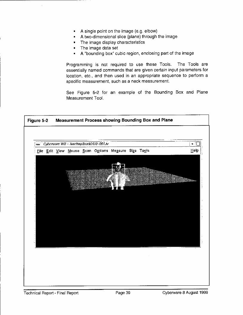
See Figure 5-2 for an example of the Bounding Box and Plane Measurement Tool.
Figure 5-2 Measurement Process showing Bounding Box and Plane
Cyberware WB - fvarltmplburk0410-001.iv 'D | File Edit View Mouse Scan Oßtions Measure Size Tools Help
Technical Report - Final Report Page 39 Cyberware 8 August 1999
Using the neck measurement as an example, the software executes Tools to:
1. Segment the body - torso, arms, legs, and head.
2. Combine (only) the head and torso segments.
3. Make a Bounding Box between the lower quarter of the head and the upper quarter of the torso. Restrict further actions to that Bounding Box area.
4. Find Neck Right, Neck Left, Neck Front, and Neck Back Base.
5. Fit a plane to those points, defined by Neck Front, Neck Side, and Neck Back.
6. Move this plane vertically within the Bounding Box to find the minimum diameter point.
This (simplified) process is an example of how a measurement is acquired from the Subject's three-dimensional data set. Other measurements may use the same Tools with different input parameters to execute other Measurement Types.
NOTE: These processes shall be explained in detail with specific step-by- step examples in the ARN Research and Analysis Applications Manual, at a level that researchers can use without requiring programming expertise.
See Figure 5-3. These Tools (scriptable commands) combined with appropriate parameters (e.g. location) can be assigned a "name" (e.g. Neck Circum) and then easily selected from the Toolkit Dialog Box for future usage.
Technical Report - Final Report Page 40 Cyberware 8 August 1999
The defined Tools can be used manually or automatically. In the Manual Mode, the user selects a pre-defined "Measurement Type" (e.g. Chest) from the Toolkit Dialog Box. They are then prompted to use the pointing device (Mouse) to indicate certain key points on the three-dimensional body image relative to the performance of that measurement. Once all the required points have been indicated, the measurement is executed and the results are displayed.
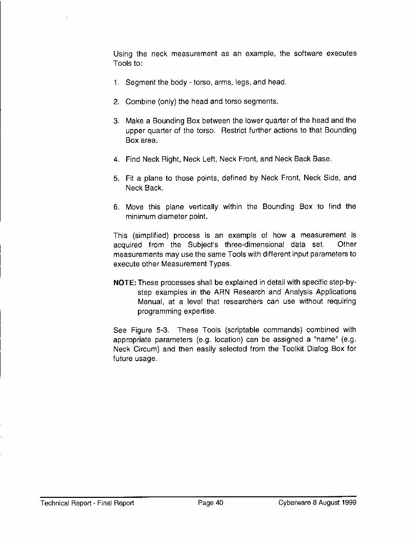
In the process of developing this complex software, an intermediate semi- automatic "Landmark" method was implemented. High luminescence markers were manually adhered to very specific body locations in order to eliminate the requirement for manually indicated body points (just explained). This process is "semi-automatic" in that once the Landmarks were manually affixed, the software could then automatically calculate measurements. See Figure 5-4. In the Landmark mode, the System detects the X-Y-Z location of these body point markers, and then uses those key locations as reference points from which measurements are positioned and calculated.
Technical Report - Final Report Page 41 Cyberware 8 August 1999
Technical Report - Final Report Page 42 Cyberware 8 August 1999
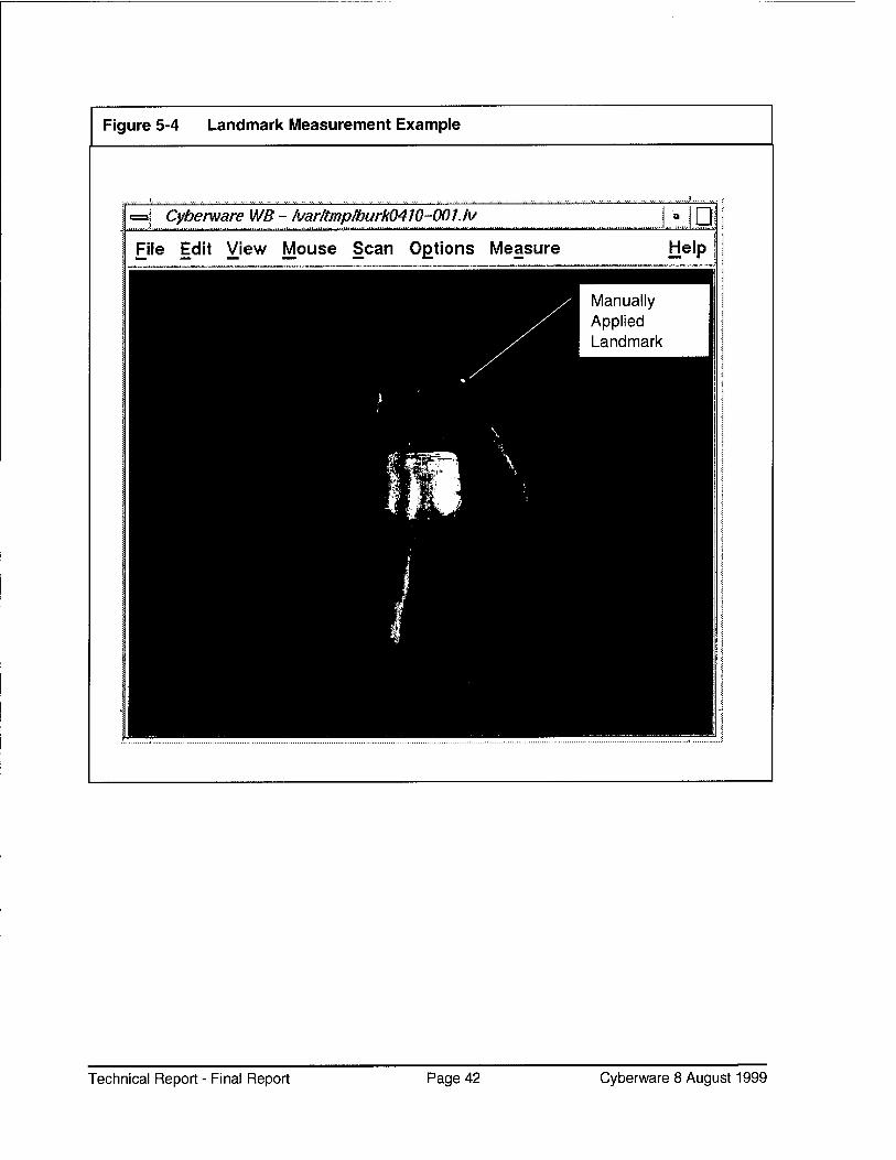
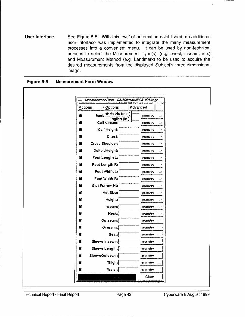
User Interface See Figure 5-5. With this level of automation established, an additional user interface was implemented to integrate the many measurement processes into a convenient menu. It can be used by non-technical persons to select the Measurement Type(s), (e.g. chest, inseam, etc.) and Measurement Method (e.g. Landmark) to be used to acquire the desired measurements from the displayed Subject's three-dimensional image.
Figure 5-5 Measurement Form Window
={ Measurement Form - 031698/mark0903-001./Vgz
Actions Options Advanced
1 if Back
: If Call
:| If Cal
; if
■ Cross S
: if Deltoi
: if FootL
; if Foot L
i if Foot
If Foot
\ m Glut Fu
if \
m
m
m
\ m o
M i
if Sleeve
if Sleeve
■ SleeveO
if
if
♦ Metric (mm.) | geometry —•
/N English (in.) 1 ^ircum:| geometry —■
_j f Height:| geometry
—J Chest: geometry
-. houlder:| geometry
-. dHeight:| geometry
-. ength L:j geometry
-1 ength R:j geometry
- Width L:| geometry
-. Width R:| geometry
-« rrow Ht:| geometry
__J Hat Size:] geometry
_; Height:] geometry
- Inseam: geometry
- Neck: geometry
-. utseam:] geometry
-u >verarm:| geometry
-1 Seat:] geometry
Inseam: | geometry
—J Length:] geometry
-. utseam: geometry
-I Thigh: |
Waist:]
geometry
geometry
II Clear ' "' ' ,""""" ' "'" ' im nimm ii i mim MI m,.niii 1.1,1 1 IM,11
Technical Report - Final Report Page 43 Cyberware 8 August 1999
Enhanced Productivity
See Figure 5-6. Once these convenient controls were implemented for use on a single Subject's image, a productivity enhancement was added in release 9.0 (2/99) to allow the selection of multiple Subjects' image files. This allows the user to select the desired Subject's files, and the desired Measurement Types and Method, and then have the selected measurements executed completely unattended.
Enhance Problem Solving
In addition, a powerful "Snapshots" feature was added in release 9.0 (2/99) to aid in quickly diagnosing unexpected results. When enabled, four (two-dimensional) views are automatically created and saved while the measurements are being calculated. This also stores the measurement path indicator (a graphic line indicating the physical path used when calculating the measurement - equivalent to the conventional tape measured path).
Figure 5-6 Batch Tool Window
.. . ..i. , , ..... , . ...1 .,
\
=| Batch Tool
Actions Actions
all -| ) okay |
SB chest geometry ->
key scanname | scandatej A ; W cross shoulder geometry ->
See Figure 5-7. To facilitate easy viewing of these "Snapshot" views, an additional user interface item was also developed in release 9.0 - the Viewer Tool. This Tool allows selection of (typically problematic) Subjects, and automatically displays the four Snapshot views for the selected Measurement Type, to aid in problem resolution, or just as a quick method for viewing how the measurement results were developed.
Each of these user interface dialog boxes also include other useful functions such as Print, Clear, Initialize, etc., to further streamline operations.
Technical Report - Final Report Page 45 Cyberware 8 August 1999
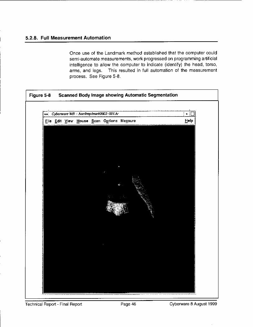
5.2.8. Full Measurement Automation
Once use of the Landmark method established that the computer could semi-automate measurements, work progressed on programming artificial intelligence to allow the computer to indicate (identify) the head, torso, arms, and legs. This resulted in full automation of the measurement process. See Figure 5-8.
Figure 5-8 Scanned Body Image showing Automatic Segmentation
Cyberware WB - A/ar#mp/mark0903-00Uv Ü File Edit View Mouse Scan Options Measure Help
Technical Report - Final Report Page 46 Cyberware 8 August 1999
Automatic Segmentation
Sophisticated software algorithms use the geometrical arrangement of the body (in a specific frontal view) to discriminate these body parts, rather than using manually applied landmarks. A major challenge in this advance was handling the wide variations of the human form.
The software identifies the body structure (head, torso, legs, etc.) by executing a segmentation process. First, the center point of the body is found (i.e. the center of the cloud of surface points). Then the front of the body is determined, based on its predictable elliptical cross-section. Once this orientation is established, the software performs measurements by "slicing" the image at various points.
Handling Body Contours
Special techniques were devised to allow the System to correlate its laser-made surface measurements to the results obtained by conventional tape measurements, such as when measuring around the trunk. Such measurements performed on many (particularly slender) Subjects result in the measuring tape not being in direct contact with some points of the body (e.g. recesses in back).
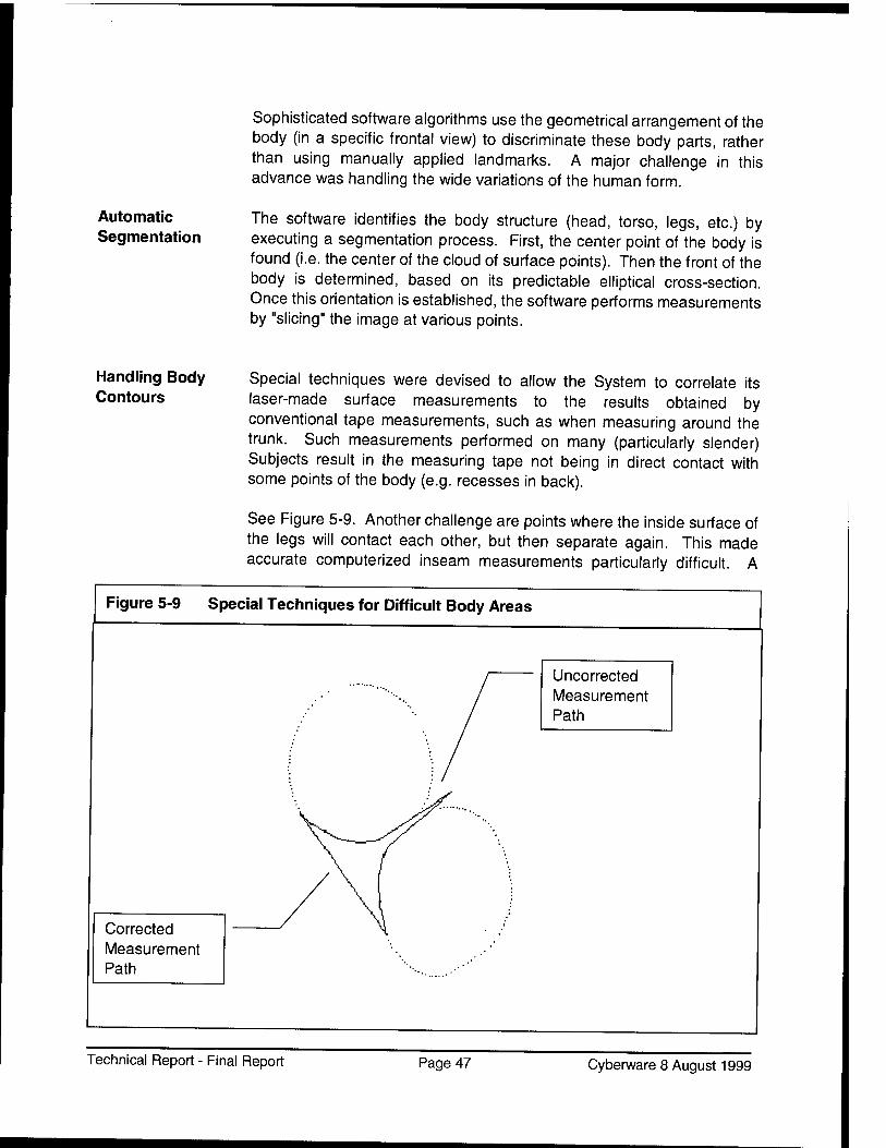
See Figure 5-9. Another challenge are points where the inside surface of the legs will contact each other, but then separate again. This made accurate computerized inseam measurements particularly difficult. A
Figure 5-9 Special Techniques for Difficult Body Areas
Corrected Measurement Path
Uncorrected Measurement Path
Technical Report - Final Report Page 47 Cyberware 8 August 1999
special (cusp locator) algorithm was developed by Joe Nurre of Ohio State University to overcome this obstacle.
Similar challenges exist where the inner surface of the arm contacts the side of the torso (near the armpit). In this case, this intersection point on the front of the body is compared to the equivalent point at the back (relaxation algorithm).
5.2.9. Testing and Validation
Initial testing of the measurement extraction process was done using manikins, followed by the use of human Subjects. Once it was established that the process was useable, an early test directed by Robert Beecher of Beecher Research was performed at the U.S. Army Natick Research Development and Engineering Center in December 1997. The results were positive, and are detailed in IPRs issued by Beecher Research. After the results of that testing were analyzed, the Programmers optimized the algorithms for speed and accuracy.
The System was then taken to MCRD - San Diego where Cyberware, Beecher Research, University of Ohio, and Anthropology Research Project, Inc. (ARP) conducted an extensive test and validation. The results are detailed in ARP's report titled "Standardized Measurement Procedures, Phase II, Validation of Measurements". Dr. Bruce Bradtmiller of ARP concluded the following regarding measurements performed by the system: "The most functional criterion, in this context, is the size grade because it directly impacts the system's ability to assign the correct size. By this criterion, ARNScan is successful on all dimensions except cross shoulder and sleeve length" (Work is ongoing to resolve issues with those two dimensions. This testing included over seven hundred scans, and due to the fact that it was performed in a "user environment", with the goal of obtaining accurate high throughput scans, served also as a preliminary Implementation Test as well.
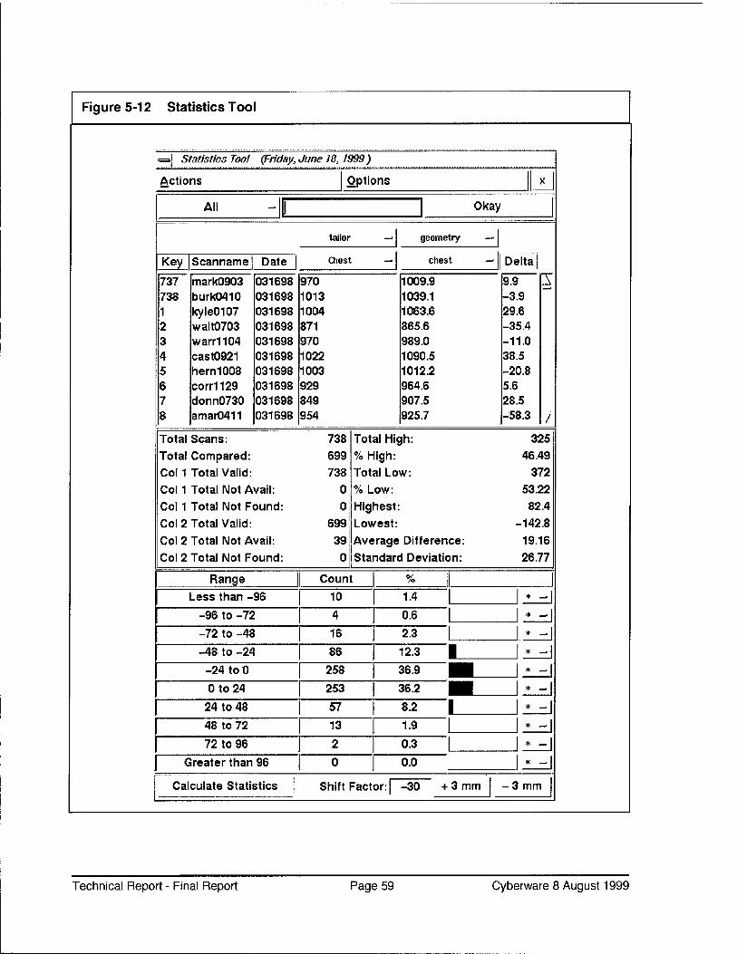
5.2.10. Analysis Tools
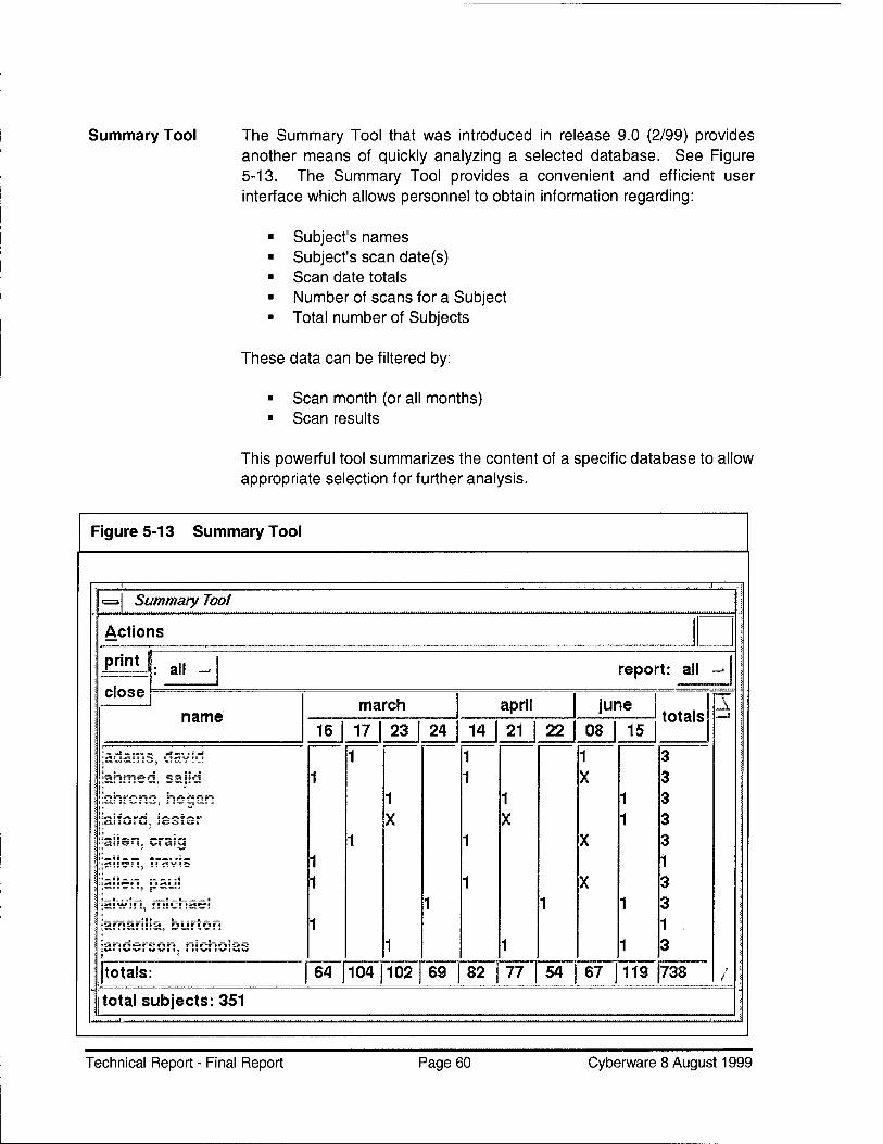
Cyberware developed two powerful analytical tools - the Statistics Tool and the Summary Tool (both explained in a following section titled, "Database Operations"). The Summary Tool quickly re-caps the overall test data acquired, including number of Subjects scanned, dates, and the general results of the scans. The Statistics Tool provides the means to quickly compare scan measurement results to conventional tape measurement results. This facilitates a fast objective analysis of the
Technical Report - Final Report Page 48 Cyberware 8 August 1999
measurement accuracy, providing a wide range of summary, statistics, and graphical distribution analysis. It also provides a very efficient method for retrieving and viewing problematic scan files. These Tools will be used on a continuing basis, greatly accelerating the development process. The results of usage of these tools are demonstrated in Appendix A.
5.2.11. Task Status
All tasks, deliverables, and completion milestones for this section (through the date of this report) were met or exceeded. All Marine uniform item measurements are currently extracted automatically (i.e. without any operator intervention) from scans. All required measurement Tools are integrated into the software and have a convenient user interface.
Future Tasks - Phase IV
■ Two additional Army dress uniforms to be added. ■ Additional measurements integrated into the software.
5.3 SIZE SELECTION (T1.3)
Goal Automate the selection of correctly sized garments, based on the measurements derived from Task 1.2.
5.3.1. Overview
In its simplest form, performing correct size selection is a matter of matching the body measurement information acquired with Sizing Tables that are linked to garment names and stock numbers. However, these Sizing Tables do not provide successful matches for every human body. Also to be considered is that there is some leeway between a body measurement (e.g. human waist) and a clothing dimension (e.g. trouser waist) to attain "proper fit". While that variable might be one inch for the waist of non-dress pants, it might be as little as one-quarter inch for a dress shirt collar; therefore, the complexity of the task increases.
The Size Selection Algorithms must also accommodate plus/minus tolerances that vary for each dimension of each garment type.
Technical Report - Final Report Page 49 Cyberware 8 August 1999
5.3.2. Alteration
When no acceptable matches are found, even given these allowances, the next decision is whether an existing stock garment has the alterability (fabric available, etc.) to meet fit requirements. If the decision is that an existing garment can be used, then which specific garment should be selected, and what should be altered to what extent. The software, at a minimum, could indicate that an altered garment is required. Enhancements could allow it to specify the stock number of the garment to alter, and provide alteration instructions. Work in this area is in the preliminary stage.
See also the "Alteration Information" section on page 36.
5.3.3. Made-to-Measure
When no garment can be found which offers adequate alterability, either manual or automated made-to-measure clothing must be produced. When configured to do so, enhanced versions of the software could output Subject and measurement information for manual tailoring, or communicate electronically with properly configured automated made-to- measure garment manufacturing equipment to produce a custom-sized garment. Work in this area is in the preliminary stage.
5.3.4. Size Selection Measurements
The first task was to collect the data from Military Garment Procurement, which listed the size specifications for every garment that was to be fitted. This information was acquired by Stephen Addleman from MCRD. In order to implement it in a manner that was user-friendly and flexible, that sizing data was transferred to industry-standard comma-delimited database files. Presently, those files are "manually" copied into the appropriate system directory (folder), but future software enhancements could include an "Import" function to streamline the inclusion and set-up of garment sizing/stock number files (including updates to earlier data).
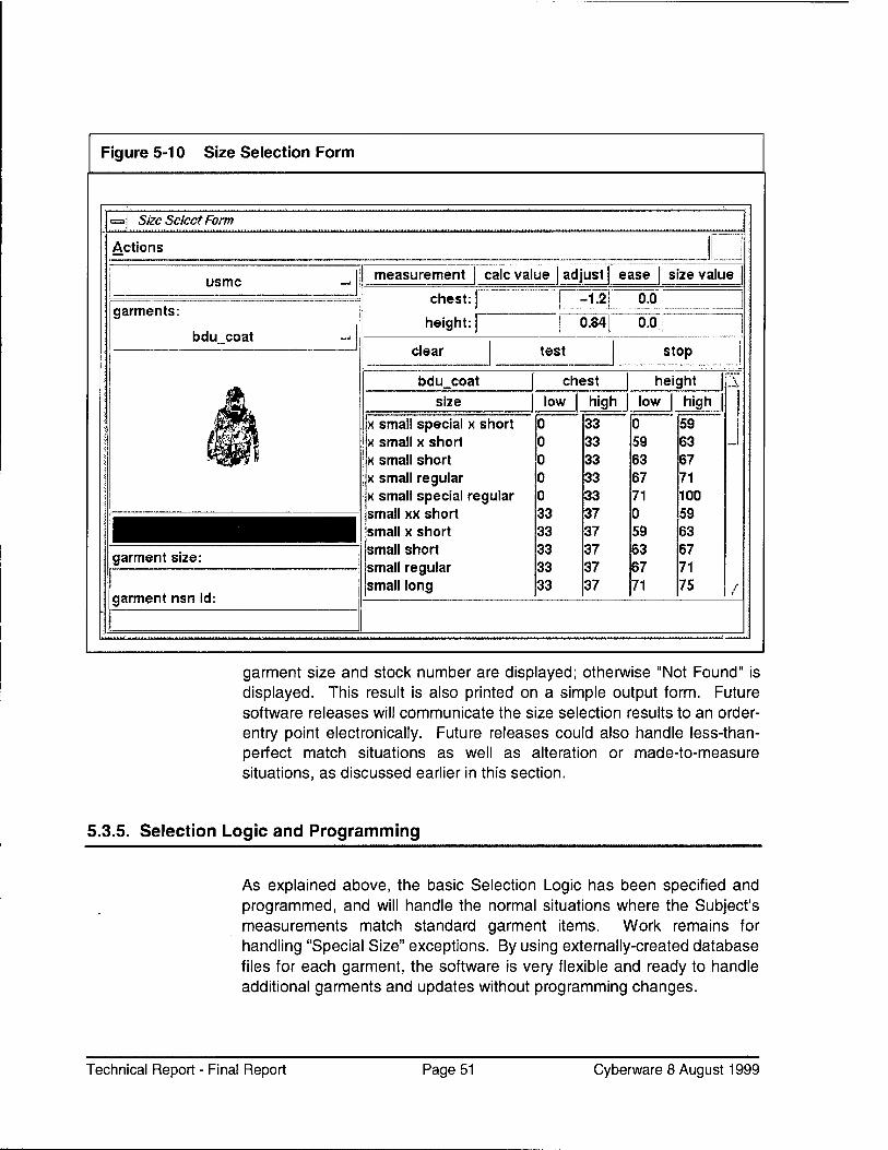
Implementation The System presently implements the Size Selection function via a convenient (preliminary) user interface, the "Size Selection Form" in release 9.0 (2/99). It supports size selection for multiple garments, and can process single or multiple Subjects in an unattended batch processing mode. See Figure 5-10. When Select Size is commanded from the Size Select Form, if there is an exact match available, the
Technical Report - Final Report Page 50 Cyberware 8 August 1999
Figure 5-10 Size Selection Form
Size Select Form
Actions
usmc measurement calc value adjust ease size value
garment size:
garment nsn id:
chest:
height:
-1.2 0.0
0.84 0.0
clear test stop
bdu coat size
x small special x short x small x short x small short x small regular x small special regular small xx short small x short small short small regular small long
garment size and stock number are displayed; otherwise "Not Found" is displayed. This result is also printed on a simple output form. Future software releases will communicate the size selection results to an order- entry point electronically. Future releases could also handle less-than- perfect match situations as well as alteration or made-to-measure situations, as discussed earlier in this section.
5.3.5. Selection Logic and Programming
As explained above, the basic Selection Logic has been specified and programmed, and will handle the normal situations where the Subject's measurements match standard garment items. Work remains for handling "Special Size" exceptions. By using externally-created database files for each garment, the software is very flexible and ready to handle additional garments and updates without programming changes.
Technical Report - Final Report Page 51 Cyberware 8 August 1999
5.3.6. Integration
As referenced earlier, Figure 5-10 illustrates the method currently available for performing garment size selection. Planned enhancements explained earlier will extend this process, and could include any or all garments entered into the system, as well as direct linkage to MTM systems. These extensions will provide support to all branches of the armed forces.
5.3.7. Testing
Initial testing and validation was conducted at Cyberware in March 1999. As of this writing, testing is under way at MCRD San Diego. Preliminary results are encouraging.
5.3.8. Task Status
The present state of the Size Selection task is that basic semi-automated size selection has been implemented for all Marine dress items. Testing is currently under way and preliminary results indicate that this task can be fully automated, but will require a significant effort to establish and integrate "rules of fit". These "rules of fit" are embedded in the detailed clothing design specifications, but not revealed in the standard garment size tariffs.
All sub-tasks in this section as scheduled to date have been initially addressed, with advanced work remaining. It is anticipated that the scheduled October/November 1999 Army garment item integration will proceed with relative ease due to the flexibility of the present software.
Technical Report - Final Report Page 52 Cyberware 8 August 1999
5.4 HARDWARE OPTIMIZATION (T1.4)
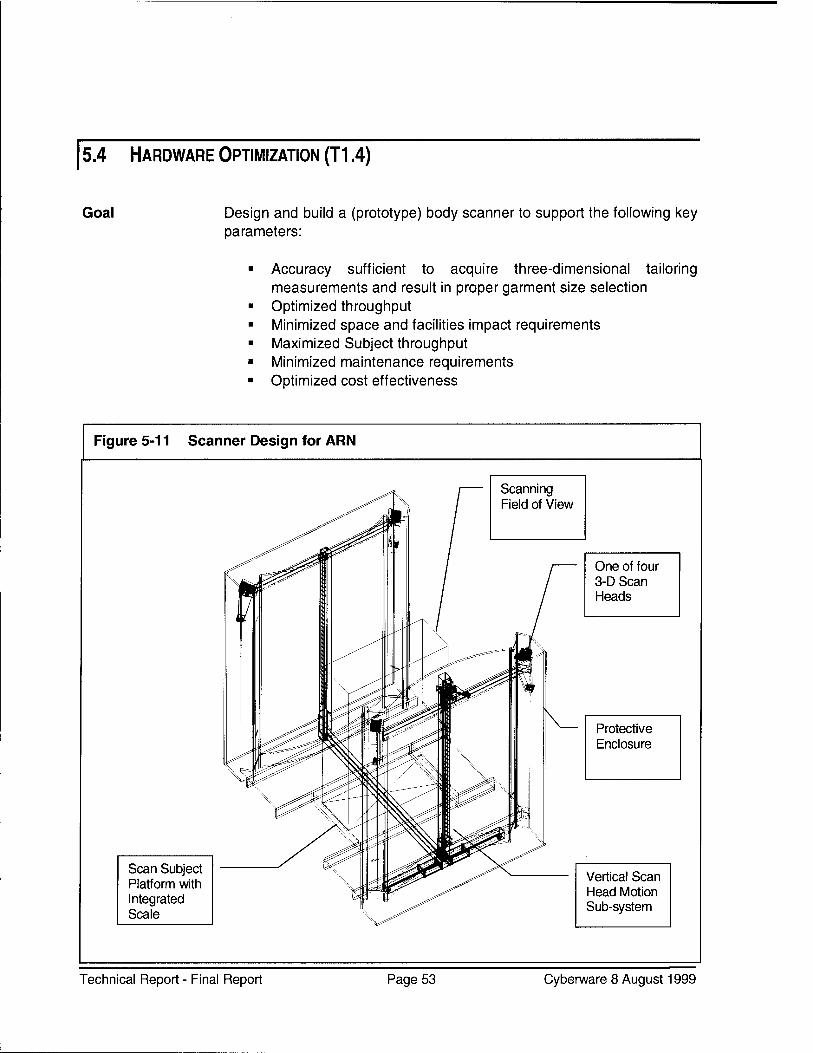
Goal Design and build a (prototype) body scanner to support the following key parameters:
Accuracy sufficient to acquire three-dimensional tailoring measurements and result in proper garment size selection Optimized throughput Minimized space and facilities impact requirements Maximized Subject throughput Minimized maintenance requirements Optimized cost effectiveness
Figure 5-11 Scanner Design for ARN
Scan Subject Platform with Integrated Scale
Scanning of View
One of four 3-D Scan Heads
Protective Enclosure
Vertical Scan Head Motion Sub-system
Technical Report - Final Report Page 53 Cyberware 8 August 1999
5.4.1. Overview
See Figure 5-11. The Cyberware WB-4 Whole Body Scanner was designed and manufactured as a portable tool for highly versatile and accurate scientific applications. While it is well-suited for the investigatory stages of the T2-P5 project, a unit is being designed which is optimized for the efficient acquisition of tailoring measurements at a maximal rate with minimal facilities and work-force impact.
NOTE: The majority of this Sub-task will be executed during Phase IV.
The preliminary Field Implementation testing performed at MCRD San Diego provided valuable "real world environment" experience that indicated actual requirements for a "production" version Scanner.
5.4.2. Features
The ARN-optimized scanning sub-system will feature:
Simplified modular assemblies will enhance reliability and reduce maintenance requirements and skill levels. The re-design will offer a significant overall cost reduction while providing needed elements for accurate body measurements along with important program-related enhancements.
5.4.3. Task Status
This task is on schedule. The design plan and layout are complete. Structural engineering and design of the Scanner Frame is complete, and a prototype is in the early stages of fabrication.
Phase IV Work A prototype of the Scanning Head sub-assembly is being fabricated, and will undergo preliminary testing during early 1999 (using the earlier Frame). The Power Supply and Controller Modules are re-designed and a prototype is being fabricated and will be tested in late 1999.
Technical Report - Final Report Page 54 Cyberware 8 August 1999
These items are on-track and are also scheduled for completion during Phase IV.
5.5 IMPLEMENTATION (T1.5)
Goal To demonstrate the practical application of key elements of the T2-P5 project, through installation and operation at typical user sites, where actual day-to-day usage requirements will be experienced. To thoroughly evaluate the results of this experience, and recommend changes that will further optimize the System.
5.5.1. Overview
The Implementation Events required:
Planning Plan review and approval An Implementation Procedure Acquisition and installation of required equipment Execution Recording of events Evaluation of results Recommendations for optimization
Progress This process has been implemented twice at MCRD San Diego. (The second Implementation Event is ongoing as of the end of this report period). The first Implementation Event in March through June 1998 evaluated the performance of the body scanning hardware and the operating software. That software handled:
Scanner operation Three-dimensional image acquisition Manual Landmark, and some Automatic measurements
(geometry-based)
Technical Report - Final Report Page 55 Cyberware 8 August 1999
Results The results demonstrated that the System was capable of making reasonably accurate body measurements at a rate that should be able to keep pace with the as-is clothing issue line. The equipment had no failures, and only one percent of the Subjects required re-scanning (due to excessive motion, or external interference). The full results of this Implementation Event were reported by Dr. Bradtmiller in Anthropology Research Project's "Standardized Measurement Procedures, Phase II, Validation of Measurements" report, dated 28 April 1999.
Advancement The Implementation Event that was ongoing concurrent with the writing of this report somewhat repeats the physical process employed in the earlier event, but integrates extensive enhancements in the software that implements totally automatic body measurement. These enhancements:
■ Improve ease of use via enhance user interface ■ Reduce operator actions ■ Increase overall throughput from about 1 minute to about 45
seconds ■ Provide basic semi-automated size selection ■ Implement tools which provide computer-driven analysis of results
This Implementation Event process results in a printed form which provides the sizes for selected garments for each Subject. The resultant clothing fit is then evaluated, and the results will be reported. The report for the results of this Implementation will be issued in June 1999.
5.5.2. Task Status
Two Implementation Events have been completed successfully (U.S. Army Natick 1997 and MCRD San Diego 1998). A third Implementation Event is well underway with encouraging results.
The Planning, Plan Review, Plan Documentation, and the Measurement Phase Implementation have been completed and reported. The preliminary Size Selection Implementation phase is currently underway and will be completed in June 1999, after which reports will be issued and evaluations performed.
Since prior tests and Implementation Events have indicated that the System makes measurements of generally satisfactory accuracy per Final Report issued by Anthropology Research Project, Inc. ("Standardized Measurement Procedures Phase II: Validation of Measurements - Marine Corps Test)., future Implementation Events are planned to be focused on:
Technical Report - Final Report Page 56 Cyberware 8 August 1999
Acceptable garment size selection Throughput Ease of use Reliability
Remaining milestones are to conduct an Implementation Event at another location (e.g. Fort Jackson), which will include male and female Subjects, and implement specified Army garments. This is planned to take place in the near future, and will include testing of the re-designed Scanning Sub- system.
Technical Report - Final Report Page 57 Cyberware 8 August 1999
5.6 DATABASE OPERATIONS (T1.6)
Goal Develop tools and procedures to attain maximum benefit from the vast database of three-dimensional scan information that will be generated. Provide an interface that allows users to extract information needed to complete the T2-P5 and other related projects without requiring programming skills.
5.6.1. Overview
Three-dimensional scan files are very large, and require careful planning to ensure manageability. In addition, many Subjects are scanned, at times in multiple occurrences. Researchers and Programmers need to be able to quickly and efficiently handle this voluminous data, deriving a wide range of results, such as:
■ Number of scans evaluated ■ Number of valid scans ■ Difference between scan measurement and tape measurement for
a specific file, or for a selected group of files ■ Number (or percent) of scans yielding results greater (or less)
than the average ■ Standard deviation for selected files ■ Distribution of variances
and other data. A graphical display of distribution variances is also available. Certain tools, such as the Statistics Tool and Summary Tool are used for development purposes, and are not required for normal System operation.
Statistics Tool See Figure 5-12. The Statistics Tool that was introduced in release 9.0 (2/99) provides a convenient and efficient user interface that allows personnel to obtain this important data. A particularly powerful feature allows quick display of the three-dimensional images showing the measurement path, which can be easily called from a selected variance distribution group. This facilitates quick resolution of problematic scan measurement results.
Technical Report - Final Report Page 58 Cyberware 8 August 1999
Total Scans: 738 Total High: 325 Total Compared: 699 % High: 46.49 Col 1 Total Valid: 738 Total Low: 372 Col 1 Total Not Avail: 0 % Low: 53.22 Col 1 Total Not Found: 0 Highest: 82.4 Col 2 Total Valid: 699 Lowest: -142.8
Col 2 Total Not Avail: 39 Average Difference: 19.16 Col 2 Total Not Found: 0 Standard Deviation: 26.77
Range | Count %
Less than -96 10 1.4 —-' I
_i 1 -96 to -72 4 0.6 *
-72 to -48 16 2.3 * -|
-48 to -24 86 12.3 ■ I » __. 1
-24 to 0 258 36.9 ^M * _ I
0to24 253 36.2 HU I * -|
24 to 48 57 8.2 | »
—' 1
48 to 72 13 1.9 mm* 1
72 to 96 2 0.3 * -|
Greater than 96 0 0.0 * -|
Calculate Statistics j Shift Factor: -30 + 3 mm -3 mm
Technical Report - Final Report Page 59 Cyberware 8 August 1999
Summary Tool The Summary Tool that was introduced in release 9.0 (2/99) provides another means of quickly analyzing a selected database. See Figure 5-13. The Summary Tool provides a convenient and efficient user interface which allows personnel to obtain information regarding:
Subject's names Subject's scan date(s) Scan date totals Number of scans for a Subject Total number of Subjects
These data can be filtered by:
■ Scan month (or all months) ■ Scan results
This powerful tool summarizes the content of a specific database to allow appropriate selection for further analysis.
Figure 5-13 Summary Tool
Summary Toot
Actions
: all -
name
totals:
report: all
march
16 17 23 24
april
14 21 22
june
08 15 totals
1
1 1
64 104 102 69 82 77 54 67 119 738
I
total subjects: 351
Technical Report - Final Report Page 60 Cyberware 8 August 1999
5.6.2. Task Status
The Planning, Validation Tool, Statistics Tool, and Image Storage Programming milestones have been completed, tested, and integrated into the software. The Size Information Data sub-task is a work in progress with a projected completion date of mid-1999.
5.7 DOCUMENTATION (T1.7)
Goal Provide documentation that will support system usage by:
and provide maintenance documentation that will allow lower level (sub- engineer) technical personnel to perform preventive and remedial maintenance in a timely manner.
5.7.1. Overview
The document set will consist of three major items:
■ Operator's Guide ■ ARN Research and Analysis Applications Manual ■ Installation and Maintenance Manual
Operator's Guide The user for this documentation will be an equipment operator with minimal training and probably a high school education.
The Operator's Guide will be structured as follows:
Preface, Warnings, Introduction, Controls and Displays, Operation, Menus, User Maintenance, Problem Solving, Obtaining Assistance, and will also include a Quick Reference Card.
Technical Report - Final Report Page 61 Cyberware 8 August 1999
Research and Analysis Applications Manual
The user for this document might be a Scientist using the system for anthropological research, a Programmer developing alternative applications or integrating the System with other systems, an Engineer developing material handling or automated garment manufacturing, or a Materials Planner for garment inventory control.
The Research and Analysis Applications Manual will be structured as follows:
Preface, Warnings, Introduction, System Fundamentals, Controls and Displays, Operation, Menus, Tool Kit, Programming, Configuration Files, Functional Description, User Maintenance, Problem Solving, Obtaining Assistance, Upgrading Software, and Glossary.
Maintenance Manual
The user of this document will be a Senior Electronics/Optics Technician or Engineer who is experienced/trained in Laser safety, computer workstations, electro-mechanical devices, servo control systems, optical alignment. They will be trained by Cyberware for support of this system. The Installation and Maintenance Manual will be structured as follows:
Preface, Warnings, Introduction, Functional Description, Maintenance, Troubleshooting, Module Replacement and Alignment, Replacement Parts, System Installation, Obtaining Assistance, and a Technical Reference.
These documents will be available from Cyberware upon request, when completed.
5.7.2. Task Status
The Research and Analysis Applications Manual is progressing well, with first drafts of many sections completed and reviewed. The User's Guide has been planned and preliminary writing has begun. The Maintenance Manual has been planned, but writing will not begin until the new ARNScan hardware is developed. None of the milestones are complete.
All of this documentation is planned for completion during Phase IV. The preliminary release Operator's Guide is planned for late 1999. The preliminary release of the Research and Analysis Applications Manual is planned for early 2000. The preliminary release of the Maintenance Manual is planned for early 2000. The Documentation Plan is available for review on request.
Technical Report - Final Report Page 62 Cyberware 8 August 1999
^8 NT OPERATING SYSTEM CONVERSION (T1.8)
Goal Convert the present SGI / UNIX-based software to run on an IBM PC/MS- Windows NT platform. This will result in significant hardware cost savings and greater user familiarity and versatility.
5.8.1. Overview
This task involves using existing software technology to convert the ARNScan code from a UNIX to a MS-Windows NT format. After the initial conversion process is done (using conversion software), the resultant code must be exhaustively tested for proper operation, and inevitable software problems introduced by the conversion must then be resolved manually.
5.8.2. Task Status
Selected software modules were converted, and ran properly in the MS- Windows NT environment. These preliminary efforts indicate that a smooth transition will occur. Finalization requires hardware integration to be completed. This task is not scheduled for completion until the remaining tasks slated for the ARN software package have been completed.
5.9 MILITARY BUSINESS PLAN (T1.10)
Goal Develop a business plan that facilitates evaluation of the impact and benefits of fully integrating the T2-P5 system into existing apparel issue facilities.
5.9.1. Overview
This plan will examine each element of the T2-P5 system and contrast it against the existing manual system. Issues of consideration are:
Technical Report - Final Report Page 63 Cyberware 8 August 1999
Facilities Staffing Interface to down-stream systems System-down contingency plans Safety Security Preventive and remedial maintenance Site design Typical and worst-case operation scenarios Data management Training requirements Financial impact
Information that establishes the basis for this plan is being collected and analyzed from the Implementation Events which have occurred at Natick, MCRD San Diego, and will be collected from future Implementation exercises. Initial writing has begun.
5.9.2. Task Status
This task is a work-in-progress. A first draft of the plan will be submitted in late 1999. The final version is scheduled for completion by January 2000.
5.10 ADVANCED BODY MODEL (T1.11)
Goal To develop an alternative data file containing the three-dimensional body image data in a smaller, more manageable structure and size without sacrificing important content.
5.10.1. Overview
A Parametric Body Model is a 3D form or template that accurately represents the scanned Subject, but does not contain the "point-cloud". It might be as simple as a data set containing and representing all of the measurement information extracted from the Subject, but without the ability to display the original three-dimensional image. In an advanced state, this model may contain shape information and features that would allow the extraction of further measurements without the overhead of the point-cloud data.
Technical Report - Final Report Page 64 Cyberware 8 August 1999
The value of such a tool can be found in the size of the file and the speed at which it can be queried. It should be useful to designers of clothing as well as the programmers.
Development steps include establishing a specification of the file content that will meet the requirements of all likely file users, programming the file extraction code, and testing the integrity and acceptability of the resultant files.
5.10.2. Task Status
This task is a lower priority work-in-progress. Planned completion is during Phase IV.
5.11 VALIDATION AND TESTING (T1.12)
Goal To provide written procedures to test the viability of the aforementioned Tasks (T1.1 through T1.11) where appropriate.
5.11.1. Overview
These test and validation procedures provide detailed protocol for preparing for the test process, conducting the test, reviewing the results, and criteria for evaluating the success achieved. These procedures are to be approved by appropriate T2-P5 program management personnel, and then applied to the relevant tasks. Reports analyzing and evaluating these tasks will be produced, based on the criteria set forth in these procedures.
5.11.2. Task Status
Test and Validation procedures have been developed for Measurement Extraction. See Appendix A. Procedures remain to be developed for Size Selection. This ongoing task is paced in conjunction with development of each relevant target task.
Technical Report - Final Report Page 65 Cyberware 8 August 1999
6. RECOMMENDATIONS
Real-world field tests have established that the Cyberware ARNScan system acquires accurate body measurements. Initial testing has also indicated that the System issues correctly sized garment orders. Preliminary testing has indicated that the Cyberware ARNScan System has the potential to offer improved throughput, and several additional important opportunities for reduction of apparel issuance costs. Therefore, we recommend continued development of this key module in the T2-P5 Customer-driven Uniform Manufacture program. This will help ensure that the benefits listed in section 2.3 (page 15) of this report can be applied to all U.S. Government apparel issuing agencies.
In order to fully implement this key program and realize the important benefits, a number of additional tasks must be accomplished. These are first summarized below, and then presented in detail in the following sections.
6.1 ADVANCED TASK EXECUTIVE SUMMARY
Ongoing Sub-Tasks
Continue work on all the tasks delineated in the preceding sections of this report; in order to attain the additional performance and efficiency enhancements that are based on those items.
Full Field Implementation
Full field implementation of a Cyberware ARNScan System, operated by "normal" staffing personnel, in a normal environment, and processing all apparel issuance sizing tasks (up to the throughput capacity of one System).
Made-to-Measure Implementation
Implement automated body measurement data input to a Made-to- Measure system in order to fully automate rapid custom-fit clothing production.
Database Enhancement
Enhance the Database resources to automate data management, and effectively enable dissemination of that valuable information to those who can benefit from it. Enhance reporting capabilities.
Technical Report - Final Report Page 66 Cyberware 8 August 1999
Expand Expand the application of this program to include additional service units, Applications additional garments, and female personnel.
Automate Further optimize system operations to reduce (or even eliminate) operator Operation intervention and routine maintenance activities.
Exception Advance the system programming to enhance handling of special sizing Handling situations where a stock garment that complies with a Subject's body
measurements is not available.
Remote System Management
Cost Reductions
Body Mass Calculation
Performance Optimizations
Develop software that will provide Web-based remote system management. This should include self-detection and remote notification of abnormalities, including above-normal quantities of re-scan requests. This added capability will facilitate enhanced operation, data management, and optimized throughput.
The current system configuration includes expensive hardware required to display three-dimensional scanned images. This capability may not be required in "production" units - the elimination of which could result in a further reduction in system cost.
With the addition of an electronic body weight scale and computational software, the lean body mass could be calculated for each scanned Subject.
As with any complex high technology project, the initial task is to establish a viable product. Cyberware recommends approval of software enhancements that will improve the throughput, reliability, and security of the System.
Technical Report - Final Report Page 67 Cyberware 8 August 1999
6.2 ADVANCED TASK RECOMMENDATION DETAILS
The following sections provide detailed information on the tasks Cyberware recommends, to optimize the effectiveness of ARNScan.
6.2.1. Complete Ongoing Sub-Tasks
Continue work on all the tasks delineated in the preceding sections of this report; in order to attain the additional performance and efficiency enhancements that are based on those items. Tasks remain to be completed in all of the existing sub-tasks:
Task Coordination Measurement Extraction Size Selection Hardware Optimization (Scanner) Implementation Database Management Documentation Software Transition to NT Military Business Plan Advanced Body Model
6.2.2. Full Field Implementation
We recommend a full field implementation of a Cyberware ARNScan System, operated by "normal" staffing personnel, in a normal environment, and processing all apparel issuance sizing tasks (up to the throughput capacity of one system).
Field trials to-date have yielded valuable information which has greatly enhanced the rapid advancement of this technology; however, a one- hundred percent "real-world" implementation could not be done in the past due to lack of completion of certain key tasks.
A full Customer Demonstration Site implementation should be conducted, where aN garment body measurement acquisition activities are performed by the ARNScan System; and further, that it be managed by Cyberware, but operated by properly trained government personnel.
Technical Report - Final Report Page 68 Cyberware 8 August 1999
A carefully structured operations protocol must be developed. This must include a comprehensive reporting and review system to monitor results and facilitate a quick response for any needed corrections. We further recommend that a preliminary version of the Military Business Plan (item T.1.10) be issued just prior to this event, and that the knowledge gained from this event would be used to optimize this business plan.
Ideally, this event should also include the introduction of the new ARN Scanner in order to make the evaluation as comprehensive as possible.
6.2.3. Full Made-to-Measure System Implementation
We recommend implementation of automated body measurement data input to a Made-to-Measure (MTM) system, in order to fully automate rapid custom-fit clothing production. A complete MTM system field trial should be conducted in cooperation with Ms. Carol Ring of Southern Polytechnic State University.
Southern Polytechnic should specify the measurements needed for the chosen test garment (recommend the Marine Dress Coat). They should also propose the exact data format required (a structured text file). Cyberware will add software enhancements to allow entry of such a requisition for the MTM item.
The ARNScan System will then acquire the needed body measurements and transmit them electronically (via Web, in the specified format) to Clemson University, where the resultant garment would be quickly produced via automated MTM equipment.
A link to an Electronic Order Form (EOF) needs to be developed and implemented, taking expense authorization into consideration as well as the Subject's body measurements and other needed personal data (duty station, etc.). Measurements and formats should be specified by Dr. Nancy Staples of Clemson Apparel Research, based on input from all affected partners. Cyberware would electronically send a structured text file with the data required to initiate the garment build.
6.2.4. Database Enhancement
We recommend that Cyberware undertake a task to enhance Database resources. This task shall focus on automated data management, and effective dissemination of that valuable information to those who can benefit from it.
Technical Report - Final Report Page 69 Cyberware 8 August 1999
The Database created by the ever-increasing data generated from Subject scans will become increasingly valuable for research and planning. We recommend adding tasks to manage this valuable resource in a way that authorized personnel will be able to query it in a flexible Web-based format. Privacy issues must also be addressed, allowing use of the data by many while protecting both the visual and name identity of the Scan Subjects (including SSAN).
Further, we recommend that all remote field scanning sites are enhanced with remote data access and control capabilities. This could allow data to be retrieved (and backed up) routinely, yielding timely reports, available via the Web. Data could be retrieved from all field sites and be maintained centrally at Cyberware.
We recommend that new software tools are developed to facilitate Web- based search of this Database, as well as tools to properly organize, structure, analyze, and maintain its integrity. Report generators should be coded which will detect trends and anomalies promptly and effectively. This will be a major asset for materials planners, etc..
6.2.5. Expand System Application
We recommend expansion of the application of this system to include additional service units, additional garments, and female personnel.
Female Garments Expansion into female garments will require development work in order to acquire and automate additional measurements, as well as proper re- location of some measurements used for male apparel (e.g. waist location).
Once this work is completed, the results must be field tested to validate the results against conventional tape measurements, and then proper garment fit. The end product of this recommended task will be applicable to all Armed Services divisions.
Further work will also be required of Carol Ring of Southern Polytechnical University, to input the measurement vs. size/stock number information for the female garments.
Other Armed Now that it has been established that the System can properly determine Services sizes and stock numbers for U.S. Marine garments, the system garment
database should be expanded to include all stock garments (requiring body measurements) for all Service divisions, allowing the benefits of this System to be realized by all.
Technical Report - Final Report Page 70 Cyberware 8 August 1999
The sub-tasks involved in achieving this goal are:
♦ Enhance the software to facilitate the input of the Subject's branch of service when performing a scan.
♦ Development of software to efficiently and effectively handle the larger garment database.
♦ Development of software that will easily allow non-programmer personnel to input new, or updated garment files (in a specified file format).
♦ Development and input of garment specification tables for all service garments requiring body measurements. This could be a Southern Polytechnical University activity.
6.2.6. Automate Operation
We recommend further optimization of system operations to reduce (or even eliminate) operator intervention and routine maintenance activities.
Presently a minimally skilled person is needed to operate the System. We recommend further hardware and software development to fully automate the process, eliminating the need for a full-time Operator. This would entail several sub-tasks to revise handling of these activities:
These activities are detailed below. See Figure 6-1.
Clothing This is Station 1. The Subject would enter a "locker room" area where Preparation they could undress and store their outer garments. There are no special
clothing requirements other than non-reflective attire with a body- conforming fit. Common Briefs are acceptable. Either signage or a video cine-loop could provide instructions at this point, followed by directions to proceed to Station 2.
Technical Report - Final Report Page 71 Cyberware 8 August 1999
Positioning Instructions
This is Station 2. A video should be produced which would instruct the Subject on proper attire fit (e.g. snug to body, no wrinkles, etc.), and proper body positioning. This video could be viewed while they are awaiting their scan. The video could be a conventional VCR/Monitor presentation, or a computer cine-loop that could be displayed on multiple video monitors for observance while in line.
Subject Data Entry
This is Station 3. Automated entry of Subject data - probably Social Security Account Number (SSAN) - based. Since this is a unique number, the Subject could:
♦ Key it in via Keypad ♦ Speak it, using voice recognition ♦ Scan in an ID card
Body Positioning Equipment
A confirmation step to verify proper entry of the Subject's data must also be included.
(This is still Station 3). The Subject would proceed to the Scanner platform. Two approaches could be taken to automate achievement of proper body positioning.
Silhouette (shadow) Projection - One fairly simple approach could be the use of a front and side projection lamp, which would cast a shadow of the Subject upon a silhouette pattern at their front and (opposite) side. The Subject could then move their body until it was within the constraints of the silhouette.
Video/Computer - A higher tech closed-loop approach could be implemented using rear and side video camera input to a computer. This could detect body position within given constraints, and issue correction instructions on a video monitor positioned in front of the Subject (but, outside of the scanning path).
When using one of these approaches:
♦ A red light could be used to indicate Not Ready ♦ A yellow light could be used to indicate Position Close to Correct ♦ A green light could be used to indicate Position Correct - Ready
for Scan.
The Instruction Monitor could then issue final instructions such as - "Hold Your Position. Remain still. Scan in Progress. Hold Position. Scan Complete. Proceed to Next Station." etc..
Technical Report - Final Report Page 72 Cyberware 8 August 1999
Scan Initialization (This is still Station 3). The actual scanning process could be initiated automatically, as explained above, when a "Ready" condition is achieved. Alternatively, either a voice command from the Subject, or a foot-switch (disabled until proper position is achieved) could allow the Subject to initiate the scan without a separate equipment operator.
Results Feedback This is Station 4. When the scan is completed, the Instruction Monitor located at the scan position would instruct the Subject to proceed to Station 5, which allows them to clear the Scanner for the next Subject, and then wait in a short line for the results, which could be either:
♦ Scan Successful, Return to Station 1 and get dressed, then proceed to (point to be determined by military procedure), or
♦ Re-scan Required, due to (reason - e.g. excessive movement, etc.). Return to Station 3 (Subject ID Input).
Figure 6-1 Body Measurement Acquisition Sequence
STATION 1 STATION 2 STATION 3 STATION 4 "Locker Room" Wait in line for Scanner Wait in line to Undress, store clothing, put on
-> scan, view instructional
"► Assume proper scan position,
> advance to Station 5 and
scan attire (if video execute scan receive scan necessary) results
i k i L + STATION 5
Printer View results: ♦ If OK, return
to Station 1 to get dressed.
♦ If error, return to Station 2 for re-scan.
Technical Report - Final Report Page 73 Cyberware 8 August 1999
These are all the steps required for automated Subject measurement acquisition. We recommend that they are all automated as detailed above, to realize very significant savings of from one to five staff positions (in the case of 24-7 manning), in addition to the elimination of the manpower normally required for tailor-performed measurement.
Electronic Presently, the Subject is issued a paper printout of the garment stock Requisitioning number(s) selected. We recommend that this data is stored electronically
in a Subject File, and automatically forwarded to the garment issuance point.
A further benefit of generating such a Subject File is that future garment requirement projections could be made. This could facilitate pre-ordering the Subject's proper garments so that they could be in stock at their duty station at normally projected replenishment times.
6.2.7. Enhanced Exception Handling
We recommend advancing the system programming to enhance handling of special sizing situations, where a stock garment that complies with a Subject's body measurements is not available.
When acquired body measurements do not correlate to the database entries for the target garment, advanced approaches should be implemented to efficiently handle these situations. Two alternative actions could be implemented:
♦ Order Made-to-Measure ♦ Order Altered Garment
The first sub-task could be to program the current humanly-executed logical process regarding which of these two actions should be implemented for this Subject under these conditions.
Secondly, if the decision is "order MTM", then route the Subject data (including duty station) and body measurements to the MTM manufacturing site.
Alternatively, if the decision is to alter an existing stock item, instructions should be programmed to:
a. Select the best garment for alteration (e.g. enough fabric in all measurement dimensions).
Technical Report - Final Report Page 74 Cyberware 8 August 1999
b. Inform the inventory system that this was an "exception", and that the actual requirement was (specify desired garment stock number). This will help to eliminate the propagation of stock level errors.
c. Issue specific alteration instructions (e.g. shorten inseam by 1.2 inches, etc.), so that lower skilled (lower cost) seamstresses (or even an outside competitive-bid contractor) could be used to make the garment modifications.
d. Print delivery instructions so that the garment reaches the Subject after alteration or MTM production is complete.
6.2.8. Remote System Management
We recommend the development of software that will provide Web-based remote system management. This should include self-detection and remote notification of abnormalities, including above-normal quantities of re-scan requests. This added capability could facilitate enhanced operation, data management, and optimized throughput.
Due to state-of-the-art communications capabilities, additional programming could allow remote system management from Cyberware Headquarters. The System could be programmed to self-detect a wide range of abnormalities. The System could automatically contact Cyberware when specified (or unspecified) abnormalities are detected.
6.2.9. Additional System Cost Reductions
The current system configuration includes expensive equipment, which is required for display of three-dimensional images. We recommend a task to develop a scan processor that would accept the three-dimensional scan data and compute the body measurements without three- dimensional display for "production" units.
If desired, two-dimensional views could be generated and displayed on conventional computer equipment while still eliminating the costly three- dimensional display capabilities.
Technical Report - Final Report Page 75 Cyberware 8 August 1999
Advanced Body Fully implementing the Advanced Body Model task could allow Model subsequent three-dimensional viewing on 3D Workstations when desired,
but removing that cost burden of this equipment from production scanning stations.
6.2.10. Body Mass Estimation
With the addition of an electronic body weight scale and computational software, the estimated lean body mass could be calculated for each scanned Subject. The software could calculate the body volume, based on the three-dimensional scan data. Then with input of the factors for body fat mass per unit volume, and body muscle and bone mass per unit volume, the estimated lean body mass percentage could be computed based on the total body weight input from the electronically coupled scale. These results could be included in the Subject File, and perhaps used as a physical conditioning goal or evaluation.
6.2.11. Performance Optimizations
As with any complex high technology project, the initial task is to establish a viable product. Cyberware recommends approval of software enhancements that will improve the throughput, reliability, and security of the system.
In the process of ongoing software development, our Programmers have become aware of a number of opportunities available for further throughput enhancement. This would require approval of additional tasks to allow realization of these opportunities. The end result could be processing a significant additional number of Subjects on the same system in less time. The investment of this software enhancement development would be realized in savings over many years of system usage.
6.2.12. Other Recommendations
Finally, we recommend the continuation of the ongoing task to:
♦ Implement the ARN-optimized Scanner
♦ Develop effective System documentation
Technical Report - Final Report Page 76 Cyberware 8 August 1999
♦ Continue the platform transition work to NT
♦ Develop the Military Business Plan
♦ Complete the Advanced Body Model
and continue with effective System implementation and validation efforts as these enhancements are implemented.
Technical Report - Final Report Page 77 Cyberware 8 August 1999
CONCLUSION
The feasibility and effectiveness of using a Body Scanner to acquire tailoring measurements coupled with advanced software to make valid decisions on garment size has been established.
Work remains to be completed to handle sizing exceptions that could result in garment alteration instructions or issuance of Made-to-Measure orders.
A high emphasis was placed on preliminary Implementation Trials to ensure the validity of continuing the project. The excellent results demonstrated should reassure project management that continuance of this project is a decision that can be affirmed with an unusual level of confidence.
Technical Report - Final Report Page 78 Cyberware 8 August 1999
8. APPENDIX
Over seven hundred scans were performed to acquire body measurements. These measurements were compared to the results obtained using traditional tailoring techniques via tape measure.
The following figures illustrate the results of that comparison. These seven figures cover the following measurements:
An annotated sample combined with explanations of the various fields is included following these figures, starting on page 92.
8.1 OVERVIEW
The Measurement Statistics Tool is very useful in the process of troubleshooting and optimizing measurement software routines. With it, we are able to do an evaluation of ARNScan versus tailoring measurements.
When the evaluation indicates a need for improvement, changes can be made in the ARNScan measurement routines, and then re-applied to the Subject's existing three-dimensional scan data. The resulting revised ARNScan measurements are then analyzed again versus the tailor measurements.
The measurement goal would seem to be bringing the ARNScan measurements into agreement with the tailor measurements; however, several issues indicate otherwise. First, for most measurements, the ARNScan results are more consistent and repeatable, due to the non- contact laser measurement approach. This is particularly true in measurements over longer distances, and across body structure paths
Technical Report - Final Report Page 79 Cyberware 8 August 1999
that are more susceptible to errors induced from measuring tape compression (e.g. chest, seat, etc.). In these cases in particular, the most effective evaluation of ARNScan measurement trends is against garment fit (rather than Tailor-performed measurements), to determine if a correction constant is required to yield consistently acceptable size selection.
Another fact that indicates that tailor-performed measurements contain variability is the physical aspect of the measuring activity. It is not humanly possible for each tailor to measure the vast variations in body shapes with consistency and precision. Tape positioning induces variables in the measurement results, as do errors in reading the tape, and in transcribing the results to paper.
Yet another consideration is the variability from tailor to tailor, how tired the tailor is, how co-operative the Subject is, etc., etc., etc.. These variables are not a factor in computer-generated measurements - once a reliable method is discovered and developed, the ARNScan System will be able to provide size selection that surpasses that performed by human methods.
NOTE: There are significant differences between the methods used to obtain anthropological versus standard tailoring measurements; which also affect the results of those measurements. The data displayed later in this Appendix compares tailoring-type measurements to ARNScan measurements.
8.2 STATISTICS EXPLANATIONS
NOTE: A detailed description of each field in the Statistics Tool window is provided, starting on page 92.
Structure See Figure 8-1 on page 85. The upper panel provides two columns headed first by the measurement method (e.g. tailor, geometry) followed below by the measurement type (e.g. height). These columns indicate the measurement results (in millimeters) from the measurement method employed. At the far right, the difference (Delta) between these two results is shown, in millimeters.
Adjustments It is important to note that this Delta Value can be adjusted (compensated) using the "Shift Factor" shown at the lower right. The Shift Factor can be employed to compensate for variables such as tape tension (a factor prevalent in chest and seat measurements). Naturally, it is somewhat challenging to arrive at a "constant" correction that will
Technical Report - Final Report Page 80 Cyberware 8 August 1999
8.2.1. Height
successfully compensate for a variable parameter (such as tape tension). In these instances, we feel that the ultimate adjustment methods will be arrived at by comparing (and then compensating) ARNScan measurements to garment fit results, rather than comparison with tailor- produced tape measurements.
In the lower third of the Statistics Tool window a (horizontally-oriented) histogram display is provided. This facilitates visual determination of any Shift Factor requirement. The goal is to have the histogram peak centered on zero. Once the Shift Factor value is empirically determined using this centering technique, the derived value can be entered into the measurement algorithms.
It is also noteworthy that the Shift Factor can be applied as a linear or proportional (percentage) offset correction. Linear Corrections are appropriate in measurements such as height, where the Scanner misses a fairly constant distance (due to hair on the top of the head). On the other hand, proportional corrections are more appropriate for soft tissue measurement paths such as the seat, where the larger the total measurement is, the more vulnerable it is to tape compression errors.
The Delta, Average Difference, and Standard Deviation values are all affected by the Shift Factor value. If we assume that the tailor measurement is the standard to be achieved (which is a questionable assumption), the Shift Factor can be adjusted until the Delta, and Average Difference values are minimized.
NOTE: We will soon have a Size Selection Statistics Tool available, which will apply similar analytical processes to a comparison of Tailor- selected garment size versus ARNScan-selected garment size. This will provide an excellent "bottom line" analysis of actual fit results.
See Figure 8-1 on page 85. The Height measurement has proved to be quite reliable once a correction (Shift Factor) of about twenty-one millimeters is applied. In an 1800 millimeter measurement, a resultant Average Difference (after compensation) of only 7.55 millimeters is insignificant. (This is a variation of about one-tenth of one percent).
Technical Report - Final Report Page 81 Cyberware 8 August 1999
8.2.2. Neck
See Figure 8-2 on page 86. The Neck is a very repeatable and precise measurement. No Shift Factor is required, probably due to the firm tissue measurement path. In addition, the neck measurement point is relatively easy to determine accurately. In a 400 millimeter measurement, a resultant Average Difference of only 6.08 millimeters is also insignificant at about 1.6 percent.
8.2.3. Cross-shoulder
See Figure 8-3 on page 87. The Cross-shoulder is one of two measurements that present significant challenges to our Software Developers (the other being sleeve length). The Average Difference value represents about a three percent error, which does not sound excessive, but is much higher than the other measurements (although statistically it only indicates about a fifteen millimeter [1/2 inch] error rate. Notice, however, the width of distribution of error, and the atypically high standard deviation value. The challenge here is that the tailor measurement technique is to use feel to determine the location of the acromion point - a method not available to the Laser Scanner. Software development will focus their efforts on this and the sleeve length measurement.
NOTE: The early mass data collection done in the Spring of 1998 did not include tailor measurements of the sleeve length, therefore we cannot evaluate that measurement in the same manner. The challenge in sleeve length (in addition to acromion determination) is precise wrist determination.
8.2.4. Chest
See Figure 8-4 on page 88. The chest measurement has not resulted in excessive size selection errors. Note that a large Shift Factor was required to center the ARNScan measurement distribution around those acquired by tailor measurements. This is a soft tissue measurement path, susceptible to a wide range of tailor measurement error induced by tape tension and measurement path variations. The fact that the ARNScan - tailor measurement variations have not resulted in excessive size selection errors indicates either (or both) of the following:
Technical Report - Final Report Page 82 Cyberware 8 August 1999
8.2.5. Waist
8.2.6. Seat
8.2.7. Inseam
• The ARNScan measurement is acceptable, and the tailor measurements are in error.
• The chest measurement is not critical - that is, a relatively wide variation still yields "acceptable" fit.
The Average Difference value indicates about a two percent error. The standard deviation indicates a very wide distribution - again, as compared to tailor measurements (which we suspect to be the cause of the variations in this case).
See Figure 8-5 on page 89. These results are similar to the Chest measurement above. This is another soft tissue measurement path. The Average Difference indicates about a two percent variation, but again the high standard deviation value shows a wide distribution.
This is another instance where the ARNScan measurement has resulted in good fit - perhaps the tailor measurements are the cause of the wide comparative distribution. This will receive further investigation.
See Figure 8-6 on page 90. Comments on Chest and Waist measurement analysis generally apply equally here. The Average Difference again is around two percent, but the distribution is wide, for the same reasons mentioned for Chest and Waist. With the exception of errors in the first scanning session due to equipment sensitivity mis- adjustment, the Seat-to-garment fit results have been quite good.
See Figure 8-7 on page 91. The results of this measurement have been surprisingly accurate considering the potential variations caused by the male anatomy. The Average Difference shows about a one percent error. Distribution and standard deviation are reasonable. Garment fit results are good.
Technical Report - Final Report Page 83 Cyberware 8 August 1999
8.2.8. Conclusion
All areas will continue to be evaluated for further optimization, with focus on the cross-shoulder and sleeve length fit. A new statistical evaluation aid, the Size Selection Statistics Tool will soon be available. This will allow a "bottom line" evaluation, based on garment fit rather than tailor measurements. There is nothing to indicate that these issues cannot be successfully resolved with continued research and development.
Technical Report - Final Report Page 84 Cyberware 8 August 1999
Col 1 Total Valid: 525 Total Low: 204 Col 1 Total Not Avail: 213 %Low: 41.89 Col 1 Total Not Found: 0 Highest: 49.0 Col 2 Total Valid: 699 Lowest: -202.0 Col 2 Total Not Avail: 39 Average Difference: 7.55 Col 2 Total Not Found: 0 Standard Deviation: 13.43
Range Count %
Less than -48 2 0.4 * -1
-48 to -36 2 0.4 * -
-36 to -24 5 1.0 * -|
-24 to-12 55 11.3 | * -|
-12 toO 162 33.3 H I ♦ -1
0to12 245 50.3 ■■ I * -
12 to 24 15 3.1 | | * -|
24 to 36 0 0.0 * -|
36 to 48 0 0.0 * -|
Greater than 48 1 j 0.2 * -1
Calculate Statistics Shift Factor: 21 +3 mm -3 mm
Technical Report - Final Report Page 85 Cyberware 8 August 1999
Total Scans: 738 Total High: 394 Total Compared: 699 % High: 56.37 CoM Total Valid: 738 Total Low: 304 Col 1 Total Not Avail: 0 % Low: 43.49 Col 1 Total Not Found: 0 Highest: 71.6 Col 2 Total Valid: 699 Lowest: -124.6 Col 2 Total Not Avail: 39 Average Difference: 14.37 Col 2 Total Not Found: 0 Standard Deviation: 19.84
Range Count % Less than -48 8 1.1 .-j
-48 to -36 9 1.3 4 -J ■-I -36 to -24 30 4.3 I
-24 to -12 85 12.2 1 * -1 -12 toO 173 24.7 ■ * -1 0 to 12 209 29.9 ■
12 to 24 115 16.5 ■ * -1 24 to 36 46 6.6 1 * -1 36 to 48 15 2.1 * -|
Greater than 48 9 1.3 * -1 Calculate Statistics Shift Factor: 0 + 3 mm -3 mm
Technical Report - Final Report Page 89 Cyberware 8 August 1999
Total Scans: 738 Total High: 317 Total Compared: 699 % High: 45.35 Col 1 Total Valid: 738 Total Low: 356
Col 1 Total Not Avail: 0 % Low: 50.93 Col 1 Total Not Found: 0 Highest: 49.0 Col 2 Total Valid: 699 Lowest: -141.0 Col 2 Total Not Avail: 39 Average Difference: 8.04 Col 2 Total Not Found: 0 Standard Deviation: 12.66
Range Count %
Less than -48 3 0.4 * — |
-48 to-36 5 0.7 | * -|
-36 to-24 15 2.1 * -|
-24 to -12 45 6.4 | *
I* -I
-12 toO 314 44.9 ^H -I 0to12 263 37.6 ^M | * -\
12 to 24 34 4.9 | * -|
24 to 36 11 1.6 * -|
36 to 48 8 1.1 * -|
Greater than 48 1 0.1 * -|
Calculate Statistics Shift Factor: 3 +3 mm - 3 mm
Technical Report - Final Report Page 91 Cyberware 8 August 1999
8.3 STATISTICS DISPLAY REFERENCE INFORMATION
Figure 8-8 Annotated Statistics Display
File Selection List
General Analysis Results
Variance Distribution Buckets
Measurement Types
Measurement Methods
total scans: total compared:
col 1 total valid: col 1 total not avail: jol 1 total not found:
col 2 total valid: col 2 total not avail:
col 2 total not found:
range
738 total high: ■% high:
total low: % low: highest:
lowest: average difference:
standard deviation:
count % less than -48 0.0
-48 to -36 0.0
-36 to -24 0.0
-24 to -12 0.0
0to12 0.0
12 to 24 0.0
24 to 36 0.0
36 to 48 0.0
greater than 48 0 | 0.0
shift factor:! 1.00 + .5% .5%
Comparison Column
Reference Column
Variance Histograms
Technical Report - Final Report Page 92 Cyberware 8 August 1999
Bucket Range
See Figure 8-8. The Bucket Range selection determines how the data processed will be displayed in the Distribution section. For example, selecting a 1/2 inch Bucket Range will result in all the Measurement Results being separated into groups differing in 1/2 inch increments.
8.3.1. Shift Factor Increment
See Figure 8-8. The Shift Factor increment setting determines whether the Shift Factor will operate in (absolute) 0.3 mm steps, or (proportional) 0.5% increments.
Please see "Shift Factor" later in this section for an explanation of that function.
8.3.2. Key
See Figure 8-8. The "Key" column in the File list provides a scan sequence number.
NOTE: Every scan (saved or not) is assigned a unique sequential "Key" number. Missing numbers in the sequence are caused by deleted or moved 3D Image Files.
8.3.3. Scanname
See Figure 8-8. Each Subject is assigned a unique Scanname, based on the first four letters of their last name, followed by the two digit month and date of their birth (as entered in the Scan Form).
8.3.4. Date
See Figure 8-8. The Date is the two digit month-date-year that the scan was performed (e.g., June 28, 1999 would be 062899). The "Key" number distinguishes between multiple scans done for the same Subject on the same date.
8.3.5. Comparison Measurement Column
See Figure 8-8. The Comparison Measurement Column shows the measurement results data (in millimeters) based on the Measurement Method and Type criteria displayed above this column. These data will be compared to the "Reference" column to the right, and the results will be displayed as a delta (difference) value (to the far right), and in various formats in the lower sections of this window.
Technical Report - Final Report Page 93 Cyberware 8 August 1999
8.3.6. Reference Measurement Column
See Figure 8-8. The Reference Measurement Column shows the measurement results data (in millimeters) based on the Measurement Method and Type criteria displayed above this column. These data will be compared to the "Comparison" column to the left, and the results will be displayed as a delta (difference) value (to the far right), and in various formats in the lower sections of this window.
8.3.7. Delta
See Figure 8-8. The Delta column displays the variance between values in the Reference Column and Comparison Columns (to the left), in millimeters. Delta is the left column subtracted from the right column. If the left column is larger, the delta will be a negative value.
8.3.8. Shift Factor
See Figure 8-8. The Shift Factor provides a method for vertically shifting the data display in the Distribution section of this window. The Distribution area is limited to ten range groups (buckets) on screen. The Shift Factor can be used to vertically position a particular range group of interest.
A Shift Factor of 1.00 provides no shift (i.e. values are multiplied by 1) when the "percent shift" mode is selected..
The Shift Factor buttons will shift the Distribution Display (above) vertically by the value displayed on these buttons (+ will shift the display upward). These buttons must be clicked successively for multiple increments. The type of shift (absolute - 0.3 mm, or relative - 0.5%) is set by selecting Shift Factor from the Options sub-menu. The aggregate result is shown in the Shift Factor Value field to the left of the Shift Factor buttons. A value of 1.10 would be a positive shift of 10%.
8.3.9. Statistical Results
The following information explains the statistical results displayed in the middle and lower sections of this window after the Calculate Statistics button is clicked.
8.3.10. Total Scans
This Total Scans value shows the total number of selected 3D Image Files.
Technical Report - Final Report Page 94 Cyberware 8 August 1999
8.3.11. Total Compared
The Total Compared value shows the quantity of selected files (above) which had valid measurements in both the Comparison and Reference columns with the specified Measurement Method and Measurement Type settings.
8.3.12. Col(1 or 2) Total Valid
The Col (1 or 2) Total Valid values show the quantity of measurements displayed in the corresponding column.
NOTE: Col 1 is the Comparison Column, Col 2 is the Reference Column.
8.3.13. Col (1 or 2) Total Not Avail(able)
The Col (1 or 2) Total Not Avail(able) value shows the quantity of selected 3D Image Files which did not have measurement results corresponding to the specified Measurement Method and/or Measurement Type settings above (e.g. no chest measurement).
NOTE: Col 1 is the Comparison Column, Col 2 is the Reference Column.
8.3.14. Col (1 or 2) Total Not Found
The Col (1 or 2) Total Not Found value shows the quantity of 3D Image Files which contained a "NOT FOUND" entry (indicating that the measurement was not successfully performed - e.g. segmentation was not successful, etc.).
8.3.15. Total High
The Total High value shows the quantity of valid measurement results in the Comparison column (right) that were higher (greater) than the corresponding value in the Reference Column (left).
8.3.16. %High
The % (Percent) High value shows the percentage of valid measurement results in the Comparison column (right) that were higher (greater) than the corresponding value in the Reference Column (left).
8.3.17. Total Low
The Total Low value shows the quantity of valid measurement results in the Comparison column (right) that were lower (less than) than the corresponding value in the Reference Column (left).
Technical Report - Final Report Page 95 Cyberware 8 August 1999
8.3.18. %Low
The % (Percent) Low value shows the percentage of valid measurement results in the Comparison column (right) that were lower (less than) than the corresponding value in the Reference Column (left).
8.3.19. Highest
The Highest value shows the highest positive measurement difference (in millimeters) between a value in the Comparison column (left) and its corresponding value in the Reference column (right).
8.3.20. Lowest
The Lowest value shows the lowest positive measurement difference (in millimeters) between a value in the Comparison column (left) and its corresponding value in the Reference column (right).
8.3.21. Average Difference
The Average Difference value is the sum of the absolute values of the differences (between valid entries in the Comparison column and the Reference column) divided by the number of files compared (i.e. valid data in both columns). E.g. An average difference of "6" indicates the average of the differences of all the valid measurement pairs compared was + or - 6 mm.
8.3.22. Standard Deviation
The Standard Deviation value shows the standard deviation of the variances between all selected (and valid) measurement values in the Comparison Column (left) subtracted from the Reference Column (Right).
It is calculated as the square root of 1 / (N -1) * the sum of the squares of
the differences between each of the (valid) deltas, minus the Mean.
NOTE: N -1 is used because the mean is calculated from the delta.
The Mean is the sum of the (valid) deltas divided by the number of deltas.
8.3.23. Range
See Figure 8-8. The Range Column in the Distribution area shows the calculated "Bucket Range" values. This is based on the availability of eight buckets with upper and lower limits, a "greater than" and "less than" category, and the bucket size selected (from the Options sub-menu).
NOTE: Range numerical values are in millimeters.
Technical Report - Final Report Page 96 Cyberware 8 August 1999
8.3.24. Count
See Figure 8-8. The Count column in the Distribution area shows the number of valid comparisons that fell into each corresponding "Range" category to the left.
8.3.25. % (Percent)
See Figure 8-8. The % (Percent) column in the Distribution area shows the percentage of all valid comparisons that fell into each corresponding "Range" category to the left.
8.3.26. Histogram
See Figure 8-8. The (horizontal) Histogram column in the Distribution area graphically displays the percentage value explained above.
The buttons to the right of the histogram bars can be clicked to reveal a pick-list of the files associated with that Range group. A file from that pick-list can be selected and displayed in the Main Window to aid in identifying the possible cause of abnormal results.
Technical Report - Final Report Page 97 Cyberware 8 August 1999