1216
AT&T DEFINITY ® Implementation 555-230-650 Issue 1, January 1992 Communications System Generic 3i

AT&T
DEFINITY ®
I m p l e m e n t a t i o n
555-230 -650Issue 1, January 1992
Communica t ionsSystem Generic 3i

© 1992 AT&TAll Rights ReservedPrinted in USA
While reasonable effort was made to ensure that the information in this document was complete and accu-rate at the time of printing, AT&T can not assume responsibility for any errors. Changes and/or correctionsto the information contained in this document may be incorporated into future issues.
Federal Communications Commission (FCC) Statement
This equipment generates, uses, and can radiate radio-frequency energy and, if not installed and used inaccordance with the instruction manual, may cause interference to radio communications. It has beentested and found to comply with the limits for a Class A computing device pursuant to Subpart J of Part 15of FCC Rules, which are designed to provide reasonable protection against such interference whenoperated in a commercial environment.
Operation of this equipment in a residential area is likely to cause interference, in which case the user athis/her own expense will be required to take whatever measures may be required to correct the interfer-ence.
Your Responsibility for Your System’s Security
You are responsible for the security of your system. AT&T does not warrant that this product is immunefrom or will prevent unauthorized use of common-carrier telecommunication services or facilities accessedthrough or connected to it. AT&T will not be responsible for any charges that result from such unauthor-ized use. Product administration to prevent unauthorized use is your responsibility and your systemadministrator should read all documents provided with this product to fully understand the features avail-able that may reduce your risk of incurring charges.
TRADEMARK NOTICE
4ESS is a trademark of AT&T.5ESS, Accunet, Callmaster, Conversant, Dataphone, DEFINITY, Dimension, Megacom, Merlin, Multi-Quest, SLC, Teleseer and UNIX and registered trademarks of AT&T.Hayes is a registered trademark and Smartmodem is a trademark of Hayes Microcomputer Products, Inc.PagePac is a trademark of the Dracon Division of the Harris Corporation.MS-DOS is a registered trademark of Microsoft Corp.
ORDERING INFORMATION
Call: AT&T Customer Information Center at 1 800 432-6600In Canada call 1 800 255-1242
Write: AT&T Customer Information Center2855 North Franklin RoadP.O. Box 19901Indianapolis, Indiana 46219-1385
Order: Document No. 555-230-650Issue 1, January 1992
Published byTechnical PublicationsAT&T Bell Laboratories

Contents
CHAPTER 1. INTRODUCTION 1-1
Overview 1-1
Organization 1-2
How to Use 1-4
CHAPTER 2. COMMUNICATIONS SURVEY 2-1
Overview 2-1
Survey Steps 2-2
CHAPTER 3. ADMINISTRATION COMMANDS AND ERROR MESSAGES 3-1
Overview 3-1
Command Structure 3-2
Action Commands 3-3
Command Entry 3-8
Command Abbreviation and Keyword Entry 3-9
Help Facilities 3-10
Special Command Line Functions 3-11
Display Screen Format 3-12
Command Return Point 3-13
Restrictions 3-14
Administration Commands 3-15
Error Messages 3-24
CHAPTER 4. SYSTEM FEATURES, FUNCTIONS, AND SERVICES 4-1
Overview 4-1
AAR/ARS Partitioning 4-4
Abandoned Call Search 4-5
Abbreviated Dialing 4-8
Access Trunk Group 4-9
Administered Connection/Access Endpoint 4-10
i

Administrable Timers (International G1.1SE and G1.2SE) 4-14
Administration Without Hardware 4-16
Advanced Private Line Termination (APLT) Trunk Group 4-17
Agent Call Handling 4-18
Alphanumeric Dialing 4-20
Answer Detection 4-21
Asynchronous Data Module (ADM) 4-22
Attendant Console 4-23
Attends Control of Trunk Group Access 4-24
Attendant Direct Extension Selection With Busy Lamp Field 4-25
Attendant Direct Trunk Group Selection 4-26
Attendant Display 4-27
Audio Information Exchange (AUDIX) Interface 4-28
Authorization Codes 4-50
Automatic Alternate Routing 4-55
Automatic Call Distribution 4-59
Automatic Callback 4-63
Automatic Circuit Assurance 4-64
Automatic Route Selection 4-66
Automatic Wakeup 4-73
Basic Call Management System 4-75
Bridged Call Appearance—Multi-Appearance Voice Terminal 4-76
Bridged Call Appearance—Single-Line Voice Terminal 4-77
Business Communications/Personal Terminals 4-78
Busy Verification of Terminals and Trunks 4-79
Call by Call Service Selection 4-80
Call Coverage 4-81
Call Forwarding—All Calls 4-85
Call Management System (CMS) Interface 4-86
Call Park 4-89
Call Pickup 4-90
Call Prompting 4-91
i i

DCS Attendant Display 4-147
DCS Automatic Callback 4-148
DCS Automatic Circuit Assurance 4-149
DCS Busy Verification of Terminals and Trunks 4-150
DCS Call Forwarding—All Calls 4-151
DCS Leave Word Calling 4-152
DCS Over ISDN-PRI D-Channel 4-154
DCS Trunk Group Busy/Warning Indication 4-168
Call Vectoring 4-93
Call Waiting Termination 4-96
Calling Party Number/Billing Number 4-97
CallVisor Adjunct-Switch Application Interface 4-100
Central Office Trunk Group 4-107
Centralized Attendant Service 4-108
Class of Restriction 4-114
Class of Service 4-122
Code Calling Access 4-123
Consult 4-124
Coverage Callback 4-125
Coverage Incoming Call Identification 4-126
Customer-Provided Equipment (CPE) Alarm 4-127
Customer-Provided Equipment (CPE) Trunk Group 4-128
D-Channel Backup 4-129
Data Call Setup 4-130
Data Hot Line 4-134
Data Modules 4-135
Data-Only Off-Premises Extensions 4-141
Data Privacy 4-142
Data Restriction 4-143
DCS Alphanumeric Display for Terminals 4-144
DCS Attendant Control of Trunk Group Access 4-145
DCS Attendant Direct Trunk Group Selection 4-146
iii

Default Dialing 4-169
Demand Print 4-170
Dial Plan 4-171
Dialed Number Identification Service (DNIS) 4-172
Digital Multiplexed Interface (DMI) 4-176
Direct Department Calling 4-177
Direct Inward Dialing (DID) 4-179
Direct Inward and Outward Dialing (DIOD) (International G1.2SE only) 4-180
Direct Outward Dialing (DOD) 4-181
Disconnect Supervision (International G1.1SE and G1.2SE) 4-182
Distinctive Ringing (Alerting) 4-183
Distributed Communications System (DCS) 4-184
Do Not Disturb 4-186
DS1 Tie Trunk Service 4-187
EIA Interface 4-188
Emergency Access to the Attendant 4-190
Enhanced Terminal Administration 4-192
Facility and Non-Facility Associated Signaling 4-193
Facility Busy Indication 4-200
Facility Restriction Levels and Traveling Class Marks 4-201
Facility Test Calls 4-203
Forced Entry of Account Codes 4-204
Foreign Exchange (FX) Trunk Group 4-206
Generalized Route Selection 4-207
Go to Cover 4-209
Hold 4-210
Hospitality Services 4-211
Hot Line Service 4-212
Hunting 4-213
Inbound Call Management 4-214
Individual Attendant Access 4-217
Information System Network (ISN) Interface 4-218
iv

Integrated Directory 4-219
Integrated Services Digital Network—Basic Rate Interface 4-221
Integrated Services Digital Network—Primary Rate Interface 4-224
Intercept Treatment 4-226
lntercom—Automatic 4-227
lntercom—Dial 4-228
International Toll/Code Restriction (International G1.1SE only) 4-229
Inter-PBX Attendant Calls 4-231
Intra-switch SMDR 4-232
Intraflow and Interflow 4-233
Last Number Dialed 4-234
Leave Word Calling 4-235
Lookahead Interflow 4-237
Loudspeaker Paging Access 4-239
Loudspeaker Paging Access—Deluxe 4-243
Manual Message Waiting 4-245
Manual Originating Line Service 4-246
Manual Signaling 4-247
Message Server Interface 4-248
Modem Pooling 4-251
Multi-Appearance Preselection and Preference 4-253
Multiple Listed Directory Numbers 4-254
Music-on-Hold Access 4-255
Names Registration 4-256
Network Access—Private 4-257
Network Access—Public 4-258
Night Service—Hunt Group 4-259
Night Service—Night Console Service 4-260
Night Service—Night Station Service 4-261
Night Service—Trunk Answer From Any Station 4-262
Night Service—Trunk Group 4-263
Off-Premises Station 4-264
v

Personal Central Office Line (PCOL) 4-265
Personalized Ringing 4-266
Priority Calling 4-267
Privacy—Attendant Lockout 4-268
Privacy—Digits to Hide 4-269
Privacy—Manual Exclusion 4-270
Property Management System Interface 4-271
Queue Status Indications 4-273
Recorded Announcements 4-274
Recorded Telephone Dictation Access 4-276
Release Link Trunk Group 4-277
Remote Access 4-278
Remote Administration 4-279
Report Scheduler and System Printer 4-282
Restricted/Unrestricted Call Lists 4-285
Restriction—Controlled 4-286
Restriction—Miscellaneous Terminal 4-287
Restriction—Miscellaneous Trunk 4-289
Restriction—Toll 4-291
Restriction—Voice Terminal—lnward 4-293
Restriction—Voice Terminal—Manual Terminating Line 4-294
Restriction—Voice Terminal—Origination 4-295
Restriction—Voice Terminal—Outward 4-296
Restriction—Voice Terminal—Termination 4-297
Ringback Queuing 4-298
Ringer Cutoff 4-299
Security Violation Notification 4-300
Send All Calls 4-303
Service Observing 4-304
Single-Digit Dialing and Mixed Station Numbering 4-305
SMDR Account Code Dialing 4-306
SMDR Enhancements for PPM (International G1.1SE and G1.2SE) 4-307
vi

Software Defined Data Network 4-308
Station Message Detail Recording (SMDR) 4-309
SMDR Privacy 4-315
Subnet Trunking 4-316
Tandem Trunk Group 4-317
Terminating Extension Group 4-318
Tie Trunk Group 4-319
Time of Day Routing 4-320
Timed Reminder 4-321
Trunk Flash 4-322
Trunk Group Busy/Warning Indicators to Attendant 4-324
Trunk Identification by Attendant 4-325
Trunk Groups 4-326
Trunk-to-Trunk Transfer 4-327
Uniform Call Distribution 4-328
Uniform Dial Plan 4-330
Voice Message Retrieval 4-331
Voice Terminal Display 4-332
Wide Area Telecommunications Service (WATS) Trunk Group 4-333
Voice Terminals 4-334
Personal Computer (PC)—MS-DOS® PC/PBX Connection 4-336
CHAPTER 5. FORMS FOR NETWORK FEATURES AND SERVICES 5-1
Overview 5 - 1
Automatic Route Selection 5-2
ARS Analysis Table 5-15
ARS Digit Conversion Table 5-20
Remote Home Numbering Plan Area (RHNPA) 5-24
Automatic Route Selection—Toll Table 5-27
Routing Patterns 5-29
vii

Time of Day Routing 5-34
Automatic Alternate Routing 5-36
AAR Analysis Table 5-40
AAR Digit Conversion Table 5-44
Centralized Attendant Service 5 4 7
Distributed Communications System (DCS) 5 4 8
DS1 Trunk Service 5-65
DS1 Circuit Pack 5-68
Integrated Services Digital Network—Primary Rate Interface 5-74
Integrated Services Digital Network—Primary Rate Interface Trunk Group 5-75
Network Facilities 5-76
CPN Prefix Table 5-79
Signaling Group 5-81
ISDN TSC Gateway Channel Assignments 5-89
Trunk Groups 5-92
Trunking—General 5-93
Access Trunk Group 5-98
APLT Trunk Group 5-112
Central Office Trunk Group 5-123
CPE Trunk Groups 5-137
Digital Multiplexed Interface (DMI)—BOS Trunk Group 5-144
Direct Inward Dialing Trunk Group 5-156
Direct Inward and Outward Dialing Trunk Group (International G1.2SE Only) 5-168
Foreign Exchange Trunk Group 5-180
Integrated Services Digital Network—Primary Rate Interface Trunk Group 5-195
Personal Central Office Line (PCOL) Group 5-217
Release Link Trunk Group 5-221
Tandem Trunk Group 5-232
Tie Trunk Group 5-247
Wide Area Telecommunications Service Trunk Group 5-264
viii

CHAPTER 6. FORMS FOR SYSTEM FEATURES AND SERVICES 6-1
Overview 6-1
Abbreviated Dialing—Enhanced List 6-2
Abbreviated Dialing—Group List 6-8
Abbreviated Dialing—Personal List 6-11
Abbreviated Dialing—System List 6-13
Abbreviated Dialing—7103A List 6-16
Access Endpoint 6-18
Adjunct Controlled Agent Table 6-20
Administered Connection 6-23
Alias Station 6-27
Alphanumeric Dialing Table 6-29
Attendant Console 6-32
Authorization Codes 6-51
Call Coverage Answer Group 6-53
Call Coverage Paths 6-55
Call Vector 6-61
CallVisor™ Adjunct-Switch Application Interface Link 6-68
Circuit Pack Administration 6-71
Class of Restriction 6-72
Class of Service 6-77
Console Parameters 6-79
Data Modules 6-83
7500B Data Module 6-84
Data Line Data Module 6-89
Modular Processor Data Modules/Modular Trunk Data Modules 6-105
Netcon Data Module 6-109
Processor Interface Data Module 6-112
Recorded Announcement Data Module 6-115
Dial Plan 6-117
Digit Absorption 6-125
ix

Feature Access Codes 6-127
Feature-Related System Parameters 6-133
Hop Channel Assignments 6-152
Hospitality-Related System Parameters 6-154
Hunt Group 6-160
Intercom Group 6-172
Interface Links 6-175
Inter-Exchange Carrier (lXC) Codes 6-178
Ma-switch SMDR 6-180
Listed Directory Numbers 6-181
Loudspeaker Paging and Code Calling Access 6-183
Modem Pool Group 6-187
Pickup Groups 6-191
Processor Channel Assignment 6-194
Recorded Announcements 6-198
Remote Access 6-203
Special Information Tones 6-207
Synchronization Plan 6-209
System-Parameters Customer-Options 6-212
Terminating Extension Group 6-214
Toll Analysis 6-216
Vector Directory Number 6-222
Voice Teminals—General 6-225
System Voice Terminals 6-225
Voice Terminal Feature Button Descriptions 6-225
Voice Terminal Feature Button Characteristics 6-226
Station Forms—Field Descriptions 6-245
10-, 20-, and 30-MET Voice Terminals 6-252
500, 2500, 7101A, 7102A, 7103A, and 7104A Voice Terminals 6-260
510D Personal Terminal and 515 Business Communications Terminal 6-268
7303S, 7305S, and 7309H Voice Terminals 6-279
7401D, 7403D, and 7404D Voice Terminals 6-287
x

7405D Voice Terminal 6-299
7406D and 7407D Voice Terminals 6-314
7410D Voice Terminal 6-328
7434D Voice Terminal 6-335
Callmaster Digital Voice Terminal 6-348
Personal Computer (PC)—6300 PC/PBX Connection 6-356
7309H Voice Terminal
7303S Voice Terminal
7305S Voice Terminal
7401D Voice Terminal
7403D Voice Terminal
7404D Voice Terminal
7405D Voice Terminal
7406D Voice Terminal
7407D Voice Terminal
7434D Voice Terminal
6-362
6-363
6-364
6-366
6-368
6-370
6-373
6-378
6-382
6-385
Callmaster Digital Voice Terminal 6-390
Personal Computer (6300/7300) PC/PBX Connection 6-393
7505D, 7506D, 7507D, and 8503T Voice Terminals 6-396
CHAPTER 7. REFERENCES 7-1
CHAPTER 8. ABBREVIATIONS AND ACRONYMS 8-1
CHAPTER 9. GLOSSARY 9-1
A P P E N D I X A A-1
Service Profile Identifier (SPID) Installation A-1
I N D E X I-1
xi

Figures
Figure 2-1.
Figure 2-2.
Figure 2-3.
Figure 2-4.
Figure 2-5.
Figure 2-6.
Figure 2-7.
Figure 2-8.
Figure 2-9.
Figure 4-1.
Figure 4-2.
Figure 4-3.
Figure 4-4.
Figure 4-5.
Figure 4-6.
Figure 4-7.
Figure 4-8.
Figure 4-9.
Figure 4-10.
Figure 4-11.
Figure 4-12.
Figure 4-13.
Figure 4-14.
Figure 4-15.
Figure 4-16.
Figure 4-17.
Fully Equipped Multi-Carrier PPN Cabinet (J58890A-1)Without Duplication Option (Front View) 2-4
Fully Equipped Multi-Carrier PPN Cabinet (J58890A-1)With Duplication Option (Front View) 2-5
Fully Equipped Multi-Carrier EPN Cabinet (J58890A-1)With or Without Duplication Option (Front View) 2-6
Port Assignment Record (for up to Eight Ports) 2-8
Port Assignment Record (for up to 24 Ports) 2-9
Expansion Interface (TN776 and TN570) Carrier/Slot Assignments 2-1 2
Single-Carrier Cabinets—Wtihout Duplication(Four-Cabinet System—Front View) 2-22
Single-Carrier Cabinets—With Duplication (Four-Cabinet System—Front View) 2-23
Single-Carrier Cabinets—Expansion Port Network 1(Four-Cabinet System—Front View) 2-24
Typical AUDIX Connections Using an MPDM or MTDM Interface 4-37
Typical AUDIX Connections Using the Control Cabinet Processor Interface Jack 4-38
Typical AUDIX in a DCS Network via BX.25—Hop Channeland Processor Channel Assignments 4-46
ISDN-PRI D-Channel DCS AUDIX Messaging 4-47
Typical Automatic Call Distribution Arrangement 4-60
Typical ISDN Gateway Interface to the System 4-99
ASAl Switch Interface Link 4-106
Typical Data Module Connections 4-140
An Integrated DCS Network 4-159
NCA-TSC and Related Data Link Assignments from PBX H to Other PBXs 4-160
Sample DCS Network Configuration 4-162
Typical EIA Interface 4-189
Example D-Channel Backup With Three ISDN-PRIs 4-194
Example FAS/NFAS Interface Configurations With Interface IDs 4-199
Typical ISN Connection to the System 4-218
Typical Message Server Interface Connections 4-250
Typical Integrated and Combined Modem Pooling Arrangement 4-252
xii

Figure 4-18.
Figure 4-19.
Figure 4-20.
Figure 4-21.
Figure 5-1.
Figure 5-1.
Figure 5-1.
Figure 5-2.
Figure 5-2.
Figure 5-2.
Figure 5-3.
Figure 6-1.
Figure 6-2.
Figure 6-3.
Figure 64.
Figure 6-5.
Figure 6-6.
Figure 6-7.
Figure 6-8.
Figure 6-9.
Figure 6-10.
Figure 6-11.
Figure 6-12.
Figure 6-13.
Figure 6-14.
Figure 6-15.
Figure 6-16.
Figure 6-17.
Figure 6-18.
Figure 6-19.
Figure 6-20.
Typical SMDR Connections 4-313
Typical SMDR Connections to a 3B2 Message Server Adjunct 4-314
Typical 7400D Series Voice Terminal PC/PBX Connections 4-337
Typical 7404D PC/PBX Connection 4-338
Automatic Route Selection Call Processing—Flow Diagram (Sheet 1 of 3) 5-6
Automatic Route Selection Call Processing—Flow Diagram (Sheet 2 of 3) 5-7
Automatic Route Selection Call Processing—Flow Diagram (Sheet 3 of 3) 5-8
Automatic Route Selection/Automatic Alternate Routing—Forms Summary (Sheet 1 of 3) 5-9
Automatic Route Selection/Automatic Alternate Routing—Forms Summary (Sheet 2 of 3) 5-10
Automatic Route Selection/Automatic Alternate Routing—Forms Summary (Sheet 3 of 3) 5-11
Distributed Communications System Using DS1 Facilities 5-49
Basic Attendant Console (301A) Button Assignments 641
Enhanced Attendant Console (302A) Button Assignments 6-42
Selector Console (24A) Administrable Hundreds Group Select Buttons 6-43
Enhanced Selector Console (26A) Administrable Hundreds Group Select Buttons 6-44
Attendant Console 24 Administrable Feature Button Number Assignments 6-50
Example of Call Coverage Paths and Associated Linkage 6-58
Typical Call Coverage Path Assignments 6-60
TN726 Data Line Circuit Pack Applications 6-90
Typical Hotel/Motel Feature Assignments 6-120
Interface Channel Assignments Between Switches 6-153
Remote Access Flow Chart 6-206
Authorization Check Flow Chart 6-220
Typical VDN Call Processing Examples 6-224
10-MET Voice Terminal 6-257
20-MET Voice Terminal 6-258
30-MET Voice Terminal 6-259
500 Voice Terminal 6-263
2500 and 2554 Voice Terminals 6-263
7101A Voice Terminal 6-264
7102A Voice Terminal 6-265
xiii

Figure 6-21.
Figure 6-22.
Figure 6-23.
Figure 6-24.
Figure 6-25.
Figure 6-26.
Figure 6-27.
Figure 6-28.
Figure 6-29.
Figure 6-30.
Figure 6-31.
Figure 6-32.
Figure 6-33.
Figure 6-34.
Figure 6-35.
Figure 6-36.
Figure 6-37.
Figure 6-38.
Figure 6-39.
Figure 6-40.
Figure 6-41.
7103A Voice Terminal 6-266
7104A Voice Terminal 6-267
510D Personal Terminal Administrable Screen Button Assignments 6-277
515 Business Communications Terminal (BCT) 6-278
7303S Voice Terminal 6-284
7305S Voice Terminal 6-285
7309H Voice Terminal 6-286
7401D Voice Terminal 6-297
7404D Voice Terminal 6-298
7405D Voice Terminal 6-310
7405D Voice Terminal With Optional Function Key Module 6-311
7405D Voice Terminal With Optional Digital Display Module 6-312
7405D Voice Terminal With Optional Call Coverage Module 6-313
7406D Voice Terminal 6-326
7407D Voice Terminal 6-327
7410D Voice Terminal 6-334
7434D Voice Terminal 6-345
7434D Voice Terminal With Optional Call Coverage Module 6-346
7434D Voice Terminal With Optional Digital Display Module 6-347
Callmaster Digital Voice Terminal 6-355
8503T Voice Terminal Feature Button Layout 6-408
xiv

Table 6-M.
Table 6-N.
Table 6-O.
Table 6-P.
Default Toll List Assignments 6-218
System Voice Terminals 6-227
Voice Terminal Feature Button Descriptions 6-228
Voice Terminal Feature Button Characteristics 6-237
xvi

Screens
Screen 2-1.
Screen 2-2.
Screen 4-1.
Screen 4-2.
Screen 4-3.
Screen 4-4.
Screen 4-5.
Screen 4-6.
Screen 4-7.
Screen 4-8.
Screen 4-9.
Screen 4-10.
Screen 4-11.
Screen 4-12.
Screen 4-13.
Screen 4-14.
Screen 4-15.
Screen 4-16.
Screen 4-17.
Screen 4-18.
Screen 4-19.
Screen 4-20.
Screen 4-21.
Circuit Pack Administration Forms 2-15
Circuit Pack Administration Forms (continued) 2-16
Typical MPDM/MTDM Data Module Form—Used to Assign AUDIX Interface Link 4-39
Typical Processor Interface Data Module Forms—Used to Assign AUDIX Interface Link 4-39
Typical Interface Links Form UsedWith MPDM Connection (MPDM assigned Ext. 49005) 4-40
Typical Interface Links Form Used With Processor Interface Jack, Connection 4-40
Typical Modular Processor Data Module Form—Used to Assign an MPDM Interface Connection 4-41
Typical Processor Channel Assignment Form—Used to Assign Processor Channel 59 To AUDIX 4-41
Typical Processor Channel Assignment Form—Used to Assign ProcessorChannel 59 to AUDIX When Using the Processor Interface Jack Connection 4-42
Typical 2500 Voice Terminal Form—Used to Assign AUDIX Voice Port Extension 49001 4-42
Typical Hunt Group Form—Used to AssignAUDIX Hunt Group and Associated AUDIX Voice Ports 4-43
Typical Hunt Group Form—Used to AssignAUDIX Hunt Group and Associated AUDIX Voice Ports (Contd) 4-43
Typical Call Coverage Paths Form (AUDIX Assigned to Coverage Point 3) 4-44
Typical Recorded Announcements Form—Used to Assign an AUDIX Announcement 4-44
Routing Pattern Form (Page 1 of 1) 4-71
Typical CAS Main Console Parameters Form 4-110
Typical CAS Main Release Link Trunk Group Form 4-111
Typical CAS Branch Console Parameters Form 4-112
Typical CAS Branch Release Link Trunk Group Form 4-113
DS1 Circuit Pack Form (Signaling Mode = "isdn-ext") 4-195
Signaling Group Form (Group 1)—D-Channel Backup, Three DS1 Interfaces 4-196
Signaling Group Form (Group 2)—No D-Channel Backup, Two DS1 Interfaces 4-196
Signaling Group Form (Group 3)—Facility Associated Signaling 4-197
xvii

Screen 4-22.
Screen 5-1.
Screen 5-2.
Screen 5-3.
Screen 5-4.
Screen 5-5.
Screen 5-6.
Screen 5-7.
Screen 5-8.
Screen 5-9.
Screen 5-10.
Screen 5-11.
Screen 5-12.
Screen 5-13.
Screen 5-14.
Screen 5-15.
Screen 5-16.
Screen 5-17.
Screen 5-18.
Screen 5-19.
Screen 5-20.
Screen 5-21.
Screen 5-22.
Screen 5-23.
Screen 5-24.
Screen 5-25.
Screen 5-26.
Screen 5-27.
Screen 5-28.
Screen 5-29.
ISDN-PRI Trunk Group Form—Trunk Memberswith Required Signaling Group Numbers Shown 4-198
ARS Analysis Table Form 5-19
ARS Digit Conversion Table Form 5-22
RHNPA Table Form (Page 1 of 1) 5-26
ARS Toll Table Form (Page 1 of 1) 5-28
Routing Pattern Form (Page 1 of 1) 5-32
List Route Patterns Form (Page 1 of 1) 5-33
Time Of Day Routing Form (Page 1 of 1) 5-35
AAR Analysis Table Form 5-43
AAR Digit Conversion Table Form 5-46
Switch A Dial Plan Form (Page 1)—Example Only 5-50
Switch A Dial Plan Form (Page 2)—Example Only 5-51
Switch A AAR Analysis Form—Example Only 5-51
Switch A DCS Voice Tie Trunk to Switch B—Example Only 5-52
Trunk Group Feature—Example Only 5-53
Switch A DCS Voice Tie Trunk to Switch B—Example Only 5-53
Switch A DCS Voice Tie Trunk to Switch C—Example Only 5-54
Trunk Group Features—Example Only 5-55
Switch A DCS Voice Tie Trunk to Switch C—Example Only 5-55
Switch A DCS DS1 Signaling Trunk to Switch B—Example Only 5-56
Trunk Group Features—Example Only 5-57
Switch A DCS DS1 Signaling Trunk to Switch B— Example Only 5-57
Switch A DCS DS1 Signaling Trunk to Switch C—Example Only 5-58
Trunk Group Features—Example Only 5-59
Switch A DCS DS1 Signaling Trunk to Switch C—Example Only . 5-59
Switch A Routing Pattern to Switch B—Example Only 5-60
Switch A Routing Pattern to Switch C—Example Only 5-60
Switch A DS1 Circuit Pack—Example Only 5-61
Switch A DS1 Circuit Pack Administration Formfor Circuit Packs in Location A06 and A04—Example Only 5-61
Switch A Synchronization Plan Form for DS1 Circuit Packs A06 and A04—Example Only 5-62
Screen 5-30. Switch A Processor Interface Data Module FormUsed To Assign Interface Link 1—Example Only 5-62
xviii

Screen 5-31.
Screen 5-32.
Screen 5-33.
Screen 5-34.
Screen 5-35.
Screen 5-36.
Screen 5-37.
Screen 5-38.
Screen 5-39.
Screen 5-40.
Screen 5-41.
Screen 5-42.
Screen 5-43.
Screen 5-44.
Screen 5-45.
Screen 5-46.
Screen 5-47.
Screen 5-48.
Screen 5-49.
Screen 5-50.
Screen 5-51.
Screen 5-52.
Screen 5-53.
Screen 5-54.
Screen 5-55.
Screen 5-56.
Screen 5-57.
Switch A Processor Interface Data Module FormUsed to Assign Interface Link 3—Example Only 5-63
Switch A Interface Links Form—Example Only 5-63
Switch A Processor Channel Assignmentsfor Interface Links 1 and 3—Example Only 5-64
DS1 Circuit Pack Form (System Defaults) 5-72
DS1 Circuit Pack Form(Signaling Mode field is "isdn-pri" and the Connect field is "pbx’’)—Example Only 5-73
DS1 Circuit Pack Form(Signaling Mode field is "isdn-ext’’)—Example Only 5-73
Network Facilities Form 5-78
CPN Prefix Table Form (Page 1 of 5) 5-80
Signaling Group Form (Page 1)—Example Only 5-84
Signaling Group Form (Page 2)—Example Only 5-85
Signaling Group Form (Page 3)—Example Only 5-86
Signaling Group Form (Page 4)—Example Only 5-87
Signaling Group Form (Page 5)—Example Only 5-88
ISDN TCS Gateway Channel Assignment (Page 1)—Example Only 5-90
ISDN TCS Gateway Channel Assignment (Page 2)—Example Only 5-91
Access Trunk Group Form (Page 1 )—Example Only (Standard) 5-106
Access Trunk Group Form (Page 2)—Example Only (Standard) 5-107
Access Trunk Group Form (Page 3)—Example Only (Standard) 5-108
Access Trunk Group Form (Page 9)—Example Only (Standard) 5-108
Access Trunk Group Form (Page 1)—Example Only (International G1.2SE only) 5-109
Access Trunk Group Form (Page 2)—Example Only (International G1.2SE only) 5-110
Access Trunk Group Administrable Timers (Page 3)—Example Only(International G1.2SE only) 5-110
Access Trunk Group Form (Page 4)—Example Only (International G1.2SE only) 5-111
Access Trunk Group Form (Page 10)—Example Only (International G1.2SE only) 5-111
Advanced Private Line Termination Trunk Group Form (Page 1)—Example Only (Standard) 5-117
Advanced Private Line Termination Trunk Group Form (Page 2)—Example Only (Standard) 5-118
Advanced Private Line Termination Trunk Group Form (Page 3)—Example Only (Standard) 5-119
xix

Screen 5-58. Advanced Private Line Termination Trunk Group Form (Page 9)—Example Only (Standard) 5-119
Advanced Private Line Termination Trunk Group Form (Page 1 )—Example Only (International G1.1SE and G1.2SE) 5-120
Screen 5-59.
Screen 5-60. Advanced Private Line Termination Trunk Group Form (Page 2)—Example Only (International G1.1SE and G1.2SE) 5-121
Screen 5-61. Advanced Private Line Termination Trunk Group Form (Page 3)—Example Only (International G1.1SE and G1.2SE) 5-122
Screen 5-62. Advanced Private Line Termination Trunk Group Form (Page 9)—Example Only (International G1.1SE and G1.2SE) 5-122
Screen 5-63.
Screen 5-64.
Screen 5-65.
Screen 5-66.
Screen 5-67.
Central Office Trunk Group Form (Page 1)—Example Only (Standard) 5-131
Central Office Trunk Group Form (Page 2)—Example Only (Standard) 5-132
Central Office Trunk Group Form (Page 3)—Example Only (Standard) 5-133
Central Office Trunk Group Form (Page 9)—Example Only (Standard) 5-133
Central Office Trunk Group Form (Page 1)—Example Only (International G1.1SE and G1.2SE) 5-134
Screen 5-68. Central Office Trunk Group Form (Page 2)—Example Only (International G1.1SE and G1.2SE) 5-135
Screen 5-69. Central Office Trunk Group Administrable Timers Form (Page 3)—Example Only (International G1.1SE and G1.2SE) 5-135
Screen 5-70. Central Office Trunk Group Form (Page 4)—Example Only (International G1.1SE and G1.2SE) 5-136
Screen 5-71. Central Office Trunk Group Form (Page 10)—Example Only (International G1.1SE and G1.2SE) 5-136
Screen 5-72. Customer-Provided Equipment Trunk Group Form (Page 1)—Example Only (Standard) 5-140
Screen 5-73. Customer-Provided Equipment Trunk Group Form (Page 2)—Example Only (Standard) 5-140
Screen 5-74. Customer-Provided Equipment Trunk Group Form (Page 3)—Example Only (Standard) 5-141
Screen 5-75. Customer-Provided Equipment Trunk Group Form (Page 9)—Example Only (Standard) 5-141
Screen 5-76. Customer-Provided Equipment Trunk Group Form (Page 1)—Example Only (International G1.1SE and G1.2SE) 5-142
Screen 5-77. Customer-Provided Equipment Trunk Group Form (Page 2)—Example Only (International G1.1SE and G1.2SE) 5-142
Screen 5-78. Customer-Provided Equipment Trunk Group Form (Page 3)—Example Only (International G1.1SE and G1.2SE) 5-143
xx

Screen 5-79. Customer-Provided Equipment Trunk Group Form (Page 9)—Example Only (International G1.1SE and G1.2SE) 5-143
Digital Multiplexed Interface Trunk Group Form (Page 1)—Example Only (Standard) 5-150
Screen 5-80.
Screen 5-81. Digital Multiplexed Interface Trunk Group Form (Page 2)—Example Only (Standard) 5-151
Digital Multiplexed Interface Trunk Group Form (Page 3)—Example Only (Standard) 5-152
Screen 5-82.
Digital Multiplexed Interface Trunk Group Form (Page 9)—Example Only (Standard) 5-152
Screen 5-83.
Digital Multiplexed Interface Trunk Group Form (Page 1)—Example Only (International G1.1SE and G1.2SE) 5-153
Screen 5-84.
Digital Multiplexed Interface Trunk Group Form (Page 2)—Example Only (International G1.1SE and G1.2SE) 5-154
Screen 5-85.
Screen 5-86. Digital Multiplexed Interface Trunk Group Form (Page 3)—Example Only (International G1.1SE and G1.2SE) 5-155
Digital Multiplexed Interface Trunk Group Form (Page 9)—Example Only (International G1.1SE and G1.2SE) 5-155
Screen 5-87.
Direct Inward Dialing Trunk Group Form (Page 1)—Example Only (Standard) 5-161Screen 5-88.
Screen 5-89.
Screen 5-90.
Screen 5-91.
Screen 5-92.
Direct Inward Dialing Trunk Group Form (Page 2)—Example Only (Standard) 5-162
Direct Inward Dialing Trunk Group Form (Page 3)—Example Only (Standard) 5-163
Direct Inward Dialing Trunk Group Form (Page 9)—Example Only (Standard) 5-163
Direct Inward Dialing Trunk Group Form (Page 1)—Example Only (International G1.1SE and G1.2SE) 5-164
Direct Inward Dialing Trunk Group Form (Page 2)—Example Only (International G1.1SE and G1.2SE) 5-165
Screen 5-93.
Direct Inward Dial Trunk Group Administrable Timers (Page 3)—Example Only (International G1.2SE) 5-166
Screen 5-94.
Direct Inward Dialing Trunk Group Form (Page 4)—Example Only (International G1.1SE and G1.2SE) 5-167
Screen 5-95.
Screen 5-96. Direct Inward Dialing Trunk Group Form (Page 10)—Example Only (International G1.1SE and G1.2SE) 5-167
Screen 5-97. Direct Inward and Outward Dial Trunk Group Form (Page 1)—Example Only (International G1.2SE only) 5-176
Direct Inward and Outward Dial Trunk Group Form (Page 2)—Example Only (International G1.2SE only) 5-177
Screen 5-98.
Direct Inward and Outward Dial Trunk Group Administrable Timers Page—Example Only 5-177
Screen 5-99.
xxi

Screen 5-100.
Screen 5-101.
Screen 5-102.
Screen 5-103.
Screen 5-104.
Screen 5-105.
Screen 5-106.
Direct Inward/Outward Trunk Group Form (Page 4)—Example Only (International G1.2SE only) 5-178
Direct lnward/Outward Trunk Group Form (Page 10)—Example Only (International G1.2SE only) 5-179
Foreign Exchange Trunk Group Form (Page 1)— Example Only (Standard) 5-188
Foreign Exchange Trunk Group Form (Page 2)— Example Only (Standard) 5-189
Foreign Exchange Trunk Group Form (Page 3)— Example Only (Standard) 5-190
Foreign Exchange Trunk Group Form (Page 9)— Example Only (Standard) 5-190
Foreign Exchange Trunk Group Form (Page 1)—Example Only (International G1.1SE and G1.2SE) 5-191
Screen 5-107.
Screen 5-108.
Screen 5-109.
Screen 5-110.
Screen 5-111.
Foreign Exchange Trunk Group Form (Page 2)—Example Only (International G1.1SE and G1.2SE) 5-192
Foreign Exchange Trunk Group Administrable Timers (Page 3)—Example Only (International G1.1SE and G1.2SE) 5-193
Foreign Exchange Trunk Group Form (Page 4)—Example Only (International G1.1SE and G1.2SE) 5-194
Foreign Exchange Trunk Group Form (Page 10)—Example Only (International G1.1SE and G1.2SE) 5-194
ISDN-PRI Trunk Group Form (Page 1)— Example Only (Standard) 5-205
Screen 5-112.
Screen 5-113.
Screen 5-114.
Screen 5-115.
Screen 5-116.
Screen 5-117.
ISDN-PRI Trunk Group Form (Page 2)— Example Only (Standard) 5-206
ISDN-PRI Trunk Group Form (Page 3)— Example Only (Standard) 5-207
ISDN-PRI Trunk Group Form (Page 4)— Example Only (Standard) 5-208
ISDN-PRI Trunk Group Form (Page 5)— Example Only (Standard) 5-209
ISDN-PRI Trunk Group Form (Page 11)— Example Only (Standard) 5-210
ISDN-PRI Trunk Group Form (Page 1)—Example Only (International G1.1SE and G1.2SE) 5-211
Screen 5-118.
Screen 5-119.
Screen 5-120.
Screen 5-121.
Screen 5-122.
Screen 5-123.
ISDN-PRI Trunk Group Form (Page 2)—Example Only (International G1.1SE and G1.2SE) 5-212
ISDN-PRI Trunk Group Form (Page 3)—Example Only (International G1.1SE and G1.2SE) 5-213
ISDN-PRI Trunk Group Form (Page 4)—Example Only (International G1.1SE and G1.2SE) 5-214
ISDN-PRI Trunk Group Form (Page 5)—Example Only (International G1.1SE and G1.2SE) 5-215
ISDN-PRI Trunk Group Form (Page 11)—Example Only (International G1.1SE and G1.2SE) 5-216
Release Link Trunk Group Form (Page 1)—Example Only (Standard) 5-226
xxii

Screen 5-124.
Screen 5-125.
Screen 5-126.
Screen 5-127.
Screen 5-128.
Screen 5-129.
Screen 5-130.
Screen 5-131.
Screen 5-132.
Screen 5-133.
Screen 5-134.
Screen 5-135.
Screen 5-136.
Screen 5-137.
Screen 5-138.
Screen 5-139.
Screen 5-140.
Screen 5-141.
Screen 5-142.
Screen 5-143.
Screen 5-144.
Screen 5-145.
Screen 5-146.
Screen 5-147.
Screen 5-148.
Screen 5-149.
Screen 5-150.
Screen 5-151.
Release Link Trunk Group Form (Page 2)—Example Only (Standard) 5-227
Release Link Trunk Group Form (Page 3)—Example Only (Standard) 5-228
Release Link Trunk Group Form (Page 9)—Example Only (Standard) 5-228
Release Link Trunk Group Form (Page 1)—Example Only (International G1.11SE and G1.2SE) 5-229
Release Link Trunk Group Form (Page 2)—Example Only (International G1.1SE and G1.2SE) 5-230
Release Link Trunk Group Form (Page 3)—Example Only (International G1.1SE and G1.2SE) 5-231
Release Link Trunk Group Form (Page 9)—Example Only (International G1.1SE and G1.2SE) 5-231
Tandem Trunk Group Form (Page 1)—Example Only (Standard) 5-240
Tandem Trunk Group Form (Page 2)—Example Only (Standard) 5-241
Tandem Trunk Group Form (Page 3)—Example Only (Standard) 5-242
Tandem Trunk Group Form (Page 9)—Example Only (Standard) 5-242
Tandem Trunk Group Form (Page 1)—Example Only (International G1.2SE only) 5-243
Tandem Trunk Group Form (Page 2)—Example Only (International G1.2SE only) 5-244
Tandem Trunk Group Administrable Timers (Page 3)—Example Only (International G1.2SE only) 5-245
Tandem Trunk Group Form (Page 4)-Example Only (International G1.2SE only) 5-245
Tandem Trunk Group Form (Page 10)—Example Only (International G1.2SE only) 5-246
Tie Trunk Group Form (Page 1)—Example Only (Standard) 5-256
Tie Trunk Group Form (Page 2)—Example Only (Standard) 5-257
Tie Trunk Group Form (Page 3)—Example Only (Standand) 5-258
Tie Trunk Group Form (Page 9)—Example Only (Standard) 5-258
Tie Trunk Group Form (Page 1)—Example Only (International G1.2SE only) 5-259
Tie Trunk Group Form (Page 2)—Example Only (International G1.2SE only) 5-260
Tie Trunk Group Administrable Timers PageExample Only (International G1.2SE only) 5-261
Tie Trunk Group Form (Page 4)—Example Only (International G1.2SE only) 5-262
Tie Trunk Group Form (Page 10)—Example Only (International G1.2SE only) 5-263
WATS Trunk Group Form (Page 1)—Example Only (Standard) 5-272
WATS Trunk Group Form (Page 2)—Example Only (Standard) 5-273
WATS Trunk Group Form (Page 3)—Example Only (Standard) 5-274
xxiii

Screen 5-152.
Screen 5-153.
Screen 5-154.
Screen 5-155.
Screen 5-156.
Screen 5-157.
Screen 6-1.
Screen 6-2.
Screen 6-3.
Screen 6-4.
Screen 6-5.
Screen 6-6.
Screen 6-7.
Screen 6-8.
Screen 6-9.
Screen 6-10.
Screen 6-11.
Screen 6-12.
Screen 6-13.
Screen 6-14.
Screen 6-15.
Screen 6-16.
Screen 6-17.
Screen 6-18.
Screen 6-19.
Screen 6-20.
Screen 6-21.
Screen 6-22.
Screen 6-23.
WATS Trunk Group Form (Page 9)—Example Only (Standard) 5-274
WATS Trunk Group Form (Page 1)—Example Only (International G1.1SE and G1.2SE) 5-275
WATS Trunk Group Form (Page 2)—Example Only (International G1.1SE and G1.2SE) 5-276
WATS Trunk Group Administrable Timers PageExample Only (International G1.1SE and G1.2SE) 5-277
WATS Trunk Group Form (Page 4)—Example Only (International G1.1SE and G1.2SE) 5-278
WATS Trunk Group Form (Page 10)—Example Only (International G1.1SE and G1.2SE) 5-279
Abbreviated Dialing Enhanced List—Form 0 (Page 1)—Example Only 6-4
Abbreviated Dialing Enhanced List—Form 0 (Page 2)—Example Only 6-5
Abbreviated Dialing Enhanced List—Form 0 (Page 3)—Example Only 6-6
Abbreviated Dialing Enhanced List—Form 0 (Page 4)—Example Only 6-7
Abbreviated Dialing Group List Form (Page 1)—Example Only 6-10
Abbreviated Dialing Personal List Form—Example Only 6-12
Abbreviated Dialing System List Form (Page 1)—Example Only 6-14
Abbreviated Dialing 7103A List Form—Example Only 6-17
Access Endpoint Form 6-19
Adjunct Controlled Agent Table Form (Page 1)—Example Only 6-21
Adjunct Controlled Agent Table Form (Page 2)—Example Only 6-22
Administered Connection Form—Example Only 6-26
Alias Station Form—Example Only 6-28
Alphanumeric Dialing Form (Page 1)—Example Only 6-30
Alphanumeric Dialing Form (Page 6)—Example Only 6-31
Attendant Console Form (Page 1)—Example Only 6-37
Attendant Console Form (Page 2)—Example Only 6-38
Attendant Console Form (Page 3)—Example Only 6-39
Attendant Console Data Module Form (Page 4)—Example Only 6-40
Authorization Code Form—Example Only 6-52
Coverage Answer Group Form—Example Only 6-54
Coverage Path Form—Example Only 6-57
Call Vector Form—Example Only 6-62
xxiv

Screen 6-24.
Screen 6-25.
Screen 6-26.
Screen 6-27.
Screen 6-28.
Screen 6-29.
Screen 6-30.
Screen 6-31.
Screen 6-32.
Screen 6-33.
Screen 6-34.
Screen 6-35.
Screen 6-36.
Screen 6-37.
Screen 6-38.
Screen 6-39.
Screen 6-40.
Screen 6-41.
Screen 6-42.
Screen 6-43.
Screen 6-44.
Screen 6-45.
Screen 6-46.
Screen 6-47.
Screen 6-48.
Screen 6-49.
Screen 6-50.
Screen 6-51.
Screen 6-52.
Screen 6-53.
Screen 6-54.
ASAI Station Form—Example Only 6-70
COR Form When ARS Partioning is Enabled and TOD Routing is Disabled 6-75
COR Form When TOD Routing is Enabled 6-76
Class of Service Form—Example Only 6-78
Console Parameters Form—Example Only 6-82
7500B Data Module Form (Page 1)—Example Only 6-87
7500B Data Module Form (Page 2)—Example Only 6-88
Data Line Data Module Form (Page 1)—Example Only 6-103
Data Line Data Module (Page 2)—Example Only 6-104
Data Line Data Module Form (Page 2)—Example Only 6-104
MPDM/MTDM Data Module Form—Example Only 6-108
Netcon Data Module Form—Example Only 6-111
Processor Interface Data Module Form—Example Only 6-114
Recorded Announcement Data Module Form—Example Only 6-116
Dial Plan Record Form—Example Only 6-121
Dial Plan Record Form—Example Only 6-122
Dial Plan Record Form (Page 2)—Example Only 6-123
Dial Plan Record Form (Page 6)—Example Only 6-124
Digit Absorption Form—Example Only 6-126
Feature Access Code Form (Page 1)—Example Only 6-129
Feature Access Code Form (Page 2)—Example Only 6-130
Feature Access Code Form (Page 3)—Example Only 6-131
Feature Access Code Form (Page 4)—Example Only 6-132
Feature-Related System Parameters Form (Page 1)—Example Only (Standard) 6-143
Feature-Related System Parameters Form (Page 2)—Example Only (Standard) 6-144
Feature-Related System Parameters Form (Page 3)—Example Only (Standard) 6-145
Feature-Related System Parameters Form (Page 4)—Example Only (Standard) 6-146
Feature-Related System Parameters Form (Page 5)—Example Only (Standard) 6-147
Feature-Related System Parameters Form (Page 1)—Example Form (International G1.1SE and G1.2SE) 6-148
Feature-Related System Parameters Form (Page 2)—Example Only (International G1.1SE and G1.2SE) 6-149
Feature-Related System Parameters Form (Page 3)—Example Only (International G1.1SE and G1.2SE) 6-150
xxv
Screen 6-55.
Screen 6-56.
Screen 6-57.
Screen 6-58.
Screen 6-59.
Screen 6-60.
Screen 6-61.
Screen 6-62.
Screen 6-63.
Screen 6-64.
Screen 6-65.
Screen 6-66.
Screen 6-67.
Screen 6-68.
Screen 6-69.
Screen 6-70.
Screen 6-71.
Screen 6-72.
Screen 6-73.
Screen 6-74.
Screen 6-75.
Screen 6-76.
Screen 6-77.
Screen 6-78.
Screen 6-79.
Screen 6-80.
Screen 6-81.
Screen 6-82.
Screen 6-83.
Screen 6-84.
Screen 6-85.
Screen 6-86.
Feature-Related System Parameters Form (Page 4)—Example Only (International G1.1SE and G1.2SE) 6-151
Hop Channel Assignment Form (Page 1)—Example Only 6-153
Hospitality-Related System Parameters Form (Page 1 )—Example Only 6-157
Hospitality-Related System Parameters Form (Page 2)—Example Only 6-158
Hospitality-Related System Parameters Form (Page 2)—Example Only 6-158
Hospitality-Related System Parameters Form (Page 2)—Example Only 6-159
Hunt Group Form (Page 1)—Example Only 6-165
Hunt Group Form (Page 1)—Example Only 6-166
Hunt Group Form (Page 1)—Example Only 6-166
Hunt Group Form (Page 1)—Example Only 6-167
Hunt Group Form (Page 1)—Example Only 6-167
Hunt Group Form (Page 1)—Example Only 6-168
Hunt Group Form (Page 1)—Example Only 6-168
Hunt Group Form (Page 1)—Example Only 6-169
Hunt Group Form (Page 2)—Example Only 6-170
Hunt Group Form (Page 6)—Example Only 6-171
Intercom Group Form (Page 1)—Example Only 6-173
Intercom Group Form (Page 2)—Example Only 6-174
Interface Links Form—Example Only 6-177
Inter-Exchange Carrier Codes Form—Example Only 6-179
Intra-switch SMDR Form 6-180
Listed Directory Numbers Form—Example Only 6-182
Loudspeaker Paging Access Form—Example Only 6-185
Code Calling IDs Form (Page 1)—Example Only 6-186
Code Calling IDs Form (Page 2)—Example Only 6-186
Integrated Modem Pool Group Form—Example Only 6-189
Combined Modem Pool Group Form—Example Only 6-190
Pickup Group Form (Page 1)—Example Only 6-192
Pickup Group Form (Page 2)—Example Only 6-193
Processor Channel Assignment Form (Page 1)—Example Only 6-196
Processor Channel Assignment Form (Page 4)—Example Only 6-197
Recorded Announcements Form (Page 1)—Example Only 6-200
xxvi

Screen 6-87.
Screen 6-88.
Screen 6-89.
Screen 6-90.
Screen 6-91.
Screen 6-92.
Screen 6-93.
Screen 6-94.
Screen 6-95.
Screen 6-96.
Screen 6-97.
Screen 6-98.
Screen 6-99.
Screen 6-100.
Screen 6-101.
Screen 6-102.
Screen 6-103.
Screen 6-104.
Screen 6-105.
Screen 6-106.
Screen 6-107.
Screen 6-108.
Screen 6-109.
Screen 6-110.
Screen 6-111.
Screen 6-112.
Screen 6-113.
Screen 6-114.
Screen 6-115.
Screen 6-116.
Screen 6-117.
Screen 6-118.
Screen 6-119.
Recorded Announcements Form (Page 2)—Example Only 6-201
Recorded Announcements Form (Page 8)—Example Only 6-202
Remote Access Form—Example Only 6-205
SIT Treatment For Call Classification Form 6-208
Synchronization Plan Form (Page 1)—Example Only 6-210
Synchronization Plan Form (Page 2)—Example Only 6-211
Terminating Extension Group Form—Example Only 6-215
Toll Analysis Form 6-221
Vector Directory Number Form 6-223
10 MET, 20 MET, and 30 MET Form (Page 1)—Example Only 6-254
10 MET, 20 MET, and 30 MET Form (Page 2)—Example Only 6-255
20- or 30-MET Sets Form (Page 3)—Example Only 6-256
Single-Line Station Form (Page 1)—Example Only 6-261
Single-Line Station Form (Page 2)—Example Only 6-262
510D Personal Terminal Form (Page 1)—Example Only 6-272
515 Business Communications Terminal Form (Page 1)—Example Only 6-273
510D and 515 BCT Form (Page 2)—Example Only 6-274
510D Personal Terminal Form (Page 3)—Example Only 6-275
510D and 515 BCT Display Button Assignments Form 6-275
510D and 515 BCT Data Module Form 6-276
7303S, 7305S, and 7309H Station Form (Page 1)—Example Only 6-281
7303S, 7305S, and 7309H Station Form (Page 2)—Example Only 6-282
7305S Voice Terminal Form (Page 3)—Example Only 6-283
7401 D Station Form (Page 1)—Example Only 6-291
7403D Station Form (Page 1)—Example Only 6-292
7404D Station Form (Page 1)—Example Only 6-293
7401D, 7403D, 7404D Station Form (Page 2)—Example Only 6-294
7404D Station Form—Example Only 6-295
7401D, 7403D, 7404D Data Module Form—Example Only 6-296
7405D Station Form (Page 1)—Example Only 6-303
7405D Station Form (Page 2)—Example Only 6-304
7405D Station Form (Page 3)—Example Only 6-305
7405D Feature Module Form 6-306
xxvii

Screen 6-120.
Screen 6-121.
Screen 6-122.
Screen 6-123.
Screen 6-124.
Screen 6-125.
Screen 6-126.
Screen 6-127.
Screen 6-128.
Screen 6-129.
Screen 6-130.
Screen 6-131.
Screen 6-132.
Screen 6-133.
Screen 6-134.
Screen 6-135.
Screen 6-136.
Screen 6-137.
Screen 6-138.
Screen 6-139.
Screen 6-140.
Screen 6-141.
Screen 6-142.
Screen 6-143.
Screen 6-144.
Screen 6-145.
Screen 6-146.
Screen 6-147.
Screen 6-148.
Screen 6-149.
Screen 6-150.
Screen 6-151.
Screen 6-152.
xxviii
7405D Coverage Module Form—Example Only 6-307
74050 Display Form—Example Only 6-308
7405D Data Module Form—Example Only 6-309
7406D Station Form (Page 1)—Example Only 6-318
7406D Station Form (Page 2)—Example Only 6-319
7406D Station Form (Page 3)—Example Only 6-320
7407D Station Form (Page 1)—Example Only 6-321
7407D Voice Terminal Form (Page 2)—Example Only 6-322
7407D Voice Terminal Form (Page 3)—Example Only 6-323
7406A and 7407D Station Form—Example Only 6-324
7406D and 7407D Data Module Form—Example Only 6-325
7410D Station Form (Page 1)—Example Only 6-331
7401D, 7403D, 7404D Station Form (Page 2)—Example Only 6-332
7410D Data Module Form (Page 3)—Example Only 6-333
7434D Station Form (Page 1)—Example Only 6-339
7434D Station Form (Page 2)—Example Only 6-340
7434D Station Form (Page 3)—Example Only 6-341
7434D Coverage Module Form 6-342
7434D Display Form 6-343
7434D Data Module Form—Example Only 6-344
602A1 Station Form (Page 1)—Example Only 6-351
602A1 Station Form (Page 2)—Example Only 6-352
602A1 Station Form (Page 3)—Example Only 6-353
602A1 Data Module Form—Example Only 6-354
PC Station Form (Page 1)—Example Only 6-359
PC Station Form (Page 2)—Example Only 6-360
PC Station Form (Page 3)—Example Only 6-360
PC Station Form—Example Only 6-361
PC Data Module Form—Example Only 6-361
7309H Voice Terminal Station Form—Example Only 6-362
7303S Voice Terminal Station Form—Example Only 6-363
7305S Voice Terminal Station Form (Page 1)—Example Only 6-364
7305S Voice Terminal Feature Button Assignments Form (Page 2)—Example Only 6-365

Screen 6-153.
Screen 6-154.
Screen 6-155.
Screen 6-156.
Screen 6-157.
Screen 6-158.
Screen 6-159.
Screen 6-160.
Screen 6-161.
Screen 6-162.
Screen 6-163.
Screen 6-164.
Screen 6-165.
Screen 6-166.
Screen 6-167.
Screen 6-168.
Screen 6-169.
Screen 6-170.
Screen 6-171.
Screen 6-172.
Screen 6-173.
Screen 6-174.
Screen 6-175.
Screen 6-176.
Screen 6-177.
Screen 6-178.
Screen 6-179.
Screen 6-180.
Screen 6-181.
Screen 6-182.
Screen 6-183.
Screen 6-184.
7410D Voice Terminal Station Form (Page 1)—Example Only 6-366
7410D Voice Data Module Form (Page 2)—Example Only 6-367
7403D Voice Terminal Station Form (Page 1)—Example Only 6-368
7403D Voice Terminal Data Module Form (Page 2)—Example Only 6-369
7404D Voice Terminal Station Form (Page 1)—Example Only 6-370
7404D Voice Terminal Feature Button Assignments Form (Page 2)—Example Only 6-371
7404D Voice Terminal Data Module Form (Page 3)—Example Only 6-372
7405D Voice Terminal Station Form (Page 1)—Example Only 6-373
7405D Feature Button Assignments Form (Page 2)—Example Only 6-374
7405D Feature Button Assignments Form—Example Only 6-375
7405D Coverage Module Button Assignments Form—Example Only 6-375
7405D Display Button Assignments Form—Example Only 6-376
7405D Data Module Form—Example Only 6-377
7406D Voice Terminal Station Form (Page 1)—Example Only 6-378
7406D Feature Button Assignments Form (Page 2)—Example Only 6-379
7406D Display Button Assignments Form (Page 3)—Example Only 6-380
7406D Voice Terminal Data Module Form (Page 4)-Example Only 6-381
7407D Voice Terminal Station Form—Example Only 6-382
7407D Voice Feature Button Assignments Form—Example Only 6-383
7407D Display Button Assignments Form—Example Only 6-383
7407D Voice Terminal Data Module Form—Example Only 6-384
7434D Voice Terminal Station Form—Example Only 6-385
7434D Button Assignments Form—Example Only 6-386
7434D Coverage Module Form—Example Only 6-387
7434D Display Button Assignments Form—Example Only 6-388
7434D Data Module Form—Example Only 6-389
Callmaster Station Form—Example Only 6-390
Callmaster Feature Button Assignments Form—Example Only 6-391
Callmaster Display Button Assignments Form—Example Only 6-391
Callmaster Data Module Form—Example Only 6-392
PC 6300/7300 Station Form—Example Only 6-393
PC 6300/7300 Feature Button Assignment Form—Example Only 6-394
xxix

Screen 6-185.
Screen 6-186.
Screen 6-187.
Screen 6-188.
Screen 6-189.
Screen 6-190.
Screen 6-191.
Screen 6-192.
Screen 6-193.
PC 6300/7300 Display Button Assignment Form—Example Only 6-395
7505D, 7506D, 7507D, and 8503T* Station Form (Page 1 )—Example Only 6-401
7505D, 7506D, and 7507D Station Form (Page 2)—Example Only 6-402
8503T Station Form (Page 2)—Example Only 6-403
7505D and 7506D Station Form (Page 3)—Example Only 6-403
7507D Station Form (Page 3)—Example Only 6-404
7505D, 7506D, and 7507D BRI Data Module Form—Example Only 6-405
7505D and 7506D Voice Terminal Feature Button Layout 6-406
7507D Voice Terminal Feature Button Layout 6-407
xxx

CHAPTER 1. INTRODUCTION
CHAPTER 1. INTRODUCTION
Overview
This manual is solely concerned with the completion of paper records and forms that are laterused to initialize and administer the DEFINITY® Communications System Generic 3i (referred toas the "System" throughout this manual). The completed hard-copy forms are used later alongwith instructions contained in DEFINITY® Communications System Generic 1 and Generic 3—System Management, 555-230-550, to implement the System. All forms and features describedin this manual apply to DEFINITY Communications System Generic 3i only. The information sup-ports the G3i software release. This document also provides information about the InternationalDEFINITY Communications System Generic 1 System Enhanced (G1.1SE and G1.2SE). Infor-mation that applies to the international product only is clearly marked as such (G 1.1 SE and/orG1.2SE).
This manual describes each form required to implement the various System and voice terminalfeatures. Instructions on how to complete each form are also provided. The DEFINITY® Com-munications System Generic 1 and Generic 3—System Management, 555-230-500, describeshow to use the completed forms (paper records) to initialize and administer the System.
To implement a System, obtain all associated information drafted in the planning process, wherethe System requirements were identified by the AT&T Account Team and the customer. Thoserequirements were converted into orderable System hardware when the Account Team config-ured the System.
To complete this manual, you must:
●
●
Have hardware and feature knowledge (consult the DEFINITY® Communications Sys-tem Generic 1 and Generic 3i—System Description, 555-230-200, and DEFINITY® Com-munications System Generic 1 and Generic 3i—Feature Description, 555-230-201).Refer to "Chapter 7. References," for a listing of all referenced documents.
Know what System and terminal hardware has been ordered [refer to the Delivery Opera-tions Support System (DOSS) order].
1-1

CHAPTER 1. INTRODUCTION
Organization
The other chapters of this manual areas follows:
Chapter 2. Communications Survey— describes the Communications Survey that consists ofgathering information about the System, its users, their job functions, and their communicationneeds. This information is essential before beginning System implementation.
Chapter 3. Administration Commands and Error Messages— describes the various types ofcommands that can be used when administering the system’s features, functions, and services.The use of an abbreviated command structure is discussed and a table of all administration-typecommands is provided. In addition, a detailed listing of administration-related error messages isprovided along with a brief explanation of what might have caused the error.
Chapter 4. System Features, Functions, and Service— provides the instructions required toimplement the System and voice terminal features. A complete alphabetical coverage of eachSystem feature or service is included in this chapter. Descriptions of each feature or service andassociated tables listing the forms or fields on forms that must be completed or considered whenimplementing the feature are also provided. The table lists the chapter/page numbers whereform instructions and associated blank forms can be found.
Chapter 5. Forms for Network Features and Services— lists the network-type forms and asso-ciated instructions required to implement Automatic Route Selection (ARS), Automatic AlternateRouting (AAR), Centralized Attendant Service (CAS), Distributed Communications System(DCS), Data Services Level (DS1), Tie Trunk Service, Integrated Services Digital Network-Primary Rate Interface (ISDN-PRI), and System trunk groups and associated trunks.
Chapter 6. Forms for System Features and Services— contains an alphabetical listing of theSystem forms and associated instructions for completing each field on the forms. The forms inthis chapter provide an accurate representation of the screen forms that are displayed on theSystem’s administration terminal (for example, DEFINITY® Communications System Generic 3Management Terminal (G3-MT)) during System initialization and on-going administration.
Chapter 7. References— contains a listing of all referenced documentation. A brief descriptionof each document is given.
Chapter 8. Abbreviations and Acronyms— contains a listing and definition of abbreviations andacronyms used in this and other related documentation.
Glossary— contains a description of terms used in this and other related documents.
Appendix— provides the procedures for entering the SPID in AT&T 7500 and 8503T voice termi-nals.
Index— contains a permuted index.
In addition, a separate Blank Forms Package accompanies this manual. The package contains acomplete set of blank forms. Reproduce these forms as needed to obtain a set of hard copyforms for the System.
The information in Chapters 4, 5, and 6 of this manual may be used after the System has beeninitialized as a reference source when adding and changing features. This manual is the onlysource of detailed descriptions of the screen forms and the forms required to be completed orconsidered when implementing a System feature.
1-2

Organization
The following items should be considered:
1. Certain data entered on paper forms (such as group numbers) is used as part of theadministrative input command when entering form data into the System. The groupnumber is then displayed on the form as associated data from the paper record is beingentered. Typically, in this manual, these types of fields are referred to as display-onlyfields although the data is required to be entered on the paper form when first makingassignments. For example, assume a paper record for Hunt Group 4 is established dur-ing implementation. The add hunt-group 4 command is then used to access theappropriate screen form for adding the hunt group. The "4" is then stored in translationsfor that hunt group. Subsequent updates to the hunt group require that the changehunt-group 4 administrative command be used to make changes. (A complete list ofadministrative commands is provided in Chapter 3 and the commands associated witheach screen form are provided with each form’s coverage in Chapter 5 and Chapter 6.)
Some of the forms listed in Chapter 6 should not be changed on a routine basis. Specifi-cally, the Dial Plan Record, Feature Related System Parameters, and Feature AccessCodes forms do not normally require changes after initialization. When making additionsor changes to the System, verify that the required forms and/or fields on the forms havebeen completed. Specify the additional data needed to add or change a feature.
2.
Many of the System forms that are displayed on the administration terminal contain dynamicfields. Dynamic fields are either displayed or not displayed, depending on how another field onthe form or the System’s optional features are administered. In this manual, dynamic fields areidentified by Implementation Notes shown below the form.
1-3

CHAPTER 1. INTRODUCTION
How to Use
The procedural checklist in the following steps should be followed to complete the forms in thismanual.
1.
2.
3.
4.
Become familiar with the contents of this manual.
Conduct a Communications Survey. Instructions for completing a Communications Sur-vey are in Chapter 2.
Review the various administration commands that are available for implementation pur-poses as shown in Chapter 3.
Use Chapter 4 of this manual to identify each form or fields on forms that require comple-tion or consideration when implementing System features and services. Complete theassociated forms as shown in Chapters 5 and 6. Blank forms are provided in the accom-panying Blank Forms Package and are to be used for reproduction of working copies ofthe forms. After these forms have been completed, they should be used with administra-tion commands in Chapter 3 and the information in DEFINITY® Communications SystemGeneric 1 and Generic System Management, 555-230-500, to administer the featuresin the System. After initialization, all completed forms should be maintained as a hard-copy record of the initialization.
1-4

CHAPTER 2. COMMUNICATIONS SURVEY
Overview
CHAPTER 2. COMMUNICATIONS SURVEY
The Communications Survey consists of gathering information about the System, its users, theirjob functions, and their communications needs. After this information is identified, it is thenmatched with available features and hardware to design a System that fulfills customer require-ments.
Basically, the survey:
● Identifies the appropriate features and calling privileges for each user
● Assigns appropriate data on hard-copy forms that subsequently become part of theSystem’s software database.
2-1

CHAPTER 2. COMMUNICATIONS SURVEY
Survey Steps
Complete each of the survey steps in the order given. Some steps are best performed by acooperative effort between the account team and the customer or customer’s representative.Where applicable, these steps are so indicated.
Before actually beginning the survey, review the information provided in Chapters 4, 5, and 6.Chapter 4 contains a brief description of each System feature, function, or service. The associ-ated forms and the fields to be completed on each form are given. Hardware and softwarerequirements are noted where applicable. You will be required to complete various forms basedon the features to be provided. Chapters 5 and 6 contain forms and instructions for completingeach field on a form. Blank forms suitable for reproduction are provided in the "Blank FormsPackage."
Review Chapters 4, 5, and 6 several times until you become familiar with the features, the formsrequired, and the data to be entered on the forms. The following documents provide additionalinformation:
●
●
●
DEFINITY® Communications System Generic 1 and Generic 3i—System Description,555-230-200
DEFINITY® Communications System Generic 1 and Generic 3i—Feature Description,555-230-201
DEFINITY® Communications System Generic 1 and Generic 3—Planning and Confi-guration, 555-230-600.
Step 1— (Account Team)
Obtain a list of equipment (including number and type) that has been ordered for the System.Identify the System cabinets ordered.
Find out what features and services are to be provided.
Step 2—Port Assignments (Account Team/Client)
This section contains the Port Assignment procedures for the System.
Port assignments play an important role in how a System is initialized and administered. Portsare the physical location on a circuit pack where terminals, trunks, or System adjuncts are con-netted. Once a port number is assigned, it becomes the "address" of the associated equipmentor facility in the System. A record of port assignments must be made and kept. The record willeventually be used for System installation/initialization and ongoing administration.
During the Planning and configuration process, the types and quantities of circuit packs to be pro-vided with the System were identified. This information must now be entered on the Port Assign-ment Records.
Using the hardware Configuration Layout record (obtain from the factory or Customer SupportService Organization, etc.) complete the Port Assignment Records per the following instructions.Note that the System cabinet configuration can include a combination of multi-carrier and single-carrier cabinets.
The following provides instructions for completing the communications survey for multi-carriercabinets (MCC). Instructions for single-carrier cabinets (SCC) are provided following themulti-carrier cabinet information.
2-2

Survey Steps
Multi-Carrier Cabinet—Port Assignment Records:
Identify in Table 2-A the cabinet type(s) and the number of port carriers to be used in the System.Figures 2-1 through 2-3 show the cabinet configurations as noted in the table.
Note: For detailed information on specific carrier slot assignments for circuit packs, refer toDEFINITY Generic 1 and Generic 3i Maintenance, 555-204-105.
TABLE 2-A. Multi-Carrier Cabinets
PORT PORT CIRCUITCABINET CARRIERS PACK SLOTS *
PPN 1 29Without 2 49
Duplication 3 694 89
PPN 1 38With 2 58
Duplication 3 78
EPN 1 or 2 1 392 593 794 99
* Number represents all universal port slots in carrier (that is, does not exclude slots associatedwith Tone Clocks, Expansion Interface, etc.).
2-3

CHAPTER 2. COMMUNICATIONS SURVEY
CONTROL CARRIER (A)J 5 8 8 9 0 A H - 1
P O R T C A R R I E R ( C )J 5 8 8 9 0 B B - 3
PORT CARRIER (B)J 5 8 8 9 0 B B - 3
FAN ASSEMBLYED-67077
PORT CARRIER (D)J58890BB-3
PORT CARRIER (E)J58890BB-3
POWER DISTRIBUTIONUNIT
J58890CE-1 (AC)J58890CF-1 (DC)
NOTE: THE CABINET IS AVAILABLE IN THE FOLLOWING ARRANGEMENTS:1. PORT CARRIER IN POSITION B.
2. PORT CARRIERS IN POSITIONS B AND C.3. PORT CARRIERS IN POSITIONS B, C, AND D.4. PORT CARRIERS IN POSITIONS B, C, D, AND E.
FIGURE 2-1. Fully Equipped Multi-Carrier PPN Cabinet (J58890A-1)Without Duplication Option (Front View)
2-4

Survey Steps
PORT CARRIER (C)J58890BB-3
DUPLICATEDCONTROL CARRIER (B)
J58890AJ-1
CONTROL CARRIER (A)J58890AH-1
F A N A S S E M B L YE D - 6 7 0 7 7
PORT CARRIER (D)J 5 8 8 9 0 B B - 3
PORT CARRIER (E)J58890BB-3
POWER DISTRIBUTIONUNIT
J58890CE-1 (AC)J58890CF-1 (DC)
NOTE: THE CABINET IS AVAILABLE IN THE FOLLOWING ARRANGEMENTS:1. PORT CARRIER IN POSITION C.
2. PORT CARRIERS IN POSITIONS C AND D.3. PORT CARRIERS IN POSITIONS C, D, AND E.
FIGURE 2-2. Fully Equipped Multi-Carrier PPN Cabinet (J58890A-1)With Duplication Option (Front View)
2-5

CHAPTER 2. COMMUNICATIONS SURVEY
PORT CARRIER (C)J58890BB-3
PORT CARRIER (B)J 5 8 8 9 0 B B - 3
EXPANSIONCONTROL CARRIER (A)
J58890AF-1
FAN ASSEMBLYE D - 6 7 0 7 7
PORT CARRIER (D)J58890BB-3
PORT CARRIER (E)J 5 8 8 9 0 B B - 3
POWER DISTRIBUTIONU N I T
J58890CE-1 (AC)J58890CF-1 (DC)
NOTE: THE CABINET IS AVAILABLE IN THE FOLLOWING ARRANGEMENTS:1. PORT CARRIER IN POSITION B.
2. PORT CARRIERS IN POSITIONS B AND C.3. PORT CARRIERS IN POSITIONS B, C, AND D.4. PORT CARRIERS IN POSITIONS B, C, D, AND E.
FIGURE 2-3. Fully Equipped Multi-Carrier EPN Cabinet (J58890A-1)With or Without Duplication Option (Front View)
2-6

Survey Steps
Remove the blank Port Assignment Record forms (Figures 2-4 and 2-5) and duplicate as manytimes as necessary to have enough pages for each type carrier and associated circuit packs tobe assigned in the System. A blank Port Assignment Record for eight ports (Figure 2-4) isrequired for all circuit packs that contain up to eight ports. Each 8-port record provides assign-ment space for up to four circuit packs on a carrier. A blank Port Assignment Record for 24 ports(Figure 2-5) is required for each carrier slot that will house circuit packs that contain more thaneight ports, for example, the TN722B DS1 Tie Trunk circuit pack, which has 24 administrableports or a TN746 Analog Line circuit pack, which has 16 administrable ports.
Obtain sets of blank records for all control and port carriers to be used, then complete the following
1.
2.
3.
4.
With a set of records for a carrier, following the "CARRIER" entry at the top of the PortAssignment Record form, enter the following carrier ID as applicable:
● Enter 1A for the Control Carrier (J58890AH-1).
● Enter 1B for the Duplicated Control Carrier (J58890AJ-1).
● Enter 2A for the Expansion Control Carrier (J58890AF-1).
● Assign a letter (B, C, D, or E) to all records for each Port Carrier (J58890BB-3).Use the letter as noted on Figures 2-1, 2-2, or 2-3 for the Port Carrier location inthe cabinet configuration.
Following the "CABINET" entry at the top of the record, enter the cabinet type as eitherProcessor Port Network (PPN), Expansion Port Network 1 (EPN 1), or Expansion PortNetwork 2 (EPN 2), as applicable.
Repeat the preceding steps and complete the sets of records for each cabinet and for allControl Carrier and Port Carriers used in each cabinet.
Assign port circuit pack slot numbers on the sets of records as follows (refer to Table 2-Bfor circuit pack port slot availability and associated notes where applicable):
● For Control Carrier 1A, begin with slot number 1 and number through 9.
● For Control Carrier 1B, begin with slot number 1 and number through 9.
● For the Expansion Control Carrier 2A, begin with slot 1 and number through 19.
● All Port Carriers (B, C, D, E) slots should be numbered 1 through 20.
Table 2-B is provided to show the number of universal port circuit pack slots available onthe various carriers and the number of administrable ports available on each circuit packtype. This manual does not provide guidelines or procedures associated with the distri-bution and configuration of circuit packs across the port networks. Considerations basedon communities of interest, shared resources, minimizing inter-port network traffic, etc.,are not covered in this manual. Obtain the hardware configuration layout from the factoryor the Technical Service Center (TSC) for your System. The layout will identify the circuitpack mounting locations of each circuit pack for your System.
2-7

CHAPTER 2. COMMUNICATIONS SURVEY
FIGURE 2-4. Port Assignment Record (for up to Eight Ports)
2-8

Survey Steps
FIGURE 2-5. Port Assignment Record (for up to 24 Ports)
2-9

CHAPTER 2. COMMUNICATIONS SURVEY
TABLE 2-B. Multi-Carrier Cabinet—Universal Port Slots and Associated Circuit Packs
Duplicated ExpansionCircuit Pack Port Carrier Control Control Control
(B, C, D, E) Carrier (1A) Carrier (1B) Carrier (2A)(J58890AH-1) (J58890AJ-1) (J58890AF-1)Port Note Port NoteSlot Slot
Name CodePorts (J58890BB-3)
Port NoteSlot
Port NoteSlot
Analog Line (8)
Analog Line (neon)
Analog Line (16)
Announcement
Auxiliary Trunk
Call Classifier
CO Trunk
Data Line
DID Trunk
Digital Line
DS1 Tie Trunk
DS1 Interface
Expansion Interface
Expansion Interface
Hybrid Line
ISDN-BRI Line
Maintenance/Test
MET Line
Pooled Modem
Power Unit
Speech Synthesizer
Tie Trunk
Tone-Clock
Tone-Clock (Stratum 3)
Tone Detector
TN742
TN769
TN746B
TN750
TN763C
TN744
TN747B
TN726B
TN753
TN754B
TN722B
TN767*
TN776
TN570
TN762B
TN556
TN771B
TN735
TN758
TN55B
TN725B
TN760C
TN768
TN780
TN748C
8
8
16
4
8
8
8
8
24
24
8
12
4
2
4
4
1-20
1-20
1-20
1-20
1-20
1-20
1-20
1-20
1-20
1-20
1-20
1 , 2
1 , 2
1-20
1-20
1-20
1-20
1-20
1-20
1-20
1-20
1-20
1
1
1
1
1
1
1
1
1
1
4
4
1
1
1
1
1
1
1
6
9
5
1-9
1-9
1-9
1-9
1-9
1-9
1-9
1-9
1-9
1-9
1-9
1-9
1,2
1,2
1-9
1-9
1-9
1-9
1-9
9
1-9
1-9
1-9
1
1
1
7
1
1
1
1
1
1
1
4
4
1
1
1
1
1
2
1
1
3
1 - 9
1 - 9
1 - 9
1 - 9
1 - 9
1 - 9
1 - 9
1 - 9
1 - 9
1 - 9
1 - 9
1 - 9
1 , 2
1 , 2
1 - 9
1 - 9
1 - 9
1 - 9
1 - 9
9
1 - 9
1 - 9
1 - 9
1
1
1
7
1
1
1
1
1
1
1
4
4
1
1
1
1
1
2
1
1
3
2-19
2-19
2-19
2-19
2-19
2-19
2-19
2-19
2-19
2-19
2-19
2-19
1,2
1 , 2
2 -19
2-19
2-19
2-19
2-19
19
2-19
2-19
2-19
1
1
1
7
1
1
1
1
1
1
1
3 , 4
3 , 4
1
1 , 4
8
1
1
2
1
1
1
* The TN464C circuit pack is used with the International G1.2SE system.
2-10

Survey Steps
Notes: 1.
2.
3.
4.
Provided as required.
TN755B Power Unit—required when neon message waiting power isrequired.
One always required.
TN776 Expansion Interface (El) may be used when the Basic Rate Inter-face (BRI) circuit packs (if any) are all on the PPN. Applies to BRI sta-tion sets and CallVisor™ Adjunct Switch Application Interface (ASAI).TN570 is required if any BRI circuit pack (voice set or ASAl) is on anEPN since the TN570 is required for any extension of the Packet Busto an EPN. Refer to Figure 2-6 for the (El) carrier/slot assignmentsbased on the system configuration.
5.
6.
7.
8.
9.
TN748C Tone Detector—one always required when equipped in cabinetpositions B and C.
TN768 Tone Clock—required when connecting to a duplicated PPN.Only required in carrier cabinet position B mounted in an EPN. Has adesignated slot.
Only one TN750 Announcement circuit pack may be assigned in theSystem. Assign in Control Carrier 1A when possible.
One TN771B required per port network in a duplicated system whenPacket Bus is activated.
Required when connecting to an external Stratum 3 clock. Has a desig-nated slot.
2-11

CHAPTER 2. COMMUNICATIONS SURVEY
NOTE: USED ONLY FOR DUPLICATlON OPTION
LEGEND:
El EXPANSION INTERFACEEPN EXPANSION PORT NETWORKPPN PROCESSOR PORT NETWORKA01 CARRIER A, SLOT 01
● ●
● ●
● ●
B03 CARRIER B, SLOT 03
FIGURE 2-6. Expansion Interface (TN776 and TN570) Carrier/Slot Assignments
2-12

Survey Steps
5.
6.
Using the hardware Configuration Layout record, assign circuit packs to port slots on allPort Assignment Records.
Identify how many ports are available on each type of circuit pack using Table 2-B. If acircuit pack contains less than eight ports, strike out (do not use) the unavailable slots onthe Port Assignment Record associated with that circuit pack.
Some of the System forms you will complete later require port information. When com-pleting such a form, first determine the type circuit pack that is required. (The type circuitpack for each feature, where required, is identified in "Chapter 4. System Features,Functions, and Services.”) Obtain the Port Assignment Record and select the next avail-able vacant port on the appropriate circuit pack. Then, complete the following PortAssignment Record items as required:
Jack #— to be completed by the installation technician. Used to denote the physicallocation of the jack.
Extension Number— This information can be taken from data obtained using DEFIN-ITY® Communications System Generic 1 and Generic 3—Planning and Configuration,555-230-600.
● old—enter the old extension number to be replaced
● new—enter the new extension number.
Bldg., Flr., Rm.— enter the identifying information for the location of the voice terminal,data terminal, etc.
Voice Terminal or Equipment Type/Color— enter the terminal or equipment informa-tion.
Voice Terminal Adjunct— enter adjunct equipment associated with the terminal, forexample, speakerphone, headsets, etc. This information can be taken from data obtainedusing DEFINITY® Communications System Generic 1 and Generic 3—Planning andConfiguration, 555-230-600.
Module— enter Modular Processor Data Module (MPDM), Digital Terminal Data Module(DTDM,) Modular Trunk Data Module (MTDM), 702A Data Module Base (use with 7404Dvoice terminal), 703A Data Services Unit (DSU) (use with 7406D voice terminal), 7400A,7400B, 7500B, Call Coverage feature, or Display module, as applicable.
Power— to be completed by the installation technician.
Blank— use as necessary.
User Name/Use— enter the name of the user or the feature name as appropriate, forexample, Station Message Detail Recording (SMDR). This information can be takenfrom data obtained using DEFINITY® Communications System Generic 1 and Generic3—Planning and Configuration, 555-230-600.
2-13

CHAPTER 2. COMMUNICATIONS SURVEY
Once the preceding information has been entered on the Port Assignment Record, enterthe port number on the System form you are completing. The port number consists of aport network number (1 = PPN, 2 = EPN 1, 3 = EPN 3), the letter assigned the carrier,and four numbers that consist of the slot number (01 to 20 depending on carrier type)and the port number (01 to 08 or 01 to 24). For example, A0208 is a port number for asingle multi-carrier cabinet System (no EPN Cabinet) and designates the Control Carrierwith a circuit pack mounted in slot 2 with port 08 assigned.
Step 3—Complete Circuit Pack Forms—Multi-Carrier Cabinet (Account Team/Client)
Note: The Circuit Pack forms do not have to be completed if the System cabinet isequipped with the circuit packs at the time of administration.
The Circuit Pack form allows the user to administer circuit packs to carrier slots before the circuitpacks are actually installed in the carrier or cabinet. This then allows the System to be config-ured (administered) when the circuit packs have not yet been physically inserted in their appropri-ate slots. In order for any end-user equipment (voice terminals, data terminals, etc.) to betranslated into the System, either a circuit pack must be physically inserted in the appropriate slotor be logically installed using the Circuit Pack form. The number of Circuit Pack forms and asso-ciated pages to be completed is dependent on the System configuration. For example, a multi-carrier PPN cabinet With Duplication requires one control carrier (use one circuit pack CARRIER1A form), one duplicated control carrier (use one circuit pack CARRIER 1A form), and up to threeport carriers (use three circuit pack CARRIER xy forms—one for each port carrier). For a PPNcabinet, mark each circuit pack form as "PPN.” In the above example, five forms must be com-pleted. When an EPN is supported, the Expansion Control carrier requires one circuit pack CAR-RIER 2A form to be completed (one for EPN 1 and one for EPN 2 ) in addition to a circuit packCARRIER xy form for each port carrier in the configuration. Mark the associated Circuit Packforms as "EPN 1 ," or "EPN 2" as appropriate. Use the circuit pack code (TN number) whenassigning the circuit packs to slots.
The Circuit Pack forms are shown in Screens 2-1 and 2-2. The information entered on the formscan be taken from the Port Assignment Record.
The Circuit Pack administration forms consist of three sets of five pages each. One set is usedfor each port network (PPN, EPN 1, EPN 2) with one page for each of the port carriers on thespecified network. Page 1 (Carrier 1A) is for Carrier A, Page 2 is for Carrier B, and so on. Pageone of the PPN has 14 circuit pack slots. Check the Control carrier J-number to be sure the phy-sical slots exist for the circuit packs you are administering. When the form is administered, theSystem will not validate that the slot you are administering actually exists. The rest of the pages(Pages 2 through 5) have 20 circuit pack slots. The single-carrier cabinet system does not have20 slots or an E Carrier. However, the form shows 20 slots and the page for the E Carrier isadministrable. Do not administer slots or carriers that you do not physically have. The A Carriersof the EPNs have 19 slots, the rest of the carriers (B-E) have 20.
2-14

Survey Steps
Page 1 of 5
CARRIER 1A
Sfx Name Slot Code Sfx N a m eSlot Code
01:
02:
03:
04:
05:
06:
07:
08:
09:
10:
11.
12.
13:
14:
*Use slots A01-A14 with
*J58890G-1 Control Carrier.*Use slots A01-A10 with J58890L-1
*or J58890M-1 Control Cabinet.
*Use slots A01-A09 with J58890AH
‘#’ indicates circuit pack conflict *or J58890AJ Control Carrier.
Page 1 of 5
CARRIER 2A
Slot Code
11:
12:
13:
14:
15:
16:
17:
18:
19:
Sfx NameSlot Code Sfx Name
01:
02:
03:
04:
05:
06:
07:
08:
09:
10:
‘#’ indicates circuit pack conflict
SCREEN 2-1. Circuit Pack Administration Forms
Note: A "#’’ displayed beside a logically administered circuit pack name indicates a conflictbetween the administered name and the physical circuit pack mounted in that slot.
2-15

CHAPTER 2. COMMUNICATIONS SURVEY
Page x of 5
CARRIER yx
Slot Code Sfx Name Slot Code Sfx Name
01: 11:
02: 12:
03: 13:
04: 14:
05: 15:
06: 16:
07: 17:
08: 18:
09: 19:
10: 20:
‘#’ indicates circuit pack conflict *Use slots 01-18 with
*J58890H-1 carrier.
SCREEN 2-2. Circuit Pack Administration Forms (continued)
Implementation Note:
CARRIER xy: x= Port Network Number (1-3), y = Carrier Letter (A-E)
Step 4—Required System Forms (Account Team/Client)
The remaining steps in the survey consist of instructions for completing System forms that arecovered in "Chapter 4. System Features, Functions, and Services.” As you proceed, there will betimes when the data for a field on a form has not yet been identified. For those cases, note thefields requiring completion and then proceed. Later, complete the form when the applicable datais identified.
The following forms are required in all Systems and should be completed in the order given. Forthe Dial Plan, Class of Restriction (COR), and Class of Service (COS) features, review the asso-ciated feature description in "Chapter 4, System Features, Functions, and Services.” Identify thefields on the form to be completed, and determine the number of forms required. The forms andassociated instructions are included in "Chapter 6, Forms for System Features and Services.”Complete the fields on all form(s) as required.
● Dial Plan
● COR
● COS
2-16

Survey Steps
● Feature Access Codes (FAC)
● Feature-Related System Parameters
● System-Parameters Customer-Options (not administrable by customer).
Note: SMDR can be provided on selected trunk groups. Talk with the customer to deter-mine the trunk groups that should be marked for SMDR. This can be done con-currently with the next step.
Step 5—Trunk Groups (Account Team)
A complete list of all trunk groups supported by the System is provided below. For each trunkgroup to be provided, review the associated trunk group description contained in "Chapter 5.Forms for Network Features and Services,” identify the associated trunk group forms requiredand the fields on the form(s) to be completed, and determine the number of forms required.Complete the appropriate fields on all forms as required.
● Access
● Advanced Private Line Termination (APLT)
● Central Office (CO)
● Customer-Provided Equipment (CPE)
● Digital Multiplexed Interface (DMI)
● Direct Inward Dialing (DID)
● Foreign Exchange (FX)
● Integrated Services Digital Network—Primary Rate Interface (ISDN-PRI)
● Personal Central Office Line Groups (PCOLG)
● Release Link
● Tandem
● Tie
● Wide Area Telecommunications Service (WATS).
Step 6—Optional Feature Software (Account Team)
Each of the following features and forms are optional and may or may not be provided with theSystem. For each feature to be provided, review the associated feature description contained in"Chapter 4. System Features, Functions, and Services," identify the associated System formsand the fields on the forms to be completed, and determine the number of forms required. (Theforms and associated instructions are included in "Chapter 6. Forms for System Features andServices.”) Complete the appropriate fields on the duplicated forms as required. Note that thefollowing features are activated on the System-Parameters Customer-Options form. The form isimplemented during the installation of the System. Information associated with the implementa-tion of the form is contained in DEFINITY® Communications System Generic 1 and Generic 3i—Installation and Test, 555-230-104. The form is not administrable by the customer.
2-17

CHAPTER 2. COMMUNICATIONS SURVEY
● Abbreviated Dialing Enhanced List
● Authorization Codes
● Automatic Call Distribution (ACD)
● A R S
● ARS/MR Digit Conversion
● ARS/MR Partitioning
● Basic Call Management System (BCMS)
● CallVisor™ ASAI
● CallVisor ASAl Capability Groups*
— Adjunct Call Control Group
— Adjunct Routing Group
– Event Notification Group
– Request Feature Group
– Set Value Group
● Call Work Codes
● Centralized Attendant Service (CAS) Branch
● Centralized Attendant Service (CAS) Main
● DCS
● Emergency Access to the Attendant
● Forced Entry of Account Codes
● Hospitality
● Hospitality Parameter Reduction
● ISDN-PRI
● Lookahead Interflow
● Calling Party Number/Billing Number (CPN/BN)
● Private Networking (AAR)
● Service Observing
* The CallVisor ASAl Capability Groups automatically default to "y” when the ASAl interface isenabled.
2-18

Survey Steps
● Time of Day Routing
● Uniform Dial Plan (UDP)
● Vectoring (Basic)
● Vectoring (Prompting)
Note: You cannot implement forms or fields on forms associated with an optional featurethat is not provided (that is, activated).
Step 7—Remaining System Features and Services (Account Team/Client)
For each feature to be assigned, review the associated feature description in "Chapter 4. SystemFeatures, Functions, and Services." Identify the associated System forms and the fields on theforms to be completed, and determine the number of forms required (also refer to Step 9 for alisting of group-related forms). Complete the fields on the duplicated forms as required. Refer toDEFINlTY® Communications System Generic 1 and Generic 3i—Feature Description, 555-230-201, for a detailed description of each feature, when required.
Step 8—End User Survey (Account Team/Client)
Establish contact with a representative from each department, section, or work group that will beusing the System. Each person selected must have the authority to make some decisions aboutthe new communications System. You will need to interview these contacts as you go about theprocess of completing the System forms.
Identify each System user name, terminal type, and extension number to be assigned.
If required, enter each user name, terminal type, and extension number on a floor plan, orequivalent drawing. The floor plan will help you visualize various work groups and make latergroup assignments such as call answering groups or call pickup groups easier. This drawing, oran equivalent, can then be used by the installation technicians when installing voice terminals andassociated equipment.
For all terminal types and quantities of each type identified, remove the applicable blank stationforms from the Blank Forms Package and duplicate as many times as necessary.
On each duplicated station form, enter the applicable terminal type, user name, extensionnumber, and port number.
Note: Refer to previous Step 2—Port Assignments for information on assigning a port andobtaining an equivalent port number for entry on the station form.
Step 9—Group Forms (Account Team/Client)
For each of the following features to be provided, review the associated description contained inChapter 4, identify the associated forms and the fields on the forms to be completed, and deter-mine the number of forms required. (The forms and associated instructions are included in"Chapter 6. Forms for System Features and Services.”) Remove the applicable blank formsfrom the Blank Forms Package and duplicate as many times as necessary. Complete each fieldon the duplicated form as required.
2-19

CHAPTER 2. COMMUNICATIONS SURVEY
● Abbreviated Dialing—System List
● Abbreviated Dialing—Group List
● Abbreviated Dialing—Personal List
● Call Coverage
● Hunt Groups (see Hunting feature description)
● Intercom Groups—Automatic and Dial
● Pickup Groups
● Terminating Extension Group.
Step 10—Voice Terminal/BCTs (Account Team/Client)
Complete the various fields on the previously obtained station forms. Before actually assigningfeatures on the forms, review the features that can be assigned to each terminal type, the recom-mended button nomenclature, and the abbreviated feature name that must be entered on theform. The maximum number of buttons that can be assigned to a feature or function must also beconsidered. Information on each voice terminal type is provided in "Chapter 6. Forms for Sys-tem Features and Services." The maximum number of buttons that can be assigned features(administrable buttons) is shown for each terminal type. You must not exceed this number whenassigning feature buttons to the terminal. Voice terminal figures in Chapter 6 show each terminalthat can be assigned, their associated button positions, and a suggested standard buttonarrangement.
The recommended button nomenclature is also used in the System’s DEFINITY® Communica-tions System Generic 1 and Generic 3 —Console Operations, 555-230-700, DEFINITY® Com-munications System Generic 1 and Generic 3—Voice Terminal Operations, 555-230-701, andrelated User Instructions. If different nomenclature is used than that recommended, the relateddocumentation for the System should be marked to reflect the changes, and that nomenclaturethen used in all System assignments. When the terminal is installed, the button nomenclature isthen entered on a label and inserted next to the button that is assigned the feature. A set of pre-printed labels comes with each voice terminal.
Step 11 —Review (Account Team/Client)
Review all features and services listed in "Chapter 4. System Features, Functions, and Services”and ensure that a form has been completed for all features and services to be provided. Reviewall features requiring hardware and ensure that a port assignment has been made on a PortAssignment Record for each port interface required, and that the associated port number hasbeen correctly entered on the associated System and circuit pack administration forms.
Retain all completed forms for use during System initialization. The method used for determiningcircuit pack locations is the same method used at the factory. If there are differences, the Sys-tem configuration, the Port Assignment Records, and the associated port assignments enteredon the System forms must match before administering the System.
This completes the Communications Survey for a multi-carrier cabinet.
2-20

Survey Steps
Single-Carrier Cabinet—Port Assignment Records:
ldentify in Table 2-C the cabinet type(s) and the number of cabinets to be used in the System.Figures 2-7 through 2-9 show various single-carrier cabinet configurations. These are examplesonly and do not depict all possible configurations. For example, some configurations may requirefewer port cabinets than are shown in the figures. Identify the type cabinet (Control, Expansion,and Port) and number of each type cabinet in your System.
TABLE 2-C. Single-Carrier Cabinets
CABINET NUMBER PORT CIRCUITCONFIGURATIONS CABINETS PACK SLOTS*
PPN 1 10Without 2 28
Duplication 3 464 64
PPN 1 10With 2 20
Duplication 3 384 56
EPN 1 or 2 1 17Without 2 35
Duplication 3 534 71
*Number represents all universal port slots in cabinet (that is, does not exclude slots associatedwith Tone Clocks, El, etc.).
2-21

CHAPTER 2. COMMUNICATIONS SURVEY
PORT CABINET D
PORT CABINET C
PORT CABINET B
CONTROL CABINET A (1A)
PPN CABINET
FIGURE 2-7. Single-Carrier Cabinets—Without Duplication(Four-Cabinet System—Front View)
2-22

Survey Steps
PORT CABINET D
PORT CABINET C
DUPLICATEDCONTROL CABINET B (1B)
CONTROL CABINET (1A)
PPN CABINET
FIGURE 2-8. Single-Carrier Cabinets—Wtih Duplication(Four-Cabinet System—Front View)
2-23

CHAPTER 2. COMMUNICATIONS SURVEY
PORT CABINET D
PORT CABINET C
DUPLICATEDCONTROL CABINET B (1B)
CONTROL CABINET A (1A)
PPN CABINET
PORT CABINET D
PORT CABINET B
PORT CABINET C
EXPANSIONCONTROL CABINET A (2A)
EPN CABINET
FIGURE 2-9. Single-Carrier Cabinets—Expansion Port Network 1(Four-Cabinet System—Front View)
2-24

Survey Steps
Remove the blank Port Assignment Record forms (Figures 2-4 and 2-5) and duplicate as manytimes as necessary to have enough pages for each type cabinet and associated circuit packs tobe assigned in the System. A blank Port Assignment Record for eight ports (Figure 2-4) isrequired for all circuit packs that contain up to eight ports. Each 8-port record provides assign-ment space for four slots on a cabinet. A blank Port Assignment Record for 24 ports (Figures 2-4and 2-5) is required for each slot that will house circuit packs that contain more than eight ports,for example, the TN722DS1 Tie Trunk or TN746 Analog Line circuit pack.
Obtain sets of blank reeds for all Control, Expansion, and Port cabinets to be used, then com-plete the following:
1.
2.
3.
4.
With a set of records for a single-carrier cabinet—following the "CARRIER” entry at thetop of the form, enter the applicable cabinet ID, as follows:
● Enter 1A for the Control Cabinet (J58890L-1) without the Duplication Option.
● Enter 1B for the Control Cabinet (J58890M-1) with the Duplication Option.
● Enter 2A for the Expansion Control Cabinet (J58890N-1).
● Assign a letter (B, C, or D) to all records for each Port Cabinet (J58890H 1). Usethe letter as noted on Figure 2-7, 2-8, or 2-9 for the Port Cabinet location in amultiple port cabinet configuration.
Following the "CABINET” entry at the top of the record, enter the applicable cabinet typeas either PPN, EPN 1, or EPN 2.
Repeat the above steps and complete a set of records for each System cabinet.
Assign port circuit pack slot numbers on the sets of records as follows (refer to Table 2-Dfor circuit pack port slot availability and associated notes):
● For Control Cabinet 1A, begin with slot number 1 and number through 10.
● For Control Cabinet 1B, begin with slot number 1 and number through 10.
● For the Expansion Control Cabinet 2A, begin with slot 1 and number through 17.
● All Port Cabinets (B, C, or D) slots should be numbered 1 through 18.
Note that Table 2-D is provided to show the number of universal port circuit pack slotsavailable on the various cabinets and the number of administrable ports available oneach circuit pack type. This manual does not provide guidelines or procedures associ-ated with the distribution and configuration of circuit packs across the port networks.Considerations based on communities of interest, shared resources, minimizing inter-portnetwork traffic, etc., are not covered in this manual. Obtain the hardware configurationlayout from the factory or the TSC for your system. The layout will identify the circuitpack mounting locations of each circuit pack for your system.
Port Cabinets B and C come equipped with a TN748C Tone Detector circuit pack in slot1. These circuit packs may be installed in any slot on the cabinets, but it is recom-mended that they remain in their provided locations. No administration is required for theTone Detector circuit packs.
2-25

CHAPTER 2. COMMUNICATIONS SURVEY .
TABLE 2-D. Single-Carrier Cabinet—Universal Port Slots and Associated Circuit Packs
Duplicated ExpansionPort Control Control Control
Circuit Pack Cabinet Cabinet Cabinet Cabinet(J58890H-1) (J58890L-1) (J58890M-1) (J58890N-1)
Name Code Ports Port Notes* Port Notes* Port Notes* Port Notes*Slot Slot Slot Slot
Analog Line (8) TN742 8 1-18 4 1-10 4 1-10 4 2-17 4
Analog Line (neon) TN769 8 1-18 4 1-10 4 1-10 4 2-17 4
Analog Line (16) TN746B 16 1-18 4 1-10 4 1-10 4 2-17 4
Announcement TN750 1-10 7 1-10 7 2-17 7
Auxiliary Trunk TN763C 4 1-18 4 1-10 4 1-10 4 2-17 4
Call Classifier TN744 1-18 1-10 1-10 2-17
CO Trunk 2-17
Data Line
DID Trunk
TN747B
TN726B
T N 7 5 3
TN754B
TN722B
TN767**
8
8
8
8
24
24
1-18
1-18
1-18
1-18
1-18
1-18
4
4
4
4
4
4
1-10
1-10
1-10
1-10
1-10
4
4
4
4
4
1-10
1-10
1-10
1-10
1-10
4
4
4
4
4
2-17
2-17
2-17
2-17
4
4
4
4
4
Digital Line
DS1 Tie Trunk
DS1 Interface
Expansion Interface TN776 2,3 3 1,2 3 1,2 3 1,2 6
Expansion Interface TN570 2,3 3 1,2 3 1,2 3 1,2 9
Hybrid Line TN762B 8 1-18 4 1-10 4 1-10 4 2-17 4
ISDN-BRI Line TN556 12 1-18 4 1-10 4 1-10 4 2-17 3,4
Maintenance/Test TN771B 1-10 8 2-17 8
MET Line TN735
Pooled Modem TN758
4
2
1-18
1-18
4
4
1-10
1-10
4
4
1-10
1-10
4
4
2-17
2-17
4
4
Power Unit TN755B 18 4 10 4 10 4 17 4
Speech Synthesizer TN725B 4 1-18 4 1-10 4 1-10 4 2-17 4
Tie Trunk TN760C 4 1-18 4 1-10 4 1-10 4 2-17 4
Tone-Clock T N 7 6 8
Tone-Clock (Stratum 3) TN780
1
1
1-18
5 5
2 Tone Detector TN748C 1-10 4 1-10 6 2-17 4
* See notes on next page.
* * The TN464C circuit pack is used with the International G1.2SE system.
2-26

Survey Steps
TABLE 2-D (continued).Single-Carrier Cabinet—Universal Port Slots and Associated Circuit Packs
Notes: 1.
2.
3.
4 .
5.
6 .
7.
8.
9 .
10.
11.
Required instead of TN768 when connecting to an external Stratum 3clock.
TN1748C Tone Detector—one always required if the cabinet is the first orsecond Port Cabinet in the System. The TN748C is not required if thecabinet is the third Port Cabinet in the System.
TN776 El may be used when the BRI circuit packs (if any) are all on thePPN. Applies to BRI station sets and CallVisor ASAl. TN570 is requiredif any BRI circuit pack (voice set or CallVisor ASAI) is on an EPN sincethe TN570 is required for any extension of the Packet Bus to an EPN.Refer to Figure 2-6 for the Expansion Interface carrier/slot assignmentsbased on the system configuration.
Provided as required.
The TN768 Tone Clock is required in Cabinet B of an EPN with duplica-tion. The TN780 is required when connecting to an external Stratum 3clock.
One always required.
Maximum of one per System. Mount in the Control Cabinet when possi-ble.
One TN771B required for a duplicated system when Packet Bus isactivated.
Provide instead of TN776 when BRI or CallVisor ASAl functions are sup-ported.
Using the hardware Configuration Layout record, assign circuit packs toavailable port slots on all completed Port Assignment Records.
Determine how many ports are available on each type of circuit packusing Table 2-D. If a circuit pack contains less than eight ports, strikeout (do not use) the unavailable slots on the Port Assignment Recordassociated with that circuit pack.
Some of the forms you will be completing require port information. When completing sucha form, first determine the type circuit pack that is required. The type circuit pack foreach feature, where required, is identified in "Chapter 4. System Features, Functions,and Services.” Next, obtain the Port Assignment Record and select the next vacant porton the appropriate circuit pack. Then, complete the following Port Assignment Recorditems as required:
Jack #— to be completed by the installation technician. Used to denote the physicallocation of the jack.
2-27

CHAPTER 2. COMMUNICATIONS SURVEY
Extension Number— This information can be taken from data obtained using DEFIN-ITY® Communications System Generic 1 and Generic 3—Planning and Configuration,555-230-600.
● old—enter the old extension number to be replaced
● new—enter the new extension number.
Bldg., Flr., Rm.— enter the identifying information for the location of the terminal orequipment.
Voice Terminal Type/Color— enter the voice terminal information.
Voice Terminal Adjunct— enter adjunct equipment associated with the terminal, forexample, speakerphone, headsets, etc. This information can be taken from dataobtained using the DEFINITY® Communications System Generic 1 and Generic-Planning and Configuration, 555-230-600.
Module— enter MPDM, DTDM, MTDM, 702A Data Module base (use with 7404D voiceterminal), 703A DSU (use with the 7406D voice terminal), 7400A, 7400B, 7500B, CallCoverage, Feature, or Display module, as applicable.
Power— to be completed by the installation technician.
Blank— use as necessary.
User name/use— enter the name of the user or the feature name as appropriate, forexample, SMDR. This information can be taken from data obtained using DEFINITY®Communications System Generic 1 and Generic 3—Planning and Configuration, 555-230-600.
Once the preceding information has been entered on the Port Assignment Record, enterthe port network number on the System form you are completing. The port number con-sists of a network number (1 = PPN cabinet, 2 = EPN 2 cabinet, 3 = EPN 3 cabinet), theletter assigned the cabinet, and four numbers that consist of the slot number (01 to 18)and the port number (01 to 08 or 01 to 24). A port number example for a single-cabinetSystem (Control Cabinet only) with a circuit pack mounted in slot 02 with port 08assigned is A0208.
Complete Circuit Pack Forms—Single-Carrier Cabinet (Account Team/Client)
Note: The Circuit Pack forms do not have to be completed if the System cabinet isequipped with the circuit packs at the time of administration.
2-28

Survey Steps
The Circuit Pack forms allow the user to administer circuit packs to carrier slots beforethe circuit packs are actually installed in the carrier or cabinet. This then allows the Sys-tem to be administered when the circuit packs have not yet been physically inserted intheir appropriate slots. In order for any end-user equipment (voice terminals, data termi-nals, etc.) to be translated into the System, either a circuit pack must be physicallyinserted in the appropriate slot or be logically installed using the Circuit Pack form. Thenumber of Circuit Pack forms and associated pages to be completed is dependent on theSystem configuration. For example, a PPN with Duplication requires one control cabinet(use one circuit pack CARRIER 1A form), one duplicated control cabinet (use one circuitpack CARRIERS 1A form), and up to two port cabinets (use two circuit pack CARRIERxy forms—one for each port cabinet). For a PPN cabinet, mark each Circuit Pack formas "PPN.” In this example, four forms must be completed. When an EPN is supported,the EPN requires one circuit pack CARRIER 2A form to be completed in addition to a cir-cuit pack CARRIER xy form for each port cabinet in the EPN configuration. Mark EPNCircuit Pack forms as "EPN 1" or "EPN 2" as appropriate. Use the circuit pack code (TNnumber) when assigning the circuit packs to slots.
The Circuit Pack forms are shown in Screens 2-1 and 2-2. The information entered onthe form can be taken from the Port Assignment Record.
The Circuit Pack administration forms consist of three sets of five pages each. One setis used for each port network (PPN, EPN 1, EPN 2) with one page for each of the portcarriers on the specified network. Page 1 is for Carrier A, Page 2 is for Carrier B, and soon. Page 1 of the PPN has 14 circuit pack slots. Check the Control carrier J-number tobe sure the physical slots exist for the circuit packs you are administering. When theform is administered, the System will not validate that the slot you are administering actu-ally exists. The rest of the pages have 20 circuit pack slots. The single-carrier cabinetsystem does not have 20 slots or an E Carrier. However, the form shows 20 slots andthe page for the E Carrier is administrable. Do not administer slots or carriers that youdo not physically have. The A Carriers of the EPNs have 19 slots and the rest of the car-riers (B-E) have 20.
2-29

CHAPTER 3. ADMINISTRATION COMMANDS
CHAPTER 3. ADMINISTRATION COMMANDS
Overview
The following provides a description of the System’s Command Line feature and a summary ofthe administration commands and associated error messages that support the feature. A user,via entry of a single command line on the System’s G3 Management Terminal, can easily com-municate with the System to perform various tasks associated with the administration and imple-mentation of the System.
The Command Line feature is divided into the following four categories:
● Administration—Used to administer data associated with terminals, facilities, and systemparameters.
● Maintenance—Used to perform maintenance on objects such as trunks, terminals, ports,and system control modules. Also used to obtain displays of error and alarm logs. Referto DEFINITY® Communications System Generic 1 and Generic 3i—Maintenance, 555-204-105, for information associated with maintenance commands.
● Measurements—Used to obtain displays of measurement reports for trunk groups, huntgroups, attendants, etc. Refer to DEFINITY® Communications System Generic 1 andGeneric 3i—System Reports, 555-204-510, for information associated with measurementcommands.
● System—Used to change passwords and administer the command authorization struc-ture. Refer to DEFINITY® Communications System Generic 1 and Generic 3-SystemManagement, 555-230-500, for information associated with system commands.
You must be logged on the system via the G3 Management Terminal before an administrationcommand can be entered. Procedures on how to log on to and log off the system and descrip-tions of the various management tasks that can be performed are provided in DEFINITY® Com-munications System Generic 1 and Generic 3—System Management, 555-230-500.
3-1

CHAPTER 3. ADMINISTRATION COMMANDS
Command Structure
An administrative command is made up of multiple words that instruct the System to do a specifictask. The command is made up of Action, Object, and, depending on the command type, Qualif-ier words.
The Action word is the first word entered on the command line and specifies the operation to beperformed (for example, "add," "change," "remove"). The Object word is the second phraseentered on the command line and specifies the specific object to be operated on, for example, astation, trunk group, or hunt group. Finally, the qualifier can be one or more key words or digitsused to further identify or complete the object. The qualifier can be mandatory or optional,depending on the command or system configuration.
Only one command line can be entered at a time. For example, the command required to add astation with extension number 1212 is shown below:
add station 1212
In the above example, add is the Action word, station is the Object word, and 1212 is the Qualif-ier word.
Spaces must be used to separate the Action, Object, and Qualifier words on the command line.
The System provides an on-line Help function (by pressing [HELP] which can be used to obtain alist of commands or to provide information for completing commands. As stated earlier, mainte-nance, measurement, and system commands and their associated add/object/qualifier words arenot covered here. Refer to the appropriate manual for that information.
3-2

Action Commands
Action Commands
Action commands are used to administer the System’s features, functions, and services. The fol-lowing provides a summary of the action words and their associated object words.
Add— The associated object being added, such as "attendant,” must not exist in the System forthe add command to be accepted. The following object words are available for use with the addcommand. They can be displayed by pressing [HELP] after entering the action word "add.”
● abbreviated-dialing ● ds1 ● signaling-group
● access-endpoint ●� hunt-group ● station
●� administered- ● intercom-group ● term-ext-groupconnection
● modem-pool ● trunk-group● attendant
● personal-CO-line ● vdn● coverage
● pickup-group● data-module
Change— the associated object being changed, such as circuit packs, must be currently admin-istered in the System before the change command can be accepted. The change commandcannot be used to identify a new object or to remove an existing object. The following objectwords are available for use with the change command. They can be displayed by pressing[HELP] after entering the action word "change."
3-3

CHAPTER 3. ADMINISTRATION COMMANDS
Change Command—Object Words (Continued)
● a a r
● abbreviated-dialing
● access-endpoint
● adjunct-controlled-agent
● administered-connection
● alias
● alphanumeric-dial-t a b l e
● announce
● ars
● attendant
● authorization-code
● circuit-pack
● communication-interface
● console-parameters
● cor
● cos
● coverage
● data-module
● dial-plan
● digit-absorption
● feature-access-code
● hunt-group
● intercom-group
● intra-switch-smdr
● isdn
● feature-access-codes
● hunt group
● intercom-group
● isdn
● ixc-code
● listed-directory-numbers
● measuredcoverage-path
● measured principal
● modem-pool
● paging
● personal-CO-line
● pickup-group
● remote access
● report-scheduler
● rhnpa
● route-pattern
● signaling-group
● sit-treatment
● station
● synchronization
● system-parameters
● term-ext-group
● time-of-day
● toll
● trunk-group
● vdn
● vector
Display— allows viewing of parameters associated with a specific object/qualifier. If the com-mand "display station 4444,” is entered, for example, the voice terminal screen form currentlyadministered for extension 4444 is displayed. If the "print” qualifier is entered, for example,"display station 4444 print,” the form is printed on the printer associated with the G3 ManagementTerminal. The following object words are available for use with the display command. They canbe displayed by pressing [HELP] after entering the action word "display.”
3-4

CHAPTER 3. ADMINISTRATION COMMANDS
List— displays parameters associated with groups of objects. This command is used to obtain alist of all, or a selected range of, voice terminals, trunks, and other features that have beenadministered. The list command and its associated qualifiers can be used to retrieve data for allthe ports in the System, or for a specified subset of ports. The following object words are avail-able for use with the list command. They can be displayed by pressing [HELP] after entering theaction word "list.”
●
●
●
●
●
●
●
●
●
●
●
●
●
aar
abbreviatedd i a l i n g
aca-parameters
access-end point
admin is te red-connection
a r s
authorization-code
bcms agent
bcms split
bcms system
bcms trunk
bridged-extensions
configuration
●
●
●
●
●
●
●
●
●
●
●
●
●
coverage
data-module
do-not disturb
emergency
extension-type
groups-of extension
history
hunt-group
intercom-g r o u p
modem-pool
monitored-station
partitioned-group
performance
●
●
●
●
●
●
●
●
●
●
●
●
●
personal-CO-line
pickup-group
pms-down
report scheduler
route-pattern
signaling-group
station
term-ext-group
t o l l
trunk-group
vdn
vector
wakeup
Monitor— allows viewing of current status information of the facility indicated by the object word.The following object words are available for use with the monitor command. They can bedisplayed by pressing [HELP] after entering the action word "monitor.”
● bcms split
● bcms system
● security-violations
3-6

Action Commands
Remove— displays the screen form for the associated object word. Pressing [CENTER] deletes theobject from the System. Pressing [CANCEL] cancels the remove requested. The following objectwords are available for use with the remove command. They can be displayed by pressing[HELP] after entering the action word "remove.”
● abbreviated-dialing ● ds1 ● report-scheduler
● access-endpoint ● hunt-group ● signaling-group
● administered ● intercom- ● stationconnection
● attendant
group
● modem-pool● term-ext-group
● trunk-group● coverage ● personal-CO-line
● v d n● data-module ● pickup-group
Status— displays the operational status of the facility indicated by the object word. A completedescription of all status commands is provided in the DEFINITY® Communications System Gen-eric 1 and Generic 3i Maintenance, 555-204-105. The following object words are available for usewith the status command. They can be displayed by pressing [HELP] after entering the actionword "status.”
● attendant ● link ● station
● data-module ● pms-link ● synchronization
● interface ● processor-channel ● trunk
● journal-link ● smdr-link
3-7

CHAPTER 3. ADMINISTRATION COMMANDS
Command Entry
Two or more keywords are needed to specify a complete command. Each keyword is delimitedby a space character or a command line terminator (that is, pressing [RETURN] or [TAB]. All thekeywords for a specific command may be entered at the same time or each keyword may beentered separately followed by a command line terminator. If each keyword is enteredseparately, [HELP] can be pressed to obtain help for the next part of the command. The user isprompted at each level of the command line entry with the original prompt and the commandwords already entered. At the command level following login, the user is prompted with theprompt enter command:.
A completed command line must be terminated by a command line terminator. If an error isencountered, the System provides a prompt at the level where the error occurred, the remainderof the command line will be ignored, and an error message will be displayed.
If just one keyword of the command is entered at a time followed with a command line terminator,the System provides a prompt for the next keyword of the command. The prompt is composedof the command line prompt and the previously accepted keywords appended to it. If an error isencountered, an error message will be displayed and a prompt requesting reentry of the keyword.
If a complete command containing one or more invalid words is entered (for example: "displaydialplan 402”), the command will be accepted up to the first invalid word and the following mes-sage will be displayed:
"xxx” is an invalid identifier; press RETURN to execute modified command
The remainder of the command line will be rejected. If [CANCEL] is pressed, the command will beaborted. If the back tab key is pressed, the last word accepted from the command will bedeleted.
3-8

CHAPTER 3. ADMINISTRATION COMMANDS
Help Facilities
At any point in the command hierarchy or on the command line, the Help key can be pressed toobtain help. The System responds with a message which depends on the current level of thecommand hierarchy. If the level requires a particular keyword (that is, the level is an Action orObject level), a list of the valid keywords at that level is displayed. If the level is the Qualifierlevel, a message is displayed describing the format and the type of parameter required at thatlevel. The use of brackets ([ ]) around keywords or qualifiers indicates that the entry of the key-word, qualifier, or the part of the qualifier enclosed in the brackets is optional.
The System will display only the commands that a user has permission to use and which areneeded for particular system configurations. (User permissions are controlled by login and pass-word assignments.) If a user does not have permission to use a particular object word, thatobject is removal from the user's help display at that level. If a user does not have permission touse any of the object words under a given level, the objects will be removed from the user's helpdisplay at that level. Similarly, if the system configuration does not require specific commands orobjects, they are removed from the user’s help display at the appropriate level. A duplicated sys-tem is the system configuration that requires additional object words and associated commands.
3-10

Special Command Line Functions
Special Command Line Functions
The following special command line functions are available:
● Logoff— Typing "logoff” at any command level will log the user off the System.
● Cancel— Pressing [CANCEL] at any level and after any character typed on the commandline will; cancel the command, prompt for a new command at the login level, and clearthe command path line.
● Character Erase— Pressing [BACKSPACE] will erase the character to the left of the cursorand will position the cursor at that position. If the cursor is at the first position, the back-space will cause the terminal bell to ring.
● Help— Pressing [HELP] displays a list of valid keywords for the current level or a messagedescribing the format and the type of parameter expected at this level.
● Word Delete— Pressing the back tab key will erase the last word typed on the commandline. If there are no words on the command line, word delete will backup one level alongthe hierarchal command structure. The command path line will be updated to reflectthe word deletion. If the user is at the top level, the top level prompt will be redisplayed.
● Command Line Terminator— Pressing the [RETURN] or [TAB] will enter the characterstyped at the current prompt into the System.
● Print— Typing "print” as part of a "display” or "list” command permits printing of all or partof the translation data of the specified object. If the "print” option is entered as part ofother commands, the System returns an error message and a prompt for a correct com-mand.
● Schedule— Adding the option "schedule” to the end of a command line will schedule thatspecific command.
When a special command line function is entered, information displayed on the screen that is notrequired is removed. For example, if help has been requested for a qualifier and then [CANCEL] ispressed, the display screen will be cleared.
3-11

CHAPTER 3. ADMINISTRATION COMMANDS
Display Screen Format
For the command line interface, the display screen is made up of 27 lines of 80 characters each.The screen is partitioned as follows:
Line 1. Line 1 is the command path line and is used to display the commandline history, the active processing element (that is, control complex)in duplicated systems, and the page number.
Line 2 through Line 22. These lines are used to display command output and multi-line helpmessages.
Line 23. This line is the message line and is used to display single line helpand error messages.
Line 24. This line is the command line and is used for command entry. Allcommands are entered on this line. The line is divided into two sec-tions. The first 64 characters on the line are used to display thecurrent command, and the last 16 characters are used to displayeither the page number for the current command and the activeswitch processing element [(SPE) - in duplicated systems)], or themessage Please Wait for commands which take longer than twoseconds to respond.
When a command first executes, the command is displayed on thefirst section of the line. Also, for duplicated systems the active SPEis displayed on the second section of the line. This allows the userto associate the command context with the response of the com-mand and to be aware of which SPE is presently active. The activeSPE is either "PE A" of "PE B" for duplicated systems. The formatfor the command path line is:
action object [ qualifier ] page x of x PE A B
where the action, object, and qualifier words have been defined ear-lier. The page information only appears when System forms aredisplayed. The command path line is highlighted using the terminal’sreverse video enhancement feature.
Line 26 and Line 27. These lines are used to display the functions of the screen labeledprogrammable keys. Normally, these lines are blank.
3-12

Command Return Point
Command Return Point
After a command has completed either successfully or unsuccessfully, the user is returned to thecommand level. The last command entered will remain on the command path line, until the nextcommand line terminator is entered. When a command line terminator has been entered, the lastcommand will be erased before the command path line is updated for the next command.
3-13

CHAPTER 3. ADMINISTRATION COMMANDS
Restrictions
A user will be restricted from executing a command if:
● The user does not have the permission to execute the command, OR
● The system configuration does not require a command, OR
● The command is a member of a set of commands which are being used by another user.
3-14

Administration Commands
Administration Commands
Table 3-A provides a summary of all administration commands. The summary is listed alphabeti-cally by the system form or feature associated with the various commands. The complete com-mand line is shown and consists of an action word, object word, and in several cases a qualifierword.
TABLE 3-A. Administration Commands
Command, Line (Note)Form/Feature Action Object Qualifier
A A R list route-chosen Enter dialed number, ['partition' (1-8),][ 'print' or 'schedule']
AAR Analysis Table change
display
list
aar analysis
aar analysis
aar analysis
Enter digits between 0-9, 'x' or 'X' (dialedstring) ['part' 1-8]Enter digits between 0-9 'x' or 'X' (dialedstring) ['part' 1-8] ['print' or 'schedule'][start dialed string] ['count' 1-2000] ['rp' 1-254or r1-r32] ['part' 1-8] ['print' or schedule']
AAR Digit Conversion changedisplay
list
aar digit-conversionaar digit-conversion
aar digit-conversion
Enter digits between 0-9 'x' or 'X'Enter digits between 0-9 'x' or 'X' ['print' or'schedule']Enter [ 's tar t ' match ing pat tern]['count' (1-300)] ['print' or 'schedule']
Abbreviated Dialing—7103A List
addchangedisplayremove
abbreviated-dialing 7103A-buttonsabbreviated-dialing 7103A-buttonsabbreviated-dialing 7103A-buttonsabbreviated-dialing 7103A-buttons
——['print' or 'schedule']—
Abbreviated Dialing—Group List
addchangedisplayl i s tremove
abbreviated-dialing groupabbreviated-dialing groupabbreviated-dialing groupabbreviated-dialing groupabbreviated-dialing group
1-100 (or 'next')1-1001-100 ['print' or 'schedule'][xx]('count' 1-100) ['print' or 'schedule']1-100
Abbreviated Dialing—Enhanced List
a d dchangedisplayremove
abbreviated-dialing enhancedabbreviated-dialing enhancedabbreviated-dialing enhancedabbreviated-dialing enhanced
Enter form number between 0 and 9Enter form number between 0 and 9Enter form number between 0 and 9Enter form number between 0 and 9
Abbreviated Dialing—Personal List
a d d
change
display
l i s t
abreviated-dialing personal
abbreviated-dialing personal
abbreviated-dialing personal
abbreviated-dialing personal
xxxx (extension number of assignedobject with a personal list) andList 1-3 or 'next'xxxx (extension number of assignedpersonal list) and List 1-3xxxx (extension number of assignedpersonal list) and list1 - 3 [ ' p r i n t ' o r ' s c h e d u l e ' ]xxxx (ex tens ion and 'count '1-1600) [ 'print' or 'schedule']
Abbreviated Dialing—System List
addchangedisplayremove
abbreviated-dialing systemabbreviated-dialing systemabbreviated-dialing systemabbreviated-dialing system
——['print' or 'schedule']—
A c c e s s - E n d p o i n taddc h a n g ed i s p l a yduplicater e m o v elist
access-endpo in taccess-endpo in taccess-endpo in taccess-endpo in taccess-endpo in taccess-endpo in t
xxxx (ext. or 'next')xxxx (ext. or 'next')xxxx (ext. or 'next') ['print' or 'schedule']xxxx (ext. or 'next')xxxx (ext. or 'next')xxxx ['count' 1-400] ['print' or 'schedule']
Note: Brackets [ ] indicate the qualifier is optional.Single Quotes (‘ ’) indicate the word inside the quote must be entered exactly as shown or an abbreviated formof the word may be entered.
3-15

CHAPTER 3. ADMINISTRATION COMMANDS
Form/FeatureAdjunct ControlledAgent TableAdjunct-SwitchApplication Interface
Qualifier
AdministeredConnection
Alias Stationd i s p l a y
AlphanumericDialing TableA n n o u n c e m e n t s
ARS
ARS Analysis Table
ARS Digit Conversion
ARS Toll Table
Attendant Console
Authorization Codes
Automatic CircuitAssurance
TABLE 3-A (continued).Administration Commands
Actionchanged i s p l a y
changedisplay
listlistremovestatusaddchangedisplayduplicateremovelistchange
changed i s p l a ychangerestore
savelist
change
display
list
changedisplaylist
changedisplayaddchangedisplayremovestatuschanged i s p l a y
listd i s p l a y
Command Line (Note)O b j e c t
adjunt-ontrolled-agent-tableadiunct-controlled-agent-tablestationstationstationhunt-groupmonitored-stationstationstation
—[’pr in t ' or ‘schedule ' ]xxxxx (extension number) or (’next’)xxxxx (extension number)xxxxx (extension number)
[’start’ extension] [count xxxxx] [print][xxxxx] (’count’ 1-1600) type ASAl ['print’ or ‘schedule’]xxxxx (extension number)
bri-port xxxxx (extension number)administered-connection 1-128 (or ‘next’)administered-connection 1-128 (or ‘next’jadministered-connection 1-128 (or ‘next’) ['print' or 'schedule']administered-connection 1-128 (or ‘next’)administered-oonnection 1-128 (or ‘next’)administered-connection 1-128 ['count' 1-128] ['print' or 'schedule']alias station —alias station [’print’ or ‘schedule’]alphanumeric-dial-table –
[print]announcementsannouncements [‘print’ or ‘schedule’]announcements —announcements —route-chosen Enter dialed number, ['partition' (1-8)],
ars analysis
ars analysis
ars analysis
ars digit-conversionars digit-conversionars digit-conversion
ars toll
['print’ or ‘schedule’]Enter digits between 0-9, ‘x’ or ‘X’ (dialedstring) ['part' 1-8] ['min’ 1-23]Enter digits between 0-9, 'x' or 'X' (dialedstring) ['part’ 1-8] ['min’ 1-23] ['print’ or ‘schedule’][start dialed string] ['count' 1-2000]['rp' 1-254 orr1 - r32] [‘part’ 1-8] ['print' or 'schedule']Enter digits between 0-9, 'x' or 'X'Enter digits between 0-9, 'x' or 'X' ['print' or 'schedule']Enter ['start’ matching pattern] ['count' (1-300)]['print' or 'schedule']
n:xxx (1-32:office code)ars toll n:xxx (1-32:office code) ['print' or 'schedule']attendant 1-7attendant 1-7attendant 1-7 ['print' or 'schedule']attendsnt 1-7attendant 1-7authorization-code auth(4-7 digit number)authorization-codeaca-parametersmeasurements-acabuttons-location-aca
Note: Brackets [ ] indicate the qualifier is optional.
auth(4-7 digit number)[’print’ or ‘schedule’][’print’ or ‘schedule’]
Single Quotes (' ') indicate the word inside the quote must be entered exactly as shown or an abbreviated formof the word may be entered.
3-16

Administration Commands
TABLE 3-A (continued).Administration Commands
Command Line (Note)Form/Feature Action Object Qualifier
Basic Call list bcms agent extension [time] [start time] [stop time]Management System ['print' or 'schedule']
bcms agent extension [day] [start day] [stop day]['print' or 'schedule']
bcms split 1-99 (split number) [time] [start time][stop time] [’print’ or ‘schedule’]
bcms split 1-99 (split number) [day] [start day][stop day] ['print' or 'schedule']
bcms system [time] [start time] ['print' or 'schedule']bcms system [day] [start day] ['print' or 'schedule']bcms trunk 1-99 (group number) [time] [start time]
[stop time] ['print' or 'schedule']bcms trunk 1-99 (group number) [day] [start day]
[stop day] ['print' or 'schedule']bcms vdn extension [time] [start time] [stop time]
['print' or 'schedule']bcms vdn extension [day] [start day] [stop day]
['print’ or ‘schedule’]monitor bcms split 1-99 (split number) [print]monitor bcms system [split number(s)/range][print]
Bridged Extensions list bridged-extensions (enter assigned extension)['print' or 'schedule']
Call Coverage Answer add coverage answer-group 1-200 (or ‘next’)Group change coverage answer-group 1-200
display coverage answer-group 1-200 ['print' or 'schedule']coverage answer-group ['print' or 'schedule']
remove coverage answer-group 1-200Call Coverage Path add coverage path 1-600 (or ‘next’)(without Hospitality change coverage path 1-600Parameter Reduction display coverage path 1-600 ['print' or 'schedule']Feature) coverage path ['print' or 'schedule']
remove coverage path 1-600Call Coverage Path add coverage path 1-5 (or ‘next’)(with Hospitality change coverage pathParameter Reduction display coverage path 1-5 ['print' or 'schedule']Feature) list coverage path ['print' or 'schedule']
remove coverage path 1-5Call Vector change vector [1-256]
display vector [1-256] ['print' or 'schedule']list vector [1-256] ['count' 1-256] ['print' or 'schedule']
Circuit Pack change circuit-packs [’print’ or ‘schedule’]display circuit-packs port network[1-3]
['print' or 'schedule']
Note: Brackets [ ] indicate the qualifier is optional.Single Quotes(' ') indicate the word inside the quote must be entered exactly as shown or an abbreviatedform of the word may be entered. <time> indicates the desired time should be entered in military time.
3-17

CHAPTER 3. ADMINISTRATION COMMANDS
TABLE 3-A (continued).Administration Commands
Command Line (Note)Form/Feature Action Object Qualifier
Class of Restriction change cor 0-63display cor 0-63 ['print' or 'schedule']list partitioned group ['print’' or 'schedule']
Class of Service change cos —display cos ['print' or 'schedule']
Configuration list configuration all ['print' or 'schedule']configuration board 4 character [network(1-3)carrier(A-E)
slot 1-20 ['print' or 'schedule']configuration stations ['print' or 'schedule']confirmation trunks ['print' or 'schedule']configuration control ['print' or 'schedule']conflguration carrier 2 character cabinet (1-3)
carrier (A-E)port network 1 character [1-3]configuration software-versions ['long' or 'memory-resident'] ['print' or 'schedule']
Communication Interface change communication-interface linksLinks: change communication-interface processor channelsInterface Links change communication-interface hop-channelsProcessor Channel Assignment display communication-interface links ['print' or 'schedule']Hop Channel Assignment display communication-interface processor channels
['print' or 'schedule']display communication-interface hop-channels ['print' or 'schedule']
A1/A2/B1/B2status link 1-8 (1-8 for multi-carrier cabinet or 1-4 for
single-carrier cabinet) ['print']status processor-channel 1-64 (processor channel)
Console Parameters change console-parameters —display console-parameters ['print' or 'schedule']
Data Modules add data-module xxxx (extension or 'next')change data-moduledisplay data-module
xxxx (extension number)xxxx (extension number)
['print' or 'schedule']duplicate data-module xxxx (extension number to
be duplicated)list data-module (starting ext number) xxxx ('count')
['print' or 'schedule']list groups-of-extension xxxx (extension number)
['print' or 'schedule']remove data-module xxxx (extension number)status data-module xxxx (extension number)
Note: Brackets [ ] indicate the qualifier is optional.Single Quotes (' ') indicate the word inside the quote must be entered exactly as shown or an abbreviated formof the word may be entered.
3-18

Administration Commands
TABLE 3-A (continued).Administration Commands
Command Line (Note)Form/Feature Action Object Qualifier
Dial Plan Record changedisplay
dialplandialplan
—['print' or 'schedule']
Digit Absorption changedisplay
digit-absorptiondigit-absorption
0-40-4 ['print' or 'schedule']
DS1 Circuit Pack addchangedisplayl i s tl i s tremove
d s 1d s 1d s 1measurements ds1measurements ds1-logds1
[P]Css*[P]Css(board)[P]Cssl o c a t i o nl o c a t i o n[P]Css
Feature Access Codes changedisplay
feature-access-codesfeature-access-codes
—['print' or 'schedule']
History l i s t history ['print' or 'schedule']Hospitality-RelatedSystem-Parameters
changedisplay
system-patameters hospitalitysystem-parameters hospitality
—['print' or 'schedule']
Hunt Groups(without HospitalityParameter ReductionFeature)
addchangedisplayl i s tremove
hunt-grouphunt-grouphunt-grouphunt-grouphunt-group
1-99 (or 'next')1-991-99 ['print' or 'schedule']['print' or 'schedule']1-99
Hunt Groups(with HospitalityParameter ReductionFeature)
addchangedisplayl i s tremove
hunt-grouphunt-grouphunt-grouphunt-grouphunt-group
1-5 (or 'next')1-51-5 ['print' or 'schedule']['print' or 'schedule']1 - 5
Intercom—Group addchangedisplayl i s tremove
intercom-groupintercom-groupintercom-groupintercom-groupintercom-group
1-32 (or 'next')1-321-32 ['print' or 'schedule']['print' or 'schedule']1 - 3 2
Inter-ExchangeCarrier Codes
changedisplay
ixc-codesixc-codes
—['print' or 'schedule']
Intra-switch SMDR c h a n g edisplay intra-switch-smdr
intra-switch-smdr
Listed DirectoryNumbers
changedisplay
listed-directory-numberslisted-directory-numbers
—['print' or 'schedule']
* [P] — part of qualifier representing pnnC — part of qualifier representing carrier (A-F)ss — part of qualifier representing slot number (01-20)
Single Quotes (' ') indicate the word inside the quote must be entered exactly as shown or an abbreviatedform of the word may be entered.
3-19

CHAPTER 3. ADMINISTRATION COMMANDS
TABLE 3-A (continued).Administration Commands
Command Line (Note)Form/Feature Action Object Qualifier
Loudspeaker change paging loudspeakerPaging and display paging loudspeaker ['print' or 'schedule']Code Calling change paging code-calling-ids —Access display paging code-calling-idsMeasured
['print' or 'schedule']measured coverage-path
Coverage-Path display measuredcoverage-path['print' or ‘schedule']
Measured change measured principalPrincipal display measured principal
['print' or 'schedule']Modem Pool add modem-pool num [1-5]Group change modem-pool num [1-5]
display modem-pool num [1-5] ['print' or 'schedule']list modem-pool num ['print' or 'schedule']remove modem-pool num [1-5]
Network Facilities change isdn network-facilitiesdisplay isdn network-facilities ['print' or 'schedule']
Personal CO Line add personal-co-line 1-40 (or 'next')Group change personal-co-line 1-40
display personal-co-line 1-40 ['print' or 'schedule']l i s t personal-co-line ['print' or 'schedule']remove personal-co-line 1-40
Pickup Groups a d d(without Hospitality) change
pickup-group 1-800 (or 'next')pickup-group 1-800
display pickup-group 1-800 ['print' or 'schedule']Reduction list pickup-group ['print' or 'schedule']Feature) remove pickup-group 1-300Pickup Groups add pickup-group 1-5 (or 'next')(with Hospitality change pickup-group 1-5
pickup-group 1-5 ['print' or 'schedule']Reduction list pickup-group ['print' or 'schedule']Feature) remove pickup-group 1-5Ports display port assigned port ['print' or 'schedule']
Propertyport-network
list pms-down ['from' time 'to' time]ManagementSystemRemote Home change rhnpa Enter RHNPA and code n:xyy n(1-32) x(0-9) y(0-9) y(0-9)Numbering Plan (Table No, 1-32:office code = code 000-999)Area display rhnpa Enter RHNPA and code n:xyy n(1-32), x(0-9) y(0-9)
(Table No. 1-32:office code = code 000-999)[’print’ or ‘schedule’]
Report Scheduler change report scheduler 1-50 [job identification number]list report scheduler [’print’ or ‘schedule’]remove report scheduler 1-50 [job identification number]
Remote Access change remote accessTo An Internal display remote access ['print' or ‘schedule’]StationRouting Pattern change route-pattern
display1-254
route-pattern 1-254 ['print']route-pattern Enter ['trunk' (1-99)] ['service'/feature name string]
['print' or ‘'schedule']
Note: Brackets [ ] indicate the qualifier is optional.Single Quotes (' ') indicate the word inside the quote must be entered exactly as shown or an abbreviatedform of the word may be entered.
3-20

Administration Commands
TABLE 3-A (continued).Administration Commands
Command Line (Note)Form/Feature Action Object QualifierSecurity clear measurements security-violationsViolation display svn-button location ['print']Notification list measurements security-violations
['print' or 'schedule']monitor security-violations [print]
Signaling add signaling-group 1-8 or 'next'Group change signaling-group 1-6
display signaling-group 1-6 ['print' or 'schedule']list signaling-group 1-6 ['print' or 'schedule']remove signaling-group 1-6
Special change sit-treatmentInformation display sit-treatment ['print' or 'schedule']TonesStations add station xxxx (extension number)(or 'next')
change station xxxxx (extension number)display station xxxxx (extension number)
['print' or 'schedule']display station xxxxx 1-1600 ['print' or 'schedule']duplicate station (extension)* ['count' 1-16][start extension]
[board address] [one-ep]list bridged-extension xxxxx (extension number)
['print' or 'schedule']list configuration stations ['print' or 'schedule']list do-not-disturb group ['print' or 'schedule']list do-not-disturb start extension and 'count'
['print' or 'schedule']list emergency start and stop times
[’print’ or ‘schedule’]list extension-type [extension]['count' 1-1600]list extension-type [extension] 'count' [number] ['print']list groups-of-extension xxxx (extension number)
['print' or 'schedule']list monitored-station ['start' extension] [count xxxxx] [print]list station [xxxxx]('count' 1-1600)
['print' or 'schedule']list station [xxxxx]('count' 1-1600) type ASAl
['print' or 'schedule']list station [xxxxx]('count' 1-1600) port
['print' or 'schedule']list station [extension] [type (station type)] [port 1-3 (port number)]
['count'(n)] ['print' or 'schedule']status station xxxxx(extension)
* extension-voice terminal extension number to be dupl icated.star t extension-star t ing extension used for f inding unassigned extensions.board addr—starting board address for finding unassigned ports.'count' (1-16)—is the number of station forms to generate.
Note: Brackets [ ] indicate the qualifier is optional.Single Quotes (' ') indicate the word inside the quote must be entered exactly as shown or an abbreviatedform of the word may be entered. <time> indicates the desired time should be entered in military time.
3-21
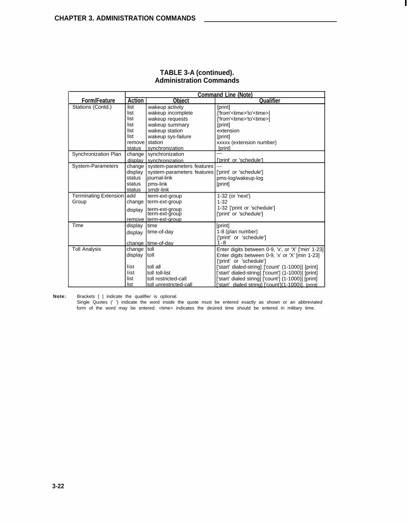
CHAPTER 3. ADMINISTRATION COMMANDS
TABLE 3-A (continued).Administration Commands
Command Line (Note)Form/Feature Action Object Qualifier
Stations (Contd.) list wakeup activity [print]list wakeup incomplete ['from'<time>'to'<time>]list wakeup requests ['from'<time>'to'<time>]list wakeup summary [print]list wakeup station extensionlist wakeup sys-failure [print]remove station xxxxx (extension number)status synchronization [print]
Synchronization Plan change synchronization —display synchronization ['print' or 'schedule']
System-Parameters change system-parameters features —display system-parameters features ['print' or 'schedule']status journal-link pms-log/wakeup-logstatus pms-link [print]status smdr-link
Terminating Extension add term-ext-group 1-32 (or 'next')Group change term-ext-group
display term-ext-group1-321-32 ['print or 'schedule']
term-ext-group ['print' or 'schedule']remove term-ext-group
Time display timedisplay time-of-day
[print]1-8 (plan number)['print' or 'schedule']
change time-of-day 1-8Toll Analysis change toll Enter digits between 0-9, 'x', or 'X' ['min' 1-23]
display toll Enter digits between 0-9, 'x' or 'X' [min 1-23]['print' or 'schedule']
list toll all ['start' dialed-string] ['count' (1-1000)] [print]Iist toll toll-list ['start' dialed-string] ['count'] (1-1000)] [print]list toll restricted-call ['start' dialed string] ['count'] (1-1000)] [print]list toll unrestricted-call ['start' dialed string] ['count'](1-1000)]. [print]
Note: Brackets [ ] indicate the qualifier is optional.Single Quotes (' ') indicate the word inside the quote must be entered exactly as shown or an abbreviatedform of the word may be entered. <time> indicates the desired time should be entered in military time.
3-22

Administration Commands
TABLE 3-A (continued).Administration Commands
Command Line (Note)Form/Feature Action Object Qualifier
Trunk Groups:
AccessAdvanced Private Line
TerminationCentral OfficeCustomer-Provided
EquipmentDigital Multiplexed
InterfaceDirect Inward DialingForeign ExchangeISDN-PRIReleaseTandemTieWATS
add*changedisplaychangedisplaydisplaylistl i s t
changechangechangeremovedisplaystatus
trunk-grouptrunk-grouptrunk-groupisdnisdnisdntrunk-groupconfiguration trunksremovei s d ni s d ntrunk-group tacgtrunk-group tactrunk-group tactrunk
1-99 (or 'next')1-99 or TAC X...1-99 or TAC X...['print' or 'schedule']network facilitiesnetwork facilitiescpn-prefix['print' or 'schedule']['print' or 'schedule']trunk-groupcpn-prefixnetwork facilitiesyyy (1-3 digit trunk access code)yyy (1-3 digit trunk access code)yyy (1-3 digit trunk access code)1-99 [1-99] (group/member number)
Vector changedisplayl i s t
vectorvectorvector
1-2561-256[xxx] ('count' 1-256) ['print' or 'schedule']
VDN addchangedisplay
removel i s t
vdnvdnvdn
vdnv d n
xxxxx (extension number of VDN to be added)xxxxx (extension number of VDN to be changed)xxxxx (extension number of VDN to be displayed)
['print' or 'schedule']xxxxx (extension number of VDN to be removed)xxxxx (extension number of VDN to be listed) ('count' 1-500)
['print' or 'schedule']
* With the Hospitality Parameter Reduction Feature, only 50 trunk groups can be added.
Note: B r a c k e t s [ ] i n d i c a t e t h e q u a l i f i e r i s o p t i o n a l .Single Quotes (' ') indicate the word inside the quote must be entered exactly as shown or an abbreviatedform of the word may be entered. <time> indicates the desired time should be entered in military time.
3-23

CHAPTER 3. ADMINISTRATION COMMANDS
Error Messages
The following is an alphabetical listing and description of the error messages associated withadministration. An error message may be displayed at any time during use of the G3 Manage-ment Terminal as the result of an improper input command, incorrect input data, exceeding arange, not specifying data in fields that require input, etc,. In some cases, [HELP] can be pressedfollowing an error message to obtain an on-screen help message associated with the currentoperation. The following descriptions provide an additional aid that can be used in the process ofresolving error messages.
In many cases, when an error message is displayed, the data being entered as part of the inputcommand is displayed at the beginning of the message. This data is not included in the followinglistings. For example, if the error message "39 Invalid toll list reference number” is displayed,locate the message "Invalid toll list reference number” for a description of the message.
If an error message is not clear or you require additional help to resolve the message, proceed asfollows:
1.
2.
3.
4.
Press [HELP] to obtain an associated help message. Valid field entries, command lineentries, etc., can be displayed.
Refer to the error message in the following listing for an additional description of the mes-sage.
Consult the form instructions provided elsewhere in this manual for a description of theform and each field on the form.
Consult your System Administrator.
Note that the following does not include error listings associated with System forms not coveredin this manual. For example, the Maintenance-Related System-Parameters form. When admin-istering forms of this type, consult the appropriate manual for associated form and field descrip-tions. The Maintenance-Related System-Parameters form is covered in the DEFINITY® Com-munications System Generic 1 and Generic 3i—Installation and Test, 555-230-104.
Note: Error message descriptions associated with features not currently covered in thismanual such as Call Associated Temporary Signaling Connections (CA-TSCs) andNon-Call Associated Temporary Signaling Connections (NCA-TSCs) are marked as"Reserved for future use.” The features and associated error message descriptionswill be provided in a future release of this manual.
3-24

Error Messages
TABLE 3-B. System Error Messages
Error Message Description
# sign must be at the end of the On the AAR/ARS Digit Conversion form—If the Replacement String fielddigits entry contains a # sign, it must be at the end of a digit string.
ARS Partitioning and either ARS or The ARS Partitioning and either the ARS or Private Networking featuresPrivate Networking must be must be enabled on the System-Parameters Customer Options formactivated before associated forms and fields on forms can be administered.
ARS and either Private Networking The ARS feature and either the Private Networking or UDP featuresor Uniform Dial Plan must be must be enabled on the System-Parameters Customer Options formactivated before associated forms and fields on forms can be administered.
ARS/AAR Digit Conversion feature The ARS/AAR Digit Conversion feature must be enabled on thenot assigned System-Parameters Customer Options form before associated forms
and fields on forms can be administered.
ARS/AAR Partitioning feature not The ARS/AAR Partitioning feature must be enabled on the System-assigned Parameters Customer Options form before associated forms and fields
on forms can be administered.
ASAI Interface feature not assigned The ASAI Interface feature must be enabled on the System-Parameterscustomer options form before associated forms and fields on forms canbe administered.
ASAI Routing capability and/or Vec- On the Call Vector form, the ASAI Routing or Basic fields must betoring (Basic) feature not assigned enabled before the associated Call Vector command can be entered on
the form.
The ASAI and/or Vectoring (Basic) feature must be enabled on theSystem-Parameters Customer Options form before associated formsand fields on forms can be administered.
Abbreviated Dialing Enhanced List The Abbreviated Dialing-Enhanced List feature must be enabled on thefeature not assigned System-Parameters Customer Options form before associated forms
and fields on forms can be administered.
Abbreviated dialing index invalid Press [HELP] to obtain a list of valid entries or consult the AbbreviatedDialing form coverage in Chapter 6 for additional information.
Absorption list entries mixed; chose On the Digit Absorption form—For the Absorption Treatment Assign-from Group I or Group II ment fields, all choices for the digits 0 through 9 must be taken from
either Group I or Group II, but not both.
Access, dmi-mos, sddn, tandem, On the ISDN-PRI Trunk Group form—the Service/Feature field entryand tie are not valid for a CBC trunk (Page 2) cannot be "access,” "dmi-mos,” "sddn,” "tandem,” or "tie” forgroup a Service Type field entry (Page 1) of "cbc.”
3-25

CHAPTER 3. ADMINISTRATION COMMANDS
TABLE 3-B (continued).System Error Messages
Error Message Description
Activation times within the same daymust be unique
On the ISDN-PRI Trunk Group form—The Act Time field entry (Pages4-11) must be unique for each entry associated with a given day of theweek.
Add primary DS1 as NFAS trunkboard or remove its ports from trunkgroups
On the Signaling Group form—Changing the Associated Signaling fieldentry from "y" (FAS) to "n" Nonfacility Associated Signaling (NFAS)requires that the Trunk Brd and associated Interface Id fields be com-pleted. The Trunk Brd entries cannot be ports associated with a DS1that is used in a FAS Signaling Group. In addition, the Trunk Brd entriesmust include the DS1 circuit pack assigned the Primary D-Channel ortrunk ports associated with the DS1 must be removed from trunkgroups.
Adjunct Call Control Group featurenot assigned
The Adjunct Call Control Group option must be enabled on the System-Parameters Customer Options form before associated forms and fieldson forms can be administered.
Adjunct Routing Group feature notassigned
The Adjunct Routing Group option must be enabled on the System-Parameters Customer Options form before associated forms and fieldson forms can be administered.
Adjunct controlled splits must be"ucd"
On the Hunt Group form—When the Controlling Adjunct field entry is"bx.25,” or "asai,” the Group Type field entry must be "ucd."
Administered NCA-TSC duplicatelyassigned; please select another
On the gateway form, the signaling group and administered Non-CallAssociated Temporary Signaling Connection (NCA-TSC) pair have beenduplicately assigned.
Administered NCA-TSC not On the gateway form, an attempt was made to use an NCA-TSC whichassigned; please select another has not been administered.
Administered NCA-TSC not used for On the gateway form, an attempt was made which is to use an NCA-gateway; please select another TSC which is not used for gateway application.
Administered codes must be On the Feature-Related System-Parameters form—The Authorizationremoved if length is decreased Code Length field entry cannot be reduced if there are AC codes of a
greater length currently administered on the Authorization Codes form.You must remove or reduce the length of the AC codes first.
Administration of Called Number On the ISDN-PRI Trunk Group form—lf the Called Len field has anrequires Called Len entry (Page 2), its associated Called Number field must have an entry.
Agents in group must be removed On the Hunt Group form—You cannot remove agent extensions fromfrom adjunct controlled agent table the hunt group until the extensions are logged into another hunt group 01
are removed from the Adjunct Controlled Agent Table.
All administered connection Displayed when using the "add administered-connection" command.numbers used; cannot assign next Indicates that the System maximum for administered connections (128)number has been reached.
3-26

Error Messages
TABLE 3-B (continued).System Error Messages
Error Message Description
All ports are assigned Assign a port on another circuit pack of the same type or function.
An assigned ASAI/BRI link exten- On the Call Vector form—For an "adjunct" command entered on thesion must be specified form, you must complete the routing link extension field.
An assigned announcement exten- Enter a valid announcement extension. Enter the "display announce-sion must be specified ments" command, if required, to display the administered announcement
extensions.
An assigned data module extension Enter an administered data module extension. Enter the "list data-must be specified module" command, if required, to list assigned extensions.
An assigned extension or attendant Enter a valid extension number or enter "0" for the attendant.(0) must be specified
An assigned station or individual Enter an assigned station extension or enter "0" for the attendant. Enterattendant extension must be speci- the "list station" command, if required, to list assigned extensions.fied
Announcement Delay must be On the Hunt Group form—If the First or Second Announcement field(s)specified has an entry, then their associated First or Second Announcement
Delay fields must also have an entry.
Announcement data module already The Recorded Announcement Data Module form (associated with theexists TN750 Announcement circuit pack) has already been administered.
Assignment of BRI extensions on Because one button transfer to data is not allowed for BRI, data exten-data extension buttons not allowed sion buttons are not allowed for BRI data extensions.
At least 1 zone must be specified for On the Loudspeaker Paging Access form—Assign at least 1 zone.all-zones data assignment
Attendant cannot be specified for On the Dial Plan form—A First Digit Table entry of "0" is not a validthis field entry for this field. "0" is reserved as the first digit for the attendant.
AUDIX Extension cannot be blank if On the Hunt Group form—lf the Message Center field entry is "rem-message center is Remote AUDIX audix," then the AUDIX Extension field must have an entry.
AUDIX application previously On the Processor Channel Assignments form—Only one link and asso-assigned in Processor Channel form ciated channel can be assigned to AUDIX.
AUDIX application previously (Reserved for future use)assigned in another Signal Group
Authorization Code cannot begin On the Authorization Codes form—The AC field entry cannot begin withwith a 1 a "1."
Authorization Codes feature not The Authorization Codes feature must be enabled on the System-assigned Parameters Customer Options form before associated forms and fields
on forms can be administered.
3-27

CHAPTER 3. ADMINISTRATION COMMANDS
TABLE 3-B (continued).System Error Messages
Error Message Description
Automatic Call Distributing (ACD) The ACD feature must be enabled on the System Parameters Customerfeature not assigned Options form before associated forms and fields on forms can be
administered.
Automatic Route Selection (ARS) The ARS feature must be enabled on the System Parameters Customerfeature not assigned Options form before associated forms and fields on forms can be
administered.
Available message sizes are 260, On the ISDN-PRI Trunk Group form-The Max Message Size to Send256, 244, and 128 field must beset to either "260," "256," "244," or "128."
BCMS agents exceed maximum- On the Hunt Group form—If the Measured field has an entry ofremove excess before changing "external," "internal," or "both," remove appropriate agents beforemeasured value changing the Measurement Interval field on the Feature-Related System
Parameters form.
BRI: B channel data not allowed on BRI supports 2 B channels. Because the system does not allow callmultipoint port blocking, only 2 objects (2 voice, 2 data, 1 voice and 1 data, and 1
integrated voice/data) may be administered per port. Because there is auser already assigned on this port the endpoint being administered canonly be a stand-alone voice or stand-alone data endpoint.
BRI: Default SPID not unique on This applies to the duplicate station command which allows entering ofport; please select another extensions. If a particular extension being assigned was not used in theextension system as an extension but the number has been assigned as a Service
Profile Identifier (SPID) of a BRI endpoint this extension may not beused.
BRI: TEl "partner"; please select Fixed Terminal Endpoint Identifier (TEl) sets are not supported inanother port. multipoint configuration. Since there is a fixed TEl endpoint
administered on this port, this port may not be used in multipointconfiguration.
BRI: Fixed TEI not allowed on Fixed Terminal Endpoint Identifier (TEl) sets are not supported inmultipoint port multipoint configuration. Because there is a user already assigned on
this port, the endpoint being administered must be an automatic TElendpoint.
BRI: No B channels available; BRI supports 2 B channels. Because the system does not allow callplease select another port. blocking, only 2 objects (2 voice, 2 data, 1 voice and 1 data, and 1
integrated voice/data) may be administered per port. This messageindicates that both B channels were already allocated on this port to 1integrated voice/data endpoint which uses one B channel for voice andone for data.
BRI: Non SPID "partner"; please SPIDs are required so that endpoints configured in multipointselect another port. configuration can be identified. Since there is an endpoint without a
SPID administered on this port, this port may not be used in multipointconfiguration.
BRI: SPID must be assigned on SPIDs are required so that endpoints configured in multipointmultipoint port configuration can be identified. Because there is a user already
assigned on this port the endpoint being administered must have SPIDinitialization capability.
3-28

Error Messages
TABLE 3-B (continued).System Error Messages
Error Message Description
BRI: SPID must be unique on a SPIDs are required so that endpoints configured in multipoint configura-port. tion can be identified. Therefore, SPIDs must be different for all end-
points on the same port.
BRI: Service SPID and any other All SPIDs assigned to the endpoints must be different from the ServiceSPID on the system cannot be SPID.same.
BRI: Two users already assigned to BRI supports up to two endpoints per port. This message indicates thatthis port please select another either 2 voice endpoints, 2 data endpoints, or 1 voice and 1 data end-
point are already assigned on this port.
Band number out of range On the Routing Pattern form—The Band field entry must be within therange of 0 through 255.
Barrier code must be "none" for On the Remote Access form—If the Barrier Code Length field has noblank barrier code length entry, the first Barrier Code field must have an entry of "none."
Basic Call Management System The Basic Call Management System Measurements feature must be(BCMS) feature not assigned enabled on the System Parameters Customer Options form before
associated forms and fields on forms can be administered.
Board suffix associated with this The Abandoned Call Search feature requires trunk port assignments onport incompatible with Abandoned a TN747B Central Office Trunk circuit pack.Call Search
Both Idle Appearance Preference On a Station form—The Auto Answer and Idle Appearance Preferenceand Auto Answer cannot be y(es) fields cannot both be administered as "y."
Bridged appearances must be Remove "abrdg-appr" feature buttons from other voice terminals thatremoved before changing from an point to this terminal before changing the Type field entry.analog station type
Bridged appearances must be Remove "brdg-appr" feature buttons from other voice terminals thatremoved before changing to an ana- point to this terminal before changing the Type field entry.log station type
Bridged appearances must be Remove all bridged appearance feature buttons from other voice termi-removed before removal nals that point to this terminal before removing the station.
Busyout MIS before The CMS must be "busied-out" before the associated object can beadding/changing/removing added, changed, or removed (use the command "busyout link_" ifmeasured object appropriate).
Busyout MIS before The CMS must be "busied-out" before the associated object can beadding/removing a VDN added, changed, or removed (use the command "busyout link_" if
appropriate).
Button type does not meet min or On the Station/Attendant Console form—The feature button administra-max requirements tion is not valid. Consult the Voice Terminal—General coverage in
Chapter 6 for feature button characteristics and descriptions.
3-29

CHAPTER 3. ADMINISTRATION COMMANDS
TABLE 3-B (continued).System Error Messages
Error Message Description
On the Station/Attendant Console form—Assign only display-typefeature buttons on display module forms. Consult the specific VoiceTerminal coverage in Chapter 6 for a list of valid display-type featurebuttons.
Button type invalid for a displaymodule
On the Station form—Do not assign a display-type button on a stationwithout a display. Consult the specific Voice Terminal coverage inChapter 6 for a list of valid feature buttons.
Button type invalid for stationwithout a display module
On the Station Form—Only call appearance buttons can be admin-istered in this field.
Button type must be call appearance
On the Station form—The feature button type is not valid for this stationtype. Consult the specific Voice Terminal coverage in Chapter 6 for alist of valid feature buttons.
Button type not allowed on thisstation type or module
COR must be specified Enter an appropriate COR in the range of 0 to 63.
CPN prefix must be 10 digits forattendant extension
On the Called Party Number (CPN) Prefix form—The CPN Prefixadministered for the attendant must be 10 digits in length.
Call Work Codes feature notassigned
The Call Work Codes feature must be enabled on the System Parame-ters Customer Options form before associated forms and fields onforms can be administered.
On the Station/Attendant Console form—A call appearance button can-not be administered in this field.
Call appearance button type notallowed
On the ISDN-PRI Trunk Group form—The Called Len field enty (Page2) cannot be fess than the number of digits in the associated CalledNumber field
Called Len cannot be less thanlength of Called Number
On the ISDN-PRI Trunk Group form—The Display, Traveling ClassMark (TCM), Lookahead Codeset field entry can only be a "6" or a "7."
Can only accept codeset 6 or 7
On the Access Endpoints form—The Name field can only be modified ifthe Access Endpoint is involved in an active administered connection(that is, the AE is assigned to an Originator or a Destination field on anAdministered Connection form and the connection is active).
Can only modify name whenassigned to an active AdministeredConnection
On the Access Endpoints (AE) form—The Communications Type fieldentry cannot be "64k-data" unless the DS1 circuit pack assigned thePort field has its Zero Code Suppression (ZCS) field set to "zcs" or itsSignaling Mode field set to "robbed-bit" (RBS).
Cannot administer 64K-data if theDS1 has ZCS or RBS
On the Hunt Group form—The First or Second Announcement Delayfields cannot be administered unless their associated First or SecondAnnouncement Extension fields have an entry.
Cannot administer AnnouncementDelay without AnnouncementExtension
Cannot administer an ASAI stationwith a data module
On the Station form—You cannot administer a data module form whenthe Set Type field entry is "asai."
3-30

Error Messages
TABLE 3-B (continued).System Error Messages
Error Message Description
Cannot assign port 24; it is reserved On the associated DSI Circuit Pack form—lf the Signaling Mode fieldfor signaling channel entry is "isdn-pri" or "common-chan," the circuit pack’s 24th channel is
reserved for the signaling channel (that is, D-Channel) and cannot beassigned as a port interface.
Cannot be entered if BRI/ASAI end- This is a Maintenance-Related System Parameters form error. Consultpoints are administered the Installation and Test manual (555-204-104) for additional informa-
tion.
Cannot be entered if packet-control This is a Maintenance-Related System Parameters form error. Consultis installed the Installation and Test manual (555-204-104) for additional informa-
tion.
Cannot bridge onto an analog On the Station form—You cannot assign a "brdg-appr" feature buttonstation that points to an analog station. Either enter an appropriate extension
number for the "brdg-appr" button or assign an "abrdg-appr" button thatpoints to the analog station.
Cannot change Measured field while On the Hunt Group form—After changing the Measured field entry, sub-changing Controlling Adjunct field mit the form. Then, change the Controlling Adjunct field entry.
Cannot change group type if group On the Modem Pool Group form—The Group Type field cannot beis assigned changed until other fields on the form associated with the current Group
Type are also changed.
Cannot change permissions for the You cannot change the permissions associated with the specified login.specified login Consult the System Administrator for assistance.
Cannot change the specified You cannot change the permissions. Consult the System Administratorpermission for assistance.
Cannot change while port installed The field entry cannot be changed if any associated DS1 circuit packports are administered in the System.
Cannot change. Data module The current field entry must be an assigned data module extension.extension assumed for this field
Cannot delete circuit pack that is Remove the circuit pack from the carrier. Then, using the "changephysically inserted circuit-packs" command, delete the circuit pack from the carrier slot.
Cannot display tone-clock board You cannot display the non-administrable TN768 Tone Clock. Use theTDM bus port "status" command if required.
3-31

CHAPTER 3. ADMINISTRATION COMMANDS
TABLE 3-B (continued).System Error Messages
Error Message Description
Cannot display tone-clock board You cannot display the non-administrable TN768 Tone Clock. Use thetone generator port "status" command if required.
Cannot enable Recurring Second On the Hunt Group form—Complete the Second Announcement Exten-Announcement without sion and Second Announcement Delay fields as appropriate.Announcement Extension
Cannot enable both ASAI Interface The System supports the use of one of these features at a time but notand CPN/BN features both.
Cannot enable both CAS and IAS On the Console Parameters form—The CAS field entry must be "none"if the Inter-PBX Attendant Services (IAS) (Branch) entry is "y." If theCAS field entry is "main" or "branch," the IAS (Branch) field entry mustbe "n."
Cannot go to same step On the Call Vector form—Do not reference the current step numberwhen using a "goto step" command.
Cannot go to same vector On the call Vector form—Do not reference the current numberwhen using a "goto vector" command.
Cannot go to undefined step On the Call Vector form—Do not reference an unassigned step (that is,step that does not have an associated command) when using a "gotostep” command.
Cannot have dial access for isdn-pri On the ISDN-PRI Trunk Group form—The Dial Acces field entry cantrunks with this service type only be "y" if the Service Type field entry is "access," "tandem," "tie,"
"dmi-mos," or blank.
Cannot have more than one audix Signal Group form—(Reserved for future use)application
Cannot hop a link to itself On the Hop Channel Assignment form—A link number can only behopped to a different link number, (that is, A Link/Chan pair can only behopped to a different Link/Chan pair.)
Cannot mix this FAC with longer dial The first digit and number of digits in the FAC must agree with the Firstcode Digit Table on the System’s Dial plan form.
Cannot remove synchronization A DS1 circuit pack cannot be removed from a carrier slot that has beensource administered as a Primary or Secondary synchronization source on the
Synchronization Plan form.
Cannot remove while port installed You must remove all associated port assignments before the circuitpack can be removed.
3-32

Error Messages
TABLE 3-B (continued).System Error Messages
Error Message Description
Cannot remove/change - stations You cannot remove the station if the station type (for example, 7434D)administered to alias set type is currently entered on the Enhanced Terminal Administration form and
is associated with an Alias Set Type.
Cannot remove; ext assigned as On the Trunk Group form—Delete the extension from the Incoming Des-trunk group incoming destination tination field if appropriate. Then remove the extension.
Cannot remove; ext assigned as On the Trunk Group form—Delete the extension from the Night Servicetrunk group night destination and Night fields if appropriate. Then remove the extension.
Cannot remove; extension assigned Remove the extension from extension-type fields on the Feature-on system parameters features form Related System Parameters form if appropriate. Then remove exten-
sion.
Cannot remove; extension assigned Remove the extension from extension-type fields on the Hospitality-on system parameters hospitality Related System Parameters form if appropriate, then remove extension.form
Cannot remove; extension is part of Remove extension from the Administered Connection form if appropri-an administered connection ate. Then remove the extension.
Cannot use same extension for On the Hospitality-Related System Parameters form—The Extension ofPMS and printers Property Management System (PMS) field entry must be different than
the Extension of PMS Log Printer or Extension of Journal/SchedulePrinter field entries.
Cannot use the predefine name On the Network Facilities Access form—The Name field entry cannot bethe same or a subset of another Service/Feature entry already definedon the form.
Centralized Attendant Service (CAS) The CAS (Main) feature must be enabled on the System ParametersBranch feature not assigned Customer Options form before associated forms and fields on forms can
be administered.
Centralized Attendant Service (CAS) The Centralized Attendant Service (Branch) feature must be enabled onMain feature not assigned the System Parameters Customer Options form before associated
forms and fields on forms can be administered.
Change not allowed; must remove Station/Attendant Console form—A Data Module extension cannot beand add changed once it has been submitted. The data module must be
removed and then added back with the correct extension.
Character invalid for this button type On the Station/Attendant Console form—Enter appropriate data for thefeature button type. Refer to the Voice Terminal—General coverageprovided in Chapter 6 for feature button description and characteristics.
Check links assignment form! Must On the Processor Channel Assignments form—Review all ISDN assign-assign ISDN to this link ments and note associated link numbers.
3-33

CHAPTER 3. ADMINISTRATION COMMANDS
TABLE 3-B (continued).System Error Messages
Error Message Description
Circuit Pack previously assigned; All ports on the circuit pack have been assigned. Administer ports onplease select another another circuit pack of the same type or the same functionality.
Circuit pack can only be admin- On the Circuit Pack Administration form—The TN570 or TN776 Expan-istered in slot labeled EXPNSN sion Interface circuit pack can only be administered in certain carrierINTRFC slots. Refer to the Expansion Interface Carrier/Slot Assignments figure
in Chapter 2 for carrier/slot information.
Circuit pack is wrong type The port administered is not correct for the associated function. Forexample, when using an "add ds1" command, the Location field entry onthe DS1 form must be a port that is associated with an administeredDS1 circuit pack.
Circuit pack must be installed first Either physically install the circuit pack in the appropriate carrier slot oradminister the circuit pack on the Circuit Pack administration form.
Cleared alarm notification requires This is a Maintenance-Related System Parameters form error. Consultalarm origination the Installation and Test manual (555-204-104) for additional
information.
Code length invalid Input appropriate code length. Press [HELP] for a listing of valid entriesor an associated help message.
Code/Suffix does not match physi- On the circuit Pack Administration form—Ensure that the Code, Sfx,cally inserted circuit pack and Name field entries agree with the circuit packs installed in the asso-
ciated carrier slots.
Combined # of Local & Remote TGS On the Attendant Console form—The combined number of Local andbuttons on feature buttons exceeds Remote TGS buttons that are administered on Page 2 of the form mustmaximum not exceed 12.
Communication type and port type On the Access Endpoints form—The Port field entry must be consistentinconsistent with the Communication Type field entry. For example, if the Communi-
cation Type field entry is "56k-data" or "64k-data," the Port entry mustbe a DS1 circuit pack port.
Corresponding abbreviated dialing The Abbreviated Dialing List type entered (for example, personal, group,list not assigned etc.,) is not administered in the System.
Count cannot be blank, if 'Starting On the command line, if you specify a starting extension, you mustExtension' specified specify a count number.
Coverage and display modules can- On the 7405D or 7434D Station form—Either the Display field entry cannot be specified on the same station be "y" or the Coverage Module field entry can be "y," but not both.
3-34

Error Messages
TABLE 3-B (continued).System Error Messages
Error Message Description
Coverage point extension must be a Enter a coverage point extension number that is assigned to a station.station
Current password must be specified
D-Channel has to be on the 24thport
DCS requires Uniform Dialing Planto be activated
DMI-BOS requires common-chansignaling
DS-1/isdn circuit is required
DS1 signaling mode must becommon-chan
DS1 signaling mode must berobbed-bit
Data extension buttons not allowedon BRI set types
Data extension group member(s)must be removed first
Enter the appropriate password. Contact the System Administrator forassistance.
On the Signaling Group form—The port number associated with thePrimary and Seoondary D-Channel field entries must be "24."
The UDP feature must be enabled on the System Parameters CustomerOptions form before associated forms and fields on forms can beadministered.
On the DS1 Circuit Pack form—lf the DMI-BOS field entry is "y," theSignaling Mode field entry must be "common-chan."
On the ISDN-PRI Trunk Group form—The Port field entries must beDS1 circuit pack ports.
On the DS1 Circuit Pack form—For alternate voice and dataapplications, the Signaling Mode field must be "common-chan."
On the DS1 Circuit Pack form—For voice tie trunk applications, the Sig-naling Mode field must be "robbed-bit."
Because one button transfer to data is not allowed for BRI, data exten-sion buttons are not allowed on BRI set types.
Remove all associated Data Extension buttons from Station/AttendantConsole forms before the Data Module can be removed or the DataModule’s Type field can be changed.
Data Extension must be removedfrom hunt group(s) before removal.
Del cannot be greater than CalledLen
Specific to data extensions. This error message is similar to the errormessage "Extension must be removed from hunt group(s) beforeremoval."
On the ISDN-PRI form—The Del field entry (Page 2) cannot be greaterthan the associated Called Len field entry.
Del, insert, SID/ANl, or Night Serv On the ISDN-PRI Trunk Group form—If a Service/Feature is specifiedfield must be specified (Page 2) associated field (that is, Del, Insert, Per Call CPN/BN, or
Night Serv) must be specified.
3-35
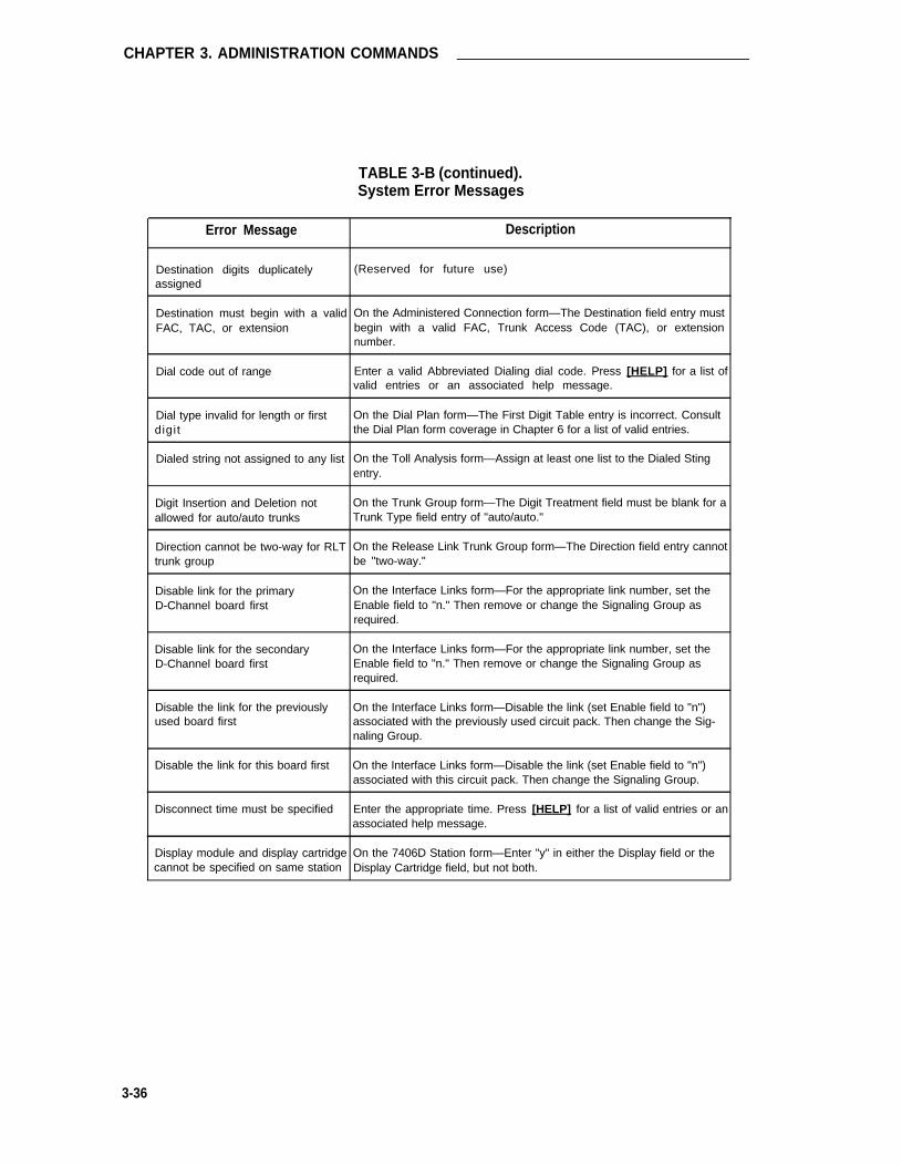
CHAPTER 3. ADMINISTRATION COMMANDS
TABLE 3-B (continued).System Error Messages
Error Message Description
Destination digits duplicately (Reserved for future use)assigned
Destination must begin with a valid On the Administered Connection form—The Destination field entry mustFAC, TAC, or extension begin with a valid FAC, Trunk Access Code (TAC), or extension
number.
Dial code out of range Enter a valid Abbreviated Dialing dial code. Press [HELP] for a list ofvalid entries or an associated help message.
Dial type invalid for length or first On the Dial Plan form—The First Digit Table entry is incorrect. Consultdigit the Dial Plan form coverage in Chapter 6 for a list of valid entries.
Dialed string not assigned to any list On the Toll Analysis form—Assign at least one list to the Dialed Stingentry.
Digit Insertion and Deletion not On the Trunk Group form—The Digit Treatment field must be blank for aallowed for auto/auto trunks Trunk Type field entry of "auto/auto."
Direction cannot be two-way for RLT On the Release Link Trunk Group form—The Direction field entry cannottrunk group be "two-way."
Disable link for the primary On the Interface Links form—For the appropriate link number, set theD-Channel board first Enable field to "n." Then remove or change the Signaling Group as
required.
Disable link for the secondary On the Interface Links form—For the appropriate link number, set theD-Channel board first Enable field to "n." Then remove or change the Signaling Group as
required.
Disable the link for the previously On the Interface Links form—Disable the link (set Enable field to "n")used board first associated with the previously used circuit pack. Then change the Sig-
naling Group.
Disable the link for this board first On the Interface Links form—Disable the link (set Enable field to "n")associated with this circuit pack. Then change the Signaling Group.
Disconnect time must be specified Enter the appropriate time. Press [HELP] for a list of valid entries or anassociated help message.
Display module and display cartridge On the 7406D Station form—Enter "y" in either the Display field or thecannot be specified on same station Display Cartridge field, but not both.
3-36

Error Messages
TABLE 3-B (continued).System Error Messages
Error Message Description
Distributed Communication Service The DCS feature must be enabled on the System Parameters Customer(DCS) feature not assigned Options form before associated forms and fields on forms can be
administered.
Duplicate Alpha-name; please press On the Alphanumeric Dialing Table form—Each Alpha name field mustHELP key have a unique entry.
Duplicate IXC access numbers are Enter a unique Inter-Exchange Carrier Code (lXC) access code, thenot allowed current entry is already assigned.
Duplicate MACHINE ID for same On the Processor Channel Assignments form—The Machine-lD field application not allowed entry cannot be entered more than once for the same Application field
entry.
Duplicate Service/Feature name is On the ISDN-PRI Trunk Group form—Duplicate Service/Feature fieldnot allowed entries (Page 2) are not allowed.
Duplicate TAC On the Loudspeaker Paging Access form—The TAC field entry must beunique for each TAC field entry on the form.
Duplicate abbreviated dialing list Each Abbreviated Dialing list reference must be unique.entry
Duplicate board On the Modem Pool Group form—Each Circuit Pack Location field entryfor an integrated modem pool group must be unique.
Duplicate board destination not On the Processor Interface Data Module form(s)—The Physicalallowed Channel field entry must be unique (that is, used only once) for all
Processor Interface Data Module assignments.
Duplicate button On the Station form—Enter a unique button type. The currentattempted entry is already assigned this station.
Duplicate destination digits not Enter a unique destination number. Press [HELP] for a list of validallowed entries or an associated help message.
Duplicate entries on the screen On the AAR/ARS Analysis and Toll Analysis forms—Each Dialed Stringand associated Min/Max field entry must be unique.
Duplicate entry is not allowed Enter a unique value or assignment. The current attempted entryalready exists. Press [HELP] for a list of valid entries or an associatedhelp message.
3-37

CHAPTER 3. ADMINISTRATION COMMANDS
TABLE 3-B (continued).System Error Messages
Error Message Description
Duplicate ext length and ext code On the CPN Prefix Table form—Each pair of Ext Len and Ext Code fieldentries must be unique.
Duplicate extension Enter a unique extension number. The current attempted entry isalready assigned.
Duplicate facility type and facility On the Network Facilities form—Duplicate Facility Type and Coding fieldcoding are not allowed entries are not allowed. Make each Facility Type and associated Coding
field entry unique.
Duplicate link for ISDN is not On the Processor Channel Assignment form—The Application field entryallowed of "isdn" can only be associated with one link number.
Duplicate link/channel pair not On the Processor Channel Assignment form—The Interface Link/Chanallowed pair entries cannot be duplicated. Each Link/Chan pair entry must be
unique.
Duplicate members Enter a non-assigned member. The current attempted entry is alreadyassigned.
Duplicate of this application type not On the Processor Channel Assignments form—Certain applications (forallowed example, "AUDIX") can only be entered once in the Appl. fields on the
form.
Duplicate port On the Modem Pool Group form—The Circuit Pack Location field entrymust not be duplicated in the associated fields on the form.
EIA port previously assigned On the Feature-Related System Parameters form—The ElectronicIndustries Association (EIA) port has already been assigned to anotherfunction. Enter a module extension instead. (Note that the data modulemust first be administered in the System before assigning its extensionnumber.)
Emergency Access to the Attendant The Emergency Access to Attendant feature must be enabled on thefeature not assigned System Parameters Customer Options form before associated forms
and fields on forms can be administered.
End time must be later than start Reenter an End Time that is later in time than the Start Time.time
Entries for same first digit cannot On the Dial Plan form—A TAC is assigned the same first digit as thefollow a TAC or AAR/ARS FAC dial type you have just entered. The dial type can have the same first
digit as the TAC as long as its length is not greater the the TAC’s length.
Entry already exists in the table Duplicate entries are not allowed. The current attempted entry alreadyexists in the table (not displayed on the current screen).
3-38

Error Messages
TABLE 3-B (continued).System Error Messages
Error Message Description
Entry contains an Alpha-name On the Alphanumeric Dialing Table—A Mapped String field entryargument that is too long contains an Alpha name like string that is greater than eight characters.
Reduce the string to eight or less character.
Entry contains an Alpha-name that On the Alphanumeric Dialing Table form—An Alpha name has beenis not administered specified in a Mapped String, and the Alpha name has not been entered
on the form. Remove name or add Alpha name to the table.
Entry creates a cycle On the Call Coverage Path form—The Next Path Number field entrycannot refer to another coverage path already in the coverage pathstring (that is, Coverage Path 1 with Next Path Number of "2," thenCoverage Path 2 with Next Path Number of "1." This creates a loop.)
Entry exceeds the limit of 4 linked On the Call Coverage Path forms—You cannot have more than fourpaths coverage paths associated with a call.
Entry exists in another partition with On the AAR/ARS Analysis form—The entry must not be assigned ondifferent call type another AAR/ARS Analysis form associated with a different PGN.
Entry must be all digits Reenter the data as all digits in the range 0 through 9.
Entry must be all digits or "all" Reenter the data as all digits in the range 0 through 9 or enter "all."
Entry must be all digits, "user," or Reenter the data as all digits in the range 0 through 9 or enter "user" or"none" "none."
Entry must be all digits, *, #, On the Administered Connection form—The Destination field entry must~p(pause), ~w(wait), or ~m(mark) be all digits and can include the "*," "#," "~p," "~w," or "~m" characters.
No other entries are allowed.
Entry must be an even number Reenter the data as an even number.
Entry must be blank for gateway (Reserved for future use)application
Entry must be blank if application is On the Process Channel Assignments form—The field must be blank fornot DCS or AUDIX. APLT field entries of other than "dcs," or "AUDIX."
Entry must be digits, #, or blank Reenter the data as either all digits, "#," or leave blank.
Entry must be in range 1 through 8 if Reenter the data in the range 1 through 8 for AUDIX applications.application is AUDIX
3-39

CHAPTER 3. ADMINISTRATION COMMANDS
TABLE 3-B (continued).System Error Messages
Error Message Description
Entry must be multiple of 5 Reenter the data as a multiple of five (for example, 5, 10, 15, etc,).
Entry must contain only Reenter the data as alphanumeric characters only (for example, spacealphanumeric characters character not allowed).
Entry must start with an alphabetic Reenter the data with the first character an alpha character in the rangecharacter A through Z.
Entry too long Reenter the data. Press [HELP] for a listing of valid field entries or anassociated help message.
Event Notification Group feature not The Event Notification Group option must be enabled on the System
assigned Parameters Customer Options form before associated forms and fieldson forms can be administered.
Exceeds level of Alpha-name On the Alphanumeric Dialing Table form—An Alpha name is specified inreferencing a Mapped string, and the specified Alpha name’s Mapped string con-
tains a reference to the Alpha name. Delete one of the Alpha namereferences.
Expected number of digits must be On a DID Trunk Group form—With a Digit Treatment field entry ofgreater than number of digits "absorption," the Expected Digits field entry must be greater than theabsorbed number of digits absorbed.
Ext code inconsistent with First Digit On the CPN Prefix Table form—The Ext Code field entry must be intable agreement with the System’s Dial Plan form. Enter an Ext Code that
agrees with the Dial Plan.
Ext length inconsistent with First On the CPN Prefix Table form—The Ext Len field entry must agree withDigit table the length of extension numbers assigned on the System’s Dial Plan
form.
Ext length must be '1' for the On the CPN Prefix Table form—The Ext Len field entry must be "1"attendant extension when the associated Ext Code field entry is "0."
Ext length plus number of CPN On the CPN Prefix Table form—The Ext Len field entry plus the numberPrefix digits must be 10 or greater of digits entered in the associated CPN Prefix field must be 10 or
greater.
Extension assigned but wrong type Enter the appropriate extension number that is associated with thefor the group group or field (for example, announcement extension, night service
extension, hunt group extension, etc.). Prefixed extensions are notallowed.
Extension assigned to an object Enter valid station extension number.other than a station
3-40

Error Messages
TABLE 3-B (continued)System Error Messages
Error Message Description
Extension assigned to invalid data On the Administered Connection form—The Originator and Destinationmodule type fields cannot be assigned an extension number that is assigned a Net-
con, Processor Interface, or Recorded Announcement Data Module.
Extension assigned to object other On the Administered Connection form—The Originator and Destinationthan access endpoint or data field entries must be extension numbers assigned to access endpointsmodule or MPTM/MTDM data modules only.
Extension does not have personal An Abbreviated Dialing Personal List cannot be referenced in an Abbre-list assigned viated Dialing List 1, 2, or 3 field if the Personal List is not assigned in
the System. Administer the Personal List first, then enter the reference.
Extension must be an off switch On the Hunt Group form—lf the Message Center field entry is "rem-(UDP) extension audix," the AUDIX Extension field entry must be a Uniform Dial Plan
(UDP) extension number.
Extension must be different from Reenter the extension number. Do not use the number assigned this tothis station extension station.
Extension must be removed from On an associated Hunt Group form(s)—Remove the extension from allhunt group(s) before removal hunt groups where it is assigned as a group member. Then remove the
extension.
Extension must be removed from On an associated Call Vector form(s)—Remove all references to thevector(s) before removal extension from all call vector commands. Then remove the extension.
Extension not assigned Enter an extension number that agrees with the System’s Dial Planform.
Extension not assigned for intercom Enter an extension number assigned the appropriate Intercom Group.dial code Assigned extensions can be displayed using the command "display
intercom-group (1 through 32)."
Extension previously assigned; Enter a valid extension that agrees with the System’s Dial Plan form andplease select another that is not already assigned an object.
Extensions defined only as On the CPN Prefix Table form—The CPN Prefix field entry cannot an"pextension" in dialplan cannot be extension defined only as a "extension" (prefixed extension) on thespecified System’s Dial Plan form.
FAC invalid please check dialplan Enter a FAC that agrees with the System’s Dial Plan form. The FAC’sfirst digit and length must agree vvith the Dial Plan’s First Digit Tableassignments for FACs.
FRL invalid Enter a FRL number in the range of 0 through 7.
3-41

CHAPTER 3. ADMINISTRATION COMMANDS
TABLE 3-B (continued).System Error Messages
Error Message Description
FRL must not be blank Enter an appropriate Facility Restriction Lead (FRL) number in the rangeof 1 through 7.
FRLs must not decrease going down Enter an appropriate FRL number that is larger numerically than thethe list previous entry.
Fas D-channel may not be on an On the signaling Group form—Reassign the Primary D-Channel portnfas signaled board assignment to the same DS1 circuit pack associated with the
B-channels (data channels).
Fas signaled board may not be in On the Signaling Group form—Reassign the Primary D-Channel portnfas signaling group assignment to a DS1 circuit pack not already assigned to a Non-Facility
Associated Signaling Group (that is, Associated Signaling field entry="n").
Feature and Data modules cannot On the 7405D Station form—The Data Module field entry and thebe specified on the same station Feature Module field entry cannot both be "y." If "y" is entered in one of
the fields, then "n" must be entered in the other.
Feature not activated in the system The associated feature must be enabled on the System ParametersCustomer Options from before associated forms and fields on forms canbe administered.
Field cannot be blank Enter appropriate data in the field. Press [HELP] for a list of validentries or an associated help message.
Field must be blank for normal PMS The associated field entry must be blank when the PMS Protocol ModeProtocol Mode field entry on the Hospitality-Related System Parameters form is
"normal."
Field must be blank for BX25 The associated field entry must be blank for BX.25 applicationsapplication (CPN/BN applications for example).
Field must be blank for ISDN On the Processor Channel Assignments form—The Remote Proc Chanapplication field entry must be blank when the associated Appl. field entry is "isdn."
Field must be blank on systems with Remove all data from the associated field.this control carrier type
Field must be enabled since port Enter "y" in the associated field for DS1 circuit pack applications.type is DS1
Field must be set to yes for ISDN Enter "y" in the associated field for ISDN applications.protocol
3-42

Error Messages
TABLE 3-B (continued).System Error Messages
Error Message Description
Fifteen Digit Account Codes not On the Feature-Related System Parameters form—Complete theassigned SMDR Account Code Length field entry to define the length of all
account codes.
First Digit Table is inconsistent with On the Dial Plan form—The length of the extension assigned in the Firstthe Plan Length Digit Table for the first digit of any PBX code in the Uniform Dial Plan
(Pages 2 through 6) or the length of any "extension" does not matchthe Plan Length field entry.
First digit has assignment remove On the Dial Plan form—The first digit field cannot be changed until allobjects with this first digit references to this digit have been removed. For example, if digit 7 is
assigned to a TAC and you want to change the digit assignment tosomething else, all items using a TAC of 7 must be removed before thedigit assigment can be changed.
For call type 'ars', 'haar', or 'hatd', On the AAR Analysis form—The Route Pat field entry must be blank forrouting pattern should be blank associated Call Type field entries of "ars," "haar," or "hatd."
Forced Entry of Account Codes not The Forced Entry of Account Codes feature must be enabled on theassigned System Parameters Customer Options form before associated forms
and fields on forms can be administered.
Format invalid On the Intercom Group form—The Direct Current (DC) field entrycannot be a "0" or begin with a "0." The entry must be all digits in therange 1 through 9.
On the Station form—When assigning an "auto-icom" (Automatic Inter-com) feature button, the DC (dial code) entry must be in agreement withthe dial codes assigned to the associated Intercom Group.
Group COR must be specified Enter an appropriate COR in the range of 0 through 63.
Group direction invalid On a Release Link Trunk Group form—The Direction field entry must beeither "outgoing" for a CAS branch location or "incoming" for a CASmain location.
On a WATS Trunk Group form—The Direction field entry must be either"incoming" or "outgoing."
Group extension must be specified Enter an extension number associated with the group.
Group full; cannot add new Either remove members from the group before adding new members ormembers create a new group.
Group members must be deleted Remove all members from the group, then remove the group.before removing group
3-43

CHAPTER 3. ADMINISTRATION COMMANDS
TABLE 3-B (continued).System Error Messages
Error Message Description
Group members must be removedbefore changing to adjunctcontrolled
Assign hunt group members to the Adjunct Controlled Agent Table ifappropriate and/or remove members from the hunt group, then changethe ACD field to "y" (if not already "y") and set the Controlling Adjunctfield to "bx.25" or "asai" as required.
Group not assigned Enter an appropriate assigned group number or assign a new group andthen reference the new group number.
Group number for this button invalid Enter an appropriate group number. If required, use the "list" or"display" command to display group assignments.
Group number invalid Enter an appropriate group number. If required, use the "list" or"display" command to display group assignments.
Group number must be all digits Reenter the group number (must be within the range of valid groupnumbers for the group type).
Group number out of range
Group type for this button invalid
Group type invalid
Reenter the group number (must be within the range of valid groupnumbers for the group type).
On the Station form—For a Uniform Call Distribution (UCD) DirectDistance Dialed (DDD) "in-call-id" (Incoming Call ID) feature button, theType field entry must be "c" for coverage or "h" for a UCD/DDC group.
Reenter the appropriate Group Type data. Press [HELP] for a list ofvalid entries or an associated help message.
Hold button required
Hospitiality Parameter Reductionrequires Hospitality to be activated
On the Attendant Console form—A Hold button is required. The formcannot be submitted unless a Hold button is assigned on the form.
The Hospitality feature must be enabled on the System ParametersCustomer Options form before the Hospitality Parameter Reduction andassociated forms and fields on forms can be administered.
Hospitality feature not assigned
Hot line feature requires KYBDdialing capability
Hunt group cannot be an ACD split ifmessage center is Remote AUDIX
Hunt group cannot have a Queue ifmessage center is Remote AUDIX
The Hospitality feature must be enabled on the System ParametersCustomer Options form before associated forms and fields on forms canbe administered.
The Data Hot Line feature requires the user to press [BREAK]. Thisrequires a data terminal and associated keyboard.
On the Hunt Group form—Enter "msa" or "AUDIX" in the MessageCenter field.
On the Hunt Group form—Enter "n" in the Queue field when theMessage Center field entry is "rem-audix."
3-44

Error Messages
TABLE 3-B (continued).System Error Messages
Error Message Description
Hunt group or split not administered Reenter the hunt group number. Do not enter a hunt group or splitnumber that is not administered.
Hunt group or split not designated On the Call Vector form—When using a Messaging command tofor messaging designate a hunt group or split for leaving messages, the Message
Center field on the Hunt Group form must be administered as "msa,""rem-audix," or "audix."
Hunt group or split not vector On the Call Vector form—When a Check or Queue command is used,controlled enter a hunt group or split number whose Vector field is set to "y."
Hunt night service buttons must be All "hunt-ns" feature buttons assigned to stations and attendantremoved before removal consoles must be removed from the station and attendant console
forms before the associated hunt group can be removed.
ID and Local PBX ID must match On the Dial Plan form—When the LCL field entry (Page 2 through 6) is"y," the associated ID and the Local PBX ID (Page 1) entries must bethe same.
ISDN-PRI and Vectoring (Basic) The ISDN-PRI and Vectoring (Basic) features must be enabled on themust be assigned System Parameter Customer Options form before associated forms
and fields on forms can be administered.
ISDN-PRI feature not assigned The ISDN-PRI feature must be enabled on the System ParametersCustomer Options form before associated forms and fields on forms canbe administered.
IXC for non-lSDN trunk groups On the Routing Pattern form—The IXC value for non-lSDN-PRl trunkshould be entered in Inserted Digits groups must be entered in the Inserted Digits field.field
IXC number must be three digits On the Routing Pattern form—The IXC field entry must be the last threedigits of a 5-digit IXC (10XXX).
Identifier invalid Reenter the data. Press [HELP] for a list of valid entries or anassociated help message.
Identifier not assigned Reenter an assigned number. The extension, hunt group, PCOL Group,trunk group, etc, number does not exist.
Identifier previously assigned; Enter an unassigned number. The number just entered is alreadyplease select another assigned an object.
Idle Appearance Preference must be On the 7410D Station form—The Idle Appearance Preference field entryn(o) for 7401D must be "n."
If 'active' is yes, 'busy' must be yes Enter "y" in the associated busy field when the active field entry is "y."
3-45

CHAPTER 3. ADMINISTRATION COMMANDS
TABLE 3-B (continued).System Error Messages
Error Message Description
Intercom dial code not assigned forextension
Interface IDs are duplicatelyassigned
Invalid Authorization Code
Invalid Group
Invalid IXC access number - mustbe 10XXX, 9501XXX or NXXXXXX
Invalid area code
254 Invalid class of restriction
Invalid count
Invalid destination
Invalid digit insertion string
Invalid Entry
Invalid Entry -- please press theHELP key
On the Station form—The dial code entered for an "auto-icom" featurebutton is not assigned on the associated Intercom Group form.
On the Signaling Group form—An Interface ID field entry cannot beentered in another Interface ID field
On the Authorization Codes form—The AC field entry must be a 4- to7-digit code and agree with the Authorization Code Length field entry onthe Feature-Related System Parameters form.
Reenter the group number. Press [HELP] for a list of valid entries or anassociated help message.
On the IXC form—The IXC Access Number field entry must be in theform 10XXX, 9501XXX, or NXXXXXX.
Enter a valid area code in the form Public Network Office Code (NXX)where N is any digit two through nine and X is any digit 0 through 9.
Enter the appropriate COR in the range of 0 through 63.
The count number entered on the command line is incorrect, reenter the command. Refer to the administration commands coverage in Chapter3 for additional information.
Reenter the data. Consult the appropriate form instructions in Chapter 5or Chapter 6 for additional information.
On the Routing Pattern form—In the Inserted Digits field, enter up to 36digits. Press [HELP] for an associated help message.
Reenter the data. Press [HELP] for an associated help message.
Reenter the data. Press [HELP] for a list of valid entries or anassociated help message.
3-46

Error Messages
TABLE 3-B (continued).System Error Messages
Error Message Description
Invalid facility restriction level Enter a valid FRL in the range 0 through 7.
Invalid number of digits deleted On the Routing Pattern form—The No. Del Digits field entry can be from0 through 18 or blank
Invalid partitioned group number The Partitioned Group Number (PGN) must be in the range one througheight. Each PGN is defined using appropriate COR forms.
Invalid: please check the Dial Plan Reenter the number. Ensure that your entry is in agreement with theSystem’s Dial Plan.
Invalid prefix mark On the Routing Pattern form—The Prefix Mark field entry must be in therange 0 through 3.
Invalid routing pattern Enter a valid routing pattern number in the range 1 through 254.
Invalid toll list reference number Enter a valid toll list number in the range 1 through 32.
Invalid trunk group number Enter a valid trunk group number in the range 1 through 99.
Is not an isdn-pri trunk group; please On the signaling Group form—(Reserved for future use)select another
Length of dialed string cannot The length of the Dialed String entry must be less than or equal to theexceed total minimum associated Min field entry.
Length of ext code greater than ext On the CPN Prefix Table form—The Ext Code field entry cannot belength greater than the associated Ext Len field entry.
Link must be assigned to a Assign the interface link on the Processor Channel Assignments or Hopprocessor or hop channel first Channel Assignments form before completing current entry.
Link/channel pair assigned to hop- Enter an appropriate link/channel pair not currently assigned to a hopchannel channel.
Link/channel pair assigned to On the Hop Channel Assignments form—Do not assign Link/Channelprocessor channel pairs if already assigned on the Processor Channel Assignments form.
3-47

CHAPTER 3. ADMINISTRATION COMMANDS
TABLE 3-B (continued).System Error Messages
Error Message Description
List number out of range On the Station/Attendant Console form—When administering anAbbreviated Dialing feature button, the associated list number entrymust be in the range of 1 through 3.
Local PBX ID not specified; please On the Administered Connection form—The Auto Restoration field entrycheck dialplan cannot be "y" unless the Local PBX ID field entry on the System’s Dial
Plan form has an entry in the range of 1 through 63.
Local PBX Id Multiply Assigned
Local extension duplicatelyassigned; please select another
On the Dial Plan form—Two identical PBX IDs (Pages 2 through 6) areentered and associated entries in the Local (LCL) fields are different.
On the Dial Plan form—Entry in two LCL fields (Pages 2 through 6) is"y" and the associated PBX IDs field entries are different.
Reenter an unassigned extension number.
Long Holding Time must be 0 forSDDN service type
On the ISDN-PRI Trunk Group form—lf the Service Type field entry is"sddn," then the Long Holding Time field entry must be "0."
Lookahead Interflow feature notassigned
The Lookahead Interflow feature must be enabled on the SystemParameters Customer Options form before associated forms and fieldson forms can be administered.
MIM support must be set to 'n' forASAI stations
On the ASAI Interface form (station form with Type field = "asai")—TheMIN Support field entry must be "n."
Maintenance extension must be The Maintenance Extension field must be administered on theadministered from active appropriate Processor Interface or Netcon Data Module form.netcon/procr-intf form
Max# Chan cannot exceed total On the ISDN-PRI Trunk Group form—The Max# Chan field entrynumber of trunk members (Page 3) cannot be gneater than the total number of trunk members
(Pages 5 through 11).
Max# Chan minus Min# Chan On the ISDN-PRI Trunk Group form—The Max# Chan field entryexceeds total members minus sum (Page 3) minus the associated Min# Chan field entry must not exceedof Min# Chan the total number of trunk members minus the sum of the Min# Chan
entries.
Maximum number of attendants withthis type has already been assigned
Maximum number of bridgedappearances for principal alreadyassigned
On the Attendant Console forms—Only one form can have a ConsoleType field entry of "principal." Also, only one as "night-only" or"day/night."
On the Station/Attendant Console form—The bridged appearancefeature button cannot be assigned the extension number just entered.The extension is currently assigned the maximum number of bridged
appearance.
3-48

Error Messages
TABLE 3-B (continued).System Error Messages
Error Message Description
Maximum number of groups The maximum number of this type of group have already beenpreviously entered; cannot add new assigned. You cannot enter a group of the same type unless yougroups remove a current group.
Maximum number of reports When using the reaport scheduler command, the maximum number ofscheduled cannot schedule new reports to be scheduled cannot exceed 50.report
Message waiting button can only be When administering a 7302H station, the Message waiting lamp must belast button administered to Button Assignments button number five.
Message(s) waiting; please delete A LWC Message Waiting feature button or associated station cannot bemessage(s) first removed if the station has a message waiting. Delete all messages that
are waiting, then remove the button and/or station.
Min# Chan cannot be greater than On the ISDN-PRI Trunk Group form—The Min# Chan field entry cannotMax# Chan be greater than its associated Max # Chan field entry.
Min/Max ranges overlap - Duplicate Two Dialed String field entries are the same but their associatedentries on the screen Min/Max field entries overlap other entries on the current display screen.
Min/Max ranges overlap - Entry Two Dialed String field entries are the same but their associatedalready exists in the table Min/Max field entries overlap other entries in the table (not on the
current display screen).
Minimum value exceeds maximum The Min field entry must be equal to or less than its associated Maxvalue field entry.
Missing port pair member On the Modem Pool Group form—For each combined modem poolgroup to be assigned, enter one analog port assignment in an Analogfield and one digital port assignment in the associated Digital field.
Modem-pool option(s) must be On the Modem Pool Group form—Complete all appropriate fields for thespecified type of modem pool being administered. Refer to the Modem Pool
Group form instructions in Chapter 6 for additional information.
Modules must be removed before On the Station form—Remove all modules and associated administra-station type can be changed tion data from the station, then change the Type field entry.
Must add this trunk board to a Sig On the ISDN-PRI Trunk Group form—A DS1 trunk port cannot beGrp before assigning this ISDN-PRI assigned if the DS1 is associated with a Non-Facility Associatedport Signaling Group but not yet administered in a Trunk Brd field on the
form. Enter the DS1 port assignment on the Signaling Group Trunk Brdfield first then enter port assignments on the trunk group.
Must administer CAS Branch on On the Release Link Trunk Group form—The Direction field entry canconsole-parameters form only be "outgoing" if the CAS field entry on the Console Parameters
form in "branch."
3-49
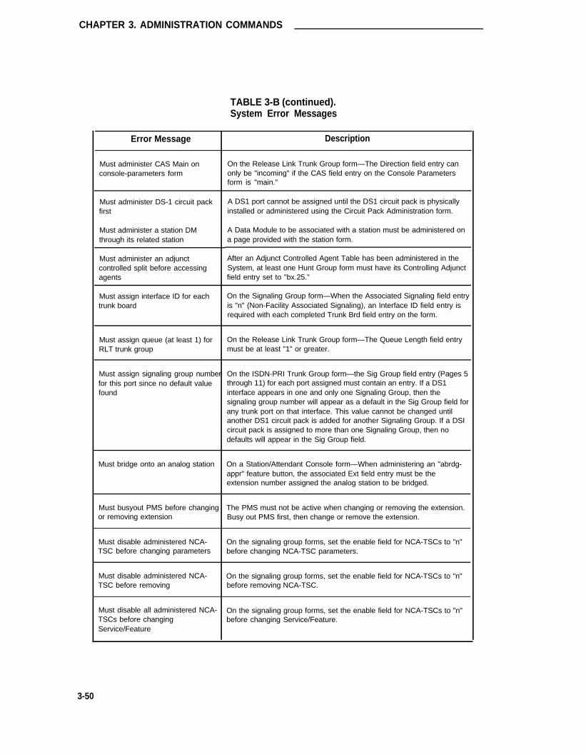
CHAPTER 3. ADMINISTRATION COMMANDS
TABLE 3-B (continued).System Error Messages
Error Message Description
Must administer CAS Main onconsole-parameters form
On the Release Link Trunk Group form—The Direction field entry canonly be "incoming" if the CAS field entry on the Console Parametersform is "main."
Must administer DS-1 circuit packfirst
Must administer a station DMthrough its related station
Must administer an adjunctcontrolled split before accessingagents
A DS1 port cannot be assigned until the DS1 circuit pack is physicallyinstalled or administered using the Circuit Pack Administration form.
A Data Module to be associated with a station must be administered ona page provided with the station form.
After an Adjunct Controlled Agent Table has been administered in theSystem, at least one Hunt Group form must have its Controlling Adjunctfield entry set to "bx.25."
Must assign interface ID for eachtrunk board
On the Signaling Group form—When the Associated Signaling field entryis "n" (Non-Facility Associated Signaling), an Interface ID field entry isrequired with each completed Trunk Brd field entry on the form.
Must assign queue (at least 1) forRLT trunk group
On the Release Link Trunk Group form—The Queue Length field entrymust be at least "1" or greater.
Must assign signaling group numberfor this port since no default valuefound
On the ISDN-PRI Trunk Group form—the Sig Group field entry (Pages 5through 11) for each port assigned must contain an entry. If a DS1interface appears in one and only one Signaling Group, then thesignaling group number will appear as a default in the Sig Group field forany trunk port on that interface. This value cannot be changed untilanother DS1 circuit pack is added for another Signaling Group. If a DSIcircuit pack is assigned to more than one Signaling Group, then nodefaults will appear in the Sig Group field.
Must bridge onto an analog station On a Station/Attendant Console form—When administering an "abrdg-appr" feature button, the associated Ext field entry must be theextension number assigned the analog station to be bridged.
Must busyout PMS before changingor removing extension
The PMS must not be active when changing or removing the extension.Busy out PMS first, then change or remove the extension.
Must disable administered NCA-TSC before changing parameters
On the signaling group forms, set the enable field for NCA-TSCs to "n"before changing NCA-TSC parameters.
Must disable administered NCA- On the signaling group forms, set the enable field for NCA-TSCs to "n"TSC before removing before removing NCA-TSC.
Must disable all administered NCA-TSCs before changingService/Feature
On the signaling group forms, set the enable field for NCA-TSCs to "n"before changing Service/Feature.
3-50

Error Messages
TABLE 3-B (continued).System Error Messages
Error Message Description
Must disable associated The Interface Link must be busied out before a "changecommunication link before communications-interface link" command can be issued. On thechange/removal Interface Links form, set the appropriate Enable field entry to "n" to busy
out the link.
Must disable communication link The Interface Link must be busied out before the associated objectorassociated with this DS1 board first DS1 port can be changed or removed. On the Interface Links form, set
the appropriate Enable field entry to "n" to busy out the link.
Must have at least one entry for On the Time of Day Routing form—There must be at least one Act Timeeach day and associated PGN field entry for each day on the form. The System
defaults are "00:00" and "1," respectively, for each day.
Must have normal button for display On the Station form—A "normal" display-type feature button must bemodule assigned if the station is administered with a display module.
Must install TN780 circuit pack for On the Synchronization Plan form—If the Statum field entry is "3," astratum 3 synchronization TN780 Tone/Clock circuit must be installed in the System.
Must install circuit pack before The associated circuit pack must be physically installed and/orinstalling equipment administered using the Circuit Pack administration form.
Must not reference its own Alpha- On the Alphanumeric Dialing Table—A Mapped String field entryname contains a reference to its associated Alpha-name field entry. Change
the Alpha-name reference in the Mapped String.
Must remove 7103A abbreviated On the 7103A Station form—Remove "7103A" from the Abbreviateddialing list before changing the set Dialing List 1, 2, or 3 fields before changing the Type field entry.
type
Must remove DS1 parameters On the DS1 Circuit Pack form—Remove appropriate entries fromassociated fields on the form before removing the circuit pack.
Must remove Secondary D-Channel On the Signaling Group form—lf the Associated Signaling field entry isfield before changing fas-nfas type to be changed from "n" (NFAS) to "y" (FAS), the secondary D-Channel
field entry must be deleted first.
Must remove administered NCA- Remove any administered NCA-TSCs from the signaling group beforeTSCs before removing signaling removing the signaling group.group
3-51

CHAPTER 3. ADMINISTRATION COMMANDS
TABLE 3-B (continued).System Error Messages
Error Message Description
Must remove all members before On the Trunk Group form—Remove all trunk port assignments beforechanging trunk group type to/from changing the Group Type field entry on Page 1 of the form.ISDN-PRI
Must remove associated Sig Grp On the ISDN-PRI Trunk Group form—The Signaling Group number (oneentry on Trunk Group form first through eight) must be removed from the Sig Grp fields on Pages 5
through 11 of the form before the Signaling Group can be removed.
Must remove associated ports from On the Trunk Group form—Before a Signaling Group can be removed,trunk group first all DS1 port assignments associated with the Signaling Group’s Primary
and Secondary D-Channel must first be removed from the trunk group.
Must remove button 31 or set data Similar to the above error message except that it refers to button 31 ofmodule to "n." the 7507D set Applies to BRI 7507D set when attempting to change to
this set type from other sets when button 31 is assigned and datamodule is optioned "y." Button 31 on 7507D set is reserved as a fixeddata button if data module is optioned as "y." Button 31 of the 7507Dset normally appears as feature button "21:" of 7405D set. However on7407D set it appears as button "31."
Must remove button 7 or set data Applies to BRI 7505D and 7506D sets when attempting to change tomodule to "n." these sets from other sets when button seven is assigned and data
module is optioned "y." Button 7 on 7505D and 7506D sets is reservedas a fixed data button if data module is optioned as "y."
Must remove entry from ISDN TSC Before removing a gateway entry from processor channel form, removeGateway form first associated entry from ISDN TSC gateway form first. Also, before
removing NCS-TSC entry with application "gateway" from the signalinggroup form, remove associated entry from ISDN TSC gateway formfirst.
Must remove entry from Signaling A DS1 circuit pack cannot be removed if the 24th channel isGroup form first administered as a D-Channel on a Signaling Group form.
A DS1 circuit pack cannot be removed if an associated port isadministered in a Trunk Brd field on an NFAS Signaling Group form.
Must remove extensions dependent On the Dial Plan form—The extensions assigned as "extensions" muston this "extension" first be removed from all objects (for example, stations, hunt groups, etc.)
before the associated entry on the First Digit Table can be changed.
3-52

Error Messages
TABLE 3-B (continued).System Error Messages
Error Message Description
Must remove installed equipment Remove circuit pack and associated interface hardware and wiring frombefore changing circuit pack type the associated port slot before changing the circuit pack type for that
slot.
Must remove the 24th port from On the Signaling Group form—lf a DS1 circuit pack is to be assigned atrunk group first D-Channel and the 24th port is currently assigned on a trunk group
form, the port must be removed from the trunk group or another DS1must be assigned as the D-Channel.
Must remove this DS1 board from On the Interface Links form—Remove the DS1 from the appropriatecommunication links form first Destination Brd field before the circuit pack can be removed.
Must remove trunk boards before On the Signaling Group form—The Trunk Brd and associated Interfacemoving signaling group ID field entries must be removed before removing the Signaling Group.
Must select an ISDN-PRI trunk When allowing TSCs on the Routing Pattern form for a preference, thegroup to establish TSC specified trunk group must be of the ISDN-PRI trunk type.
Must set IXC to blank on Routing On the Routing Pattern form—The IXC field entries must be blankPattern form first before the Grp. No. field can be changed to a non-lSDN trunk group
number.
Must set TSC request to none on When removing an ISDN trunk group or changing from ISDN trunkRouting Pattern form first group type to non-lSDN type, set TSC request to "none" on associated
routing pattern preference.
Must set to high for ISDN On the Processor Channel Assignments form—An Appl. field entry ofapplication "isdn" requires that the associated Priority field entry be "h."
Must specify at least one speed On the Modem Pool Group form—When the Group Type field entry isbetween LOW and 19200 "combined," the Speed field must have one speed specified.
Must use administered DS1 circuit A DS1 port cannot be assigned until the DS1 circuit pack is physicallypack installed and/or administered using the Circuit Pack Administration form.
Name format must be: [Last, First On the Station form—The Name field entry must be in the formatM] or [First M Last]*/ indicated. This format is required for use by the Integrated Directory
feature.
3-53

CHAPTER 3. ADMINISTRATION COMMANDS
TABLE 3-B (continued).System Error Messages
Error Message Description
Neither Service Observing nor ACD The Service Observing and ACD features must be enabled on thefeatures assigned System-Parameters Customer-Options form before associated forms
and fields on forms can be administered.
New and reentered passwords do The changed password has been entered incorrectly. Reenter the newnot match password.
New password must be specified A new password is required when changing passwords. Enter your newpassword. For additional assistance, contact your SystemAdministrator.
Night Service must be blank for On the ISDN-PRI Trunk Group form—The Night Service field entry mustSDDN service type be blank when the associated Service/Feature field entry is "sddn."
Night-serv button required On the Attendant Console form—At least one Night Service featurebutton must be administered.
No TSC assigned A TSC index that was not administered has been specified in amaintenance command.
No Night Destination has been On the Station from—A "hunt-ns" (Night Service) feature button hasadministered for this hunt group been assigned a hunt group that does not have its respective Night
Service Destination field completed.
No adjunct controlled split similarly On the Hunt Group form—You cannot remove the last Adjunctmeasured to move members to Controlled split if there are entries on the Adjunct Controlled Agents
Table form.
No available extensions in the All available extension numbers have been assigned. The Systemsystem maximum is 3500 of which 1600 can be phantom extensions. Also
check the System Dial Plan form for complete assignment of all possibleextension numbers.
No call appearance buttons have On the Station form—Assign at least two call appearance featurebeen assigned buttons to multi-appearance voice terminals.
No data in the system to list Indicates that the object in a list command (for example, hunt group,coverage group, etc.) is not assigned in the System.
3-54

Error Messages
TABLE 3-B (continued).System Error Messages
Error Message Description
No space available to add data The entry has exceeded System limitations for the associated object.Either enter new data or condense or remove current data to makeroom for the addition.
Number of BCMS measured agents The number of measured agents entered exceeds the Systemexceeds maximum maximum of 200.
Number of BCMS measured agents The number of measured agents entered in a split exceeds theper split exceeds maximum maximum of 30.
Number of BCMS measured hunt The number of measured hunt groups entered exceed the maximumgroups exceeds maximum of 99.
Number of BCMS measured trunk The number of measured trunk groups entered exceed the maximum
groups exceeds maximum of 32.
Number of local-tgs buttons on On the Attendant Console form—The maximum number of "local-tgs"feature buttons exceeds maximum buttons that can be assigned on Page 2 of the form is 12. The
combination of "local-tgs" and "remote-tgs" buttons assigned on Page 2cannot exceed 12.
Number of playing cycles must be On the Loudspeaker Paging Access form—The Code Calling PlayingSpecified Cycles field (Page 1) must be completed if the associated Code Calling
fields on the form have been completed.
Number of remote-tgs buttons on On the Attendant Console form—The maximum number of "remote-tgs"feature buttons exceeds maximum buttons that can be assigned on Page 2 of the form is 12. The
combination of "local-tgs" and "remote-tgs” buttons assigned on Page 2cannot exceed 12.
Number string may not run into an On the Alphanumeric Dialing Table form—A Mapped String field entryAlpha-name string contains a Number String that includes an Alpha-name type string.
Remove the Alpha-name type string.
OCM-SID/ANl feature not assigned The Outbound Call Management (OCM) CPN/BN feature must beenabled on the System-Parameters Customer-Options form beforeassociated forms and fields on forms can be administered.
Object in use; please try later The associated object must be busied-out or be idle before it can bechanged or removed.
3-55

CHAPTER 3. ADMINISTRATION COMMANDS
TABLE 3-B (continued).System Error Messages
Error Message Description
Object type and port type Administer the appropriate circuit pack type and port for the object beinginconsistent interfaced. For example, do not administer an Analog circuit pack port
where a DS1 Circuit pack is required. Or, do not administer portnumber 12 if the associated circuit pack has just eight ports.
One or more ports already assigned; Administer another unused circuit pack of the same type or functionality.please select another board
Only one 'audix' or 'rem-audix' On the Hunt Group form—Administer the appropriate entry in themessage center allowed in system Message Center field.
Only one abbreviated dialing list On the Station form—Only one Abbreviated Dialing List (1, 2, or 3) canentry may be 7103A have an entry of "7103A."
Only one day may be specified for When using a schedule qualifier on a command line, the deferred printdeferred reports interval may only be printed once at some later time.
Only one personal list may be Only one Abbreviated Dial List (1, 2, 3) on the form being administeredspecified can have an entry of "p."
Originator and destination cannot be On the Administered Connection form—The Originator and Destinationthe same field entries cannot both be the same.
PBX Code Multiply Assigned On the Dial Plan form—On Pages 2 through 6 of the form UDP, theCode field entry and associated RNX field entry must be different thanany other Code/RNX entry on the form. Do not assign two or moreRNXs to the same Code field entry.
PBX Code inconsistent with First On the Dial Plan form—An extension must be assigned on the FirstDigit Table Digit Table for the first digit of all PBX Codes entered on the UDP
(Pages 2 through 6).
PBX ID defined as local on dialplan On the Feature-Related System Parameters form—lf the ACA Enabledform field is "y" and the ACA Referral calls field is set to "remote," the ACA
Remote PBX Identification field must not contain the local PBX ID(defined on the System’s Dial Plan form).
3-56

Error Messages
"dmi-mos," "tandem," or "tie."
TABLE 3-B (continued).System Error Messages
Error Message Description
PBX ID duplicately assigned please On the Signaling Group form—The Interface ID field entry must not beselect another entered more than once on the form.
PBX ID must be blank if service On the ISDN-PRI Trunk Group form—The PBX ID field entry (Page 2)type is not access, dmi-mos, must be blank if the Service Type field entry (Page 1) is not "access,"tandem, or tie
PBX ID must be unique for DCS The far-end PBX-ID entered on the UDP (Dial Plan ID field on Pages 2across Dial Plan, Sig Grp, and Proc through 6) must be used on associated Processor Channel AssignmentChan forms forms (Machine ID field) and NFAS Signaling Group forms (Interface ID
field) when in a DCS configuration and referring to the same far-endPBX.
Packet bus is not activated, check The Packet Bus option must be enabled on the Maintenance-Relatedsystem-parameters maintenance System Parameters form before associated forms and fields on formsform can be administered. Information concerning this form is provided in the
DEFINITY® Communications System Generic 1 and Generic 3i—Installation and Test, 555-204-104.
Password incorrect Reenter the correct password. Contact the System Administrator ifrequired.
Path does not exist On the form being administered, the Call Coverage Path Group numberbeing referenced has not been administered in the System.
Pattern number invalid Enter a valid routing pattern number in the range 1 through 254.
Permission to change password Your login does not allow you to change the password. Contact thedenied System Administrator if required.
Personal List is not assigned The referenced Abbreviated Dialing Personal List is not administered inthe system.
Personal List previously assigned The referenced Abbreviated Dialing Personal list has already beenadministered in the System.
Personal list must be removed Remove the Abbreviated Dialing Personal List reference from all Stationbefore removal Attendant Console, Data Module, etc., forms, then remove the station.
3-57

CHAPTER 3. ADMINISTRATION COMMANDS
TABLE 3-B (continued).System Error Messages
Error Message Description
Personal list requires one digit dial Enter Abbreviated Dialing Personal List number 1, 2, or 3.code
Pextension with other definitions for On the Dial Plan form—When a pextension (prefixed extension) issame first digit not allowed administered on the First Digit Table, no other dial type (for example,
extension, tact fac, etc.) or "extension" can be entered on the samerow on the table.
Physical channel previously The physical channel (Processor Interface port) has already beenassigned; please select another assigned. Enter an interface port not currently assigned.
Points must be specified On the Call Coverage Paths form—The Point 1, 2, and 3 field entriesconsecutively, starting with Point1 must be assigned sequentially beginning with Point 1.
Assign ports 01 through 04 only for the circuit pack type installed in thePort Circuit must be 01-04 forinstalled circuit-pack type referenced location.
Port Circuit must be 01-06 for Assign ports 01 through 08 only for the circuit pack type installed in theinstalled circuit-pack type .referenced location.
Port Circuit must be 01-12 for Assign ports 01 through 12 only for the circuit pack type installed in theinstalled circuit-pack type referenced location.
Port Circuit must be 01-16 for Assign ports 01 through 16 only for the circuit pack type installed in theinstalled circuit-pack type referenced location.
Port Circuit must be 01-24 for Assign ports 01 through 24 only for the circuit pack type installed in theinstalled circuit-pack type reference location.
Port has been marked bad; please Assign another unused port on the circuit pack assign a port onselect another another circuit pack of the same type or functionality.
3-58

Error Messages
TABLE 3-B (continued).System Error Messages
Error Message Description
Port must be specified On the Loudspeaker Paging Access form—A port must be assigned toeach Loudspeaker Paging zone to be used.
Port previously assigned; please Assign another unused port on the circuit pack or assign a port onselect another another circuit pack of the same type or functionality.
Pos-busy button required On the Attendant console form—A "pos-busy" (Position Busy) featurebutton must be administered on the form.
Primary & Secondary D-Channels On the Signaling Group form—Certain level one and level two DS1have different DS1 parameters circuit pack parameters must be the same when used for Primary and
Secondary D-channels in the same Signaling Group.
Primary D-Channel can not be On the Signaling Group form—The Primary D-Channel field must haveempty an entry.
Primary/Secondary Output Layout On the Feature-Related System Parameters form—Assign "unforrmat-must be either unformatted or ted" or "expanded" to the Primary and Secondary Output Layout fieldsexpanded as appropriate to obtain SMDR records for NCA-TSCs and CA-TSCs.
Principal’s extension must be On station forms, specify the prinoipal’s extension during bridgedspecified. appearance button administration.
Principal's call appearance button On station forms, specify the principal’s call appearance button numbermust be specified. during bridged appearance button administration.
Private Networking feature not The Private Networking feature must be enabled on the System-assigned Parameters Customer-Options form before associated forms and fields
on forms can be administered.
Processor channel duplicately Enter an unused processor channel number.assigned
Processor channel not assigned; The referenced processor channel number has not been administeredplease select another on the Processor Channel Assignments form.
Processor channel not used for On the ISDN TSC gateway form, the specified processor channel is not
gateway; please select another a gateway application.
3-59

CHAPTER 3. ADMINISTRATION COMMANDS
TABLE 3-B (continued).System Error Messages
Error Message Description
Product Id must be all digits On the Maintenance-Related System Parameters form—The Product IDfield entry must be all digits. Information concerning this form isprovided in the DEFINITY® Communications System Generic 1 andGeneric 3i—Installation and Test, 555-230-104.
Product Id must start with a 1 On the Maintenance-Related System Parameters form—The Product IDfield entry must start with a "1." Information concerning this form isprovided in the DEFINITY® Communications System Generic 1 andGeneric 3i—Installation and Test, 555-230-104.
Queue Length must be 0 for SDDN On the ISDN-PRI Trunk Group form—The Queue Length field entryservice type must be "0" if the Service Type field entry is "sddn."
Queue Warning Port must be On the Hunt Group form—If the Calls Warning Threshold field has anspecified since Queue Warning entry, the Calls Warning Port field must have an entry.Threshold specified
Queue length total exceeds limit Enter a Queue Length that is within the range specified for the field.Press [HELP] for a listing of valid inputs or an associated helpmessage.
RNX assigned incorrectly On the Dial Plan form—The RNX field entries on Pages 2 through 6must be in the form; R = 2-9, N = 2-9, X= 0-9.
Two identical RNXs on the UDP are the same length and the first digitsof the associated PBX codes are different.
Two identical RNXs with values entered in the associated local (LCL)fields that are different.
Two identical RNXs with associated ID field entries (non-blank) andassociated PBX ID field entries that are different.
Receive Answer Supervision must On the Trunk Group form—lf the Direction field entry is "incoming,"be no for incoming trunk groups enter "n" in the Receive Answer Supervision field.
Reentered password must be Reenter your new password a second time, otherwise, it will not bespecified changed.
Remote PBX ID assigned to ACA on On the Feature-Related System Parameters form—The ACA Remotesystem-parameters features form PBX Identification field entry must not be the same as the Local PBX ID
field entry on the Dial Plan form.
3-60

Error Messages
TABLE 3-B (continued).System Error Messages
Error Message Description
Remove associated D-Channels Before changing fields on a DS1 circuit pack form or removing the circuitfrom signaling group first pack, all associated D-Channel assignments on Signaling Group forms
must be removed.
Remove associated trunk boards Before removing a DS1 circuit pack or changing the Signaling Mode fieldfrom signaling group first entry on a DS1 Circuit Pack form to "robbed-bit" or "common-chan,"
associated DS1 assignments must be removed from NFAS SignalingGroup forms.
Remove codes starting with "1" On the Feature-Related System Parameters form—The Authorizationbefore setting cancellation symbol Code Cancellation Symbol field cannot be set to a "1" until AC fieldto "1" entries on the Authorization Codes form that begin with a "1" are
removed.
Remove trunk boards not containing On the Signaling Group form—The Associated Signaling field entryPrimary D-channel before changing cannot be changed from "n" (NFAS) to "y" (FAS) until all Trunk Brd fieldto fas entries are removed.
Request Feature Group feature not The Request Feature Group option must be enabled on the System-assigned Parameters Customer-Options form before associated forms and fields
on forms can be administered.
Required abbreviated dialing list not On a Station’s Data Module form—Any attempt to administer theassigned Abbreviated Dialing Dial Code field requires that the Abbreviated Dialing
List 1 field must have an entry.
Required data not specified Reenter valid data. Press [HELP] for a listing of valid entries or anassociated help message.
Required data not specified or clear On the Alphanumeric Dialing Table form—An Alpha name has beenrespective Alpha-name assigned and its associated Mapped String field is blank. Complete the
Mapped String field or remove the Alpha name field entry.
Required data not specified or clear On the Alphanumeric Dialing Table form—A Mapped String has beenrespective Mapped String assigned and its associated Alpha name field is blank. Complete the
Alpha name field entry or remove the Mapped String.
Requires TN722B or TN767 circuit On the DS1 Circuit Pack form—The DMI-BOS field entry cannot be "y"pack unless a TN722B or TN767 circuit pack is installed and/or administered.
3-61

CHAPTER 3. ADMINISTRATION COMMANDS
TABLE 3-B (continued).System Error Messages
Error Message Description
Requires TN767 circuit pack On the DS1 Circuit Pack form—The Signaling Mode field entry cannotbe "isdn-ext" or "isdn-pri" unless a TN767 circuit pack is installed and/oradministered.
Requires the TN777 Network Install a TN777 Network Control circuit pack.Control board
SAI/PROTOCOL data module must Add a Processor Interface Data Module (form instructions in Chapter 6),be assigned before enabling link then enable the associated link on the Interface Links form.
SMDR ext cannot be same as PMS On the Feature-Related System Parameters form—The SMDR Primaryor Journal/Log Printer ext and Secondary Output Destination field entries cannot be the same as
the Extension of PMS Log Printer and Extension of Journal/SchedulePrinter field entries on the Hospitality-Related System Parameters form.
Scheduling table must be On the ISDN-PRI Trunk Group form—If the Scheduled field entry (Pageadministered when scheduled 4) is "y," the scheduling table fields (that is, Act Time and Plan #) mustmethod is selected have at least one entry.
Secondary source requires primary On the Synchronization Plan form—The Primary field must besynchronization source administered before the Secondary field.
Security code invalid Enter a valid 4-digit security code (used to support the Demand PrintMessages function and the retrieval of messages via speech synthesis).
Select one scheduling method On the ISDN-PRI Trunk Group form—When the Service Type field entryis "cbc" (Page 1) and the Usage Allocation field entry is "y" (Page 4), theFixed field entry must be "y."
Service Observing feature not The Service Observing feature must be enabled on the System-assigned Parameters Customer-Options form before associated forms and fields
on forms can be administered.
Service Point Identifier previously On the system maintenance form, the specified Service Point ldentifierassigned value has already been assigned.
Service type does not match on first On the ISDN-PRI Trunk Group form—When the Service Type field entrypage on Page 1 is not "cbc," the Service/Feature field entries on Page 2 must
match the Service Type entry on Page 1.
3-62

Error Messages
TABLE 3-B (continued).System Error Messages
Error Message Description
Service/Feature must be removed The Network Facilities form is a display-only type form. Administrationfrom NSF form before must be performed by the Customer Services Support Organization.removal/change
Service/Feature must be removed On the Routing Pattern form—The Service/Feature field entriesfrom Routing Pattern form before associated with an ISDN-PRI trunk group must be removed from allremoval/change Routing Pattern forms before the trunk group’s Group Type field can be
changed or the trunk group removed.
Service/Feature must be removed On the ISDN-PRI Trunk Group form—The Service/Feature field entriesfrom TRUNK GROUP form before must be removed before the trunk group’s Group Type field can beremoval/change changed or the trunk group removed.
Service/Feature only valid for CBC On the Routing Pattern form—lf the Services/Feature field is assigned antrunk groups entry, the associated ISDN-PRI Trunk Group form must have its Service
Type field entry set to "cbc."
Set Value Group feature not The Set Value Group option must be enabled on the System-assigned Parameters Customer-Options form before associated forms and fields
on forms can be administered.
Signaling Group not assigned. The Signaling Group is not administered in the System. Either add thePlease select another Signaling Group or enter an administered Signaling Group number.
Signaling field on DS-1 form must On The DS1 Circuit Pack form—The Signaling Mode field entry must behave ISDN-PRI type "isdn-pri" or "isdn-ext."
Signaling mode of this board has to On the Signaling Group form—The DS1 Interface assigned to thebe ISDN-PRI Primary and Secondary D-Channel field must have its Signaling Mode
field on the DS1 circuit pack form set to "isdn-pri" or "isdn-ext."Administer the DS1 accordingly.
Signaling mode of this board has to On the Signaling Group form—When the Associated Signaling field entrybe ISDN-PRI or lSDN-EXT is "n" (NFAS), the DS1 circuit pack assigned Trunk Brd fields on the
form must have its Signaling Mode field set to "isdn-pri" or "isdn-ext."Administer the DS1 Circuit Pack form accordingly.
Specified service must be removed On the ISDN-PRI Trunk Group form—When the Service Type field entryfrom routing patterns using this is not "cbc," associated Routing Patterns using the trunk group cannottrunk group have their Service/Feature field administered [field(s) must be blank].
3-63

CHAPTER 3. ADMINISTRATION COMMANDS
TABLE 3-B (continued).System Error Messages
Error Message Description
Specify the BCC for at least one On the Routing Pattern form—For each ISDN-PRI trunk groupclass to y(es) assigned, at least one associated BCC field entry (Page 2) must be set
to "y."
Speed invalid with default mode set This only applies to the 7500B Data Module. When the default mode isto "async"; please press help set to 'sync', valid speeds include 56K and 64K. These are not valid
when the default mode is setback to ‘async’.
Station can only be assigned to 1 Do not assign the station’s extension to more than one Call Pickup
pickup group Group.
Station must be removed and re- Remove the station using the "remove station XXXXX" command.added to change set type to or from Then, re-add the station and administer the Type field as "asai."ASAI
Station must be removed before Remove the station using the "remove station XXXXX" command.Station type can be changed Then, re-add the station and administer the Type field as required.
Station must be removed from On the Intercom Group form—Remove the station’s extension numberICOM group(s) before removal from the appropriate form and then remove the station.
Station must be removed from all Remove the station’s extension number from all groups (for example,groups before removal Intercom, Hunt, TEG, Call Coverage, etc.,), then remove the station.
Station must be removed from code On the Loudspeaker Paging Access form—Remove the station’scalling list before removal extension number from the Code Calling IDs Ext field, then remove the
station.
Station must be removed from cov- On the Call Coverage Answer Group form(s)—remove the station’sans group(s) before removal extension number from the Ext field, then remove the station.
Station must be removed from On the Coverage Paths form—Remove the station’s extension numbercoverage path before removal from a Coverage Point (Point 1, 2, 3) field, then remove the station.
Station must be removed from On the Pickup Groups form—Remove the station’s extension numberpickup group before removal from the Ext field, then remove the station.
3-64

Error Messages
TABLE 3-B (continued).System Error Messages
Error Message Description
Station must be removed from On the Terminating Extension Group form—Remove the station’sterm-ext group(s) before removal extension number from the Ext field, then remove the station.
Station must have a 7103A On the 7103A Station form—Enter "7103A" in the Abbreviated Dialingabbreviated dialing list List 1, 2, or 3 field.
Suffix must be B-Z or blank On the Circuit Pack Administration form—Enter a suffix code (B throughZ) in the Sfx field. The code should match the code on the installedcircuit pack.
Sum of Min# Chan exceeds total On the ISDN-PRI trunk Group form—The Min# Chan field entrynumber of trunk members (Page 3) must be less than the total number of channels (trunk
members) in the trunk group.
Synchronization sources must be in On the Synchronization Plan form—The Primary and Secondary fieldsame port network references must be located in the same Port Network (one through
three).
System Printer ext cannot be same On the Feature-Related system Parameters form—The Printeras PMS or Journal/Log Printer ext Extension field entry (Page 4) must be different than the Extension of
the PMS Log Printer and Extension of Journal/Schedule Printer fieldentries on the Hospitality-Related System Parameters form.
System limit of 10 CBC trunk groups On the ISDN-PRI Trunk Group form—The Service Type field entryhas been reached cannot be "cbc" because the System’s maximum of 10 CBC trunk
groups have already been assigned.
System limit of 1000 entries has The combined entries in the System’s HNPA and RHNPA Tables is setbeen reached at 1000 entries.
System limit of 233 Incoming Call On the ISDN-PRI Trunk Group form—The Incoming Call Handling TableHandling entries has been reached (Page 2) cannot have more than 288 entries.
System must be taken out of night The system must be taken out of Night Service before associated fieldsservice before removal/change on forms can be changed or an object removed.
System or group list requires two Enter an appropriate Abbreviated Dialing 2-digit dial code. A 2-digitdigit dial code code is required when referencing System and Group lists.
3-65

CHAPTER 3. ADMINISTRATION COMMANDS
TABLE 3-B (continued).System Error Messages
Error Message Description
System resource limit has been The system’s allocated memory space that is shared betweenreached AAR/ARS Analysis Tables, AAR/ARS Digit Conversion Tables, and the
Toll Analysis Table has been filled. New assignments cannot be madeunless current assignments are removed.
TAC assigned Enter a new Trunk Access Code that agrees with the System’s DialPlan.
TAC invalid; please check dialplan The TAC first digit does not agree with the first digit assigned TACs onthe Systems Dial Plan form.
TAC must be specified On the Loudspeaker Paging Access form—A TAC must be specified foreach Voice Paging or Code Calling port assigned.
TN Code of a circuit pack can not be On the circuit Pack Administration form—Enter the complete circuitblank pack code when administering a circuit pack Enter "TN" plus three
digits to complete the entry.
The maximum number of ASAl Up to eight ASAl Link Interfaces may be administered in the System.endpoints is already administered
The maximum number of BRI The maximum number of 1000 BRI endpoints has already beenendpoints is already administered administered. This includes both voice, integrated voice/data, data
endpoints, and ASAl endpoints.
The maximum number of data The maximum number of data modules that can be administered hasmodules is already administered been reached.
The maximum number of stations is Up to 1600 stations can be administered. In addition, up to 1600already administered phantom extensions can be administered (Administration Without
Hardware feature).
This D-Channel is duplicately On the Signaling Group form—A D-Channel port cannot be assigned toassigned. Please select another more than one Signaling Group, no matter if it is assigned as a Primary
or Secondary D-Channel port.
3-66

Error Messages
TABLE 3-B (continued).System Error Messages
Error Message Description
This Trunk Board does not belong to On the ISDN-PRI Trunk Group form—The Sig Grp field entry (Pages 5this Signaling Group through 11) is not associated with the Port entry (that is, the Port field
entry is not associated with the referenced Signaling Group on therespective Signaling Group form).
This field cannot be assigned to this On the Trunk Group form—The Mode, Type, and Answer Delay fieldsport and board; please enter blank on the trunk member assignments pages require that associated Port
assignments be a TN722, TN760B, or TN767 circuit pack type.
This field cannot be blank for RLT On the Release Link Trunk Group form—When the Group Type fieldapplications entry is "rlt," the Incoming Destination field must have an entry.
This station extension must be On the Station form—The Extension field associated with this form mustspecified be completed. The extension number entered must agree with the
System’s Dial Plan form.
Time of Day Routing Feature not The Time of Day Routing feature must be enabled on the System-assigned Parameters Customer-Options form before associated forms and fields
on forms can be administered.
Timeout must be specified On the Loudspeaker Paging Access form—The Voice Paging Timeoutfield must have an entry.
Toll Restriction not allowed with On the Trunk Group form—The Toll Restricted field entry must be "n"automatic trunks for automatic trunks.
Total Min minus length of dialed On the AAR/ARS Analysis form—For those entries associated with astring must be greater than or equal Route Pat (Routing Pattern) field entry of "r1-r32" (RHNPA translationsto three required), the total Min field entry minus length of the D-String entry
must be greater than or equal to three.
Total number of CA-TSCs over the On the signaling group form, the specified number of CA-TSCssystem limit exceeded the system limit.
Total number of NCA-TSCs over the On the signaling group form, the specified number of NCS-TSCssystem limit exceeded the system limit.
Total number of administered NCA- On the signaling group form, an attempt was made to administer aTSCs over the system limit greater number of NCA-TSCs then is supported by the system.
3-67

CHAPTER 3. ADMINISTRATION COMMANDS
TABLE 3-B (continued).System Error Messages
Error Message Description
Total number of entries has reached The maximum allowable entries for this field has been reached. Youthe limit must remove a current entry before a new entry can be assigned.
Total number of permanent NCA- On the signaling group form, total number of administered permanentTSCs must be <= to Max Num of NCA-TSCs must be less than or equal to the maximum number ofNCA-TSCs NCA-TSCs specified on Page 1.
Total number of permanent TSCs (Reserved for future use)must be less than this value
Total number of permanent TSCs On the signaling group form, to allow for as needed TSCs, the totalmust be less than the maximum number of permanent TSCs must be less than the maximum number ofnumber of NCA-TSCs to allow for NCA-TSCs.as-needed TSCs
Trunk Type must be ground-start to On the Trunk Group form—The Abandoned Call Search field entryenable Abandoned Call Search cannot be "y" if the Trunk Type field entry is other than "ground-start."
Trunk board is duplicately assigned The circuit pack port has already been assigned. Assign another circuitpack port of the same type or functional.
Trunk group in a routing pattern - On the Trunk Group form—You cannot change the Direction field entrycannot change to incoming to "incoming" if the trunk group is assigned on a Routing Pattern form.
Remove the trunk group from the routing pattern, then change theDirection field.
Trunk group must be removed from Remove the trunk group from all routing patterns, then remove the trunkall routing patterns before removal group.
Trunk night service buttons must be On the Station form—Remove all Trunk Night Service feature buttonsremoved before removal that point to this trunk group. Then, remove the trunk group.
Trunk type must be specified first On the Trunk Group form—Complete the Group Type field entry.
UDP extension must be local Enter a local UDP extension that agrees with the System’s Dial Planform.
3-68

Error Messages
TABLE 3-B (continued).System Error Messages
Error Message Description
UDP inconsistent with AUDIX On the Hunt Group form—The AUDIX Extension field entry (field onlyExtension in remote AUDIX hunt displayed if the Message Center field entry on the form is "rem-audix"),group is not in agreement with UDP extensions entered on the System’s Dial
Plan form.
Uniform Dialing Plan feature is not The UDP option must be enabled on the System-Parametersassigned Customer-Options form before associated forms and fields on forms can
be administered.
Unique entry cannot be selected -- When using the AAR/ARS "list route-chosen" command, the Dialedenter more digits or '#' sign Number string (part of input command) is incomplete or must end with a
# symbol.
Usage Allocation Schedule Plan is On the ISDN-PRI Trunk Group form—If the Fixed field entry is "y," thenot administered Allocation Plan Number field must be assigned a number (one through
three).
Use printable characters only Do not enter space-bar characters or other non-printable characters.
Vectoring (Basic) feature not The Vectoring (Basic) feature must be enabled on the System-assigned Parameters Customer-Options form before associated forms and fields
on forms can be administered.
Vectoring (Prompting) feature not The Vectoring (Prompting) feature must be enabled on the System-assigned Parameters Customer-Options form before associated forms and fields
on forms can be administered.
Voice Paging and/or Code Calling On the Loudspeaker Paging Access form—Complete at least one Voicedata must be specified Paging or Code Calling TAC/COR pair assignment.
Warning Threshold must be less On the Hunt Group form—The Calls Warning Threshold field entry mustthan or equal to Queue Length be less than the Queue Length field entry.
Warning Threshold must be On the Hunt Group form—If the Calls Warning Port field has an entry,specified since Warning Port the associated Calls Warning Threshold field must have an entry.specified
3-69

CHAPTER 3. ADMINISTRATION COMMANDS
TABLE 3-B (continued).System Error Messages
Error Messages Description
X not supported for sets with data On the Station form—The Port field cannot have an "x" as a valid entrymodules (supports the Administration Without Hardware feature) if a Data Module
is assigned to the station.
X not supported for this object On the Access Endpoint form—An "x" is not a valid Port field entry. An"x" is permitted as the Port field entry on certain Station forms insupport of the Administration Without Hardware feature.
X not supported for this set type An "x" is not a valid entry in the Port field on this form. An "x" ispermitted as the Port field entry on certain Station forms in support ofthe Administration Without Hardware feature.
3-70

CHAPTER 4. SYSTEM FEATURES, FUNCTIONS, AND SERVICES
CHAPTER 4. SYSTEM FEATURES, FUNCTIONS,AND SERVICES
Overview
This chapter lists the forms and fields required to implement features associated with the System.
A brief description of each feature requiring implementation is given along with associated pro-cedures and hardware requirements. A reference table is provided for each feature. The tableprovides a list of System forms required to assign the feature, the fields on the form(s) requiringcompletion, and page locations for instructions. The forms are listed in the tables in the orderthey should be completed. A listing of the forms with associated instructions and additional infor-mation, if applicable, is provided immediately following the table. Examples are provided for com-plex features. Blank forms are provided in the accompanying “Blank Forms Package”.
This chapter does not attempt to discuss any feature in detail. Refer to DEFINITY® Communica-tions System Generic 1 and Generic 3i—Feature Description, 555-230-201, for detailed featuredescriptions.
System features can be categorized into six functional areas: Voice Management, Data” Manage-ment, Network Services, System Management, Call Management, and Hospitality Features. Alist of features by these functional areas is provided on the following pages. Features requiringno implementation are denoted with an asterisk (*) on the list. Features requiring implementationare described individually following the functional list.
4-1

CHAPTER 4. SYSTEM FEATURES, FUNCTIONS, AND SERVICES
VOICE MANAGEMENT FEATURES
Abbreviated Dialing
Attendant Auto-Manual Splitting *
Attendant Call Waiting *
Attendant Control of Trunk Group Access
Attendant Direct Extension Selection With
Busy Lamp Field
Attendant Direct Trunk Group Selection
Attendant Display
Attendant Recall *
Attendant Release Loop Operation *
Audio Information Exchange (AUDIX) Interface
Authorization Codes
Automatic Callback
Automatic Incoming Call Display *
Automatic Wakeup
Bridged Call Appearance—Single-Line
Voice Terminal
Bridged Call Appearance—Multi-Appearance
Voice Terminal
Busy Verification of Terminals and Trunks
Call Coverage
Call Forwarding—All Calls
Call Management System (CMS)
Call Park
Call Pickup
Call Waiting Termination
Centralized Attendant Service
Class of Restriction
Class of Service
Code Calling Access
Conference—Attendant *
Conference—Terminal *
Consult
Coverage Callback
Coverage Incoming Call Identification
Demand Print
Dial Access to Attendant *
Dial Plan
Dialed Number Identification Service
Direct Department Calling
Direct Inward Dialing
Direct Outward Dialing
Distinctive Ringing (Alerting)
Emergency Access to the Attendant
Facility Busy Indication
Forced Entry of Account Codes
Go to Cover
Hold
Hot Line Service
Hunting
Individual Attendant Access
Integrated Directory
VOICE MANAGEMENT FEATURES (Cont’d)
Intercept Treatment
Intercom—Automatic
Intercom—Dial
Inter-PBX Attendant Calls
Intra-switch SMDR
Last Number Dialed
Leave Word Calling
Line Lockout *
Loudspeaker Paging Access
Loudspeaker Paging Access—Deluxe
Manual Message Waiting
Manual Originating Line Service
Manual Signaling
Multi-Appearance Preselection
and Preference
Multiple Listed Directory Numbers
Music-on-Hold Access
Night Service—Hunt Group
Night Service—Night Console Service
Night Service—Night Station Service
Night Service—Trunk Answer From Any
Station
Night Service—Trunk Group
Personal Central Office Line *
Personalized Ringing
Power Failure Transfer *
Priority Calling
Privacy—Attendant Lockout
Privacy—Manual Exclusion
Recall Signaling *Recorded Announcements
Recoded Telephone Dictation Access
Remote Access
Restricted/Unrestricted Call Lists
Restriction—Toll
Restriction—Controlled
Restriction—Miscellaneous Terminal
Restriction—Miscellaneous Trunk
Restriction—Voice Terminal—lnward
Restriction—Voice Terminal—Manual
Terminating Line
Restriction—Voice Terminal—Origination
Restriction—Voice Terminal—Outward
Restriction—Voice Terminal—Termination
Ringback Queuing
Ringer Cutoff
Rotary Dialing *
Send All Calls
Senderized Operation *
Single-Digit Dialing and Mixed Station
Numbering
SMDR Account Code Dialing
* Feature does not require implementation.
4-2

CHAPTER 4. SYSTEM FEATURES, FUNCTIONS, AND SERVICES
VOICE MANAGEMENT FEATURES (Cont’d)
Straight Forward Outward Completion *
Temporary Bridged Appearance *
Terminating Extension Group
Through Dialing *
Timed Reminder
Touch-Tone Dialing *
Transfer *
Trunk Flash
Trunk Group Busy/Warning Indicators
To Attendant
Trunk Identification By Attendant
Trunk-to-Trunk Transfer
Uniform Call Distribution
Voice Message Retrieval
Voice Teminal Display
DATA MANAGEMENT FEATURES
Alphanumeric Dialing
Data Call Setup
Data Hot Line
Data-Only Off-Premises Extensions
Data Privacy
Data Restriction
Default Dialing
Digital Multiplexed Interface (DMI)
Administered Connection/Access Endpoint
DS1 Tie Trunk Service
EIA Interface
Information System Network (ISN)
Interface
Modem Pooling
NETWORK SERVICES FEATURES
AAR/ARS Partitioning
Adjunct-Switch Application Interface
Automatic Alternate Routing
Automatic Circuit Assurance
Automatic Route Selection
Call by Call Service Selection
Calling Party Number/Billing Number
D-Channel Backup
Distributed Communications System (DCS)
DCS Alphanumeric Display for Terminals
DCS Attendant Control of Trunk Group
Access
DCS Attendant Direct Trunk Group
Selection
DCS Attendant Display
DCS Automatic Callback
DCS Automatic Circuit Assurance
DCS Busy Verification of
Terminate and Trunks
DCS Call Forward—All Calls
* Feature does not require implementation.
NETWORK SERVICES FEATURES (Cont’d)
DCS Call Waiting *
DCS Distinctive Ringing *
DCS Leave Word Calling
DCS Multi-Appearance
Conference/Transfer *
DCS Trunk Group Busy/Warning
Indication
Facility/Non Facility Associated Signaling
Facility Restriction Levels and
Traveling Class Marks
Generalized Route Selection
Integrated Services Digital
Network—Primary Rate Interface
Network Access—Private
Network Access—Public
Off-Premises Station
Software Defined Data Network
Subnet Trunking
Time of Day Routing
Uniform Dial Plan
SYSTEM MANAGEMENT FEATURES
Administration Without Hardware
Customer-Provided Equipment Alarm
Enhanced Terminal Administration
Facility Test Calls
Move Agent From CMS *
Recent Change History *
Report Scheduler and System Printer
Security Violation Notification
Station Message Detail Recording (SMDR)
System Measurements *
System Status Reports *
HOSPITALITY FEATURES
Automatic Wakeup
Do Not Disturb
Names Registration
Property Management System Interface
TELEMARKETING FEATURES
Abandoned Call Search
Agent Call Handling
(includes Call Work Codes and Stroke Counts)
Automatic Call Distribution
Basic Call Management System (BCMS)
Call Prompting
Call Vectoring
Inbound Call Management
Intraflow and Interflow
Lookahead Interflow
Outbound Call Management System
Queue Status Indications
Service Observing
4-3

CHAPTER 4. SYSTEM FEATURES, FUNCTIONS, AND SERVICES
AAR/ARS Partitioning
Provides for the Automatic Alternate Routing (AAR) and Automatic Route Selection (ARS) ser-vices to be partitioned among as many as eight different groups of users within the System.
Note that the ARS/AAR Partitioning feature must be enabled on the System-ParametersCustomer-Options form before fields and associated fields on forms can be administered.
Administration
To implement this feature, the following form(s) or sections of the form(s) must be completed.
Form
Class of Restriction
ARS Analysis
AAR Analysis
Time of Day Routing
Field
Partitioned GroupNumber (PGN)
Partitioned GroupNumber
Partitioned GroupNumber
All
FormInstructions
(Page #)
6-72
5-15
5-40
5-34
●
●
●
●
Class of Restriction Form—Assign a Partitioned Group Number (1 through 8) that is usedby AAR/ARS features to select the AAR/ARS service for a group of users. The PGNfield on the COR form is only displayed if the ARS/AAR Partitioning option is enabled andthe Time of Day Routing option is not enabled on the System Parameters Customeroptions form.
ARS Analysis Form—Complete the Partitioned Group Number field as required.
AAR Analysis Form—Complete the Partitioned Group Number field as required.
Time of Day Routing Form—Complete one form for each PGN as required. Note that theTime of Day Routing option must be enabled on the System Parameters CustomerOptions form before a Time of Day Routing form can be administered.
Hardware Requirements
None.
4-4

Abandoned Call Search
Abandoned Call Search
Provides identification of abandoned calls. Before an incoming trunk call to a hunt group orAutomatic Call Distribution (ACD) split rings the hunt group member or agent, the System checksto ensure that the calling party has not abandoned the call (that is, hung up). If the call has beenabandoned, the call will not ring the hunt group member or agent.
Note: Abandoned Call Search is designed to work with CO trunks (ground start—analog)that do not provide disconnect supervision. Central offices that provide disconnectsupervision should not administer the Abandoned Call Search feature.
Administration
To implement this feature, the following form(s) or sections of the form(s) must be completed.
FormForm Field Instructions
(Page #)
Central Office Trunk Abandoned Call Search 5-123Group
Foreign Exchange Trunk Abandoned Call Search 5-180Group
WATS Trunk Group Abandoned Call Search 5-284
● Trunk Group Forms—Complete Abandoned Call Search field.
Hardware Requirements
Each CO trunk requires a port on the TN747C Central Office Trunk circuit pack.
4-5

CHAPTER 4. SYSTEM FEATURES, FUNCTIONS, AND SERVICES
Abbreviated Dialing
Provides lists of stored numbers that can be accessed to place local, long-distance, and intern-ational calls; to activate features; or to perform end-to-end signaling. (End-to-end signaling allowsaccess to remote computer equipment.) Stored numbers can be accessed by voice terminalusers and data terminal users.
Note: There can be a maximum of 2000 Abbreviated Dialing (AD) lists per system.
Administration
To implement this feature, the following form(s) or sections of the form(s) must be completed.
FormForm Field Instructions
(Page #)
Feature Access Codes AD List 1 Access CodeAD List 2 Access CodeAD List 3 Access CodeProgram Access Code 6-127
Abbreviated Dialing 7103A All 6-16Button Assignment
Station (multi-appearance) AD List 1AD List 2AD List 3 6-245
Button/Feature ButtonAssignments-AD Buttons
Hot Line Destination-ADList Number (if applicable)
Console Parameters List 1, 2, 3 6-79
Attendant Console Feature Button Assignments 6-32
-AD Buttons
Abbreviated Dialing System All 6-13List
Abbreviated Dialing Group List All 6-6
Abbreviated Dialing Personal All 6-11List
Abbreviated Dialing Enhanced All 6-2List
4-6

Abbreviated Dialing
Form
Data Line Data Module
Feature-Related SystemParameters
FormField Instructions
(Page #)
List1: 6-89
Off-Premises Tone DetectTimeout Interval 6-133
●
●
●
Feature Access Codes Form—Verify that all feature access codes for accessing lists andprogramming entries in a personal list have been established in the “Abbreviated DialingList 1, List 2, and List 3 Access Code and Program Access Codes” fields.
Abbreviated Dialing 7103A Button Assignment Form—Complete all fields of the 7103Alist if the System uses 7103A Fixed Feature Voice Terminals.
Station Forms—Assign lists to voice terminal’s AD field. On multi-appearance voice ter-minals, optionally assign buttons to access an AD list entry. For example, if entry 1 onthe System List is the number of a branch office in London, then this entry can beassigned to a button. The call can be placed by lifting the receiver and pressing the but-ton. Similarly, entries from a group or personal list can be assigned to a button. Userscan program buttons which are assigned to an AD personal list entry.
Some features have a button directly associated with them; others do not. For example,a Call Pickup button can be assigned to a multi-appearance voice terminal, whereas aPriority Calling button cannot. To associate Priority Calling with a button, assign thePriority Calling feature access code to an AD list (normally the System List) and thenassign that list entry to the button. This is exactly the same procedure as discussed inthe preceding paragraph. The only difference is that the AD list entry is a feature accesscode instead of a telephone number.
Certain voice terminals supported by the System are capable of storing numbers. LikeAD, a stored number is automatically dialed when the associated button is pressed.This, however, is Repertory Dialing, not AD. In this case, the number is stored in thevoice terminal, not in the System. AD only applies for numbers stored in the System.
Console Parameters Form—Assign lists to Console Parameters AD field.
Attendant Console Form—Assign AD list button to attendant console.
AD System List Form—Establish a System List. Complete all fields.
Abbreviated Dialing Group List Form—Establish Group Lists. Contact personnel who willuse Abbreviated Dialing Group List to determine the codes or numbers that should beentered on the various Group Lists. Blank lists can be established and codes or numberscan be added later. Also, specify if calls to numbers on this list should be privileged.Complete all fields.
Abbreviated Dialing Personal List Form—Establish Personal Lists. Users can programtheir own Personal List once the list is in the System via the System’s administration ter-minal. Complete all fields.
●
●
●
●
●
4-7

CHAPTER 4. SYSTEM FEATURES, FUNCTIONS, AND SERVICES
●
●
●
Abbreviated Dialing Enhanced List Form—Establish an Enhanced List. Complete allfields. (Note that the Abbreviated Dialing Enhanced List option must be enabled on theSystem-Parameters Customer-Options form before associated forms and fields on formscan be administered.)
Data Line Data Module Form—Assign lists to Data Module List 1 field.
Feature-Related System Parameters Form—Assign the Off-Premises Tone DetectTimeout Interval (5 through 25 seconds). The AD special “wait” character, when used inan AD string, will cause a delay in the continued dialing of numbers in the string until thisinterval has elapsed. This interval is the number of seconds that a Call Progress ToneReceiver (Detector) will wait to detect a tone from off-premises during dialing. Once thetime-out interval occurs, any additional call progress tones will not be detected.
Hardware Requirements
Additional TN748C Tone Detector circuit packs (up to five per System) may be required if the ADspecial “wait” character is to be used frequently. Several “wait” characters in an AD string may“tie up” a Tone Detector for an extended period (see Feature-Related System Parametersabove).
4-8

Access Trunk Group
Access Trunk Group
An Access Trunk Group provides the System with the ability to communicate with another PBXas either a main or a tandem switch in an Electronic Tandem Network arrangement. Trunks inthis group will not send or receive Traveling Class Marks.
Note: An ISDN-PRI trunk group whose Service Type field is “access” can also function asan access trunk group.
Administration
To implement this feature, the following form(s) or sections of the form(s) must be completed.
FormForm Field Instructions
(Page #)
Access Trunk Group All 5-98
● Access Trunk Group Form—Complete all fields as required.
Hardware Requirements
A port is required on a TN722B, TN760C, or TN767 circuit pack for each trunk to be assigned inthe Access Trunk Group. A TN722B or TN767 provides 24 ports and a TN760C provides fourports.
4-9

CHAPTER 4. SYSTEM FEATURES, FUNCTIONS, AND SERVICES
Administered Connection/Access EndpointThe Administered Connection feature provides the capability to establish end-to-end connec-tions between two access/data endpoints based on Administered Connection attributes. AnAdministered Connection is automatically established by the System whenever the AdministeredConnection is scheduled or manually enabled to become active. Administered Connections pro-vide capabilities such as: alarm notification, including an administrable alarm type and threshold;automatic restoration of connections established over a Software Defined Data Network (SDDN)ISDN-PRI trunk group (service may be referred to as ISDN-PRI (AdministeredConnection/Access Endpoint) Service); scheduled as well as manually enabled connections; andadministrable retry interval for connection attempts that have failed.
The SDDN provides virtual private line connectivity using the AT&T Switched Network (via4 ESS™ switch). Access to the service is provided via a valid SDDN trunk group. The Destina-tion field entry on the Administered Connection form is used by the system to route the Admin-istered Connection when it is due to be active, based on associated Authorized Time Of Day fieldentries.
The Administered Connection feature replaces the Permanent Switched Calls feature that wasprovided in previous releases of the System.
An Administered Connection can be established between two endpoints on the same switch;between two endpoints in the same private network, but on different switches; or between oneendpoint on the controlling switch and another endpoint off the private network. In all configura-tions, the originating endpoint and the Administered Connection must be administered on thesame DEFINITY Generic 3i switch.
For an Administered Connection in a private network, if the two endpoints are on two differentswitches, normally the connection will be routed via AAR through tie trunks (that is, ISDN-PRI,DS1, or analog tie trunks) and possibly intermediate switches. However, if required, the connec-tion can be routed via ARS and the Generalized Route Selection (GRS) features through the pub-lic network. The call is routed over associated ISDN-PRI trunk group members (that is, trunks).When the far-end answers, a connection is “setup” between the far-end and the extensionnumber entered in the Originator field on the Administered Connection form.
The Access Endpoints feature provides the ability to terminate Administered Connections tonon-signaling trunks and thus use these trunks as endpoint facilities. This feature allows for theadministration of a single trunk (that is, does not require an entire trunk group) providing thecapability to assign an extension number to an individual trunk.
Access Endpoints are non-signaling trunk ports and therefore neither generate signaling to thefar-end of the trunk nor respond to any signaling from the far-end. Therefore, an Access End-point cannot be used as a trunk to route between switches. It is used primarily to support dev-ices, switches, or services which have a trunk interface but do not require signaling on the trunk.An Access Endpoint may be designated as the originating (local) endpoint or destination endpointin an Administered Connection. This provides a trunk-to-trunk cross-connect capability.
The maximum number of trunks (including access endpoints) that can be administered is 400(that is, equal to the maximum trunks that can be administered).
4-10

Administered Connection/Access Endpoint
The following are typical Administered Connection applications:
● A local data endpoint connection to a local or remote access endpoint. Examples are: anMPDM ACCUNET® data endpoint (data module) connecting to a SDDN via an lSDN-PRI trunk group DS1 port; an MPDM ACCUNET data endpoint (data module) connectingto an ACCUNET Switched 56 Service via a DS1 port.
● A local access endpoint connecting to a local or remote access endpoint. Examples area DSO cross-connect and a 4-wire leased line modem to a 4-wire leased line modemconnection via an analog tie trunk.
● A local data endpoint connecting to a local or remote data endpoint such as a connectionbetween two 3270 data modules.
The maximum number of Administered Connections that can be administered is 128.
Note that the following guidelines do not include AAR, ARS, or GRS administration information insupport of routing Administered Connection calls over trunk groups. Refer to the respectivefeature coverage elsewhere in this chapter for that information.
Administration
To implement this feature, the following form(s) or section(s) of forms must be completed:
FormForm Field Instructions
(Page #)
Data Module All 6-83
Circuit Pack (trunks) All 6-71
Access Endpoint All 6-18
Trunk Group AllISDN-PRI 5-195Tie 5-247
COR All 6-72
COS All 6-77
Dial Plan Local PBX ID 6-117
Administered Connection All 6-23
Station Button/Feature Button(multi-appearance) Assignments
-ac-alarm 6-245
Attendant Console Feature ButtonAssignments-ac-alarm 6-32
● Data Module Form—Complete the appropriate Data Module forms (for example, MPDMor MTDM) if the Administered Connection involves one or two local data modules.
4-11

CHAPTER 4. SYSTEM FEATURES, FUNCTIONS, AND SERVICES
●
●
●
●
Trunk Circuit Pack Form—Non-signaling DS1 or analog tie trunk ports, if required asaccess endpoints, may be administered as ports but not as members of trunk groups.Assign associated circuit packs using the Circuit Pack form instructions as provided inChapter 2. These circuit packs must be assigned before the port field on the AccessEndpoint form can be completed.
Access Endpoint Connection Form—Complete all fields as required. Complete a form foreach Access Endpoint to be defined.
Trunk Group Form—Complete the appropriate trunk group form for Administered Con-nection calls that are to be routed via AAR or ARS and GRS over associated trunk groupmembers.
COR Form (Optional)—Administer appropriate class of restrictions (CORs) so that onlyan Administered Connection endpoint can be connected to another Administered Con-nection endpoint. If a non-Administered Connection endpoint calls an Administered Con-nection endpoint, intercept treatment will be given the non-Administered Connection end-point.
●
●
●
●
COS Form—Administer class of service (COS) assignments so that the originating anddestination endpoints are blocked from using the Call Forwarding All Calls feature.
Dial Plan Form—The Auto Restoration field on the Administered Connection form cannotbe set to “y” (yes) unless the Local PBX ID field on the Dial Plan form is other than blank.Insure that all far-end destinations as administered on the Administered Connection formare accounted for on the Dial Plan form.
Administered Connection Form—Complete all fields as required. Complete a form foreach Administered Connection to be established. Note that the Originator (and Destina-tion if local) fields must be administered and be a valid extension of an access or dataendpoint before the Administered Connection form can be administered.
Station/Attendant Console Form—Administer "ac-alarm" feature buttons as required The associated status lamp is used to indicate an Administered Connection alarm.
Hardware Requirements
● Trunk Circuit Packs—DS1 Interface circuit pack [TN767 or TN464C (InternationalG1.2SE only)], Analog Tie Trunk (TN760C).
● TN754B Digital Line circuit pack connections including:
— MPDM (700A, 700D), MTDM (700B, 700C, 700E)
— 7400A or 7400B Data Module
— 7401D Voice Terminal with 7400B Data Module
— 7403D/7405D/7407D/7410D/7434D Voice Terminal with DTDM or 7400B DataModule
7404D or 7406D Voice Terminal—
— 510D Personal Terminal
— 515 or 615 BCT or 715 BCS Terminal
— PC/PBX Connection
4-12

Administered Connection/Access Endpoint
● TN556 ISDN-BRI Line and TN778 Packet Control circuit pack connections including:
— 7500B Data Module
— 7505D/7506D/7507D Voice Terminal with ADM
● Pooled Modem (TN758)
4-13

CHAPTER 4. SYSTEM FEATURES, FUNCTIONS, AND SERVICES
Administrable Timers (International G1.ISE and G1.2SE)
The following circuit packs provide administrable timers to support varied international trunk inter-face requirements:
● TN429 Direct Inward and Outward Dial (DIOD) Trunk Circuit Pack (G1.2SE only)
● TN464C 32 Channel DS1 Circuit Pack (G1.2SE only)
● TN465 Loop Start Circuit Pack (G1.1SE and G1.2SE)
Appropriate fields have been added to the Access, CO, DID, DIOD, FX, PCOL, Tandem, Tie, andWATS trunk group forms for administering these timers. The following table provides a summaryof these administrable timers:
TABLE 4-A. Administrable Timers
Timer
Incoming Disconnect
Outgoing Disconnect
Outgoing Dial Guard
Incoming Glare Guard
Outgoing Glare Guard
Outgoing Rotary Dial Interdigit
Ringing Monitor (CO*, FX*, WATS*, PCOL*,DID**, DIOD**)
Ringing Monitor (Tie**, Tandem**, Access**)
* With G1.1SE and G1.2SE.* * With G1.2SE only.
Range (ms)
50-12750
50-12750
200-25600
200-25600
200-25600
150-2550
200-51000
200-25500
Granularity (ms)
50
50
200
200
200
10
200
100
Default (ms)
300
300
1000
3000
3000
600
5000
5000
Timer Range (ins) Granularity (ins) Default (ins)Incoming Seizure 20-2550 10 130
Make 1 0/20 pps***
Break 1 0/20 pps***
*** The Make/Break timing is selectable in 5 ms increments. For 10 pps (pulses per second),Make/Break values are variable from 20 to 80 ms and must sum to 100; for 20 pps, Make/Breakvalues are variable from 10 to 40 ms and must sum to 50. The default values for 10 pps is 40 msfor Make and 60 ms for Break. The default values for 20 pps is 20 ms for Make and 30 ms forBreak.
In addition to the above administrable timers, rotary outpulsing timing can be adjusted on theTN465. The rate is selectable as either 10 pps or 20 pps.
4-14

Administrable Timers (International G1.1SE and G1.2SE)
Administration
To implement this feature, the following form(s) or sections of the form(s) must be completed.
FormForm Field Instructions
(Page
Trunk Groups: Administrable TimersAccess Page 5-98CO 5-123DID 5-156DIOD 5-167FX 5-180PCOL 5-217Tandem 5-232Tie 5-247WATS 5-264
Hardware Requirement
Any of the following circuit packs supports the Administrable Timers feature:
● TN429 DIOD Trunk circuit pack (G1.2SE only)
●� TN464C 32-Channel DS1 Circuit Pack (G1.2SE only)
● TN465 Loopstart Circuit Pack (G1.1SE and G1.2SE)
4-15

CHAPTER 4. SYSTEM FEATURES, FUNCTIONS, AND SERVICES
Administration Without Hardware
Provides the ability to administer station forms without specifying a port location. Stations admin-istered as such will not cause alarms or errors to be generated when the station is translated butnot yet installed. These station types are referred to as “phantom” stations. The feature sup-ports the following applications:
● Ability to administer station forms without specifying a port location.
● Ability by use of a phantom extension to provide call coverage (including AUDIX cover-age) for users who do not have stations physically located on the switch.
● Ability to use phantom extensions for ACD DNIS. This application allows a phantomextension to be administered on the switch for each call type that needs to be identifiedto ACD agents. The phantom extension is either “Call Forwarded” (via an attendant con-sole) to an ACD split, or its coverage path is defined to include the ACD split. The Namefield that is administered for the phantom extension will identify to the ACD agent whichservice the caller is attempting to reach, allowing the agent to properly address the caller.
● Ability to store station templates that can later be used with the duplicate station com-mand when implementing many station forms of the same type in the System.
The primary use of the Administration Without Hardware feature is to streamline system initializa-tions, major additions, and rearrangement/changes by allowing voice terminal translations to beentered before the actual ports are assigned. Port assignments can be done at a later time, asrequired.
The use of this feature is limited to analog, DCP (7400D series of terminals), and hybrid terminaltypes.
Note: This feature is not supported on ISDN-BRI stations, ISDN-BRI data modules, orASAI links.
Appropriate instructions are provided in each of the voice terminal administration instructions pro-vided in Chapter 6, specifically the administration of the Port field on the station forms.
Administration
To implement this feature, the following forms or sections of forms must be completed:
Form
Station (Analog)
Station (Hybrid)
Station (DCP)
FormField Instructions
(Page #)
Port 6-245
Port 6-252
Port 6-287
● Station Forms—Enter an “X’ in the Port field to indicate that there is no hardware associ-ated with the station administration. Complete the remaining fields on the station form asrequired per the station type.
4-16

Advanced Private Line Termination (APLT) Trunk Group
Advanced Private Line Termination (APLT) Trunk Group
An Advanced Private Line Termination (APLT) Trunk Group provides access to and terminationfrom private line networks. The private network may be a Common Control Switching Arrange-ment (CCSA) or an Enhanced Private Switched Communications Service (EPSCS) network. Ifthe trunk group is assigned as external, incoming calls will have a 2-burst distinctive ringing sig-nal.
Administration
To implement this feature, the following form(s) or sections of the form(s) must be completed.
FormForm Field Instructions
(Page #)
APLT Trunk Group All 5-112
● APLT Trunk Group Form—Complete all fields as required.
Hardware Requirement
A port on a TN760C Tie Trunk circuit pack or TN722B or TN767 DS1 Tie Trunk circuit pack isrequired for each trunk to be assigned in the APLT Trunk Group. A TN760C provides four portsfor 4-wire E&M lead signaling. A TN722B or TN767 provides 24 ports for tie trunks, release linktrunks, and APLT trunks.
4-17

CHAPTER 4. SYSTEM FEATURES, FUNCTIONS, AND SERVICES
Agent Call Handling
Provides Automatic Call Distribution (ACD) agents with the various capabilities required toanswer and process ACD calls. When the Forced Entry option is enabled for a split, agents arerequired to complete a Stroke Count or Call Work Code entry for every call answered in theManual-In mode.
Administration
To implement this feature, the following form(s) or sections of the form(s) must be completed.Also, refer to the ACD feature coverage.
FormForm Field Instructions
(Page #)
Feature Access Codes Complete Feature AccessCodes for Automatic CallDistribution Features 6-127
Hunt Groups Forced Stroke Countor Call Work Code 6-160
Station (multi-appearance) Button/Feature ButtonAssignments-manual-in-auto-in-aux-work-after-call-assist-release-work code-stroke-cnt 6-245
Stations Auto Answer 6-245
Attendant Console Feature Button Assignments-after-call-assist-auto-in-aux-work-manual-in-release-work code-stroke-cnt
Auto Answer 6-32
4-18

Agent Call Handling
● Feature Access Codes Form—Assign ACD features as needed.
● Hunt Group Form—Enter “y'' (yes) in the Forced Stroke Count or Call Work field if eithera Stroke Count or Call Work Code must be entered for each call answered by an agentwhen in the Manual-In mode. Note that the Call Work Codes option must be enabled onthe System-Parameters Customer-Options form before the Forced Stroke Count field canbe enabled.
● Station Forms—Assign Agent Call Handling feature buttons to multi-appearance stationsas needed. Enter “y” in the Auto Answer field if an incoming call is to be automaticallyanswered by an ACD agent.
● Attendant Console Form—Assign Agent Call Handling feature buttons to the AttendantConsole as needed. Enter “y” in the Auto Answer field if an incoming call is to beautomatically answered without any action (no button presses) by the attendant.
Hardware Requirements
None.
4-19

CHAPTER 4. SYSTEM FEATURES, FUNCTIONS, AND SERVICES
Alphanumeric Dialing
Allows a terminal user to place a data call using the Data Call Setup feature and an alphanumericstring or alpha-name for the call destination address. For example, a user can type “abcdef”instead of “9+1-403-253-1234+%0000” to make a call. Users need only remember the alpha-name of the far-end terminating point instead of the actual digit string to complete a call.Alphanumeric names can be mixed in with normal digit dialing strings for data call setup.
Alphanumeric Dialing allows a system administrator to change a “mapped string” (actual digitdialing address) without having to inform all users of a changed dial address. Users simply dialthe associated alpha name to complete calls.
Refer to the Data Call Setup feature coverage provided elsewhere in this chapter for a completelisting of functions available when using Data call Setup.
Administration
To implement this feature, the following form must be completed:
FormForm Field Instructions
(Page #)
Alphanumeric Dialing Table -Alpha-name-Mapped String 6-29
● Alphanumeric Dialing Table Form—Complete a “Alpha-name/Mapped String” dialing pairfor each combination to be defined.
Hardware Requirements
None.
4-20

Answer Detection
Answer Detection
Provides improved accuracy of the call duration in the call detail records generated by the StationMessage Detail Record (SMDR) process. The primary responsibilities of the SMDR process areto collect call detail information on trunk groups and/or internal stations (see section on lntra-switch in this chapter) from the software and to format and send that data to an external collec-tion device. This feature allows the SMDR process to generate an outgoing call detail recordwhen a call is answered by relying on the answer detection capability of the TN744 Call Classifiercircuit pack to report the state of the call prior to the arrival of Timed Far End Answer Supervi-sion. The TN744 Call Classifier circuit pack is used instead of the TN748C Tone Detector circuitpack for this feature.
Administration
This feature, which is used in conjunction with the Hospitality feature, can be enabled or disabledfrom the first page of the System-Parameters Customer-Options form.
Note: Procedures covering the use of the System-Parameters Customer-Options form areprovided in DEFINITY® Communications System Generic 1 and Generic 3i—Installation and Test, 555-230-104. See also DEFINITY® Communications SystemGeneric 1 and Generic 3i—Feature Description, 555-230-201 for a description of thisfeature.
Form
System-ParametersCustomer-Options
FormField Instructions
(Page #)
Answer Supervision 6-212by Call Classifier?
System-Parameters Customer-Options Form—When “y” (yes) is entered in the Answer Supervi-sion by Call Classifier field, it means that any CO, FX, and WATS outgoing trunk calls usingtrunks that do not receive Network Answer Supervision will automatically be classified by theTN744 Call Classifier circuit pack. If “n” (no) is entered, the TN744 circuit pack will not be used.The SMDR process will use the arrival of Network or Timed Far End Answer Supervision as thestart time. The default value for this feature is “No.”
Note: The SMDR process should be enabled to generate call detail records.
4-21

CHAPTER 4. SYSTEM FEATURES, FUNCTIONS, AND SERVICES
Asynchronous Data Module (ADM)
The Asynchronous Data Module (ADM) is a BRI data module that may be used with asynchro-nous DTE as a data stand for 7500 Series of BRI voice terminals, thus providing connection tothe ISDN network. The ADM provides integrated voice and data on the same voice terminal andsupports data rates of 300, 1200, 2400, 4800, 9600, and 19200 bps. The ADM is an adjunct toBRI voice terminals and cannot be used in a stand-alone manner. This module also supports theHayes command set, providing compatibility with PC communications packages.
Note: See also the “Integrated Services Digital Network—Basic Rate Interface” and “DataModules” sections in this chapter. Refer also to the section dealing with the “7505D,7506D, and 7507D voice terminals” in Chapter 6.
A port is required on a TN556 ISDN BRI Line circuit pack for each ADM to be assigned. Due tomultipoint support, a port may be shared with another voice-only or data-only endpoint. TheTN556 ISDN BRI Line circuit pack provides 12 ports which support a maximum of 24 stations ordata modules. In addition, the TN778 Packet Control circuit pack is also required.
4-22

Attendant Console
Attendant Console
The attendant console is a digital call-handling position with pushbutton control used not only toanswer incoming calls and place outgoing calls, but also to manage and monitor some of theSystem’s operations.
A System can have as many as six consoles in operation at any time. A daytime console candouble as a night console, or a seventh console can be provided. If a seventh console is pro-vided, it must be classified as night-only and cannot operate when the other six operate.
Administration
To implement this feature, the following form(s) or sections of the form(s) must be completed.
FormForm Field Instructions
(Page #)
Console Parameters All 6-79
Attendant Console All 6-32
● Console Parameters Form—Complete all fields as required. This provides the groupparameters for all attendant consoles to be assigned in the System.
● Attendant Console Form—Complete all fields as required. This provides the uniqueparameters for each attendant console in the System. A completed form is required foreach console to be assigned.
Hardware Requirements
Requires a port on a TN754B Digital Line circuit pack for each attendant console to be assigned.For reliability, the attendant consoles should not be assigned to ports on the same TN754B circuitpack. For example, if three attendant consoles are to be provided, assign each console to a porton three different TN754Bs, if possible. However, if required, all attendant consoles may beassigned to ports on the same TN754B circuit pack.
4-23

CHAPTER 4. SYSTEM FEATURES, FUNCTIONS, AND SERVICES
Attendant Control of Trunk Group Access
Allows the attendant to control trunk groups and prevents voice terminal users from directlyaccessing a controlled trunk group. Attendant consoles may be administered to control differenttrunk groups if required.
Administration
To implement this feature, the following form(s) or sections of the form(s) must be completeddepending on the console type.
FormForm Field Instructions
(Page #)
Attendant Console Feature ButtonAssignments
-act-tr-grp-deact-tr-g-local-tgs-remote-tgs 6-32
Trunk Group Busy ThresholdAccess 5-98APLT 5-112CO 5-123CPE 5-137DMI-BOS 5-144FX 5-180ISDN-PRI 5-195RLT 5-221Tandem 5-232Tie 5-247WATS 5-264
● Attendant Console Form—A Control Activate (act-tr-grp) and a Control Deactivate(deact-tr-g) button (one each) must be assigned to one of the 24 programmable featurebuttons on the attendant console Feature Button Assignments field. Trunk groups to becontrolled are assigned via Attendant Direct Trunk Group Selection. Trunk group selectbuttons (that is, local-tgs or remote-tgs) must be assigned for each of the trunk groups tobe controlled.
● Trunk Group Form—Assign Busy Threshold field for trunks controlled by this feature.
Hardware Requirements
None.
4-24

Attendant Direct Extension Selection With Busy Lamp Field
Attendant Direct Extension Selection With Busy Lamp Field
Allows the attendant to place or extend calls to up to 2000 extension numbers assigned in thesystem by pressing a Group Select button and a Direct Extension Selection (DXS) button insteadof dialing the extension number. Note that an associated DXS lamp for a VDN is always dark.The DXS button may be used to place a call to a VDN.
Administration
To implement this feature, the following form(s) or sections of the form(s) must be completed.
Form
Attendant Console
FormField Instructions
(Page #)
Hundreds Select 6-32Button Assignments(1-20)
● Attendant Console Form—Assign up to 20 buttons in the Hundreds Select Button Assign-ments field. If the selector console has just eight Hundred Group Select buttons, assignjust the first 8 buttons on Page 1 of the form. If required, additional buttons can beassigned to Page 2 of the form.
Hardware Requirements
A Selector Console is required. The 24A Selector Console is equipped with eight Hundred GroupSelect buttons and the 26A Selector Console is equipped with 20 Hundred Group Select buttons.
4-25

CHAPTER 4. SYSTEM FEATURES, FUNCTIONS, AND SERVICES
Attendant Direct Trunk Group Selection
Allows the attendant direct access to an idle outgoing trunk by pressing the button assigned tothe desired trunk group.
Administration
To implement this feature, the following form(s) or sections of the form(s) must be completeddepending on console type.
Form
Attendant Console
Field
DTGS Button Assignments (1 -12)-DTGS Buttons (local-tgs)
FormInstructions
(Page #)
6-32
● Attendant Console Form—Assign up to 12 buttons in the Direct Trunk Group Buttons(Access Code) field and up to 12 additional buttons, if required, on Page 2 of the form. Iftrunk groups are to be controlled via the Attendant Control Of Direct Trunk Group Accessfeature, they should only be assigned the first six Direct Trunk Group Select (DTGS) But-ton Assignments (1 through 6) if using the Basic Attendant Console (301A1).Loudspeaker Paging zones may be assigned these buttons if required. In this case, thebusy/idle lamp button indicates the busy/idle status of the associated paging zone.
This feature is closely related to the Attendant Control of Trunk Group Access and Trunk GroupBusy/Warning Indicators to Attendant features. Refer to those features for additional information.
Hardware Requirements
None.
4-26

Attendant Display
Attendant Display
Shows call-related information that helps the attendant to operate the console more efficiently.Also shows personal-service and message information. Information is shown on thealphanumeric display on the attendant console.
Administration
To implement this feature, the following form(s) or sections of the form(s) must be completeddepending on console type.
FormForm Field Instructions
(Page #)
Attendant Console Display Module Button 6-32Assignments (1-8)
● Attendant Console Form—Assign up to eight buttons in the Display Module ButtonAssignments fields.
Hardware Requirements
None.
4-27

CHAPTER 4. SYSTEM FEATURES, FUNCTIONS, AND SERVICES
Audio Information Exchange (AUDIX) Interface
Provides a communications link between the System and the Audio Information Exchange(AUDIX). AUDIX allows both System users and outside callers to write, edit, send, and forwardvoice messages to other users. In addition, System users can also receive and store incomingvoice messages from others and transfer calls into AUDIX.
The following requires implementation:
●
●
●
AUDIX Interface to Switch— The AUDIX analog connection to the System requires up to16 (small AUDIX) or 32 (large AUDIX) 2500-type Voice Terminal forms to be completedto assign AUDIX voice ports. In addition, an associated data link from the System toAUDIX must be administered.
Call Transfer Into AUDIX— A user who is an AUDIX subscriber or a covering user for aprincipal who is an AUDIX subscriber may transfer a call to AUDIX. This requires use ofthe Transfer Into AUDIX Feature Access Code or use of an abbreviated dialing buttonprogrammed with the access code.
Call Transfer Out of AUDIX— Provides call progress feedback to the calling party in theform of call ringing and voiced messages if the called party is busy. In addition, a calledparty with a display-equipped terminal is informed of the call type (director redirected)and receives associated information about the call.
Note: Administration for Call Transfer Out of AUDIX must be performed on theAUDIX machine. AUDIX machine administration is not covered in thismanual. Refer to the appropriate AUDIX manual for additional information.
● AUDIX in DCS via BX.25 Data Channels— An AUDIX connected to the System cansupport other switches (remote) in a DCS network. One AUDIX can be used to supportall switches in a DCS network or can serve a group of switches in a DCS. The remoteswitch does not have a direct data link connection to AUDIX. It passes its data to thehost switch via a BX.25 data link and associated processor channels. The AUDIXmachine on the host switch has separately administered DCS hop channels to each ofthe remote switches that it is supporting (that is, either all or a group of switches). Thehost switch then provides the AUDIX connection. All AUDIX features can be activatedfrom a host or remote switch. An AUDIX in DCS with connectivity via BX.25 data chan-nels is referred to as “Traditional DCS AUDIX” later in this section.
The remote AUDIX hunt group can be a coverage point in a call coverage path at aremote switch not connected directly to AUDIX. The remote switch must be in the DCSnetwork.
● AUDIX in a DCS via ISDN-PRI D-Channel— (May also be referred to as ISDN-PRI D-Channel DCS AUDIX feature.) This feature still uses BX.25 connectivity between theAUDIX and host switch. The ISDN-PRI connectivity is utilized between the host switchand remote switches in the DCS network The feature requires the same hardware asthe DCS Over ISDN-PRI D-Channel feature. In addition, an AUDIX R1V2 (or laterrelease) is required.
4-28

Audio Information Exchange (AUDIX) Interface
●
●
AUDIX messages are transported via administered NCA-TSCs between nodes support-ing the ISDN-PRI D-Channel DCS AUDIX feature. An administered NCA-TSC is aNCA-TSC that is established between two administered NCA-TSC endpoints on two dif-ferent PBXs and will be up or enabled for a period of time depending on administeredtranslations. The connection may be administered on a “as-needed” or “permanent”basis. (Refer to the DCS Over ISDN-PRI D-Channel feature coverage in this Chapter foradditional information on NCA-TSCs and DCS over ISDN-PRI D-Channel.)
AUDIX as an ACD Split— An AUDIX hunt group may be administered as an ACD splitby setting the ACD field on the hunt group to “y.” This then allows AUDIX traffic to bemeasured via the ACD's CMS. AUDIX requests for voice ports are recorded as loginsand AUDIX requests to the switch to disable voice ports are recorded as logouts by theC M S .
This feature is for use by Systems currently equipped with an ACD and CMS. For thoseSystems not equipped with an ACD and CMS, AUDIX traffic measurements can beobtained using the System Measurements feature functionality.
AUDIX as a Listed Directory Number (LDN) Night Destinatlon— An AUDIX may beused to support LDN calls when the System is in the night service mode. The followingsteps are required to implement this service:
1.
2.
3.
Assign a night destination extension (must be an AUDIX subscriber extension)on the Listed Directory Numbers form (the extension can be assigned to a phan-tom analog station).
Assign a coverage path to the station and assign the associated Call CoveragePaths form with the AUDIX hunt group as the first coverage point. Set the “All”coverage criteria field for outside calls on the form to “y” (yes).
Activate the Call Forwarding All Calls feature for the night extension.
Note: Refer to the AUDIX feature description in DEFINITY® Communications SystemGeneric 1 and Generic 3i—Feature Description, 555-230-201, for additional AUDIXinformation.
The following provides references to associated forms that must be completed to administereither a small or large AUDIX. Typical figures and examples of completed forms, where neces-sary, are also shown. Information required to administer DCS tie trunks and data links is notgiven in this section. Refer to the DCS coverage for those instructions. The completed forms,where shown, are examples only. The actual data assigned on the forms will vary depending onSystem configuration and prior assignment of switch facilities.
The data link interface between the System and the AUDIX may be via either an MPDM orMTDM or by the Processor Interface jack located on the back of the Control Cabinet.
4-29

CHAPTER 4. SYSTEM FEATURES, FUNCTIONS, AND SERVICES
Administration—AUDIX Interface
To implement the AUDIX interface in a non-DCS configuration, the following form(s) or sectionsof the form(s) must be completed. Figure 4-1 shows an example interface using either an MPDMor an MTDM. Figure 4-2 shows a typical interface using the Processor Interface jack located onthe back of the Control Cabinet. Screens 4-1 through 4-12 show typical completed forms for thetwo configurations.
4-30
FormForm Field Instructions
(Page #)
Processor Interface Data All (for one AUDIX link) 6-112Module
Interface Links All (for one AUDIX link) 6-175
Processor Channel Assignment All (for one AUDIX link) 6-194
Modular Processor Data Module All 6-105
or
Modular Trunk Data Module
Station—2500 Form All (for AUDIX voice port) 6-260
(up to 32 forms may be assigneddepending on AUDIX size)
Recorded Announcements All 6-198
Feature Access Codes Transfer Into AUDIX 6-127
Hunt Groups All (as required) 6-160

Audio Information Exchange (AUDIX) Interface
FormForm Field Instructions
(Page #)
Stations All, including: 6-245
(User stations as required) COS
LWC ActivationData RestrictionRedirect NotificationCall Waiting IndicationCoverage Path
Button/Feature ButtonAssignments
-call-fwd-goto-cover-lwc-store-send-calls
Class of Service Call Fwd-All Calls 6-77
Call Coverage Paths All 6-55
Note: AUDIX translations (not covered in this manual) and the System translations must be
●
●
coordinated to ensure proper operation. It is recommended (but not required) thatthe Interface Channel number associated with each logical link match AUDIX portnumbers on all forms. This helps in coordinating assignments and aids in troub-leshooting.
Processor Interface Data Module Form—Complete all fields as required. Assigns a link(interface channel) in the digital switch for the AUDIX interface. Eight links (01 through06) are available for assignment in a multi-carrier cabinet System. A single-carriercabinet has just four links (01 through 04).
If the Processor Interface jack (located on the back of the Control Cabinet) is to be used,Interface Link 1 (physical channel 01 ) must be assigned.
Interface Links Form—Complete all fields on the form for one link, as required. Assign alink from the Processor Interface circuit pack for AUDIX.
Note: Note that when administering the Interface Links form using a changecommunications-interface links command, all fields may be initiallyentered except the Enable field. After completing and administering the Pro-cessor Channel assignment form, recall the Interface Links form using thechange command and then enable the appropriate links by entering "y" in the Enable fields.
4-31

CHAPTER 4. SYSTEM FEATURES, FUNCTIONS, AND SERVICES
●
●
Processor Channel Assignment Form—Complete the required fields on the form for theAUDIX interface.
The entry in the Remote Processor Channel field must agree with an associated AUDIXport field (translated on AUDIX). The entry in the Machine ID field must agree with theAUDIX field entry as translated on the AUDIX Data Link form (typically with just oneAUDIX this entry is one.
If the Processor Interface jack (located on the back of the Control Cabinet) is to be used,Interface Link 1 (physical channel 01) must be assigned.
Modular Processor Data Module (MPDM) or Modular Trunk Data Module Form—Complete all fields as required. Complete an MTDM form when connecting to a largeAUDIX or complete an MPDM form when connecting to a small AUDIX.
Note: Instead of administering an MPDM or MTDM form, the AUDIX data link maybe directly connected to the Processor Interface jack on the back of the Con-trol Carrier (if not already in use) instead of via the MPDM or MTDM and aport on a Digital Line circuit pack. The Processor Interface jack utilizesInterface Link 01 which is administered using the Processor Interface DataModule form. It is advised not to use the Processor Interface jack in thoseSystems that have a duplicated control carrier. The connection is notdesigned so that it can be driven by either processing element in the dupli-cated System.
●
●
●
●
Station Form (2500 Voice Terminal—Complete up to 32 forms for a large AUDIX or upto 16 for a small AUDIX. This assigns AUDIX voice ports to the System. The associatedextension numbers will then be administered in a hunt group as hunt group members.Assign COR field the same COR as the AUDIX hunt group COR. Assign the Name fieldon each form as “audix.”
Recorded Announcements Form—Assign an announcement type to be associated withAUDIX, if required.
Feature Access Codes Form—Enter the Transfer to AUDIX access code.
Hunt Group Form—all fields including the following:
– Enter the AUDIX extension number in the Group Extension field on page one ofthe form.
– Enter “ucd” in the Group Type field.
– Enter “audix” in the Group Name field.
– Enter “audix” in the Message Center field.
– Enter “y” in the ACD field if AUDIX is to be an ACD split; otherwise enter “n.”
– Enter the destination (extension, attendant) where calls to the ACD split will gowhen in the Night Service mode.
– Enter “y” in the Queue field.
– Enter the number of users assigned as hunt group members in the QueueLength field. For example, if the hunt group has ten members, then 10 must beentered in the field. These members are used for AUDIX voice retrieval.
4-32

Audio Information Exchange (AUDIX) Interface
— Enter a recorded announcement extension and associated delay. The associ-ated announcement will be provided to a user after being in a call waiting queuefor the specified delay interval.
— Enter “y” in the Measured by MIS field if AUDIX traffic measurements are to beprovided by ACD CMS.
— Assign up to 32 AUDIX voice ports as member numbers for a large AUDIX or 16for a small AUDIX. Enter previously administered AUDIX voice port extensions(assigned using 2500 Station forms) in the Hunt Group Member Number Assign-ments Ext. fields.
● Station Forms (user stations)
— Assign correct COS number so voice terminal can activate Call Forwarding AllCalls feature.
– Enter “y” in the LWC Activation field.
– Enter “audix” in the LWC Reception field.
– Enter “y” in the Redirection Notification field.
– Enter “n” in the Data Restriction field.
– Enter “n” in the Call Waiting Indication field.
— Assign a coverage path number which has the AUDIX hunt group in a coveragepoint.
● COS Form—Verify Call Forwarding All Calls feature is activated.
● Call Coverage Paths Form—Assign a coverage path which includes the AUDIX huntgroup number in a coverage point. It is recommended (but not required) that the AUDIXbe the last point in a coverage path.
4-33

CHAPTER 4. SYSTEM FEATURES, FUNCTIONS, AND SERVICES
Administration—AUDIX in a DCS via BX.25 Data Channels
To implement the AUDIX interface via BX.25 Data Channels in a DCS configuration (traditionalAUDIX in a DCS), the following form(s) or sections of the form(s) must be completed. Figure 4-3shows an example of AUDIX in a DCS arrangement. Associated instructions and form entriesunique to the DCS arrangement are shown. Other switch translations (hunt groups, stations,links, etc.) are assigned using the previous AUDIX Interface instructions. Also note that allinstructions associated with implementing the DCS data links between switches and the associ-ated DCS entries on Processor Channel Assignments forms, Interface Link forms, etc., arecovered in the DCS section.
FormForm Field Instructions
(Page #)
Dial Plan (as required) 6-117(all switches)
Processor Channel Assign- (as required) 6-194ments(host and remote switch)
Hop Channel Assignments (as required) 6-152(host switch)
Hunt Groups All 6-160(host and remote switches)
Call Coverage Paths All 6-55(host and remote switches)
●
●
●
●
●
Dial Plan Form—The dial plan must be a UDP and include the host switch AUDIX exten-sion in the dial plan. One extension number should be assigned (on all switches) toaccess AUDIX.
Processor Channel Assignments Form (remote switch)—Assign the link number andassociated field entries including the host switch AUDIX Machine ID for the DCS AUDIXconnection. (See Figure 4-3 and associated instructions.)
Hop Channel Assignment Form (host switch)—Assign the Interface Link numbers andassociated channel numbers to each remote switch. Enter the priority as “h” (high).(See Figure 4-3 and associated instructions.)
Hunt Groups Form (remote switch)—Assign a remote AUDIX hunt group containing hostswitch AUDIX extension number. Complete all fields, including the following:
Message Center: Enter “rem-audix.”
AUDIX Extension: Enter host switch AUDIX extension number.
COR: Enter same COR as assigned on the host AUDIX hunt group.
Call Coverage Paths Form (remote switch):—Enter the remote AUDIX hunt groupnumber in the “Point 1:, 2:, or 3:” field. It is recommended but not required that theAUDIX be the last point on a call coverage path.
4-34

Audio Information Exchange (AUDIX) Interface
Administration—AUDIX In a DCS via ISDN-PRI D-Channel
Figure 4-4 shows an example of an AUDIX in a DCS Over ISDN-PRI D-Channel arrangement.Administration associated with the figure is provided.
To implement the AUDIX interface via ISDN-PRI D-Channel in a DCS configuration the followingform(s) or sections of the form(s) must be completed. Other switch translations (hunt groups, sta-tions, links, host switch connections to AUDIX, etc.) are assigned using the previous AUDIXInterface instructions. Also note that all instructions associated with implementing the DCS OverISDN-PRI D-Channel are covered in the DCS Over ISDN-PRI D-Channel feature coverage pro-vided elsewhere in this Chapter.
FormForm
Field Instructions(Page #)
Dial Plan (as required) 6-117(all switches)
AAR Analysis All 5-40
Signaling Group All 5-81
ISDN Trunk Group Used For DCSDCS SignalingPBX ID 5-195
Routing Pattern Trunk Group #FRLDel 5-29
ISDN TSC GatewayChannel Assignments
Sig Group
Adm’d NCA TSCIndex
Processor ChannelApplication
5-87
5-89
Hunt Groups All 6-160(host and remote switches)
Call Coverage Paths All 6-55(host and remote switches)
4-35

CHAPTER 4. SYSTEM FEATURES, FUNCTIONS, AND SERVICES
●
●
●
●
●
●
Dial Plan Form—The dial plan must be a UDP and include the host switch AUDIX exten-sion in the dial plan. One extension number should be assigned (on all switches) toaccess AUDIX. All far-end switches RNXs, PBX IDs, etc. must be entered on the UDPsection of the form.
AAR Analysis Form—Complete the Dialed String, Min/Max, Route Pat, and Call Typeentries required to communicate with each switch in the network.
ISDN-PRI Trunk Group Form—With a Group Type of “isdn-pri,” insure that the Used forDCS field entry is “y,” the DCS Signaling field entry is “d-chan,” and the PBX ID fieldentry is completed to identify the remote PBX in the network that the switch will be com-municating with.
Routing Pattern Form—Enter the above ISDN-PRI trunk group in a routing pattern andcomplete associated FRL and Del fields.
ISDN-PRI TSC Gateway Assignments Form—Complete the appropriate fields on theform if the switch is to act as a gateway between a switch that supports the ISDN-PRID-Channel DCS AUDIX feature and a PBX administered as a traditional DCS AUDIXusing BX.25 data channels for communication.
Hunt Groups Form (remote switch)—Assign a remote AUDIX hunt group containing hostswitch AUDIX extension number. Complete all fields, including the following:
Message Center: Enter “rem-audix.”
AUDIX Extension: Enter host switch AUDIX extension number.
COR: Enter same COR as assigned on the host AUDIX hunt group.
● Call Coverage Paths Form (remote switch):—Enter the remote AUDIX hunt groupnumber in the “Point 1:, 2:, or 3:” field. It is recommended but not required that theAUDIX be the last point on a call coverage path.
Hardware Requirements
The AUDIX data link interface to the System requires either one port on a TN754B Digital Linecircuit pack and an MPDM/MTDM or may be connected directly to the System via the ProcessorInterface jack located on the back of the Control Cabinet. Up to 32 ports (large AUDIX) or 16ports (small AUDIX) on a TN742, TN746B, or TN769 Analog Line circuit pack are required forAUDIX voice port assignments. Any combination of these analog packs can be used. In addi-tion, for an AUDIX in a DCS configuration, DCS hardware is required as covered in the DCSimplementation instructions.
4-36

Audio Information Exchange (AUDIX) Interface
FIGURE 4-1. Typical AUDIX Connections Using an MPDM or MTDM Interface
4-37

CHAPTER 4. SYSTEM FEATURES, FUNCTIONS, AND SERVICES
FIGURE 4-2. Typical AUDIX Connections Using the Control CabinetProcessor Interface Jack
4-38

Audio Information Exchange (AUDIX) Interface
Page 1 of 1
DATA MODULE
Data Extension: 48000
Name: AUDIX________
Type: pdm
COS: 1_
Physical Channel: 04_
COR: 1
ABBREVIATED DIALING
List1:
SCREEN 4-1. Typical MPDM/MTDM Module Form—Used to Assign AUDIX Interface Link
Page 1 of 1
DATA MODULE
Data Extension: 48000 Type: procr-inf Physical Channel: 01_
Name: AUDIX_______ COS: 1_ COR: 1_
ABBREVIATED DIALING
Listl:
SCREEN 4-2. Typical Processor lnterface Data Module Forms—Used to Assign AUDIX Interface Link
4-39

CHAPTER 4. SYSTEM FEATURES, FUNCTIONS, AND SERVICES
Page 1 of 1
INTERFACE LINKS
Link Enable Est PI Destination DTE/
Conn Ext Prot Digits Brd DCE Identification
1: n _ — B X . 2 5 — — DTE2: n _ — B X . 2 5 _ — DTE3: n _ — B X . 2 5 — - DTE4: y y 4 8 0 0 0 B X . 2 5 4 9 0 0 5 — DTE AUDIX LINK
SCREEN 4-3. Typical Interface Links Form Used With MPDM Connection(MPDM assigned Ext. 49005)
Page 1 of 1
INTERFACE LINKS
Link Enable Est PI Destination DTE/
Conn Ext Prot Digits Brd DCE Identification
1: y y 4 8 0 0 0 B X . 2 5 e i a — D T E A U D I X L I N K2: n _ — BX.25 - — DTE3: n _ - BX.25 — — DTE4: n BX.25 — — DTE
SCREEN 4-4. Typical lnterface Links Form Used With Processorlnterface Jack Connection
4-40

Audio Information Exchange (AUDIX) Interface
Port: C0508
COR : 1_
Remote Loop-Around Test: n_
Page 1 of 1
DATA MODULE
Data Extension: 49005 TYPE: pdm______
Name: AUDIX-PDM____ COS: 1
Connected to: dte
ABBREVIATED DIALING
Listl:
SCREEN 4-5. Typical Modular Processor Data Module Form—Used to Assign an MPDM Interface Connection
Page 4 of 4
PROCESSOR CHANNEL ASSIGNMENT
Proc Interface Remote
Chan Appl. Link Chan Priority Proc Chan
49: — —
50: — —•
•
•
•
•
59: A U D I X 4 0 1 h 1 1
60: — — —
Machine-ID
—
—
SCREEN 4-6. Typical Processor Channel Assignment Form—Used to Assign Processor Channel 59 To Audix
4-41

CHAPTER 4. SYSTEM FEATURES, FUNCTIONS, AND SERVICES
Page 4 of 4
PROCESSOR CHANNEL ASSIGNMENT
Proc Interface
Chan Appl. Link Chan
49: —50: —
Priority
Remote
Proc Chan Machine-ID
- —
— —
59: AUDIX 1 01
•
•
•
•
•
h
SCREEN 4-7. Typical Processor Channel Assignment Form—Used to AssignProcessor Channel 59 to AUDlX When Using the Processor Interface Jack Connection
Page 1 of 1
STATION
Extension: 49001
Type: 2500 Lock Messages: n COR: 1
Port: D1501 Security Code: COS: 1Name: AUDIX Coverage Path: _ Tests? n
FEATURE OPTIONS
LWC Reception? audix Coverage Message Retrieval? y
Auto Answer? nLWC Activation? y Data Restriction? y
Redirect Notification? n Call Waiting Indication? n
SCREEN 4-8. Typical 2500 Voice Terminal Form—Used to AssignAUDIX Voice Port Extension 49001
4-42

Audio Information Exchange (AUDIX) Interface
Page 1 of 6
HUNT GROUP
Group Number: 4 Group Extension: 48123 Group Type: ucd
Group Name: AUDIX_______ Coverage Path: ___ COR: 1_
Security Code: ___ Message Center: audix ACD? y
Queue? y Night Service Destination: Vector? n
ISDN Caller Disp:Measured? y Supervisor Extension: _
Priority On Intraflow? n Inflow Threshold: _
Controlling Adjunct? none
Queue Length: 4
Calls Warning Threshold: ___ Calls Warning Port:
Time Warning Threshold: ___ Time Warning Port:
First Ann. Extension: 48999 First Announcement Delay (sec): 2
Second Announcement Extension: ___ Second Announcement Delay (see): _
Second Announcement Recurring: nForced Entry of Stroke Count or Call Work Code? n
SCREEN 4-9. Typical Hunt Group Form—Used to Assign AUDIX Hunt Group andAssociated AUDIX Voice ports
Page 2 of 6
Group Number: 4
HUNT GROUP
Group Extension: 48123
Group Member Assignments
Ext Name
1: 49001 Audix-M Port 1
2: 49002 Audix-M Port 2
3: 49003 Audix-M Port 3
4: 49004 Audix-M Port 4
Ext
Group Type: ucd
Name
SCREEN 4-10. Typical Hunt Group Form—Used to Assign AUDIXHunt Group and Associated AUDIX Voice Ports (Contd)
4-43

CHAPTER 4. SYSTEM FEATURES, FUNCTIONS, AND SERVICES
Coverage
Next
COVERAGE CRITERIA
Station/Group Status
Active?
Busy?
Don’t Answer?
All?
SAC/Go to Cover?
COVERAGE POINTS
Page 1 of 1
COVERAGE PATH
Path Number: 1Path Number: __ Linkage: _ _
Inside Call Outside Call
n n
y y
y y Number of Rings: 3n n
y y
Point1: 48345 Point3: 48123
Point2: 48350
SCREEN 4-11. Typical Call Coverage Paths Form (AUDIX Assigned to Coverage Point 3)
Page 1 of 4ANNOUNCEMENTS
Ext. Type COR Name Queue1 :
2: 48999 integrated 1 AUDIX_ANN n Protect? y Board: CO23 :4 :
SCREEN 4-12. Typical Recorded Announcements Form—Used toAssign an AUDIX Announcement
Figure 4-3 shows an AUDIX in a DCS Network arrangement consisting of three switches. Asso-ciated Hop Channel and Processor Channel Assignments forms for each switch is provided inaddition to related AUDIX translations. The AUDIX translations are not part of the System trans-lations but are presented here for a better understanding of the System.
Translation assignments on AUDIX and each switch must be coordinated to ensure proper opera-tion. It is recommended that Interface Channel numbers associated with each logical link matchAUDIX port numbers on all forms. This helps in coordinating assignments and aids in troub-leshooting. The following guidelines must be observed when making assignments:
4-44

Audio Information Exchange (AUDIX) Interface
Processor Channel Assignments Form
1. The entry in the Remote Processor Channel field must agree with associated AUDIXport fields (on AUDIX).
For example, as shown on Figure 4-3, the association of each switch to an AUDIX port isshown on the AUDIX Translations form where Switches 2, 9, and 10 are associated withAUDIX ports 3, 2, and 1, respectively. Also note that the interface to each switches pro-cessor is via Switch Port (that is, Processor Channel) 59. As a result of this association,the Remote Processor Channel entries on switches 2, 9, and 10 Processor ChannelAssignments forms for Processor Channel 59, as shown, are 3, 2, and 1, respectively.
2. Machine IDs entered on the form must agree with the AUDIX field entry on the AUDIXData Link form (on AUDIX—form not shown). Typically, with just one AUDIX, this entryis”1.“
Hop Channel Assignments Form
Interface Link Channel entries used to show the host switch interface to AUDIX must agree withrelated AUDIX logical channels (on AUDIX).
For example, as shown on Figure 4-3, Interface Link 1, Channel 2 (1, 2) is shown logically con-nected to AUDIX logical channel 2. This then becomes part of the first line entry on the HopChannel Assignments form as shown. A similar situation is shown for Interface Link 1, Channel 3(1, 3) which is entered on the second line of the form. The remaining entries on the Hop ChannelAssignments form complete the hop connection to Switch #9 and Switch #2.
Hop Channel and Processor Channel Assignments Forms
Interface Link Channel assignments between switches must agree.
For example, as shown on Figure 4-3, Interface Channel 2 is shown associated with the logicallink from Switch #10 to Switch #9. Channel 2 is then entered on Switch #10's Hop ChannelAssignments form and on Switch #9’s Processor Channel Assignments form. A similar situationis shown for Interface Channel 3 to Switch #2.
4-45

CHAPTER 4. SYSTEM FEATURES, FUNCTIONS, AND SERVICES
FIGURE 4-3. Typical AUDIX in a DCS Network via BX.25—HopChannel and Processor Channel Assignments
4-46

Audio Information Exchange (AUDIX) interface
Figure 4-4 is an example of the ISDN-PRI D-Channel DCS AUDIX configuration in a D-ChannelDCS network with two switches (PBX A and PBX B). The administration for this configuration isprovided following the figure.
PBX A is the Host Switch, and AUDIX messages between the AUDIX and PBX A is transported .via BX.25 (link 1, channel 1). This connectivity is the same as the one in the traditional DCSAUDIX configuration. The ISDN AUDIX Gateway (link 1, channel 2 / TSC signaling group five,index two) is used in the Host Switch to pass AUDIX messages between the AUDIX and PBX B.
In PBX B, the Remote Switch, AUDIX messages are transported via an administered NCA-TSC(TSC signaling group four, index two).
PBX A PBX B
AUDIX
1/1
LINK 1
1/2
---------
bx.25
- - - - - -
LEGEND
1/1 TSC 5:1 - - - - - - - -
LINK 1 LINK 2 ISDN I
. . . . . . . . . . . . . . . . . . . . . . . . . . . . . - - - - - - - - -1/2 TSC 5:2
TSC4:1LINK 1
TSC 4:2
m/n link /channel
physical link connectivity
- - - - - logical connectivity
. . . . . . . . . . ISDN AUDIX Gateway
TSC x:y TSC index y of signaling group x
FIGURE 4-4. ISDN-PRI D-Channel DCS AUDIX Messaging
4-47

CHAPTER 4. SYSTEM FEATURES, FUNCTIONS, AND SERVICES
Administration associated with Figure 4-4 is as follows:
1. For AUDIX (not part of switch translations):
AUDIX TranslationsSwitch Number AUDIX port Switch Port * Logical Channel Data Link
1 1 59 1 1
2 2 60 2 1
* Switch Port refers to the processor channel that is used for AUDIX in the PBX.
2. For PBX A (PBX ID 1):
Dialplan FormFirst Page Second Page
Start Dig. Len Usage CODE Local RNX PBX ID.4 4 ext 4 y 221 1
5 4 ext 5 n 222 2
AAR Analysis TableDialed String Min/Max Route Pattern Call Type
22 7/7 1 haar
22 7/7 2 aar
Signaling Group Form (signaling group 5 page 2)TSC Local Enabled Establish Dest. Far-end Appl.Index Ext. Ext. Machine-lD
1 4900 Y near-end 5900 2 dcs
2 4901 Y near-end 5901 - gateway
Trunk Group FormGroup # Grp Type Used for DCS? DCS Signaling PBX ID
3 isdn-pri Y d-chan 2
Routing Pattern FormRouting Pattern # Trunk Group # FRL Del
1 3 0 3
Gateway Channel FormSignaling Group TSC Index Processor Channel Application
5 2 60 audix
Processor Channel FormProc. Application Inter. Channel Remote Machine
Channel Link Proc. Channel ID59 audix 1 1 1 160 gateway 1 2 2 .
4-48

Audio Information Exchange (AUDIX) Interface
3. For PBX B (PBX ID 2):
Dialplan FormFirst Page Second Page
Start Dig. Len Usage CODE Local RNX PBX ID.4 4 ext 4 n 221 1
5 4 ext 5 y 222 2
AAR Analysis TableDialed String Min/Max Route Pattern Call Type
22 7/7 2 aar
22 7/7 1 haar
Signaling Group Form (signaling group 4 page 2)
TSC Local Enabled Establish Dest. Far-end Appl.Index Ext. Ext. Machine-ID
1 5900 y far-end 4900 1 dcs
2 5901 y far-end 4901 1 audix
Trunk Group Form
Group # Grp Type Used for DCS? DCS Signaling PBX ID
2 isdn-pri y d-chan 1
Routing Pattern FormRouting Pattern # Trunk Group # FRL Del
1 2 0 3
4-49

CHAPTER 4. SYSTEM FEATURES, FUNCTIONS, AND SERVICES
Authorization Codes
Provides the means for extending control of the System users calling privileges.
On an internally dialed outgoing call, the COR assigned the facility (for example, station) beingused to originate the call and its PGN, when assigned, is used to select a routing pattern. At thispoint in the call, a 4-to 7-digit authorization code may be required to override the COR’s FRLassignment. This then allows users to override the FRL and users within a PGN to have accessto up to 7 FRL’s when assigned and still remain partitioned. On a remote access incoming call,the authorization code may be required as part of the initial dialing sequence, and in this case,the authorization code selects the COR and associated PGN (when assigned) to be used in rout-ing the call.
Administration
The Authorization Codes option must be enabled on the System-Parameters Customer-Optionsform before the associated forms and fields on forms can be administered. Note that the use ofauthorization codes with dialed VDN extensions is not allowed and will be blocked.
To implement this feature, the following form(s) or sections of the form(s) must be completed.
FormForm Field Instructions
(Page #
Authorization Codes AC, COR 6-51
Feature-Related System Authorization Code 6-133Parameters Enabled
Authorization Code LengthAuthorization CodeCancellation Symbol
Attendant Time Out Flag
Station COR 6-245
Class of Restriction FRL 6-72
Routing Patterns Trunk Group Number FRL 5-29
Remote Access Authorization Code 6-203Remote Access Dial Tone
4-50

Authorization Codes
FormForm Field Instructions
(Page #)
Trunk Groups: Auth CodeAccess 5-98APLT 5-112CO 5-123FX 5-180ISDN-PRI 5-195Tie 5-247WATS 5-264
●
●
Authorization Codes Form—Assign 4- to 7-digit authorization codes (with CORs 0through 63).
— In the authorization code field, enter the 4- to 7-digit authorization code the usermust dial. The number of digits entered must agree with the number assigned tothe Authorization Code Length field on the Feature-Related System Parametersform.
— In the COR field, enter the desired COR number from 0 through 63. This is thereplacement COR to be used to modify the user’s calling privileges and is effec-tive after the corresponding authorization code has been dialed.
Feature-Related System Parameters Form—Verify “y” is entered in the AuthorizationCode Enabled field so that Authorization Codes can be assigned on a System widebasis.
— In the Authorization Code Length field, enter a number from 4 through 7 thatdefines the number of digits (length) in the authorization code. This is thenumber of digits that must be assigned to the authorization code on the Authori-zation Codes form.
— In the Authorization Code Cancellation Symbol field, enter the type of symbol thecaller must enter to cancel the 10-second delay before entering the authorizationcode.
— In the Attendant Time Out Flag field, define if the caller will be routed to theattendant should the caller not dial an authorization code within 10 seconds ordials an invalid authorization code.
Station Form—Assign CORs so a separate COR exists for users with different restric-tions. If CORs are already established, they must be taken into account whenadding/assigning new CORs.
COR Form—In FRL field, assign originating Facility Restriction Levels for restricted andunrestricted users. The originating FRL can be a value of 0 through 7 where 0 is themost restrictive.
Routing Patterns Form
●
●
●
4-51

CHAPTER 4. SYSTEM FEATURES, FUNCTIONS, AND SERVICES
— In the Group Number field, enter the desired trunk group number one through 99.
— In the FRL field, assign route FRLs for each trunk group in the Route Pattern. Aroute FRL of 7 is the most restrictive (that is, only users with an FRL of 7 can usethe trunk group) and a route FRL of 0 (that is, users with FRLs from 0 to 7 canuse the trunk group) is the least restrictive. (Note that trunk groups must havebeen assigned previously on the Trunk Group form.) The first choice trunk grouphas the lowest FRL, the second choice trunk group (if there is one) has the nextlowest FRL, etc. The assigned FRL will be used for this pattern only. Trunkgroup FRLs are changeable from pattern to pattern. The FRL assigned to thetrunk group when the COR is defined is not used on ARS calls.
●
●
Remote Access
— In the Authorization Code Required field, enter “y” if an Authorization Code mustbe dialed to access the System features remotely; otherwise, enter “n.”
— In the Remote Access Dial Tone field, enter “y” if the user will receive a recalldial tone before dialing the authorization code. If Barrier Codes are assigned,the recall dial tone is heard after the Barrier Code has been dialed.
Trunk Group Forms—In the Authorization Code field, enter a “y” if an Authorization Codemust be dialed on incoming calls to access the trunks in this trunk group (that is, AuthCode field is used for incoming calls); otherwise, enter “n.”
Authorization Code Examples
The following provides three examples of typical Authorization Codes assignments.
Example 1.
Establish a group of users who must dial an authorization code in order to make outside calls.The client has ARS and the Authorization Codes feature. The forms and fields are administeredas follows:
●
●
●
●
Feature-Related System Parameters Form
- Authorization Codes Enabled y- Authorization Code Length 7- Authorization Code Cancellation Symbol 1- Attendant Timeout Flag n
Voice Terminal Forms—Assign COR = 1 for all unrestricted users and COR = 49 for res-tricted users who must dial an authorization code to make outside calls.
Authorization-Codes Form—Assign the restricted users a replacement COR = 1 and anauthorization code the same as their 7-digit phone number.
COR Form—Assign/change originating FRLS for restricted and unrestricted users.Assign an originating FRL of 7 to users with a COR of one and an originating FRL of 0(zero) to users with a COR of 49.
4-52

Authorization Codes
● Routing Patterns Form—For route pattern one, assign trunk group 40 (CO) as the firstchoice mute with a route FRL = 1, NPA = 201, and Prefix Mark = 1 (that is, dialing ”1” isrequired here to indicate a toll call). Assign first, second, and third choice routes as fol-lows:
Prefix Toll No. Del InsertedGrp No FRL NPA Mark List Digits Digits
40 1 201 12 3 201 1
32 3 201 1 9
For this example, trunk group 40 is a CO trunk, trunk group two is WATS, and trunk group 32 is atie trunk to the System 85.
When a caller dials the ARS access code to call out, the FRL of the originating facility is com-pared with the FRL of the available outgoing facility. If the FRL of the originating facility is lessthan the FRL of the trunk group, the restricted user will be prompted (via recall dial tone) to enteran authorization code. After the authorization code is entered, the call is routed to the CO forcompletion. If the FRL is insufficient to seize any trunk group in the route pattern, the user getsintercept tone.
Restricted callers will be prompted for and be required to enter an authorization code (as previ-ously described). Unrestricted users will simply dial the ARS code followed by the desirednumber.
Refer to DEFINITY® Communications System Generic 1 and Generic 3i—Feature Description,555-230-201, for additional information on the use of AAR/ARS FRLs for control of call routing.
Example 2.
Set up remote access to the switch such that the remote user must enter a barrier code and anauthorization code to access the System features from home. The forms and fields on forms areassigned as follows:
●
●
Remote Access Form
- Remote Access Extension 7XXXX- Barrier Code Length 4- Authorization Code Required y- Remote Access Dial Tone y- Barrier Code 4444- COR 1- COS 1
Remote Access using the DID Feature—To use remote access through the DID feature,dial the 7- to 10-digit Remote Access number (957-XXX) followed by the barrier code(4444). After you hear recall dial tone, enter the authorization code, for example, the 7-digit station extension number (957-ZZZZ), followed by the desired number, or dial theARS access code (9) and the 7- or 10-digit number you are calling. The call will berouted through to completion.
4-53

CHAPTER 4. SYSTEM FEATURES, FUNCTIONS, AND SERVICES
● Remote Access using a dedicated CO, FX, or WATS Trunk—To implement the remoteaccess feature via a dedicated CO, FX, or WATS trunk, the Remote Access form isadministered as above. In addition, the Incoming Destination field is assigned theRemote Access Extension number on the Trunk Group form.
When the caller dials the Listed Directory Number associated with the trunk group dedi-cated to Remote Access, the trunk group routes the call to the Remote Access Exten-sion. The caller will hear a data tone followed by dial tone. The barrier code is thenentered and, in this example, since Remote Access Dial Tone is set to ”1,“ the caller willbe prompted (via recall dial tone) to enter an authorization code. After the authorizationcode is entered, the caller will hear System dial tone. At this point, the desired numbercan be dialed and routed to completion.
Example 3.
On a System that does not use AAR or ARS for call routing, implement the Authorization Codesfeature to allow a caller to override the originating COR assigned to a specific CO trunk group.On the trunk group form, enter “y” in the Authorization Code field if an authorization code must bedialed to access the trunks in this trunk group. This is in addition to administering the parameterson the Feature-Related System Parameters form, the Station form, the Authorization Codesform, and the COR form as specified in the example provided.
Hardware Requirements
None.
4-54

Automatic Alternate Routing
Automatic Alternate Routing
Provides alternate routing choices for private on-network calls. Also provides digit modification toallow on-network calls to route through the public network when on-network routes are not avail-able.
Administration
The Private Networking option must be enabled on the System-Parameters Customer-Optionsform before associated forms and fields on forms can be administered.
To implement this feature, the following form(s) or sections of the form(s) must be completed.
FormForm Field Instructions
(Page #)
Dial Plan All 6-117
Class of Restriction FRLPartitioned Group NumberTime of Day Plan Number 6-72
Feature Access Codes AAR Access Code 6-127
Toll Analysis Dialed StringMax/MinRCLUCL (1-10)Toll List 6-216
AAR Analysis All 5-40
AAR Digit Conversion All 5-44
Routing Patterns All 5-29
Remote Home Number AllPlan Area 5-24
Time of Day Routing All(optional) 5-34
Feature-Related System AAR/ARS Dial Tone RequiredParameters 6-133
●
●
●
Dial Plan Form—Enter local area code. Complete digit identification and numbering.
Class of Restriction Form—Assign FRLs for station CORs. The minimum FRLs requiredto access a route are assigned as part of the Routing Pattern form. Assignment of thesevalues determines the calling privileges associated with calls placed from stationsassigned the COR.
If required, assign an appropriate Partitioned Group Number (1 through 8) or a Time ofDay Routing Plan Number (1 through 8) if the respective field is displayed on the form.
Feature Access Codes Form—Assign “AAR Access Code.”
4-55

CHAPTER 4. SYSTEM FEATURES, FUNCTIONS, AND SERVICES
●
●
●
●
●
●
●
Toll Analysis—Complete the Dialed String, Min/Max, Toll List, RCL, and UCL fields tocontrol outgoing call access. This is only required if an AAR call crosses over to becomean ARS call via the Call Type field entry on the AAR Analysis form being administered as“ars” or by entries on the AAR Digit Conversion form.
AAR Analysis Form—Complete all fields as required. The form allows for the mapping ofcustomer dialed numbers to routing patterns. This form replaces the RNX TranslationTable from the previous release of the System.
AAR Digit Conversion Form—Complete all fields as required. The form is used to con-vert private network numbers or to change the dialed digits to a public network number.The form may also be used to block or intercept certain private network calls to the atten-dant group.
Remote Number Plan Area Form—Complete all fields as required. The form is used for3-digit translations in the range 000 through 999. The form is typically used for mappingCO codes to routing pattern numbers.
Routing Patterns Form—Complete all fields as required. In addition to normal trunkingdata, this form provides subnetwork trunking information which extends a call through achain of subtending switches (see Subnet Trunking).
Time of Day (TOD) Routing—Assign up to eight TOD charts. Each chart can have up toeight routing plans administered, each scheduled to change (based on the time of dayentered on the form) up to six times a day for each of the 7 days in a week. This is anoptional form. The Private Networking, ARS Partitioning, and TOD Routing must beenabled on the System-Parameters Customer-Options form before this form can beimplemented.
Feature-Related System Parameters Form—Complete the AAR/ARS Dial Tone Requiredfield. Enter “y” if second dial tone is required after the feature access code; otherwiseenter “n.”
AAR Guidelines and Examples
The examples that follow are designed to illustrate some of the practical aspects of AAR. Theseare, however, only examples. In reality, each System must be administered to meet its individualneeds.
Completing the Class of Restriction Form
Make assignments as required for the following field:
●
●
●
FRL— Assign a FRL (0 through 7) for each voice terminal user activating AAR. An FRLof 0 (zero) is the most restrictive and an FRL of 7 is the least restrictive. The FRL of thecalling facility is compared against the FRL of the AAR pattern choices to select anallowed route.
Partitioned Group Number— Only displayed if the ARS Partitioning option is enabled onthe System-Parameters Customer-Options form and the TOD Routing option is notenabled. Enter an appropriate PGN (1 through 8).
Time of Day Plan Number— Only displayed if the TOD Routing option is enabled on theSystem-Parameters Customer-Options form. Enter an appropriate TOD Routing PlanNumber (1 through 8).
4-56

Automatic Alternate Routing
Completing the Feature Access Codes Form
Make assignments as required for the following field:
● Auto Alternate Routing (AAR) Access Code—Assign an access code to AAR. Theusual entry is “8.”
Completing the AAR Analysis Form
Complete one to eight AAR Analysis Tables. Each table is associated with a different PartitionedGroup Number. Complete the Dialed String, and associated Minimum and Maximum, Route Pat(Routing Pattern) and Call Type fields for each dialed string to be given specific routing con-sideration.
Complete the AAR Digit Conversion Form
Complete the Matching Pattern and associated Replacement String fields for each dialed string(matching pattern) to be modified (either in part or whole) to an alternative address. Calls will berouted based on the modified address.
Completing the Routing Pattern Form
Make assignments as required for the following fields:
●
●
●
●
●
Pattern Number— Enter a Pattern Number 1 through 254.
Grp No.— Enter the desired trunk group number 1 through 99.
FRL— Enter the Facility Restriction Level 0 through 7 (0 being the least restrictive and 7being the most restrictive) for this trunk group as it will be used by this pattern only.Trunk group FRLs are changeable from pattern to pattern. The FRL assigned to thetrunk group when the COR is defined is not used on AAR calls. The NPA, Prefix Mark,and Toll Table fields listed below are used by ARS and not AAR.
NPA— Enter the NPA of the distant end.
Prefix Mark— Enter a number 0 through four as indicated. This determines the outpuls-ing of the Prefix digit 1.
— 0 —indicates that the Prefix digit 1 is never outpulsed for 10-digit FNPA calls. Auser-dialed 1 is outpulsed for 7-digit HNPA calls.
— 1 —indicates that the Prefix digit 1 is outpulsed if and only if the call is a 10-digitcall. Prefix Mark 1 should be selected for those HNPAs that require users to dial1 to indicate a toll call.
— 2 —indicates that the Prefix digit 1 is outpulsed for all toll calls, 7- and 10-digit,whether the user dials it or not.
— 3 —indicates that the Prefix digit 1 is outpulsed for all toll calls. Toll calls arealways outpulsed as 10-digit numbers, even those within the HNPA.
Note: Prefix Marks 2 and 3 must refer to a Toll Table (see Toll List below).
4-57

CHAPTER 4. SYSTEM FEATURES, FUNCTIONS, AND SERVICES
— BCC— required by the GRS feature. Only administrable if the ISDN-PRI option isenabled on the System Parameters Customer Options form. Enter a value in therange 0 through 4.
— lTC— required by the GRS feature for data calls. Only administrable if theISDN-PRI option is enabled on the System Parameters Customer Options form.Allowed values are “rest” (restricted), “unre” (unrestricted), or “both.”
●
●
●
Toll List— Enter a number, 1 through 32, that references the ARS Toll Table assigned tothis trunk group. This field must be completed if the Prefix Mark is 2 or 3.
No. Del. Digits— Enter the total number of digits (0 through 11) to be deleted from thedialed number when this trunk group is selected for use within this pattern.
Inserted Digits— Enter the actual digits to be inserted, 0 through 36. The digits may bedivided into groups separated by a wait (~w) for dial tone separator. “Wait” takes twodigit places.
Completing the Remote Home Number Plan Area (RHNPA) Form
This form is used for the analysis of the last three digits in a dialed string. References from aDialed String entry on the AAR Analysis Table (in the “Route Pat” field) must be in the form “r1”through “r-32.” This reference points to 1 of the 32 RHNPA Table forms available. Select theproper RHNPA Table form(s) and make assignments as required for the following fields:
●
●
●
●
RHNPA Table— Enter the applicable Table Number (1 through 32).
Code— Enter the significant digit (0 through 9) to identify the hundreds block of codes tobe administered on the form.
Pattern Choice Assignment— Enter the routing pattern number (1 through 254) ineach appropriate field stating with 1:. Up to 12 different pattern choices may beassigned.
Code-Pattern Choice Assignments— Enter a routing pattern number (one through 12)from the above list beside each appropriate code that is required to provide additional 3-digit translations to that provided on the AAR Analysis form. These codes are the leasttwo significant digits of the hundreds block of codes represented on the Remote HomeNumbering Plan Area (RHNPA) form.
Hardware Requirements
Requires the use of tie trunk facilities if not already assigned.
4-58

Automatic Call Distribution
Automatic Call Distribution
Provides automatic connection of incoming calls to specific splits (hunt groups). Calls to aspecific split are automatically distributed among the agents (hunt group members) assigned tothat split. Automatic Call Distribution (ACD) data, transmitted from the switch to the CMS, isused to generate various reports on the status of ACD agents, splits, and trunks.
The ACD option on the System-Parameters Customer-Options form must be enabled beforeassociated forms or fields on forms can be administered.
ACD is implemented using the features or functions listed below. These features can be usedsingularly or in combination with each other. The features are listed alphabetically below andassociated administration instructions are provided with each feature’s coverage (this chapter).
● Abandoned Call Search
● Agent Call Handling
– Call Work Codes
– Stroke Counts
– Forced Entry of Stroke Counts
– ASAI (for adjunct-based ICM and other applications)
● Attendant Console
● Call Management System
● Call Vectoring
● Central Office Trunk Group
● Class of Restriction
● Foreign Exchange Trunk Group
● Hunting
● Intraflow and Interflow
● Lookahead Interflow
● Queue Status Indications
● Recorded Announcements
● Service Observing
● Stations
● Wide Area Telecommunications Service Trunk Group
4-59

CHAPTER 4. SYSTEM FEATURES, FUNCTIONS, AND SERVICES
Figure 4-5 provides an example of an ACD arrangement.
INCOMINGCALLS
TRUNK GROUP #2 SWITCH TRUNK GROUP #3(ACD)
TRUNK GROUP #1 TRUNK GROUP #4
SPLIT 1
BUSINESS TRAVEL
(1 0 AGENTS)
SPLIT 2
PERSONAL TRAVEL
(8 AGENTS)
SPLIT 3
GROUP TRAVEL
(5 AGENTS)
QUEUES U P E R V I S O R
(WITH SERVICE-
O B S E R V I N G
F U N C T I O N )
QUEUE
ANNOUNCEMENT1 ANNOUNCEMENT
ANNOUNCEMENT
2
CALL MANAGEMENT SYSTEM
TERMINAL PRINTER
INTRAFLOW
(CALL COVERAGE)
S P L I T 4 S P L I T 3 S P L I T 2GENERAL INFORMATION G R O U P T R A V E L
(1ST CHOICE) ( 2 N D C H O I C E )PERSONAL TRAVEL( 3 R D C H O I C E )
SPLIT 4
GENERAL INFORMATION
(15 AGENTS)
DISCONNECT
FIGURE 4-5. Typical Automatic Call Distribution Arrangement
4-60

Automatic Call Distribution
Administration
The Automatic Call Distribution option must be enabled on the System-Parameters Customer-Options form before associated forms and fields on forms can be administered.
To implement this feature, the following forms must be completed.
FormForm Field Instructions
(Page #)
Trunk Groups: Incoming DestinationCO 5-123FX 5-180Tie 5-247WATS 5-264
Attendant Console Headset, Auto Answer 6-32
Station Headset, Auto Answer 6-245
Hunt Groups ACD 6-160
Feature-Related System ACD Log-In IdentificationParameters Length 6-133
Vector Directory Number Measured 6-222
Feature Access ACD Features 6-127
●
●
●
●
●
●
●
Trunk Group Forms—Group Number Field—Assign consecutive Group Numbers to trunkgroups when two or more trunk groups are to be used to support ACD applications.
Incoming Destination Field—Enter ACD hunt group extension number in the IncomingDestination field. Note that the use of the Abandoned Call Search feature is not sup-ported for tie trunks.
Attendant Console Form—Enter “y” in the Headset and Auto Answer fields.
Station Forms—if required, enter “y” in the Headset and Auto Answer fields. Assignvoice terminals, as required, including the Callmaster™ digital voice terminal.
Hunt Groups Form—Complete fields that apply when ACD field is set to “y.”
Feature-Related System Parameters Form—Enter in the ACD Log-In ldentification fieldthe number of digits (0 through 9) that must be dialed to access ACD.
Vector Directory Number Form—Specify in the Measured field whether the System willtransmit data for the VDN to the CMS.
Feature Access Form—Assign feature access codes for the ACD features.
4-61

CHAPTER 4. SYSTEM FEATURES, FUNCTIONS, AND SERVICES
Hardware and Software Requirements
Each auxiliary queue warning level lamp requires one port on a TN742, TN746B, or TN769 Ana-log Line circuit pack. A 21C-49 indicator lamp may be used as a queue warning level lamp. Thislamp is approximately two inches in diameter and has a clear beehive lens. The lamp operateson ringing voltage and can be mounted at a location convenient to the split. Each delayannouncement requires one port on a TN750 Integrated Announcement circuit pack orannouncement equipment and one port on a TN742, TN746B, or TN769 Analog Line circuit pack.If music is to be heard after the first delay announcement, a music source and a port on aTN763C Auxiliary Trunk circuit pack is required. If a CMS is to be used, CMS software andhardware is required.
4-62

Automatic Callback
Automatic Callback
Allows internal users who placed a call to a busy or unanswered internal voice terminal to becalled back automatically when the called voice terminal becomes available. Note that AutomaticCallback is not functional for call placed to VDNs.
Administration
To implement this feature, the following form(s) or sections of the form(s) must be completed.
FormForm Field Instructions
(Pages #)
Feature-Related System Automatic Callback—No 6-133Parameters Answer Timeout Interval
(rings)
Feature Access Codes Automatic Callback 6-127Activation/Deactivation
Station (multi-appearance) Button/Feature Button 6-245Assignments
-auto-cback
Class of Service Auto Callback (0-15) 6-77
●
●
●
●
Feature-Related System Parameters Form—Specify callback time-out interval in theAutomatic Callback—No Answer Time-out Interval (rings) field.
Feature Access Codes Form—Verify Automatic Callback Activation and Deactivationfields have been assigned.
Station Forms—Assign Automatic Callback (auto-cback) buttons to multi-appearancevoice terminals, as desired.
Class of Service Form—Verify Automatic Callback field has the correct permission.
Hardware Requirements
None.
4-63

CHAPTER 4. SYSTEM FEATURES, FUNCTIONS, AND SERVICES
Automatic Circuit Assurance
Assists users in identifying possible trunk malfunctions. The System maintains a record of theperformance of individual trunks relative to short and long holding time calls. The Systemautomatically initiates a referral call to an attendant or to a designated display-equipped voice ter-minal user when a possible failure is detected.
Administration
To implement this feature, the following form(s) or sections of the form(s) must be completed.
FormForm Field Instructions
(Page #)
Feature-Related ACA EnabledSystem Parameters
ACA Referral Calls
ACA Referral Destination
ACA Short Holding TimeOriginating Extension
ACA Long Holding TimeOriginating Extension
ACA Remote PBX Identification 6-133
Attendant Console Feature Button Assignments-aca-call 6-32
Trunk Groups: ACA AssignmentShort Holding ThresholdLong Holding TimeShort Holding Time
Access 5-98APLT 5-112CO 5-123CPE 5-137DMI-BOS 5-144FX 5-180ISDN-PRI 5-195RLT 5-221Tandem 5-232Tie 5-247WATS 5-264
Station (multi-appearance) Button/Feature Button 6-245Assignments-aca-call
4-64

Automatic Circuit Assurance
●
●
●
●
Feature-Related System Parameters Form—Verify Automatic Circuit Assurance (ACA)Enabled? field is assigned and the following fields are completed:
– ACA Referral Calls— ACA Referral Destination— ACA Short Holding Time Originating Extension— ACA Long Holding Time Originating Extension— ACA Remote PBX Identification, when ACA referral is specified as “remote.”
Attendant Console Form—Assign aca-call button.
Note: Only one aca-call button can be assigned to the System. The button can beassigned to the attendant console or a voice terminal.
Trunk Group Form—Verify ACA Assignment field is completed and the Short HoldingTime, Long Holding Time, and Short Holding Time Threshold fields are completed.
Station Forms—Assign aca-call button if one was not assigned to the attendant console.
Hardware Requirements
A TN725B Speech Synthesizer circuit pack is required if the referral destination is not a display-equipped voice terminal.
4-65

CHAPTER 4. SYSTEM FEATURES, FUNCTIONS, AND SERVICES
Automatic Route Selection
Routes calls over the public network based on the preferred (normally the least expensive) routeavailable at the time the call is placed.
Administration
The ARS option must be enabled on the System-Parameters Customer-Options form beforeassociated forms and fields on forms can be administered.
To implement this feature, the following form(s) or sections of the form(s) must be completed.
FormForm Field Instructions
(Page #)
Class of Restriction FRLPartitioned Group NumberTime of Day Plan Number 6-72
Dial Plan Area Code 6-117
ARS Prefix 1 Required
Feature Access Codes Automatic Route Selection 6-127(ARS) Access Code
Toll Analysis Dialed StringMax/MinRCLUCL (1-10)Toll List 6-216
ARS Analysis All 5-15
ARS Digit Conversion All 5-20
Routing Patterns All 5-29
Remote Home Numbering All 5-24Plan Area (RHNPA)
ARS Toll Table All 5-27
Time of Day Routing All 5-34
Feature-Related System AAR/ARS Dial Tone Required 6-133Parameters
4-66

Automatic Route Selection
●
●
●
●
●
●
●
●
●
●
●
COR Forms—Assign FRLs for station CORs. The minimum FRLs required to access aroute are assigned as part of the Routing Pattern. Assignment of these values deter-mines the calling privileges associated with calls placed from stations assigned the COR.
Assign an appropriate Partitioned Group Number (1 through 8) or a TOD Routing PlanNumber (1 through 8) if the respective field is displayed on the form. (The TOD PlanNumber field is displayed if the TOD Routing option is enabled on the System-Parameters Customer-Options form. The Partitioned Group Number field is displayed ifthe ARS Partitioning option is enabled and the Time of Day Routing option is notenabled.)
Dial Plan Form—Enter the HNPA (Area Code) and complete the ARS Prefix 1 Requiredfield.
Feature Access Codes Form—Verify or assign ARS access codes (one and two).
Toll Analysis—Complete the Dialed String, Min/Max, Toll List, RCL, and UCL fields asrequired to control outgoing call access.
ARS Analysis Form—Complete all fields as required.
ARS Digit Conversion Form—Complete all fields as required.
RHNPA Form—Complete all fields as required. This form can be used for 3-digit transla-tions in addition to that provided on the ARS Analysis form. Translations for digits in therange 000 through 999 can be provided.
Routing Patterns Form—Complete all fields as required.
ARS Toll Table Form—Complete all fields as required to map 10-digit DDD numbers to7-Digit ETN numbers (RNX-XXXX).
TOD Routing Form—Assign up to eight TOD charts. Each chart can have up to eightrouting plans administered, each scheduled to change (based on the time of day enteredon the form) up to six times a day for each of the seven days in a week. This is anoptional form. The Private Networking, ARS Portioning, and TOD Routing must beenabled on the System-Parameters Customer-Options form before this form can beimplemented.
Feature-Related System Parameters Form—Complete the AAR/ARS Dial Tone Requiredfield. Enter “y” if second dial tone is required after the feature access code; otherwise,enter “n.”
ARS Guidelines and Examples
The examples that follow are designed to illustrate some of the practical aspects of ARS. Theseare, however, only examples. In reality, each System must be administered to meet its individualneeds.
4-67

CHAPTER 4. SYSTEM FEATURES, FUNCTIONS, AND SERVICES
Completing the Class of Restriction Forms
Make assignments as required for the following fields on each station’s COR form:
●
●
●
FRL— Enter an originating FRL number from 0 through 7 to assign call privileges for callsplaced from stations assigned the COR. An originating FRL of 0 has the least callingprivileges and “7” the most.
Partitioned Group Number— Only displayed when the ARS Partitioning option isenabled and the TOD Routing option is not enabled on the System-ParametersCustomer-Options form. Enter the appropriate Partitioned Group Number (1 through 8).
Time of Day Plan #— Only displayed when the TOD Routing option is enabled on theSystem-Parameters Customer-Options form. Enter the appropriate TOD Plan number (1through 8).
Completing the Dial Plan Record
Make assignments as required for the following fields:
●
●
Area Code— Enter the HNPA of the PBX.
ARS Prefix 1 Required— Enter “y” if the user is required to dial one to indicate a 10-digittoll call. This is required when the PBX is located within an area code that contains cen-tral office codes that resemble area codes. Several typical locations include: 201 in NewJersey, 212 in New York, and 312 in Chicago.
The following examples show how dialed numbers are interpreted by the System if “y” isassigned to the ARS Prefix 1 Required field. The number 9 represents the ARS AccessCode. Note that the following assumes default ARS Analysis translations (see ARSAnalysis coverage in Chapter 5). Changes to the default translations may alter the fol-lowing.
1.
2.
3.
4.
5.
9+1+(212)-201-1234 infers a 10-digit toll call.
9+(212)-201-1234 infers that 212 is a Central Office Code. The System acceptsonly the first seven digits following the ARS Access Code. The number212-2011 is sent to the CO.
9+201-1234 infers a 7-digit call within the HNPA.
9+1+201-1234 infers the first seven digits of a 10-digit toll call and waits for theremaining 3 digits. The number being outpulsed is (201)-123-4xxx.
If the number being dialed is a toll call within the HNPA and the CO Code resem-bles an area code as in the preceding example, then the HNPA must also beincluded in the number dialed (refer to example number 1).
9+922-1234 or 9+1+922-1234 infers a 7-digit call (or toll call) within the HNPA.This example differs from example number four in that the CO Code (922) doesnot resemble an area code.
● FIRST DIGIT TABLE— Assign “fac” (Feature Access Code) as the Identification for theDigit 9.
4-68

Automatic Route Selection
Completing the Feature Access Codes Form
Make assignments as required for the following fields:
● Auto Route Selection (ARS) Access Code— Assign an access code to ARS. Theusual entry is “9.”
Completing the ARS Routing Patterns Form
Make assignments as required for the following fields (see example form which follows discus-
●
●
●
●
●
Pattern Number— Enter a Pattern Number 1 through 254.
Grp No.— Enter the desired trunk group number 1 through 99.
FRL— Enter the FRL 0 through 7 (0 being the least restrictive and 7 being the most res-trictive) for this trunk group as it will be used by this pattern only. Trunk group FRLs arechangeable from pattern to pattern. The FRL assigned to the trunk group when the CORis defined is not used on ARS calls.
NPA— Enter the NPA of the distant end. For WATS trunks, the term NPA is the same asthe home NPA. For tie trunks, the NPA field is left blank.
Prefix Mark— Enter a number 0 through 4 as indicated. This determines the outpulsing ofthe Prefix digit 1.
— 0— indicates that the Prefix digit 1 is never outpulsed for 10-digit user-dialedFNPA calls, but leaves a user-dialed Prefix digit 1 for 7-digit HNPA calls. PrefixMark 0 also leaves 1’s on 10-digit calls that are not administered as FNPA- orHNPA-types.
Note: This capability is required, for example, when routing ISDN-PRIcalls to an AT&T 4ESS. If the prefix digit 1 were not suppressed,then the 4ESS would reject such calls.
— 1— indicates that the Prefix digit 1 is outpulsed if and only if the call is a 10-digitcall. Prefix Mark 1 should be selected for those HNPAs that require users to dial1 to indicate a toll call.
— 2— indicates that the Prefix digit 1 is outpulsed for all toll calls, 7- and 10-digit.
— 3— indicates that the Prefix digit 1 is outpulsed for all toll calls. These calls arealways outpulsed as 10-digit numbers, even those within the HNPA.
— 4— indicates that Prefix digit 4 will always suppress a user-dialed Prefix digit 1.
Note: This capability is required, for example, when routing ISDN-PRIcalls to an AT&T 4ESS. If the prefix digit 1 were not suppressed,then the 4ESS would reject such calls.
Note: Prefix Marks 2 and 3 must refer to a Toll Table (see next entry).
4-69

CHAPTER 4. SYSTEM FEATURES, FUNCTIONS, AND SERVICES
● Toll List— Enter a number, 1 through 32, that references the ARS Toll Table assigned tothis trunk group. This field must be completed if the Prefix Mark is 2 or 3.
● No. Del. Digits— Enter the total number of digits (0 through 18) to be deleted when thistrunk group is selected for use within this pattern.
● Inserted Digits— Enter the actual digits to be inserted, 0 through 36. The digits may bedivided into groups separated by a wait for dial tone separator. “Wait” takes two digitplaces. The “,” is used for pause, “+” for the second dial tone, and “%” for end-to-endsignaling.
As an example, assume that an FX trunk group to North Carolina (Area Code 919) is beingdefined:
1.
2.
3.
4.
The ARS user dials 9+(919)-555-1349. (The first 9 represents the ARS Access Code.)
The System checks the ARS Analysis Table for the assigned Routing Pattern.
For the identified routing pattern, if a trunk is available on the first routing preference,then the call is allowed. If a trunk is not available, then the System will search the nextrouting preference for an available trunk on the next trunk group listed on the routing pat-tern.
Assume that on the routing pattern that the value assigned to No. Del. Digits field isthree. The System deletes the first three digits dialed (that is, the digits 919 aredeleted).
Prefix Mark 2 is specified on the routing pattern and the associated Toll Table field isthree. As a result, Toll Table 3 is checked to determine if the call is a local or toll call withrespect to the office at the distant end of the trunk. If local, the number 555-1349 is out-pulsed; if toll, 1-555-1349 is outpulsed.
No digits are inserted for this example.
4-70

Automatic Route Selection
Page 1 of 1
Pattern Number: _
Pattern Assignments (Enter UP To 6)
Grp. FRL NPA Prefix Toll No. Del Inserted IXC
No. Mark List Digits Digits
1 . _
2 . _
3 . _
4 . _
5 . _
6 . _
BCC Value CA-TSC ITC BCIE Service/Feature
0 1 2 3 4 TSC Request
l. y y y y y n rest Band: _
2. y y y y y n rest Band: _
3.y y y y y n rest Band: _
4. y y y y y n rest Band: _
5.y y y y y n rest Band: _
6. y y y y y n rest Band: _
SCREEN 4-13. Routing Pattern Form (Page 1 of 1)
Implementation Note:
The IXC, BCC Value, TSC, CA-TSC Request, ITC and Service/Feature fields are onlydisplayed if the ISDN-PRI option is enabled on the System-Parameters Customer-Optionsform.
BCIE is only administrable if ITC is set to “both.”
CA-TSC is only administrable if TSC is set to “y” (yes).
The Band field is only displayed if the Service/Feature field is “outwats-band.”
Completing the ARS Analysis Table
Up to eight of these forms can be assigned. Each form can be associated with a different PGN(1 through 8). The form is used to associate dialed or modified strings to routing patterns (1through 254). An associated Call Type field for each Dialed String entry is used to identify thecall type (for example, international, operator assisted, FNPA, HNPA, etc.).
4-71

CHAPTER 4. SYSTEM FEATURES, FUNCTIONS, AND SERVICES
Competing the ARS Digit Conversion Table
This form is used to modify dialed public network numbers to private network numbers so as toroute associated calls by the private network (AAR). Its purpose is to save toll charges and toallow users to dial calls using public numbers. In addition, unauthorized public calls can be inter-cepted and routed to an attendant or given intercept treatment.
Completing the Remote Home Numbering Plan Area
The form is used for the translating of 3-digit codes in the range of 000 through 999. The formconsists of 10 pages of 100 codes each: 000-099, 100-199, 200-299, . . . . to 900-999. Up to 32RHNPA Tables may be administered. Each screen form provides fields for the selection of up to12 Routing Pattern choices. Each Code is assigned a Routing Pattern from the 12 routing pat-tern choices that can be assigned on the form. It is not necessary to assign all 12 choices.
The form can be used to translate 3-digit codes in addition to the translations provided by theARS Analysis Table
Enter a routing pattern number from the routing patterns listed (1 through 12) for each 3-digitcode to receive additional translations. Ranking of Pattern choices is not pertinent, however,because the default value for each code is one, the Routing Pattern assigned to Pattern Choice 1should be the one used most frequently.
Completing the Automatic Route Selection Toll Table Form
This form is used to specify whether calls to central office codes are toll or nontoll type calls.
This 800-entry table consists of eight screen forms of 100 office codes each: 200-299, 300-399,...800-899, 900-999. Up to 32 ARS Toll Tables may be completed. The default value foreach office code is “y.” This implies that all calls are toll calls. To identify those calls within theTable that are not toll calls, change the “y” to “n” beside the appropriate office codes.
Toll Tables are associated with the terminating NPA of a given trunk group. They are alwaysrequired for those trunk groups assigned a Prefix Mark of two or three on the Routing Patternform. Refer to Prefix Mark (described earlier under “Completing the ARS Routing PatternsForm”) for additional information on Prefix Marks.
Hardware Requirements
None.
4-72

Automatic Wakeup
Automatic Wakeup
Allows attendants, front desk users, and guests to request that a wakeup call be placed automati-cally to a certain extension number at a later time. Wakeup requests may be placed from fiveminutes to 23 hours and 55 minutes in advance of the wakeup call. Note that a wakeup call can-not be programmed for a VDN.
Administration
To implement this feature, the following form(s) or sections of the form(s) must be completed,
FormForm Field Instructions
(Page #)
Station (multi-appearance) Button/Feature Button 6-245Assignment-Auto-wkup
Attendant Console Feature Button Assignments-Auto-wkup 6-32
Class of Service Console Perms 6-77
Feature Access Codes Announcement Access Code 6-127
Feature Access Codes For Automatic Wakeup Call 6-127Hospitality Features Access Code
Voice Do Not DisturbAccess Code
Verify WakeupAnnouncement Code
Hospitality-Related System Announcement Type 6-154Parameters Length of Time To Remain
Connected To AnAnnouncement
Announcement PortsAuxiliary Board ForAnnouncementExtension To Receive FailedWakeup LWC MessagesExtension of Journal/Schedule Printer
Time of Scheduled WakeupActivity Report
Time of Scheduled WakeupSummary ReportRouting Extension OnUnavailable Voice Synthesis
4-73

CHAPTER 4. SYSTEM FEATURES, FUNCTIONS, AND SERVICES
●
●
●
●
●
●
Station Form—Assign an “auto-wkup” button to 510, 515, 615, 715 or 7400 series voiceterminal equipped with a display.
Attendant Console Form—Assign an “auto-wkup” button to the attendant console.
COS Form—Assign the correct console permissions so the attendant console can placewakeup requests for voice terminals.
Feature Access Codes Form—Assign Announcement Access Code.
Feature Access Codes for Hospitality Features Form—Assign Automatic Wakeup CallAccess Code used for voice prompting. Assign Voice DND field, and Verify WakeupAnnouncement codes.
Hospitality-Related System Parameters Form—Assign the type of automatic wakeupannouncement the hotel guest will receive.
— Assign the announcement ports if the voice synthesis was entered for theannouncement type.
— Assign an auxiliary board for announcement if external is used for announcement
type.— Assign extension number to receive unsuccessful Wakeup LWC messages.
— Assign extension number to the journal/schedule printer.
— Assign time to receive the scheduled wakeup activity report.
— Assign time to receive scheduled wakeup summary report.
— Assign length of time to remain connected to announcement.
— Assign extension number (or 0 for the attendant) to which a call will be placedduring voice synthesis entry of a wakeup message request when a voice syn-thesis port is not available.
Hardware Requirements
If voice prompting is used, a TN725B Speech Synthesizer circuit pack is required. Each circuitpack has four ports to provide voice prompting. If speech synthesis is selected for wakeup callannouncements, two ports must be resewed for wakeup announcements.
If recorded announcements are used, a model HQD614B Recorder/Announcer manufactured bythe Audichron Company is required. Each Recorder/Announcer requires four trunk ports whichmust be on the same TN763C Auxiliary circuit pack.
4-74

Basic Call Management System
Basic Call Management System
BCMS provides a subset of the 3B CMS applications within the System’s digital switch. BCMSprovides real-time and historical reports which assist in the management of individual agents,ACD splits, and trunk groups.
BCMS reports can be accessed and displayed on the DEFINITY G3 Management Terminal andcan be scheduled to print on a dedicated asynchronous printer associated with the System’sReport Scheduler. Printout intervals and associated schedules are assigned using “reportscheduler” administration commands on the G3 Management Terminal. (Refer to the ReportScheduler coverage for administration information associated with the Report Scheduler and itsdedicated System printer interface.)
Administration
To implement this feature, the following form(s) or sections of the form(s) must be completed.
FormForm Field Instructions
(Page #)
Hunt Groups Measured 6-160
Trunk Groups Measured 5-247
Feature-Related System BCMS ParametersParameters -Measurement Interval 6-133
● Hunt Group and Trunk Group Forms—Assign the Measured field on the Hunt Group andTrunk Group forms as one of the following:
— internal - measured by BCMS only (internal to the digital switch)
— external - measured by CMS adjunct only (external to the digital switch)
— both - measured by both BCMS and the CMS adjunct
— none - not measured (system default).
● Feature-Related System Parameters Form—Assign either “hour” or “half-hour” in theMeasurement Interval field associated with the BCMS Parameters to indicate the intervalto be used in polling and reporting measurement data.
Hardware Requirements
None (refer to the Report Scheduler coverage for associated printer interface requirements).
4-75

CHAPTER 4. SYSTEM FEATURES, FUNCTIONS, AND SERVICES
Bridged Call Appearance—Multi-Appearance Voice Terminal
Allows multi-appearance voice terminal users to have an appearance of another user’s primaryextension number. The bridged call appearance can be used to originate, answer, and bridgeonto calls to or from the other user’s primary extension number.
Administration
To implement this feature, the following form(s) or sections of the form(s) must be completed.
FormForm Field Instructions
(Page #)
Station (multi-appearance) Bridged Call Alerting 6-245
Button/Feature ButtonAssignments-brdg-appr
● Station Forms—Assign “brdg-appr” to a 2-lamp button. In the BTN field, enter the buttonnumber of the call appearance on the principal voice terminal that is being bridged. Enterthe principal’s extension in the “Ext.” field. Enter “y” or “n” in the Bridged Call Alertingfield to enable or disable the audible signal on bridged call appearances. One buttonmust be assigned for each bridged appearance. If the principal has three call appear-ances, the bridging extension must have three bridged appearances assigned in order toemulate the principal’s extension. Less than a full complement of bridged extensions canbe assigned, but call appearance emulation (tracking) is on a one-for-one basis.
Hardware Requirements
None.
4-76

Bridged Call Appearance—Single-Line Voice Terminal
Bridged Call Appearance—Single-Line Voice Terminal
Allows a multi-appearance voice terminal to have an appearance of a single-line voice terminal’sextension number. The appearance of the single-line terminal’s extension number at a multi-appearance terminal is called a bridged call appearance.
The bridged call appearance can be used to originate, answer, or bridge onto an existing call toor from the single-line user’s extension number.
Administration
To implement this feature, the following form(s) or sections of the form(s) must be completed.
FormForm Field Instructions
(Page #)
Station (multi-appearance) Bridged Call Alerting 6-245
Button/Feature ButtonAssignments-abrdg-appr
● Station Form—Assign “abrdg-appr” to a 2-lamp feature button. Enter the principal'sextension in the dynamic field, “Ext.” Enter “y” or “n” in the Bridged Call Alerting field toenable or disable the audible signal on bridged call appearances. One button must beassigned for each bridged appearance to a single-line voice terminal.
Hardware Requirements
None.
4-77

CHAPTER 4. SYSTEM FEATURES, FUNCTIONS, AND SERVICES
Business Communications/Personal Terminals
The System supports the following special purpose terminals:
● AT&T Personal Terminal 510D
● 515 Business Communications Terminal (BCT).
The 510D integrates voice and data transmission into a single terminal. It has an integral datamodule and provides a DCP channel intertface to the digital switch. The 510D can serve as aremote on-premises administration terminal.
The 515 BCT integrates voice and data into a single terminal. It has an integral data module andprovides a DCP channel interface to the digital switch. The 515 BCT provides a standard EIA232C interface and can serve as a remote on-premises administration terminal or as a standarddata terminal.
Administration
To implement this feature, the following form(s) or sections of the form(s) must be completed.
FormForm Field Instructions
(Page #)
510D All 6-268
515/615 BCT All 6-268715 BCS
Data Line Data Module AllI 6-89
Hardware Requirements
510D Form—Requires a port on a TN754B Digital Line circuit pack.
515 or 615 BCT Form—Requires a port on a TN754B Digital Line circuit pack.
715 BCS Terminal Form—Requires a port on a TN754B Digital Line circuit pack.
Data Line Data Module Form—Requires an ADU and a port on a TN726B Data Line circuit packwhen the terminal is used as a remote on-premises administration terminal or as a standard dataterminal.
4-78

Busy Verification of Terminals and Trunks
Busy Verification of Terminals and Trunks
Allows attendants and specified multi-appearance voice terminal users to make test calls totrunks, voice terminals, and hunt groups (DDC and UCD groups). These test calls check thestatus of an apparently busy resource. Note that Busy Verification of VDN will be denied.
Administration
To implement this feature, the following form(s) or sections of the form(s) must be completed.
Form Field
Attendant Console
Station (multi-appearance)(this feature is best utilizedon a display-equipped voiceterminal)
Feature Button Assignments-verify
Button/Feature ButtonAssignments-verify
FormInstructions
(Page #)
6-32
6-245
●
●
Attendant Console Form—Assign a “Verify” button.
Station Forms—Assign a “Verify” button per multi-appearance voice terminal.
Hardware Requirements
None.
4-79

CHAPTER 4. SYSTEM FEATURES, FUNCTIONS, AND SERVICES
Call by Call Service Selection
Allows the System to set up, on a call-by-call basis, various voice and data services and/orfeatures for a particular call. Services/Features such as MEGACOM service, ACCUNET digitalservice, and INWATS can be integrated onto a single transmission facility (ISDN-PRI trunkgroup) with flexible assignment of trunks to the Service/Feature being used. Calls such as anincoming 800 Service call requiring through switching as an Outgoing WATS call can be routedvia the same facility.
Note: The Call by Call Service Selection feature is only available if the ISDN-PRI option onthe System-Parameters Customer-Options form has been enabled.
Administration
To implement this feature, the following form(s) or sections of the form(s) must be completed.Note that in addition to the following administrable forms, the Network Facilities form (Chapter 5),which is a display-only form, provides a listing of the predefine services and features that areavailable to support the Call by Call Service Selection feature.
FormForm Field Instructions
(Page #)
ISDN-PRI Trunk Group Service Type 5-195Usage Allot
Routing Patterns IXC 5-29Service/FeatureBand
●
●
ISDN-PRI Trunk Group Form—Enter “cbc” in the Service Type field (up to ten ISDN-PRItrunk groups can be assigned with a Service Type of cbc). If the Usage Allot field isadministered as “y,” two additional Call by Call related pages of the trunk group form aredisplayed. Complete all associated fields on the form as required.
Routing Patterns Form—Complete all fields including the following:
— lXC—Enter three digits to represent the IXC which will be used to carry an asso-ciated call. If no entry is provided, calls will be carried by the presubscribed car-rier.
— Service/Feature—Enter the network provided Service/Feature for establishing anassociated call. Refer to the Network Facilities form for a list of validServices/Features (MEGACOM service, ACCUNET digital service, INWATS,etc.)
— Band—If the Service/Feature field is administered as “outwats-bnd,” the Bandfield will be displayed. Enter the wats band to be used for carrying the call.
Hardware Requirements
None (refer to ISDN-PRI Trunk Group for trunk group hardware requirements).
4-80

Call by Call Service Selection
Call Coverage
Provides automatic redirection of certain calls to alternate answering positions in a Call Coveragepath. Note that a VDN cannot be administered as a Coverage Point.
There are two reports that provide measurement information about call coverage.
● The Coverage Path Measurement Report describes coverage activity as it relates to thecoverage paths.
● The Principal Coverage Measurement Report describes coverage activity as it relates tothe principal.
For each report, there is a selection form that lists the specific coverage paths or princi-pal to be measured. For more detailed information on these reports and their associatedcommands, refer to DEFINITY® Communications System Generic 1 and Generic 3i Sys-tem Reports, 555-204-510.
Administration
To implement this feature, the following form(s) or sections of the form(s) should be completeddepending on your needs.
FormForm Field Instructions
(Page #)
Call Coverage Answer Group * All 6-53
Call Coverage Paths All 6-55
Feature-Related Coverage—Don’t Answer 6-127System Parameters Interval For Subsequent
Redirection (rings)
Coverage—CallerResponse Interval(seconds)
Keep Held SBA atCoverage Point
Feature Access Codes * Send All Calls Activation 6-127and Deactivation
Transfer into AUDIX
Hunt Groups All 6-160
Terminating Extension Group * All 6-214
* Complete if required for your needs.
4-81

CHAPTER 4. SYSTEM FEATURES, FUNCTIONS, AND SERVICES
FormForm Field Instructions
(Page #)
Station Coverage Path 6-245Redirect Notification
(principals—the one to whomthe call is first directed)
Permission
Button/Feature ButtonAssignments-goto-cover-send-calls
(Type:_Grp:_)
Station (multi-appearance) Button/Feature Button 6-245Assignments-consult-cov-cback-send-calls-goto-cover
(Type:_Grp:_)
Trunk Group Internal AlertAPLT 5-112Tie 5-247
4-82
Call Coverage Answer Group Form—Establish coverage answer groups.
Call Coverage Paths Form—Establish desired coverage paths.
Feature-Related System Parameters Form—Verify or complete Coverage Don’t AnswerInterval for Subsequent Redirection (rings), Keep Held SBA at Coverage Point, andCoverage-Caller Response Interval (sees) fields.
Feature Access Codes Form—Verify or assign a “Send All Calls Activation and Deactiva-tion” code, if desired. If required, enter the digits that must be dialed (1 to 3 digits) tohave the caller transferred to the called party’s AUDIX mail box.
Hunt Groups Form—Assign coverage path to groups, as desired.
Terminating Extension Group Form—Assign coverage paths to groups as desired.
On principal’s Station Form—(the one to whom the call was first directed):
— Assign a Call Coverage Path.
— Complete Redirect Notification field (which causes the principal’s voice terminalto receive a half ring on calls that redirect to coverage). This field is common toCall Coverage and Call Forwarding.
— Complete Coverage Msg Retrieval Permission field (which allows any user in theprincipal’s call coverage path to retrieve the principal’s LWC messages).
Coverage Msg Retrieval
●
●
●
●
●
●
●

Call Coverage
— Assign a Go to Cover (goto-cover) button, if desired.
— Assign a Send All Calls (send-calls) button, if desired.
● On covering user’s Station Form (the one to whom a call redirects), assign the followingbuttons, as desired:
– Consult
– Coverage Answer Group Numbers (in-call-id field)
– Coverage Call Back (“cov-cback”)
– Send All Calls.
●
●
Station Form—On voice terminals where users will place calls that can redirect to Cover-age, assign a Go to Coverage (goto-cover) button, if desired.
APLT and Tie Trunk Group Forms—Assign “y” to the Internal Alert field to specify thatinternal ringing and call coverage will be used for incoming calls on these trunk groups.
Call Coverage Guidelines and Examples
The examples that follow illustrate some of the practical aspects of Call Coverage. These are,however, only examples. In reality, each System must be administered to meet its individualneeds.
Three typical coverage arrangements are as follows:
● Executive Coverage
Provides a principal with call redirection to covering users having a close working rela-tionship with the principal. Because of the status of the principal, personalized answeringshould be provided. Also, the principal may or may not choose to answer his or her owncalls.
A typical example of this form of coverage is when a principal’s calls are redirected to asecretary. The secretary would be informed of the principal’s daily schedule and otherpertinent facts such as the importance of certain calls. The secretary could provide per-sonalized answering by answering calls with the principal’s name.
If the secretary is unavailable to answer the coverage call for the principal, the callredirects to a backup answering position. Personalized answering should also be pro-vided at the backup position.
● Middle Manager Coverage
Provides a group of principals with call redirection to one or more covering users (suchas a secretary). The secretary should have some knowledge of the principal’s dailyschedule. A backup answering position should be provided in case the secretary is una-vailable.
● General User Coverage
Provides less-personal coverage for a broader spectrum of users. Covering users typi-cally consist of a group or pooled answering arrangement. With this type of arrang-ement, coverage calls may be distributed among the members of the answering group.
4-83

CHAPTER 4. SYSTEM FEATURES, FUNCTIONS, AND SERVICES
As an example of how to provide a particular cover arrangement, the following provisions for theExecutive Coverage arrangement are given.
● Determine if the secretary and backup position have a call display capability.
–
–
If so, Coverage Answer Groups are not required.
If not, establish a unique Coverage Answer Group for each one without a display.Specify only the applicable extension number. The Coverage Answer Group willcontain only one member. Establish two groups, if required. Note that if thesecretary and/or the backup answering position are in a Coverage AnswerGroup, each will receive only one redirected call for the executive at any giventime. Calls do not ring a Coverage Answer Group member already busy on acall to the group. For frequently called executives, it is desirable that the secre-tary and possibly the backup answering position have a digital display capability.
● Establish a unique Call Coverage Path for the executive.
–
–
–
If the secretary will screen the calls, specify Cover All Calls as the redirection cri-teria.
If the executive will answer calls, specify Active, Busy, Don’t Answer,Active/Don’t Answer, or Busy/Don’t Answer as desired.
Specify the secretary and the backup position [or the Coverage Answer Group(s)containing the secretary’s and backup position’s extension numbers] as the cov-erage points in the path.
●
●
●
Optionally, specify a Send All Calls button on the executive’s voice terminal. If someoneelse answers the executive’s calls, the button is not needed.
Specify a Send All Calls button and a Consult button on the secretary’s voice terminal.Specify a Coverage ICI button if the secretary doesn’t have a call display capability.Send All Calls is needed if the secretary will be unavailable for a period of time. Consultis needed to enable private consultation with the executive during an established call.Coverage ICI is needed to identify the call as a call to the executive rather than a per-sonal call to the secretary.
Specify a Consult button and a Coverage ICI button on the backup position’s voice termi-nal for the same reasons these buttons were specified for the secretary.
Hardware Requirements
None.
4-84

Call Forwarding—All Calls
Call Forwarding—All Calls
Allows all calls to an extension number to be forwarded to a selected internal extension number(may be a VDN), external (off-premises) number, the attendant group, or a specific attendant.This feature is activated or deactivated by dial access code or by a Call Forwarding button.
Administration
To implement this feature, the following form(s) or sections of the form(s) must be completed.
Form
Feature Access Codes
Station (multi-appearance)
Class of Service
Field
Call Forwarding Activationand Deactivation
Redirection Notification
Button/Feature ButtonAssignments
-call-fwd
Call Forwarding (0-15)
FormInstructions
(Page #)
6-127
6-245
6-77
●
●
●
Feature Access Codes Form—Verify Call Forwarding Activation and Deactivation fieldaccess codes have been assigned.
Station Forms—Complete Redirect Notification field (which causes the forwarding termi-nal to receive a half ring on calls that forward). This field is common to Call Coverage andCall Forwarding. Assign a Call Forwarding (call-fwd) button, if desired.
COS Form—Verify Call Forwarding field has the correct permission.
Hardware Requirements
None.
4-85

CHAPTER 4. SYSTEM FEATURES, FUNCTIONS, AND SERVICES
Call Management System (CMS) Interface
The CMS is an adjunct to the System and is used to collect and process ACD data and VDN datawhere applicable. The CMS uses this data to generate various reports on the status of agents,splits, and trunks. These reports can be stored for later use or can be displayed on a terminal forreal-time information. Refer to Figure 4-5 for a typical ACD CMS arrangement.
R2 CMS enables a G3i switch to work with the Release 2 Call Management System. ACD mustbe optioned for R2 CMS, and the “Adjunct CMS Type” field must be administered as “R2” onPage 4 the Feature-Related System Parameters form.
Note: Procedures covering the use of the System-Parameters Customer-Options form areprovided in DEFINITY® Communications System Generic 1 and Generic 3i—Installation and Test, 555-230-104. Refer to Chapter 4 for a brief description of eachoptional feature or to DEFINITY® Communications System Generic 1 and Generic3i—Feature Description, 555-230-201 for a detailed description of each feature.
Messaging and reporting for VDNs and vectors are supported. However, since direct agent callstatistics are grouped with regular split call statistics, it is not recommended that direct agent cal-ling be used when a G3i switch is connected to an R2 CMS. The Basic Call Management Sys-tem (BCMS) produces the same reports regardless of the type of CMS adjunct administered onthe switch.
When a G3i switch is connected to an R2 CMS, the administration of vectoring must be the sameon both ends. If the G3i switch has vectoring/basic and/or vectoring-prompting administered,then the R2 CMS must have vectoring turned on. Similarly, if the G3i switch has neithervectoring/basic nor vectoring-prompting administered, then the R2 CMS must have vectoringturned off.
Hardware Requirement
The CMS interface requires one port on a TN754B Digital Line circuit pack and a MPDM. Eachauxiliary queue warning lamp requires one port on a TN742, TN746B, or TN769 Analog Line cir-cuit pack. A 21C-49 indicator lamp may be used as an auxiliary warning lamp.
The adjunct processor for R2 CMS is a 3B2 mini-computer.
Also, refer to the ACD feature coverage for a listing of associated forms that must be admin-istered to implement the ACD feature.
To implement CMS features, refer to the following features in this part:
● Abandoned Call Search
● Agent Call Handling
● Intraflow and Interflow
● Queue Status Indications
● Recorded Announcements
● Service Observing.
4-86

Call Management System (CMS) Interface
Administration
To implement the CMS interface, the following form(s) or sections of the form(s) must be com-pleted.
FormForm Field Instructions
(Page #)
Processor Interface Data All (for one CMS link) 6-112
Module
Interface Links All (for one CMS link) 6-175
Processor Channel Assign- All (for one CMS link) 6-194
ment
Modular Processor Data All 6-105Module
Hunt Groups Measured 6-160
Vector Directory Number Measured 6-222
Trunk Groups: MeasuredAccess 5-98
APLT 5-112
CO 5-123
CPE 5-137
DMI-BOS 5-144
FX 5-180
ISDN-PRI 5-195
RLT 5-221
Tandem 5-232
Tie 5-247WATS 5-264
Featured-Related ACD Log-In 6-133System Parameters ID Length
4-87

CHAPTER 4. SYSTEM FEATURES, FUNCTIONS, AND SERVICES
●
●
●
●
●
●
●
●
Processor Interface Data Module Form—Complete all fields as required. Assigns a link(interface channel) in the digital switch for the CMS interface. Eight links (01 through 08)are available for assignment in a multi-carrier cabinet System. A single-carrier cabinethas four links—01 through 04.
Interface Links Form—Complete all fields on the form for one link, as required. Assign alink from the Processor Interface circuit pack for CMS. Note that when administering theInterface Links form using a change communications-interface links command, allfields may be initially entered except the Enable field. After completing and administeringthe Processor Channel assignment form, recall the Interface Links form using thechange command and then enable the appropriate links by entering “y” in the Enablefields.
Processor Channel Assignment Form—Complete the required fields on the form for CMSinterface. Enter the CMS link number from the Interface Links Form.
MPDM Form—Complete all fields as required.
Hunt Groups Form—Complete the form that applies when Measured is answered either“external” or “both.”
Vector Directory Number—Specify in the Measured field whether the System will transmitdata for the VDN to the CMS.
Trunk Group Forms—Specify in the Measured field whether the System will transmit datafor the trunk group to the CMS.
Feature-Related System Parameters Form—Enter in the ACD Log-In ID Length field thenumber of digits that must be dialed to access ACD. This field cannot be “0” for CMS.
4-88

Call Park
Call Park
Allows users to put a call on hold and then retrieve the call from any other voice terminal withinthe system.
Administration
To implement this feature, the following form(s) or sections of the form(s) must be completed.
FormForm Field Instructions
(Page #)
Feature Access Codes Call Park Access Code 6-127Answer Back Access Code
Feature-Related System Call Park Timeout Interval 6-133Parameters (minutes)
Station (multi-appearance) Button/Feature Button 6-245Assignments-call-park
Console Parameters common shared 6-79Extensions-(all fields)
● Feature Access Codes Form—Verify Call Park Access Code and Answer Back AccessCode fields are completed.
● Feature-Related System Parameters Form—Complete Call Park Timeout Interval (minutes) field.
● Station Forms—Assign Call Park button to voice terminal, if desired.
● Console Parameters Form—Complete Common Shared Extension fields.
Hardware Requirements
None.
4-89

CHAPTER 4. SYSTEM FEATURES, FUNCTIONS, AND SERVICES
Call Pickup
Allows voice terminal users to answer calls to other extension numbers within the user’s specifiedCall Pickup group.
Administration
To implement this feature, the following form(s) or sections of the form(s) must be completed.
FormForm Field Instructions
(Page #)
Feature Access Codes Call Pickup Access Code 6-127
Pickup Groups All 6-191
Station (multi-appearance) Button/Feature Button 6-245Assignments-call-pkup
● Feature Access Codes Form—Complete Call Pickup Access Code field.
● Pickup Groups Form—Establish pickup groups.
● Station Forms—Assign Call Pickup (call-pkup) buttons to voice terminals, if desired.
Hardware Requirements
None.
4-90

Call Prompting
Call Prompting
Provides flexible call handling based on information (for example, touch-tone digits) collectedfrom a calling party. Applications such as an automated attendant function, limited Data In/VoiceAnswer (DIVA) capability, data collection, and message collection is supported as follows:
● Automated Attendant— Allows the calling party to enter the extension of the party to becalled. The call is routed to the desired extension.
● Data In/Voice Answer— Allows the calling party to hear a particular announcementbased on the digits entered.
● Data Collection— Allows the calling party to enter data which could then be used by ahost/adjunct to assist in call handling. This data, for example, may be the calling party’saccount number.
● Message Collection— Allows the calling party the option to leave a message for anextension (for example, split/hunt group, station, etc.) or of receiving other call treatment(for example, queue to split, if call vectoring is enabled).
Call Prompting is administered using a set of specialized Call Vector commands. Refer toDEFINITY® Communications System Generic 1 and Generic 3i—Feature Description, 555-230-201, for detailed information on the Call Prompting and Call Vector features.
Note: If a vector is to be used with BRI sets, then it it recommended that either of the fol-lowing steps be executed before collecting digits: a) an announcement step OR b)“wait time 2 sec with ringback.”
Administration
To implement this feature, the following form(s) or section(s) of forms must be completed. Notethat the Vector (Basic) and/or Vector (Prompting) options must be enabled on the System-Parameters Customer-Options form before associated Call Vector forms and fields on forms canbe administered.
Form
Vector Directory Number
Hunt Groups
Call Vector
Station (multi-appearance)
Attendant Console
FieldForm
Instructions(Page #)
All
Vector
All
Button/Feature ButtonAssignments- callr-info
Feature Button Assignments-callr-info
6-222
6-160
6-61
6-245
6-32
4-91

CHAPTER 4. SYSTEM FEATURES, FUNCTIONS, AND SERVICES
●
●
●
●
●
Vector Directory Number Form— Complete a VDN form for each Call Vector to bedefined. Up to 500 VDNs may be administered in the System.
Hunt Group Form— Enter “y” (yes) in the Vector field in each Hunt Group and Split (thatis, ACD Hunt Group) to be controlled.
Call Vector Form— Complete a Call Vector form for each Call Vector to be defined. 256Call Vector forms are available for administration in the System.
Station Form— Assign Caller Information (callr-info) buttons to multi-appearance voiceterminals equipped with a display, as desired.
Attendant Console Form— Assign Caller Information (callr-info) buttons to attendantconsoles as required.
Hardware Requirements
The announcement capabilities of the Call Prompting feature will requite either:
● A TN750 Integrated Announcement circuit pack
o r
● An external announcement facility (analog announcements). Note that each analogannouncement requires a port on a TN742, TN746B, or TN769 Analog Line circuit pack.
The TN744 Call Classifier circuit pack is required to provide Touch-Tone Receivers (TTRs) for theCall Prompting feature. Each TN744 provides eight touch tone receivers Up to a maximum of10 TN744s are allowed in the System. Note that the TN744s cannot to be used as generalTTRs. At least one TN748C must be installed for normal call processing and maintenance-related features.
4-92

Call Vectoring
Call Vectoring
Provides a flexible way to process network and internal calls. Call Vectoring is used to controlthe type of call processing an incoming network or internal call receives. Vectoring allows calls tobe directed to on-premises or off-premises destinations, to a hunt group or split, or to a treatmentsuch as announcement, forced disconnect, forced busy, or delay.
Optional capabilities also exist for collecting digits from the user, routing calls to a destinationspecified by those digits and/or doing conditional processing according to those digits (see CallPrompting feature).
Note: If a vector is to be used with BRI sets, then it it recommended that either of the fol-lowing steps be executed before collecting digits: a) an announcement step ORb) “wait time 2 sec with ringback.”
A vector step may also request routing instructions from an adjunct. In addition, the LookaheadInterflow feature makes use of Call Vectoring for its operation.
Vectors are accessed by VDNs. VDN maps to one vector. However, several VDNs may map tothe same vector. VDNs are “soft” switch extension numbers that are not assigned to a physicalequipment location. The VDN determines which vector is activated when a call terminates to theVDN. When a call enters a Call Vector, its routing and treatment will be determined by up to amaximum of 15 vector commands in each vector. Vectors can be linked for a maximum of 1000commands.
Note: It is not recommended that you change a vector while it is processing calls sincecalls already in the vector could experience problems. Instead, add a new vectorand change the VDN to point to the new vector.
An answering party’s display-type terminal, for example, can be used to display information (thatis, Parts Dept) associated with the VDN and, thus, the user can respond to a call with knowledgeof the called number. This operation provides a “Dialed Number Identification Service.”
The four primary ways that a VDN can be used to access a vector areas follows:
●
●
●
●
Internal Call— Dialing the VDN extension from a station
CO Trunk— A CO trunk may be mapped to a VDN (that is, as an incoming destination ornight service extension)
Non-CO Trunk— An incoming DID call may be routed to a VDN extension
Listed Directory Numbers (LDN)— A VDN may be a night destination for a LDN.
Refer to DEFINITY® Communications System Generic 1 and Generic 3i—Feature Description555-230-201, for a complete description of Call Vectoring and associated features.
4-93

CHAPTER 4. SYSTEM FEATURES, FUNCTIONS, AND SERVICES
Administration
The Vectoring (Basic) and/or Vectoring (Prompting) options must be enabled on the System-Parameters Customer-Options form before associated forms and fields on forms can be admin-istered.
To implement this feature, the following form(s) or section(s) of the forms must be completed:
FormForm Field Instructions
(Page #)
Vector Directory All 6-222Number
Hunt Group Vector 6-160
Call Vector All 6-61
Trunk GroupsAccess Incoming Destination 5-98APLT Night Service 5-112CO Trunk Member (Night) 5-123DID 5-156DMI 5-144FX 5-180ISDN-PRI 5-195RLT 5-221Tie 5-247Tandem 5-232WATS 5-264
Feature-Related System Music-On-Hold 6-133Parameters
●
●
●
●
●
Vector Directory Number Form— Complete a VDN form for each Call Vector to bedefined. Up to 500 VDNs and 256 Call Vectors may be administered in the System.
Hunt Group Form— Enter “y” (yes) in the Vector field in each Hunt Group and Split (thatis, ACD Hunt Group) to be vector controlled.
Call Vector Form— Complete a Call Vector form for each Call Vector to be defined. Upto 256 Call Vectors may be administered in the System.
Trunk Group Forms— lncoming Destination, Night Service, and Trunk Member Nightfields may be directed to a VDN extension. Administer as required.
Feature-Related System Parameters Form— Enter a port number for Music-On-Holdfield. This is required for the “Wait With Music” Call Vector command.
4-94

Call Vectoring
Hardware Requirements
The announcement capabilities of the Call Vectoring feature will require either:
● A TN750 Integrated Announcement circuit pack
o r
● An external announcement facility (analog announcements). Note that each analogannouncement requires a port on a TN742, TN746B, or TN769 Analog Line circuit pack.
Music source connected to a port on a TN763C Auxiliary Trunk circuit pack.
4-95
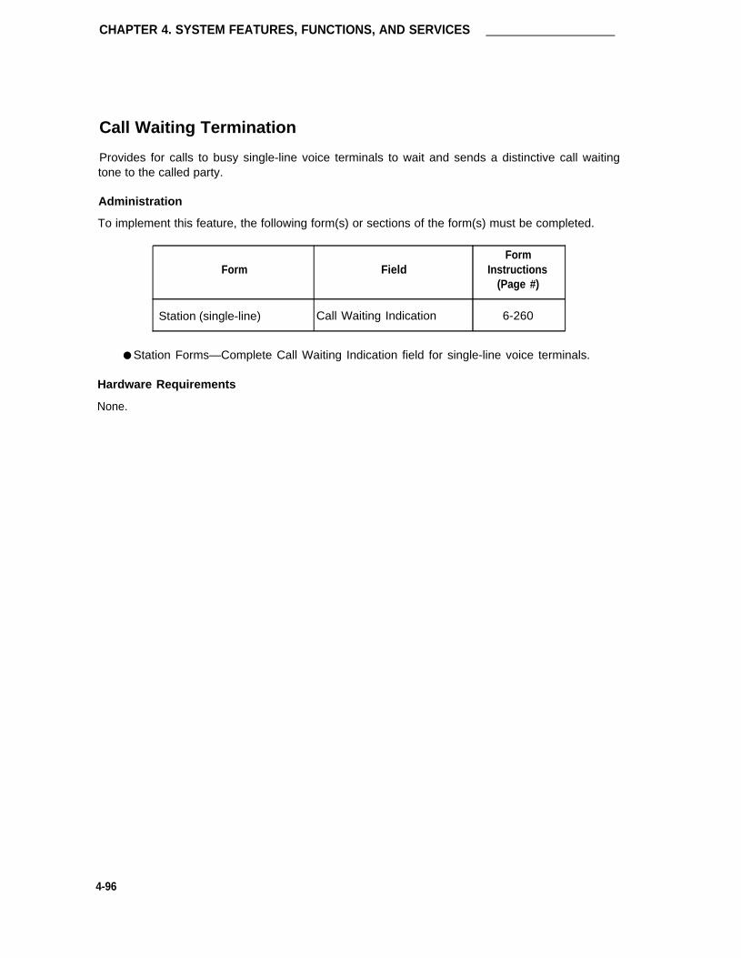
CHAPTER 4. SYSTEM FEATURES, FUNCTIONS, AND SERVICES
Call Waiting Termination
Provides for calls to busy single-line voice terminals to wait and sends a distinctive call waitingtone to the called party.
Administration
To implement this feature, the following form(s) or sections of the form(s) must be completed.
FormForm Field Instructions
(Page #)
Station (single-line) Call Waiting Indication 6-260
● Station Forms—Complete Call Waiting Indication field for single-line voice terminals.
Hardware Requirements
None.
4-96

Calling Party Number/Billing Number
Calling Party Number/Billing Number
Provides for the transmission of CPN/BN from the System to an ISDN Gateway adjunct (that is,3B2 processor) which in turn passes the information to a host or to an ICM adjunct (that is, CON-VERSANT voice system) for ICM applications. The information is subsequently available fordisplay on associated ACD agent terminals.
The CPN is the calling party’s telephone number and BN is the billing number of the calling party.The CPN/BN may also contain international country codes, where applicable.
Administration—Using ASAI Link for ICM Applications
Refer to the ICM feature for associated administration information.
Administration—Using bx.25 for ISDN Gateway Adjunct Applications
The ISDN PRI and CPN/BN features must be enabled on the System-Parameters Customer-Options form before associated forms and fields on forms can be administered.
All ISDN-PRI and ACD related forms must be administered as described in the ISDN-PRI andACD coverage provided elsewhere in this chapter.
Figure 4-6 shows the switch connections to the ISDN-PRI Gateway.
To implement this feature, the following form(s) or sections of the form(s) must be completed.
Form
ISDN-PRI Trunk Group
MPDM/MTDM DataModuleInterface LinksProcessor Interface DataModuleProcessor ChannelAssignment
FieldForm
Instructions(Page #)
All fields including “Per CallCPN/BN”All
AllAll
All (for one link)
5-195
6-105
6-1756-112
6-194
● ISDN-PRI Trunk Group—Assign all fields as required to provide an ISDN-PRI betweenthe System and a far-end node. In the Per Call CPN/BN field, enter either “cpn-only,”“cpn-pref,” “bn-only,’ or “bn-pref” as required. The corresponding information will besent with a call offered event report to the adjunct. If the field is blank, no CPN/BN infor-mation is sent to the adjunct.
4-97

CHAPTER 4. SYSTEM FEATURES, FUNCTIONS, AND SERVICES
●
●
●
●
MPDM/MTDM Forms—Complete all fields. This provides the lSDN-Gateway data link(via Digital Line circuit pack port) to the switch.
Note: Instead of administering an MPDM form, an OCM data link on a nondupli-cated system may be directly connected to the Processor Interface jack onthe back of the Control Carrier (if not already in use) instead of via theMPDM and a port on a Digital Line circuit pack. The Processor Interfacejack utilizes Interface Link 01 which is administered using the ProcessorInterface Data Module form. It is advised not to use the Processor Interfacejack in those systems that have a duplicated control carrier. The connectionis not designed so that it can be driven by either switch processing elementin the duplicated system.
Interface Links Form—All (for one data link). Assign "DCE" in the DTE/DCE field. Notethat when administering the Interface Links form using a change communications-interface links command, all fields may be initially entered except the Enable field. Aftercompleting and administering the Processor Channel Assignment form, recall the inter-face Links form using the change command and then enable the appropriate links byentering “y” in the Enable fields.
Processor Interface Data Module Form—All (for one data link).
Processor Channel Assignment Form—All (for one data link). Enter “OCM” in the Appfield. The OCM application is used to support either the CPN/BN and an associatedISDN Gateway interface or an interface to an OCM adjunct. Only one interface (that is,ISDN Gateway or OCM) can be supported in the System.
Hardware Requirements
Refer to the “Inbound Call Management” section for associated hardware requirements.
4-98

Calling Party Number/Billing Number
FIGURE 4-6. Typical ISDN Gateway Interface to the System
4-99

CHAPTER 4. SYSTEM FEATURES, FUNCTIONS, AND SERVICES
CallVisor Adjunct-Switch Application Interface
Note: For more detailed information on CallVisor™ ASAI, refer to DEFINITY® Communica-tions System CallVisor™ Adjunct-Switch Application Interface (ASAI) Protocol Refer-ence, 555-230-221 and DEFINITY® Communications System CallVisor™ Adjunct-Switch Application Interface (ASAI) Technical Reference, 555-230-220.
Supports an ISDN-BRI link between the switch and associated adjuncts (see Figure 4-1). Thefeature provides "building blocks" for implementing adjunct-based features such as Inbound CallManagement (ICM). Specifically, the interface allows adjunct applications to control calls andaccess call event reports and switch features.
The following functionality between associated adjunct and the switch is supported:
●
●
●
●
●
●
The adjunct can make requests to the switch for call originations from local endpointsand to drop calls. With each call, call progress information and event reporting istransmitted across the interface.
The adjunct can manipulate active calls in which the adjunct is not a party on the calls(that is, 3rd party). It can place calls on hold, reconnect calls, transfer calls, conferencecalls, and drop selected parties from a call.
The adjunct can request information about incoming calls to ACD splits (event notifica-tion).
The adjunct has the ability to activate certain switch features.
The adjunct can query the switch for information associated with a particular item.
The adjunct can make routing decisions. The adjunct can provide routing information forincoming calls to Vector Directory Number (VDNs) (Adjunct Routing Group).
When the System is configured with an EPN (with or without duplication), it is recommended thatthe CalIVisor ASAI resources be located in the switch’s PPN.
Note: For CallVisor ASAI applications, it is recommended that the number of DialedNumber Identification Service (DNIS) digits from the network to which a CallVisorASAl customer subscribes match the PBX dialplan regardless of the type of facilitiesused (that is, PRI or non-PRl). This will insure that network-provided DNIS andPBX-provided DNIS (for internal calls) have the same length.
On the PBX side, it is also recommended that, for non-isdn trunks, no digit manipula-tion be performed via administration. If such digit manipulation is performed, theDNIS provided to a CallVisor ASAl customer will be the number after the PBX hasmanipulated the digits. In this case, if the application needs to know the true DNIS,it would also have to know the algorithm applied by the PBX in manipulating thedigits.
4-100

CallVisor Adjunct-Switch Application Interface
Attendant-specific Button Operation
Attendant-specific buttons and features can cause calls to go through states different from thosefor station users. The following list shows which events are sent when an attendant uses buttonsthat are specification to an attendant console:
●
●
●
●
●
●
[HOLD]If an individual attendant presses the [HOLD] and the call is monitored or controlled, the"hold" event will be sent to the corresponding association.
[CALL~APPEARANCE]If an individual attendant has a call on hold and the call is controlled and/or monitored,then the "reconnect" event will be sent on the corresponding associations.
[START]If a call is present at an attendant and the call is controlled and/or monitored, and theattendant presses [START], then the call will be put on hold and a "hold" event will besent on the corresponding associations.
[CANCEL]If a call is on hold at the attendant and the attendant presses [START], putting the previ-ous call on hold, and then either dials a number and then presses [CANCEL] or presses[CANCEL] right away, the call that was originally put on hold will be reconnected and a"reconnect" event will be sent to the association monitoring and/or controlling the call.
[RELEASE]If only one call is active and the attendant presses [RELEASE], the call will be dropped andthe "dropped" event will be sent to the association monitoring and/or controlling the calls.If two calls are active at the attendant and the attendant then presses [RELEASE] , thecalls will be transferred away from the attendant and a "transfer" event will be sent to theassociation monitoring and/or controlling the calls.
[SPLIT]If two calls are active at the attendant and the attendant presses [SPLIT] , the calls will beconference at the attendant and a "conference" event will be sent to the associationscontrolling and/or monitoring the calls.
4-101

CHAPTER 4. SYSTEM FEATURES, FUNCTIONS, AND SERVICES
CallVisor ASAl Feature Administration
To use any CallVisor ASAI capability, the ASAl Interface option must first be enabled on theSystem-Parameters Customer-Options form. This action causes Page 2 of the form ("ASAICapability Groups") to be displayed (see below).
change system-parameters customer-options Page 2 of 2
ASAI CAPABILITY GROUPS
Adjunct Call Control Group? y
Adjunct Routing Group? y
Domain Control Group? y
Event Notification Group? y
Request Feature Group? y
Set Value Group? y
The above capabilities are defaulted to "y," but can be disabled at the time of system installation.A brief explanation of each of the capability groups follows:
●
●
●
●
●
●
Adjunct Call Control Group—Allows the associated adjunct to invoke Third Party CallControl capabilities, such as Third Party Selective Hold, Third Party Reconnect, ThirdParty Merge, etc., that can be used in either of the Third Party Call Control cluster sub-sets: Call Control and Domain Control. These capabilities enable the adjunct to place,monitor, control, and end calls as they move through the switch.
Adjunct Routing Group—Allows the associated adjunct to provide adjunct routing infor-mation to the switch for incoming calls.
Domain Control Group—Allows an adjunct to control calls and receive event reports forstation sets and receive logout event reports for agents in a given ACD split.
Event Notification Group—Allows the associated adjunct to request incoming call notifica-tion and enables the switch to send event reports about such calls.
Request Feature Group—Allows the associated adjunct to request features (such as"change work modes," "login," and "logout") and other station features (SAC, FMD).
Set Value Group—Allows the adjunct to request status changes for Message Waitinglamps (that is, control the on/off state of the lamps).
The following table shows which capabilities are automatically enabled when ASAI is enabled onthe System-Parameters Customer-Options form.
4-102

CallVisor Adjunct-Switch Application Interface
TABLE 4-B. Automatically Enabled ASAl Capabilities
AdjunctCall Adjunct Domain Event
CapabilityRequest Set
Control Routing Control NotIf. Feature ValueGroup Group Group Group Group Group
Call Ended Capability x
Event Reports x x x
Agent Logout x
Alerting x x x
Answered x x
Busy x x x
Call Ended Event (FAC message) x
Call Initiated x
Call Offered to Domain x
Call Redirected x x
Call Conferenced x x x
Connected x x x
Cut-Through x x x
Denial/Reorder x x x
Dropped x x x
Hold x x x
Queued x x x
Reconnected x x x
Call Transferred x x x
Trunk Seized x x x
Request Feature x
Notification Request x
Notification Cancel x
Notification Ended x
Route End x
Route Request x
Route Select x
Set Value x
Stop Call Notification x
4-103

CHAPTER 4. SYSTEM FEATURES, Functions, AND SERVICES
TABLE 4-B (continued).Automatically Enabled ASAl Capabilities
Capability
Third Party Answer
Third Party Auto DialThird Party Call EndedThird Party Clear CallThird Party Domain Control
Third Party Domain Control Ended
Third Party Make CallThird Party Make Call ProceedThird Party MergeThird Party Reconnect
Third Party Relinquish ControlThird Party Selective HoldThird Party Selective Drop
Third Party Take Control
AdjunctCall
ControlGroup
x
x
xx
xx
xxxx
AdjunctRoutingGroup
Domain Event RequestControl Notif. FeatureGroup Group Group
x
x
x
x
x
x
x x
xx
x
SetValueGroup
Note: By enabling the ASAI option(s) on Page 1 of the form, the following capabilities areautomatically enabled as well, regardless of the groups selected on Page 2: ValueQuery (includes Response Continued Capability), Abort, Heart Beat, Restart Pro-cedure, Suspend/Resume Alarm.
The capabilities shown here correspond to the operation values given in DEFINITY® Communi-cations System CallVisor™ Adjunct-Switch Application lnterface (ASAI) Protocol Reference,555-230-221.
For ASAl adjuncts, an alarm severity option can be assigned via the "Set Options" command toeach of the following categories:
● Major on-board ASAl adjunct alarms
● Major off-board ASAl adjunct alarms
● Minor on-board ASAl adjunct alarms
● Minor off-board ASAI adjunct alarms
The "Set Options" command is considered to be a maintenance command. Therefore, for moreinformation on this command, refer to DEFINITY® Communications System Generic 1 and Gen-eric 3i Maintenance, 555-204-105.
4-104

CallVisor Adjunct-Switch Application Interface
Note: The Hunt Group, Vector, Special Information Tones, Class of Service, and TrunkGroup forms may also require administration when implementing CallVisor ASAl.
Note that the following provides information on assigning an ASAI link only. Refer to specificadjunct feature coverage (that is, Inbound Call Management) for associated adjunct implementa-tion instructions.
ASAl Link Administration
Currently, this interface must be assigned when implementing an adjunct ICM application. Notethat the System can have either the ICM feature (using the CallVisor™ ASAI) or a vendor-supplied CPN/BN feature, but not both.
The Packet Bus option is automatically enabled on the Maintenance-Related System Parametersform before ASAl forms and ASAI fields on non-ASAl forms can be administered. Details regard-ing the use of this form are provided in DEFINITY® Communications System Generic 1 and Gen-eric 3i—Installation and Test, 555-230-104.
To implement the ASAl link, the following form must be completed:
FormForm Field Instructions
(Page #)
Station ExtensionTypeXIDFixed TEITEIMIM SupportCRV Length 6-68
Hardware Requirements
A port on a TN556 ISDN-BRI circuit pack (12 ports) is required for each ASAI link to be assignedper switch. Up to eight ports (maximum) may be assigned for ASAI interfaces. The remaindermay be used for BRI voice ports. ASAl interfaces may be distributed on multiple TN556 lSDN-BRI circuit packs.
Note: If a TN556 ISDN-BRI circuit pack is in an EPN, then the TN570 El circuit pack mustbe used as the expansion interface. The TN776 El may not be used in this case.
4-105

CHAPTER 4. SYSTEM FEATURES, FUNCTIONS, AND SERVICES
The TN778 Packet Control circuit pack is required for CallVisor ASAl applications. As notedabove, the Packet Bus option must be enabled on the Maintenance-Related System Parametersform.
ASAI
ADJUNCT
ISDN-BRI
TN556
ISDN-BRI
LINE
PACKET-BUS
TN778
PACKET
CONTROLLER
M-BUS
SPE
GLOSSARY
ASAI - ADJUNCT SWITCH APPLICATIONS INTERFACE
ISDN-BRI - INTEGRATED SERVICES DIGITAL NETWORK-BASIC
RATE INTERFACE
M-BUS - MEMORY BUS
SPE - SWITCH PROCESSING ELEMENT
FIGURE 4-7. ASAl Switch Interface Link
4-106

Central Office Trunk Group
Central Office Trunk Group
A Central Office (CO) Trunk Group provides access from the System to the public networkthrough the local CO.
Administration
To assign a CO Trunk Group, the following forms must be completed.
Form
Central Office Trunk Group
Digit Absorption
DS1
FormField Instructions
(Page #)
All 5-123
All 6-125
All 5-65
● CO Trunk Group Form—Complete all fields as required.
● Digit Absorption Form—If required, complete this form when the central office is a step-by-step office. The Digit Absorption List field on the CO trunk group form must referencethe Digit Absorption List Number entered on the form. DS1 circuit pack form—Completeall fields as required.
Hardware Requirements
A port on a TN747B Central Office Trunk or TN767 DS1 Interface circuit pack is required for eachCO trunk to be assigned. A TN747B provides eight ports and a TN767 provides 24 ports.
4-107

CHAPTER 4. SYSTEM FEATURES, FUNCTIONS, AND SERVICES
Centralized Attendant Service
Allows services performed by attendants in a private network of switching systems to be concen-trated at a central, or main, location. Each branch in a CAS has its own LDN or other type ofaccess from the public network. Incoming trunk calls to the branch, as well as attendant-seekingvoice terminal calls, are routed to the centralized attendants over RLTs.
Administration
The CAS Branch or the CAS Main options (depending on your location) must be enabled on theSystem-Parameters Customer-Options form before associated forms and fields on forms can beadministered.
To implement this feature, the following form(s) or sections of the form(s) must be completed.
FormForm Field Instructions
(Page #)
Attendant Console Feature Button Assignments 6-32-cas-backup-trunk-name
Console Parameters CAS 6-79RLT Trunk Group NumberCAS Back-Up ExtTimed Reminder on HoldReturn Call Timeout (see)
Station (multi-appearance) Button/Feature Button 6-245Assignments-cas-backup-flash-trunk name-night serv
Release Link Trunk Group All 5-221
Feature Access Codes CAS Remote Hold Access Code 6-127
● Attendant Console Form—Assign "cas-backup" to a designated button lamp if an atten-dant console is available at a branch. Assign "trunk-name" feature button to identify theRLT name.
4-108

Centralized Attendant Service
●
●
●
●
Console Parameters Form—Verify "CAS" is administered as either main or branch andRLT Trunk Number and CAS Back-Up Ext fields are completed as required. Administerthe Timed Reminder on Hold and Return Call time-out (sec) the same on all switches.Note that the CAS and IAS (Inter PBX Attendant service) Branch fields cannot both beadministered as "y."
Station Forms—Assign "cas backup" to a designated button lamp (an attendant consolewill probably not be available at a branch). It is a good idea to assign a "night-serv" but-ton to one station when operating without an attendant console. Assign "flash" and"trunk-name" feature buttons as required to stations that may be handling CAS calls.Administer "trunk name" buttons to display-equipped voice terminals only.
Release Link Trunk Group Form—Complete all fields. Enter "incoming" in the Directionfield if this is a CAS main location or enter "outgoing" if this is a CAS branch location.Assign Queue Length field to other than 0 when the direction field is outgoing.
Feature Access Codes Form—Complete the CAS Remote Hold Access Code field.Administer the same code on all switches.
Hardware Requirements
Requires a TN760B Tie Trunk circuit pack or TN722B or TN767 DS1 circuit pack to assign aRelease Link Trunk Group.
Screens 4-14 and 4-15 show typical Console Parameters and RLT Trunk Group forms, respec-tively, for a CAS Main location. Screens 4-16 and 4-17 show typical Console Parameters andRLT Trunk Group forms, respectively, for a CAS Branch location.
4-109

CHAPTER 4. SYSTEM FEATURES, FUNCTIONS, AND SERVICES
Page 1 of 1
CONSOLE PARAMETERS
COS : 1_ COR : 1_
Time Reminder on Hold (sec): 60_ Return Call Timeout (sec): 60_
Calls In Queue Warning: 2_ Time In Queue Warning (sec): __
Ext Alert Port (TAAS): Attendant Lockout? n
CAS: main RLT Trunk Group No.: __
CAS Back-Up Ext.: __ Night Service Act. Ext.: __
IAS (Branch)? n IAS Tie Trunk Group No.:
IAS Att. Access Code: __ DID-LDN Only to LDN Night Ext? n
ABBREVIATED DIALING
Listl: List2: List3:
COMMON SHARED EXTENSIONS
Starting Extension: 1900 Count: 4
ASSIGNED MEMBERS ( Installed attendant console types )
1: principal 5:
2: day-only 6:
3: 7:
4:
SCREEN 4-14. Typical CAS Main Console Parameters Form
4-110

Centralized Attendant Service
TRUNK GROUP Page 1 of 9
Group Number: _6 Group Type: rlt SMDR Reports? y
Group Name: RLT BRANCH___ COR: 1_ TAC: 74
Direction: incoming Outgoing Display? n
Busy Threshold: 99 Night Service: 1234
Incoming Destination: 0
TRUNK PARAMETERS
Trunk Type (in/out): delay/delay Incoming Rotary Timeout(sec): 5
Outgoing Dial Type: tone Incoming Dial Type: tone
Connected to Toll? n STT Loss: normal DTT to DCO Loss: normal
Incoming Dial Tone? y
Answer Supervision Timeout? __
SCREEN 4-15. Typical CAS Main Release Link Trunk Group Form
4-111

CHAPTER 4. SYSTEM FEATURES, FUNCTIONS, AND SERVICES
Page 1 of 1
CONSOLE PARAMETERS
COS: 1
Time Reminder on Hold (sec): 60_
Calls In Queue Warning: 2Ext Alert Port (TAAS): ___
CAS: branch
CAS Back-Up Ext.: 5573IAS (Branch)? n
IAS Att. Access Code:
ABBREVIATED DIALING
Listl: List2:
Starting
COR: 1
Return Call Timeout (see): 60Time In Queue Warning (sec): _
Attendant Lockout? n
RLT Trunk Group No.: 10
Night Service Act. Ext.:
IAS Tie Trunk Group No.:
DID-LDN Only to LDN Night Ext? n
List3:
COMMON SHARED EXTENSIONS
Extension: 5600 Count: 4
ASSIGNED MEMBERS ( Installed attendant console types )
1: principal 5:
2: 6:
3: 7:
4:
SCREEN 4-16. Typical CAS Branch Console Parameters Form
4-112

Centralized Attendant Service
TRUNK GROUP Page 1 of 9
Group Number: 10 Group Type: rlt SMDR Reports? nGroup Name: OPERATOR COR: 1 TAC: 80Direction: outgoinq Outgoing Display? y
Busy Threshold: 60
Queue Length: 10
TRUNK PARAMETERS
Trunk Type (in/out): delay/delay Incoming Rotary Timeout(sec): 5
Outgoing Dial Type: tone Incoming Dial Type: tone
Connected to Toll? n STT Loss: normal DTT to DCO Loss: normalIncoming Dial Tone? y
Answer Supervision Timeout? _
SCREEN 4-17. Typical CAS Branch Release Link Trunk Group Form
4-113

CHAPTER 4. SYSTEM FEATURES, FUNCTIONS, AND SERVICES
Class of Restriction
All System users have an assigned COR to define their calling privileges. Restrictions can beassigned to facilities as listed in the table below. The COR specifies up to 64 different classes ofcall origination and termination privileges. Systems may have only a single COR, one with norestrictions, or may have as many CORs (up to 64) as necessary to effect the desired restric-tions. A unique COR must be defined for each combination of FRLs, calling party restrictions,called party restrictions, miscellaneous restrictions, CCSA/EPSCS off-network restrictions, andaccess to FACs.
Administration
To implement this feature, the following form(s) or sections of the form(s) must be completed.
FormForm Field Instructions
(Page #)
Class of Restriction All 6-72
Attendant Console COR 6-32
Authorization Codes COR 6-51
Console Parameters COR 6-79
Hunt Groups COR 6-160
Loudspeaker Paging and COR (1-9, all) 6-183Code Calling Access
MPDM/MTDM Data Module COR 6-105
NetCon Data Module COR 6-109
Processor Interface Data Module COR 6-112
Recorded Announcement COR 6-115Data Module
Station COR 6-245
Remote Access COR (Barrier Code) 6-203
Terminating Extension Group COR 6-214
Trunk Groups COR 5-92
Vector Directory Number COR 6-222
4-114

Class of Restriction
● COR Form—Complete appropriate fields.
● Complete the "COR" fields for the following forms:
— Attendant Console
— Authorization Codes
— Console Parameters
— Data Modules (includes MPDM, MTDM, Recorded Announcement, Data Line,NetCon, and Processor Interface data modules)
– Hunt Groups
● DDC Group
● UCD Group
● ACD Split
— Loudspeaker Paging Access and Code Calling Access
— Remote Access (per barrier code)
– Station
— Terminating Extension Group
– T r u n k G r o u p s
— Vector Directory Number
Class of Restriction Guidelines and Examples
The examples which follow illustrate some of the practical aspects of assigning CORs. Theseare, however, only examples. In reality, each System must be administered to meet its individualneeds.
Example Using Miscellaneous Restrictions
As an illustration of miscellaneous restrictions, assume a System installation provides the follow-ing:
●
●
●
●
●
●
●
●
Central office trunks
WATS
FX trunks
Data modules
Attendant service
Voice terminals
DID trunks
Remote Access
4-115

CHAPTER 4. SYSTEM FEATURES, FUNCTIONS, AND SERVICES
In an unrestricted environment, each of the preceding facilities could have the same COR. How-ever, suppose the following requirements exist:
●
●
●
●
Attendants cannot make data calls.
Remote Access can be used for data calls only.
DID cannot be used for data calls except through Remote Access. (A dedicated RemoteAccess trunk group is not required, although one or more could be provided. This exam-ple assumes all Remote Access is via DID.)
There are three classes of voice terminals:
– Those that can call anywhere, anytime
– Those that can place local central office and in-house calls only
– Those that can place local central office, FX, and in-house calls only
To implement the preceding requirements, a COR must be assigned to each facility or group offacilities. For simplicity, each can have a unique COR. The CORs are arbitrarily assigned as fol-lows:
● COR 30—Local CO trunks
● COR 31—WATS trunks
● COR 32—FX trunks
● COR 33—Data modules
● COR 34—Attendant group
● COR 35—Unrestricted voice terminals
● COR 36—Voice terminals that can place in-house and local CO calls only (no FX orWATS calls)
● COR 37—Voice terminals that can place in-house, local CO and FX calls only (no WATScalls)
● COR 33—DID trunk group
● COR 39—One of the remote access barrier codes (can be up to 10)
With the CORs defined, it should be individually determined which CORs cannot call other CORs.This is done as follows:
●
●
COR 30 (local central office trunks)—No restrictions were specified for these trunks. Thedefault values on the screen form are sufficient. No action is required, except to specifya COR number of 30.
COR 31 (WATS)—CORS that cannot use WATS are specified as they are encountered.WATS itself is an outgoing service without any calling capabilities. Thus, MiscellaneousRestrictions are not specified on this form. The Calling Party Restriction should be"none" (although this restriction does not really have any meaning for an outgoing facil-ity). Similarly, the Called Party Restriction applies to facilities capable of answering acall. Since this is not the case with WATS, "none" should be specified. Again, thedefault values are sufficient, so only the COR number needs to be specified.
4-116

Class of Restriction
●
●
●
●
●
●
●
●
COR 32 (FX)—According to the requirements for this example, no restrictions apply.Reasons are the same as for WATS. Only the COR number needs to be specified.
COR 33 (data modules)—No restrictions apply for reasons similar to the reasons why norestrictions were assigned for WATS. Only the COR number needs to be specified.
COR 34 (attendant group)—The attendant group cannot call COR 33 (data modules).Specify an "n" beside COR 33 in the Calling Permission field. Specify 34 in the CORNumber field.
COR 35 (unrestricted voice terminals)—since no restrictions were specified, only theCOR number needs to be entered.
COR 36 (no FX or WATS calls)—This COR cannot call COR 32 (FX) or COR 31 (WATS).Specify an "n" beside CORS 32 and 31 in the Calling Permission field. Specify 36 in theCOR Number field.
COR 37 (no WATS calls)—This COR cannot call COR 31 (WATS). Specify an "n"beside COR 31 in the Calling Permission field. Specify 37 in the COR Number field.
COR 38 (DID)—This COR cannot call COR 33 (data modules). Specify "n" beside COR33 in the Calling Permission field. Enter 38 in the COR Number field.
COR 39 (Remote Access barrier code)—This COR can be used for data calls only.Thus, this COR can call COR 33, but not CORs 30 (local CO), 31 (WATS), 32 (FX), 34(attendant group), 35, 36, or 37 (voice terminals). Specify an "n" beside CORs 30, 31,32, 34, 35, 36, and 37 in the Calling Permission field. Enter 39 in the COR Number field.[The CORs listed in the Calling Permission field can be viewed as terminating or screen-ing CORs that can or cannot be called by the originating COR. Since COR 38 (DID) isneither a terminating nor a screening COR, it does not have to be considered whenassigning the barrier code COR.]
Example Using Calling Party Restrictions, Called Party Restrictions, and Miscellaneous Restrictions
To illustrate the use of both Calling and Called Party restrictions, Miscellaneous restrictions,assume a System installation provides the following:
● CO (outgoing)
● W A T S
● FX trunks (outgoing)
● Voice terminals
● Data modules
● T E G
● Loudspeaker Paging
Suppose that the following requirements exist:
● Only the attendant can access loudspeaker paging.
● TEG can only accept calls from internal voice terminals
4-117

CHAPTER 4. SYSTEM FEATURES, FUNCTIONS, AND SERVICES
● There are six classes of voice terminals:
– Those that are toll restricted
– Those that cannot call outside to a public network (outward restricted)
– Those that can receive calls only from an attendant
– Those that can call anywhere, anytime
– Those that cannot place FX or WATS calls
– Those that cannot place WATS calls
To implement the preceding requirements, a COR must be assigned to each facility or group offacilities. For simplicity, each can have a unique COR. The CORs are arbitrarily assigned as fol-lows:
●� COR 40—Local central office trunks
● COR 41—WATS trunks
● COR 42—FX trunks
● COR 43—Attendant group
● COR 44—Data modules
● COR 45—TEG
● COR 46—Loudspeaker Paging Access Zones
● COR 47—Unrestricted voice terminals
● COR 48—Voice terminals that are toll restricted
● COR 49—Voice terminals that are outward restricted
● COR 50—Voice terminals that can only receive calls from an attendant
● COR 51—Voice terminals that cannot place FX or WATS calls
● COR 52—Voice terminals that cannot place WATS calls
With the CORs defined, it should be determined individually which CORs cannot call other CORs.This is done as follows:
●
●
●
●
●
COR 40 (local CO trunks)—Restrictions that prohibit access to this COR are assignedwhen the originating CORs are considered. Only the COR number has to be specified onthis form.
COR 41 (WATS)—Only the COR number needs to be specified, this is the same case asdescribed in the previous configuration example.
COR 42 (FX)—Again, only the COR number needs to be specified.
COR 43 (attendant group)—No restrictions were stated, so only the COR number needsto be specified.
COR 44 (data modules)—No restrictions were stated, so only the COR number needs tobe specified.
4-118

Class of Restriction
●
●
●
●
●
●
●
●
COR 45 (Terminating Extension Group)—This COR can receive internal voice terminal-originated calls only. Since no tie trunks are specified for this example, the Inward Res-triction feature can provide the desired restriction. Specify "inward" as the Called PartyRestriction. If dial repeating tie trunks are provided, Miscellaneous Restrictions could beused to deny trunk access to the group. Also, specify 45 as the COR number.
COR 46 (Loudspeaker Paging Access zones)—Since this COR can be accessed by anattendant only, the Manual Terminating Line feature can provide the restriction. Specify"manual" as the Called Party Restriction. Specify 46 as the COR number.
COR 47 (unrestricted voice terminals)—No restrictions were stated, so only the CORnumber needs to be specified.
COR 48 (toll restricted voice terminals)—specify "toll" as the Calling Party Restriction.Specify 48 as the COR number.
COR 49 (outward restricted voice terminals)—Specify "outward" as the Calling PartyRestriction. Specify 49 as the COR number.
COR 50 (voice terminals that can only receive calls from an attendant)—specify"manual" as the Called Party Restriction. Specify 50 as the COR number.
COR 51 (voice terminals that cannot place WATS or FX calls)—None of the Calling PartyRestrictions uniquely prohibit WATS and FX calls, so Miscellaneous Restrictions areused. Enter an "n" beside COR 41 (WATS) and COR 42 (FX) in the Calling Permissionfield. Leave the Calling Party Restriction as "none" and specify 51 as the COR number.
COR 52 (voice terminals that cannot place WATS calls)—Enter an "n" beside COR 41(WATS) in the Calling Permission field. Leave the Calling Party Restriction as "none"and specify 52 as the COR number.
Another method to determine COR assignment is to consider the restrictions to be assigned.
This method is probably more difficult to use, but it minimizes the number of CORs established.This method requires nine CORs to effect the same restrictions as 13 CORs with the previousmethod.
The requirements given for this example are as follows:
● Only the attendant can access loudspeaker paging.
● Terminating Extension Groups can only accept calls from internal voice terminals.
● The six classes of voice terminals are:
– Those that are toll restricted
– Those that cannot call outside to a public network (outward restricted)
– Those that can receive calls only from an attendant
– Those that can call anywhere, anytime
– Those that cannot place FX or WATS calls
– Those that cannot place WATS calls
4-119

CHAPTER 4. SYSTEM FEATURES, FUNCTIONS, AND SERVICES
Assignments for these requirements could be made as follows:
● COR 20—Manual Terminating Line Restriction
● COR 21—Inward Restriction
● COR 22—Toll Restriction (that is, "tac-toll" or "all-toll")
● COR 23—Outward Restriction
Note: A new Manual Terminating Line Restriction for voice terminals was not esta-blished. COR 20, above, can be assigned.
● COR 24—Unrestricted
● COR 25—COR for WATS
● COR 26—COR for FX
● COR 27—Provides Miscellaneous Restrictions for WATS and FX. Enter an "n" besideCOR 25 and COR 26 on the form for COR 27.
● COR 28—Provides Miscellaneous Restriction for WATS. Enter an "n" beside COR 25 onthe form for COR 28.
Now assign the appropriate COR to each physical or screening facility:
●
●
●
●
●
●
●
●
CO trunks—COR 24 (unrestricted)
WATS—OR 25 (WATS COR)
FX—COR 26 (FX COR)
Attendant group—COR 24 (unrestricted)
Voice terminals—COR 22 (toll—"tac-toll" or "all-toll"), COR 23 (outward), COR 20(manual), COR 24 (unrestricted), COR 27 (WATS and FX miscellaneous), or COR 28(WATS miscellaneous), as required.
Data Modules—COR 24 (unrestricted)
Terminating Extension Group—COR 21 (inward)
Loudspeaker Paging trunks—COR 20 (manual)
Example Using ARS/AAR Facilities Restriction Level (FRL) for Control of Call Routing
Establish a group of users who must dial an authorization code in order to make outside calls.The client has ARS and the Authorization Codes feature. The forms and fields are administeredas follows:
1. Feature-Related System Parameter Features Form
Field Enter- Authorization Codes Enabled y- Authorization Code Length 7- Authorization Code Cancellation Symbol 1- Attendant Timeout Flag n
4-120

Class of Restriction
2.
3.
4.
5.
Station Form
Assign COR = 1 for all unrestricted users and COR = 49 for restricted users who mustdial an authorization code to make outside calls.
Authorization-Codes Form
Assign the restricted users a replacement COR = 1 and an authorization code the sameas their 7-digit phone number.
COR Form
Assign/change originating FRLs for restricted and unrestricted users. Assign an originat-ing FRL of 7 to users with a COR of 1 and an originating FRL of 0 to users with a COR of49.
AAR/ARS Route Pattern Form
For route pattern 1, assign trunk group 40 (CO) as the first choice route with a route FRL= 1, NPA = 201, and Prefix Mark = 1 (that is, dialing 1 is required hereto indicate a tollcall). Assign first, second, and third choice routes as follows:
Prefix Toll No. Del InsertedGrp No FRL NPA Mark List Digits Digits
40 1 201 12 3 201 1
32 3 201 1 9
For this example, trunk group 40 is a CO trunk, trunk group 2 is WATS, and trunk group 32 is atie trunk to the System 85.
When a caller dials the ARS access code to call out, the FRL of the originating facility is com-pared with the FRL of the available outgoing facility. If the FRL of the originating facility is lessthan the FRL of the trunk group, the restricted user will be prompted (via recall dial tone) to enteran authorization code. After the authorization code is entered, the call is routed to the CO forcompletion. If the FRL is insufficient to seize any trunk group in the route pattern, the user getsintercept tone.
Restricted callers will be prompted for and be required to enter an authorization code. Unres-tricted users will simply dial the ARS code followed by the desired number.
Another practical application of the use of auth-codes might be to enable an unrestricted user tomake a call from a restricted phone. For example, an executive could enter an authorizationcode which enables him to dial out from a restricted phone in the factory.
Hardware Requirements
None.
4-121

CHAPTER 4. SYSTEM FEATURES, FUNCTIONS, AND SERVICES
Class of Service
Defines whether or not voice terminal users may access or use the following features and func-tions (refer to DEFINITY® Communications System Generic 1 and Generic 3i—Feature Descrip-tion, 555-230-201, for feature descriptions).
● Automatic Callback (feature)
● Call Forwarding All Calls (feature)
● Data Privacy (feature)
● Priority Calling (feature)
● Console Permission (allows multi-appearance voice terminal users to control the samefeatures controlled by an attendant)
● Off-Hook Alert (see Emergency Access to Attendant feature)
● Client Room (see Hospitality Services—allows use of the check-in, check-out, roomchange/swap, and maid status features)
Administration
The 16 possible COSs are preassigned in the System. Choose and modify the appropriate COSand assign to users as required. Types of users are listed in the following table.
Form
Class of Service
Attendant Console
Console Parameters
MPDM/MTDM Data Module
Processor Interface Data Module
NetCon Data Module
Recorded AnnouncementData Module
Data Line Data Module
Station
Remote Access
Hardware Requirements
None.
Field
All
COS
COS
COS
COS
COS
COS
COS
COS
COS
FormInstructions
(Page #)
6-77
6-32
6-79
6-105
6-112
6-109
6-115
6-89
6-245
6-203
4-122

Code Calling Access
Code Calling Access
Allows attendants, voice terminal users, and tie trunk users to page with coded chime signals.
Administration
To implement this feature, the following form(s) or sections of the form(s) must be completed.
FormForm Field Instructions
(Page #)
Loudspeaker Paging and Code Calling lDs-(all fields) 6-183Code Calling Access
● Loudspeaker Paging and Code Calling Access Form—Complete Code Calling fields asfollows:
— Assign Code Calling Playing Cycles (1 to 3) to indicate the number of times acode calling identification will be played.
— Assign TN763C Auxiliary Trunk ports to each paging zone to be used.
— Assign Code Calling TACs and CORs to each zone to be assigned (1 through 9,all).
●� Assign extension numbers to Code Calling ID fields.
Hardware Requirement
Requires a port on a TN763C Auxiliary Trunk circuit pack for each of nine paging zones that canbe assigned. The Code Calling Access feature shares the same ports used for loudspeaker pag-ing.
4-123

CHAPTER 4. SYSTEM FEATURES, FUNCTIONS, AND SERVICES
Consult
Allows a covering user, after answering a coverage call, to call the principal (called party) forprivate consultation.
Administration
To implement this feature, the following form(s) or sections of the form(s) must be completed.
FormForm Field Instructions
(Page #)
Station (multi-appearance) Button/Feature Button 6-245Assignments
-consult
● Station Forms—Assign a Consult button.
Hardware Requirements
None.
4-124

Coverage Callback
Coverage Callback
Allows a covering user to leave a message for the principal (called party) to call the calling party.
Administration
To implement this feature, the following form(s) or sections of the form(s) must be completed.
FormForm Field Instructions
(Page #)
Station (multi-appearance) Button/Feature Button 6-245Assignments
-cov-cback
●� Station Forms—Assign a Cover Callback (cov-cback) button.
Hardware Requirements
None.
4-125

CHAPTER 4. SYSTEM FEATURES, FUNCTIONS, AND SERVICES
Coverage Incoming Call Identification
Allows multi-appearance voice terminal users without a display in a Coverage Answer Group toidentify an incoming call to that group.
Administration
To implement this feature, the following form(s) or sections of the form(s) must be completed.
Form Field
Station (multi-appearance) Button/Feature ButtonAssignments-in-call-id
(Type:_Grp:_)
FormInstructions
(Page #)
6-245
● Station Forms—Assign a UCD/DDC Coverage Answer Group (in-call-id) button.
Hardware Requirements
None.
4-126

Customer-Provided Equipment (CPE) Alarm
Customer-Provided Equipment (CPE) Alarm
The CPE alarm device provides an indication that a System alarm has occurred and that the Sys-tem has attempted to contact a preassigned service organization about the problem. Acustomer-provided device, such as a lamp or bell, is used to indicate the alarm situation.
The CPE Alarm field is administered on the Maintenance-Related System-Parameters form asdescribed in DEFINITY® Communications System Generic 1 and Generic 3i—Installation andTest, 555-230-104. Associated hardware requirements are also specified.
4-127

CHAPTER 4. SYSTEM FEATURES, FUNCTIONS, AND SERVICES
Customer-Provided Equipment (CPE) Trunk Group
The CPE Trunk Group provides for the connection of on-premises customer equipment to theSystem for applications such as the Recorded Telephone Dictation Access feature. The auxiliarytrunk ports that are used to connect CPE to the digital switch are administered as CPE TrunkGroup members for those features such as Recorded Telephone Dictation Access that are notsupported by port assignment fields on other System forms. For example, trunk port interfacescan be assigned on System forms for such features as Music-on-Hold Access (Feature-RelatedSystem Parameters form) and Loudspeaker Paging and Code Calling Access (Loudspeaker Pag-ing and Code Calling Access form).
Administration
To implement this feature, the following form(s) or sections of the form(s) must be completed.
Form
CPE Trunk Group
Hardware Requirements
FormField Instructions
(Page #)
All 5-137
A port on a TN763C Auxiliary Trunk circuit pack is required for each trunk to be assigned theCPE Trunk Group. A TN763C provides four ports.
4-128

D-Channel Backup
D-Channel Backup
For DS1 trunk port interfaces used for ISDN-PRI, this provides a backup signaling link (D-Channel) in the event of a signaling link failure. If a signaling link failure were to occur, a switchto a backup signaling link (D-Channel) can be implemented.
D-Channel Backup requires that one D-Channel be administered as the Primary D-Channel andthat a second D-Channel be administered as the Secondary D-Channel on the Signaling Groupform. These assignments ensure that at certain times during D-Channel Backup process thateach switch at each end of the interface select the same D-Channel.
Refer to the Facility and Non Facility Associated Signaling feature coverage for additional infor-mation. A detailed discussion of both Facility and Non Facility Associated Signaling and D-Channel Backup is provided. Sample Signaling Group forms which are used to administer thefeatures are shown.
4-129

CHAPTER 4. SYSTEM FEATURES, FUNCTIONS, AND SERVICES
Data Call Setup
Provides three methods to set up a data call: Data Terminal (keyboard) Dialing which includesAlphanumeric Dialing, Data Hot Line, and Default Dialing (features covered separately elsewherein this chapter) and Voice Terminal Dialing, or dedicating a voice terminal for data calls.
Note: Voice terminal dialing is not available in BRI applications because BRI terminals donot support voice call transfer to data or data call transfer to voice. Because of thetransfer restriction, data calls cannot be set up for BRI data modules using just anyvoice terminal. The 7500D series voice terminals when equipped with an ADM, how-ever, provide a dedicated data button which allows the use of the associated voiceterminal for data call setup.
Typically, when a data terminal is available, keyboard dialing is more convenient and requiresless steps; therefore, it should be used whenever possible.
In addition to data terminal and voice terminal dialing, the System accepts calls from other dev-ices, such as a MPDM equipped with an ACU interface module. An analog modem interfacedwith an ACU can also be used to provide dialing capability for a host computer.
The Administered Connection/Access Endpoint feature (covered elsewhere in this chapter) mayalso be used to establish a data call.
Administration—Voice Terminal Dialing
Voice Terminal Dialing must be used when the data terminal is connected to an analog modem orwhen a data terminal is not accessible for dialing.
To implement this feature, the following form(s) or sections of the form(s) must be completed.
FormForm Field Instructions
(Page #)
Feature Access Codes Data Origination Access 6-127Code
Station (multi-appearance) Button/Feature Button 6-245Assignments-data-ext (Ext:_)
Data Module AllMPDM/MTDM 6-105Data Line 6-89
Modem Pool Group Circuit Pack Assignments 6-187(1-32)
● Feature Access Codes Form—Assign a Data Origination Access Code. When a userplaces a data call to digital data endpoint, and does not transfer the call to another digitaldata endpoint but uses a modem or acoustically coupled modem, the user must dial theDate Origination access code before dialing the distant endpoint.
4-130

Data Call Setup
● Station Forms—Assign Data Call Setup buttons to multi-appearance voice terminals.This supports the use of the Data Call Setup One-Button Transfer To Data, Return-to-Voice, and Data Call Preindication features. If the Data Module form is associated withthe station form complete the form.
● Data Module Form—If the Data Module form is not associated with the station, completean MPDM/MTDM or Data Module form as required.
● Modem Pool Group Form—Assign Circuit Pack port locations if dialing outside locationsrequiring digital to analog conversion.
Depending on the hardware being used, assign ports to the following as required:
— Data Modules
— BCTs/510Ds
— 7400D Series or Callmaster Digital Voice Terminals
— 7500D Series of Voice Terminals with ADM
— Analog Modems (port is assigned using a 2500 Voice Terminal form)
Administration—Data Terminal (keyboard) Dialing
In addition to standard keyboard dialing, Data Terminal Dialing can be enhanced byAlphanumeric Dialing, Default Dialing, and the Data Hot Line features. Refer to the respectivefeature coverage provided elsewhere in this chapter for additional administration informationassociated with these features.
To implement this feature, the following form(s) or sections of the form(s) must be completed.
FormForm Field Instructions
(Page #)
Data Module AllMPDM/MTDM 6-105Data Line 6-897500B 6-84
Modem Pool Group Circuit Pack Assignments 6-187(1-32)
●
●
Data Module Form—Complete an MPDM/MTDM, Data Line Data Module, or 7500B DataModule form as required.
Modem Pool Group Form—Assign Circuit Pack port locations if dialing outside locationsrequiring digital to analog conversion.
4-131

CHAPTER 4. SYSTEM FEATURES, FUNCTIONS, AND SERVICES
Hardware Requirements
Data Call Setup is a means of using data equipment to establish data calls. Requirements fordata modules, 510D, 515, or 615 BCT and 715 BCS terminals, and modems areas follows:
● Data Modules: Each MPDM/MTDM Data Module requires one port on a TN754B DigitalLine circuit pack. The 7500B Data Module requires a port on a TN556 ISDN BRI Line cir-cuit pack. When administered in multipoint (passive bus) configuration, a BRI port maybe shared by up to two endpoints which can be of the following types stand-alone voiceor stand-alone data. However, there can only be one integrated voice and data endpointon a BRI port. A DTDM and a BRI ADM share the port with their associated voice termi-nal. Each Data Line data module requires a port on a TN726B Data Line circuit pack.
–
–
–
7400A Data Module: The 7400A Data Module may be used instead of a MTDMwhen using the combined Modem Pooling feature.
7400B Data Module: The 7400B Data Module can be used to provide voice anddata communications to 7400D series voice terminals and the 602A1 CallmasterDigital Voice terminal that have connections to a data terminal or PC. The7400B does not support synchronous communication or keyboard dialing.
Data Line Data Module Each TN726B Data Line circuit pack port connects to anADU that provides an EIA 232C interface to the switch.
●
●
●
510D or 515 BCT: Each 510D or 515 BCT requires one port on a TN754B Digital Linecircuit pack for shared use of voice and data.
615BCT or 715 BCS: Each 615BCT or 715 BCS requires one port on a TN754B DigitalLine circuit pack for shared use of voice and data.
7400D Series or Callmaster Digital Voice Terminals: Each voice terminal requiresone port on a TN754B Digital Line circuit pack for shared use of voice and data. The7403D and 74050 voice terminals require an optional DTDM. The 7404D requires anoptional messaging cartridge, the 7406D requires an optional 703A Data Stand, and the7407D requires an optional 702A DSU for connection to associated data terminals. Inaddition, a 7400B Data Module may be used to provide all 7400D series voice terminalsa connection to data terminals and a common DCP interface to the switch.
4-132

Data Call Setup
●
●
●
7500D Series Voice Terminals: Each voice terminal requires one port on a TN556ISDN-BRI Line circuit pack for shared use of voice and data. The 7505D, 7506D, and7507D require an optional ADM for connection to associated data terminals. For BRIapplications, a TN778 Packet Control circuit pack is also required to provide ISDN BRIconnectivity. The Packet Control circuit pack provides ISDN signaling links with LinkAccess Protocol for the D-Channel. See also the "Asynchronous Data Module" sectionin this Chapter.
Modems: Each modem requires one port on a TN742, TN746B, or TN769 Analog Linecircuit pack. (Administration designates the modem as a 2500-series voice terminal andassigns an extension number. A modem is connected to the port instead of a voice ter-minal. Access is through the assigned extension number.)
Modem Pooling: A TN758 Modem Pool circuit pack, or one digital port associated witha TDM (either TDM or MTDM) and one analog port with analog modem, is required foreach conversion resource.
Keyboard Dialing to off-premises data endpoints requires the use of a TN748C Tone Detector cir-cuit pack. Extensive use of features and services using tone detection may necessitate addingadditional TN748C circuit packs (several features also use a TN748C).
4-133

CHAPTER 4. SYSTEM FEATURES, FUNCTIONS, AND SERVICES
Data Hot Line
Provides for automatic nondial placement of a data call to an endpoint when the originator goesoff-hook.
Administration
To implement this feature, the following form(s) or sections of the form(s) must be completed.
Form
Abbreviated Dialing
Station
Data Modules:Data LineProcessor InterfaceMPDM, MTDMNetCon7500B
Field
All
Data Module form
AD ListSpecial Dialing Option
Hot Line DestinationAD Dial Code
AD List1 :Special Dialing OptionAD Dial Code
FormInstructions
(Page #)
6-2
6-245
6-896-1126-1056-1096-84
●
●
●
Abbreviated Dialing Form—Complete an AD form and enter the hot line dial string besidean appropriate AD Dial Code field.
Station Forms—Complete the station’s associated Data Module form. Assign the AD Listper the AD form completed above (for example, "p" for personal, "g" for group, etc.).Enter "hot-line" in the Special Dialing Option field, and enter the appropriate AD DialCode (code number on AD form that contains the hot line dial string) in the AD Dial Codefield.
Data Module Forms—Assign the AD List per the AD form completed above (for example,"p" for personal, "g" for group, etc.). Enter "hot-line" in the Special Dialing Option field,and enter the appropriate AD Dial Code (code number on AD form that contains the hotline dial string) in the AD Dial Code field.
Hardware Requirements
See Data Call Setup.
4-134

Data Modules
Data Modules
The following provides administration information for equipment requiring a data module interfaceto the switch.
Note: In addition to the equipment listed below, data module administration required for
●
●
●
●
●
●
●
●
●
●
●
●
voice terminals is provided in the appropriate terminal coverage.
Asynchronous EIA 232C compatible DTE
AUDIX
Data service unit associated with a private data line or the digital data system
Data set
Data terminal
Local host computer
MSA
On- or off-premises administration/maintenance terminal
Other DEFINITY Systems, System 75s, System 85s, or enhanced AT&T DIMENSION®
PBX nodes in a DCS
SMDR output device
System Printer
3270 type data modules
Figure 4-8 shows typical data module connections to the System.
Administration
To implement data modules the following forms must be completed.
FormForm Field Instructions
(Page #)
MPDM/MTDM All 6-105
Recorded Announcement Data All 6-115Module
Processor Interface Data Module All 6-112
Data Line Data Module All 6-89
Netcon Data Module All 6-109
7500B All 6-84
4-135

CHAPTER 4. SYSTEM FEATURES, FUNCTIONS, AND SERVICES
● MPDM/MTDM Data Module Form—
— 700A—Complete one MPDM/MTDM Data Module form for each PDM-700A tobe assigned. PDM-700A provides an interface to a MSA, SMDR output device,an on-premises administration terminal, data terminal, or a local host computer.
— 700B—Complete one MPDM/MTDM Data Module form for each TDM-700B to beassigned. A TDM-700B provides an interface to an SMDR output device, a dataset, or a data service unit associated with a private data line or the DDS.
— 700C—Complete one MPDM/MTDM Data Module form for each TDM-700C tobe assigned. The TDM-700C functions the same as a TDM-700B.
— 700D—Complete one MPDM/MTDM Data Module form for each PDM-700D tobe assigned. The PDM-700D functions similar to the PDM-700A. The MPDMcan support a variety of data interface requirements. It provides V.35, EIA 232C,or RS-449 interfaces and an ACU RS-366 interface.
— 700E—Complete one MPDM/MTDM Data Module form for each TDM-700E to beassigned. The MTDM is a multipurpose data module configured to provide digitalswitch interface to support trunk data requirements.
●
●
— 7400A—Complete one MPDM/MTDM Data Module form for each 7400A DataModule to be assigned. The 7400A may be used as a replacement for an MTDMin support of the combined Modem Pooling feature.
— 7400B—Instructions for administering a 7400B data module are provided in theappropriate voice terminal (that is, 7400D series, Callmaster digital voice termi-nal) coverage provided in Chapter 6.
Recorded Announcement Data Module Form—Complete all fields on this form. Thisform is used with the Netcon Channel form that allows the System to transfer therecorded announcements file from the announcement board to the System tape and fromthe System tape to the announcement board.
Processor Interface Data Module Form—Complete one Processor Interface Data Moduleform for each synchronous/asynchronous interface port to be assigned. These ports pro-vide communications interfaces for the following:
—
—
—
—
—
—
—
3B/CMS (maximum of one)
3B/Message Server (maximum of one)
DCS (maximum of eight for multi-carrier cabinet System and maximum of fourfor a—single-carrier cabinet System)
AUDIX (maximum of one)
ISDN-PRI (maximum of eight for multi-carrier cabinet System and maximum offour for a single-carrier cabinet System)
vendor-supplied outbound CMS (maximum of one)
ISDN Gateway Adjunct (maximum of one)—supports the Station Identification/Automatic Number Identification (SID/ANl) feature.
4-136

Data Modules
Note: Not all maximums can be achieved at the same time. Either a vendor-supplied outbound CMS or an ISDN Gateway Adjunct interface can be sup-ported in the System, but not both.
●
●
This form assigns a physical channel (01 through 08) from a TN765 Processor Interfacecircuit pack; it does not assign a physical port circuit. Connections for these interfaces isachieved via a digital line port and an MPDM combination, and/or in the case of DCS orISDN-PRI, via a DS1 interface. One of the Processor Interface circuit packs (TN765)provides one direct EIA connection (labeled as Processor Interface on the back of theControl Carrier) which is available for simplex operation only. Use of this connectioneliminates the need for one digital line/MPDM combination.
Data Line Data Module Form—Complete one Data Line Data Module form for eachAsynchronous Data Unit (ADU) EIA 232C DTE type interface to be assigned. A port ona TN726B Data Line circuit pack is required for each ADU interface to be provided.
NetCon Data Module Form—Complete one Netcon Data Module form for each of a max-imum of four data channels on the TN777 Network Control circuit pack.
The NetCon Data Module form is used to assign a physical channel (01 to 04) from theTN777 Network Control circuit pack. An associated port interface to the switch requirescompletion of a MPDM/MTDM form. The port assignment requires a port on a TN754BDigital Line circuit pack to the TDM associated with the equipment.
Since many applications can be assigned to the Netcon interface and there are just fourchannels, consideration must be given to the actual administration assignments so as notto exceed these limitations. In addition, several of the applications require use of theTerminal User’s Interface (TUl) which is an internal software process. The TUI can sup-port up to five associated ports being active at one time. As a result, care must be takenwhen provisioning a system to ensure that the assigned features can indeed be sup-ported by the hardware and software.
There are two classifications of access or paths into the software maintenance of the
lows:
Physical Paths: 1 .
2.
3.
switch central processor. The paths and their associated port requirements are as fol-
EIA Port (SMDR)—1 port
Maintenance Circuit Pack (RMATS, local G3-MT,and remote G3-MT)—4 ports
NetCon Channels (BCMS, Remote G3-MT, etc.)—4 ports
Software Path 1. Terminal User ID’s (TUI’s)—5 ports
4-137

CHAPTER 4. SYSTEM FEATURES, FUNCTIONS, AND SERVICES
The requirement for a physical path and/or software path is based on the application andthe need for login sessions. The following provides a summary of the applications thatcan be assigned these paths and their path requirements:
Application Netcon (Note) TUI (Note)
PPN G3-MT port No Yes (1)
EPN G3-MT port No Yes (1)
Remote G3-MT Yes (2) Yes (2)
BCMS Terminal Yes (2) Yes (2)
INADS No Yes (6)
SMDR - DCE Port No No
SMDR - Other Than DCE Port Yes (3) No
PMS Printer Yes (2) Yes (2)
Journal/Log Printer Yes (2) Yes (2)
System Printer - DCE Port No Yes (2)
System Printer - Other Than DCE Port Yes (2) Yes (2)
PMS Interface Yes (3) No
Announcement Circuit Pack (TN750) Yes (4) No
Data Channel Loop Test Yes (5) No
Notes: 1. TUl in use when "powered up"
2. In use while logged-in and/or printing
3. NetCon channel in use continuously once established
4. NetCon channel in-use while Saving/Restoring announcements
5. Two NetCon channels are in-use while performing a Loop-Around test
6. TUl in-use while dialed in
Access to a NetCon channel requires the assignment of a extension number on a NetConData Module form. Access to the TUI software requires a valid login. Internal design limitsallows only five of the above TUI applications to be active at one time. As shown on thetable, when announcements are Uploaded or Downloaded (store/restore to/from tape) from aTN750 Announcement circuit pack, the use of a NetCon port is required during the process.Also, maintenance requires the use of two NetCon channels during a data channel loop-around test. Several applications can share use of the same Netcon port (not simultaneouslythough) such as the Remote G3-MT and Announcement Upload/Download or the PMS inter-face and journal/log printers.
● ADM—Refer to the 7505D, 7506D, and 7507D Voice Terminal coverage in Chapter 6associated Data Module form, if required, is covered with each respective terminal’scoverage).
4-138

Data Modules
●
●
●
Digital Terminal Data Module—Refer to the 7403D and 7405D Voice Terminal coveragein Chapter 6 (the associated Data Module form, if required, is covered with each respec-tive terminal’s coverage).
3270 type Data Module Form—Complete one PDM/TDM Data Module form for each3270-type Data Module to be provided an interface to the digital switch. The 3270 DataModule allows 3270-type terminals such as an IBM* 3278 Information Display System tocommunicate with a host computer via the digital switch. A 3270 type data moduleallows connection to industry-type cluster controllers. A port on a TN754B Digital Linecircuit pack is required for each 3270 Data Module interface provided.
7500B Data Module Form—Complete one 7500B Data Module form for each 7500B DataModule to be assigned. The 7500B Data Module connects DTE such as a modem to theISDN network.
Hardware Requirements
A port is required on a TN754B Digital Line circuit pack for each MPDM, MTDM, or 7400A DataModule to be assigned. One TN754B provides eight ports.
A port is required on a TN726B Data Line circuit pack for each interface to be provided asynchro-nous EIA 232C compatible equipment. An ADU allows direct connection between the digitalswitch port on a TN726B Data Line circuit pack and EIA terminals, printers, and computer ports.One TN726B provides eight ports.
A port is required on a TN556 ISDN BRI Line circuit pack for each 7500D data module to beassigned. Due to multipoint support, a port may be shared with another voice-only or data-onlyendpoint. The TN556 ISDN BRI Line circuit pack provides 12 ports which support a maximum of24 stations or data modules. In addition, the TN778 Packet Control Circuit pack is also required.
* Registered trademark of lnternational Business Machines Corporation
4-139
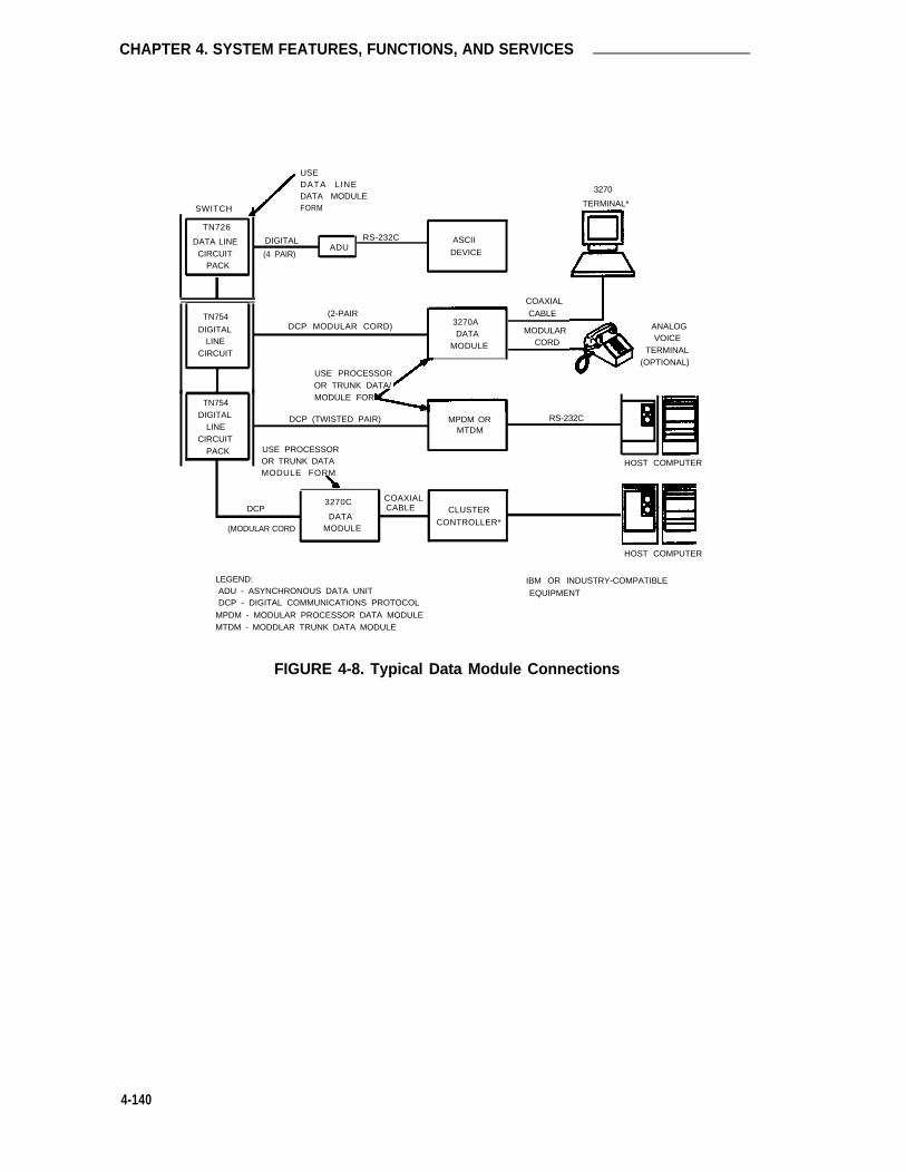
CHAPTER 4. SYSTEM FEATURES, FUNCTIONS, AND SERVICES
USEDATA LINEDATA MODULEFORM
3270
SWITCH
TN726
DATA LINE DIGITAL RS-232CADU
ASCII
CIRCUIT (4 PAIR) DEVICE
PACK
TERMINAL*
COAXIAL
CABLETN754 (2-PAIR
DIGITAL DCP MODULAR CORD) 3270ADATA MODULAR
LINE MODULE CORDCIRCUIT
USE PROCESSOR
ANALOGVOICE
TERMINAL(OPTIONAL)
OR TRUNK DATA/
TN754MODULE FOR
DIGITAL DCP (TWISTED PAIR)LINE
MPDM OR RS-232CMTDM
CIRCUITPACK USE PROCESSOR
OR TRUNK DATA HOST COMPUTERMODULE FORM
3270C COAXIALDCP CABLE
DATACLUSTER
(MODULAR CORD MODULECONTROLLER*
LEGEND:ADU - ASYNCHRONOUS DATA UNITDCP - DIGITAL COMMUNICATIONS PROTOCOL
MPDM - MODULAR PROCESSOR DATA MODULEMTDM - MODDLAR TRUNK DATA MODULE
HOST COMPUTER
IBM OR lNDUSTRY-COMPATIBLE
EQUIPMENT
FIGURE 4-8. Typical Data Module Connections
4-140

Data-Only Off-Premises Extensions
Data-Only Off-Premises Extensions
Allows users to establish data calls involving DCE or DTE that is located remotely from the Sys-tem site using DATAPHONE® data communication service or other private line data facilities. AData-Only Off-Premises Extension uses a MTDM located on-premises. Communication with theremote data equipment is accomplished through the private line facility linking the on-premisesMTDM and the remote data equipment.
Administration
To implement this feature, the following form(s) or sections of the form(s) must be completed.
FormForm Field Instructions
(Page #
MPDM/MTDM Data Module All 6-105
● MPDM/MTDM Data Module Form—Assign the associated data module port interface tothe digtal switch.
Hardware Requirements
Requires a MTDM and one port on a TN754B Digital line circuit pack.
4-141

CHAPTER 4. SYSTEM FEATURES, FUNCTIONS, AND SERVICES
Data Privacy
Protects analog or digital endpoints involved in a data connection from unwanted intrusion oftones, music, or voice which may be misconstrued as data. Data Privacy, when activated by auser, denies the system the ability to gain access to, or to superimpose tones, music, or voiceonto, the protected call.
Administration
To implement this feature, the following form(s) or sections of the form(s) must be completed.
FormForm Field Instructions
(Page #)
Feature Access Codes Data Privacy Access Code 6-127
Class of Service Data Privacy (0-15) 6-77
● Feature Access Codes Form—Complete Data Privacy Access Code field.
● COS Form—Verify Data Privacy field has the correct permission.
Hardware Requirements
None.
4-142

Data Restriction
Data Restriction
Protects analog or digital endpoints involved in a data connection from unwanted intrusion oftones, music, or voice which may be misconstrued as data. Data Restriction, when administeredto an extension number or trunk group, denies the system the ability to gain access to, or tosuperimpose tones, music, or voice onto, the protected call.
Administration
To implement this feature, the following form(s) or sections of the form(s) must be completed.
FormForm Field Instructions
(Page #)
Station Data Restriction 6-245
Trunk Groups: Data RestrictionAccess 5-98APLT 5-112CO 5-123CPE 5-137DID 5-156FX 5-180ISDN-PRI 5-195RLT 5-221Tandem 5-232Tie 5-247WATS 5-264
● Station Forms—Complete Data Restriction field.
● Trunk Group Forms—Complete Data Restriction field.
Hardware Requirements
None.
4-143

CHAPTER 4. SYSTEM FEATURES, FUNCTIONS, AND SERVICES
DCS Alphanumeric Display for Terminals
Allows calls to or from terminals on different nodes (switches) in a DCS equipped withalphanumeric displays to have transparency with respect to the display of call-related data.
Administration
To implement this feature, the following form(s) or sections of the form(s) must be completed.
FormForm Field Instructions
(Page #)
Tie Trunk Group (DCS TG) Outgoing Display 5-247
● Tie Trunk Group Form—Enter "n" in the Outgoing Display field of the DCS Tie TrunkGroup forms. This enables the called party’s name to be displayed at the calling termi-nal.
Hardware Requirements
DCS interface hardware is required.
4-144

DCS Attendant Control of Trunk Group Access
DCS Attendant Control of Trunk Group Access
Allows an attendant at any node in the DCS to exercise control over an outgoing trunk group at adifferent node in the cluster.
Administration
To implement this feature, the following form(s) or sections of the form(s) must be completed.
Form
Attendant Console
FormField Instructions
(Page #)
Feature Button Assignments 6-32-act-tr-grp-deact-tr-g-remote-tgs
● Attendant Console Form—Assign Attendant Control of Trunk Group Access Activate(act-tr-grp) and Attendant Control of Trunk Group Access Deactivate (deact-tr-g) buttonsfor each remote trunk group to be controlled. Assign a "remote-tgs" button for eachremote trunk group to be controlled [that is, Direct Trunk Group Select [1] through [6] forthe Basic Attendant Console (301A) or [1] through [12] on the Enhanced Attendant Con-sole (302A)].
Hardware Requirements
DCS interface hardware is required.
4-145

CHAPTER 4. SYSTEM FEATURES, FUNCTIONS, AND SERVICES
DCS Attendant Direct Trunk Group Selection
Allows attendants at one node to have direct access to an idle outgoing trunk at a different nodein the DCS.
Administration
To implement this feature, the following form(s) or sections of the form(s) must be completed.
FormForm Field Instructions
(Page #)
Attendant Console Direct Trunk Group Select 6-32Button Assignments-remote-tgs
● Attendant Console Form—Assign up to 12 "remote-tgs" buttons in the Direct TrunkGroup Buttons (Access Code) field on Page 1 of the form if not already assigned. Anadditional 12 buttons can be assigned on Page 2 of the form if required. Assign the TACused to access the remote switch and the TAC of the remote trunk group to beaccessed.
Hardware Requirements
DCS interface hardware is required.
4-146
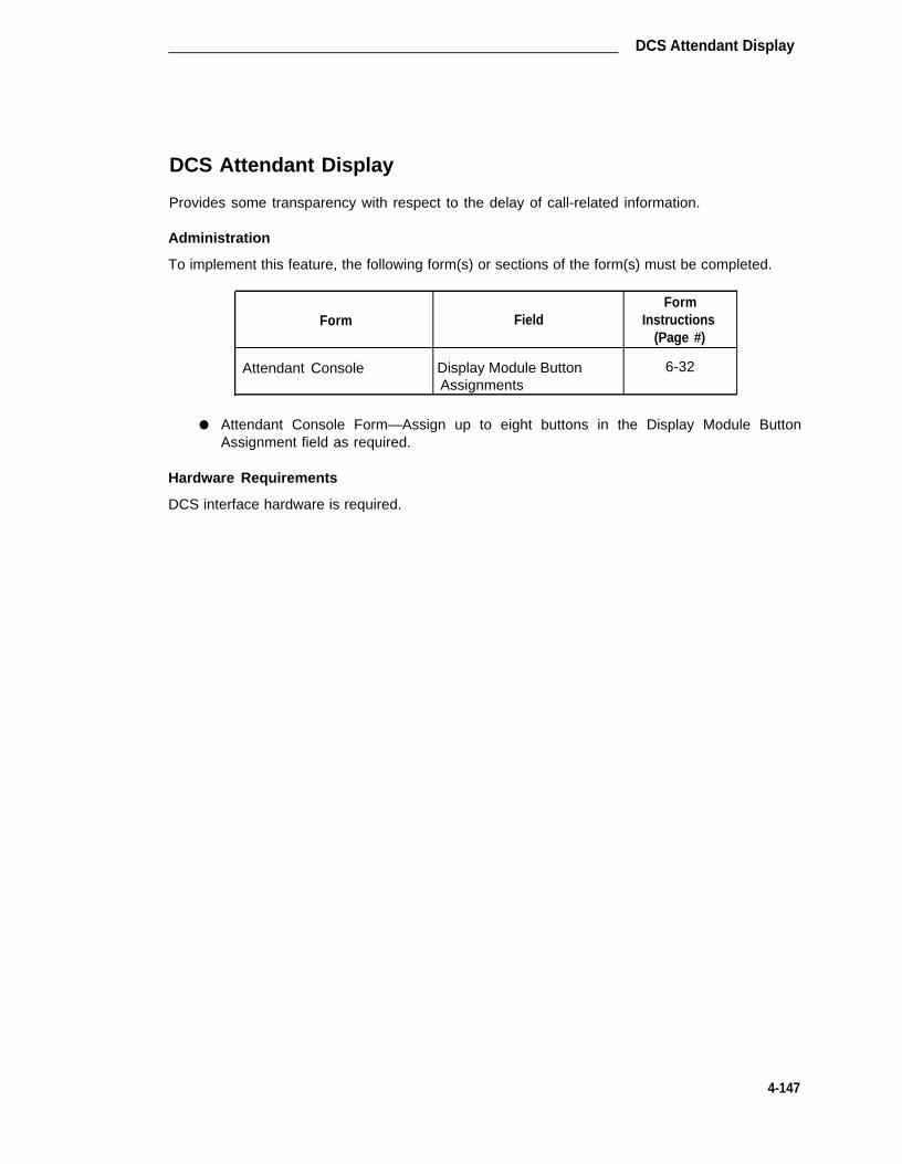
DCS Attendant Display
DCS Attendant Display
Provides some transparency with respect to the delay of call-related information.
Administration
To implement this feature, the following form(s) or sections of the form(s) must be completed.
FormForm Field Instructions
(Page #)
Attendant Console Display Module Button 6-32Assignments
● Attendant Console Form—Assign up to eight buttons in the Display Module ButtonAssignment field as required.
Hardware Requirements
DCS interface hardware is required.
4-147

CHAPTER 4. SYSTEM FEATURES, FUNCTIONS, AND SERVICES
DCS Automatic Callback
Allows a user at one node to make an automatic callback call to a user at another node in theDCS. Note that automatic callback calls do not apply for VDNs.
Administration
To implement this feature, the following form(s) or sections of the form(s) must be completed.
FormForm Field Instructions
(Page #)
Feature-Related System Automatic Callback—No 6-133Parameters Answer Timeout Interval
Feature Access Codes Automatic Callback Activation 6-127
Automatic CallbackDeactivation
Station (multi-appearance) Button/Feature Button 6-245Assignments-auto-cback
Class of Service Automatic Callback (0-15) 6-77
● Feature-Related System Parameters Form—Specify callback time-out interval in theAutomatic Callback—No Answer Timeout Interval (rings) field.
● Feature Access Codes Form—Verify Automatic Callback Activation and Deactivationfields have been assigned.
● Station Forms—Assign Automatic Callback (auto-cback) buttons to multi-appearancevoice terminals, as desired.
● COS Form—Verify Automatic Callback field has the correct permission.
Hardware Requirements
DCS interface hardware is required.
4-148

DCS Automatic Circuit Assurance
DCS Automatic Circuit Assurance
Allows a voice terminal user or attendant at a System node to activate or deactivate AutomaticCircuit Assurance (ACA) referral calls for the entire DCS network. This transparency also allowsthe referral calls to be generated at a node other than the node that detects the problem.
Administration
To implement this feature, the following form(s) or sections of the form(s) must be completed.
Form
Feature-Related SystemParameters
Attendant Console
Station (multi-appearance)
Tie Trunk Group
FieldForm
Instructions(Page #)
ACA Referral Calls
Feature Button Assignments-aca call
Button/Feature ButtonAssignments-aca call
ACA Assignment
6-133
6-32
6-245
5-247
● Feature-Related System Parameters Form—Deterrnine if ACA referral calls are to be“local,” “remote,” or “primary.”
— If administered as "local," referral calls are generated at the System node for thethe System node.
— If administered as “remote,” referral calls are generated at a remote node for theSystem node. In this case, the remote node PBX identification must also beentered. The remote PBX ID is the same PBX code as defined on the Dial Planform.
— If administered as primary, referral calls are made at the System node for one ormore remote nodes.
● Station (multi-appearance) Form—Assign ACA (aca-call) feature button if required.
● Attendant Console Form—Assign ACA (aca-call) feature button if required.
● Tie Trunk Group form—Complete the ACA Assignment and associated Long and ShortHolding Time and Short Holding Threshold fields as required.
Hardware Requirements
DCS interface hardware is required.
4-149

CHAPTER 4. SYSTEM FEATURES, FUNCTIONS, AND SERVICES
DCS Busy Verification of Terminals and Trunks
Allows attendants and multi-appearance voice terminal users to make test calls to voice terminalsand trunk groups that are located at other nodes within the DCS.
Administration
To implement this feature, the following form(s) or sections of the form(s) must be completed.
FormForm Field Instructions
(Page #)
Attendant Console Feature Button Assignments 6-32-verify
Station (multi-appearance) Button/Feature Button 6-245Assignments-verify
●
●
Attendant Console Form—Assign a “verify” button.
Station Forms—Assign a “verify” feature button on multi-appearance voice terminals.
Hardware Requirements
DCS interface hardware is required.
4-150

DCS Call Forwarding-All Calls
DCS Call Forwarding—AIl Calls
Allows all calls to an extension number to be forwarded to a selected extension number within theDCS network or to an external (off-premises) number. This feature is activated or deactivated bydial access code or by a Call Forwarding button. The feature can be activated or deactivatedonly by voice terminal users within the DCS. Note that calls can be forwarded to a VDN any-where in the DCS network. An attendant cannot activate/deactivate Call Forwarding for a VDN.
Administration
To implement this feature, the following form(s) or sections of the form(s) must be completed.
FormForm Field Instructions
(Page #)
Feature Access Codes Call Forwarding Activation 6-127
Call ForwardingDeactivation
Station Redirect Notification 6-245
Button/Feature ButtonAssignments-call-fwd
Class of Service Call Fwd-All Calls (0-15) 6-77
● Feature Access Codes Form—Verify Call Forwarding Activation and Deactivation fieldaccess codes have been assigned.
● Station Forms—Complete Redirect Notification field (which causes the forwarding termi-nal to receive a half ring on calls that forward). This field is common to Call Coverage andCall Forwarding.
● Station Forms—Assign a Call Forwarding (call-fwd) feature button.
● COS Form—Verify Call Forwarding field has the correct permission.
Hardware Requirements
DCS interface hardware is required.
4-151

CHAPTER 4. SYSTEM FEATURES, FUNCTIONS, AND SERVICES
DCS Leave Word Calling
Enables System terminal users to leave preprogrammed “call me” messages at other terminalswithin the DCS network. Messages can be left by calling, called, or covering users.
Administration
To implement this feature, the following form(s) or sections of the form(s) must be completed.
FormForm Field Instructions
(Page #)
Feature-Related System Max. Number Of 6-133Parameters Messages Per Station
Stations With System-wideMessage Retrieval Permis-
sion
Feature Access Codes LWC Message Retrieval 6-127Lock
LWC Message RetrievalUnlook
LWC Send A Message
LWC Cancel A Message
Station LWC Reception 6-245
LWC Activation
Button/Feature/ButtonAssignments-Iwc-store-Iwc-cancel-aut-msg-wt (Ext:_)-msg-retr-delete-msg-Iwc-lock-next-call-disp-cov-msg-rt
Attendant Console Feature Button Assignments 6-32-cov-msg-rt-delete-msg-next-Iwc-cancel-call-disp-Iwc-store-aut-msg-wt (Ext:_)
4-152

DCS Leave Word Calling
●
●
●
●
Feature-Related System Parameters Form—Complete the Maximum Number of Mes-sages Per Station and Stations with System-wide Retrieval Permission fields.
Feature Access Codes Form—Verify or assign the following access codes:
— LWC Message Retrieval Lock field
— LWC Message Retrieval Unlock field
— LWC Send a Message field
— LWC Cancel a Message field
Station Forms—Complete the “LWC Reception” and “LWC Activation” fields (whichspecify if the voice terminal can receive and/or activate LWC messages, respectively).
— Assign a LWC (Iwc-store) button, if desired
— Assign a Cancel (Iwc-cancel) button, if desired, to allow a calling party to cancela previously left message.
Attendant Console Form or the Station Form—For each voice terminal or attendant con-sole group that can retrieve LWC messages, optionally assign the following buttons:
—
—
—
—
—
—
—
Message Retrieve (msg-retr) to access one’s own messages—voice terminalsonly
Cover Msg Retrieval (cov-msg-rt) to access another user’s message
Delete Message (delete msg) to remove a retrieved message
Lock LWC (Iwc-lock) displays locked or unlocked status of the Message Retrieval
Next (to retrieve the next stored message)
Cancel LWC (Iwc cancel) to allow canceling a previously left message
Message name or extension # (aut-msg-wt) used for voice terminal users whomonitor another user’s messages.
Note: Buttons can be assigned on the visual display module or in the “featuresarea” of the terminal or console. If a Message Retrieval or a Coverage Mes-sage Retrieval button is specified, a Next Message and a Delete Messagebutton should also be specified. These button assignments are covered inthe Attendant Display and Voice Terminal Display features.
Hardware Requirements
DCS interface hardware is required.
4-153

CHAPTER 4. SYSTEM FEATURES, FUNCTIONS, AND SERVICES
DCS Over ISDN-PRI D-Channel
Enhances the DCS feature by allowing access to the public network to provide DCS feature con-nectivity between DCS switch nodes. DCS features are no longer restricted to private facilities.The ISDN-PRI B-Channel is used for voice communications, and the ISDN-PRI D-Channel isused to transport DCS control information. The only difference between DCS networks that donot utilize the DCS over ISDN-PRI feature and those that do is in the method of signaling. TheDCS Over ISDN-PRI D-Channel feature uses TSCS to transport certain DCS control information.
A TSC provides a temporary signaling path through ISDN switches for exchanging user-userinformation. There are two types of temporary signaling connections: Call Associated TemporarySignaling Connection (CA-TSC) and NCA-TSC.
A CA-TSC refers to a service for exchanging USER INFORMATION messages that are associ-ated with an ISDN B-Channel connection by the call reference value of the call control data pack-ets.
An NCA-TSC is a connection that is not related to any ISDN B-channel connections. It is anadministered virtual connection established for exchanging USER INFORMATION messages onthe ISDN D-Channel for the DCS over ISDN-PRI D-Channel application as well as for the DCSAUDIX application. Once an NCA-TSC has been administered and enabled it will be active foran extended period of time. There are two types of administered NCA-TSCS depending on theirsetup mechanism: Permanent— Can be established by Near-end or Far-end, and As-neededNCA-TSCs.
Once enabled, a permanent NCA-TSC will remain established while the System is running. If thepermanent NCA-TSC is dropped for any reason, the System will attempt to re-establish the con-nection. An as-needed administered NCA-TSC is established based on user request and theavailability of TSC facilities. The connection is dropped after an administered period of inactivity.
The System can transport DCS or DCS Audix messages over an ISDN-PRI D-Channel and overBX.25 data links when functioning as a gateway between a PBX equipped with the DCS OverISDN-PRI D-Channel feature and a PBX equipped with traditional DCS using BX.25 data links.In this situation, the messages travel from the gateway through the NCA-TSCs or CA-TSCs toTSC-capable PBXs and from the gateway to PBXs that support only traditional DCS via a BX.25logical channel.
ISDN DCS Gateway Node
At least one PBX must be configured as an ISDN DCS Gateway node in a DCS network thatconsists of PBXs that support DCS Over ISDN-PRI D-Channel and PBXs that do not support thefeature.
Examples of various DCS Network Configurations are provided later in this section. Administra-tion necessary to configure the TSCs and other related parameters for the network is providedwith the examples.
There are two configurations that allow the ISDN Gateway to monitor calls which involve vectorprocessing. Both of the following configurations trace calls for their durations once they terminateto an ISDN Gateway split (not necessarily answered by an agent in that split):
4-154

DCS Over ISDN-PRI D-Channel
● Calls that terminate to an ISDN Gateway split and are redirected to a vector. The callsare redirected by either call forwarding from the split to a vector or by an agent in theISDN Gateway split answering the call and then transferring the call to a vector. Thisseems to be the most useful configuration since it allows the use of “queue to main” and“check backup” vector steps.
● Calls that first terminate to a vector and then are routed to an ISDN Gateway split. Inthis configuration, the “queue to main” and “check backup” vector steps cannot be usedbecause they involve vector controlled splits.
Administration
The ISDN-PRI option must be enabled on the System-Parameters Customer-Options form beforeassociated forms and fields on forms can be administered.
Note that the following does not provide administration instructions associated with assigning anISDN-PRI trunk group or administering a DCS network. Refer to the appropriate sections in themanual for related instructions.
To implement this feature, the following form(s) or sections of the form(s) must be completed.
FormForm Field Instructions
(Page #)
SIGNALING GROUP 5-81
Page 1 contains Max number of NCA TSCTSC-related fields Max number of CA TSC
Trunk Group for NCA TSC
Pages 2 through 5 contain Complete AdministeredAdministered TSC-related “NCA-TSC Assignment”fields. fields as needed.
Service/Feature As-neededInactivity Time-out (rein)
ISDN TSC GATEWAY All 5-89CHANNEL ASSIGNMENTS
ISDN PRI TRUNK GROUP Used for DCS? 5-195(Page 2 of form) PBX ID
DCS Signaling
NCA TSC Signaling Group
ROUTING PATTERNS TSC 5-29CA-TSC Request
PROCESSOR CHANNEL Appl 6-194ASSIGNMENT
4-155

CHAPTER 4. SYSTEM FEATURES, FUNCTIONS, AND SERVICES
● Signaling Group Form—Complete the following fields:
–
–
–
–
–
Max number of NCA-TSC—Specifies the maximum number of NCA-TSCs thatwill be supported in the Signaling Group. Allowable entries are 0 through 256.Default is “0.”
Max number of CA-TSC—Specifies the maximum number of CA-TSCs that willbe supported in the Signaling Group. Allowable entries are 0 through 400.Default is “0.”
Trunk Group for NCA-TSC—Specifies the ISDN-PRI trunk group whose incom-ing Call Handling Table (ICHT) will be used to handle incoming NCA-TSCsthrough this signaling group.
Complete Pages 2 through 5 of the form as required to assign administeredNCA-TSCs. A maximum of 64 administered NCA-TSCs may be administered aspart of the Signaling Group form.
Service/Feature—Specifies the service type for all the Administered NCA-TSCsin this signaling group. Allowable entries are “accunet,” “i800,” “inwats,” “Ids,”"mega800," "megacom,“ “multiquest,” “operator,” “sdn,” “sub-operator,” “wats-max-bnd.” Default is blank.
As-needed Inactivity Time-out(min)—Specifies the inactivity time-out for as-needed NCA TSCs assigned in this signaling group. When timer expires, an as-needed administered TSC will be torn down. Enter a number between “10“ and“90.” Default is blank.
●
●
ISDN TSC Gateway Channel Assignment Form—Used to map administered NCA-TSCsto (BX.25) processor channels in an Integrated DCS Network. (Form only required forPBX location serving as an ISDN Gateway in an Integrated DCS Network). Complete allfields as required.
ISDN Trunk Group Form—Complete the following fields:
–
–
–
Used for DCS?—Appears for “access,” “rIt,” “tandem,” “tie,” and “isdn-pri” trunkgroup types. This field determines if a trunk will send and receive messages via aDCS signaling link. (NOTE: This field does not appear for an “isdn-pri” trunkgroup with a service type of “dmi-bos” or “ivbs.”) For all other “isdn-pri” trunkgroup types, if “y” is entered in this field, then the dependent fields “PBX ID” andDCS Signaling” appear.
PBX ID (dependent field)—Only displayed when the “Used for DCS?” field entryon the ISDN PRI trunk group form is “y.” Identifies the remote PBX within thenetwork with which the trunk will communicate on a DCS signaling link. Allowableentries are "1" through "63." Default is "1."
DCS Signaling (dependent field)—Only displayed when the “Used For DCS?”field entry on the ISDN PRI trunk group form is “y.” The option “bx.25” is used tosupport the traditional DCS feature. The option “d-chan” is used to support theDCS Over ISDN-PRI D-Channel feature. Enter “d-chan.”
4-156

DCS Over ISDN-PRI D-Channel
— NCA-TSC Signaling Group—Specifies on which signaling group NCA-TSC callsrouted to this trunk group should be established. Allowable entries are “1”through “8” or blank. Number entered must match at least one of the entries inthe “Sig Grp” column on the “Trunk Group Member Assignments” portion of theTrunk group form. Default is blank.
Note: If there is no ambiguity in the “Sig Grp” column (that is, only onenumber has been entered for one or more group members), then, ifthis field is left blank, the system will fill in the field based on theinformation that was entered in the “Trunk Brd” column on Page 1 ofthe Signaling Group form. If there is ambiguity, then you must fill inthis field.
● Routing Pattern Form—Complete the following fields:
— TSG—Allowable entries are “y” or “n.” When a “y” is entered in this field, the“CA-TSC” field becomes writable. (See “CA-TSC Request” below.) For anNCA-TSC, the option means that the NCA-TSC will be blocked if it is routedthrough this pattern in a tandem switch. Default is “n.”
— CA-TSC Request—This field becomes writable when a “y” is entered in the“TSC” field. (See “TSC” above.) You must specify when a CA-TSC will be esta-blished if the call is routed through a particular preference of a routing pattern.Allowable entris are then "as-needed," "at-setup," and "none." The first twoentries, “as-needed’ and “at-setup” are meaningful only for CA-TSCs. If the “as-needed options is entered, a CA-TSC will be established only when it isrequested during a call. If the “at-setup” option is requested, then the CA-TSCwill be established when the call is set up. Selection of the “none” option meansthat there will be no CA-TSC associated with this call. Default is “none.”
● Communications-Links Processor Channels Form—The “Appl” field specifies to whichapplication channel this processor channel is connected. Enter “gateway” in the associ-ated “Appl” field if the processor channel is used as one end of the gateway channelassigned in the ISDN TSC Gateway Channel Assignments form. The gateway nodeserves as the terminating node to the D-Channel DCS network as well as the terminatingnode to the traditional DCS network.
A PBX serving as an ISDN DCS Gateway node introduces some interesting situationswhen administering processor channels in an associated traditional DCS PBX. In a tradi-tional DCS network, (bx.25 processor channel links) the “Remote Proc Chan” field in theProcessor Channel Assignments form refers to the processor channel of the destinationPBX. In an Integrated DCS network, the “Remote Proc Chan” field in the ProcessorChannel Assignments form refers to the processor channel of the Gateway PBX (if thedestination PBX is an ISDN DCS PBX), NOT the destination PBX. On the contrary, the“Machine-ID” field in the Processor Channel Assignments form refers to the destinationPBX, either an ISDN DCS PBX or a traditional DCS PBX. The Gateway PBX numberMUST not be used in this field if the destination PBX is an ISDN DCS PBX.
4-157

CHAPTER 4. SYSTEM FEATURES, FUNCTIONS, AND SERVICES
Example of an Integrated DCS Network
Figure 4-9 shows an example of an integrated DCS network configuration. PBXs A, B, C, E, andF are PBXs which do not support the DCS over ISDN-PRI D-Channel feature. PBXs D, G, and Hare PBXs which support the DCS over ISDN-PRI D-Channel feature. PBX D acts as an ISDNDCS Gateway Node for PBXs A, B, and C to transport DCS messages to/from PBXs on theother side of the AT&T network. PBX G acts as an ISDN DCS Gateway Node for PBXs E and Fto transport DCS messages to/from PBXs on the other side of the AT&T network as well asto/from PBX H.
The DCS configuration between PBXs A, B, C, and D, as well as between PBXs E and F, is atraditional DCS network. That means they are interconnected with tie trunks and separate BX.25data links.1 The tie trunks are used for voice communication while the BX.25 data links are usedto transport supplementary call and feature control information. DCS messages mayhop/tandem 2 through one PBX to another PBX in a traditional DCS network.
PBXs D, G, and H are interconnected with ISDN-PRI facilities which include B-channels and D-Channels. The voice communication will be carried by B-channels while the control informationwill be carried by D-Channels. DCS messages exchanged in these PBXs are ISDN DCS mes-sages. ISDN DCS messages from PBX D to PBX H are tandemed by PBX G. Figure 4-10shows typical NCA-TSCs and Data Link connections in an Integrated DCS network.
1. These tie trunks or the BX.2S data links could be ISDN-PRI B-channels.
2. A DCS message may be hopped/tandemed to another PBX in a traditional DCS network depending on the DCSfeature and the DCS network configuration.
4-158

DCS Over ISDN-PRI D-Channel
FIGURE 4-9. An Integrated DCS Network
4-159

CHAPTER 4. SYSTEM FEATURES, FUNCTIONS, AND SERVICES
Table 4-C shows the logical connections required for PBX H to other PBXs in the integrated DCSnetwork shown in Figure 4-10.
FIGURE 4-10. NCA-TSC and Related Data Link Assignments from PBX H to Other PBXs
4-160

DCS Over ISDN-PRI D-Channel
TABLE 4-C. Example Integrated DCS Network NCA-TSC/Data Link Connections
From PBX To PBX Logical ConnectionH A An administered NCA-TSC from PBX H to PBX D which then
connects to a BX.25 logical channel from PBX D to PBX A whichhops through PBX B.
H B An administered NCA-TSC from PBX H to PBX D which thenconnects to a BX.25 logical channel from PBX D to PBX B.
H C An administered NCA-TSC from PBX H to PBX D which thenconnects to a BX.25 logical channel from PBX D to PBX C.
H D An administered NCA-TSC from PBX H to PBX D.
H E An administered NCA-TSC from PBX H to PBX G which thenconnects to a BX.25 logical channel from PBX G to PBX E whichhops through PBX F.
H F An administered NCA-TSC from PBX H to PBX G which thenconnects to a BX.25 logical channel from PBX G to PBX F.
H G An administered NCA-TSC from PBX H to PBX G.
From PBX H, a separate administered NCA-TSC connection is needed to every other PBX in theIntegrated DCS network. If the terminating PBX is not a PBX that supports the DCS over lSDN-PRI D-Channel feature then the administered NCA-TSC is terminated at the appropriate ISDNDCS gateway node and a gateway channel is administered on the gateway node to complete theconnection.
All other PBXs in the Integrated DCS network will have the similar link configuration.
Example DCS Network Configuration
Figure 4-11 provides an example of a traditional DCS Network configuration. PBXs 1, 2, and 3are TSC Capable PBXs that support DCS over ISDN PRI D-Channel. PBXs 4 and 5 do not sup-port DCS over ISDN PRI D-Channel, but use traditional DCS. Solid lines represent administeredNCA-TSCs, dotted lines represent gateway channels and hop channels, and dashed linesrepresent SCI links.
● Notation
– TSC x/y - Administered NCA-TSC Index y belonging to Signaling Group x
– (m <--> n) - represents a connection between PBX m and PBX n
– (m <--> n for z) - An administered NCA-TSC exists between PBX m and “gate-way” PBX n, for the purpose of establishing a connection between PBX m andPBX z (a non-TSC Capable PBX)
– Link a/b - Logical channel b on interface link a
– hop(a/b : c/d) - A hop channel exists between interface link a - BX.25 logicalchannel b and interface link c - logical channel d
4-161

CHAPTER 4. SYSTEM FEATURES, FUNCTIONS, AND SERVICES
ISDN PBX 1
TSC 1/1
TSC 1/2
TSC 1/3
TSC 1/4
PBX 5
link 1/1
link 1/2
link 1/3
link 1/4
(1 <--> 2)
(1 <--> 3)
(1 <--> 3 for 4)
(1 <-> 3 for 5) TSC 2/3
TSC 2/5
(5 <--> 4)- - - - - - - - - - -
(5 <--> 3)- - - - - - - - -
(5 <--> 3 for 2)- - - - - - - - -
(5 <--> 3 for 1)- - - - - - - -
ISDN PBX 2
TSC 3/4
(tandemed) (1 <--> 3)
(tandemed) (1 <--> 3 for 4)
(tandemed) (1 <--> 3 for 5)
TSC 4/1(2 <--> 3)
TSC 4/2(2 <--> 3 for 4)
TSC 4/3(2 <--> 3 for 5)
PBX 4
link 2/1
hop (2/2 : 3/1)link 2/2 link 3/1. . . . . . . . . . . . . . . . . . . .
link 3/2
hop (2/3 : 3/3)link 2/3 link 3/3. . . . . . . . . . . . . . . . . . . . .
link 3/4
hop (2/4 : 3/5link 2/4 link 3/5. . . . . . . . . . . . . . . . . . . . .
link 3/6
ISDN PBX 3(Gateway Node)
TSC 2/1
TSC 2/2. . . . . . . . . .
TSC 2/6 : :. . . . . . . . . . .. . .
T S C 2 / 7. . . . . . .. : : :. . . .. . . .
(5 <--> 3 hopped thru 4)
(4 <--> 3)- - - - - - - - - - - - - - -
(5 <--> 3 hopped thru 4 for 2)- - - - - - - - - - - - - - - - -
(4 <--> 3 for 2)
(5 <--> 3 hopped thru 4 for 1)- - - - - - - - - - - - - - - - - - - - -
(4<--> 3 for 1)- - - - - - - - - - - - - - - - - - - - - - -
Note: In the above figure, PBXs 1, 2, and 3 support TSCs. PBXs 4 and 5 do not support TSCs.
FIGURE 4-11. Sample DCS Network Configuration
4-162

DCS Over ISDN-PRI D-Channel
Administration Example
It should be noted that the following administration is not intended to be complete but merely toaid in the understanding of Figure 4-11. Refer to the various screen forms elsewhere in themanual for specific information related to the referenced forms and fields on forms.
The following describes the administration necessary to configure the DCS Network shown inFigure 4-11. For administered NCA-TSC administration, all the administered NCA-TSCs areassumed to be enabled and the establishment strategy is assumed to be in accordance with oneof the first three examples presented in Table 4-D. Table 4-E provides administration instructionsassociated with each PBX.
An entry of NA on the Processor Channel Assignments form means that field will be left blank.
● Assumptions:
— Extensions in the range 2000-2999 terminate at PBX 1
— Extensions in the range 3000-3999 terminate at PBX 2
— Extensions in the range 4000-4999 terminate at PBX 3
Administration for PBX 1
●� Administered NCA-TSC Administration:
TABLE 4-D. Administered NCA-TSC Administration - PBX 1
Signaling Group 1
Admin.TSC Index
LocalE x t .
Dest.Digits
Far EndPBX ID
Notes
1
2
3
4
2000
2001
2002
2003
3000
4000
4001
4002
2
3
4
5
A. NCA-TSC PBX 1<-->PBX 2
A. NCA-TSC PBX 1<-->PBX 3
Use Node 3 as a gateway to PBX 4
Use Node 3 as a gateway to PBX 5
4-163

CHAPTER 4. SYSTEM FEATURES, FUNCTIONS, AND SERVICES
Administration for PBX 2
● Adminstered NCA-TSC Administration:
TABLE 4-D (continued).Administered NCA-TSC Administration - PBX 2
Signaling Group 4
A. TSC Local Dest. Far EndIndex Ext. Digits PBX ID
1 3 0 0 1 4 0 0 3 3
2 3 0 0 2 4 0 0 4 4
3 3003 4005 5
Notes
A. NCA-TSC PBX 2<-->PBX 3
Use Node 3 as a gateway to PBX 4
Use Node 3 as a gateway to PBX 5
Signaling Group 3
A. TSC Local Dest. Far End NotesIndex Ext. Digits PBX ID
4 3000 2000 1 A. NCA-TSC PBX 2<-->PBX 1
4-164

DCS Over ISDN-PRI D-Channel
Administration for PBX 3 (Gateway PBX)
● Administered NCA-TSC Administration:
TABLE 4-D. (continued).Administered NCA-TSC Administration - PBX 3
Signaling Group 2
A. TSC Local Dest. Far End NotesIndex Ext. Digits PBX ID
1 4000 2001 1 A. NCA-TSC PBX 3 <-->PBX 1
2 4001 2002 gateway Gateway Channel from PBX 1 to PBX 4
3 4002 2003 gateway Gateway Channel from PBX 1 to PBX 5
5 4003 3001 2 A. NCA-TSC PBX 2<-->PBX 3
6 4004 3002 gateway Gateway Channel from PBX 2 to PBX 4
7 4005 3003 gateway Gateway Channel from PBX 2 to PBX 5
● Gateway Channel Administration:
Sig. AdministeredGroup TSC Index Channel Application
2 2 10 d c s
2 3
2 6
2 7
Processor
9 dcs
8 dcs
7 dcs
4-165

CHAPTER 4. SYSTEM FEATURES, FUNCTIONS, AND SERVICES
● Processor Channel Administration:
TABLE 4-D (continued).Administered NCA-TSC Administration - PBX 3
Proc. Application Int. Channel Remote PBXChannel Link Proc. Channel ID
5 dcs 1 1 5 5
6 dcs 1 2 6 4
7 gateway 1 3 7 NA
8 gateway 1 4 8 NA
9 gateway 1 5 9 NA
10 gateway 1 6 10 NA
Administration for PBX 4
● Processor Channel Administration:
TABLE 4-D (continued).Administered NCA-TSC Administration - PBX 4
Proc. Application Int Channel Remote PBXChannel Link Proc. Channel ID
6 4 3 26 3
8 dcs 3 4 8 2
10 dcs 3 6 10 1
11 dcs 2 1 11 5
4-166

DCS Over ISDN-PRI D-Channel
TABLE 4-D (continued).(continued).
Administered NCA-TSC Administration - PBX 4
● Hop Channel Administration:
Link Channel Link Channel
3 1 2 2
3 3 2 3
3 5 2 4
Administration for PBX 5:
● Processor Channel Administration
TABLE 4-E. Administered NCA-TSC Administration - PBX 5
Proc. Application Int. Channel Remote PBXChannel Link Proc. Channel ID
5 dcs 1 2 5 3
7 dcs 1 3 7 2
9 dcs 1 4 9 1
11 dcs 1 1 11 4
4-167

CHAPTER 4. SYSTEM FEATURES, FUNCTIONS, AND SERVICES
DCS Trunk Group Busy/Warning Indication
Provides attendants with a visual indication that the number of busy trunks in a remote group hasreached an administered level. A visual indication is also provided when all trunks in a trunkgroup are busy.
Administration
To implement this feature, the following form(s) or sections of the form(s) must be completed.
FormForm Field Instructions
(Page #)
Attendant Console Direct Trunk Group Select 6-33Button Assignments (1-6)for 301A Basic or (1 -12)for the 302A EnhancedAttendant Console.
Trunk Groups: Busy ThresholdAccess 5-94APLT 5-104CO 5-113CPE 5-123DMI-BOS 5-129FX 5-145ISDN-PRI 5-155RLT 5-174Tandem 5-183Tie 5-193WATS 5-204
● Attendant Console Form—Trunk group must be assigned to one of the first six DirectTrunk Group Button Assignments (Access Codes) field on the console. Refer to Atten-dant Direct Trunk Group Selection feature for additional information.
● Trunk Group Forms—Assign Busy Threshold (warning) field.
Hardware Requirements
DCS interface hardware is required.
4-168

Default Dialing
Default Dialing
Enhances Data Terminal (Keyboard) Dialing by allowing a data terminal user to place a data callto a pre-administered destination by simply entering a carriage return at the “DIAL” prompt. Theuser can still place calls to other destinations by entering the complete address after the “DIAL”prompt (normal Data Terminal Dialing with/without Alphanumeric dialing).
For the AT command set supported by the 7400A Data Module, the Attendant Dial (ATD) com-mand may be entered instead of a carriage return to dial the default destination. The "AT" com-mand set emulates the AT command set of the Hayes Smartmodem™.
Default Dialing can be assigned to any data endpoint that has Data Terminal Dialing capability.
Administration
To implement this feature, the following form(s) or sections of the form(s) must be completed.
Form Field
Abbreviated Dialing List All
Data Module Special Dialing OptionAbbreviated Dialing ListAD Dial Code
FormInstructions(Page #)
6-2
6-83
● Abbreviated Dialing List form—Enter the default destination on the appropriate Abbrevi-ated Dialing List form for your terminal. This list can be a System, Group, Personal, orEnhanced List.
● Data Module form—Complete the following fields on appropriate Data Module forms (thatis, Data Line, MPDM) as follows:
● Special Dialing Option—Enter “default.” Note that Default Dialing and the DataHotline feature cannot both be assigned on the Data Module form.
● Abbreviated Dialing List—Enter the abbreviated dialing list type where the defaultdestination is stored.
●� AD Dial Code—Enter the AD list number associated with the stored default desti-nation.
Hardware Requirement
Refer to the Data Call Setup feature coverage for associated hardware requirements.
4-169

CHAPTER 4. SYSTEM FEATURES, FUNCTIONS, AND SERVICES
Demand Print
Allows the voice terminal user to print his/her own undelivered messages without calling the Mes-sage Center.
Administration
To implement this feature, the following form(s) or sections of the form(s) must be completed.
Form
Station (multi-appearance)
Station
Feature Access Codes
FormField Instructions
(Page #)
Button/Feature Button 6-245Assignments-print-msgs
Security Code 6-245
Print Messages Access Codes 6-127
● Station Forms—Assign Demand Print (print-msgs) feature buttons to multi-appearancestations. Assign 4-digit code in the Security Code field to enable retrieving Demand Printmessages.
● Feature Access Codes Form—Assign Print Messages Access Codes.
Hardware Requirements
A Message Server Adjunct (MSA) such as a 3B2 equipped with appropriate Message Serversoftware and associated printers. Refer to the Message Server implemental.bn instructions foradditional information.
4-170

Dial Plan
Dial Plan
The Dial Plan is the system’s guide to digit translation. When a digit is dialed, the system mustknow what to expect, based on that digit. For example, if a voice terminal user dials a 4, the sys-tem must know how many more digits to expect before the call will be processed.
A feature access code cannot be assigned to a feature if it is not already defined and consistentwith the Dial Plan.
Administration
To implement this feature, the following form(s) or sections of the form(s) must be completed.
Form
Dial Plan
FormField Instructions
(Page #)
All 6-117
● Dial Plan Form—Enter the local area code and whether or not a digit 1 is required to indi-cate a long distance call. Identify if a UDP is to be used and complete all First DigitTable entries as required.
● If the UDP option is used, enter the number of digits in the plan (4 or 5), PBX Codes,Local/Remote Indicator, RNXs for all switches, and all PBX IDs.
Hardware Requirements
None.
4-171

CHAPTER 4. SYSTEM FEATURES, FUNCTIONS, AND SERVICES
Dialed Number Identification Service (DNIS)
Provides a called party or answering position with a personalized identification of the service orproduct associated with the call. The system can be administered to detect and display the nameof the product or service being called about.
For ISDN-PRI calls, Dialed Number Identification Service (DNIS) is the called party number in theassociated call setup messages. No additional administration is required for these type calls.
For non-lSDN-PRl type calls, DNIS can be obtained from the network by subscribing to AT&T-COMM DNIS service. The connecting central office passes four digits (extension number)representing the dialed 800 number to the digital switch. The System then connects the call toan interim TEG, hunt group, phantom extension (see Administration Without Hardware feature) orACD split which immediately forwards the call to a terminating extension. The terminating exten-sion can be either a station, hunt group, or ACD split. The interim extension is assigned thename of the product or service associated with the call. When the terminating extension answersthe call, the user’s display-equipped voice terminal shows the name of the product or servicebeing called. As a result, the user can answer the call accordingly.
Implementation of the switch for non-lSDN-PRl type calls can be accomplished in several ways.Note that the answering user requires a display-equipped station to identify the product or servicebeing called.
Administration
The following does not provide administration guidelines for the answering extension. Refer tothe appropriate coverage (for example, 7400D series Voice Terminals, ACD, DDC/UCD) in thischapter for those guidelines.
DNIS via DID Trunk Group
To implement this feature, the following form(s) or sections of the form(s) must be completed.
Form
DID Trunk Group
Hunt Group
or
Station (phantom extension)
or
Terminating Extension Group
Call Coverage Paths
FormField Instructions
(Page #)
All 5-156All 6-160
All 6-245
All 6-214
All 6-55
● DID Trunk Group Form—A separate DID trunk group must be assigned whose incomingcalls will terminate at the interim extension. The extension can be a phantom extension,TEG, hunt group, or ACD split. The Group Name field on the form can be administeredas "DNIS" or as appropriate to identify the trunk group usage.
4-172

Dialed Number Identification Service (DNIS)
●
●
●
●
Hunt Group Form—This hunt group is administered as an interim extension. The pur-pose of the hunt group is to send the call along with the name of the product or servicebeing called to an answering (display-equipped) station. The hunt group will not haveGroup Member Assignments (that is, no members). Administer the Group Extensionfield as the 4-digit number representing the 800 number being called. Administer theGroup Name field with the name of the product or service being called. Assign a cover-age path in the Coverage Path field. The Coverage Path form will be administered to for-ward the calls to the appropriate terminating extension. Optionally, the Hunt Group formcan be administered as an ACD split (ACD field = “y”), and if appropriate, the Measuredfield as “internal” (BCMS), “external” (CMS), or “both” to obtain measurement reports ofthe call activity associated with the product or service.
Station Form—Complete a station form to assign a phantom extension. Administer theExtension field as the number representing the 800 number being called. Administer theName field with the name of the product or service being called. Assign a coverage pathin the Coverage Path field. The Coverage Path form will be administered to forward thecalls to the appropriate terminating extension. Enter “x” in the Port field. This permits theadministering of a station form without having a port assigned and does not require avoice terminal.
TEG Form—This form can be administered as the interim extension instead of the HuntGroup form. Administer the Group Extension, Group Name and Coverage Path fields asrequired for the Hunt Group form. Do not administer the Group Member Assignmentsfields. Note that when using a TEG as the interim extension, measurement reports can-not be obtained.
Call Coverage Paths Form—Assign the Coverage Path Number field per the pathnumber entered on the interim extension form (that is, Hunt Group, ACD split, phantomextension, or TEG form). Assign the Coverage Criteria All field as “y” for both inside andoutside calls. Administer the Coverage Point 1 field as the terminating extension. Thisextension can be a station, hunt group, or ACD split.
DNIS via Megacom 800 Service Tie Trunk Group
To implement this feature, the following form(s) or sections of the form(s) must be completed.
FormForm Field Instructions
(Page #)
Tie Trunk Group All 5-247
Hunt Group All 6-160
or
Station (phantom extension) All 6-245
or
Terminating Extension Group All 6-214
Call Coverage Paths All 6-55
4-173

CHAPTER 4. SYSTEM FEATURES, FUNCTIONS, AND SERVICES
●
●
●
●
●
Tie Trunk Group Form—A separate Tie Trunk Group must be assigned. Administer theGroup Name field as “Megacom” or as required to identify the trunk group usage.Administer the Incoming Destination field as the interim extension. The extension can bea TEG, hunt group, phantom extension, or ACD split.
Hunt Group Form—Administer same as for DID trunk group above.
Station Form—This form can be administered as the interim extension instead of theHunt Group form. Administer same as for DID trunk group above.
Terminating Extension Group Form—This form can be administered as the interim exten-sion instead of the Hunt Group form. Administer same as for DID trunk group above.
Call Coverage Paths Form—Administer same as for DID trunk group above.
Implementation Summary
The recorded announcements that a caller hears for the various methods of DNIS implementa-tion are as follows:
● When the interim extension is a TEG or phantom extension and the final destination is anon-ACD hunt group, no announcements are heard by the caller, even if an announce-ement was administered via the hunt group.
● When the interim extension is a TEG or phantom extension and the terminating destina-tion is an ACD split, one of two situations will occur. [If a second announcement hasbeen administered for the split, that announcement will be played for the caller. The firstannouncement will not be played. If a second announcement has not been administered,no announcement will be heard by the caller.
● When the interim extension is a hunt group or an ACD split and the final destination is anon-ACD hunt group, only an announcement administered at the interim extension couldbe played. This announcement must be administered as a forced first announcement atthe interim extension.
● When the interim extension is a hunt group or ACD split and the final destination is anACD split, a forced first announcement will be played for the interim extension and thesecond announcement at the final destination will be played.
Measurements
When the interim extension is an ACD split, measurement of DNIS calls can be made. The CMSfor example, pegs all calls which leave the interim extension via the coverage path as overflowedcalls. Therefore, a count of how many calls reached the interim extension can be made. In orderto obtain an accurate count of DNIS calls, it is essential that all such calls are routed to theinterim extension first. If some DNIS calls are routed directly to the terminating extension, themeasurements for calls reaching the split via the DNIS service will not be accurate.
The measurement facility (CMS for example) can also provide information on whether or not thecovered call was connected or whether the caller abandoned the call. From this information, thenumber of calls terminated and abandoned can be determined.
4-174

Dialed Number Identification Service (DNIS)
Hardware Requirements
DNIS via DID
Requires a port on a TN753 DID trunk circuit pack or TN767 DS1 Interface circuit pack foreach DID trunk to be administered.
DNIS via Megacom 800 Service Tie Trunk Group
Requires a port on a TN760B Tie Trunk, TN722B or TN767 DS1 Tie Trunk circuit pack foreach tie trunk to be administered.
DNIS via ISDN-PRI
Refer to the ISDN-PRI coverage elsewhere in this Chapter for hardware requirements.
4-175

CHAPTER 4. SYSTEM FEATURES, FUNCTIONS, AND SERVICES
Digital Multiplexed Interface (DMI)
The Digital Multiplexed Interface (DMI) provides for digital trunk interfaces to the System. DMIsupports high volume (high speed, high capacity) data transmission via DS1 digital facilitiesbetween; host computers, another PBX, or a private or public network and analog and digital dataendpoints. When ISDN-PRI signaling is used, associated trunks can be connected to host com-puters, another PBX, or a private or public network.
Administration
Instructions for administering the DS1/DMl interface to the System are provided in DS1/DMlInterface Manual.
To implement this feature, the following form(s) or sections of the form(s) must be completed.
Form
DS1 Circuit Pack
DMI-BOS Trunk Group
ISDN-PRI Trunk Group
Synchronization Plan
FormField Instructions
(Page #)
All 5-65
All 5-144
All 5-195
All 6-89
●
●
●
●
DS1 Circuit Pack Form—Complete all fields. Assign ports for each trunk member to beassigned on the associated Trunk Group form.
DMI-BOS Trunk Group Form—Complete all fields as required when using Bit-OrientedSignaling (BOS).
ISDN-PRI Trunk Group Form—Complete all fields as required when using Message-Oriented Signaling (BOS).
Synchronization Plan Form—Complete all fields.
Hardware Requirements
A TN722B or TN767 DS1 Tie Trunk circuit pack must be provided for trunk assignments. The cir-cuit pack must be assigned (via a DS1 Circuit Pack form) prior to administration of DMI-BOS orISDN-PRI Trunk Groups. If ISDN-PRI signaling is used, a TN767 must be used in conjunctionwith a TN765 Processor Interface circuit pack. The TN722B or TN767 provides up to 24independent trunks. When used with common channel or ISDN-PRI signaling, 23 trunks areavailable for data and one trunk is used for signaling purposes.
A port is required on a TN754B Digital Line circuit pack if a Long Haul DCS is used with a highspeed modem, Data Service Unit, a DATAPHONE data set, or a Local Area Data Set.
4-176

Direct Department Calling
Direct Department Calling
Allows direct inward access to an answering group other than the attendant even if the systemdoes not have the DID feature.
A Direct Department Calling (DDC) answering group can consist of voice terminals and individualattendants.
Administration
To implement this feature, the following form(s) or sections of the form(s) must be completed.
FormForm Field Instructions
(Page #)
Recorded Announcements As Required 6-198
Recorded Announcement All 6-115Data Module
Call Coverage Paths All 6-55
Hunt Groups All 6-160
Trunk Groups: Incoming DestinationNight Service
Access 5-98APLT 5-112CO 5-123DMI-BOS 5-144FX 5-180ISDN-PRI 5-195RLT 5-221Tandem 5-232Tie 5-247WATS 5-264
●
●
●
●
●
Recorded Announcements Form—Assign recorded announcement extension numbers, ifused.
Recorded Announcement Data Module Form—Complete all fields.
Call Coverage Paths Fom—Verify or assign Call Coverage Path for the group, if used.
Hunt Groups Form—Complete all fields.
Trunk Group Forms—lf this feature is to be provided via DID, the assigned hunt groupextension number must be accessible via DID. Enter the extension number assigned tothe hunt group in the trunk group Incoming Destination and/or Night service fields.
4-177

CHAPTER 4. SYSTEM FEATURES, FUNCTIONS, AND SERVICES
Hardware Requirements
Requires one port on a TN742, TN746B, or TN769 Analog Line circuit pack for each AuxiliaryQueue Warning lamp. A 21C-49 indicator lamp may be used as a warning lamp. This lamp isapproximately two inches in diameter and has a clear beehive lens. The lamp operates on ring-ing voltage and can be mounted in any convenient location.
Each delay announcement requires announcement equipment and a port on a TN742, TN746B,or TN769 Analog Line circuit pack. If music is to be provided after the delay announcement, amusic source and a port on the TN76C Auxiliary Trunk circuit pack is also required. Theannouncement and music equipment are not provided as part of the System equipment.
Refer to the Recorded Announcements and Trunk Groups features for additional administrationand hardware requirements.
4-178

Direct Inward Dialing (DID)
Direct Inward Dialing (DID)
Connects calls from the public network directly to the dialed extension number without attendantassistance.
Administration
To implement this feature, the following form(s) or sections of the form(s) must be completed.
FormForm Field Instructions
(Page #)
Direct Inward Dialing Trunk All 5-156Group
● DID Trunk Group Form—Verify or complete all fields.
Hardware Requirements
Each Group Member Assignment (DID trunk) in the DID Trunk Group requires a port on a TN753DID Trunk circuit pack. A TN753 provides eight ports.
4-179

CHAPTER 4. SYSTEM FEATURES, FUNCTIONS, AND SERVICES
Direct Inward and Outward Dialing (DIOD) (InternationalG1.2SE only)
Note: The TN429 DIOD trunk circuit pack (G1.2SE only) is used in Japan to provide acommunication link between a public local exchange and a G1.2SE. DIOD is a com-bination of the DID feature and the CO feature. The Japanese require that both cal-ling operations be merged on the same trunk.
Allows calls from a local exchange to be made to a subscriber on a PBX system, without con-necting through the Attendant Console. The Japanese version of DID, however, implies a 2-wayservice, with both inward and outward dialing features. The TN429 circuit pack is an 8-port loopstart trunk circuit pack and can be used in any of the following ways:
●
●
DID trunk
CO trunk — 2-way, 1-way, or 1-way outgoing CO trunk capability
● Direct Inward and Outward Dialing (DIOD) trunk with DID service and one-way outgoingCO trunk capability.
The TN429 supports several administrable timers and different trunk group types (DID, CO,DIOD, FX, and WATS).
Note: When the TN429 is administered, only loop-start is allowed to be entered as its trunktype.
Administration
To implement this feature, the following form(s) or sections of the form(s) must be completed.
Form
Direct Inward andOutward Dialing
FormField Instructions
(Page #)
All 5-167
Hardware Requirements
● TN429 Direct Inward and Outward Trunk circuit pack International (G1.2SE only).
4-180

Direct Outward Dialing (DOD)
Direct Outward Dialing (DOD)
Allows voice terminal users by use of a Trunk Access Code to access the public network withoutattendant assistance.
Administration
To implement this feature, the following form(s) or sections of the form(s) must be completed.
Form
Dial Plan
Trunk Groups:COFXWATS
FormField Instructions
(Page #)
Identification/Number OfDigits for:-Local CO Trunk Group-Foreign ExchangeTrunk Group-WATS Trunk Group
All
6-117
5-1235-1805-264
● Dial Plan Form—Verify trunk access codes for local CO, FX offices, ISDN-PRI trunkgroups, and/or outward WATS.
● Trunk Group Forms—Verify or complete all fields for the applicable outgoing CO, FXoffices, or WATS Trunk Group form.
Hardware Requirements
Requires a port on a TN747B Central Office Trunk or TN767 DS1 Interface circuit pack for eachtrunk to be assigned in the trunk group. Each TN747B provides eight ports and each TN767 pro-vides 24 Ports.
4-181

CHAPTER 4. SYSTEM FEATURES, FUNCTIONS, AND SERVICES
Disconnect Supervision (International G1.1SE and G1.2SE)
Allows the system at call completion to remove resources used on a call and make them avail-able for servicing new calls; otherwise, the resources can be used indefinitely. At internationallocations, it cannot always be assumed that incoming Public Network trunks will provide a discon-nect supervision signal. If no parties on a call provide disconnect supervision, the call cannot beallowed, and without a guaranteed disconnect supervision a transfer operation is denied.
In the U.S., all incoming trunks are assumed to provide disconnect supervision, while an outgoingtrunk is assumed never to have disconnect supervision. In international locations, public networktrunks rarely provide disconnect supervision. This requires administration of incoming disconnectsupervision on a trunk group basis. The second assumption (outgoing trunks never providedisconnect supervision) will be made for both standard and international locations.
The Disconnect Supervision feature adds a new Disconnect Supervision field to the trunk groupforms.
Administration
To implement this feature, the following form(s) or section(s) of forms must be completed:
FormForm Field Instructions
(Page #)
Trunk Groups: Disconnect SupervisionAccess 5-98APLT 5-112Central Office 5-123CPE 5-137DMI-BOS 5-144DID 5-156DIOD 5-167FX 5-180ISDN-PRI 5-195PCOL 5-217Release Link 5-221Tandem 5-232Tie 5-247WATS 5-264
4-182

Distinctive Ringing (Alerting)
Distinctive Ringing (Alerting)
Helps voice terminal users and attendants distinguish between various types of incoming calls.
Distinctive Ringing is a standard feature. No administration is required to activate it. However,Distinctive Ringing can be disabled for single-line voice terminals if required.
Administration
To implement this feature, the following form(s) or sections of the form(s) must be completed.
FormForm Field Instructions
(Page #)
Station (single-line) Distinctive Audible Alert 6-260
Station Redirect Notification 6-8
● Station Forms for 500, 2500, 7101A, 7102A, 7103A, and 7104A voice terminal—Complete Distinctive Audible Alert field.
● Station Forms—Enter “y" in the Redirect Notification field to provide a half ring at thevoice terminal when calls to the terminal have been redirected (via Call Coverage or CallForwarding).
Hardware Requirements
Requires that a 500-type, 2500-type, or 7100-series voice terminal be assigned.
4-183

CHAPTER 4. SYSTEM FEATURES, FUNCTIONS, AND SERVICES
Distributed Communications System (DCS)
Allows a configuration (cluster) of two or more switches (nodes) to provide certain attendant andvoice terminal features as if the cluster is a single large System. This simplifies dialing pro-cedures between locations, and also allows transparent use of some of the System’s featuresbetween locations.
For an example of connecting three switches in a DCS configuration using voice tie trunks andDS1 signaling, refer to the Distributed Communications System coverage in Chapter 5. Exam-ples of completed forms are also provided.
For detailed information on DCS, refer to AT&T Network and Data Services Reference Manual,555-025-201, and AT&T System 75 Application Notes—Distributed Communications System,555-209-003.
Administration
The DCS option must be enabled on the System-Parameters Customer-Options form beforeassociated forms and fields on forms can be administered. In addition, when required, the UDPoption must also be enabled.
To implement this feature, the following form(s) or sections of the form(s) must be completed.
FormForm Field Instructions
(Page #)
Dial Plan All 6-117
Tie Trunk Group All 5-247
ISDN-PRI Trunk Group All 5-195
Routing Patterns All 5-29
DS1 Circuit Pack All 5-65
Synchronization Plan All 6-209
Netcon Data Module All 6-109
Processor Interface Data All 6-112Module
Processor Channel Assign- All Proc Chan fields to be 6-194ment assigned DCS
Interface Links Interface Links (assign 6-175DCS links)
Hop Channel Assignments (as required) 6-152
4-184
Distributed Communications System (DCS)
●
●
●
●
●
●
●
●
●
●
●
Dial Plan Form—Complete all fields to assign a 4- or 5-digit number for DCS and com-plete all applicable fields for UDP.
Tie Trunk Group Form—Provide data links (can be DS1 or tie trunks) and voice chan-nels. If trunk group is used for voice, enter the required number. If the trunk group isused for DS1 signaling, enter only one member in the trunk group. This one member isused to establish the link using a port on a DS1 circuit pack. Enter wink/wink in theTrunk Type field and “avd” in the Comm Type field for DS1 signaling trunk groups.
ISDN-PRI Trunk Group Form—Used to provide voice and data paths. Assign ServiceType field as "tie," ‘tandem,” or “access” as appropriate.
Routing Patterns Form—Assign routing patterns.
DS1 Circuit Pack Form—Complete form. This form must be completed if the tie trunk isused for DCS signaling.
Synchronization Plan Form—Complete form. This form must be completed if the tietrunk is used for DCS signaling. Assign a secondary circuit pack that the System canuse if the primary circuit pack fails.
NetCon Data Module Form—Assign NetCon physical channels as required.
Processor Interface Data Module Form—Assign up to eight interface links using eightProcessor Interface Data Module forms. Note that the single-carrier cabinet System hasjust four links (01 through 04) available for assignment. The interface links are assignedby entering a physical channel number from 01 through 08 in the Physical Channel field.One Processor Interface Data Module form must be completed for each interface link.
Processor Channel Assignment Form—Enter the DCS link numbers and then assignassociated channel numbers to each link. Complete all fields of the form as required.
Interface Links Form—Assign the DCS link numbers one through eight for a multi-carriercabinet System as required. Assign Link 1 if the Processor Interface jack (located on theback of the Control Cabinet) is used for the DCS interface to the switch. Assign links 1through 4 for a single-carrier cabinet System as required. Complete all fields on the formas required. Enter a TAC or extension number in the Destination field when used toroute DCS signaling data.
Hop Channel Assignments Form—ldentify the link numbers and associated channels thatare to be assigned as “hop” channels in the DCS. Complete all fields of the form asrequired.
Note: To provide 4- or 5-digit dial plan among a group of switches, refer to the UDP featureand complete all forms as indicated.
Hardware Requirements
Requires a TN765 Processor Interface circuit pack if not already provided. A DCS data link maybe assigned to a vacant channel on a TN722B Tie Trunk or TN767 DS1 Interface circuit pack or avacant port on TN754B Digital Line circuit pack.
4-185

CHAPTER 4. SYSTEM FEATURES, FUNCTIONS, AND SERVICES
Do Not DisturbAllows guests, attendants, and authorized front desk voice terminal users to request that no calls,other than priority calls, terminate at a particular extension number until a specified time. At thespecified time, the system automatically deactivates the feature and allows calls to terminate nor-mally at the extension.
Administration
To implement this feature, the following form(s) or sections of the form(s) must be completed.
FormForm Field Instructions
(Page #)
Attendant Console Feature Button Assignments 6-32-dn-dst-ext-dn-dst-grp-dn-dst
Station (multi-appearance) Button/Feature Button 6-245Assignments-dn-dst-ext-dn-dst-grp-dn-dst
Feature Access Codes for Voice Do Not Disturb 6-127Hospitality Features Access CodeFeature-Related System Controlled Termination 6-133Parameters Restriction (Do Not
Disturb)
●
●
●
●
Attendant Console Form—Assign do not disturb feature buttons.
Station Forms—Assign dn-st, ext-dn-st, and grp-dn-dst feature buttons as required toappropriate voice terminals.
Feature Access Codes for Hospitality Features Form—Assign a feature access code tothe Voice Do Not Disturb Access Code field.
Feature-Related System Parameters Form—Assign the type of intercept treatment (thatis, intercept tone, recorded announcement, call coverage, or attendant) the caller- willreceive when the call is placed to a termination restricted (Do Not Disturb active) voiceterminal.
Hardware Requirements
A TN725B Speech Synthesizer circuit pack is required if voice prompting is used. Each circuitpack has four ports to provide voice prompting.
4-186

DS1 Tie Trunk Service
DS1 Tie Trunk Service
Provides a set of digital trunks that support voice and data communications.
Refer to Chapter 5 for additional information on DS1 Tie Trunk Services including a listing anddescription of each type of trunk supported.
Administration
To implement this feature, the following form(s) or sections of the form(s) must be completed.
FormForm Field Instructions
(Page #)
DS1 Circuit Pack All 5-65
Trunk GroupAccess All 5-98APLT All 5-112DMI-BOS All 5-144ISDN-PRI All 5-195RLT All 5-221Tandem All 5-232Tie 5-247
Synchronization Plan All 6-209
● DS1 Circuit Pack Form—Assign the circuit pack to the System before the administrationof the associated trunks
● Trunk Group Forms—Associate trunk members to groups, as required.
● Synchronization Plan Form—Complete all fields.
Hardware Requirements
A TN767 DS1 circuit pack must be used when supporting ISDN-PRI services. One TN722B orTN767 DS1 Tie Trunk circuit pack is required for every 24 DS1 tie trunks when using Robbed BitSignaling or for every 23 trunks when using Common Channel or ISDN-PRI signaling. If lSDN-PRI signaling is used, a TN765 Processor Interface circuit pack is required in addition to theTN767 DS1 circuit pack. A TN768 Tone Clock circuit pack is required to provide synchronizationfor the DS1 tie trunks.
4-187

CHAPTER 4. SYSTEM FEATURES, FUNCTIONS, AND SERVICES
EIA Interface
Provides an alternative to DTDMs and MPDMs within the System hardware, for interconnectionbetween EIA 232 compatible DTE and the System. The EIA Interface consists of a Data Line cir-cuit pack port and an ADU.
Figure 4-12 shows a typical EIA interface connection.
Administration
To implement this feature, the following form(s) or sections of the form(s) must be completed.
Form
Station (multi-appearance)
Data Line Data Module
Field
Button/Feature ButtonAssignments-data-ext (Ext:_)
All
FormInstructions
(Page #)
6-245
6-69
● Station Forms—Assign Data Extension (data-ext) buttons to multi-appearance voice ter-minals.
● Data Line Data Module Form—Assign a vacant port and complete the Capabilities andOptions fields.
The following permissions can be administered on a data line port to allow DTEs to be used.
● Keyboard Dialing (KYBD)—Must be set to allow data endpoints to receive and send textduring data call origination or termination. Text prompts are provided.
● Configuration—Must be set to allow DTEs to change their data module options; that is,examine and change options, such as speed, from the DTE. Keyboard Dialing permis-sion must be granted first.
● Busy Out—Should be set for DTEs that are members of a hunt group, and to allow “busyout” (when DTE turns power off) so that calls will not terminate on that DTE.
The following options can be examined and changed from the DTE if the “configuration” permis-sion has been granted:
● Speed—All speeds (up to 19.2 kbps) at which the DTE can operate are selectable,including Autoadjust. Autoadjust is the capability of the data line port to determine whatspeed and parity the associated DTE is transmitting at and match it for terminal dialingand/or text feedback purposes.
● Parity—All choices of parity (even, odd, mark, or space) can be selected.
● Permit Mismatch—The EIA Interface may be operated at a higher transmission speedrate than the rate between the Data Line circuit and the far end data module. This allowsfor calls between digital endpoints with different speeds without changing the speed ofthe DTE.
4-188

EIA Interface
● Dial Echoing—Can be set to echo typed characters back to the DTE during dialing.
●� Disconnect—Set the signal to indicate “disconnect.” Choices are one break greater thantwo seconds or two breaks within one second.
● Answer Text—Can be selected when DTE is an intelligent device, to allow text messagesto be delivered to the DTE when a call is being answered; also, applies to text generatedby the data line circuit and received from the System. The following call progress mes-sages may be answered:
— INCOMING CALL
— PLEASE ANSWER
— TRANSFER
– FORWARDED
— ANSWERED
— ABANDONED
–
–
DISCONNECTED
OTHER END
● Connected Indication—can be set to allow the text “CONNECTED SPEED= XXXX” tobe sent to the DTE when the data call has been established.
● Other Characteristics—The Data Line circuit always operates in automatic answer (pro-vided the DTE is on), asynchronous, and full duplex modes. The “Loss of Carrier Discon-nect” is set to off; that is, the Data Line circuit, unlike other data modules, does notdisconnect upon loss of EIA updates in the previous four seconds.
Hardware Requirements
Requires an ADU and a port on a TN726B Data Line circuit pack for each interface to be pro-vided. A TN726B provides eight ports.
SWITCHHOST COMPUTER
DATATERMINAL
ADUDATA LINE
CIRCUITPACK
ADU
FIGURE 4-12. Typical EIA Interface
4-189

CHAPTER 4. SYSTEM FEATURES, FUNCTIONS, AND SERVICES
Emergency Access to the Attendant
Provides for emergency calls to be placed to an attendant. These calls can be placed automati-cally by the system or can be dialed by system users. Such calls can receive priority handling bythe attendant.
Administration
The Emergency Access to Attendant option must be enabled on the System-ParametersCustomer-Options form before associated forms and fields on forms can be administered.
To implement this feature, the following form(s) or sections of the form(s) must be completed.
Note: At least one attendant console must be administered before activating this feature.
FormForm Field Instructions
(Page #)
Class of Service Off-Hook Alert 6-77
Feature-Related System Emergency Access Queue 6-133Parameters Length
Time Before Off-HookAlert
Redirection Extension onFull Emergency AccessQueue
Hospitality-Related System Time of Scheduled 6-154Parameters Emergency Access Activity
Report
Extension of Journal/Schedule Printer
Attendant Console Feature Button Assignments 6-32-em-acc-att
Feature Access Codes for Emergency Access To 6-132Hospitality Features Attendant Access Code
●
●
●
COS Form—Assign correct permission to access Off-Hook Alert.
Feature-Related System Parameters Form—Assign the number of calls that can go inthe emergency queue. Assign the time, in seconds, a voice terminal with an off-hookalert class of service can remain off-hook before an emergency call for the voice terminalis sent to the attendant. Assign the extension number where emergency queue overflowwill redirect.
Hospitality-Related System Parameters Form—Assign time for scheduled emergencyaccess activity report.
4-190

Emergency Access to the Attendant
●
●
Attendant Console Form—Assign emergency access feature button (em-acc-att).
Feature Access Codes for Hospitality Features Form—Assign access code to the Emer-gency Access To Attendant Access Code field.
Hardware Requirements
Requires a 301A Basic or 302A Enhanced Attendant Console if a unique Emergency tone isrequired at the console, otherwise, normal ringing is heard for an emergency call and the atten-dant display flashes.
4-191

CHAPTER 4. SYSTEM FEATURES, FUNCTIONS, AND SERVICES
Enhanced Terminal Administration
Provides for the administration of new terminals that are not supported by the System’s software.Administration information associated with terminals that are supported (that is, MET sets, 7100series, 7400D series, etc.) is provided at the end of this chapter. For any new terminal types, theEnhanced Terminal Administration (ETA) feature allows the new terminal to be “mapped” to anexisting or supported type. The mapping does not guarantee set compatibility. It does allownon-supported types to be administered and tracked by their own unique names. The administra-tion commands that are used to display station set types and to obtain help messages will includethe new set types.
The administrator must refer to customer set-type documentation for supported types and termi-nal manuals for non-supported types to avoid set type mismatches between the new terminal andthe supported set-type. In particular, the protocol used by the new terminal (for example, analog,DCP, hybrid) must match the protocol used by the terminal to which it is mapped. For exampleDCP type terminals, such as the 7400D series, must be matched to existing DCP set types.
Administration
To administer a new voice terminal-type not supported by a system form, the following form mustbe completed.
FormForm Field Instructions
(Page #)
Alias Station All 6-27
Hardware Requirements
None.
4-192

Facility and Non-Facility Associated Signaling
Facility and Non-Facility Associated Signaling
Facility Associated Signaling (FAS) allows an ISDN DS1 Interface D-Channel to carry signalinginformation for only those B-Channels located on the same DS1 facility (circuit pack) as the D-Channel.
Non-Facility Associated Signaling (NFAS) allows an ISDN DS1 Interface D-Channel (signalingchannel) to convey signaling information for B-Channels (voice and data channels) on ISDN-PRIDS1 facilities other than the one containing the D-Channel. As a result, a D-Channel can carrysignaling information for numerous B-Channels located on different DS1 facilities.
In addition, to improve reliability in the event of a signaling link failure, a signaling channel (D-Channel Backup) may be administered. If a signaling link failure does occur, a switch to abackup signaling channel (D-Channel) can be implemented.
D-Channel Backup requires that one D-Channel be administered as the Primary D-Channel andthat a second D-Channel be administered as the Secondary D-Channel. These assignmentsensure that at certain times during the D-Channel back-up process, that each switch at each endof the interface select the same D-Channel. In these cases, the Primary D-channel is given pre-cedence over the Secondary D-Channel.
Immediately following the administration instructions, an example is provided for administering aFAS/NFAS interface.
Administration
Refer to the ISDN-PRI coverage in this chapter for a complete listing of forms and fields on formsto be completed for ISDN-PRI applications.
The following provisioning and administration must be considered when implementing FAS,NFAS, and D-Channel backup. Coordinate the following with the far-end switch for the DS1 facil-ities to be used:
●
●
●
Decide which DS1 facilities will use FAS.
Decide which of the remaining DS1 facilities will carry D-Channel signaling information onthe 24th channel. For those channels that have a D-Channel Backup, D-Channel pairsmust be allocated.
Define Signaling Groups (1 through 8). Each Signaling Group must be designated aseither an FAS or NFAS Signaling Group.
— A FAS Signaling Group must contain all the ISDN B-Channels on the DS1 inter-face associated with the group’s D-Channel, and cannot contain B-Channelsfrom any other DS1 circuit pack. Some of the DS1 ports may use in-band(robbed-bit) signaling and be members in a tie trunk group rather than an ISDNtrunk group. These tie trunks cannot be members of a Signaling Group.
– There is no restriction on which DS1 ports can belong to a NFAS SignalingGroup. Normally, an NFAS Signaling Group would consist of one or two D-Channels and several complete DS1 interfaces as shown in Figure 4-13.
Note that if a Signaling Group contains only a subset of a DS1’s B-Channels(ports 1 through 12 for example), it is considered an FAS Signaling Group, not anFAS Signaling Group. The remaining B-Channels on the DS1 would then beassigned as members of another NFAS Signaling Group.
4-193

CHAPTER 4. SYSTEM FEATURES, FUNCTIONS, AND SERVICES
● An Interface ID must be assigned to each DS1 facility in a NFAS Signaling Group. Forexample, if the B-Channels in a Signaling Group span three DS1 facilities, a unique inter-face ID must be assigned to each of the three DS1 facilities.
● D-Channel Backup involves two or more ISDN-PRI DS1 facilities that interconnect theswitch to another PBX or to the network. Two D-Channels must be present on the facili-ties. One of the D-Channels is designated as Primary and the other as Secondary. Thisdesignation must be agreed upon by both sides of the interface and administered prior toinitialization. The purpose of this designation is to resolve glare situations between thetwo D-Channels.
To implement FAS/Non-FAS and/or D-Channel Backup, the following form must be completed:
FormForm Field Instructions
(Page #)
Signaling Group All 5-84
● Signaling Group Form—Up to eight Signaling Groups (that is, forms) can be assigned.Complete all fields as required.
Note that the use of the DS1 circuit pack form and other related ISDN-PRI forms for implementa-tion of an ISDN-PRI interface are described in the ISDN-PRI feature coverage.
Hardware Requirements
Refer to the ISDN-PRI feature coverage.
ISDN PRIMARY RATE INTERFACES CONTROLLED BY D-CHANNEL
DEFINITY
GENERIC 1
SWITCH
FAR-END
SWITCH
(DEFINITY
OR
4 ESS)
SECONDARY D-CHANNEL PRIMARY D-CHANNEL
FIGURE 4-13. Example D-Channel Backup With Three ISDN-PRIs
4-194

Facility and Non-Facility Associated Signaling
The following examples describe the DS1 interface configuration shown in Figure 4-13 for NFAS.The examples make use of key forms associated with implementation of the ISDN-PRI featuredescribed elsewhere in this chapter in addition to the use of the Signaling Group form. Refer tothe ISDN-PRI coverage for additional information associated with implementing ISDN-PRI.When implementing FAS and NFAS, the DS1 form must be submitted first, followed by the Inter-face Link and associated forms followed by the ISDN-PRI trunk group form.
Note that the Interface Link and associated forms may be administered at any time after the DS1forms have been administered, with the following restrictions:
● A D-Channel cannot be assigned on a Signaling Group form unless the associated link isdisabled
● A trunk member cannot be assigned unless its associated Signaling Group has beenadministered.
For each DS1 circuit pack, the Signaling Mode must be specified. Currently the options are“common-channel” (default), “robbed-bit,” “isdn-pri,” or “isdn-ext.” The “isdn-ext” entry is used toindicate that the circuit pack uses ISDN (mixed) signaling, but that the 24th port on the circuitpack will not be used as a D-Channel. All trunks on this circuit pack will be signaled using eitherinband robbed-bit signaling, or by a D-Channel on another DS1 circuit pack. The following DS1screen form shows the fields that are displayed when “isdn-ext” is entered.
Page 1 of 1
DS1 CIRCUIT PACK
Location: 1B17 Name:
Line Compensation: 1 Zero Code Suppression: b8zs
Framing Mode: esf Signaling Mode: isdn-ext
MAINTENANCE PARAMETERS
Slip Detection? n Remote Loop-Around Test ? n
SCREEN 4-18. DS1 Circuit Pack Form (Signaling Mode = “isdn-ext”)
4-195

CHAPTER 4. SYSTEM FEATURES, FUNCTIONS, AND SERVICES
Next, Signaling Groups are administered using Signaling Group forms.
Group Number : 1
Trunk Brd
1: 1B15
2: 1B16
3: 1B17
4:
5:
SIGNALING GROUP
Associated Signaling? n
Primary D-Channel: 1B1524
Secondary D-Channel: 1B1624
Page 1 of 1
Max number of NCA TSC: 0
Max number of CA TSC: 0Trunk Group for NCA TSC: _
Interface ID Trunk Brd Interface ID
1 11. —
2 12. —
2 13. —
— 14. —
— 15. —
SCREEN 4-19. Signaling Group Form (Group 1)—D-Channel Backup, Three DS1 Interfaces
Group Number : 2
Trunk Brd
1: 1B17
2: 1B18
3:
4:
Page 1 of 1
SIGNALING GROUP
Associated Signaling? n Max number of NCA TSC: 0
Primary D-Channel: 1B1824 Max number of CA TSC: 0
Secondary D-Channel: Trunk Group for NCA TSC: _
Interface ID Trunk Brd Interface ID
17 1 1 . —
18 1 2 . —
— 1 3 . —
— 1 4 . —5 : — 1 5 . —
SCREEN 4-20. Signaling Group Form (Group 2)—No D-Channel Backup, Two DS1 lnterfaces
4-196

Facility and Non-Facility Associated Signaling
Page 1 of 1
SIGNALING GROUP
Group Number : 3 Associated Signaling? y Max number of NCA TSC: 0
Primary D-Channel: 1B1924 Max number of CA TSC: 0
Trunk Group for NCA TSC:—_
SCREEN 4-21. Signaling Group Form (Group 3)—Facility Associated Signaling
Note in the three previous screen displays:
●
●
●
●
Signaling Group 1 B-Channels on DS1 circuit packs (boards) B15 and B16 are signaledby D-Channel pair B1524 (see Primary D-Channel field) and B1624 (see Secondary D-Channel field).
Signaling Group 2 B-Channels on board B18 are signaled by D-Channel B1824.
Board B17 has no D-Channel. The B-Channels on board B17 can be signaled by eitherD-Channel pair B1524/B1624 (Signaling Group 1) or D-Channel B1 824 (Signaling Group2 ) .
The DS1 interface on board B19 (Signaling Group 3) is an FAS case. Note that theSecondary D-Channel and Trunk Board/Interface ID fields are not displayed when theAssociated Signaling field is “y.”
The following two communications-interface forms must be completed for the ISDN-PRI inter-face:
●
●
Interface Links Form—Used to create an association between the D-Channel on a DS1circuit pack and the port on a TN765 Processor Interface circuit pack used for this link.
Processor Channels Form—Used to assign processor channels to the link administeredon the Interface Links form.
Finally, trunk ports are added to the ISDN-PRI trunk group and to Signaling Groups.
4-197

CHAPTER 4. SYSTEM FEATURES, FUNCTIONS, AND SERVICES
GROUP MEMBER ASSIGNMENTS Page 3 of 9
Port
1: 1B1501
2: 1B15233: 1B1601
4: 1B1623
5: 1B1701
6: 1B1709
7: 1B1716
8: 1B1724
9: 1B180110: 1B1823
11: 1B1901
12: 1B1923
1
1
2
2
13:
14:
15:
Name Night Sig Grp
SCREEN 4-22. lSDN-PRI Trunk Group Form—Trunk Members withRequired Signaling Group Numbers Shown
The Sig Grp column on the above trunk group form is completed as follows:
● If a DS1 interface appears in one and only one Signaling Group, then the Sig Grp fieldmay be left blank.
● If a DS1 circuit pack appears in more than one Signaling Group, then the SignalingGroup numbers must be entered in the appropriate fields before submitting the form.
For FAS and NFAS implementation, the following signaling/configurations are supported for far-end 4ESS switch and DEFINITY Communications System Generic 2 switches:
●
●
●
●
●
●
●
●
FAS <-------> 4ESS Simplex
NFAS (no Secondary D-Channel) <------> 4ESS Simplex
NFAS (with Secondary D-Channel) <-----> 4ESS Duplex
FAS <------> DEFINITY Generic 2 FAS (no D-Channel Group assigned)
FAS <-------> DEFINlTY Generic 2 NFAS (D-Channel Group with no backup)
NFAS (no Secondary D-Channel) <---—----> DEFINITY Generic 2 NFAS (no D-ChannelGroup assigned)
NFAS (no Secondary D-Channel) <---------> DEFINITY Generic 2 NFAS (D-ChannelGroup with no backup)
NFAS (with Secondary D-Channel) <-----------> DEFINlTY Generic 2 NFAS (D-ChannelGroup with backup)
4-198

Facility and Non-Facility Associated Signaling
FIGURE 4-14. Example DAS/NFAS Interface Configurations With Interface IDs
4-199

CHAPTER 4. SYSTEM FEATURES, FUNCTIONS, AND SERVICES
Facility Busy Indication
Provides multi-appearance voice terminal users with a visual indication of the busy or idle statusof an extension number, a trunk group, terminating extension group, a hunt group (DDC or UCDgroup), or any loudspeaker paging zone, including all zones. The Facility Busy Indication buttonprovides the voice terminal user direct access to the extension number, trunk group, or pagingzone. Note that the Facility Busy lamp indication for a VDN is always off (that is, dark). Theassociated button may be used to place a call to a VDN.
Administration
To implement this feature, the following form(s) or sections of the form(s) must be completed.
FormForm Field Instructions
(Page #)
Station (multi-appearance) Button/Feature Button 6-6Assignments
-busy-ind
Attendant Console Feature Button Assignments 6-32
-busy-ind
● Station Forms—Assign "busy-ind" to a voice terminal button.
● Attendant Console Form—Assign "busy-ind" feature button.
Hardware Requirements
None.
4-200

Facility Restriction Levels and Traveling Class Marks
Facility Restriction Levels and Traveling Class Marks
Provides up to eight levels of restriction for users of the AAR and/or ARS features.
Administration
The Private Networking and ARS options must be enabled on the System-ParametersCustomer-Options form before associated forms and fields on forms can be administered.
To implement this feature, the following form(s) or sections of the form(s) must be completed.
FormForm Field Instructions
(Page #)
Class of Restriction FRL 6-72
Routing Patterns FRL (0-7) 5-29
● COR Form—Assign originating FRLs.
● Routing Patterns Form—Assign terminating FRLs.
FRL and TCM Guidelines and Examples
The examples given here are designed to help understand FRLs and to illustrate some of thepracical aspects of FRLs. These are, however, only examples. In reality, each System must beadministered to meet individual needs.
FRLs on the terminating end of a call are not checked unless the terminating facility is a trunkgroup. This simplifies assignments. At each switch, the trunk groups available to handle a givencall must be listed in the preferred order within the Routing Pattern. The most-preferred choicemust be at the top of the list. Up to six choices can be specified. Access to each of the listedtrunk groups must be determined. This, of course, is specified via an FRL. On a scale of 0through 7, the relative value is determined and assigned. Decisions are normally based on thecost of using the facility, although other criteria can be used. The same FRL value can beassigned to more than one trunk group if there is no reason to prefer one trunk group over theother.
If some users within the System are not allowed to make outside calls, use a value other than 0as the value for the first-choce trunk group. By assigning these users an FRL of 0, none of thetrunk groups can be accessed (since all trunk group FRLs will be greater than 0). Such calls aredenied.
Each Routing Pattern must be individually constructed. The same trunk group can be used inmore than one pattern. The associated FRL is assigned within the pattern and is not associatedwith the trunk group itself. The same trunk group can have a different FRL in a different pattern.
Be consistent in FRL assignments. Do not use a range of 0 through 5 in one pattern and a rangeof 2 through 7 in another pattern if all users can access the first-choice route. Admittedly, thetrunk group with an FRL of 2 may be more expensive than the trunk group with an FRL of 0, butthere is no real reason to assign a 2 to a trunk group that everyone can access. For ease ofassignments, always use a 0 for such a trunk group.
4-201

CHAPTER 4. SYSTEM FEATURES, FUNCTIONS, AND SERVICES
A COR should be established for each FRL used in a Routing Pattern. The appropriate COR isthen assigned to the users who can access the routes restricted by the FRL value. For example,a middle executive might be able to access all routes with an FRL of 5 or lower, whereas thepresident can access all routes. In this case, the executive is assigned a COR with an FRL of 5and the president is assigned a COR with an FRL of 7.
Remote Access users can access the System’s features and services the same as an on-premises user. FRL assignment is via Remote Access Barrier Codes. Up to 10 Barrier Codes,each with its own COR (and FRL), can be assigned. Although the COR defines other restric-tions, 10 Barrier Codes are enough to also provide a range of FRL assignments. Assignment ofBarrier Code FRLs is the same as if the user were on-premises. The simplest way to assignthese FRLs is to duplicate the on-premises FRLs, and then merely relate the appropriate BarrierCode to those that will be using Remote Access.
FRLs apply only on ARS and AAR calls. If SMDR 15-digit account codes are used, the FRL fieldin the SMDR record is overwritten.
The following is an example of how FRLs can be assigned:
● FRL0— No outgoing calls
● FRL1— Local calls only
● FRL2— FRL1 plus the home area code calls using WATS
● FRL3— FRL2 plus the use of local lines for all calls in the home area code
● FRL4— FRL3 plus the calls to all the U.S.A., using WATS only
● FRL5— FRL4 plus the calls to all the U.S.A., using local lines
● FRL6— FRL5 plus the international calls
● FRL7— Reserved for a spare
Hardware Requirements
None.
4-202

Facility Test Calls
Facility Test Calls
Provides a voice terminal user with the capability of making test calls to access specific trunks,touch-tone receivers, time slots, and system tones. The test call is used to make sure the facilityis operating properly. A local voice terminal user can make a test call by dialing an access code.An INADS terminal user can also make test calls.
Note: AT&T has designed the Facility Test Calls feature incorporated in this product that,when properly administered by the customer, will enable the customer to minimizethe ability of unauthorized persons to gain access to the network. It is thecustomer's responsibility to take the appropriate steps to properly implement thefeatures, evaluate and administer the various restriction levels, protect access codesand distribute them only to individuals who have been advised of the sensitive natureof the access information. Each authorized user should be instructed concerning theproper use and handling of access codes.
In rare instances, unauthorized individuals make connections to the telecommunica-tions network through use of test call features. In such event, applicable tariffsrequire that the customer pay all network charges for traffic. AT&T cannot beresponsible for such charges, and will not make any allowance or give any credit forcharges that result from unauthorized access.
Administration
To implement this feature, the following form(s) or sections of the form(s) must be completed.
Form
Feature Access Codes
Class of Restriction
Station (multi-appearance)
FormField Instructions
(Page #)
Facility Test Calls Access Code 6-127
Facility Access Trunk Test 6-72
Button/Feature Button 6-245Assignments-trk-ac-alm
●
●
●
Feature Access Codes Form—Assign the "Facility Test Calls Access Code."
COR Form—Enter "y" in the Facility Access Trunk Test (FAT) field to allow FAT callsfrom facilities assigned the associated COR.
Station (Multi-appearance) Form—Assign a "trk-ac-alm" feature button if required. Theassociated status lamp lights when a successful FAT call has occurred. Pressing thebutton when the status lamp is lighted will turn off all trk-ac-alm lamps administered in theSystem.
Hardware Requirements
None.
4-203

CHAPTER 4. SYSTEM FEATURES, FUNCTIONS, AND SERVICES
Forced Entry of Account Codes
Requires users to dial an account code when making certain types of outgoing calls.
Administration
The Forced Entry of Account Codes (FEAC) option must be enabled on the System-ParametersCustomer-Options form before associated forms and fields on forms can be administered.
To implement this feature, the following form(s) or sections of the form(s) must be completed.
For All Toll Calls via ARS or a Trunk Access Code (TAC):
FormForm Field Instructions
(Page #)
Feature-Related Forced Entry of Account 6-133System Parameters Codes for Calls
Marked on Toll Analysis FormSMDR Account Code Length
Toll Analysis Dialed String, Min, Max, SMDR FEAC 6-216
●
●
Feature-Related System Parameters Form—Enter "y" in the FEAC For Calls Marked onToll Analysis field to indicate that an account code must be entered when making a call.Complete the SMDR Account Code Length field.
Toll Analysis Form—Complete entries for the Dialed String, Min, and Max fields if theDialed String is not already on form and enter "x" in the SMDR FEAC field for each dialedstring to be marked as a call associated with the FEAC feature.
For Toll Calls Made By A Particular Group of Users (via ARS or a TAC):
FormForm Field Instructions
(Page #)
Class of Restriction Forced Entry of Account Codes 6-72
Call Originating Facility COR 6-245(for example, station, data module, etc.)
Toll Analysis Dialed String, Min, Max, SMDR FEAC 6-216
● COR Form—Assign "y" to the Forced Entry of Account Codes field on each appropriateCOR form.
● Call Originating Facility Forms—Assign the appropriate COR (Forced Entry of AccountCodes field = "y") to each station, data module, etc., form as required.
4-204

Forced Entry of Account Codes
● Toll Analysis Form—Complete appropriate lines on the form for each dialed string to beassociated with the FEAC feature. For each line, complete the Dialed String, Min, andMax fields if the Dialed String is not already on form and enter "x" in the SMDR FEACfield for each dialed string to be marked as a call associated with the Forced Entry ofAccount Code feature.
For All Calls Routed Over A Particular Trunk Group (TAC calls only):
FormForm Field Instructions
(Page #)
Class of Restriction Forced Entry of Account 6-72Codes
Trunk Group COR 5-92
●
●
Class of Restriction Form—Assign "y" to the FEAC field on each appropriate COR form.
Trunk Group Forms—Assign the appropriate COR (FEAC field = "y") to each TrunkGroup form as required.
Hardware Requirements
None.
4-205

CHAPTER 4. SYSTEM FEATURES, FUNCTIONS, AND SERVICES
Foreign Exchange (FX) Trunk Group
A Foreign Exchange (FX) Trunk Group provides for trunk connections between the System and adistant central office.
Administration
To assign an FX Trunk Group, the following form must be completed.
FormForm Field Instructions
(Page #)
Foreign Exchange Trunk Group All 5-180
Digit Absorption All 6-125
● FX Trunk Group Form—Complete all fields.
● Digit Absorption Form—lf required, complete this form when the far-end central office is astep-by-step office. The Digit Absorption List field on the FX trunk group must referencethe Digit Absorption List number entered on the form.
Hardware Requirements
A port is required on a TN747B CO Trunk or TN767 DS1 Interface circuit pack for each trunk tobe assigned. A TN747B provides eight ports and a TN767 provides 24 ports.
4-206

Generalized Route Selection
Generalized Route Selection
Enhances the AAR and ARS features by providing additional parameters to be considered in therouting decision. Optimal routing of voice and data calls is supported.
For a detailed description of the GRS feature, refer to the DEFINITY® Communications SystemGeneric 7 and Generic 3i—Feature Description, 555-230-201.
Administration
To implement this feature, the following form(s) or sections of the form(s) must be completed.
FormForm Field Instructions
(Page #)
Station (non-lSDN endpoints) ITC 6-245(Station Data Module Page)
Station (BRI) Default ITC 6-245(Station Data Module Page)
Data Module (non-lSDN endpoints) ITC 6-83(pdm, data-line,netcon, or tdm types)
Data Module (BRI) Default ITC 6-84
Trunk Group BCCITC
Access 5-98CO 5-123FX 5-180Tandem 5-232Tie 5-247WATS 5-247
Access Endpoint ITC 6-18
Routing Patterns IXC 5-29BCCITCBCIEService/FeatureBand
4-207

CHAPTER 4. SYSTEM FEATURES, FUNCTIONS, AND SERVICES
●
●
●
●
●
●
●
Station Form (non-lSDN endpoints)—The Information Transfer Capability field is notavailable for voice-only stations and BRI stations. The default of this field is set to "res-tricted." The system administrator may change the value of this field to either "restricted"or "unrestricted."
Station Form (BRI stations))—The Default ITC field is only used to administer the Infor-mation Transfer Capability for BRI Administered Connections. The default value of thisfield is "restricted." The system administrator may change the value of this field to either"restricted" or "unrestricted."
Data Module Form (non-lSDN endpoints)—The ITC field is administrable only if the datamodule is of the pdm, data-line, netcon, or tdm type. The default value of this field is"restricted." The system administrator may change the value of this field to either "res-tricted" or "unrestricted."
Data Module Form (BRI data modules)—The Default ITC field is only used to administerthe Information Transfer Capability for BRI Administered Connections. The default valueof this field is "restricted." The system administrator may change the value of this field toeither "restricted" or "unrestricted."
Trunk Group Forms—The ITC field is for non-lSDN trunk group forms only and isdisplayed and administrable only if the Comm Type field is administered as "data," "avd,"or "rbavd’ and the BCC field is not set to "0." The default value of this field is "restricted."The system administrator may change the value of this field to either "restricted" or"unrestricted." The BCC field does not appear for ISDN-PRI trunk groups.
Access Endpoint Form—The ITC field is displayed and administrable only if the CommType field is set to "56K-data" or "64K-data." The field is not available for access end-points where the comm type field is set to "voice." The default value of the ITC field is"restricted." The system administrator may change the value of this field to either "res-tricted’ or "unrestricted."
Routing Pattern Form—The changes on this form are only available if the ISDN-PRIoption has been set to "y" (yes) on the System-Parameters Customer-Options Form.The system administrator may change the value of this field to either "rest," "unre," or"both." The default value of this field is "rest." If the ITC is administered as "both," theBCIE field is displayed and administerable. The system administrator may change thevalue of the BCIE field to either "ept" (endpoint) or "unr." The default for the BCIE field is"ept" (endpoint).
Hardware Requirements
None.
4-208

Go to Cover
Go to Cover
Allows users, when making a call to another internal extension, to send the call directly to cover-age. Note that Go to Cover cannot be activated for calls placed to a VDN extension.
Administration
To implement this feature, the following form(s) or sections of the form(s) must be completed.
FormForm Field Instructions
(Page #)
Station (multi-appearance) Button/Feature Button 6-245Assignments-goto-cover
● Station Forms—Assign a Go to Cover (goto-cover) button.
Hardware Requirements
None.
4-209
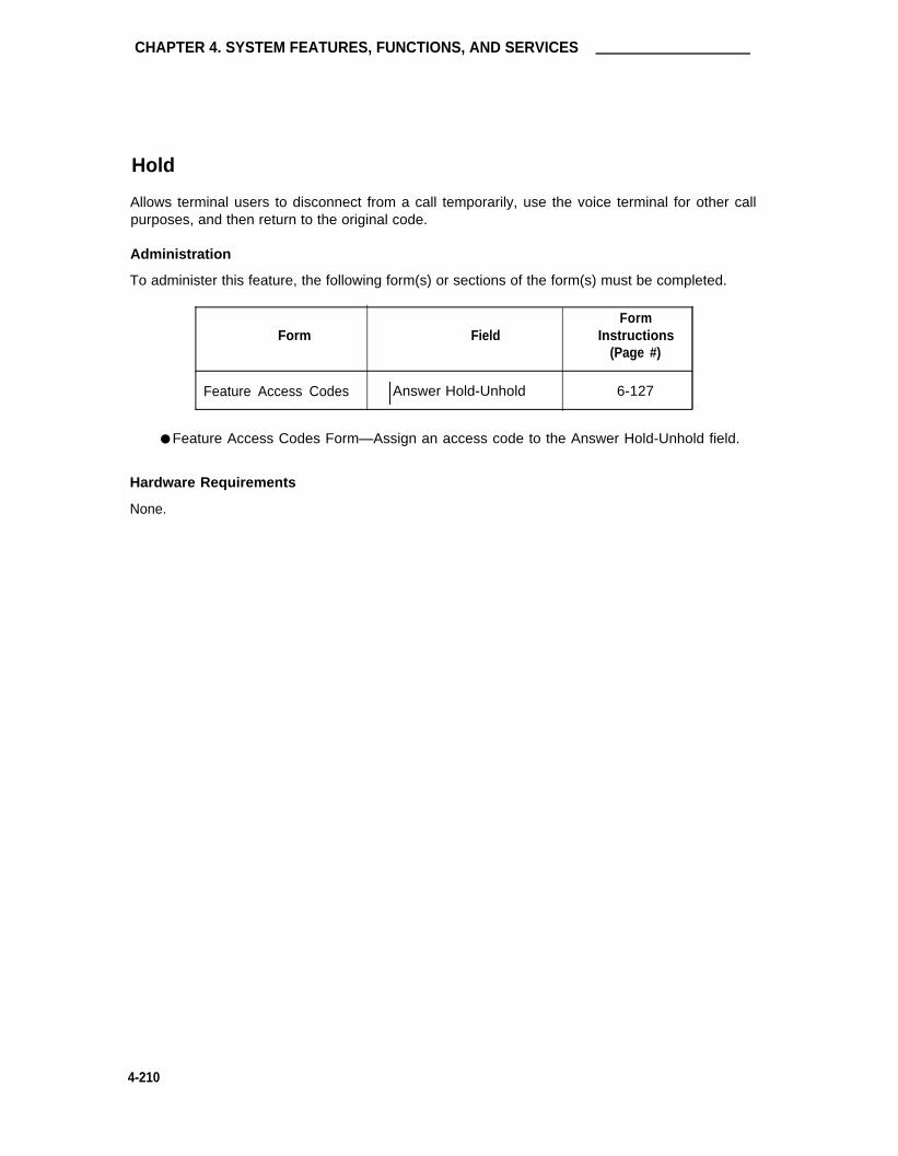
CHAPTER 4. SYSTEM FEATURES, FUNCTIONS, AND SERVICES
Hold
Allows terminal users to disconnect from a call temporarily, use the voice terminal for other callpurposes, and then return to the original code.
Administration
To administer this feature, the following form(s) or sections of the form(s) must be completed.
FormForm Field Instructions
(Page #)
Feature Access Codes Answer Hold-Unhold 6-127
● Feature Access Codes Form—Assign an access code to the Answer Hold-Unhold field.
Hardware Requirements
None.
4-210

Hospitality Services
Hospitality Services
A System with the Hospitality option enabled and Hospitality Parameter Reduction disabled onthe System-Parameters Customer-Options form provides all System capabilities and supports alltypes of customers. A System with both the Hospitality and Hospitality Parameter Reductionoptions enabled provides reduced System parameters that have a major impact on essential Sys-tem features used by non-lodging customers. The Hospitality features set (Auto Wakeup, Do NotDisturb, PMS) is the same on both packages.
The parameters that are reduced when the Hospitality Parameter Reduction option is enabled isshown in Table 4-F. The Standard or Current Package and reduced (New Package) and associ-ated maximums with each parameter are shown.
TABLE 4-F. Hospitality Parameter Reduction
Parameter Standard Package Reduced Package
Trunks 400 50
Hunt Groups 99 5
Pickup Groups 400 5
Call Coverage Paths 600 5
Administration
Both Hospitality and Hospitality Reduced Parameters options must be enabled on the System-Parameters Customer-Options form for a Reduced Parameters System. In addition, associatedhospitality parameters must be administered on the Hospitality-Related System-Parameters form(instructions provided in Chapter 6).
Hardware Requirements
None.
4-211

CHAPTER 4. SYSTEM FEATURES, FUNCTIONS, AND SERVICES
Hot Line Service
Allows single-line voice terminal users, by simply lifting the handset, to automatically place a callto a preassigned extension number, public or private network telephone number, or featureaccess code.
Administration
To implement this feature, the following form(s) or sections of the form(s) must be completed.
FormForm Field Instructions
(Page #)
Station (single-line) Hot Line Destination 6-260Number and Dial Code
Abbreviated Dialing (List 1, 2, 3)
Abbreviated Dialing 7103A List Dial Code (hot line destination) 6-16
Abbreviated Dialing System List Dial Code (hot line destination) 6-13
Abbreviated Dialing Group List Dial Code (hot line destination) 6-8
Abbreviated Dialing Personal List Dial Code (hot line destination) 6-11
Abbreviated Dialing Enhanced List Dial Code (hot line destination) 6-2
Data Modules Special Dialing OptionHot Line DestinationAD List
Data Line 6-89MPDM/MTDM 6-105Netcon 6-109Processor Interface 6-112
●
●
●
Station Forms—On associated Voice Terminal forms, complete the Hot Line Destinationfield to specify the list entry containing the Hot Line Destination. Complete AbbreviatedDialing List 1, 2, 3 field.
Abbreviated Dialing List Forms—Assign the Hot Line Destination to the Abbreviated Dial-ing list.
Data Module Form—Complete the Special Dialing Option field as "hot-line" whererequired. Complete the Hot Line Destination Abbreviated Dialing Code field.
Hardware Requirements
None.
4-212

Hunting
Hunting
Checks for the active or idle status of extension numbers in one or more ordered groups. If allmembers of a group are active, the call can route to another group through Call Coverage or canwait in a queue for an available group member, if a queue is provided.
Refer to ACD DDC, UCD, or Call Coverage. Hunting is implemented via these features, eithersingularly or in combination with each other.
4-213

CHAPTER 4. SYSTEM FEATURES, FUNCTIONS, AND SERVICES
Inbound Call Management
Provides automated handling of incoming calls to ACD splits such as telemarketing centers toincrease ACD agent efficiency and tracking. ACD agent terminal displays can be automated andassociated with new and transferred calls and assist calls to a supervisor. Incoming call informa-tion such as CPN, BN, and DNIS may be displayed on the terminal. Calls can terminate on anICM adjunct such as a CONVERSANT voice system, and the adjunct, using CallVisor ASAl 3rdparty call capabilities, can route the call accordingly. Or, for example, the adjunct can:
1.
2.
Perform a data base search on the caller information (that is, CPN/BN) or call prompter-collected digits
Retrieve caller data to display on a selected agent’s screen based on the service dialed(that is, DNIS).
An ASAI link between the ICM adjunct and the switch allows the adjunct to:
1.
2.
Control incoming calls
Control the routing
If optioned, Direct Agent Calling (DAC) allows the adjunct to direct a call to a paticular ACDagent when required and have the call treated as an ACD call.
Administration
The ACD, ASAl, and appropriate ASAl Capability Groups options must be enabled on theSystem-Parameters Customer-Options form before associated forms and fields on forms can beadministered.
Note: The ASAl Capability Groups are automatically defaulted to "y" when the ASAl inter-face option is enabled.
In addition, if Call Vectoring is to be used with this feature, the Vectoring (Basic) and/or Vectoring(Prompting) options must also be enabled.
In addition to the following administration requirements, refer to the ACD, Call Vectoring, CallPrompting, and CallVisor ASAl features (this chapter) for associated administration requirements.Figure 4-7 (provided with the CallVisor ASAl feature coverage) shows the system connectionsrequired for an adjunct ICM application.
4-214

Inbound Call Management
To implement this feature, the following form(s) or section(s) of forms must be completed:
FormForm Field Instructions
(Page #)
Trunk Group (ISDN-PRI) Per Call CPN/BN 5-195
Hunt Groups Group TypeMessage CenterACDQueueQueue LengthFirst Announcement Delay 6-160
Class of Restriction Direct Agent Calling 6-72
Call Vector All 6-61
Station All(agent stations) 6-245
Station ASAl Interface 6-245
● Trunk Group Form— Administer the Per Call CPN/BN field on the appropriate ISDN-PRItrunk group: Valid entries are "cpn-only," "cpn-pref," "bn-only," and "bn-pref." Thecorresponding information will be sent with a call offered event report to the adjunct. Ifthe field is blank, no CPN/BN information is sent to the adjunct.
● Hunt Group Form—Complete a form for each split to be controlled by the ICM adjunct.Specific entries are:
— Group Type—"ucd" is usually preferred
— Message Center—"none" is typical entry
— ACD—Enter "y"
— Queue—Enter "y"
— Queue Length—Assign a short Queue Length
— First Announcement Delay—Entering "0" implements Forced First Announce-ment (not recommended for ICM)
● COR Form— Enter "y" (yes) in the DAC field on the appropriate COR form to enable theDAC feature for the COR. DAC is only allowed if the call originator and the destinationagent have a COR that allows the DAC.
4-215

CHAPTER 4. SYSTEM FEATURES, FUNCTIONS, AND SERVICES
● Call Vector Form— lf Call Vectoring is to be used, insure that a Call Vector form hasbeen completed. An ASAl link interface extension number is required for an "adjunctrouting" command entered on the form. This extension is the same as that entered onthe station form.
● Station Forms— On the appropriate station forms, complete all ASAl interface fields asrequired to administer agent voice terminals. Queue status feature buttons may beassigned (status lamps are functional after agent login).
Hardware Requirements
Additional hardware requirements for the ASAl port interface are described with the CallVisorASAI feature coverage (this chapter).
4-216

Individual Attendant Access
Individual Attendant Access
Allows users to access a specific attendant console. Each attendant console can be assigned anindividual extension number.
Administration
To implement this feature, the following form(s) or sections of the form(s) must be completed.
Form
Dial Plan
Attendant Console
Console Parameters
●
●
●
Dial Plan Form—Ensure that the First Digit Table Assignments include extension
FormField Instructions
(Page #)
First Digit Table 6-117
Extension and Name 6-32
COR and COS 6-79
numbers to be assigned individual attendants.
Attendant Console Form—Enter attendant extension and name. Assign optional Cover-age and Make Busy feature buttons for Hunting and CAS Backup feature button forstatus indication.
Console Parameters Form—Assign COR and COS.
Hardware Requirements.
None.
4-217

CHAPTER 4. SYSTEM FEATURES, FUNCTIONS, AND SERVICES
Information System Network (ISN) Interface
The AT&T ISN is a packet switched local area network that links mainframe computers, minicom-puters, word processors, storage devices, personal computers, printers, terminals, and communi-cations processors into a single system. The interface to the System is via an ADU.
Figure 4-15 provides a typical ISN interface connection to the System using a port on a TN726BData Line circuit pack.
Administration
To implement this feature, the following form(s) or sections of the form(s) must be completed.
FormForm Field Instructions
(Page #)
Data Line Data Module All 6-89
● Data Line Data Module Form—Complete all fields.
Hardware Requirements
One TN726B Data Line circuit pack is required for each eight ISN interfaces.
FIGURE 4-15. Typical ISN Connection to the System
4-218

Integrated Directory
Integrated Directory
Allows internal System users with display-equipped terminals to access the System data base,use the touch-tone buttons to key in a name, and retrieve an extension number from the Systemdirectory. The directory contains an alphanumeric listing of the names and extension numbers .assigned to all voice terminals administered in the System. Note that the use of VDN names andextensions are not supported for this feature.
The set of characters allowed in the Integrated Directory database are alphabets "A" to "Z" and"a" to "z," numbers "0" to "9," and delimiters "blank" and "," (comma). In addition, the followingspecial characters are allowed: "-" (hyphen), " ‘ " (apostrophe), "." (period), and "&" (ampers-and). These special characters can be entered from the G3-MT and are considered charac-ters. However, the special characters will not be entered into the Integrated Directory. The spe-cial characters are treated as follows:
"." (period)—replaced by a "space""‘" (apostrophe)—ignored"-" (hyphen)—ignored"&" (ampersand)—ignored
If a character outside the allowed set is entered as the name of station or data module, that nameis not included in the Integrated Directory database, and a directory search for that name usingthe "directory" button will fail.
Administration
To implement this feature, the following form(s) or sections of the form(s) must be completed.
FormForm Field Instructions
(Page #)
Station Display Module Button Assignments 6-245(Associated Display -directoryModule Form) -next
-call-disp
Attendant Console Feature/Display Button Assignments 6-32-directory-next-call-disp
7404D Voice Terminal All 6-287(Associated DataModule Form)
• Station Forms—Enter "y" in the Display Module field. Assign an Integrated Directory(directory) display button.
• Display Module Form—Assign one Integrated Directory (directory) display feature button,if desired. If an Integrated Directory button is assigned as a feature button, you cannotassign an Integrated Button on the Display Module, or vice versa. Assign Next andReturn Call (call-disp) buttons also.
4-219

CHAPTER 4. SYSTEM FEATURES, FUNCTIONS, AND SERVICES
●
●
●
Attendant Console Form—Assign one Integrated Directory display feature button. AssignNext and Return Call (call-disp) display buttons also.
7404D Station Form—Assign a "y" to the Display field if a 7404D Messaging Cartridge isattached to the voice terminal. Complete an associated 7404D Data Line Data Modulefo rm.
7404D Station Form—Assign a "y" to the Data Module field if a 7404D Messaging Car-tridge is attached to the voice terminal. Complete an associated Data Module form.
Hardware Requirements
The 7404D voice terminal requires an optional Messaging Cartridge if the terminal is to be con-nected to an associated data terminal. (The data terminal provides display capabilities for the7404D.)
4-220

Integrated Services Digital Network—Basic Rate Interface
Integrated Services Digital Network—Basic Rate Interface
Allows connection of the system to an Integrated Services Digital Network (ISDN) by using astandard ISDN frame format called the Basic Rate Interface (BRI). Also allows connection ofadjunct systems on ASAl interface.
An ISDN provides end-to-end digital connectivity and uses a high-speed interface which providesservice-independent access to switched services. Through internationally accepted standardinterfaces, an ISDN provides circuit- or packet-switched connectivity within a network and canlink to other lSDN-supported interfaces to provide national and international digital connectivity.Two types of ISDN interfaces are currently defined: the PRI and the BRI. This descriptionfocuses on ISDN-BRL (For details on ISDN-PRI, refer to the "Integrated Services DigitalNetwork-Primary Rate Interface" sections in Chapters 4 and 5.)
The ISDN Basic Rate Interface is a 192-Kbps interface that carries two 64-Kbps "B-channels,"which transport voice and/or data, and one 16-Kbps "D-channel," which transport data, signaling,and other bits for framing.
A BRI device (most commonly a terminal) operates at 192 Kbps, and provides bearer serviceover two 64 Kbps B-channels for voice and/or data. A BRI device also has one 16-Kbps D-channel for signaling and/or data. Although BRI supports data transmission on the D-Channel,DEFINITY Generic 3i does not support this capability, and only provides signaling on this chan-nel. ISDN-BRI provides much of the same functionality that is provided with the DCP. ASAIinterfaces use only the 16-Kbps D-Channel.
Note: The term "endpoints" is used in statements that apply to a BRI voice terminal, a BRIdata module, and a BRI integrated terminal such as an integrated voice/data termi-nal.
BRI Endpoint Configurations
With ISDN-BRI, there are two possible configurations:
●
●
point-to-point—only one endpoint connected on a BRI port
multipoint—multiple endpoints connected on a BRI port. This configuration is alsoreferred to as "passive bus" configuration.
Because DEFINITY G3i BRI implementation provides non-blocking voice and data services, thenumber of endpoints supported on one BRI port in multipoint configuration is restricted to a max-imum of two.
As stated previously, each BRI interface has two B-channels. B-Channels are resources whichare dynamically chosen by the switch or BRI endpoints for voice or data service requests.Because there are two B channels, only two simultaneous service requests can be granted atany one time on a BRI port to provide non-blocking service, either through point-to-point or mul-tipoint configurations.
When one endpoint, such as the integrated voice/data endpoint, is capable of providing two ser-vice requests, it must be configured point-to-point, because both B-channels can potentially beused simultaneously by the two services. Currently, in the point-to-point configuration, you canhave the following endpoint types:
4-221

CHAPTER 4. SYSTEM FEATURES, FUNCTIONS, AND SERVICES
● 1 voice-only endpoint
● 1 stand-alone data endpoint
● 1 integrated voice/data endpoint (See note below).
Two endpoints, each capable of providing only one service request, can be administered on thesame BRI port. These two endpoints are thus configured as multipoint. Here again, both Bchannels can potentiality be used simultaneously by the two service requests. Therefore, nomore endpoints can be administered on the same BRI port. In multipoint configuration, you canhave:
● 2 voice-only endpoints
● 2 stand-alone data endpoints
● 1 voice-only endpoint and 1 stand-alone data endpoint.
Note: Although the integrated voice/data endpoint supports two services requests, it is notconsidered to be in multipoint configuration since it is only one endpoint.
Service Profile Identifier (SPID)
When more than one endpoint is connected on a BRI port, the switch associates endpoints withthe administered station or data module extensions using a Service Order Profile Identifier(SPID). A SPID is administered on the station or data module forms and is programmed in theBRI endpoint using the procedure described in Appendix A. The endpoint sends the SPID to theswitch during initialization. The SPID administered on the station or data module administrationforms must match the SPID which is programmed into the endpoint. If they don’t match, the sys-tem will restrict service to such endpoint. Therefore, the SPID administration and programmingof the SPID into the endpoint is required for multipoint configuration. When there is only one end-point connected to the BRI port, the SPID administration is optional. However, if the SPID isadministered, it must match the SPID programmed into the endpoint. If the SPID is not admin-istered, the switch will use the port to associate the endpoint with the administered station or datamodule extension.
ISDN-BRI Data Services
Data transmission on ISDN-BRI is provided by the 7500B Data Module and the ADM. The7500B Data Module is a stand-alone unit that supports asynchronous or synchronous DCE andasynchronous DTE. In asynchronous mode, the 7500B supports packet or circuit-switched datacommunications, and can be controlled via the front panel or the keyboard of a connected termi-nal. In synchronous mode, the 7500B supports circuit-switched or nailed-up data communica-tions, requires either the Multipurpose Enhancement Board or the High Speed SynchronousEnhancement Board, and can only be controlled via the front panel.
The ADM may be used with asynchronous DTE as a data stand for 7500-series BRI voice termi-nals. Consisting of a circuit pack located inside the BRI voice terminal, the ADM allows thetransmission of integrated voice and data through one voice terminal. The ADM supports theHayes command set for compatibility with PC communications packages.
The system can support a maximum of 800 data modules. This value includes both BRI andDCP data modules.
4-222
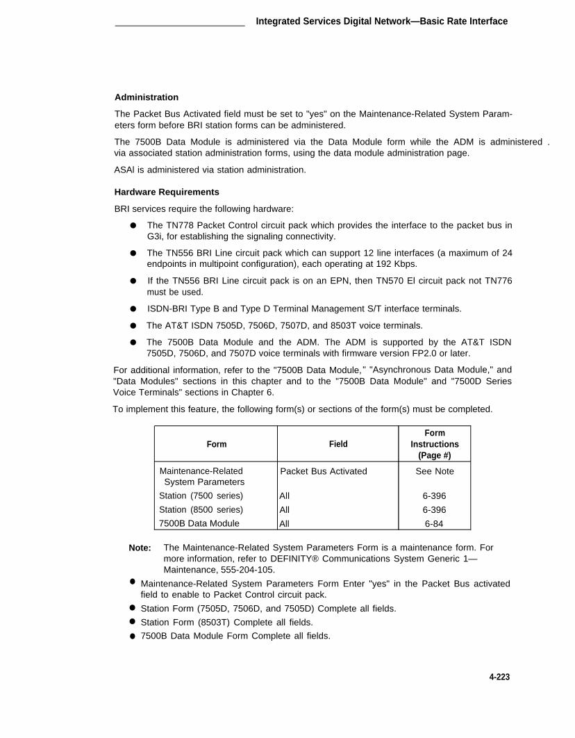
Integrated Services Digital Network—Basic Rate Interface
Administration
The Packet Bus Activated field must be set to "yes" on the Maintenance-Related System Param-eters form before BRI station forms can be administered.
The 7500B Data Module is administered via the Data Module form while the ADM is administered .via associated station administration forms, using the data module administration page.
ASAl is administered via station administration.
Hardware Requirements
BRI services require the following hardware:
●
●
●
●
●
●
The TN778 Packet Control circuit pack which provides the interface to the packet bus inG3i, for establishing the signaling connectivity.
The TN556 BRI Line circuit pack which can support 12 line interfaces (a maximum of 24endpoints in multipoint configuration), each operating at 192 Kbps.
If the TN556 BRI Line circuit pack is on an EPN, then TN570 El circuit pack not TN776must be used.
ISDN-BRI Type B and Type D Terminal Management S/T interface terminals.
The AT&T ISDN 7505D, 7506D, 7507D, and 8503T voice terminals.
The 7500B Data Module and the ADM. The ADM is supported by the AT&T ISDN7505D, 7506D, and 7507D voice terminals with firmware version FP2.0 or later.
For additional information, refer to the "7500B Data Module, " "Asynchronous Data Module," and"Data Modules" sections in this chapter and to the "7500B Data Module" and "7500D SeriesVoice Terminals" sections in Chapter 6.
To implement this feature, the following form(s) or sections of the form(s) must be completed.
FormForm Field Instructions
(Page #)
Maintenance-Related Packet Bus Activated See NoteSystem Parameters
Station (7500 series) All 6-396
Station (8500 series) All 6-396
7500B Data Module All 6-84
Note: The Maintenance-Related System Parameters Form is a maintenance form. For
●
●
●
●
more information, refer to DEFINITY® Communications System Generic 1—Maintenance, 555-204-105.
Maintenance-Related System Parameters Form Enter "yes" in the Packet Bus activatedfield to enable to Packet Control circuit pack.
Station Form (7505D, 7506D, and 7505D) Complete all fields.
Station Form (8503T) Complete all fields.
7500B Data Module Form Complete all fields.
4-223

CHAPTER 4. SYSTEM FEATURES, FUNCTIONS, AND SERVICES
Integrated Services Digital Network-Primary Rate Interface
Provides end-to-end digital connectivity within the network and can provide national and interna-tional digital connectivity to other Integrated Services Digital Networks (ISDNs) that support thePrimary Rate Interface (PRI) standard.
Note: For administration information associated with an ISDN Gateway adjunct (that is,3B2 or 6386 computer) used in support of the CPN/BN feature, refer the CPN/BNcoverage (this Chapter).
Administration
The ISDN-PRI option must be enabled on the System-Parameters Customer-Options form beforeassociated forms and fields on forms can be administered.
To implement this feature, the following form(s) or sections of the form(s) must be completed.
Field
●
●
●
4-224
Form
DS1 Circuit Pack
Signaling Group
Synchronization Plan
Processor Interface Data Module
Interface Links
Processor Channel Assignment
ISDN-PRI Trunk Group
CPN Prefix Table
Routing Patterns
Hunt Groups
Terminating Extension Group
All
All
All
All
All
All
All
All
All
ISDN Caller Display
ISDN Caller Display
FormInstructions
(Page #)
5-65
5-61
6-209
6-112
6-175
6-194
5-195
5-79
5-29
6-160
5-92
DS1 Circuit Pack Form—Assign all fields as required. For FAS, up to 23 ports are avail-able for administration as trunk members in an associated ISDN-PRI trunk group. The24th port is utilized as a signaling channel. For Non-Facility Associated Signaling, all 24ports may be used on certain DS1 circuit packs. The D-Channel signaling function forthese packs must be provided by a designated DS1 pack on it's 24th channel.
Signaling Group Form—Complete all fields. This form is used to identify groups ofISDN-PRI DS1 interface B-Channels for which a given D-Channel (or D-Channel pair) willcarry the associated signaling information (supports the FAS and NFAS).
Synchronization Plan Form—Used to assign primary and secondary external synchroni-zation sources for the DS1 circuit pack. Complete all fields of the form as required.

Integrated Services Digital Network-Primary Rate Interface
●
●
●
●
●
●
●
●
Processor Interface Data Module Form—Assign up to eight interface links using eightProcessor Interface Data Module forms for multi-carrier cabinet Systems and up to fourlinks for single-carrier cabinet Systems. One Processor Interface Data Module formmust be completed for each interface link to be assigned.
Interface Links Form—Assign link numbers 01 through 08 for a multi-carrier cabinet Sys-tem or links 01 through 04 for a single-carrier cabinet System as required. (See Notefollowing this listing.)
Processor Channel Assignments Form—Enter assigned link numbers and assign associ-ated channel numbers to each link. Complete all fields of the form as required. (SeeNote following this listing.)
ISDN-PRI Trunk Group Form—Complete all fields as required.
CPN Prefix Table Form—Complete all fields. This form is used to support the ISDN-PRICall Identification Display feature.
Routing Pattern Form—Complete all fields including the Supplemental ISDN RoutingInformation fields as required.
Hunt Group Form—Complete the ISDN Caller Display field by entering either "grp-name"or "mbr-name" to specify whether the hunt group name or member name, respectively,will be sent to the originating user (used in support of the ISDN-PRI Call IdentificationDisplay feature).
Terminating Extension Group (TEG) Form—Complete the ISDN Caller Display field byentering either "grp-name" or "mbr-name" to specify whether the group name or membername, respectively, will be sent to the originating user (used in support of the ISDN-PRICall Identification Display feature).
Note: When first administering the Interface Links/Processor Channel Assignments formsin the System for ISDN:
1. Administer the required fields for ISDN on the Interface Links form exceptthe "Enable" field.
2. Administer the required fields on the Processor Channel Assignments formfor ISDN.
3. Finally administer the "Enable" field on the Interface Links form.
Hardware Requirements
Requires a TN767 DS1 Tie Trunk circuit pack for assignment of a signaling link and up to 23ISDN-PRI Trunk Group members. The DS1 provides 24 ports. A TN768 Tone Clock circuit packis required to provide synchronization for the DS1 circuit pack. Also requires use of a TN765Processor Interface circuit pack for assignment of associated links.
Voice terminals equipped with displays are required to display ISDN-PRI Call Identification infor-mation.
4-225

CHAPTER 4. SYSTEM FEATURES, FUNCTIONS, AND SERVICES
Intercept Treatment
Provides an intercept tone or a recorded announcement or routes the call to an attendant forassistance when calls cannot be completed or when use of a feature is denied. Note that a VDNextension cannot be administered to receive intercept treatment.
Administration
To implement this feature, the following form(s) or sections of the form(s) must be completed.
Form
Feature-Related SystemParameters
Recorded Announcements
FormField Instructions
(Page #)
DID/Tie/lSDN InterceptTreatment
Controlled Restrictions 6-133
Port Assignments (1-128) 6-198
●
●
Feature-Related System Parameters Form—Complete the following fields:
— DID/Tie/lSDN Intercept Treatment—This entry (extension number or 0 for theattendant) is to be used for intercepting invalid DID and/or tie trunk calls.
— Controlled Outward Restriction Intercept Treatment—This entry determines thetype of intercept treatment the caller receives on outward restricted calls.
— Controlled Termination Restriction (Do Not Disturb)—This entry determines thetype of intercept treatment a caller receives when a call is placed to a terminationrestricted voice terminal.
— Controlled Station-to-Station Restriction—This entry determines the type of inter-cept treatment the caller receives when a call is placed to a restricted voice ter-minal.
Recorded Announcements Form—Assign intercept announcement extension number, ifused.
Hardware Requirements
Requires announcement equipment and a port on a TN742, TN746B, or TN769 Analog Line cir-cuit pack for each announcement device to be assigned. A TN750 Announcement circuit packcan be used to provide up to 16 different announcements. The announcements can be directlyrecorded onto the TN750 circuit pack (does not require announcement equipment).
4-226

lntercom—Automatic
lntercom—Automatic
Provides a talking path between two voice terminal users. Calling users press the AutomaticIntercom button and lift the handset, or vice versa. The called user receives a unique intercomalerting signal, and the status lamp associated with the Dial or Automatic Intercom button, if pro-vided, flashes.
Administration
To implement this feature, the following form(s) or sections of the form(s) must be completed.
Form
Intercom Groups
Station (multi-appearance)
FieldForm
Instructions(Page #)
Group MemberAssignments
Button/Feature ButtonAssignments-auto-icom
(Grp:_ DC:_)
6-172
6-245
● Intercom Groups Form—Complete intercom-dial fields.
● Station Forms—Assign Auto Intercom (auto-icom) button(s).
Hardware Requirements
None.
4-227

CHAPTER 4. SYSTEM FEATURES, FUNCTIONS, AND SERVICES
Intercom-Dial
Allows multi-appearance voice terminal users to gain rapid access to as many as 32 other voiceterminal users within an administered group. Calling voice terminal users lift the handset, pressthe Dial Intercom button, and dial the 1- or 2 - digit code assigned to the desired party. The calleduser receives alerting tone, and the status lamp associated with the Intercom button, if provided,flashes.
Administration
To implement this feature, the following form(s) or sections of the form(s) must be completed.
Form
Intercom Groups
Station (multi-appearance)
Field
All
Button/Feature ButtonAssignments-dial-icom (Grp:_)
FormInstructions
(Page #)
6-172
6-245
● Intercom Groups Form—Establish intercom groups.
● Station Forms—Assign Dial Icom buttons on voice terminals for all intercom groupmembers who can originate an intercom call. Anyone in a group can be called, but onlythose members with an assigned Intercom button can originate an intercom call.
Hardware Requirements
None.
4-228

International Toll/Code Restriction (International G1.1SE only)
International Toll/Code Restriction (International G1.1SE only)
Note: The following information on implementing calling restrictions is only needed forG1.1SE systems. With G1.2SE, these methods for implementing calling restrictionsare not needed because of the G1.2SE's implementation of Multi-National Call Rout-ing and Multi-National Toll Analysis, which provide for calling restrictions.
For International G1.1SE systems, USA Toll and Code Restriction features will work as in stan-dard G1.1 systems only if both the public network dialing plan and the G1.1SE follow the NorthAmerican Numbering Plan (that is, 7- and 10-digit dialing and other USA-specific restrictions). Ifthe switch has a North American Numbering Plan but the CO doesn’t, then the system adminis-trator should proceed as described in the two methods outlined below.
The use of the USA Toll Restriction feature requires that long-distance and operator-assistedcalls begin with a "1" or a "0." The USA Toll Restriction feature is implemented by administeringCO and FX trunk groups as toll restricted and then administering certain COR codes as toll res-tricted. Finally, stations assigned the COR whose calls are routed over the trunk groups areprevented from placing "1" or "0" calls unless the dialed digits are on the system’s "Allowed CallsList." As a result of using another dial plan, USA Toll Restriction cannot be implemented whenlong-distance and operator-assisted calls begin with digits other than "1" or "0," respectively.(However, if the switch is being used in a country that doesn’t use "1" or "0" as the first digits oftoll calls, it is still possible for the switch to perform a kind of toll restriction using the two methodsdescribed below.)
The USA Code Restriction feature denies the calling party completion of outgoing calls to desti-nations whose numbers have selected initial three digits (within the local calling area), specialservice, and area codes. Code Restriction applies when a code restricted user (controlled byCOR) accesses a CO or FX trunk group whose Restriction field is set to "code." The systemthen checks appropriate Code Restriction tables to determine if the call will be allowed or sent tointercept. These Code Restriction tables can be for local calling areas (called HNPAs in standardG1.1 Systems) or for long-distance calling areas (called FNPAs or Foreign Numbering PlanAreas or FNPAs in standard G1.1 Systems). Code Restricted calls are routed over CO or FXtrunks which require 7- or 10-digit dialing strings. As a result, the USA Code Restriction featurecannot be implemented in systems with 3-, 5-, 6-, or 8-digit dial plans, for example, because thetrunk group requires 7-or 10-digit dialing.
We have discussed why you can use the built-in USA Code Restriction feature only if you are in acountry that uses 7- or 10-digit dial plans similar to the USA. But in other countries, you cancreate practically the same kind of calling restrictions by one of the following two methods.Method 1 below describes a way to implement call restrictions and Method 2 describes a way toimplement the handling of special numbers (such as USA service codes 411 and 811).
4-229

CHAPTER 4. SYSTEM FEATURES, FUNCTIONS, AND SERVICES
Method 1 Calling restrictions can be implemented using ARS and FRLs. Translationsshould be implemented primarily using entries in the ARS FNPA table (for long-distance areas). While the meanings of the various dial plan entries may changefrom location to location, the basic format should remain intact. Restriction isaccomplished by using the FRLs for the various ARS Routing Patterns. ARSand FRLs are described in their own sections in this chapter. Call processingcan be controlled as follows:
●
●
●
Local Calls— Route calls based on the first three dialed numbers usingthe ARS HNPA table.
National Toll Calls— Generally of the format 0NX...X. These calls routevia the ARS FNPA table, entry 001 (labeled "Operator Assist" in thestandard manual). At locations where 01X...X translations are required,ARS FNPA entry 012 should be set to the same pattern as entry 001.
International Toll Calls— Generally of the format 00NX...X. Theseroute by the ARS FNPA table entry 003 (labeled "IXC Operator Assist" inthe standard manual). At locations where 000/001 call routing isrequired, where 00 is used by itself for international access and some-times followed by a "1" (country code for USA and Canada), then theARS FNPA entry 004 should be set to the same pattern as entry 003.
ARS FNPA entry 000 and 002 should also be set to the same pattern asentry 003 to prevent unauthorized access to toll facilities.
Method 2 When using special numbers such as service codes, the numbers should betranslated using Privileged Abbreviated Dialing lists as described in the "Abbrevi-ated Dialing" section of this chapter or by defining empty Hunt Groups and for-warding calls to those groups to the appropriate outside numbers.
4-230

Inter-PBX Attendant Calls
Inter-PBX Attendant Calls
Allows attendant positions for more than one branch location to be concentrated at one central,or main location. Incoming trunk calls to the branch location, as well as attendant-seeking voiceterminal calls, are routed over tie trunks to the attendants at the main location.
Administration
To implement this feature, the following form(s) or sections of the form(s) must be completed.
FormForm Field Instructions
(Page #)
Tie Trunk Group (Main) Incoming Destination 5-247
Console Parameters (Branch) IAS (Branch)
IAS Tie Trunk Group No.
IAS Att. Access Code 6-79
Tie Trunk Group (Branch) All 5-247
● Tie Trunk Group Form (Main)—Requires a Tie Trunk Group with the Incoming Destina-tion field set to the attendant group access code (typically 0).
● Console Parameters Form (Branch)—Enter "y" in the IAS (Branch) field. The IAS(Branch) and CAS fields cannot both be "y." Assign an "IAS Trunk Group Number" andan "Inter-PBX Attendant Access Code."
● Tie Trunk Group Form (Branch)—Requires a tie trunk group connected to the CAS Main(this is the trunk group referral to as "IAS Tie Trunk Group No." on the Console Parame-ters form.
Hardware Requirements
Requires a port on a TN722B or TN767 DS1 Tie Trunk circuit pack for each tie trunk to beassigned.
4-231

CHAPTER 4. SYSTEM FEATURES, FUNCTIONS, AND SERVICES
Intra-switch SMDR
Note: This section describes the implementation of the Intra-switch SMDR feature. Foradministrative information on SMDR, refer to the "Station Message Detail Recording(SMDR)" section in this chapter.
An administrable option that allows SMDR records to be generated for some internal calls. lntra-switch SMDR records are generated by an internal direct call that is originated by an extensionthat is optioned for intra-switch SMDR or that has a dialed number which is optioned for intra-switch SMDR.
For an Intra-switch SMDR record to be generated, one of the stations involved in a call musthave been optioned for the Intra-switch SMDR call. Intra-switch will or will not generate a recordbased on the DIALED number (assuming the originator is not intra-switch optioned), but thenumber which is actually displayed in the dialed number field will be determined by the adminis-tration of group/member/VDN information.
Some calls may look like intra-switch SMDR calls, but will result in trunk calls. For example, acall from a station to a VDN will be routed as an outgoing call on trunk T1. Such calls will not gen-erate Intra-switch SMDR records.
Note: When a trunk SMDR record and an intra-switch SMDR record are involved in a calldue to transfers or conferences, an attempt will be made to preserve intra-switchrecords. For example, if A (which has administered with the intra-switch SMDRoption) calls B (which has not been administered with the intra-switch SMDR option),and B then transfers the call to T1, an intra-switch record would be generated for theactivity between A and B before the transfer. The portion of the call between B andT1 would be output as an outgoing trunk record. However, if A calls T1, the outputwould be a trunk record.
The originating extension for ACA and SVN (that is, referral) calls cannot be admin-istered with the intra-switch option. However, the destination extension can beadministered with the intra-switch option.
Administration
To implement the Intra-switch SMDR feature, the following form must be completed.
FormForm Field Instructions
(Page #)Intra-switch SMDR All 6-180
Feature-Related System Parameters Intra-switch SMDR 6-133
The Intra-switch SMDR form has 100 fields. Allowed extensions on the form must correspond toTEGs, stations, data modules, VDNs, or hunt groups. Attendants are not allowed to be optionedon the Intra-switch SMDR form. To add the Intra-switch feature to an extension, add the exten-sion to the form. The change intra-switch-smdr and display intra-switch-smdr commands aresupported for this feature.
Note: The Intra-switch SMDR feature is not supported for ASAl stations.
4-232

Intraflow and Interflow
Intraflow and Interflow
Allows ACD calls to be redirected from one split to another split under busy or unanswered condi-tions. Intraflow provides redirection of ACD calls to other splits within the system. Interflow usesthe Call Forwarding All Calls feature to redirect ACD calls to an external location and requires nofurther administration.
Administration
To implement the Intraflow feature, the following form(s) or sections of the form(s) must be com-pleted in addition to ACD administration requirements.
Form
Feature-Related SystemParameters
Hunt Groups
Call Coverage Paths
Field
Coverage—Don’tAnswer Interval forSubsequent Redirection
Inflow Threshold
Priority on Intraflow
Don’t AnswerBusyNumber of Rings
FormInstructions
(Page #)
6-133
6-160
6-55
●
●
●
Feature-Related System Parameters Form—Assign the number of times a voice terminalin a Call Coverage path will ring before the call is routed to the next coverage point.
Hunt Group Form—Assign "y" to the Priority On Interflow field if calls incoming from thissplit to a covering split will have priority over calls waiting in the covering split’s queue.Assign the number of seconds in the Inflow threshold field that a call will remain in thequeue before no more calls will be accepted by the queue.
Call Coverage Paths Form—Complete the Coverage Criteria Busy and Don’t Answerfields for both inside and outside calls. Assign the Number of Rings field to the rings thatwill occur at an agent’s terminal before an unanswered call is redirected to the first cover-age point.
Hardware Requirements
None.
4-233

CHAPTER 4. SYSTEM FEATURES, FUNCTIONS, AND SERVICES
Last Number Dialed
Automatically redials the last number dialed when users press the Last Number Dialed button ordial the Last Number Dialed feature access code.
Administration
To implement this feature, the following form(s) or sections of the form(s) must be completed.
Form
Feature Access Codes
Station (multi-appearance)
Attendant Console
Field
Last Number DialedAccess Code
Button/Feature ButtonAssignments-last-numb
Feature ButtonAssignments-last-numb
FormInstructions
(Page #)
6-127
6-245
6-32
●
●
●
Feature Access Codes Form—Verify Last Number Dialed Access Code field.
Station Forms—Assign Last Number Dialed (last-numb) button to voice terminal.
sole.
Hardware Requirements
None.
Attendant Console Forms—Assign Last Number Dialed (last-numb) button to the con-
4-234

Leave Word Calling
Leave Word Calling
Allows internal system users to leave a short preprogrammed message for other internal users.Users can activate Leave Word Calling (LWC) at any time during a call attempt. Note that theLWC messages cannot be stored, canceled, or retrieved for VDN extensions.
Administration
To implement this feature, the following form(s) or sections of the form(s) must be completed.
FormForm Field Instructions
(Page #)
Feature-Related System Max. Number OfParameters Messages Per Station
Stations With System-Wide 6-133Message RetrievalPermission
Station LWC ReceptionLWC ActivationButton/Feature/ButtonAssignments
-Iwc-store-Iwc-cancel-aut-msg-wt (Ext:_)-call-disp-msg-retr-next-delete-msg-lwc-lock-cov-msg-rt 6-245
Attendant Console Feature ButtonAssignments
-Iwc-store-Iwc-cancel-delete-msg-next-call-disp-aut-msg-wt (Ext:_) 6-32
Feature Access Codes LWC Message RetrievalLock
LWC Message RetrievalUnlock
LWC Send A Message
LWC Cancel A Message 6-127
4-235

CHAPTER 4. SYSTEM FEATURES, FUNCTIONS, AND SERVICES
Note: Refer to the Attendant Display and Voice Terminal Display features for additionalinformation on LWC feature related buttons that can be assigned an attendant con-sole or voice terminal display.
●
●
●
Feature-Related System Parameters Form—Complete the Maximum Number of Mes-sages Per Station and Stations with System-wide Retrieval Permission fields.
Station Forms—Complete the LWC Reception and LWC Activation fields (which specify ifthe voice terminal can receive and/or activate LWC messages, respectively).
— Assign a LWC button, if desired.
— Assign a Cancel button, if desired, to allow a calling party to cancel a previouslyleft message.
— Automatic Message Waiting. (The buttons associated status lamp lights at thesame time the message lamp lights at the called voice terminal. A common useis to provide an indication of an extension’s messages on a secretary’s voice ter-minal. This lamp also provides an indication of LWC messages left for a DDCgroup, a UCD group, an ACD split, a TEG or PCOL group.)
Attendant Console Form or the Station Form—For each voice terminal or attendant con-sole group that can retrieve LWC messages, optionally assign the following buttons:
—
—
—
—
—
—
—
—
Message Retrieval (to access one’s own messages-voice terminals only)
Coverage Msg Retrieval (to access another user’s message)
Delete Message (to remove a retrieved message)
Call Display (to automatically call the person who left the message while display-ing a retrieved message)
Lock (displays locked or unlocked status of the Message Retrieval)
Next (to retrieve the next stored message)
Cancel LWC (to allow canceling a previously left message)
Automatic Message Waiting (the buttons associated indicator is used to indicatea remote message waiting).
Note: Buttons can be assigned on the visual display module or in the "features area" of theterminal or console. If a Message Retrieval or a Coverage Message Retrieval buttonis specified, a Next Message and a Delete Message button should also be specified.
● Feature Access Codes Form—Verify or assign the following access codes:
— LWC Message Retrieval Lock field
— LWC Message Retrieval Unlock field
— LWC Send a Message field
— LWC Cancel a Message field.
Hardware Requirements
None.
4-236

Lookahead Interflow
Lookahead Interflow
Provides a flexible and intelligent ACD load balancing capability based on programmable call vec-tors. It enhances the Call Vectoring (CV) feature so that calls will not interflow to a remote loca-tion that cannot accept the calls. This service is provided by the use of private network ISDN-PRIconnections. The receiving switch may accept or deny the lookahead calls and the sendingswitch has the option to initiate lokahead interflow to an alternate backup location.
Note that the receiving switch must have the Call Vectoring and the Lookahead Interflow featuresactive also. In addition, all Lookahead Interflow calls must connect ISDN-PRI switch-to-switchusing private facilities.
The Lookahead Interflow, ISDN-PRI, and CV (Basic) options must be enabled on the System-Parameters Customer-Options form.
Administration
To implement this feature, the following forms or sections of forms must be completed:
Note: Refer to the CV feature coverage in this chapter for associated CV administrationinformation.
F o r m Field
Trunk Group(ISDN-PRI)
CPN Prefix Table
-Display, TCM, LookaheadCodeset
-Outgoing Display
-Ext Len-Ext Code-CPN Prefix
FormInstructions
(Page #)
5-195
5-79
●
●
Trunk Group Form (lSDN-PRl)—lf the far-end switch can only receive Lookahead lnter-flow information in Codeset 7 (for example, System 85 R2V4) the Display, TCM, Looka-head Codeset field must be administered as "7." For switches that can receive the infor-mation in either codeset six or seven. Default is "6."
For those System’s that do not want the call originator’s display to be updated on eachLookahead Interflow call attempt, lookahead calls should be routed over trunk groupswith the Outgoing Display field set to "n."
CPN Prefix Table Form—Administer a CPN Prefix for each VDN that maps to a call vec-tor that is used to place Lookahead Interflow calls. Failure to administer a CPN/Prefixresults in a Lookahead Interflow DNIS of all spaces being sent to and displayed on theanswering agent’s terminal.
4-237

CHAPTER 4. SYSTEM FEATURES, FUNCTIONS, AND SERVICES
Hardware Requirements
Existing ISDN-PRI hardware can be used for Lookahead Interflow ISDN-PRI connectivity to thereceiving switch. Interconnecting facilities must be ISDN-PRI with no interworking (that is, callconnections that use both ISDN-PRI and non-lSDN-PRl facilities to complete) for the full capabili-ties of the feature to be operational. Lookahead Interflow calls which interwork may interflow suc-cessfully, but the ability to do so on an intelligent basis will be lost as will the lookahead DNISinformation.
4-238
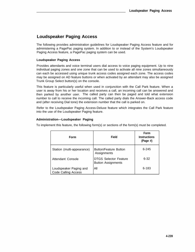
Loudspeaker Paging Access
Loudspeaker Paging Access
The following provides administration guidelines for Loudspeaker Paging Access feature and foradministering a PagePac paging system. In addition to or instead of the System’s LoudspeakerPaging Access feature, a PagePac paging system can be used.
Loudspeaker Paging Access
Provides attendants and voice terminal users dial access to voice paging equipment. Up to nineindividual paging zones and one zone that can be used to activate all nine zones simultaneouslycan each be accessed using unique trunk access codes assigned each zone. The access codesmay be assigned on AD feature buttons or when activated by an attendant may also be assignedTrunk Group Select button(s) on the console.
This feature is particularly useful when used in conjunction with the Call Park feature. When auser is away from his or her location and receives a call, an incoming call can be answered andthen parked by another user. The called party can then be paged and told what extensionnumber to call to receive the incoming call. The called party dials the Answer-Back access codeand (after receiving Dial tone) the extension number that the call is parked on.
Refer to the Loudspeaker Paging Access-Deluxe feature which integrates the Call Park featureinto the use of the Loudspeaker Paging feature.
Administration—Loudspeaker Paging
To implement this feature, the following form(s) or sections of the form(s) must be completed.
FormForm Field Instructions
(Page #)
Station (multi-appearance) Button/Feature Button 6-245Assignments
Attendant Console DTGS Selector Feature 6-32Button Assignments
Loudspeaker Paging and All 6-183Code Calling Access
4-239

CHAPTER 4. SYSTEM FEATURES, FUNCTIONS, AND SERVICES
●
●
●
●
●
●
FormForm Field Instructions
(Page #)
Feature-Related System Call Park Timeout IntervalParameters
Deluxe Paging and Call 6-133
Park Timeout to Originator
Dial Plan First Digit Table 6-117
Console Parameters Common Shared Extensions 6-79
Class of Service Console Permission 6-77
Station/Attendant Console Forms—Up to 10 (one per zone) Loudspeaker Paging Accessbuttons (per multi-appearance voice terminal and attendant console) can be assignedthrough the Attendant Direct Trunk Group Selection, AD, and the Facility Busy Indicationfeatures, if required.
Loudspeaker Paging and Code Calling Access Form—Complete Loudspeaker Pagingfields.
Feature-Related System Parameters Form—Enter in the Call Park Timeout Interval field,the desired time in minutes that a call can remain parked before it is canceled. Enter "n"in the Deluxe Paging and Call Park Timeout to Originator field. (All parked calls that timeout are returned to the attendant console.)
Dial Plan Form—Assign the length (one through three digits) of the trunk access code tobe used to activate Loudspeaker Paging Access.
Console Parameters Form—Complete the Common Shared Extensions fields that areexclusively used for Call Park.
COS Form—Complete the Console Permission field on those Class of Service forms thatwill allow associated voice terminal users to park calls on the attendant consoles "Com-mon Shared Extensions."
Hardware Requirement—Loudspeaker Paging
Requires loudspeaker paging equipment and a port on a TN763C Auxiliary Trunk circuit pack foreach individual paging zone port (maximum of nine) to be assigned. In addition, paging interfacehardware consisting of a 278A Adapter and a 24-volt power supply is required per paging zone.(This hardware can be shared with the Code Calling Access feature. Each feature is activatedvia an assigned trunk access code.) Associated wiring information is provided in the DEFINITY®Communications System Generic 1 and Generic 3i—Wiring, 555-204-111.
4-240

Loudspeaker Paging Access
PagePac Paging
In addition to, or instead of the System loudspeaker paging equipment, a PagePac paging sys-tem can be used. A PagePac paging system has an advantage over the System’s LoudspeakerPaging Access feature in that a PagePac system requires only one port to provide as many as 39paging zones. The System’s Loudspeaker Paging Access feature requires a separate port foreach paging zone with a maximum of nine zones.
PagePac equipment is easy to use. A user simply dials the trunk access code assigned to thePagePac system. This connects the user to the PagePac equipment. If there is only one pagingzone, the user then uses the handset of the voice terminal to page someone. If there are multi-ple zones, the user, after hearing a steady tone, dials a 1- or 2-digit code to access the desiredzone(s) before paging.
Administration—PagePac Paging
To implement this feature, the following form(s) or sections of the form(s) must be completed.
Form
CPE Trunk Group
Feature-Related SystemParameters
Dial Plan
Console Parameters
Class of Service
Field
All
Call Park Timeout Interval
First Digit Table
Common Shared Extensions
Console Permission
FormInstructions
(Page #)
5-137
6-133
6-117
6-79
6-77
●
●
●
CPE Trunk Group Form—Complete a CPE Trunk Group form and associated membernumber to assign a TN763C Auxiliary Trunk port interface to the PagePac paging equip-ment. Assign the TAC that will be used to access the paging equipment.
Note that the administration of this port and associated PagePac paging zones is not pro-vided for on the Loudspeaker Paging and Code Calling Access form. The port must beadministered using a CPE Trunk Group form. Support for single or multiple zone pagingis provided by the PagePac system and is not administered on the switch. Associatedwiring information is provided in the DEFINITY® Communications System Generic 1 andGeneric 3i—Wiring, 555-204-111.
Feature-Related System Parameters Form—Enter in the Call Park Timeout Interval field,the desired time in minutes that a call can remain parked before it is canceled. (Allparked calls that time out are returned to the attendant console.)
Dial Plan Form—Assign the length (one to three digits) of the trunk access code to beused to activate the paging equipment.
4-241
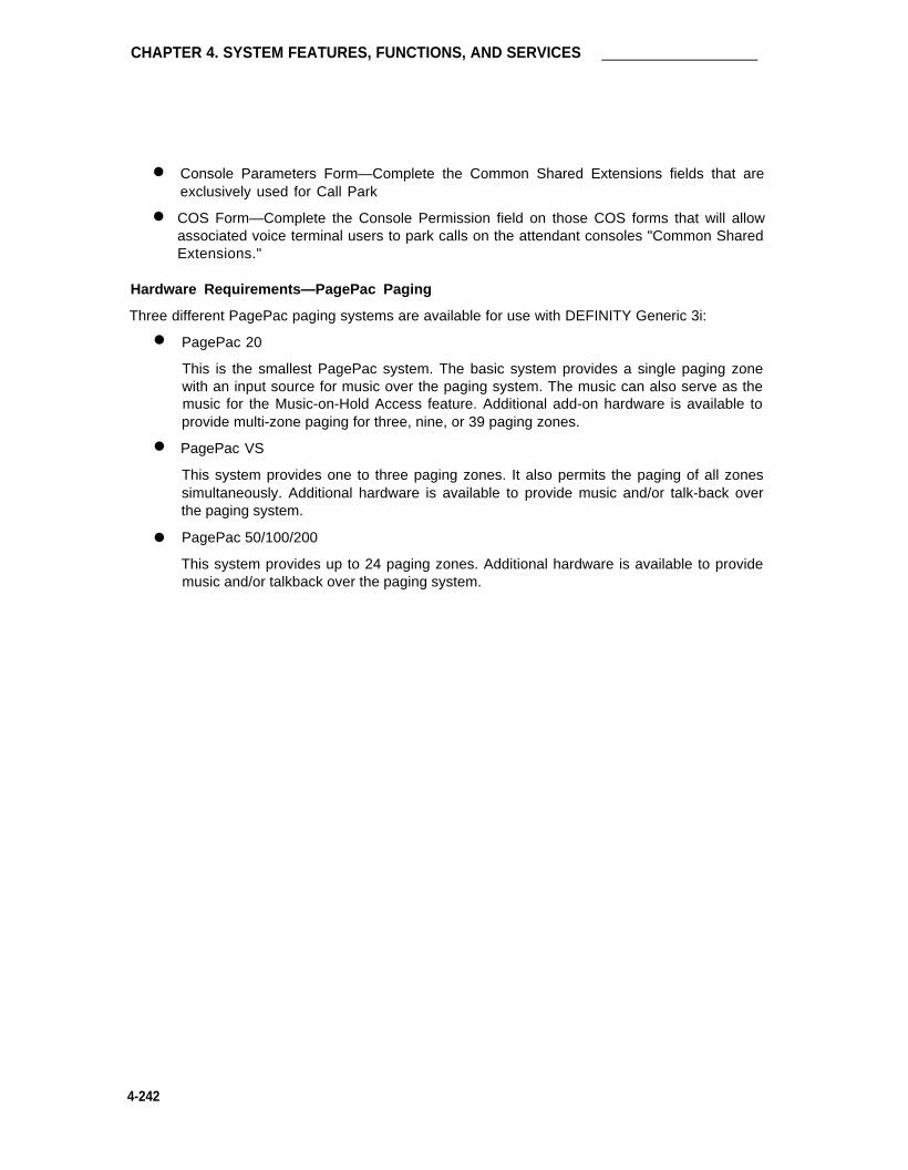
CHAPTER 4. SYSTEM FEATURES, FUNCTIONS, AND SERVICES
●
●
Console Parameters Form—Complete the Common Shared Extensions fields that areexclusively used for Call Park
COS Form—Complete the Console Permission field on those COS forms that will allowassociated voice terminal users to park calls on the attendant consoles "Common SharedExtensions."
Hardware Requirements—PagePac Paging
Three different PagePac paging systems are available for use with DEFINITY Generic 3i:
●
●
●
PagePac 20
This is the smallest PagePac system. The basic system provides a single paging zonewith an input source for music over the paging system. The music can also serve as themusic for the Music-on-Hold Access feature. Additional add-on hardware is available toprovide multi-zone paging for three, nine, or 39 paging zones.
PagePac VS
This system provides one to three paging zones. It also permits the paging of all zonessimultaneously. Additional hardware is available to provide music and/or talk-back overthe paging system.
PagePac 50/100/200
This system provides up to 24 paging zones. Additional hardware is available to providemusic and/or talkback over the paging system.
4-242

Loudspeaker Paging Acces—Deluxe
Loudspeaker Paging Access-Deluxe
Provides attendants and voice terminal users with integrated dial access to voice paging equip-ment and Call Park capabilities. Up to nine individual paging zones and one zone that can beused to activate all nine zones simultaneously can each be accessed using unique trunk accesscodes assigned each zone. The access codes may be assigned on AD feature buttons or whenactivated by an attendant may also be assigned Trunk Group Select button(s) on the console.
This feature is particularly useful in that the Call Park feature is integrated into the use of thefeature. When a user is away from his or her location and receives a call, an incoming call canbe answered and then parked by another user. The user dials the Loudspeaker Paging accesscode and upon receiving Dial tone dials the extension that the call is to be parked on. The calledparty can then be paged and told what extension number to call to receive the incoming call. Thecalled party dials the Answer-Back access code and (after receiving Dial tone) the extensionnumber that the call is parked on.
Note: Also, see "Loudspeaker Paging Access."
Administration
To implement this feature, the following form(s) or sections of the form(s) must be completed.
FormForm Field Instructions
(Page #)
Station (multi-appearance) Button/Feature Button 6-245Assignments
Attendant Console DTGS Selector Feature 6-32Button Assignments
Loudspeaker Paging and All 6-183Code Calling Access
Feature-Related System Call Park Timeout IntervalParameters Deluxe Paging and Call 6-133
Park Timeout to Originator
Dial Plan First Digit Table 6-117
Console Parameters Common Shared Extensions 6-79
Class of Service Console Permission 6-77
● Station/Attendant Console Forms—Up to 10 (one per zone) Loudspeaker Paging Accessbuttons (per multi-appearance voice terminal and attendant console) can be assignedthrough the Attendant Direct Trunk Group Selection, AD, and the Facility Busy Indicationfeatures, if required.
● Loudspeaker Paging and Code Calling Access Form—Complete Loudspeaker Pagingfields. Enter "y" in the Deluxe Paging field.
4-243

CHAPTER 4. SYSTEM FEATURES, FUNCTIONS, AND SERVICES
●
●
●
●
Feature-Related System Parameters Form—Enter in the Call Park Timeout Interval field,the desired time in minutes that a call can remain parked before it is canceled. Enter "y"(yes) in the Deluxe Paging and Call Park Timeout to Originator field. (All parked calls thattimeout are returned to the parking party.)
Dial Plan Form—Assign the length (one to three digits) of the trunk access code to beused to activate Loudspeaker Paging Access - Deluxe.
Console Parameters Form—Complete the Common Shared Extensions fields that areexclusively used for Call Park.
COS Form—Complete the Console Permission field on those COS forms that will allowassociated voice terminal users to park calls on the attendant consoles "Common SharedExtensions."
Hardware Requirements
Requires loudspeaker paging equipment and a port on a TN763C Auxiliary Trunk circuit pack foreach individual paging zone port (maximum of nine) to be assigned. In addition, paging interfacehardware consisting of a 278A Adapter and a 24-volt power supply is required per paging zone.(This hardware can be shared with the Code Calling Access feature. Each feature is activatedvia an assigned trunk access code.) Associated wiring information is provided in the DEFINITY ®
Communications System Generic 1 and Generic 3i—Wiring, 555-204-111.
4-244

Manual Message Waiting
Manual Message Waiting
Enables multi-appearance voice terminal users, by pressing a designated button on their own ter-minals, to light the status lamp associated with the Manual Message Waiting button at anothermulti-appearance voice terminal. Activating the feature causes the lamp to light on both the ori-ginating and receiving voice terminals. Either terminal user can cause the lamp to go dark bypressing the button.
Administration
To implement this feature, the following form(s) or sections of the form(s) must be completed.
FormForm Field Instructions
(Page #)
Station (multi-appearance) Button/Feature ButtonAssignments-man-msg-wt 6-245
● Station Form—Assign "man-msg-wt" to a voice terminal button.
Hardware Requirements
None.
4-245

CHAPTER 4. SYSTEM FEATURES, FUNCTIONS, AND SERVICES
Manual Originating Line Service
Connects users to the attendant automatically when the user lifts the handset.
Administration
To implement this feature, the following form(s) or sections of the form(s) must be completed.
FormForm Field Instructions
(Page #)
Abbreviated Dialing System Dial Code (attendant) 6-13List
Abbreviated Dialing Group Dial Code (attendant) 6-8List
Abbreviated Dialing Per- Dial Code (attendant) 6-11sonal List
Station (single-line) Abbreviated Dialing-List 1,2, or 3
Hot Line Destination-AD 6-260List
● AD List Forms—Verify or assign an attendant code to a list.
● Station Forms—Assign the AD List to designated single-line voice terminal. List can beList 1, 2, or 3. Complete Hot-Line Destination field to indicate the AD List entry contain-ing the attendant code.
Hardware Requirements
None.
4-246

Manual Signaling
Manual Signaling
Allows a voice terminal user to signal another voice terminal user. The receiving voice terminaluser hears a two-second burst of tone. Note that a Manual Signaling button cannot point to aVDN.
Administration
To implement this feature, the following form(s) or sections of the form(s) must be completed.
FormForm Field Instructions
(Page #)
Station (multi-appearance) Button/feature ButtonAssignments
-Signal (extension # or name) 6-245
● Station Forms—Assign Manual Signal buttons as required to the voice terminal.
Hardware Requirements
None.
4-247

CHAPTER 4. SYSTEM FEATURES, FUNCTIONS, AND SERVICES
Message Server Interface
The Message Server (MS) provides MS-based features to the System such as Directory Service,Message Center Service, and Unified Messaging Services, such as Electronic DocumentationCommunications, UNIX® system mail, Office Telesystem, and DCS Centralized Messaging (prin-cipals switch is remote from MS host switch).
Figure 4-16 shows a MS interface to the System. The Switched Communications Interface (SCI)Link connectivity (Control Path) is provided via either a MPDM (distance between the System andMessage Server less than 5000 feet) or via LADS and an associated MTDM (for distancesgreater than 5000 feet). The EIA connectivity (data path) can be implemented via one of thethree options shown.
Administration
To implement the MS interface, the following form(s) or sections of the form(s) must be com-pleted.
FormForm Field Instructions
(Page #)
SCI Link Connection
Processor Interface Data All 6-112Module
Processor Channel All 6-194Assignment
Interface Links All (for one MS link) 6-175
MPDM/MTDM All 6-105
Feature-Related System Message Server Adjunct 6-133Parameters (MSA) Connected
EIA Connection
MPDM ALL 6-105
Other
Hunt Groups All 6-160
Station All 6-245
● SCI Link Connection
— Processor Interface Data Module Form—Complete all sections as required.Assigns a link (interface channel) in the digital switch for an MS interface. Thereare eight links (01 through 08) available for assignment in multi-carrier cabinetSystems and four links available for single-carrier cabinet Systems.
— Processor Channel Assignment Form—Complete the required fields on the formfor the MS interface. Processor channels 1, 2, 3, 4, and 8 as shown on the
4-248

Message Server Interface
Processor Channel Assignments implementation instructions are reserved forMessage Center Service. Enter the appropriate channel assignments and com-plete all associated field entries.
— Interface Links Form—Complete all fields on the form for one link as required.Assigns a link from the Processor Interface circuit pack for the MS.
— MPDM or MTDM Form—Complete all sections as required. Assigns a port on aTN754B Digital Line circuit pack to provide an interface between the MS, itsassociated MPDM, and the digital switch.
— Feature-Related System Parameters Form—Enter "y" in the Message ServerAdjunct (MSA) Connected field.
● EIA Connection
● Other
— MPDM Form—Complete all sections as required. Assign a port on a TN754BDigital line circuit pack to provide a port interface.
— Hunt Group Form—Complete all fields as required to assign MS agents to thehunt group.
— Station Form—Assign the PC/PBX Connection per implementation instructions,assign MS agent work stations as required. Complete System voice terminal,and data terminal forms as required for all users.
Hardware Requirements
Requires a TN765 Processor Interface circuit pack. In addition, a port on a TN754B Digital Linecircuit pack is required to provide the MS interface from its associated MPDM or MTDM to thedigital switch. The EIA connection requires either an MPDM and a port on a TN754B Digital Linecircuit pack, an ADU and a port on a TN726B Data Line circuit pack or a modem and a port on aTN742, TN746B, or TN769 Analog Line circuit pack.
4-249

CHAPTER 4. SYSTEM FEATURES, FUNCTIONS, AND SERVICES
* PC EQUIPPED WITH 3B2 MS STATION SOFTWARE.SEE PC/PBX CONNECTIONS FOR ASSOCIATEDlMPLEMENTATlON lNSTRUCTIONS
† SCl LINK CONNECTIVITY (CONTROL PATH)FOR DISTANCES GREATER THAN 5000 FEET,USE LADS AND MTDM CONNECTION.
‡ ElA CONNECTIVlTY (DATA PATHS)
FIGURE 4-16. Typical Message Server Interface Connections
4-250

Modem Pooling
Modem Pooling
Allows switched connections between digital data endpoints (data modules) and analog data end-points, and acoustic coupled modems. The analog data endpoint can be either a trunk or line cir-cuit.
See Figure 4-17 for an example of integrated and combined modem pooling. Additional informa-tion on Modem Pooling is available in DEFINITY® Communications System Generic 1 and Gen-eric 3i—Feature Description, 555-230-201, and in AT&T System 75—Application Notes—ModemPooling, 555-209-007.
Administration
To implement this feature, the following form(s) or sections of the form(s) must be completed.
Integrated Modem Pooling
Form Field
Modem Pool Group All
Feature Access Codes Data Origination AccessCode
MPDM/MTDM All
FormInstructions
(Page #)
6-187
6-127
6-105
●
●
Modem Pool Group Form—Complete all fields. Up to file Modem Pool Groups may beadministered.
Feature Access Codes Form—Complete the Data Origination access code entry (defaultis 134) if required. This code is used to indicate a need for a modem pooling conversionresource on an analog data call origination.
MPDM/MTDM Form—Complete all fields as required when supporting a combined●
modem pool arrangement. Enter "tdm" in the forms "Type" field. A MTDM or 7400AData Module may be used in support of the combined pool.
Combined Modem Pooling
Form FieldForm
Instructions(Page #)
Modem Pool Group All 6-187
Feature Access Codes Data origination Access 6-127Code
4-251

CHAPTER 4. SYSTEM FEATURES, FUNCTIONS, AND SERVICES
● Modem Pool Group Form—Complete all fields. Up to five Modem Pool Groups may beadministered.
● Feature Access Codes Form—Complete the Data Origination access code entry (defaultis 134) if required. This code is used to indicate a need for a modem pooling conversionresource on an analog data call origination.
Hardware Requirements
A port on a TN758 Pooled Modem circuit pack is required for each integrated conversionresource to be supported. Up to 16 TN758s can be used for integrated conversion resources,each providing two ports. Combined conversion requires a port on a TN754B Digital Line circuitpack and a port on a TN742, TN746B, or TN769 Analog circuit pack for each combined resourceto be supported.
LEGEND:DCP - DIGITAL COMMUNICATIONS
PROTOCOLMPDM - MODULAR PROCESSOR DATA
MODULE
MTDM - MODULAR TRUNK DATAMODULE
FIGURE 4-17. Typical Integrated and Combined Modem Pooling Arrangement
4-252

Multi-Appearance Preselection and Preference
Multi-Appearance Preselection and Preference
Provides multi-appearance voice terminal users with options for placing or answering calls onselected appearances.
Administration
To implement this feature, the following form(s) or sections of the form(s) must be completed.
FormForm Field Instructions
(Page #)
Station (rnulti-appearance) Idle Appearance 6-245Preference
● Station Forms—Complete Idle Appearance Preference field.
Hardware Requirements
None.
4-253

CHAPTER 4. SYSTEM FEATURES, FUNCTIONS, AND SERVICES
Multiple Listed Directory Numbers
Allows a publicly published number for each incoming only and two-way FX and local CO trunkgroup assigned in the System. Also allows up to eight DID numbers to be treated as LDNs.
Administration
To implement this feature, the following form(s) or sections of the form(s) must be completed.
Form
CO Trunk Group
FX Trunk Group
Listed Directory Numbers
FormField Instructions
(Page #)
Incoming Destination 5-123
Incoming Destination 5-180
All 6-181
● Trunk Group Forms—Assign Incoming Destination field for a CO or FX Office TrunkGroup. The Incoming Destination field entry may be a VDN.
● Listed Directory Numbers Form—Assign up to eight listed directory numbers and anassociated night service destination (may be a VDN) if required.
Hardware Requirements
None.
4-254
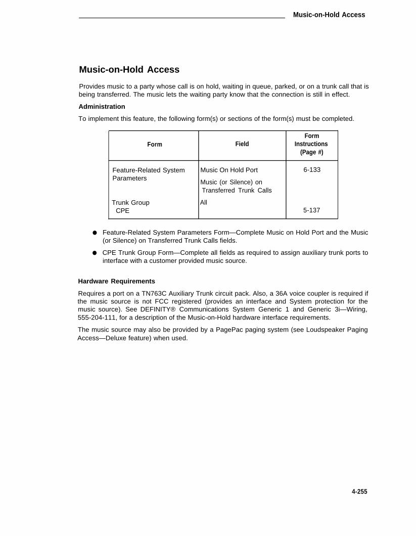
Music-on-Hold Access
Music-on-Hold Access
Provides music to a party whose call is on hold, waiting in queue, parked, or on a trunk call that isbeing transferred. The music lets the waiting party know that the connection is still in effect.
Administration
To implement this feature, the following form(s) or sections of the form(s) must be completed.
Form
Feature-Related SystemParameters
Trunk GroupCPE
FormField Instructions
(Page #)
Music On Hold Port 6-133
Music (or Silence) onTransferred Trunk Calls
All5-137
● Feature-Related System Parameters Form—Complete Music on Hold Port and the Music(or Silence) on Transferred Trunk Calls fields.
● CPE Trunk Group Form—Complete all fields as required to assign auxiliary trunk ports tointerface with a customer provided music source.
Hardware Requirements
Requires a port on a TN763C Auxiliary Trunk circuit pack. Also, a 36A voice coupler is required ifthe music source is not FCC registered (provides an interface and System protection for themusic source). See DEFINITY® Communications System Generic 1 and Generic 3i—Wiring,555-204-111, for a description of the Music-on-Hold hardware interface requirements.
The music source may also be provided by a PagePac paging system (see Loudspeaker PagingAccess—Deluxe feature) when used.
4-255

CHAPTER 4. SYSTEM FEATURES, FUNCTIONS, AND SERVICES
Names Registration
Automatically sends a guest’s name and room extension from the PMS to the System’s digitalswitch at Check-In and automatically removes the information at Check-Out. In addition, theguest’s preferred call coverage arrangement (for example, voice mail or hotel operator) will besent from the PMS to the switch at Check-In and set to the default coverage path for client roomsat checkout.
The name information can be displayed on display-equipped voice terminals to provide a displayof the name of the calling party or called party. (Do not administer these type of voice terminalsto guest rooms. The guest could dial other guest rooms and obtain the registered names.)
For suite rooms, pre-arranged call coverage paths can be administered in the switch and thenumbers stored within the PMS that would allow one room in the suite to be the coverage pointfor the other.
Administration
Refer to the PMS Interface coverage for information on the PMS interface and for associatedadministration guidelines.
To implement this feature, the following form(s) or sections of the form(s) must be completed.
FormForm Field Instructions
(Page #)
Hospitality-Related System PMS Protocol ModeParameters
Default Coverage PathFor Client Rooms
Milliseconds Before PMS LinkAcknowledgement Timeout 6-154
● Hospitality-Related System Parameters Form—In the PMS Protocol field, assign "nor-mal" (supports 4-digit room numbers) or "transparent" (supports 5-digit room numbers).
In the Default Coverage Path For Client Rooms field, assign a valid call coverage path(one through 600), or leave blank for no coverage.
In the Milliseconds Before PMS Link Acknowledgement Timeout field, enter the max-imum time the System will wait for an acknowledgement from the PMS that a transmittedmessage was received (100 through 1000 milliseconds).
Hardware Requirements
See Property Management System Interface.
4-256

Network Access—Private
Network Access—Private
Allows calls to be connected to the following types of networks:
● Common Control Switching Arrangement (CCSA)
● Electronic Tandem Network (ETN)
● Enhanced Private Switched Communications Service (EPSCS)
● Tandem Tie Trunk Network (TTTN)
Administration
The Private Networking option must be enabled on the System-Parameters Customer-Optionsform before associated forms and fields on forms can be administered.
To implement this feature, the following form(s) or sections of the form(s) must be completed.
Form
Trunk Groups:AccessAPLTISDN-PRITandemTie
Class of Restriction
Feature Access Codes
Station
Field
All
Advanced Private LineTermination
Automatic AlternateRouting Access Code
COR
FormInstructions
(Page #)
5-985-1125-1955-2325-247
6-72
6-127
6-245
●
●
●
●
Trunk Group Forms—Specify group type as access, aplt, tandem, tie, or ISDN-PRI withService Type as "access," "tie," or "tandem." Complete COR digit treatment and com-mon type fields on the Tie Trunk Groups associated with a private network. Unlessprohibited by the COR, all incoming private network trunks (except CCSA) can accessoutgoing trunks without attendant or terminal user assistance. All incoming CCSA callsmust route to the attendant or a terminal user.
COR Form—Complete the Advanced Private Line Termination field.
Feature Access Codes Form—Assign an AAR access code consistent with user’s abilityto access these tie trunks.
Station Forms—Assign a COR.
Hardware Requirements
Requires a port on a TN760C Tie Trunk circuit pack or TN722B or TN767 DS1 Tie Trunk circuitpack for each trunk assigned.
4-257

CHAPTER 4. SYSTEM FEATURES, FUNCTIONS, AND SERVICES
Network Access—Public
Provides voice terminal users and attendants with access to and from the public network.
Administration
To implement this feature, the following form(s) or sections of the form(s) must be completed.
Form
CO Trunk Group
DID Trunk Group
FX Trunk Group
ISDN-PRI
WATS Trunk Group
Field
All
All
All
All
All
FormInstructions
(Page #)
5-123
5-156
5-180
5-195
5-264
● Complete all Trunk Group Forms used for Public Network Access.
Hardware Requirements
Requires a port on a TN747B CO Trunk circuit pack or TN767 DS1 circuit pack for each trunkassigned.
4-258

Night Service—Hunt Group
Night Service—Hunt Group
Night Service—Hunt Group allows an attendant or a split supervisor to individually place a huntgroup in the night service mode. A "hunt-ns" button when pressed, places an associated huntgroup in the Night Service mode. All calls terminating on the hunt group or split in the night ser-vice mode will redirect to the designated night service extension.
Administration
To implement this feature, the following form(s) or sections of the form(s) must be completed.
Form
Station (multi-appearance)
Attendant Console
Field
Button/Feature ButtonAssignments-hunt-ns
Feature ButtonAssignments-hunt-ns
FormInstructions
(Page #)
6-245
6-32
● Station Forms—Assign "hunt-ns" buttons to designated voice terminals. Up to three huntgroup buttons can be assigned to a combination of voice terminals and attendant con-soles in each hunt group. The hunt group 2-digit number must be assigned to each but-ton. These buttons should be assigned to feature buttons that have an associated statuslamp. The lamp lights when hunt group night service is activated. If the assigned buttondoes not have a status lamp, no visual indications of the hunt group night service statusis given.
● Attendant Console Form—Assign "hunt-ns" feature button. Up to three buttons can beassigned to a combination of attendant consoles and voice terminals assigned to eachhunt group. The hunt group two-digit number must be assigned to each button.
Hardware Requirements
None.
4-259

CHAPTER 4. SYSTEM FEATURES, FUNCTIONS, AND SERVICES
Night Service—Night Console Service
Directs all calls for the primary and daytime attendant consoles to a night console.
Administration
To implement this feature, the following form(s) or sections of the form(s) must be completed.
FormForm Field Instructions
(Page #}
Attendant Console Console Type 6-32
● Attendant Console Form—The night console must be administered identical to the Pri-mary Attendant Console. Specify the console as a "night console" in the Console Typefield. Enter "night-only" if the console is dedicated to night service. Enter "day/night" if aday console is also used as the night console.
Hardware Requirements
None.
4-260

Night Service—Night Station Service
Night Service—Night Station Service
Redirects incoming attendant-seeking trunk calls to designated extension numbers whenever thesystem is placed in Night Service.
Administration
Do not provide Night Console Service with this feature assigned.
To implement this feature, the following form(s) or sections of the form(s) must be completed.
FormForm Field Instructions
(Page #)Listed Directory Numbers Night Destination 6-181
Trunk Groups: Night ServiceAccess 5-98APLT 5-112CO 5-123DMI-BOS 5-144FX 5-180ISDN-PRI 5-195RLT 5-221Tandem 5-232Tie 5-247WATS 5-264
Hunt Groups Night Service Destination 6-160
Attendant Console Feature Button Assignments-hunt-ns-trunk-ns 6-32
Station (multi-appearance) Button/Feature Button 6-245Assignments-night-ser-hunt-ns-trunk-ns
● LDN Form—Enter Night Destination extension that will receive LDN DID calls when theSystem is in the night service mode.
● Trunk Group Forms—Verify that the Night Service extension number of the answeringvoice terminal or group is specified for each desired trunk group, and where required, forspecific trunk members.
● Hunt Group Form—Enter the Night Service Destination extension (or 0 for the attendant)where calls will direct when in the night service mode.
● Attendant Console/Station Forms—Assign feature buttons as required.
Hardware Requirements
None.
4-261

CHAPTER 4. SYSTEM FEATURES, FUNCTIONS, AND SERVICES
Night Service—Trunk Answer From Any Station
Allows voice terminal users to answer all incoming attendant-seeking calls when the attendanthas activated the Night button on the primary console and when other voice terminals have notbeen designated to answer the calls and when a night console is not assigned or operational.
Administration
Do not provide a Night Console Position with this feature assigned.
To implement this feature, the following form(s) or sections of the form(s) must be completed.
FormForm Field Instructions
(Page #)
Trunk Groups: Night Service (blank)Access 5-98APLT 5-112CO 5-123CPE 5-137DMI-BOS 5-144FX 5-180ISDN-PRI 5-195RLT 5-221Tandem 5-232Tie 5-247WATS 5-264
Feature Access Codes Trunk Answer Any Station 6-127Access Code
Console Parameters Ext Alert Port (TAAS) 6-79
● Trunk Group Forms—Verify Night Service field is blank for the associated trunk group.
● Feature Access Codes Form—Verify feature access code is assigned for Trunk AnswerAny Station Access Code field.
● Console Parameters Form—Assign a port on a TN742, TN746B, or TN769 Analog Linecircuit pack to provide connection with an alerting device in the External Alerting NumberTrunk Answer From Any Station (TAAS) field.
Hardware Requirements
Requires a port on a TN742, TN746B, or TN769 Analog Line circuit pack. A maximum of fivealerting devices can be connected to one port. Also requires an external ringing device(s) posi-tioned so that users can hear them.
4-262

Night Service—Trunk Group
Night Service—Trunk Group
Allows an attendant or a designated voice terminal user to individually assign a trunk group or alltrunk groups to the night service mode.
Administration
To implement this feature, the following form(s) or sections of the form(s) must be completed.
FormForm Field Instructions
(Page #)
Station (multi-appearance) Button/Feature ButtonAssignments-trunk-ns 6-245
Attendant Console Feature Button Assignments-trunk-ns 6-32
Listed Directory Numbers Night Destination 6-181
● Station Forms—Assign "trunk-ns" to a voice terminal button. Up to three buttons can be
●
assigned to voice terminals in each trunk group. The trunk group number must beassigned to each button.
Attendant Console Form—Assign "trunk-ns" feature button. Up to three buttons can beassigned per console. The trunk group number must be assigned to each button.
Listed Directory Numbers Form—Complete Night Destination field if incoming LDN DID●
calls are to be directed to an extension or an attendant when the System is in the nightservice mode.
Hardware Requirements
None.
4-263

CHAPTER 4. SYSTEM FEATURES, FUNCTONS, AND SERVICES
Off-Premises Station
Allows a voice terminal located outside the building where the switch is located to be connectedto the System. If CO trunk circuits, the voice terminal must be analog and must be FCC-registered. Refer to DEFINITY® Communications System Generic 1 and Generic 3i—SystemDescription, 555-230-200, for cabling distance information for the various voice terminal types.
Administration
The following voice terminal types may be administered as OPS: 500, 2500, 7101, 7102A,7103A, and 7104A. These Off-Premises Stations are administered similar to on-premises voiceterminals. Refer to the appropriate voice terminal form for additional information.
Hardware Requirements
Requires cross-connecting capabilities and one port on a TN742, TN746B, or TN769 Analog Lineor TN767 DS1 Tie Trunk circuit pack for each interface to be provided. Do not assign an OPSport on a 16-port TN746B Analog Line circuit pack Note that the use of a Message Waiting indi-cator lamp on an OPS is not supported.
4-264

Personal Central Office Line (PCOL)
Personal Central Office Line (PCOL)
Provides a dedicated trunk for direct access to or from the public network for multi-appearancevoice terminal users.
Administration
To implement this feature, the following form(s) or sections of the form(s) must be completed.
Form
Personal Central OfficeLine Group
Station (multi-appearance)
Field
All
Button/Feature ButtonAssignments-per-COline (Grp:_)-aut-msg-wt (Ext:_ )
FormInstructions
(Page #)
5-217
6-245
● Personal Central Office Line Group (PCOLGs) Forms—Verify or complete all fields.
● Station Forms—Assign (per CO line) buttons to voice terminals in group. If LWC mes-sages are to be stored for the PCOLG, assign a LWC Remote Message Waiting (aut-msg-wt) feature button with status lamp to one of the voice terminals in the group.
Hardware Requirements
Requires a port on a TN747B CO Trunk circuit pack for each CO, FX, or WATS trunk assignedas a PCOL. A maximum of 40 PCOLs can be assigned in the System.
4-265

CHAPTER 4. SYSTEM FEATURES, FUNCTIONS, AND SERVICES
Personalized Ringing
Allows users of certain voice terminals to uniquely identify their own calls. Each user can chooseone of a number of possible ringing patterns.
Administration
To implement this feature, the following form(s) or sections of the form(s) must be completed.
FormForm Field Instructions
(Page #)
7303S Voice Terminal Personalized Ringing Pattern 6-279
7305S Voice Terminal Personalized Ringing Pattern 6-279
7404D Voice Terminal Personalized Ringing Pattern 6-287
7406D Voice Terminal Personalized Ringing Pattern 6-314
7407D Voice Terminal Personalized Ringing Pattern 6-314
7434D Voice Terminal Personalized Ringing Pattern 6-335
Callmaster Digital Personalized Ringing Pattern 6-348Voice Terminal
● Voice Terminal Forms—Complete Personalized Ringing Pattern field for each 7303S,7305S, 7404D, 7406D, 7407D, 7434D, and Callmaster digital voice terminal.
Note: The 7103A, 7404D, 7406D, 7407D, 7410D, 7434D, 7505D, 7506D, 7507D, 8503T,and Callmaster digital voice terminal users have the capability of setting their ownringing pattern. In the event of a power failure, the user-specified ringing pattern for a7404D, 7406D, 7407D, 7410, or Callmaster Digital voice terminal is lost. In the caseof BRI voice terminals, the user-specified ringing pattern is retained even in theevent of a power failure.
Hardware Requirements
None.
4-266

Priority Calling
Priority Calling
Provides a special form of call alerting between internal voice terminal users. The called voiceterminal user receives a distinctive 3-burst alerting signal.
Administration
To implement this feature, the following form(s) or sections of the form(s) must be completed.
FormForm Field Instructions
(Page #)
Feature Access Codes Priority Calling Access 6-127Code
Class of Service Priority Calling 6-77
Attendant Console Feature Button Assignments
-priority 6-32
Station (multi-appearance) Button/Feature Button 6-245Assignments
-priority
● Feature Access Codes Form—Verify or assign Priority Calling Access Code field.
● COS Form—Verify Priority Calling field has correct permission.
● Attendant Console/Station Forms—Assign priority feature buttons as required.
Hardware Requirements
None.
4-267

CHAPTER 4. SYSTEM FEATURES, FUNCTIONS, AND SERVICES
Privacy—Attendant Lockout
Prevents an attendant from reentering a multiple-party connection held on the console unlessrecalled by a voice terminal user.
Administration
To implement this feature, the following form(s) or sections of the form(s) must be completed.
FormForm Field Instructions
(Page #)
Console Parameters Attendant Lockout 6-79
● Console Parameters Form—Enter "y" in Attendant Lockout field.
Hardware Requirements
None.
4-268

Privacy—Digits to Hide
Privacy—Digits to Hide
Supports certain country requirements that specify a certain number of digits to be blanked fromall calls.
Administration
To implement this feature, the following form(s) or sections of the form(s) must be completed.
FormForm Field Instructions
(Page #)
Feature-Related Privacy—Digits to Hide 6-133System Parameters
4-269

CHAPTER 4. SYSTEM FEATURES, FUNCTIONS, AND SERVICES
Privacy—Manual Exclusion
Allows multi-appearance voice terminal users to keep other users with appearances of the sameextension number from bridging onto an existing call.
Administration
To implement this feature, the following form(s) or sections of the form(s) must be completed.
FormForm Field Instructions
(Page #)
Station (mutti-appearance) Button/Feature ButtonAssignments
-exclusion 6-245
● Station Form—Assign Manual Exclusion button to voice terminals of members of a TEGand/or PCOL Group, as required.
Hardware Requirements
None.
4-270

Property Management System Interface
Property Management System Interface
Provides a communications link between the System and a customer-owned Property Manage-ment System (PMS). The PMS allows a customer to control certain features used in both a hospital-type and a hotel/motel-type environment.
Administration
The Hospitality option must be enabled on the System-Parameters Customer-Options formbefore associated forms and fields on forms can be administered.
Also refer to the Names Registration feature for associated administration considerations.
To implement this feature, the following form(s) or sections of the form(s) must be completed.
FormForm Field Instructions
(Page #)
Class of Service Client Room, ConsolePermission 6-77
Hospitality-Related System All 6-154Parameters
Attendant Console Feature Button Assignments-mwn-act-mwn-deact-check-in-check-out 6-32
Feature Access Codes Hospitality Features 6-132
Station (multi-appearance) Button/Feature Button 6-245(Front Desk Terminal) Assignments
-mwn-act-mwn-deact-check-in-check-out
Netcon Data Module All 6-109
Modular Processor Data All 6-105Module
Data Line Data Module All 6-89
● COS Form—Assign "y" to Client Room field for the COS to be used for guest voice termi-nals. For the Console Permission, assign "y" for the Class of Service assigned to theattendant and front desk voice terminal. This allows the attendant or front desk station tocontrol the following items:
– Check-in
4-271

CHAPTER 4. SYSTEM FEATURES, FUNCTIONS, AND SERVICES
●
●
●
●
●
●
– Check-out
– Room change
– Swap Maid Status
Hospitality-Related System Parameters Form—Complete all fields.
Attendant Console/Station Forms—Assign mwn-act (message waiting activation), mwn-deact (message waiting deactivation), check-in, and check-out buttons. These buttonscan be assigned to the attendant console and display-equipped front desk voice termi-nals.
Feature Access Codes Form—Assign Hospitality Feature Access Codes as required.
Netcon Data Module Form—Complete all fields as required. Provides a data channel forthe PMS interface.
MPDM Form—Complete all fields. Assign three different PDMs as follows: assign onePDM for the PMS link and one PDM for each printer (Log and Journal).
Data Line Data Module Form—Complete all fields. Complete this form if the PMS link isconnected using a Data Line circuit pack.
Hardware Requirements
The PMS link can be connected to a TN754B Digital Line circuit pack using a PDM or a TN726BData Line circuit pack using an ADU. The Journal and Log printers can be connected to aTN754B Digital Line circuit pack via a PDM interface.
4-272

Queue Status Indications
Queue Status Indications
Provides indications of queue status for ACD calls based on the number of calls in queue andtime in queue. These indications are provided via lamps assigned to the terminals or consoles ofsplit agents or supervisors. In addition, auxiliary queue warning lamps can be provided to trackqueue status based on time in queue and number of calls in queue. Also, display-equipped voiceterminals and consoles can display the time in queue of a split’s oldest call and the number ofcalls in that split’s queue.
Administration
The ACD option must be enabled on the System-Parameters Customer-Options form beforefields on associated forms can be administered.
To implement this feature, the following form(s) or sections of the form(s) must be completed.
FormForm Field Instructions
(Page #)
Hunt Groups Queue LengthCalls Warning ThresholdTime Warning ThresholdTime Warning PortCalls Warning Port 6-160
Station (multi-appearance) Button/Feature ButtonAssignments-q-calls-q-time 6-245
Attendant Console Feature Button Assignments-atd-qcalls-atd-qtime 6-32
●
●
●
Hunt Groups Form—Assign the number of calls that can queue before the Systemflashes the queue status buttons and the Auxiliary Warning lamp assigned to the split.
— Assign the time a call can remain in the queue before the System flashes thequeue status buttons and the Auxiliary Warning lamp assigned to the split.
— Assign ports for the external Auxiliary Warning lamps.
Station Forms—Assign calls and time buttons.
Attendant Console Form—Assign atd-qcalls and atd-qtime buttons.
Hardware Requirements
Each auxiliary queue Warning lamp requires one port on a TN742, TN746B, or TN769 AnalogLine circuit pack. A 21C-49 lamp may be used as an auxiliary queue Warning lamp.
4-273

CHAPTER 4. SYSTEM FEATURES, FUNCTIONS, AND SERVICES
Recorded Announcements
Allows up to 128 analog or integrated announcements or any desired combination of both.Integrated announcements are assigned on the TN750 Announcement circuit pack. The analogannouncements are assigned on the TN742, TN746B, or TN769 Analog Line circuit pack which isconnected to external recording or playback equipment.
Announcement administration allows the assignment of an extension to an announcement deviceat an analog port or to an announcement on an integrated announcement board. A recordedmessage may be accessed by dialing the extension assigned the announcement on theRecorded Announcement form. References to a particular announcement extensions may befound on: Hunt Group form, Coverage Path form, Trunk Group (Incoming Destination) form, CallVector form, and Feature-Related System Parameters form (DID/Tie/lSDN Intercept Treatmentand Controlled Restriction fields).
Administration
To implement this feature, the following form(s) or sections of the form(s) must be completed.
FormForm Field Instructions
(Page #)
Recorded Announcements All 6-198
Recorded Announcement All 6-115Data Module
Netcon Data Module All 6-109
Trunk Groups: Incoming DestinationCO 5-123DMI-BOS 5-144FX 5-180WATS 5-264
Feature-Related System DID Intercept Treatment 6-133Parameters
Feature Access Codes Announcement Access Code 6-127
Call Coverage Paths Point1, Point2, Point3 6-55
Hunt Groups First and SecondAnnouncement Extensions 6-160
Station COS 6-245
●
●
●
4-274
Recorded Announcements Form—Complete all fields as required.
Recorded Announcement Data Module Form—Complete all fields for a recordedannouncement data module.
Netcon Data Module Form—Complete all fields for a Netcon data module. Provides forthe Upload/download (store/restore to/from tape) of TN750 recorded announcements.

Recorded Announcements
●
●
●
●
●
●
CO, DMI-BOS, FX, WATS Trunk Group Forms—Assign a recorded announcementextension number to the Incoming Destination field, as required.
Feature-Related System Parameters Form—Assign a recorded announcement extensionnumber to the DID Intercept Treatment field, as required.
Feature Access Codes Form—Assign announcement access code.
Call Coverage Path Form—Assign a recorded announcement extension number to acoverage point (Point1, Point2, Point3), as required.
Hunt Groups Form—Assign a recorded announcement extension number to the First andSecond Announcement Extension fields, as required.
Station Forms—Verify that the voice terminal has a COS with Console Permission sothat the user can enter an announcement.
To make, change, listen to, or delete an announcement, the user dials the announcementaccess code and the extension number. The user then performs one of the followingtasks:
— Presses [1] to record an announcement (record a new announcement or recordover an existing announcement). When the recording is complete, the usereither pushes [Drop] on the voice terminal or hangs up.
— Presses [2] to listen to an announcement. (A user can also simply dial theannouncement extension number to listen to an announcement.) A busy toneindicates there is no recording.
— Presses [3] to delete an announcement.
Announcements can also be recorded from off-switch using the Remote Access feature,provided that the Remote Access Form assigns a COS with console permissions.
Hardware Requirements
Each analog announcement to be provided requires a port on a TN742, TN746B, or TN769 Ana-log Line circuit pack. The analog recorded announcement equipment and music sources are notprovided with the System. Each access of an integrated announcement requires a port on theTN750 Announcement circuit pack. Since the integrated announcement is recorded onto theTN750 circuit pack no announcement equipment is required.
4-275

CHAPTER 4. SYSTEM FEATURES, FUNCTIONS, AND SERVICES
Recorded Telephone Dictation Access
Permits voice terminal users, including Remote Access and incoming tie trunk users, to accessdictation equipment.
Administration
To implement this feature, the following form(s) or sections of the form(s) must be completed.
FormForm Field Instructions
(Page #)
CPE Trunk Group All fields if the trunk group is 5-137not assigned, or assigntrunk port for digital switchinterface.
—or
2500 Voice Terminal All 6-260
● CPE Trunk Group Form—Verify or assign an auxiliary trunk group and associated trunkport.
● Station Form—Assign a port and extension number to 2500-series voice terminal form.Enter "n" in the tests field to prevent interference with dictation equipment operation.
Hardware Requirements
Requires telephone dictation machines and, depending on the type of machine, one port on aTN742, TN746B, or TN769 Analog Line circuit pack or one port on a TN763C Auxiliary Trunk cir-cuit pack for each dictation machine to be interfaced.
4-276

Release Link Trunk Group
Release Link Trunk Group
A Release Link Trunk Group is used to implement the CAS feature.
Administration
To assign a Release Link Trunk Group, the following form must be completed.
FormForm Field Instructions
(Page #)
Release Link Trunk Group All 5-221
● Release Link Trunk Group Form—Complete all fields as required to assign trunks thatare used to implement CAS. Associated release link trunks can originate calls going outor receive calls coming in, depending on the trunk direction (incoming or outgoing),although signaling direction can be either incoming or outgoing, but not two-way. Thereis no dial access. The trunk-type is always release link. Outgoing and incoming dialingtype is always tone and the disconnect timing is 280 milliseconds.
Hardware Requirements
A port is required on a TN722B or TN767 circuit pack for each trunk to be assigned in the TrunkGroup. A TN722B or TN767 provides 24 ports.
4-277

CHAPTER 4. SYSTEM FEATURES, FUNCTIONS, AND SERVICES
Remote Access
Permits authorized callers using the public network to access the System and then use itsfeatures and services.
Administration
To implement this feature, the following form(s) or sections of the form(s) must be completed.
Form
Remote Access
Trunk Groups:COFXISDN-PRIWATS
DID
Field
All
Incoming DestinationNight Service
All
FormInstructions
(Page #)
6 - 2 0 3
5-925-1805-1955-264
5-156
● Remote Access Form—Complete all fields. This provides Remote Access via DID if theassigned Remote Access Extension number is within the range of numbers dialable fromthe local CO.
● Trunk Group Forms:
— Optionally, on a per-trunk group basis, verify or set the Incoming Destination fieldto the Remote Access Extension number to provide the feature via a dedicatedtrunk group (Trunk Group Form for incoming trunk groups, except DID).
— Optionally, on a per-trunk group basis, verify that Incoming Destination section isequal to "0" (attendant). Verify or set Night Service field to the Remote AccessExtension number to provide Remote Access for attendant seeking calls when-ever the Night key is pressed and an Alternate Console Position is not provided(Trunk Group form for incoming trunks, except DID).
— Complete DID trunk group form as required.
Hardware Requirements
None.
4-278

Remote Administration
Remote Administration
Allows the System to be administered from a remote terminal located on the customer’s prem-ises. A local administration terminal is one that is located on-premises within 50 feet of the Sys-tem cabinet. A terminal located more than 50 feet from the System cabinet is consideredremote. A remote administration terminal can be on-premises or off-premises. The remote ter-minal can perform the same functions as the local terminal.
Administration
To implement this feature, the following form(s) or sections of the form(s) must be completed.
On-Premises Remote Administration
Form
Netcon Data Module
Data Line Data Module
Hunt Groups
Off-Premises Remote Administration
Form
Netcon Data Module
Data Line Data Module
Hunt Groups
Modem Pool GroupTrunk Group (DID System)
DID Trunk Group
or
CO Trunk Group
Trunk Group (Non-DIDSystem)
-CO Trunk Group
FormField Instructions
(Page #)
All 6-109
All 6-89
Group Extension
Group Members Assignments 6-160
Field
All
All
Group Extension
Group Members Assignments
All
All
All
All
FormInstructions
(Page #)
6-109
6-89
6-160
6-187
5-156
5-123
5-123
● NetCon Data Module Form—Complete all appropriate fields. Provides a data channel forthe G3-MT interface.
4-279

CHAPTER 4. SYSTEM FEATURES, FUNCTIONS, AND SERVICES
● Data Line Data Module Form (DLDM)—Complete all appropriate fields.
● Hunt Groups Form—Complete Group Extension and Group Members Assignment fields.
If the System will be remotely administered from an on-premises terminal, no additional transla-tions are required. However, if the System will be remotely administered from an off-premiseslocation via a dial-up facility, complete the following step.
— Modem Pool Group Form—Complete all appropriate fields.
— Trunk Group Form—Complete Trunk Group forms as follows:
DID equipped Systems
DID equipped Systems using anon-DID trunk
Non-DID equipped Systems—callsmade from Remote (off-premises)terminal will be to the LDN
Non-DID equipped Systems—callsmade from Remote (off-premises)terminal will be to a trunk dedicatedto Remote Administration
Hardware Requirements
On-Premises Remote
●
●
●
●
●
●
Using a DID trunk form, translate a new trunkgroup containing one DID trunk. The NAME(Tel. number) assigned in the GROUPMEMBER ASSIGNMENTS field must be thesame DID number assigned to the UCD huntgroup (see next item).
Using a CO trunk form, translate a new trunkgroup. In the INCOMING DESTINATION fieldand NIGHT SERVICE field, enter the UCD huntgroup extension number (see next item).
If not translated previously, translate a trunkgroup containing the LDN.
Using a CO trunk form, translate a new trunkgroup. In both the INCOMING DESTINATIONand NIGHT SERVICE fields, enter the UCDgroup extension number (see Hunt Group form).
Requires a port on a TN726B Data Line circuit pack and an associated ADU.
a port on a TN754B Digital Line circuit pack terminated with a palm, dtdm, 7400B datamodule OR
a port on a TN556 BRI circuit pack terminated with a 7500B data module or ADM on a7500D series voice terminal AND
a 513 BCT, 610 BCT, 615 MT terminal, 715 BCS, 4410 terminal, 4425 terminal OR
an analog modem and a switch equipped with a modem-pool AND
a TN754B terminated on a 510 or 515 terminal.
4-280

Remote Administration
Off-Premises Remote
● Requires a port on a TN726B Data Line circuit pack and associated ADU.
● Modem Pooling (see Modem Pooling).
● DID Trunk Group—Requires a port on a TN753 DID Trunk circuit pack.
● CO Trunk Group—Requires a port on a TN747B CO Trunk circuit pack.
● 513 BCT, 610 BCT, 615 MT terminal, 715 BCS, 4410 terminal, or 4425 terminal.
● Separate CO line to Processor circuit pack for Alarm Origination/Remote Administration.
4-281

CHAPTER 4. SYSTEM FEATURES, FUNCTIONS, AND SERVICES
Report Scheduler and System Printer
Allows the System Administrator to schedule selected G3-MT (that is, System Access Terminal)commands to be printed by an associated printer. Reports are scheduled at 15-minute intervalsfor any combination of days of the week. Reports are scheduled using the schedule commandline option on the G3-MT (for example, list config all [sched]. Up to a maximum of 50 indivi-dual reports can be scheduled.
Administration
To implement this feature, the following form(s) or sections of the form(s) must be completed.
Report Scheduler/System Printer Connected to MPDM/MTDM:
Form
NetCon Data Module
MPDM/MTDM Data Module
Feature-Related SystemParameters
Field
All
All
System Printer Parameters
Printer ExtensionEIA Device Bit RateLines per Page
FormInstructions
(Page #)
6-109
6-105
6-133
Report Scheduler/System Printer Connected to DCE Jack on the Control Carrier:
FormForm Field Instructions
(Page #)
Feature-Related System System Printer Parameters 6-133Parameters
Printer ExtensionEIA Device Bit RateLines per Page
4-282

Report Scheduler and System Printer
Report Scheduler/System Printer Connected To Data Line Circuit Pack via AsynchronousData Unit (ADU):
Form
Data Line Data Module
Netcon Data Module
Feature-Related SystemParameters
FieldForm
Instructions(Page #)
All
All
System Printer Parameters
Printer ExtensionEIA Device Bit RateLines per Page
6-89
6-109
6-133
Complete the following forms if the Report Scheduler/System Printer is connected to anMPDM/MTDM:
● Netcon Data Module Form—Complete all fields as required. This form activates a physi-cal channel on the TN777 Network Control circuit pack. An associated MPDM/MTDMData Module form must also be completed to assign the associated MTDM interface fromthe Report Scheduler/System printer to the switch.
● MPDM/MTDM Form—Complete all fields if a 700A-type MPDM is to used. This form isused to assign the Report Scheduler/System Printer to a port on a TN754B Digital Linecircuit pack.
● Feature-Related System Parameters Form—Complete the Printer Extension (enter validextension), EIA Device Bit Rate (1200, 2400, 4800, 9600), and Lines per Page (24through 132 with 60 as the system default) fields associated with the System PrinterParameters.
Complete the following form if the Report Scheduler/System Printer is connected to the DCE jackon the Control Cabinet:
● Feature-Related System Parameters Form—Complete the Printer Extension (enter "eia"),EIA Device Bit Rate (1200, 2400, 4800, 9600), and Lines per Page (24-132 with 60 asthe system default) fields associated with the System Printer Parameters.
Complete the following forms if the Report Scheduler/System Printer is connected to a TN726BData Line circuit pack via ADU:
● DLDM Form—Complete all fields as required. The Data Line circuit pack provides analternative to using an MPDM and is the preferred method. A Data Line circuit packmust be assigned if a port is not available using the Circuit Pack Administration form asshown in Chapter 2. Up to eight ports are available. A Z3A ADU is required at theprinter input.
4-283

CHAPTER 4. SYSTEM FEATURES, FUNCTIONS, AND SERVICES
●
●
Netcon Data Module Form—Complete all fields as required. This form activates a physi-cal channel on the TN777 Network Control circuit pack
Feature-Related System Parameters Form—Complete the Printer Extension (enter validextension), EIA Device Bit Rate (1200, 2400, 4800, 9600), and Lines per Page (24through 132 with 60 as the system default) fields associated with the System PrinterParameters.
Hardware Requirements
A single asynchronous System printer connection dedicated for use by the Report Scheduler isrequired. Other printers in the System include those connected to the G3-MT, the SMDR printer,and the journal printer. These printers are not used by the Report Scheduler. Currently, theReport Scheduler printer must be a serial input AT&T 475 or compatible printer.
The type of interface depends on how the Report Scheduler/System printer is connected to thedigital switch.
●
●
●
If the printer is connected to the switch via MPDM, the MPDM must be connected to aport on a TN754B Digital Line circuit pack when used.
If the printer is connected to a TN726B Data Line circuit, a TN726B port and an Z3A ADUis required.
If the printer is connected to the DCE jack on the back of the Control Cabinet, theappropriate cable (not to exceed 60 feet) is required.
4-284

Restricted/Unrestricted Call Lists
Restricted/Unrestricted Call Lists
Used to control outgoing call access. The COR assigned the facility being used to place a call ischecked to determine if it is associated with the System’s Restricted Call List (RCL) and/or one ormore Unrestricted Call Lists (UCLs). The System can have one RCL and up to 10 UCLs. All listsare administered on the Toll Analysis form. Dialed Strings and associated Min/Max fields on theform can be marked as being members of the RCL and/or UCLs as required.
A call attempt from a facility whose COR is administered as being associated with the RCL andwhose dialed string matches a RCL Dialed String will be denied. The caller will receive intercepttreatment.
A UCL is only accessed if the facilities COR’s Calling Party Restriction field is "all-toll" or "tac-toll"and the COR’s UCL field references one or more UCLs. A call from a facility whose COR meetsthe above conditions will complete if the COR is associated with a UCL whose dialed stringmatches the dialed number. Note that the call will not complete if the COR is also associatedwith the RCL and whose dialed string also matches the dialed number. The RCL takes pre-cedence over the UCL.
For additional information, an Authorization Check Flow Chart is provided with the Toll Analysisform coverage in Chapter 6. The chart depicts the checks that call processing uses in determin-ing call restrictions. (Other features that are administered on the Toll Analysis form includeRestriction-Toll and SMDR Account Code Dialing.)
Administration
To implement this feature, the following form(s) or sections of the form(s) must be completed.
FormForm Field Instructions
(Page #)
Toll Analysis Dialed StringMin/MaxRCLUCL (1-10) 6-216
Class of Restriction RCL 6-70UCL (1-10)
●
●
Toll Analysis Form—Complete the Dialed String, Min/Max, RCL, and UCL List fields asrequired.
COR Form—Complete the RCL and UCL fields on each COR form as required.
Hardware Requirements
None.
4-285

CHAPTER 4. SYSTEM FEATURES, FUNCTIONS, AND SERVICES
Restriction—Controlled
Allows an attendant or voice terminal user with console permission to activate and deactivate thefollowing restrictions for an individual voice terminal or a group of voice terminals:
● Outward—The voice terminal(s) cannot be used for placing calls to the public network.Such call attempts can receive an announcement, attendant, extension, or intercept tone.
● Total—The voice terminal(s) cannot be used for placing or receiving calls. DID calls canreceive an announcement, attendant, extension, or intercept tone.
● Station-to-Station—The voice terminal cannot receive or place station-to-station calls.Such call attempts can receive an announcement, attendant, extension, or intercept tone.
● Termination—The voice terminal cannot receive any calls. Incoming calls can receive anannouncement, attendant, extension, or intercept tone.
Administration
To implement this feature, the following form(s) or sections of the form(s) must be completed.
FormForm Field Instructions
(Page #)
Feature Access Codes User Control RestrictActivation and Deactivation
Group Control Restrict 6-127Activation and Deactivation
Feature-Related System Controlled OutwardParameters Restriction Intercept
Treatment
Controlled TerminationRestriction (Do Not Disturb)
Controlled Station-to- 6-133Station Restriction
● Feature Access Codes Form—Verify or assign User Control Restrict Activation andDeactivation and Group Control Restrict Activation and Deactivation fields.
● Feature-Related System Parameters Form—Assign the type of interface treatment thecaller receives when the call is outward restricted. Assign the type of intercept treatmentthe caller receives when the call is placed to a termination restricted voice terminal. Enterthe type of intercept treatment the caller receives when the call is placed to a restrictedvoice terminal.
Hardware Requirements
None.
4-286

Restriction-Miscellaneous Terminal
Restriction—Miscellaneous Terminal
Restricts a caller from accessing a pre-selected group of voice or data terminals. The restrictionis controlled by the COR assigned to the calling party’s voice terminal and the COR assigned topre-selected groups of voice and data terminals. The calling party’s COR either allows or deniesaccess to the COR assigned to the called facility. Note that when a call is to a VDN extension,the COR of the caller and the VDN are compared to determine if the associated Call Vector canbe accessed. After the vector is accessed, the COR of the VDN is used for further call permis-sion checking.
Administration
To implement this feature, the following form(s) or sections of the form(s) must be completed.
FormForm Field Instructions
(Page #)
Class of Restriction All 6-72
Station COR 6-245
Remote Access COR 6-203
Hunt Groups COR 6-160
Terminating Extension Group COR 6-214
Trunk Groups: CORAccess 5-98APLT 5-112CO 5-123CPE 5-137DMI-BOS 5-144DID 5-156FX 5-180RLT 5-221Tandem 5-232Tie 5-247WATS 5-264
Vector Directory Number COR 6-222
● COR Forms:
—
—
Voice/Data Terminals—Verify or establish a COR for a group of voice or data ter-minals.
Originating Facility—Verify or establish a COR for each originating facility that isto be restricted from calling the miscellaneous trunk group types. (These CORscan be different.) To assign this capability on the originating facilities CORform(s), the calling permission field associated with the CORs of the trunk groupsto be restricted must have an "n."
4-287

CHAPTER 4. SYSTEM FEATURES, FUNCTIONS, AND SERVICES
●
●
●
●
●
●
Station Forms—Assign the same COR to the miscellaneous group of voice terminals.Include the associated data module form if station has a DTDM.
Remote Access Form—Assign the miscellaneous COR to barrier codes.
Hunt Group Form—Assign the miscellaneous COR to UCD/DDC groups.
TEG Form—Assign the miscellaneous COR to the group.
Trunk Groups Forms—Assign the selected COR to incoming trunk groups and/or termi-nals. (CORs already assigned can be used if all users with the CORs will be restricted.)
VDN Form—Assign the miscellaneous COR to the appropriate VDNs.
Hardware Requirements
None.
4-288

Restriction—Miscellaneous Trunk
Restriction—Miscellaneous Trunk
Restricts users at specified voice terminals from accessing preselected groups of trunks, such asCO, CPE, etc. Any or all trunk groups can be in a given miscellaneous trunk restriction group.The restriction is controlled by the CORs assigned to the facility or item of hardware that ori-ginates the call and the trunk group being accessed. The calling party’s COR can either allow ordeny access to the COR assigned the calling facility. Note that when a call is to a VDN exten-sion, the COR of the caller and the VDN are compared to determine if the associated Call Vectorcan be accessed. After the vector is accessed, the COR of the VDN is used for further call per-mission checking.
Administration
To implement this feature, the following form(s) or sections of the form(s) must be completed.
FormForm Field Instructions
(Page #)
Class of Restriction All 6-72
Trunk Groups: CORAccess 5-98APLT 5-112CO 5-123CPE 5-137DMI-BOS 5-144FX 5-180ISDN-PRI 5-195RLT 5-221Tandem 5-232Tie 5-247WATS 5-264
Station COR 6-245
● COR Forms
—
—
Trunk Groups to be Restricted—Verify or establish a COR for various trunkgroup types that are to be restricted. Assign the same COR to each group.
Originating Facility—Verify or establish a COR for each originating facility (that is,voice terminal, etc.) that is to be restricted from calling the miscellaneous trunkgroup types. (These CORs can be different.) To assign this capability on the ori-ginating facilities COR form(s), the calling permission field associated with theCORs of the trunk groups to be restricted must have an "n."
4-289

CHAPTER 4. SYSTEM FEATURES, FUNCTIONS, AND SERVICES
●
●
Trunk Group Forms—Assign an appropriate (the same to each) COR to each trunk groupto be restricted.
Station Forms—Assign the appropriate CORs to the voice terminals. (CORs alreadyassigned can be used if all users with the CORs will be restricted.)
Hardware Requirements
None.
4-290

Restriction—Toll
Restriction—Toll
Restricts users at specified voice terminals from placing public network calls to certain numbersdesignated as toll calls by the System Administrator.
User Toll Restriction is administered on COR forms as follows:
●
●
All Toll—Denies the calling party the ability to make both ARS and trunk access calls tocertain toll areas as defined on the System’s Toll Analysis form, unless the exchange ison a UCL. The UCL is defined on the Toll Analysis form and appropriate UCL numbersare assigned on the Class of Restriction forms.
TAC Toll—Denies the calling party from making trunk access calls to certain toll areas asdefined on the Toll Analysis form, unless the exchange is on a UCL associated with thecalling party’s COR.
If the System is connected to a central office that uses a step-by-step switch, all seven of thedigits which are normally dialed for a local call may not be required by the CO to route the call.For example, the CO may only require the last five of the normally dialed seven digits. If allseven digits are dialed, the step-by-step switch uses digit absorption to absorb the unneededdigits. Digit absorption can be provided within the System to emulate the absorption at the CO.This prevents users from bypassing toll restriction by dialing unneeded digits. For example,assume that the central office absorbs leading 7s before processing a number and that a toll-restricted user wants to call someone in area code 201. The user could dial 77-1-201 plus sevenmore digits. The Toll Restriction feature would not recognize the call as a toll call and the COwould route the call. With digit absorption, the 77 is absorbed by the System before Toll Restric-tion is used. Thus, the call would be denied, as intended. Up to five digit absorption lists can beassigned.
Note that if a Digit Absorption list (see Digit Absorption in Chapter 6) is assigned to a CO or FXtrunk group, then entries on the Toll Analysis form (Chapter 6) may not be used to determine if aTAC call routed over one of these trunk groups is a toll call. The following rules apply:
●
●
If the Digit Absorption list causes no digits to be absorbed for a particular call, then theToll Analysis Form is used.
If the Digit Absorption list causes one or more digits to be absorbed for a particular call,then the Toll Analysis Form is not used. Instead, if the first non-absorbed digit is either"0" or "1" and the caller is toll restricted, the call is denied.
4-291

CHAPTER 4. SYSTEM FEATURES, FUNCTIONS, AND SERVICES
Administration
To implement this feature, the following form(s) or sections of the form(s) must be completed.
Form
Toll Analysis
Class of Restriction
Console Parameters
Station
Data Line Data Module
Attendant Console
Trunk Group (CO)
Trunk Group (FX)
Digit Absoption
Field
All
All
COR
COR
COR
COR
Toll Restricted
Toll Restricted
All
FormInstructions
(Page #)
6-216
6-72
6-79
6-245
6-89
6-32
5-123
5-180
6-107
● Toll Analysis Form—Complete all entries as required to administer certain dialed digitstring to the System’s Toll List. Enter "x" in the associated Toll List field to associate thedialed string to the toll list. Complete appropriate UCL fields to assign certain dialed digitstrings as unrestricted.
● COR Form—Verify or establish CORs with a Calling Party Restriction of "all-toll" or "tac-toll." Complete the Unrestricted Call List fields (enter appropriate UCL numbers from theSystem’s Toll Analysis form).
● Station, DLDM, and Console Parameters Forms—Assign an applicable COR to eachvoice terminal, data module, and attendant console group that is to be toll restricted.
● FX and CO Trunk Group Forms—Verify or assign appropriate FX and CO trunk groupsas toll restricted; enter "y" (yes) in the Toll Restriction field (default). Enter "n" if youwant to disable toll restriction to trunk access code type calls on this trunk group.
● Digit Absorption Form—Complete all appropriate fields. The Digit Absorption list numbermust be assigned to the appropriate CO and/or FX trunk groups.
Hardware Requirements
None.
4-292
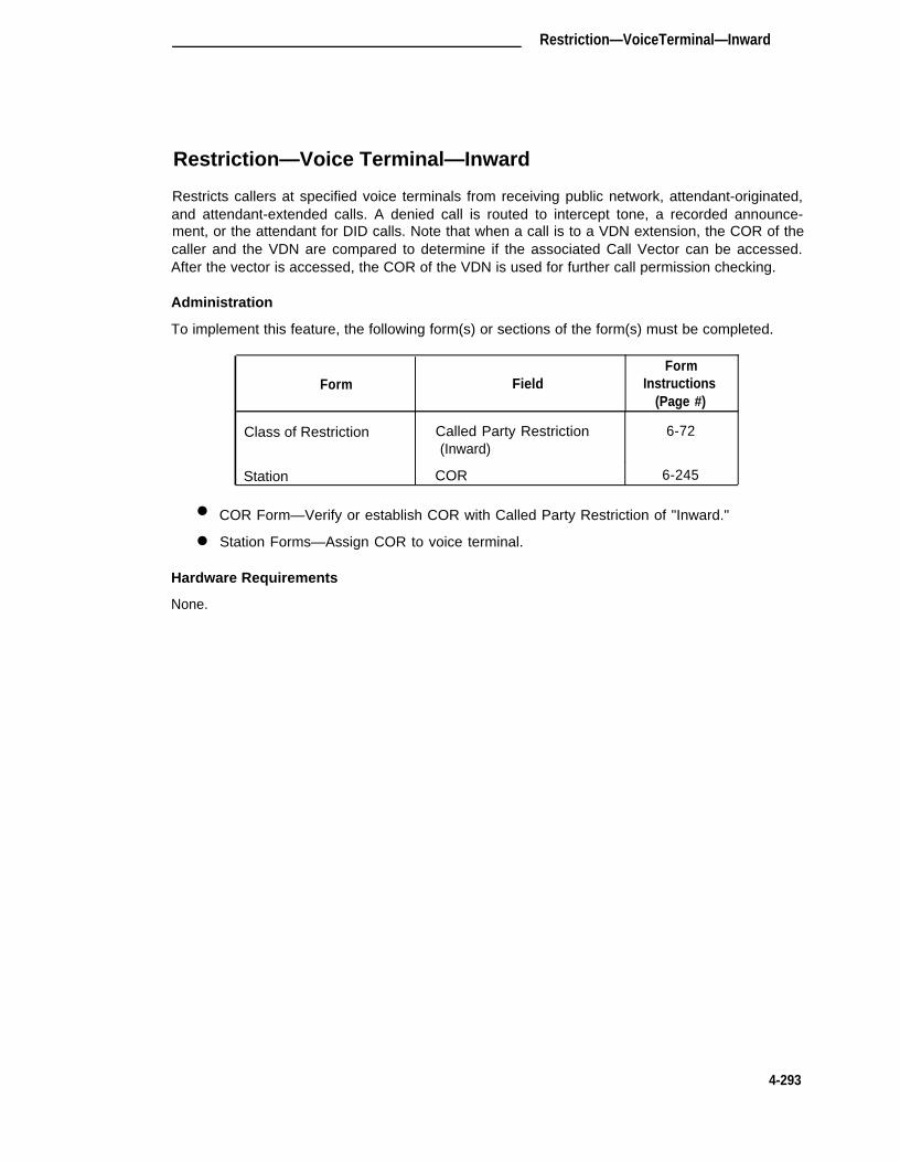
Restriction—VoiceTerminal—Inward
Restriction—Voice Terminal—Inward
Restricts callers at specified voice terminals from receiving public network, attendant-originated,and attendant-extended calls. A denied call is routed to intercept tone, a recorded announce-ment, or the attendant for DID calls. Note that when a call is to a VDN extension, the COR of thecaller and the VDN are compared to determine if the associated Call Vector can be accessed.After the vector is accessed, the COR of the VDN is used for further call permission checking.
Administration
To implement this feature, the following form(s) or sections of the form(s) must be completed.
FormForm Field Instructions
(Page #)
Class of Restriction Called Party Restriction 6-72(Inward)
Station COR 6-245
●
●
COR Form—Verify or establish COR with Called Party Restriction of "Inward."
Station Forms—Assign COR to voice terminal.
Hardware Requirements
None.
4-293

CHAPTER 4. SYSTEM FEATURES, FUNCTIONS, AND SERVICES
Restriction—Voice Terminal—Manual Terminating Line
Restricts callers at specified voice terminals from receiving calls other than those from an atten-dant. Local CO, FX and WATS calls are routed to the attendant. DID calls are routed to anannouncement or the attendant Tie trunk, and voice terminal calls are routed to intercept treat-ment. The voice terminal user can originate calls and activate features. Note that when a call isto a VDN extension, the COR of the caller and the VDN are compared to determine if the associ-ated Call Vector can be accessed. After the vector is accessed, the COR of the VDN is used forfurther call permission checking.
Administration
To implement this feature, the following form(s) or sections of the form(s) must be completed.
Form
Class of Restriction
Station
FormField Instructions
(Page #)
Called Party Restriction 6-72(Manual)
COR 6-245
● COR Form—Verify or establish COR with Called Party Restriction of "Manual."
● Station Forms—Assign COR to voice terminal.
Hardware Requirements
None.
4-294

Restriction—Voice Terminal—Origination
Restriction—Voice Terminal—Origination
Restricts callers at specified voice terminals from originating calls. Voice terminal users canreceive calls. Note that when a call is to a VDN extension, the COR of the caller and the VDNare compared to determine if the associated Call Vector can be accessed. After the vector isaccessed, the COR of the VDN is used for further call permission checking.
Administration
To implement this feature, the following form(s) or sections of the form(s) must be completed.
Form
Class of Restriction
Station
FormField Instructions
(Page #)
Calling Party Restriction 6-72(Origination)
COR 6-245
● COR Form—Verify or establish COR with Calling Party Restriction of "Origination."
● Station Forms—Assign COR to voice terminal.
Hardware Requirements
None.
4-295

CHAPTER 4. SYSTEM FEATURES, FUNCTIONS, AND SERVICES
Restriction—Voice Terminal—Outward
Prevents specified voice terminal users from placing calls to the public network. Calls can beplaced to other voice terminal users, to the attendant, and over tie trunks. Note that when a callis to a VDN extension, the COR of the caller and the VDN are compared to determine if the asso-ciated Call Vector can be accessed. After the vector is accessed, the COR of the VDN is usedfor further call permission checking.
Administration
To implement this feature, the following form(s) or sections of the form(s) must be completed.
FormForm Field instructions
(Page #)
Class of Restriction Calling Party Restriction 6-72(Outward)
Station COR 6-245
●
●
COR Form—Verify or establish COR with Calling Party Restriction of "Outward."
Station Forms—Assign COR to voice terminal.
Hardware Requirements
None.
4-296

Restriction—Voice Terminal—Termination
Restriction—Voice Terminal—Termination
Restricts voice terminal users on specified extension numbers from receiving any calls. Voiceterminal users can originate calls. DID or APLT calls are routed to a recorded announcement orthe attendant. Note that when a call is to a VDN extension, the COR of the caller and the VDNare compared to determine if the associated Call Vector can be accessed. After the vector isaccessed, the COR of the VDN is used for further call permission checking.
Administration
To implement this feature, the following form(s) or sections of the form(s) must be completed.
FormForm Field Instructions
(Page #)
Class of Restriction Called Patty Restriction 6-72(Termination)
Station COR 6-245
●
●
COR Form—Verify or establish COR with Called Party Restriction of "Termination."
Station Forms—Assign COR to voice terminal.
Hardware Requirements
None.
4-297

CHAPTER 4. SYSTEM FEATURES, FUNCTIONS, AND SERVICES
Ringback Queuing
Places outgoing calls in an ordered queue (first-in, first-out) when all trunks are busy. The voiceterminal user is automatically called back when a trunk becomes available. The voice terminalreceives a distinctive 3-burst alerting signal (Priority Calling) when called back.
Administration
To implement this feature, the following form(s) or sections of the form(s) must be completed.
FormForm Field Instructions
(Page #)
Trunk Groups: Queue LengthAccess 5-98APLT 5-112CO 5-123CPE 5-137DMI-BOS 5-144FX 5-180ISDN-PRI 5-195RLT 5-221Tandem 5-232Tie 5-247WATS 5-264
Feature-Related System Automatic Callback-No 6-133Parameters Answer Timeout Interval
Feature Access Codes Automatic Callback 6-127Activation/Deactivation
Station (multi-appearance) Buttons/Feature ButtonAssignments
auto-cback 6-245
● Trunk Group Forms for outgoing Trunk Groups—Verify or assign queuing to queueLength field.
● Feature-Related System Parameters Form—Specify Automatic Callback-No AnswerTimeout Interval (rings) field.
● Feature Access Codes Form—Verify or assign Automatic Callback Activation and Deac-tivation fields.
● Station Forms—Assign Auto Callback buttons to multi-appearance voice terminals, asdesired.
Note: Automatic Callback and Ringback Queuing share the same intervals, codes, andbuttons.
Hardware Requirements
None.
4-298

Ringer Cutoff
Ringer Cutoff
Allows users of multi-appearance voice terminals to turn on or off certain audible ringing signals.Visual alerting is not affected by this feature.
When this feature is enabled, only Priority ringing (3-burst ringing), Intercom ringing, and ManualSignaling ringing will ring at the voice terminal. 1-burst, 2-burst, and redirection notification willnot ring. When this feature is disabled, the voice terminal will have normal ringing.
Administration
To implement this feature, the following form(s) or sections of the form(s) must be completed.
FormForm Field Instructions
(Page #)
Station (multi-appearance) Button/Feature Button 6-245Assignments-ringer-off
● Station Forms-Assign "ringer-off" to a voice terminal feature button. One button may beassigned per voice terminal.
Hardware Requirements
None.
4-299

CHAPTER 4. SYSTEM FEATURES, FUNCTIONS, AND SERVICES
Security Violation Notification
The Security Violation Notification (SVN) feature provides the capability to immediately detect animminent breach of System Management or Remote Access, and to notify a designated referraldestination upon detection. It is intended to detect failed login and Remote Access (barrier code)attempts based on customer- administrable thresholds. Once a threshold is reached, for either ofthese avenues of access, (System Management login or Remote Access barrier code), the Sys-tem will initiate a referral call to an assigned referral point (attendant console or station equippedwith a display module).
An audit trail of the security violations, containing relevant information about each failed attemptto access the System, will be available through the monitor security-violations command. Thiscommand will refresh the information that is displayed every 30 seconds, providing an up to dateview of fallacious system access activity.
Information about invalid login attempts is collected at two levels:
● On an immediate basis, when an invalid login attempt is made, the SVN feature can beused to send a priority call to a designated referral point (attendant console or stationequipped with a display module) so that there is some chance of apprehending the viola-tor during the attempted violation. Upon notification, the security administrator canrequest the Security Violations Status Report which will show details of the last 16 secu-rity violations of each type.
● On a historical basis, the number of security violations of each type are collected andreported in the Security Violations Measurements Report. This report shows summaryinformation since the last time that the counters were reset at the time of system initiali-zation or by the clear measurements security-violations command. It does not showdetails of the individual security violations.
The Security Violations Measurement Report (historical) is generally available in all systemswithout special prerequisites.
Commands are available for displaying and clearing the Security Violation Report. To display thereport, enter:
list measurements security-violations [print] or [schedule]
Options: The two options for the above command are: "print" and "schedule."
To reset all counters of the Security Violation Report to zero, enter:
clear measurements security-violations
Note: Security measurements are accumulated until they are cleared.
Options: There are no options for the above command.
A typical Security Violation Measurements Report and a detailed description of the meaning ofthe data presented in the report are provided in DEFINITY® Communications System Generic 1and Generic 3i System Reports, 555-204-510.
4-300

Security Violation Notification
Status Report
The Security Violations Status Report provides current status information for invalid G3-MT orSAT-PC login or Remote Access (barrier code) attempts. Invalid G3-MT or SAT-PC loginattempts will log the time the violation occurred, the login entered, the port that was accessedduring the failed login attempt, and the extension assigned to the port (if applicable).
Note: The above applies only in the case of the Network Controller dial-up ports.
Invalid barrier code attempts will log the time the violation occurred, the number of the trunkgroup that was accessed, the trunk group member number, and the extension assigned toRemote Access. A total of 16 entries will be maintained for each type of invalid access (local orremote).
To display the Security Violation Status Report, enter:
monitor security-violations [print]
Options: There is one option for this command: "print."
A typical Security Violation Status report and a detailed description of the meaning of the datapresented in the report are provided in DEFINITY® Communications System Generic 1 and Gen-eric 3i System Reports, 555-204-510.
Administration
To implement the SVN feature the following form(s) or sections of the form(s) must be com-pleted.
FormForm Field Instructions
(Page #)
Feature-Related SystemParameters
Station (multi-appearance/)Attendantdisplay
Security Violation NotificationParameters
Button/Feature ButtonAssignments(lsvn-call)(rsvn-call
6-133
6-245
● Feature-Related—Complete all appropriate SVN Parameters on Page 5 of the form.
After completing Page 5 of the Feature-Related System Parameters form, you should thenadminister and activate any previously unadministered call-appearance buttons as the "lsvn-call"and "rsvn-call" buttons on any station. Activation of these buttons allows an SVN referral call toterminate to the designated referral destination extension.
Note: If the Isvn-call or rsvn-call feature button is deactivated, login and remote access vio-lations can still be viewed at the G3-MT or SAT-PC via the monitor security viola-tions command. A referral call will not be not spawned unless the Isvn-call or rsvn-call feature button has been administered and activated.
4-301

CHAPTER 4. SYSTEM FEATURES, FUNCTIONS, AND SERVICES
Additional Considerations
When implementing the SVN feature, bear in mind the following:● A maximum of one Referral Destination for each type of violation (login or remote
access) may be administered per switch.● The Call Coverage, Call Forwarding, and Call Pickup (for example, within pickup group)
features are not supported for SVN.● CAS attendants will not receive referral calls from branch locations.● Referral Destination must be local because SVN does not support a DCS network inter-
face.● Unlike the ACA referral call, the SVN referral call is a priority call.● Unlike ACA, Speech Synthesis Circuit pack functionality is not currently supported for
SVN.
Hardware Requirements
None.
4-302

Send All Calls
Send All Calls
Allows users to temporarily direct all incoming calls to coverage regardless of the assigned CallCoverage redirection criteria. Send All Calls also allows covering users to temporarily removetheir voice terminals from the coverage path.
Administration
To implement this feature, the following form(s) or sections of the form(s) must be completed.
FormForm Field Instructions
(Page #)
Feature Access Codes Send All Calls Activation 6-127and Deactivation
Station (multi-appearance) Button/Feature Button 6-245Assignments-send-calls
Call Coverage Paths All 6-55
●
●
Feature Access Codes Form—Assign an Activation and a Deactivation access code forSend All Calls.
Station Forms—Assign a Send All Calls button.
● Call Coverage Paths Form—Complete all fields as required to establish the call redirec-tion criteria.
Hardware Requirements
None.
4-303

CHAPTER 4. SYSTEM FEATURES, FUNCTIONS, AND SERVICES
Service Observing
Allows a specified user, such as a supervisor, to observe a call that involves other users while thecall is in progress. While observing a call, the specified user can toggle between a listen-onlyand a listen/talk connection to the call. Note that Service Observing cannot be used toward aVDN extension.
Note: The use of Service Observing features may be subject to federal, state, or locallaws, rules or regulations or require the consent of one or both of the parties to theconversation. Customers should familiarize themselves with and comply with allapplicable laws, rules and regulations before using these features.
Administration
The optional Service Observing feature must be enabled on the System-Parameters Customer-Options form before associated forms and fields on forms can be administered.
To implement this feature, the following form(s) or sections of the form(s) must be completed.
Form
Class of Restriction
Feature-Related SystemParameters
Station (multi-appearance)
Attendant Console
FieldForm
Instructions(Page #)
Service Observing
Service Observing WarningTone
Button/Feature ButtonAssignment-serv-obsrv
Feature Button Assignments-serv-obsrv
6-72
6-133
6-245
6-32
● COR Form—Complete Service Observing field.
● Feature-Related System Parameters Form—Assign "y" to Service Observing WarningTone field.
● Station Forms—Assign one serv-obsrv (service observing) button.
● Attendant Console Form—Assign a serv-obsrv button per attendant console.
Hardware Requirements
None.
4-304

Single-Digit Dialing and Mixed Station Numbering
Single-Digit Dialing and Mixed Station Numbering
Allows easy access to internal hotel/motel services and provides the capability to associate roomnumbers with guest room voice terminals.
Administration
To implement this feature, the following, form(s) or section of the form(s) must be completed.
FormForm Field Instructions
(Page #)
Dial Plan All 6-117
Hardware Requirements
None.
4-305

CHAPTER 4. SYSTEM FEATURES, FUNCTIONS, AND SERVICES
SMDR Account Code Dialing
Allows certain calls to be associated with a particular project or account number. This is accom-plished by dialing a SMDR Account Code feature access code and then the appropriate accountcode before making outgoing calls. This information is recorded by the SMDR feature and canbe used later for accounting and/or billing purposes.
Note that the Forced Entry of Account Codes feature is covered elsewhere in this chapter.
Administration
To implement SMDR Account Code Dialing, the following form(s) or sections of the form(s) mustbe completed.
Form
Feature Access Codes
Feature-Related SystemParameters
FormField Instructions
(Page #)
SMDR Account Code Length 6-127
SMDR Account Code Length 6-133
● Feature Access Codes Form—Assign an appropriate access code to the SMDR AccountCode Access Code field (system default is *6).
● Feature-Related System Parameters Form—Complete SMDR Account Code Lengthfield.
Hardware Requirements
None.
4-306

SMDR Enhancements for PPM (International G1.1SE and G1.2SE)
SMDR Enhancements for PPM(International G1.1SE and G1.2SE)
Note: The SMDR output interface has been modified to include two new SMDR record for-mats. The formats are identical to the TELESEER® SMDR Unit and "printer" for-mats used in International System 75 (IR1V2) and provide Periodic Pulse Metering(PPM) pulse counts in the output record.
Uses pulses transmitted over the trunk line from the serving CO at periodic intervals during thecourse of the outgoing call to determine call charges. Each pulse has an intrinsic value; at theend of the call, the sum of the pulses represents the charges for the call. The more expensivethe call, the faster the sending rate of the pulses becomes.
The TN465 Loop Start CO Trunk circuit pack is capable of detecting 16-kHz PPM pulses. Thepulses can occur at a maximum of once every 1.4 seconds during the call or, if the CO accumu-lates the total PPM count, they can occur up to 3 to 5 seconds after the call is dropped. In orderto ensure that delayed PPM data is received, the Outgoing Glare Guard Timer on the trunk groupshould be adjusted accordingly. Once the trunk circuit has collected the PPM count, the SMDRoutput may be either an International TELESEER or International Printer record. Each of therecords has a format to include PPM pulse count information.
Administration:
To implement this feature, the following form(s) or section(s) of forms must be completed.
FormForm Field Instructions
(Page #)
CO PPM 5-123DIOD 5-167FX 5-180PCOL 5-217WATS 5-264
Hardware Requirements:
● TN465 CO Loop Start Trunk circuit pack supports PPM pulse detection over associatedtrunks assigned to CO, FX, WATS, and PCOL Groups.
4-307

CHAPTER 4. SYSTEM FEATURES, FUNCTIONS, AND SERVICES
Software Defined Data Network
Software Defined Data Network (SDDN) provides virtual private line connectivity via the AT&Tswitched network (4ESS switch). Access to the service is provided by the ISDN-PRI feature.These services complement the SDN voice services.
SDDN offers an attractive alternative to the traditional design of data communications networks,through high speed data networking, extensive functionality, advanced call handling capabilities,and network flexibility.
SDDN also offers the Automatic Restoration capability, which restores disrupted administeredconnections between access/data endpoints. (Access endpoints are non-signaling trunks anddata endpoints are devices that connect the switch to data terminal/communications equipment.)This restoration is achieved within seconds of a service disruption so that critical data applica-tions can remain operational. The Auto Restoration function is described in more detail in theAdministered Connections feature description provided in the DEFINITY® Communications Sys-tem Generic 1 and Generic 3i—Feature Description, 555-230-201. Also refer to the AdministeredConnection/Access Endpoint feature coverage elsewhere in this Chapter for additional informa-tion associated with SDDN and Administered Connections.
SDDN is well suited for data communications applications which have one or more of the follow-ing characteristic:
●
●
Have a time window for completion (performed during night, morning, or other specifiedtime periods).
Have requirements for high speed data or high volume data.
Have restoration requirements. These are critical applications which must remain opera-tional in the event of a network failure.
●
● Have multiple end-point destinations (require serial or non-simultaneous communicationbetween an originating point and several endpoints).
Would benefit from network flexibility (traffic patterns show daily or seasonal variations,●
and may change as the network grows).
Administration
Refer to the Administered Connection/Access Endpoint and Integrated SDN-PRI features (thischapter) for administration information and associated hardware requirements.
4-308

Station Message Detail Recording (SMDR)
Station Message Detail Recording (SMDR)
Note: This section deals with Station Message Detail Recording (SMDR). For informationon the Intra-switch SMDR feature, refer to the "lntra-switch SMDR" section in thischapter.
Records detailed call information on all incoming and outgoing calls on specified trunk groups andsends this information to a SMDR output device. (Intra-switch SMDR records internal calls.) TheSMDR output device provides a detailed printout that can be used by the System Manager tocompute call costs, allocate charges, analyze calling patterns, and keep track of unnecessarycalls.
Figure 4-18 provides typical System SMDR connections and Figure 4-19 provides typical SMDRconnections to a 3B2 Message Server adjunct.
Administration
The System forms listed in the first table that follows must be completed to assign SMDR. Inaddition, depending on the SMDR output device connection to the digital switch, System forms aslisted in either the second, third, fourth, or fifth table must also be completed.
Form
Trunk Groups:AccessAPLTCOCPEDMI-BOSDIDDIOD*FXRLTTandemTieWATS
Personal Central Office LineGroups (PCOLGs)
Loudspeaker Paging andCode Calling Access
Feature-Related SystemParameters
Inter-Exchange Carrier(lXC) Codes
Feature Access Codes
● International G1.2SE only
Field
SMDR ReportsAnswer SupervisionTimeout
SMDR Reports
SMDR
SMDR Parameters (allfields)
All
SMDR Account CodeAccess Code
FormInstructions
(Page #)
5-985-1125-1235-1375-1445-1565-1675-1805-2215-2325-2475-264
5-217
6-183
6-133
6-133
6-127
4-309

CHAPTER 4. SYSTEM FEATURES, FUNCTIONS, AND SERVICES
SMDR Output Device Connected To MPDM/MTDM:
FormForm Field Instructions
(Page #)
Netcon Data Module All 6-109
MPDM/MTDM Data Module All 6-105
SMDR Output Device Connected To Message Server Adjunct:
Form Field
Processor Interface DataModule
MPDM/MTDM Data Module
Processor Channel Assign-ment
Interface Links
All
All
All
All
FormInstructions
(Page #)
6-112
6-105
6-194
6-175
SMDR Output Device Connected to DCE Jack on the Control Carrier
Form FieldForm
Instructions(Page #)
Feature-Related SystemParameters
EIA Device Bit Rate 6-133Primary output LayoutSecondary output LayoutPrimary/Secondary OutputExtension
4-310

Station Message Detail Recording (SMDR)
SMDR Output Device Connected To Data Line Circuit Pack and Asynchronous Data Unit(ADU):
FormForm Field Instructions
(Page #)
Data Line Data Module All 6-89
Netcon Data Module All 6-109
SMDR Output Device Connected To 212A-type Modem:
FormForm Field Instructions
(Page #)
Modem Pool Group All, if not already assigned; 6-187(integrated) otherwise, verify that a
circuit pack assignmenthas been made.
Station-2500 type All 6-260
●
●
●
●
●
●
Trunk Group Forms—Complete SMDR Reports field. Enter a number 0 through 250 inthe Answer Supervision Timeout field. This field specifies the amount of time in secondsat which the System will assume it received answer supervision for a call. This intervalbegins as soon as the outgoing trunk is seized.
PCOLGs Form—Complete SMDR Reports field.
Loudspeaker Paging and Code Calling Access Form—Complete SMDR field.
Feature-Related System Parameters Form—Complete all SMDR Parameters fields asrequired.
IXC Codes Form—Assign IXC codes where applicable to allow identification of the IXCon the SMDR report. If no carriers are specified, the SMDR record will contain a "0" inthe IXC code field on the SMDR printout.
Feature Access Codes Form—Complete SMDR Account Code Access Code field.
Complete the following forms if the SMDR output device is connected to MPDM/MTDM:
● Netcon Data Module Form—Complete all fields as required. This form activates a physi-cal channel on the TN777 Network Control circuit pack. An associated MPDM/MTDMData Module form must also be completed to assign the associated MTDM interface fromthe SMDR output device to the switch.
● MPDM/MTDM Data Module Form—Complete all fields if a 700A-type MPDM is to beused. The 700A-MPDM/MTDM form can be used to connect the SMDR output device toa port on a TN754B Digital Line circuit pack.
4-311

CHAPTER 4. SYSTEM FEATURES, FUNCTIONS, AND SERVICES
Complete the following forms if the SMDR output device is connected to a MSA:
●
●
●
●
Processor Interface Data Module—Complete all fields as required.
MPDM/MTDM Data Module Form—Complete all fields if a 700B MTDM is to be used.The 700B-MTDM can be used to connect the SMDR output device to a port on aTN754B Digital Line circuit pack.
Processor Channel Assignment Form—Complete the required fields to assign a proces-sor channel for the SMDR output device.
Interface Links Form—Complete required fields to assign the SMDR output device inter-face link.
Complete the following form if the SMDR output device is connected to the DCE jack on the backof the Control Carrier.
● Feature-Related System Parameters Form—Complete the EIA Device Bit Rate,Primary/Secondary Output Layout, and Primary/Secondary Output Extension fields.
Complete the following forms if the SMDR output device is connected to a TN726B Data Line cir-cuit pack via a Z3A ADU.
●
●
Netcon Data Module—Complete all required fields.
DLDM Form—Complete all fields as required. The Data Line circuit pack provides analtemative to MPDM and 212A-type modems for interconnection to SMDR output dev-ices and is the preferred method. A Data Line circuit pack must be assigned using theCircuit Pack Administration form as described in Chapter 2. Up to eight ports are pro-vided. A Z3A ADU is required at the SMDR output device.
Complete the following forms if the SMDR output device is connected to an integrated modempool.
●
●
Modem Pool Group Form—Complete all fields. Do not fill out this form if the SMDR out-put device is connected to an MPDM. This is used with the TN758 Pooled Modem circuitpack .
Station Form—Complete the required fields for a 2500-type voice terminal. This is usedwith the TN742, TN746B, or TN769 Analog Line circuit pack and provides a dial-upextension for the associated 212-type modem.
Hardware Requirements
The type of data module required depends on how the SMDR output device is connected to thedigital switch.
●
●
●
An MPDM must be connected to a port on a TN754B Digital Line circuit pack if theSMDR output device is a Printer, AT&T TELESEER SMDR Unit.
An MTDM must be connected to a port on a TN754B Digital Line circuit pack if theSMDR output device is a Host Computer or a 94A Local Storage Unit (LSU).
If the SMDR output device is connected to a conventional modem, a TN758 PooledModem circuit pack and a TN742, TN746B, or TN769 Analog Line circuit pack must beinstalled.
4-312

Station Message Detail Recording (SMDR)
● If the SMDR output device is connected to a DLDM, a TN726B Data Line circuit pack isrequired.
● If the SMDR output device is connected to the DCE jack on the back of the Control Car-rier, the appropriate 50-foot cable is required.
FIGURE 4-18. Typical SMDR Connections
4-313

CHAPTER 4. SYSTEM FEATURES, FUNCTIONS, AND SERVICES
SWITCH
SWITCH
PROCESSING ASSIGN INTERFACE
PROCESSOR CHANNELS LINK (1-8) USING
0 – - - - - 6 3PROCESSOR INTERFACE
DATA MODULE FORM AND
INTERFACE LINKS FORM
TN754INTERFACE
1DIGITAL
LINK 1● LINE CP●
64ASSIGN CHANNEL USING TPROCESSOR CHANNEL ●
DASSIGNMENT FORM ●
M●
B
u1 INTERFACE
—● LINK 8
s
●
64
—
USE MPDM FORM
MPDM
FIGURE 4-19. Typical SMDR Connections to a 3B2 Message Server Adjunct
MSA
(3B2)
4-314

SMDR Privacy
SMDR Privacy
Allows digits in the called number field of an outgoing call to be blanked, on a per-station basis.
Administration
To implement this feature, the following form(s) or sections of the form(s) must be completed.
Form
Station (all)
Feature-Related SystemParameters
FormField Instructions
(Page #)
SMDR Privacy 6-245
Privacy—Digits to Hide 6-133
4-315

CHAPTER 4. SYSTEM FEATURES, FUNCTIONS, AND SERVICES
Subnet Trunking
Provides modification of the dialed number so an AAR or ARS call can route over alternate trunkgroups.
Administration
The Private Network Access or ARS features, as appropriate, must be enabled on the System-Parameters Customer-Options form before associated forms and fields on forms can be admin-istered.
To implement this feature, the following form(s) or sections of the form(s) must be completed.
Form
Routing Patterns
Feature-Related SystemParameters
Field
No. Del. Digits
Inserted Digits
Off Premises ToneDetect Timeout Interval
FormInstructions
(Page #)
5-29
6-133
● Routing Patterns Form—Specify the number of digits to delete. Special characters, ifany, are included in the inserted digits string.
● Feature-Related System Parameters Form—Specify the number of seconds (5 to 25)that a call progress tone receiver will wait to detect a call progress tone from off-premisesduring dialing.
Hardware Requirements
None.
4-316

Tandem Trunk Group
Tandem Trunk Group
A Tandem Trunk Group provides the System with the ability to communicate with another tandemPBX switch. This trunk group will send and receive Traveling Class Marks (TCMs) as well asoutpulse 7-digit RNX-XXXX dialing.
Note: An ISDN-PRI trunk group whose Service Type field is "tandem" can also function asa tandem trunk group.
Administration
To assign a Tandem Trunk Group, the following form must be completed.
FormForm Field Instructions
(Page #)
Tandem Trunk Group A l l 5-232
Hardware Requirements
A port is required on a TN722B, TN760C, or TN767 circuit pack for each trunk to be assigned inthe Access Trunk Group. A TN760B provides four ports. A TN722B or TN767 provides 24 ports.
4-317

CHAPTER 4. SYSTEM FEATURES, FUNCTIONS, AND SERVICES
Terminating Extension Group
Allows an incoming call to ring (either audible or silent alerting) as many as four voice terminals atone time (cannot be a VDN extension). Any user in the group can answer the call.
Administration
To implement this feature, the following form(s) or sections of the form(s) must be completed.
Form
Terminating Extension Group
Station (multi-appearance)
Field
All
ButtonFeature ButtonAssignments-term-x-gr (Grp:_)-exclusion-send-term (Grp:_)-aut-msg-wt (Ext:_)
Bridged Call Alerting
FormInstructions
(Page #)
6-214
6-245
●
●
TEG Form—Complete all fields.
Station Forms—Assign Term Grp, Exclusion, Send Term, and LWC Remote MessageWaiting (aut-msg-wt) buttons to voice terminals as required. Enter either "y" or "n" in theBridged Call Alerting field to enable or disable the audible signal on a bridged call appear-ance.
Hardware Requirements
None.
4-318

Tie Trunk Group
Tie Trunk Group
Provides the System with the ability to communicate with another PBX over dedicated privatetrunks. This trunk group can also be used to connect to a 4ESS switch to support Megacom ser-vice, Megacom 800 service, OR Megacom 800 DNIS services.
Note: An ISDN-PRI trunk group whose Service Type field is "tie" can also function as a tietrunk group.
Administration
To assign a Tie Trunk Group, the following form must be completed.
Form
Form Field Instructions(Page #)
Tie Trunk Group All 5-247
Hardware Requirements
A port is required on a TN722B, TN760B, or TN767 circuit pack for each trunk to be assigned inthe Trunk Group. A TN760B provides four ports. A TN722B or TN767 provides 24 ports.
4-319

CHAPTER 4. SYSTEM FEATURES, FUNCTIONS, AND SERVICES
Time of Day Routing
Provides the most economic routing of ARS and AAR calls, based on the time of day that a call ismade. Up to eight TOD Routing plans can be administered in the System.
Administration
The optional TOD and ARS Partitioning features must be enabled on the System-ParametersCustomer-Options form before associated forms and fields on forms can be administered.
To assign a Tie Trunk Group, the following form must be completed.
FormForm Field Instructions
(Page #)
Time of Day Routing All 5-34
ARS Analysis All 5-15
AAR Analysis All 5-40
Class of Restriction Time of Day Plan Number 6-72
Station (multi-appearance) Button/Feature Button 6-245
(7400D series equipped Assignments
with a display) -man-overid-clk-overid
Attendant Console Feature Button Assignments 6-32-man-overid-cIk-overid
●
●
●
●
TOD Routing Form—Complete up to eight TOD Routing forms as required
ARS Analysis Form—Complete an ARS Analysis form for each PGN as required.
AAR Analysis Form—Complete an AAR Analysis form for each PGN as required.
COR Form—Complete the TOD Plan Number (one through eight) field on each CORform as required.
Station Form—Assign Immediate Manual Override (man-overid) and Clocked ManualOverride (clk-overid) feature buttons to 7400D series voice terminals equipped with adisplay.
Attendant Console Form—Assign Immediate Manual Override (man-overid) and Clocked
●
●
Manual Override (clk-overid) feature buttons as required.
Hardware Requirements
None.
4-320

Timed Reminder
Timed Reminder
Automaticaly alerts the attendant after a predetermined time for the following types of calls
● Extended calls waiting to be answered or waiting to be connected to a busy single-linevoice terminal
● One-party incoming calls placed on hold on the console
● Incoming calls answered by a voice terminal user, but which are unanswered after beingtransferred.
The Timed Reminder feature is not available for calls placed, transferred, or extended to a VDNextension.
Administration
To implement this feature, the following form(s) or sections of the form(s) must be completed.
FormForm Field Instructions
(Page #)
Console Parameters Timed Reminder On Hold 6-79
Return Call Timeout
● Console Parameters Form-Complete Timed Reminder on Hold and Return Call Timeoutfield.
Hardware Requirements
None.
4-321

CHAPTER 4. SYSTEM FEATURES, FUNCTIONS, AND SERVICES
Trunk Flash
Enables PBX stations to access customized services provided by a far end (for example, CO).To use this feature, the following conditions must be met:
● The trunk group must be enabled for the Trunk Flash feature. Generic 1.1 supports theTrunk Flash signal for incoming, outgoing, or two-way call directions on selected 2-wireanalog (ground-start or loop-start) or digital (DS1) trunks. The trunk group types may be"co," "fx," and/or "wats."
Note: The Trunk Flash feature is not available on PCOL.
● The Trunk Flash (Flash) button on selected multifunction voice terminals (stations) mustbe administered.
Note: The Trunk Flash (Flash) button is not available on analog voice terminals orattendant consoles.
● At the time the Trunk Flash (flash) button is pressed, the call can only involve one trunkline. This trunk line must have been administered with the Trunk flash feature.
Note: If the trunk is not directly connected to the far end/CO providing the customized ser-vices, use of the Trunk Flash signal may cause the call to be disconnected by the farend/CO.
Administration
To implement this feature, the following form(s) or sections of the form(s) must be completed.
Form
Station (MET* Sets)10 Button20 Button30 Button
Station (multi-appearance**)7303S7305S7309H7401 D7403D7404D7405D7406D7407D7434D
Field(s)
All
All
FormInstructions
(Page #)
6-2526-2526-252
6-2796-2796-2796-2876-2876-2876-2996-3146-3146-335
4-322

Trunk Flash
Form
Station (multi-appearance)"Callmaster" Terminal (602A1)7505D7506D7507D8503T
Station (Terminals)515 BCT
Trunk Group
Field(s)
CO AllFX AllWATS All
FormInstructions
(Page #)
6-3486-3966-3966-3966-396
6-270
5-925-1805-264
● MET = Multi-Button Electronic Telephone
● Station Form—Administer a station form for each one of the above voice terminals to beassigned. Assign a Trunk Flash feature button (Flash) to each terminal.
● Trunk Group Form—For CO, FX, and/or WATS trunk groups, the "Trunk Flash?" fieldmust be administered on the appropriate Trunk Group form(s).
Hardware Requirements
None.
4-323

CHAPTER 4. SYSTEM FEATURES, FUNCTIONS, AND SERVICES
Trunk Group Busy/Warning Indicators to Attendant
Provides the attendant with a visual indication that the number of busy trunks in a group hasreached an administered level. A visual indication is also provided when all trunks in a group arebusy.
Administration
To implement this feature, the following form(s) or sections of the form(s) must be completed.
FormForm Field Instructions
(Page #)
Attendant Console Direct Trunk Group Select 6-32Buttons
Trunk Groups: Busy ThresholdAccess 5-98APLT 5-112CO 5-123CPE 5-137DMI-BOS 5-144FX 5-180ISDN-PRI 5-195RLT 5-221Tandem 5-232Tie 5-247WATS 5-264
● Attendant Console Form—Trunk group must be assigned to one of the first six DirectTrunk Group Button Assignments for a Basic Attendant Console (301A) or up to 12 but-ton assignments for an Enhanced Attendant Console (302A).
● Trunk Group Forms—Assign Busy Threshold (Warning) field.
Note: Refer to the Attendant Diret Trunk Group Selection feature description for additionalinformation.
Hardware Requirements
None.
4-324

Trunk Identification by Attendant
Trunk Identification by Attendant
Allows an attendant or display-equipped voice terminal user to identify a specific trunk being usedon a call. This capability is provided by assigning a Trunk ID button to the attendant console orvoice terminal.
Administration
To implement this feature, the following form(s) or sections of the form(s) must be completed.
FormForm Field Instructions
(Page #)
Attendant Console Feature Button Assignments 6-32-trk-id
7400D Series Voice Termi- Button/Feature button 6-287nals Assignments
-trk-id
● Attendant Console Form—Assign a Trunk ID button.
● Station Forms—Assign a Trunk ID feature button to stations equipped with a display orhave an associated data terminal providing voice terminal displays.
Hardware Requirements
None.
4-325

CHAPTER 4. SYSTEM FEATURES, FUNCTIONS, AND SERVICES
Trunk Groups
Up to a maximum of 99 trunk groups can be assigned in the System. Each trunk group can haveup to 99 trunks. The maximum number of trunks that can be assigned in the System is 400.
The following trunk groups can be assigned:
●
●
●
●
●
●
●
●
●
●
●
●
●
Access
APTL (EPCS or CCSA access)
CO
Customer Provided Equipment
Digital Multiplexed lnterface—BOS
DID
FX
ISDN-PRI
PCOL
Release Link
Tandem
Tie (Analog or DS1)
WATS or 800 Service
Each trunk group type is covered separately in this chapter. Refer to the specific trunk groupcoverage for additional information.
4-326

Trunk-to-Trunk Transfer
Trunk-to-Trunk Transfer
Allows the attendant or voice terminal user to connect an incoming trunk call to an outgoing trunk.
Administration
To implement this feature, the following form(s) or sections of the form(s) must be completed.
FormForm Field Instructions
(Page #)
Feature-Related System Trunk-to-Trunk Transfer 6-133Parameters
● Feature-Related System Parameters Form—Complete Trunk-to-Trunk Transfer field.
Hardware Requirements
None.
4-327

CHAPTER 4. SYSTEM FEATURES, FUNCTIONS, AND SERVICES
Uniform Call Distribution
Provides direct access to a group of voice terminals, data modules, data line circuit ports, ormodems by either lines or trunks. Access to a group of like resources, such as modems, isthrough a single group extension number, which minimizes the dialing of a busy resource. Callsare handled on a "most idle" basis for the hunt group number.
Administration
To implement this feature, the following form(s) or sections of the form(s) must be completed.
FormForm Field Instructions
(Page #)
Recorded Announcements As Required 6-198
Recorded Announcement All 6-115Data Module
Call Coverage Paths All 6-55
Hunt Groups All 6-160
Trunk Groups: Incoming DestinationNight Service
Access 5-98APLT 5-112CO 5-123DMI-BOS 5-144FX 5-180ISDN-PRI 5-195RLT 5-221Tandem 5-232Tie 5-247WATS 5-264
● Recorded Announcements Form—Assign recorded announcement extension numbers, if
●
●
used.
Recorded Announcement Data Module Form—Complete all fields.
Call Coverage Paths Form—Verify or assign Call Coverage Path for the group, if used.
Hunt Groups Form—Complete all fields.
Trunk Group Forms—lf this feature is to be provided via DID, the assigned hunt groupextension number must be accessible via DID. Enter the extension number assigned tothe hunt group in the trunk group Incoming Destination and/or Night Service fields.
●
●
4-328

Uniform Call Distribution
Hardware Requirements
Requires one port on a TN742, TN746B, or TN769 Analog Line circuit pack for each AuxiliaryQueue Warning lamp. A 21C-49 indicator lamp may be used as a warning lamp. This lamp isapproximately two inches in diameter and has a clear beehive lens. The lamp operates on ring-ing voltage and can be mounted in any convenient location.
Each delay announcement requires announcement equipment and a port on a TN742, TN746B,or TN769 Analog Line circuit pack. If music is to be provided after the delay announcement, amusic source and a port on the TN763C Auxiliary Trunk circuit pack is also required. Theannouncement and music equipment are not provided as part of the System equipment. Refer tothe Recorded Announcements and Trunk Groups features for additional administration andhardware requirements.
4-329

CHAPTER 4. SYSTEM FEATURES, FUNCTIONS, AND SERVICES
Uniform Dial Plan
Provides a common 4- or 5-digit dial plan that can be shared among a group of switches. lnter-switch dialing and intra-switch dialing are both via 4- or 5-digit dialing. The Uniform Dial Plan(UDP) is used with Electronic Tandem Networks, Main/Satellite/Tributary and DCS configura-tions. Additionally, UDP can be used alone to provide uniform 4- or 5-digit dialing between two ormore private switching systems without Main/Satellite/Tributary or DCS configurations.
Administration
The optional UDP feature must be enabled on the System-Parameters Customer-Options formbefore associated forms and fields on forms can be administered.
Note that UDP calls cannot "crossover" to ARS by assigning "ars" as the Call Type on the AARAnalysis form (Chapter 5). A UDP call must be routed using AAR facilities only.
To implement this feature, the following form(s) or sections of the form(s) must be completed.
FormForm Field Instructions
(Page #)
Dial Plan All 6-117
AAR Analysis All 5-40
Routing Patterns All (AAR & ARS) 5-29
● Dial Plan Form—Assign a "y" in the UDP field. Specify four or five digits. Also, completepages containing PBX codes.
● AAR Analysis—Complete appropriate fields as described under AAR.
● Routing Patterns Form—Complete appropriate fields as described under MR.
Hardware Requirements
None.
4-330

Voice Message Retrieval
Voice Message Retrieval
Allows attendants, voice terminal users, and remote access users to retrieve LWC and Call Cov-erage messages in the form of a voice output.
Administration
To implement this feature, the following form(s) or sections of the form(s) must be completed.
Form
Feature Access Codes
Feature-Related SystemParameters
Station
Field
LWC Message RetrievalLock
LWC Message RetrievalUnlock
Voice Coverage MessageRetrieval Access Code
Voice Principal MessageRetrieval Access Code
FormInstructions
(Page #)
6-127
Stations With System-Wide 6-133Retrieval Permission
Security Code 6-245
● Feature Access Codes Form—Assign LWC Message Retrieval Lock/Unlock codes.Assign Voice Coverage/Principal Message Retrieval Access Codes.
● Feature-Related System Parameters Form—Complete Stations With System-wideRetrieval Permission field.
● Station Forms—Complete the Security Code field for each voice terminal.
Hardware Requirements
Requires a TN725 Speech Synthesizer circuit pack. No additional software is required.
4-331
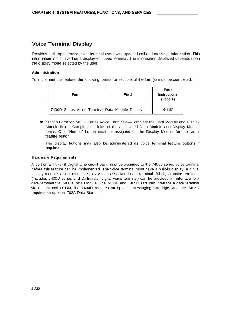
CHAPTER 4. SYSTEM FEATURES, FUNCTIONS, AND SERVICES
Voice Terminal Display
Provides multi-appearance voice terminal users with updated call and message information. Thisinformation is displayed on a display-equipped terminal. The information displayed depends uponthe display mode selected by the user.
Administration
To implement this feature, the following form(s) or sections of the form(s) must be completed.
FormForm Field Instructions
(Page #)
7400D Series Voice Terminal Data Module Display 6-287
● Station Form for 7400D Series Voice Terminals—Complete the Data Module and DisplayModule fields. Complete all fields of the associated Data Module and Display Moduleforms. One "Normal" button must be assigned on the Display Module form or as afeature button.
The display buttons may also be administered as voice terminal feature buttons ifrequired.
Hardware Requirements
A port on a TN754B Digital Line circuit pack must be assigned to the 74000 series voice terminalbefore this feature can be implemented. The voice terminal must have a built-in display, a digitaldisplay module, or obtain the display via an associated data terminal. All digital voice terminals(includes 7400D series and Callmaster digital voice terminal) can be provided an interface to adata terminal via 7400B Data Module. The 7403D and 7405D sets can interface a data terminalvia an optional DTDM, the 7404D requires an optional Messaging Cartridge, and the 7406Drequires an optional 703A Data Stand.
4-332

Wide Area Telecommunications Service (WATS) Trunk Group
Wide Area Telecommunications Service (WATS) Trunk Group
A WATS Trunk Group provides for trunk connections between the System and a WATS (or 800Service) office.
Administration
To assign a WATS Trunk Group, the following form must be completed.
FormForm Field Instructions
(Page #)
WATS Trunk Group All 5-264
● WATS Trunk Group Form—Complete all fields as required.
Hardware Requirements
A port on a TN747B CO Trunk or TN767 DS1 Interface circuit pack is required for each WATStrunk to be assigned. A TN747 provides eight ports and a TN767 provides 24 ports.
4-333

CHAPTER 4. SYSTEM FEATURES, FUNCTIONS, AND SERVICES
Voice Terminals
The following provide administrative guidelines for the System’s voice terminals. Refer to thereferenced forms for specific instructions associated with a voice terminal type.
Administration
To administer Voice Terminals, the following forms must be completed.
FormForm Field Instructions
(Page #)
Station—10-, 20-, or 30-MET Voice All 6-252Terminal
Station—500 Voice Terminal All 6-260
Station—510D Personal Terminal All 6-268
Station—515 BCT All 6-268
Station—2500 Voice Terminal All 6-260
Station—7101A Voice Terminal All 6-260
Station—7102A Voice Terminal All 6-260
Station—7103A Voice Terminal All 6-260
Station—7104A Voice Terminal All 6-260
Station—7303S All 6-279
Station—7305S All 6-279
Station—7309H Voice Terminal All 6-279
Station—7401D Voice Terminal All 6-287
Station—7403D Voice Terminal All 6-287
Station—7404D Voice Terminal All 6-287
Station—7405D Voice Terminal All 6-299
Station—7406D Voice Terminal All 6-314
Station—7407D Voice Terminal All 6-314
Station—7410D Voice Terminal All 6-328
Station—7434D Voice Terminal All 6-335
Station—7505D Voice Terminal All 6-396
Station—7506D Voice Terminal All 6-396
Station—7507D Voice Terminal All 6-396
Station—8503T Voice Terminal All 6-396
Station—602A1 Callmaster Digital All 6-348Voice Terminal
4-334

Voice Terminals
Hardware Requirements
MET Sets (10-, 20-, 30-MET)
A port in a TN735 circuit pack is required for each 10-, 20-, or 30- Multi-Button Electronic Tele-phone (MET) to be assigned. A TN735 provides four ports. Analog Voice Terminals (500,2500, 7101A, 7102A, 7103A, 7104A)
A port is required on a TN742, TN746B, or TN769 Analog Line circuit pack, or a TN767 DS1 TieTrunk for each analog Voice Terminal to be assigned. A TN742 and TN769 provides eight ports.The TN746B provides 16 ports for in-building use only. A TN767 provides 24 ports.
Hybrid Voice Terminals (7303S, 7305S, 7309H)
A port is required in a TN762 Hybrid Line circuit pack for each hybrid voice terminal to beassigned. A TN762 provides eight ports.
Digital Voice Terminals [7401D, 7403D, 7404D, 7405D, 7406D, 7407D, 7410D, 7434D, 602A1,7505D (BRI), 7506D (BRI), 7506D (BRI), 7507D (BRI), and 8503T (BRI)]
A port is required on a TN754 Digital Line circuit pack for each 7401D, 7403D, 7404D, 7405D,7406D, 7407D, 7410D, 7434D, and 603A1 digital voice terminal to be assigned. In the case ofthe 7505D, 7506D, 7507D, and 8503T BRI voice terminals (digital, but non-DCP), a port isrequired on a TN556 ISDN BRI Line circuit pack. The TN556 ISDN BRI Line circuit pack pro-vides 12 ports. When administered in multipoint (passive bus) configuration, a port may beshared by two endpoints. Each endpoint may be a voice-only or stand-alone data endpoint. ForBRI applications, a TN778 Packet Control circuit pack is also required to provide ISDN BRI con-nectivity. The Packet Control circuit pack provides ISDN signaling links with Link Access Proto-001 for the D-Channel.
510D Personal Terminal and 515 Business Communications Terminal (BCT)
A port is required on a TN754 Digital Line circuit pack for each 510D or 515 BCT to be assigned.A TN754 provides eight ports.
4-335

CHAPTER 4. SYSTEM FEATURES, FUNCTIONS, AND SERVICES
Personal Computer (PC)—MS-DOS PC/PBX Connection
Provides an integrated voice and data workstation interface from the System to an AT&T PCMS-DOS or other compatible computer. The connection provides access to a variety of hostcomputers, allowing the PC to act as a terminal for the host.
Figure 4-20 shows atypical 7400D series voice terminal PC/PBX workstation connection and Fig-ure 4-21 shows a typical 7404D voice terminal (equipped with Message Cartridge) PC/PBXworkstation connection.
Administration
To administer a PC/PBX connection, the following forms must be completed.
FormForm Field Instructions
(Page #)
PC/PBX Connection All 6-356
Hardware Requirements
A port is required on a TN754 Digital Line circuit pack for each PC/PBX connection to beinstalled. A TN754 provides eight ports.
Software Requirements
One of the following PC/PBX software packages must be installed on the PC, as appropriate:
● PC/PBX Connection Package 1
Provides features such as keyboard dialing, personal phone directory, directory dialing,and message retrieval. Hardware requirements include: PC, 7404D voice terminalequipped with a Message Cartridge.
● PC/PBX Connection Package 3
Provides Package 1 services plus additional features (such as call log, higher file transferrates, and the ability to take notes on a call). Hardware requirements include: PCequipped with a DCP card and a 7400D series voice terminal. Package 3 provides anintegrated voice and data workstation that supports:
— Dialing calls from the PC
— Use of customized phone features from the PC keyboard
— Creating a personal phone directory in the PC, searching the directory, and dial-ing voice and data calls from the directory
— Reading phone messages on the PC screen and having the PC automaticallydial calls to users that have left messages
— Logging all incoming and outgoing calls (voice and data) and the ability toautomatically recall them
— Using an associated speakerphone to make "hands-free" calls
4-336

Personal Computer (PC)—MS-DOS PC/PBX Connection
—
—
—
—
—
Use of a security feature so as to keep directory and message informationprivate
Use of the PC as a terminal connected to a variety of host computers
Transferring files between the PC and another PC or host computer
Setting up "script programs" to have the System perform selected data functionsautomatically
Using voice and data functions simultaneously. Lets you perform PC applicationwhile running the PC/PBX Connection software application in the background.
● PC/PBX Connection Package 5
Package 5 is a terminal emulation package that allows the PC to emulate a 3278/3279terminal. This is a software enhancement to Package 3 and works with Package 3hardware and software.
For additional PC/PBX user information, refer to AT&T PC/PBX Connection Package 3 User’sGuide, 555-016-703. A complete set of documents is available as AT&T PC/PBX ConnectionRelease 3 Documentation Set, 555-016-715.
SWITCHWORKSTATION
l
†
7400D
DCP DCPTN754
SERIES
PCDIGITAL
VOICE
LINE CPTERMINAL
* PC MUST BE EQUIPPED WITH DCP CARD AND APPROPRIATE
PC/PBX SOFTWARE.
† 7401D, 7403D, 7404D (WITH OUT MESSAGE CARTRIDGE), 7405D,
7406D, OR 7407D VOICE TERMINAL.
FIGURE 4-20. Typical 7400D Series Voice Terminal PC/PBX Connections
4-337

CHAPTER 4. SYSTEM FEATURES, FUNCTIONS, AND SERVICES
WORKSTATION
SWITCH
TN754
DIGITAL
LINE CP
7 4 0 4 D
VOICEDCP TERMINAL RS-232C
MESSAGE
CARTRIDGE
• PC MUST BE EQUIPPED WITH APPROPRIATE
PC/PBX SOFTWARE.
FIGURE 4-21. Typical 7404D PC/PBX Connection
4-338

CHAPTER 5. FORMS FOR NETWORK FEATURES AND SERVICES
CHAPTER 5. FORMS FOR NETWORK FEATURES AND SERVICES
Overview
This chapter contains System forms and associated instructions required to implement the follow-ing network-type features and services.
● Automatic Route Selection (ARS)
● Automatic Alternate Routing (AAR)
● Centralized Attendant Service (CAS)
● Distributed Communications System (DCS)
● DS1 Trunk Service
● Integrated Services Digital Network (lSDN)—Primary Rate Interface (PRI)
● Trunk Groups.
In addition, administration commands required to access the forms is provided along with eachform’s coverage. In some cases, just the most commonly used commands are given. Chapter 3provides a complete listing of the System’s administration commands and describes the "make-up" of the command line. Specifically, the "action," "object," and "qualifier" command words aredescribed in detail.
The farms included in this chapter are those forms that are primarily dedicated to networking anddo not include multi-use forms that support other functional areas such as voice or data manage-ment. All other forms required to implement the System, including those multi-use forms (forexample Dial Plan, Feature Access Codes) that support networking and voice and data manage-ment, are included in "Chapter 6. Forms for System Features and Services."
Refer to "Chapter 4. System Features, Functions, and Services" for a complete listing of all formsand/or related fields on forms that must be completed or considered when implementing theabove network-type features and services.
Blank forms are provided in the Blank Forms Package and may be reproduced as required. Thecopies are used as worksheets when using this manual to assign features and services. Thecompleted hard-copy forms are later used with administration commands provided in Chapter 3to implement the System. The forms should then be retained as part of the System’s hard-copyrecords.
5-1

CHAPTER 5. FORMS FOR NETWORK FEATURES AND SERVICES
Automatic Route Selection
This section contains the network-type forms and associated instructions dedicated primarily toimplementing the Automatic Route Selection (ARS) feature.
ARS routes calls over the public network based on the preferred route (normally based on acustomer-specified order and typically the least expensive) available at the time the call is placed.ARS provides a choice of up to six routes for any given public network call. The following types oftrunk groups can be accessed by ARS:
●
●
●
Foreign exchange— Used to emulate local calling in an area not served by the local cen-tral office.
Local central office— Used for local calls and to provide access to long-distance car-riers. Access to the long-distance carrier can be provided automatically by the centraloffice or by a carrier access code.
Integrated Services Digital Network (lSDN)— Primary Rate Interface (PRl)—Used forcalls over an ISDN and provides users access to a variety of switched nodal servicessuch as Megacom telecommunications service, INWATS, and ACCUNET digital serviceand allows access to other interexchange carriers.
Tie trunks— Used to provide access to an Electronic Tandem Network (ETN), or to anEnhanced Private Switched Communications Service (EPSCS) or Common ControlSwitching Arrangement (CCSA) office.
Wide Area Telecommunications Service (WATS)— Used to provide calling to prede-
●
●
fined geographic areas at a rate based on expected usage.
For the the following discussion:
●
●
●
●
●
●
Area Code = NPA = NIX (where N = 2-9, I = 0 or 1, X = 0 through 9)
Central Office (CO) Code = NXX (where N = 2-9, X =0 through 9) or NIX (see AreaCode)
Foreign Number Plan Area (FNPA) Code—see Area Code
Home Number Plan Area (HNPA) Code—see Area Code
Partitioned Group Number (PGN) = 1 through 8
Service Codes = X11 (where X = 0 through 9).
Note that the method used to administer ARS in the previous release of the DEFINITY Generic 1System has been changed with this release. The ARS HNPA and FNPA Tables and Ten-Digit toSeven-Digit Conversion forms that were previously used have been replaced with two new forms(ARS Analysis and ARS Digit Conversion). Previous assumptions about domestic numberingplan format and length have been removed, providing the following:
● A more flexible accommodation of future changes to the NANP by administrationchanges rather than software changes.
● Now able to handle NXX area codes (planned to be introduced in 1995). Currently, thereare 180 area codes in the form NIX.
● Increased ability to analyze and route international calls.
5-2

Automatic Route Selection
● A wild card capability on the forms that allows, for example, routing by exchange, acrossall area codes (for example, XXX976).
Refer to "Automatic Route Selection" in Chapter 4 for a complete listing of all System formsand/or fields on forms that must be completed or considered when implementing ARS. Formssuch as the Dial Plan, COR, Feature Access Codes, and Feature-Related System Parametersthat support both networking and other functional areas such as voice management and, datamanagement may also require implementation.
ARS also supports the following features:
● Automatic Alternate Routing— Provides automatic muting of ETN calls over private orpublic network facilities.
● Call by Call Service Selection— Allows users to gain access to a variety of switchednodal services such as Megacom service, WATS, ACCUNET digital service, and variousinter-exchange carriers.
● Generalized Route Selection— Provides separate routes for voice and data calls. Alsoprovides for the integration of voice and data over the same trunking facilities, whenrequired.
ARS Forms
The following ARS forms are included in this section:
Note: The ARS option must be enabled on the System-Parameters Customer-Optionsform before the ARS forms can be administered.
● ARS Analysis
● ARS Digit Conversion
● RHNPA
● ARS Toll Table
● Routing Patterns
● TOD Routing.
The following provides an overview of the System’s ARS forms and their purpose. A descriptionof the forms and how software uses their associated data entries to process a call is described.In addition, dialing patterns such as operator dialed calls, prefix 1 DDD calls, special service calls,international calls, and inter-exchange carrier calls are described.
Figure 5-1 is a high-level presentation on the use of the various System forms in the processingof ARS and ARS calls. AAR call processing is included here because of the interrelationship thatexists between the two features when both have been activated in a System. If your Systemdoes not have Private Networking (AAR) optioned for, disregard all call processing functionalityusing AAR as shown on the flow diagram.
5-3

CHAPTER 5. FORMS FOR NETWORK FEATURES AND SERVICES
The forms are shown in the general order that software accesses them when processing a call.Actual software processing may differ in some cases. The flow diagram does not show allsoftware processes and decision making routines that occur. It is intended only to show the useof the forms and their various parameters in call processing.
The flow chart assumes that the associated optional features have been enabled on the System-Parameters Customer-Options form. For those features not enabled, consider the flow asthrough the associated form(s) and through any decision making blocks that occur as a result ofusing the form. The optional features include:
● A R S
● Private Networking (AAR)
● ARS/AAR Partitioning
● TOD Routing
● ARS/AAR Digit Conversion.
Immediately following the flow diagram is a summary of each of the forms (Figure 5-2) and theparameters that may be administered on the forms. Use this summary as a "quick reference"when you need an overview of just what is on each form.
Following this introduction are detailed instructions for completing each form.
As shown on Figure 5-1, an ARS, call begins with the dialing of an ARS access code (typicallynine). If the facility (for example, voice terminal) is Origination or Outward restricted or the user(by COR assignment to the facility) is Controlled Outward or Total Restricted, intercept treatmentis provided as shown on the figure. Second Dial Tone is provided to the calling party if AAR/ARSDial Tone is optioned for on the Feature-Related System Parameters form. The caller then dialsa "1" (if "ARS Prefix 1 required?" is administered on the System’s Dial Plan form), if the call is a10-digit FNPA call or dials one of a variety of dialing patterns including 7-digit numbers, 10-digitDDD numbers, International Direct Distance Dialing (IDDD) numbers, service codes, Customer-Dialed Operator-Serviced (CDOS) numbers, and IXC numbers.
The dialed digits are compared to numbers entered in Matching Pattern fields on the ARS DigitConversion form. If a match occurs, a new number from the Replace field on the form is used toroute the call by AAR over the private network. Certain dialed digit strings may be routed (viatheir replacement strings) to the attendant, an announcement, or intercept if required. If nomatch is found, the dialed string is compared with digit string entries on the System’s TollAnalysis form for a relationship with the System’s Toll List, RCL, or UCL (see Toll Analysis formin Chapter 6). Calls that are not allowed to complete are given intercept treatment. If the call isallowed, call processing continues based on how the ARS Partitioning and Time of Day Routing(TDR) options are administered on the System-Parameters Customer-Options form as follows:
● ARS Partitioning Enabled and TDR Not Enabled:
The PGN of the calling party (1 through 8, administered via COR assignment to station)is used to make the choice of an ARS Analysis form with a PGN of the same number (1through 8).
5-4

Automatic Route Selection
● ARS Partitioning Enabled and TDR Enabled:
The TOD Plan Number of the calling party (1 through 8, administered via COR assign-ment to station) is used to make the choice of a TOD Routing form of the same number(1 through 8). On the form, a Plan Number (1 through 8) is identified based on the dayand time of day. This Plan Number is used to select an ARS Analysis form with a PGNof the same number (1 through 8).
� ARS Partitioning and TDR Not Enabled:
The ARS Analysis form (only one form in the System when ARS Partitioning and TDRnot enabled) is accessed for continued call processing. The PGN displayed will be a "1."
The ARS Analysis form is used to map dialed strings to routing patterns. Each dialed string entryon the form is associated with a routing pattern and a call type (for example, HNPA, FNPA,operator, service, etc.). Table 5-A (see ARS Analysis Table Coverage) provides default transla-tions for typical dialing strings. Operator, Inter-Exchange Carrier, 7-digit (digits 2 through 9 with atotal of 7 digits min/max) are initially defaulted to routing pattern one. If, for certain dialed digitstrings, RHNPA translations are required, an appropriate entry of "r1" through "r32" is entered inthe Routing Pattern field on the ARS Analysis Table form. The RHNPA form is used for translat-ing 3-digit codes in the range 000 through 999. The table is used typically for the DDD of centraloffice codes in a nonlocal NPA. The first three digits of a nonlocal FNPA are translated on theARS Analysis Table form and, where appropriate, the form points to a RHNPA table (1 through32) where further translations occur.
If the ARS Analysis table points to an RHNPA table, the next three dialed digits are comparedwith codes in the selected RHNPA table. Each code on the table may have an administeredreference to a routing pattern number (1 through 254).
The Routing Pattern form is used to route a call over one of six possible trunk groups. Up to 254Routing Patterns may be assigned in the System. Based on entries on the form, up to 18 leadingdigits may be deleted from the dialed number and up to 36 (after digit deletion) may be inserted.Up to 54 digits may be outpulsed (includes special symbols "+," "%," "#," "*," and ","). Whenused, special symbols count as two digits each. An ARS Toll Table, when referenced from therouting pattern, is used to specify whether calls are toll or local type calls.
Finally, compatibility checks ensure that the calling party’s FRL is greater than or equal to therouting preference’s FRL, the BCC of the calling party matches the BCC specified for the routingpreference if ISDN-PRI is optioned for on the System Parameters Customer Options form, andthere is an unused circuit (that is, trunk port) available in the selected trunk group. When allchecks are okay, digits are outpulsed over a selected trunk group member.
5-5

CHAPTER 5. FORMS FOR NETWORK FEATURES AND SERVICES
FIGURE 5-1. Automatic Route Selection Call Processing—Flow Diagram (Sheet 1 of 3)
5-6

Automatic Route Selection
FIGURE 5-1. (Contd) Automatic Route Selection Call Processing—Flow Diagram (Sheet 2 of 3)
5-7

CHAPTER 5. FORMS FOR NETWORK FEATURES AND SERVICES
NOTES:1. lT IS RECOMMENDED THAT PNDNs THAT ARE DIALED AFTER AN
AAR ACCESS CODE BE ADMINISTERED TO HAVE A "1" PREFIX.A DEFAULT ENTRY ON THE AAR ANALYSIS FORM WILL CAUSETHESE CALLS TO “CROSSOVER” TO ARS.
2. LOCAL USER IS A SUBTENDING PBX - DEFAULT FRL IS THE FRLASSIGNED TO THE INCOMING ACCESS TRUNK GROUP.
ATTENDANT EXTENDED CALL - DEFAULT FRL IS THE FRL ASSIGNEDTHE ATTENDANT GROUP, NOT THE FRL ASSIGNED THE USER’S
STATION OR FACILITY
REMOTE ACCESS USER - DEFAULT FRL IS THE FRL ASSOCIATED WITH ANAUTHORlZATION CODE, IF ENTERED. OTHERWISE, THE FRL ASSOCIATEDWITH THE BARRIER CODE IS USED. IF NO BARRIER CODE OR AUTHORlZATIONCODE IS USED, THE DEFAULT BARRIER CODE’S FRL IS USED.
LEGEND:AAR - AUTOMATIC ROUTE SELECTION
ARS - AUTOMATIC ROUTE SELECTIONBCC - BEARER CAPABILITY CLASSCOR - CLASS OF RESTRICTIONFRL - FACILITY RESTRICTION LEVELPNDN - PUBLIC NETWORK DESTINATION NUMBER (I,E, DDD, IDDD,
SERVICE CODE 411, 911, ETC)RHPA - REMOTE HOME NUMBER PLAN AREA
FIGURE 5-1. (Contd) Automatic Route Selection Call Processing—Flow Diagram (Sheet 3 of 3)
5-8

Automatic Route Selection
●
●
●
●
●
●
●
●
●
●
●
●
●
●
●
●
●
ROUTES MATCHED CALLS VIA AAR USING REPLACENUMBERS. (MATCH IS ON DIALED NUMBER).
MATCHING PATTERN FIELD -1 TO 18 CHARACTERS
REPLACEMENT STRING FIELD -1 TO 18CHARACTERS
MATCHED NUMBER STRINGS ARE MODIFIED USINGASSOCIATED REPLACEMENT STRINGS
CALL ROUTED PER MODIFlED NUMBER
MATCHING PATTERN FIELD -1 TO 18 CHARACTERS
REPLACEMENT STRING FIELD -1 TO 18 CHARACTERS
PROCESSES CALL BASED ON THE TIME OF DAY.THE TIME OF DAY NUMBER (1-8) OF A LOCALCALLING USER IS USED TO CHOOSE AN ASSOCIATEDTOD FORM (PLAN NO. 1-8).
FOR USERS THAT ENTER A BARRIER CODE OR ANAUTHORIZATION CODE, THE CQR SPECIFIED BYTHE BARRIER OR AUTHORIZATION CODE IS USEDTO SELECT A TOD PLAN.
EIGHT FORMS MAXIMUM, EACH ASS0CIATED WITHA DIFFERENT PLAN NO. (1-8).
A DIFFERENT PLN NO. CAN BE REFERENCED UP TOSIX TIMES A DAY FOR EACH DAY OF THE WEEK.
THE PLN NO. (1-8) IS USED TO IDENTIFY ANASSOCIATED ARS/AAR ANALYSIS FORM WITH ANEQUIVALENT PARTlTIONED GROUP NUMBER (1-8).
MATCHES USER DIALED OR MODIFIED DIGIT STRINGS TOROUTING PATTERNS (l-254). USES UP TO 18- DlGITS
MIN - MINIMUM NUMBER OF DIGITS NEEDED TOVALIDATE AND ROUTE THE CALL.
MAX - MAXIMUM NUMBER OF DIGITS NEEDED TOVALIDATE AND ROUTE THE CALL.
ROUTE PAT - THE ROUTING PATTERN TO USEFOR A CALL (1-254, r1-r32)
CALL TYPE- INT (lNTERNATIONAL)- IOP (lNTERNATIONAL OPERATOR ASSISTED)- OP (OPERATOR ASSISTED)- FNPA (10-DIGIT CALL)- HNPA (7-DIGIT CALL)- SVC (SERVICE CALL)- NATL (NO SPECIAL ATTRIBUTE - USED FOR
INTERNATIONAL APPLICATIONS)
FIGURE 5-2. Automatic Route Selection/Automatic Alternate Routing—Forms Summary(Sheet 1 of 3)
5-9

CHAPTER 5. FORMS FOR NETWORK FEATURES AND SERVICES
●
●
●
●
●
MATCHED USER DIALED OR MODIFIED DIGIT STRINGS TOROUTING PATTERNS (1-254). USES UP TO 18 DIGITS.
MIN MINIMUM NUMBER OF DIGITS NEEDED TOVALIDATE AND ROUTE THE CALL
MAX MAXIMUM NUMBER OF DIGITS NEEDED TOVALIDATE AND ROUTE THE CALL.
ROUTE PAT THE ROUTING PATTERN TO USE FORA CALL (1-254, r1-r32).
CALL TYPE
- AAR (REGULAR AAR CALL)- ARS (CROSSOVER TO ARS CALL)- ATTD (ATTENDANT)- HAAR (CALL TO TERMINATE TO LOCAL HOME SWITCH)- HATD (AAR CALL TO TERMINATE LOCALLY TO ATTENDANT
GROUP)
●
●
●
●
MAY BE USED FOR DDD OFCO CODES IN AN FNPAINTERNATIONAL NUMBERSINTER-EXCHANGE CARRIER CODES3-DIGIT TRANSLATIONS OF NUMBERS (000-999)
TEN PAGES MAXIMUM PER TABLE (32 TABLES MAX.)
UP TO 12 OF THE 254 POSSIBLE ROUTINGPATTERNS CAN BE REFERENCED ON EACH TABLE.
EACH PAGE SUPPORTS 100 CODES IN THERANGE 000-099, 100-199, 900999.
●
●●
●
●
●
●
●
●
USED FOR ARS AND NON-ARS SYSTEMS.
USED TO ASSIGN DIALED NUMBERS TO THE RESTRICTED CALL LIST(RCL), UNRESTRICTED CALL LIST(UCL), SMDR FEAC, AND TOLL LIST.
MIN MINIMUM NUMBER OF DIGITS TO COLLECT.
MAX MAXIMUM NUMBER OF DIGITS TO COLLECT.
RCL RESTRICTED CALL LIST. ALL ENTRIES OF "X" AND THEIRASSOCIATED DIALED STRINGS ARE REFERRED TO AS THE SYSTEM’S RCL
TOLL LIST ALL ENTRIES OF "X" AND THEIR ASSOCIATED DIGITSTRINGS ARE REFERRED TO AS THE SYSTEM’S TOLL LIST.
SMDR FEAC USED TO INDICATE THAT A SMDR ACCOUNT CODE MUST BEDIALED BEFORE A CALL THAT MATCHES THE "DIALED STRING "ENTRY.
UCL ALL ENTRIES OF "X" THAT ARE ASSOCIATED WITH APARTICULAR UCL NUMBER AND THEIR ASSOCIATE DIGIT STRINGS AREREFERRED TO AS THE UNRESTRICTED CALL LIST (1-10).
FIGURE 5-2. (Contd) Automatic Route Selection/Automatic Alternate Routing—Forms Summary(Sheet 2 of 3)
5-10

Automatic Route Selection
FIGURE 5-2. (Contd) Automatic Route Selection/Automatic Alternate Routing—Forms Summary
ROUTES CALL OVER ONE OFSIX POSSIBLE TRUNK GROUPS.
UP T0 254 FORMS CAN BEASSIGNED.
●
●
●
●
●
●
●
●
●
●
UP TO 23 LEADING DIGITS OFTHE DIALED NUMBER MAY BEDELETED.
UP TO 36 CHARACTERS (AFTERDIGIT DELETION) MAY BEINSERTED.
UP TO 52 DIGITS MAY BE OUTPULSED.
AN ASSOCIATED ARS TOLL LIST(TABLE) MAY BE REFERENCEDFOR EACH TRUNK GROUP TOIDENTIFY TOLL OR NON-TOLLTYPE CALLS.
CALLERS FRL MUST BETRUNK GROUPS FRL
USED TO SPECIFY TOLL ORNON-TOLL DATA FOR UP TO800 CO CODES.
EIGHT PAGES MAXIMUM PERTABLE.
UP TO 32 TABLES CAN BEASSIGNED.
(Sheet 3 of 3)
5-11

CHAPTER 5. FORMS FOR NETWORK FEATURES AND SERVICES
Dialing Patterns
The System recognizes different types of dialing patterns on outgoing calls and can route the callaccordingly. The following dialing patterns are supported.
Note: Refer to Table 5-A (ARS Analysis Default Translations) for default translations asso-ciated with the following.
●
●
Operator Assistance Calls— The first digit following the ARS access code is a 0. If a 0is dialed by itself to access an operator, a special interdigit time-out occurs, the route fordial 0 calls is selected and a 0# is outpulsed. If the user dials another 0, the route for 00is selected, and a 00# is outpulsed. The call is routed to the toll operator (if one exists)instead of the local operator in this case.
DDD Calls with Prefix Digit 1 Required— The Prefix Mark field (on the System’s Rout-ing Pattern form) can be administered as follows for each of the six possible routingchoices on each form:
Note: Prefix Mark operations only apply to fnpa or hnpa call types.
0 Indicates that the Prefix digit 1 is never outpulsed.
1 Indicates that the Prefix digit 1 is outpulsed if and only if the call is a long dis-tance FNPA call. Prefix Mark 1 should be selected for those HNPAs that requireusers to dial “1” to indicate a long distance FNPA call.
2 Indicates that the Prefix digit 1 is outpulsed for all toll calls within and outside theHNPA.
3 Indicates that the Prefix digit 1 is outpulsed for all toll calls. These calls arealways outpulsed as 10-digit numbers, even those within the HNPA.
When a Prefix “1” is required, the first dialed digit of the long distance call following theARS access code is a 1. Typically, dialing a “1” prefix in system’s that require a “1” indi-cates a 10-digit call. The main purpose of the prefix digit “1” is to distinguish between 7-and 10-digit calls when there are interchangeable CO codes (that is, CO codes that canbe NPA codes).
Another reason to dial a “1” prefix digit is to indicate a 7-digit toll call within the HNPA.This is particularly useful when there is a toll CO code in the HNPA, in addition to thesame CO code (non-protected) in an adjacent NPA which can be accessed locally bydialing a 7-digit number. In order to permit 7-digit dialing for both calls, the toll call is pre-fixed by “1.” When the user dials a “1” prefix followed by a 7-digit number, it will betreated as a toll call in the HNPA (even if the ARS Toll Table indicates local). When theuser dials the same number without the “1” prefix, it is treated as a local call across theNPA boundary.
●
●
DDD Calls with Prefix Digit 1 Not Required— The first digit of a long distance call fol-lowing the ARS access code may or may not be a 1 (dialing the “1” prefix before a 10-digit call is optional). In Systems where the 1 prefix is dialed (even though not required),the prefix will be ignored.
Operator Assisted and international Calls— The first digits following the ARS accesscode are a “0” (operator), 00 (toll operator), and optionally followed by a 10-digit DDDnumber, or by 01 or 010 (international operator) for international dialing and optionally
5-12

Automatic Route Selection
followed by international destination address digits. Because of the variable number ofdigits required for these calls, an interdigit time-out is used to recognize end of dialing.
The System employs a short inter-digit timer and a long inter-digit timer during the dialingprocess. If the digits dialed so far are a valid (for example, “0”) but more digits may fol-low, the short 3-second inter-digit timer will be started. If dialing does not continue before the timer expires, it is assumed that no more digits will follow. To override the short orlong inter-digit timer for faster call processing, the originator may dial “#” to indicate endof dialing. To prevent a time-out race condition between the caller’s switch and other net-work switches, a 10-second short inter-digit timer is used for incoming tie trunk calls. A10-second long inter-digit timer is used when the digits dialed so far are not a valid desti-nation. Time-out of this timer results in Intercept tone to the caller. The user may, how-ever, dial the # character on any of these calls to cancel the time-out interval and indicateend of dialing. The use of the # symbol to indicate end of dialing is applicable only withtouch-tone stations in the public network.
A trailing # is outpulsed for a range of digits in the dialed string (for example, internationalcalls) except when outputting dial pulses. An option on the trunk group form can be usedto suppress “#” outpulsing. The dialed digits, including the prefix 0 and the trailing #, arealways outpulsed as dialed except that # is never outpulsed when outputting dial pulses.
● International Direct Distance Dialing— An international telephone number consists of aCountry Code (CC) plus the National Number (NN). The NN is simply the number usedwhen calling within the country. In the NANP, NN is a 10-digit address. The CC is oneto three digits and the combination of CC and NN is a 12-digit maximum. In the NANP,the System is alerted to the fact that an international number is being dialed by use of aspecial prefix code as follows:
➤
➤
011—indicates that the caller is making a station paid direct international call andCC plus NN digits follow. The term IDDD is normally associated with 011 plus(011+) station calls.
011—indicates that the caller desires operator assistance in an international call,such as person-to-person, credit card, collect call, etc., and CC and NN digits fol-low. The term ICDOS (International Customer-Dialed and Operator-Serviced)reflects the nature of 01 + dialing options.
A “01 +” (lCDOS) call is similar to “0+” or “00+” (operator-assisted North Ameri-can Network) call, whereas a “011 +” (IDDD) call is similar to a “1 +” call.
● Special Service Codes— The first digit following the ARS access code is a special sys-tem or service code. Such codes consist of only three digits in the form X11 (where X =0-9) with or without dialing the 1 prefix digit. These are recognized as completeaddresses, if no further digits are dialed, and are routed to the appropriate facility. Theinterdigit time-out determines whether the call is a 3- or 7-digit call. For example, if theuser dials 911, the call will route to the police/emergency operator, and if the user dials811-XXXX, the call will be translated as a 7-digit call for the repair bureau correspondingto the last four digits (811 is a service code for repair). In any case, the call is routed onthe first three digits (X11) for these special services and translated by the ARS AnalysisTable.
● Call Dialed with Inter-Exchange Carrier (lXC) Access— The first digits following theARS access code is a 5- or 7-digit IXC code. The System then makes a determination ofthe number of digits to collect based on the digits following the code. The IXC code may
5-13

CHAPTER 5. FORMS FOR NETWORK FEATURES AND SERVICES
be followed by a DDD or IDDD number. This gives the user control over which carrier orfacilities should be used for routing the call. However, the call will be routed based onadministration of the IXC code in the ARS Analysis Table (see ARS Analysis Table).
The System supports three general IXC access arrangements which are commonlyreferred to as Feature Group A, B, and D (that is, FG A, FG B, FG D). From a callersperspective, the major differences between use of the various groups are:
●
●
●
●
To select an IXC, FG A and FG B require the dialing of 7 digits (that is, NXX-XXXX or 950-0/1 XXX, respectively) but FG D requires just 5 digits (that is,10XXX).
Single-stage dialing is supported for FG D but FG A and FG B require 2-stagedialing. (Two-stage dialing means that there is a pause for dial tone between thetwo groups of dialed digits.)
No customer identification digits are required for FG D.
A touch-tone telephone is required to enter a Personal Identification Numbercode when using FG A or FG B. A dial pulse or touch-tone telephone may beused with FG D.
System default translation used for IXC call types are shown on Table 5-A (ARS AnalysisDefault Translations).
5-14

ARS Analysis Table
ARS Analysis Table
Purpose
This form is used to administer the ARS Analysis Table. The form allows for the mapping of cus-tomer dialed numbers (dialed strings) to routing patterns, using up to 18 digits. The ARSAnalysis Table and the ARS Digit Conversion Table (coverage follows) replaces the ARS FNPA& HNPA Tables that were used in the previous release of the System.
Note: The ARS feature must be enabled on the System-Parameters Custom-Options formbefore associated ARS forms can be administered.
Administration Commands
The following administration commands can be used to access the ARS Analysis Table form. Insome cases, just the most commonly used commands are shown. Refer to Administration Com-mands and Error Messages (Chapter 3) for a complete listing of all administration commands, thecommand structure, and the use of abbreviated command words when entering a command.
Action Object Qualifier*
change ars analysis Enter digits between 0-9, ‘x’ or ‘X’ (dialed string)[’part’ 1-8] [’min’ 1-23]
display ars analysis Enter digits between 0-9, ‘x’ or ‘X’ (dialed string)[’part’ 1-8] [’min’ 1-23] [’print’ or ‘schedule’]
list ars analysis [start-dialed string] [‘count’ 1-2000 [’rp’ 1-254 orr1-r32] [‘part’ 1-8] [’print’ or ‘schedule’]
list ars route chosen Enter dialed number, [partition (1-8)],[’print’ or ‘schedule’]
● Brackets [ ] indicate the qualifier is optional.Single quotes (‘ ‘) indicate the text inside the quote must be entered exactlyas shown or an abbreviated form of the word may be entered.
Form Instructions
Make assignments as required for the following fields on the form.
● Percent Full— character display-only field. Displays the percentage of the System’smemory resources that have been utilized. A common pool of memory resources isshared between the ARS and AAR Analysis tables, the ARS and AAR Digit Conversiontables, and the Toll Analysis table.
If this field display indicates that the System memory resources are in jeopardy ofbecoming full (that is, 100 percent), perform any of the following to “free-up” memoryresources:
➤ Delete unnecessary entries from any of the shared resources tables.
➤ Utilize RHNPA tables for 6-digit ARS routing.
5-15

CHAPTER 5. FORMS FOR NETWORK FEATURES AND SERVICES
●
●
●
●
●
●
➤ Reduce dialed string field entries to shortest possible length that accomplishesthe desired function.
Partitioned Group Number (PGN)— When completing a paper form, enter the PGN tobe associated with this table. Valid entries are 1 through 8. Default is "1."
Dialed String— Enter the dialed string of significant digits. Up to 18 characters max-imum consisting of the digits 0 through 9 are allowed. A wild card letter “x” or “X” maybe used to substitute for any digit occurring in the string at the character position whereused. Valid entries are 0 through 9, x, X, or leave blank. Default is blank.
Note that the user dialed digits are matched to the Dialed String field entry that mostclosely matches the dialed number (referred to as the “longest match”). For example, ifa user dials 957-1234 and the ARS Analysis Table has Dialed String entries of 957-1 and957-123, the match is on the 957-123 entry. In addition, an exact match is made onDialed string entries of the same number of digits in cases where wild card characters(Xs) are used. For example, if 411 is dialed and the table has Dialed String entries of411 and X11, the match is on the 411 entry.
Min— Enter the minimum number of digits needed to validate and route the call. Validentries are 1 through 23. Default is blank
Max— Enter the maximum number of digits needed to validate and route the call. Validentries are 1 through 23. Default is blank.
Route Pat (Routing Pattern)— Enter the routing pattern number (1 through 254), apointer to an associated RHNPA form (r1 through r32) to be used to route the call onceall identifying digits have been received, or “ign.” The “ign” entry when used causes theassociated Dialed String entry to be ignored and the search to continue for the nextmatch. This is used typically for home NPA calls where some callers dial 10-digits andothers dial 7-digits. For example, if “201” is the Dialed String entry (min/max = 10/10,Route Pat = ign, and Call Type= fnpa), and the number dialed is 201-957-1234; the 201,when matched by the search routine is ignored and the table is researched using9571234. Valid entries for this field are 1 through 254, r1 through r32, ign, or leaveblank. Default is blank.
Call Type— Valid call types are:
CALL TYPE DESCRIPTION
fnpa 10-digit call (11 digits with Prefix Digit "1")hnpa 7-digit callint internationalnatl national numbers within a country—used for international applications)op operatorsvc service
Default is a blank field.
5-16
ARS Analysis Table
Table 5-A provides a listing of all ARS Analysis default translations.
Note: Any dialed digit string not accounted for on the table is considered invalid and thecall is routed to intercept. These default translations are used for call processingregardless of whether ARS has been optioned for on the switch.
The translations shown on Table 5-A appear only once in the switch’s memory but are displayedin sorted order (including additions) on each of the eight possible ARS Analysis Table formswhen displayed.
5-17

CHAPTER 5. FORMS FOR NETWORK FEATURES AND SERVICES
TABLE 5-A. ARS Analysis Default Translations
DialedString
00000001010011110XXX10XXX010XXX010XXX0010XXX0010XXX0110XXX01010XXX01123456789X11
Total Digits
Min.1112121031011561671715815777777773
Max.1112122332311561671723823777777773
RoutePattern
11111111
CallTypeopopopopiopiopintfnpaopopopopopiopiopinthnpahnpahnpahnpahnpahnpahnpahnpasvc
Legend:fnpa - foreign number plan area (10-digit call)hnpa - home number plan area (7-digit call)int - internationaliop - international operatorop - operatorsvc - service
X - any digit (0-9)
5-18

ARS Analysis Table
ARS Analysis TablePartitioned Group Number: 1 Percent Full:_
DialedString
TotalMin Max
RoutePat
CallType
DialedString
RoutePat
CallTypeMin Max
— ———
— — —— —
— ———
——
— —
— — ———
——
———
— — — —— — —
———— —
— — ———
——
— ——
SCREEN 5-1. ARS Analysis Table Form
5-19

CHAPTER 5. FORMS FOR NETWORK FEATURES AND SERVICES
ARS Digit Conversion Table
Purpose
This form is used to convert public network numbers (ARS) to private network numbers (AAR).Its purpose is to save toll charges and to allow users to dial all calls using a public networknumber. Also, unauthorized public network calls can be routed to an attendant or given intercepttone.
The form allows for the replacement of all or part of a dialed digit string with a modified string.The modified string represents an alternative equivalent address and results in the call beingrouted according to the modified string. If the ARS Access Code is dialed, this table is accessedduring call processing. Up to 300 entries in software can be shared between this table and theAAR Digit Conversion Table.
The ARS Digit Conversion feature enhances the capabilities of the ARS feature so that outgoingpublic network calls and private network calls can be changed to private or public network desti-nations. The calls are then routed via the AAR feature.
The ARS feature must be enabled on the System-Parameters Customer-Options form beforeassociated forms and fields on forms can be administered.
Administration Commands
The following administration commands can be used to access the ARS Digit Conversion Tableform. In some cases, just the most commonly used commands are shown. Refer to Administra-tion Commands and Error Messages (Chapter 3) for a complete listing of all administration com-mands, the command structure, and the use of abbreviated command words when entering acommand.
Action Object Qualifier*
change ars digit-conversion Enter digits between 0-9 ‘x’ or ‘X’display ars digit-conversion Enter digits between 0-9, ‘x’ or ‘X’ [’print’ or ‘schedule’]list ars digit-conversion Enter [’start’ matching pattern] [‘count’ (1-300)]
[’print’ or ‘schedule’]
* Brackets [ ] indicate the qualifier is optional.Single quotes (‘ ’) indicate the text inside the quote must be entered exactly as shown oran abbreviated form of the word maybe entered.
Form Instructions
Make assignments as required for the following fields on each page of the form.
Note that when the form is accessed via an administration command such as display or change,the entries are sorted separately in the order of the matching pattern. Specific digits are sortedbefore the wild card character “x” or “X.”
● Percent Full— 3-character display-only field. Displays the percentage of the System’smemory resources that have been utilized. A common pool of memory resources isshared between the ARS and AAR Analysis tables, the ARS and AAR Digit Conversiontables, and the Toll Analysis table.
5-20

ARS Digit Conversion Table
If the Percent Full field display indicated that the System memory resources are in jeo-pardy of becoming full (that is, 100 percent) perform any of the following to “free-up”memory resources:
➤
➤
➤
Delete unnecessary entries from any of the shared resources tables.
Utilize RHNPA tables for 6-digit ARS routing.
Reduce dialed string field entries to shortest possible length that accomplishesthe desired function.
●
●
Matching Pattern— Enter a 1-to 18-digit string to be matched against a dialed number.Matching Pattern entries must be unique within the table. The string may contain thedigits 0 through 9 and wild card character “x” or “X” which is used to match any digit inthe range of 0 through 9. If a Prefix Digit is required for 10-digit DDD numbers, then thePrefix Digit “1” must be present in the Matching Pattern string for the match to succeed.
If the associated Replacement String field has an entry, the Matching Pattern field musthave an entry.
Replacement String— Enter a 1- to 18-digit string which will replace the matched portionof the dialed number. The string may contain the digits 0 through 9, a # character, or beblank (that is, no entry). The # character, when used, must be at the end of the digitstring and is used to signify end of dialing.
Note that a blank replacement string has the effect of just deleting the matched portion ofthe dialed digit string. The # character in the replacement string signifies the end of themodified digit string so that any digits dialed by the user after the matched portion of thestring are ignored by the ARS/AAR features.
Table 5-B provides several ARS Digit Conversion examples.
The following conditions are assumed: ARS Access Code = 9, AAR Access Code = 8, HomeRNX = 222, Prefix “1” required on all long-distance DDD calls, Dashes (“-”) shown on table arefor readability only.
5-21

CHAPTER 5. FORMS FOR NETWORK FEATURES AND SERVICES
TABLE 5-B. ARS/AAR Digit Conversion Examples
ActualOperation Digits Matching Replacement Modified Notes
Dialed Pattern String Address
DDD Call 9-1-303-538-1345 1-303-538 362 362-1345 Routing pattern associ -to ETN ated with RNX 362 will be
selected.
Terminating 1-201-957-5567 1-201-957-5 222-5 222-5567 Call terminated to Homelocal DDD or RNX 222, Extension 5567.call to an 957-5567 957-5internal station
Unauthorized 9-1-212-976 1-XXX-976 # (blank) # Signifies the end of dial -call to ing. All calls to CO codeintercept 976 are blocked.
International 9-011-91-672530 011-91 222-0111# 222-0111 Call routed to local switchCalls to (RNX 222), then the atten -Attendant dant (0111). May also be
used to block unauthor-ized IDDD calls. Routecall to announcement byreplacing 0111 with anannouncement extension.
Note: The dialed digits are matched to the Matching Pattern that most closely matches thedialed number (referred to as longest match). For example, if the dialed string is957-1234 and matching patterns 957-1 and 957-123 are in the table, the match is onpattern 957-123. In addition, an exact match is made on entries of the same numberof digits in cases where wild card characters (Xs) are used. For example, if 411 isdialed and the table has Matching Pattern entries of 411 and X11, the match is onthe 411 entry.
5-22

ARS Digit Conversion Table
ARS Digit Conversion TablePercent Full:
Matching Pattern Replacement String Matching Pattern Replacement String
----------------- ------------------ ----------------- --------------------------------- ----------------- ------------------ ------------------------------- ----------------- ----------------- --------------------------------- ----------------- ----------------- ---------------------------------- ----------------- ------------------ --------------------------------- ----------------- ----------------- ---------------------------------- ----------------- ------------------ --------------------------------- ----------------- ----------------- --------------------------------- ----------------- ------------------ ---------------------------------- ----------------- ----------------- --------------------------------- ---------------- ------------------ --------------------------------- ----------------- ----------------- ------------------------------ ----------------- ------------------ ---------------------------------- ----------------- ------------------ -------------------------------- ----------------- ----------------- ---------------------------------- ----------------- ----------------- -----------------
SCREEN 5-2. ARS Digit Conversion Table Form
5-23

CHAPTER 5. FORMS FOR NETWORK FEATURES AND SERVICES
Remote Home Numbering Plan Area (RHNPA)
Purpose
This form is used when additional 3-digit translations are required in addition to translations per-formed on the ARS/AAR Analysis Table. Codes in the range of 000 through 999 may be pro-cessed. The RHNPA form is typically used for the direct distance dialing of central office codesin a nonlocal NPA. Digit translations for this type call begins on the ARS or AAR (ARS/AAR)Analysis Table. Typically, the first three digits representing a nonlocal NPA number aretranslated using the ARS/AAR Analysis Table and, where appropriate, the table then points to anRHNPA Table for the next 3-digit translation. For example, “r1,“ “r10,” “r32” entries on aARS/AAR Analysis Table point to respective RHNP Tables 1, 10, or 32. The next three digitsdialed represent a central office code in the FNPA. These digits are translated by the RHNPATable and routed via the assigned routing pattern to the central office. Digit translation requiringboth the Digit Analysis and RHNPA Tables is sometimes referred to as 6-digit translations (3-digits are translated via the Digit Analysis Table and the next 3-digits translated via the RHNPATable). The RHNPA Table can be used with any call type requiring additional 3-digit translations.
The RHNPA form is used to assign 3-digit codes and associated routing pattern numbers for upto 32 RHNPA tables. One form is required for each block of 100 codes in the range 000 through999.
The RHNPA form provides a choice of up to 12 routing patterns for the block of 000 through 999codes.
Administration Commands
The following administration commands can be used to access the RHNPA Table form. In somecases, just the most commonly used commands are shown. Refer to Administration Commandsand Error Messages (Chapter 3) for a complete listing of all administration commands, the com-mand structure, and the use of abbreviated command words when entering a command.
Action Object
change rhnpa
display rhnpa
Qualifier*
Enter RHNPA and office code n:xyy n(1-32) x(0-9) y(0-9)y(0-9) (Table No. 1-32:office code = office code 000-999)
Enter RHNPA and office code n:xyy n(1-32) x(0-9) y(0-9)y(0-9) (Table No. 1-32:office code = code 000-999)[’print’ or ‘schedule’]
* Brackets [ ] indicate the qualifier is optional.
Form Instructions
Make assignments as required for the following fields on the form:
● RHNPA TABLE— Enter the applicable table number from 1 through 32. Up to eightforms may be required for each table, one for each hundreds block, two through nine.
● CODE— Enter the desired hundreds block that is, 000-099, 100-199, 200-299, etc,through 900-999. A separate form is required for each hundreds block.
5-24

Remote Home Numbering Plan Area (RHNPA)
● Pattern Choices— Enter a pattern number from 1 through 254 representing the routingpatterns that can be accessed by the RHNPAs identified on this screen form only. Eachscreen form on each RHNPA Table may have 12 different Pattern Choices. Patternchoices listed on one screen form automatically defaults to the other forms of the sametable. If one pattern will be used most often (that is, accessed by the greatest number ofoffice codes in this block), assign that pattern as choice one. Otherwise, the correlationbetween Pattern Choice Numbers and Patterns is completely arbitrary.
● Code-Pattern Choice Assignments (from 1 through 12 above)— Enter a PatternChoice number from the list above in the field associated with each Office Code. TheCode fields represent the last two digits of the codes within the hundreds block. The Pat-tern Choice Assignment points to the Pattern Choice above, which contains the RoutingPattern to be used.
5-25

CHAPTER 5. FORMS FOR NETWORK FEATURES AND SERVICES
Page 1 of 1
RHNPA TABLE: _
CODE : x00 - x99
Pattern Choices
1: _ 3: _ 5: _ 7: _ 9: _ 11: _
2: _ 4: _ 6: _ 8: _ 10: _ 12: _
Code-Pattern Choice Assignments (from 1-12 above)
00: 1 10: 1 20: 1 30: 1 40: 1 50: 1 60: 1 70: 1 80: 1 90: 1
01: 1 11: 1 21: 1 31: 1 41: 1 51: 1 61: 1 71: 1 81: 1 91: 1
02: 1 12: 1 22: 1 32: 1 42: 1 52: 1 62: 1 72: 1 82: 1 92: 1
03: l 13: 1 23: 1 33: 1 43: 1 53: 1 63: 1 73: 1 83: 1 93: 1
04: 1 14: 1 24: 1 34: 1 44: 1 54: 1 64: 1 74: 1 84: 1 94: 1
05: 1 15: 1 25: 1 35: 1 45: l 55: 1 65: 1 75: 1 85: 1 95: 1
06: 1 16: 1 26: 1 36: 1 46: 1 56: 1 66: 1 76: 1 86: 1 96: 1
07: 1 17: 1 27: 1 37: 1 47: 1 57: 1 67: 1 77: 1 87: 1 97: 1
08: 1 18: 1 28: 1 38: 1 48: 1 58: 1 68: 1 78: 1 88: 1 98: 1
09: 1 19: 1 29: 1 39: 1 49: 1 59: 1 69: 1 79: 1 89: 1 99: 1
SCREEN 5-3. RHNPA Table Form (Page 1 of 1)
5-26

Automatic Route Selection—Toll Table
Automatic Route Selection—Toll Table
Purpose
This form is used to specify whether calls to central office codes listed on the table are, withrespect to the distant end of the trunk group, toll or nontoll calls.
The form is used to assign Toll Tables as required for ARS. One form is required for each blockof100 central office codes.
Administration Commands
The following administration commands can be used to access the ARS Toll Table form. Insome cases, just the most commonly used commands are shown. Refer to Administration Com-mands and Error Messages (Chapter 3) for a complete listing of all administration commands, thecommand structure, and the use of abbreviated command words when entering a command.
Action Object Qualifier*
change ars toll n:xxx (1-32:office code)display ars toll n:xxx (1-32:office code) [’print’ or ‘schedule’]
* Brackets [ ] indicate the qualifier is optional.
Form Instructions
Make assignments as required for the following fields on the form:
●
●
●
ARS TOLL TABLE— Enter the Toll Table number from 1 through 32. Up to eight formsmay be required for each table, one for each hundreds block 2 through 9.
OFFICE CODES— Enter a hundreds block, that is, 200 to 299 through 900 to 999. Aseparate form is required for each hundreds block.
00: through 99:— Enter “n” beside each central office code to be designated as non-toll.These fields represent the last two digits of the codes within the hundreds block. If nochanges are made, the codes are implemented as toll-type codes (System default).
5-27

CHAPTER 5. FORMS FOR NETWORK FEATURES AND SERVICES
00: y
01: y
02: y
03: y
04: y
05: y
06: y
07: y
08: y
09: y
10: y 20: y
11: y 21: y
12: y 22: y
13: y 23: y
14: y 24: y
15: y 25: y
16: y 26: y
17: y 27: y
18: y 28: y
19: y 29: y
Page 1 of 1
ARS TOLL TABLE: _
OFFICE CODES: x00-X99
30: y 40: y 50: y 60: y 70: y
31: y 41: y 51: y 61: y 71: y
32: y 42: y 52: y 62: y 72: y
33: y 43: y 53: y 63: y 73: y
34: y 44: y 54: y 64: y 74: y
35: y 45: y 55: y 65: y 75: y
36: y 46: y 56: y 66: y 76: y
37: y 47: y 57: y 67: y 77: y
38: y 48: y 58: y 68: y 78: y
39: y 49: y 59: y 69: y 79: y
80: y 90: y
81: y 91: y
82: y 92: y
83: y 93: y
84: y 94: y
85: y 95: y
86: y 96: y
87: y 97: y
88: y 98: y
89: y 99: y
SCREEN 5-4. ARS Toll Table Form (Page 1 of 1)
5-28

Routing Patterns
Routing Patterns
Purpose
The digit translations performed on a Public Network Destination Number by the ARS/AAR DigitAnalysis and RHNPA Tables cause a specific routing pattern to be selected for routing the call.The routing pattern contains a sequence of up to six trunk groups on which an attempt is made toroute the call. The trunk groups in a pattern are generally arranged by increasing cost of usingthe facility and are tested for compatibility and availability in that order.
A Routing Pattern form is used to implement one of up to 254 routing patterns, each of which cancontain up to six alternate trunk mutes. This form supports the ARS, AAR, GRS, and the Call byCall Service Selection features.
Administration Commands
The following administration commands can be used to access the Routing Pattern form. Insome cases, just the most commonly used commands are shown. Refer to Administration Com-mands and Error Messages (Chapter 3) for a complete listing of all administration commands, thecommand structure, and the use of abbreviated command words when entering a command.
Action Object Qualifier*
change route-pattern 1-254display route-pattern 1-254 [print]list mute-pattern Enter [’trunk’ (1-99)] [‘service’/feature name string]
[print]
* Brackets [ ] indicate the qualifier is optional.Single quotes (‘ ’) indicate the text inside the quote must be entered exactly as shown oran abbreviated form of the word maybe entered.
Form Instructions
Make assignments as required for the following fields on the form:
●
●
●
●
Pattern Number— This is a display-only field when the form is accessed using anadministration command such as change or display. When completing a paper form,enter a pattern number from 1 through 254.
Grp No.— Enter the desired trunk group number from 1 through 99 to specify which trunkgroup will be associated with the entries on this line of the form.
FRL— Enter the Facility Restriction Level (FRL) 0 through 7 (0 being the least restrictiveand 7 being the most restrictive) to be assigned this routing preference (that is, this lineof parameters on the form). Trunk group FRLs are changeable from pattern to pattern.The calling party’s FRL must be greater than or equal to this FRL to access the associ-ated trunk group. Valid entries are 0 through 7, or leave blank.
NPA (this entry not required when used for AAR)—For ARS applications, enter the NPAof the distant end (that is, terminating end). For WATS trunks, the term NPA is the sameas the home NPA. For tie trunks, the NPA field is left blank. Valid entries are three digitsin the form: first digit (2 through 9), second digit (0 through 9), third digit (0 through 9).Default is blank.
5-29

CHAPTER 5. FORMS FOR NETWORK FEATURES AND SERVICES
● Prefix Mark (not required for AAR)—For ARS, enter a number from 0 through 3 as indi-cated below. This specifies when the prefix digit 1 is outpulsed. Valid entries are 0through 3, or leave blank. Default is “0.”
For a WATS trunk, the Prefix Mark is the same as the local CO trunk. For tie trunks, thePrefix Mark field is left blank.
Note: Prefix Mark operations only apply to fnpa or hnpa call types.
0 Indicates that the Prefix digit 1 is never outpulsed.
1 Indicates that the Prefix digit 1 is outpulsed if and only lf the call is a 10-digit call.Prefix Mark 1 should be selected for those HNPAs that require users to dial “1”to indicate a toll call.
2 Indicates that the Prefix digit 1 is outpulsed for all toll calls, 7- and 10-digit.
3 Indicates that the Prefix digit 1 is outpulsed for all toll calls. These calls arealways outpulsed as 10-digit numbers, even those within the HNPA.
●
●
●
●
Toll List (not required for AAR)—For ARS, enter a number (1 through 32) that refer-ences the ARS Toll Table associated with the terminating NPA of the trunk group. Thisfield must be completed if the Prefix Mark field is “2” or “3.” Valid entries are 1 through32, or leave blank. Default is blank.
No. Del Digits— Enter the total number of digits (0 through 18) to be deleted from thedialed string when this trunk group is selected for call routing. Valid entries are 0 through18, or leave blank. Default is blank.
Inserted Digits— Enter the actual digits (and special characters) to be inserted into thedialed string, up to 36 digits. Characters 0 through 9, “*,” “#,” “+,” “%,” and “,” maybeinserted. Each special character (for example, “*,” %,” etc.) uses two of the 36 availableinserted character positions. The digits may be divided into four groups separated by await for dial control character (“+”). The “,” is used for pause, “+” is used to wait forsecond dial tone, “#” is used for end of dialing, and “%” is used for end-to-end signaling.A digit group is limited to a maximum of 32 characters. Up to 52 digits may be out-pulsed. This includes 34 digits inserted (32 digits maximum per group plus one specialcharacter) plus a maximum of 18 digits originally dialed. Valid entries are 0 through 9,“*," “+," “%,” “,” and “#.”
Note that the special character “p” (pause) should not be used unless absolutely neces-sary as the first character in the string. Typical misuse can result in calls such as AD orLND calls not completing to the far-end.
IXC— Only displayed if the ISDN-PRI option is enabled on the System-ParametersCustomer-Options form. Enter the last three digits to represent an equal access lnter-exchange Carrier code (for example, 10XXX). This field is used by all calls that mute viaan IXC, and is also used for SMDR. If an IXC is not specified, a call will be transmittedby the presubscribed common carrier. Note that the IXC value for non-lSDN trunkgroups must be entered in the Inserted Digits fold.
5-30

Routing Patterns
● BCC Value (required by Generalized Route Selection feature)—Only displayed if theISDN-PRI option is enabled on the System-Parameters Customer-Options form. Enter“y” or “n” in the appropriate Bearer Capability Class (BCC) column (0, 1, 2, 3, or 4) tospecify whether or not the BCC is valid for the associated route (1 through 6). Default is“y.” The following defines the BCC values:
BCC VALUE DESCRIPTION
0 Voice-Grade Data and Voice
1 56 kbps Data (Mode 1)
2 64 kbps Data (Mode 2)
3 64 kbps Data (Mode 3)
4 64 kbps Data (Mode 0)
Note: Refer to the GRS in DEFINITY® Communications System Generic 1 andGeneric 3i—Feature Description, 555-230-201, for a detailed description of(BCCs) and their use to provide specialized routing for various types of voiceand data calls. The BCC value is used to determine compatibility whennon-lSDN-PRl facilities are connected to ISDN facilities (ISDN-PRI lnter-working feature).
● TSC— Allowable entries are y or n. When a y is entered in this field, the CA-TCSfield becomes writable. (See “CA-TSC Request” below.) Default is n. For an NCA-TSC, the n option means that the NCA-TSC will be blocked if it is routed through thispattern in a tandem switch.
● CA-TSC Request— This field becomes writable when a y is entered in the TSC field.(See “TSC” above.) You must specify when a CA-TSC will be established if the call isrouted through a paticular preference of a routing pattern. Allowable entries are thenas-needed, at setup, and none. The first two entries, “as-needed” and “at-setup”are meaningful only for CA-TSCs. If the “as-needed” option is entered, a CA-TSC will beestablished only when it is requested during a call. If the “at-setup” option is requested,then the CA-TSC will be established when the call is set up. Selection of “none” optionmeans that there will be no CA-TSC associated with this call. Default is “none.”
● Service/Feature (required by the Call by Call Service Selection feature)—Only displayedif the ISDN-PRI option is enabled on the System-Parameters Customer-Options form.Enter up to 15 characters that represent the Service/Feature that is carried by a call inthis routing pattern (see the Network Facilities form for all predefined and administeredServices/Features). Default is blank.
● Band (required by the Call by Call Service Selection feature)—Enter a number (0 to 255)that represents the OUTWATS band number. This field is displayed when theServices/Features field has a value of “outwats-bnd.” Default is blank.
● ITC (Information Transfer Capability)—Used to administer the type of traffic (restricted,unrestricted, or both) that is allowed to be carried by this routing preference. If the ITCfield is administered as “rest” (restricted), then only calls that are originating from res-tricted endpoints may access this routing preference. If the ITC field is administered as“unre” (unrestricted), then only calls that are originating from unrestricted endpoints mayaccess this routing preference. If the ITC field is administered as “both,” then calls
5-31

CHAPTER 5. FORMS FOR NETWORK FEATURES AND SERVICES
originating from both restricted and unrestricted endpoints may access the facility.Default is “rest.”
● BCIE (Bearer Capability Information Element)— Used to determine how to create theInformation Transfer Capability codepoint in the Bearer Capability IE of the SETUP mes-sage. The BCIE field only applies to ISDN-PRI trunks and is displayed and administrableonly if the ITC field is administered as “both.” Allowable entries are “ept” (endpoint) and“unre” (unrestricted). Default is “ept.”
Page 1 of 1
Pattern Number: _
Grp . FRL NPA Prefix Toll No. Del Inserted IXC
No. Mark List Digits Digits
1 . _
2 . _
5 . _
4 . _
5 . _ —6 . _
BCC Value
0 1 2
1 . y y y
2 . Y Y Y3 . y y y
4 . y y y
5 . y y y
6 . y y y
CA-TSC ITC BCIE Service/Feature
3 4 TSC Request
y y n both ept Band: _
y y n rest Band: _
y y n rest Band: _
y y n rest Band: _
y y n rest Band: _
y y n rest Band: _
SCREEN 5-5. Routing Pattern Form (Page 1 of 1)
Implementation Note:
The IXC, BCC Value, TSC, CA-TSC Request, ITC, BCIE, and Service/Feature fields areonly displayed if the ISDN-PRI option is enabled on the System-Pammeters Customer-Options form.
The CA-TSC field is displayed only if the TSC field is “y.”
The BCIE field is displayed only when “both is entered in the ITC field.
The Band field is only displayed if the Service/Feature field is “outwats-band.”
5-32

Routing Patterns
list route-pattern
ROUTE PATTERNS
Route Pref Trunk FRL IXC BCC TSC CA_TSC ITC Service/Feature
Pattern Group 0 1 2 3 4 request
1 1 1 0 user y n n n n n none inwats
2 2 1 user y n n n n n none operator
3 3 2 user y n n n n n none
4 4 3 user y n n n n n none outwats
23 1 99 1 user n n y n n n none rest accunet
2 5 4 user n n n n yn none unre sdn
123 1 33 1 user n y y n n n none rest accunet
2 2 2 user n n y n n n none both accunet
3 76 4 user n n y n n n none both Sdn
SCREEN 5-6. List Route Patterns Form (Page 1 of 1)
Implementation Note:
The IXC, BCC Value, TSC, CA-TSC Request, ITC and Service/Feature fields are onlydisplayed if the ISDN-PRI option is enabled on the System-Parameters Customer-Optionsform.
The BCIE field only applies to ISDN-PRI trunks and is displayed and administrable only if theITC field is administered as “both.”
The Band field is only displayed if the Service/Feature field is “outwats-band.”
5-33

CHAPTER 5. FORMS FOR NETWORK FEATURES AND SERVICES
Time of Day Routing
Purpose
This form is used to assign the Time of Day (TOD) routing plan. The plan provides for routing ofARS and AAR calls based on the time of day that each call is made. Up to eight TOD routingplans may be administered, each scheduled to change up to six times a day for each day in theweek.
The TOD routing plan selected for a call is controlled by the Time of Day Plan Number admin-istered to the COR assigned the facility (that is, station) that a user is calling from. The COR isinspected to identify the TOD plan number (1 through 8) to be used to process the call. On theTOD Routing Plan, a “Plan #” (1 through 8, based on the time of day and the day) is identified.This plan number is used to select an ARS/AAR Analysis Table with the same Partitioned GroupNumber (1 through 8). On the Analysis Table a routing pattern is identified to route the call.
Note: The following optional features must be enabled on the System-ParametersCustomer-Options form before this form can be administered: ARS and/or PrivateNetworking, ARS Partitioning, and TOD Routing.
Administration Commands
The following administration commands can be used to access the TOD Routing Plan form. Insome cases, just the most commonly used commands are shown. Refer to Administration Com-mands and Error Messages (Chapter 3) for a complete listing of all administration commands, thecommand structure, and the use of abbreviated command words when entering a command.
Action Object Qualifier*
display time [print]display time-of-day 1-8 (plan number) ['print’ or ‘schedule’]change time-of-day 1-8
* Brackets [ ] indicate the qualifier is optional.
Form Instructions
Make assignments as required for the following fields on the form:
●
●
Time of Day Routing Plan— Specifies the TOD routing plan number. Up to eight ofthese plans can be administered. Enter a plan number from 1 through 8 when complet-ing a paper form. This is a display-only field when the form is accessed using anadministration command such as add or change.
Act Time— Specifies the time that the routing plan administered in the next field (PGN #)will become effective. The time is represented in military time. It is recommended thatactivation times for the same day must be listed in increasing order. Allowable entriesare 00:00 through 23:59. There must be at least one entry for each day. Default is“00:00.”
5-34

Time of Day Routing
● PGN #— Specifies the ARS/AAR Digit Analysis Table with a PGN of the same number (1through 8) that contains routing patterns that will be in effect from the activation time untilthe activation time of the next scheduled plan change. The Table selected and the rout-ing pattern used (1 through 254) is based on the number dialed. Enter a PartitionedGroup number (1 through 8) that points to the appropriate ARS/AAR Analysis Table to beused. There must beat least one entry for each day. Default is ”1.“
Note that it is possible to point to an AAR/ARS Analysis Table associated with a PGNthat is different than that assigned the facility that the caller is using. Proceed with cau-tion when making these assignments.
Page 1 of 1
TIME OF DAY ROUTING PLAN X
Act PGN Act PGN Act PGN Act PGN Act PGN Act PGN
Time # Time # Time # Time # Time # Time #
Sun 00:00 1 — : — — : — . — : — - — : — - — : — -
Mon 00:00 1 - :- - : - - — : — — — : — - — : — -
Tue 00:00 1 — : — — : — - — : — - — : — - — : — -
Wed 00:00 1 — : — — : — - — : — — — : — - — : — -
Thu 00:00 1 — : — — : — - — : — — - : - - — : — -
Fri 00:00 1 — : — — : — — — : — - — : — - — : — -
Sat 00:00 1 — : — — : — - — : — — - : - - — : — -
SCREEN 5-7. Time Of Day Routing Form (Page 1 of 1)
Implementation Note:
Up to eight Time of Day Routing Plans (1 through 8) may be administered. The planselected for processing a call is determined by examining the COR assigned the facility thatthe call is originating from. CORs may be administered with Time of Day Plan Numberswhere required.
5-35

CHAPTER 5. FORMS FOR NETWORK FEATURES AND SERVICES
Automatic Alternate Routing
This section contains the network-type forms and associated instructions dedicated primarily toimplementing the Automatic Alternate Routing (AAR) feature.
AAR provides alternative routing choices for private on-network calls. The feature automaticallyselects the most desirable and least expensive (by a customer-specified order) route over varioustrunking facilities for private network calls. AAR also provides digit modification to allow on-network calls to route through the public network when an on-network route is not available.
The network of PBXS interconnected with private line facilities that utilize the AAR feature arereferred to as an ETN. An ETN is a 4-level hierarchical network of PBXs. There are two levels ofTandem switches and two levels of subtending PBXs. The first level of Tandems are called fullyinterconnected tandem switches, and the second level of Tandems are called the final groups oftandem switches. The third level of PBXs, homing directly on a Tandem switch, are called MainPBXs, and the last level of PBXs homing on a Main are called Satellites or Tributaries. The Tan-dem switches contain most of the intelligence for routing and digit manipulation.
Typically, AAR simplifies dialing. Users need only dial the AAR access code (normally 8) fol-lowed by an ETN or PNDN. The feature selects the route and does whatever digit manipulationis necessary. In addition, AAR selects the most desirable On-Net or Off-Net route. If the firstchoice route is not available, another route is chosen automatically. For outgoing ISDN calls,route selection is dependent on BCC, FRL, and type of facility.
AAR assumes a Uniform Numbering Plan and its capabilities include flexible Digit Analysis, Parti-tioning, Time of Day Routing, Automatic Overflow to DDD, Trunk-to-Trunk Signaling, TravelingClass Marks, and Sub-Net Trunking. An additional capability allows a user to dial an ETNaddress to reach a specification foreign country location. The call is routed On-Net to an appropriateexit point, where digit insertion is used for conversion to the appropriate access code, countrycode, city code, and exchange.
AAR can access the same trunk groups and share the same routing patterns as ARS whenactivated.
Refer to AAR in Chapter 4 for a complete listing of all System forms and/or fields on forms thatmust be completed or considered when implementing AAR. Forms such as the Dial Plan, COR,Feature Access Codes, and Feature-Related System Parameters that support both networkingand other functional areas such as voice and data management may also require implementa-tion.
Note that the method used to administer AAR in the previous releases of the DEFINITY Generic1 System has been changed with this release. The AAR RNX Translation Table and 10-Digit to7-Digit Conversion Tables that were previously used have been replaced with two new forms(AAR Analysis and AAR Digit Conversion). Now, a more flexible private networking arrangementis supported that allows a better interworking with DEFINITY Communications System Generic 2and other systems. The System can now be administered to include RN, RNXX, and RXX dialplans, where R = 2 to 9, N = 2 to 9, and X = 0 to 9.
ETN addresses for DCS or UDP destinations remain limited to a 7-digit format. This means thatthe location code part for UDP/DCS is a 3-digit code of the form RNX and the extension numberis a 4-digit number in the XXXX format (along with limitations that the UDP/DCS number cannotstart with a “0”). For other destinations, ETN addresses are not limited to the 7-digit RNX format.ETN addresses can be administered as 5, 6, or 7 digits in length and the AAR location codes(PBX codes) of the format RN, RX, XX, RNX, RXX, XXX, and RNXX are supported.
5-36

Automatic Alternate Routing
AAR Forms
The following AAR forms are provided in this section. Since AAR and ARS share several com-mon forms, reference to the appropriate form is provided, where applicable.
Note: The Private Networking option on the System-Parameters Customer-Options formmust be enabled before associated AAR forms can be administered.
● AAR Analysis Table
● AAR Digit Conversion Table
● RHNPA (form information provided in the ARS section)
● Routing Patterns (form information provided in the ARS section)
● TOD Routing (form information provided in the ARS section)
The following provides an overview of the System’s AAR forms and their purpose. A descriptionof the forms and how software uses their associated data entries to process a call is described.
Figure 5-1 (see ARS feature description) is a high-level presentation on the use of the variousSystem forms in the processing of AAR and ARS calls. ARS call processing is included herebecause of the interrelationship that exists between the two features when both have beenactivated in a System. If your System does not have the ARS optioned for, all call processingfunctionality using ARS as shown on the flow diagram is not available.
The forms are shown in the general order that software accesses them when processing a call.Actual software processing may differ in some cases. The flow diagram does not show allsoftware processes and decision making routines that occur. It is intended only to show the useof the forms and their various parameters in call processing.
The flow diagram assumes that the associated optional features have been enabled on theSystem-Parameters Customer-Options form. For those features not enabled, consider the flowas through the associated form(s) and through any decision making blocks that occur as a resultof using the form. The optional features include:
● A R S
● Private Networking (AAR)
● ARS Partitioning
● TOD Routing
● ARS/AAR Digit Conversion.
Immediately following the flow diagram is a summary of each of the forms (Figure 5-2) and theparameters that may be administered on the forms. Use this summary as a “quick reference”when you need an overview of just what is on each form.
Following this introduction are detailed instructions for completing each unique AAR form. Referto the ARS feature description for instructions on forms that are shared between the two features(that is, RHNPA, Time of Day Routing, and Routing Patterns).
5-37

CHAPTER 5. FORMS FOR NETWORK FEATURES AND SERVICES
As shown on Figure 5-1, an AAR call begins with the dialing of an AAR access code (typically 8). -
If the facility (for example, voice terminal) is Origination or Outward restricted or the user (byCOR assignment to the facility) is Controlled Outward or Total Restricted, intercept treatment isprovided as shown on the figure. Second Dial Tone is provided to the calling party if AAR/ARSDial Tone is optioned for on the Feature-Related System Parameters form. The caller then dialsan ETN or PubIic Network Destination number.
The dialed digits are compared to numbers entered in Matching Pattern fields on the AAR DigitConversion form. If a match occurs, a new number from the Replace field on the form is used toroute the call. Certain dialed digit strings may be routed (via their replacement strings) to theattendant, an announcement, or intercept if required. If the call is allowed, call processing contin-ues based on how the ARS Partitioning and Time of Day Routing (TOD Routing) options areadministered on the System-Parameters Customer-Options form as follows:
● ARS Partitioning Enabled and TOD Routing Not Enabled:
The Partitioned Group Number (PGN) of the calling party (1 through 8, administered viaCOR assignment to station) is used to make the choice of an AAR Analysis Table formwith a PGN of the same number 1 through 8).
● ARS Partitioning Enabled and TOD Routing Enabled:
The Time of Day Plan Number of the calling party 1 through 8, administered via” CORassignment to station) is used to make the choice of a TOD Routing form of the samenumber 1 through 8). On the form, a Plan Number 1 through 8) is identified based on theday and time of day. This Plan Number is used to select an AAR Analysis Table formwith a PGN of the same number 1 through 8).
� ARS Partitioning and TOD Routing Not Enabled:
The AAR Analysis Table form (only one form in the System when ARS Partitioning andTOD Routing not enabled) is accessed for continued call processing.
The AAR Analysis Table form is used to map dialed strings to routing patterns. Each dialedstring entry on the form is associated with a routing pattern and a call type (for example, aar, ars,attendant, etc). Refer to Table 5-C in the AAR Analysis Table information for default translationsassociated with typical dialed strings.
If the Call Type field on the Analysis form for a digit string is “ars,” call processing crosses over toARS as shown on Figure 5-1 and the call is processed as an ARS call. If the Call Type is not‘tars” the call is processed based on the Call Type entry. Certain calls may be directed to theattendant or to an attendant group if required by proper administration of the Call Type field.Refer to the AAR Analysis Table information for the various Call Type options available.
For regular AAR calls, RHNPA translations are required for certain dialed strings, “r1” through“r32” is entered in the appropriate Routing Pattern field on the AAR Analysis Table form. TheRHNPA form is used for translating 3-digit codes in the range 000-999. The table is used typi-cally for the DDD of central office codes in a nonlocal NPA. The first three dialed digits aretranslated on the AAR Analysis Table form and, where appropriate, the form points to a RHNPAtable (1 through 32) for further translations.
If the AAR Analysis table points to an RHNPA table, the next three dialed digits are Comparedwith 3-digit codes in the selected RHNPA table. Each code on the table may have an admin-istered reference to a routing pattern number (1 through 254).
5-38

Automatic Alternate Routing
The Routing Pattern form is used to route a call over one of six possible trunk groups. Up to 254Routing Patterns may be assigned in the System. Based on entries on the form, up to 18 leadingdigits may be deleted from the dialed number and up to 36 (after digit deletion) may be inserted.Up to 52 digits may be outpulsed (includes special symbols “+,” “%,” “#,” “*,” and “,”). Whenthey are used, special symbols count as two digits each.
Compatibility checks ensure that the calling party’s FRL is greater than or equal to the routingpreference’s FRL, the BCC of the calling party matches the BCC specified for the routing prefer-ence (ISDN calls only), the facility type is okay for the call type, and there is an unused circuit(that is, trunk port) available in the selected trunk group. With all checks complete and okay,digits are outpulsed over the selected trunk group member.
AAR Trunking Facilities
Off-Net facilities can include trunks such as CO, FX, and WATS. These trunks may be used tocarry private network calls. On-Net facilities can include trunks such as tie, tandem, and privateISDN-PRI trunks. These trunks are dedicated to the private network.
Tandem trunks are used to interconnect two tandem nodes in an ETN. TCMs are appended tonumbers outpulsed on these trunks. (TCMs represent the originating user’s FRL or the FRL of theuser's Access trunk group.) Access trunks are used to connect a subtending main PBX to a tan-dem node. Tie trunks are used to interconnect a satellite/tributary and the homing main PBX. AnETN tandem node can, however, directly access main and tributary PBXs that are homed onanother tandem node using bypass Access trunks.
SubNet Trunking
Provides a means to modify dialed digits sent over the private or public network. Address mani-pulation may be required when the first choice route of a routing pattern is busy and the call mustbe placed over alternate facilities. The alternate facilities may require that one or more initiallydialed digits be deleted and other digits inserted to form a new digit string that is compatible withthe dialing plan of the intermediate network nodes. Sub-net Trunking is typically used for:
● Routing a call from a tandem PBX to a subtending PBX
● Reaching a final PBX and then “hopping off” to public network facilities
● Overflowing to DDD
● Placing an IDDD call via AAR
5-39

CHAPTER 5. FORMS FOR NETWORK FEATURES AND SERVICES
AAR Analysis Table
Purpose
This form is used to administer the AAR Analysis Table. The form allows for the mapping of cus-tomer dialed numbers (dialed strings) to routing patterns, using up to 18 digits. The AARAnalysis Table replaces the RNX Translation Table that was used in previous releases of theSystem.
Note: The Private Networking (that is, AAR) feature must be enabled on the System-Parameters Custom-Options form before associated AAR forms can be admin-istered.
Administration Commands
The following administration commands can be used to access the AAS Analysis Table form. Insome cases, just the most commonly used commands are shown. Refer to Administration Com-mands and Error Messages (Chapter 3) for a complete listing of all administration commands, thecommand structure, and the use of abbreviated command words when entering a command.
Action object Qualifier*
change aar analysis Enter digits between 0-9, ‘x’ or ‘X’ (dialed string)[’part’ 1-8]
display aar analysis Enter digits between 0-9, ‘x’ or ‘X’ (dialed string)[‘part’ 1-8] [’print’ or ‘schedule’]
list aar analysis [start dialed string] [’count’ 1-2000] [‘rp’ 1-254 or r1-r32][‘part’ 1-8] [’print’ or ‘schedule’]
list aar route chosen Enter dialed number, [‘partition’ (1-8)],[’print’ or ‘schedule’]
* Brackets [ ] indicate the qualifier is optional.Single quotes (‘ ’) indicate the text inside the quote must be entered exactly as shown or an abbreviated form of the word maybe entered.
Form Instructions
Make assignments as required for the following fields on the form.
● Percent Full— 3-character display-only field. Displays the percentage of the System’smemory resources that have been utilized. A common pool of memory resources isshared between the ARS and AAR Analysis tables, the ARS and AAR Digit Conversiontables, and the Toll Analysis table.
If the Percent Full field display indicates that the System memory resources are in jeo-pardy of becoming full (that is, 100 percent) perform any of the following to “free-up”memory resources:
➤ Delete unnecessary entries from any of the shared resources tables
5-40

AAR AnaLysis Table
➤
➤
Utilize RHNPA tables for 8-digit ARS routing
Reduce dialed string field entries to shortest possible length that accomplishesthe desired function.
●
●
Partitioned Group Number— When completing a paper form, enter the PGN to be asso-ciated with this table. Valid entries are 1 to 8 Default is ”1.“
Dialed String— Enter the dialed string of significant digits. Up to 18 characters max-imum consisting of the digits 0 through 9 are allowed. A wild card letter “x” or “X” maybe used to substitute for any digit occurring in the string at the character position whereused. Valid entries are 0 through 9, “x,” “X,” or leave blank. Default is blank.
Note that the user dialed digits are matched to the Dialed String field entry that mostclosely matches the dialed number (referred to as the “longest match”). For example, ifa user dials 297-1234 and the AAS Analysis Table has Dialed String entries of 297-1 and297-123, the match is on the 297-123 entry. In addition, an exact match is made onDialed string entries of the same number of digits in cases where wild card characters(Xs) are used. For example, if 424 is dialed and the table has Dialed String entries of424 and X24, the match is on the 424 entry.
As an example of Dialed String entries and associated Min and Max field entries (fieldsdescribed below), RNXs 200 through 299 can be assigned on the AAR Analysis Table ineither of the following ways:
Dialed String
2
202122. . .29
2xx
20x21x22x
. . .29x
Min. #of Digits
7
or
777. . .7
or
7
or
777. . .7
Max. #of Digits
7
777. . .7
7
777. . .7
5-41

CHAPTER 5. FORMS FOR NETWORK FEATURES AND SERVICES
●
●
●
●
Min— Enter the minimum number of digits needed to validate and route the call. Validentries are 0 through 17, or leave blank. Default is blank.
Max— Enter the maximum number of digits that can be used to validate and route thecall. Valid entries are 0 through 17, or leave blank. Default is blank.
Route Pat (Routing Pattern)— Enter the routing pattern number (1 through 254) on apointer to an associated RHNPA form (r1 through r32) to be used to route the call onceall identifying digits have been received. Valid entries are 1 through 254, r1 through r32,or leave blank. Default is blank.
Call Type— Valid call types areas follows (default is a blank field):
CALL TYPE DESCRIPTION
aar Regular aar call
ars Crossover to ARS call
attd Attendant (indicates that the call will beterminated locally to the attendant)
haar Home ETN address (indicates that the callshould be terminated locally on the homeswitch instead of routing to another ETNnode. If the location code is deleted from thedialed number, then the remaining digits are used toroute the call to a local extension.)
hatd Indicates that the AAR call should beterminated locally to the attendant group.
Table 5-C provides a listing of the AAR Analysis default translations.
TABLE 5-C. AAR Analysis Default Translations
Total DigitsDialed Route CallString Min. Max. Pattern Type
0 1 23 ars1 4 23 ars2 7 7 254 aar3 7 7 254 aar4 7 7 254 aar5 7 7 254 aar6 7 7 254 aar7 7 7 254 aar8 7 7 254 aar9 7 7 254 aar
X11 3 3 ars
5-42

AAR Analysis Table
AAR Analysis Table
Partitioned Group Number: 1 Percent Full:_
Dialed
String
Total Route Call Dialed
Min Max Pat Type String
Route Call
Pat TypeMin Max
SCREEN 5-8. AAR Analysis Table Form
5-43

CHAPTER 5. FORMS FOR NETWORK FEATURES AND SERVICES
AAR Digit Conversion Table
Purpose
The AAR Digit Conversion Table form is used to convert private network numbers to other privatenetwork numbers. Its purpose is to steer some AAR calls to other switches in the private networkor even to change the dialed digits to a public network number and eventually route the call viathe ARS feature (by specifying the call type “ars” in the AAR Analysis table). Also, this featurecan block or intercept certain private network calls to the attendant group.
The form allows for the replacement of all or part of a dialed digit string with a modified string.The modified string represents an alternative equivalent address and results in the call beingrouted according to the modified string. If the AAR Access Code is dialed, this table is accessedduring call processing. Up to 300 entries in software can be shared between this table and theARS Digit Conversion table.
The AAR Digit Conversion feature enhances the capabilities of the AAR feature so that outgoingpublic network calls and private network calls can be changed to private or public network desti-nations. The calls are then routed via the AAR feature.
Note that the Private Networking feature must be enabled on the System-Parameters Customer-Options form before associated forms and fields on forms can be administered.
Administration Commands
The following administration commands can be used to access the AAR Digit Conversion Tableform. In some cases, just the most commonly used commands are shown. Refer to Administra-tion Commands and Error Messages (Chapter 3) for a complete listing of all administration com-mands, the command structure, and the use of abbreviated command words when entering acommand.
Action Object Qualifier*
change aar digit-conversion Enter digits between 0-9 ‘x’ or ‘X'display aar digit-conversion Enter digits between 0-9 ‘x’ or ‘X'
[’print’ or ‘schedule’]list aar digit-conversion Enter [’start’ matching pattern] [‘count’ (1-300)]
[’print’ or ‘schedule’]
* Brackets [ ] indicate the qualifier is optional.Single quotes (' ') indicate the text inside the quote must be entered exactly as shown oran abbreviated form of the word maybe entered.
5-44

AAR Digit Conversion Table
Form Instructions
Make assignments as required for the following fields on each page of the form.
Note that when the form is accessed via the display (change, etc.) command, the entries aresorted separately in the order of the matching pattern. Specific digits are sorted before the wildcard character “x” or “X.”
● Percent Full— 3-character display-only field. Displays the percentage of the System’smemory resources that have been utilized. A common pool of memory resources isshared between the ARS and AAR Analysis tables, the ARS and AAR Digit Conversiontables, and the Toll Analysis table.
If the Percent Full field display indicated that the System memory resources are in jeo-pardy of becoming full (that is, 100 percent) perform any of the following to “free-up”memory resources:
➤
➤
➤
Delete unnecessary entries from any of the shared resources tables.
Utilize RHNPA tables for 8-digit ARS routing.
Reduce dialed string field entries to shortest possible length that accomplishesthe desired function.
●
●
Matching Pattern— Enter a 1-to 18-digit string to be matched against a dialed number.Matching Pattern entries must be unique within the table. The string may contain thedigits 0 through 9 and wild card character “x” or “X which is used to match any digit inthe range of 1 through 9. If a Prefix Digit is required for 10-digit DDD numbers, then thePrefix Digit ”1” must be present in the Matching Pattern string for the match to succeed.
If the associated Replacement String field has an entry, the Matching Pattern field musthave an entry.
Replacement String— Enter a 1- to 18-dgit string which will replace the matched portionof the dialed number. The string may contain the digits 0 through 9, a # character, or beblank (that is, no entry). The # character, when used, must be at the end of the digitstring and is used to signify end of dialing.
Note that a blank replacement string has the effect of just deleting the matched portion ofthe dialed digit string. The “#” character in the replacement string signifies the end of themodified digit string so that any digits dialed by the user after the matched portion of thestring are ignored by the ARS/AAR features.
5-45
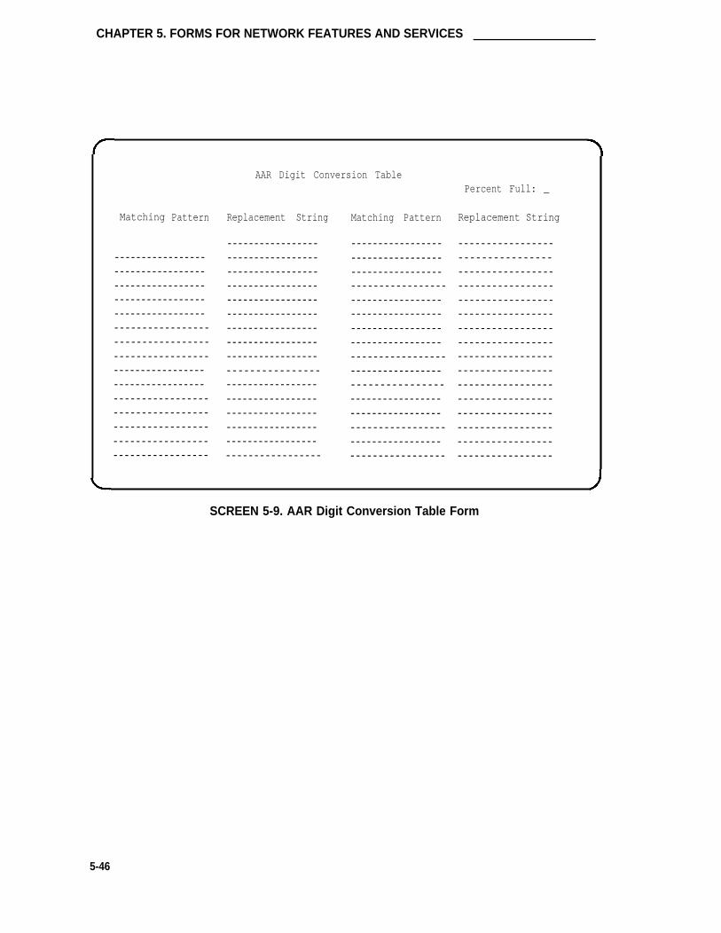
CHAPTER 5. FORMS FOR NETWORK FEATURES AND SERVICES
Matching Pattern
- - - - - - - - - - - - - - - - -- - - - - - - - - - - - - - - - -- - - - - - - - - - - - - - - - -- - - - - - - - - - - - - - - - -- - - - - - - - - - - - - - - - -- - - - - - - - - - - - - - - - -- - - - - - - - - - - - - - - - -- - - - - - - - - - - - - - - - -- - - - - - - - - - - - - - - - -- - - - - - - - - - - - - - - - -- - - - - - - - - - - - - - - - -- - - - - - - - - - - - - - - - -- - - - - - - - - - - - - - - - -- - - - - - - - - - - - - - - - -- - - - - - - - - - - - - - - - -
AAR Digit Conversion TablePercent Full: _
Replacement String
- - - - - - - - - - - - - - - - -- - - - - - - - - - - - - - - - -- - - - - - - - - - - - - - - - -- - - - - - - - - - - - - - - - -- - - - - - - - - - - - - - - - -- - - - - - - - - - - - - - - - -- - - - - - - - - - - - - - - - -- - - - - - - - - - - - - - - - -- - - - - - - - - - - - - - - - -- - - - - - - - - - - - - - - -- - - - - - - - - - - - - - - - -- - - - - - - - - - - - - - - - -- - - - - - - - - - - - - - - - -- - - - - - - - - - - - - - - - -- - - - - - - - - - - - - - - - -- - - - - - - - - - - - - - - - -
Matching Pattern
- - - - - - - - - - - - - - - - -- - - - - - - - - - - - - - - - -- - - - - - - - - - - - - - - - -- - - - - - - - - - - - - - - - -- - - - - - - - - - - - - - - - -- - - - - - - - - - - - - - - - -- - - - - - - - - - - - - - - - -- - - - - - - - - - - - - - - - -- - - - - - - - - - - - - - - - -- - - - - - - - - - - - - - - - -- - - - - - - - - - - - - - - -- - - - - - - - - - - - - - - - -- - - - - - - - - - - - - - - - -- - - - - - - - - - - - - - - - -- - - - - - - - - - - - - - - - -- - - - - - - - - - - - - - - - -
Replacement String
- - - - - - - - - - - - - - - - -- - - - - - - - - - - - - - - -- - - - - - - - - - - - - - - - -- - - - - - - - - - - - - - - - -- - - - - - - - - - - - - - - - -- - - - - - - - - - - - - - - - -- - - - - - - - - - - - - - - - -- - - - - - - - - - - - - - - - -- - - - - - - - - - - - - - - - -- - - - - - - - - - - - - - - - -- - - - - - - - - - - - - - - - -- - - - - - - - - - - - - - - - -- - - - - - - - - - - - - - - - -- - - - - - - - - - - - - - - - -- - - - - - - - - - - - - - - - -- - - - - - - - - - - - - - - - -
SCREEN 5-9. AAR Digit Conversion Table Form
5-46

Centralized Attendant Service
Centralized Attendant Service
Allows services performed by attendants in a private network of switching systems to be concen-trated at a central, or main, location. Each branch in a Centralized Attendant Service (CAS) hasits own LDN or other type of access from the public network. Incoming trunk calls to the branch,as well as attendant-seeking voice terminal calls, are routed to the centralized attendants overRLTs.
The only network-type form that requires implementation in support of the CAS feature is the RLTGroup form. The form and its associated instructions are provided in the Trunk Groups section ofthis chapter.
Refer to CAS in Chapter 4 for a complete listing of all System forms and/or fields on forms thatmust be completed or considered when implementing CAS. Forms such as the Attendant Con-sole, Console Parameters, Feature Access Codes, etc., that support both networking and otherfunctional areas such as voice and data management may also require implementation.
Note that the CAS (branch) or CAS (main) feature, as applicable, must be enabled on theSystem-Parameters Customer-Options form before the Centralized Attendant feature can beimplemented.
5-47

CHAPTER 5. FORMS FOR NETWORK FEATURES AND SERVICES
Distributed Communications System (DCS)
Allows a Configuration (cluster) of two or more switches (nodes) to provide certain attendant andvoice terminal features as if the cluster is a single large system. This simplifies dialing pro-cedures between locations, and also allows transparent use of some of the System’s featuresbetween locations.
The network-type forms that must be completed or considered when implementing DCS are:
● DS1 Circuit Pack
● Tie, Tandem, or ISDN-PRI Trunk Groups
● Routing Patterns
Refer to Distributed Communications System (DCS) in Chapter 4 for a complete listing of all Sys-tem forms and/or fields on forms that must be completed or considered when implementing DCS.Forms such as the Dial Plan, Interface Links, etc., that support both networking and other func-tional areas such as voice and data management may also require implementation.
Note that the DCS option must be enabled on the System-Parameters Customer-Options formbefore DCS can be implemented.
An example of connecting three switches in a DCS cofiguration using voice tie trunks and DS1signaling is shown in Figure 5-3. In this example, the switches are designated as Switch A, B,and C. Switch A is the master switch and switches B and C are slaves. Figure 5-3 also refer-ences the screen forms used to assign parameters for DCS signaling and voice tie trunks. Theseforms are provided as examples only. Detailed instructions for the various forms shown are pro-vided in this Chapter and in Chapter 6. The example forms provided in this section show how toassign Switch A to communicate with Switches B and C. Switches B and C in turn must be con-figured to communicate with Switch A.
Figure 5-3 does not cover all DCS configurations. For example, System 75s, System 85s, andDIMENSION® PBXs may also be included in the network. This example is intended to showhow the various screen forms can be used to implement DCS. The screen forms associated withthis example do not show all the information that can be entered on the forms. The fields on thescreen forms that can be completed for DCS have been filled in. The other fields that can be filledin depend on how the System is configured to meet your particular needs.
For detailed information on DCS, refer to Network and Data Services Reference, 555-025-201,and the AT&T System 75 Application Notes—Distributed Communications System, 555-209-003.
Completed System forms that are required to support the DCS configuration shown in Figure 5-3are provided in Screens 5-10 through 5-33.
5-48

Distributed Communications System (DCS)
SWITCH A (MASTER)
PROCESSOR
SWITCHCOMMUNICATIONS
INTERFACE
† SAI
TN722,
1
‡ MACHINE-ID:9 ILOCAL RNX:824 IEXTS:27XXX I
*TN722,
TN722B, ORTN767
TIETRUNK
LOCATIONSA04 AND
A06
I
*VOICE TRUNKS ARE ASSIGNEDUSING A TIE TRUNK FORM ANDENTERING VOICE IN THE COMMTYPE FIELD. AVD TIE TRUNKSARE ASSINED USING A TIE
AVD TIE TRUNK GROUP NO. 28(TAC 128) ( DS1-FACILITY)
VOICE TIE TRUNK GROUP NO. 27(TAC 127)
TRUNK FORM AND ENTERING *AVD*IN THE COMM TYPE FIELD. TACNUMBERS 127 AND 148 ARE USEDTO ACCESS THE VOICE TIE TRUNKGROUPS. TAC NUMBERS 128 AND149 ARE USED TO ACCESS THEAVD-DS1 TIE SIGNALING LINK.(TAC NUMBERS ARE ENTERED ONTHE TRUNK GROUP FORM AND THEDESTINATION NUMBER FIELD ONTHE INTERFACE LINKS FORM.)
ONLY ONE TRUNK GROUP MEMBER ISASSIGNED ON THE TRUNK GROUPFORM FOR AVD-DS1 TIE TRUNKS.
VOICE TIE TRUNKGROUP No. 48(TAC 148)
AVD TIE TRUNKGROUP NO. 49(TAC 149)(DS1-FACILITY)
SWITCH B (SLAVE)
PROCESSOR
SWITCHCOMMUNICATIONS
INTERFACE
[ SA l
TN722B,OR
TN767
TIETRUNK
I- - - - - - -
I ‡ MACHINE-lD:2I LOCAL RNX:834I EXTS: 34XXXI
SWITCH C (SLAVE)
PROCESSOR
SWITCH
COMMUNICATIONSINTERFACE
S A I
A
TN722,
TN722B,OR
T N 7 6
TIE
TRUNK - - - - - -
I ‡ MACHINE-ID10
I EXTS: 48XXX
I
THIS IS WHERE THE FOURINTERFACE LINKS RESIDEWHICH PROVIDE UP TO 64PROCESSOR CHANNELS PERINTERFACE LINK. THESE
LINKS ARE ASSIGNEDUSING THE INTERFACEDATA MODULE FORM. THEINTERFACE LINKS AREENABLED USING THEINTERFACE LINKS FORM.
THE PROCESSOR CHANNELASSIGNMENTS FORM FORSWlTCH A IS USED TOASSIGN AN INTERFACELINK TO EACH PROCESSORCHANNEL WHICHCOMMUNICATES WITHSWITCHES B AND C.
‡ THE MACHINE-ID-CODEUNIQUELY lDENTlFIES EACHSWITCH IN THE NETWORK.
IN THIS EXAMPLE SWITCHA HAS A MACHINE-ID-OF 9AND COMMUNICATES WITHSWITCH B (MACHINE-ID 2 ANDSWITCH C (MACHINE-ID 10).THE APPROPRIATE MACHINE-IDNUMBER IS ENTERED ON EACHSWITCHES PROCESSOR CHANNEASSIGNMENT FORM.
FIGURE 5-3. Distributed Communications System Using DS1 Facilities
5-49

CHAPTER 5. FORMS FOR NETWORK FEATURES AND SERVICES
201
FIRST DIGIT
First
Digit -1-
1
2
3
4
5
6
7
8
9
0
l
#
DIAL PLAN RECORD
Area Code:
ARS Prefix 1 Required?
Uniform Dialing Plan?
y
y
-2-
Length
-3-
tac
-4-
extension
extension
extension
extension
attendant
fac
fac
Local
-5-
Page 1 of 6
PBX ID: _
-6-
SCREEN 5-10. Switch A Dial Plan Form (Page1)—Example Only
5-50

Distributed Communications System (DCS)
Page 2 of 6
UNIFORM DIALING PLAN
CODE LCL RNX ID CODE LCL RNX ID CODE LCL RNX ID CODE LCL RNX ID
27 y 824 9
34 n 834 2
48 n 848 10
SCREEN 5-11. Switch A Dial Plan Form (Page 2)—Example Only
AAR Analysis Table
Partitioned Group Number: 1 Percent Full:_
Dialed Route Cal 1 Dialed Route Call
String Min Max Pat Type String Min Max Pat Type
834 7 7 34 aar — — —
848 7 7 48 aar — — — —
— — — — — — —
— — — — — . —
SCREEN 5-12. Switch A AAR Analysis Form—Example Only
5-51

CHAPTER 5. FORMS FOR NETWORK FEATURES AND SERVICES
TRUNK GROUP Page 1 of 9
Group Number: 27 Group Type: tie SMDR Reports? y
Group Name: Tie to Switch B_ COR: 1 TAC: 127
Direction: two - way Outgoing Display? n
Dial Access? y Busy Threshold: 60 Night Service:
Queue Length: 0 Incoming Destination: _
Comm Type: voice Auth Code? n
TRUNK PARAMETERS
Trunk Type (in/out): wink/wink Incoming Rotary Timeout(sec): 5
Outgoing Dial Type: tone Incoming Dial Type: tone
Disconnect Timing(msec): 500
Digit Treatment: Digits: _
Connected to Toll? n STT Loss: normal DDD to DCO LOSS: normal
Incoming Dial Tone? n
Answer Supervision Timeout? 10
SCREEN 5-13. Switch A DCS Voice Tie Trunk to Switch B—Example Only
Implementation Note:
“Group Number” assignments must be the same at the far-end node trunk group.
5-52

Distributed Communications System (DCS)
TRUNK GROUP Page 2 of 9
TRUNK FEATURES
ACA Assignment ? Y Measured? none1 Internal Alert? n10 Data Restriction? n
hours
sees.
Long Holding Time
Short Holding Time
.
:
Short Holding Threshold:
Used for DCS?
Suppress # Outpulsing?
15
Y PBX ID 2
n Maintenance Tests? y
SCREEN 5-14. Trunk Group Features—Example Only
GROUP MEMBER ASSIGNMENTS Page 3 of 9
Port Name Night Mode
e&m
Type Ans DelayText Text Text t1-Stan 20
2:
3:
4:
5:
6:
7:
8:
9:
10:
11:
12:
13:
14:
15:
SCREEN 5-15. Switch A DCS Voice Tie Trunk to Switch B—Example Only
Implementation Note:“Group Member Assignments” must be the same at the far-end node trunk group.
5-53

CHAPTER 5. FORMS FOR NETWORK FEATURES AND SERVICES
TRUNK GROUP Page 1 of 9Group Number: 48 Group Type: tie SMDR Reports? yGroup Name: Tie to Switch C_ COR: 1 TAC: 148Direction: two-way Outgoing Display? n
Dial Access? y Busy Threshold: 60 Night Service:Queue Length: 0 Incoming Destination: _
Comm Type: voice Auth Code? nTRUNK PARAMETERS
Trunk Type (in/out): wink/wink Incoming Rotary Timeout(sec): 5Outgoing Dial Type: tone Incoming Dial Type: tone
Disconnect Timing(msec): 500Digit Treatment: Digits :
Connected to Toll? n STT LOSS: normal DTT to DCO Loss: normalIncoming Dial Tone? n
Answer Supervision Timeout? 10
SCREEN 5-16. Switch A DCS Voice Tie Trunk to Switch C—Example Only
Implementation Note:
“Group Number’’ assignments must be the same at the far-end node trunk group.
5-54

Distributed Communications System (DCS)
TRUNK GROUP Page 2 of 9
TRUNK FEATURES
ACA Assignment? y Measured? none
Long Holding Time(hours): 1 Internal Alert? n
Short Holding Time(secs.): 10 Data Restriction? n
Short Holding Threshold: 15
Used for DCS? n PBX ID: 10
Suppress # Outpulsing? n Maintenance Tests? y
SCREEN 5-17. Trunk Group Features—Example Only
GROUP MEMBER ASSIGNMENTS Page 3 of 9
Port Name Night Mode Ans DelayType
1:
2:
3:
4:
“5:
6:
7:
8:
9:
10:
11:
12:
13:
14:
15:
A 0 4 0 1 4 8 X X X T e x t T e x t 20
SCREEN 5-18. Switch A DCS Voice Tie Trunk to Switch C—Example Only
Implementation Note:“Group Member Assignments” must be the same at the far-end node trunk group.
5-55

CHAPTER 5. FORMS FOR NETWORK FEATURES AND SERVICES
TRUNK GROUP Page 1 of 9
Group Number: 28 Group Type: tie SMDR Reports? y
Group Name: DCS SIG to Switch B_ COR: 1 TAC: 128
Direction: two-way Outgoing Display? n
Dial Access? n Busy Threshold: 60 Night Service: 27100
Queue Length: 0 Incoming Destination: 27100
Comm Type: avd Auth Code? nBCC: 0
TRUNK PARAMETERS
Trunk Type (in/OUt): wink/wink Incoming Rotary Timeout(sec): 5
Outgoing Dial Type: tone Incoming Dial Type: tone
Disconnect Timing(msec): 500
Digit Treatment: Digits: ,_
Connected to Toll? n STT Loss: normal DTT to DCO Loss: normal
Incoming Dial Tone? n
Bit Rate: 1200 synchronization: async Duplex: full
Answer Supervision Timeout? 10
SCREEN 5-19. Switch A DCS DS1 Signaling Trunk to Switch B—Example Only
Implementation Note:
It is suggested that “Group Number’’ assignments be the same at the far-end node trunkgroup.
5-56

Distributed Communications System (DCS)
TRUNK GROUP Page 2 of 9
TRUNK FEATURES
ACA Assignment? y Measured? none
Long Holding Time(hours) : 1_ Internal Alert? n
Short Holding Time(secs.): 10_ Data Restriction? n
Short Holding Threshold: 15
Used for DCS? n PBX ID: 2_
Suppress # Outpulsing? n Maintenance Tests? y
SCREEN 5-20. Trunk Group Features—Example Only
GROUP MEMBER ASSIGNMENTS Page 3 of 9
Port Name Night Mode Type Ans Delay
1: A0623___ DCS___ SIG___ — e&m t1-stan 20
2:
3:
4:
5:
6:
7:
8:
9:
10:
11:
12:
13:
14:
15:
SCREEN 5-21. Switch A DCS DS1 Signaling Trunk to Switch B—Example Only
Implementation Note:"Group Member Assignments" must be the same at the far-end node trunk group.
5-57

CHAPTER 5. FORMS FOR NETWORK FEATURES AND SERVICES
Group Number:
Group Name:
Direction:
Dial Access?
Queue Length:
Comm Type:
TRUNK PARAMETERS
TRUNK GROUP
49 Group Type: tie
DCS_ SIG_ to_ Switch_ C_ COR : 1_
two-way Outgoing Display? n_
n0
avd
Trunk Type (in/out):
Outgoing Dial Type:
Digit Treatment:
Connected to Toll?
Incoming Dial Tone?
Bit Rate:
Busy Threshold: 60
Auth Code? n
Page 1 of 9
SMDR Reports? y
TAC: 149
Night Service: 27102
Incoming Destination: 27102
Answer Supervision Timeout? 10
BCC: 0
wink/wink Incoming Rotary Timeout(sec): 5
tone Incoming Dial Type: tone
Disconnect Timing(msec): 500Digits:
n STT Loss: normal DTT to DCO Loss: normal
n
1200 synchronization: async Duplex: full
SCREEN 5-22. Switch A DCS DS1 Signaling Trunk to Switch C—Example Only
Implementation Note:
It is suggested that "Group Number" assignments be the same at the far-end node trunkgroup.
5-58

Distributed Communications System (DCS)
TRUNK GROUP Page 2 of 9
TRUNK FEATURES
ACA Assignment? y Measured? none___
Long Holding Time(hours) : 1 Internal Alert? n
Short Holding Time(secs.): 10 Data Restriction? n
Short Holding Threshold: 15
Used for DCS? y PBX ID: 10
Suppress # Outpulsing? n Maintenance Tests? y
SCREEN 5-23. Trunk Group Features—Example Only
GROUP MEMBER ASSIGNMENTS
Port Name
1: A0423 DCS-SIG2:
3:
5:
6:
7:
8:
9:
Night
11:
12:
Mode
e&m
Type
Page 3 of 9
Ans Delay
t1-stan 20
14:
15:
SCREEN 5-24. Switch A DCS DS1 Signaling Trunk to Switch C—Example Only
Implementation Note:"Group Member Assignments" must be the same at the far-end trunk group.
5-59

CHAPTER 5. FORMS FOR NETWORK FEATURES AND SERVICES
Page 1 of 1
Pattern Number: 34
Pattern Assignments (Enter UP To 6)
Grp . FRL NPA Prefix Toll No. Del Inserted
No. Mark List Digits Digits
1. 2 7 1 ____ ____ ____ 3 3 _
SCREEN 5-25. Switch A Routing Pattern to Switch B—Example Only
Page 1 of 1
Pattern Number: 48
Pattern Assignments (Enter Up To 6)
Grp . FRL NPA Prefix Toll No. Del Inserted
No. Mark List Digits Digits
1. 48 1 ____ __ ___ 3 4
SCREEN 5-26. Switch A Routing Pattern to Switch C—Example Only
5-60

Distributed Communications System (DCS)
Location: A06
Line Compensation: 1
Framing Mode: esf
DMI-BOS? n
Slip Detection? y
Page 1 of 1
DS1 CIRCUIT PACK
Name: DCS_ TO SWITCH_ B_
Zero Code Suppression: b8zs
Signaling Mode: common-chan_
MAINTENANCE PARAMETERS
Remote Loop-Around Test? n
SCREEN 5-27. Switch A DS1 Circuit Pack—Example OnIy
Location: A04
Line Compensation: 1
Framing Mode: esf
DMI-BOS? n
Page 1 of 1
DS1 CIRCUIT PACK
Name: DCS TO_ SWITCH_ C_
Zero Code Suppression: zcs_
Signaling Mode: common-chan_
MAINTENANCE PARAMETERS
Slip Detection? y Remote Loop-Around Test? n
SCREEN 5-28. Switch A DS1 Circuit Pack Administration Form for Circuit Packsin Location A06 and A04—Example Only
5-61

CHAPTER 5. FORMS FOR NETWORK FEATURES AND SERVICES
Page 1 of 2
SYNCHRONIZATION PLAN
SYNCHRONIZATION SOURCE (DS1 circuit pack location)
Primary: _ Secondary: _
DS1 CIRCUIT PACKS
LocationA06
Name Slip
DCS TO SWITCH B n
DCS TO SWITCH C n
Location Name Slip
A04
SCREEN 5-29. Switch A Synchronization Plan Form for DS1 Circuit PacksA06 and A04—Example Only
Page 1 of 1
DATA MODULE
Data Extension: 27100 Type: interface Physical Channel: 01_
Name: DCS-LINK TO Cos: _ COR: _
SWITCH B
ABBREVIATED DIALING
List1:
SCREEN 5-30. Switch A Processor lnterface Data Module Form Used ToAssign Interface Link 1—Example Only
5-62

Distributed Communications System (DCS)
Page 1 of 1
DATA MODULE
Data Extension: 27102 Type: interface Physical Channel: 03
Name: DCS-LINK TO COS: _ COR: _
SWITCH C
SCREEN 5-31. Switch A Processor Interface Data Module Form Used to Assign InterfaceLink 3—Example Only
Page 1 of 1
INTERFACE LINKS
Link Enable Est PI Destination DTE/
Conn Ext Prot Digits Brd DCE Identification
1: y y 27100 BX.25 128 _ DTE DCS Link Switch B
2: n _ — BX.25 — - DTE
3: y y 27102 BX.25 149 - DTE DCS Link Switch C
4: n _ — BX.25 - DTE
5: n _ — BX.25 — - DTE
6: n _ _ BX.25 — - DTE
7: n _ — BX.25 — - DTE
8: n _ _ BX.25 — — DTE
SCREEN 5-32. Switch A Interface Links Form—Example Only
5-63

CHAPTER 5. FORMS FOR NETWORK FEATURES AND SERVICES
Proc
Chan
1:
2:
3:
4:
5:
6:
7:
8:
9:
10:
11:
12:
13:
14:
15:
16:
Appl.
Page 1 of 4
PROCESSOR CHANNEL ASSIGNMENT
Interface Remote
Link Chan Priority Proc Chan
DCS
DCS
13
28
49
h
h
67
Machine-ID
2
10
SCREEN 5-33. Switch A Processor Channel Assignments for lnterface Links 1 and 3—Example Only
5-64

DS1 Trunk Service
DS1 Trunk Service
Introduction
DS1 Trunk Service provides a set of digital trunks utilizing the DS1 circuit pack [TN722B, TN767,(or TN464C for International G1.2SE only)] that support both voice and data communications.
Digital interfaces for the following types of trunks are supported:
●
●
●
●
●
●
●
●
●
●
●
Alternate Voice/Data (AVD) DS1 Tie Trunks
CO Trunks
DMI Tie Trunks
DID Trunks
Direct Inward and Outward Dialing Trunks (International G1.2SE only)
FX Trunks
ISDN-PRI Trunks
Off-Premises Stations
Remote Access Trunks
Voice-Grade DS1 Tie Trunks
WATS Trunks
Refer to Chapter 4 for a complete listing of all forms that must be completed or considered whenassigning DS1 Tie Trunk Service. The DS1 circuit pack form instructions are provided followingthis introduction.
The following paragraphs provide a brief description of each of the types of trunks supported bythe DS1 digital interface.
Alternate Voice/Data (AVD) Tie Trunks
AVD DS1 tie trunks permit alternate voice and data calling between DEFINlTY systems, System75s, and System 85s.
AVD DS1 tie trunks can be used to connect the System with other digital switches.
The TN722B, TN767, or TN464C (International G1.2SE only) DS1 circuit pack is used to supportAVD DS1 tie trunks in the Common Channel Signaling mode. The Common Channel Signalingmode supports 23 trunks for data transmission and 1 trunk for signaling purposes.
This type of tie trunk uses DS1 transmission facilities in the "Domestic DS1" format, which is a1.544-Mbps digital signal that consists of a 1.536-Mbps signal multiplexed with an 8-kbps framingsignal.
5-65

CHAPTER 5. FORMS FOR NETWORK FEATURES AND SERVICES
CO, FX, and WATS Trunks
When the DS1 interface (TN767 DS1 circuit pack) is used to provide CO, FX, or WATS trunkgroup service with incoming and outgoing types of ground start or loop start, RBS must be used.
When the DS1 interface is used to provide CO, FX, or WATS trunk group service with incomingoutgoing dial types administered as auto/auto, auto/delay, auto-immediate, or auto/wink, eitherCommon Channel Signaling or Robbed Bit Signaling can be used.
When the DS1 interface is used to provide CO, FX, or WATS trunk group service with incomingand outgoing types of ground start or loop start, outgoing trunk calls do not receive answer super-vision. Instead, the answer supervision is faked by the DS1 circuit pack.
DMI Tie Trunks
DMI tie trunks use Bit Oriented Signaling or ISDN-PRI signaling to interface with a host com-puter, another PBX, or a public or private network.
In addition, the TN767 DS1 circuit pack supports DMI tie trunks in the ISDN-PRI signaling mode.This mode supports 23 trunks for data transmission and one trunk for signaling purposes.
This type of tie trunk uses DS1 transmission facilities in the "Domestic DS1" format, which is a1.544-Mbps digital signal that consists of a 1.536-Mbps signal multiplexed with an 8-kbps framingsignal.
When the DS1 circuit pack is assigned ISDN-PRI signaling, RBS and ISDN-PRI signaling can beused over the same DS1 interface. Trunk groups administered with a communication type of"voice" can use RBS and trunk groups administered with a communication type of "isdn" can usethe ISDN-PRI signaling.
DID Trunks
When the DS1 interface is used to provide DID trunk group service, RBS must be used.
ISDN-PRI Trunks
When the DS1 interface is used to provide ISDN-PRI trunk group service, a TN767 DS1 circuitpack must be used. ISDN-PRI trunks provide end-to-end digital connectivity within the networkand can provide national and international digital connectivity to other ISDNs that support the PRIstandard.
ISDN-PRI trunks can carry calls for various switched services and/or features such as Megacom800 service, Megacom service, OUTWATS, and LDS (Long-Distance Service). Inter-exchangecarrier calls may also be processed. The trunks support integrated voice and data transmission.
A TN767 DS1 circuit pack utilizing "isdn-pri" signaling must be used when supporting ISDN-PRItrunks. This mode of signaling supports 23 trunks for data transmission and one trunk for signal-ing. Choosing "isdn-ext" enables the circuit pack to use ISDN signaling, but the 24th channel willnot be used as a D-Channel (that is, all 24 channels used for voice and/or data).
5-66

DS1 Trunk Service
Off-Premises Stations
DS1 off-premises stations do not receive System message waiting indications.
When the DS1 interface is used to provide off-premises stations, RBS must be used.
Remote Access Trunks
Signaling for remote access trunks depends on the trunk group and incoming/outgoing dial types.
Voice-Grade DS1 Tie Trunks
The Voice-Grade DS1 tie trunks are an alternative to 4-wire analog E&M tie trunks and may beused to interface with other properly-equipped switching systems.
Voice-Grade DS1 tie trunks can also be used as the following:
● ETN or TTTN tie trunks
● Main/Satellite tie trunks
● Tie trunks used to interface with Enhanced Private Switched Communications Service(EPSCS) and Common Control Switching Arrangement (CCSA) networks
● Release link trunks for CAS
● Access Trunks
The TN722B, TN767, or TN464C (International G1.2SE only) DS1 circuit pack is used to supportVoice-Grade DS1 tie trunks in the-RBS mode. The RBS mode supports 24 trunks for transmis-sion on the circuit pack because the least significant bit ("robbed") in every sixth frame of datatransmission is replaced by a signaling bit.
This type of tie trunk uses DS1 transmission facilities in the "Domestic DS1" format, which is a1.544-Mbps digital signal that consists of a 1.536-Mbps signal multiplexed with an 8-kbps framingsignal.
5-67

CHAPTER 5. FORMS FOR NETWORK FEATURES AND SERVICES
DS1 Circuit Pack
Purpose
This form is used to administer parameters for the TN722, TN722B, TN767, and TN464C (inter-national G1.2SE only) DS1 circuit packs. If the circuit pack has not been physically installed, itmust be logically installed using the Circuit Pack Administration form before the parameters onthis form can be administered.
The DS1 circuit pack provides a DS1 format (digital data rate of 1.544 Mbps), digital, multi-channel interface between the System and T1 transmission facilities, or it may be directly con-nected to local DS1 terminal equipment (if the distance is relatively short—that is, less than aquarter of a mile) which includes a DS1 interface to another switch, a D4 channel bank, a chan-nel division multiplexer, or a channel expansion multiplexer. On the switch side, the DS1 inter-face provides 23 unrestricted (voice or 64-kbps data) or 24 restricted (voice) digital trunksdepending on signaling mode. When configured for 64-kbps data, these trunks support voice anddata communication including AVD, DMI, and ISDN-PRI services.
The TN722B must be used instead of a TN722 when supporting DMI-Bit Oriented Signaling. ATN767 must be used for ISDN-PRI and can also support CO, DID, and Off-Premises Station sig-naling, when required.
After DS1 circuit pack parameters have been administered, the following must also be con-sidered:
●
●
●
●
Signaling Groups must be assigned using the Signaling Group form.
Individual trunks must be assigned using appropriate trunk group forms.
Parameters that govern automatic control of clock synchronization may be administeredusing the Synchronization Plan form for those DS1 circuit packs that are to be primary orsecondary synchronization sources.
For ISDN-PRI signaling, the link between the TN765 Processor Interface and the DChannel of the DS1 circuit pack must be administered using the Processor InterfaceData Module, Processor Channel Assignments, and Interface Links forms.
Administration Commands
The following administration commands can be used to access the DS1 Circuit Pack form. Insome cases, just the most commonly used commands are shown. Refer to Administration Com-mands and Error Messages (Chapter 3) for a complete listing of all administration commands, thecommand structure, and the use of abbreviated command words when entering a command.
5-68

DS1 Circuit Pack
Action Object
add ds1change ds1display ds1list measurements ds1list measurements ds1-logremove ds1
Qualifier*
[P]Css†[P]Css(board)[P]Csslocationlocation[P]Css
* Brackets [ ] indicate the qualifier is optional.
† [P] — part of qualifier representing pnnC — part of qualifier representing carrier (A through F)ss — part of qualifier representing slot number (01 through 20).
Form lnstructions
Make assignments as required for the following fields on the form:
●
●
●
Location— This is a display-only field when the form is accessed using an administrationcommand such as add or change. Enter the DS1 Interface circuit pack port locationwhen completing a paper form. Enter 5 to 6 characters. The first character identifies thenetwork (1 through 3, default is "1" if no entry); the second character identifies the carrier(A through E); the third and fourth characters identify the slot number in the carrier (01through 20 for multi-carrier cabinets [depending on carrier type] or 01 through 18 forsingle-carrier cabinets [depending on cabinet type]); the last two characters identify thecircuit number (01 through 24). The location should also be identified for record pur-poses on the Port Assignment Record and the Circuit Pack Administration form asdescribed in Chapter 2.
Name— Enter the name of the DS1 link (limit 15 characters). Typically, this is the desti-nation of the link.
Line Compensation— Enter a number from 1 through 5 as follows (default is "1"):
➤ For 22-gauge ABAM cable terminated on a DSX-1 cross-connect:
Compensation Length (feet)1 000-1332 133-2663 266-3994 399-5335 533-655
➤ For 22-gauge ABAM cable terminated on DS1 terminal equipment such as a D4Channel Bank or another System:
Compensation Length (feet)1 0000-02662 0266-05323 0532-07984 0798-10665 1066-1310
5-69

CHAPTER 5. FORMS FOR NETWORK FEATURES AND SERVICES
● Zero Code Suppression— Enter "b8zs" (bipolar eight zero substitution) or "zcs" (0 codesuppression). This method must match the method used on the other end of the link.This entry indicates which line coding format will be used to ensure that the data meetsT1-carrier requirements. When the DS1 circuit pack is used for ISDN, the ISDN D-Channel data is inverted when "zcs" is entered and not inverted when "b8zs" is used.Far-end System 85 Generic 2 system and 4ESS switch administer whether or not the theD-Channel data will be inverted.
Binary eight zero code suppression (b8zs) is an alternate line coding technique whichuses a bipolar violation to ensure adequate "ones" density in a bit sequence. Eight zerosin an 8-bit sequence triggers the bipolar violation.
Zero code suppression (zcs) is a line coding method that checks for all zeros in an 8-bittime slot and, if all zeros exist, bit two is changed from a 0 to a 1. This method of linecoding ensures adequate timing recovery of regenerative 56-kbps or less digital facilities.
● Framing Mode— Enter "d4" or "esf" (default is "esf’’)." This mode must match themethod used on the other end of the link. The network diagram should indicate whichchoice for the particular DS1/T1-span. D4 is a framing format of 12 frames for analogrepresentation on T1 carrier using DS1 signals. ESF is an extended frame format on T1carrier using DS1 signals in which 24 frames are used to convey signaling for the chan-nels.
● Signaling Mode— Enter "common-chan," "robbed-bit," "isdn-pri," or "isdn-ext’’(default is"common-chan"). This mode must match the method used on the other end of the link.
Common Channel Signaling (common-chan) is an industry standard signaling techniquein which the signals on one facility control the operation of several facilities. Whenapplied to DS1 operation, it is a signaling technique in which any one of the 24 channels"carries the signals for the other 23 channels. AT&T implementation of common channelsignaling uses the 24th channel for carrying the signals. This signaling technique is amuch broader concept than 24th channel signaling and is not limited to DS1 facilities.When the System is configured for FAS, the 24th channel signaling technique uses the24th channel in a DS1 facility to carry signals for the remaining 23 channels; also knownas "clear channel," "out-of-band," or AVD signaling. (AVD signaling is a term that is oftenused; however, the term is incorrectly used. AVD is a term used when referring to atrunk group that can be used for both voice and digital applications.)
RBS (robbed-bit) is a per-channel signaling technique for transmitting signaling bits withineach band on each of the 24 channels in a DS1 facility. The least significant bit in everysixth transmitted information frame is "robbed" and replaced by a signaling bit. Alsocalled "in-band" signaling. For voice tie trunks, enter "robbed-bit" and "common-chan"for Alternate Voice Data (AVD) trunks.
The choice of isdn-pri requires that the TN767 DS1 Interface circuit pack be used. Thischoice will enable ISDN-PRI signaling to be carried over the 24th channel of the DS1interface, and will cause the DMI-BOS field not to be displayed and the Connect field tobe displayed on the form.
5-70

DS1 Circuit Pack
The choice of "isdn-ext" also requires use of the TN767 DS1 Interface circuit pack. Thischoice will enable the TN767 to use ISDN signaling, but the 24th channel will not beused as a D channel. When the System is configured for Non-Facility Associated Signal-ing, all 24 channels on a DS1 facility may be used for voice and/or data. The signalingfor these channels is provided by the 24th channel on another DS1 facility. The Systemmay be configured for Facility and Non-Facility Associated Signaling at the same time.Refer to the Facility and Non-Facility Associated Signaling feature in Chapter 4 for addi-tional information.
●
●
●
●
DMI-BOS— Enter "y" (System default) to activate the Digital Multiplexed Interface-BitOriented Signaling (DMI/BOS) mode when the signaling mode is common-channel and aTN722B or TN767 circuit pack has been installed. Valid entries are "y" or "n." This fieldis not displayed if "isdn-pri" or "isdn-ext" is entered in the Signaling Mode field.
DMI/BOS is a 24th channel signaling scheme using a DS1 facility which uses 23 mes-sage channels and one signaling channel (24th). DMI/BOS has greater capacity (abilityto carry 64 kbps channels) than the 24th channel RBS scheme. Entering "n" indicatesthe DS1 will provide the AT&T proprietary format; "y" indicates the DS1/DMl interface willprovide the DMI format.
Connect— Only displayed when the Signaling Mode field is "isdn-pri." Specify what is onthe far end of the PBX in order to control Layer 3 protocol properly. The default value forthis field is "network." This field is displayed when the Signaling Mode field is "isdn-pri."If "pbx" is entered, the Interface field is displayed. Allowable entries are "network" (Sys-tem default), "host," and "pbx."
lnterface— Only displayed when the Connect field is "pbx." Specify whether the PBXcorresponds to the "network" or "user" side of the interface, which is needed for theLayer 2 protocol and is also used at Layer 3 to handle glare conditions. For other cases,the required entry is inferred from the Connect field entry: a ‘host" connection implies a"network" interface, and a "network" connection implies a "user" interface. Note thatwhen the far-end is a DEFINITY Generic 1 or Generic 3i system, the Interface field onone end of the connection must be "user" and the other end must be translated as "net-work." Valid entries are "network" or "user" (System default).
Slip Detection— Enter "y" to enable the slip-rate status of this circuit pack to be used bymaintenance software to determine whether an excessive frame slip rate exists. Enter"n" (System default) when DMI is used or when testing is not required.
Note: Those DS1/T1 facilities that are used to provide the primary and secondarysynchronization references should be administered for slip detection "y."Typically, those other DS1/T1 spans that are used for data applications andwhich are deemed very important should also be administered for slip detec-tion. This excludes all T1-spans connecting channel banks, unless the chan-nel bank is externally timed. Normally, those DS1/T1 spans that are usedexclusively for voice and which are not designed as the primary or secon-dary synchronization source should be administered for slip detection "y."Refer to the network synchronization diagram in order to determine whichoption to choose.
5-71
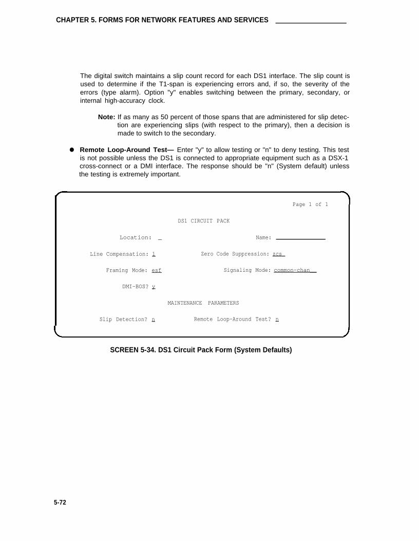
CHAPTER 5. FORMS FOR NETWORK FEATURES AND SERVICES
The digital switch maintains a slip count record for each DS1 interface. The slip count isused to determine if the T1-span is experiencing errors and, if so, the severity of theerrors (type alarm). Option "y" enables switching between the primary, secondary, orinternal high-accuracy clock.
Note: If as many as 50 percent of those spans that are administered for slip detec-tion are experiencing slips (with respect to the primary), then a decision ismade to switch to the secondary.
● Remote Loop-Around Test— Enter "y" to allow testing or "n" to deny testing. This testis not possible unless the DS1 is connected to appropriate equipment such as a DSX-1cross-connect or a DMI interface. The response should be "n" (System default) unlessthe testing is extremely important.
Location: _
Line Compensation: 1
Framing Mode: esf
DMI-BOS? y
Page 1 of 1
DS1 CIRCUIT PACK
Name:
Zero Code Suppression: zcs_
Signaling Mode: common-chan__
MAINTENANCE PARAMETERS
Slip Detection? n Remote Loop-Around Test? n
SCREEN 5-34. DS1 Circuit Pack Form (System Defaults)
5-72

DS1 Circuit Pack
Location: _
Line Compensation: 1
Framing Mode: esf
Slip Detection? n
Page 1 of 1
DS1 CIRCUIT PACK
Name:
Zero Code Suppression: zcsSignaling Mode: isdn-pri
Connect: pbx
Interface: user
MAINTENANCE
Remote
PARAMETERS
Loop-Around Test? n
SCREEN 5-35. DS1 Circuit Pack Form (Signaling Mode field is "isdn-pri" and the Connect field is "pbx")—Example Only
Page 1 of 1
Location: _
Line Compensation: 1
Framing Mode: esf
Slip Detection? n
DS1 CIRCUIT PACK
Name:
Zero Code Suppression: zcs_
Signaling Mode: isdn-ext
MAINTEANCE PARAMETERS
Remote Loop-Around Test? n
SCREENS 5-36. DS1 Circuit Pack Form (Signaling Mode field is "isdn-ext")
—Example Only
5-73

CHAPTER 5. FORMS FOR NETWORK FEATURES AND SERVICES
Integrated Services Digital Network—Primary Rate Interface
This section contains the network-type forms and associated instructions required to implementthe Integrated Services Digital Network (lSDN)—Primary Rate Interface (PRI) feature.
Refer to "Integrated Services Digital Network—Primary Rate Interface" in Chapter 4 for a com-plete listing of all forms and/or fields on forms that must be completed or considered when imple-menting ISDN-PRI. Forms such as the Dial Plan, COR, and Feature-Related System Parame-ters that support both networking and other functional areas such as voice and data managementmay also require implementation.
ISDN-PRI provides end-to-end digital connectivity within the network and can provide nationaland international digital connectivity to other ISDNs that support the PRI standard.
An ISDN-PRI trunk group can carry calls for various switched services and/or features such asMegacom 800 service, Megacom service, OUTWATS, and LDS. Inter-exchange carrier callsmay also be processed. The trunk group utilizes common channel signaling and integrated voiceand data transmission.
The ISDN-PRI feature supports the following (refer to each feature description in Chapter 4 for acomplete listing of forms to be administered to implement the feature):
●
●
●
●
●
●
●
●
Call by Call Service Selection feature
Distributed Communications System connectivity
ETN connectivity.
Generalized Route Selection feature
ISDN Call Identification Display—CPN/BN
Administered Connection/Access Endpoint feature (supports administered connectionsover a SDDN)
Interworking (mixture of ISDN-PRI and non-lSDN-PRl trunking.
FAS/NFAS
The following ISDN-PRI forms are provided in this section.
Note: The ISDN-PRI option must be enabled on the System-Parameters Customer-Options form before associated ISDN forms can be administered.
●
●
●
●
ISDN-PRI Trunk Group
Network Facilities (supports the Call by Call Service Selection feature)
CPN Prefix Table (used by the ISDN Call Identification Display feature)
Signaling Group (group of B-channels for which a given D-channel or D-channel pair willcarry the signaling information)
5-74

Integrated Services Digital Network—Primary Rate Interface Trunk Group
Integrated Services Digital Network—Primary RateInterface Trunk Group
Refer to Integrated Services Digital Network—Primary Rate Interface Trunk Group (provided laterin this chapter in the Trunk Group section) for implementation instructions.
5-75

CHAPTER 5. FORMS FOR NETWORK FEATURES AND SERVICES
Network Facilities
Purpose
This form is a display-only form of the Network Facilities Services/Features that support the Callby Call Service Selection feature. All administration on this form is performed by the TSC.
Administration Commands
The following administration commands can be used to access the Network Facilities form. Insome cases, just the most commonly used commands are shown. Refer to Administration Com-mands and Error Messages (Chapter 3) for a complete listing of all administration commands, thecommand structure, and the use of abbreviated command words when entering a command.Note that the "change" command is only available for services personnel via entry of an appropri-ate login and password.
Action Object Qualifier
change isdn network facilitiesdisplay isdn network facilities
Predefine Services/Features (see Table 5-D) and 12 fields for new Services/Features are shownon the form.
5-76

Network Facilities
TABLE 5-D. Predefine Services/Features—Network Facilities
SERVICE/FEATUREAdministration Description
Mnemonicaccunet ACCUNET Switched Digital Service—part of ACI (AT&T Communications
ISDN) phase 2.
i800 International 800 Service—allows a subscriber to receive internationalcalls without a charge to the call originating party.
inwats lNWATS—provides OUTWATS-like pricing and service for incoming calls.Ids Long-Distance Service—part of ACI (AT&T Communications ISDN)
phase 2.
outwats-bnd OUTWATS Band-WATS—is a voice-grade service providing both voiceand low speed data transmission capabilities from the user’s location todefined service areas commonly referred to as bands. Currently, the wid-est band is 5.
megacom Megacom service—an AT&T communications service that providesunhanded long-distance services using special access (PBX to 4ESSswitch) from an AT&T communications node.
megacom-800 Megacom 800 service—an AT&T communications service that providesunhanded 800 service using special access (4ESS switch to PBX) from anAT&T communications node.
multiquest AT&T MULTIQUEST® Telecommunications Service—dial 700 service. Aterminating users service supporting interactive voice service betweencallers at switched access locations and service providers directly con-nected to the AT&T Switched Network (ASN).
operator Network Operator—provides access to the network operator.sdn Software Defined Network (SDN)—an AT&T communications offering that
provides a virtual public network using the public switched network. SDNcan carry voice and data between customer locations as well as off-netlocations.
sddn Software Defined Data Network—provides a virtual private line connec-tivity via the AT&T switched network (4ESS switch). Services includevoice, data, and video applications. These services complement the SDNservice.
sub-operator Presubscribed Common Carrier Operator—provides access to the presub-scribed common carrier operator.
wats-max-bnd Maximum Banded Wats—a WATS-like offering for which a user’s calls arebilled at the highest WATS band subscribed to by the user.
5-77

CHAPTER 5. FORMS FOR NETWORK FEATURES AND SERVICES
The fields on the form areas follows:
● Name— Contains up to 15 alphanumeric characters to specify the name of the indicatedService/Feature.
● Facility Type— A "0" indicates that the associated entry is a feature, and a "1" indicatesthe associated entry is a service.
● Facility Coding— Contains five binary values which specify the ISDN-PRI encodingvalue of the associated Service/Feature.
The additional Services/Features area on the form is available for new services and features.
NETWORK-FACILITIES
Predefined Services/Features
Facility Facility
Name Type Coding Name Type Coding
outwats-bnd 1 0 0 0 0 1 mega800 1 0 0 0 1 0
operator 0 0 0 1 0 1 megacom 1 0 0 0 1 1
sub-operator 0 0 0 1 1 0 inwats 1 0 0 1 0 0
sdn 1 0 0 0 0 l wats-max-bnd 1 0 0 1 0 1accunet 1 0 0 1 1 0 lds 1 0 0 1 1 1
i800 1 0 1 0 0 0 multiquest 1 1 0 0 0 0
Additional Services/Features
Facility Facility
Name Type Coding Name Type Coding
- —
- —
- —
- —
- —
SCREEN 5-37. Network Facilities Form
5-78

CPN Prefix Table
CPN Prefix Table
Purpose
This form is used to support the ISDN Call Identification Display feature. The feature provides aname/number display for display-equipped stations within an ISDN-PRI network. The Systemuses the calling party’s name/number information and displays it on the called party’s display, ifprovided. Likewise, the called party’s name/number can be displayed on the calling party’sdisplay.
The ISDN-PRI option must be enabled on the System-Parameters Customer-Options form beforethis form can be administered.
The CPN (Calling Party Number) Prefix Table provides the following:
●
●
●
Allows the calling party’s number to be displayed on the called party’s display and theconnected party’s number to be displayed at the calling party’s display. The informationdisplay may be disabled for privacy reasons.
Allows a 10-digit CPN number to be displayed instead of the calling party’s number.
Allows up to 240 entries with a maximum of 48 entries on a page.
Administration Commands
The following administration commands can be used to access the CPN Prefix form. In somecases, just the most commonly used commands are shown. Refer to Administration Commandsand Error Messages (Chapter 3) for a complete listing of all administration commands, the com-mand structure, and the use of abbreviated command words when entering a command.
Action Object Qualif ier
change isdn cpn-prefixdisplay isdn cpn-prefix
Form Instructions
Make assignments as required for the following fields on each page of the form.
Pages 1 through 5 of the Form
●
●
Ext Len— Specifies the number of digits the extension can have. Enter a number from 1to 5 that corresponds to the extension lengths allowed by the dial plan.
Ext Code— Allows for groups of extensions to be administered. The Ext Code can be upto 5 digits long depending on the Ext Len field entry. The entry cannot be greater thanthe Ext Len field entry. For example, in the case of a 4-digit Ext Len field entry, an ExtCode of 12 is the equivalent of all extensions of the form 12xx, excluding any explicitlylisted longer codes. If a code of 123 is also listed, the 12 code is equivalent of all exten-sions of the form 12xx except extensions of the form 123x. The coding precludes havingto list all the applicable 12xx extensions. Valid digits are 0 through 9. Note that when "0"alone is entered, the Ext Len field must be "1" and the DDD number must be 10-digitslong.
5-79

CHAPTER 5. FORMS FOR NETWORK FEATURES AND SERVICES
● CPN Prefix— Specifies the number that is added to the beginning of the extension toform a 10-digit CPN number. The CPN Prefix can be a 6- to 10-digit number, or can beblank. If it is a 10-digit number, the extension number is not used to formulate the 10-digit CPN number. Only digits are allowed in the CPN Prefix column. Leading spaces, orspaces in between the digits, are not allowed.
If the number of digits in the CPN Prefix plus the extension length exceeds 10, excessleading digits of the extension are deleted when formulating the 10-digit CPN number. Ifthe number of CPN Prefix digits plus the extension length is less than 10, the entry isdisallowed except for a blank entry. If the CPN Prefix entry is left blank, no calling partynumber information is provided to the called party and no connected party number infor-mation is provided to the calling party.
Page 1 of 5
CPN PREFIX TABLE
Ext Ext CPN Ext Ext CPN Ext Ext CPN
Len Code Prefix Len Code Prefix Len Code Prefix
SCREEN 5-38. CPN Prefix Table Form (Page 1 of 5)
(To reduce repetition, pages 2 through 5 are not shown.)
5-80

Signaling Group
●
Signaling Group
Purpose
The Signaling Group form is used to identify groups of ISDN DS1 interface B-Channels for whicha given D-Channel or D-Channel pair will carry associated signaling information. The NFASfeature allows a D-Channel to convey signaling information for B-Channels that are located onDS1 facilities other than the one containing the D-Channel. With NFAS, a signaling group doesnot necessarily correspond to a single DS1 interface. The Signaling Group form is administeredto show how B-Channels and D-Channels are related.
The Signaling Group form also supports the FAS feature. The form is used to establish the factthat a D-Channel will carry signaling information for all B-Channels on its associated DS1 inter-face and for no others.
In addition, the form is used to administer TSC used in support of DCS Over ISDN PRI D-Channel (includes ISDN-PRI D-Channel DCS AUDIX.)
Administration Commands
The following administration commands can be used to access the Signaling Group form. Insome cases, just the most commonly used commands are shown. Refer to Administration Com-mands and Error Messages (Chapter 3) for a complete listing of all administration commands, thecommand structure, and the use of abbreviated command words when entering a command.
Action Object Qualifier*
add signaling-group 1-8 or nextchange signaling-group 1-8display signaling-group 1-8 [‘print’ or ‘schedule’]list signaling-group 1-8 [‘print’ or ‘schedule’]remove signaling-group 1-8
* Brackets [ ] means that the qualifier is optional.
Form Instructions
Make assignments as required for the following fields on each page of the from:
●
●
Group Number— Display-only field when the form is accessed using an administrationcommand such as display or change. Enter a group number from 1 through 8 whencompleting a paper form.
Associated Signaling— Enter "y" (yes) to indicate FAS or "n" (no) to indicate NFAS.(As stated earlier, for FAS, the D-Channel can only carry signaling information for B-Channels located on the same DS1 circuit pack.) Default is "y."
Primary D-Channel— Enter a 5-to 6-character port number associated with the DS1Interface circuit pack port: port network 1 through 3 (default is "1" if no entry); carrier (Athrough E); slot number (01 through 20 for multi-carrier cabinets depending on carriertype or 01 through 18 for single carrier cabinets depending on cabinet type); port (24).The port number 24 is used to assign the primary D-Channel in the Signaling Group.Currently, with FAS and NFAS it is always the 24th port on the DS1 Interface circuit
5-81

CHAPTER 5. FORMS FOR NETWORK FEATURES AND SERVICES
pack. It is recommended that the Primary D-Channel assignment, when possible, belocated on the PPN (that is, Port Network 1 ). Default is blank.
● Secondary D-Channel— Only displayed if the Associated Signaling field is "n" (indicatesNFAS). Enter a 5- to 6-character port number associated with the DS1 Interface portused for secondary D-Channel signaling: port network 1 through 3 (default is "1" if noentry); carrier (A through E); slot number (01 through 20 for multi-carrier cabinetsdepending on carrier type or 01 through 18 for single carrier cabinets depending oncabinet type); port (24) (currently, with FAS and NFAS it is always the 24th port on theDS1 Interface circuit pack). Default is blank.
● Max Number of NCA TSC— Used to specify the maximum number of simultaneousNCA-TSCs that can exist in the Signaling Group. This number includes all NCA-TSCsthat are administered on Pages 2 through 5 of the form and those NCA-TSCs that tan-dem through the switch in-route to another switch in the network. Valid entries are 0through 256. Default is "0."
● Max number of CA TSC— Used to specify the maximum number of simultaneous CA-TSCs that can exist in the Signaling Group. Typically the number of ISDN-PRI trunkgroup members controlled by the Signaling Group. Valid entries are 0 through 400.Default is "0."
● Trunk Group For NCA TSC— Used to specify the ISDN-PRI trunk group number whoseincoming call handling table will be used to handle incoming NCA-TSCs through the sig-naling group. Enter the assigned ISDN-PRI trunk group number whose call handlingtable will be used to route the incoming NCA TSCs. Valid entries are 1 through 99.Default is blank.
● Trunk Brd— Only displayed if the Associated Signaling field is "n" (indicates NFAS).Enter a 4-character DS1 Interface circuit pack number that has trunk members belongingto this Signaling Group: port network 1 through 3 (default is "1" if no entry); carrier (Athrough E); slot number (01 through 20 for multi-carrier cabinets depending on carriertype or 01 through 18 for single carrier cabinets depending on cabinet type). Default isblank.
● Interface lD— Only displayed if the Associated Signaling field is "n" (indicates NFAS).Enter an interface ID (0 to 31) for the corresponding DS1 Interface circuit pack. In anNFAS Signaling Group, an Interface ID must be assigned to each DS1 facility so that itcan be referenced by both interfacing switches. When a call is established betweenswitches, the Interface ID at each end is used to determine which B-channel is to beused to establish the call. The Interface ID numbers on both ends must be the same.
Pages 2 through 5 of the Form
●
●
Service/Feature— Used to specify the service type for all administered NCA-TSCsassigned in this Signaling Group. Valid entries are: "accunet," "i800," "inwats," "Ids,""mega800," "megacom," "multiquest," "operator," "sdn," "sub-operator," "wats-max-bnd,"and [user-defined services]. Default is blank.
As-needed Inactivity Time-out (min)— Used to specify the inactivity time-out for as-needed NCA-TSCs assigned in the Signaling Group. An as-needed administered NCA-TSC staying inactive in this time period will be removed from service. Valid entries are10 through 90. Default is blank.
5-82

Signaling Group
●
●
●
●
●
●
●
TSC Index— Display only field. Specifies the administered NCA-TSCs assigned. Theadministered NCA TSC index represents one DCS or DCS AUDIX logical channel con-necting any two PBXs. The Index number ranges from 1 through 64.
Local Ext— Used to assign an extension on the switch to the administered NCA-TSC.Enter an unassigned extension number. Note that the extension cannot be previouslyassigned to another administered NCA-TSC, station, or data module, etc.
Enabled— Enter "y" to enable the administered NCA-TSC or enter "n" to disable theadministered NCA-TSC. Valid entries are "y" or "n."
Establish— Used to indicate the strategy for establishing this administered NCA-TSC.An entry of "permanent" means that the administered NCA-TSC can be established byeither the near-end or the far-end. An entry of "as-needed" means the administeredNCA-TSC will be established the first time the administered NCA-TSC is needed. It canbe set up either by the near-end or far-end switch. Valid entries are "permanent" and"as-needed." Default is blank.
Dest. Digits— Used to route the administered NCA-TSC to the far-end switch. Validentries are the digits 0 through 9 and can include up to 15 digits. Default is blank.
Appl.— Specifies the application this administered NCA-TSC is going to be used for.Valid entries are "audix," "dcs," and "gateway." The "audix" entry is used for ISDN-PRID-Channel DCS AUDIX feature. The "dcs" entry is used for the DCS Over ISDN-PRID-Channel feature. The "gateway" entry is used when the administered NCA-TSC willbe used as one end in the gateway channel connecting to a BX.25 link. In "gateway" isentered, then the ISDN TSC Gateway Channel Assignments form must be completed.Default is blank.
Machine ID— Used to indicate the far-end PBX or the AUDIX machine this administeredNCA-TSC is to be connected to. Valid entries are 1 through 63 for DCS, 1 through 8 forAUDIX, or blank. Default is blank.
5-83

CHAPTER 5. FORMS FOR NETWORK FEATURES AND SERVICES
Page 1 of 5
SIGNALING GROUP
Group Number : _ Associated Signaling? n Max number of NCA TSC: —
Trunk Brd
1:
2:
3:
4:
5:
6:
7:
8:
9:
10:
Primary D-Channel: _____ Max number of CA TSC: —
Secondary D-Channel: _____ Trunk Group for NCA TSC: —
Interface ID
—
—
—
—
—
—
—
—
—
—
Trunk Brd Interface ID
11:
12:
13:
14:
15:
16:
17:
18:
19:
20:
—
—
—
—
—
—
—
—
—
—
SCREEN 5-39. Signaling Group Form (Page 1)—Example Only
Implementation Note:
The following fields are only displayed if the Associated Signaling field is "n’’ (indicates NFAS).
● Secondary D-Channel
● Trunk Brd
● lnterface lD
5-84
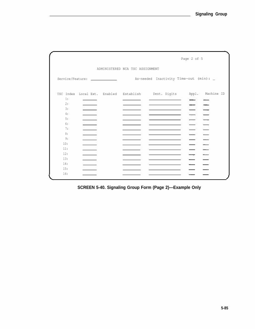
Signaling Group
ADMINISTERED
Service/Feature:
TSC Index
1:
2:
3:
4:
5:
6:
7:
8:
9:
10:
11:
12:
13:
14:
15:
16:
Local Ext. Enabled
NCA TSC ASSIGNMENT
As-needed Inactivity
Establish Dest. Digits
Page 2 of 5
Time-out (min): _
Appl. Machine ID
SCREEN 5-40. Signaling Group Form (Page 2)—Example Only
5-85

CHAPTER 5. FORMS FOR NETWORK FEATURES AND SERVICES
TSC Index
17:
18:
19:
20:
21:
22:
23:
24:
25:
26:
27:
28:
29:
30:
31:
32:
Local Ext.
ADMINISTERED NCA TSC ASSIGNMENT
Enabled Establish Dest. Digits
Page 3 of 5
Appl. Machine ID
SCREEN 5-41. Signaling Group Form (Page 3)—Example Only
5-86

Signaling Group
Page 4 of 5
NCA TSC ASSIGNMENTADMINISTERED
Ext. Enabled Machine IDTSC Index
33:
34:
35:
36:
37:
38:
39:
40:
41:
42:
43:
44:
45:
46:
47:
48:
Local Establish Dest. Digits Appl.
SCREEN 5-42. Signaling Group Form (Page 4)—Example Only
5-87

CHAPTER 5. FORMS FOR NETWORK FEATURES AND SERVICES
Page 5 of 5
ADMINISTERED
Ext. Enabled
NCA TSC ASSIGNMENT
TSC Index
49:
50:
51:
52:
53:
54:
55:
56:
57:
58:
59:
60:
61:
62:
63:
64:
Local Establish Dest. Digits Appl. Machine ID
SCREEN 5-43. Signaling Group Form (Page 5)—Example Only
5-88

ISDN TSC Gateway Channel Assignments
ISDN TSC Gateway Channel Assignments
Purpose
The ISDN TSC Gateway Channel Assignments form is required to be administered when theswitch is to act as a gateway between a switch that supports the Temporary Signaling Connec-tions (TSC) feature and a non-TSC-compatible PBX. The gateway provides interface protocolsnecessary for communications to exist between a switch administered with Non-Call AssociatedTSCs in a Signaling Group on the ISDN side and a processor channel (BX.25) on the non-lSDNside. A NCA-TSC is a type of virtual connection established for exchanging user informationmessages on ISDN D-Channels. There is no B-Channel related to the connection.
Administration Commands
The following administration commands can be used to access the ISDN TSC Gateway ChannelAssignments form. In some cases, just the most commonly used commands are shown. Referto Administration Commands and Error Messages (Chapter 3) for a complete listing of alladministration commands, the command structure, and the use of abbreviated command wordswhen entering a command. You may also wish to refer to the Signaling Group and ProcessorChannel Assignment forms.
Action Object Qualifier*
charge isdn tsc-gatewaydisplay isdn tsc-gateway [’print’]
• Brackets [ ] indicate the qualifier is optional.
Form Instructions
Make assignments as required for the following fields on each page of the from:
●
●
●
●
Sig Group— Used to indicate the Signaling Group that the NCA-TSC belongs to. Validentry is a Signaling Group number in the range of 1 through 8. Default is blank.
Adm’d NCA TSC Index— Used to indicate the administered NCA-TSC that will act as 1end point of the gateway. Valid entry is 1 through 64. Default is blank.
Processor Channel— Used to indicate the processor channel to which the administeredNCA-TSC index will be mapped. This processor channel is used as another end point ofthe connection in this gateway assignment. Valid entry is a processor channel in therange 1 through 64. Default is blank.
Application:— Used to indicate the feature this gateway is used for. A gateway channelcan be used for DCS over ISDN-PRI D-Channel or ISDN-PRI DCS AUDIX feature. Validentries are "audix" or "dcs." Default is blank
5-89

CHAPTER 5. FORMS FOR NETWORK FEATURES AND SERVICES
Page 1 of 2
TSC GATEWAY CHANNEL ASSIGNMENTISDN
Applic-
cationSig
Group
Adm'd NCA
TSC Index
Processor
Channel
Appli-
cation
Sig
Group
17: _
18: _
19: _
20: _
21: _
22: _
23: _
24: _
25: _
26: _
27: _
28: _
Adm’d NCA
TSC Index
Processor
Channel
1:
2:
3:
4:
5:
6:
7:
8:
9:
10:
11:
12:
13:
14:
15:
16:
29:
30:
31:
32:
—
—
—
—
SCREEN 5-44. lSDN TCS Gateway Channel Assignment (Page 1)—Example Only
5-90

ISDN TSC Gateway Channel Assignments
Page 2 of 2
ISDN TSC GATEWAY CHANNEL ASSIGNMENT
Sig
Group
Sig
Group
Adm’d NCA
TSC Index
Processor
Channel
Appli-
cation
Adm’d NCA
TSC Index
Processor Applic-
cationChannel
33:
34:
35:
36:
37:
38:
39:
40:
41:
42:
43:
44:
45:
46:
47:
48:
49: _
50: _
51: _
52: _
53: _
54: _
55: _
56: _
57: _
58: _
59: _
60: _
61: _
62: _
63: _
64: _
SCREEN 5-45. ISDN TCS Gateway Channel Assignment (Page 2)—Example Only
5-91

CHAPTER 5. FORMS FOR NETWORK FEATURES AND SERVICES
Trunk Groups
This section contains the forms and instructions required to implement trunk groups in the Sys-tem.
A System can be administered to have up to 99 trunk groups (maximum) and up to 400 trunks(maximum). Note that if the Hospitality Parameters Reduction Option is enabled on the System-Parameters Customer-Options form, the maximum number of trunk groups that may be admin-istered is limited to 50. In addition, the number of trunk groups that can be measured by theBCMS is 32.
Note: Trunks and Access Endpoints consume the same resource. Thus, the sum of trunksand Access Endpoints cannot exceed 400.
The following trunk group forms are included in this section:
●
●
●
●
●
●
●
●
●
●
●
●
●
●
Access Trunk Group
APLT Trunk Group
CO Trunk Group
CPE Trunk Group
DMI—BOS Trunk Group
DID Trunk Group
Direct Inward and Outward Dialing Trunk Group (International G1.2SE only)
FX Trunk Group
ISDN-PRI
PCOLGs
RLT Group
Tandem Trunk Group
Tie Trunk Group
WATS Trunk Group
5-92

Trunking—General
Trunking—General
The following provides a reference source for various trunk-related terms. Refer to this materialfor additional information when administering the System’s trunk group forms. In addition, referto AT&T Network and Data Services Reference Manual, 555-025-201, and to DEFINITY® Com-munications System Generic 1 and System 75 and System 85 DS1/DMI/ISDN-PRl Reference,555-025-101.
Trunk Characteristics
A trunk is named for its transmission characteristics and can be analog or digital depending onthe type of signals it carries. One transmission characteristic is signaling which is the transmis-sion of supervision, address, alerting, or other switching information between switches.
A trunk is further classified as one of the following:
●
●
●
1-way incoming trunk— A local trunk that can be selected (seized) by the far-end con-nected switch.
1-way outgoing trunk— A trunk that can be seized by the local switch to call the far-endswitch.
2-way trunk— A trunk that can be seized at either end of the connected switches.
Transmission of Supervision
Supervisory signaling establishes or sets up the connection of the local switch to the distantswitch. In general, supervisory signaling can bethought of in two phases: the seizure signal (theoriginating office’s signal for a request for service from the distant office) and the start dial signal(the distant office’s acknowledgement that it is ready to accept dialing from the originating office).
The following four types of supervision signaling are used in trunks:
1.
2.
E&M (Ear & Mouth) supervision—A symmetric signaling scheme used on private networktrunks in which DC voltage levels are sent over E&M leads. The E and M leads areseparate from the transmission path (T & R leads). E&M signals indicate on-/off-hookstates of each end of the connection path. E&M signaling is further divided into types(Type I through V). DIMENSION PBX systems use only Type I and DEFINITY, System75, and System 85 can use Type I or V. Type I is signaling from the trunk interface to thefar-end over the M lead using nominal -48 volts for off-hook and local ground for on-hook.Signaling from the far-end is over the E lead using far-end ground for off-hook and openfor on-hook. Type V is signaling in both directions by means of open for on-hook andground for off-hook.
GS (Ground Start) supervision—A supervisory signaling scheme used on public networktrunks in which ground is applied on the Tip (T) lead by the CO and on the Ring (R) leadby the PBX. For example, the calling PBX on a call to a central office using an outgoingtrunk interface seizes the outgoing trunk by placing a ground on the trunk interface Rlead. The CO recognizes the trunk seizure as a request for service and grounds the trunkT lead to indicate to the calling PBX that the CO is ready to receive digits. Ground Starttrunks are preferred over trunks using Loop Start signaling (description follows) for thefollowing reasons:
5-93

CHAPTER 5. FORMS FOR NETWORK FEATURES AND SERVICES
3.
4.
● The tip ground seizure that the distant switch sends minimizes the interval duringwhich a 2-way trunk can be seized from both ends (called glare) since the Sys-tem (that is, PBX) can make trunks busy to outgoing calls almost immediately.
● Ground Start trunks provide a positive indication of a distant switch’s disconnect.The removal of the tip ground can be acted upon by the PBX:
➤ to prevent a station line from being connected to CO dial tone by remain-ing off-hook after completing a call. This prevents a restricted stationfrom making an unauthorized call after placing an authorized call via theattendant.
➤ to hold the trunk busy until the CO disconnects so that another PBX sta-tion cannot seize the trunk and be connected to the CO party of the pre-vious call.
LS (Loop Start) supervision—A supervisory signaling scheme used between a telephoneand a PBX in which the telephone or far-end office completes the loop current pathformed by the trunk leads (that is, wires). The circuit provides one signaling state when itis open and another when it is closed. A third signaling state is achieved by changing thedirection or magnitude of current in the loop. The most preferred method of loop startsignaling is reverse battery signaling. Disconnect times when using Loop Start signalingcan result in delays of up to 10 to 20 seconds. In addition, glaring as described inGround Start is possible.
RB (Reverse Battery) supervision—A supervisory technique on 1-way trunks that usesopen and closure signals from the originating end and reversals of battery and groundfrom the terminating end (normally used on direct inward dialing trunks).
Transmission of Address
With Signaling there are three types of transmission of address. Transmission of address is themethod of signaling used to represent digits and/or characters for called numbers, callingnumbers, etc. The methods of addressing are dial pulse (DP), dual tone multi-frequency (DTMF),and multi-frequency (MF) addressing.
● DP addressing—A means of signaling that consists of regular momentary interruptions ofa direct or alternating current at the sending end in which the number of interruptionscorresponds to the value of a digit or character (alternating current is not used by PBXs).The interruptions are usually produced by a rotary telephone dial, or may be produced bya sender in a switching system.
● DTMF addressing—Signaling arrangements (commonly known as touch-tone) consist ofdialing signals of two simultaneous t1s. 1 t1 from a low group of four frequencies and theother from a high group of four frequencies correspond to digits, letters, or characters (0through 9, A through Y, or * and #). One of the tones (1633 Hz) from the high group is aspare.
● MF addressing—Signaling arrangements that make use of two frequencies, and onlytwo, out of six to represent ten decimal digits (0 through 9) and five auxiliary signals. MFsignals are used for called number addressing, calling number identification, ringback,and coin control.
5-94

Trunking—General
Transmission of Alerting
Network trunks operate as automatic, immediate start, dial tone, wink start, or delay dial accord-ing to the type of start dial signal (alerting) the switch sends out or expects to receive. The dif-ferent transmissions of alerting areas follows:
●
●
●
●
●
Automatic—The originating switch sends no digits or start dial signal, expecting the ter-minating switch to complete the call. The call is usually completed by the attendant orother service such as CAS.
Immediate start—The originating switch sends digits immediately without waiting for astart dial signal from the terminating switch.
Dial tone—The terminating switch sends precise dial tone to the originating switch, indi-cating that the terminating switch is ready to receive digits.
Wink start—The terminating switch sends a wink start (momentary off-hook) signal to theoriginating switch, indicating that the terminating switch is ready to receive digits.
Delay dial—The terminating switch sends a delay dial signal (an off-hook signal followedby an on-hook signal) to the originating switch, indicating that the terminating switch isready to receive digits.
With digital trunks, signaling schemes are basically the same as for analog trunks when estab-lishing a call. Supervisory, addressing, and alerting have been carried over to the digital trunks.These schemes are handled in a variety of ways to indicate particular calling states, such as on-hook, off-hook, ringing, not ringing, etc., by using "A" and "B" bit timed signaling. "A" and "B" bitscarry a zero or one depending on the type of trunk, the near-end channel unit type, far-end chan-nel type, trunk condition (open loop, loop closure, reverse battery, etc.), and whether it is transmitor receive signaling.
In addition to the above, refer to DS1 Circuit Pack description in this chapter for trunk-relatedterms associated with DS1 trunk interfaces.
Private Network Trunks
Private network trunks are referred to as tie trunks, tandem trunks, or both. The tie trunks thatinterconnect the switches of a private network are "universal" which means that the trunks can beadministered with a variety of translation encodes. The originating switch can recognize any startdial signal (precise dial tone, wink start, or delay dial) that the terminating switch sends. If the ori-ginating switch does not receive one of these start dial signals, it can be administered to senddigits after an administered time-out interval. The time-out interval is the amount of time the ori-ginating switch waits before sending digits.
Tie trunks are further classified according to the type of signal (analog or digital) they carry.
Analog Tie Trunks
Analog tie trunks are communications paths that carry voice and voiceband data communication.The term voice implies that sound is transferred into electrical form and transmitted within anapproximate voiceband of 300 Hz to 3400 Hz. Voiceband data implies that data is transmittedwithin the voiceband and requires a conversion resource (modem) at both ends of the connec-tion. The data transmission rate for analog tie trunks depends on the data-handling capability ofthe modems in the connection. Other factors that affect the data rate are the number of tie trunks
5-95

CHAPTER 5. FORMS FOR NETWORK FEATURES AND SERVICES
in the connection and the technology of any multiplex systems used in the facilities. Generally,for data rates up to 300 bps, a connection can have five tie trunks in tandem. For data ratesgreater than 300 bps up to 2400 bps, a connection can have up to three tie trunks in tandem. Fordata rates greater than 2400 bps up to 4800 bps, a connection can have up to two tie trunks intandem.
Analog tie trunks used in unswitched connections can support up to 9600 bps.
A special type of private network tie trunk is a Release Link Trunk The RLT is used between acentral or main location and a branch location to provide CAS. It functions as a 1-way outgoingcircuit from the branch locations and a 1-way incoming to the main location. RLTs participate inthe redirection of incoming calls originally directed to the branch location to attendants at themain location and handle call completion back to the branch location.
Another special type of trunk is the Advanced Private Line Termination (APLT) trunk. APLTprovides access to and termination from central office based private networks; namely, CommonControl Switching Arrangements (CCSA) and EPSCS. APLT trunks are physically the same asthose used for analog tie trunks where the trunk signaling is compatible with EPSCS and CCSAnetwork switches. The outgoing APLT trunk repeats any number of digits to the private networkas dialed. APLT trunks can tandem through the PBX from EPSCS network only; CCSA networksrequire an attendant to complete the call.
Digital Tie Trunk (DS1)
The digital tie trunk is a high-speed and a high-volume trunk interface to T1 carrier. It uses digitalsignal (DS1) on the T1 carrier. By multiplexing twenty-four 64-kbps digital channels onto a single1.544-Mbps T1 carrier, DS1 offers an economical alternative to the analog tie trunk as well as ahigh-speed fully digital (without modems) connection between the switches.
The maximum per-channel data rate for DS1 is 64 kbps, and it can carry voice, voiceband data,or high-speed data communications.
The DS1 tie trunk is also used for DMI. DMI provides high-speed communications over digitaltransmission facilities between a host computer and a DEFINITY system, System 75, or System85. The DMI trunk uses the "A" bit for signaling to provide wink-start dial-repeating into the switchand automatic out or 2-way wink start.
Public Network Trunks
Public network trunks are classified according to the type of signal (analog or digital) they carry.Public network trunks are used to connect a private network switch to a public network switch(CO). In reference to a CO, the term "local" applies to a switch within the local exchange area. Anexchange area has a single uniform set of charges for telephone service and may be served bymore than one CO. Within an exchange area, a call between any two points is a local call.
Public network trunks also function as "special access" to AT&T Communications (AT&T-C) tollnetwork. AT&T-C provides such services as Megacom service, Megacom 800 service, andACCUNET telecommunications service.
5-96

Trunking—General
Analog Trunks
Analog public network trunks are as follows:
●
●
●
●
●
●
●
CO Trunk—A 1-way outgoing, 1-way incoming, or 2-way trunk connecting the switch to aCO within the local exchange area.
FX Trunk—A 1-way outgoing, 1-way incoming, or 2-way trunk connecting the switch to aCO that is outside the local exchange area. These trunks give a caller direct access to acentral office outside the local exchange area without having to use the public network.
WATS Trunk—A 1-way outgoing or 1-way incoming trunk connecting the switch to a COequipped to handle WATS calls. The outgoing trunks allow a customer, for a monthlycharge, to place outgoing station-to-station calls to telephones in a defined service area.The service area has one or more geographic areas known as WATS bands. Incomingtrunk calls are completed by the attendant or other service.
800-Service Trunk—A 1-way incoming trunk connecting the switch to a CO equipped tohandle 800 Service calls (also known as Inward WATS). These trunks allow a customer,for a monthly charge, to receive incoming station-to-station calls from telephones in adefined service area without charge to the caller.
DID Trunk—A 1-way incoming trunk connecting the switch to a local CO. These trunksallow calls from the public network to complete to terminals (stations) assigned to aprivate network switch without attendant assistance.
DOD Trunk—A 1-way outgoing trunk for outgoing calls connecting the switch to a CO.These trunks allow terminal (station) users to place calls to a public network central officedirectly (without attendant assistance).
DIOD Trunk—A 2-way (incoming and outgoing) trunk used in Japan to provide a com-munication link between a public local exchange and a G1.2SE switch. DIOD is a combi-nation of the DID and CO calling feature (International G1.2SE only).
Digital Trunks
The digital public network trunk provides a DS1 interface to the central office over T1 carrier. TheDS1 public network trunk provides an interface to CO, FX, WATS, DID, and DIOD. The DS1interface supports incoming and outgoing dial types of ground-start, loop-start, auto/auto,auto/delay, auto/immed, and auto/wink. Signaling may be robbed-bit or common channeldepending on the trunk type and the incoming/outgoing dial type. The interface may be used toconnect the switch to a toll office directly using wink-start tie trunks for 2-way access to the tollnetwork.
5-97

CHAPTER 5. FORMS FOR NETWORK FEATURES AND SERVICES
Access Trunk Group
Purpose
This form is used to assign an Access Trunk Group and associated trunk ports. Access trunksprovide the System with the ability to communicate with another PBX as either a main or tandemswitch in an ETN arrangement. This trunk group does not send or receive Traveling ClassMarks.
Administration Commands
The following administration commands can be used to access the Access Trunk Group form. Insome cases, just the most commonly used commands are shown. Refer to Administration Com-mands and Error Messages (Chapter 3) for a complete listing of all administration commands, thecommand structure, and the use of abbreviated command words when entering a command.
Action Object Qualifier*
add trunk-group 1-99 (or ‘next’)change trunk-group 1-99 or TAC X...display trunk-group 1-99 or TAC X... ['print’ or ‘schedule’]list trunk-group ['print’ or ‘schedule’]remove trunk-group 1-99 or TAC X...
* Brackets [ ] indicate the qualifier is optional.Single quotes (‘ ’) indicate the text inside the quote must be entered exactly as shown oran abbreviated form of the word may be entered.
Form Instructions
Make assignments as required for the following fields on each page of the form:
Page 1 of the Form
●
●
●
●
●
●
Group Number— Enter a number from 1 through 99 when completing a paper form. Thisis a display-only field when the form is accessed using an administration command suchas add or change.
Group Type— Enter "access" to identify the trunk group type.
SMDR Reports— Enter "y" to provide a detailed SMDR record of both incoming and out-going calls made on all trunks in the trunk group; otherwise, enter "n." Default is "y."
Group Name— Enter a unique name that identifies the trunk group. Up to 15 characterscan be used. Default is "OUTSIDE CALL."
COR— Enter a class of restriction (COR) number from 0 through 63 that reflects thedesired restriction. Default is "1."
TAC— Enter the trunk access code (TAC) that must be dialed to access the trunk group.SMDR also uses the TAC to identify the trunk group on associated SMDR reports. A dif-ferent TAC must be assigned to each trunk group. Allowable entries are TACs that arecompatible with the System Dial Plan (1 to 3 digits).
5-98

Access Trunk Group
●
●
●
●
●
●
●
●
●
●
Direction— Enter whether the trunk group is "incoming," "outgoing," or "two-way."Default is "two-way."
Outgoing Display— Specifies whether or not the trunk group name is displayed on a ter-minal placing an outgoing call. Allowable entries are "y" or "n." Default is "n."
Dial Access— Enter "y" to allow the trunk group to be accessed via a TAC; otherwise,enter "n." Default is "y." Access via the ARS feature is allowed regardless of this entry.
Busy Threshold— Enter a number (0 through 99) of trunk group members that must bebusy before the attendant is alerted by the Warning lamp on the Attendant Console.Default is "99."
Night Service— Enter the extension number assigned to Night Service. The extensionnumber entered will receive all incoming calls when Night Service is activated and theindividual trunk member Night field is not administered to override this group extension.Allowable entries are an extension number (can be a VDN extension), 0 (attendant), orleave blank if the Trunk Type (in/out) field is not "auto/...."
Queue Length— Enter a number from 0 through 100 that indicates the number of outgo-ing calls that can be held waiting. A "0" indicates no calls will be held in queue. Enter "0"for DCS trunks. The field is turned off if the Direction field is "incoming." Default is "0."
Administrable Timers Page— Only displayed for international applications. Entering a"y" causes an Administrable Timers page to be added to the trunk group form. TheAdministrable Timers page then becomes Page 3 of x. Valid entries are "y" or "n."Default is "n." (International G1.2SE only). Incoming Destination— Indicates whereincoming calls will terminate. Allowable entries are an extension number, 0 (attendant),VDN, or leave blank if the Trunk Type (in/out) field is not "auto/...." If "0" is entered, acall is treated as an LDN call.
Comm Type— lndicates if the trunk is to be used for voice, data, alternate voice-data(that is, avd), or alternate voice/voice grade data and 56 kbps digital data (that is, rbavd)calls. Allowable enteries are "avd," "rbavd," "voice," or "data." Type "rbavd" supportsaccess to voice/data SDN service on robbed-bit T1 transmission facilities. Default is"voice." Note that "avd" and "rbavd" types require trunk member ports on a DS1 circuitpack. An "rbavd" type requires that the DS1 circuit pack be administered for robbed-bitsignaling.
Auth Code— Enter "y" if an authorization code must be dialed to complete incoming callson the trunk group; otherwise, enter "n." This field can only beset to "y" if the Authoriza-tion Codes feature is enabled on the System-Parameters Customer-Options form.Default is "n."
ITC (Information Transfer Capability)— Used by the GRS feature and enables the systemto mute calls to restricted or unrestricted facilities according to the endpoint’s informationtransfer capability. The ITC field is displayed on G3i systems for non-lSDN trunk groupsonly and is displayed and administrable only when the Comm Type field is administeredas "data," "avd," or "rbavd" and the BCC field is not set to "0." This field is not displayedif the Comm Type field is administered as "voice," nor is it displayed if the Comm Typefield is administered as "data," "avd," or "rbavd" and the BCC field is set to "0." Defaultis "rest" (restricted). Allowed values are "rest" and "unre" (unrestricted).
5-99

CHAPTER 5. FORMS FOR NETWORK FEATURES AND SERVICES
●
●
BCC (Bearer Capability Class)—Used by the GRS feature and identifies the type oftraffic on trunks in the group. The BCC entry is used by far-end tandem switches toselect outgoing routing facilities with equivalent BCC classes. Allowable entries are 0, 1,2, 3, and 4. Default is 0 for "rbavd’ and "avd" and 2 for "data." The BCC field is alwaysdisplayed when the Comm Type is "avd," "rbavd," or "data."
Note: Refer to the GRS feature description in DEFINITY® Communications Sys-tem Generic 1 and Generic 3i—Feature Description, 555-230-201, for adetailed description of BCCs and their use to provide specialized routing forvarious types of voice and data calls.
Trunk Type (in/out)— Identifies the physical type of incoming and outgoing trunks.Allowable entries are listed below.
auto/auto auto/delay auto/immed auto/winkdelay/auto delay/delay delay/immed delay/wink
immed/auto immd/delay immed/immed immed/winkwink/auto wink/delay wink/immed wink/wink
●
●
●
●
●
●
●
●
Incoming Rotary Timeout (sec)— ls the timing interval required by the central office thatthe System is connected to. If the System is connected to a step-by-step office, 18 ormore seconds must be used; if the System is not connected to a step-by-step office, fiveor more seconds may be used. The maximum value is 99 seconds. Allowable entriesare five through 99, or leave blank. Default is "5."
Outgoing Dial Type— Identifies the type of pulsing required on an outgoing call. Allow-able entries are "tone" or "rotary." Default is "tone."
Incoming Dial Type— Indicates the type of pulses required on an incoming trunk group.Allowable entries are "tone" or "rotary." Default is "tone."
Disconnect Timing (msec)— Specifies the minimum time period in milliseconds that isrequired for recognition of disconnect by the serving central office or far-end PBX. Thetime interval must be in increments of 10 (from 140 to 2550 milliseconds). Default is"500."
Digit Treatment— Indicates if digits are to be absorbed or inserted. A blank indicates nodigit absorption or insertion. Allowable entries are "absorption" or "insertion," or leaveblank.
Digits— Indicates the digits to be inserted or number of digits to be absorbed. This fieldis used with the Digit Treatment field. No entry indicates no digit absorption or insertionis done. Allowable entries are the number of digits to be absorbed (1 to 5) or the actualdigits to be inserted (up to 5 digits).
Connected to Toll— Enter "y" if connected to a CO toll office; otherwise, enter "n"(default). This field is displayed when the Trunk Type field contains an entry of "auto/...,""delay/...," "wink/...," or "immed/ ...."
STT Loss (Satellite PBX Tie Trunk Loss)— Only displayed when the Connected to Tollfield is "n." Specifies the loss plan to be used for the trunk group. Allowable entries are"normal" (default) or "low." This option affects the transmission performance of a privatePBX network.
5-100

Access Trunk Group
Although the use of this option has wider applications, only for the simplest networkarrangements should this field be administered without Network Engineering advise. The"low" option (described as the ISL digital low loss plan in DEFINITY® CommunicationsSystem Generic 1 and System 75 and System 85 DS1/DMI/ISDN-PRI Reference, 555-025-101) should only be used when:
1.
2.
3.
4.
Stations on the satellite PBX complain of too much loss on calls to the public net-work.
The PBX network consists of no more than three PBXs: one main and one ortwo satellite PBXs.
All PBXs have the "low" option available.
The total DS1 trunk connection length is less than 100 miles.
If the preceding conditions are not met, obtain Network Engineering assistance. The fieldentry is based on the following:
➤ normal— Applies to AIU-TT (Analog Interface Unit at Customer Switching Sys-tem for Tie Trunk—4-wire E&M interface), and DIU-TT (Digital Interface Unit atCustomer Switching System for Tie Trunk—voice or AVD DS1 interface) lossplans.
low— Applies to AIU-TTS (same as AIU-TT, but suitable for private network con-➤
●
nections that can be connected in tandem with public network connections) andDIU-TTS (same as DIU-TT, but suitable for private network connections that canbe connected in tandem with public network connections). These interfaceswere formerly referred to as DIU DTT ISL.
DTT to DCO Loss (Digital Tie to Digital CO Trunk Loss)—Specifies the loss plan to beused for the trunk group for interconnections from a DIU-CO (Digital Interface Unit at aCentral Office) to a DIU-DTT (Digital Interface Unit for a Digital Tie Trunk Interface). Thisfield is displayed when the Trunk Type field contains an entry of auto/..., delay/...,wink/..., or immed/ . . . .
This option affects the transmission performance of public network access via a privatePBX network Choose the "low" option only if private network users complain about toomuch loss on calls to the public network, otherwise, the "normal" option should be used.Allowable entries are "normal" (default) and "low." The entry is based on the following:
➤
➤
normal— Corresponds to a (0, -6) dB gain pair and is used as the default option.(This corresponds to the DTT/EIA DCO port to port configuration as described inDEFINITY® Communications System Generic 1 and System 75 and System 85DS1/DMI/ISDN-PRI Reference, 555-025-101.)
low— Corresponds to (+3, -3) dB gain pair. Low is used for internetwork applica-tions in which no significant configuration will encounter echo, stability, or over-load problems because of reduced loss. With the low gain pair, subscriber sta-tion DTMF signals transmitted through the digital class 5 office into the customernetwork may experience non-recoverable digit mutilation in secondary signalingapplications (that is, DTMF signaling after the connection has been established).(This corresponds to the DTT/lSL DCO port to port configuration as described inDEFINITY® Communications System Generic 1 and System 75 and System 85DS1/DMI/ISDN-PRI Reference, 555-025-101.)
5-101

CHAPTER 5. FORMS FOR NETWORK FEATURES AND SERVICES
●
●
●
●
●
●
Incoming Dial Tone— lndicates whether or not the trunk group will pass on incoming dialt1 to the calling party. Allowable entries are "y" or "n."
Bit Rate— Specifies the baud rate to be used by pooled modems. Allowable entries are"300," "1200," "2400," "4800," "9600," and "19200." This field is only displayed if theComm Type field is "avd." Default is "1200."
Synchronization— Enter whether the trunk group will use "synchronous’" or "asynchro-nous" communications. Allowable entries are "async" and "sync." This field is onlydisplayed if the Comm Type field is "avd." Default is "async."
Duplex— Specifies either full or half duplex for the trunk group. Allowable entries are"full" or "half." Default is "full." This field is only displayed if the Comm Type field is"avd."
Disconnect Supervision— Enter "y" (yes) to indicate that the CO has the ability torelease a trunk when the calling party releases from a call and the system is able torecognize the release signal; otherwise, enter "n" (no). Default is "y." (InternationalG1.1SE and G1.2SE).
Answer Supervision Timeout— Indicates the amount of time in seconds the Systemallows for the call to be answered before beginning an SMDR record of a call. This inter-val begins as soon as the outgoing trunk is seized. This time-out does not override net-work or firmware sent answer supervision. Allowable entries are 0 through 250. Thedefault is "10."
Page 2 of the Form
ACA Assignment?— Specifies whether or not ACA measurements will be taken for thistrunk group. Allowable entries are "y" or "n." Default is "n." If "y" is entered, completethe next three fields.
●
●
●
●
●
●
Long Holding Time (hours)— ls the length in hours that the System will consider asbeing a long holding time. If the value entered is "0," the System will not consider longholding calls. Allowable entries are 0 through 10. Default is "1."
Short Holding Time (secs.)— Specifies the length in seconds that the System will con-sider as being a short holding time. If this field is "0," the System will not consider shortholding calls. Allowable entries are 0 through 160. Default is "10."
Short Holding Threshold— Is the number of times that the System will record a shortholding call before an attendant or display-equipped voice terminal user is alerted to thepossibility of a faulty trunk. Allowable entries are 0 through 30. Default is "15."
Measured— Indicates if the System will transmit data for this trunk group to the CMS.Allowable entries are "internal," "external," "both," "none." Enter "internal" if the data isto be sent to the BCMS (that is, internal to the switch) for subsequent measurementreports and "external" to send the data to the 3B CMS. Enter "both" to send the data toboth systems for measurement reports or enter "none" if trunk group measurements arenot required. System default is "none."
Data Restriction— Is used to restrict System features from causing overriding tones on atrunk group. This provides permanent protection. Allowable entries are "y" or "n."Default is "n."
5-102

Access Trunk Group
●
●
●
●
Used for DCS?— Indicates whether or not the trunk will send and receive messages on aDCS Signaling Link. Allowable entries are "y" or "n." If "y" is entered, complete the PBXID field. Default is "n."
PBX lD— Identifies the remote PBX within the network that the trunk will communicatewith on a DCS Signaling Link. Allowable entries are 1 through 63. Default is "1."
Suppress # Outpulsing— Indicates end-to-end signaling begins with (and includes) the"#" when y is entered in this field. The final # is suppressed in cases where the Systemwould normally outpulse it. This field should be set to "y" when the central office (forexample, rotary) or any other facility treats # as an error. Default is "n."
Maintenance Tests— Indicates if maintenance tests will be performed on an hourly basisfor this trunk group. Allowable entries are "y" or "n." Default is "y."
Page 3 of the Form (Administrable Timers) (International G1.2SE only)
Note: This page is only displayed if "y" is entered in the Administrable Timers Page field onPage 1 of the form.
●
●
●
●
●
●
●
Incoming Disconnect (msec)— Enter the minimum time (in msec) required for recogni-tion of disconnect for an incoming call from the serving CO. Valid entries are 50 through12750 in increments of 50. The field cannot be blank. Default is "300."
Outgoing Disconnect (msec)— Enter the minimum time (in msec) required for recogni-tion of disconnect for an outgoing call. Valid entries are 50 through 12750 in incrementsof 50. The field cannot be blank. Default is "300."
Outgoing Dial Guard (msec)— Enter the minimum time (in msec) between seizure ofthe trunk and outpulsing of digits. Valid entries are 200 through 25600 in increments of200. The field cannot be blank. Default is "1000."
Incoming Glare Guard (msec)— Enter the incoming guard time (in msec) between thetime the incoming trunk is released and the same trunk can be seized again. This guardtime will ensure the far-end has released all equipment after the incoming trunk isreleased. Valid entries are 200 through 25600 in increments of 200. The field cannot beblank. Default is "3000."
Outgoing Glare Guard (msec)— Enter the outgoing guard time (in msec) between thetime the outgoing trunk is released and the same trunk can be seized again. This guardtime will ensure that the far-end has released all equipment after the outgoing trunk isreleased. Valid entries are 200 through 25600 in increments of 200. The field cannot beblank. Default is "3000."
Outgoing Rotary Dial Interdigit (msec)— Enter the interval (in msec) between rotarydial digits being outpulsed by the system (that is, PBX). Valid entries are 150 through2550 in increments of 10. The field cannot be blank. Default is "600."
Ringing Monitor (msec)— Enter the minimum time (in msec) required to determine if thetrunk is disconnected. if the ringing signal disappears for a duration longer than the timespecified in this field, the call will be assumed to be disconnected. For CO, FX, WATS,PCOL, DID, and DIOD, valid entries are 200 through 51000 in increments of 200. ForTie, Tandem and Access, valid entries are 200 through 25500 in increments of 100. Thefield cannot be blank. Default is "5000."
5-103

CHAPTER 5. FORMS FOR NETWORK FEATURES AND SERVICES
●
●
●
●
●
lncoming Seizure (msec)— Enter the minimum time (in msec) required for recognition ofincoming ringing signal from the serving CO. Valid entries are 20 through 2550 in incre-ments of 10. The field cannot be blank. Default is "130."
PPS— Enter either "10" or "20" to specify the PPS (pulses per second) assigned to rotarydial pulse trunk groups. Valid entries are "10" or "20." Default is "10."
Make (msec)— Enter the duration of the make interval while the system is outpulsingdigits using dial pulse signaling.
If the PPS field is "10," the sum of the Make and Break fields must equal 100. Validentries are 20 through 80 in increments of five. The field cannot be blank. The default is"40."
If the PPS field is "20," the sum of the Make and Break fields must equal 50. Validentries are 10 through 40 in increments of five. The field cannot be blank. The default is"20."
Break (msec)— Enter the duration of the break interval while the system is outpulsingdigits using dial pulse signaling.
If the PPS field is "10," the sum of the Make and Break fields must equal 100. Validentries are 20 through 80 in increments of five. The field cannot be blank. The default is"60."
If the PPS field is "20," the sum of the Make and Break fields must equal 50. Validentries are 10 through 40 in increments of five. The field cannot be blank. The default is"30."
PPM— Enter "y" (yes) if PPM pulses are to be collected to determine outgoing call billing,otherwise enter "n" (no). Valid entries are "y" or "n." Default is "n." (This field does notappear for DID, Tie, Tandem, or Access trunks.)
Pages 3 through 9 of the Form (Group Member Assignments)
Note: For International Systems, if "y" has been entered in the Administrable Times Pagefield on Page 1 of the form, the Group Member Assignments will appear on Pages 4through 10 of the form.
●
●
Port— Enter five to six characters. The first character identifies the network (1 through 3,default is "1" if no entry); the second character identifies the carrier (A through E); thethird and fourth characters identify the slot number in the carrier (01 through 20 for multi-carrier cabinets depending on carrier type or 01 through 18 for single-carrier cabinetsdepending on cabinet type); the last two characters identify the circuit number (01through 08).
Name— Enter up to 10 characters to identify the member of the trunk group. The namecan be a 7-digit telephone number or a 10-digit Trunk Circuit Identification number (pro-vided by trunk supplier).
Note: This information must be entered in the Night field (below) or the STT Lossfield on Page 1 of the form, as applicable.
5-104

Access Trunk Group
●
●
●
●
Night— Specifies a night destination for an individual trunk. This entry overrides thegroup Night Service entry on Page 1 of the form. Allowable entries are an extension (canbe a VDN extension), 0 (attendant), or leave blank if the Trunk Type on Page 1 is not"auto/...."
Mode— Specifies the signaling mode used on Tie Trunks when using TN760B circuitpacks. Allowable entries are "E&M" (interface), "simplex" (phantomed), or "protected."This entry must correspond to associated dip switch settings on the circuit pack. Noentry should be made in this field when using TN722, TN722B, TN767, or TN464C (Inter-national G1.2SE only) circuit packs.
Type— When using TN760B circuit packs, this entry specifies the type of trunk used.Allowable entries are "t1 stan" (Type 1 Standard), "t1 comp" (Type 1 Compatible), or"type 5." No entry should be made in this field when using TN722, TN722B, TN767, orTN464C (International G1.2SE only) circuit packs.
Ans Delay— Specifies the length of the wait for answer supervision delay in millisecondsfor DS1 or Tie Trunks using the TN722A, TN722B, TN760 (B, C, or D), TN767, orTN464C (International G1.2SE only) circuit packs. Allowable entries are 20 through 5100in increments of 20. The default is no entry (blank) and internally treated as a zero. Thisdelay serves two purposes:
1.
2.
Used to assure that the answer supervision signal is valid and not a secondarydelay-dial or wink-start signal.
Used to bridge over momentary off-hook signals resulting from connectionsmade off-network through certain No. 5 Crossbar CCSA switches as the connec-tion is being established.
5-105

CHAPTER 5. FORMS FOR NETWORK FEATURES AND SERVICES
TRUNK GROUP Page 1 of 9
Group Number: _ Group Type: access SMDR Reports? y
Group Name: OUTSIDE CALLS COR: 1 TAC: _
Direction: two-way Outgoing Display? n
Dial Access? y Busy Threshold: n Night Service: _
Queue Length: 0 Incoming Destination: _
Comm Type: voice Auth Code? n
BCC: 0_
TRUNK PARAMETERS
Trunk Type (in/out): Incoming Rotary Timeout(sec): 5
Outgoing Dial Type: tone Incoming Dial Type: tone
Disconnect Timing(msec): 500
Digit Treatment: Digits:
Connected to Toll? n STT Loss: normal DTT to DCO LOSS: normal
Incoming Dial Tone? y
Bit Rate: 1200 Synchronization: async Duplex: full
Answer Supervision Timeout? 10
SCREEN 5-46. Access Trunk Group Form (Page 1)—Example Only (Standard)
Implementation Note:
The BCC field is displayed when the Comm Type is "avd,’’ "rbavd" or "data."
The Connected to Toll and DTT to DCO Loss fields are only displayed when the Trunk Type fieldis "auto/...," "delay/...," "immed/...," or "wink/...."
The STT Loss field is only displayed when the Connected to Toll field is "n."
The Bit Rate, Synchronization, and Duplex fields are only displayed when the Comm Type field is"avd."
The lTC (lnformation Transfer Capability) field is displayed on G3i systems for non-lSDN trunkgroups only and is displayed and administrable only when the Comm Type field is administeredas "data," "avd," or "rbavd" and the BCC field is set to "0."
5-106
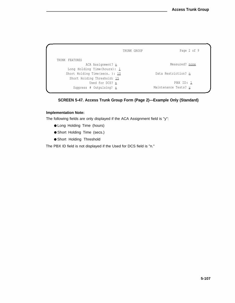
Access Trunk Group
TRUNK GROUP Page 2 of 9
TRUNK FEATURESACA Assignment? n Measured? none
Long Holding Time(hours): 1Short Holding Time(secs. ): 10 Data Restriction? n
Short Holding Threshold: 15Used for DCS? n PBX ID: 1
Suppress # Outpulsing? n Maintenance Tests? y
SCREEN 5-47. Access Trunk Group Form (Page 2)—Example Only (Standard)
lmplementation Note:
The following fields are only displayed if the ACA Assignment field is "y":
● Long Holding Time (hours)
● Short Holding Time (secs.)
● Short Holding Threshold
The PBX ID field is not displayed if the Used for DCS field is "n."
5-107

CHAPTER 5. FORMS FOR NETWORK FEATURES AND SERVICES
GROUP MEMBER ASSIGNMENTS Page 3 of 9
Port Name Night Mode Type Ans Delay1:2:3:4:5:6:7:8:9:
10:11:12:13:14:15:
SCREEN 5-48. Access Trunk Group Form (Page 3)—-Example Only (Standard)
Note: To reduce repetition, pages 4 through 8 are not shown.
GROUP MEMBER ASSIGNMENTS Page 9 of 9
Port Name Night Mode Type Ans Delay91:92:93:94:95:96:97:98:99:
SCREEN 5-49. Access Trunk Group Form (Page 9)—Example Only (Standard)
5-108

Access Trunk Group
TRUNK GROUP Page 1 of 10
Group Number: 71 Group Type: access SMDR Reports? y
Group Name: OUTSIDE CALL COR: 1 TAC: 501
Direction: two-way Outgoing Display? nDial Access? y Busy Threshold: 99 Night Service: -
Queue Length: 0 Administrable Timer Page? y Incoming Destination: 0Comm Type: voice Auth Code? n
TRUNK PARAMETERSTrunk Type (in/out): auto/auto Incoming Rotary Timeout(sec): 5Outgoing Dial Type: tone Incoming Dial Type: tone
Disconnect Timing(msec): 500
Digit Treatment: Digits:
Connected to Toll? n STT Loss: normal DTT to DCO Loss: normal
Incoming Dial Tone? y
Disconnect Supervision? yAnswer Supervision Timeout? 10
SCREEN 5-50. Access Trunk Group Form (Page 1)—Example Only(International G1.2SE only)
Implementation Note:
The BCC field is displayed when the Comm Type is "avd," "rbavd:"or "data."
The Connected to Toll and DTT to DCO Loss fields are only displayed when the Trunk Typefieldis "auto/...," "delay/...," "immed/...," or "wink/...."
The STT Loss field is only displayed when the Connected to Toll field is "n."
The Bit Rate, Synchronization, and Duplex fields are only displayed when the Comm Type field is"avd."
5-109

CHAPTER 5. FORMS FOR NETWORK FEATURES AND SERVICES
TRUNK GROUP Page 2 of 10display trunk-group 71TRUNK FEATURES
ACA Assignment? n Measured? noneData Restriction? n
Used for DCS? nSuppress # Outpulsing? n Maintenance Tests? y
SCREEN 5-51. Access Trunk Group Form (Page 2)—Example Only(International G1.2SE only)
Implementation Note:
The following fields are only displayed if the ACA Assignment field is "y":
● Long Holding Time (hours)
● Short Holding Time (secs.)
● Short Holding Time Treshold
The PBX ID field is not displayed if the Used for DCS field is "n."
ADMINISTRABLE TIMERS Page 3 of 10
Incoming Disconnect (msec) : 300 Outgoing Disconnect (msec ) : 300Outgoing Dial Guard (msec): 1000
Incoming Glare Guard (msec) : 3000 Outgoing Glare Guard (msec): 3000Outgoing Rotary Dial Interdigit (msec): 600
Ringing Monitor (msec): 5000 Incoming Seizure (msec): 130
OUTPULSING TIMINGPPS: 10 Make (msec): 40 Break (msec): 60 PPM? n
SCREEN 5-52. Access Trunk Group Administrable Timers (Page 3)—Example Only(International G1.2SE only)
lmplementation Note:
This page is only displayed if "y" is entered in the Administrable Timers Page field on Page 1.
5-110

Access Trunk Group
GROUP MEMBER ASSIGNMENTS Page 4 of 10
Port Name Night Mode Type Ans Delay1:2:3:4:5:6:7:8:9:
10:11:12:13:14:15:
SCREEN 5-53. Access Trunk Group Form (Page 4)—Example Only(International G1.2SE only)
Note: To reduce repetition, pages 5 through 9 are not shown.
GROUP MEMBER ASSIGNMENTS Page 10 of 10
Port Name Night Mode Type Ans Delay91:92:93:94:95:96:97:98:99:
SCREEN 5-54. Access Trunk Group Form (Page 10)—Example Only(International G1.2SE only)
Implementation Note:
Above Group Member Assignments pages illustrate the resulting pagination when "y" is enteredin the "Administrable Timers Page" field on Page 1 of the form; otherwise, page numbers will bethree through nine.
5-111

CHAPTER 5. FORMS FOR NETWORK FEATURES AND SERVICES
APLT Trunk Group
Purpose
This form is used to assign an Advanced Private Line Termination (APLT) Trunk Group and asso-ciated trunk ports. The APLT Trunk Group provides access to and termination from private linenetworks. APLT trunks are only to be used with a Common Control Switching Arrangement(CCSA) or EPSCS network.
Administration Commands
The following administration commands can be used to access the APLT Trunk Group form. Insome cases, just the most commonly used commands are shown. Refer to Administration Com-mands and Error Messages (Chapter 3) for a complete listing of all administration commands, thecommand structure, and the use of abbreviated command words when entering a command.
Action Object Qualifier*
add t runk -g roup 1 -99 (o r ‘ nex t ’ )change trunk-group 1-99 or TAC X...display trunk-group 1-99 or TAC X...[’print’ or ‘schedule’]list trunk-group [’print or ‘schedule’]remove trunk-group 1-99 or TAC X...
* Brackets [ ] indicate the qualifier is optional.Single quotes (‘ ’) indicate the text inside the quote must be entered exactly as shown oran abbreviated form of the word may be entered.
Form Instructions
Make assignments as required for the following fields on each page of the form:
●
●
●
●
●
●
●
5-112
Page 1 of the Form
Group Number— Enter a number from 1 through 99 when completing a paper form. Thisis a display only field when the form is accessed using an administration command suchas add or change.
Group Type— Enter "aplt" to identify the type of trunk group.
SMDR Reports— Enter "y" to provide a detailed SMDR reed of both incoming and out-going calls made on all trunks in the trunk group; otherwise, enter "n." Default is "y."
Group Name— Enter a unique name that identifies the trunk group. Up to 15 characterscan be used. Default is "OUTSIDE CALL."
COR— Enter a class of restriction (COR) number from 0 through 53 that reflects thedesired restriction. Default is "1."
TAC— Enter the trunk access code (TAC) that must be dialed to access the trunk group.SMDR also uses the TAC to identify the trunk group on associated SMDR reports. A dif-ferent TAC must be assigned to each trunk group. Allowable entries are TACs that arecompatible with the System Dial Plan (1 to 3 digits).
Direction— Enter whether the trunk group is "incoming," "outgoing," or "two-way."Default is "two-way."

APLT Trunk Group
● Outgoing Display— Specifies whether or not the trunk group name is displayed on a ter-minal placing an outgoing call. Allowable entries are "y" or "n." Default is "n."
● Dial Access— Enter "y" to allow the trunk group to be accessed via a TAC; otherwise,enter "n." Default is "y." Access via the ARS feature is allowed regardless of this entry.
● Busy Threshold— Enter the number (0 through 99) of trunk group members that must bebusy before the attendant is alerted by the Warning lamp on the Attendant Console.Default is "99."
● Night Service— Enter the extension number assigned to Night Service. The extensionnumber entered will receive all incoming calls when Night Service is activated and theindividual trunk member Night field is not administered to override this entry. Allowableentries are an extension number (can be a VDN extension), 0 (attendant), or leave blankif the Trunk Type is not "auto/...."
● Queue Length— Enter a number from 0 through 100 that indicates the number of outgo-ing calls that can be held waiting. A "0" indicates no calls will be held in queue. Defaultis "0." This field is turned off if the Direction field is "incoming."
● Incoming Destination— Indicates where incoming calls will terminate. Allowable entriesare an extension number, 0 (attendant), VDN, or leave blank if the Trunk type is not"auto."
● Auth C— Enter "y" if an Authorization Code must be dialed to complete incomingcalls on the trunk group; otherwise, enter "n." This field can only be set to "y" if theAuthorization Codes feature is enabled on the System-Parameters Customer-Optionsform. Default is "n."
● Trunk Type (in/out)— Identifies the physical type of incoming and outgoing trunks.Allowable entries are listed below.
auto/auto auto/delay auto/immed auto/winkdelay/auto delay/delay delay/immed delay/wink
immed/auto immed/delay immed/immed immed/winkwink/auto wink/delay wink/immed wink/wink
● Incoming Rotary Timeout (sec)— ls the timing interval required by the central office thatthe System is connected to. If the System is connected to a step-by-step office, 18 ormore seconds must be used; if the System is not connected to a step-by-step office, fiveor more seconds may be used. The maximum value is 99 seconds. Allowable entriesare 5 through 99. Default is "5."
● Outgoing Dial Type— Identifies the type of pulsing required on an outgoing call. Allow-able entries are "tone" or "rotary." Default is "tone."
● Incoming Dial Type— lndicates the type of pulses required on an incoming trunk group.Allowable entries are ‘lone" or "rotary." Default is "tone."
● Disconnect Timing (msec)— Specifies the minimum time period in milliseconds that isrequired for recognition of disconnect by the serving central office or far-end PBX. Thetime interval must be in increments of 10 (from 140 to 2550 milliseconds). Default is"500."
5-113

CHAPTER 5. FORMS FOR NETWORK FEATURES AND SERVICES
● Connected to Toll— Enter "y" if connected to a CO toll office; otherwise, enter "n." Thisfield is displayed when the Trunk Type field contains an entry of "auto/..." "delay/...""wink/..." or "immed..." Default is "n."
● STT Loss (Satellite PBX Tie Trunk Loss)— Only displayed when the Connected to Tollfield is "n." Specifies the loss plan to be used for the trunk group. Allowable entries are"normal" (default) or "low." This option affects the transmission performance of a privatePBX network.
Although the use of this option has wider applications, only for the simplest networkarrangements should this field be administered without Network Engineering advise. The"low" option (described as the ISL digital low loss plan in DEFINITY® CommunicationsSystem Generic 1 and System 75 and System 85 DS1/DMI/ISDN-PRl Reference, 555-025-101) should only be used when:
1.
2.
3.
4.
Stations on the satellite PBX complain of too much loss on calls to the public net-work.
The PBX network consists of no more than three PBXs; one main and one ortwo satellite PBXs.
All PBXs have the "low" option available.
The total DS1 trunk connection length is less than 100 miles.
If the above conditions are not met, obtain Network Engineering assistance. The fieldentry is based on the following:
➤ normal— Applies to AIU-TT (Analog Interface Unit at Customer Switching Sys-tem for Tie Trunk—4-wire E&M interface), and DIU-TT (Digital Interface Unit atCustomer Switching System for Tie Trunk-voice or AVD interface) loss plans.
➤ low— Applies to AIU-TTS (same as AIU-TT, but suitable for private network con-nections that can be connected in tandem with public network connections) andDIU-TTS (same as DIU-TT, but suitable for private network connections that canbe connected in tandem with public network connections). These interfaceswere formerly referred to as DIU DTT ISL.
● DTT to DCO Loss (Digital Tie to Digital CO Trunk Loss)— Specifies the loss plan to beused for the trunk group for interconnections from a DIU-CO (Digital Interface Unit at aCO) to a DIU-DTT (Digital Interface Unit for a Digital Tie Trunk Interface). This field isdisplayed when the Trunk Type field contains an entry of auto/..., delay/..., wink/..., orimmed/....
This option affects the transmission performance of public network access via a privatePBX network Choose the "low" option only if private network users complain about toomuch loss on calls to the public network otherwise, the "normal" option should be used.Allowable entries are "normal" (default) and "low." The entry is based on the following:
➤ normal— Corresponds to a (0, -6) dB gain pair and is used as the default option.(This corresponds to the DTT/EIA DCO port to port configuration as described inDEFINITY® Communications System Generic 1 and System 75 and System 85DS1/DMI/ISDN-PRI Reference, 555-025-101.)
➤ low— Corresponds to (+3, -3) dB gain pair. Low is used for internetwork applica-tions in which no significant configuration will encounter echo, stability, or over-load problems because of reduced loss. With the low gain pair, subscriber
5-114

APLT Trunk Group
station DTMF signals transmitted through the digital class five office into the cus-tomer network may experience non-recoverable digit mutilation in secondary sig-naling applications (that is, DTMF signaling after the connection has been esta-blished). (This corresponds to the DTT/lSL DCO port to port configuration asdescribed in DEFINITY® Communications System Generic 1 and System 75 andSystem 85 DS1/DMI/ISDN-PRI Reference, 555-025-101.)
● Incoming Dial Tone— Indicates whether or not the trunk group will pass on incoming dialt1 to the calling party. Allowable entries are "y" or "n." Default is "y."
● Disconnect Supervision— Enter "y" (yes) to indicate that the CO has the. ability torelease a trunk when the calling party releases from a call and the system is able torecognize the release signal; otherwise, enter "n" (no). Default is "y." (internationalG1.1SE and G1.2SE).
● Answer Supevision Timeout— Indicates the amount of time in seconds the Systemallows for the call to be answered before beginning an SMDR record of a call. This inter-val begins as soon as the outgoing trunk is seized. This time-out does not override net-work or firmware sent answer-supervision. Allowable entries are 0 through 250. Dafaultis "10."
Page 2 of the Form
●
●
●
ACA Assignment?— Specifies whether or not Automatic Circuit Assurance (ACA) meas-urements will be taken for this trunk group. Allowable entries are "y" or "n." Default is"n." If "y" is entered, complete the next three fields.
Long Holding Time (hours)— Is the length in hours that the System will consider asbeing a long holding time. If the value entered is "0," the System will not consider longholding calls. Allowable entries are 0 through 10. Default is "1."
Short Holding Time (secs.)— Specifies the length in seconds that the System will con-sider as being a short holding time. If this field is "0," the System will not consider shortholding calls. Allowable entries are 0 through 160. Default is "10."
Short Holding Threshold— Is the number of times that the System will record a shortholding call before an attendant or display-equipped voice terminal user is alerted to thepossibility of a faulty trunk. Allowable entries are 0 through 30. Default is "15."
Measured— lndicates if the System will transmit data for this trunk group to the CMS.
●
●
Allowable entries are "internal," "external," "both," "none." Enter "internal’ if the data isto be sent to the BCMS (that is, internal to the switch) for subsequent measurementreports and "external" to send the data to the 3B CMS. Enter "both" to send the data toboth systems for measurement reports or enter "none" if trunk group measurements arenot required. System default is "none."
Internal Alert— Indicates if internal ringing and call coverage is used for incoming callson this trunk group. Allowable entries are "y" and "n." Default is "n."
Data Restriction— ls used to restrict System features from causing overriding tones on atrunk group. This provides permanent protection. Allowable entries are ‘y’ or "n."Default is "n."
●
●
5-115

CHAPTER 5. FORMS FOR NETWORK FEATURES AND SERVICES
● Suppress # Outpulsing— Indicates end-to-end signaling. Begins with (and includes) the"#" when "y" is entered in this field. The final # is suppressed in cases where Systemwould normally outpulse it. This field should be set to "y" when the central office (forexample, rotary) or any other facility treats # as an error. Default is "n."
● Maintenance Tests— lndicates whether or not maintenance tests will be performed onan hourly basis for this trunk group. Allowable entries are "y" or "n." Default is "y."
Pages 3 through 9 of the Form (GROUP MEMBER ASSIGNMENTS) (Standard)
● Port— Enter five to six characters. The first character identifies the network (1 to 3,default is "1" if no entry); the second character identifies the carrier (A through E); thethird and fourth characters identify the slot number in the carrier (01 through 20 for multi-carrier cabinets depending on carrier type or 01 through 18 for single-carrier cabinetsdepending on cabinet type); the last two characters identify the circuit number (01 to 08).
● Name— Enter up to 10 characters to identify the member of the trunk group. The namecan be a 7-digit telephone number or a 10-digit Trunk Circuit ldentification number (pro-vided by trunk supplier).
Note: Night Service and Balance/Loss information must now be entered in theNight field (below) or the STT Loss field on Page 1 of the form, as applica-ble.
● Night— Specifies a night destination for an individual trunk. This entry overrides theNight Service entry on Page 1 of the form. Allowable entries are an extension (can be aVDN extension), 0 (attendant), or leave blank if the Trunk Type entry on Page 1 is not"auto/...."
●� Mode— Specifies the signaling mode used on Tie Trunks with TN722A, TN722B,TN760B, TN767, or TN464C (International G1.2SE only) circuit packs. Allowable entriesare E&M (interface), simplex (phantomed), or protected. This entry must correspond toassociated dip switch settings on the circuit pack.
● Type— Specifies the type of trunk used. Allowable entries are "t1 stan" (Type 1 Stan-dard), "t1 comp" (Type 1 Compatible), or "type 5."
● Ans Delay— Specifies the length of the wait for answer supervision delay in millisecondsfor DS1 or Tie Trunks using the TN722A, TN722B, TN760 (B, C, or D), TN767, orTN464C (International G1.2SE only) circuit packs. Allowable entries are 20 through 5100in increments of 20. The default is no entry (blank) and internally treated as a zero. Thisdelay serves two purposes:
1.
2.
Used to assure that the answer supervision signal is valid and not a secondarydelay-dial or wink-start signal.
Used to bridge over momentary off-hook signals resulting from connectionsmade off-network through certain No. 5 Crossbar CCSA switches as the connec-tion is being established.
5-116

APLT Trunk Group
TRUNK GROUP Page 1 of 9
Group Number: _ Group Type: aplt SMDR Reports? yGroup Name: OUTSIDE CALL COR: 1 TAC: _Direction: two-way Outgoing Display? n
Dial Access? yQueue Length: 0
TRUNK PARAMETERSTrunk Type (in/out)
Busy Threshold: 99 Night Service: _Incoming Destination: _
Auth Code? n
: Incoming Rotary Timeout(sec): 5Outgoing Dial Type: tone Incoming Dial Type: tone
Disconnect Timing(msec): 500Connected to Toll? n STT Loss: normal DTT to DCO Loss: normalIncoming Dial Tone? y
Answer Supervision Timeout? 10
SCREEN 5-55. Advance Private Line Termination Trunk Group Form (Page 1)—Example Only (Standard)
Implementation Note:
The Connected to Toll and DTT to DCO Loss fields are only displayed when the Trunk Type fieldis "auto/...,"delay/...," "dimmed/...," or "wink/..."
The STT Loss field is only displayed when the Connected toToll field is ’’n."
5-117

CHAPTER 5. FORMS FOR NETWORK FEATURES AND SERVICES
TRUNK GROUP Page 2 of 9
TRUNK FEATURESACA Assignment? n Measured? none
Long Holding Time(hours): 1 Internal Alert? nShort Holding Time(secs.): l0 Data Restriction? n
Short Holding Threshold: 15Suppress # Outpulsing? n Maintenance Tests? y
SCREEN 5-56. Advanced Private Line Termination Trunk Group Form (Page 2)—Example Only (Standard)
Implementation Note:
The following fields are only displayed if the ACA Assignment field is ’’y":
● Long Holding Time (hours)
● Short Holding Time (secs.)
● Short Holding Threshold
5-118

APLT Trunk Group
GROUP MEMBER ASSIGNMENTS Page 3 of 9
Port Name Night Mode Type Ans Delay1:2:3:4:5:6:7:8:9:
10:11:12:13:14:15:
SCREEN 5-57. Advanced Private Line Termination Trunk Group Form (Page 3)—Example Only (Standard)
Note: To reduce repetition, pages 4 through 8 are not shown.
GROUP MEMBER ASSIGNMENTS Page 9 of 9
Port Name Night Mode Type Ans Delay91:92:93:94:95:96:97:98:99:
SCREEN 5-58. Advanced Private Line Termination Trunk Group Form (Page 9)—Example Only (Standard)
5-119

CHAPTER 5. FORMS FOR NETWORK FEATURES AND SERVICES
TRUNK GROUP Page 1 of 9
Group Number: 71 Group Type: aplt SMDR Reports? y
Group Name: OUTSIDE CALL COR: 1 TAC : 601Direction: two-way Outgoing Display? n
Dial Access? y Busy Threshold: 99 Night Service: _Queue Length: 0 Incoming Destination:
Auth Code? nTRUNK PARAMETERS
Trunk Type (in/out): Incoming Rotary Timeout(sec): 5Outgoing Dial Type: tone Incoming Dial Type: tone
Disconnect Timing(msec): 500Connected to Toll? n STT Loss: normal DTT to DCO LOSS: normalIncoming Dial Tone? y
Disconnect Supervision: yAnswer Supervision Timeout? 10
SCREEN 5-59. Advanced Private Line Termination Trunk Group Form (Page 1)—Example Only (lntemational G1.1SE and G1.2SE)
Implementation Note:
The Connected to Toll and DTT to DCO Loss fields are only displayed when the Trunk Typefield is "auto/...," "delay/...," "immed/...," or "wink/...."
The STT Loss field is only displayed when the Connected toToll field is ’’n."
5-120

APLT Trunk Group
TRUNK GROUP Page 2 of 9TRUNK FEATURES
ACA Assignment? n Measured: noneInternal Alert? n
Data Restriction? nSuppress # Outpulsing? n Maintenance Tests? y
SCREEN 5-60. Advanced Private Line Termination Trunk Group Form (Page 2)—Example Only (International G1.1SE and G1.2SE)
Implementation Note:
The following fields are only displayed if the ACA Assignment field is ’’y":
● Long Holding Time (hours)
● Short Holding Time (secs.)
● Short Holding Threshold
5-121

CHAPTER 5. FORMS FOR NETWORK FEATURES AND SERVICES
GROUP MEMBER ASSIGNMENTS Page 3 of 9
Port Name Night Mode Type Ans Delay1:2:3:4:5:6:7:8:9:
10:11:12:13:14:15:
SCREEN 5-61. Advanced Private Line Termination Trunk Group Form (Page 3)—Example Only (International G1.1SE and G1.2SE)
Note: To reduce repetition, pages 4 through 8 are not shown.
GROUP MEMBER ASSIGNMENTS Page 9 of 9
Port Name Night Mode Type Ans Delay91:
92:
93:
94:
95:
96:
97:
98:
99:
SCREEN 5-62. Advanced Private Line Termination Trunk Group Form (Page 9)—Example Only (International G1.1SE and G1.2SE)
5-122

Central Office Trunk Group
Central Office Trunk Group
Purpose
This form is used to assign a Central Office (CO) Trunk Group and associated trunk ports. Thetrunk group connects the System to the public telecommunications network via a local CO.
Instructions
Make assignments as required for the following fields on each page of the form:
●
●
●
●
●
●
●
●
●
●
●
Page 1 of the Form
Group Number— Enter a number from 1 through 99 when completing a paper form.Assign consecutive Group Numbers to trunk groups when two or more trunk groups areto be used for ACD applications. This is a display only field when the form is accessedusing an administration command such as add or change.
Group Type— Enter "co" to identify the type of trunk group.
SMDR Reports— Enter "y" to provide a detailed SMDR record of both incoming and out-going calls made on all trunks in the trunk group; otherwise, enter "n." Default is "y."
Group Name— Enter a unique name that identifies the trunk group. Up to 15 characterscan be used. Default is "OUTSIDE CALL."
COR— Enter a class of restriction (COR) number from 0 through 63 that reflects thedesired customer restriction. Default is "1."
TAC— Enter the trunk access code (TAC) that must be dialed to access the trunk group.SMDR also uses the TAC to identify the trunk groups associated SMDR report. A dif-ferent TAC must be assigned to each trunk group. Allowable entries are TACs that arecompatible with the System Dial Plan (1 to 3 digits).
Direction— Enter whether the trunk group is "incoming," "outgoing," or "two-way."Default is "two-way."
Outgoing Display— Specifies whether or not the trunk group name is displayed on a ter-minal placing an outgoing call. Allowable entries are "y" or "n." Default is "n."
Dial Access— Enter ‘y’ to allow the trunk group to be accessed via a trunk access code;otherwise, enter "n." Default is "y." Access via the ARS feature is allowed regardless ofthis entry.
Busy Threshold— Enter a number (0 through 99) of trunk group members that must bebusy before the attendant is alerted by the Warning lamp on the Attendant Console.Default is "99."
Night Service— Enter the extension number assigned to Night Service. The extensionnumber entered will receive all incoming calls when Night Service is activated and theindividual trunk member Night field is not administered to override this entry. Allowableentries are an extension number, 0 (attendant), or leave blank if the Trunk Type is not"auto/...’."
5-123

CHAPTER 5. FORMS FOR NETWORK FEATURES AND SERVICES
● Queue Length— Enter a number from 0 through 100 that indicates the number of outgo-ing calls that can be held waiting. A "0" indicates no calls will be held in queue. This fieldis turned off if the Direction field is "incoming." Default is "0."
● Administrable Timers Page— Only displayed for international applications. Entering a"y" causes an Administrable Timers page to be added to the trunk group form. TheAdministrable Timers page then becomes Page 3 of x. Valid entries are "y" or "n."Default is "n." (International G1.1SE and G1.2SE).
● Incoming Destination— Indicates where incoming calls will terminate. Allowable entriesare an extension number, 0 (attendant), or leave blank if the Trunk Type field is not"auto."
●� Comm Type— Indicates if the trunk is to be used for voice, data, alternate voice-data(that is, avd), or alternate voice/voice grade data and 56 Kbps digital data [that is,robbed-bit alternate voice-data (rbavd)] calls. Allowable entries are "avd,’’ ’’rbavd," "voice,"or "data." Type "rbavd" supports access to voice/data SDN service on robbed-bit T1transmission facilities. Default is "voice." Note that "avd" and "rbavd" types require trunkmember ports on a DS1 circuit pack. An "rbavd" type requires that the DS1 circuit packbe administered for robbed-bit signaling.
● Auth Code— Enter "y" if an Authorization Code must be dialed to complete incomingcalls on the trunk group; otherwise, enter "n." Default is "n." This field can only be set to"y" if the Authorization Codes feature is enabled on the System-Parameters Customer-Options form.
● Digit Absorption List— Enter a digit list absorption number, if required, when this trunkgroup terminates at a step-by-step office. This field specifies the type of absorption asspecified on the System Digit Absorption form. Up to five different forms (lists 0 through4) may be administered in the System.
● Prefix-1— Specifies if the prefix 1 is required for N(0/1)X calls. Allowable entries are "y"and "n." Default is "n."
● Trunk Flash— Enter "y" or "n" to indicate if access to customized services provided by afar end (for example, CO) is permitted for this trunk group. The PBX must be directlyconnected to a far end that provides such services. Default is "n."
●
●
●
Toll Restricted— Enter "y" (yes) if this trunk group is to be toll restricted; otherwise,enter "n" (no). This field only applies for outgoing TAC calls if the originating party is tollrestricted. Default is "y."
ITC (Information Transfer Capability)— Used by the GRS feature and enables the systemto route calls to restricted or unrestricted facilities according to the endpoint’s informationtransfer capability. The ITC field is displayed on G3i systems for non-lSDN trunk groupsonly and is displayed and administrable only when the Comm Type field is administeredas "data," "avd," or ’’rbavd" and the BCC field is not set to "0." This field is not displayedif the Comm Type field is administered as "voice," nor is it displayed if the Comm Typefield is administered as "data," "avd," or "rbavd’ and the BCC field is set to "0." Defaultis restricted.
BCC (Bearer Capability Class)— Used by the GRS feature and identifies the type oftraffic on trunks in the group. The BCC entry is used by far-end tandem switches toselect outgoing routing facilities with equivalent BCC classes. Allowable entries are 0, 1,
5-124

Central Office Trunk Group
●
●
●
●
●
●
2, 3, and 4. Default is 0 for "rbavd" and "avd and 2 for "data." The BCC field isdisplayed when the Comm Type is "avd," "rbavd," or "data."
Note: Refer to the GRS feature description in DEFINITY® Communications Sys-tem Generic 1 and Generic 3i Feature Description, 555-230-201, for adetailed description of BCCs and their use to provide specialized routing forvarious types of voice and data calls.
Trunk Type— Identifies the physical type of CO trunk. It may differ for incoming and out-going types. Allowable entries are "ground-start," "loop-start," "auto/auto," "auto/delay,""auto/immed," and "auto/wink."
Outgoing Dial Type— ldentifies the type of pulsing required on an outgoing call. Allow-able entries are "automatic," "tone" or "rotary." Use "automatic" when a cut throughmode is required. Note that when "automatic" is used, the switch does not provide dialtone on the associated trunks. Default is "tone."
Trunk Termination— Specifies how the trunk group is terminated. Allowable entries are"600ohms" or "rc"; 600ohms is used when the PBX trunk port is connected to terminalequipment (for example, SLC® carrier or compensators optioned for 600 ohms inputimpedance) and the distance to the terminal equipment from the System is less than3000 feet. Enter "rc" (default) in all other cases.
Disconnect Timing (msec)— Specifies the minimum time period in milliseconds that isrequired for recognition of disconnect by the serving CO or far-end PBX. The time inter-val must be in increments of 10 (from 140 to 2550 milliseconds). Enter 500 unless thetrunk is connected to a step-by-step office. Enter 200 if the trunk is connected to a step-by-step office. If tip-ring open intervals are observed to be longer than normal (that is,500 ms) during a call setup (possibly due to a connection to an older electro-mechanicaloffice such as a #5 Cross-Bar) the disconnect timing may be increased just enough forreliable operation. Note that increasing the timing may cause longer disconnect timesand result in other problems. Proceed with caution. Default is "500."
Connected to Toll— Enter "y" if connected to a CO toll office, otherwise, enter "n"(default). This field is displayed when the Trunk Type field contains an entry of "auto/...."Default is "n."
STT Loss (Satellite PBX Tie Trunk Loss)— Only displayed when the Connected to Tollfield is "n." Specifies the loss plan to be used for the trunk group. Allowable entries are"normal" (default) or "low." This option affects the transmission performance of a privatePBX network.
Although the use of this option has wider applications, only for the simplest networkarrangements should this field be administered without Network Engineering advise. The"low" option (described as the ISL digital low loss plan in AT&T System 75 and System85—DS1/DMI/ISDN-PRI Interface, 555-025-101) should only be used when:
1.
2.
Stations on the satellite PBX complain of too much loss on calls to the public net-work.
The PBX network consists of no more than three PBXs; one main and one ortwo satellite PBXs (satellite PBX connected to maim PBX via DS1 tie trunks,main PBX connected to public network via CO trunks).
5-125

CHAPTER 5. FORMS FOR NETWORK FEATURES AND SERVICES
3. All PBXs have the "low" option available.
4. The total DS1 trunk connection length is less than 100 miles.
If the above conditions are not met, obtain Network Engineering assistance. The fieldentry is based on the following:
— normal— Applies to AIU-TT (Analog Interface Unit at Customer Switching Sys-tem for Tie Trunk—4-wire E&M interface), and DIU-TT (Digital Interface Unit atCustomer Switching System for Tie Trunk—voice or AVD interface) loss plans.
— low— Applies to AIU-TTS (same as AIU-TT, but suitable for private network con-nections that can be connected in tandem with public network connections) andDIU-TTS (same as DIU-TT, but suitable for private network connections that canbe connected in tandem with public network connections). These interfaceswere formerly referred to as DIU DTT ISL.
● DTT to DCO Loss (Digital Tie to Digital CO Trunk Loss)— Specifies the loss plan to beused for the trunk group for interconnections from a DIU-CO (Digital Interface Unit at aCentral Office) to a DIU-DTT (Digital Interface Unit for a Digital-Tie Trunk Interface). Thisfield is displayed when the Trunk Type field contains an entry of auto/..., delay/...,wink/..., or immed/ . . . .
This option affects the transmission performance of public network access via a privatePBX network. Choose the "low" option only if private network users complain about toomuch loss on calls to the public network otherwise, the "normal" option should be used.Allowable entries are "normal" (default) and "low." The entry is based on the following:
— normal— Conrresponds to a (0, -6) dB gain pair and is used as the default option.(This corresponds to the DTT/EIA DCO port to port configuration as described inAT&T System 75 and System 85—DS1/DMI/ISDN-PRl Interface, 555-025-101.)
— low— Corresponds to (+3, -3) dB gain pair. Low is used for internetwork applica-tions in which no significant configuration will encounter echo, stability, or over-load problems because of reduced loss. With the low gain pair, subscriber stationDTMF signals transmitted through the digital class five office into the customernetwork may experience non-recoverable digit mutilation in secondary signalingapplications (that is, DTMF signaling after the connection has been established).(This corresponds to the DTT/lSL DCO port to port configuration as described inAT&T System 75 and System 85 DS1/DMI/ISDN-PRI Interface, 555-025-101.)
● Terminal Balanced— Specifies whether the trunks in the trunk group are balanced. A"y" signifies that the trunks are terminally balanced and an "n" signifies that the trunksare not terminally balanced. Typically, a Trunk Termination field of "600ohm" signifies abalanced trunk group and afield of "rc" signifies a non-balanced trunk group. If the trunksin this group pass the Low Frequency Return Loss test requirements, then they are ter-minally balanced, and this field should beset to "y." This field is only displayed when theTrunk Type field is "ground-start" or "loop-start." Since most trunks are not balanced, thedefault is "n."
● RA Trunk Loss— (Remote Access Trunk Loss) Specifies the type of dB loss to beapplied to non-terminally balanced trunks (Terminal Balanced field = "n"). The 0dB entryis used in both directions as the default option. If unsatisfactory echo performance (hol-lowness) is experienced, the field should be reset to 2dB. Allowable entries are "0db"and "2db." This field is only displayed when the Terminal Balanced field entry is "n."
5-126

Central Office Trunk Group
● Bit Rate— Specifies the baud rate to be used by pooled modems. Allowable entries are300, 1200, 2400, 4800, 9600, and 19200. This field is only displayed when the CommType field is "avd." Default is "1200."
● Synchronization— Enter whether the trunk group will use "sync" (synchronous) or"async" (asynchronous) communications. Default is "async." This field is only displayedwhen the Comm Type field is "avd."
● Duplex— Specifies either full or half duplex for the trunk group. Allowable entries are"full" or "half." Default is "full." This field is only displayed when the Comm Type field is"avd."
● Disconnect Supervision— Enter "y" (yes) to indicate that the CO has the ability torelease a trunk when the calling party releases from a call and the system is able torecognize the release signal; otherwise, enter "n" (no). Default is "y." (InternationalG1.1SE and G1.2SE)
● Answer Supervision Timeout— Indicates the amount of time in seconds the Systemallows for the call to be answered before beginning an SMDR record of a call. This inter-val begins as soon as the outgoing trunk is seized. This time-out does not override net-work or firmware sent answer supervision. When the Receive Answer Supervision fieldis "y," this field should be set to "0" to disable the firmware time-out. Allowable entriesare 0 through 250. Default is "10."
● Receive Answer Supervision— Specifies whether or not the trunks provide answersupervision from the network, and is used by the OCM and SMDR features. Answersupervision refers to notification from the far-end that the called party has gone off-hookto answer the call. When answer supervision is not provided, the originating PBX canclassify a call as answered using the Answer Supervision Timeout field entry. For trunksover which answer supervision is provided by the network (for example, certain ground-start CO trunks), this field should be set to "y" and the Answer Supervision Timeout fieldset to "0" to disable the firmware time-out. Receive Answer Supervision must be "n" ifthe Direction field is "incoming." Default is "n."
Page 2 of the Form
● ACA Assignment?— Specifies whether or not Automatic Circuit Assurance (ACA) meas-urements will be taken for this trunk group. Allowable entries are "y" or "n." Default is"n." If "y" is entered, complete the next three fields.
● Long Holding Time (hours)— Is the length in hours that the System will consider asbeing a long holding time. If the value entered is "0," the System will not consider longholding calls. Allowable entries are 0 through 10. Default is "1."
● Short Holding Time (secs.)— Specifies the length in seconds that the System will con-sider as being a short holding time. If this field is "0," the System will not consider shortholding calls. Allowable entries are 0 through 160. Default is "10."
● Short Holding Threshold— Is the number of times that the System will reed a shortholding call before an attendant or display-equipped voice terminal user is alerted to thepossibility of a faulty trunk. Allowable entries are 0 through 30. Default is "15."
5-127

CHAPTER 5. FORMS FOR NETWORK FEATURES AND SERVICES
●
●
●
●
●
Measured— lndicates if the System will transmit data for this trunk group to the CMS.Allowable entries are "internal," "external," "both," "none." Enter "internal" if the data isto be sent to the BCMS (that is, internal to the switch) for subsequent measurementreports and "external" to send the data to the 3B CMS. Enter "both" to send the data toboth systems for measurement reports or enter "none" if trunk group measurements arenot required. System default is "none."
Abandoned Call Search— Enter a "y" if this trunk group will conduct an Abandoned CallSearch to identify a ghost call; otherwise, enter "n." Default is "n." This field is onlyapplicable if Trunk Type is "ground-start." Note that the CO must support Abandonedcall search for the feature to work properly.
Note: Abandoned Call Search is designed to work with CO trunks (ground start -analog) that do not provide disconnect supervision. Central offices that pro-vide disconnect supervision do not require use of the Abandoned CallSearch feature. Note that the CO must support Abandoned Call Search forthe feature to work properly.
Data Restriction— ls used to restrict System features from causing overriding tones on atrunk group. This provides permanent protection. Allowable entries are "y" or "n."Default is "n."
Maintenance Tests— Indicates whether or not maintenance tests will be performed onan hourly basis for this trunk group. Allowable entries are "y" or "n." Default is "y."
Suppress # Outpulsing— Indicates end-to-end signaling begins with (and includes) the"#" when "y" is entered in this field. The final # is suppressed in cases where Systemwould normally outpulse it. This field should be set to "y" when the CO (for example,rotary) or any other facility treats # as an error. Default is "n."
Page 3 of the Form (Administrable Timers) (International G1.1SE and G1.2SE)
Note: This page is only displayed if "y" is entered in the Administrable Timer Page on Page1 of the form.
●
●
●
●
Incoming Disconnect (msec)— Enter the minimum time (in msec) required for recogni-tion of disconnect for an incoming call from the serving CO. Valid entries are 50 through12750 in increments of 50. The field cannot be blank. Default is "300."
Outgoing Disconnect (msec)— Enter the minimum time (in msec) required for recogni-tion of disconnect for an outgoing call. Valid entries are 50 through 12750 in incrementsof 50. The field cannot be blank. Default is "300."
Outgoing Dial Guard (msec)— Enter the minimum time (in msec) between seizure ofthe trunk and outpulsing of digits. Valid entries are 200 through 25600 in increments of200. The field cannot be blank. Default is "1000."
Incoming Glare Guard (msec)— Enter the incoming guard time (in msec) between thetime the incoming trunk is released and the same trunk can be seized again. This guardtime will ensure the far-end has released all equipment after the incoming trunk isreleased. Valid entries are 200 through 25600 in increments of 200. The field cannot beblank. Default is "3000."
5-128

Central Office Trunk Group
●
●
●
●
●
●
Outgoing Glare Guard (msec)— Enter the outgoing guard time (in msec) between thetime the outgoing trunk is released and the same trunk can be seized again. This guardtime will ensure that the far-end has released all equipment after the outgoing trunk isreleased. Valid entries are 200 through 25600 in increments of 200. The field cannot beblank. Default is "3000."
Outgoing Rotary Dial Interdigit (msec)— Enter the interval (in msec) between rotarydial digits being outpulsed by the system (that is, PBX). Valid entries are 150 through2550 in increments of 10. The field cannot be blank. Default is "600."
Ringing Monitor (msec)— Enter the minimum time (in msec) required to determine if thetrunk is disconnected. If the ringing signal disappears for a duration longer than the timespecified in this field, the call will be assumed to be disconnected. For CO, FX, WATS,PCOL, DID, and DIOD, valid entries are 200 through 51000 in increments of 200. ForTie, Tandem and Access, valid entries are 200 through 25500 in increments of 100. Thefield cannot be blank. Default is "5000."
Incoming Seizure (msec)— Enter the minimum time (in msec) required for recognition ofincoming ringing signal from the serving CO. Valid entries are 20 through 2550 in incre-ments of 10. The field cannot be blank. Default is "130."
PPS— Enter either "10" or "20" to specify the pps (pulses per second) assigned to rotarydial pulse trunk groups. Valid entries are "10" or "20." Default is "10."
Make (msec)— Enter the duration of the make interval while the system is outpulsingdigits using dial pulse signaling.
If the PPS field is "10," the sum of the Make and Break fields must equal 100. Validentries are 20 through 80 in increments of five. The field cannot be blank. The default is"40."
If the PPS field is "20," the sum of the Make and Break fields must equal 50. Validentries are 10 through 40 in increments of five. The field cannot be blank. The default is"20."
Break (msec)— Enter the duration of the break interval while the system is outpulsingdigits using dial pulse signaling.
If the PPS field is "10," the sum of the Make and Break fields must equal 100. Validentries are 20 through 80 in increments of five. The five cannot be blank. The default is"60."
If the PPS field is "20," the sum of the Make and Break fields must equal 50. Validentries are 10 through 40 in increments of five. The field cannot be blank. The default is"30."
PPM— Enter "y" (yes) if PPM pulses are to be collected to determine outgoing call billing,otherwise enter "n" (no). Valid entries are "y" or "n." Default is "n." (This field does notappear for DID, DIOD, Tie, Tandem, or Access trunks.)
●
●
5-129

CHAPTER 5. FORMS FOR NETWORK FEATURES AND SERVICES
Pages 3 through 9 of the Form (Group Member Assignments)
Note: For International Systems, if "y" has been entered in the Administrable Times Pagefield on Page 1 of the form, the Group Member Assignments will appear on Pages 4through 10 of the form.
● Port— Enter five to six characters. The first character identifies the network (1 to 2,default is "1" if no entry); the second character identifies the carrier (A through E); thethird and fourth characters identify the slot number in the carrier (01 through 20 for multi-carrier cabinets or 01 through 18 for single-carrier cabinets); the last two characters iden-tify the circuit number (01 through 08).
● Name— Enter up to 10 characters to identify the member of the trunk group. The namecan be a 7-digit telephone number or a 10-digit Trunk Circuit Identification number (pro-vided by trunk supplier).
Note: Night Service and Balance/Loss information must now be entered in theNight field (below) or the STT Loss field on Page 1 of the form, as applica-ble.
● Mode— Specifies the signaling mode used on Tie Trunks with TN722A, TN722B,TN760B, TN767, or TN464C (International G1.2SE only) circuit packs. Allowable entriesare "e&m" (interface) "simplex" (phantomed), or "protected." This entry mustcorrespond to associated dip switch settings on the circuit pack.
● Type— Specifies the type of trunk used. Allowable entries are "t1 stan" (Type 1 Stan-dard), "t1 comp" (Type 1 Compatible), or "type 5."
● Ans Delay— Specifies the length of the wait for answer supervision delay in millisecondsfor DS1 or Tie Trunks using the TN722A, TN722B, TN760 (B, C, or D), TN767, orTN464C (International G1.2SE only) circuit packs. Allowable entries are 20 through 5100in increments of 20. The default is no entry (blank) and internally treated as a 0. Thisdelay serves two purposes:
1.
2.
1. Used to assure that the answer supervision signal is valid and not a secondarydelay-dial or wink-start signal.
2. Used to bridge over momentary off-hook signals resulting from connectionsmade off-network through certain No. 5 Crossbar CCSA switches as the connec-tion is being established.
5-130

Central Office Trunk Group
TRUNK GROUPGroup Number: _ Group Type:
Group Name: OUTSIDE CALL COR :Direction: two-way Outgoing Display?
Dial Access? yQueue Length: 0
Comm Type: voicePrefix-1? n code
TRUNK PARAMETERSTrunk Type:
Outgoing Dial Type:Trunk Termination:Connected to Toll?Terminal Balanced?
Bit Rate:
Busy Threshold:
Auth Code?Restriction:
Trunk Flash?:
Page 1 of 10
CO SMDR Reports? y1 TAC: _
n99 Night Service:
Incoming Destination: _n Digit Absorption List: _
Allowed Calls List? nn
tone
rc Disconnect Timing(msec): 500
n STT Loss: normal DTT to DCO Loss: normal
n RA Trunk Loss: 0db
1200 Synchronization: async Duplex: full
Answer Supervision Timeout? 10 Receive Answer Supervision? n
SCREEN 5-63. Central Office Trunk Group Form (Page 1)—Example Only Standard)
Implementation Notes:
The BCC field is displayed when the Comm Type is "avd," "rbavd," or "data."
The Connected to Toll and DTT to DCO Loss fields are only displayed if the Trunk Type fieldis "auto/..."
The STT Loss field is only displayed when the Connected to Toll field is "n."
The Terminal Balanced field is only displayed when the Trunk Type field is "ground-start" or"loop-stat" The RA Trunk Loss field is only displayed when the Terminal Balanced field is"n."
The Bit Rate, Synchronization, and Duplex fields are only displayed when the Comm Typefield is "avd."
The Trunk Flash field is only displayed when the Group Type field is "co," "fx," or "Wats."
The ITC (Information Transfer Capability) field appears for non-lSDN trunk groups only andis displayed and administrable only when the Comm Type field is administered as "data,""avd," or "rbavd’ and the BCC field is not set to "."
5-131

CHAPTER 5. FORMS FOR NETWORK FEATURES AND SERVICES
TRUNK GROUP Page 2 of 9
TRUNK FEATURESACA Assignment? n Measured? none
Long Holding Time(hours): lShort Holding Time(secs.): 10 Data Restriction? n
Short Holding Threshold: 15Abandoned Call Search? nSuppress # Outpulsing? n Maintenance Tests? y
SCREEN 5-64. Central Office Trunk Group Form (Page 2)—Example Only (Standard)
Implementation Note:
The following fields are only displayed if the ACA Assignment field is "y":
● Long Holding Time (hours)
● Short Holding Time (secs.)
● Short Holding Threshold
5-132
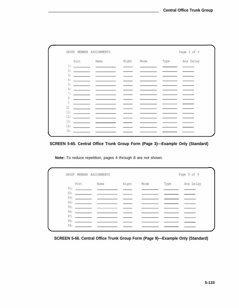
Central Office Trunk Group
Page 3 of 9GROUP MEMBER ASSIGNMENTS
Night Mode Type Ans DelayPort Name1:2:3:4:5:6:7:89
1011:12:13:14:15:
SCREEN 5-65. Central Office Trunk Group Form (Page 3)—Example Only (Standard)
Note: To reduce repetition, pages 4 through 8 are not shown.
GROUP MEMBER ASSIGNMENTS Page 9 of 9
Port Name Night Mode Type Ans Delay91:92:93:94:95:96:97:98:99:
SCREEN 5-66. Central Office Trunk Group Form (Page 9)—Example Only (Standard)
5-133

CHAPTER 5. FORMS FOR NETWORK FEATURES AND SERVICES
TRUNK GROUPGroup Number: 71 Group Type:
Group Name: OUTSIDE CALL COR :Direction: two-way Outgoing Display?
Dial Access? yQueue Length: 0
n99yn
Prefix-1? nTRUNK PARAMETERS
Trunk Type:Outgoing Dial Type:Trunk Termination:Terminal Balanced?
Busy Threshold:Administrable Timer Page?
Auth Code?Toll Restriction?
rcn
loop-starttone
Disconnect Supervision? yAnswer Supervision Timeout: 10
CO1
Page 1 of XSMDR Reports? y
TAC: 601
Night Service:Incoming Destination: 0
Digit Absorption List: _
y
Disconnect Timing(msec): 500RA Trunk Loss: 0db
Receive Answer Supervision? n
SCREEN 5-67. Central Office Trunk Group Form (Page 1)—Example Only(International G1.1SE and G1.2SE)
l m p l e m e n t a t i o n N o t e s :
The BCC field is displayed when the Comm Type is "avd,’’ ’’rbavd," or "data."
The Connected to Toll and DTT to DCO Loss fields are only displayed if the Trunk Type fieldis "’auto/..."
The STT Loss field is only displayed when the Connected to Toll field is ’’n."
The Terminal Balanced field is only displayed when the Trunk Type field is "ground-start’’ or"loop-start." The RA Trunk Loss field is only displayed when the Terminal Balanced field is"n."
The Bit Rate, Synchronization, and Duplex fields are only displayed when the Comm Typefield is "avd."
The Trunk flash field is only displayed when the Group Type field is "co," "fx," or "wats."
5-134

Central Office Trunk Group
TRUNK GROUP Page 2 of 10
TRUNK FEATURESACA Assignment? n Measured? none
Data Restriction? nAbandoned Call Search? n Maintenance Tests? ySuppress # Outpulsing? n
SCREEN 5-63. Central Office Trunk Group Form (Page 2)—Example Only(International G1.1SE and G1.2SE)
Implementation Note:
The following fields are only displayed if the ACA Assignment field is ’’y":
● Long Holding Time (hours)
● Short Holding Time (secs.)
● Short Holding Threhold
ADMINISTRABLE TIMERS
Incoming Disconnect
Incoming Glare Guard
Ringing MonitorOUTPULSING TIMING
Page 3 of X
msec) : 300 Outgoing Disconnect (msecOutgoing Dial Guard (msec
msec): 3000 Outgoing Glare Guard (msecOutgoing Rotary Dial Interdigit (msec
msec): 5000 Incoming Seizure (msec
PPS: 10 Make (msec): 40 Break (msec): 60 PPM? n
: 300: 1000: 3000: 600: 130
SCREEN 5-69. Central Office Trunk Group Administrable Timers Form (Page 3)—Example Only (International G1.1SE and G1.2SE)
Implementation Note:
The Administrable Timers Form page is only displayed if ’’y’’ is entered in the AdministrableTimers Page field on Page 1 of the form.
5-135

CHAPTER 5. FORMS FOR NETWORK FEATURES AND SERVICES
GROUP MEMBER ASSIGNMENTS Page 4 of 10
Name Night ModePort Type Ans Delay1:2:3:4:5:6:7:8:9:
10:11:12:13:14:15:
SCREEN 5-70. Central Office Trunk Group Form (Page 4)—Example Only(International G1.1SE and G1.2SE)
Note: To reduce repetition, pages 5 through 9 are not shown.
GROUP MEMBER ASSIGNMENTS Page 10 of 10
Port Name Night Mode Type Ans Delay91:92:93:94:95:96:97:98:99:
SCREEN 5-71. Central Office Trunk Group Form (Page 10)—Example Only(International G1.1SE and G1.2SE)
Implementation Note:
Above Group Member Assignments pages illustrate the resulting pagination when "y" isentered in the "Administrable Timers Page" field on Page 1 of the form; otherwise, pagenumbers will be the same as for the standard forms.
5-136

Central Office Trunk Group
CPE Trunk Group
Purpose
This form is used to assign a CPE Trunk Group and associated trunk Ports. The trunk group pro- vides access between the System and customer-provided equipment.
Administration Commands
The following administration commands can be used to access the CPE Trunk Group form. Insome cases, just the most commonly used commands are shown. Refer to Administration Com-mands and Error Messages (Chapter 3) for a complete listing of all administration commands, thecommand structure, and the use of abbreviated command words when entering a command.
Action Object Qualifier*
add trunk-group 1-99 (or ‘next’)change trunk-group 1-99 or TAC X...display trunk-group 1-99 or TAC X...['print’ or ‘schedule’]list t runk-group [ 'pr int ’ or ‘schedule’ ]remove trunk-group 1-99 or TAC X...
• Brackets [ ] indicate the qualifier is optional.Single quotes (‘ ’) indicate the text inside the quote must be entered exactlyas shown or an abbreviated form of the word may be entered.
Form Instructions
Make assignments as required for the following fields on each page of the form:
Page 1 of the Form
●
●
●
Group Number— Enter a number from 1 through 99 when completing a paper form. Thisis a display-only field when the form is accessed using an administration command suchas add or change.
Group Type— Enter "cpe" to identify the type of trunk group.
SMDR Reports— Enter "y" to provide a detailed SMDR record of both incoming and out-going calls made on all trunks in the trunk group; otherwise, enter "n." Default is "y."
Group Name— Enter a unique name that identifies the trunk group. Up to 15 characterscan be used. Default is "OUTSIDE CALL."
COR— Enter a class of restriction (COR) number from 0 through 63 that reflects thedesired restriction. Default is "1."
●
●
5-137

CHAPTER 5. FORMS FOR NETWORK FEATURES AND SERVICES
●
●
●
●
●
TAC— Enter the trunk access code (TAC) that must be dialed to access the trunk group.SMDR also uses the TAC to identify the trunk group on associated SMDR reports. A dif-ferent TAC must be assigned to each trunk group. Allowable entries are TACs that arecompatible with the System Dial Plan (1 to 3 digits).
Outgoing Display— Specifies whether or not the trunk group name is displayed on a ter-minal placing an outgoing call. Allowable entries are "y" or "n." Default is "n."
Dial Access— Enter "y" to allow the trunk group to be accessed via a trunk access code;otherwise, enter "n." Default is "y." Access via the Automatic Route Selection feature isallowed regardless of this entry.
Busy Threshold— Enter a number (0 through 99) of trunk group members that must bebusy before the attendant is alerted by the Warning lamp on the Attendant Console.Default is "99."
Queue Length— Enter a number from 0 through 100 that indicates the number of outgo-ing calls that can be held waiting. A "0" indicates no calls will be held in queue. This fieldis turned off if the Direction field is "incoming." Default is "0."
Disconnect Timing (msec)— Specifies the minimum time period in milliseconds that isrequired for recognition of disconnect by the serving central office or far-end PBX. Thetime interval must be in increments of 10 (from 140 to 2550 milliseconds). Default is" 5 0 0 . "
End-to-End Signaling— Specifies the duration (in milliseconds) of touch-tone signal tonewhich is sent to the far-end for interpretation by devices at that location. The durationtime entered must be a multiple of 10. Allowable entries are 60 through 360, or leaveblank Default is "60."
Disconnect Supervision— Enter "y" (yes) to indicate that the CO has the ability torelease a trunk when the calling party releases from a call and the system is able torecognize the release signal; otherwise, enter "n" (no). Default is "y." (InternationalG1.1SE and G1.2SE).
Answer Supervision Timeout— Indicates the amount of time in seconds the System
●
●
●
●
allows for the call to be answered before beginning an SMDR record of a call. This inter-val begins as soon as the outgoing trunk is seized. This time-out does not override net-work or firmware sent answer supervision. Allowable entries are 0 through 250. Defaultis "10."
Page 2 of the Form
● ACA Assignment?— Specifies whether or not Automatic Circuit Assurance (ACA) meas-urements will be taken for this trunk group. Allowable entries are "y" or "n." Default is"n." If "y" is entered, complete the next three fields.
● Long Holding Time (hours)— Is the length in hours that the System will consider asbeing a long holding time. If the value entered is "0," the System will not consider longholding calls. Allowable entries are 0 through 10. Default is "1."
5-138

CPE Trunk Group
●
●
●
●
●
●
Short Holding Time (secs.)— Specifies the length in seconds that the System will con-sider as being a short holding time. If this field is "0," the System will not consider shortholding calls. Allowable entries are 0 through 180. Default is "10."
Short Holding Threshold— ls the number of times that the System will record a shortholding call before an attendant or display-equipped voice terminal user is alerted to thepossibility of a faulty trunk. Allowable entries are 0 through 30. Default is "15."
Measured— Indicates if the System will transmit data for this trunk group to the CMS.Allowable entries are "internal," "external," "both," "none." Enter "internal" if the data isto be sent to the BCMS (that is, internal to the switch) for subsequent measurementreports and "external" to send the data to the 3B CMS. Enter "both" to send the data toboth systems for measurement reports or enter "none" if trunk group measurements arenot required. System default is "none."
Data Restriction— Is used to restrict System features from causing overriding tones on atrunk group. This provides permanent protection. Allowable entries are "y" or "n."Default is "n."
Suppress # Outpulsing— Indicates end-to-end signaling. Begins with (and includes) the"#" when "y" is entered in this field. The final # is suppressed in cases where Systemwould normally outpulse it. This field should be set to "y" when the CO (for example,rotary) or any other facility treats # as an error. Default is "n."
Maintenance Tests— lndicates whether or not maintenance tests will be performed onan hourly basis for this trunk group. Allowable entries are "y" or "n." Default is "y."
Pages 3 through 9 of the Form (Group Member Assignments)
●
●
Port— Enter five to six characters. The first character identifies the network (1 to 3,default is "1" if no entry); the second character identifies the carrier (A through E); thethird and fourth characters identify the slot number in the carrier (01 through 20 for multi-carrier cabinets depending on carrier type or 01 through 18 for single-carrier cabinetsdepending on cabinet type); the last two characters identify the circuit number (01through 08).
Name— Enter up to ten characters to identify the member of the trunk group. The namecan be a 7-digit telephone number or a 10-digit Trunk Circuit Identification number (pro-vided by trunk supplier).
5-139

CHAPTER 5. FORMS FOR NETWORK FEATURES AND SERVICES
Group Number:Group Name:
Dial Access?Queue Length:
TRUNK PARAMETERS
TRUNK GROUP
— Group Type:OUTSIDE CALL COR :
Outgoing Display?
y Busy Threshold:0__
Page 1 of 9
cpe SMDR Reports? y1 TAC: _
n99
End-to-End Signaling: 60Answer Supervision Timeout? 10
Disconnect Timing(msec): 500
SCREEN 5-72. Customer-Provided Equipment Trunk Group Form (Page 1)—Example Only (Standard)
TRUNK GROUP Page 2 of 9
TRUNK FEATURESACA Assignment? n Measured? Done
Long-Holding Time(hours): 1Short Holding Time(secs. ): 10 Data Restriction? nShort Holding Threshold: 15
Suppress # Outpulsing? n Maintenance Tests? y
SCREEN 5-73. Customer-Provided Equipment Trunk Group Form (Page 2)—Example Only (Standard)
Implementation Note:
The following fields are only displayed if the ACA Assignment field is ’’y":
● Long Holding Time (hours)
● Short Holding Time (secs.)
● Short Holding Threshold
5-140

CPE Trunk Group
GROUP MEMBER ASSIGNMENTS
1:2:3:4:5:6:7:8:9:
10:11:12:13:14:15:
Port Name
Page 3 of 9
SCREEN 5-74. Customer-Provided Equipment Trunk Group Form (Page 3)—Example Only (Standard)
Note: To reduce repetition, pages 4 through 8 are not shown.
GROUP MEMBER ASSIGNMENTS Page 9 of 9
91:92:93:94:95:96:97:98:99:
Port Name
SCREEN 5-75. Customer-Provided Equipment Trunk Group Form (Page 9)—Example Only (Standard)
5-141

CHAPTER 5. FORMS FOR NETWORK FEATURES AND SERVICES
Group Number:Group Name:
Dial Access?Queue Length:
TRUNK PARAMETERS
TRUNK GROUP Page 1 of 9
71 Group Type: cpe SMDR Reports? yOUTSIDE CALL COR: 1 TAC: 601
Outgoing Display? n
Y Busy Threshold: 990
Disconnect Timing(msec): 500
End-to-End Signaling: 60Disconnect Supervision? y
Answer Supervision Timeout? 10
SCREEN 5-76. Customer-Provided Equipment Trunk Group Form (Page 1)—Example Only (lnternational G1.1SE and G1.2SE)
TRUNK GROUP Page 2 of 9
TRUNK FEATURESACA Assignment? n Measured? none
Long Holding Time(hours): 1Short Holding Time(secs.): 10 Data Restriction? n
Short Holding Threshold: 15Suppress # Outpulsing? n Maintenance Tests? y
SCREEN 5-77. Customer-Provided Equipment Trunk Group Form (Page 2)—Example Only (lnternational G1.1SE and G1.2SE)
Implementation Note:
The following fields are only displayed if the ACA Assignment field is ’’y":
● Long Holding Time (hours)
●� Short Holding Time (secs.)
● Short Holding Threshold
5-142
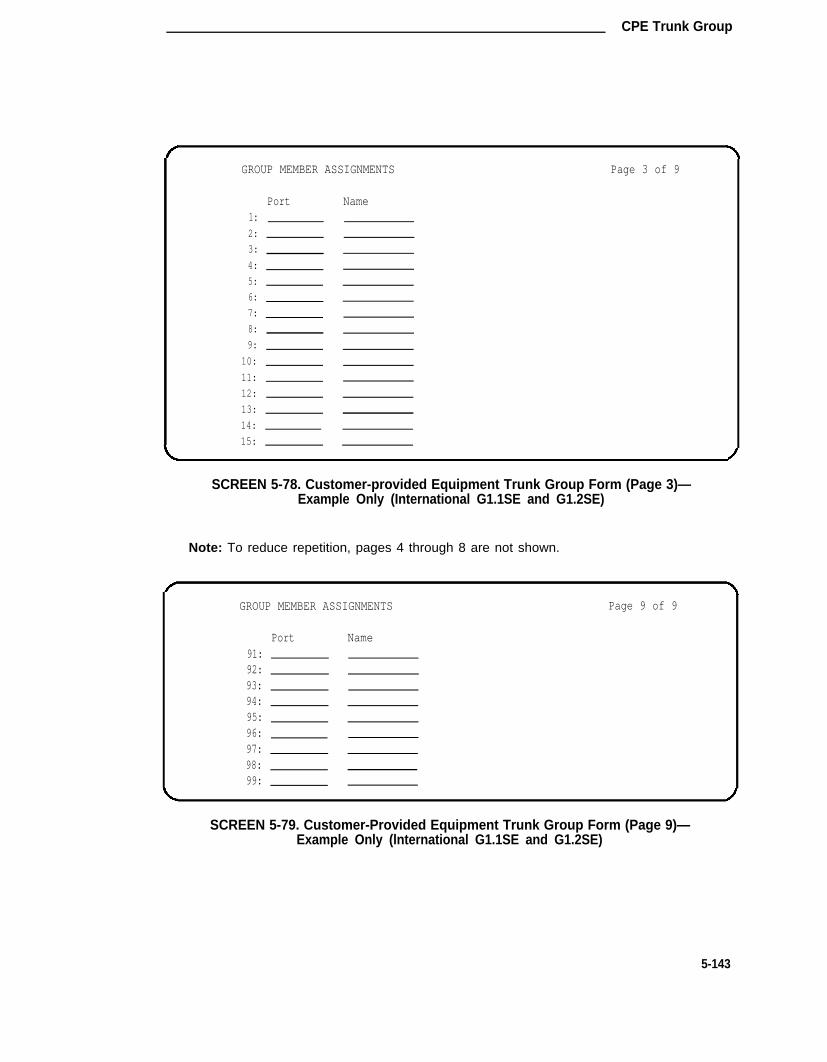
CPE Trunk Group
GROUP MEMBER ASSIGNMENTS Page 3 of 9
Port Name1:2:
3:
4:
5:
6:
7:
8:
9:
10:
11:
12:
13:
14:
15:
SCREEN 5-78. Customer-provided Equipment Trunk Group Form (Page 3)—Example Only (International G1.1SE and G1.2SE)
Note: To reduce repetition, pages 4 through 8 are not shown.
GROUP MEMBER ASSIGNMENTS Page 9 of 9
Port Name91:92:93:94:95:96:97:98:99:
SCREEN 5-79. Customer-Provided Equipment Trunk Group Form (Page 9)—Example Only (lnternational G1.1SE and G1.2SE)
5-143

CHAPTER 5. FORMS FOR NETWORK FEATURES AND SERVICES
Digital Multiplexed Interface (DMI)—BOS Trunk Group
Purpose
This form is used to assign a DMI-BOS Trunk Group and associated trunk ports. The DMI-BOSTrunk Group allows communications to/from the System using DMI-BOS protocol.
Administration Commands
The following administration commands can be used to access the DMI-BOS Trunk Group form.In some cases, just the most commonly used commands are shown. Refer to AdministrationCommands and Error Messages (Chapter 3) for a complete listing of all administration com-mands, the command structure, and the use of abbreviated command words when entering acommand.
Action Object Qualifier*
add t runk -g roup 1 -99 (o r ‘ nex t ’ )change trunk-group 1-99 or TAC X...display trunk-group 1-99 or TAC X...['print’ or ‘schedule’]list t runk-group [ 'pr int ’ or ‘schedule’ ]remove trunk-group 1-99 or TAC X...
* Brackets [ ] indicate the qualifier is optional.Single quotes (’ ‘) indicate the text inside the quote must be entered exactlyas shown or an abbreviated form of the word may be entered.
Form Instructions
Make assignments as required for the following fields on each page of the form:
Page 1 of the Form
●
●
●
●
Group Number— Enter a number from 1 through 99 when completing a paper form. Thisis a display-only field when the form is accessed using an administration command suchas "add" or "change."
Group Type— Enter "dmi-bos" to identify the type of trunk group.
SMDR Report— Enter "y" to provide a detailed SMDR reed of both incoming and out-going calls made on all trunks in the trunk group; otherwise, enter "n." Default is "y."
Group Name— Enter a unique name that identifies the trunk group. Up to 15 characterscan be used. Default is "OUTSIDE CALL."
COR— Enter a class of restriction (COR) number from 0 through 63 that reflects thedesired restriction. Default is "1."
TAC— Enter the trunk access code (TAC) that must be dialed to access the trunk group.SMDR also uses the TAC to identify the trunk group on associated SMDR reports. A dif-ferent TAC must be assigned to each trunk group. Allowable entries are TACs that arecompatible with the System Dial Plan (1 to 3 digits).
Direction— Enter whether the trunk group is "incoming," "outgoing," or "two-way."Default is "two-way."
●
●
●
5-144

Digital Multiplexed Interface (DMI)—BOS Trunk Group
●
●
●
●
Outgoing Display— Specifies whether or not the trunk group name is displayed on a ter-minal placing an outgoing call. Allowable entries are "y" or "n." Default is "n."
Dial Access—Enter "y" to allow the trunk group to be accessed via a trunk access code;otherwise, enter "n." Default is "y." Access via the ARS feature is allowed regardless ofthis entry.
Busy Threshold— Enter a number (0 through 99) of trunk group members that must bebusy before the attendant is alerted by the Warning lamp on the Attendant Console.Default is "99."
Night Service— Enter the extension number assigned to Night Service. The extensionnumber entered will receive all incoming calls when Night Service is activated and theindividual trunk member Night field is not administered to override this entry. Allowableentries are an extension number (can be a VDN extension), 0 (attendant), or leave blankif the Trunk Type is not "auto/...."
Incoming Destination— Indicates where incoming calls will terminate. Allowable entriesare an extension number, 0 (attendant), VDN, or leave blank if the Trunk Type field is not"auto/...."
Auth Code— Enter "y" if an Authorization Code must be dialed to complete incomingcalls on the trunk group; otherwise, enter "n." Default is "n." This field can only be set to"y" if the Authorization Codes feature is enabled on the System-Parameters Customer-
●
●
●
Options form.
Trunk Type (in/out)— Identifies the physical type of incoming and outgoing trunks.Allowable entries are listed below.
auto/auto auto/delay auto/immed auto/winkdelay/auto delay/delay delay/immed delay/wink
immed/auto immed/delay immed/immed immed/winkwink/auto wink/delay wink/immed wink/wink
●
●
●
Incoming Rotary Timeout (sec)— ls the timing interval required by the CO that the Sys-tem is connected to. If the System is connected to a step-by-step office, 18 or moreseconds must be used; if the System is not connected to a step-by-step office, five ormore seconds may be used. The maximum value is 99 seconds. Allowable entries are 5through 99. Default is "5."
Outgoing Dial Type— Identifies the type of pulsing required on an outgoing call. Allow-able entries are "tone" or "rotary." Default is "tone."
Incoming Dial Type— Indicates the type of pulses required on an incoming trunk group.Allowable entries are "tone" or "rotary." Default is "tone."
Disconnect Timing (msec)— Specifies the minimum time period in milliseconds that isrequired for recognition of disconnect by the serving central office or far-end PBX. Thetime interval must be in increments of 10 (from 140 to 2550 milliseconds). Default is"500."
Digit Treatment— Indicates if the digits entered are to be absorbed or inserted. No entryindicates no digit absorption or insertion. Allowable entries are "absorption" or "inser-tion."
●
●
5-145

CHAPTER 5. FORMS FOR NETWORK FEATURES AND SERVICES
●
●
●
●
Digits— Is the number of digits to be inserted or absorbed. This field is used with theDigit Treatment field. No entry indicates no digit absorption or insertion is done. Allow-able entries are 1 to five digits to be absorbed or inserted.
Connected to Toll— Enter "y" if connected to a CO toll office, otherwise, enter "n"(default). This field is displayed when the Trunk Type field contains an entry of "auto/...,’"delay/...," "wink/...," or "immed/...." Default is "n."
STT Loss (Satellite PBX Tie Trunk Loss)— Only displayed when the Connected to Tollfield is "n." Specifies the loss plan to be used for the trunk group. Allowable entries are"normal" (default) or "low." This option affects the transmission performance of a privatePBX network.
Although the use of this option has wider applications, only for the simplest networkarrangements should this field be administered without Network Engineering advise. The"low" option (described as the ISL digital low loss plan in DEFINITY® CommunicationsSystem Generic 1 and System 75 and System 85 DS1/DMI/ISDN-PRI Reference, 555-025-101) should only be used when:
1. Stations on the satellite PBX complain of too much loss on calls to the public net-work.
2. The PBX network consists of no more than three PBXs; one main and one ortwo satellite PBXs.
3. All PBXs have the "low" option available.
4. The total DS1 trunk connection length is less than 100 miles.
If the above conditions are not met, obtain Network Engineering assistance. The fieldentry is based on the following:
➤ normal— Applies to AIU-TT (Analog Interface Unit at Customer Switching Sys-tem for Tie Trunk—4-wire E&M interface), and DIU-TT (Digital Interface Unit atCustomer Switching System for Tie Trunk-voice or AVD DS1 interface) lossplans.
➤ low— Applies to AIU-TTS (same as AIU-TT, but suitable for private network con-nections that can be connected in tandem with public network connections) andDIU-TTS (same as DIU-TT, but suitable for private network connections that canbe connected in tandem with public network connections). These interfaceswere formerly referred to as DIU DTT ISL.
DTT to DCO Loss (Digital Tie to Digital CO Trunk Loss)— Specifies the loss plan to beused for the trunk group for interconnections from a DIU-CO (Digital Interface Unit at aCentral Office) to a DIU-DTT (Digital Interface Unit for a Digital Tie Trunk interface). Thisfield is displayed when the Trunk Type field contains an entry of auto/..., delay/...,wink/..., or immed/ . . . .
This option affects the transmission performance of public network access via a privatePBX network Choose the "low" option only if private network users complain about toomuch loss on calls to the public network otherwise, the "normal" option should be used.Allowable entries are "normal" (default) and "low." The entry is based on the following:
5-146

Digital Multiplexed Interface (DMI)—BOS Trunk Group
➤ normal— Corresponds to a (0, -6) dB gain pair and is used as the default option.(This corresponds to the DTT/EIA DCO port to port configuration as described inDEFINITY® Communications System Generic 1 and System 75 and System 85DS1/DMI/ISDN-PRl Reference, 555-025-101.)
➤ low— Corresponds to (+3, -3) dB gain pair. Low is used for internetwork applica-tions in which no significant configuration will encounter echo, stability, or over-load problems because of reduced loss. With the low gain pair, subscriber sta-tion DTMF signals transmitted through the digital class five office into the custo-mer network may experience non-recoverable digit mutilation in secondary sig-naling applications (that is, DTMF signaling after the connection has been esta-blished). (This corresponds to the DTT/lSL DCO port to port configuration asdescribed in DEFINITY® Communications System Generic 1 and System 75 andSystem 85 DS1/DMI/ISDN-PRl Reference, 555-025-101.)
●
●
●
●
●
●
Incoming Dial Tone— lndicates whether or not the trunk group will pass on incoming dialt1 to the calling party. Allowable entries are "y" or "n." Default is "y."
Bit Rate— Specifies the baud rate to be used by pooled modems. Allowable entries are"300," "1200," "2400," "4800," "9600," and "19200.’ Default is "1200."
Synchronization— Enter whether the trunk group will use "sync" (synchronous or"async" (asynchronous) communications. Default is "async."
Duplex— Specifies either full or half duplex for the trunk group. Allowable entries are"full" or "half." Default is "full."
Disconnect Supervision— Enter "y" (yes) to indicate that the CO has the ability torelease a trunk when the calling party releases from a call and the system is able torecognize the release signal; otherwise, enter "n" (no). Default is "y." (InternationalG1.1SE and G1.2SE).
Answer Supervision Timeout— Indicates the amount of time in seconds the Systemallows for the call to be answered before beginning an SMDR record of a call. This inter-val begins as soon as the outgoing trunk is seized. This time-out does not override net-work or firmware sent answer supervision. Allowable entries are 0 through 250. Defaultis "10."
5-147

CHAPTER 5. FORMS FOR NETWORK FEATURES AND SERVICES
Page 2 of the Form
●
●
●
ACA Assignment?— Specifies whether or not Automatic Circuit Assurance (ACA) meas-urements will be taken for this trunk group. Allowable entries are "y" or "n." Default is"n." If "y" is entered, complete the next three fields.
Long Holding Time (hours)— Is the length in hours that the System will consider asbeing a long holding time. If the value entered is "0," the System will not consider longholding calls. Allowable entries are 0 through 10. Default is "1."
Short Holding Time (secs.)— Specifies the length in seconds that the System will con-sider as being a short holding time. If this field is "0," the System will not consider shortholding calls. Allowable entries are 0 through 160. Default is"10."
Short Holding Threshold— Is the number of times that the System will record a shortholding call before an attendant or display-equipped voice terminal user is alerted to thepossibility of a faulty trunk. Allowable entries are 0 through 30. Default is "15."
Measured— Indicates if the System will transmit data for this trunk group to the CMS.Allowable entries are "internal," "external," "both," "none." Enter "internal" if the data isto be sent to the BCMS (that is, internal to the switch) for subsequent measurementreports and "external" to send the data to the 3B CMS. Enter "both" to send the data toboth systems for measurement reports or enter "none" if trunk group measurements arenot required. System default is "none."
●
●
●
●
Internal Alert— Specifies if internal ringing and coverage will be used for incoming callson this trunk group. Allowable entries are "y" or "n." Default is "n."
Data Restriction— Is used to restrict system features from causing overriding tones on atrunk group. This provides permanent protection. Allowable entries are "y" or "n."Default is "n."
Suppress # Outpulsing— Indicates end-to-end signaling. Begins with (and includes) the"#" when "y" is entered in this field. The final # is suppressed in cases where the Systemwould normally outpulse it. This field should be set to "y" when the central office (forexample, rotary) or any other facility treats #as an error. Default is "n."
Maintenance Test— lndicates whether or not maintenance tests will be performed on
●
●
an hourly basis for this trunk group. Allowable entries are "y" or "n." Default is "y."
Pages 3 through 9 of the Form (Group Member Assignments)
●
●
Port— Enter five to six characters. The first character identifies the network (1 through 3,default is "1" if no entry); the second character identifies the carrier (A through E); thethird and fourth characters identify the slot number in the carrier (01 through 20 for multi-carrier cabinets depending on carrier type or 01 through 18 for single-carrier cabinetsdepending on cabinet type); the last two characters identify the circuit number (01through 08).
Name— Enter up to ten characters to identify the member of the trunk group. The namecan be a 7-digit telephone number or a 10-digit Trunk Circuit Identification number (pro-vided by trunk supplier).
5-148

Digital Multiplexed Interface (DMI)—BOS Trunk Group
Note: Previously, for System 75, Night Service and Balance/Loss information wasentered in the Name field as "NT#..." and "TT#) . ..." This information mustnow be entered in the Night field (below) or the STT Loss field on Page 1 ofthe form, as applicable.
●
●
●
Mode— Specifies the signaling mode used on Tie Trunks with TN722A, TN722B,TN760B, TN767, TN464C (International G1.2SE only) circuit packs. Allowable entriesare "e&m" (interface), "simplex" (phantomed), or "protected." This entry mustcorrespond to associated dip switch settings on the circuit pack.
Type— Specifies the signaling type used. Allowable entries are "t1 stan" (Type 1 Stan-dard), "t1 comp" (Type 1 Compatible), or "type 5."
Ans Delay— Specifies the length of the wait for answer supervision delay in millisecondsfor DS1 or Tie Trunks using the TN722A, TN722B, TN760 (B, C, or D), TN767, orTN464C (International G1.2SE only) circuit packs. Allowable entries are 20 through 5100in increments of 20. The default is no entry (blank) and internally treated as a 0. Thisdelay serves two purposes:
1.
2.
Used to assure that the answer supervision signal is valid and not a secondarydelay-dial or wink-start signal.
Used to bridge over momentary off-hook signals resulting from connectionsmade off-network through certain No. 5 Crossbar CCSA switches as the connec-tion is being established.
5-149
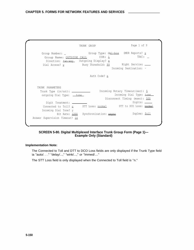
CHAPTER 5. FORMS FOR NETWORK FEATURES AND SERVICES
TRUNK GROUP Page 1 of 9
Group Number: _ Group Type: dmi-bos SMDR Reports? y
Group Name: OUTSIDE CALL COR: 1 TAC: _
Direction: two-way Outgoing Display? nDial Access? y Busy Threshold: 99 Night Service:
Incoming Destination: -
Auth Code? n
TRUNK PARAMETERSTrunk Type (in/out): Incoming Rotary Timeout(sec): 5outgoing Dial Type: tone Incoming Dial Type: tone
Disconnect Timing (msec): 500Digit Treatment: Digits:
Connected to Toll? n STT Loss: normal DTT to DCO Loss: normal
Incoming Dial Tone? yBit Rate: 1200 Synchronization: async Duplex: full
Answer Supervision Timeout? 10
SCREEN 5-80. Digital Multiplexed lnterface Trunk Group Form (Page 1)—Example Only (Standard)
Implementation Note:
The Connected to Toll and DTT to DCO Loss fields are only displayed if the Trunk Type fieldia "auto/. . ." "delay/...," "wink/...," or "immed/...."
The STT Loss field is only displayed when the Connected to Toll field is ’’n."
5-150

Digital Multiplexed Interface (DMI)—BOS Trunk Group
TRUNK GROUP Page 2 of 9
TRUNK FEATURESACA Assignment? n Measured? none
Long Holding Time(hours): 1 Internal Alert? nShort Holding Time(secs. ): 10 Data Restriction? nShort Holding Threshold: 15Suppress # Outpulsing? n Maintenance Tests? y
SCREEN 5-81. Digital Multiplexed lnterface Trunk Group Form (Page 2)—Example Only (Standard)
lmplemmtation Note:
The following fields are only displayed if the ACA Assignment field is ’’y":
● Long Holding Time (hours)
● Short Holding Time (secs.)
● Short Holding Threshold
5-151

CHAPTER 5. FORMS FOR NETWORK FEATURES AND SERVICES
GROUP MEMBER ASSIGNMENTS Page 3 of 9
Port Name Ans Delay
1:2:
3:
4:
s:
6:
7:
8:
9:
10:
11:
12:
13:
14:
15:
SCREEN 5-82. Digital Multiplexed Interface Trunk Group Form (Page 3)—Example Only (Standard)
Note: To reduce repetition, pages 4 through 8 are not shown.
Type
91:92:93:94:95:96:97:98:99:
GROUP MEMBER ASSIGNMENTS
Port Name
Mode Type
Mode
Page 9 of 9
Ans Delay
SCREEN 5-83. Digital Multiplexed Interface Trunk Group Form (Page 9)—Example Only (Standard)
5-152

Digital Multiplexed Interface (DMI)—OS Trunk Group
TRUNK GROUP Page 1 of 9
Group Number: 71 Group Type: dmi-bos SMDR Reports? yGroup Name: OUTSIDE CALL COR: 1 TAC: 601Direction: two-way Outgoing Display? n
Dial Access? y Busy Threshold: 99 Night Service:Incoming Destination: Q
Auth Code? n
TRUNK PARAMETERSTrunk Type (in/out): auto/auto Incoming Rotary Timeout(sec): 5Outgoing Dial Type: tone Incoming Dial Type: tone
Disconnect Timing (msec): 500Digit Treatment: Digits:
Connected to Toll? n STT Loss: normal DTT to DCO Loss: normalIncoming Dial Tone? y
Bit Rate: 1200 Synchronization: async Duplex: fullDisconnect Supervision? yAnswer Supervision Timeout? 10
SCREEN 5-84. Digital Multiplexed lnterface Trunk Group Form (Page 1)—Example Only (lnternational G1.1SE and G1.2SE)
Implementation Note:
The Connected to Toll and DTT to DCO Loss fields are only displayed if the Trunk Type fieldis ’’auto/...,’’ "delay/...,’’ "wink/...," or "immed/...."
The STT Loss field is only displayed when the Connected to Toll field is ’’n."
5-153

CHAPTERS. FORMS FOR NETWORK FEATURES AND SERVICES
TRUNK FEATURES
ACA Assignment? n
Internal Alert? nData Restriction? n
Suppress # Outpulsing? n
Page 2 of 9
Measured? Done
Maintenance Tests? y
Implementation Note:
The following fields are only displayed if the ACA Assignment field is ’’y":
● Long Holding Time (hours)
● Short Holding Time (secs.)
● Short Holding Threshold
SCREEN 5-85. Digital Multiplexed Interface Trunk Group Form (Page 2)—Example Only (International G1.1SE and G1.2SE)
5-154

Digital Multiplexed Interface (DMI)—BOS Trunk Group
GROUP MEMBER ASSIGNMENTS Page 3 of 9
Port Name Mode Type Ans Delay
1:2:3:4:5:6:7:8:9:
10:11:12:13:14:15:
SCREEN 5-86. Digital Multiplexed Interface Trunk Group Form (Page 3)—Example Only (International G1.1SE and G12SE)
Note: To reduce repetition, pages 4 through 8 are not shown.
GROUP MEMBER ASSIGNMENTS Page 9 of 9
Port Name Mode Type Ans Delay
91:92:93:94:95:96:97:98:99:
SCREEN 587. Digital Multiplexed Interface Trunk Group Form (Page 9)—Example Only (International G1.1SE and G1.2SE)
5-155

CHAPTER 5. FORMS FOR NETWORK FEATURES AND SERVICES
Direct Inward Dialing Trunk Group
Purpose
This form is used to assign a Direct Inward Dialing (DID) Trunk Group and associated trunk ports.A DID Trunk Group allows an incoming call from the exchange network to reach a specific exten-sion number directly without attendant intervention.
Administration Commands
The following administration commands can be used to access the DID Trunk Group form. Insome cases, just the most commonly used commands are shown. Refer to Administration Com-mands and Error Messages (Chapter 3) for a complete listing of all administration commands, thecommand structure, and the use of abbreviated command words when entering a command.
Action Object Qualifier*
add trunk-group 1-99 (or ‘next’)change trunk-group 1-99 or TAC X...display trunk-group 1-99 or TAC X...['print’ or ‘schedule’]list trunk-group ['print’ or ‘schedule’]remove trunk-group 1-99 or TAC X...
* Brackets [ ] indicate the qualifier is optional.Single quotes (‘ ’) indicate the text inside the quote must be entered exactly as shown oran abbreviated form of the word may be entered.
Form Instructions
Make assignments as required for the following fields on each page of the form:
Page 1 of the Form
●
●
●
●
●
●
Group Number— Enter a number from 1 through 99 when completing a paper form. Thisis a display-only field when the form is accessed using an administration command suchas add or change.
Group Type— Enter "did" to identify the type of trunk group.
SMDR Reports— Enter "y" to provide a detailed SMDR record of calls made on all trunksin the trunk group; otherwise, enter "n." Default is "y."
Group Name— Enter a unique name that identifies the trunk group. Up to 15 characterscan be used. Default is "OUTSIDE CALL."
COR— Enter a class of restriction (COR) number from 0 through 63 that reflects thedesired restriction. Default is "1."
TAC— Enter the trunk access code (TAC) that must be dialed to access the trunk group.SMDR also uses the TAC to identify the trunk group on associated SMDR reports. A dif-ferent TAC must be assigned to each trunk group. Allowable entries are TACs that arecompatible with the System Dial Plan (1 to 3 digits).
5-156

Direct Inward Dialing Trunk Group
•
•
•
•
•
•
•
•
•
•
Administrable Timers Page— Only displayed for international applications. Entering a“y” causes an Administrable Timers page to be added to the trunk group form. TheAdministrable Timers page then becomes Page 3 of x. Valid entries are “y” or “n.”Default is “n.” (International G1.2SE only).
Auth Code— Enter “y” if an Authorization Code must be dialed to complete incomingcalls on the trunk group; otherwise, enter “n.” Default is “n.” This field can only be set to“y” if the Authorization Codes feature is enabled on the System-Parameters Customer-Options form.
Trunk Type— Identifies the physical type of DID trunk. Allowable entries are “immed-start” or “wink-start.”
Incoming Rotary Timeout (sec)— ls the timing interval required by the CO that the Sys-tem is connected to. If the System is connected to a step-by-step office, 18 or moreseconds must be used; if the System is not connected to a step-by-step office, five ormore seconds may be used. The maximum value is 99 seconds. Allowable entries are 5through 99. Default is “5.”
Incoming Dial Type— Indicates the type of pulses required on an incoming trunk group.Allowable entries are “tone” or “rotary.” Default is “tone.”
Trunk Termination— Specifies how the trunk group is terminated. The trunk group canterminate in a resistance of 600 ohms, or a resistor capacitor (rc) network. Allowableentries are “600ohms” or “rc”; 600ohms is used when the PBX trunk port is connected toterminal equipment (for example, SLC carriers or compensators optioned for 600 ohmsinput impedance) and the distance to the terminal equipment from the System is lessthan 3000 feet. Enter “rc” in all other cases. Default is “rc.”
Disconnect Timing (msec)— Specifies the minimum time period in milliseconds that isrequired for recognition of disconnect by the serving CO or far-end PBX. The time inter-val must be in increments of 10 (from 140 to 2550 milliseconds). Enter “500” unless thetrunk is connected to a step-by-step office. Enter “200” if the trunk is connected to astep-by-step office. Default is “500.”
Digit Treatment— Indicates if digits are to be absorbed or inserted. A blank entry indi-cates no digit absorption or insertion. Allowable entries are “absorption” and “insertion.”
Digits— Is the number of digits to be inserted or absorbed. This field is used with theDigit Treatment field. A blank entry indicates no digit insertion or absorption. Allowableentries are the number of digits to be absorbed (1 through 5) or the actual digits to beinserted (up to five digits). This means that if the Digit Treatment field is absorption, thenthe Digits field is the number of digits from the beginning of the dialed number. One to 5digits can be absorbed. If the Digit Treatment is insertion, then the Digits field containsthe actual digits that are inserted into the beginning of the dialed number. A 1- to 5-digitnumber can be inserted into the beginning of the dialed number.
Expected Digits— Enter the number of digits that the CO sends for an incoming connec-tion. Default is “0.”
5-157

CHAPTER 5. FORMS FOR NETWORK FEATURES AND SERVICES
• Terminal Balanced— Specifies whether the trunks in the trunk group are balanced. A“y” signifies that the trunks are terminally balanced and an “n” signifies that the trunksare not terminally balanced. Typically, a Trunk Termination field of “600ohm” signifies abalanced trunk group and a field of “rc” signifies a non-balanced trunk group. If thetrunks in this group pass the Low Frequency Return Loss test requirements, then theyare terminally balanced, and this field should be set to "y." This field is only displayedwhen the Trunk Type field is “immed-start” or “wink-start.” Since most trunks are not bal-anced, the default is “n.”
• RA Trunk Loss (Remote Access Trunk Loss)— Specifies the type of dB loss to beapplied to non-terminally balanced trunks (Terminal Balanced field= “n”). The 0dB entryis used in both directions as the default option. If unsatisfactory echo performance (hol-lowness) is experienced, the field should be reset to 2dB. Allowable entries are “0db”and “2db.” This field is only displayed when the Terminal Balanced field is “n.”
Page 2 of the Form
• ACA Assignment?— Specifies whether or not Automatic Circuit Assurance (ACA) meas-urements will be taken for this trunk group. Allowable entries are “y” or “n.” Default is“n.” If “y” is entered, complete the next three fields.
• Long Holding Time (hours)— Is the length in hours that the System will consider asbeing a long holding time. If the value entered is “0,” the System will not consider longholding calls. Allowable entries are 0 through 10. Default is ”1.“
• Short Holding Time (secs.)— Specifies the length in seconds that the System will con-sider as being a short holding time. If this field is “0,” the System will not consider shortholding calls. Allowable entries are 0 through 160. Default is “15.”
• Short Holding Threshold— Is the number of times that the System will record a shortholding call before an attendant or display-equipped voice terminal user is alerted to thepossibility of a faulty trunk. Allowable entries are 0 through 30.
• Measured— Indicates if the System will transmit data for this trunk group to the CMS.Allowable entries are “internal,” ”external,” “both,” “none.” Enter “internal” if the data isto be sent to the BCMS (that is, internal to the switch) for subsequent measurementreports and “external” to send the data to the 3B CMS. Enter “both” to send the data toboth systems for measurement reports or enter “none” if trunk group measurements arenot required. System default is “none.”
• Data Restriction— Is used to restrict System features from causing overriding tones on atrunk group. This provides permanent protection. Allowable entries are “y” or “n.”Default is “n.”
• Disconnect Supervision— Enter “y” (yes) to indicate that the CO has the ability torelease a trunk when the calling party releases from a call and the system is able torecognize the release signal; otherwise, enter “n” (no). Default if “y.” (InternationalG1.1SE and G1.2SE.)
5-158

Direct Inward Dialing Trunk Group
• Suppress # Outpulsing— Indicates end-to-end signaling. Begins with (and includes) the“#” when “y” is entered in this field. The final # is suppressed in cases where Systemwould normally outpulse it. This field should be set to “y” when the central office (forexample, rotary) or any other facility treats # as an error. Default is “n.”
• Maintenance Tests— Indicates whether or not maintenance tests will be performed onan hourly basis for this trunk group. Allowable entries are “y” or “n.” Default is “y.”
Page 3 of the Form (Administrable Timers) (International G1.2SE only)
Note: This page is only displayed if “y” is entered in the Administrable Timers Page field onPage 1 of the form.
•
•
•
•
•
•
•
•
•
Incoming Disconnect (msec)— Enter the minimum time (in msec) required for recogni-tion of disconnect for an incoming call from the serving CO. Valid entries are 50 through12750 in increments of 50. The field cannot be blank. Default is “300.”
Outgoing Disconnect (msec)— Enter the minimum time (in msec) required for recogni-tion of disconnect for an outgoing call. Valid entries are 50 through 12750 in increments of 50. The field cannot be blank. Default is "300."
Outgoing Dial Guard (msec)— Enter the minimum time (in msec) between seizure ofthe trunk and outpulsing of digits. Valid entries are 200 through 25600 in increments of200. The field cannot be blank. Default is ”1000.”
Incoming Glare Guard (msec)— Enter the incoming guard time (in msec) between thetime the incoming trunk is released and the same trunk can be seized again. This guardtime will ensure the far-end has released all equipment after the incoming trunk isreleased. Valid entries are 200 through 25600 in increments of 200. The field cannot beblank. Default is “3000.”
Outgoing Glare Guard (msec)— Enter the outgoing guard time (in msec) between thetime the outgoing trunk is released and the same trunk can be seized again. This guardtime will ensure that the far-end has released all equipment after the outgoing trunk isreleased. Valid entries are 200 through 25600 in increments of 200. The field cannot beblank. Default is “3000.”
Outgoing Rotary Dial Interdigit (msec)— Enter the interval (in msec) between rotarydial digits being outpulsed by the system (that is, PBX). Valid entries are 150 through2550 in increments of 10. The field cannot be blank. Default is “600.”
Ringing Monitor (msec)— Enter the minimum time (in msec) required to determine if thetrunk is disconnected. If the ringing signal disappears for a duration longer than the timespecified in this field, the call will be assumed to be disconnected. For CO, FX, WATS,PCOL, DID, and DIOD, valid entries are 200 through 51000 in increments of 200. ForTie, Tandem and Access, valid entries are 200 through 25500 in increments of 100. Thefield cannot be blank. Default is “5000.”
Incoming Seizure (msec)— Enter the minimum time (in msec) required for recognition ofincoming ringing signal from the serving CO. Valid entries are 20 through 2550 in incre-ments of 10. The field cannot be blank. Default is ”130.”
PPS— Enter either “10” or “20” to specify the PPS (pulses per second) assigned to rotarydial pulse trunk groups. Valid entries are ”10“ or “20.” Default is ”10.”
5-159
CHAPTER 5. FORMS FOR NETWORK FEATURES AND SERVICES
• Make (msec)— Enter the duration of the make interval while the system is outpulsingdigits using dial pulse signaling.
If the PPS field is “10,” the sum of the Make and Break fields must equal 100. Validentries are 20 through 80 in increments of 5. The field cannot be blank. The default is
If the PPS field is “20,” the sum of the Make and Break fields must equal 50. Validentries are 10 through 40 in increments of 5. The field cannot be blank. The default is
• Break (msec)— Enter the duration of the break interval while the system is outpulsingdigits using dial pulse signaling.
If the PPS field is “10,” the sum of the Make and Break fields must equal 100. Validentries are 20 through 80 in increments of 5. The field cannot be blank. The default is“80.”
If the PPS field is “20,” the sum of the Make and Break fields must equal 50. Validentries are 10 through 40 in increments of 5. The field cannot be blank. The default is“30.”
• PPM— Enter “y” (yes) if PPM pulses are to be collected to determine outgoing call billing,otherwise enter “n” (no). Valid entries are “y” or “n.” Default is “n.” (This field does notappear for DID, Tie, Tandem, or Access trunks.)
Pages 3 through 9 of the Form (Group Member Assignments)
Note: For International Systems, if “y” has been entered in the Administrable Times Pagefield on Page 1 of the form, the Group Member Assignments will appear on Pages 4through 10 of the form.
• Port— Enter five to six characters. The first character identifies the network (1 through 3,default is “1” if no entry); the second character identifies the carrier (A through E); thethird and fourth characters identify the slot number in the carrier (01 through 20 for multi-carrier cabinets depending on carrier type or 01 through 18 for single-carrier cabinetsdepending on cabinet type); the last two characters identify the circuit number (01through 08).
• Name— Enter up to ten characters to identify the member of the trunk group. The namecan be a 7-digit telephone number or a 10-digit Trunk Circuit Identification number (pro-vided by trunk supplier).
5-160

Direct Inward Dialing Trunk Group
Group Number:
Group Name:
TRUNK GROUP
— Group Type: did
OUTSIDE CALL COR: 1
TRUNK PARAMETERS
Trunk Type:tone
Trunk Termination: rcDigit Treatment:Expected Digits: Q
Terminal Balanced: n
Auth Code? n
Incoming Rotary
Page 1 of 9
SMDR Reports?
TAC :
Timeout(sec :Incoming Dial Type:
Disconnect Timing(msec):Digits:
Y
5_
500
RA Trunk Loss: 0db
SCREEN 5-88. Direct lnward Dialing Trunk Group Form (Page 1)—Example Only (Standard)
Implementation Note:
The Terminal Balanced field is only displayed if the Trunk Type field is “immed-start” or“wink-start.”
The RA Trunk Loss field is only delayed if the Terminal Balanced field is “n.”
5-161

CHAPTER 5. FORMS FOR NETWORK FEATURES AND SERVICES
TRUNK GROUP Page 2 of 9
TRUNK FEATURESACA Assignment? n Measured? none
Long Holding Time(hours): 1Short Holding Time(secs.): 10 Data Restriction? nShort Holding Threshold: 15Suppress # Outpulsing? n Maintenance Tests? y
SCREEN 5-89. Direct Inward Dialing Trunk Group Form (Page 2)—Example Only (Standard)
Implementation Note:
The following fields are only displayed if the ACA Assignment field is “y”:
• Long Holding Time (hours)
• Short Holding Time (secs.)
• Short Holding Threshold
5-162

Direct Inward Dialing Trunk Group
GROUP MEMBER ASSIGNMENTS Page 3 of 9
Port Name
1:2:3:4:5:6:7:8:9:
10:
11:
12:13:14:15:
SCREEN 5-90. Direct Inward Dialing Trunk Group Form (Page 3)—Example Only (Standard)
Note: To reduce repetition, pages 4 through 8 are not shown.
GROUP MEMBER ASSIGNMENTS Page 9 of 9
Port Name
91:92:93:94:95:96:97:98:99:
SCREEN 5-91. Direct Inward Dialing Trunk Group Form (Page 9)—Example Only (Standard)
5-163

CHAPTER 5. FORMS FOR NETWORK FEATURES AND SERVICES
TRUNK GROUP Page 1 of x
Group Number: 71 Group Type: did SMDR Reports? y
Group Name: OUTSIDE CALL COR: 1 TAC: 601
Administrable Timer Page? yAuth Code? n
TRUNK PARAMETERS
Trunk Type: immed-start Incoming Rotary Timeout(sec): 5Incoming Dial Type: tone
Trunk Termination: rc Disconnect Timing(msec): 500
Digit Treatment: Digits:
Expected Digits: _Terminal Balanced: n RA Trunk Loss: 0db
Disconnect Supervision? y
SCREEN 5-92. Direct Inward Dialing Trunk Group Form (Page 1)—Example Only (International G1.1SE and G1.2SE)
Implementation Note:
The Terminal Balanced field is only displayed if the Trunk Type field is “immed-start”or“wink-start.”
The RA Trunk Loss field is only displayed if the Terminal Balanced field is “n.”
5-164

Direct Inward Dialing Trunk Group
Page 2 of 10
TRUNK FEATURES
ACA Assignment? n Measured? none
Data Restriction? n
Suppress # Outpulsing? n Maintenance Tests? y
SCREEN 5-93. Direct lnward Dialing Trunk Group Form (Page 2)—Example Only (International G1.1SE and G1.2SE)
Implementation Note:
The following fields are only displayed if the ACA Assignment field is “y”:
• Long Holding Time (hours)
• Short Holding Time (secs.)
• Short Holding Threshold
5-165

CHAPTER 5. FORMS FOR NETWORK FEATURES AND SERVICES
Page 3 of x
ADMINISTRABLE TIMERS
Incoming Disconnect (msec): 300 Outgoing Disconnect (msec): 300Outgoing Dial Guard (msec): 1000
Incoming Glare Guard (msec): 3000 Outgoing Glare Guard (msec): 3000Outgoing Rotary Dial Interdigit (msec): 600
Ringing Monitor (msec): 5000 Incoming Seizure (msec): 130
OUTPULSING TIMING
PPS: 10 Make (msec): 40 Break (msec): 60 PPM? n
SCREEN 5-94. Direct lnward Dial Trunk Group Administrable Timers (Page 3)—Example Only (International G1.2SE)
Implementation Note:
This page is only displayed if ’’y’’ is entered in the Administrable Timers Page field onPage 1.
5-166

Direct Inward Dialing Trunk Group
GROUP MEMBER ASSIGNMENTS Page 4 of 10Port Name
1:2:3:4:5:6:7:8:9:
10:
11:
12:
13:
14:
15:
SCREEN 5-95. Direct Inward Dialing Trunk Group Form (Page 4)—Example Only (International G1.1SE and G1.2SE)
Note: To reduce repetition, pages 5 through 9 are not shown.
GROUP MEMBER ASSIGNMENTS Page 10 of 10Port Name
91:92:93:94:95:96:97:98:99:
SCREEN 5-96. Direct Inward Dialing Trunk Group Form (Page 10)—Example Only (lnternational G1.1SE and G1.2SE)
Implementation Note:
Above Group Member Assignments page illustrate the resulting pagination when “y” isentered in the “Administrable Timers Page” field on page 1 of the form; otherwise, pagenumbers will be 3 through 9.
5-167

CHAPTER 5. FORMS FOR NETWORK FEATURES AND SERVICES
Direct Inward and Outward Dialing Trunk Group(International G1.2SE Only)
Note: The TN429D1OD Trunk circuit pack is used with G1.2SE systems in Japan. See“Direct Inward/Outward Dial (DIOD)” section in Chapter 4 for more information.
Purpose
This form is used to assign a Direct Inward and Outward Dialing (DIOD) trunk group and associ-ated trunk ports. The TN429 DIOD trunk circuit pack allows calls from a local exchange to bemade to a subscriber on a PBX system without connecting through the attendant console.
Instructions
Make assignments as required for the following fields on each page of the form:
Page 1 of the Form
•
•
•
•
•
Group Number— Enter a number from 1 through 99 when completing a paper form.Assign consecutive Group Numbers to trunk groups when two or more trunk groups areto be used for ACD applications. This is a display only field when the form is accessedusing an administration command such as add or change.
Group Type— Enter “co” to identify the type of trunk group.
SMDR Reports— Enter “y” to provide a detailed SMDR record of both incoming and out-going calls made on all trunks in the trunk group; otherwise, enter “n.” Default is “y.”
Group Name— Enter a unique name that identifies the trunk group. Up to 15 characterscan be used. Default is “OUTSIDE CALL.”
COR— Enter a class of restriction (COR) number from 0 through 63 that reflects thedesired customer restriction. Default is ”1.“
TAC— Enter the trunk access code (TAC) that must be dialed to access the trunk group.SMDR also uses the TAC to identify the trunk groups associated SMDR report. A dif-ferent TAC must be assigned to each trunk group. Allowable entries are TACs that arecompatible with the System Dial Plan (1 to 3 digits).
Direction— Enter whether the trunk group is “incoming,” “outgoing,” or "two-way:"Default is “two-way.”
Outgoing Display— Specifies whether or not the trunk group name is displayed on a ter-minal placing an outgoing call. Allowable entries are “y” or “n.” Default is “n.”
Dial Access— Enter “y” to allow the trunk group to be accessed via a trunk access code;otherwise, enter “n.” Default is “y.” Access via the ARS feature is allowed regardless ofthis entry.
•
•
•
•
5-168

Direct Inward and Outward Dialing Trunk Group (International G1.2SE Only)
•
•
•
•
•
•
•
•
•
•
•
Busy Threshold— Enter a number (0 through 99) of trunk group members that must bebusy before the attendant is alerted by the Warning lamp on the Attendant Console.Default is “99.”
Night Service— Enter the extension number assigned to Night Service. The extensionnumber entered will receive all incoming calls when Night Service is activated and theindividual trunk member Night field is not administered to override this entry. Allowableentries are an extension number, 0 (attendant), or leave blank if the Trunk Type is not“auto/...’.”
Queue Length— Enter a number from 0 through 100 that indicates the number of outgo-ing calls that can be held waiting. A “0” indicates no calls will be held in queue. This fieldis turned off if the Direction field is “incoming.” Default is “0.”
Administrable Timers Page— Only displayed for international applications. Entering a“y” causes an Administrable Timers page to be added to the trunk group form. TheAdministrable Timers page then becomes Page 3 of x. Valid entries are “y” or “n.”Default is “n.” (International G1.1SE and G1.2SE).
Incoming Destination— Indicates where incoming calls will terminate. Allowable entriesare an extension number, 0 (attendant), or leave blank if the Trunk Type field is not“auto.”
Comm Type— Indicates if the trunk is to be used for voice, data, alternate voice-data(that is, avd), or alternate voice/voice grade data and 56 Kbps digital data [that is,robbed-bit alternate voice-data (rbavd)] calls. Allowable entries are "avd," "rbavd," "voice,"or “data.” Type “rbavd” supports access to voice/data SDN service on robbed-bit T1transmission facilities. Default is “voice.” Note that “avd” and “rbavd” types require trunkmember ports on a DS1 circuit pack. An “rbavd” type requires that the DS1 circuit packbe administered for robbed-bit signaling.
Auth Code— Enter “y” if an Authorization Code must be dialed to complete incomingcalls on the trunk group; otherwise, enter “n.” Default is “n.” This field can only be set to“y” if the Authorization Codes feature is enabled on the System-Parameters Customer-Options form.
Digit Absorption List— Enter a digit list absorption number, if required, when this trunkgroup terminates at a step-by-step office. This field specifies the type of absorption asspecified on the System Digit Absorption form. Up to five different forms (lists 0 through4) maybe administered in the System.
Prefix-1— Specifies if the prefix 1 is required for N(0/1)X calls. Allowable entries are "y"and “n.” Default is “n.”
Trunk Flash— Enter “y” or “n” to indicate if access to customized services provided by afar end (for example, CO) is permitted for this trunk group. The PBX must be directlyconnected to a far end that provides such services. Default is “n.”
Toll Restricted— Enter “y” (yes) if this trunk group is to be toll restricted; otherwise,enter “n” (no). This field only applies for outgoing TAC calls if the originating party is tollrestricted. Default is “y.”
5-169

CHAPTER 5. FORMS FOR NETWORK FEATURES AND SERVICES
•
•
•
•
BCC (Bearer Capability Class)— Used by the GRS feature and identifies the type oftraffic on trunks in the group. The BCC entry is used by far-end tandem switches toselect outgoing routing facilities with equivalent BCC classes. This field is alwaysdisplayed. The Comm Type field entry is “avd,” “rbavd,” or “data.” Allowable entries are0, 1, 2, 3, and 4. Default is 0 for “bavd’ and “avd” and 2 for “data.”
Note: Refer to the GRS feature description in DEFINITY® Communications Sys-tem Generic 1 and Generic 3i Feature Description, 555-230-201, for adetailed description of BCCs and their use to provide specialized routing forvarious types of voice and data calls.
Trunk Type— Enter “loop-start” for DIOD trunk types. Default is blank. Entering “loop-start” causes the fields Terminal Balanced and RA Trunk Loss to appear.
Outgoing Dial Type— Identifies the type of pulsing required on an outgoing call. Allow-able entries are “tone” or “rotary.” Default is "tone."
Trunk Termination— Specifies how the trunk group is terminated. Allowable entries are“600ohms” or “rc”; 600ohms is used when the PBX trunk port is connected to terminalequipment (for example, SLC carrier or compensators optioned for 600 ohms inputimpedance) and the distance to the terminal equipment from the System is less than3000 feet. Enter “rc” (default) in all other cases.
Disconnect Timing (msec)— Specifies the minimum time period in milliseconds that isrequired for recognition of disconnect by the serving CO or far-end PBX. The time inter-val must be in increments of 10 (from 140 to 2550 milliseconds). Enter 500 unless thetrunk is connected to a step-by-step office. Enter 200 if the trunk is connected to a step-by-step office. If tip-ring open intervals are observed to be longer than normal (that is,500 ms) during a call setup (possibly due to a connection to an older electro-mechanicaloffice such as a #5 Cress-Bar) the disconnect timing may be increased just enough forreliable operation. Note that increasing the timing may cause longer disconnect timesand result in other problems. Proceed with caution. Default is “500.”
Connected to Toll— Enter “y” if connected to a CO toll office, otherwise, enter “n”(default). This field is displayed when the Trunk Type field contains an entry of “auto/....”Default is “n.”
STT Loss (Satellite PBX Tie Trunk Loss)— Only displayed when the Connected to Tollfield is “n.” Specifies the loss plan to be used for the trunk group. Allowable entries are“normal” (default) or “low.” This option affects the transmission performance of a privatePBX network.
Although the use of this option has wider applications, only for the simplest networkarrangements should this field be administered without Network Engineering advise. The“low” option (described as the ISL digital low loss plan in AT&T System 75 and System85—DS1/DMI/ISDN-PRI Interface, 555-025-101) should only be used when:
•
•
•
1.
2.
Stations on the satellite PBX complain of too much loss on calls to the public net-work.
The PBX network consists of no more than three PBXs; one main and one ortwo satellite PBXs (satellite PBX connected to maim PBX via DS1 tie trunks,main PBX connected to public network via CO trunks).
5-170

Direct Inward and Outward Dialing Trunk Group (International G1.2SE Only)
3. All PBXs have the “low” option available
4. The total DS1 trunk connection length is less than 100 miles.
If the above conditions are not met, obtain Network Engineering assistance. The fieldentry is based on the following:
— normal— Applies to AIU-TT (Analog Interface Unit at Customer Switching Sys-tem for Tie Trunk—4-wire E&M interface), and DIU-TT (Digital Interface Unit atCustomer Switching System for Tie Trunk—voice or AVD interface) loss plans.
— low— Applies to AIU-TTS (same as AIU-TT, but suitable for private network con-nections that can be connected in tandem with public network connections) andDIU-TTS (same as DIU-TT, but suitable for private network connections that canbe connected in tandem with public network connections). These interfaceswere formerly referred to as DIU DTT ISL.
• DTT to DCO Loss (Digital Tie to Digital CO Trunk Loss)— Specifies the loss plan to beused for the trunk group for interconnections from a DIU-CO (Digital Interface Unit at aCentral Office) to a DIU-DTT (Digital Interface Unit for a Digital Tie Trunk Interface). Thisfield is displayed when the Trunk Type field contains an entry of auto/..., delay/...,wink/..., or immed/ . . . .
This option affects the transmission performance of public network access via a privatePBX network. Choose the “low” option only if private network users complain about toomuch loss on calls to the public network otherwise, the “normal” option should be used.Allowable entries are “normal” (default) and “low.” The entry is based on the following:
— normal— Corresponds to a (0, -6) dB gain pair and is used as the default option.(This corresponds to the DTT/ElA DCO port to port configuration as described inAT&T System 75 and System 85—DS1/DMI/ISDN-PRl Interface, 555-025-101.)
— low— Corresponds to (+3, -3) dB gain pair. Low is used for internetwork applica-tions in which no significant configuration will encounter echo, stability, or over-load problems because of reduced loss. With the low gain pair, subscriber stationDTMF signals transmitted through the digital class five office into the customernetwork may experience non-recoverable digit mutilation in secondary signalingapplications (that is, DTMF signaling after the connection has been established).(This corresponds to the DTT/ISL DCO port to port configuration as described inAT&T System 75 and System 85 DS1/DMI/lSDN-PRl Interface, 555-025-101.)
• Terminal Balanced— Specifies whether the trunks in the trunk group are balanced. A“y” signifies that the trunks are terminally balanced and an “n” signifies that the trunksare not terminally balanced. Typically, a Trunk Termination field of “600ohm” signifies abalanced trunk group and a field of “rc” signifies a non-balanced trunk group. If the trunksin this group pass the Low Frequency Return Loss test requirements, then they are ter-minally balanced, and this field should beset to “y.” This field is only displayed when theTrunk Type field is “ground-start” or “loop-start.” Since most trunks are not balanced, thedefault is “n.”
5-171
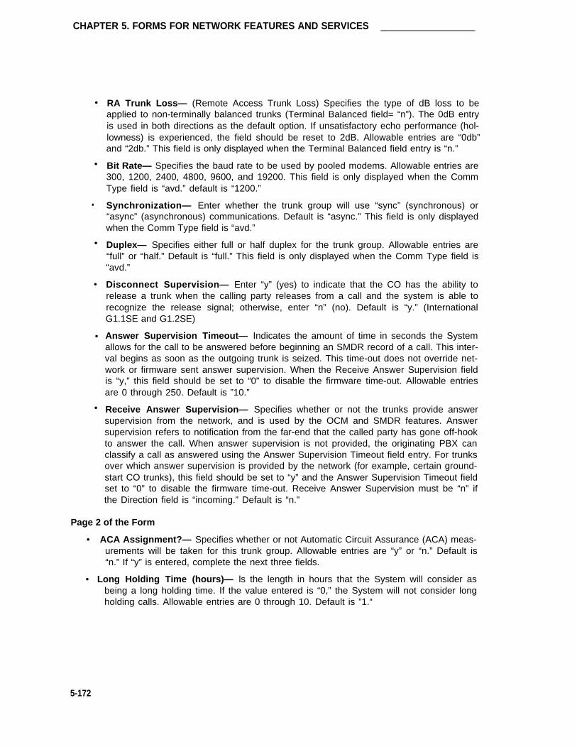
CHAPTER 5. FORMS FOR NETWORK FEATURES AND SERVICES
•
•
•
•
RA Trunk Loss— (Remote Access Trunk Loss) Specifies the type of dB loss to beapplied to non-terminally balanced trunks (Terminal Balanced field= “n”). The 0dB entryis used in both directions as the default option. If unsatisfactory echo performance (hol-lowness) is experienced, the field should be reset to 2dB. Allowable entries are “0db”and “2db.” This field is only displayed when the Terminal Balanced field entry is “n.”
Bit Rate— Specifies the baud rate to be used by pooled modems. Allowable entries are300, 1200, 2400, 4800, 9600, and 19200. This field is only displayed when the CommType field is “avd.” default is “1200.”
Synchronization— Enter whether the trunk group will use “sync” (synchronous) or“async” (asynchronous) communications. Default is “async.” This field is only displayedwhen the Comm Type field is “avd.”
Duplex— Specifies either full or half duplex for the trunk group. Allowable entries are“full” or “half.” Default is “full.” This field is only displayed when the Comm Type field is“avd.”
Disconnect Supervision— Enter “y” (yes) to indicate that the CO has the ability torelease a trunk when the calling party releases from a call and the system is able torecognize the release signal; otherwise, enter “n” (no). Default is “y.” (InternationalG1.1SE and G1.2SE)
Answer Supervision Timeout— Indicates the amount of time in seconds the Systemallows for the call to be answered before beginning an SMDR record of a call. This inter-val begins as soon as the outgoing trunk is seized. This time-out does not override net-work or firmware sent answer supervision. When the Receive Answer Supervision fieldis “y,” this field should be set to “0” to disable the firmware time-out. Allowable entriesare 0 through 250. Default is ”10.”
Receive Answer Supervision— Specifies whether or not the trunks provide answer
•
•
•supervision from the network, and is used by the OCM and SMDR features. Answersupervision refers to notification from the far-end that the called party has gone off-hookto answer the call. When answer supervision is not provided, the originating PBX canclassify a call as answered using the Answer Supervision Timeout field entry. For trunksover which answer supervision is provided by the network (for example, certain ground-start CO trunks), this field should be set to “y” and the Answer Supervision Timeout fieldset to “0” to disable the firmware time-out. Receive Answer Supervision must be “n” ifthe Direction field is “incoming.” Default is “n.”
Page 2 of the Form
• ACA Assignment?— Specifies whether or not Automatic Circuit Assurance (ACA) meas-urements will be taken for this trunk group. Allowable entries are “y” or “n.” Default is“n.” If “y” is entered, complete the next three fields.
• Long Holding Time (hours)— ls the length in hours that the System will consider asbeing a long holding time. If the value entered is “0,” the System will not consider longholding calls. Allowable entries are 0 through 10. Default is ”1.“
5-172

Direct Inward and Outward Dialing Trunk Group (International G1.2SE Only)
• Short Holding Time (secs.)— Specifies the length in seconds that the System will con-sider as being a short holding time. If this field is “0,” the System will not consider shortholding calls. Allowable entries are 0 through 160. Default is “10.”
• Short Holding Threshold— Is the number of times that the System will record a shortholding call before an attendant or display-equipped voice terminal user is alerted to thepossibility of a faulty trunk. Allowable entries are 0 through 30. Default is “15.”
• Measured— Indicates if the System will transmit data for this trunk group to the CMS.Allowable entries are “internal,” “external,” “both,” “none.” Enter “internal” if the data isto be sent to the BCMS (that is, internal to the switch) for subsequent measurementreports and “external” to send the data to the 3B CMS. Enter “both” to send the data toboth systems for measurement reports or enter “none” if trunk group measurements arenot required. System default is “none.”
• Abandoned Call Search— Enter a "y" if this trunk group will conduct an Abandoned CallSearch to identify a ghost call; otherwise, enter “n.” Default is “n.” This field is onlyapplicable if Trunk Type is “ground-start.” Note that the CO must support Abandonedcall search for the feature to work properly.
Note: Abandoned Call Search is designed to work with CO trunks (ground start -analog) that do not provide disconnect supervision. COs that providedisconnect supervision do not require use of the Abandoned Call Searchfeature. Note that the CO must support Abandoned Call Search for thefeature to work properly.
• Data Restriction— ls used to restrict System features from causing overriding tones on atrunk group. This provides permanent protection. Allowable entries are “y” or “n.”Default is “n.”
• Maintenance Tests— lndicates whether or not maintenance tests will be performed onan hourly basis for this trunk group. Allowable entries are “y” or “n.” Default is “y.”
• Suppress # Outpulsing— lndicates end-to-end signaling begins with (and includes) the“#” when “y” is entered in this field. The final # is suppressed in cases where Systemwould normally outpulse it. This field should be set to “y” when the CO (for example,rotary) or any other facility treats # as an error. Default is “n.”
Note: This page is only displayed if "y" is entered in the Administrable Timer Page onPage 1 of the form.
• Incoming Disconnect (msec)— Enter the minimum time (in msec) required for recogni-tion of disconnect for an incoming call from the serving CO. Valid entries are 50 through12750 in increments of 50. The field cannot be blank. Default is “300.”
• Outgoing Disconnect (msec)— Enter the minimum time (in msec) required for recogni-tion of disconnect for an outgoing call. Valid entries are 50 through 12750 in incrementsof 50. The field cannot be blank. Default is “300.”
• Outgoing Dial Guard (msec)— Enter the minimum time (in msec) between seizure ofthe trunk and outpulsing of digits. Valid entries are 200 through 25600 in increments of200. The field cannot be blank. Default is ”1000.”
5-173

CHAPTER 5. FORMS FOR NETWORK FEATURES AND SERVICES
•
•
•
•
•
•
•
•
•
Incoming Glare Guard (msec)— Enter the incoming guard time (in msec) between thetime the incoming trunk is released and the same trunk can be seized again. This guardtime will ensure the far-end has released all equipment after the incoming trunk isreleased. Valid entries are 200 through 25600 in increments of 200. The field cannot beblank. Default is “3000.”
Outgoing Glare Guard (msec)— Enter the outgoing guard time (in msec) between thetime the outgoing trunk is released and the same trunk can be seized again. This guardtime will ensure that the far-end has released all equipment after the outgoing trunk isreleased. Valid entries are 200 through 25600 in increments of 200. The field cannot beblank. Default is “3000.”
Outgoing Rotary Dial Interdigit (msec)— Enter the interval (in msec) between rotarydial digits being outpulsed by the system (that is, PBX). Valid entries are 150 through2550 in increments of 10. The field cannot be blank. Default is “600.”
Ringing Monitor (msec)— Enter the minimum time (in msec) required to determine if thetrunk is disconnected. If the ringing signal disappears for a duration longer than the timespecified in this field, the call will be assumed to be disconnected. For CO, FX, WATS,PCOL, DID, and DIOD, valid entries are 200 through 51000 in increments of 200. ForTie, Tandem and Access, valid entries are 200 through 25500 in increments of 100. Thefield cannot be blank. Default is “5000.”
Incoming Seizure (msec)— Enter the minimum time (in msec) required for recognition ofincoming ringing signal from the serving CO. Valid entries are 20 through 2550 in incre-ments of 10. The field cannot be blank. Default is ”130.”
PPS— Enter either ”10“ or “20” to specify the PPS (pulses per second) assigned to rotarydial pulse trunk groups. Valid entries are ”10“ or “20.” Default is “10.”
Make (msec)— Enter the duration of the make interval while the system is outpulsingdigits using dial pulse signaling.
If the PPS field is “10,” the sum of the Make and Break fields must equal 100. Validentries are 20 through 80 in increments of 5 The field cannot be blank. The default is“40.”
If the PPS field is “20,” the sum of the Make and Break fields must equal 50. Validentries are 10 through 40 in increments of 5. The field cannot be blank. The default is“20.”
Break (msec)— Enter the duration of the break interval while the system is outpulsingdigits using dial pulse signaling.
If the PPS field is “10,” the sum of the Make and Break fields must equal 100. Validentries are 20 through 80 in increments of 5. The field cannot be blank The default is“60.”
If the PPS field is “20,” the sum of the Make and Break fields must equal 50. Validentries are 10 through 40 in increments of 5. The field cannot be blank. The default is“30.”
PPM— Enter “y” (yes) if PPM pulses are to be collected to determine outgoing call billing,otherwise enter “n” (no). Valid entries are “y” or “n.” Default is “n.” (This field does notappear for DID, Tie, Tandem, or Access trunks.)
5-174

Direct Inward and Outward Dialing Trunk Group (International G1.2SE Only)
Pages 4 through 10 of the Form (Group Member Assignments)
[Pages 3 through 9 of the Form (Group Member Assignments Administrable Timer Page field isNOT enabled on Page 1.]
• Port— Enter five to six characters. The first character identifies the network (1 through 2,default is “1” if no entry); the second character identifies the carrier (A through E); thethird and fourth characters identify the slot number in the carrier (01 through 20 for multi-carrier cabinets or 01 through 18 for single-carrier cabinets); the last two characters iden-tify the circuit number (01 through 08).
• Name— Enter up to ten characters to identify the member of the trunk group. The namecan be a 7-digit telephone number or a 10-digit Trunk Circuit Identification number (pro-vided by trunk supplier).
Note: Previously, System 75 Night Service and Balance/Loss information wasentered in the Name field as “NT#...” and “TT#)....” This information mustnow be entered in the Night field (below) or the STT Loss field on Page 1 ofthe form, as applicable.
• Mode— Specifies the signaling mode used on Tie Trunks with TN722A, TN722B,TN760B, TN767, or TN464C (international G1.2SE only) circuit packs. Allowable entriesare “e&m” (interface), “simplex’” (phantomed), or “protected.” This entry mustcorrespond to associated dip switch settings on the circuit pack.
• Type— Specifies the type of trunk used. Allowable entries are “t1 stan” (Type 1 Stan-dard), “t1 comp” (Type 1 Compatible), or “type 5.”
• Ans Delay— Specifies the length of the wait for answer supervision delay in millisecondsfor DS1 or Tie Trunks using the TN722A, TN722B, TN760 (B, C, or D), TN767, orTN464C (International G1.2SE only) circuit packs. Allowable entries are 20 through 5100in increments of 20. The default is no entry (blank) and internally treated as a zero. Thisdelay serves two purposes:
1.
2.
Used to assure that the answer supervision signal is valid and not a secondarydelay-dial or wink-start signal.
Used to bridge over momentary off-hook signals resulting from connectionsmade off-network through certain No. 5 Crossbar CCSA switches as the connec-tion is being established.
5-175

CHAPTER 5. FORMS FOR NETWORK FEATURES AND SERVICES
TRUNK GROUP Page 1 of xGroup Number: 71 Group Type: diod SMDR Reports? y
Group Name: OUTSIDE CALL COR: 1 TAC: 601Direction: two-way Outgoing Display? n
Dial Access? y Busy Threshold: 99Queue Length: 0 Administrable Timer Page? y
Auth Code? n Digit Absorption List: _Prefix-1? y Toll Restricted? y
TRUNK PARAMETERSTrunk Type: loop-start
Outgoing Dial Type: tone Incoming Dial Type: toneTrunk Termination: rc
Digit Treatment: Digits:Expected digits:
Terminal Balanced? n RA Trunk Loss: 0db
SCREEN 5-97. Direct lnward and Outward Dial Trunk Group Form (Page 1)—Example Only (lnternational G1.2SE only)
Implementation Notes:
The BCC field is only displayed when lSDN-PRI is optioned for on the System-ParametersCustomer-Options form and the Comm Type field is "rbavd," "avd," or "data."
The Connected to Toll and DTT to DCO Loss fields are only displayed if the Trunk Type fieldis “auto ....”
The STT Loss field is only displayed when the Connected to Toll field is “n.”
The Terminal Balanced field is only displayed when the Trunk Type field is “ground-start” or“loop-start.” The RA Trunk Loss field is only displayed when the Terminal Balanced field is“n.”
The Bit Rate, Synchronization, and Duplex fields are only displayed when the Comm Typefield is “avd.”
5-176

Direct Inward and Outward Dialing Trunk Group (International G1.2SE Only)
Page 2 of 10
TRUNK FEATURESACA Assignment? n Measured? Done
Data Restriction? n
Suppress # Outpulsing? n Maintenance Tests? y
SCREEN 5-98. Direct lnward and Outward Dial Trunk Group Form (Page 2)—Example Only (lnternational G1.2SE only)
Implementation Note:
The Terminal Balanced field is only displayed if the Trunk Type field is “immed-start” or“wink-start.”
The RA Trunk Loss field is only displayed if the Terminal Balanced field is “n.”
Page 3 of 10
ADMINISTRABLE TIMER
Incoming Disconnect (msec): 300 Outgoing Disconnect (msec): 300Outgoing Dial Guard (msec): 1000
Incoming Glare Guard (msec): 3000 Outgoing Glare Guard (msec): 3000Outgoing Rotary Dial Interdigit (msec): 600
Ringing Monitor (msec): 5000 Incoming Seizure (msec): 130
OUTPULSING TIMING
PPS: 10 Make (msec): 40 Break (msec): 60 PPM? n
SCREEN 5-99. Direct lnward and Outward Dial Trunk Group Administrable TimersPage—Example Only
implementation Note:
This page is only displayed if “y” is entered in the Administrable Timers Page field onPage 1.
5-177

CHAPTERS. FORMS FOR NETWORK FEATURES AND SERVICES
GROUP MEMBER ASSIGNMENTS Page 4 of 10
Port Name
1:2 :
3:
4:
5:
6:
7 :
8:
9:
10:
11:
12:
13:
14:
15:
SCREEN 5-100. Direct Inward/Outward Trunk Group Form (Page 4)—Example Only (International G1.2SE only)
Note: To reduce repetition, pages 5 through 9 are not shown.
5-178

Direct Inward and Outward Dialing Trunk Group (International G1.2SE Only)
GROUP MEMBER ASSIGNMENTS
Port
91:
92:
93:
94:
95:
96:
97:
98:
99:
Name
Page 10 of 10
SCREEN 5-101. Direct Inward/Outward Trunk Group Form (Page 10)—Example Only (International G1.2SE only)
Implementation Note:
Above Group Member Assignments pages illustrate the resulting pagination when “y” isentered in the “Administrable Timers Page” field on Page 1 of the form; otherwise, Pagenumbers will be 3 through 9.
5-179

CHAPTER 5. FORMS FOR NETWORK FEATURES AND SERVICES
Foreign Exchange Trunk Group
Purpose
This form is used to assign a Foreign Exchange (FX) Trunk Group and associated trunk ports.The FX Trunk Group allows a connection between a distant central office and the System.
Administration Commands
The following administration commands can be used to access the FX Trunk Group form. Insome cases, just the most commonly used commands are shown. Refer to Administration Com-mands and Error Messages (Chapter 3) for a complete listing of all administration commands, thecommand structure, and the use of abbreviated command words when entering a command.
Action Object Qualifier*
add trunk-group 1-99 (or ‘next’)change trunk-group 1-99 or TAC X...display trunk-group 1-99 or TAC X...[‘print’ or ‘schedule’]list trunk-group [‘print’ or ‘schedule’]remove trunk-group 1-99 or TAC X...
* Brackets [ ] indicate the qualifier is optional.Single quotes (‘ ’) indicate the text inside the quote must be entered exactlyas shown or an abbreviated form of the word may be entered.
Form Instructions
Make assignments as required for the following fields on each page of the form:
Page 1 of the Form
•
•
•
•
•
•
•
5-180
Group Number— Enter a number from 1 through 99 when completing a paper form.Assign consecutive Group Numbers to trunk groups when two or more trunk groups areto be used for ACD applications. This is a display-only field when the form is accessedusing an administration command such as add or change.
Group Type— Enter “fx” to identify the type of trunk group.
SMDR Reports— Enter “y” to provide a detailed SMDR record of both incoming and out-going calls made on all trunks in the trunk group; otherwise, enter “n.” Default is “y.”
Group Name— Enter a unique name that identifies the trunk group. Up to 15 characterscan be used. Default is “OUTSIDE CALL.”
COR— Enter a class of restriction (COR) number from 0 through 63 that reflects thedesired restriction. Default is “1.”
TAC— Enter the trunk access code (TAC) that must be dialed to access the trunk group.A different TAC must be assigned to each trunk group. SMDR also uses the TAC toidentify the trunk group on associated SMDR reports. Allowable entries are TACs thatare compatible with the System Dial Plan (1 to 3 digits).
Direction— Enter whether the trunk group is “incoming,” “outgoing,” or “two-way.”Default is “two-way.”

Foreign Exchange Trunk Group
• Outgoing Display— Specifies whether or not the trunk group name is displayed on a ter-minal placing an outgoing call. Allowable entries are “y” or “n.” Default is “n.”
• Dial Access—Enter “y” to allow the trunk group to be accessed via a trunk access code;otherwise, enter “n.” Default is “y.” Access via the ARS feature is allowed regardless ofthis entry.
• Busy Threshold— Enter a number (0 through 99) of trunk group members that must bebusy before the attendant is alerted by the Warning lamp on the Attendant Console.Default is “99.”
• Night Service— Enter the extension number assigned to Night Service. The extensionnumber entered will receive all incoming calls when Night Service is activated and theindividual trunk member Night field is not administered to override this entry. Allowableentries are an extension number, 0 (attendant), or leave blank if the Trunk Type is not“auto....”
• Queue Length— Enter a number from 0 through 100 that indicates the number of outgo-ing calls that can be held waiting. A “0” indicates no calls will be held in queue. This fieldis turned off if the Direction field is “incoming.” Default is “0.”
• Administrable Timers Page— Only displayed for international applications. Entering a“y” causes an Administrable Timers page to be added to the trunk group form. TheAdministrable Timers page then becomes Page 3 of x. Valid entries are “y” or “n.”Default is “n.” (International G1.2SE only).
• Incoming Destination— Indicates where incoming calls will terminate. Allowable entriesare an extension number, 0 (attendant), or leave blank if the Trunk type is not “auto/....”
• Comm Type— Indicates if the trunk is to be used for voice, data, alternate voice-data(that is, avd), or alternate voice/voice grade data and 56 Kbps digital data [that is,robbed-bit alternate voice-data (rbavd)] calls. Allowable entries are “avd,” “rbavd,”“voice,” or “data.” Type “rbavd” supports access to voice/data SDN service on robbed-bti T1 transmission facilities. Default is “voice.” Note that “avd’ and “rbavd” typesrequire trunk member ports on a DS1 circuit pack. An “rbavd” type requires that the DS1circuit pack be administered for robbed-bit signaling.
• Auth Code— Enter “y” if an Authorization Code must be dialed to complete incomingcalls on the trunk group; otherwise, enter “n.” Default is “n.” This field can only be set to“y” if the Authorization Codes feature is enabled on the System-Parameters Customer-Options form.
• Digit Absorption List— Enter a digit list absorption number, if required, when this trunkgroup terminates at a step-by-step office. This field specifies the type of absorption asspecified on the associated Digit Absorption form. Up to five different forms (lists 0through 4) maybe administered in the System.
• Prefix-1— Specifies if the prefix 1 is required for N(0/1)X calls. Allowable entries are “y”or “n.” Default is “n.”
• Trunk Flash— Enter “y” or “n” to indicate if access to customized services provided by afar end (for example, CO) is permitted for this trunk group. The PBX must be directlyconnected to a far end that provides such services. Default is “n.”
5-181

CHAPTER 5. FORMS FOR NETWORK FEATURES AND SERVICES
• Toll Restricted— Enter “y” (yes) if this trunk group is to be toll restricted; otherwise,enter “n” (no). This field only applies for outgoing TAC calls if the originating party is tollrestricted. Default is “y.”
• ITC (Information Transfer Capability)— Used by the GRS feature and enables the systemto route calls to restricted or unrestricted facilities according to the endpoint’s informationtransfer capability. The ITC field is displayed on G3i systems for non-lSDN trunk groupsonly and is displayed and administrable only when the Comm Type field is administeredas “data,” “avd,” or ’’rbavd” and the BCC field is not set to “0.” This field is not displayedif the Comm Type field is administered as “voice,” nor is it displayed if the Comm Typefield is administered as “data,” “avd,” or “rbavd” and the BCC field is set to “0.” Defaultis “restricted.”
• BCC (Bearer Capability Class)— Used by the GRS feature and identifies the type oftraffic on trunks in the group. The BCC entry is used by far-end tandem switches toselect outgoing routing facilities with equivalent BCC classes. Allowable entries are 0, 1,2, 3, and 4. Default is 0 for “avd and “rbavd,” and 2 for “data.” The BCC field isdisplayed when the Comm Type is “avd,” “rbavd,” or “data.”
Note: Refer to the GRS feature description in DEFINITY® Communications Sys-tem Generic 1 and Generic 3i Feature Description, 555-230-201, for adetailed description of BCCs and their use to provide specialized routing forvarious types of voice and data calls.
• Trunk Type— Identifies the physical type of FX trunk. It may differ for incoming and out-going types. Allowable entries are “ground-start,” “loop-start,” “auto/auto,” “auto/delay,”“auto/immed,” and “auto/wink.”
• Outgoing Dial Type— Identifies the type of pulsing required on an outgoing call. Allow-able entries are “automatic,” “tone” or “rotary.” Default is “tone.”
• Trunk Termination— Specifies how the trunk group is terminated. The trunk group canterminate in a resistance of 600ohms, or a resistor capacitor (rc) network. Allowableentries are “600ohms” or “rc”; 600ohms is used for short loops and rc is used for longloops. Default is “rc.”
• Disconnect Timing (msec)— Specifies the minimum time period in milliseconds that isrequired for recognition of disconnect by the serving CO or far-end PBX. The time inter-val must be in increments of 10 (from 140 through 2550 milliseconds). Default is “500.”
• Connected to Toll— Enter “y” if connected to a CO toll office, otherwise, enter “n”(default). This field is displayed when the Trunk Type field contains an entry of “auto/....”
• STT Loss (Satellite PBX Tie Trunk Loss)— Only displayed when the Connected to Tollfield is “n.” Specifies the loss plan to be used for the trunk group. Allowable entries are“normal” (default) or “low.” This option affects the transmission performance of a privatePBX network.
Although the use of this option has wider applications, only for the simplest networkarrangements should this field be administered without Network Engineering advise. The“low” option (described as the ISL digital low loss plan in DEFINITY® 75/85 Communica-tions System and System 75 and System 85 DS1/DMI/ISDN-PRl Interface, 555-025-101should only be used when:
5-182

Foreign Exchange Trunk Group
1.
2.
3.
4.
Stations on the satellite PBX complain of too much loss on calls to the public net-work.
The PBX network consists of no more than three PBXs; one main and one ortwo satellite PBXs (satellite PBX connected to maim PBX via DS1 tie trunks,main PBX connected to public network via CO trunks).
All PBXs have the “low” option available.
The total DS1 trunk connection length is less than 100 miles.
If the above conditions are not met, obtain Network Engineering assistance. The fieldentry is based on the following:
— normal— Applies to AIU-TT (Analog Interface Unit at Customer Switching Sys-tem for Tie Trunk—4-wire E&M interface), and DIU-TT (Digital Interface Unit atCustomer Switching System for Tie Trunk-voice or AVD DS1 interface) lossplans.
— low— Applies to AIU-TTS (same as AIU-TT, but suitable for private network con-nections that can be connected in tandem with public network connections) andDIU-TTS (same as DIU-TT, but suitable for private network connections that canbe connected in tandem with public network connections). These interfaceswere formerly referred to as DIU DTT ISL.
• DTT to DCO Loss (Digital Tie to Digital CO Trunk Loss)— Specifies the loss plan to beused for the trunk group for interconnections from a DIU-CO (Digital Interface Unit at aCentral Office) to a DIU-DTT (Digital Interface Unit for a Digital Tie Trunk Interface). Thisfield is displayed when the Trunk Type field contains an entry of auto/.... Valid entriesare “normal” (default) or “low.”
This option affects the transmission performance of public network access via a privatePBX network. Choose the “low” option only if private network users complain about toomuch loss on calls to the public network otherwise, the “normal” option should be used.Allowable entries are “normal” (default) and “low.” The entry is based on the following:
— normal— Corresponds to a (0, -6) dB gain pair and is used as the default option.(This corresponds to the DTT/EIA DCO port to port configuration as described inAT&T System 75 and System 85—DSl/DMI/ISDN-PRl Interface, 555-025-101.)
– low— Corresponds to (+3, -3) dB gain pair. Low is used for internetwork applica-tions in which no significant configuration will encounter echo, stability, or over-load problems because of reduced loss. Which the low gain pair, subscriber stationDTMF signals transmitted through the digital class five office into the customernetwork may experience non-recoverable digit mutilation in secondary signalingapplications (that is, DTMF signaling after the connection has been established).(This corresponds to the DTT/lSL DCO port to port configuration as described inAT&T System 75 and System 85 DS1/DMI/ISDN-PRl Interface, 555-025-101.)
• Terminal Balanced— Specifies whether the trunks in the trunk group are balanced. A“y” significants that the trunks are terminally balanced and an “n” signifies that the trunksare not terminally balanced. Typically, a Trunk Termination field of “600ohm” signifies abalanced trunk group and afield of “rc” signifies a non-balanced trunk group. If the trunks
5-183
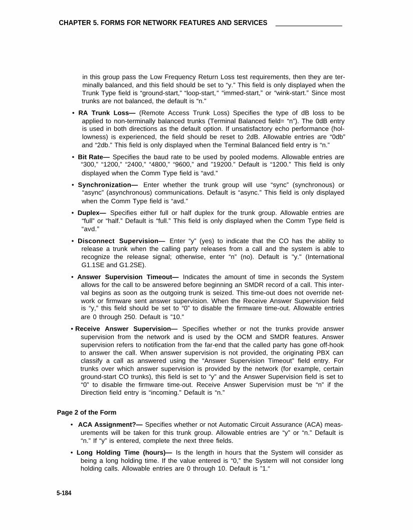
CHAPTER 5. FORMS FOR NETWORK FEATURES AND SERVICES
in this group pass the Low Frequency Return Loss test requirements, then they are ter-minally balanced, and this field should be set to “y.” This field is only displayed when theTrunk Type field is “ground-start,” “loop-start, “ “immed-start,” or “wink-start.” Since mosttrunks are not balanced, the default is “n.”
• RA Trunk Loss— (Remote Access Trunk Loss) Specifies the type of dB loss to beapplied to non-terminally balanced trunks (Terminal Balanced field= “n”). The 0dB entryis used in both directions as the default option. If unsatisfactory echo performance (hol-lowness) is experienced, the field should be reset to 2dB. Allowable entries are “0db”and “2db.” This field is only displayed when the Terminal Balanced field entry is “n.”
• Bit Rate— Specifies the baud rate to be used by pooled modems. Allowable entries are“300,” “1200,” “2400,” “4800,” “9600,” and ”19200.” Default is “1200.” This field is onlydisplayed when the Comm Type field is “avd.”
• Synchronization— Enter whether the trunk group will use “sync” (synchronous) or“async” (asynchronous) communications. Default is “async.” This field is only displayedwhen the Comm Type field is “avd.”
• Duplex— Specifies either full or half duplex for the trunk group. Allowable entries are“full” or “half.” Default is “full.” This field is only displayed when the Comm Type field is“avd.”
• Disconnect Supervision— Enter “y” (yes) to indicate that the CO has the ability torelease a trunk when the calling party releases from a call and the system is able torecognize the release signal; otherwise, enter “n” (no). Default is "y." (InternationalG1.1SE and G1.2SE).
• Answer Supervision Timeout— Indicates the amount of time in seconds the Systemallows for the call to be answered before beginning an SMDR record of a call. This inter-val begins as soon as the outgoing trunk is seized. This time-out does not override net-work or firmware sent answer supervision. When the Receive Answer Supervision fieldis “y,” this field should be set to “0” to disable the firmware time-out. Allowable entriesare 0 through 250. Default is ”10.”
• Receive Answer Supervision— Specifies whether or not the trunks provide answersupervision from the network and is used by the OCM and SMDR features. Answersupervision refers to notification from the far-end that the called party has gone off-hookto answer the call. When answer supervision is not provided, the originating PBX canclassify a call as answered using the “Answer Supervision Timeout” field entry. Fortrunks over which answer supervision is provided by the network (for example, certainground-start CO trunks), this field is set to “y” and the Answer Supervision field is set to“0” to disable the firmware time-out. Receive Answer Supervision must be “n” if theDirection field entry is “incoming.” Default is “n.”
Page 2 of the Form
• ACA Assignment?— Specifies whether or not Automatic Circuit Assurance (ACA) meas-urements will be taken for this trunk group. Allowable entries are “y” or “n.” Default is“n.” If “y” is entered, complete the next three fields.
• Long Holding Time (hours)— Is the length in hours that the System will consider asbeing a long holding time. If the value entered is “0,” the System will not consider longholding calls. Allowable entries are 0 through 10. Default is ”1.“
5-184

Foreign Exchange Trunk Group
• Short Holding Time (secs.)— Specifies the length in seconds that the System will con-sider as being a short holding time. If this field is “0,” the System will not consider shortholding calls. Allowable entries are 0 through 160. Default is “10.”
• Short Holding Threshold— Is the number of times that the System will record a shortholding call before an attendant or display-equipped voice terminal user is alerted to thepossibility of a faulty trunk. Allowable entries are 0 through 30. Default is “15.”
• Measured— Indicates if the System will transmit data for this trunk group to the CMS.Allowable entries are “internal,” ”external,” “both,” “none.” Enter “internal” if the data isto be sent to the BCMS (that is, internal to the switch) for subsequent measurementreports and “external” to send the data to the 3B CMS. Enter “both” to send the data toboth systems for measurement reports or enter “none” if trunk group measurements arenot required. System default is “none.”
• Abandoned Call Search— Enter a “y” if this trunk group will conduct an Abandoned CallSearch to identify a ghost call; otherwise, enter “n.” Default is “n.” This field is onlyapplicable if Trunk Type is “ground-start.”
Note: Abandoned Call Search is designed to work with CO trunks (ground start -analog) that do not provide disconnect supervision. COs that providedisconnect supervision do not require use of the Abandoned Call Searchfeature. Note that the CO must support Abandoned Call Search for thefeature to work properly.
• Data Restriction— ls used to restrict System features from causing overriding tones on atrunk group. This provides permanent protection. Allowable entries are ‘y” or “n.”Default is “n.”
• Maintenance Tests— Indicates whether or not maintenance tests will be performed onan hourly basis for this trunk group. Allowable entries are ‘y” or “n.” Default is “y.”
• Suppress # Outpulsing— Indicates end-to-end signaling begins with (and includes) the“#” when “y” is entered in this field. The final # is suppressed in cases where the Systemwould normally outpulse it. This field should be set to “y” when the CO (for example,rotary) or any other facility treats # as an error. Default is “n.”
Page 3 of the Form (Administrable Timers) (International G1.2SE only)
Note: This page is only displayed if “y” is entered in the Administrable Timers Page field onPage 1 of the form.
• Incoming Disconnect (msec)— Enter the minimum time (in msec) required for recogni-tion of disconnect for an incoming call from the sewing CO. Valid entries are 50 through12750 in increments of 50. The field cannot be blank. Default is “300.”
• Outgoing Disconnect (msec)— Enter the minimum time (in msec) required for recogni-tion of disconnect for an outgoing call. Valid entries are 50 through 12750 in incrementsof 50. The field cannot be blank. Default is “300.”
• Outgoing Dial Guard (msec)— Enter the minimum time (in msec) between seizure ofthe trunk and outpulsing of digits. Valid entries are 200 through 25600 in increments of200. The field cannot be blank. Default is ”1000.”
5-185

CHAPTER 5. FORMS FOR NETWORK FEATURES AND SERVICES
•
•
•
•
•
•
•
•
•
Incoming Glare Guard (msec)— Enter the incoming guard time (in msec) between thetime the incoming trunk is released and the same trunk can be seized again. This guardtime will ensure the far-end has released all equipment after the incoming trunk isreleased. Valid entries are 200 through 25600 in increments of 200. The field cannot beblank. Default is “3000.”
Outgoing Glare Guard (msec)— Enter the outgoing guard time (in msec) between thetime the outgoing trunk is released and the same trunk can be seized again. This guardtime will ensure that the far-end has released all equipment after the outgoing trunk isreleased. Valid entries are 200 through 25600 in increments of 200. The field cannot beblank. Default is “3000.”
Outgoing Rotary Dial Interdigit (msec)— Enter the interval (in msec) between rotarydial digits being outpulsed by the system (that is, PBX). Valid entries are 150 through2550 in increments of 10. The field cannot be blank. Default is “600.”
Ringing Monitor (msec)— Enter the minimum time (in msec) required to determine if thetrunk is disconnected. If the ringing signal disappears for a duration longer than the timespecified in this field, the call will be assumed to be disconnected. For CO, FX, WATS,PCOL, DID, and DIOD, valid entries are 200 through 51000 in increments of 200. ForTie, Tandem and Access, valid entries are 200 through 25500 in increments of 100. Thefield cannot be blank. Default is “5000.”
Incoming Seizure (msec)— Enter the minimum time (in msec) required for recognition ofincoming ringing signal from the serving CO. Valid entries are 20 through 2550 in incre-ments of 10. The field cannot be blank. Default is ”130.”
PPS— Enter either “10” or “20” to specify the PPS (pulses per second) assigned to rotarydial pulse trunk groups. Valid entries are ”10“ or “20.” Default is ”10.”
Make (msec)— Enter the duration of the make interval while the system is outpulsingdigits using dial pulse signaling.
If the PPS field is “10,” the sum of the Make and Break fields must equal 100. Validentries are 20 through 80 in increments of 5. The field cannot be blank. The default is“40.”
If the PPS field is “20,” the sum of the Make and Break fields must equal 50. Validentries are 10 through 40 in increments of 5. The field cannot be blank. The default is“20.”
Break (msec)— Enter the duration of the break interval while the system is outpulsingdigits using dial pulse signaling.
If the PPS field is “10,” the sum of the Make and Break fields must equal 100. Validentries are 20 through 80 in increments of 5. The field cannot be blank. The default is“60.”
If the PPS field is “20,” the sum of the Make and Break fields must equal 50. Validentries are 10 through 40 in increments of 5. The field cannot be blank. The default is“30.”
PPM— Enter “y” (yes) if PPM pulses are to be collected to determine outgoing call billing,otherwise enter “n” (no). Valid entries are “y” or “n.” Default is “n.” (This field does notappear for DID, Tie, Tandem, or Access trunks.)
5-186

Foreign Exchange Trunk Group
Pages 3 through 9 of the Form (Group Member Assignments)
Note: For International Systems, if “y” has been entered in the Administrable Times Pagefield on Page 1 of the form, the Group Member Assignments will appear on Pages 4through 10 of the form.
• Port— Enter five to six characters. The first character identifies the network (1 through 2,default is “1” if no entry); the second character identifies the carrier (A through E); thethird and fourth characters identify the slot number in the carrier (01 through 20 for multi-carrier cabinets or 01 through 18 for single-carrier cabinets); the last two characters iden-tify the circuit number (01 through 08).
• Name— Enter up to 10 characters to identify the member of the trunk group. The namecan be a 7-digit telephone number or a 10-digit Trunk Circuit Identification number (pro-vided by trunk supplier).
Note: Previously, for System 75, Night Service and Balance/Loss information wasentered in the Name field as “NT#...” and “TT#)....” This information mustnow be entered in the Night field (below) or the STT Loss field on Page 1 ofthe form, as applicable.
• Night— Specifies a night destination for an individual trunk. This entry overrides thegroup Night Service entry on Page 1 of the form. Allowable entries are an extension, 0(attendant), or leave blank if the Trunk Type entry on Page 1 is not “auto/. ...”
• Mode— Specifies the signaling mode used on Tie Trunks with TN722A, TN722B,TN760B, TN767, or TN464C (International G1.2SE only) circuit packs. Allowable entriesare “e&m” (interface), “simplex” (phantomed), or “protected.” This entry must correspondwith the associated dip switch settings on the circuit pack.
• Type— Specifies the signaling used. Allowable entries are “t1 stan” (Type 1 Standard),“t1 comp” (Type 1 Compatible), or “type 5.”
• Ans Delay— Specifies the length of the wait for answer supervision delay in millisecondsfor DS1 or Tie Trunks using the TN722A, TN722B, TN760 (B, C, or D), TN767, orTN464C (International G1.2SE only) circuit packs. Allowable entries are 20 through 5100in increments of 20. The default is “no entry (blank) and internally treated as a 0. Thisdelay serves two purposes:
1.
2.
Used to assure that the answer supervision signal is valid and not a secondarydelay-dial or wink-start signal.
Used to bridge over momentary off-hook signals resulting from connectionsmade off-network through certain No. 5 Crossbar CCSA switches as the connec-tion is being established.
5-187

CHAPTER 5. FORMS FOR NETWORK FEATURES AND SERVICES
Group Number:Group Name:Direction:
Dial Access?Queue Length:
Comm Type:Prefix-1? code
TRUNK PARAMETERSTrunk Type:
Outgoing Dial Type:Trunk Termination:Connected to Toll?Terminal Balanced?
Bit Rate:
TRUNK GROUP
— Group Type:OUTSIDE CALL COR :two-way Outgoing Display?
y Busy Threshold:0voice Auth Code?n Restriction:
Trunk Flash?
Page 1 of 9
fx SMDR Reports? y
1 TAC: _
n99 Night Service:
Incoming Destination: _
n Digit Absorption List: _Allowed Calls List? n
n
tone
rcn STT Loss: normal
n1200 Synchronization: async
Answer Supervision Timeout? 10
Disconnect Timing(msec): 500DTT to DCO Loss: normal
RA Trunk Loss: 0dbDuplex: full
Receive Answer Supervision? n
SCREEN 5-102. Foreign Exchange Trunk Group Form (Part 1)—Example Only (Standard)
Implementation Notes:
The BCC field is displayed when the Comm Type is “avd,” “rbavd,” or “data.”
The Connected to Toll and DTT to DCO Loss fields are only displayed when the Trunk Typefield is “auto/....”
The STT Loss field is only displayed when the Connected to Toll field is “n.”
The Terminal Balanced field is only displayed when the Trunk Type field is "ground-start" or“loop-start.” The RA Trunk Loss field is only displayed when the Terminal Balanced field is“n.”
The Bit Rate, Synchronization, and Duplex fields are only displayed when the Comm Typefield is “avd.”
The Trunk Flash field is only displayed when the Group Type field is “co,” “fx,” or “wats.”
The ITC (Information Transfer Capability) field is appears for non-lSDN trunk groups onlyand is displayed and administrable only when the Comm Type field is administered as“data,” “avd,” or “rbavd” and the BCC field is not set to “0.”
5-188

Foreign Exchange Trunk Group
TRUNK GROUP Page 2 of 9
TRUNK FEATURESACA Assignment? n Long Holding Time(hours) : 1
Short Holding Time(secs): 10 Short Holding Threshold: 15Measured? none Abandoned Call Search? n
Data Restriction? nMaintenance Tests? y
Suppress # Outpulsing? n
SCREEN 5-103. Foreign Exchange Trunk Group Form (Page 2)—Example Only (Standard)
Implementation Note:
The following fields are only displayed if the ACA Assignment field is ’’y”:
• Long Holding Time (hours)
• Short Holding Time (secs.)
• Short Holding Threshold
5-189

CHAPTER 5. FORMS FOR NETWORK FEATURES AND SERVICES
Page 3 of 9GROUP MEMBER ASSIGNMENTSPort Name Night Mode Type Ans Delay
1:2:3:4:5:6:7:8:9:
10:11:12:13:14:15:
SCREEN 5-104. Foreign Exchange Trunk Group Form (Page 3)—Example Only (Standard)
Note: To reduce repetition, pages 4 through 8 are not shown.
GROUP MEMBER ASSIGNMENTS Page 9 of 9Ans DelayNight Mode TypePort Name
91:92:93:94:95:96:97:98:99:
SCREEN 5-105. Foreign Exchange Trunk Group Form (Page 9)—Example Only (Standard)
5-190

Foreign Exchange Trunk Group
TRUNK GROUP Page 1 of xGroup Number: _ Group Type: fx SMDR Reports? y
Group Name: OUTSIDE CALL COR: 1 TAC: _Direction: two-way Outgoing Display? n
Dial Access? y Busy Threshold: 99 Night Service:
Queue Length: 0 Incoming Destination: _Comm Type: voicePrefix-1? n Restriction: code Allowed Calls List? n
Trunk Flash? n Toll Restricted? yTRUNK PARAMETERS
Trunk Type:Outgoing Dial Type: toneTrunk Termination: rc Disconnect Timing(msec): 500Connected to Toll? n STT Loss: normal DTT to DCO LOSS: normalTerminal Balanced? n RA Trunk Loss: 0db
Bit Rate: 1200 Synchronization: async Duplex: full
Answer Supervision Timeout? 10 Receive Answer Supervision? n
SCREEN 5-106. Foreign Exchange Trunk Group Form (Page 1)—Example Only (International G1.1SE and G1.2SE)
implementation Notes:
The BCC field is displayed when the Comm Type is ’’avd,” ’’rbavd,” or “data.”
The Connected to Toll and DTT to DCO Loss fields are only displayed when the Trunk Typefield is ’’auto/....”
The STT Loss field is only displayed when the Connected to ToIl field is ’’n.”
The Terminal Balanced field is only displayed when the Trunk Type field is ’’ground-start” or“loop-start.” The RA Trunk Loss field is only displayed when the Terminal Balanced field is“n.”
The Bit Rate, Synchronization, and Duplex fields are only displayed when the Comm Typefield is “avd.”
The Trunk Flash field is only displayed when the Group Type field is “co,” “fx,” or “wats.”
5-191

CHAPTER 5. FORMS FOR NETWORK FEATURES AND SERVICES
TRUNK FEATURESACA Assignment? n
Page 2 of 10
Measured: none
Data Restriction? nAbandoned Call Search? n Maintenance Tests? ySuppress # Outpulsing? n
SCREEN 5-107. Foreign Exchange Trunk Group Form (Page 2)—Example Only (International G1.1SE and G1.2SE)
lmplemetation Note:
The following fields are only displayed if the ACA Assignment field is “y”:
• Long Holding Time (hours)
• Short Holding Time (secs.)
• Short Holding Threshold
5-192

Foreign Exchange Trunk Group
Page 3 of 10
ADMINISTRABLE TIMERS
Incoming Disconnect (msec) : 300 Outgoing Disconnect (msec): 300Outgoing Dial Guard (msec): 1000
Incoming Glare Guard (msec): 3000 Outgoing Glare Guard (msec): 3000Outgoing Rotary Dial Interdigit (msec): 600
Ringing Monitor (msec): 5000 Incoming Seizure (msec): 130
OUTPULSING TIMING
PPS: 10 Make (msec): 40 Break (msec): 60 PPM? n
SCREEN 5-103. Foreign Exchange Trunk Group Administrable Timers (Page 3)—Example Only (International G1.1SE and G1.2SE)
Implementation Note:
This page is only displayed if ’’y’’ is entered in the Administrable Timers Page field onPage 1.
5-193

CHAPTER 5. FORMS FOR NETWORK FEATURES AND SERVICES
GROUP MEMBER ASSIGNMENTS
Port
1:2:3:4:5:6:7:8:
Name Night Mode Type
Page 4 of 10
Ans Delay
9:10:11:12:13:14:15:
SCREEN 5-109. Foreign Exchange Trunk Group Form (Page 4)—Example Only (International G1.1SE and G1.2SE)
Note: To reduce repetition, pages 5 through 9 are not shown.
GROUP MEMBER ASSIGNMENTS Page 10 of 10
Port Name Night Mode Type Ans Delay
91:
92:
93:
94:
95:
96:
97:
98:
99:
SCREEN 5-110. Foreign Exchange Trunk Group Form (Page 10)—Example Only (International G1.1SE and G1.2SE)
5-194

Integrated Services Digital Network—Primary Rate Interface Trunk Group
Integrated Services Digital Network—Primary RateInterface Trunk Group
Purpose
This form is used to assign an Integrated Services Digital Network-Primary Rate Interface(ISDN-PRI) Trunk group which supports the ISDN-PRI and Call by Call Service Selectionfeatures. The trunk group provides end-to-end digital connectivity and supports a wide range ofservices including voice and non-voice services to which users have access by a limited set ofCClTT defined, standard multipurpose user-network interfaces. Calls to a variety of switchednodal services such as Megacom telecommunications service, WATS, and ACCUNET digital ser-vice and calls destined for different inter-exchange carriers can be processed.
Administration Commands
The following administration commands can be used to access the ISDN-PRI Trunk Group form.In some cases, just the most commonly used commands are shown. Refer to AdministrationCommands and Error Messages sections (Chapter 3) for a complete listing of all administrationcommands, the command structure, and the use of abbreviated command words when entering acommand.
Action Object Qualifier*
add trunk-group 1-99 (or ‘next’)change trunk-group 1-99 or TAC X...display trunk-group 1-99 or TAC X...[‘print’ or ‘schedule’]list trunk-group [‘print’ or ‘schedule’]remove trunk-group 1-99 or TAC X...
* Brackets [ ] indicate the qualifier is optional.Single quotes (‘ ’) indicate the text inside the quote must be entered exactly as shown oran abbreviated form of the word maybe entered.
Form Instructions
Make assignments as required for the following fields on each page of the form:
Page 1 of the Form
• Group Number— Enter a number from 1 through 99 when completing a paper form. Thisis a display-only field when the form is accessed using an administration command suchas add or change. Note that when supporting DCS, it is suggested that the far-end nodetrunk group be assigned the same “Group Number.”
• Group Type— Enter “isdn” to identify the type of trunk group. This type can only beentered if the ISDN-PRI field on the System-Parameters Customer-Options form hasbeen enabled.
• SMDR Reports— Enter “y” to provide a detailed record of both incoming and outgoingcalls made on all trunks in the trunk group. Allowable entries are “y” or “n.” Default is"y."
• Group Name— Enter a unique name that identifies the trunk group. Up to 15 characterscan be used. Default is “OUTSIDE CALL.”
5-195

CHAPTERS. FORMS FOR NETWORK FEATURES AND SERVICES
•
•
•
•
•
COR— Enter a class of restriction (COR) number from 0 through 63 that reflects thedesired restriction. Default is ”1.“
TAG— Enter the trunk access code (TAC) that must be dialed to access the trunk group.A different TAC must be assigned to each trunk group. SMDR also uses the TAC toidentify the trunk group on associated SMDR reports. Allowable entries are TACs com-patible with the System Dial Plan (1 to 3 digits).
Direction— ldentifies whether the trunk group is “incoming,” “outgoing,” or “two-way.”Default is “two-way.”
Outgoing Display— Specifies whether or not the trunk group name is displayed on out-going calls. Allowable entries are “y” or “n.” Default is “n.”
Dial Access— Enter “y” to allow the trunk group to be accessed via a trunk access code;otherwise, enter “n.” Access via the ARS feature is allowed regardless of this entry. A“y” may only be entered if the Service Type field entry is “access,” “tie,” “tandem,” ordmi-mos. Default is “y.”
• Busy Threshold— Enter the number (0 through 99) of trunk group members that must bebusy before the attendant is alerted by the Warning lamp on the Attendant Console.Default is “99.”
• Night Service— Enter the extension number assigned to Night Service. The extensionnumber entered will receive all incoming calls when Night Service is activated. Allowableentries are an extension number, 0 (attendant), or leave blank. Leave blank for a Ser-vice Type field entry of “sddn.” This entry can be overridden by the Night Service entryon page 2 or 5 through 11 of the form.
• Queue Length— Enter a number from 0 through 100 that indicates the number of outgo-ing calls that can be held waiting. A “0” indicates no calls will be held in queue. Enter “0”for DCS trunks or a Service Type field entry of “sddn.” Default is “0.”
• Service Type— lndicates the service for which this trunk group will be dedicated. Table5-E provides a listing of predefine entries. In addition to the Services/Features, listedon the table, “access,” “dmi-mos, “ “sddn,” “tie,” “tandem,” “wats,” and any user-definedservices as administered on the Network Facilities form is allowed. An entry of “cbc” isalso allowed which indicates that this trunk group is used by the Call by Call ServiceSelection feature.
A maximum of 10 ISDN-PRI trunk groups can have the Service Type field administeredas “cbc.”
• Auth Code— Enter “y” if an Authorization Code must be dialed to complete incomingcalls on the trunk group; otherwise, enter n. Default is “n.” This field can only be set to“y” if the Authorization Codes feature on the System-Parameters Customer-Options formhas been enabled.
• Usage Allot— Specifies whether or not the user wishes to allocate the usage of the ser-vices provided by the trunk group. This field only appears if the Service Type field is“cbc.” Allowable entries are “y” and “n.” Default is “n.” If “y” is entered, two additionalCBC related forms are displayed.
5-196

Integrated Services Digital Network-Primary Rate Interface Trunk Group
• Far End Test No.— Specifies the number that will be sent to the far-end’s ISDN test lineextension. Currently, Far End Test No. is only supported on the private network. Whenthe test trunk long command is issued, this exact number is sent to the far-end to estab-lish a call that tests the integrity of the trunk member under test. The number does notpass through routing or undergo digit manipulation. The digits entered here must bewhat the far-end expects. For example, for an ISDN tandem trunk, the far-end testnumber should be a 7-digit ETN number. Up to 15 digits maybe entered in this field.
• Testcall lTC— Controls the encoding of the ITC codepoint of the Bearer Capability IE inthe SETUP message. Note that ISDN TestCall feature does not go through routing, so atestcall will never be blocked due to an incompatible ITC. Allowed values are“rest’’(ricted) and “unre’’(stricted). Default is “rest.”
• Testcall BCC— ControIs the encoding of the Bearer Capability IE (BCIE) in the SETUPmessage. Allowed values are:
• 0—voice
• 1—DCP Mode 1
• 2—Mode 2 async
• 3—Mode 3 circuit
• 4—DCP Mode 0 (default)
5-197
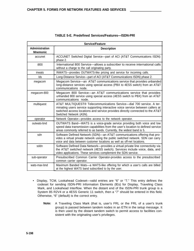
CHAPTER 5. FORMS FOR NETWORK FEATURES AND SERVICES
TABLE 5-E. Predefined Services/Features—lSDN-PRl
AdministrationMnemonic
accunet
i800
inwatsIds
megacom
megacom-800
multiquest
operatoroutwats-bnd
sdn
sddn
sub-operator
wats-max-bnd
Service/Feature
Description
ACCUNET Switched Digital Service—part of ACI (AT&T Communications ISDN)phase 2.International 800 Service—allows a subscriber to receive international callswithout a charge to the call originating party.lNWATS—provides OUTWATS-like pricing and service for incoming calls.Long-Distance Service—part of ACI (AT&T Communications ISDN) phase 2.Megacom Service—an AT&T communications service that provides unbandedlong-distance services using special access (PBX to 4ESS switch) from an AT&Tcommunications node.Megacom 800 Service—an AT&T communications service that providesunhanded 800 service using special access (4ESS switch to PBX) from an AT&Tcommunications node.AT&T MULTIQUEST® Telecommunications Service—dial 700 service. A ter-minating users service supporting interactive voice service between callers atswitched access locations and service provides directly connected to the AT&TSwitched Network (ASN).Network Operator—provides access to the network operator.OUTWATS Band—WATS is a voice-grade service providing both voice and lowspeed data transmission capabilities from the user’s location to defined serviceareas commonly referred to as bands. Currently, the widest band is 5.Software Defined Network (SDN)—an AT&T communications offering that pro-vides a virtual private network using the public switched network. SDN can carryvoice and data between customer locations as well as off-net locations.Software Defined Data Network—provides a virtual private line connectivity viathe AT&T switched network (4ESS switch). Services include voice, data, andvideo applications. These services complement the SDN service.Presubscribed Common Carrier Operator-provides access to the presubscribedcommon carrier operator.Maximum Banded Wats—a WATS-like offering for which a user’s calls are billedat the highest WATS band subscribed to by the user.
• Display, TCM, Lookahead Codeset—valid entries are “6” or “7.” This entry defines thecodeset for sending ISDN-PRI Information Elements (lEs) for Display, Traveling ClassMark, and Lookahead Interflow. When the distant end of the ISDN-PRI trunk group is aSystem 85 R2V4 or a 4ESS Generic 11 switch, then a “7” should be entered in this field.Otherwise, “6” (default) is the correct entry.
Note: A Traveling Class Mark (that is, user’s FRL or the FRL of a user's trunkgroup) is passed between tandem nodes in an ETN in the setup message. Itis then used by the distant tandem switch to permit access to facilities con-sistent with the originating user's privileges.
5-198

Integrated Services Digital Network—Primary Rate Interface Trunk Group
•
•
•
•
Max Message Size to Send— Valid entries are 128, 244, 256, 260. Defines the max-imum size of ISDN-PRI messages sent by the switch. Currently, System 85 R2V4 andNo. 4ESS version 4E11 switches can only receive messages of 128 bytes. The Systemcan receive 260 byte messages. Default is “260.”
Toll— Enter “y” if connected to a CO toll office; otherwise, enter “n.” Default is “n.”
STT Loss (Satellite PBX Tie Trunk Loss)— Only displayed when the Toll field is “n.”Specifies the loss plan to be used. Allowable entries are “normal” (default) or “low.” Thisoption affects the transmission performance of a private PBX network.
Although the use of this option has wider applications, only for the simplest networkarrangements should this field be administered without Network Engineering advise. The“low” option (described as the ISL digital low loss plan in DEFINITY® CommunicationsSystem Generic 1 and System 75 and System 85 DS1/DMI/ISDN-PRI Reference, 555-025-101) should only be used when:
1.
2.
3.
4.
Stations on the satellite PBX complain of too much loss on calls to the public net-work.
The PBX network consists of no more than three PBXs; one main and one ortwo satellite PBXs.
All PBXs have the “low” option available.
The total DS1 trunk connection length is less than 100 miles.
If the above conditions are not met, obtain Network Engineering assistance. The fieldentry is based on the following:
➤ normal— Applies to AIU-TT (Analog Interface Unit at Customer Switching Sys-tem for Tie Trunk—4-wire E&M interface), and DIU-TT (Digital Interface Unit atCustomer Switching System for Tie Trunk—voice or AVD DS1 interface) lossplans.
➤ Iow— Applies to AIU-TTS (same as AIU-TT, but suitable for private network con-nections that can be connected in tandem with public network connections) andDIU-TTS (same as DIU-TT, but suitable for private network connections that canbe connected in tandem with public network connections). These interfaceswere formerly referred to as DIU DTT ISL.
DTT to DCO Loss (Digital Tie to Digital CO Trunk Loss)— Specifies the loss plan to beused for the trunk group for interconnections from a DIU-CO (Digital Interface Unit at aCentral Office) to a DIU-DTT (Digital Interface Unit for a Digital Tie Trunk Interface). Thisfield is displayed when the Trunk Type field contains an entry of auto/..., delay/...,wink/..., or immed/... Valid entries are “normal” (default) or “low.”
This option affects the transmission performance of public network access via a privatePBX network. Choose the “low” option only if private network users complain about toomuch loss on calls to the public network; otherwise, the “normal” option should be used.Allowable entries are “normal” (default) and “low.” The entry is based on the following:
➤ normal— Comesponds to a (0, -6) dB gain pair and is used as the default option.(This corresponds to the DTT/EIA DCO port to port configuration as described inDEFINITY® Communications System Generic 1 and System 75 and System 85DS1/DMI/ISDN-PRl Reference, 555-025-101.)
5-199

CHAPTER 5. FORMS FOR NETWORK FEATURES AND SERVICES
➤ low— Corresponds to (+3, -3) dB gain pair. Low is used for internetwork applica-tions in which no significant configuration will encounter echo, stability, or over-load problems because of reduced loss. With the low gain pair, subscriber sta-tion DTMF signals transmitted through the digital class five office into the custo-mer network may experience non-recoverable digit mutilation in secondary sig-naling applications (that is, DTMF signaling after the connection has been esta-blished). (This corresponds to the DTT/lSL DCO port to port configuration asdescribed in DEFINITY® Communications System Generic 1 and System 75 andSystem 85 DS1/DMI/ISDN-PRl Reference, 555-025-101.)
• Bit Rate— Specifies the baud rate used for pooled modems. Allowable entries are “300,”“1200,” “2400,” “4800,” “9600,” and ”19200.” Default is “1200.”
• Synchronnization— Specifies if the trunk group will use synchronous or asynchronouscommunications. Allowable entries are “async” and “sync.” Default is “async.”
• Duplex— Specifies if the trunk will operate full or half duplex. Allowable entries are “full”and “half.” Default is “full.”
• Disconnect Supervision— Enter “y” (yes) to indicate that the CO has the ability torelease a trunk when the calling party releases from a call and the system is able torecognize the release signal; otherwise, enter “n” (no). Default is “y.” (InternationalG1.1SE and G1.2SE).
Page 2 of the Form
• ACA Assignment— Specifies whether or not Automatic Circuit Assurance (ACA) meas-urements will be taken for this trunk group. Allowable entries are “y” or “n.” Default is“n.” If “y” is entered, complete the next three fields.
• Long Holding Time (hours)— Is the length in hours that the System wiII consider asbeing a long holding time. If “0” is entered, the System will not consider long holdingcalls. Allowable entries are 0 through 10. Default is ”1.“ Field must be “0” for a ServiceType field entry of “sddn.”
• Short Holding Time (secs.)— Specifies the length in seconds that the System will con-sider as being a short holding time. If “0” is entered, the System will not consider shortholding calls. Allowable entries are 0 through 180. Default is “10.”
• Short Holding Threshold— Is the number of times that the System will record a shortholding call before an attendant or display-equipped voice terminal user is alerted to theposibility of a faulty trunk. Allowable entries are 0 through 30. Default is “15.”
• Measured— Indicates if the System will transmit data for this trunk group to the CMS.Allowable entries are “internal,””external,” “both,” “none.” Enter “internal” if the data isto be sent to the BCMS (that is, internal to the switch) for subsequent measurementreports and “external” to send the data to the 3B CMS. Enter “both” to send the data toboth systems for measurement reports. Enter “none” if trunk group measurements arenot required. System default is “none.”
• Internal Alert— Specifies if internal ringing and coverage will be used for incoming calls.Allowable entries are “y” or “n.” Default is “n.”
• Default NCA TSC Routing— Enter “y” (yes) if the Sig Grp fields on the Group MemberAssignments forms (Pages 5 through 11) will be used as signaling groups for sending out
5-200

Integrated Services Digital Network—Primary Rate Interface Trunk Group
the Non-Call Associated Temporary Signaling Connection (NCA TSC). Entering “n” (no)causes the Sig Grp field to be displayed on this page of the form.
Note that TSC is a virtual connection established within a D-channel in a ISDN-PRI facil-ity so that users can transport non-call control user to user information. With NCA TSC,there is no B-channel associated with the connection.
• Data Restriction— Is used to prevent System features from generating tones on a datacall that would cause erroneous data transmission. Allowable entries are “y” or “n.”Default is “n.”
• Sig Grp— Only displayed when “n” is entered in the Default NCA TSC Routing field. It isused to identify which signaling group an NCA TSC will be routed out on. Enter theappropriate signaling group numbers (1 through 8). The signaling groups entered will bechosen by “round-robin” method. To balance the load of sending TSCs on every signal-ing group, a signaling group number can be entered twice to increase its probability ofbeing used as an outgoing route for NCS TSCs.
A signaling group is a group of B-channels for which a given D-channel (or D-channelpair) will carry the signaling information.
• Send CPN— Specifies if the calling party’s number is sent to the network on incomingand/or outgoing ISDN calls. Allowable entries are “y” or “n.” If “y” is entered, the CPNPrefix Table is accessed to construct the actual number to be sent over the network.(Note that the CPN Prefix Table can override the Send CPN field entry for any administr-able block of extensions.) Default is “n.”
• Send Name— Specifies if the calling/connected party’s administered name is sent to thenetwork on incoming and/or outgoing calls. Allowable entries are “y” or “n.” Default is“n.”
• Used for DCS— Specifies whether the trunk group will send and receive messages on aDCS signaling link. Allowable entries are ‘y’ or “n.” If “y” is entered, complete the PBXID field entry. Default is “n.”
• PBX lD— Identifies the remote PBX within the network that the trunk wiII communicatewith on a DCS Signaling Link. Allowable entries are 1 through 63. Default is ”1.“
• DCS Signaling— Only delayed when the Used for DCS field is “y.” Enter either “bx.25”or “d-chan.” Enter “bx.25” for the standard DCS feature and enter “d-chan” for the DCSover ISDN-PRI D-channel feature.
• Maintenance Tests— lndicates whether or not hourly maintenance tests will be made onthis trunk group. Allowable entries are “y” or “n” Default is “y.”
The following fields on Page 2 of the form provide an incoming call handling table. The table can(optionally) be used to provide unique call treatment for different incoming calls on any ISDN-PRItrunk group. Twelve unique treatment specifications are possible, corresponding to the 12 rows(lines) on the table. Unique digit manipulation capabilities, CPN/BN requests, and night servicedestinations are possible for different types of incoming calls. The unique digit manipulationcapabilities can be particularly useful to accommodate different dial plans for different services ona ISDN-PRI trunk type with a Service Type (field entry) of “cbc” (Call-by-Call). The table canalso be used for ISDN-PRI trunk groups that are not Call-by-Call. For example, an ISDN-PRIgroup with service type “megacom-800” could use the Incoming Call Handling Table to distin-guish treatment of calls to different 800 numbers based on the Dialed Number Identification Ser-vice (DNIS) number that is incoming to the PBX.
5-201

CHAPTER 5. FORMS FOR NETWORK FEATURES AND SERVICES
Each row in the table consists of seven columns. The first three columns (that is,Service/Feature, Called Len, and Called Number) constitute a key that together select which rowor unique treatment should apply for an incoming call on the group. The remaining four columns(that is, Del, Insert, ...) specify the treatment to be provided for a call that matches the key.
If an incoming call is for a service listed in a row on the table, then that row may specify the treat-ment for the call, depending on the other two columns of the key. The Called Len field is used tocontinue the row determination. If the number of digits received with the incoming call matchesthe number of digits in the Called Len field for calls to the matched service, then this row mayapply. If no other row also contains a matching service and called length, then this row doesapply. If another row does exist with the same service and number length, then the CalledNumber field will be used to continue the row determination. If the leading digits received withthe incoming call match the digits specified in the Called Number field, then this row applies tothe call. Therefore, with this table, a unique treatment can be given to any incoming call, even ifthese calls are to the same service or have the same length of digits. The remaining four fieldsspecify the unique treatment for the call once the row has been determined. Together, the Deland Insert fields can be used to manipulate the incoming number that will be used to route thecall. The Per Call CPN/BN field can be used to request CPN/BN only for specific calls incomingon the group. The Night Serv field is used to have calls of different types routed to different nightdestinations when night service is in effect.
The following provides information for each field that can be administered:
• Service/Feature— Specifies the ISDN-PRI Services/Features for an incoming call type.See the Service Type field description for a list of predefine Services/Features that canbe received. The identifier “other” can be used for any Service/Features not explicitlyspecified.
• Called Len— Specifies the number of digits received for an incoming call. A blank entryis used as a “wild card” entry and, when used, means that any length of digits associatedwith the specified Service/Feature can match in this field. Allowable entries are 0 through21, or leave blank.
• Called Number— Specifies the leading digits received for an incoming call. A blank entryis used as a “wild card’ entry and, when used, means that any number associated withthe specified Service/Feature can match in this field. Allowable entries are 1 through 16digits, or leave blank.
• Del— Specifies the number of leading digits to be deleted from the incoming Called PartyNumber. Calls of a particular type may be administered to be routed to a single destina-tion by deleting all incoming digits and then administering the Insert field with the desiredextension. Allowable entries are 1 through 21, “all,” or leave blank.
• Insert— Specifies the digits to be prepended to the front of the remaining digits after any(optional) digit deletion has been performed. The resultant number formed from digitdeletion/insertion is used to route the call, provided night service is not in effect. Allow-able entries are up to 16 digits, or leave blank.
• Per Call CPN/BN— Specifies if and how to request Calling Party Number (CPN) or BillingNumber (BN) for calls of this type. An entry of “none” indicates that the switch will notrequest either CPN or BN for any incoming calls of this type. Allowable entries are “cpn-only,” “bn-only,“ “bn-pref” (prefer BN, but will accept CPN, “cpn-pref” (prefer CPN, but
5-202

Integrated Services Digital Network—Primary Rate Interface Trunk Group
will accept BN), “none,” or leave blank. Default is “blank. Leave blank when connectedto another PBX switch. Note that a 4-second delay will occur in terminating the call tothe far-end station if the connecting switch does not respond to the request.
• Night Serv— Specifies a night service extension (can be a VDN extension) perService/Feature. An entry other than blank overrides the Night Service field entry onPage 1 of the form. This entry can be overridden by the Trunk/Member Night Serviceentry when provided. Allowable entries are an assigned extension, 0 (attendant), orleave blank.
Page 3 of the Form
Page 3 is only displayed if the Service Type on Page 1 is “cbc” and Usage Allot is “y.” Page 3 isused to set a minimum and maximum number of members for up to 10 differentServices/Features for up to 3 different Usage Allocation Plans (1 through 3).
Note: Refer to the Call By Call Service Selection feature in DEFINITY® CommunicationsSystem and Generic 1 and Generic 3i—Feature Description, 555-230-201, for adetailed description of Usage Allocation Plans.
• Service/Feature— Specifies the ISDN-PRI Services/Features that can be requested atcall setup time when using this trunk group. See the Service Type field description for alist of predefined Services/Features that can be received on a call by call basis. Theidentifier “other” is used for all Services/Features not explicitly specified.
• Min# Chan— lndicates the minimum number of members of an ISDN-PRI trunk groupwith a Service Type of cbc that are reserved for a particular Service/Feature can use atany given time. The sum of the minimum number of members for all Service/Featuresmust not exceed the total number of members of the trunk group. Allowable entries are0 through 99, or leave blank.
• Max# Chan— Indicates the maximum number of members of a ISDN-PRI trunk groupwith a Service Type of cbc that a particular Service/Feature can use at any given time.This field must be completed if a Service/Feature has been entered on Page 2 of theform. Allowable entries are 1 through 99, or leave blank.
Page 4 of the Form
Page 4 is only displayed if the Service Type on Page 1 is “cbc” and Usage Allot is “y.” Page 4provides for administering a fixed schedule or administering a schedule that can change up to sixtimes a day for each day of the week.
• Fixed— Indicates whether the allocation plan will be fixed. If "y" is entered in this field, theplan number entered in the Allocation Plan Number field will be enabled. This field mustbe completed if a Service/Feature has been entered on Page 2 of the form. Allowableentries are “y” and “n.” Default is “y.”
• Allocation Plan Number— Specifies the CBC Trunk Allocation Plan (1 through 3) that isin effect if a fixed usage method has been selected. This field must be assigned if theFixed field is “y.” Valid entries are 1 through 3, or blank. Default is “blank.”
5-203

CHAPTER 5. FORMS FOR NETWORK FEATURES AND SERVICES
• Scheduled— lndicates whether the allocation plans will be in effect according to theschedule found on this page. If “y” is entered in this field then there must be at least oneentry in the schedule. Allowable entries are “y” and “n.” Default is “n.”
• Act Time— lndicates the time that the usage allocation plan administered in the next field(Plan #) will become effective. The time is entered in military time. There must beatleast one entry per day. Allowable entries are 00:00 through 23:59.
• Plan #— Specifies the number of the usage allocation plan which will be in effect from theactivation time until the activation time of the next scheduled plan change. Allowableentries are 1 through 3.
Pages 5 through 11 of the Form (GROUP MEMBER ASSIGNMENTS)
Note: When supporting DCS, Member Number Assignments must be the same betweennodes (that is, Member #1 must be Member #1 at the far-end trunk group).
• Port— Indicates the trunk port number in the form. Enter five to six characters. The firstcharacter identifies the network (1 through 3, default is ”1” if no entry); the second char-acter identifies the carrier (A through E); the third and fourth characters identify the slotnumber in the carrier (01 through 20 for multi-carrier cabinets depending on Carrier typeor 01 through 18 for single-earner cabinets depending on cabinet type); the last two char-acters identify the circuit number (01 through 08). Refer to the Port Assignment Record.
• Name— Enter up to 10 characters to identify the member of the trunk group. The namecan be a 7-digit telephone number or a 10-digit Trunk Circuit Identification number (pro-vided by trunk supplier).
• Night— Specifies a night destination for an individual trunk. This entry overrides thegroup Night Service entry on Page 1 of the form. Allowable entries are an extension (canbe a VDN extension), 0 (attendant), or leave blank.
• Sig Grp— Enter the appropriate signaling group number (1 through 8). See SignalingGroup Form for additional information. If a DS1 interface appears in one and only onesignaling group, then the number of that signaling group will appear as a default in theSig Grp column for any trunk on that interface. This value cannot be altered withoutadding a circuit pack TN code for DS1 interface to another signaling group. If a DS1 cir-cuit pack appears in more than one signaling group, then no default will appear in the SigGrp column.
5-204

Integrated Services Digital Network—Primary Rate Interface Trunk Group
TRUNK GROUP Page 1 of 11
Group Number: _ Group Type: isdn-pri SMDR Reports? y
Group Name: OUTSIDE CALL COR: 1 TAC: _
Direction: two-wav Outgoing Display? nDial Access: y Busy Threshold: 99 Night Service:Queue Length: 0Service Type: Auth Code? n Testcall ITC: rest
Usage Allot? n Far End Test No:
TestCall BCC: 4TRUNK PARAMETERS
Display, TCM, Lookahead Codeset: 6Max Message Size to Send: 260Toll? n STT Loss: normal DTT to DCO LOSS: normal
Bit Rate: 1200 Synchronization: async Duplex: full
SCREEN 5-111. lSDN-PRI Trunk Group Form (Page 1)—Example Only (Standard)
Implementation Note:
“Queue Length” is only displayed if the Direction field is ’’outgoing” or ’’two-way.”
“Usage Alloc’’ is only displayed if in the Service Type field is ’’cbc.”
5-205

CHAPTER 5. FORMS FOR NETWORK FEATURES AND SERVICES
Page 2 of 11TRUNK FEATURES
ACA Assignment? n Measured: none Internal Alert? nLong Holding Time(hours): 1 Default NCA TSC Routing? nShort Holding Time(secs.): 10 Data Restriction? n Sig GrP: _
Short Holding Threshold: 15 Send CPN? n Send Name? nUsed For DCS? y PBX ID: 1 DCS Signaling? bx.25
Maintenance Tests? yService/ Called Called Del Insert Per Call NightFeature Len Number CPN/BN Serv
SCREEN 5-112. lSDN-PRl Trunk Group Form (Page 2)—Example Only (Standard)
Implementation Note:
The following fields are only displayed if the ACA Assignment field is ’’y”:
• Long Holding Time (hours)
• Short Holding Time (secs.)
• Short Holding Threshold
The lnternal Alert field is not displayed if the Service Type field on page 1 is ’’cbc.”
Sig Grp field only displayed if “n” is entered in the “Default NCA TSC Routing” field.
DCS Signaling field only displayed when Used for DCS field is “y.”
The PBX-ID field is not displayed if the Used For DCS field is “n.”
5-206

Integrated Services Digital Network—Primary Rate Interface Trunk Group
Page 3 of 11
CBC Service Type Usage Allocation
Usage Allocation Plan 1 Usage Allocation Plan 2 Usage Allocation Plan 3
Service/Feature Min# Max# Service/Feature Min# Max# Service/Feature Min# Max#Chan Chan Chan Chan Chan Chan
— — — — — —— — — — — —— — — — — —— — — — — —— — — — — —— — — — — —— — — — — —— — — — — —— — — — — —— — — — — —
SCREEN 5-113. lSDN-PRI Trunk Group Form (Page 3)—Example Only (Standard)
Implementation Note:
This page is only displayed if the Service Type field on Page 1 is ’’cbc.”
5-207

CHAPTER 5. FORMS FOR NETWORK FEATURES AND SERVICES
Page 4 of 11
Service Type Usage Allocation Plan Assignment ScheduleCBC
Method:Usage
Allocation Plan Number: _Fixed?Scheduled?
Y
Usage Allocation Plan Activation Schedule:
Act Plan Plan#
Plan#
Plan#
Plan#
Plan#
ActTime
ActTime
ActTime
ActTime
ActTimeTime #
Sun
Mon
Tue
Wed
Thu
Fri
Sat
SCREEN 5-114. lSDN-PRl Trunk Group Form (Page 4)—Example Only (Standard)
Implementation Note:
This page is only displayed if the Service Type field on Page 1 is “cbc.”
5-208

Integrated Services Digital Network—Primary Rate Interface Trunk Group
GROUP MEMBER ASSIGNMENTS Page 5 of 11
Port Name Night Sig Grp
1:2:3:4:5:6:7:8:9:
10:11:12:13:14:15:
SCREEN 5-115. ISDN-PRI Trunk Group Form (Page 5)—
Note: To reduce repetition, pages 6 through 10 are not shown.
Example Only (Standard)
5-209

GROUP MEMBER ASSIGNMENTS Page 11 of 11
Port Name Sig GrpNight
91:92:93:94:95:96:97:98:99:
CHAPTER 5. FORMS FOR NETWORK FEATURES AND SERVICES
SCREEN 5-116. ISDN-PRI Trunk Group Form (Page 11)—Example Only (Standard)
Implementation Note:
Above Group Member Assignments pages are for an ISDN-PRI Trunk Group type “cbc”; oth-erwise, Page numbers will be 3 through 9.
5-210

Integrated Services Digital Network—Primary Rate Interface Trunk Group
TRUNK GROUP Page 1 of 9
Group Number: 71 Group Type: isdn-pri SMDR Reports? y
Group Name: OUTSIDE CALL COR: 1 TAC: 601Direction: two-wav Outgoing Display? n
Dial Access: y Busy Threshold: 99 Night Service:Queue Length: 0Service Type: cbc Auth Code? n
Far End Test No:
TestCall BCC: 4
TRUNK PARAMETERS
Display, TCM, Lookahead codeset: 6
Max Message Size to Send: 260
Connected To: Main
Connected to Toll? n STT Loss: normal DTT to DCO LOSS: normal
Bit Rate: 1200 Synchronization: async Duplex: fullDisconnect Supervision? y
SCREEN 5-117. lSDN-PRI Trunk Group Form (Page 1)—Example Only (International G1.1SE and G1.2SE)
Implementation Note:
“Queue Length” is only displayed if the Direction field is ’’outgoing” or ’’two-way.”
“Usage Alloc ’’is only displayed if in the Service Type field is ’’cbc.”
5-211

CHAPlER 5. FORMS FOR NETWORK FEATURES AND SERVICES
Del
Page 2 of 9TRUNK FEATURES
ACA Assignment? n Measured: noneData Restriction? n NCA-TSC Signaling Group:
Send CPN? n Send Name? nUsed For DCS? n Maintenance Tests? y
Service/ Called Called Insert Per Call NightFeature Len Number CPN/BN Serv
SCREEN 5-118. lSDN-PRl Trunk Group Form (Page 2)—Example Only (International G1.1SE and G1.2SE)
lmplementation Note:
The following fields are only displayed if the ACA Assignment field is ’’y”:
• Long Holding Time (hours)
• Short Holding Time (secs.)
• Short Holding Threshold
The Internal Alert field is not displayed if the Service Type field on Page 1 is “cbc.”
Sig Grp field only displayed if “n” is entered in the “Default NCA TSC Routing” field.
DCS Signaling field only displayed when Used for DCS field is “y.”
The PBX-ID field is not displayed if the Used For DCS field is “n.”
5-212

Integrated Services Digital Network—Primary Rate Interface Trunk Group
Page 3 of 11
CBC Service Type Usage Allocation
Usage Allocation Plan 1 Usage Allocation Plan 2 Usage Allocation Plan 3
Service/Feature Min# Max# Service/Feature Min# Max# Service/Feature Min# Max#Chan Chan Chan Chan Chan Chan
— — — — — —— — — — — -— — — — — —— — — — — —— — — — — —— — — — — —— — — — — —— — — — — —— — — — — —— — — — — —
SCREEN 5-119. lSDN-PRl Trunk Group Form (Page 3)—Example Only (International G1.1SE and G1.2SE)
Implementation Note:
This page is only displayed if the Service Type field on Page 1 is ’’cbc.”
5-213

CHAPTER 5. FORMS FOR NETWORK FEATURES AND SERVICES
Page 4 of 11
CBC Service Type Usage Allocation Plan Assignment Schedule
Usage Method:
Fixed? yScheduled? n
Usage Allocation Plan Activation Schedule:
Allocation Plan Number: _
Sun
Mon
Tue
Wed
Thu
Fri
Sat
Act Plan Act Plan Act PlanTime # Time # Time #
ActTime
Plan#
Act PlanTime #
ActTime
Plan#
SCREEN 5-120. lSDN-PRl Trunk Group Form (Page 4)—Example Only (International G1.1SE and G1.2SE)
lmplementation Note:
This page is only displayed if the Service Type field on Page 1 is ’’cbc.”
5-214

Integrated Services Digital Network—Primary Rate Interface Trunk Group
GROUP MEMBER ASSIGNMENTS Page 5 of 11
Port Name Night Sig Grp
1:2:3:4:5:6:7:8:9:
10:11:12:13:14:15:
SCREEN 5-121. ISDN-PRI Trunk Group Form (Page 5)—Example Only (International G1.1SE and G1.2SE)
Note: To reduce repetition, pages 6 through 10 are not shown.
5-215

CHAPTER 5. FORMS FOR NETWORK FEATURES AND SERVICES
GROUP MEMBER ASSIGNMENTS Page 11 of 11
Port Name Night Sig Grp
91:92:93:94:95:96:97:98:99:
SCREEN 5-122. ISDN-PRI Trunk Group Form (Page 11)—Example Only (International G1.1SE and G1.2SE)
Implementation Note:
Above Group Member Assignments pages are for an ISDN-PRI Trunk Group type “cbc”; oth-erwise, Page numbers will be 3 through 9.
5-216

Personal Central Office Line (PCOL) Group
PersonaI Central Office Line (PCOL) Group
Purpose
This section contains the form necessary to implement a Personal Central Office Line (PCOL)Group. The PCOL provides a dedicated trunk circuit between multi-appearance voice terminalsand a CO or other switch via the PBX network. Up to 40 PCOL Groups can be implemented.
Administration Commands
The following administration commands can be used to access the PCOL Group form. In somecases, just the most commonly used commands are shown. Refer to Administration Commandsand Error Messages (Chapter 3) for a complete listing of all administration commands, the com-mand structure, and the use of abbreviated command words when entering a command.
Action Object Qualifier*
add personal-co-line 140 (or ‘next’)change personal-co-line 140display personal-co-line 140 [‘print’ or ‘schedule’]list personal-co-line [‘print’ or ‘schedule’]remove personal-co-line 140
• Brackets [ ] indicate the qualifier is optional.Single quotes (‘’) indicate the text inside the quote must be entered exactly as shown oran abbreviated form of the word maybe entered.
Instructions
Make assignments as required for the following fields on the form:
•
•
•
•
•
•
Group Number— Enter a number from 1 through 40 when completing a paper form. Thisis a display-only field when the form is accessed using an administration command suchas add or change.
Group Type— Enter CO, FX or WATS to identify the type of PCOL Group as follows:
— Central Office (CO)
— Foreign Exchange (FX)
— Wide Area Telecommunications Service (WATS).
SMDR Reports— Enter “y” to provide a detailed SMDR record of incoming and outgoingcalls made on the PCOL; otherwise enter “n.” Default is “y.”
Group Name— Enter a unique name that identifies the PCOL Group. Up to 15 characterscan be used (all forms). Default is “OUTSIDE CALL.”
Coverage Path— Enter the number of the Call Coverage Path (1 through 600) used toredirect the incoming calls on this PCOL Group. This field maybe left blank.
TAC— Enter the trunk access code (TAC) that must be dialed to access the PCOLGroup. SMDR also uses the TAC to identify the trunk group on associated SMDRreports. A different TAC must be assigned to each trunk group. Allowable entries areTACs that are compatible with the System Dial Plan (1 to 3 digits).
5-217

CHAPTER 5. FORMS FOR NETWORK FEATURES AND SERVICES
5-218
•
•
•
•
•
•
•
•
•
•
•
Disconnect Supervision— Enter “y” (yes) to indicate that the CO has the ability torelease a trunk when the calling party releases from a call and the system is able torecognize the release signal; otherwise, enter “n” (no). Default is “y.” (InternationalG1.1SE and G1.2SE).
Administrable Timers Page— Only displayed for international applications. Entering a“y” causes an Administrable Timers page to be added to the trunk group form. TheAdministrable Timers Page then becomes Page 3 of x. Valid entries are “y” or “n.”Default is “n.” (International G1.1SE and G1.2SE).
Security Code— Is a 4-digit security code used for message retrieval, including voicemessage retrieval and the Demand Print Message feature. This field maybe left blank.
Outgoing Display— Allows the display of the PCOL Group name on outgoing calls madeby voice terminals that have a display. Allowable entries are “y” or “n.” Default is “n.”
Data Restriction— ls used to restrict System features from causing overriding tones on aPCOL. This provides permanent protection. Allowable entries are “y” or “n.” Default is“n.”
Trunk Type— ldentifies the type of PCOL as “ground-start” or “loop-start.”
Trunk Direction— ldentifies the direction of the trunks in the PCOL Group. Allowableentries are “incoming,“ “outgoing,” or “two-way” for Group Types of CO and FX, or“incoming” or “outgoing” only for Group Types of WATS. Default is “two-way.”
Trunk Port— Enter five to six characters. The first character identifies the network (1through 3, default is ”1” if no entry); the second character identifies the carrier (A throughE); the third and fourth characters identify the slot number in the carrier (01 through 20for multi-carrier cabinets depending on carrier type or 01 through 18 for single-carriercabinets depending on cabinet type); the last two characters identify the circuit number(01 through 08).
Disconnect Timing (msec)— Represents the time in milliseconds that is required forrecognition of the disconnect signal from the serving CO. The time interval must be inincrements of 10 (from 140 through 2550 milliseconds). Default is “500.”
Trunk Name— Is a 7-character name that identifies the PCOL Group.
Trunk Termination— Defines how the PCOL is terminated. The PCOL can terminate in aresistance of 600 ohms, or a resistor capacitor (rc) network. The network iS used tomatch long loops; 600 ohm is used to match short loops. Allowable entries are“600ohms” or “rc”; 600ohms is used when the PBX trunk port is connected to terminalequipment.
Page 3 of the Form (Administrable Timers) (International G1.2SE only)
Note: This page is only displayed if “y” is entered in the Administrable Timers Page fieldon Page 1 of the form.
• Incoming Disconnect (msec)— Enter the minimum time (in msec) required recogniza-tion of disconnect for an incoming call from the serving CO. Valid entries are 50 through12750 in increments of 50. The field cannot be blank. Default is “300.”

Personal Central Office Line (PCOL) Group
• Outgoing Disconnecting (msec)— Enter the minimum time (in msec) required forrecognization of disconnect for an outgoing call. valid entries are 50 through 12750 inincrements of 50. The field cannot be blank. Default is “300.”
• Outgoing Dial Guard (msec)— Enter the minimum time (in msec) between seizure ofthe trunk and outpulsing of digits. Valid entries are 200 through 25600 in increments of200. The field cannot be blank Default is ”1000.”
• Incoming Glare Guard (msec)— Enter the incoming guard time (in msec) between thetime the incoming trunk is released and the same trunk can be seized again. This guardtime will ensure the far-end has released all equipment after the incoming trunk isreleased. Valid entries are 2000 through 25600 in increments of 200. The field cannotbe blank. Default is “3000.”
• Outgoing Glare Guard (msec)— Enter the outgoing guard time (in msec) between thetime the outgoing trunk is released and the same trunk can be seized again. This guardtime will ensure that the far-end has released all equipment after the outgoing trunk isreleased. Valid entries are 200 through 25600 in increments of 200.’ The field cannot beblank. Default is “3000.”
• Outgoing Rotary Dial Interdigit (msec)— Enter the interval in (msec) between rotarydial digits being outpulsed by the system (that is, PBX). Valid entries are 150 through2550 in increments of 10. The field cannot be blank. Default is “600.”
• Ringing Monitor (msec)— Enter the minimum time (in msec) required to determine if thetrunk is disconnected. If the ringing signal disappears for a duration longer than the timespecified in this field, the call will be assumed to be disconnected. For CO, FX, WATS,PCOL, DID, and DIOD, valid entries are 200 through 5100 in increments of 200. For Tie,Tandem and Access, valid entries are 200 through 25500 in increments of 100. The fieldcannot be blank. Default is “5000.”
• Incoming Seizure (msec)— Enter the minimum time (in msec) required for recognition ofincoming ringing signal from the serving CO. Valid entries are 20 through 2550 in incre-ments of 10. The field cannot be blank Default is ”130.”
• PPS— Enter either ”10“ or “20” to specify the PPS (pulses per second) assigned to rotarydial pulse trunk groups. Valid entries are ”10“ or “20.” Default is ”10.”
• Make (msec)— Enter the duration of the make interval while the system is outpulsingdigits using dial pulse signaling.
If the PPS field is “10,” the sum of the Make and Break fields must equal 100. Validentries are 20 through 60 in increments of 5. The field cannot be blank. The default is“40.”
If the PPS field is “20,” the sum of the Make and Break fields must equal 50. Validentries are 10 through 40 in increments of 5. The field cannot be blank. The default is“20.”
• Break (msec)— Enter the duration of the break interval while the system is outpulsingdigits using dial pulse signaling.
If the PPS field is “10,” the sum of the Make and Break fields must equal 100. Validentries are 20 through 60 in increments of 5. The field cannot be blank. The default is“60.”
5-219

CHAPTER 5. FORMS FOR NETWORK FEATURES AND SERVICES
If the PPS field is “20,” the sum of the Make and Break fields must equal 50. Valid”entries are 10 through 40 in increments of 5. The field cannot be blank. The default is“30.”
• PPM— Enter “y” (yes) if PPM pulses are to be collected to determine outgoing call billing,otherwise enter “n” (non). Valid entries are “y” or “n.” Default is “n.” (This field does notappear for DID, Tie, Tandem, or Access trunks.)
5-220

Release Link Trunk Group
Release Link Trunk Group
Purpose
This form is used to assign a Release Link Trunk (RLT) Group and associated trunk ports. Thetrunk group is used to implement the CAS feature and is used to connect attendant-seeking callsfrom a branch location to a main location.
Administration Commands
The following administration commands can be used to access the Release Link Trunk Groupform. In some cases, just the most commonly used commands are shown. Refer to Administra-tion Commands and Error Messages (Chapter 3) for a complete listing of all administration com-mands, the command structure, and the use of abbreviated command words when entering acommand.
Action Object Qualifier
add trunk-group 1-99 (or ‘next’)change trunk-group 1-99 or TAC X...display trunk-group 1-99 or TAC X...[‘print’ or ‘schedule’]list trunk-group [‘print’ or ‘schedule’]remove trunk-group 1-99 or TAC X...
• Brackets [ ] indicate the qualifier is optional.Single quotes (‘ ’) indicate the text inside the quote must be entered exactly as shown oran abbreviated form of the word maybe entered.
Form Instructions
Make assignments as required for the following fields on each page of the form:
Page 1 of the Form
•
•
•
•
Group Number— Enter a number from 1 through 99 when completing a paper form. Thisis a display-only field when the form is accessed using an administration command suchas “add” or “change.”
Group Type— Enter “rlt” to identify the type of trunk group.
SMDR Reports— Enter “y” to provide a detailed SMDR record of both incoming and out-going calls made on all trunks in the trunk group; otherwise, enter “n.” Default is “y.”
Group Name— Enter a unique name that identifies the trunk group. Up to 15 characterscan be used. Default is “OUTSIDE CALL”
COR— Enter a class of restriction (COR) number from 0 through 63 that reflects thedesired restriction. Default is ”1.“
TAC— Enter the trunk access code (TAC) that must be dialed to access the trunk group.A different TAC must be assigned to each trunk group. SMDR also uses the TAC toidentify the trunk group on associated SMDR reports. Allowable entries are TACs thatare compatible with the System Dial Plan (1 to 3 digits).
•
•
5-221

CHAPTER 5. FORMS FOR NETWORK FEATURES AND SERVICES
• Direction— For CAS, enter “outgoing” if the switch is a CAS Branch location or enter“incoming” if the switch is a CAS Main location.
• Outgoing Display— Specifies whether or not the trunk group name is displayed on a ter-minal placing an outgoing call. Allowable entries are “y” or “n.” Default is “n.”
• Busy Threshold— Enter a number (0 through 99) of trunk group members that must bebusy before the attendant is alerted by the Warning lamp on the Attendant Console.Default is “99.”
• Night Service— Enter the extension number assigned to Night Service. The extensionnumber entered will receive all incoming calls when Night Service is activated and theindividual trunk member Night field is not administered to override this entry. Allowableentries are an extension number (can be a VDN extension), 0 (attendant), or leave blankif the Trunk Type is not “auto/....”
• Queue Length— Enter a number from 0 through 100 that indicates the number of outgo-ing calls that can be held waiting. A “0” indicates no calls will be held in queue. Enter“0” for DCS trunks. Default is “0.” This field is not displayed if the Direction field is“incoming.”
• Incoming Destination— Indicates where incoming calls will terminate. Allowable entriesare an extension number (can be a VDN extension), 0 (attendant), or leave blank if TrunkType is not “auto/....”
• Trunk Type (in/out)— Identifies the physical type of incoming and outgoing trunks.Allowable entries are listed below. The RLT trunk in a CAS Branch location should beassigned “immed/auto” if the main PBX is a System 85 or DIMENSION PBX equippedwith Feature Package 8. If the main PBX is not AT&T equipment, translations at theSystem Branch must be set to match what the main RLTs provide. If the far-end switchis a DEFINITY system or System 75, both switches should be translated as: Main =auto/wink or auto/immediate, Branch = wink/auto or immediate/auto. If a DEFINITY sys-tem is replacing another switch, the System’s translations should match the existingsetup.
auto/delay auto/immed auto/wink delay/winkdelay/auto delay/delay delay/immed immed/wink
immed/auto immed/delay immed/immed wink/winkwink/auto wink/delay wink/immed
• Incoming Rotary Timeout (see)— ls the timing interval required by the CO that the Sys-tem is connected to. If the System is connected to a step-by-step office, 18 or moreseconds must be used; if the System is not connected to a step-by-step office, five ormore seconds may be used. The maximum value is 99 seconds. Allowable entries are 5through 99. Default is “5.”
• Outgoing Dial Type— ldentifies the type of pulsing required on an outgoing call. Allow-able entries are “tone” or “rotary.” Default is “tone.”
5-222

Release Link Trunk Group
•
•
•
•
Incoming Dial Type— Indicates the type of pulses required on an incoming trunk group.Allowable entries are ‘tone” or ‘rotary.” Default is “tone.”
Connected to Toll— Enter “y” if connected to a CO toll office; otherwise, enter “n”(default). This field is displayed when the Trunk Type field contains an entry of “auto/...,”“delay/...,” “wink/...,” or “immed/....” Default is “n.”
STT Loss (Satellite PBX Tie Trunk Loss)— Only displayed when the Connected to Tollfield is “n.” Specifies the loss plan to be used for the trunk group. Allowable entries are“normal” (default) or “low.” This option affects the transmission performance of a privatePBX network.
Although the use of this option has wider applications, only for the simplest networkarrangements should this field be administered without Network Engineering advise. The“low” option (described as the ISL digital low loss plan in DEFINITY® CommunicationsSystem Generic 1 and System 75 and System 85 DS1/DMI/SDN-PRI Reference, 555-025-101) should only be used when:
1.
2.
3.
4.
Stations on the satellite PBX complain of too much loss on calls to the public net-work.
The PBX network consists of no more than three PBXs; one main and one ortwo satellite PBXs.
All PBXs have the “low” option available.
The total DS1 trunk connection length is less than 100 miles.
If the above conditions are not met, obtain Network Engineering assistance. The fieldentry is based on the following:
• normal— Applies to AIU-TT (Analog Interface Unit at Customer Switching Sys-tem for Tie Trunk—4-wire E&M interface), and DIU-TT (Digital Interface Unit atCustomer Switching System for Tie Trunk—voice or AVD DS1 interface) lossplans.
— low— Applies to AIU-TTS (same as AIU-TT, but suitable for private network con-nections that can be connected in tandem with public network connections) andDIU-TTS (same as DIU-TT, but suitable for private network connections that canbe connected in tandem with public network connections). These interfaceswere formerly referred to as DIU DTT ISL.
DTT to DCO Loss (Digital Tie to Digital CO Trunk Loss)—Specifies the loss plan to beused for the trunk group for interconnections from a DIU-CO (Digital Interface Unit at aCentral Office) to a DIU-DTT (Digital Interface Unit for a Digital Tie Trunk Interface). Thisfield is displayed when the Trunk Type field contains an entry of auto/..., delay/...,wink/..., or immed/....
This option affects the transmission performance of public network access via a privatePBX network. Choose the “low” option only if private network users complain about toomuch loss on calls to the public network otherwise, the “normal” option should be used.Allowable entries are “normal” (default) and “low.” The entry is based on the following:
5-223
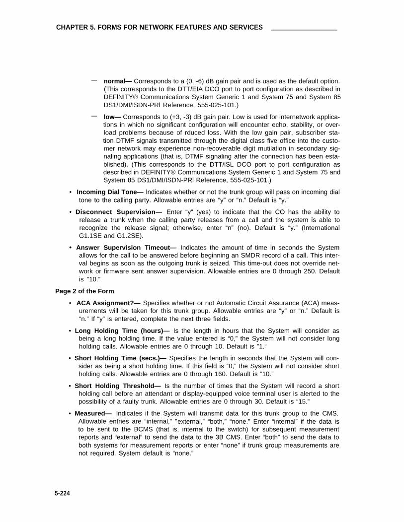
CHAPTER 5. FORMS FOR NETWORK FEATURES AND SERVICES
— normal— Corresponds to a (0, -6) dB gain pair and is used as the default option.(This corresponds to the DTT/EIA DCO port to port configuration as described inDEFlNITY® Communications System Generic 1 and System 75 and System 85DS1/DMI/ISDN-PRl Reference, 555-025-101.)
— low— Corresponds to (+3, -3) dB gain pair. Low is used for internetwork applica-tions in which no significant configuration will encounter echo, stability, or over-load problems because of rduced loss. With the low gain pair, subscriber sta-tion DTMF signals transmitted through the digital class five office into the custo-mer network may experience non-recoverable digit mutilation in secondary sig-naling applications (that is, DTMF signaling after the connection has been esta-blished). (This corresponds to the DTT/lSL DCO port to port configuration asdescribed in DEFINITY® Communications System Generic 1 and System 75 andSystem 85 DS1/DMI/ISDN-PRl Reference, 555-025-101.)
• Incoming Dial Tone— lndicates whether or not the trunk group will pass on incoming dialtone to the calling party. Allowable entries are “y” or “n.” Default is “y.”
• Disconnect Supervision— Enter “y” (yes) to indicate that the CO has the ability torelease a trunk when the calling party releases from a call and the system is able torecognize the release signal; otherwise, enter “n” (no). Default is “y.” (InternationalG1.1SE and G1.2SE).
• Answer Supervision Timeout— Indicates the amount of time in seconds the Systemallows for the call to be answered before beginning an SMDR record of a call. This inter-val begins as soon as the outgoing trunk is seized. This time-out does not override net-work or firmware sent answer supervision. Allowable entries are 0 through 250. Defaultis ”10.”
Page 2 of the Form
• ACA Assignment?— Specifies whether or not Automatic Circuit Assurance (ACA) meas-urements will be taken for this trunk group. Allowable entries are “y” or “n.” Default is“n.” If “y” is entered, complete the next three fields.
• Long Holding Time (hours)— Is the length in hours that the System will consider asbeing a long holding time. If the value entered is “0,” the System will not consider longholding calls. Allowable entries are 0 through 10. Default is ”1.“
• Short Holding Time (secs.)— Specifies the length in seconds that the System will con-sider as being a short holding time. If this field is “0,” the System will not consider shortholding calls. Allowable entries are 0 through 160. Default is ”10.”
• Short Holding Threshold— Is the number of times that the System will record a shortholding call before an attendant or display-equipped voice terminal user is alerted to thepossibility of a faulty trunk. Allowable entries are 0 through 30. Default is “15.”
• Measured— Indicates if the System will transmit data for this trunk group to the CMS.Allowable entries are “internal,” ”external,” “both,” “none.” Enter “internal” if the data isto be sent to the BCMS (that is, internal to the switch) for subsequent measurementreports and “external” to send the data to the 3B CMS. Enter “both” to send the data toboth systems for measurement reports or enter “none” if trunk group measurements arenot required. System default is “none.”
5-224
Release Link Trunk Group
•
•
•
•
•
Data Restriction— Is used to restrict System features from causing overriding tones on atrunk group. This provides permanent protection. Allowable entries are “y” or “n.”Default is “n.”
Used for DCS?— Indicates whether or not the trunk will send and receive messages on aDCS Signaling Link. Allowable entries are “y” or “n.” Default is “n.” If “y” is entered,complete the PBX ID field.
PBX lD— Identifies the remote PBX within the network that the trunk will communicatewith on a DCS Signaling Link. Allowable entries are 1 through 63. Default is ”1.“
Suppress # Outpulsing— Indicates end-to-end signaling. Begins with (and includes) the“#” when “y” is entered in this field. The final # is suppressed in cases where the Systemwould normally outpulse it. This field should be set to “y” when the CO (for example,rotary) or any other facility treats # as an error. Default is “n.”
Maintenance Tests— Indicates whether or not maintenance tests will be performed onan hourly basis for this trunk group. Default is “y.” Allowable entries are “y” or “n.”
Pages 3 through 9 of the Form (GROUP MEMBER ASSIGNMENTS)
• Port— Enter 5 to 6 characters. The first character identifies the network (1 through 3,default is “1” if no entry); the second character identifies the carrier (A through E); thethird and fourth characters identify the slot number in the carrier (01 through 20 for multi-carrier cabinets depending on carrier type or 01 through 18 for single-carrier cabinetsdepending on cabinet type); the last two characters identify the circuit number (01through 08).
• Name— Enter up to 10 characters to identify the member of the trunk group. The namecan be a 7-digit telephone number or a 10-digit Trunk Circuit Identification number (pro-vided by trunk supplier).
Note Previously, System 75 Night Service and Balance/Loss information wasentered in the Name field as “NT#...” and “TT#)....” This information mustnow be entered in the Night field (below) or the STT Loss field on Page 1 ofthe form, as applicable.
• Night— Specifies a night destination for an individual trunk. This entry overrides thegroup Night Service field entry on Page 1 of the form which is displayed when the Direc-tion field is “incoming.” Allowable entries are an extension, 0 (attendant) (can be a VDNextension), or leave blank if the Trunk Type field on Page 1 is not “auto/....”
• Mode— Specifies the signaling mode used on Tie Trunks when using TN760B circuitpacks. Allowable entries are “e&m” (interface), “simplex” (phantomed), or “protected.”This entry must correspond to associated dip switch settings on the circuit pack. Noentry should be made in this field when using TN722, TN722B, TN767, or TN464C (inter-national G1.2SE only) circuit packs.
• Type— When using TN760B circuit packs, this entry specifies the type of trunk used.Allowable entries are “t1 stan” (Type 1 Standard), “t1 comp” (Type 1 Compatible), or“type 5.” No entry should be made in this field when using TN722, TN722B, TN767, orTN464C (International G1.2SE only) circuit packs.
5-225

CHAPTER 5. FORMS FOR NETWORK FEATURES AND SERVICES
• Ans Delay— Specifies the length of the wait for answer supervision delay in millisecondsfor DS1 or Tie Trunks using the TN722A, TN722B, TN760 (B, C, or D), TN767, orTN464C (International G1.2SE only) circuit packs. Allowable entries are 20 through 5100in increments of 20. The default is no entry (blank) and internally treated as a zero. Thisdelay serves three purposes:
1. Used to assure that the answer supervision signal is valid and not a secondarydelay-dial or wink-start signal.
2. Used to bridge over momentary off-hook signals resulting from connectionsmade off-network through certain No. 5 Crossbar CCSA switches as the connec-tion is being established.
3. Used to delay cut-through in RLT applications so that the central attendant doesnot miss call progress tones. For RLT applications, set this field to 320 orgreater.
TRUNK GROUP Page 1 of 9
Group Number: _ Group Type: rlt SMDR Reports? y
Group Name: OUTSIDE CALL COR : 1 TAC : _
Direction: Outgoing Display? nBusy Threshold: 99 Night Service: _
Queue Length: 0 Incoming Destination: _
TRUNK PARAMETERSTrunk Type ( in/out) : Incoming Rotary Timeout ( sec ) : 5Outgoing Dial Type: tone Incoming Dial Type: tone
Connected to Toll? n STT Loss: normal DTT to DCO Loss: normalIncoming Dial Tone? y
Answer Supervision Timeout ? 10
SCREEN 5-123. Release Link Trunk Group Form (Page 1)—Example Only (Standard)
Implementation Note:
The Night Service and Incoming Destination fields are only displayed if the Direction field is“incoming.”
The Queue Length field is not displayed if the Direction field is “incoming.”
The Connected to Toll and DTT to DCO Loss fields are only displayed when the Trunk Typefield is “auto/...,” ”delay/..., “ “immed...,” “wink/....”
The STT Loss field is only displayed when the Connected to Toll field is “n.”
5-226

Release Link Trunk Group
TRUNK GROUP Page 2 of 9
TRUNK FEATURESACA Assignment? n Measured? none
Long Holding Time(hours): 1Short Holding Time(secs. ): 10 Data Restriction? n
Short Holding Threshold: 15Used for DCS? n PBX ID: 1
Suppress # Outpulsing? n Maintenance Tests? y
SCREEN 5-124. Release Link Trunk Group Form (Page 2)—Example Only (Standard)
Implementation Note:
The following fields are only displayed if the ACA Assignment field is “y”:
• Long Holding Time (hours)
• Short Holding Time (secs.)
• Short Holding Threshold
The PBX ID field is not displayed if the Used for DCS field is “n.”
5-227

CHAPTER 5. FORMS FOR NETWORK FEATURES AND SERVICES
GROUP MEMBER ASSIGNMENTS Page 3 of 9
Port Name Night Mode Type Ans Delay
1:2:3:4:5:6:7:8:9:
10:11:12:13:14:15:
SCREEN 5-125. Release Link Trunk Group Form (Page 3)—Example Only (Standard)
Note: To reduce repetition, pages 4 through 8 are not shown.
GROUP MEMBER ASSIGNMENTS Page 9 of 9
Port Name Night Mode Type Ans Delay
91:92:93:94:95:96:97:98:99:
SCREEN 5-126. Release Link Trunk Group Form (Page 9)—Example Only (Standard)
5-228

Release Link Trunk Group
TRUNK GROUP Page 1 of 9
Group Number: 71 Group Type: rlt SMDR Reports? yGroup Name: OUTSIDE CALL COR: 1 TAC: 601Direction: incominq Outgoing Display? n
Busy Threshold: 99 Night Service: _Incoming Destination: O
TRUNK PARAMETERSTrunk Type (in/out): auto/delay Incoming Rotary Timeout(sec): 5Outgoing Dial Type: tone Incoming Dial Type: tone
Connected to Toll? n STT Loss: normal DTT to DCO Loss: normalIncoming Dial Tone? y
Bit Rate: 1200 Synchronization: asyhc Duplex: fullDisconnect Supervision: y
Answer Supervision Timeout? 10
SCREEN 5-127. Release Link Trunk Group Form (Page 1)—Example Only (lntemational G1.1SE and G1.2SE)
Implementation Note:
The Night Service and lncoming Destination fields are only displayed if the Direction field is“incoming.”
The Queue Length field is not displayed if the Direction field is “incoming.”
The Connected to Toll and DTT to DCO Loss fields are only displayed when the Trunk Typefield is “auto/...” “delay/...,” “immed...,” “wink/....”
The STT Loss field is only displayed when the Connected to Toll field is “n.”
5-229

CHAPTER 5. FORMS FOR NETWORK FEATURES AND SERVICES
Page 2 of 9
TRUNK FEATURESACA Assignment? n Measured? none
Data Restriction? nUsed for DCS? n
Suppress # Outpulsing? n Maintenance Tests? y
SCREEN 5-128. Release Link Trunk Group Form (Page 2)—Example Only (International G1.1SE and G1.2SE)
Implementation Note:
The following fields are only displayed if the ACA Assignment field is ’’y”:
• Long Holding Time (hours)
• Short Holding Time (secs.)
• Short Holding Threshold
The PBX ID field is not displayed if the Used for DCS field is “n.”
5-230

Release Link Trunk Group
GROUP MEMBER ASSIGNMENTS Page 3 of 9
Port Name Night Mode Type Ans Delay
1:2:3:4:5:6:7:8:9:
10:11:12:13:14:15:
SCREEN 5-129. Release Link Trunk Group Form (Page 3)—Example Only (International G1.1SE and G1.2SE)
Note: To reduce repetition, pages 4 through 8 are not shown.
GROUP MEMBER ASSIGNMENTS Page 9 of 9
Port Name Night Mode Type Ans Delay
91:92:93:94:95:96:97:98:99:
SCREEN 5-130. Release Link Trunk Group Form (Page 9)—Example Only (International G1.1SE and G1.2SE)
5-231

CHAPTER 5. FORMS FOR NETWORK FEATURES AND SERVICES
Tandem Trunk Group
Purpose
This form is used to assign a Tandem Trunk Group in the System. Tandem trunks are used tointerconnect tandem nodes in an ETN network. The trunk group provides the System with theability to act as an intermediate switch (through switch) in a private network and is capable oftransmitting and receiving Traveling Class Marks as well as outpulsing 7-digit RNX-XXXX dialednumbers. A Traveling Class Mark represents a user’s Facility Restriction Level (FRL), or the FRLof the user’s trunk group.
Administration Commands
The following administration commands can be used to access the Tandem Trunk Group form.In some cases, just the most commonly used commands are shown. Refer to AdministrationCommands and Error Messages (Chapter 3) for a complete listing of all administration com-mands, the command structure, and the use of abbreviated command words when entering acommand.
Action Object Qualifier*
add trunk-group 1-99 (or ‘next’)change trunk-group 1-99 or TAC X...display trunk-group 1-99 or TAC X...[‘print’ or ‘schedule’]list trunk-group [‘print’ or ‘schedule’]remove trunk-group 1-99 or TAC X...
• Brackets [ ] indicate the qualifier is optional.Single quotes (‘ ’) indicate the text inside the quote must be entered exactly as shown oran abbreviated form of the word maybe entered.
Form Instructions
Make assignments as required for the following fields on each page of the form:
Page 1 of the Form
• Group Number— Enter a number from 1 through 99 when completing a paper form. Thisis a display-only field when the form is accessed using an administration command suchas “add” or “change.” Note that when supporting DCS, it is suggested that the far-endnode trunk group be assigned the same “Group Number.”
• Group Type— Enter “tandem” to identify the type of trunk group.
• SMDR Reports— Enter “y” to provide a detailed SMDR record of both incoming and out-going calls made on all trunks in the trunk group; otherwise, enter “n.” Default is “y.”
• Group Name— Enter a unique name that identifies the trunk group. Up to 15 characterscan be used. Default is “OUTSIDE CALL.”
• COR— Enter a class of restriction (COR) number from 0 through 63 that reflects thedesired restriction. Default is “1.”
5-232

Tandem Trunk Group
•
•
•
•
•
•
•
•
•
•
TAC— Enter the trunk access code (TAC) that must be dialed to access the trunk group.A different TAC must be assigned to each trunk group. SMDR also uses the TAC toidentify the trunk group on associated SMDR reports. Allowable entries are TACs thatare compatible with the System Dial Plan (1 to 3 digits).
Direction— Enter whether the trunk group is “incoming,” “outgoing,” or “two-way.”Default is “two-way.”
Outgoing DispIay— Specifies whether or not the trunk group name is displayed on a ter-minal placing an outgoing call. Allowable entries are “y” or “n.” Default is “n.”
Dial Access— Enter “y” to allow the trunk group to be accessed via a trunk access code;otherwise, enter “n.” Access via the ARS feature is allowed regardless of this entry.Default is “y.”
Busy Threshold— Enter a number (0 through 99) of trunk group members that must bebusy before the attendant is alerted by the Warning lamp on the Attendant Console.Default is “99.”
Night Service— Enter the extension number assigned to Night Service. The extensionnumber entered will receive all incoming calls when Night Service is activated and theindividual trunk member Night field is not administered to override this entry. Allowableentries are an extension number, 0 (attendant), or leave blank if the Trunk Type is not“auto/....”
Queue Length— Enter a number from 0 through 100 that indicates the number of outgo-ing calls that can be held waiting. A “0” indicates no calls will be held in queue. Enter “0”for DCS trunks. This field is turned off if the Direction field is “incoming.” Default is “0.”
Administrable Timers Page— Only displayed for international applications. Entering a“y” causes an Administrable Timers page to be added to the trunk group form. TheAdministrable Timers Page then becomes Page 3 of x. Valid entries are “y” or “n.”Default is “n.” (International G1.2SE only.)
Incoming Destination— Indicates where incoming calls will terminate. Allowable entriesare an extension number (can be a VDN extension), 0 (attendant), or leave blank if TrunkType is not “auto/....”
Comm Type— lndicates if the trunk is to be used for voice, data, alternate voice-data(that is, avd), or alternate voice/voice grade data and 56 kbps digital data (that is, rbavd)calls. Allowable entries are “avd,” “ rbavd,” “voice,” or “data.” Type “rbavd” supportsaccess to voice/data SDN service on robbed-bit T1 transmission facilities. Default is“voice.” Note that “avd” and “rbavd” types require trunk member ports on a DS1 circuitpack. An “rbavd” type requires that the DS1 circuit pack be administered for robbed-bitsignaling.
• ITC (Information Transfer Capability)— Used by the GRS feature and enables the systemto route calls to restricted or unrestricted facilities according to the endpoint’s informationtransfer capability. The ITC field is displayed on G3i systems for non-lSDN trunk groupsonly and is displayed and administrable only when the Comm Type field is administeredas “data,” “avd,” or ’’rbavd” and the BCC field is not set to “0.” This field is not displayedif the Comm Type field is administered as “voice,” nor is it displayed if the Comm Typefield is administered as “data,” “avd,” or “rbavd” and the BCC field is set to “0.” Defaultis “rest” (ricted).”
5-233

CHAPTER 5. FORMS FOR NETWORK FEATURES AND SERVICES
•
•
•
BCC (Bearer Capability Class)—Used by the Generalized Route Selection feature andidentifies the type of traffic on trunks in the group. The BCC entry is used by far-end tan-dem switches to select outgoing routing facilities with equivalent BCC classes. Allowableentries are 0, 1, 2, 3, and 4. Default is 0 for “avd,” “rbavd,” and 2 for “data.” The BCCfield is displayed when the Comm Type is “avd,” “rbavd,” or “data.”
Note: Refer to the GRS feature in DEFINITY® Communications System Generic 1and Generic 3i Feature Description, 555-230-201, for a detailed descriptionof BCCs and their use to provide specialized routing for various types ofvoice and data calls.
Trunk Type (in/out)— Identifies the physical type of incoming and outgoing trunks.Allowable entries are Iisted below.
auto/auto auto/delay auto/immed auto/winkdelay/auto delay/delay delay/immned delay/wink
immed/auto immed/delay immed/immed immed/winkwink/auto wink/delay wink/immed wink/wink
Incoming Rotary Timeout (sec)— ls the timing interval required by the central office thatthe System is connected to. If the System is connected to a step-by-step office, 18 ormore seconds must be used; if the System is not connected to a step-by-step office, fiveor more seconds may be used. The maximum value is 99 seconds. Allowable entriesare 5 through 99. Default is “5.”
Outgoing Dial Type— Identifies the type of pulsing required on an outgoing call. Allow-able entries are “tone” or “rotary.” Default is “tone.”
Incoming Dial Type— Indicates the type of pulses required on an incoming trunk group.Allowable entries are “tone” or “rotary.” Default is “tone.”
Disconnect Timing (msec)— Specifies the minimum time period in milliseconds that isrequired for recognition of disconnect by the serving CO or far-end PBX. The time inter-val must be in increments of 10 (from 140 to 2550 milliseconds). Default is “500.”
Digit Treatment— Indicates if the digits entered are to be absorbed or inserted. No entryindicates no digit absorption or insertion. Allowable entries are “absorption” or “inser-tion.”
Digits— Is the number of digits to be inserted or absorbed. This field is used with theDigit Treatment field. No entry indicates no digit absorption or insertion is done. Allow-able entries are the number of digits to be absorbed (1 through five) or the actual digits tobe inserted (up to five digits).
Connected to Toll— Enter “y” if connected to a CO toll office, otherwise, enter “n”(default). This field is displayed when the Trunk Type field contains an entry of “auto/...,”“delay/...,” “wink/...,” or “immed/....” Default is “n.”
STT Loss (Satellite PBX Tie Trunk Loss)— Only displayed when the Connected to Tollfield is “n.” Specifies the loss plan to be used for the trunk group. Allowable entries are“normal” (default) or “low.” This option affects the transmission performance of a privatePBX network.
•
•
•
•
•
•
•
5-234

Tandem Trunk Group
Although the use of this option has wider applications, only for the simplest networkarrangements should this field be administered without Network Engineering advise. The“low” option (described as the ISL digital low loss plan in DEFINITY® CommunicationsSystem Generic 1 and System 75 and System 85 DS1/DMI/ISDN-PRl Reference, 555-025-101) should only be used when:
1. Stations on the satellite PBX complain of too much loss on calls to the public net-work.
2. The PBX network consists of no more than three PBXs; one main and one ortwo satellite PBXs.
3. All PBXs have the “low” option available.
4. The total DS1 trunk connection length is less than 100 miles.
If the above conditions are not met, obtain Network Engineering assistance. The fieldentry is based on the following:
— normal— Applies to AIU-TT (Analog Interface Unit at Customer Switching Sys-tem for Tie Trunk—4-wire E&M interface), and DIU-TT (Digital Interface Unit atCustomer Switching System for Tie Trunk—voice or AVD DS1 interface) lossplans.
— low— Applies to AIU-TTS (same as AIU-TT, but suitable for private network con-nections that can be connected in tandem with public network connections) andDIU-TTS (same as DIU-TT, but suitable for private network connections that canbe connected in tandem with public network connections). These interfaceswere formerly referred to as DIU DTT ISL.
• DTT to DCO Loss (Digital Tie to Digital CO Trunk Loss)— Specifies the loss plan to beused for the trunk group for interconnections from a DIU-CO (Digital Interface Unit at aCentral Office) to a DIU-DTT (Digital Interface Unit for a Digital Tie Trunk Interface). Thisfield is displayed when the Trunk Type field contains an entry of auto/..., delay/...,wink/..., or immed/....
This option affects the transmission performance of public network access via a privatePBX network. “Low” is used when making a tandem connection from digital private net-work facilities to analog public network facilities. The “low” option does not apply to aMegacom facility or trunk group. Also, choose the “low” option if private network userscomplain about too much loss on calls to the public network otherwise, the “normal”option should be used. Normally, engineering support should be obtained in determiningif the “low” loss option is to be used. Allowable entries are “normal” (default) and “low.”The entry is based on the following:
— normal— Corresponds to a (0, -6) dB gain pair and is used as the default option.(This corresponds to the DTT/EIA DCO port to port configuration as described inDEFlNITY® Communications System Genetic 1 and System 75 and System 85DS1/DMI/ISDN-PRI Reference, 555-025-101.)
— low— Corresponds to (+3, -3) dB gain pair. Low is used for internetwork applica-tions in which no significant configuration will encounter echo, stability, or over-load problems because of reduced loss. With the low gain pair, subscriber sta-tion DTMF signals transmitted through the digital class five office into the custo-mer network may experience non-recoverable digit mutilation in secondary
5-235

CHAPTER 5. FORMS FOR NETWORK FEATURES AND SERVICES
signaling applications (that is, DTMF signaling after the connection has beenestablished). (This corresponds to the DTT/ISL DCO port to port configurationas described in DEFINITY® Communications System Generic 1 and System 75and System 85 DS1/DMI/ISDN-PRI Reference, 555-025-101.)
• Incoming Dial Tone— Indicates whether or not the trunk group will pass on incoming dialtone to the calling party. Allowable entries are “y” or “n.” Default is “y.”
• Bit Rate— Specifies the baud rate to be used by pooled modems. Allowable entries are“300,” “1200,” “2400,” “4800,” “9600,” and ”19200.” Default is “1200.” This field is onlydisplayed when the Comm Type field is “avd.”
• Synchronization— Enter whether the trunk group will use “sync” (synchronous) or“async” (asynchronous) communications. This field is only displayed when the CommType field is “avd.” Default is “async.”
• Duplex— Specifies either full or half duplex for the trunk group. Allowable entries are‘full’ or “half.” Default is “full.” This field is only displayed when the Comm Type field is“avd.”
• Disconnect Supervision— Enter “y” (yes) to indicate that the CO has the ability torelease a trunk when the calling party releases from a call and the system is able torecognize the release signal; otherwise, enter “n” (no). Default is “y.” (InternationalG1.1SE and G1.2SE).
• Answer Supervision Timeout— Indicates the amount of time in seconds the Systemallows for the call to be answered before beginning an SMDR record of a call. This inter-val begins as soon as the outgoing trunk is seized. This time-out does not override net-work or firmware sent answer supervision. Allowable entries are 0 through 250. Defaultis “10.”
Page 2 of the Form
• ACA Assignment?— Specifies whether or not Automatic Circuit Assurance (ACA) meas-urements will be taken for this trunk group. Allowable entries are “y” or “n.” Default is“n.” If “y” is entered, complete the next three fields.
• Long Holding Time (hours)— Is the length in hours that the System will consider asbeing a long holding time. If the value entered is “0,” the System will not consider longholding calls. Allowable entries are 0 through 10. Default is ”1.“
• Short Holding Time (secs.)— Specifies the length in seconds that the System will con-sider as being a short holding time. If this field is “0,” the System will not consider shortholding calls. Allowable entries are 0 through 160. Default is “10.”
• Short Holding Threshold— Is the number of times that the System will record a shortholding call before an attendant or display-equipped voice terminal user is alerted to thepossibility of a faulty trunk Allowable entries are 0 through 30. Default is “15.”
• Measured— lndicates if the System will transmit data for this trunk group to the CMS.Allowable entries are “internal,” “external,” “both,” ”none.” Enter “internal” if the data isto be sent to the BCMS (that is, internal to the switch) for subsequent measurementreports and “external” to send the data to the 3B CMS. Enter “both” to send the data toboth systems for measurement reports or enter “none” if trunk group measurements arenot required. System default is “none.”
5-236

Tandem Trunk Group
• Data Restriction— Used to restrict features from causing overriding tones on a trunkgroup. This provides permanent protection. Allowable entries are “y” or “n.” Default is“n.”
• Used for DCS?— Indicates whether or not the trunk will send and receive messages on aDCS Signaling Link. Allowable entries are “y” or “n.” If “y” is entered, complete the PBXID field. Default is “n.”
• PBX lD— Identifies the remote PBX within the network that the trunk will communicatewith on a DCS Signaling Link. Allowable entries are 1 through 63. Default is ”1.“
• Suppress # Outpulsing— Indicates end-to-end signaling. Begins with (and includes) the“#” when “y” is entered in this field. The final # is suppressed in cases where the Systemwould normally outpulse it. This field should be set to “y” when the central office (forexample, rotary) or any other facility treats #as an error. Default is “n.”
• Maintenance Test— Indicates whether or not maintenance tests will be performed onan hourly basis for this trunk group. Allowable entries are “y” or “n.” Default is “y.”
Page 3 of the Form (Administrable Timers) (International G1.2SE only)
Note: This page is only displayed if “y” is entered in the Administrable Timers Page field onPage 1 of the form.
• Incoming Disconnect (msec)— Enter the minimum time (in msec) required for recogni-tion of disconnect for an incoming call from the serving CO. Valid entries are 50 through12750 in increments of 50. The field cannot be blank. Default is “300.”
• Outgoing Disconnect (msec)— Enter the minimum time (in msec) required for recogni-tion of disconnect for an outgoing call. Valid entries are 50 through 12750 in incrementsof 50. The field cannot be blank. Default is “300.”
• Outgoing Dial Guard (msec)— Enter the minimum time (in msec) between seizure ofthe trunk and outpulsing of digits. Valid entries are 200 through 25600 in increments of200. The field cannot be blank. Default is ”1000.”
• Incoming Glare Guard (msec)— Enter the incoming guard time (in msec) between thetime the incoming trunk is released and the same trunk can be seized again. This guardtime will ensure the far-end has released all equipment after the incoming trunk isreleased. Valid entries are 200 through 25600 in increments of 200. The field cannot beblank. Default is “3000.”
• Outgoing Glare Guard (msec)— Enter the outgoing guard time (in msec) between thetime the outgoing trunk is released and the same trunk can be seized again. This guardtime will ensure that the far-end has released all equipment after the outgoing trunk isreleased. Valid entries are 200 through 25600 in increments of 200. The field cannot beblank. Default is “3000.”
• Outgoing Rotary Dial Interdigit (msec)— Enter the interval (in msec) between rotarydial digits being outpulsed by the system (that is, PBX). Valid entries are 150 through2550 in increments of 10. The field cannot be blank. Default is “600.”
• Ringing Monitor (msec)— Enter the minimum time (in msec) required to determine if thetrunk is disconnected. If the ringing signal disappears for a duration longer than the timespecified in this field, the call will be assumed to be disconnected. For CO, FX, WATS,
5-237

CHAPTER 5. FORMS FOR NETWORK FEATURES AND SERVICES
•
•
•
PCOL, DID, and DIOD, valid entries are 200 through 51000 in increments of 200. ForTie, Tandem and Access, valid entries are 200 through 25500 in increments of 100. Thefield cannot be blank. Default is “5000.”
Incoming Seizure (meet)— Enter the minimum time (in msec) required for recognition ofincoming ringing signal from the serving CO. Valid entries are 20 through 2550 in incre-ments of 10. The field cannot be blank. Default is ”130.”
PPS— Enter either ”10“ or “20” to specify the PPS (pulses per second) assigned to rotarydial pulse trunk groups. Valid entries are ”10“ or “20.” Default is “10.”
Make (msec)— Enter the duration of the make interval while the system is outpulsingdigits using dial pulse signaling.
If the PPS field is “10,” the sum of the Make and Break fields must equal 100. Validentries are 20 through 80 in increments of 5. The field cannot be blank. The default is“40.”
If the PPS field is “20,” the sum of the Make and Break fields must equal 50. Validentries are 10 through 40 in increments of 5. The field cannot be blank. The default is“20.”
Break (msec) —Enter the duration of the break interval while the system is outpulsingdigits using dial pulse signaling.
If the PPS field is “10,” the sum of the Make and Break fields must equal 100. Validentries are 20 through 80 in increments of 5. The field cannot be blank. The default is“60.”
If the PPS field is “20,” the sum of the Make and Break fields must equal 50. Valid .entries are 10 through 40 in increments of 5. The field cannot be blank. The default is“30.”
PPM— Enter “y” (yes) if PPM pulses are to be collected to determine outgoing call billing,
•
•otherwise enter “n” (no). Valid entries are “y” or “n.” Default is “n.” (This field does notappear for DID, Tie, Tandem, or Access trunks.)
Pages 3 through 9 of the Form (Group Member Assignments)
Note: For International Systems, if “y” has been entered in the Administrable Times Pagefield on Page 1 of the form, the Group Member Assignments will appear on Pages 4through 10 of the form.
Note: When supporting DCS, member number assignments must be the same betweennodes (that is, Member #1 must be Member #1 at the far-end node trunk group).
• Port— Enter 5 to 6 characters. The first character identifies the network (1 through 3,default is “1” if no entry); the second character identifies the carrier (A through E); thethird and fourth characters identify the slot number in the carrier (01 through 20 for multi-carrier cabinets depending on carrier type or 01 through 18 for single-carrier cabinetsdepending on cabinet type); the last two characters identify the circuit number (01through 8).
5-238

Tandem Trunk Group
• Name— Enter up to 10 characters to identify the member of the trunk (group. The namecan be a 7-digit telephone number or a 10-digit Trunk Circuit Identification number (pro-vided by trunk supplier).
•
•
Note: Previously, System 75 Night Service and Balance/Loss information wasentered in the Name field as “NT#...” and “TT#)....” This information mustnow be entered in the Night field (below) or the STT Loss field on Page 1 ofthe form, as applicable.
Night— Specifies a night destination for an individual trunk. This entry overrides thegroup Night Service entry on Page 1 of the form. Allowable entries are an extension (canbe a VDN extension), 0 (attendant), or leave blank if the Trunk Type is not “auto.”
Mode— Specifies the signaling mode used on Tie Trunks when using TN760B circuitpacks. Allowable entries are “e&m” (interface), “simplex” (phantomed), or “protected.”This entry must correspond to associated dip switch settings on the circuit pack. Noentry should be made in this field when using TN722, TN722B, TN767, or TN464C (Inter-national G1.2SE only) circuit packs.
Type— When using TN760B circuit packs, this entry specifies the type of trunk used.Allowable entries are “t1 Stan” (Type 1 Standard), “t1 comp” (Type 1 Compatible), or“type 5.” No entry should be made in this field when using TN722, TN722B, TN767, orTN464C (International G1.2SE only) circuit packs.
Ans Delay— Specifies the length of the wait for answer supervision delay in millisecondsfor DS1 or Tie Trunks using the TN722A, TN722B, TN760 (B, C, or D), TN767, orTN464C (International G1.2SE only) circuit packs. Allowable entries are 20 through 5100in increments of 20. The default is “no entry (treated as a 0). The delay serves two pur-
•
•
poses:
1.
2.
Used to assure that the answer supervision signal is valid and not a secondarydelay-dial or wink-start signal.
Used to bridge over momentary off-hook signals resulting from connectionsmade off-network through certain No. 5 Crossbar CCSA switches.
5-239

CHAPTER 5. FORMS FOR NETWORK FEATURES AND SERVICES
TRUNK GROUP Page 1 of 9
Group Number: _ Group Type: tandem SMDR Reports? y
Group Name: OUTSIDE CALL COR: 1 TAC: _Direction: two-way Outgoing Display? n
Dial Access? y Busy Threshold: 99 Night Service:Queue Length: 0 Incoming Destination: _
Comm Type: voice
TRUNK PARAMETERSTrunk Type (in/out): Incoming Rotary Timeout(sec): 5Outgoing Dial Type: tone Incoming Dial Type: tone
Disconnect Timing(msec): 500Digit Treatment: Digits:
Connected to Toll? n STT Loss: normal DTT to Dco LOSS: normalIncoming Dial Tone? y
Bit Rate: 1200 Synchronization: async Duplex: full
Answer Supervision Timeout? 10
SCREEN 5-131. Tandem Trunk Group Form (Page 1)—Example Only (Standard)
lmplementation Note:
The BCC field is displayed when the Comm Type field entry is ’’avd,” “rbavd,’ or ’’data.”
The Connected to Toll and DTT to DCO Loss fields are only displayed when the Trunk Typefield is “auto/...,” “delay/...,” “wink/...,” or “immed/...”
The STT Loss field is only displayed when the Connected to Toll field is “n.”
The Bit Rate, Synchronization, and Duplex fields are only displayed when the Comm Typefield is “avd.”
The ITC (Information Transfer Capability) field appears for non-lSDN trunk groups only andis displayed and administrable only when the Comm Type field is administered as “data,”“avd,” or “rbavd” and the BCC field is not set to “0.”
5-240

Tandem Trunk Group
TRUNK GROUP Page 2 of 9
TRUNK FEATURESACA Assignment? n Measured? none
Long Holding Time(hours) : 1Short Holding Time(secs. ): 10 Data Restriction? n
Short Holding Threshold: 15Used for DCS? n PBX ID: 1
Suppress # Outpulsing? n Maintenance Tests? y
SCREEN 5-132. Tandem Trunk Group Form (Page 2)—Example Only (Standard)
Implementation Note:
The following fields are only displayed if the ACA Assignment field is ’’y”:
• Long Holding Time (hours)
• Short Holding Time (secs.)
• Short Holding Threshold
The PBX ID field is not displayed if the Used for DCS field is ’’n.”
5-241

CHAPTER 5. FORMS FOR NETWORK FEATURES AND SERVICES
GROUP MEMBER ASSIGNMENTS Page 3 of 9
Ans DelayPort Name Night Mode Type
1:2:3:4:5:6:7:8:9:
10:11:12:13:14:15:
SCREEN 5-133. Tandem Trunk Group Form (Page 3)—Example Only (Standard)
Note: To reduce repetition, pages 4 through 9 are not shown.
Page 9 of 9GROUP MEMBER ASSIGNMENTS
Night Mode Type Ans DelayPort Name
91:92:93:94:95:96:97:98:99:
SCREEN 5-134. Tandem Trunk Group Form (Page 9)—Example Only (Standard)
5-242

Tandem Trunk Group
TRUNK GROUP Page 1 of X
Group Number: 71 Group Type: tandem SMDR Reports? yGroup Name: OUTSIDE CALL COR: 1 TAC: 601
Direction: two-waY Outgoing Display? nDial Access? y Busy Threshold: 99 Night Service:Queue Length: 0 Administrable Timer Page? y Incoming Destination: _
Comm Type: voice
TRUNK PARAMETERSTrunk Type (in/out): auto/auto Incoming Rotary Timeout(sec): 5Outgoing Dial Type: tone Incoming Dial Type: tone
Disconnect Timing(msec): 500Digit Treatment: D i g i t s :
Connected to Toll? n STT Loss: normal DTT to Dco LOSS: normalIncoming Dial Tone? y
Disconnect Supervision? yAnswer Supervision Timeout? 10
SCREEN 5-135. Tandem Ttunk Group Form (Page 1)—Example Only (International G12SE only)
Implementation Note:
The BCC field is displayed when the Comm Type is “avd,” “rbavd,” or “data.”
The Connected to Toll and DTT to DCO Loss fields are only displayed when the Trunk Typefield is “auto/...,” “delay/...,” “wink/...,” or “immed/....”
The STT Loss field is only displayed when the Connected to Toll field is “n.”
The Bit Rate, Synchronization, and Duplex fields are only displayed when the Comm Typefield is “avd.”
5-243

CHAPTER 5. FORMS FOR NETWORK FEATURES AND SERVICES
Page 2 of 10TRUNK FEATURES
ACA Assignment? n Measured? noneData Restriction? n
Used for DCS? nSuppress # Outpulsing? n Maintenance Tests? y
SCREEN 5-136. Tandem Trunk Group Form (Page 2)—Example Only (International G1.2SE only)
Implementation Note:
The following fields are only displayed if the ACA Assignment field is ’’y”:
• Long Holding Time (hours)
• Short Holding Time (secs.)
• Short Holding Threshold
The PBX ID field is not displayed if the Used for DCS field is “n.”
5-244

Tandem Trunk Group
Page 3 of 10
ADMINISTRABLE TIMERS
Incoming Disconnect
Incoming Glare Guard
Ringing Monitor
OUTPULSING TIMING
(msec): 300 Outgoing DisconnectOutgoing Dial Guard
(msec): 3000 Outgoing Glare GuardOutgoing Rotary Dial Interdigit
30010003000600130
(msec):(msec):(msec):(msec):
(msec): 5000 Incoming Seizure (msec):
40 Break (msec): 60 PPM? nPPS: 10 Make (msec):
SCREEN 5-137. Tandem Trunk Group Administrable Timers (Page 3)—Example Only (International G1.2SE only)
GROUP MEMBER ASSIGNMENTS Page 4 of 10Port Name Night Mode Type Ans Delay
1:2:3:4:5:6:7:8:9:
10:11:12:13:14:15:
SCREEN 5-138. Tandem Trunk Group Form (Page 4)—Example Only (lnternational G1.2SE only)
Note: To reduce repetition, pages 5 through 9 are not shown.
5-245

CHAPTER 5. FORMS FOR NETWORK FEATURES AND SERVICES
GROUP MEMBER ASSIGNMENTS
Port
91:92:93:94:95:96:97:98:99:
Name Night Mode Type
Page 10 of 10
Ans Delay
SCREEN 5-139. Tandem Trunk Group Form (Page 10)—Example Only (International G1.2SE only)
Implementation Note:
Above Group Member Assignments pages illustrate the resulting pagination when “y” isentered in the “Administrable Timers Page” field on Page 1 of the form; otherwise, Pagenumbers will be 3 through 9.
5-246

Tie Trunk Group
Tie Trunk Group
Purpose
This form is used to assign a Tie Trunk Group and associated trunk ports. The trunk group pro-vides private access between the System and another PBX or CENTREX. The trunks are usedto interconnect a satellite, tributary, and a main PBX in an Electronic Tandem Network. Thetrunk group can also be used to interface a 4ESS switch in support of Megacom service,Megacom 800 service, and Megacom 800 DNIS service.
Administration Commands
The following administration commands can be used to access the Tie Trunk Group form. Insome cases, just the most commonly used commands are shown. Refer to Administration Com-mands and Error Messages (Chapter 3) for a complete listing of all administration commands, thecommand structure, and the use of abbreviated command words when entering a command.
Action Object Qualifier*
add trunk-group 1-99 (or ‘next’)change trunk-group 1-99 or TAC X...display trunk-group 1-99 or TAC X...[‘print’ or ‘schedule’]list trunk-group [‘print’ or ‘schedule’]remove trunk-group 1-99 or TAC X...
* Brackets [ ] indicate the qualifier is optional.Single quotes (‘ ’) indicate the text inside the quote must be entered exactly as shown oran abbreviated form of the word maybe entered.
Form Instructions
Make assignments as required for the following fields on each page of the form:
Page 1 of the Form
•
•
Group Number— Enter a number from 1 through 99 when completing a paper form. Thisis a display-only field when the form is accessed using an administration command suchas add or change. Note that when supporting DCS, it is suggested that the far-end nodetrunk group be assigned the same “Group Number.” Also assign consecutive GroupNumbers to trunk groups when two or more trunk groups are to be used for ACD applica-tions.
Group Type— Enter “tie” to identify the type of trunk group.
SMDR Report— Enter “y” to provide a detailed SMDR record of both incoming and out-going calls made on all trunks in the trunk group; otherwise, enter “n.” Enter “y” if sup-porting Megacom services. Default is “y.”
Group Name— Enter a unique name that identifies the trunk group. Up to 15 characterscan be used. Default is “OUTSIDE CALL.”
COR— Enter a class of restriction (COR) number from 0 through 63 that reflects thedesired restriction. Default is ”1.“
•
•
•
5-247

CHAPTER 5. FORMS FOR NETWORK FEATURES AND SERVICES
•
•
•
•
•
•
•
•
•
•
•
•
TAC— Enter the trunk access code (TAC) that must be dialed to access the trunk group.A different TAC must be assigned to each trunk group. SMDR also uses the TAC toidentify the trunk group on associated SMDR reports. Allowable entries are TACs thatare compatible with the System Dial Plan (1 to 3 digits).
Direction— Enter whether the trunk group is incoming, outgoing, or two-way. Enter “out-going” if Megacom service is supported, “incoming” if Megacom 800 service or Megacom800 DNIS is supported. Default is “two-way.”
Outgoing Display— Specifies whether or not the display of the trunk group name issuppressed on a terminal placing an outgoing call. Allowable entries are “y” or “n.”Default is “n.” Normally, enter “y” when supporting Megacom services.
Dial Access— Enter “y” to allow the trunk group to be accessed via a trunk access code;otherwise, enter “n.” Access via the ARS feature is allowed regardless of this entry.Enter "y" when supporting Megacom services. Default is “y.”
Busy Threshold— Enter a number (0 through 99) of trunk group members that must bebusy before the attendant is alerted by the Warning lamp on the Attendant Console.Default is “99.”
Night Service— Enter the extension number assigned to Night Service. The number willreceive all incoming calls when Night Service is activated and the individual trunkmember Night field is not administered to override this entry. Allowable entries are anextension number, 0 (attendant), or leave blank if the Trunk Type field is “auto/....”Leave blank when supporting Megacom outbound service.
Queue Length— Enter a number from 0 through 100 that indicates the number of outgo-ing calls that can be held waiting. A “0” indicates no calls will be held in queue. Defaultis “0.” This field is not displayed if the Direction field is “incoming.”
Administrable Timers Page— Only displayed for international applications. Entering a“y” causes an Administrable Timers page to be added to the trunk group form. TheAdministrable Timers Page then becomes Page 3 of x. Valid entries are “y” or “n.”Default is “n.” (International G1.2SE only.)
Incoming Destination— Indicates where incoming calls will terminate. Allowable entriesare an extension number (can be a VDN extension), 0 (attendant), or leave blank if theTrunk Type is not auto/... or when supporting Megacom outbound service.
Comm Type— Indicates if the trunk is to be used for voice, data, alternate voice-data(that is, avd), or alternate voice/voice grade data and 56 kbps digital data (that is, rbavd)calls. Allowable entries are “avd,” “rbavd,” “voice,” or “data.” Type “rbavd” supportsaccess to voice/data SDN service on robbed-bit T1 transmission facilities. Enter “voice”when supporting Megacom 800 DNIS. Default is “voice.” Note that “avd” and “rbavdtypes require trunk member ports on a DS1 circuit pack. An “rbavd” type requires thatthe DS1 circuit pack be administered for robbed-bit signaling.
Auth Code— Enter “y” if an Authorization Code must be dialed to complete incomingcalls on the trunk group; otherwise, enter “n.” Default is “n.” This field can only be set to“y” if the Authorization Codes feature is enabled on the System-Parameters Customer-Options form.
ITC (Information Transfer Capability)— Used by the GRS feature and enables the systemto route calls to restricted or unrestricted facilities according to the endpoint’s informationtransfer capability. The ITC field is displayed on G3i systems for non-lSDN trunk groups
5-248

Tie Trunk Group
only and is displayed and administrable only when the Comm Type field is administeredas “data,” “avd,” or “rbavd” and the BCC field is not set to “0.” This field is not displayedif the Comm Type field is administered as “voice,” nor is it displayed if the Comm Typefield is administered as “data,” “avd,” or “rbavd’ and the BCC field is set to “0.” Defaultis “restricted.”
• BCC (Bearer Capability Class)— Used by the GRS feature and identifies the type oftraffic on trunks in the group. The BCC entry is used by far-end tandem switches toselect outgoing routing facilities with equivalent BCC classes. Allowable entries are 0, 1,2, 3, and 4. Default is 0 for “avd,” “rbavd,” and 2 for “data.” The BCC field is displayedwhen the Comm Type is “avd,” “rbavd,” or “data.”
Note: Refer to the GRS feature description in DEFINITY® Communications Sys-tem Generic 1 and Generic 3i Feature Description, 555-230-201, for adetailed description of BCCs and their use to provide specialized routing forvarious types of voice and data calls.
• Trunk Type (in/out)— Identifies the physical type of incoming and outgoing trunks.Allowable entries are Iisted below.
auto/auto auto/delay auto/immed auto/winkdelay/auto delay/delay delay/immed delay/wink
immed/auto immed/delay immed/immed immed/winkwink/auto wink/delay wink/immed wink/wink
When supporting Megacom services, enter “auto/wink” for Megacom service andwink/auto for Megacom 800 DNIS and for Megacom 800 service. Enter “wink/wink”when the trunk group is used for DCS DS1 signaling.
• Incoming Rotary Timeout (sec)— Timing interval required by the CO that the System isconnected to. If the System is connected to a step-by-step office, 18 or more secondsmust be used; if the System is not connected to a step-by-step office, five or moreseconds may be used. The maximum value is 99 seconds. Allowable entries are 5through 99. Enter “5” when supporting Megacom services. Default is “5.”
• Outgoing Dial Type— Identifies the type of pulsing required on an outgoing call. Allow-able entries are “automatic,” “tone,” or “rotary.” When supporting Megacom services,enter “tone” for Megacom service and leave blank for Megacom 800 service andMegacom 800 DNIS. If connected to a 4ESS switch equipped with 4e9 software, enter“rotary” instead of “tone,” where applicable. Default is “tone.”
• Incoming Dial Type— Indicates the type of pulses required on an incoming trunk group.Allowable entries are “tone” or “rotary.” Enter “tone” when supporting Megacom ser-vices. Default is “tone.”
• Disconnect Timing (msec)— Specifies the minimum time period in milliseconds that isrequired for recognition of disconnect by the serving central office or far-end PBX. Thetime interval must be in increments of 10 (from 140 to 2550 milliseconds). Enter “300”when connected to a step-by-step office, otherwise enter 200. Enter “500” when sup-porting Megacom services. Default is “500.”
5-249

CHAPTER 5. FORMS FOR NETWORK FEATURES AND SERVICES
• Digit Treatment— lndicates if the digits entered are to be absorbed or inserted. No entryindicates no digit absorption or insertion. Allowable entries are “absorption” or “inser-tion.” Normally, leave blank when supporting Megacom services.
• Digits— Enter the number of digits to be inserted or absorbed. This field is used with theDigit Treatment field. No entry indicates no digit absorption or insertion is done. Allow-able entries are the number of digits to be absorbed (1 through 5) or the actual digits tobe inserted (up to five digits). Normally, leave blank when supporting Megacom services.
• Connected to Toll— Enter “y” if connected to a CO toll office, otherwise, enter “n”(default). This field is displayed when the Trunk Type field contains an entry of “auto/...,”“delay/...,” “wink/...,” or “immed/....”
• STT Loss (Satellite PBX Tie Trunk Loss)— Only displayed when the Connected to Tollfield is “n.” Specifies the loss plan to be used for the trunk group. Allowable entries are“normal” (default) or “low.” This option affects the transmission performance of a privatePBX network.
Although the use of this option has wider applications, only for the simplest networkarrangements should this field be administered without Network Engineering advise. The“Iow” option (described as the ISL digital low loss plan in DEFINITY® CommunicationsSystem Generic 1 and System 75 and System 85 DS1/DMI/ISDN-PRI Reference, 555-025-107) should only be used when:
1. Stations on the satellite PBX complain of too much loss on calls to the public net-work.
2. The PBX network consists of no more than three PBXs; one main and one ortwo satellite PBXs.
3. All PBXs have the “Iow” option available.
4. The total DS1 trunk connection length is less than 100 miles.
If the above conditions are not met, obtain Network Engineering assistance. The fieldentry is based on the following:
— normal— Applies to AIU-TT (Analog Interface Unit at Customer Switching Sys-tem for Tie Trunk—4-wire E&M interface), and DIU-TT (Digital Interface Unit atCustomer Switching System for Tie Trunk—voice or AVD DS1 interface) lossplans.
— low— Applies to AIU-TTS (same as AIU-TT, but suitable for private network con-nections that can be connected in tandem with public network connections) andDIU-TTS (same as DIU-TT, but suitable for private network connections that canbe connected in tandem with public network connections). These interfaceswere formerly referred to as DIU DTT ISL.
• DTT to DCO Loss (Digital Tie to Digital CO Trunk Loss)— Specifies the loss plan to beused for the trunk group for interconnections from a DIU-CO (Digital Interface Unit at aCentral Office) to a DIU-DTT (Digital Interface Unit for a Digital Tie Trunk Interface). Thisfield is displayed when the Trunk Type field contains an entry of auto/..., delay/...,wink/... , or immed/....
5-250

Tie Trunk Group
This option affects the transmission performance of public network access via a privatePBX network. “Low” is used when making a tandem connection from digital private net-work facilities to analog public network facilities. The “low” option does not apply to aMegacom facility or trunk group. Also, choose the “low” option if private network userscomplain about too much loss on calls to the public network; otherwise, the “normal”option should be used. Normally, engineering support should be obtained in determiningif the “low” loss option is to be used. Allowable entries are “normal” (default) and “low.”The entry is based on the following:
— normal— Corresponds to a (0, -6) dB gain pair and is used as the default option.(This corresponds to the DTT/ElA DCO port to port configuration as described inDEFlNITY® Communications System Generic 1 and System 75 and System 85DS1/DMI/ISDN-PRI Reference, 555-025-101.)
— low— Corresponds to (+3, -3) dB gain pair. Low is used for internetwork applica-tions in which no significant configuration will encounter echo, stability, or over-load problems because of reduced loss. With the low gain pair, subscriber sta-tion DTMF signals transmitted through the digital class five office into the custo-mer network may experience non-recoverable digit mutilation in secondary sig-naling applications (that is, DTMF signaling after the connection has been esta-blished). (This corresponds to the DTT/lSL DCO port to port configuration asdescribed in DEFINITY® Communications System Generic 1 and System 75 andSystem 85 DS1/DMI/ISDN-PRI Reference, 555-025-101.)
• Incoming Dial Tone— lndicates whether or not the trunk group will pass on incoming dialtone to the calling party. Allowable entries are “y” or “n.” Enter “n” when supportingMEGCOM services. Default is “y.”
• Bit Rate— Specifies the baud rate to be used by pooled modems. Allowable entries are“300,” “1200,” “2400,” “4800,” “9600,” and “19200.” Default is “1200.” This field is onlydisplayed when the Comm Type field is “avd.”
• Synchronization— Enter whether the trunk group will use “sync” (synchronous) or“async” (asynchronous) communications. This field is only displayed when the, CommType field is “avd.” Default is “async.”
• Duplex— Specifies either full or half duplex for the trunk group. Allowable entries are“full” or “half.” This field is only displayed when the Comm Type field is “avd.” Default is“full.”
• Disconnect Supervision— Enter “y” (yes) to indicate that the CO has the ability torelease a trunk when the calling party releases from a call and the system is able torecognize the release signal; otherwise, enter “n” (no). Default is “y.” (InternationalG1.1SE and G1.2SE).
• Answer Supervision Timeout— Indicates the amount of time in seconds the Systemallows for the call to be answered before beginning an SMDR record of a call. This inter-val begins as soon as the outgoing trunk is seized. This time-out does not override net-work or firmware sent answer supervision. Allowable entries are 0 through 250. Defaultis ”10.”
5-251

CHAPTER 5. FORMS FOR NETWORK FEATURES AND SERVICES
Page 2 of the Form
• ACA Assignment?— Specifies whether or not Automatic Circuit Assurance (ACA) meas-urements will be taken for this trunk group. Allowable entries are “y” or “n.” Default is“n.” If “y” is entered, complete the next three fields.
• Long Holding Time (hours)— Is the length in hours that the System will consider asbeing a long holding time. If the value entered is “0,” the System will not consider longholding calls. Enter “1” for Megacom services. Allowable entries are 0 through 10.Default is “1.”
• Short Holding Time (secs.)— Specifies the length in seconds that the System will con-sider as being a short holding time. If this field is “0,” the System will not consider shortholding calls. Enter “10“ for Megacom services. Allowable entries are 0 through 160.Default is ”10.”
• Short Holding Threshold— ls the number of times that the System will record a shortholding call before an attendant or display-equipped voice terminal user is alerted to thepossibility of a faulty trunk. Enter “15“ for Megacom services. Allowable entries are 0through 30. Default is “15.”
• Measured— Indicates if the System will transmit data for this trunk group to the CMS.Allowable entries are “internal,” “external,” “both,” “none.” Enter “internal” if the data toto be sent to the BCMS (that is, internal to the switch) for subsequent measurementreports and “external” to send the data to the 3B CMS. Enter “both” to send the data toboth systems for measurement reports or enter “none” if trunk group measurements arenot required. System default is “n.”
• Internal Alert— Specifies if internal ringing and coverage will be used for incoming callson this trunk group. Allowable entries are “y” and “n.” Default is “n.” Enter “n” whensupporting Megacom services.
• Data Restriction— Is used to restrict System features from causing overriding tones on atrunk group. This provides permanent protection. Allowable entries are “y” or “n.” Enter“n” when supporting Megacom services. Default is “n.”
• Used for DCS— Indicates whether or not the trunk will send and receive messages on aDCS Signaling Link. Allowable entries are “y” or “n.” If “y” is entered, complete the PBXID field. Enter “n” if this trunk group is used for DCS signaling or for Megacom services.Enter “y” if used for DCS voice trunks. Default is “n.”
• PBX lD— Identifies the remote PBX within the network that the trunk will communicatewith on a DCS Signaling Link. Allowable entries are 1 through 63. Default is “1.”
• Suppress # Outpulsing— Indicates end-to-end signaling begins with (and includes) the“#” when “y” is entered in this field. The final # is suppressed in cases where the Systemwould normally outpulse it. This field should be set to “y” when the CO (for example,rotary) or any other facility treats #as an error. Enter “n” when supporting Megacom ser-vices. Default is “n.”
• Maintenance Tests— lndicates whether or not maintenance tests will be performed onan hourly basis for this trunk group. Allowable entries are “y” or “n.” Default is “y.”Enter “y” when supporting Megacom services.
5-252

Tie Trunk Group
Page 3 of the Form (Administrable Timers) (International G1.2SE only)
Note: This page is only displayed if “y” is entered in the Administrable Timers Page field on
•
•
•
•
•
Page 1 of the form.
Incoming Disconnect (msec)— Enter the minimum time (in msec) required for recogni-tion of disconnect for an incoming call from the serving CO. Valid entries are 50 through12750 in increments of 50. The field cannot be blank. Default is “300.”
Outgoing Disconnect (msec)— Enter the minimum time (in msec) required for recogni-tion of disconnect for an outgoing call. Valid entries are 50 through 12750 in incrementsof 50. The field cannot be blank. Default is “300.”
Outgoing Dial Guard (msec)— Enter the minimum time (in msec) between seizure ofthe trunk and outpulsing of digits. Valid entries are 200 through 25600 in increments of200. The field cannot be blank. Default is “1000.”
Incoming Glare Guard (msec)— Enter the incoming guard time (in msec) between thetime the incoming trunk is released and the same trunk can be seized again. This guardtime will ensure the far-end has released all equipment after the incoming trunk isreleased. Valid entries are 200 through 25600 in increments of 200. The field cannot beblank. Default is “3000.”
Outgoing Glare Guard (msec)— Enter the outgoing guard time (in msec) between thetime the outgoing trunk is released and the same trunk can be seized again. This guardtime will ensure that the far-end has released all equipment after the outgoing trunk isreleased. Valid entries are 200 through 25600 in increments of 200. The field cannot beblank. Default is “3000.”
Outgoing Rotary Dial Interdigit (msec)— Enter the interval (in msec) between rotarydial digits being outpulsed by the system (that is, PBX). Valid entries are 150 through2550 in increments of 10. The field cannot be blank. Default is “600.”
Ringing Monitor (msec)— Enter the minimum time (in msec) required to determine if thetrunk is disconnected. If the ringing signal disappears for a duration longer than the timespecified in this field, the call will be assumed to be disconnected. For CO, FX, WATS,PCOL, DID, and DIOD, valid entries are 200 through 51000 in increments of 200. ForTie, Tandem and Access, valid entries are 200 through 25500 in increments of 100. Thefield cannot be blank. Default is “5000.”
Incoming Seizure (msec)— Enter the minimum time (in msec) required for recognition ofincoming ringing signal from the serving CO. Valid entries are 20 through 2550 in incre-ments of 10. The field cannot be blank. Default is ”130.”
PPS— Enter either ”10“ or “20” to specify the PPS (pulses per second) assigned to rotarydial pulse trunk groups. Valid entries are ”10“ or “20.” Default is ”10.”
Make (msec)— Enter the duration of the make interval while the system is outpulsingdigits using dial pulse signaling.
If the PPS field is “10,” the sum of the Make and Break fields must equal 100. Validentries are 20 through 80 in increments of 5. The field cannot be blank. The default is“40.”
•
•
•
•
•
5-253

CHAPTER 5. FORMS FOR NETWORK FEATURES AND SERVICES
If the PPS field is “20,” the sum of the Make and Break fields must equal 50. Validentries are 10 through 40 in increments of 5. The field cannot be blank. The default is“20.”
• Break (msec)— Enter the duration of the break interval while the system is outpulsingdigits using dial pulse signaling.
If the PPS field is “10,” the sum of the Make and Break fields must equal 100. Validentries are 20 through 80 in increments of 5. The field cannot be blank. The default is“60.”
If the PPS field is “20,” the sum of the Make and Break fields must equal 50. Validentries are 10 through 40 in increments of 5. The field cannot be blank. The default is“30.”
• PPM— Enter “y” (yes) if PPM pulses are to be collected to determine outgoing call billing,otherwise enter “n” (no). Valid entries are “y” or “n.” Default is “n.” (This field does notappear for DID, Tie, Tandem, or Access trunks.)
Pages 3 through 9 of the Form (Group Member Assignments)
Note: For International Systems, if “y” has been entered in the Administrable Times Pagefield on Page 1 of the form, the Group Member Assignments will appear on Pages 4through 10 of the form.
Note: When supporting DCS, Member Number Assignments must be the same betweennodes (that is, Member #1 must be Member #1 at far-end node trunk group).
• Port— Enter 5 to 6 characters. The first character identifies the network (1 through 3,default is “1” if no entry); the second character identifies the Carrier (A through E); thethird and fourth characters identify the slot number in the earner (01 through 20 for multi-carrier cabinets depending on carrier type or 01 through 18 for single-carrier cabinetsdepending on cabinet type); the last two characters identify the circuit number (01through 08).
• Name— Enter up to ten characters to identify the member of the trunk group. The namecan be a 7-digti telephone number or a 10-digit Trunk Circuit Identification number (pro-vided by trunk supplier).
Note: Previously, System 75 Night Service and Balance/Loss information wasentered in the Name field as “NT#...” and “TT#)....” This information mustnow be entered in the Night field (below) or the STT Loss field on Page 1 ofthe form, as applicable.
• Night— Specifies a night destination for an individual trunk. This entry overrides thegroup Night Service entry on Page 1 of the form. Allowable entries are an extension (canbe a VDN extension), 0 (attendant), or leave blank if the Trunk Type is not “auto/....”
5-254

Tie Trunk Group
• Mode— Specifies the signaling mode used on Tie Trunks when using TN760B circuitpacks. Allowable entries are “e&m” (interface), “simplex” (phantomed), or “protected.”This entry must correspond to associated dip switch settings on the circuit pack. Noentry should be made in this field when using TN722, TN722B, TN767, or TN464C (Inter-national G1.2SE only) circuit packs.
• Type— When using TN760B circuit packs, this entry specifies the type of trunk used.Allowable entries are “t1 stan” (Type 1 Standard), “t1 comp” (Type 1 Compatible), or“type 5.” No entry should be made in this field when using TN722, TN722B, TN767, orTN464C (International G1.2SE only) circuit packs.
• Ans Delay— Specifies the length of the wait for answer supervision delay in millisecondsfor DS1 or Tie Trunks using the TN722A, TN722B, TN760 (B, C, or D), TN767, orTN464C (International G1.2SE only) circuit packs. Allowable entries are 20 through 5100in increments of 20. The default is “20.” This delay serves two purposes:
1. Used to assure that the answer supervision signal is valid and not a secondarydelay-dial or wink-start signal.
2. Used to bridge over momentary off-hook signals resulting from connectionsmade off-network through certain No. 5 Crossbar CCSA switches as the connec-tion is being established.
If the System misinterprets a second wink signal from the far-end as answersupervision followed by disconnect supervision and drops associated calls, setAns Delay to 300 to eliminate the problem.
5-255

TRUNK GROUP Page 1 of 9Group Number: _ Group Type: tie SMDR Reports? y
Group Name: OUTSIDE CALL COR: 1 TAC: _Direction: two-way Outgoing Display? n
Dial Access? y Busy Threshold: 99 Night Service:Queue Length: 0 Incoming Destination: _
Comm Type: voice Auth Code? n
TRUNK PARAMETERSTrunk Type (in/out): Incoming Rotary Timeout(sec): 5Outgoing Dial Type: tone Incoming Dial Type: tone
Disconnect Timing(msec): 500Digit Treatment: Digits:
Connected to Toll? n STT Loss: normal DTT to DCO Loss: normalIncoming Dial Tone? y
Bit Rate: 1200 Synchronization: async Duplex: fullAnswer Supervision Timeout? 10
CHAPTER 5. FORMS FOR NETWORK FEATURES AND SERVICES
SCREEN 5-140. Tie Trunk Group Form (Page 1)—Example Only (Standard)
The BCC field is displayed when the Comm Type is ’’avd,’’ “rbavd,” or “data.”
The Connected to Toll and DTT to DCO Loss fields are only displayed when the Trunk Typefield is “auto/...,” “delay/...,” “wink/...,” or “immed/....”
The STT Loss field is only displayed when the Connected to Toll field is ’’n.”
The Bit Rate, Synchronization, and Duplex fields are only displayed when the Comm Typefield is ’’avd.”
The lTC (lnformation Transfer Capability) field appears for non-lSDN trunk groups only andis displayed and administrable only when the Comm Type field is administered as “data,”“avd,” or “rbavd” and the BCC field is not set to “0.”
5-256

Tie Trunk Group
TRUNK GROUP
TRUNK FEATURESACA Assignment? n
Long Holding Time(hours): 1
Short Holding Time(secs. ): 10
Short Holding Threshold: 15
Used for DCS? n
Suppress # OutPulsing? n
Page 2 of 9
Measured? none
Internal Alert? n
Data Restriction? n
PBX ID: 1
Maintenance Tests? y
SCREEN 5-141. Tie Trunk Group Form (Page 2)—Example Only (Standard)
Implementation Note:
The following fields are only displayed if the ACA Assignment field is “y”:
• Long Holding Time (hours)
• Short Holding Time (secs.)
• Short Holding Threshold
The PBX ID field is not displayed if the Used for DCS field is “n.”
5-257

CHAPTER 5. FORMS FOR NETWORK FEATURES AND SERVICES
GROUP MEMBER ASSIGNMENTS Page 3 of 9Port Name Night Mode Type Ans Delay
1:2:3:4:5:6:7:8:9:
10:11:12:13:14:15:
SCREEN 5-142. Tie Trunk Group Form (Page 3)—Example Only (Standard)
Note: To reduce repetition, pages 4 through 8 are not shown.
GROUP MEMBER ASSIGNMENTS Page 9 of 9Port Name Night Mode Type Ans Delay
91:92:93:94:95:96:97:98:99:
SCREEN 5-143. Tie Trunk Group Form (Page 9)—Example Only (Standard)
5-258

Tie Trunk Group
TRUNK GROUP Page 1 of x
Group Number: 71 Group Type: tie SMDR Reports? y
Group Name: OUTSIDE CALL COR: 1 TAC: 601
Direction: two-way Outgoing Display? nDial Access? y Busy Threshold: 99 Night Service:
Queue Length: 0 Administerable Timer Page? y Incoming Destination: _
Comm Type: voice Auth Code? n
TRUNK PARAMETERSTrunk Type (in/out): auto/auto Incoming Rotary Timeout(sec): 5
Outgoing Dial Type: tone Incoming Dial Type: toneDisconnect Timing(msec): 500
Digit Treatment: Digits:
Connected to Toll? n STT Loss: normal DTT to DCO Loss: normal
Incoming Dial Tone? yDisconnect Supervision? yAnswer Supervision Timeout? 10
SCREEN 5-144. Tie Trunk Group Form (Page 1)—Example Only (lnternational G1.2SE only)
The BCC field is displayed when the Comm Type is “avd,’’ “rbavd,” or “data.”
The Connected to Toll and DTT to DCO Loss fields are only displayed when the Trunk Typefield is “auto/...,” “delay/...,” “wink/...,” or “immed/....”
The STT Loss field is only displayed when the Connected to Toll field is “n.”
The Bit Rate, Synchronization, and Duplex fields are only displayed when the Comm Typefield is “avd.”
5-259

CHAPTER 5. FORMS FOR NETWORK FEATURES AND SERVICES
TRUNK GROUP Page 2 of 9
TRUNK FEATURESMeasured? noneACA Assignment? n
Internal Alert? n
Data Restriction? n
Used for DCS? n
Suppress # Outpulsing? n Maintenance Tests? y
SCREEN 5-145. Tie Trunk Group Form (Page 2)—Example Only (lnternational G1.2SE only)
Implementation Note:
The following fields are only displayed if the ACA Assignment field is ’’y”:
• Long Holding Time (hours)
• Short Holding Time (secs.)
• Short Holding Threshold
The PBX ID field is not displayed if the Used for DCS field is “n.”
5-260

Tie Trunk Group
Page 3 of 10
ADMINISTRABLE TIMERS
Incoming Disconnect (msec) : 300
Incoming Glare Guard (msec): 3000
Ringing Monitor (msec): 5000
OUTPULSING TIMING
PPS: 10
Outgoing
Make (msec): 40
Outgoing Disconnect (msec): 300
Outgoing Dial Guard (msec): 1000
Outgoing Glare Guard (msec): 3000
Rotary Dial Interdigit (msec): 600
Incoming Seizure (msec): 130
Break (msec): 60 PPM? n
SCREEN 5-146. Tie Trunk Group Administrable Timers Page—Example Only (International G1.2SE only)
5-261

CHAPTER 5. FORMS FOR NETWORK FEATURES AND SERVICES
GROUP MEMBER ASSIGNMENTS Page 4 of 10
Port Name Night Mode Type Ans Delay
1:2:3:4:5:6:7:8:9:
10:11:12:13:14:15:
SCREEN 5-147. Tie Trunk Group Form (Page 4)—Example Only (International G1.2SE only)
Note: To reduce repetition, pages 5 through 9 are not shown.
5-262

Tie Trunk Group
GROUP MEMBER ASSIGNMENTS Page 10 of 10
Port Name Night Mode Type Ans Delay
91:92:93:94:95:96:97:98:99:
SCREEN 5-148. Tie Trunk Group Form (Page 10)—Example Only (lnternational G1.2SE only)
Implementation Note:
Above Group Member Assignments pages illustrate the resulting pagination when “y” isentered in the “Administrable Timers Page” field on Page 1 of the form; otherwise, Pagenumbers will be 3 through 9.
5-263

CHAPTER 5. FORMS FOR NETWORK FEATURES AND SERVICES
Wide Area Telecommunications Service Trunk Group
Purpose
This form is used to assign a Wide Area Telecommunications Service (WATS) Trunk Group andassociated trunk ports. The trunk group provides access to/from a portion of the DDD networkvia dedicated trunks to/from a WATS serving office.
Instructions
Make assignments as required for the following fields on each page of the form:
Page 1 of the Form
•
•
•
•
•
•
•
•
•
•
•
•
Group Number— Enter a number from 1 through 99 when completing a paper form.Also assign consecutive Group Numbers to trunk groups when two or more trunk groupsare to be used for ACD applications. This is a display only field when the form isaccessed using an administration command such as add or change.
Group Type— Enter “WATS” to identify the type of trunk group.
SMDR Reports— Enter “y” to provide a detailed SMDR record of both incoming and out-going calls made on all trunks in the trunk group; otherwise, enter “n.” Default is “y.”
Group Name— Enter a unique name that identifies the trunk group. Up to 15 characterscan be used. Default is “OUTSIDE CALL.”
COR— Enter a class of restriction (COR) number from 0 through 63 that reflects thedesired restriction. Default is ”1.“
TAC— Enter the trunk access code (TAC) that must be dialed to access the trunk group.A different TAC must be assigned to each trunk group. SMDR also uses the TAC toidentify the trunk group on associated SMDR reports. Allowable entries are TACs thatare compatible with the System Dial Plan (1 to 3 digits).
Direction— Enter whether the trunk group is “incoming” or “outgoing.”
Outgoing Display— Specifies whether or not the trunk group name is displayed on a ter-minal placing an outgoing call. Allowable entries are “y” or “n.” Default is “n.”
Dial Access— Enter “y” to allow the trunk group to be accessed via a trunk access code;otherwise, enter “n.” Access via the ARS feature is allowed regardless of this entry.Default is “y.”
Busy Threshold— Enter a number (0 through 99) of trunk group members that must bebusy before the attendant is alerted by the Warning lamp on the Attendant Console.Default is “99.”
Night Service— Enter the extension number assigned to Night Service. The extensionnumber entered will receive all incoming calls when Night Service is activated and theindividual trunk member Night field is not administered to override this entry. Allowableentries are an extension number, 0 (attendant), or leave blank.
Queue Length— Enter a number from 0 through 100 that indicates the number of outgo-ing calls that can be held waiting. A “0” indicates no calls will be held in queue. This fieldis turned off if the Direction field is “incoming.” Default is “0.”
5-264

Wide Area Telecommunications Service Trunk Group
• Administrable Timers Page— Only displayed for international applications. Entering a“y” causes an Administrable Timers page to be added to the trunk group form. TheAdministrable Timers Page then becomes Page 3 of x. Valid entries are “y” or “n.”Default is “n.” (International G1.1SE and G1.2SE).
• Incoming Destination— Indicates where incoming calls wiII terminate. Allowable entriesare an extension number, 0 (attendant), or leave blank if the Trunk Type field is not“auto/....”
• Comm Type— lndicates if the trunk is to be used for voice, data, alternate voice-data(that is, avd), or alternate voice/voice grade data and 56 Kbps digital data [(that is,robbed-bit alternate voice-data (rbavd)] calls. Allowable entries are “avd,” “rbavd,”“voice,” or “data.” Type “rbavd” supports access to voice/data SDN service on robbed-bit T1 transmission facilities. Default is “voice.” Note that “avd” and “rbavd” typesrequire trunk member ports on a DS1 circuit pack. An “rbavd” type requires that the DS1circuit pack be administered for robbed-bit signaling.
• Auth Code— Enter “y” if an Authorization Code must be dialed to complete incomingcalls on the trunk group; otherwise, enter “n.” This field must be administered as “y” ifthe Authorization Codes feature is enabled on the System-Parameters Customer-Optionsform. Default is “n.”
• Trunk Flash— Enter “y” or “n” to indicate if access to customized services provided by afar end (for example, CO) is permitted for this trunk group. The PBX must be directlyconnected to a far end that provides such services. Default is “n.”
• ITC (Information Transfer Capability— Used by the GRS feature and enables the systemto route calls to restricted or unrestricted facilities according to the endpoint’s informationtransfer capability. The ITC field is displayed on G3i systems for non-lSDN trunk groupsonly and is displayed and administrable only when the Comm Type field is administeredas “data,” “avd,” or ’’rbavd” and the BCC field is not set to “0.” This field is not displayedif the Comm Type field is administered as “voice,” nor is it displayed if the Comm Typefield is administered as “data,” “avd,” or “rbavd” and the BCC field is set to “0.” Defaultis “restricted.”
• BCC (Bearer Capability Class)— Used by the GRS feature and identifies the type oftraffic on trunks in the group. The BCC entry is used by far-end tandem switches toselect outgoing routing facilities with equivalent BCC classes. Allowable entries are 0, 1,2, 3, and 4. The BCC field is displayed when the Comm Type is “avd,” “rbavd,” or“data.”
Note: Refer to the GRS feature description in DEFINITY® Communications Sys-tem Generic 1 and Generic 3i Feature Description, 555-230-201, for adetailed description of BCCs and their use to provide specialized routing forvarious types of voice and data calls.
• Trunk Type— ldentifies the physical type of incoming and outgoing trunks. Allowableentries are “ground-start,” “loop-start,” “auto/auto,” “auto/delay,” “auto/immed,”“auto/wink.”
• Outgoing Dial Type— Identifies the type of pulsing required on an outgoing call. AIIowable entries are “automatic,” “tone” or “rotary.” Default is “tone.”
5-265

CHAPTER 5. FORMS FOR NETWORK FEATURES AND SERVICES
•
•
•
•
Incoming Dial Type— lndicates the type of pulses required on an incoming trunk group.Allowable entries are “tone” or “rotary.” Default is “tone.”
Trunk Termination— Specifies how the trunk group is terminated. The trunk group canterminate in a resistance of 600 ohms or a resistor capacitor (rc) network. Allowableentries are “600ohms” or “rc.” 600ohms is used for short loops and rc is used for longloops. Default is “rc.”
Disconnect Timing (msec)— Specifies the minimum time period in milliseconds that isrequired for recognition of disconnect by the serving CO or far-end PBX. The time inter-val must be in increments of 10 (from 140 to 2550 milliseconds). Default is “500.”
Connected to Toll— Enter “y” if connected to a CO toll office, otherwise, enter “n”(default). This field is displayed when the Trunk Type field contains an entry of “auto/....”Default is “n.”
STT Loss (Satellite PBX Tie Trunk Loss)— Only displayed when the Connected to Tollfield is “n.” Specifies the loss plan to be used for the trunk group. Allowable entries are“normal” (default) or “low.” This option affects the transmission performance of a privatePBX network.
Although the use of this option has wider applications, only for the simplest networkarrangements should this field be administered without Network Engineering advise. The“low” option (described as the ISL digital low loss plan in DEFINITY® 75/85 Communica-tions System and System 75 and System 85 DS1/DMI/ISDN-PRl interface, 555-025-101)should only be used when:
•
1.
2.
3.
4.
Stations on the satellite PBX complain of too much loss on calls to the public net-work.
The PBX network consists of no more than three PBXs; one main and one ortwo satellite PBXs (satellite PBX connected to maim PBX via DS1 tie trunks,main PBX connected to public network via CO trunks).
All PBXs have the “low” option available.
The total DS1 trunk connection length is less than 100 miles.
If the above conditions are not met, obtain Network Engineering assistance. The fieldentry is based on the following:
— normal— Applies to AIU-TT (Analog Interface Unit at Customer Switching Sys-tem for Tie Trunk—4-wire E&M interface), and DIU-TT (Digital Interface Unit atCustomer Switching System for Tie Trunk-voice or AVD DS1 interface) lossplans.
— low— Applies to AIU-TTS (same as AIU-TT, but suitable for private network con-nections that can be connected in tandem with public network connections) andDIU-TTS (same as DIU-TT, but suitable for private network connections that canbe connected in tandem with public network connections). These interfaceswere formerly referred to as DIU DTT ISL.
DTT to DCO Loss (Digital Tie to Digital CO Trunk Loss)— Specifies the loss plan to be •used for the trunk group for interconnections from a DIU-CO (Digital Interface Unit at aCentral Office) to a DIU-DTT (Digital Interface Unit for a Digital Tie Trunk Interface). Thisfield is displayed when the Trunk Type field contains an entry of auto/..., delay/...,wink/..., or immed/....
5-266

Wide Area Telecommunications Service Trunk Group
This option affects the transmission performance of public network access via a privatePBX network Choose the “low” option only if private network users complain about toomuch loss on calls to the public network, otherwise, the “normal” option should be used.Allowable entries are “normal” (default) and “low.” The entry is based on the following:
— normal— Corresponds to a (0, -6) dB gain pair and is used as the default option.(This corresponds to the DTT/EIA DCO port to port configuration as described inDEFINITY® 75/85 Communications System and System 75 and System 85DS1/DMI/ISDN-PRl Interface, 555-025-101.)
— low— Corresponds to (+3, -3) dB gain pair. Low is used for internetwork applica-tions in which no significant configuration will encounter echo, stability, or over-load problems because of reduced loss. With the low gain pair, subscriber sta-tion DTMF signals transmitted through the digital class five office into the custo-mer network may experience non-recoverable digit mutilation in secondary sig-naling applications (that is, DTMF signaling after the connection has been esta-blished). (This corresponds to the DTT/lSL DCO port to port configuration asdescribed in DEFINITY® 75/85 Communications System and System 75 andSystem 85 DS1/DMI/ISDN-PRI Interface, 555-025-101.)
• Terminal Balanced— Specifies whether the trunks in the trunk group are balanced. A“y” signifies that the trunks are terminally balanced and an “n” signifies that the trunksare not terminally balanced. Typically, a Trunk Termination field of “600ohm” signifies abalanced trunk group and a field of “rc” signifies a non-balanced trunk group. If thetrunks in this group pass the Low Frequency Return Loss test requirements, then theyare terminally balanced, and this field should be set to “y.” This field is only displayedwhen the Trunk Type field is “ground-start” or “loop-start.” Since most trunks are not bal-anced, the default is “n.”
• RA Trunk Loss— (Remote Access Trunk Loss)Specifies the type of dB loss to beapplied to non-terminally balanced trunks (Terminal Balanced field= “n”). The 0dB entryis used in both directions as the default option. If unsatisfactory echo performance (hol-lowness) is experienced, the field should be reset to 2dB. Allowable entries are “0db”and “2db.” This field is only displayed when the Terminal Balanced field entry is “n.”
• Bit Rate— Specifies the baud rate to be used by pooled modems. Allowable entries are“300,” “1200,” “2400,” “4800,” “9600,” and ”19200.” Default is “1200.” This field is onlydisplayed when the Comm Type field is “avd.”
• Synchronization— Enter whether the trunk group will use “sync” (synchronous) or“asynch” (asynchronous) communications. This field is only displayed when the CommType field is “avd.” Default is “async.”
• Duplex— Specifies either full or half duplex for the trunk group. Allowable entries are“full” or “half.” This field is only displayed when the Comm Type field is “avd.” Default is“full.”
• Answer Supervision Timeout— lndicates the amount of time in seconds the Systemallows for the call to be answered before beginning an SMDR record of a call. This inter-val begins as soon as the outgoing trunk is seized. The time-out does not override net-work or firmware sent answer supervision. When the Receive Answer Supervision fieldis “y,” this field should be set to a “0” to disable the firmware time-out. Allowable entriesare 0 through 250. Default is ”10.”
5-267

CHAPTER 5. FORMS FOR NETWORK FEATURES AND SERVICES
• Receive Answer Supervision— Specifies whether or not the trunks provide answersupervision from the network and is used by the OCM and SMDR features. Answersupervision refers to notification from the far-end that the called party has gone off-hookto answer the call. When answer supervision is not provided, the originating PBX canclassify a call as answered using the Answer Supervision Timeout field entry. For trunksover which answer supervision is provided by the network (for example, certain ground-start CO trunks), this field should be set to “y” and the Answer Supervision Timeout fieldset to “0” to disable the firmware time-out. Receive Answer Supervision must be “n”when the Direction field entry is “incoming.” Allowable entries are “y” and “n.” Default is“n.”
Page 2 of the Form
•
•
•
•
•
ACA Assignment?— Specifies whether or not Automatic Circuit Assurance (ACA) meas-urements wilI be taken for this trunk group. Allowable entries are “y” or “n.” Default is“n.” If “y” is entered, complete the next three fields.
Long Holding Time (hours)— Is the length in hours that the System will consider asbeing a long holding time. If the value entered is “0,” the System wiII not consider longholding calls. Allowable entries are 0 through 10. Default is ”1.“
Short Holding Time (secs.)— Specifies the length in seconds that the System wiII con-sider as being a short holding time. If this field is “0,” the System will not consider shortholding calls. Allowable entries are 0 through 160. Default is “10.”
Short Holding Threshold— Is the number of times that the System will record a shortholding call before an attendant or display-equipped voice terminal user is alerted to thepossibility of a faulty trunk. Allowable entries are 0 through 30. Default is “15.”
Measured— Indicates if the System will transmit data for this trunk group to the CMS.Allowable entries are “internal,” “external,” “both,” “none.” Enter “internal” if the data isto be sent to the BCMS (that is, internal to the switch) for subsequent measurementreports and “external” to send the data to the 3B CMS. Enter “both” to send the data toboth systems for measurement reports or enter “none” if trunk group measurements arenot required. System default is “none.”
Abandoned Call Search— Enter a “y” if this trunk group will conduct an Abandoned callSearch to identify a ghost call; otherwise, enter “n.” This field is only applicable if TrunkType is “ground-start.” Default is “n.”
Note: Abandoned Call Search is designed to work with CO trunks (ground start -analog) that do not provide disconnect supervision. CO that provide discon-nect supervision do not require use of the Abandoned Call Search feature.Note that the CO must support Abandoned Call Search for the feature towork properly.
Data Restriction— Is used to restrict System features from causing overriding tones on atrunk group. This provides permanent protection. Allowable entries are “y” or “n.”Default is “n.”
Maintenance Tests— lndicates whether or not maintenance tests will be performed onan hourly basis for this trunk group. Allowable entries are “y” or “n.” Default is “y.”
•
•
•
5-268

Wide Area Telecommunications Service Trunk Group
• Suppress # Outpulsing— lndicates end-to-end signaling begins with (and includes) the“#” when “y” is entered in this field. The final # is suppressed in cases where the Systemwould normally outpulse it. This field should be set to “y” when the central office (forexample, rotary) or any other facility treats # as an error. Default is “n.”
Page 3 of the Form (Administrable Timers) (International G1.1SE and G1.2SE)
Note: This page is only displayed if “y” is entered in the Administrable Timers Page field onPage 1 of the form.
• Incoming Disconnect (msec)— Enter the minimum time (in msec) required for recogni-tion of disconnect for an incoming call from the serving CO. Valid entries are 50 through12750 in increments of 50. The field cannot be blank. Default is “300.”
• Outgoing Disconnect (msec)— Enter the minimum time (in msec) required for recogni-tion of disconnect for an outgoing call. Valid entries are 50 through 12750 in incrementsof 50. The field cannot be blank. Default is “300.”
• Outgoing Dial Guard (msec)— Enter the minimum time (in msec) between seizure ofthe trunk and outpulsing of digits. Valid entries are 200 through 25600 in increments of200. The field cannot be blank Default is “1000.”
• Incoming Glare Guard (msec)— Enter the incoming guard time (in msec) between thetime the incoming trunk is released and the same trunk can be seized again. This guardtime will ensure the far-end has released all equipment after the incoming trunk isreleased. Valid entries are 200 through 25600 in increments of 200. The field cannot beblank. Default is “3000.”
• Outgoing Glare Guard (msec)— Enter the outgoing guard time (in msec) between thetime the outgoing trunk is released and the same trunk can be seized again. This guardtime will ensure that the far-end has released all equipment after the outgoing trunk isreleased. Valid entries are 200 through 25600 in increments of 200. The field cannot beblank. Default is “3000.”
• Outgoing Rotary Dial lnterdigit (msec)— Enter the interval (in msec) between rotarydial digits being outpulsed by the system (that is, PBX). Valid entries are 150 through2550 in increments of 10. The field cannot be blank. Default is “600.”
• Ringing Monitor (msec)— Enter the minimum time (in msec) required to determine if thetrunk is disconnected. if the ringing signal disappears for a duration longer than the timespecified in this field, the tail will be assumed to be disconnected. For CO, FX, WATS,PCOL, DID, and DIOD, valid entries are 200 through 51000 in increments of 200. ForTie, Tandem and Access, valid entries are 200 through 25500 in increments of 100. Thefield cannot be blank. Default is “5000.”
• Incoming Seizure (msec)— Enter the minimum time (in msec) required for recognition ofincoming ringing signal from the serving CO. Valid entries are 20 through 2550 in incre-ments of 10. The field cannot be blank. Default is “130.”
• PPS— Enter either ”10“ or “20” to specify the PPS (pulses per second) assigned to rotarydial pulse trunk groups. Valid entries are ”10“ or “20.” Default is “10.”
5-269

CHAPTER 5. FORMS FOR NETWORK FEATURES AND SERVICES
• Make (msec)— Enter the duration of the make interval while the system is outpulsingdigits using dial pulse signaling.
If the PPS field is “10,” the sum of the Make and Break fields must equal 100. Validentries are 20 through 80 in increments of 5. The field cannot be blank. The default is“40.”
If the PPS field is “20,” the sum of the Make and Break fields must equal 50. Validentries are 10 through 40 in increments of 5. The field cannot be blank. The default is“20.”
• Break (msec)— Enter the duration of the break interval while the system is outpulsingdigits using dial pulse signaling.
If the PPS field is “10,” the sum of the Make and Break fields must equal 100. Validentries are 20 through 80 in increments of 5. The field cannot be blank. The default is “60.”
If the PPS field is “20,” the sum of the Make and Break fields must equal 50. Validentries are 10 through 40 in increments of 5. The field cannot be blank. The default is “30.”
• PPM— Enter “y” (yes) if PPM pulses are to be collected to determine outgoing call billing,otherwise enter “n” (no). Valid entries are “y” or “n.” Default is “n.” This field does notappear for DID, Tie, Tandem, or Access trunks.)
Pages 3 through 9 of the Form (Group Member Assignments)
Note: For International Systems, if “y” has been entered in the Administrable Times Pagefield on Page 1 of the form, the Group Member Assignments will appear on Pages 4through 10 of the form.
• Port— Enter five to six characters. The first character identifies the network (1 through 2,default is “1” if no entry); the second character identifies the carrier (A through E); thethird and fourth characters identify the slot number in the carrier (01 through 20 for multi-carrier cabinets or 01 through 18 for single-carrier cabinets); the last two characters iden-tify the circuit number (01 through 08).
• Name— Enter up to 10 characters to identify the member of the trunk group. The namecan be a 7-digit telephone number or a 10-digit Trunk Circuit Identification number (pro-vided by trunk supplier).
Note: Previously, System 75 Night Service and Balance/Loss information wasentered in the Name field as “NT#...” and “TT#)....” This information mustnow be entered in the Night field (below) or the STT Loss field on Page 1 ofthe form, as applicable.
• Night— Specifies a night destination for an individual trunk. This entry overrides thegroup Night Service entry on Page 1 of the form. Allowable entries are an extension, 0(attendant), or leave blank if the Trunk Type entry on Page 1 is not “auto/....”
5-270

Wide Area Telecommunications Service Trunk Group
• Mode— Specifies the signaling mode used on Tie Trunks when using TN760B circuitpacks. Allowable entries are “e&m” (interface), “simplex” (phantomed), or “protected.”This entry must correspond to associated dip switch settings on the circuit pack. Noentry should be made in this field when using TN722, TN722B, TN767, or TN464C (Inter-national G1.2SE only) circuit packs.
• Type— When using TN760B circuit packs, this entry specifies the type of trunk used.Allowable entries are “t1 stan” (Type 1 Standard), “t1 comp” (Type 1 Compatible), or“type 5.” No entry should be made in this field when using TN722, TN722B, TN767, orTN464C (International G1.2SE only) circuit packs.
• Ans Delay— Specifies the length of the wait for answer supervision delay in millisecondsfor DS1 or Tie Trunks using the TN722A, TN722B, TN760 (B, C, or D), TN767, orTN464C (International G1.2SE only) circuit packs. Allowable entries are 20 through 5100in increments of 20. The default is no entry (blank) and internally treated as a 0. Thisdelay serves two purposes:
1. Used to assure that the answer supervision signal is valid and not a secondarydelay-dial or wink-start signal.
2. Used to bridge over momentary off-hook signals resulting from connectionsmade off-network through certain No. 5 Crossbar CCSA switches as the connec-tion is being established.
5-271

CHAPTER 5. FORMS FOR NETWORK FEATURES AND SERVICES
TRUNK GROUP Page 1 of 9Group Number: _ Group Type: wats SMDR Reports? y
Group Name: OUTSIDE CALL COR: 1 TAC: _Direction: Outgoing Display? n
Dial Access? yQueue Length: 0_
Comm Type: voice
TRUNK PARAMETERSTrunk Type:
Outgoing Dial Type:Trunk Termination:Connected to Toll?Terminal Balanced?
Bit Rate:
Busy Threshold: 99 Night Service:Incoming Destination: _
Auth Code? nTrunk Flash? n BCC: 0
tone Incoming Dial Type: tonerc Disconnect Timing(msec): 500
n STT Loss: normal DTT to DCO Loss: normal
n RA Trunk Loss: 0db1200 Synchronization: async Duplex: full
Answer Supervision Timeout? 10 Receive Answer Supervision? n
SCREEN 5-149. WATS Trunk Group Form (Page 1)—Example Only (Standard)
Implementation Notes:
The BCC field is displayed when the Comm Type is ’’avd,’’ “rbavd,” or “data”
The Connected to Toll and DTT to DCO Loss fields are only displayed when the Trunk Typefield is ’’auto/...”
The STT Loss field is only displayed when the Connected to Toll field is ’’n.”
The Terminal Balanced field is only displayed when the Trunk Type is “ground-start” or“loop-start.'' The RA Trunk Loss is only displayed when the Terminal Balanced field is ’’n.”
The Bit Rate, Synchronization, and Duplex fields are only displayed when the Comm Typefield is “avd.”
The Trunk Flash field is only displayed when the Group Type field is “co,” “fx,” or “wats.”
The ITC (Information Transfer Capability) field is displayed on G3i systems for non-lSDNtrunk groups only and is displayed and administrable only when the Comm Type field isadministered as “data,” “avd,” or “rbavd” and the BCC field is not set to “0.”
5-272

Wide Area Telecommunications Service Trunk Group
TRUNK GROUP Page 2 of 9
TRUNK FEATURESACA Assignment? n Long Holding Time(hours): 1
Short Holding Time(secs. ): 10 Short Holding Threshold: 15Measured? none Abandoned Call Search: n
Data Restriction? nMaintenance Tests? y
Suppress # Outpulsing? n
SCREEN 5-150. WATS Trunk Group Form (Page 2)— Example Only (Standard)
Implementation Note:
The following fields are only displayed if the ACA Assignment field is ’’y”:
• Long Holding Time (hours)
• Short Holding Time (secs.)
• Short Holding Threshold
5-273

CHAPTER 5. FORMS FOR NETWORK FEATURES AND SERVICES
GROUP MEMBER ASSIGNMENTS Page 3 of 9
Night Mode TypePort Name
1:2:3:4:5:6:7:8:9:
10:11:12:13:14:15:
SCREEN 5-151. WATS Trunk Group Form (Page 3)—Example Only (Standard)
Note: To reduce repetition, pages 4 through 8 are not shown.
GROUP MEMBER ASSIGNMENTS Page 9 of 9
Night Mode TypePort Name
91:92:93:94:95:96:97:98:99:
SCREEN 5-152. WATS Trunk Group Form (Page 9)—Example Only (Standard)
5-274

Wide Area Telecommunications Service Trunk Group
TRUNK GROUP Page 1 of x
Group Number: 71 Group Type: wats SMDR Reports? y
Group Name: OUTSIDE CALL COR: 1 TAC: 601Direction: two-way Outgoing Display? n
Dial Access? y Busy Threshold: 99 Night Service:Queue Length: 0 Administrable Timer Page? n Incoming Destination: _
Comm Type: voice Auth Code? n
TRUNK PARAMETERSTrunk Type: loop-start
Outgoing Dial Type: tone Incoming Dial Type: toneTrunk Termination: rc Disconnect Timing(msec): 500Terminal Balanced? n RA Trunk Loss: 0db
Disconnect Supervision? yAnswer Supervision Timeout? 10 Receive Answer Supervision? n
SCREEN 5-153. WATS Trunk Group Form (Page 1)—Example Only (lnternational G1.1SE and G12SE)
lmplementation Notes:
The BCC field is displayed when the Comm Type is “avd,” “rbavd” or “data.”
The Connected to Toll and DTT to DCO Loss fields are only displayed when the Trunk Typefield is ’’auto/ . ...”
The STT Loss field is only displayed when the Connected to Toll field is ’’n.”
The Terminal Balanced field is only displayed when the Trunk Type is “ground-start” or“loop-start.” The RA Trunk Loss is only displayed when the Terminal Balanced field is ”n”
The Bit Rate, Synchronization, and Duplex fields are only displayed when the Comm Typefield is ’’avd.”
The Trunk Flash field is only displayed when the Group Type field is “co,” “fx” or “wats.”
5-275

CHAPTER 5. FORMS FOR NETWORK FEATURES AND SERVICES
TRUNK FEATURESACA Assignment? n
TRUNK GROUP Page 2 of 10
Abandoned Call Search? n
Suppress # Outpulsing? n
Measured? none
Data Restriction? n
Maintenance Tests? y
SCREEN 5-154. WATS Trunk Group Form (Page 2)—Example Only (lnternational G1.1SE and G1.2SE)
Implementation Note:
The following fields are only displayed if the ACA Assignment field is “y”:
• Long Holding Time (hours)
• Short Holding Time (secs.)
• Short Holding Threshold
5-276

Wide Area Telecommunications Service Trunk Group
ADMINISTRABLE TIMERS
Incoming Disconnect (msec) : 300 Outgoing Disconnect (msec) : 300Outgoing Dial Guard (msec): 1000
Incoming Glare Guard (msec): 3000 Outgoing Glare Guard (msec): 3000Outgoing Rotary Dial Interdigit (msec): 600
Ringing Monitor (msec): 5000 Incoming Seizure (msec): 130
OUTPULSING TIMING
PPS: 10 Make (msec): 40 Break (msec): 60 PPM? n
Page x of 10
SCREEN 5-155. WATS Trunk Group Administrable Timers Page—Example Only (lnternational G1.1SE and G1.2SE)
5-277

CHAPTER 5. FORMS FOR NETWORK FEATURES AND SERVICES
GROUP MEMBER ASSIGNMENTS Page 4 of 10
Port Name Night Mode Type Ans Delay
1:2:3:4:5:6:7:8:9:
10:11:12:13:14:15:
SCREEN 5-156. WATS Trunk Group Form (Page 4)—Example Only (International G1.1SE and G1.2SE)
Note: To reduce repetition, pages 5 through 9 are not shown.
5-278

Wide Area Telecommunications Service Trunk Group
GROUP MEMBER ASSIGNMENTS
Port Name Night Mode Type
Page 10 of 10
Ans Delay
91:92:93:94:95:96:97:98:99:
SCREEN 5-157. WATS Trunk Group Form (Page 10)—Example Only (International G1.1SE and G1.2SE)
Implementation Note:
Above Group Member Assignments pages illustrate the resulting pagination when “y” isentered in the “Administrable Timers Page” field on Page 1 of the form; otherwise, Pagenumbers will be 3 through 9.
5-279

CHAPTER 6. FORMS FOR SYSTEM FEATURES AND SERVICES
CHAPTER 6. FORMS FOR SYSTEM FEATURES AND SERVICES
Overview
This chapter contains the forms and associated instructions required to implement the System’svoice management, data management, call management, and hospitality features, functions, andServices.
The forms included in this chapter are those forms dedicated primarily for non-network typefeatures such as voice management and data management. Chapter 5 contains the forms dedi-cated to networking such as AAR, ARS, CAS, DCS, DS1 Tie Trunk Service, ISDN, and trunkgroups. Multi-use forms such as the Dial Plan and Feature Access Codes that support both net-work, voice management, data management, etc., are covered in this chapter.
The forms are accurate representations of the screens that will be displayed on the System’sadministration terminal. Default data that is shown when the form is displayed is provided on theforms.
In addition, administration commands required to access the forms are provided along with eachform’s coverage. In some cases, just the most commonly used commands are given. Chapter 3provides a complete listing of the System’s administration commands and describes the “make-up” of the command line. Specifically, the “action, “ “object,” and “qualifier” command words aredescribed in detail.
Blank forms (without default data) are provided in the Blank Forms Package and may be repro-duced as required. The copies are to be used as worksheets when using this manual to assignfeatures and services. The completed forms are later used with administration commands con-tained in Chapter 3 and system management information contained in the DEFINITY® Communi-cations System Generic 1 and Generic 3—System Management, 555-230-500, to implement theSystem. The hard copy forms should then be retained as part of the System’s hard copyrecords.
6-1

CHAPTER 6. FORMS FOR SYSTEM FEATURES AND SERVICES
Abbreviated Dialing-Enhanced List
Purpose
The following forms are used to implement an Enhanced Abbreviated Dialing List. The EnhancedList consists of 10 separate forms numbered from 0 through 9, which allows up to 1000 numbersto be assigned that can be accessed by users to place local, long-distance, and internationalcalls; to activate/deactivate features or to access remote computer equipment.
Note: The Abbreviated Dialing Enhanced List option must be enabled on the System-Parameters Customer-Options form before an Enhanced List can be administered.
The forms used to enter the 1000 enhanced dial code list entries are divided as follows
• Form 0 is used to assign dial code Iist entries 000 through 099
• Form 1 is used to assign dial code list entries 100 through 199
• Form 2 is used to assign dial code list entries 200 through 299
• Form 3 is used to assign dial code list entries 300 through 399
• Form 4 is used to assign dial code list entries 400 through 499
• Form 5 is used to assign dial code list entries 500 through 599
• Form 6 is used to assign dial code list entries 600 through 699
• Form 7 is used to assign dial code list entries 700 through 799
• Form 8 is used to assign dial code list entries 800 through 899
• Form 9 is used to assign dial code list entries 900 through 999.
Only one Enhanced Abbreviated Dialing List can be assigned in the System. The list is controlledby the System Manager. Up to 8000 abbreviated dialing list entries (includes enhanced, system,group, and personal lists) may be administered in the System.
Administration Commands
The following administration commands can be used to access the Abbreviated Dialing EnhancedList form. In some cases, just the most commonly used commands are shown. Refer toAdministration Commands and Error Messages (Chapter 3) for a complete listing of all adminis-tration commands, the command structure, and the use of abbreviated command words whenentering a command.
Action Object Qualifier
add abbreviated-dialing enhanced Enter form number between 0 and 9change abbreviated-dialing enhanced Enter form number between 0 and 9display abbreviated-dialing enhanced Enter form number between 0 and 9remove abbreviated-dialing enhanced Enter form number between 0 and 9
6-2

Abbreviated Dialing-Enhanced List
Form Instructions
Make assignments as required for the following fields on each page of the form. Note that thescreen form example is only Form 0.
Page 1 of the Form
•
•
Pages
•
Size (multiple of five)— Enter the number of dial code list entries that will be entered onthe form. Up to 100 entries perform are allowed. The size must be entered in multiplesof five up to 100. Default is “5.”
Privileged— Enter “y” or “n.” If “y” is entered, the originating party’s class of restriction(COR) is never checked and any number in the list will be dialed. If “n” is entered, theCOR is checked to determine if the number can be dialed. Default is “n.”
1 through 4 of the Form
DIAL CODE— Enter the numbers you want to assign to each dial code. Up to 24 charac-ters can be used for each entry. Note that a VDN extension may also be assigned.
Allowable entries for each dial code are:
– digits 0 through 9
– [*] (star) used for a feature activation code
– [#] (pound) used for a feature deactivation code
– special characters (count as two characters each):
~p (pause)
~w (wait)
~m (mark)
~s (suppress)
See Abbreviated Dialing in DEFINITY® Communications System Generic 1 and Generic 3i—Feature Description, 555-230-201, for a detailed description of the special characters.
6-3

CHAPTER 6. FORMS FOR SYSTEM FEATURES AND SERVICES
Page 1 of 4
ABBREVIATED DIALING LIST
Enhanced List
Size (multiple of 5) : 5
DIAL CODE
000:001:002:003:004:005:006:007:008:009:010:011:012:013:014:
015:016:017:018:019:020:021:022:023:024:025:026:027:028:029:
Privileged? n
SCREEN 6-1. Abbreviated Dialing Enhanced List—Form 0 (Page 1)—Example Only
6-4

Abbreviated Dialing—Enhanced List
DIAL CODE
030:031:032:033:034:035:036:037:038:039:040:041:042:043:044:
Page 2 of 4
ABBREVIATED DIALING LIST
Enhanced List
045:046:047:048:049:050:051:052:053:054:055:056:057:058:059:
SCREEN 6-2. Abbreviated Dialing Enhanced List—Form 0 (Page 2)—Example Only
6 - 5

CHAPTER 6. FORMS FOR SYSTEM FEATURES AND SERVICES
Page 3 of 4
ABBREVIATED DIALING LIST
Enhanced List
DIAL CODE
060:061:062:063:064065066067068:069:070:071:072:073:074:
075:076:077:078:079:080:081:082:083:084:085:086:087:088:089:
SCREEN 6-3. Abbreviated Dialing Enhanced List—Form 0 (Page 3)—Example Only
6-6

Abbreviated Dialing—Enhanced List
Page 4 of 4
DIAL CODE
ABBREVIATED DIALING LIST
Enhanced List
090:091:092:093:094:095:096:097:098:099:
SCREEN 6-4. Abbreviated Dialing Enhanced List—Form 0 (Page 4)—Example Only
Implementation Note
To reduce repetition, Forms 1 through 9 are not shown. For a complete set of blank forms, referto the Blank Forms Package.
6-7

CHAPTER 6. FORMS FOR SYSTEM FEATURES AND SERVICES
Abbreviated Dialing—Group List
Purpose
This form is used to implement the Abbreviated Dialing Group List. Up to 100 lists can beassigned. The Group Lists are controlled by the System Manager. Up to 8000 Abbreviated Dial-ing list entries (includes enhanced, group, system, and personal lists) may be administered in theSystem. Up to 90 numbers can be entered per group list which can be accessed by users toplace local, long-distance, and international calls; to activate/deactivate features; or to accessremote computer equipment.
Administration Commands
The following administration commands can be used to access the Abbreviated Dialing GroupList form. In some cases, just the most commonly used commands are shown. Refer toAdministration Commands and Error Messages (Chapter 3) for a complete listing of all adminis-tration commands, the command structure, and the use of abbreviated command words whenentering a command.
Action
addchangedisplaylistremove
Object Qualifier*
abbreviated-dialing group 1-100 (or ‘next’)abbreviated-dialing group 1-100abbreviated-dialing group 1-100 [‘print’ or ‘schedule’]abbreviated-dialing group [xx] (‘count’ 1-100) [‘print’ or ‘schedule’]abbreviated-dialing group 1-100
* Brackets [ ] indicate the qualifier is optional.Single quotes (‘ ’) indicate the text inside the quote must be entered exactly as shown oran abbreviated form of the word may be entered.
Form Instructions
Make assignments, as required, for the following fields on each page of the form:
Page 1
•
•
•
of the Form
Group List— Enter a group number from 1 through 100 when completing a paper form.This is a display-only field when the form is accessed using an administration commandsuch as “add” or “change.”
Size (multiple of five)— Enter the number of abbreviated dialing codes you want toassign. The number must be entered in multiples of five, for example, 5, 10, 15, up to90. Default is “5.”
Privileged— Enter “y” or “n.” If “y” is entered, the calling voice terminal’s COR is neverchecked and any number in the group list will be dialed. If “n” is entered, the callingvoice terminal’s COR is checked to determine if the number can be dialed. Default is “n.”
6-8

Abbreviated Dialing—Group List
Pages 1 through 3 of this Form
• DIAL CODE— Enter the numbers you want to assign to each dial code. Up to 24 charac-ters can be used for each entry. Note that a VDN extension may also be assigned.
Allowable entries for each dial code are:
– digits 0 through 9
– [*] (star) used for a feature activation code
– [#] (pound) used for a feature deactivation code
– special characters (count as two characters each):
~p (pause)
~w (wait)
~m (mark)
~s (suppress)
See Abbreviated Dialing in DEFINITY® Communications System Generic 1 and Generic 3i—Feature Description, 555-230-201, for a detailed description of special characters.
6-9

CHAPTER 6. FORMS FOR SYSTEM FEATURES AND SERVICES
ABBREVIATED DIALING LIST
Group List:
Size (multiple of 5): 5
DIAL CODE
11:12:13:14:15:16:17:18:19:20:21:22:23:24:25:
26:27:28:29:30:31:32:33:34:35:36:37:38:39:40:
Page 1 of y
Privileged? n
SCREEN 6-5. Abbreviated Dialing Group List Form (Page 1)—Example Only
Implementation Note:
The default value for the Size field is 5. Therefore, only DIAL CODES 11 through 15 will bedisplayed initially. This form becomes two pages for Size field entries of 35 through 60 and threepages for entries of 65 through 90.
To reduce repetition, Page 2 and Page 3 are not shown. For a complete set of blank forms, referto the Blank Forms Package.
6-10

Abbreviated Dialing—Personal List
Abbreviated Dialing—Personal List
Purpose
This form is used to establish a personal dialing list for voice terminal/data module users. Thepersonal list must first be assigned to the voice terminal by the System Manager before the voiceterminal user can add entries to the list. Up to 1600 personal lists can be assigned in the Sys-tem. The lists can be accessed by users to place local, long-distance, and international calls; toactivate/deactivate features; or to access remote computer equipment. Up to 8000 list entries(includes enhanced, group, system, and personal lists) can be administered in the System.
Administration Commands
The following administration commands can be used to access the Abbreviated Dialing PersonalList form. In some cases, just the most commonly used commands are shown. Refer toAdministration Commands and Error Messages (Chapter 3) for a complete listing of all adminis-tration commands, the command structure, and the use of abbreviated command words whenentering a command.
Action Object Qualifier*
add abbreviated-dialing personal xxxx (extension number of assigned objectwith a personal list) and List 1-3 or ‘next’
change abbreviated-dialing personal xxxx (extension number of assigned personallist) and List 1-3
display abbreviated-dialing personal xxxx (extension number of assigned personallist) and List 1-3 [‘print’ or ‘schedule’]
list abbreviated-dialing personal xxxx (extension and ‘count’ 1-1600 [‘print’ or‘schedule’]
* Brackets [ ] indicate the qualifier is optional.Single quotes (‘ ’) indicate the text inside the quote must be entered exactly as shown oran abbreviated form of the word may be entered.
Form Instructions
Make assignments as required for the following fields on the form:
• Personal List— Enter the extension number of the voice terminal that will use this list.
• List Number— Enter a number from 1 through 3. This number identifies each of thethree personal lists that can be assigned to the voice terminal.
• Size (five or 10)— Enter the number of personal abbreviated dialing numbers you want toassign. Default is “5.”
• DIAL CODE— Enter the numbers you want to assign to each dial code. Up to 24 charac-ters can be used for each entry. Note that a VDN extension may also be assigned.
Allowable entries for each dial code are:
– digits 0 through 9
– [*] (star) used for a feature activation code
6-11

CHAPTER 6. FORMS FOR SYSTEM FEATURES AND SERVICES
– [#] (pound) used for a feature deactivation code
– special characters (count as two characters each):
~p (pause)
~w (wait)
~m (mark)
~s (suppress)
See Abbreviated Dialing in DEFINITY® Communications System Generic 1 and Generic 3i—Feature Description, 555-230-201, for a detailed description of special characters.
Page 1 of 1ABBREVIATED DIALING LISTPersonal List: _ List Number: _
Size (multiple of 5) : 5DIAL CODE
1: 6:2: 7:3: 8:4: 9:5: 0:
SCREEN 6-6. Abbreviated Dialing Personal List Form—Example Only
Implementation Note:
The default value for Size is “5.” Therefore, only DIAL CODES 1 through 5 will be displayed ini-tially. DIAL CODES 6 through 0 will also be displayed if the Size field is ”10.”
6-12

Abbreviated Dialing—System List
Abbreviated Dialing—System List
Purpose
This form is used to implement a System abbreviated dialing list. Only one system list can beassigned and is administered by the System Manager. The list can be accessed by users toplace local, long-distance, and international calls; to activate/deactivate features; or to accessremote computer equipment. Up to 8000 list entries (includes enhanced, group, system, and per-sonal lists) may be administered in the System.
Administration Commands
The following administration commands can be used to access the Abbreviated Dialing SystemList form. In some cases, just the most commonly used commands are shown. Refer toAdministration Commands and Error Messages (Chapter 3) for a complete listing of all adminis-tration commands, the command structure, and the use of abbreviated command words whenentering a command.
Action Object Qualifier*
add abbreviated-dialing system —change abbreviated-dialing system —display abbreviated-dialing system [‘print’ or ‘schedule’]remove abbreviated-dialing system —
* Brackets [ ] indicate the qualifier is optional.
Form Instructions
Make assignments as required for the following fields on each page of the form:
Page 1 of the Form
• Size (multiple of five)— Enter the number of abbreviated dialing numbers to beassigned. This number must be entered in multiples of five, for example, 5, 10, 15,through 90 can be entered. Default is “30.”
• Privileged— Enter “y” if the originating party’s COR is never checked and any number inthe list can be dialed. Enter “n” if the COR is to be checked to determine if the numbercan be dialed. Default is “n.”
Pages 1 through 3 of the Form
• DIAL CODE— Enter the numbers you want to assign to each dial code. Up to 24 charac-ters can be used for each entry. A maximum of 90 entries can be assigned. Note that aVDN extension may also be assigned.
6-13

CHAPTER 6. FORMS FOR SYSTEM FEATURES AND SERVICES
Allowable entries for each dial code are:
— digits 0 through 9
— [*] (star) used for a feature activation code
— [#] (pound) used for a feature deactivation code
— special characters (count as two characters each):
~p (pause)
~w (wait)
~m (mark)
~s (suppress)
See Abbreviated Dialing in DEFINITY® Communications System Generic 1 and Generic 3i—Feature Description, 555-230-201, for a more detailed description of special characters.
Page 1 of y
ABBREVIATED DIALING LIST
System List
Size (multiple of 5): 30
DIAL CODE
11:12:13:14:15:16:17:18:19:20:21:22:23:24:25:
26:27:28:29:30:31:32:33:34:35:36:37:38:39:40:
Privileged? n
SCREEN 6-7. Abbreviated Dialing System List Form (Page 1)—Example Only
6-14

Abbreviated Dialing—System List
Implementation Note:
The default value for the Size field is 5. Therefore, only DIAL CODES 11 through 15 will bedisplayed initially. This form becomes two pages for Size field entries of 35 through 60 and threepages for entries of 65 through 90.
To reduce repetition, Page 2 and Page 3 are not shown. For a complete set of blank forms, referto the Blank Forms Package.
6-15
CHAPTER 6. FORMS FOR SYSTEM FEATURES AND SERVICES
Abbreviated Dialing—7103A List
Purpose
This form is used to assign abbreviated dialing numbers to the 7103A voice terminal buttons.The entries can then be accessed by 7103A voice terminal users to place local, long-distance,and international calls; activate/deactivate features; or to access remote computer equipment.This form applies only to 7103A fixed feature voice terminals. Only one 7103A abbreviated dial-ing list can be implemented in the System and it applies to all 7103A fixed feature voice terminalsin the System. This list is controlled by the System Manager.
Administration Commands
The following administration commands can be used to access the Abbreviated Dialing 7103AList form. In some cases, just the most commonly used commands are shown. Refer toAdministration Commands and Error Messages (Chapter 3) for a complete listing of all adminis-tration commands, the command structure, and the use of abbreviated command words whenentering a command.
Action Object Qualifier*
add abbreviated-dialing 7103A-buttons —change abbreviated-dialing 7103A-buttons —display abbreviated-dialing 7103A-buttons [‘print’ or ‘schedule’]remove abbreviated-dialing 7103A-buttons —
• Brackets [ ] indicate the qualifier is optional.
Form Instructions
Make assignments as required for each field on the form:
(In the following, the dial code numbers 1 through 8 as shown on the form relate to the buttonson the 7103A voice terminal.)
• DIAL CODE (For The 7103A Station Buttons)— Enter the desired number you want toassign to each dial code (button). Any additions or changes apply to all 7103A fixedfeature voice terminals.
Allowable entries for abbreviated dialing codes:
– digits 0 through 9
– [*] (star) used for a feature activation code
– [#] (pound) used for a feature deactivation code
– special characters (count as two characters each):
~p (pause)
~w (wait)
~m (mark)
~s (suppress)
See Abbreviated Dialing in DEFINITY® Communications System Generic 1 and Generic 3i—Feature Description, 555-230-201, for a more detailed description of special characters.
6-16

Abbreviated Dialing—7103A List
Page 1 of 1
ABBREVIATED DIALING LIST
7103A Button Assignment
DIAL CODE (FOR THE 7103A STATION BUTTONS)
1: 5:2: 6:3: 7:4: 8:
SCREEN 6-8. Abbreviated Dialing 7103A List Form— Example Only
6-17

CHAPTER 6. FORMS FOR SYSTEM FEATURES AND SERVICES
Access Endpoint
Purpose
An Access Endpoint is a non-signaling trunk that neither responds to signaling nor generates sig-naling. Access Endpoints eliminate the need to dedicate an entire trunk group for the access of asingle trunk by providing the capability to assign an extension number to a single trunk. AnAccess Endpoint can be specified as the Originator or Destination endpoint of an administeredconnection.
Note: Access Endpoints consume the same resource that trunks use. Thus, the sum ofAccess Endpoints and trunks cannot exceed 400.
Refer to Administered Connection/Access Endpoint feature in Chapter 4 for additional informa-tion.
Administration Commands
The following administration commands can be used to access the Access Endpoint form. Insome cases, just the most commonly used commands are shown. Refer to Administration Com-mands and Error Messages (Chapter 3) for a complete listing of all administration commands, thecommand structure, and the use of abbreviated command words when entering a command.
Action Object Qualifier*
add access-endpoint xxxx (ext. or ‘next’)change access-endpoint xxxx (ext. or ‘next’)display access-endpoint xxxx (ext. or ‘next’) [‘print’ or ‘schedule’]duplicate access-endpoint xxxx (ext. or ‘next’)remove access-endpoint xxxx (ext. or ‘next’)list access-endpoint xxxx [‘count’ 1-400] [‘print’ or ‘schedule’]
* Brackets [ ] indicate the qualifier is optional.Single quotes (‘ ’) indicate the text inside the quote must be entered exactly as shown oran abbreviated form of the word may be entered.
Form Instructions
Make assignments as required for the following fields on the form:
• Extension— Display-only field when the form is accessed using an administration com-mand such as change or display. This is the extension number assigned to the non-signaling trunk and used to access the trunk. Enter a valid unassigned extension numberwhen completing a paper form. Default is blank.
• Port— Enter a 6-character port number to identify the physical port associated with theextension: port network (1 through 3) default is ”1” if no entry; Carrier (A through E); slot(1 through 20 for multi-carrier cabinets depending on carrier type or one through 18 forsingle-carrier cabinets depending on cabinet type); circuit number (01 through 04 for ana-log tie trunks or 01 through 24 for DS1 Interface ports).
The DS1 circuit number corresponds to the channel that will carry the data traffic. Chan-nels 1 through 24 may be used when the DS1 signaling type is “robbed-bit” or “isdn-ext.”In the case of Common Channel Signaling or ISDN-PRI, use of the channels is limited to
6-18

Access Endpoint
channel 1 through 23. A channel can be administered as an access endpoint regardlessof the DS1 signaling type.
• Communication Type— For an analog tie trunk access endpoint, enter “voice-grade-data.” For a DS1 access endpoint, enter either “56k-data,” “64k-data,” or “voice-grade-data.” Default is “voice-grade-data.”
• Name— Enter up to 10 alphanumeric characters to identify the endpoint. Default isblank.
• COR— Enter the appropriate class of restriction (COR) number in the range from 0through 63. The COR is administered (see COR form instructions) so that only anadministered connection endpoint can be connected to another AC endpoint. Default is
“1.”
• ITC (Information Transfer Capability) (G3i)— Enter “restricted” or “unrestricted.” Thisfield is only displayed if the Comm Type field is administered as “56K-data” or “64K-data.” The field will not be displayed if the comm type has been set to “voice-grade-data.” The default value of this field is set to “restricted.”
• COS— Enter the appropriate COS number in the range from 0 through 15. The COS isadministered (see COS form instructions) so that the use of the Call Forwarding All Callsfeature for access endpoints is prohibited. Default is “1.“
ACCESS ENDPOINT
Extension: Port:
Communication Type: 64K-data Name:
COR : 1 COS :ITC : restricted
SCREEN 6-9. Access Endpoint Form
6-19

CHAPTER 6. FORMS FOR SYSTEM FEATURES AND SERVICES
Adjunct Controlled Agent Table
Purpose
This form is used to assign vendor-supplied outbound call management adjunct controlled agentextensions. Up to 80 extensions may be administered.
An agent whose extension is on the Adjunct Controlled Agent Table (ACAT) may log into any(vendor-supplied) outbound call management adjunct-controlled split without having to be amember of each split. At Iogin, the System checks to ensure that:
• The agent is a valid adjunct controlled agent.
• The split is adjunct controlled.
• The 3B2 CMS is not currently moving the agent.
• The agent is not logged into another split (that is, agent may only be a member of onebx.25 adjunct controlled split at a time).
If these criteria are met and the agent is not already a member of the split as a result of a previ-ous Iogin, the System moves the agent to the new split. Agent moves will be blocked during asave translation.
A subsequent display of the associated Hunt Group form’s split members will show the agent asa member of the split.
A display of the ACAT will show the split number that the agent is currently assigned to. Anasterisk (*) beside the split number indicates that the agent is logged into the split.
Administration Commands
The following administration commands can be used to access the ACAT form. In some cases,just the most commonly used commands are shown. Refer to Administration Commands andError Messages (Chapter 3) for a complete listing of all administration commands, the commandstructure, and the use of abbreviated command words when entering a command.
Action Object Qualifier*
change adjunct-controlled-agent-table —display adjunct-controlled-agent-table [‘print’ or ‘schedule’]
* Brackets [ ] indicate the qualifier is optional.
Form instructions
Make assignments as required for the following fields on each page of the form.
•
•
6-20
Ext— Enter an assigned agent extension for each agent that is to be controlled by avendor-supplied outbound call management adjunct.
Split— Display-only field. Displays the split the agent Ext (extension) is a member of.The Split field will be marked with an asterisk if the agent is logged into the split. Agentextensions initially entered on the table are automatically assigned to a default adjunctcontrolled split number. System defaults to first adjunct-control split administered inthe System.

Adjunct Controlled Agent Table
Agent
1 2 3 4 5 6 7 8 91011121314
ADJUNCT CONTROLLED
Ext Split Agent Ext
1516171819202122232425262728
Page 1 of 2
AGENT TABLE
Split Agent Ext
2930313233343536373839404142
Split
SCREEN 6-10. Adjunct Controlled Agent Table Form (Page 1)—Example Only
6-21

CHAPTER 6. FORMS FOR SYSTEM FEATURES AND SERVICES
Agent
Page 2 of 2
ADJUNCT CONTROLLED AGENT TABLE
Ext Split Agent Ext Split Agent
43444546474a4950515253545556
5758596061626364656667686970
71727374757677787980
Ext Split
SCREEN 6-11. Adjunct Controlled Agent Table Form (Page 2)—Example Only
6-22

Administered Connection
Administered Connection
Purpose
This form is used to assign an end-to-end Administered Connection between two access end-points or data endpoints. The Administered Connection is automatically established by the Sys-tem whenever the System is restarted or the Administered Connection is due to be active. Referto Administered Connection/Access Endpoint in Chapter 4 for additional information.
Administration Commands
The following administration commands can be used to access the Administered Connectionform. In some cases, just the most commonly used commands are shown. Refer to Administra-tion Commands and Error Messages (Chapter 3) for a complete listing of all administration com-mands, the command structure, and the use of abbreviated command words when entering acommand.
Action Object Qualifier*
add administered-connection 1-128 (or ‘next’)change administered-connection 1-128 (or ‘next’)display administered-connection 1-128 (or ‘next’) [‘print’ or ‘schedule’]duplicate administered-connection 1-128 (or ‘next’)remove administered-connection 1-128 (or ‘next’)list administered-connection 1-128 [‘count’ 1-128] [‘print’ or ‘schedule’]
* Brackets [ ] indicate the qualifier is optional.Single quotes (‘ ’) indicate the text inside the quote must be entered exactly as shown oran abbreviated form of the word may be entered.
Form Instructions
Make assignments as required for the following fields on the form
• Connection Number— This is a display-only field when the form is accessed using anadministration command such as change or display. Enter an unassigned AdministeredConnection number in the range from 1 through 128.
• Enable— Enter “y” to indicate that an attempt will be made to establish the AdministeredConnection when the Administered Connection is due to be active; otherwise, enter “n.”Default is “y.”
• Originator— Enter the assigned extension of the originating access endpoint or data end-point. The endpoint must be local to the switch on which the Administered Connection isadministered. Endpoints may be:
— Access Endpoint
— TN726 Data Line Circuit Pack
• Asynchronous EIA 232C compatible equipment
— TN754 Digital Line Circuit Pack connections, including:
• MPDM (700A, 700D), MTDM (700B, 700C, 700E)
6-23

CHAPTER 6. FORMS FOR SYSTEM FEATURES AND SERVICES
•
•
•
•
•
•
•
—
—
—
—
—
7400A or 7400B Data Module
7401D Voice Terminal with 7400B Data Module
7403D/7405D/7407D/7410D/7434D Voice Terminal with DTDM or 7400BData Module
7404D or 7406D Voice Terminal
510D Personal Terminal
515 or 615 BCT or 715 BCS Terminal
PC/PBX Connection.
TN556 ISDN-BRI Line Circuit Pack connections, inducing:
• 7500B Data Module
• 7505D/7506D/7507D Voice Terminal with ADM
Default is blank.
Destination— Used to route the Administered Connection to a desired endpoint.Enter the address of the destination access or data endpoint. This endpoint isthe terminating party of the Administered Connection and need not be local tothe switch on which the Administered Connection is assigned. Valid entries arethe digits 0 through 9, [*] , [#] , and the three special characters “~p” (pause),“~w” (wait), and “~m” (mark). The entry must be consistent with the localswitch’s dial plan (that is, the first digits are assigned as an extension, featureaccess code, trunk access code, or DDD Number).
Note: A FAC is restricted to AAR, ARS, Abbreviated Dialing, Data Origina-tion, Data Privacy, and SMDR Account Code Dialing.
If a local extension is entered, it must be assigned to either an access or dataendpoint. Up to 36 characters may be entered. Special characters “~p,” etc.,count as two. Abbreviated Dialing entries may be used in this field. Default isblank.
Name— Enter a short identification of the Administered Connection. This entry isoptional. Up to 15 printable alphanumeric characters maybe entered. Default isblank.
Continuous— Enter “y” to indicate that the Administered Connection is continu-ous (that is, not scheduled to be active at a certain time); otherwise, enter “n.” If“y” is entered, the seven Start Days and associated Duration fields are notdisplayed. If “n” is entered, these fields are displayed. Default is “y.”
Start Days (Sun through Sat)— Only displayed if the Continuous field entry is“n.” Enter a “y” in each of the required days of the week fields to indicate that anattempt will be made to establish the Administered Connection; otherwise, enter“n.”
6-24

Administered Connection
Note that these fields indicate only the days on which an attempt will be made toestablish the Administered Connection and not necessarily the days on which theAdministered Connection is active. A scheduled Administered Connection maybe active over a number of days and, in this situation, these fields should beused only to specify the days on which the Administered Connection starts andnot other days on which the Administered Connection may be active. Default is“n.”
— Start Time— Only displayed if the Continuous field entry is “n.” Enter the time ofthe day when an attempt should begin to establish a scheduled AdministeredConnection. The time is specified in two fields separated by a colon. Validentries are in the range 00:00 through 23:59 [hours (00-23), minutes (00-59)].Default is “00:00.”
— Duration— Only displayed if the Continuous field entry is “n.” Enter the period oftime that the scheduled Administered Connection should remain active. Thisperiod is specified in two fields separated by a colon. The maximum duration is167 hours and 59 minutes (that is, one minute less than one week). Valid entriesare 000 through 167 for the hour field and 00 through 59 for the minute field.Default is “000:00.”
— Alarm Type— Enter the type of alarm to be generated if the Administered Con-nection cannot be initially established, or fails and cannot be reestablished, andthe number of consecutive failures equals the alarm threshold. Note that thealarm notification may be disabled for this Administered Connection by entering“none” in this field. Valid entries are “major,” “minor,” “warning,” or “none.”Default is “warning.”
Note: All Administered Connection alarms and the errors that caused thealarms are recorded in the System’s alarm and error log. In addi-tion, a status lamp associated with an attendant console or voice ter-minal feature button (at-alarm) may be used to indicate the Admin-istered Connection alarm.
— Alarm Threshold— Only displayed if an entry of other than “none” is entered inthe Alarm Type field. Enter the number of times an attempt to establish or rees-tablish an Administered Connection must fail consecutively before an Admin-istered Connection alarm will be generated. An alarm will be generated on thefirst failure if a “1” is entered in this field. Valid entries are 1 through 10. Defaultis five (an alarm will be generated after the fourth retry has failed, thus, with thedefault retry interval of two minutes, an alarm wiII be generated approximatelyeight minutes after the first failure occurred).
— Retry Interval— Enter the number of minutes between attempts to establish orreestablish the Administered Connection. Valid entries are 1 through 60. Defaultis “2.”
— Auto Restoration— Enter “y” to indicate that an attempt is to be made to rees-tablish an Administered Connection that has failed; otherwise, enter “n.” AutoRestoration is only available for an Administered Connection that is establishedover an ISDN-PRI, SDDN trunk group. A “y” entered in this field is ignored in allother situations. Default is “n.”
6-25

CHAPTER 6. FORMS FOR SYSTEM FEATURES AND SERVICES
— Priority— Enter a number in the range from 1 through 8 that is to be used todetermine the order in which Administered Connections are to be established(one is the highest and eight the lowest priority). Default is “5.”
Connection Number: 1Originator:
Destination:Name:
AUTHORIZED TIME OF DAY
Continuous?Sun?
Start Time:Duration:
MISCELLANEOUS PARAMETERS
Alarm Type:Retry Interval:
Priority:
Page 1 of 1
ADMINISTERED CONNECTION
Enable? y
nn Mon? n Tue? n Wed? n Thu? n Fri? n Sat? n
00:00000:00
warninq Alarm Threshold: 5
2 Auto Restoration? Y
5
SCREEN 6-12. Administered Connection Form—Example Only
Implementation Note:
Sun-Sat, Start Time and Duration fields only displayed when the Continuous field entry is “n.”
Alarm Threshold field only displayed if the Alarm Type field entry is other than “none.”
6-26

Alias Station
Alias Station
Purpose
This form allows the administration of new voice terminal types that are not supported by systemsoftware. The Alias Station form allows the mapping of new terminal types to the supported ter-minal types. This mapping does not guarantee compatibility, but allows non-supported terminalsto be administered and tracked by their own names.
System Administration must refer to customer voice terminal documentation for supported typesand associated manuals for non-supported types to avoid type mismatches between the new ter-minal and the supported terminal. Note that DCP terminal types must be mapped (aliased) toDCP terminal types, hybrid types to hybrid types, and analog to analog types.
Refer to the Enhanced Terminal Administration feature in Chapter 4 for additional information.
Administration Commands
The following administration commands can be used to access the Alias Station form. In somecases, just the most commonly used commands are shown. Refer to Administration Commandsand Error Messages (Chapter 3) for a complete listing of all administration commands, the com-mand structure, and the use of abbreviated command words when entering a command.
Action Object Qualifier*
change alias station —display alias station [‘print’ or ‘schedule’]
* Brackets [ ] indicate the qualifier is optional.
Form Instructions
Make assignments as required for the following fields on the form.
• Alias Set Type— Enter a non-supported voice terminal type that is to be aliased to asimilar supported voice terminal type. Up to five characters (all printable charactersexcept blank characters) are allowed. Note that a duplicate non-supported type entry isnot allowed on the form (that is, SET20 and Set20 are considered as duplicates).
• Supported Set Type— Enter a supported voice terminal type that is to be mapped oraliased to the non-supported type entered immediately to the left in the “Alias Set Type”field. Up to five characters (all printable characters except blank characters) are allowed.Supported voice terminal types are summarized in the Voice Terminals—General infor-mation provided later in this chapter.
6-27

CHAPTER 6. FORMS FOR SYSTEM FEATURES AND SERVICES
Page 1 of 1
ALIAS STATION
Alias Set Type Supported Set Type
SCREEN 6-13. Alias Station Form—Example Only
6-28

Alphanumeric Dialing Table
Alphanumeric Dialing Table
This form is used to associate alpha-names to dialed digit strings. This then allows terminalusers to place a data call by simply typing the alpha-name. Users need only remember far-endalpha-names instead of the actual digit strings.
The form consists of 200 paired Alpha-name/Mapped String fields (that is, six pages). Pages 1through 5 have 34 paired fields per page. Page 6 has 30 paired fields. Entries may be made inany order on the form. However, before the form is displayed for changing or reviewing, theentries in the table are sorted alphanumerically by the alpha-name. All entries will be moved tothe beginning of the table, leaving all blank entries at the end.
Administration Commands
The following administration commands can be used to access the Alphanumeric Dialing Tableform. In some cases, just the most commonly used commands are shown. Refer to Administra-tion Commands and Error Messages (Chapter 3) for a complete listing of all administration com-mands, the command structure, and the use of abbreviated command words when entering acommand.
Action Object Qualifier*
change alphanumeric-dial-table —display alphanumeric-dial-table [print]
* Brackets [ ] indicate the qualifier is optional.
Form Instructions
Make assignments as required for the following fields on the form:
• Alpha-name— Enter from 1 to 8 alphanumeric characters. The entry must start with analphabetic character and may not have blank spaces between characters. All alpha-names in the table must be unique and cannot be referenced in their own “MappedString.” The alpha-names can be used in any other “Mapped String” and multiple timesin a “Mapped String.” Default is blank.
• Mapped String— Enter from 1 to 24 characters that may contain alphanumeric, readabil-ity, delimiters, and/or special characters. The entry is used to generate the final dialingstring and can include Facility Access Codes. The following characters are allowed:
Numeric—Digits 0 through 9.
Alpha—A through Z, a through z (note upper-case entries are mapped to lower-case).
Readability—Character delimiters used for easy reading of the dial string. The charac-ters are “(,” “),” “/,” “/,” and the space character.
Note: A Mapped String may not contain an Alpha-Name whose Mapped Stringalso contains a Alpha-Name.
6-29

CHAPTER 6. FORMS FOR SYSTEM FEATURES AND SERVICES
• Special Characters— are used to identify a special operation. The characters are:
“#” and “*”—Each treated as a numeric.
“^’’—Treated as a readability character.
“+’’—Suspend digit outpulsing until a dial tone is detected.
“,’’—Pause 1.5 seconds. (Used only for outgoing trunk calls. If used internally, the 1.5second pause is ignored.)
“%’’—Digits following this character are for end-to-end signaling. Following digits to beoutpulsed as tones regardless of type of trunk signaling, pulse, or tone.
Delimiters can consist of both readability and special characters and are used toseparate tokens of “alpha-names” or numeric sub-strings. For example, “(205) mt-1234+0000.”
Entries 1-17Alpha -name
Page 1 of 6ALPHANUMERIC DIALING TABLE
Mapped String I I I I I I I I I I I I I I I I I I I I
Entries 18-34Alpha-name Mapped String
SCREEN 6-14. Alphanumeric Dialing Form (Page 1)—Example Only
6-30

Alphanumeric Dialing Table
ALPHANUMERIC
Entries 171-185Alpha-name Mapped String
Page 6 of 6DIALING TABLE
I I I I I I I I I I I I I I I I I I
Entries 186-200Alpha-name Mapped String
SCREEN 6-15. Alphanumeric Dialing Form (Page 6)—Example Only
Implementation Note:
To reduce repetition, Pages 2 through 5 are not shown.
6-31

CHAPTER 6. FORMS FOR SYSTEM FEATURES AND SERVICES
Attendant Console
Purpose
This form is used to assign one Attendant Console in the System. Up to seven consoles maybeassigned. The form is used to administer either a Basic Attendant Console (Figure 6-1) orEnhanced Attendant Console (Figure 6-2). As far as administration is concerned, the basic con-sole and enhanced console are treated as the same console.
Administration Commands
The following administration commands can be used to access the Attendant Console form. Insome cases, just the most commonly used commands are shown. Refer to Administration Com-mands and Error Messages (Chapter 3) for a complete listing of all administration commands, thecommand structure, and the use of abbreviated command words when entering a command.
Action Object Qualifier*
add attendant 1-7change attendant 1-7display attendant 1-7 [‘print’ or ‘schedule’]remove attendant 1-7
* Brackets [ ] indicate the qualifier is optional.
Form Instructions
Make assignments in the following fields on each page of the form:
Page 1 of the Form
• Attendant Console x— Enter the console number (1 through 7) when completing apaper form. This is a display-only field when the form is accessed using an administra-tion command such as add or change.
• Type— System default is “console” (this is the only choice).
• Extension— Enter the extension for the individual attendant console. If an extension isnot assigned, then the attendant can only be addressed as a member of the attendantgroup via the dial “0” access code. Refer to the Individual Attendant Access feature inDEFINITY® Communications System Generic 1 and Generic 3i—Feature Description,555-230-201, for additional information.
Note that, once administered, the individual attendant extension may also be entered inany of the following:
— Any coverage point in a call coverage path (Call Coverage Paths form)
— CAS Backup Extension (Console Parameters form)
— Hunt Group Supervisor Extension (Hunt Group form)
— LDN Night Extension
6-32

Attendant Console
•
•
•
•
•
•
•
•
•
— Stations with Systemwide Message Retrieval Permission (Feature-Related Sys-tem Parameters form)
— Member of a Hunt Group (Hunt Group form)
— Incoming Destination for a Trunk Group (Trunk Group forms)
— Night Service Destination for a Hunt Group (Hunt Group form).
Name— Enter the name of this console (up through 15 alphanumeric characters). Anyentry is accepted.
Console Type— Enter the intended use for this console; valid entries are “principal,”“day-only, “ “night-only,” or “day/night.” There can only be one night-only or oneday/night console in the System. Night Service is activated from the principal consoleonly.
COS— Enter the class of service (COS) for this attendant console (0 through 15).Default is”1 .“
Auto Answer— Enter “y” if the attendant console has auto answer otherwise, enter “n.”Auto Answer indicates that an incoming call will be automatically answered without anyaction (no button presses required) by the attendant. Default is “n.”
Port— Enter 5 to 6 characters. The first character identifies the network (1 through 3,default is “1” if no entry); the second character identifies the carrier (A through E); thethird and fourth identify the slot number in the carrier (01 through 20 for multi-carriercabinets depending on carrier type or 01 through 18 for single-carrier cabinets dependingon cabinet type); the last two characters identify the circuit number (01 through 08).Each attendant console requires a port on a TN754 Digital Line circuit pack. For reliabil-ity, the attendant consoles should not be assigned to the same circuit pack. For example,if three attendant consoles are implemented, assign each console to a port on threeseparate TN754 Digital Line circuit packs. However, if necessary, all attendant consolescan be connected to one Digital Line circuit pack.
COR— Enter the class of restriction (0 through 63) that reflects the desired restriction.Default is”1 .“
Data Module— Enter “y” if the console is to be connected to a data terminal via 7400BData Module; otherwise, enter “n.” If “y” is entered, the Data Module form (Page 4) mustbe completed. Default is “n.”
Direct Trunk Group Select Button Assignments (Trunk Access Codes) (See Screen6-17 or 6-18)—Enter the trunk access codes (TACs) for local and remote PBXs. (Thereare fields for one local TAC and one remote TAC per button, labeled Local and Remote.)The local TAC refers to a trunk group or Loudspeaker Paging zone on this PBX. RemoteTACs are only useful in a DCS network. The remote TAC refers to a trunk group on theremote PBX. If a remote TAC is given, then the local TAC must refer to a trunk groupthat connects directly to the remote PBX.
Hundreds Select Button Assignments— Enter in the appropriate field (1 through 20),the hundreds group to be associated with a Hundreds Group Select button located on anoptional Selector Console (Figure 6-3 and Figure 6-4). Fields 1 through 8 are used whenthe Selector Console is a 24A-type console (Figure 6-3) and fields 1 through 20 are usedwhen the console is a 26A-type console (Figure 6-4). The hundreds group numberentered in the field represents all but the last two digits of an extension number (for
6-33

CHAPTER 6. FORMS FOR SYSTEM FEATURES AND SERVICES
example, the Hundreds Select Button—on the Selector Console—for extension 3822would be “38”; the Hundreds Select Button for extension 27105 would be “271”). Thelast two digits of an extension number are obtained (after pressing a Hundreds GroupSelect button) by pressing the appropriate extension button (00 through 99) on the con-sole.
Page 2 of the Form
• Feature Button Assignment— Enter the desired feature buttons from Table 6-A thatyou want to assign to the attendant console. The fixed buttons which cannot be changed(that is, split and forced release) are shown on the form. The hold, night-serv, and pos-busy buttons are shown in the System default locations. These buttons may be admin-istered elsewhere on the form. The following provides descriptions of feature buttonsthat are unique to the attendant console. Refer to the Voice Terminal—General section(this Chapter) for a description of feature buttons as shown on Table 6-A that are notincluded in the following list.
• Audible Tones On/Off
— “cw-ringoff’’—Call waiting ringer off; turns on/off the audible tone for callwaiting on attendant console. (One per console maximum.)
— “in-ringoff’’—lncoming call ringer off; turns on/off the audible tone forincoming call ringer. (One per console maximum.)
— “re-ringoff’‘—Timed reminder ringer off; turns on/off the audible tone fortimer reminder ringer. (One per console maximum.)
• Attendant Control of Trunk Group Access
— “act-tr-grp”—Activate trunk group access; allows the attendant to controla trunk group. All calls going to the trunks will be routed to the atten-dant. (One per console maximum.)
— “deact-tr-g”—Deactivate trunk group access; allows the attendant torelease control of a trunk group. (One per console maximum.)
• Display COR (“class-rstr”)—Display COR; used to display the COR associatedwith a call. (One per console maximum.)
• Emergency Access to the Attendant (“em-acc-att”)—Emergency access to atten-dant; the associated status lamp is flashed when there is one or more calls onthe emergency attendant queue. (One per console maximum.)
• Trunk Group Select
— “local-tgs’’—Local trunk group select; allows the attendant to accesstrunk groups on the local PBX. (Combination of 12 Iocal-tgs/remote-tgsper console maximum.)
— “remote-tgs”—Remote trunk group select; allows the attendant to accesstrunk groups on a remote PBX. (Combination of 12 Iocal-tgs/remote-tgsper console maximum.)
6-34

Attendant Console
Up to 12 Hundreds Group Select buttons maybe assigned on Page 2 of the form. Thissupplements those that can be administered on Page 1. (Note that only 20 HundredsGroup Select buttons maximum can be administered between the two pages of theform.)
The capability to administer Hundred Group Select buttons on Page 2 was provided in aprevious release of the System. It supported adding more Hundreds Group Select but-tons (when using a 301A-type attendant console and a 24A-type Selector Console) forsystems with more than 800 lines that require more than eight Hundreds Group Selectbuttons.
If up to 12 Hundreds Group Select buttons are to be administered on Page 2, it is recom-mended that the night, pos busy, and hold buttons be reassigned to button locations 20,21, and three, respectively, as shown on Screen 6-21. The Hundreds Group Select but-tons should then be assigned in the rightmost three columns, as required.
In addition to the 12 Direct Trunk Group Select (DTGS) Button Assignments on Page 1 ofthe form, up to 12 single lamp DTGS buttons may be administered on Page 2. Thestatus lamp associated with the feature button is used to monitor the busy/idle status ofthe trunk. Trunk groups administered on these buttons cannot be controlled using Atten-dant Control of Trunk Group Select buttons. The single lamp DTGS buttons may beadministered as follows:
— Iocal-tgs— Used to access trunk groups on the local switch. A subfield labeled“TAC” must be completed with the TAC of the local trunk group.
— remote-tgs— Used to access trunk groups on a remote PBX. Two subfields aredisplayed (L-TAC and R-TAC). L-TAC should be completed with the TAC of thelocal trunk group that connects to the remote PBX. R-TAC should be completedwith the TAC for the trunk group on the remote PBX to be accessed.
Page 3 of the Form
• Display Module Button Assignment— Enter the desired feature or functions fromTable 6-A. Display-type buttons are used to obtain display functions on the associatedalphanumeric display. These buttons are noted as “[display button]” in the Feature orFunction column on the table. Also, several feature buttons can be administered so thattheir associated status lamps can be used to provide visual indications of the associatedfeature or function. In some cases, the button itself is not operational. These buttonsare noted as “[status lamp].” If a Call Cover Msg Rt (cov-msg-rt) button is assigned, aLeave Word Calling Delete Msg (delete-msg) button and a Next (next) button must alsobe assigned.
Page 4 of the Form
• Only displayed if the Data Module field on Page 1 is “y.” Complete the DataModule form as follows:
— Data Extension— Enter the extension number assigned to the data module. Adata extension can be a 1-to 5-digit number and must agree with the System’sDial Plan.
6-35

CHAPTER 6. FORMS FOR SYSTEM FEATURES AND SERVICES
— BCC— Display-only field. Only displayed when the ISDN-PRI option is enabledon the System-Parameters Customer-Options form.
Note: Refer to GRS in DEFINITY® Communications System Generic 1and Generic 3i—Feature Description, 555-230-201, for a detaileddescription of BCCs and their use to provide specialized routing forvarious types of voice and data calls. The BCC value is used todetermine compatibility when non-lSDN-PRl facilities are connectedto ISDN facilities (ISDN-PRI InterWorking feature).
— Name— Enter the name of the user associated with the data module. The nameis optional, it can be left blank.
— COR— Enter the desired COR number from 0 through 63. Default is ”1.“
— COS— Enter the desired COS number from 0 through 15 to designate allowedfeatures. Refer to COS form for additional information on the allowed features.Default is ”1.“
— Abbreviated Dialing List 1:— Enter “p” for personal, “s” for system, “g” forgrow, or “e” for enhanced. If “g” or “p” is entered, a group number (1 through100), or personal list number (1 through 3), respectively, is also required.
— Special Dialing Option— Enter one of three dialing options that are available.This identifies the destination of all call when this data module originates calls.Valid entries are “hot-line,” “default,” or leave blank.
— Hot Line Destination—Abbreviated Dialing Dial Code— Only displayed whenthe SPECIAL DIALING OPTION field is “hot-line.” Enter a list number (associ-ated with the above AD List) from 0 through 999. The associated AD number willbe dialed when the user goes off-hook on a Data Hot Line call.
— Default Dialing— Abbreviated Dialing Dial Code From above list—Onlydisplayed when the Special Dialing Option field is “default.” Enter a list number(associated with the above AD List) from 0 through 999. The associated ADnumber will be dialed when the user goes off-hook and enters a carriage returnfollowing the “DIAL” prompt. The data call originator can also perform data ter-minal dialing by specifying a dial string that mayor may not contain alphanumericnames.
— Ext— Make no entry. This is the extension number of a previously administereduser who has an associated Data Extension buttons and who will share the useof the module.
— Name— Display-only field. Contains the name assigned to the above extensionnumber.
6-36

Attendant Console
Type:Extension:
Console Type:Port:
consoleName:COS: 1COR: 1
AutoData
Local Remote1:2:3:4:5:6:
1:2:3:4:5:
Page 1 of 4
ATTENDANT CONSOLE
DIRECT TRUNK GROUP SELECT BUTTON ASSIGNMENTS (Trunk Access Codes)
6:7:8:9:
10:
HUNDREDS SELECT BUTTON ASSIGNMENTS
11:12:13:14:15:
7:8:9:
10:11:12:
Local Remote
16:17:18:19:20:
Answer? nModule? n
SCREEN 6-16. Attendant Console Form (Page 1)—Example Only
6 - 3 7

CHAPTER 6. FORMS FOR SYSTEM FEATURES AND SERVICES
Page 2 of 4
ATTENDANT CONSOLE
FEATURE BUTTON ASSIGNMENTS
1: split 13:2: 14:3: 15:4: 16:5: 17:6: hold * 18:7: 19: forced-rel8: 20:9: 21:
10: 22:11: 23: night-serv *12: 24: pos-busy *
SCREEN 6-17. Attendant Console Form (Page 2)—ExampIe Only
Implementation Note
* Feature button administrable to other button locations (shown in system default location).
6 - 3 8

Attendant Console
Page 3 of 4
ATTENDANT CONSOLE
DISPLAY MODULE BUTTON ASSIGNMENTS
1: normal 5: delete-msq
2: _inspect 6: call-disp
3: cov-msq-rt 7: date-time
4: next 8: timer
SCREEN 6-18. Attendant Console Form (Page 3)—Example Only
Implementation Note:
Defaulted feature buttons show above. Other display feature buttons as noted on Table 6-Amaybe administered here, as required.
6-39

CHAPTER 6. FORMS FOR SYSTEM FEATURES AND SERVICES
Page 4 of 4STATION
DATA MODULE
Data Extension: BCC: 2 ITC: restrictedName: COR: 1 COS: 1
ABBREVIATED DIALING
Listl:SPECIAL DIALING OPTION:
HOT LINE DESTINATIONDEFAULT DIALING
Abbreviated Dialing Dial Code (From above list): _
ASSIGNED MEMBER (station with a data extension button for this data module)
Ext Name1:
SCREENS 6-19. Attendant Console Data Module Form (Page 4)—Example Only
This page is only displayed if the Data Module field on Page 1 is ’’y.”
The BCC field is only displayed if the lSDN-PRl option is enabled on the System-ParametersCustomer-Options form.
Implementation Note
HOTLINE DESTINATION only displayed when the SPECIAL DIALING OPTION field is ’’hot-Iine.”
DEFAULT DIALING only displayed when the SPECIAL DIALING OPTION field is “default.”
Abbreviated Dialing Dial Code only displayed when SPECIAL DIALING OPTION is “hot-line” or“default.”
6-40

Attendant Console
ALPHANUMERICDISPLAY AREA
8 ADMINISTRABLE DISPLAYMODULE BUTTONS (NUMBERS 1-8ARE FOR IDENTIFICATION ONLY)
12 ADMINISTRABLE DIRECTTRUNK GROUP BUTTONSSELECT AREA(NUMBERS (1-12) ARE FORIDENTIFICATION ONLY)
24 ADMINISTRABLEFEATURE BUTTONSFOR FEATURES AREA(NUMBERS 1-24 ARE FORIDENTIFICATION ONLY)
L00P AREA
FIGURE 6-1. Basic Attendant Console (301A) Button Assignments
6-41

CHAPTER 6. FORMS FOR SYSTEM FEATURES AND SERVICES
DISPLAYFEATUREBUTTONAREA
CALL
RINGER VOLUMECONTROL AREA
TRUNK GROUPSELECT AREA
PROCESSING
AREA
PROGRAMMABLE
FEATURE AREA
CALL
HANDSET
ALPHANUMERICDISPLAY AREA
LAMPTESTSWITCH
FIGURE 6-2. Enhanced Attendant Console (302A) Button Assignments
6-42
AREA
HANDSET
APPEARANCE
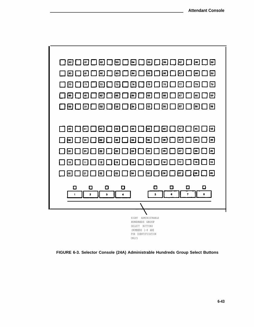
Attendant Console
EIGHT ADMINISTRABLEHUNDREDS GROUPSELECT BUTTONS(NUMBERS 1-8 AREFOR IDENTIFICATIONONLY)
FIGURE 6-3. Selector Console (24A) Administrable Hundreds Group Select Buttons
6-43

CHAPTER 6. FORMS FOR SYSTEM FEATURES AND SERVICES
TWENTY ADMINISTRABLEHUNDREDS GROUPSELECT BUTTONS(NUMBERS 1-20 AREFOR IDENTIFICATIONONLY)
FIGURE 6-4 Enhanced Selector Console (26A) Administrable Hundreds Group Select Buttons
6-44

Attendant Console
TABLE 6-A. Attendant Console Feature Button Characteristics
Feature Recommended Name EnteredOr Button On Station Maximum Notes
Function Label Form Allowed* †Abbreviated AD abrv-dial 1 per List/DC 1Dialing (AD) (List:__
DC:__
Administered AC Alarm at-alarm 1Connection[status lamp]
After after-call N 2Call (Grp. No._)Work
Assist assist 1 per split group 2(Grp. No:_)
Auto In auto-in 1 per split group 2
Automatic Call (Grp. No._)
Distribution Auxiliary aux-work 1 per split group 2(ACD) Work (Grp. No._)
Manual-In manual-in 1 per split group 2(Grp. No._)
Release release 1
Work Code work-code 1
Stroke (O-9) stroke-cnt 1 10(Code:_)
Attendant Con- CW Aud Off cw-ringoff 1sole (Calls Wait-ing)Attendant Control Cent Act act-tr-grp 1of Trunk GroupAccess (Activate)
*
†
N = any number of buttons on the voice terminal can be assigned to this feature.Feature button descriptions are provided in the “Voice Terminals—General” sectionof this chapter.
See Notes at end of table.
6-45

CHAPTER 6. FORMS FOR SYSTEM FEATURES AND SERVICES
TABLE 6-A (continued).Attendant Console Feature Button Characteristics
*
†
Feature Recommended Name EnteredOr Button On Station Maximum Notes
Function Label Form Allowed* †Attendant Control Cont Deact deact-tr-g 1of Trunk GroupAccess (Deac-tivate)
Attendant Direct Local TG Iocal-tgs 12 9Trunk Group Select Remote TG remote-tgs
Attendant Display Date/Time date-time 1[display buttons]
Inspect Mode inspect 1Normal Mode normal 1Stored Number stored-num 1Timer timer 1
Attendant Hun- Group Select _ hundrd-sel 20 per console 11dreds Group Select (Grp:_)
Automatic Circuit ACA aca-call 1 per SystemAssurance
Automatic Wakeup Auto auto-wkup 1(Hospitality) Wakeup
Busy Verification Busy Verify verify 1Cover Cback cov-cback 1
Call Coverage Consult consult 1Go To Cover goto-cover 1
Call Coverage Cover Msg Rt Cov-msg-rt 1[display button]Call Prompting Caller Info callr-info 1[display button]Centralized CAS-Backup cas-backup 1Attendant Service
Feature button descriptions are provided in the “Voice Terminals—General” sectionof this chapter.
See Notes at end of table.
6-46

Attendant Console
8
TABLE 6-A (continued).Attendant Console Feature Button Characteristics
Feature Recommended Name EnteredOr Button On Station Maximum Notes
Function Label Form Allowed* †Check In/Out Check In check-in 1(Hospitality)[display buttons] Check Out check-out 1Class of Restric- COR class-rstr 1tion[display button]Demand Print Print Msgs print-msgs 1
Do Not Disturb Do Not Disturb dn-dst 1(Hospitality)Do Not Disturb Do Not Disturb Ext ext-dn-dst 1(Hospitality)[display buttons] Do Not Disturb Grp grp-dn-dst 1
Emergency Emerg. em-acc-att 1Access To the Access ToAttendant Attndt
Facility Busy lndi- Busy (trunk or busy-ind 1 per TAC/Ext.cation extension) (TAC/Ext: —[status lamp]
Facility Test Calls FTC Alarm trk-ac-alm 1[status lampHardware Failure Major major-alrm 10 per System[status lamps] Hdwe
Failure
Auto Wakeup pr-awu-alm 1
DS1 (facility) ds1-alarm 10 per systemPMS Failure pros-alarm 1PMS Ptr Alm pr-pms-alm 1SMDR 1 Failure smdr1-alrm 1SMDR 2 Failure smdr2-alrm 1Sys Ptr Alm pr-sys-alm 1
* Feature button descriptions are provided in the “Voice Terminals—General” sectionof this chapter.
See Notes at end of table. †
6-47

CHAPTER 6. FORMS FOR SYSTEM FEATURES AND SERVICES
TABLE 6-A (continued.)Attendant Console Feature Button Characteristics
Feature Recommended Name EnteredOr Button On Station Maximum Notes
Function Label Form Allowed* †Integrated Direc- Integrtd Directory directory 1tory[display button]Incoming Call lden- Coverage (Group in-call-id Ntification number, type,
name, or ext.#)Cancel LWC
Leave Word Callinglwc-cancel 1
LWC lwo-store 1
Delete delete-msg 1
Leave Word Calling Msg[display buttons] Next next 1
Call Display call-disp 1
Leave Word Calling Msg (name or aut-msg-wt N 8(Remote Message extension #) (Ext:__
Waiting)[status lamp]
Link Failure Link link-alarm 1 per Link # 3Failure (Link No._)(Link No._)
Night Service Hunt Group hunt-ns 1 per hunt group 4(ACD) (Grp. No._)
Trunk Grp. trunk-ns 1 per trunk group 5(Grp. No. _
PMS Interface Message Waiting mwn-act 1 per systemAct.
[display buttons]Message Waiting mwn-deact 1 per SystemDeact.
Priority Prior priority NCalling Call
* N = any number of buttons on the voice terminal can be assigned to this feature.Feature button descriptions are provided in the “Voice Terminals—General” sectionof this chapter.
† See Notes at end of table.
6-48

Attendant Console
TABLE 6-A (continued.Attendant Console Feature Button Characteristics
Feature Recommended Name EnteredOr Button On Station Maximum Notes
Function Label Form Allowed* †
Queue Status AQC atd-qcalls 1 6Indications (Grp:_)(ACD) AQT atd-qtime 6[display buttons] (Grp:_)
Queue Status NQC q-calls (Ext:_) 1 7Indications(ACD)
OQT q-time (Ext:_) 1 per hunt group 7
[status lamps]Ringing In Aud Off in-ringoff 1
System Reset System Reset rs-alert 1Alert Alert
[status lamp]Time of Day Immediate Override man-ovrid 1Routing Clocked Override[display buttons]
clk-overid 1
Timed Reminder RC Aud Off re-ringoff 1
Trunk Identifica- Trunk-lD trk-id 1tion[display button]
Trunk Group Trunk-Name trunk-name 1Name[display button]
* N = any number of buttons on the voice terminal can be assigned to this feature.Feature button descriptions are provided in the “Voice Terminals—General” sectionof this chapter.
† See Notes below.
Notes:
1. List: List number 1 to 3 where the destination number isstored.
DC: Dial codes of destination number.
2. Grp: The split group number for ACD (1 through 32).
6-49

CHAPTER 6. FORMS FOR SYSTEM FEATURES AND SERVICES
Notes From Previous Table (continued).
Notes:
3. Link: A link number—1 to 8 for multi-carrier cabinets, 1 to 4for single-carrier cabinets).
4. Grp: A hunt group number (1 through 32).
5. Grp: A trunk group number (1 through 99).
6. Grp: Group number of the hunt group.
7. Ext: Extension number of the hunt group (may not be a VDN extension).
8. Ext: May be a VDN extension.
9. TAC: local-tgs—TAC of local TGremote-tgs—(L-TAC) TAC of TG to remote PBXremote-tgs—(R-TAC) TAC of TG on remote PBX
Note that the combination of Iocal-tgs/remote-tgs per consolemust not exceed 12 (maximum). Label associated button appropriatelyso as to eaisly identify the trunk group.
10. Code: Enter a stroke code (0 through 9).
11. Grp: Enter a hundreds group number (1 through 20).
24 ADMINISTRABLEFEATURE BUTTONS(NUMBERS 1-24 AREFOR IDENTIFICATIONONLY)
FIGURE 6-5. Attendant Console 24 Administrable Feature Button Number Assignments
6-50

Authorization Codes
Authorization Codes
Purpose
This form is used to assign authorization codes and associate them with CORs. On an internaloriginating call, the COR assigned the facility (for example, station) being used to originate thecall and its PGN (when assigned) is used to select a routing pattern. With this, the calling partycan dial a 4- to 7-digit authorization code to override the FRL assigned the COR (may be associ-ated with voice/data terminals, incoming trunk groups, remote access trunk groups, or attendantconsoles). This allows users within each PGN to have access to all seven FRLs (when assigned)and still remain partitioned. On an incoming remote access call, dialing an authorization code aspart of the call dialing sequence selects the COR and the associated PGN to be used in process-ing the call. Up to 96 different authorization codes can be assigned on one form and 5000 codescan be assigned in the the System. Note that the use of authorization codes when accessing aVDN extension wiII be denied.
Administration Commands
The following administration commands can be used to access the Authorization Codes form. Insome cases, just the most commonly used commands are shown. Refer to Administration Com-mands and Error Messages (Chapter 3) for a complete listing of all administration commands, thecommand structure, and the use of abbreviated command words when entering a command.
Action Object Qualifier*
change authorization-code auth (4-7 digit number)display authorization-code auth (4-7 digit number)
Form Instructions
Make assignments as required for the following fields on each page of the form:
• Number of Codes Administered— This is a display-only field and contains the sum ofthe number of Authorization Codes that has been administered using the AuthorizationCodes form.
• AC— Enter the 4- to 7-digit authorization code the user must dial. The number of digitsentered must agree with the number assigned to the Authorization Code Length field onthe Feature-Related System Parameters form.
• COR— Enter the desired COR number from 0 through 63.
6-51

CHAPTER 6. FORMS FOR SYSTEM FEATURES AND SERVICES
Page 1 of 1
Authorization Code - COR Mapping
Number of Codes Administered:
AC COR AC COR AC COR AC COR AC COR AC COR
SCREEN 6-20. Authorization Code Form—Example Only
6-52

Call Coverage Answer Group
Call Coverage Answer Group
Purpose
This form is used to establish Call Coverage Answer Groups.
An answer group is a group of up to eight members who act as a coverage point for anotheruser. For example, if several secretaries are responsible for answering a department’s redirectedcalls, all the secretaries could be assigned to an answer group. The answer group is assigned agroup number, and that group number appears in the department’s coverage path. All terminalsin an answer group ring (alert) simultaneously. Any member of the group can answer the call.
Each coverage answer group is identified by a number from 1 through 200. The members of thegroup are identified by their extension number. Any installed voice terminal (but not attendants)can be assigned to a coverage answer group.
Administration Commands
The following administration commands can be used to access the Coverage Answer Groupform. In some cases, just the most commonly used commands are shown. Refer to Administra-tion Commands and Error Messages (Chapter 3) for a complete listing of all administration com-mands, the command structure, and the use of abbreviated command words when entering acommand.
Action Object Qualifier*
add coverage answer-group 1-200 (or ‘next’)change coverage answer-group 1-200display coverage answer-group 1-200 [‘print’ or ‘schedule’]list coverage answer-group [‘print’ or ‘schedule’]remove coverage answer-group 1-200
* Brackets [ ] indicate the qualifier is optional.Single quotes (‘ ’) indicate the text inside the quote must be entered exactly as shown oran abbreviated form of the word may be entered.
Form Instructions
Make assignments as required for the following fields on the form:
• Group Number— Enter a number from 1 through 200 when completing a paper form.This is a display-only field when the form is accessed using an administration commandsuch as add or change.
• Group Name— Enter the group name you want to use to identify this group. Up to 15characters can be used, for example, typing pool, mom 12, secy, etc. Default is “COV-ERAGE GROUP.”
Performance Tip: Enter the extension numbers that are group members. This thenallows a list coverage answer group command to be used to list the voice terminalsthat will be alerted. The list command can be used in conjunction with the list station,list coverage path, and list hunt group commands to determine stations involved in callcoverage. This makes it possible to follow call coverage for any extension, allowing theadministrator to easily track call coverage paths.
6-53
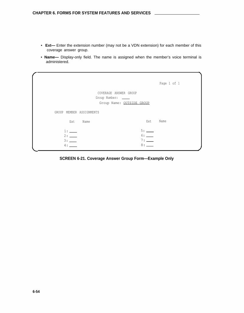
CHAPTER 6. FORMS FOR SYSTEM FEATURES AND SERVICES
• Ext— Enter the extension number (may not be a VDN extension) for each member of thiscoverage answer group.
• Name— Display-only field. The name is assigned when the member’s voice terminal isadministered.
Page 1 of 1
COVERAGE ANSWER GROUPGroup Number:
Group Name: OUTSIDE GROUP
GROUP MEMBER ASSIGNMENTS
Ext Name Ext Name
1: 5: 2: 6:
3: 7: 4: 8:
SCREEN 6-21. Coverage Answer Group Form—Example Only
6-54
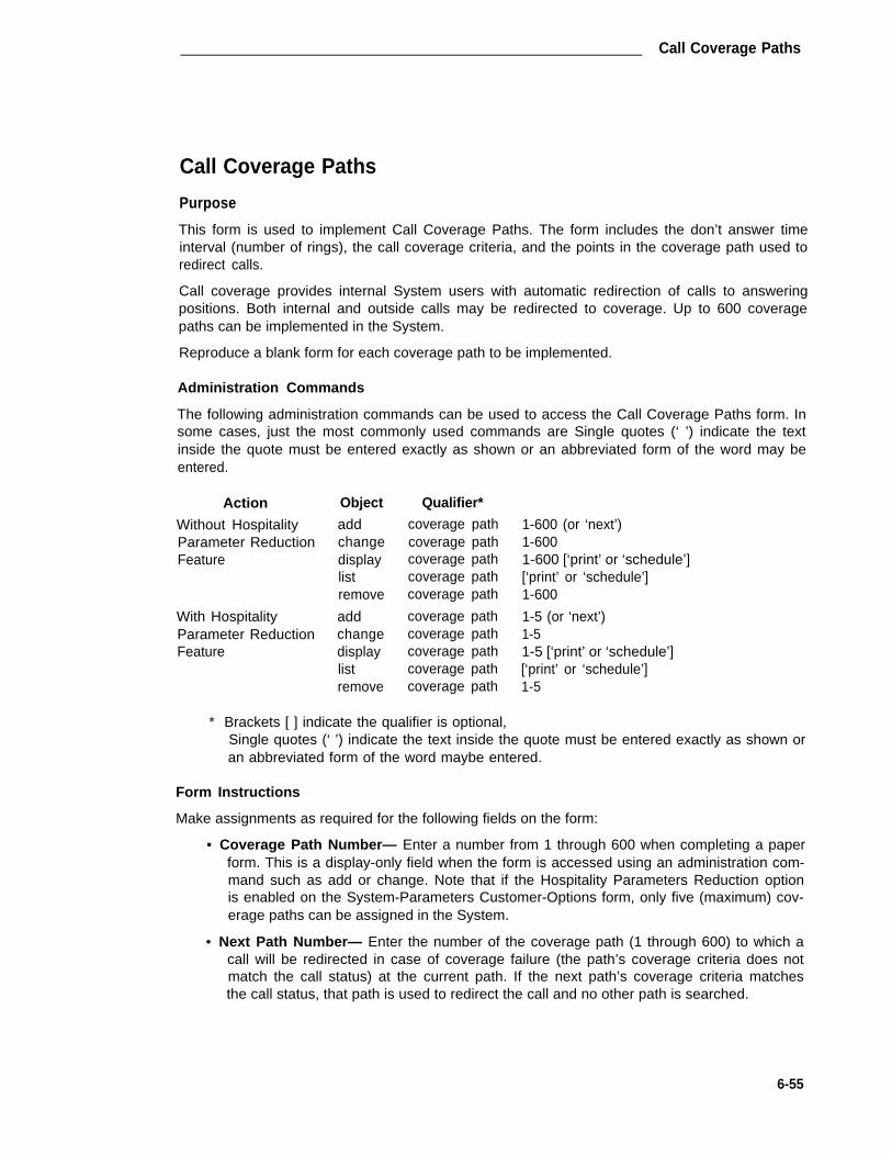
Call Coverage Paths
Call Coverage Paths
Purpose
This form is used to implement Call Coverage Paths. The form includes the don’t answer timeinterval (number of rings), the call coverage criteria, and the points in the coverage path used toredirect calls.
Call coverage provides internal System users with automatic redirection of calls to answeringpositions. Both internal and outside calls may be redirected to coverage. Up to 600 coveragepaths can be implemented in the System.
Reproduce a blank form for each coverage path to be implemented.
Administration Commands
The following administration commands can be used to access the Call Coverage Paths form. Insome cases, just the most commonly used commands are Single quotes (‘ ’) indicate the textinside the quote must be entered exactly as shown or an abbreviated form of the word may beentered.
Action Object Qualifier*
Without Hospitality add coverage pathParameter Reduction change coverage pathFeature display coverage path
list coverage pathremove coverage path
With Hospitality add coverage pathParameter Reduction change coverage pathFeature display coverage path
list coverage pathremove coverage path
* Brackets [ ] indicate the qualifier is optional,
1-600 (or ‘next’)1-6001-600 [‘print’ or ‘schedule’][‘print’ or ‘schedule’]1-600
1-5 (or ‘next’)1-51-5 [‘print’ or ‘schedule’][‘print’ or ‘schedule’]1-5
Single quotes (‘ ’) indicate the text inside the quote must be entered exactly as shown oran abbreviated form of the word maybe entered.
Form Instructions
Make assignments as required for the following fields on the form:
• Coverage Path Number— Enter a number from 1 through 600 when completing a paperform. This is a display-only field when the form is accessed using an administration com-mand such as add or change. Note that if the Hospitality Parameters Reduction optionis enabled on the System-Parameters Customer-Options form, only five (maximum) cov-erage paths can be assigned in the System.
• Next Path Number— Enter the number of the coverage path (1 through 600) to which acall will be redirected in case of coverage failure (the path’s coverage criteria does notmatch the call status) at the current path. If the next path’s coverage criteria matchesthe call status, that path is used to redirect the call and no other path is searched.
6-55
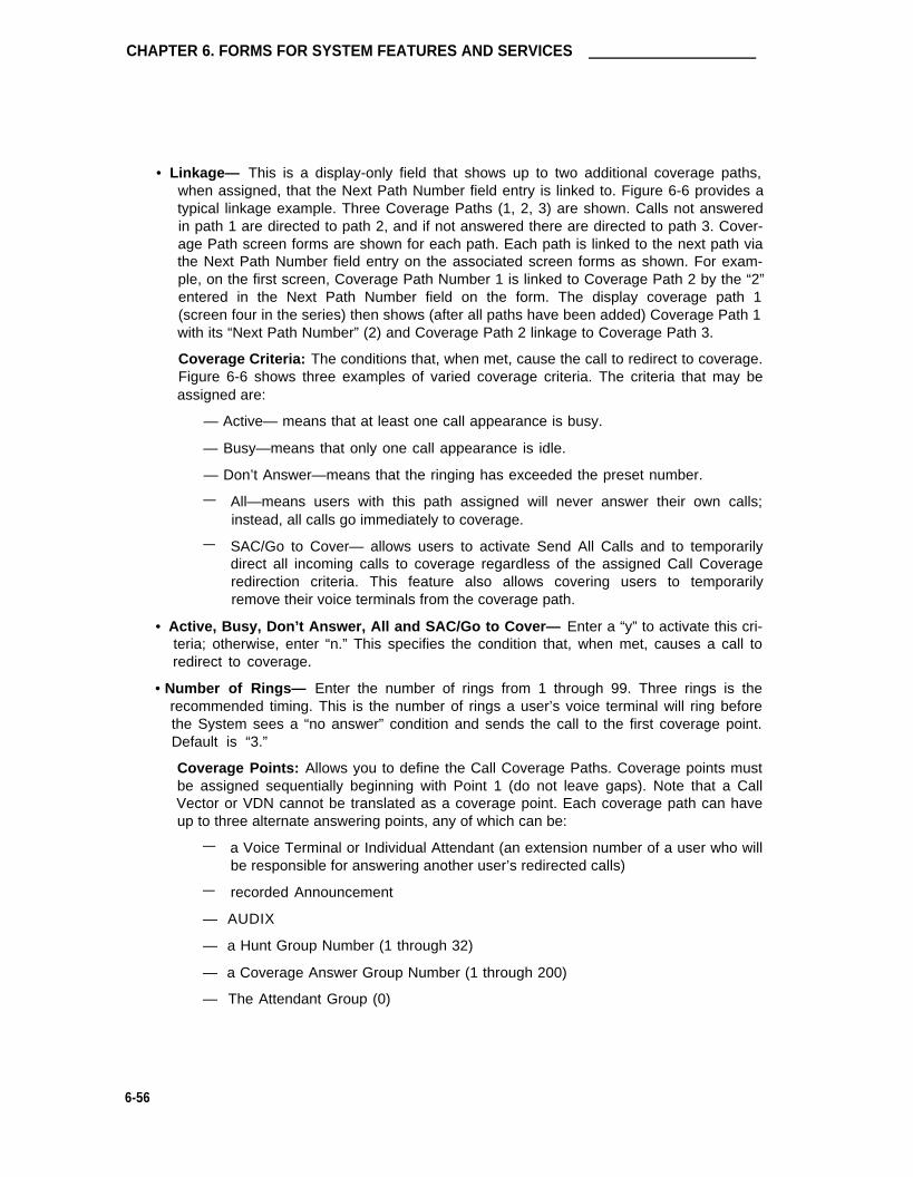
CHAPTER 6. FORMS FOR SYSTEM FEATURES AND SERVICES
• Linkage— This is a display-only field that shows up to two additional coverage paths,when assigned, that the Next Path Number field entry is linked to. Figure 6-6 provides atypical linkage example. Three Coverage Paths (1, 2, 3) are shown. Calls not answeredin path 1 are directed to path 2, and if not answered there are directed to path 3. Cover-age Path screen forms are shown for each path. Each path is linked to the next path viathe Next Path Number field entry on the associated screen forms as shown. For exam-ple, on the first screen, Coverage Path Number 1 is linked to Coverage Path 2 by the “2”entered in the Next Path Number field on the form. The display coverage path 1(screen four in the series) then shows (after all paths have been added) Coverage Path 1with its “Next Path Number” (2) and Coverage Path 2 linkage to Coverage Path 3.
Coverage Criteria: The conditions that, when met, cause the call to redirect to coverage.Figure 6-6 shows three examples of varied coverage criteria. The criteria that may beassigned are:
— Active— means that at least one call appearance is busy.
— Busy—means that only one call appearance is idle.
— Don’t Answer—means that the ringing has exceeded the preset number.
— All—means users with this path assigned will never answer their own calls;instead, all calls go immediately to coverage.
— SAC/Go to Cover— allows users to activate Send All Calls and to temporarilydirect all incoming calls to coverage regardless of the assigned Call Coverageredirection criteria. This feature also allows covering users to temporarilyremove their voice terminals from the coverage path.
• Active, Busy, Don’t Answer, All and SAC/Go to Cover— Enter a “y” to activate this cri-teria; otherwise, enter “n.” This specifies the condition that, when met, causes a call toredirect to coverage.
• Number of Rings— Enter the number of rings from 1 through 99. Three rings is therecommended timing. This is the number of rings a user’s voice terminal will ring beforethe System sees a “no answer” condition and sends the call to the first coverage point.Default is “3.”
Coverage Points: Allows you to define the Call Coverage Paths. Coverage points mustbe assigned sequentially beginning with Point 1 (do not leave gaps). Note that a CallVector or VDN cannot be translated as a coverage point. Each coverage path can haveup to three alternate answering points, any of which can be:
— a Voice Terminal or Individual Attendant (an extension number of a user who willbe responsible for answering another user’s redirected calls)
— recorded Announcement
— AUDIX
— a Hunt Group Number (1 through 32)
— a Coverage Answer Group Number (1 through 200)
— The Attendant Group (0)
6-56

Call Coverage Paths
When entering data for the three coverage points, use the following notations:
•
•
Use the letter “h” to indicate hunt, followed by a hunt group number (1through 32). For example, you would enter “h32” if you want a coveragepoint to be routed to hunt group number 32.
Use the letter “c” to indicate coverage answer group followed by the cov-erage group number (1 through 200). For example, you would enter“c100” if you wanted a coverage point to be routed to call coverageanswer group 100.
Use a 0 (zero) if you want a coverage point to be an attendant.
Use the extension number assigned to a voice terminal, announcement,
•
•
and AUDIX.
• Point 1:, Point 2:, Point 3:— Enter one of the following: an extension number for thevoice terminal, AUDIX, announcement, h1-h32 (hunt), c1-c200 (coverage), or zero (0) forattendant. If a DCS AUDIX is used and this is a remote switch served by the AUDIX on ahost switch, enter an associated AUDIX hunt group number (h1-h32). A unique HuntGroup form must be administered with the AUDIX extension number in the Group Exten-sion field. If 0 is entered and the System has CAS, the call will go to the CAS attendant.
If calls redirect to Message Center (a special Uniform Call Distribution hunt group),AUDIX, or to the attendant, do not list any additional coverage points. These calls willnormally queue and never redirect to another coverage point.
Calls to any hunt group will queue if possible. Calls redirect from a hunt group only if allhunt group members are busy and either the queue is full or there is no queue:
CoverageNext
COVERAGE CRITERIAStation/Group Status
Active?Busy?
Don’ t Answer?All?
SAC/Go to Cover?COVERAGE POINTS
Page 1 of 1
COVERAGE PATH
Path Number: _Path Number: _ Linkage: _ _
Inside Call Outside Calln ny yy y Number of Rings: 3n ny y
Point 1: Point 3: Point 2:
SCREEN 6-22. Coverage Path Form—Example Only
6-57

CHAPTER 6. FORMS FOR SYSTEM FEATURES AND SERVICES
POINT 1 POINT 2
COVERAGEPATH 1
INCOMINGCALL
X1200 X1204
COVERAGEPATH 2
X1212
COVERAGEPATH 3
AUDIX
X1216 X1200 X2000
ADD COVERAGEPATH 1 FORM
X1208
POINT 3
NOTUSED
NOTUSED
Page l of 1
COVERAGE PATHCoverage Path Number: _ 1
Next Path Number: _ Linkage __
COVERAGE CRITERIAStation/Group Status Inside Call Outside Cdl
Active? n n
Busy? y yDon’t Answer7 y y Number of Rings 3
All? n n
SAC/GO to Cover? y yCOVERAGE POINTS
Point l: 120 Point 3: _
Point 2: 1204
FIGURE 6-6. Example of Call Coverage Paths and Associated Linkage
6-58
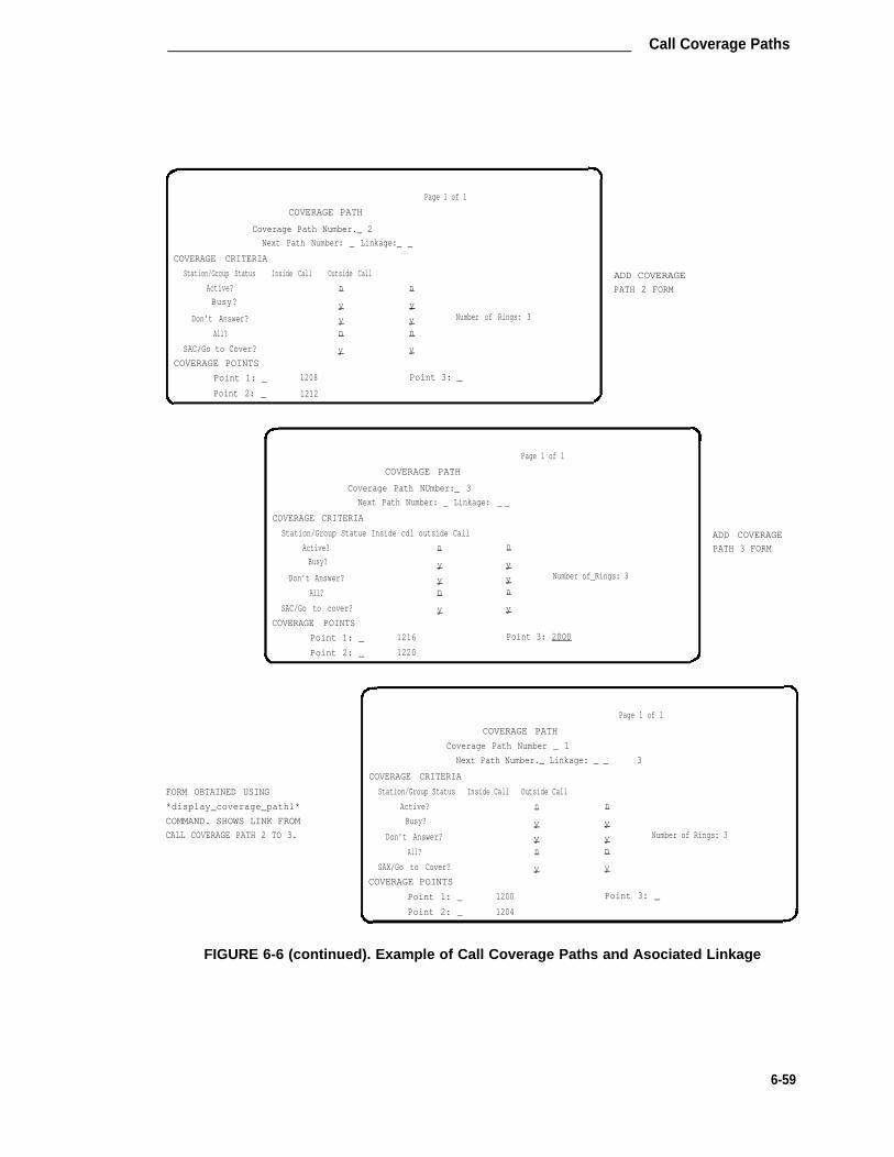
Call Coverage Paths
Page 1 of 1
COVERAGE PATH
Coverage Path Number._ 2
Next Path Number: _ Linkage:_ _
COVERAGE CRITERIA
Station/Group Status Inside Call Outside Call
Active? n n
Busy? y y
Don’t Answer? y y Number of Rings: 3
All? n n
SAC/Go to Cover? y y
COVERAGE POINTS
Point 1: _ 1208 Point 3: _
Point 2: _ 1212
ADD COVERAGE
PATH 2 FORM
Page 1 of 1
COVERAGE PATH
Coverage Path NUmber:_ 3
Next Path Number: _ Linkage: _ _
COVERAGE CRITERIA
Station/Group Statue Inside cdl outside Call
Active? n n
Busy? y y
Don’t Answer? y y Number of_Rings: 3
All? n n
SAC/Go to cover? y y
COVERAGE POINTS
Point 1: _ 1216 Point 3: 2000
Point 2: _ 1220
FORM OBTAINED USING
*display_coverage_path1*
COMMAND. SHOWS LINK FROM
CALL COVERAGE PATH 2 TO 3.
ADD COVERAGE
PATH 3 FORM
Page 1 of 1
COVERAGE PATH
Coverage Path Number _ 1
Next Path Number._ Linkage: _ _ 3
COVERAGE CRITERIA
Station/Group Status Inside Call Outside Call
Active? n n
Busy? y y
Don’t Answer? y y Number of Rings: 3
All? n n
SAX/Go to Cover? y y
COVERAGE POINTS
Point 1: _ 1200 Point 3: _
Point 2: _ 1204
FIGURE 6-6 (continued). Example of Call Coverage Paths and Asociated Linkage
6-59

CHAPTER 6. FORMS FOR SYSTEM FEATURES AND SERVICES
EXAMPLE 1 COVERAGE PATH FOR OUTSIDE CALLS
call type - OUTSIDE
CRITERIA - busy, don’t answer, and send all calls (when activated)
mr. brown’s
terminalpoint 1 point 2 point 3
Incoming
call
another assistant coverage answer
manager manager group with ici
EXAMPLE 2 COVERAGE PATH FOR INSIDE CALLS
call type - INSIDE
criteria - BUSY AND DON’T ANSWER (SEND ALL CALLS NOT ACTIVATED)
mr. brown’s
terminalpoint 1 point 2 point 3
Incoming
callaudix
assistant coverage answer
manager group with ici
EXAMPLE 3 COVERAGE PATH FOR INSIDE CALLS
call type - INSIDE
criteria - SEND ALL CALLS ACTIVATED
mr. brown’s
terminalpoint 1 point 2
Incoming
callaudix
coverage answer
group with ici
point 3
not
used
FIGURE 6-7. Typical Call Coverage Path Assignments
6-60

Call Vector
Call Vector
Purpose
The Call Vector form is used to program a series of commands that specify how to handle callsdirected to a VDN.
For additional information on Call Vectors refer to Call Vectoring in Chapter 4.
Administration Commands
The following administration commands can be used to access the Call Vector form. In somecases, just the most commonly used commands are shown. Refer to Administration Commandsand Error Messages (Chapter 3) for a complete listing of all administration commands, the com-mand structure, and the use of abbreviations when entering a command.
Action Object Qualifier*
change † vector [1-256]displaylist
*
†
vector [1-256] [‘print’ or ‘schedule’]vector [1-256] [‘count’ 1-256] [‘print’ or ‘schedule’]
Brackets [ ] indicate the qualifier is optional.Single quotes (‘ ’) indicate the text inside the quote must be entered exactly as shown oran abbreviated form of the word maybe entered.
Do not change a call vector while it is processing a call. It is recommended to add a newvector and then change the form to point to the new vector.
Form Instructions
Make assignments as required for the following fields on the form:
•
•
•
Number— is play-only field when the form is accessed using a change or displayadministration command. Enter a vector number in the range from 1 through 256 whencompleting a paper form.
Name— Enter up to 15 alphanumeric characters to represent the vector name. This is anoptional field. Default is blank.
ASAI Routing— Display-only field. Indicates whether or not the ASAI Routing option isenabled on the System-Parameters Customer-Options form. Valid values are “y” (yes)or “n” (no).
Basic— Display-only field. Indicates whether or not the “Vectoring (Basic)” option isenabled on the System-Parameters Customer-Options form. Valid values are “y” (yes)or “n” (no).
Prompting— Display-only field. Indicates whether or not the “Vectoring (Prompting)”option is enabled on the System-Parameters Customer-Options form. Valid values are“y” (yes) or “n” (no).
•
•
6-61

CHAPTER 6. FORMS FOR SYSTEM FEATURES AND SERVICES
• 01 through 15-Enter up to 15 vector commands as required. Any Command field whichis left blank is skipped during vector processing. There is an implicit “Stop” after Step 15.Valid vector commands are: “adjunct, “ “announcement, “ “busy,“ “check,” “collect,”“disconnect,” “goto,” “messaging,” “queue,” “route,” “stop,” or “wait.” Blank steps mayappear anywhere in a vector. Default is blank.
The Basic field must be “y” before “busy,” “check,” “disconnect,” “queue,” or “wait’ canbe entered. The Prompting field must be “y” before “collect” can be entered. “Adjunct”can only be entered if ASAI Routing and Basic are “y.”
Call Vector—Dynamic Fields
Table 6-B provides a summary of the Call Vector commands that can be entered in the Com-mand field. Up to 15 commands may be entered on the form. The vector command line isshown in each of the following descriptions. The bold entry indicates the required data for theparticular vector command and underlined entries indicate variable fields on the command line.Branching to other vectors from a vector is permitted but the system will stop all vector process-ing after 1000 vector steps have been processed.
Page 1 of 1
CALL VECTOR
Number: _ Name:
ASAI Routing? y Basic? y Prompting? y
0102030405060708091011121314
15
SCREEN 6-23. Call Vector Form—Example Only
6-62

Call Vector
TABLE 6-B. Call Vector Commands
Command Conditions* Description†
adjunct routing link extension ______. Enter the ASAI link extension (must be a
Form Fields “ASAI Routing” and “Basic” valid ISDN-BRI link extension) throughwhich the switch will send a routingmust be “y.” request to the associated adjunct. Thiscommand is only available when theInbound Call Management feature isactive.
announcement extension . Enter a valid announcement extension to
Form Fields: “Basic” or “Prompting” be given callers. The announcement is
must be “y.” treated as a forced announcement. Ifthe announcements queue is currentlyfull, the call retries the announcementstep indefinitely before processing anynew vector steps. If the requestedannouncement is not available, thecurrent step will be skipped and vectorprocessing will continue at the next vec-tor step.
busy Form Fields “Basic” must be “y.” Causes termination of vector processingand gives the caller.busy tone. If thecall is a CO trunk call and answer super-vision (via announcement command orwait command with music) has not beensent, the CO will ignore the busy andcontinue giving the caller CO ringback.Busy, if successfully applied will timeoutand the call will drop after 45 seconds.
check backup split _ priority _ if unconditionally. Enter the priority for queuing a call
(split 1-99, default is blank) priority: l (low), m (medium), h (high), t unconditionally (will always attempt to
(top). Default is “m.” queue) to a second split or hunt group
Form Fields: “Basic” must be “y.”queue. (Split or hunt group must bevector controlled.)
check backup split_ priority _ if available agents >_. Enter the priority and the number of
(split 1-99, default is blank) priority: l (low), m (medium), h (high), t available agents requirement before
(top). Default is “m.” queuing a call to the backup split.
available agents >: 0-199, default is 0.Form Fields: “Basic” must be “y.”
* Legend: < (less than), > (greater than). Variable field entries shown below commandline.
† Data that must be entered as part of the command line is shown in bold. Variable fieldsthat must be completed are shown underlined. Detailed descriptions of the Call Vectorand Call Prompting commands is provided in the DEFINITY® Communications SystemGeneric 1 and Generic 3i—Feature Description, 555-230-201.
6-63

CHAPTER 6. FORMS FOR SYSTEM FEATURES AND SERVICES
TABLE 6-B (continued).Call Vector Commands
Command Conditions * Description †
check backup split _ priority _ if staffed agents >_. Enter the priority and the number of
(split 1-99, default is blank) priority: l (low), m (medium), h (high), t staffed (logged in) agents requirement
(top). Default is “m.” before queuing a call to the backup split.
staffed agents >: 0-199, default is 0.Form Fields: “Basic” must be “y.”
check backup split _ priority _ if calls queued <_. Enter the priority and the number of calls
(split 1-99, default is blank) priority: l (low), m (medium), h (high), t queued requirement before queuing a
(top). Default is “m.” call to the backup split.
Calls queued <: 1-199, default is 1.Form Fields: “Basic” must be “y.”
check backup split _ priority _ if oldest-call-waiting <_. Enter the priority and the oldest-call-
(split 1-99, default is blank) priority: l (low), m (medium), h (high), t waiting requirement before queuing a
(top). Default is “m.” call to the backup split. The call willqueue if the oldest call has been waiting
oldest-call-waiting <: 2-998, default is 2. less than the specified number ofForm Fields: “Basic must be “y.” seconds.
collect _ digits after announcement extension Enter the number of digits to collect from — .collect: (1 to 16, default is 1) extension: “none” or valid announcement a touch-tone phone and the extension
extension. number associated with an optionalannouncement to be given the calling
Form Fields: “Prompting” must be “y.” party before receiving the digits; other-wise, enter “none.”
disconnect after announcement extension Enter a valid announcement extension if______.extension: “none” or valid announcement an announcement is to be given a caller
before disconnect occurs. Disconnectextension.Form Fields: “Basic” must be “y.”
ends treatment of a call and removesthe call from the switch.
goto step_ unconditionally Enter the vector step or vector to branch
(step: 1-15) Form Fields: “Basic” or “Prompting” to. This command always branches.
-or- must be “y.”
goto vector _
(vector: 1-256)
* Legend: < (less than), > (greater than). Variable field entries shown below commandline.
† Data that must be entered as part of the command line is shown in bold. Variable fieldsthat must be completed are shown underlined. Detailed descriptions of the Call Vectorand Call Prompting commands is provided in the DEFINITY® Communications SystemGeneric 1 and Generic 3i—Feature Description, 555-230-201.
6-64

Call Vector
TABLE 6-B (continued).Call Vector Commands
Command Conditions* Description†
goto step_ if available-agents in split _ is _ __. Enter the vector step or vector to branch
(step: 1-15) split: 1-99, default is “blank.” to. This command executes if the avail-able agents in the indicated split is less
-or- is: < or >, 0-200, defaults are > and 1. than (<) or greater than (>) the number
goto vector_ Form Fields: “Basic” must be “y.” specified (0-200).
(vector: 1-256)
goto step _ if staffed-agents in split _ is _. Enter the vector step or vector to branch
(step: 1-15) split: 1-99, default is blank. to. This command executes if thestaffed (logged in) agents in the indi-
-or- is < or >: 0-200, default is 1. cated split is greater than (>) the number
goto vector_ Form Fields: “Basic” must be “y.” specified (0-200).
(vector: 1-256)
goto step _ if calls-queued in split _ is _ __ pri _. Enter the vector step or vector to branch
(step: 1-15) split: 1-99, default is blank. to. This command executes if the callsqueued in the indicated split is less than
-or- is: <or>, 0-200, defaults are < and 1. (<) or greater than (>) the number speci-pri: Priority—l (low), m (medium), h fied (0-200). Check for queued calls atgoto vector _ (high), t (top). Default is “m.” the priority level specified or at higher
(vector: 1-256) Form Fields: “Basic” must be “y.” priority levels.
goto step _ if oldest-call-waiting in split _ is - Enter the vector step or vector to branch
(step: 1-15) — . to. This command executes if the
split: 1-99, default is blank. oldest-call-waiting in the indicated split-or- has been waiting Iess than (<) or greater
is: <or>, 0-998 (even numbers only), than (>) the number of seconds speci-goto vector_ defaults are > and 2. fied (0-998).(vector: 1-256) pri: Priority—l (low), m (medium), h
(high), t (top). Default is “m.”
Form Fields: “Basic” must be “y.”
goto step _ if digits Enter the vector step or vector to branch
(step: 1-15) digits: 1 to 16 digits to. This command executes if the digitsfrom the Collect command match the
-or- Form Fields: “Prompting” must be “y.” specified digit string.
goto vector _
(vector: 1-256)
* Legend: < (less than), > (greater than). Variable field entries shown below commandline.
† Data that must be entered as part of the command line is shown in bold. Variable fieldsthat must be completed are shown underlined. Detailed descriptions of the Call Vectorand Call Prompting commands is provided in the DEFINITY® Communications SystemGeneric 1 and Generic 3i—Feature Description, 555-230-201.
6-65

CHAPTER 6. FORMS FOR SYSTEM FEATURES AND SERVICES
TABLE 6-B (continued).Call Vector Commands
Command Conditions* Description†
goto step_ if time-of-day is _ _:_ to_ _ : _. Enter the vector step or vector to branch
(step: 1-15) to. This command executes if the timeis (day) (hour): (minute) to (day)(hour):(minute): of day criteria are met.
-or-day: mon, tue, wed, thr, fri, sat, sun.
goto vector _ Default is “mon” and “fri.”(vector: 1-256) hour: 00 to 23 (military format). Default
is “09” and “17.”minute: 00 to 59 (military format).Default is “00” and “00.”
Form Fields: “Basic” must be “y.”
messaging split_ for extension . Enter the split or hunt group number and
(split: 1-99, default is blank) extension: “none,” or valid extension. extension where the caller can leave a
Form Fields “Basic” or “Prompting”message; otherwise, enter “none.”
must be “y.”
queue> to main split_ priority _. Enter the split number and priority level
(split 1-99, default is blank) priority: l (low), m (medium), h (high), t to have a call queue at a split. A call
(top). Default is “m.” sent with this command will either con-
Form Fields: “Basic” must be “y.”nect to an agent in the split or enter thesplit’s queue.
route to number if uncon- Enter the number to mute a call to.ditionally Abbreviated Dialing special characters
number: 1 to 16 digits (includes * and # ~p (pause), ~w (wait), ~m (mark), and
plus AD special characters) ~s (suppress) can also be used. These
Form Fields: “Basic” or “Prompting”characters count as two digits eachwhen used. The destination can be; an
must be “y.” attendant or attendant queue, a localextension, a remote extension (that is,UDP extension), an external number, ora VDN number.
* Legend: < (less than), > (greater than). Variable field entries shown below commandline.
† Data that must be entered as part of the command line is shown in bold. Variable fieldsthat must be completed are shown underlined. Detailed descriptions of the Call Vectorand Call Prompting commands is provided in the DEFINITY® Communications SystemGeneric 1 and Generic 3i—Feature Description, 555-230-201.
6-66

Call Vector
TABLE 6-B (continued).Call Vector Commands
Command Conditions* Description†
route to number if digit Enter the number to route a call to if theequals _. digit entered by the calling party for the
last collect digits command matchesnumber: 1 to 16 digits (includes * and # the single digit (0-9) entered followingplus AD special characters) the word “equals.” Note that this com -equals: 0 -9 mand can only be used for routing basedForm Fields: “Prompting” must be “y.” on single digit comparisons.
route to digits with coverage_. Enter whether call coverage should
coverage: n (no), y (yes). Default is “n.” apply when routing a call based on thedigits collected from the calling patty
Form Fields: “Prompting” must be “y.” using the last collect digits command.
stop Form Fields: “Basic” or “Prompting” Enter stop to terminate processing ofmust be “y.” any subsequent vector steps. The fol-
lowing remain in effect after processingthe stop command any calls that arealready queued, remain queued, and anywait treatment such as silence, ring-back, or music is continued.
wait time _ secs hearing Enter the time (in seconds) before pro-
time: 0-996 cessing the next vector step and indi-cate the treatment to be given a caller
hearing: silence, ringing, music. Default during the wait period. A wait time of “0”is “silence.” seconds can be used to change the callForm Fields: “Basic” must be “y.” treatment without executing a delay.
* Legend: < (less than), > (greater than). Variable field entries shown below commandline.
† Data that must be entered as part of the command line is shown in bold. Variable fieldsthat must be completed are shown underlined. Detailed descriptions of the Call Vectorand Call Prompting commands is provided in the DEFINITY® Communications SystemGeneric 1 and Generic 3i—Feature Description, 555-230-201.
6 - 6 7

CHAPTER 6. FORMS FOR SYSTEM FEATURES AND SERVICES
CallVisor™ Adjunct-Switch Application Interface Link
Purpose
This form is used to administer a CallVisor Adjunct-Switch Application Interface (ASAI) Link. Thisassigns a port interface from the switch’s TN556 ISDN-BRI circuit pack (12 ports) to an adjunctsuch as ICM adjunct.
Note: For more detailed information on ASAI, refer to DEFINITY® CallVisor™ Adjunct-Switch Application Interface (ASAI) Protocol Reference, 555-230-221 and DEFIN-lTY® CallVisor™ Adjunct-Switch Application Interface (ASAI) Technical Reference,555-230-220.
Administration Commands
The following ASAI administration commands are useful. The commands that can be used toaccess the station form are marked with an asterisk (*). In some cases, just the most commonlyused commands are shown. Refer to Administration Commands and Error Messages (Chapter3) for a complete listing of all administration commands, the command structure, and the use ofabbreviated command words when entering a command.
Action Object Qualifier*
* add station xxxxx (extension number) or (‘next’)* changestation xxxxx (extension number)* display station xxxxx (extension number)
list hunt-grouplist monitored-station [‘start’ extension] [count xxxxx] [print]
* list station [xxxxx] (‘count’ 1-1600) type ASAI[‘print’ or ‘schedule’]
* list station [xxxxx] (‘count’ 1-1600) port[‘print’ or ‘schedule’]
list vdn* removestation xxxxx (extension number)
* Brackets [ ] indicate the qualifier is optional.Single quotes (‘ ’) indicate the text inside the quote must be entered exactly as shown oran abbreviated form of the word maybe entered.
Form Instructions
Make assignments as required for the following fields on each page of the form:
Page 1 of the Form
• Extension— This is a display-only field when accessing this form using an administrationcommand such as change or display. When completing a blank paper form, enter avalid extension number (1 through 5 digits) that agrees with the dial plan.
6-68

CallVisor™ Adjunct-Switch Application Interface Link
• Type— Enter “asai.”
Note: The BCC field disappears when “asai” is entered as the station type.
•
•
•
•
•
COR— Make no entry. Not required for the ASAI Link. (Default is ”1.“)
Port— Enter 5 to 6 characters. The first character identifies the network (1 through 3,default is “1” if no entry); the second character identifies the carrier (A through E); thethird and fourth characters identify the slot number in the carrier (01 through 20 for multi-carrier cabinets depending on carrier type or 01 through 18 for single-carrier cabinetsdepending on cabinet type); the last two characters identify the circuit number (01through 12).
COS— Make no entry. Not required for the ASAI Link. (Default is ”1.“)
Name— Enter the name of the adjunct associated with this interface. Up to 15 characterscan be used or the field maybe left blank.
XlD— Enter “y” to indicate layer 2 XID testing capability; otherwise, enter “n.” When sup-porting the CONVERSANT® Voice Information System, set XID to “y.” Setting is depen-dant on specific vendor’s office and managing applications (DEC=’’n”). Default is “y.”
• Fixed TEI— Enter “y” or “n” depending on the vendor of adjunct (DEC=’’n”). Default is“n.”
• TEI— Displayed when Fixed TEI is “y.” This field identifies if the ASAI Link has a FixedTerminal Identification (TEl) capability. TEI identifies a unique access point in the sys-tem. When Fixed TEI is “y,” the TEI field must be administered. Enter a 1- or 2-digitnumber used to identify the unique access point within the service. Valid entries are 0through 63. For example, if the CONVERSANT Voice Information System is supported,set the TEI to “3.”
• MIM Support— (Management Information Message Support) Used to support two typesof capabilities; MIM endpoint initialization capability (SPID support), otherMaintenance/Management capability. Valid entries are “y” or “n.” Enter “n” for ASAI andfor all other vendors. Default is “n.” Form is adjusted accordingly.
• CRV Length— (Call Reference Value Length) Used to indicate the length of Call Refer-ence Value (CRV) for each ASAI interface. Enter”1” or “2” (DEC=“2”). Default is ”1.“
6-69

CHAPTER 6. FORMS FOR SYSTEM FEATURES AND SERVICES
Page 1 of 1STATION
Extension: Type: asai COR: 1Port: COS: 1Name:
FEATURE OPTIONS
XID? y Fixed TEI? y TEI: 3MIM Support? n
SCREEN 6-24. ASAI Station Form—Example Only
Note: The above form shows a system administered for CONVERSANT Voice lnformationSystem.
Implementation Note:
BCC field is only present if the ISDN-PRI option is enabled on the System-ParametersCustomer-Options form.
TEI field only displayed when the Fixed TEI field is “y.”
6-70

Circuit Pack Administration
Circuit Pack Administration
Purpose
The Circuit Pack Administration form allows the user to administer circuit packs to carrier slotsbefore the circuit packs are actually installed in the carrier or cabinet. This then allows the Sys-tem to be configured (administered) when the circuit packs have not yet been physically insertedin their appropriate slots. Before any voice terminals, attendant consoles, or trunks can beadministered in the System, the correct type of circuit pack must be installed in the appropriateslot or, using the Circuit Pack form, a circuit pack must be assigned to the slot.
The Circuit Pack Administration forms do not have to be completed if the System cabinet isequipped with the circuit packs at the time of administration.
Refer to Chapter 2 for circuit pack administration forms and associated instructions. (Note thatthe DS1 circuit pack and associated translations coverage is provided in Chapter 4.)
Note: For initial installation procedures, circuit packs should only be assigned slots per thehardware Configuration Layout record (obtained from the factory or Customer Ser-vices Support Organization). Arbitrarily assigning circuit packs to slots should not beattempted because this will eventually require (at the time of installation and test)realignment of the circuit packs and reworking associated wiring to agree with thesoftware translations or new software translations to agree with the shippedhardware configuration.
6-71

CHAPTER 6. FORMS FOR SYSTEM FEATURES AND SERVICES
Class of Restriction
Purpose
This form is used to implement Class of Restrictions (CORs). A COR is used to control call origi-nation and termination. A system may have only one COR or as many as necessary to controlcalling privileges. Up to 64 different CORs (0 through 63) can be assigned. Note that CORs areassigned to facilities such as stations, they are not assigned to users.
Note that when a call is to a VDN extension, the COR of the caller and the VDN are compared todetermine if the associated Call Vector can be accessed. After the vector is accessed, the CORof the VDN is used for further call permission checking.
Administration Commands
The following administration commands can be used to access the COR form. In some cases,just the most commonly used commands are shown. Refer to Administration Commands andError Messages (Chapter 3) for a complete listing of all administration commands, the commandstructure, and the use of abbreviated command words when entering a command.
Action Object Qualifier*
change cordisplay cor 0-63 [‘print’ or ‘schedule’]list partitioned group [‘print’ or ‘schedule’]
0-63
* Brackets [ ] indicate the qualifier is optional.
Form Instructions
Make assignments as required for the following fields on the form:
• COR Number— Enter a number from 0 through 63 when completing a paper form. Thisis a display-only field when the form is accessed via an administration command such aschange or display.
• FRL— Enter an originating FRL number from 0 through 7. This entry is used by AARand/or ARS features to determine call access to an outgoing trunk group. Outgoing callrouting is determined by a comparison of the FRLs in the AAR/ARS Routing Pattern andthe FRL associated with the COR of the call originator (typically, a voice terminal user).An originating FRL of zero has the least calling privileges. Default is “7.”
Attendants use the FRL assigned via COR administration. This FRL is used for atten-dant origination and assisted calls.
• APLT— Enter “n” to allow access to EPSCS or CCSA off-net facilities. Default is “y.”
• Calling Party Restriction— Enter one of the following: “origination,” “outward,” “all-toll,”“tac-toll,” or “none.”
– Origination restriction (“origination”) denies the calling party the ability to originatea call from the facility (that is, station) at any time. The party can only receivecalls.
6-72

Class of Restriction
— Outward restriction (“outward”) denies the calling party the ability to directlyaccess the exchange network.
— All-toll restriction (“all-toll”) denies the calling party the ability to make both ARSand trunk access calls from a facility assigned the COR to certain toll areas asdefined in the Dialed String Field on the Toll Analysis form. The Dialed Stringfield on the form must be marked as being associated with the System’s Toll List.The call will complete if the facilities COR is also associated with an UnrestrictedCall List and whose Dialed String field on the Toll Analysis form also matches thedialed number.
— With “tac-toll” restriction, the calling party cannot make trunk access calls fromthe facility assigned the COR to certain toll areas as defined in the Dialed Stringfield on the Toll Analysis form. The Dialed String field on the form must bemarked as being associated with the System’s Toll List. The call will complete ifthe facilities COR is also associated with an Unrestricted Call List and whoseDialed String field on the Toll Analysis form also matches the dialed number.Refer to Toll Analysis form in this Chapter for additional information.
• Partitioned Group Number— Only displayed if the “Automatic Route Selection Partion-ing” option is enabled and the Time of Day Routing has not been enabled on theSystem-Parameters Customer-Options form. Enter a PGN from one to eight. WhenAAR and ARS services are to be partitioned among different groups of users, all users ina specific group share the same PGN. The PGN is not a restriction but a means used toindicate the choice of call routing tables (that is, ARS/AAR Analysis) to be used on a par-ticular call. Default is ”1.“
Note: It is recommended that since OCM may place calls using ARS or AAR andmay thus invoke the ARS/AAR Digit Conversion feature that a separateARS/AAR partition (that is, unique PGN) be used. Though OCM can sharetrunks with ARS/AAR, it is recommended that this practice be avoided. AnOCM adjunct will not be able to determine which trunk group has beenselected by ARS/AAR for a particular call. Partitioned Groups are assignedusing the COR form.
• Time of Day Chart Number— Only displayed when the Time of Day Routing option hasbeen enabled on the System-Parameters Customer-Options form. This value specifieswhich Time of Day chart is to be inspected to determine which call routing table (that is,ARS/AAR Analysis) is to be used to determine the muting pattern to be used on a partic-ular call. Valid entries are 1 to 8.
• Called Party Restriction— Enter one of the following: “inward,” “manual,” “termination,”or “none.”
– Inward restriction (“inward”) denies the calling party the ability to receive incom-ing exchange network calls, attendant originated calls, and attendant completedcaIls.
– Using manual termination restriction (“manual”), the called party may onlyreceive calls originated or extended by the attendant.
– Termination restriction (“termination”) denies the called party the ability to receiveany calls at anytime.
6-73

CHAPTER 6. FORMS FOR SYSTEM FEATURES AND SERVICES
• Service Observing (see Note)— Enter “y” to allow a voice terminal user to be monitored -
by a service observer otherwise, enter “n.” Only an “n” can be entered if the ServiceObserving option is not enabled on the System-Parameters Customer-Options form.Default is “n.”
Note: The use of Service Observing features may be subject to federal, state, orlocal laws, rules or regulations or require the consent of one or both of theparties to the conversation. Customers should familiarize themselves withand comply with all applicable laws, rules and regulations before using thesefeatures.
• Forced Entry of Account Codes— Enter “y” to indicate that an account code must bedialed when making outgoing trunk calls. Entering “n” indicates that an account code isnot required. Default is “n.” As a result of entering a “y,” any voice terminal assigned theassociated COR must dial an account code before making an outgoing call. Any trunkgroup assigned that COR cannot be accessed until an account code is dialed. If a call isbeing routed by AAR or ARS, account code checking is not done on the COR. Note thatForced Entry of Account Codes may also be required for all outgoing calls if the ForcedEntry of Account Codes for Toll Calls field on the System-Parameters Customer-Optionsform is set to “y.” Note that if a COR requiring entry of account codes is assigned aVDN, the route to commands executed by the associated vector will not be successful.
• Priority Queuing— Enter “y” to allow the voice terminal user’s calls to be placed aheadof nonpriority calls in a hunt group queue; otherwise, enter “n.” Only an “n” can beentered if the ACD Option is not enabled on the System-Parameters Customer-Optionsform. Default is “n.”
• Direct Agent Calling— Enter “y” to allow a user to originate or receive direct ACD agentcalls. When disabled (“n” entered in field), the user can neither originate nor receivedirect agent calls. Default is “n.” This is used whenever a caller should talk directly witha specific ACD agent, not just anyone in the pool of agents. If the System is in NightService, the call will be routed to the Night Service extension.
• Restricted Call List— Enter “y” to specify that this COR will have access to the System’sRestricted Call List (see Toll Analysis form). This list can be used whether or not theCOR is toll restricted. The Restricted Call List (RCL) has priority over the Toll AnalysisUnrestricted Call List (UCL). A call attempt from a facility assigned a COR (with RCLfield = “y”), whose dialed digit string is on the Toll Analysis form and is marked as beingassociated with the RCL, will be denied. Valid entries are “y” or “n.” Default is “n.”
• Facility Access Trunk Test— Enter “y” to allow Facility Access Trunk Tests (FAT). Testcalls from facilities (for example, voice terminals) will be allowed to complete if their CORFAT field = “y.” For calls from facilities whose COR FAT field = “n,” intercept treatmentwill be given. An associated feature button (that is, “trk-ac-alm”) status lamp will lightwhen a successful FAT access has occurred. Pressing one of the alarm buttons (tenmaximum) when it’s associated status lamp is lighted will turn off all lamps on all buttonswhether or not the access is still in progress or has completed. Valid entries ar “y” or “n.”Default is “n.”
6-74

Class of Restriction
• Unrestricted Call List— Only displayed if the Calling Party Restriction field is “all-toll” or“tac-toll.” The Unrestricted Call List (see Toll Analysis form) is a list of digit strings thatcan be dialed from the facility assigned the COR. Enter Unrestricted Call List (UCL)numbers (1 through 10), where appropriate, to indicate the UCLs that the COR is to beassociated with. Up to 10 unique UCL numbers may be entered in the fields provided.Valid entries are 1 through 10 or leave blank. Default is blank.
A toll call from a facility that is “all-toll” restricted, for example, will complete if it’s COR isassociated with a UCL whose dialed string matches the dialed number. Note that the callwill not complete if the COR is also associated with the System’s RCL and whose dialedstring also matches the dialed number. The RCL takes precedence over the UCL.
• Calling Permission 0 through 63— Enter “n” for each COR number (0 through 63) thatcannot be called by the COR being implemented. A “y” means that an originating facilityassigned this COR can be used to call facilities assigned this COR. Default is “y.”
Page 1 of 1
CLASS OF RESTRICTION
COR Number: _ FRL: 7APLT? y Calling Party Restriction: none
Partitioned Group Number: 1 Called Party Restriction: noneService Observing? n Forced Entry of Account Codes? nPriority Queuing? n Direct Agent Calling? _
Restricted Call List? _ Facility Access Trunk Test? nUnrestricted Call List: _ _ _ _ _ _ _ _ _ _
CALLING PERMISSION ( Enter "y" to grant permission to call specified COR )
0? y 8? y 16? y 24? y 32? y 40? y 48? y 56? y1? y 9? y 17? y 25? y 33? y 41? y 49? y 57? y2? y 10? y 18? y 26? y 34? y 42? y 50? y 58? y
3? y 11? y 19? y 27? y 35? y 43? y 51? y 59? y4? y 12? y 20? y 28? y 36? y 44? y 52? y 60? y5? y 13? y 21? y 29? y 37? y 45? y 53? y 61? y6? y 14? y 22? y 30? y 38? y 46? y 54? y 62? y
7? y 15? y 23? y 31? y 39? y 47? y 55? y 63? y
SCREEN 6-25. COR Form When ARS Portioning is Enabled and TOD Routing is Disabled
Implementation Note:
The Partitioned Group Number field is only displayed if the “Automatic Route Selection Partioning” option is enabled and the “Time of Day Routing” option is disabled on the System-Parameters Customer-Options form.
6-75

CHAPTER 6. FORMS FOR SYSTEM FEATURES AND SERVICES
Page 1 of 1
CLASS OF RESTRICTION
COR Number: _ FRL: 7APLT? y Calling Party Restriction: none
Time of Day Chart Number: 1 Called Party Restriction: none
Service Observing? n Forced Entry of Account Codes? n
Priority Queuing? n Direct Agent Calling? _Restricted Call List? _ Facility Access Trunk Test? n
Unrestricted Call List: _ _ _ _ _ _ _ _ _ _
CALLING PERMISSION ( Enter "y" to grant permission to call specified COR )
0? y
1? y
2? y
3? y
4? y
5? y
6? y
7? y
8? y
9? y
10? y
11? y
12? y
13? y
14? y
15? y
16? y
17? y
18? y
19? y
20? y
21? y
22? y
23? y
24? y
25? y
26? y
27? y
28? y
29? y
30? y
31? y
32? y
33? y
34? y
35? y
36? y
37? y
38? y
39? y
40? y
41? y
42? y
43? y
44? y
45? y
46? y
47? y
48? y
49? y
50? y51? y
52? y
53? y
54? y
55? y
56? y
57? y
58? y
59? y
60? y
61? y
62? y
63? y
SCREEN 6-26. COR Form When TOD Routing is Enabled
Implementation Note: “Time of Day Routing’’ option is enabled on the System-ParametersCustomer-Options form.
6-76

Class of Service
Class of Service
Purpose
Used to administer access permissions for call processing features that require dial code and/orfeature button access permission. Note that Class of Service (COS) does not apply to trunkgroups except for the Remote Access feature. A COS assignment defines whether or not a voiceterminal user may access or use the following features and functions. Refer to DEFINITY®Communications System Generic 1 and Generic 3i—Feature Description, 555-230-201, fordescriptions of the listed features. Up to 16 different COS numbers may be administered (0through 15).
• Automatic Callback— (feature)
• Call Forwarding All Calls— (feature)
• Data Privacy— (feature)
• Priority Calling— (feature)
• Console Permission— (allows multi-appearance voice terminal users to control the fol-lowing features (normally controlled by the attendant):
• Automatic Wakeup
• Controlled Restrictions
• Do Not Disturb
• Call Forwarding All
• Integrated Announcement Recording
• Off-Hook Alert— (see Emergency Access to Attendant feature). Requires that either theHospitality or Emergency Access to Attendant (optional features) be enabled on theSystem-Parameters Customer-Option form.
• Client Room— (see Hospitality Services-allows use of the Check-In, Check-Out, RoomChange/Swap, and Maid Status features). Requires that the Hospitality feature (optionalfeature) be enabled on the System-Parameters Customer-Option form. When ClientRoom is “y,” a user is required to dial a FAC and then the extension when activating afeature.
Administration Commands
The following administration commands can be used to access the COS form. In some cases,just the most commonly used commands are shown. Refer to Administration Commands andError Messages (Chapter 3) for a complete listing of all administration commands, the commandstructure, and the use of abbreviated command words when entering a command.
Action Object Qualifier*
change cos —display cos [‘print’ or ‘schedule’]
* Brackets [ ] indicate the qualifier is optional.
6-77

CHAPTER 6. FORMS FOR SYSTEM FEATURES AND SERVICES
Form Instructions
Make assignments as required on the form.
The form lists the default values for each COS/feature combination. For a particular combination,a “y” allows access to the feature and an “n” denies access to the feature. Assign entries on theform for each COS to be implemented. Default values are shown on the form.
0 1 2 3Auto Callback y y y y
13 14 15y y y
Call Fwd-All Calls y y y y y y y
Data Privacy y y y y y y y
Priority Calling y y y y y y y
Console Perms n n n n n n n n n n n
Off-hook Alert n n n n n n n n n n n n n n n n
Client Room n n n n
Page 1 of 1
CLASS OF SERVICE
4 5 6 7 8 9
y y y y y y
y y y y y y
y y y y y y
y y y y y y
n n
10 11 12y y y
y y y
y y y
y y y
n n n
n n n n n n n n n n n n
SCREEN 6-27. Class of Service Form—Example Only
8-78

Console Parameters
Console Parameters
Purpose
This form is used to administer attendant console group parameters. This includes basic param-eters for CAS and Inter-PBX Attendant Service (IAS). A list of the administered attendant con-soles is also displayed on this form.
Administration Commands
The following administration commands can be used to access the Console Parameters form. Insome cases, just the most commonly used commands are shown. Refer to Administration Com-mands and Error Messages (Chapter 3) for a complete listing of all administration commands, thecommand structure, and the use of abbreviated command words when entering a command.
Action Object Qualifier*
change console-parameters —display console-parameters [‘print’ or ‘schedule’]
* Brackets [ ] indicate the qualifier is optional.
Form Instructions
Make assignments as required for the following fields on the form:
• COS— Enter a Class of Service (COS) number (0 through 15) that reflects the desiredfeatures for the attendant. Default is ”1.“
• COR— Enter the Class of Restriction (COR) number (0 through 63) that reflects thedesired restrictions for the attendant console group. Default is ”1.“
• Time Reminder on Hold (sec)— Enter the time in seconds (10 through 1024) that a callremains on hold at the console before the attendant is alerted. In a CAS arrangement,the main and the branch consoles (when administered) should be administered thesame. Default is “30.”
• Return Call Timeout (sec)— Enter the time in seconds (10 through 1020) before a splitaway call (call removed from the console by the attendant for the purpose of answeringanother call) returns to the console. Default is “30.”
• Calls In Queue Warning— Enter a number from 1 through 30 to indicate the number ofincoming calls that can be in the attendant queue before the console’s Call Waiting lamplights. The first (leftmost) console’s Call Waiting lamp lights when one, or more, incomingcall(s) is waiting to be answered. The second lamp lights when the preset number isreached. Default is “5.”
• Time In Queue Warning (sec)— Enter the number of seconds from 0 through 999 that acall can remain in the attendant queue before activating an alert. Valid entries are 0through 999 or leave blank.
• Ext Alert Port (TAAS)— Enter the port number assigned to the external alerting device(this supports the Night Service—Trunk Answer From Any Station feature). The firstcharacter identifies the network (1 through 3, default is ”1” if no entry); the second char-acter identifies the carrier (A through E); the third and fourth characters identify the slot
6-79

CHAPTER 6. FORMS FOR SYSTEM FEATURES AND SERVICES
(01 through 20 for multi-carrier cabinets depending on carrier type or 01 through 18 forsingle-carrier cabinets depending on cabinet type); the last two characters identify the cir-cuit number (01 through 08). When the attendant is not on duty, a voice terminal usercan answer calls made to the attendant. The incoming call will activate a gong, bell, orchime. The voice terminal user then dials an access code from any unrestricted voice ter-minal and answers the call.
• Attendant Lockout— Enter “y” to activate the Privacy-Attendant Lockout feature; other-wise, enter “n.” If “y” is entered, the attendant is prohibited from reentering a call thathas been extended to a voice terminal unless recalled by a voice terminal user on thecall. Default is “y.”
• CAS— Enter “main” to enable the CAS Main feature; enter “branch” to enable the CASBranch feature; otherwise, enter “none.” Note that the CAS Main or Branch featuresmust be enabled on the System-Parameters Customer-Options form for either of thesefeatures to be functional here. Default is “none.”
• f3RLT Trunk Group No.—Enter the trunk group number from 1 through 99 correspond-ing to the Release Link Trunk (RLT) trunk group to the main location when supportingCAS Branch service.
• CAS Back-Up Ext.— If the System is a CAS Branch location, enter the extensionnumber of a voice terminal, individual attendant console, hunt group, or TEG assigned tohandle attendant seeking calls if the trunk group to the CAS Main is out of service or ifCAS Branch is enabled. A VDN extension is not allowed. Valid entries are an extensionnumber for a station, individual attendant console, hunt group, TEG, or leave blank.
• Night Service Act. Ext.— Is a display-only field that contains the extension of the currentnight service activation station, if any. Such a station is administered by assigning it a“night-setv” button.
• IAS (Branch)— Enter “y” to enable or “n” to disable the inter-PBX Attendant Service(IAS) Branch feature. Default is “n.”
Note: CAS and IAS cannot both be active at the same time.
• IAS Tie Trunk Group No.—Enter the number of the tie trunk group (1 through 99) to themain for the IAS (Branch). This entry is required when the IAS Branch field is “y.”
• IAS Att. Access Code— Enter the extension number of the attendant group at the mainPBX (typically “0”). This entry is required when the IAS Branch field is “y.”
• DID-LDN Only to LDN Night Ext.— Enter “y” to allow only LDN calls to go to the listeddirectory night service number extension; otherwise, enter “n” (all attendant seeking callswill be routed there). Default is “n.”
• List 1, List 2, List 3:— Enter “system, ” “group,” or “enhanced” to each List # as required.If “group” is entered, a subfield for the group number is displayed. The subfield has adefault value of “1” (range is 1 through 100). Abbreviated Dialing Personal Lists cannotbe assigned.
6-80

Console Parameters
Common Shared Extensions— provided to the attendant group for parking calls. CommonShared Extensions are administered using two fields, a starting extension of the common sharedblock and the number of common shared extensions in the block. For additional information onthe Call Park feature and Common Shared Extensions, refer to DEFINITY® CommunicationsSystem Generic 1 and Generic 3i—Feature Description, 555-230-201.
• Starting Extension— Enter an unassigned extension number that conforms to the DialPlan Record. The associated numbers are used by the attendant to park calls.
• Count— Enter a number from 1 through 10 to indicate the number of consecutive exten-sions (beginning with the Start Extension) to be used as common shared extensions.Valid entries are 1 through 10, or leave blank.
These extension numbers (with no physical voice terminals assigned) are used by theattendant to park calls. For example, you may enter 4300/3 which directs the System tostore three consecutive extension numbers 4300, 4301, and 4302. These numbers aregiven to the attendant so that he/she knows where to park a call and how many calls canbe parked.
The extensions should be assigned to the optional Attendant Selector Console in the 00through 09 block (bottom row) in any hundreds group for easy identification by the atten-dant. The lamp associated with the number will identify “call parked” or “no call parked”(instead of busy or idle status).
• Assigned Members (Installed attendant console types)— Display-only field. A list of allattendants in the group will be displayed. Individual attendant consoles are administeredusing the Attendant Console form.
6-81
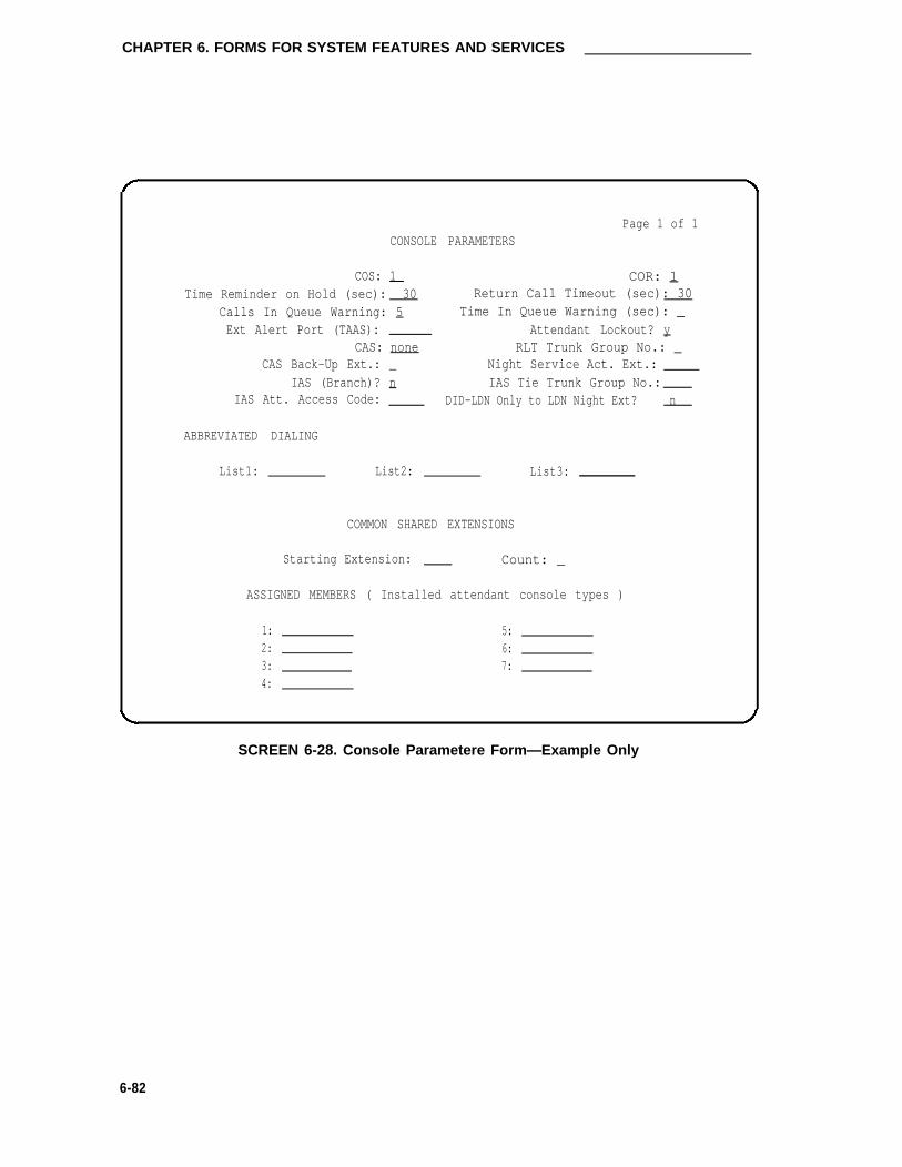
CHAPTER 6. FORMS FOR SYSTEM FEATURES AND SERVICES
Page 1 of 1CONSOLE PARAMETERS
COS: 1 COR: 1Time Reminder on Hold (sec): 30 Return Call Timeout (sec): 30
Calls In Queue Warning: 5 Time In Queue Warning (sec): _Ext Alert Port (TAAS): Attendant Lockout? y
CAS: none RLT Trunk Group No.: _CAS Back-Up Ext.: _ Night Service Act. Ext.:
IAS (Branch)? n IAS Tie Trunk Group No.:IAS Att. Access Code: DID-LDN Only to LDN Night Ext? n
ABBREVIATED DIALING
List1: List2: List3:
COMMON SHARED EXTENSIONS
Starting Extension: Count: _
ASSIGNED MEMBERS ( Installed attendant console types )
1: 5:2: 6:3: 7:4:
SCREEN 6-28. Console Parametere Form—Example Only
6-82

Data Modules
Data Modules
The following data modules can be used with the System:
• 7400A Data Module (see MPDM/MTDM)
• 7400B Data Module (see MPDM/MTDM)
• 7500B Data Module (ISDN Basic Rate Interface)
• Data Line Data Module
• MPDM/MTDM
• Netcon Data Module
• Processor Interface Data Module
• Recorded Announcement Data Module
This following pages describe the purpose of each data module and provide administration com-mands and form instructions.
6-83

CHAPTER 6. FORMS FOR SYSTEM FEATURES AND SERVICES
7500B Data Module
Purpose
This form is used to implement a 7500B Data Module.
Administration Commands
The following administration commands can be used to access the 7500B Data Module form. Insome cases, just the most commonly used commands are shown. Refer to Administration Com-mands and Error Messages (Chapter 3) for a complete listing of all administration commands, thecommand structure, and the use of abbreviated command words when entering a command.
Action object Qualifier*
add data-module xxxxx (extension or ‘next’)change data-module xxxxx (extension number)display data-module xxxxx (extension number) [‘print’ or ‘schedule’]duplicate data-module xxxxx (extension number)list data-module (starting ext number) xxxxx (‘count’) [‘print’ or ‘schedule’]remove data-module xxxxx (extension number)
* Brackets [ ] indicate the qualifier is optional.Single quotes (‘ ’) indicate the text inside the quote must be entered exactly as shown oran abbreviated form of the word maybe entered.
Form Instructions
Make assignments as required for the following fields on the form:
Page 1 of the Form
• Data Extension— When completing a paper form, enter the extension number to beassigned to the data module. A data extension can be a 1- to 5-digit number. The digitsassigned must agree with the Dial Plan Record. When implementing the form, “DataExtension” is part of the input command used to access the form and is a display-onlyfield.
• Type— Enter “7500.”
• Port— Enter 5 to 6 characters. The first character identifies the network (1 through 3,default is “1” if no entry); the second character identifies the carrier (A through E); thethird and fourth characters identify the slot number in the carrier (01 through 20 for multi-carrier cabinets or 01 through 18 for single-carrier cabinets); the last two characters iden-tify the circuit number (01 through 12).
6-84

7500B Data Module
BRI provides multipoint configuration capability which allows a previously assigned portto be specified more than once. However, for the following cases, the port will beassumed to be fully assigned:
— Maximum number of endpoints (currently two) is assigned on the port.
Note: Maximum number of endpoints can be any of the following: twovoice-only, two stand-alone data, or one voice-only and one stand-alone data.
— One of the endpoints on the port is a fixed TEl station.
— One of the endpoints on the port has B-channel voice and B-channel data capa-bility.
— One of the endpoints on the port has no SPID assigned, that includes terminalswhich have no SPID initialization capability.
Note: A 1-character entry of “X” in the Port field may not be used for BRI to indi-cate that there is no hardware associated with the port assignment (that is,Administration Without Hardware feature). The Administration WithoutHardware feature does not support BRI-type endpoints.
• Name— Enter the name of the user associated with the netcon channel. The name isoptional.
• COS— Enter the desired Class of Service (COS) number from 0 through 15. Default is“1.“
• COR— Enter the desired Class of Restriction (COR) number from 0 through 63 that willallow or deny access. Default is ”1.“
• Abbreviated Dialing List 1— Enter “p” for personal, “s” for system, “g” for group, or “e”for enhanced. If “g” or “p” is entered, a group number or personal list number, respec-tively, is also required. This field can be left blank. The entry in this field and the follow-ing Hot Line Destination field support the Data Hot Line feature.
• Special Dialing Option— Enter one of three dialing options that are available. This iden-tifies the destination of all call when this data module originates calls. Valid entries are“hot-line,” “default,” or leave blank.
• CIRCUIT SWITCHED DATA ATTRIBUTES
Note: These fields represent defaults needed for modem pooling conversionresource insertion when the endpoint does not support data query capability.These fields have no significance for data modules providing data query [allAT&T-supported BRI data modules (7500B and ADM)]. For AT&T BRI datamodules, the default settings should be used.
— Default Duplex— Used to identify the duplex mode. Valid entries are “full” or“half.” Default is “full.”
6-85

CHAPTER 6. FORMS FOR SYSTEM FEATURES AND SERVICES
— Default Mode— Used to identify the data mode. Valid entries are “sync” (syn-chronous) or “async” (asynchronous). Default is “asyn.”
— Default Speed— Used to identify the data rate. Valid entries are “1200,” “2400,”“4800,” and “19200.” Default is “1200.”
Note: When default mode is “sync,” valid entries also include speeds of“56000” and “64000.”
• Data Module Capabilities
— Default ITC (Information Transfer Capability)— Used to administer the infor-mation Transfer Capability when the 7500B data module is the originator ofadministered connector.
— Default Data Applications— Used to identify mode to be used for originatingdata calls when the mode is not specified with the calling parameters. This modewill also be used for terminating trunk calls which do not have bearer capabilityspecified or administered connections. Possible mode values are M0 (mode 0),M1 (mode 1), M2 (mode 2), and M3/2 (mode 3/2 adaptable), or blank. Validentries are “M0,” “M1,” “M2_A,” “M2_S,” or “M3/2.” Default is “M2_A.”
Page 2 of the Form
•
•
•
•
XlD— Used to identify layer two XID testing capability. Valid entries are “y” (yes) or “n”(no). Default is “y.”
Fixed TEI— Used to indicate whether or not the endpoint has Fixed TEI capability. TEI isused to identify a unique access point within a service. For Fixed TEI stations, the TEImust be administered. For terminals with automatic TEI capability, the associated TEI isassigned by the System. Valid entries are “y” (yes) or “n” (no). Default is “n.”
TEI— Only displayed if the Fixed TEI field entry is “y.” Enter a 1-to 2-digit number in therange of 0 through 63.
MIM Support— (Management Information Message Support) Used to support two typesof capabilities; MIM endpoint initialization capability (SPID support), otherMaintenance/Management capability. Valid entries are “y” or “n.” Default is “y.”
Endpoint Initialization— Only displayed if the MIM Support field entry is “y.” Used toindicate the terminal’s endpoint initialization capability. Endpoint initialization is a pro-cedure, required for multipoint operation, by which User Service Order Profile (USOP) isassociated with an endpoint on the BRI. This association is made via the SPID, admin-istered into the system and entered into the BRI terminal. For a BRI terminal to becomeoperational in a multipoint configuration, both the administered SPID and the SPID pro-grammed into the BRI terminal must be the same. This means that the SPID of the newor re-used terminals must be programmed to match the administered SPID value. Validentries are “y” (yes) or “n” (no). Default is “y.”
•
6-86

7500B Data Module
• SPID— Only displayed if the Endpoint Initialization field entry is “y.” The SPID is a vari-able parameter of up to ten digits. The SPID is a numeric string value, which means thata value of “00” is different from “000.” The SPID must be different for all terminals on theBRI and on the Service SPID. The SPID should always be assigned, if the SPID is notassigned for the first BRI on a port, any other BRI assignment to that port will be blocked.Valid entries are numeric strings in the range of 0 through 9999999999. Default is thestation’s extension number.
• MIM Mtce/Mgt— Only displayed if the MIM Support field entry is “y.” Used to indicate ifthe terminal supports MIM Maintenance and Management capabilities, other then end-point initialization. Valid entries are “y” (yes) or “n” (no). Default is “y.”
Page 1 of 2
DATA MODULE
Data Extension: Type: 7500 Port:
Name: COS : 1 COR : 1
ABBREVIATED DIALING
List1:
SPECIAL DIALING OPTION: hot-line
HOT LINE DESTINATION
Abbreviated Dialing Dial Code (From above list ) : _
CIRCUIT SWITCHED DATA ATTRIBUTES (used for modem pooling)
Default Duplex: full Default Mode: async Default Speed: 1200
DATA MODULE CAPABILITIES
Default ITC: restricted Default Data Application? M2_A
SCREEN 5-29. 7500B Data Module Form (Page 1)—Example Only
Implementation Note:
HOT LINE DESTINATION only displayed when “hot-line” is entered in the SPECIAL DIALINGOPTION field.
DEFAULT DIALING only displayed when “default” is entered in the SPECIAL DIALING OPTIONfield.
Abbreviated Dialing Dial Code only displayed when SPECIAL DIALING OPTION is “hot-line” or“default.”
6-87

CHAPTER 6. FORMS FOR SYSTEM FEATURES AND SERVICES
DATA MODULE
Page 2 of 2
BRI LINK/MAINTENANCE PARAMETERS
XID? y Fixed TEI? n TEI: _
MIM Support? y Fixed Init? y SPID: 3 0 0 MIM Mtce/Mgt? y
SCREEN 6-30. 7500B Data Module Form (Page 2)—Example Only
Implementation Note:
The TEI field is only displayed if the Filed TEl field entry is “y.”
The Endpt Init, SPID, and MIM Mtce/Mgt fields are only displayed if the MIM Support field entry is
“y.”
The SPID field is only displayed when the Endpt Init field entry is “y.”
6-88

Data Line Data Module
Data Line Data Module
Purpose
The Data Line Data Module (DLDM) form is used to assign ports on the TN726 Data Line circuitpack (DLC) that allows EIA (EIA 232C) devices* to connect to the System. The DLC, with acompanion ADU, provides a less expensive data interface to the System than data modules suchas DTDMs, MPDMs, or MTDMs.
The DLC supports asynchronous transmissions at speeds of Low and 300, 1200, 2400, 4800,9600, and 19200 bps (bits per second) over 2-pair (full-duplex) lines. These lines can have vari-ous lengths, depending on the transmission speed and wire gauge.
The DLC has eight ports. The connection from the port to the EIA device is direct, meaning thatno multiplexing is involved. A single port of the DLC is equivalent in functionality to a datamodule and a digital line port. The DLC appears as a data module to the Digital Terminal Equip-ment (DTE) and as a digital line port to the switch.
The DLC connects the following EIA 232C equipment to the System:
• Printers
• Non-lntelligent Data Terminals
• Intelligent Terminals, Personal Computers (PCs)
• Host Computers
• ISN (Information Systems Network), EIA 232C LANs (Local Area Networks), or otherdata switches
The following figure shows some typical DLC applications.
* In this chapter, the term “device” is used to refer to EIA (EIA 232C) equipment including data terminals, personalcomputers, printers, and host computers.
6-89

CHAPTER 6. FORMS FOR SYSTEM FEATURES AND SERVICES
SWITCHTN726 TN726
ADU ORTN726B
TN726B
ORINFORMATION
SYSTEMS AIM
NETWORK 8
(ISN) TN726ADU OR
TN726B
TN754 TN726EIA
7403DTERMINAL
OR
TN754BTN726B
OR
TN754B (M)PDM
EIAADU
TERMINAL
TN742,
TN746B,
OR
TN769
T N 7 2 6
ORTN726B
TN754
OR
EIAADU
DEVICE*
DATA
MODULE
HOST
COMPUTER
OR
MODEM
* PRINTER, PERSONAL COMPUTER,
OR DATA TERMINAL
FIGURE 6-8. TN726 Data Line Circuit Pack Applications
Administration Commands
The folIowing administration commands can be used to access the DLDM form. In some cases,just the most commonly used commands are shown. Refer to Administration Commands andError Messages (Chapter 3) for a complete Iisting of all administration commands, the commandstructure, and the use of abbreviated command words when entering a command.
6-90

Data Line Data Module
Action Object QuaIifier*
add data-module xxxx (extension or ‘next’)change data-module xxxx (extension number)display data-module xxxx (extension number) [print or schedule]duplicate data-module xxxx (extension number to be duplicated)list data-module (starting ext number) xxxx (‘count’) [print or schedule]remove data-module xxxx (extension number)
* Brackets [ ] indicate the qualifier is optional.Single quotes (‘ ’) indicate the text inside the quote must be entered exactly as shown oran abbreviated form of the word maybe entered.
Form Instructions
Make assignments as required for the following fields on each page of the form:
Page 1 of the Form
•
•
Data Extension— Enter the extension number assigned to the Data Line port. A dataextension number can be from 1 to 5 digits. The digits assigned must agree with the DialPlan Record.
BCC (Bearer Capability Class)— This field is only displayed when the ISDN-PRI option isenabled on the System-Parameters Customer-Options form. It is a display-only field.The value in the field corresponds to the speed setting of the data module. A BCC of”1”relates to 56 kbps, BCC values of 2, 3, and 4 relate to 64 kbps. The entry in this fieldshould be compared with the BCC value in an associated routing pattern when attemptedcalls utilizing the data module fail to complete. The BCC values must be the same.
Note: Refer to the GRS feature description in DEFINITY® Communications Sys-
•
•
tem Generic 1 and Generic 3i—Feature Description, 555-230-201, for adetailed description of BCCs and their use to provide specialized routing forvarious types of voice and data calls. The BCC value is used to determinecompatibility when non-lSDN-PRl facilities are connected to ISDN facilities(ISDN-PRI InterWorking feature).
Type— Enter “data-line.”
Port— Enter five to six characters. The first character identifies the network (1 through 3,default is “1” if no entry); the second character identifies the carrier (A through E); thethird and fourth characters identify the slot number in the carrier (01 through 20 for multi-carrier cabinets depending on carrier type or 01 through 18 for single-carrier cabinetsdepending on cabinet); the last two characters identify the circuit number (01 through08).
Name— Enter the name of the user associated with the data module. The name isoptional, it can be left blank.
COS— Enter the desired Class of Service (COS) number from 0 through 15. Default is“1.”
•
•
6-91

CHAPTER 6. FORMS FOR SYSTEM FEATURES AND SERVICES
•
•
•
•
•
COR— Enter the desired Class of Restriction (COR) number from 0 through 63. Defaultis ”1.“
ITC (Information Transfer Capability)— Used by the GRS feature and enables the sys-tem to route calls to restricted or unrestricted facilities according to the endpoint’s infor-mation transfer capability. Default is restricted.
Connected To— Enter “dte” (Data Terminal Equipment) or “isn” (Information SystemsNetwork). This field shows what the ADU is connected to. Default is “dte.”
List 1— Enter “p” for personal, “s” for system, “g” for group, or “e” for enhanced. If “g” or“p” is entered, a group number (1 through 100) or personal list number (1 through 3) isalso required.
Special Dialing Option— Enter one of three dialing options that are available. This iden-tifies the type of dialing for calls when this data module originates calls. Valid entries are“hot-line,” “default,” or leave blank for regular (normal) keyboard dialing.
Hot Line Destination Abbreviated Dialing Dial Code— Only displayed when the Spe-cial Dialing Option field is “hot-line.” Enter a list number (associated with the above ADList) from 0 through 999. The associated AD number will be dialed when the user goesoff-hook on a Data Hot Line call.
Default Dialing Abbreviated Dialing Dial Code From above list— Only displayed whenthe Special Dialing Option field is “default.” Enter a list number (associated with theabove AD List) from 0 through 999. The associated AD number will be dialed when theuser goes off-hook and enters a carriage return following the “DIAL” prompt. The datacall originator can also perform data terminal dialing by specifying a dial string that mayor may not contain alphanumeric names.
Ext— Make no entry. The extension number is automatically assigned when the systemis administered. This is the extension number of the user who has an associated DataExtension button and will share the module.
Name— Make no entry. The name is assigned when the System is administered. This is
•
•
•
•the name assigned to this extension number.
Page 2 of the Form
Refer to the DLC Option Settings information that follows these instructions for additional infor-mation when assigning entries for the remaining fields on the form.
• Keyboard Dialing— Enter “y” to allow keyboard dialing; otherwise, enter “n.” Thisenables the data endpoint to receive and transmit text during call origination or termina-tion. If “y” is entered, complete the following applicable fields. If “y” is entered in thisfield, an “n” must be entered in the Low field.
This option must be enabled to allow data endpoints to originate calls via the EIA 232Cinterface and obtain ASCII feedback text. When enabled, the user will get the dialprompt. This option is normally enabled for “originate/receive” DTE that has a need toset up data calls. If this option is disabled, originations cannot be done at the DTE andtext feedback will not occur at the DTE during call setup/take down. Data call answeringis still allowed but without text feedback.
• Configuration— Enter “y” to allow the viewing and changing of options from the DTE;otherwise, enter “n.” (This field appears only when “KYBD Dialing” is enabled.)
6-92

Data Line Data Module
This option is normally enabled for “originate/receive” DTE, such as non-intelligent termi-nals, and disabled for intelligent devices such as computers. Keyboard dialing must beenabled with this option.
• Busy Out— Enter “y” to place the DLC port in a busied-out state once the DTE controllead to the DLC is dropped; otherwise, enter “n.” This option should be enabled forDTEs that are members of a hunt group and to allow “busy out” when DTE turns poweroff so that calls will not terminate on that DTE.
• SPEEDS—Low— Enter “y” to instruct the DLC to operate at a low speed from 0 to 1800bits per second (bps). Enter “n” if “y” is entered in the Keyboard Dialing field.
• SPEED—300; 1200; 2400; 4800; 9600; 19200— Enter “y” beside the desired operatingspeed. Enter “n” if the speed is not desired. The DLC can be set to any one of thesespeeds. The speed will be matched for the duration of the call, from call setup to calltakedown.
When multiple speeds are selected (select three or more, do not select just two speeds)and autoadjust is disabled, the DTE's speed must be set to the highest selected speed.This is required because all feedback text is delivered to the DTE at the highest selectedspeed.
• SPEEDS—Autoadjust— Enter “y” which tells the DLC port to automatically adjust to theoperating speed and parity of the DTE it is connected to. Enter “n” if this option is notdesired. (This field only appears when “KYBD Dialing” is enabled.) Autoadjust can beselected with any of the speed selected in the previous step. Autoadjust allows the DLCport to determine the speed and parity of the DTE and then match itself to this speed.Autoadjust only applies to calls originated by the user through Keyboard Dialing.
If “Autoadjust” is set to ’’y,” the user must press [BREAK] and then [RETURN] to receive the“DIAL” prompt.
• Permit Mismatch— Enter “y” to instruct the DLC to operate at the highest selectedspeed, which is a higher rate than the far-end data module. Enter “n” if this option is notdesired.
This option allows the EIA interface to operate at a rate different than that agreed to inthe data module handshake. (The data module handshake is always the highest compa-tible rate as determined by the repotted speed option of each data module.) PermitMismatch eliminates the need to change the DTE/DLC speed every time a call is placedto/from an endpoint operating at a different speed. When this option is enabled, the DLCreports the highest optioned speed and all the lower speeds (or the previously selectedautoadjust speed only) during the handshake process. Caution must be used whenusing this option to send information from a DTE/DCE that is transmitting data at higherrates than that of the far end. Sustained usage of this type transmission will result in lossof data. Whenever this option is enabled, the DTE must be set to match the highestspeed selected for the associated DLC port.
This option is intended to be used by a DTE device operating locally at a higher baud ratethan that of its far-end connection but transmitting relatively low amounts of data (forexample, a user typing at a terminal). Also, this option may be selected whether or notKeyboard Dialing is selected.
6-93

CHAPTER 6. FORMS FOR SYSTEM FEATURES AND SERVICES
Note: The Low speed setting is not reported as an available speed when PermitMismatch is enabled.
• Dial Echoing— Enter “y” to echo characters back to the DTE; otherwise, enter “n.” (Thisfield is enabled only if “KYBD Dialing” is enabled.) Dial echoing should be disabled whenkeyboard dialing is done by an intelligent device.
• Disconnect Sequence— Enter “long-break” or “two-breaks” to select the sequence for adisconnect. A long-break is greater than two seconds and two-breaks is within onesecond. (This field is enabled only when “KYBD Dialing” is enabled.)
• Answer Text— Enter “y” to allow text messages to be delivered to the DTE when a call isbeing answered. Enter “n” if this option is not desired. (This field is enabled only when“KYBD Dialing” is enabled.)
This option enables text feedback which is normally delivered to the DTE when a call isanswered or disconnected. The Answer Text option applies to DLC-generated text aswell as text received from the System. If this option is disabled, the System will still gen-erate the text, but the DLC will prevent it from being sent to the device. This applies tothe following messages:
– Incoming Call
– Answered
– Disconnected
– Disconnected Other End
This option is usually disabled when the answering DTE is a computer or an intelligentdevice.
• Parity— Enter “even,” “odd,” “mark,” or “space” to select the desired type of parity. (Thisfield is enabled only when “KYBD Dialing” is enabled.) The parities (even, odd, mark,and space) are generated by the DLC when call setup text is sent to the DTE. The DLCdoes not check the parity when receiving dialing characters. Parity has nothing to dowith the far end; it is only for the DLC to terminal communications during call setup.
• Connected lndication— Enter “y” to give text feedback to the DTE when a connectionhas been established. (This field is enabled only when “KYBD Dialing” is enabled.) Thisoption generates a “CONNECTED” message to the DTE when the connection has beenestablished. If KYBD Dialing is not selected, the connected indication is provided by theDLC activating its EIA 232C control lead.
6-94

Data Line Data Module
DLC Option Settings
The following provides additional information on the option settings for DLCs when used with thefollowing types of devices:
• Printers
• Non-intelligent Terminals
• Data Terminals and Personal Computers
• Host Computers
• ISN
This information must be considered when completing the various fields on the DLDM form.
Printer
A DLC port, attached to a printer, usually terminates a data call. Therefore, in this connection,the printer is the endpoint device. The originating device maybe attached to a DCP mode 2 datamodule (such as the MPDM) or the DLC. A 23A ADU extends the range of the EIA 232C con-nection.
When a receive-only printer (or any printer that does not generate the Transmit Data and DTRleads) is used, the ADU must be powered from a small plug-mounted transformer (2012D, orequivalent) connected to pins 7 and 8 of the modular jack. (Refer to ADU User Manual, 555-401-701, for details.)
An ADU cannot be used if the printer has hardware flow control using the Clear To Send (CTS)lead. An ADU can be used, however, if the printer is using software flow control.
6-95

CHAPTER 6. FORMS FOR SYSTEM FEATURES AND SERVICES
A printer connected to a DLC is usually assigned as a line. The following table lists the optionsettings for printer connections:
TABLE 6-C. DLDM Form Option Settings for Printer Connection
Field On Form Option Comments
speed Highest speed at which Subject to distance limi-the Printer operates tatios; Autoadjust not
used
KYBD Dialing no
Busy Out yes If printer is member ofHunt Group
Permit Mismatch yes No, if printer is lowspeed
Parity Don’t care
Dial Echoing Don’t care
Disconnect Sequence Don’t care
Answer Text Don’t care
Connected Indication Don’t care
Configuration no
6-96

Data Line Data Module
Non-Intelligent Terminals
A non-intelligent terminal connected to the DLC is usually assigned as a line.
The following table lists the option settings for non-intelligent terminals.
TABLE 6-D. DLDM Form Option Settings for Connection to Non-Intelligent Terminals
Field On Form Option Comments
Speed All speeds at which the Subject to distance limi-terminal can operate; tations; Autoadjust onlyautoadjust if Keyboard Dialing is
yes and the Terminalcan geneate an ASCII“carriage return”
KYBD Dialing yes
Busy Out no Yes, if terminal ismember of a hunt group
Permit Mismatch yes -
Parity Same as DTE
Dial Echoing yes Only if KYBD Dialing isyes
Disconnect Sequence 2 <BREAK>s Depends on terminal
Answer Text yes
Connected Indication - Don’t care
Configuration yes
6-97

CHAPTER 6. FORMS FOR SYSTEM FEATURES AND SERVICES
Data Terminals and Personal Computers
An intelligent data terminal or a personal computer (PC) attached to a DLC can either originate orterminate a data call. A single ADU at the site of the originating device extends the distance sig-nals can travel to the switch (the model ADU depends on the terminal connector). An analogtelephone can be attached to this arrangement whenever an ADU uses the standard building wir-ing.
The following table lists the option settings used for data terminal and personal computer connec-tions.
TABLE 6-E. DLDM Form Option Settings for Connection to Data Terminal or Personal Computer
6-98
Field On Form Option Comments
Speed All speeds at which the Subject to distance limi-Data Terminal or PC tations; Autoadjust notcan operate used
KYBD Dialing yes
Busy Out no Yes, if device isaccessed through ahunt group
Permit Mismatch yes No, if device does not support XON/XOFF flowcontrol
Parity Same as DTE
Dial Echoing no These devices can dialin the ASCII streamwithout human interven-tion
Disconnect Sequence Long <BREAK> -
Answer Text no These devices may notwant to see any text
Connected Indication Don’t care
Configuration yes

Data Line Data Module
Host Computers
A host computer may originate and terminate a data call. For this application, the number ofDLCs required depend on the number of ports needed. An MADU can be used (instead of eightADUs) to complete the connection.
The following table lists option settings for a port that has a terminating connection to a host com-puter.
Note: When Keyboard Dialing is disabled, the rest of the option settings are irrelevant.
TABLE 6-F. DLDM Form Option Settings for Terminating Connection to Host Computer
Field On Form Option Comments
Speed All speeds at which the Subject to distance limi-computer can operate tations; Autoadjust not
used
KYBD Dialing no
Busy Out - Don’t care
Permit Mismatch - Don’t care
Parity - Don’t care
Dial Echoing - Don’t care
Disconnect Sequence - Don’t care
Answer Text - Don’t care
Connected Indication - Don’t care
Configuration - Don’t care
6-99

CHAPTER 6. FORMS FOR SYSTEM FEATURES AND SERVICES
The following table shows the option settings for a port that has an originating connection from ahost computer.
TABLE 6-G. DLDM Form Option Settings for Originating Connection From a Host Computer
Field On Form Option Comments
Speed All speeds at which the Subject to distance limi-computer can operate tations; Autoadjust not
used
KYBD Dialing yes
Busy Out no Yes, if computer isaccessed through ahunt group
Permit Mismatch yes No, if computer doesnot support XON/XOFFflow control
Parity Same as DTE
Dial Echoing no The computer can dialin the ASCII streamwithout human interven-tion
Disconnect Sequence Long <BREAK> -
Answer Text no The computer may notwant to see any text
Connected Indication - Don’t care
Configuration no
6-100

Data Line Data Module
Information Systems Network
The DLC can also connect the Information Systems Network (ISN) to the System. The ISN canoriginate and terminate data calls.
Two lines are required for bidirectional data transmission between ISN and the System. Asviewed by the System, these are: one terminating line (from ISN to the System) and one ori-ginating line (from the System to ISN). Fixed baud rate lines should be used in both directions.
To successfully connect the Z3A3 ADU to the DLC, a crossover cord (or 25-pair crossover cable)must be used between the DLC and the ADU. This connects the near-end pair of transmit datawires to the far-end receive pair and connects the near-end receive pair to the far-end transmitpair. Without crossover, data transfer cannot take place. Refer to the ADU User Manual, 555-401-701, for cabling information. Another method to achieve the necessary crossover is to usethe D8AM-87 cord.
An ISN connected to a DLC is usually translated as two lines. The next two tables list the basicoption settings for both the originating (outgoing) and the terminating (incoming) line. See theISN Application Notes, 555-300-400, for additional information.
TABLE 6-H. DLDM Form Option Settings for Outgoing Line to ISN
Field On Form Option Comments
Speed Highest Speed at which Subject to distance limitations;the ISN can operate Autoadjust not used
KYBD Dialing no
Busy Out no Yes, if ISN is accessed througha hunt group
Permit Mismatch no The ISN can operate at higherspeeds than the data communi-cations link; data loss can occurif Permit Mismatch is yes andthe ISN is transmitting
Parity Same as ISN
Dial Echoing no The ISN can dial in the ASCIIstream without human interven-tion
Disconnect Sequence Long <BREAK>Answer Text no The ISN may not want to see
any text
Connected Indication - Don’t careCofiguration no
6-101

CHAPTER 6. FORMS FOR SYSTEM FEATURES AND SERVICES
TABLE 6-I. DLDM Form Option Settings for Incoming Line From ISN
Field On Form Option COMMENTSSpeed Highest Speed at which Subject to distance limitations;
the ISN can operate Autoadjust not used
KYBD Dialing yes
Busy Out Don’t care
Permit Mismatch no The /S/V can operate at higherspeeds than the data communi-cations link; yes, if ISN has itsOutgoing port set to high speedsuch as 9.6 kbps and the far-end connections will be at nogreater than 9.6 kbps
Parity Same as ISN
Dial Echoing yes
Disconnect Sequence Long <BREAK>
Answer Text no The lSN may not want to seeany text
Connected Indication - Don’t care
Configuration no
6-102

Data Line Data Module
Page 1 of 2
DATA MODULE
Data Extension: BCC: _ Type: data-linePort:_
Name: COS: 1 COR: 1_
connected To: dte ITC : restricted
ABBREVIATED DIALING
List1:
SPECIAL DIALING OPTION: __HOT LINE DESTINATIONDEFAULT DIALING
Abbreviated Dialing Dial Code (From above list): _
ASSIGNED MEMBER ( Station with a data extension button for this data module )
Ext Name1:
SCREEN 6-31. Data Line Data Module Form (Page 1)—Example Only
Implementation Note:
This page is only displayed if the Data Module field on Page 1 is “y.”
The BCC field is only displayed if the lSDN-PRl option is enabled on the System-ParametersCustomer-Options form.
Hot Line Destination only displayed when the Special Dialing Option field is ’’hot-line.”
Default Dialing only displayed when the Special Dialing Option field is “default.”
Abbreviated Dialing Dial Code only displayed when SPECIAL DIALING OPTION is “hot-line” or“default.”
6-103

CHAPTER 6. FORMS FOR SYSTEM FEATURES AND SERVICES
CAPABILITIESKYBD Dialing?
Busy Out?SPEEDS
Low? n 1200?300? y 2400?
OPTIONSPermit Mismatch?
Disconnect Sequence:Parity:
DATA MODULE
4800? y9600? y
Page 2
Configuration? nyn
y 19200?
y Autoadjust?
n Dial Echoing?two-breaks Answer Text?
even Connected Indication?
of 2
yn
yyy
SCREEN 6-32. Data Line Data Module (Page 2)—Example Only
Note: lf KYBD Dialing is “y,” the above page is displayed.
CAPABILITIES
SPEEDSLow?300?
OPTIONS
KYBD Dialing? nBusy Out? n
y 1200? y
y 2400? y
Permit Mismatch? n
DATA MODULE
4800? y9600? y
Page 2 of 2
19200? y
SCREEN 6-33. Data Line Data Module Form (Page 2)—Example Only
Note: lf KYBD Dialing is “n,” the above page is displayed.
6-104

Modular Processor Data Modules/Modular Trunk Data Modules
Modular Processor Data Modules/Modular Data Modules
Purpose
These forms are used to assign Modular Processor Data Modules (MPDMs) and Modular TrunkData Modules (MTDMs) in the system. One form is required for assigning MPDMs (700A, 700D)or 7400B Data Modules and another form for MTDMs (700B, 700C, 700E, 7400A). One formmust be completed for each MPDM, 7400B, or MTDM in the System.
The MPDM or 7400B Data Module provides a DCE interface for connection to equipment such asdata terminals, SMDR output devices, on-premises administration terminal, Message Server,PMS, AUDIX, and host computers. It also provides a DCP interface to the digital switch. (DigitalCommunications Equipment is the equipment on the network side of a communications link thatprovides all the functions required to make the binary serial data from the source or transmittercompatible with the communications channel.)
The MTDM provides an EIA DTE interface for connection to off-premises private line trunk facili-ties or a switched telecommunications network and a DCP interface for connection to the digitalswitch. (Data Terminal Equipment is the equipment comprising the endpoints in a connectionover a data circuit. For example, in a connection between a data terminal and a host computer,the terminal, the host, and their associated modems or data modules make up the DTE.) TheMTDM or 7400A Data Module can also serve as part of a conversion resource for CombinedModem Pooling.
Administration Commands
The following administration commands can be used to access the MPDM/MTDM form. In somecases, just the most commonly used commands are shown. Refer to Administration Commandsand Error Messages (Chapter 3) for a complete listing of all administration commands, the com-mand structure, and the use of abbreviated command words when entering a command.
Action Object Qualifier*
add data-module xxxx (extension or ‘next’)change data-module xxxx (extension number)displaylist
data-module xxxx (extension number) [‘print’ or ‘schedule’]data-module (starting ext number) xxxx (‘count’) [‘print’ or ‘schedule’]
* Brackets [ ] indicate the qualifier is optional.Single quotes (‘ ’) indicate the text inside the quote must be entered exactly as shown oran abbreviated form of the word maybe entered.
Form Instructions
These instructions can be used to assign an MPDM and an MTDM. The differences in the fieldson the forms are explained in the instructions. Note that administration instructions for a 7400BData Module associated with a 7400D-series voice terminal are provided in the appropriate voiceterminal information provided later in this chapter.
6-105

CHAPTER 6. FORMS FOR SYSTEM FEATURES AND SERVICES
Make assignments as required for the following fields on the form:
•
•
•
•
Data Extension— When completing a paper form, enter the extension number to beassigned to the data module. A data extension can be a 1- to 5-digit number. The digitsassigned must agree with the Dial Plan Record. When implementing the form, “DataExtension” is part of the input command used to access the form and is a display-onlyfield.
BCC (Bearer Capability Class)— This field is only displayed when the ISDN-PRI optionis enabled on the System-Parameters Customer-Options form. It is a display-only field.The value in the field corresponds to the speed setting of the data module. A BCC of “1”relates to 56 kbps, BCC values of 2, 3, and 4 relate to 64 kbps. This field may be com-pared with the BCC value in an associated muting pattern when attempted calls utilizingthe data module fail to complete. The BCC values must be the same.
Note: Refer to the GRS feature in DEFINITY® Communications System Generic 1and Generic 3i—Feature Description, 555-230-201, for a detailed descriptionof BCCs and their use to provide specialized routing for various types ofvoice and data calls. The BCC value is used to determine compatibilitywhen non-lSDN-PRl facilities are connected to ISDN facilities (ISDN-PRIInterworking feature).
Type— Enter “pdm” when assigning a DCE interface or “tdm” when assigning a DTEinterface. Default is “pdm.”
Port— Enter the port location that the data module is connected to. The first characteridentifies the network (1 through 3, default is “1” if no entry); the second character identi-fies the carrier (A through E); the third and fourth characters identify the slot number inthe carrier (01 through 20 for multi-carrier cabinets depending on carrier type or 01through 18 for single-carrier cabinets depending on cabinet type); the last two charactersidentify the circuit number (01 through 24).
Name— Enter the name of the user associated with the data module. The name isoptional, it can be left blank.
COS— Enter the desired Class of Service (COS) number from 0 through 15. Default is“1.“
COR— Enter the desired Class of Restriction (COR) number from 0 through 63. Defaultis “1.“
ITC (Information Transfer Capability)— Used by the GRS feature and enables the sys-tem to route calls to restricted or unrestricted facilities according to the endpoint’s infor-mation transfer capability. Default is restricted.
Connected to— Enter “dte” if the data module is connected to DTE or enter “isn” if con-nected to an ISN.
Remote Loop-Around Test— Enter “y” if the data module supports a loop-back test atthe EIA interface; otherwise, enter “n.” In general, AT&T equipment will support this testbut it is not required by Level 2 Digital Communications Protocol.
Abbreviated Dialing List 1— Enter “p” for personal, “s” for system, “g” for group, or “e”for enhanced. If “g” or “p” is entered, a group number (1 through 100) or personal listnumber (1 through 3), respectively, is also required. The entry in this field and the
•
•
•
•
•
•
•
6-106

Modular Processor Data Modules/Modular Trunk Data Modules
following HOT LINE DESTINATION field support the Data Hot Line feature. This fieldcan be left blank.
• Special Dialing Option— Enter one of three dialing options that are available. This iden-tifies the type of dialing for calls when this data module originates calls. Valid entries are“hot-line,” “default,” or leave blank for regular (normal) keyboard dialing.
• Hot Line Destination— Abbreviated Dialing Dial Code— Only displayed when the Spe-cial Dialing Option field is “hot-line.” Enter a list number (associated with the above ADList) from 0 through 999. The associated AD number will be dialed when the user goesoff-hook on a Data Hot Line call.
• Default Dialing Abbreviated Dialing Dial Code From above list— Only displayed whenthe Special Dialing Option field is “default.” Enter a list number (associated with theabove AD List) from 0 through 999. The associated AD number will be dialed when theuser goes off-hook and enters a carriage return following the “DIAL” prompt. The datacall originator can also perform data terminal dialing by specifying a dial string that mayor may not contain alphanumeric names.
• Ext— Make no entry. The extension number is automatically assigned when the systemis administered. This is the extension number of the user who has an associated DataExtension button and will share the module.
• Name— Make no entry. The name is automatically assigned when the System is admin-istered. This is the name assigned to the above extension number.
6-107

CHAPTER 6. FORMS FOR SYSTEM FEATURES AND SERVICES
Page 1 of 1
DATA MODULE
Data Extension: BCC: _ T y p e : p d m Port : _Name: COS: 1 COR: 1
ITC: _connected to: _ Remote Loop-Around Test: _
ABBREVIATED DIALING
Listl:
SPECIAL DIALING OPTION: _HOT LINE DESTINATIONDEFAULT DIALING
Abbreviated Dialing Dial Code (From above list): _ASSIGNED MEMBER ( Station with a data extension button for this data module )
Ext Name1:
SCREEN 6-34. MPDM/MTDM Data Module Form—Example Only
Implementation Note:
The Type field may be either ’’pdm” or ’’tdm.” lf ’’tdm’’ is entered, the Connected to field is notdisplayed.
The BCC field is only displayed if the lSDN-PRl option is enabled on the System-ParametersCustomer-Options form.
HOTLINE DESTINATION only displayed when the SPECIAL DIALING OPTION field is ’’hot-Iine.”
DEFAULT DIALING only displayed when the SPECIAL DIALING OPTION field is “default.”
Abbreviated Dialing Dial Code only displayed when SPECIAL DIALING OPTION is “hot-line” or“default.”
6-108

Netcon Data Module
Netcon Data Module
Purpose
Netcon data modules are the PDMs that are integrated into the System’s network control portsthat provide asynchronous circuit switched interfaces to the maintenance and administration ter-minals, Hospitality journal printers, and SMDR line printer. They are characterized by their specialIocations, that is, special port identifications.
Note: Refer to Data Modules in Chapter 4 for information on the administration, considera-tions, and uses of a Netcon channel interface.
Administration Commands
The following administration commands can be used to access the Netcon Data Module form. Insome cases, just the most commonly used commands are shown. Refer to Administration Com-mands and Error Messages (Chapter 3) for a complete listing of all administration commands, thecommand structure, and the use of abbreviated command words when entering a command.
Action Object Qualifier*
add data-module xxxx (extension or ‘next’)change data-module xxxx (extension number)display data-module xxxx (extension number) [‘print’ or ‘schedule’]list data-module (starting ext number) xxxx (‘count’) [‘print’ or ‘schedule’]
* Brackets [ ] indicate the qualifier is optional.Single quotes (‘ ’) indicate the text inside the quote must be entered exactly as shown oran abbreviated form of the word maybe entered.
Form Instructions
Make assignments as required for the following fields on the form:
• Data Extension— When completing a paper form, enter the extension number to beassigned to the data module. A data extension can be a 1- to 5-digit number. The digitsassigned must agree with the Dial Plan Record. When implementing the form, “DataExtension” is part of the input command used to access the form and is a display-onlyfield.
• BCC— This field is only displayed when the ISDN-PRI option is enabled on the System-Parameters Customer-Options form. It is a display-only field.
Note: Refer to the GRS feature in DEFINITY® Communications System Generic 1and Generic 3i—Feature Description, 555-230-201, for a detailed descriptionof BCCs and their use to provide specialized routing for various types ofvoice and, data calls. The BCC value is used to determine compatibilitywhen non-lSDN-PRl facilities are connected to ISDN facilities (ISDN-PRIInterworking feature).
• Type— Enter “netcon.”
6-109

CHAPTER 6. FORMS FOR SYSTEM FEATURES AND SERVICES
• Physical Channel— Enter a netcon data channel number from 01 through 04.
• Name— Enter the name of the user associated with the netcon channel. The name isoptional.
• COS— Enter the desired Class of Service (COS) number from 0 through 15. Default is“1.”
• COR— Enter the desired Class of Restriction (COR) number from 0 through 63 that willallow or deny access. Default is “1.“
• Maintenance Extension— Enter the extension number required to perform maintenancefunctions on the standby netcon physical channel in a duplicated System. The standbyremote loop around tests will fail if this field is not administered.
• ITC (Information Transfer Capability)— Used by the GRS feature and enables the sys-tem to route calls to restricted or unrestricted facilities according to the endpoint’s infor-mation transfer capability. Default is restricted.
• Abbreviated Dialing List 1— Enter “p” for personal, “s” for system, “g” for group, or “e”for enhanced. If “g” or “p” is entered, a group number or personal list number, respec-tively, is also required. This field can be left blank. The entry in this field and the follow-ing Hot Line Destination field support the Data Hot Line feature.
• Special Dialing Option— Enter one of three dialing options that are available. This iden-tifies the destination of all call when this data module originates calls. Valid entries are“hot-line,” “default,” or leave blank.
• Hot Line Destination—Abbreviated Dialing Dial Code— Only displayed when the Spe-cial Dialing Option field is “hot-line.” Enter a list number (associated with the above ADList) from 0 through 999. The associated AD number will be dialed when the user goesoff-hook on a Data Hot Line call.
• Ext— Make no entry. The extension number is automatically assigned when the systemis administered. This is the extension number of the user who has an associated DataExtension button and will share the module.
• Name— Make no entry. The name is assigned when the System is administered. This isthe name assigned to the above extension number.
6-110

Netcon Data Module
DATA MODULE
Page 1 of 1
Data Extension: BCC: _ Type: netcon Physical Channel : _
Name: Cos: 1 COR: 1
Maintenance Extension:
ITC: restricted
ABBREVIATED DIALING
List1:
SPECIAL DIALING OPTION: _
HOT LINE DESTINATIONAbbreviated Dialing Dial Code (From above list): _
ASSIGNED MEMBER ( station with a data extension button for this data module )
Ext Name
1:
SCREEN 6-35. Netcon Data Module Form—Example Only
Implementation Note:
The BCC field is only displayed if the ISDN-PRI option is enabled on the System-ParametersCustomer-Options form.
HOT LINE DESTINATION only displayed when the SPECIAL DIALING OPTION field is ’’hot-Iine.”
Abbreviated Dialing Dial Code only displayed when SPECIAL DIALING OPTION is “hot-line.”
6-111

CHAPTER 6. FORMS FOR SYSTEM FEATURES AND SERVICES
Processor Interface Data Module
Purpose
The Processor Interface data modules are the PDMs that are integrated into the System’ssynchronous/asynchronous Processor Interface circuit pack ports. They are used to provide thefollowing interfaces:
• 3B/CMS (maximum of one)
• 3B/Message Server (maximum of one)
• DCS (maximum of eight)
• AUDIX (maximum of one)
• ISDN-PRI (maximum of eight)
Note: Not all maximums can be achieved at the same time).
Connections for these interfaces are achieved via a digital line port and MPDM combination,and/or in the case of DCS or ISDN-PRI, via a DS1 interface. One direct EIA connection is avail-able (labeled as Processor Interface on the back of the Control Cabinet) for simplex operation.When used, the physical channel assignment (see below) must be “01.“ Use of the EIA connec-tion eliminates the need for one digital line port/MPDM combination.
Administration Commands
The following administration commands can be used to access the Processor Interface DataModule form. In some cases, just the most commonly used commands are shown. Refer toAdministration Commands and Error Messages (Chapter 3) for a complete listing of all adminis-tration commands, the command structure, and the use of abbreviated command words whenentering a command.
Action Object Qualifier*
add data-module xxxx (extension or ‘next’)change data-module xxxx (extension number)display data-module xxxx (extension number) [‘print’ or ‘schedule’]list data-module (starting ext number) xxxx (‘count’) [‘print’ or
‘schedule’]
* Brackets [ ] indicate the qualifier is optional.Single quotes (‘ ’) indicate the text inside the quote must be entered exactly as shown oran abbreviated form of the word maybe entered.
6-112

Processor Interface Data Module
Form Instructions
Make assignments as required for the following fields on the form:
•
•
•
•
•
•
•
•
•
•
•
•
Data Extension— When completing a paper form, enter the extension number to beassigned to the data module. A data extension can be a 1- to 5-digit number. The digitsassigned must agree with the Dial Plan Record. When implementing the form, “DataExtension” is part of the input command used to access the form and is a display-onlyfield.
Type— Enter “procr-infc.”
Physical Channel— Enter the 2-digit circuit number of the Processor Interface port. Amulti-carrier cabinet system supports the use of two Processor Interface circuit packs,the first circuit pack (mounted in Control Carrier A) supports physical channels or links 01through 04, the second (mounted in Control Carrier A) supports physical channels orlinks 05 through 08. A single-carrier cabinet system supports one Processor interfacecircuit pack and physical channels or links 01 through 04 only. The Physical Channelnumber is referred to on associated System forms as the Interface Link number.
Name— Enter the name of the system associated with the data channel, such as AUDIX,DCS, etc. This entry is optional.
COS— Enter the desired Class of Service (COS) number from 0 through 15. Default is“1.“
COR— Enter the desired Class of Restriction (COR) number from 0 through 63 that wiIIallow or deny access. Default is “1.“
Maintenance Extension— Enter the extension number required to perform maintenancefunctions on the standby physical channel in a duplicated System. The standby remoteloop around tests will fail if this field is not administered.
Abbreviated Dialing List 1— Enter “p” for personal, “s” for system, “g” for group, or “e”for enhanced. If “g” or “p” is entered, a group number or personal list number, respec-tively, is also required. The entry in this field and the Hot Line Destination field supportthe Data Hot Line feature. This field can be left blank.
Special Dialing Option— Enter one of three dialing options that are available. This iden-tifies the destination of all call when this data module originates calls. Valid entries are“hot-line,” “default,” or leave blank.
Hot Line Destination— Abbreviated Dialing Dial Code-Only displayed when the Spe-cial Dialing Option field is “hot-line.” Enter a list number (associated with the above ADList) from 0 through 999. The associated AD number will be dialed when the user goesoff-hook on a Data Hot Line call.
Ext— Make no entry. The extension number is automatically assigned when the systemis administered. This is the extension number of the user who has an associated DataExtension button and will share the module.
Name— Make no entry. The name is assigned when the System is administered. This isthe name assigned to the above extension number.
6-113

CHAPTER 6. FORMS FOR SYSTEM FEATURES AND SERVICES
Page 1 of 1
DATA MODULE
Data Extension: Type: procr-infc Physical Channel: _
Name: Cos: 1 COR: 1
Maintenance Extension:
ABBREVIATED DIALING
List1:
SPECIAL DIALING OPTION: _
HOT LINE DESTINATION
Abbreviated Dialing Dial Code (From above list): _
ASSIGNED MEMBER ( Station with a data extension button for this data module )
Ext Name
1:
SCREEN 6-36. Processor lnterface Data Module Form—Example Only
Implementation Note:
The BCC field is only displayed if the ISDN-PRI option is enabled on the System-ParametersCustomer-Options form.
HOTLINE DESTINATION only displayed when the SPECIAL DIALING OPTION field is ’’hot-Iine.”
DEFAULT DIALING only displayed when the SPECIAL DIALING OPTION field is ’’default.”
Abbreviated Dialing Dial Code only displayed when SPECIAL DIALING OPTION is “hot-line.”
6-114

Recorded Announcement Data Module
Recorded Announcement Data Module
Purpose
The TN750 Announcement circuit pack has a built-in data module that is administered using theAnnouncement Data Module form. This data module in conjunction with an administered NetconData Module (see Recorded Announcements in Chapter 4) allows the System to transfer therecorded announcements file from the TN750 announcement circuit pack to the System tape(save operation) and from the System tape to the announcement circuit pack (restore operation).
Administration Commands
The following administration commands can be used to access the Recorded AnnouncementData Module form. In some cases, just the most commonly used commands are shown. Referto Administration Commands and Error Messages (Chapter 3) for a complete listing of alladministration commands, the command structure, and the use of abbreviated command wordswhen entering a command.
Action Object Qualifier*
add data-module xxxx (extension or ‘next’)change data-module xxxx (extension number)display data-module xxxx (extension number) [‘print’ or ‘schedule’]list data-module (starting ext number) xxxx (‘count’) [‘print’ or
‘schedule’]
* Brackets [ ] indicate the qualifier is optional.Single quotes (‘ ’) indicate the text inside the quote must be entered exactly as shown oran abbreviated form of the word maybe entered.
Form Instructions
Make assignments as required for the following fields on the form: Administer only oneRecorded Announcement Data Module form. If several forms are administered, the last formentered will become part of the current translations (the previous form is overwritten).
• Data Extension— When completing a paper form, enter the extension number assignedto the announcement data module. A data extension can be a 1- to 5-digit number. Thedigits assigned must agree with the Dial Plan Record. When implementing the formusing an administration command, the extension number is part of the input command.
• Type— Enter “announcement.”
• Board— Enter the announcement board number that indicates the physical board theannouncement module is connected to. Enter three to four characters. The first charac-ter identifies the network (1 through 3, default is “1” if no entry); the second characteridentifies the carrier (A through E); the third and fourth characters identify the slotnumber in the carrier (01 through 20 for multi-carrier cabinets depending on carrier typeor 01 through 18 for single-earner cabinets depending on cabinet type).
• Name— Enter the name of the user associated with the data module. The name isoptional, it can be left blank.
• COS— Enter the desired Class of Service (COS) number from 0 through 15. Default is“1.“
6-115

CHAPTER 6. FORMS FOR SYSTEM FEATURES AND SERVICES
• COR— Enter the desired Class of Restriction (COR) number from 0 through 63. Default- is ”1.“
• Ext— Make no entry. This is the extension number of the user (previously administered)with associated Data Extension buttons who will share the module.
• Name— Make no entry. This is the name assigned to the above extension number.
Page 1 of 1
DATA MODULE
Data Extension: Type: announcement Board:
Name: COS : 1 COR : 1
ASSIGNED MEMBER ( Station with a data extension button for this data module )
Ext Name
1:
SCREEN 6-37. Recorded Announcement Data Module Form—Example Only
6-116

Dial Plan
Dial Plan
Purpose
The Dial Plan is the System’s guide to translating the digits dialed by various System users.Refer to the Dial Plan and Single-Digit Dialing and Mixed Station Numbering features in theDEFINlTY® Communications System Generic 1 and Generic 3i—Feature Description, 555-230-201, for additional information. Typical Dial Plan examples are shown for both Single-Digit andMixed Station Numbering.
Administration Commands
The following administration commands can be used to access the Dial Plan Record form. Insome cases, just the most commonly used commands are shown. Refer to Administration Com-mands and Error Messages (Chapter 3) for a complete listing of all administration commands, thecommand structure, and the use of abbreviated command words when entering a command.
Action Object Qualifier*
change dialplan —display dialplan [print or schedule]
* Brackets [ ] indicate the qualifier is optional.
Form Instructions
Make assignments as required for the following fields on each page of the form:
Page 1 of the Form
•
•
•
Area Code— Enter the area code number where the System is located. Valid entries areany area code in the form NXX where N is any digit 2 through 9 and X is any digit 0through 9. Entry must be all digits.
Local PBX lD— Enter a number from 1 through 63 to uniquely identify a node in a PBXnetwork. The PBX ID is used by the automatic restoration capability of AdministeredConnections. The PBX ID entry must match the DCS switch node number and theSMDR node number if they are specified. The field may be left blank if automatic res-toration, DCS, and SMDR are not used.
ARS Prefix 1 Required— Enter “y” (system default) if dialing a “1” is required to call anarea code; otherwise, enter “n.” Enter “y” if the office codes in the HNPA are inter-changeable with NPAs; otherwise, enter “n.” Requiring a “1” Prefix is typically usedwithin those area codes where local central office codes resemble area codes (that is,middle digit is a “0” or a “1“). For example: 201 in New Jersey, or 212 in New York.
The following examples show how dialed numbers are interpreted by the System if “y” isassigned to ARS Prefix 1 Required field. The number nine represents the ARS AccessCode.
— 9+1+(212)-201-1234 infers a 10-digit toll call.
— 9+(212)-201-1234 infers that 212 is a local CO. System accepts only the firstseven digits following the ARS Access Code. The number 212-2011 is sent tothe CO.
6-117

CHAPTER 6. FORMS FOR SYSTEM FEATURES AND SERVICES
— 9+201-1234 infers a 7-digit call within the HNPA.
— 9+1+201-1234 infers the first seven digits of a 10-digit toll call. The System waitsfor the remaining three digits. The number outpulsed is (201)-123-4xxx.
If the number being dialed is a toll call within the HNPA and the CO Code resem-bles an area code as in the example above, then the HNPA must also beincluded in the number dialed (refer to example number one).
— 9+922-1234 or 9+1+922-1234 infers a 7-digit call (or toll call) within the HNPA.This example differs from the preceding example in that the CO Code (922) doesnot resemble an area code.
• Uniform Dialing Plan— Enter “y” (yes) if a UDP is to be administered on this switch; oth-erwise, enter “n” (System default). If this field is set to “y,” the Dial Plan becomes sixpages. Note that the UDP option must be enabled on the System-ParametersCustomer-option form before a “y” can be entered in this field.
The UDP provides a common 4-or 5-digit dial plan that can be shared among a group ofswitches. Interswitch dialing and intraswitch dialing both require 4- or 5-digit dialing. TheUDP is used with ETN, Main/Satellite/Tributary, and DCS configurations. Additionally,UDP can be used alone to provide uniform 4- or 5-digit dialing between two or moreprivate switching systems without ETN, Main/Satellite/Tributary, or DCS configurations.
• First Digit TabIe— The First Digit table consists of fields for each possible first digit anddialed number length. The first digit ranges from 0 through 9 plus the [*] (star) and [#](pound) symbols. The dialed digit length ranges from 1 through 6. Entries on the table(referred to as dial types) can be the following:
— blank (no object is assigned)— All fields default to blank except for the first digitof 0 and dialed digit length of one, which is assigned as “attendant.” Users dial-ing the single digit 0 will be connected to the attendant group.
— “extension” (primary extension number)— can have a first digit of 1 through 9( [*] and [#] not allowed) and a dialed digit length of 1 through 5. For example, ifextension numbers 400 through 499 are required, “extension” is entered at theintersection of the “-3-” column and the First Digit “4” row. If a 4-digit number isadministered with a first digit of six, the extension numbers 6000 through 6999will be allowed (“extension” is entered at the intersection of the “-4-” column andthe First Digit “6” row). Note the “extension” cannot have the same first digit asthe ARS or AAR facility access code (FAC).
— “fac” (feature access code)— can have a first digit of 1 through 9 plus the [*](star) and [#] (pound) symbols. A FAC can be from 1 to 3 digits in length. The[*] and [#] symbols count as a digit each when used and must be the first digit.For example, [*] [2] could be used to activate a feature and [#] [2] used to deac-tivate the feature. It is recommended that a FAC be the last item entered in arow when mixed numbering is used. Otherwise, problems may be encounteredwhen 3-digit FACs and 4-digit extension number begin with the same first digitand the FAC is an abbreviated dialing list access code. If the abbreviated dial listentry that a user wants to dial in on a station feature button, no problems will beencountered in dialing. If a user manually dials the access code and the listentry number, he/she must wait for the interdigit time-out to expire after dialingthe list access code and before dialing the list entry number. Otherwise, the callwill go to intercept or to an extension number.
8-118

Dial Plan
— “tac” (trunk access code)— can have a first digit of 1 through 9 ( [*] and [#] notallowed) and be 1 to 3 digits in length. For example, nine could be used for localtrunk access, 8 for WATS trunk access, and 7 for tie trunk access. A TAC mustbe the last item entered in a row when mixed station numbering is used. Notethat the “tac” cannot have the same first digit as the ARS or AAR FAC.
— “attendant’’— the attendant group number is fixed at the single digit 0 (default)and cannot be changed. Individual attendant access is provided by assigningeach attendant an individual extension number.
— “prefixed extension”—is made up of a prefix (first digit) which can be a 1 through9 ( [*] and [#] not allowed) and an extension number of up to five digits in length.The maximum length of a prefix and extension combination is six digits. The pur-pose of the prefix is to identify the dial type as an extension. After digit collec-tion, the prefix digit is removed from the string of dialed digits. The remainingdigits (extension number) are then processed. A prefixed extension allows theuse of extensions numbers with any first digit (the extension length must bespecified on the table).
Note: The System does not support “prefixed extensions” with the sameleading digit and adjacent lengths. For example, 3- and 4-digitextensions with the same leading digit cannot be used. Lengthsmust differ by at least two. Nor can the “prefixed extension” havethe same first digit as the ARS or AAR facility access code (FAC).
Note: When a dial plan has mixed station numbering, extension numbersof various lengths (all with the same first digit) are mapped on theFirst Digit table as shown on Page 1 of the form. The System thenemploys an interdigit time-out to ensure that all dialed digits are col-lected. The interdigit time-out may add several seconds to the dialtime. An alternative to the delay required in the time-out mechanismat the expense of dialing an extra digit is to use prefixed extensionsin the dial plan.
• Plan Length— Only displayed if the UDP field entry is “y.” Enter the number of digits inthe UDP. Valid entries are “4” or “5.” Default is “4.” These numbers are used to signifythe use of a 4- or 5-digit Dial Plan.
Pages 2 through 6 of the Form
The following fields are only displayed if the UDP field entry is “y.”
• CODE— Enter a PBX Code number (1 through 9999) representing the first one, two,three, or four digits of a 4- or 5-digti extension. Each PBX Code will have an associatedLCL, RNX, and ID field. Fields are provided for up to 240 PBX Codes. It is possible thatthe code can be the same as a local extension number. In this case, the UDP PBX codeoverrides the extension number at the local switch.
6-119

CHAPTER 6. FORMS FOR SYSTEM FEATURES AND SERVICES
• LCL— Enter “y” if the associated PBX Code is local to the System being administered.Enter “n” if it is located on a remote switch or PBX.
CAUTION: Do not assign extensions as remote extensions (LCL = “n”) if theyare currently administered to facilities on this switch.
• RNX— Enter the RNX assigned to the associated PBX in the form XXX (where X is anydigit 0 through 9). In the System UDP, the PBX code yields the associated RNX and thisRNX is then used to select a Routing Pattern for the call.
• lD— Enter a number from one through 63 representing a specific switch. At present, thisfield is used only with DCS. If DCS is not used, leave this field blank.
Dial Plan for Hotel/Motel Use
The dial plan can be implemented to provide easy access to internal hotel/motel services and toprovide the capability to associate room numbers with guest room voice terminals. Thesenumbers can be printed on a faceplate (not provided by AT&T) which can be placed over thefront of the voice terminal. The next figure provides an example of how the numbers andfeatures can be used on a faceplate.
3
ROOM SERVICE
TOUCH 1
6BELL CAPTAIN
VALET
TOUCH 2
9FRONT DESK
MESSAGE
TOUCH 3
#
HOUSEKEEPING
TOUCH 4
HOSPITALLITY
TOUCH 51
1
4
7
*
2
5
8
0
HOT LINE
TOUCH 55
ROOM TO ROOM
TOUCH 7 +
ROOM NUMBER
LONG DIST.
8+1 OR
0+ NUMBER
LOCAL
TOUCH 9+ NO.
OPERATOR
WAKE-UP
TOUCH 0
FIGURE 6-9. Typical Hotel/Motel Feature Assignments
6-120

Dial Plan
Page 1 of 1
DIAL PLAN RECORD
(Page 1 of 1)”
Area Code: _
ARS Prefix 1 Required? y
Uniform Dialing Plan? n
FIRST DIGIT TABLE
First
Digit -1-
1:
2:
3:
4:
5:
6:
7:
8:
9:
0:
*:
#:
-2-
Length
-3- -4-
Local PBX ID: _
-5-
attendant
-6-
SCREEN 6-38. Dial Plan Record Form—Example Only
Implementation Note:
This is a 1-page form if the UDP field is ”n.”
6-121

CHAPTER 6. FORMS FOR SYSTEM FEATURES AND SERVICES
Page 1 of 6
DIAL PLAN RECORD
Area code: _
ARS Prefix 1 Required? y
Uniform Dialing Plan? y
Local
Plan
PBX ID: __
Length: 5
FIRST DIGIT TABLE
First
Digit -1-
Length
-3- -4--2- -5- -6-
1:
2:
3:
4:
5:
6:
7:
8:
9:
0:
*:
attendant
#:
SCREEN 6-39. Dial Plan Record Form—Example Only
Implementation Note:
This form becomes six pages if the UDP field is “y.”
6-122

Dial Plan
Page 2 of 6
UNIFORM DIALING PLAN
CODE LCL RNX ID CODE LCL RNX ID CODE LCL RNX IDCODE LCL RNX ID
SCREEN 6-40. Dial Plan Record Form (Page 2)—Example Only
Note: To reduce repetition, pages 3 through 5 are not shown.
6-123

CHAPTER 6. FORMS FOR SYSTEM FEATURES AND SERVICES
Page 6 of 6
UNIFORM DIALING PLAN
CODE LCL RNX ID CODE LCL RNX ID CODE LCL RNX ID CODE LCL RNX ID
SCREEN 6-41. Dial Plan Record Form (Page 6)—Example Only
6-124

Digit Absorption
Digit Absorption
Purpose
This form is used to implement up to five digit absorption lists. The form may be required foreach CO and FX trunk group connected to a step-by-step CO. Each outgoing digit string fromthe switch to the step-by-step office is treated per entries in the “Absorption Treatment Assign-ment” section of the form.
Administration Commands
The following administration commands can be used to access the Digit Absorption form. Insome cases, just the most commonly used commands are shown. Refer to Administration Com-mands and Error Messages (Chapter 3) for a complete listing of all administration commands, thecommand structure, and the use of abbreviated command words when entering a command.
Action Object Qualifier*
change digit-absorption 0-4display digit-absorption 0-4 [print or schedule]
* Brackets [ ] indicate the qualifier is optional.
Form Instructions
Make assignments as required for the following fields on the form:
• List Number— This is a display-only field when accessed during administration using acommand such as change or display. When completing a paper form, enter a listnumber 0, 1, 2, 3, or 4. The list number is referenced via field entry on the associatedtrunk group. Up to five different Digit Absorption forms maybe administered.
• Absorption Treatment Assignment— 0, 1, 2, 3, 4, 5, 6, 7, 8, or 9—Enter a desiredtreatment letter (A through F). All choices for the digits 0 through 9 must be taken fromthe same group (that is, Group I or Group II). Default is “A.”
6-125

CHAPTER 6. FORMS FOR SYSTEM FEATURES AND SERVICES
Page 1 of 1
DIGIT ABSORPTION
List Number: _
ABSORPTION TREATMENT INFORMATION (All selections must be from same group)
Choice Meaning
Group I. A Digit not absorbed.
B Digit absorbed repeatedly.
C Digit absorbed once with no further absorption.
Group II. A Digit not absorbed.
D Digit absorbed only if it is the first digit.
E Digit absorbed only if it is the second digit and
the first digit was already absorbed.
F Digit absorbed only if it is the first or second digit.
ABSORPTION TREATMENT ASSIGNMENT (Select treatment (A-F) for each digit below)0: A 2: A 4: A 6: A 8: A
1: A 3: A 5: A 7: A 9: A
SCREEN 6-42. Digit Absorption Form—Example Only
6-126

Feature Access Codes
Feature Access Codes
Purpose
This form is used to assign feature access codes (FACs) that, when dialed, will activate or cancelcertain System features.
Administration Commands
The following administration commands can be used to access the FACs form. In some cases,just the most commonly used commands are shown. Refer to Administration Commands andError Messages (Chapter 3) for a complete listing of all administration commands, the commandstructure, and the use of abbreviated command words when entering a command.
Action Object Qualifier*
change feature-access-codes —display feature-access-codes [‘print’ or ‘schedule’]
* Brackets [ ] indicate the qualifier is optional.
Form Instructions
Make assignments as required for the following fields on each page of the form:
Pages 1 through 4 of the Form
• In each field that ends with Access Code— enter the digits required to access thefeature.
The emergency Access to Attendant Access Code cannot be used if the feature is notenabled on the System-Parameters Customer-Options form.
The access codes assigned to the Housekeeping Status (Client Room) and Housekeep-ing Status (Station) are assigned to reflect the customer requirements. These codes aretransmitted to the PMS for processing.
• In each field that ends with Activation— enter the digits required to activate the feature.
• In each field that ends with Deactivation— enter the digits required to cancel or deac-tivate a feature.
Page 2 of the Form
• Leave Word Calling Message Retrieval Lock— Enter the digits that must be dialed tolock the display module on voice terminals. Valid entries area 1- to 3-digit number con-sisting of the 0 zero through 9; * and # can be used as the first digit. (The lock function isactivated at a voice terminal by dialing the systemwide Lock access code. This preventsunauthorized users from displaying, canceling, or deleting messages associated with thevoice terminal.) The Lock Messages field on the voice terminal form must also beenabled. Default is “*1.”
6-127
CHAPTER 6. FORMS FOR SYSTEM FEATURES AND SERVICES
• Leave Word Calling Message Retrieval Unlock— Enter the digits that must be dialed tounlock a voice terminal’s display module. Valid entries area 1-to 3-digit number consist-ing of the digits 0 through 9; [*] and [#] can be used as the first digit. The lock function iscanceled at the voice terminal by dialing the Unlock security code (four digits) unique tothe voice terminal. Default is “ [#] 1.“
• Leave Word Calling Send A Message— Enter the digits that must be dialed to send amessage. Valid entries are a 1-to 3-digit number consisting of the digits 0 through 9; [*]and [#] can be used as the first digit. Default is “ [*] 4.”
• Leave Word Calling Cancel A Message— Enter the digits that must be dialed to cancela message. Valid entries are a 1- to 3-digit number consisting of the digits 0 through 9;[*] and [#] can be used as the first digit. Default is “ [#] 4.”
• Transfer into AUDIX— Enter the digits that must be dialed to allow coverage to transferthe caller to the original call recipient’s AUDIX mail box where the caller can leave a mes-sage. Valid entries are a 1- to 3-digit number consisting of the digits 0 through 9; [*] and[#] can be used as the first digit. Default is blank.
Page 3 of the Form
The next seven fields are only available for administration if the ACD option has been enabled onthe System-Parameters Customer-Options form.
•
•
•
•
After Call Work Access Code— Enter the digits the agent must dial when the agent willbe performing work-related ACD activities.
Assist Access Code— Enter the digit the agent must dial to request assistance from thesplit supervisor.
Auto-In Access Code— Enter the digits the agent must dial to become automaticallyavailable to receive another ACD call on completion of a current call.
Aux Work Access Code— Enter the digits the agent must press when the agent wiII beperforming non-ACD activities.
Login Access Code— Enter the digits the agent must enter to gain access to the ACDfunctions. This is a systemwide digit for all ACD agents.
Logout Access Code— Enter the Iogout code the agent must enter to exit ACD. This is asystemwide logout code for all ACD agents.
Manual-In Access Code— Enter the digits the agent must press to receive new ACD
•
•
•calls upon the completion of an ACD call.
Page 4 of the Form
The next five fields are only available if the Hospitality option has been enabled on the System-Parameters Customer-Options form.
• Automatic Wakeup Call Access Code— Enter the access code the user must dial toschedule or cancel a wakeup call.
6-128

Feature Access Codes
• Housekeeping Status (Client Room) Access Code— Enter the access code the house-keeper dials from the client’s room to provide room status. There are six codes.
• Housekeeping Status (Station) Access Code— Enter the access code the housekeeper must dial to provide room status. This access code must be dialed from desig-nated voice terminals. There are four codes.
• Verify Wakeup Announcement Access Code— Enter the access code the user can dialto verify a wakeup announcement.
• Voice Do Not Disturb Access Code— Enter the access code the user must dial to enteror cancel a do not disturb request without using a display—through the use of voiceprompting.
Page 1 of 4
FEATURE ACCESS CODE (FAC)
Abbreviated Dialing List1 Access Code: 101
Abbreviated Dialing List2 Access Code: 102
Abbreviated Dialing List3 Access Code: 103Announcement Access Code: _
Answer Back Access Code: 120
Auto Alternate Routing (AAR) Access Code: _
Auto Route Selection (ARS) Access Codel: _ Access Code2: _
Automatic Callback Activation: *5 Deactivation: #5
Call Forwarding Activation: *2 Deactivation: #2
Call Park Access Code: 115 (see Note)Call Pickup Access Code: *7
CAS Remote Hold / Answer Hold-Unhold Access Code: _
Data Origination Access Code: 134Data Privacy Access Code: 135
Emergency Access To Attendant Access Code: _
Facility Test Calls Access Code: 197
SCREEN 6-43. Feature Access Code Form (Page 1)—Example Only
Implementation Notes:
The Emergency Access to Attendant Access Code field is displayed when the optional Emer-gency Access to the Attendant feature has been enabled on the System-Parameters Customer-Options form.
Call Park Access Code—Do not administer to have the same first digit as another feature accesscode that is longer in length.
6-129

CHAPTER 6. FORMS FOR SYSTEM FEATURES AND SERVICES
Page 2 of 4
FEATURE ACCESS CODE (FAC)
Group Control Restrict Activation: 125 Deactivation: 126
Hunt Group Busy Activation: *8 Deactivation: #8
Last Number Dialed Access Code: *9
Leave Word Calling Message Retrieval Lock: *1Leave Word Calling Message Retrieval Unlock: #1
Leave Word Calling Send A Message: *4
Leave Word Calling Cancel a Message: #4
Print Messages Access Code: _
Priority Calling Access Code: 117
Program Access Code: *0
Send All Calls Activation: *3 Deactivation: #3
SMDR Account Code Access Code: *6
Transfer into AUDIX: _ (see Note)
Trunk Answer Any Station Access Code: 112
User Control Restrict Activation: 105 Deactivation: 106
Voice Coverage Message Retrieval Access Code: _
Voice Principal Message Retrieval Access Code: _
SCREEN 6-44. Feature Access Code Form (Page 2)—Example Only
Implementation Note:
Transfer into AUDIX Access Code—Do not administer to have the same first digit as anotherfeature access code that is longer in length.
6-130

Feature Access Codes
Page 3 of 4
FEATURE ACCESS CODE (FAC)
Automatic Call Distribution Features
After Call Work Access Code: _Assist Access Code: _
Auto-In Access Code: _
Aux Work Access Code: _Login Access Code: _
Logout Access Code: _
Manual-In Access Code: _
SCREEN 6-45. Feature Access Code Form (Page 3)—Example Only
Implementation Note:
The ACD split group features are displayed when the optional ACD feature has been enabled onthe System-Parameters Customer-Options Form.
6-131

CHAPTER 6. FORMS FOR SYSTEM FEATURES AND SERVECES
Page 4 of 4
FEATURE ACCESS CODE (FAC)
Hospitality Features
Automatic Wakeup Call Access Code:
Housekeeping Status (Client Room) Access Code:
Housekeeping Status (Client Room) Access Code:
Housekeeping Status (Client Room) Access Code:
Housekeeping Status (Client Room) Access Code:
Housekeeping Status (Client Room) Access Code:
Housekeeping Status (Client Room) Access Code:
Housekeeping Status (Station) Access Code:
Housekeeping Status (Station) Access Code:
Housekeeping Status (Station) Access Code:
Housekeeping Status (Station) Access Code:
Verify Wakeup Announcement Access Code:
Voice Do Not Disturb Access Code:
SCREEN 6-46. Feature Access Code Form (Page 4)—Example Only
Implementation Note:
The Hospitality features are displayed when the Hospitality feature has been enabled on theSystem-Parameters Customer-Options form.
6-132

Feature-Related System Parameters
Feature-Related System Parameters
Purpose
This form is used to implement System parameters associated with various System features.
Administration Commands
The following administration commands can be used to access the Feature-Related SystemParameters form. In some cases, just the most commonly used commands are shown. Refer toAdministration Commands and Error Messages (Chapter 3) for a complete listing of all adminis-tration commands, the command structure, and the use of abbreviated command words whenentering a command.
Action Object Qualifier*
change system-parameters features —display system-parameters features [’print’ or ‘schedule’]
* Brackets [ ] indicate the qualifier is optional.
Form Instructions
Additional information on the parameters listed below can be found within feature descriptions ofthe same name by referring to DEFINITY® Communications System Generic 1 and Generic 3i—Feature Description, 555-230-201.
Make assignments as required for the following fields on each page of the form:
Page 1 of the Form
•
•
•
•
Trunk-to-Trunk Transfer— Enter “y” to enable trunk-to-trunk transfer. This allows voiceterminal users to set up trunk-to-trunk transfer, go on-hook without disconnecting the call,and forward the call to a remote location. Trunk-to-Trunk Transfer will only affect callswhere both trunks are CO, FX, WATS, or CPE. Enter “n” (default) if this option is notdesired.
Coverage—Don’t Answer Interval for Subsequent Redirection (rings)— Enter thenumber of times a voice terminal in a Call Coverage path will ring before the call is routedto the next coverage point. Valid entries are 1 through 99. A typical (recommended)interval is 2 to 3 rings. Default is “3.”
Coverage—Caller Response Interval (seconds)— Enter the time in seconds that thecaller (internal caller only) will have before the call redirects to the called party’s firstcoverage point. The calling party can either hang up, use Leave Word Calling, or press[Go to Cover] during this time interval. Valid entries are 0 through 10.Default is “4.”
Keep Held SBA at Coverage Point— Enter “y” (yes) to keep a simulated bridgedappearance on hold at the coverage point when the principal enters the call; otherwise,enter “n.” If the bridged appearance is kept, the covering user may then enter the callalong with the principal and the calling party.
6-133

CHAPTER 6. FORMS FOR SYSTEM FEATURES AND SERVICES
•
•
•
•
•
•
•
•
•
•
•
Automatic Callback— No Answer Timeout Interval (rings)— Enter the number of timesthat the callback call rings at the calling station before the callback call is canceled. Validentries are 2 through 9. Default is “4.”
Call Park Timeout Interval (minutes)— Enter the number (of minutes) that a call canremain parked before it is canceled. Valid entries are 1 through 90. Default is ”10.”
Off-Premises Tone Detect Timeout Interval (seconds)— Enter the number of secondsthat a call progress tone receiver (CPTR) will try to detect a tone from off-premises dur-ing dialing. Once the time-out interval occurs, any additional call progress tones will notbe recorded. Valid entries are 5 through 25. Default is “20.”
AAR/ARS Dial Tone Require— Enter “y” (yes) to indicate that a second dial tone is tobe given to the calling party on a incoming tie or DID trunk call that is to be routed viaAAR/ARS; otherwise, enter “n.” A second dial tone provides feedback to the user thatadditional dialing can occur. Default is “y.”
Music On Hold Port— Enter the port number that will provide Music-on-Hold access.This requires a port on a TN783 Auxiliary Trunk circuit pack. For multi-carrier cabinets,enter the port network (1 through 3), the carrier letter (A to E), the slot numbers (01through 20 depending on carrier type), and circuit number (01 through 24). For single-carrier cabinets, enter the port network (1 through 3), the carrier letter (A to E), the slotnumbers (01 through 18 depending on cabinet type), and circuit number (01 through 24).
Music (or Silence) On Transferred Trunk Calls— Enter “all” to allow all transferredtrunk calls to receive music until the call is answered if the Music-on-Hold feature is avail-able. Enter “no” if trunk callers are to hear music (or silence if Music-on-Hold is notadministered) while waiting to be transferred, and then ringback as soon as the transferis completed till the call is answered. Enter “call-wait” if trunk calls transferred to stationsthat require the call to wait, will hear music (if administered), all other transferred trunkcalls will receive ringback tone.
DID/Tie/lSDN Intercept Treatment— Enter a recorded announcement extension numberor “0” for the attendant to be used for intercept of invalid DID and/or tie trunk calls.Default is “0.”
Message Server Adjunct (MSA) Connected— Enter “y” (yes) if MSA is connected tothe System; otherwise, enter “n.” Default is “n.”
Automatic Circuit Assurance (ACA) Enabled— Enter “y” if ACA measurements will betaken; otherwise, enter “n.” If “y” is entered, complete the following ACA-related fields.Default is “n.”
ACA Referral Calls— (Only displayed when the ACA Enabled field is “y.”) Enter “local”(default), “primary,” or “remote” to indicate where ACA referral calls will be generated.Remote referral calls are generated at another switch in a DCS network. Local referralcalls are generated on and for the local switch. Primary referral calls are generated onthe local switch for remote switches as well as the local switch. Also, ACA button statuswill be transmitted to other switches when in a DCS network. Default is “local.”
ACA Referral Destination— Enter the extension on the local switch that is to receive theACA referral call or enter “0” for attendant. The specified extension should be equippedwith a display module. This field is only displayed if “local” or “primary” is entered in theACA Referral Calls field.
6-134

Feature-Related System Parameters
• ACA Short Holding Time Originating Extension and ACA Long Holding Time Ori-ginating Extension— Enter an unassigned extension number in each field. Do not usethe same extension number for both fields. The specified extensions are automaticallyassigned by the System when the form is submitted. These fields are only displayed if“local” or “primary” is entered in the ACA Referral Calls field.
The extension number assigned to ACA Short Holding Time originates ACA referral callsfor short holding time warnings and is identified on the destination’s display module as“ACA CALL (SHORT).” The extension number assigned to ACA Long Holding Time ori-ginates ACA referral calls for long holding time warnings and is identified on thedestination’s display module as “ACA CALL (LONG).”
• ACA Remote PBX Identification— Enter a number from 1 through 63 to identify theswitch in a DCS network that makes the referral call. This field is only displayed if“remote” is entered in the ACA Referral Calls field. The remote PBX identified in thisfield must not be defined as “local” on the System’s Dial Plan form.
Page 2 of the Form
• Primary Output Layout— Specifies the output format that is sent to the primary recipientof SMDR data which is less likely to lose data. Allowable entries are dependent on theOutput Layout Fields information as shown in the following table.
• Secondary Output Layout— Specifies the output format that is sent to the secondaryrecipient of SMDR data. Allowable entries are shown in the following table and dependon the Primary Output Layout field entry.
Note: Both the Primary Output Layout and the Secondary Output Layout fields can beadministered to provide International output records that include PPM data.
6-135

CHAPTER 6. FORMS FOR SYSTEM FEATURES AND SERVICES
TABLE 6-J. SMDR Primary/Secondary Output Layout Fields (Standard)
Primary SecondaryDescription Output Layout Output Layout
Field Entry Field EntryA record layout that can be sent to COMSTOR. 59-char cdru/lsu or
leave blankA 24-word layout which has space between expanded cdru/Isu, unformattedfields and can be output to printers, personal or leave blankcomputers, etc.A generic local storage unit. Either 94A/LSU or cdru/Isu cdru/Isu or3B2 CDRU fits this category. This is an 18-word leave blankrecord.An 18-word record layout which has spaces printer cdru/Isu orbetween the fields and can be output to printers, leave blankPCs, etc.An 18-word record layout that can be sent to teleseer cdru/lsu orAT&T CAS or TELESEER SMDR. leave blankA 24-word record layout that has no spaces unformatted cdru/lsu, unformattedbetween the fields and can be sent to printers, or leave blankPCs, and the 3B2 CDRU.
leave blank cdru/Isuor unformatted
6-136

Feature-Related System Parameters
TABLE 6-K SMDR Primary/Secondary Output Layout Fields (International G1.1SE and G1.2SE)
Primary SecondaryDescription Output Layout Output Layout
Field Entry Field Entry
A record layout that can be sent to COMSTOR. 59-char Isu, int-direct,int-process, ~orleave blank
A 24-word layout which has space between expanded Isu, unformatted,fields and can be output to printers, personal int-direct, int-process,computers, etc. or leave blank
A generic local storage unit. Either 94A/LSU or Isu Isu, int-direct,362 CDRU fits this category. This is an 18-word int-process, orrecord. leave blank
An 18-word record layout which has spaces printer Isu, int-direct,between the fields and can be output to printers, int-process, orPCs, etc. leave blank
An 18-word record layout that can be sent to teleseer Isu, int-direct,Call Accounting System or TELESEER SMDR. int-process, or
leave blank
A 24-word record layout that has no spaces unformatted Isu, unformatted,between the fields and can be sent to printers, int-direct, int-process,PCs, and the 362 CDRU. or leave blank
This record layout is identical to System 75 int-direct Isu, int-direct,IR1V2 “printer” record, and includes the 5-digit int-process, orPPM count for outgoing calls. leave blank
This record layout is identical to System 75 int-process Isu, int-direct,IR1V2 TELESEER SMDR record, and includes int-process, orthe 5-digit PPM count for outgoing calls. leave blank
blank int-direct, ~int-process,Isu, ~unformatted
6-137

CHAPTER 6. FORMS FOR SYSTEM FEATURES AND SERVICES
•
•
•
•
•
•
•
•
•
Primary and Secondary Output Destination— Displayed when an entry is placed in theassociated Primary or Secondary Output Layout field. Enter the extension numberassigned the SMDR output device (assigned using an MPDM or MTDM Data Moduleform) or enter “eia” to indicate that the SMDR output device will use an EIA interface tothe switch such as the DCE jack located on the the back of the Control Cabinet. Refer tothe SMDR section in Chapter 4 for alternative SMDR device connection methods.
Use ISDN Layout— Only displayed if the ISDN-PRI option is enabled on the SystemParameters Customer Option form. Enter “y” if the SMDR port is to output data in ISDNformat; otherwise, enter “n.” If the Primary Output Layout field is set to “59-char,” thisfield is not displayed.
EIA Device Bit Rate— Enter the operating speed of the SMDR device. This field mustbe completed if “eia” was entered in the Output Ext. field. Allowable entries are “300,”“1200,” “2400,” “4800,” or “9600.” Default is “9600.”
SMDR Account Code Length— Enter the number of digits that will be collected by tailprocessing when an SMDR account code is entered in the System. Valid entries are 1through 15. All account codes must be the same length. Default is “2.”
Record Outgoing Calls Only— Enter “y” to record SMDR information on outgoing callsonly; otherwise, enter “n.” An entry of “n” enables both incoming and outgoing calls to berecoded. Default is “n.”
Disconnect Information In Place of FRL— Enter “y” to allow call disconnect data to berecorded in the place of an FRL data on the SMDR report otherwise, enter “n” (default).An entry of “n” enables FRL field data to be recorded on the SMDR report. If “y” isentered, the following call disconnect data (1 through 3) is printed on the SMDR reportinstead of the FRL data:
• “0”—don’t know who dropped first
• “1”—-station disconnected
• “2”—the trunk dropped first
• “3”—maintenance seized the trunk
Forced Entry of Acct Code for Calls Marked on Toll Analysis Form— Enter “y” or “n”to indicate whether or not an account code will be required when making an outgoing call.The dialed strings associated with calls that require account cedes are defined on the TollAnalysis form. Entering “y” requires the Forced Entry of Account Codes feature to beenabled on the System-Parameters Customer-Options form. Default is “n.”
Suppress SMDR for Ineffective Call Attempts— Enter “y” to suppress recording unsuc-cessful call attempts; otherwise, enter “n.” An ineffective call attempt is a call originatingat the station on the System that is blocked due to an insufficient FRL, AuthorizationCode feature, or no available outgoing trunks. Default is “y.”
Calls to Hunt Group-Record— Allows SMDR to record calls made to a hunt group ormember of a hunt group. Allowable entries are “group-ext” for the hunt group or“member-ext” for member of a hunt group. Default is “member-ext.”
6-138

Feature-Related System Parameters
• Record Called Vector Directory Number Instead of Group or Member— Enter “y”(yes) if a VDN will be included in the Dialed Number field of an SMDR record; otherwise,enter “n” (no). Note that this option overrides the “Calls to Hung Group Record” option.If a call is directed through more than one VDN, the first VDN is stored on the SMDRrecord. Default is “n.”
• Record Non-Call-Associated Temporary Signaling Connection— Only displayed ifthe Use ISDN Layouts field entry is “y.” Used to specify whether NCA-TSC should berecorded for SMDR. Note that information about CA-TSCs will be automatically includedin the lSDN-format SMDR records of the associated calls if the Use ISDN Layouts fieldentry is “y.” Valid entries are “y” and “n.”
• Privacy - Digits to Hide— Enter the number of digits to be blanked from the SMDR callrecord. (The digits are blanked from the back of the dialed string. For example, if thisfield was set to “4,” and a user dialed 957-5567, only 957 would appear in the “DigitsDialed” field of the SMDR record.) This supports certain country requirements thatspecify a certain number of digits to be blanked from all calls. Valid entry is a number inthe range of 0 through 7. Default is “0.”
• Intra-switch SMDR— Only displayed when the Primary Layout field entry is other than“59-char.” Enter “y” to allow SMDR records to be generated for internal calls to or froman administered set of extensions. Otherwise, enter “n.” Valid entries are “y” and “n.”Default is “n.”
Page 3 of the Form
• Emergency Access Queue Length— Enter the number of calls from 1 through 50 thatcan go in to the emergency queue. Default is “5.”
• Time Before Off-Hook Alert— Enter the time in seconds that a voice terminal with anOff-Hook Alert Class of Service can remain off-hook before an emergency call is sent tothe attendant. Allowable entries are 10 to 3000 seconds. Default is ”10.”
• Redirection Extension on Full Emergency Access Queue— Enter the extensionnumber (can be a VDN) where emergency queue overflow will redirect.
• Service Observing Warning Tone —Enter “y” to assign a warning tone to be given tovoice terminal users and calling parties whenever their calls are being monitored usingthe Service Observing feature. Enter “n” if this feature is not desired. Default is “n.”
Note: The use of Service Observing features may be subject to federal, state, orlocal laws, rules or regulations or require the consent of one or both of theparties to the conversation. Customers should familiarize themselves withand comply with all applicable laws, rules, and regulations before usingthese features.
• Automatic Call Distribution (ACD) Log-in Identification Length— The number of digits(0 through 9) that must be dialed in order to access Automatic Call Distribution (ACD).Default is “0.” If you are using CMS, this field cannot be “0.”
• Outbound Call Management COR— Enter desired COR number from 0 through 63.
• Outbound Call Management CO— Enter desired COS number from 0 through 15.
6-139

CHAPTER 6. FORMS FOR SYSTEM FEATURES AND SERVICES
•
•
•
•
•
•
•
Controlled Outward Restriction Intercept Treatment— Enter the type of intercept treat-ment the caller receives when the call is outward restricted. Allowable entries are:“announcement,” “attendant, ” “extension” (may not be a VDN extension), or “tone.” Ifannouncement or extension is entered, the extension number for the announcement orextension must be entered in an associated field. Default is “tone.”
Controlled Termination Restriction (Do Not Disturb)— Enter the type of intercept treat-ment the caller receives when the call is placed to a termination restricted voice terminal.Allowable entries are: “announcement,” “attendant, ” “extension” (may not be a VDNextension), or “tone.” If announcement or extension is entered, an associated extensionnumber field must be completed. Default is “tone.”
Controlled Station-to-Station Restriction— Enter the type of intercept treatment thecaller receives when the call is placed to a restricted voice terminal. Allowable entriesare: “announcement,” “attendant,” “extension” (may not be a VDN extension), or “tone.”If announcement or extension is entered, an associated extension number field isdisplayed. Enter the extension of the restricted voice terminal in the field. Default is“tone.”
Deluxe Paging and Call Park Timeout to Originator— An entry of “y” enables theLoudspeaker Paging-Deluxe feature which essentially integrates the Loudspeaker Pag-ing and Call Park features. All parked calls that time out (not answered by paged party)return to the parking party. An entry of “n” enables the Loudspeaker Paging feature.Paged calls that are to be parked require separate activation of the Call Park feature. Allparked calls that time out return to the attendant. Default is “n.”
Authorization Code Enabled— An entry of “y” enables the Authorization Codes featureon a system-wide basis. This field cannot be administered if the Authorization Codesfeature is not enabled on the System-Parameters Customer-Options form. Default is “n.”
Authorization Code Length— Enter a number from 4 through 7 that defines the numberof digits (length) in the Authorization Code field. This field is displayed and must be com-pleted if the Authorization Codes Enabled field is enabled. This is the number of digitsthat must be assigned to the Authorization Code field on the Authorization Code form.Default is “7.”
Authorization Code Cancellation Symbol— Enter the symbol a caller must dial to can-cel the 10-second wait period during which the user can enter an authorization code. Thecancellation code # should be entered if the main and tandem switches are both thesame type of switch. The cancellation code 1 must be entered if an AT&T System 85 orDIMENSION PBX switch is part of the complex/network. This field is displayed when theAuthorization Code field is “y.” Default is “#.”
• Attendant Time Out Flag— Enter “y” if a call is to be routed to the attendant if the callerdoes not dial an authorization code within 10 seconds or dials an invalid authorizationcode. If this field is not enabled, the caller will receive Intercept tone. This flag affectsonly remote users or incoming calls over trunks requiring an authorization code. Defaultis “n.”
6-140

Feature-Related System Parameters
Page 4 of the Form
System Printer Parameters (printer dedicated to support the Report Scheduler feature):
• Printer Extension— Enter either the data module extension number associated with theSystem printer or enter “eia” if the DCE jack is used to interface the printer.
• EIA Device Bit Rate— Enter “1200,” “2400,” “4800,” or “9600” per the required printerspeed setting. Default is “1200.”
• Lines Per Page— Enter the number of lines per page required for the report. Validentries are 24 through 132 (system default is 60).
Basic Call Management Parameters:
•
•
Measurement Interval— Enter the time interval (“hour” or “half-hour”) to be used for pol-ling and reporting measurement data. There are a maximum of 25 time slots availablefor measurement intervals. If “hour” is specified, an entire day of traffic information willbe available for history reports; otherwise, only half a day will be available. This does notaffect daily summaries as they will always refIect traffic information for the entire day.The interval may be changed at any time, but will not go into effect until the next hourboundary completes. Default is “hour.”
The BCMS Measurements option must be enabled on the System-ParametersCustomer-Options form before associated forms or fields on forms can be activated.
Adjunct CMS Release— Specifies the release of the CMS adjunct used with the system.Allowable entries are <blank> or “R2.” Default is <blank>.
Page 5 of the Form (Standard only)
Leave Word Calling Parameters/Security Violation Notification Parameters
• Maximum Number of Messages Per Station (when MSA not in service)— Enter themaximum number of LWC Messages (0 through 125) that can be stored by the Systemfor a voice terminal at a given time. Default is “10.”
• Stations With System-wide Retrieval Permission (enter extension)— Enter up to 10voice terminal extension numbers that can retrieve LWC Messages for all other voice ter-minals. A VDN extension is not allowed. A “0” entry gives retrieval permission to allattendants.
• SVN Login Violation Notification Enabled— Enter “y” if a designated referral destina-tion will be notified in the event of a Iogin security violation. Otherwise, enter “n.” Validentries are “y” or “n.” Default is “n.”
The following four fields are only displayed when the SVN Login Violation NotificationEnabled field entry is “y.”
6-141

CHAPTER 6. FORMS FOR SYSTEM FEATURES AND SERVICES
– Originating Extension— Enter the originating extension that is to initiate the referral callin the event of a login security violation. It also triggers the display of the appropriatealerting message on the referral destination display module. Valid entry is an unassignedextension number. Default is blank.
– Referral Destination— Enter the extension assigned to the station with display or atten-dant console that will receive the referral call in the event of a Iogin security violation.Valid entry is an assigned extension or “0” (attendant”). The referral destination, if a sta-tion, must be equipped with a display module. Default is blank.
– Login Threshold— Enter the minimum number of Iogin security violations that will bepermitted before a referral call is generated. The entry in this field and in the Time inter-val field will determine whether a login security violation has occurred. Valid entry is anumber in the range 1 through 99. Default is “5.”
– Time Interval— Enter the time period within which the Iogin security violations mustoccur. The time interval (in hours and minutes) is specified as two fields separated by acolon (that is, h:mm). Default is “0:03.”
• SVN Remote Access Violation Notification Enabled— Enter “y” if a designated referraldestination will be notified in the event of a remote access violation. Otherwise, enter“n.” Valid entries are “y” or “n.” Default is “n.”
The following four fields are only displayed when the SVN Remote Access ViolationNotification Enabled field entry is “y.”
– Originating Extension— Enter the originating extension that is to initiate the referral callin the event of a remote access security violation. It also triggers the display of theappropriate alerting message on the referral destination display. Valid entry is an unas-signed extension number. Default is blank.
– Referral Destination— Enter the extension assigned to the station or attendant consolethat will receive the referral call in the event of a remote access security violation. Validentry is an assigned extension or “0” (attendant”). Default is blank. The referral destina-tion, if a station, must be equipped with a display module.
– Barrier Code Threshold— Enter the minimum number of barrier code security violationsthat will be permitted before a referral call is generated. The entry in this field and in theTime Interval field, will determine whether a remote access security violation hasoccurred. Valid entry is an number in the range 1 through 99. Default is ”10.”
– Time Interval— Enter the time period within which the remote access security violationsmust occur. The time interval is specified as two fields separated by a colon (that is,h:mm). Default is “0:03.”
6-142

Feature-Related System Parameters
Page 1 of 5
FEATURE-RELATED SYSTEM PARAMETERS
Trunk-to-Trunk Transfer? n
Coverage - Don’t Answer Interval for Subsequent Redirection (rings): 3
Coverage - Caller Response Interval (seconds): 4
Keep Held SBA at Coverage Point? —
Automatic Callback - NO Answer Timeout Interval (rings): 4
Call Park Timeout Interval (minutes): 10
Off-Premises Tone Detect Timeout Interval (seconds): 20AAR/ARS Dial Tone Required? y
Music On Hold Port: _
Music (or Silence) On Transferred Trunk Calls: n
DID/Tie/ISDN Intercept Treatment: 0
Message Server Adjunct (MSA) Connected? n
Automatic Circuit Assurance (ACA) Enabled? nACA Referral Calls: local
ACA Referral Destination:
ACA Short Holding Time Originating Extension:
ACA Long Holding Time Originating Extension:ACA Remote PBX Identification: _
SCREEN 6-47. Feature-Related System Parameters Form (Page 1)—Example Only (Standard)
lmplementation Note:
lf ACA Enabled is “n” associated ACA fields will not be displayed.
lf ACA Referral CalIs is “local” or “primary,” the ACA Referral Destination and the ACA Short andLong Holding Time fields are displayed.
lf ACA Referral Calls is “remote,” the ACA Remote PBX ldentification field is displayed.
6-143

CHAPTER 6. FORMS FOR SYSTEM FEATURES AND SERVICES
Page 2 of 5FEATURE-RELATED SYSTEM PARAMETERS
SMDR PARAMETERS
Primary Output Layout: Primary Output Destination:
Secondary Output Layout: Secondary Output Destination:
Use ISDN Layouts? n EIA Device Bit Rate: 9600SMDR Account Code Length: 2
Record Outgoing Calls Only? n
Disconnect Information In Place of Facility Restriction Level? n
Forced Entry of Acct Code for Calls Marked on Toll Analysis Form? n
Suppress SMDR for Ineffective Call Attempts? y
Calls to Hunt Group-Record (Group or Member): member-ext
Record Called Vector Directory Number Instead of Group or Member? _
Record Non-Call-Associated Temporary Signaling Connections? _
Privacy - Digits to Hide: _Intra-switch SMDR? _
SCREEN 6-48. Feature-Related System Parameters Form (Page 2)—Example Only (Standard)
Implementation Notes:
Use lSDN Layouts field only displayed if the lSDN-PRl feature is enabled on the System Param-eters Customer Options form.
Record Non-Call associated Temporary Signaling Connections field only displayed if the UselSDN Layout field entry is “y.”
SMDR Call Splitting - Incoming field only displayed if the Record Outgoing Calls Only field entry(Page 2) is “n.”
Attendant Call Recording field only displayed if one of the SMDR Call Splittting field entries is “y.”
lntra-switch SMDR field only displayed when the Primary Layout field entry is other than “54-char.”
6-144

Feature-Related System Parameters
Page 3 of 5
FEATURE-RELATED SYSTEM PARAMETERS
Emergency Access Queue Length: 5
Time Before Off-Hook Alert: 10
Redirection Extension on Full Emergency Access Queue: _Service Observing Warning Tone? n
Automatic Call Distribution (ACD) Log-in Identification Length: 0Deluxe Paging and Call Park Timeout to Originator? 0
Controlled Outward Restriction Intercept Treatment: tone __
Controlled Termination Restriction (Do Not Disturb): tone __
Controlled Station-to-Station Restriction: tone __
AUTHORIZATION CODE PARAMETERSAuthorization Code Enabled? n
Authorization Code Length: 7
Authorization Code Cancellation Symbol? #Attendant Time Out Flag? n
SCREEN 6-49. Feature-Related System Parameters Form (Page 3)—Example OnIy (Standard)
Implementation Note:
The Authorization Code Length, Cancellation Symbol, and Attendant Time Out Flag fields areonly displayed when the Authorization Code Enabled field is “y.”
6-145

CHAPTER 6. FORMS FOR SYSTEM FEATURES AND SERVICES
Page 4 of 5
FEATURE-RELATED SYSTEM PARAMETERS
SYSTEM PRINTER PARAMETERS
Printer Extension:
EIA Device Bit Rate: 1200
Lines Per Page: 60
CALL MANAGEMENT SYSTEM PARAMETERS
BCMS Measurement Interval: hour
Adjunct CMS Release: R2
SCREEN 6-50. Feature-Related System Parameters Form (Page 4)—Example Only (Standard)
6-146
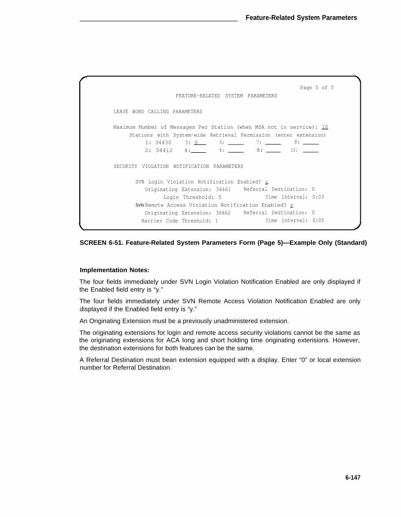
Feature-Related System Parameters
Page 5 of 5
FEATURE-RELATED SYSTEM PARAMETERS
LEAVE WORD CALLING PARAMETERS
Maximum Number of Messages Per Station (when MSA not in service): 10
Stations with System-wide Retrieval Permission (enter extension)1: 34430 3: 0 5: 7: 9:
2: 34412 4: 6: 8: 10:
SECURITY VIOLATION NOTIFICATION PARAMETERS
SVN Login Violation Notification Enabled? y
Originating Extension: 36661 Referral Destination: 0
Login Threshold: 5 Time Interval: 0:03
SVN Remote Access Violation Notification Enabled? y
Originating Extension: 36662 Referral Destination: 0
Barrier Code Threshold: 1 Time Interval: 0:05
SCREEN 6-51. Feature-Related System Parameters Form (Page 5)—Example Only (Standard)
Implementation Notes:
The four fields immediately under SVN Login Violation Notification Enabled are only displayed ifthe Enabled field entry is “y.”
The four fields immediately under SVN Remote Access Violation Notification Enabled are onlydisplayed if the Enabled field entry is “y.”
An Originating Extension must be a previously unadministered extension.
The originating extensions for login and remote access security violations cannot be the same asthe originating extensions for ACA Iong and short holding time originating extensions. However,the destination extensions for both features can be the same.
A Referral Destination must bean extension equipped with a display. Enter “0” or local extensionnumber for Referral Destination.
6-147

CHAPTER 6. FORMS FOR SYSTEM FEATURES AND SERVICES
Page 1 of 4
FEATURE-RELATED SYSTEM PARAMETERS
Trunk-to-Trunk Transfer? n
Coverage - Don’t Answer Interval for Subsequent Redirection (rings): 3
Coverage - Caller Response Interval (seconds): 4Keep Held SBA at Coverage Point? _
Automatic Callback - No Answer Timeout Interval (rings): 4
Call Park Timeout Interval (minutes): 10
Off-Premises Tone Detect Timeout Interval (seconds): 10
AAR/ARS Dial Tone Required? y
Music On Hold Port:
Music (or Silence) On Transferred Trunk Calls: n
DID/Tie/ISDN Intercept Treatment: 0
Message Server Adjunct (MSA) Connected? n
Automatic Circuit Assurance (ACA) Enabled? n
ACA Referral Calls: local
ACA Referral Destination:
ACA Short Holding Time Originating Extension:
ACA Long Holding Time Originating Extension:
ACA Remote PBX Identification: _
SCREEN 6-52. Feature-Related System Parameters Form (Page 1)—Example Form(International G1.1SE and G1.2SE)
Implementation Note:
lf ACA Enabled is “n,” associated ACA fields will not redisplayed.
lf ACA Referral Calls is “local” or “primary,” the ACA Referral Destination and the ACA Short andLong Holding Time fields are displayed.
lf ACA Referral Calls is “remote,” the ACA Remote PBX ldentification field is displayed.
6-148

Feature-Related System Parameters
Page 2 of 4
FEATURE-RELATED SYSTEM PARAMETERS
LEAVE WORD CALLING PARAMETERS
Maximum Number of Messages Per Station (when MSA not in service) : 10
Stations with System-wide Retrieval Permission (enter extension)
3: 5: 7: 9:
4: 6: 8: 10:
SMDR PARAMETERS
Primary Output Layout: int-processs Primary Output Destination: 4883
Secondary Output Layout: Secondary Output Destination:
Use ISDN Layouts? n EIA Device Bit Rate: 9600
SMDR Account Code Length: 2Record Outgoing Calls Only? n
Disconnect Information in Place of Facility Restriction Level? n
Forced Entry of Acct Code for Calls Marked on Toll Analysis Form? n
Suppress SMDR for Ineffective Call Attempts? y
Calls to Hunt Group - Record (Group or Member): member-ext
Record Called Vector Directory Number Instead of Group or Member? n
Record Non-Call-Associated Temporary Signaling Connections? n
Record Call-Associated Temporary Signaling Connections? n
SCREEN 6-53. Feature-Related System Parameters Form (Page 2)—Example Only(International G1.1SE and G1.2SE)
Implementation Notes:
Use lSDN Layouts field only displayed if the lSDN-PRl feature is enabled on the System Param-eters Customer Options form.
Record Non-Call associated Temporary Signaling Connections field only displayed if the UselSDN Layout field entry is “y.”
SMDR Call Splitting - Incoming field only displayed if the Record Outgoing Calls Only field entry(Page 2) is “n.”
Attendant Call Recording field only displayed if one of the SMDR Call Splitting field entries is “y.”
lntra-switch SMDR field only displayed when the Primary Layout field entry is other than “54-char.”
6-149

CHAPTER 6. FORMS FOR SYSTEM FEATURES AND SERVICES
Page 3 of 4
FEATURE-RELATED SYSTEM PARAMETERS
Emergency Access Queue Length: 5
Time Before Off-Hook Alert: 10
Redirection Extension on Full Emergency Access Queue: _
Service Observing Warning Tone? n
Automatic Call Distribution (ACD) Log-in Identification Length: 0
Deluxe Paging and Call Park Timeout to Originator? n
Controlled Outward Restriction Intercept Treatment: tone __
Controlled Termination Restriction (Do Not Disturb): tone __
Controlled Station-to-Station Restriction: tone __
AUTHORIZATION CODE PARAMETERSAuthorization Code Enabled? n
Authorization Code Length: 7
Authorization Code Cancellation Symbol? #
Attendant Time Out Flag? n
SCREEN 6-64. Feature-Related System Parameters Form (Page 3)—Example Only(International G1.1SE and G1.2SE)
Implementation Note:
The Authorization Code Length, Cancellation Symbol, and Attendant Time Out Flag fields areonly displayed when the Authorization Code Enabled field is “y.”
6-150

Feature-Related System Parameters
Page 4 of 4
FEATURE-RELATED SYSTEM PARAMETERS
SYSTEM PRINTER PARAMETERS
Printer Extension:
EIA Device Bit Rate: 1200
Lines Per Page: 60
BASIC CALL MANAGEMENT PARAMETERS
Measurement Interval:
SCREEN 6-55. Feature-Related System Parameters Form (Page 4)—Example Only(International G1.1SE and G1.2SE)
6-151

CHAPTER 6. FORMS FOR SYSTEM FEATURES AND SERVICES
Hop Channel Assignments
Purpose
This form is used to assign up to 64 Hop Channels. Up to 64 connections may be establishedbetween channels on the System’s interface links.
Administration Commands
The following administration commands can be used to access the Hop Channel Assignmentform. In some cases, just the most commonly used commands are shown. Refer to Administra-tion Commands and Error Messages (Chapter 3) for a complete listing of all administration com-mands, the command structure, and the use of abbreviated command words when entering acommand.
Action Object Qualifier*
change communication-interface hop-channelsdisplay communication-interface hop-channels [‘print’ or ‘schedule’]
* Brackets [ ] indicate the qualifier is optional.
Form Instructions
Observe the following when assigning hop channels:
—
—
—
—
—
Both links in a hop channel assignment must be on the same Processor Interface circuitpack. Currently, links 1 through 4 are on Processor Interface circuit pack one and links 5through 8 are on Processor Interface circuit pack two for multi-carrier cabinet systems(single-carrier cabinet systems have just four links).
The Link/Chan pair must not be assigned to a local processor channel on the ProcessorChannel Assignments form.
A link used for ISDN cannot be assigned on the Hop Channel Assignments form.
All five fields associated with a hop channel must be either filled in or left blank.
Use the following table to ensure that the interface link channel numbers match betweenswitches.
Make assignments as required for the following fields on each page of the form
Pages 1 and 2 of the Form
• Link (two fields)— Enter an interface link number in each field from 1 through 8 for multi-carrier cabinet systems and 1 through 4 for single-carrier cabinet systems.
• Chan (two fields)— Enter a number from 1 through 64 in each field.
• Priority— Enter “h” or “l” to indicate whether the hop channel has high or low priority.Priorities should be assigned based on the operational speed of the links and the numberof hops in the network channel.
6-152

Hop Channel Assignments
PROCESSOR INTERFACE
CHANNEL CHANNEL
1 30
SWITCH A
INTERFACE INTERFACECHANNEL CHANNEL
40
TANDEM SWITCH
INTERFACE PROCESSOR
CHANNEL CHANNEL
40 9
SWITCH B
THE INTERFACE CHANNELS ON THE TANDEM
SWlTCH SHOULD MATCH THE INTERFACE CHANNELS
ON SWITCHES A AND B. THE PROCESSOR CHANNELS
DO NOT HAVE TO MATCH.
FIGURE 6-10. Interface Channel Assignments Between Switches
Page 1 of 2
HOP CHANNEL ASSIGNMENT
Link/Chan Link/Chan Priority Link/Chan Link/Chan Priority
— — — — — — — — — —
— — — — — — — — — —
— — — — — — — — — —
— — — — — — — — — —
— — — — — — — — — —
— — — — — — — — — —
— — — — — — — — — —
— — — — — — — — — —
— — — — — — — — — —
— — — — — — — — — —
— — — — — — — — — —
— — — — — — — — — —
— — — — — — — — — —
— — — — — — — — — —
— — — — — — — — — —
— — — — — — — — — —
SCREEN 6-56. Hop ChanneI Assignment Form (Page 1)—Example Only
(To reduce repetition, page 2 is not shown)
6-153

CHAPTER 6. FORMS FOR SYSTEM FEATURES AND SERVICES
Hospitality-Related System Parameters
Purpose
This form is used to implement the System parameters associated with the hospitality features.
Administration Commands
The following administration commands can be used to access the Hospitality-Related SystemParameters form. In some cases, just the most commonly used commands are shown. Refer toAdministration Commands and Error Messages (Chapter 3) for a complete listing of all adminis-tration commands, the command structure, and the use of abbreviated command words whenentering a command.
Action Object Qualifier
change system-parameters hospitality —display system-parameters hospitality [‘print’ or ‘schedule’]
* Brackets [ ] indicate the qualifier is optional.
Form Instructions
Make assignments as required for the following fields on each page of the form:
Page 1 of the Form
• Message Waiting Configuration— lndicates if message waiting notification requests andchanges are being exchanged between the System and PMS. If it is active, the Systemand the PMS, when used, exchange message waiting information. Allowable entries are“act-nopms,” or “act-pms”; act-nopms indicates message waiting is activated but no wait-ing message information is being transmitted between PMS and the System; act-pmsindicates message waiting is activated and transmitting information between the PMSand the System. Default is “act-nopms.”
• Controlled Restrictions Configuration— Indicates if notification of controlled restrictionis being exchanged between the System and PMS. If “act-pms,” the System and thePMS, when used, exchange controlled restriction information. Allowable entries are “act-nopms,” or “act-pms.” Default is “act-nopms.”
• Housekeeper Information Configuration— Indicates if housekeeper information is beingexchanged between the System and PMS. If “act-pms,” the System and PMS exchangehousekeeper information. Allowable entries are “act-nopms,” or “act-pms.” Default is“act-nopms.”
• Number of Housekeeper ID Digits— Enter the number of digits from 0 through 6 thatthe housekeeper must dial for identification. Default is “0.”
• Extension of PMS Log Printer— Enter the extension number (may not be a VDN exten-sion) of the data module or data line that is connected to the PMS/Log printer.
6-154

Hospitality-Related System Parameters
•
•
•
•
•
•
•
•
•
Extension of Journal/Schedule Printer— Enter a valid data extension number (may notbe a VDN extension) assigned to the Journal/Log printer. This extension number isdialed by the System so it can send log and scheduled hospitality reports information tothe printer.
Client Room Coverage Path Configuration— This field indicates if the PBX and PMSexchange coverage path information for guest stations. Setting this field to “act-pms”enables the PMS to update the coverage path of a guest station. Setting this field to“act-nopms” prevents the PMS from setting a room’s coverage path. Default is “act-nopms” prevents the PMS from setting a room’s coverage path. Default is “act-nopms.”When upgrading from a release that does not support this field, the field will be set to“act-pms” if the PMS protocol made was administered as “transparent.” Otherwise, thisfield will be set to “act-nopms.”
Default Coverage Path For Client Rooms— Enter Coverage Path number (1 through600) or leave blank (System default). This field defines the call coverage path numberset for an extension when the System receives a check-out message in the “transparent”mode. The extension must belong to a station that has “Client Room” COS and has“occupied” room status (before check out). This value is also used during a “save trans-lations” operation as the coverage path for each station with “Client Room” COS. Entriescan only be made in this field when the PMS Protocol Mode field is “transparent.”
Extension of PMS— Enter the data extension number (may not be a VDN extension) theSystem must dial to access PMS.
PMS Protocol Mode— Enter “normal” (System default) or “transparent” to identify themode of the message protocol and the message set to be used between the digitalswitch and the PMS. The “normal” mode supports up to 4-digit room extension numbersand the “transparent” mode supports up to 5-digit room extension numbers, name regis-tration, and other enhancements.
Seconds Before PMS Link Idle Timeout— Enter the idle time in seconds (5 through 20)the System will wait before it concludes that the PMS is not sending data across thetransmission link. Default is ”10.”
Milliseconds Before PMS Link Acknowledgement Timeout— Enter the time in mil-liseconds (100 through 500) the System waits for an acknowledgement from the PMSindicating it correctly received a message. Default is “200.”
PMS Link Maximum Retransmission— Enter the number of times (1 through 5) thatthe System will retransmit a message in response to a negative acknowledgement orsend an inquiry for an acknowledgement from the PMS for a message before giving upon the message transmission. Default is “3.”
PMS Link Maximum Retransmission Request— Enter the number of times (1 through5) that the switch will request the PMS to retransmit a message. Default is “3.”
6-155

CHAPTER 6. FORMS FOR SYSTEM FEATURES AND SERVICES
• Take Down Link for Lost Messages— Enter a “y” to cause the PBX to take down thePMS link if a message is sent and rejected the number of times specified in the “PMSLink Maximum Retransmissions” field. An “n” in this field causes the PBX to leave upthe PMS link but to stop trying to send the message. Careful monitoring of the PMSerror log is recommended when using this option. Default is “y.”
Note: It is recommended that this field be left at the default setting.
Page 2 of the Form
• Time of Scheduled Wakeup Activity Report— Enter the time the Wakeup ActivityReport will be printed. This report summarizes the wakeup activity for each extensionthat had wakeup activity for the past 24 hours. Enter the time hh[:mm][a/pm] wherehh=hour, mm=minute, a/pm=am or pm.
• Time of Scheduled Wakeup Summary Report— Enter the time the Wakeup SummaryReport will be printed. This report gives an hour-by-hour summary of the number ofscheduled wakeup calls and a list of extensions to which wakeup calls were attemptedbut did not complete during the hour. Enter the time hh[:mm][a/pm] where hh=hour,mm=minute, a/pm=am or pm.
• Time of Scheduled Emergency Access Activity Report— Enter the time the Emer-gency Access Activity Report will be printed. Enter the time hh[mm][a/pm] wherehh=hour, mm=minute, a/pm=am or pm.
• Announcement Type— Enter the type of automatic wakeup announcement the hotelguest will receive. Allowable entries are “external,” “music-on-hold,” “silence,” or “voice-synthesis.”
If “voice-synthesis” is entered, complete the Announcement Ports field. If “external” isentered, complete the Auxiliary Board for Announcement field.
• Announcement Ports— Enter two port numbers of 5 to 6 characters each. The portnumbers are assigned to two different ports (01, 02, 03, 04—any two of the four) on theVoice Synthesizer circuit pack. The first port character identifies the network (1 to 2,default is “1” if no entry); the second character identifies the carrier (A through E); thethird and fourth characters identify the slot number in the carrier (01 through 20 for multi-carrier cabinets or 01 through 18 for single-carrier cabinets); the last two characters iden-tify the circuit number (01 through 04).
• Auxiliary Board For Announcement— Enter a 3- or 4-character circuit pack number.This field requests the circuit pack address that connects to the external announcementequipment. The first character identifies the network (1 through 2, default is “1” if noentry); the second character identifies the carrier (A through E); the third and fourth char-acters identify the slot number in the carrier (01 through 20 for multi-carrier cabinets or01 through 18 for single-carrier cabinets).
• Length of Time To Remain Connected To Announcement— Enter the length of time inseconds (0 through 300) the hotel guest will receive a wakeup call announcement.
• Extension To Receive Failed Wakeup LWC Messages— Enter the extension number(may not be a VDN extension) where unsuccessful wakeup LWC messages will bestored. A dedicated unassigned extension (0 not allowed) is required.
6-156

Hospitality-Related System Parameters
• Routing Extension On Unavailable Voice Synthesis— Enter the extension number(may not be a VDN extension) or 0 (attendant) to which a call will be placed during voicesynthesis entry of wakeup requests when a voice synthesis port is not available.
• Display Room Information in Call Display— Enter “y” when the information in theRoom field on Station forms is to be used in the Extension Display field on display-equipped voice terminals. If the associated station form defines a “Client Room” COSand a non-blank value in the Room field, the characters in the Room field are shown inthe extension portion of call displays. If the Room field has more than five characters,only the first five characters are shown. This supports situations where there are severalphones with different extension numbers in one guest room. The room number willalways be displayed no matter which phone is in use. Default is “n.”
Page 1 of 2
HOSPITALITY RELATED SYSTEM PARAMETERS
Message Waiting Configuration: act-nopms
Control Restrictions Configuration: act-nopms
Housekeeper Information Configuration: act-nopms
Number of Housekeeper ID Digits: 0Extension of PMS Log Printer:
Extension of Journal/Schedule Printer:
Client Room Coverage Path Configuration: act-nopmsDefault Coverage Path For Client Rooms: _
PMS LINK PARAMETERS
Extension of PMS: _
PMS Protocol Mode: normalSeconds before PMS Link Idle Timeout: 10
Milliseconds before PMS Link Acknowledgement Timeout: 200
PMS Link Maximum Retransmissions: 3
PMS Link Maximum Retransmission Request: 3
Take Down Link for Lost Messages? y
SCREEN 6-57. Hospitality-Related System Parameters Form (Page 1)—Example Only
6-157

CHAPTER 6. FORMS FOR SYSTEM FEATURES AND SERVICES
Page 2 of 2
HOSPITALITY RELATED SYSTEM PARAMETERS
Time of Scheduled Wakeup Activity Report:
Time of Scheduled Wakeup Summary Report: __
Time of Scheduled Emergency Access Activity Report:Announcement Type: silence
Length of Time To Remain Connected To Announcement: 30
Extension To Receive Failed Wakeup LWC Messages:
Routing Extension On Unavailable Voice Synthesis:
Display Room Information in Call Display? n
SCREEN 6-58. Hospitality-Related System Parameters Form (Page 2)—Example Only
Implementation Note:
This is Page 2 when the Announcement Type field is “silence.”
Page 2 of 2
HOSPITALITY RELATED SYSTEM PARAMETERS
Time of Scheduled Wakeup Activity Report: _____
Time of Scheduled Wakeup Summary Report:
Time of scheduled Emergency Access Activity Report:Announcement Type: voice-synthesis
Announcement Ports:
Length of Time To Remain Connected To Announcement: _____
Extension To Receive Failed Wakeup LWC Messages:
Routing Extension On Unavailable Voice Synthesis:Display Room Information in Call Display? n
SCREEN 6-59. Hospitality-ReIated System Parameters Form (Page 2)—Example Only
Implementation Note:
This is Page 2 when the Announcement Type field is “voice-synthesis.” The AnnouncementPorts field must be completed if “voice-synthesis” is entered as the Annoumement Type.
6-158

Hospitality-Related System Parameters
Page 2 of 2
HOSPITALITY RELATED SYSTEM PARAMETERS
Time of Scheduled Wakeup Activity Report:
Time of Scheduled Wakeup Summary Report:
Time of Scheduled Emergency Access Activity Report:Announcement Type: external
Auxiliary Board For Announcement:
Length of Time To Remain Connected To Announcement:
Extension To Receive Failed Wakeup LWC Messages:
Routing Extension On Unavailable Voice Synthesis:Display Room Information in Call Display? n
SCREEN 6-60. Hospitality-Related System Parameters Form (Page 2)—Example Only
Implementation Note:
This is Page 2 when the Announcement Type field is “external.” The Auxiliary Board ForAnnouncement field must be completed if “external” is entered as the Announcement Type.
6-159

CHAPTER 6. FORMS FOR SYSTEM FEATURES AND SERVICES
Hunt Group
Purpose
Allows calls to be answered by users (that is, agents) at a pre-designated group of terminals ordevices.
This form is used to create a Hunt Group that is identified by a Hunt Group number from 1through 99. Users assigned to a Hunt Group are identified by their extension number. Up to 200users can be assigned to a Hunt Group. Note that if the Hospitality Parameters Reduction optionis enabled on the System-Parameters Customer-Options form; only five (maximum) Hunt Groupsmay be assigned.
Several different hunt group forms can be used to implement a hunt group and its associatedfeatures such as ACD and Hunt Group Queuing. Look at the various hunt group forms andchoose the forms that can be used to implement your hunt group requirements.
The System checks for the busy or idle status of extension numbers in the hunt group whenanswering calls. A UCD type hunt group selects the “most idle” extension in the group whenanswering a new call. A DDC type hunt group selects the first available extension (in the admin-istered sequence) when answering a new call.
Once the forms have been chosen, review the following instructions and use them for the fieldsthat appear on the forms. The instructions listed below describe all the fields that can be used;however, some of the fields may not appear on the forms you selected. Implementation Notes atthe bottom of the screen form examples lists the field entries required to obtain the associatedform.
Note that vector controlled splits (that is, ACD hunt group with vector= “y”) maybe called directlyvia the split extension (instead of calling a VDN mapped to a vector that will terminate the call toa vector controlled split); however, the calls will not receive any announcements, be forwarded,redirect to coverage, or intraflow/interflow to another hunt group.
Administration Commands
The following administration commands can be used to access the Hunt Group form. In somecases, just the most commonly used commands are shown. Refer to Administration Commandsand Error Messages (Chapter 3) for a complete listing of all administration commands, the com-mand structure, and the use of abbreviated command words when entering a command.
6-160

Hunt Group
Action
Without HospitalityParameter ReductionFeature
With HospitalityParameter ReductionFeature
Object
addchangedisplaylistremove
addchangedisplaylistremove
Qualifier*
hunt-grouphunt-grouphunt-grouphunt-grouphunt-group
hunt-grouphunt-grouphunt-grouphunt-grouphunt-group
1-99 (or ‘next’)1-991-99 [’print’ or ‘schedule’][’print’ or ‘schedule’]1-99
1-5 (or ‘next’)1-51-5 [’print’ or ‘schedule’][‘print’ or ‘schedule’]1-5
• Brackets [ ] indicate the qualifier is optional.Single quotes (‘ ’) indicate the text inside the quote must be entered exactly as shown oran abbreviated form of the word maybe entered.
Form Instructions
Make assignments as required for the following fields on each page of the form:
• Group Number— Enter a hunt group number from 1 through 99 when completing apaper form (only five Hunt Groups may be assigned if the Hospitality Parameters Reduc-tion option is enabled on the System-Parameters Customer-Options form). Note that theCMS Release 3 software (required for G3i) can measure up to 99 hunt groups and GroupNumbering restrictions required by previous releases of the software no longer apply.This is a display-only field when the form is accessed using an administration commandsuch as add or change.
• Group Extension— Enter an unused extension number (1 through 5 digits) to beassigned to the hunt group.
• Group Type— Enter the type of hunt group: “ucd” or “ddc.” Enter “ucd” if the hunt grouphas an AUDIX or Message Server Adjunct message center. Also, “ucd” is required whensupporting a vendor-supplied outbound call management system and when the “Control-ling Adjunct” field is administered as “asai” or “bx.25.” Default is “ucd.”
• Group Name— Enter a 15-character string that uniquely identifies the group, for exam-ple, “parts dept,” “purchasing,” or “sales dept.”
• Coverage Path— Enter a coverage path number from 1 through 600. This assigns acoverage path for the Hunt Group. The coverage path is assigned using the Call Cover-age Path form. Valid entries are 1 through 600 or leave blank.
• COR— Enter the COR number from 0 through 63 that reflects the desired restriction forthe hunt group. If this is a hunt group supporting the AUDIX in a DCS feature, the CORson the Hunt Group form on each switch must be the same. Default is “1.“
• Security Code— Enter a 4-digit security code (password) used for the Demand Printfeature. Valid entries are a 4-digit security code or leave blank.
• Message Center— Enter the type of message center the hunt group connects to. Allow-able entries are “msa” (Message Server Adjunct), “rem-audix” (DCS feature allowingAUDIX to be located on another switch), or “audix” (for AUDIX located on this switch).Entering “none” indicates the hunt group does not serve as a message center hunt
6-161

CHAPTER 6. FORMS FOR SYSTEM FEATURES AND SERVICES
group. Default is “none.” Only one hunt group in the System may be administered asrosa, one as rem-audix, and one as audix. For a hunt group serving as a split for avendor-supplied outbound call management system, the typical entry is “none.”
• ACD— Enter “y” if the hunt group will function as an ACD split. AUDIX and “msa” huntgroups may function as ACD splits. This field cannot be completed if the “ACD” option isnot enabled on the System-Parameters Customer-Options form. Enter “n” if this featureis not desired, even though ACD is enabled on the System-Parameters Customer-Options form. When the hunt group is assigned as an ACD split, the hunt groupmembers will serve as ACD agents. The agents in this split are allowed to log in andreceive ACD split calls. If AUDIX is used as the hunt group message center, enter “y” tohave the ACD CMS provide AUDIX traffic measurements. If this hunt group is on aremote switch using the AUDIX in a DCS feature, enter “n” in this field.
• Queue— Enter “y” if the hunt group will be served by a queue; otherwise, enter “n.”Default is “n.”
The next seven fields apply if Queue is “y.”
1. Queue Length— Enter the maximum number of calls (1 through 200) that can bein the queue at the same time. This field must have an entry when Queue is “y.”For vendor-supplied outbound call management splits, a short queue lengthshould be assigned and coordinated with the outbound call management adjunctadministration.
2. Calls Warning Threshold— Enter the number of calls that can be queued beforethe System flashes the queue status (feature buttons assigned on agents voiceterminals) and the optional Auxiliary Queue Call Warning Threshold lampassigned to the split. These lamps are lighted steadily when at least 1 call is inqueue and the threshold has not yet been reached. Valid entries are a numberfrom 1 through 200 and must be less than or equal to the queue length or leaveblank. This field must not be left blank if the Calls Warning Port field is assigneda port number.
3. Calls Warning Port— Enter the port number assigned to connect the optionalexternal Auxiliary Queue Call Warning Threshold lamp that will flash when thenumber of calls in queue has exceeded the queue warning threshold (assigned inthe Calls Warning Threshold field). Enter 5 to 6 characters. The first characteridentifies the network (1 through 3, default is “1” if no entry); the second charac-ter identifies the carrier (A through E); the third and fourth characters identify theslot number in the carrier (01 through 20 for multi-carrier cabinets depending oncarrier type or 01 through 18 for single-carrier cabinets depending on cabinettype); the last two characters identify the circuit number (01 through 16). Thisport is assigned to an Analog Line circuit pack.
4. Time Warning Threshold— Enter the time in seconds from 0 through 999 that acall can remain in the queue before the System flashes the Queue status lamps(feature buttons assigned members voice terminals) and the Auxiliary QueueTime Warning lamp assigned to this split. An entry of “0” provides a warningwhenever a call is queued. Valid entries are 0 through 999 or leave blank.
6-162

Hunt Group
5.
6.
7.
Time Warning Port— Enter the port number assigned to the Auxiliary QueueTime Warning lamp that flashes when the time entered in the Time WarningThreshold field has been reached by a call in queue. Enter 5 to 6 characters.The first character identifies the network (1 through 3, default is “1” if no entry);the second character identifies the carrier (A through E); the third and fourthcharacters identify the slot number in the carrier (01 through 20 for multi-carriercabinets depending on carrier type or 01 through 18 for single-carrier cabinetsdepending on cabinet type); the last two characters identify the circuit number(01 through 16). This port is assigned to an Analog Line circuit pack.
First Announcement Extension— Enter a recorded announcement extensionnumber or leave blank. This is the announcement the caller will receive afterbeing in the queue for the time interval specified in the First AnnouncementDelay field. If the call hasn’t been answered after the announcement, the callerwill hear music (only for first announcement) if Music-on-Hold is provided or ring-ing for as long as it remains in the queue. Leaving this field blank indicates therewill be no announcement.
First Announcement Delay (sec)— Enter the number of seconds from 0 through99 that a call can remain in queue before the associated first announcement isgiven the calling party. The call retains its place in the queue while the caller islistening to the recorded announcement. If the call hasn’t been answered afterthe announcement, the caller will hear music (for first announcement only) ifMusic-on-Hold is provided or ringing for as long as the call remains in queue.When “0” is entered, the first announcement is provided immediately to the caller(not recommended for outbound call management splits). This value is automati-cally set to “0” if there is no queue. This field must be blank if there is no firstannouncement.
• Night Service Destination— Enter the destination where calls to this ACD split willredirect when the split is in the night service mode. Allowable entries are an assignedextension number (can be a VDN extension), 0 (attendant), or leave blank. Note that thisfield is not supported when the Controlling Adjunct field entry is “bx.25.”
• ISDN Caller Disp— Enter “grp-name” or “mbr-name” to specify whether the hunt groupname or member name, respectively, will be sent to the originating user. This field isrequired if the ISDN-PRI option on the System-Parameters Customer-Options form isenabled. If ISDN-PRI is not enabled, this field must be blank.
• Audix Extension— This field is only displayed if the Message Center field is “rem-audix.”Enter a valid Uniform Dial Plan (UDP) extension (4 to 5 digits) that identifies the AUDIXextension number on the host switch that will be used as the message center for thishunt group (supports the AUDIX In A DCS feature).
The next four fields are displayed if Queue is “y” and ACD is “y.”
1. Inflow Threshold— Enter the number of seconds from 0 through 999 that a call canremain in the queue before no more calls will be accepted by the queue. if “0” isentered, a call will be redirected to this split only if there is an available agent. Validentries are 0 through 999.
6-163

CHAPTER 6. FORMS FOR SYSTEM FEATURES AND SERVICES
2.
3.
4.
Second Announcement Extension— Enter the extension number assigned to arecorded announcement or leave blank. Leaving the field blank indicates that there is nosecond announcement. It is recommended that if this split or hunt group is a coveragepoint for another split, that this delay should not be more than 15 seconds.
Second Announcement Delay (sec)— Enter the time in seconds from 1 through 99before the call in the queue receives second recorded announcement or that the secondannouncement is repeated. Leave blank if there is no second announcement.
Second Announcement Recurring— Enter “y” to have the second announcementrepeated; otherwise, enter “n.” Leave blank if there is no second announcement.
The next four fields are displayed if ACD is “y.”
1.
2.
3.
4.
•
•
•
Measured— Enter “internal” to have change of state messages for the ACD split meas-ured by the BCMS (internal to switch) and enter “external” to have measurements madeby the 3B CMS (external to switch). Enter “both” to have data sent to both systems formeasurement reports. Enter “none” if measurement reports for this hunt group is notrequired. Default is “none.” Note that all bx.25 controlled splits (Controlling Adjunct fieldis “bx.25”) must have the same entry in this field.
Supervisor Extension— Enter the extension number (may not be a VDN number) of theACD split supervisor that agents can dial to request assistance.
Priority On lntraflow— Enter “y” if calls intra-flowing from this split to a covering split willbe given priority over other calls waiting in the covering split’s queue. Default is “n.”
Controlling Adjunct— Displayed when the ACD field is “y.” Enter “none” to indicate thatmembers of the split or hunt group are not controlled by an adjunct processor. When setto “asai” or “bx.25,” all agent Iogins are controlled by an associated adjunct and logged-inagents can only use their data terminal keyboards (that is, locked out from using theirassociated voice terminals); otherwise, enter “none.” If the controlling adjunct is a CON-VERSANT voice system (requires an ASAI link), then enter “asai” in this field. (TheASAI option must be enabled on the System-Parameters Customer-Option form forCallVisor ASAI capability.) Valid entries are “asai,” “bx.25,” or “none.”
ASAI Link Extension— Displayed when Controlling Adjunct field is “asai.” Enter theappropriate ASAI Link extension. (See Adjunct/Switch Applications Interface Link infor-mation elsewhere is this chapter.) Field may not be blank. Note that “asai” and “bx.25”interfaces cannot both be provided on the switch. Only one of the interface types can beadministered.
Forced Entry of Stroke Counts or Call Word Codes— This field is only displayed whenthe ACD field is “y” and the Controlling Adjunct field is set to “none.” Enter “y” if either aStroke Count or Call Work Code must be entered for each call answered by an agentwhen in the Manual-In mode.
Vector— Enter “y” to indicate that this hunt group will be vector controlled. TheVectoring-Basic option must be enabled on the System-Parameters Customer-Optionform before “y” can be entered in the field. Valid entries are “y” or “n.” Default is “n.”(See example screen forms for fields that are displayed when “y” is entered in this field.)
6-164

Hunt Group
Pages 2 through 6 Of the Form
• Group Number— Display-only field
• Group Extension— Display-only field
• Group Type— Dispiay-only field
• Ext— Display-only field if the Controlling Adjunct field is “y.” Controlled Agent extensionsmust be entered on the Adjunct Controlled Agent Table form. For Controlling Adjunct =“n,” enter the extension number associated with a member in the Hunt Group or with anassociated data module. The extension may not be a VDN. The data module cannot bea member of an ACD split.
• Name— Make no entry, this is a display-only field. The name is assigned to the aboveextension number when it is administered in the System.
Page 1 of 6
HUNT GROUP
Group Number: _ Group Extension: Group Type: ucd
Group Name: Coverage Path: _ COR : 1
Security Code: Message Center: none ACD? n
Queue? n Night Service Destination: Vector? n
ISDN Caller Disp:
SCREEN 6-61. Hunt Group Form (Page 1)—Example Only
Implementation Note:
This is Page 1 when the ACD, Queue, and Vector fields are “n.”
6-165

CHAPTER 6. FORMS FOR SYSTEM FEATURES AND SERVICES
Page 1 of 6
HUNT GROUP
Group Number: _ Group Extension: Group Type: ucd
Group Name: coverage Path: _ COR: 1
Security Code: _ Message Center: none ACD? n
Queue? y Night Service Destination: _ Vector? n
ISDN Caller Disp:
Queue Length: 1Calls Warning Threshold: _ Calls Warning Port: _
Time Warning Threshold: _ Time Warning Port: _
First Announcement Extension: _ First Announcement Delay (sec): _
SCREEN 6-62. Hunt Group Form (Page 1)—Example Only
lmplementation Note:
This is Page 1 when the Queue field is “y” and the ACD and Vector fields are “n.”
Page 1 of 6
HUNT GROUP
Group Number: _ Group Extension: _ Group Type: ucd
Group Name: coverage Path: _ COR: 1
Security Code: Message Center: none ACD? y
Queue? n Night Service Destination: _ Vector? n
ISDN Caller Disp:
Measured? n Supervisor Extension: _
Priority On Intraflow? n
Controlling Adjunct? none
First Ann. Extension: _Forced Entry of Stroke Count or Call Work Code? n
SCREEN 6-63. Hunt Group Form (Page 1)—Example Only
Implementation Note:
This is Page 1 when the Queue and Vector fields are “n” and the ACD field is “y.”
6-166

Hunt Group
Group Number:
Group Name:
Security Code:
Queue?
ISDN Caller Disp:
Priority On
Page 1 of 6
HUNT GROUP
Group Extension: _— Group Type: ucd
Coverage Path: _ COR: 1
Message Center: none ACD? y
y Night Service Destination: __ Vector? n
Measured?
Intraflow?
Controlling Adjunct?
Queue Length:
Calls Warning Threshold:
Time Warning Threshold:
First Ann. Extension:
Second Announcement Extension:
none
none Supervisor Extension: _
n Inflow Threshold: _
1Calls Warning Port: ____
Time Warning Port:
First Announcement Delay (sec): _
Second Announcement Delay (sec): _
Forced Entry of Stroke Count or Call Work Code? n
SCREEN 6-64. Hunt Group Form (Page 1)—Example Only
Implementation Note:
This is Page 1 when the Queue fields is “y” and the ACD and Vector fields are "n."
Page 1 of 6
HUNT GROUP
Group Number: _ Group Extension: _ Group Type: ucd
Group Name: Message Center: none ACD? n
Security Code: COR: 1
Queue? n Vector? y.
ISDN Caller Disp:
SCREEN 6-65. Hunt Group Form (Page 1)—Example Only
Implementation Note:
This is Page 1 when the Vector fieid is “y” and the ACD and Queue fields are “n.”
6-167

CHAPTER 6. FORMS FOR SYSTEM FEATURES AND SERVICES
Page 1 of 6
HUNT GROUP
Group Number: _ Group Extension: Group Type: ucdGroup Name: Coverage Path: _ COR: 1
Security Code: Message Center: rem-audix ACD? nQueue? n Night Service Destination: Vector? n
ISDN Caller Disp: Audix Extension:
SCREEN 6-66. Hunt Group Form (Page 1)—Example Only
lmplementation Note:
This is Page 1 when the Queue and ACD fields are “n” and Message Center field is “rem-audix.”
Page 1 of 6
HUNT GROUP
Group Number: ___ Group Extension: Group Type: ucd
Group Name: Message Center: none ACD? y
Queue? n Vector? n
Security Code: Night Service Destination: COR: 1ISDN Caller Disp: Coverage Path: _
Measured? n Supervisor Extension?
Priority on Intraflow? y
Controlling Adjunct: asai ASAI Link Extension:
First Announcement Extension:
SCREEN 6-67. Hunt Group Form (Page 1)—Example Only
Implementation Note:
This is Page 1 when Controlling Adjunct is “asai” and the Vector and Queue fields are “n” and theACD field is “y.”
6-168

Hunt Group
Group Number:
Group Name:
Queue?
Security Code:
ISDN Caller Disp:
Measured?
Controlling Adjunct:Queue Length:
Calls Warning Threshold:
asai1
Time Warning Threshold:
Page 1 of 6
HUNT GROUP
Group Extension: _ Group Type: ucd—Message Center: none ACD? y
y
n SupervisorASAI Link
Vector? y
COR: 1
Extension?
Extension:
_ Calls Warning Port:
Time Warning Port:
SCREEN 6-68. Hunt Group Form (Page 1)—Example Only
lmplementation Note:
This is Page 1 when Controlling Adjunct is “asai” and the Vector, Queue, and ACD fields are “y.”
6-169
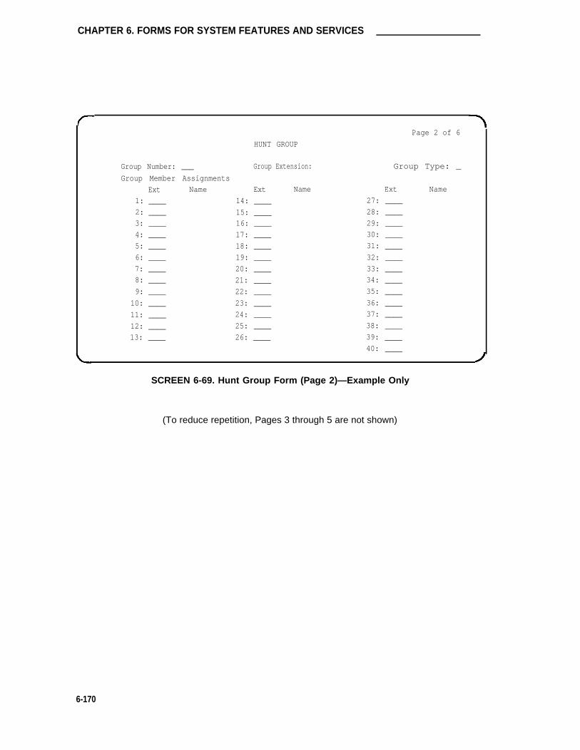
CHAPTER 6. FORMS FOR SYSTEM FEATURES AND SERVICES
HUNT GROUP
Group Number: ___ Group Extension:
Group Member Assignments
Ext
1: ____
2: ____
3: ____
4: ____
5: ____
6: ____
7: ____
8: ____
9: ____
10: ____
11: ____
12: ____
13: ____
Name Ext Name
14: ____
15: ____16: ____
17: ____
18: ____
19: ____
20: ____
21: ____
22: ____
23: ____
24: ____
25: ____
26: ____
Page 2 of 6
Group Type: _
Ext Name
27: ____
28: ____
29: ____
30: ____
31: ____
32: ____
33: ____
34: ____
35: ____
36: ____
37: ____
38: ____
39: ____
40: ____
SCREEN 6-69. Hunt Group Form (Page 2)—Example Only
(To reduce repetition, Pages 3 through 5 are not shown)
6-170

Hunt Group
Page 6 of 6
HUNT GROUP
Group Number: __ Group Extension: Group Type: __
Group Member Assignments
Ext Name Ext Name Ext Name
161: 174: 187:
162: 175: 188:
163: 176: 189:
164: 177: 190:
165: 178: 191:
166: 179: 192:
167: 180: 193:
168: 181: 194:
169: 182: 195:
170: 183: 196:
171: 184: 197:
172: 185: 198:
173: 186: 199:
200:
SCREEN 6-70. Hunt Group Form (Page 6)—Example Only
6-171

CHAPTER 6. FORMS FOR SYSTEM FEATURES AND SERVICES
Intercom Group
Purpose
The Automatic and Dial Intercom features are available to users whose voice terminals haveintercom feature button assignments. Members of an intercom group may have Dial Intercom,Automatic Intercom, both, or neither with respect to placing an Intercom call. Single-line voiceterminals, if a member of the group, can receive an Intercom call, but cannot place an Intercomcall.
This form is used to specify the group members, not the type of Intercom. (The intercom typeand associated feature buttons are assigned to multi-appearance voice terminals using the multi-appearance voice terminal forms.)
Up to 32 Dial Intercom groups can be assigned. A group can have up to 32 members. The totalnumber of Intercom group members allowed in the System is 128.
Administration Commands
The following administration commands can be used to access the Intercom Group form. Insome cases, just the most commonly used commands are shown. Refer to Administration Com-mands and Error Messages (Chapter 3) for a complete listing of all administration commands, thecommand structure, and the use of abbreviated command words when entering a command.
Action Object Qualifier*
add intercom-group 1-32 (or ‘next’)change intercom-group 1-32display intercom-group 1-32 [’print’ or ‘schedule’]list intercom-group [’print’ or ‘schedule’]remove intercom-group 1-32
* Brackets [ ] indicate the qualifier is optional.Single quotes (‘ ’) indicate the text inside the quote must be entered exactly as shown oran abbreviated form of the word may be entered.
Form Instructions
Make assignments as required for the following fields on each page of the form:
Pages 1 and 2 of the Form
• Group Number— Enter a number from 1 through 32 when completing a paper form. Thisis a display-only field when the form is accessed using an administration command suchas add or change.
• Length of Dial Code— On Page 1, enter “1” or “2.” This is the number of digits thatmust be dialed to access someone in the group. Enter “1” if group members are lessthan 10 or “2” if group members are 10 or more. Default is ”1.“ (Page 2 is a display-onlyfield.)
• Ext— Enter the extension number of each member of the group. Note that VDN exten-sions are not allowed.
6-172

Intercom Group
• DC— Enter a 1- or 2-digit code. The number of digits entered depends on the numberassigned in the Length of Dial Code field. The digit 0 may not be used as the leadingdigit, and this field cannot be left blank. This is the code that must be dialed to accessthat group member.
• Name— Make no entry. The name is assigned when the member’s associated extensionwas administered.
Page 1 of 2
INTERCOM GROUP
Group Number: _Length of Dial Code: 1
GROUP MEMBER ASSIGNMENTSExt DC Name Ext DC Name
1: _ 9: _
2: _ 10: _
3: _ 11: _
4: _ 12: _
5: _ 13: _
6: _ 14: _
7: _ 15: _
8: _ 16: _
SCREEN 6-71. Intercom Group Form (Page 1)—Example Only
6-173

CHAPTER 6. FORMS FOR SYSTEM FEATURES AND SERVICES
INTERCOM GROUP
Group Number:
Length of Dial Code:
GROUP MEMBER ASSIGNMENTS
17:
18:
19:
20:
21:
22:
23:
24:
Ext DC
—
—
_
—
—
_
_
_
_
_
_
_
_
_—
—
Name
_
1
Ext
25:
26:
27:
28:
29:
30:
31:
32:
DC
Page 2 of 2
Name
SCREEN 6-72. Intercom Group Form (Page 2)—Example Only
6-174

Interface Links
Interface Links
Purpose
This form is used to identify, describe, and enable Interface Links. There is one Interface Linkform per System. Interface Links provide a physical interface between the System and the othernodes in a DCS, ISDN, a Message Server Adjunct, a CMS, a vendor-supplied outbound callmanagement system, an ISDN Gateway adjunct (supports CPN/BN), or an AUDIX.
Administration Commands
The following administration commands can be used to access the Interface Links form. In somecases, just the most commonly used commands are shown. Refer to Administration Commandsand Error Messages (Chapter 3) for a complete listing of all administration commands, the com-mand structure, and the use of abbreviated command words when entering a command.
Action Object Qualifier*
change communication-interface linksdisplay communication-interface links [‘print’ or ‘schedule’]
* Brackets [ ] indicate the qualifier is optional.
Form lnstructions
Make assignments as required for the following fields on the form:
• Link— This is a display-only field. Indicates the physical interface link number (1 through8 for multi-carrier cabinet systems and 1 through 4 for single-carrier cabinet systems)that connects to another node in a DCS or ISDN network, a Message Server, CMS, avendor-supplied outbound call management system, ISDN Gateway, or AUDIX. Formulti-carrier cabinets, links 1 through 4 are located in a Processor Interface circuit packmounted in Control Carrier A, Links 5 through 8 are located in a second Processor inter-face circuit pack mounted in Control Carrier A.
• Enable— Enter “y” to enable the link. An entry of “n” suppresses any message flow overthe link. Default is “n.”
Note that when administering the Interface Links form, all fields may be initially enteredexcept the Enable field (must be “n”). After completing and administering the associatedProcessor Interface Data Module and Processor Channel Assignment forms for all links,recall the Interface Links form (via the change command) and then enable the appropri-ate links by entering “y” in the enable fields.
• Est Conn— Enter “y” if the System is responsible for any part of the call setup requiredfor the link between the System and the far-end data module.
If the physical link is through a pair of MPDMs or MTDMs, then each switch terminatingthe link must set up a connection between its Processor Interface Data Module andMPDM/MTDM.
If the physical link is over a DS1 interface, it is possible (except for ISDN signaling links)for one switch to set up the entire connection (see Destination below). In this case, theother switch will not initiate any part of the connection between the two endpoints. Typi-
6-175

CHAPTER 6. FORMS FOR SYSTEM FEATURES AND SERVICES
cally when using a DS1 interface, the Enable field will be set to “y” on both the originatingand terminating switches but only one link between the two switches will have the EstConn field set to “y.” The originating switch is defined as having the Est Conn field set to
“y.”
If the link is to be used for ISDN signaling, enter “y.”
• PI Ext— This is the data extension assigned on the Processor Interface Data Moduleform. This field is a display-only. The System automatically assigns the extensionnumber to this field when the Processor Interface data module is administered in Systemtranslations. If the data module has not been administered, this field will be blank.
• Prot— Enter the protocol type that is to be established on the link. Allowable entries are“BX.25” and “lSDN.” Default is “BX.25.”
• Destination— Leave blank if the System is not involved in establishing any part of theconnection (may not be a VDN extension).
For BX.25 links [allowable entries are extension number, TAC (for DS1 data link), or “eia”(link 1 only)]:
➤ Enter the extension number in the Digits field that is used to set up a connectionor part of a connection between the local and far-end data modules for the link.
➤ If the BX.25 link is through a pair of PDMs or TDMs, then the extension of thePDM/TDM is used as the destination address.
➤ If the BX.25 link is through a DS1 interface and the local switch is establishingthe connection, enter the TAC if the far-end trunk group is administered with anincoming destination (for example, the far-end data module extension). Other-wise, enter the TAC followed by the far-end data module extension.
For ISDN-PRI links:
➤ Enter the TN767 DS1 circuit pack address in the Brd field that has been previ-ously administered as using ISDN signaling. If channel 24 on the DS1 circuitpack is used for Facility Associated Signaling, it cannot be administered as amember of the trunk group. A DS1 circuit pack address can only appear once asa destination address on the form. Allowable entries are the 4-character DS1 cir-cuit pack location. The first character identifies the network (1 through 3, defaultis “1” if no entry); the second character identifies the carrier (A through E); thethird and fourth characters identify the slot number in the carrier (01 through 20for multi-carrier cabinets depending on carrier type or 01 through 18 for single-carrier cabinets depending on cabinet type).
• DTE/DCE— Enter “DTE” or “DCE” to define the type of interface. This field is onlyadministrable if the Prot field is “BX.25.” If one endpoint of a link is DTE, then the othermust be DCE, and vice versa. The assignments must be coordinated on a network-widelevel. Endpoint Switch Links are generally DTE and Tandem links are generally DCE. Ifboth endpoints are of the same type (that is, endpoints or tandem), then the assignmentof which is DTE and which is DCE is arbitrary. Typically, when using a DS1 interface,the originating switch should be administered as “DTE” and the terminating switch as“DCE.” Default is DTE. For an outbound call management system interface, enter“DCE.”
6-176

Interface Links
• Identification— Enter a 15-character name for the link. It is used for identification pur-poses only. It may be used to identify the destination machine or the field may be leftblank.
Page 1 of 1
INTERFACE LINKS
Link Enable Est PI Destination DTE/
Corm Ext Prot Digits Brd DCE Identification
1: n BX.25 DTE
2: n BX.25 DTE
3: n BX.25 DTE
4: n BX.25 DTE
5: n BX.25 DTE
6: n BX.25 DTE
7: n BX.25 DTE
8: n BX.25 DTE
SCREEN 6-73. Interface Links Form—Example Only
6-177

CHAPTER 6. FORMS FOR SYSTEM FEATURES AND SERVICES
Inter-Exchange Carrier (lXC) Codes
Purpose
The purpose of entering Inter-Exchange Carrier (lXC) codes on this form is to allow identificationof the IXC in the SMDR record.
Administration Commands
The following administration commands can be used to access the IXC codes form. In somecases, just the most commonly used commands are shown. Refer to Administration Commandsand Error Messages (Chapter 3) for a complete listing of all administration commands, the com-mand structure, and the use of abbreviated command words when entering a command.
Action Object Qualifier*
change ixc-codes —display ixc-codes [‘print’ or ‘schedule’]
* Brackets [ ] indicate the qualifier is optional.
Form Instructions
Make assignments as required for the following fields on the form:
• IXC Access Number— Enter the digits dialed or inserted by AAR/ARS into the outpulseddigit string to gain access to the inter-exchange carrier. No duplicate access numbersare allowed in the table.
• IXC Name— Enter 0 through 15 characters to identify the IXC. This description is forinformation purposes only.
6-178

Inter-Exchange Carrier (lXC) Codes
Page 1 of 1
INTER-EXCHANGE CARRIER CODES
IXC Codes Assignments (Enter UP to 15)
SMDR
IXC
Code
1.
2.
3.
4.
5.
6.
7.
8.
IXC
Access
Number IXC Name
SMDR
IXC
Code
9.
10.
11.
12.
13.
14.
15.
IXC
Access
Number IXC Name
SCREEN 6-74. Inter-Exchange Carrier Codes Form—Example Only
6-179

CHAPTER 6. FORMS FOR SYSTEM FEATURES AND SERVICES
Intra-switch SMDR
Purpose
The purpose of this form is to administer extensions for which Intra-switch SMDR is to beenabled. Attendants are not allowed to be optioned for the Intra-switch SMDR feature. To addthe Intra-switch SMDR feature to additional extensions, add the extension(s) to this form.
Page 1 of 1
INTRA-SWITCH SMDR
ASSIGNED MEMBERS
1: 72447 18: 35: 52: 69: 86:
2: 72448 19: 36: 53: 70: 87:
3: 20: 37: 54: 71: 88:
4: 21: 38: 55: 72: 89:
5: 22: 39: 56: 73: 90:
6: 23: 40: 57: 74: 91:
7: 24: 41: 58: 75: 92:
8: 25: 42: 59: 76: 93:
9: 26: 43: 60: 77: 94:
10: 27: 44: 61: 78: 95:
11: 28: 45: 62: 79: 96:
12: 29: 46: 63: 80: 97:
13: 30: 47: 64: 81: 98:
14: 31: 48: 65: 82: 99:
15: 32: 49: 66: 83: 100:
16: 33: 50: 67: 84:
17: 34: 51: 68: 85:
SCREEN 6-75. Intra-switch SMDR Form
Implementation Note:
A maximum of 100 (non-ASAI) extensions maybe optioned.
The change intra-switch-smdr and display intra-switchsmdr commands with this feature.
6-180

Listed Directory Numbers
Listed Directory Numbers
Purpose
This form allows up to eight DID numbers to be treated as public LDNs. When one of thesenumbers is direct inward dialed, the calling party is routed to the attendant. The attendant displayindicates a Listed Directory Number call and the name associated with the dialed extension.Refer to the Multiple Listed Directory Numbers feature in DEFINITY® Communications SystemGeneric 1 and Generic 3i—Feature Description, 555-230-201, for additional information.
Administration Commands
The following administration commands can be used to access the Listed Directory Numbersform. In some cases, just the most commonly used commands are shown. Refer to Administra-tion Commands and Error Messages (Chapter 3) for a complete listing of all administration com-mands, the command structure, and the use of abbreviated command words when entering acommand.
Action Object Qualifier*
change Iisted-directory-numbers —display Iisted-directory-numbers [‘print’ or ‘schedule’]
* Brackets [ ] indicate the qualifier is optional.
Form Instructions
Make assignments as required for the following fields on the form:
• Ext— Enter a valid unassigned extension number (1 to 5 digits).
• Name— Enter a name used to identify the Listed Directory Number. Up through 15alphanumeric characters may be used.
• Night Destination— Enter the valid assigned extension number (may be a night serviceextension, a recorded announcement extension, a VDN, an individual attendant exten-sion, or an AUDIX hunt group extension) that will receive calls to these listed numberswhen the System is in the Night Service mode. Enter 1 to 5 digits.
6-181

CHAPTER 6. FORMS FOR SYSTEM FEATURES AND SERVICES
1:
2:
3:
4:
Ext
LISTED DIRECTORY NUMBERS
Name Ext
Page 1 of 1
Name
5:
6:
7:
8:
Night Destination:
SCREEN 6-76. Listed Directory Number Form—ExampIe Only
6-182

Loudspeaker Paging and Code Calling Access
Loudspeaker Paging and Code Calling Access
Purpose
These forms are used to implement Loudspeaker Paging, Loudspeaker Paging—Deluxe, andCode Calling Access. The Loudspeaker Paging Access form contains the fields required toassign zone (speaker location) information for the Loudspeaker Paging, Loudspeaker Paging—Deluxe, and Code Calling Access features.
The Code Calling IDs form is used to assign extension numbers to code calling identificationnumbers. As many as 125 three-digit chime codes can be provided. Only one extension numbercan be assigned to each chime code. The System translates the ID number associated with acode calling extension to a chime code and then plays the code over a zone loudspeaker asassigned on the Loudspeaker Paging form.
Administration Commands
The following administration commands can be used to access the Loudspeaker Paging Accessform. In some cases, just the most commonly used commands are shown. Refer to Administra-tion Commands and Error Messages (Chapter 3) for a complete listing of all administration com-mands, the command structure, and the use of abbreviated command words when entering acommand.
Action Object Qualifier*
change paging loudspeaker —display paging loudspeaker [’print’ or ‘schedule’]change paging code-calling-ids —display paging code-calling-ids [’print’ or ‘schedule’]
* Brackets [ ] indicate the qualifier is optional.
Form Instructions
Make assignments as required for the following fields on the form:
Page 1 of the Loudspeaker Paging Access Form
• SMDR— Enter “y” to indicate if you want SMDR data collection on the paging ports; oth-erwise, enter “n.” Default is “y.”
6-183

CHAPTER 6. FORMS FOR SYSTEM FEATURES AND SERVICES
•
•
•
•
•
•
•
•
Voice Paging Timeout (sec)— Enter from 10 to 600 seconds. This is the length of timethe user can be connected to the paging equipment. After the time has elapsed, the callis disconnected. Analyze the typical messages you expect to broadcast; time them; thenadd another 4 to 5 seconds.
Code Calling Playing Cycle— Enter a number from 1 through 3 to indicate the numberof times the code calling identification will play. Analyze who your code calling users areand whether they are likely to hear the code chime the first time.
Port— Enter 5 to 6 characters. The first character identifies the network (1 through 3,default is “1” if no entry); the second character identifies the carrier (A through E); thethird and fourth characters identify the slot number in the carrier (01 through 20 for multi-carrier cabinets depending on carrier type or 01 through 18 for single-carrier cabinetsdepending on cabinet type); the last two characters identify the circuit number (01through 16). Each assigned paging zone requires a port on a TN763 Auxiliary Line circuitpack.
If a port is not assigned to a zone, then the SMDR, Voice Paging Timeout, and Code Cal-ling Playing Cycles will be set to the System default values when the System is admin-istered.
Voice Paging—TAC— Enter a 1-, 2-, or 3-digit TAC that corresponds with the Dial PlanRecord. One TAC must be assigned for each zone. This is the code you will dial toaccess the zone (the physical Iocation of the loudspeakers). TAC for the field labeledALL activates all speakers in the nine zones when that access code is dialed. Thesecodes can be assigned to Abbreviated Dialing feature buttons on user stations or to theDTGS buttons on the attendant consoles for easy activation by attendants. A differentTAC must be assigned for each paging zone.
Voice Paging—COR— Enter the desired number from 0 through 63. Each TAC must beassigned a COR that reflects the desired restriction for Loudspeaker Paging.
Code Calling—TAC— Enter a 1-, 2-, or 3-digit TAC that corresponds with the Dial PlanRecord. These codes can be assigned to Abbreviated Dialing feature buttons on userstations or to the DTGS buttons on the attendant console for direct access to the zone bythe attendant. A different TAC must be assigned for each paging zone.
Code Calling—COR— Enter the desired number from 0 through 63. Each TAC must beassigned a COR that reflects the desired restriction for Code Calling.
Location— Enter the Iocation where the loudspeakers are installed, for example, confer-ence room A, warehouse, storeroom. Default is “PAGING.”
Pages 1 and 2 of the Code Calling IDs Form
Make assignments as required for the following fields on each page of the form:
• Ext— Enter an assigned or unassigned extension number (may not be a VDN extension).The extension number, when dialed using the Code Calling Access feature, will cause anassociated chime signal to be broadcast via an associated zone loudspeaker. Leave thisfield blank if you do not want to assign a code.
6-184

Loudspeaker Paging and Code Calling Access
Page 1 of 1
LOUDSPEAKER PAGING ACCESS
SMDR? yVoice Paging Timeout (sec): _
Code Calling Playing Cycles: _
PAGING PORT ASSIGNMENTS
Zone
1:
2:
3:
4:
5:
6:
7:
8:
9:
ALL :
Port
Voice Paging
TAC COR
__________
__________
PAGING
Code
TAC
Calling
COR Location
PAGING
PAGINGPAGING
PAGING
PAGINGPAGING
PAGING
PAGING
SCREEN 6-77. Loudspeaker Paging Access Form—Example Only
6-185

CHAPTER 6. FORMS FOR SYSTEM FEATURES AND SERVICES
ID ASSIGNMENTS
Id Ext
111:
112:
113:
114:
115:
121:
122:
123:
124:
125:
131:
132:
133:
134:
135:
Id Ext
141:
142:
143:
144:
145:
151:
152:
153:
154:
155:
211:
212:
213:
214:
215:
Page 1 of 2
CODE CALLING IDs
Id Ext
221:
222:
223:
224:
225:
231:
232:
233:
234:
235:
241:
242:
243:
244:
245:
Id Ext
251:
252:
253:
254:
255:
311:
312:
313:
314:
315:
321:
322:
323:
324:
325:
Id Ext
331:
332:
333:
334:
335:
341:
342:
343:
344:
345:
351:
352:
353:
354:
355:
SCREEN 6-78. Code Calling IDs Form (Page 1)—Example Only
ID ASSIGNMENTS
Id Ext
411:
412:
413:
414:
415:
421:
422:
423:
424:
425:
Id Ext
431:
432:
433:
434:
435:
441:
442:
443:
444:
445:
CODE CALLING IDs
Id Ext
451:
452:
453 :
454:
455:
511:
512:
513:
514:
515:
Id Ext
521:
522:
523:
524:
525:
531:
532:
533:
534:
535:
Page 2 of 2
Id Ext
541:
542:
543:
544:
545:
551:
552:
553:
554:
555:
SCREEN 6-79. Code Calling IDs Form (Page 2)—Example Only
6-186

Modem Pool Group
Modem Pool Group
Purpose
There are two types of conversion resources for Modem Pooling. The first type, an integratedconversion resource, is a circuit pack that emulates a Trunk Data Module connected to a212A-type modem. Two conversion resources are on each circuit pack. Up to 160 conversionresources can be administered.
The second type, a combined conversion resource, is a separate Trunk Data Module andmodem administered as a unit. The Trunk Data Module component of the conversion resourcemay be either a MTDM or 7400A Data Module and connects to a digital port using DCP; themodem connects to an analog port.
Administration Commands
The following administration commands can be used to access the Modem Pool Group form. Insome cases, just the most commonly used commands are shown. Refer to Administration Com-mands and Error Messages (Chapter 3) for a complete listing of all administration commands, thecommand structure, and the use of abbreviated command words when entering a command.
Action Object Qualifier*
add modem-pool num [1-5]change modem-pool num [1-5]display modem-pool num [1-5] [’print’ or ‘schedule’]list modem-pool num [’print’ or ‘remove’]remove modern-pool num [1-5]
* Brackets [ ] indicate the qualifier is optional.
Form Instructions:
Make assignments as required for the following fields on the form:
• Group Number— When completing a paper form, enter a number from 1 through 5. Thisis a display-only field when the form is accessed using an administration command suchas add or change.
• Group Type— Enter “integrated” or “combined.”
• Receiver Responds to Remote Loop— Enter “y” to allow far-end modem to put conver-sion resource into loop back mode. Default is “n.” (This field is enabled only whenGroup Type is “integrated.”)
• Hold Time (min)— Enter the maximum number of minutes (1 through 99) that a conver-sion resource in the group may be held while a call waits in a queue or reserved afterData Call Preindication. Default is “5.”
• Send Space Disconnect— Enter “y” to allow the conversion resource to send fourseconds of space before disconnecting; otherwise, enter “n.” Default is “y.” (This field isenabled only when Group Type is “integrated.”)
6-187

CHAPTER 6. FORMS FOR SYSTEM FEATURES AND SERVICES
•
•
•
•
Receive Space Disconnect— Enter “y” to allow the conversion resource to disconnectafter receiving 1.6 seconds of space; otherwise, enter “n.” Default is “y.” (This field isenabled only when Group Type is “integrated.”)
CF-CB Common— Enter “y” to indicate that the CF and CB leads on the conversionresource are logically connected; otherwise, enter “n.” Default is “y.” (This field isenabled only when Group Type is “integrated.”)
Loss of Carrier Disconnect— Enter “y” to permit conversion resource to disconnect if itdetects a dropped carrier; otherwise, enter “n” (no). Default is “y.” (This field is enabledonly when Group Type is “integrated.”)
Modem Name— Enter a 1- to 6-alphanumeric character string to indicate the name of themodem pool. (This field is enabled only when Group Type is “combined.”)
The following fields (Speed, Duplex, and Synchronization) cannot be filled out for the “integrated”pooled modem forms but can be assigned on the “combined” pooled modem form. Theintegrated conversion resource will automatically adjust its speed and synchronization to the end-point it is connected to. In synchronous mode, the integrated modem pool can operate at 1200baud. In asynchronous mode, it can operate at 300 or 1200 baud. Full-duplex operation is alwaysused.
• Speed— Enter the communication speed in bits per second (LOW—0 to 300 blind sam-pled, 300, 1200, 2400, 4800, 9600, or 19200) of the conversion resources in the group.Enter 1 to 3 speeds separated by slashes (for example, 300/1200/2400) to indicate amaximum of three running speeds. Default is “LOW/300/1200.”
• Duplex— Enter “full” or “half” to indicate the duplex mode of the conversion resources inthe group. Default is “full.”
• Synchronization— Enter “sync” or “async” to indicate the synchronization mode of theconversion resources in the group. Default is “async.”
Circuit Pack Assignments are optional on “integrated” conversion resource forms only.
• Circuit Pack Location— Enter the port associated with the conversion resource on theintegrated modem pool board. Enter four characters to identify the port. The first char-acter identifies the network (1 through 3, default is “1” if no entry); the second characteridentifies the carrier (A through E); the third and fourth characters identify the slotnumber in the carrier (01 through 20 for multi-carrier cabinets depending on carrier type)or (01 through 18 for single-carrier cabinets depending on cabinet type).
Port Pair Assignments are optional on “combined” pooled modem forms only.
• Analog Digital— Enter the port numbers of the modem— TDM pair in a conversionresource. Enter four characters. The first character identifies the network (1 through 3,default is “1” if no entry); the second character identifies the carrier (A through E); thethird and fourth characters identify the slot number in the carrier (01 through 20 for multi-carrier cabinets depending on carrier type or 01 through 18 for single-carrier cabinetsdepending on cabinet type). Note that two port entries are required.
6-188

Modem Pool Group
Page 1 of 1
MODEM POOL GROUP
Group Number: 1 Group Type: integrate
Receiver Responds to Remote Loop? n Hold Time (rein): 5
Send Space Disconnect? y Receive Space Disconnect? y
CF-CB Common? y Loss of Carrier Disconnect? y
Speed: LOW/300/1200 Duplex: full Synchronization: a/sync
CIRCUIT PACK ASSIGNMENTS
Circuit Pack Circuit Pack
SCREEN 6-80. Integrated Modem Pool Group Form—Example Only
Location
1: _
2: _
3: _
4: _
5: _
6: _
7: _
8: _
Location
9: _
10: _
11: _
12: _
13: _
14: _
15: _
16: _
Implementation Note
This is Page 1 of 1 when the Group Type field is ’’integrated.”
6-189

CHAPTER 6. FORMS FOR SYSTEM FEATURES AND SERVICES
Page 1 of 1
MODEM POOL GROUP
Group Number: _ Group Type: combined
Modem Name: ___ Hold Time (min): 5
Speed: LOW/300/1200 Duplex: full Synchronization: async
PORT PAIR ASSIGNMENTS
Analog Digital Analog Digital Analog Digital Analog Digital
1: 9: 17: 25:
2: 10: 18: 26:
3: 11: 19: 27:
4: 12: 20: 28:
5: 13: 21: 29:
6: 14: 22: 30:
7: 15: 23: 31:
8: 16: 24: 32:
SCREEN 6-81. Combined Modem Pool Group Form—Example Only
Implementation Note
This is Page 1 of 1 when the Group Type field is “combined.”
6-190

Pickup Groups
Pickup Groups
Purpose
This form is used to implement up to 800 call pickup groups with up to 50 extensions per group.A pickup group is a group of users authorized to answer calls to a voice terminal extension withinthat group of users. A voice terminal extension number can only belong to one pickup group. Upto 1600 members are allowed in the System.
Administration Commands
The following administration commands can be used to access the Pickup Group form. In somecases, just the most commonly used commands are shown. Refer to Administration Commandsand Error Messages (Chapter 3) for a complete listing of all administration commands, the com-mand structure, and the use of abbreviated command words when entering a command.
Action Object
Without Hospitality addParameter Reduction changeFeature display
listremove
With Hospitality addParameter Reduction changeFeature display
listremove
Qualifier*
pickup-grouppickup-grouppickup-grouppickup-grouppickup-group
pickup-grouppickup-grouppickup-grouppickup-grouppickup-group
1-800 (or ‘next’)1-8001-800 [’print’ or ‘schedule’][’print’ or ‘schedule’]1-800
1-5 (or ‘next’)1-51-5 [’print’ or ‘schedule’][’print’ or ‘schedule’]1-5
* Brackets [ ] indicate the qualifier is optional.Single quotes (‘ ’) indicate the text inside the quote must be entered exactly as shown oran abbreviated form of the word maybe entered.
Form Instructions
Make assignments as required for the following fields on each page of the form:
Pages 1 and 2 of the Form
• Group Number— Enter a number from 1 through 800 when completing a paper form.This is a display-only field when the form is accessed using an administration commandsuch as add or change. Note that if the Hospitality Parameters Reduction option isenabled on the System-Parameters Customer-Options form, only five (maximum) groupnumbers maybe assigned.
Ext— Enter the extension number of each user in the group. Note that a VDN cannot beassigned to a Call Pickup group.
Name— Make no entry. The name is assigned to the above extension number when thethe users and their associated extensions were administered.
•
•
6-191

CHAPTER 6. FORMS FOR SYSTEM FEATURES AND SERVICES
PICKUP GROUP
Group Number: _
GROUP MEMBER ASSIGNMENTS
Ext Name Ext
1: 14:
2: 15:
3: 16:
4: 17:
5: 18:
6: 19:
7: 20:
8: 21:
9: 22:
10: 23:
11: 24:
12: 25:
13:
Page 1 of 2
Name
SCREEN 6-62. Pickup Group Form (Page 1)—Example Only
6-192
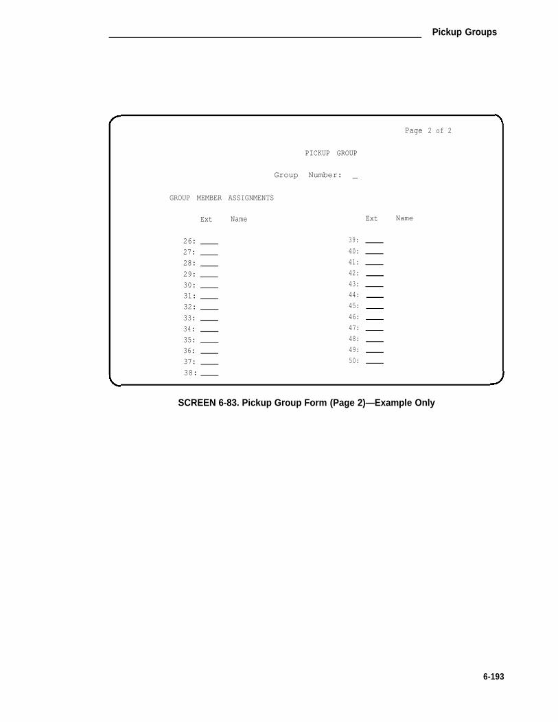
Pickup Groups
Page 2 of 2
PICKUP GROUP
Group Number: _
GROUP MEMBER ASSIGNMENTS
Ext Name
26:
27:
28:
29:
30:
31:
32:
33:
34:
35:
36:
37:
38:
39:
40:
41:
42:
43:
44:
45:
46:
47:
48:
49:
50:
Ext Name
SCREEN 6-83. Pickup Group Form (Page 2)—Example Only
6-193

CHAPTER 6. FORMS FOR SYSTEM FEATURES AND SERVICES
Processor Channel Assignment
Purpose
This form is used to assign up to 64 Processor Channels to the System’s interface links.
Administration Commands
The following administration commands can be used to access the Processor Channel Assign-ment form. In some cases, just the most commonly used commands are shown. Refer toAdministration Commands and Error Messages (Chapter 3) for a complete listing of all adminis-tration commands, the command structure, and the use of abbreviated command words whenentering a command.
Action Object Qualifier*
change communication-interface processor channelsdisplay communication-interface processor channels [’print’ or ‘schedule’]
* Brackets [ ] indicate the qualifier is optional.
Form Instructions
Make assignments as required for the following fields on each page of the form:
Pages 1 through 4 of the Form
• Proc Chan— This field is display-only and indicates each of the 64 processor channels.It is recommended that channels one, two, three, four, and eight be reserved for MSAconnectivity since the MSA uses fixed channel numbers. Channel 10 should be reservedfor MIS and Channel 59 for AUDIX.
• Appl— Enter the type of application that connects to this processor channel. Validentries are noted in the Entry column in the “Processor Channel Applications” table thatfollows. Note that MSA applications, if administered, must be assigned to freed proces-sor and remote processor (MSA) channels (one, two, three, four, and eight, respectively)as shown on the table. Also note that when the MIS adjunct processor is a MSA, theAppl field must be “msamis.” For MIS 3B adjunct processors, the Appl field is set to“mis.” If the Appl field is administered as “isdn,” then no other channels may use theinterface link specified for this processor channel. A link used for ISDN-PRI cannot bemultiplexed to provide other applications. When “OCM” is used, the associated interfacelink may be used to interface either a vendor-supplied outbound call management systemadjunct or an ISDN Gateway adjunct (supports CPN/BN applications) but not both. If aprocessor channel is not assigned, leave this field blank.
6-194

Processor Channel Assignment
TABLE 6-l. Processor Channel Applications
Appl. ProcessorEntry Description Channel Priority
msamcs MSA Message Center Service 1 high (h)msahlwc MSA High Priority Leave Word Calling 2 high (h)msallwc MSA Low Priority Leave Word Calling 3 low (l)msaamwl MSA Automatic Message Waiting Lamp 4 low (l)msaclk Switch/MSA Clock Synchronization 8 high (h)dcs DCS high (h)mis MIS 10 low (l)msamis MSA/MIS - low (l)audix AUDIX 59 high (h)isdn ISDN-PRI - highOCM Outbound Call Management - high
• Interface Link— Enter a number from 1 through 8 for multi-carrier cabinets (1 through 4for single-carrier cabinets) to identify the interface Iink/channel pair used to establish aconnection to the remote machine. (This field and the Interface Chan field must beassigned as a pair or both left blank except when the Appl field is “isdn.”) This is the linknumber assigned on the Processor Interface Data Module form.
• lnterface Chan— This field, together with the Interface Link field, identifies theIink/channel pair that is associated with the local processor channel. Enter a numberfrom 1 through 64 to identify the interface channel that is associated with the local pro-cessor channel. The Interface Link/Channel association establishes a network channelto the remote machine. (This field and the Interface Chan field must be assigned as apair or both left blank except when the Appl field is “isdn.”) Valid entries are 1 through 84or leave blank.
Once a Link/Channel Pair is assigned on the Processor Channel Assignments form, thepair cannot be assigned on the Hop Channel Assignments form (see Hop ChannelAssignments—this chapter).
• Priority— Enter “h” (high) or “l” (low) to indicate the priority of this processor channel.High priority channels have precedence over the low priority channels. Assignmentsshould be made based on the operational speed of the links and the number of hops inthe network channel. Enter the appropriate priority (as per the “Processor Channel Appli-cations” table).
• Remote Proc Chan— Cannot be assigned when the Appl field is “isdn.” Enter the pro-cessor channel number (1 through 84) of the remote switch that connects to the localprocessor channel. Valid entries are 1 through 64 or leave blank.
• Machine-lD— Enter the Machine ID number associated with the port if the Appl field is“dcs,” “audix,” or “ocm”; otherwise, leave this field blank. Machine-lDs are administeredas part of the UDP. Valid entries are 1 through 99 or leave blank. When supportingAUDIX, the Machine ID must agree with the AUDIX field entry on the AUDIX Data Linkform (part of AUDIX translations). Typically, with just one AUDIX, this entry is “1.”
6-195

CHAPTER 6. FORMS FOR SYSTEM FEATURES AND SERVICES
CHANNEL
ProcChan
1:
2:
3:
4:
5:
6:
7:
8:
9:
10:
11:
12:
13:
14:
15:
16:
Appl.
PROCESSOR
Interface
Link Chan
Page 1 of 4
ASSIGNMENT
Priority
Remote
Proc Chan Machine-ID
SCREEN 6-84 Processor Channel Assignment Form (Page 1)—Example Only
(To reduce repetition, Pages 2 through 3 are not shown).
6-196

Processor Channel Assignment
Page 4 of 4
PROCESSOR CHANNEL ASSIGNMENT
Interface Remote
Link Chan Priority Proc Chan
Proc
Chan
49:
50:
51:
52:
53:
54:
55:
56:
57:
58:
59:
60:
61:
62:
63:
64:
Machine-IDAppl.
—
—
—
—
-
—
—
—
—
—
—
—
—
—
—
—
SCREEN 6-85. Processor Channel Assignment Form (Page 4)—Example Only
6-197

CHAPTER 6. FORMS FOR SYSTEM FEATURES AND SERVICES
Recorded Announcements
Purpose
This form is used to assign up to 128 analog or integrated announcements, or any desired combi-nation of both. Integrated announcements are assigned and recorded on the TN750 Announce-ment circuit pack. The analog announcements are assigned on the TN742, TN746B, or TN769Analog Line circuit pack that is connected to external recording or playback equipment.
Each announcement is accessed by dialing an extension number that is assigned to eachannouncement.
Integrated announcements on the TN750B circuit pack may be recorded at 16 Kbits per second(for eight minutes and 32 seconds of announcement time) or 32 Kbits per second (for fourminutes and 16 seconds of announcement time), depending on administration. A differentrecording speed may be used for each integrated announcement. These capacities will be dif-ferent if a combination of different recording speeds is used.
Administration Commands
The following administration commands can be used to access the Recorded Announcementsform. In some cases, just the most commonly used commands are shown. Refer to Administra-tion Commands and Error Messages (Chapter 3) for a complete listing of all administration com-mands, the command structure and the use of abbreviated command words when entering acommand.
Action Object Qualifier*
change announcements —display announcements [‘print’ or ‘schedule’]restore announcements —save announcements —
* Brackets [ ] indicate the qualifier is optional.
Note: Announcements are not saved when translations are saved. You must use the“save announcements” command to save your recorded announcements. The “saveannouncements” command takes at least thirty minutes to complete.
Form Instructions
Make assignments as required for the following fields on each page of the form:
Pages 1 through 8 of the Form
• Ext— Enter a 1- to 5-digit unassigned extension number that agrees with the dial plan.Up to 128 extension numbers may be assigned on the form, one extension number foreach announcement. References to a particular announcement “Ext” may be from thefollowing forms: Hunt Group, Call Coverage Paths, Trunk Group (Incoming Destination),Call Vector, and Feature-Related System Parameters (DID/Tie/lSDN Intercept Treat-ment, Controlled Restriction fields).
6-198

Recorded Announcements
• Type— Enter the type of announcement you want to assign to this extension number.Allowable entries are “integrated” or “analog.”
If “integrated” is entered, the Protect and Rate fields must be completed. If “analog” isentered, the Queue Length and Port fields must be completed. The Queue Length fieldonly applies if “y” is entered in the Queue field.
• COR— Enter the desired Class of Restriction (COR) number from 0 through 63. Defaultis “1.”
• Name— Enter up to 15 alphanumeric characters to describe the announcement mes-sage.
• Queue— Enter “y” (yes) to queue calls for the announcement; otherwise, enter “n” (no).Default is “n.”
Page 1 of the Form Only
• Queue Length— Applicable if the Queue field is “y” and the Type field is “analog.” Enterthe number of calls that can be queued for this analog announcement. Allowable entriesare 1 through 150. The sum of the queue entries for all analog announcements cannotexceed 150. Default is “0.” When the Type field entry is “integrated,” “N/A” will bedisplayed in this field.
• Protect— Enter “y” (yes) to protect the integrated announcement from being deleted orchanged by any user. Enter “n” (no) to allow only users with a console permission COSto change or delete an announcement. Default is “n.” Note that when the Type field is“analog,” the Rate field is set to “N/A.”
• Rate— Used to specify the recoding speed when recording announcements on theTN750B Integrated circuit pack. Valid entries are “16” and “32.” Default is “32.” Notethat when the Type field is “analog,” the Rate field is set to “N/A.”
• Port— Enter a 6-character port number. The first character identifies the network (1through 3, default is “1” if no entry); the second character identifies the carrier (A throughE); the third and fourth characters identify the slot number in the carrier (01 through 20for multi-carrier cabinets depending on carrier type or 01 through 18 for single-carriercabinets depending on cabinet type); the last two characters identify the circuit number(01 through 16). When the Type field entry is “integrated,” “N/A” will be displayed in thisfield.
6-199

CHAPTER 6. FORMS FOR SYSTEM FEATURES AND SERVICES
Page 1 of 8
ANNOUNCEMENTS
Ext. Type COR Name Queue Q-Len Protect? Rate Port
1: 1701 analog 1 busy y 10 N/A N/A 1B0404
2: 1702 analog 1 out of service n N/A N/A N/A 1B1701
3: 1703 integrate 1 please dial n N/A n 32 N/A
4: 1 n5: 1 n6: 1 n7: 1 n8: 1 n9: 1 n
10: 1 n11: 1 n12: 1 n13: 1 n14: 1 n15: 1 n16: 1 n
SCREEN 6-86. Recorded Announcements Form (Page 1)—Example Only
Implementation Note:
Announcements one and two show the fields that are assigned to the analog and integratedannouncement, respectively.
The Queue Length field is only displayed when the Type field is “analog” and the Queue field is“y.”
The Port field is only displayed when the Type field is “analog.”
The Protect field is only displayed when the Type field is “integrated.”
6-200

Recorded Announcements
Page 2 of 8
ANNOUNCEMENTS
Ext. Type COR Name Queue
17: 1 n
18: 1 n19: 1 n20: 1 n21: 1 n22: 1 n23: 1 n24: 1 n25: 1 n26: 1 n27: 1 n
28: 1 n29: 1 n30: 1 n31: 1 n32: 1 n
SCREEN 6-87. Recorded Announcements Form (Page 1)—Example Only
(To reduce repetition, pages 3 through 7 are not shown).
6-201

CHAPTER 6. FORMS FOR SYSTEM FEATURES AND SERVICES
113:
114:
115:
116:
117:
118:
119:
120:
121:
122:
123:
124:
125:
126:
127:
128:
Ext. Type COR
Page 8 of 8
ANNOUNCEMENTS
Name Queue
1
1
1
1
1
1
1
1
1
1
1
1
1
1
1
1
n
n
n
n
n
n
n
n
n
n
n
n
n
n
n
n
SCREEN 6-88. Recorded Announcements Form (Page 8)—Example Only
6-202

Remote Access
Remote Access
Purpose
This form is used to implement the Remote Access feature. Remote Access permits a callerlocated outside the System to access the System through the public or private network and thenuse the features and services of the System.
Remote Access users can dial into the System using CO, FX, WATS, and ISDN-PRI trunks. Inaddition, a dedicated Remote Access DID number can be provided.
After System dial tone is obtained, the Remote Access user is, for reasons of System security,required to dial a Barrier Code. One of up to 10 Barrier Codes, each with a different Class ofRestriction, can be assigned.
Refer to the “Remote Access Flow Chart” figure at the end of this section. The chart depicts thesequence of events associated with Remote Access call processing.
Administration Commands
The following administration commands can be used to access the Remote Access form. Insome cases, just the most commonly used commands are shown. Refer to Administration Com-mands and Error Messages (Chapter 3) for a complete listing of all administration commands, thecommand structure, and the use of abbreviated command words when entering a command.
Action Object Qualifier*
change remote access —display remote access [‘print’ or ‘schedule’]
* Brackets [ ] indicate the qualifier is optional.
Form lnstructions
Make assignments as required for the following fields on the form:
Note: AT&T has designed the Remote Access feature incorporated in this product that,when properly administered by the customer, will enable the customer to minimizethe ability of unauthorized persons to gain access to the network. It is thecustomers responsibility to take the appropriate steps to properly implement thefeatures, evaluate and administer the various restriction levels, protect access codesand distribute them only to individuals who have been advised of the sensitive natureof the access information. Each authorized user should be instructed concerning theproper use and handling of access codes.
In rare instances, unauthorized individuals make connections to the telecommunica-tions network through use of remote access features. In such event, applicable tar-iffs require that the customer pay all network charges for traffic. AT&T cannot beresponsible for such charges, and will not make any allowance or give any credit forcharges that result from unauthorized access.
6-203

CHAPTER 6. FORMS FOR SYSTEM FEATURES AND SERVICES
• Remote Access Extension— Enter an extension number (may not be a VDN extension)for Remote Access. This extension is associated with each trunk that supports theRemote Access feature. May only be blank if no barrier codes assigned. Default isblank. The extension is used as if it was a DID extension. Only one DID extension maybe assigned as the Remote Access Extension. Calls to that number are treated thesame as calls on the Remote Access trunk.
When a trunk group is dedicated to Remote Access, the Remote Access extensionnumber is administered on the trunk group’s Incoming Destination field. Typically,Remote Access is used for after business hours to administer the Incoming Destinationfield on the trunk group as “0” (attendant) and administer the Remote Access extensionas the Night Service extension. Incoming calls route to attendant until the Night Servicebutton is pressed on console.
• Barrier Code Length— Enter the desired barrier code length (4 to 7 digits) or leave blank(indicates no barrier code is required). All Barrier Codes assigned in the system must bethe same length. Default is blank.
• Authorization Code Required— Enter “y” if an Authorization Code must be dialed byremote access users to access the System’s facilities; otherwise, enter “n.” Default is“n.”
• Remote Access Dial Tone— This field is only displayed when the Authorization CodeRequired field is “y.” Default is “n” (no). Enter “y” (yes) if recall dial tone is to bereturned to a remote access caller after having dialed a barrier code but before dialing anauthorization code (if both are required).
• Barrier Code— Enter any desired Barrier Codes. All codes must be a 4- to 7-digitnumber and conform to the desired length selected above. The code can be any combi-nation of the digits 0 through 9. If the Barrier Code Length field is blank, the first BarrierCode field must be specified as “none.” Duplicate entries are not allowed. Default isblank.
• COR— Enter the Class of Restriction (COR) number (0 through 63) associated with theBarrier Code that defines the call restriction features. Default is “1.“
• COS— Enter a Class of Service (COS) number (0 through 15) associated with the BarrierCode that defines access permissions for call processing features. Default is “1.“
6-204

Remote Access
Page 1 of 1
REMOTE ACCESS
Remote Access Extension: _
Barrier Code Length: _
Authorization Code Required? n
Remote Access Dial Tone? _
BARRIER CODE ASSIGNMENTS (Enter up to 10)
Barrier Code COR COS Barrier Code COR COS
1 : 1 1 6: 1 1
2 : 1 1 7: 1 1
3 : 1 1 8: 1 1
4 : 1 1 9: 1 1
5 : 1 1 10: 1 1
SCREEN 6-89. Remote Access Form—Example Only
6-205
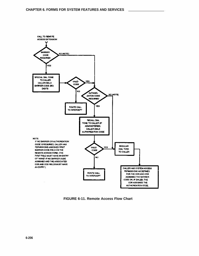
CHAPTER 6. FORMS FOR SYSTEM FEATURES AND SERVICES
FIGURE 6-11. Remote Access Flow Chart
6-206

Special Information Tones
Special Information Tones
Purpose
Provides the capability of specifying the treatment of Special Information Tones (SITS) used foroutbound call management-type calls. The TN744 Call Classifier circuit pack ports are used todetect SITS. The TN744 is capable of detecting the following six SITS:
• SIT Ineffective Other
• SIT Intercept
• SIT No Circuit
• SIT Reorder
• SIT Vacant Code
• SIT Unknown
The CPN/BN option must be enabled on the System-Parameters Customer-Options form beforeassociated forms or fields on forms can be administered.
Administration Commands
The following administration commands can be used to access the SIT Treatment For Call Clas-sification form. In some cases, just the most commonly used commands are shown. Refer toAdministration commands and Error Messages (Chapter 3) for a complete listing of all adminis-tration commands, the command structure, and the use of abbreviated command words whenentering a command.
Action Object Qualifier*
change sit-treatment —display sit-treatment [’print’ or ‘schedule’]
* Brackets [ ] indicate the qualifier is optional.
Form Instructions
Make assignments as required for each field on the form as follows: In the field following eachtype of SIT, enter “answered” to specify that the call is classified as answered, and is thereforesent to an agent; or enter “dropped” to specify that the call is classified as not answered, and istherefore not sent to an agent.
•
•
•
SIT Ineffective Other— Sample announcement following this SIT—“You are not requiredto dial a “1” when calling this number.” Valid entries are “answered” and “dropped.”Default is “dropped.”
SIT Intercept— Sample announcement following this SIT—“XXX-XXXX has beenchanged to YYY-YYYY, please make a note of it.” Valid entries are “answered” and“dropped.” Default is “answered.”
SIT No Circuit— Sample announcement following this SIT—“AII circuits are busy, pleasetry to call again later.” Valid entries are “answered” and “dropped.” Default is “dropped.”
6-207

CHAPTER 6. FORMS FOR SYSTEM FEATURES AND SERVICES
• SIT Recorder— Sample announcement following this SIT—“Your call did not go through,please hang up and dial again.” Valid entries are “answered” and “dropped.” Default is“dropped.”
• SIT Vacant Code— Sample announcement following this SIT—“Your call cannot be com-pleted as dialed, please check the number and dial again.” Valid entries are “answered”and “dropped.” Default is “dropped.”
• SIT Unknown— A situation or condition that is unknown to the network is encountered.Valid entries are “answered” and “dropped.” Default is “dropped.”
SIT TREATMENT FOR CALL CLASSIFICATION
SIT Ineffective Other: dropped
SIT Intercept: answeredSIT No Circuit: dropped
SIT Reorder: dropped
SIT Vacant Code: droppedSIT Unknown: dropped
SCREEN 6-90. SIT Treatment For Call Classification Form
6-208

Synchronization Plan
Synchronization Plan
Purpose
This form is used to assign primary and secondary external synchronization sources. This pro-vides synchronization between the switch and digital facilities that the switch is connected to.When the switch is connected to digital facilities, the switch (both PPN and EPN) must be syn-chronized to the incoming data rate of 8000 frames per second. This timing information refer-ence may be derived from DS1 facilities or from a Stratum 3 external clock. Loss of the refer-ence signal, excessive phase changes, and variation in timing frequency can cause loss of dataor dropped data connections. When no external digital facilities, including Stratum 3 externalclocks, are present or when a switch is the “master” node of a network providing timing to therest of the network, the timing can come from an oscillator on the switch’s tone/clock circuit pack.
It should be noted that the Synchronization Plan may not be required for some digital connec-tions. The switch’s internal clock may suffice.
Administration Commands
The following administration commands can be used to access the Synchronization Plan form. Insome cases, just the most commonly used commands are shown. Refer to Administration Com-mands and Error Messages (Chapter 3) for a complete listing of all administration commands, thecommand structure, and the use of abbreviated command words when entering a command.
Action Object Qualifier*
change synchronization —display synchronization [‘print’ or ‘schedule’]
* Brackets [ ] indicate the qualifier is optional.
Form Instructions
Make assignments as required for the following fields on each page of the form:
Page 1 of the Form
• Stratum— Enter the stratum level to be used for synchronization. Valid entries are “3” or“4.” Note that Stratum 3 capability is only possible when using a TN780 Tone Clock cir-cuit pack. Default is “4.”
• Port Network— Only displayed when the Stratum field entry is “3.” Enter the port net-work that the Stratum 3 being used for synchronization is connected to. Valid entries are1 through 3.
• Primary— Only displayed when the Stratum field entry is “4.” Note that the Primary andSecondary synchronization sources (DS1 facilities) must be on the same Port Network(that is, PPN, EPN1, or EPN3). Enter a 4-character DS1 circuit pack location number forthe DS1 circuit pack that will function as the primary synchronization source. The firstcharacter identifies the network (1 through 3, default is “1” if no entry), the second char-acter identifies the carrier (A through E), and the last two identify the circuit pack slotnumber (01 through 20 for multi-carrier cabinets depending on carrier type or 01 through
6-209

CHAPTER 6. FORMS FOR SYSTEM FEATURES AND SERVICES
•
•
18 for single-carrier cabinets depending on cabinet type). A blank entry means no exter-nal source. The clock circuit pack’s internal source is the implicit last choice. Only oneswitch in the network can function as the primary synchronization source.
Secondary— Only displayed when the Stratum field entry is “4.” Note that the Primaryand Secondary synchronization sources (DS1 facilities) must be on the same Port Net-work (that is, PPN, EPN1, or EPN3). Enter a 4-character DS1 circuit pack locationnumber for the DS1 circuit pack that will function as a secondary synchronization source.The first character identifies the network (1 through 3, default is “1” if no entry), thesecond character identifies the carrier (A through E), and the last two identify the circuitpack slot number (01 through 20 for multi-carrier cabinets depending on carrier type or01 through 18 for single-carrier cabinets depending on cabinet type). The system willautomatically select the secondary circuit pack if the primary circuit has a failure.
Pages 1 and 2 of the Form
DS1 CIRCUIT PACKS—Location/Name/Slip— Only displayed if the Stratum field entryis “4.” Identifies the location, name, and slip detection parameter for each DS1 circuitpack administered via the DS1 Circuit Pack form. These fields are display-only.
Instructions for administering a DS1/DMl interface are provided in the AT&T System 75 and Sys-tern 85 DS1/DMI/ISDN-PRI Interface Service Manual, 555-025-101.
Page 1 of 2SYNCHRONIZATION PLAN
SYNCHRONIZATION SOURCE ( DS1 circuit pack location)
Stratum: 4
Port Network: 1
Primary: _ Secondary: _
DS1 CIRCUIT PACKS
Location Name Slip Location Name Slip
SCREEN 6-91. Synchronization Plan Form (Page 1)—Example Only
lmplementation Note:The Port Network field is only displayed if the Stratum field entry is “3.”
6-210

Synchronization Plan
Location Name Slip
Page 2 of 2SYNCHRONIZATION PLAN
DS1 CIRCUIT PACKS
Location Name Slip
SCREEN 6-92. Synchronization Plan Form (Page 2)—Example Only
6-211

CHAPTER 6. FORMS FOR SYSTEM FEATURES AND SERVICES
System-Parameters Customer-Options
The System-Parameters Customer-Options form is implemented in the system during the instal-lation process. The form is not available for use after installation except when option changesare required by the customer. Procedures covering the use of the System-ParametersCustomer-Options form are provided in DEFINITY® Communications System Generic 1 andGeneric 3i—Installation and Test, 555-230-104. Refer to Chapter 4 for a brief description of eachoptional feature or to DEFlNITY® Communications System Generic 1 and Generic 3i—FeatureDescription, 555-230-201 for a detailed description of each feature.
The optional features that supplement the standard system voice/data feature package capabili-ties are as follows. Note that the System can be optioned for either ASAI or CPN/BN but notboth.
• Abbreviated Dialing—Enhanced List
• CallVisor ASAI
In addition, the following ASAI capability groups automatically default to “y” if the ASAIInterface is enabled:
— Adjunct Call Control Group—Allows the associated adjunct (for example, ICM) toinvoke third party capabilities.
— Adjunct Routing Group—Allows the associated adjunct to provide adjunct routinginformation to the switch for incoming calls.
— Domain Control Group—Allows the associated adjunct to: (1) control andreceive event reports for station sets and (2) receive Iogout event reports for agiven ACD split.
— Event Notification Group—Allows the associated adjunct to request incoming callnotification and enables the switch to send event reports about such calls.
— Request Feature Group—Allows the associated adjunct to request features suchas “change work modes,” “login,” and “logout.”
— Set Value Group—Allows the adjunct to request status changes for MessageWaiting lamps (that is, control the on/off state of the lamps).
Note: The above options are initially defaulted to “yes,” but can be disabled duringthe system installation process.
• Authorization Codes
• ACD
• ARS
• ARS/AAR Digit Conversion (requires ARS and Private Networking or UDP to be enabled)
• ARS/AAR Partitioning
• Basic CMS Measurements
• Call Work Codes (CWC) (requires ACD to be enabled)
• CAS Branch
6-212

System-Parameters Customer-Options
•
•
•
•
•
•
•
•
•
•
•
•
•
•
•
•
CAS Main
DCS
Emergency Access to the Attendant
Forced Entry of Account Codes
Hospitality
Hospitality Parameter Reduction (requires Hospitality to be enabled)
ISDN-PRI
Lookahead Interflow [requires ISDN-PRI and Vectoring (Basic) to be enabled]
CPN/BN
Private Networking
Service Observing
Time of Day Routing (requires ARS Partitioning and either ARS or Private Networkingfeatures to be enabled)
TN744 Answer Detection
UDP
Vectoring (Basic)
Vectoring (Prompting)
After activation of an optional feature, the associated form(s) and fields on forms require comple-tion to define the feature parameters and service criteria. The implementation procedures for allfeatures are provided in this manual. However, if an optional feature is not provided, the associ-ated implementation procedures are blocked.
Note: EPN and duplication option are optional features that do not need to be admin-istered; these feature options are dependent upon the hardware configuration of thesystem. See DEFlNITY® Communications System Generic 1 and Generic 3i—System Description, 555-230-200, for additional information on the EPN and theduplication option.
6-213

CHAPTER 6. FORMS FOR SYSTEM FEATURES AND SERVICES
Terminating Extension Group
Purpose
This form is used to define Terminating Extension Groups (TEGs).
Any voice terminal can be assigned as a TEG member however, only a multi-appearance voiceterminal can be assigned a TEG button with associated status lamp. The TEG button allows theterminal user to select a TEG call appearance for answering or for bridging onto an existing call.
The TEG members are assigned on an extension number basis. Call reception restrictions appli-cable to the group are specified by the group COR. The group COR takes precedence over anindividual member’s COR. The members could all be termination restricted but still receive callsif the group is not restricted.
The system allows for as many as 32 TEGs with up to four members each. An extension numbercan be assigned to more than one TEG but can have only one appearance of each group.
Administration Commands
The following administration commands can be used to access the TEG form. In some cases,just the most commonly used commands are shown. Refer to Administration Commands andError Messages (Chapter 3) for a complete listing of all administration commands, the commandstructure, and the use of abbreviated command words when entering a command.
Action Object Qualifier*
add term-ext-group 1-32 (or ‘next’)change term-ext-group 1-32display term-ext-group 1-32 [‘print’ or ‘schedule’]list term-ext-group [‘print’ or ‘schedule’]remove term-ext-group 1-32
* Brackets [ ] indicate the qualifier is optional.Single quotes (‘ ’) indicate the text inside the quote must be entered exactly as shown oran abbreviated form of the word maybe entered.
Form Instructions
Make assignments as required for the following fields on the form:
•
•
•
•
•
6-214
Group Number— Enter a group number from 1 through 32 when completing a paperform. This is a display-only field when the form is accessed using an administration com-mand such as add or change.
Group Extension— Enter an unused extension number (may not be a VDN extension)consisting of 2 to 5 digits (do not leave blank).
Group Name— Enter up to 15 characters to identify the group.
Coverage Path— Enter a number from 1 through 600 for the call coverage path for thisgroup. (A TEG cannot serve as a coverage point; however, calls to a TEG can redirectto coverage.) Valid entries are one through 600 or leave blank.
Security Code— Enter a 4-digit security code or leave blank. This code is used for theDemand Print feature.

Terminating Extension Group
•
•
•
•
COR— Enter the desired Class of Restriction (COR) number (0 through 63) that reflectsthe desired restrictions. Default is “1.”
ISDN Caller Display— Enter “grp-name” or “mbr-name” to specify whether the TEGgroup name or member name (member of TEG where call terminated) will be sent to theoriginating user. This field is required if the ISDN-PRI option is enabled on the System-Parameters Customer-Options form. If ISDN-PRI is not enabled, leave blank.
Ext— Enter the extension number (may not be a VDN extension) for the members of thisgroup.
Name— Make no entry. The name is assigned to the preceding extension number whenthe TEG member's voice terminal is administered.
TERMINATING
Group Number: _
Group Name:
Security Code:
ISDN Caller Display:
GROUP MEMBER ASSIGNMENTS
Ext Name
1:
2:
Page 1 of 1
Group Extension:
Coverage Path:
COR:
Ext Name
3:
4:
1
SCREEN 6-93. Terminating Extension Group Form—Example Only
6-215
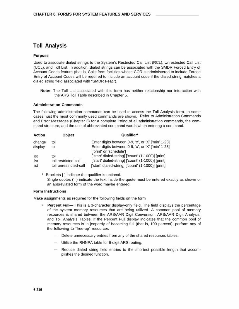
CHAPTER 6. FORMS FOR SYSTEM FEATURES AND SERVICES
Toll Analysis
Purpose
Used to associate dialed strings to the System’s Restricted Call List (RCL), Unrestricted Call List(UCL), and Toll List. In addition, dialed strings can be associated with the SMDR Forced Entry ofAccount Codes feature (that is, Calls from facilities whose COR is administered to include ForcedEntry of Account Codes will be required to include an account code if the dialed string matches adialed string field associated with “SMDR Feac”).
Note: The Toll List associated with this form has neither relationship nor interaction withthe ARS Toll Table described in Chapter 5.
Administration Commands
The following administration commands can be used to access the Toll Analysis form. In somecases, just the most commonly used commands are shown. Refer to Administration Commandsand Error Messages (Chapter 3) for a complete listing of all administration commands, the com-mand structure, and the use of abbreviated command words when entering a command.
Action Object Qualifier*
change toll Enter digits between 0-9, ‘x’, or ‘X’ [‘min’ 1-23]display toll Enter digits between 0-9, ‘x’, or ‘X’ [‘min’ 1-23]
[‘print’ or ‘schedule’]list toll [’start’ dialed-string] [’count’ (1-1000)] [print]list toll restricted-call [’start’ dialed-string] [’count’ (1-1000)] [print]list toll unrestricted-call [’start’ dialed-string] [’count’ (1-1000)] [print]
* Brackets [ ] indicate the qualifier is optional.Single quotes (‘ ’) indicate the text inside the quote must be entered exactly as shown oran abbreviated form of the word maybe entered.
Form Instructions
Make assignments as required for the following fields on the form
• Percent Full— This is a 3-character display-only field. The field displays the percentageof the system memory resources that are being utilized. A common pool of memoryresources is shared between the ARS/AAR Digit Conversion, ARS/AAR Digit Analysis,and Toll Analysis Tables. If the Percent Full display indicates that the common pool ofmemory resources is in jeopardy of becoming full (that is, 100 percent), perform any ofthe following to “free-up” resources
— Delete unnecessary entries from any of the shared resources tables.
— Utilize the RHNPA table for 6-digit ARS routing.
— Reduce dialed string field entries to the shortest possible length that accom-plishes the desired function.
6-216

Toll Analysis
• Dialed String— Enter up to an 18-character dialed digit string. Valid entries include thedigits 0 through 9 and the wild card character “x” or “X.” The wild card letter “x” or “X”may be used to substitute for any digit in the string. A Dialed String, when entered, mustbe associated with at least one RCL, UCL, SMDR Forced Entry Account Code (SMDRFEAC), or Toll List.
• Min— Enter the minimum number of digits to collect (1 through 18). The user can actu-ally dial up to 23 digits (match is on first 18). Valid entries are 1 through 18. Default isblank.
• Max— Enter the maximum digits to collect. The value must be greater than or equal tothe Min value. Valid entries are 1 through 23. Default is blank.
• RCL— Enter “x” to assign the Dialed String to the RCL. All entries of “x” and their asso-ciated dialed strings are referred to as the System’s RCL. The RCL can be assigned toany COR. A call attempt from a facility whose COR is marked as being associated withthe RCL and whose dialed string matches a RCL dialed string field will be denied. Thecaller will receive intercept treatment. Default is blank.
• Toll List— Enter “x” to assign the Dialed String to the Toll List. All entries of “x” and theirassociated dialed strings are referred to as the System’s Toll List. The Toll List is a list ofdialed strings used for toll restriction analysis. Default is blank.
When a user calls from a facility whose COR has a Calling Party Restriction of “all-toll” or“tac-toll,” the System checks the Toll Analysis form for the user’s dialed string. If amatch occurs and the Toll List field is set to “x,” the call will be denied unless the string isalso associated with an UCL that is also assigned the facility’s COR. Refer to the CORform instructions in this Chapter for definitions of the Calling Party Restrictions. Alsorefer to the UCL field description for additional information about UCLs.
Note that this Toll List has no relationship to the ARS Toll Table described in Chapter 5.
The next table shows the System’s default toll list assignments.
6-217

CHAPTER 6. FORMS FOR SYSTEM FEATURES AND SERVICES
TABLE 6-M. Default Toll List Assignments
Dialed TollString Min Max List
0 1 23 x
1 4 23 x
20 10 10 x
21 10 10 x
30 10 10 x
31 10 10 x
40 10 10 x
41 10 10 x
50 10 10 x
51 10 10 x
60 10 10 x
61 10 10 x
70 10 10 x
71 10 10 x
80 10 10 x
81 10 10 x
90 10 10 x
91 10 10 x
• SMDR FEAC— Enter “x” to assign the dialed string to the SMDR Forced Entry ofAccount Code feature. Users who place calls from facilities whose COR is marked asbeing associated with Forced Entry of Account Codes and whose dialed string matchesan SMDR FEAC dialed string field will be required to enter an account code before thecall will complete. Default is blank.
• Unrestricted Call List— Enter “x” in the appropriate field (1 through 10) to assign thedialed string to one of the System’s UCL. A UCL (10 maximum in the System) is a list ofdialed strings that can be dialed from a facility whose COR assignment includes the UCLList number. The UCL number or numbers (one through 10) are assigned on appropriateCOR forms and associate the COR with the UCL List(s). A toll call from a facility that is“all-toll” restricted, for example, will complete if the facilities COR is associated with aUCL whose dialed string field matches the dialed number. Note that the call will notcomplete if the COR is also associated with the System’s RCL and whose dialed stringalso matches the dialed number. The RCL takes precedence over the UCL. Default isblank for all felds.
6-218

Toll Analysis
The following Authorization Check Flow Chart (see figure) depicts the order of call processingfunctions that occur as a result of user dialed numbers and associated entries on the TollAnalysis form and the user's COR form.
As shown on the flowchart, RCLs have priority over UCLs. Checks are made as follows:
1. The first check determines if the dialed string is associated with the RCL on the TollAnalysis form. If it is, the RCL field on the COR form associated with the calling party’sstation is checked. If the field is set to “y,” the call is denied, otherwise, checking contin-ues.
2. The next check determines if the Calling Party Restriction field on the COR form is “all-toll” or “tac-toll.” If it is, checking continues, otherwise the call is allowed.
3. The next check determines if the dialed string is associated with the Toll List on the TollAnalysis form. If it is, checking continues, otherwise, the call is allowed.
4. The next check determines if the dialed string is associated with a UCL number (onethrough 10) on the Toll Analysis form. If it is, the COR form is checked to determine ifthe UCL number is entered on the UCL field on the form. If it is, the call is allowed, oth-erwise, the call is denied.
In summary, calls from facilities are processed based on the COR assigned the facility, theCOR’s association with the System’s RCL, UCL, and Toll List, and the specific digits dialed.
6-219

CHAPTER 6. FORMS FOR SYSTEM FEATURES AND SERVICES
THIS FLOW CHART DOES NOT REFLECT
ANY FEATURE INTERACTIONS THAT
MIGHT TAKE PLACE, SUCH AS WITH
AUTHORIZATION CODES
FIGURE 6-12. Authorization Check Flow Chart
6-220

Toll Analysis
Percent Full:_TOLL ANALYSIS
Toll
List
SMDR
FEAC
<--Unrestricted Call List-->
8 9 10Dialed String Min RCL 1 2 3 4 5 6 7Max
SCREEN 6-94. Toll Analysis Form
Implementation Note:
Entries on the form do not have to be input in a sorted order. Subsequent displays of theform will show all entries in a sorted increasing order.
6-221

CHAPTER 6. FORMS FOR SYSTEM FEATURES AND SERVICES
Vector Directory Number
Purpose
This form is used to define Vector Directory Numbers (VDNs) for the Call Vector feature. A VDNis an extension number used to access a call vector. Each VDN is mapped to one call vector.
VDNs are software extension numbers (that is, not assigned to physical equipment). A VDN isaccessed via a direct dial CO trunk mapped to the VDN (incoming destination or night serviceextension), a DID trunk a LDN call. Note that the VDN may be Night Destination for LDN. A callvector consists of a set of commands that instruct the System on how to process calls to theVDN.
The System allows a maximum of 500 VDNs and 256 call vectors. For additional information,refer to the Call Vectoring feature description in DEFINITY® Communication System Generic 1and Generic 3i—Feature Description, 555-230-201. The Vectoring (Basic) or Vectoring (Prompt-ing) options must be enabled on the System-Parameters Customer-Options form before the VDNForm can be administered.
Administration Commands
The following administration commands can be used to access the VDN form. In some cases,just the most commonly used commands are shown. Refer to Administration Commands andError Messages (Chapter 3) for a complete listing of all administration commands, the commandstructure, and the use of abbreviated command words when entering a command.
Action Object Qualifier*
add vdn xxxxx (extension number of VDN to be added)change vdn xxxxx (extension number of VDN to be changed)display vdn xxxxx (extension number of VDN to be displayed ) [’print’ or ’schedule’]list vdn xxxxx (extension number of VDN to be listed) (’count’ 1-500)
[’print’ or ’schedule’]remove vdn xxxxx (extension number of VDN to be removed)
* Brackets [ ] indicate the qualifier is optional.Single quotes (’ ’) indicate the text inside the quote must be entered exactly as shown oran abbreviated form of the word maybe entered.
Form Instructions
Make assignment as required for the following fields on the form:
• Extension:— Enter the extension associated with the VDN when completing a paperform. The extension is a 1- to 5-digit number which starts with a valid first digit andlength as defined by the System’s dial plan. This is a display-only field when using anadministration command such as “add vdn xxx” to access the form.
• Name:— Enter up to a 15-character alphanumeric name that is used to identify the VDN.This is an optional field that need not contain any data.
6-222

Vector Directory Number
• Display Override?— This entry affects the operation of an agent’s display when a call isrouted through several VDNs. If it is set to “n” (no), the name of this VDN appears onthe agent’s display. If any subsequent VDNs are used to process this call, their nameswill not appear on the terminating display. If the field is set to “y” (yes), the name of theVDN appearing on the terminating display will depend on the administration and chainingof the subsequent VDNs. The default value for the field is “n.”
• COR:— Enter a 1-to 2-digit number which specifies the class of restriction (COR) to beassigned the VDN. The default value is “1.“ The field cannot be blank and must have anentry in the range from 0 through 63.
• Vector Number— Enter a 1- to 3-digit vector number that specifies a particular call vec-tor that is accessed through the VDN. Valid entries are in the range from 1 through 256.The field cannot be blank.
• Measured— Determines whether the VDN will be measured by CMS or BCMS or both. Ifit is to be measured, any calls placed to the VDN will be tracked by CMS or BCMS orboth. Allowable entries are “none,” “internal,” “external,” or “both.” Default is “none.”
VECTOR DIRECTORY NUMBER
Extension: XXXXXName:
Display Override? n
COR: 1Vector Number: 1
Measured: none
SCREEN 6-95. Vector Directory Number Form
Implementation Note:
The BCMS feature must have been optioned if the “Measured” field is set to “internal” or “both.”In addition, the appropriate CMS release must be administered on the Feature-Related SystemParameters form if the field is being changed to “external” or “both.”
The next figure shows three typical examples of how VDNs are used. An outside call to a VDN isprocessed based on the various elements that are entered on the VDN form. Handling of the callis based on the commands associated with the vector. Displayed information is dependent onthe setting of the Display Override field entry. As shown in the third example, the Display Over-ride field set to “N” for VDN 4501 determines the name displayed on the terminating extension7000.
6-223

CHAPTER 6. FORMS FOR SYSTEM FEATURES AND SERVICES
OUTSIDE VECTOR DIRECTORY NUMBERCALL
DISPLAY VECTOR
EXTENSION NAME OVERRIDE COR NUMBER VECTOR # 7 (HUNT GROUP)
4501 PARTS N 16 7 ROUTE TO NUMBER 7000
STATION 7000 DISPLAY
SHOWS “OUTSIDE CALL
TO PARTS”
OUTSIDE
CALL
DISPLAY VECTOR
EXTENSION N A M E O V E R R I D E COR NUMBER VECTOR # 7
- COLLECT 1 DIGIT
4601 PARTS Y 16 7 -ROUTE TO NUMBER
5501 IF DIGIT EQUALS 1
VECTOR #9
5501 PARTS 2 Y 16 9 ROUTE TO NUMBER 7000
STATION 7000 DISPLAY
SHOWS “OUTSIDE CALL
TO PARTS 2”
OUTSIDE
CALL
DISPLAY VECTOR
EXTENSION NAME OVERRIDE COR NUMBER VECTOR #7
- COLLECT 1 DIGIT
4501 PARTS N 16 7 - ROUTE TO NUMBER
5501 IF DIGIT EQUALS 1
VECTOR #9
5501 PARTS 2 Y 16 9 ROUTE TO NUMBER 7000
FIGURE 6-13. Typical VDN Call Processing Example
STATION 7000 DISPLAY
SHOWS “OUTSIDE CALL
TO PARTS”
6-224

CHAPTER 6. FORMS FOR SYSTEM FEATURES AND SERVICES
Voice Terminals—General
Voice terminals combine the capabilities of both a telephone and computer and have a variety ofcontrolling and monitoring capabilities. While providing basic telephone service (placing andanswering calls), voice terminals can also be used to activate or deactivate the advancedfeatures of the System. Both single-line and multi-appearance voice terminals are supported. Asingle-line voice terminal can have only one incoming call appearing at the terminal at a time.Multi-appearance voice terminals can have up to 10 calls appearing at the terminal at the sametime. Several of the terminals have associated alphanumeric display capabilities for display ofcall progress and related status information.
Each voice terminal to be assigned in the System must be administered using System forms.Unique forms are provided for the terminals which are administered by their voice terminal type.Certain terminals that do not have their own forms can be administered using an existing form.Terminals not accounted for may be administered using the Enhanced Terminal Administration(ETA) feature and its associated Alias Station form. Refer to the ETA feature description inChapter 4 for additional information. Refer to the voice terminal information provided later in thisChapter for specific implementation instructions for each terminal type.
System Voice Terminals
The “System Voice Terminals” table that follows lists that are administrable in the system. Inaddition, administration is supported for Personal Computer-6300 and 7300 PBX Connections.
Voice Terminal Feature Button Descriptions
The “Voice Terminal Feature Button Descriptions” table in this section provides descriptions ofthe feature buttons that can be administered on multi-appearance voice terminals. The admin-istrable software names and recommended button label names are shown.
6-225

CHAPTER 6. FORMS FOR SYSTEM FEATURES AND SERVICES
Voice Terminal Feature Button Characteristics
The “Voice Terminal Feature Button Characteristics” table provides a listing of voice terminalfeature button characteristics. The features or functions that have associated feature buttons arelisted alphabetically on the table. Recommended button labels and administration names thatmust be entered on System forms are listed for each button type. Certain buttons are admin-istered so that their associated status lamps can be used to provide visual status indications of arelated feature or function. In some cases, the button itself is not functional. These buttons arenoted as “[status lamp]” in the Feature or Function column on the table. (Note that when assign-ing one of these buttons that the button must have an associated status lamp.) Buttons noted as“[display button]” are used to support voice terminals equipped with alphanumeric displays.These buttons are only functional if the terminal has a display.
Note that depending on the voice terminal type (for example, MET, analog, digital), certainfeature buttons may or may not be administrable on the voice terminal. Coverage for each voiceterminal type (where appropriate) includes a listing of the feature buttons that can be admin-istered on the terminal.
6-226

Voice Terminal Feature Button Characteristics
TABLE 6-N. System Voice Terminals
Terminal Type Model † Administered As
500 500Single-Line 2500 2500
Analog 2500 With Message Waiting Adjunct 25007101A 7101A7102A 7101A7103A Programmable 7103A7104A 7104A
Multi-Appearance 7303S 7303SHybrid 7305S 7305S
7309H 7309H
Multi-Appearance 7401D 7401DDigital 7403D 7403D
7404D 7404D7405D 7405D7406D 7406D7407D 7407D7410D 7403D7434D 7434D“CaIlmaster” Terminal (602A1) 602A1
Multi-Button 10 Button 10METElectronic 10 Button With Built-in Speakerphone 10MET
Telephone (MET) 20 Button 20METSets 30 Button 30MET
Terminals 510D 510515BCT 515
ISDN-BRI Station — asai*
ISDN-BRI Station 7505D 7505D7506D 7506D7507D 7507D8503T 8503T
Note: When administering a system that will be comprised of a large number of digitalvoice terminals, 20- and 30-MET sets, or hybrid sets equipped with feature buttons,administer the voice terminals in the following order:
1. Digital voice terminals2. 20-, 30-MET sets3. Hybrid sets equipped with feature buttons4. All others (that is, analog, hybrids, 10-MET, etc.)
* “asai” is administered as the ISDN-BRI set type in support of an ASAl link. This interfacesupports use of CallVisor ASAl and an associated adjunct such as CONVERSANT speechprocessor used with ICM feature. Refer to ASAl Link form (in this Chapter) and CallVisorASAI feature description in Chapter 4 for additional information.
6-227

CHAPTER 6. FORMS FOR SYSTEM FEATURES AND SERVICES
TABLE 6-O. Voice Terminal Feature Button Descriptions
ADMINISTRATION BUTTON DESCRIPTlONNAME LABEL
abr-prog AbrvDial Abbreviated Dialing Program Mode: allows the user to program or reprogramProgram abbreviated dialing buttons or to store or change a number in a personal list asso-
ciated with the station. (One per-station maximum.)
abr-spchar AbrvDial Abbreviated Dialing Special Character: allows the user to enter an associated(char) special character [~m (mark), ~p (pause), ~s (suppress), or ~w (wait)] when pro-
gramming an abbreviated dialing list entry. [One each (~m, ~p, ~s, ~w) per sta-tion.]
abrdg-appr (extension) Bridged Call Appearance of an Analog Station: allows the user to have anappearance of a single-line voice terminal’s extension number. (Can only beassigned to a 2-lamp button. Refer to specific terminal information for max-imums.)
abrv-dial AD Abbreviated Dialing: used to access an associated abbreviated dialing list entryand causes the associated stored number it to be dialed. (One per AD list perdial code; otherwise, no per-station maximum.)
ac-alarm AC Alarm Administered Connection Alarm Notification: associated status lamp Iights whenthe number of failures for at least one administered connection has equaled thespecified threshold. (One per-station maximum.)
aca-call Auto-Ckt Automatic Circuit Assurance (display button): allows users of display-equippedAssure voice terminals to identify trunk malfunctions. The System automatically initiates
a referral call to the terminal when a possible failure occurs. The button is usedto activate/deactivate referral calls. (One per-system maximum.)
after-call After Call After Call Work Mode: used to remove an agent from ACD call distribution in* Work order for the agent to complete ACD-related activities such as forms completion.
(One per split group; otherwise, no per-station maximum.)
assist Assist Supervisory Assistance used by an ACD agent to place a call to a split supervi-* ser. (One per split group; otherwise, no per-station maximum.)
atd-qcalls AQC Attendant Queue Calls (display button): used to track the number of calls in the‡ attendant group’s queue and obtain a display of the queue status. (One per-
station maximum.)
atd-qtime AQT Attendant Queue Time (display button): used to track the calls in the attendant‡ group’s queue with regards to the oldest time a call has been queued, and obtain
a display of the queue status. (One per-station maximum.)
* The Automatic Call Distribution feature must be enabled on the System-Parameters Customer-Options form beforethe feature button can be administered.
‡ The voice terminal must be equipped with a display before the feature button can be administered.
6-228

Voice Terminal Feature Button Characteristics
TABLE 6-O (continued).Voice Terminal Feature Button Descriptions
ADMlNISTRATION BUTTON DESCRIPTlONNAME LABEL
aut-msg-wt Message Automatic Message Waiting: associated status lamp automatically lights when an(name or LWC message has been stored in the System for the associated extension (canext #) be a VDN). (One per aut-msg-ext; otherwise, no per-station maximum.)
auto-cback Auto Automatic Call Back: when activated, allows inside user who placed a call to aCallBack busy or unanswered voice terminal to be called back automatically when the
called voice terminal becomes available to receive a call. (One per-station max-imum.)
auto-icom Auto Automatic Intercom: used to place a call to the station associated with the button.(name or The called user receives a unique alerting signal, and a status lamp assoiated
ext #) with a Dial or Automatic Intercom button, if provided, flashes. (One per group perdial code; otherwise, no per-station maximum.)
auto-in Auto In Auto-In Mode: allows the user to become automatically available for new ACD* calls upon completion of an ACD call. (One per split group otherwise, no per-
station maximum.)
auto-wkup Auto Automatic Wakeup (display button): allows attendants, front-desk users, and
† ‡ Wakeup guests to request a wakeup call to be placed automatically to a certain extensionnumber (may not be a VDN extension) at a later time. (One per-station max-imum.)
aux-work Auxiliary Auxiliary Work Mode: removes agent from ACD call distribution in order to com-* Work plate non-ACD-related activities. (One per split group and one per-station max-
imum.)
brdg-appr (extension) Bridged Call Appearance of a Multi-Appearance Station: provides an appearanceof a voice terminal’s primary extension number at the terminal assigned the brdg-appr button. The button tracks and may be used like a call appearance on thetracked station. (Can only be assigned to a 2-lamp button. Refer to specific ter-minal information for maximums.) A VDN cannot be assigned to a bridged
appearance button.
busy-ind Busy Station Busy Indication: (see Facility Busy Indication feature) provides user with a(trunk or visual indication of the busy or idle status of an extension (can be a VDN exten-
ext #) sion), trunk group, hunt group (DDC or UCD), or paging zone. User can use but-ton for direct access to associated facility. (One per TAC/Ext; otherwise, no per-station maximum.)
* The Automatic Call Distribution feature must be enabled on the System-Parameters Customer-Options form beforethe feature button can be admnistered.
† The Hospitality feature must be enabled on the System-Parameters Customer-Options form before the feature but-ton can be administered.
‡ The voice terminal must be equipped with a display before the feature button can be administered.
6-229

CHAPTER 6. FORMS FOR SYSTEM FEATURES AND SERVICES
TABLE 6-O (continued).Voice Terminal Feature Button Descriptions
ADMlNISTRATlON BUTTON DESCRIPTIONNAME LABEL
call-appr (extension) Call Appearance: used to originate or receive calls. (Refer to specific voice termi-nal information for maximums allowed.)
call-disp Return Call Call Displayed Number (display button): automatically initiates a call to the‡ currently displayed number, which may be a part of a leave word calling message
or a number retrieved using the integrated directory feature. (One per-stationmaximum.)
calI-fwd C a l l Call Forwarding: used to activate/deactivate the Call Forwarding All Calls feature.Forwarding Calls that would normally terminate at the station are redirected (forwarded) to
another extension (may not be a VDN extension). (One per-station maximum.)
call-park Call Park Call Park: used to place a current call in the call park state and later used toretrieve the call. Note that a call cannot be parked on a VDN extension. (Oneper-station maximum.)
call-pkup Call Pickup Call Pickup: used to pickup a call that is ringing in the users pickup group. (Oneper-station maximum.)
callr-info Caller Info Caller Information (display button): used with the Call Prompting feature to allowthe user to display information (that is, digits) collected from the originator. (Oneper-station maximum.)
cas-backup CAS Centralized Attendant Service Backup Mode: used to redirect all CAS calls to aBackup backup extension in the local branch if all RLTs are out-of-service or maintenance
busy. The associated status lamp indicates if CAS is in the backup mode. (Oneper-station maximum.)
check-in Check In Check In (display button): used to change the state of the associated guest room† ‡ to “occupied” and turn off the outward caling restriction for the guest room’s sta-
tion. (One per-station maximum.)
check-out Check Out Check Out (display button): used to change the state of the associated guest† ‡ room to “vacant” and turn on the outward calling restriction for the guest mom’s
station. Also clears (removes) any wake-up request for the station. (One per-station maximum.)
clk-overid Clocked Clocked Manual Override (display button): used in association with the Time of‡ Override Day Routing feature to override the routing plan in effect for the activating user’s
partitioned group number. The routing plan is overridden for a specified period oftime. (One per-station maximum.)
† The Hospitality feature must be enabled on the System-Parameters Customer-Options form before the feature but-ton can be administered.
‡ The voice terminal must be equipped with a display before the feature button can be administered.
6-230
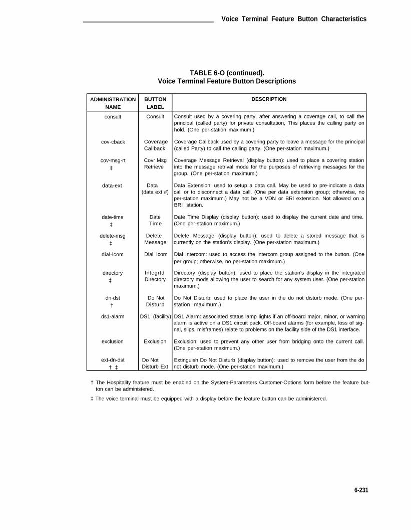
Voice Terminal Feature Button Characteristics
TABLE 6-O (continued).Voice Terminal Feature Button Descriptions
ADMINISTRATION BUTTON DESCRIPTION
NAME LABEL
consult Consult Consult used by a covering party, after answering a coverage call, to call theprincipal (called party) for private consultation, This places the calling party onhold. (One per-station maximum.)
cov-cback Coverage Coverage Callback used by a covering party to leave a message for the principalCallback (called Party) to call the calling party. (One per-station maximum.)
cov-msg-rt Covr Msg Coverage Message Retrieval (display button): used to place a covering station
‡ Retrieve into the message retrival mode for the purposes of retrieving messages for thegroup. (One per-station maximum.)
data-ext Data Data Extension; used to setup a data call. May be used to pre-indicate a data(data ext #) call or to disconnect a data call. (One per data extension group; otherwise, no
per-station maximum.) May not be a VDN or BRl extension. Not allowed on aBRI station.
date-time Date Date Time Display (display button): used to display the current date and time.
‡ Time (One per-station maximum.)
delete-msg Delete Delete Message (display button): used to delete a stored message that is
‡ Message currently on the station’s display. (One per-station maximum.)
dial-icom Dial Icom Dial Intercom: used to access the intercom group assigned to the button. (Oneper group; otherwise, no per-station maximum.)
directory Integrtd Directory (display button): used to place the station’s display in the integrated
‡ Directory directory mods allowing the user to search for any system user. (One per-stationmaximum.)
dn-dst Do Not Do Not Disturb: used to place the user in the do not disturb mode. (One per-
† Disturb station maximum.)
ds1-alarm DS1 (facility) DS1 Alarm: associated status lamp Iights if an off-board major, minor, or warningalarm is active on a DS1 circuit pack. Off-board alarms (for example, loss of sig-nal, slips, misframes) relate to problems on the facility side of the DS1 interface.
exclusion Exclusion Exclusion: used to prevent any other user from bridging onto the current call.(One per-station maximum.)
ext-dn-dst Do Not Extinguish Do Not Disturb (display button): used to remove the user from the do† ‡ Disturb Ext not disturb mode. (One per-station maximum.)
† The Hospitality feature must be enabled on the System-Parameters Customer-Options form before the feature but-ton can be administered.
‡ The voice terminal must be equipped with a display before the feature button can be administered.
6-231

CHAPTER 6. FORMS FOR SYSTEM FEATURES AND SERVICES
TABLE 6-O (continued).Voice Terminal Feature Button Descriptions
ADMINISTRATION BUTTON DESCRIPTION
NAME LABEL
flash Flash Flash; used for two types of calls: 1) allows a station on a trunk call with TrunkFlash enabled to send a Trunk Flash signal to the far end (for example, CO); 2)allows a station on a CAS main call to send a Trunk Flash signal over the con-nected RLT trunk back to the branch to conference/transfer the call on thebranch. (One per station maximum.)
goto-cover Go To Cover Go To Coverage: used to send a call directly to coverage instead of waiting forthe called inside user to answer. (One per-station maximum.)
grp-dn-dst Do Not Group Do Not Disturb (display button): used to remove a group of users from the† ‡ Disturb Grp do not disturb mode. (One per-station maximum.)
hunt-ns Hunt Group Hunt-Group Night Service: used to place a hunt-group into night service. (One* per hunt group maximum.)
in-call-id Coverage Incoming Call Identification: used to identify the hunt or coverage answer group
(group # associated with the current incoming call. (One per group type per group other-type, name, wise, no per-station maximum.)
or ext #)
inspect Inspect Inspect (display button): used to display the extension number of the current ring-‡ Mode ing call, or the extension behind a subsequently pressed call appearance button.
(One per-station maximum.)
last-numb LastNumb Last Number Dialed: used to originate a call to the number last dialed by the sta-Dialed tion user. (One per-station maximum.)
Iink-alarm Link Failure Link Alarm: associated status lamp is used to indicate that a failure has occurred(link #) on one of the Processor Interface circuit pack data links. (One to eight per-
station maximum.)
lsvn-call Login SVN Login Violations Notification (display button): associated Iamp indcates‡ Security Vio- whether or not that destination is able to receive lsvn referral calls, When button
Iat ion Not is activated, lamp will light. (One per-system maximum.)Notificationcall
lwc-cancel Cancel LWC Leave Word Calling Cancel: used to cancel the last leave word calling messageoriginated by the user. (One per-station maximum.)
lwc-lock Lock LWC Leave Word Calling Lock: used to lock the message retrieval capability of thedisplay module on the station. (One per-station maximum.)
lwc-store LWC Leave Word Calling Store: used to leave a message for the user associated withthe last number dialed to return the call to the originator. (One per-station max-imum.)
major-alrm Major Hdwe Major Alarm: associated status lamp is used to indicate that a vital systemFailure hardware component(s) has failed. This type of alarm represents a disruption of
overall System performance. (One per-station maximum.)
* The Automatic Call Distribution feature must be enabled on the System-Parameters Customer-Options form beforethe feature button can be administered.
† The Hospitality feature must be enabled on the System-Parameters Customer-Options form before the feature but-ton can be administered.
‡ The voice terminal must be equipped with a display before the feature button can be administered.
6-232

Voice Terminal Feature Button Characteristics
TABLE 6-O (continued).Voice Terminal Feature Button Descriptions
ADMINISTRATION BUTTON DESCRIPTlON
NAME LABEL
man-msg-wt Msg Wait Manual Message Waiting used to turn on a message waiting lamp on the station(name or associated with the button. Note that the Manual Message Waiting button may
ext #) not point to a VDN. (No per-station maximum.)
man-overid Immediate Immediate Manual Override (display button): used in association with the Time of
* Override Day Routing feature to temporarily override the routing plan in effect for theactivating user’s partitioned group number. The routing plan is overridden uponactivation. (One per-station maximum.)
manual-in Manual In Manual-In Mode: used to prevent the user from becoming available for new ACD* call upon completion of an ACD call by automatically placing the agent in the
after call work mode. (One per split group; otherwise, no per-station maximum.)
mj/mn-alrm Major/Minor Minor Alarm: associated status lamp is used to indicate that a System hardwareHdwe component has failed that will disrupt service on a limited scale. (One per-station
Failure maximum.)
msg-retr Message Message Retrieval (display button): used to place the station’s display into the
‡ Retrieve message retrieval mode. (One per-station maximum.)
mwn-act Message Message Waiting Activation (supports PMS feature): used to turn on a message
† Waiting waiting lamp on an associated station. (One per-station maximum.)Act.
mwn-deact Message Message Waiting Deactivation (supports PMS feature): used to turn off a mes-
† Waiting sage waiting lamp on an associated station. (One per-station maximum.)Deact
next Next Next Message (display button): used to step to the next message when the
‡ station’s display is in message retrival mode. (One per-station maximum.)
night-serv Night Night Service Activation: used to place the System into or out of the night serviceServ mode. (One per-system maximum.)
normal Normal Normal (display button): used to place the station’s display into the normal call
‡ Mode identification mode. (One per-station maximum.)
per-COline CO Line Personal CO Line: allows the user to receive calls directly via a specific trunk.(Iine #) (One per group; otherwise, no per-station maximum.)
* The Automatic Call Distribution feature must be enabled on the System-Parameters Customer-Options form beforethe feature button can be administered.
† The Hospitality feature must be enabled on the System-Parameters Customer-Options form before the feature but-ton can be administered.
‡ The voice terminal must be equipped with a display before the feature button can be administered.
6-233

CHAPTER 6. FORMS FOR SYSTEM FEATURES AND SERVICES
TABLE 6-O (continued).Voice Terminal Feature Button Descriptions
ADMINISTRATION BUTTON DESCRIPTION
NAME LABEL
pms-alarm PMS Failure PMS Alarm: associated status lamp is used to indicate that a failure in the PMShas occurred. A major or minor alarm condition will raise the alarm. (One per-station maximum.)
pr-awu-alm Auto Automatic Wakeup Printer Alarm: associated status lamp is used to indicate thatWakeup Alm an automatic wakeup printer interface failure has occurred. (One per-station
maximum.)
pr-pms-alm PMS Ptr Alarm PMS Printer Alarm: associated status lamp is used to indicate that a PMS printerinterface failure has occurred. (One per-station maximum.)
pr-sys-alm Sys Ptr Alarm System Printer Alarm: associated status lamp is used to indicate that a SystemPrinter (dedicated to Report Scheduler feature) interface failure has occurred.(One per-station maximum.)
print-msgs Print Msgs Print Messages: allows the user to print messages for any extension by pressingthe button and then entering the extension number and a security code (if oneassigned). (One per-station maximum.)
priority Priority Priority Calling: allows the user to place a priority call by pressing the button andCall then dialing an extension, or change an existing call to a priority call by pressing
the button after the extension has been dialed. (One per-station maximum.)
q-calls NQC Queue Calls: associated status lamp flashes if a call warning threshold has been* reached. (One per hunt group per-station maximum.)
q-time OQT Queue Time: associated status lamp flashes if a time warning threshold has been* reached. (One per hunt group per-station maximum.)
release Release Release: used to release an agent from an ACD call. (One per station.)
ringer-off Ringer Ringer-Off: used to silence the alerting ringer on the station. (One per-stationCutoff maximum.)
rs-alert System System Reset Alert: the associated status lamp will light if the System has aReset problem that escalates beyond a warm start. (One per-station maximum.)Alert
rsvn-call Remote SVN Remote Access Violations Notification (display button): associated lamp‡ Security indicates whether or not that destination is able to receive lsvn referral calls.
Violation When button is activated, lamp will light (One per-system maximum.)NotificationCall
send-calls Send All Send All Calls: used to send all calls to coverage as soon as they terminate atCalls the station. (One per-station maximum.)
send-term Send All Send All Calls For Terminating Extension Group: allows the user to forward allCalls-TEG calls directed to a terminating extension group. (One per group; otherwise, no
per-station maximum.)
* The Automatic Call Distribution feature must be enabled on the System-Parameters Customer-Options form beforethe feature button can be administered.
6-234

Voice Terminal Feature Button Characteristics
TABLE 6-O (continued).Voice Terminal Feature Button Descriptions
ADMINISTRATION BUTTON DESCRIPTlON
NAME LABEL
serv-obsrv Service Service Observing: activates the Service Observing feature. Used to toggle* Observing between a Iisten-only and a listen-talk mode. Deactivate by hanging up or press-
ing another call-appearance button. (One per-station maximum.)
signal Signal Signal: allows the user to manually signal (via ringing) a station associated with(name or the button. Note that the button cannot point to a VDN. (One per signal exten-ext #) sion maximum; otherwise, no per-station maximum.)
smdr1-aIrm SMDR 1 SMDR Alarm: associated status lamp is used to indicate that a failure in the inter-Failure face to the primary SMDR output device has occurred. (One per-station max-
imum.)
smdr2-alrm SMDR 2 SMDR Alarm: associated status lamp is used to indicate that a failure in the inter-Failure face to the secondary SMDR output device has occurred. (One per-station max-
imum.)
stored-num Stored Stored Number (display button): used to place the station’s display into the stored
‡ Number number mode. This allows the user to query button translations and displayassociated stored numbers. (One per-station maximum.)
stroke-cnt Stroke _ ACD stroke count: allows an agent to send a message to the CMS to intercept a* stroke count number. Up to 10 Stroke Count buttons (each associated with a dif-
ferent code number zero through nine) may be administered on a voice terminal.
term-x-gr Term Grp Terminating Extension Group: used to provide one or more extensions (may not(name or be a VDN extension) for a station. Calls may be received but not originated withext #) this button. (One per group; otherwise, no per-station maximum.)
timer Timer Timer (display button): used to start a clock on the station to display elapsed‡ time. (One per-station maximum.)
trk-ac-alrm FTC Alarm Facility Test Call Alarm: associated status lights when a successful Facility TestCall (FTC) has occurred. Pressing an FTC button (up to 10 may be admin-istered) when its status lamp is Iighted will turn off all FTC status lamps whetheror not the FTC is still in progress or has completed. FTC access is controlled viaCOR assignment. The status lamp provides an indication that a FTC hasoccurred.
trk-id Trunk ID Trunk Identification (display button): used to identify the tac (trunk access code)* and trunk member number associated with a call. (One per-station maximum.)
* The Automatic Call Distribution feature must be enabled on the System-Parameters Customer-Options form beforethe feature button can be administered.
‡ The voice terminal must be equipped with a display before the feature button can be administered.
6-235

CHAPTER 6. FORMS FOR SYSTEM FEATURES AND SERVICES
TABLE 6-O (continued).Voice Terminal Feature Button Desciptions
ADMINISTRATION BUTTON DESCRIPTION
NAME LABEL
trunk-name Trunk Trunk Name (display button): used to display the name of the trunk as admin-
‡ Name istered on the CAS Main or on a switch without CAS. (One per-station max-imum.)
trunk-ns Trunk Grp Trunk-Group Night Service: used to place a trunk-group into night service. (One* per trunk-group maximum.)
verify Verify Busy Verification: allows the user to make test calls and check the condition of astation, stations in a hunt group, or a trunk and quickly identify faulty equipment.(One per-station maximum.)
work-code Work Code Call Work Code: allows an ACD agent after pressing “work-code” to send up to* 16 digits (using the dial pad) to CMS. The data is associated with a current ACD
call, and may represent account codes, social security numbers, or telephonenumbers, for example. (One per-station maximum.)
* The Automatic Call Distribution feature must be enabled on the System-Parameters Customer-Options form beforethe feature button can be administered.
‡ The voice terminal must be equipped with a display before the feature button can be administered.
6-236
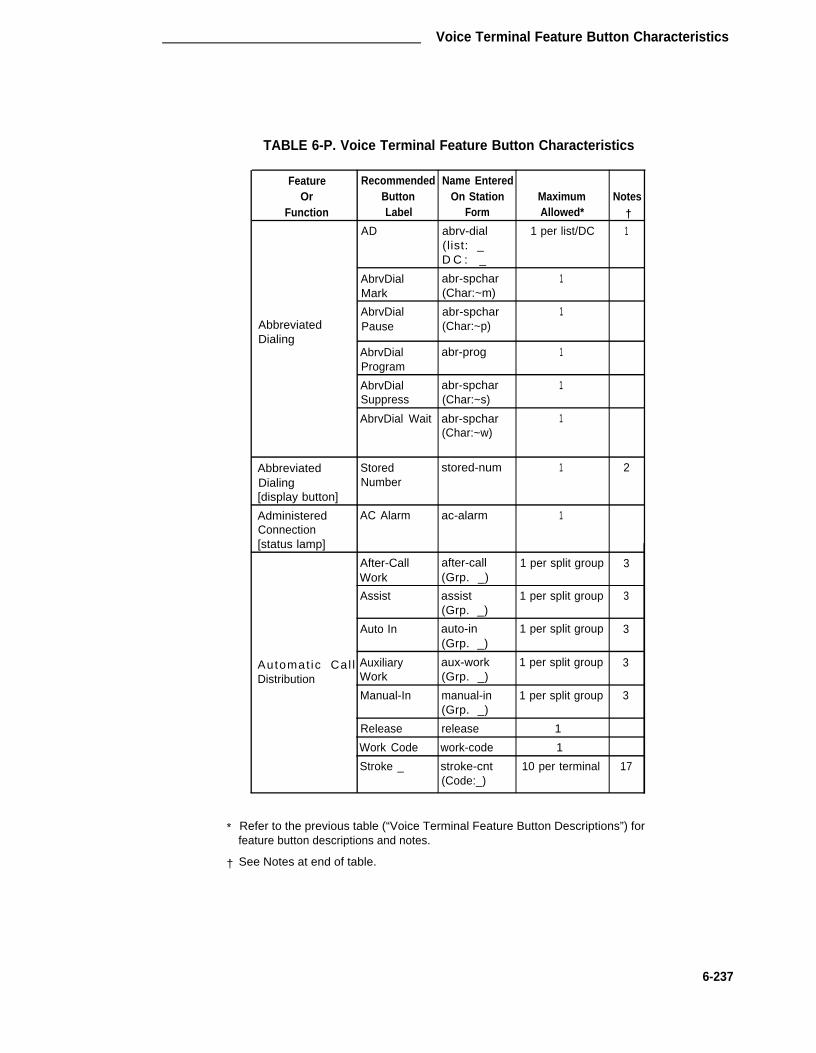
Voice Terminal Feature Button Characteristics
TABLE 6-P. Voice Terminal Feature Button Characteristics
Feature Recommended Name EnteredOr Button On Station Maximum Notes
Function Label Form Allowed* †AD abrv-dial 1 per list/DC 1
(list: _D C : _
AbrvDial abr-spchar 1Mark (Char:~m)
AbrvDial abr-spchar 1Abbreviated Pause (Char:~p)Dialing
AbrvDial abr-prog 1Program
AbrvDial abr-spchar 1Suppress (Char:~s)
AbrvDial Wait abr-spchar 1(Char:~w)
Abbreviated Stored stored-num 1 2Dialing Number[display button]
Administered AC Alarm ac-alarm 1Connection[status lamp]
After-Call after-call 1 per split group 3Work (Grp. _)
Assist assist 1 per split group 3(Grp. _)
Auto In auto-in 1 per split group 3(Grp. _)
Automat ic Cal l Auxiliary aux-work 1 per split group 3Distribution Work (Grp. _)
Manual-In manual-in 1 per split group 3(Grp. _)
Release release 1
Work Code work-code 1
Stroke _ stroke-cnt 10 per terminal 17(Code:_)
*
†
Refer to the previous table (“Voice Terminal Feature Button Descriptions”) forfeature button descriptions and notes.
See Notes at end of table.
6-237

CHAPTER 6. FORMS FOR SYSTEM FEATURES AND SERVICES
TABLE 6-P (continued).Voice Terminal Feature Button Characteristics
FeatureOr
Function
AutomaticCallback
Automatic CircuitAssurance
Auto Wakeup[display button]
Bridged~CallAppearance
Busy Verification
Call Appearance
Call Coverage
Call Coverage[display button]
Call Forwarding
Call Park
Call Pickup
Recommended Name EnteredButton On Station MaximumLabel Form Allowed*
Auto auto-cback 1Callback
Auto-ckt aca-call 1Assure
Auto auto-wkup 1 per split groupWakeup
Extension brdg-appr N
Extension abrdg-appr N
Verify
ExtensionConsult
CoverageCallback
Send AllCalls-TEG
Go to Cover
Send All Calls
Covr MsgRetrieve
CallForwarding
Call Park
Call Pickup
verify
call-appr
consult
cov-cback
1
‡
1
1
send-term 1 per Grp.(Grp: _)
goto-cover 1
send-calls 1
cov-msg-rt 1
call-fwd 1
call-park 1
call-pkup 1
Notes†
2
2
* N = any number of buttons on the voice terminal can be assigned to this feature.Refer to the previous table (“Voice Terminal Feature Button Descriptions”) forfeature button descriptions and notes.
† See Notes at end of table.
‡ Refer to specific voice terminal information provided later in this Chapter for max-imum allowed.
6-238

Voice Terminal Feature Button Characteristics
TABLE 6-P (continued).Voice Terminal Feature Button Characteristics
Feature Recommended Name EnteredOr Button On Station Maximum Notes
Function Label Form Allowed* ‡
Call Prompting Caller Info callr-info 1[display button]
Centralized CAS-Backup cas-backup 1Attendant Flash flash 1 18Service
Data Call Setup Data data-ext 1 per Ext.(data (Ext: __)extension #)
Date and Time Date date-time 1 2[display button] Time
Demand Print Print print-msgs 1Msgs
Do Not Disturb Do Not dn-dst 1Disturb
Do Not ext-dn-dst 1 2
Do Not Disturb Disturb Ext[display buttons] Do Not grp-dn-dst 1 2
Disturb Grp
Elapsed Time Timer timer 1 2[display button]
Facility Busy Busy busy-ind~(TAC/ 1 per TAC/Ext. 4Indication (trunk or Ext:___)[status lamp] extension #)
Facility Test Calls FTC Alarm trk-ac-alm 10 per system[status lamp]
*
†
N = any number of buttons on the voice terminal can be assigned to this feature.Refer to the previous table (“Voice Terminal Feature Button Descriptions”) forfeature button descriptions and notes.
See Notes at end of table.
6-239

CHAPTER 6. FORMS FOR SYSTEM FEATURES AND SERVICES
TABLE 6-P (continued).Voice Terminal Feature Button Characteristics
FeatureOr
Function
Hardware Failure[status Iamps]
Inspect[display button]
IntegratedDirectory[display-button]
lntercom-Automatic
Intercom-Dial
Last~NumberDialed
_ Leave WordCalling
Recommendad Name EnteredButton On Station Maximum NotesLabel Form Allowed* †
Major major-alrm 10 per systemHdweFailure
Major/Minor mj/mn-alrm 10 per systemHdweFailure
DS1 (facility) ds1-alarm 10 per system
PMS Failure pms-alarm 1
PMS Ptr Alm pr-pms-alm 1
SMDR 1 Failure smdr1-alrm 1
SMDR 2 Failure smdr2-alrm 1
Auto Wakeup Alm pr-awu-alm 1
Sys Ptr Alm pr-sys-alrm 1
Inspect inspect 1 2Mode
Integrtd directory 1 2Directory
Autolcom auto-icom 1 per Grp/DC 5(name or exten- G r p : _ DC: __)sion #)
DialIcom dial-icom 1 per Grp. 6(Grp: _)
LastNumb last-numb 1DialedLWC Iwc-store 1
Cancel LWC Iwc-cancel 1
Lock LWC Iwc-lock 1
* Refer to the previous table (“Voice Terminal Feature Button Descriptions”) forfeature button descriptions and notes.
See Notes at end of table.†
6-240

Voice Terminal Feature Button Characteristics
TABLE 6-P (continued).Voice Terminal Feature Button Characteristics
Feature Recommended Name EnteredOr Button On Station Maximum Notes
Function Label Form Allowed* †
Leave~Word Message aut-msg-wt 1 per Ext. 7Calling~(Remote (name or (Ext: __)Message extension #)Waiting)[status lamp]
Return Call call-disp 1 2
Leave Message msg-retr 1 2Word Calling Retrieve
[display buttons] Next next 1 2
Delete Message delete-msg 1 2
Link Failure Link link-alarm 1 per Link # 8[status lamp] Failure (Link #_)
(Link No._)
Manual Signaling Signal signal (Ext: __) 1 per Ext. 16(name orextension #)
Manual Msg Wait man-msg-wt 1 per Ext. 9Message (name or (Ext: __)Waiting extension #)
Night Serv night-serv 1
Hunt Group hunt-ns 1 per Grp. 10Night Service (Grp. __)
Trunk Grp. trunk-ns 1 per Grp. 11(Grp. __)
Normal Mode Normal normal 1 2[display button] Mode
Personal Central CO Line per-COline 1 per Grp. 12Office Line (telephone #) (Grp: __)
N = any number of buttons on the voice terminal can be assigned to this feature.Refer to the previous table (“Voice Terminal Feature Button Descriptions”) forfeature button descriptions and notes.
*
† See Notes at end of table.
6-241

CHAPTER 6. FORMS FOR SYSTEM FEATURES AND SERVICES
TABLE 6-P (continued).Voice Terminal Feature Button Characteristics
Feature Recommended Name EnteredOr Button On Station Maximum Notes
Function Label Form Allowed* †
Check-In check-in 1 2
Check-Out check-out 1 2
PMS Interface Message Waiting mwn-act 1 2[display button] Act.
Message Waiting mwn-deact 1 2Deact.
Priority Calling Priority Call priority 1
Privacy— Exclusn exclusion 1Manual Exclusion
Queue Status NQC q-calls (Grp:_ 1 per hunt group 13Indications[status lamps] OQT
q-time (Grp:_) 1 per hunt group 13
Queue Status AQC atd-qcalls 1Indications AQT[display buttons]
atd-qtime 1
Ringer Cutoff Ringer Cutoff ringer-off 1
Security Violation Login SVN lsvn-call 1 per systemNotification[display buttons]
Remote SVN rsvn-call 1 per system
Service Service serv-obsrv 1Observing ‡ Observing
System Reset System rs-alert 1Alert Reset Alert
[status lamp]
Terminating Term Grp term-x-gr 1 per Grp. 14Extension Group (name or (Grp:__)
extension #)
* Refer to the previous table (“Voice Terminal Feature Button Descriptions”) forfeature button descriptions and- notes.
† See Notes at end of table.
‡ The use of service observing features may be subject to federal, state, or locallaws, rules or regulations or require the consent of one or both of the parties to theconversation. Customers should familiarize themselves with and comply with allapplicable laws, rules and regulations before using these features.
6-242

Voice Terminal Feature Button Characteristics
Label
trk-id 1 2
Notes:
1.
2.
3.
4.
5.
6.
TABLE 6-P (continued).Voice Terminal Feature Button Characteristics
FeatureOr
Function
Time-of-DayRouting[display buttons]
TrunkIdentification[display button]
Trunk GroupName[display button]
UCD/DDC
UCD/DDC/lntraflowCall-Coverage(Answer Group)
RecommendedButton
Immediate Override
Clocked Override
Trunk-lD
Trunk-Name
Auxiliarywork
Coverage(group number,type or name or ext#)
Name EnteredOn Station Maximum Notes
Form Allowed* †
man-overid 1 2
clk-overid 1 2
trunk-name 1 2
aux-work 1 per Grp.(Grp : _
in-call-id 1 per Type/Grp. 15
(Type: _G r p : _
* Refer to the previous table (“Voice Terminal Feature Button Descriptions”) forfeature button descriptions and notes.
† See the following Notes.
List: List number 1 to 3 where the destination number is stored.
DC: Dial codes of destination number.
— Display-type buttons may be administered if the voice terminal isequipped with the optional Digital Display or alphanumeric display.
Grp: The split group number for ACD (1 to 99).
TAC/Ext: Trunk or extension number of voice terminal to be monitored.
Grp: Dial Icom group number (1 to 32). This extension and destinationextension number must be in the same group.
Grp: Dial Icom group number (1 to 32).
6-243

CHAPTER 6. FORMS FOR SYSTEM FEATURES AND SERVICES
TABLE 6-P (continued).Voice Terminal Feature Button Characteristics
Notes:
7. Ext:
8. Link
9. Ext:
10. Grp:
11. Grp:
12. Grp:
13. Grp:
14. Grp:
15. Type:
Grp:
16. -
17. Code:
18. Flash:
Extension number of principal. (Maybe a VDN extension.)
Link number—1 to 8 for multi-carrier cabinets or 1 to 4 for single-carrier cabinets.
The destination extension. (May be a VDN extension.)
Hunt group number (1 to 99).
Trunk group number (1 to 99).
CO line group number (1 to 40).
Group number of hunt group.
TEG Number (1 to 32).
A “c” for coverage answer group, “h” for a uniform call distribution, ordirect department calling group.
The number of the group (1 to 100 for “c,” one to 99 for “h”).
The extension may not be a VDN extension.
Stroke count number (0 through 9).
Not administrable on Attendant Consoles.
6-244

Station Forms—Field Descriptions
Station Forms—Field Descriptions
The following provides descriptions of the fields that are displayed on the various pages of thestation forms. Some of the fields are only used for specific voice terminal types; others are usedfor all terminals. Fields and/or pages of the form that require unique consideration are coveredwhere appropriate with the respective voice terminal coverage. The descriptions are organizedby form page number and listed alphabetically within each grouping for easy access.
Page 1 of the Form
• Adjunct Supervision— Enter “y” if an analog disconnect signal will be automatically sentto the port after a call is terminated. This signal is used by analog devices such asanswering machines and speakerphones to turn the devices off after a call has ter-minated. In a hunt group environment, however, this signal blocks the reception of ziptone and incoming call notification by an auto answer station when a call is queued forthe station. In these environments, set this field to “n” so that hunt group agents will bealerted to an incoming call. Valid entries are “y” (default) or “n.”
• Att. Call Waiting lndication— Enter “y” (default) to assign the Attendant Call Waitingfeature to the voice terminal. This allows attendant originated and extended calls to abusy single-line voice terminal to wait and sends a distinctive two-burst call waiting toneto the single-line user. Use of the feature is denied if the Data Restriction field is “y” orthe Switchhook Flash field is “n,” or if via the voice terminal’s COS assignment, the DataPrivacy feature is active. Valid entries are “y” or “n.” Default is “y.”
• Auto Answer— Enter “y” if this terminal has Auto Answer; otherwise, enter “n.” AutoAnswer indicates if an incoming call will be automatically answered without any action bythe user (that is, by an Automatic Call Distribution agent). Default is “n.”
• BCC— Display-only field set to “0” (default) for stations (that is, indicates voice or voice-grade data). Only displayed when the ISDN-PRI option is enabled on the System-Parameters Customer-Options form.
Note: Refer to the GRS feature description in DEFINITY® Communications Sys-tem Generic 1 and Genetic 3i—Feature Description, 555-230-201, for adetailed description of BCCs and their use to provide specialized routing forvarious types of voice and data calls. The BCC value is used to determinecompatibility when non-lSDN-PRl facilities are connected to ISDN facilities(ISDN-PRI Interworking feature).
• Bridged Call Alerting— Enter “y” to allow incoming calls on bridged appearances ofanother terminal’s primary extension number, TEG calls, or PCOL calls, otherwise, enter“n.” Default is “n.”
• Call Waiting lndication— Enter “y” to activate the Call Waiting Termination feature forthe voice terminal. This allows other voice terminal, attendant-originated, and outsidecalls to busy single-line voice terminals to wait and sends a distinctive call waiting tone tothe single-line user. Use of the feature is denied if the Data Restriction field is “y” or theSwitchhook Flash field is “n,” or if via the voice terminal’s COS assignment, the DataPrivacy feature is active. Valid entries are “y” or “n.” Default is “y.”
6-245

CHAPTER 6. FORMS FOR SYSTEM FEATURES AND SERVICES
•
•
•
•
•
•
•
•
•
•
•
COR— Enter a Class of Restriction (COR) number from 0 through 63 that reflects thedesired restriction. Default is “1.”
COS— Enter the desired Class of Service (COS) number from 0 through 15 to designateallowed features. See COS form (Chapter 6) for additional information. Default is ”1.“
Coverage Msg Retrieval— Enter a “y” to allow a user in the voice terminal’s CoveragePath to retrieve Leave Word Calling (LWC) messages for this voice terminal. This fieldonly applies if the voice terminal is marked for LWC Reception. Default is “y.”
Coverage Path— Enter a coverage path number (1 through 600) from a previouslyadministered Call Coverage Path form. Leave blank if no coverage is desired.
Data Module— Indicates if a data module is to be administered with the voice terminal.Enter “y” or “n.” Default is “n.” If a “y” is entered, then Page x of the Form is displayed.See below.
Data Restriction— Enter “y” to prevent tones, such as Call Waiting Tones, from inter-rupting this user’s calls. Data restriction provides permanent protection and cannot bechanged by the voice terminal user. Default is “n.”
Distinctive Audible Alert— Enter “y” so the voice terminal can receive the three differenttypes of ringing patterns that identify the type of incoming calls. Features that provide dis-tinctive ringing might function improperly toward an off-premises voice terminal. Enter “n”if this feature is not desired. Default is “y.”
Endpt lnit— Only displayed if the MIM Support field entry is “y.” Indicates terminal’s end-point initialization capability. The endpoint initialization procedure, required for multipointoperation, associates the USOP translation belonging to the extension with the Physical.endpoint on the BRI interface. This association is made via the SPID that has beenadministered on the System and entered into the BRI terminal. This implies that in orderfor a BRI terminal to become operational in the multipoint configuration, both the admin-istered SPID and the SPID programmed into the BRI terminal must be the same. There-fore, the SPID of a new or re-used terminal must be programmed to match the admin-istered SPID value. For information on SPID installation, refer to “Appendix A.” Allow-able entries are “y” or “n.” Default is “y.”
Extension— When completing a blank paper form, enter a valid extension number (1through 5 digits) that agrees with the dial plan. When implementing the form, “Extension”is part of the input command used to access the form and is a display-only field.
Fixed TEI— indicates if the endpoint has a fixed Terminal Endpoint Identifier (TEl). Thisfield only appears for ISDN BRI stations and data modules. The TEI identifies a uniqueaccess point within a service. For terminals with the automatic TEI capability, the systemdynamically assigns the TEI. Therefore, for the freed TEI terminals, TEIs must be admin-istered. Allowable entries are “y” or “n.” Default is “n.” If a “y” is entered, then the TEIfield is displayed.
Idle Appearance Preference— Enter “y” or “n” (default) to indicate which call appear-ance is selected when the user lifts the handset and there is an incoming call. If “y” isentered, the Idle Appearance Preference is set and the user is connected to an idle callappearance instead of the ringing call. If “n” is entered, Alerting Appearance Preferenceis set and the user is connected to the ringing call appearance.
6-246

Station Forms—Field Descriptions
•
•
•
•
•
•
•
LWC Activation— Enter “y” to allow internal voice terminal users to leave short LWCmessages for this terminal. If the system has the hospitality features, enter “y” for voiceterminals in the guest rooms if the terminal designated to receive failed wakeup mes-sages is to receive LWC messages indicating incomplete wakeup calls. Enter “y” if“audix” was entered for LWC Reception. Default is “y.”
LWC Reception— Enter “msa-spe” if LWC messages are stored in the system or on theMessaging Server Adjunct—Switch Processor or enter “audix” if the messages arestored on the Audio Information Exchange System; otherwise, enter “none.” Default is“msa-spe.”
Lock Messages— Enter “y” to restrict other users from reading or canceling the voiceterminal messages or retrieving messages via Voice Message Retrieval; otherwise, enter“n.” Default is “n.”
Message Waiting Indicator— (Applies to 500, 2500, and 7104A voice terminals only.)Enter “led” if the message waiting indicator is a LED or “neon” if the indicator is a neonlight waiting indicator.
MIM Mtce/Mgt— Only displayed if the MIM Support field entry is “y.” Used to indicate ifthe terminal supports MIM Maintenance and Management capabilities other then end-point initialization. Valid entries are “y” (yes) or “n” (no). Default is “y.”
MIM Support— (Management Information Message Support) Used to support two typesof capabilities: (1) MIM endpoint initialization capability (SPID support) and (2) otherMaintenance/Management capability. Valid entries are “y” or “n.” Default is “y.” Thisfield only appears for an ISDN-BRI data module. If “y” is entered, the following depen-dent fields appear: Endpt Init and MIM Mtce/Mgt.
Name— Enter the name of person associated with this voice terminal. Up to 15 charac-ters can be used. This field can be shared with a Room #. The name assigned to a voiceterminal remains with that voice terminal until it is changed.
The Integrated Directory feature lists the names as they should be entered on the forms.Names can be entered in all uppercase letters, all lowercase letters, or a mixture ofuppercase and lowercase letters. Also, the first or last name can be entered first and amiddle name or initial can be used. Spaces or commas can be used between names.For systems using a 3B2 Messaging Server Adjunct, the last name must be the firstentry.
Periods, hyphens, apostrophes, or other special characters, if used, are discarded by thesystem when the name is entered into the database. The following examples show for-mats that are required in order for the name to be retrieved by the Integrated Directoryfeature. Note also that this field can be any printable character string or can be leftblank.
— Bill J Doe
— Doe,Bill J
— Bill Doe
• Off Premise Station— Enter “y” if this voice terminal is not located in the same buildingwith the system. Enter “n” if the voice terminal is located in the same building with thesystem. If “y” is entered, the R Balance Network field must be completed. Default is “n.”
6-247

CHAPTER 6. FORMS FOR SYSTEM FEATURES AND SERVICES
• Personalized Ringing Pattern— Enter a Personalized Ringing Pattern, 1 through 8, asfollows (default is “l”):
Ring Pattern Tone Sequence1 MMM (standard ringing)2 HHH3 LLL4 LHH5 HHL6 HLL7 HLH8 LHL
L = 530Hz, M = 750Hz, and H = 1060Hz
• Port— Enter 5 to 6 characters. The first character identifies the network (1 through 3,default is “1” if no entry); the second character identifies the carrier (A through E); thethird and fourth characters identify the slot number in the carrier (01 through 20 for multi-carrier cabinets or 01 through 18 for single-carrier cabinets); the last two characters iden-tify the circuit number (01 through 24). For DCP sets, the port may only be assignedonce. BRI provides multipoint configuration capability which allows a previously assignedport to be specified more than once as follows: two stand-alone voice endpoints, twostand-alone data endpoints, or one integrated voice and data endpoint.
Note: A 1-character entry of “X” in the Port field maybe used to indicate that thereis no hardware associated with the port assignment (that is, AdministrationWithout Hardware feature). This permits preadministration of stations thatwill be implemented at a later time. These stations are referred to as “phan-tom stations.” The BRI interface does not support this capability.
• R Balance Network— Enter “y” to select the R Balance Capacitor network, or “n” toselect the standard resistor capacitor network. This field must be completed if “y” wasentered in the Off Premise Station field. Enter “n” when the station port circuit is con-nected to terminal equipment (for example, SLC carriers or impedance compensators)optioned for 600 ohm input impedance and the distance to the terminal equipment fromthe system is less than 3000 feet. Enter “y” in all other cases. Default is “n.”
• Redirect Notification— Enter “y” to give a half ring at this voice terminal when calls tothis terminal are redirected (via Call Forwarding or Call Coverage). Enter “y” if audix wasentered for LWC Reception. Default is “y.”
• Restrict Last Appearance— Enter “y” to restrict the last idle call appearance for incom-ing priority calls and outgoing call originations only; otherwise, enter “n.” Default is “y.”
• Security Code— Enter a 4-digit security code required by users to retrieve messages viathe Demand Print or Voice Message Retrieval feature.
• SMDR Privacy— An administrable option which allows digits in the called number field ofan outgoing call to be blanked, on a per-station basis. The number of blocked digits isadministered system-wide in the “Privacy—Digits to Hide” field on the Feature-RelatedSystem Parameters form. Enter “y” to enable the call privacy feature for each station.Default is “n”.
6-248

Station Forms—Field Descriptions
• Switchhook Flash— Enter “y” to allow users to use the switchhook flash function toactivate the Conference/Transfer/Hold and Call Waiting features; otherwise, enter “n.”An “n” entered in this field disables the flash function, and when the switchhook ispressed while active on a call, the call will be dropped. If this field is set to “n,” the CallWaiting Indication field must be set to “n.” Default is “y.”
• TEI— Only displayed if “y” is entered in Fixed TEI field. Enter a 1- or 2-digit number inthe range of 0 through 63. Default is blank.
• Type— Enter the voice terminal type.
• XlD— Used to identify layer two XID testing capability. Valid entries are “y” (yes) or “n”(no). Default is “y.” This field only appears for an ISDN-BRI data module.
Page 2 of the Form
•
•
•
•
•
•
Abbreviated Dialing List 1:, List 2:, List 3:— Enter “p” for personal, “s” for system, “g”for group, or “e” for enhanced. Up to three AD lists can be accessed by the voice termi-nal. If “p” or “g” is entered, a personal Iist number or a group number, respectively, isalso required.
Button Assignments— The feature buttons that can be assigned to voice terminals arelisted with each terminal’s coverage. Depending on the button type, additional auxiliaryinformation may be required when administering buttons. For example, since the LoginSecurity Violation Notification and Remote Access Security Violation Notification ReferralDestination buttons can only be administered on on voice terminals equipped withdisplay, refer to appropriate voice terminal coverage in this chapter for instructions.
Cable— Enter up to five characters to identify the cable number that connects the voiceterminal jack to the system. This field may be left blank. This information can also beentered in the Blank column on the Port Assignment Record.
Headset— Enter “y” if this terminal has a headset; otherwise, enter “n” (default).
Jack— Enter up to five characters that are used to identify the jack location the where thevoice terminal is connected. This field may be left blank. See the Port AssignmentRecord.
Room— Enter up to 10 characters to identify the voice terminal’s location. See the PortAssignment Record (Chapter 2). This field may be blank.
If this station is one of several to be assigned a guest room and the Hospitqality-RelatedSystem Parameters form has “y” entered in the “Display Room Information in CallDisplay” field, enter up to five characters in the Room field to identify the guest roomnumber.
6-249

CHAPTER 6. FORMS FOR SYSTEM FEATURES AND SERVICES
Page x of the Form—Data Module
• Abbreviated Dialing List 1:— Enter “p” for personal, “s” for system, “g” for group, or “e”for enhanced. If “g” or “p” is entered, a group number or personal list number respec-tively is also required. The entry in this field and the HOT LINE DESTINATION field sup-port the Data Hot Line feature.
• Assigned Member—Ext— Make no entry. The extension number is automaticallyassigned when the system is administered. This is the extension number of the userwho has an associated Data Extension button and will share the module.
• Assigned Member—Name— Display-only field. Contains the name assigned to theAssigned Member—Ext number.
• BCC— Display-only field. Only displayed when the ISDN-PRI option is enabled on theSystem-Parameters Customer-Options form.
Note: Refer to GRS in DEFlNITY® Communications System Generic 1 and Gen-eric 3i—Feature Description, 555-230-201, for a detailed description ofBCCs and their use to provide specialized routing for various types of voiceand data calls. The BCC value is used to determine compatibility whennon-lSDN-PRi facilities are connected to ISDN facilities (ISDN-PRI lnter-working feature).
• ITC (Information Transfer Capability)— Used by the GRS feature and enables the sys-tem to route calls to restricted or unrestricted facilities according to the endpoint’s infor-mation transfer capability. Default is restricted.
• COR— Enter the desired Class of Restriction (COR) number from 0 through 63 thatreflects the desired restriction. Default is ”1.“
• COS— Enter the desired Class of Service (COS) number (0 through 15) to designateallowed features. Refer to COS form for additional information on the allowed features.Default is ”1 .“
• Data Extension— Enter the extension number assigned to the data module. A dataextension can be a 1-to 5-digit number and must agree with the System’s Dial Plan.
• Default Dialing Abbreviated Dialing Dial Code From above list— only displayed whenthe Special Dialing Option field is “default.” Enter a list number (associated with theabove AD List) from 0 through 999. The associated AD number will be dialed when theuser goes off-hook and enters a carriage return following the “DIAL” prompt. The datacall originator can also perform data terminal dialing by specifying a dial string that mayor may not contain alphanumeric names.
• Hot Line Destination— Abbreviated Dialing Dial Code— Only displayed when the SPE-CIAL DIALING OPTION field is “hot-line.” Enter a list number (associated with the aboveAD List) from 0 through 999. The associated AD number will be dialed when the usergoes off-hook on a Data Hot Line call.
• Name— Enter the name of the user associated with the data module. The name isoptional, it can be left blank.
• Special Dialing Option— Enter 1 of 3 dialing options that are available. This identifiesthe type of dialing for calls when this data module originates calls. Valid entries are “hot-line,” “default,” or leave blank for regular (normal) keyboard dialing.
6-250

Station Forms—-Field Descriptions
• Circuit Switched Data Attributes— The following fields only appear on the BRI DataModule Form:
— Default Duplex— Used to identify the duplex mode. Valid entries are “full” or“half.” Default is “full.”
— Default Mode— Used to identify the data mode. Valid entries are “sync” (syn- chronous) or “async” (asynchronous). Default is “asyn.”
— Default Speed— Used to identify the data rate. Valid entries are “1200,” “2400,”“4800,” and “19200.” Default is “1200.”
• Data Module Capabilities— The following fields only appear on the BRI Data ModuleForm:
— Origination Default Data Applications— Used to identify mode to be used fororiginating data calls when the mode is not specified with the calling parameters.This mode will also be used for terminating trunk calls which do not have bearercapability specified or administered connections. Possible mode values are M0(mode 0), Ml (mode 1), M2 (mode 2), and M3/2 (mode 3/2 adaptable), or blank.Valid entries are “M0,” “M1,“ “M2_A,” “M2_S,” or “M3/2.” Default is “M2_A.”
6-251

CHAPTER 6. FORMS FOR SYSTEM FEATURES AND SERVICES
10-, 20-, and 30-MET Voice Terminals
Purpose
This form is used to implement 10-, 20-, and 30-MET voice terminals.
Administration Commands
The following administration commands can be used to access the Voice Terminal form. In somecases, just the most commonly used commands are shown. Refer to Administration Commandsand Error Messages (Chapter 3) for a complete listing of all administration commands, the com-mand structure, and the use of abbreviated command words when entering a command.
Action Object Qualifier*
add station xxxxx (extension number) or (’next’)change station xxxxx (extension number)display station xxxxx (extension number)duplicate stationIist station [xxxxx] (’count’ 1-1600) type [’print’ or ’schedule’]list station [xxxxx] (’count’ 1-1600) port [’ptint’ or ’schedule’]remove station [xxxxx] (extension number)
* Brackets [ ] indicate the qualifier is optional.Single quotes (’ ’) indicate the text inside the quote must be entered exactly as shown oran abbreviated form of the word maybe entered.
Form Instructions
Please review the “Voice Terminals—General” information at least once before completing theform. General information including feature button descriptions and characteristics are covered.In addition, descriptions of the administrable fields appearing on Pages 1 and 2 of the form areprovided in the “Voice Terminals—General” section. Instructions are provided below for fieldsand/or pages of the form that require additional consideration because of the terminal type.
Page 1 of the Form
• Type— Enter ”10MET,” “20MET,” or “30MET” as appropriate.
Page 2 of the Form
• Button Assignments
The feature buttons that can be assigned to the 10/20/30 MET sets are listed below. Theabbreviated software name (that is, administration name) as shown on the following Iistmust be entered on the form. Depending on the button type, additional auxiliary informat-ion may be required when administering buttons.
6-252

10-, 20-, and 30-MET Voice Terminals
•
•
•
•
•
•
•
•
•
•
•
•
•
•
•
•
•
•
•
•
•
abr-prog
abr-spchar
abrdg-appr
abrv-dial
ac-alarm
aca-call
after-call
assist
aut-msg-wt
auto-cback
auto-icom
auto-in
aux-work
brdg-appr
busy-ind
call-appr
call-fwd
call-park
call-pkup
cas-backup
consult
•
•
•
•
•
•
•
•
•
•
•
•
•
•
•
•
•
•
•
•
•
cov-cback
data-ext
dial-icom
dn-dst
ds1-alarm
exclusion
flash
goto-cover
hunt-ns
in-call-id
last-numb
link-alarm
Iwc-cancel
Iwc-store
major-alrm
man-msg-wt
manual-in
mj/mn alrm
night-ser
per-COline
pros-alarm
•
•
•
•
•
•
•
•
•
•
•
•
•
•
•
•
•
•
•
•
•
pr-awu-alm
pr-pms-alm
pr-sys-alm
print-msgs
priority
q-calls
q-time
release
ringer-off
rs-alert
send-calls
send-term
serv-obsrv
signal
smdr1 -alrm
smdr2-alrm
stroke-cnt
term-x-gr
trk-ac-alm
trunk-ns
verify
The figures entitled “10-MET Voice Terminal,” “20-MET Voice Terminal,” and “30-MET VoiceTerminal” respectively, which appear at the end of this section dealing with MET Voice Terminals,show the voice terminal button number assignments in relation to the button numbers on theassociated Voice Terminal Forms. The first three buttons are defaulted as call appearance.
Page 3 of the Form (20-and 30-MET Only)
• Feature Button Assignments
The feature buttons that can be assigned to the 20/30 MET sets Page 3 of 3 are thesame as those listed for BUTTON ASSIGNMENTS above.
The figures entitled “20-MET Voice Terminal” and “30-MET Voice Terminal” respec-tively, which appear at the end of this section dealing with MET Voice Terminals, showthe voice terminal button number assignments in relation to the button numbers on theassociated Voice Terminal Forms.
6-253

CHAPTER 6. FORMS FOR SYSTEM FEATURES AND SERVICES
Extension:
Type:
Port:
Name:
FEATURE OPTIONS
Page 1 of x
STATION
BCC: 0
Lock Messages: n
Security Code: _____Coverage Path: _____
LWC Reception? msa-spe Coverage Msg Retrieval? y
LWC Activation? y Auto Answer?
SMDR Privacy? n Data Restriction?
Redirect Notification? y Idle Appearance Preference?
Bridged Call Alerting? n Restrict Last Appearance?
n
n
n
Y
COR: 1
COS: 1
SCREEN 6-96. 10 MET, 20 MET, and 30 MET Form (Page 1)—Example Only
lmplementation Note:
The BCC field is only displayed if the lSDN-PRl option is enabled on the System-ParametersCustomer-Options form.
6-254

10-, 20-, and 30-MET Voice Terminals
STATION
List2:
Headset? n
Page 2 of x
NON-SWITCH DATA
Room:
Jack:
Cable:
ABBREVIATED DIALING
Listl:
BUTTON ASSIGNMENTS
1: call-atmr
2: call-appr
3: call-appr
4:
5:
List3:
SCREEN 6-97. 10 MET, 20 MET, and 30 MET Form (Page 2)—Example Only
Implementation Note:
The first three button assignments are defaulted as call-appr (call appearance).
6-255

CHAPTER 6. FORMS FOR SYSTEM FEATURES AND SERVICES
STATION
Page 3 of 3
FEATURE BUTTON ASSIGNMENTS
1: 11:
2: 12:
3: 13:
4: 14:
5: 15:
6: 16:
7: 17:
8: 18:
9: 19:
1 0 : 2 0 :
SCREEN 6-98. 20- or 30-MET Sets Form (Page 3)—Example Only
Implementation Note:
Buttons 1 through 5 may only be assigned “call-appr,” “abrd-appr,” or “brdg-appr.”
Buttons 11 through 20 are only displayed for the 30-MET set.
6-256

10-, 20-, and 30-MET Voice Terminals
FlVE ADMINISTRABLE BUTTONS (NUMBERS 1-5
ARE FOR IDENTIFICATION ONLY)
RECALL
(1)
(2)
(3)
(4)
(5)
FIXED FEATURE BUTTONS
FOR MESSAGE, HOLD,
TRANSFER, CONFERENCE,
AND DROP (NOT ADMINISTRABLE)
FIGURE 6-14. 10-MET Voice Terminal
6-257

CHAPTER 6. FORMS FOR SYSTEM FEATURES AND SERVICES
FIVE ADMINISTRABLE
BUTTONS (NUMBERS 1-5 ARE
FOR IDENTIFICATION ONLY)
RECALL
(1)
(2)
(3)
(4)
(5)
(1)
(2)
(3)
(4)
(5)
(6)
(7)
(8)
(9)
(10)
FIXED FEATURE BUTTONS
FOR MESSAGE HOLD,
TRANSFER, CONFERENCE
AND DROP (NOT ADMINISTRABLE)
T E N
ADMINISTRABLE
BUTTONS
(NUMBER 1-10
ARE FOR
IDENTIFICATION
ONLY)
FIGURE 6-15. 20-MET Voice Terminal
6-258

10-, 20-, and 30-MET Voice Terminals
TWENTY ADMINISTRABLE BUTTONSFIVE ADMINISTRABLE BUTTONS (NUMBERS 1-20 ARE FOR(NUMBERS 1-5 ARE FOR IDENTIFICATION ONLY)IDENTIFICATION ONLY)
(1)
(2)
(3)
(4)
(5)
(6)
(7)
(8)
(9)
(10)
(11)
(12)
(13)
(14)
(15)
(16)
(17)
(18)
(19)
(20)
FIXED FEATURE BUTTONS
FOR MESSAGE, HOLD,
TRANSFER, CONFERENCE,
AND DROP (NOT ADMINISTRABLE)
FIGURE 6-16. 30-MET Voice Terminal
6-259

CHAPTER 6. FORMS FOR SYSTEM FEATURES AND SERVICES
500, 2500, 7101A, 7102A, 7103A, and 7104A Voice Terminals
Purpose
This form is used to implement a 500, 2500, 710IA, 7102A, 7103A, or 7104A single-line voiceterminal. The terminals are shown in the figures immediately following the sample station formsin this section dealing with the 500, 2500, 7101A, 7102A, 7103A, and 7104A Voice Terminals.
Administration Commands
The following administration commands can be used to access the Voice Terminal form. In somecases, just the most commonly used commands are shown. Refer to Administration Commandsand Error Messages (Chapter 3) for a complete listing of all administration commands, the com-mand structure, and the use of abbreviated command words when entering a command.
Action Object Qualifier*
add station xxxxx (extension number) or (’next’)change station xxxxx (extension number)display station xxxxx (extension number)duplicate stationlist station [xxxxx] (’count’ 1-1600) type [’print’ or ’schedule’]list station [-] (’count’ 1-1600) port [’print’ or ’schedule’]remove station xxxxx (extension number)
* Brackets [ ] indicate the qualifier is optional.Single quotes (’ ’) indicate the text inside the quote must be entered exactly as shown oran abbreviated form of the word maybe entered.
Form Instructions
Please review the “Voice Terminals-General” information at least once before completing theform. General information including feature button descriptions and characteristics are covered.In addition, descriptions of the administrable fields appearing on Pages 1 and 2 of the form areprovided in the “Voice Terminal-General” section of this chapter. Instructions are providedbelow for fields and/or pages of the form that require additional consideration because of the ter-minal type.
Page 1 of the Form
•
•
Type— Enter “500,” “2500” (see note), “7101A,” 7103A,” or “7104A,” as appropriate.For a 7102A Voice Terminal, enter “7101A” in the Type field.
Note: For a 2500 DMGC voice terminal, enter “7101A” in the Type field. Thisenables the Recall button and switchhook flash functions.
Tests— Enter “y” to enable port maintenance tests. Enter “n” when the voice terminal isconnected through a peripheral unit, such as a dictating machine, that will cause thetests to fail. Default is “y.”
6-260

500, 2500, 7101A, 7102A, 7103A, and 7104A Voice Terminals
Page 2 of the Form
• Abbreviated Dialing List 1:, List 2:, List 3:—Up to three AD lists may be accessed bythe voice terminal. Enter “p” for personal, “s” for system, “g” for group, or “e” enhanced.If “p” or “g” is entered, a personal list number (1 through 3) or a group number (on ethrough 100), respectively, is also required. If the set type is a 7103A, then enter“7103A” as a List type.
Page 1 of 2
STATION
Extension: BCC : 0
Type: Lock Messages: n COR : 1
Port: Security Code: COS : 1
Name: coverage Path: _ Tests? y
FEATURE OPTIONS
LWC Reception? msa-spe Coverage Msg Retrieval? y
LWC Activation? y Auto Answer? n
SMDR Privacy? y Data Restriction? n
Redirect Notification? y Call Waiting Indication? y
Off Premise Station? n Att. Call Waiting Indication? y
R Balance Network? n Distinctive Audible Alert? y
Switchhook Flash? y Message Waiting Indicator? _
Adjunct, Supervision? y
SCREEN 6-99. Single-Line Station Form (Page 1)—Example Only
Implementation Note:
The BCC field is only displayed if the lSDN-PRl option is enabled on the System-ParametersCustomer-Options form.
The R Balance Network field is only displayed when the Off Premise Station field is “y.”
The Message Waiting Indicator field is only displayed when the Type field is “500,” “2500,” or“7104D.”
The Adjunct Supervision field is only displayed when the Type field is “500” or “2500.”
6-261

CHAPTER 6. FORMS FOR SYSTEM FEATURES AND SERVICES
NON-SWITCH DATA
Room:
Jack:
Cable:
ABBREVIATED DIALING
Listl:
HOT LINE DESTINATION
Abbreviated
STATION
List2:
Dialing List Number
Headset? n
Page 2 of 2
(From above 1, 2 or 3): _
List3:
Dial Code: _
SCREEN 6-100. Single-Line Station Form (Page 2)—ExampIe Only
6-262

500,2500, 710IA, 7102A, 7103A, and 71 04A Voice Terminals
HANDSET
ROTARY DIAL
FIGURE 6-17. 500 Voice Terminal
25542500
HANDSET
TOUCH-TONE
DIAL
HANDSET
TOUCH-TONE
DIAL
FIGURE 8-18. 2500 and 2554 Voice Terminals
6-263

CHAPTER 6. FORMS FOR SYSTEM FEATURES AND SERVICES
MESSAGE
L A M P
FIGURE 6-19. 7101A Voice Terminal
6-264
TOUCH-TONE
DIAL
FIXED
FEATURE
BUTTONS
HANDSET
V O L U M E
CONTROL

500, 2500, 7101A, 7102A, 7103A, and 7104A Voice Terminals
HANDSET
RINGER VOLUME
CONTROL
FIGURE 6-20. 7102A Voice Terminal
MESSAGE LAMP
ACCESS CODES CARD
DIAL PAD
RECALL
6-265

CHAPTER 6. FORMS FOR SYSTEM FEATURES AND SERVICES
FEATURE BUTTONS
(NUMBER 1-8 ARE
FOR IDENTIFICATION
ONLY
MESSAGE
L A M P
F I X E D
FEATURE
BUTTONS
FIGURE 6-21. 7103A Voice Terminal
6-266

500, 2500, 7101A, 7102A, 7103A, and 7104A Voice Terminals
DISPLAY
ONE-TOUCH
DIAL BUTTONS
FEATURE CONTROL
BUTTONS
RECALL
SPEAKER BUTTON
SPEAKER VOLUME
DISCONNECTCONTROL
BUTTON lNSTRUCTION CARD
MESSAGE
WAITING
LAMP
MESSAGE
WAITING
ADJUNCT
FIGURE 6-22. 7104A Voice Terminal
6-267

CHAPTER 6. FORMS FOR SYSTEM FEATURES AND SERVICES
510D Personal Terminal and 515 Business CommunicationsTerminal
Purpose
The following forms are used to implement an AT&T 510D Personal Terminal or an AT&T 515Business Communications Terminal (BCT).
Administration Commands
The following administration commands can be used to access the form. In some cases, just themost commonly used commands are shown. Refer to Administration Commands and Error Mes-sages (Chapter 3) for a complete listing of all administration commands, the command structure,and the use of abbreviated command words when entering a command.
Action Object Qualifier*
add station xxxxx (extension number) or (’next’)change station xxxxx (extension number)display station xxxxx (extension number)duplicate stationlist station [xxxxx] (’count’ 1-1600) type [’print’ or ’schedule’]list station [xxxxx] (’count’ 1-1600) port [’print’ or ’schedule’]remove station xxxxx (extension number)
* Brackets [ ] indicate the qualifier is optional.Single quotes (’ ’) indicate the text inside the quote must be entered exactly as shown oran abbreviated form of the word maybe entered.
Please review the “Voice Terminals—General” information at least once before completing theform. General information including feature button descriptions and characteristics are covered.In addition, descriptions of the administrable fields appearing on Pages 1 and 2 of the form areprovided in the “Voice Terminals—General” section of this chapter. Instructions are providedbelow for fields and/or pages of the form that require additional consideration because of the ter-minal type.
Page 1 of the Form
• Port— Enter 5 to 6 characters. The first character identifies the network (1 through 3,default is “1” if no entry); the second character identifies the carrier (A through E); thethird and fourth characters identify the slot number in the carrier (01 through 20 for multi-carrier cabinets or 01 through 18 for single-carrier cabinets); the last two characters iden-tify the circuit number (01 through 08).
• PCOL/TEG Call Alerting— (510D only) Enter “y” if the user will be alerted of aPCOL/TEG call; otherwise, enter “n.” Default is “n.”
• Bridged Call Alerting— (515 BCT only) Enter “y” to allow incoming calls on bridgedappearances of another terminals primary extension number or TEG or PCOL calls toalert at this terminal. Default is “n.”
• Data Module— Display-only field. Restricted to “y.”
6-268

510D Personal Terminal and 515 Business Communications Terminal
• Display— Display-only field. Restricted to “y.”
Page 2 of the Form
• Button Assignments
The following list defines the feature buttons that can be assigned to the 510 PersonalTerminal (PT) and 515 BCT are listed below. The abbreviated software name (that is,administration name) as shown on the following list must be entered on the form.Depending on the button type, additional auxiliary information may be required whenadministering buttons.
6-269

CHAPTER 6. FORMS FOR SYSTEM FEATURES AND SERVICES
•
•
•
•
•
•
•
•
•
•
•
•
•
•
•
•
•
•
•
•
•
•
•
•
•
•
•
•
•
•
•
abr-prog
abr-spchar
abrdg-appr
abrv-dial
ac-alarm
aca-call
after-call
assist
atd-qcalls *
atd-qtime *
aut-msg-wt
auto-cback
auto-icom
auto-in
auto-wkup *
aux-work
brdg-appr
busy-ind
call-appr
call-disp *
call-fwd
call-park
call-pkup
callr-info*
cas-backup
check-in *
check-out *
clk-overid *
consult
cov-cback
cov-msg-rt *
•
•
•
•
•
•
•
•
•
•
•
•
•
•
•
•
•
•
•
•
•
•
•
•
•
•
•
•
•
•
•
data-ext
date-time *
delete-msg *
dial-icom
directory *
dn-dst
ds1-alarm
exclusion
ext-dn-dst *
flash
goto-cover
grp-dn-dst *
hunt-ns
in-call-id
inspect *
last-numb
link-alarm
lsvn-call *
lsvn-call *
lwc-cancel
lwc-store
major-alrm
man-msg-wt
man-overid *
manual-in
mj/mn alrm
msg-retr *
mwn-act *
mwn-deact *
next *
night-ser
•
•
•
•
•
•
•
•
•
•
•
•
•
•
•
•
•
•
•
•
•
•
•
•
•
•
•
•
•
normal *
per-COline
pms-alarm
pr-awu-alm
pr-pms-alm
pr-sys-alm
print-msgs
priority
q-calls
q-time
release
ringer-off
rs-alert
rsvn-call *
send-calls
send-term
serv-obsrv
signal
smdr1-alrm
smdr2-alrm
stored-num *
stroke-cnt
term-x-gr
timer *
trk-ac-alm
trunk-name *
trunk-ns
verify
work-code
* Display-type buttons
6-270

510D Personal Terminal and 515 Business Communications Terminal
The 5100 and 515 button number assignments in relation to the button numbers on the form areshown in the figures entitled “510D Personal Terminal Administrable Screen Button Assign-ments” and “515 Business Communications Terminal (BCT)” located at the end of this sectiondealing with the 510D and 515D terminals.
Page 3 of the Form (510D Only)
• Feature Button Assignments— The features and functions that can be assigned to the510 Personal Terminal (PT) Page 3 of x are the same as those listed for BUTTONASSIGNMENTS above.
The 510D button number assignments in relation to the button numbers on the form areshown in the figure entitled “510D Personal Terminal Administrable Screen ButtonAssignments” located at the end of this section dealing with the 510D and 515D termi-nals.
Page x of the Form
• (Display Button Assignments)— The administrable display-type buttons that can beassigned are shown on the above list (see BUTTON ASSIGNMENTS) and are noted as[display buttons].
Page x of the Form
• Data Module— Refer to the “Station Forms—Field Descriptions” section of this chapterfor associated field descriptions.
6-271

CHAPTER 6. FORMS FOR SYSTEM FEATURES AND SERVICES
Page 1 of x
STATION
Extension: BCC: 0Type: 510 Lock Messages: n COR: 1Port: Security Code: COS: 1Name: Coverage Path:
FEATURE OPTIONS
LWC Reception? msa-spe Coverage Msg Retrieval? yLWC Activation? y Auto Answer? n
SMDR Privacy? n Data Restriction? nRedirect Notification? y Idle Appearance Preference? n
PCOL/TEG Call Alerting? nRestrict Last Appearance? y
Data Module? yDisplay? y
SCREEN 6-101. 510D Personal Terminal Form (Page 1)—Example Only
Implementation Note:
The BCC field is only displayed if the ISDN-PRI option is enabled on the System-ParametersCustomer-Options form-
6-272

510D Personal Terminal and 515 Business Communications Terminal
Extension:Type:Port:Name:
515 11
FEATURE OPTIONS
LWC Reception?LWC Activation?
Redirect Notification?Bridged Call Alerting?
Data Module?Display?
Page 1 of x
STATION
BCC: 0Lock Messages: nsecurity Code: _Coverage Path: _
COR :COS :
msa-spe Coverage Msg Retrieval?
y Auto Answer?Data Restriction?
ynn
y Idle Appearance
n Restrict Last
yy
Preference?Appearance?
ny
SCREEN 6-102. 515 Business Communcations Terminal Form (Page 1)—Example Only
Implementation Note:
The BCC field is only displayed if the lSDN-PRl option is enabled on the System-ParametersCustomer-Options form.
6-273

CHAPTER 6. FORMS FOR SYSTEM FEATURES AND SERVICES
Page 2 of x
STATION
NON-SWITCH DATARoom: Headset? n
Jack:Cable:
ABBREVIATED DIALING
Listl: List2: List3:
BUTTON ASSIGNMENTS
1: call-appr 6:2: call-appr 7:3: call-appr 8:4: call-appr 9:5: 10:
SCREEN 5-103. 510D and 515 BCT Form (Page 2)—Example Only
Implementation Note:
Button Assignments 5 through 10 are only displayed on the 515 BCT form.
The first three button assignments default to call-appr (call appearance) for the 515 BCT.The first four button assignments must be assigned to call-appr (call appearance).
6-274

510D Personal Terminal and 515 Business Communications Terminal
STATION
FEATURE BUTTON ASSIGNMENTS
column
column
column
1:
2:
3:
1:2:3:
4:5:6:
7:8:9:
Page 3 of x
SCREEN 6-104. 510D Personal Terminal Form (Page 3)—Example Only
DISPLAY
1:2:3:4:5:6:7:
Page x of x
STATION
BUTTON ASSIGNMENTS
SCREEN 6-105. 510D and 515 BCT Display Button Assignments Form
6-275

CHAPTER 6. FORMS FOR SYSTEM FEATURES AND SERVICES
STATION
BCC: 2COR: 1
ITC : restrictedCOS: 1
Page x of x
DATA MODULE
Data Extension:Name:
ABBREVIATED DIALING
Listl:SPECIAL DIALING OPTION:
HOT LINE DESTINATIONDEFAULT DIALING
Abbreviated Dialing Dial Code (From above list): _
ASSIGNED MEMBER ( Station with a data extension button for this data module )
Ext Name1:
SCREEN 6-106. 510D and 515 BCT Data Module Form
Implementation Note:
This page is only displayed if the Data Module field on Page 1 is “y.”
The BCC field is only displayed if the lSDN-PRl option is enabled on the System-ParametersCustomer-Options form.
Hot Line Destination only displayed when the Special Dialing Option field is “hot-line.”
Default Dialing only displayed when the Special Dialing Option field is “default.”
Abbreviated Dialing Dial Code only displayed when SPECIAL DIALING OPTION is “hot-line”or “default.”
6-276

510D Personal Terminal and 515 Business Communications Terminal
FIXED
FEATURE
BUTTONS
BUTTON
ASSIGNMENTS
DISPLAY
BUTTON
ASSIGNMENTS ● (1) ● (5) ● (6) ● (7)
FEATURE
BUTTON
ASSIGNMENTS
● (1) call-appr IDLE
● (2) call-appr IDLE PHONE ● CONFERENCE
● (3) call-appr IDLE ● TRANSFER
● (4) call-appr IDLE ● DROP ● HOLD
● (2) ● (3) ● (4)
● (1) ● (4) ● (7)
● (2) ● (5) ● (8)
● (3) ● ● (9)
(COLUMN 1) (COLUMN 2) (COLUMN 3)
FIGURE 6-23. 510D Personal Terminal Administrable Screen Button Assignments
6-277

CHAPTER 6. FORMS FOR SYSTEM FEATURES AND SERVICES
SEVEN
ADMINISTRABLE
DISPLAY BUTTONS
(NUMBERS 1-7 ARE
FOR IDENTIFICATIONO N L Y )
TEN ADMINISTRABLE
FEATURE BUTTONS
(NUMBERS 1-10 ARE
FOR IDENTIFICATION
ONLY)
TO KEYBOARD
FIGURE 6-24. 515 Business Communications Terminal (BCT)
6-278

7303S, 7305S, and 7309H Voice Terminals
7303S, 7305S, and 7309H Voice Terminals
Purpose
This form is used to implement a 7303S, 7305S, and a 7309H multi-appearance voice terminal.
Administration Commands
The following administration commands can be used to access the Voice Terminal form. In somecases, just the most commonly used commands are shown. Refer to Administration Commandsand Error Messages (Chapter 3) for a complete listing of all administration commands, the com-mand structure, and the use of abbreviated command words when entering a command.
Action Object Qualifier*
add station xxxxx (extension number) or (’next’)change station xxxxx (extension number)display station xxxxx (extension number)duplicate stationlist station [xxxxx] (’count’ 1-1600) type [’print’ or ’schedule’]list station [xxxxx] (’count’ 1-1600) port [’print’ or ’schedule’]remove station xxxxx (extension number)
* Brackets [ ] indicate the qualifier is optional.Single quotes (’ ’) indicate the text inside the quote must be entered exactly as shown oran abbreviated form of the word maybe entered.
Form Instructions
Please review the “Voice Terminals-General” information at least once before completing theform. General information including feature button descriptions and characteristics are covered.In addition, descriptions of the administrable fields appearing on Pages 1 and 2 of the form areprovided. Instructions are provided below for fields and/or pages of the form that require addi-tional consideration because of the terminal type.
Page 1 of the Form
• Type— Enter “7303S,” “7305S,” or “7309H” as appropriate.
Page 2 of the Form
• Button Assignments
The feature buttons that can be assigned to the 7303S, 7305S, and 7309H voice termi-nals are listed below. The abbreviated software name (that is, administration name) asshown on the following list must be entered on the form. Depending on the button type,additional auxiliary information may be required when administering buttons. This infor-mation is provided in the “Voice Terminals—General” section.
6-279
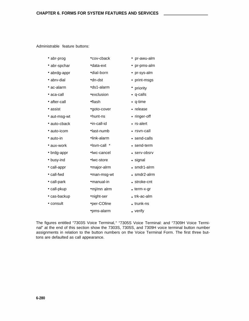
CHAPTER 6. FORMS FOR SYSTEM FEATURES AND SERVICES
Administrable feature buttons:
•
•
•
•
•
•
•
•
•
•
•
•
•
•
•
•
•
•
•
•
•
abr-prog
abr-spchar
abrdg-appr
abrv-dial
ac-alarm
aca-call
after-call
assist
aut-msg-wt
auto-cback
auto-icom
auto-in
aux-work
brdg-appr
busy-ind
call-appr
call-fwd
call-park
call-pkup
cas-backup
consult
•
•
•
•
•
•
•
•
•
•
•
•
•
•
•
•
•
•
•
•
•
•
cov-cback
data-ext
dial-born
dn-dst
ds1-alarm
exclusion
flash
goto-cover
hunt-ns
in-call-id
last-numb
link-alarm
lsvn-call *
lwc-cancel
lwc-store
major-alrm
man-msg-wt
manual-in
mj/mn alrm
night-ser
per-COline
pms-alarm
•
•
•
•
•
•
•
•
•
•
•
•
•
•
•
•
•
•
•
•
•
•
pr-awu-alm
pr-pms-alm
pr-sys-alm
print-msgs
priority
q-calls
q-time
release
ringer-off
rs-alert
rsvn-call
send-calls
send-term
serv-obsrv
signal
smdr1-aIrm
smdr2-alrm
stroke-cnt
term-x-gr
trk-ac-alm
trunk-ns
verify
The figures entitled “7303S Voice Terminal, “ “7305S Voice Terminal: and “7309H Voice Termi-nal” at the end of this section show the 7303S, 7305S, and 7309H voice terminal button numberassignments in relation to the button numbers on the Voice Terminal Form. The first three but-tons are defaulted as call appearance.
6-280

7303S, 7305S, and 7309H Voice Terminals
Page 3 of the Form (7305S only)
• Feature Button Assignments
The features and functions that can be assigned to the 7305S on Page 3 of 3 are the same as those listed for BUTTON ASSIGNMENTS above.
The figure entitled “7305S Voice Terminal” shows the 7305S voice terminal buttonnumber assignments in relation to the button numbers on the Voice Terminal Form. Thefirst three buttons are defaulted as call appearance.
Extension: BCC : 0Type:Port:Name:
FEATURE OPTIONSLWC Reception? msa-spe
LWC Activation? ySMDR Privacy? n
Redirect Notification? yBridged Call Alerting? n
Page 1 of x
STATION
Lock Messages: n COR : 1Security Code: COS : 1Coverage Path: _
Coverage Msg Retrieval?Auto Answer?
Data Restriction?Idle Appearance Preference?
Personalized Ringing Pattern:Restrict Last Appearance?
ynnn
y
SCREEN 6-107. 7303S, 7305S, and 7309H Station Form (Page 1)—Example Only
Implementation Note:
The BCC field is only displayed if the ISDN-PRI option is enabled on the System-ParametersCustomer-Options form.
For 7303S and 7309H voice terminals, this is a 2-page form.
For 7305S voice terminal, this is Page 1 of a 3-page form.
6-281

CHAPTER 6. FORMS FOR SYSTEM FEATURES AND SERVICES
Page 2 of x
STATION
NON-SWITCH DATARoom:Jack:
Cable:
ABBREVIATED DIALING
Listl:
BUTTON ASSIGNMENT
1:2:3:4:5:
List2:
call-appr 6:call-appr 7:
call-appr 8 :9 :10:
Headset? n
List3:
SCREEN 6-106. 7303S, 7305S, and 7309H Station Form (Page 2)—Example Only
6-282

7303S, 7305S, and 7309H Voice Terminals
Page 3 of 3
STATION
FEATURE BUTTON ASSIGNMENTS
1:2:
4:5:6:7:8:9:
10:11:12:
13:14:15:16:17:18:19:20:21:22:23:24:
SCREEN 6-109. 7305S Voice Terminal Form (Page 3)—Example Only
6-283

CHAPTER 6. FORMS FOR SYSTEM FEATURES AND SERVICES
Ten Administrable Feature
Buttons (Number 1-10 Are
For Ident i f i ca t ion Only)
FIGURE 6-25. 7303S Voice Terminal
6-284

7303S, 7305S, and 7309H Voice Terminals
Thirty-Four Aministrable
Feature Buttons (Numbers
1-10, and 1-24 Are ForIdentification Only)
FIGURE 6-26. 7305S Voice Terminal
6-285

CHAPTER 6. FORMS FOR SYSTEM FEATURES AND SERVICES
(ON SIDE)
HANDSET PROGRAAMMABLE
BUTTONS (10)
TEST/PROGRAMWITH I-USE AND
SWITCHSTATUS LEDs
(ON SIDE)
TOUCH DIAL
PAD
SPEAKER/RINGVOLUME CONTROL
CONFERENCE TRANSFER
DROP HOLD
MESSAGE HFAI MICROPHONE
RECALL SPEAKER
FIGURE 6-27. 7309H Voice Terminal
6-286

7401D, 7403D, and 7404D Voice Terminals
7401D, 7403D, and 7404D Voice Terminals
Purpose
This form is used to implement a 7401D, 7403D, and a 7404D voice terminal.
Administration Commands
The following administration commands can be used to access the Voice Terminal forms. Insome cases, just the most commonly used commands are shown. Refer to Administration Com-mands and Error Messages (Chapter 3) for a complete listing of all administration commands, thecommand structure, and the use of abbreviated command words when entering a command.
Action
addchangedisplayduplicatelistlistremove
Object Qualifier*
station xxxxx (extension number) or (’next’)station xxxxx (extension number)station xxxxx (extension number)stationstation [xxxxx] (’count’ 1-1600) type [’print’ or ’schedule’]station [xxxxx] (’count’ 1-1600)port [’print’ or ’schedule’]station xxxxx (extension number)
* Brackets [ ] indicate the qualifier is optional.Single quotes (’ ’) indicate the text inside the quote must be entered exactly as shown oran abbreviated form of the word maybe entered.
Form Instructions
Please review the “Voice Terminals—General” information at least once before completing theform. General information including feature button descriptions and characteristics are covered.Instructions are provided below for fields and/or pages of the form that require additional con-sideration because of the terminal type.
Page 1 of the Form
•
•
•
•
Type— Enter “7401D,” “7403D,” or “7404D” as appropriate.
PCOL/TEG Call Alerting— (For 7401 D Voice Terminal only)—Enter “y” to allow incom-ing calls on PCOLs/TEGs to audibly alert at this voice terminal. Default is “n.”
Bridged Call Alerting— (For 7403D and 7404D Voice Terminals only)—Enter “y” toallow incoming calls on bridged appearances at another voice terminal’s primary exten-sion, TEG, or PCOL calls to alert at this voice terminal. Default is “n.”
Personalized Ringing Pattern— (For 7401 D and 7404D Voice Terminals only)—Enter aPersonalized Ringing Pattern, 1 through 8, as follows:
6-287

CHAPTER 6. FORMS FOR SYSTEM FEATURES AND SERVICES
Ring Pattern Tone Sequence12345678
MMM (standard ringing)HHHL L LLHHHHLHLLHLHLHL
L=530Hz, M=750Hz, and H=1060Hz
• Data Module— For the 7401 D, enter “y” if this terminal is to be connected to a data ter-minal via a 7400B Data Module. For the 7403D, enter “y” if this terminal is to be con-nected to a data terminal via optional DTDM or 7400B Data Module; otherwise, enter “n.”For the 7404—this is a display-only field set to “y.” If “y” is entered, the Data Moduleform must be completed. Allowable entries are “y” or “n.” Default is “n.”
• Display— Enter “y” (yes) if the voice terminal is to have a display via a 7400B DataModule and associated data terminal or an optional Messaging Cartridge (7404D only)and an associated data terminal; otherwise, enter “n.” Default is “n.” If “y” is entered,the Display Button Assignments form must be completed.
Page 2 of the Form
• Headset— For a 7401 D or 7404D, enter “n,” these sets cannot have a headset. For a7403D, enter “y” if the terminal is to have a headset; otherwise, enter “n.” Default is “n.”
• Button Assignments
The feature buttons that can be assigned to the 7401D, 74030, or 7404D voice terminalsare listed below. The abbreviated software name (that is, administration name) as shownon the following list must be entered on the form. Depending on the button type, addi-tional auxiliary information maybe required when administering buttons. This informationis provided in the “Voice Terminals—General” section.
6-288

7401D, 7403D, and 7404D Voice Terminals
•
• abr-prog
• abr-spchar
• abrdg-appr †
• abrv-dial
• ac-alarm
• aca-call
• after-call
• assist
• atd-qcalls *
• atd-qtime *
• aut-msg-wt
• auto-cback
• auto-icom
• auto-in
• auto-wkup *
• aux-work
• brdg-appr †
• busy-ind
• call-appr †
• call-disp *
• caIl-fwd
• call-park
• call-pkup
• callr-info*
• cas-backup
• check-in *
• check-out *
• clk-overid *
• consult
• cov-cback
•
•
•
•
•
•
•
•
•
•
•
•
•
•
•
•
•
•
•
•
•
•
•
•
•
•
•
•
•
•
Cov-msg-rt *
data-ext
date-time *
delete-msg *
dial-icom
directory *
dn-dst
ds1-alarm
exclusion
ext-dn-dst *
flash
goto-cover
grp-dn-dst *
hunt-ns
in-call-id
inspect *
last-numb
link-alarm
lsvn-call *
lwc-cancel
Iwc-store
major-alrm
man-msg-wt
man-overid *
manual-in
mj/mn alrm
msg-retr *
mwn-act *
mwn-deact *
next *
•
•
•
•
•
•
•
•
•
•
•
•
•
•
•
•
•
•
•
•
•
•
•
•
•
•
•
•
•
night-ser
normal *
per-COline
pms-alarm
pr-awu-alm
pr-pms-alm
pr-sys-alm
print-msgs
priority
q-calls
q-time
release
ringer-off
rs-alert
rsvn-call *
send-calls
send-term
serv-obsrv
signal
smdr1-alrm
smdr2-alrm
stored-num *
stroke-cnt
term-x-gr
timer *
trk-ac-alm
trunk-name *
trunk-ns
verify
work code
*
†
Display-type buttons (not administrable on 7401D or 7403D voice terminal)
Not administrable on the 7401D voice terminal
6-289

CHAPTER 6. FORMS FOR SYSTEM FEATURES AND SERVICES
For the 7401D voice terminal, BUTTON ASSIGNMENTS 3 through 9 are used to assign featuresto dialpad keys one through seven (BUTTON ASSIGNMENT three corresponds to dialpad keyone, BUTTON ASSIGNMENT four corresponds to dialpad key two, etc.). The call-appr buttonsdefaulted in BUTTON ASSIGNMENTS one and two are not administrable (display-only).
On the 7403D and 7404D voice terminals, the first three buttons are defaulted as call appearancebuttons.
Page x of the Form (DISPLAY BUTTON ASSIGNMENTS)
• Only displayed if the Display field on Page 1 is “y.” Administer display buttons per theImplementation Note associated with the screen form. The display function is obtainedvia an optional Messaging Cartridge and an associated data terminal (also requiresadministering the following Data Module form).
Page x of the Form (DATA MODULE)
• Only displayed if the Data Module field on Page 1 is “y.” Refer to the “Station Forms—Field Descriptions” section in this chapter for associated field descriptions.
6-290

7401D, 7403D, and 7404D Voice Terminals
STATION
BCC : 0Lock Messages: nSecurity Code: _Coverage Path: _
Page 1 of x
Extension:Type: 7401D COR: 1
Port: COS: 1
Name:
FEATURE OPTIONS
LWC Reception? msa-spe Coverage Msg Retrieval? y
LWC Activation? y Auto Answer? n
SMDR Privacy? n Data Restriction? n
Redirect Notification? y Idle Appearance Preference? n
PCOL/TEG Call Alerting? n personalized Ringing Pattern: _Restrict Last Appearance? y
Data Module? n
SCREEN 6-110. 7401D Station Form (Page 1)—Example Only
Implementation Note:The BCC field is displayed if the ISDN-PRI option is enabled on the System-Parameters
Customer-Options form.
6-291

CHAPTER 6. FORMS FOR SYSTEM FEATURES AND SERVICES
STATION
Page 1 of x
Extension: BCC: 0Type: 7403D Lock Messages: n COR: 1Port: Security Code: COS: 1Name: Coverage Path: _
FEATURE OPTIONSLWC Reception? psa-spe Coverage Msg Retrieval? y
LWC Activation? y Auto Answer? nSMDR Privacy? n Data Restriction? n
Redirect Notification? y Idle Appearance Preference? nBridged Call Alerting? n
Restrict Last Appearance? yData Module? n
SCREEN 6-111. 7403D Station Form (Paga 1)—Example Only
Implementation Note:
The BCC field is only displayed if the lSDN-PRl option is enabled on the System-ParametersCustomer-Options form.
6-292

7401D, 7403D, and 7404D Voice Terminals
Extension:Type:Port:Name:
7404D COR: 1COS: 1
FEATURE OPTIONS
LWC Reception?LWC Activation?
SMDR Privacy?Redirect Notification?Bridged Call Alerting?
Data Module?Display?
Page 1 of x
STATION
BCC: 0Lock Messages: nSecurity Code:Coverage Path: _
msa-spe Coverage Msg Retrieval? y
Y Auto Answer? n
n Data Restriction? n
Y Idle Appearance Preference? n
n Personalized Ringing Pattern: _Restrict Last
nn
Appearance? y
SCREEN 6-112. 7404D Station Form (Page 1)—Example Only
Implementation Note:
The BCC field is only displayed if the lSDN-PRl option is enabled on the System-ParametersCustomer-Options form.
6-293

CHAPTER 6. FORMS FOR SYSTEM FEATURES AND SERVICES
Page 2 of x
STATION
NON-SWITCH DATA
Room: Headset? n
Jack:Cable:
ABBREVIATED DIALING
Listl: List2: List3:
BUTTON ASSIGNMENTS
1: call -appr 6:
2: call-appr 7:
3: call-appr 8:
4: 9:
5: 10:
SCREEN 6-113. 7401D, 7403D, 7404D Station Fom (Page 2)—Example Only
Implementation Note:
Button Assignments:
• 7401D 1 through 9 only displayed. Buttons 1 and 2 not administrable (that is, assignedas “call-appr”). Button 3 may be assigned as required.
• 7403D 1 through 10 displayed.
• 7404D 1 through 6 only displayed. Buttons 1 through 3 must be assigned as “call-appr.”
6-294

7401D, 7403D, and 7404D Voice Terminals
Page x of xDISPLAY BUTTON ASSIGNMENTS
1: normal2: inspect3: msq-retr
4: next 5: call-disp6: delete-msg7: date-time
SCREEN 6-114. 7404D Station Form—Example Only
Implementation Note:
This page is only displayed if the Display field on Page 1 is ’’y.” Buttons 1 through 7 , whenadministered, relate to function buttons [F1] through [F7] on the associated data terminal.
For a 7404D equipped with an optional Messaging Cartridge without Integrated Directory, displaybuttons must be administered as shown on the form.
For a 7404D equipped with an optional Messaging Cartridge with Integrated Directory, displaybuttons must be administered as shown on the form with the exception of the date/time (button 7)which must be administered as “directory.”
6-295

CHAPTER 6. FORMS FOR SYSTEM FEATURES AND SERVICES
Page x of x
STATION
DATA MODULEData Extension: BCC: 2 ITC: restricted
Name: COR: 1 COS: 1
ABBREVIATED DIALING
Listl:SPECIAL DIALING OPTION:
HOT LINE DESTINATIONDEFAULT DIALING
Abbreviated Dialing Dial Code (From above list): _
ASSIGNED MEMBER ( Station with a data extension button for this data module )
Ext Name1:
SCREEN 6-115. 7401D, 7403D, 7404D Data Module Form—Example Only
Implementation Note:
This page is only displayed if the Data Module field on Page 1 is “y.”
The BCC field is only displayed if the lSDN-PRl option is enabled on the System-ParametersCustomer-options form.
HOTLINE DESTINATION only displayed when the SPECIAL DIALING OPTION field is “hot-line.”
DEFAULT DIALING only displayed when the SPECIAL DIALING OPTION field is “default.”
Abbreviated Dialing Dial Code only displayed when SPECIAL DIALING OPTION is “hot-line” or“default.”
6-296

7401D, 7403D, and 7404D Voice Terminals
FIGURE 6-28. 7401D Voice Terminal
6-297

CHAPTER 6. FORMS FOR SYSTEM FEATURES AND SERVICES
6 ADMINISTRABLR FEATURE BUTTONS
(NUMBERS 1-6 ARE FOR IDENTIFICATION ONLY)
FIGURE 6-29. 7404D Voice Terminal
6-298

74050 Voice Terminal
7405D Voice Terminal
Purpose
This form is used to implement a 7405D multi-appearance voice terminal.
Administration Commands
The following administration commands can be used to access the Voice Terminal form. In someoases, just the most commonly used commands are shown. Refer to Administration Commandsand Error Messages (Chapter 3) for a complete listing of all administration commands, the com-mand structure, and the use of abbreviated command words when entering a command.
Action
addchangedisplayduplicatelistlistremove
Object Quallfier*
station xxxxx (extension number) or (’next’)station xxxxx (extension number)station xxxxx (extension number)stationstation [xxxxx] (’count’ 1-1600) type [’print’ of ’schedule’]station [xxxxx] (’count’ 1-1600) port [’print’ or ’schedule’]station xxxxx (extension number)
* Brackets [ ] indicate the qualifier is optional.Single quotes (’ ’) indicate the text inside the quote must be entered exactly as shown oran abbreviated form of the word maybe entered.
Form Instructions
Please review the “Voice Terminals—General” information at least once before completing theform. General information including feature button descriptions and characteristics are covered.In addition, descriptions of the administrable fields appearing on Pages 1 and 2 of the form areprovided. Instructions are provided below for fields and/or pages of the form that require addi-tional consideration because of the terminal type.
Page 1 of the Form
• Type— Enter “7405D.”
• Data Module— Enter “y” if this terminal is connected to an optional DTDM; otherwise,enter “n.” If a “y” is entered, the Data Module form (Page 2) must be completed. Defaultis “n.”
• Feature Module— Enter “y” if the voice terminal is to be connected to an optionalFeature Module. If “y” is entered, the Feature Module form must also be completed.Enter “n” if a Feature Module is not desired. Default is “n.”
• Display— Enter “y” if the voice terminal is to have a display by an optional Digital DisplayModule; otherwise, enter “n.” If “y” is entered, the Display Button assignments formmust be completed. Default is “n.”
6-299

CHAPTER 6. FORMS FOR SYSTEM FEATURES AND SERVICES
• Coverage Module— Enter “y” if the voice terminal is to be connected to an optional CallCoverage Module; otherwise, enter “n.” If “y” is entered, the Coverage Module formmust be completed. The voice terminal cannot have an optional Coverage Module andoptional Digital Display
Page 2 of the Form
• Button Assignments
Module at the same time. Default is “n.”
The feature buttons that can be assigned to the 7405D voice terminal are listed below.The abbreviated software name (that is, administration name) as shown on the followinglist must be entered on the form. Depending on the button type, additional auxiliary infor-mation may be required when administering buttons. This information is provided in the“Voice Terminals—General” section.
6-300

7405D Voice Terminal
•
•
•
•
•
•
•
•
•
•
•
•
•
•
•
•
•
•
•
•
•
•
•
•
•
•
•
•
•
•
abr-prog
abr-spchar
abrdg-appr
abrv-dial
ac-alarm
aca-call
after-call
assist
atd-qcalls *
atd-qtime *
aut-msg-wt
auto-cback
auto-icom
auto-in
auto-wkup *
aux-work
brdg-appr †
busy-ind
call-appr †
call-disp *
call-fwd
call-park †
call-pkup
callr-info *
cas-backup
check-in *
check-out *
clk-overid *
consult
cov-cback
•
•
•
•
•
•
•
•
•
•
•
•
•
•
•
•
•
•
•
•
•
•
•
•
•
•
•
•
•
•
cov-msg-rt *
data-ext
date-time *
delete-msg *
dial-icom
directory *
dn-dst
ds1-alarm
exclusion
ext-dn-dst *
flash
goto-cover
grp-dn-dst *
hunt-ns
in-call-id
inspect *
last-numb
link-alarm
lsvn-call *
lwc-cancel
lwc-store
major-alrm
man-msg-wt
man-overid *
manual-in
mj/mn alrm
msg-retr *
mwn-act *
mwn-deact *
next *
•
•
•
•
•
•
•
•
•
•
•
•
•
•
•
•
•
•
•
•
•
•
•
•
•
•
•
•
•
•
night-ser
normal *
per-COline
pms-alarm
pr-awu-alm
pr-pms-alm
pr-sys-alm
print-msgs
priority
q-calls
q-time
release
ringer-off
rs-alert
rsvn-call *
send-calls
send-term
serv-obsrv
signal
smdr1-alrm
smdr2-alrm
stored-num *
stroke-cnt
term-x-gr
timer *
trk-ac-alm
trunk-name *
trunk-ns
verify
work-code
*
†
Display-type button (not administrable on Coverage Module form)
Not administrable on Feature Module form
6-301

CHAPTER 6. FORMS FOR SYSTEM FEATURES AND SERVICES
On the the 7405D voice terminal button number assignments, the first three buttons are defaultedas call appearances. As shown in the figures at the end of this section, the 7405D Voice Termi-nal can have an optional Function Key Module (administered as a Feature Module), DigitalDisplay Module, and Coverage Module, respectively.
Page 3 of the Form
• Feature Button Assignments
The features buttons that can be assigned to the 7405D Page 3 form are the same asthose listed for the preceding BUTTON ASSIGNMENTS. Display-type feature buttonsmay only be assigned if the Display field on Page 1 is “y.”
The figure entitled “7405D Voice Terminal” at the end of this section depicts the 7405Dvoice terminal button number assignments in relation to the button numbers on the VoiceTerminal form.
Page x of the Form (Feature Module Button Assignments)
• Only displayed if the Feature Module field on Page 1 is “y.” The features buttons thatcan be assigned are the same as those listed for BUTTON ASSIGNMENTS above. (Callappearance and bridged call appearance buttons cannot be administered on this form.)Refer to the figure entitled “7405D Voice Terminal” for the button assignments locations(1 through 24) on the Function Key Module.
Page x of the Form (Coverage Module Button Assignments)
• Only displayed if the Coverage Module field on Page 1 is “y.”
The features buttons that can be assigned are the same as those listed for the precedingBUTTON ASSIGNMENTS (display-type buttons cannot be administered on this form).Refer to the figure entitled “7405D Voice Terminal” for the Coverage Module button loca-tions.
Up to 10 call appearance, 10 abrdg-appr, and 10 brdg-appr buttons can be distributedbetween a Coverage Module and the associated administrable buttons on the 7405DVoice Terminal.
Page x of the Form (Display Button Assignments)
• Only displayed if the Display field on Page 1 is “y.” The display-type buttons that can beassigned are noted with an asterisk on the above list.
Page x of the Form (Data Module)
• Only displayed if the Data Module field on Page 1 is “y.” Refer to the “Station Forms—Field Descriptions” section in this chapter for associated field descriptions.
6-302

7405D Voice Terminal
Page 1 of x
STATION
Extension:Type:Port:Name:
11
FEATURE
7405D
BCC: 0Lock Messages: nSecurity Code: _Coverage Path: _
COR :COS :
OPTIONSLWC Reception? msa-spe Coverage Msg Retrieval? y
LWC Activation? y Auto Answer? n
SMDR Privacy? n Data Restriction?
Redirect Notification? y Idle Appearance Preference?
Bridged Call Alerting? nRestrict Last Appearance?
Data Module? n Feature Module?
Display? n Coverage Module?
n
ynn
SCREEN 6-116. 7405D Station Form (Page 1)—Example Only
lmplementation Note:
The BCC field is only displayed if the lSDN-PRl option is enabled on the System-ParametersCustomer-Options form.
6-303

CHAPTER 6. FORMS FOR SYSTEM FEATURES AND SERVICES
NON-SWITCH
Room:Jack:
Cable:
DATA
Page 2 of x
STATION
ABBREVIATED DIALINGListl:
BUTTON ASSIGNMENTS
List2:
1:2:3:4:5:
call-apprcall-apprcall-appr
6:7:8:9:
10:
Headset? n
List3:
SCREEN 6-117. 7405D Station Form (Page 2)—Example Only
6-304

7405D Voice Terminal
Page 3 of x
STATION
FEATURE BUTTON ASSIGNMENTS
1: 13:
2: 14:3: 15:4: 16:5: 17:
6: 18:7: 19:8: 20:9: 21:
10: 22:
11: 23:
12: 24:
SCREEN 8-118. 7405D Station Form (Page 3)—Example Only
Implementation Note:
This form is used to assign features to the 24 administrable buttons on the 7405D voice terminal(does not include Bridged Call Appearance buttons). Feature buttons to be assigned to theoptional Function Key Module (administered as Feature Module) or Coverage Module, whenused, must be assigned on their respective form(s) (covered later in this section).
6-305

CHAPTER 6. FORMS FOR SYSTEM FEATURES AND SERVICES
Page x of x
STATION
FEATURE MODULE BUTTON ASSIGNMENTS
1:2:3:4:5:6:7:8:9:
10:11:12:
13:14:
161718
15:
1920:21:22:23:24:
SCREENS-119. 7405D Feature Module Form
Implementation Note
Only displayed if the Feature Module field on Page 1 is “y.”
6-306

7405D Voice Terminal
COVERAGE MODULE BUTTON
1:2:3:4:5:6:7:8:9:10:
Page x of x
STATION
ASSIGNMENTS
11:12:13:14:15:16:17:18:19:20:
SCREEN 6-120. 7405D Coverage Module Form—Example Only
Implementation Note
Only displayed if the Coverage Module field on Page 1 is “y.”
6-307

CHAPTER 6. FORMS FOR SYSTEM FEATURES AND SERVICES
Page x of x
STATION
DISPLAY BUTTON ASSIGNMENTS
1:2:3:4:5:6:7:
SCREEN 6-121. 7405D Display Form—Example Only
Implementation Note
Only displayed if the Display field on Page 1 is “y.” Button locations (1 through 7) are associatedwith buttons one through seven on the optional Digital Display Module.
6-308

7405D Voice Terminal
ITC : restricted
COS : 1
Page x of x
STATION
DATA MODULE
Data Extension: BCC: 2
Name: COR: 1
ABBREVIATED DIALINGListl:SPECIAL DIALING OPTION: _
HOT LINE DESTINATIONDEFAULT DIALING
Abbreviated Dialing Dial Code (From above list): _
ASSIGNED MEMBER ( Station with a data extension button for this data module )
Ext Name1:
SCREENS 6-122. 7405D Data Module Form—Example Only
Implementation Note
This page is only displayed if the Data Module field on Page 1 is ’’y.”
The BCC field is only displayed if the lSDN-PRl option is enabled on the System-ParametersCustomer-Options form.
HOT LINE DESTINATION only displayed when the SPECIAL DIALING OPTION field is ’’hot-Iine.”
DEFAULT DIALING only displayed when the SPECIAL DIALING OPTION field is “default.”
Abbreviated Dialing Dial Code only displayed when SPECIAL DIALING OPTION is “hot-line” or“default.”
6-309

CHAPTER 6. FORMS FOR SYSTEM FEATURES AND SERVICES
ADMINISTRABLE
BUTTONS (NUMBERS 24 ADMINISTRABLE
1-10 ARE FOR BUTTONS (NUMBERS 1-24
IDENTIFICATION ARE FOR IDENTIFICATIONONLY) ONLY)
FIGURE 6-30. 7405D Voice Terminal
6-310

7405D Voice Terminal
F U N C T I O N
KEY MODULE
24 ADMINISTRABLE
BUTTONS AS THEY
ARE ASSIGNED ON
THE FEATURE MODULE
FORM (NUMBERS 1-24 ARE
FOR IDENTIFICATION
ONLY)
FIGURE 6-31. 7405D Voice Terminal With Optional Function Key Module
6-311

CHAPTER 6. FORMS FOR SYSTEM FEATURES AND SERVICES
DIGITAL
DISPLAY
MODULE
BUTTONS (NUMBERS
1-7 ARE FOR
IDENTIFICATION ONLY)
40-CHARACTER
ALPANUMERIC
DISPLAY
7 ADMINISTRABLE
FIGURE 6-32. 7405D Voice Terminal With Optional Digital Display Module
6-312
ON/OFF
SWITCH

74050 Voice Terminal
20 ADMINISTRABLE
STATUS INDICATORBUTTONS FOR
CALL COVERAGE CUSTOMER-DESIGNATEDLAMPS
MODULE CALL APPEARANCES
AND/OR FEATURES
(NUMBERS 1-20 ARE FOR
IDENTIFICATION ONLY)
FIGURE 6-33. 7405D Voice Terminal With Optional Call Coverage Module
6-313

CHAPTER 6. FORMS FOR SYSTEM FEATURES AND SERVICES
7406D and 7407D Voice Terminals
Purpose
This form is used to implement a 7406D and 7407D voice terminal.
Administration Commands
The following administration commands can be used to access the Voice Terminal forms. Insome cases, just the most commonly used commands are shown. Refer to Administration Com-mands and Error Messages (Chapter 3) for a complete listing of all administration commands, thecommand structure, and the use of abbreviated command words when entering a command.
Action
addchangedisplayduplicatelistlistremove
Object Qualifier*
station xxxxx (extension number) or (’next’)station xxxxx (extension number)station xxxxx (extension number)stationstation [xxxxx] (’count’ 1-1600) type [print’ or ’schedule’]station [xxxxx] (’count’ 1-1600) port [’print’ or ’schedule’]station xxxxx (extension number)
* Brackets [ ] indicate the qualifier is optional.Single quotes (’ ’) indicate the text inside the quote must be entered exactly as shown oran abbreviated form of the word maybe entered.
Form Instructions
Please review the “Voice Terminals—General” information at least once before completing theform. General information including feature button descriptions and characteristic are covered.In addition, descriptions of the administrable fields appearing on Pages 1 and 2 of the form areprovided. Instructions are provided below for fields and/or pages of the form that require addi-tional consideration because of the terminal type.
Page 1 of the Form
• Type— Enter “7406D’ or “7407D’ as appropriate.
• Display Cartridge (7406D Only)— Enter “y” if this terminal is to have a display via anassociated data terminal.
• Data Module— Enter “y” if this voice terminal is equipped with an optional 703A DataStand (7406D), a 702AL1-DSU (7407D), or 7400B Data Module (7406D or 7407D) andconnected to an associated data terminal; otherwise, enter “n.” If “y” is entered, theData Module form must be completed. Default is “y.”
• Display— Display-only field (set to “y”) for the 7407D. For the 7406D, enter “y” if thevoice terminal is equipped with an optional digital display; otherwise, enter “n.”
For the 7407D form, the Display Button Assignments form must be completed. Default is“n.”
6-314

7406D and 7407D Voice Terminals
Page 2 of the Form
• Headset— For the 7406D, enter “y” if a headset is to be used; otherwise, enter “n.” Notethat the 7407D cannot have a headset. Default is “n.”
• Button Assignments
The following list defines the feature buttons that can be assigned to the 7406D or 7407Dvoice terminals. The abbreviated software name (that is, administration name) as shownon the following list must be entered on the form. Depending on the button type, addi-tional auxiliary information may be required when administering buttons. This informationis provided in the “Voice Terminals—General” section.
Note: On set versions 7406D05A and 7406D06A, feature buttons [F2] and [F3] arepreassigned and therefore, cannot be assigned as feature buttons.
6-315

CHAPTER 6. FORMS FOR SYSTEM FEATURES AND SERVICES
•
•
•
•
•
•
•
•
•
•
•
•
•
•
•
•
•
•
•
•
•
•
•
•
•
•
•
•
•
•
abr-prog
abr-spchar
abrdg-appr
abrv-dial
ac-alarm
aca-call
after-call
assist
atd-qcalls *
atd-qtime *
aut-msg-wt
auto-cback
auto-icom
auto-in
auto-wkup *
aux-work
brdg-appr
busy-ind
call-appr
call-disp *
call-fwd
call-park
call-pkup
callr-info *
cas-backup
check-in *
check-out *
clk-overid *
consult
cov-cback
•
•
•
•
•
•
•
•
•
•
•
•
•
•
•
•
•
•
•
•
•
•
•
•
•
•
•
•
•
•
cov-msg-rt *
data-at
date-time *
delete-msg *
dial-icom
directory *
dn-dst
ds1-alarm
exclusion
ext-dn-dst *
flash
goto-cover
grp-dn-dst *
hunt-ns
in-call-id
inspect *
last-numb
link-alarm
lsvn-call *
lwc-cancel
lwc-store
major-alrm
man-msg-wt
man-overid *
manual-in
mj/mn alrm
msg-retr *
mwn-act *
mwn-deact *
next *
•
•
•
•
•
•
•
•
•
•
•
•
•
•
•
•
•
•
•
•
•
•
•
•
•
•
•
•
•
•
night-ser
normal *
per-COline
pms-alarm
pr-awu-alm
pr-pms-alm
pr-sys-alm
print-msgs
priority
q-calls
q-time
release
ringer-off
rs-alert
rsvn-call *
send-calls
send-term
serv-obsrv
signal
smdr1-alrm
smdr2-alrm
stored-num *
stroke-cnt
term-x-gr
timer *
trk-ac-alm
trunk-name *
trunk-ns
verify
work-code
* Display-type Button
6-316

7406D and 7407D Voice Terminals
The figures entitled “7406D Voice Terminal” and “7407D Voice Terminal” at the end of this sec-tion show the 7406D and 7407D voice terminal button number assignments in relation to the but-ton numbers on the voice terminal form. The first three buttons are defaulted as call appearance.
Page 3 of the Form
• Feature Button Assignments
The features and functions that can be assigned to the 7406D or 7407D voice terminaladministrable buttons are the same as those listed for BUTTON ASSIGNMENTS above.
The figures entitled “7406D Voice Terminal” and “7407D Voice Terminal” at the end ofthis section show the 7406D and 7407D voice terminal button number assignments inrelation to the button numbers on the voice terminal form.
Page x of the Form (Display Button Assignment)
• Only displayed if the “Display Cartridge” or “Display” field on Page 1 (7406D form) is “y”or the Type field on Page 1 is “7407D.” The display buttons that can be administered arenoted with asterisks on the above list (see BUTTON ASSIGNMENTS). The abbreviatednames as shown on the Iii must be entered on the form.
Page x of the Form (Data Module)
• Only displayed if the Data Module field on Page 1 is “y.” Refer to “Station Forms—FieldDescriptions” section in this chapter for associated field descriptions.
6-317
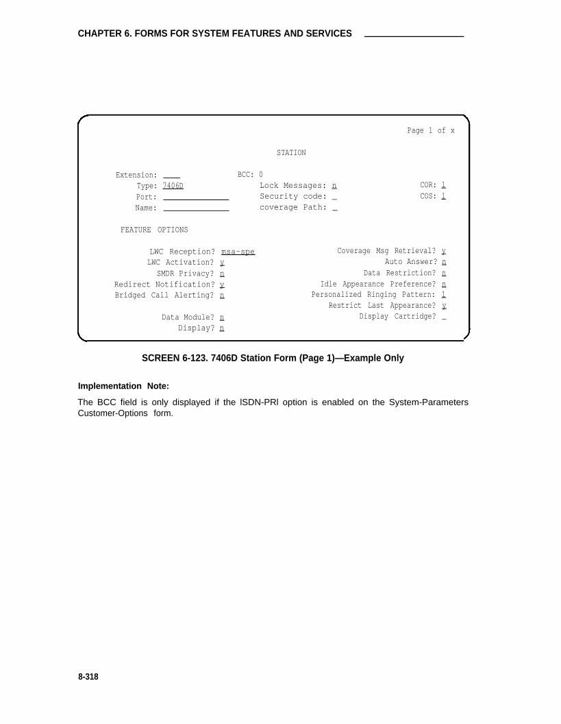
CHAPTER 6. FORMS FOR SYSTEM FEATURES AND SERVICES
Page 1 of x
STATION
Extension: BCC: 0Type: 7406D Lock Messages: n COR: 1
Port: Security code: _ COS: 1Name: coverage Path: _
FEATURE OPTIONS
LWC Reception? msa-spe Coverage Msg Retrieval? yLWC Activation? y Auto Answer? n
SMDR Privacy? n Data Restriction? nRedirect Notification? y Idle Appearance Preference? nBridged Call Alerting? n Personalized Ringing Pattern: 1
Restrict Last Appearance? yData Module? n Display Cartridge? _
Display? n
SCREEN 6-123. 7406D Station Form (Page 1)—Example Only
Implementation Note:
The BCC field is only displayed if the lSDN-PRl option is enabled on the System-ParametersCustomer-Options form.
8-318

7406D and 7407D Voice Terminals
NON-SWITCHRoom:Jack:
Cable:
ABBREVIATED
Listl:
DATA
Page 2 of x
STATION
Headset? n
DIALING
List2: List3:
BUTTON ASSIGNMENTS
1: call-appr 4:
2: call-appr 5:3: call-appr
SCREEN 6-124. 7406D Station Form (Page 2)—Example Only
6-319

CHAPTER 6. FORMS FOR SYSTEM FEATURES AND SERVICES
STATION
Page 3 of x
FEATURE BUTTON ASSIGNMENTS2:3:
1: 4:
5: 12:6: 13:7: 14:8: 15:9: 16:
10: 17:11: 18:
SCREEN 6-125. 7406D Station Form (Page 3)—Example Only
Implementation Note:
Buttons 5 through 11 are dual function buttons. An associated [Shift] button on the voice terminalis used to enable either buttons 5 through 11 or enable associated buttons 12 through 18.
Only buttons 1 through 4 have status lamps. It is recommended that feature button assignmentsrequiring status lamp indications not be administered to buttons 5 through 18.
6-320

7406D and 7407D Voice Terminals
Extension:Type:Port:Name:
BCC: 07407D 1
1
FEATURE OPTIONS
LWC Reception? msa-speLWC Activation? y
SMDR Privacy? nRedirect Notification? yBridged Call Alerting? n
Data Module? nDisplay? y
Page 1 of x
STATION
Lock Messages: nsecurity Code: _Coverage Path: _
COR:COS:
Coverage Msg Retrieval? y
Auto Answer?Data Restriction?
Idle Appearance Preference?Personalized Ringing Pattern:
nn
Restrict Last Appearance?
n
_y
SCREEN 6-126. 7407D Station Form (Page 1)—Example Only
Implementation Note:
The BCC field is only displayed if the lSDN-PRl option is enabled on the System-ParametersCustomer-Options form.
6-321

CHAPTER 6. FORMS FOR SYSTEM FEATURES AND SERVICES
Page 2 of x
NON-SWITCH DATA
Room:Jack:
Cable:
STATION
Headset? n
ABBREVIATED DIALING
List1:
BUTTON ASSIGNMENTS
List2:
1:2:3:4:5:
call-apprcall-appr
call-appr
6:7:8:9:
10:
List3:
SCREEN 6-127. 7407D Voice Terminal Form (Page 2)—Example Only
6-322

7406D and 7407D Voice Terminals
Page 3 of x
FEATURE BUTTON ASSIGNMENTS
STATION
1:3:4:5:6:7:8:9:
10:11:12:13:
2:14:15:16:17:18:19:20:21:22:23:24:
SCREEN 6-128. 7407D Voice Terminal Form (Page 3)—ExampIe Only
Implementation Note:
Only buttons 1 and 2 have status lamps. It is recommended that feature button assignmentsrequiring status lamp indications not be administered to buttons 3 through 24.
6-323
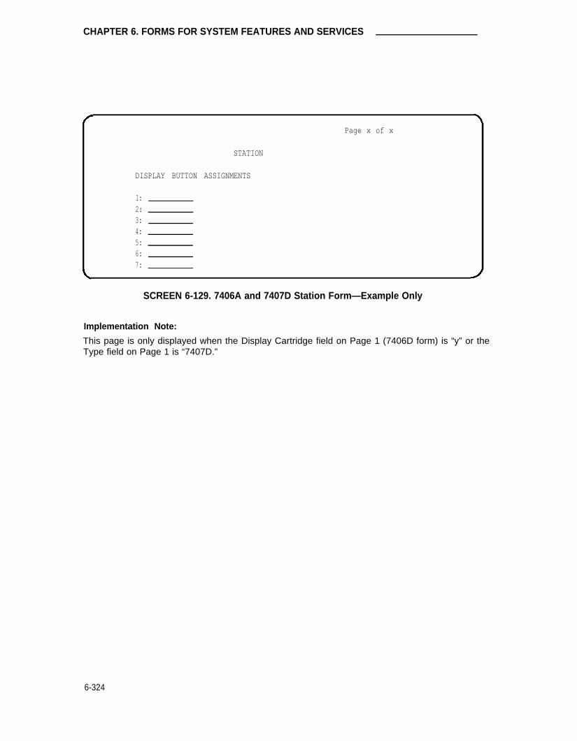
CHAPTER 6. FORMS FOR SYSTEM FEATURES AND SERVICES
Page x of x
STATION
DISPLAY BUTTON ASSIGNMENTS
1:2:3:4:5:6:7:
SCREEN 6-129. 7406A and 7407D Station Form—Example Only
Implementation Note:
This page is only displayed when the Display Cartridge field on Page 1 (7406D form) is “y” or theType field on Page 1 is “7407D.”
6-324

7406D and 7407D Voice Terminals
Page x of x
STATION
DATA MODULE
Data Extension: BCC: 2 ITC: restrictedName: COR: 1 COS: 1
ABBREVIATED DIALING
List1:SPECIAL DIALING OPTION: _
HOT LINE DESTINATIONDEFAULT DIALING
Abbreviated Dialing Dial Code (From above list): _
ASSIGNED MEMBER ( Station with a data extension button for this data module )
Ext Name1:
SCREEN 6-130. 7406D and 7407D Data Module Form—Example Only
Implementation Note:
This page is only displayed if the Data Module field on Page 1 is “y.”
The BCC field is only displayed if the lSDN-PRl option is enabled on the System-ParametersCustomer-Options form.
HOTLINE DESTINATION only displayed when the SPECIAL DIALING OPTION field is “hot-Iine.”
DEFAULT DIALING only displayed when the SPECIAL DIALING OPTION field is “default.”
Abbreviated Dialing Dial Code only displayed when SPECIAL DIALING OPTION is “hot-line” or“default.”
6-325

CHAPTER 6. FORMS FOR SYSTEM FEATURES AND SERVICES
ADMINISTRABLE CALL APPEARANCE FEATURE
BUTTONS (NUMBERS CORRESPOND TO BUTTON
ASSIGNMENTS ON VOICE TERMINAL SCREEN
FORM, PAGE 2)
ON 7406D05A AND 7406D06A
ONLY, BUTTON (2) IS THE
SPEAKERPHONE ON/OFF BUTTON,
BUTTON (3) IS THE
SPEAKERPHONE MUTE BUTTON,
AND THE BUTTON SHOWN AS
“SPEAKER” IS THE SPEAKER
VOLUME BUTTON.
ADMINISTRABLE FEATURE-ONLY BUTTONS
(NUMBERS CORRESPOND TO FEATURE
BUTTON ASSIGNMENTS ON VOICE TERMINAL
SCREEN FORM, PAGE 3)
FIGURE 6-34. 7406D Voice Terminal
6-326

7406D and 7407D Voice Terminals
10 CALL APPEARANCE FEATURE FUNCTION
(NUMBERS 1-10 ARE FOR IDENTIFICATION ONLY)
7 ADMINISTRATIVE 22 NO-LED FEATURE
DISPLAY BUTTONS BUTTONS (NUMBERS
(NUMBERS D1-D7 ARE F1-F24 ARE FOR
FOR IDENTIFICATION IDENTIFICATION ONLY)
ONLY)
FIGURE 6-35. 7407D Voice Terminal
6-327

CHAPTER 6. FORMS FOR SYSTEM FEATURES AND SERVICES
7410D Voice Terminal
Purpose
This form is used to implement a 7410D voice terminal.
Administration Commands
The following administration commands can be used to access the Voice Terminal form. In somecases, just the most commonly used commands are shown. Refer to Administration Commandsand Error Messages (Chapter 3) for a complete listing of all administration commands, the com-mand structure, and the use of abbreviated command words when entering a command.
Action
addchangedisplayduplicatelistlistremove
Object Qualifier*
station xxxxx (extension number) or (’next’)station xxxxx (extension number)station xxxxx (extension number)stationstation [xxxxx] (’count’ 1-1600) type [’print’ or ’schedule’]station [xxxxx] (’count’ 1-1600) port [’print’ or ’schedule’]station xxxxx (extension number)
* Brackets [ ] indicate the qualifier is optional.Single quotes (’ ’) indicate the text inside the quote must be entered exactly as shown oran abbreviated form of the word maybe entered.
Form Instructions
Please review the “Voice Terminals—General” information at least once before completing theform. General information including feature button descriptions and characteristic are covered.In addition, descriptions of the administrable fields appearing on Pages 1 and 2 of the form areprovided. Instructions are provided below for fields and/or pages of the form that require addi-tional consideration because of the terminal type.
Page 1 of the Form
• Type— Enter “7410D.”
• Data Module— Enter “y” if this terminal is to be connected to a data terminal via optional7400B Data Module; otherwise, enter “n.” If “y” is entered, the Data Module form mustbe completed. Allowable entries are “y” or “n.” Default is “n.”
• Display— Enter “y” (yes) if the voice terminal is to have a display via a 7400B DataModule and associated data terminal; otherwise, enter “n.” Default is “n.” If “y” isentered, the Display Button Assignments form must be completed.
6-328

7410D Voice Terminal
Page 2 of the Form
• Button Assignments
The feature buttons that can be assigned to the voice terminal are listed on the followingpage. The abbreviated software name (that is, administration name) as shown on the fol-lowing list must be entered on the form. Depending on the button type, additional auxili-ary information may be required when administering buttons. This information is providedin the “Voice Terminals-General” section.
6-329

CHAPTER 6. FORMS FOR SYSTEM FEATURES AND SERVICES
•
•
•
•
•
•
•
•
•
•
•
•
•
•
•
•
•
•
•
•
•
•
•
•
•
•
•
•
•
•
abr-prog
abr-spchar
abrdg-appr
abrv-dial
ac-alarm
aca-call
after-call
assist
atd-qcalts *
atd-qtime *
aut-msg-wt
auto-cback
auto-icom
auto-in
auto-wkup *
aux-work
brdg-appr
busy-ind
call-appr
call-disp *
call-fwd
call-park
call-pkup
callr-info *
cas-backup
check-in *
check-out *
clk-overid *
consult
cov-cback
•
•
•
•
•
•
•
•
•
•
•
•
•
•
•
•
•
•
•
•
•
•
•
•
•
•
•
•
•
•
cov-msg-rt *
data-ext
date-time *
delete-msg *
dial-icom
directory *
dn-dst
ds1-alarm
exclusion
ext-dn-dst *
flash
goto-cover
grp-dn-dst *
hunt-ns
in-call-id
inspect *
last-numb
link-alarm
lsvn-call
lwc-cancel
lwc-store
major-alrm
man-msg-wt
man-overid *
manual-in
mj/mn alrm
msg-retr *
mwn-act *
mwn-deact *
next *
•
•
•
•
•
•
•
•
•
•
•
•
•
•
•
•
•
•
•
•
•
•
•
•
•
•
•
•
•
•
night-ser
normal *
per-COline
pms-alarm
pr-awu-alm
pr-pms-alm
pr-sys-alm
print-msgs
priority
q-calls
q-time
release
ringer-off
rs-alert
rsvn-call
send-calls
send-term
serv-obsrv
signal
smdr1-alrm
smdr2-alrm
stored-num *
stroke-cnt
term-x-gr
timer *
trk-ac-alm
trunk-name *
trunk-ns
verify
work code
* Display-type buttons
6-330

7410D Voice Terminal
The figure entitled “7410D Voice Terminal” show the 7410D voice terminal button number assign-ments in relation to the button numbers on the Voice Terminal Form.
Page x of the Form (Data Module)
• Only displayed if the Data Module field on Page 1 is “y.” Refer to “Station Forms—FieldDescriptions” section in this chapter for associated field descriptions.
Page 1 of x
STATION
Extension: BCC : 0Type: 7410D Lock Messages: n COR : 1
Port: Security Code: COS : 1
Name: coverage Path: _
FEATURE OPTIONS
LWC Reception? msa-spe Coverage Msg Retrieval? yLWC Activation? y Auto Answer? n
SMDR Privacy? n Data Restriction? n
Redirect Notification? y Idle Appearance Preference? nBridged Call Alerting? n
Restrict Last Appearance? yData Module? n
SCREEN 6-131. 7410D Station Form (Page 1)—Example Only
Implementation Note:
The BCC field is only displayed if the ISDN-PRI option is enabled on the System-ParametersCustomer-Options form.
6-331

CHAPTER 6. FORMS FOR SYSTEM FEATURES AND SERVICES
Headset? n
Page 2 of 3
STATION
NON-SWITCH DATA
Room:Jack:
Cable:
ABBREVIATED DIALING
List1:
BUTTON ASSIGNMENTS
1: call-appr 6:2: call-appr 7:3: call-appr 8:4: 9:5: 10:
List2 : List3:
SCREEN 6-132. 7401D, 7403D, 7404D Station Form (Page 2)—ExampIe Only
Implementation Note:
Button Assignments:
• 7401D 1 through 9 only displayed. Buttons 1 and 2 not administrable (that is, assignedas “call-appr”). Button 3 maybe assigned as required.
• 7403D 1 through 10 displayed.
• 7404D 1 through 6 only displayed. Buttons 1 through 3 must be assigned as “call-appr.”
6-332

7410D Voice Terminal
DATA MODULE
Data Extension:Name:
Page 3 of 3
STATION
BCC: 2 ITC: restrictedCOR: l COS: 1
ABBREVIATED DIALING
List1:SPECIAL DIALING OPTION:
HOT LINE DESTINATIONDEFAULT DIALING
Abbreviated Dialing Dial Code (From above list): _
ASSIGNED MEMBER ( Station with a data extension button for this data module )
Ext Name1:
SCREEN 6-133. 7410D Data Module Form (Page 3)—Example Only
lmplementation Note:
This page is only displayed if the Data Module field on Page list 1 is “y.”
The BCC field is only displayed if the lSDN-PRl option is enabled on the System-ParametersCustomer-Options form.
HOTLINE DESTINATION only displayed when the SPECIAL DIALING OPTION field is “hot-Iine.”
DEFAULT DIALING only displayed when the SPECIAL DIALING OPTION field is “default.”
Abbreviated Dialing Dial Code only displayed when SPECIAL DIALING OPTION is “hot-line” or“default.”
6-333

CHAPTER 6. FORMS FOR SYSTEM FEATURES AND SERVICES
HANDSET CALL APPEARANCES/
feature buttons
RINGER VOLUME
CONTROL
hold but ton
MESSAGE LAMP
CONFERENCE BUTTON
DROP BUTTON
transfer button
dial pad
SELECT RING BUTTON
select ring LAMP
FIGURE 6-36. 7410D Voice Terminal
6-334

7434D Voice Terminal
7434D Voice Terminal
Purpose
This form is used to implement a 7434D multi-appearance voice terminal.
Administration Commands
The following administration commands can be used to access the Voice Terminal form. In somecases, just the most commonly used commands are shown. Refer to Administration Commandsand Error Messages (Chapter 3) for a complete listing of all administration commands, the com-mand structure, and the use of abbreviated command words when entering a command.
Action
addchangedisplayduplicatelistlistremove
Object QuaIifier*
station xxxxx (extension number) or (’next’)station xxxxx (extension number)station xxxxx (extension number)stationstation [xxxxx] (’count’ 1-1600) type [’print’ or ’schedule’]station [xxxxx] (’count’ 1-1600) port [’print’ or ’schedule’]station xxxxx (extension number)
* Brackets [ ] indicate the qualifier is optional.Single quotes (’ ’) indicate the text inside the quote must be entered exactly as shown oran abbreviated form of the word maybe entered.
Form Instructions
Please review the “Voice Terminals-General” information at least once before completing theform. General information including feature button descriptions and characteristics are covered.In addition, descriptions of the administrable fields appearing on Pages 1 and 2 of the form areprovided. Instructions are provided below for fields and/or pages of the form that require addi-tional consideration because of the terminal type.
Page 1 of the Form
• Type— Enter “7434D.”
• Data Module— Enter “y” if this terminal is connected to an optional 7400B Data Module;otherwise, enter “n.” If a “y” is entered, the Data Module form (Page x) must be com-pleted. Default is “n.”
• Display— Enter “y” if the voice terminal is to have a display by an optional Digital DisplayModule; otherwise enter “n.” If “y” is entered, the Display Button assignments form mustbe completed. Default is “n.”
• Coverage Module— Enter “y” if the voice terminal is to be connected to an optional CallCoverage Module; otherwise enter “n.” If “y” is entered, the Coverage Module form mustbe completed. The voice terminal cannot have an optional Coverage Module and optionalDigital Display Module at the same time. Default is “n.”
6-335

CHAPTER 6. FORMS FOR SYSTEM FEATURES AND SERVICES
Page 2 of the Form
• Button Assignments
The feature buttons that can be assigned to the 7434D voice terminal are listed on thefollowing page. The abbreviated software name (that is, administration name) as shownon the following list must be entered on the form. Depending on the button type, addi-tional auxiliary information may be required when administering buttons. This informationis provided in the “Voice Terminals—General” section.
6-336

7434D Voice Terminal
•
•
•
•
•
•
•
•
•
•
•
•
•
•
•
•
•
•
•
•
•
•
•
•
•
•
•
•
•
•
abr-prog
abr-spchar
abrdg-appr
abrv-dial
ac-alarm
aca-call
after-cd
assist
atd-qcalls *
atd-qtime *
aut-msg-wt
auto-cback
auto-icom
auto-in
auto-wkup *
aux-work
brdg-appr
busy-ind
call-appr
call-disp *
call-fwd
call-park
call-pkup
callr-info *
cas-backup
check-in *
check-out *
clk-overid *
consult
cov-cback
•
•
•
•
•
•
•
•
•
•
•
•
•
•
•
•
•
•
•
•
•
•
•
•
•
•
•
•
•
•
mv-msg-rt *
data-ext
date-time *
delete-msg *
dial-icom
directory *
dn-dst
ds1-alarm
exclusion
ext-dn-dst *
flash
goto-cover
grp-dn-dst *
hunt-ns
in-call-id
inspect *
last-numb
link-alarm
lsvn-call *
lwc-cancel
lwc-store
major-alrm
man-msg-wt
man-overid *
manual-in
mj/mn alrm
msg-retr *
mwn-act *
mwn-deact *
next *
•
•
•
•
•
•
•
•
•
•
•
•
•
•
•
•
•
•
•
•
•
•
•
•
•
•
•
•
•
•
night-ser
normal *
per-COline
pms-alarm
pr-awu-alm
pr-pms-alm
pr-sys-alm
print-msgs
priority
q-calls
q-time
release
ringer-off
rs-alert
rsvn-call *
send-calls
send-term
serv-obsrv
signal
smdr1-alrm
smdr2-alrm
stored-num *
stroke-cnt
term-x-gr
timer *
trk-ac-alm
trunk-name *
trunk-ns
verify
work-code
• Display-type button
6-337

CHAPTER 6. FORMS FOR SYSTEM FEATURES AND SERVICES
The figure entitled “7434D Voice Terminal” at the end of this section shows the 7434D voice ter-minal button number assignments in relation to the button numbers on the Voice Terminal form.The first three buttons are defaulted as call appearance. To see drawings of the 7434D with anoptional Coverage Module and Display Module, respectively, refer to the last two figures in thissection.
Page 3 of the Form
• Feature Button Assignments
The features buttons that can be assigned are the same as those listed for BUTTONASSIGNMENTS above. The abbreviated name as shown on the list must be entered onthe form.
The figure entitled “7434D Voice Terminal” shows the 7434D voice terminal buttonnumber assignments in relation to the button numbers on the Voice Terminal form.
Page x of the Form (Coverage Module Button Assignments)
• Only displayed if the Coverage Module field on Page 1 is “y.” The features buttons thatcan be assigned are the same as those listed for BUTTON ASSIGNMENTS aboveexcept that display-type buttons cannot be assigned. The abbreviated name as shownon the list must be entered on the form.
A minimum of two or a maximum of 10 call appearance buttons can be administered.When two call appearance buttons are administered, the maximum number of BridgedAppearance buttons that can be administered is 52 or 32 with or without a CoverageModule, respectively.
Page x of the Form (Display Button Assignment)
• Only displayed if the Display field on Page 1 is “y.” The display-type buttons that can beassigned are shown on the preceding BUTTON ASSIGNMENTS list. Display-type but-tons are noted with an asterisk. The abbreviated name as shown on the list must beentered on the button field on the form.
Page x of the Form (Data Module)
• Only displayed if the Data Module field on Page 1 is “y.” Refer to the “Station Forms-Field Descriptions” section in this chapter for associated field descriptions.
6-338

7434D Voice Terminal
Page 1 of x
STATION
Extension: BCC: 0Type: 7434D Lock Messages: n COR: 1Port: Security Code: COS: 1Name: coverage Path: _
FEATURE OPTIONS
LWC Reception? msa-spe Coverage Msg Retrieval? yLWC Activation? y Auto Answer? n
SMDR Privacy? n Data Restriction? nRedirect Notification? y Idle Appearance Preference? nBridged Call Alerting? n Personalized Ringing Pattern: 1
Restrict Last Appearance? yData Module? n
Display? n Coverage Module? n
SCREEN 6-134. 7434D Station Form (Page 1)—Example Only
Implementation Note:
The BCC field is only displayed if the lSDN-PRl option is enabled on the System-ParametersCustomer-Options form.
6-339

CHAPTER 6. FORMS FOR SYSTEM FEATURES AND SERVICES
NON-SWITCH
Room:Jack:
Cable:
ABBREVIATED
List1:
DATA
Page 2 of x
STATION
DIALING
List2:
BUTTON ASSIGNMENTS
1:2:3:4:5:
sail-appr 6:
sail-addr 7:
sail-appr 8:9:
10:
Headset? n
List3:
SCREEN 6-135. 7434D Station Form (Page 2)—Example Only
6-340

7434D Voice Terminal
BUTTON ASSIGNMENTS
STATION
Page 3 of x
11: 23:12: 24:13: 25:14: 26:15: 27:16: 28:17: 29:18: 30:19: 31:20: 32:21: 33:22: 34:
SCREEN 6-136. 7434D Station Form (Page 3)—Example Only
Implementation Note:
This form is used to assign features to the 24 administrable buttons on the 7434D voice terminal(may include call appearance and bridged call appearance buttons). Feature buttons to beassigned to the optional Coverage Module, when used, must be assigned on its respective form(see next page).
6-341

CHAPTER 6. FORMS FOR SYSTEM FEATURES AND SERVICES
Page x of x
STATION
COVERAGE MODULE BUTTON ASSIGNMENTS
1:2:3:4:5:6:7:8:9:
10:
11:12:13:14:15:16:17:18:19:20:
SCREEN 6-137. 7434D Coverage Module Form
Implementation Note:
Only displayed if the Coverage Module field on Page 1 is “y.”
Do not administer display-type buttons (for example, inspect, normal) on this form.
6-342

7434D Voice Terminal
Page x of x
STATION
DISPLAY BUTTON ASSIGNMENTS
1:2:3:4:5:6:7:
SCREEN 6-138. 7434D Display Form
Implementation Note:
Only displayed if the Display field on Page 1 is “y.” Button locations (1 through 7) are associatedwith buttons 1 through 7 on the optional Digital Display Module.
6-343

CHAPTER 6. FORMS FOR SYSTEM FEATURES AND SERVICES
STATION
BCC: 2COR: 1
ITC: restrictedCOS: 1_
Page x of x
DATA MODULE
Data Extension:Name:
ABBREVIATED DIALING
List1:
SPECIAL DIALING OPTION:HOT LINE DESTINATIONDEFAULT DIALING
Abbreviated Dialing Dial Code (From above list): _
ASSIGNED MEMBER ( Station with a data extension button for this data module )
Ext Name
1:
SCREEN 6-139. 7434D Data Module Form—Example Only
Implementation Note:
This page is only displayed if the Data Moduie field on Page 1 is “y.”
The BCC field is only displayed if the lSDN-PRl option is enabled on the System-ParametersCustomer-Options form.
HOT LINE DESTINATION only displayed when the SPECIAL DIALING OPTION field is “hot-line.”
DEFAULT DIALING only displayed when the SPECIAL DIALING OPTION field is “default.”
Abbreviated Dialing Dial Code only displayed when SPECIAL DIALING OPTION is “hot-line" or“default.”
6-344

7434D Voice Terminal
ADMINISTRABLE BUTTONS ADMINISTRABLE BUTTONS
(NUMBERS 1-10 ARE FOR (NUMBERS 11-34 ARE FOR
IDENTIFICATION ONLY) IDENTIFICATION ONLY)
HANDSET
MESSAGE
LAMP
DIAL PAD
SELECT RING
FIGURE 6-37. 7434D Voice Terminal
6-345

CHAPTER 6. FORMS FOR SYSTEM FEATURES AND SERVICES
20 ADMINISTRABLE
BUTTONS FOR
L A M P S
STATUS lNDICATORCALL COVERAGE CUSTOMER-DESIGNATED
MODULE CALL APPEARANCESA N D / O R F E A T U R E S
(NUMBER 1-20 ARE FOR
IDENTIFICATION ONLY)
FIGURE 6-38. 7434D Voice Terminal With Optional Call Coverage Module
6-346

7434D Voice Terminal
DIGITALDISPLAYMODULE
40-CHARACTERALPHANUMERICDISPLAY
7 ADMINISTRABLEBUTTONS (NUMBERS1-7 ARE FORIDENTIFICATION ONLY)
ON/OFFSWITCH
FIGURE 6-39. 7434D Voice Terminal With Optional Digital Display Module
6-347

CHAPTER 6. FORMS FOR SYSTEM FEATURES AND SERVICES
Callmaster Digital Voice Terminal
Purpose
This form is used to assign the Callmaster™ digital voice terminal. The terminal may also beused to support the ACD feature.
Administration Commands
The following administration commands can be used to access the Voice Terminal form. In somecases, just the most commonly used commands are shown. Refer to Administration Commandsand Error Messages (Chapter 3) for a complete listing of all administration commands, the com-mand structure, and the use of abbreviated command words when entering a command.
Action
addchangedisplayduplicatelistlistremove
Object Qualifier
station xxxxx (extension number) or (’next’)station xxxxx (extension number)station xxxxx (extension number)stationstation [xxxxx] (’count’ 1-1600) type [’print’ or ’schedule’]station [xxxxx] (’count’ 1-1600) port [’print’ or ’schedule’]station xxxxx (extension number)
* Brackets [ ] indicate the qualifier is optional.Single quotes (’ ’) indicate the text inside the quote must be entered exactly as shown oran abbreviated form of the word maybe entered.
Form Instructions
Please review the “Voice Terminals-General” information at least once before completing theform. General information including feature button descriptions and characteristics are covered.In addition, descriptions of the administrable fields appearing on Pages 1 and 2 of the form areprovided. Instructions are provided below for fields and/or pages of the form that require addi-tional consideration because of the terminal type.
Page 1 of the Form
• Type— Enter “602A1.”
• Data Module— Enter “y” if this terminal is connected to a data terminal via 7400B DataModule, otherwise, enter “n.” If “y” is entered, the Data Module form must be completed.Allowable entries are “y” or “n.” Default is “n.”
• Display— Display-only field; restricted to “y.” Display-type buttons are administered onPage 3 of the form.
6-348

Callmaster Digital Voice Terminal
Page 2 of the Form
• Button Assignments
The feature buttons that can be assigned to the Callmaster digital voice terminal arelisted below. The abbreviated software name (that is, administration name) as shown onthe following list must be entered on the form. Depending on the button type, additionalauxiliary information may be required when administering buttons. This information isprovided in the “Voice Terminals—General” section.
6-349

CHAPTER 6. FORMS FOR SYSTEM FEATURES AND SERVICES
•
•
•
•
•
•
•
•
•
•
•
•
•
•
•
•
•
•
•
•
•
•
•
•
•
•
•
•
•
•
abr-prog
abr-spchar
abrdg-appr
abrv-dial
ac-alarm
aca-all
after-call
assist
atd-qcalls *
atd-qtime *
aut-msg-wt
auto-cback
auto-icom
auto-in
auto-wkup *
aux-work
brdg-appr
busy-ind
call-appr
call-disp *
call-fwd
call-park
call-pkup
callr-info *
cas-backup
check-in *
check-out *
clk-overid *
consult
cov-cback
•
•
•
•
•
•
•
•
•
•
•
•
•
•
•
•
•
•
•
•
•
•
•
•
•
•
•
•
•
•
cov-msg-rt *
data-ext
date-time *
delete-msg *
dial-icom
directory *
dn-dst
ds1 -alarm
exclusion
ext-dn-dst *
flash
goto-cover
grp-dn-dst *
hunt-ns
in-call-id
inspect *
last-numb
link-alarm
Isvn-call *
Iwc-cancel
Iwc-store
major-alrm
man-msg-wt
man-overid *
manual-in
mj/mn alrm
msg-retr *
mwn-act *
mwn-deact *
next *
•
•
•
•
•
•
•
•
•
•
•
•
•
•
•
•
•
•
•
•
•
•
•
•
•
•
•
•
•
•
night-ser
normal *
per-COline
pms-alarm
pr-awu-alm
pr-pms-alm
pr-sys-alm
print-msgs
priority
q-calls
q-time
release
ringer-off
rs-alert
rsvn-call *
send-calls
send-term
serv-obsrv
signal
smdr1 -alrm
smdr2-alrm
stored-num *
stroke-cnt
term-x-gr
timer *
trk-ac-alm
trunk-name *
trunk-ns
verify
work-code
* Display-type button
6-350

Callmaster Digital Voice Terminal
The figure entitled “Callmaster Digital Voice Terminal” at the end of this section shows theCallmaster digital voice terminal’s button locations in relation to the button numbers on the forms.
Page x of the Form
• Feature Button Assignments
The features and functions that can be assigned to the terminal’s administrable buttonsare the same as those for BUTTON ASSIGNMENTS above. The abbreviated name asshown on the list must be entered on the form. At least two buttons must be admin-istered as call appearances.
Page x of the Form (Data Module)
• Only displayed if the Data Module field on Page 1 is “y.” Refer to “Station Forms—FieldDescriptions” section in this chapter for associated field descriptions.
Page 1 of x
STATION
Extension: BCC : 0Type: 602Al Lock Messages: n COR : 1Port: Security Code: ___ COS : 1Name: coverage Path: _
FEATURE OPTIONS
LWC Reception? msa-spe Coverage Msg Retrieval? yLWC Activation? y Auto Answer ? n
SMDR Privacy? n Data Restriction? nRedirect Notification? y Idle Appearance Preference? nBridged Call Alerting? n Personalized Ringing Pattern: _
Restrict Last Appearance? yData Module? n
Display? y
SCREEN 6-140. 602A1 Station Form (Page 1)—Example Only
Implemetation Note:
The BCC field is only displayed if the ISDN-PRI option is enabled on the System-Parameterscustomer-options form.
6-351

CHAPTER 6. FORMS FOR SYSTEM FEATURES AND SERVICES
STATION
List2:
Headset? n
Page 2 of x
NON-SWITCH DATA
Room:J a c k : _
Cable:
ABBREVIATED DIALING
List1:
BUTTON ASSIGNMENTS
1: call-appr 6:
2: call-appr 7:
3: call-appr 8:
4: 9:
5: 10:
List3:
SCREENS-141. 602A1 Station Form (Page 2)—Example Only
Implementation Note:
At least two BUTTON ASSIGNMENT buttons must be assigned to call-appr (call appearance.)
6-352

CaIlmaster Digital Voice Terminal
STATION
Page 3 of x
FEATURE BUTTON ASSIGNMENTS
1st column1:2:3:4:5:6: mute
3rd Column13:14:15:16:17:18:
2nd Column7:8:9:
10:11:12:
SCREEN 6-142. 602A1 Station Form (Page 3)—Example Only
Implementation Note:
Feature button [6] is preassigned as a mute button (not administrable).
6-353

CHAPTER 6. FORMS FOR SYSTEM FEATURES AND SERVICES
Page x of x
STATION
DATA MODULE
Data Extension: _ BCC : 2 ITC: restricted
Name: COR : 1 COS : 1
ABBREVIATED DIALING
List1:
SPECIAL DIALING OPTION: —HOT LINE DESTINATIONDEFAULT DIALING
Abbreviated Dialing Dial Code (From above list): -
ASSIGNED MEMBER ( Station with a data extension button for this data module )
Ext Name
1:
SCREEN 6-143. 602A1 Data Module Form—Example Only
lmplementation Note:
This page is only displyed if the Data Module field on Page 1 is “y.”
The BCC field is only displayed if the lSDN-PRl option is enabled on the System-ParametersCustomer-options form.
HOTLINE DESTINATION only displayed when the SPECIAL DIALING OPTION field is “hot-Iine.”
DEFAULT DIALING only displayed when the SPECIAL DIALING OPTION field is “default.”
Abbreviated Dialing Dial Code only displayed when SPECIAL DIALING OPTION is “hot-line” or“default.”
6-354

Callmaster Digital Voice Terminal
ALPHANUMERIC
DISPLAY AREA
17 ADMINISTRABLESINGLE LAMP
FEATURE BUTTONS.BUTTONS #6 SET TOLOCAL MUTE.
(NUMBERS 1-18 ARE FORIDENTIFICATION ONLY)
10 ADMINISTRABLEDOUBLE LAMP
FEATURE BUTTONS(NUMBERS 1-10 ARE FORlDENTlFICATION ONLY)
FIGURE 6-40. Callmaster Digital Voice Terminal
5-355

CHAPTER 6. FORMS FOR SYSTEM FEATURES AND SERVICES
Personal Computer (PC)—6300 PC/PBX Connection
Purpose
This form is used to implement a PC/PBX Connection. The PC can be either an AT&T PC 6300Personal Computer (or other compatible PC) which can be used with a 7400D series voice termi-nal to form a workstation arrangement. [Refer to “Personal Computer (PC)—CO PC/PBX Con-nection” in this Chapter for additional information and typical connections.]
Administration Commands
The following administration commands can be used to access the form. In some cases, just themost commonly used commands are shown. Refer to Administration Commands and Error Mes-sages (Chapter 3) for a complete listing of all administration commands, the command structure,and the use of abbreviated command words when entering a command.
Action
addchangedisplayduplicatelistlistremove
Object Qualifier*
station xxxxx (extension number) or (’next’)station xxxxx (extension number)station xxxxx (extension number)stationstation [xxxxx] (’count’ 1-1600) type [’print’ or ’schedule’]station [xxxxx] (’count’ 1-1600) port [’print’ or ’schedule’]station xxxxx (extension number)
* Brackets [ ] indicate the qualifier is optional.Single quotes (’ ’) indicate the text inside the quote must be entered exactly as shown oran abbreviated form of the word maybe entered.
Form Instructions
Please review the “Voice Terminals-General” information at least once before completing theform. General information including feature button descriptions and characteristics are covered.In addition, descriptions of the administrable fields appearing on Pages 1 and 2 of the form areprovided. Instructions are provided below for fields and/or pages of the form that require addi-tional consideration because of the terminal type.
Page 1 of the Form
• Type— Enter “pc.”
• Set— Enter the digital voice terminal type the PC is connected to. Allowable entries are“7401 D,” “7403D,” “7404D,” “7405D,” “7406D,” “7407D,” 7434D, and “602A1.”
• PCOL— TEG Call Alerting-Enter “y” if the PC user will be alerted on an incomingPCOLG/TEG call; otherwise, enter “n.” Default is “n.”
• Data Module— Display-only (set to “y”).
• Display— Display-only (set to “y”).
6-356

Personal Computer (PC)—6300 PC/PBX Connection
Page 2 of the Form
• Button Assignments
The feature buttons that can be assigned to the associated voice teminal are listedbelow. The abbreviated software name (that is, administrable name) as shown on thefollowing list must be entered on the form. Depending on the button type, additional auxi-liary information may be required when administering buttons. This information is pro-vided in the “Voice Terminal—General” section.
6-357

CHAPTER 6. FORMS FOR SYSTEM FEATURES AND SERVICES
•
•
•
•
•
•
•
•
•
•
•
•
•
•
•
•
•
•
•
•
•
•
•
•
•
•
•
•
•
•
abr-prog
abr-spchar
abrdg-appr
abrv-dial
ac-alarm
aca-wall
after-call
assist
atd-qcalls *
atd-qtime *
aut-msg-wt
auto-cback
auto-icom
auto-in
auto-wkup *
aux-work
brdg-appr
busy-ind
call-appr
call-disp *
call-fwd
call-park
call-pkup
callr-info *
cas-backup
check-in *
check-out *
clk-overid *
consult
cov-cback
•
•
•
•
•
•
•
•
•
•
•
•
•
•
•
•
•
•
•
•
•
•
•
•
•
•
•
•
•
•
Cov-msg-rt *
data-ext
date-time *
delete-msg *
dial-icom
directory *
dn-dst
ds1 -alarm
exclusion
ext-dn-dst *
flash
goto-cover
grp-dn-dst *
hunt-ns
in-call-id
inspect *
last-numb
link-alarm
Isvn-call *
Iwc-cancel
Iwc-store
major-alrm
man-msg-wt
man-overid *
manual-in
mj/mn alrm
msg-retr *
mwn-act *
mwn-deact *
next *
•
•
•
•
•
•
•
•
•
•
•
•
•
•
•
•
•
•
•
•
•
•
•
•
•
•
•
•
•
•
night-ser
normal *
per-COiine
pms-alarm
pr-awu-alm
pr-pms-alm
pr-sys-alm
print-msgs
priority
q-calls
q-time
release
ringer-off
rs-alert
rsvn-call *
send-calls
send-term
serv-obsrv
signal
smdr1 -alrm
smdr2-alrm
stored-num *
stroke-cnt
term-x-gr
timer *
trk-ac-alm
trunk-name *
trunk-ns
verify
work-code
* Display-type buttons
6-358

Personal Computer (PC)—6300 PC/PBX Connection
Page 3 of the Form
• Feature Button Assignments
The feature buttons that can be administered are the same as those for BUTTONASSIGNMENTS above. The abbreviated name as shown on the list must be entered onthe form.
Page x of the Form (Display Button Assignments)
Administer display-type buttons as required. Display-type buttons are noted with an asterisk onthe above BUTTON ASSIGNMENTS list. The abbreviated name as shown on the list must beentered on the form.
Page x of the Form (Data Module)
Complete the Data Module fields as required. Refer to “Station Forms—Field Descriptions” sec-tion in this chapter for associated field descriptions.
Page 1 of x
STATION
Extension: BCC : 0
Type: PC Set: 7404D Lock Messages: n COR : 1Port: Security Code: _ COS : 1Name: Coverage Path: _
FEATURE OPTIONS
LWC Reception? msa-spe Coverage Msg Retrieval? yLWC Activation? y Auto Answer ? n
SMDR Privacy? n Data Restriction? nRedirect Notification? y Idle Appearance Preference? n
PCOL/TEG Call Alerting? nRestrict Last Appearance? y
Data Module? yDisplay Module? y
SCREEN 6-144. PC Station Form (Page 1)—Example Only
Implementation Note:
The BCC field is only displayed if the ISDN-PRI option is enabled on the System-ParametersCustomer-Options form.
6-359

CHAPTER 6. FORMS FOR SYSTEM FEATURES AND SERVICES
STATIONNON-SWITCH DATA
Room:Jack:
Cable:
ABBREVIATEDList1:
DIALING
BUTTON ASSIGNMENTS1:2:3:4:5:
call-apprcall-appr
call-appr
(Fl)(F3)(F5)(F7)(AF1)
List2:
6:7:8:9:
10:
Page 2 of x
Headset? n
List3 :
(AF3)(AF5)(AF7)(AF2)(AF4)
SCREEN 6-145. PC Station Form (Page 2)—Example Only
Implementation Note:
Characters in parenthesis (F1), (F2), etc., represent button locations on the PC.
Page 3 of x
STATION
FEATURE BUTTON ASSIGNMENTS
1: 13:2: 14:3: 15:4: 16:5: 17:6: 18:7: 19:8: 20:9: 21:
10: 22:11: 23:12: 24:
SCREEN 6-146. PC Station Form (Page 3)—Example Only
6-360

Personal Computer (PC)—6300 PC/PBX Connection
Page x of xSTATION
DISPLAY BUTTON ASSIGNMENTS
1: (CF1)2: (CF2)3: (CF3)4: (CF4)5: (CF5)6: (leave blank)7: (leave blank)
SCREEN 6-147. PC Station Form—Example Only
Page x of xSTATION
DATA MODULE
Data Extension: BCC: 2Name: COR: 1 COS : 1
ABBREVIATED DIALINGList1:
SPECIAL DIALING OPTION:HOT LINE DESTINATIONDEFAULT DIALING
Abbreviated Dialing Dial Code (From above list): _ASSIGNED MEMBER ( Station with a data extension button for this data module )
Ext Name1:
SCREEN 6-148. PC Data Module For—Example OnIy
Implementation Note:
This page is only displayed if the Data Module field on Page 1 is “y.”
The BCC field is only displayed if the lSDN-PRl option is enabled on the System-ParametersCustomer-Options form.
HOTLINE DESTINATION only displayed when the SPECIAL DIALING OPTION field is “hot-line.”
DEFAULT DIALING only displayed when the SPECIAL DIALING OPTION field is “default.”
Abbreviated Dialing Dial Code only displayed when SPECIAL DIALING OPTION is “hot-line” or“default.”
6-361

CHAPTER 6. FORMS FOR SYSTEM FEATURES AND SERVICES
7309H Voice Terminal
Page 1 of 1STATION
Extension: BCC: 0Type: 7309H Lock Messages: _ COR: _ Room:
Port: security Code: _ COS: _ Jack:
Name: coverage Path: _ Cable:
FEATURE OPTIONSLWC Reception? Headset? _ Coverage Msg Retrieval? _
Lwc Activation? _ Auto Answer? _ Data Restriction? _
Redirect Notification? _ Idle Appearance Preference? _
Bridged Call Alerting? _ Personalized Ringing Pattern: _Restrict Last Appearance? _
ABBREVIATED DIALINGList1: List2: List3:
BUTTON ASSIGNMENTS1: 6:2: 7:3: 8:4: 9:5: 10:
SCREEN 6-149. 7309H Voice Terminal Station Form—Example Only
Implementation Note:
The BCC field is only displayed when the lSDN-PRl optionis enabled on the System-ParametersCustomer-Options form.
The first three Button Assignment fields may only be assigned as call-appr (call appearance).
6-362

7303S Voice Terminal
7303S Voice Terminal
Page 1 of 1STATION
Extension: BCC: 0Type: 73035 Lock Messages: _ COR: _ Room:
Port: Security Code: _ COS: _ Jack:
Name: coverage Path: _ Cable:
FEATURE OPTIONSLWC Reception? Headset? _ Coverage Msg Retrieval? -
LWC Activation? _ Auto Answer? _ Data Restriction? _
Redirect Notification? _ Idle Appearance Preference? _
Bridged Call Alerting? _ Personalized Ringing pattern: _Restrict Last Appearance? _
ABBREVIATED DIALINGList1:
BUTTON ASSIGNMENTS1: 6:
2: 7:
3: 8:
4: 9:
5: 10:
List2: List3:
SCREEN 6-150. 7303S Voice Terminal Station Form—Example Only
lmplementation Note:
The BCC field is only displayed when the lSDN-PRl options enabled on the System-ParametersCustomer-Options form.
The first three Button Assignments fields may only be assigned as call-appr (call appearance).
6-363

CHAPTER 6. FORMS FOR SYSTEM FEATURES AND SERVICES
7305S Voice Terminal
Page 1 of 2STATION
Extension: BCC: 0Type: 7305S Lock Messages: _ COR: _ Room:Port: security Code: COS: _ Jack:Name: Coverage Path: _ Cable:
FEATURE OPTIONSLWC Reception? Headset? _ Coverage Msg Retrieval? _
LWC Activation? _ Auto Answer? _ Data Restriction? _Redirect Notification? _ Idle Appearance Preference? _
Bridged Call Alerting? _ Personalized Ringing Pattern: _Restrict Last Appearance? _
ABBREVIATED DIALINGList1: List2: List3:
BUTTON ASSIGNMENTS1: 6:2: 7:3: 8:4: 9:5: 10:
SCREEN 6-151. 7305S Voice Terminal Station Form (Page 1)—Example Only
Implementation Note:
The BCC field is only displayed when the lSDN-PRl options is enabled on the System-ParametersCustomer-Options form.
The first three Button Assignments fields may only be assigned as call-appr (call appearance).
6-364

7305S Voice Terminal
STATIONPage 2 of 2
FEATURE BUTTON ASSIGNMENTS
1: 13:2: 14:3: 15:4: 16:5: 17:6: 18:7: 19:8: 20:9: 21:
10: 22:11: 23:12: 24:
SCREEN 6-152. 7305S Voice Terminal Feature Button Assignments Form (Page 2)—Example Only
6-365

CHAPTER 6. FORMS FOR SYSTEM FEATURES AND SERVICES
7401D Voice Terminal
Page 1 of 2STATION
Extension: BCC: 0Type: 7401D Lock Messages: _ COR: _ Room:Port: Security Code: COS: _ Jack:Name: Coverage Path: _ Cable:
FEATURE OPTIONSLWC Reception? Headset? _ Coverage Msg Retrieval? _
LWC Activation? _ Auto Answer? _ Data Restriction? _Redirect Notification? _ Idle Appearance Preference? _PCOL/TEG Call Alerting? _ personalized Ringing: _
Restrict Last Appearance? _Data Module? -
ABBREVIATED DIALINGList1: List2: List3:
.BUTTON ASSIGNMENTS
1: call-appr 6:2: call-appr 7:3: 8:4: 9:5:
SCREEN 6-153. 7410D Voice Terminal Station Form (Page 1)—Example Only
Implementation Note:
The BCC field is only displayed when the lSDN-PRl option is enabled on the System-ParametersCustomer-Options form.
6-366

7401D Voice Terminal
STATION
BCC : 2COR : _
ITC: restrictedCOS:_
Page 2 of 2
DATA MODULEData Extension:
Name:
ABBREVIATED DIALINGList1:
HOT LINE DESTINATIONAbbreviated Dialing Dial Code (From above list): _
ASSIGNED MEMBER ( Station with a data extension button for this data module )Ext Name
1:
SCREEN 6-154. 7410D Voice Data Module Form (Page 2)—Example Only
Implementation Note:
This page is only displayed if the Data Module field on Page 1 is “y.”
The BCC field is only displayed when the lSDN-PRl options enabled on the System-ParametersCustomer-Options form.
6-367

CHAPTER 6. FORMS FOR SYSTEM FEATURES AND SERVICES
7403D Voice Terminal
Page 1 of 2STATION
Extension: BCC: 0Type: 7403D Lock Messages: _ COR: _ Room:
Port: security Code: _ COS: _ Jack:Name: coverage Path: _ Cable:
FEATURE OPTIONSLWC Reception? Headset? _ Coverage Msg Retrieval? _
LWC Activation? _ Auto Answer? _ Data Restriction? _
Redirect Notification? _ Idle Appearance Preference? _Bridged Call Alerting? _
Restrict Last Appearance? _Data Module? _
ABBREVIATED DIALINGList1: List2:
BUTTON ASSIGNMENTS1: 6:2: 7:
3: 8:4: 9:5: 10:
List3:
SCREEN 6-155. 7403D Voice Terminal Station Form (Page 1)—Example Only
Implementation Note:
The BCC field is only displayed when the lSDN-PRl option is enabled on the System-ParametersCustomer-Options form.
6-366

7403D Voice Terminal
Page 2 of 2STATION
DATA MODULEData Extension:
Name:
ABBREVIATED DIALINGList1:
HOT LINE DESTINATIONAbbreviated Dialing Dial Code (From above list): _
ASSIGNED MEMBER ( Station with a data extension button for this data module )Ext Name
1:
BCC: 2COR: _
ITC: restrictedCOS: _
SCREEN 6-156. 7403D Voice Terminal Data ModuIe Form(Page 2)—Example Only
Implementation Note:
This page is only displayed if the Data Module field on Page 1 is “y.”
The BCC field is only displayed when the ISDN-PRI option is enabled on the System-ParametersCustomer-Options form.
6-369

CHAPTER 6. FORMS FOR SYSTEM FEATURES AND SERVICES
7404D Voice Terminal
Page 1 of 3STATION
Extension: BCC: 0
Type: 7404D Lock Messages: _ COR: _ Room:Port: Security Code: COS: _ Jack :Name: Coverage Path: _ Cable:
FEATURE OPTIONSLWC Reception? Headset? _ Coverage Msg Retrieval? _
LWC Activation? _ Auto Answer? _ Data Restriction? _Redirect Notification? _ Idle Appearance Preference? _Bridged Call Alerting? _ Personalized Ringing Pattern: _
Restrict Last Appearance? _Data Module? _
Display? _
ABBREVIATED DIALINGList1: List2: List3 :
BUTTON ASSIGNMENTS1: 4:2: 5:3: 6:
SCREEN 6-157. 7404D Voice Terminal Station Form (Page 1)—Example Only
lmplementation Note:
The BCC field is only displayed when the lSDN-PRl option is enabled on the System-ParametersCustomer-Options form.
6-370

7404D Voice Terminal
Page 2 of 3
STATION
DISPLAY BUTTON ASSIGNMENTS
1: normal2: inspect3: msg-retr4: next5: call-disp6: delete-msg7:
SCREEN 6-158. 7404D Voice Terminal Feature Button Assignments Form (Page 2)—Example Only
Implementation Notes:
This page is only displayed if the Display field on Page 1 is “y.” Buttons 1 through 7 relate tofunction buttons ( [F1] through [F7] ) on the associated data terminal.
For 7404D Voice Terminal equipped with an optional Messaging Cartridge, administer displaybuttons as shown on the form. Button 7 must be administered as “date-time.”
For 7404D Voice Terminal equipped with an optional Messaging Cartridge with Integrated Direc-tory, administer display buttons as shown on the form. Button 7 must be administered as “direc-tory.”
6-371

CHAPTER 6. FORMS FOR SYSTEM FEATURES AND SERVICES
STATION
BCC: 2COR: _
ITC: restrictedCOS: _
Page 3 of 3
DATA MODULEData Extension: _
Name:
ABBREVIATED DIALINGList1:
HOT LINE DESTINATIONAbbreviated Dialing Dial Code (From above list): _
ASSIGNED MEMBER ( Station with a data extension button for this data module )Ext Name
1:
SCREEN 6-159. 7404D Voice Terminal Data Module Form (Page 3)—Example Only
Implementation Note:
The BCC field is only displayed when the ISDN-PRI option is enabled on the System-ParametersCustomer-Options form.
6-372

7405D Voice Terminal
7405D Voice Terminal
Page 1 of xSTATION
Extension: BCC : 0Type: 7405D Lock Messages: _ COR: _ Room:Port: Security code: _ COS: _ Jack:Name: Coverage Path: _ Cable:
FEATURE OPTIONSLWC Reception? Headset? _ Coverage Msg Retrieval? _LWC Activation? _ Auto Answer? _ Data Restriction? _
Redirect Notification? _ Idle Appearance Preference? _Bridged Call Alerting? _
Restrict Last Appearance? _Data Module? _ Feature Module? _
Display? _ Coverage Module? _
ABBREVIATED DIALINGList1: List2: List3:
BUTTON ASSIGNMENTS1: 6:2: 7:3: 8:4: 9:5: 10:
SCREEN 6-160. 7405D Voice Terminal Station Form (Page 1)—Example Only
Implementation Note:
The BCC field is only displayed when the lSDN-PRl option is enabled on the System-ParametersCustomer-Options form.
6-373

CHAPTER 6. FORMS FOR SYSTEM FEATURES AND SERVICES
Page 2 of x
STATION
FEATURE BUTTON ASSIGNMENTS1: 13:2: 14:3: 15:4: 16:5: 17:6: 18:7: 19:8: 20:9: 21:
10: 22:11: 23:12: 24:
SCREEN 6-161. 7405D Feature Button Assignments Form (Page 2)—Example Only
Implementation Note:
This form is used to assign features to the 24 administrable buttons on the 7405D voice terminal.Feature buttons to be assigned to the optional Function Key Module (administered using FeatureModule form) or the Coverage Module, when used, must be assigned using their respectiveforms.
6-374

7405D Voice Terminal
7405D Voice Terminal (Contd)
FEATURE MODULE BUTTON1:2:3:4:5:6:7:8:9:
10:11:12:
Page x of ySTATION
ASSIGNMENTS13:14:15:16:17:18:19:20:21:22:23:24:
SCREEN 6-162. 7405D Feature Button Assignments Form—Example Only
Implementation Note:
This form is displayed if the “Feature Module” field on Page 1 is “y.”
Page x of ySTATION
COVERAGE MODULE BUTTON ASSIGNMENTS1:2:3:4:5:6:7:8:9:
10:
11:12:13:14:15:16:17:18:19:20:
SCREEN 6-163. 7405D Coverage Module Button Assignments Form—Example Only
Implementation Note:
This form is displayed if the “Coverage Module” field on Page 1 is “y.”
6-375

CHAPTER 6. FORMS FOR SYSTEM FEATURES AND SERVICES
Page x of y
STATION
DISPLAY BUTTON ASSIGNMENTS1:2:3:4:5:6:7:
SCREEN 6-164. 7405D Display Button Assignments Form—Example Only
Implementation Note
This page is displayed if the Display field on Page 1 is “y.” Assign display-type buttons asrequired.
6-376

7405D Voice Terminal
DATA MODULEData Extension:
Name:
ABBREVIATED DIALINGList1:
HOT LINE DESTINATION
STATION
BCC:COR:
2
—
Abbreviated Dialing Dial Code
ASSIGNED MEMBER ( Station with a dataExt Name
1:
(From above list
extension button
Page x of y
ITC: restrictedCOS: _
:_
for this data module
SCREEN 6-165. 7405D Data Module Form—Example Only
Implementation Note:
This form is displayed if the Data Module field on Pagel is “y.”
The BCC field is only displayed when the ISDN-PRI option is enabled on the System-ParametersCustomer-Options form.
6-377

CHAPTER 6. FORMS FOR SYSTEM FEATURES AND SERVICES
7406D Voice Terminal
Page 1 of 4
STATION
Extension: _ BCC : 0
Type: 7406D Lock Messages: _ COR: _ Room:
Port: Security Code: COS: _ Jack:
Name: Coverage Path: _ Cable:
FEATURE OPTIONSLWC Reception? Headset? _ coverage Msg Retrieval? _
LWC Activation? _ Auto Answer? _ Data Restriction? _
Redirect Notification? _ Idle Appearance Preference? _
Bridged Call Alerting? _ personalized Ringing pattern: _Restrict Last Appearance? _
Data Module? _ Display Cartridge: _
Display? _
ABBREVIATED DIALINGList1: List2: List3:
BUTTON ASSIGNMENTS1: 4:
2: 5:
3:
SCREEN 6-166. 7406D Voice Terminal Station Form (Page 1)—Example Only
lmplementation Note:
The BCC field is only displayed when the lSDN-PRl option is enabled on the System-ParametersCustomer-Options form.
6-378

7406D Voice Terminal
FEATURE BUTTON ASSIGNMENTS
Page 2 of 4STATION
2:3:
1: 4:5: 12:6: 13:7: 14:8: 15:9: 16:
10: 17:11: 18:
SCREEN 6-167. 7406D Feature Button Assignments Form (Page 2)—Example Only
Implementation Note:
Buttons 12 through 18 are accessed by shifting buttons 5 through 11.
6-379

CHAPTER 6. FORMS FOR SYSTEM FEATURES AND SERVICES
Page 3 of 4STATION
DISPLAY BUTTON ASSIGNMENTS1:2:3:4:5:6:7:
SCREEN 6-168. 7406D Display Button Adssignments Form (Page 3)—Example Only
Implementation Note
This form is displayed when the Display Cartridge field on Page 1 is “y.” Administer display-typebuttons as required.
6-380

7406D Voice Terminal
STATION
BCC: 2COR: _
Page 4 of 4
DATA MODULEData Extension: ITC: restricted
Name: COS: _
ABBREVIATED DIALINGList1:
HOT LINE DESTINATIONAbbreviated Dialing List Number (From above 1, 2 or 3): _
Dial Code: _ASSIGNED MEMBER ( Station with a data extension button for this data module )
Ext Name1:
List2: List3:
SCREEN 6-169. 7406D Voice TerminaI Data Module Form (Page 4)—Example Only
Implementation Note:
This page is displayed when the Data Module field on Page 1 is “y.”
The BCC field is only displayed when the lSDN-PRl option is enabled on the System-ParametersCustomer-Options form.
6-381

CHAPTER 6. FORMS FOR SYSTEM FEATURES AND SERVICES
7407D Voice Terminal
Page 1 of 4STATION
Extension: _ BCC: OType: 7407D Lock Messages: _ COR: _ Room:
Port: Security Code: _ COS: _ Jack:
Name: Coverage Path: _ Cable:
FEATURE OPTIONSLWC Reception? Headset? _ Coverage Msg Retrieval? _
LWC Activation? _ Auto Answer? _ Data Restriction? _
Redirect Notification? _ Idle Appearance Preference? _
Bridged Call Alerting? _ personalized Ringing pattern? _Restrict Last Appearance? –
Data Module? _Display? _
ABBREVIATED DIALINGList1: List2: List3:
BUTTON ASSIGNMENTS1: 6:2: 7:
3: 8:4: 9:5: 10:
SCREEN 6-170. 7407D Voice Terminal Station Form—Example Only
Implementation Note:
The BCC field is only displayed when the lSDN-PRl option is enabled on the System-ParametersCustomer-Options form.
The first three Button Assignments fields may only be assigned as call-appr (call appearance).
6-382

7407D Voice Terminal
Page 2 of 4
STATION
FEATURE BUTTON ASSIGNMENTS1:3:4:5:6:7:8:9:
10:11:12:13:
2:14:15:16:17:18:19:20:21:22:23:24:
SCREEN 6-171. 7407D Voice Feature Button Assignments Form—Example Only
Page 3 of 4STATION
DISPLAY BUTTON ASSIGNMENTS1:2:3:4:5:6:7:
SCREEN 6-172. 7407D Display Button Assignments Form—Example Only
Implementation Note:
Administer display-type buttons as required.
6-383

CHAPTER 6. FORMS FOR SYSTEM FEATURES AND SERVICES
BCC: 2COR: _
Page 4 of 4STATION
DATA MODULEData Extension: ITC: restricted
Name: COS: _
ABBREVIATED DIALINGList1: List2: List3:
HOT LINE DESTINATIONAbbreviated Dialing List Number (From above 1, 2 or 3): _
Dial Code: _
ASSIGNED MEMBER ( Station with a data extension button for this data module )Ext Name
1:
SCREEN 6-173. 7407D Voice Terminal Data Module Form—Example Only
Implementation Note:
This page is displayed if the Data Module field on Page 1 is “y.”
The BCC field is only displayed when the lSDN-PRl option is enabled on the System-ParametersCustomer-Options form.
6-384

7434D Voice Terminal
7434D Voice Terminal
Extension:Type:Port:Name:
FEATURE OPTIONSLWC Reception?LWC Activation? _
Redirect Notification? _Bridged Call Alerting? _
Data Module? _Display? _
ABBREVIATED DIALINGList1:
BUTTON ASSIGNMENTS1:2:3:4:5:
Page 1 of x
STATIONBCC: 0
Lock Messages: _Security Code:Coverage Path: _
Headset? _Auto Answer? _
List2:
COR: _ Room:COS: _ Jack:
Cable:
Coverage Msg Retrieval? _Data Restriction? _
Idle Appearance Preference? _Personalized Ringing Pattern: _
Restrict Last Appearance? _
Coverage Module? _
6:7:8:9:
10:
List3:
SCREEN 6-174. 7434D Voice Terminal Station Form—Example Only
Implementation Note:
The BCC field is only displayed if the lSDN-PRl option is enabled on the System-ParametersCustomer-Options form.
6-385

CHAPTER 6. FORMS FOR SYSTEM FEATURES AND SERVICES
Page 2 of xSTATION
BUTTON ASSIGNMENTS11: 23:12: 24:13: 25:14: 26:15: 27:16: 28:17: 29:18: 30:19: 31:20: 32:21: 33:22: 34:
SCREEN 6-175. 7434D Button Assignments Form—Example Only
Implementation Note:
This form is used to assign features to the 24 administrable buttons on the 7434D voice terminal(may include call appearance and bridged call appearance buttons). Feature buttons to beassigned to the optional Coverage Module, when used, must be assigned on its respective form(see next page).
6-386

7434D Voice Terminal
Page x of x
STATION
COVERAGE MODULE BUTTON ASSIGNMENTS
2:3:4:5:6:7:8:9:
10:
11:12:13:14:15:16:17:18:19:20:
SCREEN 6-176. 7434D Coverage Module Form—Example Only
lmplementation Note
Only displayed if the Coverage Module field on Page 1 is “y.”
6-387

CHAPTER 6. FORMS FOR SYSTEM FEATURES AND SERVICES
Page x of xSTATION
DISPLAY BUTTON ASSIGNMENTS1:2:3:4:5:6:7:
SCREEN 6-177. 7434D Display Button Assignments Form—Example Only
lmplementation Note
Only displayed if the Display field on Page 1 is “y.” Button locations (1 through 7) are associatedwith buttons 1 through 7 on the optional Digital Display Module.
6-388

7434D Voice Terminal
Page x of x
DATA MODULEData Extension:
Name:
STATION
BCC: 2 ITC:COR: _ COS:
ABBREVIATED DIALINGList1:
HOT LINE DESTINATIONAbbreviated Dialing Dial Code (From above list): _
restricted—
ASSIGNED MEMBER ( Station with a data extension button for this data module )Ext Name
1:
SCREEN 6-178. 7434D Data Module Form—Example Only
Implementation Note:
This page is only displayed if the Data Module field on Page 1 is “y.”
The BCC field is only displayed if the lSDN-PRl option is enabled on the System-ParametersCustomer-Options form.
6-389

CHAPTER 6. FORMS FOR SYSTEM FEATURES AND SERVICES
CalImaster™ Digital Voice Terminal
Page 1 of 4
STATION
Extension: _ BCC:0
Type: 602Al Lock Messages: _ COR: _ Room:
Port: Security Code: _ COS: _ Jack:
Name: coverage Path: _ Cable:
FEATURE OPTIONSLWC Reception? Headset? _ Coverage Msg Retrieval? _
Lwc Activation? _ Auto Answer? _ Data Restriction? _
Redirect Notification? _ Idle Appearance Preference? _
Bridged Call Alerting? _ Personalized Ringing pattern: _Restrict Last Appearance? _
Data Module? _Display? _
ABBREVIATED DIALINGList1: List2: List3:
BUTTON ASSIGNMENTS1: 6:
2: 7:
3: 8:
4: 9:
5: 10:
SCREEN 6-179. Callmaster Station Form—Example Only
Implementation Note:
The BCC field is only displayed when the lSDN-PRl option is enabled on the System-ParametersCustomer-Options form.
At least two BUTTON ASSIGNMENTS fields must be assigned as call-appr (call appearance.)
6-390

Callmaster™ Digital Voice Terminal
Page 2 of 4
FEATURE BUTTON ASSIGNMENTS1st column
1:
2:
3:
4:
5:
6:
13:
14:
15:
16:
17:
18:
mute
3rd Column
STATION
2nd Column7:
8:
9:10:11:12:
SCREEN 6-180. Callmaster Feature Button Assignments Form—Example Only
Page 3 of 4
STATION
DISPLAY BUTTON ASSIGNMENTS1:2:3:4:5:6:7:
SCREEN 6-181. Callmaster Display Button Assignments Form—Example Only
Implementation Note:
This Display Button Assignments form is displayed, but no administration is required.
6-391

CHAPTER 6. FORMS FOR SYSTEM FEATURES AND SERVICES
ITC: restrictedCOS: _
BCC: 2COR: _
Page 4 of 4STATION
DATA MODULEData Extension:
Name:
ABBREVIATED DIALINOList1:
HOT LINE DESTINATIONAbbreviated Dialing Dial Code (From above list): _
ASSIGNED MEMBER ( Station with a data extension button for this data module )Ext Name
1:
SCREEN 6-182. Callmaster Data Module Fotm—Example Only
Implementation Note:
The BCC field is only displayed when the ISDN-PRI option is enabled on the System-ParametersCustomer-Options form.
6-392

Personal Computer (6300/7300) PC/PBX Connection
Personal Computer (6300/7300) PC/PBX Connection
Page 1 of 4STATION
Extension: BCC: 0Type: PC Set: Lock Messages: _ COR: _ Room:
Port: Security Code: COS: _ Jack:
Name: Coverage Path: _ Cable:
FEATURE OPTIONSLWC Reception? Headset? _
LWC Activation? _ Auto Answer? _Redirect Notification? _PCOL/TEG Call Alerting? _
Data Module? _Display? _
ABBREVIATED DIALINGList1:
BUTTON ASSIGNMENTS1: 6:
2: 7:
3: 8:4: 9:5: 10:
List2:
Coverage Msg Retrieval? _Data Restriction? _
Idle Appearance Preference? _
Restrict Last Appearance? y
List3:
SCREEN 6-183. PC 6300/7300 Station Form—Example Only
Implementation Note:
The BCC field is only displayed when the lSDN-PRl option is enabled on the System-ParametersCustomer-Options form.
6-393

CHAPTER 6. FORMS FOR SYSTEM FEATURES AND SERVICES
Page 2 of 4
STATION
FEATURE BUTTON ASSIGNMENTS1:2:3:4:5:6:7:8:9:.
10:11:12:
13:14:15:16:17:18:19:20:21:22:23:24:
SCREEN 6-184. PC 6300/7300 Feature Button Assignment Form—Example Only
6-394

Personal Computer (6300/7300) PC/PBX Connection
STATIONPage 3 of 4
DISPLAY BUTTON ASSIGNMENTS1:2:3:4:5:6:7:
SCREEN 6-185. PC 6300/7300 Display Button Assignment Form—Example Only
6-395

CHAPTER 6. FORMS FOR SYSTEM FEATURES AND SERVICES
7505D, 7506D, 7507D, and 8503T Voice Terminals
Purpose
This form is used to implement the 7505D, 7506D, 7507D, and 8503T ISDN Basic Rate Interfacevoice terminals.
Administration Commands
The following administration commands can be used to access the Voice Terminal forms. Insome cases, just the most commonly used commands are shown. Refer to Administration Com-mands and Error Messages (Chapter 3) for a complete listing of all administration commands, thecommand structure, and the use of abbreviated command words when entering a command.
Action Object Qualifier*
add station xxxxx (extension number) or (’next’)change station xxxxx (extension number)display station xxxx (extension number) [’print’]duplicate station xxxxx (extension number) [’count’ 1-16] [’start’ extension]
[’Board’ address] [’one-ep’]list station [xxxxx] [’count’ 1-1600] [’type’ station type]
[’port’ port number] [’print’ or ‘schedule’]list station [xxxxx] (’count’ 1-1800) port [’print’ or ‘schedule’]remove station xxxxx (extension number)
* Brackets [ ] indicate the qualifier is optional.Single quotes (‘ ’) indicate the text inside the quote must be entered exactly as shown oran abbreviated form of the word maybe entered.
Form Instructions
Please review the “Voice Terminals—General” information at least once before completing theform. General information including feature button descriptions and characteristics are covered.In addition, descriptions of the administrable fields appearing on Pages 1 and 2 of the form areprovided. Instructions are provided below for fields and/or pages of the form that require addi-tional consideration because of the terminal type.
Page 1 of the Form
Note: The “Data Module?” field is only displayed for the 7505D, 7506D, and 7507D BRIvoice terminals. This field does not appear for the 8503T BRI voice terminal.
• Type— Enter “7505D,” “7506D,” “7507D,” or “8503T,” as appropriate.
• Port— Enter 5 to 6 characters. The first character identifies the network (1 through 3,default is “1” if no entry); the second character identifies the carrier (A through E); thethird and fourth characters identify the slot number in the carrier (01 through 20 for multi-carrier cabinets or 01 through 18 for single-carrier cabinets); the last two characters iden-tify the circuit number (01 through 04). BRI provides multipoint configuration capabilitywhich allows a previously assigned port to be specified more than once. However, forthe following cases, the port wiII be assumed to be fully assigned:
6-396

7505D, 7506D, 7507D, and 8503T Voice Terminals
•
•
•
•
•
•
—
—
—
—
Maximum number of endpoints (currently two) is assigned on the port.
Note: Maximum number of endpoints can be any of the following: twovoice-only, two stand-alone data, or one voice-only and one stand-alone data.
One of the endpoints on the port is a fixed TEI station.
One of the endpoints on the port has B-channel voice and B-channel data capa-bility.
One of the endpoints on the port has no SPID assigned, that includes terminalswhich have no SPID initialization capability.
Note: A 1-character entry of “X” in the Port field may not be used for BRI to indi-cate that there is no hardware associated with the port assignment (that is,Administration Without Hardware feature). The Administration WithoutHardware feature does not support BRI-type endpoints.
XlD— Used to identify layer 2 XID testing capability. Valid entries are “y” or “n”. Defaultis “y.”
Fixed TEI— Used to indicate whether or not the station has TEI capability. TEI is used toidentify a unique access point within a service. For Fixed TEI stations, the TEI must beadministered. For terminals with automatic TEI capability, the associated TEl is assignedby the System. Valid entries are “y” or “n”. Default is “n.”
TEI— Only displayed if the Fixed TEI field entry is “y.” Enter a 1- to 2-digit number in therange of 0 through 63.
MIM Support— Management Information Message Support) Used to support two typesof capabilities; MIM endpoint initialization capability (SPID support), otherMaintenance/Management capability. Valid entries are “y” or “n.” Default is “y.”
Endpoint Initialization— only displayed if the MIM Support field entry is “y.” Used toindicate the station’s endpoint initialization capability. Endpoint initialization is a pro-cedure, required for multipoint operation, by which USOP is associated with an endpointon the BRI. This association is made via the SPID, administered into the system andentered into the BRI terminal. For a BRI terminal to become operational in a multipointconfiguration, both the administered SPID and the SPID programmed into the BRI termi-nal must be the same. This means that the SPID of the new or re-used terminals mustbe programmed to match the administered SPID value. For information on SPID installa-tion, refer to “Appendix A.” Valid entries are “y” or “n”. Default is “y.”
SPID— Only displayed if the Endpoint Initialization field entry is “y.” The Service ProfileIdentifier (SPID) is a variable parameter of up to 10 digits. The SPID is a numeric stringvalue, which means that a value of “00” is different from “000.” The SPID must be dif-ferent for all terminals on the BRI and from the Service SPID. The SPID should alwaysbe assigned, if the SPID is not assigned for the first BRI on a port, any other BRI assign-ment to that port will be blocked. Valid entries are numeric strings in the range of 0through 9999999999. Default is the station’s extension number.
6-397

CHAPTER 6. FORMS FOR SYSTEM FEATURES AND SERVICES
• MIM Mtce/Mgt— Only displayed if the MIM Support field entry is “y.” Used to indicate ifthe terminal supports MIM Maintenance and Management capabilities, other then end-point initialization. Valid entries are “y” or “n”. Default is “y.”
Page 2 of the Form
• BUTTON ASSIGNMENTS
The feature buttons that can be assigned to the 7505D, 7506D, 7507D, and 8503T voiceterminals are listed below. Associated descriptions and characteristics of the buttons areprovided in the “Voice Terminals—General” section. The abbreviated software name(that is, administration name) as shown on the following list must be entered on the form.Depending on the button type, additional auxiliary information may be required whenadministering buttons. This information is provided in the “Voice Terminals—General”section.
6-398
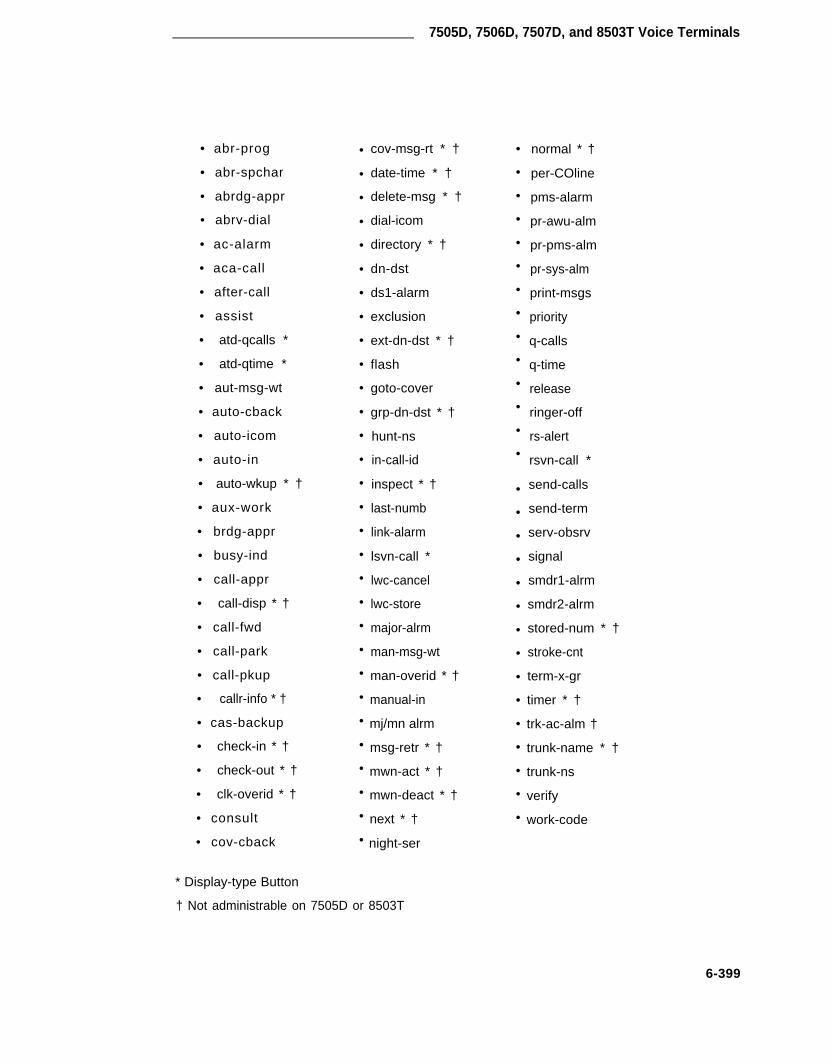
7505D, 7506D, 7507D, and 8503T Voice Terminals
• abr-prog
• abr-spchar
• abrdg-appr
• abrv-dial
• ac-alarm
• aca-call
• after-call
• assist
• atd-qcalls *
• atd-qtime *
• aut-msg-wt
• auto-cback
• auto-icom
• auto-in
• auto-wkup * †
• aux-work
• brdg-appr
• busy-ind
• call-appr
• call-disp * †
• call-fwd
• call-park
• call-pkup
• callr-info * †
• cas-backup
• check-in * †
• check-out * †
• clk-overid * †
• consult
• cov-cback
* Display-type Button
•
•
•
•
•
•
•
•
•
•
•
•
•
•
•
•
•
•
•
•
•
•
•
•
•
•
•
•
•
•
cov-msg-rt * †
date-time * †
delete-msg * †
dial-icom
directory * †
dn-dst
ds1-alarm
exclusion
ext-dn-dst * †
flash
goto-cover
grp-dn-dst * †
hunt-ns
in-call-id
inspect * †
last-numb
link-alarm
lsvn-call *
lwc-cancel
lwc-store
major-alrm
man-msg-wt
•
•
•
•
•
•
•
•
•
•
•
•
•
•
•
•
•
•
•
•
•
•
•
•
•
•
•
•
•
man-overid * †
manual-in
mj/mn alrm
msg-retr * †
mwn-act * †
mwn-deact * †
next * †
night-ser
normal * †
per-COline
pms-alarm
pr-awu-alm
pr-pms-alm
pr-sys-alm
print-msgs
priority
q-calls
q-time
release
ringer-off
rs-alert
rsvn-call *
send-calls
send-term
serv-obsrv
signal
smdr1-alrm
smdr2-alrm
stored-num * †
stroke-cnt
term-x-gr
timer * †
trk-ac-alm †
trunk-name * †
trunk-ns
verify
work-code
† Not administrable on 7505D or 8503T
6-399

CHAPTER 6. FORMS FOR SYSTEM FEATURES AND SERVICES
Figures showing the 7505D, 7506D, 7507D, and 8503T voice terminal button number assign-ments in relation to the button numbers on the voice terminal form are located at the end of thissection dealing with the 7500/8500 BRI voice terminals. The first three buttons are defaulted ascall appearance.
Page 3 of the Form
• Feature Button Assignments
The features and functions that can be assigned to the 7505D, 7506D, 7507D, and8503T voice terminal administrable buttons are the same as those listed for BUTTONASSIGNMENTS above.
Figures showing the 7505D, 7506D, 7507D, and 8503T voice terminal button numberassignments in relation to the button numbers on the voice terminal form are located atthe end of this section dealing with the 7500/8500 BRI voice terminals.
Page x of the Form (Data Module)
Applicable only to 7505D, 7506D, and 7507D Voice Terminals
• Only displayed if the Data Module field on Page 1 is “y.” Instructions are provided belowfor fields that require additional consideration because of the terminal type. Otherwiserefer to “Station Forms—Field Descriptions” salon in this chapter for associated fielddescriptions.
• Circuit Switched Data Attributes
Note: These fields represent defaults needed for modem pooling conversionresource insertion when the endpoint does not support data query capability.These fields have no significance for data modules providing data query [allAT&T-supported Basic Rate Interface data modules (7500B and ADM)]. ForAT&T BRI data modules, the default settings should be used.
Applicable only to 7505D, 7506D, and 7507D Voice Terminals
– Default Duplex— Used to identify the duplex mode. Valid entries are “full” or“half.” Default is “full.”
– Default Mode— Used to identify the data mode. Valid entries are “sync” (syn-chronous) or “async” (asynchronous). Default is “asyn.”
– Default Speed— Used to identify the data rate. Valid entries are “1200,” “2400,”“4800,” and “19200.” Default is “1200.”
Note: When default mode is “sync,” valid entries also include speeds of“56000” and “64000.”
6-400

7505D, 7506D, 7507D, and 8503T Voice Terminals
• Data Module Capabilities
Applicable only to 7505D, 7506D, and 7507D Voice Terminals
— Default lTC— Used to identify the Information Transfer Capability (restricted orunrestricted) when the ITC is not specified with the calling parameters (for exam-ple, when a BRI data module is the originator of an administered connection).Allowed values are restricted and unrestricted. Default is restricted.
— Default Data Applications— Used to identify mode to be used for originatingdata calls when the mode is not specified with the calling parameters. This modewill also be used for terminating trunk calls which do not have bearer capabilityspecified or administered connections. Possible mode values are M0 (mode 0),M1 (mode 1), M12 (mode 2), and M3/2 (mode 3/2 adaptable), or blank. Validentries are “M0,” “M1,” “M2_A,” “M2_S,” or “M3/2.” Default is “M2_A”
Page 1 of xSTATION
Extension: BCC: 0Type: Lock Messages: n COR : 1
Port: Security Code: COS : 1
Name: Coverage Path: _
FEATURE OPTIONSLWC Reception? msa-spe Coverage Msg Retrieval? y
LWC Activation? y Auto Answer? nSMDR Privacy? n Data Restriction? n
Redirect Notification? y Idle Appearance’ Preference? nBridged Call Alerting? n
Restrict Last Appearance? yData Module? n
XID? y Fixed TEI? n TEI: _MIM Support? y Endpt Init? y SPID: 300 MIM Mtce/Mgt? y
SCREEN 6-186. 7505D, 7506D, 7507D, and 8503T* Station Form (Page 1)—Example Only
Implementation Note:
The BCC field is only displayed if the ISDN-PRI option is enabled on the System-ParametersCustomer-Options form.
* The Data Module field is not displayed for the 8503T voice terminal.
When adding an unsupported station using the Enhanced Terminal Administration feature, if theFreed TEl field is set to “y,” the TEI field will be displayed.
The Endpt Init and MIM Mtce/Mgt fields are only displayed if the MIM Support field entry is “y.”
The SPID field is only displayed if the Endpt Init field entry is “y.”
6-401

CHAPTER 6. FORMS FOR SYSTEM FEATURES AND SERVICES
NON-SWITCH DATARoom:Jack:
Cable:
ABBREVIATED DIALINGList1:
BUTTON ASSIGNMENTS1: call-appr2: call-appr3: call-appr4:
Page 2 of xSTATION
Headset? n
List2: List3:
6:7:8:9:
10:
SCREEN 6-187. 7505D, 7506D, and 7507D Station Form (Page 2)—Example Only
Implementation Note:
For a 7505D or 7506D voice terminal, button 7 can be administered as a call appearance buttonif an ADM is not attached to the station. When an ADM is attached, the button acts as a DATAbutton regardless of whether or not the data module has been administered. If the ADM hasbeen administered, “DATA” will be displayed in the field and access to the field will also be res-tricted. If the station is aliased as a 7505D or 7505D via the Enhanced Terminal Administrationfeature, button 7 can be administered as a call appearance button whether or not an ADM isassigned. Button 7 is never used as a DATA button on the 7507D voice terminal. The 7507Dvoice terminal uses button 31 as a DATA button if an ADM is attached.
6-402

7505D, 7506D, 7507D, and 8503T Voice Terminals
NON-SWITCHRoom:Jack:
Cable:
ABBREVIATEDList1:
Page 2 of xSTATION
DATA
DIALINGList2:
Headset? n
List3 :
BUTTON ASSIGNMENTS1: call-appr2: call-appr3: call-appr
SCREEN 6-188. 8503T Station Form (Page 2)—Example Only
Page 3 of x
STATION
FEATURE BUTTON ASSIGNMENTS1: 4:2: 5:3: 6:
7:
SCREEN 6-189. 7505D and 7506D station Form (Page 3)—Example Only
6-403

CHAPTER 6. FORMS FOR SYSTEM FEATURES AND SERVICES
Page 3 of xSTATION
BUTTON ASSIGNMENTS11: 20:12: 21:
13: 22:
14: 23:
15: 24:
16: 25:
17: 26:
18: 27:
19: 28:29:
31:32:33: 37:
34: 38:
35: 39:
36: 40:
SCREEN 6-190. 7507D Station Form (Page 3)—Example Only
Implementation Note:
Button 31 can be administered as a feature button if an ADM is not attached to the station.When an ADM is attached, the button sots as a DATA button regardless of whether the datamodule has been administered. If the ADM has been administer, “DATA” will be displayed inthe field and the button will be restricted. If the station is aliased as a 7507D via the EnhancedTerminal Administration feature, button 31 can be administered as a feature button whether ornot an ADM is assigned.
6-404

7505D, 750SD, 7507D, and 8503T Voice Terminals
Page x of xSTATION
DATA MODULEData Extension:
Name: COR: 1 COS: 1
ABBREVIATED DIALINGList1:
SPECIAL DIALING OPTION: hot-lineHOT LINE DESTINATION
Abbreviated Dialing Dial Code (From above list): _
CIRCUIT SWITCHED DATA ATTRIBUTESDefault Duplex: full Default Mode: async Default Speed: 1200
DATA MODULE CAPABILITIESDefault ITC: restricted Default Data Application? M2 A
SCREEN 6-191. 7505D, 7506D, and 7507D BRl Data Module Form—Example Only
Implementation Note:
This page is only displayed if the Data Module field on Page 1 is “y.”
HOTLINE DESTINATION only displayed when “hot-line” is entered in the SPECIAL DIALINGOPTION field.
DEFAULT DIALING only displayed when “default” is entered in the SPECIAL DIALING OPTIONfield.
Abbreviated Dialing Dial Code only displayed when SPECIAL DIALING OPTION is “hot-line” or“default.”
6-405

CHAPTER 6. FORMS FOR SYSTEM FEATURES AND SERVICES
||||||||||||||||||
| || || || || || || ||HS|| || || || || || ||__|
| DISPLAY AREA (7506D only) || |
CA1 (1)CA2 (2)CA3 (3)
CA4 (4) CA8 ( 8)CA5 (5) CA9 ( 9)CA6 (6) CA1O(10)CA7 (7) F1 (1) / F4 (4)
F2 (2) / F5 (5)OTHER FIXED BUTTONS F3 (3) / F6 (6)
REDIAL / F7 (7)... DIAL PAD ...
||||||||||||||||||
Where: (.) represent the set button numberCA1, CA2, CA3... are call appearance buttons which
appear on page one of the station form.Fl, F2, F3... are the feature buttons.
Note: Buttons F4 through F6 are accessed by shifting buttonsF1 through F3. Button F7 is accessed by shifting fixedREDIAL button.
SCREEN 6-192. 7505D and 7506D Voice Terminal Feature Button Layout
6-406

7505D, 7506D, 7507D, and 8503T Voice Terminals
| ___ || | | | DISPLAY AREA A | || | | | | || | | | DISPLAY AREA B | || | | | | || | | || | | || | | CA1 (1) CA6 (6) CA1l (11) CA20 (20) || | | CA2 (2) CA7 (7) FIXED CA12 (12) CA21 (21) || | | CA3 (3) CA8 (6) BTNS . CA13 (13) CA22 (22) || | HS | CA4 (4) CA9 (6) CA14 (14) CA23 (23) || | | CA5 (5) CA1O (10) CA15 (15) CA24 (24) || | | CA16 (16) CA25 (25) || | | F2 (32) F7 (37) CA17 (17) CA26 (26) || | | F3 (33) F8 (38) .. KEYPAD .. CA18 (18) CA27 (27) || | | F4 (34) F9 (39) CA19 (19) CA28 (28) || | | F5 (35) F10 (40) MSG(63) REDIAL CA29 (29) || | | F6 (36) F1/DATA (31) CA30 (30) || | | || |
Where: (.) represent the set button numberCA1, CA2, ..., CA30 are call appearance buttons (2 lamp buttons)Fl, F2, F3... are the feature buttons (one LED).
Note: The 7507D terminal supports 31 buttons with two LEDs,however, the software will only support administrationof 30 of these as call appearance buttons (buttons CA1-CA30).The system maximum of 10 call appearance buttons still applies.Buttons CA1-CA30 which are not used as Call Appearance buttonscan be administered as Bridged Appearance buttons.
SCREEN 6-193. 7507D Voice Terminal Feature Button Layout
6-407

CHAPTER 6. FORMS FOR SYSTEM FEATURES AND SERVICES
Note: CA1, CA2, CA3 are call appearance buttons (2 lamp buttons)FIXED BTNS with 1 LED: PROG, MUTE, CONF, TRANSFIXED BTNS with no LED: REDIAL, DROP, HOLD, MEMORY
FIGURE 6-41. 8503T Voice Terminal Feature Button Layout
6-408

CHAPTER 7. REFERENCES
7-i

CHAPTER 7. REFERENCES
CHAPTER 7. REFERENCES
The following is an abbreviated listing of Generic 1 and System 75 documents. Included is a briefdescription of each document in the list. User instructions are also available for all terminalsused with the systems.
To order copies of any of these documents, refer to the address on the back of the title page.
Business Communications Systems Publications Catalog 555-000-010
Provides a list of publications that support AT&T business communications systems. Also pro-vides a brief description of each publication listed.
DEFINITY® Communications System and System 75 and System 85— 555-015-104Terminals and Adjuncts-Installation and Test
Provides procedures for installing and removing voice terminals (including Business Communica-tions Terminal built-in voice terminals) and adding modules and adjuncts to voice terminals. Alsoshows how to provide auxiliary power for voice terminals and associated modules and adjuncts.Provides references to other documents that contain step-by-step instructions for making cross-connections.
DEFINITY® Communications System and System 75 and System 85— 555-015-201Terminals and Adjuncts—Reference
Provides concise physical and functional descriptions of the peripheral equipment that can beused with DEFINITY Generic 3, DEFINITY Generic 2, System 75, and System 85. It is intendedas an aid for both AT&T and customer personnel in selecting appropriate components for thesesystems and in training and management.
DEFINITY® Communications System and System 75 and System 85— 555-025-101DS1/DMI/ISDN-PRl—Reference
Provides a broad but detailed description of the DS1 Tie Trunk Service, DMI, and ISDN-PRIfeatures. Introduces and defines concepts and terminology unique to DS1, DMI, and ISDN-PRI.Also includes applications, engineering procedures and considerations, cabling and connectionarrangements, administration requirements, restrictions and limitations, etc.
An Introduction to DEFINITY® Communications System Generic 3 555-230-020
Provides an overview of DEFINITY Generic 3. Major hardware components, such as the switch,terminals, and software applications, are described to provide an understanding of the system’sfunctional areas. Also provides an overview of System Management and data features and func-tions available with DEFINITY Generic 3.
7-1

CHAPTER 7. REFERENCES
Introduction to DEFINITY® Communications System 555-230-021Hospitality services
Provides an overview of DEFINITY Generic 3 Hospitality Services. Major hardware components,such as the system cabinet and terminals, are described to provide an understanding of thesystem’s functional areas. Also provides an overview of the hospitality features available with thesystem, as well as other voice, data, and System Management features.
DEFINITY® Communcations System Generic 1 and Generic 3i— 555-230-201Feature Description
Provides a technical description of the system features and parameters. For each feature, the fol-lowing information is provided:
• Limitations/considerations
• Feature interactions
• Administration requirements
• Hardware and software requirements
DEFlNITY® Communications System Generic 3— 555-230-202Pocket Reference
Provides the reader with a quick, pocket-sized reference to the benefits, requirements, limita-tions, parameters, features, and circuit packs associated with the system.
DEFINITY® Communications System Generic 1 and Generic 3— 555-230-600Planning and Configuration
Provides information be used by the Account Team to determine the customer% requirementsand to collect the information needed to estimate system hardware requirements.
DEFINITY® Communications System Generic 1 and Generic 3—Console 555-200-700Operations
Provides “how-to-operate” instructions for the attendant console. Serves as a reference whendefining the console control keys and Incoming Call Identification requirements.
DEFINITY® Communications System Generic 1 and Generic 3— 555-230-701Voice Terminal Operations
Describes all the voice features and provides the “how-to-operate” instructions for each voice ter-minal. Serves as a training guide for system users.
DEFINITY® Communications System Generic 1 and Generic 3— 555-230-722Automatic Call Distribution—Agent Instructions
Provides information for use by agents after training is completed. The various ACD features aredescribed and the procedures for using them are provided in this document.
7-2

CHAPTER 7. REFERENCES
DEFINITY® Communications System Generic 1 and Generic 3— 555-230-723User’s Guide—Hospitality Operations
Contains procedures for using the Hospitality Services of DEFINITY Generic 1 and Generic 3.These services include a group of system-based features that support the lodging and healthindustries.
DEFINITY® Communications System Generic 1 and Generic 3— 555-230-734Automatic Call Distribution—Supervisor Instructions
Provides information for use by supervisors after training is completed. The various ACDfeatures are described and the procedures for using them are provided in this document.
DEFINITY® Communications System Generic 1 and Generic 3i— 555-230-104installation and Test
Provides the information necessary to perform the tasks of installing and testing the system’scommon equipment. Includes a description of the necessary tools and equipment.
DEFINITY® Communications System Generic 1 and Generic 3i— 555-204-105Maintenance
Provides the information necessary for monitoring, testing, and maintaining DEFINITY Generic 1and Generic 3i. It is intended to cover many of the faults and troubles that can occur in the sys-tem.
DEFINITY® Communications System Generic 1 and Generic 3i— 555-204-106Upgrades and Additions
Provides procedures and information required to upgrade a DEFINITY G1.1 to a DEFINITY Gen-eric 3i system and make additions to an operational system, after the initial switch installation.
DEFINITY® Communications System Generic 1 and Generic 3i— 555-204-111Wiring
Provides an overview of the DEFINITY Generic 1 and Generic 3i wiring plan.
DEFINITY® Communications System Generic 1 and Generic 3i— 555-230-200System Description
Provides a technical description of the system and its hardware, environmental and spacerequirements, and parameters. Also provides a brief description of features and services.
INTERNATIONAL DEFINITY® Communications System Generic 1— 555-204-440Supplemental Information
Provides information on enhancements to the DEFINITY Communications System Generic 1 forinternational applications.
7-3

CHAPTER 7. REFERENCES
DEFINITY® Communications System Generic- 555-230-499Capabilities
Provides a description of the new capabilities, features, and enhancements available on DEFIN-ITY Generic 3 systems that were not available on DEFINITY Generic 1.1 systems.
DEFINlTY® Communications System Generic 3i- 555-230-650/650BImplementation
Provides the procedures and associated forms for collecting system and terminal software infor-mation for G3i systems. Also describes various administration commands and error messages.This information is used to initialize the system using the System Access Terminal.
DEFINITY® Communications System Generic 1 and Generic 3- 555-230-703Basic Call Management System Operations
Describes all the features and provides the “how-to-operate” instructions for the Basic CallManagement System (BCMS) feature.
DEFINITY® Communications System Generic 1 and System 75- 555-209-013Application Notes—Automatic Call Distribution
Describes in detail the ACD feature of System 75 R1V3 and DEFINITY Generic 1 systems. Alsodescribed are the associated “embedded” features (such as lntraflow/lnterflow, Queue StatusIndications, Agent Call Handling, etc.) required for efficient operation and use of the ACD feature.
DEFINITY® Communications System Generic 1 and System 75- 555-209-017Application Notes—7400B Data Module
Provides guidelines for administering the 7400B Data Module in DEFINlTY® Communications Sys-tem Generic 1.2.
DEFINITY® Communications System Generic 1 and Generic 3—System 555-230-500Management
Describes G3 terminal types, function keys, and other G3 terminal operations. Also describesvarious administrative tasks such as logon and logoff, changing of password, remote administra-tion, etc.
DEFINITY® Communications System Generic 1 and Generic 3i- 555-204-510System Reports
Explains switch-based measurement, traffic, performance, and summary reports. Descriptionsinclude the overall purpose and uses for each report, complete definitions for each field, correla-tions with other reports, and possible actions that can be taken to further diagnose situations andremedy unsatisfactory conditions.
7-4

CHAPTER 7. REFERENCES
AT&T ISDN Gateway Release 1 Version 2 585-245-201Pianning and Application Development
Provides a description of the AT&T ISDN Gateway and information on how to plan for it. It alsocontains information on ISDN Gateway interfaces that can be used for software applicationdevelopment.
7-5

CHAPTER 8. ABBREVIATIONS AND ACRONYMS
8-i

CHAPTER 8. ABBREVIATIONS AND ACRONYMS
CHAPTER 8. ABBREVIATIONS AND ACRONYMS
AARACACAACDACUACWADADUAEAIMALM-ACKAMWANANIAPAPLTARSASAIASCIIATBATDAUDIXAVDAWT
BCCBCMSBCTBHCCBLFBOSBRIBTU
CACRCAGCAMACARR-POWCASCA-TSCCBCCCCClSCCITTCCMSCCSCCSA
Automatic Alternate RoutingAlternating CurrentAutomatic Circuit AssuranceAutomatic Call DistributionAutomatic Call UnitAfter Call WorkAbbreviated DialingAsynchronous Data UnitAccess EndpointAsynchronous Interface ModuleAlarm AcknowledgeAutomatic Message WaitingAnalogAutomatic Number IdentificationApplications ProcessorAdvanced Private Line TerminationAutomatic Route SelectionAdjunct Switch Applications InterfaceAmerican Standard Code for Information InterchangeAll Trunks BusyAttention DialAudio Information ExchangeAlternate Voice DataAverage Work Time
Bearer Capability ClassBasic Call Management SystemBusiness Communications TerminalBusy Hour Calls CompletionsBusy Lamp fieldBit Oriented SignalingBasic Rate InterfaceBritish Thermal Unit
Cancellation of Authorization Code RequestCoverage Answer GroupCentralized Automatic Message AccountingCarrier Port and Power Unit for AC Powered systemsCentralized Attendant ServiceCall Associated Temporary Signaling ConnectionCall-by-CallCountry CodeCommon Channel Interoffice SignalingConsultative Committee for International Telephone and TelegraphCommon Channel Message SetHundred Call SecondsCommon Control Switching Arrangement
8-1

HAPTER 8. ABBREVIATIONS AND ACRONYMS
CDMCDOSCDRRCDRUCEMCICMDRCMSCOCORCOSCPCPECPN/BNCPTRCRCCSACSDCSMCSUCTSCWC
DACDCDCEDCPDCSDDCDDDDIDDLCDLDMDMIDNDDNISDODDOSSDOTDS1D S IDSUDTDMDTEDTGSDTMFDXS
E&MEBCDIC
Channel Division MultiplexingCustomer-Dialed and Operator ServicedCall Detail Recording and ReportingCall Detail Recording UtilityChannel Expansion MultiplexClock InputCentralized Message Detail RecorderCall Management SystemCentral OfficeClass of RestrictionClass of ServiceCircuit PackCustomer Provided EquipmentCalling Party Number/Billing NumberCall Progress Tone ReceiverCyclical Redundancy CheckingCanadian Safety AssociationCustomer Service DocumentCentralized System ManagementChannel Service UnitClear to SendCall Work Codes
Direct Agent CallingDirect CurrentData Communications EquipmentDigital Communications ProtocolDistributed Communications SystemDirect Department CallingDirect Distance DialedDirect Inward DialedData Line CircuitData Line Data ModuleDigital Multiplexed InterfaceDo Not DisturbDialed Number Identification ServiceDirect Outward DialedDelivery Operations Support SystemDuplication Option TerminalData Services Level 1Digital Service InterfaceData Service UnitDigital Terminal Data ModuleData Terminal EquipmentDirect Trunk Group SelectDual Tone MultifrequencyDirect Extension Selection
Ear and Mouth (Receive and Transmit)Extended Binary Coded Decimal Interchange Code
8-2

CHAPTER 8. ABBREVIATIONS AND ACRONYMS
ECCEIEIAEMIEPNEPROMEPSCSESFETN
FACFASFATFCCFEACFICFNPAFRLFX
GPTRGRS
HNPA
IASICICCICDOSICHTICIICMIDDDIEINADSINSINWATSISDNISNITPIXC
KBPS
LANLAPDLATALDNLDSLED
Error Correct CodeExpansion InterfaceElectronic Industries AssociationElectro-Magnetic InterferenceExpansion Port NetworkErasable Programmable Read Only MemoryEnhanced Private Switched Communications ServicesExtended Superframe FormatElectronic Tandem Network
Feature Access CodeFacility Associated SignalingFacility Access Trunk TestFederal Communications CommissionForced Entry of Account CodesFacility Interface CodesForeign Numbering Plan AreaFacility Restriction LevelForeign Exchange
General Purpose Tone ReceiverGeneralized Route Selection
Home Numbering Plan Area Code
inter-PBX Attendant ServiceInter-CabinetInter Carrier CableInternational Customer Dialed Operator ServicedIncoming Call Handling TableIncoming Call IdentifierInbound Call ManagementInternational Direct Distance DialingInformation ElementInitialization and Administration SystemISDN Network ServiceInward Wide Area Telephone ServiceIntegrated Services Digital NetworkInformation Systems NetworkInstallation Test ProceduresInter-Exchange Carrier Code
Kilo-Bits Per Second
Local Area NetworkLink Access Procedure DataLocal Access and Transport AreaListed Directory NumberLong-Distance ServiceLight-Emitting Diode
8-3

CHAPTER 8. ABBREVIATIONS AND ACRONYMS
LSULWC
MA-UUIM-BusMBPSMCCMCSMDMMDRMETMIMMISMISCIDMMSMOSMSMSAMPDMMTDMMTPMTTMWL
NANPNAUNCA/TSCNCOSSNCSONECNFASNIDNNNPANPENQCNSENSUNXX
OAOCMOPSOQTOSHAOSSOTQ
PBXPC
Local Storage UnitsLeave Word Calling
Message Associated User-to-User SignalingMemory BusMega-Bits Per SecondMulti-Carrier CabinetMessage Center ServiceModular Data ModuleMessage Detail RecordMultibutton Electronic TelephoneManagement Information MessageManagement Information SystemMiscellaneous IdentificationMaterial Management ServicesMessage Oriented SignalingMessage ServerMessage Servicing AdjunctModular Processor Data ModuleModular Trunk Data ModuleMaintenance Tape ProcessorMulti-Tasking TerminalMessage Waiting Lamp
North American Numbering PlanNetwork Access UnitNon-Call Associate/Temporary Signaling ConnectionNetwork Control Operations Support CenterNational Customer Support OrganizationNational Engineering CenterNon-Facility Associated SignalingNetwork Inward DialingNational NumberNumbering Plan AreaNetwork Processing ElementNumber of Queued CallsNight Service ExtensionNetwork Sharing UnitPublic Network Office Code
Operator AssistedOutbound Call ManagementOff-Premises StationOldest Queued TimeOccupational Safety and Health ActOperations Support SystemOutgoing Trunk Queuing
Private Branch ExchangePersonal Computer
8-4

CHAPTER 8. ABBREVIATIONS AND ACRONYMS
PCOLPCOLGPCMPCSPDMPDSPEPECPEIPGNPIPIBPLPMSPNPPMPPNPRIPSCPSDNPT
RAMRBSRCLRHNPARLTRNXROMRPNRSC
SABMSAKISATSCCSCISCOSDDNSDNSIDSITSMDRSPESPIDSSIST3STARLANSVNSXS
Personal Central Office LinePersonal Central Office Line GroupPulse Code ModulatedPermanent Switched CallsProcessor Data ModulePremises Distribution SystemProcessing ElementPrice Element CodesProcessor Element InterchangePartitioned Group NumberProcessor InterfaceProcessor Interface BoardPrivate LineProperty Management SystemPort NetworkPeriodic Pulse MeteringProcessor Port NetworkPrimary Rate InterfacePremises Service ConsultantPacket Switch Public Data NetworkPersonal Terminal
Random Access MemoryRobbed-Bit SignalingRestricted Call ListRemote Home Numbering Plan AreaRelease Link TrunkPrivate Network Office CodeRead Only MemoryRouting Plan NumberRegional Support Center
Set Asynchronous Balance ModeSanity and Control InterfaceSystem Access TerminalSingle Carrier CabinetSwitch Communications InterfaceSystem Control OfficeSoftware Defined Data NetworkSoftware Defined NetworkStation Identification NumberSpecial Information TonesStation Message Detail RecordingSwitch Processing ElementService Profile IdentifierStandard Serial InterfaceStratum 3 Clock BoardStar-based Local Area NetworkSecurity Violation NotificationStep-by-Step
8-5

CHAPTER 8. ABBREVIATIONS AND ACRONYMS
TAASTACTCTCMTDMTDRTEGTEITODTOPTSCTTR
TTTNTTY
UAPUCDUCLUDPULUNPUPSUSOP
VDNVLSIVM
WATSWSA
ZCS
Trunk Answer From Any StationTrunk Access CodeTechnical ConsultantTraveling Class MarkTrunk Data ModuleTime of Day RoutingTerminating Extension GroupTerminal Endpoint IdentifierTime of DayTask Oriented ProtocolTechnical Service CenterTouch Tone ReceiverTerminating Trunk TransmissionTandem Tie Trunk NetworkTeletypewriter
Usage Allocation PlanUniform Call DistributionUnrestricted Call ListUniform Dial PlanUnderwriter LaboratoriesUniform Numbering PlanUninterruptible Power SupplyUser Service Order Profile
Vector Directory NumberVery Large Scale IntegrationVoltmeter
Wide Area Telecommunications ServiceWaiting Session Accept
Zero Code Suppression
8-6

CHAPTER 9.GLOSSARY
9-i

CHAPTER 9. GLOSSARY
CHAPTER 9. GLOSSARY
A
Across Code
A 1-, 2-, or 3-digit dial code used to activate or cancel a feature or access an outgoingtrunk. The [*] and [#] can be used as the first digit of an access code.
Access Endpoint
Either a non-signaling channel on a DS1 interface or a non-signaling port on an AnalogTie Trunk circuit pack that is assigned a unique extension.
Access Tie Trunks
Tie trunk used to handle normal ETN calls between Main and Tandem switches.
ACD Split
An ACD split is a UCD/DDC hunt group in a system where ACD has been optioned bythe customer and the hunt group has been administered as used for ACD. ACD Splitsare capable of being measured, that is, data concerning the split and its members’ statuswill be sent to the CMS.
Adjunct
Any processor connected to the switch and capable of controlling certain functionalities.
Adjunct-Controlled Split
An ACD split that is administered to be under adjunct control. Login to such split is underadjunct control. When an ACD agent is logged into an adjunct-controlled split, the ACDagent’s voice set is locked.
Adjunct-Switch Application Interface
An ISDN interface to adjuncts that permits the adjuncts to establish and control calls,access switch features, and query the information about certain switch resources.
Administer
To access and change the parameters associated with the services or features of thesystem.
Administered Connection
An end-to-end connection between two access endpoints or two data modules that isautomatically established whenever the system is restarted or the administered connec-tion is administered and the Administered Connection is due to be active.
9-1

CHAPTER 9. GLOSSARY
Agent
An agent is a member of a hunt group. The term “ACD agent” is used to specify that thehunt group in question is an ACD split.
Alphanumeric Dialing
Allows a terminal user to place a data call using Data Terminal Dialing (see Data CallSetup feature) and an alphanumeric dialing string or alpha name for the call destinationaddress.
Announcements
Announcements are prerecorded messages that give the caller information. If the firstannouncement given to a caller is played before the call is queued to any split, it is aForced First Announcement.
Answer-Back Code
A code dialed to retrieve a parked call.
Answer Supervision
Answer supervision is a signal, sent from the switch to the sewing CO, that tells the COto begin recording toll charges for a call. However, while a call waits in queue, AT&TACD software often delays sending answer supervision so that the ACD owner/operatoror caller can avoid excessive toll charges. Call vectoring commands work in a similarmanner, several steps behave differently depending on whether answer supervision hasbeen supplied. The Call Vectoring commands that most notably affect or depend uponanswer supervision are the announcement, busy, disconnect, and wait commands.
Appearance
See Call Appearance.
Applications Processor
A minicomputer used to support several user-controlled applications such as trafficanalysis and electronic documentation.
ARWAAR Digit Conversion
ARS Digit Conversion replaces the initial digits of a number dialed after the ARS accesscode (or of a call crossed over from AAR) with another digit string. The call is thenrouted as if the modified digits were dialed after the AAR access code.
AAR Digit Conversion replaces the initial digits of a number dialed after the AAR accesscode with another digit string. The call is then routed as if the modified digits were dialedafter the AAR access code.
9-2

CHAPTER 9. GLOSSARY
ASAI Adjunct
Any adjunct that makes use of the ASAl protocol, including adjuncts that perform ICMfunctions.
Asynchronous Data Transmission
A scheme for transmitting data where each character is preceded by a start bit and fol-lowed by a stop bit, thus permitting data elements to occur at irregular intervals. Thistype transmission is advantageous when transmission is not regular (characters typed ata keyboard).
Asynchronous Data Unit (ADU)
A DCE type device that allows direct connection between EIA 232C equipment and thesystem digital switch.
Attendant
The operator of the Attendant Console. Individual who handles the processing of varioustypes of internal, incoming, and outgoing calls. May also manage and monitor some ofthe System’s operations.
Attendant Console
An electronic call-handling position with pushbutton control. Used by attendants toanswer and place calls and to manage and monitor some of the system operations. Twoconsole types are supported; Basic Attendant Console (301A) and Enhanced AttendantConsole (302A).
Audio Information Exchange (AUDIX)
A unit that provides voice mail service to users.
Authorization Codes
Authorization Codes have three purposes. First, certain trunk groups that receive incom-ing calls can be administered to require authorization codes for incoming calls.Secondary, Remote Access to PBX Services users can be required to enter an authoriza-tion code instead of, or in addition to, a barrier code when accessing local PBX facilities.Lastly, they can be used for re-routing ARS/AAR calls that were blocked because thedefault FRL was not high enough to continue routing.
Auto-In
Auto-In is an ACD agent work mode that makes the agent available to receive calls andallows the agent to receive a new ACD call immediately after disconnecting from the pre-vious call.
9-3

CHAPTER 9. GLOSSARY
Automatic Alternate Routing (AAR)
Used to route calls over alternate private and public network facilities in the order ofpreference specified by the customer. The preference order is specified by translating agroup of trunks into a routing pattern that is used for calls to a particular network location.AAR also provides privilege checking that allows the customer to restrict access to partic -ular trunk groups to a limited set of users. This is done by comparing the Facility Restric-tion Level (FRL) of the calling party with the FRL of the particular routing pattern entry.
Automatic Call Distribution (ACD)
Automatic Call Distribution (ACD) provides automatic termination of incoming calls toagents that have been administered into hunt groups called splits. Calls are distributedaccording to the algorithm selected by the customer, either UCD or DDC.
Automatic Route Selection (ARS)
ARS provides automatic routing of outgoing calls over customer trunk facilities with tran-sparent access to an IXC based on the DDD number. Alternate trunk groups areselected during peak demand periods when the primary trunk groups are busy. Thealternate trunk groups are selected in decreasing order of preference for making thecalls.
Automatic Route Selection Partitioning
ARS Partitioning provides for up to eight different user groups having access to their ownor shared trunk groups in ARS patterns.
Automatic Trunk
A trunk that does not require the sending or receiving of digits. The destination ispredetermined. A request for service on the trunk (called a seizure) is sufficient to routethe call. The normal destination of an automatic trunk is the system attendant group.
Automatic Restoration
A service that restores disrupted connections between access endpoints (non-signalingtrunks) and data endpoints (devices that connect the switch to dataterminal/communications equipment). This restoration is achieved within seconds of aservice disruption so that critical data applications can remain operational.
Auxiliary Work
Auxiliary Work is an ACD agent work mode that makes the agent unavailable to receiveany ACD calls for the specified split. It is used when an agent is performing non-ACDrelated activities such as going on a break.
Available Agent
An ACD agent is considered available to receive a call through an ACD split if logged inand not on a call, and in the Auto-In or Manual-In mode.
9-4

CHAPTER 9. GLOSSARY
B
Barrier Code
A security code used with the Remote Access feature to prevent unauthorized access tothe system.
Basic Call Management System (BCMS)
The Basic Call Management System (BCMS) provides traffic reports for ACD. Thereports are a subset of the adjunct CMS applications.
Bearer Capability Class (BCC)
The Bearer Capability Class (BCC) identifies the type of a call, for example, voice anddifferent types of data. Determination of BCC is based on the call originator’s charac-teristics for non-lSDN endpoints and on signaling in the D-channel for ISDN endpoints.There are five BCCs (0 to 4), based on voice and data Modes 0, 1, 2, 3 capabilities.
Bit (Binary Digit)
One unit of information in binary notation (having two possible states or values, 0 or 1 ).
Bridge (Bridging)
The appearance of a voice terminal’s extension at one or more other voice terminals.
Bridged Appearance
A call appearance on a voice terminal that matches a call appearance on another voiceterminal for the duration of a call.
Buffer
A circuit or component that isolates one electrical circuit from another. Typically, a bufferholds data from one circuit or process until another circuit or process is ready to acceptthe data.
Bus
A multi-conductor electrical path used to transfer information over a common connectionfrom any of several sources to any of several destinations.
Bus, Time Division Multiplex
See Time Division Multiplex Bus.
Business Communications Terminals
An advanced series of semi-intelligent terminals.
9-5

CHAPTER 9. GLOSSARY
Bypass Tie Trunks
One-way, outgoing tie trunks from a Tandem switch to a Main switch in an ETN. Thesetrunks, provided in limited quantities, are used as a “last-choice” route when all trunks toanother Tandem switch are busy. Bypass tie trunks are used only if all applicable inter-tandem trunks are busy.
Byte
A sequence of bits, eight bits long, that is usually shorter than a word. A word is 16 bitslong.
C
Call Appearance, Attendant Console
Six buttons, labeled a through f, used to originate, receive, and hold calls. Each buttonhas two associated lamps to show the status of the call appearance.
Call Appearance, Voice Terminal
A button labeled with an extension number used to place outgoing calls, receive incomingcalls, or hold calls. Two lamps next to the button show the status of the call appearanceor status of the call.
Call Classification
The function of receiving and/or detecting call progress tones and call outcaling (ringing,busy, answered) and notifying the adjunct responsible for recoding the call status. Callclassification may be done by the switch automatically or done by the user listening tocall progress tones.
Call Management System (CMS)
An adjunct processor that collects data from an ACD and generates reports to be storedor displayed concerning status of agents, splits, and trunks.
Callback Call
A call that is automatically returned to a voice terminal user who activated the AutomaticCallback or Ringback Queuing feature.
Call Vector
A set of up to 15 vector commands to be performed for an incoming or internal call.
Call Vectoring
A flexible call handling method of managing incoming calls that gives unique treatment toa particular call type based on dialed number or trunk terminating to a vector. Vectorcommands dictate the treatment given to callers.
9-6

CHAPTER 9. GLOSSARY
Call Vector Step
Vectors are made up of 15 steps that are processed sequentially unless a “GoTo” vectorcommand is encountered or vector processing stops.
Call Waiting Ringback Tone
A low-pitched tone identical to the ringback tone except the tone decreases the last 0.2second. This tone notifies the attendant that the Attendant Call Waiting feature has beenactivated and that the called user is aware of the waiting call.
Call Work Code
A number, up to 16 digits, entered by ACD agents to record the occurrence of customer-defined events (such as account codes, social security numbers, or phone numbers) onACD calls.
Central Office (CO)
The location housing telephone switching equipment that provides local telephone ser-vice and access to toll facilities for long-distance calling.
Central Office Codes
The first three digits of a 7-digit public network telephone number. These codes are. typi-cally numbered from 200 through 999.
Central Office Trunk
A telecommunications channel that provides access from the system to the public net-work through the local CO.
Channel
A communications path for transmitting voice and data.
Circuit Pack Vintage
The vintage of a circuit pack is a numeric tag to identify the Read Only Memory thatresides on that pack. It is used to facilitate record keeping and maintainability.
Class of Restriction (COR)
A number (0 through 63) that specifies the restrictions assigned to voice terminals, voiceterminal groups, data modules, and trunk groups.
Class of Service (COS)
A number (0 through 15) that specifies if voice terminal users can activate the AutomaticCallback, Call Forwarding—All Calls, Data Privacy, or Priority Calling features.
9-7

CHAPTER 9. GLOSSARY
Common Control Switching Arrangement (CCSA)
A private telecommunications network using dedicated trunks and a shared switchingcenter for interconnecting company locations.
Confirmation Tone
Three short bursts of tone followed by silence; indicates that the feature activated, deac-tivated, or canceled has been accepted.
Console
See Attendant Console.
Controlled Outward Restriction
A calling party with this feature activated is restricted from dialing outgoing exchange net-work calls. Restricted calls are routed to the attendant, coverage, or intercept.
Controlled Restrictions
The controlled restrictions are distinct from the calling and called restrictions admin-istered through the COR. Controlled Restrictions are activated by an attendant or by astation with the “Console Permission” COS. The controlled restrictions are activated foran individual terminal or for a predefine group of terminals. The COR is used to pre-define a group of terminals.
Controlled Station-to-Station Restriction
A calling patty or called party with this feature activated is restricted from placing orreceiving station-to-station calls. Restricted calls are routed to the attendant, coverage,or intercept.
Controlled Termination Restriction
A called party with this feature activated is restricted from receiving any calls. Restrictedcalls are routed to the attendant, coverage, or intercept. This form of controlled restric-tion is used in the Do Not Disturb feature to prevent termination to a user. It may beoverridden only by a priority call.
Controlled Total Restriction
A calling party or called party with this feature activated is restricted from placing orreceiving any calls. DID or APLT calls to a station with Controlled Total Restriction activeare routed to the attendant or to a recorded announcement. All other calls are routed tointercept.
Coverage Answer Group
A group of up to eight voice terminals that ring simultaneously when a call is redirected toit by Call Coverage. Any one of the group can answer the call.
9-8

CHAPTER 9. GLOSSARY
Coverage Call
A call that is automatically redirected from the called party’s extension number to analternate answering position when certain coverage criteria are met.
Coverage Path
The order in which calls are redirected to alternate answering positions.
Coverage Point
The attendant positions (as a group), DDC group, UCD group, Coverage Answer Group,a voice terminal extension, or Message Center Hunt Group designated as an alternateanswering position in a coverage path.
Covering User
The person at an alternate answering position who answers a coverage call.
D
Data Channel
A communications path between two points used to transmit digital signals.
Data Communications Equipment (DCE)
The equipment on the network side of a communications link that provides all the func-tions required to make the binary serial data from the source or transmitter compatiblewith the communications channel.
Data Endpoint
Data Endpoints refer to the various DTE and DCE that are connected to the System.They are associated with an extension. In the switching environment, they can be analogor digital endpoints serving as the interface between a host computer port and the switch,or between a data network and the switch.
Data Terminal Equipment (DTE)
Equipment comprising the source or link of data, or both, that also provides communica-tion control functions (protocol). DTE is any piece of equipment at which a communica-tions path begins or ends.
D-Channel Pair
Refers to a pair of D-Channels, where one is designated as the primary D-Channel, andthe other is the secondary D-Channel.
9-9

CHAPTER 9. GLOSSARY
Distributed Communication System (DCS)
A private network of distributed switches linked together with private trunks and datalinks.
Default Dialing
Enhances Data Terminal Dialing by allowing a data terminal user to place a data call to apre-administered destination by simply entering a carriage return at the “DIAL” prompt.(See Data Call Setup—Chapter 4.)
Delay-Dial Trunk
After a request for service (called a seizure) is detected on an incoming trunk, the systemsends a momentary signal followed by a steady tone over the trunk. This informs the cal-ling party that dialing can start. This type of trunk allows dialing directly into the system.That is, the digits are received as they are dialed.
Designated Voice Terminal
The specific voice terminal to which calls, originally directed to a certain extensionnumber, are redirected. Commonly used to mean the “forwarded-to” terminal when CallForwarding All Calls is active.
Dialed Number Identification Service
Provides an indication (display) to the answering agent of the service (or project) ornumber called by the caller so that agents grouped in one split may answer callsappropriately for many different services.
Digital Communications Protocol (DCP)
Defines the capability for providing simultaneous voice and data transmission over thesame channel.
Digital Data Endpoints
Digital data endpoints include the following:
• 510D Personal Terminal or 515-Type Business Communications Terminal
• 7404D Terminals
• 7406D or 7407D Equipped With Optional Data Module Base
• Asynchronous Data Units
• Digital Terminal Data Modules
• (Modular) Processor Data Modules
9-10

CHAPTER 9. GLOSSARY
• (Modular) Trunk Data Modules
• 3270 Data Modules
• Internal Data Channels.
Digital Multiplexed Interface (DMI)
Specifies the remote interface requirements for multiplexed data communicationsbetween a host computer and a private switching system.
Digital Terminal Data Module (DTDM)
An adjunct to Model 7403D or 7405D voice terminals. Provides the required interfacebetween the system and a data terminal such as a 513 Business Communications Termi-nal.
Digital Trunk
A circuit in a telecommunications channel designed to handle digital voice and data.
Digit Conversion
A process used to convert specific dialed numbers into other dialed numbers. ARS usesDigit Conversion to convert public network numbers (ARS) to private network numbers(AAR) in order to save toll charges. AAR uses Digit Conversion to convert private net-work numbers (ARS) to other private or public network numbers (AAR).
Direct-Agent Calls
A special type of ACD call directed to a particular agent, rather than any available agentin the split.
Direct Agent Calling (DAC)
An entry is provided in the COR to allow originating and receiving of direct-agent calls. Adirect-agent call is a special type of ACD call directed to a particular agent, rather thanany available agent in the split.
A calling party that is DAC restricted is denied the ability to originate direct-agent calls. Acalled party that is DAC restricted is denied the ability to receive direct-agent calls. Res-tricted calls are routed to intercept.
Direct Extension Selection (DXS)
An option at the attendant console that allows an attendant direct access to voice termin-als by pressing a Group Select button and a DXS button.
Distributed Communications System (DCS)
The Distributed Communications System is a private network of distributed switcheslinked together with trunks to form a DCS complex. The switches in the complex areconnected with data links that allow call processing information to be passed from one
9-11

CHAPTER 9. GLOSSARY
switch to another. This provides feature transparency so that certain features are per-ceived by users to be the same whether they are talking to a station served by the sameswitch or to a station on a different switch in the complex.
Data Services Level 1 (DS1)
A DS1 trunk multiplexes up to twenty-four 64 kbps digital channels over a 4-wire inter-face for data or voice. The 64 kbps capacity is achieved by having 8000 frames of eightbit data per second. This trunk can be used as a timing reference for the switch or by anexternal Stratum 3 clock.
E
Electronic Tandem Network (ETN)
A special tandem tie trunk network that has automatic call routing capabilities based onthe number dialed and most preferred route available at the time the call is placed. Eachswitch in the network is assigned a unique private network office code (RNX) and eachvoice terminal is assigned a unique extension number.
End-to-End Signaling
The transmission of touch-tone signals generated by dialing from a voice terminal user toremote computer equipment. A connection must first be established over an outgoingtrunk from the calling party to the computer equipment. Then additional digits can bedialed to transmit information to be processed by the computer equipment.
Enhanced Private Switched Communications Service (EPSCS)
A private telecommunications network that provides advanced voice and data telecom-munications services to companies with many locations.
Expansion Interface (El)
Used to connect an EPN to the PPN TDM Bus and provide connectivity between theTDM Buses on the PPN and EPNs. This circuit pack carries synchronization informationbetween the two cabinets that it connects and also provides connectivity between thepacket buses on the PPN and EPNs.
Expansion Port Network (EPN)
A cabinet that contains port circuit packs but no processor. Up to two EPNs may be con-nected to a PPN.
Extension Number
A 1- to 5-digit number assigned to each voice terminal, certain system groups, datamodules, and various other facilities on the switch. The number is used in call process-ing to access the facilty.
9-12
CHAPTER 9. GLOSSARY
External Call
A connection between a system user and a party on the public telephone network or on atie trunk.
F
Facility
A general term used for the telecommunications transmission pathway and associatedequipment.
Facility Restriction Level (FRL)
The Facility Restriction Level (FRL) is used to determine the accessibility of a user trunkgroups in a routing pattern. When searching for a routing pattern, the originator’s FRLmust be greater than or equal to the FRL for the accessed trunk group.
FAS/NFAS
Facility-Associated Signaling (FAS)—describes the type of signaling in which an ISDNDS1 interface D-Channel carries signaling information for only those B-Channels locatedon the same DS1 facility as the D-Channel.
Non-Facility Associated Signaling—describes the type of signaling in which an ISDN DS1interface D-Channel carries signaling information on one DS1 facility for B-Channelslocated on another DS1 facility.
Feature
A specifically defined function or service provided by the system.
Feature Button
A labeled button on a voice terminal or attendant console designating a specific feature.
Foreign Exchange (FX)
A CO other than the one providing local access to the public telephone network.
Foreign Exchange Trunk
A telecommunications channel that directly connects the system to a central office otherthan its local central office.
Foreign Numbering Plan Area Code (FNPA)
An area code other than the local area code. The foreign area code must be dialed tocall outside the local geographical area.
9-13

CHAPTER 9. GLOSSARY
G
Ground-Start Trunk
On outgoing calls, the system transmits a request for services to the distant switchingsystem by grounding the trunk ring lead. When the distant system is ready to receive thedigits of the called number, that system grounds the trunk tip lead. When the systemdetects this ground, the digits are sent. (Tip and ring are common nomenclature to dif-ferentiate between ground-start trunk leads.) On incoming calls, detection of ground onthe ring lead is sufficient to cause the call to route to a predetermined destination, nor-mally the system attendant group. No digits are received.
H
Handshaking Logic
A format used to initiate a data connection between two data module devices.
Home Numbering Plan Area Code (HNPA)
The local area code. The area code does not have to be dialed to call numbers withinthe local geographical area.
Hospitality
Hospitality features, such as Automatic Wakeup and Do Not Disturb, are those requiredfor the administration of stations considered to be “guests” or “clients” of the customer.Additionally, these features allow the customer to connect the System to a PMS, which isused to collect and manage guest room information.
Hospitality Parameter Reduction
Provides the user with a reduced set of system parameters. Namely, the number oftrunks, number of hunt-groups, number of pick-up groups and the number of coveragepaths.
Host
A customer processor that, when connected to the switch using ASAI, for example, isconsidered an adjunct.
Hunt Group
A group of stations which answer calls that are distributed using a routing algorithm. AnACD split is a special type of hunt group.
9-14
CHAPTER 9. GLOSSARY
I
Immediate-start Tie Trunk
After establishing a connection with the distant switching system for an outgoing call, thesystem waits a nominal 65 milliseconds before sending the digits of the called number.This allows time for the distant system to prepare to receive the digits. Similarly, on anincoming call, the system has less than 65 milliseconds to prepare to receive the digits.
Information Exchange
The exchange of data between users of two different systems (DEFINITY Generic 3i andhost computer) over a local area network.
Initialization and Administration System (INADS)
An AT&T Network Operations Division (NOD) services alarm reception and trouble track-ing system.
Integrated Services Digital Network-Primary Rate Interface (ISDN-PRI)
ISDN-PRI is an internationally accepted standard interface that provides end-to-end digi-tal connectivity. It uses a high-speed interface which provides service independentaccess to switches services. It uses a T1 Interface and supports twenty-three 64 kbpsvoice or data “B-Channels” and one 64 kbps signaling “D channel” (on the 24th channelwhen using Facility Associated Signaling) or 24 “B-Channels” on one DS1 facility and a“D-Channel” on a separate DS1 facility (when using Non-facility Associated Signaling) fora total bandwidth of 1.544 MB.
Intercept Tone
An alternating high and low tone; indicates a dialing error or denial of the servicerequested.
interface
A common boundary between two systems or pieces of equipment.
Interflow
InterFlow allows calls directed or redirected to one split to be redirected to an externaldestination.
Internal Call
A connection between two users within the system.
9-15

CHAPTER 9. GLOSSARY
Interworking
The linking of dissimilar networks to provide an end-to-end call. In public networks inter-working might include a Common Channel Intetroffice Signaling (CCIS) path, which doesnot support ISDN. In private networks, a tandeming PBX might interface an existing ana-log facility to an ISDN facility to provide calls end-to-end.
Intraflow
Intraflow allows calls that are unanswered within a predefine time, at a split to beredirected to other split on the same switch.
In-Use Lamp
A red lamp on a multi-appearance voice terminal that lights to show which call appear-ance will be selected when the handset is lifted or which call appearance is active when auser is off-hook.
Inward Restriction
A called party is that inward restricted is denied the ability to receive incoming exchangenetwork calls, attendant originated calls, and attendant completed calls.
A call that is denied because of termination or inward restriction is routed to intercept, theattendant, or a recorded announcement depending on the calling party. If the callingparty is a DID, APLT or tie trunk, the call is routed to the attendant or recordedannouncement, at the customer’s option. In all other cases the call is routed to intercept. .
Integrated Services Digital Network-Basic Rate Interface (ISDN-BRI
ISDN-BRI is one of the two standard ISDN frame formats. The ISDN-BRI is typicallyused to connect telephones or work stations to an ISDN capable switching system. Itprovides one 16 kbps signaling and data channel (D-channel) and two 64 kbps informa-tion channels (B-channels). The primary purpose of the signaling channel is to conveyQ.931 message oriented signaling for the setup and tear down of calls carried by the B-Channels on the BRI interface.
ISDN-BRI is only used to provide an ASAl link to the switch in support of the InboundCall Management feature.
ISDN Gateway
An adjunct network that forwards information from the switch to a host for data screendelivery to agents in an ACD split.
9-16

CHAPTER 9. GLOSSARY
L
Link
A transmitter-receiver channel or system that connects two locations.
Listed Directory Number (LDN)
A Listed Directory Number (LDN) is a publically listed telephone number for an organiza-tion. These numbers are administered as special extensions, each associated with a fif-teen character name. DID for any of these extensions causes routing of the call to theattendant group with the terminating attendant display indicating an LDN call and thename associated with the dialed extension.
Local Clock
The tone/clock circuit pack that has a local oscillator that can be used to maintain timingfor the switch if DS1’s are not used or if both DS1 primary and secondary clock refer-ences fail.
Lookahead Interflow
Lookahead Interflow is an enhancement to Call Vectoring that checks the status ofremote ACD locations that calls may be interflowed to. For example, calls under vectorcontrol will not interflow to a remote ACD location that is not accepting calls. This capa-bility will be provided via the use of a private or public network ISDN-PRI connection withthe receiving switch having the capability to rejector accept the call.
Loop-Start Trunk
After establishing a connection with the distant switching system for an outgoing call, thesystem waits for a signal on the loop formed by the trunk leads before sending the digitsof the called number. On incoming calls, the received request for service is sufficient tocause the call to route to a predetermined destination, normally the system attendantgroup. No digits are received.
M
Main/Satellite/Tributary
A Main switch provides: interconnection, via tie trunks, with one or more subtendingswitches, called Satellites; all attendant positions for the Main/Satellite configuration; and,access to and from the public network. To a user outside the complex, a Main/Satelliteconfiguration appears as a single switch, with a single LDN. A Tributary is a switch, con-nected to the Main via tie trunks, but which has its own attendant position(s) and its ownLDN.
9-17

CHAPTER 9. GLOSSARY
Manual-In
Manual-In is an ACD agent work mode that makes the agent available to receive callsand automatically puts the agent into After Call Work mode after disconnecting from anACD call.
Manual Terminating Line Service
A called party that has manual terminating line service is only allowed to receive calls ori-ginated or extended by an attendant. Termination of all other calls is denied.
Message Center
An answering service for calls that might otherwise go unanswered; an agent acceptsand stores messages for later retrieval.
Message Center Agent
A member of the Message Center Hunt Group who takes and retrieves messages forvoice terminal users.
Miscellaneous Station Restriction
A calling party can be disallowed access to pre-selected groups of terminals. The termmiscellaneous refers to this grouping of terminals. Any or all terminals can be in a givenmiscellaneous station restriction group. This restriction is controlled by the CORsassigned to the calling party and to the terminal being accessed. All terminals in a givenmiscellaneous station restriction group must be assigned the same COR. A calling partyis restricted by its COR which denies permission to call the terminal’s COR. Restrictedcalls are routed to intercept.
Miscellaneous Trunk Restriction
A calling party can be disallowed access to pre-selected groups of trunk groups. Theterm miscellaneous refers to this pre-selected grouping of trunk groups. Any or all trunkgroups can be in a given miscellaneous trunk restriction group. This restriction is con-trolled by the CORs assigned to the calling party and to the trunk group being accessed.All trunk groups in a given miscellaneous trunk restriction group must be assigned thesame COR. A calling party is restricted by its COR which denies permission to call thetrunk group’s COR. Restricted calls are routed to intercept.
Modular Processor Data Module (MPDM)
See Processor Data Module.
Modular Trunk Data Module (MTDM)
See Trunk Data Module.
9-18

CHAPTER 9. GLOSSARY
Modem Pooling
Provides shared-use conversion resources that eliminate the need for a dedicatedmodem when a data module accesses, or is accessed by, an analog line or trunk.
Multi-Appearance Voice Terminal
A terminal equipped with several call appearance buttons for the same extensionnumber. Allows the user to handle more than one call, on that same extension number,at the same time.
Multiplexer
A device for simultaneous transmission of two or more signals over a common transmis-sion medium.
O
Offhook
Term used for the switchhook up, or the Speakerphone turned on, or the Headsetplugged in. For multi-appearance stations, the term offhook also includes choosing a callappearance on which to originate the call.
Off-Net
Off-Net facilities (for example, WATS, FX, or CO trunk groups) are not part of acustomer's private network, but may be utilized to carry private network calls. Wheneverthe call uses Off-Net facilities, it is called an Off-Net call.
Onhook
Term used for a depressed switchhook, the Speakerphone turned off, or the Headsetunplugged. Also, depression of the DISCONNECT button sends an onhook message,followed by an offhook message.
On-Net
On-Net facilities (for example, TIE trunks, private ISDN-PRI trunks) are dedicated to acustomer’s private network. Whenever the call is routed over the customer’s privatetrunking facilities, it is called an On-Net call.
Outward Restriction
A calling party that is outward restricted is denied the ability of directly accessing theexchange network.
9-19

CHAPTER 9. GLOSSARY
N
Network
An arrangement of inter and/or intra location circuits designed to perform specific func-tions.
Non-Facility Associated Signaling
See FAS/NFAS.
P
Paging Trunk
A telecommunications channel used to access an amplifier for loudspeaker paging.
Partitioned Group Number (PGN)
A Partitioned Group Number (PGN) is a number (1 through 8) assigned to differentgroups of users. The PGN is used to determine the AAR/ARS services to be provided ona call. A PGN is not used directly to restrict the user, it is only used as a method to indi-cate the choice of call routing tables (AAR/ARS Analysis forms) to be used to process acall.
Pickup Group
A group of individuals authorized to answer any call directed to an extension numberwithin the group.
Port
A designation of the location of a circuit that provides an interface between the systemand lines and/or trunks.
Port Network
May be either an EPN or a PPN.
Primary Reference
A DS1 circuit pack facility used as a reference for clock timing synchronization; the pri-mary reference should be chosen to be a more reliable DS1 link.
Primary/Secondary D-Channel
The D-Channel Backup feature requires that one D-Channel be administered as the pri-mary” D-Channel, and that a second D-Channel be administered as the secondary” D-Channel. The reason for this distinction is that at certain times during the D-ChannelBackup procedures, both D-Channels are in the same state, and it is imperative in order
9-20

CHAPTER 9. GLOSSARY
to avoid a deadlock situation that both switches at opposite ends of the PRI select thesame D-Channel to be put into service. In these case, the primary D-Channel is givenprecedence over the secondary D-Channel.
Principal (User)
In terms of Call Coverage, a person for whom a call was originally intended.
Priority Queuing
An entry is provided in the COR to allow priority queuing. The queuing priority of a callcan be raised such that when a call with increased priority is queued, it is queued aheadof calls of normal priority. This priority queuing is for non-vector controlled calls andnon-direct-agent calls.
Private Networking
A Private Network is a network of customer switches linked with private lines that carryvoice and data communication throughout the network. A Private Network is character-ized by a uniform numbering plan that includes the assignment of a unique number toeach station in the network. The AAR Analysis table is used to route private networkcalls.
Private Network Office Code (RNX)
The first three digits of a 7-digit private network number. These codes are numbered 220through 999, excluding any codes that have a 0 or 1 as the second digit.
Privileged Station
A station that has been administered with console privileges allowing it to perform func-tions normally associated with an attendant.
Processor Data Module (PDM)
Provides the required interface between the system and an EIA computer or data termi-nal.
Processor Port Network
The cabinet in which the switch processor resides. Only one of these per switch isallowed.
Property Management System (PMS)
A stand-alone computer that Lodging and Health Services organizations use for servicessuch as reservations, housekeeping, billing, etc.
Protocol
A set of conventions or rules governing the format and timing of message exchanges tocontrol data movement and correction of errors.
9-21

CHAPTER 9. GLOSSARY
Public Network
The network that can be openly accessed by all customers for local or long-distance cal-ling.
Q
Queue
An ordered sequence of calls waiting to be processed.
Queuing
The process of holding calls in order of their arrival to await connection to an attendant,to an answering group, or to an idle trunk.
R
Random Access Memory (RAM)
A storage arrangement whereby information can be retrieved at a speed independent ofthe location of the stored information.
Read Only Memory (ROM)
A storage arrangement primarily for information retrieval applications.
Recall Dial Tone
Three short bursts of tone followed by steady dial tone; indicates the system has com-pleted some action (such as holding a call) and is ready to accept dialing.
Redirection Criteria
The information administered for each voice terminal’s coverage path that determineswhen an incoming call is redirected to coverage.
Remote Access Barrier Code
Used with remote access trunks to limit access to the System. When a call comes in ona remote access trunk, the user may be required to dial a barrier code to gain access. Ifthe user dials an invalid barrier code, the call is routed to intercept.
A barrier code has an associated COR that defines call restriction features and COS thatdefines feature restrictions. The use of barrier codes is a customer option. If barriercodes are used, they apply to all remote access trunk groups in a given System. If theyare not required, the default barrier code’s COR is used. There may be more than onebarrier code in the System.
9-22

CHAPTER 9. GLOSSARY
Remote Home Numbering Plan Area Code (RHNPA)
A foreign numbering plan area code that is treated as a home area code by theAutomatic Route Selection feature. Calls can be allowed or denied based on the areacode and the dialed central office code rather than just the area code. If the call isallowed, the Automatic Route Selection pattern used for the call is determined by thesesix digits.
Removable Mass Storage Subsystem (RMSS)
A tape storage device that stores the software information for the system.
Reorder Tone
A fast-busy tone repeated 120 times a minute; indicates that at least one of the facilities,such as a trunk or a digit transmitter, required for the call was not available at the timethe call was placed.
Restricted Call List
A list of digit strings that can be assigned to any COR.
Routing Pattern
A routing pattern is a list of up to six trunk groups that ARS and AAR use to try to selecta trunk when routing outgoing calls. There are a maximum of 254 routing patterns thatcan be assigned. The patterns can be shared between the AAR and ARS features.
Trunk groups are arranged in the routing pattern in descending order of desirability (mostdesirable first). If the first choice route (usually the least expensive facility) is unavail-able, a call is attempted over the second choice route. This procedure continues until anavailable route is found, or all routing preferences are exhausted.
S
Secondary Reference
The secondary reference is a backup DS1 facility used as a clock timing reference forsynchronization in case the primary reference fails or has too many slips.
Service Observing
Service observing allows users to monitor calls. Once the feature is activated and a sta-tion call is being monitored, the activating user has the capability to toggle back and forthbetween a listen-only connection and a Iisten/talk connection on the call. Subsequentcalls at the station can be monitored without having to reactivate the feature.
Signaling Groups
Refers to a group of B-Channels for which a given D-Channel (or D-Channel Pair) willcarry the signaling information.
9-23

CHAPTER 9. GLOSSARY
Single-Line Voice Terminals
Voice terminals served by a single-line tip and ring circuit (for example, models 500,2500, 7101A, 7103A).
Software
A set of computer programs that accomplish one or more tasks.
Special Information Tones (SIT)
Tones that precede certain recorded announcements provided by the network. Suchannouncements are used when the caller encounters a condition that requires an expla-nation (for example, “no such number”).
Split
A condition whereby a caller is temporarily separated from a connection with the atten-dant. This split condition automatically occurs when the attendant, active on a call,presses the Start button.
Standard Serial Interface (SSI)
A communications protocol developed by AT&T Teletype Corporation for use with the500 Business Communications Terminals and the 400-series printers.
Status Lamp
A green lamp that shows the status of a call appearance or a feature button by the stateof the lamp (lighted, flashing, fluttering, broken flutter, or dark).
Stratum 3 Clock
This is the most accurate clock supported by the System; it is duplicated and has a hold-over of 24 hours. The implementation requires external hardware to provide timing to theTN780 Tone/Clock circuit pack.
Stroke Counts
Method used by ACD agents to record up to nine customer-defined events on a per callbasis when the Call Management System (CMS) is active.
Suffix
A suffix is an alphabetic character (for example, A, B, C) that is sometimes appended toa circuit pack code (TN number). It indicates additional feature functionality of a particu-lar circuit pack.
Switchhook
The button(s) on a voice terminal located under the receiver.
9-24

CHAPTER 9. GLOSSARY
Switch Processing Element (SPE)
The complex of circuit packs that provide high level processing functions within theswitch.
Synchronous Data Transmission
A scheme for sending and receiving data, where data elements may occur only at regularspecified times. Sending and receiving devices must operate in step with each other.
System Manager
A person responsible for specifying and administering features and services for the sys-tem.
System Reload
A process that allows stored data to be written from a tape into the system memory (nor-mally after a power outage).
T
Tandem Switch
A switch within an ETN that provides the logic to determine the best route for a networkcall, possibly modifies the digits outpulsed, and allows or denies certain calls to certainusers.
Tandem Through
The switched connection of an incoming trunk to an outgoing trunk without human inter-vention.
Tandem Tie Trunk Network (TTTN)
A private network that interconnects several customer switching systems by dial repeat-ing tie trunks. Access to the various systems is dictated by codes that must be individu-ally dialed for each system.
Terminal Alarm Notification
A method of customer alarm notification using lamps associated with feature buttons onmulti-appearance digital or hybrid voice terminals or attendant console terminals or both.
Termination Restriction
A called party that is termination restricted is denied the ability to receive any calls at anytime.
9-25


