17
DEHUMIDIFICATION Planning guidelines for technical building services and specialist planners Humidification Dehumidification Evaporative cooling
DEHUMIDIFICATIONPlanning guidelines for technical building services and specialist planners
HumidificationDehumidificationEvaporative cooling
INTRODUCTION These guidelines should support you in selecting a suitable dehumidification system for professional applications. They explain the basic principles of the two most common dehumidification technol-ogies — dehumidification through con-densation and drying through sorption. Knowledge of the operating and applica-tion limitations enables the optimal tech-nology for the respective dehumidification task to be determined early in the plan-ning phase. In addition, notes are provided as to which framework conditions must be clarified on-site in advance and what
specifications are required to ensure prop-er design.Then, some sample calculation approach-es are presented. For demanding dehumidification tasks, a specialist should always be called in, since there is a diverse range of system designs in use, and indeed larger dehumidification aggregates offer enormous potential ener-gy savings once the correct configuration is used.
Planning Guidelines for Dehumidification Systems
PageINTRODUCTION ..............................................................................................................................................3
1. Terms and definitions ..................................................................................................41.1 The gas mixture of air ...................................................................................................................41.2 Humidity ............................................................................................................................................41.3 Partial pressure of water vapor .................................................................................................41.4 Relative humidity ............................................................................................................................41.5 Absolute humidity .........................................................................................................................41.6 Dew point temperature ...............................................................................................................41.7 Density ................................................................................................................................................42. Mollier’s h-x diagram ....................................................................................................63. Dehumidification and drying methods .....................................................................94. Condensing dehumidifier ..........................................................................................114.1 Condensing dehumidifier operation ...................................................................................114.2 Sizing ................................................................................................................................................114.3 Notes on the planning, selection and operation of a condensing dehumidifier ..................................................................................................................................125. Desiccant dryers ..........................................................................................................155.1 Desiccant dryer operation ........................................................................................................155.2 Regeneration .................................................................................................................................165.3 Stored heat .....................................................................................................................................165.4 Sizing ................................................................................................................................................165.5 Notes on the planning, selection and operation of a desiccant dryer ..................175.6 Summary .........................................................................................................................................186. Calculation basis6.1 Specifications required for the planning and design of dehumidification
systems in the industrial and commercial sector ..........................................................196.2 Specifications required for the planning and design of swimming
pool dehumidifiers ......................................................................................................................206.3 Approximate design of a dehumidification system .....................................................216.4 Basic method for calculating dehumidifier/dryer performance .............................226.5 Calculating dehumidifier/dryer performance to avoid going below
dew point ........................................................................................................................................247. Regulation of dehumidification systems ................................................................268. Recommended conditions in accordance with areas of application ..................289. Bibliography ................................................................................................................30
AUTHOR:Dipl. -Ing. Klaus Achenbach
Market Development Manager Central Europe
3 2
1. Terms and definitions
1.1 The gas mixture of airIn nature, air is always humid. Humid air is comprised of dry air and water vapor. The dry air is a gas mixture made up of approx. 78 vol% nitrogen, 21 vol% oxygen and 1 vol% argon.
1.2 HumidityThe term “humidity” describes the propor-tion of water vapor in the gas mixture of air. The water vapor content’s value may be stated in different ways. Only the val-ues that are relevant for calculating and designing dehumidification systems are presented here.
1.3 Partial pressure of water vaporAll gases contained in the air exert a cer-tain level of pressure within the mixture (partial pressure). The partial pressure of the water vapor is therefore the water va-por partial pressure pP.
As a result of the water vapor partial pres-sure, the water vapor is distributed evenly in the air. A higher water vapor content — at the same temperature — also means a higher water vapor partial pressure.
1.4 Relative humidityRelative humidity φ represents the rela-tionship of the water vapor partial pres-sure p
P to the saturation pressure p
S at
a given temperature. This enables the degree to which the air is saturated with water vapor to be determined directly. The water vapor volume required for sat-uration is temperature-dependent. Thus, stating the moisture content as relative humidity is only significant if the tem-perature is provided also.
1.5 Absolute humidity The absolute humidity x, also referred to as moisture content, is defined as a rela-tionship of humidity m
W to the mass of
dry air mAIR.
Since the saturation pressure ps is tem-
perature-dependent, the absolute humid-ity x can be determined from the measur-able dimensions of relative humidity φ,
temperature t and total pressure p of the air:
The absolute humidity x depends on pres-sure and temperature and represents a direct measurement for the water vapor content in a given volume of air.
1.6 Dew point temperatureThe dew point temperature is the tem-perature at which condensation is first produced from a gas mixture (unsaturat-ed, humid air) in the presence of isobaric cooling. In the h-x diagram (see page 7), the dew point lies at the intersection of line x = const. with the saturation line.
Water vapor condenses on surfaces and expanses whose temperatures are below the dew point temperature.To dehumidify unsaturated air, the temperature of the cooler surface (=evaporator) of a condensing dehumidi-fier must always be below the dew point temperature.
1.7 DensityThe density ϱ states the mass m of a substance which is contained in a certain volume. The density of humid air can be determined as follows:
For applications at sea level and in a tem-perature range of 0–35°C, however, a val-ue of 1.2 kg/m3 can be used to calculate to sufficient accuracy.
5 4
ϱ =
pAIR +
pP = p x ϱ x ps +
ϱ x ps RAIR x T RP x T RAIR x T RP x T
Ρ =
pP or ϱ = pP x 100%
pS pS
similarly ϱ =
xP
xs
x =
mp in kg H2O
mAIR.
kg dry air
x = 0.622 x
ϱ x ps P – ps x ϱ
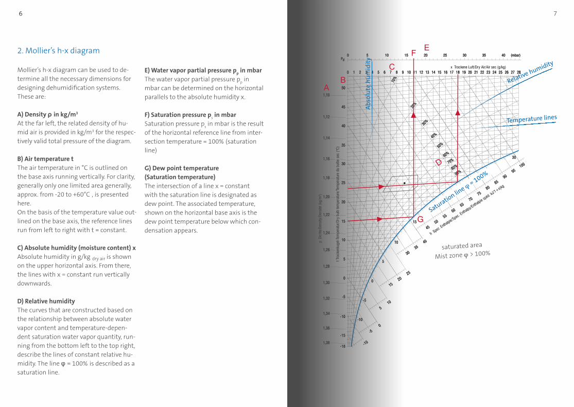
E) Water vapor partial pressure pp in mbar
The water vapor partial pressure pp in
mbar can be determined on the horizontal parallels to the absolute humidity x.
F) Saturation pressure ps in mbar
Saturation pressure ps in mbar is the result
of the horizontal reference line from inter-section temperature = 100%
(saturation
line)
G) Dew point temperature (Saturation temperature)The intersection of a line x = constant with the saturation line is designated as dew point. The associated temperature, shown on the horizontal base axis is the dew point temperature below which con-densation appears.
2. Mollier’s h-x diagram
Mollier’s h-x diagram can be used to de-termine all the necessary dimensions for designing dehumidification systems. These are:
A) Density ρ in kg/m3
At the far left, the related density of hu-mid air is provided in kg/m3 for the respec-tively valid total pressure of the diagram.
B) Air temperature tThe air temperature in °C is outlined on the base axis running vertically. For clarity, generally only one limited area generally, approx. from -20 to +60°C
, is presented
here. On the basis of the temperature value out-lined on the base axis, the reference lines run from left to right with t = constant.
C) Absolute humidity (moisture content) xAbsolute humidity in g/kg dry air is shown on the upper horizontal axis. From there, the lines with x = constant run vertically downwards.
D) Relative humidityThe curves that are constructed based on the relationship between absolute water vapor content and temperature-depen-dent saturation water vapor quantity, run-ning from the bottom left to the top right, describe the lines of constant relative hu-midity. The line φ = 100%
is described as a
saturation line.
saturated area
Mist zone φ > 100%
Abs
olu
te h
um
idit
y
Temperature lines
Saturation lin
e φ = 100%
Relative humidity
7 6
F E
C
AB
G
D
9 8
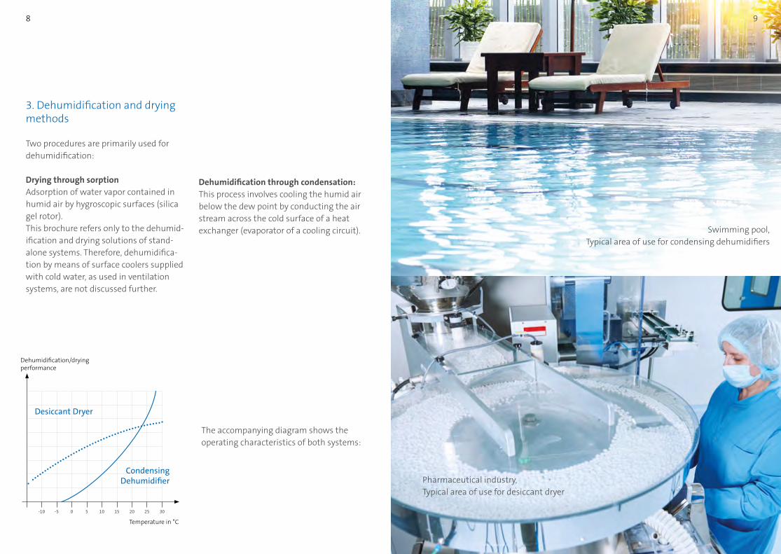
Swimming pool,Typical area of use for condensing dehumidifiers
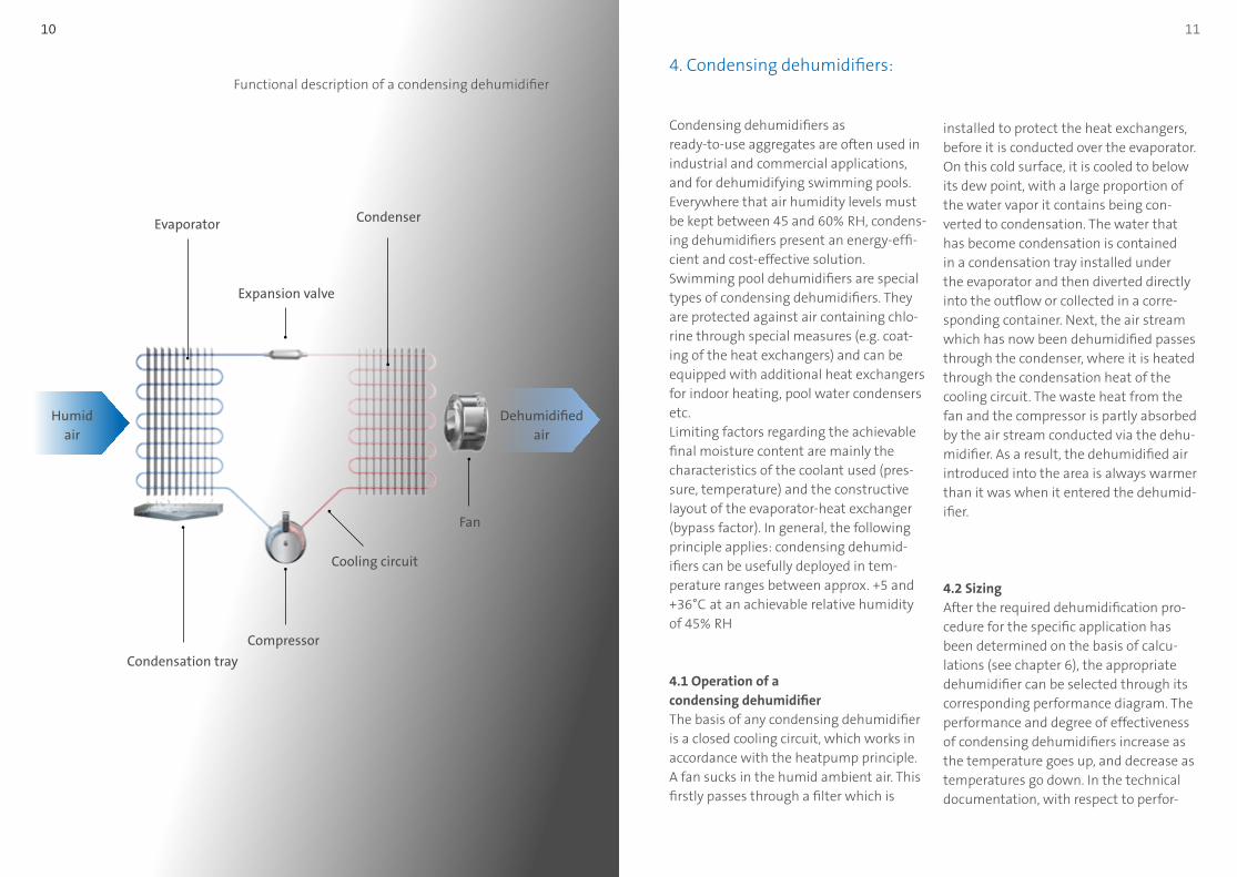
Pharmaceutical industry,Typical area of use for desiccant dryer
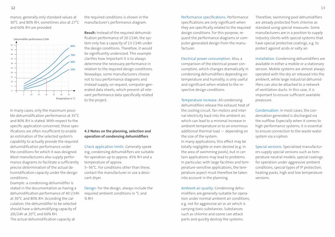
3. Dehumidification and drying methods
Two procedures are primarily used for dehumidification:
Drying through sorption Adsorption of water vapor contained in humid air by hygroscopic surfaces (silica gel rotor).This brochure refers only to the dehumid-ification and drying solutions of stand-alone systems. Therefore, dehumidifica-tion by means of surface coolers supplied with cold water, as used in ventilation systems, are not discussed further.
Dehumidification through condensation: This process involves cooling the humid air below the dew point by conducting the air stream across the cold surface of a heat exchanger (evaporator of a cooling circuit).
The accompanying diagram shows the operating characteristics of both systems:
Dehumidification/drying performance
Temperature in °C
-10 0 10 20-5 5 15 25 30
Desiccant Dryer
Condensing Dehumidifier
11 10
Condensing dehumidifiers as ready-to-use aggregates are often used in industrial and commercial applications, and for dehumidifying swimming pools. Everywhere that air humidity levels must be kept between 45 and 60%
RH, condens-
ing dehumidifiers present an energy-effi-cient and cost-effective solution. Swimming pool dehumidifiers are special types of condensing dehumidifiers. They are protected against air containing chlo-rine through special measures (e.g. coat-ing of the heat exchangers) and can be equipped with additional heat exchangers for indoor heating, pool water condensers etc.Limiting factors regarding the achievable final moisture content are mainly the characteristics of the coolant used (pres-sure, temperature) and the constructive layout of the evaporator-heat exchanger (bypass factor). In general, the following principle applies: condensing dehumid-ifiers can be usefully deployed in tem-perature ranges between approx. +5 and +36°C
at an achievable relative humidity
of 45% RH
4.1 Operation of a condensing dehumidifierThe basis of any condensing dehumidifier is a closed cooling circuit, which works in accordance with the heatpump principle. A fan sucks in the humid ambient air. This firstly passes through a filter which is
4. Condensing dehumidifiers:
installed to protect the heat exchangers, before it is conducted over the evaporator. On this cold surface, it is cooled to below its dew point, with a large proportion of the water vapor it contains being con-verted to condensation. The water that has become condensation is contained in a condensation tray installed under the evaporator and then diverted directly into the outflow or collected in a corre-sponding container. Next, the air stream which has now been dehumidified passes through the condenser, where it is heated through the condensation heat of the cooling circuit. The waste heat from the fan and the compressor is partly absorbed by the air stream conducted via the dehu-midifier. As a result, the dehumidified air introduced into the area is always warmer than it was when it entered the dehumid-ifier.
4.2 SizingAfter the required dehumidification pro-cedure for the specific application has been determined on the basis of calcu-lations (see chapter 6), the appropriate dehumidifier can be selected through its corresponding performance diagram. The performance and degree of effectiveness of condensing dehumidifiers increase as the temperature goes up, and decrease as temperatures go down. In the technical documentation, with respect to perfor-
Functional description of a condensing dehumidifier
CondenserEvaporator
Condensation tray
Compressor
Cooling circuit
Fan
Dehumidified air
Humid air
Expansion valve
13 12
mance, generally only standard values at 30°C
and 80%
RH, sometimes also at 27°C
and 60% RH are provided.
In many cases, only the maximum possi-ble dehumidification performance at 35°C
and 80% RH is stated. With respect to the
specific application concerned, these spec-ifications are often insufficient to enable an estimation of the selected system’s capability to actually provide the required dehumidification performance under the conditions for which it was designed. Most manufacturers also supply perfor-mance diagrams to facilitate a sufficiently precise determination of the actual de-humidification capacity under the design conditions. Example: a condensing dehumidifier is stated in the documentation as having a dehumidification performance of 40 l/24h at 30°C
and 80%
RH. According the cal-
culation, the dehumidifier to be selected should have a dehumidifying capacity of 20l/24h at 20°C and 60% RH.The actual dehumidification capacity at
the required conditions is shown in the manufacturer’s performance diagram.
Result: Instead of the required dehumidi-fication performance of 20 l/24h, the sys-tem only has a capacity of 13 l/24h under the design conditions. Therefore, it would be significantly undersized. This example clarifies how important it is to always determine the necessary performance in relation to the required design conditions. Nowadays, some manufacturers choose not to Issu performance diagrams and instead supply, on request, computer-gen-erated data sheets, which present all rele-vant performance data specifically related to the project.
4.3 Notes on the planning, selection and operation of condensing dehumidifiers
Check application limits: Generally speak-ing, condensing dehumidifiers are suitable for operation up to approx. 45%
RH and a
temperature of approx. 5–36°C.
For conditions other than these,
contact the manufacturer or use a desic-cant dryer.
Design: For the design, always include the required ambient conditions in °C and % RH.
Performance specifications: Performance specifications are only significant when they are specifically related to the required design conditions. For this purpose, re-quest the performance diagrams or com-puter-generated design from the manu-facturer.
Electrical power consumption: Also, a comparison of the electrical power con-sumption, which changes dramatically in condensing dehumidifiers depending on temperature and humidity, is only useful and significant when related to the re-spective design conditions.
Temperature increase: All condensing dehumidifiers release the exhaust heat of the cooling circuit, fan motors and inter-nal electricity back into the ambient air, which can lead to a minimal increase in ambient temperature or to an enormous additional thermal load — depending on the size of the system. In many applications, this effect may be totally negligible or even desired (e.g. In the area of swimming pools), but in cer-tain applications may lead to problems. In particular, with large facilities and tem-perature-sensitive applications, the tem-perature aspect must therefore be taken into account in the planning.
Ambient air quality: Condensing dehu-midifiers are generally suitable for opera-tion under normal ambient air conditions, e.g. not for aggressive air or air which is carrying toxic substances. Substances such as chlorine and ozone can attack parts and quickly destroy the systems.
Therefore, swimming pool dehumidifiers are already protected from chlorine as standard using special measures. Some manufacturers are in a position to supply industry clients with special systems that have special protective coatings, e.g. to protect against acids or salty air.
Installation: Condensing dehumidifiers are available in either a mobile or a stationary version. Mobile systems are almost always operated with the dry air released into the ambient, while large industrial dehumid-ifiers can also be attached to a network of ventilation ducts. In this case, it is important to ensure sufficient available preassure.
Condensation: In most cases, the con-densation generated is discharged via the outflow. Especially when it comes to high-performance systems, it is essential to ensure connection to the waste water system via a siphon.
Special versions: Specialized manufactur-ers supply special versions such as tem-perature-neutral models, special coatings for operation under aggressive ambient conditions, special types of IP protection, heating packs, high and low temperature versions.
Dehumidifier performance l/24h
Temperature in °C
5
0
15
30
45
15 2510
10
25
40
5
20
35
50
20 30 35
80%
70%
60%
50%
15
15 14
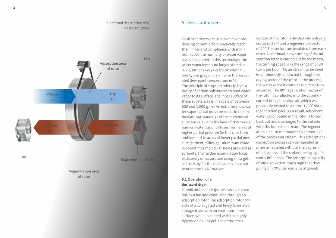
Desiccant dryers are used wherever con-densing dehumidifiers physically reach their limits and compliance with mini-mum absolute humidity or water vapor levels is required. In this technology, the water vapor level is no longer stated in % RH, rather always in the absolute hu-midity x in g/kg of dry air or in the associ-ated dew point temperature in °C.The principle of sorption refers to the ca-pacity of certain substances to bind water vapor to its surface. The inner surface of these substances is in a scale of between 600 and 1,000 g/m2. An extremely low wa-ter vapor partial pressure exists in the im-mediate surroundings of these chemical substances. Due to the laws of thermo-dy-namics, water vapor diffuses from areas of higher partial pressure (in this case from ambient air) to areas of lower partial pres-sure (sorbent). Silica gel, aluminum oxide or sometimes molecular sieves are used as sorbents. The further examination focus exclusively on adsorption using silica gel, as this is by far the most widely-used sor-bent on the HVAC market.
5.1 Operation of a desiccant dryerHumid ambient air (process air) is sucked out by a fan and conducted through an adsorption rotor. The adsorption rotor con-sists of a corrugated and finely laminated storage mass with an enormous inner surface, which is coated with the highly hygroscopic silica gel. The entire cross
5. Desiccant dryers
section of the rotor is divided into a drying sector of 270° and a regeneration sector of 90°. The sectors are insulated from each other. A continual, slow turning of the ad-sorption rotor is carried out by the motor, the turning speed is in the range of 5–30 turns per hour. The air stream to be dried is continuously conducted through the drying sector of the rotor. In the process, the water vapor it contains is almost fully adsorbed. The 90° regeneration sector of the rotor is conducted into the counter-current of regeneration air, which was previously heated to approx. 120°C
via a
regeneration pack. As a result, adsorbent water vapor bound in the rotor is forced back out and discharged to the outside with the humid air stream. The regener-ation air current amounts to approx. 1/3 of the process air stream. This adsorption/desorption process can be repeated as often as required without the degree of effectiveness of the sorbent being signifi-cantly influenced. The adsorption capacity of silica gel is that much high that dew points of -70°C can easily be attained.
Functional description of a desiccant dryer
Fan
FanAdsorption area
of rotor
Regeneration area of rotor
Regeneration heater
Regeneration air
Dry air
Humid air
Process air
17 16
5.2 RegenerationIn order to force out and discharge adsor-bent water vapor bound in the rotor, the adhesive powers operating on the surface of the sorbent must be removed. To do this, the regeneration air stream must be heated accordingly. This is carried out by means of an upstream regeneration heater. With smaller desiccant dryers, the regeneration heating is always carried out using electricity. In the case of larger ag-gregates, the regeneration heater can be operated as follows: Electrically (standard) Using steam Using hot water Combination of electrical and PWW
heat pack Combination of electrical and steam or
hot water heat pack.
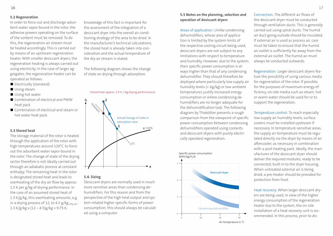
5.3 Stored heatThe storage material of the rotor is heated through the application of the rotor with high temperatures around 120°C
to force
out the adsorbent water vapor bound in the rotor. The change of state of the drying sector therefore is not ideally carried out through an adiabatic process at constant enthalpy. The remaining heat in the rotor is designated stored heat and leads to overheating of the dry air flow by approx. 1.5 K per g/kg of drying performance. In the case of an assumed stored heat of 1.3 K/g/kg, this overheating amounts, e.g. in a drying process of 12, to 4.5 g/kg dry air: 1.3 K/g/kg x (12 – 4.5)g/kg = 9.75 K.
Knowledge of this fact is important for the assessment of the integration of a desiccant dryer into the overall air condi-tioning strategy of the area to be dried. In the manufacturer’s technical calculations, the stored heat is already taken into con-sideration and the actual temperature of the dry air stream is stated.
The following diagram shows the change of state on drying through adsorption.
Specific power consumption (kWh/kg/H
20)
Air temperature in °C
0
0
1
2
3
2010 30
Desiccant dryer
Condensing dehumidifier
h
x
Stored heat approx. 1.5 K / (kg drying performance)
Actual change of state in adsorption rotor
Adiabatic
φ 100%
h1
5.4. SizingDesiccant dryers are normally used in much more sensitive areas than condensing de-humidifiers. For this reason and from the perspective of the high heat output and sys-tem-related higher specific forms of power consumption, this should always be calculat-ed using a computer.
5.5 Notes on the planning, selection and operation of desiccant dryers
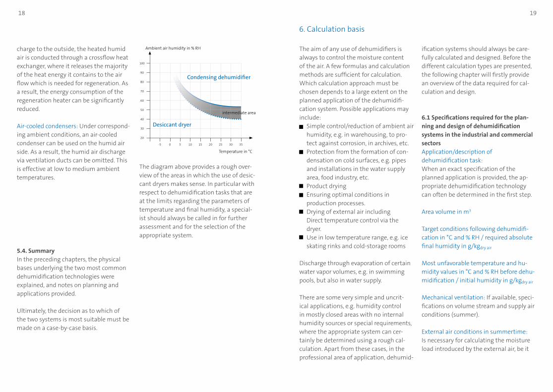
Areas of application: Unlike condensing dehumidifiers, whose area of applica-tion is limited by the system limits of the respective cooling circuit being used, desiccant dryers are not subject to any limitations with respect to temperature and humidity. However, due to the system, their specific power consumption is al-ways higher than that of any condensing dehumidifier. They should therefore be deployed where particularly low supply air humidity levels (< 6g/kg) or low ambient temperatures justify increased energy consumption or where condensing de-humidifiers are no longer adequate for the dehumidification task. The following diagram by Thiekötter presents a rough comparison from the viewpoint of specific power consumption between condensing dehumidifiers operated using coolants and desiccant dryers with purely electri-cally operated regeneration.
Connection: The different air flows of the desiccant dryer must be conducted through ventilation ducts. This is generally carried out using spiral ducts. The humid air duct going outside should be insulated. If external air is used as process air, care must be taken to ensure that the humid air outlet is sufficiently far away from the external air outlet. The humid air must always be conducted outwards.
Regeneration: Larger desiccant dryers fea-ture the possibility of using various media for regeneration of the rotor. If possible, for the purposes of maximum energy ef-ficiency, on-site media such as steam, hot or warm water should be used for or to support the regeneration.
Temperature control: To reach especially low supply air humidity levels, surface coolers must be installed upstream if necessary. In temperature-sensitive areas, the supply air temperature must be regu-lated directly via the dryer by means of an aftercooler, as necessary in combination with a post-heating pack. Ideally, the man-ufacturer of the desiccant dryer should deliver the required modules, ready to be connected, built-in to the dryer housing. When untreated external air is being dried, a pre-heater should be provided for protection from frost.
Heat recovery: When larger desiccant dry-ers are being used, in view of the higher energy consumption of the regeneration heater due to the system, the on-site installation of a heat recovery unit is rec-ommended. In this process, prior to dis-
1
2
18 19
6. Calculation basis
charge to the outside, the heated humid air is conducted through a crossflow heat exchanger, where it releases the majority of the heat energy it contains to the air flow which is needed for regeneration. As a result, the energy consumption of the regeneration heater can be significantly reduced.
Air-cooled condensers: Under correspond-ing ambient conditions, an air-cooled condenser can be used on the humid air side. As a result, the humid air discharge via ventilation ducts can be omitted. This is effective at low to medium ambient temperatures.
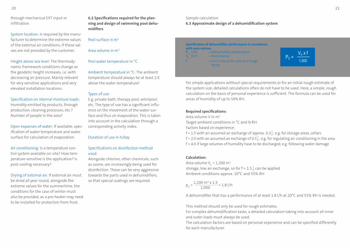
Ambient air humidity in % RH
Temperature in °C
-5
20
50
80
30
40
70
100
60
90
3510 200 5 15 25 30
Desiccant dryer
intermediate area
Condensing dehumidifier
5.4. SummaryIn the preceding chapters, the physical bases underlying the two most common dehumidification technologies were explained, and notes on planning and applications provided.
Ultimately, the decision as to which of the two systems is most suitable must be made on a case-by-case basis.
The diagram above provides a rough over-view of the areas in which the use of desic-cant dryers makes sense. In particular with respect to dehumidification tasks that are at the limits regarding the parameters of temperature and final humidity, a special-ist should always be called in for further assessment and for the selection of the appropriate system.
The aim of any use of dehumidifiers is always to control the moisture content of the air. A few formulas and calculation methods are sufficient for calculation. Which calculation approach must be chosen depends to a large extent on the planned application of the dehumidifi-cation system. Possible applications may include: Simple control/reduction of ambient air
humidity, e.g. in warehousing, to pro-tect against corrosion, in archives, etc.
Protection from the formation of con-densation on cold surfaces, e.g. pipes and installations in the water supply area, food industry, etc.
Product drying Ensuring optimal conditions in production processes. Drying of external air including Direct temperature control via the dryer. Use in low temperature range, e.g. ice
skating rinks and cold-storage rooms
Discharge through evaporation of certain water vapor volumes, e.g. in swimming pools, but also in water supply.
There are some very simple and uncrit-ical applications, e.g. humidity control in mostly closed areas with no internal humidity sources or special requirements, where the appropriate system can cer-tainly be determined using a rough cal-culation. Apart from these cases, in the professional area of application, dehumid-
ification systems should always be care-fully calculated and designed. Before the different calculation types are presented, the following chapter will firstly provide an overview of the data required for cal-culation and design.
6.1 Specifications required for the plan-ning and design of dehumidification systems in the industrial and commercial sectors Application/description of dehumidification task: When an exact specification of the planned application is provided, the ap-propriate dehumidification technology can often be determined in the first step.
Area volume in m3
Target conditions following dehumidifi-cation in °C and % RH / required absolute final humidity in g/kgdry air
Most unfavorable temperature and hu-midity values in °C and % RH before dehu-midification / initial humidity in g/kgdry air
Mechanical ventilation: If available, speci-fications on volume stream and supply air conditions (summer).
External air conditions in summertime: Is necessary for calculating the moisture load introduced by the external air, be it
20 21
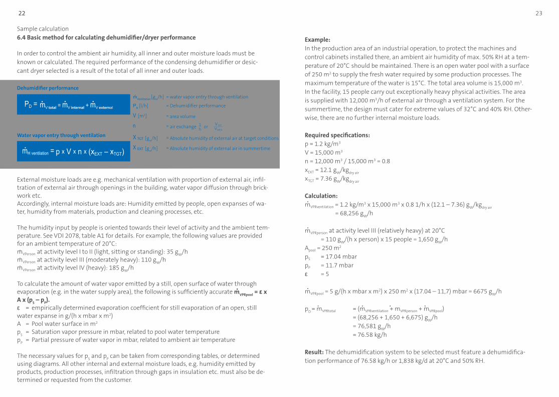
Sample calculation6.3 Approximate design of a dehumidification system
Required specifications:Area volume V in m3
Target ambient conditions in °C and % RHFactors based on experience:f = 1.5 with an assumed air exchange of approx. 0.3 , e.g. for storage areas, cellarsf = 2.0 with an assumed air exchange of 0.5 , e.g. for regulating air conditioning in the area f = 4.0 if large volumes of humidity have to be discharged, e.g. following water damage
Calculation:Area volume V
A = 1,200 m3
storage, low air exchange, so for f = 1.5 can be appliedAmbient conditions approx. 20°C
and 55%
RH
pD =
1,200 m3 x 1.5 = 1.8 l/h
1,000
A dehumidifier that has a performance of at least 1.8 l/h at 20°C and 55%
RH is needed.
This method should only be used for rough estimates. For complex dehumidification tasks, a detailed calculation taking into account all inner and outer loads must always be used. The calculation factors are based on personal experience and can be specified differently for each manufacturer.
Specification of dehumidifier performance in accordance with area volumeP
D [l/h] = Dehumidifier performance
VA [m3] = Area volume
f = 2 to 3 should be used as a rough factor
1,000PD =
VA x f
For simple applications without special requirements or for an initial rough estimate of the system size, detailed calculations often do not have to be used. Here, a simple, rough calculation on the basis of personal experience is sufficient. The formula can be used for areas of humidity of up to 50% RH.
1h
1h
1h
through mechanical EXT input or infiltration.
System location: Is required by the manu-facturer to determine the extreme values of the external air conditions, if these val-ues are not provided by the customer.
Height above sea level: The thermody-namic framework conditions change as the geodetic height increases, i.e. with decreasing air pressure. Mainly relevant for very sensitive applications and very elevated installation locations.
Specification on internal moisture loads: Humidity emitted by products, through production, cleaning processes, etc.? Number of people in the area?
Open expanses of water: If available, spec-ification of water temperature and water surface for calculation of evaporation.
Air conditioning: Is a temperature con-trol system available on-site? How tem-perature-sensitive is the application? Is post-cooling necessary?
Drying of external air: If external air must be dried all year round, alongside the extreme values for the summertime, the conditions for the case of winter must also be provided, as a pre-heater may need to be installed for protection from frost.
6.2 Specifications required for the plan-ning and design of swimming pool dehu-midifiers
Pool surface in m2
Area volume in m3
Pool water temperature in °C
Ambient temperature in °C: The ambient temperature should always be at least 2 K above the water temperature!
Types of use: E.g. private bath, therapy pool, whirlpool, etc. The type of use has a significant influ-ence on the movement of the water sur-face and thus on evaporation. This is taken into account in the calculation through a corresponding activity index.
Duration of use in h/day
Specifications on disinfection method used: Alongside chlorine, other chemicals, such as ozone, are increasingly being used for disinfection. These can be very aggressive towards the parts used in dehumidifiers, so that special coatings are required.
23
Sample calculation6.4 Basic method for calculating dehumidifier/dryer performance
External moisture loads are e.g. mechanical ventilation with proportion of external air, infil-tration of external air through openings in the building, water vapor diffusion through brick-work etc.Accordingly, internal moisture loads are: Humidity emitted by people, open expanses of wa-ter, humidity from materials, production and cleaning processes, etc.
The humidity input by people is oriented towards their level of activity and the ambient tem-perature. See VDI 2078, table A1 for details. For example, the following values are provided for an ambient temperature of 20°C:mVPerson at activity level I to II (light, sitting or standing): 35 g
W/h
mVPerson at activity level III (moderately heavy): 110 gW
/hmVPerson at activity level IV (heavy): 185 g
W/h
To calculate the amount of water vapor emitted by a still, open surface of water through evaporation (e.g. in the water supply area), the following is sufficiently accurate m
VPRpool = ε x
A x (pS – p
P).
ε = empirically determined evaporation coefficient for still evaporation of an open, still water expanse in g/(h x mbar x m2)A = Pool water surface in m2
pS = Saturation vapor pressure in mbar, related to pool water temperature
pP = Partial pressure of water vapor in mbar, related to ambient air temperature
The necessary values for pS and p
P can be taken from corresponding tables, or determined
using diagrams. All other internal and external moisture loads, e.g. humidity emitted by products, production processes, infiltration through gaps in insulation etc. must also be de-termined or requested from the customer.
In order to control the ambient air humidity, all inner and outer moisture loads must be known or calculated. The required performance of the condensing dehumidifier or desic-cant dryer selected is a result of the total of all inner and outer loads.
Dehumidifier performance
Water vapor entry through ventilation
mVentilation
[gw
/h] = water vapor entry through ventilation
PD [l/h] = Dehumidifier performance
V [m3] = area volume
n = air exchange or
X TGT [gw
/h] = Absolute humidity of external air at target conditions
X EXT [gw
/h] = Absolute humidity of external air in summertime
23 22
mV total = mV internal + mV external
p x V x n x (xEXT – xTGT)
PD =
mH ventilation =
1h
V EXT
VAREA
Example: In the production area of an industrial operation, to protect the machines and control cabinets installed there, an ambient air humidity of max. 50% RH at a tem-perature of 20°C
should be maintained. There is an open water pool with a surface
of 250 m2 to supply the fresh water required by some production processes. The maximum temperature of the water is 15°C.
The total area volume is 15,000 m3.
In the facility, 15 people carry out exceptionally heavy physical activities. The area is supplied with 12,000 m3/h of external air through a ventilation system. For the summertime, the design must cater for extreme values of 32°C
and 40%
RH. Other-
wise, there are no further internal moisture loads.
Required specifications:p = 1.2 kg/m3 V = 15,000 m3
n = 12,000 m3 / 15,000 m3 = 0.8xEXT = 12.1 g
W/kg
dry air
xTGT = 7.36 gW
/kgdry air
Calculation:mVPRventilation = 1.2 kg/m3 x 15,000 m3 x 0.8 1/h x (12.1 – 7.36) g
W/kg
dry air
= 68,256 gW
/h
mVPRperson at activity level III (relatively heavy) at 20°C = 110 g
W/(h x person) x 15 people = 1,650 g
W/h
Apool = 250 m2
pS = 17.04 mbar pP = 11.7 mbarε = 5
mVPRpool = 5 g/(h x mbar x m2) x 250 m2 x (17.04 – 11,7) mbar = 6675 gW
/h
pD
= mVPRtotal = (mVPRventilation + mVPRperson + mVPRpool) = (68,256 + 1,650 + 6,675) g
W/h
= 76,581 gW
/h = 76.58 kg/h
Result: The dehumidification system to be selected must feature a dehumidifica-tion performance of 76.58 kg/h or 1,838 kg/d at 20°C and 50% RH.
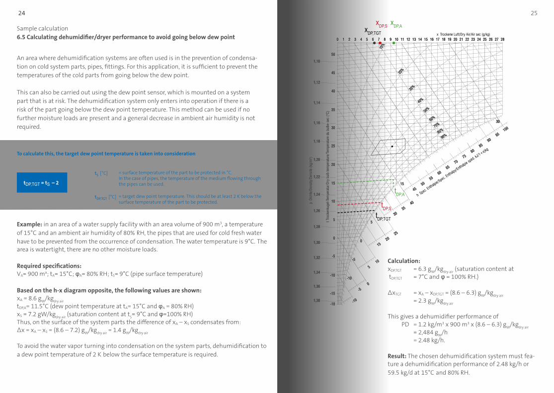
24 25 24
Example: in an area of a water supply facility with an area volume of 900 m3, a temperature of 15°C
and an ambient air humidity of 80%
RH, the pipes that are used for cold fresh water
have to be prevented from the occurrence of condensation. The water temperature is 9°C. The
area is watertight, there are no other moisture loads.
Required specifications:VA= 900 m³; tA= 15°C; φA= 80% RH; tS= 9°C (pipe surface temperature)
Based on the h-x diagram opposite, the following values are shown:xA = 8.6 g
W/kg
dry air
tDP,A= 11.5°C (dew point temperature at tA= 15°C and φA = 80% RH) xS = 7.2 gW/kg
dry air (saturation content at t
S= 9°C and φ=100% RH)
Thus, on the surface of the system parts the difference of xA – xS condensates from: Δx = xA – xS = (8.6 – 7.2) g
W/kg
dry air = 1.4 g
W/kg
dry air
To avoid the water vapor turning into condensation on the system parts, dehumidification to a dew point temperature of 2 K
below the surface temperature is required.
Sample calculation6.5 Calculating dehumidifier/dryer performance to avoid going below dew point
To calculate this, the target dew point temperature is taken into consideration
tS [°C] = surface temperature of the part to be protected in °C.
In the case of pipes, the temperature of the medium flowing through the pipes can be used.
tDP,TGT [°C] = target dew point temperature. This should be at least 2 K below the
surface temperature of the part to be protected.
tDP,TGT = tS – 2
tDP,A
xDP,AxDP,SxDP,TGT
An area where dehumidification systems are often used is in the prevention of condensa-tion on cold system parts, pipes, fittings. For this application, it is sufficient to prevent the temperatures of the cold parts from going below the dew point.
This can also be carried out using the dew point sensor, which is mounted on a system part that is at risk. The dehumidification system only enters into operation if there is a risk of the part going below the dew point temperature. This method can be used if no further moisture loads are present and a general decrease in ambient air humidity is not required.
Calculation:xDP,TGT = 6.3 g
W/kg
dry air (saturation content at
tDP,TGT = 7°C and φ = 100% RH.) ΔxTGT = xA – xDP,TGT = (8.6 – 6.3) g
W/kg
dry air
= 2.3 gW
/kgdry air
This gives a dehumidifier performance of PD = 1.2 kg/m3 x 900 m3 x (8.6 – 6.3) g
W/kg
dry air
= 2,484 gW
/h = 2.48 kg/h.
Result: The chosen dehumidification system must fea-ture a dehumidification performance of 2.48 kg/h or 59.5 kg/d at 15°C
and 80% RH.
tDP,StDP,TGT
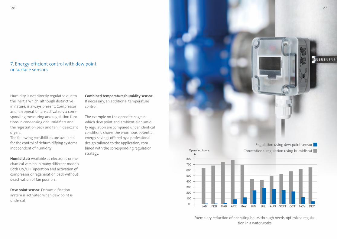
Humidity is not directly regulated due to the inertia which, although distinctive in nature, is always present. Compressor and fan operation are activated via corre-sponding measuring and regulation func-tions in condensing dehumidifiers and the registration pack and fan in desiccant dryers. The following possibilities are available for the control of dehumidifying systems independent of humidity:
Humidistat: Available as electronic or me-chanical version in many different models. Both ON/OFF operation and activation of compressor or regeneration pack without deactivation of fan possible.
Dew point sensor: Dehumidification system is activated when dew point is undercut.
7. Energy-efficient control with dew point or surface sensors
Combined temperature/humidity sensor: If necessary, an additional temperature control.
The example on the opposite page in which dew point and ambient air humidi-ty regulation are compared under identical conditions shows the enormous potential energy savings offered by a professional design tailored to the application, com-bined with the corresponding regulation strategy.
JAN
300
0
400
100
500
600
700
800
200
Operating hours
MAR APR MAY JUL AUG OCT NOV DECJUNFEB SEPT
Exemplary reduction of operating hours through needs-optimized regula-tion in a waterworks
Conventional regulation using humidistat
Regulation using dew point sensor
27 26
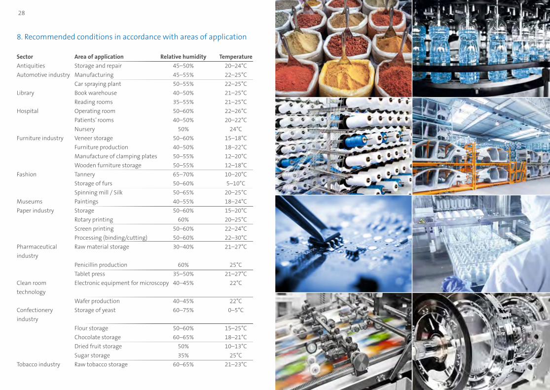
8. Recommended conditions in accordance with areas of application
Sector Area of application Relative humidity Temperature
Antiquities Storage and repair 45–50% 20–24°C
Automotive industry Manufacturing 45–55% 22–25°C
Car spraying plant 50–55% 22–25°C
Library Book warehouse 40–50% 21–25°C
Reading rooms 35–55% 21–25°C
Hospital Operating room 50–60% 22–26°C
Patients’ rooms 40–50% 20–22°C
Nursery 50% 24°C
Furniture industry Veneer storage 50–60% 15–18°C
Furniture production 40–50% 18–22°C
Manufacture of clamping plates 50–55% 12–20°C
Wooden furniture storage 50–55% 12–18°C
Fashion Tannery 65–70% 10–20°C
Storage of furs 50–60% 5–10°C
Spinning mill / Silk 50–65% 20–25°C
Museums Paintings 40–55% 18–24°C
Paper industry Storage 50–60% 15–20°C
Rotary printing 60% 20–25°C
Screen printing 50–60% 22–24°C
Processing (binding/cutting) 50–60% 22–30°C
Pharmaceutical Raw material storage 30–40% 21–27°C
industry
Penicillin production 60% 25°C
Tablet press 35–50% 21–27°C
Clean room Electronic equipment for microscopy 40–45% 22°C
technology
Wafer production 40–45% 22°C
Confectionery Storage of yeast 60–75% 0–5°C
industry
Flour storage 50–60% 15–25°C
Chocolate storage 60–65% 18–21°C
Dried fruit storage 50% 10–13°C
Sugar storage 35% 25°C
Tobacco industry Raw tobacco storage 60–65% 21–23°C
29 28 29
31
[1] Henne, Erich: Luftbefeuchtung (Humidification), Oldenbourg Verlag München/Wien, 1995
[2] Cerbe, Günter / Hoffmann, Hans-Joachim: Einführung in die Thermodynamik (Introduction to thermodynamics), Carl Hanser Verlag München/Wien 1996
[3] Recknagel/Sprenger/Schramek: Taschenbuch für Heizung und Klimatechnik (Pocket guide to heating and air-conditioning technology),
Oldenbourg Industrieverlag GmbH München 2013
[4] Reinmuth, Friedrich: Raumlufttechnik (Ventilation technology), Vogel Verlag Würzburg, 1996
[5] Siemens Building Technologies: Das h,x-Diagramm, Aufbau und Anwendung
(The h-x diagram, structure and application), Siemens Building Technologies AG
[6] VDI-Richtlinie 2089 Blatt 1 (German Engineer’s Association directive 2089 Folio 1) Technische Gebäudeausrüstung von Schwimmbädern
(Technical building services of swimming pools), VDI-Verlag Düsseldorf, 2010
[7] VDI-Richtlinie VDI 2078 Berechnung der thermischen Lasten und Raumtemperaturen (German Engineer’s Association directive 2078 Calculating
thermal loads and ambient temperatures), VDI-Verlag Düsseldorf, 2015
[8] Steiner, Reinhard: Branchendokumentation 208 (Sector documentation 208) Luftentfeuchtung — Lufttrocknung (Dehumidification — air drying), Offenbach
1988
[9] DVGW-Merkblatt W 621: Entfeuchtung, Lüftung, Heizung in Wasserwerken (German Technical and Scientific Association for Gas and Water factsheet W 621: dehumidification, ventilation, heating in water works),
DVGW Eschborn, 1993
[10] Werksunterlagen Condair GmbH, Garching (company records of Condair GmbH, Garching)
[11] Werksunterlagen Cotes A/S (company records of Cotes A/S), Slagelse DK
9. Bibliography
31 30

Condair AGTalstrasse 35-37, 8808 Pfäffikon SZ, Switzerlandwww.condair.com; [email protected]
© 10/2016 Rights to technical modifications and errors reserved.


