AIAA-94-1250-CP Deictic Primitives for General Purpose Navigation* Jill D. Crisman, Ph.D. Robotic and Vision Systems Laboratory Departent of Electrical and Computer Engineering Northeastern University Boston, MA 02115 Abstract We are investigating visually-based deictic primitives to be used as an elementary command set for general purpose navigation. Each deictic primitive specifies how the robot should move relative to a visually distinctive target. The system uses no prior information about target objects (e.g. shape and color), thereby insuring general navigational capabilities which are achieved by sequentially issuing these deictic primitives to a robot system. Our architecture consists of five control loops, each independently controlling one of the five rotary joints of our robot. We show that these control loops can be merged into a stable navigational system if they have the proper delays. We have also developed a simulation which we are using to define a set of deictic primitives which can be used to achieve general purpose navigation. Encoded in the simulated environment are positions of visually distinctive objects which we believe will make good visual targets. We discuss the current results of our simulation. Our deictic primitives offer an ideal solution for many types of partially supervised robotic applications. Scientists could remotely command a planetary rover to go to a particular rock formation that may be interesting. Similarly an expert at plant maintenance could obtain diagnostic information remotely by using deictic primitives on a mobile platform. Moreover, since no object models are used in the deictic primitives, we could imagine that the exact same control software could be used for all of these applications. 1. Introduction We are developing a robot architecture which uses a natural deictic interface that allows the user to point out targets to the system. To operate a deictic mobile robot, the user would select a target in a video image and then issue a command such as "approach that" or "pass to the fight of that" where 'that' is the target selected in the video image. In this paper, we describe the robot architecture that we are using for this deictic system. We also describe our simulation environment that we are developing to explore the definition of a set of deictic primitives to be used for general purpose navigation. This work is important since the elementary deictic primitives give researchers a novel way to think about programming robot systems. Most robots are controlled by specifying a target in geometric terms, for example as a Cartesian position and orientation (e.g. 'go to 20m, 12m, and face 10 degrees') or as a location on a map. On the other hand, deictic primitives would involve a user pointing out a sequence of * This work is supported by the National Science Foundation under grant number IRI-921056. This work is also aided by the donation of a Coenex 4400 Machine Vision System by Cc_nex Corp.. Needham, MA. Copyright c 1993 by the American Institute of Asronautics and Astronautics, Inc. with permission 527 https://ntrs.nasa.gov/search.jsp?R=19950005105 2018-07-01T12:57:12+00:00Z
Transcript
AIAA-94-1250-CP
Deictic Primitives for General Purpose Navigation*
Jill D. Crisman, Ph.D.
Robotic and Vision Systems Laboratory
Departent of Electrical and Computer EngineeringNortheastern University
Boston, MA 02115
Abstract
We are investigating visually-based deicticprimitives to be used as an elementarycommand set for general purpose navigation.Each deictic primitive specifies how the robotshould move relative to a visually distinctivetarget. The system uses no prior information
about target objects (e.g. shape and color),thereby insuring general navigationalcapabilities which are achieved bysequentially issuing these deictic primitives toa robot system.
Our architecture consists of five control
loops, each independently controlling one ofthe five rotary joints of our robot. We showthat these control loops can be merged into astable navigational system if they have theproper delays. We have also developed asimulation which we are using to define a setof deictic primitives which can be used toachieve general purpose navigation. Encodedin the simulated environment are positions ofvisually distinctive objects which we believewill make good visual targets. We discussthe current results of our simulation.
Our deictic primitives offer an ideal solutionfor many types of partially supervised roboticapplications. Scientists could remotely
command a planetary rover to go to aparticular rock formation that may be
interesting. Similarly an expert at plant
maintenance could obtain diagnosticinformation remotely by using deicticprimitives on a mobile platform. Moreover,since no object models are used in the deicticprimitives, we could imagine that the exactsame control software could be used for all of
these applications.
1. Introduction
We are developing a robot architecture whichuses a natural deictic interface that allows the
user to point out targets to the system. Tooperate a deictic mobile robot, the user would
select a target in a video image and then issuea command such as "approach that" or "passto the fight of that" where 'that' is the targetselected in the video image. In this paper, wedescribe the robot architecture that we are
using for this deictic system. We alsodescribe our simulation environment that we
are developing to explore the definition of aset of deictic primitives to be used for generalpurpose navigation.
This work is important since the elementarydeictic primitives give researchers a novelway to think about programming robotsystems. Most robots are controlled byspecifying a target in geometric terms, forexample as a Cartesian position andorientation (e.g. 'go to 20m, 12m, and face10 degrees') or as a location on a map. Onthe other hand, deictic primitives would
involve a user pointing out a sequence of
* This work is supported by the National Science Foundation under grant number IRI-921056. This work is alsoaided by the donation of a Coenex 4400 Machine Vision System by Cc_nex Corp.. Needham, MA.
Copyright c 1993 by the American Institute of Asronautics and Astronautics, Inc. with permission
visual targets and the robot moving relative tothose targets. We believe that this type of
programming interface is more natural forhumans since people tend to move relative to
what they perceive. For example, we would'walk to the doorway' rather than 'walkforward 10 feet'. As our work progresses inthe future, we will add object models so that
our system would be able to 'approach thedoorway'. Therefore, we believe that deicticcommands would be a more natural method
for people to interact with a mobile robot
system.
This deictic interface is very different thaninterfaces to traditional mobile robots. Manyrobots are controlled by specifying a target
location in geometric Cartesian coordinatewith respect to an initial robot location. Inthis case, the robot must keep track of itslocation in order to know if it has reached the
goal location. Other mobile robots navigatewith respect to a map of the environmentwhere goal locations are specified by ageometric coordinate on the map. The robotmust continually track its position withrespect to the map to determined if it hasobtained its goal. Still other robots navigateto target objects which have pre-storedmodels so that the robot can identifylandmarks. In all of these traditional
approaches to interfacing with the robot,environmental knowledge must be encodedgeometrically for the system to operate.
Our deictic system is very different in that therobot only needs to keep track of thedestination object in it video field. Sincetarget tracking is more robust than objectidentification, the processing time of oursystem is decreased. The robot does notneed to keep track of its location with respectto a global map, therefore our system is notsusceptable to position tracking errors. Wetake advantage of movable camera systems to
simplify our robot control architecture.
This deictic interface for semiautonomous
robots has many applications, especially in
exploratory robots. Scientists can control aplanetary rover by selecting a location ofinterest in the video screen and commanding
the robot to go to that area. Underwaterrobots can be controlled with lower
bandwidth communications than is typically
necessary for remotely operated vehicles.Moreover, semi-autonomous robots have
applications in aids for the handicapped.
In this paper, we overview the robotarchitecture which uses five feedback control
loops to control the motion of the robot. Weshow that with the time constants on the
feedback loops that this system can providesmooth and stable motion of all joints of the
robot. We also present our initial work on asimulator for exploring the definition of a setof deictic primitive commands. We show theresults of this simulation for a series of
approach commands.
2. Related Work
Developing mobile robot systems based ontraditional computer vision and roboticsparadigms requires the use of an a prioriobject model for the goal and a referencecoordinate frame [16] [20]. The visionsystem identifies the goal in the scene byusing the a priori object model provided.The object positions and orientations areperceived in the camera coordinate frame andmust be transformed into the reference
coordinate frame and added to the worldmodel. Other sensor modules addinformation to the world model. Motion
decisions for the robot system are made by apath planning module using the most recentinformation from the sensors which has been
integrated into the world model. As the robotmoves, the system must record and updatethe robot's position within the world model.This system has been used in many robotic
systems including [21] [11]. This traditionalsolution is somewhat limited since it assumes
that prior object models are available, whichis often not the case in applications such asplanetary exploration and household robotics.
Similar systems, for example [13], constructa world model without having the a priori
object models. However, the world modelconstruction process is computationally very
528
h 0 'I
I
I
I hOcl
1"
,' _ Oh
I
Figure 1: Robot Head. Our robot head has
four joints. The first joint controls rOh, the
pan of the head with respect to the robot base.
The second joint controls the tilt, x, of the
cameras. The third and fourth joints control
the pan of the cameras
expensive. These systems require calibrationbetween the camera system and the robot, alocalization routine so that the robot can
identify its location with respect to the localmap (so that the world model can beintegrated over time), and a good kinematicand dynamic model of the robot system. Thecalibration, kinematic, and dynamic modelsalways have associated with them someapproximation errors. Motion planning,which is done on the world model, can
become difficult as the robot modeling errorsaccumulate.
Visual servoing techniques have beenproposed to eliminate the geometricdependence of the motion commands. Rather
than directing the robot to a destinationlocation, the robot is instructed to maintain its
visually apparent position with respect to anobject using dynamic visual feedback. Robotmanipulators with a camera mounted on thearm can now track specific objects in 3-Dspace [22] [10] and navigation systems cantrack pathways [6] [9]. These systems workin real-time by tracking a specific visualfeature rather than reconstructing a complete3D description of the world.
Other researchers have abandoned traditional
methods and instead have promotedbehavior-based robotic architectures and local
path planning algorithms [1] [3] [4] [12][19]. These systems tend to use a distributed
computer system to acheive tightly coupledcontrol loops between the sensing andactuation. Therefore these systems havebetter reaction times in the presence ofmoving objects. Ultrasonic sensors are acommon choice to provide fast obstacledetection [2] [14].
Our system currently uses a simple and fastmethod for determining the motion of therobot and most closely resembles thesebehavior based systems. Therefore our
system is able to react quickly to a moving ornewly detected obstacle. We use a visual
servoing technique to position the gaze ofeach camera directly at the target. The mobilerobot then moves in the gaze direction of thecameras if the pathway is clear of obstacles.Otherwise it moves around the obstacle and
continues seeking the target.
Q Mobile RobotHardware
Our experimental equipment consists of amobile robot base with a ring of ultrasonicsensors, an active robot head, and a highspeed video processor. The active robot headhas four controllable motions. The robot
head carries two cameras and controls the panof each camera individually and it controls thetilt and pan of the pair of cameras, as shown
in Figure 1. This platform is similar to thosedescribed in [5], [15], and [17]. The
platform was constructed such that the panand tilt of the cameras occur approximatelyabout the focal point of the cameras. ACognex 4400 Machine Vision system iscurrently handling the real-time videoprocessing of the cameras. The active camerahead is mounted on a mobile robot platformwith a ring of 24 ultrasonic sensors. Eachultrasonic sensor can determine the distance
to the closest object in a 30 ° field of view.
529
4. System Architecture
Our goal is to achieve fast, reliable pursuit ofa target while avoiding obstacles in the path.Our system includes three components: atarget tracker, obstacle detector, and mediatoras shown in Figure 2. The target trackerfollows the target location selected by theuser and reports the angle and distance of thetarget to the mediator. The active robot headis used to simplify the target tracking task.The obstacle detector reports themeasurements from the ultrasonic sensor
ring. These measurements are the distance tothe closest object within the field-of-view ofeach sensor as a function of angle from therobot. The mediator then determines the
speed and steering angle of the robot. In thefollowing subsections, we describe in moredetail the three components of this system.
4.1. Tracker
The tracker is responsible for reporting theangle and distance to the target. Since we arefocusing on a video interface, we will beusing targets from video images from ""-LIIC;
stereo cameras. We are using stereo camerasto determine the distance to the target. Whiledetermining the distance to a stationary targetis possible from a moving platform with a
known motion, we do not assume that the
target is stationary nor that the motion of thetarget is known. As the robot and target aremoving, the tracker must determine thelocation of the target in the image. Since thetarget can easily move outside of the field ofview of the cameras, we use an active robot
head to keep the target in sight and thus tosimplify the tracker.
The tracker operates as four independentcontrollers, one for each motion of the
camera head: right camera pan, left camerapan, head pan and tilt (see Figure 1). Thetarget is first located independently in eachstereo image. The camera pans, 0cl and 0cr,and the head tilt z are used to move the
cameras such that the position of the targetappears in the center of the stereo images.The head pan is independently controlled totry to face the cameras directly at the target.The angle to the target can then be directlymeasured from the pan of the robot head.
The angles of the stereo cameras with respectto the robot head can be used to compute thedistance to the target. For more details of this
controller see [7] and on video tracking [8].
4.2. Obstacle Detection
The sonar system is responsible for reportingthe locations of obstacles surrounding thevehicle. In a typical ultrasonic system, each
Robot :- TARGETHesd TRACKER
Ultrasonic 1
Sensor -f OB STACLE
Ring r_ DETECTOR
SrMEDIATOR
8r
Figure 2: System Overview. Target tracking uses the active robot head to report the direction and distanceof the target relative to the mobile robot base. Obstacle detection reports the distance to the closest objectwithin the field-of-view of each sonar sensor. The mediator picks the best speed and steering anglecommands for the mobile robot base.
530
sonar covers a 30 ° field-of-view. The objectwhich is closest within this field is detected
by the sonar. The sonars are spaced in a ringaround our platform. The mediator receivesthe result of each sonar individually. Thesereadings can be thought of as the cost of therobot traversing in that direction.
4.3. Mediator
The mediator decides the steering and speedcommands that will be sent to the mobile
robot. The tracker reports to the mediator thecurrent direction and distance to the target.
The obstacle detector determines a radial mapof distances to obstacles surrounding thevehicle (see Figure 2). Interestingly, we
found that the mediator need not be complexto steer the robot successfully.
Consider that the robot can only steer withinthe resolution that it can sense. Therefore, to
track the target in an image, the robot cansteer according to the resolution of the pixelsin the image. However, if obstacles aredetected, the robot only knows that an
obstacle appears within a 30 ° field-of-view.
Therefore, the robot can only steer in 30 °increments. Each ultrasonic readingcorresponds to a steering direction. If anultrasonic sensor detects an obstacle, then the
robot should not steer into the 30 ° field-of-
view of the detecting sensor.
If there are no obstructions in the direction of
the target, then the robot pursues the targetdirection. If there is currently an obstructionin the direction of the target, the mediator willselect the closest open steering angle to thetarget.
The mediator also considers the closest
obstacle and the distance to the target whenselecting the vehicle speed. The speed isinversely proportional to the distance to theclosest object. We pursue the target to withina fixed distance. For safety reasons, therobot's speed is also clipped to a maximumvalue.
4.4. Simulation
To show the competence and stability of thesystem we have simulated a robot motionmodel to test our navigation algorithms. Toensure a realistic simulation, we havemodeled each motion of the robot as a
second-order system. The motion of therobot joints is modeled as a damped responseto the desired motion commands issued bythe mediator.
At each step in our simulation, two cameraimages and 24 ultrasonic measurements aretaken of the environment. We assume that
these measurements are relatively accurate.We completely model the limited field ofview of the cameras and the quantization ofthe camera measurements. We also add
random noise to these measurements. Theultrasonic measurements also have noise
added and we model a 30 ° field-of-view ofthe ultrasonic sensors.
The simulation keeps track of the motion ofthe target and the motion and orientation of
the robot with respect to a world coordinateframe. Notice that in our architecture, therobot does not know about a worldcoordinate frame since it has no world model.
The robot only concentrates on pursuing thetarget location and it considers its location inthe world irrelevant. For the purpose ofdisplay and sensor input computations, werepresent locations of objects, targets, and therobot with respect to a world coordinateframe. Our simulation is two-dimensional,
ignoring the z axis. Therefore, the tilt of thecamera head is not simulated.
In the following subsections, we describe thesimulation of the camera input, the sonarreadings, and the motion model of the robot.
4.4.1. Camera Pan and TiltSimulation
For our simulation, we currently do notmodel projection, back projection, andcamera measurements. Instead, we compute
531
the desired angle for the camera pans bytransforming the position of the target to thecamera frame. The transformation betweenthe camera frame and the world coordinate
frame is updated as the robot moves.
4.4.2. Ultrasonic MeasurementSimulation
The obstacles in our simulation are
represented by their corner locations. Foreach comer of an object, the position of eachcomer is transformed to the coordinate frame
of the robot. We then compute the angle tothis location to determine in which of theultrasonic measurements this corner will
appear. If the new distance, with additivenoise, is less than the current minimum
distance know by that sensor, then the sensormeasurement is updated Given the rangeultrasonic sensor in the ring effected by eachobject allows us to compute the intermediatesonar values.
4.4.3. Motion Control
We model each joint motion as a second-order system. We assume that the jointcontroller is critically damped and that thediscrete inputs from the computer controllerare modelled by step input functions. Thistype of motion is achieved by using aproportional-derivative (PD) controller.These PD controllers have been successful in
controlling the vergence of stereo cameras ona robot platform [18]. The motion responseto the desired input is shown in Figure 3.The equations of the response function is:
0(t) = 0 d (1 - exp(t/x))
where t is reset to zero when 0d changes. 0d
is the desired angle of the joint that iscomputed by our joint motion algorithms
described previously. 0d is a piecewise stepfunction since it is being computed by adiscrete controller, x is the time constant of
the system which controls how fast the jointcan track the desired input. We also limit thevelocity of each joint and we insure that themotion of each joint stays within its range.
Our current parameter values for the timeconstant and maximum velocity for each jointis summarized below:
Zcr = 50
Xcl = 50
_h = 10
Zr= 5
10_crlmax= 90 deg/sec
IO_cllmax= 90 deg/sec
Io_hlmax = 60 deg/sec
Ioklmax = 30 deg/sec
5O
50
40
30
20
I00 0.2 0.4 0.6 0.8 1
Figure 3: Response of the motion of a joint to a_ut.
4.5. Results
We have run the simulator on numerous
examples and we show a couple of resultshere. In all attempted scenarios, we havesuccessfully arrived at the target locationwithout colliding with obstacles. In the firstexample, we assumed a stationary target atlocation (10,7) with respect to the initial robotframe (see Figure 6.) Recall that the xcoordinate of the robot frame specifies itsdirection of motion. Since our slowest time
for processing a single frame was 100milliseconds, we used this time as the
sampling period of the system. We assumedthat the vehicle could travel a maximum of 3meters/second.
We present a test sequence where the target isat the limit of the cameras' field-of-view.
Therefore, the desired pan of the cameras willbe at its largest possible value. Wedemonstrate to show that the system is stableand controls the head and robot motions
smoothly even given the largest step input tothe system.
532
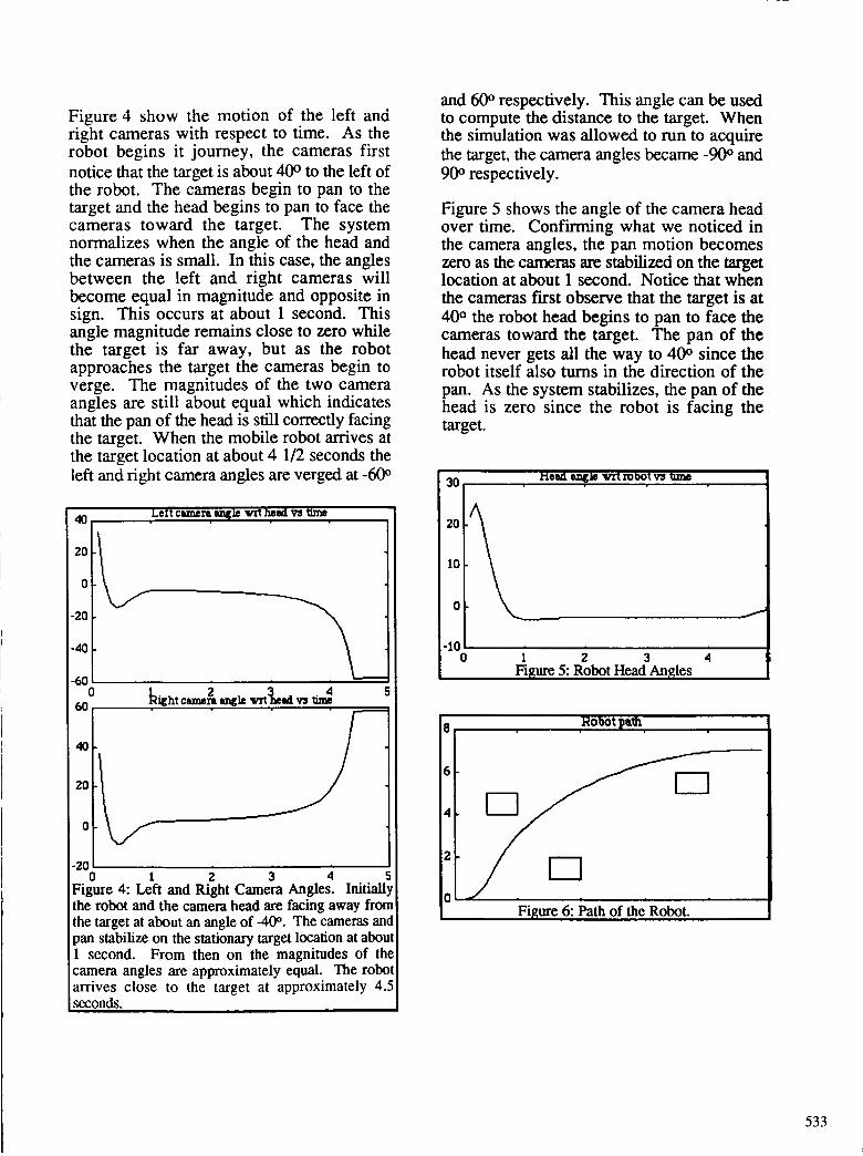
Figure 4 show the motion of the left andright cameras with respect to time. As therobot begins it journey, the cameras first
notice that the target is about 40 ° to the left ofthe robot. The cameras begin to pan to thetarget and the head begins to pan to face thecameras toward the target. The systemnormalizes when the angle of the head andthe cameras is small. In this case, the anglesbetween the left and right cameras will
become equal in magnitude and opposite insign. This occurs at about 1 second. Thisangle magnitude remains close to zero whilethe target is far away, but as the robotapproaches the target the cameras begin toverge. The magnitudes of the two cameraangles are still about equal which indicatesthat the pan of the head is still correctly facingthe target. When the mobile robot arrives atthe target location at about 4 1/2 seconds the
left and right camera angles are verged at -60 °
o6o
40
20
o
-2o0 1 2 3 4 S
Figure 4: Left and Right Camera Angles. Initiallythe robot and the camera head are facing away fromthe target at about an angle of -40 ° . The cameras and
pan stabilize on the stationary target location at about1 second. From then on the magnitudes of the
camera angles are approximately equal. The robotarrives close to the target at approximately 4.5seconds.
and 60 ° respectively. This angle can be usedto compute the distance to the target. Whenthe simulation was allowed to run to acquire
the target, the camera angles became -90 ° and
90 ° respectively.
Figure 5 shows the angle of the camera headover time. Confirming what we noticed in
the camera angles, the pan motion becomeszero as the cameras are stabilized on the targetlocation at about 1 second. Notice that when
the cameras first observe that the target is at
40 ° the robot head begins to pan to face thecameras toward the target. The pan of the
head never gets all the way to 40 ° since therobot itself also turns in the direction of the
pan. As the system stabilizes, the pan of thehead is zero since the robot is facing the
target.
30
20
10
0
.101 2 3 4
Figure 5: Robot Head An les
8--------_
6
4
2
0........_........._ 6: Path of the Robot.
533
Figure 6 shows the path of the robot to thestationary target at (10,7). The robot avoidsa couple of obstacles that were placed close tothe straight line path to the goal. Notice thatthe motion of the robot corresponds tosmooth forward trajectories that would bepossible with a nonholonomic robot thatwould be steered similarly to an automobile.
Finally, Figure 7 show the path of the robottracking a moving target. The target isfollowing a circular path with a changingradius. The target locations, denoted by an'x', begin at position (10,7) and end atposition (10.4, -4.75). The interesting thingis that even though the robot is not estimatingthe motion of the target, the path developedby the visual pursuit algorithm seems toanticipate the new location of the target andcorrectly intercepts it.
4.6. Discussion
In our system, the motion of the camerahead, panning the two cameras toward thetarget, is a redundant motion with the steeringof the robot. This motion is necessary to
allow the robot to freely manuever aroundobstacles without allowing the target to moveoutside the field-of-view of the cameras at the
maximum camera angles. This gives therobot the freedom to track a target that mayeven move behind the robot.
The architecture is very simple and providesfor much of the navigational and path
planning abilities necessary in the system.Unlike other path planning research, we arenot focusing on singular conditions in thepath planning (e.g. trapping in 'U' shapedobstacle on path to the goal.) This is becauseour system inherently has a human in theloop, who can select a new intermediatetarget to move the robot away for the trap.
We discovered that the all the joint motionswill oscillate if the response times of thecamera pans, head pan, and robot turning arethe same. Smooth paths were generated andsmooth positioning of the cameras wereobtained only if the response of the camerapans are faster than the response of the headpan which in turn is faster than the responseof the robot.
5. Deictic CommandSimulation
We have also extended our previouslydescribed simulation to explore the deicticprimitives that are necessary to perform ageneral purpose navigation. Our goal is is tocatalog a large number of environments andthe visually interesting or _trackable featuresof the environment. Each environment also
has a set of possible goal locations. Usingthis simulator, we test if the robot can
traverse from all starting locations to allpossible goals using deictic commands inreference to the visually distintive to the
targets.
We read polygonal environment descriptionsfrom an input file. We also mark on thesefiles, objects in the environment which we
feel are easily trackable by our video system.We currently have descriptions of a standardliving room and the third floor corridors ofone of the buildings at NortheasternUniversity.
Currently, we have implemented an approach
command where the robot directlyapproaches the target location. We showexamples of paths taken by our robot whencommanded to approach a sequence of
534
targets.The datadepictsthecorridorsof theNortheasternUniversityengineeringbuildingandwe navigateto targetswhich we feelaretrackableby video systemsin thecorridors.In Figure 8, we showtherobotnavigatinginthecorridors from just outsidetheelevatorson thethird floor of our Snellbuilding to thedoorwaybetweenSnellandDana. Therobotis issuedthreeapproachcommands:Thefirsttargetis the sign on avendingmachinenearthe end of the first corridor. The secondcommandsapproachesa doorknob on thedoorat the startof the secondcorridor. Thefinal commandapproachesthe sign on thedoorat theendof thecorridor.
In Figure 9, the robot goesto an office inSnell,againfrom outsidetheelevators.Therobot first approaches the fire alarmsmountedon thewall to the left neartheendofthefirst corridor. Then it approachesa signon a door office to round the corner. Asecondalarm becomesthe next target,andfinally, the poster in the office is used tonavigatetherobotinto theoffice.
6. Conclusions andFuture Work
Our initial work on integrating an active robothead into a navigation scenario has beenextremely promising. We have shown that asimple, 'follow your eyes' scenario issufficient for tracking a moving target. Inour situation, we do not plan extensive pathsthrough the field of obstacles but we rely on alow resolution sonar sensor to detect obstacle
locations. The motion of the joints on therobot head is smooth and can react to stepchanges in the target location. We enforce inour simulation a reasonable model of the
response of the mechanical systems and thelimitations of velocity and acceleration.
Because of this modeling of the robot motionlatency, the simulation produces realisticpaths of the robot.
We are implementing our algorithms on ourhardware platform and intend to developalgorithms for obstacle detection using the
active robot head. We will test this algorithmextensively to determine what steps we willneed to improve the algorithm to acheivebetter performance in many environments.We will also begin working on visionalgorithms that can robustly track manytargets. We want to develop a number ofvisually directed commands useful forgeneral navigation. Later, we will extend this
work to include targets and orientationconstraints. We hope to eventually develop aset of visual commands for manipulation aswell.
Not only does this system provide solutionsin current semi-autonomous applications, it isalso an alternative philosophy for developingfully-autonomous, general-purpose mobilerobot systems. Many researchers aredeveloping autonomous mobile robots whichcan navigate in limited situations, for exampleroad-following or corridor tracking. Theirphilosophy is to merge autonomous systemsperforming specific tasks and to derive ageneral purpose autonomous system. We,on the other hand, are developing a robust
mobile robot which can navigate in generalsituations. To make general mobilitypossible, our system will rely on morehuman interaction than typical mobile robotsystems. Over time we will decrease the
amount of user interaction by adding generalenvironmental knowledge to the systemthereby increasing the autonomy of thesystem. This will result in systems that areeasily configured to a number of applicationsincluding underwater and space exploration,flexible manufacturing, and roboticwheelchairs.
R.C. Arkin, "Navigational Path Planningfor a Vision-Based Mobile Robot,"Robotica, vol. 7, 49-63, 1989.
535
[3]
[4]
[5]
[6]
[7]
[8]
[9]
[IO1
[11]
[12]
J. Borenstein and Y. Koren,"Teleautonomous Guidance for MobileRobots," SMC, vol. 20, no. 6, 1437-1442,
Nov/Dec 1990.
R. Brooks, "A Robust Layered ControlSystem for a Mobile Robot," IEEE Trans.Robotics and Automation, vol. RA-2, no. 1,
14-23, 1986.
C.M. Brown, "The Rochester Robot," Tech.
Rep., Computer Science, 257, Sept 1988.
J.D. Crisman, "Color Vision for theDetection of Unstructured Roads and
Intersections," Ph.D. thesis, CarnegieMellon University, Dept. of Electrical and
Computer Engineering, May 1990.
J.D. Crisman, Y. Du, and M. Cleary,
"Adaptive Control of Camera Position forStereo Vision," in Optics, Illumination,and Image Sensing for Machine Vision VIII,SPIE, Boston, MA, September 1993,
invited paper.
J.D. Crisman and Y. Du, "Generic TargetTracking Using Color," in IntelligentRobotics and Computer Vision XII: ActiveVision and 3D Methods, SPIE, Boston,
M_A__September 1993, invited paper.
E.D. Dickmanns, B. Mysliwetz, and T.Christians, "An Integrated Spatio-TemporalApproach to Automated Visual Guidance ofAutonomous Vehicles," IEEE Trans. on
Systems, Man, and Cybernetics, vol. 20,no. 6, 1273-1284, Nov/Dec 1990.
J.T. Fennema and O.W. Mitchell, "Vision
Guided Servoing with Feature-BasedTrajectory Generation," IEEE Trans.Robotics and Automation, vol. 5, no. 5,
691-699, Oct. 1989.
C. Fennema, A. Hanson, E. Riseman, J.R.Bevride, and R. Kumar, "Model DirectedMobile Robot Navigation," SMC, vol. 20,no. 6, 1352-1369, Nov/Dec 1990.