IEEE TRANSACTIONS ON MILITARY ELECTRONICS Delay Line Secondaries in Phase-Modulated Sweep Integrators HARRY URKOWITZ, SENIOR MEMBER, IEEE Abstract-A video sweep integrator is a device for adding succes- sive radar returns of transmitted pulses. One type of sweep inte- grator uses an ultrasonic delay line for storage, requiring that the delay line transmission be in the form of a modulated carrier. Addition is obtained by means of a closed regenerative loop that operates for a finite time to provide uniformly weighted addition or operates continuously with exponentially decaying memory. The former type of operation is called iteration to distinguish it from the continuous operation called integration. This paper treats the case of phase modulation imposed upon the carrier. Delay line secondary, or spurious, responses result from multi- path propagation through the delay line. The cumulative effect of these secondaries after circulation in the sweep integrator or iterator may set a severe limitation on dynamic range. This paper treats two cases of secondary buildup: 1) the coherent buildup case in which relative buildup of secondaries is much greater than that of the signal, and 2) noncoherent buildup in which the built-up secondary effect is less than in the coherent case. It is suggested that it is possible to assure noncoherent secondary buildup by changing the carrier fre- quency in an irregular manner upon each circulation around the regenerative loop. NOMENCLATURE ei(t) =delay line input eo(t) =delay line output Co =relative transmission of main delay path Cj =relative transmission of jth secondary path CMu = relative transmission of strongest secondary path to=time delay of main delay path tj=time delay of jth secondary path 01(t) =total phase of ei(t) Oo(t) = total phase of eo(t) wo= 27r times carrier frequency at the delay line input I(t) =signal component of 61(t), 1(t) =01(t) -w0t H(t) = phase deviation of eo(t) k = feedback factor of continuous sweep integrator n =number of circulations in the iterator I, =peak value or "amplitude" of the phase devia- tion of short pulse video input (5=pulse duration tm= time delay of strongest secondary bjr = sin [wo (to -1tj) + I(t - t j) - I(t -to) I o-lI2= variance of largest secondary after random (or noncoherent) buildup Od= variance of distortion after random (nonco- herent) buildup 0 '(t)=unmodulated 01(t) 6o'(t) =unmodulated 6o(t) Manuscript received June 10, 1964; revised January 8, 1965. The author is with the General Atronics Corp., Wyndmoor, Pa. He was formerly with Philco Corp., Blue Bell, Pa. INTRODUCTION A PREVIOUS PAPER [1 ] treats the effects of delay line secondary responses in carrier-type sweep integrators in which the modulation imposed upon the carrier is either amplitude or frequency modu- lation. The present paper considers a carrier sweep inte- grator that has phase modulation. The use of phase modulation has some advantage in loop stability, but it is not the author's purpose to discuss this aspect. In [1 ] some experimental results, as well as theoretical analysis, are presented. In the present paper only the- oretical results are given. As in [1], both iterators and integrators are considered. A sweep integrator consists, essentially, of a closed loop containing a delay medium, such as an ultrasonic delay line. The magnitude of the loop gain, called "feedback factor," is less than unity. An iterator is structurally sim- ilar, but differs in that a number of successive traces are added with unity feedback factor; the sum is then read out and the loop modulation is wiped out. The process is then repeated. As a matter of collateral interest, an article by Cooper [2] on secondaries in an experimental AM sweep inte- grator deserves mention. Basic to the analysis in [1], as well as in the present paper, is the assumption that the secondaries are very small compared to the primary sig- nal. Cooper describes an AM integrator in which at least one secondary is sizable and suggests that some AM secondaries may be reduced or eliminated by vary- ing the carrier frequency. Two forms of a phase-modulated sweep integrator are shown in Fig. 1. Figure 1(a) is straightforward. In Fig. 1(b), there are two feedback paths for the signal; one path is regenerative and is completely at carrier. The successive phase deviations are added at the phase modulator, resulting in an effective feedback factor of unity for this path. To get a feedback factor less than unity, a small amount of degeneration is introduced at video by an auxiliary path from output to input. This degenerative weighting is 1-k, where k is the overall feedback factor. The sweep integrator may be made to operate as an iterator by imposing the proper gating on the weighting amplifier. As it was shown in [1], in an iterator having n circu- lations, the signal buildup is by a factor n. In an inte- grator with feedback factor k, the signal buildup factor is 1- kn 1 1 + k + k2+ kn.1.= n--+=_> as n xc. 1-k 1-k 189
Transcript
IEEE TRANSACTIONS ON MILITARY ELECTRONICS
Delay Line Secondaries in Phase-Modulated Sweep Integrators
HARRY URKOWITZ, SENIOR MEMBER, IEEE
Abstract-A video sweep integrator is a device for adding succes-sive radar returns of transmitted pulses. One type of sweep inte-grator uses an ultrasonic delay line for storage, requiring that thedelay line transmission be in the form of a modulated carrier.Addition is obtained by means of a closed regenerative loop thatoperates for a finite time to provide uniformly weighted addition oroperates continuously with exponentially decaying memory. Theformer type of operation is called iteration to distinguish it from thecontinuous operation called integration. This paper treats the caseof phase modulation imposed upon the carrier.
Delay line secondary, or spurious, responses result from multi-path propagation through the delay line. The cumulative effect ofthese secondaries after circulation in the sweep integrator or iteratormay set a severe limitation on dynamic range. This paper treats twocases of secondary buildup: 1) the coherent buildup case in whichrelative buildup of secondaries is much greater than that of the signal,and 2) noncoherent buildup in which the built-up secondary effect isless than in the coherent case. It is suggested that it is possible toassure noncoherent secondary buildup by changing the carrier fre-quency in an irregular manner upon each circulation around theregenerative loop.
NOMENCLATURE
ei(t) =delay line inputeo(t) =delay line outputCo =relative transmission of main delay pathCj=relative transmission of jth secondary pathCMu = relative transmission of strongest secondary
pathto=time delay of main delay pathtj=time delay of jth secondary path
01(t) =total phase of ei(t)Oo(t) = total phase of eo(t)wo= 27r times carrier frequency at the delay line
inputI(t) =signal component of 61(t), 1(t) =01(t) -w0tH(t) = phase deviation of eo(t)
k = feedback factor of continuous sweep integratorn =number of circulations in the iteratorI, =peak value or "amplitude" of the phase devia-
tion of short pulse video input(5=pulse durationtm= time delay of strongest secondarybjr = sin [wo (to -1tj) + I(t - tj) - I(t -to) Io-lI2= variance of largest secondary after random (or
noncoherent) buildupOd= variance of distortion after random (nonco-
Manuscript received June 10, 1964; revised January 8, 1965.The author is with the General Atronics Corp., Wyndmoor, Pa.
He was formerly with Philco Corp., Blue Bell, Pa.
INTRODUCTION
A PREVIOUS PAPER [1 ] treats the effects of delayline secondary responses in carrier-type sweepintegrators in which the modulation imposed
upon the carrier is either amplitude or frequency modu-lation. The present paper considers a carrier sweep inte-grator that has phase modulation. The use of phasemodulation has some advantage in loop stability, butit is not the author's purpose to discuss this aspect. In[1 ] some experimental results, as well as theoreticalanalysis, are presented. In the present paper only the-oretical results are given.As in [1], both iterators and integrators are considered.
A sweep integrator consists, essentially, of a closed loopcontaining a delay medium, such as an ultrasonic delayline. The magnitude of the loop gain, called "feedbackfactor," is less than unity. An iterator is structurally sim-ilar, but differs in that a number of successive tracesare added with unity feedback factor; the sum is thenread out and the loop modulation is wiped out. Theprocess is then repeated.As a matter of collateral interest, an article by Cooper
[2] on secondaries in an experimental AM sweep inte-grator deserves mention. Basic to the analysis in [1], aswell as in the present paper, is the assumption that thesecondaries are very small compared to the primary sig-nal. Cooper describes an AM integrator in which atleast one secondary is sizable and suggests that someAM secondaries may be reduced or eliminated by vary-ing the carrier frequency.Two forms of a phase-modulated sweep integrator
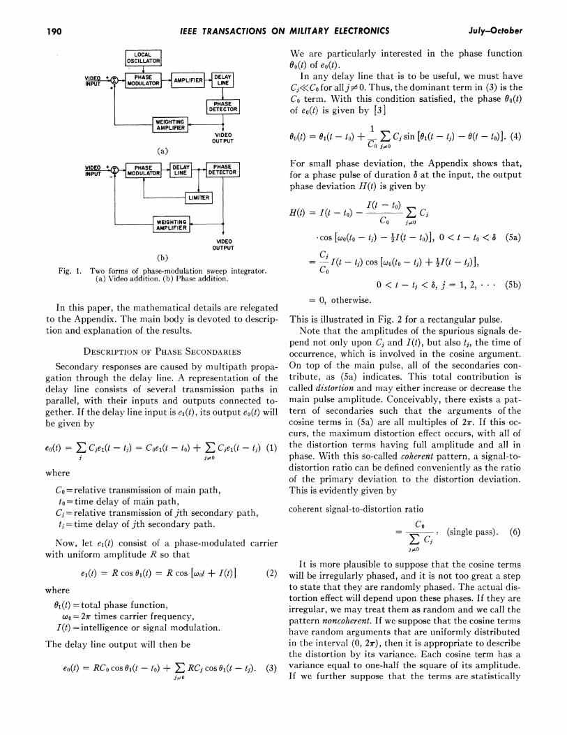
are shown in Fig. 1. Figure 1(a) is straightforward. InFig. 1(b), there are two feedback paths for the signal;one path is regenerative and is completely at carrier.The successive phase deviations are added at the phasemodulator, resulting in an effective feedback factor ofunity for this path. To get a feedback factor less thanunity, a small amount of degeneration is introduced atvideo by an auxiliary path from output to input. Thisdegenerative weighting is 1-k, where k is the overallfeedback factor.The sweep integrator may be made to operate as an
iterator by imposing the proper gating on the weightingamplifier.As it was shown in [1], in an iterator having n circu-
lations, the signal buildup is by a factor n. In an inte-grator with feedback factor k, the signal buildup factoris
1- kn 11 + k + k2+ kn.1.= n--+=_> as n xc.
1-k 1-k
189
IEEE TRANSACTIONS ON MILITARY ELECTRONICS
LOCALOSCILLATOR
VIDEO +< > HAMPL_ AMPLIFIERR D
IDTECTOR
|WEIGHTINGAMPLIFIER
VlIDEOOUTPUT
(a)
VIDEO + DEA PHASPAEINPUT MODUATO LINE ;DETECTOR
WEIGHTINGL I,iAMPLIFIER
VIDEOOUTPUT
(b)Fig. 1. Two forms of phase-modulation sweep integrator.
(a) Video addition. (b) Phase addition.
In this paper, the mathematical details are relegatedto the Appendix. The main body is devoted to descrip-tion and explanation of the results.
DESCRIPTION OF PHASE SECONDARIES
Secondary responses are caused by multipath propa-gation through the delay line. A representation of thedelay line consists of several transmission paths inparallel, with their inputs and outputs connected to-gether. If the delay line input is el(t), its output eo(t) willbe given by
Co= relative transmission of main path,to=time delay of main path,C =relative transmission of jth secondary path,tj=time delay of jth secondary path.
Now, let ei(t) consist of a phase-modulated carrierwith uniform amplitude R so that
el(t) = R cos 01(t) = R cos [cot + I(t)] (2)
where01(t) = total phase function,W =2r times carrier frequency,
I(t) =intelligence or signal modulation.
The delay line output will then be
eo(t) = RCo cos 01(t - to) + E RCj cos 01(t - tj). (3)j O
We are particularly interested in the phase functionGo(t) of eo(t).
In any delay line that is to be useful, we must haveCj<<Co for all ji 0. Thus, the dominant term in (3) is theCo term. With this condition satisfied, the phase 6o(t)of eo(t) is given by [3]
For small phase deviation, the Appendix shows that,for a phase pulse of duration 8 at the input, the outputphase deviation H(t) is given by
I(t- to) z
co jso
-cos [oo(to - tj)- I(t - to)], 0 <1- to < a (5a)
Ci=- I(t - tj) cos [wo(to -tj) + II(t -tj)
Co
0 < t-tj < 6, j = 11 2, . . . (5b)= 0 otherwise.
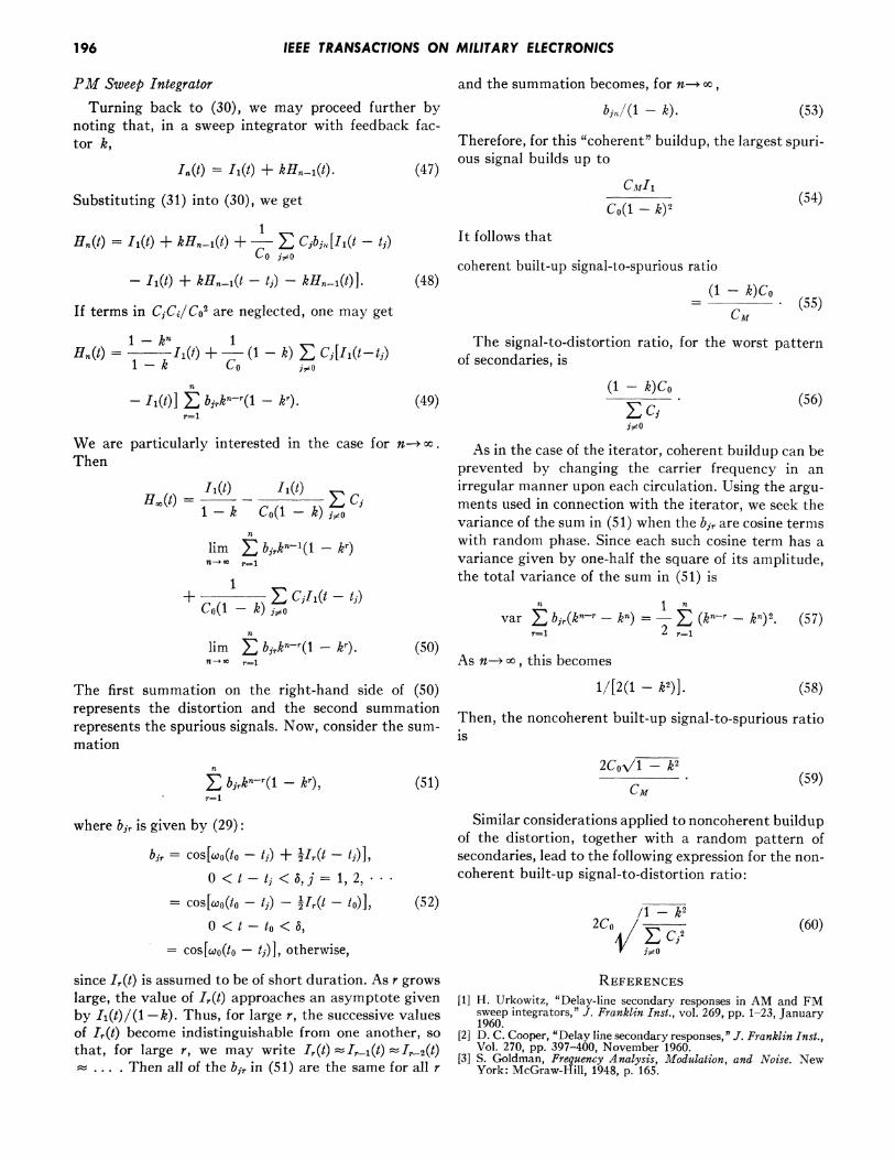
This is illustrated in Fig. 2 for a rectangular pulse.Note that the amplitudes of the spurious signals de-
pend not only upon Cj and I(t), but also tj, the time ofoccurrence, which is involved in the cosine argument.On top of the main pulse, all of the secondaries con-tribute, as (5a) indicates. This total contribution iscalled distortion and may either increase or decrease themain pulse amplitude. Conceivably, there exists a pat-tern of secondaries such that the arguments of thecosine terms in (5a) are all multiples of 2r. If this oc-curs, the maximum distortion effect occurs, with all ofthe distortion terms having full amplitude and all inphase. With this so-called coherent pattern, a signal-to-distortion ratio can be defined conveniently as the ratioof the primary deviation to the distortion deviation.This is evidently given by
coherent signal-to-distortion ratioco
-I (single pass). (6)
It is more plausible to suppose that the cosine termswill be irregularly phased, and it is not too great a stepto state that they are randomly phased. The actual dis-tortion effect will depend upon these phases. If they areirregular, we may treat them as random and we call thepattern noncoherent. If we suppose that the cosine termshave random arguments that are uniformly distributedin the interval (0, 27r), then it is appropriate to describethe distortion by its variance. Each cosine term has avariance equal to one-half the square of its amplitude.If we further suppose that the terms are statistically
190 July-October
H(l) = I(t to)
Urkowitz: Phase-Modulated Sweep Integrators
I (t)
H(a)
-. 8 >-
SPURIOUS SIGNALS
(b)Fig. 2. Phase deviation of delay input and output with pulse PM
input. (a) Phase deviation of delay line input. (b) Phase deviationof delay line output.
independent, the total variance will be the sum of theindividual variances. Thus, with a random or nonco-herent secondary pattern,
noncoherent signal-to-distortion ratio2C0
= ( eC2)1/2 (single pass). (7)
iso
As for the spurious responses, let us concentrate onthe largest one, indicated by the index j =M. If theargument of its cosine function is a multiple of 2ir, thefull value CM will be effective. T'hen the single passratio of main signal to spurious s,ignal will be simply
Cosignal-to-spurious ratio = (single pass). (8)
CM
This is the lowest value for the signal-to-spurious ratio.
SECONDARIES IN PM ITERATION
When the delay line is used in an iterator, successiveinputs are added; the secondaries are also added, butthese may be built up to a greater relative extent thanthe primary signal. Let us trace through the addition ofseveral pulses. Let the input to the iterator be a trainof uniform pulses with a period to. As the first pulse-phase deviation arrives at the delay line output, it isaccompanied by its pattern of secondaries, the largesthaving a transmission CM. We concentrate upon thisone. The next pulse in the input pulse train causes adeviation that adds directly to the deviation of the firstpulse. The result is a pulse deviation twice as large asbefore. This larger deviation produces a secondary withamplitude proportional to the second pulse deviationand, therefore, twice asWlarge as the secondary ampli-tude from the first pulse. This second secondary occursat the same time as the first secondlary. The resultant, orcombined, amplitude depends upon the arguments of thecosines associated with each of these secondaries. As suc-
cessive primary pulses are added, the number of secon-daries occurring at the same time increases propor-tionately. The amplitude of the rth successive secondaryis r times the amplitude of the first. Thus, after the addi-tion of n primary pulses, the largest secondary is theresultant of n secondaries whose amplitudes form anarithmetic progression. However, the cosine argumentsare another story. The actual secondary buildup de-pends upon these arguments. The worst possible caseoccurs when they are all multiples of 2-r. We call this"coherent" buildup. Since the sum of the first n integersis n(n+l)/2, coherent buildup results in a secondaryamplitude n(n+l)/2 times the amplitude of the singlepass amplitude. Recalling that the signal builds up ntimes, the coherent built-up signal-to-spurious ratio isgiven by
coherent built-up signal-to-spurious ratio
2Cm(n + 1)CM
(9)
In general, of course, the secondary buildup will notbe coherent. It would be most desirable that the buildupbe of such a nature that the secondary terms wouldcancel. This is too much to hope for, however; the bestwe can reasonably hope for is that the arguments of thecosines be made random. As explained in the Appendix,this condition can be approximated by changing thecarrier frequency in an irregular manner from circula-tion to circulation. When this is done, the cosine termsin the secondary buildup have random arguments, andthe buildup is termed noncoherent. In defining the built-up signal-to-spurious ratio, an appropriate quantity touse for the secondary is the built-up variance. Sinceeach cosine factor has a variance of one-half the squareof its amplitude, the variance o,,2 of the largest built-upspurious will be
I12CM2 n 2=I2n(n + 1)(2n + l)CM22C02 r=l 12C02
(10)
where A1 is the peak value or "amplitude" of I1(t).Then,the built-up signal-to-spurious ratio with noncoherentbuildup is
ninoncoherent built-up signal-to-spurious ratio =
CM
2Co / 3n
CM (n + 1)(2n + 1)(11)
which is valid for large n.It may be seen that the essential distinction between
coherent and noncoherent spurious buildup is that, rela-tive to the primary signal, coherent spurious buildup isproportional to n, whereas noncoherent spurious build-up is proportional to V/n.
Similar considerations apply to the buildup of dis-
1911965
co 6y
cm n
IEEE TRANSACTIONS ON MILITARY ELECTRONICS
tortion; we consider two cases: 1) the buildup is co-herent with a coherent secondary pattern; and 2) thebuildup is noncoherent with a noncoherent secondarypattern. The resulting ratios, derived in the Appendix,are
built-up coherent signal-to-distortion ratio
2CO
(n + 1) ECjj?O
built-up noncoherent signal-to-spurious ratio
3n2
/ (n + 1)(2n + 1) Cj2
/ 6
In 'ECj2 (3
SECONDARIES IN PM INTEGRATION
We turn now to the continuous sweep integrator. Letthe input consist of a periodic sequence of pulses withperiod to. For n pulses, the signal deviation builds up to(1-kn)/(1 -k) times the deviation of a single pulse. Asn-* o, the buildup factor becomes 1/(1 -k). Thus, aftersufficient time, the pulse deviation being circulated is aconstant, and the secondary caused by each circulationadds to the secondary of the previous trace whose am-plitude is reduced to k (the feedback factor) times itsoriginal amplitude. The successive secondaries pile upon top of one another, and their amplitudes form ageometric progression: 1, k, k2, k3, . . . . The resultantamplitudes depend on the cosine arguments. If these areall multiples of 27r, the secondary contributions will allbe in phase and will have their full amplitude. Thus, thebuildup factor for each spurious signal is 1/(1 -k) timesthe buildup factor for the primary signal. Under thiscoherent buildup, the signal-to-spurious ratio is given by
coherent built-up signal-to-spurious ratio
(1 - k)CO= (______) ° (14)CM
It can be seen that, for k close to unity, coherent spuri-ous buildup can be very serious.The situation will not be so severe if the buildup is
random or noncoherent. This condition can be achieveddeliberately as explained in the last section by irregularchange of carrier frequency. In this case, we are in-terested in the variance of the built-up spurious signal,which is proportional to 1/(1 -k2). Then, the built-upsignal-to-spurious ratio for noncoherent buildup is
(2CoV1 - k2)/CM. (15)
Similarly, it is shown in the Appendix that the built-up signal-to-distortion ratio is given by
1) For coherent buildup and a coherent secondarypattern,
signal-to-distortion ratio = (1 k)Coz jjHO
(16)
2) For noncoherent buildup and a noncoherentsecondary pattern,
/1 -k2signal-to-distortion ratio = 2Co EC./ 2
jO
(17)
CONCLUSIONS
An ultrasonic delay line is a useful device for obtain-ing long delay with a large bandwidth and is, therefore,very useful in radar sweep integration (or iteration) foradding successive received video traces. However, itssecondary responses, which are caused by multipathpropagation through the delay line, constitute a formof self-interference. This paper analyzes the effects ofthese secondaries when phase modulation is used on thecarrier wave passing through the delay line. A train ofvideo pulses at the integrator input causes phase devia-tions that build up as successive sweeps are circulated.The secondaries caused by the signal pulses also circu-
late and build up. The way in which they build updepends on how they are phased with respect to oneanother and on how these secondary phases are relatedafter repeated circulation. We have considered twocases, one in which the secondaries are so phased thatthey build up to their maximum extent, such buildupbeing called coherent. With coherent buildup, the sec-ondaries build up much more rapidly than the signaland can set a severe limitation on the dynamic range ofthe iterator or integrator. The other case treated is thatof noncoherent buildup in which the secondaries stillbuild up more rapidly than the signal, but not so rapidlyas in coherent buildup. The secondary responses causetwo effects. One effect is called distortion and affectsthe built-up primary by causing its amplitude to be dif-ferent from what it should be. The other effect producesspurious responses; all of these have the same nature, sowe have concentrated upon the larger one.
Signal-to-distortion and signal-to-spurious ratios havebeen defined both for the coherent and noncoherentcases. The coherent signal-to-secondary (distortion orspurious) ratio is straightforwardly defined as the ratioof peak signal to peak secondary effect. In the nonco-herent case, we have treated the secondaries as ran-domly phased during buildup and have, therefore, de-fined a signal-to-spurious ratio as the peak signal tosecondary standard deviation, the secondary variancedefined as the sum of the squares of the amplitudes ofthe contributing members divided by two.
In coherent buildup, the signal-to-secondary ratio isinversely proportional to the number of circulations;
July-October192
Urkowitz: Phase-Modulated Sweep Integrators
whereas in noncoherent buildup, the signal-to-secondaryratio is inversely proportional to the square root of thenumber of circulations. For the sweep integrator, thecoherent buildup signal-to-secondary ratio is propor-tional to (1 - k), where k is the feedback factor of theintegrator. With noncoherent buildup the signal-to-secondary is proportional to the square root of (1- k2).Although it is possible that the conditions of opera-
tion would cause noncoherent buildup, one cannot besure that this would always be so. It is suggested thatnoncoherent buildup can be assured by irregular changeof the carrier frequency as the traces circulate aroundthe iterator or integrator.
In the previous paper [1] it was pointed out that theFM secondaries in response to a pulse input take theform of ripples whose frequency depended on the fre-quency deviation caused by the pulse input. Therefore,what was of interest there was the properties of theenvelopes of these secondary ripples. In random buildupthese ripples would have a Rayleigh distribution whoseaverage value is V/ir/2 times the standard deviation ofthe sum of the ripple components making up theresultant built-up secondary.On the other hand, in the PM case, the secondaries do
not manifest themselves as ripples in response to apulse input. They appear as actual spurious pulseswhose resultant height after buildup is a random vari-able that is the sum of a number of cosine random vari-ables, not cosine functions of time. Thus, the resultantheight of built-up secondary pulse actually tends tobecome a Gaussian random variable after a large num-ber of circulations having a mean value zero and avariance given by the sum of the component variances.Thus, a suitable measure of signal-to-secondary ratio inthe PM case involves the ratio of signal amplitude tosecondary standard deviation. It follows that a simplecomparison of signal-to-secondary ratios for the FM andPM cases_ should show that they are different by afactor -Vr/2.
This is an appropriate place to point out an algebraicerror in the previous paper [1]. The quantity labelledRo, the secondary rms sum after buildup, should bedecreased by a factor V\2, so that the formulas for aver-age relative distortion and average relative maximumspurious signal should have their right-hand sides multi-plied by \/2.
APPENDIX
GENERAL DESCRIPTION OF SECONDARIES
In the analysis to follow, [1] is heavily drawn upon.If the delay line input is ei(t) and the output is eo(t), then
eo(t) = E Ciei(t - 1j)i
= Coei(t- to) + E Cjel(t - tj) (18)jSo
whereCo= relative transmission of main path,to= time delay of main path,Cj=relative transmission of jth secondary path,tj= time delay of jth secondary path.
Let the input to the delay line be
el(t) = R cos 01(t) (19)
where R is the amplitude of the input, and El(t) is thetotal phase variation of the input. Then,
eo(t) = RCo cos 01(t - to) + E RCj cos 01(t - tj)j9o
(20)
It is assumed that Cj<<Co forj 0. With this assumptionthe total phase 0o(t) at the delay line output is [3]
0o(t) = OI(t -to)
+ E Cj sin [01(t - tj) - 1(t - to). (21)Co i"60
Now it is necessary to find that part of (21) whichrepresents the actual phase deviation. At the input tothe delay line the actual signal deviation I(t) imposedis the difference between 01(t) and wot, where co is 2irtimes the carrier frequency:
I(t) = 01(t) -coot. (22)
That is, the unmodulated value of 01(t) is wot. When thisis substituted into (21), the result is the unmodulatedvalue 6o'(t) of Go(t):
1001(t) = wo(t - to) + - E C1 sin coo(to - t3).
Cojs0(23)
The resulting phase deviation H(t) at the delay lineoutput is
H(t) = Oo(t) -Oo(t)
- I(t -t0) + C E Cj| sin [wo(to - tj) + I(t - tj)
- I(t - t)] - sin co(to - tj)}
= I(t -to) +- Cj sin 2 [I(t -ti) - I(- to)J2oCo iso
[cs[Coo(to - tj) + 2I(t - tj) - 1I(t - to)]. (24)
Generally, the interest in this paper will be confinedto small phase deviation. Consequently, since sin x xfor small x, (24) may be written
The first term on the right-hand side of (25) representsthe main signal, and the remaining terms are the un-wanted secondaries. The nature of these products de-
1 965 193
IEEE TRANSACTIONS ON MILITARY ELECTRONICS
pends upon the input signal 1(t). To be specific, let I(t)be a short pulse (not necessarily rectangular) of dura-tion a so that there is no overlap of secondaries. Then(25) may be written as follows:
1H(t) = I(t - to) - I(t - to) Cjcos [co(to - tj)
co jFO
-2i(t -to)], O < t -to < a (26a)
- CjI(t - tj) cos [co(to - tj) + I(t -tj)co2
0 < t -tj < 6, j = 1, 2, (26b)= 0, otherwise.
In (26a), the summation on the right-hand side repre-sents the distortion, so-called because the terms all existat the same time as the signal component of the outputand they distort the value of I(t-to). The maximumpossible amplitude of the distortion would occur whenall the cosine terms have phases that are multiples of2wr. Then, the signal-to-distortion ratio would be
co E c3.jFO
Conceivably, there exists a certain pattern of secondar-ies which will produce this common phasing, but thisevent should be rare. As explained in connection with(7), it is more plausible to suppose that the secondaryterms are randomly phased, leading to (7) for the singlepass noncoherent signal-to-distortion ratio.
.In (26b), because of the assumption of no overlap for
a short input pulse, the individual terms occur at dif-ferent times. Concentrating on the largest of these spuri-ous signals (j= M), it can be seen that the single passsignal-to-spurious ratio is given by (8).
If the input pulse is extended in time, some of thesecondaries overlap in time, because I(t-to) and I(t-tj)overlap more and more for one or more values of j. Then,according to (25), the amplitude of the distortion woulddecrease. On the other hand, the spurious signals wouldincrease in amplitude as more secondaries overlap at thesame point in time. As the pulse duration becomeslarge, the distortion and spurious signals change roles.Thus, for the extended pulse, the signal-to-distortionratio approaches Co/CM, the minimum signal-to-spuri-ous ratio approaches
PM ITERATION AND PM SWEEP INTEGRATIONWhen the delay line is used in a phase-modulated
(PM) sweep integrator or iterator, successive inputs areadded. The secondary responses are also added and arebuilt up to a greater relative extent. In an iterator, nsuccessive inputs are added with the same weightingfactor and the sum is read out. The device is then wipedclean and the operation repeated. In a sweep integrator,the device operates continuously; each output is multi-plied by a feedback factor k and then added to theinput.
For pulses of short duration, there is no overlap amqngthe various terms of (33), which then can be written as
Hn(t) = nIj(t) - >2 C ( E rbjr)Co j;O r=1
1 n~+-E Cj E> rbir) 1(t - tj).
C0 j4O \ r=l(34)
The value of the built-up signal is n1l, where h1 is thepeak value or "amplitude" of 11(t) indicated simply byomitting the argument. The value of the distortion andof the spurious signal depends on just how the buildupoccurs. Considering, first, the largest spurious response,its value is given by
CMIl n
C 2 rbMr.CO r=l
194 July-October
Urkowitz: Phase-Modulated Sweep Integrators
If bMr [see (29) ] has a phase that is a multiple of 2r forevery value of r, we say that the spurious buildup is co-herent. Since
n
Z r = n(n + 1)/2, (36)r=1
with coherent buildup the largest spurious signal buildsup to
n(n + l)CMIl
2C0(37)
Therefore, it follows that
2C0built-up signal-to-spurious ratio = (38)
(n + 1)Cm
The built-up distortion depends on the particularpattern of secondaries as well as on how the phase ofeach bjr changes with r. The worst possible situationoccurs when all the b,r have phases that are multiples of2r. In this case,
coherent built-up distortion = n(n + )Il CC. (39)2Co jxo
It follows that
coherent built-up signal-to-distortion ratio
2CO- ~~~~~(40)(n + 1) E Cjj#o
Equations (38) and (40) show that the secondariesget relatively worse as the number of additions in theiterator increases. Clearly, if n is large, the secondariesmay severely limit the dynamic range. It is natural toask whether anything can be done to prevent coherentbuildup. The answer lies in (29). Suppose that the car-rier frequency were changed in an irregular manner uponeach circulation. Then (29) would become
n
var Erbir =r=l
1 n n(n + 1)(2n + 1)
2 r-1 12(42)
Then, from the final term of (34), the variance oM2 of thelargest spurious signal is
(JM =
CM2n(n + 1)(2n + 1)I,21 2CO2 (43)
With this sort of secondary buildup, called "random"or "noncoherent" buildup, the signal-to-spurious ratiocan be defined conveniently as the ratio of n1l to SM.Thus,
noncoherent built-up signal-to-spurious ratio
2Co / 3n
CM V (n + 1)(2n + 1)
CO 6ztI /-ICM/ n
(44)
which is valid for large n.Similar considerations apply to the noncoherent or
random buildup of the distortion terms, with the addi-tional consideration that the actual value of the built-up distortion depends upon the pattern of secondaries.Previously, we noted that the worst distortion occurswhen all of the secondary terms on any circulation havetheir phases equal to a multiple of 27r. Now, this sort ofphasing ought to occur rarely. Instead, we suppose thatthe pattern is such that the phases are random on eachcirculation. In this case, the distortion is appropriatelydescribed by its variance 0Td2- Straightforward calcula-tion from (34) yields
where wor is the (angular) carrier frequency on the rthcirculation. Of course, it will be necessary to keepaccurate track of the carrier frequency for proper de-modulation of the signal. Also, there may be consider-able practical difficulty in the design of the necessarycircuits, and although I have no wish to depreciate thedifficulties, such considerations are beyond the scope ofthis paper.
Let it be assumed that the carrier frequency ischanged in such a way that the terms in (41) are randomwith phases uniformly distributed in the interval (0, 27r)and that the terms are statistically independent. Eachbjr has a variance of 2; it follows that the variance ofthe sum of the rbjr terms is given by
The signal-to-distortion ratio is the ratio of n1l to ogd:noncoherent built-up signal-to-distortion ratio
~3n= VC n(n + 1)(2n + 1) E Cj2
V/6Co(46)
n Cc2jq,-o
Essentially, the comparison between coherent andnoncoherent secondary buildup is that, relative to thesignal, in coherent buildup the secondary buildup isproportional to n and in noncoherent buildup thesecondary buildup is proportional to Vn.
1 965 195
,
IEEE TRANSACTIONS ON MILITARY ELECTRONICS
PM Sweep IntegratorTurning back to (30), we may proceed further by
noting that, in a sweep integrator with feedback fac-tor k,
(47)Substituting (31) into (30), we get
1Hn(t) = Il(t) + kHn-1(t) + - Cjbj,[I1(t -t)
CO j3O
- Il(t) + kH,-.(t -tj) -kHn_l(t)] (48)
and the summation becomes, for n- oo,
bj (1 - k). (53)Therefore, for this "coherent" buildup, the largest spuri-ous signal builds up to
CMIr cmi, ~~~~~(54)Co(l - k)2
It follows that
coherent built-up signal-to-spurious ratio
(1 - k)CocMIf terms in CCi/Co2 are neglected, one may get (55)
Hn (t) =
We areThen
1 - kn-Ii(t) +-(1- k) E CjI i(t-tj)1-k Co0so
n- Il(t)] Z bjrk-r(1 - kr). (49)
r=ly
particularly interested in the case for n--+oo.
H(t) Il(t) __ I_(t)_E1-k Co(l -k) zo
n
lim E bjkn-1'(I - kr)n- X r==1
1+ E CjI1(t-tj)Co(l - k) jso
nlim E brkn-r(l - kr).n- o r=l
The first summation on the right-hand side of (50)represents the distortion and the second summationrepresents the spurious signals. Now, consider the sum-
mation
(50)
The signal-to-distortion ratio, for the worst patternof secondaries, is
(1 - k)Co / \
ECjjp40
(56)
As in the case of the iterator, coherent buildup can beprevented by changing the carrier frequency in anirregular manner upon each circulation. Using the argu-ments used in connection with the iterator, we seek thevariance of the sum in (51) when the bjr are cosine termswith random phase. Since each such cosine term has avariance given by one-half the square of its amplitude,the total variance of the sum in (51) is
nW 1 nvar E bj,(kn-r - kn) = -f (kn-r - kn)2
r=l 2 r=1
As n-> xo, this becomes
1/[2(1 - k2)].
(57)
(58)
Then, the noncoherent built-up signal-to-spurious ratiois
Similar considerations applied to noncoherent buildupof the distortion, together with a random pattern ofsecondaries, lead to the following expression for the non-coherent built-up signal-to-distortion ratio:
(52)0 < t - to < 8,
= cos[wo(to - t)], otherwise,
since Ir(t) is assumed to be of short duration. As r growslarge, the value of Ir(t) approaches an asymptote givenby Il(t)/(l -k). Thus, for large r, the successive valuesof 1I(t) become indistinguishable from one another, sothat, for large r, we may write Ir(t) Iri(t)I r2(t)
. .. . Then all of the by, in (51) are the same for all r
/1 - k
2CoV/1 C2j0
(60)
REFERENCES[1] H. Urkowitz, "Delay-line secondary responses in AM and FM
sweep integrators," J. Franklin Inst., vol. 269, pp. 1-23, January1960.
[2] D. C. Cooper, "Delay line secondary responses," J. Franklin Inst.,Vol. 270, pp. 397-400, November 1960.
[3] S. Goldman, Frequency Analysis, Modulation, and Noise. NewYork: McGraw-Hill, 1948, p. 165.