Technical coordination Guidelines Lead partners: Sandia National Laboratories and The University of Exeter Contributing partners: Tecnalia, DEME Blue Energy (DBE), WavEC Offshore Renewables Authors: Jason Heath, Richard Jensen, Jose Arguello Jr., Jesse Roberts, Diana Bull, Sandia National Laboratories; Sam Weller, Jon Hardwick, Lars Johanning, The University of Exeter This project has received funding from the European Union’s Seventh Programme for research, technological development and demonstration under grant agreement No 608597 Deliverable 4.2: Specific requirements for MRE foundation analysis
Transcript
Technical coordination Guidelines
Lead partners: Sandia National Laboratories and The University of Exeter
Contributing partners:
Tecnalia, DEME Blue Energy (DBE), WavEC Offshore Renewables
Authors: Jason Heath, Richard Jensen, Jose Arguello Jr., Jesse Roberts, Diana Bull, Sandia National Laboratories; Sam Weller, Jon Hardwick, Lars Johanning, The University of Exeter
This project has received funding from the European Union’s Seventh Programme for research, technological development and demonstration under grant agreement No 608597
Deliverable 4.2: Specific requirements for MRE
foundation analysis
Deliverable 4.2 – MRE Foundation Analysis
Doc: DTO_WP4_SNL_D4.2 Rev: 1.0 Date: 24.04.2014
2
D4.2: Report on specific requirements for MRE foundation analysis
Project: DTOcean - Optimal Design Tools for Ocean Energy Arrays
Code: DTO_WP4_SNL_D4.2
Name Date
Prepared Work Package 4 22.04.14
Checked Work Package 9 23.04.14
Approved Project Coordinator 25.04.14
The research leading to these results has received funding from the European Community’s Seventh Framework Programme under grant agreement No. 608597 (DTOcean). No part of this publication may be reproduced, stored in a retrieval system, or transmitted in any form – electronic, mechanical, photocopy or otherwise without the express permission of the copyright holders. This report is distributed subject to the condition that it shall not, by way of trade or otherwise, be lent, re-sold, hired-out or otherwise circulated without the publishers prior consent in any form of binding or cover other than that in which it is published and without a similar condition including this condition being imposed on the subsequent purchaser.
Deliverable 4.2 – MRE Foundation Analysis
Doc: DTO_WP4_SNL_D4.2 Rev: 1.0 Date: 24.04.2014
3
Deliverable 4.2 – MRE Foundation Analysis
Doc: DTO_WP4_SNL_D4.2 Rev: 1.0 Date: 24.04.2014
4
Executive Summary
Marine Renewable Energy (MRE) systems involve single or arrays of devices that
are secured to the seafloor via foundations and/or anchors. These MRE devices will
transmit long-term cyclic loads to the seafloor sediment or rock, which may affect
seafloor material properties and hence the overall physical performance of the MRE
system. The response of seafloor sediments or rock formations is uncertain for the
novel MRE systems and especially large arrays of 10s to >1000s of devices. This
report summarizes critical inputs and tools for the design and analysis of
foundations, anchors, and the response of the seafloor materials. Followed by an
introduction in Section 1, Section 2 reviews the offshore structure and MRE literature
to highlight current approaches and needed inputs for assessing interactions
between foundations or anchors and seafloor materials, including potential
environmental impacts. Section 3 addresses relevant marine geological settings that
control key geotechnical engineering properties. Data collection activities are
described, including in-situ site surveys and laboratory testing. Section 4 considers
the unique interactions between MRE systems and seafloor materials, particularly
cyclic loading and sediment response. Section 5 describes analytical and numerical
tools and associated inputs for the design process of MRE foundations and anchors.
Constitutive models are key to simulating sediment response and thus are discussed
in detail. Important summary tables relate key variables of geology, geotechnical
parameters, foundation or anchor type, and quantitative assessment tools including
numerical analysis. Section 5 also addresses the incorporation of the geotechnical
analysis into system-level tools to support decision making for MRE arrays. Section
6 presents conclusions and recommendations for future work.
settings that control key geotechnical engineering properties. Data collection
activities are described, including in-situ site surveys and laboratory testing. Section
4 considers the unique interactions between MRE systems and seafloor materials,
particularly cyclic loading and sediment response. Section 5 describes analytical and
numerical tools and associated inputs for the design process of MRE foundations
and anchors. Constitutive models are key to simulating sediment response and thus
are discussed in detail. Important summary tables relate key variables of geology,
geotechnical parameters, foundation or anchor type, and quantitative assessment
tools including numerical analysis. Section 5 also addresses the incorporation of the
geotechnical analysis into system-level tools to support decision making for MRE
arrays. Section 6 presents conclusions and recommendations for future work.
Deliverable 4.2 – MRE Foundation Analysis
Doc: DTO_WP4_SNL_D4.2 Rev: 1.0 Date: 24.04.2014
8
2. LITERATURE REVIEW ON MRE FOUNDATIONS AND ANCHORS
2.1 Special Foundation-Anchor Design Needs
MRE devices are a unique application for foundations and anchors, especially for
full-scale arrays [1]. It is necessary that several criteria specific to these devices are
satisfied for design, installation, and maintenance. A brief overview of these criteria
is provided in this section. For further information, the reader is directed to the report
DTOcean Deliverable 4.1 – A comprehensive assessment of the applicability of
available and proposed offshore mooring and foundation technologies and design
tools for array applications [6] as well as more general reference documents [7].
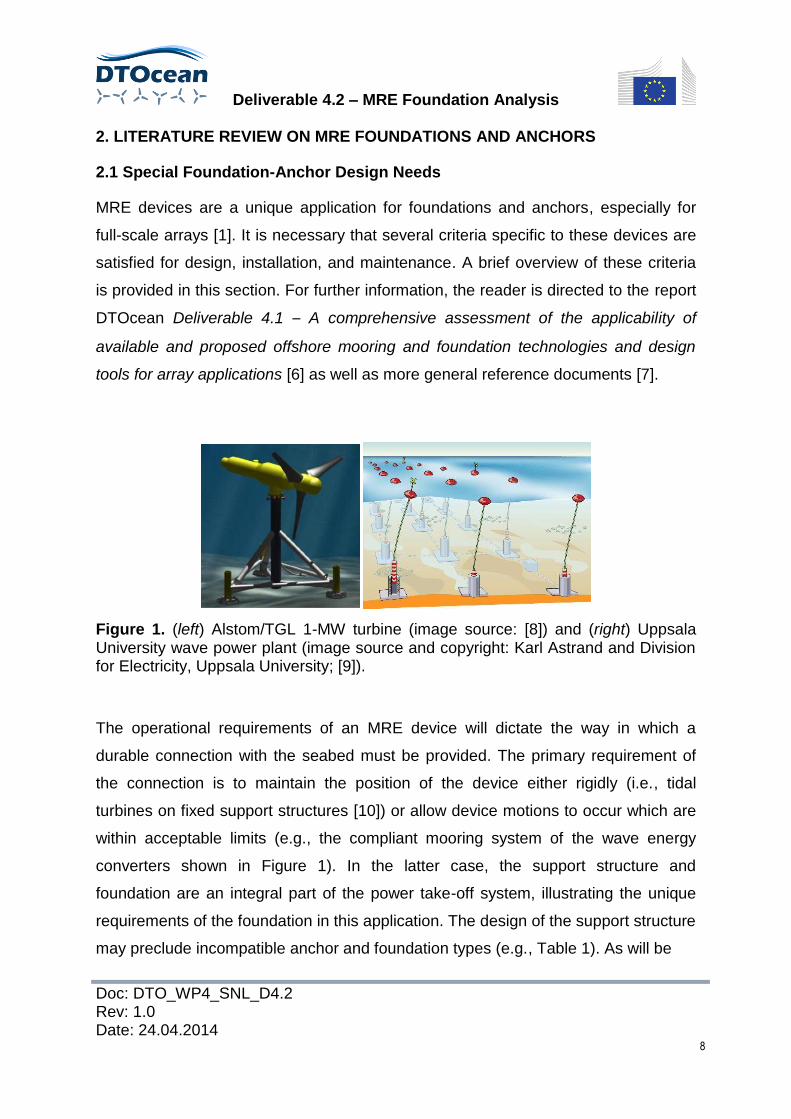
Figure 1. (left) Alstom/TGL 1-MW turbine (image source: [8]) and (right) Uppsala University wave power plant (image source and copyright: Karl Astrand and Division for Electricity, Uppsala University; [9]).
The operational requirements of an MRE device will dictate the way in which a
durable connection with the seabed must be provided. The primary requirement of
the connection is to maintain the position of the device either rigidly (i.e., tidal
turbines on fixed support structures [10]) or allow device motions to occur which are
within acceptable limits (e.g., the compliant mooring system of the wave energy
converters shown in Figure 1). In the latter case, the support structure and
foundation are an integral part of the power take-off system, illustrating the unique
requirements of the foundation in this application. The design of the support structure
may preclude incompatible anchor and foundation types (e.g., Table 1). As will be
Table 1. Compatibility matrix for tidal turbine foundations and anchors.
discussed in this report, initial design selections such as these will determine which
analysis techniques are used to determine the seafloor material response (see
Section 5).
Guidance produced by certification agencies such as Det Norske Veritas is used to
ensure that the designed and specified components are adequately durable and
reliable for the application (e.g., [11]). Component durability incorporates the
capacity to withstand infrequent peak loads as well as the effects of load cycling,
environmental exposure, and changes in material properties over time. Reliability
requirements are likely to be specified over different time-scales (i.e., over the entire
deployment lifetime or between maintenance and/or replacement intervals).
Guidance on these aspects exists for MRE devices, such as DNV-OSS-312 [12], the
DNV/Carbon Trust Guidelines on design and operation of wave energy converters
[13], and forthcoming International Electrotechnical Commission/TC 114 guidelines
[14]. These documents largely refer back to existing offshore guidance for
foundations and anchors (e.g. DNV-OS-C101 [15] for steel structures and DNV-OS-
Deliverable 4.2 – MRE Foundation Analysis
Doc: DTO_WP4_SNL_D4.2 Rev: 1.0 Date: 24.04.2014
10
E301 Position Mooring [16]) with consequence criteria modified for this new
application. Whilst insight into MRE foundation and anchor durability and analysis is
provided by a few studies (e.g., [17]), in the absence of deployment examples
lessons can be learnt from similar foundations used in different applications, such as
offshore wind turbines [18] and offshore platforms [19].
The economics of foundations and moorings will have a significant influence on
which technology is selected. With the exception of off-the-shelf components (such
as anchors and connecting hardware), costs are design dependent and highly
variable (i.e., the commodity cost of steel [20]). Indicative capital costs for monopile
installations can be drawn from the offshore wind industry, such as the UK Energy
Research Centre’s Great Expectations report [21]. Installation, maintenance, and
decommissioning costs bring added complexity due to the variability of vessel and
equipment day rates and accessibility (e.g., weather windows [22]). In addition to the
cost-scalability of arrays, shared mooring, and foundation infrastructure for arrays of
devices is a possible way of achieving capital cost savings as well as a way of
reducing the number and difficulty of installation, maintenance, and/or
decommissioning operations [23, 24].
The seafloor geotechnical response of full-scale arrays of 10s to >1000s of devices
is of major importance to the physical performance of MRE systems. Previous MRE-
specific work mainly focuses on hydrodynamics of the MRE system and not
foundation and/or anchor response for devices in an array [1, 25-27]. More general
offshore foundation and anchor literature focuses on the design and response of
single foundations and anchors (for example, see [28]). Recent work such as [29]
indicate that geological heterogeneity of seafloor sediments and bedforms may
impact array layouts, design, and performance. Future research is needed to
determine if arrays designed for maximum power output or other factors also satisfy
geological limitations on foundation and anchor design. Of concern is the possibility
of free drifting devices from failures of anchoring systems (e.g., due to unexpected
dynamic loading to anchors), which then may affect neighbouring devices.
Deliverable 4.2 – MRE Foundation Analysis
Doc: DTO_WP4_SNL_D4.2 Rev: 1.0 Date: 24.04.2014
11
The assessment of anchoring and foundation systems will include determining
environmental impact during the lifetime of the project. Installation operations have
been identified as a potential source of noise, which could have negative
environmental impacts [30], particularly noise during the installation of large piles
(e.g., [31]). Monitoring and assessment of impact is not a trivial issue, particularly
when background noise levels are significant and thus make noise source
identification difficult [32]. The presence of the mooring or foundation system may be
a migratory barrier or collision risk to marine species, but also provide habitat [33].
MRE arrays, such as tidal-stream turbines, may impact water level, tidal currents,
sediment transport, and bacteria levels at great distances (e.g., in the tens of
kilometres, see [1]). Further research is required to determine potential
environmental impacts of anchors and foundations in this new application.
2.2 Relevant Literature for Sediment-Foundation Interactions
Detailed guidelines, best practices, handbooks, and textbooks exist for the general
design, installation, and maintenance of offshore structures and associated
foundations and anchors, including regional and site specific surveys and laboratory
testing [28, 34, 35]. Much of this information is highly relevant for arrays of MRE
devices, although the information is not directly targeted at array design. MRE-
specific guidance is rapidly developing (e.g., see [36, 37]). Recent work highlights
MRE-specific concerns. Barrie and Conway [29] present seabed characterization
results for potential tidal, wave, and wind-energy MRE resources for the Pacific
offshore of Canada. Their results indicate that subaqueous dune fields, mobile gravel
lag, and boulder pavements, a result of a combination of climatic and eustatic sea
level change and tectonic processes, can greatly impact local site development for
MRE. Geological environments thus control geotechnical properties of seafloor
materials, and foundation or anchor types are appropriate for certain sediment or
rock types (see Section 5 for more detail; also see [28] for a summary of foundation-
anchor types and performance for marine sediment types). Recent work
investigating the effect of tidal- or current-turbine MRE systems on sediment
transport indicates turbines can alter flow patterns and lead to local scour around
Deliverable 4.2 – MRE Foundation Analysis
Doc: DTO_WP4_SNL_D4.2 Rev: 1.0 Date: 24.04.2014
12
seafloor structures [38], and sediment transport can be affected far (i.e., 15 km) from
turbine arrays [1]. Altered patterns of flow within an array may lead to different loads
on foundations and/or anchors that are placed at the margins or within an array of
MRE devices. Thus, loading may be in part a function of the location of a foundation
or anchor in a full-scale array of many devices. Foundation and anchor design may
therefore need to address array size, impacts on local loads within an array, and the
potential for cascading failure caused by an initial single failure within an array, and
impact due to the location where a failure of a single device first occurs. The wind
power industry may offer analogous examples of how to cope with different loads
and foundation response due to placement of a device within a large array.
Literature on cyclic behaviour on marine sediment interaction with foundations and
anchors is extremely important, as MRE systems will transmit cyclic loads (see
Section 4 for information on MRE loading cases). Le et al. [39] study offshore wind
farms and cyclic loading and failure of a marine clay with laboratory cyclic triaxial and
shear testing, as a function of the total number of cycles and the average shear
stress. A variety of cyclic-loading related studies, not specifically for tidal, current, or
wave MRE, are still relevant and provide important background information for future
work [3, 40-44]. The cyclic studies indicate potential failure processes due to
strength and stiffness degradation, as a function of the magnitude and total number
of the cyclic loads; a variety of laboratory and in-situ testing attempts to capture
sediment response through initial, reloading, and unloading cycles. The constitutive
behaviour of the sediments is key to performance of offshore support structures
under cyclic loading [3]. Cyclic constitutive behaviour is thus discussed in detail with
examples in Section 5, which address tools and inputs for quantitative analysis of
foundations and anchors for MRE. Pertaining to MRE arrays of devices, excess pore
pressure near to the foundation or anchor of a single device may possibly interact
with adjacent foundations or anchors, depending on sediment permeability, anchor
spacing, and the magnitude of the of excess pore pressure. (For more detail on
excess pore pressure, see Section 4.)
Deliverable 4.2 – MRE Foundation Analysis
Doc: DTO_WP4_SNL_D4.2 Rev: 1.0 Date: 24.04.2014
13
3. SEAFLOOR GEOLOGY AND MATERIAL PROPERTIES
3.1 Seafloor Geologic Environments and Materials
In the DTOcean project, the primary seafloor geologic environments for MRE arrays
are those of the continental shelves, for water depths of approximately 0–200 m.
These include relatively high-energy tidal and ocean current environments of
nearshore regions and the open shelf, as defined in the DTOcean deliverable D1.1:
Detailed deployment scenarios for wave and tidal energy converters [45]. Relatively
lower-energy, weak wave action, sediment-choked nearshore environments are
excluded, such as lagoons, tidal flats, and deltas.
A continental shelf is the portion of the seafloor immediately adjacent to the
continent, which slopes seaward at an average value of ~1° [46]. Its boundary is
defined by an increase in slope to ~4°, which divides it from the deeper seafloor
regions of the continental slope, the continental rise, and the abyssal plain.
Continental shelves vary in width depending on whether the margins of the
continents are passive or active in terms of plate tectonics. The width of continental
shelves average only a few kilometres at the Pacific coast of North and South
America, and are greater than 1000 km in the Arctic Ocean [46]. Topography of
continental shelves range from smooth to irregular, depending on tectonic history,
sediment transport and deposition, and sea level change over geologic timescales
[29, 46, 47].
The relevant environments are typically dominated by terrigenous sediments [28,
48], which are derived by erosion of the adjacent continents. Typical composition of
these sediments includes quartz, feldspar, and clay minerals. Sediment grain size
can vary greatly (i.e., clay-sized at <4 μm to silt, sand, and up to boulder), depending
on the sediment source and particular marine environment. The seafloor may also
include pre-existing sediment or rock formations onto which the ocean may
transgressed (due to changes in sea level over geologic time), or volcanic rock
associated with islands or seamounts. Biogenous (i.e., derived from carbonate or
siliceous hard parts of marine organisms) and hydrogenous (i.e., precipitated
Deliverable 4.2 – MRE Foundation Analysis
Doc: DTO_WP4_SNL_D4.2 Rev: 1.0 Date: 24.04.2014
14
chemically from seawater) sediments [48] will probably be a minor component of
seafloor materials for the desired environments for MRE; the deep, open ocean
away from the continental margins is typically dominated by siliceous and carbonate
biogenous sediments (see [48] for further information).
The distribution of sediments of different grain sizes and their style of layering or
internal structure depends on the sediment source, transport, and depositional
processes. The tidal-, wave-, and/or storm-dominated nearshore and open shelf
environments exhibit a great range of sediment types, bedforms (e.g., subaqueous
dunes), and heterogeneity [47, 49]. The marine geology thus plays a major role in
controlling the distinct material geotechnical engineering properties of the sediments.
Since certain foundation and anchors perform better in some sediments or rock
types than others, knowledge of the marine geological environment and sediment
distribution is key (Section 5 introduces the explicit constitutive relationships between
seafloor materials and foundation and anchor performance).
Site surveys for geological and geotechnical properties for MRE systems include
gathering information from previous studies, the so-called “Desk Top Study” and site-
specific investigations. The Marine Geotechnical Engineering Handbook [28] lists
several sources on seafloor material properties, including universities and
government organizations (mainly in the U.S.), journal, and conference proceedings.
The handbook also gives details on several types of recommended regional to site-
specific surveys that apply to foundations and anchor types that can be used for
MRE. The EU-funded MESH (Mapping European Seabed Habitats) project has been
collating a large amount of mapping data (some of it dating back as far as 1870),
which document seabed habitats and landscapes. An example of the mapping data
is shown in Figure 2.
Deliverable 4.2 – MRE Foundation Analysis
Doc: DTO_WP4_SNL_D4.2 Rev: 1.0 Date: 24.04.2014
15
Figure 2. Example of a seabed landscape map of the seas around the southern UK.
Regional surveys can include acoustic reconnaissance for seafloor bathymetry and
subbottom layering (e.g., sidescan sonar), limited seafloor material sampling (e.g.,
grab or dredge samplers, gravity corers, and vibracorers), and direct visual
observation (e.g., underwater video camera; see for more detail [28, 29] on such
data collection techniques). Site-specific surveys can include additional geophysical
data collection at close survey line sampling for higher resolution seafloor and
subbottom profiling. Sampling for laboratory testing should include relatively
undisturbed samples for certain geotechnical tests (e.g., triaxial testing) that depend
on original sediment structure. In-situ cone penetrometer, dynamic penetrometer,
pressuremeter (based on expansion of an in-situ membrane within a borehole), and
vane shear tests are also recommended for strength testing and sediment or soil
classification (see the Marine Geotechnical Handbook [28], Chapter 2). Geophysical
borehole logging techniques are also available, the techniques of which can
characterize geological (e.g., layering), mechanical, and flow properties, but at
Deliverable 4.2 – MRE Foundation Analysis
Doc: DTO_WP4_SNL_D4.2 Rev: 1.0 Date: 24.04.2014
16
relatively higher cost. It may be possible for site planners to use existing data to
minimize costs. There are some open source data available on the seafloor
landscape (e.g., such as the MESH project). Within the oil and gas arena, data from
surveys are considered to be valid for certain time windows [50]; it could therefore
follow that any previous survey data could be used when deciding what surveys
need to be conducted. The full suite of sampling may be dictated by risks of failure
(e.g., due to specific sediment and foundation/anchor types, such as anchor pullout
versus foundation overturning), the specific geological environment, and regulatory
requirements.
The UK has not produced any legislation regarding the regulation of surveying the
seabed. There are some non-mandatory guidelines available when using seismic
equipment [51], produced by the Joint Nature Conservation Committee (JNCC),
which is part of the Department of Environment, Food and Rural Affairs (DEFRA).
The use of Marine Mammal Observers are recommended and is also mentioned in
the 2007 Code of Practice for the Protection of Marine Mammals during Acoustic
Seafloor Surveys in Irish Waters [52]. A requirement of the Food and Environmental
Protection Act is that surveys have to be carried out to determine levels of scour
around wind turbine foundations and cables, as well as sediment contamination,
sediment suspension, and impacts due to marine life [53]. This may also therefore
be necessary for MRE devices and arrays.
3.2 Seafloor Geotechnical Parameters
Figure 3 presents a qualitative summary diagram on the progression from marine
geological environment, to sediment type, to geotechnical engineering properties,
and finally to foundation and anchor selection and performance. Prediction of
foundation and anchor performance, in general, requires knowledge of sediment
type and geotechnical or so-called engineering properties. Figure 3 summarizes
sediment type data, including Atterberg limits, grain size, and texture (e.g., sorting
and angularity); engineering properties include metrics for the degree of cohesion,
shear strength (under drained or undrained conditions for sands or lower
Deliverable 4.2 – MRE Foundation Analysis
Doc: DTO_WP4_SNL_D4.2 Rev: 1.0 Date: 24.04.2014
17
Fig
ure
3. S
che
matic o
f th
e in
flu
en
ce
of g
eolo
gic
al a
nd
geo
tech
nic
al p
rop
ert
ies o
f se
aflo
or
ma
teria
ls a
nd
pe
rfo
rma
nce
of M
RE
fo
un
da
tio
ns a
nd
an
cho
rs.
Up
pe
r le
ft im
ag
e is a
da
pte
d f
rom
[47
]. U
pp
er
rig
ht im
ag
e is f
rom
[4
9].
Deliverable 4.2 – MRE Foundation Analysis
Doc: DTO_WP4_SNL_D4.2 Rev: 1.0 Date: 24.04.2014
18
permeability materials), stiffness, swell index, and friction angle, all of which are
affected by the amount of sand versus clay. The bottom portion of Figure 3 presents
information on the relative physical performance of different foundations or anchors,
given a sediment type (based on information from [28]). See the Handbook for
Marine Geotechnical Engineering [28] for detailed descriptions of these parameters
and their use in general foundation and anchor design. In Section 5, we present
further information on more sophisticated numerical modelling analyses and
associated parameterization of constitutive models from laboratory or field testing,
which includes cyclic triaxial testing, and cyclic shear testing, centrifuge, and other
testing. Section 5 also includes a flow chart for foundation and anchor design and
assessing seafloor sediment response, which uses information from the major
sections of Figure 3.
4. INTERACTIONS BETWEEN MRE SYSTEMS AND SEAFLOOR MATERIALS
Specific performance requirements for MRE foundations and anchors arise from the
loads applied to and the response of the seafloor materials. Of particular interest is
the long-term “fair weather” cyclic loading with less frequent higher magnitude
loading due to storm conditions, rogue waves, or highly dynamic device motions.
MRE systems are novel and thus previous foundation and anchor designs from other
applications may not have considered the specific MRE loading cases for single
devices to large-scale arrays with possible multiple devices connected to shared
foundation or anchor points. Previous work has considered some interactions from
the wake of arrays of tidal turbines for determining spacing and power, but not any
impacts on foundations or anchors (e.g., see [25]).
Seelig [54] describes the following three categories of cyclic loading for direct-
embedment anchors [54]:
1) cyclic line loadings and subsequent loss in strength of seafloor sediment
immediately surrounding the anchor;
Deliverable 4.2 – MRE Foundation Analysis
Doc: DTO_WP4_SNL_D4.2 Rev: 1.0 Date: 24.04.2014
19
2) cyclic line loadings that cause accumulated movement or creep of anchors
into shallower sediments, resulting in loss of short-term static holding
capacity; and
3) earthquake-induced loading that causes loss in sediment strength and anchor
failure.
In general, the impact on sediment strength due to cyclic loading is dependent on the
time-scale of pore fluid flow in the sediments and the dissipation of excess pore
pressure. If pore water drainage cannot occur quickly enough under the cycles of
loading, the undrained shear strength will control sediment failure. Stiffness and
strength degradation can also occur as deformation accumulates due to repeated
loading and unloading [3, 40]. Interaction of excess pore pressure between devices
in an MRE array may be a possible concern, which will depend on device spacing,
the magnitude of excess pore pressure, and sediment permeability. Seelig [54]
describes loss in strength due to anchor creep as dependent on sediment type,
state, and the type of cyclic loading. Another major concern for cyclic loading in
general is liquefaction or the condition of excess pore pressure under which
sediments lose strength and behave like a liquid [3, 40, 55], which may need to be
considered during foundation or anchor emplacement and during cyclic loading
without sufficient dissipation of excess pore pressure in relatively low permeability
sediments. Sediment characteristics that mitigate cyclic-induced strength loss
include [54]:
denser sediment (i.e., relatively higher unit weight);
higher yield strength and strain-hardening behaviour;
lower magnitude of cyclic loading; and
lower frequency of total load cycles over the device lifetime.
Possible loading cases for floating and fixed MRE devices are given in Table 2,
including information for devices tethered or attached to single or multiple foundation
Deliverable 4.2 – MRE Foundation Analysis
Doc: DTO_WP4_SNL_D4.2 Rev: 1.0 Date: 24.04.2014
20
Wave Energy Arrays Tidal Stream Arrays
Fixed Floating Fixed Floating
Example Device Oyster Pelamis AR-1000 SR250kW
Fre
qu
en
t
Turbine rotation and blade passing frequencies
Power Take-off and gearbox harmonics
Wave / Tidal loading
Wind loading * *
Ice loading (location dependent)
Anchor line pick-up and drop
Irregular loading at shared connection points / foundations / anchors
Infr
eq
uen
t
Turbulence (eddies and surges)
Steep waves / storms * *
Tidal velocity extremes
Wave slamming * *
Seismic activity
Wind gusts * *
Impact from vessels / marine life / ice flows
Effect of anchor displacement and re-embedment (drag anchors only)
Snatch loading at shared connection points
Load and device response amplification due to hydrodynamic interactions between devices
Table 2. Possible loading cases for wave and tidal energy devices. Loads relevant for surface piercing structures or devices are indicated with an asterisk.
Deliverable 4.2 – MRE Foundation Analysis
Doc: DTO_WP4_SNL_D4.2 Rev: 1.0 Date: 24.04.2014
21
or anchor points. Based on expected peak cyclic loads and the total number of load
cycles for the desired lifetime of the MRE devices, the capacity to withstand static
and dynamic loading as well as liquefaction and creep movement should be carefully
assessed with modelling tools (see Section 5). An example of loading during both
calm and mild storm conditions was recorded by the South West Mooring Test
Facility (Figure 4). These measurements were taken in the semi-sheltered Falmouth
Bay, Cornwall, UK. The loads during the calm conditions show that each mooring
limb experience gentle oscillations with no large spikes or anomalies. During the
storm conditions, it can be seen that, in addition to the cyclic loads being significantly
larger, there are also cases of much larger load spikes.
5. ANALYSIS OF MRE FOUNDATIONS AND ANCHORS
5.1 Design Process
Tools for the analysis of interactions between foundations, anchors, and seafloor
materials need to be evaluated for their suitability for design, installation, estimation
of maintenance timeframe, and full life-time performance assessment as a
component of a MRE system. Design of foundation and anchors depends on
seafloor material behaviour, and thus Figure 5 presents a flowchart that ties the
geological setting of a proposed MRE site to required geotechnical parameters,
seafloor foundation-anchor type, seafloor material analytical or numerical analysis,
and ultimately installation.
The design of single foundations and anchors, taking into account seafloor material
response, is an iterative process (see [28] for a general workflow, which is
summarized here). The structural configuration of an MRE device and its loads affect
the seafloor response. The geology of the site dictates the geotechnical engineering
properties. Those properties are obtained through both review of previous studies
and site-specific regional and local surveys and engineering judgement when data
are not available [28]. Key controlling factors on seafloor response include the
degree of cohesion, sediment texture (e.g., grain-size distribution, grain angularity,
Deliverable 4.2 – MRE Foundation Analysis
Doc: DTO_WP4_SNL_D4.2 Rev: 1.0 Date: 24.04.2014
22
(a)
(b)
(c)
Figure 4. Tension time-series measured for the three mooring lines of the South West Mooring Test Facility (SWMTF) during a) calm and b) mild storm conditions in Falmouth Bay. c) Number of occurrences of significant axial mooring loads identified from tension measurements for all three lines recorded during the first deployment. Tensions are expressed in terms of the minimum break load specified by the rope
manufacturer (MBL=466kN). Further details can be found in [56].
Deliverable 4.2 – MRE Foundation Analysis
Doc: DTO_WP4_SNL_D4.2 Rev: 1.0 Date: 24.04.2014
23
Figure 5. Flow chart for the selection, design, and installation of foundations and anchors, given geological and geotechnical properties.
Deliverable 4.2 – MRE Foundation Analysis
Doc: DTO_WP4_SNL_D4.2 Rev: 1.0 Date: 24.04.2014
24
and sorting), and strength parameters. Based on knowledge of the site and
geological seafloor setting and materials, a preliminary foundation or anchor type is
selected. This foundation or anchor must generally be commensurate with the
designed function of the MRE device. Reasonable dimensions of key
foundation/anchor components are first selected. The analysis for physical
performance metrics then follows, including bearing capacity, resistance to horizontal
or vertical forces (where applicable, see Table 3), holding capacity, predilection for
creep movement of anchor, consolidation, and settlement. Several analytical
solutions are available in the literature for the foundations and anchor types given in
Table 3 (e.g., see Chapters 4-7 in the Handbook for Marine Geotechnical
Engineering, [28]). At this point, the performance must be checked against desired
function: will the performance be adequate or has the foundation/anchor been
overdesigned; is the foundation/anchor too costly in terms of materials, installation,
or maintenance? If so, it will be necessary to select more reasonable dimensions of
the foundation/anchor and continue again through the subsequent steps. The design
process will also need to include attention on potential interactions of devices in an
array, such as: tethering of multiple devices in single anchors or foundations; excess
pore pressure build-up due to overly closely spaced foundations or anchors; and
potential cascading failure through an array started by failure of a single device (see
Section 4).
Due to the complexity of the seafloor materials (e.g., layering or interbedding of
sediment types like mixtures of sand and clay, spatial heterogeneity, and anisotropy
of mechanical and hydrological properties) and MRE device and/or array loading
cases (see Table 2), most performance assessment requires commensurate
sophisticated analysis. Thus, numerical methods are warranted that can handle
scenarios that are intractable for analytical methods, as discussed in Section 5.2.
Assessment of failure mode is part of the step that addresses adequate function
design. Depending on the foundation/anchor type (and in addition to structural failure
mechanisms), failure modes may include: bearing capacity failure (e.g., leading to
rotation of the foundation), overturning (perhaps due to eccentric loads), uplifting,
Deliverable 4.2 – MRE Foundation Analysis
Doc: DTO_WP4_SNL_D4.2 Rev: 1.0 Date: 24.04.2014
25
Ta
ble
3.
Rela
tion
ship
be
twe
en f
ou
nda
tio
n a
nd
an
cho
r ty
pes a
nd
the
ir p
rim
ary
fu
nction
, pe
rfo
rma
nce
me
tric
s,
an
d k
ey d
esig
n e
lem
en
ts.
Th
e c
om
pa
nio
n T
ab
le 4
fu
rth
er
tie
s f
oun
da
tio
n a
nd
anch
ors
to
ge
olo
gic
al se
ttin
gs a
nd e
ngin
ee
ring
pro
pe
rtie
s.
Mu
ch
in
form
atio
n in
this
tab
le is s
um
ma
rize
d f
rom
[2
8].
Deliverable 4.2 – MRE Foundation Analysis
Doc: DTO_WP4_SNL_D4.2 Rev: 1.0 Date: 24.04.2014
26
Ta
ble
4.
Rela
tion
ship
be
twe
en g
eo
log
ic s
ett
ing
an
d s
ea
flo
or
ma
teria
l p
rope
rtie
s t
o f
oun
da
tio
n t
yp
e a
nd
mo
tiva
tio
n fo
r num
erica
l a
naly
sis
.
Se
e T
able
3 f
or
furt
he
r d
eta
ils o
n f
oun
da
tio
n a
nd a
nch
or
types.
Mu
ch in
form
ation
in
th
is t
ab
le is s
um
ma
rize
d f
rom
[2
8].
Sea
flo
or
mat
eria
l
(Geo
log
y)
Geo
tech
ind
ex
pro
per
ties
Geo
tech
en
gin
eeri
ng
pro
ps
Ap
pro
pri
ate
fou
nd
atio
n o
r
anch
or
typ
e
Rel
ativ
e
fun
ctio
n
Rel
ativ
e
inst
alla
tio
n c
ost
sM
oti
vati
on
fo
r n
um
eric
al a
nal
ysis
Sha
llow
foun
datio
ngo
odlo
wdi
ffere
ntia
l con
solid
atio
n, a
niso
trop
y
Dea
dwei
ght a
ncho
rgo
odlo
wdi
ffere
ntia
l con
solid
atio
n, a
niso
trop
y
Dire
ct e
mbe
dmen
t anc
hors
(pr
imar
ily
plat
e-ty
pe)
good
inte
rmed
iate
"soa
king
" pr
oces
s, s
ensi
tive
sedi
men
ts
Dra
g-em
bedm
ent a
ncho
rsgo
odin
term
edia
te"s
oaki
ng"
proc
ess
Pile
foun
datio
n; p
ile a
ncho
rok
high
cons
olid
atio
n, la
rge
stra
ins
Sha
llow
foun
datio
ngo
odlo
whe
tero
gene
ous
cons
olid
atio
n
Dea
dwei
ght a
ncho
rgo
odlo
whe
tero
gene
ous
cons
olid
atio
n
Pile
foun
datio
n; p
ile a
ncho
rgo
odhi
ghhe
tero
gene
ous
cons
olid
atio
n
Dra
g-em
bedm
ent a
ncho
rsok
inte
rmed
iate
pene
trat
ion
into
har
d la
yer
Sha
llow
foun
datio
ngo
odlo
wan
isot
r., l
ow p
erm
., ex
cess
por
e pr
ess.
Dea
dwei
ght a
ncho
rgo
odlo
wan
isot
r., l
ow p
erm
., ex
cess
por
e pr
ess.
Dire
ct e
mbe
dmen
t anc
hors
(pr
imar
ily
plat
e-ty
pe)
good
inte
rmed
iate
anis
otr.
, low
per
m.,
exce
ss p
ore
pres
s.
Pile
foun
datio
n; p
ile a
ncho
rgo
odhi
ghan
isot
r., l
ow p
erm
., ex
cess
por
e pr
ess.
Dra
g-em
bedm
ent a
ncho
rsgo
odin
term
edia
tean
isot
r., l
ow p
erm
., ex
cess
por
e pr
ess.
Sha
llow
foun
datio
ngo
odlo
wbe
dfor
ms
and
over
turn
ing
Dea
dwei
ght a
ncho
rgo
odlo
wbe
dfor
ms
and
over
turn
ing
Dire
ct e
mbe
dmen
t anc
hors
(pr
imar
ily
plat
e-ty
pe)
good
inte
rmed
iate
bedf
orm
s an
d pe
netr
atio
n
Pile
foun
datio
n; p
ile a
ncho
rgo
odhi
ghvi
brat
ion
and
lique
fact
ion
Dra
g-em
bedm
ent a
ncho
rsgo
odlo
wbe
dfor
ms
and
pene
trat
ion
Sha
llow
foun
datio
ngo
odlo
wex
trem
ely
hete
roge
neou
s
Dea
dwei
ght a
ncho
rgo
odlo
wex
trem
ely
hete
roge
neou
s
Dire
ct e
mbe
dmen
t anc
hors
(pr
imar
ily
plat
e-ty
pe)
good
inte
rmed
iate
extr
emel
y he
tero
gene
ous
Pile
foun
datio
n; p
ile a
ncho
rgo
odhi
ghex
trem
ely
hete
roge
neou
s
Dra
g-em
bedm
ent a
ncho
rsok
low
defle
ctio
n of
anc
hor
and
poor
em
bed.
Sha
llow
foun
datio
ngo
odlo
wst
abili
ty a
nd to
pogr
aphy
Dea
dwei
ght a
ncho
rgo
odlo
wst
abili
ty a
nd to
pogr
aphy
Sha
llow
foun
datio
ngo
odlo
wpr
e-ex
istin
g fr
actu
res/
wea
knes
ses
Dea
dwei
ght a
ncho
rgo
odlo
wpr
e-ex
istin
g fr
actu
res/
wea
knes
ses
Dire
ct e
mbe
dmen
t anc
hors
(pr
imar
ily
plat
e-ty
pe)
good
high
pre-
exis
ting
frac
ture
s/w
eakn
esse
s
Pile
foun
datio
n; p
ile a
ncho
rgo
odhi
ghpr
e-ex
istin
g fr
actu
res/
wea
knes
ses
Sha
llow
foun
datio
ngo
odlo
wpr
e-ex
istin
g fr
actu
res/
wea
knes
ses
Dea
dwei
ght a
ncho
rgo
odlo
wpr
e-ex
istin
g fr
actu
res/
wea
knes
ses
Dire
ct e
mbe
dmen
t anc
hors
(pr
imar
ily
plat
e-ty
pe)
okhi
ghst
reng
th a
nd d
amag
e du
ring
inst
alla
tion
Pile
foun
datio
n; p
ile a
ncho
rok
high
stre
ngth
and
dam
age
durin
g in
stal
latio
n
Sof
t cla
y, m
ud
Wat
er c
onte
nt, u
nit
wei
ght,
spec
ific
grav
ity,
liqui
d lim
it, p
last
ic li
mit,
plas
ticity
inde
x, g
rain
size
Und
rain
ed s
hear
str
engt
h,
sens
itivi
ty, s
oil c
ohes
ion,
fric
tion
angl
e, c
ompr
essi
on
inde
x, c
oeffi
cien
t of
com
pres
sibi
lity,
per
mea
bilit
y
Sof
t cla
y (0
-6 m
)
over
har
d la
yer
Wat
er c
onte
nt, u
nit
wei
ght,
spec
ific
grav
ity,
liqui
d lim
it, p
last
ic li
mit,
plas
ticity
inde
x, g
rain
size
Und
rain
ed s
hear
str
engt
h,
sens
itivi
ty, s
oil c
ohes
ion,
fric
tion
angl
e, c
ompr
essi
on
inde
x, c
oeffi
cien
t of
com
pres
sibi
lity,
per
mea
bilit
y
Stif
f cla
y
Wat
er c
onte
nt, u
nit
wei
ght,
spec
ific
grav
ity,
liqui
d lim
it, p
last
ic li
mit,
plas
ticity
inde
x, g
rain
size
Und
rain
ed s
hear
str
engt
h,
sens
itivi
ty, s
oil c
ohes
ion,
fric
tion
angl
e, c
ompr
essi
on
inde
x, c
oeffi
cien
t of
com
pres
sibi
lity,
per
mea
bilit
y
San
d
Wat
er c
onte
nt, u
nit
wei
ght,
spec
ific
grav
ity,
grai
n si
ze
Und
rain
ed s
hear
str
engt
h, s
oil
cohe
sion
, fric
tion
angl
e,
com
pres
sion
inde
x, c
oeffi
cien
t
of c
ompr
essi
bilit
y,
perm
eabi
lity
Har
d gl
acia
l till
Wat
er c
onte
nt, u
nit
wei
ght,
spec
ific
grav
ity,
liqui
d lim
it, p
last
ic li
mit,
plas
ticity
inde
x, g
rain
size
Und
rain
ed s
hear
str
engt
h,
sens
itivi
ty, s
oil c
ohes
ion,
fric
tion
angl
e, c
ompr
essi
on
inde
x, c
oeffi
cien
t of
com
pres
sibi
lity,
per
mea
bilit
y
Bou
lder
s
Wat
er c
onte
nt, u
nit
wei
ght,
spec
ific
grav
ity,
poro
sity
Bou
lder
-siz
e di
strib
utio
n;
natu
re o
f pac
king
or
pave
men
t
Sof
t roc
k or
cor
al
Wat
er c
onte
nt, u
nit
wei
ght,
spec
ific
grav
ity,
poro
sity
Unc
onfin
ed c
ompr
essi
ve
stre
ngth
, ten
sile
str
engt
h,
Poi
sson
's r
atio
, bul
k m
odul
us,
resi
dual
she
ar s
tren
gth,
fric
tion
angl
e
Har
d, m
onol
ithic
rock
Wat
er c
onte
nt, u
nit
wei
ght,
spec
ific
grav
ity,
poro
sity
Unc
onfin
ed c
ompr
essi
ve
stre
ngth
, ten
sile
str
engt
h,
Poi
sson
's r
atio
, bul
k m
odul
us,
resi
dual
she
ar s
tren
gth,
fric
tion
angl
e
Deliverable 4.2 – MRE Foundation Analysis
Doc: DTO_WP4_SNL_D4.2 Rev: 1.0 Date: 24.04.2014
27
pullout, horizontal sliding or combinations of these; slow foundation displacements
(excessive consolidation settlement) including non-uniform displacement; installation
problems; and recovery problems with high resistance to breakout; and finally scour
and undermining (see [28] for further discussion, which has been summarized here).
The companion Tables 3 and 4 are capstone tables of this report. They show the
relationships between many key factors in the design of MRE foundations and
anchors, including: the geologic setting, geotechnical engineering, the relative
function (or preferred foundation or anchor type given a particular seafloor material,
where “good” means it functions well, “ok” is typically not preferred, and no listing for
a particular foundation/anchor means poor performance), relative costs for
installation, and motivating factors for sophisticated numerical modelling.
5.2 Applicable Tools and Inputs
Analytical solutions and empirical equations for general foundation and anchor
design are presented in the literature (see [28, 34]); however, the unique loading
cases and long lifetimes of MRE systems may necessitate sophisticated analyses
that relax many of the strict assumptions of the analytical solutions and provide
predictive results that empirical equations cannot. If a particular design has unique
features or is one that is judged close to some failure limit from a performance
perspective, numerical modelling may elucidate additional details of its performance
permitting a detailed assessment of its adequacy for the intended purpose instead of
only relying on the application of a larger factor of safety. Furthermore, numerical
analysis may also facilitate deeper understanding of foundation-anchor behaviour
where greater understanding is sought, not just for design, but also for the
foundation’s performance relative to other pieces of the overall system (e.g.,
changes in stiffness to the overall system as a result of the response of the
foundation). Numerical analysis an important method to address behaviour of the
nonlinear coupled nature of fluid saturated porous media.
Numerical analysis methods may be needed that can address:
Deliverable 4.2 – MRE Foundation Analysis
Doc: DTO_WP4_SNL_D4.2 Rev: 1.0 Date: 24.04.2014
28
transversely isotropic (e.g., properties are uniform in horizontal directions but
different in the vertical direction) or fully anisotropic (e.g., properties vary with
direction) mechanical and fluid flow properties;
coupled fluid flow, excess (relative to hydrostatic) pore pressure increase and
dissipation, and sediment deformation;
complex geometries for the interfaces between seafloor materials and
foundation and anchors;
simultaneous mechanical and flow modelling of the seafloor material
response and the entire foundation or anchor itself;
appropriate constitutive (or material) models that capture the range of stress-
strain, yield, and failure behaviour of the relevant seafloor materials, including
dynamic, large strains, non-linear, plastic deformation, and cyclic degradation
of strength and stiffness;
failure planes, disaggregation, or liquefaction;
complex time-series for boundary conditions, which capture cyclic loading and
loads changing direction, possibly due to multiple tethering to single anchors;
aging effects due to “soaking” or re-consolidation of sediments surrounding a
drag embedment anchor after placement (see [28]);
spatially heterogeneous mechanical and fluid flow properties, including the
ability to input geostatistical realizations of property fields; and
large-scale simulations for evaluation of entire arrays in realistic tidal channels
or other heterogeneous environments to determine, for example, whether pre-
designed regular rectangular MRE device array spacing conflicts with
heterogeneity of seafloor sediments.
Commercially-available numerical modelling software has been used successfully for
over 30 years in offshore geotechnical engineering of foundations and other related
applications (e.g., for discussion of the historic use of Abaqus finite element analysis
(FEA) on consolidation, gravity-based structures, driven piles, suction piles, and
other applications, see [57]; for an example of modelling of cone penetrometer
Deliverable 4.2 – MRE Foundation Analysis
Doc: DTO_WP4_SNL_D4.2 Rev: 1.0 Date: 24.04.2014
29
testing, see [58]). A variety of commercial codes applicable to marine geotechnical
engineering are available (e.g., Abaqus, Plaxis, COMSOL, ANSYS, etc.); however,
code comparison and validation has not yet been performed to determine the relative
suitably of the codes for the MRE single device or array design. Commercial codes
can offer a vast arsenal of material constitutive relations or models that can range
from elastic, hypo- to hyper-elastic, viscoelastic, to a variety of plastic behaviour.
Commercial codes also typically have an Applications Program Interface (API),
which allows a user-defined constitutive model to be incorporated into the code. The
API typically has access to the entire variety of solver options available in the code,
so that the user can thereby incorporate whatever phenomena is deemed
appropriate in the user-defined constitutive model. This capability is extremely useful
when the user does not want to be limited to the constitutive models built into the
code. Commercial codes can also incorporate separate constitutive models for the
device itself and the surrounding sediment (e.g., see [59] for an Abaqus FEA study
using linear elastic behaviour of a suction bucket foundation and elastoplastic
behaviour of the sediment). The literature has examples of incorporating
sophisticated generalized plasticity models into commercial codes for modelling
cyclic forces and complex interactions between offshore structures and marine
sediment, including non-linear behaviour with cyclic-loading-induced strength and
stiffness degradation [42].
When using numerical methods to model offshore structure/seafloor interactions, the
constitutive relations (or models) of marine sediment response are of prime
importance—even more so than the particular modelling software used, as poor
results will be obtained if an inappropriate constitutive model is used, regardless of
the modelling code. To constrain the summary of information from the literature, we
focus mainly on constitutive models that can accommodate MRE-related
phenomena, including the following: cyclic loading and associated changes in
material properties, large-strain (e.g., for structure embedment or in situ cone
penetration testing), liquefaction, and/or layered sediments, and/or cohesive and
cohesionless sediments (Table 5). Sophisticated numerical analysis, at the
Deliverable 4.2 – MRE Foundation Analysis
Doc: DTO_WP4_SNL_D4.2 Rev: 1.0 Date: 24.04.2014
30
Ta
ble
5.
Constitu
tive
rela
tio
ns a
pp
licab
le to
ma
rine
se
dim
ents
.
Co
nst
itu
tive
mo
del
sM
ater
ial
Fea
ture
sC
om
men
ts o
n c
yclic
load
ing
Ref
. exa
mp
le(s
)
Bou
ndin
g su
rfac
e pl
astic
ity
mod
el b
y H
u et
al.
(see
[42]
)
Mar
ine
clay
, ove
r to
unde
rcon
solid
ated
Bou
ndin
g su
rfac
e m
odel
s (is
otro
pic
and
kine
mat
ic h
arde
ning
rul
es; a
pplie
d in
AB
AQ
US
(se
e [4
1])
Cap
ture
s cy
clic
beh
avio
rs: c
yclic
sha
kedo
wn
and
stre
ngth
deg
rada
tion;
initi
al a
niso
trop
y; 8
mat
eria
l
prop
erty
par
amet
ers,
obt
aina
ble
from
lab
test
s
[41,
42]
BW
GG
Coh
esiv
e so
il
1D, s
tatic
/dyn
amic
res
pons
e; r
epro
duce
s
com
plex
non
-line
ar b
ehav
iors
: cyc
lic
mob
ility
; liq
uefa
ctio
n; s
tres
s-st
rain
loop
s;
pore
-wat
er p
ress
ure
build
up; e
xam
ple
not
foun
d fo
r m
oder
n M
RE
sys
tem
s
Rep
rodu
ces
stiff
ness
and
str
engt
h de
grad
ing
beha
vior
due
to c
yclic
load
ing;
may
req
uire
in s
itu
or la
b cy
clic
tria
xial
and
cyc
lic s
impl
e sh
ear
test
s fo
r
para
met
eriz
atio
n; 3
par
amet
ers
to c
aptu
re
expe
rimen
tal m
odul
us d
eclin
e an
d da
mpi
ng g
row
th
vers
us s
hear
str
ain
curv
e
[40]
Dis
turb
ed-s
tate
con
cept
(DS
C)
Sat
urat
ed c
ohes
ive
(cla
y-be
arin
g) s
oils
Inel
astic
res
pons
e du
ring
load
ing
(virg
in)
and
unlo
adin
g-re
load
ing
(non
-virg
in)
beha
vior
; dra
ined
and
und
rain
ed b
ehav
ior
and
pore
wat
er p
ress
ure
Acc
omm
odat
es c
yclic
load
ing;
15
para
met
ers,
(inta
ct s
tate
, crit
ical
sta
te, d
istu
rban
ce p
aram
eter
s,
nonv
irgin
par
amet
ers)
; par
amet
eriz
atio
n m
ay
incl
ude
cycl
ic c
ylin
dric
al tr
iaxi
al a
nd tr
uly
tria
xial
devi
ces
[43]
Dru
cker
-Pra
ger
San
d, c
lay
Pla
stic
def
orm
atio
n; c
one
pene
trat
ion
exam
ples
incl
ude
von
Mis
es y
ield
crit
erio
n
with
ass
ocia
ted
flow
rul
e; im
plem
ente
d in
AB
AQ
US
; lar
ge d
ispl
acem
ent
Our
lite
ratu
re s
earc
h ha
s no
t yet
foun
d di
rect
exam
ples
for
cycl
ic lo
adin
g; c
one
pene
trat
ion
exam
ples
are
rel
evan
t
[60,
61]
Ela
stop
last
icS
oft c
ohes
ive
mar
ine
soils
Lite
ratu
re in
clud
es v
on M
ises
pla
stic
or
Tre
sca
yiel
d cr
iterio
n fo
r m
arin
e
appl
icat
ions
; can
inco
rpor
ate
dept
h
depe
nden
t she
ar s
tren
gth;
sol
ved
with
AB
AQ
US
and
Arb
itrar
y La
gran
gian
-Eul
eria
n
Can
be
appl
ied
to c
yclic
load
ing
(see
[59]
); n
umbe
r
of c
ycle
s ve
ry im
port
ant o
n ul
timat
e be
arin
g
capa
city
; som
e ap
plic
atio
ns, e
.g.,
cone
pen
etra
tion
test
, not
app
licab
le to
cyc
lic lo
adin
g an
d m
ore
for
larg
e-st
rain
pro
blem
s
[58,
59,
62,
63]
Ela
sto-
visc
opla
stic
bas
ed
on C
am-C
lay
mod
el
Cla
y/sa
nd, l
ayer
ed
mat
eria
l
Ela
sto-
visc
opla
stic
for
norm
ally
con
solid
ated
clay
, bas
ed o
n C
am-C
lay
mod
el a
nd th
e
exte
nsio
n of
an
over
stre
ss-t
ype
visc
opla
stic
ity; p
revi
ousl
y us
ed fo
r
eart
hqua
ke a
pplic
atio
ns; l
ow to
hig
h le
vel
stra
in; I
QC
A-2
D, e
ffect
ive
stre
ss-b
ased
lique
fact
ion
code
Obt
ains
cyc
lic lo
adin
g an
d po
ssib
le li
quef
actio
n fo
r
sand
/cla
y la
yerin
g[5
5]
Gen
eral
ized
pla
stic
ity
fram
ewor
k
San
d (p
rese
nted
by
[3])
Isot
ropi
c m
ater
ial r
espo
nse
for
gran
ular
soi
l
beha
vior
und
er m
onot
onic
and
cyc
lic
load
ing,
non
-line
ar e
last
ic s
oil r
espo
nse;
capt
ures
crit
ical
sta
te c
ondi
tion,
dila
tive
resp
onse
afte
r pe
ak, l
ique
fact
ion
in lo
ose
sand
s, m
emor
y of
pre
viou
s st
ress
pat
h,
plas
tic m
odul
us
Han
dles
cyc
lic lo
adin
gs a
nd c
ompl
ex fo
unda
tion-
stru
ctur
e in
tera
ctio
n; S
andP
Z s
uite
d fo
r w
ater
-soi
l
and
wat
er-s
truc
ture
and
str
uctu
re-s
oil i
nter
face
s; 1
3
mat
eria
l par
amet
ers
requ
iring
def
initi
on; n
eed
mon
oton
ic a
nd c
yclic
tria
xial
test
s in
gen
eral
[3]
Deliverable 4.2 – MRE Foundation Analysis
Doc: DTO_WP4_SNL_D4.2 Rev: 1.0 Date: 24.04.2014
31
minimum, may need these types of material models. Stickle et al. [3] strongly
emphasize the need of an appropriate constitutive model to capture sediment or soil
response for marine foundations or structures. They identify cyclic loading as the
principle feature of an appropriate constitutive model. They state that classical
plasticity models, such as Von Mises, Drucker-Prager [60, 61], and Cam-Clay, do not
capture plastic deformation due to repetitive loading as the reloading-unloading
cycles are placed within the yield surface interior and thus, elastic deformations are
represented, but not plastic sediment or soil degradation with repetitive loading. The
constitutive model should capture the non-associative plasticity of the geomaterials.
Stickle et al. [3] list a variety of approaches to improve upon classical plasticity
theory models, including the re-modified Cam-Clay model, isotropic-kinematic
hardening plasticity models, bounding surface models, bubble models, and
generalized plasticity models. They prefer generalized plasticity models because
yield or potential surfaces are not explicitly defined, but rather gradients in those
functions, and furthermore, because of the combination of simplicity and accuracy of
these models. Table 5 presents several constitutive models of sediment response to
loads from offshore structures, with literature sources for cyclic loading and large
strain examples [3, 40-43, 55, 58-63].
The constitutive models require parameterization or material parameters to properly
represent the sediment or rock response. This is a primary input for the numerical
modelling, in addition to boundary conditions and geometrical considerations. Such
parameterization typically requires data to be collected from in-situ field testing or,
probably most commonly, from laboratory testing of sophisticated sediment response
behaviour. The initial stress state may also be required. The number of parameters
depends on the particular constitutive model (see Table 5, showing that some
require 8 and as many as 15, for the examples given). For example, the Hu et al.
[42] bounding surface plasticity model requires four parameters related to critical
state soil mechanics and four for the hardening modulus. Table 6 summarizes a
subset of the constitutive models of Table 5 that capture cyclic sediment response,
Deliverable 4.2 – MRE Foundation Analysis
Doc: DTO_WP4_SNL_D4.2 Rev: 1.0 Date: 24.04.2014
32
Ta
ble
6.
Constitu
tive
mo
de
ls w
ith
info
rma
tion
on p
ara
me
ters
and
in
situ
or
labo
rato
ry t
estin
g.
Exa
mp
le r
efer
ence
Co
nst
itu
tive
mo
del
Co
nst
itu
tive
mo
del
par
amet
ers1
Ob
tain
ing
par
amet
ers
[42]
Bou
ndin
g su
rfac
e
plas
ticity
8 pa
ram
eter
s
Crit
ical
sta
te s
oil m
echa
nics
(λ, κ
, M, G
, or
ν)
Har
deni
ng m
odul
us
(γ, ζ
r, η,
β)
Crit
ical
sta
te p
aram
eter
s fr
om in
situ
or
lab
test
s;
test
s m
ay in
clud
e is
otro
pic
cons
olid
atio
n in
clud
ing
criti
cal s
tate
line
s in
ext
ensi
on a
nd c
ompr
essi
on;
mon
oton
ic e
lem
ent t
ests
Har
deni
ng fr
om tr
ial a
nd e
rror
mod
elin
g of
lab
resu
lts
of u
ndra
ined
mon
oton
ic s
hear
ing
and
undr
aine
d
cycl
ic tr
iaxi
al te
sts;
rel
oadi
ng a
nd u
nloa
ding
cyc
les
need
ed fo
r ζ r
and
η,
[40]
BW
GG
Par
amet
ers
for
shea
r m
odul
us a
nd d
ampi
ng
curv
es
She
ar m
odul
us, u
ndra
ined
she
ar s
tren
gth,
para
met
ers
for
hyst
eret
ic n
onlin
ear
resp
onse
of
sedi
men
t, an
d ot
hers
(se
e re
fere
nce
as th
e
para
met
ers
are
not p
rese
nted
in th
e re
fere
nce
for
read
y en
umer
atio
n he
re)2
Lab
test
s in
clud
ing
cycl
ic tr
iaxi
al a
nd c
yclic
sim
ple
shea
r; r
eloa
ding
and
unl
oadi
ng c
urve
s ne
eded
In s
itu te
sts
incl
udin
g st
anda
rd p
enet
ratio
n (S
PT
) an
d
the
cros
shol
e
Cen
trifu
ge o
r sh
akin
g ta
ble
sedi
men
t res
pons
e
[43]
Dis
turb
ed-s
tate
conc
ept
15 p
aram
eter
s
two
for
elas
ticity
(E
, ν)
five
for
δ 0 m
odel
(γ,
β, n
, h1,
h2)
two
for
criti
cal s
tate
(m
', λ)
,
two
for
dist
urba
nce
func
tion
(A, Z
)
four
for
non-
virg
in lo
adin
g (K
1,K
2,βU
L ,βR
L )
Lab
test
ing
incl
udes
load
ing-
unlo
adin
g-re
load
ing;
stre
ss p
aths
incl
ude
conv
entio
nal t
riaxi
al
com
pres
sion
, red
uced
tria
xial
com
pres
sion
, and
cycl
ic; s
hear
test
s in
clud
e co
nsol
idat
ed u
ndra
ined
with
por
e-w
ater
-pre
ssur
e m
easu
rem
ents
; ref
eren
ce
disc
usse
s cy
lindr
ical
and
cub
ical
sam
ples
(fo
r tr
uly
tria
xial
test
ing)
[3]
Gen
eral
pla
stic
ity
fram
ewor
k
13 p
aram
eter
s
Dim
ensi
onle
ss p
aram
eter
s in
volv
ing
initi
al b
ulk
mod
ulus
, ini
tial m
ean
effe
ctiv
e st
ress
, ini
tial s
hear
mod
ulus
, the
exp
onen
t for
non
-line
ar e
last
ic
stiff
ness
, fitt
ing
shap
e of
str
ess
path
in u
ndra
ined
tria
xial
test
, fitt
ing
for
num
ber
of c
ycle
s in
a s
erie
s
of lo
adin
g-re
load
ing,
and
oth
ers
(see
ref
eren
ce fo
r
full
deta
ils)
Gen
eral
ly o
btai
ned
from
lab
test
s, in
clud
ing
mon
oton
ic a
nd c
yclic
tria
xial
test
s
1 See
ref
eren
ce fo
r de
finiti
on o
f par
amet
ers,
esp
ecia
lly fo
r th
ose
give
n he
re w
ith s
ymbo
ls2 N
ote
that
full
met
hodo
logy
for
para
met
er id
entif
icat
ion
not i
nclu
ded
in th
e re
fere
nce
for
this
con
stitu
tive
mod
el
Deliverable 4.2 – MRE Foundation Analysis
Doc: DTO_WP4_SNL_D4.2 Rev: 1.0 Date: 24.04.2014
33
with listing of the parameters needed and the types of laboratory or field testing
required.
Geotechnical laboratory testing can be labor intensive, involving many samples and
stress paths. Testing may involve the following (also see Table 6): cyclic simple
shear and cyclic triaxial (or truly triaxial) with loading-unloading-reloading paths;
reduced triaxial compression; measurement of pore-water-pressure; or centrifuge or
shaking table sediment response measurements. A complete discussion of specific
parameters and associated tests is beyond the scope of this report; we simply note
that sophisticated numerical modelling may involve commensurate sophisticated
laboratory or field testing. We also note that geological materials can be very
spatially heterogeneous, depending on the geologic environment. A very involved
(and potentially expensive) field sampling and laboratory testing plan may be
required to capture heterogeneous properties necessary for numerical modelling that
incorporates spatially varying properties.
Future research needs to determine what specific constitutive models are relevant
for novel MRE systems, for the MRE cyclic and other loading cases (see Table 2),
and what laboratory or field testing will give the required parameters. The peer-
reviewed literature does not yet seem (as far as we can tell) to have a study on what
constitutive models are most appropriate for sophisticated numerical modelling MRE
analyses, which tackle the complex examples given in the bulleted list above.
Commercial numerical codes are mainly suited for running on desktop computers
and/or typical engineering workstations. Simulations with commercial codes are by
design limited to problem sizes on the order of hundreds of million degrees of
freedom, or so. This allows for simulating the sediment and the structure. However,
MRE studies may require very sophisticated simulations, such as those tackling
some of the problems listed above, including: full spatial (and temporal)
heterogeneity in fluid flow and mechanical properties; complex geometries of a
variety of interfaces (e.g., device-sediment, device-seafloor); and full-scale, entire
MRE device arrays of up to 1000s of devices. Only massively parallel architecture
Deliverable 4.2 – MRE Foundation Analysis
Doc: DTO_WP4_SNL_D4.2 Rev: 1.0 Date: 24.04.2014
34
and software specifically designed for such architectures can handle such problems
with complex heterogeneous multiphysics. These massively parallel systems may
accommodate more degrees of freedom than can be handled by the commercial
codes by several orders of magnitude. Systems such as these are generally only
available at some governmental institutions and large companies in the oil and gas
industry. Although commercial software may have certain specific coupling
capabilities (e.g., Abaqus/Aqua capabilities in Abaqus/Standard to model wave,
buoyancy, current and wind loading), full coupling of computational fluid dynamics of
open ocean water interaction with mooring systems, the device operation, and the
sediment-foundation/anchor interaction is probably beyond current computational
abilities. Thus, loads for seafloor material-foundation/anchor interaction require
boundary conditions from other sources, such as separate simulations by other
methods for the loads or measurements from the field. While not ideal, this may be
advantageous for the foundation and/or anchor designer in that it permits the focus
to remain on the foundation and/or anchor analysis and design.
It needs to be emphasized that there are a number of numerical software solutions,
both commercial codes as well as academic codes that can adequately model
offshore sediments under a cyclic loading regime that would be applied as a result of
the interaction between an MRE foundation or mooring. However, it is of the utmost
importance that appropriate constitutive models be utilized in the numerical
simulation.
5.3 Systems-level Decision Tool for MRE Arrays Design
The DTOcean project [6] is developing a system-level tool for MRE array design that
will take input criteria about a site and devices and undertake analysis of several
interlinked aspects of MRE array design, including the following: array layout,
moorings and foundations, power systems, system control, and operation. The tool
may include several submodules to analyse the numerous assessment criteria,
installation, operations, maintenance and decommissioning) as well as physical
performance (e.g., power generation) of the particular type of array configuration.
This report supports the development of a foundation/anchor and sediment response
submodule of Work Package 4 of the DTOcean project’s future system-level tool on
mooring and foundations by assembling information that may become part of the
submodule. The submodule should probably include the major processes or
phenomena detailed in the flow chart of Figure 5, from site selection, surveys, to
analysis and design of foundations and anchors and predicting sediment response.
Equations in the submodule will need to capture the relevant physics of single to full-
scale arrays of multiple devices. Interactions of multiple devices may need to capture
excess pore development, local loads due to location in an array, and varying
seafloor material properties due to heterogeneity and time-dependent processes,
and potential impacts of cascading failure for different anchor types (e.g., overturning
of foundations versus pullout of anchors). As detailed in Sections 2 and 5, a variety
of inputs and analytical or numerical techniques exist to design the foundations and
anchors and predict physical performance. The system-level tool, however, will
probably not be able to run numerical models directly due to long run times:
response surfaces or reduced-order models will probably be necessary so that run
times of the system-level tool will be reasonable (for an example of developing
reduced order models for sensitivity and uncertainty analysis from the field of
geologic CO2 storage, see [64]). Rapid run times of the system-level tool could
incorporate probability density functions of parameters and examination of system
performance (e.g., physical or economic) and sensitivity to model inputs, thus
determining what parameters have the greatest control on desired system-level
behaviour.
6. CONCLUSIONS AND RECOMMENDATIONS
The hydrodynamic performance of MRE device arrays is probably easiest to
optimize using regular spacing, which may not be commensurate with seafloor
Deliverable 4.2 – MRE Foundation Analysis
Doc: DTO_WP4_SNL_D4.2 Rev: 1.0 Date: 24.04.2014
36
complexity. The marine geological environment can be very heterogeneous in terms
of seafloor topography (e.g., due to bedforms), distribution of material mechanical
and flow fluid properties of sediments, and sediment types. Thus, numerical analysis
may be necessary to understand and predict foundation/anchor and sediment
interactions and hence the performance of the MRE devices in an array
configuration. The state of the art for geotechnical commercial codes for numerical
analysis is able to incorporate sophisticated constitutive models (e.g., involving
general plasticity models) of sediment response, even including stiffness and
strength degradation due to cyclic loading. However, commercial codes, typically
run on engineering workstation computers, do not have the degrees of freedom
necessary to simulate full-scale MRE device arrays for 100s to 1000s of devices in
heterogeneous geologic environments. Massively parallel architecture and software
specifically designed for such architectures could handle full-scale simulation of
foundation/anchor and sediment response for 1000s of MRE devices with
heterogeneous multi-physics involving the geomechanics of the sediments, fluid
flow, and the mechanics of the devices themselves. Future work for sophisticated
analysis of MRE foundations, anchors, and sediment response thus requires
sophisticated field and/or laboratory testing to parameterize constitutive models, and
to possibly utilize massively parallel simulations if the behavior of full scale arrays in
complex geologic environments, like tidal channels, is desired. Laboratory testing for
cyclic sediment response needs to reflect the particular loading conditions of MRE
systems, including possibly stochastic or spectral oscillations to represent realistic
loading [3]. Massively parallel computers are not readily available; governmental
institutions or large oil and gas companies, which have such capabilities, may need
to get involved if such studies are deemed necessary. With this being said, much
can be learned about the behavior of individual devices and seafloor response using
commercial software or even analytical solutions with factors of safety used to
account for performance and/or reliability uncertainties. The choice for using
sophisticated numerical analysis may derive from the need to avoid strict
Deliverable 4.2 – MRE Foundation Analysis
Doc: DTO_WP4_SNL_D4.2 Rev: 1.0 Date: 24.04.2014
37
assumptions of analytical solutions and to facilitate deeper understanding of the
performance of full-scale MRE arrays.
REFERENCES
[1] R. Ahmadian, R. Falconer, and B. Bockelmann-Evans, [2012]. Far-field modelling of the hydro-environmental impact of tidal stream turbines, Renewable Energy, 38(1): p. 107-116, DOI: 10.1016/j.renene.2011.07.005.
[2] Department of Energy and Climate Change, [2012]. UK Renewable Energy Roadmap Update 2012, p. 68, https://www.gov.uk/government/publications/uk-renewable-energy-roadmap-update.
[3] M. M. Stickle, P. De La Fuente, C. Oteo, M. Pastor, and P. Dutto, [2013]. A modelling framework for marine structure foundations with example application to vertical breakwater seaward tilt mechanism under breaking wave loads, Ocean Engineering, 74: p. 155-167, DOI: 10.1016/j.oceaneng.2013.09.004.
[4] D. J. Meggitt, E. Jackson, J. Machin, and R. Taylor, [2013]. Marine micropile anchor systems for Marine Renewable Energy applications, Proceedings of the OCEANS 2013, San Diego.
[6] University of Exeter, [2014]. Deliverable 4.1: A comprehensive assessment of the applicability of available and proposed offshore mooring and foundation technologies and design tools for array applications, Report for DTOcean - Optimal Design Tools for Ocean Energy Arrays Work Package 4.
[7] BMT Cordah Limited, [2009]. Foundations and Moorings for Tidal Energy Systems, report produced for the Carbon Trust.
[9] T. Garcia, [2013]. Positional Analysis of Wave Power Applied at the Pacific Ocean in Mexico, Masters Thesis, Uppsala University.
[10] F. G. Nielsen, K. Argyriadis, N. Fonseca, M. Le Boulluec, P. Liu, H. Suzuki, J. Sirkar, N. J. Tarp-Johansen, S. R. Turnock, J. Waegter, and Z. Zong, [2009]. [Report of] Specialist Committee V.4: Ocean, Wind and Wave Energy
Utilization, Proceedings of the 17th International Ship and Offshore Structures Congress, Seoul, Korea, Seoul National University, p. 201-257.
[11] E. Vaitkunaite, L. B. Ibsen, B. N. Nielsen, and S.D. Molina, [2013]. Comparison of Foundation Systems for Wave Energy Converters Wavestar, Proceedings of the 10th European Wave and Tidal Energy Conference, Aalborg, Denmark.
[12] Det Norske Veritas, [2008]. Certification of Tidal and Wave Energy Converters, Offshore Service Specification DNV-OSS-312.
[13] Det Norske Veritas/Carbon Trust, [2005]. Guidelines on design and operation of wave energy converters, prepared by DNV for use by Carbon Trust.
[14] International Electrotechnical Commission, [in progress]. Marine energy – Wave, tidal and other water current converters - Part 10: The assessment of mooring system for marine energy converters (MECs), IEC/TS 62600-10 Ed. 1.0.
[15] Det Norske Veritas, [2011]. Design of offshore steel structures, general (LRFD method), Offshore Standard DNV-OS-C101.
[16] Det Norske Veritas, [2010]. Position Mooring, Offshore Standard DNV-OS-E301.
[17] V. Harnois, D. Parish, and L. Johanning, [2012]. Physical measurement of a slow drag of a drag embedment anchor during sea trials, Proceedings of the 4th International Conference on Ocean Energy, Dublin, Ireland, 6 pages.
[18] W. Carswell, R. S. Arwade, D. J. DeGroot, and M. A. Lackner, [2014]. Soil–structure reliability of offshore wind turbine monopile foundations. Wind Energy, DOI: 10.1002/we.1710.
[19] L. Andresen, H. P. Jostad, K. H. Andersen, and K. Skau, [2008]. Finite Element Analyses in Offshore Foundation Design, Proceedings of the 12th International Conference of International Association for Computer Methods and Advances in Geomechanics (IACMAG), Goa, India, p. 3247-3262.
[20] Bob van der Zwaan, Rodrigo Rivera-Tinoco, Sander Lensink, and Paul van den Oosterkamp, [2012]. Cost reductions for offshore wind power: Exploring the balance between scaling, learning and R&D, Renewable Energy, 41: p. 389-393, DOI: 10.1016/j.renene.2011.11.014.
[21] R. Gross, [2010]. Great Expectations: The cost of offshore wind in UK waters – understanding the past and projecting the future, UKERC Technology and Policy Assessment, 17 pages.
Deliverable 4.2 – MRE Foundation Analysis
Doc: DTO_WP4_SNL_D4.2 Rev: 1.0 Date: 24.04.2014
39
[22] R. T. Walker, J. van Nieuwkoop-McCall, L. Johanning, and R. J. Parkinson, [2013]. Calculating weather windows: Application to transit, installation and the implications on deployment success, Ocean Engineering, 68: p. 88-101, DOI: 10.1016/j.oceaneng.2013.04.015.
[23] P. Ricci, A. Rico, P. Ruiz-Minguela, F. Boscolo, and J. L. Villate, [2012]. Design, Modelling and Analysis of an Integrated Mooring System for Wave Energy Arrays. Proceedings of the 4th International Conference on Ocean Energy, Dublin, Ireland.
[24] P.A. Young, [2011]. The Power of Many? Linked Wave Energy Point Absorbers, Thesis, Master of Science, University of Otago.
[25] A. S. Bahaj and L. E. Myers, [2013]. Shaping array design of marine current energy converters through scaled experimental analysis, Energy, 59: p. 83-94, DOI: 10.1016/j.energy.2013.07.023.
[26] S. W. Funke, P. E. Farrell, and M. D. Piggott, [2014]. Tidal turbine array optimisation using the adjoint approach, Renewable Energy, 63: p. 658-673, DOI: 10.1016/j.renene.2013.09.031.
[27] Simon P. Neill, James R. Jordan, and Scott J. Couch, [2012]. Impact of tidal energy converter (TEC) arrays on the dynamics of headland sand banks, Renewable Energy, 37(1): p. 387-397, DOI: 10.1016/j.renene.2011.07.003.
[28] D. Thompson and D. J. Beasley, eds, [2012]. SP-2209-OCN Handbook for Marine Geotechnical Engineering, Books Express Publishing.
[29] J. V. Barrie and K. W. Conway, [2013]. Seabed characterization for the development of marine renewable energy on the Pacific margin of Canada. Continental Shelf Research. Continental Shelf Research, http://dx.doi.org/10.1016/j.csr.2013.10.016i.
[30] S. Patrício, A. Moura, and T. Simas, [2009]. Wave energy and underwater noise: State of art and uncertainties, Proceedings of the OCEANS 2009 Europe p. 1-5.
[31] C. Mueller-Blenkle, P. K. McGregor, A. B. Gill, M. H. Andersson, J. Metcalfe, V. Bendall, P. Sigray, D. T. Wood, and F. Thomsen, [2010]. Effects of Pile-driving Noise on the Behaviour of Marine Fish, COWRIE Ref: Fish 06-08, Technical Report 31st March 2010, 62 pages.
[32] J. Garrett, M. Witt, and L. Johanning, [2013]. Underwater Sound Levels at a Wave Energy Device Testing Facility in Falmouth Bay, UK, Proceedings of the Effects of Noise on Aquatic Life, 3rd International Conference 11-16 August 2013, AN2013, Budapest, Hungary.
[33] Natural Environment Research Council, [2013]. Impacts on Fish and Shellfish Ecology, Wave and Tidal Consenting Position Paper Series.
[34] American Petroleum Institute, [2011]. Geotechnical and Foundation Design Considerations, ANSI/API RECOMMENDED PRACTICE 2GEO FIRST EDITION, APRIL 2011, ISO 19901-4:2003 (Modified), Petroleum and natural gas industries—Specific requirements for offshore structures, Part 4—Geotechnical and foundation design considerations, American Petroleum Institute.
[35] Det Norske Veritas, [1992]. Foundations, Classification Note DNV CN30.4.
[36] J. Gribble and S. Leather, [2011]. Offshore Geotechnical Investigations and Historic Environment Analysis: Guidance for the Renewable Energy Sector, Commissioned by COWRIE Ltd (project reference GEOARCH-09).
[37] A. Rahim and R. F. Stevens, [2013]. Design procedures for marine renewable energy foundations, Proceedings of the 1st Marine Energy Technology Symposium, Washington, D.C.
[38] L. Chen and W. Lam, [2014]. Methods for predicting seabed scour around marine current turbine, Renewable & Sustainable Energy Reviews, 29: p. 683-692, DOI: 10.1016/j.rser.2013.08.105.
[39] T. M. H. Le and R. E. Gudmund, [2014]. Cyclic behavior of an overconsolidated marine clay at Sheringham Shoal offshore wind farm, Journal of Ocean and Wind Energy, 1(1): p. 59-64.
[40] N. Gerolymos and G. Gazetas, [2005]. Constitutive model for 1-D cyclic soil behaviour applied to seismic analysis of layered deposits, Soils and Foundations, 45(3): p. 147-159.
[41] Cun Hu and Haixiao Liu, [2014]. Implicit and explicit integration schemes in the anisotropic bounding surface plasticity model for cyclic behaviours of saturated clay, Computers and Geotechnics, 55: p. 27-41, DOI: 10.1016/j.compgeo.2013.07.012.
[42] C. Hu, H. X. Liu, and W. Huang, [2012]. Anisotropic bounding-surface plasticity model for the cyclic shakedown and degradation of saturated clay, Computers and Geotechnics, 44: p. 34-47, DOI: 10.1016/j.compgeo.2012.03.009.
[43] D. R. Katti and C. S. Desai, [1995]. Modeling and testing of cohesive soil using Disturbed-state Concept, Journal of Engineering Mechanics-Asce, 121(5): p. 648-658, DOI: 10.1061/(asce)0733-9399(1995)121:5(648).
Deliverable 4.2 – MRE Foundation Analysis
Doc: DTO_WP4_SNL_D4.2 Rev: 1.0 Date: 24.04.2014
41
[44] J. A. Schneider, M. L. Maynard, and M. Senders, [2010]. Geotechnical engineering for offshore wind turbine foundations, Sea Technology, 51(9): p. 29-33.
[45] Hydraulics & Maritime Research Centre - University College Cork, [2014]. D1.1: Detailed deployment scenarios for wave and tidal energy converters, Report for DTOcean - Optimal Design Tools for Ocean Energy Arrays Work Package 1.
[46] S. Kershaw, [2000]. Oceanography: An Earth Science Perspective, Cheltenham: Stanely Thornes.
[47] N. P. James and R. W. Dalrymple, eds., [2010]. Facies Model 4, St. John's, Newfoundland and Labrador, Canada: Geological Association of Canada, p. 586.
[48] H. J. Tobin, [2011]. Oceanography: Exploring Earth's Final Wilderness, Course Guidebook, Chantilly, Virginia: The Teaching Company, p. 347.
[49] OzCoasts (Geoscience Australia), [2013]. Evolution of Australian estuaries and coastal waterways, http://www.ozcoasts.gov.au/conceptual_mods/geomorphic/evolution.jsp, accessed online: 23 April 2013.
[50] International Association of Oil & Gas Producers, [2013]. Guidelines for the conduct of offshore drilling hazard site surveys, version 1.2, Report No. 373-18-1: London, 38 pages.
[51] Joint Nature Conservation Council, [2010]. JNCC guidelines for minimising the risk of injury and disturbance to marine mammals from seismic surveys, JNCC, Aberdeen, UK, 16 pages.
[52] Heritage and Local Government Department of Environment, [2007]. Code of Practice for the Protection of Marine Mammals during Acoustic Seafloor Surveys in Irish Waters, version 1.1: Dublin, Ireland, 18 pages, http://www.npws.ie/media/npws/publications/marine/media,5176,en.pdf, accessed online: 22 April 2014.
[54] W. N Seelig, [2012]. Direct embedment anchors, in SP-2209-OCN Handbook for Marine Geotechnical Engineering, D. Thompson and D.J. Beasley, eds., Books Express Publishing.
[55] F. Oka, T. Kodaka, and Y. S. Kim, [2004]. A cyclic viscoelastic-viscoplastic constitutive model for clay and liquefaction analysis of multi-layered ground, International Journal for Numerical and Analytical Methods in Geomechanics, 28(2): p. 131-179, DOI: 10.1002/nag.329.
[56] S. D. Weller, P. Davies, A. W. Vickers, and L. Johanning, [2014]. Synthetic rope responses in the context of load history: Operational performance, Ocean Engineering, 83: p. 111-124 DOI: http://dx.doi.org/10.1016/j.oceaneng.2014.03.010.
[57] J. S. Templeton, [2012]. Finite Element Analysis in Offshore Geotechnics – A Thirty-Year Retrospective, Proceedings of the Simulia Community Conference, May 15-17, 2012, Providence, Rhode Island.
[58] A. Abelev, J. Simeonov, and P. Valent, [2009]. Numerical investigation of dynamic free-fall penetrometers in soft cohesive marine sediments using a finite element approach, Proceedings of the OCEANS 2009, MTS/IEEE Biloxi - Marine Technology for Our Future: Global and Local Challenges, abstract number: 090612-059.
[59] K. Wu, M. Ma, and R. Chen, [2010]. Numerical analysis of cyclic bearing capacity of suction bucket foundation based on elasto-plastic FEM. Electronic Journal of Geotechnical Engineering, 15B.
[60] M. Z. Tekeste, R. L. Raper, E. W. Tollner, and T. R. Way, [2007]. Finite element analysis of cone penetration in soil for prediction of hardpan location, Transactions of the Asabe, 50(1): p. 23-31.
[61] J. Walker and H. S. Yu, [2006]. Adaptive finite element analysis of cone penetration in clay, Acta Geotechnica, 1(1): p. 43-57, DOI: 10.1007/s11440-006-0005-9.
[62] Q. Lu, M. F. Randolph, Y. Hu, and I. C. Bugarski, [2004]. A numerical study of cone penetration in clay, Geotechnique, 54(4): p. 257-267, DOI: 10.1680/geot.54.4.257.36358.
[63] J. H. Wang, C. Li, K. Moran, and Isope, [2005]. Cyclic undrained behavior of soft clays and cyclic bearing capacity of a single bucket foundation, in Proceedings of the Fifteenth, International Society Offshore& Polar Engineers: Cupertino. p. 392-399.
[64] Z. Dai, R. Middleton, H. Viswanathan, J. Fessenden-Rahn, J. Bauman, R. Pawar, S. Y. Lee, and B. McPherson, [2014]. An Integrated Framework for Optimizing CO2 Sequestration and Enhanced Oil Recovery, Environmental Science and Technology, 1: p. 49-54.