Deliverable D2.4: Cable Ageing Progress Report n°1, Normal operation and Accident Mode Simulation WP2: Cable Provision and Ageing Grant Agreement number: 755183 NFRP-2016-2017-1 Euratom programme Research and Innovation Action Start date of project: 1 st September 2017 Duration: 54 months Lead beneficiary of this deliverable: UJV Dissemination Level: Public Document type: Report Due date of deliverable: 28/02/2019 Actual submission date: 27/02/2019 Author(s) of this deliverable: Pavel Zak, Vit Placek, Zuzana Šaršounová, Xavier Colin, Anne Xu Description: Description of the achievements, real ageing parameters, described uncertainties.
Transcript
Deliverable D2.4: Cable Ageing Progress Report n°1, Normal operation and Accident Mode Simulation
WP2: Cable Provision and Ageing
Grant Agreement number: 755183 NFRP-2016-2017-1
Euratom programme Research and Innovation Action
Start date of project: 1st September 2017 Duration: 54 months
Lead beneficiary of this deliverable: UJV
Dissemination Level: Public Document type: Report
Due date of deliverable: 28/02/2019 Actual submission date: 27/02/2019
Author(s) of this deliverable: Pavel Zak, Vit Placek, Zuzana Šaršounová, Xavier Colin, Anne Xu
Description: Description of the achievements, real ageing parameters, described uncertainties.
TMC-D2_4-CABLE_AGEING_progress_report_no1.docx
TEAM CABLES – 755183 2019-02-27
Public Copyright TeaM Cables consortium Page 2 / 35
Public Copyright TeaM Cables consortium Page 3 / 35
Glossary
Abbreviation/ acronym
Description
ATH Alumina Trihydrate
DBE Design Basis Events
EAB Elongation At Break
FDR Frequency Domain Reflectometry
IR Insulation resistance
LOCA Loss of Coolant Accident
LV Low Voltage
PHR Part per hundred of resin
PE Polyethene
TDR Time Domain Reflectometry
TGA Thermogravimetric Analysis
XLPE Crosslinked PE
TMC-D2_4-CABLE_AGEING_progress_report_no1.docx
TEAM CABLES – 755183 2019-02-27
Public Copyright TeaM Cables consortium Page 4 / 35
1 Executive Summary
This first progress report presents a detailed description of all work performed in WP2 until the end of month 18 of the project.
Within this period, all samples were received from Nexans company. Test samples include tapes, dumb-bells, three types of sheets, different types of cables (coaxial, twisted-pair) and raw material such as additives. All samples were marked with a clear identification before ageing. A specific sequence has been defined for the tests. Samples were/will be subjected to thermal ageing, radiation ageing and simultaneous thermal and radiation ageing. Visual inspection was/will be performed, and various diagnostic methods have been used.
In ENSAM laboratory, thermal ageing is being performed with three different combinations of temperature and time periods. ÚJV Řež laboratory simulates radiation ageing at three different dose rates and one combination of thermal and radiation ageing. At ÚJV Řež, all ageing types have already started. INCT performs irradiation for EPR measurement.
Aged samples were/will be stored and shipped in polyethene bags, following a different procedure depending on the type of ageing.
No significant delay or problem was observed.
In comparison to the test specification, more samples have been aged, and more measurements have been done until now.
TMC-D2_4-CABLE_AGEING_progress_report_no1.docx
TEAM CABLES – 755183 2019-02-27
Public Copyright TeaM Cables consortium Page 5 / 35
2 Introduction
This document is the fourth deliverable of WP2 in the TeaM Cables project.
The aim of this document is to present a detailed description of all work done until the end of month 18 of the project. Within the TeaM Cables project, seven types of ageing procedures are beeing performed in UJV Řež, INCT and ENSAM laboratories.
TMC-D2_4-CABLE_AGEING_progress_report_no1.docx
TEAM CABLES – 755183 2019-02-27
Public Copyright TeaM Cables consortium Page 6 / 35
3 Ageing Test Program
The selection of samples and cables and the required cable ageing procedures are described in the document “Deliverable D2.2: Specifications of tests - accelerated ageing protocol, test strategy” [1] and in the document “Deliverable D2.1: Material and cable samples” [2].
3.1 Test Samples
The samples selected for the tests are shown in the following table. More detailed information about the procedure and the cables can be found in documents [1] and [2].
Tab. I: Sample description.
№ Form of the sample Dimension Material
1 tape/sheet/dumb-bells
Tape: width 50 mm and thickness 0.5 mm Sheet: (80×80×1) mm and (80×80×0.5) mm and (60×60×0.5) mm Dumb-bells: Size acc. IEC 60811-501
Silane crosslinked PE
2 tape/sheet/dumb-bells Silane crosslinked PE + 1phr of a phenolic antioxidant
3 tape/sheet/dumb-bells Silane crosslinked PE + 1phr of a thioether antioxidant
4 tape/sheet/dumb-bells
Silane crosslinked PE + 1phr of a phenolic antioxidant + 1phr of a thioether antioxidant
5 tape/sheet/dumb-bells Silane crosslinked PE + 25phr of ATH
6 tape/sheet/dumb-bells Silane crosslinked PE + 50phr of ATH
7 tape/sheet/dumb-bells
Silane crosslinked PE + 50phr of ATH + 1phr of a phenolic antioxidant + 1phr of a thioether antioxidant
8 Cable – coaxial cable (50 Ω)
LSZH jacket, the same that is used for NPP cable XLPE insulation, not filled, just antioxidant and stabiliser (material No 4)
9 Cable – twisted pairs cable (3×2×1 mm)
LSZH jacket outer, standard NPP material Pair № 1: XLPE insulation, not filled, just antioxidant and stabiliser XLPE (material No 4) Pair № 2: XLPE insulation + antioxidant + ATH (material No 7) Pair № 3: EVA/EPDM
TMC-D2_4-CABLE_AGEING_progress_report_no1.docx
TEAM CABLES – 755183 2019-02-27
Public Copyright TeaM Cables consortium Page 7 / 35
Two cable types are used within the TeaM Cables project. There is a coaxial cable and a twisted pair cable, both manufactured by NEXANS (Fig. 1 and Fig. 3).
Fig. 1: Structure of a coaxial cable sample.
Fig. 2: Example of coaxial cable samples used in the project.
TMC-D2_4-CABLE_AGEING_progress_report_no1.docx
TEAM CABLES – 755183 2019-02-27
Public Copyright TeaM Cables consortium Page 8 / 35
Fig. 3: Structure of a twisted-pair cable sample.
Fig. 4: Example of twisted-pair cable samples used in the project.
3.1.2 Raw Material
INCT will make the chemical analysis of raw materials and additives. The following materials will be studied:
• Each additive: approximately 5 g for each type;
• Each polymeric material: approximately 50 g for each type;
• Both cable samples: approximately 20 cm per type.
These samples will be delivered by NEXANS directly to INCT.
3.1.3 Received Samples
All samples, except raw materials, were received at UJV on:
• 19 February 2018: tape/sheet/dumb-bells made from materials №s. 1 – 7
• 7 March 2018: Coaxial cable
• 22 March 2018: Twisted-pair cable for the Round Robin test
• 23 April 2018: Project twisted-pair cable.
TMC-D2_4-CABLE_AGEING_progress_report_no1.docx
TEAM CABLES – 755183 2019-02-27
Public Copyright TeaM Cables consortium Page 9 / 35
Some additional materials were delivered later. These materials were prepared based on the requirements proposed during the TeaM Cables General Assembly held in Prague in April 2018.
Fig. 5: Example of the tape/sheet/dumb-bells materials received.
Fig. 6: Twisted-pair cable received.
3.2 Test Sequence
The tests to be performed on aged samples have met the sequence that follows:
• Visual inspection of samples
• Initial diagnostic measurement
• Accelerated ageing (thermal, radiation or combined thermal/radiation) o Partial withdrawals o Periodical diagnostic measurement on long samples
• Irradiation by accident dose (only long cables)
• DBE simulation (only long cables)
• Post-DBE ageing (accelerated or non-accelerated) (only long cables) o Periodical diagnostic measurement on long samples
• Severe accident simulation at IRSN (simultaneous simulation of accident dose irradiation and thermodynamic profile on short cables – no measurement during the test). For more details see Deliverable 2.3.
• DBE simulation at UJV (simultaneous simulation of accident dose irradiation and thermodynamic profile on cores or coaxial cables – possible electrical measurement during the test). For more details see Deliverable 2.3.
• Final diagnostic measurement.
3.3 Ageing Types
Within TeaM Cables, samples are subjected to the following types of ageing:
• Thermal Ageing
o 87 °C; 2 years
o 110 °C; 1.5 year
o 130 °C; 1 year
TMC-D2_4-CABLE_AGEING_progress_report_no1.docx
TEAM CABLES – 755183 2019-02-27
Public Copyright TeaM Cables consortium Page 10 / 35
• Combined radiation/thermal ageing
o 86 °C, 6.0-7.2 Gy/h, and 2 years (estimated total Dose: 100-140 kGy).
• Radiation ageing at room temperature
o Low dose rate: 6.4 Gy/h – 8.5 Gy/h, 2 years (estimated total Dose: 110 - 150 kGy).
o Medium dose rate: 59.4 Gy/h – 77.8 Gy/h, 210 days
o High dose rate: 400 Gy/h, started on 17 January 2019.
• Radiation ageing for EPR measurement
o Dose rate 0.28 kGy/h or 2.8 kGy/h, the ambient temperature of 77 K, total dose up to 20 kGy.
A detailed description of ageing and samples is mentioned in Tab. II.
RA at RT: (47 °C), 6.4 Gy/h – 8.5 Gy/h, 2 years (Dose: 65-130 kGy).
UJV Panoza
× × × ⎯
RA at RT: (47 °C), 59.4 Gy/h – 77.8 Gy/h,
up to 130 kGy.
UJV Panoza
× × ⎯ ⎯
RA at RT: (34 °C), 300 – 500 Gy/h, the total dose not stated yet
UJV Roza × × ⎯ ⎯
RA for EPR measurement INCT ⎯ ⎯ ×
AD + DBE + post-DBE accelerated (15 – 30 days)
UJV ⎯ ⎯ × ⎯
AD + DBE + post-DBE not-accelerated (350 days)
UJV ⎯ ⎯ × ⎯
AD + SA simultaneously IRSN ⎯ × ⎯ ⎯
New sample + DBE simultaneously (coax) UJV ⎯ ⎯
×
(only one coax)
⎯
Aged sample + DBE simultaneously (cable or insulation only)
UJV ⎯ ⎯ × ⎯
TMC-D2_4-CABLE_AGEING_progress_report_no1.docx
TEAM CABLES – 755183 2019-02-27
Public Copyright TeaM Cables consortium Page 11 / 35
4 Samples Setup in UJV
Sample marking used in this section is only for the purpose of UJV irradiation. After the samples are removed from the irradiation facilities, they are marked in accordance with the rules described in the Deliverable 3.1 “Database available for upload”. Samples are distributed to the partners with correct marking. The reason why UJV uses own labelling to describe the samples for ageing is limited space available. Hence, UJV prepared a short description.
Simultaneous Thermal and Radiochemical Ageing at Low Dose Rate
Samples were attached to the irradiation annulus (thermobox) at the irradiation facility PANOZA. Long cables were attached to the thermobox wall using ceramic cable cleats (Fig. 7). Six cables are placed in the thermobox:
1. Coaxial cable (36 m (4 loops full in thermobox) + 24 m (2x12 m pulled out of thermobox and irradiation wall through penetration)), orientation № 8-5-4-AB;
2. Twisted-pair cable (36 m + 24 m (2x12 m pulled out)), orientation № 9-5-4-AB; 3. Coaxial cable for SA in UJV (9 m), № 8-5-4-C; 4. Only pairs protected by the shielding of the twisted-pair cable for SA in UJV (9 m), № 9-5-4-C; 5. Backup coaxial cable (9 m), № 8-5-4-D; 6. Twisted-pair cable (9 m thermobox + 9 m in Panoza + 12 m pulled out) – Samples for TDR/FDR
(CEA) and then for Nexans, № 9-8-4.
These cables are fixed all the time without any movement, closed in the thermobox. For easier connection of the measuring instruments, both ends of cables №s. 8-5-4 and 9-5-4 are pulled out through the thermobox and the irradiation chamber wall. In the case of cables №s 9-8-4, only one end of the cable was pulled out; the second end with mounted connectors is protected against radiation using lead bricks. The length of the pulled part of each end of the cable is about 12 m. Only long cables mentioned in points №s. 1, 2 and 6 are being measured during irradiation ageing. The period of measurement is approximately twice a month.
The coaxial cable has been equipped with N-type connectors on both sides.
The twisted-pair cable № 9-8-4 has also been equipped with N-type connectors on both ends. These N-type connectors were delivered by CEA, and at the end of this ageing, they will be sent back to CEA. The configuration is one conductor (of one pair) to the pin of the N-type connector and the second conductor to the shielding of the connector.
The twisted-pair cable № 9-5-4 has been equipped with SMA connectors on both ends. The configuration is: one conductor to one SMA connector and the second conductor to the second SMA connector, the braid of the pair will be connected to the braid of both SMA connectors.
Cables mentioned in points №s. 3 – 5 were not pulled out of the irradiation facility; the ends of cables are protected by self-heat sealing repair tape (Den Braven).
TMC-D2_4-CABLE_AGEING_progress_report_no1.docx
TEAM CABLES – 755183 2019-02-27
Public Copyright TeaM Cables consortium Page 12 / 35
Fig. 7: Attachment of the long cables to the thermobox in the irradiation facility Panoza.
Fig. 8: Attachment of dumb-bells.
All other samples have been fixed to the metal plate (see chapter 4.1.1). There were 5 sets of samples. Every five dumb-bells from one material family has been fixed together using aluminium self-adhesive tape as in Fig. 8.
Samples are being aged at the target temperature of 86 °C (for more details see Fig. 26) with the expected dose rate between 6 Gy/h (samples on metal plates and short cables) – 7.2 Gy/h (long cables).
Samples were/will be sent to partners after each withdrawal.
Temperature measurement inside the thermobox started with dataloggers with four PT1000; however, the device was damaged by the radiation, so it was replaced by the second data logger and four PT100 sensors.
Fig. 9: Metal plates with samples (withdrawal № 1 and 2) placed inside the thermobox.
Fig. 10: Short cable samples placed inside the thermobox.
TMC-D2_4-CABLE_AGEING_progress_report_no1.docx
TEAM CABLES – 755183 2019-02-27
Public Copyright TeaM Cables consortium Page 13 / 35
4.1.1 Samples on Metal Plate
Samples (tapes, sheets and short cables) during combined radiation/thermal ageing, during radiation ageing at low doses, medium dose rate and high dose rate are being spaced on the metal plates. The dimension of metal plates is 50×40 cm. Samples were placed on the plates made of perforated stainless steel according to the scheme in Fig. 11 and Fig. 12 (real setup).
Tapes and sheets were drilled by 4 mm drill. Sheets and tapes were fixed to the metal plate by 3 mm stainless steel screw. Distances between samples were made by small pieces of silicon tube, see Fig. 13. The ends of short cables were protected by self-heat sealing repair tape (Den Braven) (see Fig. 14).
Fig. 11: Preliminary spacing one set of samples (one withdrawal).
1 Short cables (4 pcs);
2 Tapes (7×5 pcs or 7×12 pcs);
3 Dumb-bells (7×5 pcs);
4 Sheets (7×1 pcs) – only certain withdrawal.
In the irradiation facility, all short cables were put on one separate metal plate with the same dimensions.
TMC-D2_4-CABLE_AGEING_progress_report_no1.docx
TEAM CABLES – 755183 2019-02-27
Public Copyright TeaM Cables consortium Page 14 / 35
Fig. 12: Example of the plate with samples put in the thermobox.
Fig. 13: Example distances made by silicon tube between samples on the metal plates.
Fig. 14: Short cable samples termination.
TMC-D2_4-CABLE_AGEING_progress_report_no1.docx
TEAM CABLES – 755183 2019-02-27
Public Copyright TeaM Cables consortium Page 15 / 35
4.2 Radiochemical Ageing at Low Dose Rate and Room Temperature
The samples are being aged in the irradiation facility PANOZA at room temperature at low doses. Long cables are coiled to a diameter of approx. 80 cm and they are attached to the wall. Six cables are being aged:
1. Coaxial cable (36 m + 24 m (2x12 m)) pulled out of thermobox and irradiation wall through penetration, orientation № 8-5-5-AB;
2. Twisted-pair cable (36 m + 24 m (2x12 m pulled out)), orientation № 9-5-5-AB; 3. Coaxial cable for SA in UJV (9 m), № 8-5-5-C; 4. Only pairs protected by the shielding of the twisted-pair cable for SA in UJV (9 m, i.e. 1 loop),
№ 9-5-5-C; 5. Backup coaxial cable (9 m), № 8-5-5-D; 6. Twisted-pair cable (18 m + 12 m pulled out) – Samples for TDR/FDR (CEA) and then for Nexans,
№ 9-8-5.
These cables are fixed all the time without any movement. For simple connection of the measuring instruments, both cables ends of cables №s. 8-5-5 and 9-5-5 have been pulled out of the irradiation chamber wall. In the case of cable №s 9-8-5, only one end of the cable was pulled out; the second end with mounted connectors is protected against radiation using lead bricks. The length of the pulled part of each end of the cable is about 12 m. Only long cables mentioned in points №s. 1, 2 and 6 are measured during irradiation ageing. The period of measurement is approximately twice a month.
The coaxial cable is equipped with N-type connectors on both sides.
The twisted-pair cable № 9-8-5 is also equipped with N-type connectors on both ends. The twisted-pair cable № 9-5-5 is equipped with SMA connectors on both ends.
Cables mentioned in points №s. 3 – 5 were not pulled out of the irradiation facility; the ends of cables were protected by self-heat sealing repair tape (Den Braven).
Samples were/will be sent to partners after each withdrawal.
Temperature and relative humidity will not be measured by the temperature/humidity data logger, because the first datalogger that was put inside the facility was damaged by the radiation. However, the temperature is still measured using another datalogger.
Fig. 15: Metal plates with samples and long cables placed in Panoza facility – low dose rate irradiation at RT.
Fig. 16: Short cables prepared for low dose rate irradiation.
TMC-D2_4-CABLE_AGEING_progress_report_no1.docx
TEAM CABLES – 755183 2019-02-27
Public Copyright TeaM Cables consortium Page 16 / 35
Samples are being aged at the dose rate between 8.5 Gy/h (samples on metal plates and short cables) and 6.4 Gy/h (long cables). The temperature is expected to be approximately 47 °C (for more details see Fig. 27).
4.3 Radiochemical Ageing at Medium Dose Rate and Room Temperature
Samples are being irradiated in PANOZA facility at medium dose rate. This ageing is being performed at room temperature, which is the same as the one measured in case of low-dose-rate irradiation (see Fig. 27). Only samples of dumb-bells, tapes, sheets and short cables are subjected to this kind of ageing. Samples are fixed to the metal plates that were put on the cylinder with a diameter of 90 cm and 50 cm of height (an example can be seen in Fig. 17). There were 5 sets of samples at the beginning. Now there is only one last plate.
Every five dumb-bells from one material family were fixed together using self-adhesive aluminium tape as in Fig. 8. Tapes and sheets were drilled by 4 mm drill. Sheets and tapes were fixed to the metal plate by 3 mm screw. Distances between samples were made by small pieces of silicon tube. The ends of short cables are protected by self-heat sealing repair tape (Den Braven).
Plates with samples were placed on the inner side of the metal cylinder. Short cable samples were placed on the outer side of the metal cylinder.
Samples are being aged at the dose rate between 77.8 Gy/h (samples on metal plates) and 59.4 Gy/h (short cables).
All five plates with samples (five withdrawals) are flipped over every three weeks to ensure homogeneity of the radiation field. Cable samples are placed in the centre of the metal cylinder. Thus it is not necessary to rotate.
Samples were/will be sent to partners after each withdrawal.
Fig. 17: Plates with the samples placed on the inner side of the 90 cm cylinder.
TMC-D2_4-CABLE_AGEING_progress_report_no1.docx
TEAM CABLES – 755183 2019-02-27
Public Copyright TeaM Cables consortium Page 17 / 35
Fig. 18: Short cable samples placed on the outer side of the 90 cm cylinder.
4.4 Radiochemical Ageing at High Dose Rate
Samples are being irradiated in PRAZDROJ facility at high dose rate. A photo of this facility can be seen in Fig. 19. This ageing will be at room temperature of 20 °C. Only samples of dumb-bells, tapes, sheets and short cables are being subjected to this kind of ageing. Samples are fixed to the metal cylinder with 80 cm diameter and 50 cm height. There are five sets of samples.
Every five dumb-bells from one material family will be fixed together using aluminium self-adhesive tape as in Fig. 8. Tapes and sheets are drilled by 4 mm drill. Sheets and tapes are fixed to the metal plate by 3 mm screw. Distances between samples are made by small pieces of silicon tube. The ends of short cables are protected by self-heat sealing repair tape (Den Braven).
Samples are being aged at the dose rate 400 Gy/h.
All samples will be sent to the partners after the end of ageing in one package.
TMC-D2_4-CABLE_AGEING_progress_report_no1.docx
TEAM CABLES – 755183 2019-02-27
Public Copyright TeaM Cables consortium Page 18 / 35
Fig. 19: Photo of ROZA irradiation facility with a cylinder inside.
TMC-D2_4-CABLE_AGEING_progress_report_no1.docx
TEAM CABLES – 755183 2019-02-27
Public Copyright TeaM Cables consortium Page 19 / 35
5 Samples Setup in ENSAM
Samples will be thermally aged in classical air-ventilated ovens regulated at a moderated temperature,
typically at 87 1 °C, 110 1°C and 130 + 1°C. A photograph of such a facility can be seen in Fig. 20. Only samples of dumb-bells, tapes, sheets and short cables will be subjected to this kind of ageing. The materials will be aged in separate ovens according to their formulation in order to avoid the exchange of additives (in particular, of antioxidants) by physical migration and thus, to avoid undesired modifications of the oxidation kinetics.
For each ageing temperature, the 5 sets of samples (5 withdrawals in total for each ageing temperature) will be regularly distributed over the entire ageing duration: every 4.8 months at 87°C, every 3.6 months at 110°C and every 2.4 months at 130°C.
Fig. 20: Photograph of an air-ventilated thermal oven.
All tapes, sheets and dumb-bells will be stored in drilled aluminum boxes, in which each level of samples will be separated with drilled and corrugated Teflon sheets. Samples will be stored separately by their formulation and form (i.e. each aluminum box only contains one formulation), as shown in Fig. 21. These boxes will then be placed in separate air-ventilated ovens, according to their formulation, as shown in Fig. 23.
TMC-D2_4-CABLE_AGEING_progress_report_no1.docx
TEAM CABLES – 755183 2019-02-27
Public Copyright TeaM Cables consortium Page 20 / 35
Fig. 21: Example of aluminum boxes containing tapes, sheets (80x80x1 mm, 80x80x0.5 mm and 60x60x0.5 mm) and dumb-bells
Short cables will be protected on their extremities using a self-fusing silicon rubber (Scotch® 70) to ensure a homogeneous thermal ageing, as shown in Fig. 22. The cables will then be disposed on Teflon sheet in the air-ventilated ovens (as shown in Fig. 23).
Bottom
Top
Bottom
Top
Bottom
Top
Bottom
Top
TMC-D2_4-CABLE_AGEING_progress_report_no1.docx
TEAM CABLES – 755183 2019-02-27
Public Copyright TeaM Cables consortium Page 21 / 35
Fig. 22: Short cables protected on each of their extremities with a self-fusing silicon rubber (Scotch® 70)
As mentioned previously, samples will be thermally aged in separated air-ventilated ovens according to their formulation to avoid additives exchange (in particular of antioxidants) during ageing. There will be 4 air-ventilated ovens per ageing temperature (as shown in Fig. 23):
- Oven 1: No antioxidants (Mod1, Mod5 and Mod6) - Oven 2: Phenolic antioxidant only (Mod2) - Oven 3: Thioether antioxidant only (Mod3) - Oven 4: Both phenolic and thioether antioxidants (Mod4, Mod7 and short cables)
1) Air-ventilated oven containing materials without antioxidant (Mod1, Mod5 and Mod6)
Mod1
Mod5
Mod6
TMC-D2_4-CABLE_AGEING_progress_report_no1.docx
TEAM CABLES – 755183 2019-02-27
Public Copyright TeaM Cables consortium Page 22 / 35
2) Air-ventilated oven containing materials with phenolic antioxidant only (Mod2)
3) Air-ventilated oven containing materials with thioether antioxidant only (Mod3)
Mod2
Mod3
TMC-D2_4-CABLE_AGEING_progress_report_no1.docx
TEAM CABLES – 755183 2019-02-27
Public Copyright TeaM Cables consortium Page 23 / 35
4) Air-ventilated oven containing materials with both phenolic and thioether antioxidant s (Mod4, Mod7 and Short Cables)
Fig. 23: Samples placed in separated air-ventilated ovens according to their formulation (antioxidants) for one ageing temperature
Mod4
Mod7
Twisted-pairs
cables
Coaxial cables
Teflon sheet
TMC-D2_4-CABLE_AGEING_progress_report_no1.docx
TEAM CABLES – 755183 2019-02-27
Public Copyright TeaM Cables consortium Page 24 / 35
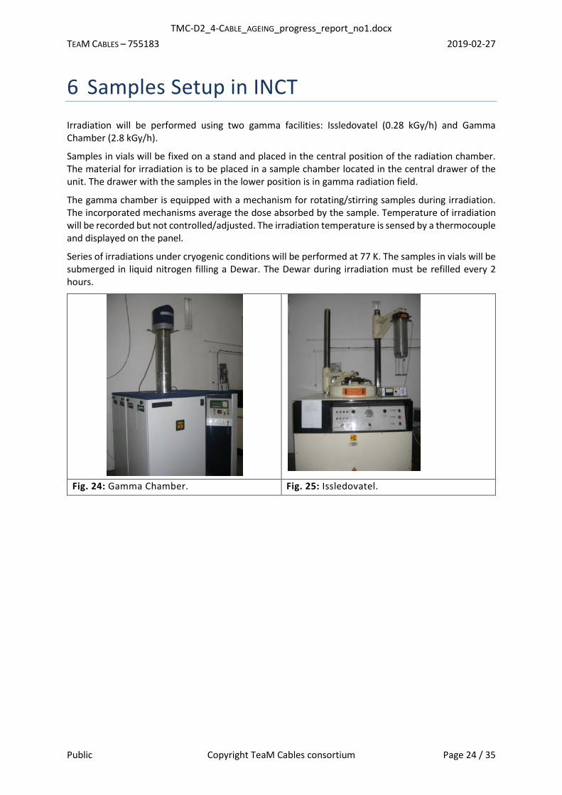
6 Samples Setup in INCT
Irradiation will be performed using two gamma facilities: Issledovatel (0.28 kGy/h) and Gamma Chamber (2.8 kGy/h).
Samples in vials will be fixed on a stand and placed in the central position of the radiation chamber. The material for irradiation is to be placed in a sample chamber located in the central drawer of the unit. The drawer with the samples in the lower position is in gamma radiation field.
The gamma chamber is equipped with a mechanism for rotating/stirring samples during irradiation. The incorporated mechanisms average the dose absorbed by the sample. Temperature of irradiation will be recorded but not controlled/adjusted. The irradiation temperature is sensed by a thermocouple and displayed on the panel.
Series of irradiations under cryogenic conditions will be performed at 77 K. The samples in vials will be submerged in liquid nitrogen filling a Dewar. The Dewar during irradiation must be refilled every 2 hours.
Fig. 24: Gamma Chamber. Fig. 25: Issledovatel.
TMC-D2_4-CABLE_AGEING_progress_report_no1.docx
TEAM CABLES – 755183 2019-02-27
Public Copyright TeaM Cables consortium Page 25 / 35
7 Environmental Parameters and Withdrawal Time Schedule
7.1 Samples Aged in ÚJV Řež, a.s.
7.1.1 Combined Thermal/Radiation Ageing
7.1.1.1 Temperature Profile
Temperature measurement inside the thermobox started with dataloggers with four PT1000; however the device was damaged by the radiation, so it was replaced by the second data logger and four PT100 sensors.
The chart of temperature from the beginning of ageing can be seen in Fig. 26. The stabilised temperature is approximately 86 °C.
Fig. 26: Temperature measured inside the thermobox.
7.1.1.2 Dose Rates Samples aged in the thermobox are irradiated with the following dose rates:
• Metal plates with samples: 6.0 Gy/h,
• Short cable samples: 6.0 Gy/h,
• Long cables: 7.2 Gy/h.
7.1.1.3 Withdrawal Time Schedule Time schedule is listed in the Tab. III.
29
32
35
38
41
44
47
50
53
56
59
62
65
68
71
74
77
80
83
86
89
92
T(°C)
TMC-D2_4-CABLE_AGEING_progress_report_no1.docx
TEAM CABLES – 755183 2019-02-27
Public Copyright TeaM Cables consortium Page 26 / 35
Tab. III: Thermal/radiation ageing time schedule.
Withdrawal № Date of the
withdrawal
Estimated total integrated dose (kGy)
Start 23.7.2018 –
1 29.11.2018 17.3
2 11.4.2019 1) 37 2)
3 5.9. 2019 1) 58 2)
4 23.1.2020 1) 78 2)
5 17.6.2020 1) 99 2)
1) These dates are only estimates; they can be slightly modified.
2) These values are the maximum values calculated for the total time. In fact, the irradiation time is smaller due to measurements periods when the irradiation is paused (measurement, withdrawal, etc.)
7.1.2 Low Dose Rate Radiation Ageing
Temperature is measured with pt100 datalogger. The chart of temperature from the beginning of ageing can be seen in the Fig. 27. The temperature is not stabilised, because of opening Panoza facility during the measurements, withdrawals and few temporary shutdowns.
Fig. 27: Ambient temperature measured inside the Panoza irradiation facility.
7.1.2.1 Dose Rates
Samples are irradiated with the following dose rates:
• Metal plates with samples: 8.5 Gy/h,
28.0
29.0
30.0
31.0
32.0
33.0
34.0
35.0
36.0
37.0
38.0
39.0
40.0
41.0
42.0
43.0
44.0
45.0
46.0
47.0
48.0
49.0
T(°C)
TMC-D2_4-CABLE_AGEING_progress_report_no1.docx
TEAM CABLES – 755183 2019-02-27
Public Copyright TeaM Cables consortium Page 27 / 35
• Short cable samples: 8.5 Gy/h,
• Long cables: 6.4 Gy/h.
7.1.2.2 Withdrawal Time Schedule
Time schedule is listed in the Tab. IV.
Tab. IV: Low dose rate radiation ageing time schedule
Withdrawal № Date of the
withdrawal
Estimated total integrated dose (kGy)
Start 23.7.2018 –
1 29.11.2018 24.5
2 11.4.2019 1) 54 2)
3 5.9. 2019 1) 84 2)
4 23.1.2020 1) 112 2)
5 17.6.2020 1) 142 2)
1) These dates are only estimates; they can be slightly modified.
2) These values are the maximum values calculated for the total time. In fact, the irradiation time is smaller due to measurements periods when the irradiation is paused (measurement, withdrawal, etc.)
7.1.3 Medium Dose Rate Radiation Ageing
7.1.3.1 Dose Rates
Samples aged in the thermobox are irradiated with the following dose rates:
• Metal plates with samples: 77.8 Gy/h,
• Short cable samples: 59.4 Gy/h,
7.1.3.2 Withdrawal Time Schedule
Time schedule is listed in the Tab. V.
Tab. V: Medium dose rate radiation ageing time schedule
Withdrawal № Date Note Estimated total integrated dose (kGy)
Plates Short cables
- 16.8.2018 Start – –
- 6.9.2018 Flip over – –
1 27.9.2018 Withdrawal 67.1 51.2
- 18.10.2018 Flip over – –
2 8.11.2018 Withdrawal 145 110
- 29.11.2018 Flip over – –
3 19.12.2018 Withdrawal 220 168
TMC-D2_4-CABLE_AGEING_progress_report_no1.docx
TEAM CABLES – 755183 2019-02-27
Public Copyright TeaM Cables consortium Page 28 / 35
- 10.1.2019 Flip over – –
4 31.1.2019 Withdrawal 298 227
- 21.2.2019 Flip over – –
5 14.3.2019 1) Withdrawal 392 2) 300 2)
1) This date is only an estimate; it can be slightly modified.
2) These values are the maximum values calculated for the total time. In fact, the irradiation time is smaller due to measurements periods when the irradiation is paused (measurement, withdrawal, etc.)
7.1.4 High Dose Rate Radiation Ageing
Samples will be sent together at the end of ageing.
7.1.4.1 Dose Rates
Samples aged are irradiated with the following dose rates:
• Metal plates with samples: 400 Gy/h,
• Short cable samples: 400 Gy/h,
• Long cables: 400 Gy/h.
7.1.4.2 Withdrawal Time Schedule
Time schedule is listed in the Tab. IV.
Tab. VI: Low dose rate radiation ageing time schedule
Withdrawal № Date of the
withdrawal
Estimated total integrated dose (kGy)
Start 17.1.2019 –
1 24.1.2019 67
2 31.1.2019 134
3 7.2.2019 202
4 14.2.2020 296
5 21.2.2020 336
7.2 Samples Aged at ENSAM
7.2.1 Thermal Ageing at 87 °C
Thermal ageing at 87°C was started in July 2018 and should last 2 years. Samples will be sent to all partners after each withdrawal (every 4.8 months, i.e. approx. 144 days), according to the distribution plan (Tab. XII). The time schedule of this ageing is listed in the Tab. VII.
TMC-D2_4-CABLE_AGEING_progress_report_no1.docx
TEAM CABLES – 755183 2019-02-27
Public Copyright TeaM Cables consortium Page 29 / 35
Tab. VII: Thermal ageing at 87 °C time schedule
Withdrawal № Date Note Ageing time
(days) Ageing time
(months)
- 19.07.2018 Start – –
1 10.12.2018 Withdrawal 144 4.8
2 08.05.2019 Withdrawal 288 9.6
3 24.09.2019 Withdrawal 432 14.4
4 15.02.2020 Withdrawal 576 19.2
5 08.07.2020 Withdrawal 720 24
7.2.2 Thermal Ageing at 110 °C
Thermal ageing at 110 °C was started in August 2018 and should last 1.5 year. Samples will be sent to all partners after each withdrawal (every 3.6 months, i.e. approx. 108 days), according to the distribution plan (Tab. XIII). The time schedule of this ageing is listed in the Tab. VIII.
Tab. VIII: Thermal ageing at 110 °C time schedule
Withdrawal № Date Note Ageing time
(days) Ageing time
(months)
- 07.08.2018 Start – –
1 23.11.2018 Withdrawal 108 3.6
2 11.03.2019 Withdrawal 216 7.2
3 27.06.2019 Withdrawal 324 10.8
4 13.10.2019 Withdrawal 432 14.4
5 29.01.2020 Withdrawal 540 18
7.2.3 Thermal Ageing at 130 °C
Thermal ageing at 130 °C of Mod1, Mod2, Mod3, Mod5 and Mod6 was started in December 2018 and should last 1 year. Samples will be sent to all partners after each withdrawal (every 2.4 months, i.e. approx. 72 days), according to the distribution plan (Tab. XIII). The time schedule of this ageing is listed in the Tab. IX.
Tab. IX: Thermal ageing at 130 °C of Mod1/Mod2/Mod3/Mod5/Mod6 time schedule
Withdrawal № Date Note Ageing time
(days) Ageing time
(months)
- 20.12.2018 Start – –
1 02.03.2019 Withdrawal 72 2.4
2 13.05.2019 Withdrawal 144 4.8
TMC-D2_4-CABLE_AGEING_progress_report_no1.docx
TEAM CABLES – 755183 2019-02-27
Public Copyright TeaM Cables consortium Page 30 / 35
3 24.07.2019 Withdrawal 216 7.2
4 04.10.2019 Withdrawal 288 9.6
5 15.12.2019 Withdrawal 360 12
Thermal ageing at 130 °C of Mod4, Mod7 and cables (i.e. samples with combination of both antioxidants) has not been started yet due to the current unavailability of an extra thermal oven, but should be started soon.
7.3 Thermal ageing at UJV
Coaxial and twisted pair cables were thermally aged in UJV. One part of the cable was placed inside the oven in whole (global ageing), the second part was aged locally. This thermal treating was carried out for CEA TECH for the purpose to test TDR/FDR methodology (WP5.4).
Aged cables:
1. Coaxial cable (№ 8), 10 m, aged in whole
2. Coaxial cable (№ 8), 10 m, aged locally
3. Twisted-pair cable (№ 9), 10 m, aged in whole
4. Twisted-pair cable (№ 9), 10 m, aged locally
Ageing conditions
All cables were aged at 150 °C for 3 weeks in the oven with forced air circulation. Connectors were not
attached.
Whole cable ageing
Cables were coiled to a diameter of approximately 40 cm and placed in the oven. Coaxial cable and
twisted pairs can be seen in Fig. 28.
Locally aged cable
Cable was locally aged on three parts; while the rest of the cable was pulled out of the oven. UJV had to modify the oven doors to be able to pull all the cables in and out. The minimal length in the oven is limited by the allowed bending radius of the twisted-pair cable. Installed cable lengths are the following (see schematic drawing below): 100 cm, 75 cm, 200 cm, 100 cm, 200 cm, 125 cm, 174 cm (red part in the oven), see Fig. 29. With the parts in the oven door the total length is 10 m.
Samples were sent to CEA TECH, Mr. Josy Cohen, with the requested labelling:
- Coaxial cable: 8GA global ageing, 8LA local ageing - Twisted pairs cable: 9GA global ageing, 9LA local ageing
TMC-D2_4-CABLE_AGEING_progress_report_no1.docx
TEAM CABLES – 755183 2019-02-27
Public Copyright TeaM Cables consortium Page 31 / 35
Fig. 28: Coaxial and twisted pairs cables aged in whole and/or locally for CEA TECH reflectometry method methodology.
Fig. 29: Parameters of locally aged cables. Shaded parts were in oven.
TMC-D2_4-CABLE_AGEING_progress_report_no1.docx
TEAM CABLES – 755183 2019-02-27
Public Copyright TeaM Cables consortium Page 32 / 35
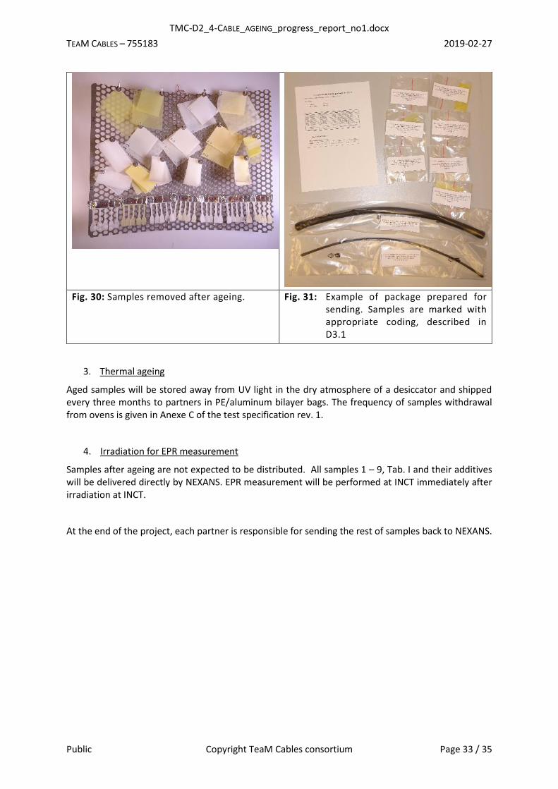
8 Samples Storage and Samples Shipment
Aged samples will be stored and shipped in PE bags. Before sending, all samples are checked and picture documentation is made. Samples are sent:
1. Irradiation at elevated temperature, low dose rate:
o Samples were/will be sent to partners after each withdrawal (sampling interval 4 months) according to the sample distribution schema described in Annex C of the test specification rev. 1 [1].
2. Radiation ageing at ambient temperature
o Low dose rate:
▪ Samples were/will be sent to partners after each withdrawal (sampling interval 4 months) according to the sample distribution schema.
o Medium dose rate:
▪ Samples were/will be sent to partners after each withdrawal (sampling interval 6 weeks) according to the sample distribution schema. This will make analysis easier to the partners.
o High dose rate:
▪ All samples were sent to the partners after the end of ageing in one package according to the sample distribution schema.
▪ Before final sending, aged samples were stored in PE bags filled with dry nitrogen. The nitrogen atmosphere was used to stop post-radiation chemical reaction in the aged samples. This procedure was used only during the high dose rate ageing because the withdrawal period, in this case, was only one week. So it was reasonable to send all samples in one package after the end of ageing. Samples were in the dark at room temperature.
After ageing, each PE bag was/will be marked with UJV orientation number as well as with the full project number.
TMC-D2_4-CABLE_AGEING_progress_report_no1.docx
TEAM CABLES – 755183 2019-02-27
Public Copyright TeaM Cables consortium Page 33 / 35
Fig. 30: Samples removed after ageing. Fig. 31: Example of package prepared for sending. Samples are marked with appropriate coding, described in D3.1
3. Thermal ageing
Aged samples will be stored away from UV light in the dry atmosphere of a desiccator and shipped every three months to partners in PE/aluminum bilayer bags. The frequency of samples withdrawal from ovens is given in Anexe C of the test specification rev. 1.
4. Irradiation for EPR measurement
Samples after ageing are not expected to be distributed. All samples 1 – 9, Tab. I and their additives will be delivered directly by NEXANS. EPR measurement will be performed at INCT immediately after irradiation at INCT.
At the end of the project, each partner is responsible for sending the rest of samples back to NEXANS.
TMC-D2_4-CABLE_AGEING_progress_report_no1.docx
TEAM CABLES – 755183 2019-02-27
Public Copyright TeaM Cables consortium Page 34 / 35
9 Conclusion
This D2.4 document presents a detailed description of all work performed in WP2 until the end of month 18 of the project.
In ENSAM laboratory, thermal ageing is being performed with three different combinations of temperature and time periods. ÚJV Řež laboratory simulates radiation ageing at three different dose rates and one combination of thermal and radiation ageing. At ÚJV Řež, all ageing types have already started. INCT performs irradiation for EPR measurement.
No significant delay or problem was observed.
In comparison to the test specification, more samples have been aged and more measurements have been done until now.
TMC-D2_4-CABLE_AGEING_progress_report_no1.docx
TEAM CABLES – 755183 2019-02-27
Public Copyright TeaM Cables consortium Page 35 / 35
10 References [1] Deliverable D2.2: Specifications of tests - accelerated ageing protocol, test strategy, Authors:
Pavel Žák and Vit Plaček (UJV).
[2] Deliverable D2.1: Material and cable samples, Authors: Hakim Janah (Nexans).


![Workpackage Deliverable ID · Sioux CCM 2018 [2] Van der Veen, G. D2.4 General specification and design of I-MECH reference platform. Deliverable of I-MECH project. I-MECH October,](https://static.documents.pub/doc/80x56/600181cebf7251681a3d0339/workpackage-deliverable-id-sioux-ccm-2018-2-van-der-veen-g-d24-general-specification.jpg)


