77
Deliverable D3.1: Comparative Analysis of Candidate V2X Radio Technologies Version: V1.0 October 23, 2018

Deliverable D3.1: Comparative Analysis of Candidate V2X Radio Technologies
Version: V1.0
October 23, 2018
Deliverable D3.1: Comparative Analysis of Candidate V2X Radio Technologies V1.0
. 2
Revision history
Revision Date Description
1.0 October 23, 2018 First release version

Deliverable D3.1: Comparative Analysis of Candidate V2X Radio Technologies V1.0
3
Contents
Scope ............................................................................................................................... 5
References ....................................................................................................................... 6
Definitions and Abbreviations ..................................................................................... 11
Definitions ........................................................................................................................................ 11 Abbreviations ................................................................................................................................... 12
General V2X Comparison ............................................................................................. 14
Scope and Overview ....................................................................................................................... 14 Architectures and Reference Points ................................................................................................ 16
Analysis of V2X Technologies ..................................................................................... 17
Introduction ...................................................................................................................................... 17 802.11p-based Technologies .......................................................................................................... 17
Introduction to 802.11p, DSRC and ITS-G5 ...................................................................... 17 DSRC/WAVE Technology ................................................................................................. 18
5.2.2.1 . IEEE 802.11 Architecture ......................................................................................... 18 5.2.2.2 . Main modulation and coding parameters ................................................................. 19 5.2.2.3 . 802.11p Physical Layer frame format ....................................................................... 20 5.2.2.4 . Multiple access mechanism ..................................................................................... 21 5.2.2.5 . MAC Frame Format .................................................................................................. 22 5.2.2.6 . Overall DSRC/WAVE protocol stack ........................................................................ 23
ETSI ITS-G5/C-ITS Technology ........................................................................................ 25 5.2.3.1 . Architecture .............................................................................................................. 25 5.2.3.2 . Modulation and Coding ............................................................................................ 25 5.2.3.3 . Multiple access mechanism ..................................................................................... 25 5.2.3.4 . MAC Frame Format .................................................................................................. 25 5.2.3.5 . Overall ETSI ITS-G5/C-ITS protocol stack ............................................................... 25 5.2.3.6 . Decentralized Congestion Control ............................................................................ 27
CEN DSRC Technology .................................................................................................... 29 LTE .................................................................................................................................................. 30
LTE side link (PC5 interface) ............................................................................................. 32 LTE cellular link (Uu interface) .......................................................................................... 34
Comparison of features ................................................................................................................... 34
Performance Assessment ............................................................................................ 36
Link Level Performance ................................................................................................................... 36 BLER vs SNR .................................................................................................................... 36 BLER vs Relative Speed ................................................................................................... 38
System Level Performance ............................................................................................................. 38 PRR vs Distance ............................................................................................................... 38 PRR vs Traffic Load .......................................................................................................... 40 Latency vs Traffic load ...................................................................................................... 41 Throughput vs Traffic Load ............................................................................................... 42
Suitability for ConVeX Use Cases ............................................................................... 44
Radio Spectrum Aspects .............................................................................................. 50
Current allocation of spectrum for ITS services ............................................................................... 50 Introduction ....................................................................................................................... 50

Deliverable D3.1: Comparative Analysis of Candidate V2X Radio Technologies V1.0
ConVeX Project 4 (77)
Europe ............................................................................................................................... 50 USA ................................................................................................................................... 52
Spectrum requirements for ITS services using direct V2X communication ..................................... 53 Introduction ....................................................................................................................... 53 V2X scenarios and propagation model.............................................................................. 54 Deterministic method ......................................................................................................... 58 System simulation based method ..................................................................................... 60 Theoretical spectrum efficiency based model ................................................................... 61 Queuing theory based approach ....................................................................................... 64 Conclusions on spectrum requirements ............................................................................ 67
Coexistence of DSRC and C-V2X systems ..................................................................................... 68 Regulatory aspects............................................................................................................ 68 Spectrum sharing between C-V2X and ETSI ITS-G5 ........................................................ 68 Spectrum sharing framework proposed by 5GAA ............................................................. 70
Summary and Conclusions .......................................................................................... 73

Deliverable D3.1: Comparative Analysis of Candidate V2X Radio Technologies V1.0
ConVeX Project 5 (77)
Scope
The objective of this document is to describe V2X use cases, requirements and performance
evaluation criteria. It analyses and compares the features of existing radio technologies 802.11p and
LTE, both cellular and sidelink. For the features relevant for use cases defined in the project, the
document assesses the theoretical performance and on that basis draws conclusion on the suitability
for the respective use cases. Furthermore the radio spectrum requirements are estimated, together
with the required density of cellular base stations and R-ITS. The advantages of licenses over
unlicensed spectrum for individual use cases are discussed as well.
Deliverable D3.1: Comparative Analysis of Candidate V2X Radio Technologies V1.0
ConVeX Project 6 (77)
References
[1] C-ITS Platform, Final report, January 2016,
https://ec.europa.eu/transport/sites/transport/files/themes/its/doc/c-its-platform-final-report-
january-2016.pdf
[2] PRE-DRIVE C2X Project, Final Report, September 2010 (http://www.drive-
c2x.eu/tl_files/publications/PRE-
DRIVE%20C2X%20Deliverable%20D0.3%20Final%20report_20100929.pdf)
[3] ETSI TR 102 638 V1.1.1: "Intelligent Transport Systems (ITS); Vehicular Communications;
Basic Set of Applications; Definitions"
[4] ETSI TS 102 637-1 V1.1.1 (2010-09): “Intelligent Transport Systems (ITS); Vehicular
Communications; Basic Set of Applications; Part 1: Functional Requirements”
[5] 3GPP TR 21.905: "Vocabulary for 3GPP Specifications".
[6] 3GPP TS 22.185: "Service requirements for V2X services".
[7] 3GPP TR 22.885: "Study on LTE support for V2X services".
[8] SAE J2945/1, “ On-board System Requirements for V2V Safety Communications”-, issued
2016-03-13
[9] US Department of Transportation (DOT), Connected Vehicle Reference Implementation
Architecture (CVRIA) Applications
http://local.iteris.com/cvria/html/applications/applications.html
[10] 5G Americas, V2X FINAL Report
http://www.5gamericas.org/files/2914/7769/1296/5GA_V2X_Report_FINAL_for_upload.pdf
[11] US DOT HS 811 492B, Vehicle Safety Communications – Applications (VSC-A) Final
Report: Appendix Volume 1, System Design and Objective Test, pp C-2-4 and C-2-5.
[12] ETSI TS 102 894-2 V1.2.1, "Intelligent Transport Systems (ITS); Users and applications
requirements; Part 2: Applications and facilities layer common data dictionary"
[13] ETSI TR 103 299 (V0.0.10): "Intelligent Transport System, Cooperative Adaptive Cruise
Control (CACC)".
[14] 5G-PPP, “Living document on 5G PPP use cases and performance evaluation models”,
Version 1.0, 2016-04-25, available at http://www.5g-ppp.eu/.
[15] 5G-PPP, ERTICO ITS Europe, White Paper “5G Automotive Vision”, October 30, 2015,
available at http://www.5g-ppp.eu/.
[16] 3GPP TS37.571-1 “Universal Terrestrial Radio Access (UTRA) and Evolved UTRA (E-
UTRA) and Evolved Packet Core (EPC); User Equipment (UE) conformance specification for
UE positioning; Part 1: Conformance test specification”
[17] National Research Council, “The Global Positioning System: A Shared National Asset”,
National Academy Press, Washington D.C., 1995
[18] Qualcomm QxDMTM: https://www.qualcomm.com/documents/qxdm-professional-
qualcomm-extensible-diagnostic-monitor
[19] SAE J2945/9 “Vulnerable Road User Safety Message Minimum Performance Requirements”
[20] Statistisches Bundesamt, “Unfallentwicklung auf deutschen Strassen 2015“,
https://www.destatis.de/DE/PresseService/Presse/Pressekonferenzen/2016/Unfallentwicklung_
2015/Pressebroschuere_unfallentwicklung.pdf.

Deliverable D3.1: Comparative Analysis of Candidate V2X Radio Technologies V1.0
ConVeX Project 7 (77)
[21] ETSI EN 302 665; Intelligent Transport Systems (ITS); Communication Architecture; V1.1.1
(2010-09)
[22] ETSI EN 302 637-2; Intelligent Transport Systems (ITS); Vehicular Communications; Basic
Set of Applications; Part 2: Specification of Cooperative Awareness Basic Service; V1.3.1
(2014-09)
[23] ETSI EN 302 637-3; Intelligent Transport Systems (ITS); Vehicular Communications; Basic
Set of Applications; Part 3: Specifications of Decentralized Environmental Notification Basic
Service; V1.2.1 (2014-09)
[24] H. D. Schotten, R. Sattiraju, D. G. Serrano, Z. Ren and P. Fertl, "Availability indication as key
enabler for ultra-reliable communication in 5G," 2014 European Conference on Networks and
Communications (EuCNC), Bologna, 2014, pp. 1-5.
[25] P. Popovski, "Ultra-reliable communication in 5G wireless systems," 1st International
Conference on 5G for Ubiquitous Connectivity, Akaslompolo, 2014, pp. 146-151.
[26] P. Popovski, V. Braun, G. Mange, P. Fertl, D. Gozalvez-Serrano, N. Bayer, H. Droste, A.
Roos, G. Zimmerman, M. Fallgren, A. Hoglund, H. Tullberg, S. Jeux, O. Bulakci, J. Eichinger,
Z. Li, P. Marsch, K. Pawlak, M. Boldi, and J. F. Monserrat, “Initial report on horizontal topics,
first results and 5g system concept,” METIS Deliverable D6.2, March 2014
[27] Wang Min, Martin Winbjörk, Zhang Zhang, Ricardo Blasco, Hieu Do, Stefano Sorrentino,
Marco Belleschi, Yunpeng Zang: Comparison of LTE and DSRC-Based Connectivity for
Intelligent Transportation Systems, IEEE VTC 2017 spring, Sidney, Australia, June 2017
[28] IEEE Standard for Information Technology-Telecommunications and Information Exchange
Between Systems-Local and Metropolitan Area Networks-Specific Requirements - Part 11:
Wireless LAN Medium Access Control (MAC) and Physical Layer (PHY), IEEE Std. 802.11,
2012.
[29] R. Blasco, H. Do, S. Shalmashi, S. Sorrentino, and Y. Zang, “3GPP LTE Enhancements for
V2V and comparison to IEEE 802.11p,” in 11th ITS European Congress, Glasgow, Scotland,
Jun. 2016.
[30] Preliminary ConVeX System Architecture Description, ConVex Project Deliverable D2.1,
Dec. 2017
[31] IEEE Std 802.11p-2010 (Amendment to IEEE Std 802.11-2007), IEEE Standard for
Information technology—Telecommunications and information exchange between systems—
Local and metropolitan networks—Specific requirements—Part 11: Wireless LAN Medium
Access Control (MAC) and Physical Layer (PHY) Specifications— Amendment 6: Wireless
Access in Vehicular Environments
[32] ASTM E2213 -03 Standard Specification for Telecommunications and Information Exchange
Between Roadside and Vehicle Systems 5 GHz Band Dedicated Short Range
Communications (DSRC) Medium Access Control (MAC) and Physical Layer (PHY)
Specifications
[33] IEEE Std 1609.0-2013, IEEE Guide for Wireless Access in Vehicular Environments
(WAVE)—Architecture
[34] IEEE Std 1609.2-2016, IEEE Standard for Wireless Access in Vehicular Environments,
Security Services for Applications and Management Messages
[35] IEEE Std 1609.3-2016, IEEE Standard for Wireless Access in Vehicular Environments
(WAVE)—Networking Services
[36] IEEE Std 1609.4-2016 (Revision of IEEE Std 1609.4-2010), IEEE Standard for Wireless
Access in Vehicular Environments (WAVE) - Multi-Channel Operation.

Deliverable D3.1: Comparative Analysis of Candidate V2X Radio Technologies V1.0
ConVeX Project 8 (77)
[37] IEEE Std 1609.5, Standard for Wireless Access in Vehicular Environments (WAVE) -
Communication Manager, not published yet.
[38] IEEE Std 1609.6, Standard for Remote Management Service, not published yet.
[39] IEEE Std 1609.11-2010, Standard for Wireless Access in Vehicular Environments (WAVE)--
Over-the-Air Electronic Payment Data Exchange Protocol for Intelligent Transportation
Systems (ITS)
[40] IEEE Std 1609.12-2016, Standard for Wireless Access in Vehicular Environments (WAVE) -
Identifier Allocations
[41] Andreas Festag, Standards for vehicular communication – from IEEE 802.11p to 5G,
Elektrotechnik & Informationstechnik, Springer, Volume 132, Issue 7, pp. 409-416, Sep. 2015,
available at http://festag-net.de/doc/2015_from11p-to-5G_festag.pdf.
[42] Abdeldime M.S. Abdelgader, Wu Lenan, The Physical Layer of the IEEE 802.11p WAVE
Communication Standard: The Specifications and Challenges, Proceedings of the World
Congress on Engineering and Computer Science 2014 Vol II WCECS 2014, 22-24 October,
2014, San Francisco, USA
[43] ETSI TR 102 638 V1.1.1: "Intelligent Transport Systems (ITS); Vehicular Communications;
Basic Set of Applications; Definitions"
[44] ETSI TR 101 607 (V1.1.1): "Intelligent Transport Systems (ITS); Cooperative ITS (C-ITS);
Release 1"
[45] ETSI ES 202 663 V1.1.0: "Intelligent Transport Systems (ITS); European profile standard for
the physical and medium access control layer of Intelligent Transport Systems operating in the
5 GHz frequency band"
[46] ETSI TS 302 663 “Intelligent Transport Systems (ITS); Access layer specification for
Intelligent Transport Systems operating in the 5 GHz frequency band”
[47] ETSI TS 302 665 V1.1.1: “Intelligent Transport Systems (ITS); Access layer specification for
Intelligent Transport Systems operating in the 5 GHz frequency band”
[48] ETSI TS 102 687 (V1.1.1): "Intelligent Transport Systems (ITS); Decentralized Congestion
Control Mechanisms for Intelligent Transport Systems operating in the 5 GHz range; Access
layer part"
[49] ETSI TS 102 636-1 V1.2.1 “Intelligent Transport Systems (ITS); Vehicular Communications;
GeoNetworking; Part 1: Requirements
[50] ETSI TS 102 636-2 V1.2.1 “Intelligent Transport Systems (ITS); Vehicular Communications;
GeoNetworking; Part 2: Scenarios “
[51] ETSI TS 102 636-4-1 V1.2.1 “Intelligent Transport System (ITS); Vehicular communications;
GeoNetworking; Part 4: Geographical addressing and forwarding for point-to-point and point-
to-multipoint communications; Sub-part 1: Media-Independent Functionality”
[52] ETSI TS 102 636-4-2 V1.1.1 “Intelligent Transport Systems (ITS); Vehicular
Communications; GeoNetworking; Part 4: Geographical addressing and forwarding for point-
to-point and point-to-multipoint communications; Sub-part 2: Media dependent functionalities
for ITS-G5A media”
[53] ETSI TS 102 636-5-1 V1.2.1 “Intelligent Transport Systems (ITS); Vehicular
Communications; GeoNetworking; Part 5: Transport Protocols; Sub-part 1: Basic Transport
Protocol”
[54] ETSI TS 102 636-6-1 V1.2.1 “Intelligent Transport Systems (ITS); Vehicular
Communications; GeoNetworking; Part 6: Internet Integration; Sub-part 1: Transmission of
IPv6 Packets over GeoNetworking Protocols”

Deliverable D3.1: Comparative Analysis of Candidate V2X Radio Technologies V1.0
ConVeX Project 9 (77)
[55] FCC Report and Order FCC 03-324, available at:
https://apps.fcc.gov/edocs_public/attachmatch/FCC-03-324A1.pdf
[56] ETSI EN 302 571 (V1.1.1): "Intelligent Transport Systems (ITS); Radiocommunications
equipment operating in the 5 855 MHz to 5 925 MHz frequency band; Harmonized EN
covering the essential requirements of article 3.2 of the R&TTE Directive".
[57] William Stallings, “Data and Computer Communications”, 8th Edition, Pearson Education,
Inc., Pearson Prentice Hall 2007, available at
http://www.portcity.edu.bd/ELibrary/CSE/Dataandcomputercommunications.pdf
[58] Abdeldime M.S. Abdelgader, Wu Lenan, “The Physical Layer of the IEEE 802.11p WAVE
Communication Standard: The Specifications and Challenges”, Proceedings of the World
Congress on Engineering and Computer Science 2014 Vol II WCECS 2014, 22-24 October,
2014, San Francisco, USA.
[59] G. Bianchi, “Performance Analysis of the IEEE 802.11 Distributed Coordination Function”,
IEEE JSAC, March 2000.
[60] SAE J2735, Dedicated Short Range Communications (DSRC) Message Set Dictionary,
Working Draft August 2015
[61] SAE J2945/0, Dedicated Short Range Communication (DSRC) Systems Engineering Process
Guidance for J2945/x Documents and Common Design Concepts, draft revision 2016-12
[62] SAE J2945/1, On-Board System Requirements for V2V Safety Communications
[63] SAE J2945/9, Vulnerable Road User Safety Message Minimum Performance Requirements
[64] EU Directorate General for Mobility and Transport, he European Electronic Toll Service
(EETS), available at
https://ec.europa.eu/transport/sites/transport/files/media/publications/doc/2011-eets-european-
electronic-toll-service_en.pdf
[65] ETSI TS 103 097 v1.2.1: "Intelligent Transport Systems (ITS); Security; Security header and
certificate formats".
[66] Jinling Hu1, Shanzhi Chen1, Li Zhao1, Yuanyuan Li1, Jiayi Fang1, Baozhu Li2, Yan Shi2:
"Link Level Performance Comparison between LTE V2X and DSRC", Journal of
Communications and Information Networks, Vol.2, No.2, Jun. 2017
[67] K. Abboud, H. Aboubakr Omar, W. Zhuang, “Interworking of DSRC and Cellular Network
Technologies for V2X Communications: A Survey”, IEEE Transactions on Vehicular
Technologies, Vol. 65, No. 12, December 2016, pp. 9457-9470.
[68] 3GPP TS 23.285 v14.2.0: “Architecture enhancements for V2X services"
[69] Zeeshan Hameed Mir* and Fethi Filali: LTE and IEEE 802.11p for vehicular networking: a
performance evaluation, EURASIP Journal on Wireless Communications and Networking,
2014
[70] 3GPP TS 36.213 v14.0.0: “Physical layer procedures", Dec. 2016
[71] 3GPP TS 36.321 v14.6.0 (2018-03)
[72] ETSI EN 300 674 (all parts): "Electromagnetic compatibility and Radio spectrum Matters
(ERM); Road Transport and Traffic Telematics (RTTT); Dedicated Short Range
Communication (DSRC) transmission equipment (500 kbit/s / 250 kbit/s) operating in the 5,8
GHz Industrial, Scientific and Medical (ISM) band".
[73] ECC/REC/(08)01: "ECC Recommendation (08)01 on the use of the band 5855-5875 MHz for
Intelligent Transport Systems (ITS)".
Deliverable D3.1: Comparative Analysis of Candidate V2X Radio Technologies V1.0
ConVeX Project 10 (77)
[74] ERC/DEC(99)23: "ERC Decision of 29 November 1999 on the harmonised frequency bands to
be designated for the introduction of High Performance Radio Local Area Networks
(HIPERLANs)".
[75] ECC/DEC(02)01: "ECC Decision of 15 March 2002 on the frequency bands to be designated
for the co-ordinated introduction of Road Transport and Traffic Telematic Systems".
[76] Commission Decision 2005/513/EC of 11 July 2005 on the harmonised use of radio spectrum
in the 5 GHz frequency band for the implementation of wireless access systems including
radio local area networks (WAS/RLANs).
[77] Commission Decision 2007/90/EC of 12 February 2007 amending Decision 2005/513/EC on
the harmonised use of radio spectrum in the 5 GHz frequency band for the implementation of
Wireless Access Systems including Radio Local Area Networks (WAS/RLANs).
[78] Commission Decision 2008/671/EC of 5 August 2008 on the harmonised use of radio
spectrum in the 5 875-5 905 MHz frequency band for safety-related applications of Intelligent
Transport Systems (ITS).
[79] ETSI EN 302 663 V1.2.1 (2013-07), Intelligent Transport Systems (ITS); Access layer
specification for Intelligent Transport Systems operating in the 5 GHz frequency band
[80] ETSI EN 302 571 V2.1.1 (2017-02) , Intelligent Transport Systems (ITS);
Radiocommunications equipment operating in the 5 855 MHz to 5 925 MHz frequency band
[81] ECC Decision (08)01: "ECC Decision of 14 March 2008 on the harmonised use of the 5875-
5925 frequency band for Intelligent Transport Systems (ITS)", approved 14 March 2008 and
amended 3 July 2015.
[82] 5GAA-WG4 S-170044, A Framework for Estimating Spectrum Needs of ITS Services Using
Direct V2X Communication; Ericsson, May 2017
[83] 5GAA-WG4 S-170080, Discussion on spectrum needs estimation of LTE-V2X direct link
transmission; Huawei, July 2017
[84] 5GAA-WG4 S-170144, Draft Technical Report, Study of spectrum needs for safety related
intelligent transportation systems.
[85] 3GPP TS 22.185 V14.3.0 (2017-03), Service requirements for V2X services; Stage 1 (Release
14)
[86] 3GPP TR 36.885 V14.0.0 (2016-06), Study on LTE-based V2X Services (Release 14)
[87] 3GPP TS 22.185 V14.4.0 (2018-06 ), Service requirements for enhanced V2X scenarios
[88] Tim Irnich, Bernhard Walke, “Spectrum estimation methodology for next generation wireless
systems”, Personal, Indoor and Mobile Radio Communications, 2004. PIMRC 2004. 15th
IEEE International Symposium
[89] J. G. Proakis, “Digital Communications”, 4th Edition, McGraw-Hill 2008.
[90] Radio Equipment Directive (RED), Directive 2014/53/EU Of The European Parlament and Of
The Council of 16 April 2014
[91] ETSI EN 301 893 V2.0.7 (2016-11), 5 GHz RLAN; Harmonised Standard covering the
essential requirements of article 3.2 of Directive 2014/53/EU
[92] ETSI EN 103 301 V1.1.1 (2016-11), Intelligent Transport Systems (ITS); Vehicular
Communications; Basic Set of Applications; Facilities layer protocols and communication
requirements for infrastructure services
[93] 5GAA Position Paper, Coexistence of C-V2X and ITS-G5 at 5.9 GHz, 05 April 2017
[94] 3GPP TS 36.101: "User Equipment (UE) radio transmission and reception", V14.4.0, June
2017.

Deliverable D3.1: Comparative Analysis of Candidate V2X Radio Technologies V1.0
ConVeX Project 11 (77)
[95] Kapsch TrafficCom "KVE-3320.V2X ECU".
http://connectedvehicles.kapsch.net/download/Kapsch%20Onboard%20Unit%20KVE-
3320.pdf, retrieved July 2018
[96] IEEE 802.11-14/1335r1, https://mentor.ieee.org/802.11/dcn/14/11-14-1335-01-0reg-dsrc-
band-plan-rationale.ppt, October 2014, retrieved August 2018
[97] Use Cases, Requirements, Performance Evaluation Criteria, ConVex Project Deliverable D1.1,
Oct. 2017
Definitions and Abbreviations
Definitions
Host Vehicle (HV): The vehicle whose driver is alerted or notified by a warning or notification
indication by its InVehicleInformation system (e.g. visually and/or acoustically), as a result of the
reception and processing of CAM’s and DENM’s from surrounding other vehicles.
PC5 transport: Transmission of V2X data from a source UE (e.g., a vehicle) to a destination UE
(e.g., another vehicle, road infrastructure, a pedestrian, etc.) via ProSe Direct Communication over
the PC5 interface between the UEs (sidelink).
Remote vehicle (RV): The collection of all vehicles in a traffic scenario which surround a
considered Host Vehicle. The Remote Vehicles broadcast their positions and vehicle information
periodically and also create special DENM warning messages in case of safety-relevant events.
Road Side Unit (RSU): An entity supporting V2I Service that can transmit to, and receive from a
UE using V2I application. RSU is implemented in an eNB or a stationary UE.
Uu transport: Transmission of V2X data from a source UE (e.g., a vehicle) to a destination UE
(e.g., another vehicle, road infrastructure, a pedestrian, etc.) via the eNB over the conventional Uu
interface (uplink and downlink).
V2I Service: A type of V2X Service, where one party is a UE and the other party is an RSU both
using V2I application.
V2N Service: A type of V2X Service, where one party is a UE and the other party is a serving
entity, both using V2N applications and communicating with each other via cellular network (e.g.
LTE or 5G) .
V2P Service: A type of V2X Service, where both parties of the communication are UEs using V2P
application. For this service the vehicle-side UE is a V-ITS-S, the pedestrian-side (respectively
VRU-side) UE is a P-ITS-S.
V2V Service: A type of V2X Service, where both parties of the communication are UEs using V2V
application. . For this service both vehicle-side UEs represent V-ITS-S.
Vulnerable Road User (VRU): A road user, such as a pedestrian, a cyclist or a motorcyclist,
bearing a greater risk of serious injury than vehicle occupants when involved in a traffic accident.

Deliverable D3.1: Comparative Analysis of Candidate V2X Radio Technologies V1.0
ConVeX Project 12 (77)
Abbreviations
3GPP 3rd Generation Partnership Project
5G 5th Generation
5GAA 5G Automotive Association
5G-PPP 5G Private Public Partnership
A9 Motorway A9
ACC Adaptive Cruise Control
CACC Corporative Adaptive Cruise Control
C2C-CC CAR 2 CAR Communication Consortium
CAM Cooperative Awareness Message as defined in ETSI a message vehicles issue in 1Hz to
10 Hz interval to send their at least position and heading to its surrounding using local
communication (e.g. 802.11p
C-ITS Cooperative Intelligent Transport Systems
C-V2X Cellular V2X
CV2XBox Cellular V2X Communication Module
CVRIA Connected Vehicle Reference Implementation Architecture
DCC Decentralized Congestion Control
DENM Decentralised Environmental notification Message as defined in ETSI a message
vehicles or infrastructure components send case any relevant warning shall be issued to
nearby vehicles
DSRC Dedicated Short Range Communications
EEBL Emergency Electronic Brake Light (use case)
EIRP Equivalent Isotropically Radiated Power
ERTICO European Road Transport Telematics Implementation Coordination
ETSI European Telecommunications Standards Institute
E-UTRA Evolved UMTS Terrestrial Radio Access
EU European Union
FCD Floating Car Data
FCW Forward Collision Warning
GLOSA Green Light Optimal Speed Advisory
GNSS Global Navigation Satellite System
HGV Heavy Goods Vehicle
HW Hardware
ICS ITS Central Station
IEEE Institute of Electrical and Electronics Engineers
ITS Intelligent Transport System
IVI In Vehicle Information as defined in SAE and CEN/ISO information on current
(dynamic) sign display to be sent from infrastructure to vehicles
IRS ITS Roadside station
IVS In-Vehicle Signage

Deliverable D3.1: Comparative Analysis of Candidate V2X Radio Technologies V1.0
ConVeX Project 13 (77)
KPI Key Performance Indicators
LTE Long Term Evolution
MAC Media Access Control (layer)
MDM Mobility Data Marketplace
OEM Original Equipment Manufacturer
PC5 ProSe Communication reference point 5.
PHY Physical (layer)
ProSe Proximity-based Services
PRR Packet Reception Rate
PVD Prove Vehicle Date as in discussion in CEN/ISO a message to allow vehicles to issue
collected data to other vehicles or infrastructure
P-ITS-S Personal ITS Station
REFSENS Reference Sensitivity
R-ITS-S Roadside Intelligent Transport System Station
RV Remote Vehicle
RSU Road Side Unit
SAE Society of Automotive Engineers
SINR signal-to-interference and noise ratio
SNR signal-to-noise ratio
SPaT/MAP Signal Phase and Time / Map Standard
SW Software
SWD Shockwave Damping Service Deployment
TCC Traffic Control Center
TGW Traffic jam ahead warning
UE User Equipment
V2C Vehicle to Cloud
V2I Vehicle to Infrastructure
V2N Vehicle to Network
V2P Vehicle to Pedestrian
V2V Vehicle to Vehicle
V2X Vehicle to Everything
V-ITS-S Vehicular Intelligent Transport System Station
VMS Variable Message Sign
VRU Vulnerable Road User
WAVE Wireless Access in Vehicular Environments

Deliverable D3.1: Comparative Analysis of Candidate V2X Radio Technologies V1.0
ConVeX Project 14 (77)
General V2X Comparison
Scope and Overview
V2X communication around the globe is supported by different technologies and standards (ARIB-
Japan, IEEE-US, ETSI-Europe, 3GPP-Global). C-V2X has been added as the 3GPP LTE - and in
future 5G - based communication approach. The following sections will provide some more detailed
insights into the specifics of the relevant European technologies which are based on C-ITS (ETSI)
and C-V2X (3GPP). The following Table 4.1-1 and Table 4.1-2 provide an overview of C-ITS and
3GPP with respect to frequency bands and standards relevant for Europe based on [32] and
augmented for the LTE C-V2X information.
Table 4.1-1: V2X Technologies in Europe: Bands
Band [MHz] Channelization In-use or Allocated Applications
5470-5725
(ITS-G5C)
Dynamic Frequency Selection
(DFS) of 10 MHz or 20 MHz
service channel
Allocated ITS applications based on V2I
communication
5795-5815 Four 5 MHz channels In-use Road transport and telematics
5855-5925 One 10 MHz control channel
and six 10 MHz service
channels
Allocated Non-safety applications [5855-
5875 MHz (ITS-G5B)]
safety applications [5875-5905
MHz (ITS-G5A)]
future ITS applications [5905-
5925 MHz]
LTE Bands:
1 [FDD 2100],
3 [FDD 1800],
7 [FDD 2600],
8 [FDD 900],
20 [FDD 800],
42 [TDD
3500]
Typically, 5, 10 or 20 MHz In-use or allocated V2N

Deliverable D3.1: Comparative Analysis of Candidate V2X Radio Technologies V1.0
ConVeX Project 15 (77)
Table 4.1-2: V2X Technologies in Europe: Standards and Scope
Standards Scope
ETSI 3GPP (LTE)
EN302571 Requirements for operation in [5855-5925] MHz
EN300674-1 Requirements for operation in [5795-5815] MHz
ES202663 (ITS-G5)
ES202663 (ITS-G5)
TS36.321
TS36.21x (x=1,2,3,4)
MAC
PHY
TS33.303 3GPP PC5/ProSe security aspects
EN302665 Communication architecture
EN302636-3 Network architecture
EN302636-4-1 Geographical routing functionality
TS102636-4-2 Geographical routing based on ITS-G5
EN302636-6-1 Tx of IPv6 packets using geographical routing
EN302636-5-1 Transport layer
EN302637-2 CAM
EN302637-3 DENM
TS36 series Uu interface
As can be identified from Table 4.1-2 the 3GPP C-V2X focus is on providing the lower layer (MAC
and PHY) functionality to be integrated with the ITS protocol stack and services specified by ETSI.
More details on the C-V2X technology and protocol stacks (PC5, Uu) can be found in the other
relevant project descriptions, e.g., [30], and in Section 5 of this document.

Deliverable D3.1: Comparative Analysis of Candidate V2X Radio Technologies V1.0
ConVeX Project 16 (77)
Architectures and Reference Points
This section provides a quick review, overview and comparison of V2X technologies with reference
to further sources of information. Figure 4.2-1 shows the high-level architecture with the relevant
use case categories and the relevant interfaces provided by the technologies of ETSI and 3GPP,
respectively.
Figure 4.2-1 High Level Network Architecture and Technology/Protocol Support
The V2X specifications in 3GPP Release 14 and in ETSI, respectively, include up to two
complementary communication interfaces. Direct communication such as vehicle-to-vehicle (V2V)
is realized through PC5 (ProSe Communication reference point 5). The same holds for vehicle-to-
pedestrian (V2P) and vehicle-to-infrastructure (V2I) communications. The respective ETSI protocol
for these communications is ITS-G5 based on IEEE 802.11p as outlined in the previous section
already.
In addition, the LTE - or in future the 5G NR - Uu connection complements any communication for
the non-direct links within the (wide area) network for V2N cases. This connection might also be
used as backhaul-link between road-side-units (RSU) and their (traffic management) center, acting
as transparent IP connection. This interface is solely supported by the 3GPP LTE (4G) and 5G-NR
Uu interfaces; ETSI does not provide an own interface for this but relies on the 3GPP interfaces in a
hybrid fashion.
There are some commonalities but as well as some fundamental differences between the 3GPP PC5
based C-V2X and the ETSI ITS-G5 V2X approaches. The main difference exists in the lower layers
of MAC and PHY, and the integration within the whole protocol stack up to the service/application
layer mainly with respect to management and security. Section 5 is providing these insights and
comparison in more detail.
Deliverable D3.1: Comparative Analysis of Candidate V2X Radio Technologies V1.0
ConVeX Project 17 (77)
Analysis of V2X Technologies
Introduction
The present section 5 describes the main functions and characteristics of the current candidate V2X
radio technologies:
• DSRC/WAVE specified by the US Department of Transportation (U.S. DOT)
• ETSI C-ITS / ITS-G5 specified by ETSI by mandate of the European Commission
• 3GPP Rel-14 Cellular V2X based on LTE Uu and PC5 radio technologies
Both DSRC/WAVE and ETSI C-ITS / ITS-G5 are based on IEEE 802.11 WLAN radio
technologies, namely a MAC/PHY variant of the 802.11a standard which is denoted IEEE 802.11p.
Therefore, both technologies are colloquially often referred to as “WLAN-based” or “WiFi-based”
V2X technologies. Section 5.2 introduces the overall protocol stacks of DSRC/WAVE and ETSI C-
ITS / ITS-G5 and elaborates the commonalities and differences between these technologies.
Section 5.3 presents the main features of 3GPP Rel-14 LTE-based cellular V2X radio technologies
examined in the ConVeX project, namely LTE Uu radio technology applied for V2N
communications, and LTE PC5 (“sidelink”) radio technology for V2V/V2I/V2P communications.
Section 5.4 provides an analysis of the main performance characteristics of the considered V2X
technologies.
802.11p-based Technologies
Introduction to 802.11p, DSRC and ITS-G5
The IEEE 802.11p specification has been developed as an amendment [31] to the IEEE 802.11
WLAN standard series of specifications. The goal of this effort was to introduce radio technology
enhancements in order to support communication between vehicles (V2V) and between vehicle and
road side infrastructure (V2I) at typical vehicle speeds.
IEEE 802.11p comprises a specification of the physical (PHY) layer and Media Access Control
(MAC) layer processing. In fact, IEEE 802.11p represents a modified version of the IEEE 802.11a
amendment which was designed for WLAN networks operating in the 5 GHz band (approx. 5.2 to
5.8 MHz) with nominal data rates up to 54 Mbps.
The application of 802.11p PHY/MAC technology with the Wireless Access for Vehicular
Environments (WAVE) extensions to the MAC and upper layer ITS protocol stack is referred to as
Dedicated Short Range Communications (DSRC). The term DSRC has been introduced in a
customized version of the IEEE 802.11p MAC/PHY standards which has been published by ASTM
International (originally founded as American Society for Testing and Materials, today an
organization which corresponds to DIN e.V. in Germany) as ASTM E2213-03 specification [32].
This specification has been adopted by the US department of Transportation (U.S. DOT) for ITS
services in the USA.

Deliverable D3.1: Comparative Analysis of Candidate V2X Radio Technologies V1.0
ConVeX Project 18 (77)
The overall DSRC/WAVE protocol stack is presented in more detail in Section 5.2.2.
In Europe, ETSI has created a V2X standard which is builds upon the IEEE 802.11p MAC/PHY
standard and DSRC [32], which however adds a significant cross-layer function which affects the
MAC and some upper layers, denoted as Decentralized Congestion Control (DCC). This modified
version of 802.11p/DSRC is denoted as ETSI ITS-G5 technology. ETSI has also redefined other
upper layer functionality substantially. The overall ETSI V2X standard is commonly denoted as
ETSI C-ITS (Cooperative Intelligent Transport System). This standard is described in detail in
Section 5.2.3.
Another technology which is based on DSRC [32] is employed for Electronic Fee Collection (EFC)
services. This technology is denoted CEN DSRC in Europe. This standard is defined by CEN
Technical Committee (TC) 278 and specified in EN 12253, EN 12795, EN 12834 [ISO 15628] and
EN 13372 (see http://www.itsstandards.eu/efc).
CEN DSRC is briefly described in Section 5.2.4.
DSRC/WAVE Technology
5.2.2.1 IEEE 802.11 Architecture
Figure 5.2.2.1-1 shows the principal architecture model applicable to any IEEE 802.11 system,
including 802.11p [57].
The smallest building block of a wireless LAN is a basic service set (BSS), which consists of some
number of stations (STA) executing the same MAC protocol and competing for access to the same
shared wireless medium. A BSS may be isolated or it may connect to a backbone distribution system
(DS) through an access point (AP). The AP functions as a bridge and a relay point. In a BSS, client
stations do not communicate directly with one another. Rather, if one station in the BSS wants to
communicate with another station in the same BSS, the MAC frame is first sent from the originating
station to the AP, and then from the AP to the destination station. Similarly, a MAC frame from a
station in the BSS to a remote station is sent from the local station to the AP and then relayed by the
AP over the DS on its way to the destination station. The BSS generally corresponds to what is
referred to as a cell in the literature. The DS can be a switch, a wired network, or a wireless network.
When all the stations in the BSS are mobile stations, with no connection to other BSSs, the BSS is
called an independent BSS (IBSS). An IBSS is typically an ad hoc network. In an IBSS, the stations
all communicate directly, and no AP is involved. A simple configuration is shown in Figure 5.2.2-1,
in which each station belongs to a single BSS; that is, each station is within wireless range only of
other stations within the same BSS. It is also possible for two BSSs to overlap geographically, so
that a single station could participate in more than one BSS. Further, the association between a
station and a BSS is dynamic. Stations may turn off, come within range, and go out of range. An
extended service set (ESS) consists of two or more basic service sets interconnected by a distribution
system. Typically, the distribution system is a wired backbone LAN but can be any communications
network. The extended service set appears as a single logical LAN to the logical link control (LLC)
level. Figure 5.2.2.1-1 indicates that an access point (AP) is implemented as part of a station; the AP
is the logic within a station that provides access to the DS by providing DS services in addition to
acting as a station. To integrate the IEEE 802.11 architecture with a traditional wired LAN, a portal

Deliverable D3.1: Comparative Analysis of Candidate V2X Radio Technologies V1.0
ConVeX Project 19 (77)
is used. The portal logic is implemented in a device, such as a bridge or router, that is part of the
wired LAN and that is attached to the DS.
Figure 5.2.2.1-1: IEEE 802.11 architecture model
5.2.2.2 Main modulation and coding parameters
The IEEE 802.11p PHY layer is characterized by the modulation parameters listed as follows:
• Modulation and multiple access scheme: OFDM
• symbol duration 8 µs (while 11a supports 4 µs), including the guard time interval 1.6µs
(while 11a has 0.8µs)
• subcarrier spacing of 156250 Hz (half of 11a)
• 52 useful carriers per symbol (48 for data, 4 pilot) in 10 MHz (twice in 20 MHz)
• BPSK/QPSK/16QAM/64QAM.
• 10 and 20 MHz bandwidth
• supports nominal bit rates (before channel coding) of 3/4.5/6/9/12/18/24/27 Mbps, i.e. half
the rates of 802.11a (shown in the table below) due to doubled symbol duration
The OFDM carrier allocation is illustrated in Figure 5.2.2.2-1 [58]. The 52 useful plus 12 nulled
carriers are mapped into a FFT constellation with N = 64 carriers. The green carriers are used for
data, the red carriers represent pilot information. Since the spectrum of a sampled signal is periodic,
the null subcarriers numbered 27 ... 37 correspond to the edge frequencies of a 10 MHz transmission
channel. This enables use of band selection filters with moderate slope. Also, the DC carrier number
0 is not used for data transmission in order to prevent issues due to DC offsets.

Deliverable D3.1: Comparative Analysis of Candidate V2X Radio Technologies V1.0
ConVeX Project 20 (77)
Figure 5.2.2.2-1: OFDM carrier format source: [42]
Channel coding: forward error correction (FEC) convolutional coding is used with coding rates of
1/2, 2/3, or 3/4.
Data Rate given in the first column of Table 5.2.2.2-1 can be calculated from the number of data bits
per OFDM symbol divided by OFDM symbol length
Table 5.2.2.2-1: Parameters of 802.11p modulation and coding
Data Rate
(Mbit/s)
Modulation Coding rate Coded bits
per subcarrier
Coded bits
per OFDM
symbol
Data bits per
OFDM
symbol
3 BPSK 1/2 1 48 24
4.5 BPSK 3/4 1 48 36
6 QPSK 1/2 2 96 48
9 QPSK 3/4 2 96 72
12 16-QAM 1/2 4 192 96
18 16-QAM 3/4 4 192 144
24 64-QAM 2/3 6 288 192
27 64-QAM 3/4 6 288 216
5.2.2.3 802.11p Physical Layer frame format
Figure 5.2.2.3-1 shows the format of an IEEE 802.11p Physical Layer Protocol Data Unit (PPDU)
which applies to 802.11p as well.
Deliverable D3.1: Comparative Analysis of Candidate V2X Radio Technologies V1.0
ConVeX Project 21 (77)
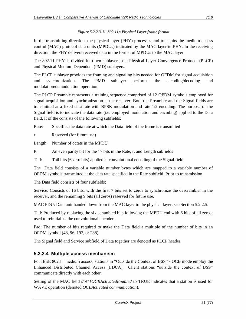
Figure 5.2.2.3-1: 802.11p Physical Layer frame format
In the transmitting direction. the physical layer (PHY) processes and transmits the medium access
control (MAC) protocol data units (MPDUs) indicated by the MAC layer to PHY. In the receiving
direction, the PHY delivers received data in the format of MPDUs to the MAC layer.
The 802.11 PHY is divided into two sublayers, the Physical Layer Convergence Protocol (PLCP)
and Physical Medium Dependent (PMD) sublayers.
The PLCP sublayer provides the framing and signaling bits needed for OFDM for signal acquisition
and synchronization. The PMD sublayer performs the encoding/decoding and
modulation/demodulation operation.
The PLCP Preamble represents a training sequence comprised of 12 OFDM symbols employed for
signal acquisition and synchronization at the receiver. Both the Preamble and the Signal fields are
transmitted at a fixed data rate with BPSK modulation and rate 1/2 encoding. The purpose of the
Signal field is to indicate the data rate (i.e. employed modulation and encoding) applied to the Data
field. It of the consists of the following subfields:
Rate: Specifies the data rate at which the Data field of the frame is transmitted
r: Reserved (for future use)
Length: Number of octets in the MPDU
P: An even parity bit for the 17 bits in the Rate, r, and Length subfields
Tail: Tail bits (6 zero bits) applied at convolutional encoding of the Signal field
The Data field consists of a variable number bytes which are mapped to a variable number of
OFDM symbols transmitted at the data rate specified in the Rate subfield. Prior to transmission.
The Data field consists of four subfields:
Service: Consists of 16 bits, with the first 7 bits set to zeros to synchronize the descrambler in the
receiver, and the remaining 9 bits (all zeros) reserved for future use.
MAC PDU: Data unit handed down from the MAC layer to the physical layer, see Section 5.2.2.5.
Tail: Produced by replacing the six scrambled bits following the MPDU end with 6 bits of all zeros;
used to reinitialize the convolutional encoder.
Pad: The number of bits required to make the Data field a multiple of the number of bits in an
OFDM symbol (48, 96, 192, or 288).
The Signal field and Service subfield of Data together are denoted as PLCP header.
5.2.2.4 Multiple access mechanism
For IEEE 802.11 medium access, stations in “Outside the Context of BSS” - OCB mode employ the
Enhanced Distributed Channel Access (EDCA). Client stations “outside the context of BSS”
communicate directly with each other.
Setting of the MAC field dot11OCBActivatedEnabled to TRUE indicates that a station is used for
WAVE operation (denoted OCBActivated communication).

Deliverable D3.1: Comparative Analysis of Candidate V2X Radio Technologies V1.0
ConVeX Project 22 (77)
EDCA is contention-based and applies Carrier Sense Multiple Access with Collision Avoidance
(CSMA/CA). With CSMA/CA, a device listens to the channel before starting any own
transmissions. If the channel is occupied, the station delays its own transmission by a random
duration of time, denoted as backoff time, and then probes the channel again. Stations differentiate
data, assign the data to access categories (ACs), and handle the data from different access categories
with other CSMA/CA-related parameters, which effectively allows for data traffic prioritization
[41].
The EDCA mechanism uses the IEEE 802.11 Distributed Coordination Function (DCF) to setup
multiple queues for different QoS/priority. This mechanism allows up to eight levels of MAC-
sublayer priority as specified in IEEE Std 802.11.
A brief summary of the IEEE 802.11p MAC and EDCA is given in Annex B.4 of ETSI TS 302 663
[46]. Details are specified in Section 5 of IEEE 1609.4 [36].
5.2.2.5 MAC Frame Format
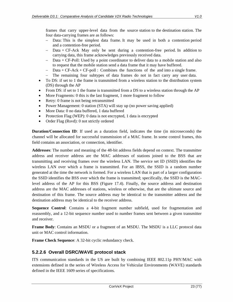
Figure 5.2.2.5-1 shows the frame format of the IEEE 802.11 MAC protocol [57].
Figure 5.2.2.5-1: 802.11p frame format
The fields of the MAC PDU serve the following purpose [57]:
Frame Control: Indicates the type of frame (control, management, or data) and provides control
information. Control information includes whether the frame is to or from a Distribution System
(DS), fragmentation information, and privacy information. The two bytes frame control information
includes the following on bit level (note that this information can be monitored e.g. with
WireShark). This field is common to all IEEE 802.11 systems.
• Protocol version: 2 bits protocol version information
• Frame type/subtype: Indicates the type of a frame and the subtype of data frames. There are
eight data frame subtypes, organized into two groups. The first four subtypes define
Deliverable D3.1: Comparative Analysis of Candidate V2X Radio Technologies V1.0
ConVeX Project 23 (77)
frames that carry upper-level data from the source station to the destination station. The
four data-carrying frames are as follows:
− Data: This is the simplest data frame. It may be used in both a contention period
and a contention-free period.
− Data + CF-Ack May only be sent during a contention-free period. In addition to
carrying data, this frame acknowledges previously received data.
− Data + CF-Poll: Used by a point coordinator to deliver data to a mobile station and also
to request that the mobile station send a data frame that it may have buffered.
− Data + CF-Ack + CF-poll : Combines the functions of the and into a single frame.
− The remaining four subtypes of data frames do not in fact carry any user data.
• To DS: if set to 1 the frame is transmitted from a wireless station to the distribution system
(DS) through the AP
• From DS: if set to 1 the frame is transmitted from a DS to a wireless station through the AP
• More Fragments: 0 this is the last fragment, 1 more fragment to follow
• Retry: 0 frame is not being retransmitted
• Power Management: 0 station (STA) will stay up (no power saving applied)
• More Data: 0 no data buffered, 1 data buffered
• Protection Flag (WEP): 0 data is not encrypted, 1 data is encrypted
• Order Flag (Rsvd): 0 not strictly ordered
Duration/Connection ID: If used as a duration field, indicates the time (in microseconds) the
channel will be allocated for successful transmission of a MAC frame. In some control frames, this
field contains an association, or connection, identifier.
Addresses: The number and meaning of the 48-bit address fields depend on context. The transmitter
address and receiver address are the MAC addresses of stations joined to the BSS that are
transmitting and receiving frames over the wireless LAN. The service set ID (SSID) identifies the
wireless LAN over which a frame is transmitted. For an IBSS, the SSID is a random number
generated at the time the network is formed. For a wireless LAN that is part of a larger configuration
the SSID identifies the BSS over which the frame is transmitted; specifically, the SSID is the MAC-
level address of the AP for this BSS (Figure 17.4). Finally, the source address and destination
address are the MAC addresses of stations, wireless or otherwise, that are the ultimate source and
destination of this frame. The source address may be identical to the transmitter address and the
destination address may be identical to the receiver address.
Sequence Control: Contains a 4-bit fragment number subfield, used for fragmentation and
reassembly, and a 12-bit sequence number used to number frames sent between a given transmitter
and receiver.
Frame Body: Contains an MSDU or a fragment of an MSDU. The MSDU is a LLC protocol data
unit or MAC control information.
Frame Check Sequence: A 32-bit cyclic redundancy check.
5.2.2.6 Overall DSRC/WAVE protocol stack
ITS communication standards in the US are built by combining IEEE 802.11p PHY/MAC with
extensions defined in the series of Wireless Access for Vehicular Environments (WAVE) standards
defined in the IEEE 1609 series of specifications.

Deliverable D3.1: Comparative Analysis of Candidate V2X Radio Technologies V1.0
ConVeX Project 24 (77)
IEEE Std 1609.0-2013 [33] describes the overall WAVE protocol architecture
IEEE Std 1609.4-2010 (Multi-Channel Operations) [36] specifies extensions to the IEEE 802.11
MAC layer protocol and includes the following features [33]:
• Channel timing and switching
• Use of IEEE 802.11 facilities, e.g., channel access, Enhanced Distributed Channel Access
(EDCA), outside the context of a BSS (Basic Service Set)
• Use of IEEE 802.11 Vendor Specific Action and Timing Advertisement frames in a WAVE
system
• MAC-layer readdressing in support of pseudonymity
IEEE Std 1609.3-2010 (Networking Services) [35] includes the following features:
• WAVE Service Advertisements and channel scheduling
• WAVE Short Message Protocol
• Use of existing protocols, e.g., LLC and IPv6, including streamlined IPv6 configuration
• Delivery of general management information over the air interface
IEEE Std 1609.2-2013 (Security Services for Applications and Management Messages) specifies
• communications security for WAVE Service Advertisements and WAVE Short Messages
and additional
• security services that may be provided to higher layers.
IEEE P1609.5 (Communication Manager) [37] is an open project for addressing network
management requirements.
IEEE P1609.6 (Remote Management Services) [38], is under development. It will include over-the-
air management and alias features.

Deliverable D3.1: Comparative Analysis of Candidate V2X Radio Technologies V1.0
ConVeX Project 25 (77)
Figure 5.2.2.6-1: WAVE/DSRC protocol stack
The DSRC/WAVE messaging layer is defined in SAE J2735 [60]. The Basic Safety Messages
(BSM) are specified in SAE J2945/1. Messages for non-safety related use cases will be specified in
other specifications of the SAE J2945/x series in future.
Generally, messages are specified in ASN.1 syntax with Unaligned Packet Encoding Rules (UPER)
message encoding. However other encoding styles (typically due to reuse from other standards) are
encapsulated and supported in various places, see SAE J2735 [60].
The Logical Link Control (LLC) layer adds 2 bytes LLC header information. This enables
differentiation between IPv6 and WSMP messages (see details in [35]).
ETSI ITS-G5/C-ITS Technology
5.2.3.1 Architecture
The overall architecture described in Section 5.2.2.1 also applies to ETSI ITS-G5 systems. The
overall ETSI communications reference architecture is described in ETSI EN 302 665 [47].
5.2.3.2 Modulation and Coding
The modulation and coding scheme as described in Section 5.2.2.2 applies to the ETSI ITS-G5
physical layer.
5.2.3.3 Multiple access mechanism
The multiple access mechanism as described in Section 5.2.2.3 applies to the ETSI ITS-G5 physical
layer.
5.2.3.4 MAC Frame Format
The MAC frame format as described in Section 5.2.2.4 applies to the ETSI ITS-G5 MAC layer. The
main difference between the MAC protocols of DSRC/WAVE and ETSI ITS-G5 protocol stacks is
that the Distributed Congestion Control (DCC) function is mandatory for ETSI ITS-G5 while it is
optional for DSRC/WAVE.
5.2.3.5 Overall ETSI ITS-G5/C-ITS protocol stack
In the present document we use the term ETSI Cooperative ITS (ETSI C-ITS) to refer to the system
specified by the series of specifications which are listed in ETSI TR 101 607 [44]. Note that this
series is comprised of more than 80 documents. In this section, only a small subset of these
specifications are referenced.
This series of specifications originates from work carried out by the ETSI Technical Committee ITS.
The overall ETSI C-ITS protocol stack is shown in Figure 5.2.3.5-1.
The PHY and MAC layers are specified in ETSI ES 202 663 [45] and ETSI TS 302 663 [46].
Deliverable D3.1: Comparative Analysis of Candidate V2X Radio Technologies V1.0
ConVeX Project 26 (77)
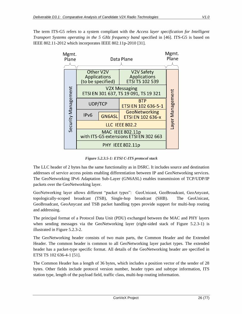
The term ITS-G5 refers to a system compliant with the Access layer specification for Intelligent
Transport Systems operating in the 5 GHz frequency band specified in [46]. ITS-G5 is based on
IEEE 802.11-2012 which incorporates IEEE 802.11p-2010 [31].
Figure 5.2.3.5-1: ETSI C-ITS protocol stack
The LLC header of 2 bytes has the same functionality as in DSRC. It includes source and destination
addresses of service access points enabling differentiation between IP and GeoNetworking services.
The GeoNetworking IPv6 Adaptation Sub-Layer (GN6ASL) enables transmission of TCP/UDP/IP
packets over the GeoNetworking layer.
GeoNetworking layer allows different “packet types”: GeoUnicast, GeoBroadcast, GeoAnycast,
topologically-scoped broadcast (TSB), Single-hop broadcast (SHB). The GeoUnicast,
GeoBroadcast, GeoAnycast and TSB packet handling types provide support for multi-hop routing
and addressing.
The principal format of a Protocol Data Unit (PDU) exchanged between the MAC and PHY layers
when sending messages via the GeoNetworking layer (right-sided stack of Figure 5.2.3-1) is
illustrated in Figure 5.2.3-2.
The GeoNetworking header consists of two main parts, the Common Header and the Extended
Header. The common header is common to all GeoNetworking layer packet types. The extended
header has a packet-type specific format. All details of the GeoNetworking header are specified in
ETSI TS 102 636-4-1 [51].
The Common Header has a length of 36 bytes, which includes a position vector of the sender of 28
bytes. Other fields include protocol version number, header types and subtype information, ITS
station type, length of the payload field, traffic class, multi-hop routing information.

Deliverable D3.1: Comparative Analysis of Candidate V2X Radio Technologies V1.0
ConVeX Project 27 (77)
The Extended Header includes fields such as sequence number, lifetime, position information of
source and destination, GeoNetworking address (see [51]) for details). Depending on the packet
type, the extended header can become quite large, i.e. up to 88 bytes.
The GeoNetworking Security Header corresponds to the header field of the signedData message
format as described in Section 6.5.3.5 of Deliverable D2.1. The security header is specified in ETSI
TS 103 097 [65].
The Basic Transport Protocol (BTP) provides a connectionless transport service. It is specified in TS
102 636-5-1 [53] . This protocol is very similar to UDP [RFC 768].
MAC
Header Header
GeoNetworking
Header
GeoNetworking
Security Header
(optional)
Payload
(optional)
Figure 5.2.3.5-2: GeoNetworking packet structure (source: ETSI TS 102 636-4 [51] )
5.2.3.6 Decentralized Congestion Control
ETSI TS 302 663 [46] mandates that Decentralized Congestion Control (DCC) mechanism is used
for control of channel load and to avoid unstable behavior of the system, when used in the ITS-G5A,
ITS-G5B and ITS-G5D bands.
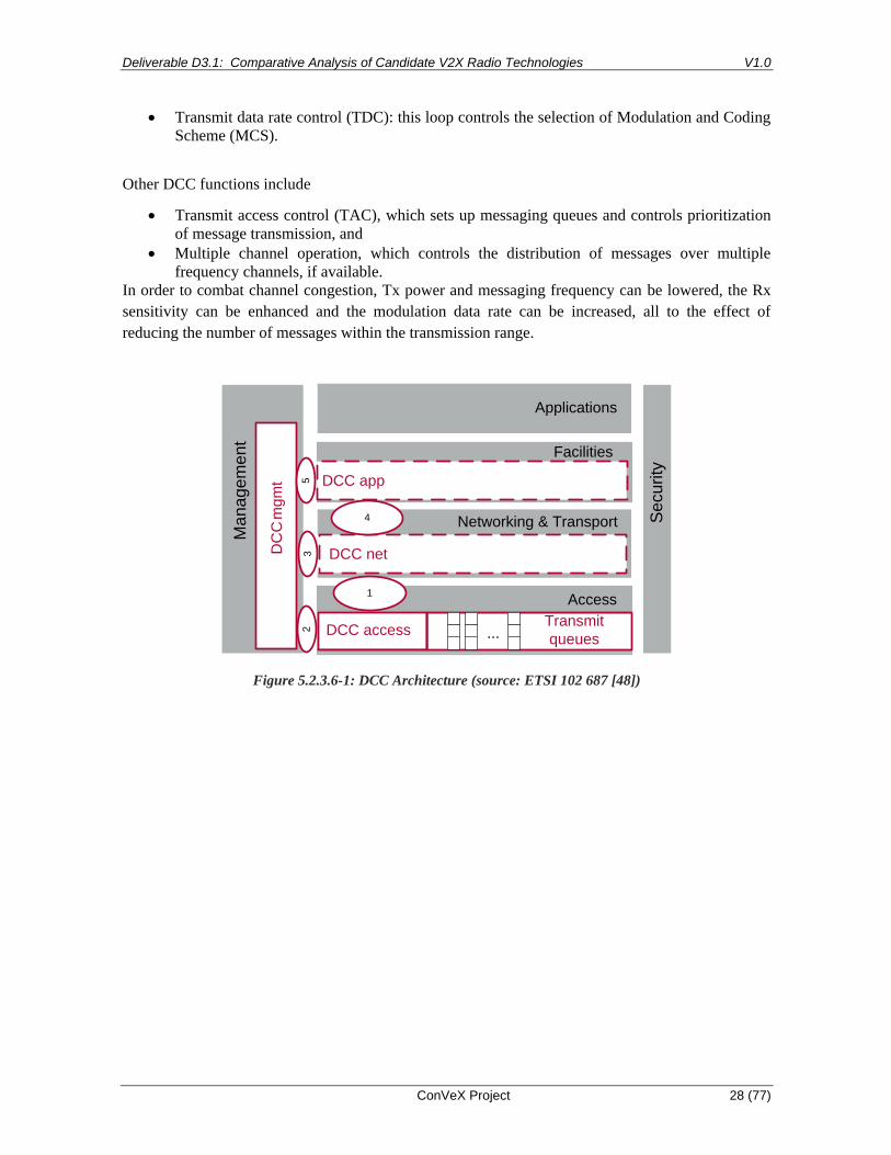
DCC is a cross-layer function which requires special functionality on the MAC, the Network and the
Facilities layers. Note that mandatory support of DCC represents a major difference between ITS C-
ITS and the US WAVE/DSRC technologies. The overall cross-layer architecture of DCC is
illustrated in Figure 5.2.3.6-1. The circled numbers refer to the Service Access Points (SAP)
between protocol layers which are defined in ETSI 102 687 [48].
The DCC_access mechanism consists of the following building blocks:
• setup of transmit queues
• channel probing for Clear Channel Assessment (CCA)
• assessment of transmit statistics
• setup of various control loops
The EDCA/DCF mechanism is part of the DCC transmit queuing function.
The MAC-part of ITS-G5 DCC feature is specified in ETSI 102 687 [48]. Figure 5.2.3.6-2 shows
the main DCC functions on the MAC layer.
The DCC mechanism aims to avoid channel congestion while maintaining fair resource allocation
across all ITS Stations by control of four parameters: transmission (Tx) power, reception (Rx)
sensitivity, messaging frequency and transmission data rate. Accordingly, DCC implements 4
different control loops:
• Transmit power control (TPC): this loop controls the range of transmission.
• DCC sensitivity control (DSC): this loop adapts the CCA sensitivity thresholds.
• Transmit rate control (TRC): this loop controls the frequency of periodically transmitted
messages.
Deliverable D3.1: Comparative Analysis of Candidate V2X Radio Technologies V1.0
ConVeX Project 28 (77)
• Transmit data rate control (TDC): this loop controls the selection of Modulation and Coding
Scheme (MCS).
Other DCC functions include
• Transmit access control (TAC), which sets up messaging queues and controls prioritization
of message transmission, and
• Multiple channel operation, which controls the distribution of messages over multiple
frequency channels, if available.
In order to combat channel congestion, Tx power and messaging frequency can be lowered, the Rx
sensitivity can be enhanced and the modulation data rate can be increased, all to the effect of
reducing the number of messages within the transmission range.
Ma
na
ge
me
nt
Access
Networking & Transport
Facilities
DCC access
Applications
DC
C m
gm
t
1
DCC net
Se
cu
rity
32
Transmit
queues...
5 DCC app
4
Figure 5.2.3.6-1: DCC Architecture (source: ETSI 102 687 [48])

Deliverable D3.1: Comparative Analysis of Candidate V2X Radio Technologies V1.0
ConVeX Project 29 (77)
Figure 5.2.3.6-2: DCC_access functional view (source: ETSI 102 687 [48])
CEN DSRC Technology
CEN DSRC [32] is employed for Electronic Fee Collection (EFC) services. This technology is often
denoted CEN DSRC in Europe. This standard is defined by European Committee for
Standardization and specified in EN 12253, EN 12795, EN 12834 [ISO 15628] and EN 13372.
These standards are not available for free. An overview on regulatory requirements is provided in
[64].
The messaging layer complies with IEEE Std 1609.11-2010 (Over-the-Air Electronic Payment Data
Exchange Protocol for ITS) [39].
An example use case illustrating electronic fee collection is provided in C.2 of IEEE 1609.0. The
essential radio parameters of CEN DSRC are summarized in Table 5.2.4-1
Table 5.2.4-1: Parameters of CEN DSRC radio technology
Parameter CEN DSRC
Band 5 795 – 5 815 GHz (20 MHz)
Number of Channels 4
Channel Bandwidth 5 MHz
Data Rate Downlink: 500 Kbps
Uplink: 250 Kbps
Range 15 - 20 m
Modulation RSU TX: 2-ASK
OBU TX: 2-PSK
When using V2X technology in the 5.9 GHz band, it must be ensured that CEN DSRC systems
operated along the route are not experiencing any harmful interference within their communication
range. The mobile V2X stations must be able to detect that they are approaching a CEN DSRC
system and possibly lower their TX power. The permitted emission limits are defined in ETSI EN
302 571 [56].

Deliverable D3.1: Comparative Analysis of Candidate V2X Radio Technologies V1.0
ConVeX Project 30 (77)
LTE
An overview of LTE and the functionality most relevant for V2X is provided in [30].
LTE-based V2X communications can be realized over the uplink/downlink interface (Uu interface)
or the sidelink interface (PC5). For downlink traffic on the Uu interface, both unicast and
multicast/broadcast transport may be utilized to deliver the message within the area of interest.
However, in the test network, multicast/broadcast is not supported.
Figure 5.3.x shows the high level view of the non-roaming architecture for PC5 and LTE-Uu based
V2X communication [68].
E-UTRAN
UE A (Vehicle)
UE D(stationary)
V2X Application
LTE-Uu-
V5
V1
V5
PC5
PC5
PC5
V5
MME
HSS
S/P-GW
S1
S6a
V3
V4
V3
V2X Application
Server
V2X Control Function
V3
UE B (Vehicle)
UE C (pedestrian)
V2X Application
V2X Application
V2X Application
V2SGi
LTE-Uu
Figure 5.3-1: Non-roaming reference architecture for PC5 and LTE-Uu based V2X communication
Figure 4.2.2-1a and figure 4.2.2-1b show the high level view of the reference architectures with
MBMS for LTE-Uu based V2X communication. V2X Application Server may apply either MB2 or
xMB reference points when managing MBMS service related information via BM-SC, MB2
reference point as defined in TS 23.468 [7] provides functionality related to group communication
and xMB reference point as defined in TS 26.346 [11] provides functionality overall for any content
and also supports security framework between content provider and BM-SC.

Deliverable D3.1: Comparative Analysis of Candidate V2X Radio Technologies V1.0
ConVeX Project 31 (77)
Reference points
V1: The reference point between the V2X application in the UE and in the V2X Application Server.
This reference point is out of scope of this specification.
V2: The reference point between the V2X Application Server and the V2X Control Function in the
operator's network. The V2X Application Server may connect to V2X Control Functions
belonging to multiple PLMNs.
V3: The reference point between the UE and the V2X Control Function in UE's home PLMN. It is
based on the service authorization and provisioning part of the PC3 reference point defined in
clause 5.2 of TS 23.303 [5]. It is applicable to both PC5 and LTE-Uu based V2X
communication and optionally MBMS and LTE-Uu based V2X communication.
V4: The reference point between the HSS and the V2X Control Function in the operator's network.
V5: The reference point between the V2X applications in the UEs. This reference point is not
specified in this release of the specification.
V6: The reference point between the V2X Control Function in the HPLMN and the V2X Control
Function in the VPLMN.
PC5: The reference point between the UEs used for user plane for ProSe Direct Communication for
V2X Service.
S6a: In addition to the relevant functions defined in TS 23.401 [6] for S6a, in case of V2X Service
S6a is used to download V2X Service related subscription information to MME during E-
UTRAN attach procedure or to inform MME subscription information in the HSS has changed.
S1-MME: In addition to the relevant functions defined in TS 23.401 [6] for S1-MME, in case of V2X
Service it is also used to convey the V2X Service authorization from MME to eNodeB.
LTE-Uu: The reference point between the UE and the E-UTRAN.
V2X Control Function
The V2X Control Function is the logical function that is used for network related actions required
for V2X. There is only one logical V2X Control Function in each PLMN that supports V2X
Services.
NOTE 1: If multiple V2X Control Functions are deployed within the same PLMN (e.g., for load
reasons), then the method to locate the specific V2X Control Function (e.g., through a database
lookup, etc.) is not defined in the specification.
V2X Control Function is used to provision the UE with necessary parameters in order to use V2X
communication. It is used to provision the UEs with PLMN specific parameters that allow the UE to
use V2X in this specific PLMN. V2X Control Function is also used to provision the UE with
parameters that are needed when the UE is "not served by E-UTRAN" (Mode 4).
The V2X Control Function may also be used to obtain V2X USDs for UEs to receive MBMS based
V2X traffic, through V2 reference point from the V2X Application Server.
The case of roaming UEs is not considered in the ConVeX system, however solutions are elaborated
in [68]

Deliverable D3.1: Comparative Analysis of Candidate V2X Radio Technologies V1.0
ConVeX Project 32 (77)
The V2X Control Function is not used in the ConVeX system. The necessary parameters are
preconfigured on the UEs (modem part of ITS stations).
UE
The UE may support the following functions:
- Exchange of V2X control information between UE and the V2X Control Function over the V3
reference point.
- Procedures for V2X communication over PC5 reference point and/or LTE-Uu reference point.
- Configuration of parameters for V2X communication (e.g., destination Layer-2 IDs, radio
resource parameters, V2X Application Server address information). These parameters can be pre-
configured in the UE, or, if in coverage, provisioned by signalling over the V3 reference point to
the V2X Control Function in the HPLMN.
The Layer-2 IDs are used to distinguish V2X services e.g. PSID or ITS-AIDs of the V2X application
[40].
MBMS and the related nodes and interfaces are not used in convex system.
V2X Application Server
The V2X Application Server (V2X AS) may support the following capabilities:
- Receiving uplink data from the UE over unicast.
- Delivering data to the UE(s) in a target area using Unicast Delivery and/or MBMS Delivery.
- Several capabilities related to MBMS, which is not used in the ConVeX system.
MME
In addition to the functions defined in TS 23.401 [6] and TS 23.246 [8], in case of V2X the MME
performs the following functions:
- Obtains subscription information related to V2X as part of the subscription data.
- Provides indication to the E-UTRAN about the UE authorization status on V2X use.
LTE side link (PC5 interface)
An overview of the LTE side link (PC5 interface) and the functionality most relevant for V2X is
provided in [30] section 6.1.
The PSSCH is variable in size (as described within the SCI) and can be transmitted with QPSK or
16QAM modulation (according to the MCS).
For each MCS index, Table 8.6.1-1 of [70] gives the TBS index and modulation order, which is
equal to the number of encoded bits per symbol and subcarrier. For the PC5 interface, the maximum
order is 4. From the TBS index and the number of physical resource blocks (PRB) the TB size can
be obtained from Table 7.1.7.2.1-1 of [70]. For 10 MHz bandwidth there are 50 PRBs. Assuming a
transport block is used in every subframe of 1 ms, finally the resulting data rate can be calculated

Deliverable D3.1: Comparative Analysis of Candidate V2X Radio Technologies V1.0
ConVeX Project 33 (77)
and the results are shown in Table 5.3.1-1. From the number of encoded bits/symbol and the fact that
there are 600 subcarriers for 10 MHz and 9 OFDM symbols per subframe available for data
transmission, the encoded bit rate (after turbo coding) can be calculated. The ratio of bit rates before
and after coding denotes the code rate. The resulting code rate are also shown in Table 5.3.1-1.
9 OFDM symbols used for data transmission includes the first OFDM symbol, which is also called
the AGC symbol, because within this symbol the receiver performs automatic gain control to adjust
its amplification and ADC settings to the received power. Depending on implementation the
receivers may not be able to make any use of the signal received during the AGC symbol for the
channel decoding, so effectively it receives only 8 symbols, which can be translated to a higher code
rate. The 3GPP performance requirements in [94] are in fact based on the assumption that only 8
symbols are received. For this reason, in Table 5.3.1-1 we state the code rate for both 8 and 9
symbols.
Comparing the LTE PC5 data rates to the ones of DSRC in section 5.2.2.2, the PC5 rates are lower.
The reason is the higher overhead in DSRC for channel access time, preamble and PLCP header and
cyclic prefix. DSRC, however, supports 64QAM modulation, which in LTE PC5 is only supported
from Release 15. Since the ConVeX project focuses on Release 14, use of 64QAM on PC5 is not
taken into account here.
Table 5.3.1-1: Relation of MCS index, data rate, code rate and encoded bits/symbol
MCS
Index
data
rate
[Mb/s]
code rate
excl. AGC
symbol
code rate
incl. AGC
symbol
encoded
bits /
symbol
0 1.4 0.15 0.13 2
1 1.8 0.19 0.17 2
2 2.2 0.23 0.20 2
3 2.9 0.30 0.27 2
4 3.6 0.38 0.33 2
5 4.4 0.46 0.41 2
6 5.2 0.54 0.48 2
7 6.2 0.65 0.57 2
8 7.0 0.73 0.65 2
9 8.0 0.83 0.74 2
10 8.8 0.92 0.81 2
11 8.8 0.46 0.41 4
12 9.9 0.52 0.46 4
13 11.4 0.60 0.53 4
14 13.0 0.68 0.60 4
15 14.1 0.73 0.65 4
16 15.3 0.80 0.71 4
17 16.4 0.85 0.76 4
18 18.3 0.95 0.85 4
19 19.8 1.03 0.92 4
20 21.4 1.11 0.99 4
Deliverable D3.1: Comparative Analysis of Candidate V2X Radio Technologies V1.0
ConVeX Project 34 (77)
LTE cellular link (Uu interface)
An overview of the LTE cellular link (Uu interface) and the functionality most relevant for V2X is
provided in [30] section 6.2.
Comparison of features
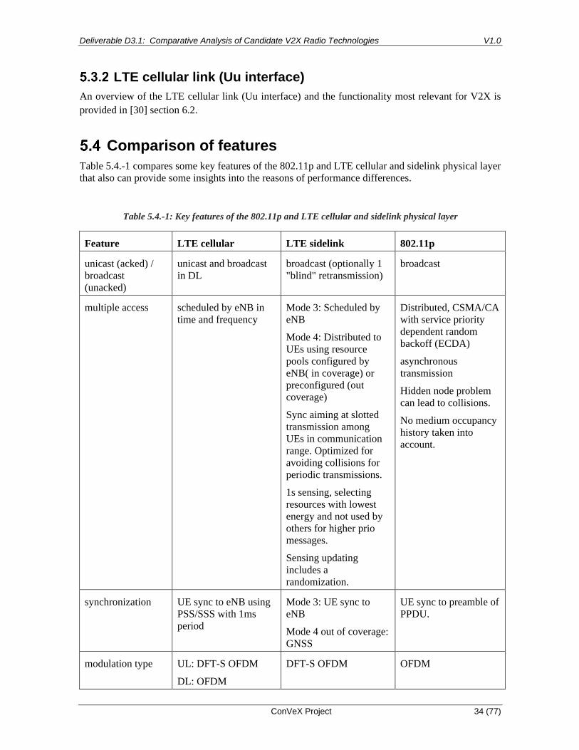
Table 5.4.-1 compares some key features of the 802.11p and LTE cellular and sidelink physical layer
that also can provide some insights into the reasons of performance differences.
Table 5.4.-1: Key features of the 802.11p and LTE cellular and sidelink physical layer
Feature LTE cellular LTE sidelink 802.11p
unicast (acked) /
broadcast
(unacked)
unicast and broadcast
in DL
broadcast (optionally 1
"blind" retransmission)
broadcast
multiple access scheduled by eNB in
time and frequency
Mode 3: Scheduled by
eNB
Mode 4: Distributed to
UEs using resource
pools configured by
eNB( in coverage) or
preconfigured (out
coverage)
Sync aiming at slotted
transmission among
UEs in communication
range. Optimized for
avoiding collisions for
periodic transmissions.
1s sensing, selecting
resources with lowest
energy and not used by
others for higher prio
messages.
Sensing updating
includes a
randomization.
Distributed, CSMA/CA
with service priority
dependent random
backoff (ECDA)
asynchronous
transmission
Hidden node problem
can lead to collisions.
No medium occupancy
history taken into
account.
synchronization UE sync to eNB using
PSS/SSS with 1ms
period
Mode 3: UE sync to
eNB
Mode 4 out of coverage:
GNSS
UE sync to preamble of
PPDU.
modulation type UL: DFT-S OFDM
DL: OFDM
DFT-S OFDM OFDM

Deliverable D3.1: Comparative Analysis of Candidate V2X Radio Technologies V1.0
ConVeX Project 35 (77)
modulation order UL: up to 64QAM
DL: up to 256QAM
up to 16QAM
typically QPSK ½
up to 64QAM
typically QPSK ½
link budget
(TxPwr, RxSens
QPSK for AWGN)
downlink:
TxPwr: 46 dBm
REFSENS (Band 7
2.6 GHz FDD):
-95 dBm (10 MHz)
-92 dBm (20 MHz)
uplink: [94]
TxPwr: 23 dBm
REFSENS: -101 dBm
[94]
TxPwr: 23 dBm
REFSENS for 3.5 Mb/s
(QPSK 1/3):
-90.4 dBm
(V2X Band 47, i.e. 5.9
GHz, QPSK)
TxPwr: 23 dBm
between -82 dBm
(QPSK 1/2)
and -83 dBm (BPSK
3/4) [96]
One product
specification:
Typ. Sensitivity for
6 Mb/s (QPSK 1/2):
-95 dBm [95] for
AWGN:
-88 dBm for fading,
50 km/h
OFDM symbol
time
67.7 us + 4.7 us CP
(7.1% overhead)
67.7 us + 4.7 us CP
(7.1% overhead)
8 us incl. 1.6 us CP
(25% overhead)
Subcarrier spacing 15 kHz 15 kHz 156250 Hz
# subcarriers/
10 MHz
600 600 64
bandwidth 1.4, 3, 5, 10, 15,
20 MHz
10 MHz or 20 MHz 10 MHz or 20 MHz
occupied
bandwidth
90% (edges
unoccupied)
90% (edges unoccupied) 81.25%
TTI 1ms 1ms depending on message
size and MCS
RS / pilot density time: 4 per TTI
frequency: every 4.
subcarrier
time: 4 per TTI (3 for
synch subframe)
frequency: every
subcarrier
time: every symbol
4 subcarriers of 52
From the table it is visible that LTE with 600 subcarriers uses much more than 802.11p. With state-
of-the-art technology this is not a cost driver. The lower subcarrier spacing achieved with LTE
results in longer OFDM symbols. This in turn has the advantage that a cyclic prefix long enough to
cover the delay spread in a typical V2X propagation channel represents lower overhead. Table 5.4
shows that the CP overhead is 7.1% in the case of LTE versus 25% overhead in the case of 802.11p.
Deliverable D3.1: Comparative Analysis of Candidate V2X Radio Technologies V1.0
ConVeX Project 36 (77)
Performance Assessment
Link Level Performance
As already explained in section 5.3, LTE cellular link (Uu interface), LTE sidelink (PC5 interface)
and IEEE 802.11p DSRC have different link level designs, e.g. coding scheme and frame structure.
The link level performance is usually evaluated by Block Error Rate (BLER) under different
conditions, e.g. Signal to Noise Ratio (SNR) and relative speed.
BLER vs SNR
Reference [66] has presented a link level performance comparison between LTE-V2X PC5, i.e.
LTE-V in Figure 6.1.1-1, Figure 6.1.1-2 and Figure 6.1.1-3, and DSRC based on simulation. Both
LTE-V2X PC5 and DSRC UEs are assumed to use same modulation scheme, coding rate, carrier
frequency, fast fading model, noise figure and number of antennas. BLER values for different SNRs
and receiving powers are evaluated. Detailed simulation parameters are shown in Appendix A.1. The
difference between random and fixed carrier frequency offset, i.e. CFO in the figures, is negligible
in this context.
Figure 6.1.1-1, Figure 6.1.1-2 and Figure 6.1.1-3 provide the simulation results for scenarios with
different relative speeds. Line of Sight (LOS) propagation is also assumed. As usual, BLER
decreases when SNR/receive power increases. For both PC5 and DSRC the SNR required for a
specific BLER hardly depends on the message size, but for PC5 the required received power does.
The paper does not provide an explanation, also not for why this is not the case for DSRC. Possibly
it has been assumed that in the case of PC5 with its frequency-domain multiplexing on PRB basis,
for the larger message a wider bandwidth is allocated, thereby leading to a larger received power of
about 2 dB for the same SNR, whereas the fact that in the case of DSRC the message extends over a
longer period of time is not revealed in this type of results.
Comparatively, under the same relative speed condition DSRC requires higher SNR/receive power
to reach the same BLER as LTE-V2X PC5, for the target BLER of 5% at 30 km/h – 120 km/h as
much as 4 – 5 dB more, whereas for 500 km/h LTE degrades more than DSRC so that the advantage
decreased to 2 – 3 dB. For this high speed the performance however depends heavily on the
employed receiver algorithms and all details are not disclosed in the source. The paper also does not
explain why the differences in required receive power between DSRC and PC5 are even larger, for
the 30 km/h 8 - 10 dB depending on message size. Possibly for DSRC the power is aggregated over
the entire 10MHz channel (excluding guard band) whereas for PC5 only a subset of the 10MHz
bandwidth is occupied, whereas the fact that the PC5 transmission time is with the LTE subframe
length of 1ms longer than for DSRC does not impact this type of results. In essence, the receive
power results are significantly less meaningful to compare efficiency than the SNR results, so we
propose to focus on the latter.
According to the author, the superiority of LTE-V2X PC5 may be owing to the fact that turbo code
used in LTE-V2X PC5 outperforms convolutional code used in DSRC. Other factors could be the
ones discussed in section 5.4.

Deliverable D3.1: Comparative Analysis of Candidate V2X Radio Technologies V1.0
ConVeX Project 37 (77)
Figure 6.1.1-1: Link level performance comparison between LTE V2X and DSRC (urban case: LOS;
relative speed 30 km/h). (a) SNR-BLER; (b) receiving power-BLER
Figure 6.1.1-2: Link level performance comparison between LTE V2X and DSRC (urban case: LOS;
relative speed 120 km/h). (a) SNR-BLER; (b) receiving power-BLER

Deliverable D3.1: Comparative Analysis of Candidate V2X Radio Technologies V1.0
ConVeX Project 38 (77)
Figure 6.1.1-3: Link level performance comparison between LTE V2X and DSRC (freeway case: LOS;
relative speed 500 km/h). (a) SNR-BLER; (b) receiving power-BLER
BLER vs Relative Speed
In vehicular environment, the high relative speed is one of the most challenging issue resulting in
frequency offset and reception failure.
To overcome this problem, LTE-V2X sidelink increases the number of DMRS from two in LTE
D2D to four [30]. These DMRS help to estimate the channel and compensate the frequency offset to
a certain extent. Similarly, DSRC uses short and long training sequences to estimate and compensate
the frequency offset. Therefore, it can be seen in Figure 6.1.1-1 and Figure 6.1.1-2, that when
relative speed raises from 30 km/h to 120 km/h, performances of LTE-V2X sidelink and DSRC
almost remain unchanged.
On the other hand, LTE-V2X sidelink by nature is more sensitive to frequency offset than DSRC.
This is because LTE-V2X sidelink has subcarrier spacing of 15 kHz which is smaller than 156.25
kHz subcarrier spacing in DSRC. As a result, LTE-V2X sidelink can tolerate ±0.1 ppm frequency
error while DSRC can operate with frequency error between ±20 ppm. It can be observed in Figure
6.1.1-3 that when relative speed is up to 500 km/h, both LTE-V2X sidelink and DSRC suffer from a
severe Doppler effect and their performances degrade. In addition, the superiority of LTE-V2X
sidelink becomes less obvious. However, the performance degradation for relative vehicle speed 500
km/h, appears to be rather pessimistic compared to results experienced in ConVeX field trials. It is
planned to revisit the issue of performance degradation at high relative vehicle speed in the follow-
up deliverable D3.2.
System Level Performance
Different from link level performance, system level performance focuses on the E2E performance,
e.g. packet reception ratio (PRR) and latency, under more realistic scenarios considering
communication distance and vehicle density etc. In this sense, MAC layer design is the key factor
causing different system level performances and will be discussed in this section.
PRR vs Distance
Reference [27] compared the reliability performance for V2X CAM message transmission using
LTE multicast, LTE-V2X PC5 mode 3, LTE-V2X PC5 mode 4 and DSRC respectively. The
performances of the different vehicular communication alternatives are evaluated in the two
scenarios as below:
- Urban slow scenario: models a dense urban deployment with 3 horizontal streets and 3
vertical streets with 175 vehicles/cell travelling at low speeds, i.e.15 km/h.
- Freeway fast scenario: models a 6-lane highway deployment resulting in 54 vehicles/cell
travelling at high speeds i.e. 140 km/h.
During the simulation, all vehicles generate, send, and receive CAMs. CAMs are generated at
regular interval of 100 ms. For every five messages, the first message has size 300 bytes followed by
four messages of size 190 bytes. Detailed simulation parameters are given in Appendix A.2.

Deliverable D3.1: Comparative Analysis of Candidate V2X Radio Technologies V1.0
ConVeX Project 39 (77)
The simulation results are shown in Figure 6.2.1-1 and Figure 6.2.1-2. In general, reliability
decreases when transmitter and receiver UEs are far away from each other. More precisely, LTE
multicast has the best reliability performance than others, LTE-V2X PC5 mode 3 reaches a slightly
higher PRR than LTE-V2X PC5 mode 4, and DSRC has the lowest PRR among them.
In addition to the link level performance as addressed in section 5.3 and 6.1, MAC layer design
plays a significant role in terms of reliability. MAC layer for DSRC is EDCA and CSMA/CA
based, where UE accesses the medium randomly with a back-off mechanism to avoid a certain level
of collision. Sensing based Semi Persistent Scheduling (SPS) is used for LTE-V2X mode 4. SPS is
designed for periodic message transmissions, e.g. CAM, and one UE is aware of the resource
utilization via sensing and decoding SCI from other UEs. Hence, LTE-V2X mode 4 can do more
efficient scheduling with the knowledge of resource reservation for future transmission. Since
scheduling is conducted by eNodeB in LTE-V2X mode 3, collisions due to hidden node problem in
mode 4 can be avoided and therefore a relatively higher PRR can be achieved. In LTE-V2X PC
mode 3 and mode 4, it’s allowed to let two UEs far away from each other transmit using the same
resources and the interference is assumed to be minimized. In contrast, the same resource will not be
reused in the same cell, as a result, receiver UE in LTE multicast suffers less interference and can
reach a higher PRR.
It’s worth mentioning that in this study, PRR is compared with the distance between two UEs,
however, it’s the distance between UE and eNodeB that matters in LTE multicast scenario. Hence, it
can be observed that reliability for LTE multicast is lower than others for urban slow scenario when
distance between UEs are smaller than 80m.
Figure 6.2.1-1: Comparison between different technologies at required
vehicle density, i.e., 175 vehicles/cell in Urban Slow scenario at 6 GHz
carrier

Deliverable D3.1: Comparative Analysis of Candidate V2X Radio Technologies V1.0
ConVeX Project 40 (77)
Figure 6.2.1-2: Comparison between different technologies at required
vehicle density, i.e., 54 vehicles/cell in Freeway Fast scenario at 6 GHz
carrier
PRR vs Traffic Load
Reference [69] conducted performance comparison between LTE, i.e. LTE cellular unicast, and
DSRC under different traffic load conditions. The simulation scenario is set to be a 5x5 Manhattan
grid with a number of vehicles transmitting a beacon message periodically (for both cases, LTE and
DSRC) and the communication range is assumed to be 250 meters as described in Appendix A.3.
Various traffic load is generated in the simulation by adapting two parameters, i.e. the beacon
transmission frequency and the number of vehicles.
Figure 6.2.2-1and Figure 6.2.2-2 show the reliability performances of DSRC based and LTE based
vehicular network respectively. It can be seen in Figure 6.2.2-1 that PRR, i.e. Packet Delivery Ratio
in the figure, declines when there are more vehicles, i.e. “n” in the figure, transmitting at the same
time or when vehicles are transmitting with a higher beacon transmission frequency. The reason is
that the collision issue in CSMA/CA based MAC protocol becomes more severe with a higher traffic
load. Additionally, DSRC is a broadcast system without ACK/NACK feedback, thus lost packet will
not be retransmitted.
For LTE cellular unicast, a transmission only occurs when there are free resources available, in other
words, vehicles within the same cell will not experience packet loss due to transmission collision.
Besides, the HARQ process is enabled in LTE cellular unicast. A retransmission will be triggered if
the packet is not received successfully and retransmission attempts are limited by a maximal number
depending the configuration. As shown in Figure 6.2.2-2 if messages are delivered via LTE cellular
unicast, PRRs above 96% can be achieved and they reduce slightly when increasing the beacon
transmission frequency while a more observable reduction happens when increasing the number of
vehicles in the simulation.

Deliverable D3.1: Comparative Analysis of Candidate V2X Radio Technologies V1.0
ConVeX Project 41 (77)
Figure 6.2.2-1: Packet delivery ratio (%) vs. beacon transmission frequency (Hz), IEEE 802.11p-based
vehicular network
Figure 6.2.2-2: Packet delivery ratio (%) vs. beacon transmission frequency (Hz), LTE-based vehicular
network
Latency vs Traffic load
The latency performance is also studied in [69]. It is shown in Figure 6.2.3-1 that the End-to-End
delay raises dramatically from 1 ms to over 2000 ms when DSRC is used and the traffic load is high.
The result reflects the analysis in 5.2 that if the cannel is busy, potential transmissions in DSRC
must back-off a certain amount of time until the channel is idle again. Therefore, with a higher
traffic load, a longer back-off time is expected. In comparison, every transmission is scheduled by
eNodeB in LTE network and unnecessary back-off time can be saved. As a result, the End-to-End
delay remains reasonably low even with a high traffic load as depicted in Figure 6.2.3-2.

Deliverable D3.1: Comparative Analysis of Candidate V2X Radio Technologies V1.0
ConVeX Project 42 (77)
As pointed out by the author, the vehicle density considered in [69] is relatively small, and the
results may probably differ when a much higher vehicle density is applied. For instance, the delay in
LTE unicast downlink will be heavily impacted when there are more target receivers.
Figure 6.2.3-1: E2E delay (ms) vs. beacon transmission frequency (Hz), IEEE 802.11p-based vehicular
network
Figure 6.2.3-2: E2E delay (ms) vs. beacon transmission frequency (Hz), LTE-based vehicular network
Throughput vs Traffic Load
The actual throughput of one system can be evaluated by multiplying the transmitted data rate with
the achieved reception ratio. The throughput performances of LTE and DSRC in study [69] can be
deduced from Section 6.2.2.1 as shown in Figure 6.2.4-1 and Figure 6.2.4-2.Due to the low
reliability performance of DSRC, the actual achieved throughput is also significantly lower than
LTE network.

Deliverable D3.1: Comparative Analysis of Candidate V2X Radio Technologies V1.0
ConVeX Project 43 (77)
Figure 6.2.4-1: Throughput (kbps) vs. beacon transmission frequency (Hz), IEEE 802.11p-based vehicular
network.
Figure 6.2.4-2: Throughput (kbps) vs. beacon transmission frequency(Hz), LTE-based vehicular network.

Deliverable D3.1: Comparative Analysis of Candidate V2X Radio Technologies V1.0
ConVeX Project 44 (77)
Suitability for ConVeX Use Cases
The objective of this chapter is to analyze the suitability of the radio technologies ETSI-ITS, C-V2X
PC5 and C-V2X-Uu for the use cases defined in the ConVeX project.
Therefore, for each use case the critical requirements related to these radio technologies need to be
defined.
The following table shows a summary of the requirements and how each technology covers them.
Table 7-1: Suitability for ConVeX Use Cases
Use Case Critical
Requirement
ETSI-C-ITS C-V2X PC5 C-V2X Uu
FollowMe
Information
Range and vehicle
speed
not defined / not
applicable (yet)
targeted use case
(by design)
feasible (with
larger delays
especially
suitable for
distances out of
PC5 range)
Cloud Based
Sensor Sharing
Coverage area,
high number and
variety of sensor
devices
no network
support defined
could support
device to device
hopping
best suited, large
coverage area
Blind Spot /
Lane Change
Warning
Short range, short
delay, vehicle
speed
Feasible feasible, higher
speeds
not suited
Do Not Pass
Warning
Range (Passing
Alert Distance,
PAD) and vehicle
speed
PAD=625 m
e.g. HV/OLRV:
v = 100 km/h
ARV:
v= 60 km/h [97]
PAD=1250 m
e.g. HV/OLRV:
v = 100 km/h
ARV:
v= 80 km/h [97]
can potentially
extend range for
early discovery of
RVs
Emergency
Electronic
Brake Lights
Short range, short
delay
Feasible feasible, larger
range; may
support even
higher vehicle
speeds
can extend range
for remote RVs,
larger delays
Intersection
Movement
Assist
Range
(obstructions),
delay
lower range in
case of Non-LOS
(lower max.
allowable path
loss)
larger range in
case of Non-LOS
(higher max.
allowable path
loss)
not considered
Left Turn
Assist
Range,
obstructions,
delay, vehicle
speed
lower range in
case of Non-LOS
(lower max.
allowable path
loss), lower RV
larger range in
case of Non-LOS
(larger max.
allowable path
loss), higher RV
not considered

Deliverable D3.1: Comparative Analysis of Candidate V2X Radio Technologies V1.0
ConVeX Project 45 (77)
speeds speeds
Vulnerable
Road User
Warning
Detectability of
users
feasible but not
defined yet
reliable detection
within intended
short range
not considered
Shockwave
Damping
Range, traffic
density
Lower range,
higher density of
RSU per area
higher range for
vehicles and
RSUs, lower
density of RSUs
per area
can extend range
for remote RVs
In-Vehicle
Information
Range
(obstructions),
vehicle speed,
traffic density
Feasible, higher
density of RSU
for high speeds?
larger range,
higher max.
allowable path
loss
can extend range
of communicating
devices
Road Works
Warning
Range
(obstructions),
vehicle speeds,
traffic density
lower range,
higher delays,
lower vehicle
speeds
larger range,
higher vehicle
speeds
can extend range
of communicating
devices, higher
delays
See Through Data rates, range
(obstructions),
delays, vehicle
speeds
lower range,
higher delays,
lower vehicle
speeds
larger range,
lower delays,
higher vehicle
speeds
can extend range
of communicating
devices, higher
delays
Network
Availability
Prediction
Service
availability and
reliability, area
can support
device to device
communication,
restricted service
area
can support
device to device
communication,
restricted but
larger service area
proven service
availability and
reliability in large
area
In the following part a few more differentiating aspects of the communication technologies, ETSI-C-
ITS, C-V2X PC5 and C-V2X Uu are listed and described.
• ETSI-C-ITS
o Allows direct car-to-car communication within a typically low to medium range
distance (up to 50 m for urban and 300 m for highway) and low to medium vehicle
speeds not optimally suited for the very high speed motorway scenarios up to 250
km/h or relative car speeds of up to 500 km/h.
• C-V2X PC5
o Expected to allow direct car-to-car communication within a superior range distance
and higher vehicle speeds (up to 250 km/h) and thus is best suited to fulfill the wide
range of speed and road scenario requirements listed earlier.
• C-V2X Uu
o LTE - and in future 5G - operated networks typically allow larger signal coverage
areas (depending on the underlying network layout) but might be somewhat limited
in very rural environments. Any involvement of such infrastructure will lead to
additional end-to-end delays compared to a direct car-to-car communication.
Considering these aspects, C-V2X Uu seems best suited for support of use cases
characterized by large(r) coverage requirements at the expense of lower end-to-end
delay requirements.

Deliverable D3.1: Comparative Analysis of Candidate V2X Radio Technologies V1.0
ConVeX Project 46 (77)
FollowMe Information
Compared to a clearly safety related use case the FollowMe Information Use Case can work with
longer update cycles. In order to maintain the main functionality of receiving the path and position
information of the HV in closer proximities, a feasible latency with a reasonable information update
rate a certain level of quality of service should be available up to high vehicle speed. Since the main
use case should contain a car following another one a relative speed of 250 km/h should be target.
With an increased distance between the cars the position and path information could also be
forwarded by a cloud-based infrastructure in a lower frequency and a less accurate set position
information.
Cloud Based Sensor Sharing
Since the use case does not aim for handling/solving an explicit driving maneuver (e.g. emergency
break), but instead to share information on road users, forming a baseline for coordinated driving,
the latency has to be low enough so that a movement prediction does not deviate too much from the
real progression of events under normal driving circumstances. A stable latency and high reliability
are more important. Thus, IEEE 802.11p is not suitable for the use case because of its unpredictable
transmit back off time, while a cellular communication (incl. multicast) fulfils the requirements
much better, and PC5 is in principle also suitable.
However, the cloud-based sensor sharing use case requires a backhaul communication to the cloud
instance for data aggregation & fusion. This is most efficiently solved over a cellular network, which
may also offer a cellular broadcast for efficient message dissemination in the downlink in case of a
lot of road users. On the other hand, a cellular broadcast may (depending on the configuration) come
with significant extra delay, which should be avoided. Furthermore, a long backhaul connection
should be avoided, which adds several 10ms latency, but a deployment directly at the radio edge is
not needed.
Blind Spot / Lane Change Warning
The critical requirement for this use case is the short end-to-end delay between detection of the RV
in the blind spot of the HV and the notification of the driver of the HV. The shorter this delay, the
more time to react for the driver of the HV is left. Direct V2V communication is clearly the most
efficient communication technique here. V2N communication via the Uu interface involving further
network elements is detrimental to this. The range requirements of this use case are short to medium
distances between RV and HV, essentially depending of the driven absolute speeds of RV and HV
on the one side and the relative speeds between RV and HV on the other side. The speed range can
be from 0 km/h for cars leaving a parking lot up to 250 km/h for Motorway scenarios.
Do Not Pass Warning
Here the most relevant requirement will be the maximum feasible range of communication while
allowing speeds up to around 100 km/h for rural passing scenarios. The larger the allowable distance
between HV and RV for reliable exchange of CAM messages between the involved cars will be the

Deliverable D3.1: Comparative Analysis of Candidate V2X Radio Technologies V1.0
ConVeX Project 47 (77)
more time is available to avoid risky maneuvers. V2N assistance might enlarge the relevant
detection area given that network coverage is available.
Emergency Electronic Brake Lights
Similar to the blind spot warning use case the short end-to-end delay between the emergency
breaking event of the RV and the notification of the driver of the HV is most important. The typical
distance between RV and the (closest) following HV will be around half the distance in meters of
the driven vehicle speeds (following the German rule of thumb of the security distance between two
cars). For a critical Motorway scenario of 250 km/h this would mean a distance of 125 m. For other
cars following at larger distances the RV, V2N involvement can considerably increase the covered
relevant notification area.
Intersection Movement Assist
The most critical requirement for this use case will be the short end-to-end delay of the
communication between RV and HV in all intersection scenarios with line-of-sight (LOS) and non-
line-of-sight (NLOS) transmission and reception cases. Especially in cases where buildings or other
objects and obstructions are impacting the human assessment as well as propagation of radio waves
the fast and reliable communication between RV and HV is essential. The typical vehicle speeds
within the zero or low range are less of a concern, and mainly depending on the signage with “Stop”
or “Yield” signs and traffic situation and density.
Left Turn Assist
The requirement argumentation for the left turn assist use case follows mainly the ones given in the
previous intersection movement use case. One typical difference might be the driven vehicle speeds,
as it can be expected that in more left turn scenarios the driven HV speed might be higher than in the
intersection use case, but again depending on the actual left turn scenario, traffic situation and
density.
Vulnerable Road User Warning
For this use case the high reliability of detecting a vulnerable road user is most critical. Any
obstructions and path loss impacts (e.g., placing a user’s device within a backpack, bag, boxes,
clothes, etc.) should not lower the detection reliability of the device carrying user.
Shockwave Damping
In order for the shockwave damping algorithm to work a gapless coverage of a highway section is
optimal. Critical traffic situations are typically linked to a high density of vehicles. Thus, the RSU is
required to have a long range for sending IVIM and receiving CAMS even in presence of many
OBUs, meaning less RSU devices per section are needed.

Deliverable D3.1: Comparative Analysis of Candidate V2X Radio Technologies V1.0
ConVeX Project 48 (77)
In-Vehicle Information
IVIM must not only be received at high vehicle speeds in a free traffic flow situation but also in a
traffic jam or near traffic jam situation. A higher RSU range increases the coverage efficiency, i.e.
less installed devices per distance. Ideally the effect of obstacles like gantries, trees or trucks has
only a limited effect on the RSUs range and visibility.
Road Works Warning
For this use case the same applies as in the “In-Vehicle Information” use case for DENMs instead of
IVIM.
See Through
See Through aims at scenarios with lower relative speeds in intersection and vehicle scenarios where
the vehicles are in close proximity and a similar orientation. Especially on the infrastructural side a
broadcast of the video stream seems reasonable.
To keep a certain level of usability the video information should be transmitted within less than
300ms end-to-end delay on application level without any noticeable loss of critical packets (e.g. key
frames)
High latency and/or an entire breakdown of the communication must be detectable.
Network Availability Prediction
The C-V2X technology is envisaged to support ultra-reliable low latency communication scenarios
(for e.g., road safety warnings) with strict requirements in terms of reliability and latency. This
requires a shift of the system design from the traditional throughput oriented to the one based on
dependability. The current generation of wireless networks (including C-V2X) assumes the
availability of a Reliable Transmission Link (RTL) and on the top employs redundancy techniques
(for e.g., retransmissions) in order to increase the probability of successful transmission. However,
this may change in the future revisions where the URLLC service/application relies on the wireless
communication only in those instances in which the RTL is guaranteed with a certain probability
(also referred to as Ultra-Reliable Requirement).
In this regard, the purpose of this use case is to predict the RTL availability for the future timeslots
based on the historical data from metrics such as predicted SINR, RSSI, RSRP etc. This is done by
using the Machine Learning (ML) schemes and in particular the Recurrent Neural Networks (RNNs)
since the prediction itself can be formulated as a time series forecasting problem.
Depending upon the type of connection, two prediction time windows can be foreseen
NAP aims to predict the link availability for the future timeslots based on historical data from
metrics such as post equalized SINR, RSSI, RSRP etc. Depending upon the type of connection (V2V
or V2N), two prediction time windows can be foreseen

Deliverable D3.1: Comparative Analysis of Candidate V2X Radio Technologies V1.0
ConVeX Project 49 (77)
• Prediction over Short Term (PST) - Suited for V2V / V2I and V2N connectivity where the
availability of the network needs to be predicted for short time windows. This requires local
temporal knowledge about the previous transmissions in order to make a prediction (channel
tracking). An example use case benefitting from such a short term prediction is platooning
where the inter platoon distance is varied according to the network conditions
• Prediction over Long Term (PLT) - Suited for V2N connectivity where the availability of
the network needs to be predicted for a longer time window. An example of use cases
requiring such long term prediction are over-the-air software update (as in the case of Tesla
vehicles)
NAP requires real-time vehicle data such as speed, location etc. and very low feedback reporting
delays (in the order of 2-5 ms). It may not be applicable to communication scenarios with no
feedback channel (e.g. broadcast) and to vehicles with a very high relative velocity due to the short
term nature of the connection. The feedback channel is assumed to be perfect.

Deliverable D3.1: Comparative Analysis of Candidate V2X Radio Technologies V1.0
ConVeX Project 50 (77)
Radio Spectrum Aspects
Current allocation of spectrum for ITS services
Introduction
This section provides information on spectrum allocations for ITS services in Europe and in the US.
Europe
In Europe, the frequency bands 5470 MHz to 5725 MHz, 5795 to 5815 MHz and 5855 MHz to 5925
MHz are assigned to ITS applications. The regulatory framework is defined by a series of ECC
decisions, ECC Recommendations and EU Commission Decisions, see [73] - [78]. This ITS band
allocation in Europe is illustrated in Figure 8.1.2-1.
Figure 8.1.2-1: ITS band allocation in Europe in the 5 GHz range [79]
ETSI EN 302 663 [79] specifies the frequency allocation when deploying ETSI ITS-G5 systems in
Europe in addition with a number of system-specific details and described as follows.
The ITS G5A band (5,875 GHz to 5,905 GHz) contains the channels CCH, SCH1 and SCH2. They
are dedicated to road safety related service. The usage of the CCH, SCH1 and SCH2 channels is
under control of the decentralized congestion control (DCC).
The Control Channel (CCH) is basically dedicated to cooperative road safety. It is the default
channel for the transmission of DP1 and DP2 messages. The transmissions of messages using
different DCC profiles (DP3 to DP8) on the CCH are allowed in the DCC state "RELAXED". In this
DCC state the channel is not crowded and therefore no restrictions occur.

Deliverable D3.1: Comparative Analysis of Candidate V2X Radio Technologies V1.0
ConVeX Project 51 (77)
The Service Channel 1 (SCH1) is the default channel for announcing and offering ITS services for
safety & road efficiency under the DCC state ACTIVE and RESTRITIVE of the CCH. The
transmissions of other message-types on the SCH1 are allowed if channel conditions according to
the restrictions in the present document permit.
The Service Channel 2 (SCH2) is the second service channel on ITS G5A and is used as an alternate
channel for traffic safety-related services. Due to its frequency band allocation between the CCH
and the SCH1 and the resulting potential adjacent channel interference issues, the flexibility of the
deployment of the SCH2 is limited. The limitations are taken into account in the requirement
descriptions for the SCH2.
The ITS G5B band (5,855 GHz to 5,9875 GHz) contains the channels SCH3 and SCH4. It is
considered for general purpose ITS services (e.g. road efficiency, service announcements, multi-
hopping, etc.). The ITS G5B band is not allocated European wide. Thus, local usage restrictions
might apply.
The ITS G5C band (5 470 MHz to 5 725 MHz), a.k.a. the RLAN/WLAN/BRAN band, is
regulated in EN 301 893 [91], which conditions are given in Commission Decisions 2005/513/EC
and 2007/90/EC.
The ITS G5D band (5 905 MHz to 5 925 MHz) is set aside for future usage of ITS road traffic
applications and it is allowed to be used by ITS-G5 compliant stations as specified in ETSI EN 302
663 [79].
Table 8.1.2-1 ITS bands allocated in Europe
ITS
Band
Frequency range Usage Regulation Harmonized
standard
G5D 5 905 MHz to 5 925
MHz
Future ITS
applications
ECC Decision [75]
EN 302 571 [80] G5A 5 875 MHz to 5 905
MHz
ITS road safety Commission Decision
[78]
G5B 5 855 MHz to 5 875
MHz
ITS non-safety
applications
ECC Recommendation
[73]
G5C 5 470 MHz to 5 725
MHz
RLAN (BRAN,
WLAN)
ERC Decision [74]
Commission Decisions
[76] and [77]
EN 301 893 [91]
Table 8.1.2-2 shows the channel allocation and transmit power limits for ITS systems deployed in
Europe. Note that the data in this table is obtained from ETSI EN 302 663 [79]. However, the TX
power limits have been aligned with the latest version of EN 302 571 [9], which is more up to date.
Table 8.1.2-2 Channel allocation and power limits in Europe
Channel
Type
Center
frequency
IEEE 802.11-
2012 channel
Channel
spacing
Default data
rate
TX power
limit
TX power
density

Deliverable D3.1: Comparative Analysis of Candidate V2X Radio Technologies V1.0
ConVeX Project 52 (77)
(MHz) number (MHz) Mbit/s (dBm
EIRP)
limit
(dBm/M
Hz)
G5-
CCH
5 900 180 10 6 33 23
G5-
SCH2
5 890 178 10 12 33 23
G5-
SCH1
5 880 176 10 6 33 23
G5-
SCH3
6 870 174 10 6 33 23
G5-
SCH4
5 860 172 10 6 33 23
G5-
SCH5
5 910 182 10 6 33 23
G5-
SCH6
5 920 184 10 6 33 23
G5-
SCH7
As described
in EN 301
893 for the
band 5 470 to
5 725 MHz
94 to 145 several Dependent
on channel
spacing
33
(DFS
master)
33
(DFS slave)
23
NOTE: With respect to emission limit/power density limit, the more stringent requirement
applies
USA
In the US, the FCC has allocated spectrum of 75 MHz bandwidth from 5850 to 5925 MHz for
vehicle to vehicle and vehicle to infrastructure communication as shown in the figure 8.1.3-1.
The maximum permitted transmit power (and antenna EIRP) depends on the channel and is shown
in Table 8.1.3-1.
Figure 8.1.3-1: Band allocation for DSRC in the 5.9 GHz Band in the US [FCC]

Deliverable D3.1: Comparative Analysis of Candidate V2X Radio Technologies V1.0
ConVeX Project 53 (77)
Table 8.1.3-1: Maximum EIRP in the 5.9 GHz Band in the US [FCC]
Spectrum requirements for ITS services using direct V2X communication
Introduction
In this section, we describe methodologies suitable for estimation of the overall amount of radio
spectrum required to reliably support ITS services employing direct communication between
vehicles (V2V), vehicles and RSUs (V2I) and between vehicles and pedestrians (V2P).
The amount of radio spectrum required depends principally on the type of ITS services to be
supported (including number and size of the messages and their statistical distribution), the
performance characteristics of the employed radio technology (spectrum efficiency, targeted
communication range), and the density of ITS stations (i.e. vehicles, RSUs and VRUs) for typical
road traffic scenarios, such as e.g. highway and urban street scenarios.
Focusing on ITS basic safety messages, V2X traffic consists of periodically sent CAMs and event-
based triggered DENMs. The vast majority of messages will be CAMs.
There are also additional non-safety related message types (see ETSI TS 103 301 [92]), e.g. in-
vehicle information massage (IVIM), road/lane topology and traffic maneuver message (MAPEM),
and signal phase and timing extended message (SPATEM) which contribute to the spectrum
requirement.
The spectrum bandwidth BWreq (Hz) required to serve a given traffic load in a radio network can be
represented as the ratio of the required overall communication traffic data rate Creq (bit/s) and
spectrum efficiency SE (bit/s/Hz):
𝐵𝑊𝑟𝑒𝑞 =𝐶𝑟𝑒𝑞
𝑆𝐸
(1)
The required overall network communication traffic data rate Creq is also denoted required system
capacity. The offered traffic load CA is the aggregated data rate of all users of a communication
channel. In order to serve the offered traffic load at a finite delay, the condition
𝐶𝑟𝑒𝑞 ≥ 𝐶𝐴 (2)

Deliverable D3.1: Comparative Analysis of Candidate V2X Radio Technologies V1.0
ConVeX Project 54 (77)
must be met. A radio network is congested (overloaded) if its capacity C is lower than the offered
traffic load. The required system capacity can be further expressed as follows by introducing a
resource utilization efficiency, 0 ≤ α ≤ 1:
𝐶𝑟𝑒𝑞 ≥ 𝐶𝐴/𝛼 ≥ 𝐶𝐴 (3)
The resource utilization efficiency expresses the fact that
(a) not all radio resources can be utilized for message transmissions of the stations inside
resource reuse range DRR,
(b) additional protocol and signaling overhead needs to be taken into account.
Even if ideal scheduling of transmissions is assumed, i.e. no collisions due to simultaneous
transmission attempts, the utilization factor is typically smaller than 1 in a radio system due to
required overhead. Both, offered traffic load CA and spectrum efficiency SE are random variables
which depend on many parameters. The offered traffic load depends on the number and
geographical distribution of the ITS stations, as well as the statistical distribution of the ITS
messages and of their length (in bytes). Spectrum efficiency depends on the radio access technology,
modulation and coding scheme, the random radio propagation characteristics and the target QoS
requirements (see section 8.2.2).
V2X scenarios and propagation model
This section provides a description of typical V2X scenarios (urban street and highway scenarios)
and radio performance aspects relevant to the analysis of the spectrum requirements.
The required spectrum depends on
• Size and frequency of transmitted messages (“packets”)
• Number of ITS stations (vehicles, RSUs, VRUs) transmitting messages (density per area
unit)
• Geographical distribution and mobility of the ITS stations
• Target performance characteristics (PRR, delay, communication range)
• Radio propagation characteristics
• Spectrum efficiency of the radio technology for the given scenario
Consider a scenario as illustrated schematically in Figure 8.2.2-1. Assuming isotropic radio
propagation, the signal transmitted by a vehicular ITS station V1 can be received by stations which
are located within a circular area of radius DR around the transmitter (stations V2 and V3). We
denote DR as the V2V communication range. The distance DR may be determined such that all are
served at a desired target level of QoS performance.
QoS performance can be defined in terms of a desired target Packet Reception Rate (PRR) of e.g.
95 % and a probabilistic limit on the transmission latency L.
Any vehicles inside the circle of radius DR can be considered to be served adequately. The circle of
radius DR defines the service area around a considered reference ITS station.
The performance of a V2V transmission system is furthermore impacted by ITS stations which
contribute to interference on any of the receiving stations within range DR. This is illustrated in
Figure 8.2.2-1 with a second circle of radius DRR. ITS stations (V8, V9, V10) outside of DRR are

Deliverable D3.1: Comparative Analysis of Candidate V2X Radio Technologies V1.0
ConVeX Project 55 (77)
considered to not produce harmful interference to stations inside the considered communication
range. Note that stations separated by at least the distance DRR from each other could all transmit
simultaneously without producing harmful interference onto a receiver located at the edge of the
respective transmission range (i.e. the receiver in the most unfavorable radio condition).
The carrier sensing range DCS is the maximum distance between two ITS stations where the one
station is able to sense if the other station is transmitting. To avoid harmful transmission collisions, it
is necessary to operate at a carrier sensing range which is at least equal to the resource reuse
distance, i.e. DCS ≥ DRR.
In 802.11p based systems, only a single ITS station inside the resource reuse range DRR can transmit
at a given time. Any simultaneous transmissions of two or more stations would cause a collision and
cause loss of both colliding messages.
The 3GPP PC5 interface allows resource allocations where multiple stations can transmit
simultaneously when different frequency resources of the resource pool are employed.
DR
DRR
V1V2V3
V4
V5
V6V7V8
V9
V10
Figure 8.2.2-1: V2V propagation scenario
Table 8.2.2-1 lists the parameters and their definitions which are relevant to estimation of V2X
spectrum requirements.
Table 8.2.2-1: Symbols and Definitions used in spectrum requirement estimations
Name Symbol Definition
Required system
capacity
Creq System capacity in bit/s required to serve all communications at
the desired target QoS
Latency limited
data rate
CL Instantaneous peak data rate due to critical latency requirement
Aggregated data
rate
CA Overall aggregated transmission data rate in a long-time scale
and periodic manner
Communication
Range
DR Maximum distance between transmitter and receiver allowing
reception at the target QoS level (defined in terms of PRR and
delay)
Carrier Sensing
Range
DCS The maximum distance between ITS station allowing sensing of
transmission
Resource Reuse
Distance
DRR The minimal distance between two stations which can transmit
simultaneously on the same radio resources without causing
intolerable interference.

Deliverable D3.1: Comparative Analysis of Candidate V2X Radio Technologies V1.0
ConVeX Project 56 (77)
Message size S V2X message (packet) size in bits or bytes per packet
Message
frequency
F Frequency of periodically transmitted V2X messages in packets
per second
Number of
vehicles within
resource reuse
distance
N The number of transmitting ITS stations contributing to the
overall offered traffic load
Channel
Bandwidth
BWch Bandwidth of a single radio transmission channel in Hz
Required
Bandwidth
BWreq Required total spectral bandwidth to serve a given offered traffic
load in the V2X radio communication system
Spectrum
Efficiency
SE The amount of bit rate transmitted per Hz
Required Signal
to Interference
and Noise Ratio
(SINR)
𝑆𝐼𝑁𝑅𝑟𝑒𝑞 For a certain technique, it represents the needed SINR to achieve
the target PRR
SINR at the edge
of
communication
range
𝑆𝐼𝑁𝑅𝑅 For a certain technique, it represents the actual SINR at the edge
of the communication range
Resource
utilization
efficiency
Α Fraction of radio resources available for message transmission (in
practice <1 due to non-ideal scheduling and overhead required
for message acquisition)
Vehicle density Ρ Average number of vehicles per meter (for unidimensional
geographic distribution)
Latency
constraint
L Maximum tolerable latency in seconds
Figures 8.2.2-2 and 8.2.2-3 illustrate two typical traffic scenarios frequently used for assessment of
offered traffic load, a highway and an urban street junction scenario, respectively.
A highway scenario as shown in Figure 8.2.2-2 is typically a straight road section with 2 to 6 lanes
per direction. The distance between vehicles depends on the speed. In a “dense traffic” scenario a
vehicle speed of 70 km/h is assumed. In a “sparse traffic” scenario a vehicle speed of 140 km/h is
assumed. The distribution of vehicles is typically represented as a Poisson point distribution in each
lane with 2.5 s mean time ahead between two cars. This corresponds to ~50 m and ~100 m in the
dense and sparse traffic scenarios, respectively.
Assuming a communication range of DR = 400 m, each lane may include on average 800/50 = 16 or
800/100 = 8 vehicles in the dense and sparse highway scenarios, respectively, within communication
range. Assuming DRR = 2DR, there are on average 32 and 16 cars located inside the frequency reuse
distance relevant for calculation of the offered traffic load. Considering 6 lanes, there are in total N =
192 and 96 cars inside DRR in the dense and sparse scenarios, respectively.
Considering the transmission of CAM (indicating position locations of the vehicles) only, a
transmission frequency of F =10 messages/s (i.e. message period 100 ms), and an average message
length S = 300 bytes/message, the offered traffic load can be calculated as
𝐶𝐴 = 𝑁 ∙ 𝑆 ∙ 𝐹 (4)

Deliverable D3.1: Comparative Analysis of Candidate V2X Radio Technologies V1.0
ConVeX Project 57 (77)
which amounts to 192·2400·10 bps = 4.61 Mbps and 2.3 Mbps in the dense and sparse
highway scenarios, respectively.
DR
V1V2
DR
Figure 8.2.2-2: Illustration of highway scenario
The example metropolitan street junction (without flyovers), as schematically illustrated in Figure
8.2.2-3, shows 3 lanes in each direction. Assuming a communication range of DR = 50 m and a
resource reuse distance of DRR = 2 DR = 100 m.
Assuming car length of 4.5 m and distance between cars of 2.8 m, there will be 14 cars per lane per
DRR = 100 m which results in a total number of 14 · 3 (lanes) · 2 (drive directions) · 2 (courses) =
168 cars inside DRR. Note that this example corresponds to the calculation of the traffic on two
crossing straight streets independent of each other. The traffic inside of the junction’s cross-section
is approximated with this approach.
The offered traffic load amounts in this example to CA = 168·2400·10 bps = 4.032 Mbps.
If the assumed resource reuse distance DRR would be doubled, then also the offered traffic load
doubles.
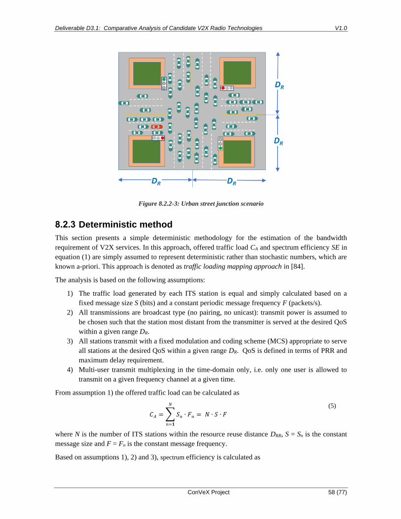
Deliverable D3.1: Comparative Analysis of Candidate V2X Radio Technologies V1.0
ConVeX Project 58 (77)
Figure 8.2.2-3: Urban street junction scenario
Deterministic method
This section presents a simple deterministic methodology for the estimation of the bandwidth
requirement of V2X services. In this approach, offered traffic load CA and spectrum efficiency SE in
equation (1) are simply assumed to represent deterministic rather than stochastic numbers, which are
known a-priori. This approach is denoted as traffic loading mapping approach in [84].
The analysis is based on the following assumptions:
1) The traffic load generated by each ITS station is equal and simply calculated based on a
fixed message size S (bits) and a constant periodic message frequency F (packets/s).
2) All transmissions are broadcast type (no pairing, no unicast): transmit power is assumed to
be chosen such that the station most distant from the transmitter is served at the desired QoS
within a given range DR.
3) All stations transmit with a fixed modulation and coding scheme (MCS) appropriate to serve
all stations at the desired QoS within a given range DR. QoS is defined in terms of PRR and
maximum delay requirement.
4) Multi-user transmit multiplexing in the time-domain only, i.e. only one user is allowed to
transmit on a given frequency channel at a given time.
From assumption 1) the offered traffic load can be calculated as
𝐶𝐴 = ∑ 𝑆𝑛
𝑁
𝑛=𝟏
∙ 𝐹𝑛 = 𝑁 ∙ 𝑆 ∙ 𝐹
(5)
where N is the number of ITS stations within the resource reuse distance DRR, S = Sn is the constant
message size and F = Fn is the constant message frequency.
Based on assumptions 1), 2) and 3), spectrum efficiency is calculated as

Deliverable D3.1: Comparative Analysis of Candidate V2X Radio Technologies V1.0
ConVeX Project 59 (77)
𝑆𝐸𝑡𝑥 =𝑅𝑡𝑥
𝐵𝑊𝑐ℎ
(6)
where Rtx is the nominal transmission data rate associated with the selected MCS and BWch is the
nominal channel bandwidth of 10 MHz.
The spectral efficiency in (6) is indexed with “tx” and referred to as spectral efficiency at the
transmitter. This is reasonable because its amount depends solely on the characteristics of the used
modulation and coding scheme employed by the transmitter. Characteristics of radio propagation
and of reception performance are not incorporated in the calculation of SEtx.
The bandwidth requirement can be calculated from equation (1) to (6) as
𝐵𝑊𝑟𝑒𝑞 ≥ 𝑁 ∙ 𝑆 ∙ 𝐹
𝑆𝐸tx ∙ 𝛼
(7)
Example for 802.11p-based systems in urban traffic scenario:
Calculation of the offered traffic load:
CAM size (as assumed in 5GAA studies [84]): S = 300 bytes = 2400 bits
The packet size S is assumed to include lower layer protocol overhead (approx. 40 bytes + security
overhead).
Offered traffic load for the urban scenario in Figure 8.2.2-3 has been derived in Section 8.2.2 as CA =
4.032 Mbps.
Calculation of the spectrum efficiency:
Assuming MCS associated with data rate Rtx = 6 Mbps (QPSK, r = 1/2), presumed to be suitable for
the coverage range DR = 50 m of the urban scenario in Figure 8.2.2-3 for the given QoS
requirements.
SEtx = 6 Mbps / 10 MHz = 0.6 bps/Hz (48 bits per OFDM symbol and transmit time 8 us/OFDM
symbol)
On the MAC layer, MAC protocol information of 34 Bytes is added to each CAM message payload
(see Section 5.2.2.5). On the PHY layer, a 16 bit Service field and 6 tail bits are added (see Section
5.2.2.3). The overall packet size on the PHY layer amounts to (300+34)·8 + 22 = 2694 bits. This
packet is mapped onto 57 OFDM symbols.
Each individual PHY packet requires an additional overhead of 13 symbols for PLCP (see section
5.2.2.3). The PLCP overhead can be converted into a resource utilization efficiency of α = 50/63 =
0.79.
Calculation of the spectrum requirement:
Calculating the spectrum requirement from eq. (4) yields:
BWreq ≥ 4.032 Mbps/0.6 bit/Hz/0.79 = 8.51 MHz
Example for C-V2X LTE sidelink in urban traffic scenario:

Deliverable D3.1: Comparative Analysis of Candidate V2X Radio Technologies V1.0
ConVeX Project 60 (77)
The LTE sidelink employs a fixed time interval of 1 ms (i.e. a subframe) to transmit data packets.
Sidelink transmission allows flexible mappings of data packets onto the symbols of a subframe. The
mapping may be done such that only a fraction of the channel bandwidth is utilized. The remaining
portion of spectrum can for instance be used for transmissions of multiple ITS stations in a
frequency division multiplex (FDM) fashion. Alternatively, the mapping could be such that the
entire spectrum is utilized by a single packet. In this case, however, very strong encoding of the data
bits can be applied, i.e. requiring a lower SINR to achieve reliable packet reception performance.
Derivation of the spectrum requirement with the deterministic method as given in equation (7) is
therefore somewhat tricky for LTE sidelink if the result should allow a comparison with the result
obtained for 802.11p. In the following example we make the assumption that both systems transmit
a data packet at the same modulation order (i.e. QPSK) and approximately the same coding rate of
1/2. In this case the LTE sidelink does not use the full available channel bandwidth and allows
FDM. The result of this calculation does not take into account that the SINR requirement for LTE
sidelink can be expected to be lower due to usage of a better encoding scheme (i.e. turbo coding
versus convolutional coding in 802.11p).
Offered load: CA = 4.032 Mbps (see example above)
Calculation of the spectrum efficiency:
We assume that at the desired edge of the communication range, the SINR is large enough to use
MCS=6. According to Table 5.3.1-1 this implies QPSK with code rate 1/2 is used, such that 𝑆𝐸𝑡𝑥
can be determined to be 0.52 bps/Hz.
The sidelink MAC layer adds a header of 10 Bytes (see 3GPP TS 36.321 [71]). The ITS message
with MAC header then has a size of 310 Bytes (2480 bits), which can be mapped onto a Transport
Block of size 2600 bits, requiring 25 Resource Blocks (RBs) for transmission at MCS=6, see [70]. In
addition 2 RBs are required for the Physical Sidelink Control CHannel PSCCH, so that in total 27
RBs are transmitted per message.
The spectrum efficiency number of 𝑆𝐸𝑡𝑥 = 0.52 bps/Hz from Table 5.3.1-1 applies to transmission
of 50 RBs. The resource utilization efficiency can be determined from the MAC and PSCCH
overhead α = 300/310 · 25/27 = 0.90 can therefore be assumed, provided all available subframes are
utilized for data transmission (i.e. for ideal scheduling).
Calculation of the spectrum requirement:
Calculating the spectrum requirement from eq. (6) yields:
BWreq ≥ 4.032 Mbps/0.52 bps/Hz/0.9 = 8.61 MHz
System simulation based method
In the simulation based method, vehicular traffic is simulated for selected scenarios according to a
statistical model (e.g. Poisson point distribution of a given density). Then packet transmission for
each of the vehicles involved in the traffic scenario is simulated applying statistical radio
propagation channel models and appropriate link-to system-level mapping methods by which static
signal-to-interference and noise ratios (SINR) are converted into PRR performance. By realistic
modelling of V2V message generation for each vehicle, carrier sensing and of the medium access

Deliverable D3.1: Comparative Analysis of Candidate V2X Radio Technologies V1.0
ConVeX Project 61 (77)
mechanisms, it is also feasible to investigate the delay performance. Simulation techniques used by
3GPP working groups are described in detail in 3GPP TR 36.885 [86].
For instance, for a highway street scenario as shown in Figure 8.2.2-2, a straight road section of
about 3500 m length is typically considered. The length of the investigated road section in such
simulations should be at least twice the resource reuse distance DRR and larger than twice the target
communication range DR.
A critical parameter in such simulations is the SINR required to achieve a target PRR-performance.
This parameter depends primarily on the characteristics of the propagation channel, the MCS of the
transmitted signal, as well as the assumed receiver technology. In simulations a typical assumption
on receiver technology is that Minimum Mean Square Error with Interference Rejection Combining
(MMSE-IRC) receivers with 2 receive antennas are employed.
For a given vehicular traffic distribution and a given communication traffic model, the result can be
determined as a curve showing PRR and/or delay performance versus the available frequency
bandwidth (e.g. for n available 10 MHz frequency channels, or other channel bandwidth
allocations).
Theoretical spectrum efficiency based model
The method described in this section has been proposed in [82].
As described in section 8.2.3, the spectrum demand can be evaluated by dividing required capacity
𝐶𝑟𝑒𝑞 (bit/s) using spectrum efficiency 𝑆𝐸 (bit/s/Hz) as in equation (1).
Since communication requirements are critical for V2X use cases and have significant impact on
spectrum demand, the evaluation framework shall include those factors. The remainder of this
subsection describes a framework based on equation (1) while taking required communication range,
reliability, and latency into consideration.
First, the required system capacity 𝐶𝑟𝑒𝑞 (bit/s) is calculated by equation (2) to (6). It equals to the
maximum among latency limited data rate 𝐶𝐿 and aggregated transmission data rate 𝐶𝐴 times
required reliability defined in terms of Packet Reception Rate 𝑃𝑅𝑅 (%) and then divided by resource
utilization ratio 𝛂. 𝐶𝐿 represents the instantaneous peak data rate due to critical latency requirement
and is greater than or equal to the ratio between the V2X message of size 𝑆 (bits) and the latency
constraint 𝐿 (s) for transmitting the message over the air, as shown in (8). In case various messages
are used in the V2X system, the 𝐶𝐿 shall be determined by the most demanding message, i.e. the
message having the highest 𝐶𝐿 value. 𝐶𝐴 stands for aggregated data rate in a long-time scale and
periodic manner. It is the product of message size 𝑆, message generation frequency 𝐹 (Hz) and
number of vehicles 𝑁 as given in (9). 𝑁 vehicles are assumed to fully utilize the spectrum and it
equals to vehicle density 𝜌 (vehicles/m) times resource reuse distance 𝐷𝑅𝑅 (m). In direct V2X
communication, the time-frequency channel resource can be reused in the spatial domain, provided
that the co-channel interference at the desired receiver does not exceed the acceptable level. 𝐷𝑅𝑅,
which is expressed in meters, is the distance between two vehicles that use the same channel
resource. The maximum among 𝐶𝐿 and 𝐶𝐴 represents the required transmission data rate, while the
actually required system capacity is the transmission date rate times the required reliability 𝑃𝑅𝑅.

Deliverable D3.1: Comparative Analysis of Candidate V2X Radio Technologies V1.0
ConVeX Project 62 (77)
𝑪𝒓𝒆𝒒 = 𝒎𝒂𝒙{𝑪𝑳, 𝑪𝑨} ∙ 𝑷𝑹𝑹
𝜶 (8)
𝑪𝑳 ≥𝑺
𝑳
(9)
𝑪𝑨 = 𝑺 ⋅ 𝑭 ∙ 𝑵 (10)
𝑵 = 𝝆 ⋅ 𝑫𝑹𝑹 (11)
Assuming an additive white Gaussian noise (AWGN) channel, the spectrum demand lower bound
𝐵𝑊𝐴𝑊𝐺𝑁, which is technology agnostic, can be determined by (11). Note that (11) represents the
information-theoretic Shannon bound on the capacity of an AWGN channel [89]. 𝑆𝑁𝑅𝑅 is the
reference signal-to-noise-ratio (SNR) for which the channel capacity Creq can be obtained for an
AWGN.
𝑩𝑾𝑨𝑾𝑮𝑵 =𝑪𝒓𝒆𝒒
𝒍𝒐𝒈𝟐(𝟏 + 𝑺𝑵𝑹𝑹) (12)
The reference SNR in equation (12) can be expressed as
𝑺𝑵𝑹𝑹 =𝑪𝒓𝒆𝒒
𝑩𝑾𝑨𝑾𝑮𝑵
∙𝑬𝒃
𝑵𝟎
(13)
where Eb and N0 are the bit energy and noise spectral density, respectively.
To evaluate the spectrum demand when using a specific technique, e.g. DSRC or LTE-PC5, we can
first determine the spectrum efficiency 𝑆𝐸𝑡𝑥 at the transmitter side as defined in subsection 8.2.3.
Note that SEtx is calculated by dividing the nominal payload data rate CN (bit/s) by the occupied
bandwidth W (Hz) according to the specification of the V2X technology. It denotes the spectral
efficiency solely due to the modulation and coding scheme parameters without considering the
reliability performance at receivers.
Considering reception failure due to noise and interference and the mismatch between the required
reliability and the achieved reliability, the effective spectrum efficiency at receiver side can be
estimated as (13).
𝑆𝐼𝑁𝑅𝑟𝑒𝑞 is the required SINR to achieve the target PRR for a given MCS and given radio channel
characteristics, and 𝑆𝐼𝑁𝑅𝑅 is the actual SINR at the edge of the communication range. Note that the
reference SINR can be expressed similarly to equation (13), where the noise spectral density N0 is
replaced by an equivalent noise spectral density 𝑁0′, which includes the interference power density.
The ratio 𝑙𝑜𝑔2(1+𝑆𝐼𝑁𝑅𝑅)
𝑙𝑜𝑔2(1+𝑆𝐼𝑁𝑅𝑟𝑒𝑞) expresses the spectrum efficiency improvement/degradation due to SINR
margin, e.g. modulation scheme adaptation, additional bit energy spent for reference signals and
retransmission. For instance, assuming highway scenario, MCS = 6, 2.5 dB 𝑆𝐼𝑁𝑅𝑟𝑒𝑞 is required to
reach 95% reliability while the actual 𝑆𝐼𝑁𝑅𝑅 can be 0dB and the corresponding PRR is 90%..

Deliverable D3.1: Comparative Analysis of Candidate V2X Radio Technologies V1.0
ConVeX Project 63 (77)
To compensate the low reliability caused by low SINR, one can select a lower MCS index to have
more robust coding scheme or transmit the same packet multiple times, e.g. blind retransmission. In
any case, the spectrum efficiency will be reduced in order to have a higher reliability. With the
assumed system scenario, 𝑆𝐼𝑁𝑅𝑅 can be derived based on channel modelling. PRR requirement
varies according to use cases, e.g. ranges from 90% to 99.999% in 3GPP TS 22.185 [87]. The
corresponding 𝑆𝐼𝑁𝑅𝑟𝑒𝑞 for PRR = 95% depends on the applied technology, e.g. LTE sidelink or
DSRC, and transmission parameters, e.g. MCS. A more detailed example will be given later in this
section.
𝑆𝐸𝑟𝑥 = 𝑆𝐸𝑡𝑥 ⋅ 𝑃𝑅𝑅 ⋅𝑙𝑜𝑔2(1 + 𝑆𝐼𝑁𝑅𝑅)
𝑙𝑜𝑔2(1 + 𝑆𝐼𝑁𝑅𝑟𝑒𝑞) (14)
In the end, the demanded minimum spectrum bandwidth can be expressed as (15). The selection of
𝐷𝑅𝑅 is crucial to the overall system spectrum demand: A larger 𝐷𝑅𝑅 value results in a lower co-
channel interference level at receivers, i.e. a higher SINR value, and reduces the demand of spectrum
𝐵𝑊. On the other hand, considering constant vehicle density, a larger 𝐷𝑅𝑅 value increases the
number of vehicles requiring distinct channel resource blocks resulting in an overall higher system
spectrum demand. The optimal value of 𝐷𝑅𝑅 minimizes the overall spectrum demand for the given
vehicle density and the required communication reliability. In practice, when the V2X system uses a
channel access algorithm based on channel sensing, the value of 𝐷𝑅𝑅 is usually controlled by
adapting the sensing threshold of channel busy status, e.g. the clear channel assessment (CCA)
threshold in IEEE 802.11p system.
𝐵𝑊 =𝐶𝑟𝑒𝑞
𝑆𝐸𝑟𝑥=
𝑚𝑎𝑥 {𝑆𝐿
, 𝜌 ∙ 𝐷𝑅𝑅 ∙ 𝑆 ∙ 𝐹}
𝑆𝐸𝑡𝑥 · 𝛼∙
𝑙𝑜𝑔2(1 + 𝑆𝐼𝑁𝑅𝑟𝑒𝑞)
𝑙𝑜𝑔2(1 + 𝑆𝐼𝑁𝑅𝑅)
(15)
One example is given to evaluate the spectrum demand for highway dense traffic scenario described
in section 8.2.2 using LTE-V2V technique. Thus, message size 𝑆 = 300 Bytes or 2400 bits, message
frequency 𝐹 = 10 Hz, vehicle density for 6 lane highway 𝜌 = 0.12 vehicles/m, maximum latency
𝐿 = 100 ms. Assuming 1/2 code rate QPSK is used, 𝑆𝐸𝑡𝑥 can be determined to be 0.52 bps/Hz. The
required SINR (dB) to reach 95% reliability requirement is about 2.5 dB for highway line of sight
(LOS) scenario and 8 dB for urban non-line of sight (NLOS) scenario [66]. With required
communication range 𝐷𝑅,which is set to 400 m for highway scenario and 50 m for urban scenario,
and resource reuse distance of 𝐷𝑅𝑅, the experienced 𝑆𝐼𝑁𝑅𝑅 at the edge of communication range can
be derived using the WINNER+B1 model defined in 3GPP TR 36.885 [86]. For simplicity, only the
nearest interferer is considered and 𝑆𝐼𝑁𝑅𝑅 can be expressed as equation (16) where 𝑃𝑡𝑥 is the
transmission power of 23 dBm, 𝑃𝑁 is the noise power of -104 dBm, 𝐻 is the channel path loss
coefficient which is a function of communication distance, e.g. 𝐻(𝐷𝑅) represents the channel
coefficient for UE at the edge of communication range.
𝑆𝐼𝑁𝑅𝑅 =𝑃𝑡𝑥 · 𝐻(𝐷𝑅)
𝑃𝑡𝑥 · 𝐻(𝐷𝑅𝑅 − 𝐷𝑅) + 𝑃𝑁 (16)
Knowing other system parameters, equation (15) becomes a function of resource reuse distance 𝐷𝑅𝑅:

Deliverable D3.1: Comparative Analysis of Candidate V2X Radio Technologies V1.0
ConVeX Project 64 (77)
𝐵𝑊 =
𝑚𝑎𝑥 {2400
0.1, 𝜌 · 2400 · 10 · 𝐷𝑅𝑅}
0.52 · 0.9∙
𝑙𝑜𝑔2(1 + 𝑆𝐼𝑁𝑅𝑟𝑒𝑞)
𝑙𝑜𝑔2(1 + 𝑆𝐼𝑁𝑅𝑅 (𝐷𝑅𝑅))
(17)
Figure 8.2.5-1 illustrates how spectrum demand for scenarios described in section 8.2.2 varies when
different 𝐷𝑅𝑅 is used. For highway scenario, when 𝐷𝑅𝑅=1060 m the minimum spectrum demand of
7.17 MHz can be found. For urban scenario, when DRR = 230 m the minimum spectrum demand is
7.72 MHz.
Figure 8.2.5-1: Example spectrum demand estimation
Queuing theory based approach
Another approach to assess V2X spectrum requirements can be derived from queuing theory. This
methodology has been proposed first in [88]. It is especially suitable for taking delay performance
requirements into account in the analysis, also allowing differentiation between service categories
with different delay requirements.
A model frequently employed to analyze packet data transmission systems is denoted M/G/1 queue.
In this model, the packet arrival process is modeled as a Poisson point distribution (M refers to
memoryless or Markovian), i.e. packets arrive randomly with exponential interarrival time
distribution. In that, the model is not typical for CAM, which is has more regular interarrival times.
This could lead to an increased spectrum requirement, unless some coordination or randomization of
the message generation is used. The server is modeled as a statistical process with general
distributed service time (G refers to general distribution) and the number of servers is 1. This is a
simplification in that - in the case of LTE - multiple UEs can be multiplexed in the frequency
domain, so in fact for LTE the spectrum requirements obtained by this methodology tend to be
overestimated to some extent.
In this context, the server is represented by the given radio resource which allows to serve a single
message transmission at a given time. If the radio resource is busy, transmissions of other users must
wait in a queue until the resource is free again. The model does not take into account that in the case
of LTE, the transmission is slotted, i.e. a packet has to wait for the next slot and is delivered only at

Deliverable D3.1: Comparative Analysis of Candidate V2X Radio Technologies V1.0
ConVeX Project 65 (77)
the end of a slot regardless of how much of the slot it occupies. However, this is relevant only for
delay requirements on the order of the slot duration.
From the statistical distribution of the queuing delay experienced by each user, a delay requirement
can be defined in terms of the probability that a target maximum delay is not exceeded.
The following input parameters are required. For each service category, k = 1…K, determine
• offered traffic load CA,k in bit/s,
• mean message size Sk in bits/message,
• required mean latency Lk.
It is assumed that the service category with index k = 1 refers to the highest, k = K to lowest priority
(this means that the delay requirement for service category k = 1 is the strongest).
Offered traffic represents the total traffic (in bit/s) of all transmissions of a specific service category
within the area defined by resource reuse distance DRR, see Figure 8.2.2-1. Each type of C-V2X
message (e.g. CAM, DENM, IVIM etc.) can be represented as a different services category in this
model. The various service categories are indexed with the index k = 1…K in the following.
Dividing offered traffic CA,k by messages size Sk results in the traffic intensity λk (“packets per
second”), also denoted as packet arrival rate:
𝜆𝑘 =𝐶𝐴,𝑘
𝑆𝑘
(18)
The system capacity Creq,k needed to fulfil the delay requirement of service category k can be
calculated as follows. The priority level demanding the highest capacity denotes the total required
system capacity, since for the case that the QoS requirements of the most demanding service
category are fulfilled, the requirements of the other service categories are even exceeded. Therefore,
the overall required system capacity Creq is given by:
𝐶𝑟𝑒𝑞 = 𝑚𝑎𝑥(𝐶𝑟𝑒𝑞,1, 𝐶𝑟𝑒𝑞,2, … , 𝐶req,𝐾) (19)
When considering non-preemptive packet priorities, it is assumed that each packet is completely
served before the current radio resource allocation is changed. This is a valid assumption, because in
many cases interrupting the service of a packet causes loss of radio resources already spent for that
packet.
The mean packet latency Lk for service category k is the sum of mean waiting time and mean service
duration. For a M/G/1 non-preemptive priority queue, the mean packet latency can be expressed as a
function of the required system capacity Creq as follows [16]:
𝐿𝑘(𝐶𝑟𝑒𝑞) =∑ 𝜆𝑘𝑆𝑘
(2)Kk=𝟏
2(𝐶𝑟𝑒𝑞 − ∑ 𝜆𝑖𝑆𝑖𝑘𝑖=1 )(𝐶𝑟𝑒𝑞 − ∑ 𝜆𝑖𝑆𝑖
𝑘−1𝑖=1 )
+𝑆𝑘
𝐶𝑟𝑒𝑞
(20)
This expression is used for determining the system capacity Creq,k required to satisfy the QoS
condition Lk(Creq,k) = Lk. i.e. regarding the left hand side of (20) as a QoS input and solving it for
Creq,k, which is then a solution of the cubic equation:
𝑎𝑘𝑥3 + 𝑏𝑘𝑥2 + 𝑐𝑘𝑥 + 𝑑𝑘 = 0 (21)
with coefficients ak, bk, ck and dk according to:

Deliverable D3.1: Comparative Analysis of Candidate V2X Radio Technologies V1.0
ConVeX Project 66 (77)
𝑎𝑘 = 2𝐿𝑘
𝑏𝑘 = −2 (𝐿𝑘 (∑ 𝜆𝑖𝑆𝑖 +
𝑘
𝑖=1
∑ 𝜆𝑖𝑆𝑖
k−1
𝑖=1
) + 𝑆𝑘)
𝑐𝑘 = 2 (𝐿𝑘 (∑ 𝜆𝑖𝑆𝑖
𝑘
𝑖=1
) (∑ 𝜆𝑖𝑆𝑖
k−1
𝑖=1
) − 𝑆𝑘 (∑ 𝜆𝑖𝑆𝑖 +
𝑘
𝑖=1
∑ 𝜆𝑖𝑆𝑖
k−1
𝑖=1
)) − ∑ 𝜆𝑖𝑆𝑖(2)
K
𝑖=1
𝑑𝑘 = −2𝑆𝑘 (∑ 𝜆𝑖𝑆𝑖
𝑘
𝑖=1
) (∑ 𝜆𝑖𝑆𝑖
𝑘−1
𝑖=1
)
(22)
For the solution of cubic equations good symbolic solution is available by using for example
Cardano’s formula. Mathematically, equation (21) has three solutions. To determine the correct
solution among these three, the stability border of the queuing system has to be considered, i.e.:
∑ 𝜆𝑖𝑆𝑖
𝑘−1
𝑖=1
< 𝐶𝑟𝑒𝑞,𝑘 (23)
In order to deliver the packets with finite packet delay, the system capacity cannot be smaller than
the aggregated offered load given in (18).
The spectrum requirement can be derived by the capacity Creq (bit/s) obtained with (19) and
spectrum efficiency (bit/s/Hz) using equation (1). The spectrum efficiency can be estimated with
equation (7) or equation (15). Using SEtx in (5) results in
𝐵𝑊𝑟𝑒𝑞 =𝐶𝑟𝑒𝑞
𝑆𝐸𝑡𝑥 · α (24)
The benefit of this bandwidth estimation methodology is that it allows to take into account the
requirements of multiple service categories.
Example:
K = 2 service categories: k = 1 for DENM, k = 2 for CAM
Traffic intensity λk of each service category:
λ1 = 125 packets per second,
λ2 = 3360 packets per second (as in the example in section 8.2.2 for the urban street junction
scenario)
Packet size Sk of each service category:
S1 = 4000 bits/packet, S2 = 2400 bits/packet
Offered load CA,k = λk · Sk of each service category:
CA,1 = 0.5 Mbps, CA,2 = 4.032 Mbps

Deliverable D3.1: Comparative Analysis of Candidate V2X Radio Technologies V1.0
ConVeX Project 67 (77)
Latency requirement of each service category:
L1 = 0.001 s (1 ms)
L2 = 0.1 s (100 ms)
Note that in this example the latency requirement L1 is set extremely stringent in order to emphasize
that a challenging requirement on delay can have a strong impact on the required capacity even
when the offered traffic load CA,1 is rather low in relation to the offered load of a service category
with much less stringent delay requirements.
Resolving equation (20) for k = 1 and k = 2 yields the main result:
Creq,1 = 5.8418 Mbps, Creq,2 = 4.5924 Mbps
Thus from (18), we obtain Creq = Creq,1 = 5.8418 Mbps.
Using (5) for calculation of the bandwidth requirement and the assumptions used in the example in
8.2.3 for the 802.11p-based system:
BWreq = 5.8418 Mbps/0.6 bit/Hz/0.71= 13.71 MHz
Using (5) for calculation of the bandwidth requirement and the assumptions used in the example in
8.2.3 for the C-V2X sidelink:
BWreq ≥ 5.8418 Mbps/0.52 bps/Hz/0.9= 12.48 MHz
Comparing the above results with the ones in section 8.2.3 (i.e. BWreq = 9.46 MHz for 802.11p and
8.61 MHz for C-V2X sidelink) it can be concluded that a strong latency requirement imposed for a
delay-critical servicer can increase the spectrum requirement substantially.
If the latency requirement in the above example is lowered to 10 ms for the DENM messages, there
is no significant increase of the spectrum requirement compared to the examples in Section 8.2.3.
Conclusions on spectrum requirements
Our spectrum analysis indicates that for typical traffic scenarios a single 10 MHz channel can be
likely sufficient to serve the communication traffic load due to basic safety messages (i.e. CAMs and
DENMs) as long as message delay requirements are not set extremely strong.
The results also show that the spectrum demand of C-V2X sidelink technology can be expected to be
around 10% lower than required for ITS-G5, due to improved spectrum efficiency and reduced
overhead. This applies even if the expected advantage of C-V2X with regard to receiver sensitivity
and SINR requirement is not taken into account. We expect that the advantage of C-V2X will
increase substantially when incorporating receiver sensitivity and SINR requirement into the
analysis. This will be further analyzed in the follow-up deliverable D3.2.

Deliverable D3.1: Comparative Analysis of Candidate V2X Radio Technologies V1.0
ConVeX Project 68 (77)
However, as new use cases will likely be added in future it is evident that the spectrum demand will
increase beyond 10 MHz of available spectrum.
For C-V2X systems larger bandwidth requirement can be handled either by allocating a single
channel with 20 MHz contiguous bandwidth or allocating two channels with 10 MHz each. In the
latter case, ITS-stations may need to be able to receive multiple frequency channels concurrently.
For 3GPP C-V2X, this feature is part of Release-15.
Coexistence of DSRC and C-V2X systems
Regulatory aspects
The frequency band 5855 - 5925 MHz (see Table 8.1.2-1) is subject to the following harmonisation
measures in Europe:
The European Commission has harmonised the band 5875-5905 MHz for safety-related applications
of Intelligent Transport Systems in the European Union via the legally binding Commission
Decision 2008/671/EC [78].
ECC Decision (08)01 [74] indicates in addition that CEPT administrations shall consider within a
future review of Decision 2008/671/EC [78] the designation of the frequency sub-band 5905-5925
MHz for an extension of ITS spectrum.
ECC also recommends, via ECC Recommendation (08)01 [73], that CEPT administrations should
make the frequency band 5855 - 5875 MHz available for ITS non-safety applications.
The ETSI Harmonized Standard EN 302 571 [80], defines requirements for operation of ITS
equipment in 5855-5925 MHz frequency band, covering the essential requirements of article 3.2 of
the Radio Radio Equipment Directive (RED), 2014/53/EU [90]. According to ECC DEC (08)01 [74]
and ECC REC (08)01 [73], ITS equipment complying with EN 302 571 [80] are exempt from
individual licensing for operating in this band.
The principle of technology neutrality in the European spectrum regulations implies that any radio
technology which can demonstrate conformance with the essential requirements of the Radio
Equipment Directive (e.g. through compliance with EN 302 571 [80]) is permitted to operate in the
5855 - 5925 MHz frequency band.
Spectrum sharing between C-V2X and ETSI ITS-G5
As has been described in section 5, C-V2X and ETSI ITS-G5 systems employ different PHY and
MAC protocols. As such these two technologies cannot employ simultaneously the same frequency
channel in the same geographical area without interfering each other harmfully.
There are two technical solutions to enable operation of both technologies in the ITS frequency
band:
1) Time division multiplexing (TDM)
2) Frequency division multiplexing (FDM)
Time division multiplexing (TDM)

Deliverable D3.1: Comparative Analysis of Candidate V2X Radio Technologies V1.0
ConVeX Project 69 (77)
Sharing of the same frequency channel may be feasible if the two technologies are operated in TDM
fashion. There are two options to implement this:
a) Fixed time allocation for each technology
b) Dynamic time allocation with sensing of channel status
Fixed time allocation means that fixed time slots based on absolute GPS timing are assigned to
either technology. Dynamic time allocation means that either technology needs to be able to sense if
a station using the same or different radio technology is already transmitting. This however would
include the capability to decode the information for how long the channel is busy.
Figure 8.3.4-1: Spectrum sharing in TDM fashion: a) fixed time slot allocation, b) dynamic timeslot
allocation
Frequency division multiplexing (FDM)
Different frequency channels are assigned to either radio technology. Some channels can be assigned
such that use of a specific technology is preferred while other channels can be assigned dynamically
depending on the geographical needs. An example [93] of spectrum allocation is shown in Figure
8.3.4-2. The channel 5875 – 5885 MHz may be assigned to be used preferably by technology A,
which could e.g. be ETSI ITS-G5. The channel 5895 – 5905 MHz may be assigned to be used
preferably by technology B, which could e.g. be 3GPP LTE-based C-V2X. The channel 5885 – 5895
MHz could be assigned flexibly depending on the needs given in a specific geographical area, for
instance based on detect-and-vacate mechanisms.

Deliverable D3.1: Comparative Analysis of Candidate V2X Radio Technologies V1.0
ConVeX Project 70 (77)
Figure 8.3.4-2: Assignment of frequency channels to radio technologies [93]
Spectrum sharing framework proposed by 5GAA
The 5GAA is proposing a spectrum sharing framework in Europe [93] which in short term should
start with the FDM solution shown in Figure 8.3.5-1, where a preselected 10 MHz channel each is
assigned to either technology, C-V2X and ETSI ITS-G5. These channels should be employed for
safety-related use cases.
In a second step, as the deployment of the two technologies matures, technical solutions such as
mutual detect-and-vacate can be put in place to enable access to the remaining parts of the 5875 -
5905 MHz band and eventually to the entire 5855 - 5925 MHz band, with a reduced likelihood of
harmful co-channel interference as illustrated in Figure 8.3.5-1.
In this scenario, Technology A equipment would operate without any special measures in 5875-
5885 MHz. If Technology A equipment wished to transmit in 5885-5895 MHz, then it would need to
monitor activity on this channel, and proceed with transmissions if and only if Technology B
transmissions are not detected. A symmetrical procedure would apply to Technology B. If
Technology B equipment wished to transmit in 5885-5895 MHz, then it would need to monitor
activity on that channel, and proceed with transmissions if and only if Technology A transmissions
are not detected.
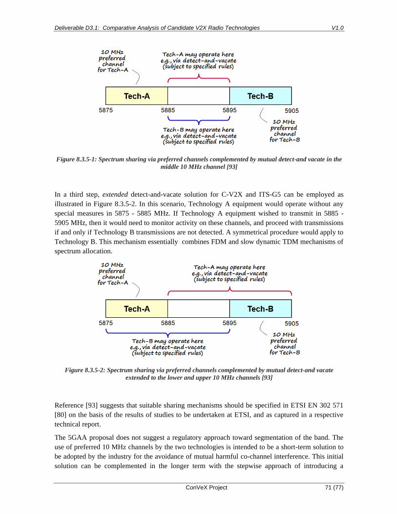
Deliverable D3.1: Comparative Analysis of Candidate V2X Radio Technologies V1.0
ConVeX Project 71 (77)
Figure 8.3.5-1: Spectrum sharing via preferred channels complemented by mutual detect-and vacate in the
middle 10 MHz channel [93]
In a third step, extended detect-and-vacate solution for C-V2X and ITS-G5 can be employed as
illustrated in Figure 8.3.5-2. In this scenario, Technology A equipment would operate without any
special measures in 5875 - 5885 MHz. If Technology A equipment wished to transmit in 5885 -
5905 MHz, then it would need to monitor activity on these channels, and proceed with transmissions
if and only if Technology B transmissions are not detected. A symmetrical procedure would apply to
Technology B. This mechanism essentially combines FDM and slow dynamic TDM mechanisms of
spectrum allocation.
Figure 8.3.5-2: Spectrum sharing via preferred channels complemented by mutual detect-and vacate
extended to the lower and upper 10 MHz channels [93]
Reference [93] suggests that suitable sharing mechanisms should be specified in ETSI EN 302 571
[80] on the basis of the results of studies to be undertaken at ETSI, and as captured in a respective
technical report.
The 5GAA proposal does not suggest a regulatory approach toward segmentation of the band. The
use of preferred 10 MHz channels by the two technologies is intended to be a short-term solution to
be adopted by the industry for the avoidance of mutual harmful co-channel interference. This initial
solution can be complemented in the longer term with the stepwise approach of introducing a

Deliverable D3.1: Comparative Analysis of Candidate V2X Radio Technologies V1.0
ConVeX Project 72 (77)
dynamic spectrum sharing solution with suitable mutual detect-and-vacate mechanisms to enable
fair access to the whole of 5855 - 5925 MHz band.
The steps of the approach proposed in [93] are the following:
• Initially, assignment of preferred channels for C-V2X and ITS-G5 (with each of the 5875 -
5885 and 5895 - 5905 MHz channels paired with one of either C-V2X or ITS-G5);
• Shared use of the middle channel (5885 - 5895 MHz);
• Shared use of all channels of the 5855 - 5925 MHz band.

Deliverable D3.1: Comparative Analysis of Candidate V2X Radio Technologies V1.0
ConVeX Project 73 (77)
Summary and Conclusions
In this document we have provided an analysis of V2X technologies. We have presented an
overview of 802.11p-based technologies and LTE for V2X, both the cellular LTE radio technology
and sidelink technology. We have compared side-by-side key features of the physical layer, where
802.11p had disadvantages from high cyclic prefix overhead and guard bands and very relaxed
requirements on receiver sensitivity and older channel codes (convolutional), whereas LTE has high
pilot overhead.
Link level simulation result have shown that LTE has 4 - 5 dB lower SINR requirements for relative
speeds up to 120 km/h and 2 - 3 dB for 500 km/h. This translates into a much larger range of LTE,
90 m vs. 50 m in urban and 450 m vs. 200 m for the freeway scenario, as shown by system
simulations.
Estimated spectrum requirements for LTE are 10% lower than for DSRC, whereby based on the
link-level differences, larger LTE spectrum requirement advantages can be expected and the analysis
should be further developed for the follow-up deliverable D3.2.

Deliverable D3.1: Comparative Analysis of Candidate V2X Radio Technologies V0.1
ConVeX Project Confidential 74 (77)
Appendix
Appendix A Simulation setup
Appendix A.1 Link Level Simulation 1
Simulation parameters
Simulation Parameters LTE-V2X PC5 DSRC
Modulation QPSK QPSK
Coding rate ½ ½
Carrier frequency 5.9 GHz 5.9 GHz
Number of antennas 1 TX and 2RX antennas 1 TX and 2RX antennas
Noise figure 9 dB 9 dB
Appendix A.2 System Level Simulation 1
Simulation parameters
Simulation parameters Values
Cellular layout Urban slow: 21 cells, ISD 500M, Manhattan
Grid
Freeway fast: ISD 1732 m, length >= 2km
Channel bandwidth 10 MHz
Carrier frequency 6 GHz
Modulation Broadcast: QPSK ½
Unicast: adaptive MCS

Deliverable D3.1: Comparative Analysis of Candidate V2X Radio Technologies V0.1
ConVeX Project Confidential 75 (77)
Data traffic Urban: 2 Hz CAM
Freeway: 10 Hz CAM
Tx power eNB: 46 dBm UE: 23 dBm
Required communication range Urban: 150 m
Freeway: 320 m
Required PRR 90%
Vehicle density Urban: 175 vehicles/cell
Freeway: 54 vehicles/cell
Road configuration for urban scenario
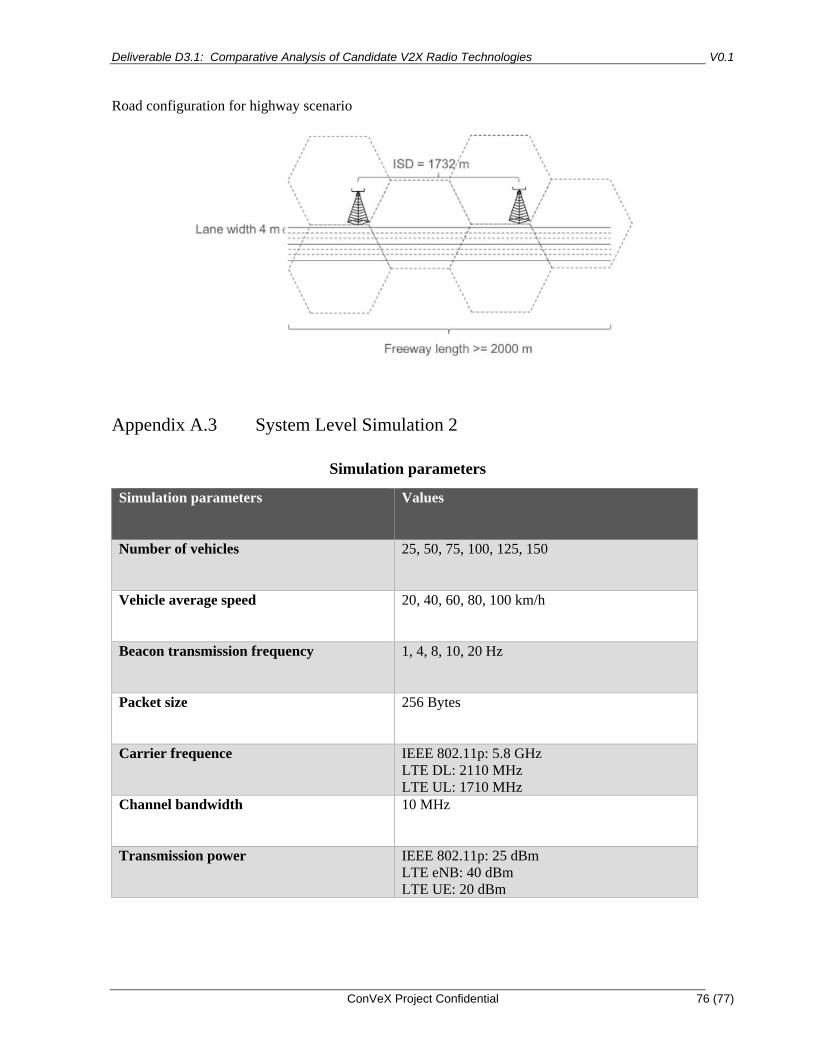
Deliverable D3.1: Comparative Analysis of Candidate V2X Radio Technologies V0.1
ConVeX Project Confidential 76 (77)
Road configuration for highway scenario
Appendix A.3 System Level Simulation 2
Simulation parameters
Simulation parameters Values
Number of vehicles 25, 50, 75, 100, 125, 150
Vehicle average speed 20, 40, 60, 80, 100 km/h
Beacon transmission frequency 1, 4, 8, 10, 20 Hz
Packet size 256 Bytes
Carrier frequence IEEE 802.11p: 5.8 GHz
LTE DL: 2110 MHz
LTE UL: 1710 MHz
Channel bandwidth 10 MHz
Transmission power IEEE 802.11p: 25 dBm
LTE eNB: 40 dBm
LTE UE: 20 dBm
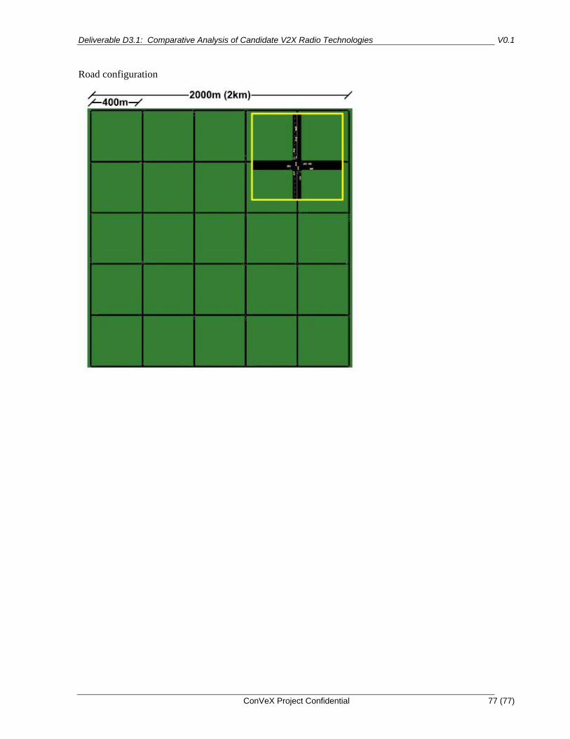
Deliverable D3.1: Comparative Analysis of Candidate V2X Radio Technologies V0.1
ConVeX Project Confidential 77 (77)
Road configuration


