Deliverable D3.2 5G-PPP security enablers open specifications (v1.0) Project name 5G Enablers for Network and System Security and Resilience Short name 5G-ENSURE Grant agreement 671562 Call H2020-ICT-2014-2 Delivery date 1.6.2016 Dissemination Level: Public Lead beneficiary Thales Services (TS) Pascal Bisson, [email protected]Authors VTT : Jouni Hiltunen, Olli Mämmelä, Pekka Ruuska, Jani Suomalainen TS: Pascal Bisson, Olivier Bettan, Edith Félix, Cyrille Martins ALBLF 1 : Linas Maknavicius EAB: Mats Näslund, Håkan Englund IT-Innov: Stephen C. Phillips, Stefanie Wiegand LMF: Bengt Sahlin NEC: Felix Klaedtke, Mihai Moraru Nixu: Tommi Pernilä Orange: Jean-Philippe Wary, Ghada Arfaoui SICS: Martin Svensson, Rosario Giustolisi, Nicolae Paladi TASE: Gorka Lendrino Vela and Carlas Salas Cano TCS : Emmanuel Dotaro, Sébastien Keller TIIT: Madalina Baltatu, Luciana Costa, Dario Lombardo UOXF: Piers O'Hanlon 1 Nokia Bell Labs since Jan 14, 2016
Transcript
Deliverable D3.2 5G-PPP security enablers open specifications (v1.0)
Project name 5G Enablers for Network and System Security and Resilience
Short name 5G-ENSURE
Grant agreement 671562
Call H2020-ICT-2014-2
Delivery date 1.6.2016
Dissemination Level: Public
Lead beneficiary Thales Services (TS) Pascal Bisson, [email protected]
Authors
VTT : Jouni Hiltunen, Olli Mämmelä, Pekka Ruuska, Jani Suomalainen TS: Pascal Bisson, Olivier Bettan, Edith Félix, Cyrille Martins ALBLF1: Linas Maknavicius EAB: Mats Näslund, Håkan Englund IT-Innov: Stephen C. Phillips, Stefanie Wiegand LMF: Bengt Sahlin NEC: Felix Klaedtke, Mihai Moraru Nixu: Tommi Pernilä Orange: Jean-Philippe Wary, Ghada Arfaoui SICS: Martin Svensson, Rosario Giustolisi, Nicolae Paladi TASE: Gorka Lendrino Vela and Carlas Salas Cano TCS : Emmanuel Dotaro, Sébastien Keller TIIT: Madalina Baltatu, Luciana Costa, Dario Lombardo UOXF: Piers O'Hanlon
1 Nokia Bell Labs since Jan 14, 2016
D3.2 5G-PPP security enablers open specifications (v1.0)
671562 5G-ENSURE 2
Executive summary
This document describes the open specifications of 5G Security enablers planned to compose the first
software release (i.e. v1.0) of 5G-ENSURE Project due in September 2016 (M11). The enablers’ open
specifications are presented per security areas in scope of the project, namely: Authentication,
Authorization and Accounting (AAA), Privacy, Trust, Security Monitoring, and Network management &
virtualisation isolation. For each of these categories the open specifications of all enablers planned in the
project's Technical Roadmap for v1.0 and having features for v1.0 are detailed following the same
template. Overall, this deliverable paves the way towards the development and demonstration of the first
set of 5G-ENSURE security enablers as planned for v1.0 in the project's Technical Roadmap (i.e. D3.1). It is
also a valuable input to both works on the 5G Security architecture and 5G Security testbed, since it
provides the details regarding security enablers necessary in order to understand their mapping to 5G
security architectural components, as well as their integration, testing, demonstration, and assessment on
the 5G security testbed.
D3.2 5G-PPP security enablers open specifications (v1.0)
671562 5G-ENSURE 3
Foreword
5G-ENSURE belongs to the first group of EU-funded projects which collaboratively develop 5G under the
umbrella of the 5G Infrastructure Public Private Partnership (5G-PPP) in the Horizon 2020 Programme. The
overall goal of 5G-ENSURE is to deliver strategic impact across technology and business enablement,
standardisation and vision for a secure, resilient and viable 5G network. The project covers research &
innovation - from technical solutions (5G security architecture and testbed with 5G security enablers) to
market validation and stakeholders’ engagement - spanning various application domains.
Deliverable D3.2 follows deliverable D3.1 5G-PPP security enablers Technical Roadmap (early vision) that has delivered an early description of 5G security enablers requested to achieve 5G security vision as illustrated in deliverable D2.1 on Use Cases. Whereas objective of D3.1 was mainly focusing on highlighting 5G Security enablers requested (in terms of their high level product vision) and their scheduling between release one and the next release, D3.2 clearly focuses on providing the open specifications of enablers planned to be software released (through their planned features) for the first release (i.e. v1.0 due at M11). As such, D3.2 details the open specifications of each of the enablers whose features are planned for the first software release (v1.0). The 5G-ENSURE security enablers’ open specifications are public and royalty free (see Open specification legal notice in Annex A) in order to enable anyone interested to come up with its own “compliant” implementation. D3.2 will be followed by deliverable D3.3 “5G-PPP Security enablers software release (v1.0)” and deliverable D3.4 “5G-PPP Security enablers documentation (v1.0)” due both at M11, that are respectively devoted to a software release of the 5G Security enablers v1.0 with their planned features (i.e. reference implementations following open specifications) and their accompanying documentation (e.g. installation and administration guide, user & programmer guide, unit testing plan). This deliverable is also an important input to other technical Work packages of the project to feed into their
work. Especially WP2 for what concerns the on-going work on 5G security architecture, since enablers
specified in D3.2 would form some of the main building blocks of this architecture, but also WP4, as it is
responsible for the instigation of a 5G security testbed where these enablers can be hosted and assessed.
Disclaimer
The information in this document is provided ‘as is’, and no guarantee or warranty is given that the
information is fit for any particular purpose.
The EC flag in this deliverable is owned by the European Commission and the 5G PPP logo is owned by the
5G PPP initiative. The use of the flag and the 5G PPP logo reflects that 5G-ENSURE receives funding from
the European Commission, integrated in its 5G PPP initiative. Apart from this, the European Commission or
the 5G PPP initiative have no responsibility for the content.
2.1.2 Status ....................................................................................................................................... 22
2.2.2 Status ....................................................................................................................................... 36
2.3.2 Status ....................................................................................................................................... 53
3.1.2 Status ....................................................................................................................................... 62
3.2.2 Status ....................................................................................................................................... 73
4.1.2 Status ....................................................................................................................................... 80
4.2.2 Status ....................................................................................................................................... 88
4.3.2 Status ....................................................................................................................................... 97
D3.2 5G-PPP security enablers open specifications (v1.0)
671562 5G-ENSURE 19
vGBA Vertical GBA
VLR Visitor Location Register
XRES Expected User Response
D3.2 5G-PPP security enablers open specifications (v1.0)
671562 5G-ENSURE 20
1 Introduction
This document describes the open specifications of 5G Security enablers planned to compose the first
software release (i.e. v1.0) of 5G-ENSURE Project due in September 2016 (M11). As such this document
mainly focuses on enablers identified in the project's Technical Roadmap (D3.1) and having features for
v1.0. As for enablers planned for v1.0 but with no feature planned, the open specifications would be given
in the context of the next release of this deliverable with the exception of the Basic AAA enabler where
open specs were assessed as good enough to be here reported. The enablers’ open specifications are
presented per security areas in scope of the project, namely: Authentication, Authorization and Accounting
(AAA), Privacy, Trust, Security Monitoring, and Network management & virtualisation isolation. For each of
these categories the open specifications of the enablers planned in the Technical Roadmap for v1.0 and
having features for v1.0 are detailed following same template.
The table below summarizes the 5G-ENSURE technical roadmap for R1 (or v1.0) as described in D3.1. It
shows the 5G security enablers in scope providing their (code) name, the category to which they belong to
(i.e. AAA, Privacy, Trust, Security Monitoring, Network management & virtualization isolation), as well as
the features planned for their 1st software release. The enablers for R1 (v1.0) and having features are those
whose open specifications are given in this deliverable, with the exception of basic AAA whose early open
specification is also here provided.
Table 1: 5G-ENSURE Technical Roadmap for R1
Category 5G-ENSURE security enablers Features planned for 1st sw release (R1)
AAA Basic AAA enabler A pre-study is required in the time frame of R1, however, due to lack of resources, an implementation is not feasible for the same release. Prototyping can potentially be done for R2.
Internet of things (IoT) Group authentication
Fine-grained Authorization Basic Authorization in Satellite systems
Basic distributed authorization Enforcement for RCDs
Federative authentication and identification enabler
none
Privacy Privacy Enhanced Identity Protection Encryption of Long Term Identifiers (IMSI public-key based encryption)
End-to-end encryption none
Device identifier(s) privacy Enhanced privacy for network attachment protocols
SIM-based anonymization none
Privacy policy analysis none
Trust Trust Builder2 5G Asset model
2 The features planned for this enabler in R1 have changed. Please see the status section of the Trust Builder
specification for more information.
D3.2 5G-PPP security enablers open specifications (v1.0)
671562 5G-ENSURE 21
Category 5G-ENSURE security enablers Features planned for 1st sw release (R1)
The Legal notice that applies to these specifications is given in Annex A.
2.1.5 Terms and definitions
A group is formed by one or more members that share similar features. Examples of common features
include members that do the same task, members located in the same geographical area, or members
belonging to the same owner. A group may also share a macro feature that is derived by a combination of
single features.
An inverted hash tree [1] is a data structure in which a node is linked to at most two successors (children),
and the value of each node is computed using a family of hash functions h∗. The value of the root is given,
while the value associated with any other node is derived from the hash value of its parent (Figure 1). Since
two siblings use two different hash functions, they get two different hash values. In particular, we consider
two hash functions h0and h
1, and recursively assign the value of each node n
ij located at ith position and jth
level as follows.
D3.2 5G-PPP security enablers open specifications (v1.0)
671562 5G-ENSURE 24
Figure 1: Example of an inverted hash tree of level 2
2.1.6 Overview
The IoT Enabler consists of four main features: support for authenticating USIM-less devices; enabling
authentication based on 3rd party identities, i.e. bring-your-own-identity (BYOI); vertical GBA; and
introduced support for group-based authentication, aimed at resource constrained devices. As mentioned
above, all features will be introduced in the first chapters, while group-based authentication will be
described in detail, as it is scheduled for release 1.
An important aspect of IoT, in the context of 5G, is to be able to use non-USIM/SIM based authentication
schemes in a 3GPP network. The feature authentication of USIM-less devices looks into the adaptions to
the AAA framework needed to introduce such a features in the authentication schemes in a 3GPP network,
including aspects of identifying which algorithm to use in the AKA as well as which AAA server to contact.
A similar adaption to authentication in 5G, with the expected boom of devices, is the group-based
authentication feature, which introduces an extension of the current EPS-AKA, mainly aimed at resource
constrained devices. The goal of the group-based AKA protocol is to make it more suitable for massive
deployment scenarios by reducing the signaling between the serving and home network.
Thirdly, the vertical Generic Bootstrapping Architecture (GBA) feature optimizes the use of GBA (3GPP TS
33.220) for resource constrained devices by having the device implicitly perform the GBA bootstrapping
during authentication to the network, in the network attach. Thus, the device does not have to perform the
HTTP Digest AKA negotiation with the BSF to bootstrap its GBA credentials. Once attached to the 3GPP core
the device can set-up a secure connection, e.g. perform GBA based HTTP Digest authentication, to a NAF
without additional signaling to the BSF. The solution is called vertical GBA (vGBA) as the keys generated
during AKA are re-used at different layers in the stack. The solution is described using the nodes of 4G
networks, as 5G network nodes are yet to be specified.
With 5G’s expected “as a service” approach, the IoT enabler will also introduce a framework for enabling an
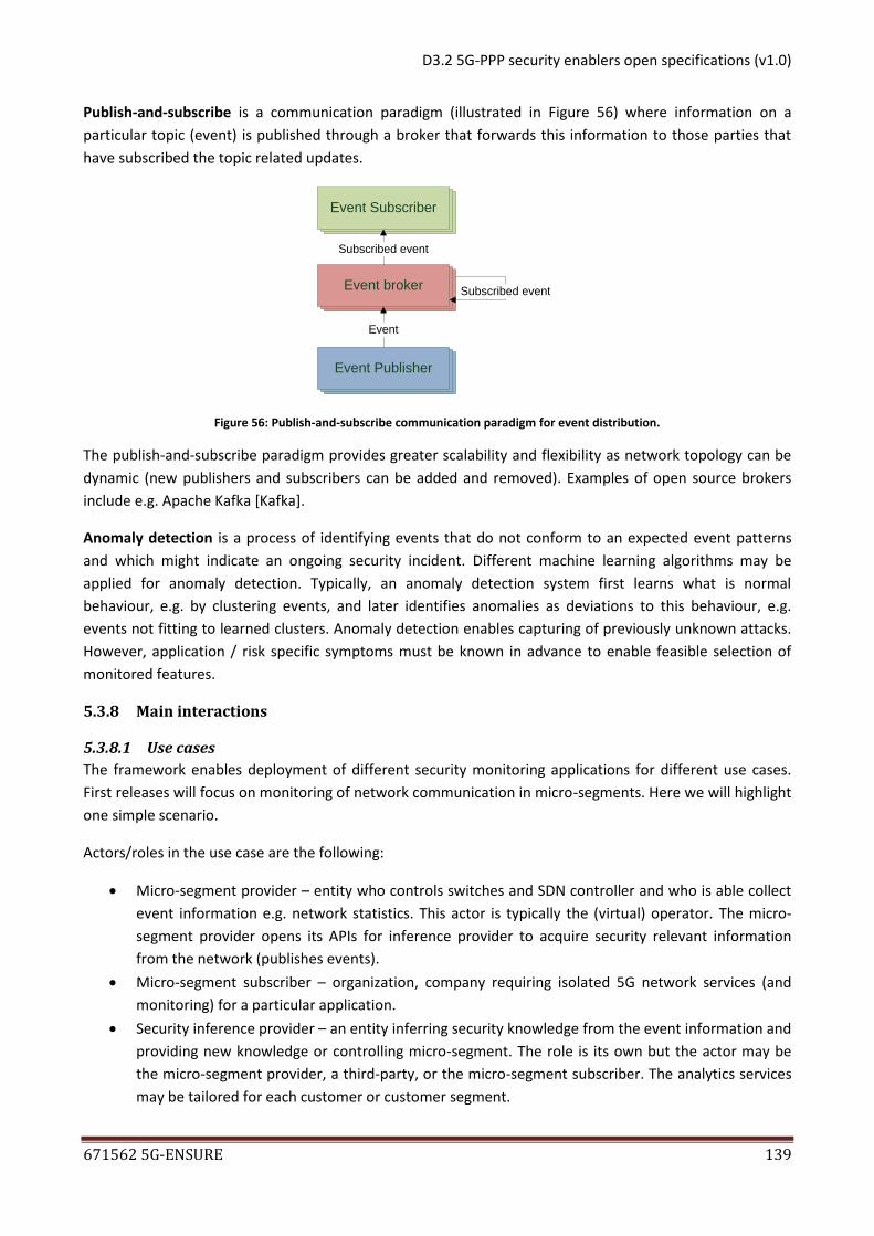
organization to reuse an existing AAA infrastructure to authorize 5G access via a MNO. The access stratum
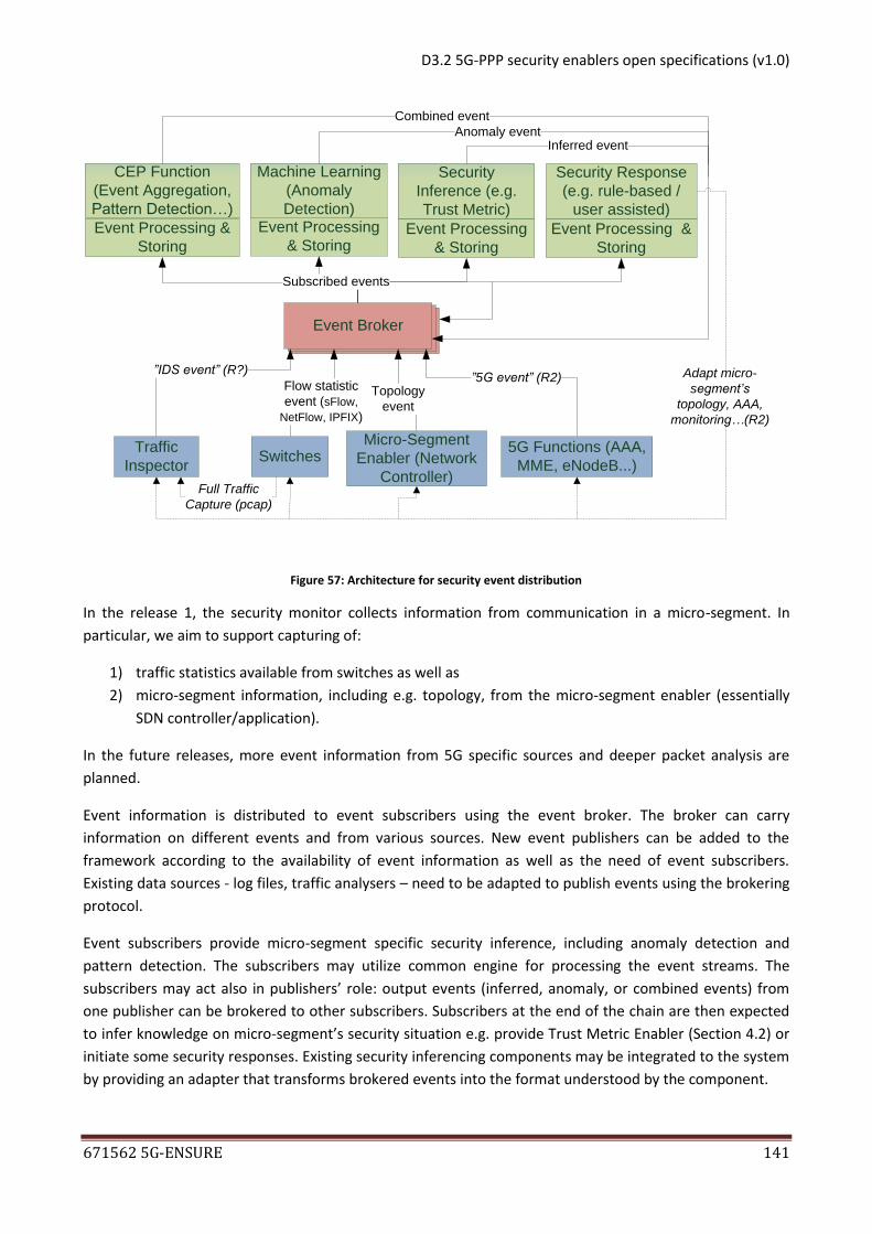
n00
n01=h0(n00)
n02=h0(n01) n12=h1(n01)
n11=h1(n00)
n22=h0(n21) n32=h1(n11)
D3.2 5G-PPP security enablers open specifications (v1.0)
671562 5G-ENSURE 25
may be provided by either the MNO or the organization itself, it is however assumed that the organization
is unable, or find it undesirable, to provide a full core network. From a high level, the setup is technically
similar to a Mobile Virtual Network Operator (MVNO) providing networks services via a MNOs network.
However, from a trust perspective, it introduces entirely new aspects as the organization may not abide by
the same rules and regulations as classical operator. It is thus possible that the organization may need to
adopt to additional regulatory frameworks, but this is outside the technical scope of the enabler. A new
entity, the Industrial Automation Control (IAC), which is functionally similar to an MME, is introduced in the
operator network in order for the operator to distinguish between roaming agreements with other MNOs
and other external organizations.
2.1.7 Basic concepts
Relevant LTE/EPS signaling entities and interfaces during roaming
The interfaces between a UE and the eNB is denoted Uu, the interface between an eNB and a MME is
denoted S1-MME. The interface between the MME and the HSS is denoted S6a. In a classical roaming
scenario, the MME and eNB are provided by a visited network, the MME will request authentication data
from the HSS located in the home network of the subscriber.
Figure 2: Signalling entities and interfaces during roaming
The authentication vector on the S6a reference point
When a UE attaches to the 3GPP core network it performs the AKA exchange for mutual authentication and
key agreement with the network. The AKA is performed between the UE and the MME, which fetches
authentication vectors (AV) from the HSS over the S6a reference point.
Generic Bootstrapping Architecture
GBA is a way of using the 3GPP subscription credentials for authenticating the UE and getting keys to a
service (Network Application Function, NAF). To achieve this, the UE first bootstraps with the Bootstrapping
Server Function (BSF), a bootstrapping entity in the 3GPP core, using the 3GPP credentials and the HTTP
Digest AKA protocol. The BSF fetches AVs from the HSS over the Zh reference point, in a similar way as the
MME over the S6a reference point. After bootstrapping, the UE can, e.g. using HTTP Digest, authenticate to
the service (NAF) based on the bootstrapping context with the BSF. The BSF provides the NAF with a service
specific key that the NAF can use for authentication of the UE and securing further communication of the
session.
UE MME HSS eNB S6a S1-MME Uu
Home network Visited network
D3.2 5G-PPP security enablers open specifications (v1.0)
671562 5G-ENSURE 26
Group-based AKA
The functional goal of a group-based AKA protocol is to authenticate a group of devices efficiently,
minimizing the cost of repeated message exchanges and communication delays. More specifically, a group-
based AKA protocol aims to reduce the signalling between the mobility management entity (MME) and
home subscriber server (HSS) when a large group of machine-type communication (MTC) devices with
similar features requires network access simultaneously.
2.1.8 Main interactions
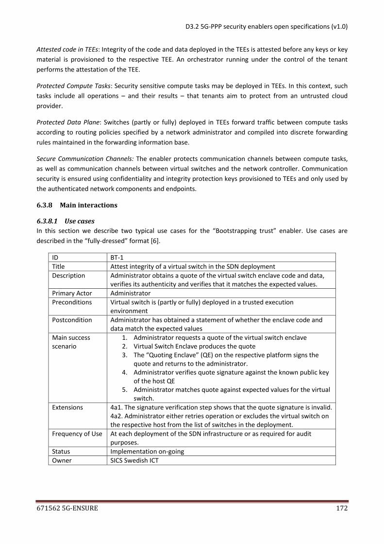
2.1.8.1 Use cases
A 5G PLMN is expected to support a much wider range of devices than previous generations. Additionally,
slicing technology will also enable compartmentalization of devices that could potentially be classified into
different security categories. It is expected that the USIM is unsuitable for certain categories, e.g. IoT and
resource-constrained devices, which will be addressed by the authentication of USIM-less devices feature
that looks into the integration of non-USIM based AKA procedure into the 5G system.
Similarly, group-based authentication aims to increase the capacity for massive deployments of MTC
devices in 5G. At large events, e.g. sporting events, we envision that 5G connected sensors and tracking
devices will be deployed at a massive scale. We foresee that the existing EPS-AKA is not sufficiently efficient
to handle the massive simultaneous authentication requests that these devices will incur. This is especially
important in the case of device subscriptions in a roaming setup. With the group-based authentication
approach, the signalling between the MTC devices and their HSS are significantly reduced, enabling the
serving network to handle almost all of the signalling independently from the home network, and reducing
the latency drastically.
The MTC is preconfigured with the necessary group terms, such as the group ID. The pre-configuration can
be performed via non-3GPP access. The identity of the MTC is stored in the USIM, fulfilling the
requirements of securing the identities against attacks such as cloning.
We imagine that the configuration of the groups will be performed using an application programming
interface (API) to access the network. It allows for an automated approach for submitting the MTC
identities that should belong to the specific group.
To further enhance 5G for resource-constrained devices, the enabler will introduce vertical GBA. The basic
use case for vertical GBA is that a constrained UE wishes to use some GBA enabled service(s). Constrained
devices are in many cases constrained especially regarding power supply and might be operating solely on
battery power. To optimize the performance of these types of devices, reducing the amount of signalling
required by the device is an important step for improving the lifetime of the device. With vGBA, the UE
does not have to perform an explicit GBA bootstrapping with the BSF, thus using vGBA reduces the amount
of signalling needed for authentication to GBA enabled services (NAFs), using the pre-generated GBA
credentials.
Finally, the use case for BYOI is to attract enterprises that already have a deployed AAA infrastructure to
use 5G. By establishing a contract with a MNO, the enterprise can allow their devices to perform roaming
and utilize other aspects of a PLMNO.
D3.2 5G-PPP security enablers open specifications (v1.0)
671562 5G-ENSURE 27
2.1.8.2 Components and interaction overview
Authentication of non-USIM based devices
Non-USIM based AKA procedures will impact the AKA protocol as well as the identification protocols
utilized by the current 3GPP standards, e.g., in a certificate public key pair based authentication system the
standard IMSI may not necessarily be an identifier that is used to identify the subscription.
Figure 3: Network deployment considered for non-USIM based devices
In the considered solution, it is assumed that there will be no support for negotiation of authentication
methods, the subscription will be associated with an identifier that maps uniquely to a provided ID. The ID
provider may either be the MNO, that utilize HSS for AKA procedures, or an enterprise that has deployed an
Enterprise AAA for the AKA procedures. It is also assumed that the identifier uniquely determines the AKA
protocols to be used. A UE may support several AKA protocols and multiple ID providers, e.g., both towards
a HSS and an Enterprise AAA. In such a situation it is assumed that the UE selects which AKA protocol to
use, e.g., based on the selected slice ID.
Authentication support for BYOI
As illustrated by the uses cases 1.2 and 1.3 in [2], different levels of enterprise network deployment can be
imagined. In all cases, the enterprise is assumed to operate its own AAA. In some scenarios, the
organization own and operate their own base stations. However, this is similar to the Home eNodeBs
already supported in LTE/EPS and should, as such, not introduce new aspects, beyond the currently defined
Home eNB technical solutions. The deployment considered is summarized in figure 4.
Figure 4: Network deployment where Enterprise operates an AAA
The main difference compared to classical roaming, is that the IAC may require some form of security
assurance from the UE and Enterprise AAA during the AKA procedure: this could be in the form of a remote
UE IAC Enterprise AAA eNB S6y S1-MME Uu
UE
IAC Enterprise AAA
eNB
S6x
S1-IAC
Uu
Enterprise MNO
D3.2 5G-PPP security enablers open specifications (v1.0)
671562 5G-ENSURE 28
attestation procedure, where the device attests to its current security state; or could just be a classification
of the security level of the algorithms used that can be used to assess which slice the UE is allowed to
utilize. Alternatively, or in addition, a contractual agreement (with liabilities) between the MNO and the
Enterprise could stipulate requirements on secure storage/processing of the credentials in the UE.
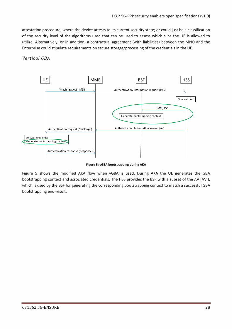
Vertical GBA
Figure 5: vGBA bootstrapping during AKA
Figure 5 shows the modified AKA flow when vGBA is used. During AKA the UE generates the GBA
bootstrapping context and associated credentials. The HSS provides the BSF with a subset of the AV (AV’),
which is used by the BSF for generating the corresponding bootstrapping context to match a successful GBA
bootstrapping end-result.
D3.2 5G-PPP security enablers open specifications (v1.0)
671562 5G-ENSURE 29
Group-based authentication
Figure 6: The message sequence chart of group-based authentication when the MME cannot derive the keys for the MTC
The underlying idea of the proposed group-based AKA is to associate each MTC device to a value of the leaf
node of an inverted hash tree. The tree is generated by the HSS, which reveal a sub-root node to the MME
so that it can authenticate the (sub)group of all MTC descendants. This allows the HSS to control the trade-
off between security and efficiency dynamically. Additionally, no shared credentials exist in the group.
Two cases can be distinguished in the proposed protocol: Case A, in which the MME cannot derive the keys
for the MTC without signalling with the HSS; Case B, in which the MME can derive such keys.
Case A: Figure 6 provides an overview of the initial Attach Request from an MTC device for a specific group,
thus requiring the MME to retrieve the group elements from the HSS. The protocol follows the message
exchange as specified for EPS-AKA, with additional terms included for the group-based authentication,
which are addressed for the MME.
The MTC initiates the protocol by issuing the Attach Request, containing the additional terms necessary to
specify the group it belongs to, and its position in the inverted hash tree. If the MME is unable to derive
keys associated with the MTC device (e.g. the request sent by the first MTC of a specific group), it requests
authentication vectors from the HSS via an Authentication Data Request.
D3.2 5G-PPP security enablers open specifications (v1.0)
671562 5G-ENSURE 30
The HSS will verify that the group id and path is valid and generates and send the authentication vector,
including the new terms intended for the MME to enable group-based authentication for future attach
requests. Specifically, the HSS decides which sub-root node of the inverted hash tree is sent to the MME.
After receiving the Authentication Data Response from the HSS, the MME will continue the message
exchange as specified in EPS-AKA. The MME will be able to derive keys for future authentication requests,
based on the additional terms provided in the authentication data response from the HSS. This is covered
by Case B.
Shall an MTC device crash during the protocol run, it can reattempt the authentication procedure using the
classic AKA procedure.
Figure 7: The message sequence chart of group-based authentication when the MME can derive the keys for the MTC
Case B: Figure 7 provides an overview of the succeeding AKA protocol runs for the same group. The MME
has stored the necessary terms from the Authentication Data Response as in Figure 6, and can derive keys
for the remaining MTC devices. The protocol is executed solely within the serving network, without the
need to interact with the HSS of the group members home network.
2.1.9 Architectural drivers
In the following chapters, the specification will solely cover the release 1 feature of the enabler, group-
based authentication.
D3.2 5G-PPP security enablers open specifications (v1.0)
671562 5G-ENSURE 31
2.1.9.1 High-Level functional requirements
The main goal of the group-based authentication extension is to make the EPS-AKA protocol more suitable for massive deployment scenarios. This is achieved by removing the existing 1-to-1 correlation between the number of MTC devices and the number of messages in the authentication signaling to the HSS, located in the subscriber’s home environment. A group can be defined by an arbitrary attribute. The group(s) are defined in the HSS, thus in this release the members of a group must be subscribers of the same (virtual) operator, as the HSS must know the individual identity of each MTC device. Additionally, the feature requires provisioning of the group ID, the assigned path of the binary tree, and the obfuscated value given to each MTC. The provisioning procedure is out of scope in the current release. With a configured group in the HSS, only the first authentication request, independent of the actual MTC device that requests it, is sent to the HSS. The HSS will thereafter send the necessary terms to the MME to enable group-based authentication for the succeeding authentication requests. The group-based authentication feature requires a universal integrated circuit card (UICC or (e)UICC) based authentication in this release to provide a strong identification of the MTC device. To prevent cloning of shared credentials, the feature is built with independent secrets for each MTC device, configured by the HSS. Furthermore, the feature provides properties of perfect forward secrecy (PFS) to prohibit future, or past, members of a group of being able to decipher data exchanged when they were not part of the specific group. The feature is compliant with lawful interception requirements since all members of a group can be uniquely identified.
2.1.9.2 Quality attributes
A product implementing one or several of the features described in enabler should be evaluated
primarily based on the following quality attributes:
*Security:
Confidentiality
Integrity
Non-repudiation
Accountability
Authenticity
*Compatibility:
Co-existence
Interoperability
2.1.9.3 Technical constraints
Since the group is configured in the HSS, all members in a specific group must have a subscription from the
same HSS. Furthermore, the key provisioning for each MTC device that should be part of a group is out of
scope for this release, hence it must be preconfigured manually at this stage of research. Additionally, the
API access for configuring the group(s) to the core network is out of scope.
2.1.9.4 Business constraints
No known business constraint exists.
D3.2 5G-PPP security enablers open specifications (v1.0)
671562 5G-ENSURE 32
2.1.10 Detailed specifications
2.1.10.1 Introduction
In this section, key concepts regarding the group-based authentication protocol and the new terms used
are introduced.
The proposed group-based extension to the AKA protocol use the same cryptographic primitives that
already exist in EPS-AKA, e.g. hash and MAC functions, no new primitives are added. However, new terms
are introduced in the protocol to support this feature, see Table 2.
In the message exchange between the MTC device and MME, the initial message of the protocol is the
Attach Request. Depending on whether the MME has earlier authenticated an MTC of the same group as
the Attack Request or not, the second run of the protocol may differ. In Case A (see Figure 6), the MME
contacts the HSS to retrieve the necessary information. The response from the HSS, namely the
authentication vector, is returned to the MME as specified in EPS-AKA, however with additional elements
for group-based authentication support. The new elements are stored in the MME.
In Case B (see Figure 7), the MME does not need to contact the HSS to authenticate the MTC.
Term Description
GID Group identifier
PATH The path assigned to the MTC. Each MTC is assigned with the
same path in both trees.
NONCE Random number
GKij The (sub)group key assigned to the ith of GK tree at j
th level.
CHij The challenge key assigned to the ith of CH tree at j
th level.
GKMTC The key associated to the MTC. It is the hash value of the leaf
of the GK tree at PATH.
CHMTC The challenge key associated the MTC. It is the hash value of
the leaf of the CH tree at PATH.
OMTC The obfuscated value that hides the key associated to the MTC
AUTD The authentication parameter in the group authentication
RESD The response parameter in the group authentication
KasmeD The session key generated in the group authentication
Table 2: New terms introduced by the group-based authentication protocol
D3.2 5G-PPP security enablers open specifications (v1.0)
671562 5G-ENSURE 33
2.1.10.2 Conformance
An implementation to be reported as conformant should comply with the open specifications here stated
for the enabler.
2.1.10.3 API specifications
The group-based authentication protocol will introduce functionality adjustments, modifications as well as
new content in the EPS that will need specification. A high-level description of the new aspects and
elements introduced in the main entities which perform AKA will be presented first, thereafter the
modifications to the AKA signaling will be presented.
2.1.10.3.1 New functions, messages and commands
In this section the new functions, messages and USIM commands are introduced in the UE, MME and HSS
respectively.
2.1.10.3.1.1 UE, USIM application & UICC commands
The USIM application is responsible for interaction between the mobile equipment (ME) and the Universal
Integrated Circuit Card (UICC). The ME and USIM combined is denoted user equipment (UE). The UICC is
responsible for storing security critical data. The group-based authentication protocol introduces four new
elements, which must be supported by the USIM application with regards to the secure storage in the UICC.
The purpose of these elements is defined in Table 2.
GID
PATH
NONCE
OMTC
Additionally, the UE must support new commands in order to perform the group-based authentication
protocol.
A key derivation and authentication command in the USIM, which produce the session key KasmeD,
authenticates the token AUTD to enable authentication of the network, and produce the response
RESD. See Table 2 for a description of the terms.
A random generator command for producing the NONCE value.
Moreover, the UICC must provide functionality to update and read additional elementary files (EFs). For
read operations of GID; PATH; OMTC the output value should be the value variable. For update operations
of GID; PATH; OMTCthe output should be success/failure.
2.1.10.3.1.2 Mobility Management Entity (MME)
The group-based authentication protocol introduces five new elements to the MME to enable session
handling, processing and authentication.
GID
PATH
NONCE
D3.2 5G-PPP security enablers open specifications (v1.0)
671562 5G-ENSURE 34
GKij
Chij
Additionally, the MME requires two new functions in order to perform the group-based authentication
protocol.
A function to produce KasmeD and RESD , described in Table 2, to enable the MME to authenticate
the UE.
A function for generating the authentication token AUTD used in Case B (figure 7), of the group-
based authentication protocol.
2.1.10.3.1.3 Home Subscriber Server (HSS)
The group-based authentication protocol introduces 5 new elements to the HSS. The purposes of these
elements are described in Table 2.
GID
PATH
NONCE
GKij
Chij
Additionally, the HSS requires a function for fetching or generating Chij, GKij elements depending on GID
and PATH.
2.1.10.3.2 Signalling
There are five messages included in the group-authentication protocol: attach request, authentication data
request, authentication data response, authentication request derivable, and authentication response
derivable. These can be seen in Figure 6 and Figure 7.
These messages closely correspond to the five message exchanges in the current EPS AKA procedure. In
order to perform the group-authentication protocol, the network is required to support additional
elements, which are added to the existing AKA messages. Additionally, the protocol requires a new
message in scenario Case B.
2.1.10.3.2.1 UE – MME
The signalling between the UE and the MME in Case B requires a new message denoted Authentication
Request Derivable, sent from the MME to the UE, see Figure 7. The Authentication Request Derivable is sent
as a response of the Attach request; in case the specific device is initiating its first authentication request.
The UE responds with Authentication Response Derivable, containing RESD, see Table 2 for explanation of
RESD. The Authentication Response Derivable is similar to the Authentication Response in EPS-AKA, which
contain RES.
D3.2 5G-PPP security enablers open specifications (v1.0)
671562 5G-ENSURE 35
2.1.10.3.2.2 MME - HSS
The signalling methods between the MME and HSS, specified in the S6a interface, contain the
authentication information request (AIR) and the authentication information answer (AIA) message. The
group-based authentication protocol appends two attribute value pairs (AVPs) to these message.
The Requested-group-authentication-info include the Nonce and Path, which are added as information
elements to the AIR.
The Group-response-vector include the GKij, CHij, and IMSI, which are appended as an option in the existing
Authentication Info information element.
2.1.11 Re-utilised Technologies/Specifications
The software prototype for group-based authentication is built using the Open Air Interface as foundation.
2.1.12 References
[1] Page, T, “The application of hash chains and hash structures to cryptography,” Technical report Royal
Holloway, University of London, 2009.
[2] 5G-Ensure Consortium, Deliverable 2.1 Use Cases, [Online]. Available:
D3.2 5G-PPP security enablers open specifications (v1.0)
671562 5G-ENSURE 37
PDP (policy decision point): component which computes access decisions by evaluating the
applicable access control policies; one of the main functions of the PDP is to mediate or deconflict
policies.
PEP (policy enforcement point): component which enforces policy decisions in response to a
request from a subject requesting access to a protected resource; the access control decisions are
made by the PDP.
PIP (policy information point): the system entity that acts as a source of attribute values (e.g.
LDAP).
Policy: A set of rules, an identifier for the rule-combining algorithm and (optionally) a set of
obligations or advice. May be a component of a policy set.
RBAC (role-based access control): an access control paradigm whereby access rights are granted
according to roles and privileges.
RCD (resource-constrained device): a device which has very few resources to run.
Resource: Data, service or system component.
Subject: An actor whose attributes may be referenced by a predicate.
For a summary of terms and definitions managed, please refer to “INCITS 359-2012” standard [1] and
XACML v3.0 standard [5] section 1.1.1.
2.2.6 Overview
2.2.6.1 Target Use for R1
The enabler provides an AAA solution suitable for an environment of resource-constrained devices and
satellite resources, relying on ABAC and/or RBAC policies. It consists of:
a AAA service, based on 5G AAA credentials, able to provide a secured and standalone proof of the
rights granted to a given client over a given device or satellite resource;
a module for resource-constrained devices, able to ensure the validity and the enforcement of the
proof towards a performed request, without requiring more external communication;
a module for satellite resources, able to ensure the validity and the enforcement of the proof
towards a performed request.
We assume that a trust relationship has been pre-established between the owner/provider of the enabler
and the devices. The enabler scope does not include the security of the communication channels of the
different components. The access control of the enabler administration API is also out of the enabler open
specification scope.
2.2.6.2 Target Use for R2
The next release is expected to support policies for decision per user, resource and action, and access
control based on dynamically changing parameters.
Also, in the satellite context, the next release is expected to integrate the authentication and authorization
mechanism with the Satellite system.
Finally, in the resource-constrained context, the next release is expected to provide the final version of PEP
and PDP embedded on the RCD, and the Authentication server delivering a self-sufficient security token
allowing decentralized authentication and authorization, compatible with RCDs in terms of performance.
D3.2 5G-PPP security enablers open specifications (v1.0)
671562 5G-ENSURE 38
2.2.7 Basic concepts
2.2.7.1 OAuth2concepts
OAuth2 is an authorization protocol which enables a third-party application to obtain limited access to a
resource over HTTP, through a prior authorization from the resource owner. OAuth2 defines 4 distinct roles
[3]:
Resource owner: an entity capable of granting access to a protected resource. In the enabler
context, it refers to a RCD owner who can define its access rights.
Resource server: the server hosting the protected resources, capable of accepting and responding
to protected resource requests using access tokens. In the enabler context, it refers to the RCD
itself, with the access token enforcement module.
Client: an application making protected resource requests. In the enabler context, it refers to the
user who performs a request toward a protected RCD.
Authorization server: the server issuing authorization to the client to access protected resources.
In the enabler context, it refers to the enabler AAA service.
In OAuth2, the authorization server grants rights by delivering access tokens. Access tokens are credentials,
representing specific scopes of access rights and duration of access, understood by the resource server.
They can have different formats, structures, methods of utilization (e.g. cryptographic properties) according
to resource server requirements. The token scope is a parameter which is used to limit token access rights.
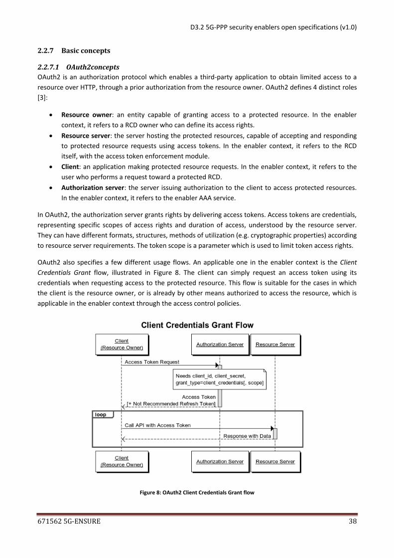
OAuth2 also specifies a few different usage flows. An applicable one in the enabler context is the Client
Credentials Grant flow, illustrated in Figure 8. The client can simply request an access token using its
credentials when requesting access to the protected resource. This flow is suitable for the cases in which
the client is the resource owner, or is already by other means authorized to access the resource, which is
applicable in the enabler context through the access control policies.
Figure 8: OAuth2 Client Credentials Grant flow
D3.2 5G-PPP security enablers open specifications (v1.0)
671562 5G-ENSURE 39
Another applicable flow is the Authorization Code Grant flow, illustrated in Figure 9. This flow is suitable in
cases where a resource owner can explicitly grant a client an access to its protected resources. The client
must get an authorization code in order to access the resource that it requests from the authorization
server. The server responds with a redirection URI that the resource owner must reach to log in and then
explicitly grant the requested access. The client can then exchange this authorization code against an
access token usable with the resource server.
Figure 9: OAuth2 Authorization Code Grant flow
OpenID Connect is an authentication standard based on OAuth2, specifying how to perform authentication
through OAuth2, using Authorization Code Grant flow. In this context, the client is a service requiring a user
identity; the protected resource is the user identity, obviously owned by the user, which will authenticate
to the authorization server in order to provide the client a proof of his identity. The usability of OpenID
Connect in the enabler context will be studied for the enabler second release.
2.2.7.2 RBAC concepts
RBAC is an access control method for controlling user access applying roles and permissions. Roles are
created for various operations. The permissions to perform certain operations are assigned to specific
roles. Subjects are assigned particular roles, and through those role assignments acquire the permissions to
perform particular operations.
D3.2 5G-PPP security enablers open specifications (v1.0)
671562 5G-ENSURE 40
Three primary rules are defined for RBAC:
Role assignment: A subject can exercise permission only if the subject has selected or been
assigned a role.
Role authorization: A subject's active role must be authorized for the subject. With rule 1 above,
this rule ensures that users can take on only roles for which they are authorized.
Permission authorization: A subject can exercise permission only if the permission is authorized for
the subject's active role. With rules 1 and 2, this rule ensures that users can exercise only
permissions for which they are authorized.
2.2.7.3 ABAC concepts
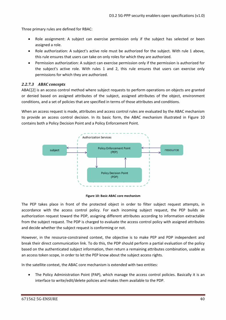
ABAC[2] is an access control method where subject requests to perform operations on objects are granted
or denied based on assigned attributes of the subject, assigned attributes of the object, environment
conditions, and a set of policies that are specified in terms of those attributes and conditions.
When an access request is made, attributes and access control rules are evaluated by the ABAC mechanism
to provide an access control decision. In its basic form, the ABAC mechanism illustrated in Figure 10
contains both a Policy Decision Point and a Policy Enforcement Point.
Figure 10: Basic ABAC core mechanism
The PEP takes place in front of the protected object in order to filter subject request attempts, in
accordance with the access control policy. For each incoming subject request, the PEP builds an
authorization request toward the PDP, assigning different attributes according to information extractable
from the subject request. The PDP is charged to evaluate the access control policy with assigned attributes
and decide whether the subject request is conforming or not.
However, in the resource-constrained context, the objective is to make PEP and PDP independent and
break their direct communication link. To do this, the PDP should perform a partial evaluation of the policy
based on the authenticated subject information, then return a remaining attributes combination, usable as
an access token scope, in order to let the PEP know about the subject access rights.
In the satellite context, the ABAC core mechanism is extended with two entities:
The Policy Administration Point (PAP), which manage the access control policies. Basically it is an
interface to write/edit/delete policies and makes them available to the PDP.
D3.2 5G-PPP security enablers open specifications (v1.0)
671562 5G-ENSURE 41
The Policy Information Point (PIP), which acts as a source of attribute values using LDAP. Basically if
there are missing attributes in the request which is sent by PEP, PIP would find them for the PDP to
evaluate the policy.
2.2.7.4 XACML concepts
XACML (eXtensible Access Control Markup Language) is an OASIS standard [5] specification of an ABAC
language based on XML.
We can summarize it in three parts:
Policy language: XACML defines a XML data model for defining authorization policies, as well as the
logic to follow to evaluate them in a given access request context. Rule, Policy (set of Rules), and
PolicySet (set of Policy elements) constitute the main elements of the model. In short, a rule
consists of a condition on the access request attributes, and a decision – Permit or Deny - to apply if
the condition holds true for the request. A Policy (resp. PolicySet) combines multiple Rules (resp.
Policies) and therefore multiple decisions together in various ways (defined in the standard) to
make the final decision.
Request-Response protocol: The XACML standard also defines a XML/JSON data model for the
authorization decision request (XACML Request) that a PEP (described later) creates with all the
necessary access request attributes and sends to the PDP API for evaluation; and the resulting
response (XACML Response) that contains the final decision (Permit or Deny).
Architecture framework: The XACML standard also defines a high-level architecture, re-using the
ABAC concepts described in 2.2.7.3.
2.2.8 Main interactions
2.2.8.1 Use cases
2.2.8.1.1 Authorization in resource-constrained devices
This enabler covers the use case 4.1: Authorization in Resource-Constrained Devices Supported by 5G
Network defined in D2.1 [8].
RCD owner
Define RCD access
control policy
Fine-grained authorization enabler
User
Request RCD
Figure 11 : Authorization in resource-constrained devices Use cases diagram
Figure 11 shows a generic use cases diagram for the enabler. The user (Alice in D2.1) can perform an
authenticated request towards a RCD (a sensor in D2.1). The details of the authentication and verification
are not part of the use case but will be taken into account and described in the sections below. In the same
D3.2 5G-PPP security enablers open specifications (v1.0)
671562 5G-ENSURE 42
way, the RCD owner (sensors’ owner in D2.1) can define the security policies which will be enforced in front
of its RCD and condition the user access.
2.2.8.1.2 Authorization in satellite systems Use case
This enabler covers the use case 1.3 “Satellite Identity Management for 5G Access” defined in D2.1 [8].
Figure 12 : Authorization in satellite systems Use cases diagram
Figure 12 shows a generic use cases diagram for the enabler. The user (Bob in D2.1) can perform an access
request towards a satellite resource. The details of the authentication and verification are not part of the
use case but will be taken into account and described in the sections below. In the same way, the satellite
resource owner (Satellite Network Operator in D2.1) can define the access control policies which will be
enforced in front of the satellite resources and condition the user access.
2.2.8.2 Components and interaction overview
2.2.8.2.1 Authorization in resource-constrained devices feature
Figure 13 shows a static view of the different components implementing the enabler and their links. The
different APIs exposed by the enabler are described in section 2.2.10.3.
D3.2 5G-PPP security enablers open specifications (v1.0)
671562 5G-ENSURE 43
Resource-constrained device
AAA server
Authenticationservice
PolicyDecision Point
Policy Enforcement Point
Client
Administration
RCD Service
AAA API
RCD API
Policy Administration API
Fine-grained authorization enabler
Figure 13: Authorization in resource-constrained devices Components diagram
A client can address the PEP in order to request a RCD, as well as an Authentication service in order to get
an access token which will be used to grant the RCD request. The Authentication service is linked to the
PDP in order to define a scope for the token, for evaluation by the PEP. Contrary to the common ABAC
architecture described in section 2.2.7.3, the PDP and the PEP are not linked together, the information they
usually need to share will be part of the token. The dynamic flow of RCD requesting use case is detailed on
Figure 14.
D3.2 5G-PPP security enablers open specifications (v1.0)
671562 5G-ENSURE 44
as : Authenticationservice
pdp : PolicyDecision Point
request_token (c, rcd)
rcd : RCD Servicepep : Policy
Enforcement Point
get_scope (c, rcd)
c : Client
token, scopescope
request (token, scope)
validate (token)
validate (scope)
request ()
responseresponse
Figure 14 : Use case “Request RCD” sequence diagram
Moreover, an administration API is exposed by the PDP component in order to let the RCD owner define his
own access control policies through any administration component. The dynamic flow of the RCD access
control policy definition use case is detailed on Figure 15.
a : Administrationpdp : Policy
Decision Point
set_policy(policy)
OK
Figure 15: Use case “Define RCD access control policy” sequence diagram
2.2.8.2.2 Authorization in satellite systems feature
A geosynchronous satellite imposes a delay between messages: a radio signal takes approximately 0.25 of a
second to reach and return from the satellite. Addressing this constraint involves optimizing the number of
messages interchanged (e.g. in authorization functionality) with the satellite device. Therefore, this feature
is related to satellite systems, but may also relate to other systems (e.g. RCD).
Figure 16 shows a static view of the different components implementing the enabler and their links. The
different APIs are described in section 2.2.10.5.
D3.2 5G-PPP security enablers open specifications (v1.0)
671562 5G-ENSURE 45
Figure 16: Authorization in satellite systems Components diagram
An administration API is exposed by the PAP component in order to let the satellite resource owner define
his own access control policies through any administration component.
A client can address the PEP in order to request a satellite resource, as well as an Authentication service in
order to get an access token which will be used to grant the satellite resource request. The Authentication
service is linked to the PDP in order to define a scope for the token, for evaluation by the PEP. Unless the
common ABAC architecture described in section 2.2.7.3, the PDP and the PEP are not linked together, the
information they usually need to share will be part of the token. The dynamic flow of satellite resource
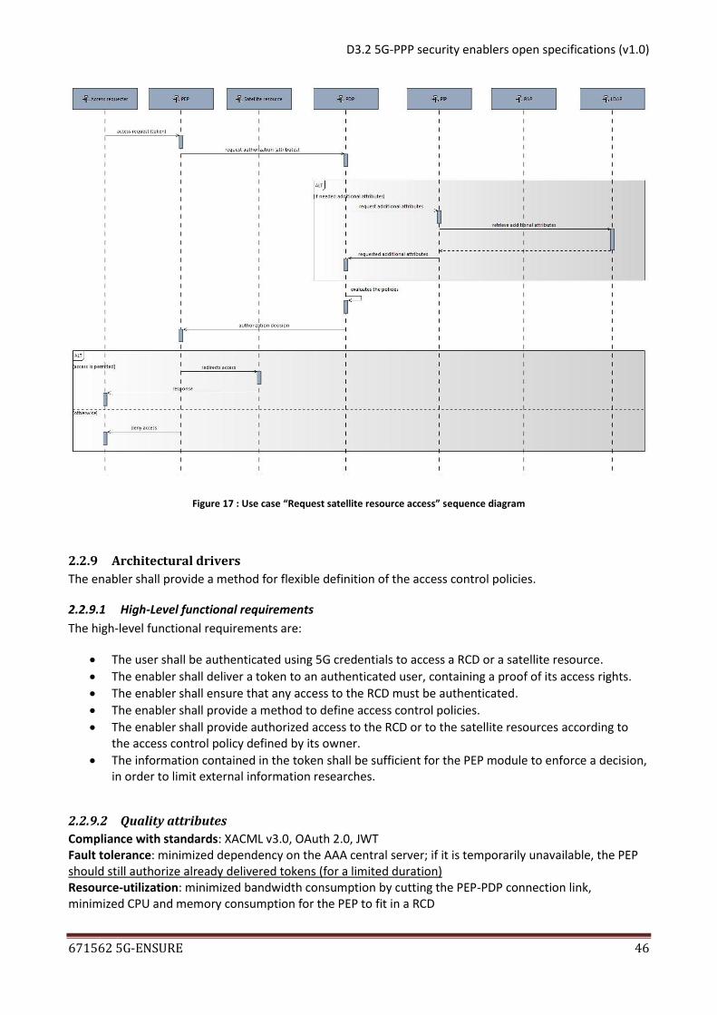
requesting use case is detailed on Figure 17.
D3.2 5G-PPP security enablers open specifications (v1.0)
671562 5G-ENSURE 46
Figure 17 : Use case “Request satellite resource access” sequence diagram
2.2.9 Architectural drivers
The enabler shall provide a method for flexible definition of the access control policies.
2.2.9.1 High-Level functional requirements
The high-level functional requirements are:
The user shall be authenticated using 5G credentials to access a RCD or a satellite resource.
The enabler shall deliver a token to an authenticated user, containing a proof of its access rights.
The enabler shall ensure that any access to the RCD must be authenticated.
The enabler shall provide a method to define access control policies.
The enabler shall provide authorized access to the RCD or to the satellite resources according to the access control policy defined by its owner.
The information contained in the token shall be sufficient for the PEP module to enforce a decision, in order to limit external information researches.
2.2.9.2 Quality attributes
Compliance with standards: XACML v3.0, OAuth 2.0, JWT Fault tolerance: minimized dependency on the AAA central server; if it is temporarily unavailable, the PEP should still authorize already delivered tokens (for a limited duration) Resource-utilization: minimized bandwidth consumption by cutting the PEP-PDP connection link, minimized CPU and memory consumption for the PEP to fit in a RCD
D3.2 5G-PPP security enablers open specifications (v1.0)
671562 5G-ENSURE 47
Integrity/Non-repudiation/Authenticity: token information must be signed by Authentication service, and are authenticatable end-to-end.
2.2.9.3 Technical constraints
In the resource-constrained context, the PEP module should be deployable on a RCD with 900MHz CPU and
1GB RAM.
2.2.9.4 Business constraints
None.
2.2.10 Detailed specifications
2.2.10.1 Introduction
This specification defines the Fine-grained authorization API, which provides fine-grained authorization
access to RCD and satellite resources based on defined access control policies.
The API follows the REST design principles and complies with XACML 3.0.
Fine-grained authorization enabler is currently being developed. Below is a preliminary API specification of
the enabler.
2.2.10.2 Conformance
An implementation that conforms to this open specification shall implement fully the architecture
described.
All the interfaces described are mandatory and must be implemented in order to be compliant with.
The usage of LDAP as a source of attribute values is optional.
2.2.10.3 Authorization in resource-constrained devices API specifications
2.2.10.3.1 AAA API
The AAA API is compliant with OAuth 2.0 standard API. According to the Client Credentials Grant flow, the
only interesting OAuth2 endpoint is the token endpoint. Since the client authentication is used as
authorization grant, no additional authorization request is needed.
Method Name request_token
Method Definition/Description
Request the OAuth2 token endpoint in order to get an access token.
Note that the client must authenticate in any way to call this method.
Method input attributes
Name Type Description
grant_type String Must be set to “client_credentials”.
Method output attributes
Name Type Description
token JWT-encoded JSON
A JWT-encoded OAuth2 access token, containing the following fields:
access_token: an access token identifier
D3.2 5G-PPP security enablers open specifications (v1.0)
671562 5G-ENSURE 48
token_type: the access token type
expires_in: the lifetime in seconds of the access token
scope: the scope of the token, containing the access rights granted to the client. The scope should be defined by the PDP, according to the access control policy.
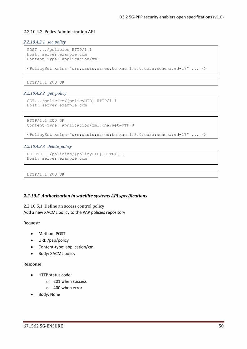
2.2.10.3.2 Policy Administration API
The Policy Administration API is a RESTful HTTP API defined as below:
Method Name set_policy
Method Definition/Description
Add a XACML PolicySet.
Method input attributes
Name Type Description
Policy PolicySet A XACML PolicySet
Method output attributes
Name Type Description
policyUID String
PolicySet unique identifier (PolicySet UID). This is the identifier allocated by the Service Provider for the PolicySet resource. Note that this is different from the XACML PolicySetId in at least two ways:
1. It is allocated by the Service Provider whereas the XACML PolicySetId is defined by the Service Consumer.
2. It identifies the XACML PolicySetId AND Version.
In other words, you can have two different resources with the same PolicySetId but different Versions (therefore different PolicySet UIDs).
Method Name get_policy
Method Definition/Description
Get a deployed XACML PolicySet.
Method input attributes
Name Type Description
policyUID String The PolicySet UID (see set_policy return)
Method output attributes
D3.2 5G-PPP security enablers open specifications (v1.0)
671562 5G-ENSURE 49
Name Type Description
Policy PolicySet The XACML PolicySet matching the UID. None if no PolicySet match the UID.
Method Name delete_policy
Method Definition/Description
Delete a deployed XACML PolicySet
Method input attributes
Name Type Description
policyUID String The PolicySet UID (see set_policy return)
Method output attributes
Name Type Description
-- -- --
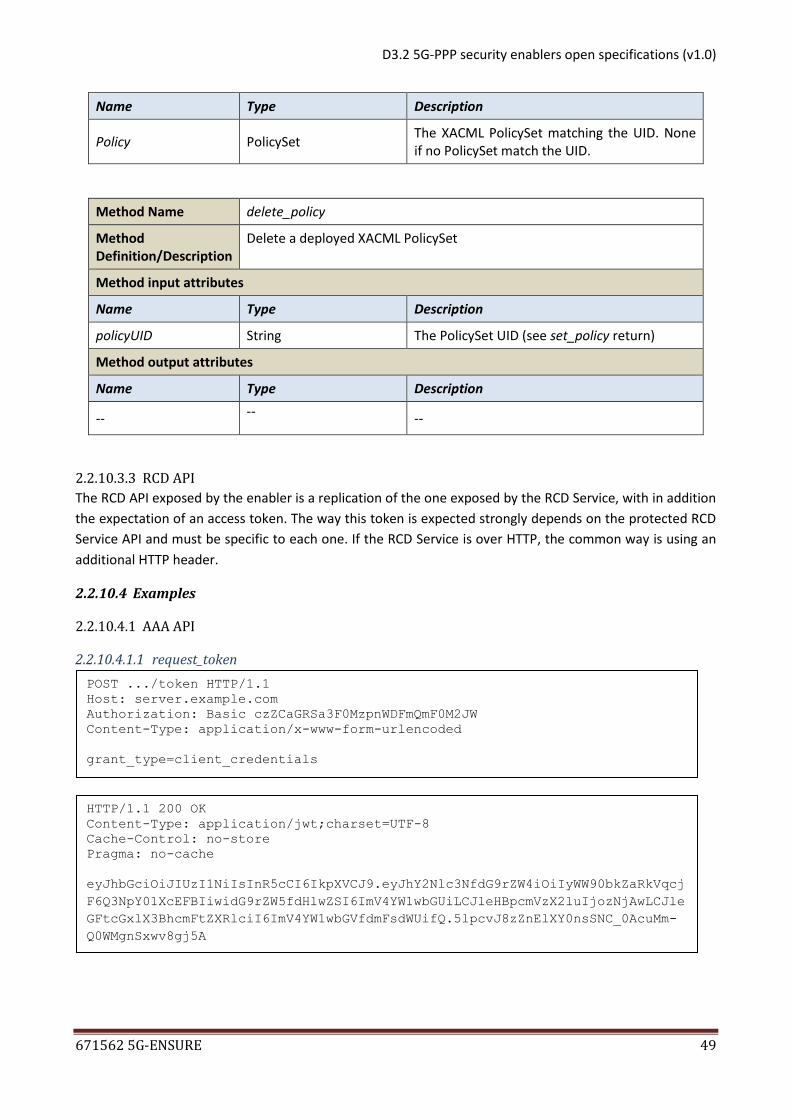
2.2.10.3.3 RCD API
The RCD API exposed by the enabler is a replication of the one exposed by the RCD Service, with in addition
the expectation of an access token. The way this token is expected strongly depends on the protected RCD
Service API and must be specific to each one. If the RCD Service is over HTTP, the common way is using an
The Legal notice that applies to these specifications is given in Annex A.
2.3.5 Terms and definitions
Authentication, Authorization and Accounting
Authentication and Key Agreement Protocol that establishes mutual authentication and a shared key used for further protection of the communication
Authentication Management Field An input parameter of the AKA' authentication algorithms. (in 4 hex digits)
Access Stratum Mobile Equipment Notation used to indicate that it is a key shared between the Access Stratum (MME) and the ME (should really be UE as it could be on USIM)
Authentication Vector Set of quadruplets {XRES,CK,IK,AK} user for mutual authentication of network and UE, and for key establishment
Ciphering Key Key used for confidentiality protection of information
Evolved Packet Core Is a framework for an evolution or migration of the 3GPP system to a higher-data-rate, lower-latency, packet-optimized system that supports, multiple RATs (From TR21.905 v13.0.0 [1])
Evolved Packet System Is an evolution of the 3G UMTS characterized by higher-data-rate, lower-latency, packet-optimized system that supports multiple RATs. The Evolved Packet System comprises the Evolved Packet Core together with the evolved radio access network (E-UTRA and E-UTRAN). (From TR21.905 v13.0.0 [1])
EvolvedUTRA/EvolvedUTRAN Evolved UTRA is an evolution of the 3G UMTS radio-access technology/network towards a high-data-rate, low-latency
D3.2 5G-PPP security enablers open specifications (v1.0)
671562 5G-ENSURE 54
and packet-optimized radio-access technology.
Home Environment Responsible for overall provision and control of the Personal Service Environment of its subscribers (From TR21.905 v13.0.0 [1])
Hashed Message Authentication Code Integrity check calculated by using hash functions with a secret key as input as well as the message.
Home Subscriber Server Server managing subscription related information including keys and functions for producing authentication vectors
Integrity Key Key used for integrity protection of information
Long Term Evolution Name of the 3GPP project for E-UTRAN, has since been adopted as the name for E-UTRAN. Does not include EPS.
Message Authentication Code A secret key dependent checksum that is used to verify the authenticity and integrity of data
Mobile Equipment The mobile device excluding the USIM/UICC
Man-In-The-Middle An attack where a man in the middle can establish connections with both communicating parties without either end point being aware that data is relayed between an entity in between.
Public Land Mobile Network A network that provides communication services according to the specifications to mobile users in a geographical area
Serving GPRS Support Node A node responsible for the delivery of data packets from and to the UEs within its geographical service area. Its tasks include packet routing and transfer, mobility management, logical link management, and authentication and charging functions.
Serving Network The serving network provides the user with access to the services of home environment (From TR21.905 v13.0.0 [1])
User Equipment ME+USIM
Universal Mobile Telecommunications System An umbrella term for the third generation radio technologies developed within 3GPP
Universal Subscriber Identity Module An application residing on the UICC used for accessing services provided by mobile networks, which the application is able to register on with the appropriate security (from TR21.905 v13.0.0 [1])
Visitor Location Register A database that contains information about roaming subscribers within a locations area.
2.3.6 Overview
The Basic AAA enabler builds on the assumption that the AAA framework utilized by 4G to a large degree is
inherited also into 5G. The enabler looks into three areas of new functionality or improvements, namely
AAA aspects of trusted micro-segmentation in 5G networks; Perfect Forwards Secrecy for the AKA protocol;
Trusted interconnect and authorization. The features will be described independently in the document.
AAA aspects of trusted micro-segmentation in 5G networks
Micro-segments are virtualized, isolated parts of the 5G network, meant to provide customizable security
to subscribers, which can be hospitals, factories, and Industrial Internet and Internet of Things (IoT) based
D3.2 5G-PPP security enablers open specifications (v1.0)
671562 5G-ENSURE 55
companies. Micro-segmentation aims to provide a more homogeneous and smaller environment to
manage by security monitoring. By means of this, better accuracy can be achieved for e.g. anomaly
detection. The AAA method in micro-segments depends on the needed security level, which is determined
by the micro-segment subscriber. One possible authentication method could be Extensible Authentication
Protocol over LAN (EAPoL).
Perfect Forward Secrecy
This feature introduces perfect forward secrecy into the AKA protocol to ensure that a compromised key
does not affect the secrecy of messages protected by other keys established as a result of previous or
future AKA runs. The aim is to only modify the necessary parts of the current AKA protocol and reuse
properties, such as mutual authentication.
2.3.7 Basic concepts
2.3.7.1 Perfect Forward Secrecy
Perfect forward secrecy is a property of a protocol which ensures that a key leakage does not compromise
sessions using successor keys, or future sessions using newly established keys, i.e., only the session
encrypted/integrity protected with the affected key can be attacked.
2.3.7.2 UMTS / LTE AKA procedure
On a high level, AKA works as in Figure 18
Figure 18: AKA procedure
AUTN is a parameter composed of different fields: AMF, MAC and a sequence number indication (SQN,
possibly encrypted by an anonymity key AK). The MAC is a Message Authentication Code that protects
RAND, SQN and AMF from being forged by a 3rd party through the cryptographic functions implemented by
the USIM as shown in Figure 19. The keys CK and IK are used directly for ciphering /integrity protection in
3G and are used indirectly for these purposes in 4G/LTE by deriving ciphering/integrity keys from CK and IK.
UE MME HSS
Authentication data request Generate
authentication
vectors
AV(1…n) Authentication data response AV(1…n)
* Store authentication
vectors
*Select AV(i)
User authentication request
RAND(i)||AUTN(i) *Verify AUTN(i)
*Compute RES(i)
User authentication response
RES(i) *Compare RES(i)
and XRES(i)
*Select CK(i) and
IK(i)
*Derive KASME etc
from CK(i),IK(i)
Derive KASME etc
from CK(i),IK(i)
D3.2 5G-PPP security enablers open specifications (v1.0)
671562 5G-ENSURE 56
K
S Q N
R A N D
f1 f2 f3 f4
f5
X M A C R E S C K IK
A K
S Q N A K A M F M A C
A U T N
V e r ify M A C = X M A C
V e r ify th a t S Q N is in th e c o r r e c t r a n g e
Figure 19: USIM AKA calculations
2.3.7.3 Diffie-Hellman key exchange protocol
The original protocol is based on the multiplicative groups of integers module a prime number p, the
generator element g is primitive root modulo p. Both parties each randomly generates a secret value, the
UE generates value x, and the network generates value y. The UE calculates gy (which does not need to be
kept secret) and sends the result to the network, the network calculates gx and sends to the UE, see Figure
20.
Figure 20: Diffie-Hellman key exchange procedure
The UE and the network can then each calculate the shared secret key as k=(gx)y=(gy)x. For an adversary
with knowledge of gx and gy it is believed difficult to derive gxy.
gx
UE Network
gy
Generate:
x=random()
Calculate: gx
Calculate:
k=(gy)x
Generate: y=random()
Calculate: gy
Calculate:
k=(gx)y
D3.2 5G-PPP security enablers open specifications (v1.0)
671562 5G-ENSURE 57
2.3.8 Main interactions
2.3.8.1 Use cases
AAA aspects of trusted micro-segmentation in 5G networks
Once a micro-segment has been created, nodes can be added to the micro-segment. Before adding nodes
to the micro-segment, they need to be authenticated by the micro-segment AAA entity and subsequently
authorized to use the micro-segment. As mentioned earlier, the AAA methods in micro-segmentation
depend on the used application or the requirements of the micro-segmentation subscriber. The AAA
method is thus fully customizable.
An example of a new AAA policy could be the setting of more detailed requirements on the authentication
of users. Also, preventing users or group of users from the use of a micro-segment is another possible
action.
Perfect Forward Secrecy
In this use case, a subscriber and a MNO want to reduce the security effect of any compromised keys
shared between the subscriber and the operator. Current AKA procedures suffer from the fact that a
comprompise of the long term keys stored in HSS/USIM can lead to all future, and past messages, sent with
keys derived from the compromised key can be decrypted. It is proposed that the key agreement protocol
is updated to use the Diffie-Hellman key exchange protocol instead to ensure that a compromised key only
affect sessions in which that particular key is used. To prevent man-in-the-middle attacks on the Diffie
Hellman protocol, the authentication aspects of the AKA procedure are reused.
2.3.8.2 Components and interaction overview
AAA aspects of trusted micro-segmentation in 5G networks
Each micro-segment could have its own AAA entity, but the AAA functionality of a micro-segment should
not add to the overall complexity. This component would be a virtualized resource or function, i.e.,
Network Function Virtualization (NFV) would be used. It is for further study how to bootstrap the micro-
segment AAA entities.
Perfect forward secrecy
The Diffie-Hellman protocols in general requires transportation of parameters that are much larger than the
parameters of the AKA protocol (RAND, RES, etc). Even if it is possible to increase the number of bits signaled over
the air interface, it would be desirable to maintain the standardized USIM-ME interface, which implies a bottleneck
for the size of the protocol parameters which falls below the level where DH offers strong security. RAND is
currently 128 bits, and to reach a security matching the 128-bit strength of AKA:
DH parameters of at least 256-bits are need for elliptic curve variants of DH
around 3000-bits for standard discrete log DH modulo a prime, p
around 6000-bits for supersingular isogeny DH, out of which it is sufficient to transfer roughly 3000 bits
(this variant is believed to be quantum computer immune).
Another aspect to consider is that DH is sensitive to a man-in-the-middle (MITM) attacks, as a result, a mechanism
to authenticate the DH parameters is necessary.
D3.2 5G-PPP security enablers open specifications (v1.0)
671562 5G-ENSURE 58
The RAND information element can be used to carry a DH value when sent from the network to UE: RAND = gx. The
result is likely to be substantially larger than the current size of 128-bits. To maintain the USIM-ME interface, we
propose to compress RAND, e.g. by cryptographic hashing: RAND’ = H(RAND) = H(gx), where H denotes taking the
128 LSB of SHA256, i.e., H(x)=TRUNC128-LSB(SHA256(x)). H is applied in the ME, before inputting RAND’ to the USIM.
As a consequence, the AKA MAC-field will be computed in dependency of RAND’, but through the use of H, it will in
effect still be computed in dependency of gx. Therefore, the authenticity of the DH value g
x is ensured between the
AuC/HSS and the USIM, which prevents MITM attacks, in particular between the serving network and UE.
The UE will need to compute a response DH-value of the form gy, which is computed from a (pseudo) randomly
generated value, y, in the UE. Again, to thwart MITM attacks, this value must be authenticated. To this end,
however, we propose to use RES and add a standard MAC, i.e., by computing RES’ = MAC(RES , gy), and thus the UE
responding with RES’, gy. It is proposed that the MAC function is based on HMAC.
Note that the AuC/HSS needs to generate the authentication vectors sent to the serving network accordingly, i.e.
compute parameters: RAND’ = H(gx), before inputting it to the f-functions, etc.
Note: In principle, the HSS does not need to send CK, IK (or keys derived therefrom) to the MME as part of
Authentication Vectors (AV) since the resulting shared key will be based on gxy
which is not known to the HSS at time
of AV generation. However, in EPS/LTE keys are “bound” to the access network through inclusion of a PLMN
identifier in the derivation of the KASME key from CK, IK. Since the HSS as noted does not know gxy
at the point when
AVs are generated, a binding to PLMN ID could be achieved by including the PLMN ID in derivation of some further
key from CK, IK and including that derived key in the AV.
Also the MME would need updates, i.e. given XRES in the AV from the HSS, it would compute XRES’ = MAC(XRES, g
y)
before verifying subscriber authenticity, and it would need to derive KASME as KDF(gxy
), where KDF denotes the key
derivation function as defined in TS 33.401 [2] (accompanied by some newly chosen string S). The UE would
compute KASME similarly. The updated AKA procedure is shown in Figure 21.
Figure 21: Adding PFS to the USIM AKA procedure
USIM ME MME HSS
IMSI IMSI
Generate AV:
x=random()
RAND’=H(gx)
MAC=f1(k,RAND’)
AUTN=MAC…
XRES=f2(K…)
2.) AV=x,XRES,AUTN
3.) gx,AUTN
4.) RAND’
5.) RES,CK,IK
y=random()
KASME=KDF( (gx)
y )
RES’=MAC(RES,gy)
6.) gy,RES’
Verify:
RES’=MAC(XRES,,gy)?
KASME=KDF( (gy)
x )
Calculate: gx
Calculate:
RAND’= H(gx)
D3.2 5G-PPP security enablers open specifications (v1.0)
671562 5G-ENSURE 59
2.3.9 Architectural drivers
2.3.9.1 High-Level functional requirements
AAA aspects of trusted micro-segmentation in 5G networks
In general, the AAA methods of a micro-segment should not add to the complexity of the whole system.
The authentication protocol of micro-segments depends on the needed security level, which is adjustable.
For example, if the application or service requires strong authentication, Extensible Authentication Protocol
over LAN (EAPoL) may be used.
Micro-segments may support and require particular authentication mechanisms. For example, if the mobile
device has been authenticated strongly to the mobile network by the use of USIM, it can be authorized to
use the micro-segment. However, if lighter authentication methods have been used in the mobile network,
the device may need to be re-authenticated using a stronger or a second-factor mechanism to authorize
use of the micro-segment.
Perfect Forward Secrecy
The AKA procedure shall provide perfect forward secrecy, i.e., a compromised long term keys shall not
affect keys established during other AKA procedures.
2.3.9.2 Quality attributes
A product implementing one or several of the features described in enabler should be evaluated
primarily based on the following quality attributes:
Security:
o Confidentiality
o Integrity
o Non-repudiation
o Accountability
o Authenticity
Compatibility
o Co-existence
o Interoperability
Performance efficiency
o Time Behavior
o Resource Utilization
2.3.9.3 Technical constraints
The enabler is scheduled for release 2 and is currently in a research phase, thus there are no known
technical constraints at this stage.
2.3.9.4 Business constraints
No known business constraints.
D3.2 5G-PPP security enablers open specifications (v1.0)
671562 5G-ENSURE 60
2.3.10 Detailed specifications
2.3.10.1 Introduction
In this section, detailed information about the required updates to the 3GPP specifications to implement
the suggested AAA enhancements are provided.
2.3.10.2 Conformance
An implementation to be reported as conformant should comply with the open specifications here stated
for the enabler.
2.3.10.3 API specifications
Perfect Forward Secrecy
For the interface between the MME and the HSS, i.e., S6a, a new Authentication-Info needs to be defined,
as documented by TS29.272 [3]
5G-Vector ::= <AVP header: 14xx 10415>
[ Item-Number ]
{ x }
{ XRES }
{ AUTN }
*[AVP]
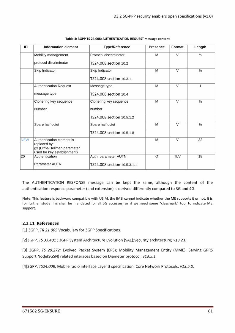
In addition, the NAS AUTHENTICATION REQEST message needs to be updated according to Table 3 (see
TS24.008 v13.5.0 [4] section 9.2.2 for original values).
D3.2 5G-PPP security enablers open specifications (v1.0)
IEI Information element Type/Reference Presence Format Length
Mobility management Protocol discriminator M V ½
protocol discriminator TS24.008 section 10.2
Skip Indicator Skip Indicator M V ½
TS24.008 section 10.3.1
Authentication Request Message type M V 1
message type TS24.008 section 10.4
Ciphering key sequence Ciphering key sequence M V ½
Number number
TS24.008 section 10.5.1.2
Spare half octet Spare half octet M V ½
TS24.008 section 10.5.1.8
NEW Authentication element is replaced by: gx (Diffie-Hellman parameter used for key establishment)
M V 32
20 Authentication Auth. parameter AUTN O TLV 18
Parameter AUTN TS24.008 section 10.5.3.1.1
The AUTHENTICATION RESPONSE message can be kept the same, although the content of the
authentication response parameter (and extension) is derived differently compared to 3G and 4G.
Note: This feature is backward compatible with USIM, the IMSI cannot indicate whether the ME supports it or not. It is for further study if is shall be mandated for all 5G accesses, or if we need some “classmark” too, to indicate ME support.
2.3.11 References
[1] 3GPP, TR 21.905 Vocabulary for 3GPP Specifications.
The Legal notice that applies to these specifications is given in Annex A.
3.1.5 Terms and definitions
ABE - Attribute Base Encryption
In an ABE system, users’ keys and ciphertexts are labelled with sets of descriptive attributes and a particular key can decrypt a particular ciphertext only if there is a match between the attributes of the ciphertext and the user's key.
AKA - Authentication and Key-agreement
The 3rd generation Authentication and Key Agreement mechanism, specified for Universal Mobile Telecommunications System (UMTS) in TS33.102.
EAP - Extensible Authentication Protocol
The Extensible Authentication Protocol Method is defined in RFC 3748.
EAP-AKA, EAP-AKA’ The Extensible Authentication Protocol Authentication Key Agreement method is defined in RFC 4187, while EAP-AKA’ is defined in RFC 5448.
EAP-SIM The Extensible Authentication Protocol Method for Global System for Mobile Communications (GSM) Subscriber Identity Modules (EAP-SIM) is defined in RFC 4186.
KP-ABE In a Key Policy ABEcryptosystem, ciphertexts are labelled with sets of attributes and private keys are associated with access structures that control which ciphertexts a key is able to decrypt. The attributes are specific to each system implementation and enable users to selectively share their encrypted data at a fine-grained level.
D3.2 5G-PPP security enablers open specifications (v1.0)
671562 5G-ENSURE 64
In order to indicate to the server the use of modified EAP-AKA (we may call it EAP-AKA-p) with an encrypted
IMSI we can use other unallocated values for this byte, like for example “2”. This will always lead to an
identifier decryption at server side prior to any other processing.
The encryption function is deployed on UE, while the decryption function is deployed on AuS. An additional
system, a trusted authority entity (TA) is required and is responsible with the initialization of the
cryptographic system and the generation of cryptographic material (the public key, the private keys and the
attributes and the corresponding access structures required for encryption and decryption). The functions
will be described in detail in the following sections.
Figure 22: Architecture overview.
3.1.7 Basic concepts
Public key cryptography can be used in order to avoid sending long term identifiers in clear text over the
network in situations where the user is not known/authenticated to the network. For example, the user
equipment UE can encrypt the IMSI with the public key of the network, such as only the authorized
network entity in possession of the corresponding private key can decrypt the identifier. This setting will
avoid IMSI sniffing attacks if the attacker does not know the private key. This configuration does not scale
well when the user changes its location to another network appertaining to a different administration
domain (e.g., in roaming scenarios), where a different private/public key pair is in place and user has to be
provisioned again the public key of the network certified by a trusted authority.
D3.2 5G-PPP security enablers open specifications (v1.0)
671562 5G-ENSURE 65
Attribute Based Encryption is a type of public key based cryptosystem which may enable the encryption of
data by a single public key and decryption by different secret private keys according to access policies.
Access policies are expressed as access structures in terms of attributes and can be built in the private
decryption keys (key-policy ABE [1]) or in the ciphertext (ciphertext-policy ABE [9]). In KP-ABE the attribute
or the set of attributes is built in the ciphertext and the access policies in private decryption keys of the
authorized entities.
The present enabler consists in a cryptographic library that implements the KP-ABE encryption scheme
described in [1] to encrypt and decrypt a given IMSI. The library also provides the setup and key generation
functions.
The algorithms implemented by the library are briefly described below with reference to the components
illustrated in Figure 24.
Setup: runs on a trusted authority server TA which is also responsible for the generation of private keys to trusted entities (e.g., network elements like authentication servers) based on the user access policy. At the cryptographic system initialization time, TA generates a public parameter (public key) and a master key. The latter is only known by the TA server.
Keygen: runs on the TA server. An entity entitled to perform decryption (e.g., a network element like an authentication server) requests the provisioning of the decryption key (the private key) by presenting an access policy over an attribute or a set of attributes. The randomized key generation algorithm takes as input the public parameters (public key), the master key and the access policy. It outputs the authentication server’s private key which is able to decrypt all IMSIs encrypted under the attributes that satisfy the access policy.
Encryption: runs on the client components, e.g., on the UE devices. The randomized encryption algorithm takes as input the user identity (i.e., the IMSI) to be encrypted, an attribute or set of attributes, and the public key. It outputs the ciphertext, i.e., the encrypted IMSI. In this way only the authentication servers which have the decrypted key generated with the correct access policy (that matches the encryption attributes) will be able to decrypt the ciphertext.
Decryption: the decryption algorithm runs on an authorized network element (i.e., the authentication server). It takes as input the ciphertext, which was encrypted under the set of attributes, the public key parameter and the private key for access control. The output is the IMSI in clear text if the attributes included in the ciphertext satisfy the access policy.
The present enabler will provide a C library (libkpabe) containing all the functions required to perform all
the cryptographic operations described above. The library is developed by making use of some
mathematics and cryptographic libraries that implement basic functionalities required by ABE systems.
3.1.8 Main interactions
3.1.8.1 Use cases
The use case chosen for the implementation of the current enabler refers to a non-3GPP access network
which uses the EAP-SIM/EAP-AKA authentication protocol.
To complete the authentication, the UE sends an EAP Response/Identity message. The UE send its identity
complying with Network Access Identifier (NAI) format specified in [5]. NAI contains either a pseudonym
allocated to the UE in a previous run of the authentication procedure or, in the case of first authentication,
the IMSI. In this case the IMSI or NAI is encrypted with the encryption function of the enabler.
D3.2 5G-PPP security enablers open specifications (v1.0)
671562 5G-ENSURE 66
Figure 23: Use case architecture.
The IMSI is encrypted on the client using the kpabe_imsi_encryption() function from the libkpabe
library. Specifically, the encryption function is integrated in the wpa_supplicant (see Figure 23) that is the
component residing on the client side that implements the EAP-AKA/SIM authentication protocol.
The IMSI is decrypted by the authentication server (AuS in Figure 23) using the kpabe_imsi_decryption()
function from the libkpabe library.
All cryptographic material (the public key and all authorized private keys) is provided by TA using the
functions kpabe_sys_setup() (run only once) and kpabe_entity_keygen() (run all times a private key is
required). These are also functions implemented in the libkpabe library.
A use case diagram is provided in Figure 24. The main actors which use the system are the network
administrator and the normal network user. The network administrator runs the Setup and Keygen
algorithms on TA and provides the private key and the access policy to AuS and the public key to the
network user together with the access network attribute(s). The user, who has a valid subscription and
therefore a SIM and the corresponding IMSI; saves the public key and the attribute and issues the network
connection requests for which EAP-SIM authentication is required. The KP-ABE algorithms are implemented
on the user’s device (wpa_supplicant) and AuS, therefore during the EAP-SIM authentication exchange the
long term identity of the user is transferred encrypted.
D3.2 5G-PPP security enablers open specifications (v1.0)
671562 5G-ENSURE 67
Figure 24: Use case diagram.
3.1.8.2 Components and interaction overview
The enabler implementation corresponds to a simple client server architecture, to be subsequently
contextualized in the network that uses the encryption scheme. For the use case example from Figure 23,
the main components are the client (the UE or wireless device), the server (the AuS) and a trusted authority
entity (TA).
Prior to EAP authentication there must be some (secure) OOB interactions between the TA and AuS and
then the UE for the setup and the key generation procedure and public key provisioning. In Figure 24 these
interactions corresponds to the dashed lines between TA and AuS and TA (or AuS) and the UE
(wpa_supplicant).
The EAP authentication is triggered by the access point AP (hostap) by sending the EAP
Request/Identity message to the UE requesting network connection.
The UE sends an EAP Response/Identity message inserting its identity complying with Network
Access Identifier (NAI) format specified in TS 23.003 [8]. NAI contains the user IMSI that is first
encrypted with kpabe_imsi_encryption function.
The AP (implemented by the HostAP component), based on the realm part of the NAI, routes the
EAP Response/Identity messages to the correct AuS as described in [3].
The AuS decrypt the username part of the NAI using the kpabe_imsi_decryptionfunction and
retrieves the user IMSI in clear. The IMSI is the used to identify the user in the HSS. The
authentication procedure then follows as defined in [8].
The messages which transfer encrypted IMSIs are represented by the bold arrows in Figure 25.
The Response/Identity message and EAP Response/GSM Subscriber Identity message. The specific libpkabe
functions called for each interaction that require encryption and decryption are also indicated Figure 25
D3.2 5G-PPP security enablers open specifications (v1.0)
671562 5G-ENSURE 68
Figure 25: Interactions between components.
In our example implementation the AuS component has both the AAA/EAP server and HSS/AuC
authentication functionalities. The EAP server and the HSS server are processes on the same Linux box and
communicate through a UNIX socket. The EAP server receives from the client (the wpa_supplicant) the
username containing a byte code set to “2”, for indicating EAP-AKA-p, concatenated with the encrypted
IMSI The EAP server initiates the EAP-AKA authentication procedure, by sending the authentication request
to the HSS server, containing the encrypted IMSI and the Encryption flag (Eflag) set to true indicating that
for this user the IMSI is encrypted (see Figure 26). The HSS controls the Eflag and calls the kpabe decryption
function for obtaining the IMSI in clear text. From now on the EAP-AKA proceeds in the traditional way, the
HSS computes the authentication data for the IMSI and sends it to the EAP server in order to authenticate
the user.
D3.2 5G-PPP security enablers open specifications (v1.0)
671562 5G-ENSURE 69
Figure 26: AuS implementation details.
3.1.9 Architectural drivers
3.1.9.1 High-Level functional requirements
The high level requirement of the enabler is the randomized encryption of the long term identifiers, i.e., IMSIs, therefore the enabler must implement the encryption of the long time identifier with random encryption and in such way that only the authorized network entities can perform the decryption and obtain the identifier in clear text. The enabler should also provide means to generate the keys used by the actors of the crypto system. The requirements are so split on the system components:
At the client side (the wpa_supplicant) the function implemented is the encryption of the long term identifier (IMSI) with random encryption using the network AAA server’s public key and the corresponding attribute.
At the authentication server (AuS) side the function implemented is the decryption of the long term identifier (IMSI) by means of the private key corresponding to the access policy that is matched by the attribute.
An additional system, the TA (trusted authority) entity provides the initialization phase of the system and implements the private keys generation procedure.
3.1.9.2 Quality attributes
A product implementing one or several of the features described in this enabler should be evaluated primarily based on the following quality attributes: performance efficiency, security (confidentiality) and maintainability.
3.1.9.3 Technical constraints
The implementation of libkpabe is based on the use of PBC (Pairing-Based Cryptography) library, a free C
library (released under the GNU Lesser General Public License) built on the GMP library that performs the
mathematical operations underlying pairing-based cryptosystems. This library works on evolved OSes like
the Linux OS, and could work on smartphone OSes, like Android OS. Nevertheless, to the best of our
knowledge, an implementation does not exist on a SIM/UICC at the present time.
For the same reason, more research is needed to understand if an implementation is possible on a
Resource Constrained Devices like IoT sensor devices. This is out of the scope for the present enabler.
D3.2 5G-PPP security enablers open specifications (v1.0)
671562 5G-ENSURE 94
4.2.8.2 Components and interaction overview
The main components, APIs and interactions are presented in the following figures as discussed previously.
Figure 36: Main component diagram
Figure 37: High level interaction sequence diagram
Exploitation
Real-time assessment
Third-party service provider Trust metric enabler5G security enablers
UpdateTrustModel()
UpdateTrustModel()
5G measurement entity
UpdateMeasurementDB()
UpdateMeasurementDB()
UpdateTrustMetricDB()
TrustMetricDBReq()
TrustMetricDBResp()
Initialization
TrustMetricDBReq()
TrustMetricDBResp()
D3.2 5G-PPP security enablers open specifications (v1.0)
671562 5G-ENSURE 95
4.2.9 Architectural drivers
4.2.9.1 High-Level functional requirements
Third-party API
5G third-party (standard) API is required. Measurement and 5G internal APIs
These APIs should be based on standard interfaces. However, it could be sufficient to rely on APIs defined for 5G security enablers such as Micro-segmentation Enabler (network capabilities) and Security Monitoring Enabler (security related measurements) in some use cases.
Producing trust metric values
Trust metric values are produced in Aggregator component based on trust models and measurements. The trust models include the high-level information to map measurements to trust values. It is essential to develop a well-defined API for this purpose. The enabler provides an abstraction layer to third-party by e.g. hiding the details of network requirement validation.
Dynamic network management
The third-party trust model could define network requirements that require dynamic network configurations, at least in the setup phase. The 5G system should facilitate dynamic network management e.g. through SDN and NFV or otherwise this functionality could be restricted to be used only with Micro-Segment Enabler.
4.2.9.2 Quality attributes
The following list presents quality attributes are relevant when assessing the realizations of the enabler.
The list also illustrates how the current framework plans support these attributes:
Reliability – use of mature software technologies
Operability – use of widely adopted and accepted software technologies;
Performance efficiency – scalability through micro-segmenting to handle large amount of real-time
events
Security – advancing security through integrating trust models of the third party service provider
and the network operators
Compatibility – support for various standardized event sources and use of open interfaces for
output format
Maintainability – use of easily utilized programming languages and widely utilized technologies;
Efficiency – capability to cover large variety of applications through one API
4.2.9.3 Technical constraints
5G network capabilities could restrict deployment of some use cases e.g. because of lack of dynamic
network management. The feasibility of the Enabler is uncertain in use cases where the trust assessment of
the whole end-to-end transport network cannot be ensured.
D3.2 5G-PPP security enablers open specifications (v1.0)
671562 5G-ENSURE 96
4.2.9.4 Business constraints
The business relationships between the entities need to be studied further. The basic assumption is that
the third-party service provider purchases the service enabled by the Trust Metric Enabler (and other
Security Enablers) from the MNO. The pricing could be based on the characteristics (e.g. network
requirements and NFVs) defined in the trust model which is provided by the third-party.
4.2.10 Detailed specifications
Since the ‘Trust Metric Enabler‘ is closely related to ‘Micro Segmentation Enabler’ (see Chapter 6.4 of this
document) and ‘Security Monitor for 5G Micro-Segments’ (Chapter 5.3), its implementation is also close to
these, and it will be based on similar technologies.
This section specifies the APIs and protocols utilized. The interfaces may be considered internal for the
Trust Metric Enabler. External interfaces (including user interfaces) for controlling the behaviour of
inference layer will be specified in the forthcoming releases.
In testing Trust Metric Enabler in a mobile networking architecture, there needs to be a way to integrate
the different functions of mobile networks (e.g. PGW, SGW, MME, PCRF) with SDN and network
virtualization technologies. One possible solution could be to use the OpenEPC framework [1] that covers
all the functional elements in the 3GPP Evolved Packet Core (EPC) and Systems Architecture Evolution (SAE)
technologies up to 3GPP Release 12. Another alternative is the OpenAirInterface [2].
4.2.10.1 Conformance
The implementation of the enabler relies on SDN and virtualization technologies. For SDN, an SDN
controller that can be chosen quite freely is needed. In this work we selected the Ryu SDN controller [3].
For network virtualization, OpenVirteX software [5] is used, but another type of network hypervisor is also
plausible.
4.2.10.2 API specifications
The Trust Metric Enabler takes the following inputs:
Validated network requirements (which may dynamically change)
Number of connected IoT Devices (and to which UEs they are connected)
Number of connected UEs
End-to-end encrypted traffic or not
Subscribed IDS alerts
o High severity (i.e. indicates attacks and malware)
The enabler produces a binary value (0,1) output based on the input actions:
Value 0 (trust metric unacceptable)
Value 1 (trust metric acceptable)
The specific technical details of the API depend on the selection of the network hypervisor and the SDN
controller. For example, in this work (as also to implement the Micro-Segmentation Enabler) OpenVirteX is
used as the network hypervisor to accomplish the network virtualization. Ryu SDN framework is utilized as
a SDN controller. Apache Kafka [5] may produce events coming from the enabler while REST API could send
commands to the enabler. Information needed from the Ryu SDN controller can be retrieved via REST API.
D3.2 5G-PPP security enablers open specifications (v1.0)
671562 5G-ENSURE 97
4.2.10.3 Examples
After initialization, a third-party service provider is accepted by the Trust Metric Enabler. Micro-segment
Orchestrator (Figure 34) accepts IoT devices from an untrusted access network through 802.1X
authentication. The Trust Metric Enabler may enable data plane transmission from IoT devices through an
untrusted micro-segment to an UE. When number of IoT devices connected to one UE exceeds its limit (e.g.
10 devices), Trust Metric Enabler disables the traffic.
D3.2 5G-PPP security enablers open specifications (v1.0)
671562 5G-ENSURE 99
using the hash of this. This Repository must be managed by a third party not involved in the certification
process and independent of the VNF owner. It could be a state institution or an independent organization.
4.3.8 Main interactions
4.3.8.1 Use cases
The virtualization of network functions and network equipment enable to instantiate several of them on
commodity servers, thus sharing physical resources (CPU, RAM, memory and network) with other hosted
virtual machines. Nowadays, the infrastructure provider manages its own VNFs on its own infrastructure. In
case a VMNO wants to use a proprietary VNF (developed by another VMNO for example), how could a
VMNO actor provides trustworthiness assurance to the infrastructure provider? How the infrastructure
provider could trust a VNF coming from a third party?
In a simple use case, the different actors involved into the certification process are:
The VNF owner who provides the VNF and also some technical information about the
implementation of it. He must also validate the publication of the certificate.
The evaluator who is in charge of evaluating the VNF to extract trustworthiness evidence. The
result of the evaluation will be used by the certifier to produce the DTwC. The evaluation could be
realised by inspection or using automatic analysis tools to extract independently information about
the VNF. For a VNF evaluation, there could be different evaluators providing different kind of
evidences.
The certifier who collects information regarding the VNF in order to fill the trustworthiness
elements of the DTwC. He is responsible of the validity of the information set into the certificate.
For that, he must verify the different information provided by the VNF owner and evaluators. For a
VNF certification, only one certifier is involved into the certification. However, we could have
different certifiers authorized to certify VNF (dependent, for instance, of their area of expertise).
Each certifier must have a certificate delivered by certification authority trusted by the DTwCs
repository. This certificate is used to sign the DTwC and also to authenticate the certifier during the
transfer of the DTwC to the DTwCs repository. (Note: the PKI is not part of this open specification)
The VNF consumer (here the infrastructure provider) who uses the DTwC to know more
trustworthiness information about the VNF he wants to deploy. Using this DTwC, he could compare
the information against his internal deployment policies and decide whether to deploy or not the
VNF into his infrastructure.
VNF owner and VNF consumer need to trust certifier to provide trustworthy services. This can take place
either through contractual business relationships or through industry agreements (i.e. commonly
established certification body). The main use case is the deployment of a new VNF into an NFV
infrastructure where the basic flow of events is the following:
- The VNF owner wants to propose his VNF to be deployed by different VNF consumers. For that, he
must, beforehand, provide the VNF element and some information about it to the certifier and to
the different evaluators.
- The evaluator(s) will extract evidence from the VNF by inspection or by tests in order to provide
trustworthiness evidences to the certifier
D3.2 5G-PPP security enablers open specifications (v1.0)
671562 5G-ENSURE 100
- Using the different elements provided by the VNF owner and the evaluator(s), the certifier will
produce a DTwC representing the trustworthiness of the VNF.
- If the VNF owner authorizes the publication, the certifier will upload this DTwC into a centralised
service containing all the certificate of all the VNFs. This service is unique and could be replicated
for security and performance aspect.
- In the next step, when a VNF consumer wants to deploy a VNF, he could find the DTwC for it in the
centralised service and decide whether to deploy (or not) this element into his infrastructure by
comparing the trustworthiness elements provided by the DTwC with the trustworthiness
requirements of his platform.
This simple use case could be integrated into the different use cases of D2.1, like 5.2 “Adding a 5G Node to
a Virtualized Core Network” , 5.4 “Verification of the Virtualized Node and the Virtualization Platform“, 5.5
“Control and Monitoring of Slice by Service Provider” or 9.3 “Authentication of New Network Elements “.
For example, in the 5.4 “Verification of the Virtualized Node and the Virtualization Platform“ use case, the
DTwC certificate could be used to validate the integrity of the VNF or know the different threats and
controls around this VNF before the deployment of a new instance.
4.3.8.2 Components and interaction overview
The following diagram describes the logical architecture of the VNF Certification enabler. It covers the
whole certification lifecycle.
Figure 38: Logical architecture of the VNF Certification enabler
D3.2 5G-PPP security enablers open specifications (v1.0)
671562 5G-ENSURE 101
In this section we describe the logical components.
- The VNF Certification Tool: this component manages the trustworthiness evaluation of the VNF. It
is composed by three main elements,
o the user interface which must guide the certifier into the certification process,
o the orchestration element which manages the different evaluations involved in the
certification process
o and the Certification generation element in charge to collect the trustworthiness
information provided by the certifier and by the different evaluations to produce the DTwC.
- The Analysis tools: These elements, managed by evaluators, represent a set of external tools called
by the certification to retrieve information about the VNF. Each analysis tool must return the result
of its analysis to the certification tool. Then each result will be validated and inserted into the DTwC
during the generation. This validation and insertion could be automatic or manually interpreted by
the certifier (following his experience and the other evaluation results)
- The DTwC delivery: This element is in charge of uploading the DTwC generated to the DTwC
repository in a secured way after validation of the VNF owner.
- The DTwC repository: This element stores and manages the different DTwCs generated by the
different certifications. It also provides an interface to retrieve certificates for a specific VNF (One
certificate by VNF version).
Regarding the different workflows, we have the generation of the DTwC and the usage of this DTwC.
Sequence diagrams are given below to clarify how these components interact. The list of diagrams is
not exhaustive but assists in understanding the links between actors and logical components.
Figure 39: DTwC generation
This sequence diagram depicted on Figure 39 focuses on the DTwC generation:
- The certifier, through the Certification platform interface, asks the evaluators to collect the
evidences using analysis tools or fill manually information regarding the evaluation of the VNF
- The evaluator analyses the VNF (by inspection or by testing) and returns the result to the DTwC
generator element.
- The values are verified and consolidated in order to be pushed into the DTwC
D3.2 5G-PPP security enablers open specifications (v1.0)
671562 5G-ENSURE 102
- The certifier generates the DTwC using the information collected before and inserts security
information to link strongly the certificate, the VNF and the certifier (Hash and signature). If some
evaluations can’t be realized, the associated metric presented into the certificate will be put to
undefined; otherwise, a metric value will be set to characterize the evidence
- The certifier publishes the DTwC into the centralized repository, after authorization of the VNF
owner, in a secured way (the repository must authenticate the certifier in order to accept the DTwC
published).
This second workflow shows the interaction between the VNF consumer and the DTwC repository.
Figure 40: Interaction between the VNF consumer and the DTwC repository
In this workflow, the VNF consumer:
- Calls the DTwC repository to retrieve the DTwC of the VNF he wants to deploy. This search is not
secured (at the authentication level but the communication must be secured using TLS) because
the DTwC are considered as public and the information inside the certificate are validated and
authorized to be published through the authorization of the VNF ownerArchitectural drivers
4.3.8.3 High-Level functional requirements
The main feature of this enabler is the VNF trustworthiness evaluation. This feature could be described by two functions: the certification of the VNF implementation and the exposition of their characteristics through a DTwC.
4.3.8.4 Quality attributes
The following list presents quality attributes which are relevant when assessing the realization of the enabler. The list also illustrates how the current framework plans to support these attributes:
- Operability- The User Interface provided to generate the certificate must be "user friendly" to guide the certifier into the certification process
- Reliability - mature software technologies must be used - Security - The publication of DtWC is limited only to the authorized persons. In addition, the
security mechanisms put in place to secure the DtWC must guarantee the integrity, the accountability and the non-repudiation of it.
- Compatibility - The Trustworthiness elements used to characterize the VNF must be compatible with standards like ETSI or 3GPP.
4.3.8.5 Technical constraints
4.3.8.5.1 The evaluation:
To find evidences to characterize the trustworthiness of a VNF, the different possibilities are:
- The blackbox testing (e.g., fuzzing) and/or source code analysis if available
D3.2 5G-PPP security enablers open specifications (v1.0)
671562 5G-ENSURE 103
- The deployment of probes into the VNF
- The technical information coming from the VNF owner
The selection of methods is up to the certifier and the evaluators. The different methods have their
interests and combined together, provide information to characterize the trustworthiness of an element.
However, the realization of probes and tests for VNF is complicated due to the heterogeneity of the
different VNFs (different functionality and implementation). More, the deployment of probes directly into
the VNF could be a problem regarding deployment due to some security constraints imposed by the VNF.
The blackbox testing does not necessarily reveal all the possible vulnerabilities. If this is complemented
with source code analysis, then the coverage of testing is more complete. However, source code analysis
can be time consuming.
4.3.8.5.2 The certification process
Also, the different elements provided by the VNF Owner must be validated to be taken into account in the
certification process. It’s the responsibility of the certifier to validate all the evidences collected about the
VNF before the insertion into the certificate.
Additional considerations can be given to the possibility of assessing also the development practices of the
VNF owner. This could also be performed by complementing the certification process with other applicable
certificates the organization possesses, e.g., ISO 27001 or PCI DSS (one ought to make sure that the scope
of the certification matches the scope of VNF owner development activities).
Another consideration relates to the new versions of a specific VNF as bug or feature updates are likely to
invalidate the certificate. Applying the whole process to each version of VNF might end up being too
restrictive. Some alternative approaches (such as used in Mirrorlink DAP certification) include the possibility
to provide a certification hierarchy, which certifies the VNF owner, who then has the possibility of issuing
its own certificates. However, this makes system more complex and the assessment process ought to also
ensure that VNF owner is capable of sound key management practices.
4.3.8.6 Business constraints
The business relationships between the different entities need to be further studied. Especially the
potential liability aspects that might arise from misbehaving VNFs need to be solved. VNF consumer might
need to make a risk assessment, whether to rely on testing done by another entity or whether to conduct
its own testing. It is likely that at least VNF owner needs to have a business contract with the certifier as
there likely is a cost involved (and evaluators most likely wish to be compensated).
The certifier could be a commercial entity or an industry body. One needs to study whether several such
entities exist or whether there is just one. As this has regulatory implications, so it is more likely that
several entities will exist. Also, evaluators could be separate entities from the certifier, thus it has to be
decided what sort of requirements are set for these. One possibility is to expect them to be accredited ISO
27001 auditors or other similar accreditations.
D3.2 5G-PPP security enablers open specifications (v1.0)
671562 5G-ENSURE 104
4.3.9 Detailed specifications
4.3.9.1 Introduction
The implementation of this enabler imposes the API specification to be compliant with and also to use the
same DTwC format specified in the next paragraph.
4.3.9.2 Conformance
All the interfaces described by this specification are mandatory and must be implemented in order to be compliant with.
The usage of DTwC model is also mandatory in order to have the same level of information for all the
certifications. This DTwC concept represents the basic element for the definition of a certificate instance.
Four concepts are part of its definition: SystemDescription, TWProblemDefinition, TWPropertySpecification
and Evidence.
Figure 41: DTwC model concepts
Let us start considering SystemDescription
Figure 42: System description
The SystemDescription concept allows for detailing the NVF component and the system being certified. The
three main elements of a SystemDescription are Stakeholder, Component and Asset. The Stakeholder
concept can be used to indicate the stakeholders (or actors) having a role in the system being described. It
is possible to detail the system’s architecture through a set of Components, and through the creation of a
ComponentModel instance, it is possible to illustrate all subcomponents of a Component. The Asset
concept allows for declaring which Components are verified by the Certification Authority.
D3.2 5G-PPP security enablers open specifications (v1.0)
671562 5G-ENSURE 105
Figure 43: TWProblemDefintion concept
The TWProblemDefinition concept aims at illustrating how a threat affects an Asset
Figure 44: TWPropertSpecification
The TWPropertySpecification is a concept that allows for the expression of TW characteristics of Assets: its
constituting elements are a TWProperty and a Control. TW Property links an Asset to a TW Attribute and a
Context that further specifies the TW Attribute.The Control concept allows for the indication of a
mechanism that is able to influence or enforce the TWProperty.
Figure 45: TWPropery concept
The Evidence concept captures any form of proof that is deemed sufficient by the Certification Authority.
The nature and form of an Evidence can vary significantly, according for instance to the type of TWProperty
it demonstrates.
4.3.9.3 API specifications
This enabler is composed of two parts, the User Interface helping the certifier to produce the DTwC,
associated with evaluation tools and the DTwC repository which centrally stores all the DTwCs produced
and gives the possibility to retrieve these.
D3.2 5G-PPP security enablers open specifications (v1.0)
671562 5G-ENSURE 106
- The Certification UI: This first element is a UI with no specific API. In the reference implementation,
this Certification UI will be provided like an eclipse plugin
- The DTwC repository: This second element provides an API to upload the generated DTwC and to
download a specific DTwC. In the reference implementation, this element will be provided like a
REST service hosted into an application server (like Tomcat)
The different APIs are:
- Push DTwC
This method is used to push the DTwC into the repository. This needs to be authenticated and the integrity
of the upload verified in order to ensure that no malicious content gets stored in the repository.
Method: POST
Path: /uploadDTwCs
Headers:
o Content-Type:multipart/form-data
o Accept: text/html,application/xhtml+xml,application/xml
- Get a DTwC
To search for a specific DTwC, two methods are possible, a query using the hash of the VNF
The research by hash
Method: GET
Path : /downloadDTwCByHash/{hash}")
4.3.9.4 Examples
Some examples of requests for the previous requests
D3.2 5G-PPP security enablers open specifications (v1.0)
671562 5G-ENSURE 109
Datalog: a declarative logic programming language that syntactically is a subset of Prolog.
IDMEF: Intrusion Detection Message Exchange Format (https://www.ietf.org/rfc/rfc4765.txt)
IoT: Internet of Things
MulVAL: Multi-host, Multi-stage Vulnerability Analysis Language. It is a research project at Kansas State
University and a logic-based enterprise network security analyser.
NFV: Network Function Virtualization
NIST: National Institute of Standards and Technology (http://www.nist.gov)
NVD: National Vulnerability Database
PulSAR: Proactive Security Analysis and Remediation
SDN: Sofware Defined Network
SIEM: Security Information and Event Management
TVA: Topological Vulnerability Analysis, a framework that combines an exploit knowledge base with a
remote network vulnerability scanner to analyse exploit sequences leading to attack goals
XML: eXtended Markup Language
5.1.5 Overview
Cyber Security is the first step towards understanding the actual risk exposure of a communication system
and, hence, towards exploiting it with desired security behavior and detection of potential attacks or non-
authorized usages. The Proactive Security Analysis and Remediation (PulSAR) enabler deals with detection
of Cyber Security risks on sensitive “assets” at large, up to proposing possible remediation. It intends to
address the detection and management of cyber-security risks on different kind of environments from
classical IT systems to complex 5G environments involving NFV and SDN.
PulSAR enables complex attack detection, provides a clear view on an attack’s progression by giving means
to understand on-going attacks when a node is known as compromised and also automatically computes
possible remediation depending on the system’s assets, and the system’s vulnerabilities. The possible
means of remediation are sorted by a cost function based on the cost of deployment of the different
remediation means such as network reconfiguration, patch deployment, etc.
This enabler aims at providing means to protect against cyber-attacks. Its main features can be summarized
as follows:
1. Collect the topology and the vulnerabilities, evaluate the potential threats and attack paths, assess risks,
2. Identify most probable and impacting on-going attacks based on third parties’ aggregated Security Information and Event Management (SIEM) and monitoring sensors’ events and alerts about compromised nodes,
3. Propose remediation solutions, 4. Deliver a visualization service centered on risk/attrition level.
Before going into the details of the enabler, Figure 46 shows its eco-system with possible interactions with a 5G eco-system and other enablers of this project. This eco-system includes traditional network and computer infrastructures, virtualized networks and data-centers, satellite networks, and potentially 5G-specific entities such network slices and micro-segments, Internet-Of-Things environments, etc. For all those environments, PulSAR needs to collect several kinds of data, both to initialize the cyber risk computation and to follow it at run-time.
Topological data
Vulnerability data
User scoring preferences, i.e. user defined scores on attack graph nodes
D3.2 5G-PPP security enablers open specifications (v1.0)
671562 5G-ENSURE 110
PulSAR computes then:
attack paths scored by attrition levels for a better readability by the security operator,
dynamic risk analysis when it comes to exploit run-time alerts from SIEMs,
possible remediation and countermeasures. The results of these computations are made available through a single REST/JSON interface.
Figure 46: PulSAR in its eco-system
5.1.6 Basic concepts
PulSAR responds mainly to two different goals:
A proactive engine which computes scored attack paths and associated remediation based on a network topology and a vulnerability scan.
A reactive engine which shows the progression of on-going attacks based on SIEM alerts, and computes associated counter-measures.
Figure 47 provides an initial architectural sketch of the components inside PulSAR and their main
interactions. This section gives a short insight for each component. The figure below is also explained in the
following Architecture section.
For its basic operation, PulSAR needs mainly two types of Data as inputs, namely the network topology and a vulnerability scan. These two inputs are fed into the Cyber Data Extraction module, which generates a single input file.
D3.2 5G-PPP security enablers open specifications (v1.0)
671562 5G-ENSURE 111
This input file is sent to the proactive part of the PulSAR server, and more precisely to one of its components, which is an Attack Graph Engine. In order to make the results of the attack graph computation more readable, all the attack paths computed are scored by attrition level. This scoring is performed thanks to the CVS scoring and manually imported user scoring preferences corresponding to his/her knowledge of the most challenging risks according to context at hands. It is done by the Scored attack paths module. The remediation module computes associated remediation such as network reconfiguration, or virtual patching according to type of remediation supported.
All the results of the PulSAR server are made available through a REST/JSON interface, that is to say the attack paths scored by attrition level, the remediation, but also the active attack paths and the countermeasures. A visualization module exploits all these results and makes them accessible to the Security operator. This module is also to security operator scoring preferences.
PulSAR reactive part provides a view on on-going attacks. It leverages external SIEM reports in IDMEF format. These alerts are sent to a Dynamic Risk Analysis module which confronts the in-coming alerts to the scored attack paths. This enables to show the already compromised nodes and to predict the next steps of an attack. From this, a Counter-measures module computes possible countermeasures to stop the on-going attack.
Figure 47: Building blocks of PulSAR
D3.2 5G-PPP security enablers open specifications (v1.0)
671562 5G-ENSURE 112
5.1.7 Main interactions
5.1.7.1 Use cases
Visualization and User scoring preferences
The use case below in Figure 48 shows a Security Operator using PulSAR through the visualization interface.
S/he is also able to set her/his own preferences for scoring the impact of the vulnerability on the nodes of
the graph.
Figure 48: Visualization and user scoring preferences use case
SIEM alerts
The use case below in Figure 49 shows a SIEM equipment sending alerts to the PulSAR server, used
internally by the Dynamic Risk Analysis of PulSAR.
D3.2 5G-PPP security enablers open specifications (v1.0)
671562 5G-ENSURE 113
Figure 49: SIEM alerts use case
5.1.7.2 Components and Interactions overview
Figure 47 above gives an overview of the internal architecture of the PulSAR enabler. As presented in the
Basic concepts section, PulSAR includes the following components, which are described in detail below:
Cyber data extraction
Attack graphs
Scored attack paths
Remediation
Dynamic Analysis
Counter-measures
Visualization
Cyber Data Extraction
The Cyber Data Extraction component provides an external interface called Cyber Data Extraction Interface
for Cyber data collection. This interface is specified in the API specification section. It collects network
topology information and vulnerability scan reports.
In order to give access to the vulnerability and topological information to the other components internally,
the Cyber Data Extraction can generate two types of inputs:
The Attack graph input generation file which is a Datalog file used by the Attack graph engine,
A XML file aggregating all vulnerabilities and topological information needed by the Remediation and the Countermeasure components.
D3.2 5G-PPP security enablers open specifications (v1.0)
671562 5G-ENSURE 114
Attack graph Engine
The attack graph engine relies on a MulVAL attack Graph Engine.
This component takes as input the Attack graph input generation file generated by the Cyber Data
Extractor. The first action of this component is to generate the attack graph using MulVAL.
The attack graph output will be the basis used by the scored attack paths component. This attack graph
gives the probability scores of each attack graph node, translating the probability of success of each step in
the attack graph.
Scored Attack Paths
The scored attack paths takes as input the attack graph computed by the Attack graph Engine.
This Attack graph gives the basic information for the scored attack path to be computed, that is to say both
the potential attack paths and the probability scores of each attack graph node, translating the probability
of success to each step in the attack graph. These probability scores are the basis for computing the risk
score of an attack path.
PulSAR offers here the possibility for the Security operator to enter its own scores for each node of an
attack, based on its own vision of the attack probability or of the asset criticality for the business. This input
is performed through the external REST/JSON interface by mean of the visualization component.
Therefore, the scored attack paths component uses two types of inputs:
The attack graph from the attack graph component,
The user scoring preferences from the external REST/JASON Interface via the visualization component.
The scored attack paths are the output available through PulSAR external REST/JASON Interface and used
internally by the other components of PulSAR:
The remediation component uses it as the basis to remediate the most critical attack paths,
The dynamic risk analysis component uses it as the support to identify on-going attacks,
The visualization component exploits it as the basis of the visualization. Mainly, the internal and external interfaces will operate via file input/output with a defined XML data
structure for the file content.
Remediation
The remediation application needs two types of inputs:
The scored attack paths from the Scored Attack Paths component,
The XML file aggregating all vulnerabilities and topological information generated by the Cyber Data Extraction component.
The interactions between the Scored Attack Paths and the remediation are necessary because attack paths
are the starting point of the remediation process. Security operators need to select an attack path for
remediation in the list provided by the Scored Attack Paths. On the other hand, the attack path engine is
also useful to validate the remediation selected by the security operators. This feedback is necessary to
compare the security state of the system before and after deploying a remediation.
D3.2 5G-PPP security enablers open specifications (v1.0)
671562 5G-ENSURE 115
The interactions between the remediation tool and the Cyber Data Extraction are necessary because the
network topology (hosts, routes, deployed firewall rules …) is necessary to compute the topological related
remediation (attack signature deployment and firewall rules). The remediation tool provides also a means
to apply automatically some of the remediation chosen by the security operators. To do that, this tool
needs to change some parameters (e.g. a firewall rule) in the Cyber Data Extraction.
Besides the internal interactions between the Remediation engine and the Cyber Data Extraction and
Scored Attack Paths, the Remediation engine especially provides output through the external REST/JSON
interface which is then exploited by the Visualization component to display to the user the possible
remediation for the risks on his/her information system.
Dynamic Risk Analysis
The dynamic Risk analysis is computed using the attack graph, SOC alerts and assets value for inputs. It
computes which machines on the network are likely to have been compromised (the risk probability), and
uses this result to determine the risk, using the impact of compromising.
Counter-measures
Attacks can be followed on the attack graph, and so the attacker’s next step can be foreseen. Following a
dynamic risk analysis, the engine can provide to an operator a list of possible counter-measures which are
likely to block the next step of the attacker’s path in the attack graph. Some chosen simple counter
measures could be applied automatically (IP blacklisting for example).
Visualization
The Visualization offers a visualization service that allows users to visualize data. It exploits in fact the
External REST/JSON interface which makes available data such as the Scored Attack Paths, the
remediation, the active attack paths or the counter-measures.
The user accesses the visualization service through a standard web browser connected to the web
application server using some network connection (such as the Internet). The user will experience a single
integrated application. Behind the scenes, the browser will get access to the information generated by the
other components.
5.1.8 Architectural drivers
5.1.8.1 High level functional requirements
PulSAR leverages upon WP2 –T2.4 architecture introducing the 5G concepts such as NFV and
orchestrators, SDN and network controllers, slices, micro-segmentation. It enables to show the
consequences of an attack on orchestrators and controllers. In the eventuality of monitoring of
slices and micro-segmentations, PulSAR could implement new rules to follow such new attacks.
5.1.8.2 Quality Attributes
Operability/Ease of use
The design of the PulSAR aims at stressing on characteristics such as usability, packaged solutions and
solutions that scale.
D3.2 5G-PPP security enablers open specifications (v1.0)
671562 5G-ENSURE 116
Compatibility/Interoperability
Therefore, the following transverse design principles have been applied for the PulSAR:
Standard data formats for exchange between the different components. Interoperability with of-the-shelf SIEMs through the IDMEF standard. Use of asynchronous process Proper error handling: to prevent any wrong analysis due to incorrect use the tools or incorrect
input data (non-accurate or incomplete topology information shall be rejected). Flexibility and modularity: use a script programming language (such as Python) to develop the
Cyber Data Extractor, to make it easy the plug new connectors into the component, if a user of the enabler wants to use another input format, while keeping the same outputs, adapted to each components. For example, if the vulnerability scanner used in a company is OpenVAS, rather than Nessus, it is easily possible, in few lines of code, to develop a connector to OpenVAS, which can be used in addition to the one of Nessus, while keeping the same outputs for MulVAL Attack Graph Engine.
5.1.8.3 Technical Constraints
Reasoning rules specify semantics of different kinds of exploits, compromise propagation, and multi-hop
network access.
Datalog is used as the modelling language for the elements in the analysis (bug specification, configuration description, reasoning rules, operating-system permission and privilege model, etc.). It leverages existing vulnerability databases and scanning tools easily by expressing their output in Datalog and feeding it to the Attack Graph reasoning engine. MulVAL Attack Graph Engine adopts this modelling language [1].
Compared with a graph data structure, Datalog provides a declarative specification for the reasoning logic,
making it easier to review and augment the reasoning engine when necessary.
MulVAL Attack Graph Engine uses a dependency graph to represent the pre and post conditions for
exploits. Then a graph search algorithm can combine individual exploits and find attack paths involving
multiple vulnerabilities. This algorithm is adopted in Topological Vulnerability Analysis (TVA), a framework
that combines an exploit knowledge base with a remote network vulnerability scanner to analyse exploit
sequences leading to attack goals.
5.1.8.4 Business Constraints
The reasoning engine consists of a collection of Datalog rules that captures the operating system behavior
and the interaction of various components in the network. Thus, integrating information from the bug-
reporting community and off-the-shelf scanning tools in the reasoning model is straightforward.
The interaction rules characterize general attack methodologies (such as “Trojan Horse client program”),
not specific vulnerabilities. Thus the rules do not need to be changed frequently, even if new vulnerabilities
are reported frequently.
The reasoning engine scales well with the size of the network. Once all the information is collected, the
analysis can be performed in seconds for networks with thousands of machines.
A key requirement is the compliance to industrial standards.
D3.2 5G-PPP security enablers open specifications (v1.0)
671562 5G-ENSURE 117
5.1.9 Detailed specifications
5.1.9.1 Introduction
PulSAR components presented above are described in detail below.
5.1.9.1.1 Cyber Data Extraction
The Cyber Data Extraction collects several type of input data described hereafter:
1. The topology of the Information System: The topology is extracted from CSV files describing the hosts, the services and the IP networks, the available routes from one host to another, the firewall rules, and also information regarding VNF domains, controllers and potentially other needed 5G objects.
2. The report of a vulnerability scanner (e.g. NESSUS): The Cyber Data Extraction component handles the vulnerability scanner reports generated by Nessus for example. Nessus is a vulnerability scanner designed to automate the testing and discovery of known security issues. Nessus uses a client-server technology. Servers can be placed at various strategic points on a network allowing tests to be conducted from various points of view. A central client or multiple distributed clients can control all the servers. Nessus has the ability to detect the flaws of the hosts on the network remotely but it can also detect flaws and missing patches by scanning locally if it is given the credentials to log in and run commands on the host itself. Nessus has the ability to test SSL-enabled services such as https, smtps, imaps, and more. The report generated by the Nessus scanner helps to have an overview of the status of the network and its vulnerabilities, which is the first step to prevent vulnerabilities. It detects only known vulnerabilities for which a detection plugin has been provided by Nessus. Although most of the vulnerabilities that can be exploited by a medium-level attacker have a corresponding Nessus detection plugin, very high-level attackers may know zero-days (unpublished vulnerabilities) that are not addressed by any of those plugins.
The Cyber Data Extraction generates two types of output:
The first one is the Datalog file needed by the MulVAL Attack Graph Engine to generate the
attack graph. This file contains both vulnerability and topological information.
The second one is an XML file aggregating all vulnerabilities and topological information
needed by the Remediation application, in order to simulate remediation in the network
topology.
5.1.9.1.2 Attack graph
The attack graph engine relies on a MulVAL attack Graph Engine.
The first action of this component is to generate the attack graph using MulVAL, thanks to the input file
generated by the Cyber Data Extractor.
In this process, for example, the results of the vulnerability scanner are converted into Datalog clauses like
the following ones:
vulExists(webServer, ’CAN-2002-0392’, httpd). Namely, it identifies a vulnerability with CVE id CAN-2002-0392 on machine webServer. The
vulnerability involved the server program httpd. However, the effect of the vulnerability — how it
can be exploited and what its consequences are — is not contained directly in the results of the
vulnerability scanner. The National Vulnerability Database (NDV) developed by the National
D3.2 5G-PPP security enablers open specifications (v1.0)
671562 5G-ENSURE 118
Institute of Standards and Technology (NIST), provides the information about a vulnerability’s
effect through CVSS Impact metrics. The relevant information is converted from CVSS into Datalog
clauses such as:
vulProperty(’CAN-2002-0392’, remoteExploit,privilegeEscalation). The MulVAL Attack Graph Engine models elements in Datalog. The model elements are recorded as
Datalog facts. The MulVAL Attack Graph Engine requires all Datalog facts to be defined prior to
performing any analysis. Missing or incorrect facts will result in a misleading analysis of the system
being modeled.
The interactions among multiple network elements must be considered in order to determine which
security impact software vulnerabilities have on a particular network. The model used in the vulnerability
analysis must be able to automatically integrate formal vulnerability specifications from heterogeneous
vulnerability sources. The MulVAL Attack Graph Engine is an end-to-end framework and reasoning system
that conducts multi-host, multi-stage vulnerability analysis on a network. The MulVAL Attack Graph Engine
adopts Datalog (a query and rule language for deductive databases) as the modeling language for the
elements in the analysis (bug specification, configuration description, reasoning rules, operating-system
permission and privilege model, etc.). It has leveraged existing vulnerability database and scanning tools by
expressing their output in Datalog to feed the Attack Path Engine. The rules can be modeled according the
security expertise and skills. In other terms, the normal users do not need to modify these rules and just
need to update the database with all published vulnerabilities from NIST
(http://www.nist.gov/itl/csd/stvm/nvd.cfm). The inputs to the MulVAL Attack Graph Engine’s analysis are:
Advisories: What vulnerabilities have been reported and do they exist on my machines? Host configuration: What software and services are running on my hosts, and how are they
configured? Network configuration: How are my network routers and firewalls configured? Principals: Who are the users of my network? Interaction: What is the model of how all these components interact? Policy: What accesses do I want to allow?
The Cyber Security Data Extraction allows to generate automatically such inputs, from automatically
generated data (such as the vulnerability scanner) or easy to understand data (description of hosts, with
their importance on a scale Negligible/Minor/Medium/Severe/Catastrophic). This allows non-expert users
such as SMEs to use this tool, without high technical knowledge. The current MulVAL Attack Graph Engine
data model relies on the exploit range (local or remote) and the privilege escalation consequence data that
are stored in NIST NVD (National Vulnerability Database). The Figure 50 below shows an extract of a logical
attack graph computed by the MulVAL Attack Graph Engine. This logical graph explains how an attacker on
the Internet (attackerLocated(internet)) can succeed to exec arbitrary code on a webserver
(execCode(webserver,apache)) using the vulnerability CAN-2002-0392.
D3.2 5G-PPP security enablers open specifications (v1.0)
671562 5G-ENSURE 119
Figure 50: Example of logical attack graph
The MulVAL Attack Graph Engine uses Datalog (a subset of Prolog) to produce logical attack graphs. It takes
as input a set of first-order logical configuration predicates and produces the corresponding attack graph.
These configuration predicates include network-specific security policies, binding information and
vulnerability data gathered from vulnerability databases. These are automatically generated from the NIST
NVD, or from the topological configuration, thanks to the Cyber Data Extraction Component. The MulVAL
Attack Graph Engine identifies possible policy violations through logical inference.
An attack graph presents a qualitative view of security discrepancies:
It shows what attacks are possible, but does not tell you how bad the problem is. It captures the interactions among all attack possibilities in your system.
CVSS (Common Vulnerability Scoring System (https://nvd.nist.gov/cvss.cfm)) provides a quantitative
property of individual vulnerabilities:
It tells you how bad an individual vulnerability could be. But it does not tell you how bad it may be in your system.
The idea is to use CVSS to produce a component metric, i.e. a numeric measure on the conditional
probability of success of an attack step. The MulVAL Attack Graph Engine aggregates the probabilities over
the attack-graph structure to provide a cumulative metric, i.e. the probability of attacker success in your
system. Suppose there is a “dedicated attacker” who will try all possible ways to attack your system. If one
path fails, he/she will try another. The cumulative metric is the probability that he/she can succeed in at
least one path.
MulVAL Attack Graph Engine rules for 5G
Specific 5G rules must be added to support 5G environment compared to previous traditional network and
IT versions.
A special focus is put on the description of the vulnerabilities of hypervisor, NFV orchestrators and SDN
controllers and the impact of the compromising of those. For example, if an hypervisor is compromised, all
the Virtual Machines (VMs) depending on it might be compromised at next step of an attack. Same type of
reasoning is performed for NFV orchestrators and SDN controllers.
5.1.9.1.3 Scored Attack Paths
This Attack graph gives the basic information for the scored attack path to be computed:
D3.2 5G-PPP security enablers open specifications (v1.0)
671562 5G-ENSURE 120
The potential attack paths; The probability scores of each attack graph node, translating the probability of success to each step
in the attack graph. These probability scores are the basis for computing the risk score of an attack path.
Once the attack paths related to a given target is obtained, altogether with the score for each of the attack
paths, the result will be output to the Remediation engine and Visualization component, in order to be
employed for the objectives of the latter. Besides the internal interactions with the Attack Graph Engine
and the Remediation engine, the Scored attack paths component provides one external interface to get the
user preferences for attack path scoring. Scored Attack Paths represents the next step, following the
metrics provided by the MulVAL Attack Graph Engine. Based on the Attack Graph provided by the MulVAL
Attack Graph Engine, and the individual scores of each step, the objective is to yield the possible attack
paths, along with a score associated to each one of the paths.
The considered attack paths that will be included in the list are selected based on the target node selected
in the attack graph. The score of each path reflects the risk associated to the path as a whole, based on the
individual scores of each step that have been previously calculated by the MulVAL Attack Graph Engine.
Additionally to the risk score metric, the score of each path includes a second scoring component that takes
into account the business impact of all IT resource(s) impacted by such attack path. Next section will
elaborate on how the business impact is entered.
The main idea of scoring attack paths (see figure 51 below) is to consider paths independently from one
another, as opposed to the approach of the MulVAL Attack Graph Engine, composed of individual scores,
the latter being computed by taking into account all the connections existing in the attack graph.
Figure 51: Flow diagram of scoring attack paths
5.1.9.1.4 Remediation
The Remediation application provides tools to security operators for proposing cost-sensitive remediation
to attack paths. The attack paths are shown to a security operator, ordered by their scores, which allow
easily understanding the severity of the consequences of the attack paths. To calculate remediation (see
Figure 52 below) to the chosen attack path, the tool first extracts the necessary information from the
attack path to be corrected. Then, it computes several lists of remediation that could reduce / cut this
attack path. Finally, it estimates the cost of each list of remediation and proposes all the lists of
remediation, ordered by cost, to security operators. Operators can choose one remediation list and, thanks
to the remediation validation, check whether or not the system is more secure after applying this
remediation.
D3.2 5G-PPP security enablers open specifications (v1.0)
671562 5G-ENSURE 121
Figure 52: Remediation process
Remediation using a remediation database
To compute remediation, a remediation database is needed. This database makes a connection between
vulnerabilities (for example thanks to a Common Vulnerabilities and Exposures identifier - CVE ID) and a
possible adapted remediation. Several types of remediation could be used, for example a patch (it corrects
a vulnerability) or Virtual Patching (a signature of known attacks which prevents the exploitation of a
vulnerability) to quote few examples. To build the remediation database, information about patches can be
extracted from publicly available sources of data (for example the National Vulnerability Database), or in
Security Advisories (for example, coming from CERT-EU). Information about signatures and the related
vulnerability could be extracted from the signatures database that contains the CVE ID. Python scripts are
given together with the tool, in order to populate or update automatically the remediation database, from
such open sources. The only action needed by the user, in order to do that, is to launch the script, which
will download the files from the Internet, and populate the database.
Network remediation
The other types of remediation provided by the Remediation application cannot be stored in the
remediation database, because these are network remediation, such as firewall or routing configuration
change. The network configuration feature needs the simulation of the network topology obtained after
modifying the network configuration, in order to confirm that it removes the vulnerability and reduces the
risk to attacks. To sort the list of remediation, a cost function is applied to compute an estimate cost of
each list. This cost contains two main components: operational costs and impact costs. The operational
costs represent the costs caused by the deployment of the remediation (length of the deployment,
maintenance costs, tests costs, …) whereas the impact costs represents the negative impact (side effects)
that could happen following a remediation deployment.
Remediation Automation
One main feature of this Remediation application is the proposition to highlight automatically the best
remediation to some risks through an adaptive tuning and machine learning. This is done with a learning of
the responses that have been applied by operators on similar attack paths. A similar attack path can be, for
example, an attack path targeting the same machines, but using a different vulnerability. When a
remediation is applied by an operator, the server learns what has been done by the operator. When a new
attack path is detected, if it is similar to an attack path already corrected, and has a remediation similar to
the one that has been applied before, the remediation that will be the first to be proposed to the operator
is the similar remediation.
D3.2 5G-PPP security enablers open specifications (v1.0)
671562 5G-ENSURE 122
5.1.9.1.5 Dynamic Risk Analysis
The Dynamic Risk Analysis Engine takes as input the attack graph, in XML format, the alerts in XML format,
following the IDMEF standard (RFC 4765), and information about the value of each assets in the network.
As alerts come by, the probability of each asset to have been compromised will be computed. The analysis
output is the risk on every machine in the network, based on the calculated probability and the value (given
as input) of the asset.
This technique can lower the false-negative rate, at it is able to detect a step which must have occurred in
the graph, but has not been detected by the SIEM.
5.1.9.1.6 Counter-measures
The counter-measures aim at blocking an attacker while he’s trying to go deeper into the system. This
process takes as input the result of the Dynamic Risk Analysis (probability of every machine to have been
compromised), and the attack graph. PULSAR can use the Dynamic Risk Analysis and the attack graph to
determine what step have been executed by the attackers, and what will be their probable next moves.
Using similar algorithm than the remediation, counter measure can be proposed to the operator, to block
specific actions for certain user. Some chosen counter measure could be applied automatically. The counter
measures differ from the remediation as it does not correct vulnerability, but reconfigure the network to
prevent the exploitation of an unpatched vulnerability. Also, when a counter measure is applied, the attack
graph does not need to be recalculated.
5.1.9.1.7 Visualization
The visualization is the main component of the Enabler to manage the computation of attack paths and
remediation, and to display them. Systems that evaluate the security of a network, such as the Attack
Graph or Scored Attack Paths Engines, can generate a large amount of data. The Visualization aims to find
ways to display such big graphs, in order to present to an operator something that he/she can understand.
This can for example be done thanks to the display of an attrition level associated to attack paths; therefore
the Risk Visualization is performed genuinely by attrition level.
The visualization interface also describes the different remediation that can correct attack paths, in order
to help a security operator to make a choice.
The visualization is also used for Dynamic Risk Analysis, by depicting the elements of the attack graphs that
have been detected in SIEM alerts and are currently being attacked.
5.1.9.2 Conformance
For an implement to be conformant it should implement specifications as here stated.
5.1.9.3 API specifications
The APIs are pictures on the first and second figure of this enabler section. The main external Interfaces of
the PulSAR enabler are:
Cyber data extraction Interface
Run-time alert processing interface
XML/JSON interface
D3.2 5G-PPP security enablers open specifications (v1.0)
671562 5G-ENSURE 123
Cyber Data extraction Interface
The Cyber Data extraction Interface collects all kind of data useful to feed the computation of the Attack
Graphs. These data are mainly twofold:
Network topology
Vulnerability scan
These external interfaces will operate via file input/output with a defined CSV data structure for the file
content.
Network topology includes elements that can be listed as follow:
Hosts interface
Service - Application
VLAN
Routing tables
Firewall rules
Network status
Flow matrix
And specifically for 5G/NFV/SDN environments
Tenant Domain VNF list
Infra or Party Domain VNF list
Run-time network reconfiguration
Slices
Micro-segments…
Rules related to slices and micro-segments are not defined in R1. The opportunity to develop special rules
around such concepts will be considered in R2.
Vulnerability scanis typically a report generated by a tool like Nessus for example.
Run-time alert processing interface
Alerts coming from the SIEM are used for the dynamic risk analysis and counter measures. They will be
received in XML format, following the IDMEF standard (RFC 4765), through a REST API exposed to the SIEM.
XML/JSON interface
A REST API will be used to query the results: attack paths, remediation, actives paths (dynamic risk analysis)
and the counter measures. The answers will be in JSON format.
5.1.9.4 Examples
The example illustrates the SIEM alert use case presented in 5.1.7.1. It shows the format used by the run-time alert processing interface to receive IDMEF alerts and response.
D3.2 5G-PPP security enablers open specifications (v1.0)
D3.2 5G-PPP security enablers open specifications (v1.0)
671562 5G-ENSURE 126
NFVO NFV Orchestrator
VNFM Virtualized network Function Manager
VIM Virtualized Infrastructure Manager
SDN Software Defined Network Table 4: Acronyms list
5.2.6 Overview
The Generic Collector Enabler, presented in Figure 53, aims at collecting logs and events basically generated
by the 5G core network components (e.g., MME, HSS, P-GW, S-GW…). To this end, the Generic Collector
Enabler consists of two engines: Server engine and Client engine.
- The Server engine is the software managing the monitoring operations. It is responsible of
o Triggering and ending the real-time monitoring (basic function)
o Trigger specific commands, for instance, to get data specific to a component and / or a
given Network layer and /or a particular protocol (cf §5.2.8.1 Use Cases).
o Data processing: based on the retrieved data and some other information (e.g., security
patterns), the server engine can identify abnormal behaviors and incidents.
o Providing inputs to other enablers such as PulSAR and System Security State repository
- The Client engine is the software installed in the 5G core network components. This software is
responsible of
o Reporting data about its state, for instance, the type of the component, Component ID,
active interfaces, etc.
o Reporting signalling data (i.e., control plane) that transit by it.
o Answering any specific request originating from the Server engine.
Figure 53: Generic Collector Enabler Overview
In Figure 53, the Generic Collector enabler provides inputs to PulSAR enabler as well as System security
State Repository enabler. PulSAR enabler receives the set of identified incidents in the network. Regarding
D3.2 5G-PPP security enablers open specifications (v1.0)
671562 5G-ENSURE 127
System security State Repository enabler, it receives all the collected events extracted from logs. These two
enablers may also have other inputs in addition to the data provided by the Generic Collector enabler. In a
second phase, the interactions between these enablers should be formalized. Generic Collector enabler can
also have interaction with other enablers namely other monitoring enablers. This should also be
investigated in a further phase.
5.2.7 Basic concepts
In this section, we provide the definition of the Core Network main components / functions.
Mobility Management Entity (MME) [TS 23.401, TS 23.402, TS 36.300]: it is a control plane entity that
handles the signalling related to mobility and security such as Non-Access Stratum signalling and security,
inter Core Network node signalling for mobility between 3GPP access networks, tracking Area list
management, packet Data Network GateWay and Serving GateWay selection, roaming, authentication, and
lawful Interception of signalling traffic.
Home Subscriber Server (HSS) [TS 23002]: it is a database that contains subscription related information
namely:
- User Identification, Numbering and addressing information;
- User Security information: Network access control information for authentication and
authorization;
- User Location information at inter-system level: the HSS supports the user registration, and stores
inter-system location information, etc.;
- User profile information.
It also provides support functions in mobility management, call and session setup, user authentication and
access authorization.
Packet Data Network GateWay (P-GW) [TS 23.002, TS 23.401,TS 23.402]: it is the point of interconnect
between the EPC and the Packet Data Network (i.e., external IP networks). It is a user plane entity. Among
the functions of P-GW:
- Per-user based packet filtering (by e.g. deep packet inspection); - Lawful Interception; - User equipment IP address allocation; - Transport level packet marking in the uplink and downlink - UL and DL service level charging, gating control, rate enforcement; - UL and DL rate enforcement based on APN-AMBR; - DL rate enforcement based on the accumulated MBRs of the aggregate of SDFs with the same GBR
QCI (e.g. by rate policing/shaping); - DHCPv4 (server and client) and DHCPv6 (client and server) functions;
Serving GateWay (S-GW) [TS 23.401, TS 23.402]: it is the point of interconnect between the Core Network
and the radio. It is a user plane entity. It provides a set of functions such as:
- the local Mobility Anchor point for inter-eNodeB handover;
- Mobility anchoring for inter-3GPP mobility;
- Lawful Interception;
- Packet routeing and forwarding;
- Transport level packet marking in the uplink and the downlink;
D3.2 5G-PPP security enablers open specifications (v1.0)
671562 5G-ENSURE 128
- Accounting on user and QCI granularity for inter-operator charging;
- Event reporting (change of RAT, etc.) to the Policy and Charging Rules Function (PCRF);
Network Function Virtualization (NFV) [ETSI, NFV]: it is a networking initiative led by Telcos, to embed
QoE Management, video optimizers, etc.) in commodity hardware (high-volume standard servers, storage
and switches). Network functions become then VNFs (Virtualized Network Functions). The NFV reference
architecture defined by ETSI NFV group is composed of:
NFV Orchestrator manages a networking service;
VNF Manager ensures the life-cycle of the VNFs
VIM maps the VNFs and virtual links on to the physical infrastructure (i.e., computing, memory and network)
Software Defined network (SDN) [ONF]: it is a novel network architecture based on abstraction, open
interfaces, and control plane-data plane separation. The SDN concept is centered on the abstraction and
network programmability. Open Networking Foundation (ONF) defines SDN as “The physical separation of
the network control plane from the forwarding plane, where the control plane controls several devices”. A
controller SDN dictates the forwarding rules to the network elements (SDN resources) by means of flows
through the southbound protocol (de facto standard OpenFlow).
Authentication, Authorization and Accounting (AAA): this is a type of applications and protocols enabling
the authentication of users, the authorization of some services to these users, and collecting data about the
usage of resources for billing. Diameter is one of the current AAA protocols.
5.2.8 Main interactions
5.2.8.1 Use cases
A mobile network operator can send a specific request to an instance of P-GW (P-GW-VNF). The request
consists on retrieving the following information:
- Its unique identifier (ID)
- The ID of the VNF Manager that manages this instance
- The ID of the VIM that manages this instance
- Its state (functional “0” or defective “1”)
- The used operating system
- The size of the instance
- The physical address (Host ID)
- The number of received packets
This request can be direct from the Operator Server engine to the P-GW instance. In addition, the request
can be indirect, via other Server Engines as shown in Figure 54. The Operator Server engine sends the
request to the relevant Server engine. This latter forwards the request to Layer Server engine in the
Virtualized functions layer that transmits the request to the designated P-GW instance. Note that the
request path and the Server / Client engine hierarchical architecture would vary based on the architectural
choices that will be made in the project.
D3.2 5G-PPP security enablers open specifications (v1.0)
671562 5G-ENSURE 129
5.2.8.2 Components and interaction overview
We distinguish two main building blocks of the Generic Collector Enabler. First, the Client Engines are the
collect points. Client Engines receive Commands and return back reports containing its state and the
collected data. Second, Server Engines are the analysis and stance points which can be physical as well as
functional / logical. Server Engines send Commands to Client engines and other Server engines, and receive
reports about the network state. Given that in 5G, new layers will arise such as Virtualization and
virtualized functions layers, the security monitoring of the 5G core network will not be limited to
monitoring the infrastructure. Therefore, we propose to have Client and Server engines dedicated to every
layer (i.e., Access layer, Infrastructure layer, Virtualization layer, Virtualization function layer and
Applications services layer). Then, we organize Server engines into a hierarchically distributed architecture,
as shown in Figure 54. There are three categories / levels of Server engines: Layer server engines, Slice
server engine and Operator server engine.
A Layer server engine is a server engine dedicated to a given layer (e.g., Infrastructure Server engine). For
instance, Client engine implemented in the Infrastructure nodes communicates only with the Layer Server
engine of this layer. Thus, it only accepts commands coming from this given layer Server engine and make
reports to it. Similarly, a slice server engine (that can be physical as well as functional / logical) is a server
engine dedicated to a given slice. Hence, Layer server engines located in a slice S will communicate only
with the slice server engine of S. Finally, Operator server engine is the root. Only Slice server engines and
some layer server engines can communicate with it.
Communications between two categories of server engines respect the same protocol (Command / Report)
and the same message format. Indeed, we propose a 3GPP compliant format, i.e. an xml file that describes
the requested data or reports data. The format that we propose is an enhancement of the 3GPP proposal
[TS 32.421, TS 32.422, TS 32.423]. We give further details about the format in section 5.2.10.1.
Figure 54: Generic Collector Enabler in layers
D3.2 5G-PPP security enablers open specifications (v1.0)
671562 5G-ENSURE 130
5.2.9 Architectural drivers
5.2.9.1 High-Level functional requirements
The Generic Collector enabler should ensure two main functional requirements. First, the monitoring of the network should not result in an overload. Interactions between the network equipment and the Generic Collector enabler may be imply additional load in the network. This may alter the statistics, hence; impact the following processes (e.g., incident identification and remediation). Second, the Generic Collector enabler aims to collect events and incidents from the network and perform real-time operations (in R2) on the collected data. This implies a high performance. The Generic Collector enabler should then provide an efficient solution.
5.2.9.2 Quality attributes
For R 1, there are only the following quality attributes:
Performance: capacity to handle large amount of real-time events
Security: the enabler should authenticate the event sources and the user of the enabler.
5.2.9.3 Technical constraints
As previously explained, the Generic Collector enabler contains two main components, i.e., Client engine
(Collect points) and Server engine (analysis and stand points). The major constraint is on the collect points.
The latter will be developed on network components. A network component may provide monitoring
interfaces. The ideal situation is when the monitoring interfaces provide the required data. Otherwise, if
the monitoring interfaces do not cover all the requested data or there are no monitoring interfaces, we
must develop a solution that can extract the required data without any interfaces. In other words, the
dilemma consists in “what can we really collect VS what we want to retrieve”.
5.2.9.4 Business constraints
No business constraints.
5.2.10 Detailed specifications
5.2.10.1 API specifications
In this section, we detail the format of the XML files “Command” and “Report”” and describe the interfaces
of the Generic Collector enabler. In this first draft, we mainly focus on four mobile core network entities,
i.e., MME, HSS, P-GW and S-GW. Therefore, our specification is strongly inspired by the 3GPP proposal in
[TS 33.421, TS 33.422, TS 33.423]. Indeed, we consider MME, HSS, P-GW and S-GW as virtualized network
functions (VNFs). Hence, we improve the 3GPP proposal with VNF monitoring information. In Table 5, we
provide details about the format of a Report file (i.e., fields). Table 5 is organized as follows: Interface /
Entity Name - IE name – Notes. Table 6 and Table 7 give further details about two fields (i.e.,
“SwImageDescriptor” and “VirtualStorageDescriptor”).
Interface name IE name Notes
NFV Orchestrator
ID This is a unique identifier of a NFV Orchestrator.
NFV Managers number We cannot directly retrieve this value. We need to perform some
computation to have it.
D3.2 5G-PPP security enablers open specifications (v1.0)
671562 5G-ENSURE 131
State
Ideally, this value will be “0” if the NFV Orchestrator is functional and
“1” if the NFV Orchestrator is defective. But as there is no
implementation (to the best of our knowledge), we do not know if we
can get such an information.
VNF Managers IDs These are a set of the identifiers of VNF Managers managed by a
given NFV Orchestrator
VNF Managers states
Ideally, for every NFV Manager, this value will be “0” if the NFV
Manager is functional and “1” if the node is defective. But as there is
no implementation (to the best of our knowledge), we do not know if
we can get such an information.
VNF ID – VL ID Ideally, a NFV Orchetrator should have the list of VNFs that it is
managing and its associated virtual links (VL).
VIM
ID This is the identifier of VIM
NFV Orchestrator ID This is the ID of the NFV Orchestrator that manages the VIM.
VNF address This is the physical address of the VNFs
VNF-StorageID For every VNF, this is the Identifier of the virtualised storage
resource.
VNF-storageName For every VNF, this is the name of the virtualised storage resource.
VNF-typeOfStorage For every VNF, this is the type of virtualised storage resource (e.g.
volume, object).
VNF-sizeOfStorage For every VNF, this is the size of virtualised storage resource (e.g.
size of volume, in GB).
VNF-ownerId
For every VNF, this is the identifier of the virtualised resource that
owns and uses such a virtualised storage resource. The value can be
NULL if the virtualised storage is not attached yet to any other
resource (e.g., a virtual machine).
VNF-zoneId For every VNF, If present, it identifies the Resource Zone where the
virtual storage resources have been allocated.
VNF-hostId
For every VNF, this is the identifier of the host where the virtualised
storage resource is allocated. A cardinality of 0 refers to distributed
storage solutions.
State For every VNF, this is the state of the resource allocated to the VNF.
VNF-metadata List of metadata key-value pairs used by the consumer to associate
meaningful metadata to the related virtualised resource.
VNF-startTime Timestamp to start the consumption of the VNF resources. If the time
value is 0, resources are reserved for immediate use.
VNF-endTime
Timestamp indicating the end time of the reservation (when it is
expected that the resources will no longer be needed) and used by
the VIM to schedule the reservation. If not present, resources are
reserved to the VNF for unlimited usage time.
VNF Manager
ID This is a unique identifier of the VNF Manager.
D3.2 5G-PPP security enablers open specifications (v1.0)
671562 5G-ENSURE 132
State
Ideally, this value will be “0” if the VNF Manager is functional and “1”
if the VNF Manager is defective. But as there is no implementation
(to the best of our knowledge), we do not know if we can get such an
information.
NFV Orchestrator ID This is the ID of the NFV Orchestrator that manages the VNF
Manager
VNFs number Perhaps, we cannot directly retrieve this value. We need to perform
some computation to have it.
VNFs IDs The identifiers of VNFs that are managed by a given VNF Manager.
VNFs states Ideally, for every VNF, this value will be “0” if the VNF is functional
and “1” if the VNF is defective.
MME-VNF
ID This is the identifier of the MME-VNF
VNF Manager ID This is the ID of the VNF Manager that manages the MEE-VNF
VIM ID This is the ID of the VIM that manages the MEE-VNF
MME-VNF state Ideally, this value will be “0” if the VNF is functional and “1” if the VNF
is defective.
SwImageDescriptor This describes the loaded software. We give further details about this
IE in Table 6.
VirtualStorageDescriptor This describes the storage parameter of a virtual storage associated
to a VNF. We give further details about this IE in Table 7.
The remaining fields are the same as in 3GPP [TS 32 423]
HSS-VNF
ID This is the identifier of the HSS -VNF
VNF Manager ID This is the ID of the VNF Manager that manages the HSS -VNF
VIM ID This is the ID of the VIM that manages the HSS -VNF
HSS-VNF state Ideally, this value will be “0” if the VNF is functional and “1” if the VNF
is defective.
SwImageDescriptor This describes the loaded software. We give further details about this
IE in Table 6.
VirtualStorageDescriptor This describes the storage parameter of a virtual storage associated
to a VNF. We give further details about this IE in Table 7.
The remaining fields are the same as in 3GPP [TS 32 423]
P-GW-VNF
ID This is the identifier of the P-GW-VNF
VNF Manager ID This is the ID of the VNF Manager that manages the P-GW-VNF
VIM ID This is the ID of the VIM that manages the P-GW-VNF
P-GW-VNF state Ideally, this value will be “0” if the VNF is functional and “1” if the VNF
is defective.
SwImageDescriptor This describes the loaded software. We give further details about this
IE in Table 6.
D3.2 5G-PPP security enablers open specifications (v1.0)
671562 5G-ENSURE 133
VirtualStorageDescriptor This describes the storage parameter of a virtual storage associated
to a VNF. We give further details about this IE in Table 7.
The remaining fields are the same as in 3GPP [TS 32 423]
S-GW-VNF
ID This is the identifier of the S-GW-VNF
VNF Manager ID This is the ID of the VNF Manager that manages the S-GW-VNF
VIM ID This is the ID of the VIM that manages the S-GW-VNF
S-GW-VNF state Ideally, this value will be “0” if the VNF is functional and “1” if the VNF
is defective.
SwImageDescriptor This describes the loaded software. We give further details about this
IE in Table 6.
VirtualStorageDescriptor This describes the storage parameter of a virtual storage associated
to a VNF. We give further details about this IE in Table 7
The remaining fields are the same as in 3GPP [TS 32 423]
SDN Controller
southband
interface nodes number
We cannot directly retrieve this value. We need to perform some
computation to have it.
nodes IDs
The node IDs are called Data Path ID (DPID). It consists in 64 bits
such that the lower 48 bits are intended for the switch MAC address,
while the top 16 bits are up to the implementer.
links
A link connects two nodes. Therefore, it is identified as a couple of
DPID.
(DPID - DPID)
links number We cannot directly retrieve this value. We need to perform some
computation to have it.
nodes states Ideally, this value will be “0” if the node is functional and “1” if the
node is defective. But current implementations do not allow it.
hosts number We cannot directly retrieve this value. We need to perform some
computation to have it.
Hosts IDs A host ID can be an IP address or / and a MAC address.
N_packetsPerRule This is the number of packets assigned to a rule
N_packetsPerPort This is the number of packets that passed a port
N_packetsWRule This is the number of packets without rules
Table 5: Report file details
IE name IE Parameters Notes
SwImageDescriptor
ID This is the identifier of the SwImageDescriptor
Type This indicates the type of virtualised storage
resource (e.g. volume, object).
D3.2 5G-PPP security enablers open specifications (v1.0)
671562 5G-ENSURE 134
Size This indicates the size of virtualised storage
resource (e.g. size of volume, in GB).
swImageDescriptorPointer This is a pointer to Software image of a VNF to be
loaded on the VirtualStorage Resource based on
this VirtualStorageDescriptor.
swImage This is a reference to the actual software image.
The reference can be relative to the root of the
VNF package or can be a URL.
Version This is the version of the software image.
operatingSystem
This identifies the operating system used in the
software image. This may also identify if a 32bit or
64 bit software image is used.
supportedVirtualisationEnvironment This identifies the virtualisation environments (e.g.
hypervisor) compatible with this software image.
Table 6: The details of “SwImageDescriptor”
IE name IE Parameters Notes
VirtualStorageDescriptor
ID This is the identifier of the
VirtualStorageDescriptor
Checksum
containerFormat The container format describes the container file
format in which the software image is provided.
diskFormat The disk format of a software image is the format
of the underlying disk image
minDisk The minimal Disk for this software image.
minRam The minimal RAM for this software image.
Size This is the size of the software image
Table 7: The details of “VirtualStorageDescriptor”
In this first draft, we focused on a proactive approach. Indeed, based on the data reported by the different
network nodes in the “Report” file, the operator server engine will study these logs, identify events and
incidents, and consider further actions. In the forward version of the enabler (i.e., release 2), we will
consider studying and implementing an active approach for incident reporting. Therefore, we propose a
first draft of an incident format, as detailed in Table 8.
IE name Attributes Notes
HostID MAC Address and / or IP address The identifier of the host that detected /
reported an incident.
VNFdescriptor
- ID - VNF Manager ID - VIM ID - VNF state - SwImageDescriptor - VirtualStorageDescriptor
The VNF descriptor contains all the
information associated to the VNF that
generated / identified the incident.
D3.2 5G-PPP security enablers open specifications (v1.0)
671562 5G-ENSURE 135
IncidentDescriptor - ID - Session ID - Protocol ID
The Incident descriptor contains all the
information associated to incident that
occurred.
Table 8: Incident format details
Generic Collector API
The Generic Collector enabler encompasses two main types of components, i.e., Client Engine and Server
Engine. Both have two interfaces types: southbound and northbound interfaces (we borrow the SDN
terminology). The southbound interfaces of a Client Engine are two and enable it to exchange with the
network component, i.e., request (first interface) and retrieve data (second interface). The northbound
interfaces of a Client engine are also two and enable it to communicate with a Server Engine, i.e., receive
“commands” (first interface) and send “reports” (second interface). The northbound and southbound
interfaces of a Server Engine are similar. Indeed, there two interfaces: the first is dedicated to receive
“Commands” and the second interface is to send “reports”. Only the northbound interfaces of an Operator
Server Engine are used to communicate with other enablers.
5.2.10.2 Examples
5.2.11 Re-utilised Technologies/Specifications
We would like to enhance the following 3GPP specifications [TS 32.421, TS 32.422, TS 32.423]. These
specifications provide details about subscriber and equipment trace namely trace data definition and
management, trace concept and requirements, and trace control and configuration management. Indeed,
these specifications focus on the call level (User plane) in UMTS to enable monitoring and optimization
operations.
Compared to UMTS, 5G network will encompass new layers. In addition to the physical and application
layers, a virtualization and slicing layers will probably arise. Along with the new layers, new network
components / entities will show up such us the NFV Orchestrator, VIM, VNF Manager or SDN controller.
Because of this new context, we need to enhance the current security monitoring approaches in order to
face the new security challenges of 5G.
In these circumstances, the Generic Collector enabler will perform security monitoring. However, we pay
further attention on the control plane (contrarily to [TS 32.421, TS 32.422, TS 32.423]). In the scope of R1,
we provide a common format of collected events and logs.
5.2.12 References
[ETSI] ETSI NFV Group Specification: “Network Functions Virtualisation (NFV); Management And
Orchestration”, Dec. 2014
[NFV] R. Guerzoni, “Network Functions Virtualisation: An Introduction, Benefits, Enablers, Challenges and
Call for Action. Introductory white paper,” in SDN and OpenFlow World Congress, June 2012.
[ONF] Open Networking Foundation, ‘SDN Architecture Overview’. December 2013. Available
The Legal notice that applies to these specifications is given in Annex A.
5.3.5 Terms and definitions
AAA Authentication, Authorization and Accounting
CEP Complex Event Processing
JSON JavaScript Object Notation
IDS Intrusion Detection System
IPS Intrusion Protection System
SDN Software Defined Network
SIEM Security Information and Event Management
5.3.6 Overview
5.3.6.1 5G Micro-Segments
Micro-segments4or network slices are isolated parts of 5G network that have been dedicated e.g. for
particular applications or organizations. For instance, a micro-segment may be dedicated for IoT
communication of a company or for vehicular communication. Micro-segments can be created using
software defined networking (SDN) and virtualization concepts. Micro-segments, if correctly implemented,
minimize the attack surface – an attack in 5G networks or in one micro-segment is restricted from
spreading and affecting other micro-segments. They also ease configuration and customization of security
as each micro-segment may have its own security functions.
4 The concept of micro-segments - often used in data centers - is a similar to the concept of a (small) network slice (or
sub-slice). Here we use the term micro-segmentation to emphasize the focus on security. See Micro-segmentation Enabler description in Section 6.4 for more detailed discussion on micro-segments.
D3.2 5G-PPP security enablers open specifications (v1.0)
671562 5G-ENSURE 137
5.3.6.2 Security Monitor for 5G Micro-Segments
The ’security monitoring enabler’ collects information on security related events in micro-segments and
infers knowledge by processing and combining these events. The goal of is to enable gaining of real-time
awareness of the security situation in micro-segments and detection of some ongoing security incidents.
Micro-segmentation based monitoring provides:
Customization - Security monitoring for different micro-segments can be customized and
provide different security levels. For instance, some micro-segments can be deeply monitored
to detect stealth incidents (e.g. advanced persistent threats) and some micro-segments can be
monitored only in lightweight-manner (e.g. to detect denial of service attacks). The light
monitoring could, for instance, inspection of communication statistics while the heavier
monitoring could include inspection of communication in the different levels (cross-layer
monitoring), inspection of encrypted traffic (decrypting payload for monitoring). The monitored
aspects may also vary from segment to segment (e.g. searching different known threat patterns
against availability and versus detection of anomalies caused by sophisticated attacks).
Dynamic adaptation - The monitoring solution may be used to make micro-segment’s security
solutions more autonomous. The intensity or focus of monitoring may change dynamically
based e.g. on changes on micro-segment’s topology or (monitored) risk levels. For instance,
detected suspicious traffic may trigger more intensified monitoring. Also, other security
functions may be adapted according to knowledge inferred by monitoring (tightening AAA
policies, quarantining nodes etc.).
Scalability – as heavy monitoring solutions do not have to be resourced for whole 5G network
but resources may be targeted only for micro-segmented part of the network.
Accuracy – as micro-segments have fewer nodes, the system can monitor more parameters
and features. Further, in some cases the micro-segments may contain more homogeneous
traffic - coherent traffic patterns - enabling anomalies to be more easily detected.
The first phase of development – Release 1 – will provide a ‘distributed complex event processing
framework’. The framework provides a tool chain that can be used when constructing different monitoring
setups. It provides a mechanism to collect and share events from various sources and to distribute them to
security inherence components.
The framework increases scalability and flexibility of 5G security monitoring by:
enabling new heterogeneous event sources to be easily added and reusable components to be
used for event stream to be processing (e.g. merging, aggregating, inferring)
enabling different ‘inherence components’ - such as pattern detectors, machine learners,
correlation analyzers… - to be integrated to the system when a need arises in different micro-
segments (the solution provides efficiency as events are provided to those components that
are interested on them and only for those)
D3.2 5G-PPP security enablers open specifications (v1.0)
671562 5G-ENSURE 138
deploying state-of-the-art analytics ‘big data’ technologies(in particular Apache Kafka5 and
Spark6) that are able to handle large amounts of event streams in near real-time
A downside of the approach is increased complexity. Existing sources of monitoring information (‘probes’),
Security Information and Event Management (SIEM), Intrusion Detection or Protection Systems (IDS/IPS)
etc. must be adapted to connect through the framework. However, the hypothesis is that the scalability
and flexibility benefits exceed the adaptation costs.
5.3.7 Basic concepts
Security event is an occurrence in a system that is relevant to the security of the system. For instance,
changes in network topologies and new communication flows between devices are events.
Security Monitoring is a process of colleting, analysing, and inferring of security events information in order
to gain awareness of system’s security state and to detect and respond to security incidents.
Complex Event Processing (CEP) is a process of analysing streams of information about events from
multiple sources in order to extract meaningful knowledge. Typical CEP functions are, for instance, event
filtering, aggregation and transformation, as well as pattern and correlation detection. When combined
with history information there may also be functions for anomaly detection. CEP functions are typically
chained to derive new knowledge from the event streams as illustrated in the simple example in Figure 55.
Event stream
Event stream
Event stream
Filter
Detect
correlation
Inferred knowledge
(e.g. likehood of
security incident)
Transform
Detect anomaly
AggregateDetect pattern
Figure 55: Example illustrating typical CEP functions which are chained to infer knowledge from events.
To ease development of CEP applications, different software engines have emerged, enabling developers to
easily specify CEP rules. Processing of large event streams (big data) can be based on frameworks which
enable parallelization of the computation. Notable existing stream processing tools are e.g. Apache Storm
[Storm] and Apache Spark Streaming [Spark].
5Apache Kafka is publish-and-subscribe system that wasdeveloped originally by LinkedIn. It is designed to be fast,
scalable, and durable.Kafka brokers can be clustered to provide more resources elastically and transparently. A broker keeps messages on disk and replicates them within a cluster to prevent data losses. Each broker should be able to store terabytes of messages and handle megabytes of reads and writes per second from thousands of clients. 6Apache Spark is a general engine for cluster-based data processing originating from UC Berkeley. It provides
specialized data processing libraries (including SQL and DataFrames, MLlib for machine learning, GraphX, and Spark Streaming) which may be combined to create own parallelized applications. Spark is designed to be fast and by supporting mainstream languages (Java, Scala, Python and R languages) it is easily accessible for developers. It can be run as a stand-alone mode or e.g. within Hadoop - which is framework for distributed storage (using HDFS) and processing (using MapReduce) of large sets of (history) data.
D3.2 5G-PPP security enablers open specifications (v1.0)
671562 5G-ENSURE 139
Publish-and-subscribe is a communication paradigm (illustrated in Figure 56) where information on a
particular topic (event) is published through a broker that forwards this information to those parties that
have subscribed the topic related updates.
PublisherPublisher
Event brokerEvent broker
SubscriberSubscriber
Event broker
Event Subscriber
Event Publisher
Event
Subscribed event
Subscribed event
Figure 56: Publish-and-subscribe communication paradigm for event distribution.
The publish-and-subscribe paradigm provides greater scalability and flexibility as network topology can be
dynamic (new publishers and subscribers can be added and removed). Examples of open source brokers
include e.g. Apache Kafka [Kafka].
Anomaly detection is a process of identifying events that do not conform to an expected event patterns
and which might indicate an ongoing security incident. Different machine learning algorithms may be
applied for anomaly detection. Typically, an anomaly detection system first learns what is normal
behaviour, e.g. by clustering events, and later identifies anomalies as deviations to this behaviour, e.g.
events not fitting to learned clusters. Anomaly detection enables capturing of previously unknown attacks.
However, application / risk specific symptoms must be known in advance to enable feasible selection of
monitored features.
5.3.8 Main interactions
5.3.8.1 Use cases
The framework enables deployment of different security monitoring applications for different use cases.
First releases will focus on monitoring of network communication in micro-segments. Here we will highlight
one simple scenario.
Actors/roles in the use case are the following:
Micro-segment provider – entity who controls switches and SDN controller and who is able collect
event information e.g. network statistics. This actor is typically the (virtual) operator. The micro-
segment provider opens its APIs for inference provider to acquire security relevant information
Security inference provider – an entity inferring security knowledge from the event information and
providing new knowledge or controlling micro-segment. The role is its own but the actor may be
the micro-segment provider, a third-party, or the micro-segment subscriber. The analytics services
may be tailored for each customer or customer segment.
D3.2 5G-PPP security enablers open specifications (v1.0)
671562 5G-ENSURE 140
A micro-segment has been subscribed by a company deploying critical IoT devices. The company needs high
assurances on the authenticity, availability, and confidentiality of the communication between the devices
and the cloud service. There is a risk that the devices or switches in the micro-segment become
compromised. The risk cannot be completely prevented with proactive perimeter defences - such as
authentication and authorization. However, some ongoing incidents may be reactively detected by security
monitoring. The detectable incidents are such which have symptoms that are difficult to hide – for
example, delays (a symptom of man-in-the-middle attack), excessive traffic (a symptom of denial-of-service
attack), and messages with ‘odd’ target or source addresses (a symptom of reconnaissance or control
channels to infected devices).
The micro-segment subscriber decides to use a security monitoring service that the inference provider is
‘selling’ as an extra assurance for homogeneous IoT traffic. The switches in the micro-segment collect (and
publish) data on who is in communication with whom and when. The anomaly detecting components of the
monitoring solution (subscribe and) use this information to produce estimates on the probability of on-
going risks. The micro-segment provider, that is considered as the infrastructure operator for Release R1,
may also deploy functions for quarantining components. The monitoring system is automatically able to
request the micro-segment to quarantine nodes when the probability of node’s compromise is considered
large enough.
5.3.8.2 Components and interaction overview
The architecture separates (network and infrastructure specific) security event sources from (application
and resource specific) security inference components by adding an event distribution and event processing
layers between them.
An initial architecture for security event distribution is shown in Figure 57. The figure illustrates planned
event publishers (blue in the figure), event consumers (i.e. inference components – green in the figure),
and, as central distributing component, event brokers (red in the figure). The figure also encompasses some
event sources planned for future releases.
D3.2 5G-PPP security enablers open specifications (v1.0)
671562 5G-ENSURE 141
5G Functions (AAA,
MME, eNodeB...)Switches
Event brokerEvent broker
Security
Inference (e.g.
Trust Metric)
CEP Function
(Event Aggregation,
Pattern Detection…)
Event Broker
Machine Learning
(Anomaly
Detection)
Anomaly event
Combined event
”5G event” (R2)Flow statistic
event (sFlow,
NetFlow, IPFIX)
Event Processing
& Storing
Full Traffic
Capture (pcap)
Traffic
Inspector
”IDS event” (R?) Adapt micro-
segment’s
topology, AAA,
monitoring…(R2)
Micro-Segment
Enabler (Network
Controller)
Topology
event
Event Processing &
StoringEvent Processing
& Storing
Subscribed events
Inferred event
Security Response
(e.g. rule-based /
user assisted)
Event Processing &
Storing
Figure 57: Architecture for security event distribution
In the release 1, the security monitor collects information from communication in a micro-segment. In
particular, we aim to support capturing of:
1) traffic statistics available from switches as well as
2) micro-segment information, including e.g. topology, from the micro-segment enabler (essentially
SDN controller/application).
In the future releases, more event information from 5G specific sources and deeper packet analysis are
planned.
Event information is distributed to event subscribers using the event broker. The broker can carry
information on different events and from various sources. New event publishers can be added to the
framework according to the availability of event information as well as the need of event subscribers.
Existing data sources - log files, traffic analysers – need to be adapted to publish events using the brokering
protocol.
Event subscribers provide micro-segment specific security inference, including anomaly detection and
pattern detection. The subscribers may utilize common engine for processing the event streams. The
subscribers may act also in publishers’ role: output events (inferred, anomaly, or combined events) from
one publisher can be brokered to other subscribers. Subscribers at the end of the chain are then expected
to infer knowledge on micro-segment’s security situation e.g. provide Trust Metric Enabler (Section 4.2) or
initiate some security responses. Existing security inferencing components may be integrated to the system
by providing an adapter that transforms brokered events into the format understood by the component.
D3.2 5G-PPP security enablers open specifications (v1.0)
671562 5G-ENSURE 142
The framework is targeted for real-time or near-real-time processing of monitored data streams. However,
in security inference, also history data is needed - e.g. short term history for correlation analysis and longer
history for machine learning. Smaller amounts of history data can be stored by the broker and for longer
term history data the inference components must be integrated with a database for storing relevant
events.
Brokers may be clustered and chained. Event information from a broker in one micro-segment may be
subscribed and delivered to other brokers in order to further distribute decision making (to enable further
scalability) and e.g. to enable micro-segments to share information and detect cross-segment attacks.
The system aims to make micro-segments and monitoring solutions more self-adaptive. Components that
implement security response actions may, after being triggered by inferred event, request functions in the
micro-segment (e.g. the micro-segment enabler, network controller, or switches) to change their
behaviour. For instance, a micro-segment may remove some nodes from its topology or remove access
permissions from a particular end-user. The brokering architecture itself enables event subscribers to adapt
by subscribing more or less event streams. Additionally, there could be control mechanisms enabling event
subscribers to request event publishers to intensify monitoring i.e. to publish more event information.
5.3.9 Architectural drivers
5.3.9.1 High-level functional requirements
Coverage by connecting event sources – Different event streams must be adapted so that event
information from these streams can be published through the common brokering mechanism. The more
event sources (publishing events) there are, the richer security monitoring applications can be build. In
particularly, the larger amount of event sources enables more accurate correlation analyses.
Flexibility to add (easily and dynamically) application specific security inferencing components e.g. for
pattern and anomaly detection. Building a solution that can be easily customized for different micro-
segments that are dynamic and may have different sizes and types of communication.
5.3.9.2 Quality attributes
The following list presents quality attributes are relevant when assessing the realizations of the enabler.
The list also illustrates how the current framework plans support these attributes:
Functional suitability – accuracy of detecting security incidents is increased by focusing
heterogeneous micro-segment which enables analysis to use more (correlated) parameters
Reliability – use of mature big data software technologies
Operability – use of widely adopted and accepted big data software technologies; customization as
each micro-segment may be provided own monitoring functions
Performance efficiency – scalability to handle large amount of real-time events supported by micro-
segmentation concept and selected technologies
o Horizontal scalability – the system utilizes event brokering (publish-and-subscribe
architecture) to enable new processing nodes and information sources to be added.
o Vertical scalability – the system should be scalable to micro-segments of different sizes and
to near-real-time processing of event streams for different inference applications. Vertical
scalability (adding more resources for single node) is enabled by software technology
D3.2 5G-PPP security enablers open specifications (v1.0)
671562 5G-ENSURE 143
selection (i.e. by using big data components supporting parallel and clustered computation
as well as cloud-based deployments).
Security – Authentication, reliability and confidentiality of event streams – Event information
coming from some sources may be unreliable, untrustworthy, or malicious. Consequently, the
broker should authenticate the event sources. Trustworthiness and quality of the event data may
also be considered when inferring knowledge and determining probabilities of security incident.. In
cases where information is shared between different actors also confidentiality and access control
policies may be required to determine who can access event streams.
Compatibility – support for various standardized event sources and use of open interfaces for
output format
Maintainability – use of easily utilized programming languages and widely utilized big data
technologies; modularity enabled by brokered architecture
Effectiveness – accuracy of detecting security incidents in homogenous micro-segments
Efficiency – capability to cover large amount of security incidents is possible in
5.3.9.3 Technical constraints
To achieve interoperability with legacy event sources (logs etc.), monitored data must be transformed into
event information that is understood by the inference components. We do adaptation and parsing in two
phases. First the event sources (e.g. switches, traffic inspectors, or log collectors attached to the switches)
encapsulate monitored data into events which can be published through the broker. Second, the inference
layer transforms the content of events to extract needed information and derive knowledge.
5.3.9.4 Business constraints
The open framework is based on proven and widely adopted open protocols and open source software, which are scalable for large data amounts. Openness and scalability increases acceptability of the solution and eases integration as there are more directly compatible implementations and examples available.
5.3.10 Detailed specifications
5.3.10.1 Introduction
This section specifies the APIs and protocols utilized by the CEP framework (and its projection to security
monitoring of micro-segments). The interfaces may be considered internal for the micro-segment monitor.
External interfaces (including user interfaces) for controlling the behaviour of inference layer will be
specified in the forthcoming releases.
5.3.10.2 Conformance
For an implementation to be conformant it should implement specifications as here stated.
5.3.10.3 API specifications
5.3.10.3.1 Event distribution layer
The event distribution (brokering) follows Apache Kafka API specifications, which are described at
[Kafka_API]. The event distribution approach can be replaced with alternative mechanisms but in this case
interoperability at the distribution layer with the reference implementation is lost.
Events are presented as {“topic”: “content”} tuples. The “topic” can be directly mapped to Kafka topic. The
structure of the content depends on the event source (e.g. flow statistics or network controller event
publishers).
D3.2 5G-PPP security enablers open specifications (v1.0)
671562 5G-ENSURE 144
The naming of “topics” follows the following format: [“micro-segment_identifier”, “node_identifier”,
“event_identifier”], where “node_identifier” should be unique for the micro-segment7 (or for monitoring
system consisting of several segments) and “event_identifier” locally unique for the event publisher
(typically a device or virtualized function).
5.3.10.3.2 Flow statisticevents
Flow statistic events from switches are structured using the following standards:
1. sFlow (sample flow) [sFlow5]
2. NetFlow is Cisco’s defacto standard [NetFlow9]
3. IP Flow Information Export [IPFIX]
Published events are parsed by event subscribers.
5.3.10.3.3 Network controller events
Network related information, including micro-segment’s topology and also some data flow statistics from
switches, can be collected from Micro-Segment Enabler – and in particular from micro-segment enabler’s
SDN controllers and network virtualization components..
Each time a micro-segment changes the relevant event information is published. Information requests may
trigger additional events to be published.
In Release 1, the supported formats will follow output formats specified for Micro-Segmentation Enabler
(Section 6.4). The micro-segment enabler should be able to publish micro-segment events. These events
are triggered by “create”, “modify topology”, and “modify settings” commands, which are made by micro-
segment subscriber. Further, the framework can be requested to publish additional flow statistics
information using “get information” request.
The micro-segment enabler will support OpenVirteX [openvirtex_API] and Ryu SDN framework [Ryu_API],
which output datain JavaScript Object Notation format [JSON]:
1. OpenVirteX monitoring API defines the following methods for querying information:
D3.2 5G-PPP security enablers open specifications (v1.0)
671562 5G-ENSURE 148
eNB (E-UTRAN Node B, Evolved Node B or eNodeB)
Hardware connected to the mobile network that communicates directly wirelessly with UEs
HAPS (High Altitude Pseudo-satellites) Long-endurance aerostatic or aerodyne platforms in the lower stratosphere, above commercial aviation airspace
Indicators Information periodically collected from the network components (hardware status, alarms…) and counters from the specific business logic (transfer rate, number of requests…). These indicators can be classified in three categories:
Health status: o Intrusion detection o Alarms scanned by network devices o Excessive load
Configuration state: o Network status (e.g. logged status, SW
version…) o Network configuration o Credential status
Counters (performance indicators): o Volume counters o Efficiency counters
SatNO (Satellite Network Operator) Owns and is responsible for maintaining, managing, deploying and operating the Satellite Network, i.e. leasing satellite transponders and providing the associated ground segment equipment
Smart antenna eNB antenna with self-pointing capabilities
5.4.6 Overview
The introduction of Broadband services through the satellite is increasing significantly over the past years
and is supposed to continue in that direction over the years to come. The “Satellite Network Monitoring”
enabler is related to broadband telecommunication systems or telecommunication ground user segments,
but may also relate to other systems.
Such as a security monitoring enabler is important because there are several 5G use cases that can only be
served by satellites or for which satellites provide a more efficient solution.
Current Satellite and Terrestrial communication networks can be complemented by new HAPS or drone
based services in the short future.
5.4.6.1 Target Use for R1
The enabler provides a security monitoring solution suitable for an environment of integrated satellite and
terrestrial networks. It consists in:
A client-side feature, able to collect indicators from the network component and send them to the
server-side feature.
A server-side feature, able to configure the client-side features and provide pseudo real-time
monitoring of consumed indicators.
D3.2 5G-PPP security enablers open specifications (v1.0)
671562 5G-ENSURE 149
The “Satellite Network Monitoring” enabler consists of a client-side feature deployed on each network
component. This client-side feature able to collect indicators from the network component and
Network components that are subject to security analysis will be identified.
5.4.6.2 Target Use for R2
The following functionalities will be described and analysed in detail in R2:
Determine security metrics, counter measures and the mitigation level they provide.
Server-side security analysis to detect attacks and malicious behavior: use of data analytics to
response to the identified threats (e.g. notify the operator, network topology reconfiguration, …).
The security level shall be configurable. Some of the threats currently identified are:
o Attack on network components: RF interference, power or communications lines…
o Attack on the SNM: intruding the system by hijacking, blackmailing, placing or
impersonating the operator, to obtain credentials or/and gain control of the system, …
o Denial of service: flood the network with dummy indicators to make the network unusable,
preventing any useful communications with the network management system.
[2] J. Anderson. Computer Security Technology Planning Study. Technical Report ESD-TR-73-51. US Air Force Electronic System Division, 1973.
[3] P. Berde, M. Geralo, J. Hart, Y. Higuchi, M. Kobayashi, T. Koide, B. Lantz, B. O’Conner, P. Radoslavov, W. Snow, and G.M. Parulkar. ONOS: towards an open, distributed SDN OS. In Proceedings of the 3rd SIGCOMM Workshop on Hot Topics in Software Defined Networking (HotSDN). ACM Press, 2014.
[4] F. Klaedtke, G. O. Karame, R. Bifulco and H. Cui. Access control for SDN controllers. In Proceedings of the 3rd SIGCOMM Workshop on Hot Topics in Software Defined Networking (HotSDN), 2014.
[5] F. Klaedtke, G. O. Karame, R. Bifulco and H. Cui. Towards an access control scheme for accessing flows in SDN. In Proceedings of the 1st IEEE Confernce on Network Softwarization (NetSoft), 2015.
[6] N. McKeown, T. Anderson, H. Balakrishnan, G. Parulkar, L. Peterson, J. Rexford, S. Shenker, and J. Turner. OpenFlow: Enabling innovation in campus networks. SIGCOMM Computer Communication Review, 38(2):69–74, 2008.
[7] ONOS - a new carrier-grade SDN network operating system designed for high availability, performance, scale-out. [Online]. Available: http://onosproject.org/.
[8] Open Networking Foundation (ONF). OpenFlow switch specification – version 1.3.0 (wire protocol 0x04). 2012.
D3.2 5G-PPP security enablers open specifications (v1.0)
671562 5G-ENSURE 170
[2] R. Alur and T. A. Henzinger. Logics and models of real time: A survey. In Proceedings of the 1991 REX Workshop on Real Time: Theory in Practice, volume 600 of Lect. Notes Comput. Sci., pages 74–106. Springer, 1992.
[3] C. Baier and J.-P. Katoen. Principles of model checking. MIT Press, 2008. [4] D. Basin, F. Klaedtke, and E. Zalinescu. Monitoring metric first-order temporal properties. J. ACM,
62(2): 15, 2015. [5] D. Basin, F. Klaedtke, and E. Zalinescu. Failure-aware runtime verification of distributed systems. In
Proceedings of the 35th IARCS Annual Conference on Foundations of Software Technology and Theoretical Computer Science. Leibniz International Proceedings in Informatics (LIPIcs), volume 45, pages 590—603, 2015.
[6] N. McKeown, T. Anderson, H. Balakrishnan, G. Parulkar, L. Peterson, J. Rexford, S. Shenker, and J. Turner. OpenFlow: Enabling innovation in campus networks. SIGCOMM Computer Communication Review, 38(2):69–74, 2008.
[7] D. L. Mills. Improved algorithms for synchronizing computer network clocks. IEEE/ACM Trans. Netw., 3(3):245–254, 1995.
[8] Network Time Protocol (NTP). http://www.ntp.org/. [9] Open Networking Foundation (ONF). OpenFlow switch specification – version 1.3.0 (wire protocol
0x04). 2012. [10] C. Scott, A. Wundsam, B. Raghavan, A. Panda, A. Or, J. Lai, E. Huang, Z. Liu, A. El-Hassany, S.
Whitlock, H.B. Acharya, K. Zarifis, and S. Shenker. Troubleshooting blackbox SDN control software with minimal causal sequences. In Proceedings of the ACM SIGCOMM 2014 Conference. ACM Press, 2014.
6.3 Bootstrapping Trust in SDN deployments: open specification
6.3.1 Preface
The physical infrastructure supporting 5G networks will be multiplexed among multiple tenants with own
environments, similar to a cloud infrastructure model. In this model, SDN allows tenants to configure
complex topologies with rich network functionality, managed by a network controller [1]. The availability of
a global view of the data plane enables advanced controller capabilities – from pre-calculating optimized
traffic routing to managing software applications that replace hardware middleboxes. However, these
capabilities also turn the controller into a valuable attack target: once compromised, it can provide the
adversary with complete control over the network [2]. Furthermore, the global view itself is security
sensitive: an adversary capable of impersonating network components – such as virtual switches -- may
distort the controller’s view of the data plane and influence the network-wide routing policies. Virtual
switches are security sensitive elements in SDN deployments. They run on commodity operating systems
(OS) and are often assigned the same trust level and privileges as physical switches – specialized, hardware
components with compact embedded software. Commodity OS with large code bases are likely to contain
multiple security flaws which can be exploited to compromise virtual switches. For example, their
configuration can be modified to disobey the protocol, breach network isolation and reroute traffic to a
malicious destination or hijack other network edge elements through lateral attacks. Such risks are
accentuated by the extensive control a cloud provider has over the compute, storage and networking
infrastructure of its tenants.
This enabler aims to reduce the risk to the integrity of the virtual switches in the SDN deployment, as well
as to the integrity and confidentiality of the communication between the virtual switches and network
The Legal Notice that applies to this specification is given in Annex A.
6.3.5 Terms and definitions
OpenFlow Protocol standardized by the Open Networking Foundation (ONF) for controller-switch communication.
SDN Software-Define Networking
TEE Trusted Execution Environment
ISA Instruction Set Architecture
PSK TLS Pre-shared key Transport Layer Security
ABI Application Binary Interface
FIB Forwarding Information Base
6.3.6 Overview
The Bootstrapping Trust enabler allows to create a system where tenants can securely deploy virtual
switches in trusted execution environments and set up virtualized network topologies in a cloud
environment, under the adversary model described in [3]. Furthermore, the enabler allows tenants to
establish trust in the topology of the SDN deployment using attestation and enrolment procedures. Thus,
only virtual switch instances running in TEEs and attested by the network controller are considered enrolled
in the topology of the SDN deployment.
Furthermore, following the enrolment, all communication between the network controller and the virtual
switches is confidentiality and integrity protected. Such communication includes both the unmatched
packets sent from the virtual switches to the network controller, as well as updates to the forwarding
information base (FIB) made by the network controller. This prevents the adversary from learning the
contents of the virtual switch FIB, thus preventing topology and traffic fingerprinting.
6.3.7 Basic concepts
The main principles of this enabler are presented in Figure 61 and described below.
Figure 61: Principles of the Bootstrapping Trust enabler
Trusted Execution Environments (TEEs) guarantee isolated execution in the given adversary model,
assuming correct implementation of the CPU and of the executed code. The TEE can be located on the
same platform or on other platforms within the deployment.
Host 1
Compute Task 1.1
TEE1.1
Compute Task 1.2
TEE1.2 Host 2
Compute Task 2.1
TEE2.1
Compute Task 2.2
TEE2.2
Network
Controller
TEE2.3
Protect ed comput e tasks
TEE1.3
Protect ed data plan e
Trusted Execut ion Enviroment sSecure Commu nicat ion Channels
Orc
he
str
ato
r
Attested code
in TEEs
D3.2 5G-PPP security enablers open specifications (v1.0)
671562 5G-ENSURE 172
Attested code in TEEs: Integrity of the code and data deployed in the TEEs is attested before any keys or key
material is provisioned to the respective TEE. An orchestrator running under the control of the tenant
performs the attestation of the TEE.
Protected Compute Tasks: Security sensitive compute tasks may be deployed in TEEs. In this context, such
tasks include all operations – and their results – that tenants aim to protect from an untrusted cloud
provider.
Protected Data Plane: Switches (partly or fully) deployed in TEEs forward traffic between compute tasks
according to routing policies specified by a network administrator and compiled into discrete forwarding
rules maintained in the forwarding information base.
Secure Communication Channels: The enabler protects communication channels between compute tasks,
as well as communication channels between virtual switches and the network controller. Communication
security is ensured using confidentiality and integrity protection keys provisioned to TEEs and only used by
the authenticated network components and endpoints.
6.3.8 Main interactions
6.3.8.1 Use cases
In this section we describe two typical use cases for the “Bootstrapping trust” enabler. Use cases are
described in the “fully-dressed” format [6].
ID BT-1
Title Attest integrity of a virtual switch in the SDN deployment
Description Administrator obtains a quote of the virtual switch enclave code and data, verifies its authenticity and verifies that it matches the expected values.
Primary Actor Administrator
Preconditions Virtual switch is (partly or fully) deployed in a trusted execution environment
Postcondition Administrator has obtained a statement of whether the enclave code and data match the expected values
Main success scenario
1. Administrator requests a quote of the virtual switch enclave 2. Virtual Switch Enclave produces the quote 3. The “Quoting Enclave” (QE) on the respective platform signs the
quote and returns to the administrator. 4. Administrator verifies quote signature against the known public key
of the host QE 5. Administrator matches quote against expected values for the virtual
switch.
Extensions 4a1. The signature verification step shows that the quote signature is invalid. 4a2. Administrator either retries operation or excludes the virtual switch on the respective host from the list of switches in the deployment.
Frequency of Use At each deployment of the SDN infrastructure or as required for audit purposes.
Status Implementation on-going
Owner SICS Swedish ICT
D3.2 5G-PPP security enablers open specifications (v1.0)
671562 5G-ENSURE 173
ID BT-2
Title Enrol virtual switch into SDN deployment
Description For an attested virtual switch enclave, the orchestrator provisions the necessary key material to establish a protected communication channel with the network controller and updates the list of virtual switches in the deployment.
Primary Actor Software Orchestrator
Preconditions Virtual switch is (partly or fully) deployed in a TEE and its integrity has been attested
Postcondition The virtual switch enclave has established a secure communication channel to the network controller.
Main success scenario
1. Orchestrator locates virtual switch enclave identity and its public key in the list of attested virtual switches enclaves.
2. Orchestrator generates an “enrolment message” containing necessary certificates and a pre-shared key.
3. Orchestrator confidentiality and integrity protects the “enrolment message” using the public key of the switch enclave.
4. Orchestrator provisions enrolment message to virtual switch enclave.
5. Virtual switch enclave uses contents of the enrolment message to establish a PSK TLS session with the network controller.
Extensions None
Frequency of Use At each deployment of the virtual switch enclave.
Status Implementation on-going
Owner SICS Swedish ICT
6.3.8.2 Components and interaction overview
In this section we describe the high level overview of the enabler components and their interaction.
Figure 62 illustrates the interaction between the main actors in the Bootstrapping Trust enabler. The
subjects of the interaction are the Administrator and the Orchestrator, the signature verification service
and the application fingerprint store. The subjects of the interaction are the network deployment
components – the virtual switches on the hosts within the deployment and the SDN network controller.
The below description follows the numbered steps illustrated in Figure 62.
D3.2 5G-PPP security enablers open specifications (v1.0)
671562 5G-ENSURE 174
Figure 62: High-level components and interactions
In step (1), the Administrator initiates the deployment of the network infrastructure components, which is
performed by the Orchestrator. Next, the orchestrator deploys (2) the SDN network controller (we assume
that the network controller is deployed on a trusted host under the control of the administrator), as well as
(3) the virtual switches on the host in the deployment. The code and data for the virtual switches, along
with a bootstrap application, are first deployed on the host. Next, the bootstrap application initializes a TEE
and deploys the virtual switches in the TEE.
Step (3) also includes the Orchestrator’s request for a quote of the TEE. A quoting enclave signs the quote
prior to being returning it to the Orchestrator. This signature is required in order to prove – while
presenting the privacy of the platform – that the TEE is executing on a genuine platform capable to create a
TEE (we assume in this specification that the TEE is implemented using Intel SGX [7]).
Next the Orchestrator verifies the signature of the quote message (4), and then attests (matches) the
quote message against an application fingerprint store. If the quote message matches the respective entry
in the application fingerprint store, the orchestrator enrols the virtual switches by sending it an enrolment
message (6). The enrolment message contains the data necessary to establish a protected communication
channel between each of the virtual switch enclaves and the network controller (7), as well as among the
virtual switches themselves.
In this scenario, it is critical that the signature verification service is reliable enough to detect attempts to
modify or forge the quote messages; it is also essential to ensure the integrity of the application fingerprint
store. However, these aspects are out of the scope of Bootstrapping trust enabler.
6.3.9 Architectural drivers
6.3.9.1 High-level functional requirements
Authentication All communication between control plane components must the authenticated, and a
secure enrolment mechanism for management applications and data plane components must be in place.
Topology integrity: The network controller must be protected from network components that attempt to
distort the visible global network view. This applies both to centralized and distributed network controllers.
D3.2 5G-PPP security enablers open specifications (v1.0)
671562 5G-ENSURE 175
Component integrity: Integrity of the data plane components must be verified prior to enrolment and the
cryptographic material required for their network access must be protected with a hardware root of trust.
Confidentiality protection of domain secrets: Network domain secrets – such as VPN session keys – should
not be revealed in plaintext even if the adversarysucceeds in compromising the software stack on the host.
Confidentiality and integrity of network communication: All network communication in the tenant domain
must be confidentiality and integrity protected.
6.3.9.2 Quality attributes
Several preliminary quality attributes have been defined for the Bootstrapping trust enabler. The quality
attributes below have been defined following the currently assumed use cases and the principles of
network virtualization:
- Virtual switches deployed in TEEs using the Bootstrapping trust enabler should forward packets at a
rate similar to virtual switches deployed outside of TEEs.
o Clarification: Intra-host virtual switching is near instant, as packets are matched against
policies and transferred in memory and use of TEEs should not induce a significant
overhead. Implementation should be done with TEEs that offer native performance. Failure
to keep up with the required performance would transform virtual switches deployed in
TEEs into bottlenecks and would prevent their adoption.
- Virtual switches deployed in TEEs using the Bootstrapping trust enabler should be easily upgradable
and interoperate with other commodity components and common protocols.
o Clarification: Radical changes in the software architecture or operation of the virtual
switches deployed in TEEs could limit their maintainability or require the use of
implementation-specific protocols. This in turn would the prevent adoption of virtual
switches deployed in TEEs.
As the enabler is currently in development, the specified quality attributes may change at a later stage.
6.3.9.3 Technical constraints
The Bootstrapping Trust enabler introduces a number of technical constraints and prerequisites, on the
platform, software and protocol level.
On hardware level, the virtualization platforms must have support for Intel Software Guard Extensions
(SGX) or other technology for creating TEEs with properties comparable to SGX enclaves. In the absence of
such support, emulation software – such as OpenSGX [4] – can be used. While it is helpful or even essential
for development and testing, an emulator cannot be used in practical deployments, as this would moot any
security guarantees expected from a TEE.
Software applications may need modification in order to add support for executing in a TEE. In most cases,
this excludes closed-source software from the list of potential software applications to be used by the
enabler (unless the vendor itself adds the required support). Additionally, software orchestrator software
must be extended in order to add support for TEE attestation functionality.
Finally, on the protocol level, it is desirable that the OpenFlow protocol [1] supports pre-shared key (PSK)
cipher suites for transport layer security (TLS).Considering that SDN infrastructure offers a controlled
environment, the use of PSK TLS to establish communication secure channels can significantly reduce the
D3.2 5G-PPP security enablers open specifications (v1.0)
671562 5G-ENSURE 176
TLS handshake overhead compared to the use of other TLS modes [8]. PSK TLS communication can be
established using a key provisioned at deployment time.
6.3.9.4 Business constraints
No business constraints have been found at this point.
6.3.10 Detailed specifications
6.3.10.1 Introduction
The purpose of the Bootstrapping trust enabler is to deploy and operate a trusted SDN infrastructure, given
that the physical security is ensured and that the underlying roots of trust – in this case the platform
processor and the code and data of the network components deployed in TEEs – have been implemented
correctly.
The enabler aims to be implementation-agnostic and one should be able to implement the principles of the
enabler using different technologies. However, for the sake of clarity, the specification uses – where
needed – concrete technologies and software applications.
The Bootstrapping trust enabler aims specifically to allow tenants securely deploy virtual switches in
trusted execution environments and set up virtualized network topologies in a cloud environment. While,
this addresses some of the threats towards SDN infrastructure deployments, as described in [3, 5], it does
not protect the SDN deployment from exploits of vulnerabilities in the implementations of the network
controller, network management applications or virtual switches. The Bootstrapping trust enabler is a
mechanism to deploy the virtual switch code and data in immutable TEEs and attest that its integrity has
been maintained in the process.
Another important aspect is that executing software in a TEE such as Intel SGX enclaves requires certain
adaptations to the ABI available to SGX enclaves. To minimize the effort required for enabler
implementation, one may choose to only place security sensitive parts of the application in TEEs. The
definition of which parts are security sensitive is application specific and out of the scope of this
specification.
Finally, it must be noted that the current API specification is likely to change both as the enabler itself
matures, and in case the enabler will be implemented for platforms with available SGX support. Currently
no such platforms are widely available and the enabler will be developed using an emulator, OpenSGX9.
6.3.10.2 Conformance
The enabler requires the use of SDN and support for trusted execution environments, and various TEE
implementations. This particular enabler implementation uses Intel SGXs to create the required TEEs.
Once the SDN components (namely the virtual switches) have been deployed in TEEs, various approaches
for establishing a secure communication channel can be used. This particular enabler implementation uses
PSK TLS to establish a secure communication session between the components.
In order to be conformant, an enabler should comply with all the specifications described below.
D3.2 5G-PPP security enablers open specifications (v1.0)
671562 5G-ENSURE 177
6.3.10.3 API specifications
Below is a preliminary API specification of the enabler.
Each API call is described with title, the set of expected inputs, the set of expected outputs and a
clarification comment. As the enabler is under development, this API is preliminary and may – with a high
probability – be changed. As the enabler implementation will mature, a more detailed API will be made
available.
1. Deploy switch enclaves
a. Input
i. List of target hosts (ip addresses/hostnames)
ii. Url to repository with enclave-capable virtual switch application code
iii. Url to repository with bootstrap application code
b. Output
i. Tuple list of <target host, enclave identity> (for hosts where deployment was
successful)
ii. Tuple list of <target host, error message> (for hosts where deployment has failed)
c. Comment This API command is intended to the initial deployment of virtual switch
application code on the virtualization hosts (or bare-metal hosts) within the domain of the
tenant, specified by the list of target hosts. On each target host, upon receiving the
command, the bootstrap application retrieves the virtual switch code and interacts with
the host-local SGX driver (or OpenSGX emulator software) to create an enclave and deploy
the enclave-capable virtual switch application code. As a result, on each target host, the
bootstrap application either obtains an enclave identity of the created enclave, or an error
code in case of failure. These results are returned to the caller.
2. Quote switch enclaves
a. Input
i. Tuple list <target host, enclave identity>
b. Output
i. Tuple list <target host, quote message> (for cases when the signature of the quote
has been successfully validated)
ii. Tuple list <target host, error message> (for cases when the quote signature
validation failed)
c. Comment Quoting a switch enclave allows to reliably obtain a snapshot of the virtual
switch code executing in the created enclave. The trustworthiness of the quote depends
upon the properties of the trusted execution environment (in this implementation – Intel
SGX enclaves) and on the security of the signing keys (the signing keys are provided by the
vendor and never leave the trusted execution environment of the platform). The signature
of the quote message is then validated against the public key of the platform in order to
ascertain its integrity and authenticity. Failure to do so invalidates any trust expectations
on the respective enclave.
3. Attest switch enclave
a. Input
i. Tuple list <Enclave identity, Quote>
b. Output
i. Tuple list <Enclave identity, Attestation Result>
D3.2 5G-PPP security enablers open specifications (v1.0)
671562 5G-ENSURE 178
c. Comment Attestation allows to verify whether the code and data executing in the switch
enclave has not been modified and its fingerprint is identical to the expected values. This is
a simple matching operation with a binary answer – the fingerprint either matches or does
not. If the fingerprint matches, the switch enclave is executing the expected code and data
(assuming trust in the implementation of the platform). If the fingerprint does not match,
nothing can be said about the integrity of the enclave.
4. Enrol switch enclave
a. Input
i. Tuple list <Enclave identity, Enrolment message>
b. Output
i. Updated list/view of the switches in the topology
c. Comment Successfully attested virtual switch enclaves (i.e. with a matching fingerprint) are
included in the topology. The enrolment message sent to each switch enclave is
confidentiality and integrity protected (using the public key of the switch enclave, which
was earlier communicated as part of the quote message), and contains the keying material
used to establish a protected communication channel between the network controller and
each individual switch, as well as among the switches in the same domain or segment
(multiple such domains are possible). The details of the enrolment message will be
specified in a later version of this API.
6.3.11 Re-utilized technologies/specifications
The bootstrapping trust enabler uses the Ryu SDN controller and the “Open vSwitch” virtual switch. Both
are modified where necessary for the purposes of the enabler. In addition, the enabler utilizes the
OpenSGX emulator software.
6.3.12 References
[1] Open Networking Foundation (ONF). OpenFlow switch specification – version 1.3.0 (wire protocol 0x04). 2012.
[2] Porras, P., Cheung, S., Fong, M., Skinner, K., Yegneswaran, V.: Securing the software-defined network control layer. In: Proceedings of the 2015 Network and Distributed System Security Symposium (NDSS), San Diego, California (2015)
Trustcom/BigDataSE/ISPA, 2015 IEEE. vol. 1, pp. 1180–1185. IEEE (2015)
[4] Jain, P., Desai, S., Kim, S., Shih, M.W., Lee, J., Choi, C., Shin, Y., Kim, T., Kang, B.B., Han, D.: OpenSGX: An Open Platform for SGX Research. In: Proceedings of the Network and Distributed
System Security Symposium. San Diego, CA (February 2016)
[5] Svensson, Martin, Nicolae Paladi, and Rosario Giustolisi. "5G: Towards secure ubiquitous connectivity beyond 2020." (2015). Tech. report, SICS Swedish ICT http://soda.swedishict.se/5933/1/T2015_08.pdf
[6] Cockburn, Alistair. "Writing effective use cases." Addison-Wesley, 2001. ISBN 9780201702255 [7] Anati, I., Gueron, S., Johnson, S., Scarlata, V.: Innovative technology for CPU based attestation and
sealing. In: Proceedings of the 2nd International Workshop on Hardware and Architectural Support for Security and Privacy. p. 10 (2013)
D3.2 5G-PPP security enablers open specifications (v1.0)
671562 5G-ENSURE 179
[8] Kuo, Fang-Chun, et al. "Comparison studies between pre-shared and public key exchange mechanisms for transport layer security." INFOCOM 2006. 25th IEEE International Conference on Computer Communications. Proceedings. IEEE, 2006.
6.4 Micro-segmentation Enabler: open specification
6.4.1 Preface
The upcoming 5G networks are currently being designed and the general vision is that 5G will be software-
defined and virtual. There will be a new mobile ecosystem that consists of heterogeneous services,
applications, networks, users and devices.
The security of 5G will be critical, as multiple different players will be included in the 5G ecosystem, such as
Massive Machine-Type Communications (mMTC), Machine to Machine (M2M) or Industrial Internet based
companies. In the case of a cyber-attack, the consequences could be dramatic.
Consequently, the role of isolation, virtualization and network management is going to be important.
Applications or services requiring high level of security need to be clearly isolated and secure from the rest
of the network. Network slicing has been introduced before to provide network isolation and this work
presents the concept of micro-segmentation into 5G network security.
6.4.2 Status
These are preliminary open specifications of Micro-segmentations focusing on enabler in R1 (v1.0).
6.4.3 Copyright
The enabler is owned by VTT. VTT is currently the only contributor to this enabler.
The Legal Notice that applies to this specification is given in Annex A.
6.4.5 Terms and definitions
AAA Authentication, Authorization, Accounting
IoT Internet of Things
LTE Long Term Evolution
MME Mobile Management Entity
NFV Network Function Virtualization
PCRF Policy Control Resource Function
PGW Packet Data Network Gateway
SGW Serving Gateway
VMNO Virtual Mobile Network Operator
6.4.6 Overview
The micro-segmentation enabler describes how network virtualization can be used to secure the network,
users, and their traffic effectively against cyber-attacks.The enabler allows creating secure segments into
the 5G network in which granular access controls and strict security policies can be enforced.
Network slicing [1]-[4] is said to be a key component of 5G networks. Network slices provide a dedicated,
logical network for a specific application, such as IoT. In other words, they provide all necessary
D3.2 5G-PPP security enablers open specifications (v1.0)
671562 5G-ENSURE 180
functionality for a service and basic isolation. All other functionality is thus avoided in order to minimize the
internal complexity of the slice. In general, it can be seen that network slices provide basic network
security.
Micro-segments10 can be viewed as a further sub-partition of slices into parts with more specific security
properties. They are meant to complement network slicing by providing customizable security settings that
can be modified to fit the purpose of the used service or application. In other words, they are an extra
option for network slices.
Table 9 shows a general comparison of network slicing and micro-segmentation. Compared to network
slices, micro-segments are in general more dynamic and hold smaller number of subscribers. They can be
created, deleted, merged, and split on-demand while network slices are more static and hold larger
number of subscribers. Micro-segmentation places more emphasis on security compared to general
network slices. Of course, secure slices may be implemented but micro-segmentation is a cost-effective
solution for the mobile network security control as methods such as next generation firewalls and reactive
counter-measures based on complex event processing may not be practical in large scope.
Table 9 Network slicing and micro-segmentation comparison
Property Network Slicing Micro-segmentation
General Provides necessary functionality for a particular service by the use of network virtualization.
Provides flexible security mechanisms that can be modified to fit user needs and different use cases and applications. Network virtualization is used.
Size Larger number of subscribers and more heterogeneous environment.
Smaller number of subscribers and more homogeneous environment.
Dynamics More static than micro-segments. Dynamic and flexible.
Security Provides a high level of security and isolation.
Provides granular, flexible, autonomous and cost-effective security.
Generally there are three entities regarding the micro-segmentation concept: micro-segment provider,
micro-segment subscriber, and security inference provider. Micro-segment provider is an entity who
controls the switches and SDN controllers in micro-segments and collects event information, e.g. network
statistics. This actor is typically the Mobile Network Virtual Operator (MVNO).
Security inference provider is an entity that acquires security information from micro-segments through the
APIs of the micro-segment provider. This information is used for analytics and controlling the micro-
segment. The actor can be a micro-segment provider, a third-party, or the micro-segment subscriber.
Micro-segment subscriber is an organization, company requiring isolated 5G network services (and
monitoring) for a particular application.
Figure 63 shows an example of the micro-segmentation approach in a single domain (single operator) that
could be built on top of existing 4G architecture. Network slices and micro-segments are created by the use
10
Another term that could be used is a sub-slice (i.e. a small network slice) or a secure network slice. In this document we use the term micro-segments, used previously in data centres, to put more emphasis on network security.
D3.2 5G-PPP security enablers open specifications (v1.0)
671562 5G-ENSURE 181
of virtualization. For example, there could be one general network slice for “IoT”, but two micro-segments
for “smart metering” and “personal health”. The subscriber of a micro-segment is typically an organization,
service provider or a Virtual Mobile Network Operator (VMNO). The overall control of the micro-segments
would be by (virtual) operators. The organizations and service providers that use the micro-segments may
also have some control, especially related to the security functionalities within the micro-segment.
Individual end-users would not have control over a micro-segment. Within a single domain, the segments
should typically lay within a single network slice.
PGW
Personal health company
SGW
MME PCRF
IXP
(v)MME(v)SGW
(v)PGW
(v)PGW(v)SGW
(v)PGW(v)SGW
IoT Network slice
Smart metering micro-
segmentPersonal health
micro-segment
Mobile Network Operator
LTE/5G network
InternetVirtualization
(v)AAA
(v)AAA
(v)AAA
AAA
Smart metering company
Virtual Mobile Network Operator
Mobile Network Operator
IoT GW
Figure 63: Micro-segmentation in a single domain network.
6.4.7 Basic concepts
The specific components that are included in a network slice or micro-segment depend essentially on the
used application or service. What kind of functionality from the mobile core network is needed to run the
service or application? By discarding unneeded functionality, the complexity of a micro-segment can be
reduced.
In a 4G LTE network, the minimum requirements could be to include virtualized instances of both the
Serving Gateway (SGW) and the Policy Control Resource Function (PCRF) in a network slice or micro-
segment. For applications or services requiring Internet access, the network slice or micro-segment should
include also the Mobile Management Entity (MME) and the Packet Data Network Gateway (PGW). Each
network slice and micro-segment could also have its own AAA entity, but the AAA functionality of a micro-
D3.2 5G-PPP security enablers open specifications (v1.0)
671562 5G-ENSURE 182
segment should not be too heavy to avoid the complexity. All these components would be virtualized
resources or functions, i.e., Network Function Virtualization (NFV) would be used.
A micro-segment instance is, however, not necessarily required to form a complete logical network.
Typically some parts of the functionalities of network slices can be inherited by micro-segments and a
single micro-segment instance includes only a part of the subscribers of a network slice.
For instance, a massive Internet of Things (IoT) service may not necessarily require features such as
handover or location update, which are being used with mobile devices. This is because the IoT service
connects with a large number of immobile sensors that measure different parameters, such as humidity,
precipitation, etc. and mobility is thus not considered. However, security for the service is critical.
Micro-segmentation needs to take into account different trust models for different micro-segments. Some
micro-segments may require a Zero Trust model, which states that all nodes should be authenticated
before attaching them into the micro-segment. The main principle of Zero Trust is “Never trust, always
verify and authenticate”. Zero Trust employs a least privilege and unit-level trust model that has no default
trust level for any entity or object in the network. Such a trust model can be, e.g., provided to micro-
segments with critical services. Such a case could be an authority network in a crisis situation, in which trust
would not be self-evident and the micro-segment should be highly secure. Other possible use case includes
networks related to critical infrastructures, such as electricity distribution.
6.4.8 Main interactions
6.4.8.1 Use cases
Potential customers for the micro-segmentation approach in 5G networks include hospitals, factories,
Industrial Internet and IoT based companies. An IoT company that is using the 5G network needs to gather
data from different sensors reliably and securely. The delay may not need to be small but security is of high
concern. Hospitals would also benefit from a dedicated micro-segment from the 5G network that is highly
secure since e.g. gathering patient information from various sensors needs to be extremely private.
6.4.8.2 Components and interaction overview
Figure 64 depicts the micro-segmentation concept in an SDN network. The physical topology consists of
two micro-segment subscribers, i.e. organizations or companies, connected to SDN switches and a SDN
virtualization controller. The micro-segments are virtual networks that consist of a virtual SDN controller
and several virtual SDN switches. The physical users are connected to one micro-segment while the physical
SDN switches may be connected to both micro-segments. The virtual SDN controller is responsible for
controlling the traffic inside the micro-segment and the SDN virtualization controller used for creating the
two micro-segments A and B by the use of OpenVirteX [5] virtualization software. The virtual SDN
controllers may hold applications for AAA and Security monitoring. Each micro-segment thus can have its
own AAA entity for authenticating and authorizing users and accounting.
D3.2 5G-PPP security enablers open specifications (v1.0)
671562 5G-ENSURE 183
Virtualization
(OpenVirteX)
Micro-segment A Micro-segment B
Physical
Topology
Virtual
TopologyVirtual SDN switch Virtual SDN switchVirtual SDN switchVirtual SDN switch
SDN switch SDN switch
SDN virtualization
controller
- OpenVirteX
- AAA
Virtual SDN
controller B
NOS: Ryu
Apps: AAA,
Monitoring
Virtual SDN
controller A
NOS: Ryu
Apps: AAA,
MonitoringVirtual SDN switch
Virtual SDN switch
Micro-segment
subscriber
Micro-segment
subscriber
Figure 64: Micro-segmentation in an SDN network.
Figure 65 shows the architectural diagram of the micro-segmentation enabler. As can be seen from the
figure, the enabler is related to a Security framework that consists of Security monitoring enabler and Trust
metric enabler. Security framework needs information about micro-segments in order to modify micro-
segment contents. The trust metric enabler also needs information about micro-segments to calculate a
trust metric value for a micro-segment. Also, micro-segmentation enabler needs information from the SDN
controller. Each time a certain change happens in the system, the micro-segmentation enabler informs the
Security framework about it by sending an event (micro-segment created, micro-segment deleted, micro-
segment modified).
In the release 1, the enabler shall be functioning independently without a connection to the Security
framework. This means that the enabler will be able to create micro-segments, delete micro-segments, add
nodes to micro-segment, and delete micro-segments without control from the Security framework.
D3.2 5G-PPP security enablers open specifications (v1.0)
671562 5G-ENSURE 184
Create micro-
segment
(security
level)
Modify micro-
segment
topology
(delete, split,
merge, add
node, remove
node)
Micro-
segment
created -
event
Micro-
segment
deleted -
event
Modified
micro-
segment -
event
Security monitoring
enablerTrust metric enabler
Get
information
about micro-
segment
Micro-
segment
information -
event
Security framework
SDN controller
Modify micro-
segment
security settings
(AAA, trust,
monitoring,
privacy)
Micro-
segmentation
enabler
Figure 65: Architectural diagram of the micro-segmentation enabler.
6.4.9 Architectural drivers
6.4.9.1 High-Level functional requirements
The enabler will in general create, delete, split, and merge micro-segments, which are isolated parts of the
5G network. In other words, micro-segments are virtualized, logical instantiations of the network that are
highly isolated and secure.
Micro-segmentation will in effect provide a more homogeneous and smaller environment for security
monitoring in order to respond better to abnormal behavior or attacks. Consequently, the threat landscape
becomes smaller.
6.4.9.2 Quality attributes
When using the micro-segmentation enabler, it should be able to provide up-to-date information to the
security framework in order to do appropriate decisions. Also, when deployed in the 5G network, the
enabler should not degrade the performance of the running applications or services in the micro-segment,
i.e., the Service Level Agreements (SLAs) should be guaranteed.
6.4.9.3 Technical constraints
It needs to be investigated how the micro-segmentation approach can be implemented into the 5G
network architecture. For example, what network functions of the architecture can be included in a micro-
segment, which is a virtualized part of the mobile core network? Are there any limitations in virtualizing
mobile network functions? Should micro-segments have common network functions?
D3.2 5G-PPP security enablers open specifications (v1.0)
671562 5G-ENSURE 185
6.4.9.4 Business constraints
The enabler is built on existing open source software that can be quite easily integrated together. This
facilitates the applicability of the solution to other environments.
6.4.10 Detailed specifications
6.4.10.1 Introduction
In order to implement micro-segmentation, SDN and virtualization technologies are needed. Figure 64
showed the micro-segmentation concept in an SDN network that showed how micro-segments are in
general created. There needs to be an SDN virtualization controller that is able to create virtual networks
that are isolated from the physical network. In our scenario, the virtualization is done by OpenVirteX
software [5]but other network virtualization hypervisors are possible. A detailed review of different
hypervisors can be found here [6]. The SDN virtualization controller may also have its own AAA application.
For controlling the traffic inside the micro-segment, a virtual SDN controller is needed. In our case we are
using the Ryu SDN controller [7]but other type of SDN controller is plausible. The virtual SDN controller
needs to have SDN applications for AAA and security monitoring. The AAA application will be used for
authenticating and authorizing users and monitoring user statistics, i.e., accounting. In the first phase, the
authentication will be based on Extensible Authentication Protocol over LAN (EAPoL).
Micro-segments may support and require particular authentication mechanisms. For example, if the mobile
device has been authenticated strongly to the mobile network by the use of USIM, it can be authorized to
use the micro-segment. However, if lighter authentication methods have been used in the mobile network,
the device needs to be authenticated using stronger or second-factor mechanismto authorize use of the
micro-segment. The security monitoring application will be used for monitoring traffic inside the micro-
segment and responding to threats, attacks, and anomaly behaviour. The monitoring enabler is a separate
entity from the SDN controller and it tries to gather information from a wide perspective in addition to the
network traffic information that can be obtained through the SDN controller.
In order to test micro-segmentation with mobile networking architecture, there needs to be a way how to
integrate the different functions of mobile networks (e.g. PGW, SGW, MME, PCRF) with SDN and network
virtualization technologies. One possible solution could be to use the OpenEPC [8] that covers all the
functional elements in the 3GPP Evolved Packet Core (EPC) and Systems Architecture Evolution (SAE)
technologies up to 3GPP Release 12. Another alternative is the OpenAirInterface [9].
6.4.10.2 Conformance
The enabler needs SDN and virtualization technologies for implementation and these two are the building
blocks of the enabler. For SDN, an SDN controller is needed that can be chosen quite freely. In this work we
are currently using the Ryu SDN controller[7].For network virtualization, OpenVirteX software [5]is used,
but another type of network hypervisor is plausible.
For AAA methods, the selection depends on the used application. If a high level of security is needed, then
perhaps a strong authentication method is in place. The AAA methods can be therefore chosen quite freely.
6.4.10.3 API specifications
Figure 65 showed the architectural diagram of the micro-segmentation enabler, which takes the following
input actions:
D3.2 5G-PPP security enablers open specifications (v1.0)
671562 5G-ENSURE 186
Create micro-segment based on the needed security level. The security level can depend on the
following entities: AAA (e.g. how are the end users authenticated?), security monitoring (e.g. what
kind of monitoring is needed?), anomaly detection (e.g. what kind of anomaly detection is
needed?), intrusion detection (what kind of intrusion detection is needed?), and prevention
mechanisms (e.g. what kind of prevention mechanisms are needed? E.g. Deep Packet Inspection?).
Modify micro-segment topology. This can be done by either splitting a single micro-segment into
several micro-segments or merging several micro-segments into single micro-segments.
Modification of the micro-segment also includes adding and deleting nodes from the micro-
segment. Micro-segment can also be deleted.
Modify micro-segment security settings. This includes modifying AAA, trust, monitoring and
privacy settings.
Get information about a micro-segment. This action is used for getting general status of the micro-
segment: what are the nodes connected to the micro-segment, statistics, network traffic, etc. This
can be retrieved from the SDN controller.
The enabler produces the following outputs based on the input actions:
Micro-segment created based on the needed security level.
Micro-segment is deleted.
A modified micro-segment is generated based on the input action (split, merge, add node, remove
node).
General information about a micro-segment is sent forward.
The specific technical details of the API depend on the selection of the network hypervisor and the SDN
controller. For example, in this work OpenVirteX is used as the network hypervisor that does the network
virtualization and Ryu SDN framework is used as an SDN controller. Apache Kafka[10] could be used as an
API that produces events coming from the enabler while REST API could be the way how commands are
sent to the enabler. Information needed from the Ryu SDN controller can be retrieved via REST API.
In release 1 of the micro-segmentation enabler, creation of micro-segments, deleting micro-segments,
adding nodes to micro-segment, and deleting nodes from micro-segment shall be implemented. Next
releases will include other functionalities (merge, split) and integration with the Security framework.
6.4.10.4 Examples
Micro-segments can be provided by Mobile Virtual Network Operators (MVNOs) to subscribers, such as
hospitals, factories, Industrial Internet and Internet of Things (IoT) based companies. Initially, the micro-
segment subscriber informs the MVNO that a micro-segment with a certain security level is needed. The
security level can depend on the used AAA methods, type of security monitoring, privacy, and trust.
Ultimately, micro-segments are customizable. Subsequently the micro-segment is created based on the
subscriber input. A micro-segment created – event is sent to the security framework module to inform of a
new micro-segment in the system.
The security framework gathers information from the micro-segmentation enabler about micro-segments,
possibly via Apache Kafka API. This information is gathered via the SDN controller of a micro-segment
through REST API. The controller sees all the switches and nodes in the micro-segment, micro-segment
topology, and status information about amount of packet/bit network traffic.
D3.2 5G-PPP security enablers open specifications (v1.0)
671562 5G-ENSURE 187
The security framework also provides actions to the micro-segment enabler to modify micro-segment
topology or modify micro-segment security settings. This could be done via REST API. Modifying the
topology can happen when nodes need to be removed or added to the micro-segment or micro-segments
need to be deleted, split or merged. Deleting a micro-segment can happen when the subscribers are no
longer using the micro-segment. Merging happens when two micro-segments need to be combined
together and splitting divides a single micro-segment into several micro-segments. All of these events are
subsequently provided to the security framework to handle up to date information about micro-segments
and nodes in micro-segments.
6.4.11 Re-utilised Technologies/Specifications
The enabler uses the OpenVirteX software for network virtualization and the Ryu SDN controller for
management of micro-segments. Both of these are modified to fit the purpose of the enabler.