SEcure Cloud computing for CRitical Infrastructure IT Contract No 312758 Deliverable D6.2 Demonstrators validation AIT Austrian Institute of Technology • ETRA Investigación y Desarrollo • Fraunhofer Institute for Experimental Software Engineering IESE • Karlsruhe Institute of Technology • NEC Europe • Lancaster University • Mirasys • Hellenic Telecommunications Organization OTE• Ayuntamiento de Valencia • AMARIS
Transcript
SEcure Cloud computing for CRitical
Infrastructure IT
Contract No 312758
Deliverable D6.2 Demonstrators validation
AIT Austrian Institute of Technology • ETRA Investigación y Desarrollo • Fraunhofer Institute for Experimental Software Engineering IESE • Karlsruhe Institute of Technology • NEC Europe •
Lancaster University • Mirasys • Hellenic Telecommunications Organization OTE• Ayuntamiento de Valencia • AMARIS
Document control information Title Deliverable 6.2: Demonstrators validation Creator Mirasys Editor Mari Matinlassi Description Prototypes supporting the test cases and demonstration scenarios
are available and running. This document is describing the technologies that have been developed and integrated in the prototypes as well as screenshots illustrating the demos.
Classification Red – Highly sensible Information, limited access for: Yellow – restricted limited access for: Green – restricted to consortium members White – public
Reviewers AIT ETRA IESE KIT NEC
ULANC MIRASYS OTE VLC AMARIS
Review status Draft WP Manager accepted Co-ordinator accepted
Action requested to be revised by Partners involved in the preparation of the Project Deliverable
to be reviewed by applicable SECCRIT Partners for approval of the WP Manager for approval of the Project Co-ordinator
Requested deadline 31/12/2015
Versions Version Date Change Comment/Editor 0.1 6/3/2015 Document created,
TOC added Mari Matinlassi
0.2 17/3/2015 Slight changes based on kick-off telco
Mari Matinlassi
0.3 10/8/2015 Integrated input of AMARIS, NEC and ETRA
Puschacher Thomas (section 2.1) Simon Oechsner (section 3.2.3) Alberto Zambrano Galbis (section 4.1) Mari Matinlassi (section 1 and integration)
0.4 26/8/2015 Updated status of test case validation in telco
Our SECCRIT demonstrators Demo 1: Storage and processing of sensitive data and Demo 2: Hosting critical urban mobility services are validating our technical outputs. Validation is an act of checking that a software system meets specifications and fulfills its intended purpose. Two deliverables document our validation process: D6.2 Demonstrators Validation – functionality of technical outputs and D6.3 Demonstrators Validation results – quality evaluation of technical outputs. This document (D6.2) illustrates the first part of the results of individual technical outputs in various test cases whereas D6.3 is the second, complementing part of results that provides more in-depth and detailed validation of technical results and their quality. This document covers both demonstrators and, describes ten test cases. The test cases described here illustrate the core functionality of each RTD output. The functionality is described with a template where the starting status in the beginning of the test cases is first depicted, a description of steps required in the test case, and finally the status after the test case has been successfully conducted is given. In the end of each test case, a summary is provided about what happened in the test case and how these results validate the intended functional purpose of the RTD output in question.
1 Introduction ................................................................................................................................ 8 1.1 Purpose of the Document ................................................................................................. 8 1.2 Scope ................................................................................................................................ 8 1.3 Test iterations .................................................................................................................... 9 1.4 Structure ............................................................................................................................ 9
2 Test setup description ............................................................................................................. 10 2.1 VMWare .......................................................................................................................... 10
2.1.1 Access to physical hosts ............................................................................................. 11 2.1.2 Access to VMware Dashboard, virtual networks - images and OS desktop – consoles 13
2.2 Openstack ....................................................................................................................... 13 2.2.1 Access to physical hosts ............................................................................................. 14 2.2.2 Access to Openstack Dashboard, virtual networks - images and OS desktop – consoles .................................................................................................................................. 15 2.2.3 Characteristics of VMs ................................................................................................ 17 2.2.4 OTE Testbed Calendar ............................................................................................... 17
3 SECCRIT Demo 1 validation: Storage and Processing of Sensitive CCTV Data .................. 18 3.1 Test Case TC-002 – Dedicated host .............................................................................. 18
3.1.1 Test subset description ............................................................................................... 18 3.1.2 Validation of Tools for Audit Trails and Root Cause Analysis (TAT) .......................... 21 3.1.3 Validation of Policy Specification, Decision and Enforcement.................................... 31 3.1.4 Summary ..................................................................................................................... 40
3.2 Test Case TC-007 – Failure recovery ............................................................................. 40 3.2.1 Test subset description ............................................................................................... 40 3.2.2 Validation of Tools for Audit Trails and Root Cause Analysis (TAT) .......................... 42 3.2.3 Validation of Resilience Framework with focus on Deployment Function .................. 47 3.2.4 Validation of Assurance Framework ........................................................................... 55 3.2.5 Summary ..................................................................................................................... 64
3.3 Test Case TC-008 – Geolocation of sensitive data ........................................................ 65 3.3.1 Test subset description ............................................................................................... 65 3.3.2 Validation of Tools for Audit Trails and Root Cause Analysis (TAT) .......................... 66 3.3.3 SECCRIT View (CloudInspector Interface) – GeolocationValidation of techno-legal guidance .................................................................................................................................. 70 3.3.4 Summary ..................................................................................................................... 70
4.2 Test Case TC-001 – Risk assessment ........................................................................... 74 4.2.1 Test subset description ............................................................................................... 74 4.2.2 Validation of Risk Assessment .................................................................................... 75 4.2.3 Summary ..................................................................................................................... 76
4.3 Test Case TC-003 – Lost network connectivity .............................................................. 76 4.3.1 Test subset description ............................................................................................... 76 4.3.2 Validation of Policy Specification, Decision and Enforcement.................................... 77 4.3.3 Summary ..................................................................................................................... 80
4.4 Test Case TC-004 – Growth in resource consumption .................................................. 80 4.4.1 Test subset description ............................................................................................... 80 4.4.2 Validation of Policy Specification, Decision and Enforcement.................................... 81 4.4.3 Summary ..................................................................................................................... 88
4.5 Test Case TC-005 – Growth in database ....................................................................... 88 4.5.1 Test subset description ............................................................................................... 88 4.5.2 Validation of Resilience Framework with focus on Anomaly Detection ...................... 89 4.5.3 Summary ..................................................................................................................... 94
4.6 Test Case TC-006 – Network pattern changes .............................................................. 94 4.6.1 Test subset description ............................................................................................... 94 4.6.2 Validation of Resilience Framework with focus on Anomaly Detection ...................... 95 4.6.3 Summary ..................................................................................................................... 99
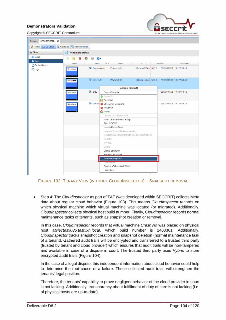
4.7 Test Case TC-009 - Legal evidence provision ............................................................... 99 4.7.1 Test subset description ............................................................................................... 99 4.7.2 Validation of Tools for Audit Trails and Root Cause Analysis (TAT) ........................ 100 4.7.3 Validation of Techno-legal guidance ......................................................................... 108 4.7.4 Summary ................................................................................................................... 108
4.8 Test Case TC-010 – Real-time monitoring of issues in the cloud ................................ 109 4.8.1 Test subset description ............................................................................................. 109 4.8.2 Validation of Policy Specification, Decision and Enforcement and ETRA I+D Alert Monitor .................................................................................................................................. 109 4.8.3 Summary ................................................................................................................... 113
4.9 Validation of Cloud Security Guideline ......................................................................... 113 5 Summary ............................................................................................................................... 114 6 References ............................................................................................................................ 117 7 Linkage to Other Project Results .......................................................................................... 119
AAF Assurance Assessment Framework AD3 Anomaly Detection using Data Density AL Assurance Level API Application Programming Interface CCTV Closed-circuit television CMD Command prompt CIMS Cloud Infrastructure Management System CLI Command Line Interface CoE Component of Evaluation CPU Central processing unit CSV Comma-Separated Values DB Database DF Deployment Function ECAS European Commission Authentication Service EMC Egan and Marino Company ESXi Hypervisor Operating System of VMware DLL Dynamic Link Library GoE Group of Evaluation GUI Graphical User Interface HW Hardware ID Identificator IND²UCE Integrated Distributed Data Usage Control Enforcement IP Internet Protocol IS Information System LTS Long Term Support NAT Network Address Translation NIC Network Interface Card OS Operating System PAP Policy Administration Point PEP Policy Enforcement Point PIP Policy Information Point PDP Policy Decision Point PMP Policy Management Point PoC Proof of Concept PXP Policy Execution Point RAM Random Access Memory RTD Research and Technological Development SDN Software Defined Networking SP Security Property SSH Secure Shell SWING API for providing a graphical user interface for Java programs. SQL Structured Query Language TAT Tools for Audit Trails and Root Cause Analysis TC Test case TCS Traffic Control Server UC Use case UI User Interface UCS Unified Computing System UTMS Urban Traffic Management System VM Virtual Machine VMS Video Management System VNC Virtual Network Computing VPN Virtual Private Network
The validation of SECCRIT technical outputs has been done in two demonstrators. Validation means checking that a software system meets specifications and fulfills its intended purpose. We documented the validation in two deliverables:
• D6.2 Demonstrators Validation – functionality of technical outputs
The purpose of this document (D6.2) is to illustrate the first part of the validationresults of individual technical outputs in various test cases. D6.3 will provide more in-depth, complementing and detailed validation of technical results and their quality.
1.2 Scope
The technologies that have been developed are described in individual deliverables of work packages 2-5 and are listed in Section 7 of this document.
Source codes of the RTD outputs are either available as open source [1] on the project website or, if not under open source license, they are downloadable at the ECAS website, see availability details in [2].
This document describes the test cases, how technologies have been integrated in the prototypes as well as screenshots illustrating the demonstrators. Document covers both demonstrators and, describes ten test cases as shown in Table 1. The test cases described here illustrate mostly the functionality of each RTD output. That is, starting situation in beginning of the test case, description of steps required in the test case and, final situation after the test case has been successfully conducted. Summary on what happened in the test case and how these results validate the intended functional purpose of the RTD output in question.
Validation of quality properties of each RTD output is out of the scope of this document and is considered in D6.3.
Further details of the technologies can be found, for example, in the following references. These papers are examples of main references of work. Full list of references is available at [3].
Resilience Management Framework: The framework is described in [4] and explored in [5-8].
Mechanisms and tools for Anomaly Detection: The tool chain is described in [9] and explored in [10-13].
In [14], the idea of user-friendly and tailored policy administration points as well as the policy administration point framework is described.
In [15], we presented our policy specification approach and how it was applied for critical infrastructure services in the cloud.
In [16], we describe the enforcement with IND²UCE for cloud environments based on VMware.
Security guideline is described initially in [17], Impact of Critical Infrastructure Requirements on Service Migration Guidelines to the Cloud. [18]
Categorization of Standards, Guidelines and Tools for Secure System Design for Critical Infrastructure IT in the Cloud has been done in [19].
Risk assessment was initially defined in [20] and further explored in [21].
Assurance Framework has been initially defined in (D5.1) [22] and further research towards continuous cloud service assurance for critical infrastructure IT has been done in [23]. A Multi-Layer and Multi-Tenant Cloud Assurance Evaluation Methodology has been introduced in [24].
1.3 Test iterations
Testing and validation of RTD outputs has been done in two iterations. While seven test cases in Iteration 1 are already defined in D2.6 [25] (TC-001 – TC-007), this deliverable describes three new test cases for Iteration 2: TC008, TC009, and TC010. Further, TC-002 was refined during test iteration 2. Overview of test cases is depicted in Table 1.
1.4 Structure
This document is structured as follows. First, we give descriptions of test setups in two different cloud environments: VMWare and OpenStack. Then, we provide demo validations for both demos on the corresponding test cases. Overview and structure of demos and related test cases is given in Table 1. In the end, we summarize the results of the validation.
TABLE 1. INTERRELATIONS BETWEEN DEMOS, TEST CASES, CLOUD PLATFORMS AND RTD OUTPUTS.
Test Case ID
Description Expected reaction Platform RTD Outputs used
Demo 1: Storage and processing of sensitive data TC-002 Dedicate host i.e.
anti-affinity of virtual machines
Migrate VM and provide an independent view of current situation
VMware
Policy Specification, Decision and Enforcement
Tools for Audit Trails and Root Cause Analysis
TC-007 Failure recovery of a virtual machine with minimum interruption to a service
VM Replacement Openstack
Tools for Audit Trails and Root Cause Analysis
Resilience Framework with focus on Deployment Function
Assurance Framework
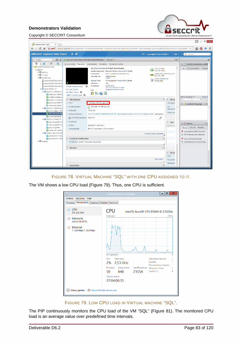
TC-008 Asserting Right of access (Data Protection Law) - Geo location of personal data
TC-004 Unexpected growth in resource consumption on host
Notification and dynamic resource adaption
VMWare
Policy Specification, Decision and Enforcement
TC-005 Database grows unexpectedly
Notification Openstack
Resilience Framework focus on Anomaly Detection
Assurance Framework
TC-006 Network pattern changes
Notification Openstack
Resilience Framework with focus on Anomaly Detection
TC-009
Legal evidence provision for proving negligent behavior
AuditTrails VMware
Tools for Audit Trails and Root Cause Analysis
Legal Guidance
TC-010 Real-time monitoring of issues in the cloud
Notification via GUI VMware
Policy Specification, Decision and Enforcement
Resilience framework
2 Test setup description We perform the test cases on different virtualization environments based on VMware at AMARIS and Openstack at OTE. To this end, both demos used the same hardware. However, the configuration for the cloud environments are different, which results in a different virtualization topology.
2.1 VMWare
AMARIS Qloudwise infrastructure is based on:
• Server components: Cisco UCS Blade System
• Network elements: Cisco Nexus Switches, Routers and Firewalls
• Storage: EMC VNX-Series and EMC Isilon
• Virtualization & Cloud Platform: VMware
Qloudwise Virtual Data Center is based on VMware vCloud Director, which allows the separation of each tenant or customer. Customers are the partners MIRASYS and ETRA, providing the two demos. VMware vCloud Director runs on top of our VMware vCenter Environment.
Redundant network devices, redundant shared storages and the built-in VMware ESXi high availability functionalities guarantee high availability.
Figure 1 shows an Overview of the VMware vCloud Director layer and VMware vCenter layer together with the virtual Datacenters of each tenant.
Figure 2 shows the technical overview of all components involved to provide a Qloudwise Virtual Data Center.
2.1.1 Access to physical hosts Direct access to physical hosts and VMware vCenter Management is forbidden per default to customers and allowed only for Amaris Engineers. The whole Datacenter is protected via multiple Cisco ASA Firewall Clusters to protect the physical Environment. Management Access to the VMware vCenter, which is needed to install several modules on the Hypervisor etc. by Seccrit Partners, can be reached after a Cisco ClientVPN Connection is established. The Client VPN has to established to host “remotevpn.qloudwise.com”
FIGURE 2. INFRASTRUCTURE OVERVIEW.
2.1.2 Access to VMware Dashboard, virtual networks - images and OS desktop – consoles
The customer access to the virtual Datacenter is allowed directly from the internet to the VMware vCloud Director Webinterface where ETRA and Mirasys have different URLS to manage their virtual Datacenter.
Every virtual Datacenter has their own internal network and virtual Firewall based on VMware vshield to protect the virtual machines and to configure public IP-Addresses.Following virtual machines are installed in Mirasys virtual Datacenter: Server name Function Internal IP-Address Public IP-Address vm01 VMS master server
(A) 10.127.52.11 212.9.140.32
vm02 VMS Recorder (A) 10.127.52.12 212.9.140.33 vm03 VMS master server
Following virtual machines are installed in ETRA virtual Datacenter: Server name Function Internal IP-Address Public IP-Address Commsmain Commsmain 10.127.53.11 212.9.140.42 SQL SQL 10.127.53.12 212.9.140.43 UrbanTrafficMain UrbanTrafficMain 10.127.53.13 212.9.140.44 CrashVM CrashVM 10.127.53.14
2.2 Openstack
The OTE Openstack testbed was setup and configured following the recommendations1 from AIT. The OS used in all hosts is Ubuntu Server 14.04 LTS, as one of the most active Linux distributions, which provide a Long Term Support (LTS). The LTS ensures that any issue, within the next five years, will be fixed. Additionally, the Virtualization & Cloud Platform is Openstack2 cloud, version Icehouse3. Openstack is one of the most active projects, providing close to commercial features, expendability and good documentation, CL (Command Line Interface) and GUI (Graphical User Interface) control and integrates well with Openflow, allowing the creation for complex architectures including both cloud and SDN technologies. This testbed is also interconnected with OTE’s other labs, providing many capabilities for testing new technologies either for PoC (Proof of Concept) or for systems aimed at the field. OTE Openstack testbed has the following topology (Figure 3).
Network elements: all host ports are 1GB ports and the switches used are NETGEAR GS608 with 1GB Ethernet ports as well.
2.2.1 Access to physical hosts The whole setup is behind a Cisco PIX 515 firewall, which provides NAT to the address 193.218.97.140. The traffic is forwarded to the Gateway server, so we can directly (without VPN)
use SSH to 193.218.97.140. From the gateway, we can connect to the other hosts again with SSH in the 192.168.5.0/24 network.
Additionally, a VPN has been set up on the Gateway, which once connected to, provides direct access to the other Openstack hosts and the running VMs as well.
2.2.2 Access to Openstack Dashboard, virtual networks - images and OS desktop – consoles
After connecting through VPN, we can access the dashboard from the following link:
Once connected to the dashboard, we see the virtual network topology (Figure 4), VM, host and other information. We created two virtual subnets to support the two distinct demos.
We separated the two subnets, so there is no communication possible with each other. Hence, the two demos cannot have negative influences on each other.
If we hover the mouse pointer over an instance, we will get three options, which one of those is “Open Console”
If we select “Open Console”, another browser window will open where we will be able to access the respective Windows or Linux console.
Additionally, we can get access to a console by using VNC software such as uvnc4.
Apart from that after connecting through VPN, we can connect with SSH to the VMs from their floating IP, in the network 172.16.6.0/24, if they are assigned one.
2.2.3 Characteristics of VMs The VMs instantiated in the Openstack cloud reside in the compute nodes, depending on the available resources. Each image may be running any OS compatible with Openstack, in our case mostly Windows, which were created from the SECCRIT partners that are participating in the demo cases. The created images contain the applications that are used in the demo cases. Additionally, the research partners installed some of their tools in the Openstack nodes or in the instantiated VMs, in order to showcase and validate their RTD outputs.
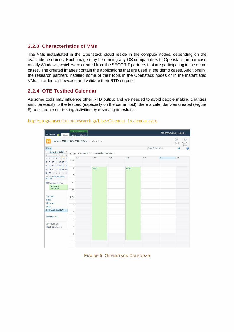
2.2.4 OTE Testbed Calendar As some tools may influence other RTD output and we needed to avoid people making changes simultaneously to the testbed (especially on the same host), there a calendar was created (Figure 5) to schedule our testing activities by reserving timeslots. ,
3 SECCRIT Demo 1 validation: Storage and Processing of Sensitive CCTV Data
3.1 Test Case TC-002 – Dedicated host
3.1.1 Test subset description This test case will test two different RTD components, as follows:
• Policy Specification, Decision and Enforcement
• Tools for Audit Trails and Root Cause Analysis (TAT)
The selected cloud platform for the test case is VMware.
The test case corresponds directly to story 2 – “The misbehaving politician” of UC-001 in D2.1, where sensitive data leaked from the system. In order to mitigate the risk of data leak, virtual machine Database has to run on a physical host where no virtual machines from other tenants are instantiated. This is due to minimize the risk of side-channel attacks from virtual machines of other tenants.
Test Case Dedicated host, i.e. anti-affinity of virtual machines ID TC-002
Description (narrative) Defined in D2.1 (test iteration 1):
Only one Virtual Memory System instantiated either as Master or as HotStandbyMaster is allowed to run at once on one physical host. This is due to confidentiality requirements of the tenant leading to virtual machine and/or data isolation requirements. This requirement could be expressed as the following: anti-affinity of virtual machines – No more than one Virtual Memory System, from the same tenant, is allowed to be instantiated on the same physical host Figure 6 illustrates the test case on high level. The policy enforcement will detect if this is not the case (violation of anti-affinity) and inform the tenant by email. If possible, the problem is resolved by the policy enforcement automatically, i.e. virtual machine is migrated to a different physical host. If suitable physical hosts are not available, the tenant is informed about the situation. At any point in time, TAT will provide an independent view on the current situation. This view will be provided on-demand as result to corresponding tenant requests. New complementary Description (test iteration 2): The above mentioned isolation requirement of virtual machines can also be interpreted in different way: dedicated host – it is not allowed to execute virtual machines from different tenants on the same physical host where a specific virtual machine of a tenant is running. Virtual machines from the same tenant are allowed. Therefore, virtual machine Database has to run onto a physical host where no virtual machines from other tenants are instantiated. This is due to minimize the risk of side-channel attacks from virtual machines
of other tenants (such as XSA148 / CVE-2015-78355 or VMSA-2014-0005 / CVE-2014-37936). At any point in time, TAT will provide an independent view on the current situation. This view will be provided on-demand as result to corresponding tenant requests. The policy decision and enforcement tools can detect the dedicated hosts violation and start countermeasures such as migration tasks in the CIMS (Cloud Infrastructure Management System)to resolve the problem. With currently present security policies, where the problem is resolved by migrating the Database virtual machine to a dedicated host. Other compensation actions such as migrating other tenant’s virtual machines to other physical hosts is also possible with the IND²UCE framework.
Resources AMARIS: 3 physical machines (hosts), 1 virtual machine with Ubuntu7. IESE: Provide IND²UCE framework8, management component, policies for test case. Mirasys: Names and details of the virtual machines and services. KIT: TAT, on-demand check if policy has been fulfilled or not.
Pre-Conditions Defined in D2.1: Three physical hosts
- Host 1: running Virtual Memory System Master server, TAT. - Host 2: running Virtual Memory System HotStandbyMaster
server, TAT. - Host 3: available (no virtual machines running on this host), TAT.
Additional host with Ubuntu, running TAT. New complementary Pre-Conditions:
- VM Database runs on a dedicated host (no virtual machines of different tenants are running there)
Post-Conditions /Expected Results
Defined in D2.1: Two possible outcomes:
- Virtual machines are migrated to different hosts, i.e. virtual machine Master stays in host 1 and HotStandbyMaster is migrated to available host (2 or 3).
- No physical hosts available just inform the tenant about the situation.
At any point in time, it is possible to audit anti-affinity status of virtual machines. In this way, we can verify what is actually happening in the cloud. New complementary Post-Conditions/Expected Results: Two possible outcomes:
5 x86: Uncontrolled creation of large page mappings by PV guests. Available from Xen Security Advisories: http://xenbits.xen.org/xsa/advisory-148.html - 10/2015 6 VMware Workstation, Player, Fusion, and ESXi patches address a guest privilege escalation. Available from VMware Security Advisories: https://www.vmware.com/security/advisories/VMSA-2014-0005.html - 05/2014 7 For more details see: http://www.ubuntu.com/ 4 IND²UCE: Integrated Distributed Data Usage Control Enforcement. More related information can be found, for
example, at: http://www.iese.fraunhofer.de/content/dam/iese/en/dokumente/Fraunhofer-IESE_IND2UCE_e.pdf
- Virtual machine Database runs on physical Host 3 or any other host that runs no virtual machines from other tenants. This will lead to fulfilment of dedicated host requirement
- Virtual machine Database runs on physical Host 1 or any other host that runs virtual machines from other tenants. This will lead to violation of dedicated host requirement
At any point in time, it is possible to audit dedicated host status of virtual machines. In this way, we can verify what is actually happening in the cloud. The policy decision and enforcement tools can be triggered by migration events and check whether the specified security policies are violated by the migration activities.
Flow of events Defined in D2.1: 1. Tenant examines the anti-affinity status of virtual machines – no anti-
FIGURE 6: OVERVIEW OF THE TEST CASE ON DEDICATED HOST
3.1.2 Validation of Tools for Audit Trails and Root Cause Analysis (TAT) Starting situation: Testbed is set up and virtual machines are running.
The functionality to be validated in this test case is the behavior of TAT. At this point RTD output CloudInspector is been validated. RTD output Hybris will be validated in test case TC-009. Both are described in more detail in deliverable D5.1 and D5.3.
In this case, validation of TAT is focused on CIMS-independent inside view regarding to contractual agreements (such as anti-affinity or dedicated host) with respect to current situation. CloudInspector should be able to reveal if a cloud provider does not fulfil tenant’s contractual agreements. Additionally, CloudInspector should be able to uncover CIMS malfunction (i.e. software bugs) which lead to contract violation. Presently, this information is not transparent. Instead, tenants of a cloud provider must trust the provider to “act as agreed” (i.e. that CIMS enforces its contractual agreements).
• Step 1: The tenant and the cloud provider have contractually agreed that the virtual machine Master and the virtual machine HotStandbyMaster are not allowed to be executed on the same physical host (anti-affinity). Additionally they agreed that the virtual machine Database is only allowed to be executed on a physical host where no virtual machines of other tenants are present (dedicated host). Currently, the tenant is only able to check virtual machine status (up, down, suspend, running) via the external interface of AMARIS (VMware technology).
Without CloudInspector (Figure 7), the tenant is not able to verify if his dedicated host or anti-affinity requirement is currently fulfilled. Additionally, the CIMS will not provide any active real-time checks to monitor contractual agreements. Consequently, the tenant will
not have a proof in its hands in case of a violation of contractual agreements (i.e. if the CIMS have a malfunction or the cloud provider acts negligent).
Therefore, real-time transparency regarding contractual agreements is lacking.
• Step 2a: The cloud provider is able to manage and monitor all virtual machines and physical hosts via AMARIS management interface (based on values of CIMS - VMware technology). The CIMS provides for each virtual machine detailed information, e.g. underlying physical hosts.
Therefore, the cloud provider is able to verify if contractual agreements of tenants are fulfilled (anti-affinity or dedicated host). However, he has no capability to detect malfunction or misconfiguration of the CIMS.
The cloud provider verifies that virtual machine Master is not executed on the same physical host as virtual machine HotStandbyMaster (anti-affinity requirement from tenant). Currently, virtual machine Master is executed on physical host atviectesx090.text.ixn.local (Figure 8).
Due to the lack of transparency, this information is not available for tenants. Furthermore, provided information depends on CIMS so that CIMS-malfunction is not detectable.
FIGURE 7. TENANT VIEW (WITHOUT CLOUDINSPECTOR)
FIGURE 8. THE CLOUD PROVIDER IS ABLE TO MANAGE AND MONITOR ALL VIRTUAL MACHINES AND PHYSICAL HOSTS VIA AMARIS MANAGEMENT INTERFACE.
• Cloud Provider View (CIMS) Step 2a cont.: The cloud provider is able to examine the physical host of virtual machine HotStandbyMaster, in the same way (Figure 9). The virtual machine HotStandbyMaster is executed on a different physical host atviectesx086.text.ixn.local. The anti-affinity requirement is currently fulfilled.
Due to the lack of transparency, this information is not available for tenants. Furthermore, provided information depends on CIMS so that malfunction is not detectable.
FIGURE 9. CLOUD PROVIDER VIEW (CIMS).
• Step 2b: Furthermore, the cloud provider is able to examine the physical host of virtual machine Database. Currently, this virtual machine is executed on physical host atviectesx090.text.ixn.local. Additionally, the cloud provider is able to examine if virtual machines of other tenants are executed on atviectesx090.text.ixn.local, which is currently not the case. Therefore, the dedicated host requirement is currently fulfilled.
Due to the lack of transparency, this information is not available for tenants. Furthermore, provided information depends on CIMS so that malfunction is not detectable.
• Step 3: The tenant is able to use the CloudInspector interface (Figure 10). The CloudInspector interface is part of TAT and was developed within SECCRIT. The tenant is able to run several on-demand checks (such as affinity, anti-affinity or dedicated host) or to configure continuous logging policies of contractual agreements.
• Step 4a: The tenant is able to verify if virtual machine Master and HotStandbyMaster are currently running on different physical hosts within the cloud infrastructure (called anti-affinity).
The sources of information for this audit command are CIMS-independent data sources on physical hosts. The CloudInspector interface gathers a local view of all physical hosts. After that, CloudInspector checks whether all virtual machines are instantiated on different physical hosts.
The tenant gets real-time feedback from CloudInspector that his contractual agreed anti-affinity requirement (regarding to virtual machine Master and HotStandbyMaster) is currently fulfilled. CloudInspector will report Anti-Affinity Check Passed (Figure 11).
No transparency regarding anti-affinity requirement is lacking. Furthermore, provided information by CloudInspector does not depend on CIMS values so that malfunction will be detectable.
• Step 4b: The tenant is in the same manner able to verify if the virtual machine Database is currently running on a dedicated physical host within the cloud infrastructure (called dedicated host). That implies that no virtual machines of other tenants are executed on the same physical host.
The sources of information for this audit command are CIMS-independent data sources on physical hosts. CloudInspector gathers a local view of all physical hosts. After that, CloudInspector checks whether all VMs are placed on physical hosts where no virtual machines of other tenants are executed.
The tenant gets real-time feedback from CloudInspector that his contractual agreed dedicated host requirement (regarding to virtual machine Database) is currently fulfilled. CloudInspector will report Dedicated Host Check Passed (Figure 12).
No transparency regarding dedicated host requirement is lacking. Furthermore, provided information by CloudInspector does not depend on CIMS values so that malfunction will be detectable.
• Step 5: However, the cloud provider is able to migrate virtual machines Master and HotStandbyMaster to the same physical host (Figure 13). Additionally, the cloud provider is able to migrate the virtual machine Database to a physical host where already virtual machines of other tenants are executed. Furthermore, the CIMS is able to manipulate placement of virtual machines within the cloud infrastructure individually.
This could happen if the cloud provider acts negligent, for example by manually manipulating physical host configuration instead of using CIMS interface. Additionally, this unwanted outcome (contract violation) could happen if the CIMS has an internal failure and therefore is not able to correctly implement requirements from tenants.
It is very important to deactivate the IND²UCE outcome during TAT validation. Otherwise, IND²UCE will additionally migrate virtual machines as defined by polices. This will complicate TAT validation. Although, CloudInspector will be fully functional under these circumstances.
FIGURE 13. MIGRATING MASTER AND HOTSTANDBYMASTER.
• Cloud Provider View (CIMS) – Start of MigrationStep 5 cont.: The Cloud provider migrates virtual machine HotStandbyMaster to the same physical host of virtual machine Master
(atviectesx086.text.ixn.local), Figure 14. This migration process is a violation of the contractual agreed anti-affinity requirement.
Due to the lack of transparency, this information is not available for tenants.
FIGURE 14. CLOUD PROVIDER VIEW (CIMS) – MIGRATION PROCESS OF A VIRTUAL MACHINE
• Step 6, Figure 15: With CloudInspector the tenant is still able to verify if his contractual agreement (i.e. anti-affinity of virtual machine Master and HotStandbyMaster) is fulfilled.
The tenant is already able to uncover the violation of contractual agreement while the unwanted migration process starts. As the information provided by CloudInspector is based on independent real-time information (see step 4a), the tenant is able to observe the migration process step-by-step (duplication of VM, synchronizing state).
The tenant gets real-time feedback from CloudInspector that his contractual agreed anti-affinity requirement (regarding to virtual machine Master and HotStandbyMaster) is currently not fulfilled. CloudInspector will report Anti-Affinity Check Failed.
No transparency regarding anti-affinity requirement is lacking. Furthermore, provided information by CloudInspector does not depend on CIMS values so that malfunction will be detectable.
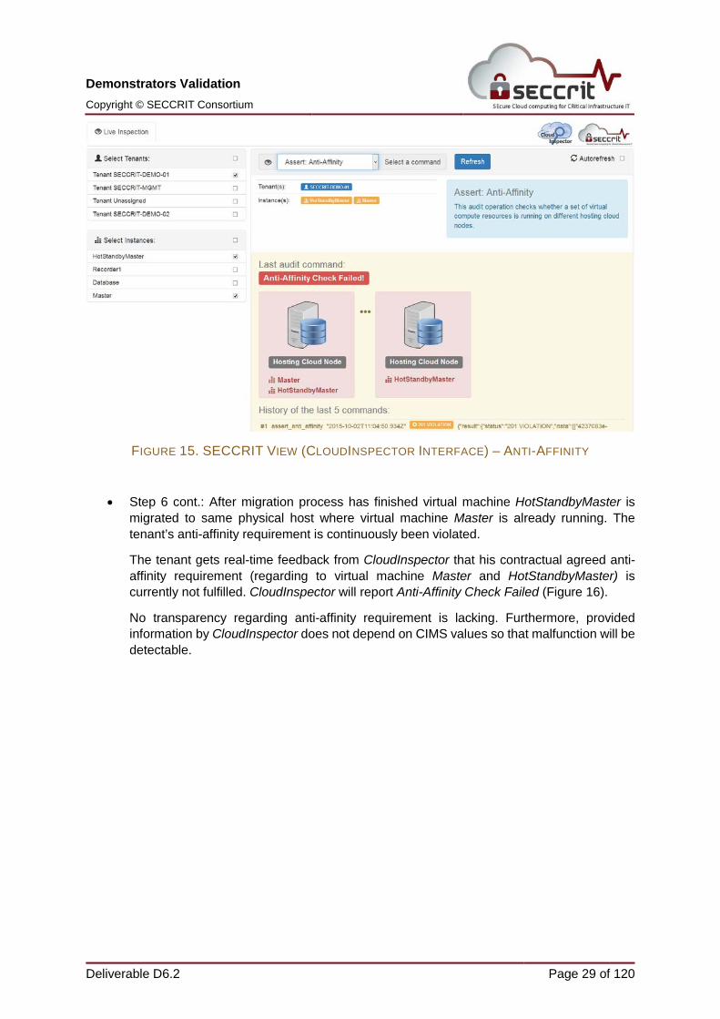
• Step 6 cont.: After migration process has finished virtual machine HotStandbyMaster is migrated to same physical host where virtual machine Master is already running. The tenant’s anti-affinity requirement is continuously been violated.
The tenant gets real-time feedback from CloudInspector that his contractual agreed anti-affinity requirement (regarding to virtual machine Master and HotStandbyMaster) is currently not fulfilled. CloudInspector will report Anti-Affinity Check Failed (Figure 16).
No transparency regarding anti-affinity requirement is lacking. Furthermore, provided information by CloudInspector does not depend on CIMS values so that malfunction will be detectable.
• Step 7: The cloud provider migrates virtual machine Database to a physical host where already virtual machines of other tenants are executed (in the same manner as described for virtual machine HotStandbyMaster in step 5). The tenant’s dedicated host requirement is been violated.
Due to the Lack of Transparency, this information is not available for tenants.
• Step 8: The tenant gets real-time feedback from CloudInspector that his contractual agreed dedicated host requirement (regarding virtual machine Database) is currently not fulfilled. CloudInspector will report Dedicated Host Check Failed (Figure 17).
No transparency regarding dedicated host requirement is lacking. Furthermore, provided information by CloudInspector does not depend on CIMS values so that malfunction will be detectable.
3.1.3 Validation of Policy Specification, Decision and Enforcement The IND²UCE framework is deployed to the VMware cluster within a VM on which the following core IND²UCE components are running. For further information about the implementation, we refer to SECCRIT Deliverable D4.4 Policy Decision and Enforcement Tools [26]):
- Policy Management Point (PMP) including a management dashboard
- Policy Decision Point (PDP)
- VMware Policy Enforcement Point (PEP) for detecting events from the VMware management environment that are used to trigger the IND²UCE policy evaluation
- VMware Policy Information Points (PIP) for critical service detection
- Policy Execution Points (PXP)
o VMware PXP for triggering VMware actions (e.g., migration or changing configuration parameters of VMs)
o Notification PXP for sending log messages to MIRASYS Demo UI
o Sendmail PXP for sending email messages as notifications
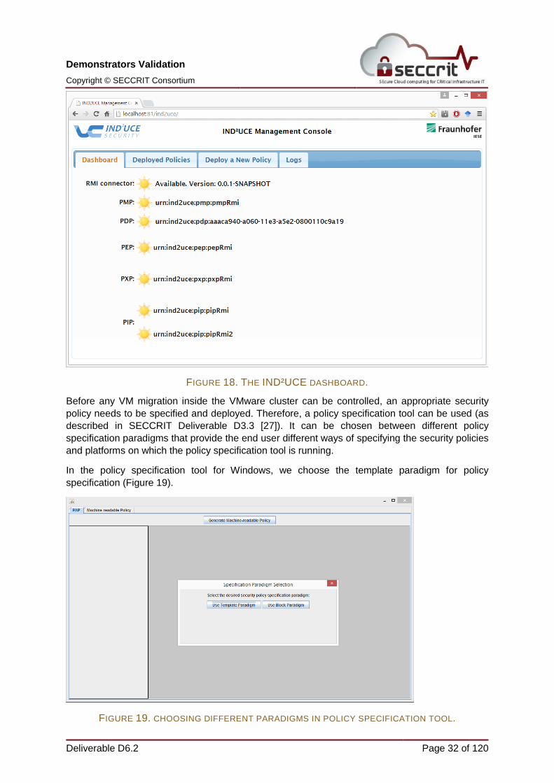
The IND²UCE dashboard (Figure 18) shows all currently running components with their unique identifiers including a health status.
Before any VM migration inside the VMware cluster can be controlled, an appropriate security policy needs to be specified and deployed. Therefore, a policy specification tool can be used (as described in SECCRIT Deliverable D3.3 [27]). It can be chosen between different policy specification paradigms that provide the end user different ways of specifying the security policies and platforms on which the policy specification tool is running.
In the policy specification tool for Windows, we choose the template paradigm for policy specification (Figure 19).
FIGURE 19. CHOOSING DIFFERENT PARADIGMS IN POLICY SPECIFICATION TOOL.
Next, we select the security policy template for “Critical VM Migration” (Figure 20) and instantiate it to our needs. For this test case, we come up with the following natural language security policy:
“If a critical virtual machine is moved to a host already running a critical VM, then move virtual machine to a host not running a critical VM, notify [email protected] via email, and write a log entry”.
FIGURE 20. SELECTING SECURITY POLICY TEMPLATE.
The corresponding machine readable security policy, which can be enforced by the IND²UCE framework, is generated and ready for deployment (Figure 21).
Depending on the end user, different ways of interaction for the policy specification might be appropriate. The Policy Administration Point Framework is a highly extensible toolkit that generates different policy specification tools (Policy Administration Points or PAP). In the context of SECCRIT, we provide two different platforms “SWING” and “Android” as well as two different specification paradigms, namely “template paradigm” and “block paradigm”. In Figure 22, we can see the same policy template as above in a PAP using the block paradigm on SWING.
FIGURE 22. POLICY TEMPLATE USING THE BLOCK PARADIGM ON SWING.
We also can generate PAPs for the Android platform, using the same security policy templates and the presentation module “template paradigm” (Figure 23). The modules for managing the security policy templates and the transformation into machine-readable security policies are in all three cases identical.
FIGURE 23. ANDROID PLATFORM, USING THE SAME SECURITY POLICY TEMPLATES AND THE PRESENTATION MODULE “TEMPLATE PARADIGM”.
On the IND²UCE dashboard, we can deploy the machine-readable security policy (Figure 24).
FIGURE 24. DEPLOYING MACHINE READABLE POLICY.
We activate the generated policy as XML file “demo_dedicatedHW1.xml” on the IND²UCE dashboard by using the “Deploy a New Policy” tab. After the successful deployment, we receive a deployment confirmation (Figure 25).
FIGURE 25. CONFIRMATION THAT DEPLOYMENT HAS BEEN SUCCESSFUL.
If a critical VM is now migrated to another host already having a critical service running, then compensating actions will be performed. In Figure 26 we can see two relevant VMs in the VMware vSphere Web Client, namely the VMs “Master” and “HotStandbyMaster”. The VM Master is currently running on the host “atviectesx086.test.ixn.local”.
FIGURE 26. MASTER VM IN THE VMWARE VSPHERE WEB CLIENT.
The VM “HotStandbyMaster” is currently running on the host “atviectesx090.test.ixn.local” (Figure 27).
FIGURE 27. HOTSTANDBYMASTER VM IN THE VMWARE VSPHERE WEB CLIENT
Now, we trigger a migration of the “HotStandbyMaster” to the host “atviectesx086.test.ixn.local”, which is running the “Master” (Figure 28).
FIGURE 28. TRIGGERING MIGRATION.
After the successful migration, the IND²UCE framework detects a policy violation. Compensating actions are directly executed. The PDP log (Figure 29) shows the execution of a further VM migration of the “HotStandbyMaster” (internal VMware id: vm-40434) to the currently free host “atviectesx090.test.ixn.local” (internal VMware id: host-38439). In addition, the log shows the sending of a notification email as well as the writing of a log entry.
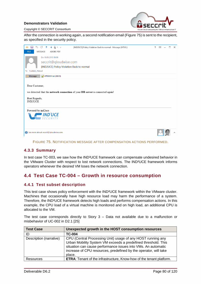
FIGURE 31. NOTIFICATION VIA HTTP CHANNEL IN TENANT GUI.
After the compensation actions are completed, we can see in the VMware vSphere Web Client that the VM “HotStandbyMaster” was successfully migrated to the free host (Figure 32).
FIGURE 32. HOTSTANDBYMASTER AT A FREE HOST. The complementary setup of TC-002 works in the same way as the described validation steps. The specified security policy and the corresponding policy information point have to check whether the VM Database runs on a dedicated host (no VMs of other tenants are running) contrary to other critical services are running on the same physical host.
3.1.4 Summary This test case successfully validates TAT, namely CloudInspector. With CloudInspector, tenants are able to run CIMS-independent on-demand checks of contractual agreements, such as anti-affinity or dedicated host status of virtual machines. CloudInspector is able to reveal if a cloud provider does not fulfil tenant’s contractual agreements. Furthermore, provided information by TAT does not depend on CIMS. Therefore, CloudInspector is able to uncover CIMS malfunction (i.e. software bugs) which lead to contract violation. No transparency regarding to contractual agreements is lacking. Presently, this information is not transparent. Instead, tenants of a cloud provider must trust the provider to “act as agreed” (i.e. that CIMS enforces its contractual agreements). Finally, violation of contractual agreements could be collected continuously for Root Cause Analysis in court, similar as shown in validation of test case TC-009.
This test case demonstrates two possible solutions for enforcing anti-affinity rules for virtual machines. In the first solution, the IND²UCE framework prevents that two critical machines are running on the same host. If such a scenario is detected, one machine is directly migrated to another host, on which no other critical service is running. In the second solution, the IND²UCE framework ensures the use of dedicated hardware for specific virtual machines. Hence, IND²UCE checks whether other virtual machines are executed on the same physical hardware and resolves the problem. Both solutions are extended by additional actions such as sending a notification email or showing some notification in the MIRASYS UI.
3.2 Test Case TC-007 – Failure recovery
3.2.1 Test subset description This test case will test three different RTD components, as follows:
• Tools for Audit Trails and Root Cause Analysis (TAT).
• Service deployment part of Resilience Framework
• Assurance Management Framework
The selected cloud platform for the test case shall be Openstack.
The test case corresponds directly to Story 1 – “Act of vandalism in the night” of UC-001 in D2.1, where there was no alarm delivered to the security service due to technical failure. In order to mitigate the risk of this kind of failure situations, an automated recovery mechanism is established.
Test Case Failure recovery of a virtual machine with minimum interruption to a service
ID TC-007
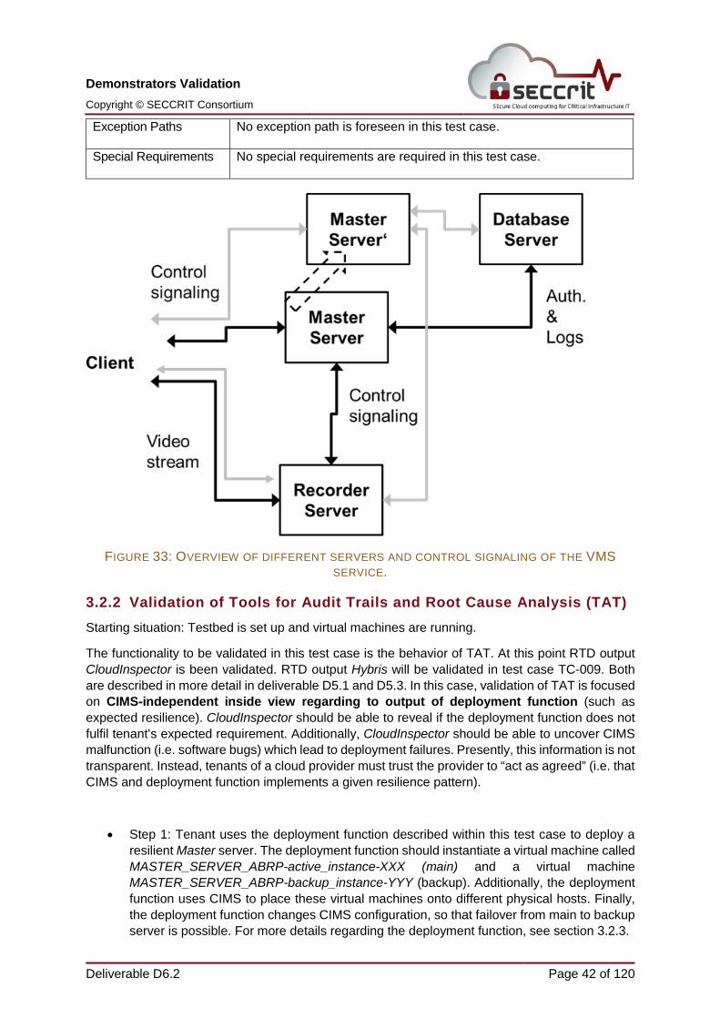
Description (narrative) The Mirasys VMS (Video Management System) service has to be resilient to the failure of an instance of a Master Server. The Master Server is connected to a back-end Database server and a Recorder Server. Figure 33: Overview of different servers and control signaling of the VMS service. The whole VMS service will be provided through virtual machines. The virtual machine Master Server is the main server and the virtual machine Master Server’ is the backup server. In case of a failure of the main server, the VMS service could be provided through backup server. Black arrows illustrate the control signaling in
the beginning of the test case and grey arrows illustrate the situation after the failover has taken place. The deployment function will be used to provision redundant instances of Master Servers and configure Openstack in a way that allows an automated failover from the main Master server to the backup Master Server (virtual machine Master Server’). At any point in time, TAT will provide an independent view on the current deployment. This view will be provided on-demand as result to corresponding tenant requests. The tenant does not have to rely on information from the CIMS or deployment function. As a first step, TAT and the deployment function will be setup in OTE’s testbed in parallel. The deployment function will be set up with virtual machines. Additionally, Mirasys virtual machines will be set up. TAT will be set up. After the setup process, the tenant is able to instantiate VMS service with help of the deployment function. The deployment function will ensure that a main Master Server and a backup Master Server is instantiated. Additionally, the deployment function ensures that Openstack is configured in a way that allows an automated failover. At any time, TAT is able to monitor output of deployment function (if expected resilience is given). That means instantiation of main and backup server as well as configuration of Openstack. We will also evaluate how this changes the assurance level via AITs assurance framework.
Resources OTE: Testbed with 5 physical machines running Openstack with IceHouse9, Openstack maintenance. NEC: Service deployment and configuration in Openstack (part of Resilience Framework) KIT: TAT Mirasys: VMs server configurations and placement of virtual machines. AIT: Assurance Management Framework
Pre-Conditions TAT and Openstack are running, deployment function is running.
Post-Conditions /Expected Results
System has recovered from the failure and the VMS service is running, using the failover server i.e. Master Server’.
Flow of events 1. Description of the deployment, i.e. template is generated by deployment function.
2. Openstack creates the instances of the VMS service 3. First audit call from tenant to check if backup virtual machine is
running. 4. Hard failure of the active server e.g. shut down the virtual machine.
Automatically shall happen as follows: Backup server (Master Server’) takes over the service as an active server.
5. Second audit call from tenant to check if backup virtual machine is running.
6. Investigation of impact of mitigation countermeasures on assurance
9 More related information can be found at: http://docwiki.cisco.com/wiki/Openstack:_Icehouse_All-in-One
Exception Paths No exception path is foreseen in this test case.
Special Requirements No special requirements are required in this test case.
FIGURE 33: OVERVIEW OF DIFFERENT SERVERS AND CONTROL SIGNALING OF THE VMS SERVICE.
3.2.2 Validation of Tools for Audit Trails and Root Cause Analysis (TAT) Starting situation: Testbed is set up and virtual machines are running.
The functionality to be validated in this test case is the behavior of TAT. At this point RTD output CloudInspector is been validated. RTD output Hybris will be validated in test case TC-009. Both are described in more detail in deliverable D5.1 and D5.3. In this case, validation of TAT is focused on CIMS-independent inside view regarding to output of deployment function (such as expected resilience). CloudInspector should be able to reveal if the deployment function does not fulfil tenant’s expected requirement. Additionally, CloudInspector should be able to uncover CIMS malfunction (i.e. software bugs) which lead to deployment failures. Presently, this information is not transparent. Instead, tenants of a cloud provider must trust the provider to “act as agreed” (i.e. that CIMS and deployment function implements a given resilience pattern).
• Step 1: Tenant uses the deployment function described within this test case to deploy a resilient Master server. The deployment function should instantiate a virtual machine called MASTER_SERVER_ABRP-active_instance-XXX (main) and a virtual machine MASTER_SERVER_ABRP-backup_instance-YYY (backup). Additionally, the deployment function uses CIMS to place these virtual machines onto different physical hosts. Finally, the deployment function changes CIMS configuration, so that failover from main to backup server is possible. For more details regarding the deployment function, see section 3.2.3.
• Step 2: Without CloudInspector, the tenant is not able to verify if the deployment function has instantiated the VMS service as expected (Figure 34). The deployment function should create two virtual machines (main and backup); instantiated both on different physical hosts, and configure CIMS accordingly (creation of stack). The CIMS will not provide any active real-time checks to monitor deployment function results. Consequently, the tenant will not have a proof in its hands in case malfunction of deployment or CIMS. The same applies if the cloud provider acts negligent.
Therefore, real-time transparency regarding to results of deployment function is lacking (i.e. if expected resilience is given).
FIGURE 34. TENANT VIEW (WITHOUT CLOUDINSPECTOR)
• Step 3: The cloud provider is able to check if the deployment function places and instantiates both virtual instances (MASTER_SERVER_ABRP-active_instance-XXX and MASTER_SERVER_ABRP-backup_instance-YYY) of VMS service as expected: on different physical hosts within the cloud infrastructure and in one configuration stack (CIMS internal). Information regarding to CIMS configuration is based on values of CIMS (i.e. Openstack), Figure 35.
The cloud provider verifies that virtual machine MASTER_SERVER_ABRP-active_instance-XXX is not executed on the same physical host as virtual machine MASTER_SERVER_ABRP-backup_instance-YYY (anti-affinity). Additionally, CIMS verifies that both virtual machines are configured in a stack. Currently, the deployment function has instantiated the VMS service as expected.
Due to the lack of transparency, this information is not available for tenants. Furthermore, provided information depends on CIMS only so that malfunction is not detectable.
• Step 4: The tenant is able to use the CloudInspector interface. The CloudInspector interface is part of TAT and was developed within SECCRIT. The tenant is able to run several on-demand checks to verify if the expected resilience pattern is given. Additionally, tenants are able to configure continuous logging policies of deployment function outcomes.
The tenant is able to verify if a virtual machine was deployed correctly, so that resilience in case of one virtual machine failure will be given. The sources of information for this audit command are CIMS-independent data sources on physical hosts. Additionally, CloudInspector has to verify if CIMS configured both virtual machines as expected (i.e. creation of a stack). The CloudInspector gathers a local view of all physical hosts. After that, CloudInspector checks whether virtual machines (regarding to resilience pattern) are instantiated on different physical hosts and CIMS is configured accordingly.
The tenant gets real-time feedback from CloudInspector that the expected resilience pattern is currently fulfilled. CloudInspector will report Backup Pattern Check Passed (Figure 36 and 37).
No transparency regarding to deployment function outcomes is lacking. Furthermore, most of the provided information by CloudInspector does not depend on CIMS values (expect to configuration of stack) so that malfunction may be detectable.
• SECCRIT View (CloudInspector Interface) – Backup Pattern – Backup ServerStep 5: However, the cloud provider is able to shut down a virtual machine or an entire physical
host. Furthermore, the CIMS is able to manipulate placement of virtual machines within the cloud infrastructure individually (instead of using instructions of deployment function).
This could happen if the cloud provider acts negligent, for example by manually manipulating physical host configuration instead of using CIMS interface. Additionally, this unwanted outcome (resilience pattern violation) could happen if the CIMS has an internal failure and therefore is not able to implement requirements from deployment function (i.e. different physical host; creation of a stack).
In this case, the cloud provider terminates virtual machine MASTER_SERVER_ABRP-backup_instance-YYY.
Due to the Lack of Transparency, this information is not available for tenants.
• Step 6: With CloudInspector, the tenant is still able to run several on-demand checks to verify if the expected resilience pattern is given.
The tenant is able to uncover violation of expected resilience or malfunction of deployment function. The tenant gets real-time feedback from CloudInspector that his expected resilience pattern (regarding to virtual machine MASTER_SERVER_ABRP-active_instance-XXX) is currently not fulfilled. CloudInspector will report Backup Pattern Check Failed (Figure 38).
No transparency regarding to deployment function outcomes is lacking. Furthermore, most of the provided information by CloudInspector does not depend on CIMS values (expect to configuration of stack) so that malfunction may be detectable.
3.2.3 Validation of Resilience Framework with focus on Deployment Function
The functionality to be validated in this test case is the correct working of the Deployment Function (DF) as part of the Resilience Framework. In principle, this function could place an active-backup resilience pattern such as the one tested here in a larger physical infrastructure, taking into account configured availability and delay values. However, the functionality that can be validated in the test case is that the active and the backup instance of the resilience pattern are started on two separate nodes, i.e., a basic anti-affinity. This is however not due to a limitation of the functionality of the Deployment Function, but rather of the testbed environment, which consists of only two compute nodes.
The test case also includes showing the failover procedure using the actual Mirasys software components. While this serves to illustrate the applicability of the project output to a real deployment, it needs to be clarified that neither the failover procedure nor the scripts implementing it form part of the DF itself. What is shown is that the DF can configure these scripts as part of its functionality. The scripts implementing the resilience pattern in the virtual machines themselves have only been created for demo purposes and thus are not in the focus of the validation of the deployment function and are not considered a scientific project output.
• The situation at the start of the test case (Figure 39) is that no Master Server instance is running in the testbed. The instance including both the Mirasys Recorder software as well as the Spotter client (called ‘recorder instance’ in the following for conciseness) is already running, but the Spotter client has not yet tried to connect.
FIGURE 39. TESTBED SITUATION AT THE BEGINNING OF THE TEST CASE.
• The next step is thus to instantiate the Master Server, using an active-backup resilience pattern (Figure 40). To this end, we use a browser plugin to adapt the Openstack dashboard interface (‘Advanced Options’ under ‘Launch Instance’), Figure 41.
FIGURE 40. CONFIGURING THE INSTANTIATION OF THE NEW MASTER INSTANCE.
FIGURE 41. BROWSER PLUGIN TO ADAPT THE OPENSTACK DASHBOARD INTERFACE.
Launching with this option allows to set a minimum availability and a maximum delay between the redundant instances. Values for this testbed have been preconfigured to ensure a placement on separate physical machines if a minimum availability of 95% is chosen with a suitable delay (we test usually with 12ms). Using the ‘Launch’ button redirects the necessary parameters to a server implemented for the DF, which creates a stack that instantiates and configures automatically the active and the backup instance of the resilience pattern (Figure 42).
FIGURE 42. TESTBED SITUATION AFTER THE START OF THE MASTER INSTANCE RESILIENCE PATTERN.
• The Master images have been configured to automatically connect to the existing recorder instance. The Spotter client can connect to the public IP address (172.16.6.21) the active Master Server instance has assigned itself once the boot process of that VM has finished. From this point on, the client can stream the video via the Master Server. The backup Master Server is running as well, but does not handle the client traffic.
o The correct instantiation on different physical machines can be shown by checking the assignment of the compute nodes to the different zones, using e.g. the Openstack Nova CLI (Figure 43).
FIGURE 43. CONFIGURATION OF TESTBED COMPUTER HOSTS.
o The previous steps thus validate the correct working of the DF. The steps that follow just illustrate the feasibility of such a resilience pattern with the Mirasys software.
o The Mirasys spotter client can now be connected to the public IP address of the service, as shown in Figure 44 and 45.
o Video demonstration “vandalism at the train station” shown in Figure 45, 49 and 50 was done according to the ethical guidance defined in D2.8 [28]. Video surveillance demonstrator was exclusively conducted within a dedicated environment, ensuring that no person is recorded without previously given, well-informed and written consent. The environment was set-up exclusively for the purpose of evaluation and demonstration within project SECCRIT and no further data (like, for instance, other, already existing recordings from other places) were used during evaluation and demonstration.
FIGURE 45. MIRASYS SPOTTER CLIENT CONNECTED TO THE MASTER SERVER.
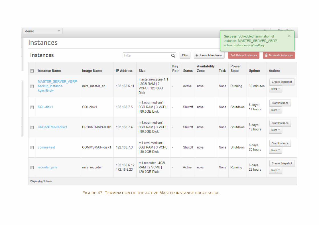
• To create a situation that necessitates a failover, the active Master Server instance is terminated using the Openstack dashboard (Figure 46 and 47).
FIGURE 46. MANUALLY TERMINATING MASTER SERVER INSTANCE.
As a result, the heartbeat mechanism running on the backup instance initiates the failover and reassigns the public IP address previously held by the active instance to itself (Figure 48).
FIGURE 47. TERMINATION OF THE ACTIVE MASTER INSTANCE SUCCESSFUL.
FIGURE 48. TESTBED SITUATION AFTER THE FAILOVER. BACKUP MASTER INSTANCE HAS TAKEN OVER PUBLIC IP ADDRESS OF THE SERVICE
o The Mirasys spotter client might see a lost connection to the Master Server for a short interval, but automatically reconnects to the public IP. The Video playback is not interrupted (Figure 49).
FIGURE 49. SPOTTER VIEW DURING INTERRUPTION. VIDEO IS STILL PLAYING.
• Thus, at the end of the test case, the backup server has automatically become active by taking over the public IP address of the service, and client will have noticed just a short period of interruption with little effect on the service (Figure 50).
FIGURE 50. SPOTTER VIEW AFTER SERVICE RESTORATION.
3.2.4 Validation of Assurance Framework The final functionality validated within the TC-007 will demonstrate real-time security assessment in multi-layered and multi-tenant environments, such as SECCRIT reference architecture, via Assurance Assessment Framework (AAF). The AAF can be easily deployed in large-scale infrastructures to monitor security-based parameters (that in AAF terminology are refer to as security properties) across independent layers of the cloud-based environments. In principle, AAF can be deployed as an independent solution where an individual user can easily tailor security policies of AAF according to his personal preferences, whereby a user can be both Cloud customer and Cloud provider. Cloud customer can customize set of security properties that he would like to be monitored and define interest group or elements (i.e., group of components that should be evaluated such as physical or virtual servers, VMs, databases, whole virtual or physical level, etc.). Cloud provider can perform continuous evaluation of individual components or complete infrastructure by including interdependencies, driven according to the requirements of various security based standards or audits.
The test case 007 for minimal service interruption is demonstrated via the above mentioned resilience framework as a deployment function to mitigate service interruption test case scenario. As mentioned above, for demonstrational purposes of the TC-007 Mirasys service components are hosted in an Openstack environment to simulate the failover functionality (Figure 51). In order to illustrate the AAF functionalities the whole Openstack testbed is under observation, including the hosted Mirasys software, as a multi-layered environment composed of independent components at various levels (e.g., service, tenant and physical) with mutual interdependencies (Figure 52). For the AAF purpose, these autonomous components are afterwards abstracted and observed as the essential asset for extracting security related information. Together with their interdependencies, components are used to perform security assessment (horizontal and vertical security aggregation) that gives an overall security result referred as assurance level.
FIGURE 51. MIRASYS SERVICE COMPONENTS HOSTED IN AN OPENSTACK ENVIRONMENT.
Because the Assurance framework is used to evaluate the running service, we will refer to the setup of the Resilience Framework for Master Server instances (active and running backup) to evaluate the assurance assessment methodology.
FIGURE 52. OPENSTACK TESTBED UNDER OBSERVATION.
Hosted component-based service is abstracted as set of individual components (components of evaluation - CoEN) that are evaluated with corresponding dependencies, which build a composite service (Target of Evaluation ToE, ToE = {CoE1, CoE2, CoE3, CoE4, CoE5, CoE6, CoE7}) that is marked as target of our security evaluated, cf. Figure 53.
FIGURE 53. HOSTED COMPONENT-BASED SERVICE ABSTRACTED.
In order to deliver the result of an overall security assessment, Assurance Level (AL), in each individual CoE security related information will be extracted, i.e. a collector is installed that acquires security related information for a set of predefined security monitoring artefacts referred to as security properties (SP). Security property in this sense is as a security related monitoring artefact that acquires information based on certain security requirement (e.g., encryption – security property that acquires that prove presence of encryption of data, physical or virtual disks, communication links). For the scope of the test case TC007, a set of Security Properties was developed to address partner specific security requirements.
Operating System
Linux Windows
Assurance Class Security Property Implementation Status I T S I T S
This security property validates the concurrent sessions of an individual user for a particular service (e.g. physical device, application or service, virtual machine).
This security property validates the regular rotation of the password (i.e. max or min change interval) for a particular service (e.g. physical device, application or service, virtual machine).
Strong Password
This security property validates the password complexity strength (i.e. checks whether a predefined set of following characteristics is fulfilled: length, characters, special characters, or numbers) for a particular service (e.g. physical device, application or service, virtual machine).
Encryption
This security property validates if the encryption mechanisms on a particular service (i.e. connection) or device (i.e. disks) are applied in a correct manner.
System/Service Integrity
This security property validates that there are proper mechanisms in place that perform the consistency of the system configuration (e.g. Linux kernel, Windows DLL or registry) and general configuration of the system as a whole.
Information (Data) Consistency
This security property validates the consistency of the data or information that is of prior interest.
Error Correction
This security property validates that there are proper mechanisms in place that perform the error correction.
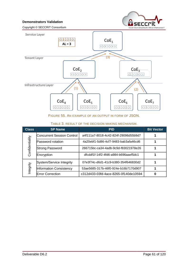
As mentioned, for each individual Component of Evaluation (CoE) in for the targeted service security-related information is periodically been collected (shown in Figure 54 as output of CoE2) via collectors and sent to the AAF to perform the calculation of the assurance level. The frequency of collecting data is flexible and it can be adapted to an individual use case. An example of an output in form of JSON is shown in Figure 55 supported with a Table 3 showing what the result of the decision making mechanism is, in AAF that transforms raw JSON data to a Bit Vector (Figure 56) that is used afterwards in the Assurance Aggregation process (Figure 57). The AAF takes each bit vector of a CoE and performs bitwise conjunction in a post order tree traversal order to gain an overall assurance level for the whole target of evaluation.
In addition, the test case 007 refers to the failover recovery of a virtual machine, i.e., as soon as the primary or master machine fails to perform its service the standby machine is taking over, therefore we illustrate how to define certain point of interest with AAF methodology. Due to the fact that processing after failover procedure is forwarded to another VM (standby VM), which results that at the different point of time different interest groups in terms of components should be evaluated. This is easily handled with AAF by defining group of interests that are formally referred to as Group of Evaluation (GoE). Within an individual group, user can define set of components that are of particular interest and its assurance level should be determined according to user
personal preference. For the purpose of this test case, we therefore define evaluation groups based on the VM (Figure 58):
• GoE1 = {CoE1, CoE2, CoE4, CoE5} - this evaluation group is focused on monitoring the active VM and the corresponding physical servers where the VM resides
• GoE2 = {CoE1, CoE3, CoE6, CoE7} - this evaluation group is focused on monitoring the standby VM which takes over the processing after the active VM fails, and the corresponding physical servers where the VM resides
FIGURE 58. TEST CASE EVALUATION GROUPS.
As we can see above, by choosing different interest group (GoE1 or GoE2) based on the fact if we would like to see how secure our service is before (GoE1) and after (GoE2) the failover. Another motivational example would be if a user would like to see if the underlying physical infrastructure fulfils its security objectives, which would then only include the following components GoE3 = {CoE4, CoE5, CoE6, CoE7} and resulted in an assurance level 7 since all security properties are fulfilled.
Finally, the technical overview of our Assurance Assessment Framework (Figure 59) which works in several stages: data acquisition with individual collector installed directly at the components of evaluation, system for handling large scale data sets (Apache Kafka), system for distributed and parallel processing (Apache Storm), and finally Assurance level computation module used to calculate the assurance level.
FIGURE 59. OVERVIEW OF ASSURANCE ASSESSMENT FRAMEWORK.
3.2.5 Summary This test case successfully validates TAT, namely CloudInspector. With CloudInspector, tenants are able to run CIMS-independent on-demand checks of deployment function outcomes, such as implementation of a resilience pattern. CloudInspector is able to reveal if the deployment function does not implement tenant’s resilience pattern (either in case of deployment function misbehavior or CIMS malfunction). Furthermore, provided information by TAT generally does not depend on CIMS (expect to configuration of stack). Therefore, CloudInspector is able to uncover CIMS malfunction (i.e. software bugs) which lead to resilience pattern violation. No transparency regarding to deployment function outcomes is lacking. Presently, this information is not transparent. Instead, tenants of a cloud provider must trust the provider to “act as agreed” (i.e. that CIMS and deployment function implements a given resilience pattern). Finally, violation of expected resilience pattern could be collected continuously for Root Cause Analysis in court, similar as shown in validation of test case TC-009.
This successfully validates the Assurance Assessment Framework showing changes that occur during some period of time and potentially indicating a malfunction of the infrastructure where the service is deployed. The user is therefore able to react in real time instead when it is too late to take any additional measures.
3.3 Test Case TC-008 – Geolocation of sensitive data
3.3.1 Test subset description This test case will test two different RTD components, as follows:
• Tools for Audit Trails and Root Cause Analysis (TAT).
• Legal guidance
The selected cloud platform for the test case shall be Openstack.
The test case corresponds directly to story 2 – “The misbehaving politician” of UC-001 in D2.1, where sensitive data leaked from the system. Control over the personal data can be increased by knowing the exact location of the personal data, with the capability to check any time whether this is true and therefore permit the fulfilment of the data protection right of the customer. In [18] geolocation was explicitly mentioned as differencing factor to industry requirements. Test Case Asserting Right of Access (Data Protection Law) - Geolocation
of personal data ID TC-008 Description (narrative) Mirasys is using a cloud based-solution of OTE and has outsourced
personal data of a customer. The personal data is stored in a Virtual Machine (VM) called Database. Mirasys and OTE have contractually agreed that the VM Database is only persisted in European countries (such as Greece or Austria) and therefore personal data can only be stored within the EU. Mirasys expects therefore that the data stored within virtual machine Database be not outsourced in a Non-European country as OTE has contractually guaranteed it. Additionally, Mirasys does not have to fear any possible accesses of non-EU intelligence agencies. By now, this is only based on trust: Mirasys needs to agree with OTE where the exact location of the personal data (VM Database) is, without any possibility to check if this true. TAT will provide an independent view of the current situation at any time and enables Mirasys to fulfill the data protection right of the customer. Mirasys can directly and independently of OTE check where the personal data of the customer (VM Database) is stored.
Resources OTE: Virtual Datacenters in EU and non-EU countries Mirasys: Personal data of a customer stored in VM Database. KIT-tm: TAT KIT-zar: Legal guidance
Pre-Conditions OTE has a datacenter located within the EU (Athens) called EU-DC and one located outside the EU called NonEU-DC. Both datacenters are up and running. Mirasys runs a virtual machine called Database that stores personal data of a customer. OTE has set up TAT to enable tenants (such as Mirasys) to run on-demand checks.
Post-Conditions /Expected Results
Two possible outcomes: - The VM Database which stores personal data of a customer is
located within the EU datacenter EU-DC - The VM Database which stores personal data of a customer is
At any point in time, it is possible to audit the location of virtual machines. In this way it can be verified what is actually happening in the cloud. Legal obligations by data protection law are fulfilled.
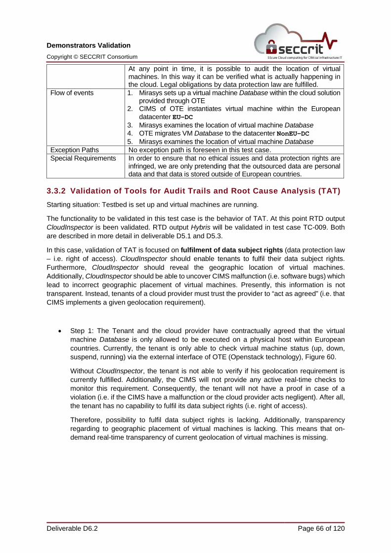
Flow of events 1. Mirasys sets up a virtual machine Database within the cloud solution provided through OTE
2. CIMS of OTE instantiates virtual machine within the European datacenter EU-DC
3. Mirasys examines the location of virtual machine Database 4. OTE migrates VM Database to the datacenter NonEU-DC 5. Mirasys examines the location of virtual machine Database
Exception Paths No exception path is foreseen in this test case. Special Requirements In order to ensure that no ethical issues and data protection rights are
infringed, we are only pretending that the outsourced data are personal data and that data is stored outside of European countries.
3.3.2 Validation of Tools for Audit Trails and Root Cause Analysis (TAT) Starting situation: Testbed is set up and virtual machines are running.
The functionality to be validated in this test case is the behavior of TAT. At this point RTD output CloudInspector is been validated. RTD output Hybris will be validated in test case TC-009. Both are described in more detail in deliverable D5.1 and D5.3.
In this case, validation of TAT is focused on fulfilment of data subject rights (data protection law – i.e. right of access). CloudInspector should enable tenants to fulfil their data subject rights. Furthermore, CloudInspector should reveal the geographic location of virtual machines. Additionally, CloudInspector should be able to uncover CIMS malfunction (i.e. software bugs) which lead to incorrect geographic placement of virtual machines. Presently, this information is not transparent. Instead, tenants of a cloud provider must trust the provider to “act as agreed” (i.e. that CIMS implements a given geolocation requirement).
• Step 1: The Tenant and the cloud provider have contractually agreed that the virtual machine Database is only allowed to be executed on a physical host within European countries. Currently, the tenant is only able to check virtual machine status (up, down, suspend, running) via the external interface of OTE (Openstack technology), Figure 60.
Without CloudInspector, the tenant is not able to verify if his geolocation requirement is currently fulfilled. Additionally, the CIMS will not provide any active real-time checks to monitor this requirement. Consequently, the tenant will not have a proof in case of a violation (i.e. if the CIMS have a malfunction or the cloud provider acts negligent). After all, the tenant has no capability to fulfil its data subject rights (i.e. right of access).
Therefore, possibility to fulfil data subject rights is lacking. Additionally, transparency regarding to geographic placement of virtual machines is lacking. This means that on-demand real-time transparency of current geolocation of virtual machines is missing.
• Step 2: The cloud provider is able to check on which physical cloud node virtual machine Database is currently executed (Figure 61). The cloud provider is able to unveil in which country a physical cloud node is located. Currently, virtual machine Database is executed on physical cloud node Compute1. Compute1 is a physical host in a European country. Therefore, the derived geolocation requirement is currently fulfilled.
Due to the Lack of Transparency, this information is not available for tenants. Furthermore, provided information depends on CIMS so that malfunction is not detectable.
FIGURE 61. CLOUD PROVIDER VIEW (CIMS)
• Step 3: The tenant is able to use the CloudInspector interface. The CloudInspector interface is part of TAT and was developed within SECCRIT (Figure 62). The tenant is able to run several on-demand checks to verify if the expected geolocation requirement is fulfilled. Additionally, tenants are able to configure continuous logging policies of geographic location of virtual machines. Real-time inspection of geographic location of virtual machines helps to exercise data subject rights (i.e. right of access).
The tenant is able to verify, if a virtual machine was within a European country (exercise data subject rights), so that no non-EU intelligence agency has access to the data. The sources of information for this audit command are CIMS-independent data sources on physical hosts (preconfigured values). The CloudInspector gathers a local view of all physical hosts. After that, CloudInspector checks whether virtual machines in question are instantiated on physical hosts, which resides within a European country.
The tenant gets real-time feedback from CloudInspector that the expected geolocation requirement is currently fulfilled. CloudInspector will report Instances are located within European countries.
No possibility to fulfil data subject rights is lacking. No transparency regarding to geographic placement of virtual machines is lacking. This means that on-demand real-time transparency of current geolocation of virtual machines is possible. Furthermore, provided information by CloudInspector does not depend on CIMS values so that malfunction will be detectable
• Step 4: However, the cloud provider is able to migrate virtual machine Database to another physical host, which does not reside within European countries. Furthermore, the CIMS is able to manipulate placement of virtual machines within the cloud infrastructure individually.
This could happen if the cloud provider acts negligent, for example by manually manipulating physical host configuration instead of using CIMS interface. Additionally, this unwanted outcome could happen if the CIMS has an internal failure and therefore is not able to implement requirements from tenants (i.e. geolocation of virtual machines).
In this case, the cloud provider migrates virtual machine database to physical host Compute2 (Figure 63). This physical host is located in a non-European country.
Due to the Lack of Transparency, this information is not available for tenants.
• Step 5: With CloudInspector the tenant is still able to verify if his geolocation requirement (i.e. within a European country) of virtual machine Database is currently fulfilled. The tenant is able to exercise data subject rights (i.e. right of access). The tenant gets real-time feedback from CloudInspector that his geolocation requirement is currently not fulfilled. CloudInspector will report At least one Instance is located outside a European country (Figure 64).
No possibility to fulfil data subject rights is lacking. No transparency regarding to geographic placement of virtual machines is lacking. This means that on-demand real-time transparency of current geolocation of virtual machines is possible. Furthermore, provided information by CloudInspector does not depend on CIMS values so that malfunction will be detectable
3.3.3 SECCRIT View (CloudInspector Interface) – GeolocationValidation of techno-legal guidance
The controller is obliged to fulfill the data subject’s rights like the right of access for example. As the location of the data is very important for the data protection requirements to be met, like the need of other legal requirements in the cases of a transfer to non-European countries, the controller needs to be aware where the actual location of the data is. The location is thus linked to specific data protection requirements. In order to assess the right of access of the data subject properly as otherwise the controller would risk legal proceedings / sanctions; he needs to be aware of the location of the data. For further information concerning the necessity of fulfilling the right of access of the data subject, see D2.7, which summarizes in detail the data protection problems occurring in the different constellations tenant / cloud provider as well as tenant / cloud provider / data subject.
3.3.4 Summary This test case successfully validates TAT, namely CloudInspector. With CloudInspector, tenants are able to fulfil data subject rights (data protection law – i.e. right of access). CloudInspector is able to reveal if a cloud provider does not fulfil tenant’s geolocation agreement. Furthermore, provided information by TAT does not depend on CIMS. Therefore, CloudInspector is able to uncover CIMS malfunction (i.e. software bugs) which lead to geographic misplacement. No possibility to fulfil data subject rights is lacking. No transparency regarding to geographic placement of virtual machines is lacking. Presently, this information is not transparent. Instead, tenants of a cloud provider must trust the provider to “act as agreed”. Finally, violation of geographic requirements could be collected continuously for Root Cause Analysis in court, similar as shown in validation of test case TC-009.
A replica of the Valencia Urban Traffic Management System (UTMS) has been deployed in two different cloud platforms. Each installation consists of three virtual machines on the cloud, following the distribution of the system installed in Valencia Traffic Management facilities. Overview of the system is provided in Figure 65.
• CommsMain runs the System Kernel, a middleware providing basic functions such as communication with field devices and monitoring of the field devices’ status, as well as its dependencies.
• UrbanTrafficMain runs the remaining applications. The most significant ones are:
o The Traffic Control Server (TCS), the application that processes sensor data, converts this data into information, distributes the information to other components and sends control commands to the traffic controllers.
o The Information System (IS), the application that provides a link between the different information sources of the system (TCS or third party applications such as parking facilities, public transport operators or municipalities) and the information media (elements capable of spreading information, such as Variable Message Signs or web services for third party applications)
o Desktop GUIs for the TCS and IS.
• SQL holds a Microsoft SQL Server 2012 hosting all databases necessary for the correct operation of the system.
In order to simulate the on-street devices (mainly Traffic Controllers and Variable Message Signs), several simulators are running outside the AMARIS Qloudwise environment. These simulators communicate via Internet with the System Kernel running inside the cloud environment, and simulate around 90% of the existing traffic controllers in the city of Valencia. Simulators are capable of responding to traffic control actions and sending sensor data.
FIGURE 65. OVERVIEW OF TEST ENVIRONMENT AND SYSTEM.
As stated above, a desktop TCS GUI (Figure 66) has been installed in the UrbanTrafficMain machine, allowing the interaction with the system in the same way the traffic operators do in their workstations in the Valencia Traffic Management facilities.
In addition, a desktop IS GUI has been installed (Figure 67). This interface allows the user interaction with the different information media available. In the city of Valencia, these media are mainly Variable Message Signs that can display information about the traffic status on different areas of city, information about traffic incidents (closed streets, traffic jams, etc.), information about availability on the parking of the city, etc.
4.1.1 AMARIS Qloudwise Test cases TC-003, TC-004 and TC-010 will run on the replica of the Valencia Urban Traffic Management System (UMTS) deployed in the AMARIS cloud platform Qloudwise, based in VMWare (Figure 68).
FIGURE 68. VALENCIA UMTS DEPLOYED IN VMWARE.
4.1.2 Openstack Test cases TC-005, TC-006 and TC-011 will run on the replica of the Valencia Urban Traffic Management System (UMTS) deployed in the OTE cloud platform, based in Openstack (Figure 69).
FIGURE 69. VALENCIA UMTS DEPLOYED IN OPENSTACK.
4.2 Test Case TC-001 – Risk assessment
4.2.1 Test subset description In this test case, a risk assessment for the cloudification process of the Traffic Management System in Valencia has been conducted following the Cloud Adoption Risk Assessment Process described in D3.1 Methodology for Risk Assessment and Management [20].
The test case corresponds directly to story 2 – Data not available due to a malfunction or misbehavior of UC-002 in D2.1 Report on requirements and use cases [25]
Test Case Risk assessment of mobility services in the cloud ID TC-001
Description (narrative) Goal: To evaluate the risks inherently derived of moving a critical
infrastructure in the cloud. In this case, the main applications and services run in the Valencia’s Traffic Control Centre. For that reason, the tenant and the end user should come up with a clear map of risks and should be able to analyze them, in order to establish all preventive, protective and reactive measures needed.
Resources VLC: End User of the platform, Know-how of the final applications and services. ETRA: Tenant on the cloud platform, Know-how of the ICT (Information and Communications Technology) infrastructure, system components interactions and processes flow. AIT: Support on the risk management methodology and risk strategy, provision of cloud specific risk catalogue.
Pre-Conditions The only pre-condition to run this test case is a computer with Verinice [29] installed and configured.
Post-Conditions /Expected Results
Both tenant and end user will have a more complete overview on the risks specific to the cloud, and hence more information on how to deploy protective security measures.
Flow of events 1. Infrastructure tenant or end user wants to have a “more complete” overview on the cloud risks and “how this may affect the services the infrastructure is offering”.
2. He/she installs Verinice in a computer to carry out the exercise. 3. Includes all assets, components and services, into the Verinice to
carry out the exercise. 4. Imports all cloud threats and risks from the SECCRIT catalogue. 5. Maps each asset with the possible threats and risks, by also
assessing the probability and impact in each one of the cases. 6. Completes the exercise and generates a report automatically with the
Verinice tool. Exception Paths No exception path is foreseen in this test case. Special Requirements No special requirements are required in this test case.
4.2.2 Validation of Risk Assessment This process is based upon the standard Verinice-supported information security risk assessment, which is extended with the SECCRIT Cloud Adoption Risk Assessment Extension, further steps on the risk assessment that aim at identifying Cloud-specific risks by using the SECCRIT Vulnerability and Threat Catalog, which is an outcome of SECCRIT project.
The Figure 70 shows a screenshot of Verinice, the tool used to perform the risk assessment. On the right side, the imported SECCRIT Vulnerability and Threat Catalog is shown. This catalog is provided as a CSV file that can be easily imported and used in the Verinice environment.
4.2.3 Summary Further details and results of the performed risk assessment are provided in D6.3 Report on validation results [30].
4.3 Test Case TC-003 – Lost network connectivity
4.3.1 Test subset description In this test case, the IND²UCE framework monitors the network connections of virtual machines in the VMware cluster. If a network connection is lost, email notifications are sent to specified recipients.
The test case corresponds directly to Story 3 – Data not available due to a malfunction or misbehavior of UC-002 in D2.1 [25]
Test Case Lost network connectivity for the database VM ID TC-003 Description (narrative) VM hosting the DB server loses network connectivity, at virtual
hardware layer. No VMs can communicate with DB (Data Base). This situation has to send a warning as soon as possible to the operator.
Resources ETRA: Tenant of the infrastructure, Know-how of the tenant platform. IESE: IND²UCE platform for policy specification and enforcement. AMARIS: Cloud provider based on VMWare.
Pre-Conditions DB Virtual Machine is connected to the network, and all other VMs are storing/reading data to/from DB without any errors.
Post-Conditions /Expected Results
R/W (Read/Write) operations to DB are failing. A warning is send via email to the pre-defined operator and a warning is shown in IND2UCE web interface.
Flow of events 1- Any process on any VM can connect to the DB successfully, and is capable to complete R/W transactions.
2- Suddenly, DB connections start failing (timeouts and connection error)
3- The necessary data cannot be stored to, or read from the DB. 4- The Urban mobility system has no access to the information stored
into the database. 5- A warning must be raised in the IND2UCE tool and an email sent to
the operator. Exception Paths No exception path is foreseen in this test case. Special Requirements No special requirements are required in this test case.
4.3.2 Validation of Policy Specification, Decision and Enforcement The IND²UCE framework is deployed to the VMware cluster within a VM on which the following core IND²UCE components are running:
- Policy Management Point (PMP)
- Policy Decision Point (PDP)
- VMware Policy Enforcement Point (PEP)
- VMware Policy Information Points (PIP)
o PIP for network connectivity checks
- Policy Execution Points (PXP)
o Notification PXP for sending log messages to ETRA Demo UI
o Sendmail PXP for sending email messages as notifications
Before the loss of network connectivity can be detected, an appropriate security policy need to be specified. We specify the following security policy (Figure 71):
“If the network connection of the DB server ‘SQL Server’ is lost, then notify [email protected] via email, write a log entry and write a notification and make a log entry, if the DB server is connected again.”
The policy specification tools transform the security policy (Figure 72) in a machine-readable equivalent that can be enforced by the IND²UCE framework.
FIGURE 72. MACHINE READABLE POLICY.
Now, the IND²UCE framework can detect the network connectivity loss of the VM “SQL”. If now, for example, due to a misconfiguration, the network connectivity is disabled (Figure 73), the IND²UCE framework detects the policy violation. The specified compensating actions are performed.
After the connection is working again, a second notification email (Figure 75) is sent to the recipient, as specified in the security policy.
FIGURE 75. NOTIFICATION MESSAGE AFTER COMPENSATION ACTIONS PERFORMED.
4.3.3 Summary In test case TC-003, we saw how the IND²UCE framework can compensate undesired behavior in the VMware Cluster with respect to lost network connections. The IND²UCE framework informs operators whenever the desired VM loses the network connection.
4.4 Test Case TC-004 – Growth in resource consumption
4.4.1 Test subset description This test case shows policy enforcement with the IND²UCE framework within the VMware cluster. Machines that occasionally have high resource load may harm the performance of a system. Therefore, the IND²UCE framework detects high loads and performs compensation actions. In this example, the CPU load of a virtual machine is monitored and on high load, an additional CPU is allocated to the VM.
The test case corresponds directly to Story 3 – Data not available due to a malfunction or misbehavior of UC-002 in D2.1 [25]
Test Case Unexpected growth in the HOST consumption resources ID TC-004 Description (narrative) CPU (Central Processing Unit) usage of any HOST running any
Urban Mobility System VM exceeds a predefined threshold. This situation can cause performance issues into VMs. An automatic increase of CPU resources, predefined by the operator, will take place.
Resources ETRA: Tenant of the infrastructure, Know-how of the tenant platform.
IESE: IND²UCE platform for policy specification and enforcement. AMARIS: Cloud provider based on VMWare.
Pre-Conditions Physical HOST resources are under predefined threshold, and all VMs are running properly.
Post-Conditions /Expected Results
VMs running into overloaded HOST begin to experience performance problems, and timeouts may occur in some processes or connections with other machines, causing the Urban Mobility service malfunction. After this happens, all must go into normal after increasing automatically the resources.
Flow of events 1- Physical HOST resources are under predefined threshold, and all VMs are running properly.
2- CPU usage of any HOST running any Urban Mobility System VM exceeds a predefined threshold (e.g., CPU reaches 95% three times in less than 24 hours).
3- The VMs are forced to share too many resources (CPU). 4- Processes within the machines slow down and timeouts occur. 5- A warning must be raised and an automatic increase of the resources
(resources are scale up 10% automatically). Exception Paths No exception path is foreseen in this test case. Special Requirements No special requirements are required in this test case.
4.4.2 Validation of Policy Specification, Decision and Enforcement The IND²UCE framework is deployed to the VMware cluster within a VM on which the following core IND²UCE components are running:
- Policy Management Point (PMP)
- Policy Decision Point (PDP)
- VMware Policy Enforcement Point (PEP)
- VMware Policy Information Points (PIP)
o PIP for critical service detection and network connectivity checks
o PIP for CPU load detection
- Policy Execution Points (PXP)
o VMware PXP for triggering VMware actions (e.g. migration of VMs)
o Notification PXP for sending log messages to Demo UI
o Sendmail PXP for sending email messages as notifications
We specify the following security policy (Figure 76):
“If the average CP U load of the DB server exceeds 80% for 3 timesteps, then notify [email protected] via email, write a log entry, and show notification on demo UI. If the load is still too high after 6 timesteps, increase the amount of CPUs by one, and inform [email protected] about the change. If the load is low again for 3 timesteps, then notify [email protected] via email. One time step represents 10 seconds.”
The policy specification tools generate the corresponding machine-readable security policy (Figure 77), which is then deployed to the PDP via the IND²UCE Management Dashboard.
FIGURE 77. MACHINE READABLE SECURITY POLICY.
In the beginning of the test case, the VM “SQL” has one CPU assigned to it as can be seen in the VMware vSphere Web Client (Figure 78).
Suddenly, the CPU load is rapidly increasing and reaches 100% for a period of time (Figure 80).
FIGURE 80. HIGH CPU LOAD IN VIRTUAL MACHINE “SQL”.
The PIP recognizes the high CPU load (Figure 82).
FIGURE 81. MONITORING CPU LOAD.
FIGURE 82. MONITORING CPU LOAD WITH PIP.
After 3 timesteps (30 seconds), in which the average CPU load is higher than 80%, an email notification is sent to the specified recipient (Figure 83).
After 6 time steps (60 seconds), in which the average CPU load is higher than 80%, compensating actions are performed by the IND²UCE framework, as specified in the security policy. A second CPU is assigned to the VM “SQL”, which directly results in a lower CPU load of 50% (Figure 84).
FIGURE 84. REGULATED CPU LOAD IN VIRTUAL MACHINE “SQL”.
A notification about the increasing of the CPU amount is sent to the email receiver (Figure 85).
After 3 more time steps, in which the average CPU load is continuously lower than 80%, an all-clear notification is sent (Figure 87).
FIGURE 87. NOTIFICATION MESSAGE AFTER COMPENSATING ACTIONS.
4.4.3 Summary In test case TC-004, we presented how the IND²UCE framework can compensate undesired behavior in the VMware Cluster with respect to VMs with too high CPU load. Triggered by security policies that are enforced by the IND²UCE framework, the amount of CPUs for a VM with high CPU load is increased and notifications are sent.
4.5 Test Case TC-005 – Growth in database
4.5.1 Test subset description The test case “Database that grows unexpectedly” is related to Demo 2 and directly corresponds to story 3 i.e., Data not available due to a malfunction or misbehavior of Usecase-002 in D2.1 [25]. The test case will test “anomaly detector” component of the resilience framework described in deliverable D4.2 [4] and D4.3 [29].
Test Case Database grows unexpectedly ID TC-005 Description (narrative) A database inside the DB server grows unexpectedly in a certain
period of time, and if growth continues, then the DB server could run out of disk space, thus impacting the entire system. In this case, a notification (alert) to the operation in time will be enough in order to solve the issue.
Resources ETRA: Tenant of the infrastructure, Know-how of the tenant platform. ULANC: Resilience Framework provider, with focus on anomaly detection techniques.
OTE: Cloud provider based on OpenStack environment. Pre-Conditions Database growth is in regular limits from a high level perspective and
the DBs are under normal operational conditions
Post-Conditions /Expected Results
Unexpected growth of any database causes that the DB server runs out of disk space. This affects R/W operations over all databases and hence, the operator must be informed (an alert to User Interface of ETRA will be enough for this purpose).
Flow of events DB server working properly, and databases’ growth patterns are normal. Database growth pattern becomes unusual. Database grows until server runs out of disk space. An error is raised on most of R/W operations, over any database. Urban Mobility System is then not working properly. An alert should be sent to the operator, as soon as possible, in order to inform him/her about this event. Investigation of impact of mitigation countermeasures on assurance
Exception Paths No exception path is foreseen in this test case.
Special Requirements No special requirements are required in this test case.
4.5.2 Validation of Resilience Framework with focus on Anomaly Detection
Starting situation: An OpenStack testbed is setup and relevant Virtual Machines are running.
Intermediate steps: Our solution is based on monitoring API Monasca10, Figure 88, which is scalable monitoring solution that leverages high-speed message queues and computational engines. All external interaction within the Monasca service is done via a first-class REST API.
Following components of the framework must be running on the compute node:
• Message Queue (Kafka11)
• Metrics, events, and alarms database (InfluxDB12)
• Configuration database (MySQL)
• Threshold Engine
• Transform Engine
• Event Engine
• Anomaly Engine (AD3 technique, described in deliverable D4.3)
For further information on installing these engines on OpenStack, we refer to the resilience framework installation guide available online: https://forge.comp.lancs.ac.uk/hosted/networking/doku.php?id=seccrit:anomaly-detection-framework-installation).
FIGURE 88. MONITORING API.
• Go to Notification link under “monitoring” and create notification (Figure 89): Name: OTE, Type: Webhook, Address: http://localhost/box_connector
(This is important to send notification to ETRA UI)
FIGURE 89. CREATING NOTIFICATION.
• As a next step, we invoke an agent that executes a configurable plugin (see installation notes).
• Agent consists of a “Collector” component that runs at a configurable interval, generating a set of metrics.
• The plugin is customized to this specific test case to collect most relevant features from database server (VM) running in the testbed. Following is a list of relevant features made available to message queue:
• Below we list configuration file for the agent, which is located on compute node in /etc/monasca/agent/conf.d.
• Metrics and events are received by the API and published to a message queue (Kafka). The “Transform Engine” calculates time based derivatives and creates metrics that are published back to the message queue.
• Click “Alarm Definition” and then “Create alarm definition”, Figure 90: Name: OTE-db-tc005, Expression: max, database.overall.rde.anomaly_score, > , 0.
Number Reads, Bytes Read, IO Stall Read, Number of Writes, Bytes Written, IO Stall Write and Bytes on Disk
• Set “Notifications” (form bottom) to OTE and click “Create Alarm Definition”
• As a next step, go to “Alarms” and click “Graph Metric ” on previously created alarm
• The metrics are then consumed by Anomaly Engine from the same message queue, which then computes overall mean of the data, density and evaluates anomaly score as probabilities.
• The Dashboard (Figure 91) displays the visualization of the output from anomaly detector.
• The Figure 91 shows the overall anomaly score during the period when database growth is going unexpectedly high (when mean of the data drops below the density).
• We then create disk utilization alarm. The framework allows associating alarm definitions with the likelihood by creating an alarm definition on the probability of an anomaly.
• Database growth is detected with high accuracy. Figure 92 shows the alarm going off when that happens and alert being sent to ETRA UI (Figure 93).
Final situation:
FIGURE 92. DATABASE GROWTH IS DETECTED AND ALARM GOING OFF.
4.5.3 Summary The mechanisms presented in this test case define components that should exist in a cloud environment to support overall resilience to challenges. More specifically, we have evaluated an online anomaly detection and identification using a technique called AD3 (Anomaly Detection using Data Density). The method is embodied by a resilience architecture that was initially defined in [29] and further explored in [13]. Our evaluation focused on detecting anomalies during the onset of various network level attacks.
4.6 Test Case TC-006 – Network pattern changes
4.6.1 Test subset description The test case “Network pattern changes” is related to Demo 2 and directly corresponds to story 3 i.e., Data not available due to a malfunction or misbehavior of Use case-002 in D2.1 [1]. The test case will validate “anomaly detector” component of the resilience framework described in deliverables D4.2 and D4.3 [5, 6]. The overview of the test case is shown in Figure 94.
FIGURE 94. OVERVIEW OF THE TEST CASE.
Test Case Network pattern change ID TC-006
Description (narrative) Network traffic pattern between communications server and devices
on public areas changes unexpectedly. This may indicate that “something is going wrong” and a warning must be sent to the operator.
Resources ETRA: Tenant of the infrastructure, Know-how of the tenant platform.
ULANC: Resilience Framework provider, with focus on anomaly detection techniques. OTE: Cloud provider based on OpenStack environment.
Pre-Conditions Communication with devices located in public areas is working fine.
Post-Conditions /Expected Results
A notification is sent to the operator to warn him/her about an unexpected pattern network change in the traffic behavior.
Flow of events Communication with devices located in public areas is working fine. Network traffic pattern among communications VM and public devices has an unusual pattern (i.e. low or high value). Communication with street devices may even fail. A warning must be sent to the operator, to avoid this situation as soon as the pattern changes.
Exception Paths No exception path is foreseen in this test case.
Special Requirements No special requirements are required in this test case.
4.6.2 Validation of Resilience Framework with focus on Anomaly Detection
Starting situation: An Openstack testbed is setup and Virtual Machines relevant to test case are running.
Intermediate steps:
• This test case is similar to what is described in previous test case (TC005 : Unexpected database growth) However, the agent uses “network stat” plugin which is a customized plugin in order to collect most relevant network features and publish them on to the message queue. The plugin has option to capture statistics from an interface and following features are collected:
Byte sent, packets sent, active flows, byte distribution, source port distribution, destination port distribution, source IP distribution and destination IP distribution.
• Following steps are required to invoke network plugin.
• Download plugin source available from https://scc-forge.lancs.ac.uk/svn-repos/seccrit-internal/monasca-network-agent/trunk
• Once downloaded and in the directory, install requirements
sudo pip install -r requirements
• Next, we edit the configuration file network_stats.yaml.
• Install the agent and configuration - these directories tend to change per system, should problem check before.
• Next, we grant permission for network capture. Since the network stats plugin has the option to capture stats from an interface, a task that normally requires admin privileges.
• Once the main dashboard is available, go to “Monitoring” -> “Overview” and click on the agent (that is monitoring the network traffic) under “Servers”.
• Go to “Notification” link under monitoring and create notification: Name: OTE, Type: Webhook, Address: http://localhost/box_connector
(This is important to send notification to ETRA UI)
• Click “Alarm Definition” and then “Create alarm definition” Figure 95: Name: OTE-net-tc006, Expression: max, net_stat.overall.rde.anomaly_score, > , 0.
• Set “Notifications” (form bottom) to OTE and click “Create Alarm Definition”
• As a next step, go to “Alarms” and click “Graph Metric” on previously created alarm
(You can also add other metrics using the above three steps)
• As result of the above steps, metrics will be available for Anomaly Detection Engine that will consume those in order to evaluate likelihood and anomaly score as probabilities (Figure 96).
When metrics are consumed by anomaly detection engine, it will compute overall mean, data density, and peak going high when network pattern changes significantly over time as can be seen in Figure 97 and notification going off (Figure 98).
4.6.3 Summary In this test case, we have evaluated an online anomaly detection and identification using a technique called AD3 (Anomaly Detection using Data Density). The method is embodied by a resilience architecture that was initially defined in [29] and further explored in [13].
4.7 Test Case TC-009 - Legal evidence provision
4.7.1 Test subset description This test case will test two different RTD components, as follows:
• Tools for Audit Trails and Root Cause Analysis (TAT).
• Legal guidance
The selected cloud platform for the test case shall be VMware.
The test case corresponds directly to Story 3 – “Data not available due to a malfunction or misbehavior” of UC-002 in D2.1 [25].
Test Case Audit Trail provision for Root Cause Analysis in court ID TC-009
Description (narrative) The Municipality of Valencia has a contract with ETRA for providing a
traffic management system. ETRA (tenant) is using a cloud-based solution of AMARIS (Cloud Infrastructure Provider). In this test case, a situation is induced in which the traffic management system deployed in the cloud suffers a breakdown caused by a negligent behavior of AMARIS which causes a damage for the Municipality of Valencia. If Municipality of Valencia sues ETRA, ETRA, as the defendant will need to prove that neither they themselves have acted negligently nor AMARIS, as they are also responsible for the behavior of the persons they employ (AMARIS) to fulfil their duty against their client (Municipality of Valencia).
a) By now: Municipality of Valencia will win (first) lawsuit against ETRA. As a breach of duty (unavailable service) and damage is given, ETRA will not be able to disprove possible own default. Additionally, ETRA will lose potential (second) lawsuit against AMARIS, as they cannot contradict non-default of AMARIS (missing evidence for negligent behavior).
b) After SECCRIT: ETRA will still lose lawsuit against Municipality of Valencia (first lawsuit; contractual agreed service is unavailable and damage is given). However, ETRA may win subsequent process against AMARIS (second lawsuit), as additional evidence is available and they may prove that AMARIS acted negligently.
ETRA will use the outcomes of TAT in order to retrieve evidence that can be presented in a court to assist analyzing the root cause of a failure. The audits trails may prove that the fault was out of ETRA’s scope and that the Cloud Infrastructure Provider (AMARIS) is responsible for the failure (acted negligent).
Resources AMARIS: Virtual Datacenter ETRA: Traffic Management System KIT-tm: TAT KIT-zar: Legal guidance and log analysis from legal perspective
Pre-Conditions AMARIS sets up a virtual datacenter based on VMware ESXi. AMARIS has not exercised reasonable care and forgot to update one of their physical cloud nodes from VMware ESXi 5.5 Update 3 to a newer version. Therefore, this node is vulnerable to a bug (KB2133118) (http://www.virten.net/2015/10/vmware-esxi-5-5-update-3-snapshot-bug/) that causes unexpected virtual machine failure after snapshot consolidation. TAT is deployed and continuously monitors VMware ESXi versions as well as all maintenance operations (snapshot creation and deletion). Within the lawsuit, a third party notice is given, which has the consequence that in a subsequent process the decision of the first lawsuit underlies the second process (b – AMARIS acted negligent).
Post-Conditions /Expected Results
TAT is able to retrieve a set of logs in which the following can be shown: • The virtual machine that crashed was running on cloud node with
a vulnerable version of VMware ESXi • Tenant was performing a regular maintenance (snapshot
creation and deletion) task when breakdown occurred With the expert evidence and a legal inspection, these log files will permit to detect a negligent behavior, as the version was not updated as expected and the causality with the breakdown is given. Therefore, as the judge is free to assess and judge the evidence, he will with the expert evidence conclude that AMARIS has acted negligently, as he should have updated the virtual machines.
Flow of events 1. ETRA sets up a virtual machine for the Municipality of Valencia 2. VM of ETRA is migrated to the vulnerable cloud node 3. ETRA performs a regular maintenance task, taking a snapshot, on
the virtual machine of Municipality of Valencia 4. ETRA performs a regular maintenance task, deleting a snapshot, on
the virtual machine of Municipality of Valencia 5. The virtual machine of Municipality of Valencia crashes and causes
the damage 6. If Municipality of Valencia will sue ETRA additional evidence for
Root Cause Analysis in court should be available 7. Expert analyses of these log files should conclude that these audit
trails recognitions are non-tampered and attest AMARIS negligent behavior.
8. Judge will in this case come to the result that it was AMARIS fault and favors for the Municipality of Valencia.
9. ETRA could sue AMARIS in return, and as third party notice is given, will win this process.
Exception Paths No exception path is foreseen in this test case. Special Requirements We are only pretending that AMARIS acts negligent. Generally, AMARIS
will stress to fulfil their duty of care (in this case, keep operating system up-to-date). As the software bug of CIMS does not lead to a reproducible behavior, this test case is unsuitable for demonstration. However, to ensure that no major damage of our demonstration setup will happen at the time when the defect occurs, we will use VM CrashVM for validation (and evaluation).
4.7.2 Validation of Tools for Audit Trails and Root Cause Analysis (TAT) Starting situation: Testbed is set up and virtual machines are running.
The functionality to be validated in this test case is the behavior of TAT. At this point RTD output CloudInspector is been validated. RTD output Hybris will be validated in test case TC-009. Both are described in more detail in deliverable D5.1 and D5.3.
In this case, validation of TAT is focused on CIMS-independent collection of evidence for root cause analyses in court (maybe prove negligent behavior of the cloud provider). CloudInspector should be able to collect relevant Meta data of cloud behavior, which is useful to analyze the root cause of a failure. Additionally, CloudInspector should be able to uncover CIMS malfunction (i.e. software bugs). Presently, this information is nor transparent, neither been collected so that it is not available in court. Instead, tenants of a cloud provider must trust the provider to “act as agreed”. Tenants will not have a proof in their hands in case of service degradation.
• Step 1: The tenant instantiates a virtual machine called CrashVM within his virtual datacenter (provided by the cloud provider), Figure 99. Currently, the tenant is only able to check virtual machine status (up, down, suspend, running) via the external interface of AMARIS (VMware technology). Without CloudInspector, the tenant has no way to know if the cloud provider currently carries out its duties with due diligence. Additionally, the CIMS will not provide any active real-time checks to monitor current cloud behavior (for example if all physical servers are up-to-date). Consequently, the tenant will not have a proof in its hands in case of a breach of duty (i.e. if the CIMS have a malfunction or the cloud provider acts negligent).
Therefore, the tenants’ capability to prove negligent behavior of the cloud provider in court is lacking. Additionally, transparency about fulfillment of duty of care is lacking (i.e. of physical hosts are up-to-date).
FIGURE 99. TENANT VIEW (WITHOUT CLOUDINSPECTOR)
• Step 2: The cloud provider is able to manage and monitor all virtual machines and physical hosts via AMARIS management interface (based on values of CIMS - VMware technology). The CIMS provides for each virtual machine detailed information, e.g. underlying physical hosts and build number, Figure 100.
Therefore, the cloud provider is able to verify, if all physical hosts are up-to-date, (actual version is ESXi-build 2403361). However, he has no possibility to detect malfunction or misconfiguration of the CIMS.
The cloud provider verifies that the physical host that executes virtual machine CrashVM (here atviectesx086) is not vulnerable to KB2133118. As the build number is 2403361 this host is not vulnerable and security is not compromised. Currently, the cloud provider carries out its duties with due diligence as all physical servers are up-to-date.
Due to the lack of transparency, this information is not available for tenants. Furthermore, provided information depends on CIMS so that malfunction is not detectable.
FIGURE 100. CLOUD PROVIDER VIEW (CIMS)
• Step 3: The Tenant performs normal maintenance task, such as creation of a virtual machine snapshots (Figure 101) or removal of virtual machine snapshots (Figure 102). Everything works as expected.
• Step 4: The CloudInspector as part of TAT (was developed within SECCRIT) collects Meta data about regular cloud behavior (Figure 103). This means CloudInspector records on which physical machine which virtual machine was located (or migrated). Additionally, CloudInspector collects physical host build number. Finally, CloudInspector records normal maintenance tasks of tenants, such as snapshot creation or removal.
In this case, CloudInspector records that virtual machine CrashVM was placed on physical host atviectesx086.test.ixn.local, which build number is 2403361. Additionally, CloudInspector tracks snapshot creation and snapshot deletion (normal maintenance task of a tenant). Gathered audit trails will be encrypted and transferred to a trusted third party (trusted by tenant and cloud provider) which ensures that audit trails will be non-tampered and available in case of a dispute in court. The trusted third party uses Hybris to store encrypted audit trails (Figure 104).
In the case of a legal dispute, this independent information about cloud behavior could help to determine the root cause of a failure. These collected audit trails will strengthen the tenants’ legal position.
Therefore, the tenants’ capability to prove negligent behavior of the cloud provider in court is not lacking. Additionally, transparency about fulfillment of duty of care is not lacking (i.e. of physical hosts are up-to-date).
FIGURE 104. SECCRIT VIEW (HYBRIS) – STORAGE OF AUDIT TRAILS
• Step 5: However, the cloud provider is able to migrate virtual machines CrashVM to another physical host (Figure 105), which is not up-to-date (i.e. atviectesx086.text.ixn.local which is
vulnerable to KB2133118 – build 3029944). Furthermore, the CIMS is able to manipulate placement of virtual machines within the cloud infrastructure individually.
This could happen if the cloud provider acts negligent, for example by manually manipulating physical host configuration instead of using CIMS interface. Additionally, this unwanted outcome (breach of duty) could happen if the CIMS has an internal failure. Normally, a cloud provider ensures that physical hosts that are not up-to-date will not take part in production cloud behavior.
Due to the Lack of Transparency, this information is not available for tenants. Furthermore, provided information depends on CIMS so that malfunction is not detectable. Without CloudInspector, the tenants’ capability to prove negligent behavior of the cloud provider in court is lacking. Additionally, transparency about fulfillment of duty of care is lacking (i.e. of physical hosts are up-to-date).
FIGURE 105. CLOUD PROVIDER VIEW (CIMS)
• Step 6a: The Tenant performs normal maintenance task (same as described in step 3), such as creation of a virtual machine snapshots or removal of virtual machine snapshots. Virtual machine CrashVM crashed (stop execution).
Without CloudInspector, there will be no evidence for root cause analysis in court available. Tenants’ legal position is very weak. The capability to prove negligent behavior of the cloud provider in court is lacking
• Step 6b: As shown in step 4, CloudInspector is able to collect evidence about virtual machine placement (Figure 106), patch level of physical hosts, and normal maintenance tasks (such as snapshot creation and removal).
In this case, CloudInspector records that virtual machine CrashVM was placed on physical host atviectesx090.test.ixn.local, which build number is 3029944. Additionally, CloudInspector tracks snapshot creation and snapshot deletion (normal maintenance task of a tenant). Gathered audit trails will be encrypted and transferred to a trusted third party (trusted by tenant and cloud provider) which ensures that audit trails will be non-tampered and available in case of a dispute in court. The trusted third party uses Hybris to store encrypted audit trails (Figure 107).
In the case of a legal dispute, this independent information about cloud behavior could help to determine the root cause of a failure. These collected audit trails will strengthen the tenants’ legal position.
Therefore, the tenants’ possibility to prove negligent behavior of the cloud provider in court is not lacking. Additionally, transparency about fulfillment of duty of care is not lacking (i.e. of physical hosts are up-to-date).
As the virtual machine CrashVM has crashed during exercising step 6a, the tenant would proceed and bring a case.
• Storage of Audit Trails Step 7: In this case, recorded audit trails contain enough Meta data to prove that the cloud provider acted negligent. As build 3029944 has the documented defect KB2133118 that leads to virtual machine crashes if a tenant creates and removes snapshots. Therefore, the root cause of the virtual machine crash could be determined in court.
4.7.3 Validation of Techno-legal guidance The current legal proving situation of the cloud user is very weak as he can neither contradict the non-default of the provider nor disprove an own default, if the provider shows that he did not act negligent. With such an independent inside view, accessible to the cloud user, the proving situation of the cloud user is strengthening. For further information concerning the use of such tools and how their output can be used in court, see D2.7, which summarizes in detail what are recognized proofs and how they will be assessed in court properly.
4.7.4 Summary This test case successfully validates TAT, namely CloudInspector. With CloudInspector, collection of evidence for root cause analyses in court. CloudInspector is able to reveal if a cloud provider does not fulfil its due diligence (i.e. keeping physical hosts up-to-date). Furthermore, provided information by TAT does not depend on CIMS. Therefore, CloudInspector is able to uncover CIMS malfunction (i.e. software bugs). No possibility to prove negligent behavior of the cloud provider in court is lacking. Additionally, transparency about exercising reasonable care is not lacking (i.e. of physical hosts are up-to-date). Presently, this information is not transparent. Instead, tenants of a cloud provider must trust the provider to “act as agreed”. As the defect in the vulnerable version is not reproducible, we assume during validation that a virtual machine will crash if a created snapshot is deleted. However, we are able to record the real defect during validation.
4.8 Test Case TC-010 – Real-time monitoring of issues in the cloud
4.8.1 Test subset description Test Case Real-time monitoring of issues in the cloud ID TC-010 Description (narrative)
Current test case represents a second iteration over previous test cases TC-003, TC-004, TC-005 and TC-006. Those test cases demonstrate how the Policy Specification, Decision and Enforcement tools and the Resilience framework successfully monitor problems such as network connectivity issues or unexpected growth in the use of the resources.
Current test case focus is put in the perspective of the system operator and the technology provider. They must get the notifications fast and in an easily interpretable manner. Keeping these objectives in mind, the tools have been integrated with the ETRA I+D Alert Monitor, an interface available both to the system operators and the technology provider. The purpose of this interface is to provide clear information of the events happening in the cloudified system, thus allowing the corresponding parties to take required actions as fast as possible and in possession of clear evidences of the problem.
Resources ETRA: Tenant of the infrastructure, Know-how of the tenant platform, technology provider (customer support service) IESE: IND²UCE platform for policy specification and enforcement. ULANC: Resilience Framework provider, with focus on anomaly detection techniques. AMARIS: Cloud provider based on VMWare.
Pre-Conditions Physical HOST resources are under predefined threshold, and all VMs are running properly.
Post-Conditions /Expected Results
IND²UCE platform for policy specification and enforcement VMs running into overloaded HOST begin to experience performance problems, and timeouts may occur in some processes or connections with other machines, causing the Urban Mobility service malfunction. Policies have been defined to monitor that certain thresholds are not overcome. After this happens, a notification is triggered to the ETRA I+D Alert Monitor Resilience Framework with focus on anomaly detection techniques Unexpected growth of databases or anomalies in the network traffic patterns can be early symptoms of future problems. Hence, the operator must be informed in the ETRA I+D Alert Monitor
Flow of events 1- Events are triggered within the demo environment, as described in TC-003, TC-004, TC-005 and TC-006
2- Corresponding notifications must be raised in the ETRA I+D Alert Monitor
Exception Paths No exception path is foreseen in this test case. Special Requirements No special requirements are required in this test case.
4.8.2 Validation of Policy Specification, Decision and Enforcement and ETRA I+D Alert Monitor
Initially, the operator / technology provider customer service logs in to the ETRA I+D Alert Monitor as shown in Figure 108. No issue is shown (Figure 109).
IND²UCE platform for policy specification and enforcement
After the IND²UCE framework detects an unusually high average CPU load, as set by the corresponding policy, an alert is triggered and shown in the interface in Figure 110. The interface shows that an alert has appeared at the Valencia facility, and that current severity level for that facility has arisen from 0 to 5 out of 10.
FIGURE 110. AN ALERT IS TRIGGERED AND SHOWN IN THE INTERFACE.
The security operator and the supporting technology provider can proceed to inspect the details of the alert (Figure 111). The following information is presented:
• Timeline over last 24 hours: time-based tendency of the alerts coming from that particular facility
• Distribution of the source of the last 24 hours alerts
• Alerts triggered per monitoring tool or application
By selecting the corresponding tool, details on the alerts triggered are shown (Figure 112). At this point, an ordered list of the last alerts is presented, where the last alert occupies the first position. Alerts are colored accordingly to their severity. Alerts that have already been treated can be ignored (ignored alarms do not contribute to the calculation of the overall severity status of a facility).
FIGURE 112. DETAILS OF ALERTS FOR POLICY SPECIFICATION, DECISION AND ENFORCEMENT TOOL.
Resilience Framework with focus on anomaly detection techniques
After the Resilience framework detects an anomaly in the network traffic pattern of one of the virtual machines, an alert is triggered and shown in the interface, Figure 113. The interface shows that an alert has appeared at the Barcelona facility, and that current severity level for that facility has arisen from 0 to 5 out of 10.
FIGURE 113. AN ALERT OF AN ANOMALY IN THE NETWORK TRAFFIC PATTERN.
The security operator and the supporting technology provider can proceed to inspect the details of the alert (Figure 114).
FIGURE 114. DETAILS OF ALERT IN RESILIENCE FRAMEWORK TOOL.
4.8.3 Summary This test case targets directly the necessity of the end users and technology providers of cloudified systems of having a clear and easy way to access and inspect the results triggered by the tools that are monitoring the performance of the cloud.
The integration of the different tool outputs in the ETRA I+D Alert Monitor fulfils these requirements. This interface is particularly useful for the traffic operators (municipality staff) and the customer support service (technology provider staff), since they can obtain real-time detailed alerts of problems happening in several different installations. This facilitates the understanding of the problem, reduces the response time and the time required to solve it, thus reducing the risk of long breakdown periods, which is of great importance in critical services.
4.9 Validation of Cloud Security Guideline
Demo 2 was also used to evaluate the Cloud Security Guideline (WP3). The evaluation is documented in the public deliverable D3.4.
5 Summary Deliverable D6.2 Demonstrators validation, is describing the technologies that have been developed in the project by integrating them into the prototypes and providing illustrative screenshots from the demos. The goal of this deliverable is to document test cases and test case results in order to show that developed technologies meet the specifications that have been set earlier in the project. The goal is to provide initial validation of running demos and illustrate executed test cases. Deliverable D6.3 describes test cases validation in more detail.
Scientific novelty of the validated technical approaches is summarized in section 3.1 of [2] and full list of related scientific papers is available at [3].
There are total of 10 test cases for the two demonstrations. We run test cases in two different cloud platforms, namely VMware and Openstack. Test cases are executed in two iterations during 2015.
Demo 1: Storage and processing of sensitive data has been validated in three test cases and the main validation results of each technology in each test case are summarized below.
TC-002 Dedicated host i.e. anti-affinity of virtual machines on the same host. Dedicating a host to a virtual machine running a critical service reduces the risk for unauthorized data access and therefore data leak. Data leak is the main concern in the use case story of a misbehaving politician whose personal data was leaked out to public.
• Policy Specification, Decision and Enforcement. The results of the test case show that now it is possible to use IND²UCE framework in preventing unknown virtual machines to migrate on a host that is already running a critical service with sensitive data.
• Tools for Audit Trails and Root Cause Analysis. The results of the test case show that now it is possible for a tenant to run on-demand check to see the contractually agreed requirements and the check provides an independent view of current situation to find out if the cloud provider has acted negligent or if the Cloud Infrastructure Management System has an internal failure.
TC-007 Failure recovery of a virtual machine with minimum interruption to a service. Sometimes there might be a failure situation in a virtual machine running a critical service with sensitive data. Failure situation may cause the service to be unavailable for a short while and if simultaneously an alarm needs to be created and sent it will not be done. This may cause vandalism to happen within the surveillance area without any notice to security service provider. This is what happened in the use case story of unalarmed vandalism.
• Resilience Framework with focus on Deployment Function. The results of this test case show that deployment function is working correctly by providing redundant instances of Master Servers and a failover between the main Master server and the backup Master server occurs automatically. There is no interruption to the service therefore mitigating the risk of any vandalism to happen without notice.
• Tools for Audit Trails and Root Cause Analysis. The results of this test case show that tools are able to provide an independent view of server deployment to the tenant, providing the means to audit the availability of the Master Server component without having to rely on information from the CIMS (Cloud Infrastructure Management System). This functionality would contribute to ensuring Master Service availability and therefore mitigate the risk of unnoticed vandalism within the surveillance area.
• Assurance Framework. The results of this test case show that Assurance Framework can continuously evaluate the likelihood of security incidents in the system and display the level
of likelihood in the user interface. This functionality indicates any change in the likelihood of security incidents and therefore contributes in ensuring Master Service availability.
TC-008 Asserting Right of access (Data Protection Law) - Geo location of personal data. Personal data owner is responsible for the stored sensitive data and naturally wants to know where the data is geographically located. This can be agreed in contracts, but it is very difficult to check whether the data really is where it is said to be.
• Tools for Audit Trails and Root Cause Analysis. The results of this test case show that data owner (tenant in this case) is now able to (independently of data storage service provider) check where the sensitive data is stored.
• Legal Guidance. With the help of the legal guidance, it is now possible to ensure that control options and right of access are fulfilled.
Demo 2: Hosting critical urban mobility services has been validated in seven test cases and the main validation results of each technology in each test case are summarized below.
TC-001 Risk assessment of mobility services in the cloud. Managers of the Traffic Management System need to assess and evaluate the risks of the cloudified system and compare them to those of the non-cloud system. The objectives are gaining insight of the details of the cloud environment, identifying risks and looking for security improvements that deal with those risks, taking into account the SECCRIT knowledge base to investigate strategies to improve security in the cloud.
• Risk Assessment. The results of this test case show how to apply the SECCRIT methodology for performing a risk assessment as part of the cloudification process. This risk assessment is particularly useful for understanding the implications of bringing a system to the cloud and determining the risks and the necessity for controls that minimize the impact of those risks and provide an independent view of the actions taken by the new actors.
TC-003 Lost network connectivity for the database VM. Urban mobility system stores important data in a cloud database. The system is not able to fully function without a connection to the remote database and retaining this connection is crucial to the availability of higher level services as well as knowing if lost connection has occurred.
• Policy Specification, Decision and Enforcement. The results of this test case show that if network connection is lost, a notification email is sent to a defined recipient. This functionality notifies a system malfunction and therefore contributes in preventing data unavailability.
TC-004 Unexpected growth in resource consumption on host. Availability is one of the most important quality aspects for urban mobility system. Well performing virtual machines contribute to the availability of services. If virtual machine performance is compromised when e.g. resource consumption on host is growing unexpectedly, this may affect availability or even cause a malfunction.
• Policy Specification, Decision and Enforcement. As a result of this test case, we may conclude that Policy Specification, Decision and Enforcement is able to raise a warning and automatically increase CPU resources. This contributes to preventing system malfunction.
TC-005 Database grows unexpectedly. Database size may differ during the system execution and it is normal, expected behavior. However, unexpectedly large growth in database size may quickly consume all storage space at database server. This situation would cause system malfunction.
• Resilience Framework with focus on Anomaly Detection. The results show that it is possible to detect abnormal database growth as an anomaly of the system and the accuracy of the detection is high.
TC-006 Network traffic pattern changes. Expected, normal network traffic between communications server and public area devices on urban mobility service system follows an expected traffic pattern. Unexpected pattern may indicate abnormally low or high amount of communications, this again indicates that something is wrong or is about to go wrong in the system. System operator needs to receive a warning to take mitigating actions.
• Resilience Framework with focus on Anomaly Detection. As a result, it is possible to define metrics for anomaly detection engine and consume them in order to successfully detect network pattern anomalies.
TC-009 Legal evidence provision for proving negligent behavior. When there happens a massive breakdown in cloud services, it may be possible that legal actions are brought into the table. In these situations, those responsible want to prove their behavior has not been negligent.
• Tools for Audit Trails and Root Cause Analysis. In the test case, it was possible to use the outcomes of TAT in order to retrieve evidences that can be presented in a court to assist analyzing the root cause of a failure.
• Legal Guidance. With the help of the legal guidance, it is now possible to ensure that Audit trails can be used as a proof in court.
TC-010 Real-time monitoring of issues in the cloud. System operator wants to be aware of any relevant problem in the urban mobility services system. Sending emails is one possible solution, but may not be a sufficient and the most convenient way to share this information in all cases. Therefore, a separate Monitoring Interface is tested in this test case.
• Policy Specification, Decision and Enforcement and ETRA I+D Alert Monitor. Test case results show that it is possible to detect performance problems such as timeouts in connections and failures in database read/write operations. Further, it has been shown that it is possible to show a notification in the ETRA I+D Alert Monitor and share the details of the problems with the system operator.
• Resilience Framework with focus on anomaly detection techniques and ETRA I+D Alert Monitor. Test case results show that anomalies in the traffic network pattern and in the databases growth rates can be detected. Those issues trigger a notification in the ETRA I+D Alert Monitor where the details of the problems are presented to the system operator.
The test cases showed the overall feasibility and functionality of the technologies validated in different test environments and situations. All test cases have been validated together with the demo partners MIRASYS and ETRA and the hosting partners AMARIS and OTE.
6 References [1 ] Collection of project results available under open source license. SECCRIT Consortium.
2015. Available [Online]: https://seccrit.eu/publications/opensource
[2] D7.5 Exploitation plan 2. SECCRIT Consortium. 2015.
[3] Collection of project scientific publications at SECCRIT project website. SECCRIT Consortium. 2015. Available [Online]: https://www.seccrit.eu/publications
[4] D4.2 Resilience Management Framework. 2014. Available [Online]: https://seccrit.eu/upload/upload/D4.2_Resilience_Management_Framework.pdf
[5] A framework for Resilience Management in the Cloud Noor-ul-hassan Shirazi, Steven Simpson, Simon Oechsner, Andreas Mauthe and David Hutchison e&i Elektrotechnik und Informationstechnik Springer Journal Feb 2015 2015/01/15 confirmed accepted Springer https://pp.seccrit.eu/svn/seccrit/Publications/20141218-CAISJournal-CRMF(Published)
[6] A Multilevel Approach Towards Challenge Detection in Cloud Computing Noor Shirazi, Michael Watson, Angelos K M, Andreas Mauthe and David Hutchison Cyberpatterns2013: http://tech.brookes.ac.uk/CyberPatterns2013/ July 2013 June 2013 confirmed accepted https://pp.seccrit.eu/svn/seccrit/Publications/Cyberpatterns2013
[7] Malware Analysis in Cloud Computing: Network and System Characteristics Angelos K. Marnerides, Michael R.Watson, Noorulhassan Shirazi, Andreas Mauthe and David Hutchison Globecom 2013 Dec 2013 Aug 2013 ... confirmed accepted IEEE https://pp.seccrit.eu/svn/seccrit/Publications/
[8] Towards a Distributed, Self-Organising Approach to Malware Detection in Cloud Computing Michael R.Watson, Noorulhassan Shirazi,Angelos K. Marnerides, Andreas Mauthe and David Hutchison IWSOS 2013 May 2013 April 2013 ... confirmed accepted https://pp.seccrit.eu/svn/seccrit/Publications
[9] D4.1, The Anomaly Detection Techniques for Cloud Computing. SECCRIT.
[10] Anomaly Detection in the Cloud using Data Density" Noorulhassan Shirazi, Steven Simpson, Andreas Mauthe and David Hutchiso. In IEEE ICC October,2015 (Currently Under Review)
[11] Malware Detection in Cloud Computing Infrastructures Michael R. Watson, Noor-ul-hassan Shirazi, Angelos K. Marnerides, Andreas Mauthe and David Hutchison IEEE Transaction on dependable and secure computing TBC 2014/10/20 accepted IEEE https://pp.seccrit.eu/svn/seccrit/Publications/2014-TDSC-Malwarepaper (Published)
[12] Anomaly detection In Secure Cloud Environments Using a Self-Organizing Feature Map (SOFM) Model for Clustering Sets of R-Ordered Vector-Structured Features Ioannis M.Stephanaki, Ioannis P. Chochliouros, Evangelos Sfakisanakis, Noorulhassan Shirazi. In , IPMSC2015 in conjunction with EANN 2015 (Published)
[13] Noorulhassan Shirazi, S.Simpson, A.K.Marnerides, M.Watson, A.Mauthe and D.Hutchison. Assessing the impact of intra-cloud live migration on anomaly detection. In Cloud Networking (CloudNet), 2014 IEEE 3rd International Conference, pages 52- 57, Octo 2014.
[14] Manuel Rudolph: User-friendly and Tailored Policy Administration Points. In: 1st International Conference on Information Systems Security and Privacy, 2015.
[15] Manuel Rudolph, Christian Jung, Reinhard Schwarz: Security Policy Specification
Templates for Critical Infrastructure Services in the Cloud. 5th International Workshop on Cloud Applications and Security (CAS’14), 8-10 December 2014.
[16] Christian Jung, Andreas Eitel, Reinhard Schwarz: Enhancing Cloud Security with Context-aware Usage Control Policies. INFORMATIK2014: Big Data- Komplexität meistern. Workshop on Provisioning and Management of Portable and Secure Cloud-Services (CloudCycle 2014), 22-26 September, 2014.
[18] C. Wagner, Hudic, A., Maksuti, S., Tauber, M., and Pallas, F., “Impact of Critical Infrastructure Requirements on Service Migration Guidelines to the Cloud”, in FiCloud, 2015.
[19] S. Paudel, Tauber, M., Wagner, C., Hudic, A., and Ng, W. - K., “Categorization of Standards, Guidelines and Tools for Secure System Design for Critical Infrastructure IT in the Cloud”, in CloudCom2014, 2014.
[20] D3.1 Methodology for Risk Assessment and Management. SECCRIT Consortium. 2013. Available [Online]: https://seccrit.eu/upload/D3-1-Methodology-for-Risk-Assessment-and-Management.pdf
[21] T. Hecht, Smith, P., and Schöller, M., “Critical Services in the Cloud: Understanding Security and Resilience Risks”, in RNDM 2014 - 6th International Workshop on Reliable Networks Design and Modeling, 2014.
[22] D5.1 Design and API for audit trails and root-cause analysis. SECCRIT consortium. 2015.
[23] A. Hudic, Hecht, T., Tauber, M., Mauthe, A., and Caceres-Elvira, S., “Towards Continuous Cloud Service Assurance for Critical Infrastructure IT”, in The 2nd International Conference on Future Internet of Things and Cloud (IEEE FiCloud-2014),
[24] B. A. Hudic, Tauber, M., Lorünser, T., Krotsiani, M., Spanoudakis, G., Mauthe, A., and Weippl, E. R., “A Multi-Layer and Multi-Tenant Cloud Assurance Evaluation Methodology”, in CloudCom2014, 2014.
[25] D2.1 Report on requirements and use cases. SECCIT consortium. 2013.:
[26] D4.4 Policy Decision and Enforcement Tools. SECCRIT Consortium. 2015.
7 Linkage to Other Project Results This appendix describes the linkage of this deliverable to other deliverables, and results within the SECCRIT project. The results used from already existing work are mentioned as well as results from this deliverable that can potentially be used by future deliverables and other project outcomes.
Deliverable Used Results Provided results
D2.6 Update on requirements and use cases
Test case definitions were used to conduct demonstrators’ validations’
D2.7 Summary of legal aspects
Legal Guidance. Especially for test case TC008 and TC009 Legal Case Studies
D2.8 Final Ethics Report Guidance on video demonstration ethics and data protection legal issues
D3.2 Policy Specification Methodology
Policy specification, policy templates
D3.3 Policy Specification Tool
Policy specification tool
D3.4 Security guideline Process-oriented security guideline for the migration and operation of critical infrastructure IT systems in cloud computing environments
D4.1
The Anomaly Detection Techniques for Cloud Computing
Tool chain for anomaly detection
D4.2 Resilient Cloud Management
Initial definition of Resilience Management Framework
D4.4 Policy Decision and Enforcement Tools
Policy decision and enforcement components for VMware
D5.1
Design and API for Audit Trails and Root-Cause Analysis –Updated–
Real-time auditing and Evidence Gathering API. Reliable Audit Trails Repository
D5.3
Tools and Evaluation of Audit and Root-cause Tools