Page 1
EUROPEAN COMMISSION 7th EURATOMFRAMEWORK PROGRAMME 2007-2013
THEME [Fission-2011-2.3.1][R&D activities in support of the implementation
of the Strategic Research Agenda of SNE-TP]
SILERSeismic-Initiated events risk mitigation
in LEad-cooled Reactors
Grant Agreement N°: 295485
Deliverable title: Description of the sloshing effects inLFR system
WorkPakage
Deliverablenumber
Lead contractor Date
WP3 D3.1 IDOM 16/December/2013
Responsible person detailsname: telephone: email:
Starting date Due date Actual date Delay* Nature1/January/2013 31/Oct/2013 1/March/2014 Three months Input dataDescription of the activities:In this report, the sloshing effects in the isolated LFR concept are analyzed. Detailed models of the vessel internals components are included. Seismic input is introduced through acelerograms obtained in WP2 .In the first part (by IDOM), the report includes the models, procedures and results obtained using the FLUENT code for the dynamic displacements study of the liquid lead. In this approach no fluid structureinteraction is considered. ANSYS code is used for the stress evaluation in vessel and internal components. Furthermore, the ABAQUS code is used with the objective to evaluate the fluid structure interaction. A first step with no-interaction is analysed and a second step with iteraction is developed in order to have data for the interaction magnitude. From the examination of the obtained results,some recommendations are given on the design of the reactor vessel and its internal components.In the second part (by KTH), simulation of the dynamic phenomena in which local equipment response could undergo significant coupling with the overall motion of the reactor is carried out. KTH has studied the sloshing in terms of gas entrapment and fluid structure interaction within the vessel of the ELSY LFR configuration.SIGNATURESAuthors: A. Moreno, IDOMG. Barrera, IDOMA. Guerrero, IDOMM. Jeltsov, KTHW. Villanueva, KTHP. Kudinov, KTH
WP Leader: P. Kudinov, KTHCoordinator: M. Forni, ENEA
A.M.
FP7-295485-SILER
1
Page 2
G.B.
A.G.
M.J.
W.V.
P.K.
FP7-295485-SILER
2
Page 3
EUROPEAN COMMISSION 7th EURATOM FRAMEWORK PROGRAMME 2007-2013
THEME [Fission-2011-2.3.1] [R&D activ ities in support of the implementation
of the Strategic Research Agenda of SNE-TP]
SILERSeismic-Initiated events risk mitigation
in LEad-cooled Reactors
Grant Agreement N°: 295485
Foreword
In this report, the sloshing effects in the isolated LFR concept are analyzed. Detailed models of the vessel internals components are included. Seismic input is introduced through acelerograms obtained in WP2. Este document contiene dos partes: la primera realizada por IDOM y la segunda por KTH
Description of the activities:
1st PART: In the first part developed by IDOM, the report includes the models, procedures and results obtained using the FLUENT code for the dynamic displacements study of the liquid lead. In this approach no fluid structure interaction is considered. ANSYS code is used for the stress evaluation in vessel and internal components. Furthermore, the ABAQUS code is used with the objective to evaluate the fluid structure interaction. A first step with no-interaction is analysed and a second step with iteraction is developed in order to have data for the interaction magnitude. From the examination of the obtained results,some recommendations are given on the design of the reactor vessel and its internal components.
2nd PART: In the second part developed by KTH, simulation of the dynamic phenomena in which local equipment response could undergo significant coupling with the overall motion of the reactor is carried out. KTH has studied the sloshing in terms of gas entrapment and fluid structure interaction within the vessel of the ELSY LFR configuration.
3rd PART: Three annexes of the first part, developed by IDOM, are included in the third part. The second part, developed by KTH, doesn’t have annexes.
Page 4
Seismic-Initiated ev ents risk mitigation in LEad-cooled Reactors
Analy sis of Seismic Sloshing of Coolant in the ELSY-LFR
16962 CD 3.1/01 Rev. 0 FP7-295485-SILER D3.1 - PART I Page 1 of 68
Part I: Analysis of Seismic Sloshing of Coolant in the
ELSY-LFR(IDOM)
Page 5
Seismic-Initiated ev ents risk mitigation in LEad-cooled Reactors
Analy sis of Seismic Sloshing of Coolant in the ELSY-LFR
16962 CD 3.1/01 Rev. 0 FP7-295485-SILER D3.1 - PART I Page 2 of 68
TABLE OF CONTENTS
1. INTRODUCTION ........................................................................................................6
1.1. Preamble ............................................................................................................6
1.2. Purpose ..............................................................................................................6
1.3. Scope .................................................................................................................6
1.4. Organization of the document ...............................................................................7
2. INPUT DATA ..............................................................................................................8
2.1. Reactor vessel description....................................................................................8
2.2. Seismic input .......................................................................................................9
2.3. FLUENT methodology........................................................................................11
2.3.1.CFD ANALYSIS .......................................................................................12
2.4. ABAQUS methodology.......................................................................................13
3. DESCRIPTION OF THE MODEL.............................................................................13
3.1. FLUENT model..................................................................................................13
3.1.1.2D ANALYSIS ..........................................................................................13
3.2. FLUENT 3D ANALYSIS .....................................................................................14
3.2.1.Model ......................................................................................................14
3.2.2.Fluid properties ........................................................................................17
3.2.3 Load cases ..............................................................................................17
3.2.4 Reference points ......................................................................................18
3.3. ABAQUS model.................................................................................................20
3.3.1.Abaqus model with rigid components .........................................................21
3.3.2.Abaqus model with deformable components ..............................................23
4. ASSESSMENTS OF FLUENT RESULTS ...............................................................24
4.1. 2D MODEL........................................................................................................24
4.2. FLUENT 3D MODEL RESULTS .........................................................................27
5. ASSESSMENTS OF ABAQUS RESULTS .............................................................38
5.1. Seismic asse ssments.........................................................................................38
5.1.1.ABAQUS model with rigid components ......................................................38
5.1.2.ABAQUS model with deformable components: ...........................................39
5.1.3.Displacement comparison .........................................................................41
5.2. Pressure distribution ..........................................................................................42
5.2.1.ABAQUS model with rigid components ......................................................42
5.2.2.ABAQUS model with deformable components ............................................45
5.3. Fluid-Structure Interaction ..................................................................................47
6. ASSESSMENTS OF STRESSES RESULTS..........................................................49
6.1. ANSYS RESULTS ON STRUCTURAL ANALYSIS...............................................49
6.1.1.MODEL ...................................................................................................49
Page 6
Seismic-Initiated ev ents risk mitigation in LEad-cooled Reactors
Analy sis of Seismic Sloshing of Coolant in the ELSY-LFR
16962 CD 3.1/01 Rev. 0 FP7-295485-SILER D3.1 - PART I Page 3 of 68
6.1.2.Finite Element model ................................................................................50
6.1.3.Material properties....................................................................................51
6.1.4.Boundary conditions .................................................................................52
6.1.5.Load cases ..............................................................................................53
6.1.6.RESULTS ................................................................................................54
6.2. ABAQUS RESULTS ..........................................................................................56
7. RESULTS EVALUATION ........................................................................................61
7.1. FLUENT ANSYS RESULTS ...............................................................................61
7.1.1.Fluid pressures.........................................................................................61
7.1.2.Stresse s re sults........................................................................................61
7.2. ABAQUS ANALYSIS RESULTS .........................................................................62
7.2.1.Fluid pressures re sults..............................................................................62
7.2.2.Stresse s re sults........................................................................................63
8. CONCLUSIONS .......................................................................................................63
9. REFERENCES .........................................................................................................65
ANNEX I: ALE Method v alidation. Slosh height in a rectangular tank
ANNEX II: FLUID AND STRUCTURAL ANALYSIS WITH FLUENT-ANSYS
ANNEX II.1: FLUID ANALYSIS
ANNEX II.1.1: ELSY GEOMETRY
ANNEX II.1.2: FLUID DOMAIN. GEOMETRY AND MESH
ANNEX II.1.3: ACCELERATION TIME HISTORIES
ANNEX II.1.4: RESULTS
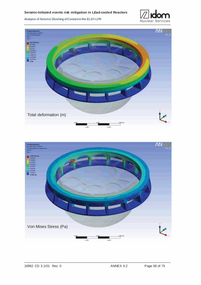
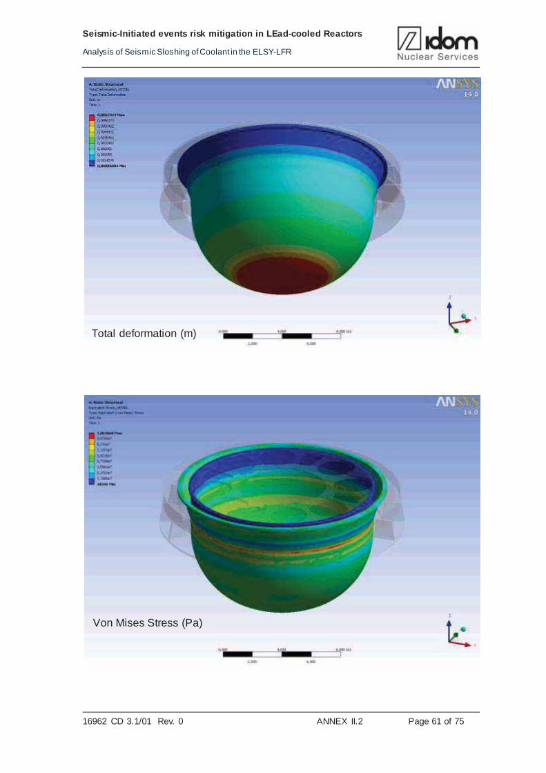
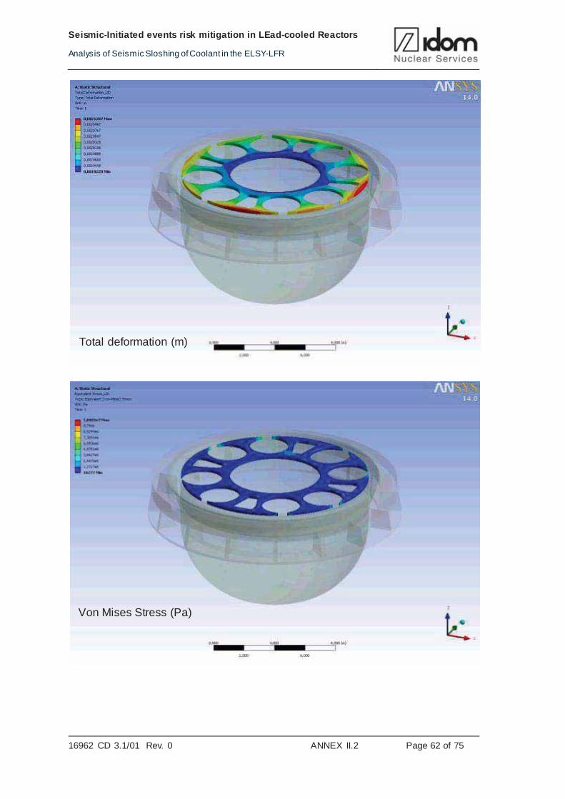
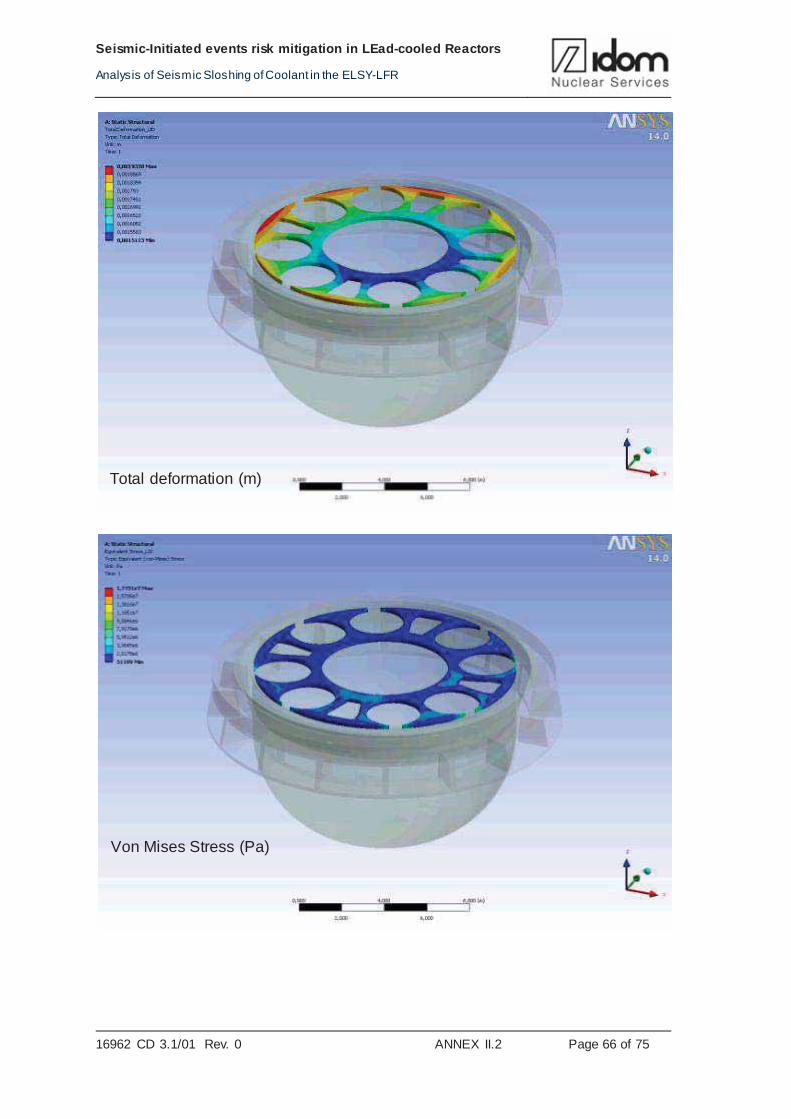
ANNEX II.2: STRUCTURAL ANALYSIS
ANNEX II.2.1: MODEL
ANNEX II.2.2: RESULTS
ANNEX III: ABAQUS FLUID STRUCTURE ANALYSIS
ANNEX III.1: ACCELEROGRAMS: INPUT LOADS
ANNEX.III.2. PRESSURE TIME HISTORIES
ANNEX III.2.1: PRESSURE TIME HISTORIES: RIGID CASES
ANNEX III.2.2: PRESSURE TIME HISTORIES: FLEXIBLE CASES
ANNEX III.3: TIME HISTORIES ANALYISI: FRECUENCY CONTENTS
ANNEX III.3.1: FRECUENCY CONTENTS: RIGID CASE
ANNEX III.3.2: FRECUENCY CONTENTS: FLEXIBLE CASE
ANNEX III.4: CONTACT FORCES
ANNEX III.4.1: CONTACT FORCES: RIGID CASES
ANNEX III.4.2: CONTACT FORCES: FLEXIBLE CASES
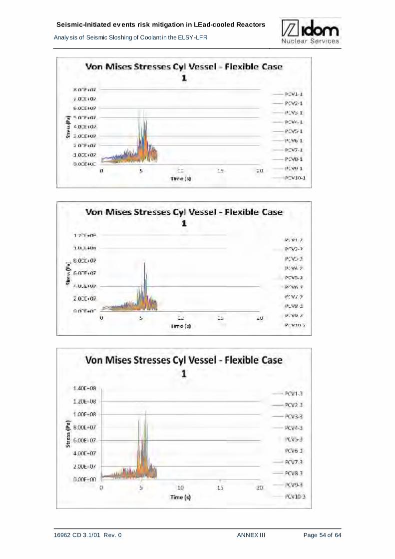
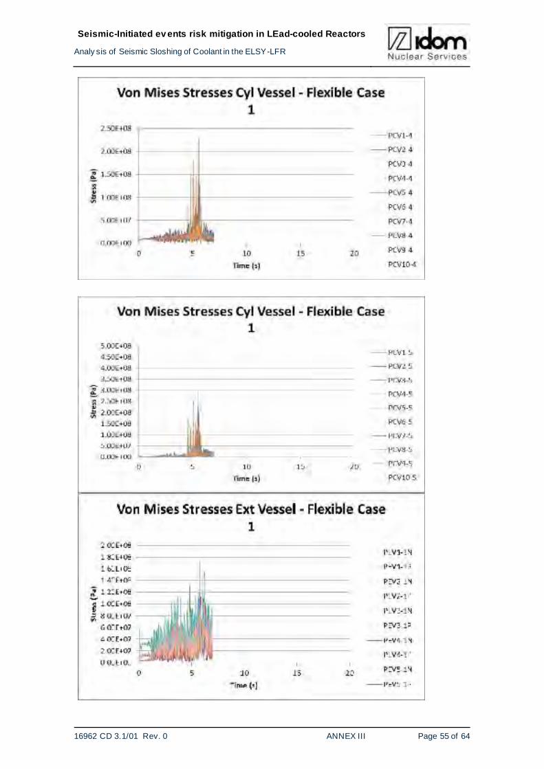
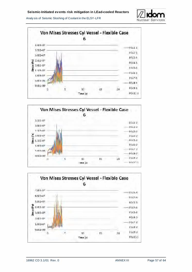
ANNEX III.5: VON MISES STRESSES: FLEXIBLE CASES
ANNEX III.6: FREE SURFACE VERTICAL DISPLACEMENTS
Page 7
Seismic-Initiated ev ents risk mitigation in LEad-cooled Reactors
Analy sis of Seismic Sloshing of Coolant in the ELSY-LFR
16962 CD 3.1/01 Rev. 0 FP7-295485-SILER D3.1 - PART I Page 4 of 68
LIST OF TABLES
Table 3-1 Load cases............................................................................................................18
Table 3-2 Location of the reference points ..............................................................................19
Table 4-1 Data corresponding with part a for CASE_1.............................................................29
Table 4-2 Data corresponding with part b and c for CASE_1....................................................29
Table 4-3 Data corresponding with part a for CASE_3.............................................................30
Table 4-4 Data corresponding with part b and c for CASE_3....................................................30
Table 4-5 Data corresponding with part a for CASE_6.............................................................31
Table 4-6 Data corresponding with part b and c for CASE_6....................................................31
Table 4-7 Data corresponding with part a for CASE_12 ...........................................................32
Table 4-8 Data corresponding with part b and c for CASE_12..................................................32
Table 4-9 Maximum percentage of surface lid wet by molten lead and time it occurs .................35
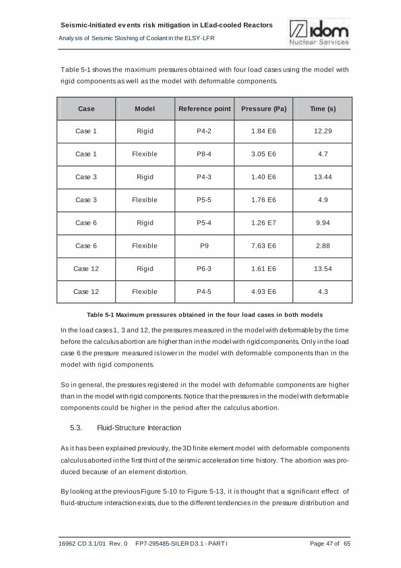
Table 5-1 Maximum pressures obtained in the four load cases in both models..........................47
Table 6-1 Maximum displacements and Von Mises stresse s (MPa).........................................55
Table 6-2 Maximum Von Mises stresses obtained for all cases for the inner and external vessel ................................................................................................................57
LIST OF FIGURES
Figure 2-1 Main components of the ELSY/LFR reactor ..............................................................9
Figure 2-2 Horizontal response spectra – Cases 1, 3, 6, 12 .....................................................10
Figure 2-3 Vertical response spectra – Cases 1, 3, 6, 12 .........................................................11
Figure 3-1 2D model .............................................................................................................14
Figure 3-2 ELSY reactor geometry .........................................................................................15
Figure 3-3 Fluid domain geometry..........................................................................................16
Figure 3-4 Fluid domain mesh ...............................................................................................16
Figure 3-5 Geometrical distribution of the reference points ......................................................19
Figure 3-6 Abaqus model with rigid components. Shell elements .............................................22
Figure 3-7 Abaqus model with rigid components. Molten lead elements....................................23
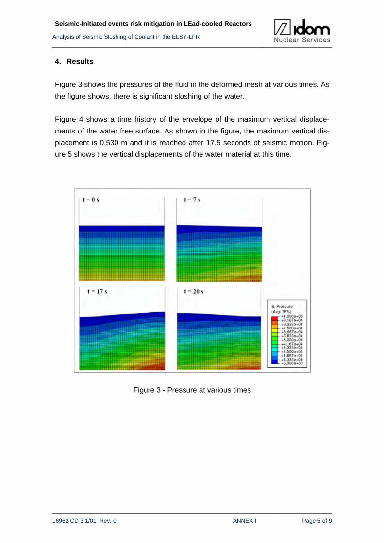
Figure 4-1 Pressure ..............................................................................................................24
Figure 4-2 Volume fraction: Red – Lead; Blue-Argon...............................................................25
Figure 4-3 Volume fraction at rest ..........................................................................................25
Figure 4-4 Velocity ................................................................................................................26
Figure 4-5 Horizontal velocity.................................................................................................26
Figure 4-6 Vertical velocity ....................................................................................................27
Figure 4-7 Percentage of reactor vessel lid in contact with molten lead for case 1 .....................33
Figure 4-8 Percentage of reactor vessel lid in contact with molten lead for case 3 .....................34
Figure 4-9 Percentage of reactor vessel lid in contact with molten lead for case 6 .....................34
Page 8
Seismic-Initiated ev ents risk mitigation in LEad-cooled Reactors
Analy sis of Seismic Sloshing of Coolant in the ELSY-LFR
16962 CD 3.1/01 Rev. 0 FP7-295485-SILER D3.1 - PART I Page 5 of 68
Figure 4-10 Percentage of reactor vessel lid in contact with molten lead for case 12 .................35
Figure 4-11 Maximum seismic loads pressure versu s the pressure at rest for case 1 ................36
Figure 4-12 Maximum seismic loads pressure versu s the pressure at rest for case 3 ................36
Figure 4-13 Maximum seismic loads pressure versu s the pressure at rest for case 6 ................37
Figure 4-14 Maximum seismic loads pressure versu s the pressure at rest for case 12...............37
Figure 5-1 Vertical displacement of the free surface for the case 1 and the rigid model..............38
Figure 5-2 Vertical displacement of the free surface for the case 6 and the rigid model..............39
Figure 5-3 Vertical displacement of the free surface for the case 1 and the flexible model..........40
Figure 5-4 Vertical displacement of the free surface for the case 6 and the flexible model..........40
Figure 5-5 Comparison rigid vs flexible model of the vertical displacement for the case 1 ..........41
Figure 5-6 Comparison rigid vs flexible model of the vertical displacement for the case 6 ..........41
Figure 5-7 Distribution and location of the reference elements .................................................42
Figure 5-8 Step time 11.20 s in the model with rigid components case 1. (P=1.74 MPa) ............43
Figure 5-9 Step time 13.60 s in the model with rigid components case 6. (P=10.25 MPa) ..........44
Figure 5-10 Step time 13.60 s in the model with rigid components case 6. (P=10.25 MPa) ........44
Figure 5-11 Step time 13.60 s in the model with rigid components case 6. (P=10.25 MPa) ........45
Figure 5-12 Step time 13.60 s in the model with rigid components case 6. (P=10.25 MPa) ........46
Figure 5-13 Step time 13.60 s in the model with rigid components case 6. (P=10.25 MPa) ........46
Figure 6-1 ELSY Reactor geometry for structural analysis .......................................................50
Figure 6-2 ELSY Reactor mesh for structural analysis .............................................................51
Figure 6-3 Distribution and location of the reference elements to obtain stresses in the inner and external vessel .............................................................................................56
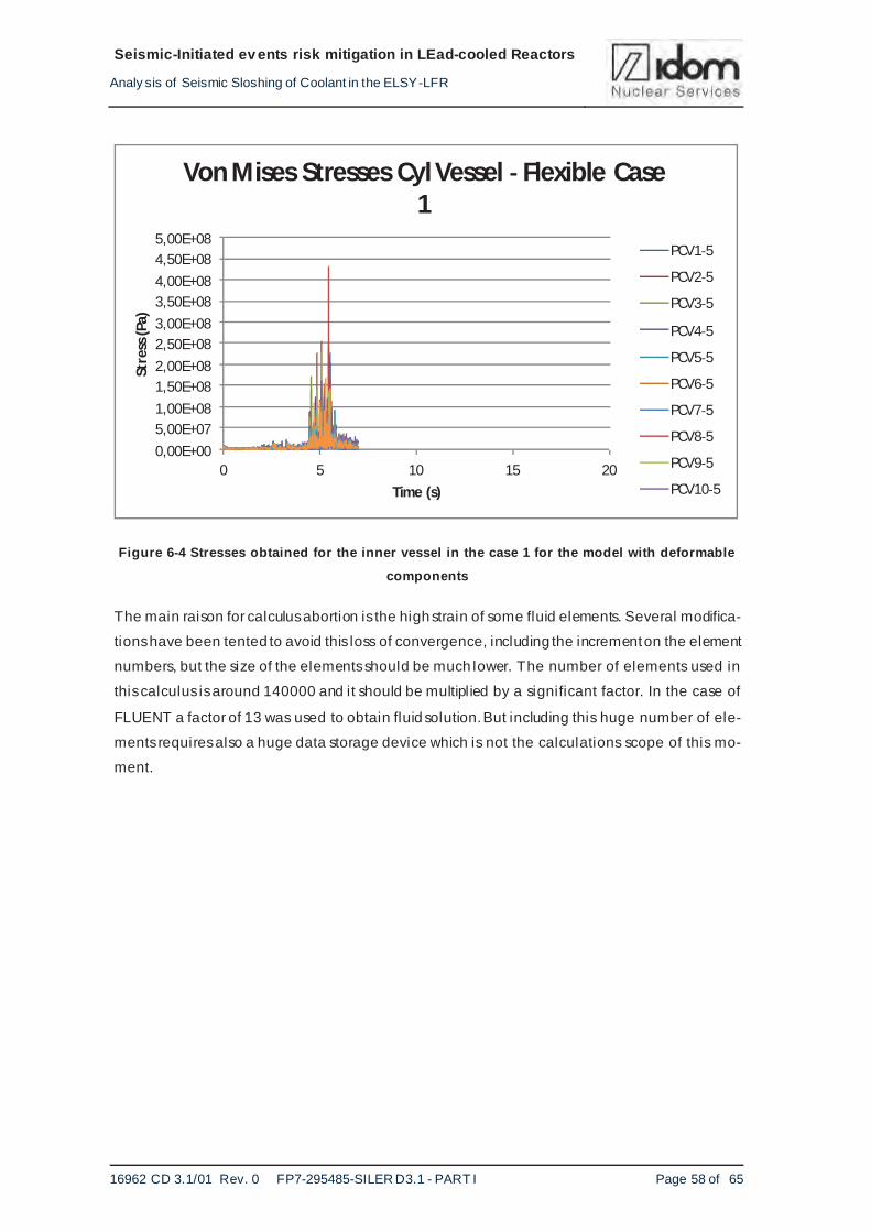
Figure 6-4 Stresses obtained for the inner vessel in the case 1 for the model with deformable components........................................................................................................58
Figure 6-5 Stresses obtained for the external vessel in the case 1 for the model with deformable components ......................................................................................59
Figure 6-6 Stresses obtained for the inner vessel in the case 6 for the model with deformable components........................................................................................................59
Figure 6-7 Stresses obtained for the external vessel in the case 6 for the model with deformable components ......................................................................................60
LIST OF ACRONYMS AND ABBREVIATIONS
DHR Decay Heat Removal
IV Inner Vessel
LFR Lead cooled Fast Reactor
RV Reactor Vessel
SG Steam generator
SILER Seismic-Initiated events risk mitigation in LEad-cooled Reactors
Page 9
Seismic-Initiated ev ents risk mitigation in LEad-cooled Reactors
Analy sis of Seismic Sloshing of Coolant in the ELSY-LFR
16962 CD 3.1/01 Rev. 0 FP7-295485-SILER D3.1 - PART I Page 6 of 65
1. INTRODUCTION
1.1. Preamble
SILER is a Collaborative Project within the seventh Framework Programme of the European
Commission, aimed at studying the risks associated to seismic initiated events in Gen IV Heavy
Liquid Metal reactors and developing adequate protection measures. The attention is focused on
the evaluation of the effects of earthquakes, with particular regards to unexpected (beyond de-
sign) events, and the identification of mitigation strategies like seismic isolation, acting on both
structures and components design.
In this context, task 3.1 of SILER includes the study of sloshing in seismic isolated reactors. In
order to study the sloshing effects in the LFR concept, detailed and refined models of key com-
ponents inside the reactor vessel have been realized, moving for the response spectra pro-
duced in WP2 (S.R.S. Servizi di Ricerche e Sviluppo Societa a Responsabilita Limitata). The
purpose is to identify if there is contact between the lead free surface and the lid during the
earthquake and the significant loads in the internal components due to the lead displacement.
During the study, solid-structure interaction has also been analysed.
The present report gathers the work carried out within task 3.1 regarding sloshing.
1.2. Purpose
The purpose of the work described in this document is the study of the sloshing effect in ELSY
reactor by seismic loads. The first part is a CFD (Computational Fluid Dynamics) analysis with
ANSYS_FLUENT program in order to calculate: free surface displacement, pressure on
components, etc. With the results from the first analysis a structural analysis is made with
ANSYS_MECHANICAL in order to obtain the stresses, displacement, etc. on considered
components
The second purpose of the study is to analyse the fluid-structure interaction between the lead
and the exterior and cylindrical inner vessel. In this study, the rest of internal components have
been modelled as rigid solids. These activities have been developed with ABAQUS software.
1.3. Scope
The purpose above has been met by the following scope of activities:
Detailed models of the reactor vessel and the main internal components have been made
Page 10
Seismic-Initiated ev ents risk mitigation in LEad-cooled Reactors
Analy sis of Seismic Sloshing of Coolant in the ELSY-LFR
16962 CD 3.1/01 Rev. 0 FP7-295485-SILER D3.1 - PART I Page 7 of 65
for studying sloshing effects, moving for the response spectra at component locations produced
in WP2. These models behavior have been evaluated with FLUENT approach.
1. Fluid and structural analysis in order to obtain the fluid and solid solution fields. For the
structural analysis ANSYS code has been used.
2. In order to evaluate the fluid structure interaction, two models of the ELSY/LFR reactor
have been developed. In the first one, the reactor has been modelled as a rigid body,
and in the second one, the main components (heat exchangers and steam generators)
have been modelled as rigid bodies, but the external and the cylindrical inner vessel
have not been modelled like that. Those models have been processed with ABAQUS.
3. Run the four seismic load scenarios of the different seismic inputs for all cases
described above. The object was to obtain information on the sloshing of the free
surface and on the fluid-structure interaction, with both approaches..
4. Conclusions and recommendations: From the examination of the studies described
above, responses from the two models will be compared to conclude with the significant
loads on the vessel and vessel l id and on the internal components.
These activities are described in detail in the following chapters.
1.4. Organization of the document
The present proposal includes eight additional chapters and three appendixes.
Chapter 2 gives the description of the input data used for analysis and a description of the
FLUENT and ABAQUS methodologies used.
Chapter 3 describes with detail the developed finite element models used for the analysis in the
two used approaches.
Chapter 4 is the assessment of the FLUENT results. Includes a description of the evaluation
performed with these approach. Contains a description of main results obtained for the seismic
loads cases.
Chapter 5 gives the assessment of the ABAQUS results. Includes a description of the evaluation
performed with these approach. Contains a description of main results obtained for the seismic
loads cases. Both analysis results with rigid component and with flexible vessels are included.
Chapter 6 gives a description of the stresses analysis results obtained with both approaches
ANSYS and ABAQUS with flexible vessels.
Chapter 7 deals with a comparative analysis of the results obtained with both approaches.
Page 11
Seismic-Initiated ev ents risk mitigation in LEad-cooled Reactors
Analy sis of Seismic Sloshing of Coolant in the ELSY-LFR
16962 CD 3.1/01 Rev. 0 FP7-295485-SILER D3.1 - PART I Page 8 of 65
Finally, chapter 8 is devoted to the conclusions and suggestions for future works.
Chapter 9 is a l ist of the main references.
ANNEX I contains the ALE method validation.
ANNEX II contains all the results obtained with the FLUENT methodology
ANNEX III contains all the results obtained with the ABAQUS methodology
2. INPUT DATA
2.1. Reactor vessel description
The geometry of ELSY/LFR,used in these analysis, has been supplied by Ansaldo Nucleare
(Ref. 3). In essence, the reactor consists of the reactor vessel (RV), the lid, a cylindrical inner
vessel (IV), eight steam generators (SG) and four Decay Heat Removal (DHR) exchangers,
together with the connection pipes of internals. Figure 2-1 shows a sketch of the main
components.
The reactor vessel is shaped as a cylindrical vessel with hemispherical bottom head and the lid.
The diameter of the vessel is 12.30 m and the height, 8.40 m. The vessel is fi l led with 7.91 m of
molten lead at 480ºC. The distance between the molten free surface and the bottom surface of
the reactor roof is 0.490 m at rest. The reactor vessel is supported by a forged Y-piece, the outer
leg of which is supported directly by the ring beam anchored to the reactor pit and the inner leg
is supporting the roof.
The lid consists of an annular thick plate with penetrations for the dip components and for the
cylindrical inner vessel. The thickness of the roof is 200.0 mm.
The cylindrical inner vessel contains the above core structures, including the upper heads of fuel
elements. It provides for lateral restraint of the core, but it does not have a core support plate.
The outer diameter of its circular cross section is 5.95 m. This vessel has ducts branching out
from its lower part, each of one connected with one SG. The vessel is supported on the upper
part by the roof.
The SGs are vertical, circular cross-section units that hung from the reactor vessel roof and are
immersed in the molten lead. They contain the primary pumps. They are axisymmetrically
positioned by pairs and are located in the annular space between the cylindrical inner vessel and
the reactor vessel wall.
Page 12
Seismic-Initiated ev ents risk mitigation in LEad-cooled Reactors
Analy sis of Seismic Sloshing of Coolant in the ELSY-LFR
16962 CD 3.1/01 Rev. 0 FP7-295485-SILER D3.1 - PART I Page 9 of 65
The DHR exchangers also hung from the reactor vessel and are immersed in the molten lead.
They are not connected to the inner vessel.
Figure 2-1 Main components of the ELSY/LFR reactor
2.2. Seismic input
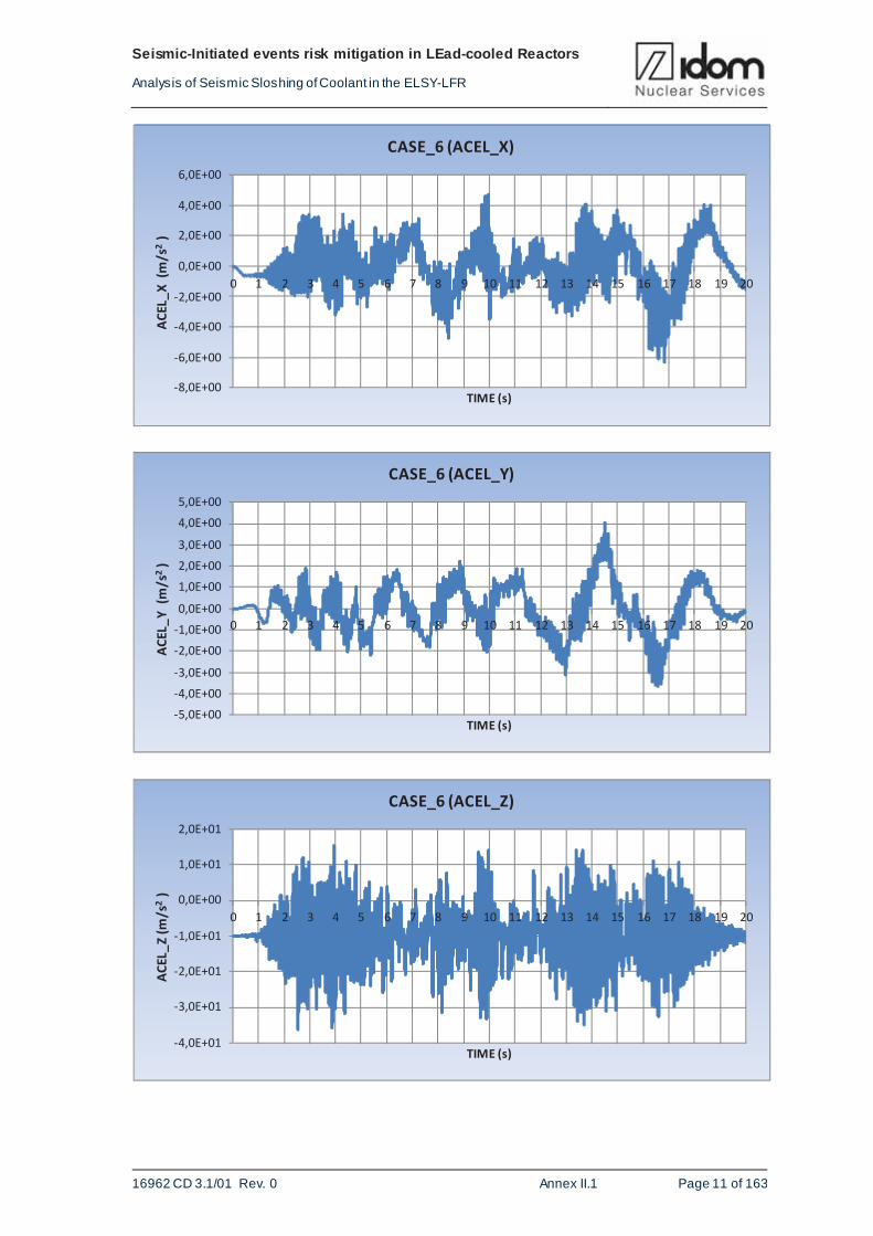
The seismic input for all the analyses consists of three acceleration time histories which are
obtained from the seismic analysis of the ELSY Reactor Building model with and without seismic
isolators (Ref.5). The following cases are analysed:
a) Case 1: Hard soil, no isolators, and Design Base Earthquake;
b) Case 3: Hard soil, with isolators, and Design Base Earthquake;
Page 13
Seismic-Initiated ev ents risk mitigation in LEad-cooled Reactors
Analy sis of Seismic Sloshing of Coolant in the ELSY-LFR
16962 CD 3.1/01 Rev. 0 FP7-295485-SILER D3.1 - PART I Page 10 of 65
c) Case 6: Hard soil, with isolators and Beyond Design Base Earthquake; and
d) Case 12: Soft soil, with isolators, and Design Base Earthquake.
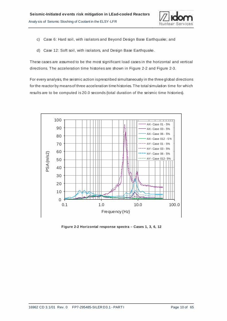
These cases are assumed to be the most significant load cases in the horizontal and vertical
directions. The acceleration time histories are shown in Figure 2-2 and Figure 2-3.
For every analysis, the seismic action is prescribed simultaneously in the three global directions
for the reactor by means of three acceleration time histories. The total simulation time for which
results are to be computed is 20.0 seconds (total duration of the seismic time histories).
Figure 2-2 Horizontal response spectra – Cases 1, 3, 6, 12
0
10
20
30
40
50
60
70
80
90
100
0.1 1.0 10.0 100.0
PS
A (m
/s2)
Frequency (Hz)
AX- Case 01 - 5%
AX- Case 03 - 5%
AX- Case 06 - 5%
AX- Case 012 - 5%
AY- Case 01 - 5%
AY- Case 03 - 5%
AY- Case 06 - 5%
AY- Case 012- 5%
Page 14
Seismic-Initiated ev ents risk mitigation in LEad-cooled Reactors
Analy sis of Seismic Sloshing of Coolant in the ELSY-LFR
16962 CD 3.1/01 Rev. 0 FP7-295485-SILER D3.1 - PART I Page 11 of 65
Figure 2-3 Vertical response spectra – Cases 1, 3, 6, 12
2.3. FLUENT methodology
In order to solve the sloshing problem, by using a fluid dynamic analysis, the ANSYS FLUENT
computational fluid program was used, which solves the Navier-Stokes equations using the finite
volume numerical technique based on cell center.
Being a free surface simulation, we have used one of the many formulations of the program for
solving multiphase flow.
FLUENT analysis is based on the Eulerian approach. In the Euler-Euler approach, the different
phases are treated mathematically as a continuum. Since the volume of a phase cannot be oc-
cupied by the other phases, the concept of volume fraction is introduced. These volume frac-
tions are assumed to be continuous functions of space and time and their sum is equal to one.
Conservation equations for each phase are derived in order to obtain a set of equations, which
have similar structure for all phases. These equations are closed constitutive relations obtained
from empirical information.
The FLUENT program has three different Euler-Euler multiphase models: the volume of fluid
(VOF), the mixture model, and the Eulerian model. In this analysis, VOF (Direct method of pre-
dicting interface shape between immiscible phases) multiphase model was used.
0
20
40
60
80
100
120
140
160
180
200
0.1 1.0 10.0 100.0
PS
A (m
/s2)
Frequency (Hz)
AZ- Case 01 - 5%
AZ- Case 03 - 5%
AZ- Case 06 - 5%
AZ- Case 12 - 5%
Page 15
Seismic-Initiated ev ents risk mitigation in LEad-cooled Reactors
Analy sis of Seismic Sloshing of Coolant in the ELSY-LFR
16962 CD 3.1/01 Rev. 0 FP7-295485-SILER D3.1 - PART I Page 12 of 65
The VOF model is a surface tracking technique applied to a fixed Eulerian mesh. It is designed
for two or more immiscible fluids where the position of the interface between the fluids is of in-
terest. In the VOF model, a single set of momentum equations is shared by the phases, and the
volume fraction of each of the phases in each computational cell is tracked throughout the do-
main.
Applications of the VOF model include stratified flows, free-surface flows, fi l l ing, sloshing, the
motion of large bubbles in a l iquid, the motion of l iquid after a dam break, the prediction of jet
breakup (surface tension), and the steady or transient tracking of any liquid-gas interface.
2.3.1. CFD ANALYSIS
The basic problem of fluid structure interaction (FSI), when a fluid flow interacts with a solid
structure, involves the evaluation of the hydrodynamic pressure distribution. The hydrodynamic
pressure of l iquids in moving rigid containers could be split into two hydrodynamic components
namely:
• Impulsive component due to rigid-body motion of the liquid. Under dynamic loading, part
of the liquid moves synchronously with the vessel as an added mass and is subject to the same
acceleration levels as the vessel.
• Convective component due to sloshing of the liquid at the free surface. Under lateral exci-
tation, oscil lations of the fluid occur and this results in the generation of pressures on the walls,
base and roof of the vessel.
A CFD analysis with ANSYS-FLUENT solver, with appropriate 3-D FEM model, has been ap-
plied in order to obtain the induced hydrodynamic pressures from sloshing effects due to the
fluid motion.
The analysis is transient and the solution is obtained through an iterative process due to the non
linear nature of the problem.
In a first approximation it considers that the contour of the both fluids, coolant and cover gas, is
rigid. The fluid and solid structure fields are solved separately. The pressure exerted by the fluid
on the structure may cause structural deformations significant enough to change the fluid flow
itself (2 way interaction), or the deformations may be neglected on the fluid side (1 way). 1 way
or 2 way analysis depends on the results of structural analysis.
Page 16
Seismic-Initiated ev ents risk mitigation in LEad-cooled Reactors
Analy sis of Seismic Sloshing of Coolant in the ELSY-LFR
16962 CD 3.1/01 Rev. 0 FP7-295485-SILER D3.1 - PART I Page 13 of 65
2.4. ABAQUS methodology
This methodology solves the fluid structure interaction problem with ABAQUS/Explicit (Ref.6) by
using the ALE (Arbitrary Lagrangian-Eulerian) method to represent the fluid response. The
reactor vessel and its main components are first represented as a rigid body in order to obtain
the fluid response without taking into account the vessel and internals deformation contribution.
At a later stage, the reactor vessel is no longer considered rigid and fluid structure interaction is
assessed and compared with the results from the rigid body assumption.
The ALE method of space discretization is a hybrid of the Lagrange and Euler methods. This
method makes it possible to maintain a high-quality mesh throughout an analysis, by allowing
the mesh to move independently of the material. The method redefines the mesh continuously
as the calculation proceeds. The advantage of ALE is the ability to reduce difficulties caused by
severe mesh distortions encountered by the Lagrange method and allows a calculation to
continue efficiently.
In order to validate the application of the ALE method with Abaqus Explicit to determine the
sloshing in the ELSY reactor, a simplified model is analysed by applying this method. Results
are then compared to a reference solution obtained by the analytical approach given by Housner
(Ref. 8). Appendix 1 shows the analysis performed for validation. Several parameters : bulk
modulus, viscosity and mesh size have been checked to validate convergency and results.
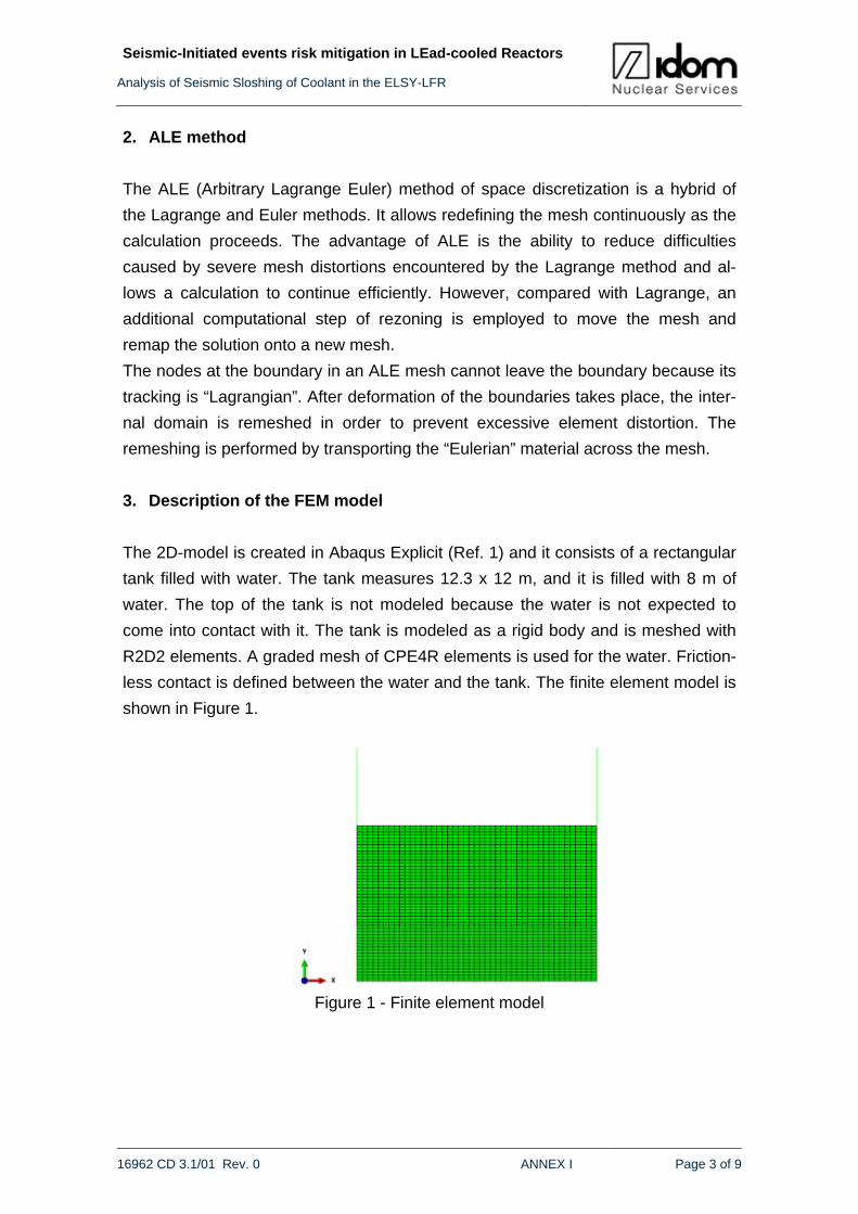
3. DESCRIPTION OF THE MODEL
3.1. FLUENT model
3.1.1. 2D ANALYSIS
Previous to the 3D analysis, it has performed a 2D analysis in order to confirm that fluids can
displace properly inside the reactor vessel and internals: main pipes, steam generators, core
and core upper internals.
With this model the following has checked: porosity, head pump, free surface displacement, etc.
These will be used in the 3D analysis. The 2D model has got 74000 nodes and 69000 elements.
Figure 3-1 shows the geometry and mesh of the 2D model
Page 17
Seismic-Initiated ev ents risk mitigation in LEad-cooled Reactors
Analy sis of Seismic Sloshing of Coolant in the ELSY-LFR
16962 CD 3.1/01 Rev. 0 FP7-295485-SILER D3.1 - PART I Page 14 of 65
Figure 3-1 2D model
3.2. FLUENT 3D ANALYSIS
Five independent CFD analyses have been carried out. The first one only concerns about the
dead load, which means the weight of the molten lead and argon fluids.
The other ones allow to determine the fluid response undergoing the seismic excitation. The
main results from these analysis are the hydrodynamic pressure distribution into the reactor
vessel and the internal components as well as the free surface displacement, due to the molten
lead motion.
The pressure distribution will be used in order to check the structural integrity of the reactor
vessel and the internal components.
3.2.1. Model
The analysis requires of two models: the first one allows to determine the fluid response
(velocity, pressure, free surface displacement, etc) by using a fluid dynamic analysis with
FLUENT code and the second one uses the results obtained from the first analysis at several
times in order to perform a static structural assessment of the vessel (stresses, displacements,
etc) with ANSYS code. Both of them are 3D.
The CFD (Computational Fluid Dynamics) model is performed from ELSY Reactor geometry.
The geometry considered includes the following main components:
• REACTOR VESSEL (RV)
• INNER VESSEL (IV)
• LID
Page 18
Seismic-Initiated ev ents risk mitigation in LEad-cooled Reactors
Analy sis of Seismic Sloshing of Coolant in the ELSY-LFR
16962 CD 3.1/01 Rev. 0 FP7-295485-SILER D3.1 - PART I Page 15 of 65
• STEAM GENERATOR (SG)
• DECAY HEAT REMOVAL (DHR)
• FUEL ASSEMBLY (FA)
In this analysis, all of them are considered rigid.
Appropriate 3-D finite element models were set up and implemented in FLUENT code
Figure 3-2 shows the ELSY Reactor geometry:
Figure 3-2 ELSY reactor geometry
The fluid domain has been generated from Elsy Reactor geometry considered, which consists of
a two-phase model composed of a coolant fluid (molten lead at 480ºC) and a cover gas (argon).
The fluid domain has been created fi lling the ELSY Reactor geometry and using as fluid bounda-
ry condition, the reactor vessel and the main internal components (IV, LID, SG, DHR, and FA).
The interface between the molten lead and the gas is located, at rest, 0.490 m below the reactor
vessel l id.Figure 3-3 and Figure 3-4 show the fluid domain geometry and mesh:
Page 19
Seismic-Initiated ev ents risk mitigation in LEad-cooled Reactors
Analy sis of Seismic Sloshing of Coolant in the ELSY-LFR
16962 CD 3.1/01 Rev. 0 FP7-295485-SILER D3.1 - PART I Page 16 of 65
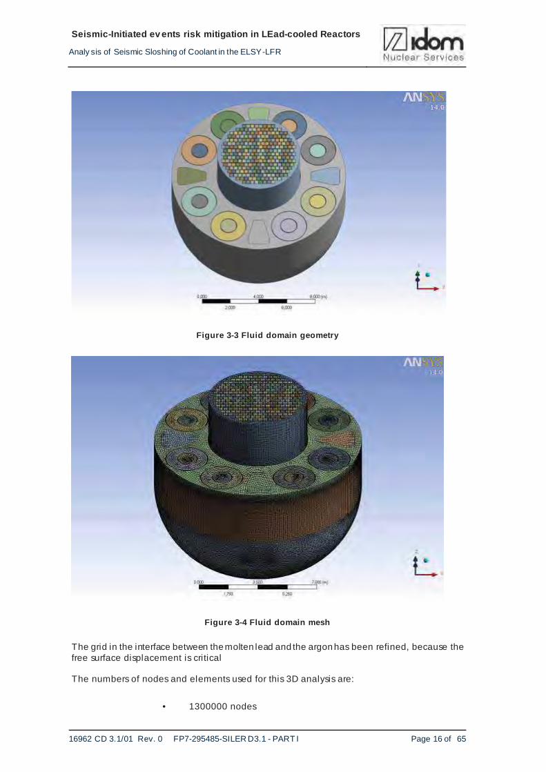
Figure 3-3 Fluid domain geometry
Figure 3-4 Fluid domain mesh
The grid in the interface between the molten lead and the argon has been refined, because the free surface displacement is critical
The numbers of nodes and elements used for this 3D analysis are:
• 1300000 nodes
Page 20
Seismic-Initiated ev ents risk mitigation in LEad-cooled Reactors
Analy sis of Seismic Sloshing of Coolant in the ELSY-LFR
16962 CD 3.1/01 Rev. 0 FP7-295485-SILER D3.1 - PART I Page 17 of 65
• 1900000 elements
The objective of these high node numbers is twofold. The first one is to have a good description
of the vessel internal which could impair the fluid displacement. The second one is to avoid the
loss of convergence it has been experienced with smaller models, especially for the seismic
loads with high accelerations.
3.2.2. Fluid properties
The fluids considered in the analysis are molten lead and argon (modelled as an ideal gas). The
properties at 480ºC are the following:
a) Molten lead
Density: 10470.0 kg/m3
Specific heat: 145.4 j/kg-K
Thermal conductivity: 17.5 w/m-K
Viscosity: 0.0018820 kg/m-s
b) Argon
Density: 1.784 kg/m3
Specific heat: 520.64 j/kg-K
Thermal conductivity: 0.0158 w/m-K
Viscosity:2.125x10⁻⁵ kg/m-s
3.2.3 Load cases
Five independent CFD analyses have been carried out. The first only takes into account the
dead load. The others corresponds with the four load cases shown in Table 3-1.
Page 21
Seismic-Initiated ev ents risk mitigation in LEad-cooled Reactors
Analy sis of Seismic Sloshing of Coolant in the ELSY-LFR
16962 CD 3.1/01 Rev. 0 FP7-295485-SILER D3.1 - PART I Page 18 of 65
CASE CASE redu. SOIL ISOLATORS EARTHQUAKE
1 1 HARD NO DBE
3 3 HARD YES DBE
13 6 HARD YES BDBE
23 12 SOFT YES DBE
Table 3-1 Load cases
In all cases shown in the Table 3-1, for each load case, the seismic action is prescribed
simultaneously in the three global directions for the reactor by means of three acceleration time
histories. See paragraph 2.2.
The seismic input for all the analyses are three acceleration stories, with a total duration of 20.0
seconds. The time increment is of 0.01 seconds, and they are shown in ANNEX-II.1.3.
3.2.4 Reference points
It has fixed 49 points, denominated control points or reference points, for these points the pres-
sure on the external vessel is saved in time step each 0.01 seconds. They are grouped in sever-
al height with respect to the global coordinate system. Each group has got eight points, situated
in circumferential direction, each 45º, except P_H0_1 point. This point is located at the bottom of
the reactor vessel. Table 3-2 shows axial an d radial position of each group. Figure 3-5 shows
the position and numbering of the point situated in XZ plane.
Page 22
Seismic-Initiated ev ents risk mitigation in LEad-cooled Reactors
Analy sis of Seismic Sloshing of Coolant in the ELSY-LFR
16962 CD 3.1/01 Rev. 0 FP7-295485-SILER D3.1 - PART I Page 19 of 65
Figure 3-5 Geometrical distribution of the reference points
Reference points group
Z (m) R (m)
H0 - 8.380 0.000
H1 - 7.750 2.970
H2 - 7.095 4.130
H3 - 4.530 5.900
H4 - 0.490 6.120
H5_EXT 0.000 6.050
H5_INT 0.000 3.000
Table 3-2 Location of the reference points
Page 23
Seismic-Initiated ev ents risk mitigation in LEad-cooled Reactors
Analy sis of Seismic Sloshing of Coolant in the ELSY-LFR
16962 CD 3.1/01 Rev. 0 FP7-295485-SILER D3.1 - PART I Page 20 of 65
3.3. ABAQUS model
Two 3D finite element models are created using Abaqus/Explicit (Ref.6). Both represent the
reactor vessel and the outer shells of its main components: the roof, the cylindrical inner vessel,
the eight SG and the four DHR exchangers. The molten lead located in the annular space
between the reactor vessel and the cylindrical inner vessel is represented by using a single
adaptive mesh domain that follows the ALE technology.
Using the ALE method, the molten lead response is intended to be analysed in both models in
terms of its free surface sloshing and in terms of the hydrodynamic pressure applied by the fluid
on the wall interfaces during the seismic motion.
In order to represent more adequately the hydrodynamic pressure applied by the molten lead
during the earthquake at the bottom of the reactor vessel, the molten lead located inside the
cylindrical inner vessel is also represented in both models. As the inner vessel does not have a
bottom plate the molten lead from the inside and the outside of the inner vessel are
communicated. Since lateral movement of the molten lead located inside the inner vessel is
restricted by the presence of the fuel components, additional vertical elements are placed in the
interior of the inner vessel model. These vertical elements limit the horizontal molten lead flow
inside the inner vessel and do not allow the fluid to impact laterally onto the inner vessel walls.
Since fuel elements placed inside the inner vessel are no represented in the models, the height
of the molten lead column inside the inner vessel is lower than it should be, as it has been
decided to conserve the original mass of molten lead inside the inner vessel.
On the other hand, since the sloshing effect of the molten lead located inside the inner vessel is
considered not to be significant, an auxiliary l id close to this fluid free surface is modelled. The
purpose of putting this extra l id is to avoid excessive distortion of the free surface of the molten
lead mesh located inside the inner vessel during computation.
Since the main objective of this analysis is evaluating the importance of the fluid-structure
interaction this modelling issue is not significant.
The difference between both models is that the first one does not take into account the effect of
the flexibility of the external and internal vessel in the fluid response and the second one does,
i.e., the second model is the one that considers the fluid-structure interaction.
Although the reactor components elements are defined differently in both models for the reason
explained above, the definition of the molten lead is the same for both. To model the molten lead
material it is used a simple Newtonian viscous shear model and a linear volumetric equation of
state for the bulk response. The bulk modulus functions as a penalty parameter for the
incompressible constraint. Since sloshing problems are unconfined, it can be chosen a bulk
Page 24
Seismic-Initiated ev ents risk mitigation in LEad-cooled Reactors
Analy sis of Seismic Sloshing of Coolant in the ELSY-LFR
16962 CD 3.1/01 Rev. 0 FP7-295485-SILER D3.1 - PART I Page 21 of 65
modulus lower than the actual value for molten lead in order to avoid an overly stiff response
and the molten lead will sti l l behave as an incompressible medium. The following parameters are
taken into account to represent the molten lead material:
Density: 10470.0 kg/m3
Linear volumetric response (Equation of State)
Speed of sound: 800.0 m/s (obtained from the reduced bulk modulus)
Shear behaviour (Newtonian fluid)
Viscosity: 1.882x10⁻³ Pa·s
No turbulence or l imit layer effects
Additionally, for computation stabil ity purposes, a very low coefficient of friction (i.e., 0.05) is
taken into account between every fluid-wall interfaces.
Gravity and seismic loads are considered to act simultaneously in the models. To represent the
gravity loading, an initial geostatic stress field is defined to equilibrate the stresses caused by the
self-weight of the molten lead. The four seismic case loads described above are analysed with
these two models.
Regarding the gravity action in the molten lead located inside the inner vessel, an additional
pressure load is needed to be applied on its free surface because the height of molten lead
column inside the inner vessel does not coincide with the real one. The value of the applied
pressure is directly proportioned to the difference of height between the originally projected and
the finally modelled molten lead. This additional pressure load allows that, at the same level,
every point of molten lead located either inside or outside the inner vessel could have the same
hydrostatic pressure due to gravity.
3.3.1. Abaqus model with rigid components
The objective of the first Abaqus model is to obtain the fluid response without taking into account
the effect of the reactor flexibility. For this purpose, the model represents the reactor vessel and
its components as a rigid body using shell elements. The elements of the molten lead mesh are
hexahedral elements (C3D8R, Ref.6). Figure 3-6 and Figure 3-7 show different views of the
whole model, which consists of 138104 elements.
Since the reactor vessel and its components are represented as a rigid body, all of them move
accordingly to the seismic motion.
Page 25
Seismic-Initiated ev ents risk mitigation in LEad-cooled Reactors
Analy sis of Seismic Sloshing of Coolant in the ELSY-LFR
16962 CD 3.1/01 Rev. 0 FP7-295485-SILER D3.1 - PART I Page 22 of 65
Figure 3-6 Abaqus model with rigid components. Shell elements
Page 26
Seismic-Initiated ev ents risk mitigation in LEad-cooled Reactors
Analy sis of Seismic Sloshing of Coolant in the ELSY-LFR
16962 CD 3.1/01 Rev. 0 FP7-295485-SILER D3.1 - PART I Page 23 of 65
Figure 3-7 Abaqus model with rigid components. Molten lead elements
3.3.2. Abaqus model with deformable components
In this second Abaqus model, the fluid-structure interaction is taken into account. In particular,
the effect of the flexibil ity of the reactor vessel, its roof and the cylindrical inner vessel are taken
into consideration. On the other hand, the eight SG and the four DHR exchangers are sti l l
represented as rigid bodies because the effect of their flexibil ity is considered negligible.
In this model, the forged Y-piece that supports the reactor vessel is also represented and its
flexibil ity is also considered. At the ending points of this piece, boundary conditions are
prescribed. Specifically, the seismic motion is prescribed at this set of points simultaneously in
the three global directions.
The whole model consists of 135396 elements. The elements of the molten lead mesh are
hexahedral elements (C3D8R, Ref.6). Every component whose flexibility is taken into account is
represented in the model with S4 and S4R elements (Ref.6).
Original thicknesses of all of the deformable components outer shells are considered in the
model except for the cylindrical inner vessel. For this component, the represented thickness is
the sum of the thicknesses of the two outer shells, which are connected by stiffeners.
The material of the deformable components of the reactor vessel is SA 240 TP 316 LN steel. In
the model, the material is assumed to be linear elastic with a Young's modulus of 200.0x10⁹ Pa,
a Poisson's ratio of 0.3 and a density of 7850.0 kg/m3.
Page 27
Seismic-Initiated ev ents risk mitigation in LEad-cooled Reactors
Analy sis of Seismic Sloshing of Coolant in the ELSY-LFR
16962 CD 3.1/01 Rev. 0 FP7-295485-SILER D3.1 - PART I Page 24 of 65
In order to include the mass of the internal components of the inner vessel that are not
represented in the model, an additional equivalent mass is distributed over the inner vessel
elements. The mass distribution is made by maintaining the original centre of mass.
Regarding the SG and the DHR exchangers, an additional mass for each component is added to
its centre of mass in order to take into account the masses of their non-modelled internal
components.
In relation with the loads applied to the model, in this model an additional pressure load is
applied to the walls of the cylindrical inner vessel. This triangular pressure load represents the
effect of the hydrostatic pressure of the part of molten lead that is located in the inner vessel and
that is not represented in the model.
4. ASSESSMENTS OF FLUENT RESULTS
4.1. 2D MODEL
Figure 4-1 to Figure 4-6show the main results of the 2D model. Figures show the fluid velocity
which demonstrates that it can be displaced in all directions. The main conclusions are that
displacements are strongly l imited by the internal surfaces and that these surfaces should be
correctly located.
Figure 4-1 Pressure
Page 28
Seismic-Initiated ev ents risk mitigation in LEad-cooled Reactors
Analy sis of Seismic Sloshing of Coolant in the ELSY-LFR
16962 CD 3.1/01 Rev. 0 FP7-295485-SILER D3.1 - PART I Page 25 of 65
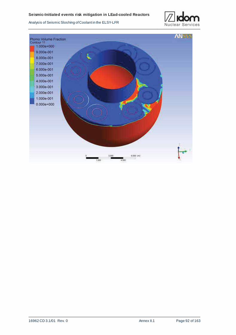
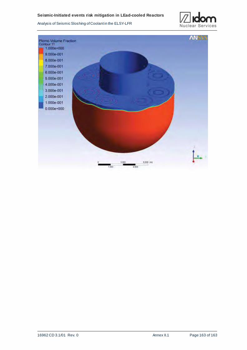
Figure 4-2 Volume fraction: Red – Lead; Blue-Argon
Figure 4-3 Volume fraction at rest
Page 29
Seismic-Initiated ev ents risk mitigation in LEad-cooled Reactors
Analy sis of Seismic Sloshing of Coolant in the ELSY-LFR
16962 CD 3.1/01 Rev. 0 FP7-295485-SILER D3.1 - PART I Page 26 of 65
Figure 4-4 Velocity
Figure 4-5 Horizontal velocity
Page 30
Seismic-Initiated ev ents risk mitigation in LEad-cooled Reactors
Analy sis of Seismic Sloshing of Coolant in the ELSY-LFR
16962 CD 3.1/01 Rev. 0 FP7-295485-SILER D3.1 - PART I Page 27 of 65
Figure 4-6 Vertical velocity
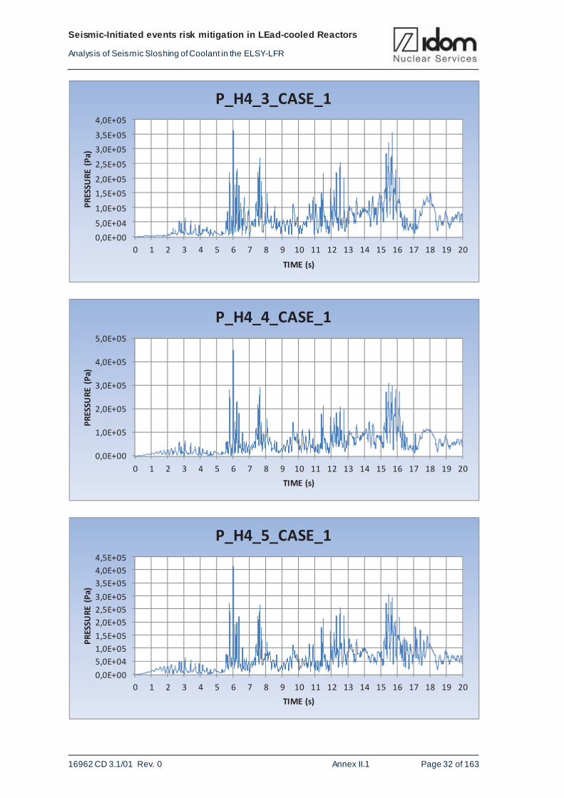
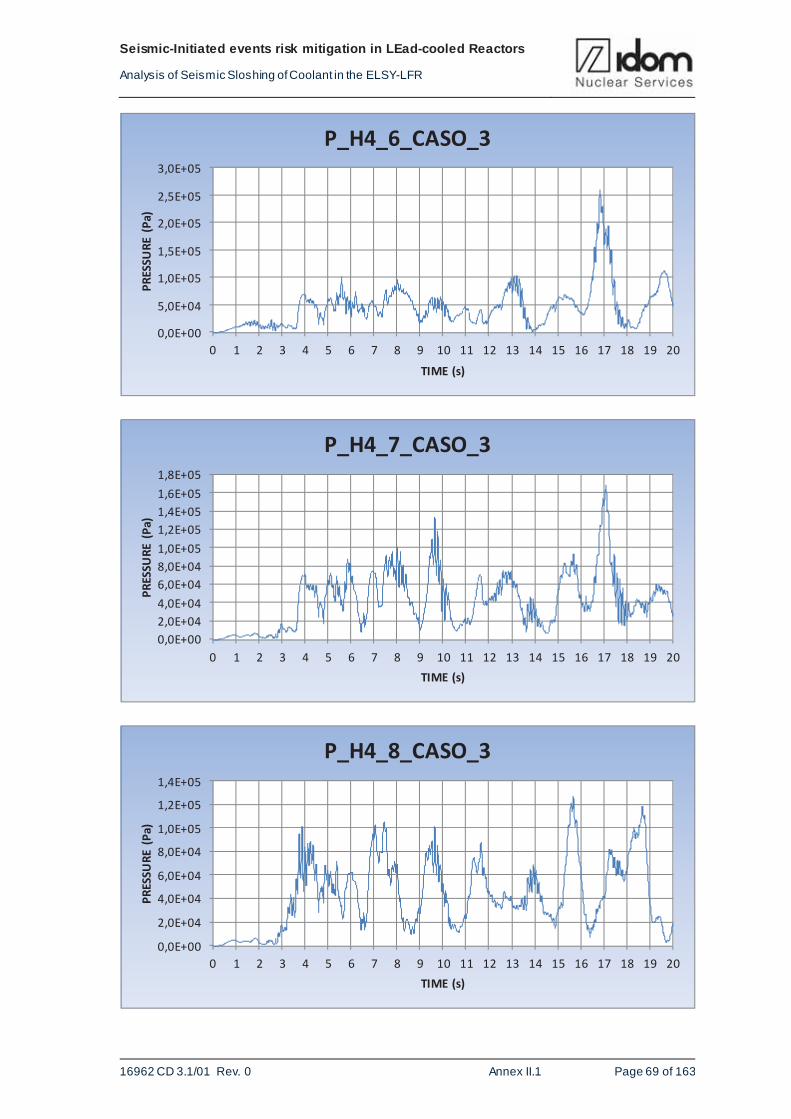
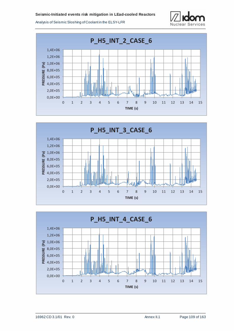
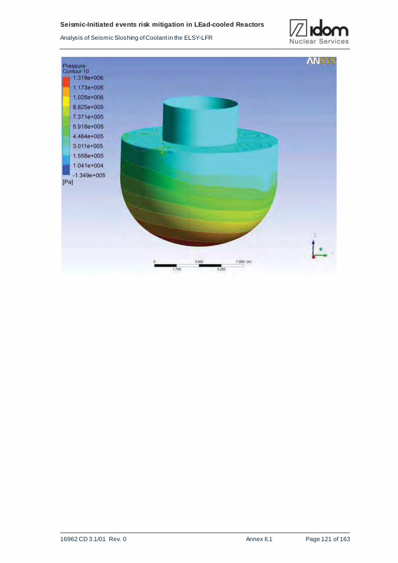
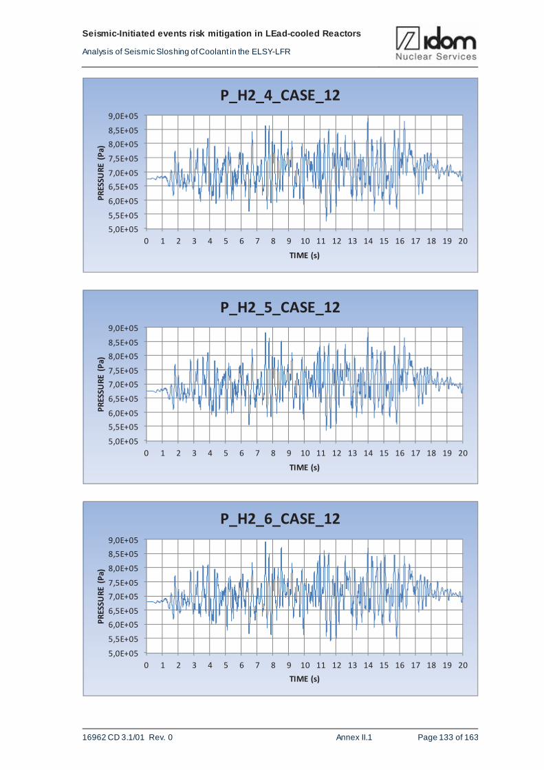
4.2. FLUENT 3D MODEL RESULTS
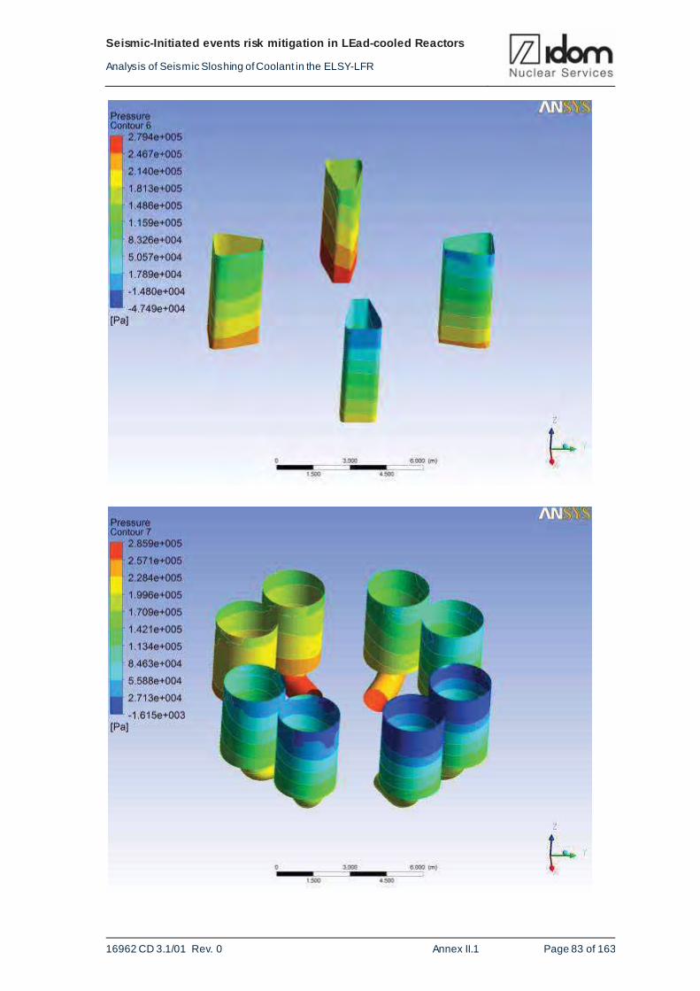
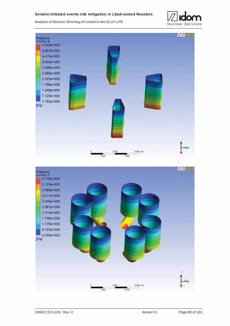
The results, when only considered dead load, are pressure in reference points and pressure
distribution in the reactor vessel and internals. These results are shown in the ANNEX-II.1.4,
where pressure distribution at the vessel and internal components is shown. Maximum internal
pressure is located in the external vessel bottom with 0.8 MPa.
The main results, corresponding with the seismic loads, cases: 1, 3, 6 and 12 are the following:
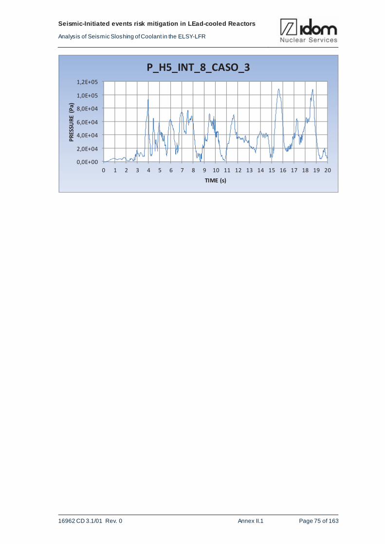
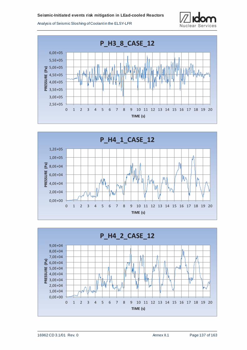
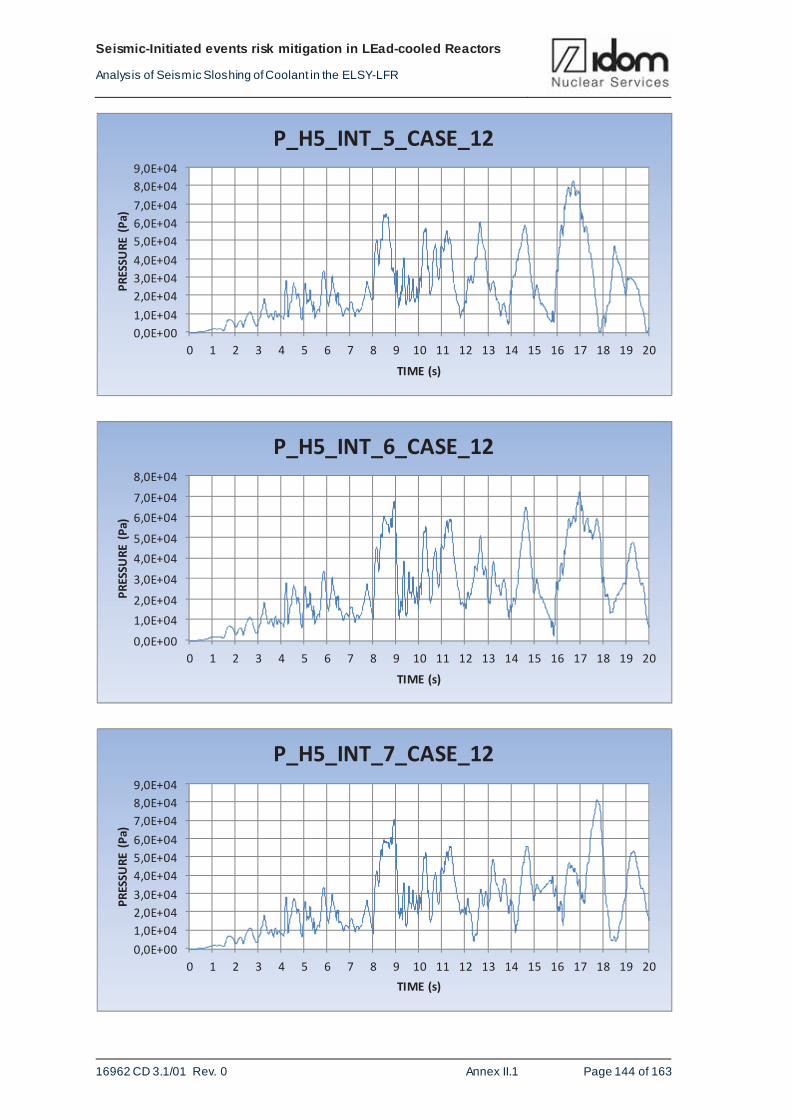
1. Temporal evolution of pressure in reference points
2. Pressure distribution in the reactor vessel and internals
3. Free surface position
4. Percentage of the lid surface in contact with the molten lead
ANNEX: II.1.4 present results for case 1, case 3, case 6 and case 12.
It would be desirable to have the results for the post-processing every 0.01 seconds, time step
coinciding with the time step of the acceleration stories. The only results stored every 0.01 sec-
onds, are the pressures at reference points. For the other ones, there is only information every
0.2 seconds. The reason is that the size of the fi les to store the pressure in the reference points
is relatively small. In return, to store the other ones, very large fi les are necessary. The problem
with this is the loss of information needed to know what and at what time the worst situation
Page 31
Seismic-Initiated ev ents risk mitigation in LEad-cooled Reactors
Analy sis of Seismic Sloshing of Coolant in the ELSY-LFR
16962 CD 3.1/01 Rev. 0 FP7-295485-SILER D3.1 - PART I Page 28 of 65
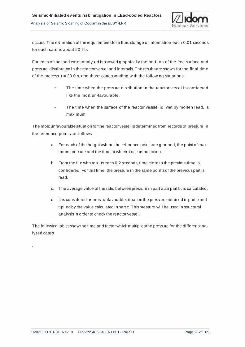
occurs. The estimation of the requirements for a fluid storage of information each 0.01 seconds
for each case is about 20 Tb.
For each of the load cases analysed is showed graphically the position of the free surface and
pressure distribution in the reactor vessel and internals, The results are shown for the final time
of the process, t = 20.0 s, and those corresponding with the following situations:
• The time when the pressure distribution in the reactor vessel is considered
like the most un-favourable.
• The time when the surface of the reactor vessel l id, wet by molten lead, is
maximum
The most unfavourable situation for the reactor vessel is determined from records of pressure in
the reference points, as follows:
a. For each of the heights where the reference points are grouped, the point of max-
imum pressure and the time at which it occurs are taken.
b. From the fi le with results each 0.2 seconds, time close to the previous time is
considered. For this time, the pressure in the same points of the previous part is
read.
c. The average value of the ratio between pressure in part a an part b, is calculated.
d. It is considered as most unfavorable situation the pressure obtained in part b mul-
tiplied by the value calculated in part c. This pressure will be used in structural
analysis in order to check the reactor vessel.
The following tables show the time and factor which multiplies the pressure for the different ana-
lyzed cases.
.
Page 32
Seismic-Initiated ev ents risk mitigation in LEad-cooled Reactors
Analy sis of Seismic Sloshing of Coolant in the ELSY-LFR
16962 CD 3.1/01 Rev. 0 FP7-295485-SILER D3.1 - PART I Page 29 of 65
CASE_1
Reference points
Pressure (Pa) Time (sec)
P_H0_1 1388330.0 15.44
P_H1_4 1541898.0 15.44
P_H2_4 1522937.0 15.44
P_H3_4 1290202.0 15.45
P_H4_2 609822.0 15.36
P_H5_EXT_2 696689.0 15.36
P_H5_INT_2 634809.0 16.98
Table 4-1 Data corresponding with part a for CASE_1
CASE_1 (TIME = 15.8 sec)
Reference points Pressure (Pa) P (table 3.3)/P (t=15.8 s)
P_H0_1 1129466.5 1.229
P_H1_4 898309.0 1.716
P_H2_4 763234.0 1.995
P_H3_4 400715.0 3.219
P_H4_2 96910.0 6.292
P_H5_EXT_2 96910.0 7.189
P_H5_INT_6 194924.0 3.256
Av erage v alue 3.55
Table 4-2 Data corresponding with part b and c for CASE_1
Page 33
Seismic-Initiated ev ents risk mitigation in LEad-cooled Reactors
Analy sis of Seismic Sloshing of Coolant in the ELSY-LFR
16962 CD 3.1/01 Rev. 0 FP7-295485-SILER D3.1 - PART I Page 30 of 65
CASE_3
Reference points Pressure (Pa) Time (sec)
P_H0_1 1585307.0 3.86
P_H1_4 1481062.0 3.86
P_H2_4 1352589.0 3.86
P_H3_4 874565.0 3.86
P_H4_6 260265.0 16.81
P_H5_EXT_3 228206.0 7.60
P_H5_INT_6 187511.0 17.00
Table 4-3 Data corresponding with part a for CASE_3
CASE_3 (TIME = 4.0 sec)
Reference points Pressure (Pa) P (table 3.5)/P (t=4.0 s)
P_H0_1 1257329.0 1.261
P_H1_4 1174748.0 1.261
P_H2_4 1073647.0 1.260
P_H3_4 698601.0 1.252
P_H4_6 67700.0 3.844
P_H5_EXT_3 68074.0 3.352
P_H5_INT_6 61525.0 3.048
Av erage v alue 2.18
Table 4-4 Data corresponding with part b and c for CASE_3
Page 34
Seismic-Initiated ev ents risk mitigation in LEad-cooled Reactors
Analy sis of Seismic Sloshing of Coolant in the ELSY-LFR
16962 CD 3.1/01 Rev. 0 FP7-295485-SILER D3.1 - PART I Page 31 of 65
CASE_6
Reference points
Pressure (Pa) Time (sec)
P_H0_1 3289981.7 13.68
P_H1_4 3123347.2 13.68
P_H2_4 2947532.5 4.36
P_H3_4 2302257.5 4.36
P_H4_2 1316391.7 9.70
P_H5_EXT_2 1884037.6 3.35
P_H5_INT_2 1606643.9 13.01
Table 4-5 Data corresponding with part a for CASE_6
CASE_6 (TIME = 13.8 sec)
Reference points Pressure (Pa) P (table 4.5)/P (t=13.8 s)
P_H0_1 2441657.5 1.3474
P_H1_4 2300620.2 1.3576
P_H2_4 2130498.0 1.3832
P_H3_4 1382724.4 1.665
P_H4_2 226356.2 5.8156
P_H5_EXT_2 154592.3 12.187
P_H5_INT_6 154569.0 10.394
Av erage v alue 4.87
Table 4-6 Data corresponding with part b and c for CASE_6
Page 35
Seismic-Initiated ev ents risk mitigation in LEad-cooled Reactors
Analy sis of Seismic Sloshing of Coolant in the ELSY-LFR
16962 CD 3.1/01 Rev. 0 FP7-295485-SILER D3.1 - PART I Page 32 of 65
CASE_12
Reference points
Pressure (Pa) Time (sec)
P_H0_1 1027357.0 13.99
P_H1_4 970366.0 13.99
P_H2_4 890725.0 13.99
P_H3_4 594835.0 16.30
P_H4_3 142783.0 16.46
P_H5_EXT_4 134482.0 16.40
P_H5_INT_1 153105.0 9.88
Table 4-7 Data corresponding with part a for CASE_12
CASE_12 (TIME = 14.0 sec)
Reference points Pressure (Pa) P (table 3.9)/P (t=14.0s)
P_H0_1 989210.0 1.04
P_H1_4 934746.0 1.04
P_H2_4 858400.0 1.04
P_H3_4 563084.0 1.06
P_H4_3 28651.0 5.00
P_H5_EXT_4 35742.0 3.77
P_H5_INT_1 35846.0 4.28
Av erage v alue 2.46
Table 4-8 Data corresponding with part b and c for CASE_12
Table 4-1 to Table 4-8 show the time and factor to be applied to the pressure for the analyzed
cases.
The main conclusion of this data is that in order to have a real estimation of the pressures
effects on the vessel the results obtained for each 0.2 seconds should be multiplied by a factor
of 3.55 for case 1, 2.18 for case 3, 4.87 for case 6, and 2.46 for case 12.
Page 36
Seismic-Initiated ev ents risk mitigation in LEad-cooled Reactors
Analy sis of Seismic Sloshing of Coolant in the ELSY-LFR
16962 CD 3.1/01 Rev. 0 FP7-295485-SILER D3.1 - PART I Page 33 of 65
The second point of interest is the evolution of the fluid loads on the lid. The following graphics
results show the percentage of surface lid in contact with molten lead versus time. This value
has been obtained from the fi le with results every 0.2 seconds. Be aware that these means that
the real results if we were able to store data each 0.01 seconds will be higher. This percentage
versus time is showed in the following figures for all cases analyzed.
Figure 4-7 Percentage of reactor vessel lid in contact with molten lead for case 1
0,0
2,0
4,0
6,0
8,0
10,0
12,0
14,0
16,0
18,0
20,0
0 1 2 3 4 5 6 7 8 9 10 11 12 13 14 15 16 17 18 19 20
(%)
TIME (s)
CASE_1Surface LID in contact with lead
Page 37
Seismic-Initiated ev ents risk mitigation in LEad-cooled Reactors
Analy sis of Seismic Sloshing of Coolant in the ELSY-LFR
16962 CD 3.1/01 Rev. 0 FP7-295485-SILER D3.1 - PART I Page 34 of 65
Figure 4-8 Percentage of reactor vessel lid in contact with molten lead for case 3
Figure 4-9 Percentage of reactor vessel lid in contact with molten lead for case 6
0,0
1,0
2,0
3,0
4,0
5,0
6,0
7,0
8,0
9,0
0 1 2 3 4 5 6 7 8 9 10 11 12 13 14 15 16 17 18 19 20
(%)
TIME (s)
CASE_3Surface LID in contact with lead
0,0
5,0
10,0
15,0
20,0
25,0
30,0
35,0
40,0
45,0
0 1 2 3 4 5 6 7 8 9 10 11 12 13 14 15
(%)
TIME (s)
CASE_6Surface LID in contact with lead
Page 38
Seismic-Initiated ev ents risk mitigation in LEad-cooled Reactors
Analy sis of Seismic Sloshing of Coolant in the ELSY-LFR
16962 CD 3.1/01 Rev. 0 FP7-295485-SILER D3.1 - PART I Page 35 of 65
Figure 4-10 Percentage of reactor vessel lid in contact with molten lead for case 12
CASE
MAXIMUM VALUE OF SURFACE LID WET BY MOLTEN LEAD
(%)
TIME
1 17.50 17.40
3 8.40 17.00
6 41.9 13.40
12 3.70 17.80
Table 4-9 Maximum percentage of surface lid wet by molten lead and time it occurs
These results show that this is a significant load on the upper l id due to sloshing. It means that it
is a parameter that should be evaluated specifically. This is another issue that should be evalu-
ated also related with these load impact on the lid. It is the corresponding load associated with
the different temperature between the lid and fluid lead.
Finally, Figure 4-11 to Figure 4-14 bellow show the relationship between the maximum seismic
loads pressure and the pressure at rest, for all reference points. It can be seen a high pressure
step between reference levels PH-3 and PH-4. This step is due to the change of fluid displace-
ment from fluid impulsive behaviour in the lower part of the vessel to the convective one in the
upper part of the fluid. It means that there are also significant loads in the upper part of the ves-
sel due to these convective loads. See ANNEX-II.1.4
0,0
0,5
1,0
1,5
2,0
2,5
3,0
3,5
4,0
0 1 2 3 4 5 6 7 8 9 10 11 12 13 14 15 16 17 18 19 20
(%)
TIME (s)
CASE_12Surface LID in contact with lead
Page 39
Seismic-Initiated ev ents risk mitigation in LEad-cooled Reactors
Analy sis of Seismic Sloshing of Coolant in the ELSY-LFR
16962 CD 3.1/01 Rev. 0 FP7-295485-SILER D3.1 - PART I Page 36 of 65
Figure 4-11 Maximum seismic loads pressure versus the pressure at rest for case 1
Figure 4-12 Maximum seismic loads pressure versus the pressure at rest for case 3
1,0E+00
1,0E+01
1,0E+02
1,0E+03
1,0E+04
1,0E+05P_H
0_1
P_H
1_8
P_H
2_8
P_H
3_8
P_H
4_1
P_H
4_8
P_H
5_EX
T_8
P_H
5_IN
T_8
Pm
ax/
Pat
rest
REFERENCE POINTS
CASE_1
1,0E+00
1,0E+01
1,0E+02
1,0E+03
1,0E+04
P_H
0_1
P_H
1_8
P_H
2_8
P_H
3_8
P_H
4_1
P_H
4_8
P_H
5_EX
T_8
P_H
5_I
NT_
8
Pm
ax/
Pat
rest
REFERENCE POINTS
CASE_3
Page 40
Seismic-Initiated ev ents risk mitigation in LEad-cooled Reactors
Analy sis of Seismic Sloshing of Coolant in the ELSY-LFR
16962 CD 3.1/01 Rev. 0 FP7-295485-SILER D3.1 - PART I Page 37 of 65
Figure 4-13 Maximum seismic loads pressure versus the pressure at rest for case 6
Figure 4-14 Maximum seismic loads pressure versus the pressure at rest for case 12
In these figures, the impulsive component due to rigid-body motion of l iquid and the convective
component due to sloshing of the liquid at the free surface, can be checked. Transition from
impulsive to convective component occurs inside the control points range covered by H3 and H4
groups.
Those results show that the loads on the vessel upper part including the lid are significant due to
the sloshing lead displacements.
1,0E+001,0E+011,0E+021,0E+031,0E+041,0E+05
P_H
0_1
P_H
1_8
P_H
2_8
P_H
3_8
P_H
4_1
P_H
4_8
P_H
5_E
XT_
8
P_H
5_IN
T_8P
max/
Pat
rest
REFERENCE POINTS
CASE_6
1,0E+00
1,0E+01
1,0E+02
1,0E+03
1,0E+04
P_H
0_1
P_H
1_8
P_H
2_8
P_H
3_8
P_H
4_1
P_H
4_8
P_H
5_EX
T_8
P_H
5_IN
T_8
Pm
ax/
Pat
rest
REFERENCE PPOINTS
CASE_12
Page 41
Seismic-Initiated ev ents risk mitigation in LEad-cooled Reactors
Analy sis of Seismic Sloshing of Coolant in the ELSY-LFR
16962 CD 3.1/01 Rev. 0 FP7-295485-SILER D3.1 - PART I Page 38 of 65
5. ASSESSMENTS OF ABAQUS RESULTS
5.1. Seismic assessments
5.1.1. ABAQUS model with rigid components
In this model, all internal and external elements, either cylindrical inner vessel and exterior
vessel, have been modelled as rigid bodies. It means that everything will move and respond
following the seismic input data.
The seismic input data has been described in chapter 2.2. It consists of three acceleration time
histories for each case analysed. Four different cases have been chosen to be analysed in this
report.
For every case analysed, the sloshing effect of the free surface has been studied.
As the 3D finite element model has been modelled as rigid body, the entire model responds
referred to a reference point, and the seismic input data has been applied to that reference point.
Figure 5-1 and Figure 5-2 show the evolution of the height of the lead free surface during the fulll
period of the earthquake for the cases 1 and 6. Note that only in cases 1 and 6 the free surface
reach the 0.49 m height in which is located the lid.
Figure 5-1 Vertical displacement of the free surface for the case 1 and the rigid model
0
0,1
0,2
0,3
0,4
0,5
0,6
0 5 10 15 20
Ver
tica
lDis
pla
cem
ent
(m)
Time (s)
Vertical Displacement Free SurfaceRigid Case 1
U3_Max_Env_Free_Surface_Rigid_Case1
Page 42
Seismic-Initiated ev ents risk mitigation in LEad-cooled Reactors
Analy sis of Seismic Sloshing of Coolant in the ELSY-LFR
16962 CD 3.1/01 Rev. 0 FP7-295485-SILER D3.1 - PART I Page 39 of 65
Figure 5-2 Vertical displacement of the free surface for the case 6 and the rigid model
5.1.2. ABAQUS model with deformable components:
As it has been described previously, in this model, the mail components have been modelled as
rigid bodies, but the cylindrical inner vessel and the exterior vessel have been modelled as de-
formable components..
In this model, the support consists of a forged Y piece which is anchored to the roof. In the mod-
el, it has been created two reference points: one of them is created to determine the rigid body
movement between the main components. The second one is created to l ink all the support
points and to apply the seismic acceleration time history input data.
In all cases the calculus aborted in this before the end of the seismic acceleration time histories
due to element distortion. In cases 1, 3 and 12, the simulation aborted approximately in the in-
terval t=7.0 s, and in the case 6, in the interval t=4.0 s. These result mean that the model should
be developed in a more detailed way in order to be able to accommodate the big deformations
suffered by some fluid lead elements.
Analysing the sloshing of the lead free surface in all cases mentioned above, it can be observed
that during the time before the calculus aborts, the lead free surface does not reach the 0.490 m
height where is located the lid. Figure 5-3 and Figure 5-4 show the evolution of the height of the
free surface during the earthquake until the simulation aborts. Even though, looking at the evolu-
tion in the first seconds of the earthquake, it is probably that the lead could reach the lid in cases
0
0,1
0,2
0,3
0,4
0,5
0,6
0 5 10 15 20
Ver
tica
lDis
pla
cem
ent
(m)
Time (s)
Vertical Displacement Free SurfaceRigid Case 6
U3_Max_Env_Free_Surface_Rigid_Case6
Page 43
Seismic-Initiated ev ents risk mitigation in LEad-cooled Reactors
Analy sis of Seismic Sloshing of Coolant in the ELSY-LFR
16962 CD 3.1/01 Rev. 0 FP7-295485-SILER D3.1 - PART I Page 40 of 65
1 and 6. These results are coherent with the results obtained in the model with rigid compo-
nents.
Figure 5-3 Vertical displacement of the free surface for the case 1 and the flexible model
Figure 5-4 Vertical displacement of the free surface for the case 6 and the flexible model
As a conclusion of the seismic assessment, it has been observed that in the model with rigid
components, the free surface reaches the lid, located at the height of 0.490 m, in the cases 1
and 6. In the model with deformable components, the calculus aborts before ending all the peri-
od that defines the acceleration time history of the earthquake.
0,1
0
0,1
0,2
0,3
0,4
0,5
0,6
0 5 10 15 20
Ver
tica
lDis
pla
cem
ent
(m)
Time (s)
Vertical Displacement Free SurfaceFlexible Case 1
U3_Max_Env_Free_Surface_Flex_Case1
0,1
0
0,1
0,2
0,3
0,4
0,5
0,6
0 5 10 15 20
Ver
tica
lDis
pla
cem
ent
(m)
Time (s)
Vertical Displacement Free SurfaceFlexible Case 6
U3_Max_Env_Free_Surface_Flex_Case6
Page 44
Seismic-Initiated ev ents risk mitigation in LEad-cooled Reactors
Analy sis of Seismic Sloshing of Coolant in the ELSY-LFR
16962 CD 3.1/01 Rev. 0 FP7-295485-SILER D3.1 - PART I Page 41 of 65
5.1.3. Displacement comparison
Looking at the evolution of the height of the free surface, comparing with the evolution of height
of the free surface measured in the model with rigid components, it is very probable that the free
surface could reach the lid, in cases 1 and 6, as well as in the model with rigid components.
Figure 5-5 and Figure 5-6 show the comparison of the sloshing produced between the model
with rigid components and the model with deformable components. Results for case 6 show that
fluid lead will impact on lid earlier , which means a higher interaction fluid lead/lid.
Figure 5-5 Comparison rigid vs flexible model of the vertical displacement for the case 1
Figure 5-6 Comparison rigid vs flexible model of the vertical displacement for the case 6
0,1
0
0,1
0,2
0,3
0,4
0,5
0,6
0 5 10 15 20
Ver
tica
lDis
pla
cem
ent
(m)
Time (s)
Vertical Displacement Free SurfaceCase 1 Comparison rigid vs flexible
U3_Max_Env_Free_Surface_Rigid_Case1
U3_Max_Env_Free_Surface_Flex_Case1
0,1
0
0,1
0,2
0,3
0,4
0,5
0,6
0 5 10 15 20
Ver
tica
lDis
pla
cem
ent
(m)
Time (s)
Vertical Displacement Free SurfaceCase 6 Comparison rigid vs flexible
U3_Max_Env_Free_Surface_Rigid_Case6
U3_Max_Env_Free_Surface_Flex_Case6
Page 45
Seismic-Initiated ev ents risk mitigation in LEad-cooled Reactors
Analy sis of Seismic Sloshing of Coolant in the ELSY-LFR
16962 CD 3.1/01 Rev. 0 FP7-295485-SILER D3.1 - PART I Page 42 of 65
5.2. Pressure distribution
5.2.1. ABAQUS model with rigid components
In the ABAQUS model, it has been selected a total number of 41 elements to request the
pressure history output. They are distributed every 45º and in each angle, there are another 5
elements distributed in different heights, and another element located in the centre of the
external vessel and in the lowest point. Figure 5-7 shows the distribution of those points men-
tioned above.
Figure 5-7 Distribution and location of the reference elements
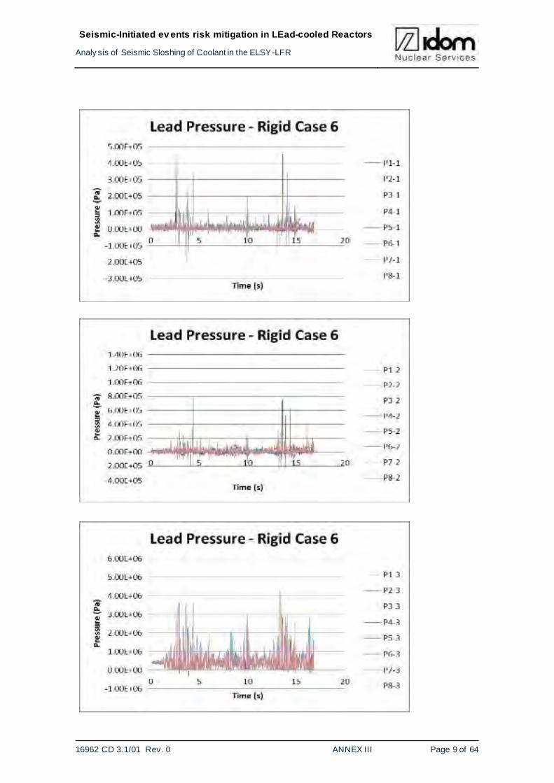
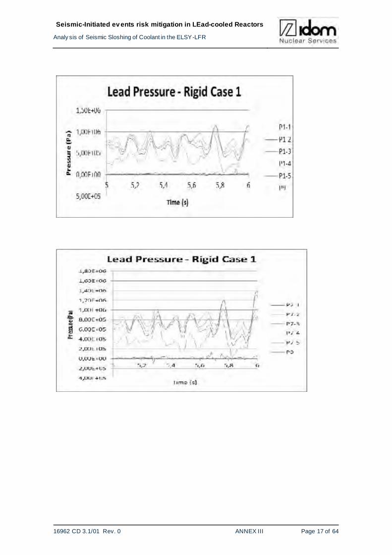
Pressure time history during all the period of the earthquake has been obtained. Those figures
are attached in the ANNEX.III.2.1
It has been checked that in the lowest element (P9) the mean of the pressure time history is
similar to the hydrostatic pressure obtained at rest.
It can also be observed that in the elements located in the free surface a very high pressure has
been measured in a very short time range, so it corresponds to impact loads.
The values of these pressures measured are approximately:
1.8 MPa at the interval t=12.29 s in the case 1.
12.0 MPa at the interval t=9.94 s in the axe 5 and at the interval t=14.98 s in the axe 8 in
the case 6.
P1-Y
P2-Y P3-Y P4-Y
P5-Y
P6-YP7-Y
P8-Y
PX-1 PX-2
PX-3
PX-4
PX-5
P9
P9
Page 46
Seismic-Initiated ev ents risk mitigation in LEad-cooled Reactors
Analy sis of Seismic Sloshing of Coolant in the ELSY-LFR
16962 CD 3.1/01 Rev. 0 FP7-295485-SILER D3.1 - PART I Page 43 of 65
Note that in case 6, the spectrums have been multiplied by 3, it is well above the design bases
earthquake.
It is important to note that without taking into account the impact loads, the pressure time histo-
ries have been measured around the value of 3.0 MPa. It has been observed that the highest
pressure measured coincide in time with the spectrum peaks.
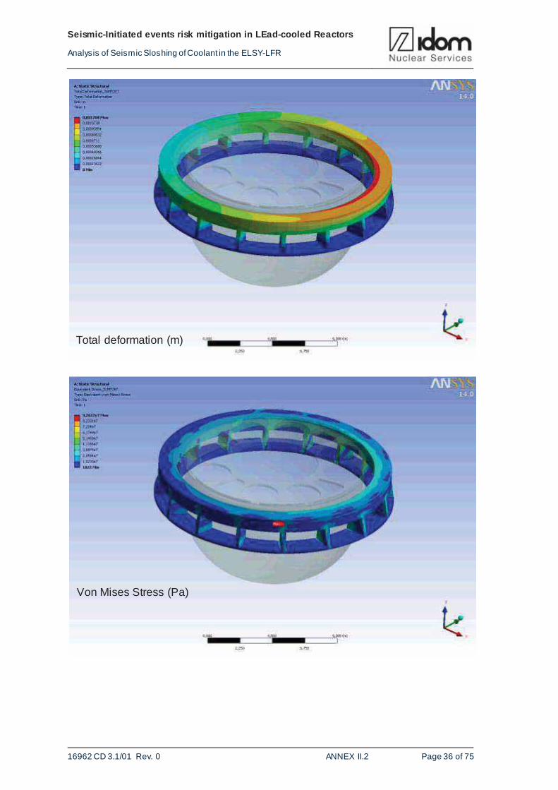
Figure 5-8 and Figure 5-9 show these impact and local loads which should be analysed in future
studies.
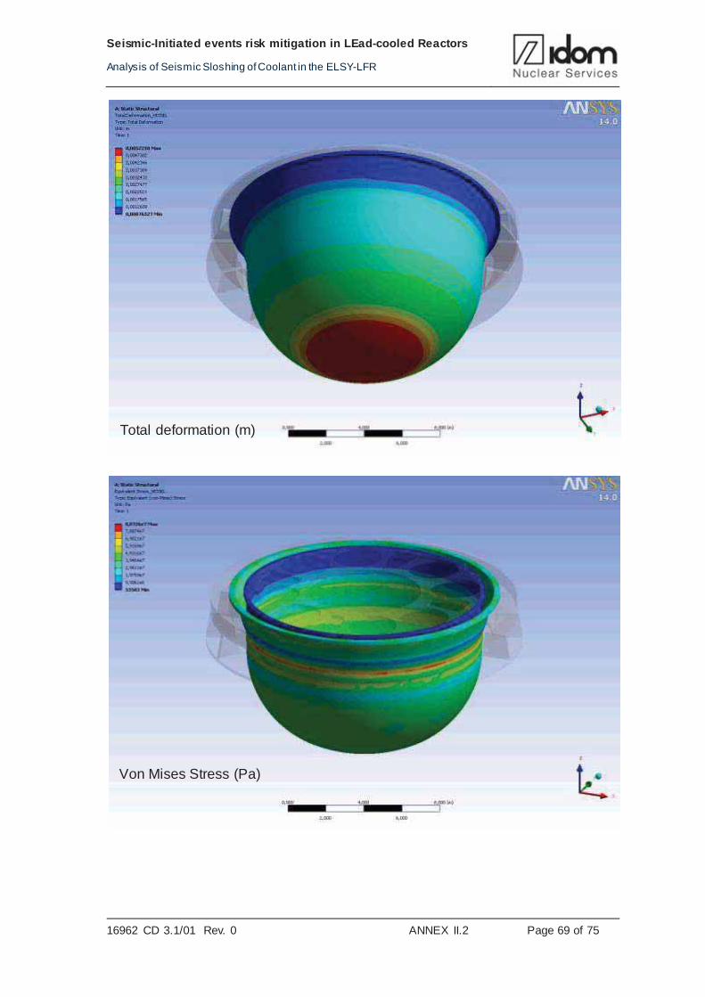
Figure 5-8 Step time 11.20 s in the model with rigid components case 1. (P=1.74 MPa)
Page 47
Seismic-Initiated ev ents risk mitigation in LEad-cooled Reactors
Analy sis of Seismic Sloshing of Coolant in the ELSY-LFR
16962 CD 3.1/01 Rev. 0 FP7-295485-SILER D3.1 - PART I Page 44 of 65
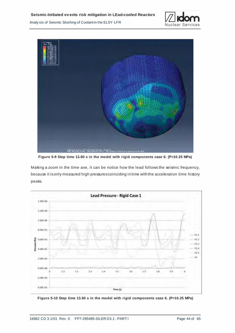
Figure 5-9 Step time 13.60 s in the model with rigid components case 6. (P=10.25 MPa)
Making a zoom in the time axe, it can be notice how the lead follows the seismic frequency,
because it is only measured high pressures coinciding in time with the acceleration time history
peaks.
Figure 5-10 Step time 13.60 s in the model with rigid components case 6. (P=10.25 MPa)
Page 48
Seismic-Initiated ev ents risk mitigation in LEad-cooled Reactors
Analy sis of Seismic Sloshing of Coolant in the ELSY-LFR
16962 CD 3.1/01 Rev. 0 FP7-295485-SILER D3.1 - PART I Page 45 of 65
Figure 5-11 Step time 13.60 s in the model with rigid components case 6. (P=10.25 MPa)
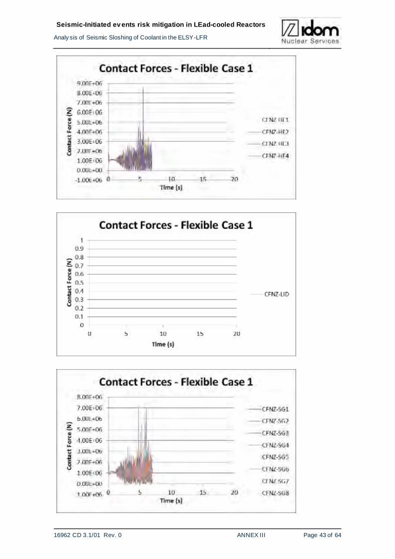
5.2.2. ABAQUS model with deformable components
Remembering that the calculus of this model aborted before the ending of the seismic accelera-
tion time history input data (approximately at the interval of 7.0 s in cases 1, 3 and 12 and at the
interval of 4.0 s in case 6) the results obtained will be compared where possible with the results
obtained in the model with rigid components. Results can be seen in ANNEX.III.2.2.
In that short period of time, the comparison between the model with rigid components and that
model , in a similar time interval, show that pressures measured in the model with deformable
components are higher than the model with rigid components. The multiplication factor range
between 1 and 2. But a full time description is required for the flexible case.
Making a zoom in the pressure time history obtained it can be observed that there is a significant
interaction between the deformable structure of the vessel and the lead, because the pressure
distribution has different frequencies than in the model with rigid components. Figure 5-12 shows
that difference. Results can be seen in ANNEX.III.3.1., and III.3.2..
Page 49
Seismic-Initiated ev ents risk mitigation in LEad-cooled Reactors
Analy sis of Seismic Sloshing of Coolant in the ELSY-LFR
16962 CD 3.1/01 Rev. 0 FP7-295485-SILER D3.1 - PART I Page 46 of 65
Figure 5-12 Step time 13.60 s in the model with rigid components case 6. (P=10.25 MPa)
Figure 5-13 Step time 13.60 s in the model with rigid components case 6. (P=10.25 MPa)
In the pressure time histories obtained in these models, it has also been observed a high in-
creasing of the pressure in a very l ittle interval of times, which are related with impact loads.
Page 50
Seismic-Initiated ev ents risk mitigation in LEad-cooled Reactors
Analy sis of Seismic Sloshing of Coolant in the ELSY-LFR
16962 CD 3.1/01 Rev. 0 FP7-295485-SILER D3.1 - PART I Page 47 of 65
Table 5-1 shows the maximum pressures obtained with four load cases using the model with
rigid components as well as the model with deformable components.
Case Model Reference point Pressure (Pa) Time (s)
Case 1 Rigid P4-2 1.84 E6 12.29
Case 1 Flexible P8-4 3.05 E6 4.7
Case 3 Rigid P4-3 1.40 E6 13.44
Case 3 Flexible P5-5 1.76 E6 4.9
Case 6 Rigid P5-4 1.26 E7 9.94
Case 6 Flexible P9 7.63 E6 2.88
Case 12 Rigid P6-3 1.61 E6 13.54
Case 12 Flexible P4-5 4.93 E6 4.3
Table 5-1 Maximum pressures obtained in the four load cases in both models
In the load cases 1, 3 and 12, the pressures measured in the model with deformable by the time
before the calculus abortion are higher than in the model with rigid components. Only in the load
case 6 the pressure measured is lower in the model with deformable components than in the
model with rigid components.
So in general, the pressures registered in the model with deformable components are higher
than in the model with rigid components. Notice that the pressures in the model with deformable
components could be higher in the period after the calculus abortion.
5.3. Fluid-Structure Interaction
As it has been explained previously, the 3D finite element model with deformable components
calculus aborted in the first third of the seismic acceleration time history. The abortion was pro-
duced because of an element distortion.
By looking at the previous Figure 5-10 to Figure 5-13, it is thought that a significant effect of
fluid-structure interaction exists, due to the different tendencies in the pressure distribution and
Page 51
Seismic-Initiated ev ents risk mitigation in LEad-cooled Reactors
Analy sis of Seismic Sloshing of Coolant in the ELSY-LFR
16962 CD 3.1/01 Rev. 0 FP7-295485-SILER D3.1 - PART I Page 48 of 65
pressure time histories measured compared to the pressure time histories obtained in the model
created with rigid components.
Page 52
Seismic-Initiated ev ents risk mitigation in LEad-cooled Reactors
Analy sis of Seismic Sloshing of Coolant in the ELSY-LFR
16962 CD 3.1/01 Rev. 0 FP7-295485-SILER D3.1 - PART I Page 49 of 65
6. ASSESSMENTS OF STRESSES RESULTS
6.1. ANSYS RESULTS ON STRUCTURAL ANALYSIS
An structural analysis has been made in order to evaluate the effects of both, the fluid pressure
at rest and hydrodynamic pressures induced by the fluid motion due to the seismic loads. In
order to get it, five independent static analyses have been carried out using the pressure results
which have been got from the Computational Fluid Dynamics (CFD) analysis.
3-D finite element model with ANSYS_MECHANICAL has been made in order to obtain the
stress, displacement, etc. on considered components.
6.1.1. MODEL
A detailed 3-D finite element model has been made from ELSY Reactor geometry. The geome-
try considered includes the following main components:
REACTOR VESSEL INNER VESSEL LID STEAM GENERATOR DECAY HEAT REMOVAL REACTOR VESSEL SUPPORT
The next figure shows the considered geometry
Page 53
Seismic-Initiated ev ents risk mitigation in LEad-cooled Reactors
Analy sis of Seismic Sloshing of Coolant in the ELSY-LFR
16962 CD 3.1/01 Rev. 0 FP7-295485-SILER D3.1 - PART I Page 50 of 65
Figure 6-1 ELSY Reactor geometry for structural analysis
6.1.2. Finite Element model
The mesh was performed from the previous geometry with 670000 nodes and 200000 elements.
The next figure shows the mesh generated
Page 54
Seismic-Initiated ev ents risk mitigation in LEad-cooled Reactors
Analy sis of Seismic Sloshing of Coolant in the ELSY-LFR
16962 CD 3.1/01 Rev. 0 FP7-295485-SILER D3.1 - PART I Page 51 of 65
Figure 6-2 ELSY Reactor mesh for structural analysis
6.1.3. Material properties
The Reactor Vessel and internals are made of SA 240 316LN and the Reactor Vessel Support is
made of SA 516 Gr 70 carbon steel.
The properties of these materials are the following:
a. SA 240 316 LN
Density: 8030.0 kg/m3
Moduli of elasticity: 1.95x10¹¹ Pa
Poisson's ratio: 0.31
Tensile strength: 512.0x10⁶ Pa (422.0x10⁶ at 450oC)
Yield strength: 205.0x10⁶ Pa (111.0x10⁶ at 450oC)
b. SA 516 Gr 70 carbon steel
Density: 7750.0 kg/m3
Page 55
Seismic-Initiated ev ents risk mitigation in LEad-cooled Reactors
Analy sis of Seismic Sloshing of Coolant in the ELSY-LFR
16962 CD 3.1/01 Rev. 0 FP7-295485-SILER D3.1 - PART I Page 52 of 65
Moduli of elasticity: 2.10x10¹¹ Pa
Poisson's ratio: 0.30
Tensile strength: 485.0x10⁶ Pa
Yield strength: 260.0x10⁶ Pa
6.1.4. Boundary conditions
The imposed boundary conditions are the following:
Null displacement in the bottom of reactor vessel support
Rigid junction between Y-piece and reactor vessel support
Rigid junction between lid and reactor vessel
Page 56
Seismic-Initiated ev ents risk mitigation in LEad-cooled Reactors
Analy sis of Seismic Sloshing of Coolant in the ELSY-LFR
16962 CD 3.1/01 Rev. 0 FP7-295485-SILER D3.1 - PART I Page 53 of 65
Rigid junction between lid and inner vessel
Rigid junction between steam generator and heat decay removal with l id
Rigid junction steam generator and inner vessel
6.1.5. Load cases
Structural analysis have been carried out using the pressures which have been got from the
Computational Fluid Dynamics (CFD) analyses. The pressure used in the first analysis is got as
a consequence of the fluid weight at rest. The rest of analyses use hydrodynamic pressures
induced by the fluid motion due to the seismic loads. For each of the four seismic loads consid-
ered, results for 20.0 s are available, that is the time in which the seismic loads are working,
which are saved each 0.2 s. Pressures which have been used for each of the four seismic loads
considered, are the following:
Time for the most unfavourable situation. Two analyses are done, the first one using the
pressure saved in the results fi le for the time corresponding to the most unfavourable
situation, and another one using this pressure but being increased using the specific
Page 57
Seismic-Initiated ev ents risk mitigation in LEad-cooled Reactors
Analy sis of Seismic Sloshing of Coolant in the ELSY-LFR
16962 CD 3.1/01 Rev. 0 FP7-295485-SILER D3.1 - PART I Page 54 of 65
average coefficient obtained to take in account the lack of storage space . Note: the time
and coefficient stated before are calculated later in the point 3.2.5 of this report.
Time in which the wet l id surface percentage is maximum. This time and percentage are
shown in the table 4.9
Final time, t=20.0 s.
Finally 17 different load cases have been analysed. Taking as a reference the first structural
analysis (with dead load), the results of the following structural analysis allow to evaluate the
effect of the seismic loads.
6.1.6. RESULTS
This work only checks the integrity of the vessel reactor, and that’s why it only takes into account
the vessel, the lid and the vessel support. However, pressure results are available each 0.2 s for
the next components:
REACTOR VESSEL INNER VESSEL LID STEAM GENERATOR DECAY HEAT REMOVAL
It would be possible to check just as it is done for the vessel, the integrity for each of these com-
ponents due to seismic loads used.
Graphical results are shown in the annex-II.2.2
Next table 6.1 includes a results summary:
Page 58
Seismic-Initiated ev ents risk mitigation in LEad-cooled Reactors
Analy sis of Seismic Sloshing of Coolant in the ELSY-LFR
16962 CD 3.1/01 Rev. 0 FP7-295485-SILER D3.1 - PART I Page 55 of 65
COMPONENTS
REACTOR VESSEL LID SUPPORT
CASE TIME DISPLACEMENT (mm)
VON_MISES STRESS (MPa)
DISPLACEMENT (mm)
VON_MISES STRESS (MPa)
DISPLACEMENT (mm)
VON_MISES STRESS (MPa)
1
15.8 9.34 143.6 3.7 44.5 3.2 285.3 (* *)
17.4 6.6 100.0 2.5 20.1 2.1 159.8 (* *)
20.0 5.7 98.7 2.0 12.5 1.35 131.0 (* *)
15.8(*) 33.17 509.9 13.1 158.1 11.4 1013.0 (* *)
3
4.0 7.8 139.2 2.7 18.2 1.6 166.9 (* *)
17.0 3.1 74.1 1.5 26.6 1.2 92.6 (* *)
20.0 5.4 93.9 1.9 8.1 1.2 101.0 (* *)
4.0(*) 17.1 303.8 6.0 39.6 3.6 364.1 (* *)
6
13.8 15.35 272.4 5.5 59.8 3.7 367.1 (* *)
13.4 8.5 171.3 3.4 51.16 2.5 242.1 (* *)
20.0
13.8(*) 74.7 1326.5 26.6 291.1 17.9 1787.7 (* *)
12
14.0 6.2 106.6 2.1 11.0 1.3 133.4 (* *)
17.8 5.4 94.6 1.9 17.8 1.3 129.2 (* *)
20.0 5.2 88.7 1.7 5.6 1.1 108.2 (* *)
14.0(*) 15.3 262.2 5.2 26.9 3.2 328.2 (* *)
AT REST 5.1 85.2 1.7 0.76 0.95 104.5 (* *)
Table 6-1 Maximum displacements and Von Mises stresses (MPa)
(*) Results include the multiplication coefficients calculated in the point 3.2.5 to take in account
the time step recording value of 0.2 s.
(* *) Local stresses
Page 59
Seismic-Initiated ev ents risk mitigation in LEad-cooled Reactors
Analy sis of Seismic Sloshing of Coolant in the ELSY-LFR
16962 CD 3.1/01 Rev. 0 FP7-295485-SILER D3.1 - PART I Page 56 of 65
The results show that the seismic loads produce stress exceeding the yield strength in localized
parts of the reactor vessel , therefore, locally impair its integrity.
6.2. ABAQUS RESULTS
In the ABAQUS simulation stresses have been obtained also in the model with deformable
components. As it has been explained before, in the chapter 3.3.2, only the external and the
inner vessel have been modelled as deformable components. It has allowed obtaining the
stresses reached in the external and inner vessel because of the lead movement.
Stresses time histories have been obtained in the reference elements shown in Figure 6-3 in the
inner and external vessel. The field output could not be obtained due to the fi le size. It is im-
portant to remember that the simulation aborts before the ending of the acceleration time history,
so the stresses obtained should be multiplied by the same factor that increases the pressure in
the model with deformable components respect to the model with rigid components.
Figure 6-3 Distribution and location of the reference elements to obtain stresses in the inner and
external vessel
Figure 6-3 show the reference points where it has been measured the maximum values of Von
Mises stresses. Table 6-2 shows the maximum values of the stresses obtained and the time
when it occurs.
Page 60
Seismic-Initiated ev ents risk mitigation in LEad-cooled Reactors
Analy sis of Seismic Sloshing of Coolant in the ELSY-LFR
16962 CD 3.1/01 Rev. 0 FP7-295485-SILER D3.1 - PART I Page 57 of 65
Reference point Case Von Mises stress (MPa)
Time (s)
Inner vessel 8-5 Case 1 430.654 5.46
External vessel 11-4 Case 1 200.794 5.8
Inner vessel 8-4 Case 3 103.942 4.9
External vessel 9-4 Case 3 142.294 4.8
Inner vessel 12-4 Case 6 91.514 2.59
External vessel 8-4 Case 6 324.208 3.36
Inner vessel 3-5 Case 12 337.562 4.3
External vessel 9-4 Case 12 144.125 4.3
Table 6-2 Maximum Von Mises stresses obtained for all cases for the inner and external vessel
The materials considered in the model are SS-SA 240 316LN (Symin = 190.0 MPa (20ºC);
Symin = 103.0 MPa (450ºC)) for the reactor vessel and carbon steel SA 516 Gr 70 for the
reactor support.
In the model the Young modulus has been defined temperature-independent, with a value of
200.0x10⁹ Pa.
Looking at the Table 6-2, the Von Mises stresses obtained in the cases 1 and 6 are up to 4 times
higher than the yield strength of the material at 450ºC.
It is important to note that those values obtained have been measured in the only first 4 and 7
seconds of the simulation, because the calculus aborted at the 7th second in the load cases 1, 3
and 12, and at the 4th second in the load case 6.
Page 61
Seismic-Initiated ev ents risk mitigation in LEad-cooled Reactors
Analy sis of Seismic Sloshing of Coolant in the ELSY-LFR
16962 CD 3.1/01 Rev. 0 FP7-295485-SILER D3.1 - PART I Page 58 of 65
Figure 6-4 Stresses obtained for the inner vessel in the case 1 for the model with deformable
components
The main raison for calculus abortion is the high strain of some fluid elements. Several modifica-
tions have been tented to avoid this loss of convergence, including the increment on the element
numbers, but the size of the elements should be much lower. The number of elements used in
this calculus is around 140000 and it should be multiplied by a significant factor. In the case of
FLUENT a factor of 13 was used to obtain fluid solution. But including this huge number of ele-
ments requires also a huge data storage device which is not the calculations scope of this mo-
ment.
0,00E+00
5,00E+07
1,00E+08
1,50E+08
2,00E+08
2,50E+08
3,00E+08
3,50E+08
4,00E+08
4,50E+08
5,00E+08
0 5 10 15 20
Str
ess
(Pa)
Time (s)
Von Mises Stresses Cyl Vessel Flexible Case1
PCV1 5
PCV2 5
PCV3 5
PCV4 5
PCV5 5
PCV6 5
PCV7 5
PCV8 5
PCV9 5
PCV10 5
Page 62
Seismic-Initiated ev ents risk mitigation in LEad-cooled Reactors
Analy sis of Seismic Sloshing of Coolant in the ELSY-LFR
16962 CD 3.1/01 Rev. 0 FP7-295485-SILER D3.1 - PART I Page 59 of 65
Figure 6-5 Stresses obtained for the external vessel in the case 1 for the model with deformable
components
Figure 6-6 Stresses obtained for the inner vessel in the case 6 for the model with deformable
components
0,00E+00
5,00E+07
1,00E+08
1,50E+08
2,00E+08
2,50E+08
0 5 10 15 20
Str
ess
(Pa)
Time (s)
Von Mises Stresses Ext Vessel Flexible Case1
PEV1 4N
PEV1 4P
PEV2 4N
PEV2 4P
PEV3 4N
PEV3 4P
PEV4 4N
PEV4 4P
PEV5 4N
PEV5 4P
0,00E+00
1,00E+07
2,00E+07
3,00E+07
4,00E+07
5,00E+07
6,00E+07
7,00E+07
8,00E+07
9,00E+07
1,00E+08
0 5 10 15 20
Str
ess
(Pa)
Time (s)
Von Mises Stresses Cyl Vessel Flexible Case6
PCV1 4
PCV2 4
PCV3 4
PCV4 4
PCV5 4
PCV6 4
PCV7 4
PCV8 4
PCV9 4
PCV10 4
Page 63
Seismic-Initiated ev ents risk mitigation in LEad-cooled Reactors
Analy sis of Seismic Sloshing of Coolant in the ELSY-LFR
16962 CD 3.1/01 Rev. 0 FP7-295485-SILER D3.1 - PART I Page 60 of 65
Figure 6-7 Stresses obtained for the external vessel in the case 6 for the model with deformable
components
0,00E+00
5,00E+07
1,00E+08
1,50E+08
2,00E+08
2,50E+08
3,00E+08
3,50E+08
0 5 10 15 20
Stre
ss(P
a)
Time (s)
Von Mises Stresses Ext Vessel Flexible Case6
PEV1 4N
PEV1 4P
PEV2 4N
PEV2 4P
PEV3 4N
PEV3 4P
PEV4 4N
PEV4 4P
PEV5 4N
PEV5 4P
Page 64
Seismic-Initiated ev ents risk mitigation in LEad-cooled Reactors
Analy sis of Seismic Sloshing of Coolant in the ELSY-LFR
16962 CD 3.1/01 Rev. 0 FP7-295485-SILER D3.1 - PART I Page 61 of 65
7. RESULTS EVALUATION
7.1. FLUENT ANSYS RESULTS
7.1.1. Fluid pressures
1. The maximum vessel pressure loads obtained for the dynamic cases are: 1.4 MPa for
case 1, 1.6 MPa for case 3, 3.3 MPa for case 6 and 1.0 MPa for case 12
2. The total number of elements require to get the results is of 1.9 Mill ions of elements.
With a lower number a convergence problem erased, specially in the case of a very
high loads such as case 6.
3. So far, only have been processed seventeen seconds of the case 6.
4. To manage the high amount of data generated a huge storage device is required. That
is why only the time history in specific points is stored, while the full set of results are
stored only each 0.2 s. From the comparison of he pressure peaks for 0.01 s and 0.2 s.
some multiplication factor have been obtained in order to evaluate the effect of the data
losses because the lag of storage capacity. Those factors have been applied to the cal-
culated stresses.
5. In ANNEX II.1.4 Pressure time histories and vessel pressures in 3D distribution in spe-
cific time can be review. This 3D pressures represent the behaviour at specific time not
when the time peak pressure is obtained.
7.1.2. Displacements and stresses results
1. Displacements in the reactor vessel are relatively small. Therefore one way analysis is
acceptable for fluid displacements.
2. In all studied cases, the elastic l imit of the vessel material is exceeded in some points
3. There is a significant contact area between the lid and fluid lead. These means signifi-
cant loads on the lid.
4. There is a significant effect between the impulsive and the convective area. More points
should be placed between the H3 and H4 in order to describe precisely the transition be-
tween impulsive to convective components.
5. As is indicated in Table 6.1 maximum stresses appear in case 6 at the external vessel
with a value of 272.0 MPa. While at the lid it is of 60.0 MPa. These stresses are consid-
Page 65
Seismic-Initiated ev ents risk mitigation in LEad-cooled Reactors
Analy sis of Seismic Sloshing of Coolant in the ELSY-LFR
16962 CD 3.1/01 Rev. 0 FP7-295485-SILER D3.1 - PART I Page 62 of 65
ering the pressures stored every 0.2 seconds and applied statically. If applied afeccted
by the factor calculated in the point 3.2.5 of this report, the values of these stresses are
1326.0 MPa in the external vessel and 291.0 MPa at the lid.
6. The results should be stored for each time step defined in the seismic loads. This allows
for a detailed dynamic structural analysis and thus take into account the amplifying ef-
fect due to dynamic loads evaluated in this study.
7. Since fluid lead enters in contact with the lid, it would be suitable to analyse the temper-
ature effects on the lid.
7.2. ABAQUS ANALYSIS RESULTS
7.2.1. Fluid pressures results
1. Maximum pressures in the lower part of the external vessel are: For the rigid case, 1.15
MPa for case 1, 1.2 MPa for case 3, 12.7 MPa for case 6 and 0.9 MPa for case 12. For
the flexible case these values are, 1.8 MPa for case 1, 1.4 MPa for case 3, 7.6 MPa for
case 6 and 1.5 Mpa for case 12.
2. The impact loads on the lid can be as higher as 1.6 MPa for case 1 and 1.2 MPa for
case 6.
3. The above results show a significant fluid structure interaction. That can be higher be-
cause the calculations for the flexible cases was aborted before the end time. The multi-
plication factor for pressures can range between 1 and 2. See ANNEX.III.3.1 and 3.2.
4. Table 5.1 show that pressure peaks can be of the order of 12.7 MPa for the rigid case.
See ANNEX III.2.1 and III.2.2
5. In figures 5.8 and 5.9 can be seen that peak pressures are local loads acting in very
short time intervals.
6. There is a significant fluid structure interaction, figures 5.10 and 5.13, show significant
differences on the peak pressures and on the pressure time histories.
7. The calculus abortion in the flexible cases was produced by the distortion excess of
some fluid elements. More detailed models should be developed to evaluate properly
the fluid structure interaction.
Page 66
Seismic-Initiated ev ents risk mitigation in LEad-cooled Reactors
Analy sis of Seismic Sloshing of Coolant in the ELSY-LFR
16962 CD 3.1/01 Rev. 0 FP7-295485-SILER D3.1 - PART I Page 63 of 65
8. There is a significant contact pressure between fluid lead and the vessel l id for cases 1
and 6. For case 1 the contact starts around the second 14.0 s. and for case 6 around
the second 9.0 s.
9. This contact will start earlier for the flexible vessel cases as is indicated in figure 5-6.
Where vertical surface displacement is described for both cases rigid and flexible.
7.2.2. Stresses results
1. As is indicated in table 6.2 maximum stresses appear in case 1 at the inner vessel with
values of 430.0 MPa. While at the external vessel maximum values are of the order of
324.0 MPa for case 6. These values could be higher because the flexible case calcula-
tions was aborted because the fluid element distortions.
2. The internal loads transmitted to the vessel l id have been obtained. This information was
gathered in the ANNEX.III.4. The results show that very high loads are transmited to the
lid and sent to the vessel supports This transmission mechanism should be evaluated in
detail. ANNEX III.4.
8. CONCLUSIONS
1. In order to ensure the stabil ity of the calculation is necessary to develop models with a
high number of elements. The instability also depends on the load level. It means that it
is required to have a high capacity of data storage and, to avoid long calculation times,
work with high capacity computers.
2. The case number 6 by generating a high strain on the elements of lead, led to the nu-
merical instability that has led to the abortion of the ABAQUS calculations for the case.
With the FLUENT model, convergence has been solved but calculation time has been
significantly multiplied (For every second of the seismic time histories, about two or
three days of process).
3. The maximum pressure in the inner and outer vessel reaches values several times
higher than the pressure associated with the hydrostatic pressure. This implies high
stresses on the internal components of the vessel.
4. During seismic response, high specific pressures in small areas and for short time inter-
vals are generated. These pressure pulses are responsible for the identified peaks in the
pressure histograms.
Page 67
Seismic-Initiated ev ents risk mitigation in LEad-cooled Reactors
Analy sis of Seismic Sloshing of Coolant in the ELSY-LFR
16962 CD 3.1/01 Rev. 0 FP7-295485-SILER D3.1 - PART I Page 64 of 65
5. In the process of dynamic response calculations it has been shown that the liquid lead
was in contact with the upper cover, thus generating significant areas with big loads on
the vessel l id.
6. The interaction between the refrigerant and the internal components generates signifi-
cant loads on the upper cap of the vessel. These loads and their transmission mecha-
nisms should be evaluated in detail.
7. The comparison of the calculations with rigid vessel and with flexible vessel, shows that
there is an effect of fluid structure interaction that must be taken into account.
8. The high pressures on the vessel show that local stresses can be very high. This gener-
ates a major impact on the design of the reactor vessel, which may require, well a ge-
ometry change with a thickness modifications or a material change in order to modify
mechanical capabilities.
Page 68
Seismic-Initiated ev ents risk mitigation in LEad-cooled Reactors
Analy sis of Seismic Sloshing of Coolant in the ELSY-LFR
16962 CD 3.1/01 Rev. 0 FP7-295485-SILER D3.1 - PART I Page 65 of 65
9. REFERENCES
1. SMO12000005. “Seismic re-evaluation of EMO 1&2 NPPs – Seismic adequacy assessment
of mechanical and electrical equipment for the Seismic re-evaluation of EMO 1&2 NPPs”,
Rev. 02. Purchasing Technical Specifications. ENEL. January 2013.
2. SMO12000256. “Seismic re-evaluation of EMO 1&2 NPPs – Tender Participation
Requirements. Seismic adequacy assessment of mechanical and electrical equipment for
the Seismic re-evaluation of EMO 1&2 NPPs”, Rev. 00. ENEL. January 2013.
3. Ansaldo Nucleare. E-mail from Luigi Mansani (Ansaldo) to Francisco Beltran (IDOM), dated
on 10/Apr/2013.
4. Empresarios Agrupados. “SILER - Description of Systems, LFR”. Document 092-260-F-C-
00101, Issue 2. SILER Project, Work Package 2, deliverable D2.1a. July 2012.
5. SILER. WP2. Reactor Building Seismic Analysis. RPV seismic time histories.
6. ABAQUS. Release 6.10.
7. ANSYS_FLUENT. Release 14.0.
8. G. W. Housner. "Dynamic Pressures on Accelerated Fluid Containers". Bull.Seismol. Soc.
Am., 47(1). January 1957.
Page 69
FP7-295485-SILER D3.1 Part II
Part II: Sloshing Maps and Parametric Sensitivity Analysis
(KTH)
Page 70
FP7-295485-SILER D3.1 Part II
Page 71
FP7-295485-SILER D3.1 Part II
Page 72
FP7-295485-SILER D3.1 Part II
Page 73
FP7-295485-SILER D3.1 Part II
Page 74
FP7-295485-SILER D3.1 Part II
Page 75
FP7-295485-SILER D3.1 Part II
Page 76
FP7-295485-SILER D3.1 Part II
Page 77
FP7-295485-SILER D3.1 Part II
Page 78
FP7-295485-SILER D3.1 Part II
•oo
•oo
•o
Page 79
FP7-295485-SILER D3.1 Part II
o
Page 80
FP7-295485-SILER D3.1 Part II
Page 81
FP7-295485-SILER D3.1 Part II
Page 82
FP7-295485-SILER D3.1 Part II
Page 83
FP7-295485-SILER D3.1 Part II
Page 84
FP7-295485-SILER D3.1 Part II
•••
Page 85
FP7-295485-SILER D3.1 Part II
Page 86
FP7-295485-SILER D3.1 Part II
Page 87
FP7-295485-SILER D3.1 Part II
Page 88
FP7-295485-SILER D3.1 Part II
Page 89
FP7-295485-SILER D3.1 Part II
Page 90
FP7-295485-SILER D3.1 Part II
Page 91
FP7-295485-SILER D3.1 Part II
Page 92
FP7-295485-SILER D3.1 Part II
Page 93
FP7-295485-SILER D3.1 Part II
Page 94
FP7-295485-SILER D3.1 Part II
Page 95
FP7-295485-SILER D3.1 Part II
Page 96
FP7-295485-SILER D3.1 Part II
Page 97
FP7-295485-SILER D3.1 Part II
Page 98
FP7-295485-SILER D3.1 Part II
Page 99
FP7-295485-SILER D3.1 Part II
Page 100
FP7-295485-SILER D3.1 Part II
Page 101
FP7-295485-SILER D3.1 Part II
Page 102
FP7-295485-SILER D3.1 Part II
Page 103
FP7-295485-SILER D3.1 Part II
Page 104
FP7-295485-SILER D3.1 Part II
Page 105
FP7-295485-SILER D3.1 Part II
Page 106
FP7-295485-SILER D3.1 Part II
Page 107
FP7-295485-SILER D3.1 Part II
Page 108
FP7-295485-SILER D3.1 Part II
Page 109
FP7-295485-SILER D3.1 Part II
Page 110
FP7-295485-SILER D3.1 Part II
Page 111
FP7-295485-SILER D3.1 Part II
Page 112
FP7-295485-SILER D3.1 Part II
Page 113
FP7-295485-SILER D3.1 Part II
Page 114
FP7-295485-SILER D3.1 Part II
Page 115
FP7-295485-SILER D3.1 Part II
Page 116
FP7-295485-SILER D3.1 Part II
Page 117
FP7-295485-SILER D3.1 Part II
Page 118
FP7-295485-SILER D3.1 Part II
Page 119
Seismic-Initiated ev ents risk mitigation in LEad-cooled Reactors
Analy sis of Seismic Sloshing of Coolant in the ELSY-LFR
Part III: ANNEXES
ANNEXES PART I: ANNEX I: ALE Method validation. Slosh height in a rectangular tank ANNEX II: Fluid and Structural analysis with FLUENT-ANSYS ANNEX III: ABAQUS Fluid Structure analysis
ANNEXES PART II: (No Annexes)
Page 120
Seismic-Initiated events risk mitigation in LEad-cooled Reactors
Analysis of Seismic Sloshing of Coolant in the ELSY-LFR
16962 CD 3.1/01 Rev. 0 ANNEX I Page 1 of 9
ANNEX I:
ALE METHOD VALIDATION
Page 121
Seismic-Initiated events risk mitigation in LEad-cooled Reactors
Analysis of Seismic Sloshing of Coolant in the ELSY-LFR
16962 CD 3.1/01 Rev. 0 ANNEX I Page 2 of 9
ALE METHOD VALIDATION
Slosh height in a rectangular tank
Table of contents
1. Objective and scope
2. ALE method
3. Description of the FEM model
4. Results
5. Conclusions
6. References
Annex - “Maximum slosh height in a rectangular tank - Housner procedure”
1. Objective and scope
The objective of the present document is to validate the application of the ALE
method to determine the sloshing in the ELSY reactor, in the context of the SILER
project.
In order to perform the validation, the maximum slosh height of a water-filled tank
shacked by a horizontal seismic motion is determined applying the ALE method by
using Abaqus Explicit (Ref. 1). Results are compared to a reference solution ob-
tained by the analytical approach given by Housner (see annex).
Page 122
Seismic-Initiated events risk mitigation in LEad-cooled Reactors
Analysis of Seismic Sloshing of Coolant in the ELSY-LFR
16962 CD 3.1/01 Rev. 0 ANNEX I Page 3 of 9
2. ALE method
The ALE (Arbitrary Lagrange Euler) method of space discretization is a hybrid of
the Lagrange and Euler methods. It allows redefining the mesh continuously as the
calculation proceeds. The advantage of ALE is the ability to reduce difficulties
caused by severe mesh distortions encountered by the Lagrange method and al-
lows a calculation to continue efficiently. However, compared with Lagrange, an
additional computational step of rezoning is employed to move the mesh and
remap the solution onto a new mesh.
The nodes at the boundary in an ALE mesh cannot leave the boundary because its
tracking is “Lagrangian”. After deformation of the boundaries takes place, the inter-
nal domain is remeshed in order to prevent excessive element distortion. The
remeshing is performed by transporting the “Eulerian” material across the mesh.
3. Description of the FEM model
The 2D-model is created in Abaqus Explicit (Ref. 1) and it consists of a rectangular
tank filled with water. The tank measures 12.3 x 12 m, and it is filled with 8 m of
water. The top of the tank is not modeled because the water is not expected to
come into contact with it. The tank is modeled as a rigid body and is meshed with
R2D2 elements. A graded mesh of CPE4R elements is used for the water. Friction-
less contact is defined between the water and the tank. The finite element model is
shown in Figure 1.
Figure 1 - Finite element model
Page 123
Seismic-Initiated events risk mitigation in LEad-cooled Reactors
Analysis of Seismic Sloshing of Coolant in the ELSY-LFR
16962 CD 3.1/01 Rev. 0 ANNEX I Page 4 of 9
The material model for water is defined by the following parameters:
- Density: 983.2 kg/m3
- Linear volumetric response (Equation of State)
- Speed of sound: 451 m/s
- Shear behaviour (Newtonian fluid)
- Viscosity: 1.4 10-3 Pa s
- No turbulence or limit layer effects
The wave speed is determined based on the bulk modulus, which has been chosen
one order of magnitude less than the actual bulk modulus of water (2 GPa) in order
to avoid an overly stiff response. On the other hand, since sloshing problems are
unconfined, the bulk modulus chosen can be reduced and the water will still behave
as an incompressible medium.
The water is subjected to gravity loading. Consequently, an initial geostatic stress
field is defined to equilibrate the stresses caused by the self-weight of the water.
In addition, an acceleration time history is prescribed for the tank in the horizontal
direction in order to represent the seismic motion corresponding to case 07, X-
direction (see figure 2). The sloshing analysis is performed for 20 seconds.
-10
-8
-6
-4
-2
0
2
4
6
8
10
0 5 10 15 20
Acc
ele
ratio
n (
m/s
2)
Time (s)
Horizontal accelerogram (X direction)
Ax - case 07
Figure 2 - Horizontal accelerogram (X direction), case 07
Page 124
Seismic-Initiated events risk mitigation in LEad-cooled Reactors
Analysis of Seismic Sloshing of Coolant in the ELSY-LFR
16962 CD 3.1/01 Rev. 0 ANNEX I Page 5 of 9
4. Results
Figure 3 shows the pressures of the fluid in the deformed mesh at various times. As
the figure shows, there is significant sloshing of the water.
Figure 4 shows a time history of the envelope of the maximum vertical displace-
ments of the water free surface. As shown in the figure, the maximum vertical dis-
placement is 0.530 m and it is reached after 17.5 seconds of seismic motion. Fig-
ure 5 shows the vertical displacements of the water material at this time.
Figure 3 - Pressure at various times
Page 125
Seismic-Initiated events risk mitigation in LEad-cooled Reactors
Analysis of Seismic Sloshing of Coolant in the ELSY-LFR
16962 CD 3.1/01 Rev. 0 ANNEX I Page 6 of 9
Figure 4 - Water free surface maximum displacement
Figure 5 - Vertical displacements of the water material.
Page 126
Seismic-Initiated events risk mitigation in LEad-cooled Reactors
Analysis of Seismic Sloshing of Coolant in the ELSY-LFR
16962 CD 3.1/01 Rev. 0 ANNEX I Page 7 of 9
5. Conclusions
Maximum vertical displacement of the water free surface is obtained from a finite
element model created in Abaqus Explicit using the ALE technology. Its value is
0.530 m.
The reference solution, obtained from the Housner procedure, gives a maximum
vertical displacement of 0.547 m.
Comparing both methods, there is a difference between them of 3.2%, which is
considered acceptable.
Hence, the application of the ALE method is considered suitable to determine the
sloshing in the ELSY reactor.
6. References
1. Simulia. “ABAQUS User’s Manual”. Version 6.10.
Page 127
Seismic-Initiated events risk mitigation in LEad-cooled Reactors
Analysis of Seismic Sloshing of Coolant in the ELSY-LFR
16962 CD 3.1/01 Rev. 0 ANNEX I Page 8 of 9
ANNEX
“Maximum slosh height in a rectangular tank - Housner procedure”
Page 128
Seismic-Initiated events risk mitigation in LEad-cooled Reactors
Analysis of Seismic Sloshing of Coolant in the ELSY-LFR
16962 CD 3.1/01 Rev. 0 ANNEX I Page 9 of 9
Page 129
Seismic-Initiated events risk mitigation in LEad-cooled Reactors
Analysis of Seismic Sloshing of Coolant in the ELSY-LFR
16962 CD 3.1/01 Rev. 0 ANNEX I Page 10 of 9
Page 130
Seismic-Initiated events risk mitigation in LEad-cooled Reactors
Analysis of Seismic Sloshing of Coolant in the ELSY-LFR
16962 CD 3.1/01 Rev. 0 ANNEX I Page 11 of 9
Page 131
Seismic-Initiated events risk mitigation in LEad-cooled Reactors
Analysis of Seismic Sloshing of Coolant in the ELSY-LFR
16962 CD 3.1/01 Rev. 0 Annex II.1 Page 1 of 163
ANNEX-II
FLUID AND STRUCTURAL ANALYSIS WITH FLUENT-ANSYS
ANNEX-II.1
FLUID ANALYSIS
ANNEX-II.1.1
ELSY GEOMETRY
Page 132
Seismic-Initiated events risk mitigation in LEad-cooled Reactors
Analysis of Seismic Sloshing of Coolant in the ELSY-LFR
16962 CD 3.1/01 Rev. 0 Annex II.1 Page 2 of 163
Page 133
Seismic-Initiated events risk mitigation in LEad-cooled Reactors
Analysis of Seismic Sloshing of Coolant in the ELSY-LFR
16962 CD 3.1/01 Rev. 0 Annex II.1 Page 3 of 163
Page 134
Seismic-Initiated events risk mitigation in LEad-cooled Reactors
Analysis of Seismic Sloshing of Coolant in the ELSY-LFR
16962 CD 3.1/01 Rev. 0 Annex II.1 Page 4 of 163
ANNEX-II.1.2
FLUID DOMAIN
(GEOMETRY AND MESH)
Page 135
Seismic-Initiated events risk mitigation in LEad-cooled Reactors
Analysis of Seismic Sloshing of Coolant in the ELSY-LFR
16962 CD 3.1/01 Rev. 0 Annex II.1 Page 5 of 163
GEOMETRY
Page 136
Seismic-Initiated events risk mitigation in LEad-cooled Reactors
Analysis of Seismic Sloshing of Coolant in the ELSY-LFR
16962 CD 3.1/01 Rev. 0 Annex II.1 Page 6 of 163
MESH
Page 137
Seismic-Initiated events risk mitigation in LEad-cooled Reactors
Analysis of Seismic Sloshing of Coolant in the ELSY-LFR
16962 CD 3.1/01 Rev. 0 Annex II.1 Page 7 of 163
MESH
Page 138
Seismic-Initiated events risk mitigation in LEad-cooled Reactors
Analysis of Seismic Sloshing of Coolant in the ELSY-LFR
16962 CD 3.1/01 Rev. 0 Annex II.1 Page 8 of 163
ANNEX-II.1.3
(ACCELERATION TIME HISTORIES FOR CASES 1,3,6 AND 12)
Page 139
Seismic-Initiated events risk mitigation in LEad-cooled Reactors
Analysis of Seismic Sloshing of Coolant in the ELSY-LFR
16962 CD 3.1/01 Rev. 0 Annex II.1 Page 9 of 163
Page 140
Seismic-Initiated events risk mitigation in LEad-cooled Reactors
Analysis of Seismic Sloshing of Coolant in the ELSY-LFR
16962 CD 3.1/01 Rev. 0 Annex II.1 Page 10 of 163
Page 141
Seismic-Initiated events risk mitigation in LEad-cooled Reactors
Analysis of Seismic Sloshing of Coolant in the ELSY-LFR
16962 CD 3.1/01 Rev. 0 Annex II.1 Page 11 of 163
Page 142
Seismic-Initiated events risk mitigation in LEad-cooled Reactors
Analysis of Seismic Sloshing of Coolant in the ELSY-LFR
16962 CD 3.1/01 Rev. 0 Annex II.1 Page 12 of 163
Page 143
Seismic-Initiated events risk mitigation in LEad-cooled Reactors
Analysis of Seismic Sloshing of Coolant in the ELSY-LFR
16962 CD 3.1/01 Rev. 0 Annex II.1 Page 13 of 163
ANNEX-II.1.4
RESULTS
FLUID ANALYSIS
ANNEX-II.1.4.1
RESULTS AT REST
Page 144
Seismic-Initiated events risk mitigation in LEad-cooled Reactors
Analysis of Seismic Sloshing of Coolant in the ELSY-LFR
16962 CD 3.1/01 Rev. 0 Annex II.1 Page 14 of 163
ANNEX-II.1.4.1.1
PRESSURE IN REFERENCE POINTS
Page 145
Seismic-Initiated events risk mitigation in LEad-cooled Reactors
Analysis of Seismic Sloshing of Coolant in the ELSY-LFR
16962 CD 3.1/01 Rev. 0 Annex II.1 Page 15 of 163
Reference points Pressure (Pa) Reference points Pressure (Pa) Reference points Pressure (Pa)
P_H0_1 808118,25
P_H1_1 746053,56 P_H2_1 P_H3_1
P_H1_2 742203,93 P_H2_2 P_H3_2
P_H1_3 742027,25 P_H2_3 P_H3_3
P_H1_4 746498,43 P_H2_4 P_H3_4
P_H1_5 739975,5 P_H2_5 P_H3_5
P_H1_6 742991,37 P_H2_6 P_H3_6
P_H1_7 745301,81 P_H2_7 P_H3_7
P_H1_8 748579,37 P_H2_8 P_H3_8
P_H4_1 P_H5_EXT_1 P_H5_INT_1
P_H4_1 P_H5_EXT_2 P_H5_INT_2
P_H4_3 P_H5_EXT_3 P_H5_INT_3
P_H4_4 P_H5_EXT_4 P_H5_INT_4
P_H4_5 P_H5_EXT_5 P_H5_INT_5
P_H4_6 P_H5_EXT_6 P_H5_INT_6
P_H4_7 P_H5_EXT_7 P_H5_INT_7
P_H4_8 P_H5_EXT_8 P_H5_INT_8
Page 146
Seismic-Initiated events risk mitigation in LEad-cooled Reactors
Analysis of Seismic Sloshing of Coolant in the ELSY-LFR
16962 CD 3.1/01 Rev. 0 Annex II.1 Page 16 of 163
ANNEX-II.1.4.1.2
PRESSURE IN REACTOR VESSEL AND INTERNALS
Page 147
Seismic-Initiated events risk mitigation in LEad-cooled Reactors
Analysis of Seismic Sloshing of Coolant in the ELSY-LFR
16962 CD 3.1/01 Rev. 0 Annex II.1 Page 17 of 163
Pressure
Pressure
Page 148
Seismic-Initiated events risk mitigation in LEad-cooled Reactors
Analysis of Seismic Sloshing of Coolant in the ELSY-LFR
16962 CD 3.1/01 Rev. 0 Annex II.1 Page 18 of 163
Pressure
Page 149
Seismic-Initiated events risk mitigation in LEad-cooled Reactors
Analysis of Seismic Sloshing of Coolant in the ELSY-LFR
16962 CD 3.1/01 Rev. 0 Annex II.1 Page 19 of 163
ANNEX-II.1.4.1.3
FREE SURFACE POSITION
Page 150
Seismic-Initiated events risk mitigation in LEad-cooled Reactors
Analysis of Seismic Sloshing of Coolant in the ELSY-LFR
16962 CD 3.1/01 Rev. 0 Annex II.1 Page 20 of 163
Free surface
Red : Lead Blue : Argon
Page 151
Seismic-Initiated events risk mitigation in LEad-cooled Reactors
Analysis of Seismic Sloshing of Coolant in the ELSY-LFR
16962 CD 3.1/01 Rev. 0 Annex II.1 Page 21 of 163
ANNEX-II.1.4.2
(RESULTS CASE-1)
Page 152
Seismic-Initiated events risk mitigation in LEad-cooled Reactors
Analysis of Seismic Sloshing of Coolant in the ELSY-LFR
16962 CD 3.1/01 Rev. 0 Annex II.1 Page 22 of 163
ANNEX-II.1.4.2.1
(PRESSURE IN REFERENCE POINTS)
Page 153
Seismic-Initiated events risk mitigation in LEad-cooled Reactors
Analysis of Seismic Sloshing of Coolant in the ELSY-LFR
16962 CD 3.1/01 Rev. 0 Annex II.1 Page 23 of 163
Page 154
Seismic-Initiated events risk mitigation in LEad-cooled Reactors
Analysis of Seismic Sloshing of Coolant in the ELSY-LFR
16962 CD 3.1/01 Rev. 0 Annex II.1 Page 24 of 163
Page 155
Seismic-Initiated events risk mitigation in LEad-cooled Reactors
Analysis of Seismic Sloshing of Coolant in the ELSY-LFR
16962 CD 3.1/01 Rev. 0 Annex II.1 Page 25 of 163
Page 156
Seismic-Initiated events risk mitigation in LEad-cooled Reactors
Analysis of Seismic Sloshing of Coolant in the ELSY-LFR
16962 CD 3.1/01 Rev. 0 Annex II.1 Page 26 of 163
Page 157
Seismic-Initiated events risk mitigation in LEad-cooled Reactors
Analysis of Seismic Sloshing of Coolant in the ELSY-LFR
16962 CD 3.1/01 Rev. 0 Annex II.1 Page 27 of 163
Page 158
Seismic-Initiated events risk mitigation in LEad-cooled Reactors
Analysis of Seismic Sloshing of Coolant in the ELSY-LFR
16962 CD 3.1/01 Rev. 0 Annex II.1 Page 28 of 163
Page 159
Seismic-Initiated events risk mitigation in LEad-cooled Reactors
Analysis of Seismic Sloshing of Coolant in the ELSY-LFR
16962 CD 3.1/01 Rev. 0 Annex II.1 Page 29 of 163
Page 160
Seismic-Initiated events risk mitigation in LEad-cooled Reactors
Analysis of Seismic Sloshing of Coolant in the ELSY-LFR
16962 CD 3.1/01 Rev. 0 Annex II.1 Page 30 of 163
Page 161
Seismic-Initiated events risk mitigation in LEad-cooled Reactors
Analysis of Seismic Sloshing of Coolant in the ELSY-LFR
16962 CD 3.1/01 Rev. 0 Annex II.1 Page 31 of 163
Page 162
Seismic-Initiated events risk mitigation in LEad-cooled Reactors
Analysis of Seismic Sloshing of Coolant in the ELSY-LFR
16962 CD 3.1/01 Rev. 0 Annex II.1 Page 32 of 163
Page 163
Seismic-Initiated events risk mitigation in LEad-cooled Reactors
Analysis of Seismic Sloshing of Coolant in the ELSY-LFR
16962 CD 3.1/01 Rev. 0 Annex II.1 Page 33 of 163
Page 164
Seismic-Initiated events risk mitigation in LEad-cooled Reactors
Analysis of Seismic Sloshing of Coolant in the ELSY-LFR
16962 CD 3.1/01 Rev. 0 Annex II.1 Page 34 of 163
Page 165
Seismic-Initiated events risk mitigation in LEad-cooled Reactors
Analysis of Seismic Sloshing of Coolant in the ELSY-LFR
16962 CD 3.1/01 Rev. 0 Annex II.1 Page 35 of 163
Page 166
Seismic-Initiated events risk mitigation in LEad-cooled Reactors
Analysis of Seismic Sloshing of Coolant in the ELSY-LFR
16962 CD 3.1/01 Rev. 0 Annex II.1 Page 36 of 163
Page 167
Seismic-Initiated events risk mitigation in LEad-cooled Reactors
Analysis of Seismic Sloshing of Coolant in the ELSY-LFR
16962 CD 3.1/01 Rev. 0 Annex II.1 Page 37 of 163
Page 168
Seismic-Initiated events risk mitigation in LEad-cooled Reactors
Analysis of Seismic Sloshing of Coolant in the ELSY-LFR
16962 CD 3.1/01 Rev. 0 Annex II.1 Page 38 of 163
Page 169
Seismic-Initiated events risk mitigation in LEad-cooled Reactors
Analysis of Seismic Sloshing of Coolant in the ELSY-LFR
16962 CD 3.1/01 Rev. 0 Annex II.1 Page 39 of 163
ANNEX-II.1.4.2.2
(RESULTS FOR TIME =15.8 sec)
Page 170
Seismic-Initiated events risk mitigation in LEad-cooled Reactors
Analysis of Seismic Sloshing of Coolant in the ELSY-LFR
16962 CD 3.1/01 Rev. 0 Annex II.1 Page 40 of 163
ANNEX-II.1.4.2.2.1
(PRESSURE IN REACTOR VESSEL AND INTERNALS)
Page 171
Seismic-Initiated events risk mitigation in LEad-cooled Reactors
Analysis of Seismic Sloshing of Coolant in the ELSY-LFR
16962 CD 3.1/01 Rev. 0 Annex II.1 Page 41 of 163
Page 172
Seismic-Initiated events risk mitigation in LEad-cooled Reactors
Analysis of Seismic Sloshing of Coolant in the ELSY-LFR
16962 CD 3.1/01 Rev. 0 Annex II.1 Page 42 of 163
Page 173
Seismic-Initiated events risk mitigation in LEad-cooled Reactors
Analysis of Seismic Sloshing of Coolant in the ELSY-LFR
16962 CD 3.1/01 Rev. 0 Annex II.1 Page 43 of 163
ANNEX-II.1.4.2.2.2
(FREE SURFACE POSITION)
Page 174
Seismic-Initiated events risk mitigation in LEad-cooled Reactors
Analysis of Seismic Sloshing of Coolant in the ELSY-LFR
16962 CD 3.1/01 Rev. 0 Annex II.1 Page 44 of 163
Page 175
Seismic-Initiated events risk mitigation in LEad-cooled Reactors
Analysis of Seismic Sloshing of Coolant in the ELSY-LFR
16962 CD 3.1/01 Rev. 0 Annex II.1 Page 45 of 163
ANNEX-II.1.4.2.3
(RESULTS FOR TIME =17.4 sec)
Page 176
Seismic-Initiated events risk mitigation in LEad-cooled Reactors
Analysis of Seismic Sloshing of Coolant in the ELSY-LFR
16962 CD 3.1/01 Rev. 0 Annex II.1 Page 46 of 163
ANNEX-II.1.4.2.3.1
(PRESSURE IN REACTOR VESSEL AND INTERNALS)
Page 177
Seismic-Initiated events risk mitigation in LEad-cooled Reactors
Analysis of Seismic Sloshing of Coolant in the ELSY-LFR
16962 CD 3.1/01 Rev. 0 Annex II.1 Page 47 of 163
Page 178
Seismic-Initiated events risk mitigation in LEad-cooled Reactors
Analysis of Seismic Sloshing of Coolant in the ELSY-LFR
16962 CD 3.1/01 Rev. 0 Annex II.1 Page 48 of 163
Page 179
Seismic-Initiated events risk mitigation in LEad-cooled Reactors
Analysis of Seismic Sloshing of Coolant in the ELSY-LFR
16962 CD 3.1/01 Rev. 0 Annex II.1 Page 49 of 163
ANNEX-II.1.4.2.3.2
(FREE SURFACE POSITION)
Page 180
Seismic-Initiated events risk mitigation in LEad-cooled Reactors
Analysis of Seismic Sloshing of Coolant in the ELSY-LFR
16962 CD 3.1/01 Rev. 0 Annex II.1 Page 50 of 163
Page 181
Seismic-Initiated events risk mitigation in LEad-cooled Reactors
Analysis of Seismic Sloshing of Coolant in the ELSY-LFR
16962 CD 3.1/01 Rev. 0 Annex II.1 Page 51 of 163
ANNEX-II.1.4.2.4
(RESULTS FOR TIME =20.0 sec)
Page 182
Seismic-Initiated events risk mitigation in LEad-cooled Reactors
Analysis of Seismic Sloshing of Coolant in the ELSY-LFR
16962 CD 3.1/01 Rev. 0 Annex II.1 Page 52 of 163
ANNEX-II.1.4.2.4.1
(PRESSURE IN REACTOR VESSEL AND INTERNALS)
Page 183
Seismic-Initiated events risk mitigation in LEad-cooled Reactors
Analysis of Seismic Sloshing of Coolant in the ELSY-LFR
16962 CD 3.1/01 Rev. 0 Annex II.1 Page 53 of 163
Page 184
Seismic-Initiated events risk mitigation in LEad-cooled Reactors
Analysis of Seismic Sloshing of Coolant in the ELSY-LFR
16962 CD 3.1/01 Rev. 0 Annex II.1 Page 54 of 163
Page 185
Seismic-Initiated events risk mitigation in LEad-cooled Reactors
Analysis of Seismic Sloshing of Coolant in the ELSY-LFR
16962 CD 3.1/01 Rev. 0 Annex II.1 Page 55 of 163
ANNEX-II.1.4.2.4.2
(FREE SURFACE POSITION)
Page 186
Seismic-Initiated events risk mitigation in LEad-cooled Reactors
Analysis of Seismic Sloshing of Coolant in the ELSY-LFR
16962 CD 3.1/01 Rev. 0 Annex II.1 Page 56 of 163
Page 188
Seismic-Initiated events risk mitigation in LEad-cooled Reactors
Analysis of Seismic Sloshing of Coolant in the ELSY-LFR
16962 CD 3.1/01 Rev. 0 Annex II.1 Page 57 of 163
ANNEX-II.1.4.3
RESULTS CASE-3
Page 189
Seismic-Initiated events risk mitigation in LEad-cooled Reactors
Analysis of Seismic Sloshing of Coolant in the ELSY-LFR
16962 CD 3.1/01 Rev. 0 Annex II.1 Page 58 of 163
ANNEX-II.1.4.3.1
(PRESSURE IN REFERENCE POINTS)
Page 190
Seismic-Initiated events risk mitigation in LEad-cooled Reactors
Analysis of Seismic Sloshing of Coolant in the ELSY-LFR
16962 CD 3.1/01 Rev. 0 Annex II.1 Page 59 of 163
Page 191
Seismic-Initiated events risk mitigation in LEad-cooled Reactors
Analysis of Seismic Sloshing of Coolant in the ELSY-LFR
16962 CD 3.1/01 Rev. 0 Annex II.1 Page 60 of 163
Page 192
Seismic-Initiated events risk mitigation in LEad-cooled Reactors
Analysis of Seismic Sloshing of Coolant in the ELSY-LFR
16962 CD 3.1/01 Rev. 0 Annex II.1 Page 61 of 163
Page 193
Seismic-Initiated events risk mitigation in LEad-cooled Reactors
Analysis of Seismic Sloshing of Coolant in the ELSY-LFR
16962 CD 3.1/01 Rev. 0 Annex II.1 Page 62 of 163
Page 194
Seismic-Initiated events risk mitigation in LEad-cooled Reactors
Analysis of Seismic Sloshing of Coolant in the ELSY-LFR
16962 CD 3.1/01 Rev. 0 Annex II.1 Page 63 of 163
Page 195
Seismic-Initiated events risk mitigation in LEad-cooled Reactors
Analysis of Seismic Sloshing of Coolant in the ELSY-LFR
16962 CD 3.1/01 Rev. 0 Annex II.1 Page 64 of 163
Page 196
Seismic-Initiated events risk mitigation in LEad-cooled Reactors
Analysis of Seismic Sloshing of Coolant in the ELSY-LFR
16962 CD 3.1/01 Rev. 0 Annex II.1 Page 65 of 163
Page 197
Seismic-Initiated events risk mitigation in LEad-cooled Reactors
Analysis of Seismic Sloshing of Coolant in the ELSY-LFR
16962 CD 3.1/01 Rev. 0 Annex II.1 Page 66 of 163
Page 198
Seismic-Initiated events risk mitigation in LEad-cooled Reactors
Analysis of Seismic Sloshing of Coolant in the ELSY-LFR
16962 CD 3.1/01 Rev. 0 Annex II.1 Page 67 of 163
Page 199
Seismic-Initiated events risk mitigation in LEad-cooled Reactors
Analysis of Seismic Sloshing of Coolant in the ELSY-LFR
16962 CD 3.1/01 Rev. 0 Annex II.1 Page 68 of 163
Page 200
Seismic-Initiated events risk mitigation in LEad-cooled Reactors
Analysis of Seismic Sloshing of Coolant in the ELSY-LFR
16962 CD 3.1/01 Rev. 0 Annex II.1 Page 69 of 163
Page 201
Seismic-Initiated events risk mitigation in LEad-cooled Reactors
Analysis of Seismic Sloshing of Coolant in the ELSY-LFR
16962 CD 3.1/01 Rev. 0 Annex II.1 Page 70 of 163
Page 202
Seismic-Initiated events risk mitigation in LEad-cooled Reactors
Analysis of Seismic Sloshing of Coolant in the ELSY-LFR
16962 CD 3.1/01 Rev. 0 Annex II.1 Page 71 of 163
Page 203
Seismic-Initiated events risk mitigation in LEad-cooled Reactors
Analysis of Seismic Sloshing of Coolant in the ELSY-LFR
16962 CD 3.1/01 Rev. 0 Annex II.1 Page 72 of 163
Page 204
Seismic-Initiated events risk mitigation in LEad-cooled Reactors
Analysis of Seismic Sloshing of Coolant in the ELSY-LFR
16962 CD 3.1/01 Rev. 0 Annex II.1 Page 73 of 163
Page 205
Seismic-Initiated events risk mitigation in LEad-cooled Reactors
Analysis of Seismic Sloshing of Coolant in the ELSY-LFR
16962 CD 3.1/01 Rev. 0 Annex II.1 Page 74 of 163
Page 206
Seismic-Initiated events risk mitigation in LEad-cooled Reactors
Analysis of Seismic Sloshing of Coolant in the ELSY-LFR
16962 CD 3.1/01 Rev. 0 Annex II.1 Page 75 of 163
Page 207
Seismic-Initiated events risk mitigation in LEad-cooled Reactors
Analysis of Seismic Sloshing of Coolant in the ELSY-LFR
16962 CD 3.1/01 Rev. 0 Annex II.1 Page 76 of 163
ANNEX-II.1.4.3.2
(RESULTS FOR TIME =4.0 sec)
Page 208
Seismic-Initiated events risk mitigation in LEad-cooled Reactors
Analysis of Seismic Sloshing of Coolant in the ELSY-LFR
16962 CD 3.1/01 Rev. 0 Annex II.1 Page 77 of 163
Page 209
Seismic-Initiated events risk mitigation in LEad-cooled Reactors
Analysis of Seismic Sloshing of Coolant in the ELSY-LFR
16962 CD 3.1/01 Rev. 0 Annex II.1 Page 78 of 163
Page 210
Seismic-Initiated events risk mitigation in LEad-cooled Reactors
Analysis of Seismic Sloshing of Coolant in the ELSY-LFR
16962 CD 3.1/01 Rev. 0 Annex II.1 Page 79 of 163
ANNEX-II.1.4.3.2.2
(FREE SURFACE POSITION)
Page 211
Seismic-Initiated events risk mitigation in LEad-cooled Reactors
Analysis of Seismic Sloshing of Coolant in the ELSY-LFR
16962 CD 3.1/01 Rev. 0 Annex II.1 Page 80 of 163
Page 212
Seismic-Initiated events risk mitigation in LEad-cooled Reactors
Analysis of Seismic Sloshing of Coolant in the ELSY-LFR
16962 CD 3.1/01 Rev. 0 Annex II.1 Page 81 of 163
ANNEX-II.1.4.3.3
(RESULTS FOR TIME =17.0 sec)
Page 213
Seismic-Initiated events risk mitigation in LEad-cooled Reactors
Analysis of Seismic Sloshing of Coolant in the ELSY-LFR
16962 CD 3.1/01 Rev. 0 Annex II.1 Page 82 of 163
ANNEX-II.1.4.3.3.1
(PRESSURE IN REACTOR VESSEL AND INTERNALS)
Page 214
Seismic-Initiated events risk mitigation in LEad-cooled Reactors
Analysis of Seismic Sloshing of Coolant in the ELSY-LFR
16962 CD 3.1/01 Rev. 0 Annex II.1 Page 83 of 163
Page 215
Seismic-Initiated events risk mitigation in LEad-cooled Reactors
Analysis of Seismic Sloshing of Coolant in the ELSY-LFR
16962 CD 3.1/01 Rev. 0 Annex II.1 Page 84 of 163
Page 216
Seismic-Initiated events risk mitigation in LEad-cooled Reactors
Analysis of Seismic Sloshing of Coolant in the ELSY-LFR
16962 CD 3.1/01 Rev. 0 Annex II.1 Page 85 of 163
ANNEX-II.1.4.3.3.2
(FREE SURFACE POSITION)
Page 217
Seismic-Initiated events risk mitigation in LEad-cooled Reactors
Analysis of Seismic Sloshing of Coolant in the ELSY-LFR
16962 CD 3.1/01 Rev. 0 Annex II.1 Page 86 of 163
Page 218
Seismic-Initiated events risk mitigation in LEad-cooled Reactors
Analysis of Seismic Sloshing of Coolant in the ELSY-LFR
16962 CD 3.1/01 Rev. 0 Annex II.1 Page 87 of 163
ANNEX-II.1.4.3.4
(RESULTS FOR TIME =20.0 sec)
Page 219
Seismic-Initiated events risk mitigation in LEad-cooled Reactors
Analysis of Seismic Sloshing of Coolant in the ELSY-LFR
16962 CD 3.1/01 Rev. 0 Annex II.1 Page 88 of 163
ANNEX-II.1.4.3.4.1
(PRESSURE IN REACTOR VESSEL AND INTERNALS)
Page 220
Seismic-Initiated events risk mitigation in LEad-cooled Reactors
Analysis of Seismic Sloshing of Coolant in the ELSY-LFR
16962 CD 3.1/01 Rev. 0 Annex II.1 Page 89 of 163
Page 221
Seismic-Initiated events risk mitigation in LEad-cooled Reactors
Analysis of Seismic Sloshing of Coolant in the ELSY-LFR
16962 CD 3.1/01 Rev. 0 Annex II.1 Page 90 of 163
Page 222
Seismic-Initiated events risk mitigation in LEad-cooled Reactors
Analysis of Seismic Sloshing of Coolant in the ELSY-LFR
16962 CD 3.1/01 Rev. 0 Annex II.1 Page 91 of 163
ANNEX-II.1.4.3.4.2
(FREE SURFACE POSITION)
Page 223
Seismic-Initiated events risk mitigation in LEad-cooled Reactors
Analysis of Seismic Sloshing of Coolant in the ELSY-LFR
16962 CD 3.1/01 Rev. 0 Annex II.1 Page 92 of 163
Page 224
Seismic-Initiated events risk mitigation in LEad-cooled Reactors
Analysis of Seismic Sloshing of Coolant in the ELSY-LFR
16962 CD 3.1/01 Rev. 0 Annex II.1 Page 93 of 163
ANNEX-II.1.4.4
(RESULTS CASE-6)
Page 225
Seismic-Initiated events risk mitigation in LEad-cooled Reactors
Analysis of Seismic Sloshing of Coolant in the ELSY-LFR
16962 CD 3.1/01 Rev. 0 Annex II.1 Page 94 of 163
ANNEX-II.1.4.4.1
(PRESSURE IN REFERENCE POINTS)
Page 226
Seismic-Initiated events risk mitigation in LEad-cooled Reactors
Analysis of Seismic Sloshing of Coolant in the ELSY-LFR
16962 CD 3.1/01 Rev. 0 Annex II.1 Page 95 of 163
Page 227
Seismic-Initiated events risk mitigation in LEad-cooled Reactors
Analysis of Seismic Sloshing of Coolant in the ELSY-LFR
16962 CD 3.1/01 Rev. 0 Annex II.1 Page 96 of 163
Page 228
Seismic-Initiated events risk mitigation in LEad-cooled Reactors
Analysis of Seismic Sloshing of Coolant in the ELSY-LFR
16962 CD 3.1/01 Rev. 0 Annex II.1 Page 97 of 163
Page 229
Seismic-Initiated events risk mitigation in LEad-cooled Reactors
Analysis of Seismic Sloshing of Coolant in the ELSY-LFR
16962 CD 3.1/01 Rev. 0 Annex II.1 Page 98 of 163
Page 230
Seismic-Initiated events risk mitigation in LEad-cooled Reactors
Analysis of Seismic Sloshing of Coolant in the ELSY-LFR
16962 CD 3.1/01 Rev. 0 Annex II.1 Page 99 of 163
Page 231
Seismic-Initiated events risk mitigation in LEad-cooled Reactors
Analysis of Seismic Sloshing of Coolant in the ELSY-LFR
16962 CD 3.1/01 Rev. 0 Annex II.1 Page 100 of 163
Page 232
Seismic-Initiated events risk mitigation in LEad-cooled Reactors
Analysis of Seismic Sloshing of Coolant in the ELSY-LFR
16962 CD 3.1/01 Rev. 0 Annex II.1 Page 101 of 163
Page 233
Seismic-Initiated events risk mitigation in LEad-cooled Reactors
Analysis of Seismic Sloshing of Coolant in the ELSY-LFR
16962 CD 3.1/01 Rev. 0 Annex II.1 Page 102 of 163
Page 234
Seismic-Initiated events risk mitigation in LEad-cooled Reactors
Analysis of Seismic Sloshing of Coolant in the ELSY-LFR
16962 CD 3.1/01 Rev. 0 Annex II.1 Page 103 of 163
Page 235
Seismic-Initiated events risk mitigation in LEad-cooled Reactors
Analysis of Seismic Sloshing of Coolant in the ELSY-LFR
16962 CD 3.1/01 Rev. 0 Annex II.1 Page 104 of 163
Page 236
Seismic-Initiated events risk mitigation in LEad-cooled Reactors
Analysis of Seismic Sloshing of Coolant in the ELSY-LFR
16962 CD 3.1/01 Rev. 0 Annex II.1 Page 105 of 163
Page 237
Seismic-Initiated events risk mitigation in LEad-cooled Reactors
Analysis of Seismic Sloshing of Coolant in the ELSY-LFR
16962 CD 3.1/01 Rev. 0 Annex II.1 Page 106 of 163
Page 238
Seismic-Initiated events risk mitigation in LEad-cooled Reactors
Analysis of Seismic Sloshing of Coolant in the ELSY-LFR
16962 CD 3.1/01 Rev. 0 Annex II.1 Page 107 of 163
Page 239
Seismic-Initiated events risk mitigation in LEad-cooled Reactors
Analysis of Seismic Sloshing of Coolant in the ELSY-LFR
16962 CD 3.1/01 Rev. 0 Annex II.1 Page 108 of 163
Page 240
Seismic-Initiated events risk mitigation in LEad-cooled Reactors
Analysis of Seismic Sloshing of Coolant in the ELSY-LFR
16962 CD 3.1/01 Rev. 0 Annex II.1 Page 109 of 163
Page 241
Seismic-Initiated events risk mitigation in LEad-cooled Reactors
Analysis of Seismic Sloshing of Coolant in the ELSY-LFR
16962 CD 3.1/01 Rev. 0 Annex II.1 Page 110 of 163
Page 242
Seismic-Initiated events risk mitigation in LEad-cooled Reactors
Analysis of Seismic Sloshing of Coolant in the ELSY-LFR
16962 CD 3.1/01 Rev. 0 Annex II.1 Page 111 of 163
Page 243
Seismic-Initiated events risk mitigation in LEad-cooled Reactors
Analysis of Seismic Sloshing of Coolant in the ELSY-LFR
16962 CD 3.1/01 Rev. 0 Annex II.1 Page 112 of 163
ANNEX-II.1.4.4.2
(RESULTS FOR TIME =13.8 sec)
Page 244
Seismic-Initiated events risk mitigation in LEad-cooled Reactors
Analysis of Seismic Sloshing of Coolant in the ELSY-LFR
16962 CD 3.1/01 Rev. 0 Annex II.1 Page 113 of 163
ANNEX-II.1.4.4.2.1
(PRESSURE IN REACTOR VESSEL AND INTERNALS)
Page 245
Seismic-Initiated events risk mitigation in LEad-cooled Reactors
Analysis of Seismic Sloshing of Coolant in the ELSY-LFR
16962 CD 3.1/01 Rev. 0 Annex II.1 Page 114 of 163
Page 246
Seismic-Initiated events risk mitigation in LEad-cooled Reactors
Analysis of Seismic Sloshing of Coolant in the ELSY-LFR
16962 CD 3.1/01 Rev. 0 Annex II.1 Page 115 of 163
Page 247
Seismic-Initiated events risk mitigation in LEad-cooled Reactors
Analysis of Seismic Sloshing of Coolant in the ELSY-LFR
16962 CD 3.1/01 Rev. 0 Annex II.1 Page 116 of 163
ANNEX-II.1.4.4.2.2
(FREE SURFACE POSITION)
Page 248
Seismic-Initiated events risk mitigation in LEad-cooled Reactors
Analysis of Seismic Sloshing of Coolant in the ELSY-LFR
16962 CD 3.1/01 Rev. 0 Annex II.1 Page 117 of 163
Page 249
Seismic-Initiated events risk mitigation in LEad-cooled Reactors
Analysis of Seismic Sloshing of Coolant in the ELSY-LFR
16962 CD 3.1/01 Rev. 0 Annex II.1 Page 118 of 163
ANNEX-II.1.4.4.3
(RESULTS FOR TIME =13.4 sec)
Page 250
Seismic-Initiated events risk mitigation in LEad-cooled Reactors
Analysis of Seismic Sloshing of Coolant in the ELSY-LFR
16962 CD 3.1/01 Rev. 0 Annex II.1 Page 119 of 163
ANNEX-II.1.4.4.3.1
(PRESSURE IN REACTOR VESSEL AND INTERNALS)
Page 251
Seismic-Initiated events risk mitigation in LEad-cooled Reactors
Analysis of Seismic Sloshing of Coolant in the ELSY-LFR
16962 CD 3.1/01 Rev. 0 Annex II.1 Page 120 of 163
Page 252
Seismic-Initiated events risk mitigation in LEad-cooled Reactors
Analysis of Seismic Sloshing of Coolant in the ELSY-LFR
16962 CD 3.1/01 Rev. 0 Annex II.1 Page 121 of 163
Page 253
Seismic-Initiated events risk mitigation in LEad-cooled Reactors
Analysis of Seismic Sloshing of Coolant in the ELSY-LFR
16962 CD 3.1/01 Rev. 0 Annex II.1 Page 122 of 163
ANNEX-II.1.4.4.3.2
(FREE SURFACE POSITION)
Page 254
Seismic-Initiated events risk mitigation in LEad-cooled Reactors
Analysis of Seismic Sloshing of Coolant in the ELSY-LFR
16962 CD 3.1/01 Rev. 0 Annex II.1 Page 123 of 163
Page 255
Seismic-Initiated events risk mitigation in LEad-cooled Reactors
Analysis of Seismic Sloshing of Coolant in the ELSY-LFR
16962 CD 3.1/01 Rev. 0 Annex II.1 Page 124 of 163
ANNEX-II.1.4.3.4
(RESULTS FOR TIME =20.0 sec)
Page 256
Seismic-Initiated events risk mitigation in LEad-cooled Reactors
Analysis of Seismic Sloshing of Coolant in the ELSY-LFR
16962 CD 3.1/01 Rev. 0 Annex II.1 Page 125 of 163
ANNEX-II.1.4.3.4.1
(PRESSURE IN REACTOR VESSEL AND INTERNALS)
PROCESSING PENDING
Page 257
Seismic-Initiated events risk mitigation in LEad-cooled Reactors
Analysis of Seismic Sloshing of Coolant in the ELSY-LFR
16962 CD 3.1/01 Rev. 0 Annex II.1 Page 126 of 163
ANNEX-II.1.4.3.4.2
(FREE SURFACE POSITION)
PROCESSING PENDING
Page 258
Seismic-Initiated events risk mitigation in LEad-cooled Reactors
Analysis of Seismic Sloshing of Coolant in the ELSY-LFR
16962 CD 3.1/01 Rev. 0 Annex II.1 Page 127 of 163
ANNEX-II.1.4.5
(RESULTS CASE-12)
Page 259
Seismic-Initiated events risk mitigation in LEad-cooled Reactors
Analysis of Seismic Sloshing of Coolant in the ELSY-LFR
16962 CD 3.1/01 Rev. 0 Annex II.1 Page 128 of 163
ANNEX-II.1.4.5.1
(PRESSURE IN REFERENCE POINTS)
Page 260
Seismic-Initiated events risk mitigation in LEad-cooled Reactors
Analysis of Seismic Sloshing of Coolant in the ELSY-LFR
16962 CD 3.1/01 Rev. 0 Annex II.1 Page 129 of 163
Page 261
Seismic-Initiated events risk mitigation in LEad-cooled Reactors
Analysis of Seismic Sloshing of Coolant in the ELSY-LFR
16962 CD 3.1/01 Rev. 0 Annex II.1 Page 130 of 163
Page 262
Seismic-Initiated events risk mitigation in LEad-cooled Reactors
Analysis of Seismic Sloshing of Coolant in the ELSY-LFR
16962 CD 3.1/01 Rev. 0 Annex II.1 Page 131 of 163
Page 263
Seismic-Initiated events risk mitigation in LEad-cooled Reactors
Analysis of Seismic Sloshing of Coolant in the ELSY-LFR
16962 CD 3.1/01 Rev. 0 Annex II.1 Page 132 of 163
Page 264
Seismic-Initiated events risk mitigation in LEad-cooled Reactors
Analysis of Seismic Sloshing of Coolant in the ELSY-LFR
16962 CD 3.1/01 Rev. 0 Annex II.1 Page 133 of 163
Page 265
Seismic-Initiated events risk mitigation in LEad-cooled Reactors
Analysis of Seismic Sloshing of Coolant in the ELSY-LFR
16962 CD 3.1/01 Rev. 0 Annex II.1 Page 134 of 163
Page 266
Seismic-Initiated events risk mitigation in LEad-cooled Reactors
Analysis of Seismic Sloshing of Coolant in the ELSY-LFR
16962 CD 3.1/01 Rev. 0 Annex II.1 Page 135 of 163
Page 267
Seismic-Initiated events risk mitigation in LEad-cooled Reactors
Analysis of Seismic Sloshing of Coolant in the ELSY-LFR
16962 CD 3.1/01 Rev. 0 Annex II.1 Page 136 of 163
Page 268
Seismic-Initiated events risk mitigation in LEad-cooled Reactors
Analysis of Seismic Sloshing of Coolant in the ELSY-LFR
16962 CD 3.1/01 Rev. 0 Annex II.1 Page 137 of 163
Page 269
Seismic-Initiated events risk mitigation in LEad-cooled Reactors
Analysis of Seismic Sloshing of Coolant in the ELSY-LFR
16962 CD 3.1/01 Rev. 0 Annex II.1 Page 138 of 163
Page 270
Seismic-Initiated events risk mitigation in LEad-cooled Reactors
Analysis of Seismic Sloshing of Coolant in the ELSY-LFR
16962 CD 3.1/01 Rev. 0 Annex II.1 Page 139 of 163
Page 271
Seismic-Initiated events risk mitigation in LEad-cooled Reactors
Analysis of Seismic Sloshing of Coolant in the ELSY-LFR
16962 CD 3.1/01 Rev. 0 Annex II.1 Page 140 of 163
Page 272
Seismic-Initiated events risk mitigation in LEad-cooled Reactors
Analysis of Seismic Sloshing of Coolant in the ELSY-LFR
16962 CD 3.1/01 Rev. 0 Annex II.1 Page 141 of 163
Page 273
Seismic-Initiated events risk mitigation in LEad-cooled Reactors
Analysis of Seismic Sloshing of Coolant in the ELSY-LFR
16962 CD 3.1/01 Rev. 0 Annex II.1 Page 142 of 163
Page 274
Seismic-Initiated events risk mitigation in LEad-cooled Reactors
Analysis of Seismic Sloshing of Coolant in the ELSY-LFR
16962 CD 3.1/01 Rev. 0 Annex II.1 Page 143 of 163
Page 275
Seismic-Initiated events risk mitigation in LEad-cooled Reactors
Analysis of Seismic Sloshing of Coolant in the ELSY-LFR
16962 CD 3.1/01 Rev. 0 Annex II.1 Page 144 of 163
Page 276
Seismic-Initiated events risk mitigation in LEad-cooled Reactors
Analysis of Seismic Sloshing of Coolant in the ELSY-LFR
16962 CD 3.1/01 Rev. 0 Annex II.1 Page 145 of 163
Page 277
Seismic-Initiated events risk mitigation in LEad-cooled Reactors
Analysis of Seismic Sloshing of Coolant in the ELSY-LFR
16962 CD 3.1/01 Rev. 0 Annex II.1 Page 146 of 163
ANNEX-II.1.4.5.2
(RESULTS FOR TIME =14.0 sec)
Page 278
Seismic-Initiated events risk mitigation in LEad-cooled Reactors
Analysis of Seismic Sloshing of Coolant in the ELSY-LFR
16962 CD 3.1/01 Rev. 0 Annex II.1 Page 147 of 163
ANNEX-II.1.4.5.2.1
(PRESSURE IN REACTOR VESSEL AND INTERNALS)
Page 279
Seismic-Initiated events risk mitigation in LEad-cooled Reactors
Analysis of Seismic Sloshing of Coolant in the ELSY-LFR
16962 CD 3.1/01 Rev. 0 Annex II.1 Page 148 of 163
Page 280
Seismic-Initiated events risk mitigation in LEad-cooled Reactors
Analysis of Seismic Sloshing of Coolant in the ELSY-LFR
16962 CD 3.1/01 Rev. 0 Annex II.1 Page 149 of 163
Page 281
Seismic-Initiated events risk mitigation in LEad-cooled Reactors
Analysis of Seismic Sloshing of Coolant in the ELSY-LFR
16962 CD 3.1/01 Rev. 0 Annex II.1 Page 150 of 163
ANNEX-II.1.4.5.2.2
(FREE SURFACE POSITION)
Page 282
Seismic-Initiated events risk mitigation in LEad-cooled Reactors
Analysis of Seismic Sloshing of Coolant in the ELSY-LFR
16962 CD 3.1/01 Rev. 0 Annex II.1 Page 151 of 163
Page 283
Seismic-Initiated events risk mitigation in LEad-cooled Reactors
Analysis of Seismic Sloshing of Coolant in the ELSY-LFR
16962 CD 3.1/01 Rev. 0 Annex II.1 Page 152 of 163
ANNEX-II.1.4.5.3
(RESULTS FOR TIME =17.8sec)
Page 284
Seismic-Initiated events risk mitigation in LEad-cooled Reactors
Analysis of Seismic Sloshing of Coolant in the ELSY-LFR
16962 CD 3.1/01 Rev. 0 Annex II.1 Page 153 of 163
ANNEX-II.1.4.5.3.1
(PRESSURE IN REACTOR VESSEL AND INTERNALS)
Page 285
Seismic-Initiated events risk mitigation in LEad-cooled Reactors
Analysis of Seismic Sloshing of Coolant in the ELSY-LFR
16962 CD 3.1/01 Rev. 0 Annex II.1 Page 154 of 163
Page 286
Seismic-Initiated events risk mitigation in LEad-cooled Reactors
Analysis of Seismic Sloshing of Coolant in the ELSY-LFR
16962 CD 3.1/01 Rev. 0 Annex II.1 Page 155 of 163
Page 287
Seismic-Initiated events risk mitigation in LEad-cooled Reactors
Analysis of Seismic Sloshing of Coolant in the ELSY-LFR
16962 CD 3.1/01 Rev. 0 Annex II.1 Page 156 of 163
ANNEX-II.1.4.5.3.2
(FREE SURFACE POSITION)
Page 288
Seismic-Initiated events risk mitigation in LEad-cooled Reactors
Analysis of Seismic Sloshing of Coolant in the ELSY-LFR
16962 CD 3.1/01 Rev. 0 Annex II.1 Page 157 of 163
Page 289
Seismic-Initiated events risk mitigation in LEad-cooled Reactors
Analysis of Seismic Sloshing of Coolant in the ELSY-LFR
16962 CD 3.1/01 Rev. 0 Annex II.1 Page 158 of 163
ANNEX-II.1.4.5.4
(RESULTS FOR TIME =20.0 sec)
Page 290
Seismic-Initiated events risk mitigation in LEad-cooled Reactors
Analysis of Seismic Sloshing of Coolant in the ELSY-LFR
16962 CD 3.1/01 Rev. 0 Annex II.1 Page 159 of 163
ANNEX-II.1.4.5.4.1
(PRESSURE IN REACTOR VESSEL AND INTERNALS)
Page 291
Seismic-Initiated events risk mitigation in LEad-cooled Reactors
Analysis of Seismic Sloshing of Coolant in the ELSY-LFR
16962 CD 3.1/01 Rev. 0 Annex II.1 Page 160 of 163
Page 292
Seismic-Initiated events risk mitigation in LEad-cooled Reactors
Analysis of Seismic Sloshing of Coolant in the ELSY-LFR
16962 CD 3.1/01 Rev. 0 Annex II.1 Page 161 of 163
Page 293
Seismic-Initiated events risk mitigation in LEad-cooled Reactors
Analysis of Seismic Sloshing of Coolant in the ELSY-LFR
16962 CD 3.1/01 Rev. 0 Annex II.1 Page 162 of 163
ANNEX-II.1.4.5.4.2
(FREE SURFACE POSITION)
Page 294
Seismic-Initiated events risk mitigation in LEad-cooled Reactors
Analysis of Seismic Sloshing of Coolant in the ELSY-LFR
16962 CD 3.1/01 Rev. 0 Annex II.1 Page 163 of 163
Page 295
Seismic-Initiated events risk mitigation in LEad-cooled Reactors
Analysis of Seismic Sloshing of Coolant in the ELSY-LFR
16962 CD 3.1/01 Rev. 0 ANNEX II.2 Page 1 of 75
ANNEX-II.2
STRUCTURAL ANALYSIS
Page 296
Seismic-Initiated events risk mitigation in LEad-cooled Reactors
Analysis of Seismic Sloshing of Coolant in the ELSY-LFR
16962 CD 3.1/01 Rev. 0 ANNEX II.2 Page 2 of 75
ANNEX-II.2.1
3-D MECHANICAL MODEL: GEOMETRY AND MESH
Page 297
Seismic-Initiated events risk mitigation in LEad-cooled Reactors
Analysis of Seismic Sloshing of Coolant in the ELSY-LFR
16962 CD 3.1/01 Rev. 0 ANNEX II.2 Page 3 of 75
Geometry
Geometry
Page 298
Seismic-Initiated events risk mitigation in LEad-cooled Reactors
Analysis of Seismic Sloshing of Coolant in the ELSY-LFR
16962 CD 3.1/01 Rev. 0 ANNEX II.2 Page 4 of 75
Mesh
Mesh
Page 299
Seismic-Initiated events risk mitigation in LEad-cooled Reactors
Analysis of Seismic Sloshing of Coolant in the ELSY-LFR
16962 CD 3.1/01 Rev. 0 ANNEX II.2 Page 5 of 75
Mesh
Mesh
Page 300
Seismic-Initiated events risk mitigation in LEad-cooled Reactors
Analysis of Seismic Sloshing of Coolant in the ELSY-LFR
16962 CD 3.1/01 Rev. 0 ANNEX II.2 Page 6 of 75
ANNEX-II.2.2
RESULT
Page 301
Seismic-Initiated events risk mitigation in LEad-cooled Reactors
Analysis of Seismic Sloshing of Coolant in the ELSY-LFR
16962 CD 3.1/01 Rev. 0 ANNEX II.2 Page 7 of 75
ANNEX-II.2.2.1
RESULTS AT REST
Page 302
Seismic-Initiated events risk mitigation in LEad-cooled Reactors
Analysis of Seismic Sloshing of Coolant in the ELSY-LFR
16962 CD 3.1/01 Rev. 0 ANNEX II.2 Page 8 of 75
Total deformation (m)
Von Mises Stress (Pa)
Page 303
Seismic-Initiated events risk mitigation in LEad-cooled Reactors
Analysis of Seismic Sloshing of Coolant in the ELSY-LFR
16962 CD 3.1/01 Rev. 0 ANNEX II.2 Page 9 of 75
Total deformation (m)
Von Mises Stress (Pa)
Page 304
Seismic-Initiated events risk mitigation in LEad-cooled Reactors
Analysis of Seismic Sloshing of Coolant in the ELSY-LFR
16962 CD 3.1/01 Rev. 0 ANNEX II.2 Page 10 of 75
Total deformation (m)
Von Mises Stress (Pa)
Page 305
Seismic-Initiated events risk mitigation in LEad-cooled Reactors
Analysis of Seismic Sloshing of Coolant in the ELSY-LFR
16962 CD 3.1/01 Rev. 0 ANNEX II.2 Page 11 of 75
ANNEX-II.2.2.2
(RESULTS CASE-1)
Page 306
Seismic-Initiated events risk mitigation in LEad-cooled Reactors
Analysis of Seismic Sloshing of Coolant in the ELSY-LFR
16962 CD 3.1/01 Rev. 0 ANNEX II.2 Page 12 of 75
ANNEX-II.2.2.2.1
(RESULTS FOR TIME =15.8 sec)
Page 307
Seismic-Initiated events risk mitigation in LEad-cooled Reactors
Analysis of Seismic Sloshing of Coolant in the ELSY-LFR
16962 CD 3.1/01 Rev. 0 ANNEX II.2 Page 13 of 75
Total deformation (m)
Von Mises Stress (Pa)
Page 308
Seismic-Initiated events risk mitigation in LEad-cooled Reactors
Analysis of Seismic Sloshing of Coolant in the ELSY-LFR
16962 CD 3.1/01 Rev. 0 ANNEX II.2 Page 14 of 75
Total deformation (m)
Von Mises Stress (Pa)
Page 309
Seismic-Initiated events risk mitigation in LEad-cooled Reactors
Analysis of Seismic Sloshing of Coolant in the ELSY-LFR
16962 CD 3.1/01 Rev. 0 ANNEX II.2 Page 15 of 75
Total deformation (m)
Von Mises Stress (Pa)
Page 310
Seismic-Initiated events risk mitigation in LEad-cooled Reactors
Analysis of Seismic Sloshing of Coolant in the ELSY-LFR
16962 CD 3.1/01 Rev. 0 ANNEX II.2 Page 16 of 75
ANNEX-II.2.2.2.2
(RESULTS FOR TIME =17.4 sec)
Page 311
Seismic-Initiated events risk mitigation in LEad-cooled Reactors
Analysis of Seismic Sloshing of Coolant in the ELSY-LFR
16962 CD 3.1/01 Rev. 0 ANNEX II.2 Page 17 of 75
Total deformation (m)
Von Mises Stress (Pa)
Page 312
Seismic-Initiated events risk mitigation in LEad-cooled Reactors
Analysis of Seismic Sloshing of Coolant in the ELSY-LFR
16962 CD 3.1/01 Rev. 0 ANNEX II.2 Page 18 of 75
Total deformation (m)
Von Mises Stress (Pa)
Page 313
Seismic-Initiated events risk mitigation in LEad-cooled Reactors
Analysis of Seismic Sloshing of Coolant in the ELSY-LFR
16962 CD 3.1/01 Rev. 0 ANNEX II.2 Page 19 of 75
Total deformation (m)
Von Mises Stress (Pa)
Page 314
Seismic-Initiated events risk mitigation in LEad-cooled Reactors
Analysis of Seismic Sloshing of Coolant in the ELSY-LFR
16962 CD 3.1/01 Rev. 0 ANNEX II.2 Page 20 of 75
ANNEX-II.2.2.2.3
(RESULTS FOR TIME =20.0 sec)
Page 315
Seismic-Initiated events risk mitigation in LEad-cooled Reactors
Analysis of Seismic Sloshing of Coolant in the ELSY-LFR
16962 CD 3.1/01 Rev. 0 ANNEX II.2 Page 21 of 75
Total deformation (m)
Von Mises Stress (Pa)
Page 316
Seismic-Initiated events risk mitigation in LEad-cooled Reactors
Analysis of Seismic Sloshing of Coolant in the ELSY-LFR
16962 CD 3.1/01 Rev. 0 ANNEX II.2 Page 22 of 75
Total deformation (m)
Von Mises Stress (Pa)
Page 317
Seismic-Initiated events risk mitigation in LEad-cooled Reactors
Analysis of Seismic Sloshing of Coolant in the ELSY-LFR
16962 CD 3.1/01 Rev. 0 ANNEX II.2 Page 23 of 75
Total deformation (m)
Von Mises Stress (Pa)
Page 318
Seismic-Initiated events risk mitigation in LEad-cooled Reactors
Analysis of Seismic Sloshing of Coolant in the ELSY-LFR
16962 CD 3.1/01 Rev. 0 ANNEX II.2 Page 24 of 75
ANNEX-II.2.2.2.4
RESULTS FOR TIME 15.8 s With the pressure increased by the coefficient
calculated in the point 3.
Page 319
Seismic-Initiated events risk mitigation in LEad-cooled Reactors
Analysis of Seismic Sloshing of Coolant in the ELSY-LFR
16962 CD 3.1/01 Rev. 0 ANNEX II.2 Page 25 of 75
Total deformation (m)
Von Mises Stress (Pa)
Page 320
Seismic-Initiated events risk mitigation in LEad-cooled Reactors
Analysis of Seismic Sloshing of Coolant in the ELSY-LFR
16962 CD 3.1/01 Rev. 0 ANNEX II.2 Page 26 of 75
Total deformation (m)
Von Mises Stress (Pa)
Page 321
Seismic-Initiated events risk mitigation in LEad-cooled Reactors
Analysis of Seismic Sloshing of Coolant in the ELSY-LFR
16962 CD 3.1/01 Rev. 0 ANNEX II.2 Page 27 of 75
Total deformation (m)
Von Mises Stress (Pa)
Page 322
Seismic-Initiated events risk mitigation in LEad-cooled Reactors
Analysis of Seismic Sloshing of Coolant in the ELSY-LFR
16962 CD 3.1/01 Rev. 0 ANNEX II.2 Page 28 of 75
ANNEX-II.2.2.3
(RESULTS CASE-3)
Page 323
Seismic-Initiated events risk mitigation in LEad-cooled Reactors
Analysis of Seismic Sloshing of Coolant in the ELSY-LFR
16962 CD 3.1/01 Rev. 0 ANNEX II.2 Page 29 of 75
ANNEX-II.2.2.3.1
(RESULTS FOR TIME =4.0 sec)
Page 324
Seismic-Initiated events risk mitigation in LEad-cooled Reactors
Analysis of Seismic Sloshing of Coolant in the ELSY-LFR
16962 CD 3.1/01 Rev. 0 ANNEX II.2 Page 30 of 75
Total deformation (m)
Von Mises Stress (Pa)
Page 325
Seismic-Initiated events risk mitigation in LEad-cooled Reactors
Analysis of Seismic Sloshing of Coolant in the ELSY-LFR
16962 CD 3.1/01 Rev. 0 ANNEX II.2 Page 31 of 75
Total deformation (m)
Von Mises Stress (Pa)
Page 326
Seismic-Initiated events risk mitigation in LEad-cooled Reactors
Analysis of Seismic Sloshing of Coolant in the ELSY-LFR
16962 CD 3.1/01 Rev. 0 ANNEX II.2 Page 32 of 75
Total deformation (m)
Von Mises Stress (Pa)
Page 327
Seismic-Initiated events risk mitigation in LEad-cooled Reactors
Analysis of Seismic Sloshing of Coolant in the ELSY-LFR
16962 CD 3.1/01 Rev. 0 ANNEX II.2 Page 33 of 75
ANNEX-II.2.2.3.2
(RESULTS FOR TIME =17.0 sec)
Page 328
Seismic-Initiated events risk mitigation in LEad-cooled Reactors
Analysis of Seismic Sloshing of Coolant in the ELSY-LFR
16962 CD 3.1/01 Rev. 0 ANNEX II.2 Page 34 of 75
Total deformation (m)
Von Mises Stress (Pa)
Page 329
Seismic-Initiated events risk mitigation in LEad-cooled Reactors
Analysis of Seismic Sloshing of Coolant in the ELSY-LFR
16962 CD 3.1/01 Rev. 0 ANNEX II.2 Page 35 of 75
Total deformation (m)
Von Mises Stress (Pa)
Page 330
Seismic-Initiated events risk mitigation in LEad-cooled Reactors
Analysis of Seismic Sloshing of Coolant in the ELSY-LFR
16962 CD 3.1/01 Rev. 0 ANNEX II.2 Page 36 of 75
Total deformation (m)
Von Mises Stress (Pa)
Page 331
Seismic-Initiated events risk mitigation in LEad-cooled Reactors
Analysis of Seismic Sloshing of Coolant in the ELSY-LFR
16962 CD 3.1/01 Rev. 0 ANNEX II.2 Page 37 of 75
ANNEX-II.2.2.3.3
(RESULTS FOR TIME =20.0 sec)
Page 332
Seismic-Initiated events risk mitigation in LEad-cooled Reactors
Analysis of Seismic Sloshing of Coolant in the ELSY-LFR
16962 CD 3.1/01 Rev. 0 ANNEX II.2 Page 38 of 75
Total deformation (m)
Von Mises Stress (Pa)
Page 333
Seismic-Initiated events risk mitigation in LEad-cooled Reactors
Analysis of Seismic Sloshing of Coolant in the ELSY-LFR
16962 CD 3.1/01 Rev. 0 ANNEX II.2 Page 39 of 75
Total deformation (m)
Von Mises Stress (Pa)
Page 334
Seismic-Initiated events risk mitigation in LEad-cooled Reactors
Analysis of Seismic Sloshing of Coolant in the ELSY-LFR
16962 CD 3.1/01 Rev. 0 ANNEX II.2 Page 40 of 75
Total deformation (m)
Von Mises Stress (Pa)
Page 335
Seismic-Initiated events risk mitigation in LEad-cooled Reactors
16962 CD 3.1/01 Rev. 0 ANNEX II.2 Page 41 of 75
Analysis of Seismic Sloshing of Coolant in the ELSY-LFR
ANNEX-II.2.2.3.4
RESULTS FOR TIME 4.0 s With the pressure increased by the coefficient
calculated in the point 3.2.5
Page 336
Seismic-Initiated events risk mitigation in LEad-cooled Reactors
16962 CD 3.1/01 Rev. 0 ANNEX II.2 Page 42 of 75
Analysis of Seismic Sloshing of Coolant in the ELSY-LFR
Total deformation (m)
Von Mises Stress (Pa)
Page 337
Seismic-Initiated events risk mitigation in LEad-cooled Reactors
16962 CD 3.1/01 Rev. 0 ANNEX II.2 Page 43 of 75
Analysis of Seismic Sloshing of Coolant in the ELSY-LFR
Total deformation (m)
Von Mises Stress (Pa)
Page 338
Seismic-Initiated events risk mitigation in LEad-cooled Reactors
16962 CD 3.1/01 Rev. 0 ANNEX II.2 Page 44 of 75
Analysis of Seismic Sloshing of Coolant in the ELSY-LFR
Total deformation (m)
Von Mises Stress (Pa)
Page 339
Seismic-Initiated events risk mitigation in LEad-cooled Reactors
16962 CD 3.1/01 Rev. 0 ANNEX II.2 Page 45 of 75
Analysis of Seismic Sloshing of Coolant in the ELSY-LFR
ANNEX-II.2.2.4
(RESULTS CASE-6)
Page 340
Seismic-Initiated events risk mitigation in LEad-cooled Reactors
16962 CD 3.1/01 Rev. 0 ANNEX II.2 Page 46 of 75
Analysis of Seismic Sloshing of Coolant in the ELSY-LFR
ANNEX-II.2.2.4.1
(RESULTS FOR TIME =13.8 sec)
Page 341
Seismic-Initiated events risk mitigation in LEad-cooled Reactors
16962 CD 3.1/01 Rev. 0 ANNEX II.2 Page 47 of 75
Analysis of Seismic Sloshing of Coolant in the ELSY-LFR
Total deformation (m)
Von Mises Stress (Pa)
Page 342
Seismic-Initiated events risk mitigation in LEad-cooled Reactors
16962 CD 3.1/01 Rev. 0 ANNEX II.2 Page 48 of 75
Analysis of Seismic Sloshing of Coolant in the ELSY-LFR
Total deformation (m)
Von Mises Stress (Pa)
Page 343
Seismic-Initiated events risk mitigation in LEad-cooled Reactors
16962 CD 3.1/01 Rev. 0 ANNEX II.2 Page 49 of 75
Analysis of Seismic Sloshing of Coolant in the ELSY-LFR
Total deformation (m)
Von Mises Stress (Pa)
Page 344
Seismic-Initiated events risk mitigation in LEad-cooled Reactors
16962 CD 3.1/01 Rev. 0 ANNEX II.2 Page 50 of 75
Analysis of Seismic Sloshing of Coolant in the ELSY-LFR
ANNEX-II.2.2.4.2
(RESULTS FOR TIME =13.4sec)
Page 345
Seismic-Initiated events risk mitigation in LEad-cooled Reactors
16962 CD 3.1/01 Rev. 0 ANNEX II.2 Page 51 of 75
Analysis of Seismic Sloshing of Coolant in the ELSY-LFR
Total deformation (m)
Von Mises Stress (Pa)
Page 346
Seismic-Initiated events risk mitigation in LEad-cooled Reactors
16962 CD 3.1/01 Rev. 0 ANNEX II.2 Page 52 of 75
Analysis of Seismic Sloshing of Coolant in the ELSY-LFR
Total deformation (m)
Von Mises Stress (Pa)
Page 347
Seismic-Initiated events risk mitigation in LEad-cooled Reactors
16962 CD 3.1/01 Rev. 0 ANNEX II.2 Page 53 of 75
Analysis of Seismic Sloshing of Coolant in the ELSY-LFR
Total deformation (m)
Von Mises Stress (Pa)
Page 348
Seismic-Initiated events risk mitigation in LEad-cooled Reactors
16962 CD 3.1/01 Rev. 0 ANNEX II.2 Page 54 of 75
Analysis of Seismic Sloshing of Coolant in the ELSY-LFR
ANNEX-II.2.2.4.3
(RESULTS FOR TIME =20.0 sec)
Page 349
Seismic-Initiated events risk mitigation in LEad-cooled Reactors
16962 CD 3.1/01 Rev. 0 ANNEX II.2 Page 55 of 75
Analysis of Seismic Sloshing of Coolant in the ELSY-LFR
ANNEX-II.2.2.4.4
RESULTS FOR TIME 13.8 s With the pressure increased by the coefficient
calculated in the point 3.2.5
Page 350
Seismic-Initiated events risk mitigation in LEad-cooled Reactors
16962 CD 3.1/01 Rev. 0 ANNEX II.2 Page 56 of 75
Analysis of Seismic Sloshing of Coolant in the ELSY-LFR
Total deformation (m)
Von Mises Stress (Pa)
Page 351
Seismic-Initiated events risk mitigation in LEad-cooled Reactors
16962 CD 3.1/01 Rev. 0 ANNEX II.2 Page 57 of 75
Analysis of Seismic Sloshing of Coolant in the ELSY-LFR
Total deformation (m)
Von Mises Stress (Pa)
Page 352
Seismic-Initiated events risk mitigation in LEad-cooled Reactors
16962 CD 3.1/01 Rev. 0 ANNEX II.2 Page 58 of 75
Analysis of Seismic Sloshing of Coolant in the ELSY-LFR
Total deformation (m)
Von Mises Stress (Pa)
Page 353
Seismic-Initiated events risk mitigation in LEad-cooled Reactors
16962 CD 3.1/01 Rev. 0 ANNEX II.2 Page 59 of 75
Analysis of Seismic Sloshing of Coolant in the ELSY-LFR
ANNEX-II.2.2.5
(RESULTS CASE-12)
Page 354
Seismic-Initiated events risk mitigation in LEad-cooled Reactors
16962 CD 3.1/01 Rev. 0 ANNEX II.2 Page 60 of 75
Analysis of Seismic Sloshing of Coolant in the ELSY-LFR
ANNEX-II.2.2.5.1
(RESULTS FOR TIME =14.0 sec)
Page 355
Seismic-Initiated events risk mitigation in LEad-cooled Reactors
16962 CD 3.1/01 Rev. 0 ANNEX II.2 Page 61 of 75
Analysis of Seismic Sloshing of Coolant in the ELSY-LFR
Total deformation (m)
Von Mises Stress (Pa)
Page 356
Seismic-Initiated events risk mitigation in LEad-cooled Reactors
16962 CD 3.1/01 Rev. 0 ANNEX II.2 Page 62 of 75
Analysis of Seismic Sloshing of Coolant in the ELSY-LFR
Total deformation (m)
Von Mises Stress (Pa)
Page 357
Seismic-Initiated events risk mitigation in LEad-cooled Reactors
16962 CD 3.1/01 Rev. 0 ANNEX II.2 Page 63 of 75
Analysis of Seismic Sloshing of Coolant in the ELSY-LFR
Total deformation (m)
Von Mises Stress (Pa)
Page 358
Seismic-Initiated events risk mitigation in LEad-cooled Reactors
16962 CD 3.1/01 Rev. 0 ANNEX II.2 Page 64 of 75
Analysis of Seismic Sloshing of Coolant in the ELSY-LFR
ANNEX-II.2.2.5.2
(RESULTS FOR TIME =17.8sec)
Page 359
Seismic-Initiated events risk mitigation in LEad-cooled Reactors
16962 CD 3.1/01 Rev. 0 ANNEX II.2 Page 65 of 75
Analysis of Seismic Sloshing of Coolant in the ELSY-LFR
Total deformation (m)
Von Mises Stress (Pa)
Page 360
Seismic-Initiated events risk mitigation in LEad-cooled Reactors
16962 CD 3.1/01 Rev. 0 ANNEX II.2 Page 66 of 75
Analysis of Seismic Sloshing of Coolant in the ELSY-LFR
Total deformation (m)
Von Mises Stress (Pa)
Page 361
Seismic-Initiated events risk mitigation in LEad-cooled Reactors
16962 CD 3.1/01 Rev. 0 ANNEX II.2 Page 67 of 75
Analysis of Seismic Sloshing of Coolant in the ELSY-LFR
Total deformation (m)
Von Mises Stress (Pa)
Page 362
Seismic-Initiated events risk mitigation in LEad-cooled Reactors
16962 CD 3.1/01 Rev. 0 ANNEX II.2 Page 68 of 75
Analysis of Seismic Sloshing of Coolant in the ELSY-LFR
ANNEX-II.2.2.5.3
(RESULTS FOR TIME =20.0 sec)
Page 363
Seismic-Initiated events risk mitigation in LEad-cooled Reactors
16962 CD 3.1/01 Rev. 0 ANNEX II.2 Page 69 of 75
Analysis of Seismic Sloshing of Coolant in the ELSY-LFR
Total deformation (m)
Von Mises Stress (Pa)
Page 364
Seismic-Initiated events risk mitigation in LEad-cooled Reactors
16962 CD 3.1/01 Rev. 0 ANNEX II.2 Page 70 of 75
Analysis of Seismic Sloshing of Coolant in the ELSY-LFR
Total deformation (m)
Von Mises Stress (Pa)
Page 365
Seismic-Initiated events risk mitigation in LEad-cooled Reactors
16962 CD 3.1/01 Rev. 0 ANNEX II.2 Page 71 of 75
Analysis of Seismic Sloshing of Coolant in the ELSY-LFR
Total deformation (m)
Von Mises Stress (Pa)
Page 366
Seismic-Initiated events risk mitigation in LEad-cooled Reactors
16962 CD 3.1/01 Rev. 0 ANNEX II.2 Page 72 of 75
Analysis of Seismic Sloshing of Coolant in the ELSY-LFR
ANNEX-II.2.2.5.4
RESULTS FOR TIME 14.0 s With the pressure increased by the coefficient
calculated in the point 3.2.5
Page 367
Seismic-Initiated events risk mitigation in LEad-cooled Reactors
16962 CD 3.1/01 Rev. 0 ANNEX II.2 Page 73 of 75
Analysis of Seismic Sloshing of Coolant in the ELSY-LFR
Total deformation (m)
Von Mises Stress (Pa)
Page 368
Seismic-Initiated events risk mitigation in LEad-cooled Reactors
16962 CD 3.1/01 Rev. 0 ANNEX II.2 Page 74 of 75
Analysis of Seismic Sloshing of Coolant in the ELSY-LFR
Total deformation (m)
Von Mises Stress (Pa)
Page 369
Seismic-Initiated events risk mitigation in LEad-cooled Reactors
16962 CD 3.1/01 Rev. 0 ANNEX II.2 Page 75 of 75
Analysis of Seismic Sloshing of Coolant in the ELSY-LFR
Total deformation (m)
Von Mises Stress (Pa)
Page 370
Seismic-Initiated ev ents risk mitigation in LEad-cooled Reactors
Analy sis of Seismic Sloshing of Coolant in the ELSY-LFR
16962 CD 3.1/01 Rev. 0 ANNEX III Page 1 of 64
ANNEX III:
ABAQUS FLUID/STRUCTURE
ANALYSIS
Page 371
Seismic-Initiated ev ents risk mitigation in LEad-cooled Reactors
Analy sis of Seismic Sloshing of Coolant in the ELSY-LFR
16962 CD 3.1/01 Rev. 0 ANNEX III Page 2 of 64
ANNEX III.1:
ACCELEROGRAM INPUT LOADS
Page 372
Seismic-Initiated ev ents risk mitigation in LEad-cooled Reactors
Analy sis of Seismic Sloshing of Coolant in the ELSY-LFR
16962 CD 3.1/01 Rev. 0 ANNEX III Page 3 of 64
Page 373
Seismic-Initiated ev ents risk mitigation in LEad-cooled Reactors
Analy sis of Seismic Sloshing of Coolant in the ELSY-LFR
16962 CD 3.1/01 Rev. 0 ANNEX III Page 4 of 64
Page 374
Seismic-Initiated ev ents risk mitigation in LEad-cooled Reactors
Analy sis of Seismic Sloshing of Coolant in the ELSY-LFR
16962 CD 3.1/01 Rev. 0 ANNEX III Page 5 of 64
Page 375
Seismic-Initiated ev ents risk mitigation in LEad-cooled Reactors
Analy sis of Seismic Sloshing of Coolant in the ELSY-LFR
16962 CD 3.1/01 Rev. 0 ANNEX III Page 6 of 64
ANNEX III.2:
PRESSURE TIME HISTORIES
ANNEX III.2.1: RIGID VESSEL CASES
Page 376
Seismic-Initiated ev ents risk mitigation in LEad-cooled Reactors
Analy sis of Seismic Sloshing of Coolant in the ELSY-LFR
16962 CD 3.1/01 Rev. 0 ANNEX III Page 7 of 64
Page 377
Seismic-Initiated ev ents risk mitigation in LEad-cooled Reactors
Analy sis of Seismic Sloshing of Coolant in the ELSY-LFR
16962 CD 3.1/01 Rev. 0 ANNEX III Page 8 of 64
Page 378
Seismic-Initiated ev ents risk mitigation in LEad-cooled Reactors
Analy sis of Seismic Sloshing of Coolant in the ELSY-LFR
16962 CD 3.1/01 Rev. 0 ANNEX III Page 9 of 64
Page 379
Seismic-Initiated ev ents risk mitigation in LEad-cooled Reactors
Analy sis of Seismic Sloshing of Coolant in the ELSY-LFR
16962 CD 3.1/01 Rev. 0 ANNEX III Page 10 of 64
Page 380
Seismic-Initiated ev ents risk mitigation in LEad-cooled Reactors
Analy sis of Seismic Sloshing of Coolant in the ELSY-LFR
16962 CD 3.1/01 Rev. 0 ANNEX III Page 11 of 64
ANNEX III.2.2:
FLEXIBLE VESSEL CASES
Page 381
Seismic-Initiated ev ents risk mitigation in LEad-cooled Reactors
Analy sis of Seismic Sloshing of Coolant in the ELSY-LFR
16962 CD 3.1/01 Rev. 0 ANNEX III Page 12 of 64
Page 382
Seismic-Initiated ev ents risk mitigation in LEad-cooled Reactors
Analy sis of Seismic Sloshing of Coolant in the ELSY-LFR
16962 CD 3.1/01 Rev. 0 ANNEX III Page 13 of 64
Page 383
Seismic-Initiated ev ents risk mitigation in LEad-cooled Reactors
Analy sis of Seismic Sloshing of Coolant in the ELSY-LFR
16962 CD 3.1/01 Rev. 0 ANNEX III Page 14 of 64
Page 384
Seismic-Initiated ev ents risk mitigation in LEad-cooled Reactors
Analy sis of Seismic Sloshing of Coolant in the ELSY-LFR
16962 CD 3.1/01 Rev. 0 ANNEX III Page 15 of 64
Page 385
Seismic-Initiated ev ents risk mitigation in LEad-cooled Reactors
Analy sis of Seismic Sloshing of Coolant in the ELSY-LFR
16962 CD 3.1/01 Rev. 0 ANNEX III Page 16 of 64
ANNEX III.3 :
TIME HISTORY ANALYSIS
ANNEX III.3.1: RIGID VESSEL CASES
Page 386
Seismic-Initiated ev ents risk mitigation in LEad-cooled Reactors
Analy sis of Seismic Sloshing of Coolant in the ELSY-LFR
16962 CD 3.1/01 Rev. 0 ANNEX III Page 17 of 64
Page 387
Seismic-Initiated ev ents risk mitigation in LEad-cooled Reactors
Analy sis of Seismic Sloshing of Coolant in the ELSY-LFR
16962 CD 3.1/01 Rev. 0 ANNEX III Page 18 of 64
Page 388
Seismic-Initiated ev ents risk mitigation in LEad-cooled Reactors
Analy sis of Seismic Sloshing of Coolant in the ELSY-LFR
16962 CD 3.1/01 Rev. 0 ANNEX III Page 19 of 64
Page 389
Seismic-Initiated ev ents risk mitigation in LEad-cooled Reactors
Analy sis of Seismic Sloshing of Coolant in the ELSY-LFR
16962 CD 3.1/01 Rev. 0 ANNEX III Page 20 of 64
ANNEX III.3.2: FLEXIBLE VESSEL
CASES
Page 390
Seismic-Initiated ev ents risk mitigation in LEad-cooled Reactors
Analy sis of Seismic Sloshing of Coolant in the ELSY-LFR
16962 CD 3.1/01 Rev. 0 ANNEX III Page 21 of 64
Page 391
Seismic-Initiated ev ents risk mitigation in LEad-cooled Reactors
Analy sis of Seismic Sloshing of Coolant in the ELSY-LFR
16962 CD 3.1/01 Rev. 0 ANNEX III Page 22 of 64
Page 392
Seismic-Initiated ev ents risk mitigation in LEad-cooled Reactors
Analy sis of Seismic Sloshing of Coolant in the ELSY-LFR
16962 CD 3.1/01 Rev. 0 ANNEX III Page 23 of 64
ANNEX III.4 : CONTACT FORCES
ANNEX III.4.1: RIGID VESSEL CASES
Page 393
Seismic-Initiated ev ents risk mitigation in LEad-cooled Reactors
Analy sis of Seismic Sloshing of Coolant in the ELSY-LFR
16962 CD 3.1/01 Rev. 0 ANNEX III Page 24 of 64
Page 394
Seismic-Initiated ev ents risk mitigation in LEad-cooled Reactors
Analy sis of Seismic Sloshing of Coolant in the ELSY-LFR
16962 CD 3.1/01 Rev. 0 ANNEX III Page 25 of 64
Page 395
Seismic-Initiated ev ents risk mitigation in LEad-cooled Reactors
Analy sis of Seismic Sloshing of Coolant in the ELSY-LFR
16962 CD 3.1/01 Rev. 0 ANNEX III Page 26 of 64
Page 396
Seismic-Initiated ev ents risk mitigation in LEad-cooled Reactors
Analy sis of Seismic Sloshing of Coolant in the ELSY-LFR
16962 CD 3.1/01 Rev. 0 ANNEX III Page 27 of 64
Page 397
Seismic-Initiated ev ents risk mitigation in LEad-cooled Reactors
Analy sis of Seismic Sloshing of Coolant in the ELSY-LFR
16962 CD 3.1/01 Rev. 0 ANNEX III Page 28 of 64
Page 398
Seismic-Initiated ev ents risk mitigation in LEad-cooled Reactors
Analy sis of Seismic Sloshing of Coolant in the ELSY-LFR
16962 CD 3.1/01 Rev. 0 ANNEX III Page 29 of 64
Page 399
Seismic-Initiated ev ents risk mitigation in LEad-cooled Reactors
Analy sis of Seismic Sloshing of Coolant in the ELSY-LFR
16962 CD 3.1/01 Rev. 0 ANNEX III Page 30 of 64
Page 400
Seismic-Initiated ev ents risk mitigation in LEad-cooled Reactors
Analy sis of Seismic Sloshing of Coolant in the ELSY-LFR
16962 CD 3.1/01 Rev. 0 ANNEX III Page 31 of 64
Page 401
Seismic-Initiated ev ents risk mitigation in LEad-cooled Reactors
Analy sis of Seismic Sloshing of Coolant in the ELSY-LFR
16962 CD 3.1/01 Rev. 0 ANNEX III Page 32 of 64
Page 402
Seismic-Initiated ev ents risk mitigation in LEad-cooled Reactors
Analy sis of Seismic Sloshing of Coolant in the ELSY-LFR
16962 CD 3.1/01 Rev. 0 ANNEX III Page 33 of 64
Page 403
Seismic-Initiated ev ents risk mitigation in LEad-cooled Reactors
Analy sis of Seismic Sloshing of Coolant in the ELSY-LFR
16962 CD 3.1/01 Rev. 0 ANNEX III Page 34 of 64
Page 404
Seismic-Initiated ev ents risk mitigation in LEad-cooled Reactors
Analy sis of Seismic Sloshing of Coolant in the ELSY-LFR
16962 CD 3.1/01 Rev. 0 ANNEX III Page 35 of 64
Page 405
Seismic-Initiated ev ents risk mitigation in LEad-cooled Reactors
Analy sis of Seismic Sloshing of Coolant in the ELSY-LFR
16962 CD 3.1/01 Rev. 0 ANNEX III Page 36 of 64
Page 406
Seismic-Initiated ev ents risk mitigation in LEad-cooled Reactors
Analy sis of Seismic Sloshing of Coolant in the ELSY-LFR
16962 CD 3.1/01 Rev. 0 ANNEX III Page 37 of 64
Page 407
Seismic-Initiated ev ents risk mitigation in LEad-cooled Reactors
Analy sis of Seismic Sloshing of Coolant in the ELSY-LFR
16962 CD 3.1/01 Rev. 0 ANNEX III Page 38 of 64
ANNEX III.4.2:
FLEXIBLE VESSEL CASES
Page 408
Seismic-Initiated ev ents risk mitigation in LEad-cooled Reactors
Analy sis of Seismic Sloshing of Coolant in the ELSY-LFR
16962 CD 3.1/01 Rev. 0 ANNEX III Page 39 of 64
Page 409
Seismic-Initiated ev ents risk mitigation in LEad-cooled Reactors
Analy sis of Seismic Sloshing of Coolant in the ELSY-LFR
16962 CD 3.1/01 Rev. 0 ANNEX III Page 40 of 64
Page 410
Seismic-Initiated ev ents risk mitigation in LEad-cooled Reactors
Analy sis of Seismic Sloshing of Coolant in the ELSY-LFR
16962 CD 3.1/01 Rev. 0 ANNEX III Page 41 of 64
Page 411
Seismic-Initiated ev ents risk mitigation in LEad-cooled Reactors
Analy sis of Seismic Sloshing of Coolant in the ELSY-LFR
16962 CD 3.1/01 Rev. 0 ANNEX III Page 42 of 64
Page 412
Seismic-Initiated ev ents risk mitigation in LEad-cooled Reactors
Analy sis of Seismic Sloshing of Coolant in the ELSY-LFR
16962 CD 3.1/01 Rev. 0 ANNEX III Page 43 of 64
Page 413
Seismic-Initiated ev ents risk mitigation in LEad-cooled Reactors
Analy sis of Seismic Sloshing of Coolant in the ELSY-LFR
16962 CD 3.1/01 Rev. 0 ANNEX III Page 44 of 64
Page 414
Seismic-Initiated ev ents risk mitigation in LEad-cooled Reactors
Analy sis of Seismic Sloshing of Coolant in the ELSY-LFR
16962 CD 3.1/01 Rev. 0 ANNEX III Page 45 of 64
Page 415
Seismic-Initiated ev ents risk mitigation in LEad-cooled Reactors
Analy sis of Seismic Sloshing of Coolant in the ELSY-LFR
16962 CD 3.1/01 Rev. 0 ANNEX III Page 46 of 64
Page 416
Seismic-Initiated ev ents risk mitigation in LEad-cooled Reactors
Analy sis of Seismic Sloshing of Coolant in the ELSY-LFR
16962 CD 3.1/01 Rev. 0 ANNEX III Page 47 of 64
Page 417
Seismic-Initiated ev ents risk mitigation in LEad-cooled Reactors
Analy sis of Seismic Sloshing of Coolant in the ELSY-LFR
16962 CD 3.1/01 Rev. 0 ANNEX III Page 48 of 64
Page 418
Seismic-Initiated ev ents risk mitigation in LEad-cooled Reactors
Analy sis of Seismic Sloshing of Coolant in the ELSY-LFR
16962 CD 3.1/01 Rev. 0 ANNEX III Page 49 of 64
Page 419
Seismic-Initiated ev ents risk mitigation in LEad-cooled Reactors
Analy sis of Seismic Sloshing of Coolant in the ELSY-LFR
16962 CD 3.1/01 Rev. 0 ANNEX III Page 50 of 64
Page 420
Seismic-Initiated ev ents risk mitigation in LEad-cooled Reactors
Analy sis of Seismic Sloshing of Coolant in the ELSY-LFR
16962 CD 3.1/01 Rev. 0 ANNEX III Page 51 of 64
Page 421
Seismic-Initiated ev ents risk mitigation in LEad-cooled Reactors
Analy sis of Seismic Sloshing of Coolant in the ELSY-LFR
16962 CD 3.1/01 Rev. 0 ANNEX III Page 52 of 64
Page 422
Seismic-Initiated ev ents risk mitigation in LEad-cooled Reactors
Analy sis of Seismic Sloshing of Coolant in the ELSY-LFR
16962 CD 3.1/01 Rev. 0 ANNEX III Page 53 of 64
ANNEX III.5:
VON MISES STRESSES FLEXIBLE
VESSEL CASES
Page 423
Seismic-Initiated ev ents risk mitigation in LEad-cooled Reactors
Analy sis of Seismic Sloshing of Coolant in the ELSY-LFR
16962 CD 3.1/01 Rev. 0 ANNEX III Page 54 of 64
Page 424
Seismic-Initiated ev ents risk mitigation in LEad-cooled Reactors
Analy sis of Seismic Sloshing of Coolant in the ELSY-LFR
16962 CD 3.1/01 Rev. 0 ANNEX III Page 55 of 64
Page 425
Seismic-Initiated ev ents risk mitigation in LEad-cooled Reactors
Analy sis of Seismic Sloshing of Coolant in the ELSY-LFR
16962 CD 3.1/01 Rev. 0 ANNEX III Page 56 of 64
Page 426
Seismic-Initiated ev ents risk mitigation in LEad-cooled Reactors
Analy sis of Seismic Sloshing of Coolant in the ELSY-LFR
16962 CD 3.1/01 Rev. 0 ANNEX III Page 57 of 64
Page 427
Seismic-Initiated ev ents risk mitigation in LEad-cooled Reactors
Analy sis of Seismic Sloshing of Coolant in the ELSY-LFR
16962 CD 3.1/01 Rev. 0 ANNEX III Page 58 of 64
Page 428
Seismic-Initiated ev ents risk mitigation in LEad-cooled Reactors
Analy sis of Seismic Sloshing of Coolant in the ELSY-LFR
16962 CD 3.1/01 Rev. 0 ANNEX III Page 59 of 64
Page 429
Seismic-Initiated ev ents risk mitigation in LEad-cooled Reactors
Analy sis of Seismic Sloshing of Coolant in the ELSY-LFR
16962 CD 3.1/01 Rev. 0 ANNEX III Page 60 of 64
ANNEX III.6:
FREE SURFACE
VERTICAL DISPLACEMENTS
RIGID AND FLEXIBLE VESSELS
Page 430
Seismic-Initiated ev ents risk mitigation in LEad-cooled Reactors
Analy sis of Seismic Sloshing of Coolant in the ELSY-LFR
16962 CD 3.1/01 Rev. 0 ANNEX III Page 61 of 64
Page 431
Seismic-Initiated ev ents risk mitigation in LEad-cooled Reactors
Analy sis of Seismic Sloshing of Coolant in the ELSY-LFR
16962 CD 3.1/01 Rev. 0 ANNEX III Page 62 of 64
Page 432
Seismic-Initiated ev ents risk mitigation in LEad-cooled Reactors
Analy sis of Seismic Sloshing of Coolant in the ELSY-LFR
16962 CD 3.1/01 Rev. 0 ANNEX III Page 63 of 64
Page 433
Seismic-Initiated ev ents risk mitigation in LEad-cooled Reactors
Analy sis of Seismic Sloshing of Coolant in the ELSY-LFR
16962 CD 3.1/01 Rev. 0 ANNEX III Page 64 of 64