Abstract This document provides steps for configuring and deploying PowerEdge MX networking switches in SmartFabric mode. Deployment examples include Dell EMC Networking, Cisco Nexus, and Cisco ACI environments. November 2018
Table of contents Revisions............................................................................................................................................................................. 2
7.2.4 Server templates............................................................................................................................................... 33
8.3.1 show vpc ........................................................................................................................................................... 45
8.3.2 show vpc consistency-parameters ................................................................................................................... 46
8.3.3 show lldp neighbors .......................................................................................................................................... 47
8.3.4 show spanning-tree summary .......................................................................................................................... 47
9 Scenario 3 - SmartFabric deployment while connected to Cisco ACI leaf switches .................................................. 48
9.3.4 Server templates............................................................................................................................................... 57
9.5.1 Validation using the OME-M Console............................................................................................................... 62
9.5.2 Validation using the MX9116n CLI ................................................................................................................... 67
9.5.4 Verify connectivity between VMs ...................................................................................................................... 76
A Additional information ................................................................................................................................................. 77
A.1 Resetting PowerEdge MX7000 to factory defaults ........................................................................................... 77
A.1.1 Remove the SmartFabric .................................................................................................................................. 77
A.1.2 Remove the MCM group .................................................................................................................................. 77
A.1.3 Use RACADM to reset each chassis ................................................................................................................ 77
A.2 Reset OS10EE switches to factory defaults ..................................................................................................... 78
B Validated components ................................................................................................................................................ 82
B.1 Scenarios 1 and 2 ............................................................................................................................................. 82
C Technical resources ................................................................................................................................................... 85
D Support and feedback ................................................................................................................................................ 86
1 Introduction The new Dell EMC PowerEdge MX, a unified, high-performance data center infrastructure, provides the agility, resiliency, and efficiency to optimize a wide variety of traditional and new, emerging data center workloads and applications. With its kinetic architecture and agile management, PowerEdge MX dynamically configures compute, storage and fabric, increases team effectiveness and accelerates operations. Its responsive design delivers the innovation and longevity customers of all sizes need for their IT and digital business transformations.
This document provides examples for deployment of two PowerEdge MX7000 chassis and the setup and configuration of the new switch operating mode, SmartFabric. This guide also demonstrates connectivity with different leaf switch options, including:
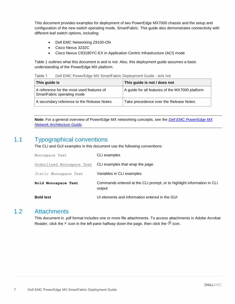
Table 1 outlines what this document is and is not. Also, this deployment guide assumes a basic understanding of the PowerEdge MX platform.
Dell EMC PowerEdge MX SmartFabric Deployment Guide - is/is not
This guide is This guide is not / does not
A reference for the most used features of SmartFabric operating mode
A guide for all features of the MX7000 platform
A secondary reference to the Release Notes Take precedence over the Release Notes
Note: For a general overview of PowerEdge MX networking concepts, see the Dell EMC PowerEdge MX Network Architecture Guide.
1.1 Typographical conventions The CLI and GUI examples in this document use the following conventions:
Monospace Text CLI examples
Underlined Monospace Text CLI examples that wrap the page
Italic Monospace Text Variables in CLI examples
Bold Monospace Text Commands entered at the CLI prompt, or to highlight information in CLI output
Bold text UI elements and information entered in the GUI
1.2 Attachments This document in .pdf format includes one or more file attachments. To access attachments in Adobe Acrobat Reader, click the icon in the left pane halfway down the page, then click the icon.
2 Hardware overview This section briefly describes the hardware that is used to validate the deployment examples in this document. Appendix B contains a complete listing of hardware and software validated for this guide.
Note: While the steps in this document were validated using the specified Dell EMC Networking switches and operating system(s), they may be leveraged for other Dell EMC Networking switch models utilizing the same networking OS version or later assuming the switch has the available port numbers, speeds, and types.
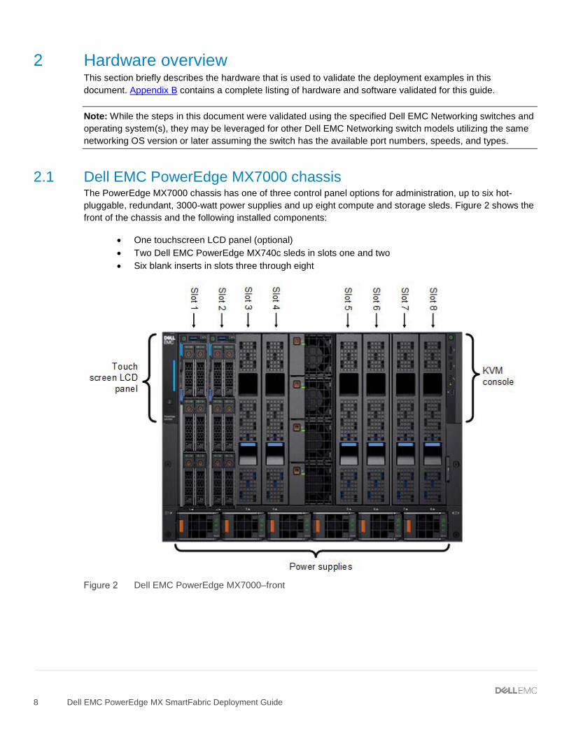
2.1 Dell EMC PowerEdge MX7000 chassis The PowerEdge MX7000 chassis has one of three control panel options for administration, up to six hot-pluggable, redundant, 3000-watt power supplies and up eight compute and storage sleds. Figure 2 shows the front of the chassis and the following installed components:
• One touchscreen LCD panel (optional) • Two Dell EMC PowerEdge MX740c sleds in slots one and two • Six blank inserts in slots three through eight
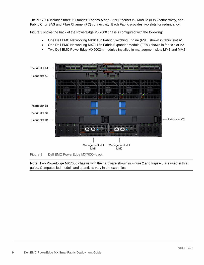
The MX7000 includes three I/O fabrics. Fabrics A and B for Ethernet I/O Module (IOM) connectivity, and Fabric C for SAS and Fibre Channel (FC) connectivity. Each Fabric provides two slots for redundancy.
Figure 3 shows the back of the PowerEdge MX7000 chassis configured with the following:
• One Dell EMC Networking MX9116n Fabric Switching Engine (FSE) shown in fabric slot A1 • One Dell EMC Networking MX7116n Fabric Expander Module (FEM) shown in fabric slot A2 • Two Dell EMC PowerEdge MX9002m modules installed in management slots MM1 and MM2
Dell EMC PowerEdge MX7000–back
Note: Two PowerEdge MX7000 chassis with the hardware shown in Figure 2 and Figure 3 are used in this guide. Compute sled models and quantities vary in the examples.
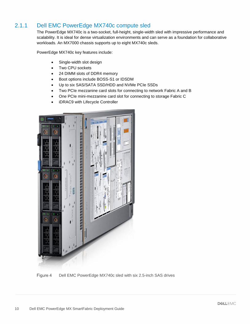
2.1.1 Dell EMC PowerEdge MX740c compute sled The PowerEdge MX740c is a two-socket, full-height, single-width sled with impressive performance and scalability. It is ideal for dense virtualization environments and can serve as a foundation for collaborative workloads. An MX7000 chassis supports up to eight MX740c sleds.
PowerEdge MX740c key features include:
• Single-width slot design • Two CPU sockets • 24 DIMM slots of DDR4 memory • Boot options include BOSS-S1 or IDSDM • Up to six SAS/SATA SSD/HDD and NVMe PCIe SSDs • Two PCIe mezzanine card slots for connecting to network Fabric A and B • One PCIe mini-mezzanine card slot for connecting to storage Fabric C • iDRAC9 with Lifecycle Controller
Dell EMC PowerEdge MX740c sled with six 2.5-inch SAS drives
2.1.2 Dell EMC PowerEdge MX840c compute sled The PowerEdge MX840c, a powerful four-socket, full-height, double-width sled features dense compute and memory capacity and a highly expandable storage subsystem. It is the ultimate scale-up server that excels at running a wide range of database applications, substantial virtualization, and software-defined storage environments. An MX7000 chassis supports up to four MX840c sleds.
PowerEdge MX840c key features include:
• Dual-width slot design • Four CPU sockets • 48 DIMM slots of DDR4 memory • Boot options include BOSS-S1 or IDSDM • Up to eight SAS/SATA SSD/HDD and NVMe PCIe SSDs • Four PCIe mezzanine card slots for connecting to network Fabric A and B • Two PCIe mini-mezzanine card slots for connecting to storage Fabric C • iDRAC9 with Lifecycle Controller
Dell EMC PowerEdge MX840c sled with eight 2.5-inch SAS drives
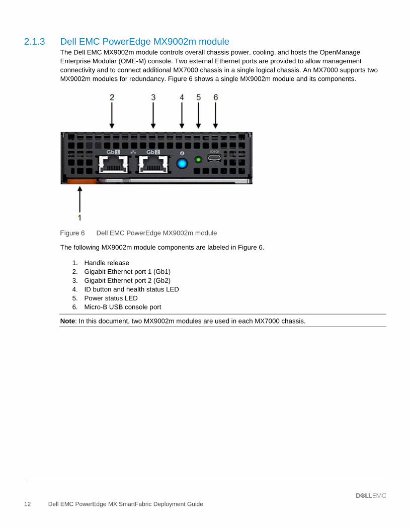
2.1.3 Dell EMC PowerEdge MX9002m module The Dell EMC MX9002m module controls overall chassis power, cooling, and hosts the OpenManage Enterprise Modular (OME-M) console. Two external Ethernet ports are provided to allow management connectivity and to connect additional MX7000 chassis in a single logical chassis. An MX7000 supports two MX9002m modules for redundancy. Figure 6 shows a single MX9002m module and its components.
Dell EMC PowerEdge MX9002m module
The following MX9002m module components are labeled in Figure 6.
1. Handle release 2. Gigabit Ethernet port 1 (Gb1) 3. Gigabit Ethernet port 2 (Gb2) 4. ID button and health status LED 5. Power status LED 6. Micro-B USB console port
Note: In this document, two MX9002m modules are used in each MX7000 chassis.
2.1.4 Dell EMC Networking MX9116n Fabric Switching Engine The Dell EMC Networking MX9116n Fabric Switching Engine (FSE) is a scalable, high-performance, low latency 25GbE switch purpose-built for the PowerEdge MX platform. The MX9116n FSE provides enhanced capabilities and cost-effectiveness for the enterprise, mid-market, Tier2 cloud, and NFV service providers with demanding compute and storage traffic environments.
In addition to 16 internal 25GbE ports, the MX9116n FSE provides the following external interfaces:
• Two 100GbE QSFP28 ports • Two 100GbE/100GFC QSFP28 unified ports • Twelve 200GbE QSFP28-Double Density (DD) ports
The two 100GbE QSFP28 ports provide Ethernet uplink connectivity. The two QSFP28 unified ports support SAN connectivity supporting both NPIV Proxy Gateway (NPG) and direct attach FC capabilities.
The QSFP28-DD ports provide capacity for additional uplinks, Virtual Link Trunking interconnect (VLTi) links, and connections to rack servers at 10GbE or 25GbE using breakout cables. Also, the QSFP28-DD ports provide fabric expansion connections for up to nine additional MX7000 chassis leveraging the MX7116n Fabric Expander Module in Fabric A and B. See Appendix A.5 for QSFP28-DD connector information.
Dell EMC Networking MX9116n FSE
The following MX9116n FSE components are labeled in Figure 7:
1. Express service tag 2. Storage USB port 3. Micro-B USB console port 4. Power and indicator LEDs 5. Module insertion/removal latch 6. Two QSFP28 ports 7. Two QSFP28 unified ports 8. Twelve QSFP28-DD ports
Note: In this document, two MX9116n FSEs are used–one in each MX7000 chassis.
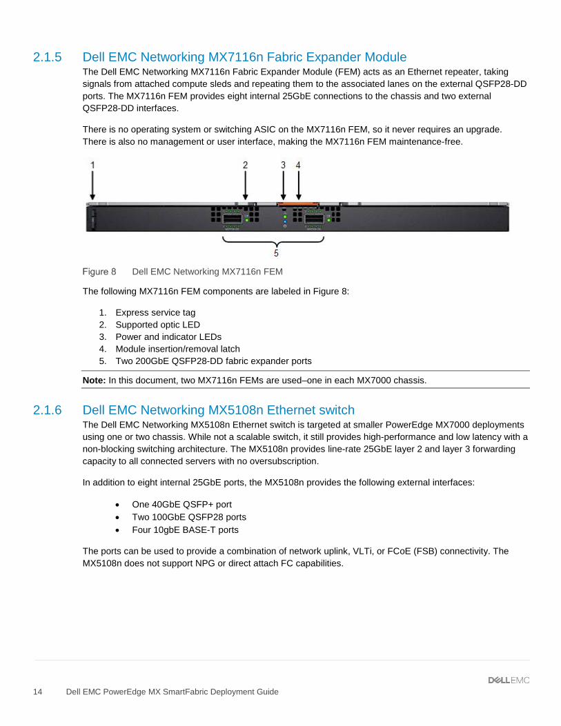
2.1.5 Dell EMC Networking MX7116n Fabric Expander Module The Dell EMC Networking MX7116n Fabric Expander Module (FEM) acts as an Ethernet repeater, taking signals from attached compute sleds and repeating them to the associated lanes on the external QSFP28-DD ports. The MX7116n FEM provides eight internal 25GbE connections to the chassis and two external QSFP28-DD interfaces.
There is no operating system or switching ASIC on the MX7116n FEM, so it never requires an upgrade. There is also no management or user interface, making the MX7116n FEM maintenance-free.
Dell EMC Networking MX7116n FEM
The following MX7116n FEM components are labeled in Figure 8:
1. Express service tag 2. Supported optic LED 3. Power and indicator LEDs 4. Module insertion/removal latch 5. Two 200GbE QSFP28-DD fabric expander ports
Note: In this document, two MX7116n FEMs are used–one in each MX7000 chassis.
2.1.6 Dell EMC Networking MX5108n Ethernet switch The Dell EMC Networking MX5108n Ethernet switch is targeted at smaller PowerEdge MX7000 deployments using one or two chassis. While not a scalable switch, it still provides high-performance and low latency with a non-blocking switching architecture. The MX5108n provides line-rate 25GbE layer 2 and layer 3 forwarding capacity to all connected servers with no oversubscription.
In addition to eight internal 25GbE ports, the MX5108n provides the following external interfaces:
• One 40GbE QSFP+ port • Two 100GbE QSFP28 ports • Four 10gbE BASE-T ports
The ports can be used to provide a combination of network uplink, VLTi, or FCoE (FSB) connectivity. The MX5108n does not support NPG or direct attach FC capabilities.
The following MX5108n components are labeled in Figure 9:
1. Luggage Tag 2. Storage USB Port 3. Micro-B USB console port 4. Power and indicator LEDs 5. Module insertion/removal latch 6. One QSFP+ port 7. Two QSFP28 ports 8. Four 10GbE BASE-T ports
Note: While the examples in this guide are specific to the MX9116n FSE and MX7116n FEM, the use of two MX5108n switches in a single chassis is supported for the solutions shown. Cabling options for the MX5108n will differ from the MX9116n/MX7116n as shown in the Dell EMC PowerEdge MX IO Guide.
2.2 Rack-mounted networking switches This section covers the rack-mounted networking switches used in the examples in this guide.
2.2.1 Dell EMC Networking S3048-ON The Dell EMC Networking S3048-ON is a 1-Rack Unit (RU) switch with forty-eight 1GbE BASE-T ports and four 10GbE SFP+ ports. In this document, one S3048-ON supports out-of-band (OOB) management traffic for all examples.
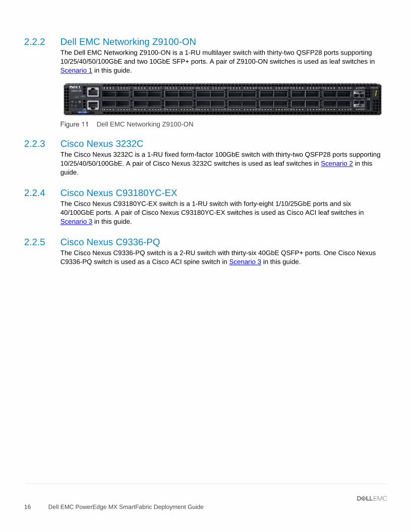
2.2.2 Dell EMC Networking Z9100-ON The Dell EMC Networking Z9100-ON is a 1-RU multilayer switch with thirty-two QSFP28 ports supporting 10/25/40/50/100GbE and two 10GbE SFP+ ports. A pair of Z9100-ON switches is used as leaf switches in Scenario 1 in this guide.
Dell EMC Networking Z9100-ON
2.2.3 Cisco Nexus 3232C The Cisco Nexus 3232C is a 1-RU fixed form-factor 100GbE switch with thirty-two QSFP28 ports supporting 10/25/40/50/100GbE. A pair of Cisco Nexus 3232C switches is used as leaf switches in Scenario 2 in this guide.
2.2.4 Cisco Nexus C93180YC-EX The Cisco Nexus C93180YC-EX switch is a 1-RU switch with forty-eight 1/10/25GbE ports and six 40/100GbE ports. A pair of Cisco Nexus C93180YC-EX switches is used as Cisco ACI leaf switches in Scenario 3 in this guide.
2.2.5 Cisco Nexus C9336-PQ The Cisco Nexus C9336-PQ switch is a 2-RU switch with thirty-six 40GbE QSFP+ ports. One Cisco Nexus C9336-PQ switch is used as a Cisco ACI spine switch in Scenario 3 in this guide.
3 PowerEdge MX7000 chassis fabrics The PowerEdge MX7000 chassis includes two I/O fabrics, fabric A and fabric B. The vertically aligned compute sleds in slots one through eight connect to the horizontally aligned IOMs in slots A1, A2, B1, and B2. This orthogonal connection method results in a midplane-free design and allows the adoption of new I/O technologies without the burden of having to upgrade the midplane.
The MX740c supports two mezzanine cards, and the MX840c supports four mezzanine cards. Each mezzanine card connects to a pair of IOMs installed in the corresponding fabric slots as shown in Figure 12. For example, port one of mezzanine card A1 connects to fabric slot A1, containing an MX9116n FSE for example (not shown). Port two of mezzanine card A1 connects to fabric slot A2, containing an MX7116n FEM for example (not shown).
Dell EMC PowerEdge MX740c mezzanine cards
Table 2 shows the port mapping for fabric A. The MX9116n FSE in slot A1 maps dual-port mezzanine cards to odd-numbered ports. The MX7116n FEM, connected to the MX9116n FSE, maps to virtual ports with each port representing a compute sled attached to the MX7116n FEM.
Port mapping example for fabric A
MX7000 slot MX9116n FSE ports MX7116n FEM virtual ports
4.1 OS10 Enterprise Edition The Dell EMC Networking MX9116n FSE and MX5108n support Dell EMC Networking OS10 Enterprise Edition (OS10EE). OS10EE is a network operating system supporting multiple architectures and environments.
The following additional OS10EE CLI commands are available for the MX9116n FSE to assist with MX7116n FEM management:
• show switch-operating-mode – displays the current operating mode of a supported switch • show port-group – displays the current port-group configuration on the switch • show discovered-expanders – displays the MX7116n FEMs attached to the MX9116n FSEs • show unit-provision – displays the unit ID and service tag of the MX7116n FEM attached to
an MX9116n FSE • port-group – configures a group of front-panel unified ports or QSFP28-DD port
Note: For more information, see the OS10 Enterprise Edition User Guide for PowerEdge MX I/O Modules on the Support for Dell EMC Networking MX9116n - Manuals and documents web page.
4.2 Operating Modes The Dell EMC Networking MX9116n FSE and MX5108n operate in one of two modes:
1. Full Switch Mode – Enabled by default, all switch-specific OS10EE capabilities are available 2. SmartFabric Mode – Switches operate as layer 2 I/O aggregation devices and are managed through
the Open Manage Enterprise Modular console Table 3 outlines the differences between the two operating modes. The differences between operating modes apply to both the MX9116n FSE and the MX5108n.
IOM operating mode differences
Full Switch mode SmartFabric mode
Configuration changes are persistent during power cycle events.
Only the configuration changes made using the OS10 commands below are persistent across power cycle events. All other CLI configuration commands are disabled.
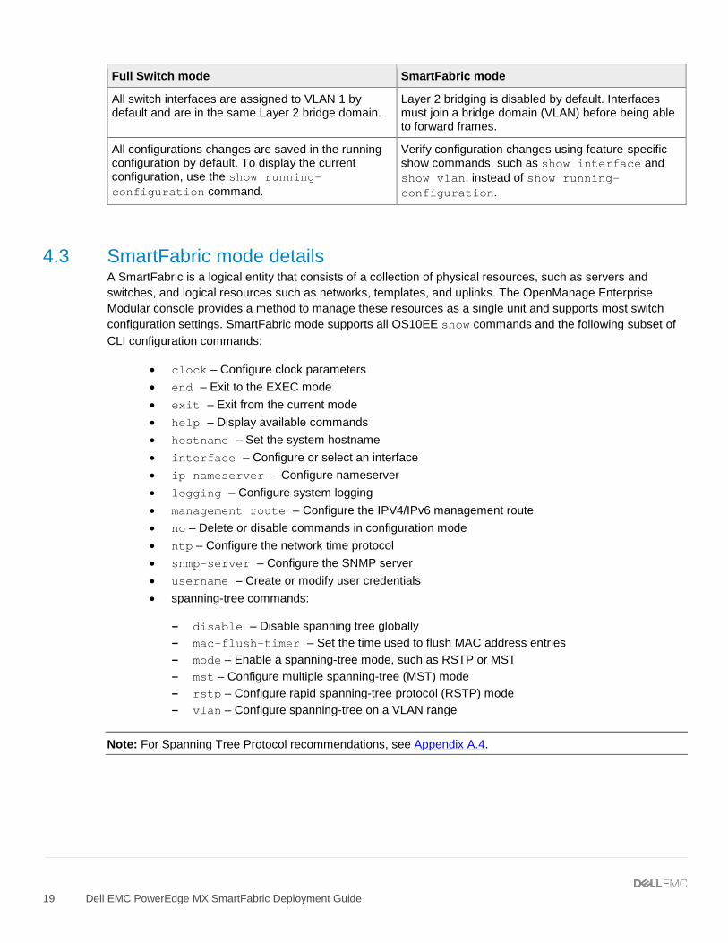
All switch interfaces are assigned to VLAN 1 by default and are in the same Layer 2 bridge domain.
Layer 2 bridging is disabled by default. Interfaces must join a bridge domain (VLAN) before being able to forward frames.
All configurations changes are saved in the running configuration by default. To display the current configuration, use the show running-configuration command.
Verify configuration changes using feature-specific show commands, such as show interface and show vlan, instead of show running-configuration.
4.3 SmartFabric mode details A SmartFabric is a logical entity that consists of a collection of physical resources, such as servers and switches, and logical resources such as networks, templates, and uplinks. The OpenManage Enterprise Modular console provides a method to manage these resources as a single unit and supports most switch configuration settings. SmartFabric mode supports all OS10EE show commands and the following subset of CLI configuration commands:
• clock – Configure clock parameters • end – Exit to the EXEC mode • exit – Exit from the current mode • help – Display available commands • hostname – Set the system hostname • interface – Configure or select an interface • ip nameserver – Configure nameserver • logging – Configure system logging • management route – Configure the IPV4/IPv6 management route • no – Delete or disable commands in configuration mode • ntp – Configure the network time protocol • snmp-server – Configure the SNMP server • username – Create or modify user credentials • spanning-tree commands:
- disable – Disable spanning tree globally - mac-flush-timer – Set the time used to flush MAC address entries - mode – Enable a spanning-tree mode, such as RSTP or MST - mst – Configure multiple spanning-tree (MST) mode - rstp – Configure rapid spanning-tree protocol (RSTP) mode - vlan – Configure spanning-tree on a VLAN range
Note: For Spanning Tree Protocol recommendations, see Appendix A.4.
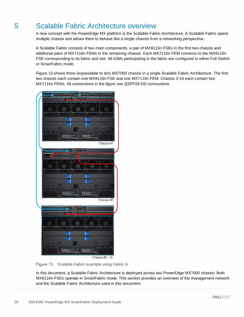
5 Scalable Fabric Architecture overview A new concept with the PowerEdge MX platform is the Scalable Fabric Architecture. A Scalable Fabric spans multiple chassis and allows them to behave like a single chassis from a networking perspective.
A Scalable Fabric consists of two main components, a pair of MX9116n FSEs in the first two chassis and additional pairs of MX7116n FEMs in the remaining chassis. Each MX7116n FEM connects to the MX9116n FSE corresponding to its fabric and slot. All IOMs participating in the fabric are configured in either Full Switch or SmartFabric mode.
Figure 13 shows three (expandable to ten) MX7000 chassis in a single Scalable Fabric Architecture. The first two chassis each contain one MX9116n FSE and one MX7116n FEM. Chassis 3-10 each contain two MX7116n FEMs. All connections in the figure use QSFP28-DD connections.
Scalable Fabric example using Fabric A
In this document, a Scalable Fabric Architecture is deployed across two PowerEdge MX7000 chassis. Both MX9116n FSEs operate in SmartFabric mode. This section provides an overview of the management network and the Scalable Fabric Architecture used in this document.
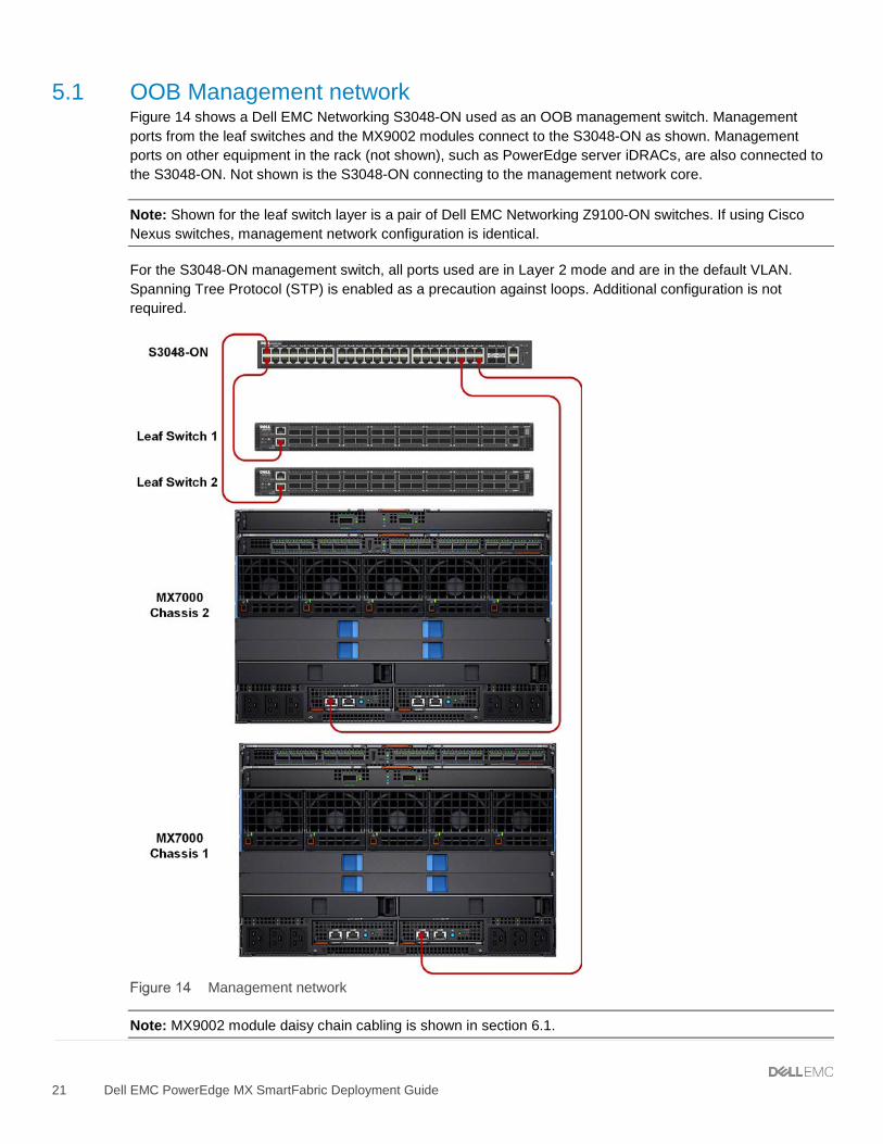
5.1 OOB Management network Figure 14 shows a Dell EMC Networking S3048-ON used as an OOB management switch. Management ports from the leaf switches and the MX9002 modules connect to the S3048-ON as shown. Management ports on other equipment in the rack (not shown), such as PowerEdge server iDRACs, are also connected to the S3048-ON. Not shown is the S3048-ON connecting to the management network core.
Note: Shown for the leaf switch layer is a pair of Dell EMC Networking Z9100-ON switches. If using Cisco Nexus switches, management network configuration is identical.
For the S3048-ON management switch, all ports used are in Layer 2 mode and are in the default VLAN. Spanning Tree Protocol (STP) is enabled as a precaution against loops. Additional configuration is not required.
Management network
Note: MX9002 module daisy chain cabling is shown in section 6.1.
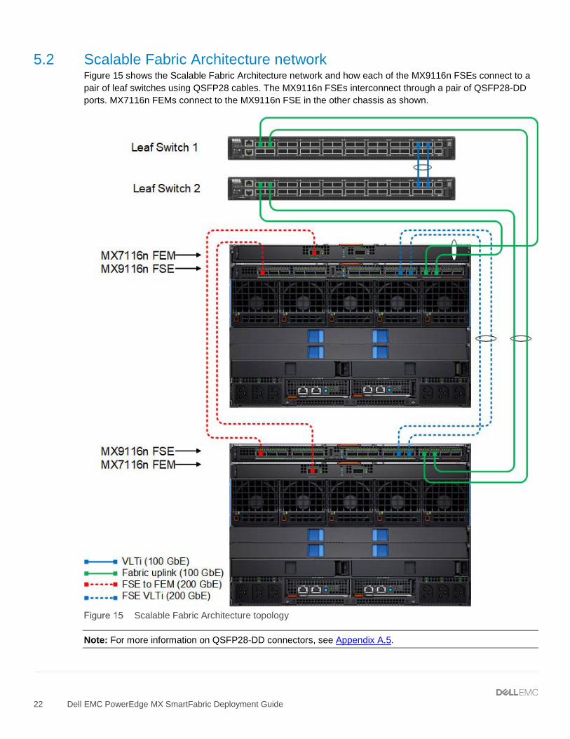
5.2 Scalable Fabric Architecture network Figure 15 shows the Scalable Fabric Architecture network and how each of the MX9116n FSEs connect to a pair of leaf switches using QSFP28 cables. The MX9116n FSEs interconnect through a pair of QSFP28-DD ports. MX7116n FEMs connect to the MX9116n FSE in the other chassis as shown.
Scalable Fabric Architecture topology
Note: For more information on QSFP28-DD connectors, see Appendix A.5.
6 OpenManage Enterprise Modular console The PowerEdge MX9002m module hosts the OpenManage Enterprise Modular (OME-M) console. OME-M is the latest addition to the Dell OpenManage Enterprise suite of tools and provides a centralized management interface for the PowerEdge MX platform. OME-M console features include:
• End-to-end lifecycle management for servers, storage, and networking • A touch LCD for initial setup and error notification • Leverages iDRAC9 intelligent automation and security features • Manages one or multiple chassis from a single web or REST API leveraging multi-chassis
management (MCM) groups • OpenManage Mobile for configuration and troubleshooting including wireless server vKVM • Creation and deployment of SmartFabric topologies
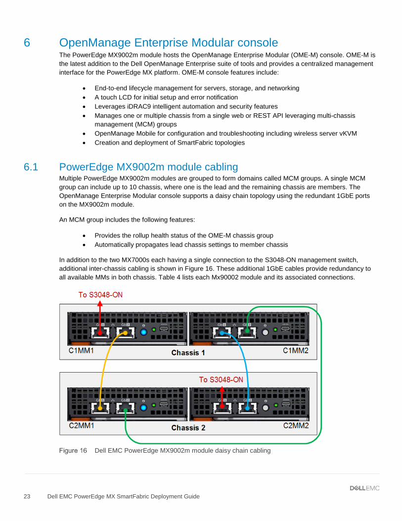
6.1 PowerEdge MX9002m module cabling Multiple PowerEdge MX9002m modules are grouped to form domains called MCM groups. A single MCM group can include up to 10 chassis, where one is the lead and the remaining chassis are members. The OpenManage Enterprise Modular console supports a daisy chain topology using the redundant 1GbE ports on the MX9002m module.
An MCM group includes the following features:
• Provides the rollup health status of the OME-M chassis group • Automatically propagates lead chassis settings to member chassis
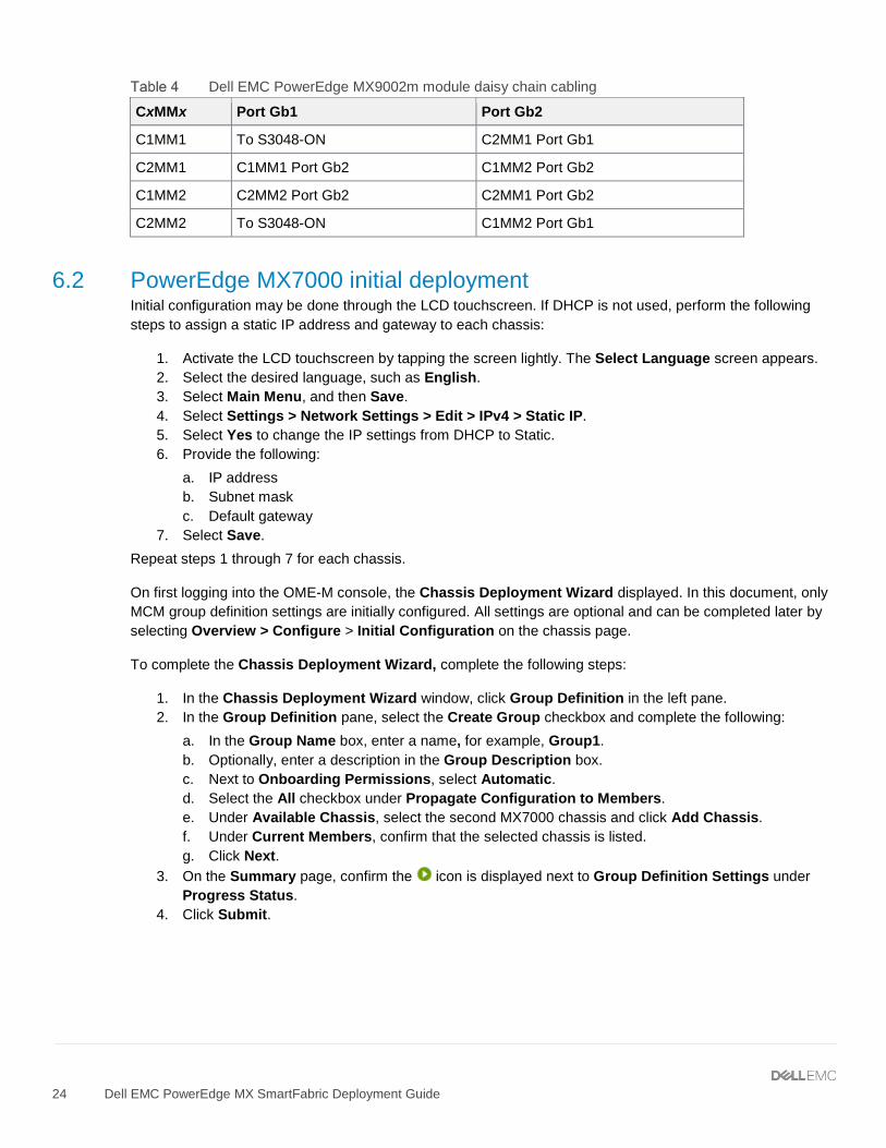
In addition to the two MX7000s each having a single connection to the S3048-ON management switch, additional inter-chassis cabling is shown in Figure 16. These additional 1GbE cables provide redundancy to all available MMs in both chassis. Table 4 lists each Mx90002 module and its associated connections.
6.2 PowerEdge MX7000 initial deployment Initial configuration may be done through the LCD touchscreen. If DHCP is not used, perform the following steps to assign a static IP address and gateway to each chassis:
1. Activate the LCD touchscreen by tapping the screen lightly. The Select Language screen appears. 2. Select the desired language, such as English. 3. Select Main Menu, and then Save. 4. Select Settings > Network Settings > Edit > IPv4 > Static IP. 5. Select Yes to change the IP settings from DHCP to Static. 6. Provide the following:
a. IP address b. Subnet mask c. Default gateway
7. Select Save. Repeat steps 1 through 7 for each chassis.
On first logging into the OME-M console, the Chassis Deployment Wizard displayed. In this document, only MCM group definition settings are initially configured. All settings are optional and can be completed later by selecting Overview > Configure > Initial Configuration on the chassis page.
To complete the Chassis Deployment Wizard, complete the following steps:
1. In the Chassis Deployment Wizard window, click Group Definition in the left pane. 2. In the Group Definition pane, select the Create Group checkbox and complete the following:
a. In the Group Name box, enter a name, for example, Group1. b. Optionally, enter a description in the Group Description box. c. Next to Onboarding Permissions, select Automatic. d. Select the All checkbox under Propagate Configuration to Members. e. Under Available Chassis, select the second MX7000 chassis and click Add Chassis. f. Under Current Members, confirm that the selected chassis is listed. g. Click Next.
3. On the Summary page, confirm the icon is displayed next to Group Definition Settings under Progress Status.
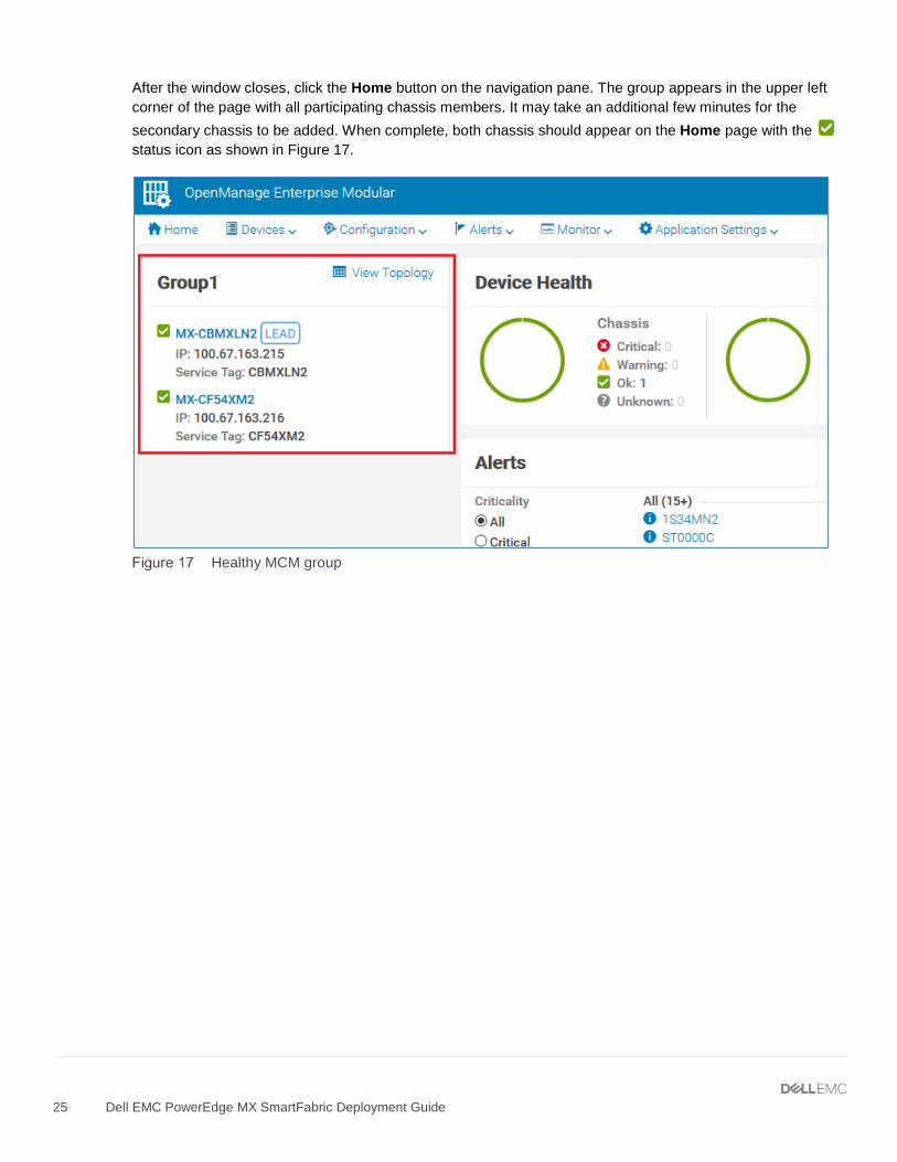
After the window closes, click the Home button on the navigation pane. The group appears in the upper left corner of the page with all participating chassis members. It may take an additional few minutes for the secondary chassis to be added. When complete, both chassis should appear on the Home page with the status icon as shown in Figure 17.
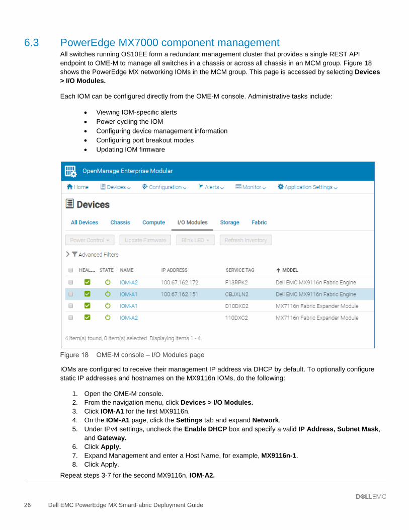
6.3 PowerEdge MX7000 component management All switches running OS10EE form a redundant management cluster that provides a single REST API endpoint to OME-M to manage all switches in a chassis or across all chassis in an MCM group. Figure 18 shows the PowerEdge MX networking IOMs in the MCM group. This page is accessed by selecting Devices > I/O Modules.
Each IOM can be configured directly from the OME-M console. Administrative tasks include:
• Viewing IOM-specific alerts • Power cycling the IOM • Configuring device management information • Configuring port breakout modes • Updating IOM firmware
OME-M console – I/O Modules page
IOMs are configured to receive their management IP address via DHCP by default. To optionally configure static IP addresses and hostnames on the MX9116n IOMs, do the following:
1. Open the OME-M console. 2. From the navigation menu, click Devices > I/O Modules. 3. Click IOM-A1 for the first MX9116n. 4. On the IOM-A1 page, click the Settings tab and expand Network. 5. Under IPv4 settings, uncheck the Enable DHCP box and specify a valid IP Address, Subnet Mask,
and Gateway. 6. Click Apply. 7. Expand Management and enter a Host Name, for example, MX9116n-1. 8. Click Apply.
7 Scenario 1 - SmartFabric deployment while connected to Z9100-ON switches Figure 19 shows the production topology using a pair of Z9100-ONs as leaf switches. This section walks through configuring the Z9100-ONs as well as creating a SmartFabric and the corresponding uplinks.
SmartFabric with Z9100-ON leaf switches
Note: See Appendix A.5 for more information on QSFP28-DD cables.
7.1 Dell EMC Networking Z9100-ON leaf switch configuration The following section outlines the configuration commands issued to the Dell EMC Networking Z9100-ON leaf switches. The switches start at their factory default settings per Appendix A.2.
1. Use the following commands to set the hostname, and to configure the OOB management interface and default gateway.
Z9100-ON Leaf 1 Z9100-ON Leaf 2
configure terminal hostname Z9100-Leaf1 interface mgmt 1/1/1 no ip address dhcp no shutdown ip address 100.67.162.35/24 management route 0.0.0.0/0 100.67.162.254
configure terminal hostname Z9100-Leaf2 interface mgmt 1/1/1 no ip address dhcp no shutdown ip address 100.67.162.34/24 management route 0.0.0.0/0 100.67.162.254
2. Configure the VLT on each spine switch using the following commands. VLT configuration involves setting a discovery interface range and discovering the VLT peer in the VLTi.
Z9100-ON Leaf 1 Z9100-ON Leaf 2
interface range ethernet1/1/29-1/1/31 description VLTi no shutdown no switchport vlt-domain 1 backup destination 100.67.162.34 discovery-interface ethernet1/1/29-1/1/31
interface range ethernet1/1/29-1/1/31 description VLTi no shutdown no switchport vlt-domain 1 backup destination 100.67.169.35 discovery-interface ethernet1/1/29-1/1/31
3. Configure the required VLANs on each switch.
Z9100-ON Leaf 1 Z9100-ON Leaf 2
interface vlan10 description “Company A General Purpose” no shutdown
interface vlan10 description “Company A General Purpose” no shutdown
7.2 Deploy a SmartFabric SmartFabric deployment consists of four broad steps all completed using the OME-M console:
1. Create the VLANs to be used in the fabric. 2. Select switches and create the fabric based on the physical topology desired. 3. Create uplinks from the fabric to the existing network and assign VLANs to those uplinks. 4. Deploy the appropriate server templates to the compute sleds.
7.2.1 Define VLANs To define VLANs using the OME-M console, perform the following steps:
1. Open the OME-M console. 2. From the navigation menu, click Configuration > Networks. 3. In the Network pane, click Define. 4. In the Define Network window, complete the following:
a. Enter VLAN0010 in the Name box. b. Optionally, enter a description in the Description box. c. Enter 10 in the VLAN ID box. d. From the Network Type list, select General Purpose (Bronze). e. Click Finish.
Note: For information on Network Types, see Appendix A.6.
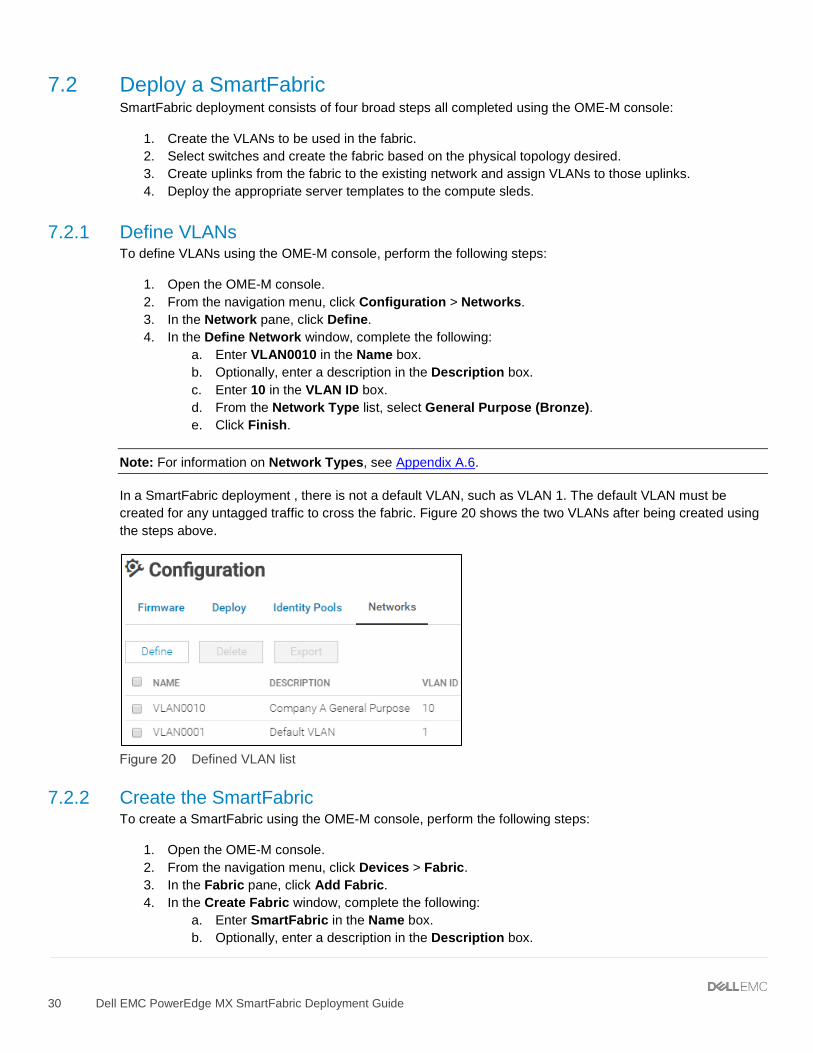
In a SmartFabric deployment , there is not a default VLAN, such as VLAN 1. The default VLAN must be created for any untagged traffic to cross the fabric. Figure 20 shows the two VLANs after being created using the steps above.
Defined VLAN list
7.2.2 Create the SmartFabric To create a SmartFabric using the OME-M console, perform the following steps:
1. Open the OME-M console. 2. From the navigation menu, click Devices > Fabric. 3. In the Fabric pane, click Add Fabric. 4. In the Create Fabric window, complete the following:
a. Enter SmartFabric in the Name box. b. Optionally, enter a description in the Description box.
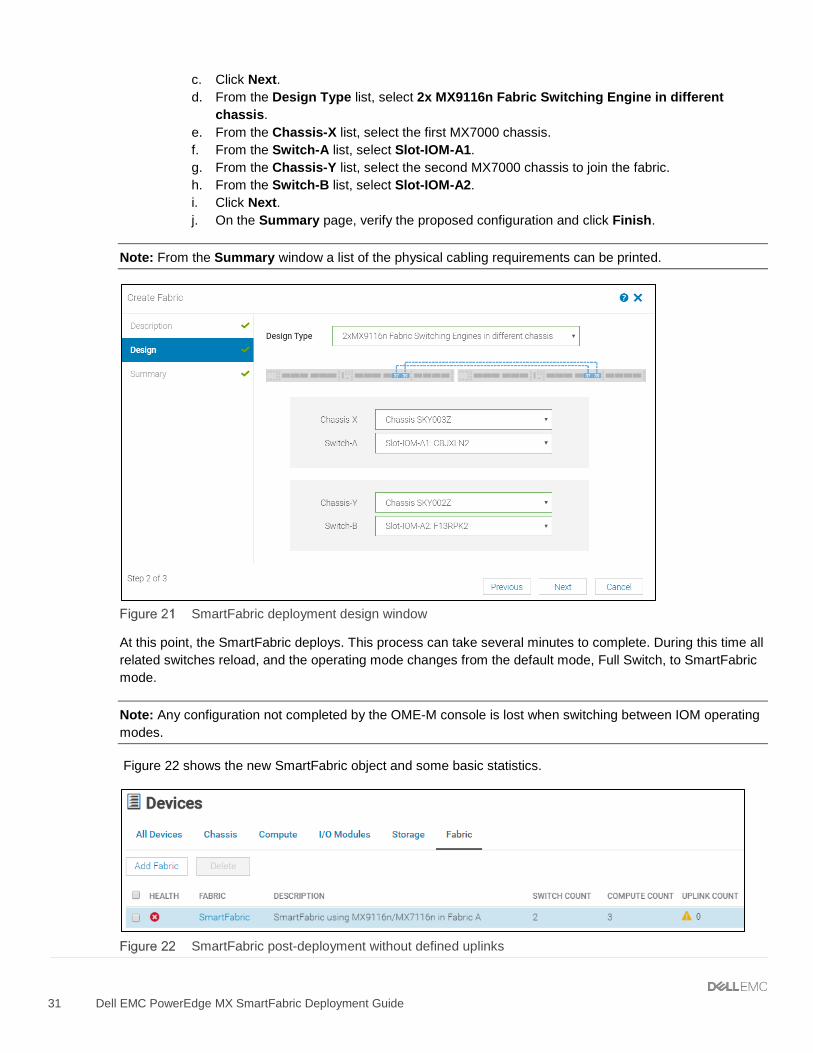
c. Click Next. d. From the Design Type list, select 2x MX9116n Fabric Switching Engine in different
chassis. e. From the Chassis-X list, select the first MX7000 chassis. f. From the Switch-A list, select Slot-IOM-A1. g. From the Chassis-Y list, select the second MX7000 chassis to join the fabric. h. From the Switch-B list, select Slot-IOM-A2. i. Click Next. j. On the Summary page, verify the proposed configuration and click Finish.
Note: From the Summary window a list of the physical cabling requirements can be printed.
SmartFabric deployment design window
At this point, the SmartFabric deploys. This process can take several minutes to complete. During this time all related switches reload, and the operating mode changes from the default mode, Full Switch, to SmartFabric mode.
Note: Any configuration not completed by the OME-M console is lost when switching between IOM operating modes.
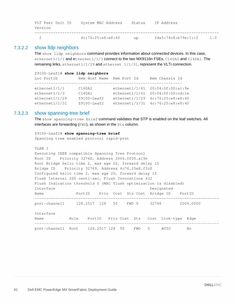
Figure 22 shows the new SmartFabric object and some basic statistics.
SmartFabric post-deployment without defined uplinks
7.2.3 Define uplinks After initial deployment, the new fabric shows Uplink Count as ‘zero’ and shows a warning ( ). The lack of a fabric uplink results in a failed health check ( ). To create uplinks, follow these steps:
1. Open the OME-M console. 2. From the navigation menu, click Devices > Fabric. 3. Click on the fabric name, SmartFabric. 4. In the Fabric Details pane, click Uplinks. 5. Click on the Add Uplinks button. 6. In the Add Uplink window complete the following:
a. Enter Uplink01 in the Name box. b. Optionally, enter a description in the Description box. c. From the Uplink Type list, select Ethernet. d. Click Next. e. From the Switch Ports list, select ethernet 1/1/41 and ethernet 1/1/42 for both MX9116n FSEs. f. From the Tagged Networks list, select VLAN0010. g. From the Untagged Network list, select VLAN0001. h. Click Finish.
At this point, SmartFabric creates the uplink object and the status for the fabric changes to OK ( ).
7.2.4 Server templates A server template contains the parameters extracted from a server and allows these parameters to be quickly applied to multiple compute sleds. The templates contain settings for the following categories:
• Local access configuration • Location configuration • Power configuration • Chassis network configuration • Slot configuration • Setup configuration
Additionally, server templates also allow an administrator to associate VLANs to compute sleds.
7.2.4.1 Create a server template To create a server template, follow these steps:
1. Open the OME-M console. 2. From the navigation menu, click Configuration > Deploy. 3. From the center pane, click Create Template > From Reference Device. 4. In the Create Template window, complete the following:
a. Enter M740c with Intel mezzanine in the Template Name box. b. Optionally, enter a description in the Description box. c. Click Next. d. In the Device Selection pane, click Select Device. e. In the Select Devices window, choose Sled-1 from Chassis-1. f. In the Select Devices window, click Finish. g. From the Elements to Clone list, select the following options:
i. iDRAC ii. System iii. NIC
h. Click Finish.
Note: Both iDRAC and NIC settings need to be captured to enable virtual identities. For additional information about virtual identities, see Appendix A.7.
A job starts, and the new server template displays on the list. When complete, the status displays as Completed successfully. Next, associate the VLANs created previously with the template.
7.2.4.2 Associate server template with a VLAN After successfully creating a new template, associate the template with a network:
1. From the Deploy pane, select the R740c with Intel mezzanine server template. 2. From the Deploy pane, click Edit Network. 3. In the Edit Network window, complete the following:
a. Optionally, from the Identity Pool list, choose Ethernet ID Pool. (see Appendix A.7). b. For both ports, from the Untagged Network list, select VLAN0001. c. For both ports, from the Tagged Network list, choose VLAN0010. d. Click Finish.
Figure 23 shows the associated networks for the server template.
7.2.4.3 Deploy a server template To deploy the server template, complete the following steps:
1. From the Deploy pane, select the R740c with Intel mezzanine server template. 2. From the Deploy pane, click Deploy Template. 3. In the Deploy Template window, complete the following:
a. Click the Select button to choose which slots or compute sleds to deploy the template to. b. Select the Do not forcefully reboot the host OS. c. Click Next. d. Choose Run Now e. Click Finish.
The interfaces on the MX9116n FSE are updated automatically. SmartFabric configures each interface with an untagged VLAN and any tagged VLANs. Additionally, SmartFabric deploys associated QoS settings. See Appendix A.6 for more information.
7.3 Verify configuration This section covers the validation of the SmartFabric and the Z9100-ON leaf switches.
7.3.1 PowerEdge MX7000 validation This section covers validation specific to the Dell EMC PowerEdge MX7000.
7.3.1.1 Show the MCM group topology The OME-M console can be used to show the physical cabling of thee SmartFabric.
1. Open the OME-M console. 2. In the left pane click View Topology. 3. Click the lead chassis and then click Show Wiring. 4. The icons can be clicked to show cabling.
Figure 24 shows the current wiring of the SmartFabric.
7.3.1.2 Show the SmartFabric status The OME-M console can be used to show the overall health of the SmartFabric.
1. Open the OME-M console. 2. From the navigation menu, click Devices > Fabric. 3. Select SmartFabric1 to expand the details of the fabric.
Figure 25 shows the details of the fabric.
Fabric status details
The Overview tab shows the current inventory, including switches, servers, and interconnects between the MX9116n FSEs in the fabric. Figure 26 shows the SmartFabric switch in a healthy state. Figure 27 shows the participating servers in a healthy state.
7.3.1.3 Show port status The OME-M console can be used to show MX9116n FSE port status.
1. Open the OME-M console. 2. From the navigation menu, click Devices > I/O Modules. 3. Select an IOM and click the View Details button to the right of the inventory screen. The IOM
overview for that device, displays. 4. From the IOM Overview, click Hardware. 5. Click to select the Port Information tab.
Figure 30 shows ethernet 1/1/1, 1/1/3, 1/71/1, and 1/72/1 in the correct operational status (Up). These interfaces correspond to the MX740c compute sleds in slots 1 and 2 in both chassis. The figure also shows the VLT connection (port channel 1000) and the uplinks (port channel 1) to the Z9100-ON leaf switches.
IOM Port Information
7.3.1.4 show switch-operating-mode Use the show switch-operating-mode command to display the current operating mode:
C140A1# show switch-operating-mode Switch-Operating-Mode : Smart Fabric Mode
7.3.1.5 show discovered-expanders The show discovered-expanders command is only available on the MX9116n FSE and displays the MX7116n FEMs service tag attached to the MX9116n FSEs and the associated port-group and virtual slot.
C140A1# show discovered-expanders Service Model Type Chassis Chassis-slot Port-group Virtual tag service-tag Slot-Id -------------------------------------------------------------------------- D10DXC2 MX7116n 1 SKY002Z A1 1/1/1 71 FEM
7.3.1.6 show unit-provision The show unit-provision command is only available on the MX9116n FSE and displays the unit ID and the provision and discovered name of the MX7116n FEM attached to the MX9116n FSE.
C140A1# show unit-provision
Node ID | Unit ID | Provision Name | Discovered Name | State | ---------+---------+---------------------------------+-------| 1 | 71 | D10DXC2 | D10DXC2 | up |
7.3.1.7 show lldp neighbors The show lldp neighbors command shows information about LLDP neighbors. Ethernet1/1/1, ethernet 1/1/3, and ethernet 1/1/71-1/1/72 represent the two MX740c sleds. The first entry is the iDRAC for the compute sled. The iDRAC uses connectivity to the mezzanine card to advertise LLDP information. The second entry is the mezzanine card itself.
Ethernet 1/71/1 and ethernet 1/71/2 represent the MX740c compute sleds connected to the MX7116n FEM in the other chassis.
Ethernet range ethernet1/1/37-1/1/40 are the VLTi interfaces for the SmartFabric. Last, ethernet1/1/41-1/1/42 are the links in a port channel connected to the Z9100-ON leaf switches.
C140A1# show lldp neighbors Loc PortID Rem Host Name Rem Port Id Rem Chassis Id ---------------------------------------------------------------------------- ethernet1/1/1 iDRAC-CBMP9N2 CBMP9N2 NIC.Mezzanine.1A-1-1 d0:94:66:2a:07:2f ethernet1/1/1 Not Advertised 24:6e:96:9c:e3:50 24:6e:96:9c:e3:50 ethernet1/1/3 iDRAC-1S35MN2 1S35MN2 NIC.Mezzanine.1A-1-1 d0:94:66:29:fa:f4 ethernet1/1/3 Not Advertised 24:6e:96:9c:e5:48 24:6e:96:9c:e5:48 ethernet1/1/37 C160A2 ethernet1/1/37 20:04:0f:00:a1:9e ethernet1/1/38 C160A2 ethernet1/1/38 20:04:0f:00:a1:9e ethernet1/1/39 C160A2 ethernet1/1/39 20:04:0f:00:a1:9e ethernet1/1/40 C160A2 ethernet1/1/40 20:04:0f:00:a1:9e ethernet1/1/41 Z9100-Leaf1 ethernet1/1/3 4c:76:25:e8:f2:c0 ethernet1/1/42 Z9100-Leaf2 ethernet1/1/3 4c:76:25:e8:e8:40 ethernet1/71/1 Not Advertised 24:6e:96:9c:e5:d8 24:6e:96:9c:e5:d8 ethernet1/71/1 iDRAC-CF52XM2 CF52XM2 NIC.Mezzanine.1A-1-1 d0:94:66:29:fe:b4 ethernet1/71/2 Not Advertised 24:6e:96:9c:e5:da 24:6e:96:9c:e5:da ethernet1/71/2 iDRAC-1S34MN2 1S34MN2 NIC.Mezzanine.1A-1-1 d0:94:66:29:ff:27
7.3.1.8 show qos system The show qos system command displays the QoS configuration applied to the system. The command is useful to verify the service policy created manually or automatically by a SmartFabric deployment.
C140A1# show qos system Service-policy (input): PM_VLAN ETS Mode : off
7.3.1.9 show policy-map Using the service policy from show qos system, the show policy-map type qos PM_VLAN command displays QoS policy details including associated class maps, for example, CM10, and QoS queue settings, qos-group 2.
C140A1# show policy-map type qos PM_VLAN Service-policy (qos) input: PM_VLAN Class-map (qos): CM10 set qos-group 2
7.3.1.10 show class-map The command show class-map displays details for all the configured class-maps. For example, the association between CM10 and VLAN 10 is shown.
C140A1# show class-map Class-map (application): class-iscsi Class-map (qos): class-trust Class-map (qos): CM10(match-any) Match: mac vlan 10 Class-map (qos): CM2(match-any
7.3.2 Z9100-ON validation This section contains validation commands for the Dell EMC Networking Z9100-ON leaf switches.
7.3.2.1 show vlt The show vlt command validates the VLT configuration status when the VLTi Link Status is up. The role of one switch in the VLT pair is primary, and its peer switch (not shown) is assigned the secondary role.
Z9100-Leaf1# show vlt 1 Domain ID : 1 Unit ID : 1 Role : primary Version : 1.0 Local System MAC address : 4c:76:25:e8:f2:c0 VLT MAC address : 4c:76:25:e8:f2:c0 IP address : fda5:74c8:b79e:1::1 Delay-Restore timer : 90 seconds Peer-Routing : Disabled Peer-Routing-Timeout timer : 0 seconds VLTi Link Status port-channel1000 : up
VLT Peer Unit ID System MAC Address Status IP Address Version -------------------------------------------------------------------------------- 2 4c:76:25:e8:e8:40 up fda5:74c8:b79e:1::2 1.0
7.3.2.2 show lldp neighbors The show lldp neighbors command provides information about connected devices. In this case, ethernet1/1/1 and ethernet1/1/3 connect to the two MX9116n FSEs, C160A2 and C140A1. The remaining links, ethernet1/1/29 and ethernet 1/1/31, represent the VLTi connection.
Z9100-Leaf1# show lldp neighbors Loc PortID Rem Host Name Rem Port Id Rem Chassis Id ---------------------------------------------------------------- ethernet1/1/1 C160A2 ethernet1/1/41 20:04:0f:00:a1:9e ethernet1/1/3 C140A1 ethernet1/1/41 20:04:0f:00:cd:1e ethernet1/1/29 Z9100-Leaf2 ethernet1/1/29 4c:76:25:e8:e8:40 ethernet1/1/31 Z9100-Leaf2 ethernet1/1/31 4c:76:25:e8:e8:40
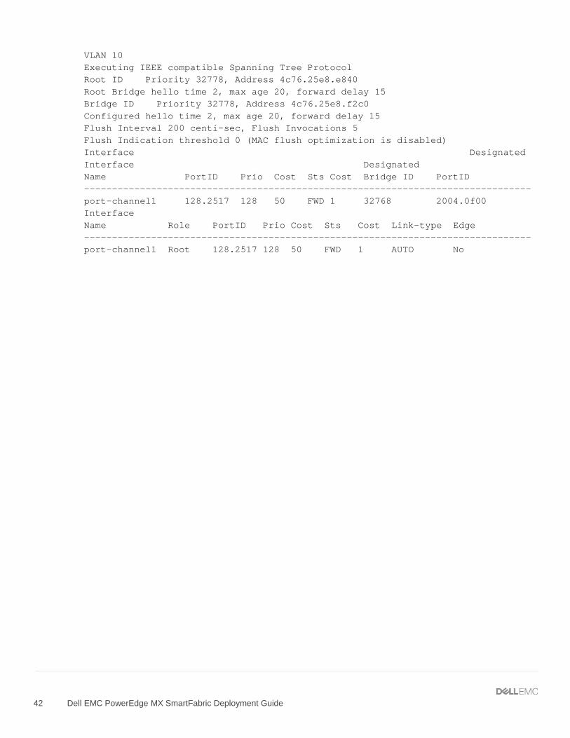
7.3.2.3 show spanning-tree brief The show spanning-tree brief command validates that STP is enabled on the leaf switches. All interfaces are forwarding (FWD), as shown in the Sts column.
Z9100-Leaf1# show spanning-tree brief Spanning tree enabled protocol rapid-pvst VLAN 1 Executing IEEE compatible Spanning Tree Protocol Root ID Priority 32768, Address 2004.0f00.a19e Root Bridge hello time 2, max age 20, forward delay 15 Bridge ID Priority 32769, Address 4c76.25e8.f2c0 Configured hello time 2, max age 20, forward delay 15 Flush Interval 200 centi-sec, Flush Invocations 432 Flush Indication threshold 0 (MAC flush optimization is disabled) Interface Designated Name PortID Prio Cost Sts Cost Bridge ID PortID -------------------------------------------------------------------------------- port-channel1 128.2517 128 50 FWD 0 32768 2004.0f00 Interface Name Role PortID Prio Cost Sts Cost Link-type Edge -------------------------------------------------------------------------------- port-channel1 Root 128.2517 128 50 FWD 0 AUTO No
8 Scenario 2 - SmartFabric deployment while connected to Cisco Nexus 3232C leaf switches Figure 31 shows the production topology using a pair of Cisco Nexus 3232C as leaf switches. This section configures the Cisco Nexus 3232Cs and creating a SmartFabric with the corresponding uplinks.
SmartFabric with Cisco Nexus 3232C leaf switches
Note: See Appendix A.5 for more information on QSFP28-DD cables.
8.1 Cisco Nexus 3232C leaf switch configuration The following section outlines the configuration commands issued to the Cisco Nexus 3232C leaf switches. The switches start at their factory default settings, as described in Appendix A.3.
1. Enter the following commands to set the hostname, enable required features, and enable RPVST spanning tree mode. Configure the management interface and default gateway.
Cisco Nexus 3232C Leaf 1 Cisco Nexus 3232C Leaf 2
configure terminal hostname 3232C-Leaf1 feature vpc feature lldp feature lacp spanning-tree mode rapid-pvst interface mgmt0 vrf member management ip address 100.67.162.201/24 vrf context management ip route 0.0.0.0/0 100.67.162.254
configure terminal hostname 3232C-Leaf2 feature vpc feature lldp feature lacp spanning-tree mode rapid-pvst interface mgmt0 vrf member management ip address 100.67.162.200/24 vrf context management ip route 0.0.0.0/0 100.67.162.254
2. Enter the following commands to create a virtual port channel (vPC) domain and assign the keepalive destination to the peer switch management IP. Then create a port channel for the vPC peer link and assign the appropriate switchport interfaces.
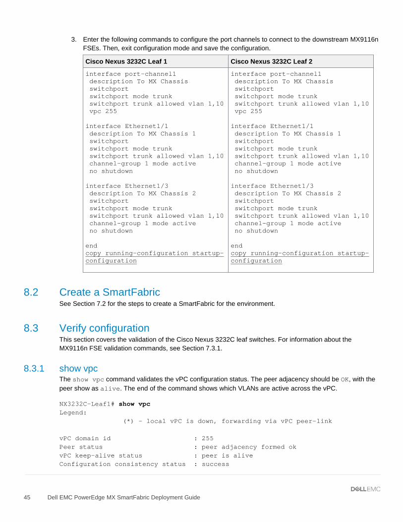
3. Enter the following commands to configure the port channels to connect to the downstream MX9116n FSEs. Then, exit configuration mode and save the configuration.
Cisco Nexus 3232C Leaf 1 Cisco Nexus 3232C Leaf 2
interface port-channel1 description To MX Chassis switchport switchport mode trunk switchport trunk allowed vlan 1,10 vpc 255 interface Ethernet1/1 description To MX Chassis 1 switchport switchport mode trunk switchport trunk allowed vlan 1,10 channel-group 1 mode active no shutdown interface Ethernet1/3 description To MX Chassis 2 switchport switchport mode trunk switchport trunk allowed vlan 1,10 channel-group 1 mode active no shutdown end copy running-configuration startup-configuration
interface port-channel1 description To MX Chassis switchport switchport mode trunk switchport trunk allowed vlan 1,10 vpc 255 interface Ethernet1/1 description To MX Chassis 1 switchport switchport mode trunk switchport trunk allowed vlan 1,10 channel-group 1 mode active no shutdown interface Ethernet1/3 description To MX Chassis 2 switchport switchport mode trunk switchport trunk allowed vlan 1,10 channel-group 1 mode active no shutdown end copy running-configuration startup-configuration
8.2 Create a SmartFabric See Section 7.2 for the steps to create a SmartFabric for the environment.
8.3 Verify configuration This section covers the validation of the Cisco Nexus 3232C leaf switches. For information about the MX9116n FSE validation commands, see Section 7.3.1.
8.3.1 show vpc The show vpc command validates the vPC configuration status. The peer adjacency should be OK, with the peer show as alive. The end of the command shows which VLANs are active across the vPC.
NX3232C-Leaf1# show vpc Legend: (*) - local vPC is down, forwarding via vPC peer-link vPC domain id : 255 Peer status : peer adjacency formed ok vPC keep-alive status : peer is alive Configuration consistency status : success
Per-vlan consistency status : success Type-2 inconsistency reason : Consistency Check Not Performed vPC role : secondary, operational primary Number of vPCs configured : 1 Peer Gateway : Disabled Dual-active excluded VLANs : - Graceful Consistency Check : Enabled Auto-recovery status : Disabled Delay-restore status : Timer is off.(timeout = 30s) Delay-restore SVI status : Timer is off.(timeout = 10s) vPC Peer-link status --------------------------------------------------------------------- id Port Status Active vlans -- ---- ------ -------------------------------------------------- 1 Po255 up 1,10 vPC status ---------------------------------------------------------------------- id Port Status Consistency Reason Active vlans -- ---- ------ ----------- ------ ------------ 255 Po1 up success success 1,10
8.3.2 show vpc consistency-parameters The show vpc consistency-parameters command displays the configured values on all interfaces in the vPC. The displayed configurations are only those configurations that limit the vPC peer link and vPC from coming up.
NX3232C-Leaf1# show vpc consistency-parameters vpc 255 Legend: Type 1 : vPC will be suspended in case of mismatch Name Type Local Value Peer Value ------------- ---- ---------------------- ----------------------- STP Port Type 1 Normal Port Normal Port STP Port Guard 1 Default Default STP MST Simulate PVST 1 Default Default lag-id 1 [(1000, [(1000, 20-4-f-0-cd-1e, 1, 0, 20-4-f-0-cd-1e, 1, 0, 0), (7f9b, 0), (7f9b, 0-23-4-ee-be-ff, 80ff, 0-23-4-ee-be-ff, 80ff, 0, 0)] 0, 0)] mode 1 active active delayed-lacp 1 disabled disabled Speed 1 100 Gb/s 100 Gb/s Duplex 1 full full Port Mode 1 trunk trunk Native Vlan 1 1 1 MTU 1 1500 1500
Dot1q Tunnel 1 no no Switchport Isolated 1 0 0 vPC card type 1 N9K TOR N9K TOR Allowed VLANs - 1,10 1,10 Local suspended VLANs - - -
8.3.3 show lldp neighbors The show lldp neighbors command provides information about lldp neighbors. In this case Eth1/1 and Eth1/3 are connected to the two MX9116n FSEs, C160A2 and C140A1. The remaining links, Eth1/29 and Eth1/31, represent the VLTi connection.
NX3232C-Leaf1(config)# show lldp neighbors Capability codes: (R) Router, (B) Bridge, (T) Telephone, (C) DOCSIS Cable Device (W) WLAN Access Point, (P) Repeater, (S) Station, (O) Other Device ID Local Intf Hold-time Capability Port ID S3048-ON mgmt0 120 PBR ethernet1/1/45 C160A2 Eth1/1 120 PBR ethernet1/1/41 C140A1 Eth1/3 120 PBR ethernet1/1/41 NX3232C-Leaf2 Eth1/29 120 BR Ethernet1/29 NX3232C-Leaf2 Eth1/31 120 BR Ethernet1/31 Total entries displayed: 5
8.3.4 show spanning-tree summary The show spanning-tree summary command validates that STP is enabled on the leaf switches. All interfaces are shown as forwarding.
NX3232C-Leaf1# show spanning-tree summary Switch is in rapid-pvst mode Root bridge for: VLAN0010 Port Type Default is disable Edge Port [PortFast] BPDU Guard Default is disabled Edge Port [PortFast] BPDU Filter Default is disabled Bridge Assurance is enabled Loopguard Default is disabled Pathcost method used is short STP-Lite is disabled Name Blocking Listening Learning Forwarding STP Active ---------------------- -------- --------- -------- ---------- ---------- VLAN0001 0 0 0 2 2 VLAN0010 0 0 0 2 2 ---------------------- -------- --------- -------- ---------- ---------- 2 vlans 0 0 0 4 4
9 Scenario 3 - SmartFabric deployment while connected to Cisco ACI leaf switches This chapter covers deploying a PowerEdge MX SmartFabric connected to a Cisco ACI environment. By integrating PowerEdge MX into an ACI environment, compute resources in the MX environment can use ACI gateways and access ACI resources.
The Cisco ACI environment validated includes a pair of Nexus C93180YC-EX switches as leaf switches as shown in Figure 32. Both C93180YC-EX leafs are connected to a single Nexus C9336-PQ spine using 40GbE uplinks (not shown).
Smart Fabric connected to Cisco ACI leaf switches
Connections from MX9116n FSE switches to C93180YC-EX leafs are 100GbE. These connections are shown in blue in Figure 32.
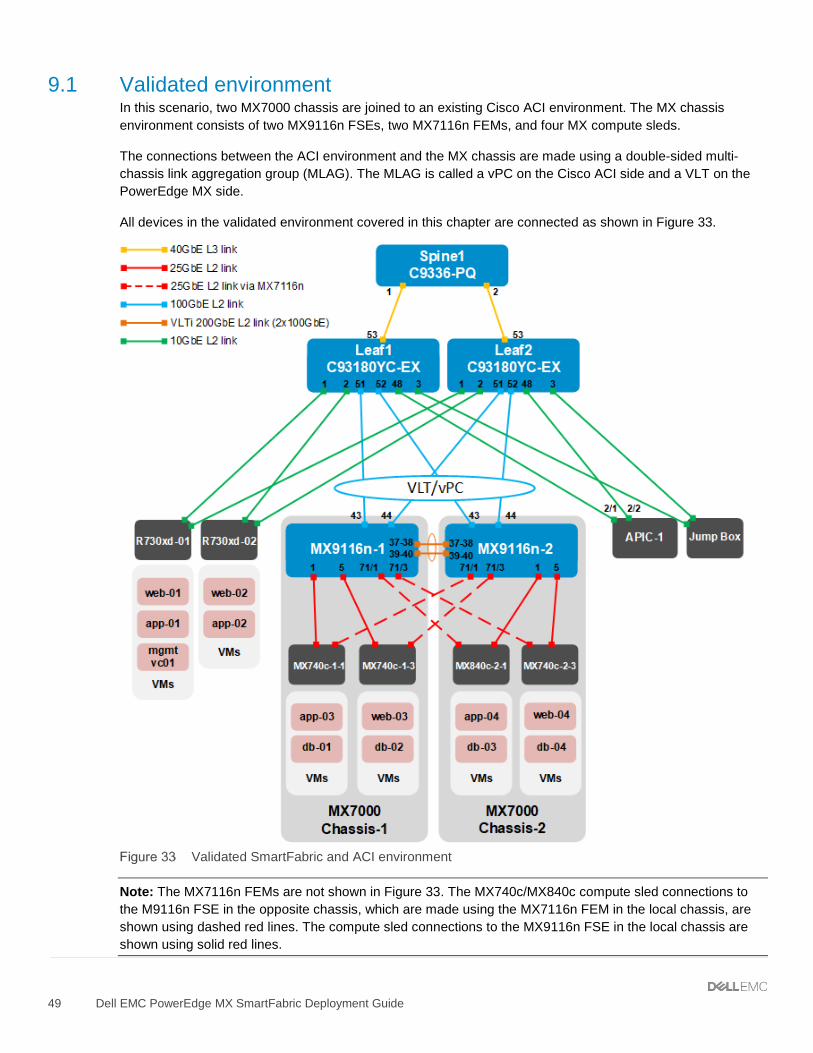
9.1 Validated environment In this scenario, two MX7000 chassis are joined to an existing Cisco ACI environment. The MX chassis environment consists of two MX9116n FSEs, two MX7116n FEMs, and four MX compute sleds.
The connections between the ACI environment and the MX chassis are made using a double-sided multi-chassis link aggregation group (MLAG). The MLAG is called a vPC on the Cisco ACI side and a VLT on the PowerEdge MX side.
All devices in the validated environment covered in this chapter are connected as shown in Figure 33.
Validated SmartFabric and ACI environment
Note: The MX7116n FEMs are not shown in Figure 33. The MX740c/MX840c compute sled connections to the M9116n FSE in the opposite chassis, which are made using the MX7116n FEM in the local chassis, are shown using dashed red lines. The compute sled connections to the MX9116n FSE in the local chassis are shown using solid red lines.
Note: No peer link is used between the Cisco ACI leaf switches. See the Cisco ACI documentation for more information. Cisco recommends a minimum of three Application Policy Infrastructure Controllers (APICs) in a production environment. For this validation effort, a single APIC, named APIC-1, is used.
All PowerEdge R730xd rack servers and MX compute sleds in this example are running VMware ESXi 6.7.0. VMs named “web,” “app,” and “db” on the ESXi hosts are running Ubuntu Linux guest operating systems. An optional jump box (shown in Figure 33), accessible over the OOB management network, is added to assist with vCenter configuration.
The existing Cisco ACI environment has two PowerEdge R730xd rack servers directly connected to the ACI leafs. These rack servers are in a VMware vSphere cluster, with a vCenter VM named mgmtvc01 located on R730xd-01 as shown in Figure 33.
Integrating the MX environment into the Cisco ACI environment enables the four MX compute sleds in the two chassis to join the existing VMware vSphere cluster. This allows all hosts and VMs to communicate using the relevant networks.
The environment uses the six networks shown in Table 5.
Networks used
VLAN ID VLAN name Description Network address Gateway address
9.2 Cisco APIC configuration The Cisco APIC configuration includes the ports connected to the R730xd rack servers (and jump box, if used) and the vPC that connects to the MX9116n VLT port channel. This includes configuration of the ACI fabric interfaces, switches, and application-level elements such as ACI endpoint groups (EPGs) and bridge domains.
The networks used in the validated environment are shown in Table 7, along with the corresponding bridge domain, and application EPG names used in APIC configuration.
Validated environment network information
VLAN ID VLAN name Gateway IP
address/mask Bridge domain name Application EPG name
In this deployment, EPGs are extended outside of the ACI fabric by mapping EPGs to external VLANs. This is so when a frame tagged with, VLAN 1611 for example, enters the ACI fabric, ACI knows that it belongs to the ESXi Management EPG and treats it accordingly.
ESXi Mgmt EPGESXi Mgmt BD
vMotion EPGvMotion BD
vSAN EPGvSAN BD
VLAN 1611
VLAN 1612
VLAN 1613
...
External devices
Bridge domains are associated with EPGs, which are mapped to external VLANs.
APIC configuration steps used in the validated environment are provided in the attachment named Scenario 3 – APIC config steps.pdf. See the Cisco ACI documentation for detailed APIC configuration instructions.
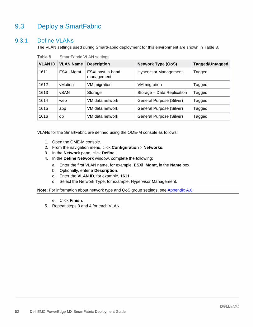
9.3.1 Define VLANs The VLAN settings used during SmartFabric deployment for this environment are shown in Table 8.
SmartFabric VLAN settings
VLAN ID VLAN Name Description Network Type (QoS) Tagged/Untagged
1611 ESXi_Mgmt ESXi host in-band management
Hypervisor Management Tagged
1612 vMotion VM migration VM migration Tagged
1613 vSAN Storage Storage – Data Replication Tagged
1614 web VM data network General Purpose (Silver) Tagged
1615 app VM data network General Purpose (Silver) Tagged
1616 db VM data network General Purpose (Silver) Tagged
VLANs for the SmartFabric are defined using the OME-M console as follows:
1. Open the OME-M console. 2. From the navigation menu, click Configuration > Networks. 3. In the Network pane, click Define. 4. In the Define Network window, complete the following:
a. Enter the first VLAN name, for example, ESXi_Mgmt, in the Name box. b. Optionally, enter a Description. c. Enter the VLAN ID, for example, 1611. d. Select the Network Type, for example, Hypervisor Management.
Note: For information about network type and QoS group settings, see Appendix A.6.
e. Click Finish. 5. Repeat steps 3 and 4 for each VLAN.
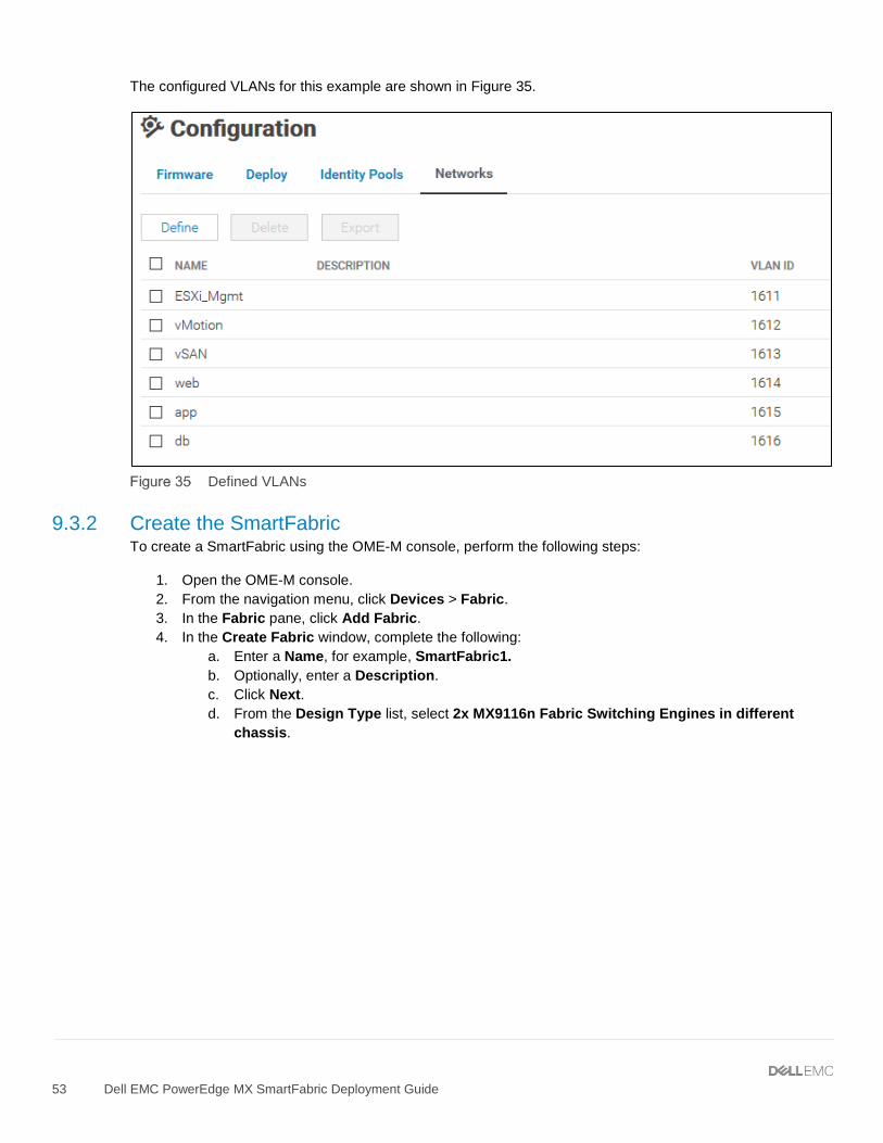
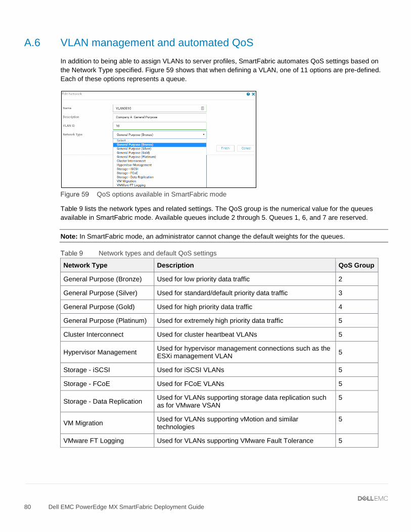
The configured VLANs for this example are shown in Figure 35.
Defined VLANs
9.3.2 Create the SmartFabric To create a SmartFabric using the OME-M console, perform the following steps:
1. Open the OME-M console. 2. From the navigation menu, click Devices > Fabric. 3. In the Fabric pane, click Add Fabric. 4. In the Create Fabric window, complete the following:
a. Enter a Name, for example, SmartFabric1. b. Optionally, enter a Description. c. Click Next. d. From the Design Type list, select 2x MX9116n Fabric Switching Engines in different
e. From the Chassis-X list, select the first MX7000 chassis. f. From the Switch-A list, select Slot-IOM-A1. g. From the Chassis-Y list, select the second MX7000 chassis to join the fabric. h. From the Switch-B list, select Slot-IOM-A2.
SmartFabric deployment design window
i. Click Next. j. On the Summary page, verify the proposed configuration and click Finish.
The SmartFabric deploys. This process takes several minutes to complete. During this time, all related IOMs reload, the operating mode of the IOMs changes from their default, Full Switch, to SmartFabric, and the SmartFabric is created.
Figure 37 shows the new SmartFabric object.
SmartFabric after deployment before uplinks are created
Note: After creation, the SmartFabric shows the Uplink Count is 0 and the icon. The Health column displays the icon until uplinks are defined in the next section.
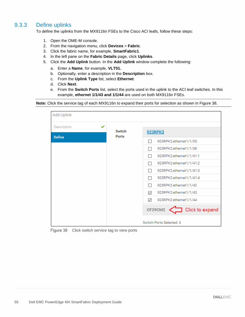
9.3.3 Define uplinks To define the uplinks from the MX9116n FSEs to the Cisco ACI leafs, follow these steps:
1. Open the OME-M console. 2. From the navigation menu, click Devices > Fabric. 3. Click the fabric name, for example, SmartFabric1. 4. In the left pane on the Fabric Details page, click Uplinks. 5. Click the Add Uplink button. In the Add Uplink window complete the following:
a. Enter a Name, for example, VLT01. b. Optionally, enter a description in the Description box. c. From the Uplink Type list, select Ethernet. d. Click Next. e. From the Switch Ports list, select the ports used in the uplink to the ACI leaf switches. In this
example, ethernet 1/1/43 and 1/1/44 are used on both MX9116n FSEs.
Note: Click the service tag of each MX9116n to expand their ports for selection as shown in Figure 38.
f. Under Tagged Networks, select the checkbox next to each VLAN that the uplink will be tagged. The uplink is a tagged member of all six VLANs in this example as shown in Figure 39.
g. If the uplink will be an untagged member of a VLAN, select the VLAN from the drop-down list next to Untagged Network. In this example, this is left at None.
Note: If the uplink is an untagged member of a VLAN, see the Cisco ACI documentation for setting the corresponding EPG to access (untagged) mode in ACI.
Tagged and untagged networks selected
h. Click Finish.
SmartFabric creates the uplink object. If the connected Cisco ACI vPC is configured correctly, as shown in the attachment Scenario 3 – APIC config steps.pdf, the uplink comes up and the status for the fabric changes to Ok on the Devices > Fabric page as shown in Figure 40.
9.3.4 Server templates A server template contains the parameters that are extracted from a compute sled and enables these parameters to be quickly applied to multiple compute sleds. The templates contain settings for the following categories:
• Local access configuration • Location configuration • Power configuration • Chassis network configuration • Slot configuration • Setup configuration
Also, server templates enable an administrator to associate VLANs to compute sleds.
9.3.4.1 Create server templates A server template should be created for each unique server and NIC combination used in the MX7000 chassis group. If all servers are identical, only one template needs to be created. For the hardware used in this example, three templates are created:
• MX740c with QLogic QL41232HMKR NIC • MX740c with Intel XXV710 NIC • MX840c with QLogic QL41232HMKR NIC
To create a server template, follow these steps:
1. Open the OME-M console. 2. From the navigation menu, click Configuration > Deploy. 3. Click Create Template > From Reference Device. 4. In the Create Template window, complete the following:
a. Enter a name such as MX740c with QLogic QL41232HMKR NIC in the Template Name box. b. Optionally, enter a description in the Description box. c. Click Next. d. On the Device Selection page, click Select Device. e. In the Select Devices window, choose an appropriate sled for the template, for example, Sled-1
from Chassis-1 and click Finish. f. In the Elements to Clone list, select the following options:
i. iDRAC ii. System iii. NIC
g. Click Finish.
Note: Capture both iDRAC and NIC settings to enable virtual identities. For additional information about virtual identities, see Appendix A.7.
A job starts, and the new server template displays in the list. When done, the status changes to Completed.
Repeat steps 3 and 4 above if more templates need to be created. The templates created for this example are shown in Figure 41.
9.3.4.2 Add VLANs to the server templates After successfully creating server templates, associate each template with VLANs as follows:
1. On the Configuration > Deploy page, select a server template previously created such as MX740c with QLogic QL41232HMKR NIC.
2. Click the Edit Network button. 3. In the Edit Network window, complete the following:
a. For both ports, if they will be untagged members of a VLAN, select the VLAN from the drop-down box under Untagged Network. No ports are untagged in this example.
b. For both ports, select the VLANs they are tagged members of in the drop-down box under Tagged Network. Both ports are tagged members of all six VLANs in this example as shown in Figure 42.
9.3.4.3 Deploy the server templates To deploy the server templates, complete the following steps:
1. On the Configuration > Deploy page, select a server template such as MX740c with QLogic QL41232HMKR NIC.
2. Click the Deploy Template button. Click Yes if prompted to use the physical identities. 3. In the Deploy Template window, complete the following:
a. Click the Select button to choose which sleds to deploy the template. After sleds are selected, click Finish.
b. Under Host OS Reboot Options, select the Do not forcefully reboot the host OS checkbox. c. Click Next. d. Optionally, configure the iDRAC Management IP settings for each sled. In this example, it is kept
at Don’t Change IP settings. Click Next. e. Choose Run Now > Finish. Read the “deploying template” warning and click Yes to confirm.
Repeat the steps above using applicable templates for any remaining sleds.
SmartFabric configures each MX9116n FSE interface with the VLAN settings automatically per the template. This enables hosts in the MX Chassis to access the networks configured.
SmartFabric also deploys the associated QoS settings based on the network type assigned to each VLAN. For more information on QoS settings, see Appendix A.6.
9.4 vCenter configuration overview The existing ACI environment has two PowerEdge R730xd rack servers connected to the ACI leafs. The rack servers are in a vSphere cluster named Management.
After the SmartFabric is deployed, MX compute sleds can communicate with the rack servers and the vCenter, mgmtvc01. The MX compute sleds are joined to the vSphere cluster by an administrator as shown in Figure 43.
Hosts and VMs used in the validated environment in a single vSphere cluster
Note: The VM locations in the topology are shown in Figure 33 at the beginning of this chapter.
A VDS named VDS-Mgmt, along with six distributed port groups, one for each VLAN, are used as shown in Figure 44.
VDS and port groups used in the validated environment
Note: For each port group in the VDS in this example, both uplinks are active and the load balancing method used is Route based on physical NIC load as recommended in VMware Validated Design Documentation. Detailed vCenter configuration is beyond the scope of this document.
Note: Cisco ACI supports VMware vCenter VDS integration where the APIC learns ESXi host locations using LLDP. With intermediate switches between ESXi hosts and ACI leaf switches, this is not possible without an LLDP relay mechanism. This feature is planned for a future OS10EE release.
9.5 Verify configuration This section covers methods to verify the SmartFabric and ACI environment is configured properly.
9.5.1 Validation using the OME-M Console
9.5.1.1 Show the MCM group topology The OME-M console can be used to show the physical cabling of the SmartFabric.
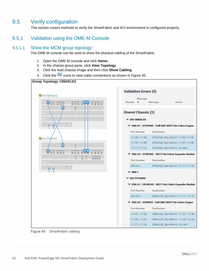
1. Open the OME-M console and click Home. 2. In the chassis group pane, click View Topology. 3. Click the lead chassis image and then click Show Cabling. 4. Click the icons to view cable connections as shown in Figure 45.
The Group Topology page shows the MX9116n and MX7116n connections and if any validation errors are present. On the MX9116n FSEs, ports 1/1/17-18 are used to connect to the MX7116n FEMs. Ports 1/1/37-40 are used for the VLTi.
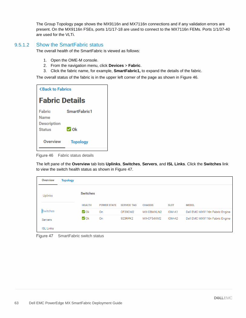
9.5.1.2 Show the SmartFabric status The overall health of the SmartFabric is viewed as follows:
1. Open the OME-M console. 2. From the navigation menu, click Devices > Fabric. 3. Click the fabric name, for example, SmartFabric1, to expand the details of the fabric.
The overall status of the fabric is in the upper left corner of the page as shown in Figure 46.
Fabric status details
The left pane of the Overview tab lists Uplinks, Switches, Servers, and ISL Links. Click the Switches link to view the switch health status as shown in Figure 47.
Click the Servers link to view the server health status as shown in Figure 48.
SmartFabric server status
Select the Topology tab to view uplinks and fabric connections. Figure 49 shows the VLT port channel connection, VLT01, connected to the Cisco ACI vPC using ports 1/1/43-1/1/44 on each MX9116n. The VLTi connection between the two MX9116n FSEs is also shown.
9.5.1.3 Show port status The OME-M console can be used to show MX9116n FSE port status, toggle administrative states, configure breakouts, MTU settings, and auto-negotiation.
1. Open the OME-M console. 2. From the navigation menu, click Devices > I/O Modules. 3. Click an IOM name for the first MX9116n, for example, IOM-A1. The IOM Overview page for that
device is displayed. 4. On the IOM Overview page, click Hardware > Port Information.
Figure 51 shows ports 1/1/1, 1/1/5, 1/71/1 and 1/71/3 are up. Ports 1/1/1 and 1/1/5 are connected to the compute sleds in the local chassis. Ports 1/71/1 and 1/71/3, in port group 1/1/1, are connected to the compute sleds in the opposite chassis via the MX7116n FEM.
The figure also shows the uplinks to the Cisco ACI leafs, using port channel 1, are up. It also shows the VLTi ports, using port channel 1000, are up.
9.5.2 Validation using the MX9116n CLI The CLI commands shown in this section are available to help validate the configuration. The commands and output shown below are from the MX9116n in the first chassis. The CLI output from the MX9116n in the second chassis, not shown, is similar.
Note: The MX9116n CLI is accessible using SSH. The default username and password are both admin.
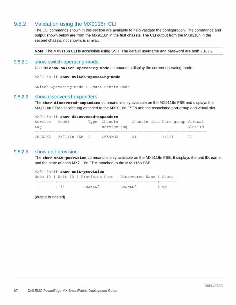
9.5.2.1 show switch-operating-mode Use the show switch-operating-mode command to display the current operating mode.
MX9116n-1# show switch-operating-mode Switch-Operating-Mode : Smart Fabric Mode
9.5.2.2 show discovered-expanders The show discovered-expanders command is only available on the MX9116n FSE and displays the MX7116n FEMs service tag attached to the MX9116n FSEs and the associated port-group and virtual slot.
MX9116n-1# show discovered-expanders Service Model Type Chassis Chassis-slot Port-group Virtual tag service-tag Slot-Id -------------------------------------------------------------------------- CBJWLN2 MX7116n FEM 1 CF54XM2 A1 1/1/1 71
9.5.2.3 show unit-provision The show unit-provision command is only available on the MX9116n FSE. It displays the unit ID, name, and the state of each MX7116n FEM attached to the MX9116n FSE.
MX9116n-1# show unit-provision Node ID | Unit ID | Provision Name | Discovered Name | State | ---------+---------+---------------------------------+-------| 1 | 71 | CBJWLN2 | CBJWLN2 | up | (output truncated)
9.5.2.4 show vlt domain-id The show vlt domain-id command validates the VLT configuration status. The role of one switch in the VLT pair is primary (not shown), and its peer switch is assigned the secondary role. The VLT domain ID of 255 is automatically configured in SmartFabric mode. The VLTi link Status and VLT Peer Status must both be up. SmartFabric automatically configures the VLTi as port channel 1000.
MX9116n-1# show vlt 255 Domain ID : 255 Unit ID : 1 Role : secondary Version : 1.0 Local System MAC address : 20:04:0f:00:b8:1e VLT MAC address : 20:04:0f:00:b8:1e IP address : fda5:74c8:b79e:1::1 Delay-Restore timer : 90 seconds Peer-Routing : Disabled Peer-Routing-Timeout timer : 0 seconds VLTi Link Status port-channel1000 : up VLT Peer Unit ID System MAC Address Status IP Address Version -------------------------------------------------------------------------------- 2 20:04:0f:00:9d:1e up fda5:74c8:b79e:1::2 1.0
9.5.2.5 show vlt domain-id vlt-port-detail The show vlt domain-id vlt-port-detail command shows the VLT port channel status for both VLT peers. The VLT in this example is connected to the Cisco ACI vPC. It is automatically configured in port channel 1, and it consists of two ports on each switch.
MX9116n-1# show vlt 255 vlt-port-detail vlt-port-channel ID : 1 VLT Unit ID Port-Channel Status Configured ports Active ports ------------------------------------------------------------------------------- * 1 port-channel1 up 2 2 2 port-channel1 up 2 2
9.5.2.6 show interface port channel summary The show interface port-channel summary command shows the LAG number (VLT port channel 1 in this example), the mode, status and ports used in the port channel.
MX9116n-1# show interface port-channel summary LAG Mode Status Uptime Ports 1 L2-HYBRID up 00:29:20 Eth 1/1/43 (Up) Eth 1/1/44 (Up)
9.5.2.7 show lldp neighbors The show lldp neighbors command shows information about directly connected devices. Ports 1/1/1, 1/1/5, 1/71/1, and 1/71/3 are connected to the four compute sleds.
Note: Ports 1/71/1 and 1/71/3 are the compute sleds connected to the MX7116n FEM in the other chassis.
Two instances appear for each port connected to a compute sled. One instance is the compute sled iDRAC. The iDRAC uses connectivity to the mezzanine card to advertise LLDP information. It includes the iDRAC name in the Rem Host Name column, the sled service tag and mezzanine card number-port-partition in the Rem Port ID column, and the iDRAC MAC address in the Rem Chassis Id column. The second instance is the mezzanine card itself and the MAC address of the mezzanine card port is shown.
Ports 1/1/37-1/1/40 are the VLTi interfaces for the SmartFabric. Ports 1/1/43-1/1/44 are the links in VLT port channel 1 connected to the Cisco ACI leaf switches.
MX9116n-1# show lldp neighbors Loc PortID Rem Host Name Rem Port Id Rem Chassis Id -------------------------------------------------------------------------------- ethernet1/1/1 Not Advertised f4:e9:d4:f2:6f:26 f4:e9:d4:f2:6f:26 ethernet1/1/1 MX740c-1-1-idrac ST0000C NIC.Mezzanine.1A-1-1 d0:94:66:2d:b3:f4 ethernet1/1/5 Not Advertised 24:6e:96:9c:e5:da 24:6e:96:9c:e5:da ethernet1/1/5 MX740c-1-3-idrac 1S34MN2 NIC.Mezzanine.1A-1-1 d0:94:66:29:ff:27 ethernet1/1/37 MX9116n-2 ethernet1/1/37 20:04:0f:00:9d:1e ethernet1/1/38 MX9116n-2 ethernet1/1/38 20:04:0f:00:9d:1e ethernet1/1/39 MX9116n-2 ethernet1/1/39 20:04:0f:00:9d:1e ethernet1/1/40 MX9116n-2 ethernet1/1/40 20:04:0f:00:9d:1e ethernet1/1/43 Leaf1 Eth1/51 00:be:75:19:40:13 ethernet1/1/44 Leaf2 Eth1/51 4c:77:6d:f1:ee:7d ethernet1/71/1 Not Advertised f4:e9:d4:f2:6f:da f4:e9:d4:f2:6f:da ethernet1/71/1 MX840c-2-1-idrac ST00000 NIC.Mezzanine.1A-1-1 d0:94:66:2d:b5:2c ethernet1/71/3 Not Advertised 24:6e:96:9c:e5:48 24:6e:96:9c:e5:48 ethernet1/71/3 MX740c-2-3-idrac 1S35MN2 NIC.Mezzanine.1A-1-1 d0:94:66:29:fa:f4
9.5.2.8 show qos system The show qos system command displays the QoS configuration applied to the system. The command is useful to verify the service policy created automatically by the SmartFabric deployment.
MX9116n-1# show qos system Service-policy (input): PM_VLAN ETS Mode : off
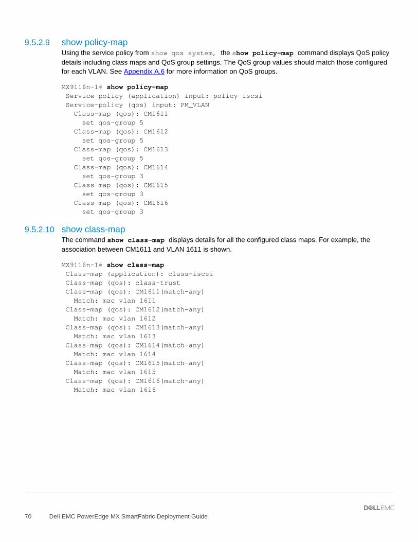
9.5.2.9 show policy-map Using the service policy from show qos system, the show policy-map command displays QoS policy details including class maps and QoS group settings. The QoS group values should match those configured for each VLAN. See Appendix A.6 for more information on QoS groups.
MX9116n-1# show policy-map Service-policy (application) input: policy-iscsi Service-policy (qos) input: PM_VLAN Class-map (qos): CM1611 set qos-group 5 Class-map (qos): CM1612 set qos-group 5 Class-map (qos): CM1613 set qos-group 5 Class-map (qos): CM1614 set qos-group 3 Class-map (qos): CM1615 set qos-group 3 Class-map (qos): CM1616 set qos-group 3
9.5.2.10 show class-map The command show class-map displays details for all the configured class maps. For example, the association between CM1611 and VLAN 1611 is shown.
MX9116n-1# show class-map Class-map (application): class-iscsi Class-map (qos): class-trust Class-map (qos): CM1611(match-any) Match: mac vlan 1611 Class-map (qos): CM1612(match-any) Match: mac vlan 1612 Class-map (qos): CM1613(match-any) Match: mac vlan 1613 Class-map (qos): CM1614(match-any) Match: mac vlan 1614 Class-map (qos): CM1615(match-any) Match: mac vlan 1615 Class-map (qos): CM1616(match-any) Match: mac vlan 1616
9.5.3.1 Verify vPC configuration Verify the vPC connection from the Cisco ACI fabric to the Dell MX SmartFabric VLT, shown in Figure 33, is up and properly configured to allow designated VLANs and EPGs. This is done as follows:
1. In the APIC GUI, go to Fabric > Inventory > Pod name > Leaf name > Interfaces > vPC Interfaces and drill down to the applicable port channel/vPC policy group as shown in Figure 52.
Cisco ACI vPC port channel and interfaces
2. Verify the port channel uses active LACP and is operationally up 3. Verify all leaf switch interfaces in the vPC, for example, eth1/51-52, are listed beneath the port
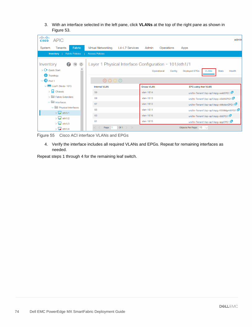
4. With the port channel/vPC interface policy group selected in the left pane, click VLANs at the top of the right pane as shown in Figure 53.
Cisco ACI vPC port channel VLANs and EPGs
5. Verify the port channel includes all required VLANs, and EPGs are mapped to the correct VLANs. Repeat steps 1 through 5 for the remaining leaf switch.
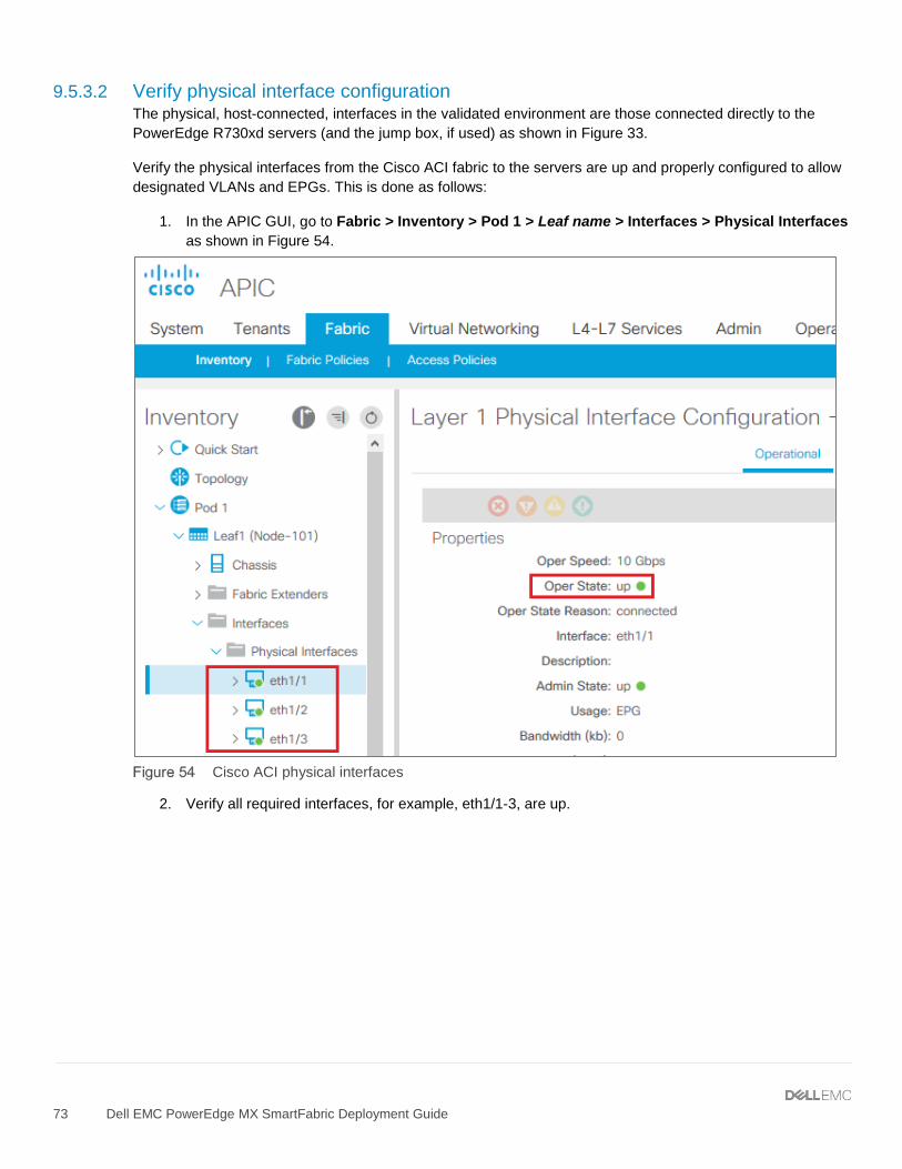
9.5.3.2 Verify physical interface configuration The physical, host-connected, interfaces in the validated environment are those connected directly to the PowerEdge R730xd servers (and the jump box, if used) as shown in Figure 33.
Verify the physical interfaces from the Cisco ACI fabric to the servers are up and properly configured to allow designated VLANs and EPGs. This is done as follows:
1. In the APIC GUI, go to Fabric > Inventory > Pod 1 > Leaf name > Interfaces > Physical Interfaces as shown in Figure 54.
Cisco ACI physical interfaces
2. Verify all required interfaces, for example, eth1/1-3, are up.
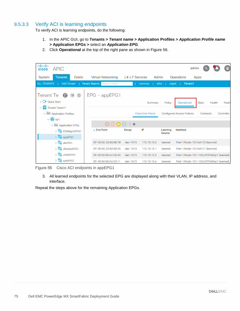
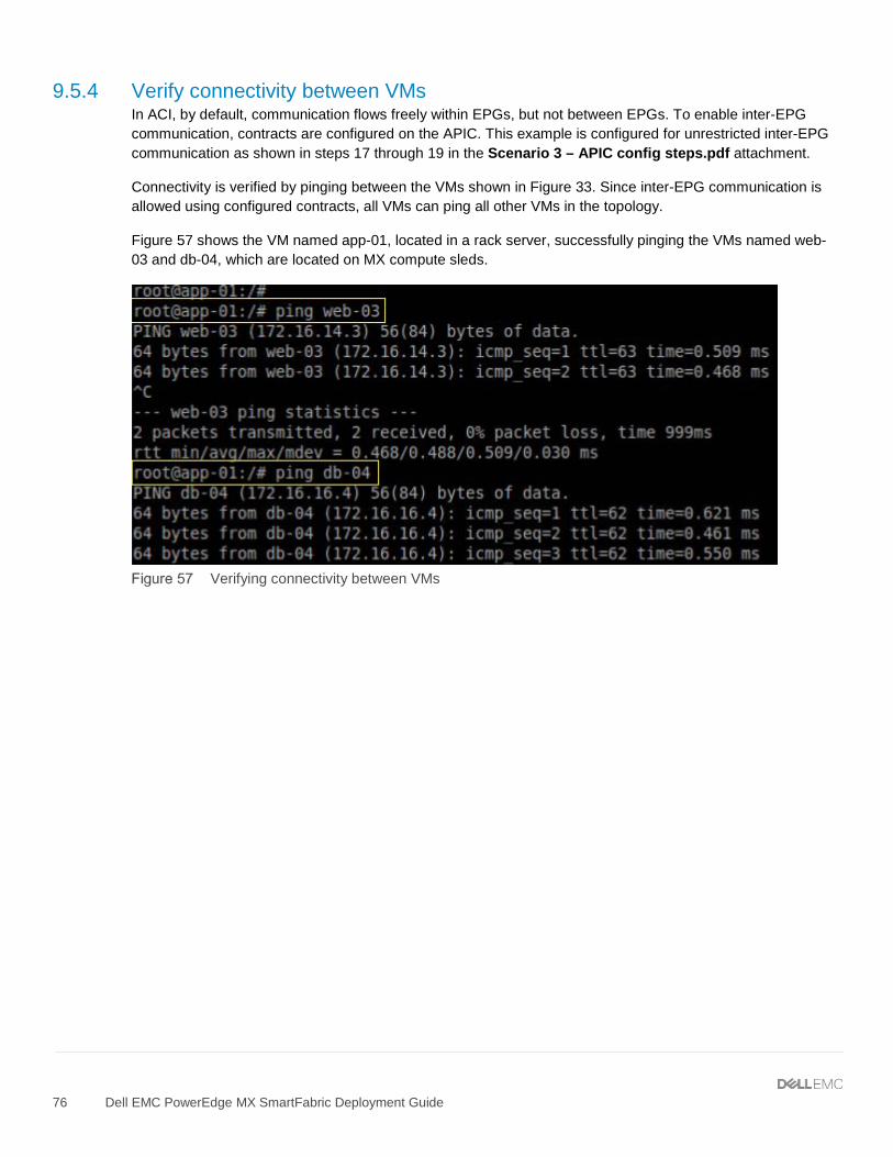
9.5.4 Verify connectivity between VMs In ACI, by default, communication flows freely within EPGs, but not between EPGs. To enable inter-EPG communication, contracts are configured on the APIC. This example is configured for unrestricted inter-EPG communication as shown in steps 17 through 19 in the Scenario 3 – APIC config steps.pdf attachment.
Connectivity is verified by pinging between the VMs shown in Figure 33. Since inter-EPG communication is allowed using configured contracts, all VMs can ping all other VMs in the topology.
Figure 57 shows the VM named app-01, located in a rack server, successfully pinging the VMs named web-03 and db-04, which are located on MX compute sleds.
A.1 Resetting PowerEdge MX7000 to factory defaults This section covers resetting a PowerEdge MX7000 with IOMs in SmartFabric mode to factory defaults.
A.1.1 Remove the SmartFabric
To remove the SmartFabric using the OME-M console, perform the following steps:
1. Open the OME-M console. 2. From the navigation menu, click Devices > Fabric. 3. Select SmartFabric. 4. Click the Delete button. 5. In the delete fabric dialog box click Yes.
All participating switches reboot to Full Switch mode.
Note: Any configuration not completed by the OME-M console is lost when switching between IOM operating modes.
A.1.2 Remove the MCM group
To remove an MCM group using the OME-M console, perform the following steps:
1. Open the OME-M console. 2. In the MCM group pane, click the name of the lead chassis. 3. From the Configure menu, select Delete Group. 4. In the Delete Group dialog box, click Confirm.
At this point, the OME-M console removes the MCM group. To manage the chassis, use the individual IP addresses assigned to each.
A.1.3 Use RACADM to reset each chassis
To reset the chassis to factory default settings, perform the following steps:
1. Connect to the MX9002m IP address using SSH. The default username is root, and the default password is calvin.
2. In the RACADM shell, run the racadm racresetcfg command. 3. The factory reset process is initiated, and a status message displays.
Note: The process takes several minutes to complete.
4. Optionally, after the reset process is complete, use the LCD screen to reassign a static IP address. See Section 6.2 for more information.
A.2 Reset OS10EE switches to factory defaults To reset OS10EE switches back to the factory default configuration, enter the following commands:
OS10# delete startup-configuration Proceed to delete startup-configuration [yes/no(default)]:yes OS10# reload System configuration has been modified. Save? [yes/no]:no Proceed to reboot the system? [confirm yes/no]:yes
The switch reboots with default configuration settings.
A.3 Factory default Cisco Nexus 3232C To reset the Cisco Nexus 3232C switches to the factory default configuration, enter the following commands:
3232C# write erase Warning: This command will erase the startup-configuration. Do you wish to proceed anyway? (y/n) [n] y
After the next reboot the switch loads with default configuration settings.
A.4 Spanning Tree Protocol recommendations By default, OS10EE uses Rapid per-VLAN Spanning Tree Plus (RPVST+) across all switching platforms including PowerEdge MX networking IOMs. OS10EE also supports RSTP and MST.
Caution should be taken when connecting an RPVST+ to an existing RSTP environment. RPVST+ creates a single topology per VLAN with the default VLAN, typically VLAN 1, for the Common Spanning Tree (CST) with RSTP.
For non-native VLANs, all Bridge Protocol Data Unit (BPDU) traffic is tagged and forwarded by the upstream, RSTP-enable switch, with the associated VLAN. These BPDUs use a protocol-specific multicast address. Any other RPVST+ tree attached to the RSTP tree might processes these packets accordingly leading to the potential of unexpected trees.
Note: When connecting to an existing environment that is not using RPVST+, Dell EMC Networking recommends changing to the existing spanning tree protocol before connecting an OS10EE switch.
In the example below, RSTP is enabled globally on an MX9116n FSE. MST configuration is similar.
C140A1(config)# spanning-tree mode rstp C140A1 (config)# end C140A1#show spanning-tree brief Spanning tree enabled protocol rstp with force-version rstp Executing IEEE compatible Spanning Tree Protocol Root ID Priority 0, Address 4c76.25e8.f2c0
Root Bridge hello time 2, max age 20, forward delay 15 Bridge ID Priority 32768, Address 2004.0f00.cd1e Configured hello time 2, max age 20, forward delay 15 Flush Interval 200 centi-sec, Flush Invocations 95 Flush Indication threshold 0 (MAC flush optimization is disabled)
A.5 QSFP28 double density connectors Quad Small Form-Factor Pluggable 28 Double Density, or QSFP28-DD connectors, expand on the QSFP28 pluggable form factor. By doubling the number of available lanes from four to eight, with each lane operating at 25 Gbps, the result is 200 Gbps for each connection.
Note: A QSFP28-DD transceiver is not compatible with a QSFP28 port due to the specifications required to lengthen the PCB connector to allow for the additional four lanes. However, a QSFP28 transceiver can be inserted into a QSFP28-DD port.
QSFP28-DD and QSFP28 physical interfaces
The MX9116n FSE supports direct attach cables (DAC), active optic cables (AOC), as well as multi-mode fiber (MMF) cables with supported Dell EMC Networking optics.
A.6 VLAN management and automated QoS In addition to being able to assign VLANs to server profiles, SmartFabric automates QoS settings based on the Network Type specified. Figure 59 shows that when defining a VLAN, one of 11 options are pre-defined. Each of these options represents a queue.
QoS options available in SmartFabric mode
Table 9 lists the network types and related settings. The QoS group is the numerical value for the queues available in SmartFabric mode. Available queues include 2 through 5. Queues 1, 6, and 7 are reserved.
Note: In SmartFabric mode, an administrator cannot change the default weights for the queues.
Network types and default QoS settings
Network Type Description QoS Group
General Purpose (Bronze) Used for low priority data traffic 2
General Purpose (Silver) Used for standard/default priority data traffic 3
General Purpose (Gold) Used for high priority data traffic 4
General Purpose (Platinum) Used for extremely high priority data traffic 5
Cluster Interconnect Used for cluster heartbeat VLANs 5
Hypervisor Management Used for hypervisor management connections such as the ESXi management VLAN 5
Storage - iSCSI Used for iSCSI VLANs 5
Storage - FCoE Used for FCoE VLANs 5
Storage - Data Replication Used for VLANs supporting storage data replication such as for VMware VSAN
5
VM Migration Used for VLANs supporting vMotion and similar technologies
5
VMware FT Logging Used for VLANs supporting VMware Fault Tolerance 5
When a VLAN-capable server template deploys, SmartFabric creates a class map. For example, class map CM10, matching all traffic associated with VLAN 10. Then a policy map, for example, PM_VLAN, sets this class map to the appropriate queue, as in qos-group 2.
A.7 Identity Pools Identity Pools, or virtual identities, abstract the network identity for Ethernet, FCoE, iSCSI, or FC access. Virtual identities allow the assignment of a static MAC address or WWPN to a slot. This allows the replacement of a network device, like a mezzanine card, without causing any interruption to other applications relying on that hardware address.
Identity Pools are used in conjunction with server templates to automate network onboarding of compute sleds. To create an Ethernet ID pool, follow these steps:
1. Open the OME-M console. 2. From the navigation menu, click Configuration > Identity Pools. 3. Click Create. 4. In the Create Identity Pool window, complete the following:
a. Enter Ethernet ID pool in the Pool Name box. b. Optionally, enter a description in the Description box. c. Click Next. d. Select the Include ethernet virtual MAC Addresses option. e. Enter the first address in the Starting MAC Address box. f. Enter 320 in the Number of Virtual MAC Identities box. g. Click Finish.
Note: The starting MAC address must be a locally administered unicast address.
B.1 Scenarios 1 and 2 The following tables include the hardware, software, and firmware used to configure and validate Scenario 1 and Scenario 2 in this document.
B.1.1 Dell EMC Networking switches
Dell EMC Networking switches and OS versions – Scenarios 1 and 2
Abstract This document is an attachment to the Dell EMC PowerEdge MX SmartFabric Deployment Guide. It provides APIC configuration steps for the validated environment used in Scenario 3 of the guide. November 2018
This document is an attachment to the Dell EMC PowerEdge MX Smart Fabric Deployment Guide. It provides APIC configuration steps for the validated environment used in Scenario 3 of the guide.
These configuration steps begin after initial Cisco ACI deployment steps have been performed, including:
1. One or more Cisco APICs have been deployed. 2. Nexus leaf and spine switches have been discovered and registered with the APIC. The node ID
numbers and names used in this example are listed in Table 1.
APIC leaf and spine node IDs and names
Node ID Node name
101 Leaf1
102 Leaf2
201 Spine1
The networks used are shown in Table 2, along with the corresponding bridge domain and application EPG names used in APIC configuration.
Network information
VLAN ID VLAN name Gateway IP address/mask Bridge domain name Application EPG name
The following steps were performed in the Cisco APIC GUI to configure APIC-1 for the validated environment.
1. Create a VLAN Pool:
a. Go to Fabric > Access Policies > Pools > VLAN b. Right click on VLAN and select Create VLAN Pool c. Name - VLANPool1 d. Allocation mode – Static e. Click +
i. VLAN Range - 1611-2000 ii. Allocation mode – Static Allocation iii. Role - External or On the wire encapsulations (default)
a. Go to Fabric > Access Policies > Physical and External Domains > Physical Domains b. Right click on Physical Domain and select Create Physical Domain c. Name - physDomain1 d. Assign VLANPool1 (created above) to the physical domain > Submit
3. Create an Attachable Access Entity Profile:
a. Go to Fabric > Access Policies > Policies > Global > Attachable Access Entity Profiles b. Right click on Attachable Access Entity Profiles and select Create Attachable Access Entity
Profile c. Name - AEP1 d. Domain Profile - associate it with physDomain1 (created above) e. Next > Finish
4. Create a Port Channel Policy:
a. Go to Fabric > Access Policies > Policies > Interface > Port Channel b. Right click on Port Channel and select Create Port Channel Policy c. Name - LACPPol1 d. Mode – LACP Active e. Control – keep default settings f. Submit
5. Create a vPC Interface Policy Group:
a. Go to Fabric > Access Policies > Interfaces > Leaf Interfaces > Policy Groups > VPC Interface
b. Right click on VPC Interface and select Create VPC Interface Policy Group c. Name - vPCPolGrp1 d. Attached entity profile – AEP1 (created above) e. Port Channel policy - LACPPol1 (created above) f. Submit
6. Create a Leaf Access Port Policy Group:
a. Go to Fabric > Access Policies > Interfaces > Leaf Interfaces > Policy Groups > Leaf Access Port
b. Right click on Leaf Access Port and select Create Leaf Access Port Policy Group c. Name - LeafHostPortGrp1 d. Attached entity profile – AEP1 (created above) e. Submit
7. Create a Leaf Interface Profile:
a. Go to Fabric > Access Policies > Interfaces > Leaf Interfaces > Profiles b. Right click on Profiles and select Create Leaf Interface Profile c. Name - LeafIntProf1 d. Create Access Port Selectors:
i. LeafHostSel1, contains directly connected host interfaces 1/1-3, associate to LeafHostPortGrp1 created above > Submit
ii. LeafvPCSel1, contains vPC interfaces 1/51-52, associate it to vPCPolGrp1 (created above) iii. Submit
8. Create a VPC Domain Policy:
a. Go to Fabric > Access Policies > Policies > Switch > VPC Domain b. Right click on VPC Domain and select Create VPC Domain Policy c. Name - vPCDom1 d. Submit
9. Create a VPC Explicit Protection Group:
a. Go to Fabric > Access Policies > Policies > Switch and select Virtual Port Channel default b. Leave Pairing Type set to Explicit (default) c. Next to Explicit VPC Protection Groups, click + d. Name - vPCExpProGrp1 e. ID - 101 f. VPC Domain Policy - select vPCDom1 (created above) g. Switch 1 – select the first leaf switch, 101/Leaf1 h. Switch 2 – select the second leaf switch, 102/Leaf2 i. Submit
10. Create a Leaf Profile:
a. Go to Fabric > Access Policies > Switches > Leaf Switches > Profiles b. Right click on Profiles and select Create Leaf Profile c. Name – LeafProf1 d. Next to Leaf Selectors, click + to create a Leaf Selector:
i. Name - LeafSel1 ii. Blocks - select switches 101 and 102 and click Update iii. Click Next iv. Interface Selector Profiles – select LeafIntProf1 (created above) > Finish
11. Create a Tenant:
a. Go to Tenants > Add Tenant b. Name - Tenant1 c. Submit
12. Create a VRF:
a. Go to Tenants > Tenant1 > Networking > VRFs b. Right click on VRFs and select Create VRF c. Name - VRF1 d. Uncheck Create a Bridge Domain and click Finish
13. Create Bridge Domains:
Note: Refer to Table 2 if needed.
Bridge domains are created for each VLAN as follows:
a. Go to Tenants > Tenant1 > Networking > Bridge Domains b. Right click on Bridge Domains and select Create Bridge Domain c. Enter the Name of the first bridge domain, webBD1 d. Next to VRF, select VRF1 (created above), and click Next e. Next to Subnets, click + f. Add the Gateway IP address and mask for the bridge domain - 172.16.14.254/24 and leave the
remaining values at their defaults g. Click OK > Next > Finish h. Repeat as needed for each VLAN, additional bridge domains created in this example are
appBD1, dbBD1, ESXiMgmtBD1, vMotionBD1, and vSANBD1.
14. Create an Application Profile:
a. Go to Tenants > Tenant1 > Application Profiles b. Right click on Application Profiles and select Create Application Profile c. Name – ap1 d. Submit
15. Create Application EPGs:
Note: Refer to Table 2 if needed.
a. Go to Tenants > Tenant1 > Application Profiles > ap1 > Application EPGs b. Right click on Application EPGs and select Create Application EPG c. Enter the Name of the first EPG, webEPG1 d. Next to Bridge Domain – select the associated bridge domain, webBD1 e. Click Finish f. Create a separate EPG for each of the remaining bridge domains, remaining EPG names used in
this example are appEPG1, dbEPG1, ESXiMgmtEPG1, vMotionEPG1, and vSANEPG1
16. Configure the Access Entity Profile with EPGs and VLANs:
Note: Refer to Table 2 if needed.
a. Go to Fabric > Access policies > Policies > Global > Attachable Access Entity Profiles b. Select AEP1 (created above) c. At bottom of page next to Application EPGs, click + d. For the first EPG, webEPG1:
i. Tenant – select Tenant1 ii. Application Profile - select ap1 iii. EPG - webEPG1 iv. Encap - vlan-1614 v. Primary Encap – leave blank vi. Mode – Trunk vii. Click Update
e. Repeat for all remaining EPGs using their associated VLAN IDs
To communicate between EPGs, contracts are created as follows:
17. Create a Contract Filter:
a. Go to Tenants > Tenant1 > Contracts > Filters b. Right click on Filters and select Create Filter c. Name - AllowAllFilter1 d. Next to Entries, click +
i. Name - Allow ii. EtherType - IP iii. Leave remaining items at their defaults and click Update > Submit
18. Create a Contract:
a. Go to Tenants > Tenant1 > Contracts > Standard b. Right click on Standard and select Create Contract c. Name - AllowAllContract1 d. Next to Subjects, click + e. Name - AllowAllSub1 f. Next to Filters, click + g. Under filter Name, select AllowAllFilter1 (created above) h. Click Update > OK > Submit
19. Apply the contract to the VRF:
a. Go to Tenant > Tenant1 > Networking > VRFs > VRF1 b. Expand VRF1 and select EPG collection for VRF c. Next to Provided Contracts, click +
i. Name – select AllowAllContract1 (created above) ii. Click Update
d. Next to Consumed Contracts, click +
i. Name – select AllowAllContract1 (created above) ii. Click Update
Use of 25GbE ports for leaf-to-MX9116n connections Note: If 100GbE ports on Nexus leaf switches are used to connect to MX9116 FSEs, disregard the following steps.
If 25GbE ports on Nexus leaf switches are used with breakout cables to connect to MX9116n FSEs, disable forwarding error correction (FEC) on the corresponding Nexus ports by following these two additional steps:
1. Create a Link Level policy:
a. Go to Fabric > Access Policies > Policies > Interface > Link Level b. Right click on Link Level and select Create Link Level Policy c. Name – NoFEC