410
Dell EMC™ SRDF/TimeFinder Manager for IBM i Version 9.0 and later Product Guide REV 01

Dell EMC™ SRDF/TimeFinder Manager for IBM iVersion 9.0 and later
Product GuideREV 01
Dell EMC SRDF/TimeFinder Manager for IBM i Version 9.0 and later Product Guide2
Copyright © 1999 - 2018 Dell Inc. or its subsidiaries. All rights reserved.
Published May 2018
Dell believes the information in this publication is accurate as of its publication date. The information is subject to change without notice.
THE INFORMATION IN THIS PUBLICATION IS PROVIDED “AS-IS”. DELL MAKES NO REPRESENTATIONS OR WARRANTIES OF ANY KIND WITH RESPECT TO THE INFORMATION IN THIS PUBLICATION, AND SPECIFICALLY DISCLAIMS IMPLIED WARRANTIES OF MERCHANTABILITY OR FITNESS FOR A PARTICULAR PURPOSE. USE, COPYING, AND DISTRIBUTION OF ANY DELL SOFTWARE DESCRIBED IN THIS PUBLICATION REQUIRES AN APPLICABLE SOFTWARE LICENSE.
Dell, EMC, and other trademarks are trademarks of Dell Inc. or its subsidiaries. Other trademarks may be the property of their respective owners. Published in the USA.
Dell EMCHopkinton, Massachusetts 01748-91031-508-1000 In North America 1-866-464-7381www.DellEMC.com
CONTENTS
Preface
Part 1 SRDF/TimeFinder Manager Standard features
Chapter 1 Standard Features Introduction
Standard features description .................................................................. 22 Supported arrays and array features ........................................................ 23
Enginuity, HYPERMAX OS, and PowerMaxOS requirements ............. 23TimeFinder functionality..................................................................... 23SRDF functionality ............................................................................. 27Supported features for arrays running PowerMaxOS 5978 or HYPERMAX OS 5977 ......................................................................... 29Supported features for arrays running Enginuity 5876 ....................... 29
Supported operations and configurations................................................. 31TimeFinder/Consistency Group.......................................................... 31Supported TimeFinder features for cascaded sessions....................... 33
Load Source Extender and Load Source Mirroring.................................... 36RLSM with TimeFinder and SRDF ...................................................... 37Required 2107/2105 emulation configuration for RLSM ..................... 37
SRDF/TimeFinder terminology and restrictions ....................................... 38Terminology........................................................................................ 38
Usage Restrictions ................................................................................... 39User profile restriction........................................................................ 39Single instance restriction .................................................................. 39
Chapter 2 Configuration and Control Menus
Overview.................................................................................................. 42 Navigating SRDF/TimeFinder Manager .................................................... 42 Accessing the main menu......................................................................... 42 Dell EMC SRDF/TimeFinder Manager for IBM i main menu ..................... 43 Control Menu........................................................................................... 44 Configuration by Image screen................................................................. 46 Work with Associated Paths screen ......................................................... 47 Disk Units screen ..................................................................................... 50 List of Pools screen ................................................................................. 56 Running remote commands...................................................................... 57
Chapter 3 Operational Features, Settings, and Displays
Setting user-configurable preferences ..................................................... 60Controlling pop-up messages ............................................................. 60Setting the restricted state wait time................................................. 60Controlling the SRDF/A Split wait time .............................................. 60Viewing the current values in the FLSHCFG data area ....................... 61Resetting the lockbox password......................................................... 62
Dell EMC SRDF/TimeFinder Manager for IBM i Version 9.0 and later Product Guide 3

Contents
Discovering array and host configuration details ...................................... 63Turning on the discovery process from the EMCCTL library .............. 63Running the DISCOVER command ..................................................... 63Turning off the discovery process ...................................................... 64
Configuring IFS files to support Solutions Enabler................................... 65Modifying the Solutions Enabler configuration files ............................ 65
Working with Solutions Enabler daemons ................................................ 67Configuring daemons using the daemons options file ......................... 67
Working with the SYMAPI server ............................................................. 69Configuring the SYMAPI server.......................................................... 69Starting the SYMAPI Server............................................................... 70Stopping the SYMAPI Server .............................................................. 71
Viewing version information ..................................................................... 72
Chapter 4 Configuring the Environment
Configuration overview ............................................................................ 74 Configuring images .................................................................................. 74
Adding ASPs to an image.................................................................... 74Removing ASPs from an image........................................................... 75
Configuring paths..................................................................................... 76Predefined and user-defined paths..................................................... 77Step Types ......................................................................................... 79
Working with paths .................................................................................. 79Adding/creating paths........................................................................ 79Removing (disassociating) a path....................................................... 83Deleting a path ................................................................................... 84Associating paths with an image......................................................... 85
Configuring device pairs........................................................................... 86Pairing overview and rules for replication pairs................................... 86Pairing devices ................................................................................... 90Viewing devices .................................................................................. 95
Configuring device pools.......................................................................... 99Working with SAVE pools ................................................................... 99Managing pools and devices ............................................................. 105Working with Virtual Provisioning™ and thin pools ........................... 108
Chapter 5 Controlling TimeFinder
Overview................................................................................................ 130 Establish/Re-establish BCV or Clone emulation pairs ........................... 130
Establish or re-establish BCV pairs ................................................... 130 Split BCV or Clone emulation pairs operation ......................................... 131
Restricted state and daemon jobs ..................................................... 131Split BCV pairs: Restricted state ...................................................... 132Split BCV pairs: Hold jobs and job queues......................................... 134Split BCV pairs: Maintenance ........................................................... 136TimeFinder Split: Split While Active................................................... 137Cancel BCV or Clone emulation pairs................................................ 138
TimeFinder/Snap and TimeFinder/Clone operations............................... 139Creating a Snap copy session or Clone copy session ........................ 139Activating a Snap virtual copy session or Clone copy session ............ 141Canceling/Terminating TimeFinder session ....................................... 141
Cancelling/terminating device pairs....................................................... 142
4 Dell EMC SRDF/TimeFinder Manager for IBM i Version 9.0 and later Product Guide

Contents
Unpairing BCV, Clone or Snap devices ................................................... 142BCV device unpairing........................................................................ 143Snap device unpairing....................................................................... 143Clone device unpairing...................................................................... 143
Recovering from a NotConsistent state ................................................. 143 TimeFinder/SnapVX operations.............................................................. 144
Establishing SnapVX session ............................................................ 144Linking/Relinking Snapshots ............................................................ 150Unlinking Snapshots ......................................................................... 152Setting Time to Live ......................................................................... 152Restoring Snapshots ........................................................................ 153Terminating Snapshots..................................................................... 154
Monitoring TimeFinder operations.......................................................... 155Monitoring invalid and % copied tracks ............................................ 155
Automating TimeFinder operations ......................................................... 156
Chapter 6 Controlling SRDF
Overview................................................................................................ 160RDF group/device compatibility ....................................................... 160Adaptive copy write pending (ACWP) mode behavior with PowerMaxOS 5978 or HYPERMAX OS 5977 .................................... 161
Creating and controlling SRDF Groups .................................................. 162Creating dynamic SRDF groups........................................................ 162Modifying dynamic SRDF groups (associated/dissociated local and remote director/port with RDF group) ............................................. 163Removing dynamic SRDF groups...................................................... 164
Setting the SRDF group attributes......................................................... 165 Dynamic SRDF pairs................................................................................ 170
Creating a device file ......................................................................... 170Creating pairs .................................................................................... 170Rules for dynamic concurrent SRDF pairing ...................................... 172Dynamic pairing restrictions .............................................................. 172Deleting SRDF pairs........................................................................... 173Restrictions for deleting pairs............................................................ 174Deleting half pairs.............................................................................. 174
Setting modes of SRDF/A operation ....................................................... 175Consistency protection in SRDF/A mode .......................................... 176Enabling consistency protection........................................................ 176Disabling consistency protection ....................................................... 176
Establishing SRDF links .......................................................................... 176 Splitting/Suspending SRDF links operation ............................................ 178
Splitting/Suspending SRDF links: Restricted state............................ 179Suspend/Split SRDF links: Hold jobs and job queues ......................... 181Splitting/Suspending SRDF links: Maintenance mode ...................... 183Resuming SRDF operation ............................................................... 183
Monitoring SRDF operations .................................................................. 184Monitoring invalid and % copied tracks ............................................ 184
Recovering from NotConsistent SRDF state .......................................... 185 Listing and monitoring SRDF groups ...................................................... 185
Displaying SRDF group details .......................................................... 186 Performing dynamic SRDF personality swaps ......................................... 187 Automating SRDF operations ................................................................. 188
Dell EMC SRDF/TimeFinder Manager for IBM i Version 9.0 and later Product Guide 5

Contents
Appendix A Standard Features Commands Reference
Conventions ........................................................................................... 190 CRTDLTRDFP ......................................................................................... 191 CRTNETCNFG....................................................................................... 193 CTLACT ................................................................................................. 194 CTLPOOL .............................................................................................. 202 CTLRDFGRP.......................................................................................... 208 DISCOVER............................................................................................. 212 DISCOVERC .......................................................................................... 213 ENDSTMSRV......................................................................................... 214 RELDEVLCK........................................................................................... 215 RELDEVLCKC ........................................................................................ 216 RTVSTMINF............................................................................................ 217 SAVEPOOL ............................................................................................ 225 SETRDFGRP.......................................................................................... 226 SETRDFMOD.......................................................................................... 231 STMENDSBS......................................................................................... 232 STMRMTCMD ....................................................................................... 234 STMSTRSBS ......................................................................................... 235 STORDAEMON...................................................................................... 236 STRSTMSRV ......................................................................................... 240
Appendix B Symmetrix Integration Toolkit
Supported Solutions Enabler CLI commands ......................................... 242 Command line examples ........................................................................ 243 Supporting documentation..................................................................... 243
Appendix C Standard Features Messages
Appendix D Miscellaneous Device Information
2105 to 2107 devices (thick devices)...................................................... 274 D910 device support (thin devices) ........................................................ 275 Variable-sized LUNs............................................................................... 277
Appendix E Troubleshooting
Handling failed or non-reporting hardware resources............................. 280 Error generated when running Discover command within SST ............... 280 Multipath reset ...................................................................................... 280 Error when running CRTSYMAPI or CRTSYMAPIC commands ............... 281
Part 2 SRDF/TimeFinder Manager Extended Features
Chapter 7 Extended Features Introduction
Extended features description................................................................ 286 Independent ASP functionality .............................................................. 287
Two-node solution............................................................................ 287Three-node solution ......................................................................... 288Four-node solution ........................................................................... 289
6 Dell EMC SRDF/TimeFinder Manager for IBM i Version 9.0 and later Product Guide

Contents
Chapter 8 Configuring for IASP Environment
Requirements......................................................................................... 292Cluster requirements ........................................................................ 292IOA requirements ............................................................................. 292
Configuration procedures....................................................................... 293Starting and stopping the server job................................................. 293Performing initial TimeFinder/SRDF operations ............................... 295Configuring an IASP image ............................................................... 296Building/rebuilding the IOA file ......................................................... 298Making target devices visible to the backup node ............................ 299
Configuring the environment for IASP.................................................... 300Prepare cluster and IASP nodes ....................................................... 300Start the server ................................................................................ 300Configure paths................................................................................ 301Configure an IASP session................................................................ 302Populate the IOAs for each node in the cluster................................. 303Post-configuration considerations.................................................... 304
Chapter 9 IASP-Supported Operations
IASP-supported operations .................................................................... 306Three-node planned failover (DR) and recovery solution.................. 306Three-node failover and recovery (unplanned) solution.................... 308Backup operations............................................................................ 309Restore operations ........................................................................... 312Managing a four-node solution with a high availability node ............. 313
SRDF/TimeFinder Manager IASP-specific menu options........................ 315Establish/create, split/activate/link/relink, and cancel/terminate operations ........................................................................................ 315Adding or removing IOAs ................................................................... 317Varying on and varying off IASP images locally................................. 319Varying on and varying off IASP images remotely ............................ 319Displaying an IASP configuration by ASP.......................................... 320Removing image information ............................................................ 321
Executing IASP control actions .............................................................. 322Executing IASP control actions on primary node .............................. 322Executing IASP control actions on DR or backup node..................... 324Executing SRDF or TimeFinder control actions on DR or backup node ..................................................................................... 326Preparing target HA node................................................................. 327Executing SRDF control actions during DR on primary node ............ 329
Automated operations ............................................................................ 330Failing over/failing back ................................................................... 330Preparing source/target nodes for backup and restore .................... 331
Appendix F Non-EMC Procedures
Overview................................................................................................ 334 Displaying contents of a physical file on each node................................ 335 Verifying IOA information ....................................................................... 336
Dell EMC SRDF/TimeFinder Manager for IBM i Version 9.0 and later Product Guide 7

Contents
Appendix G Extended Features Commands Reference
Conventions ........................................................................................... 338 ADDRMVIOA.......................................................................................... 339 CRTNETCNFG....................................................................................... 341 CTLACT ................................................................................................. 342 CTLACTTGT .......................................................................................... 343 DISCOVER............................................................................................. 354 DISCOVERC .......................................................................................... 355 ENDSTMSRV......................................................................................... 356 IASPCTL ................................................................................................ 357 IASPCTLC.............................................................................................. 364 IASPCTLHA ........................................................................................... 366 IASPFAILBK ........................................................................................... 368 IASPFAILOV............................................................................................ 371 IASPFILE................................................................................................ 374 IASPTFBCK ........................................................................................... 375 IASPTFEST............................................................................................ 379 RELDEVLCK........................................................................................... 381 RELDEVLCKC ........................................................................................ 382 RTVSTMINF........................................................................................... 383 SETRDFMOD......................................................................................... 384 SETRDFMODC ...................................................................................... 385 SRDFDRCTL .......................................................................................... 386 STMRMTCMD ....................................................................................... 389 STRSTMSRV ......................................................................................... 390
Appendix H Extended Features Messages
Glossary
8 Dell EMC SRDF/TimeFinder Manager for IBM i Version 9.0 and later Product Guide

FIGURES
1 Multiple arrays — single image ................................................................................ 282 TimeFinder/CG ........................................................................................................ 323 Restore Snap session to fully copied Clone.............................................................. 334 SRDF/TimeFinder Manager for IBM i main menu..................................................... 435 Control Menu........................................................................................................... 456 Configuration by Image screen................................................................................ 467 Configuration by Image screen — collapsed ........................................................... 478 Work with Associated Paths screen — overview ..................................................... 489 Disk Units screen ..................................................................................................... 5010 IBM i View................................................................................................................ 5011 Disk Units screen — SVX type of step..................................................................... 5512 List of the Pools screen ........................................................................................... 5613 Display Data Area screen with FLSHCFG data area with default values ................... 6114 Run Discover Process (DISCOVER) screen ............................................................. 6415 Create SYMAPISVR netconfg file (CRTNETCFG) screen........................................ 6916 Control EMC daemon process (STORDAEMON) screen.......................................... 7017 Program Version Information screen........................................................................ 7218 Adding an ASP to an image ...................................................................................... 7519 Removing an ASP from the SYSTEM image............................................................. 7520 Confirm Remove ASP from the image screen .......................................................... 7621 Returning an ASP to the NON _CONFIG pool.......................................................... 7622 Work with Available Paths screen ............................................................................ 7923 Work with Associated Paths screen — add path ..................................................... 8024 Paths not Associated with the Image screen............................................................ 8125 Paths Defined on the System screen ....................................................................... 8226 New paths added to screens.................................................................................... 8327 Disassociating a Path screen.................................................................................... 8428 Deleting a Path Associated with an Image screen .................................................... 8429 Deleting a Path Not Associated with an Image screen ............................................. 8530 Work with Associated Paths screen — associating paths with image ...................... 8631 TimeFinder Pairing Options screen .......................................................................... 9032 Device File used for SnapVX .................................................................................... 9133 Type of the BCV devices screen .............................................................................. 9134 Disk Units screen with Pair option for device not paired .......................................... 9235 Type of the target device screen ............................................................................. 9336 All STD/BCV/SNAP devices of matching screen .................................................... 9337 Disk Units screen with device paired........................................................................ 9438 Disk Units screen — Clone type of step................................................................... 9539 Disk Units screen — SnapVX type of step ............................................................... 9640 Mapping View screen ............................................................................................... 9641 Disk Units screen — IBM i View............................................................................... 9742 Disk Units Details screen for step type SNAP .......................................................... 9743 Disk Units Details screen for thin device .................................................................. 9844 List of the Pools screen ......................................................................................... 10045 Existing Pools screen .............................................................................................. 10146 Work with Pool screen ........................................................................................... 10247 Not Pooled Save/Data Devices screen .................................................................. 10348 Create Device File to Use with CTLPOOL .............................................................. 10449 Confirmation screen for device file name............................................................... 10450 Create Device File to Use with CTLPOOL screen with message ............................ 105
Dell EMC SRDF/TimeFinder Manager for IBM i Version 9.0 and later Product Guide 9

51 Rename Pool screen ............................................................................................... 10752 Work with Thin Bound Devices screen .................................................................... 11253 Work with Thin Unbound Devices screen ................................................................ 11354 List of the Connected Symmetrix systems screen .................................................. 11455 Work with Thin Bound Devices screen .................................................................... 11556 List of Thin Pools screen......................................................................................... 11657 List of Bound/Allocated Devices screen.................................................................. 11658 List of Allocated Devices screen ............................................................................. 11759 Change Maximum Subscription Percent screen..................................................... 12060 Name of the Migration Session to be Used screen.................................................. 12461 List of the Migration Sessions screen .................................................................... 12662 Migration Session Information screen .................................................................... 12663 Confirm Establish BCV pairs and CLONE emulation pairs screens .......................... 13164 Split operation for BCV or Clone emulation pairs .................................................... 13265 STM End All Subsystem (STMENDSBS) screen ..................................................... 13366 System not in restricted state screen ..................................................................... 13467 Confirmation Window screen ................................................................................. 13568 Jobs Not on Hold and Job Queues Not on Hold screens......................................... 13669 Confirm Cancel BCV pairs and CLONE emulation session screens.......................... 13870 Dell EMC SRDF or TimeFinder Control (CTLACT) screen — create Snap or
Clone session ......................................................................................................... 13971 Create VP Snap screen .......................................................................................... 14072 Confirm Recreate SNAP copy and Recreate CLONE copy session screens ........... 14073 List of the Snap Save Pools screen ......................................................................... 14174 Confirm Terminate SNAP Session and Confirm Terminate CLONE Session............ 14275 Dell EMC SRDF or TimeFinder Control (CTLACT) screen — create SnapVX
session ................................................................................................................... 14476 Work with Associated Paths .................................................................................. 14677 Existing Snapshots screen ..................................................................................... 14678 Work with Snapshots screen................................................................................... 14879 Rename Snapshot screen........................................................................................ 14880 Snapshot Details screen......................................................................................... 14981 List of Snapshots screen......................................................................................... 15182 Link Option screen .................................................................................................. 15183 Set Time to Live screen ......................................................................................... 15384 Control Dynamic RDF Group (CTLRDFGRP) screen .............................................. 16285 Set SRDF Group (SETRDFGRP) screen ................................................................ 16586 Create/Delete RDF pairs with Control Action —CREATE....................................... 17187 Create/Delete RDF pairs with Control Action — DELETE ...................................... 17388 Confirm Delete Half Pair screen.............................................................................. 17489 Set SRDF Mode (SETRDFMOD) screen ................................................................. 17590 Confirm Establish SRDF Link screen ....................................................................... 17791 Split or Suspend SRDF links operation .................................................................... 17892 STM End All Subsystems (STMENDSBS) screen ................................................... 17993 System not in restricted state screen .................................................................... 18094 Confirmation Window screen .................................................................................. 18195 Jobs Not on Hold and Job Queues Not on Hold screens.......................................... 18296 Confirm Resume Link screen................................................................................... 18497 List of the SRDF Groups screen............................................................................. 18598 SRDF Group Information screen ............................................................................ 18699 TSTRTVINF command return message .................................................................. 223100 TSTRTVINF command return message when retrieving a subset of parameters .... 224101 Two-node cluster and two-node DR configuration................................................. 287102 Three-node DR environment.................................................................................. 288103 Four-node high availability setup............................................................................ 289
Dell EMC SRDF/TimeFinder Manager for IBM i Version 9.0 and later Product Guide10

104 EMC SRDF or TimeFinder Control (CTLACT) screen with CREATE action............ 295105 Work with Associated Paths screen ....................................................................... 297106 Configure IASP Session screen with configuration detail ....................................... 297107 Configure IASP Session screen.............................................................................. 302108 IASP View by ASP screen ...................................................................................... 320109 IASP File Utility (IASPFILE) screen......................................................................... 321110 EMC Independent ASP Control (IASPCTL) screen with ADDIOA action ................ 322111 Specify Value for Parameter Action screen............................................................ 323112 EMC Independent ASP Control (IASPCTLC) screen.............................................. 324113 Specify Value for Parameter Action screen............................................................ 325114 Control Action REMOVEIOA .................................................................................. 325115 EMC SRDF or TimeFinder Control (CTLACTTGT) screen with CREATE action..... 326116 EMC IASP HA Control (IASPCTLHA) screen ......................................................... 327117 EMC SRDF DR Control (SRDFDRCTL) screen....................................................... 329118 Displaying the contents of a physical file................................................................ 335119 Verifying IOA information....................................................................................... 336120 EMC Add/Remove IOA screen............................................................................... 340121 IASP Fail Back Procedure screen ........................................................................... 369122 IASP Fail Over Procedure screen ........................................................................... 372123 IASP TimeFinder Backup procedure screen ........................................................... 377124 IASP TimeFinder Restore procedure screen........................................................... 379
11

Dell EMC SRDF/TimeFinder Manager for IBM i Version 9.0 and later Product Guide12

TABLES
1 PowerMaxOS, HYPERMAX OS, and Enginuity requirements ................................... 232 SRDF/TimeFinder Manager for IBM i main menu options ........................................ 433 Control Menu options .............................................................................................. 454 Fields for the Configuration by Image screen .......................................................... 475 Fields for the Work with Associated Paths screen ................................................... 496 Fields for the Disk Units screen................................................................................ 517 Fields for the Disk Units screen for SVX type of step............................................... 558 Fields for the List of the Pools screen...................................................................... 579 Predefined and user-defined configurations and paths ............................................ 7710 Supported step types for SRDF and TimeFinder operations..................................... 7911 Configuration actions for replication types .............................................................. 8712 Field descriptions For Snapshot Details screen ...................................................... 14913 Steps in the path and its associated action after personality swap ......................... 18714 Compatible devices for 2015 to 2107 conversion.................................................... 27415 IASP View by ASP screen ...................................................................................... 320
Dell EMC SRDF/TimeFinder Manager for IBM i Version 9.0 and later Product Guide 13

Tableses
14 Dell EMC SRDF/TimeFinder Manager for IBM i Version 9.0 and later Product Guide

PREFACE
As part of an effort to improve its product lines, Dell EMC periodically releases revisions of its software and hardware. Therefore, some functions described in this document might not be supported by all versions of the software or hardware currently in use. The product release notes provide the most up-to-date information on product features.
Contact your Dell EMC representative if a product does not function properly or does not function as described in this document.
Note: This document was accurate at publication time. New versions of this document might be released on the Dell EMC Online Support site. Check the Dell EMC Online Support site to ensure that you are using the latest version of this document.
Product informationDell EMC SRDF/TimeFinder Manager for IBM i is a set of utilities that provides an IBM i interface to PowerMax, VMAX All Flash, VMAX3, VMAX®, and DMX® arrays, including a Remote Data Facility (SRDF) control facility and an EMC TimeFinder control facility. See “Standard features description” on page 22 for more detail.
SRDF/TimeFinder Manager also provides extended features for the IBM Independent Auxiliary Storage Pools (IASP) functionality. Display and assign multiple TimeFinder BCV devices. See “Extended features description” on page 286 for more detail.
PurposeThis product guide shows how to:
◆ Configure, and use the Dell EMC SRDF/TimeFinder Manager for IBM i
◆ Use the IBM Independent Auxiliary Storage Pools (IASPs) which are a set of switchable or private auxiliary disk pools.
AudienceThis guide is for the IBM i security officer and operator, who control the SRDF and TimeFinder environment using IBM i host software.
Readers of this guide are expected to be familiar with the following:
◆ IBM i operating environments
◆ PowerMax, VMAX All Flash, VMAX3 Family, VMAX Family, and DMX arrays operating environment
◆ SRDF and TimeFinder operation
Dell EMC SRDF/TimeFinder Manager for IBM i 15
Preface
Related documentationThe following documents provide additional information about SRDF/TimeFinder Manager and Solutions Enabler:
◆ Dell EMC Solutions Enabler Release Notes — Describe new features and any known limitations. The notes also show how to install the product.
◆ Dell EMC Solutions Enabler Installation and Configuration Guide — Provides host-specific installation instructions.
◆ Dell EMC Solutions Enabler CLI Reference — Documents the SYMCLI commands, daemons, error codes and option file parameters provided with the Solutions Enabler man pages.
◆ Dell EMC Solutions Enabler SRDF Family CLI User Guide — Shows how to configure and manage SRDF environments using SYMCLI commands.
◆ Dell EMC Solutions Enabler TimeFinder SnapVX CLI User Guide — Shows how to configure and manage TimeFinder SnapVX environments using SYMCLI commands.
◆ Dell EMC Solutions Enabler SRM CLI User Guide — Provides Storage Resource Management (SRM) information related to various data objects and data handling facilities.
◆ SRDF Interfamily Connectivity Information — Defines the versions of HYPERMAX OS and Enginuity that make up valid configurations for SRDF Remote replication.
◆ Dell EMC PowerMax Family Security Configuration Guide— Describes how to configure PowerMax Family security settings.
◆ EMC VMAX All Flash and VMAX 3 Family Security Configuration Guide — Describes how to configure VMAX All Flash and VMAX Family security settings.
The following documents provide additional hardware platform information:
◆ Dell EMC PowerMax Family Product Guide — Contains information relating to PowerMax OS on the PowerMax and VMAX All Flash arrays.
◆ EMC VMAX All Flash Product Guide — Contains information related to the VMAX All Flash arrays.
◆ EMC VMAX 3 Family Product Guide — Contains information related to the VMAX 3 arrays.
◆ Dell EMC PowerMAX OS 5978.144.144 Release Notes for Dell EMC PowerMax and VMAX All Flash— Describe new features and any known limitations.
◆ HYPERMAX OS for VMAX All Flash and VMAX3 Family Release Notes — Describe new features and any known limitations.
◆ E-Lab™ Interoperability Navigator (ELN) — Provides a web-based interoperability and solution search portal. You can find the ELN at https://elabnavigator.EMC.com.
16 Dell EMC SRDF/TimeFinder Manager for IBM i Version 9.0 and later Product Guide
Preface
Typographical Conventions used in this document Dell EMC uses the following type style conventions in this document:
Where to get helpDell EMC support, product, and licensing information can be obtained on Dell EMC Online Support, as described next.
Note: To open a service request through Dell EMC Online Support you must have a valid support agreement. Contact your Dell EMC sales representative for details about obtaining a valid support agreement or to answer any questions about your account.
Normal Used in running (nonprocedural) text for: Names of interface elements, such as names of windows, dialog
boxes, buttons, fields, and menus Names of resources, attributes, pools, Boolean expressions, buttons,
DQL statements, keywords, clauses, environment variables, functions, and utilities
URLs, pathnames, filenames, directory names, computer names, links, groups, service keys, file systems, and notifications
Bold Used in running (nonprocedural) text for names of commands, daemons, options, programs, processes, services, applications, utilities, kernels, notifications, system calls, and man pages
Used in procedures for: Names of interface elements, such as names of windows, dialog
boxes, buttons, fields, and menus What the user specifically selects, clicks, presses, or types
Italic Used in all text (including procedures) for: Full titles of publications referenced in text Emphasis, for example, a new term Variables
Courier Used for: System output, such as an error message or script URLs, complete paths, filenames, prompts, and syntax when shown
outside of running text
Courier bold Used for specific user input, such as commands
Courier italic Used in procedures for: Variables on the command line User input variables
< > Angle brackets enclose parameter or variable values supplied by the user
[ ] Square brackets enclose optional values
| Vertical bar indicates alternate selections — the bar means “or”
{ } Braces enclose content that the user must specify, such as x or y or z
... Ellipses indicate nonessential information omitted from the example
Dell EMC SRDF/TimeFinder Manager for IBM i Version 9.0 and later Product Guide 17

Preface
Product information
For documentation, release notes, software updates, or for information about Dell EMC products, licensing, and service, go to Dell EMC Online Support (registration required) at: https://support.EMC.com.
Technical support
Dell EMC offers a variety of support options.
Support by Product — Dell EMC offers consolidated, product-specific information on the Web at: https://support.EMC.com/products.
The Support by Product web pages offer quick links to Documentation, White Papers, Advisories (such as frequently used Knowledgebase articles), and Downloads, as well as more dynamic content, such as presentations, discussion, relevant Customer Support Forum entries, and a link to Dell EMC Live Chat.
Dell EMC Live Chat — Open a Chat or instant message session with an Dell EMC Support Engineer.
eLicensing support
To activate your entitlements and obtain your license files, visit the Service Center on http://support.EMC.com, as directed on your License Authorization Code (LAC) letter emailed to you.
For help with missing or incorrect entitlements after activation (that is, expected functionality remains unavailable because it is not licensed), contact your Dell EMC Account Representative or Authorized Reseller.
For help with any errors applying license files through Solutions Enabler, contact the Dell EMC Customer Support Center.
If you are missing a LAC letter, or require further instructions on activating your licenses through the Online Support site, contact Dell EMC's worldwide Licensing team at [email protected] or call:
◆ North America, Latin America, APJK, Australia, New Zealand: SVC4EMC (800-782-4362) and follow the voice prompts.
◆ EMEA: +353 (0) 21 4879862 and follow the voice prompts.
Your comments
Your suggestions wil l help us continue to improve the accuracy, organization, and
overall quality of the user publications. Send your opinions of this document to:
18 Dell EMC SRDF/TimeFinder Manager for IBM i Version 9.0 and later Product Guide

PART 1
SRDF/TimeFinder Manager Standard features
Part 1 of this product guide describes the menus, configuration for SRDF/TimeFinder Manager, and shows how to control TimeFinder and SRDF replication sessions. It contains the following chapters and appendixes:
Chapter 1, “Standard Features Introduction”
Contains an overview of EMC SRDF/TimeFinder Manager for IBM i and introduces the components that it supports for the SRDF family and TimeFinder family of replication solutions.
Chapter 2, “Configuration and Control Menus”
Describes the SRDF/TimeFinder Manager configuration and control menus.
Chapter 3, “Operational Features, Settings, and Displays”
Shows how to set up, maintain, and display the SRDF/TimeFinder Manager environment.
Chapter 4, “Configuring the Environment”
Shows the configuration steps that allows for control of SRDF and TimeFinder replication environments with IBM i hosts.
Chapter 5, “Controlling TimeFinder”
Shows how to control TimeFinder operations using the SRDF/TimeFinder Manager Control Menu.
Chapter 6, “Controlling SRDF”
Shows how to control SRDF links, including how to enable and disable consistency protection for SRDF/A and set the RDF mode.
Appendix A, “Standard Features Commands Reference”
Contains reference information, syntax, and examples for control commands.
Appendix B, “Symmetrix Integration Toolkit”
Lists the supported Solutions Enabler CLI commands that are packaged with the SRDF/TimeFinder Manager software in the Integration Toolkit, and provides some examples.
Appendix C, “Standard Features Messages”
Lists the messages that SRDF/TimeFinder Manager components may produce.
Appendix D, “Miscellaneous Device Information”
Describes miscellaneous device information such as device pairing compatibility and variable LUN support.
Appendix E, “Troubleshooting”
Provides some troubleshooting information for SRDF/TimeFinder Manager.


CHAPTER 1Standard Features Introduction
This chapter provides an overview of SRDF/TimeFinder Manager for IBM i and introduces the components that it supports for the SRDF family and TimeFinder family of replication solutions.
This chapter also introduces the switchable Independent Auxiliary Storage Pool (IASP) functionality that SRDF/TimeFinder Manager supports for disaster recovery and backup operations in combined IBM i and array environments.
◆ Standard features description .............................................................................. 22◆ Supported arrays and array features .................................................................... 23◆ Supported operations and configurations............................................................. 31◆ Load Source Extender and Load Source Mirroring ............................................... 36◆ SRDF/TimeFinder terminology and restrictions ................................................... 38◆ Usage Restrictions............................................................................................... 39
Standard Features Introduction 21

Standard Features Introduction
Standard features description SRDF/TimeFinder Manager is a set of host-based utilities that provides an IBM i interface to Remote Data Facility (SRDF) and TimeFinder. The SRDF/TimeFinder interface enables you to configure and control SRDF or TimeFinder operations on PowerMax, VMAX All Flash, VMAX3, VMAX, and DMX arrays attached to IBM i hosts. The operations are:
◆ Run TimeFinder commands to establish and split TimeFinder BCV devices where BCVs are used for local mirroring, or are used as the source device in multi-hop replication solutions.
◆ Create point-in-time copies of full volumes or individual data sets using TimeFinder/Clone copy sessions.
◆ Create logical point-in-time snapshots of images for:
Arrays running PowerMaxOS 5978 using TimeFinder SnapVX.
Arrays running HYPERMAX OS 5977 using TimeFinder SnapVX.
Arrays running Enginuity 5876, using TimeFinder/VP Snap.
Arrays, running Enginuity 5876 or earlier, using TimeFinder/Snap.
Note: TimeFinder/Snap is not available on VMAX 10K arrays or on arrays running PowerMaxOS 5978 or HYPERMAX OS 5977.
◆ Run SRDF commands to perform establish and split operations for local replication solutions, or for extended-distance replication solutions, such as SRDF/Asynchronous (SRDF/A).
◆ SRDF/TimeFinder Manager provides support for the IBM i host environment, such as multipath, boot from SAN, and independent ASP (IASP) functionality.
22 Dell EMC SRDF/TimeFinder Manager for IBM i Version 9.0 and later Product Guide
Standard Features Introduction
Supported arrays and array featuresSRDF/TimeFinder Manager is used in environments that contain PowerMax Family, VMAX All Flash Family, VMAX3 Family, VMAX Family, and DMX arrays.
The following rules and requirements apply to VMAX 10K arrays and arrays running PowerMaxOS 5978 or HYPERMAX OS 5977:
◆ D910 device emulation only. Emulation for 2107 devices is not available.
◆ Thin devices only. Thick devices are not available.
◆ Thin (bound) gatekeeper devices only.
Note: Meta devices are available on VMAX 10K arrays but not on arrays running PowerMaxOS 5978 or HYPERMAX OS 5977.
Enginuity, HYPERMAX OS, and PowerMaxOS requirements
The version of PowerMaxOS, HYPERMAX OS, or Enginuity that you need depends on the type of storage array:
Enginuity versions 5771, 5772, 5874, and 5875 are no longer supported.
TimeFinder functionality
The TimeFinder family of local replication software allows users to non-disruptively create and manage point-in-time copies of data to allow operational processes, such as backup, reporting, and application testing to be performed independent of the source application, and to maximize service levels without impacting performance or availability.
TimeFinder technologies available on PowerMaxOS 5978 or HYPERMAX OS 5977
TimeFinder SnapVX is the TimeFinder technology available on arrays running PowerMaxOS 5978 or HYPERMAX OS 5977. TimeFinder Mirror and Clone commands can be run on PowerMaxOS 5978 or HYPERMAX OS 5977, but emulations use SnapVX as the underlying technology. When running emulation sessions, devices cannot be a SnapVX source or a link target; and when devices are SnapVX sources or link targets they cannot be used for emulation sessions. TimeFinder Snap sessions are not supported, therefore, there is no emulation for this local replication type.
Table 1 PowerMaxOS, HYPERMAX OS, and Enginuity requirements
Storage arrayRequired version of PowerMaxOS, HYPERMAX OS, or Enginuity
PowerMax Family PowerMaxOS 5978
VMAX All Flash Family PowerMaxOS 5978 or HYPERMAX OS 5977
VMAX3 Family HYPERMAX OS 5977
VMAX Family Enginuity 5876
DMX Enginuity 5773 or 5774
Supported arrays and array features 23

Standard Features Introduction
TimeFinder SnapVX
SnapVX creates point-in-time copies directly in the Storage Resource Pool (SRP) of the source device, thus eliminating the concepts of target devices and source/target pairing. If point-in-time data is needed, linked targets are created. The maximum number of SnapVX snapshots for each source device is 256.
Storage Resource Pools
All point-in-time data saved in the SRP of the source device is limited by the TF_reserve_capacity as defined in the SRP. Once this limit is reached no more allocations are allowed for snapshot data. Point-in-time data is saved in the SRP using a shared allocation mechanism. For multiple snapshots that are saving the same tracks, only one track is saved in the SRP.
Snapshot identification
Snapshots have a user-supplied name. The same name may be used for multiple devices and/or multiple snapshots. For multiple snapshots a generation number is produced to differentiate point-in-time copies of the same name on the same devices. Snapshots and their associated generation numbers are ordered by a timestamp. The most recent snapshot is generation 0 and older snapshots are consecutive increasing positive numbers. As snapshots are established and terminated, the generation numbers are reassigned by snapshot timestamps so there are no gaps in the generation numbers.
The snapshot names are assigned by the user at the time the snapshot is established. After that, snapshots are uniquely identified for subsequent commands by name, source device, and generation number. If the generation number is omitted, generation 0 is assumed. Snapshots are established on source devices only. The point-in-time copy data is saved in the SRP of the source device.
Snapshot Termination and Restore
Snapshots can only be terminated when there are no links. Snapshots may be set for automatic termination with an optional “Time To Live” setting specified in days. Snapshots automatically terminate when the Time to Live has expired (plus or minus 15 seconds), but only if there are no links. If the Time to Live has expired on a snapshot with one or more links, the snapshot is terminated when the last link has been unlinked.
Restore to the original source device is supported and is differential by default. If the original source device is a link target of another snapshot, the link must be fully copied prior to the restore.
Failed Snapshots
A snapshot can fail if no more allocations can be made from the SRP for the snapshot or if a corruption occurs on the source device. To recover a “Failed” snapshot terminate and re-establish it.
Consistent Snapshots
By default al l snapshots are consistent. Depending on the state of the devices at the time of the snapshot, Local ECA or SRDF/A is used to ensure that I/O is paused while the snapshot is created.
24 Dell EMC SRDF/TimeFinder Manager for IBM i Version 9.0 and later Product Guide
Standard Features Introduction
The following rules apply to the source devices, when the snapshot is created, in order to ensure that the snapshot is consistent:
◆ A mixture of R1 and R2 devices is not allowed.
◆ A mixture of R1 and non-RDF devices is al lowed. The R1 devices can be a mixture of RW and NR on the RDF link.
◆ A mixture of R2 and non-RDF devices is al lowed if the R2 devices are NR on the RDF link.
◆ A mixture of R1 and R21 devices is al lowed if the R1->R21 is NR on the RDF link.
◆ A mixture of R2 and R21 devices is al lowed:
if the R1->R2 and the R1->R21 are all RW on the RDF link.
if the R1->R2 and the R1->R21 are all NR on the RDF link.
Note: When SnapVX is used remotely and there are several SRDF groups in the configuration, SRDF mode for the links should be synchronize or links should be split.
If the source devices do not meet these criteria the snapshot cannot be created.
Managing Point-in-time data
SnapVX defaults to only having the source device participating in the sessions. If point-in-time data is needed, the user creates one or more links from the snapshot session to one or more target devices. Links can be created in Copy mode for a permanent copy on the target device, or in NoCopy mode for temporary use. Linked point-in-time copies can be mapped to and made visible to a host. Point-in-time copies are identified by a user-supplied name and device.
In SRDF/TimeFinder Manager pairing is done from a device file.
Linking rules
◆ The target device must be of equal size as or larger than the source device.
◆ Maximum number of linked targets per source device is 1024.
◆ Host writes to a linked target device do not change the point-in-time copy, so only the linked target device contains a modified point-in-time copy. To restore a modified point-in-time copy to the original source device, a snapshot from the target device must be established followed by a Copy mode link of that snapshot to the source device. When the copy is complete both the link and the target device’s snapshot may be removed.
◆ A relink command automatically unlinks an existing link to a snapshot and links to a new selected snapshot. When the relink is executed the copy is differential between the original linked snapshot and the newly linked snapshot.
◆ The relink command is also used to relink to the same snapshot. This has the effect of refreshing the point-in-time copy on the link target when it’s been modified by host writes.
◆ A link to a target that has a snapshot may not be removed until the link is fully copied. If the link is a NoCopy, it must first be changed to Copy and then removed when fully copied.
Supported arrays and array features 25
Standard Features Introduction
◆ When a device is used as a link target, al l of its previous track allocations are deallocated. Any pre-existing data on the target is lost during a link or relink. When a link with Copy mode is issued and the data is fully copied; the point-in-time data remains on the target device when an unlink is issued.
◆ When a link with NoCopy mode or Copy mode is issued, but the data is not fully copied, after the unlink the integrity of the data is uncertain.
◆ Devices with persistent track allocations cannot be used as links targets.
◆ Linked devices must have all tracks defined before being used a source for another snapshot.
◆ A link can fail if:
Allocations are no longer available from the SRP associated with the link device. If more space is added to the SRP, it may be possible to recover from a failed link. Otherwise, the link must be terminated and re-established.
A corruption occurs on the link device, the failed link must be terminated and re-established.
TimeFinder technologies supported for Enginuity 5876 or earlierTimeFinder/Clone, TimeFinder/Snap, and TimeFinder/Mirror are supported on arrays running Enginuity 5876 or earlier. Except where noted these technologies are referred to as “TimeFinder” in this document.
TimeFinder base products
◆ TimeFinder/Clone — Provides clone copy sessions that create point-in-time copies of full volumes or individual data sets. TimeFinder/Clone enables users to make copies of data simultaneously on multiple target devices from a single source device. The data is available to the target host immediately upon activation, even if the copy process has not completed. Data may be copied from a single source device to as many as 16 target devices. Both source and target devices can be either a standard device or a BCV device.
◆ TimeFinder/Snap — Provides snap copy sessions that create economical, pointer-based replicas simultaneously on multiple target devices from a single source device where only the pre-images of changed data are written. TimeFinder/Snap enables users to configure special devices called virtual devices (VDEVs) and save area devices (SAVE devices).
Note: TimeFinder/Snap is not supported on VMAX 10K arrays.
◆ TimeFinder/Mirror — Provides full physical copies of data from a standard device, which are online for regular I/O operations from the host. Data is copied to BCV devices as a mirror of the primary data. Data is available to the target host after devices are split.
Note: For Enginuity version 5876, TimeFinder/Mirror native operations are no longer available. However, TimeFinder/Mirror commands are stil l available using the TimeFinder/Clone Emulation feature. TimeFinder/Clone Emulation enables TimeFinder/Mirror scripts that were developed and deployed on previous generation DMX arrays to run on the VMAX Family arrays. Clone Emulation is the default for RAID 5/RAID 6-protected BCVs. TimeFinder/Mirror operations work on DMX arrays running Enginuity version 5773.
26 Dell EMC SRDF/TimeFinder Manager for IBM i Version 9.0 and later Product Guide

Standard Features Introduction
SRDF functionality
Within the SRDF family of software, SRDF/TimeFinder Manager provides:
◆ SRDF Cascaded replication
◆ SRDF Extended Distance Protection (SRDF/EDP)
◆ SRDF Reserve Capacity with Transmit Idle
◆ SRSF/A Delta Set Extension (DSE)
◆ SRDF/Synchronous (SRDF/S)
◆ SRDF/Asynchronous (SRDF/A)
◆ Concurrent SRDF/S
◆ Concurrent SRDF/A
◆ SRDF/A Multi-Cycle
Note: SRDF/S and SRDF/A are two of the SRDF base products. Except where noted, SRDF/S and SRDF/A are called SRDF in this guide.
For detailed information on configuring SRDF for IBM i see “Controlling SRDF” on page 159.
Ensuring data integritySRDF/TimeFinder Manager prevents suspension of the SRDF links under conditions that can result in inconsistent data on the target volumes.
Internal mechanisms on the array maintain the current status of every track stored in the system. In an SRDF configuration, a track status is invalid until the data received from a host write request is written to both the source and target arrays.
In synchronous mode, the array responds to the host with access to the source (R1) device on a write operation only after the array containing the target (R2) device acknowledges that it has received and checked the data.
When the command to suspend the SRDF links is executed, SRDF/TimeFinder Manager checks for invalid tracks. There should be little or no write activity from the host, because normal operation is to perform one of the following:
◆ Bring the source IBM i host to a restricted state using the STMENDSBS command.
◆ Hold all jobs and job queues before suspending SRDF links.
◆ For IASP operations, vary off the ASP before a split operation.
Note: For V6R1 and higher, you can use the Change ASP Activity command (CHGASPACT) to quiesce an IASP if it is varied on and the split can be run without varying it off. The CHGASPACT command suspends initiations of new transactions and operations before a split operation, writes changes to auxiliary storage before the split and then resumes initiations of new transactions and operations after split.
These processes ensure that one or more target volumes contain a point-in-time frozen image that exactly matches the image of the source storage device at the time the links are suspended.
The Dell EMC Solutions Enabler SRDF Family CLI User Guide contains information on SRDF link states, such as SyncInProg, Synchronized, and Split.
Supported arrays and array features 27

Standard Features Introduction
Multiple SRDF configurationsSystem storage can span across multiple source arrays with a like number of target arrays providing mirror copies. SRDF/TimeFinder Manager ensures that the frozen image is consistent across all arrays before a Suspend or Split operation is performed. This ensures that no invalid tracks are present on any of the target arrays when the frozen image is created. Figure 1 shows a system where a single image spans two arrays.
.
Figure 1 Multiple arrays — single image
Note that both source (R1) and target (R2) volumes shown in Figure 1 may also be part of a TimeFinder BCV pair (not shown).
IBM isourcehost
Tape device
R2
R1R2 Local
volumesSourcevolumes
LocalvolumesTarget
volumes
Targetvolumes
IBM itargethost
R1Sourcevolumes
ICO-IMG-000112
Single image spans two arrays
Single image spans two arrays
28 Dell EMC SRDF/TimeFinder Manager for IBM i Version 9.0 and later Product Guide

Standard Features Introduction
Supported features for arrays running PowerMaxOS 5978 or HYPERMAX OS 5977
For SRDF/TimeFinder Manager, and IBM i operating system version 6.1.1 or higher with device type D910-099, automated FAST control is available on arrays that run PowerMaxOS 5978 or HYPERMAX OS 5977. The automated FAST handles all thin device binding and allocation, and manages the movement of application data across all of the storage capacity defined in a Storage Resource Pool (SRP). Data movement is based on gathered performance data and a performance Service Level Priority (SLP) defined for the application.
Supported features for arrays running Enginuity 5876
The following features are available on arrays running Enginuity 5876 with SRDF/TimeFinder Manager, and IBM i operating system version 6.1.1 or higher with device type D910-099:
◆ FAST VP
◆ VLUN VP Migration
◆ Virtual Provisioning
For a list of al l minimum requirements for D910 support refer to “D910 device support (thin devices)” on page 275.
These features are available using native IBM i Solutions Enabler CLI commands, and are also available from open systems hosts using Solutions Enabler CLI commands or Unisphere for VMAX.
Virtual Provisioning is also available through SRDF/TimeFinder Manager commands and screens.
FAST VPFAST VP allows for automated policy-driven storage tiering that performs dynamic non disruptive movement of data to meet performance and capacity demands for applications. FAST can move data among three tiers Flash, Fibre Channel, or SATA drives depending on the demand for the data. FAST VP also allows for movement of data at the sub-LUN level. FAST VP is configured using IBM i Solutions Enabler CLI commands.
Refer to “Supported Solutions Enabler CLI commands” on page 242 for specific Solutions Enabler CLI commands for managing FAST VP.
VLUN VP MigrationVLUN VP Migration enables transparent, non disruptive data mobility for standard volumes between storage tiers and RAID protection schemes while providing constant data availability and protection. VLUN VP Migration can be used to migrate standard devices and meta devices of any emulation — FBA, CKD, and IBM i. VLUN VP Migration can be configured using IBM i Solutions Enabler CLI commands.
Refer to “Supported Solutions Enabler CLI commands” on page 242 for specific Solutions Enabler CLI commands for managing VLUN VP Migration.
Supported arrays and array features 29

Standard Features Introduction
Virtual ProvisioningIn Virtual Provisioning, thin devices present to the host disk configurations with inflated capacity. Thin devices can be created with an inflated capacity, because the actual storage space for the data written to thin devices is on DATA devices that are located in a thin pool. When more storage space is needed the thin device can provision more storage from the pool without disrupting the host application. Virtual Provisioning for IBM i is managed through the SRDF/TimeFinder Manager commands and screens. Refer to “Working with Virtual Provisioning™ and thin pools” on page 108 for details on Virtual Provisioning configuration.
Note: If using Solutions Enabler CLI commands to create FAST policies, create tiers, and migrate data, refer to the latest Dell EMC Solutions Enabler CLI Reference for details on how to use the symfast, symtier, and symmigrate commands. If using Unisphere for PowerMax or Unisphere for VMAX, the online help has details on how to perform FAST. For more information on FAST VP and VLUN VP Migration operations refer to Dell EMC Solutions Enabler Array Controls and Management CLI User Guide.
Thin device compression
Data within a thin device can be compressed to save space and uncompressed when needed. Data can either be compressed or uncompressed manually, or can be compressed by FAST as part of its processing. Refer to “Working with Virtual Provisioning™ and thin pools” on page 108 for details on thin device compression configuration and management using SRDF/TimeFinder Manager screens, or through the command “CTLPOOL” on page 202.
Thin device migration
Virtual LUN VP (virtual pools) migration allows thin device allocations to be moved between pools. For a given list of devices, the data tracks are moved from their current pool to a target pool. Thin device migration is only allowed for locally attached arrays.
Two types of migration are supported:
◆ Full migration — Full migration migrates all of the thin device’s al locations. After the migration, if the thin device is not already bound to the target pool, it is automatically bound to that pool.
◆ Pool-level migration — Pool-level differs from the full migration of a thin device in that not all the thin device allocations are migrated, just the allocations that are in the source pool. Any allocations in pools other than the source pool are not migrated to the target pool. After the migration, device binding does not change to the target pool. If rebinding the thin device to the target pool is desired, it is the user's responsibility to rebind the device to the target pool.
Prior to a migration, the thin devices, source pool, and target pool need to be identified.
Refer to “Working with Virtual Provisioning™ and thin pools” on page 108 for details on thin device migration configuration and management using SRDF/TimeFinder Manager screens, or through the command “CTLPOOL” on page 202.
30 Dell EMC SRDF/TimeFinder Manager for IBM i Version 9.0 and later Product Guide

Standard Features Introduction
Supported operations and configurationsBecause SRDF/TimeFinder Manager is an IBM i interface to array functionality, the following operations can be performed and configurations are supported:
◆ Display and assign multiple TimeFinder BCV devices.
◆ Run TimeFinder commands to establish and split TimeFinder BCV devices used in replication solutions that vary in complexity, such as where BCVs are used for local mirroring or are used as the source device in multihop replication solutions.
◆ Run SRDF commands to suspend and resume SRDF Remote Link Directors and perform establish and split operations for local replication solutions or for extended-distance replication solutions, such as SRDF/A.
◆ Use TimeFinder/Clone Emulation in configurations containing RAID 5/RAID 6-protected BCVs. The following devices do not take mirror positions of the standard device:
Standard devices paired with RAID 5/RAID 6-protected BCV devices
Mixed-BCV configurations — some BCV devices are RAID 5/RAID 6 protected, and some BCV devices are not RAID 5/RAID 6 protected
RAID 5/RAID 6-protected BCVs used as R1 devices (BCV/R1)
Remote RAID 5/RAID 6-protected BCVs
◆ Create, activate, and recreate TimeFinder/Snap virtual copy sessions or TimeFinder/Clone copy sessions for creating logical point-in-time snapshots of images for arrays.
Note: Recreate functionality, for TimeFinder/Snap virtual copy sessions, is only available in environments running Enginuity 5876 or higher.
◆ Use IASPs to present a target device with an IASP image to another partition or host for business continuance (BC) processes.
◆ Establish SnapVX snapshots and link point-in-time data to target devices if needed.
◆ Concurrent RDF.
◆ Multi-hop configurations that work with combinations of TimeFinder and SRDF.
TimeFinder/Consistency Group
TimeFinder/Consistency Group (TimeFinder /CG) enables SRDF/TimeFinder Manager to split local or remote BCVs, clones, and snap images (Figure 2 on page 32) while the source system is operational. This feature is referred to as Split While Active (SPLITWA). “CTLACT” provides further detail on SPLITWA.
Supported operations and configurations 31

Standard Features Introduction
Figure 2 TimeFinder/CG
TimeFinder/CG features are as follows:
◆ Ensures dependent write consistency for al l devices in the step that was selected through the SRDF/TimeFinder Manager menu or from the CTLACT command.
◆ SPLITWA operations do not require that the IBM i host be in a restricted state or that Hold Jobs operation be performed.
◆ The image that SPLITWA creates can be IPL’d on another partition or host. Data in main memory at the time of the split is not available on the split image.
TimeFinder/CG prerequisites are as follows:
◆ SRDF/TimeFinder Manager client and the controlling host must have a gatekeeper configured on each locally attached array. For detailed information on array gatekeeper management, refer to the Dell EMC Solutions Enabler Installation and Configuration Guide.
◆ Separate license key, and the netcnfg file must be configured on the client using the CRTNETCNFG command. This ensures that correct information (node name, IP address, port, and security level) points to the remote server. Only non secure connections are supported for IBM i.
Note: When using this split type, the data in main memory is not included in the image. Only use SPLITWA when the host and applications are in a quiesced state. If that is unacceptable to your business needs, use other operating system functions like journaling and database commitment control to get an image up to the last transaction.
Note: When SPLITWA is used remotely and there are several SRDF groups in the configuration, SRDF mode for the links should be synchronize or links should be split.
Copy
X
Consistent instant BCV split
X
X
BCV_ACTN_SPLIT
Device (Consistency) Group ProdAgrp
Host A
DBMS Instance
Contolling host
SYMAPI ECA
STD
Data
STD
Data
STD
Data
BCV
BCV
BCV
32 Dell EMC SRDF/TimeFinder Manager for IBM i Version 9.0 and later Product Guide

Standard Features Introduction
Supported TimeFinder features for cascaded sessions
SRDF/TimeFinder Manager supports the following TimeFinder features for cascaded sessions:
◆ Recreate of Clone session with Snap or VP Snap session off Clone target
◆ Restore from TimeFinder cascaded Snap or VP Snap to a fully copied Clone
◆ Incremental restore of Clone target to active Snap or VP Snap source device
◆ Time Finder/Snap or VP Snap off SRDF/A R2 in SRDF multi-site topologies
Recreate of Clone session with Snap or VP Snap session off Clone target This feature permits recreate of Clone sessions when the target device is the source of a cascaded Snap or VP Snap session. The subsequent activation of the recreated session is only allowed after the first pre-copy is complete. Following the recreate operation when the state of the Clone target is Not Ready.
Restore from TimeFinder cascaded Snap or VP Snap to a fully copied Clone
Note: This feature is supported only for IASP configurations.
This feature permits cascaded Clone/Snap or Clone/VP Snap sessions to copy data back from Snap devices to Clone devices, as shown in Figure 3.
Figure 3 Restore Snap session to fully copied Clone
Rules and restrictions for restoring snap session to Clone
◆ In a cascaded session where A/B pair is a Clone session and B/C pair is a Snap session:
If the AB pair is in the Copied or Split state and the BC pair is in the CopyOnWrite or Copied state, incremental restore is al lowed for the BC pair. Following the restore, the state of the VDEV device is Not Ready.
If the AB pair is in the Copied or Split state and BC pair in the Restored state, incremental restore is al lowed for the AB pair.
Supported operations and configurations 33
Standard Features Introduction
Once both the AB and the BC pair sessions are restored, only the terminate operation is al lowed on either pair. For the AB pair this is termination of the entire session, for BC pair this is termination of the persistent restore session. Once the AB pair is terminated, al l operations for a non-cascaded session are allowed for the remaining BC pair. Once the BC pair persistent restore is terminated, al l operations for a cascaded session are allowed for both the AB and BC pairs.
◆ In a cascaded session where the AB pair is a Clone Emulation session and the BC pair is a Snap session:
If the AB pair is in the Split state and BC in the CopyOnWrite or Copied state, an incremental restore is al lowed for the BC pair. Following the restore the state of the VDEV device is Not Ready.
If the AB pair is in the Split state and the BC pair is in the Restored state, a restore is not allowed for the AB pair until the persistent restore session is terminated for the BC pair. This restriction allows for compatibility with native TimeFinder.
When the BC pair is restored, the only operations allowed are cancelling the AB pair session or terminating the BC pair restore session.
◆ In a cascaded session where the AB pair is a Clone session and the BC pair is a VP Snap session:
If the AB pair is in the Copied or Split state and BC in the CopyOnWrite or Copied state, an incremental restore is al lowed for the BC pair. Following the restore the state of the target device is Not Ready.
If the AB pair is in the Copied or Split state and the BC pair is in the Restored state, an incremental restore is al lowed for the AB pair.
Once both the AB and the BC pair sessions are restored only the terminate operation is al lowed on either pair. For the AB pair the entire session terminates, for BC pair the persistent restore session terminates. Once the AB pair is terminated, al l operations for a non-cascaded session are allowed for the remaining BC pair. Once the BC pair persistent restore is terminated, al l operation for a cascaded session are allowed for both the AB and BC pairs.
◆ In a cascaded session where the AB pair is a Clone Emulation session, and the BC pair is a VP Snap session:
Cascading from TF Clone Emulation targets is not supported.
◆ Session cancellation/termination operations:
For the AB pair, the Clone terminate operation is allowed when the pair is in any state.
For the BC pair, the Clone terminate or Snap terminate operation is al lowed when the pair is in any state.
For the AB pair, the Clone Emulation cancel operation is only allowed when the pair is in the Split state.
34 Dell EMC SRDF/TimeFinder Manager for IBM i Version 9.0 and later Product Guide
Standard Features Introduction
Incremental restore of Clone target to active Snap or VP Snap source deviceThis feature permits incremental restore of Clone target to source devices with active Snap or VP Snap sessions. Pair state for Snap or VP Snap session should be in the CopyOnWrite or Copied state before the restore.
Note: This feature is supported only for IASP configurations.
Time Finder/Snap or VP Snap off SRDF/A R2 in SRDF multi-site topologies
Note: For SRDF/TimeFinder Manager, this feature does not include SRDF/Star, as SRDF/TimeFinder Manager does not support SRDF/Star configurations.
This feature permits TimeFinder Snaps and Clones off the R2 device of an R21 to an R2 SRDF device pair operating in asynchronous SRDF mode.
Also required for this feature is support for SRDF/A group-level and device-level write pacing for R21 to R2 SRDF device pairs in cascaded configurations, which are supported in the following Enginuity versions:
◆ Group-level write pacing, whether on demand or using autostart, the R21 array requires Enginuity 5876.159.102 or later and the R2 array requires Enginuity 5876 or later.
◆ Device-level write pacing, whether on demand or using autostart, the R21 array requires Enginuity 5876.159.102 and the R2 requires Enginuity 5876 or later.
The following rules and restrictions apply for this feature:
◆ The R21 array must run Enginuity 5876.159.102 or later.
◆ The R2 array must run Enginuity 5876 or later.
◆ If the R21 to R2 SRDF/A session is active, the SRDF pair states cannot be TransIdle, and SRDF/A device-level write pacing must be activated and supported for the R21 to an R2 SRDF/A session. The R21 device must also be pace-capable.
◆ If the R21 to R2 SRDF/A session is not active, SRDF/A device-level write pacing must be configured with autostart enabled for the SRDF group that contains the R1 mirror of the R21 device.
Supported operations and configurations 35

Standard Features Introduction
Load Source Extender and Load Source MirroringEnvironments that use the Load Source Extender (LSE) can mirror the load source device to another data device on the storage array. This provides redundancy and increased availability.
Note: The following information is only provided as an overview and example. EMC recommends that you use updated PTFs and follow all IBM i and OS/400 documentation and technical support procedures for RLSM and other storage changes. The IBM Redbook, iSeries in Storage Area Networks: A Guide to Implementing FC Disk and Tape with iSeries (SG 24-6220-01) contains more detail on RLSM.
◆ Supported device types for RLSM:
6718-50 to 2105-A824326-50 to 2105-A854327-50 to 2105-A844328-50 to 2107-A86
◆ Unsupported device type for RLSM:
6717-50 to 2105-A81
The mirroring process can take 15 minutes to several hours, depending on the server and the number of devices in the configuration.
After the load source unit (LSU) is mirrored and the system is operational, OS/400 and IBM i wil l continue to run even if there is a service event to the EMC Load Source Extender, or its Fibre Channel cable and path. After the LSE or its path is repaired, in most cases the operating system recognizes the recovery and refreshes the LSE data without intervention.
The IBM backup and recovery documentation contains detailed information about how to recover systems with mirrored protection.
The Load Source Emulator is only supported on DMX arrays running Enginuity 5773.
The Load Source Emulator is not supported on VMAX Family arrays, running Enginuity 5876 and later, where only booting from SAN is available. However, the use of remote load source mirror is supported to provide protection for the SAN boot load source device. With IBM i 6.1 and later operating system on the host, multipathing of the load source is available. This is the preferred method for load source protection with the i 6.1 and later operating systems, and it is supported on DMX and VMAX Family arrays. For more information, refer to the EMC Host Connectivity Guide for IBM i.
Note: Load Source Extender LSE-FHDA was withdrawn in 2007 and firmware or break/fix updates are no longer provided. Customers should move to a SAN boot.
36 Dell EMC SRDF/TimeFinder Manager for IBM i Version 9.0 and later Product Guide
Standard Features Introduction
RLSM with TimeFinder and SRDF
In TimeFinder and SRDF configurations, each load source device and its mirror has its own BCV or R2 device. Both devices are processed for control actions, such as establish and split operations.
The disk configuration status (in SST) for both the load source and its mirror should be Active for normal operations. If the mirror device status is other than Active (that is suspended, resuming, or unknown), a warning message is written to the job log during the Split control action processing and when the split operation is performed. If the load source device status is other than Active, an error message is issued, and the split operation stops.
Required 2107/2105 emulation configuration for RLSM
The remote load source mirror device must be presented to the host as an unprotected device (210x-A8x), as protection is provided by the use of the host level mirroring.
It is recommended that all other devices be presented to the host as protected devices (210x-A0x).
210x-Axx emulations are external disk emulations based on the IBM ESS/DSS storage subsystems. IBM recognizes the disks as being connected through Fibre Channel disk controllers and not within the IBM server racks.
Descriptions of the emulation types are as follows:
◆ 210x-A8x emulation is reported to the host as an unprotected disk which allows it to be used for host level mirroring. Any protection internal to the array, which may have local protection (2-way mirror and/or remote protection (SRDF)), does not affect the “unprotected” state of the 210x-A8x disk.
◆ 210x-A0x emulation is reported to the host as a parity-protected disk which cannot be used for host level mirroring. Any protection internal to the array, which may have local protection (2-way mirror and/or remote protection (SRDF)), does not affect the “parity-protected” state of the 210x-A8x disk.
To configure remote load source mirroring, the “mirror” device must be an unprotected type (210x-A8x) and it must be added to the ASP. Using the IBM DST (Dedicated Service Tool - with options available during a manual IPL) enable the load source mirroring option, and then select the option to start mirrored protection. Follow the on-screen instructions and the system wil l IPL. Once the operating system starts, the mirroring begins during the storage management recovery phase of the IPL. For complete details on configuring and running RLSM refer to the IBM documentation.
Load Source Extender and Load Source Mirroring 37
Standard Features Introduction
SRDF/TimeFinder terminology and restrictionsSRDF/TimeFinder Manager activates and provides access to the array’s pre-configured BCV, clone or snap devices, SnapVX control operations, and SRDF link control. These operations are controlled using menu-driven interfaces or a command line interface.
SRDF/TimeFinder Manager concepts and terminology used in the menus and command line interface are described below.
Terminology
SRDF/TimeFinder Manager uses the concept of an image as the high-level controlling object, and the concepts of paths and steps for representing how data on the source device gets copied to one or more target devices.
ImagesAn image is a set of auxiliary storage pools (ASPs) that can be operated on simultaneously. The types of images are as follows:
◆ System image — A combination of the system ASP and all user ASPs. SRDF/TimeFinder Manager represents a System image on screens as SYSTEM.
◆ IASP image — An image that contains the following:
A primary IASP and all secondary IASPs, if any, that are associated with the primary IASP group. The image name of the ASP group is the name of the primary IASP.
A user defined file system (UDFS) IASP. The image name of the UDFS is the name of the disk pool of that UDFS.
See “SRDF/TimeFinder Manager Extended Features” on page 283 for more information on IASP functionality.
◆ NON_CONFIG image — A nonconfigured unit, or any user ASP that is not part of the SYSTEM image. SRDF/TimeFinder Manager does not control or process the devices in the NON_CONFIG image.
Paths and stepsSRDF/TimeFinder Manager uses the following concepts to configure, monitor, and control the array configuration:
◆ A path consists of steps, which describe how data on devices of the source image gets to devices of the target image.
◆ Each step is a description of the replication mechanism used to copy data from one device to another device.
SRDF/TimeFinder Manager supports paths containing up to five steps. Steps in the path are predefined and are identified by their position (1 through 5) in the path. Step numbers are used with control commands to identify which steps in a path are to be processed.
Example of paths and steps:
Configuration type — BCV/R1 (STD BCV/R1 R2)
Path name — BCVR1
Steps on path— /BCV1/RDF1
Refer to “Configuring paths” on page 76 for more information.
38 Dell EMC SRDF/TimeFinder Manager for IBM i Version 9.0 and later Product Guide

Standard Features Introduction
Usage RestrictionsSRDF/TimeFinder Manager has the following usage restrictions.
User profile restriction
SRDF/TimeFinder Manager must be installed under the QSECOFR user profile as follows:
◆ All objects are owned by the security officer.
◆ All users must belong to the QSECOFR class and have *ALLOBJ, *JOBCTL, and *SERVICE special authority.
◆ Users that do not belong to the *SECOFR user class with *ALLOBJ authority must have the following special authorities for the flowing objects to run SRDF/TimeFinder Manager menu options and commands:
QSYS/QCSTCTL(*SRVPGM)QSYS/QCSTCRG1(*SRVPGM)QSYS/QCSTCRG4(*SRVPGM)
To satisfy this requirement, system administrators must grant users *USE access to the above objects. The command EDTOBJAUT can be used for this purpose.
◆ Users need *IOSYSCFG and *JOBCTL authority in their user profile or inherited from a group that the user belongs to.
◆ To use commands such as DISCOVER, STMENDSBS, and STMSTRSBS a user must belong to the QSECOFR class and have *ALLOBJ, *JOBCTL, and *SERVICE special authority either in their profile or inherited from a group the user belongs to.
Single instance restriction
The Work with Images and Work with Pools screens do not lock the SYMAPI database file, which allows multiple jobs to access SRDF/TimeFinder Manager screens at the same time. In addition, the STATUS action does not lock the SYMAPI database file. However, the single instance restriction does apply to SRDF/TimeFinder Manager control actions, where only one control action can be run at a time.
Usage Restrictions 39

Standard Features Introduction
40 Dell EMC SRDF/TimeFinder Manager for IBM i Version 9.0 and later Product Guide

CHAPTER 2Configuration and Control Menus
This chapter describes the commonly used SRDF/TimeFinder Manager menus. It also introduces running SRDF/TimeFinder Manager commands from remote IBM systems.
◆ Overview.............................................................................................................. 42◆ Navigating SRDF/TimeFinder Manager................................................................ 42◆ Accessing the main menu..................................................................................... 42◆ Dell EMC SRDF/TimeFinder Manager for IBM i main menu ................................. 43◆ Control Menu....................................................................................................... 44◆ Configuration by Image screen............................................................................. 46◆ Work with Associated Paths screen ..................................................................... 47◆ Disk Units screen ................................................................................................. 50◆ List of Pools screen ............................................................................................. 56◆ Running remote commands.................................................................................. 57
Configuration and Control Menus 41

Configuration and Control Menus
OverviewThe following screens, detailed in this chapter, are accessed from the main menu and are used to control SRDF/TimeFinder Manager actions:
◆ The Control Menu — Performs control actions for al l supported SRDF and TimeFinder operations and other system-control operations.
◆ Configuration by Image screen — Performs operations at the image and step level.
◆ Work with Associated Paths screen — Performs operations at the path level.
◆ Disk Units screen — Performs operations at the device level.
◆ List of the Pools screen — Displays existing pools and performs control actions for al l supported actions on pools.
Navigating SRDF/TimeFinder ManagerWhen working in SRDF/TimeFinder Manager screens, the following actions return to a previous screen or exit from SRDF/TimeFinder Manager screens:
◆ Press F5 to refresh the information on SRDF/TimeFinder Manager screens.
◆ Press F3 to return to the Configuration by Image screen.
◆ Press F12 to display the previous screen.
◆ Repeatedly press F3 or F12 until control returns to the IBM i Main Menu.
Accessing the main menuTo access the Dell EMC SRDF/TimeFinder Manager for IBM i main menu:
1. On the source IBM i host, ensure that the product library EMCCTL is present in the library list by entering:
ADDLIBLE EMCCTL
Note: EMCCTL must be at the top of the library list to ensure proper execution of SRDF/TimeFinder Manager operations.
2. At the command prompt on the system console, enter:
GO MAINCTL
The Dell EMC SRDF/TimeFinder Manager for IBM i main menu (Figure 4 on page 43) appears.
42 Dell EMC SRDF/TimeFinder Manager for IBM i Version 9.0 and later Product Guide
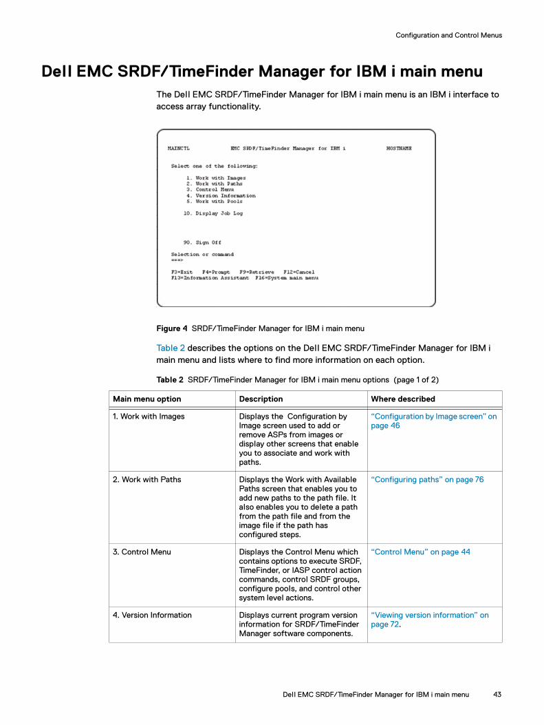
Configuration and Control Menus
Dell EMC SRDF/TimeFinder Manager for IBM i main menuThe Dell EMC SRDF/TimeFinder Manager for IBM i main menu is an IBM i interface to access array functionality.
Figure 4 SRDF/TimeFinder Manager for IBM i main menu
Table 2 describes the options on the Dell EMC SRDF/TimeFinder Manager for IBM i main menu and lists where to find more information on each option.
Table 2 SRDF/TimeFinder Manager for IBM i main menu options (page 1 of 2)
Main menu option Description Where described
1. Work with Images Displays the Configuration by Image screen used to add or remove ASPs from images or display other screens that enable you to associate and work with paths.
“Configuration by Image screen” on page 46
2. Work with Paths Displays the Work with Available Paths screen that enables you to add new paths to the path file. It also enables you to delete a path from the path file and from the image file if the path has configured steps.
“Configuring paths” on page 76
3. Control Menu Displays the Control Menu which contains options to execute SRDF, TimeFinder, or IASP control action commands, control SRDF groups, configure pools, and control other system level actions.
“Control Menu” on page 44
4. Version Information Displays current program version information for SRDF/TimeFinder Manager software components.
“Viewing version information” on page 72.
Dell EMC SRDF/TimeFinder Manager for IBM i main menu 43
Configuration and Control Menus
Control MenuUse the Control Menu to:
◆ Perform SRDF, TimeFinder, or IASP control actions against devices in a step.
◆ Independent ASP control
◆ Discover arrays and host configuration detail.
◆ Toggle the SRDF mode type.
◆ Bring an IBM i host to a restricted state.
◆ Start subsystems.
◆ Control Daemons.
◆ Control device pools whose devices are configured for SRDF/A DSE, SNAP, or Virtual Provisioning operations.
◆ List SRDF groups.
◆ Control Dynamic SRDF Groups.
◆ Set SRDF groups.
◆ Create/Delete RDF pairs.
To access the Control Menu, select option 3. Control Menu from the Dell EMC SRDF/TimeFinder Manager for IBM i main menu (Figure 4 on page 43).
5. Work with Pools Displays the List of the Pools screen where you can create or delete save or data pools, as well as work with thin devices (bind, rebind, or unbind thin devices to the data pool), compress or uncompress thin device data, and migrate thin devices (full or pool level). Also enables access to other screens that allow you to enable, disable, add, or remove save or data devices in the pool. For arrays running HYPERMAX OS 5977, only freeall and rename actions are supported.
“List of the Pools screen” on page 56.
10. Display Job Log Displays the current job log. This is an OS/400 function; it is not documented in this guide.
90. Sign Off Exits SRDF/TimeFinder Manager and signs off from the IBM i host.
Table 2 SRDF/TimeFinder Manager for IBM i main menu options (page 2 of 2)
44 Dell EMC SRDF/TimeFinder Manager for IBM i Version 9.0 and later Product Guide

Configuration and Control Menus
Figure 5 Control Menu
Table 3 provides a brief description of the Control Menu options and lists where each option is discussed in greater detail.
Table 3 Control Menu options (page 1 of 2)
Control Menu option Description Where discussed
1. SRDF or TimeFinder Control
Displays the Dell EMC SRDF or TimeFinder Control (CTLACT) screen for controlling devices in an image/path/step for SRDF and TimeFinder operations.
“Controlling SRDF” on page 159 “Controlling TimeFinder” on page 129“CTLACT” on page 194
2. Independent ASP Control
Displays the Dell EMC Independent ASP Control (IASPCTL) screen, for processing IASP control actions.
“SRDF/TimeFinder Manager Extended Features” on page 283
3. Run Discover Displays the Run Discover Process (DISCOVER) screen, which executes the DISCOVER command.
“Discovering array and host configuration details” on page 63 “DISCOVER” on page 212
4. Set SRDF Mode Displays the Set SRDF Mode (SETRDFMOD) screen for setting the SRDF mode (synchronous, asynchronous, or Adaptive Copy disk, Adaptive Copy write pending mode) to use for a selected image/path/step.
“SETRDFMOD” on page 231
5. Bring system to a restricted state
Puts an IBM i host in a restricted state and ends the subsystems, except the subsystem running the Solutions Enabler daemon jobs. The two daemon jobs STORAPID and STORGNSD must be running to execute the control commands.
“STMENDSBS” on page 232
6. Start subsystems Starts subsystems by executing the program defined in the SYSTEM value QSTRUPPGM.
“STMSTRSBS” on page 235
Control Menu 45
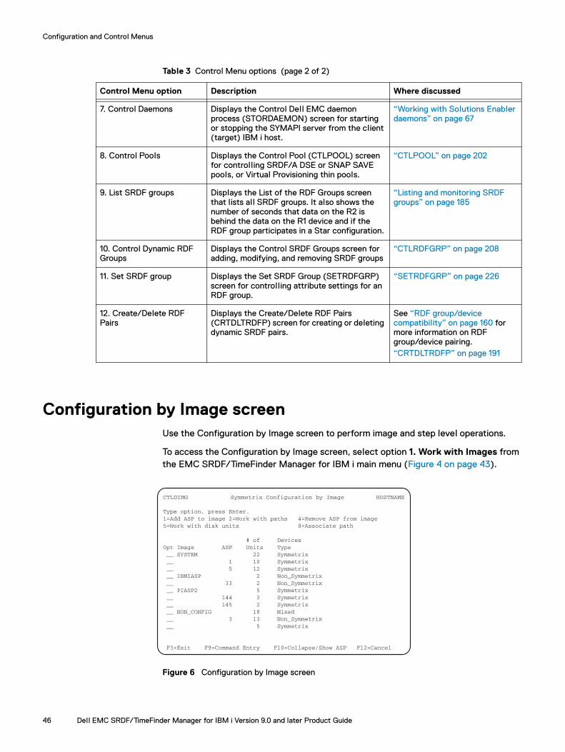
Configuration and Control Menus
Configuration by Image screenUse the Configuration by Image screen to perform image and step level operations.
To access the Configuration by Image screen, select option 1. Work with Images from the EMC SRDF/TimeFinder Manager for IBM i main menu (Figure 4 on page 43).
Figure 6 Configuration by Image screen
7. Control Daemons Displays the Control Dell EMC daemon process (STORDAEMON) screen for starting or stopping the SYMAPI server from the client (target) IBM i host.
“Working with Solutions Enabler daemons” on page 67
8. Control Pools Displays the Control Pool (CTLPOOL) screen for controlling SRDF/A DSE or SNAP SAVE pools, or Virtual Provisioning thin pools.
“CTLPOOL” on page 202
9. List SRDF groups Displays the List of the RDF Groups screen that lists all SRDF groups. It also shows the number of seconds that data on the R2 is behind the data on the R1 device and if the RDF group participates in a Star configuration.
“Listing and monitoring SRDF groups” on page 185
10. Control Dynamic RDF Groups
Displays the Control SRDF Groups screen for adding, modifying, and removing SRDF groups
“CTLRDFGRP” on page 208
11. Set SRDF group Displays the Set SRDF Group (SETRDFGRP) screen for controlling attribute settings for an RDF group.
“SETRDFGRP” on page 226
12. Create/Delete RDF Pairs
Displays the Create/Delete RDF Pairs (CRTDLTRDFP) screen for creating or deleting dynamic SRDF pairs.
See “RDF group/device compatibility” on page 160 for more information on RDF group/device pairing.“CRTDLTRDFP” on page 191
Table 3 Control Menu options (page 2 of 2)
Control Menu option Description Where discussed
CTLDIMG Symmetrix Configuration by Image HOSTNAME
Type option, press Enter. 1=Add ASP to image 2=Work with paths 4=Remove ASP from image 5=Work with disk units 8=Associate path # of Devices Opt Image ASP Units Type __ SYSTEM 22 Symmetrix __ 1 10 Symmetrix __ 5 12 Symmetrix __ IBMIASP 2 Non_Symmetrix __ 33 2 Non_Symmetrix __ PIASP2 5 Symmetrix __ 144 3 Symmetrix __ 145 2 Symmetrix __ NON_CONFIG 18 Mixed __ 3 13 Non_Symmetrix __ 5 Symmetrix
F3=Exit F9=Command Entry F10=Collapse/Show ASP F12=Cancel
46 Dell EMC SRDF/TimeFinder Manager for IBM i Version 9.0 and later Product Guide

Configuration and Control Menus
Press F10=Collapse/Show ASP, to display the information at the image level (Figure 7).
Figure 7 Configuration by Image screen — collapsed
Press F10 again to display information at the ASP level (Figure 6).
Table 4 describes the fields on the Configuration by Image screen.
Work with Associated Paths screenUse the Work with Associated Paths screen to perform operations on paths.
To access Work with Associated Paths screen, select option 2. Work with Paths from the Configuration by Image screen (Figure 6 on page 46).
CTLDIMG Symmetrix Configuration by Image HOSTNAME
Type option, press Enter. 1=Add ASP to image 2=Work with paths 4=Remove ASP from image 5=Work with disk units 8=Associate path # of Devices Opt Image ASP Units Type __ SYSTEM 22 Symmetrix __ IBMIASP 2 Non_Symmetrix __ PIASP2 5 Symmetrix __ NON_CONFIG 18 Mixed F3=Exit F9=Command Entry F10=Collapse/Show ASP F12=Cancel
Table 4 Fields for the Configuration by Image screen
Field Description
Opt Entry field for configuration action options.
Image SYSTEM — Displays the system ASP (ASP 1) and all basic user ASPs (2-32) configured on the system. NAME — Displays the name of the IASP image, when IASP images (ASPs 33-255) are present in the configuration. NON_CONFIG — Displays non-configured units (devices) and any user ASPs not part of the SYSTEM image.
ASP ASP number.
# of Units Total number of devices in the ASP or image, depending upon which screen appears.
Devices Type Displays the device types in the configuration: Symmetrix — Contains only Symmetrix devices. Non_Symmetrix — Contains only non-Symmetrix devices. Mixed — Contains both Symmetrix and non-Symmetrix devices.
Work with Associated Paths screen 47
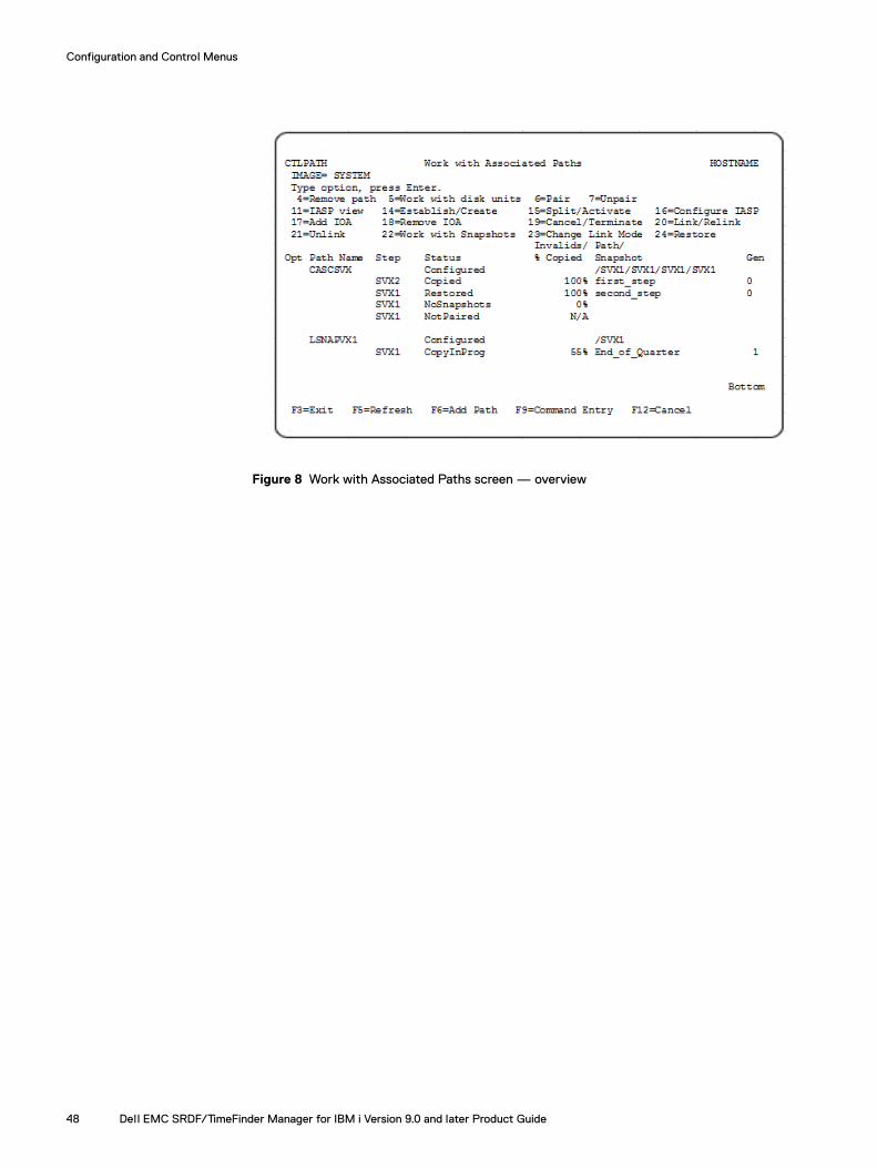
Configuration and Control Menus
Figure 8 Work with Associated Paths screen — overview
48 Dell EMC SRDF/TimeFinder Manager for IBM i Version 9.0 and later Product Guide

Configuration and Control Menus
Table 5 describes the fields on the Work with Associated Paths screen.
Table 5 Fields for the Work with Associated Paths screen
Field Description
Opt The entry field for configuration action options.
Path Name The name of the path used to move data on devices of the source image to devices of the target image.
Step The description of how data is copied from source devices to target devices.
Statusa Identifies the status of the selected path.
Invalids/%Copied The number of invalid tracks remaining during SRDF or TimeFinder synchronization operations, or percent of copy completion for TimeFinder/Clone or TimeFinder/Snap operations.
Path/Snapshot Description of steps in the path associated with the selected image. Snapshot name is displayed if target devices for the SVXn are linked to the snapshot, or source devices restored from the snapshot and target devices are not linked.
Gen For SVXn step, if target devices are linked to the snapshot or source devices restored from the snapshot and target devices are not linked then the generation number is displayed.
a. Possible step status for SnapVX :
- NotConfigured – step is not paired and no snapshots for source devices in the step exist.
- NotPaired – step is not paired and at least one snapshot for source devices in the step exists.
- Established – devices are paired, snapshots exist but are not linked. Step has snapshots, is paired, but not linked.
- NoSnapshots – step is paired and no snapshots for source devices in the step exist.
- If the step is paired, at least one snapshot for source devices in the step exists but target devices are not linked, the status of the first Snapshot would be presented. If snapshot has restores, the status would be Restored or RestoreInProg.
- RestNotPaired – step is not paired and source devices are restored.
- Status of the link – If target devices are linked.
Work with Associated Paths screen 49
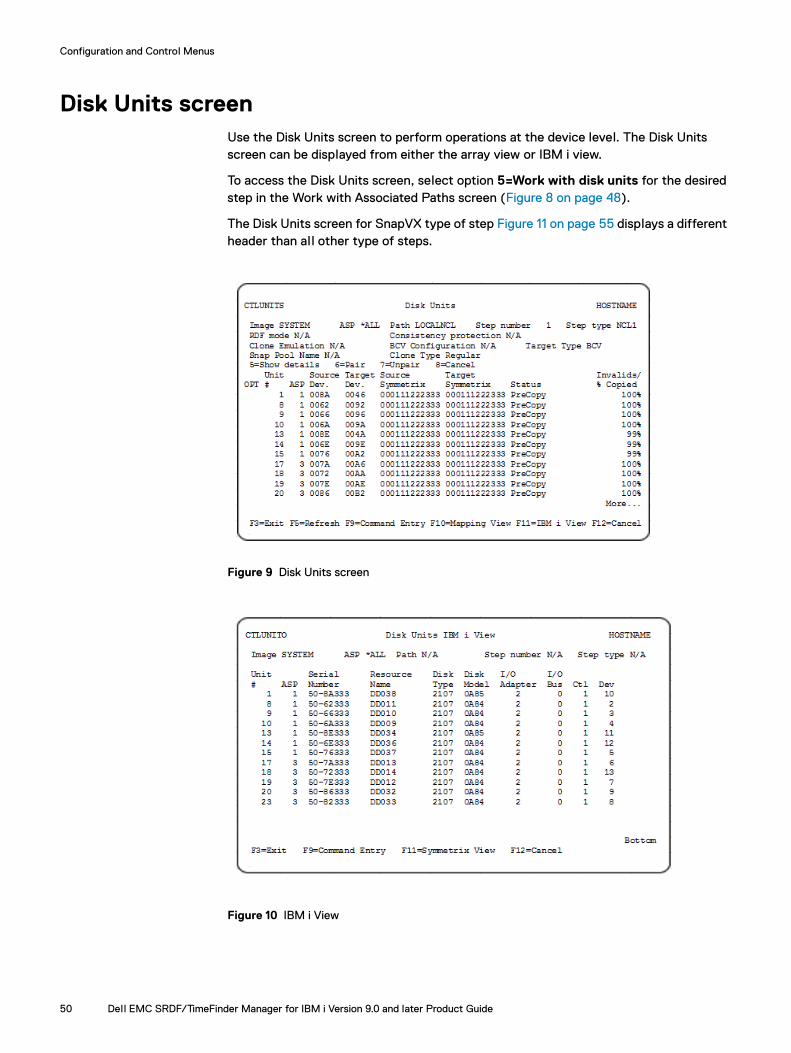
Configuration and Control Menus
Disk Units screenUse the Disk Units screen to perform operations at the device level. The Disk Units screen can be displayed from either the array view or IBM i view.
To access the Disk Units screen, select option 5=Work with disk units for the desired step in the Work with Associated Paths screen (Figure 8 on page 48).
The Disk Units screen for SnapVX type of step Figure 11 on page 55 displays a different header than all other type of steps.
Figure 9 Disk Units screen
Figure 10 IBM i View
50 Dell EMC SRDF/TimeFinder Manager for IBM i Version 9.0 and later Product Guide
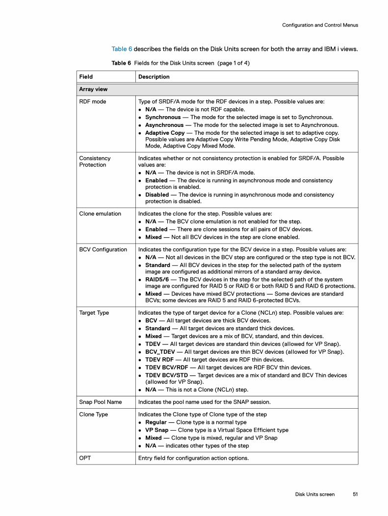
Configuration and Control Menus
Table 6 describes the fields on the Disk Units screen for both the array and IBM i views.
Table 6 Fields for the Disk Units screen (page 1 of 4)
Field Description
Array view
RDF mode Type of SRDF/A mode for the RDF devices in a step. Possible values are: N/A — The device is not RDF capable. Synchronous — The mode for the selected image is set to Synchronous. Asynchronous — The mode for the selected image is set to Asynchronous. Adaptive Copy — The mode for the selected image is set to adaptive copy.
Possible values are Adaptive Copy Write Pending Mode, Adaptive Copy Disk Mode, Adaptive Copy Mixed Mode.
Consistency Protection
Indicates whether or not consistency protection is enabled for SRDF/A. Possible values are: N/A — The device is not in SRDF/A mode. Enabled — The device is running in asynchronous mode and consistency
protection is enabled. Disabled — The device is running in asynchronous mode and consistency
protection is disabled.
Clone emulation Indicates the clone for the step. Possible values are: N/A — The BCV clone emulation is not enabled for the step. Enabled — There are clone sessions for all pairs of BCV devices. Mixed — Not all BCV devices in the step are clone enabled.
BCV Configuration Indicates the configuration type for the BCV device in a step. Possible values are: N/A — Not all devices in the BCV step are configured or the step type is not BCV. Standard — All BCV devices in the step for the selected path of the system
image are configured as additional mirrors of a standard array device. RAID5/6 — The BCV devices in the step for the selected path of the system
image are configured for RAID 5 or RAID 6 or both RAID 5 and RAID 6 protections. Mixed — Devices have mixed BCV protections — Some devices are standard
BCVs; some devices are RAID 5 and RAID 6-protected BCVs.
Target Type Indicates the type of target device for a Clone (NCLn) step. Possible values are: BCV — All target devices are thick BCV devices. Standard — All target devices are standard thick devices. Mixed — Target devices are a mix of BCV, standard, and thin devices. TDEV — All target devices are standard thin devices (allowed for VP Snap). BCV_TDEV — All target devices are thin BCV devices (allowed for VP Snap). TDEV RDF — All target devices are RDF thin devices. TDEV BCV/RDF — All target devices are RDF BCV thin devices. TDEV BCV/STD — Target devices are a mix of standard and BCV Thin devices
(allowed for VP Snap). N/A — This is not a Clone (NCLn) step.
Snap Pool Name Indicates the pool name used for the SNAP session.
Clone Type Indicates the Clone type of Clone type of the step Regular — Clone type is a normal type VP Snap — Clone type is a Virtual Space Efficient type Mixed — Clone type is mixed, regular and VP Snap N/A — indicates other types of the step
OPT Entry field for configuration action options.
Disk Units screen 51

Configuration and Control Menus
Unit # Number assigned by the system to identify a specific disk.0 — Non-configured devices.
ASP ASP number in the current configuration.0 — Non configured devices.
Source Device Array device name of the source device.
Target Device Array device name of the target device.
Source Symmetrix Array serial number for the source device.
Target Symmetrix Array serial number for the target devices (only if present). If BCV, Clone, or Snap devices are present, the serial number is the same as the source array.
Status of the RDF pair
Status for the selected SRDF pair (if relevant). Possible values are: N/A — Device is not SRDF capable. Consistent — The R2 mirrors of SRDF/A devices are in a Consistent state, which
signifies the normal state of operation for device pairs operating in asynchronous mode.
Failed Over — R1 is Not Ready or Write Disabled, and the operation is failed over to the R2 device.
Invalid — The default state when another RDF state applies, such as when the combination of R1, R2, and RDF link states and statuses do not match any other pair state. An Invalid status can occur if there is a problem at the disk director level.
Partitioned — The SYMAPI is currently unable to communicate through the corresponding RDF path to the remote array. A Partitioned status may apply to devices within an RA group.
R1 UpdInProg — The R1 is currently Not Ready or Write Disabled to the host. There are invalid local (R1) tracks on the source side and the link is Ready or Write Disabled.
R1 Updated — The R1 is currently Not Ready or Write Disabled to the host. There are no local invalid tracks on the R1 side and the link is Ready or Write Disabled.
Synchronized — The R1 and R2 are currently in a synchronized state and have identical data.
SyncInProg — Synchronization is currently in progress between the R1 and the R2. There are existing invalid tracks between the two pairs and the logical link between both sides of an RDF pair is up. During an Establish operation, data is copied from the standard device to the RDF device until both devices contain identical data.
Split — SRDF links were established and are currently split. The R1 and the R2 are currently Ready to their hosts, but the link is Not Ready or Write Disabled.
Suspended — The RDF links have been suspended and are Not Ready or Write Disabled. If the R1 is Ready while the links are suspended, any I/O wil l accumulate as invalid tracks owed to the R2 device.
TransIdle — The RDF group is operating in SRDF/A Transmit Idle mode. The SRDF/A session cannot push data in the transmit cycle across the link because the link is down.
Table 6 Fields for the Disk Units screen (page 2 of 4)
Field Description
52 Dell EMC SRDF/TimeFinder Manager for IBM i Version 9.0 and later Product Guide
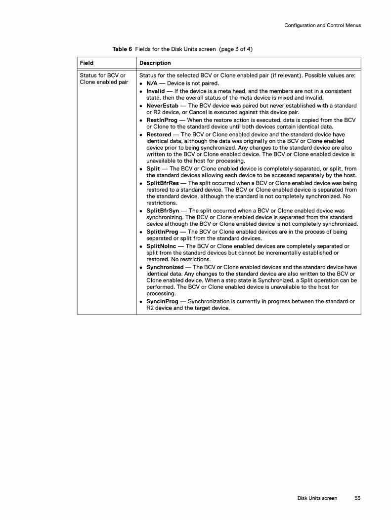
Configuration and Control Menus
Status for BCV or Clone enabled pair
Status for the selected BCV or Clone enabled pair (if relevant). Possible values are: N/A — Device is not paired. Invalid — If the device is a meta head, and the members are not in a consistent
state, then the overall status of the meta device is mixed and invalid. NeverEstab — The BCV device was paired but never established with a standard
or R2 device, or Cancel is executed against this device pair. RestInProg — When the restore action is executed, data is copied from the BCV
or Clone to the standard device until both devices contain identical data. Restored — The BCV or Clone enabled device and the standard device have
identical data, although the data was originally on the BCV or Clone enabled device prior to being synchronized. Any changes to the standard device are also written to the BCV or Clone enabled device. The BCV or Clone enabled device is unavailable to the host for processing.
Split — The BCV or Clone enabled device is completely separated, or split, from the standard devices allowing each device to be accessed separately by the host.
SplitBfrRes — The split occurred when a BCV or Clone enabled device was being restored to a standard device. The BCV or Clone enabled device is separated from the standard device, although the standard is not completely synchronized. No restrictions.
SplitBfrSyn — The split occurred when a BCV or Clone enabled device was synchronizing. The BCV or Clone enabled device is separated from the standard device although the BCV or Clone enabled device is not completely synchronized.
SplitInProg — The BCV or Clone enabled devices are in the process of being separated or split from the standard devices.
SplitNoInc — The BCV or Clone enabled devices are completely separated or split from the standard devices but cannot be incrementally established or restored. No restrictions.
Synchronized — The BCV or Clone enabled devices and the standard device have identical data. Any changes to the standard device are also written to the BCV or Clone enabled device. When a step state is Synchronized, a Split operation can be performed. The BCV or Clone enabled device is unavailable to the host for processing.
SyncInProg — Synchronization is currently in progress between the standard or R2 device and the target device.
Table 6 Fields for the Disk Units screen (page 3 of 4)
Field Description
Disk Units screen 53
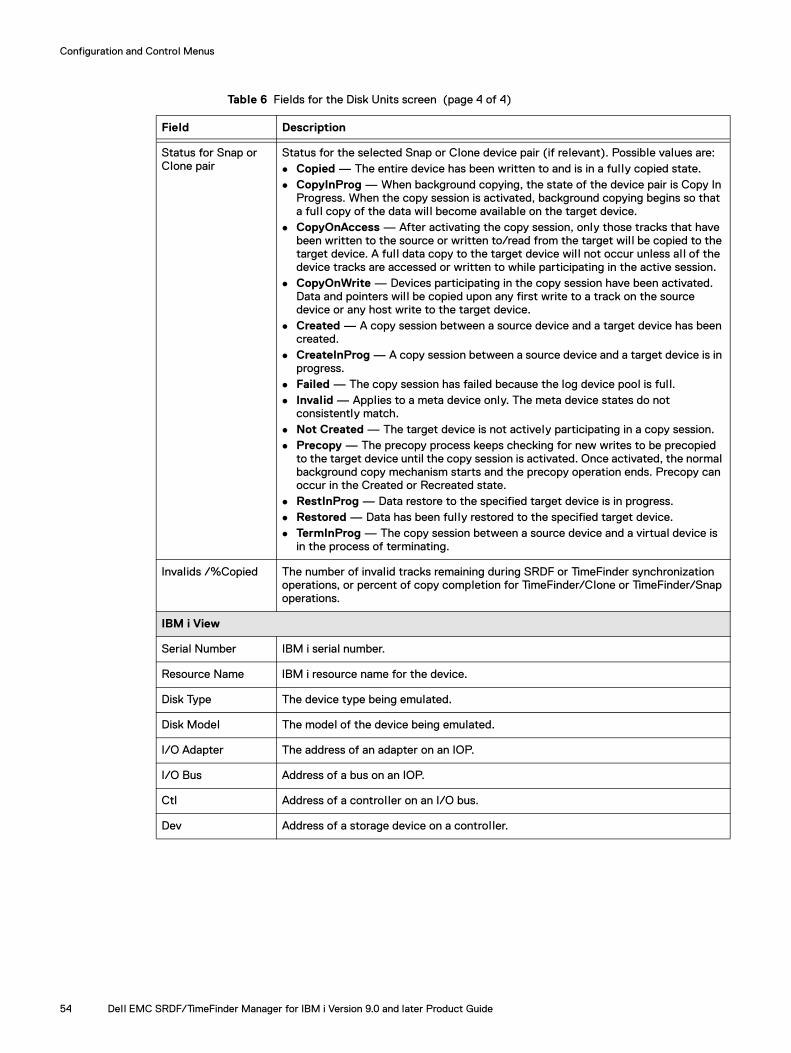
Configuration and Control Menus
Status for Snap or Clone pair
Status for the selected Snap or Clone device pair (if relevant). Possible values are: Copied — The entire device has been written to and is in a fully copied state. CopyInProg — When background copying, the state of the device pair is Copy In
Progress. When the copy session is activated, background copying begins so that a full copy of the data wil l become available on the target device.
CopyOnAccess — After activating the copy session, only those tracks that have been written to the source or written to/read from the target wil l be copied to the target device. A full data copy to the target device wil l not occur unless all of the device tracks are accessed or written to while participating in the active session.
CopyOnWrite — Devices participating in the copy session have been activated. Data and pointers wil l be copied upon any first write to a track on the source device or any host write to the target device.
Created — A copy session between a source device and a target device has been created.
CreateInProg — A copy session between a source device and a target device is in progress.
Failed — The copy session has failed because the log device pool is full. Invalid — Applies to a meta device only. The meta device states do not
consistently match. Not Created — The target device is not actively participating in a copy session. Precopy — The precopy process keeps checking for new writes to be precopied
to the target device until the copy session is activated. Once activated, the normal background copy mechanism starts and the precopy operation ends. Precopy can occur in the Created or Recreated state.
RestInProg — Data restore to the specified target device is in progress. Restored — Data has been fully restored to the specified target device. TermInProg — The copy session between a source device and a virtual device is
in the process of terminating.
Invalids /%Copied The number of invalid tracks remaining during SRDF or TimeFinder synchronization operations, or percent of copy completion for TimeFinder/Clone or TimeFinder/Snap operations.
IBM i View
Serial Number IBM i serial number.
Resource Name IBM i resource name for the device.
Disk Type The device type being emulated.
Disk Model The model of the device being emulated.
I/O Adapter The address of an adapter on an IOP.
I/O Bus Address of a bus on an IOP.
Ctl Address of a controller on an I/O bus.
Dev Address of a storage device on a controller.
Table 6 Fields for the Disk Units screen (page 4 of 4)
Field Description
54 Dell EMC SRDF/TimeFinder Manager for IBM i Version 9.0 and later Product Guide

Configuration and Control Menus
Figure 11 Disk Units screen — SVX type of step
Table 7 describes the fields on the Disk Units screen for SVX type of step.
Table 7 Fields for the Disk Units screen for SVX type of step (page 1 of 2)
Field Description
Array view
Snapshot Name Name of the SnapVX snapshot.
Generation Identifies the point-in-time copy when multiple snapshots are made for the same name on the same devices.
OPT Entry field for configuration action options.
Unit # Number assigned by the system to identify a specific disk.0 — Non-configured devices.
ASP ASP number in the current configuration.0 — Non configured devices.
Source Device Array device name of the source device.
Target Device Array device name of the target device.
Source Symmetrix Array serial number for the source device.
Disk Units screen 55

Configuration and Control Menus
List of Pools screenUse the List of Pools screen to work with pools.
To access the List of Pools, select option 5. Work with Pools from the EMC SRDF/TimeFinder Manager for IBM i main menu (Figure 4 on page 43).
Figure 12 List of the Pools screen
Target Symmetrix Array serial number for the target devices (only if present). If target devices are present, the serial number is the same as the source array.
Status for SnapVX pair
Status for the SnapVX pair. Possible values are: N/A — Source device is not paired and not restored.
Linked — Target device is linked to snapshot in NoCopy mode.
Copied — Target device is linked to snapshot in Copy mode when it is 100% copied.
CopyInProg — Target device is linked to snapshot in Copy mode and it is in transient state to Copied.
RestoreInProg — Restore from snapshot to source device is in progress and source device is not paired.
Restored — Source device is restored from the snapshot and source device is not paired.
NotLinked — Target device is not linked to the snapshot.
Failed — Link failed if no more allocations can be made from the SRP associated with the link device or if a corruption occurs on the link device.
Invalids/%Copied Percent of the total device size that has been copied to the target when the COPY flag is set, or when the source device is restored from the snapshot.
Table 7 Fields for the Disk Units screen for SVX type of step (page 2 of 2)
Field Description
56 Dell EMC SRDF/TimeFinder Manager for IBM i Version 9.0 and later Product Guide

Configuration and Control Menus
Table 8 describes the fields on the List of the Pools screen.
Running remote commandsFor SRDF/TimeFinder Manager versions earlier than 8.0, preparing to run SRDF/TimeFinder Manager commands from a remote IBM system requires several configuration steps, including starting the REXEC server on both the local and remote system. In order to simplify using this feature, SRDF/TimeFinder Manager 8.0 and later uses the STMRMTCMD command and executes remote commands through the STM server.
See “STMRMTCMD” on page 234 for more information on how to run the remote feature for STM commands.
Table 8 Fields for the List of the Pools screen
Field Description
Opt The entry field for configuration action options.
Symmetrix Array serial number
Pool Name Name of the pool.
Emulation Type Emulation type of the pool devices.
Pool Type The type of device pools. Possible values are SNAP, DSE, or DATA
# of Devices Number of devices in the pool.
State Status of the devices in pool. Possible values are Enabled, Disabled, Balancing, or N/A
Compr Compression status of the thin pool. Possible values Enabled, Disabled, Enabling, Disabling, or N/A. Field is only relevant for thin pools. For all other pools state is N/A.
Running remote commands 57

Configuration and Control Menus
58 Dell EMC SRDF/TimeFinder Manager for IBM i Version 9.0 and later Product Guide
CHAPTER 3Operational Features, Settings, and Displays
Invisible Body T
This chapter shows how to set up, maintain, and display the SRDF/TimeFinder Manager environment.
◆ Setting user-configurable preferences................................................................. 60◆ Discovering array and host configuration details .................................................. 63◆ Configuring IFS files to support Solutions Enabler .............................................. 65◆ Working with Solutions Enabler daemons ............................................................ 67◆ Working with the SYMAPI server ......................................................................... 69◆ Viewing version information ................................................................................. 72
Operational Features, Settings, and Displays 59
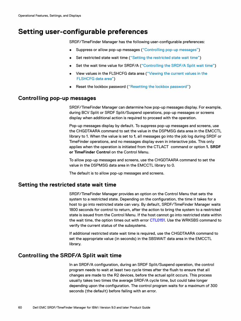
Operational Features, Settings, and Displays
Setting user-configurable preferencesSRDF/TimeFinder Manager has the following user-configurable preferences:
◆ Suppress or al low pop-up messages (“Controlling pop-up messages”)
◆ Set restricted state wait time (“Setting the restricted state wait time”)
◆ Set the wait time value for SRDF/A (“Controlling the SRDF/A Split wait time”)
◆ View values in the FLSHCFG data area (“Viewing the current values in the FLSHCFG data area”)
◆ Reset the lockbox password (“Resetting the lockbox password”)
Controlling pop-up messages
SRDF/TimeFinder Manager can determine how pop-up messages display. For example, during BCV Split or SRDF Split/Suspend operations, pop-up messages or screens display when additional action is required to proceed with the operation.
Pop-up messages display by default. To suppress pop-up messages and screens, use the CHGDTAARA command to set the value in the DSPMSG data area in the EMCCTL library to 1. When the value is set to 1, al l messages go into the job log during SRDF or TimeFinder operations, and no messages display even in interactive jobs. This only applies when the operation is initiated from the CTLACT command or option 1. SRDF or TimeFinder Control on the Control Menu.
To allow pop-up messages and screens, use the CHGDTAARA command to set the value in the DSPMSG data area in the EMCCTL library to 0.
The default is to allow pop-up messages and screens.
Setting the restricted state wait time
SRDF/TimeFinder Manager provides an option on the Control Menu that sets the system to a restricted state. Depending on the configuration, the time it takes for a host to go into restricted state can vary. By default, SRDF/TimeFinder Manager waits 1800 seconds for control to return, after the action to bring the system to a restricted state is issued from the Control Menu. If the host cannot go into restricted state within the wait time, the option times out with error CTL0151. Use the WRKSBS command to verify the current status of the subsystems.
If additional restricted state wait time is required, use the CHGDTAARA command to set the appropriate value (in seconds) in the SBSWAIT data area in the EMCCTL library.
Controlling the SRDF/A Split wait time
In an SRDF/A configuration, during an SRDF Split/Suspend operation, the control program needs to wait at least two cycle times after the flush to ensure that all changes are made to the R2 devices, before the actual split occurs. This process usually takes two times the average SRDF/A cycle time, but could take longer depending upon the configuration. The control program waits for a maximum of 300 seconds (the default) before failing with an error.
60 Dell EMC SRDF/TimeFinder Manager for IBM i Version 9.0 and later Product Guide
Operational Features, Settings, and Displays
SRDF/TimeFinder Manager can control the wait time for a Split/Suspend operation before failing with an error.
To control the Split wait time, set a value in the SRDFATIME data area using the CHGDTAARA command.
Viewing the current values in the FLSHCFG data area
A preference can be set to view the current values in the FLSHCFG data area.
To view the current values in the FLSHCFG data area, use the following command. If necessary, change EMCCTL to the library containing the data area.
DSPDTAARA EMCCTL/FLSHCFG
The Display Data Area screen (Figure 13) appears:
Figure 13 Display Data Area screen with FLSHCFG data area with default values
You can modify three fields:
◆ Suspend timeout (seconds) — If the database Suspend operation does not complete within this time, the action defined in the following field occurs. The default value is 000060.
◆ Timeout action End/Continue (E/C)
E — When a suspend timeout occurs, an escape message is written in the joblog, the Suspend operation is terminated, and the SRDF/TimeFinder Manager Split operation is terminated.
C — When a suspend timeout occurs, a diagnostic message is written in the joblog, the Suspend operation continues, and the SRDF/TimeFinder Manager operation continues.
The default value is E.
Setting user-configurable preferences 61

Operational Features, Settings, and Displays
Note: If the Suspend operation fails, an escape message is written in the joblog. If operation is successful, a completion message is written to the joblog. When C is specified in the data area check the Additional Message Information.
◆ Option SUSPEND/FRCWRT (S/F)
When performing a SPLITWA action in the CTLACTTGT command, the value of this field determines which mode the CTLACTTGT uses to run the CHGASPACT command:
S — CHGASPACT runs in *SUSPEND mode.
F — CHGASPACT runs in *FRCWRT mode.
The default value is S.
To change values in this data area, use the CHGDTAARA command. For example:
To change the Suspend timeout (seconds):
CHGDTAARA DTAARA(EMCCTL/FLSHCFG (40 6)) VALUE('nnnnnn')
To change Timeout Action End/Continue (E/C):
CHGDTAARA DTAARA(EMCCTL/FLSHCFG (90 1)) VALUE('E')
Resetting the lockbox password
The lockbox password for array accessibility is set to the default (hostname@SELockbox1) when the CRTSYMAPI and CRTSYMAPIC commands are run during SRDF/TimeFinder Manager installation. The password can be changed by running the following SYMCLI command:
symcfg –lockbox [–password <Password>] reset –ssv setpw [–new_password <NewPassword>]
62 Dell EMC SRDF/TimeFinder Manager for IBM i Version 9.0 and later Product Guide
Operational Features, Settings, and Displays
Discovering array and host configuration detailsThe Discover function is used to perform the discovery process after changes to the host configuration or array configuration. However, by default, the SRDF/TimeFinder Manager Discover function is turned off and it does not automatically run the discovery process while viewing configuration details, performing control operations, or making configuration changes.
The discovery process is activated one of two ways:
◆ Changing the discover data area value in the EMCCTL library — default is set to discovery process off.
◆ Running the DISCOVER command.
Note: The discovery process run from the DISCOVER command is independent of the setting in the EMCCTL library.
Turning on the discovery process from the EMCCTL library
To turn on the discovery process, use the CHGDTAARA command to set the Discover data area in the EMCCTL library to 1. The Discover function remains on and the discovery process runs until the value is set to 0.
Running the DISCOVER command
The DISCOVER command performs a one-time discovery process, and does not enable automatic discovery. For subsequent configuration changes, unless the Discover data area value is set to 1, the command must be run again to update configuration files.
Run the discovery process as follows:
1. Select option 3. Control Menu from the Dell EMC SRDF/TimeFinder Manager for IBM i main menu (Figure 4 on page 43).
2. Select option 3. Run Discover from the Control Menu to display the Run Discover Process (DISCOVER) screen (Figure 14 on page 64).
Discovering array and host configuration details 63

Operational Features, Settings, and Displays
Figure 14 Run Discover Process (DISCOVER) screen
3. Enter the following required parameters:
a. Remove Symmetrix information:
– *NO — Do not remove old array data from the SYMAPI database. *NO is the default.
– *YES — Remove previously discovered array information that is no longer valid from the SYMAPI database.
When the RDF link is down, do not run DISCOVER with Remove Symmetrix information set to *YES. Doing so can remove relevant R2 information, such as BCV or Clone pairing for the array from the SYMAPI database.
b. Check IMAGE file:
– *NO — Do not verify information stored in the IMAGE file with current device information of the host. *NO is the default.
– *YES — Verify information stored in the IMAGE file with the current device information of the host and remove any old device information from the file.
4. Press Enter to start the discovery process.
Turning off the discovery process
To turn off the discovery process, use the CHGDTAARA command to set the Discover data area in the EMCCTL library to 0.
64 Dell EMC SRDF/TimeFinder Manager for IBM i Version 9.0 and later Product Guide
Operational Features, Settings, and Displays
Configuring IFS files to support Solutions EnablerIn order to support Solutions Enabler operations, the required files are installed to the IBM i Integrated File System (IFS) during SRDF/TimeFinder Manager installation. These files are installed in the following IFS directories:
◆ /var/symapi/config – Holds the Solutions Enabler configuration files, and an alias file that can be used to run CLIs in a QShell environment.
◆ /usr/storapi/man/man1 – Holds the help files for the CLIs.
◆ /usr/storapi/locales/en – Holds the error.properties file that enables error reporting in different languages.
The installation of these Solutions Enabler files is performed by the CRTSYMAPI or CRTSYMAPIC program. When either of these programs are run, these files are restored from a save file in the EMCCTL or EMCCTLC library. The save files are called SYMAPICNFG, STORAPILOC and STORAPIMAN.
Modifying the Solutions Enabler configuration files
Once installed the SYMAPICNFG files require some modification for Solutions Enabler to function properly.
Modifying the readme configuration filesThe following “README” files are templates can be renamed or copied to a file that does not include “README” in the file name. For example README.daemon_options file can be renamed to daemon_options.
◆ /var/symapi/config/README.daemon_options — The daemon_options file contains parameters that control the behavior of the various Solutions Enabler daemons. Each daemon reads this file at startup and applies any settings that apply. The daemon_options file is created by the CRTSYMAPI or CRTSYMAPIC program. For SRDF/TimeFinder Manager, the daemon options that control which subsystem the daemon is started in is set to the EMCCTL subsystem as a default. See “Working with Solutions Enabler daemons” on page 67 more for information. The parameters in this file can be modified by the user.
◆ /var/symapi/config/README.daemon_users — The daemon_users file lists the local users that are authorized to control and, in some cases, make use of the various Solution Enabler daemons. The parameters in this file can be modified by the user.
◆ /var/symapi/config/README.options — This options file contains behavior parameters that can be set to critically change the default behavior of SYMCLI operations, SYMAPI calls, and their control actions. It can be used to set certain global restrictions as well as customize and streamline command line coding to the user-specific environment. The options file is being set by the CRTSYMAPI file.
Note: Altering these files is not a prerequisite for normal use, and changing parameters in these files should only be attempted by experienced SYMCLI or SYMAPI users. Changes to these files may cause unwanted feature restrictions, or may cause the array environment to stop functioning.
Configuring IFS files to support Solutions Enabler 65

Operational Features, Settings, and Displays
◆ /var/symapi/config/README.netcnfg — This network service file maps a service name to a remote server host node name and/or internet address, and to a port number, to provide a TCP/IP connection for executing remote SYMAPI functions. The NETCNFG file is created by the CRTNETCNFG command. This file can be modified to list more than one service by defining one unique system per line.
Modifying the QShell configuration filesThe following files require modification to allow aliases to function in QShell:
◆ /var/symapi/config/alias/profile — This file is a template used to modify the /etc/profile file.
Copy the line from the /var/symapi/config/alias/profile file and paste it into the /etc/profile file. If /etc/profile does not exist then copy the profile file from the /.../alias directory to /etc directory.
To set this feature at the user level:
1. Copy the profile file from the /etc directory to the /home/<user directory>.
2. Change the profile file name in the user directory to .profile. (add period in front of “profile”).
◆ /var/symapi/config/alias/qshrc — This file holds setup information that is used by QShell. When running QShell, the /etc/profile file points to qshrc file to set the environmental values defined by this file.
1. Verify that the qshrc file points to the default library EMCCTL or EMCCTLC, by checking that the following two lines are set as shown below:
– export PATH=$PATH:/QSYS.LIB/EMCCTL.LIB
– liblist -af EMCCTL
2. If the lines in the qshrc file, shown above, do not point to the EMCCTL or EMCCTLC library, modify the lines accordingly.
66 Dell EMC SRDF/TimeFinder Manager for IBM i Version 9.0 and later Product Guide
Operational Features, Settings, and Displays
Working with Solutions Enabler daemonsThe STORDAEMON command allows for SRDF/TimeFinder Manager to start, stop, and query the Solutions Enabler daemons. Refer to “STORDAEMON” on page 236 for details on using this command.
The daemons that are managed are:
◆ Storapid (Base) — Provides centralized gatekeeper device management for al l Solutions Enabler applications. It al leviates contention when there are limited gatekeeper resources available and also eliminates the need for every client to constantly select, open, lock, and ping for an available gatekeeper device for every online function.
Additionally, the base daemon monitors Symmetrix External Locks (SEL) and Device External Locks (DEL), and releases any lock(s) held by a crashed application. The base daemon also eliminates the need for Solutions Enabler applications to run as root.
◆ Storsrvd (Symapi) — Provides the SYMAPI server, a multi-threaded program that listens for SYMAPI sessions and management requests initiated by the STORDAEMON command. The server also listens for management requests from the system operator console.
◆ Storgnsd (GNS) — Provides a global, distributed repository for DG and CG group definitions. Changes made to a group from one host are automatically visible to other hosts where the GNS daemon is running.
Configuring daemons using the daemons options file
There is a daemon options file used to control daemon behavior. At startup each daemon reads this file and applies all relevant settings. In most cases the default settings are sufficient. However, there are four options available that are specific to IBM i. The file is located in the IFS directory /var/symapi/config and must be named daemon_options.
The options specific to IBM i are:
◆ ibmi_jobq_name = <*JOBD> | jobq name — An example jobq name is EMCCTL. If the jobq name is not set, the default *JOBD is used. When *JOBD is used the job description defined in the current user profile is used to determine the job queue name. The second option does not need to be set if the library of named job description is in the library list. If the second option is specified and the first option is set to *JOBD, the second value is ignored.
◆ ibmi_jobq_lib_name = <*LIBL> | Library name — An example library name is EMCCTL. If the Library name is not set, the default value *LIBL is used.
Note: For both of these options the name has a maximum character length of 10, and upper and lower case characters are allowed. If an option is longer than 10 characters an error message appears.
Working with Solutions Enabler daemons 67

Operational Features, Settings, and Displays
◆ ibmi_allow_subsystem_start = <yes>|<no> — The default value is yes. If the daemon jobs are not started yet, this value is used to control automatic startup of the subsystem that is being used for the Solutions Enabler daemons. If the subsystem cannot be started, the daemon jobs do not start and an error message is generated.
Both Base and GNS daemon jobs are started when an SRDF/TimeFinder Manager or Solutions Enabler command is run on the host. By default SRDF/TimeFinder Manager uses the EMCCTL subsystem to run the daemon jobs. The subsystem defined (ibmi_jobq_name) in the daemon options file must be started manually if the daemon_option, ibmi_allow_subsystem_start,is set to no. If the daemon option, ibmi_allow_subsystem_start, is set to yes the subsystem and daemon jobs start automatically.
If you want the daemon jobs run in the QBATCH subsystem, in the daemon options file set the option as follows:
ibmi_jobq_name = qbatch
ibmi_jobq_lib_name = *libl
Note: Make sure that the subsystem and job queue entry is set to allow multiple jobs and multiple threads.
◆ redirect_std_fds = enable | disable – For IBM i, the default value for this option is enable. This option ensures that the standard output for the running daemon is not directed to the default spool file. This option does not need to be set in the daemon_options file if default is being used.
When this option is set to disable, a spool file is created and all the output for the running daemon job is directed to a spool file. The spool file can become large when running for an extended period of time. Eventually the file reaches its maximum allowable size and an informational message is generated. When the message appears, the daemon job halts and all SRDF/TimeFinder Manager operations are impacted until the user replies to the message.
Note: The daemon may stop running if this message is not replied to for a long period of time. If this happens, restart the deamon.
For more information on configuring Solutions Enabler daemons refer to the Dell EMC Solutions Enabler Installation and Configuration Guide.
68 Dell EMC SRDF/TimeFinder Manager for IBM i Version 9.0 and later Product Guide
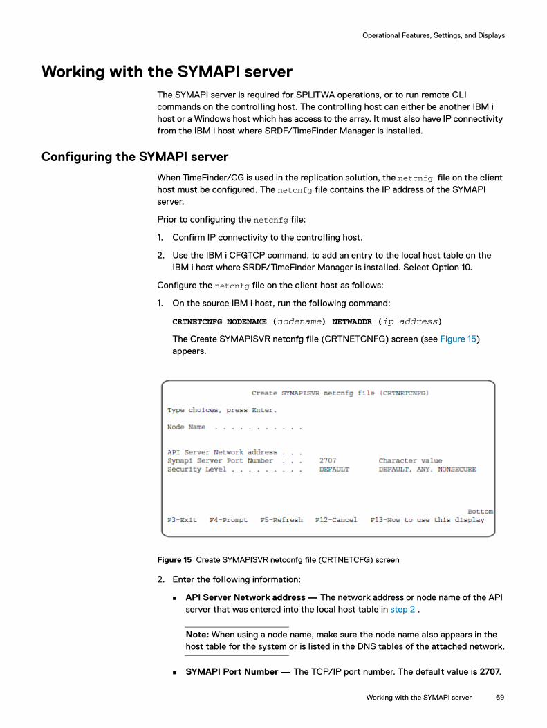
Operational Features, Settings, and Displays
Working with the SYMAPI serverThe SYMAPI server is required for SPLITWA operations, or to run remote CLI commands on the controlling host. The controlling host can either be another IBM i host or a Windows host which has access to the array. It must also have IP connectivity from the IBM i host where SRDF/TimeFinder Manager is installed.
Configuring the SYMAPI server
When TimeFinder/CG is used in the replication solution, the netcnfg file on the client host must be configured. The netcnfg file contains the IP address of the SYMAPI server.
Prior to configuring the netcnfg file:
1. Confirm IP connectivity to the controlling host.
2. Use the IBM i CFGTCP command, to add an entry to the local host table on the IBM i host where SRDF/TimeFinder Manager is installed. Select Option 10.
Configure the netcnfg file on the client host as follows:
1. On the source IBM i host, run the following command:
CRTNETCNFG NODENAME (nodename) NETWADDR (ip address)
The Create SYMAPISVR netcnfg file (CRTNETCNFG) screen (see Figure 15) appears.
Figure 15 Create SYMAPISVR netconfg file (CRTNETCFG) screen
2. Enter the following information:
API Server Network address — The network address or node name of the API server that was entered into the local host table in step 2 .
Note: When using a node name, make sure the node name also appears in the host table for the system or is listed in the DNS tables of the attached network.
SYMAPI Port Number — The TCP/IP port number. The default value is 2707.
Working with the SYMAPI server 69

Operational Features, Settings, and Displays
Security Level — The security connection level for the server: DEFAULT, ANY, NONSECURE, or SECURE.
Note: A SECURE connection is not supported for IBM i hosts.
3. Press Enter.
An entry similar to the following is added to the netcnfg file:
SPLITWA_SERVICE - TCPIP - 10.123.456.789 2707 -
Starting the SYMAPI Server
To start the SYMAPI Server:
1. Select option 3. Control Menu from the EMC SRDF/TimeFinder Manager for IBM i main menu.
2. Select option 7. Control Daemons from the Control Menu.
The Control EMC daemon process (STORDAEMON) screen (Figure 16) appears.
Figure 16 Control EMC daemon process (STORDAEMON) screen
3. Enter the following information:
Daemon Action — START
Daemon Name — STORSRVD
STORSRVD Port Numer — Default is 2707.
Note: Refer to “STORDAEMON” on page 236 for more information.
70 Dell EMC SRDF/TimeFinder Manager for IBM i Version 9.0 and later Product Guide
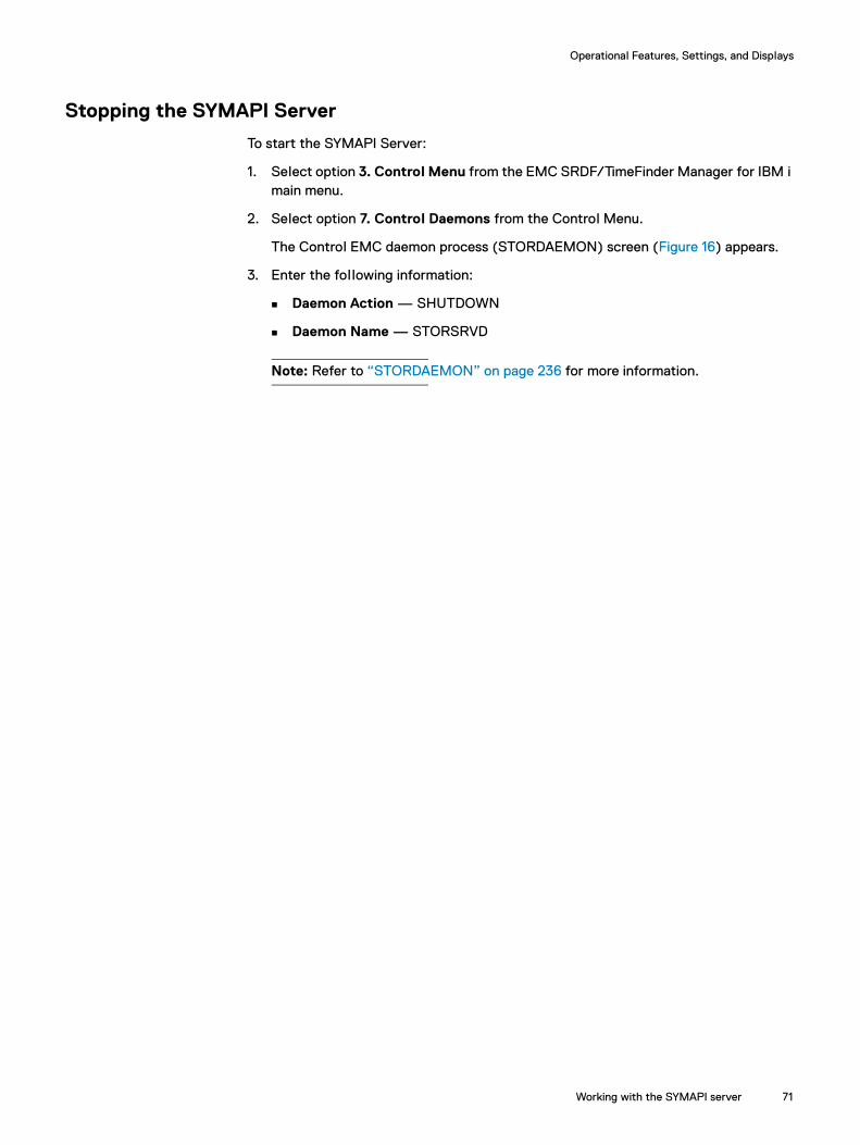
Operational Features, Settings, and Displays
Stopping the SYMAPI Server
To start the SYMAPI Server:
1. Select option 3. Control Menu from the EMC SRDF/TimeFinder Manager for IBM i main menu.
2. Select option 7. Control Daemons from the Control Menu.
The Control EMC daemon process (STORDAEMON) screen (Figure 16) appears.
3. Enter the following information:
Daemon Action — SHUTDOWN
Daemon Name — STORSRVD
Note: Refer to “STORDAEMON” on page 236 for more information.
Working with the SYMAPI server 71

Operational Features, Settings, and Displays
Viewing version informationTo view the current program version information:
1. On the source IBM i host, display the EMC SRDF/TimeFinder Manager for IBM i main menu (see “Accessing the main menu” on page 42).
2. Select option 4. Version Information.
The Program Version Information screen (Figure 17) appears listing current program version information for the Base SRDF/TimeFinder Manager, I/O Driver, and SYMAPI.
Figure 17 Program Version Information screen
Note: The version number of the operating environment appears on the Disk Units Details screen (Figure 42 on page 97).
72 Dell EMC SRDF/TimeFinder Manager for IBM i Version 9.0 and later Product Guide

CHAPTER 4Configuring the Environment
This chapter describes the configuration steps that enable SRDF/TimeFinder Manager to control SRDF and TimeFinder replication environments with IBM i hosts.
◆ Configuration overview ........................................................................................ 74◆ Configuring images .............................................................................................. 74◆ Configuring paths ................................................................................................ 76◆ Working with paths .............................................................................................. 79◆ Configuring device pairs....................................................................................... 86◆ Configuring device pools ..................................................................................... 99◆ Working with Virtual Provisioning™ and thin pools............................................. 108
Configuring the Environment 73

Configuring the Environment
Configuration overviewThe initial configuration consists of:
◆ Creating paths and associating paths with images
◆ Pairing devices for TimeFinder environments
◆ Configuring devices and device pools
If TimeFinder/CG is used in the replication solution, configure the netcnfg file on the client host as well. Refer to “Working with the SYMAPI server” on page 69 for a complete description of the procedure.
Carry out these configuration steps only once, after a new installation. However, if system storage resources are altered, such as when a new disk is added to an ASP using IBM i System Service Tools, repeat these configuration steps.
Configuring imagesThe procedure for adding ASPs to an image or removing ASPs from an image is similar. This operation allows ASPs to participate or be excluded from control operations. The removed ASPs display in the NON_CONFIG image on the Symmetrix Configuration by Image screen.
Adding ASPs to an image
To add ASPs to an image:
1. Select option 1. Work with Images on the Dell EMC SRDF/TimeFinder Manager for IBM i main menu to display the Symmetrix Configuration by Image screen.
2. On the Symmetrix Configuration by Image screen, type 1 (Add ASP to image) next to the ASP in the NON_CONFIG image pool to be added to the SYSTEM image (Figure 18 on page 75).
74 Dell EMC SRDF/TimeFinder Manager for IBM i Version 9.0 and later Product Guide
Configuring the Environment
The Configuration by Image screen re-appears (Figure 18) with the ASP removed from the NON_CONFIG image and added to the ASP list of the SYSTEM image.
Figure 18 Adding an ASP to an image
Removing ASPs from an image
To remove ASPs from an image:
1. On the Configuration by Image screen, type 4 (Remove ASP from image) next to the ASP to be removed from the SYSTEM image (Figure 19).
Figure 19 Removing an ASP from the SYSTEM image
CTLDIMG Symmetrix Configuration by Image HOSTNAME
Type option, press Enter. 1=Add ASP to image 2=Work with paths 4=Remove ASP from image 5=Work with disk units 8=Associate path # of Devices Opt Image ASP Units Type __ SYSTEM 22 Symmetrix __ 1 10 Symmetrix __ 5 12 Symmetrix __ NON_CONFIG 18 Mixed __ 3 13 Non_Symmetrix __ 5 Symmetrix F3=Exit F9=Command Entry F10=Collapse/Show ASP F12=Cancel
ASP to be removed from the NON_CONFIG Image and added to the SYSTEM image
CTLDIMG Symmetrix Configuration by Image HOSTNAME
Type option, press Enter. 1=Add ASP to image 2=Work with paths 4=Remove ASP from image 5=Work with disk units 8=Associate path # of Devices Opt Image ASP Units Type __ SYSTEM 35 Mixed __ 1 10 Symmetrix __ 5 12 Symmetrix __ 3 13 Non_Symmetrix __ NON_CONFIG 5 Symmetrix __ 5 Symmetrix F3=Exit F9=Command Entry F10=Collapse/Show ASP F12=Cancel
ASP that was added tothe SYSTEM image pooland removed from the.NON_CONFIG image
CTLDIMG Symmetrix Configuration by Image HOSTNAME
Type option, press Enter. 1=Add ASP to image 2=Work with paths 4=Remove ASP from image 5=Work with disk units 8=Associate path # of Devices Opt Image ASP Units Type __ SYSTEM 35 Mixed __ 1 10 Symmetrix __ 5 12 Symmetrix __ 3 13 Non_Symmetrix __ NON_CONFIG 5 Symmetrix __ 5 Symmetrix F3=Exit F9=Command Entry F10=Collapse/Show ASP F12=Cancel
ASP to be removed from the SYSTEM image and returnedto the NON_CONFIG image pool
Configuring images 75

Configuring the Environment
The Confirm Remove ASP from the image screen (Figure 20) appears.
Figure 20 Confirm Remove ASP from the image screen
2. Type Y to confirm the ASP removal from the SYSTEM image.
The Configuration by Image screen (Figure 21) appears with the ASP added to the ASP list in the NON_CONFIG image pool.
Figure 21 Returning an ASP to the NON _CONFIG pool
When an ASP is removed, the target image for that ASP may not be synchronized with the source standard devices. This feature adds flexibility to SRDF and TimeFinder operations. For example, for system configurations where one or more ASPs containing non-Symmetrix devices are permitted, al lowing operations to continue for some ASPs while the ineligible ASPs are removed. Note that the SRDF link status for the image must be in an eligible state.
Configuring paths Paths can contain up to five steps. Steps in the path are defined during configuration and are identified by their positions (1 through 5) in the path. Step numbers are used with control commands to identify which steps in the path are to be processed (Table 9 on page 77).
◆ Each image can have multiple paths. With IASP images, only one step of a path can be presented to a target host at a time.
◆ A path cannot be associated with an image (IBMIASP) that contains non-Symmetrix devices.
◆ You cannot associate a path on the NON_CONFIG image.
...........................................: Confirm Remove ASP from the image :: :: Removing an ASP from the image will :: erase all pairing information. :: Do not remove an ASP from the image :: until you have cancelled/terminated :: any clone enabled or snap steps. :: :: Remove an ASP? Y or N :: :: F3=Exit F12=Cancel ::.........................................:
ASP removed from the
CTLDIMG Symmetrix Configuration by Image HOSTNAME
Type option, press Enter. 1=Add ASP to image 2=Work with paths 4=Remove ASP from image 5=Work with disk units 8=Associate path # of Devices Opt Image ASP Units Type __ SYSTEM 22 Symmetrix __ 1 10 Symmetrix __ 5 12 Symmetrix __ NON_CONFIG 18 Mixed __ 3 13 Non_Symmetrix __ 5 Symmetrix F3=Exit F9=Command Entry F10=Collapse/Show ASP F12=Cancel
SYSTEM image and returned to the NON_CONFIGimage
76 Dell EMC SRDF/TimeFinder Manager for IBM i Version 9.0 and later Product Guide
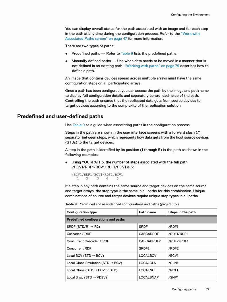
Configuring the Environment
You can display overall status for the path associated with an image and for each step in the path at any time during the configuration process. Refer to the “Work with Associated Paths screen” on page 47 for more information.
There are two types of paths:
◆ Predefined paths — Refer to Table 9 lists the predefined paths.
◆ Manually defined paths — Use when data needs to be moved in a manner that is not defined in an existing path. “Working with paths” on page 79 describes how to define a path.
An image that contains devices spread across multiple arrays must have the same configuration steps on all participating arrays.
Once a path has been configured, you can access the path by the image and path name to display full configuration details and separately control each step of the path. Controlling the path ensures that the replicated data gets from source devices to target devices according to the complexity of the replication solution.
Predefined and user-defined paths
Use Table 9 as a guide when associating paths in the configuration process.
Steps in the path are shown in the user interface screens with a forward slash (/) separator between steps, which represents how data gets from the host source devices (STDs) to the target devices.
A step in the path is identified by its position (1 through 5) in the path as shown in the following examples:
◆ Using YOURPATH3, the number of steps associated with the full path /BCV1/RDF1/BCV1/RDF1/BCV1 is 5:
/BCV1/RDF1/BCV1/RDF1/BCV1 1 2 3 4 5
If a step in any path contains the same source and target devices on the same source and target arrays, the step type is the same in al l paths for this combination. Unique combinations of source and target devices require unique step types in al l paths.
Table 9 Predefined and user-defined configurations and paths (page 1 of 2)
Configuration type Path name Steps in the path
Predefined configurations and paths
SRDF (STD/R1 R2) SRDF /RDF1
Cascaded SRDF CASCADRDF /RDF1/RDF1
Concurrent Cascaded SRDF CASCADRDF2 /RDF2/RDF1
Concurrent RDF SRDF2 /RDF2
Local BCV (STD BCV) LOCALBCV /BCV1
Local Clone Emulation (STD BCV) LOCALCLN /CLN1
Local Clone (STD BCV or STD) LOCALNCL /NCL1
Local Snap (STD VDEV) LOCALSNAP /SNP1
Configuring paths 77

Configuring the Environment
V
Local SnapVX (STD BCV or STD LOCALSNAPVX /SVX1
Duplicate Snap (STD VDEV VDEV) DUPSNAP /SNP1/SNP2
Remote BCV (STD/R1 R2 BCV) REMOTEBCV /RDF1/BCV1
BCV/R1 (STD BCV/R1 R2) BCVR1 /BCV1/RDF1
BRBCV (STD BCV/R1 R2 BCV) BRBCV /BCV1/RDF1/BCV1
Remote Clone Emulation (STD/R1 R2 BCV)
REMOTECLN /RDF1/CLN1
Remote Clone (STD/R1 R2 BCV or STD) REMOTENCL /RDF1/NCL1
Remote Snap (STD/R1 R2 VDEV) REMOTESNAP /RDF1/SNP1
Remote SnapVX (STD/R1 R2 BCV or STD)
REMOTESNAPVX
/RDF1/SVX1
User-defined configurations and paths
Multiple BCVs each with a unique path name and step
MULT_BCV1MULT_BCV2MULT_BCV3MULT_BCV4
/BCV1/BCV2/BCV3/BCV4
Concurrent RDF (RDF1 and RDF2) requires two path names
CONC_SRDF1CONC_SRDF2
/RDF1 /RDF2
Concurrent BCV (BCV1 and BCV2) with unique steps
CONC_BCV1CONC_BCV2
/BCV1 /BCV2
Multihop to third array: (STD/R1 R2 BCV/R1 R2)(STD/R1 R2 BCV/R1 R2 BCV/R1)(STD BCV/R1 R2 BCV/R1 R2 BCV)
YOURPATH1YOURPATH2YOURPATH3
/RDF1/BCV1/RDF1/RDF1/BCV1/RDF1/BCV1/BCV1/RDF1/BCV1/RDF1/BC1
Predefined configurations and paths
SRDF (STD/R1 R2) SRDF /RDF1
Cascaded SRDF CASCADRDF /RDF1/RDF1
Table 9 Predefined and user-defined configurations and paths (page 2 of 2)
Configuration type Path name Steps in the path
78 Dell EMC SRDF/TimeFinder Manager for IBM i Version 9.0 and later Product Guide
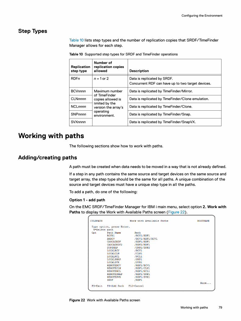
Configuring the Environment
Step Types
Table 10 lists step types and the number of replication copies that SRDF/TimeFinder Manager allows for each step.
Working with pathsThe following sections show how to work with paths.
Adding/creating paths
A path must be created when data needs to be moved in a way that is not already defined.
If a step in any path contains the same source and target devices on the same source and target array, the step type should be the same for al l paths. A unique combination of the source and target devices must have a unique step type in al l the paths.
To add a path, do one of the following:
Option 1 - add path
On the EMC SRDF/TimeFinder Manager for IBM i main menu, select option 2. Work with Paths to display the Work with Available Paths screen (Figure 22).
Figure 22 Work with Available Paths screen
Table 10 Supported step types for SRDF and TimeFinder operations
Replication step type
Number of replication copies allowed Description
RDFn n = 1 or 2 Data is replicated by SRDF.Concurrent RDF can have up to two target devices.
BCVnnnn Maximum number of TimeFinder copies allowed is limited by the version the array’s operating environment.
Data is replicated by TimeFinder/Mirror.
CLNnnnn Data is replicated by TimeFinder/Clone emulation.
NCLnnnn Data is replicated by TimeFinder/Clone.
SNPnnnn Data is replicated by TimeFinder/Snap.
SVXnnnn Data is replicated by TimeFinder/SnapVX.
Working with paths 79
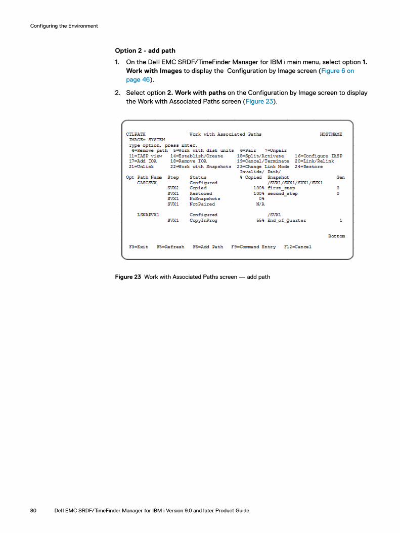
Configuring the Environment
Option 2 - add path
1. On the Dell EMC SRDF/TimeFinder Manager for IBM i main menu, select option 1. Work with Images to display the Configuration by Image screen (Figure 6 on page 46).
2. Select option 2. Work with paths on the Configuration by Image screen to display the Work with Associated Paths screen (Figure 23).
Figure 23 Work with Associated Paths screen — add path
80 Dell EMC SRDF/TimeFinder Manager for IBM i Version 9.0 and later Product Guide
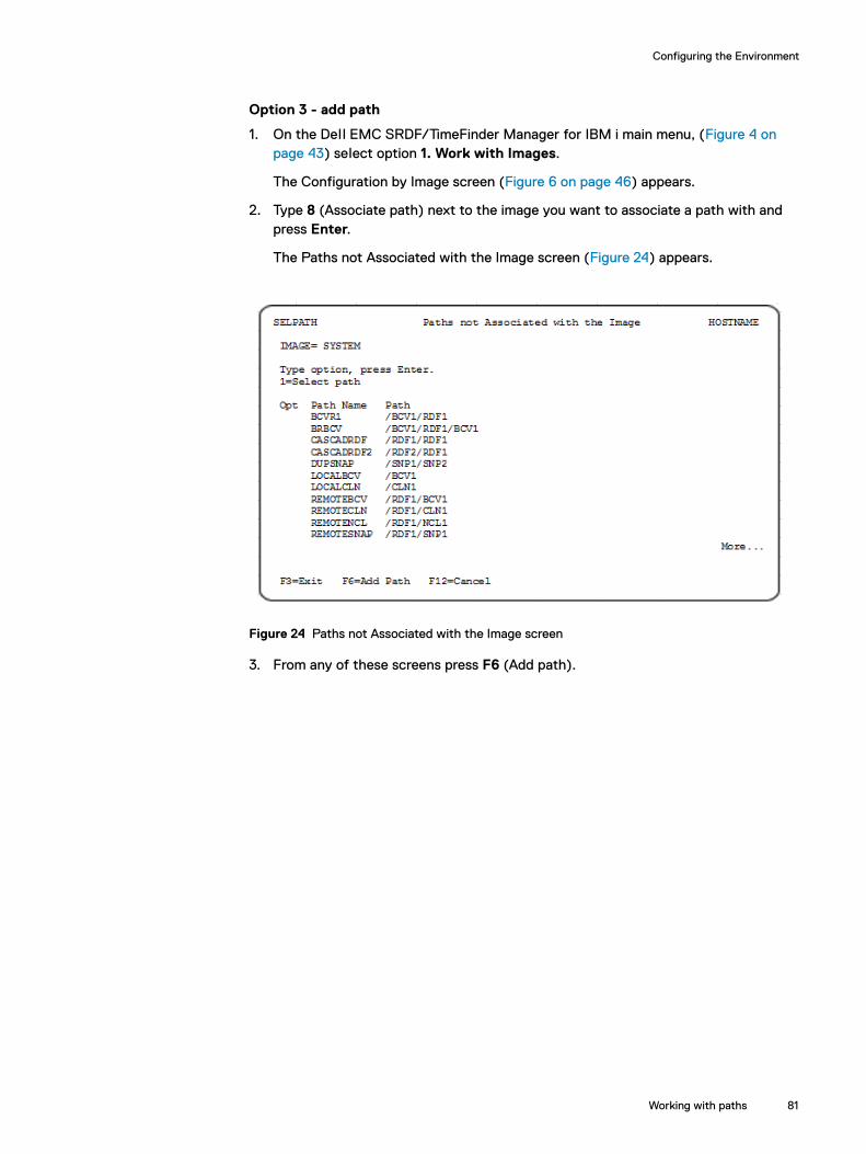
Configuring the Environment
Option 3 - add path
1. On the Dell EMC SRDF/TimeFinder Manager for IBM i main menu, (Figure 4 on page 43) select option 1. Work with Images.
The Configuration by Image screen (Figure 6 on page 46) appears.
2. Type 8 (Associate path) next to the image you want to associate a path with and press Enter.
The Paths not Associated with the Image screen (Figure 24) appears.
Figure 24 Paths not Associated with the Image screen
3. From any of these screens press F6 (Add path).
Working with paths 81
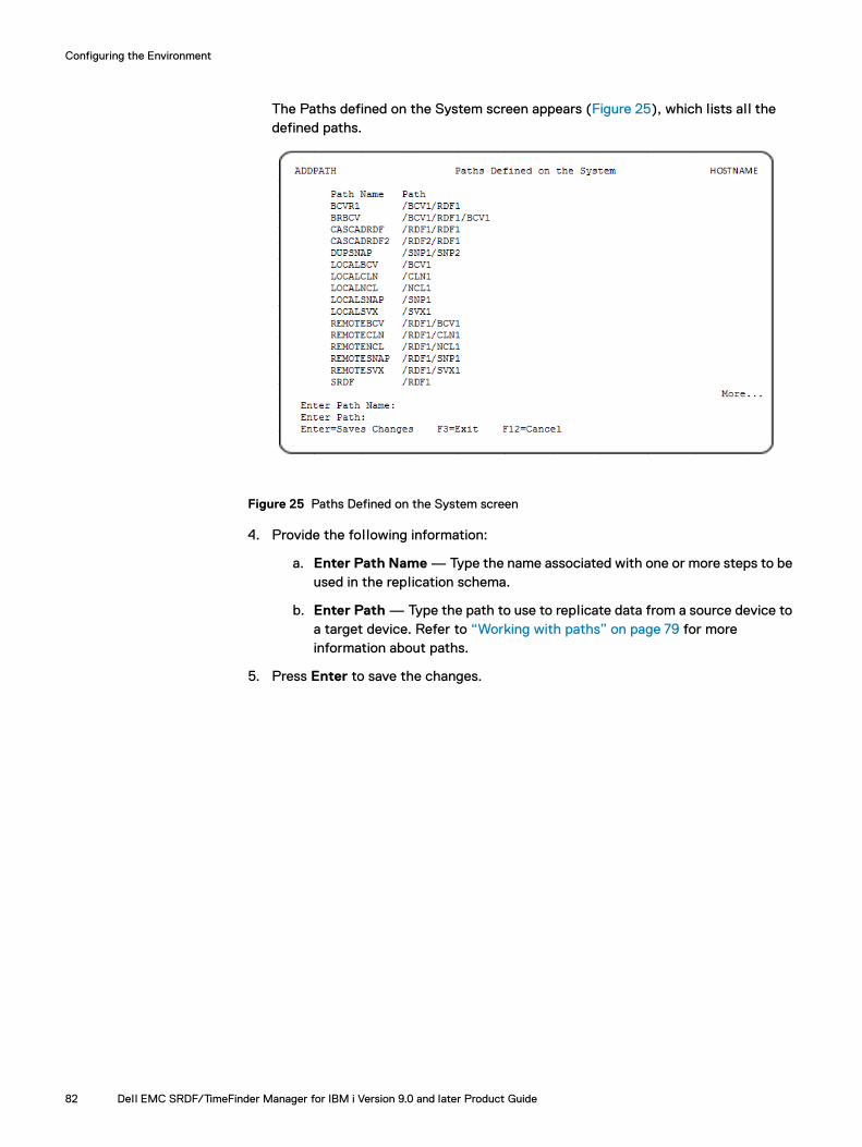
Configuring the Environment
The Paths defined on the System screen appears (Figure 25), which lists al l the defined paths.
Figure 25 Paths Defined on the System screen
4. Provide the following information:
a. Enter Path Name — Type the name associated with one or more steps to be used in the replication schema.
b. Enter Path — Type the path to use to replicate data from a source device to a target device. Refer to “Working with paths” on page 79 for more information about paths.
5. Press Enter to save the changes.
82 Dell EMC SRDF/TimeFinder Manager for IBM i Version 9.0 and later Product Guide

Configuring the Environment
Note: When you press F6 (Add path) from the Work with Associated Paths screen, the new path is immediately associated with the image.
Figure 26 New paths added to screens
If additional paths are required, repeat step 1 through step 3.
Removing (disassociating) a path
To remove (disassociate) a path:
1. On the Dell EMC SRDF/TimeFinder Manager for IBM i main menu, select option 1. Work with Images to display the Configuration by Image screen (Figure 6 on page 46).
2. On the Configuration by Image screen, select option 2. Work with paths to display the Work with Associated Paths screen (Figure 22 on page 79).
3. On the Work with Associated Paths screen, type 4 (Remove path) next to the path to be removed from the image file.
Depending on how the path is configured, the result is one of the following:
If the first step in a path is not configured, the path is disassociated from the image without warning.
If a path has configured steps, the Disassociating a Path screen (Figure 27 on page 84) prompts to disassociate the selected path or cancel the operation.
If a path has a step in which a Snap or a Clone is not terminated or a clone-enabled BCV is not canceled, the path cannot be disassociated.
User-defined
User-defined
CTLDPATH Work with Available Paths HOSTNAME
Type option, press Enter. 4=Delete path Opt Path Name Path __ BCVR1 /BCV1/RDF1 __ BRBCV /BCV1/RDF1/BCV1 __ CASCADRDF /RDF1/RDF1 __ LOCALBCV /BCV1 __ LOCALCNL /CLN1 __ LOCALSNAP /SNP1 __ REMOTEBCV /RDF1/BCV1 __ REMOTECLN /RDF1/CLN1 __ REMOTESNAP /RDF1/SNP1 __ SRDF /RDF1 __ MYPATH /BCV3 BottomF3=Exit F6=Add path F12=Cancel
Working with paths 83
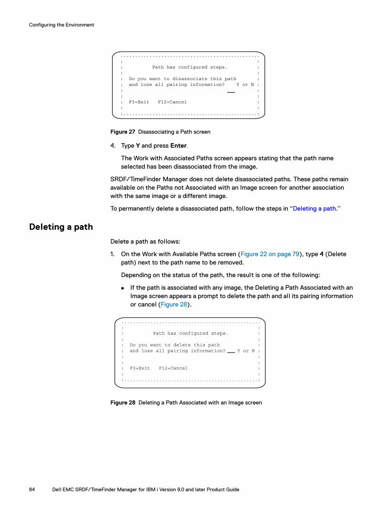
Configuring the Environment
Figure 27 Disassociating a Path screen
4. Type Y and press Enter.
The Work with Associated Paths screen appears stating that the path name selected has been disassociated from the image.
SRDF/TimeFinder Manager does not delete disassociated paths. These paths remain available on the Paths not Associated with an Image screen for another association with the same image or a different image.
To permanently delete a disassociated path, follow the steps in “Deleting a path.’’
Deleting a path
Delete a path as follows:
1. On the Work with Available Paths screen (Figure 22 on page 79), type 4 (Delete path) next to the path name to be removed.
Depending on the status of the path, the result is one of the following:
If the path is associated with any image, the Deleting a Path Associated with an Image screen appears a prompt to delete the path and all its pairing information or cancel (Figure 28).
Figure 28 Deleting a Path Associated with an Image screen
................................................ : : : Path has configured steps. : : : : Do you want to disassociate this path : : and lose all pairing information? Y or N : : : : : : F3=Exit F12=Cancel : : : :..............................................:
................................................ : : : Path has configured steps. : : : : Do you want to delete this path : : and lose all pairing information? Y or N : : : : : : F3=Exit F12=Cancel : : : :..............................................:
84 Dell EMC SRDF/TimeFinder Manager for IBM i Version 9.0 and later Product Guide

Configuring the Environment
If the path is not associated with any image, Figure 29 appears a message confirming path deletion.
Figure 29 Deleting a Path Not Associated with an Image screen
2. Type Y and press Enter.
The Work with Available Paths screen (Figure 22 on page 79) appears with the selected path deleted.
Associating paths with an image
The following steps describe how to associate paths with an image:
1. On the Dell EMC SRDF/TimeFinder Manager for IBM i main menu, (Figure 4 on page 43) select option 1. Work with Images.
The Configuration by Image screen (Figure 6 on page 46) appears.
2. Type 8 (Associate path) next to the image you want to associate a path with and press Enter.
The Paths not Associated with the Image screen (Figure 24 on page 81) appears. Type 1 (Select path) next to one or more path names for the paths you want associated with the image, and press Enter.
SRDF/TimeFinder Manager associates all paths you selected and displays the Configuration by Image screen (Figure 6 on page 46).
3. On the Configuration by Image screen, type 2 (Work with Paths) next to the image.
The Work with Associated Paths screen (Figure 30 on page 86) appears, which contains all paths that have been associated with the image. In this example, the image is SYSTEM. Note that all ASPs in the image have the same paths available.
.............................................. : : : : : Are you sure that you want to : : delete the path? Y or N : : : : : : F3=Exit F12=Cancel : : : :............................................:
Working with paths 85

Configuring the Environment
.
Figure 30 Work with Associated Paths screen — associating paths with image
Configuring device pairsAfter an image is selected, and a path is associated with the image, create pairs of al l BCV, Clone, or Snap devices used in the TimeFinder replication solution.
Pairing overview and rules for replication pairs
The BCV device pairing algorithm attempts to prevent the selection of a BCV device that is on the same physical drive as one of the mirrors of the standard device. If a BCV has two mirrors, only the first mirror is checked.
To search for the optimal BCV pair, SRDF/TimeFinder Manager uses the following selection criteria by priority:
1. If a BCV exists, that was the last BCV paired and established with the current standard device, SRDF/TimeFinder Manager selects this BCV device first if the BCV is not on the same physical drive. If not, the search continues. The best BCV pair to use is a device with the same emulation or a compatible emulation as the standard device that is not on the same physical disk as any of its mirrors.
2. If SRDF/TimeFinder Manager cannot find a compatible BCV device that is not on the same disk as one of the mirrors, it performs the pairing sends an informational message “CTL0083” to the job log. This message states the standard and BCV devices numbers.
3. If SRDF/TimeFinder Manager finds an optimal BCV device for a standard or R2 device, but this standard or R2 device was previously established with a different BCV device, it sends an informational message “CTL0009” or “CTL0083” to the job log .The message states the standard device is now paired with the BCV device but was previously paired with a different BCV device.
Dynamic SRDF pairing is available from SRDF/TimeFinder Manager as “Dynamic SRDF pairs” on page 170 describes.
86 Dell EMC SRDF/TimeFinder Manager for IBM i Version 9.0 and later Product Guide
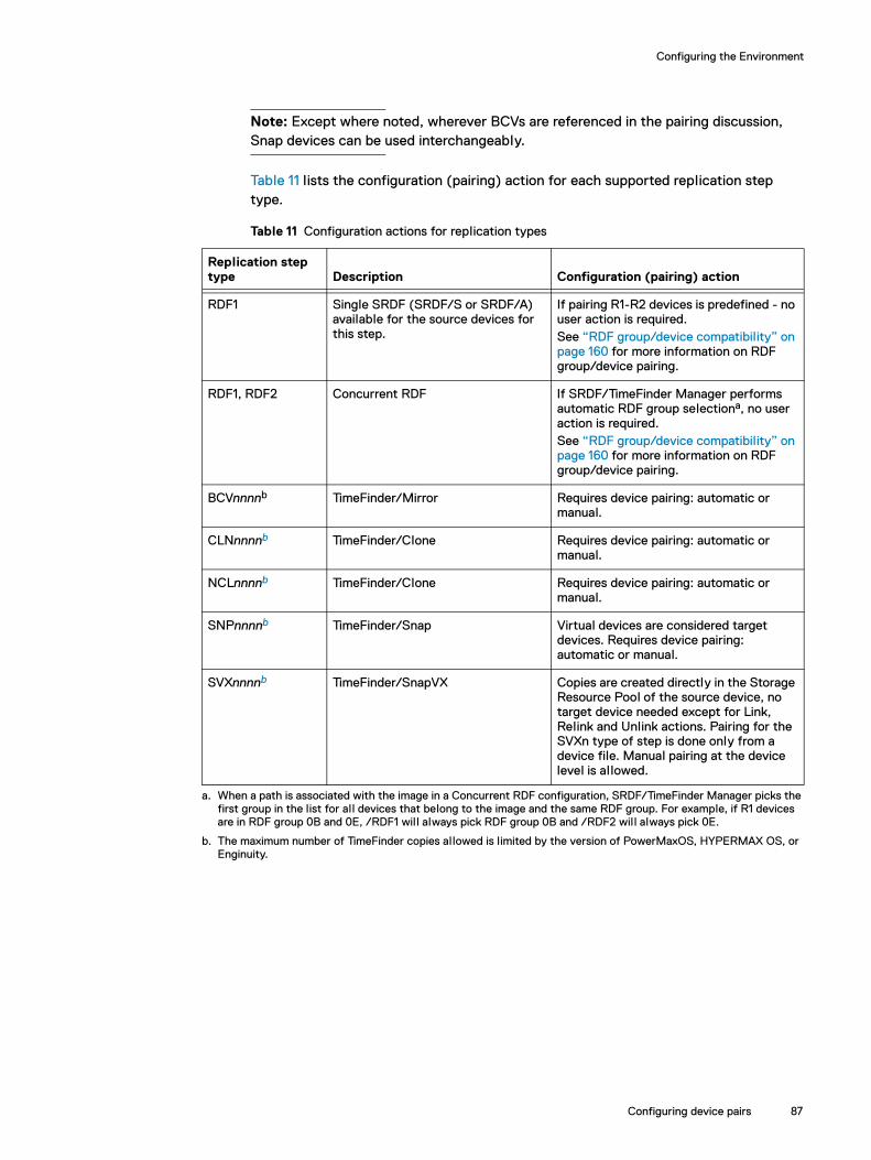
Configuring the Environment
Note: Except where noted, wherever BCVs are referenced in the pairing discussion, Snap devices can be used interchangeably.
Table 11 lists the configuration (pairing) action for each supported replication step type.
Table 11 Configuration actions for replication types
Replication step type Description Configuration (pairing) action
RDF1 Single SRDF (SRDF/S or SRDF/A) available for the source devices for this step.
If pairing R1-R2 devices is predefined - no user action is required.See “RDF group/device compatibility” on page 160 for more information on RDF group/device pairing.
RDF1, RDF2 Concurrent RDF If SRDF/TimeFinder Manager performs automatic RDF group selectiona, no user action is required.See “RDF group/device compatibility” on page 160 for more information on RDF group/device pairing.
BCVnnnnb TimeFinder/Mirror Requires device pairing: automatic or manual.
CLNnnnnb TimeFinder/Clone Requires device pairing: automatic or manual.
NCLnnnnb TimeFinder/Clone Requires device pairing: automatic or manual.
SNPnnnnb TimeFinder/Snap Virtual devices are considered target devices. Requires device pairing: automatic or manual.
SVXnnnnb TimeFinder/SnapVX Copies are created directly in the Storage Resource Pool of the source device, no target device needed except for Link, Relink and Unlink actions. Pairing for the SVXn type of step is done only from a device file. Manual pairing at the device level is al lowed.
a. When a path is associated with the image in a Concurrent RDF configuration, SRDF/TimeFinder Manager picks the first group in the list for all devices that belong to the image and the same RDF group. For example, if R1 devices are in RDF group 0B and 0E, /RDF1 wil l always pick RDF group 0B and /RDF2 wil l always pick 0E.
b. The maximum number of TimeFinder copies allowed is limited by the version of PowerMaxOS, HYPERMAX OS, or Enginuity.
Configuring device pairs 87

Configuring the Environment
BCV device pairingBCV device pairing can be performed as follows:
◆ Automatically — When you are pairing by image, SRDF/TimeFinder Manager automatically makes selections as described in “Pairing overview and rules for replication pairs” on page 86. For example, when you perform BCV pairing, the Pair option attempts to find a matching available BCV device on the array and pairs the standard or R2 device with a BCV device for the specified image.
◆ Using a device file with source and target device pairs - A text file containing pairs of source and target devices. Refer to “Creating a device file” on page 94 for more information.
◆ Manually — You can individually select the BCV device from the All STD/BCV/SNAP Devices of Matching screen to pair with a standard device.
Using meta devices
When using meta devices, the BCV selection criteria above are applied at the meta device member level. SRDF/TimeFinder Manager does a single pass through all the devices in the image.
Note: If you attempted to unpair al l the devices and pair them again, it is likely that SRDF/TimeFinder Manager creates the same device pairing. If this pairing is not sufficient, try manually swapping around several devices, which may create different pairings.
Note: For arrays running PowerMaxOS 5978 or HYPERMAX OS 5977, there is no meta device support. Creating RDF pairs between an array running Enginuity 5876 and an array running PowerMaxOS 5978 or HYPERMAX OS 5977, where the devices on the 5876 array are meta devices, is al lowed provided the appropriate 5876 fixes are applied to the array.
TimeFinder/Clone device pairingThe source and target devices in a TimeFinder/Clone device pair can be either standard devices or BCV devices as long as they are all of the same size and type. Clone copies of striped or concatenated meta devices can also be created, but the source and target meta devices must have completely identical stripe count, stripe size, and capacity. Once it is activated, the copy can be instantly accessed by a target's host, even before the data is fully copied to the target device.
In environments running Enginuity 5876 or higher, the target device of a clone session can be used as the source for one or more clone sessions. This al lows a clone operation to take place with a device that is already involved in a clone operation without ending the first clone session. This applies to clone target devices of both TimeFinder/Clone sessions and TimeFinder/Clone sessions.
For target devices that are BCV devices, automatic pairing is performed. For standard target devices, either the name of the file containing these devices must be provided or manual pairing must be performed.
88 Dell EMC SRDF/TimeFinder Manager for IBM i Version 9.0 and later Product Guide

Configuring the Environment
For TimeFinder/Clone emulation sessions, source devices can only be standard devices and target devices can only be BCV devices.
Note: Do not mix standard and BCV devices for TimeFinder/Clone (NCLn) step device pairing, if planning to use TimeFinder Consistency Group ECA (SPLITWA) splits. Use either standard or BCV devices for the entire group of devices.
TimeFinder/Snap device pairingA TimeFinder/Snap device pair consists of a standard, R1, R2, or a BCV device and a virtual device.
Duplicate snaps
A duplicate snap is a duplicate of a point-in-time copy of a virtual device that has been activated in a previous snap session. This second point-in-time copy session resides with the source device of the original snap session and is charged as part of the maximum number of sessions for that source device.
The duplicate snap is an actual copy of the virtual device to another virtual device.
In order to support duplicate snaps, SRDF/TimeFinder Manager supports paths such as /SNP1/SNP2.
A duplicate snap requires creation and activation, described as follows:
◆ Creation of a duplicate session.
Following the creation of the duplicate snap, a virtual device to virtual device session is in the Created state. Although this is the same point-in-time as the original virtual device, the time stamp is not inherited from the original virtual device's session. The newly created session has its own time stamp indicating the actual time of creation.
When the duplicate session is in the Created state, the original session between the standard device and the virtual device cannot be terminated until the duplicated session is activated. Also, duplicated sessions in the Created state are limited to a maximum of two sessions for any standard device.
◆ Activation of the duplicate session.
Following the activation of the duplicate snap, the session reverts to a normal snap session between the source device of the original session and the duplicate virtual device, which may be recreated or terminated the same as any other snap session. Similar to the create operation; the activated session has a time stamp that reflects the time of the latest operation. Once activated, the normal snap rules for maximum number of sessions associated with a standard device apply.
Following the activation of the duplicate snap, a new path with a step such as/SNP2 can be associated. This picks up existing pairing (source device and the virtual device that was used as duplicate snap). Operations can be performed on either the second step of the path /SNP1/SNP2 or first step of the /SNP2 path.
After terminating the existing copy session, virtual devices can again be used for duplicate snap (pairing for virtual device — virtual device is restored). The Disk Units screen and the Disk Units Details screen show the current status of the copy sessions.
Configuring device pairs 89

Configuring the Environment
SnapVX device pairingCopies are created directly in the Storage Resource Pool of the source device, so no target device needed except for Link, Relink and Unlink actions. Pairing for this step type can only be done from a device file. See “Creating a device file” on page 94.
Pairing devices
Devices can be paired using the following methods:
◆ Automatic — SRDF/TimeFinder Manager attempts pairing all devices in the image.
◆ Manual — each target is individually selected and paired.
◆ Using a device file with source and target device pairs - A text file containing pairs of source and target devices. See “Creating a device file” on page 94 for more information.
Note: For SRDF pairing operations, static pairing occurs during initial array configuration, and dynamic pairing occurs while the array is in operation. For arrays running PowerMaxOS 5978 or HYPERMAX OS 5977, only dynamic SRDF groups are supported. To support dynamic SRDF groups, a new command “CTLRDFGRP” (Control Dynamic RDF Group) is available.
Pairing Devices automatically To set up device pairing:
1. On the Work with Associated Paths screen, type 6 (Pair) next to the step of the associated path for the image. The TimeFinder Pairing Options screen appears (Figure 31).
Figure 31 TimeFinder Pairing Options screen
90 Dell EMC SRDF/TimeFinder Manager for IBM i Version 9.0 and later Product Guide
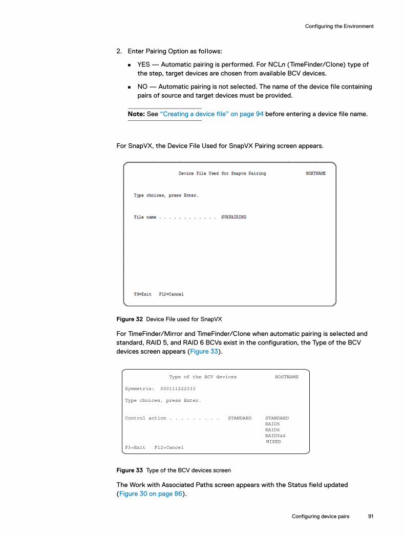
Configuring the Environment
2. Enter Pairing Option as follows:
YES — Automatic pairing is performed. For NCLn (TimeFinder/Clone) type of the step, target devices are chosen from available BCV devices.
NO — Automatic pairing is not selected. The name of the device file containing pairs of source and target devices must be provided.
Note: See “Creating a device file” on page 94 before entering a device file name.
For SnapVX, the Device File Used for SnapVX Pairing screen appears.
Figure 32 Device File used for SnapVX
For TimeFinder/Mirror and TimeFinder/Clone when automatic pairing is selected and standard, RAID 5, and RAID 6 BCVs exist in the configuration, the Type of the BCV devices screen appears (Figure 33).
Figure 33 Type of the BCV devices screen
The Work with Associated Paths screen appears with the Status field updated (Figure 30 on page 86).
Type of the BCV devices HOSTNAME
Symmetrix: 000111222333
Type choices, press Enter.
Control action . . . . . . . . . STANDARD STANDARD RAID5 RAID6 RAID5&6 MIXED F3=Exit F12=Cancel
Configuring device pairs 91

Configuring the Environment
Pairing devices manually for BCV, Clone, Snap or SnapVX devicesRefer to “Miscellaneous Device Information” on page 273 for a list of compatible devices. Perform device pairing as follows:
1. On the Disk Units screen enter option 6 (Pair) next to the device (Figure 34 on page 92).
Note: For the SnapVX type of step the Disk Unit screen contains different header information. (Figure 39 on page 96). Table 7 on page 55 defines the fields on the Disk Unit screen for SnapVX.
Figure 34 Disk Units screen with Pair option for device not paired
For a step type of Clone and SnapVX, the Type of the target device screen appears (Figure 35).
92 Dell EMC SRDF/TimeFinder Manager for IBM i Version 9.0 and later Product Guide

Configuring the Environment
Figure 35 Type of the target device screen
2. Choose the target device type (Standard or BCV).
3. The All STD/BCV/SNAP Devices of matching screen appears (Figure 36).
Figure 36 All STD/BCV/SNAP devices of matching screen
The All STD/BCV/SNAP devices of matching screen displays a list of the STD/BCV/SNAP devices that are of the same or compatible type as the source type.
4. Use Option 1=Pair with Standard for pairing devices.
The Disk Units screen appears with the device paired (Figure 37).
Configuring device pairs 93
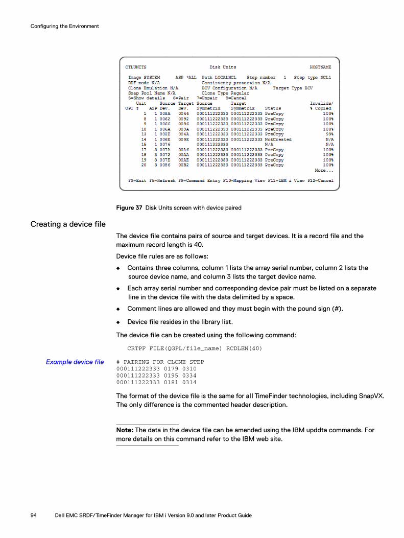
Configuring the Environment
Figure 37 Disk Units screen with device paired
Creating a device file The device file contains pairs of source and target devices. It is a record file and the maximum record length is 40.
Device file rules are as follows:
◆ Contains three columns, column 1 lists the array serial number, column 2 lists the source device name, and column 3 lists the target device name.
◆ Each array serial number and corresponding device pair must be listed on a separate line in the device file with the data delimited by a space.
◆ Comment lines are allowed and they must begin with the pound sign (#).
◆ Device file resides in the library list.
The device file can be created using the following command:
CRTPF FILE(QGPL/file_name) RCDLEN(40)
Example device file # PAIRING FOR CLONE STEP000111222333 0179 0310000111222333 0195 0334000111222333 0181 0314
The format of the device file is the same for al l TimeFinder technologies, including SnapVX. The only difference is the commented header description.
Note: The data in the device file can be amended using the IBM upddta commands. For more details on this command refer to the IBM web site.
94 Dell EMC SRDF/TimeFinder Manager for IBM i Version 9.0 and later Product Guide
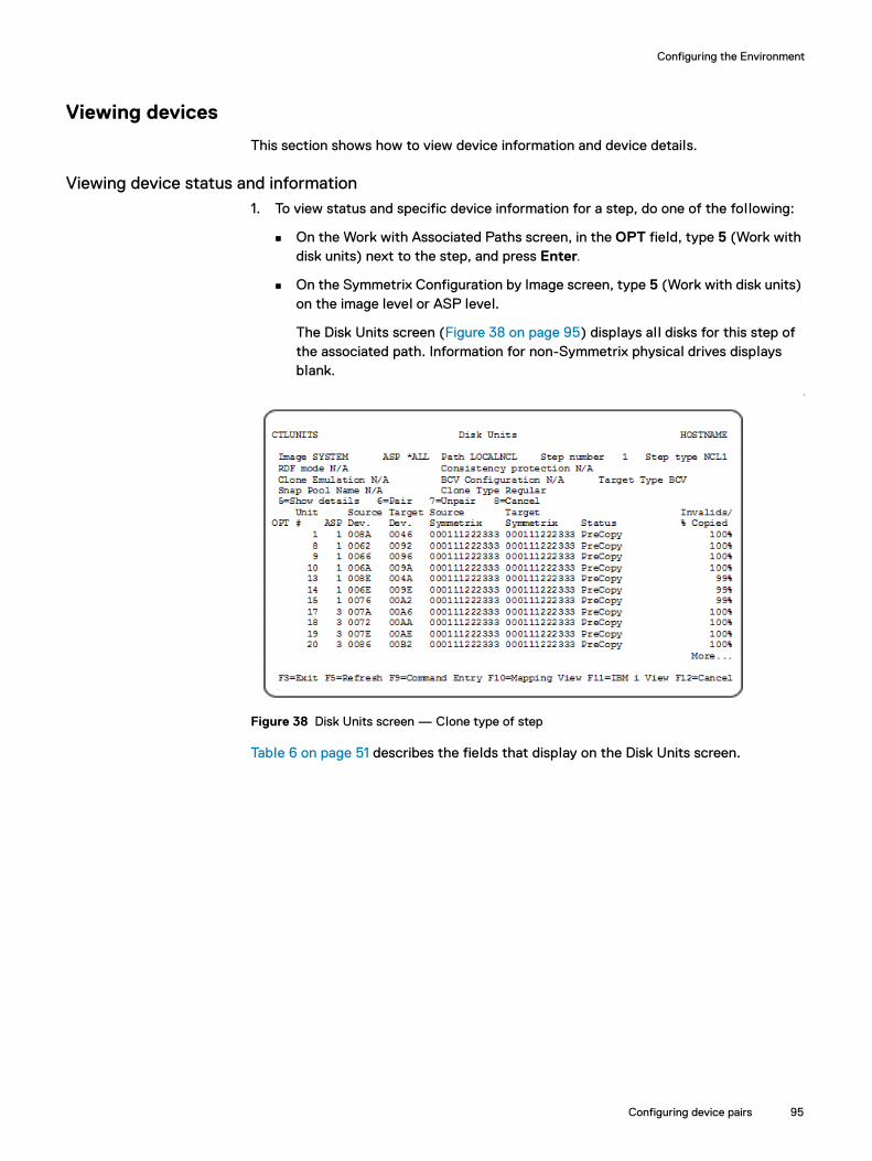
Configuring the Environment
Viewing devices
This section shows how to view device information and device details.
Viewing device status and information1. To view status and specific device information for a step, do one of the following:
On the Work with Associated Paths screen, in the OPT field, type 5 (Work with disk units) next to the step, and press Enter.
On the Symmetrix Configuration by Image screen, type 5 (Work with disk units) on the image level or ASP level.
The Disk Units screen (Figure 38 on page 95) displays all disks for this step of the associated path. Information for non-Symmetrix physical drives displays blank.
‘
Figure 38 Disk Units screen — Clone type of step
Table 6 on page 51 describes the fields that display on the Disk Units screen.
Configuring device pairs 95

Configuring the Environment
For the SnapVX type of step the Disk Unit screen contains different header information (Figure 39). Table 7 on page 55 defines the fields on the Disk Units screen for SnapVX.
Figure 39 Disk Units screen — SnapVX type of step
Viewing mapping informationTo view mapping information (Figure 40) for al l devices in the step (source and target), press F10=Mapping View.
Figure 40 Mapping View screen
96 Dell EMC SRDF/TimeFinder Manager for IBM i Version 9.0 and later Product Guide

Configuring the Environment
Viewing Disk Units in IBM i viewTo display the Disk Units screen (Figure 41) showing source devices in the IBM i view, press F11.
Figure 41 Disk Units screen — IBM i View
Press F11 to return to the Disk Units screen (Figure 38 on page 95) in the view.
Displaying device detailsTo display details for a device, from the Disk Units screen, type 5 (Show details) next to the device.
The Disk Units Details screen (Figure 42) appears. This screen displays details about the selected device for and no-devices.
Figure 42 Disk Units Details screen for step type SNAP
For SNAP type of the step, the Step Type field is expanded to display the save pool name, as shown in Figure 42.
Configuring device pairs 97
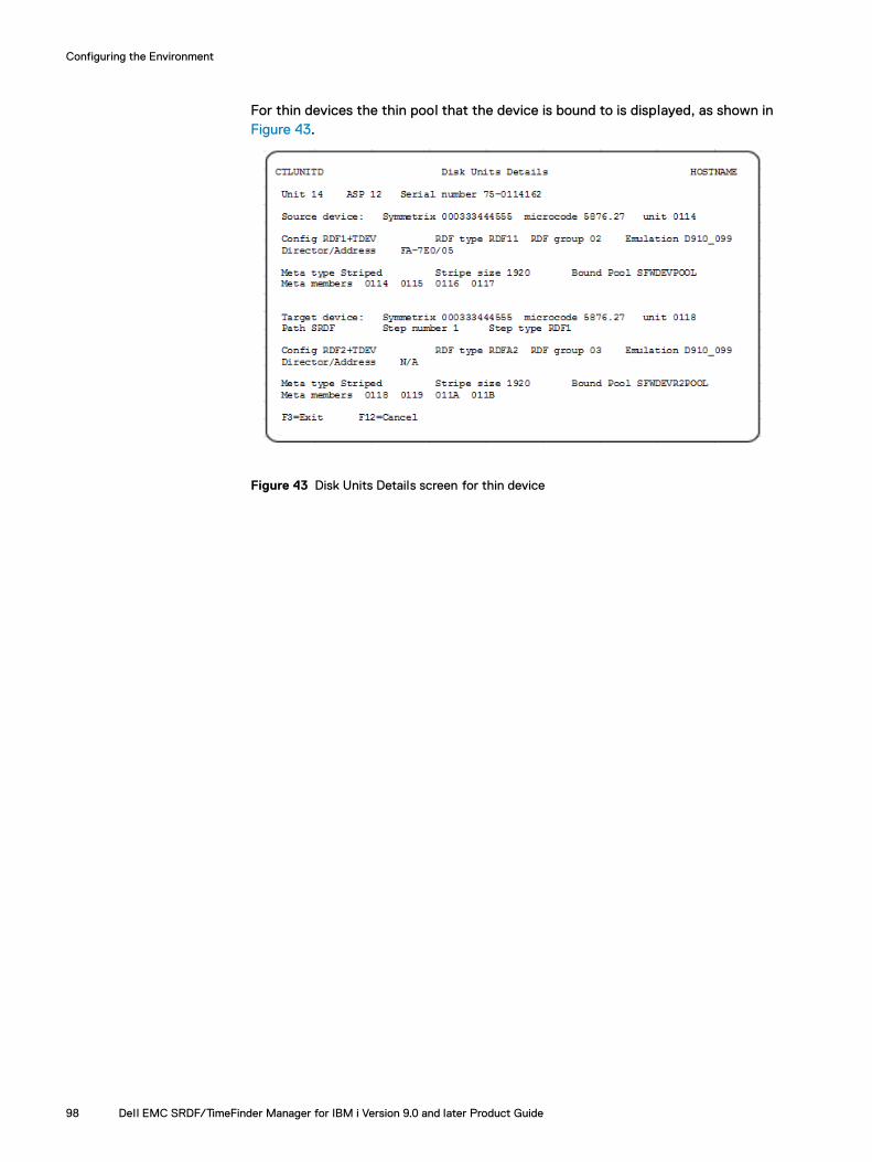
Configuring the Environment
For thin devices the thin pool that the device is bound to is displayed, as shown in Figure 43.
Figure 43 Disk Units Details screen for thin device
98 Dell EMC SRDF/TimeFinder Manager for IBM i Version 9.0 and later Product Guide

Configuring the Environment
Configuring device pools
Note: For arrays running PowerMaxOS 5978 or HYPERMAX OS 5977, Snap and DSE pools are not supported, and thin pools and DATA devices are pre-configured, so pool management is not supported. Therefore, for PowerMaxOS 5978 and HYPERMAX OS 5977 arrays, creating and deleting thin pools, and management of existing pools and DATA devices (except for pool renaming and freeing devices) are not supported.
For arrays running Enginuity version 5876 and earlier, the following device pools are created and managed by SRDF/TimeFinder Manager:
◆ SAVE pools contain SAVE devices
The two types of SAVE pools are:
SNAP pools — Used for TimeFinder/Snap operations.
DSE pools — Used for RDF/A DSE operations.
◆ Thin pools contain DATA devices. Thin pools are used for Virtual Provisioning.
Working with SAVE pools
SAVE pools are groups of SAVE devices used to store pre-update data from TimeFinder/Snap source devices or to store excess cycle data from SRDF/A Delta Set Extension (DSE) operations.
The sections that follow describe the procedures for working with SAVE pools and their associated SAVE pool devices. The procedure for disabling, enabling, or removing devices from the SAVE pool is essential ly the same.
These operations can be performed through the SRDF/TimeFinder Manager main menu by selecting option 5. Working with pools which navigates through a series of screens, or by selecting option 8. Control Pools from the Control Menu to access the CTLPOOL command. “CTLPOOL” on page 202 describes this command in detail. The following examples use screens.
SAVE pool restrictionsThe following restrictions apply to SAVE pools:
◆ All SAVE device pools must have the same disk type (Fibre Channel, SATA, EFD).
◆ All devices in a SAVE pool must have the same type. The pool itself is not defined to be a specific type. However, the first device added to the pool defines the type.
All devices in a SAVE pool must have the same protection type. If the first device added to the pool is a 2-way mirror configuration, al l subsequent added devices must have 2-way mirror protection.
Configuring device pools 99
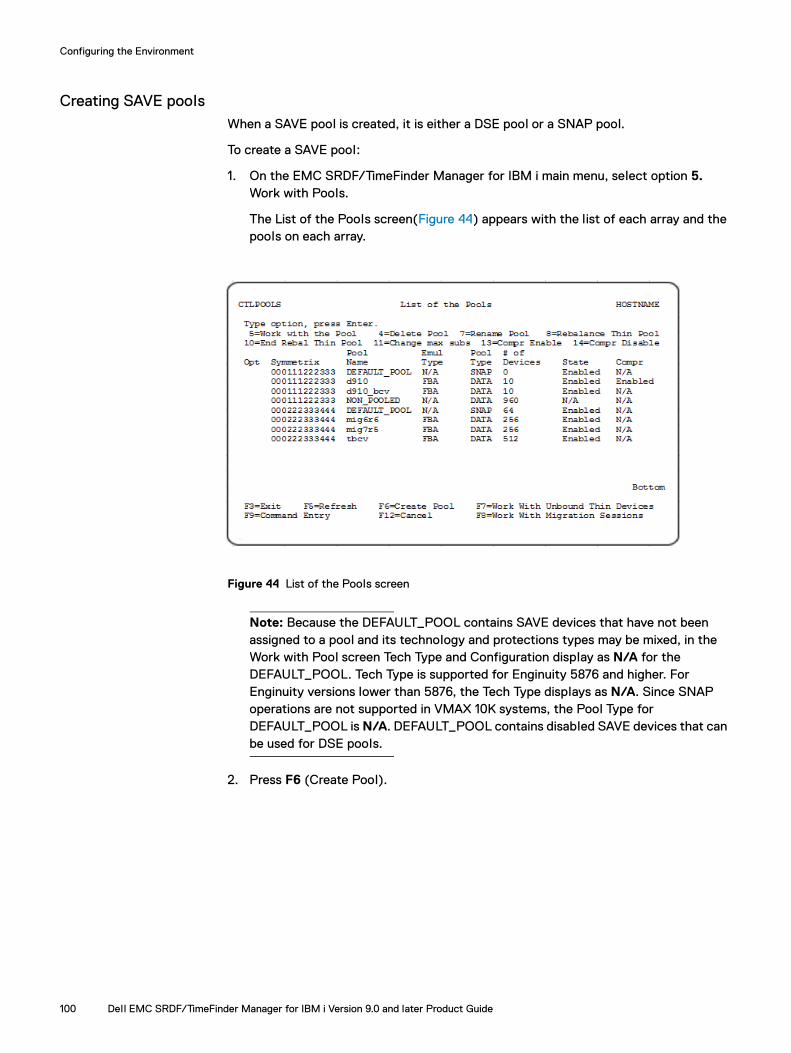
Configuring the Environment
Creating SAVE poolsWhen a SAVE pool is created, it is either a DSE pool or a SNAP pool.
To create a SAVE pool:
1. On the EMC SRDF/TimeFinder Manager for IBM i main menu, select option 5. Work with Pools.
The List of the Pools screen(Figure 44) appears with the list of each array and the pools on each array.
Figure 44 List of the Pools screen
Note: Because the DEFAULT_POOL contains SAVE devices that have not been assigned to a pool and its technology and protections types may be mixed, in the Work with Pool screen Tech Type and Configuration display as N/A for the DEFAULT_POOL. Tech Type is supported for Enginuity 5876 and higher. For Enginuity versions lower than 5876, the Tech Type displays as N/A. Since SNAP operations are not supported in VMAX 10K systems, the Pool Type for DEFAULT_POOL is N/A. DEFAULT_POOL contains disabled SAVE devices that can be used for DSE pools.
2. Press F6 (Create Pool).
100 Dell EMC SRDF/TimeFinder Manager for IBM i Version 9.0 and later Product Guide

Configuring the Environment
The Existing Pools screen (Figure 45) appears.
Figure 45 Existing Pools screen
3. Provide the following information:
Symmetrix ID — The name of the array on which this command is performed.
Pool Name — The name for the SAVE pool.
Pool Type — SNAP or DSE.
Note: Max Subs% and VP Compress only apply to DATA (thin) pools.
4. Press Enter to save the changes.
The List of the Pools screen updates with the new pool.
Adding devices to the SAVE poolTo add a device to a SAVE pool:
1. On the Dell EMC SRDF/TimeFinder Manager for IBM i main menu, select option 5. Work with Pools.
The List of the Pools screen(Figure 44 on page 100) appears with the list of each array and the pools on each array.
2. Type 5 (Work with the Pool) in Opt field next to the SAVE pool where devices wil l be added, and press Enter.
The Work with Pool screen (Figure 46 on page 102) appears. Pool Type is SNAP.
Configuring device pools 101

Configuring the Environment
Figure 46 Work with Pool screen
3. Press F6 (Add Device.)
The Not Pooled Save/Data Devices screen (Figure 47 on page 103) appears.
When the SAVE pool is not empty, only non-pooled devices with the same array type are presented. When the SAVE pool is empty, al l non-pooled SAVE devices are presented.
Note: Excluding the DEFAULT_POOL pool, SAVE pools can only have SAVE devices with the same type, disk type, and protection.
102 Dell EMC SRDF/TimeFinder Manager for IBM i Version 9.0 and later Product Guide
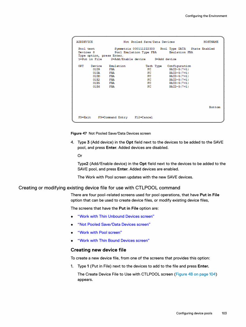
Configuring the Environment
Figure 47 Not Pooled Save/Data Devices screen
4. Type 3 (Add device) in the Opt field next to the devices to be added to the SAVE pool, and press Enter. Added devices are disabled.
Or
Type2 (Add/Enable device) in the Opt field next to the devices to be added to the SAVE pool, and press Enter. Added devices are enabled.
The Work with Pool screen updates with the new SAVE devices.
Creating or modifying existing device file for use with CTLPOOL commandThere are four pool-related screens used for pool operations, that have Put in File option that can be used to create device files, or modify existing device files,
The screens that have the Put in File option are:
◆ “Work with Thin Unbound Devices screen”
◆ “Not Pooled Save/Data Devices screen”
◆ “Work with Pool screen”
◆ “Work with Thin Bound Devices screen”
Creating new device file
To create a new device file, from one of the screens that provides this option:
1. Type 1 (Put in File) next to the devices to add to the file and press Enter.
The Create Device File to Use with CTLPOOL screen (Figure 48 on page 104) appears.
Configuring device pools 103

Configuring the Environment
Figure 48 Create Device File to Use with CTLPOOL
◆ In the File Name field, enter the new device file name and press Enter.
The device file is created and saved in the QGPL library.
Modifying existing device file
To modify (overwrite) an existing device file, from one of the screens that provides this option:
1. Type 1 (Put in File) next to the devices to add to the file and press Enter.
The Create Device File to Use with CTLPOOL screen (Figure 48) appears.
2. Enter the existing file name and press Enter.
3. A confirmation screen Figure 49 appears.
Figure 49 Confirmation screen for device file name
4. To overwrite existing file, type Y.
The current file in the QGPL library is overwritten with new data.
104 Dell EMC SRDF/TimeFinder Manager for IBM i Version 9.0 and later Product Guide
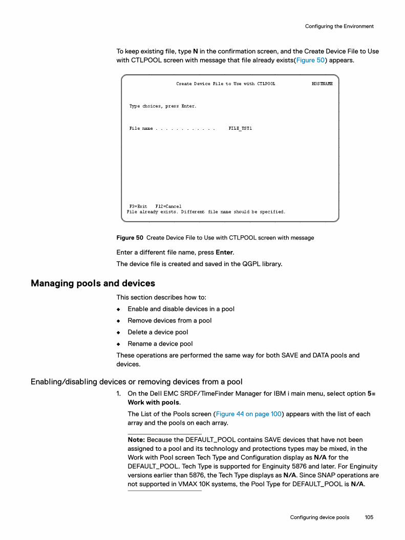
Configuring the Environment
To keep existing file, type N in the confirmation screen, and the Create Device File to Use with CTLPOOL screen with message that file already exists(Figure 50) appears.
Figure 50 Create Device File to Use with CTLPOOL screen with message
Enter a different file name, press Enter.
The device file is created and saved in the QGPL library.
Managing pools and devicesThis section describes how to:
◆ Enable and disable devices in a pool
◆ Remove devices from a pool
◆ Delete a device pool
◆ Rename a device pool
These operations are performed the same way for both SAVE and DATA pools and devices.
Enabling/disabling devices or removing devices from a pool1. On the Dell EMC SRDF/TimeFinder Manager for IBM i main menu, select option 5=
Work with pools.
The List of the Pools screen (Figure 44 on page 100) appears with the list of each array and the pools on each array.
Note: Because the DEFAULT_POOL contains SAVE devices that have not been assigned to a pool and its technology and protections types may be mixed, in the Work with Pool screen Tech Type and Configuration display as N/A for the DEFAULT_POOL. Tech Type is supported for Enginuity 5876 and later. For Enginuity versions earlier than 5876, the Tech Type displays as N/A. Since SNAP operations are not supported in VMAX 10K systems, the Pool Type for DEFAULT_POOL is N/A.
Configuring device pools 105

Configuring the Environment
2. Type 5 (Work with the Pool) in the Opt field next to the SAVE pool to perform an operation on, and press Enter.
The Work with Pool screen (Figure 46 on page 102) appears.
3. In the OPT field next to one or more devices, enter one of the following options and press Enter:
Note: Only one type of operation can be performed at a time.
2 (Enable device)
3 (Disable device)
4 (Remove device)
Note: When a SAVE device is disabled, the selected device is drained and placed in a Draining state so that it is logically removed from further Snap operations. Draining a SAVE device deactivates the device in the pool, and moves all used tracks to other devices in the same pool without affecting existing Snap sessions or DSE operations. Once the number of used tracks on the device decrements to zero, the device state changes to Disabled.
After an option is entered, the State field updates in the Work with Pool screen.
Note: When working with the DEFAULT_POOL pool, devices can only be disabled. For removed devices, the screen appears without confirmation of device removal from the SAVE pool. On VMAX 10K arrays, no operations are allowed with the DEFAULT_POOL.
Deleting device poolsIn order to be deleted, device pools cannot have active sessions, must be disabled, and cannot contain members to be deleted.
To delete one or more pools:
1. On the Dell EMC SRDF/TimeFinder Manager for IBM i main menu, select option 5= Work with pools.
The List of the Pools screen (Figure 44 on page 100) appears with the list of each array and the pools on each array.
2. Type 4 (Delete Pool) in the OPT field next to one or more pools to delete, and press Enter.
The List of Pools screen updates.
106 Dell EMC SRDF/TimeFinder Manager for IBM i Version 9.0 and later Product Guide
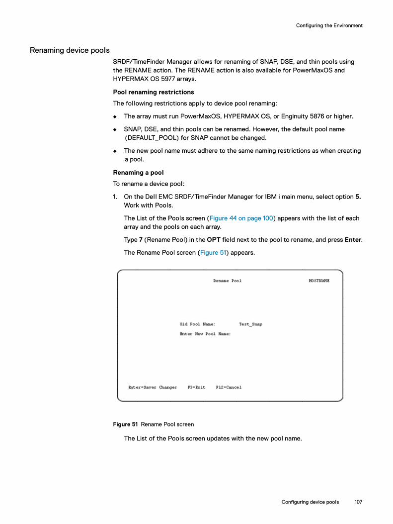
Configuring the Environment
Renaming device poolsSRDF/TimeFinder Manager allows for renaming of SNAP, DSE, and thin pools using the RENAME action. The RENAME action is also available for PowerMaxOS and HYPERMAX OS 5977 arrays.
Pool renaming restrictions
The following restrictions apply to device pool renaming:
◆ The array must run PowerMaxOS, HYPERMAX OS, or Enginuity 5876 or higher.
◆ SNAP, DSE, and thin pools can be renamed. However, the default pool name (DEFAULT_POOL) for SNAP cannot be changed.
◆ The new pool name must adhere to the same naming restrictions as when creating a pool.
Renaming a pool
To rename a device pool:
1. On the Dell EMC SRDF/TimeFinder Manager for IBM i main menu, select option 5. Work with Pools.
The List of the Pools screen (Figure 44 on page 100) appears with the list of each array and the pools on each array.
Type 7 (Rename Pool) in the OPT field next to the pool to rename, and press Enter.
The Rename Pool screen (Figure 51) appears.
Figure 51 Rename Pool screen
The List of the Pools screen updates with the new pool name.
Configuring device pools 107

Configuring the Environment
Working with Virtual Provisioning™ and thin pools
Note: For arrays running PowerMaxOS 5978 or HYPERMAX OS 5977, thin pools and DATA devices are pre-configured, so pool management (see page 108, actions on thin pools) is not supported (except for pool renaming). For arrays running Enginuity 5876, the actions on thin pools described below are supported by SRDF/TimeFinder Manager, except for FREEALL which is available only on PowerMaxOS and HYPERMAX OS 5977 or later arrays.
EMC SRDF/TimeFinder Manager for IBM i supports D910-099 as thin devices which also allows SRDF/TimeFinder Manager to take advantage of the Virtual Provisioning feature. Virtual Provisioning (commonly known as thin provisioning) allows for storage to be allocated and accessed on demand from a pool of storage, servicing one or many applications. Virtual Provisioning has the ability to define to the host a disk configuration that is far larger than current needs.
The Virtual Provisioning feature introduces three new concepts: thin devices, DATA devices, and thin pools or DATA pools. Thin devices can be created with an inflated capacity, because the actual storage space for the data written to thin devices is on DATA devices that are located in a thin pool. When additional storage is needed, more DATA devices can be added to the thin pool. DATA devices have FBA emulation and are not visible to the host. Thin devices bound to pools containing DATA devices are the components used for the Virtual Provisioning feature. Each write to a thin device by the host is written in the bound DATA device pool.
The same naming conventions that apply to SNAP pools and DSE pools apply to the thin pools, the only exception is there is no default thin pool.
Actions on thin pools◆ BIND◆ UNBIND◆ REBIND◆ BALANCE◆ STOP_BALANCE◆ CHANGE_SUBS (change subscription)◆ COMPR ENABLE/DISABLE (compression enable/disable pool)◆ COMP_START/END (compress devices)◆ UNCOMP_START/END (uncompress devices)◆ MIGRATE◆ FREEALL (free up device allocations, see note)
Note: On PowerMaxOS 5978 or HYPERMAX OS 5977, al l devices are under FAST control and FAST handles all device binding and allocation. However, the FREEALL action is available as a mechanism for the user to free up device allocations. This action frees up allocations regardless of whether or not data written to the device. FREEALL is only supported for arrays running PowerMaxOS 5978 or HYPERMAX OS 5977. All other actions listed above are supported on arrays running Enginuity 5876.
108 Dell EMC SRDF/TimeFinder Manager for IBM i Version 9.0 and later Product Guide

Configuring the Environment
Thin device and pool rules and restrictionsThe following restrictions apply to thin pools:
◆ The only IBM i thin device supported is the D910 device with 512 bytes/block geometry. Support is not provided for the legacy IBM i 2107 device with 520 bytes/block.
◆ D910 DATA devices are not supported. The data devices for IBM i thin pools are standard Server-type FBA devices.
◆ IBM i and Server-type FBA devices can share the same pool.
◆ All device pools must have the same disk type; SATA, Fibre Channel, or EFD.
◆ A thin pool can only contain DATA devices of one type. The pool itself is not defined to be a pool for a specific type. Instead, the first DATA device added to the thin pool defines the type.
◆ All DATA devices in a thin pool must have the same protection. For example, if a thin pool has the first DATA device defined as a 2-Way-Mir, al l subsequent added DATA devices must be 2-Way-Mir devices.
◆ A DATA device of a specific protection can be added to an empty thin pool, or a pool that only contains DATA devices that have the same protection and type.
◆ A DATA device can only be removed from a thin pool if it is disabled and has no used tracks on it.
◆ If the total pool capacity needed to store existing thin device data becomes insufficient as a result of disabling a range of the devices, none of the devices in the requested range are disabled.
◆ Devices that do not belong to any pools are available to be added to a pool.
◆ Devices in a pool are available for use once they are enabled.
Creating thin poolsOperations for thin pools can be performed through the SRDF/TimeFinder Manager main menu using option 5. Working with pools which navigates through a series of screens, or by using option 8. Control Pools from the Control Menu to access the CTLPOOL command. “CTLPOOL” on page 202 describes this command in detail. The examples below use the Working with pools option from the main menu.
To create a thin pool:
1. On the Dell EMC SRDF/TimeFinder Manager for IBM i main menu, select option 5. Work with Pools.
The List of the Pools screen (Figure 44 on page 100) appears with the list of each array and the pools on each array.
2. Press F6 (Create Pool).
The Existing Pools screen (Figure 45 on page 101) appears.
Configuring device pools 109
Configuring the Environment
3. Provide the following information:
Symmetrix ID — The name of the array on which this command is performed.
Pool Name — The name for the DATA pool.
Pool Type — DATA
Max Subs % — Enter a value of 1- 65534, or leave blank.
VP Compress — Enter enable or disable, or leave blank.
4. Press Enter to save the changes.
5. The List of the Pools screen updates with the new pool.
Adding thin devices to thin poolsTo add a device to a DATA pool:
1. On the Dell EMC SRDF/TimeFinder Manager for IBM i main menu, select option 5. Work with Pools.
The List of the Pools screen (Figure 44 on page 100) appears with the list of each array and the pools on each array.
2. Type 5 (Work with the Pool) in the Opt field next to the DATA pool where devices wil l be added, and press Enter.
3. The Work with Pool screen (Figure 46 on page 102) appears and the Pool Type field displays as DATA.
4. Press F6 (Add Device).
The Not Pooled Save/Data Devices screen (Figure 47 on page 103) appears and the Pool Type field displays as DATA.
When the DATA pool is not empty, only non-pooled devices with the same type, disk type, and protection are shown. When the DATA pool is empty, al l non-pooled DATA devices are shown.
Note: DATA pools can only have DATA devices with the same type, disk type, and protection.
5. On the Not Pooled Save/Data Devices screen, select option 3=Add device in Opt field next to the devices to add to the DATA pool and press Enter. Added devices are disabled.
Or
Type 2 (Add/Enable device) in the Opt field next to the devices to add to the DATA pool, and press Enter. The added devices are enabled.
The Work with Pool screen updates with the new DATA devices.
110 Dell EMC SRDF/TimeFinder Manager for IBM i Version 9.0 and later Product Guide

Configuring the Environment
Managing DATA pools and DATA devicesFor DATA devices and pools, refer to “Managing pools and devices” on page 105 for enabling/disabling devices, removing devices from a pool, renaming pools, and deleting pools. Performing these operations is the same for both SAVE and DATA pools.
The following control operations and parameters are unique to DATA pools and thin devices:
Note: With one exception, these operations are not available on arrays running PowerMaxOS 5978 or HYPERMAX OS 5977. The exception is the FREEALL command which available on PowerMaxOS 5978 and HYPERMAX OS 5977 arrays only.
◆ “Binding operations for thin devices”◆ “Balancing operations for thin pools”◆ “Setting subscription limit for thin pools”◆ “Thin device data compression”◆ “Thin device migration”
Steps to perform each of these operations are described below.
Binding operations for thin devicesThe following bind operations are available for thin devices:
◆ BIND — Binds a thin device to a thin pool of DATA devices◆ UNBIND — Unbinds a thin device from a thin pool.
A thin device cannot be unbound from a pool if it is:
Mapped to a front-end port or in the Ready state Masked by VCM Has active snap sessions Held Source or target of a clone session Meta member Part of enabled SRDF CG group An RDF device
◆ REBIND — Changes a thin device’s subsequent binding to another pool.
Note: Rebind does not move any existing data to the new pool, but al l new allocations to the thin device go to the new pool after the rebind completes.
◆ FREEALL — Frees up all al locations associated with a given device regardless of whether or not there is data written to the device. The following behavior applies the FREEALL command:
The FREEALL_START operation is blocked on any device participating in any replication operation. The device must also be not mapped or not ready.
The following operations are blocked if a FREEALL operation is running in the background on a device:
– RDF createpair– TF/Mirror full establish and full restore– TF/Clone create, full establish and full restore– TF/SnapVX establish and link
Configuring device pools 111
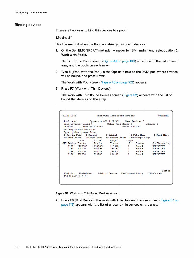
Configuring the Environment
Binding devices There are two ways to bind thin devices to a pool.
Method 1
Use this method when the thin pool already has bound devices.
1. On the Dell EMC SRDF/TimeFinder Manager for IBM i main menu, select option 5. Work with Pools.
The List of the Pools screen (Figure 44 on page 100) appears with the list of each array and the pools on each array.
2. Type 5 (Work with the Pool) in the Opt field next to the DATA pool where devices wil l be bound, and press Enter.
The Work with Pool screen (Figure 46 on page 102) appears.
3. Press F7 (Work with Thin Devices).
The Work with Thin Bound Devices screen (Figure 52) appears with the list of bound thin devices on the array.
.
Figure 52 Work with Thin Bound Devices screen
4. Press F6 (Bind Device). The Work with Thin Unbound Devices screen (Figure 53 on page 113) appears with the list of unbound thin devices on the array.
112 Dell EMC SRDF/TimeFinder Manager for IBM i Version 9.0 and later Product Guide
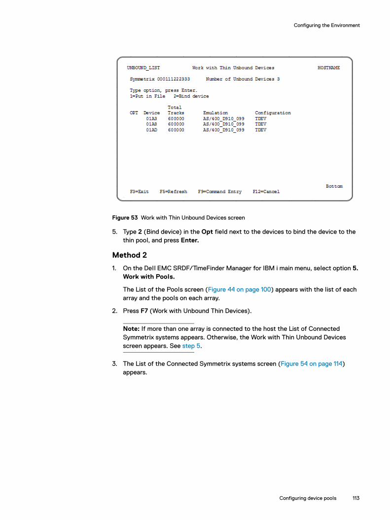
Configuring the Environment
Figure 53 Work with Thin Unbound Devices screen
5. Type 2 (Bind device) in the Opt field next to the devices to bind the device to the thin pool, and press Enter.
Method 2
1. On the Dell EMC SRDF/TimeFinder Manager for IBM i main menu, select option 5. Work with Pools.
The List of the Pools screen (Figure 44 on page 100) appears with the list of each array and the pools on each array.
2. Press F7 (Work with Unbound Thin Devices).
Note: If more than one array is connected to the host the List of Connected Symmetrix systems appears. Otherwise, the Work with Thin Unbound Devices screen appears. See step 5.
3. The List of the Connected Symmetrix systems screen (Figure 54 on page 114) appears.
Configuring device pools 113

Configuring the Environment
Figure 54 List of the Connected Symmetrix systems screen
4. Type 1 (Select Symm) in the OPT field next to the array where devices wil l be bound.
The Work with Thin Unbound Devices screen (Figure 53 on page 113) appears with the list of unbound thin devices on the specified array.
5. Type 2 (Bind device) in the OPT field next to the thin devices to bind to the pool, and press Enter.
Note: If more than one thin pool exist on the array chosen in step 4, The List of Thin Pools screen (Figure 56 on page 116) appears with the list of al l thin pools that exist on the array. Enter 1=Select Pool next to the pool, press Enter to bind devices.
Unbinding thin devices from a thin pool1. On the EMC SRDF/TimeFinder Manager for IBM i main menu, select option 5.
Work with pools.
The List of the Pools screen (Figure 44 on page 100) appears with the list of each array and the pools on each array.
2. Type 5 (Work with the Pool) in the Opt field next to the DATA pool where devices wil l be unbound, and press Enter.
The Work with Pool screen (Figure 46 on page 102) appears.
3. Press F7 (Work with Thin Devices).
114 Dell EMC SRDF/TimeFinder Manager for IBM i Version 9.0 and later Product Guide
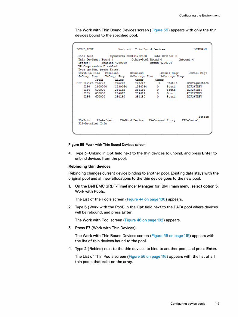
Configuring the Environment
The Work with Thin Bound Devices screen (Figure 55) appears with only the thin devices bound to the specified pool.
Figure 55 Work with Thin Bound Devices screen
4. Type 3=Unbind in Opt field next to the thin devices to unbind, and press Enter to unbind devices from the pool.
Rebinding thin devices
Rebinding changes current device binding to another pool. Existing data stays with the original pool and all new allocations to the thin device goes to the new pool.
1. On the Dell EMC SRDF/TimeFinder Manager for IBM i main menu, select option 5. Work with Pools.
The List of the Pools screen (Figure 44 on page 100) appears.
2. Type 5 (Work with the Pool) in the Opt field next to the DATA pool where devices wil l be rebound, and press Enter.
The Work with Pool screen (Figure 46 on page 102) appears.
3. Press F7 (Work with Thin Devices).
The Work with Thin Bound Devices screen (Figure 55 on page 115) appears with the list of thin devices bound to the pool.
4. Type 2 (Rebind) next to the thin devices to bind to another pool, and press Enter.
The List of Thin Pools screen (Figure 56 on page 116) appears with the list of al l thin pools that exist on the array.
Configuring device pools 115

Configuring the Environment
Figure 56 List of Thin Pools screen
5. Type 1 (Select Pool) next to the new pool assignment, and press Enter to rebind devices.
Confirming pool assignments after a rebind operationOn the Work with Thin Bound Devices screen (Figure 55 on page 115), press F13 (Detailed Info) (F13 = Shift + F1).
The List of Bound/Allocated Devices screen (Figure 57) appears bound devices for the current pool, and allocations in any other pools for the listed devices.
Figure 57 List of Bound/Allocated Devices screen.
Figure 57 shows device 0190 and 0194 after a rebind operation. For the current pool, al locations and status are listed. For allocations for these devices on any other pool, al located tracks are listed, but status is not reported.
116 Dell EMC SRDF/TimeFinder Manager for IBM i Version 9.0 and later Product Guide
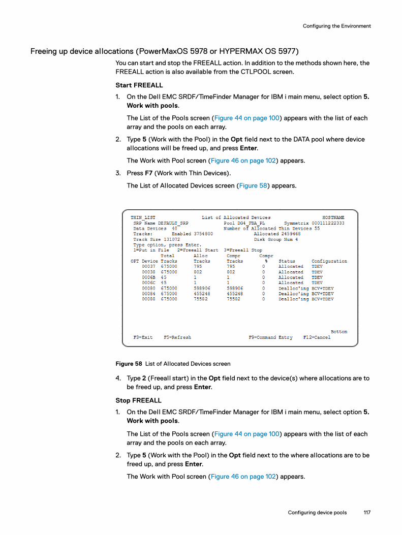
Configuring the Environment
Freeing up device allocations (PowerMaxOS 5978 or HYPERMAX OS 5977)You can start and stop the FREEALL action. In addition to the methods shown here, the FREEALL action is also available from the CTLPOOL screen.
Start FREEALL
1. On the Dell EMC SRDF/TimeFinder Manager for IBM i main menu, select option 5. Work with pools.
The List of the Pools screen (Figure 44 on page 100) appears with the list of each array and the pools on each array.
2. Type 5 (Work with the Pool) in the Opt field next to the DATA pool where device allocations wil l be freed up, and press Enter.
The Work with Pool screen (Figure 46 on page 102) appears.
3. Press F7 (Work with Thin Devices).
The List of Allocated Devices screen (Figure 58) appears.
Figure 58 List of Allocated Devices screen
4. Type 2 (Freeall start) in the Opt field next to the device(s) where allocations are to be freed up, and press Enter.
Stop FREEALL
1. On the Dell EMC SRDF/TimeFinder Manager for IBM i main menu, select option 5. Work with pools.
The List of the Pools screen (Figure 44 on page 100) appears with the list of each array and the pools on each array.
2. Type 5 (Work with the Pool) in the Opt field next to the where allocations are to be freed up, and press Enter.
The Work with Pool screen (Figure 46 on page 102) appears.
Configuring device pools 117

Configuring the Environment
3. Press F7 (Work with Thin Devices).
The List of Allocated Devices screen (Figure 58) appears.
4. Type 3 (Freeall stop) in the Opt field next to the device(s) where allocations wil l be freed up, and press Enter.
Balancing operations for thin poolsWhenever writes occur on a thin device, the actual data is written to the DATA devices in the thin pool to which the thin device is bound. The array distributes the I/O equally on all the DATA devices in the thin pool. Therefore, at any point in time the used capacity of each DATA device is uniform across the pool. However, when new devices are added to the pool, the allocation spread is no longer uniform. SRDF/TimeFinder Manager allows for rebalancing any unbalanced pools.
The following operations are available for starting and stopping write balancing on a pool:
◆ BALANCE — balances the DATA devices in the pool. On a balance operation SRDF/TimeFinder Manager checks for a balancing operation already in progress. If pool balancing is not in progress, SRDF/TimeFinder Manager initiates the operation.
While write balancing is in progress, it is possible for data to be moved from deactivated data devices but never to deactivated data devices. The SRDF/TimeFinder Manager reports the pool state as Balancing. After the balancing operation completes, the pool state does not show as Balancing. The pool state indicates whether any balancing is in progress on a pool at any given time. All pool balancing operations are initiated by the user.
◆ STOP_BALANCE — stops the write balancing operation.
Note: Balancing is available on thin pools and is not applicable for SNAP or DSE pools.
Thin pool balancing and stop balancing
To balance a pool:
1. On the Dell EMC SRDF/TimeFinder Manager for IBM i main menu, select option 5. Work with Pools.
The List of the Pools screen (Figure 44 on page 100) appears with the list of each array and the pools on each array.
2. Type 8 (Rebalance Thin Pool) in the Opt field next to the DATA pool that are to be rebalanced, and press Enter to start the balancing operation.
Confirm that the pool state is Balancing in the List of the Pools screen.
Balancing can also be done from the Work with Pool screen (Figure 46 on page 102) by pressing F8 (Rebalance Thin Pool).
To stop the balancing operation:
1. On the Dell EMC SRDF/TimeFinder Manager for IBM i main menu, select option 5. Work with Pools.
The List of the Pools screen (Figure 44 on page 100) appears with the list of each array and the pools on each array.
118 Dell EMC SRDF/TimeFinder Manager for IBM i Version 9.0 and later Product Guide
Configuring the Environment
2. Type 10 (End Rebalance Thin Pool) in the Opt field next to the DATA pool to stop balancing, and press Enter.
Confirm that the balancing operation has been canceled by checking that the pool state is Enabled in the List of the Pools screen (Figure 44 on page 100).
Stopping the balancing operation can also be done from the Work with Pool screen (Figure 46 on page 102) by pressing F10 (End Rebalance Thin Pool).
Setting subscription limit for thin poolsThe maximum subscription percent which is the limit for a thin pool can be set to any value between 1 and 65534. This number is the total host-perceived capacity of thin devices, divided by physical thin pool capacity. Maximum subscription percent is only used with thin pools.
If the value is not specified the default value is used, meaning there is no limit set and the amount of oversubscription is not restricted. Setting a value of 1 wil l al low only a maximum thin capacity that totals 1/100th of the actual physical capacity of the pool. Setting a value of 100 wil l prevent oversubscription of the pool.
The following parameters and control actions are available for controlling the maximum subscription percent:
◆ MAX_SUBS — sets the maximum subscription percent when creating a thin pool. This parameter is only used with thin pools.
◆ CHANGE_SUBS — Changes maximum subscription percent for the specified thin pool.
Changing pool maximum subscription percent
To change the maximum subscription percent for a pool:
1. On the Dell EMC SRDF/TimeFinder Manager for IBM i main menu, select option 5. Work with Pools.
The List of the Pools screen (Figure 44 on page 100) appears with the list of each array and the pools on each array.
2. Type 11 (Change max subs of the Thin Pool) in the Opt field next to the DATA pool where max subscription value wil l be changed, and press Enter.
Configuring device pools 119

Configuring the Environment
The Change Maximum Subscription Percent screen (Figure 59) appears.
Figure 59 Change Maximum Subscription Percent screen
3. Type the new value in the New Max Sub% field, and press Enter to save the change.
Confirm the new value of the Max Subscription% field in the Work with Pools screen (Figure 46 on page 102).
Changing the maximum subscription percent can also be done from the Work with Pool screen (Figure 46 on page 102) by pressing F11.
Thin device data compressionData within a thin device can be compressed to save space and uncompressed when needed. Data can either be compressed or uncompressed manually, or it can be compressed by FAST as part of its processing.
Enginuity allows read and write operations to compressed data. To do this, Enginuity uncompresses the data, when it is needed, into space that is reserved in the thin pool that contains the thin device compressed allocations. To reserve this space and allow allocations in a pool to be compressed, a pool must be enabled for compression. This is done by setting the compression capability on a thin pool to Enabled. When compression is no longer desired for al locations in a pool, the compression capability on a pool can be disabled.
A write operation always writes the uncompressed allocations on the thin device. Over time if the data has not been accessed, compression may occur if the device is under FAST management, and FAST is supporting compression on the associated device. The data on the device can also be manually compressed at any time.
Virtual Provisioning compression rules and restrictions
The following rules and restrictions apply to Virtual Provisioning compression:
◆ Once a pool is enabled for compression, a background process runs to reserve storage in the pool that is used to temporarily uncompress data. No compressions of al locations in this pool can occur until this process completes.
120 Dell EMC SRDF/TimeFinder Manager for IBM i Version 9.0 and later Product Guide

Configuring the Environment
◆ When compression is disabled, the reserved storage in the pool is returned to the pool only after al l compressed allocations are uncompressed. Disabling the compression capability on a pool does not cause compressed allocations to be uncompressed. The uncompressing action needs to be performed.
◆ When compressing a device, only allocations that have been written are compressed. Any allocations that were created during the bind or al locate processing that have not been written are reclaimed during the compression process. This means that when a compressed device is uncompressed, these allocations no longer exist.
◆ Once a compression request is accepted, the thin device has an associated background task that performs the compression. While this task is running, no other background task, like allocate or reclaim, can be run against the thin device.
◆ Requested compression action fails if al l targeted devices are already in the state for the requested action. For example, if a compress start is issued for devices that are currently compressing, then SRDF/TimeFinder Manager rejects the request and displays Solutions Enabler error: SYMAPI_C_ALREADY_IN_STATE.
Note: If some of the targeted devices are in the state for the requested action, but the remaining devices do not have a conflicting state, SRDF/TimeFinder Manager processes the request on those devices and skips the devices that are already in the desired state.
◆ Requested compression action fails if any of the targeted devices are in a conflicting state relative to the requested action. For example, if an uncompress start action is issued and some devices are in a compressing state, SRDF/TimeFinder Manager rejects the request and displays Solutions Enabler error: SYMAPI_C_INVALID_STATE_FOR_ACTION.
◆ If compression has not been enabled for a pool where a device has allocations, the SRDF/TimeFinder Manager does not fail a compress start action. However, compression does not occur for those allocations.
◆ Requested compression action fails if the array is not running Enginuity 5876. SRDF/TimeFinder Manager rejects the request and displays Solutions Enabler error: SYMAPI_C_FEATURE_NOT_SUPPORTED.
Compressing thin device data
To start compression:
1. On the Dell EMC SRDF/TimeFinder Manager for IBM i main menu, select option 5. Work with Pools.
The List of the Pools screen (Figure 44 on page 100) appears with the list of each array and the pools on each array.
2. Type 5 (Work with the Pool) in the Opt field next to the DATA pool where compression wil l be performed, press Enter.
The Work with Pool screen (Figure 46 on page 102) appears.
3. If VP compression state is disabled, press F13 (Compr Enable) to enable compression for the pool. The VP Compression state changes to Enabled.
Configuring device pools 121
Configuring the Environment
4. Press F7 (Work with Thin Devices).
The Work with Thin Bound Devices screen (Figure 55 on page 115) appears with the list of thin devices bound to the pool.
5. Type 6 (Compr Start) in the Opt field next to the device where compression wil l be performed, and press Enter.
6. Confirm that the device is in Compressing state in the Work with Thin Bound Devices screen (Figure 55 on page 115). This screen also shows the number of compressed tracks and the percent compression for the device.
To stop compression:
1. On the Dell EMC SRDF/TimeFinder Manager for IBM i main menu, select option 5. Work with Pools.
The List of the Pools screen (Figure 44 on page 100) appears with the list of each array and the pools on each array.
2. Type 5 (Work with the Pool) in the Opt field next to the DATA pool where compression wil l be performed, and press Enter.
The Work with Pool screen (Figure 46 on page 102) appears.
3. Press F7 (Work with Thin Devices). The Work with Thin Bound Devices screen (Figure 55 on page 115) appears with the list of thin devices bound to the pool.
4. Type 7 (Compr Stop) in the Opt field next to the device that is compressing, and press Enter to stop.
5. Confirm that the device is no longer in the Compressing state and shows as Bound in the Work with Thin Bound Devices screen(Figure 55 on page 115). This screen also shows the number of compressed tracks and the percent compression for the device.
Uncompressing thin device data
To start uncompression:
1. On the Dell EMC SRDF/TimeFinder Manager for IBM i main menu, select option 5. Work with Pools.
The List of the Pools screen (Figure 44 on page 100) appears with the list of each array and the pools on each array.
2. Type 5 (Work with the Pool) in the Opt field next to the DATA pool where uncompression wil l be performed, press Enter.
The Work with Pool screen (Figure 46 on page 102) appears.
3. Press F7 (Work with Thin Devices). The Work with Thin Bound Devices screen (Figure 55 on page 115) appears with the list of thin devices bound to the pool.
4. Type 8 (Uncompr Start) in the Opt field next to the device to uncompress, and press Enter.
5. Confirm that the device is in the Uncompressing state in the Work with Thin Bound Devices screen. This screen also shows the number of compressed tracks and the percent compression for the device.
122 Dell EMC SRDF/TimeFinder Manager for IBM i Version 9.0 and later Product Guide

Configuring the Environment
To stop uncompression:
1. On the Dell EMC SRDF/TimeFinder Manager for IBM i main menu, select option 5. Work with Pools.
The List of the Pools screen (Figure 44 on page 100) appears with the list of each array and the pools on each array.
2. Type 5 (Work with the Pool) in the Opt field next to the DATA pool where uncompression wil l be performed, and press Enter.
The Work with Pool screen (Figure 46 on page 102) appears.
3. Press F7 (Work with Thin Devices). The Work with Thin Bound Devices screen (Figure 55 on page 115) appears with the list of thin devices bound to the pool.
4. Type 9 (Uncompr Stop) in the Opt field next to the device that is uncompressing, and press Enter.
5. Confirm that the device is no longer in the Uncompressing state and shows as Bound in the Work with Thin Bound Devices screen. This screen also shows the number of compressed tracks and the percent compression for the device.
Thin device migration Virtual LUN VP (virtual pools) migration allows thin device allocations to be moved between pools. For a given list of devices, the data tracks are moved from their current pool to a target pool.
The following rules and restrictions apply to thin device migration:
◆ All source devices must be thin devices.
◆ Allowed only on locally attached systems.
◆ Thin devices that are currently involved in an active migration session cannot be transitioned to other thin device states until the migration completes and is terminated.
◆ Thin devices must be in the bound state to be migrated.
◆ Thin devices that are part of any migration session cannot be migrated.
There are two types of thin device migration:
◆ Full migration — Full migration migrates all of the thin device’s al locations. After the migration, if the thin device is not already bound to the target pool it is bound to that pool after the migration completes.
◆ Pool-level migration — Pool-level migration only migrates the device allocations from the designated source pool. After the migration, device binding does not change to the target pool. If rebinding the thin device to the target pool is desired, then this requires manual rebinding. Refer to “Rebinding thin devices” on page 115.
Configuring device pools 123

Configuring the Environment
Performing full migration of thin device data
1. On the Dell EMC SRDF/TimeFinder Manager for IBM i main menu, select option 5. Work with Pools.
The List of the Pools screen (Figure 44 on page 100) appears with the list of each array and the pools on each array.
2. Type 5 (Work with the Pool) in the Opt field next to array and pool where migration is to be performed, press Enter.
The Work with Pool screen (Figure 46 on page 102) appears.
3. Press F7 (Work with Thin Devices).
The Work with Thin Bound Devices screen (Figure 55 on page 115) appears with the list of thin devices bound to the pool.
4. Type 4 (Full Migr) in the Opt field next to the source devices, and press Enter.
The List of Thin Pools screen (Figure 56 on page 116) appears.
5. Type 1 (Select Pool) inthe OPT field next to the target pool, and press Enter.
6. The Name of the Migration Session to be Used screen (Figure 60 on page 124) appears.
Figure 60 Name of the Migration Session to be Used screen
7. Type the new session name. If the session name entered already exists, an error message appears.
8. Press Enter to start the full migration session.
124 Dell EMC SRDF/TimeFinder Manager for IBM i Version 9.0 and later Product Guide

Configuring the Environment
Performing pool-level migration of thin device data
1. On the Dell EMC SRDF/TimeFinder Manager for IBM i main menu, select option 5. Work with Pools.
The List of the Pools screen (Figure 44 on page 100) appears with the list of each array and the pools on each array.
2. Type 5 (Work with the Pool) in the Opt field next to the devices where migration wil l be performed, press Enter.
The Work with Pool screen (Figure 46 on page 102) appears.
3. Press F7 (Work with Thin Devices).
The Work with Thin Bound Devices screen (Figure 55 on page 115) appears with the list of thin devices bound to the pool.
4. Type 5 (Pool Migr) in the Opt field next to the source devices, and press Enter.
The List of Thin Pools screen (Figure 56 on page 116) appears.
5. Type 1 (Select Pool) in the OPT field next to the target pool, and press Enter.
The Name of the Migration Session to be Used screen (Figure 60) appears.
6. Type the new session name. If the session name entered already exists, an error message appears.
7. Press Enter to start the pool-level migration session.
Monitoring migration sessions
1. On the Dell EMC SRDF/TimeFinder Manager for IBM i main menu, select option 5. Work with Pools.
The List of the Pools screen (Figure 44 on page 100) appears with the list of each array and the pools on each array.
2. Press F8 (Work with Migration Sessions).
Note: If more than one array is connected to the host, the List of Connected Symmetrix systems screen (Figure 54 on page 114) appears, otherwise the List of Migration Sessions screen appears, see Figure 61. Only locally attached arrays display in the List of Connected Symmetrix systems screen.
Configuring device pools 125

Configuring the Environment
3. The List of the Migration Sessions screen (Figure 61), which lists the migration session name, status, and percent migration complete, appears.
Figure 61 List of the Migration Sessions screen
For Further migration session details, type 5 (Display Session Information) in the Opt field next to the session name, and press Enter.
The Migration Session Information screen (Figure 62 on page 126) which lists the devices, status, migration percent complete, and migration type (full or pool-level), appears.
Figure 62 Migration Session Information screen
126 Dell EMC SRDF/TimeFinder Manager for IBM i Version 9.0 and later Product Guide

Configuring the Environment
Terminating/Deleting a thin device migration session
1. On the Dell EMC SRDF/TimeFinder Manager for IBM i main menu, select option 5. Work with Pools.
The List of the Pools screen (Figure 44 on page 100) appears with the list of each array and the pools on each array.
2. Press F8 (Work with Migration Sessions).
Note: If more than one is connected to the host, the List of Connected Symmetrix systems screen (Figure 54 on page 114) appears, otherwise the List of Migration Sessions screen appears, see Figure 61 on page 126. Only locally attached arrays display in the List of Connected Symmetrix systems screen.
3. On the Work with Migration Sessions screen (Figure 61 on page 126), type 4 (Terminate Session) in the OPT field next to desired migration session, and press Enter.
Note: A migration session in the “Migrated” state remains active until it is terminated. If a session in progress is terminated, the migration is stopped.
Configuring device pools 127

Configuring the Environment
128 Dell EMC SRDF/TimeFinder Manager for IBM i Version 9.0 and later Product Guide
CHAPTER 5Controlling TimeFinder
Invisible Body Tag
This chapter describes the procedures for controlling TimeFinder operations using the SRDF/TimeFinder Manager Control Menu.
◆ Overview............................................................................................................ 130◆ Establish/Re-establish BCV or Clone emulation pairs ....................................... 130◆ Split BCV or Clone emulation pairs operation ..................................................... 131◆ TimeFinder/Snap and TimeFinder/Clone operations........................................... 139◆ Cancelling/terminating device pairs .................................................................. 142◆ Unpairing BCV, Clone or Snap devices............................................................... 142◆ TimeFinder/SnapVX operations.......................................................................... 144◆ Monitoring TimeFinder operations...................................................................... 155◆ Automating TimeFinder operations..................................................................... 156
Controlling TimeFinder 129
Controlling TimeFinder
OverviewSRDF/TimeFinder Manager relies on a specific sequence of operations to ensure proper execution of TimeFinder control options. SRDF/TimeFinder Manager checks the configuration and operation considerations prior to executing any command that changes the state of a device or the system.
Note: SRDF/TimeFinder Manager does not perform a discover process automatically, which can take several minutes to run. After any change to the configuration of the host or array, turn on the discover function or run the DISCOVER command (see “Discovering array and host configuration details” on page 63).
TimeFinder control operations are performed on images in which all devices are PowerMax, VMAX All Flash, VMX3, VMAX, or DMX array devices. Control operations are performed at the step level in the path for each image.
Establish/Re-establish BCV or Clone emulation pairs The Establish operation copies the contents of the standard device to the BCV device and performs the following tasks:
◆ For a standard BCV, assign the BCV as the next available mirror of a standard array device.
◆ Copy the entire contents of the standard array device to the BCV device.
◆ If standard BCV devices are used in the BCVn step (established and split), and then used in the Clone emulation (CLNn) step, SRDF/TimeFinder Manager performs a full Establish. The data is replicated by TimeFinder/Mirror, and one source device can have up to four target devices.
The BCV device is unavailable to any host while the BCV device is in this established state.
After you establish BCV pairs, the array device automatically copies the data from its standard device mirrors to the newly assigned BCV device mirror. The array mirroring function also automatically writes to the BCV device all writes that occur on the standard device, while it is in the established pair state.
When you use Establish for BCV pairs that have been established previously (re-establishing a BCV pair), the array copies, to the BCV device, only those updates made to the standard device that occurred while the BCV pair was split.
Establish or re-establish BCV pairs
1. On the Control Menu, select option 1. SRDF or TimeFinder Control to display the EMC SRDF or TimeFinder Control (CTLACT) screen.
2. Provide the Image Name, Path Name, and Step Number.
3. Select the ESTABLISH control action.
The Dell EMC SRDF or TimeFinder Control (CTLACT) screen appears with a Protected BCV Establish prompt.
4. Type *YES or *NO for the PROT_ESTAB parameter depending upon the configuration.
130 Dell EMC SRDF/TimeFinder Manager for IBM i Version 9.0 and later Product Guide

Controlling TimeFinder
The Confirm Establish BCV pairs or the Confirm Establish CLONE emulation pairs screen (Figure 63) appears.
SRDF/TimeFinder Manager attempts to perform TimeFinder operations on all ASPs in the image. Remove any ASPs that are not eligible for the operation (see “Removing ASPs from an image” on page 75).
You can monitor the synchronization process through the array configuration and status option (see “Monitoring invalid and % copied tracks” on page 155).
Figure 63 Confirm Establish BCV pairs and CLONE emulation pairs screens
5. Type Y to continue.
SRDF/TimeFinder Manager establishes the BCV or Clone emulation pairs.
Split BCV or Clone emulation pairs operationWhen a Split operation is issued on a step of the image, the Split occurs for all BCV devices or Clone emulation pairs in that step.
By default, SRDF/TimeFinder Manager performs an instant split, and checks to ensure that synchronization is complete between all specified standard and BCV mirrored pairs, or standard and Clone emulation pairs.
A check for complete synchronization ensures that the split pair contains an updated, consistent copy at the time of the termination. After the Split operation for the BCV or Clone emulation pairs completes, the host can resume operation with the standard array device. Figure 64 on page 132 shows the Split BCV pairs or Split Clone emulation pairs operation.
Restricted state and daemon jobs
When using split or activate you can hold all jobs, bring the system to a restricted state, use split while active, or do a maintenance split/activate. The hold jobs option holds all jobs in the system except for the daemon jobs Storapid and Storgnsd.
Additionally, choosing the restricted state option does not stop the subsystem where Storapid and Storgnsd are running. Other jobs that are running in that same subsystem are stopped using the STMENDSBS command. This command stops all subsystems.
..........................................: :: Confirm Establish BCV pairs :: :: Establishing BCV pairs will :: overwrite the frozen image. Do not :: Establish BCV pairs unless you are :: finished working with the image. :: :: Establish BCV pairs? Y or N :: :: F3=Exit F12=Cancel :: ::.........................................
Split BCV or Clone emulation pairs operation 131

Controlling TimeFinder
During a split, The STMENDSBS command checks status of the subsystems for the restricted state. The split fails and you are asked to hold jobs when any of these conditions exist:
◆ The required daemons are not running.
◆ There are other jobs running in the subsystems where the daemon jobs are running.
◆ There are subsystems running, other than the subsystems where the daemon jobs are running.
Figure 64 Split operation for BCV or Clone emulation pairs
The following sections describe the TimeFinder operations.
Split BCV pairs: Restricted state
This procedure uses the restricted state to ensure that I/O activity is halted before the BCV pair split. If you need to hold jobs and job queues rather than bring the system to a restricted state, see “Split BCV pairs: Hold jobs and job queues” on page 134.
The amount of time needed to move a host into the restricted state depends on the system configuration. By default, SRDF/TimeFinder Manager waits 1800 seconds for control to return, after issuing the command to bring the system to a restricted state. If additional time is required to bring the system to a restricted state, use the procedure “Setting the restricted state wait time” on page 60.
For IASP images, see “SRDF/TimeFinder Manager Extended Features” on page 283.
Start SRDF/TimeFinder Manager
Subsystemsmust bestopped
Yes Bring systemto a restrictedstate
Split BCV pairsorClone pairs
Start subsystems
Yes
No
No
Exit
Hold Jobs and job queues
Split BCV pairs
Release Jobs and Job Queues
Resume normal operations
Continue normaloperations
Split devices
while active(SPLITWA)
Continue normaloperations
Subsystemsremainonline
Hold Jobs and job
queues?
132 Dell EMC SRDF/TimeFinder Manager for IBM i Version 9.0 and later Product Guide
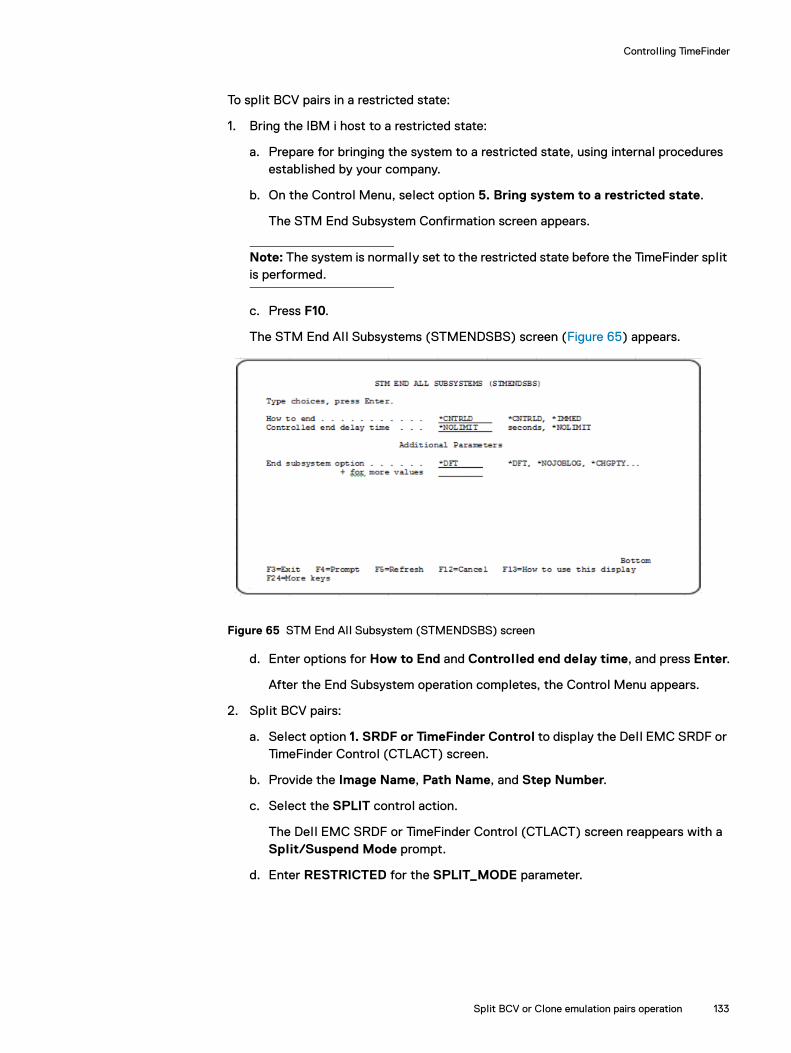
Controlling TimeFinder
To split BCV pairs in a restricted state:
1. Bring the IBM i host to a restricted state:
a. Prepare for bringing the system to a restricted state, using internal procedures established by your company.
b. On the Control Menu, select option 5. Bring system to a restricted state.
The STM End Subsystem Confirmation screen appears.
Note: The system is normally set to the restricted state before the TimeFinder split is performed.
c. Press F10.
The STM End All Subsystems (STMENDSBS) screen (Figure 65) appears.
Figure 65 STM End All Subsystem (STMENDSBS) screen
d. Enter options for How to End and Controlled end delay time, and press Enter.
After the End Subsystem operation completes, the Control Menu appears.
2. Split BCV pairs:
a. Select option 1. SRDF or TimeFinder Control to display the Dell EMC SRDF or TimeFinder Control (CTLACT) screen.
b. Provide the Image Name, Path Name, and Step Number.
c. Select the SPLIT control action.
The Dell EMC SRDF or TimeFinder Control (CTLACT) screen reappears with a Split/Suspend Mode prompt.
d. Enter RESTRICTED for the SPLIT_MODE parameter.
Split BCV or Clone emulation pairs operation 133
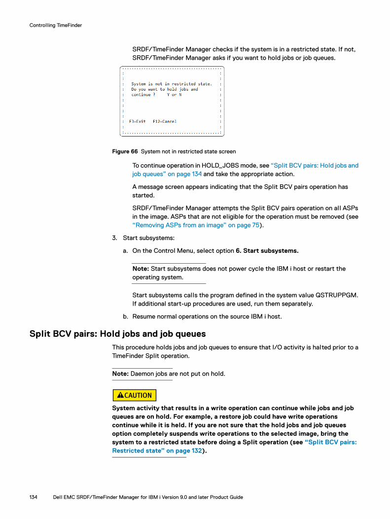
Controlling TimeFinder
SRDF/TimeFinder Manager checks if the system is in a restricted state. If not, SRDF/TimeFinder Manager asks if you want to hold jobs or job queues.
Figure 66 System not in restricted state screen
To continue operation in HOLD_JOBS mode, see “Split BCV pairs: Hold jobs and job queues” on page 134 and take the appropriate action.
A message screen appears indicating that the Split BCV pairs operation has started.
SRDF/TimeFinder Manager attempts the Split BCV pairs operation on all ASPs in the image. ASPs that are not eligible for the operation must be removed (see “Removing ASPs from an image” on page 75).
3. Start subsystems:
a. On the Control Menu, select option 6. Start subsystems.
Note: Start subsystems does not power cycle the IBM i host or restart the operating system.
Start subsystems calls the program defined in the system value QSTRUPPGM. If additional start-up procedures are used, run them separately.
b. Resume normal operations on the source IBM i host.
Split BCV pairs: Hold jobs and job queuesThis procedure holds jobs and job queues to ensure that I/O activity is halted prior to a TimeFinder Split operation.
Note: Daemon jobs are not put on hold.
System activity that results in a write operation can continue while jobs and job queues are on hold. For example, a restore job could have write operations continue while it is held. If you are not sure that the hold jobs and job queues option completely suspends write operations to the selected image, bring the system to a restricted state before doing a Split operation (see “Split BCV pairs: Restricted state” on page 132).
134 Dell EMC SRDF/TimeFinder Manager for IBM i Version 9.0 and later Product Guide

Controlling TimeFinder
To split BCV pairs with jobs and job queues on hold:
1. On the Control Menu, select option 1. SRDF or TimeFinder Control to display the Dell EMC SRDF or TimeFinder Control (CTLACT) screen.
2. Provide the Image Name, Path Name, and Step Number
3. Select the SPLIT control action.
The Dell EMC SRDF or TimeFinder Control (CTLACT) screen reappears with a Split/Suspend mode prompt.
4. Enter HOLD_JOBS for the SPLIT_MODE parameter.
Note: The BCV pair status for the image must be in an eligible state.
SRDF/TimeFinder Manager repeatedly attempts to put all jobs and job queues on hold, and then executes the Split operation.
If one or more jobs or job queues remain active, the Confirmation Window screen (Figure 67) appears.
Figure 67 Confirmation Window screen
5. Select the appropriate option:
1 - Try again to hold Jobs/Queues — SRDF/TimeFinder Manager repeatedly attempts to hold all jobs and job queues.
If jobs or job queues are not on hold, the Confirmation Window screen reappears.
2 - Continue Split/Suspend operation — Accept that some jobs remain active and continue with the Split or Suspend operation.
Selecting Continue Split/Suspend operation acknowledges that some write activity can continue during the Split operation. If any writes occur to the specified ASP during the Split operation, the resulting copy is not valid.
............................................: Confirmation Window :: :: You have Jobs or Job Queues, :: that are not on HOLD. :: :: Do you want to continue? _ 1, 2, 3 or 5 :: :: 1 - Try again to hold Jobs/Queues :: 2 - Continue Split/Suspend operation :: 3 - Abort :: 5 - Display, what is not on HOLD ::..........................................:
Split BCV or Clone emulation pairs operation 135

Controlling TimeFinder
3 - Abort — Do not perform the Split or Suspend operation and return to the Control Menu.
5 - Display, what is not on HOLD — Show a list of the jobs and job queues that SRDF/TimeFinder Manager cannot hold (Figure 68 on page 136).
Figure 68 Jobs Not on Hold and Job Queues Not on Hold screens
6. Press F3 or Enter to return to the Confirmation screen (Figure 67 on page 135).
After al l jobs and job queues are successfully on hold, or you select option 2 - Continue Split/Suspend operation, SRDF/TimeFinder Manager performs the Split operation.
A message screen appears indicating that the Split BCV pairs operation has started.
After the Split operation completes, al l jobs and job queues held by SRDF/TimeFinder Manager are released.
7. Optionally, use the Work with Associated Paths screen or the Disk Units screen to monitor and verify the change in BCV pair status (see “Monitoring TimeFinder operations” on page 155).
8. Resume normal operation on the source IBM i host.
Split BCV pairs: Maintenance
The Split operation in maintenance mode splits BCV pairs without interfering with the source host operations.
Note: This type of Split operation results in a BCV copy that is not usable as a backup. If you intend to use the BCV copy, use the RESTRICTED or HOLD_JOBS options.
Perform a Split operation in maintenance mode only when you need to IPL the secondary host with attached BCV devices. The secondary host cannot IPL while the BCVs are established with the standard devices. Therefore, perform a split before attempting an IPL.
Jobs that are NOT on HOLD 1/28/07 09:54:50
User Job Job Subsystem Job Name Name Number Name Status QUSER QZBSEVTM 000612 QSYSWRK EVTW QUSER QZDASOINIT 000681 QSERVER PSRW QTCP QTMSNMPRCV 000683 QSYSWRT TIMW F3 or ENTER=Exit
Job queues from active subsystems 1/28/07 09:54:50 that are NOT on HOLD
Job Queue Job Queue Subsystem Job Queue Name Library Name Status QSPL QGPL QSPL RELEASED QSYSNOMAX QSYS QSYSWRK RELEASED QINTER QGPL QSYSWRK RELEASED F3 or ENTER=Exit
136 Dell EMC SRDF/TimeFinder Manager for IBM i Version 9.0 and later Product Guide

Controlling TimeFinder
To split BCV pairs for maintenance:
1. On the Control Menu, select option 1. SRDF or TimeFinder Control to display the EMC SRDF or TimeFinder Control (CTLACT) screen.
2. Provide the Image Name, Path Name, and Step Number.
3. Select the SPLIT control action to perform.
The EMC SRDF or TimeFinder Control (CTLACT) screen reappears with a Split/Suspend mode prompt.
4. Enter MAINTENANCE for the SPLIT_MODE parameter.
The SRDF/TimeFinder Manager performs the Split operation without interfering with the source host operations.
TimeFinder Split: Split While Active
Split While Active enables SRDF/TimeFinder Manager to split local/remote BCVs or Clone emulations, or activate Snap or Clone images while the source system is operational. A consistent split ensures dependent write consistency for al l devices in the selected step.
The SYMAPI server jobs must be running on the source and controlling hosts before you run this option.
The netcnfg file must be configured on the client using the CRTNETCNFG command. This ensures that the correct information points to the remote server. IBM i systems support non-secure connections only. “CRTNETCNFG” on page 193 has details of this command.
IMPORTANT
Use caution when performing this type of split as the data in main memory is not included in the image. Use SPLITWA only when the host and applications are in a quiescent state. If that is unacceptable to your business needs, use other operating system functions like journaling and database commitment control to get an image current with the last transaction.
To split BCV, Clone emulation, Snap, or Clone pairs while active:
◆ Run the CTLACT command from the command line (see “CTLACT” on page 194).
Note: Since I/O is briefly being held for al l devices, including the devices in the system ASP, the control action needs to be executed from a different host (see “CTLACT” on page 194).
◆ Access the Dell EMC SRDF or TimeFinder Control (CTLACT) screen and select the appropriate control action:
1. On the Control Menu, select option 1. SRDF or TimeFinder Control to display the EMC SRDF or TimeFinder Control (CTLACT) screen.
2. Provide the Image Name, Path Name, and Step Number
3. Select the SPLIT/ACTIVATE control action to perform.
The EMC SRDF or TimeFinder Control (CTLACT) screen reappears with a Split/Suspend mode prompt.
Split BCV or Clone emulation pairs operation 137
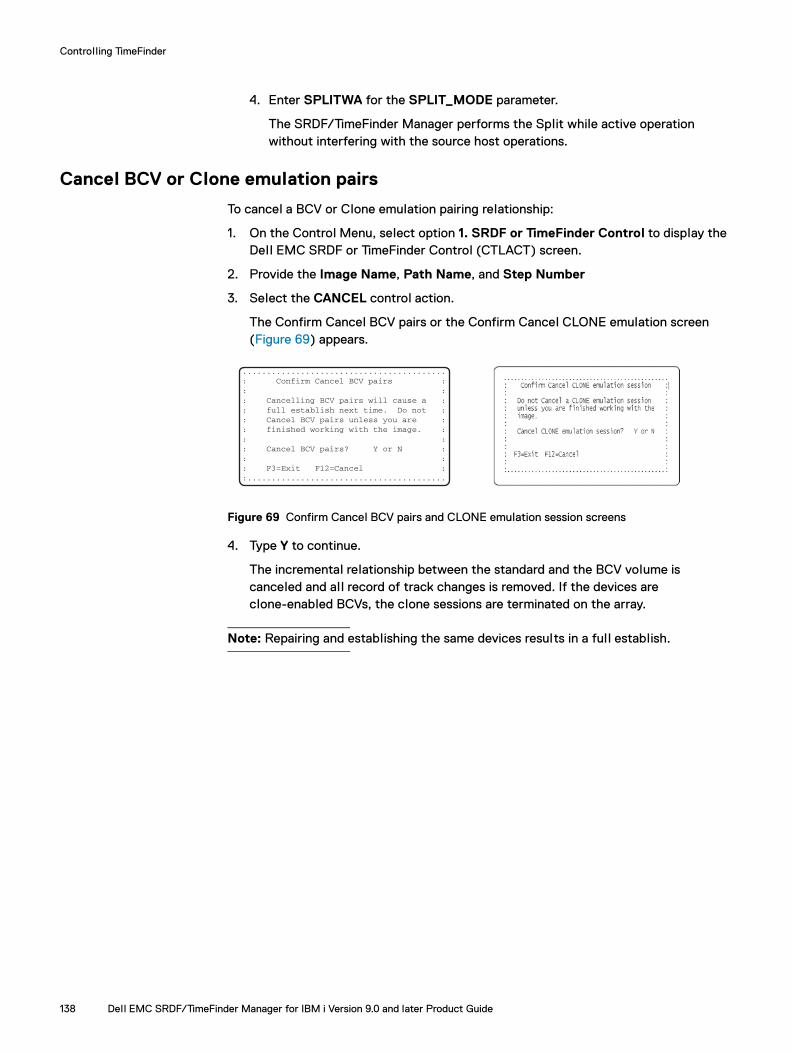
Controlling TimeFinder
4. Enter SPLITWA for the SPLIT_MODE parameter.
The SRDF/TimeFinder Manager performs the Split while active operation without interfering with the source host operations.
Cancel BCV or Clone emulation pairs
To cancel a BCV or Clone emulation pairing relationship:
1. On the Control Menu, select option 1. SRDF or TimeFinder Control to display the Dell EMC SRDF or TimeFinder Control (CTLACT) screen.
2. Provide the Image Name, Path Name, and Step Number
3. Select the CANCEL control action.
The Confirm Cancel BCV pairs or the Confirm Cancel CLONE emulation screen (Figure 69) appears.
Figure 69 Confirm Cancel BCV pairs and CLONE emulation session screens
4. Type Y to continue.
The incremental relationship between the standard and the BCV volume is canceled and all record of track changes is removed. If the devices are clone-enabled BCVs, the clone sessions are terminated on the array.
Note: Repairing and establishing the same devices results in a full establish.
..........................................: Confirm Cancel BCV pairs :: :: Cancelling BCV pairs will cause a :: full establish next time. Do not :: Cancel BCV pairs unless you are :: finished working with the image. :: :: Cancel BCV pairs? Y or N :: :: F3=Exit F12=Cancel ::.........................................
138 Dell EMC SRDF/TimeFinder Manager for IBM i Version 9.0 and later Product Guide
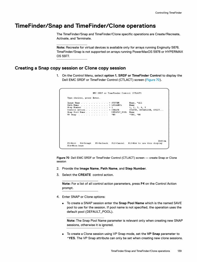
Controlling TimeFinder
TimeFinder/Snap and TimeFinder/Clone operations 139
TimeFinder/Snap and TimeFinder/Clone operationsThe TimeFinder/Snap and TimeFinder/Clone specific operations are Create/Recreate, Activate, and Terminate.
Note: Recreate for virtual devices is available only for arrays running Enginuity 5876. TimeFinder/Snap is not supported on arrays running PowerMaxOS 5978 or HYPERMAX OS 5977.
Creating a Snap copy session or Clone copy session
1. On the Control Menu, select option 1. SRDF or TimeFinder Control to display the Dell EMC SRDF or TimeFinder Control (CTLACT) screen (Figure 70).
Figure 70 Dell EMC SRDF or TimeFinder Control (CTLACT) screen — create Snap or Clone session
2. Provide the Image Name, Path Name, and Step Number.
3. Select the CREATE control action.
Note: For a list of al l control action parameters, press F4 on the Control Action prompt.
4. Enter SNAP or Clone options:
To create a SNAP session enter the Snap Pool Name which is the named SAVE pool to use for the session. If pool name is not specified, the operation uses the default pool (DEFAULT_POOL).
Note: The Snap Pool Name parameter is relevant only when creating new SNAP sessions, otherwise it is ignored.
To create a Clone session using VP Snap mode, set the VP Snap parameter to *YES. The VP Snap attribute can only be set when creating new clone sessions.

Controlling TimeFinder
For rules and restrictions for the snap pool name feature and VP Snap mode refer to “CTLACT” on page 194.
Note: If initiating Clone sessions using option 14 (Establish/Create) on the Work with Associated Paths screen, the Create VP Snap screen (Figure 71) appears only if al l devices in the image are running with Enginuity 5876 or higher, and the step status is NotCreated.
Figure 71 Create VP Snap screen
If a session previously was created and activated a confirmation screen appears (Figure 72) and recreate action is performed.
Figure 72 Confirm Recreate SNAP copy and Recreate CLONE copy session screens
SRDF/TimeFinder Manager creates the SNAP virtual copy or Clone copy session and displays a completion message.
Note: If initiating SNAP sessions using option 14 (Establish/Create), on the Work with Associated Paths screen (Figure 8 on page 48), and the status of the SNAP type of the step is NotCreated, the List of the Snap Save Pools screen(Figure 73 on page 141) appears. A pool can be selected from the list of save pools. If the image spans over several arrays, al l SNAP SAVE pools are displayed, and the pool that exists on all of the arrays should be selected.
140 Dell EMC SRDF/TimeFinder Manager for IBM i Version 9.0 and later Product Guide
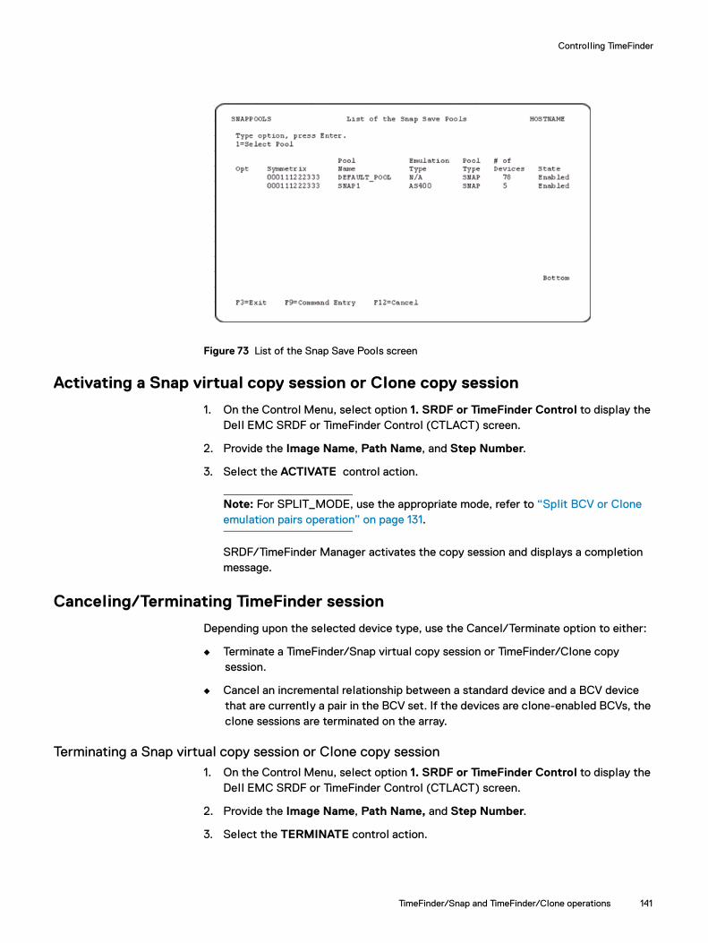
Controlling TimeFinder
Figure 73 List of the Snap Save Pools screen
Activating a Snap virtual copy session or Clone copy session
1. On the Control Menu, select option 1. SRDF or TimeFinder Control to display the Dell EMC SRDF or TimeFinder Control (CTLACT) screen.
2. Provide the Image Name, Path Name, and Step Number.
3. Select the ACTIVATE control action.
Note: For SPLIT_MODE, use the appropriate mode, refer to “Split BCV or Clone emulation pairs operation” on page 131.
SRDF/TimeFinder Manager activates the copy session and displays a completion message.
Canceling/Terminating TimeFinder session
Depending upon the selected device type, use the Cancel/Terminate option to either:
◆ Terminate a TimeFinder/Snap virtual copy session or TimeFinder/Clone copy session.
◆ Cancel an incremental relationship between a standard device and a BCV device that are currently a pair in the BCV set. If the devices are clone-enabled BCVs, the clone sessions are terminated on the array.
Terminating a Snap virtual copy session or Clone copy session1. On the Control Menu, select option 1. SRDF or TimeFinder Control to display the
Dell EMC SRDF or TimeFinder Control (CTLACT) screen.
2. Provide the Image Name, Path Name, and Step Number.
3. Select the TERMINATE control action.
TimeFinder/Snap and TimeFinder/Clone operations 141
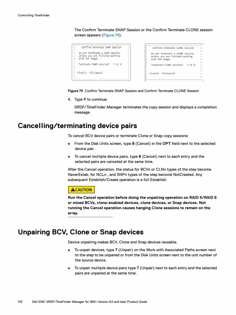
Controlling TimeFinder
The Confirm Terminate SNAP Session or the Confirm Terminate CLONE session screen appears (Figure 74).
Figure 74 Confirm Terminate SNAP Session and Confirm Terminate CLONE Session
4. Type Y to continue.
SRDF/TimeFinder Manager terminates the copy session and displays a completion message.
Cancelling/terminating device pairsTo cancel BCV device pairs or terminate Clone or Snap copy sessions:
◆ From the Disk Units screen, type 8 (Cancel) in the OPT field next to the selected device pair.
◆ To cancel multiple device pairs, type 8 (Cancel) next to each entry and the selected pairs are canceled at the same time.
After the Cancel operation, the status for BCVn or CLNn types of the step become NeverEstab, for NCLn , and SNPn types of the step become NotCreated. Any subsequent Establish/Create operation is a full Establish.
Run the Cancel operation before doing the unpairing operation on RAID 5/RAID 6 or mixed BCVs, clone-enabled devices, clone devices, or Snap devices. Not running the Cancel operation causes hanging Clone sessions to remain on the array.
Unpairing BCV, Clone or Snap devicesDevice unpairing makes BCV, Clone and Snap devices reusable.
◆ To unpair devices, type 7 (Unpair) on the Work with Associated Paths screen next to the step to be unpaired or from the Disk Units screen next to the unit number of the source device.
◆ To unpair multiple device pairs type 7 (Unpair) next to each entry and the selected pairs are unpaired at the same time.
142 Dell EMC SRDF/TimeFinder Manager for IBM i Version 9.0 and later Product Guide

Controlling TimeFinder
BCV device unpairing
For a standard or R2 device paired with a BCV device, the unpair option on a device removes pairing information, for the specified image.
A BCV pair cannot be unpaired while the devices are in a Synchronized, Restored, SyncInProg, or RestInProg state. Prior to performing this operation, the pairs must be split and canceled.
If clone emulation is enabled for the BCV pair, cancel the relationship prior to unpairing. If the BCVs were established, the information about the previous standard/BCV relationship is stored in the SYMAPI database. To recover the information about the devices, the devices must be paired again.
Snap device unpairing
For a standard or BCV device paired a virtual device, the unpair option on a device removes pairing information, for the specified image.
You cannot unpair Snap devices while the devices are in a CopyInProg, Copied, Created, CopyOnWrite, CreateInProg, RestInProg, or Restored state. Run the Terminate option before unpairing Snap devices.
Clone device unpairing
For a standard or BCV device paired with a standard or BCV device, the unpair option on a device removes pairing information, for the specified image.
Clone device unpairing cannot be done unless they are in a NotCreated state. Prior to performing this operation, terminate the pairs.
Recovering from a NotConsistent stateWhen BCV device pairs, in a step of an image, are at different states (for example one pair is in Synchronized state and another in Split state), the BCV status for that step of the image becomes NotConsistent.
To recover from a NotConsistent state:
◆ For BCV or Clone emulation devices, perform the Establish operation on BCV or Clone emulation pairs.
The Establish operation on BCV or Clone emulation pairs checks the state of each device pair that belongs to each step of the image.
If the state is eligible for the Establish command, the operation starts for that device pair. Otherwise, the job log receives an error message providing the device numbers and their status information.
◆ For Snap devices or Clone devices, perform a Create operation.
The Create operation checks the state of each device pair that belongs to each step of the image. If the state is eligible for the Create command, the operation starts for that device pair. Otherwise, the job log receives an error message providing the device numbers and their status information.
Recovering from a NotConsistent state 143
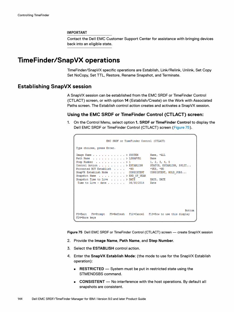
Controlling TimeFinder
IMPORTANT
Contact the Dell EMC Customer Support Center for assistance with bringing devices back into an eligible state.
TimeFinder/SnapVX operationsTimeFinder/SnapVX specific operations are Establish, Link/Relink, Unlink, Set Copy Set NoCopy, Set TTL, Restore, Rename Snapshot, and Terminate.
Establishing SnapVX session
A SnapVX session can be established from the EMC SRDF or TimeFinder Control (CTLACT) screen, or with option 14 (Establish/Create) on the Work with Associated Paths screen. The Establish control action creates and activates a SnapVX session.
Using the EMC SRDF or TimeFinder Control (CTLACT) screen:
1. On the Control Menu, select option 1. SRDF or TimeFinder Control to display the Dell EMC SRDF or TimeFinder Control (CTLACT) screen (Figure 75).
Figure 75 Dell EMC SRDF or TimeFinder Control (CTLACT) screen — create SnapVX session
2. Provide the Image Name, Path Name, and Step Number.
3. Select the ESTABLISH control action.
4. Enter the SnapVX Establish Mode: (the mode to use for the SnapVX Establish operation):
RESTRICTED — System must be put in restricted state using the STMENDSBS command.
CONSISTENT — No interference with the host operations. By default al l snapshots are consistent.
144 Dell EMC SRDF/TimeFinder Manager for IBM i Version 9.0 and later Product Guide

Controlling TimeFinder
IMPORTANT
Use Consistent Establish with care, as the data in main memory is not included in the image. Use this only when the host and applications are in a quiescent state. If that is unacceptable to your business needs, use other operating system functions like journaling and database commitment control to get an image current with the last transaction.
HOLD_JOBS — All jobs and job queues wil l be put on HOLD.
Note: To display a list of al l control action parameters, press F4 on the Control Action prompt.
5. Type a Snapshot Name.
The name can be used for multiple devices and/or multiple snapshots. For multiple snapshots for the same device with the same name, a generation number (Gen) is used to differentiate between these point-in-time copies. Snapshots and generation numbers are time stamped and are listed from newest to oldest with Gen 0 being the most recent snapshot.
6. Optional: Enter the Time To Live (TTL) — Sets the time when the snapshot is automatically terminated, and is specified in days from now (DAYS) or a future date can be set (DATE). The value in DAYS can be set from 1 to 400. The DATE value can be set to a date up to 400 days in the future from the time the ESTABLISH action occurs.
If a snapshot has TTL set and has one or more link targets, it is not terminated until links are unlinked. If the TTL value is not specified, the snapshot remains until it is manually terminated.
SRDF/TimeFinder Manager creates and activates the SnapVX session and displays the snapshot status as EstablishInProg while the copy is in progress. It then displays the status as Establish when the data is fully copied. Once established the snapshots are uniquely identified by name, Gen number, and source device for control actions.
Using the Work with Associated Paths screen1. On the Dell EMC SRDF/TimeFinder Manager for IBM i main menu, select option 1.
Work with Images to display the Symmetrix Configuration by Image screen (Figure 6 on page 46).
2. Select option 2. Work with paths to display the Work with Associated Paths screen (Figure 76 on page 146).
TimeFinder/SnapVX operations 145
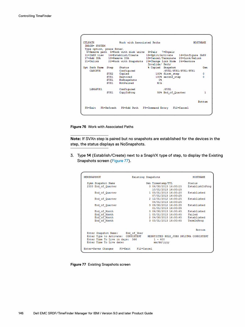
Controlling TimeFinder
Figure 76 Work with Associated Paths
Note: If SVXn step is paired but no snapshots are established for the devices in the step, the status displays as NoSnapshots.
3. Type 14 (Establish/Create) next to a SnapVX type of step, to display the Existing Snapshots screen (Figure 77).
Figure 77 Existing Snapshots screen
146 Dell EMC SRDF/TimeFinder Manager for IBM i Version 9.0 and later Product Guide

Controlling TimeFinder
4. Type a Snapshot Name.
The name can be used for multiple devices and/or multiple snapshots. For multiple snapshots for the same device with the same name, a generation number (Gen) is used to differentiate between these point-in-time copies. Snapshots and generation numbers are time stamped and are listed from newest to oldest with Gen 0 being the most recent snapshot.
5. Enter optional Time To Live (TTL) — Sets the time to when the snapshot is automatically terminated, and is specified in days from now (DAYS) or a future date can be set (DATE). The value in DAYS can be set from 1 to 400. The DATE value can be set to a date up to 400 days in the future from the time the ESTABLISH action occurs.
If a snapshot has TTL set and has one or more link targets, it is not terminated until links are unlinked. If the TTL value is not specified, the snapshot remains until it is manually terminated.
SRDF/TimeFinder Manager creates and activates the SnapVX session and displays the snapshot status as EstablishInProg while the copy is in progress, and then displays the status as Establish when the data is fully copied.
Renaming a Snapshot1. On the Dell EMC SRDF/TimeFinder Manager for IBM i main menu, select option 1.
Work with Images to display the Symmetrix Configuration by Image screen (Figure 6 on page 46).
2. Select option 2. Work with paths to display the Work with Associated Paths screen (Figure 76 on page 146).
3. Type 22 (Work with Snapshots) next to a SnapVX type of step, to display the Work with Snapshots screen (Figure 78 on page 148).
Note: The operations available from the Work with Snapshot screens, such as Link/Relink, Restore, Set TTL, Rename, and Terminate, are described in “TimeFinder SnapVX” on page 24.
TimeFinder/SnapVX operations 147

Controlling TimeFinder
Figure 78 Work with Snapshots screen
Note: If Snapshot has links, ‘L’ appears in the Status field. If Snapshot has restores, ‘R’ appears in the Status field. If snapshot has links and restores ‘L/R’ appears in the status field.
4. Type 7 (Rename) next to a snapshot to display the Rename snapshots screen (Figure 79).
Figure 79 Rename Snapshot screen
5. Type the New Snapshot Name.
Snapshot screens are updated with the new name.
148 Dell EMC SRDF/TimeFinder Manager for IBM i Version 9.0 and later Product Guide

Controlling TimeFinder
Displaying Snapshot details1. On the Dell EMC SRDF/TimeFinder Manager for IBM i main menu, select option 1.
Work with Images to display the Symmetrix Configuration by Image screen (Figure 6 on page 46).
2. Select option 2. Work with paths to display the Work with Associated Paths screen (Figure 76 on page 146).
3. Type 22 (Work with Snapshots) next to a SnapVX type of step, to display the Work with Snapshots screen (Figure 78 on page 148).
4. Type 5 (Show Details) next to a snapshot to display the Snapshot Details screen.
Figure 80 Snapshot Details screen
Table 12 Field descriptions For Snapshot Details screen (page 1 of 2)
Field Description
Symmetrix Symmetrix ID.
Snapshot The user assigned name of the snapshot.
Gen Generation number when there are multiple snapshots of the same name. Generation 0 is the most recent snapshot and the numbers increase for older point-in-time snapshots.
Timestamp Time when snapshot was established.
Time to Live The date and time when the snapshot wil l automatically be terminated (Time to Live feature requires auto-terminate to be the enabled state).
# Devices Number of snapshot source devices.
Established Number of the devices participating in the snapshot. This number wil l differ from the number of source devices only if of any of the devices is in a Failed or EstablishInProg state.
EstablishInProg Number of the devices transitioning to Established state
Linked Number of target devices linked to the snapshot in NoCopy mode.
TimeFinder/SnapVX operations 149
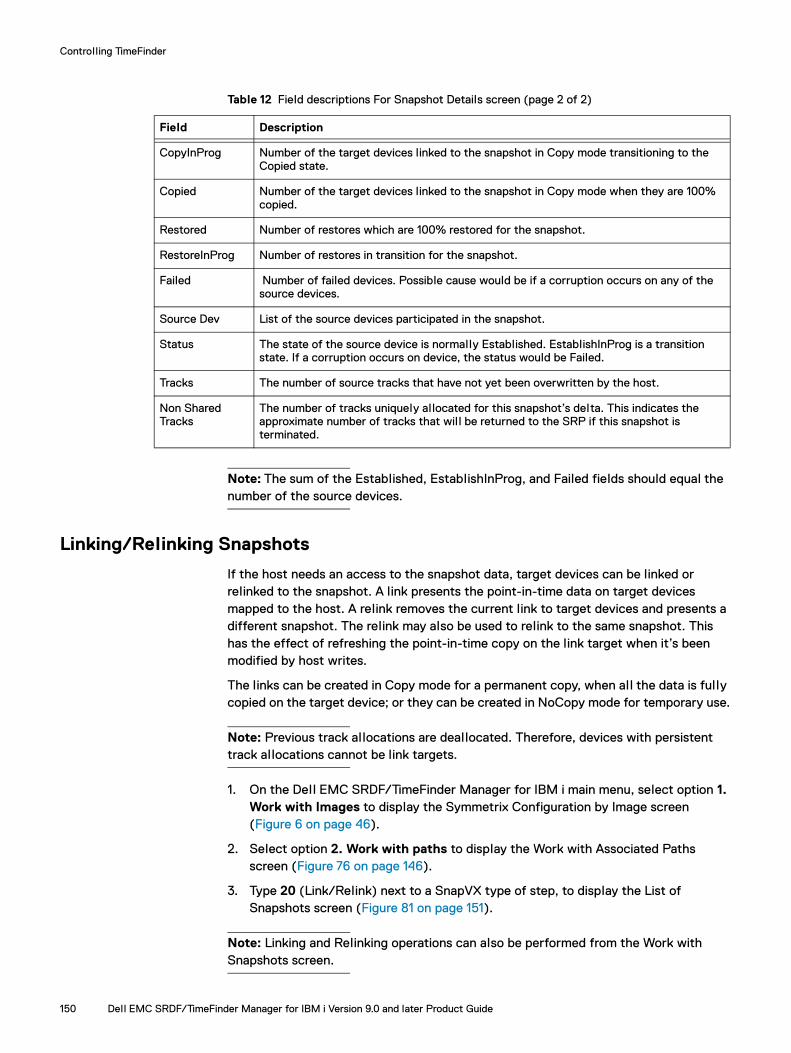
Controlling TimeFinder
Note: The sum of the Established, EstablishInProg, and Failed fields should equal the number of the source devices.
Linking/Relinking Snapshots
If the host needs an access to the snapshot data, target devices can be linked or relinked to the snapshot. A link presents the point-in-time data on target devices mapped to the host. A relink removes the current link to target devices and presents a different snapshot. The relink may also be used to relink to the same snapshot. This has the effect of refreshing the point-in-time copy on the link target when it’s been modified by host writes.
The links can be created in Copy mode for a permanent copy, when all the data is fully copied on the target device; or they can be created in NoCopy mode for temporary use.
Note: Previous track allocations are deallocated. Therefore, devices with persistent track allocations cannot be link targets.
1. On the Dell EMC SRDF/TimeFinder Manager for IBM i main menu, select option 1. Work with Images to display the Symmetrix Configuration by Image screen (Figure 6 on page 46).
2. Select option 2. Work with paths to display the Work with Associated Paths screen (Figure 76 on page 146).
3. Type 20 (Link/Relink) next to a SnapVX type of step, to display the List of Snapshots screen (Figure 81 on page 151).
Note: Linking and Relinking operations can also be performed from the Work with Snapshots screen.
CopyInProg Number of the target devices linked to the snapshot in Copy mode transitioning to the Copied state.
Copied Number of the target devices linked to the snapshot in Copy mode when they are 100% copied.
Restored Number of restores which are 100% restored for the snapshot.
RestoreInProg Number of restores in transition for the snapshot.
Failed Number of failed devices. Possible cause would be if a corruption occurs on any of the source devices.
Source Dev List of the source devices participated in the snapshot.
Status The state of the source device is normally Established. EstablishInProg is a transition state. If a corruption occurs on device, the status would be Failed.
Tracks The number of source tracks that have not yet been overwritten by the host.
Non Shared Tracks
The number of tracks uniquely allocated for this snapshot’s delta. This indicates the approximate number of tracks that wil l be returned to the SRP if this snapshot is terminated.
Table 12 Field descriptions For Snapshot Details screen (page 2 of 2)
Field Description
150 Dell EMC SRDF/TimeFinder Manager for IBM i Version 9.0 and later Product Guide
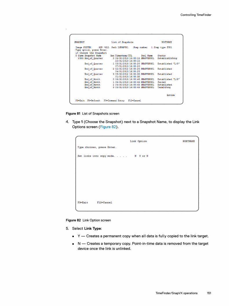
Controlling TimeFinder
.
Figure 81 List of Snapshots screen
4. Type 1 (Choose the Snapshot) next to a Snapshot Name, to display the Link Options screen (Figure 82).
Figure 82 Link Option screen
5. Select Link Type:
Y — Creates a permanent copy when all data is fully copied to the link target.
N — Creates a temporary copy. Point-in-time data is removed from the target device once the link is unlinked.
TimeFinder/SnapVX operations 151

Controlling TimeFinder
Viewing status of link/relink operationFrom the Disk Units screen and Work with Associated Paths screen the status displays as CopyInProg while the copy is in progress, and then as Linked when the data is fully copied. If the link is performed in copy mode, the status displays as Copied.
Snapshot linking can also be performed from the Dell EMC SRDF or TimeFinder Control (CTLACT) screen using the Control Action LINK. (Figure 75 on page 144).
Option 23 on the Work with Associated Paths screen (Figure 76 on page 146) changes Link Mode, from NoCopy to Copy mode or from Copy to NoCopy, when the status of the step is Linked/CopyInProg/Copied.
Unlinking Snapshots
Unlink all links before terminating a snapshot.
1. On the Dell EMC SRDF/TimeFinder Manager for IBM i main menu, select option 1. Work with Images to display the Symmetrix Configuration by Image screen (Figure 6 on page 46).
2. Select option 2. Work with paths to display the Work with Associated Paths screen (Figure 76 on page 146).
3. Type 21 (Unlink) next to a SnapVX type of step.
Note: Target devices can be unlinked if the status of the step is Linked or Copied.
The snapshot is unlinked from the target link. From the Work with Associated Paths screen the status of the SnapVX type of step displays as Established or Restored, if source devices are restored from snapshot.
Snapshot unlinking can also be performed from the Dell EMC SRDF or TimeFinder Control (CTLACT) screen using the Control Action UNLINK (Figure 75 on page 144).
Setting Time to Live
1. On the Dell EMC SRDF/TimeFinder Manager for IBM i main menu, select option 1. Work with Images to display the Symmetrix Configuration by Image screen (Figure 6 on page 46).
2. Select option 2. Work with paths to display the Work with Associated Paths screen (Figure 76 on page 146).
3. Type 22 (Work with Snapshots) next to a SnapVX type of step, to display the Work with Snapshots screen (Figure 78 on page 148).
4. Type 3 (TTL) next to a snapshot to display the Set Time To Live (Figure 79 on page 148).
152 Dell EMC SRDF/TimeFinder Manager for IBM i Version 9.0 and later Product Guide

Controlling TimeFinder
Figure 83 Set Time to Live screen
5. Enter the Time to Live in days or set a specific date. If you do not supply a value, the Time to Live value is set to unlimited and the snapshot is kept until it is manually terminated.
Setting Time to Live can also be performed from the Dell EMC SRDF or TimeFinder Control (CTLACT) screen using the Control Action SET_TTL (Figure 75 on page 144).
Restoring Snapshots
1. On the Dell EMC SRDF/TimeFinder Manager for IBM i main menu, select option 1. Work with Images to display the Symmetrix Configuration by Image screen (Figure 6 on page 46).
2. Select option 2. Work with paths to display the Work with Associated Paths screen (Figure 76 on page 146).
3. Type 22 (Work with Snapshots) next to a SnapVX type of step, to display the Work with Snapshots screen (Figure 78 on page 148).
4. Type 2 (Restore) next to a snapshot to copy point-in-time data back to the original source device (Figure 79 on page 148). The snapshot must be fully established to perform a restore.
Note: For System Image, a restore is not allowed for the first step.
A restore can also be performed from the Work with Associated Paths (Figure 76 on page 146 screen, or by using the Dell EMC SRDF or TimeFinder Control (CTLACT) screen using the control action RESTORE (Figure 75 on page 144).
TimeFinder/SnapVX operations 153

Controlling TimeFinder
Terminating Snapshots
Snapshots can only be terminated if there are no links (see “Unlinking Snapshots” on page 152).
1. On the Dell EMC SRDF/TimeFinder Manager for IBM i main menu, select option 1. Work with Images to display the Symmetrix Configuration by Image screen (Figure 6 on page 46).
2. Select option 2. Work with paths to display the Work with Associated Paths screen (Figure 76 on page 146).
3. Type 22 (Work with Snapshots) next to a SnapVX type of step, to display the Work with Snapshots screen (Figure 78 on page 148).
4. Type 8 (Terminate) next to the snapshot to be terminated.
Note: If Snapshot has restores, only restores would be terminated. Use Option 8 again to terminate a snapshot.
Snapshot termination can also be performed from the Dell EMC SRDF or TimeFinder Control (CTLACT) screen using the Control Action TERMINATE. (Figure 75 on page 144).
154 Dell EMC SRDF/TimeFinder Manager for IBM i Version 9.0 and later Product Guide

Controlling TimeFinder
Monitoring TimeFinder operations You can monitor the TimeFinder operations at the step level from the Work with Associated Paths screen or at the device level through the Disk Units screen. These procedures are in “Viewing devices” on page 95.
Monitoring invalid and % copied tracks
The Disk Unit screen and the Work with Associated Paths screen each have a column labeled Invalids/%Copied.
For SRDF or TimeFinder synchronization, this column lists the number of invalid tracks remaining during the synchronization operation. On the Disk Units screen invalid track counts display at the device level, and on the Work with Associated Paths screen invalid track counts display by image.
For TimeFinder/Clone, TimeFinder/Snap, and TimeFinder SnapVX operations, this column represents the percentage of copied tracks.
Note: The invalid tracks information is accurate only while synchronization is in progress. The invalid track information is not accurate while devices are Split or Activated.
For TimeFinder/SnapVX, when the COPY flag is set or when the source device is restored from the snapshot, this field displays percent of the total device size that has been copied to the target.
Monitoring TimeFinder operations 155
Controlling TimeFinder
Automating TimeFinder operationsSRDF/TimeFinder Manager provides the option of incorporating TimeFinder control operations in customized CL programs. The CL command, CTLACT, includes the following TimeFinder control actions and parameters:
◆ TimeFinder/BCV control actions are as follows:
ESTABLISH — Establishes/re-establishes BCV or Clone emulation pairs for BCV control.
SPLIT — Splits BCV or Clone emulation pairs for BCV control.
CANCEL — Cancels the existing TimeFinder device relationship.
STATUS — Provides TimeFinder control status information.
◆ TimeFinder/Snap and TimeFinder/Clone control actions are as follows:
CREATE — Creates or recreates a virtual copy session for making Snap data copies between source devices and target virtual devices; or creates/recreates a clone copy session that defines and sets up the cloning devices selected for the clone operation.
ACTIVATE — Activates a virtual copy session or clone copy session to make data instantly accessible to target host.
TERMINATE — Terminates a virtual copy session or clone copy session to remove holds on target devices and delete device pairing information from the array.
◆ The following SPLIT_MODE parameter options are available for both the SPLIT command and the ACTIVATE command:
SPLIT_MODE(RESTRICTED) — Splits BCV, Clone emulation. Activates Clone, or Snap image while the system is in a restricted state.
SPLIT_MODE(HOLD_JOBS) — Holds all jobs and job queues before performing a Split or Activate control operation.
SPLIT_MODE(SPLITWA) — Splits a local or remote BCV or Clone emulation. Activates Clone, or Snap image while the source system is operational.
SPLIT_MODE(MAINTENANCE) — Splits BCV, Clone emulation. Activates Clone, or Snap image in maintenance mode (that is, no interference with host operations).
◆ TimeFinder/SnapVX control actions are:
ESTABLISH — Creates and activates a SnapVX snapshot. SnapVX Establish Mode can be set to:
– RESTRICTED — Put a system in the restricted state by using option 5 from the Control menu using “Bring System to a Restricted State”, or with the STMENDSBS command. This ensures that al l subsystems and jobs are ended except for the daemon jobs and their corresponding subsystems.
– CONSISTENT — No interference with the host operations. By default al l snapshots are consistent.
156 Dell EMC SRDF/TimeFinder Manager for IBM i Version 9.0 and later Product Guide
Controlling TimeFinder
IMPORTANT
Use Consistent Establish with care as the data in main memory is not included in the image. Use this only when the host and applications are in a quiescent state. If that is unacceptable to your business needs, use other operating system functions like journaling and database commitment control to get an image current with the last transaction.
– HOLD_JOBS — All jobs and job queues wil l be put on HOLD.
STATUS — Provides control status information for the step in the associated path for the image. If status of the SVXn step is Linked, CopyInProg, Copied, Restored, RestoreInProg, RestNotPaired, or RestgNotPaired, the snapshot name and generation is provided. If Snapshot name and generation are specified, state of the specified snapshot is provided.
TERMINATE — Removes an existing SnapVX snapshot.
LINK — Presents the point-in-time data on target devices. If target devices are already linked, relink operation would be executed.
RENAME — Changes the snapshot name.
RESTORE — Copies the point-in-time data from a snapshot back to the original source device.
Note: If snapshot has restores, only restores are terminated.
SET_TTL — Sets a time to live for a snapshot as either number of days from now or a future date from now.
SETCOPY — Changes the copy mode of a link to “copy”.
SETNOCOPY — Changes the copy mode of a link to “nocopy”.
UNLINK — Removes the current link to target devices.
Automating TimeFinder operations 157

Controlling TimeFinder
158 Dell EMC SRDF/TimeFinder Manager for IBM i Version 9.0 and later Product Guide

CHAPTER 6Controlling SRDF
Invisible Body Tag
This chapter describes the procedures to control SRDF links, including how to enable and disable consistency protection for SRDF/A and set the RDF mode.
◆ Overview............................................................................................................ 160◆ Creating and controlling SRDF Groups .............................................................. 162◆ Setting the SRDF group attributes..................................................................... 165◆ Dynamic SRDF pairs ........................................................................................... 170◆ Setting modes of SRDF/A operation ................................................................... 175◆ Establishing SRDF links ...................................................................................... 176◆ Splitting/Suspending SRDF links operation ........................................................ 178◆ Monitoring SRDF operations.............................................................................. 184◆ Recovering from NotConsistent SRDF state ...................................................... 185◆ Listing and monitoring SRDF groups .................................................................. 185◆ Performing dynamic SRDF personality swaps..................................................... 187◆ Automating SRDF operations ............................................................................. 188
Controlling SRDF 159

Controlling SRDF
OverviewSRDF/TimeFinder Manager relies on a specific sequence of operations to ensure proper execution of SRDF control options. SRDF/TimeFinder Manager checks the configuration and operation considerations prior to executing a command that could change a device or system state.
SRDF Control operations are performed at the step level in the path for each image. These operations can be performed on both static and dynamic SRDF configurations, where:
◆ Static pairing occurs during initial array configuration
◆ Dynamic pairing occurs while the array is in operation.
However, static RDF groups and devices are not supported on arrays running PowerMaxOS 5978 or HYPERMAX OS 5977.
Note: SRDF/TimeFinder Manager does not perform a discover process automatically, which can take several minutes to run per operation. After changing the configuration of a host or array, turn on the discover function or use the DISCOVER command. “Discovering array and host configuration details” on page 63 shows how to perform a discover operation.
RDF group/device compatibility
SRDF/TimeFinder Manager supports only the following array replication configurations when creating RDF groups between PowerMaxOS 5978 or HYPERMAX OS 5977 arrays and other Enginuity versions:
◆ PowerMaxOS 5978 or HYPERMAX OS 5977 array ↔ Enginuity 5876 array with Enginuity fix 67492
◆ PowerMaxOS 5978 or HYPERMAX OS 5977 array ↔ PowerMaxOS 5978 or HYPERMAX OS 5977 array
Device grouping/pairing rules and restrictions between Enginuity/HYPERMAX OS versions:◆ Static device pairing is available between arrays running Enginuity levels earlier
than HYPERMAX OS 5977.
◆ For arrays running PowerMaxOS 5978 or HYPERMAX OS 5977, only dynamic SRDF groups and devices are supported, and, pairing of static SRDF groups/devices with dynamic SRDF groups or devices is not allowed.
◆ All SRDF groups created between arrays running PowerMaxOS 5978 or HYPERMAX OS 5977 and arrays runnning Enginuity 5876 can be created through the Solutions Enabler symrdf command or the SRDF/TimeFinder Manager “CTLRDFGRP”command, and only with dynamic RDF-capable devices.
The symrdf command is supported on IBM i and is run from the IBM i command line or Qshell. See “Supported Solutions Enabler CLI commands” on page 242, and refer to Solutions Enabler SYMCLI Command Reference Guide for details of command actions and parameters, and command options.
◆ All devices on arrays running PowerMaxOS 5978 or HYPERMAX OS 5977 are reported as dynamic RDF-capable.
160 Dell EMC SRDF/TimeFinder Manager for IBM i Version 9.0 and later Product Guide

Controlling SRDF
Adaptive copy write pending (ACWP) mode behavior with PowerMaxOS 5978 or HYPERMAX OS 5977
SRDF mode Adaptive Copy Write Pending (ACWP) is not available when the R1 mirror of the RDF pair is on an array running PowerMaxOS 5978 or HYPERMAX OS 5977. The CRTDLTRDFP, SETRDFMOD, and SETRDFMODC commands check the code level of the operating environment when you set the RDF mode to Adaptive Copy Write Pending.
SRDF/TimeFinder Manager sets the RDF mode to Adaptive Copy Disk mode when the R2 mirror of the SRDF pair is on an array running PowerMaxOS 5978 or HYPERMAX OS 5977 and you use:
◆ The CTLACTTGT command with the control action SWAP
or
◆ The CTLACTTGT or SRDFDRCTL commands with control action FAILOVER (with the ESTABLISH option or the RESTORE flag set)
Overview 161

Controlling SRDF
Creating and controlling SRDF GroupsBefore creating SRDF pairs, create dynamic SRDF groups. Use the CTLRDFGRP command to add, modify, or remove dynamic groups When adding dynamic SRDF groups, there are several parameters available that control the behavior of the group.
Creating dynamic SRDF groups
1. On the Control Menu, select option 10. Control Dynamic SRDF Groups to display the Control Dynamic RDF Group (CTLRDFGRP) screen (Figure 84).
Figure 84 Control Dynamic RDF Group (CTLRDFGRP) screen
2. Provide the following information for the selected image:
Control Action — Enter ADD. (Create new RDF group)
Symmetrix ID — The local array ID where this command is performed.
SRDF Group Label — The RDF group label.
SRDF Group Number — The RDF group number.
Note: For the ADD action specify both of the SRDF Group Label and SRDF Group Number parameters.
Director/Port Combination:
– Director IDent — The local array director ID, such as 1a, 1b and so on. – Port Number — The local array director port number. (0-31)
Note: For PowerMaxOS 5978 or HYPERMAX OS 5977 RDF directors support up to 32 ports.
Remote Symmetrix ID — Specifies remote array where this command is performed.
162 Dell EMC SRDF/TimeFinder Manager for IBM i Version 9.0 and later Product Guide

Controlling SRDF
Remote RDF Group Number — The remote RDF group number.
Remote Director/Port:
– Director IDent — The remote director ID, such as 1a, 1b and so on. – Port Number — The remote array director port number. (0-31)
Note: For HYPERMAX OS 5977 or later RDF directors support up to 32 ports.
Auto Link Recovery — YES (default)
Remote Auto Link Recovery — YES (default)
Link Limbo — 10 (default)
Note: Link Limbo — Only experienced SRDF users should use this option.
Specifies the local link limbo value which is the length of time for PowerMaxOS, HYPERMAX OS, or Enginuity to wait, from the point of a link-down detection, prior to updating the link status as Down. If the link status is stil l sensed as Not Ready after the link limbo time expires, devices are marked Not Ready to the link. The link limbo range is 0-120 seconds. The default time is 10 seconds. This option is used only with the ADD control action.
Remote Link Limbo — 10 (default). Same as link limbo except performed on a remote array.
3. Press Enter.
Modifying dynamic SRDF groups (associated/dissociated local and remote director/port with RDF group)
You also use the Control Dynamic RDF Group (CTLRDFGRP) screen (Figure 84 on page 162) to modify a dynamic group. When doing so, the following screen/command requirements and options are available:
◆ Control Action◆ Symmetrix ID◆ SRDF Group Label◆ SRDF Group Number
Note: You can specify either SRDF Group Label or Group Number.
◆ Actions for Modify — Add or Remove associated/dissociated local and remote director/port with the RDF group
◆ Director/Port Combination◆ Remote Director/Port
Creating and controlling SRDF Groups 163
Controlling SRDF
Removing dynamic SRDF groups
You also use the Control Dynamic RDF Group (CTLRDFGRP) screen (Figure 84 on page 162) to remove a dynamic group. You can remove only an empty dynamic group. Alternatively, you can use the List of the SRDF Groups screen (Figure 97 on page 185) to remove a dynamic group.
When removing a dynamic group the following screen/command requirement and options are available:
◆ Control Action◆ Symmetrix ID◆ SRDF Group Label◆ SRDF Group Number
Note: You can specify either SRDF Group Label or Group Number.
◆ Use Sym Force Flag
164 Dell EMC SRDF/TimeFinder Manager for IBM i Version 9.0 and later Product Guide

Controlling SRDF
Setting the SRDF group attributesSRDF group behavior can be controlled by setting group attributes, such as whether SRDF/A DSE is automatically activated, when a SRDF/A session is activated, and how SRDF/TimeFinder Manager should handle situations where the transmission link is idling.
Note: For arrays running PowerMaxOS 5978 or HYPERMAX OS 5977, DSE autostart for SRDF groups is enabled by default.
Note: If the SRDF/A group consists of D910 devices, the FBA DSE pool should be associated with the group. If the group consists of the 2107 devices, the AS400 DSE pool should be associated with the group. If group has mixed device s (2107 and D910) both types of DSE pools (FBA and AS400) should be associated to the group. Spil lover happens only to the DSE pool that has matching emulation.
Set the SRDF/A group as follows:
1. On the Control Menu, select option 11. Set RDF Group to display the Set SRDF Group (SETRDFGRP) screen (Figure 85).
Figure 85 Set SRDF Group (SETRDFGRP) screen
2. Provide the following information:
Symmetrix ID — The name of the array on which this command is performed.
Note: If you know the array ID, enter its name. Otherwise, press F4 to display a list of al l local and remote arrays attached to the host.
SRDF Group Number — The number of the RA group whose parameters should be modified.
Setting the SRDF group attributes 165
Controlling SRDF
SAVE Pool Name — The name of the SRDF/A DSE pool to be associated with the SRDF group. Options are as follows:
– *SAME — Use the pool that is currently associated.
– NO_POOL — Disassociate a pool from the group. Until the pool has a guarantee that it has been drained for the group, the pool remains related to the group.
Note: If more than one pool is associated to the group, al l pools are disassociated.
– Pool name — The name of the SAVE pool.
Setting a new pool name for the group replaces the existing associated pool name. This automatically disassociates the old pool from the group. If there is data from the group spil led over in the pool, the old pool is put in the draining state.
Note: Pools should be of the same type, if not the new pool is not associated to the group.
Note: For arrays running PowerMaxOS 5978 or HYPERMAX OS 5977, you cannot associate a DSE pool with an RDF group. For this configuration, the SETRDFGRP command does not associate an RDF group with a DSE pool. The array is preconfigured to associate the DSE with a Storage Resource Pool (SRP), so managing pools is not required.
DSE auto start — Whether SRDF/A DSE is automatically activated when the SRDF/A session is activated for the group. Options are as follows:
– ENABLE — Automatically activates SRDF/A DSE when an SRDF/A session is activated for the group.
– DISABLE — Does not automatically activate SRDF/A DSE when an SRDF/A session is activated for the group.
– *SAME — Ignores the parameter during command processing or when ENABLE/DISABLE is specified and DSE auto start is already in the desired state.
Note: For arrays running HYPERMAX OS 5977 or PowerMaxOS 5978, DSE autostart for SRDF groups is enabled by default.
DSE threshold — Specifies the percentage of the array's write pending limit. DSE threshold is an optional parameter.
Groups with higher threshold values keep their data in cache longer at the expense of groups with lower values. Valid values range from 20 to 100. If nothing is specified, or an SRDF group already has a desired DSE threshold, SRDF/TimeFinder Manager ignores this parameter during command processing.
Transmit idle — Specifies how SRDF/TimeFinder Manager should handle situations where the transmission link is idling. Options are as follows:
– ENABLE — Tolerates SRDF/A.
– DISABLE — Drops SRDF/A.
– *SAME — Ignores the parameter during command processing or when ENABLE or DISABLE is specified and Transmit Idle is already in the desired state.
166 Dell EMC SRDF/TimeFinder Manager for IBM i Version 9.0 and later Product Guide
Controlling SRDF
Device-level Write Pacing — Specifies whether SRDF/A device-level write pacing is automatically activated when SRDF/A session is activated for the group. Options are as follows:
– ENABLE — Automatically activate SRDF/A device-level write pacing when SRDF/A session is activated for the group.
– DISABLE — Do not automatically activate SRDF/A device-level write pacing when SRDF/A session is activated for the group.
– *SAME — Ignores the parameter during command processing, or when ENABLE or DISABLE is specified and SRDF/A device-level write pacing is already in the desired state. This is the default.
SRDF/A device-level write pacing feature is supported with the Enginuity 5876 or later.
Enabling SRDF/A device-level write pacing is required when using RDF2 Async device as a Snap source.
Write Pace Autostart — Specifies whether the SRDF/A group-level write pacing feature is automatically enabled or disabled when an SRDF/A session is activated for the SRDF group. Options are as follows:
– ENABLE — Automatically activates SRDF/A group-level write pacing when an SRDF/A session is activated for the group.
– DISABLE — Do not automatically activate SRDF/A group-level write pacing when an SRDF/A session is activated for the group.
– *SAME — Ignores the parameter during command processing, or when ENABLE or DISABLE is specified, and SRDF/A group-level write pacing is already in the desired state. This is the default.
Write Pace Delay — Sets the maximum host I/O delay, in microseconds, that triggers SRDF/A write pacing. Valid values are between 1 and 1000000 micro-seconds. Write pacing delay is an optional parameter. The default value is 50000 micro-seconds.
If the write pace delay is not specified, or an SRDF group already has a desired write pacing delay, SRDF/TimeFinder Manager ignores this parameter during command processing.
Write Pace Threshold — Sets the minimum percentage of the system write-pending cache at which the array begins pacing host write I/Os, for an SRDF group. Valid values are between 1 and 99. Write pacing threshold is an optional parameter. The default value is 60.
If the write pace threshold is not specified, or an SRDF group already has a desired write pacing threshold, SRDF/TimeFinder Manager ignores this parameter during command processing.
Note: SRDF/A group-level write pacing feature is available on Enginuity 5876 or later and PowerMaxOS 5978 or HYPERMAX OS 5977. If you plan to swap the personalities of the R1 and R2 devices, configure the same SRDF/A write pacing values on both devices.
Setting the SRDF group attributes 167
Controlling SRDF
Hardware compression — Specifies whether to enable or disable hardware compression for the SRDF group. Options are as follows:
– ENABLE — Enables hardware compression for the SRDF group.
– DISABLE — Disables hardware compression for the SRDF group.
– *SAME — Ignores the parameter during command processing, or when ENABLE or DISABLE is specified, and compression for the SRDF group is already in the desired state. This is the default.
Software compression — Specifies whether to enable or disable software compression for the SRDF group. Options are as follows:
– ENABLE — Enables software compression for the SRDF group.
– DISABLE — Disables software compression for the SRDF group.
– *SAME — Ignores the parameter during command processing, or when ENABLE or DISABLE is specified, and compression for the SRDF group is already in the desired state. This is the default.
Compression minimizes the amount of data to be transmitted over an SRDF link. Enabling hardware compression on GigE directors and software compression on Fibre and GigE directors using Solutions Enabler is available with Enginuity 5876 or later.
Rules and restrictions for compression are as follows:
– Enabling hardware compression on Fibre directors is available with Enginuity 5876 or later.
– Software and hardware compression can be enabled on the R1 and R2 sides of the SRDF link, but the actual compression takes place on the side initiating the I/O, which is typically the R1 side. Since most I/O requests are initiated from the R1 side, make sure compression is enabled on this side.
Auto Link Recovery — Specifies whether to use the Auto Link Recovery feature locally.
– ENABLE — Enables Auto Link Recovery.
– DISABLE — Disables Auto Link Recovery.
– *SAME — Ignores this parameter during command processing, if *SAME is specified, or if ENABLE or DISABLE is specified and Auto Link Recovery is in the desired state. This is the default.
Link Limbo — Specifies the length of time for Enginuity to wait from the point of link-down detection before actually updating the link status as down. If the link status is stil l sensed as Not Ready after the link limbo time expires, devices are marked Not Ready to the link. If nothing is specified, Ignores the parameter during command processing, if *SAME is specified, or if RDF group already has a desired link limbo value. The link limbo range is 0-120 seconds. The default time is 10 seconds.
Note: Only experienced SRDF users should use this option.
168 Dell EMC SRDF/TimeFinder Manager for IBM i Version 9.0 and later Product Guide

Controlling SRDF
Both Sides Flag - Specifies whether changes should be applied only locally or both locally and remotely:
– *YES — Changes are applied locally and remotely.
Note: If the remote side cannot be reached and the flag is set to YES, the command fails.
– *NO — Changes are applied locally. This is the default.
Setting the SRDF group attributes 169
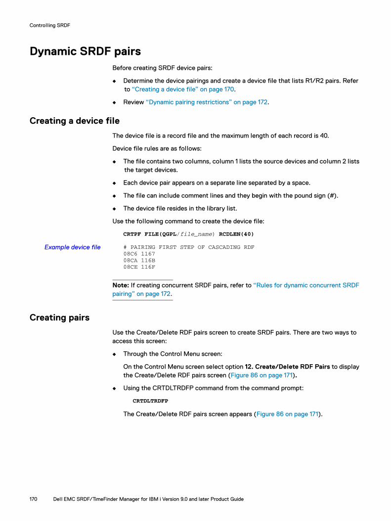
Controlling SRDF
Dynamic SRDF pairsBefore creating SRDF device pairs:
◆ Determine the device pairings and create a device file that lists R1/R2 pairs. Refer to “Creating a device file” on page 170.
◆ Review “Dynamic pairing restrictions” on page 172.
Creating a device file
The device file is a record file and the maximum length of each record is 40.
Device file rules are as follows:
◆ The file contains two columns, column 1 lists the source devices and column 2 lists the target devices.
◆ Each device pair appears on a separate line separated by a space.
◆ The file can include comment lines and they begin with the pound sign (#).
◆ The device file resides in the library list.
Use the following command to create the device file:
CRTPF FILE(QGPL/file_name) RCDLEN(40)
Example device file # PAIRING FIRST STEP OF CASCADING RDF08C6 116708CA 116B08CE 116F
Note: If creating concurrent SRDF pairs, refer to “Rules for dynamic concurrent SRDF pairing” on page 172.
Creating pairs
Use the Create/Delete RDF pairs screen to create SRDF pairs. There are two ways to access this screen:
◆ Through the Control Menu screen:
On the Control Menu screen select option 12. Create/Delete RDF Pairs to display the Create/Delete RDF pairs screen (Figure 86 on page 171).
◆ Using the CRTDLTRDFP command from the command prompt:
CRTDLTRDFP
The Create/Delete RDF pairs screen appears (Figure 86 on page 171).
170 Dell EMC SRDF/TimeFinder Manager for IBM i Version 9.0 and later Product Guide
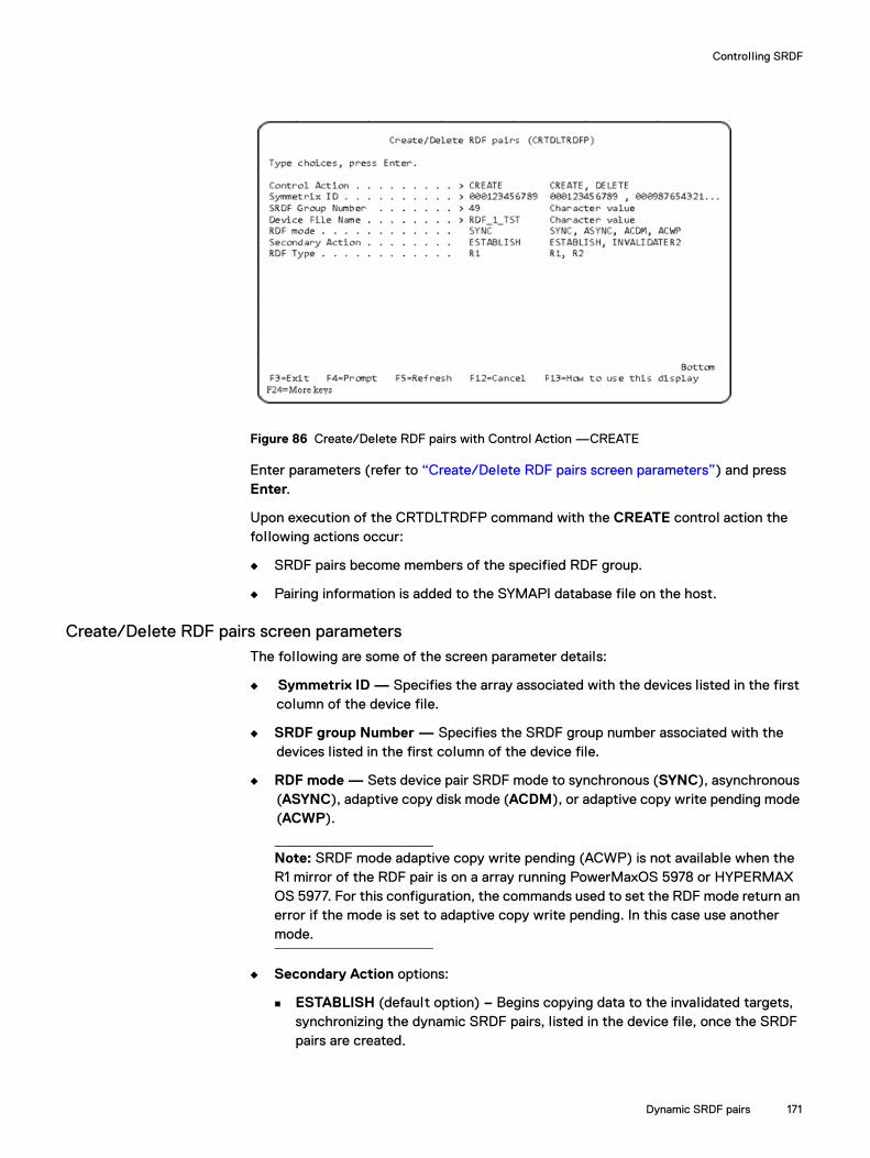
Controlling SRDF
Figure 86 Create/Delete RDF pairs with Control Action —CREATE
Enter parameters (refer to “Create/Delete RDF pairs screen parameters”) and press Enter.
Upon execution of the CRTDLTRDFP command with the CREATE control action the following actions occur:
◆ SRDF pairs become members of the specified RDF group.
◆ Pairing information is added to the SYMAPI database file on the host.
Create/Delete RDF pairs screen parametersThe following are some of the screen parameter details:
◆ Symmetrix ID — Specifies the array associated with the devices listed in the first column of the device file.
◆ SRDF group Number — Specifies the SRDF group number associated with the devices listed in the first column of the device file.
◆ RDF mode — Sets device pair SRDF mode to synchronous (SYNC), asynchronous (ASYNC), adaptive copy disk mode (ACDM), or adaptive copy write pending mode (ACWP).
Note: SRDF mode adaptive copy write pending (ACWP) is not available when the R1 mirror of the RDF pair is on a array running PowerMaxOS 5978 or HYPERMAX OS 5977. For this configuration, the commands used to set the RDF mode return an error if the mode is set to adaptive copy write pending. In this case use another mode.
◆ Secondary Action options:
ESTABLISH (default option) – Begins copying data to the invalidated targets, synchronizing the dynamic SRDF pairs, listed in the device file, once the SRDF pairs are created.
Dynamic SRDF pairs 171

Controlling SRDF
Note: When RDF Mode is ASYNC and the ESTABLISH option is selected, consistency protection is automatically enabled for the new device pair after executing a CREATE operation. Also, if the SRDF group for the new devices already contains devices, the CONS_EXEMPT (consistency exempt) flag is automatically enabled. The CONS_EXEMPT flag allows devices to be added to the SRDF group without affecting the state of the SRDF/A session, or requiring that other devices in the session be suspended. Consistency protection is automatically enabled for the new device pair if it is already enabled for other devices in the group.
INVALIDATER2 — Marks the R2 devices in the device file list to be the invalidated target for a full device copy once the SRDF pairs are created.
◆ RDF Type — Indicates whether the device in the first column of the device file is an R1 or an R2 device.
Rules for dynamic concurrent SRDF pairing
The following rules apply when creating dynamic concurrent SRDF pairs:
◆ Remote BCVs that have been designated as dynamic SRDF devices are not supported.
◆ The two SRDF mirrors of the concurrent device must be assigned to different RA groups.
◆ The concurrent dynamic SRDF, dynamic SRDF, and concurrent SRDF states must be enabled in the array configuration.
Two separate device files must be created when dynamically creating a second remote mirror using the CRTDLTRDFP command. One file lists the first set of R1/R2 device pairs, and the other device file lists the same R1 devices paired with different remote R2 devices. Refer to “Creating a device file” on page 170.
Dynamic pairing restrictions
The CREATE option fails if any of the following apply:
◆ The device is in one of the following BCV pair states: Synchronized, SyncInProg, Restored, RestoreInProg, or SplitInProg.
◆ The device is the source or target of a TimeFinder/Snap operation.
◆ There is a background BCV split operation in progress.
◆ Devices are in the back-end Not Ready state.
◆ The type, size of the devices, configuration are not the same, such as IBM i which has specific pairing rules.
Note: For migration, larger R2 devices are allowed for D910 devices.
◆ There are existing, local invalid tracks on either the local or remote device.
◆ The SRDF group is in asynchronous mode and the devices being added are not the same SRDF type R1 or R2.
172 Dell EMC SRDF/TimeFinder Manager for IBM i Version 9.0 and later Product Guide
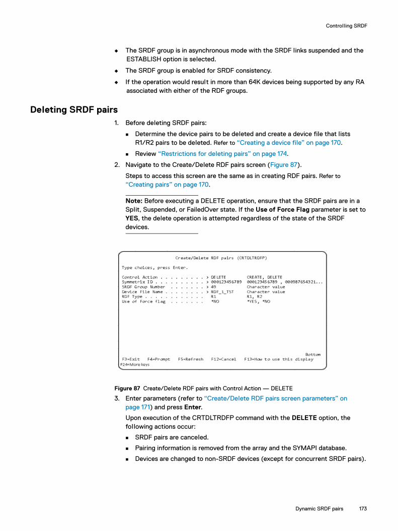
Controlling SRDF
◆ The SRDF group is in asynchronous mode with the SRDF links suspended and the ESTABLISH option is selected.
◆ The SRDF group is enabled for SRDF consistency.
◆ If the operation would result in more than 64K devices being supported by any RA associated with either of the RDF groups.
Deleting SRDF pairs1. Before deleting SRDF pairs:
Determine the device pairs to be deleted and create a device file that lists R1/R2 pairs to be deleted. Refer to “Creating a device file” on page 170.
Review “Restrictions for deleting pairs” on page 174.
2. Navigate to the Create/Delete RDF pairs screen (Figure 87).
Steps to access this screen are the same as in creating RDF pairs. Refer to
“Creating pairs” on page 170.
Note: Before executing a DELETE operation, ensure that the SRDF pairs are in a Split, Suspended, or FailedOver state. If the Use of Force Flag parameter is set to YES, the delete operation is attempted regardless of the state of the SRDF devices.
Figure 87 Create/Delete RDF pairs with Control Action — DELETE
3. Enter parameters (refer to “Create/Delete RDF pairs screen parameters” on page 171) and press Enter.
Upon execution of the CRTDLTRDFP command with the DELETE option, the following actions occur:
SRDF pairs are canceled.
Pairing information is removed from the array and the SYMAPI database.
Devices are changed to non-SRDF devices (except for concurrent SRDF pairs).
Dynamic SRDF pairs 173
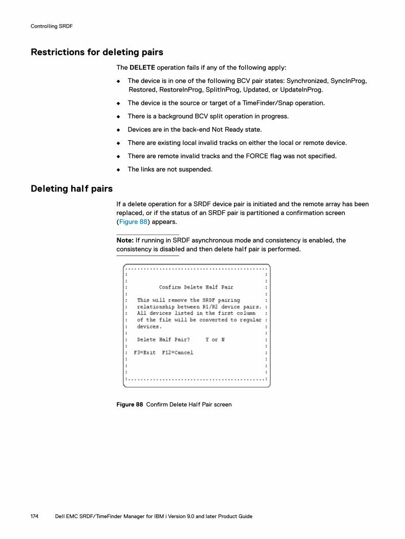
Controlling SRDF
Restrictions for deleting pairs
The DELETE operation fails if any of the following apply:
◆ The device is in one of the following BCV pair states: Synchronized, SyncInProg, Restored, RestoreInProg, SplitInProg, Updated, or UpdateInProg.
◆ The device is the source or target of a TimeFinder/Snap operation.
◆ There is a background BCV split operation in progress.
◆ Devices are in the back-end Not Ready state.
◆ There are existing local invalid tracks on either the local or remote device.
◆ There are remote invalid tracks and the FORCE flag was not specified.
◆ The links are not suspended.
Deleting half pairs
If a delete operation for a SRDF device pair is initiated and the remote array has been replaced, or if the status of an SRDF pair is partitioned a confirmation screen (Figure 88) appears.
Note: If running in SRDF asynchronous mode and consistency is enabled, the consistency is disabled and then delete half pair is performed.
Figure 88 Confirm Delete Half Pair screen
174 Dell EMC SRDF/TimeFinder Manager for IBM i Version 9.0 and later Product Guide

Controlling SRDF
Setting modes of SRDF/A operationSRDF modes of operation are SRDF/Synchronous (SYNC), SRDF/Asynchronous (ASYNC), adaptive copy disk mode (ACDM), and adaptive copy write pending (ACWP).
Note: SRDF mode adaptive copy write pending (ACWP) is not available when the R1 mirror of the RDF pair is on a array running PowerMaxOS 5978 or HYPERMAX OS 5977. For this configuration, the commands used to set the RDF mode return an error if the mode is set to adaptive copy write pending. In this case use another mode.
To set the SRDF mode for a selected image, path:
1. On the Control Menu, select option 4. Set SRDF mode to display the Set SRDF Mode (SETRDFMOD) screen (Figure 89).
Figure 89 Set SRDF Mode (SETRDFMOD) screen
2. Provide the characteristics of the selected image:
Image Name — The name of the image to perform a control action on. Path Name — The path name associated with the image on which to perform a
control action. Step Number — The step number for which the control action is to be initiated. SRDF Mode Type — The mode to use for SRDF operations. The options are:
– SYNC enables SRDF/Synchronous mode. – ASYNC enables SRDF/Asynchronous mode.– ACDM enables adaptive copy disk mode.– ACWP enables adaptive copy write pending mode.
Note: Note: SRDF mode Adaptive Copy Write Pending (ACWP) is not available when the R1 mirror of the RDF pair is on an array running PowerMaxOS 5978 or HYPERMAX OS 5977.
3. Press Enter.
IMPORTANT
For SRDF, do not use ACDM or ACWP mode while creating the RDF or remote TimeFinder images during split as this is not supported. Instead, for SRDF, use SYNC or ASYNC mode.
You can also use the SETRDFMOD command from the command line. Refer to “SETRDFMOD” on page 231 for more information.
Set SRDF Mode (SETRDFMOD)
Type choice, press Enter:
Image NamePath Name . . . . . . . . . . .Step Number . . . . . . . . . .SRDF Mode Type . . . . . . . . .
BottomF3=Exit F4=Prompt 5=Refresh F12=Cancel F13=How to use this display F24=More keys
Name Name 1, 2, 3, 4, 5 SYNC, ASYNC, ACDM, ACWP
. . . . . . . . . . .
Setting modes of SRDF/A operation 175

Controlling SRDF
Consistency protection in SRDF/A mode
In SRDF Asynchronous mode, consistency protection can be enabled or disabled for SRDF/A devices. When consistency protection is enabled, if data cannot be copied from the R1 to the R2, al l devices in the group are made Not Ready on the link to preserve the R2 data consistency.
In Asynchronous mode, consistency protection is automatically enabled after the control action Resume or Establish is run. When the control action Split or Suspend is run, consistency protection is disabled and the Split or Suspend operation is performed. If consistency protection is enabled for the devices, consistency protection must be disabled before you attempt to change the mode from Asynchronous.
Enabling consistency protection
To enable SRDF/A consistency protection:
1. On the Control Menu, select option 1. SRDF or TimeFinder Control to display the EMC SRDF or TimeFinder Control (CTLACT) screen.
2. Provide the Image Name, Path Name, and Step Number
3. Select the control action ENABLE.
A message appears indicating that the enable consistency protection operation started successfully.
Disabling consistency protection
To disable SRDF/A consistency protection:
1. On the Control Menu, select option 1. SRDF or TimeFinder Control to display the EMC SRDF or TimeFinder Control (CTLACT) screen.
2. Provide the Image Name, Path Name, and Step Number.
3. Select the control action DISABLE.
A message appears indicating that the disable consistency protection operation started successfully.
Establishing SRDF linksTo establish SRDF links:
1. On the Control Menu, select option 1. SRDF or TimeFinder Control to display the EMC SRDF or TimeFinder Control (CTLACT) screen.
2. Provide the Image Name, Path Name, and Step Number.
3. Select the control action ESTABLISH.
176 Dell EMC SRDF/TimeFinder Manager for IBM i Version 9.0 and later Product Guide
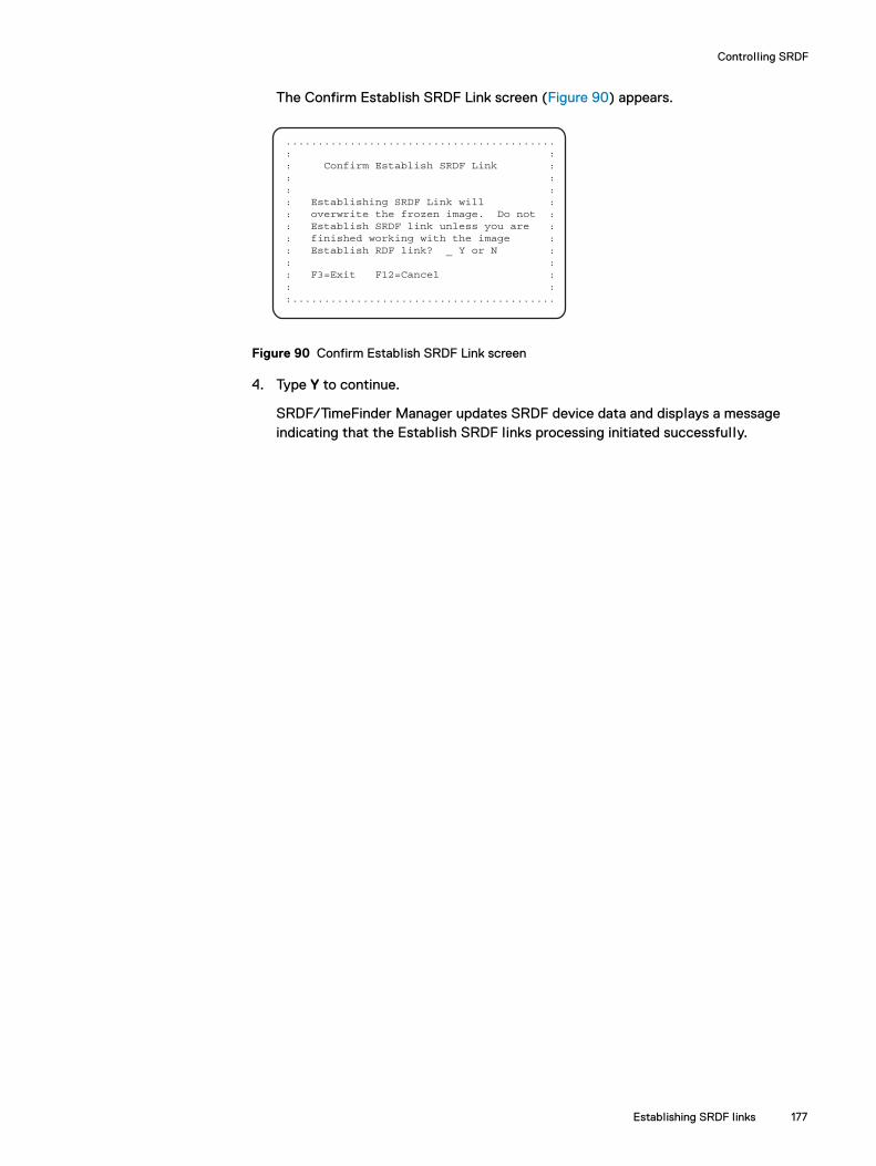
Controlling SRDF
Establishing SRDF links 177
The Confirm Establish SRDF Link screen (Figure 90) appears.
Figure 90 Confirm Establish SRDF Link screen
4. Type Y to continue.
SRDF/TimeFinder Manager updates SRDF device data and displays a message indicating that the Establish SRDF links processing initiated successfully.
..........................................: :: Confirm Establish SRDF Link :: :: :: Establishing SRDF Link will :: overwrite the frozen image. Do not :: Establish SRDF link unless you are :: finished working with the image :: Establish RDF link? _ Y or N :: :: F3=Exit F12=Cancel :: ::.........................................
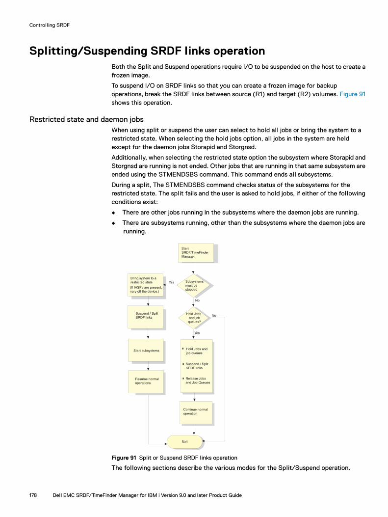
Controlling SRDF
Splitting/Suspending SRDF links operationBoth the Split and Suspend operations require I/O to be suspended on the host to create a frozen image.
To suspend I/O on SRDF links so that you can create a frozen image for backup operations, break the SRDF links between source (R1) and target (R2) volumes. Figure 91 shows this operation.
Restricted state and daemon jobsWhen using split or suspend the user can select to hold all jobs or bring the system to a restricted state. When selecting the hold jobs option, al l jobs in the system are held except for the daemon jobs Storapid and Storgnsd.
Additionally, when selecting the restricted state option the subsystem where Storapid and Storgnsd are running is not ended. Other jobs that are running in that same subsystem are ended using the STMENDSBS command. This command ends all subsystems.
During a split, The STMENDSBS command checks status of the subsystems for the restricted state. The split fails and the user is asked to hold jobs, if either of the following conditions exist:
◆ There are other jobs running in the subsystems where the daemon jobs are running.
◆ There are subsystems running, other than the subsystems where the daemon jobs are running.
Figure 91 Split or Suspend SRDF links operation
The following sections describe the various modes for the Split/Suspend operation.
StartSRDF/TimeFinderManager
Subsystemsmust bestopped
YesBring system to a restricted state
Suspend / Split SRDF links
Start subsystems
Resume normaloperations
Yes
No
No
Hold Jobs andjob queues
Suspend / Split SRDF links
Release Jobs and Job Queues
Hold Jobs and job queues?
Exit
Continue normaloperation
(If IASPs are present, vary off the device.)
178 Dell EMC SRDF/TimeFinder Manager for IBM i Version 9.0 and later Product Guide

Controlling SRDF
Splitting/Suspending SRDF links: Restricted state
The following procedure uses the restricted state to ensure that I/O activity is halted before the SRDF link is suspended or split.
Depending on the configuration, the time it takes for a host to go into a restricted state can vary. By default, SRDF/TimeFinder Manager waits 1800 seconds for control to return, after issuing the command to bring the system to a restricted state. If additional time (in seconds) is required to bring the system to a restricted state, use the procedure “Setting the restricted state wait time” on page 60.
For IASP images, see “SRDF/TimeFinder Manager Extended Features” on page 283.
To split/suspend SRDF links in a restricted state:
1. Bring the IBM i host to a restricted state:
a. Prepare for bringing the system to a restricted state, using internal procedures established by your company.
b. On the Control Menu, select option 5. Bring system to a restricted state to display the STM End Subsystem Confirmation screen.
c. Press F10 to bring the IBM i host to a restricted state.
The STM End All Subsystems (STMENDSBS) screen (Figure 92) appears.
Figure 92 STM End All Subsystems (STMENDSBS) screen
d. Select options for How to end and Controlled end delay time, and press Enter.
After the End Subsystem operation completes, the Control Menu appears.
2. Split/suspend SRDF links:
a. From the Control Menu, select option 1. SRDF or TimeFinder Control to display the EMC SRDF or TimeFinder Control (CTLACT) screen.
b. Provide the Image Name, Path Name, and Step Number.
c. Select the SPLIT or SUSPEND control action.
Splitting/Suspending SRDF links operation 179

Controlling SRDF
d. The Dell EMC SRDF or TimeFinder Control (CTLACT) screen reappears with a Split/Suspend Mode prompt.
e. Enter RESTRICTED for the SPLIT_MODE parameter.
SRDF/TimeFinder Manager checks to see if the system is in a restricted state. If the system is not in a restricted state, SRDF/TimeFinder Manager displays the Confirmation Window screen (Figure 93) asking if you want to hold jobs and job queues.
Figure 93 System not in restricted state screen
To continue the operation in HOLD_JOBS mode, refer to “Suspend/Split SRDF links: Hold jobs and job queues” on page 181 and take the appropriate action.
A message screen appears indicating that the Split SRDF links operation started successfully.
SRDF/TimeFinder Manager attempts to perform the SRDF links operation on all ASPs in the image. ASPs that are not eligible for the operation must be removed (see “Removing ASPs from an image” on page 75).
3. Start subsystems:
a. On the Control Menu, select option 6. Start subsystems.
The Start Subsystems command resumes normal IBM i working processes from the IBM host restricted state.
Note: The start subsystems command checks to see if the daemon jobs are the only jobs running in their dedicated subsystems. If the system is not in a restricted state, or there are other jobs running besides the daemon jobs, a message appears. This command then brings the system into a true restricted state by ending all subsystems including daemon jobs. When this is complete, the controlling subsystem is started. This should start al l the required subsystems and jobs, depending on what jobs are defined as auto start jobs and what is set as a startup program defined in the system value QSTRUP. If you use additional start-up procedures, run them separately. Start Subsystems does not power cycle the IBM i host or restart the OS/400 operating system.
b. Resume normal operations.
180 Dell EMC SRDF/TimeFinder Manager for IBM i Version 9.0 and later Product Guide

Controlling SRDF
Suspend/Split SRDF links: Hold jobs and job queues
The following procedure holds jobs and job queues to ensure that I/O activity is halted prior to the Split or Suspend SRDF links operation.
System activity that results in a write operation can continue while jobs and job queues are on hold. For example, a restore job could have write operations continue while it is held. If you are not sure that the hold job and job queues option completely suspend write operations to the selected image, bring the system to a restricted state before running a Split or Suspend operation. “Splitting/Suspending SRDF links: Restricted state” on page 179 contains instructions on how to do this.
To split or suspend SRDF links with jobs and job queues on hold:
1. On the Control Menu, select option 1. SRDF or TimeFinder Control to display the Dell EMC SRDF or TimeFinder Control (CTLACT) screen.
2. Provide the Image Name, Path Name, and Step Number.
3. Select the SPLIT or SUSPEND control action.
The Dell EMC SRDF or TimeFinder Control (CTLACT) screen reappears with a Split/Suspend mode prompt.
4. Enter HOLD_JOBS for the SPLIT_MODE parameter.
Note: The SRDF link status for the image must be in an eligible state.
SRDF/TimeFinder Manager repeatedly attempts to put all jobs and job queues on hold and then executes the Split or Suspend operation.
When one or more jobs or job queues remain active, SRDF/TimeFinder Manager displays the Confirmation Window screen (Figure 94).
Figure 94 Confirmation Window screen
............................................: Confirmation Window :: :: You have Jobs or Job Queues, :: that are not on HOLD. :: :: Do you want to continue? _ 1, 2, 3 or 5 :: :: 1 - Try again to hold Jobs/Queues :: 2 - Continue Split/Suspend operation :: 3 - Abort :: 5 - Display, what is not on HOLD ::..........................................:
Splitting/Suspending SRDF links operation 181

Controlling SRDF
5. Select the appropriate option:
1 - Try again to hold Jobs/Queues — SRDF/TimeFinder Manager repeatedly attempts to hold all jobs and job queues.
If any job or job queues remain not on hold, the Confirmation screen reappears.
2 - Continue Split/Suspend operation — Accept that some jobs remain active and continue with the Split or Suspend operation.
Selecting the Continue Split/Suspend operation acknowledges that some write activity can continue during the Split operation. If any writes occur to the specified ASP during the Split operation, the resulting copy is not valid.
3 - Abort — Do not perform the Split or Suspend operation and return to the Control Menu.
5 - Display, what is not on HOLD — Show a list of the jobs and job queues that SRDF/TimeFinder Manager cannot hold (Figure 95).
Figure 95 Jobs Not on Hold and Job Queues Not on Hold screens
6. Press F3 or Enter to return to the Confirmation Window screen.
After al l jobs and job queues are successfully on hold, or if option 2 - Continue Split/Suspend operation is selected from the Confirmation Window screen, the Suspend or Split operation is performed. A message screen appears indicating that the Split or Suspend SRDF links operation started successfully.
After the Split or Suspend operation is complete, al l jobs and job queues held by SRDF/TimeFinder Manager are released.
7. Use the Work with Associated Paths screen or the Disk Units screen to monitor and verify the change in links status.
Jobs that are NOT on HOLD 1/28/07 09:54:50
User Job Job Subsystem Job Name Name Number Name Status QUSER QZBSEVTM 000612 QSYSWRK EVTW QUSER QZDASOINIT 000681 QSERVER PSRW QTCP QTMSNMPRCV 000683 QSYSWRT TIMW F3 or ENTER=Exit
Job queues from active subsystems 1/28/07 09:54:50 that are NOT on HOLD
Job Queue Job Queue Subsystem Job Queue Name Library Name Status QSPL QGPL QSPL RELEASED QSYSNOMAX QSYS QSYSWRK RELEASED QINTER QGPL QSYSWRK RELEASED F3 or ENTER=Exit
182 Dell EMC SRDF/TimeFinder Manager for IBM i Version 9.0 and later Product Guide
Controlling SRDF
Splitting/Suspending SRDF links: Maintenance mode
Performing a Suspend/Split operation in maintenance mode suspends or splits the SRDF links without interfering with the source host operations.
Unless you employ another method of suspending write operations, the Split or Suspend SRDF Links maintenance operation results in an R2 copy that is not usable.
Note: If you use an R2 copy in a simple SRDF R1/R2 configuration, perform a Split or Suspend with Restricted state or a Split or Suspend with HOLD_JOBS.
To suspend or split SRDF links in maintenance mode:
1. On the Control Menu, select option 1. SRDF or TimeFinder Control to display the EMC SRDF or TimeFinder Control (CTLACT) screen.
2. Provide the Image Name, Path Name, and Step Number.
3. Select the SPLIT or SUSPEND control action.
The EMC SRDF or TimeFinder Control (CTLACT) screen reappears with a Split/Suspend mode prompt.
4. Enter MAINTENANCE for the SPLIT_MODE parameter.
The Split SRDF links or Suspend SRDF links operation performs without interfering with the source host operations.
Resuming SRDF operation
SRDF/TimeFinder Manager on the source IBM i host is used to restore SRDF operation by resuming the links between source (R1) and target (R2) volumes.
Note: The Resume SRDF links operation cannot be used when the SRDF links status is Split.
Resuming the SRDF links before backup is complete may result in unusable backup tapes or save files. Use the Work with Associated Paths screen or the Disk Units screen to monitor and verify the change in links status.
To resume SRDF links:
1. On the Control Menu, select option 1. SRDF or TimeFinder Control to display the EMC SRDF or TimeFinder Control (CTLACT) screen.
2. Provide the Image Name, Path Name, and Step Number.
3. Select the control action RESUME.
Splitting/Suspending SRDF links operation 183
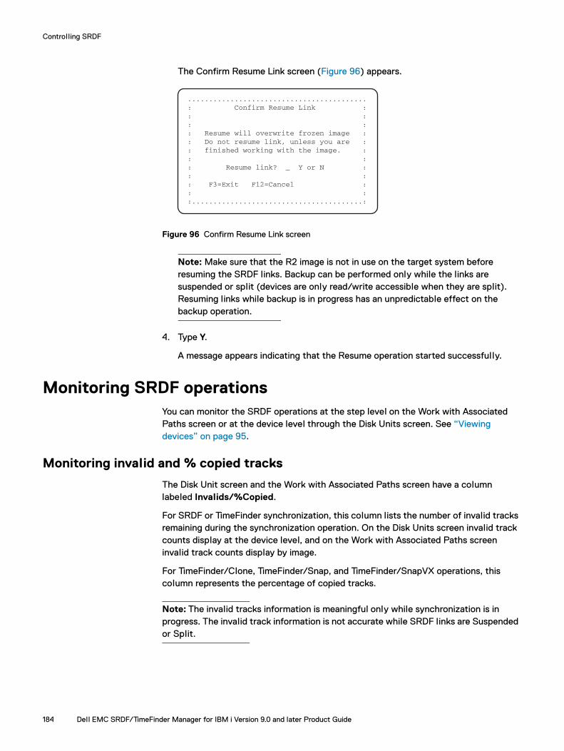
Controlling SRDF
The Confirm Resume Link screen (Figure 96) appears.
Figure 96 Confirm Resume Link screen
Note: Make sure that the R2 image is not in use on the target system before resuming the SRDF links. Backup can be performed only while the links are suspended or split (devices are only read/write accessible when they are split). Resuming links while backup is in progress has an unpredictable effect on the backup operation.
4. Type Y.
A message appears indicating that the Resume operation started successfully.
Monitoring SRDF operationsYou can monitor the SRDF operations at the step level on the Work with Associated Paths screen or at the device level through the Disk Units screen. See “Viewing devices” on page 95.
Monitoring invalid and % copied tracks
The Disk Unit screen and the Work with Associated Paths screen have a column labeled Invalids/%Copied.
For SRDF or TimeFinder synchronization, this column lists the number of invalid tracks remaining during the synchronization operation. On the Disk Units screen invalid track counts display at the device level, and on the Work with Associated Paths screen invalid track counts display by image.
For TimeFinder/Clone, TimeFinder/Snap, and TimeFinder/SnapVX operations, this column represents the percentage of copied tracks.
Note: The invalid tracks information is meaningful only while synchronization is in progress. The invalid track information is not accurate while SRDF links are Suspended or Split.
..........................................: Confirm Resume Link :: :: :: Resume will overwrite frozen image :: Do not resume link, unless you are :: finished working with the image. :: :: Resume link? _ Y or N :: :: F3=Exit F12=Cancel :: ::........................................:
184 Dell EMC SRDF/TimeFinder Manager for IBM i Version 9.0 and later Product Guide
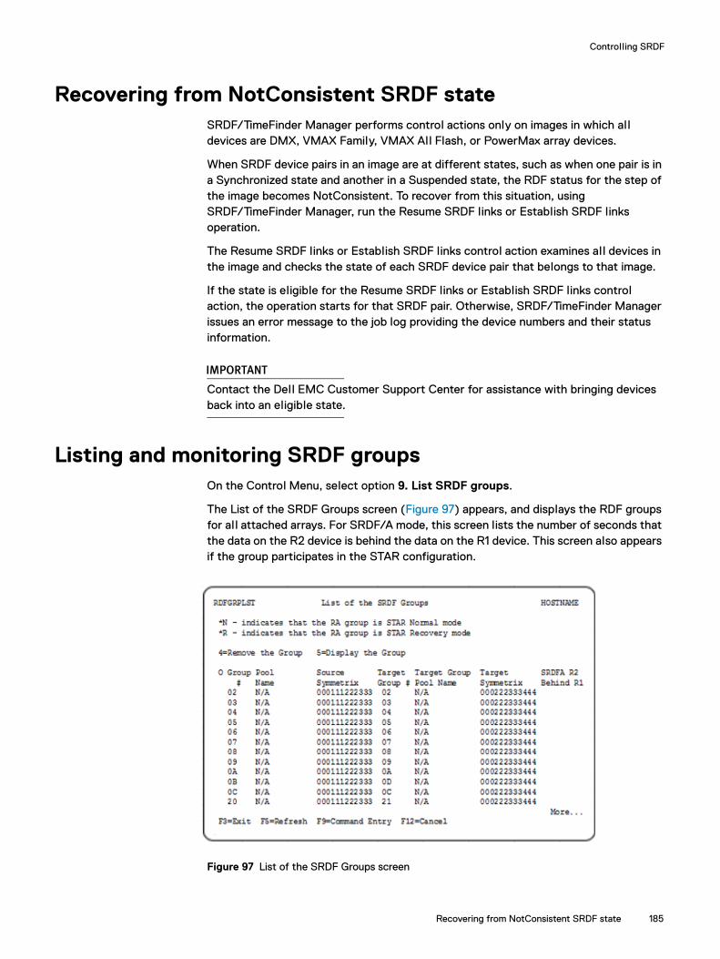
Controlling SRDF
Recovering from NotConsistent SRDF stateSRDF/TimeFinder Manager performs control actions only on images in which all devices are DMX, VMAX Family, VMAX All Flash, or PowerMax array devices.
When SRDF device pairs in an image are at different states, such as when one pair is in a Synchronized state and another in a Suspended state, the RDF status for the step of the image becomes NotConsistent. To recover from this situation, using SRDF/TimeFinder Manager, run the Resume SRDF links or Establish SRDF links operation.
The Resume SRDF links or Establish SRDF links control action examines all devices in the image and checks the state of each SRDF device pair that belongs to that image.
If the state is eligible for the Resume SRDF links or Establish SRDF links control action, the operation starts for that SRDF pair. Otherwise, SRDF/TimeFinder Manager issues an error message to the job log providing the device numbers and their status information.
IMPORTANT
Contact the Dell EMC Customer Support Center for assistance with bringing devices back into an eligible state.
Listing and monitoring SRDF groupsOn the Control Menu, select option 9. List SRDF groups.
The List of the SRDF Groups screen (Figure 97) appears, and displays the RDF groups for al l attached arrays. For SRDF/A mode, this screen lists the number of seconds that the data on the R2 device is behind the data on the R1 device. This screen also appears if the group participates in the STAR configuration.
Figure 97 List of the SRDF Groups screen
Recovering from NotConsistent SRDF state 185
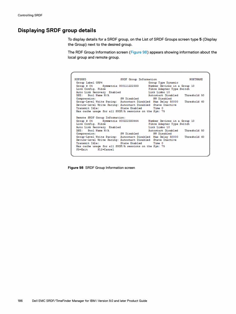
Controlling SRDF
Displaying SRDF group details
To display details for a SRDF group, on the List of SRDF Groups screen type 5 (Display the Group) next to the desired group.
The RDF Group Information screen (Figure 98) appears showing information about the local group and remote group.
Figure 98 SRDF Group Information screen
186 Dell EMC SRDF/TimeFinder Manager for IBM i Version 9.0 and later Product Guide

Controlling SRDF
Performing dynamic SRDF personality swapsSRDF/TimeFinder Manager supports Dynamic SRDF. This section explains how to use SRDF/TimeFinder Manager, after using the Solutions Enabler CLI for personality swaps.
For more information on dynamic SRDF, refer to the Dell EMC Solutions Enabler SRDF CLI User Guide.
Dynamic personality SRDF (R2R1) swaps for the System image (*SYSBAS) must be performed through the Solutions Enabler CLI. After the swap, launch SRDF/TimeFinder Manager from the target host and use any remote devices (BCV, Clone, Snap, and SnapVX) as local devices. However, as Table 13 shows, depending on the step in the path, additional path association may be necessary.
Table 13 Steps in the path and its associated action after personality swap
Source Target Target status after swap Associated action after swap
/BCV1/RDF1/BCV1
/RDF1/BCV1/BCV1
Both pairs are associated No action required
/BCV1 /BCV1 NotConfigured No action required
/RDF1/BCV1 Does not exist Need to associate
/RDF1/BCV1 /RDF1/BCV1 NotConfigured No action required
/BCV1 Does not exist Need to associate
Performing dynamic SRDF personality swaps 187
Controlling SRDF
Automating SRDF operationsSRDF/TimeFinder Manager provides the option of incorporating SRDF control operations in your customized CL programs. The CL command, CTLACT, includes the following SRDF control options:
◆ SRDF control actions:
ESTABLISH — Establishes SRDF links for SRDF control.
RESUME — Resumes SRDF links for SRDF control.
SUSPEND — Suspends SRDF links for SRDF control.
SPLIT — Splits SRDF links for SRDF control.
SPLIT_MODE(RESTRICTED) — Splits/suspends SRDF links for SRDF control while the system is in a restricted state.
SPLIT_MODE(HOLD_JOBS) — Holds all jobs and job queues before performing a Split or Suspend control operation.
SPLIT_MODE(MAINTENANCE) — Splits/suspends SRDF links for SRDF control in maintenance mode (that is, no interference with host operations).
STATUS — Provides SRDF control status information.
◆ SRDF/Asynchronous control actions:
ENABLE — Enables the consistency protection for SRDF/A devices.
DISABLE — Disables the consistency protection for SRDF/A devices.
Note: Appendix A, “Standard Features Commands Reference,” contains detailed command reference information.
188 Dell EMC SRDF/TimeFinder Manager for IBM i Version 9.0 and later Product Guide
Appendix AStandard Features Commands Reference
visible Body Tagefernce
This appendix provides reference information, syntax, and examples for control commands.
◆ Conventions....................................................................................................... 190◆ CRTDLTRDFP ..................................................................................................... 191◆ CRTNETCNFG................................................................................................... 193◆ CTLACT ............................................................................................................. 194◆ CTLPOOL .......................................................................................................... 202◆ CTLRDFGRP...................................................................................................... 208◆ DISCOVER......................................................................................................... 212◆ DISCOVERC ...................................................................................................... 213◆ ENDSTMSRV..................................................................................................... 214◆ RELDEVLCK ...................................................................................................... 215◆ RELDEVLCKC .................................................................................................... 216◆ RTVSTMINF ....................................................................................................... 217◆ SAVEPOOL........................................................................................................ 225◆ SETRDFGRP...................................................................................................... 226◆ SETRDFMOD...................................................................................................... 231◆ STMENDSBS..................................................................................................... 232◆ STMRMTCMD ................................................................................................... 234◆ STMSTRSBS ..................................................................................................... 235◆ STORDAEMON.................................................................................................. 236◆ STRSTMSRV ..................................................................................................... 240
Standard Features Commands Reference 189
Standard Features Commands Reference
ConventionsThe descriptions of the commands in this appendix can contain the following sections:
◆ Syntax — Presents the syntax of the command. Variables that you specify are shown in italics. The optional parameters are indicated by brackets.
◆ Description — Describes the purpose and result of the command.
◆ Required parameters — Describes parameters that must be specified at the command line. Each description contains all possible values of the variable and states which, if any, of the values is the default. Variables that you must specify are shown in italics.
◆ Optional parameters — Describes parameters that can be included at the command line. Each description contains all possible values of the variable and states which, if any, of the values is the default. Variables that you can specify are shown in brackets.
◆ Usage notes — Presents specific points that you should keep in mind when using the command.
◆ Examples — Presents one or more examples of the command.
190 Dell EMC SRDF/TimeFinder Manager for IBM i Version 9.0 and later Product Guide

Standard Features Commands Reference
CRTDLTRDFPCreates or deletes SRDF pairs while the array is in operation.
SyntaxCRTDLTRDFP ACTION(CREATE|DELETE) SYMID(sym_id)GRPNUM(group_number) FILENAME(device_file_name)[RDF_MODE(rdf_mode)] [RDF_FLAG(ESTABLISH|INVALIDATER2)] [RDF_TYPE(R1|R2)] [FORCE_FLAG(*YES|*NO)]
Description Creates or deletes SRDF pairs while the array is in operation. All RDF device pairs created between PowerMaxOS 5978 or HYPERMAX OS 5977 arrays and Enginuity 5876 arrays must be created with dynamic RDF-capable devices. All devices running on arrays running PowerMaxOS 5978 or HYPERMAX OS 5977 are reported as dynamic RDF-capable.
Required parametersSYMID(sym_id)
The Symmetrix ID specified in this field is associated with the devices listed in the first column of the device file.
GRPNUM(group_number)SRDF group Number. The group number specified in this field is associated with the devices listed in the first column of the device file.
FILENAME(device_file_name) Name of the file that lists the designated device pairs.
ACTION(control_action)Specifies the control operation to perform:
CREATE — SRDF pairs become members of the specified RDF group. Pairing information is added to the SYMAPI database file on the host.
DELETE — SRDF pairs are canceled and pairing information is removed from the array and the SYMAPI database. Devices are changed to non-SRDF devices (except for concurrent SRDF pairs).
Optional parametersRDF_MODE(rdf_mode)
Sets device pair SRDF mode:
SYNC — Synchronous (default)
ASYNC — Asynchronous
ACDM — Adaptive copy disk mode
ACWP — Adaptive copy write pending
CRTDLTRDFP 191

Standard Features Commands Reference
Note: SRDF mode adaptive copy write pending (ACWP) is not available when the R1 mirror of the RDF pair is on an array running PowerMaxOS 5978 or HYPERMAX OS 5977. For this configuration, the CRTDLTRDFP command returns an error if the mode is set to adaptive copy write pending. In this case use another mode.
RDF_FLAG(ESTABLISH|INVALIDATER2)Sets RDF copying options as follows:
ESTABLISH (default option) — Once the SRDF pairs are created, begins copying data to the invalidated targets, synchronizing the dynamic SRDF pairs that are listed in the device file.
INVALIDATER2 — Once the SRDF pairs are created, marks the R2 devices that are listed in the device file as the invalidated target for a full device copy.
RDF_TYPE(R1|R2)Indicates whether the device in the first column of the device file is an R1 or an R2 device. R1 is the default.
FORCE_FLAG(*YES|*NO) Indicates whether to use or not use the force flag during DELETE operation. *NO is the default.
192 Dell EMC SRDF/TimeFinder Manager for IBM i Version 9.0 and later Product Guide

Standard Features Commands Reference
CRTNETCNFGCreates the NETCNFG file and adds network services to the file.
SyntaxCRTNETCNFG NODENAME(node_name) NETWADDR(ip_address)SECLVL(DEFAULT|ANY|NONSECURE|SECURE) PORTNBR(port_number)
DescriptionCRTNETCNFG creates the NETCNFG file in the /var/symapi/config directory and adds network services to the file. Specify either the node name or the IP address of the remote SYMAPI server. You cannot omit both of these parameters. In addition, the security level of the connection type is mandatory.
Required parametersNODENAME(node_name)
The name of the remote SYMAPI server. NODENAME is required if the NETWADDR parameter has not been specified.
Note: When using a node name, make sure the node name is also entered into the host table of the system or is listed in the DNS tables of the attached network.
NETWADDR(ip_address)The IP address of the remote SYMAPI server. NETWADDR is required if the NODENAME parameter has not been specified.
SECLVL(DEFAULT|ANY|NONSECURE|SECURE)The security level for the connection type that the SYMAPI server is expecting to negotiate:
DEFAULT — The SYMAPI client and server are initial ly configured to negotiate either secure or non-secure sessions. This is the default.
ANY — Indicates that either secure or non-secure sessions are negotiated between the client and the server if the SSL (secure socket layer) capabilities do not agree and between supported and unsupported platforms.
NONSECURE — Indicates that only non-secure sessions are negotiated between the client and the server. This level is intended as the last resort in situations where SSL cannot be used for some reason or is undesirable. NONSECURE can be useful in matters of performance and availability.
SECURE — Indicates that only secure sessions are negotiated between the open host and the server. This level is intended in situations where SSL desirable.
Note: The SECURE option is not supported on the IBM i hosts.
PORTNBR(port_number)The TCP/IP port number for the remote SYMAPI server.
The default value is 2707.
CRTNETCNFG 193

Standard Features Commands Reference
CTLACTProcesses SRDF and TimeFinder control actions for one or al l images (SYSTEM and IASP).
Do not use the CTLACT command with IASP images, except for initial IASP configuration. Instead, use the options on the Work with Associated Paths screen or the IASPCTL command. Using either these ensures that SRDF/TimeFinder Manager does rigorous error checking before executing the control actions against the IASPs. For more information, see “IASPCTL” on page 357.
SyntaxCTLACT IMAGE_NAME(image_name|*ALL)PATH_NAME(path_name)STEPNUM(step_number)ACTION(control_action)[SPLIT_MODE(RESTRICTED|HOLD_JOBS|SPLITWA|MAINTENANCE)][PROT_ESTAB(*YES|*NO)][POOL_NAME(pool_name)][VP_SNAP(*YES|*NO)][SVX_MODE(CONSISTENT|HOLD_JOBS| RESTRICTED)][SNAPVXNAME(snapshot_name)][SNAPVXGEN(snapshot_generation)][SNAPVXTTL(DAYS|DATE)][N_SNPSHOT(new_snapshot_name)][LINK_MODE(NOCOPY|COPY)][TTL_DAYS(1-400)][TTL_DATE(Date)]
DescriptionCTLACT processes the control action specified in the ACTION parameter for the IMAGE parameter, PATH parameter, and the STEPNUM parameter. If the specified control action is directed to any of the Suspended/Split SRDF links, Split BCV pairs, an Activate Snap virtual copy session, or Clone copy session, use the SPLIT_MODE parameter to specify which method to use to stop writes to the devices in the image.
If SnapVX Establish control action is specified, use the SVX_MODE parameter to specify which method to use when stopping writes to the devices in the image.
You can use CTLACT to control multiple images as long as all images use the same path and step number.
Required parametersIMAGE_NAME(image_name|*ALL)
The name of the image (image_name) or *ALL to indicated all images.
PATH_NAME(path_name)The path name associated with the image to be used in an SRDF or TimeFinder control operation.
STEPNUM(step_number)The specific step number for which the control action is initiated in an SRDF or TimeFinder control operation.
Steps in the path are defined during configuration and are identified by their position (1 through 5) in the path.
194 Dell EMC SRDF/TimeFinder Manager for IBM i Version 9.0 and later Product Guide

Standard Features Commands Reference
ACTION(control_action)Specifies which control operation to perform:
STATUS — Provides SRDF, Snap, Clone, Clone emulation, BCV, or SnapVX control status information for the step in the associated path of the image. For SnapVX, if a snapshot name and generation are specified, the state of the specified snapshot is provided.
Note: If the status of the SnapVX step is Linked, CopyInProg, Copied, Restored, RestoreInProg, RestNotPaired, or RestgNotPaired an additional message is provided with the snapshot name and generation.
ESTABLISH — Establishes SRDF links for SRDF control or establishes/re-establishes BCV or Clone emulation pairs for BCV control. When running in SRDF/A mode, consistency protection is automatically enabled after executing an ESTABLISH operation is executed.
For SnapVX type of step, ESTABLISH creates and activates a SnapVX snapshot session.
SPLIT — Splits SRDF links for SRDF control or splits BCV or Clone emulation pairs for TimeFinder control. When the system is running in SRDF/A mode and a SPLIT is executed, consistency protection is disabled and then the SPLIT operation is performed.
Note: For TimeFinder/Clone configurations, if the devices are in Restored state, use the SPLIT option to change the direction of the clone relationship (that is, the original source device becomes the source device for a future copy), which allows the use of the RECREATE command and normal processing continues. This does not apply if VP Snap is enabled.
RESUME — Resumes SRDF links for SRDF control. When the system is running in SRDF/A mode, consistency protection is automatically enabled after a RESUME operation is executed.
SUSPEND — Suspends SRDF links for SRDF control. When the system is running in SRDF/A mode and a SUSPEND is executed, the consistency protection is disabled and then the SUSPEND operation is performed.
ENABLE — Enables the consistency protection for SRDF/A backed devices when running in SRDF/A mode. If data cannot be copied from the R1 to the R2, al l devices in the group become Not Ready on the link to preserve the R2 data consistency.
Note: If devices are enabled for consistency group protection, the devices must be disabled before you can change the mode to Synchronous or initiate the SPLIT/SUSPEND operation.
DISABLE — Disables the consistency protection for SRDF/A backed devices when running in SRDF asynchronous mode.
CTLACT 195

Standard Features Commands Reference
CREATE — Creates or recreates a TimeFinder/Snap virtual copy session or Clone copy session with devices in the image. While the operation is in progress for TimeFinder/Snap, the state of the device pair is CreateInProg. For TimeFinder/Clone the state of the device pair is PreCopy. When the Create operation completes, the state changes to Created.
You must run CREATE before you activate the session, which has a shorter duration than an Establish operation.
For TimeFinder Snap, Recreate is only available in environments running Enginuity 5876 or higher.
See “TimeFinder/Snap Usage notes” on page 200 for more information about using Recreate.
ACTIVATE — Activates a TimeFinder/Snap virtual copy session or Clone copy session with the devices in the image. For TimeFinder/Snap, while the operation is in progress the state of the device pair is CopyOnWrite. For TimeFinder/Clone, while the operation is in progress the state of the device pair is CopyInProg. Once the copy is complete, the state changes to Copied.
Note: The point-in-time copy becomes available after an ACTIVATE operation. Create must be done before you can activate a TimeFinder/Snap copy session or Clone copy session.
LINK — Copies the SnapVX point-in-time data to the target device.
There are two types of links, NOCOPY (the default) or COPY. NOCOPY links do not retain point-in-time data once the link is removed and any previous target data is lost. Copy mode must be used in order for the linked target to retain data after the link is removed. When linking a snapshot, COPY or NOCOPY must be specified.
RELINK — Removes the current SnapVX link to target device(s) and presents a different snapshot. The relink may also be used to relink to the same snapshot. This has the effect of refreshing the point-in-time copy on the link target if it has been modified by host writes.
UNLINK - Removes the current SnapVX link to target device(s).
RESTORE — For SnapVX , copies the point-in-time data from a snapshot back to the original source device. The snapshot must be fully established to perform a restore. Restore action is not allowed for the first step for a System Image.
RENAME — Changes the SnapVX snapshot name. Renames on the specified generation. If generation is not specified, then generation 0 is renamed.
SET TTL — Sets a time to live for a SnapVX snapshot, from when TTL is set, in days or a date. The value in days can be set to any value between 1 and 400. The date value is a specified date up to 400 days in the future, from which a value in days is created, based on the difference between the specified absolute time and the host time when the action is performed. When the TTL expires the snapshot automatically terminates unless there are one or more links. Automatic termination takes place when the links are removed. If TTL is not set, the snapshot remains established until it is manually terminated.
196 Dell EMC SRDF/TimeFinder Manager for IBM i Version 9.0 and later Product Guide

Standard Features Commands Reference
SETCOPY - Changes the copy mode of a link to copy. Data is physically copied to the target device(s). When the link is terminated the data is retained on the target.
SETNOCOPY - Changes the copy mode of a link to NoCopy. Data is presented on the target device(s), but not physically copied. When the link is terminated the data is not retained on the target.
TERMINATE — Stops the existing TimeFinder/Snap virtual copy session or Clone copy session between the specified source and target devices in the image.
For SnapVX snapshot sessions, TERMINATE removes the snapshot. All links must be unlinked before terminating a snapshot.
Note: If a snapshot has restores, only the restored session is terminated.
CANCEL — Cancels the existing internal session between the specified standard device and the BCV devices in the image.
Once the session is canceled, the corresponding BCV devices are placed in a SplitNoInc state, and the BCV pair can no longer be incrementally established or restored.
Run Cancel before you run an unpairing operation on Clone Enabled BCV devices. Not running Cancel causes hanging Clone sessions to remain on the array.
Optional parametersPOOL_NAME(DEFAULT_POOL|pool_name)
Specifies the named SAVE pool to use when creating a TimeFinder/Snap operation. If pool name is not specified, the operation uses the default pool (DEFAULT_POOL). By default, IBM i commands converts names to the upper case. If you want the name to be in lower or mixed case, put the name in quotes.
SNAP pool name rules and restrictions:
◆ The POOL_NAME parameter is only used when creating new SNAP sessions. Otherwise it is ignored.
◆ The specified pool must exist and contain at least one enabled device before creating a TimeFinder/Snap session.
◆ If the image spans over several arrays the specified pool must exist on all arrays.
◆ If at least one device in a step has established a SNAP session all other copy sessions use the pool in the established copy session.
◆ With mixed devices (2107 and D910) you can specify only the DEFAULT_POOL.
VP_SNAP(*YES|*NO)Specifies whether to use TimeFinder VP Snap mode. The VP Snap parameter may only be set when a session is created.
VP Snap allows for concurrent sessions.
CTLACT 197

Standard Features Commands Reference
VP Snap rules and restrictions:
◆ Active sessions are in the CopyOnWrite state.
◆ Support is limited to D910 IBM i (512 byte blocksize) thin-to-thin device clone pairs. No other IBM i type devices are supported.
◆ All VP Snap target devices must be bound to the same thin pool. Once a VP Snap session is created for a source device, additional new sessions are rejected if the new target device is not bound to the same thin pool as the target for the existing session.
Restrictions for cascaded sessions:
◆ Clone sessions must be in the Copied or Split state for a VP Snap session to be created from its target device.
◆ The Clone session must exist before the target device is used as a VP Snap source. Creating a Clone session using a VP Snap source as its target device is not permitted.
◆ Snap sessions and VP Snap sessions cannot be on the same source device.
◆ Rebind and VLUN VP Migration operations that cause a device to be rebound are not allowed on VP Snap target devices.
◆ The target of a VP Snap session cannot be used as a source for any other Clone or Snap session.
◆ Cascading from TimeFinder Clone emulation is not supported.
SPLIT_MODE(RESTRICTED|HOLD_JOBS|SPLITWA|MAINTENANCE)The mode to use for a Suspend, Split, or Activate operation:
RESTRICTED — Executes the operation when the system is in a restricted state. This is the default. System must be put in restricted state by using option 5 from the Control menu using “Bring System to a Restricted State”, or by using the STMENDSBS command. This ensures that al l subsystems and jobs are ended except for the daemon jobs and their corresponding subsystems.
HOLD_JOBS — Executes the operation after holding all jobs and job queues.
SPLITWA — Executes the operation after holding I/Os on the array. Splits a local or remote BCV, Clone, Clone emulation, or Snap image while the source system is operational. The resulting image is consistent and holds data upon the last commit.
With TimeFinder/CG (SPLITWA) operations, you do not have to put the IBM i host in a restricted state or perform a hold jobs operation.
The SRDF/TimeFinder Manager client and the controlling host must have a gatekeeper configured on each locally attached array. For detailed information on array gatekeeper management, refer to the Dell EMC Solutions Enabler Installation and Configuration Guide.
On the client, the netcnfg file must be configured using the CRTNETCNFG command. This ensures that correct information (node name, IP address, port, and security level) points to the remote server. Only non-secure connections are supported for IBM i.
MAINTENANCE — Splits or Suspends SRDF links, splits BCV pairs or activates a virtual copy session or Clone copy session in maintenance mode (that is, no interference with host operations).
198 Dell EMC SRDF/TimeFinder Manager for IBM i Version 9.0 and later Product Guide

Standard Features Commands Reference
PROT_ESTAB(*YES|*NO)Performs a Protected or normal BCV Establish operation:
*YES — Establish two mirrors of a BCV device to the standard device. When the split occurs, both mirrors are split simultaneously. This operation moves all mirrors of the locally mirrored BCV devices to join the mirrors of a standard device
*NO — Perform a normal Establish operation for the BCV device. This is the default.
SVX_MODE(CONSISTENT|HOLD_JOBS| RESTRICTED)The mode to use for the SnapVX Establish operation:
CONSISTENT —Executes the operation in Consistent mode (that is, no interference with the host operations). This is the default.
IMPORTANT
Use caution when performing this Consistent Establish mode, as the data in main memory is not included in the image. Use this mode when the host and applications are in a quiescent state. If that is unacceptable to your business needs, use other operating system functions such as journaling and database commitment control to get an image current with the last transaction.
HOLD_JOBS — Executes the operation after holding all jobs and job queues.
RESTRICTED — Executes the operation when the system is in a restricted state. Put the system restricted state by using option 5 from the Control menu using “Bring System to a Restricted State”, or by using the STMENDSBS command. This ensures that al l subsystems and jobs are ended except for the daemon jobs and their corresponding subsystems.
SNAPVXNAMEThe name of the Snapshot.
By default, IBM i commands convert names to the upper case. Put the name in quotes if you want it to be in the lower or mixed case.
Note: For ESTABLISH action SNAPVXNAME specifies the name for new snapshots. For al l other control actions SNAPVXNAME specifies the name of the existing snapshots to be operated on. This parameter is required for all SnapVX control actions except STATUS where it is optional.
SNAPVXGEN The Generation of the Snapshot. For al l SnapVX control actions, except ESTABLISH, specifies the generation of the existing snapshots to be operated on. If set to zero, the most recent snapshot is used for the control action.
SNAPVXTTL For ESTABLISH and SET_TTL SnapVX controls specifies a Time to Live:
DAYS -Specifies the time to live in days.
DATE - Specifies a date for the snapshot time to live.
If you do not specify a value, the Time to Live is unlimited and the Snapshot is kept until manually terminated.
CTLACT 199
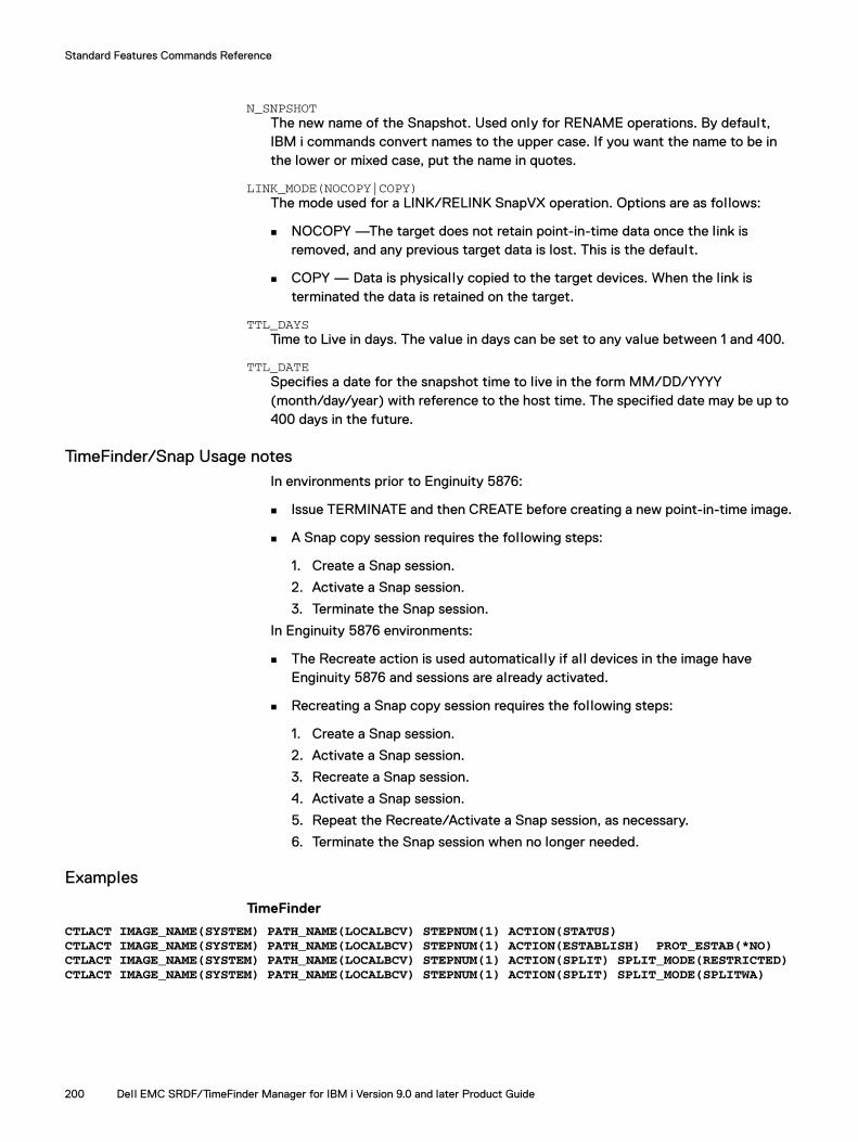
Standard Features Commands Reference
N_SNPSHOT The new name of the Snapshot. Used only for RENAME operations. By default, IBM i commands convert names to the upper case. If you want the name to be in the lower or mixed case, put the name in quotes.
LINK_MODE(NOCOPY|COPY) The mode used for a LINK/RELINK SnapVX operation. Options are as follows:
NOCOPY —The target does not retain point-in-time data once the link is removed, and any previous target data is lost. This is the default.
COPY — Data is physically copied to the target devices. When the link is terminated the data is retained on the target.
TTL_DAYS Time to Live in days. The value in days can be set to any value between 1 and 400.
TTL_DATE Specifies a date for the snapshot time to live in the form MM/DD/YYYY (month/day/year) with reference to the host time. The specified date may be up to 400 days in the future.
TimeFinder/Snap Usage notes In environments prior to Enginuity 5876:
Issue TERMINATE and then CREATE before creating a new point-in-time image.
A Snap copy session requires the following steps:
1. Create a Snap session.
2. Activate a Snap session.
3. Terminate the Snap session.
In Enginuity 5876 environments:
The Recreate action is used automatically if al l devices in the image have Enginuity 5876 and sessions are already activated.
Recreating a Snap copy session requires the following steps:
1. Create a Snap session.
2. Activate a Snap session.
3. Recreate a Snap session.
4. Activate a Snap session.
5. Repeat the Recreate/Activate a Snap session, as necessary.
6. Terminate the Snap session when no longer needed.
Examples
TimeFinder
CTLACT IMAGE_NAME(SYSTEM) PATH_NAME(LOCALBCV) STEPNUM(1) ACTION(STATUS)CTLACT IMAGE_NAME(SYSTEM) PATH_NAME(LOCALBCV) STEPNUM(1) ACTION(ESTABLISH) PROT_ESTAB(*NO)CTLACT IMAGE_NAME(SYSTEM) PATH_NAME(LOCALBCV) STEPNUM(1) ACTION(SPLIT) SPLIT_MODE(RESTRICTED)CTLACT IMAGE_NAME(SYSTEM) PATH_NAME(LOCALBCV) STEPNUM(1) ACTION(SPLIT) SPLIT_MODE(SPLITWA)
200 Dell EMC SRDF/TimeFinder Manager for IBM i Version 9.0 and later Product Guide
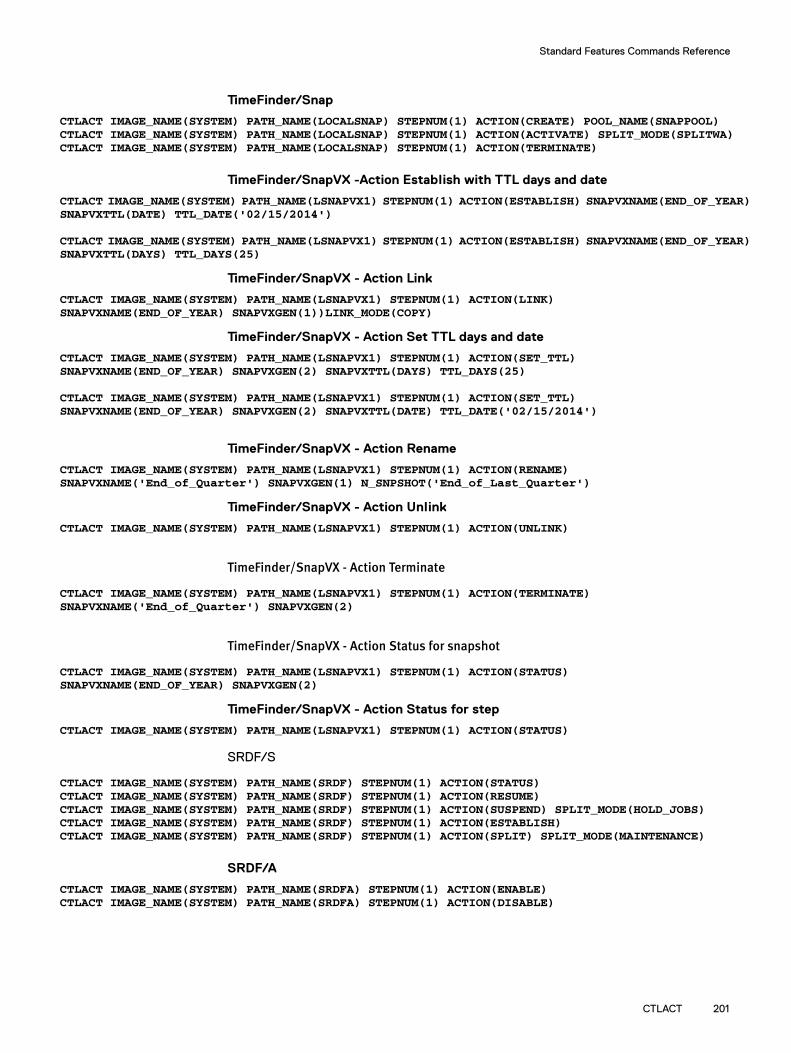
Standard Features Commands Reference
CTLACT 201
TimeFinder/Snap
CTLACT IMAGE_NAME(SYSTEM) PATH_NAME(LOCALSNAP) STEPNUM(1) ACTION(CREATE) POOL_NAME(SNAPPOOL)CTLACT IMAGE_NAME(SYSTEM) PATH_NAME(LOCALSNAP) STEPNUM(1) ACTION(ACTIVATE) SPLIT_MODE(SPLITWA)CTLACT IMAGE_NAME(SYSTEM) PATH_NAME(LOCALSNAP) STEPNUM(1) ACTION(TERMINATE)
TimeFinder/SnapVX -Action Establish with TTL days and date
CTLACT IMAGE_NAME(SYSTEM) PATH_NAME(LSNAPVX1) STEPNUM(1) ACTION(ESTABLISH) SNAPVXNAME(END_OF_YEAR) SNAPVXTTL(DATE) TTL_DATE('02/15/2014')
CTLACT IMAGE_NAME(SYSTEM) PATH_NAME(LSNAPVX1) STEPNUM(1) ACTION(ESTABLISH) SNAPVXNAME(END_OF_YEAR) SNAPVXTTL(DAYS) TTL_DAYS(25)
TimeFinder/SnapVX - Action Link
CTLACT IMAGE_NAME(SYSTEM) PATH_NAME(LSNAPVX1) STEPNUM(1) ACTION(LINK)SNAPVXNAME(END_OF_YEAR) SNAPVXGEN(1))LINK_MODE(COPY)
TimeFinder/SnapVX - Action Set TTL days and date
CTLACT IMAGE_NAME(SYSTEM) PATH_NAME(LSNAPVX1) STEPNUM(1) ACTION(SET_TTL)SNAPVXNAME(END_OF_YEAR) SNAPVXGEN(2) SNAPVXTTL(DAYS) TTL_DAYS(25)
CTLACT IMAGE_NAME(SYSTEM) PATH_NAME(LSNAPVX1) STEPNUM(1) ACTION(SET_TTL)SNAPVXNAME(END_OF_YEAR) SNAPVXGEN(2) SNAPVXTTL(DATE) TTL_DATE('02/15/2014')
TimeFinder/SnapVX - Action Rename
CTLACT IMAGE_NAME(SYSTEM) PATH_NAME(LSNAPVX1) STEPNUM(1) ACTION(RENAME) SNAPVXNAME('End_of_Quarter') SNAPVXGEN(1) N_SNPSHOT('End_of_Last_Quarter')
TimeFinder/SnapVX - Action Unlink
CTLACT IMAGE_NAME(SYSTEM) PATH_NAME(LSNAPVX1) STEPNUM(1) ACTION(UNLINK)
TimeFinder/SnapVX - Action Terminate
CTLACT IMAGE_NAME(SYSTEM) PATH_NAME(LSNAPVX1) STEPNUM(1) ACTION(TERMINATE)SNAPVXNAME('End_of_Quarter') SNAPVXGEN(2)
TimeFinder/SnapVX - Action Status for snapshot
CTLACT IMAGE_NAME(SYSTEM) PATH_NAME(LSNAPVX1) STEPNUM(1) ACTION(STATUS) SNAPVXNAME(END_OF_YEAR) SNAPVXGEN(2)
TimeFinder/SnapVX - Action Status for step
CTLACT IMAGE_NAME(SYSTEM) PATH_NAME(LSNAPVX1) STEPNUM(1) ACTION(STATUS)
SRDF/S
CTLACT IMAGE_NAME(SYSTEM) PATH_NAME(SRDF) STEPNUM(1) ACTION(STATUS)CTLACT IMAGE_NAME(SYSTEM) PATH_NAME(SRDF) STEPNUM(1) ACTION(RESUME)CTLACT IMAGE_NAME(SYSTEM) PATH_NAME(SRDF) STEPNUM(1) ACTION(SUSPEND) SPLIT_MODE(HOLD_JOBS)CTLACT IMAGE_NAME(SYSTEM) PATH_NAME(SRDF) STEPNUM(1) ACTION(ESTABLISH)CTLACT IMAGE_NAME(SYSTEM) PATH_NAME(SRDF) STEPNUM(1) ACTION(SPLIT) SPLIT_MODE(MAINTENANCE)
SRDF/A
CTLACT IMAGE_NAME(SYSTEM) PATH_NAME(SRDFA) STEPNUM(1) ACTION(ENABLE)CTLACT IMAGE_NAME(SYSTEM) PATH_NAME(SRDFA) STEPNUM(1) ACTION(DISABLE)
Standard Features Commands Reference
CTLPOOLControls the device pools (SAVE and thin) and devices (SAVE and DATA) in the pools. Also allows for migration session termination.
For arrays running PowerMaxOS 5978 or HYPERMAX OS 5977, Snap and DSE pools are not supported, and thin pools and DATA devices are pre-configured, so pool management is not available. Therefore for PowerMaxOS 5978 and HYPERMAX OS 5977 arrays, creating and deleting thin pools, and management of existing pools and DATA devices (except for pool renaming) are not available. For arrays running Enginuity 5876 or earlier, the actions on thin pools described below are allowed by SRDF/TimeFinder Manager, except for FREEALL which is available on PowerMaxOS 5978 and HYPERMAX OS 5977 arrays only.
SyntaxCTLPOOL SYMID(sym_id) POOLNAME(DEFAULT_POOL|pool_name) DEVPLTYPE(SNAP|DSE|DATA) CTLACT(control_action) [FILENAME(file_name)][STARTDEV(device_number|*ALL)] [ENDDEV(device_number|*ALL)][OPTION(DISABLE|ENABLE)][NEW_POOL(pool_name)][MAX_SUBS(1-65534)][COMPR(DISABLE|ENABLE)][DEV_COMPR(COMP_START|COMP_END|UNCOMP_START|UNCOMP_END)][FREEALL(START|STOP)][SRC_POOL(pool_name)][SESSION(session_name)}
DescriptionThe CTLPOOL command allows the control of the device pools (SAVE and thin), and devices (SAVE and DATA) in those pools, as well as thin device association (bound/unbound) to thin pools. This command can also be used for Virtual Provisioning (migrating thin devices from one pool to another and thin device compression), and to terminate migration sessions.
CTLPOOL allows control of the device pools. SAVE pools are either SNAP (available for TimeFinder/Snap operations) or DSE pools (available for RDF/A DSE operations). Thin pools contain DATA devices (available for Virtual Provisioning).
With CTLPOOL, SAVE and DATA devices can be added to a pool, enabled or disabled in once in the pool, or removed from the pool. Thin devices can be bound to the pool (bind), unbound from the pool (unbind), bound to a different pool (rebind), migrated to a different pool, and compressed or uncompressed.
For control operations on devices, file name or range of devices (START/END) can be specified.
Required parametersSYMMETRIX_ID(sym_id)
The name of the array on which to perform this command.
Note: If the array ID is known, enter its name. If the array ID is not known, press F4 to display a list of al l local and remote arrays attached to the host.
202 Dell EMC SRDF/TimeFinder Manager for IBM i Version 9.0 and later Product Guide
Standard Features Commands Reference
POOLNAME(DEFAULT_POOL|Pool_name)The name for the device pool.:
Note: For control actions ADD, BIND, REBIND, and MIGRATE, this parameter is the name of the target pool.
DEFAULT_POOL — The special Snap pool, which exists by default, and contains SAVE devices that have not been assigned to any named pools but are available for Snap operations. The devices in DEFAULT_POOL are either enabled or disabled but have used tracks. Devices can be disabled using a range of values or *ALL. Devices can only be enabled using *ALL.
Pool_name — The name for the device pool.
By default, IBM i commands convert names to the upper case. If you want the name to be in the lower or mixed case, put the name in quotes.
DEVPLTYPE(SNAP|DSE|DATA)The type of the device pool:
SNAP — Contains SAVE devices that are used for TimeFinder/Snap operations.
DSE — RDF/A DSE contains SAVE devices that are used for SRDF/A DSE operations.
DATA — Contains DATA devices used for Virtual Provisioning.
Note: DATA pools are supported with Enginuity 5876 and later.
Note: For unbinding of thin devices, thin device compression and termination of the migration session, pool name and pool type parameters are ignored.
CTLACT(control_action)Specifies which control operation to perform on the device pool or devices in the pool:
ADD — Adds SAVE or DATA devices to the specified pool. Devices must be disabled. SAVE devices that do not belong to any pool are available to be added to a RDF/A DSE or SNAP pool. DATA devices that do not belong to any pools are available to be added to the DATA (thin) pool.
Disabled devices can be moved from one named pool to another pool. The target device pool must be empty, or consist of the devices with the same type as devices to be moved.
BALANCE - Starts write balancing operation for the specified thin pool. If pool balancing is not in progress, SRDF/TimeFinder Manager initiates balancing on the specified pool.
BIND — Binds thin devices to the DATA (thin) pool.
CHANGE_SUBS - Changes the oversubscription ratio for the specified thin pool. The limit is set by specifying the maximum subscription value when creating thin pool. Existing thin pools can be modified to change a maximum subscription percent.
CREATE — Creates a new device pool. When a pool is created, it can be created as a RDF/A DSE pool, a Snap pool, or a DATA (thin) pool.
CTLPOOL 203

Standard Features Commands Reference
DELETE — Deletes a device pool. In order to be deleted, pools must have no active sessions, must be disabled, and cannot contain any members.
DISABLE — Changes the state of devices in the pool to Disabled. Once the devices are disabled, they can be removed from the device pool.
ENABLE — Changes the state of devices in the pool to Enabled. Enabled SAVE devices can be used during SNAP or SRDF/A DSE operations. Enabled DATA devices can be used for Virtual Provisioning.
MIGRATE — Migrates allocations from one pool to another. For full migration rebinds migrated devices to the target DATA (thin) pool. If a source pool (SRC_POOL) is specified then thin device pool-level migration is performed, otherwise full migration is performed. Migration is only allowed for locally attached arrays.
TERMINATE — Terminates thin device migration sessions during the migration process.
Note: Termination is only allowed on locally attached arrays.
REBIND — Rebinds thin devices to a different DATA (thin) pool. Rebind changes the thin device's current binding to a new pool. Rebind does not move any existing data to the new pool, but al l new allocations to the thin device go to the new pool after the rebind action completes.
FREEALL — Frees up all al locations associated with a given device regardless of whether or not there is data written to the device. Freeall is available only on arrays running PowerMaxOS 5978 or HYPERMAX OS 5977.
REMOVE — Removes devices from the specified pool. In order to remove a device from a pool it must be disabled in the pool.
RENAME — Renames the specified pool. SNAP, DATA (thin), and DSE pools can be renamed. The default pool name (DEFAULT_POOL) for Snap cannot be changed. Rename is al lowed for arrays running PowerMaxOS 5978, HYPERMAX OS 5977 and earlier.
STOP_BALANCE — Stops any write balancing operation for the specified DATA (thin) pool.
UNBIND — Unbinds thin devices from the DATA (thin) pool.
VP_COMPR — Allows for enabling or disabling the thin pool for compression.
VP_DEV_COMPR — Starts or stops thin device compression or uncompression.
FILENAME(file_name)Specifies the name of the device file used that can be used with the CTLPOOL command, and lists the designated devices for the ADD, REMOVE, ENABLE, DISABLE, BIND, UNBIND, REBIND, MIGRATE and VP_DEV_COMPR control actions.
Device files that can be used with the CTLPOOL command are created from a set of screens or created manually.
204 Dell EMC SRDF/TimeFinder Manager for IBM i Version 9.0 and later Product Guide

Standard Features Commands Reference
Files can be created from the following screens:
Work with Thin Bound Devices
Work with Thin Unbound Devices
Work with Pool
Not Pooled Save/Data Devices
If creating the file manually the following rules apply:
The file is a record file and record length must not exceed 40.
The file contains only one column that lists the source devices.
List each device on a separate line.
Comment lines are allowed and they must begin with the pound sign (#).
The device file resides in the library list.
Example device file: # Devices for CTLPOOL command 009A
009E009F
Optional parameters STARTDEV(device_number|*ALL)The starting array device number or *ALL to specify device numbers, and is used with ADD, REMOVE, ENABLE, DISABLE, BIND, UNBIND, REBIND, MIGRATE and VP_DEV_COMPR control actions.
ENDDEV(device_number|*ALL)The ending array device number or *ALL to specify device numbers, and is used with ADD, REMOVE, ENABLE, DISABLE, BIND, UNBIND, REBIND, MIGRATE and VP_DEV_COMPR control actions.
Note: Start and end devices usually specify a range of devices. To specify a pool containing a single device, specify the same device name for the start and end devices. For DEFAULT_POOL, specify *ALL for the start and end devices.
OPTION(DISABLE|ENABLE)Allows for the option to also enable or disable the SAVE or DATA devices, and is used only with the ADD operation.
DISABLE — Leaves devices disabled after adding them to the pool. DISABLE is the default.
ENABLE — Changes the state of devices to enabled after adding them to the device pool.
NEW_POOL(pool_name) Specifies the new device pool name, and is used only with the RENAME action.
By default, IBM i commands convert names to the upper case. Put the name in quotes if you want it to be in the lower or mixed case.
MAX_SUBS(1-65534) Specifies the maximum subscription percent for a pool, and is used with the CREATE and CHANGE_SUBS control actions. This parameter is only used with (DATA) thin pools.
CTLPOOL 205

Standard Features Commands Reference
The maximum subscription percent is a value between 1 and 65534. If the value is not specified the default value is passed, meaning there is no limit set and the amount of oversubscription is not restricted. Setting a value of 1 al lows only a maximum thin capacity that totals 1/100th of the actual physical capacity of the pool. Setting a value of 100 prevents the pool from oversubscription.
COMPR(DISABLE|ENABLE)Specifies if thin pool is enabled or disabled for compression, and is used with the CREATE and VP_COMPR control actions. This parameter is only used with (DATA) thin pools.
DISABLE — Compression is not allowed for the thin pool.
ENABLE — Enables Thin pool for the compression.
Note: If a value is not specified, the compression parameter value assigned to the new pool is Disabled. During new pool creation, if the Enginuity version level does not support thin devices, or if the pool is a SNAP or DSE pool this parameter is ignored,
DEV_COMPR (COMP_START|COMP_END|UNCOMP_START|UNCOMP_END)Specifies the compression action on the selected devices, and is used with VP_DEV_COMPR control action. This action can only be performed for DATA (thin) pools that are enabled for compression.
COMP_START - Starts the compression on selected devices.
COMP_END - Stops the compression on selected devices.
UNCOMP_START - Starts the uncompression on selected devices.
UNCOMP_END - Stops the uncompression on selected devices.
FREEALL (START|STOP)]Specifies the freeall action on the selected Thin devices. This parameter is available only on arrays running PowerMaxOS 5978 or HYPERMAX OS 5977.
START - Starts process of the freeing allocations on selected devices.
STOP - Stops the free operation on the selected devices.
SRC_POOL(pool_name)Specifies the source device pool name, and is used only with the MIGRATE control action. If source pool is not specified then full migration is performed. This parameter is used only with DATA (thin) pools.
By default, IBM i commands convert names to the upper case. If you want the name to be in the lower or mixed case, put the name in quotes.
SESSION(session_name)Specifies migration session name, and is used with the MIGRATE and TERMINATE control actions. This parameter is used only with DATA (thin) pools.
By default, IBM i commands converts names to the upper case. If you want the name to be in the lower or mixed case, put the name in quotes.
206 Dell EMC SRDF/TimeFinder Manager for IBM i Version 9.0 and later Product Guide

Standard Features Commands Reference
Examples
Add devices to a pool type DSE
CTLPOOL SYMID(000123456789) POOLNAME(MYSAVPOOL) DEVPLTYPE(DSE) CTLACT(ADD) STARTDEV(0250) ENDDEV(0252)
Enable devices in pool type SNAP
CTLPOOL SYMID(000123456789) POOLNAME(DEFAULT_POOL) DEVPLTYPE(SNAP) CTLACT(ENABLE) STARTDEV(*ALL) ENDDEV(*ALL)
Add and enable devices to pool type thin
Using the optional parameter OPTION (ENABLE) available with the CTLACT(ADD) control action.
CTLPOOL SYMID(000123456789) POOLNAME(MYTHINPOOL) DEVPLTYPE(DATA) CTLACT(ADD) STARTDEV(0001) ENDDEV(000A) OPTION(ENABLE)
Create a pool type DATA
CTLPOOL SYMID(000123456789) POOLNAME(MYDATAPOOL) DEVPLTYPE(DATA) CTLACT(CREATE) MAX_SUBS(100) COMPR(ENABLE)
Start compression
CTLPOOL SYMID(000123456789) POOLNAME(POOL_NAME) DEVPLTYPE(DATA) CTLACT(VP_DEV_COMPR) FILENAME(SRC_FILE) DEV_COMPR (COMP_START)
Full Migration
CTLPOOL SYMID(000123456789) POOLNAME(POOL_NAME) DEVPLTYPE(DATA) CTLACT(MIGRATE) FILENAME(SRC_FILE) SESSION(MIGR_SESSION)
Pool Migration
CTLPOOL SYMID(000123456789) POOLNAME(POOL_NAME) DEVPLTYPE(DATA) CTLACT(MIGRATE) FILENAME(SRC_FILE) SRC_POOL(SRC_POOL) SESSION(MIGR_SESSION)
Terminate session
CTLPOOL SYMID(000123456789) CTLACT(TERMINATE) SESSION(MIGR_SESSION)
VP Device Freeall
CTLPOOL SYMID(000123456789) CTLACT(FREEALL) FILENAME(TEST) FREEALL(START)CTLPOOL SYMID(000123456789) CTLACT(FREEALL) FILENAME(TEST) FREEALL(STOP)
CTLPOOL 207

Standard Features Commands Reference
CTLRDFGRPThe CTLRDFGRP command controls the dynamic RDF group.
SyntaxCTLRDFGRP ACTION (control_action)SYMID(sym_id)[GRPLABEL (group_label)][GRPNUM (group_nmber)][MODIFY_ACT (modify_action)][SYM_FORCE(*YES|*NO)][DIRPORT((Dir1(Port1 Port2 …)[(Dir2 (Port….)]…) [RSYMID(sym_id)][RGRPNUM (group_nmber)][RDIRPORT((Dir1(Port1 Port2 …)[(Dir2 (Port….)]…) [AUTO_LINK(*YES|*NO)][RAUTOLINK(*YES|*NO)][LINK_LIMBO (0-120)] [RLINKLIMBO (0-120)]
Required ParametersACTION(control action)
Specifies the control action to perform:
ADD — Creates a new dynamic SRDF group.
MODIFY — Modifies an existing dynamic SRDF group
Note: This action enables the local and remote director/port to be associated/dissociated with the RDF Group.
REMOVE — Removes a dynamic SRDF group.
Note: You can remove (delete) an empty RDF group only.
SYMID(sym_id) The name of the array on which this command is performed. If the array ID is known it can be entered. Otherwise, press F4 key to display a list of al l local and remote arrays attached to the host.
Optional ParametersGRPLABEL(group_label)
Specifies a label for the dynamic SRDF group. By default, IBM i commands converts names to the upper case. Put the label in quotes if you want it to be in the lower or mixed case.
GRPNUM(group_number)Specifies the SRDF (RA) group number.
Note: If using the ADD control action, specify both the group label and the group number. Otherwise, specify only one of the parameters.
MODIFY_ACT(modify_action) Specifies which control action to perform. Options are as follows:
ADD — Adds supporting SRDF directors to a dynamic SRDF group.
REMOVE — Removes supporting RDF directors from a dynamic SRDF group.
208 Dell EMC SRDF/TimeFinder Manager for IBM i Version 9.0 and later Product Guide
Standard Features Commands Reference
SYM_FORCE(*YES|*NO)Indicates whether to use the array force operation when normally it is rejected. This option is used only with REMOVE action. Removes one side of a dynamic SRDF group if the other side is not defined or is not accessible.
*YES — Enables Sym Force.
*NO — Disables Sym Force. This is the default.
Note: To enable SYM_FORCE, a parameter called SYMAPI_ALLOW_RDF_SYMFORCE in the options file must be set to ENABLED.
Use care when applying SYM_FORCE, as data could be lost or corrupted. Use of this option is not recommended, except in extreme cases.
DIRPORT((Dir1(Port1 Port2 …)[(Dir2 (Port….)]…)Specifies local director/port combination. This option is used with the ADD and MODIFY control actions:
Director ID (Dir 1, Dir 2...) — This is the list of the local array directors, such as, 1a, 1b, and so on.
Port Number (Port 1, Port 2...) — This is the list of local array director ports.
Note: For PowerMaxOS 5978 and HYPERMAX OS 5977, the RDF director supports up to 32 ports.
The SYMCLI command symcfg can be used to display all available local director/port combinations. For example:
Addlible emcctlCALL PGM(SYMCFG) PARM('list' '-ra' 'all' '-sid''000111222333')
RSYMID(sym_id)The name of the remote array for adding new SRDF group. This option is used only with the ADD control action. If the array ID is known, the name could be entered. If the array ID is not known, press F4 to display a list of al l local and remote arrays attached to the host.
RGRPNUM (group_nmber)Specifies the SRDF group number for the remote array. This option is used only with the ADD control action.
RDIRPORT((Dir1(Port1 Port2 …)[(Dir2 (Port….)]…)Specifies remote director/port combination. This option is used with the ADD and MODIFY control actions. Options are:
Director ID (Dir 1, Dir 2...) — This is the list of the remote array directors, such as, 1a, 1b and so on.
Port Number (Port 1, Port 2...) — This is the list of remote array director ports.
Note: For PowerMaxOS 5978 and HYPERMAX 5977, the RDF director supports up to 32 ports.
CTLRDFGRP 209
Standard Features Commands Reference
You can use the SYMCLI command symcfg to display all available remote director/port combinations. For example:
Addlible emcctlCALL PGM(SYMCFG) PARM('list' '-ra' 'all' '-sid''000123456789')
AUTO_LINK(*YES|*NO)Specifies whether to use the auto link recovery feature locally. This option is used only with ADD action.
*YES — Enables local Auto Link Recovery. This is the default.
*NO — Disables local Auto Link Recovery.
RAUTOLINK(*YES|*NO)Specifies whether to use the auto link recovery feature remotely. This option is used only with ADD action.
*YES — Enables remote Auto Link Recovery. This is the default.
*NO — Disables remote Auto Link Recovery.
LINK_LIMBO (0-120)
Note: The option should only be used by experienced SRDF users.
Specifies the local link limbo value which is the length of time for Enginuity to wait, from the point of a link-down detection, prior to updating the link status as Down. If the link status is stil l sensed as Not Ready after the link limbo time expires, devices are marked Not Ready to the link. The link limbo range is 0-120 seconds. The default time is 10 seconds. This option is used only with the ADD control action.
RLINK_LIMBO (0-120)Specifies the remote link limbo value which is the length of time for Enginuity to wait, from the point of a link-down detection, prior to updating the link status as Down. If the link status is stil l sensed as Not Ready after the link limbo time expires, devices are marked Not Ready to the link. The link limbo range is 0-120 seconds. The default time is 10 seconds. This option is used only with the ADD control action.
Examples
Create new SRDF groups on local and remote arrays
CTLRDFGRP ACTION(ADD) SYMID(000111222333) GRPLABEL(GRP_20_21) GRPNUM(20) DIRPORT((7H (10 11)) (8H (8 9 10 11))) RSYMID(000222333444) RGRPNUM(21) RDIRPORT((8H (8 9)))
CTLRDFGRP ACTION(ADD) SYMID(000111222333) GRPLABEL(GRP_22_23) GRPNUM(22) DIRPORT((7H (10)) (8H (11))) RSYMID(000222333444) RGRPNUM(23) RDIRPORT((8H (8 9)))AUTO_LINK(*NO) R_AUTOLINK(*NO) LINK_LIMBO(20) RLINKLIMBO(20)
Modify SRDF groups
CTLRDFGRP ACTION(MODIFY) SYMID(000111222333) GRPNUM(20) MODIFY_ACT(ADD) DIRPORT((2F (10))) RDIRPORT((8F (10)))CTLRDFGRP ACTION(MODIFY) SYMID(000111222333) GRPNUM(20) MODIFY_ACT(REMOVE) DIRPORT((8H (10 11)))
Remove SRDF groups from the Local array
CTLRDFGRP ACTION(REMOVE) SYMID(000111222333) GRPNUM(20)
210 Dell EMC SRDF/TimeFinder Manager for IBM i Version 9.0 and later Product Guide

Standard Features Commands Reference
Remove SRDF groups from the Remote array
CTLRDFGRP ACTION(REMOVE) SYMID(000222333444) GRPNUM(23)
CTLRDFGRP 211
Standard Features Commands Reference
DISCOVERDiscovers new devices, removes old device information from the SYMAPI database, and updates the database with new information. This command also updates information in the IMAGE file.
SyntaxDISCOVER MODE(*NO|*YES) CHECK(*NO|*YES)
Description DISCOVER performs the discover process that is required when the configuration on the host or array changes. By default, information about all arrays visible at one time from this host remains in SYMAPI database until explicitly removed.
Required parametersMODE(*NO|*YES)
*NO — Do not remove old data from the SYMAPI database.This is the default value.
*YES — Remove previously discovered array information from the SYMAPI database that is no longer valid (visible).
CHECK(*NO|*YES)
*NO — Do not verify information stored in the IMAGE file with the current device information of the host or remove any old device information from the files. This is the default value.
*YES — Verify the device information stored in the IMAGE file with the current device information of the host and remove any old device information from the files.
Do not run this command with mode *YES when the RDF link is down. Doing so can remove relevant R2 information, such as remote BCV pairing for the array, from the SYMAPI database. If this information is removed, it requires additional repair or reconfiguration to restore the array data. Refer to “Running the DISCOVER command” on page 63 for more information.
212 Dell EMC SRDF/TimeFinder Manager for IBM i Version 9.0 and later Product Guide

Standard Features Commands Reference
DISCOVERCDiscovers new devices, removes old device information from the SYMAPI database, and updates the database with new information.
SyntaxDISCOVERC MODE(*NO|*YES)
Description DISCOVERC performs the discover process on the target side that is required when the configuration on the host or array changes. By default, information about all arrays visible at some point from this host remains in SYMAPI database until explicitly removed.
Required parametersMODE(*NO|*YES)
*NO — Do not remove old data from the SYMAPI database.This is the default value.
*YES — Remove previously discovered array information from the SYMAPI database that is no longer valid (visible).
Do not run this command with MODE *YES when the RDF link is down. Doing so can remove relevant R2 information. Refer to “Running the DISCOVER command” on page 63 for more information.
DISCOVERC 213
Standard Features Commands Reference
ENDSTMSRVShuts down the SRDF/TimeFinder Manager server job.
SyntaxENDSTMSRV PORTNUM(port_number)
DescriptionENDSTMSRV ends the SRDF/TimeFinder Manager server job session on the node where this command executes. If you do not include the port number, the command uses a default of 8000.
Required parameterPORTNUM(port_number)
The TCP/IP port number.
If you used a port number other than the default, use that port number on the primary node, backup node, and main partition.
214 Dell EMC SRDF/TimeFinder Manager for IBM i Version 9.0 and later Product Guide
Standard Features Commands Reference
RELDEVLCKChecks and releases device external locks (DEL) on an array for any image.
SyntaxRELDEVLCK IMAGENAME(image_name) PATHNAME(path_name) STEPNUM(step_number)
Description RELDEVLCK checks for one or more SYMAPI device external locks (DEL) that were left on the array and attempts to release those locks using SYMAPI calls. Specify the image name, path name, and step number for the locks to be released.
Required parametersIMAGENAME(image_name)
The name of the image for which you want to release the locks.
PATHNAME(path_name)The path name associated with the image for which you want to release locks.
STEPNUM(step_number)The step number associated with the path of the image for which you want to release locks.
Note: Steps in the path are defined during the configuration and are identified by their positions (1 through 5) in the path.
RELDEVLCK 215
Standard Features Commands Reference
RELDEVLCKCChecks and releases device external locks (DEL) on an array for any image on the target side.
SyntaxRELDEVLCKC IMAGENAME(image_name) PATHNAME(path_name) STEPNUM(step_number)
Description RELDEVLCKC checks for one or more SYMAPI device external locks (DEL) that were left on the array and attempts to release those locks using SYMAPI calls. Specify the image name, path name, and step number for the locks to be released.
Required parametersIMAGENAME(image_name)
The name of the image for which you want to release the locks.
PATHNAME(path_name)The path name associated with the image for which you want to release locks.
STEPNUM(step_number)The step number associated with the path of the image for which you want to release locks.
216 Dell EMC SRDF/TimeFinder Manager for IBM i Version 9.0 and later Product Guide

Standard Features Commands Reference
RTVSTMINFReturns status information for the selected image, path, and step. It also returns SRDF/TimeFinder Manager, Solutions Enabler, Enginuity, and IO driver and release level information. This command can only be run within an IBM i command language program. See “Example command language program” on page 221 for an example command language program, and how to run the program.
Note: Some of the parameter return values are strings and others are decimal values. See “Return parameters” on page 218.
SyntaxRTVSTMINF IMAGENAME(image_name)PATHNAME(path_name)STEPNUM(step_number)NODENAME(node_name)IASPSTS(&IASPSTS)IOASTS(&IOASTS)SYMSTS(&SYMSTS)SYMSTSSTR(&SYMSTSSTR)STEPTYPE(&STEPTYPE)RDFTYPE(&RDFTYPE)RDFMODE(&RDFMODE)RDFACMODE(&RDFACMODE)INVTRACKS(&INVTRACKS)STMRELLVL(&STMRELLVL)STMEDTLVL(&STMEDTLVL)STMBLDLVL(&STMBLDLVL)SERELLVL(&SERELLVL)SEPCTHLVL(&SEPCTHLVL)LBIORELLVL(&LBIORELLVL)LBIOBLDLVL(&LBIOBLDLVL)UCODE1(&UCODE1)...UCODE5(&UCODE5)[SRCORTGT (TGTDEV|SRCDEV)]
Required parametersIMAGENAME(image_name)
The name of the image.
PATHNAME(path_name)The path name associated with the image.
STEPNUM(step_number)The step number associated with the path of the image.
NODENAME(node_name)The node name where the operation is performed. Node name must be a cluster node name. The node name entered must be part of the cluster that is configured on this system. If this is not the case a message appears indicating that the node cannot be found.
Note: The special node name R21NOHST is changed to R21NONOD.
RTVSTMINF 217
Standard Features Commands Reference
Optional parametersSRCORTGT (TGTDEV|SRCDEV)
This parameter is used to differentiate between source or target in the event both images are located on the same node.
This can happen, for example, when an R2 and remote BCV image are used on the same node. Only specifying the node is not enough. If the IASP file does not have an entry where the source and target node is the same, this parameter is set to the default value (TGTDEV).
Return parameters◆ IASPSTS(&IASPSTS) — decimal value(5 0)
Returns one of the following values for IASP status:
0 – IASP status cannot be found. 1 – IASP is varied off. 2 – IASP is varied on. 3 – IASP is active. 4 – IASP is available
◆ IOASTS(&IOASTS) — decimal value(5 0)Returns one of the following value for IOA status:
100 – IOA is active. 101 – IOA is not active. 102 – IOA is in a mixed state. 103 – IOA status not found.
◆ SYMSTS(&SYMSTS)Returns a decimal value for the array copy status or RDF link status.
CL var for SYMSTS (8 0)
Specifies the name of the CL variable that receives the Symmetrix link state. The state value depends on the step type. When the setup is not in a correct state a general status is provided to indicate what is wrong. The SYMSTSSTR is set to unknown.
Note: Values can be returned in string format using the return parameter SYMSTSSTR(&SYMSTSSTR).
Return values for SYMSTS are dependent on the STEPTYPE:
STEPTYPE is BCV (1) or CLN (2) decimal value (8 0):
– 00001000 - Never Established– 00001001 - Sync in progress– 00001002 - Synchronized– 00001003 - Split in progress– 00001004 - Split before sync– 00001005 - Split– 00001006 - Split no incremental– 00001007 - Restore in progress
218 Dell EMC SRDF/TimeFinder Manager for IBM i Version 9.0 and later Product Guide
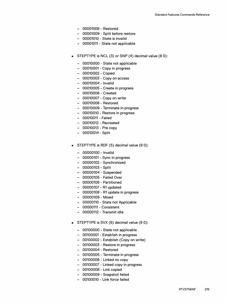
Standard Features Commands Reference
– 00001008 - Restored– 00001009 - Split before restore– 00001010 - State is invalid– 00001011 - State not applicable
STEPTYPE is NCL (3) or SNP (4) decimal value (8 0):
– 00010000 - State not applicable– 00010001 - Copy in progress– 00010002 - Copied– 00010003 - Copy on access– 00010004 - Invalid– 00010005 - Create in progress– 00010006 - Created– 00010007 - Copy on write– 00010008 - Restored– 00010009 - Terminate in progress– 00010010 - Restore in progress– 00010011 - Failed– 00010012 - Recreated– 00010013 - Pre copy– 00010014 - Split
STEPTYPE is RDF (5) decimal value (8 0):
– 00000100 - Invalid– 00000101 - Sync in progress– 00000102 - Synchronized– 00000103 - Split– 00000104 - Suspended– 00000105 - Failed Over– 00000106 - Partitioned– 00000107 - R1 updated– 00000108 - R1 update in progress– 00000109 - Mixed– 00000110 - State not Applicable– 00000111 - Consistent– 00000112 - Transmit idle
STEPTYPE is SVX (6) decimal value (8 0):
– 00100000 - State not applicable– 00100001 - Establish in progress– 00100002 - Establish (Copy on write)– 00100003 - Restore in progress– 00100004 - Restored– 00100005 - Terminate in progress– 00100006 - Linked no copy– 00100007 - Linked copy in progress– 00100008 - Link copied– 00100009 - Snapshot failed– 00100010 - Link force failed
RTVSTMINF 219
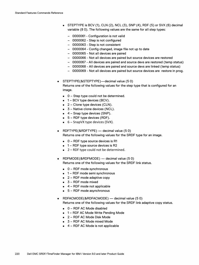
Standard Features Commands Reference
STEPTYPE is BCV (1), CLN (2), NCL (3), SNP (4), RDF (5) or SVX (6) decimal variable (8 0). The following values are the same for al l step types:
– 0000061 - Configuration is not valid– 0000062 - Step is not configured– 0000063 - Step is not consistent– 0000064 - Config changed, image file not up to date– 0000065 - Not all devices are paired– 0000066 - Not all devices are paired but source devices are restored – 0000067 - All devices are paired and source devs are restored (temp status)– 0000068 - All devices are paired and source devs are linked (temp status)– 0000069 - Not all devices are paired but source devices are restore in prog.
◆ STEPTYPE(&STEPTYPE)—decimal value (5 0)Returns one of the following values for the step type that is configured for an image.
0 – Step type could not be determined. 1 – BCV type devices (BCV). 2 – Clone type devices (CLN). 3 – Native clone devices (NCL). 4 – Snap type devices (SNP). 5 – RDF type devices (RDF). 6 – SnapVX type devices (SVX).
◆ RDFTYPE(&RDFTYPE) — decimal value (5 0)Returns one of the following values for the SRDF type for an image.
0 – RDF type source devices is R1 1 – RDF type source devices is R2 2 – RDF type could not be determined.
◆ RDFMODE(&RDFMODE) — decimal value (5 0)Returns one of the following values for the SRDF link status.
0 – RDF mode synchronous 1 – RDF mode semi synchronous 2 – RDF mode adaptive copy 3 – RDF mode mixed 4 – RDF mode not applicable 5 – RDF mode asynchronous
◆ RDFACMODE(&RDFACMODE) — decimal value (5 0)Returns one of the following values for the SRDF link adaptive copy status.
0 – RDF AC Mode disabled 1 – RDF AC Mode Write Pending Mode 2 – RDF AC Mode Disk Mode 3 – RDF AC Mode mixed Mode 4 – RDF AC Mode is not applicable
220 Dell EMC SRDF/TimeFinder Manager for IBM i Version 9.0 and later Product Guide

Standard Features Commands Reference
◆ INVTRACKS(&INVTRACKS) Returns the value for the amount of invalid tracks or the percentage of data copied (16 characters).
123456789012 - number of invalid tracks 100% - percentage INV_TR_NA - Invalid tracks could not be determined
◆ STMRELLVL(&STMRELLVL)Returns the value for the SRDF/TimeFinder Manager release level (5 characters).
◆ STMEDTLVL(&STMEDTLVL)Returns the value for the SRDF/TimeFinder Manager edit level (5 characters).
◆ STMBLDLVL(&STMBLDLVL)Returns the value for the SRDF/TimeFinder Manager build level (5 characters).
◆ SEREVLVL(&SEREVLVL)Returns the value for Solutions Enabler release level (15 characters).
◆ SEPTCLVL(&SEPTCLVL)Returns the value for Solutions Enabler patch level (15 characters).
◆ LBIORELLVL(&LBIORELLVL)Returns the value for I/O driver LIBIO release level (6 characters).
◆ LBIOBLDLVL(&LBIOBLDLVL)Returns the value for I/O driver LIBIO build level (5 characters).
◆ UCODE1(&UCOCDE1)...UCODE5(&UCOCDE5)Returns the value for EMC array ID, Enginuity release level, and Enginuity patch level for up to five arrays (35 characters).
Example command language program A program must be written to run the RTVSTMINF command, and to format the display for the information that the command returns. The following is an example program named TSTRTVINF:
PGM PARM(&IMGNAME &PATHNAME &STEPNUM &NODENAME &SRCORTGT)
DCL VAR(&IMGNAME) TYPE(*CHAR) LEN(10) DCL VAR(&PATHNAME) TYPE(*CHAR) LEN(10) DCL VAR(&STEPNUM) TYPE(*CHAR) LEN(1) DCL VAR(&NODENAME) TYPE(*CHAR) LEN(8) DCL VAR(&SRCORTGT) TYPE(*CHAR) LEN(6)
DCL VAR(&IASPSTS) TYPE(*DEC) LEN(5 0) DCL VAR(&IOASTS) TYPE(*DEC) LEN(5 0) DCL VAR(&STEPTYPE) TYPE(*DEC) LEN(5 0) DCL VAR(&SYMSTSSTR) TYPE(*CHAR) LEN(32) DCL VAR(&SYMSTS) TYPE(*DEC) LEN(8 0) DCL VAR(&RDFTYPE) TYPE(*DEC) LEN(5 0) DCL VAR(&RDFMODE) TYPE(*DEC) LEN(5 0) DCL VAR(&RDFACMODE) TYPE(*DEC) LEN(5 0) DCL VAR(&INVTRACKS) TYPE(*CHAR) LEN(12) DCL VAR(&STMRELLVL) TYPE(*CHAR) LEN(5) DCL VAR(&STMEDTLVL) TYPE(*CHAR) LEN(5) DCL VAR(&STMBLDLVL) TYPE(*CHAR) LEN(5) DCL VAR(&SERELLVL) TYPE(*CHAR) LEN(20) DCL VAR(&SEPTCHLVL) TYPE(*CHAR) LEN(20) DCL VAR(&LBIORELLVL) TYPE(*CHAR) LEN(6)
RTVSTMINF 221

Standard Features Commands Reference
DCL VAR(&LBIOBLDLVL) TYPE(*CHAR) LEN(5) DCL VAR(&UCODE1) TYPE(*CHAR) LEN(35) DCL VAR(&IASPSTSA) TYPE(*CHAR) LEN(10) DCL VAR(&IOASTSA) TYPE(*CHAR) LEN(10) DCL VAR(&STEPTYPEA) TYPE(*CHAR) LEN(10) DCL VAR(&SYMSTSA) TYPE(*CHAR) LEN(10) DCL VAR(&RDFTYPEA) TYPE(*CHAR) LEN(10) DCL VAR(&RDFMODEA) TYPE(*CHAR) LEN(10) DCL VAR(&RDFACMODEA) TYPE(*CHAR) LEN(10)
RTVSTMINF IMAGENAME(&IMGNAME) PATHNAME(&PATHNAME) STEPNUM(&STEPNUM) NODENAME(&NODENAME) SRCORTGT(&SRCORTGT) IASPSTS(&IASPSTS) IOASTS(&IOASTS) SYMSTS(&SYMSTS) STEPTYPE(&STEPTYPE) RDFTYPE(&RDFTYPE)RDFMODE(&RDFMODE) RDFACMODE(&RDFACMODE)INVTRACKS(&INVTRACKS) STMRELLVL(&STMRELLVL) STMEDTLVL(&STMEDTLVL) STMBLDLVL(&STMBLDLVL) SEREVLVL(&SEREVLVL) SEPTCLVL(&SEPTCLVL) LBIORELLVL(&LBIORELLVL)LBIOBLDLVL(&LBIOBLDLVL)
UCODE1(&UCODE1) UCODE2(&UCODE2)UCODE3(&UCODE3)UCODE4(&UCODE4) UCODE5(&UCODE5)
CHGVAR &IASPSTSA &IASPSTS CHGVAR &IOASTSA &IOASTS CHGVAR &STEPTYPEA &STEPTYPE CHGVAR &SYMSTSA &SYMSTS CHGVAR &RDFTYPEA &RDFTYPE CHGVAR &RDFMODEA &RDFMODE CHGVAR &RDFACMODEA &RDFACMODE
SNDPGMMSG MSG('RESULTS STMVER:' *BCAT &STMRELLVL *BCAT + &STMEDTLVL *BCAT &STMBLDLVL)
SNDPGMMSG MSG('RESULTS LIBIOV:' *BCAT &LBIORELLVL *BCAT &LBIOBLDLVL)
SNDPGMMSG MSG('RESULTS SE_VER:' *BCAT &SERELLVL *BCAT &SEPTCHLVL) SNDPGMMSG MSG('RESULTS IOASTS:' *BCAT &IOASTSA) SNDPGMMSG MSG('RESULTS IASPSTS:' *BCAT &IASPSTSA) SNDPGMMSG MSG('RESULTS SYMSTS:' *BCAT &SYMSTSA) SNDPGMMSG MSG('RESULTS SYMSTSSTR:' *BCAT &SYMSTSSTR) SNDPGMMSG MSG('RESULTS STEPTYPE:' *BCAT &STEPTYPEA) SNDPGMMSG MSG('RESULTS RDFTYPE:' *BCAT &RDFTYPEA) SNDPGMMSG MSG('RESULTS RDFMODE:' *BCAT &RDFMODEA) SNDPGMMSG MSG('RESULTS RDFACMODE:' *BCAT &RDFACMODEA) SNDPGMMSG MSG('RESULTS INVTRACKS:' *BCAT &INVTRACKS) SNDPGMMSG MSG('RESULTS UCODE1:' *BCAT &UCODE1)
ENDPGM
Run example program (TSTRTVINF) from the IBM i command line
CALL PGM(TSTRTVINF) PARM(PRIM1 LOCALNCL '1' NODE124)
222 Dell EMC SRDF/TimeFinder Manager for IBM i Version 9.0 and later Product Guide

Standard Features Commands Reference
A command line message returns upon completion of the RTVSTMINF command.
Figure 99 TSTRTVINF command return message
If the TSTRTVINF command fails, the following message returns:
Retrieve STM information failed.
Note: The output for this example program reports Enginuity version levels for one array. The Enginuity versions for up to five arrays can be reported.
It is not required to call for al l parameters in the command line program. For example, to retrieve only the IOA status (Figure 100 on page 224), the RTVSTMINF and SNDPGMMSG commands in the CL program are as follows:
◆ For the RTVSTMINF command:
RTVSTMINF IMAGENAME(&IMGNAME) PATHNAME(&PATHNAME) STEPNUM(&STEPNUM) NODENAME (&NODENAME) IOASTS(&IOASTS)
◆ For the SNDPGMMSG command:
SNDPGMMSG MSG('RESULTS IOASTS:' *BCAT &IOASTSA)
Retrieve STM information completed.. RESULTS STMVER: 8.0 0 64 RESULTS LIBIOV: 4.4.02 10 RESULTS SE_VER: X8.0-1900 0.431 RESULTS IOASTS: 0000000100 RESULTS IASPSTS: 0000000001 RESULTS SYMSTS: 0000010002 RESULTS SYMSTSSTR: Copied RESULTS STEPTYPE: 0000000003 RESULTS RDFTYPE: 0000000002 RESULTS RDFMODE: 0000000004 RESULTS RDFACMODE: 0000000004 RESULTS INVTRACKS: 100% RESULTS UCODE1: 000195600231 :5876 .229
BottomPress Enter to continue.
F3=Exit F5=Refresh F12=Cancel F17=Top F18=Bottom
RTVSTMINF 223
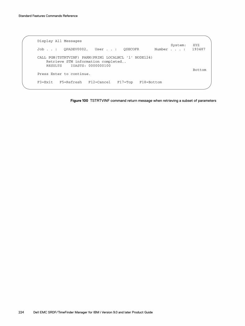
Standard Features Commands Reference
Figure 100 TSTRTVINF command return message when retrieving a subset of parameters
Display All Messages System: XYZ
Job . . : QPADEV0002, User . . : QSECOFR Number . . . : 193487
CALL PGM(TSTRTVINF) PARM(PRIM1 LOCALNCL '1' NODE124) Retrieve STM information completed.. RESULTS IOASTS: 0000000100 Bottom
Press Enter to continue.
F3=Exit F5=Refresh F12=Cancel F17=Top F18=Bottom
224 Dell EMC SRDF/TimeFinder Manager for IBM i Version 9.0 and later Product Guide

Standard Features Commands Reference
SAVEPOOLEnables all SAVE devices in the default SAVE pool.
SyntaxSAVEPOOL SYMID(sym_id) POOLNAME(DEFAULT_POOL)
DescriptionSAVEPOOL enables all SAVE devices in the default SAVE pool.
Required parametersSYMID(sym_id)
The name of the array where SAVE devices are enabled.
Note: If the array ID is known, you can enter its name. If the ID is unknown, press F4 to display a list of al l local and remote arrays attached to the host.
POOLNAME(DEFAULT_POOL)The name for the SAVE pool.
SAVEPOOL 225
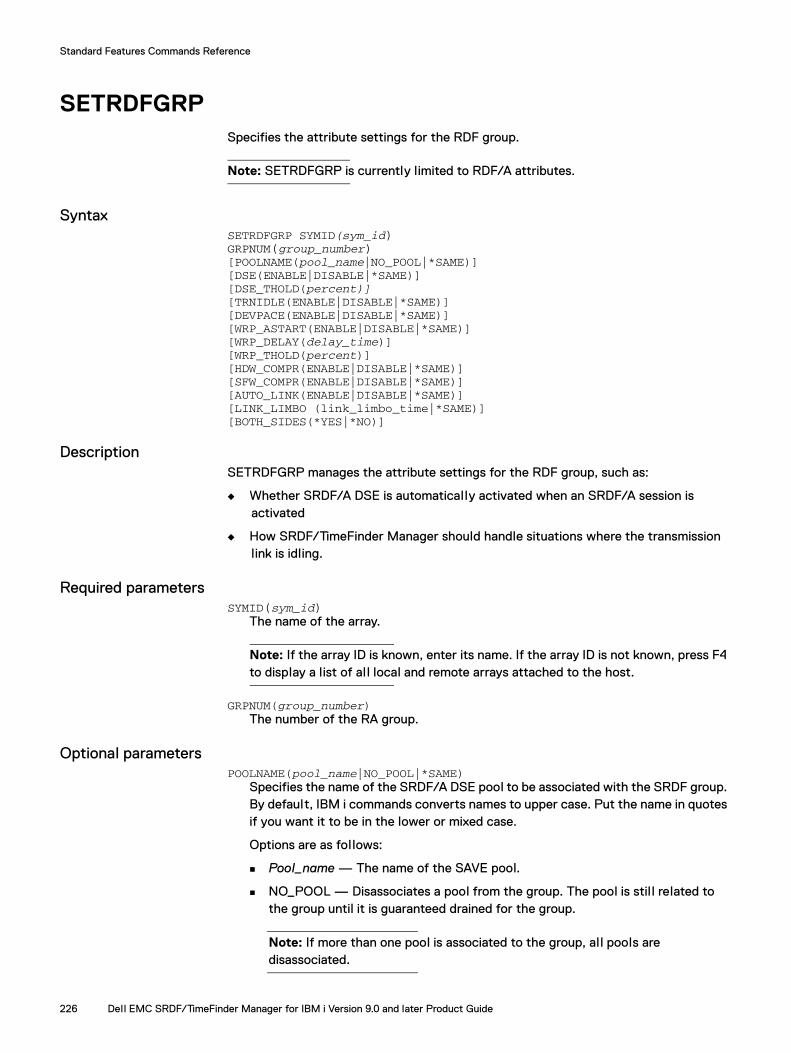
Standard Features Commands Reference
SETRDFGRP Specifies the attribute settings for the RDF group.
Note: SETRDFGRP is currently limited to RDF/A attributes.
SyntaxSETRDFGRP SYMID(sym_id)GRPNUM(group_number)[POOLNAME(pool_name|NO_POOL|*SAME)][DSE(ENABLE|DISABLE|*SAME)][DSE_THOLD(percent)] [TRNIDLE(ENABLE|DISABLE|*SAME)][DEVPACE(ENABLE|DISABLE|*SAME)][WRP_ASTART(ENABLE|DISABLE|*SAME)][WRP_DELAY(delay_time)][WRP_THOLD(percent)][HDW_COMPR(ENABLE|DISABLE|*SAME)][SFW_COMPR(ENABLE|DISABLE|*SAME)][AUTO_LINK(ENABLE|DISABLE|*SAME)][LINK_LIMBO (link_limbo_time|*SAME)] [BOTH_SIDES(*YES|*NO)]
DescriptionSETRDFGRP manages the attribute settings for the RDF group, such as:
◆ Whether SRDF/A DSE is automatically activated when an SRDF/A session is activated
◆ How SRDF/TimeFinder Manager should handle situations where the transmission link is idling.
Required parametersSYMID(sym_id)
The name of the array.
Note: If the array ID is known, enter its name. If the array ID is not known, press F4 to display a list of al l local and remote arrays attached to the host.
GRPNUM(group_number)The number of the RA group.
Optional parametersPOOLNAME(pool_name|NO_POOL|*SAME)
Specifies the name of the SRDF/A DSE pool to be associated with the SRDF group. By default, IBM i commands converts names to upper case. Put the name in quotes if you want it to be in the lower or mixed case.
Options are as follows:
Pool_name — The name of the SAVE pool.
NO_POOL — Disassociates a pool from the group. The pool is stil l related to the group until it is guaranteed drained for the group.
Note: If more than one pool is associated to the group, al l pools are disassociated.
226 Dell EMC SRDF/TimeFinder Manager for IBM i Version 9.0 and later Product Guide

Standard Features Commands Reference
*SAME — Uses the pool currently associated. This is the default.
You can replace the existing associated pool for the group by setting a new pool name for the group. This automatically disassociates the old pool from the group. If any data from the group spil led over in the pool, the old pool is put in the Draining state.
Note: Pools should be of the same type, otherwise the new pool is associated to the group.
Note: For arrays running PowerMaxOS 5978 or HYPERMAX OS 5977, associating a DSE pool with an RDF group is not available. For this configuration, the SETRDFGRP command does not associate an RDF group with a DSE pool. The array is pre-configured to associate the DSE with a Storage Resource Pool (SRP), so managing pools is not required.
DSE(ENABLE|DISABLE|*SAME)Specifies whether SRDF/A DSE is automatically activated when an SRDF/A session is activated for the group. Options are as follows:
ENABLE — Automatically activates SRDF/A DSE when an SRDF/A session is activated for the group.
DISABLE — Does not automatically activate SRDF/A DSE when an SRDF/A session is activated for the group.
*SAME —Ignores this parameter during command processing, or when ENABLE or DISABLE is specified, and DSE auto start is already in the desired state. This is the default.
Note: For arrays running PowerMaxOS 5978 or HYPERMAX OS 5977, DSE autostart for SRDF/A groups is enabled by default.
DSE_THOLD(percent)Specifies the percentage of the write pending limit of the DSE threshold.
Groups with higher threshold values wil l keep their data in cache longer at the expense of groups with lower values. Valid values range from 20 to 100. If nothing is specified or the RDF group has a desired DSE threshold, SRDF/TimeFinder Manager ignores this parameter during command processing.
TRNIDLE(ENABLE|DISABLE|*SAME)Specifies how to handle a situation where the transmission link is idling.
Transmit Idle, an SRDF/A Reserve Capacity feature, al lows SRDF/A sessions to seamlessly tolerate a transient link failure. Transmit Idle provides an extra level of protection from sessions dropping when the RDF link cannot transmit data. When links associated with SRDF/A are unable to transmit data, the Transmit Idle state is activated.
Options are as follows:
ENABLE — Tolerate SRDF/A.
DISABLE — Drop SRDF/A.
*SAME —Ignores this parameter during command processing, or when ENABLE or DISABLE is specified, and Transmit Idle is already in the desired state. This is the default.
SETRDFGRP 227

Standard Features Commands Reference
DEVPACE(ENABLE|DISABLE|*SAME)Specifies whether SRDF/A Device-level Write Pacing is automatically activated when an SRDF/A session is activated for the group:
ENABLE — Automatically activates SRDF/A Device-level Write Pacing when an SRDF/A session is activated for the group.
DISABLE — Do not automatically activate SRDF/A Device-level Write Pacing when an SRDF/A session is activated for the group.
*SAME —Ignores this parameter during command processing, or when ENABLE or DISABLE is specified, and DSE device-level write pacing auto start is already in the desired state. This is the default.
SRDF/A device-level write pacing feature is supported with the Enginuity 5876 or higher.
Enabling SRDF/A device-level write pacing is required when using RDF2 Async device as a Snap or VP Snap source.
WRP_ASTART(ENABLE|DISABLE|*SAME)Specifies whether the SRDF/A group-level write pacing feature is automatically enabled or disabled when an SRDF/A session is activated for the SRDF group:
ENABLE — Automatically activates SRDF/A Group-level Write Pacing when an SRDF/A session is activated for the group.
DISABLE — Do not automatically activate SRDF/A Group-level Write Pacing when an SRDF/A session is activated for the group.
*SAME — Ignores this parameter during command processing, or when ENABLE or DISABLE is specified, and SRDF/A group-level write pacing is already in the desired state. This is the default.
WRP_DELAY(delay_time)Sets the maximum host I/O delay, in microseconds, that triggers SRDF/A write pacing. Valid values are between 1 and 1000000 micro-seconds. The default value is 50000 micro-seconds.
If the write pace delay is not specified, or an SRDF group already has a desired write pacing delay, SRDF/TimeFinder Manager ignores this parameter during command processing.
WRP_THOLD(percent)Sets the minimum percentage of the system write-pending cache at which the array begins pacing host write I/Os, for an SRDF group. Valid values are between 1 and 99. The default value is 60.
If the write pace threshold is not specified, or an SRDF group already has a desired write pacing threshold, SRDF/TimeFinder Manager ignores this parameter during command processing.
Note: SRDF/A group-level write pacing feature is supported with the Enginuity 5876 or later. If you plan on swapping the personalities of the R1 and R2 devices, configure the same SRDF/A write pacing values on both of these devices.
228 Dell EMC SRDF/TimeFinder Manager for IBM i Version 9.0 and later Product Guide

Standard Features Commands Reference
SRDF software and hardware compression.
Compression minimizes the amount of data to be transmitted over an SRDF link. Enabling hardware compression on GigE directors and software compression on Fibre and GigE directors using Solutions Enabler is available with Enginuity 5876 or later.
Rules and restrictions for compression are as follows:
◆ Enabling hardware compression on Fibre directors is available with Enginuity 5876 or later.
◆ Software and hardware compression can be enabled on the R1 and R2 sides of the SRDF link, but the actual compression takes place on the side initiating the I/O, which is typically the R1 side. Since most I/O requests are initiated from the R1 side, make sure compression is enabled on this side.
◆ Software and hardware compression can only be set at the group level.
HDW_COMPR(ENABLE|DISABLE|*SAME)Specifies whether to enable or disable hardware compression for the SRDF group:
ENABLE — Enables hardware compression for the SRDF group.
DISABLE — Disables hardware compression for the SRDF group.
*SAME — Ignores this parameter during command processing, or when ENABLE or DISABLE is specified, and compression for the SRDF group is already in the desired state. This is the default.
SFW_COMPR(ENABLE|DISABLE|*SAME)Specifies whether to enable or disable software compression for the SRDF group:
ENABLE — Enables software compression for the SRDF group.
DISABLE — Disables software compression for the SRDF group.
*SAME — Ignores this parameter during command processing, or when ENABLE or DISABLE is specified, and compression for the SRDF group is already in the desired state. This is the default.
AUTO_LINK(ENABLE|DISABLE|*SAME)Specifies whether to use the Auto Link Recovery feature locally.
ENABLE — Enables Auto Link Recovery.
DISABLE — Disables Auto Link Recovery.
*SAME — Ignores this parameter during command processing, if *SAME is specified, or if ENABLE or DISABLE is specified and Auto Link Recovery is in the desired state. This is the default.
LINK_LIMBO (link_limbo_time|*SAME)
Note: The option should only be used by experienced SRDF users.
Specifies the length of time for Enginuity to wait from the point of link-down detection before actually updating the link status as down. If the link status is stil l sensed as Not Ready after the link limbo time expires, devices are marked Not Ready to the link. If nothing is specified, Ignores the parameter during command processing, if *SAME is specified, or if RDF group already has a desired link limbo value. The link limbo range is 0-120 seconds. The default time is 10 seconds.
SETRDFGRP 229

Standard Features Commands Reference
BOTH_SIDES(*YES|*NO)Specifies whether changes should be applied only locally or both locally and remotely:
*YES — Changes are applied locally and remotely.
Note: If the remote side cannot be reached and the flag is set to YES, the command fails.
*NO — Changes are applied locally. This is the default.
ExamplesSETRDFGRP SYMID(000123456789) GRPNUM(7B) DSE_THOLD(60) TRNIDLE(ENABLE) DEVPACE(ENABLE) WRPA_START(ENABLE) WRP_DELAY(60000) WRP_THOLD(70) HRDW_COMPR(ENABLE) SOFTW_COMPR(ENABLE) BOTH_SIDES(*YES)
SETRDFGRP SYMID(000123456789) GRPNUM(20) TRNIDLE(ENABLE) DEVPACE(ENABLE)WRP_ASTART(ENABLE) WRP_DELAY(60000) WRP_THOLD(70) HDW_COMPR(ENABLE) SFW_COMPR(ENABLE) AUTO_LINK(ENABLE) LINK_LIMBO(20) BOTH_SIDES(*YES)
230 Dell EMC SRDF/TimeFinder Manager for IBM i Version 9.0 and later Product Guide

Standard Features Commands Reference
SETRDFMODSets the SRDF mode for a selected image.
SyntaxSETRDFMOD IMAGE_NAME(image_name)PATH_NAME(path_name) STEPNUM(step_number) MODE_TYPE(SYNC|ASYNC|ACDM|ACWP)
DescriptionSETRFDMOD sets the SRDF mode (Synchronous, Asynchronous, adaptive copy disk mode (ACDM), and adaptive copy write pending (ACWP)) for a selected image. The name of image name, path name, and the SRDF mode associated with the image are mandatory items.
Note: SRDF mode adaptive copy write pending (ACWP) is not available when the R1 mirror of the RDF pair is on an array running PowerMaxOS 5978 or HYPERMAX OS 5977. For this configuration, the SETRDFMOD command returns an error if the mode is set to adaptive copy write pending. In this case use another node.
Required parametersIMAGE_NAME(image_name)
Specifies the name of the image.
PATH_NAME(path_name)Specifies the name of the path for the image.
STEPNUM(step_number)Specifies the step number.
Steps in the path are defined during configuration and are identified by their positions (1 through 5) in the path.
MODE_TYPE(SYNC|ASYNC|ACDM|ACWP)Specifies the SRDF mode.
IMPORTANT
Do not use ACDM or ACWP mode for SRDF while creating RDF or remote TimeFinder images (split) using SRDF/TimeFinder Manager. This is not supported. Instead, use SYNC or ASYNC mode.
ExamplesSETRDFMOD IMAGE_NAME(SYSTEM) PATH_NAME(SRDFA) STEPNUM(1) MODE_TYPE(SYNC)SETRDFMOD IMAGE_NAME(SYSTEM) PATH_NAME(SRDFA) STEPNUM(1) MODE_TYPE(ASYNC)SETRDFMOD IMAGE_NAME(SYSTEM) PATH_NAME(SRDFA) STEPNUM(1) MODE_TYPE(ACDM)SETRDFMOD IMAGE_NAME(SYSTEM) PATH_NAME(SRDFMETRO) STEPNUM(1) MODE_TYPE(METRO) METROMODE(A)
SETRDFMOD 231
Standard Features Commands Reference
STMENDSBSStops all running subsystems except for the subsystem where the daemon jobs are running.
SyntaxSTMENDSBS OPTION(*CNTRLD|IMMED)DELAY(0-99999 seconds|*NOLIMIT) ENDSBSOPT(*DFT|*NOJOBLOG|*CHGPTY|*CHGTSL)
DescriptionSTMENDSBS stops all running subsystems prior to splitting BCV devices or Clone pairs, or SRDF links.
◆ You can run this command interactively or in batch mode
◆ To run this command, you must have the *JOBCTL privilege in your user profile or in any of the group profiles that your account is associated with.
◆ STMENDSBS waits for al l subsystems and jobs to end. Once they have ended, STMENDSBS sends this message to QSYSOPR:
CTL240: System ended to semi-restricted condition.
If a subsystem or job does not complete for any reason, STMENDSBS does not continue and does not send this message to QSYSOPR.
◆ When STMENDSBS completes in batch mode, the QCTL is in the ACTIVE state. When the command completes interactively the QCTL state is RSTD.
Required parametersOPTION(*CNTRLD|*IMMED)
Specifies whether jobs in the subsystems are ended in a controlled manner or immediately.
DELAY(0-99999 seconds|*NOLIMIT)Specifies the time delay for a controlled ending for running subsystems. The default value is *NOLIMIT.
ENDSBSOPT(*DFT|*NOJOBLOG|*CHGPTY|*CHGTSL)Specifies the options available when ending the active subsystems. In most cases, specifying one of these options improves the performance of the ENDSBS command. This parameter has no effect on jobs that are already in the ending status.
*DFT — The subsystems end with special ending option. This is the default value.
*NOJOBLOG — No job logs are created for jobs that are ended. This includes subsystem monitor jobs and all user jobs in the subsystem.
*CHGPTY — The CPU priority of jobs that are ending changes to a higher value (lower priority) and may take longer to finish. The remaining active jobs on the system may have better performance when *CHGPTY is specified. This option is ignored if the subsystem is ending controlled. However, if the DELAY time limit expires, this option takes effect immediately.
232 Dell EMC SRDF/TimeFinder Manager for IBM i Version 9.0 and later Product Guide

Standard Features Commands Reference
*CHGTSL — The time slice of jobs that are ending is changed to a lower value and may take longer to finish. The remaining active jobs on the system may have better performance when *CHGTSL is specified. This option is ignored if the subsystem is ending controlled. However, if the DELAY time limit expires, this option takes effect immediately.
ExamplesSTMENDSBS OPTION(*CNTRLD) DELAY(*NOLIMIT)
STMENDSBS 233
Standard Features Commands Reference
STMRMTCMDRuns remote commands.
SyntaxSTMRMTCMD CMD(stm command) RMTNODENAME(nodename)PORTNUM (8000|1-65535)
DescriptionSTMRMTCMD command allows execution of commands, on a remote IBM system, through the STM server. The commands used with the STMRMTCMD command are limited to the SRDF/TimeFinder Manager commands that are available on the source or client system, and the following IBM i series commands:
APING DSPASPSTS PING VRYCFG VFYTCPCNN WRKCFGSTS
Prior to running the STMRMTCMD command, the STM server must be running and configurations must be complete.
When the command completes a file is created that holds the results of the remote command. The file is located in the QGPL library and called RMTCMDOUTC at the client side and RMTCMDOUTS on the server side, and can have multiple members (SPL, SPL2, and so on) depending on the output.
See “STRSTMSRV” on page 240 for starting the STM server.
Required parametersSTMRMTCMD CMD(stm command)
Specifies the SRDF/TimeFinder Manager command to run from the remote IBM i system.
RMTNODENAME(nodename)Specifies the node name of the remote IBM i system.
PORTNUM(8000|1-65535)Specifies the port number of the remote STM server. Default port is 8000.
Examples
Run CTLACT command remotely to check the status of TimeFinder Snap.
Start STM server, see “STRSTMSRV” on page 240, then enter the following command:
STMRMTCMD COMMAND('CTLACT IMAGE_NAME(SYSTEM) PATH_NAME(LOCALSNAP) STEPNUM(1) ACTION(STATUS)') RMTNODNAME(NODE100) PORTNUM(12345)
234 Dell EMC SRDF/TimeFinder Manager for IBM i Version 9.0 and later Product Guide
Standard Features Commands Reference
STMSTRSBS Starts all subsystems.
SyntaxSTMSTRSBS
DescriptionSTMSTRSBS starts al l subsystems after running the STMENDSBS command. The command checks to see if the daemon jobs are the only jobs active or if the system is in already in a restricted state. This command then brings the system into a true restricted state by ending all subsystems including the daemon jobs. When this is complete, the controlling subsystem is started. This starts al l the required subsystems and jobs, depending on what jobs are defined as auto start jobs and what is set as a startup program defined in the system value QSTRUPPGM.
◆ You can run this command interactively or in batch mode.
◆ To run this command you must have the *JOBCTL privilege in your user profile or in any of the group profiles that you account is associated with.
◆ STMSTRSBS calls a custom startup program when running in batch mode, as long as the STARTUPPGM data area is not blank. STMSTRSBS does not call a custom startup program when running interactively.
◆ The custom startup program can be set up in the EMCCTL or STARTUPPGM data area in the EMCCTL library. The format of the STARTUPPGM data are is:
The first 10 characters contain the program name.
The next 10 characters contain the name of the library where the program is stored.
If this identification is entered incorrectly, STMSTRSBS fails.
Required parametersNone
STMSTRSBS 235
Standard Features Commands Reference
STORDAEMONStarts, stops and queries Solutions Enabler daemons.
SyntaxSTORDAEMONACTION(START|SHUTDOWN|STARTALL|SHUTDOWNALL|LIST|SHOW|SHOWLOG)DAEMONNAME(STORAPID|STORSRVD|STORGNSD)PORTNBR(port_number between 1 and 65535)LISTOPT(VERBOSE|RUNNING)SHOWLOGOPT(number between 1 and 1000)
DescriptionStarts, stops, and queries the Solutions Enabler daemons:
◆ Storapid (Base)
◆ Storsrvd (Symapi server)
◆ Storgnsd (GNS)
Note: See “Working with Solutions Enabler daemons” on page 67 for daemon descriptions.
Required parametersSTORDAEMON ACTION(START|SHUTDOWN|SHUTDOWNALL|LIST|SHOW|SHOWLOG)
Specifies which action to perform on the specified daemon:
START — Starts the specified daemon.
SHUTDOWN — Stops specified daemon.
STARTALL — Starts all daemons controlled by this command.
SHUTDOWNALL — Stops all daemons controlled by this command.
LIST — Lists al l running daemons. See examples below for list type with LISTOPT set to RUNNING and VERBOSE.
SHOW — Shows details for a specified daemon.
SHOWLOG — Displays the lines from a daemon log file. The number of lines to display is specified by SHOWLOGOPT, starting with the most recently written lines.
DAEMONNAME(STORAPID|STORSRVD|STORGNSD)Specifies the daemon on which to perform the action.
PORTNBR(port_number between 1 and 65535) Sets the port number for daemon commands. The default is 2707.
LISTOPT(VERBOSE|RUNNING)When running the LIST command, specifies what data to display.
VERBOSE — Lists the details for al l running daemon.
RUNNING — Lists al l running daemons, names only.
SHOWLOGOPT(number between 1 and 1000)When running the SHOWLOG commands specifies the number of lines to display from a daemon log file, starting with the most recently written lines. The default is 10.
236 Dell EMC SRDF/TimeFinder Manager for IBM i Version 9.0 and later Product Guide

Standard Features Commands Reference
Examples
Start and stop a daemon
STORDAEMON ACTION(START) DAEMONNAME(STORAPID) PORTNBR(2707)
STORDAEMON ACTION(SHUTDOWN) DAEMONNAME(STORAPID)
Stop all daemons
STORDAEMON ACTION(SHUTDOWNALL)
Show the details of a daemon
STORDAEMON ACTION(SHOW) DAEMONNAME(STORAPID)
Daemon State : RunningDaemon Start Time : Mon Dec 2 08:55:04
2013Version : X8.0-1900 (0.353)Auto-Restart by Watchdog : Disabled
Total Number of Connections : 4Number of Active Connections : 0Total Number of Requests : 171Gatekeeper Management :Gatekeeper (GK) Management State : RunningGK Management Total open GKs : 0GK Management open GKs highwater : 2Allow PPath Native Devs as GKs : N/AMPGK Selection : conditionalUnreachable Array Time Limit : 7 daysPath Algorithm : QOSAlt. Path Algorithm : randomAllow QOS Path Failover : YesForce RDF Path Analysis : NoTotal File Descriptors : 22
Feature options : Parallel Discovery : Enabled Parallel Inquiry : Disabled Lock Information Export : Enabled Background Audit Logging : Disabled Background App Registration : Enabled
Config options : Resource Recovery Interval : 7 second(s) Parallel Discovery Max Threads : 6 Parallel Inquiry Max Threads : N/A Device Inquiry Timeout : N/A Background App Reg Interval : 900 second(s) Persistent DEL Recovery Interval : 60 second(s) SFS File Recovery Interval : N/A Maximum FDs allowed : N/A
QOS options : Dev Name Inquiry Interval : 15 minutes Rec. Dev Name Inq. Interval : 15 minutes Short Term Sync interval : 1 minute Short Term Sync Limit : 5 minutes Long Term Sync Interval : Disabled Short Term Backoff Interval : 15 minutes Short Term Backoff Limit : 1 hour Long Term Backoff Interval : 1 hour
STORDAEMON 237
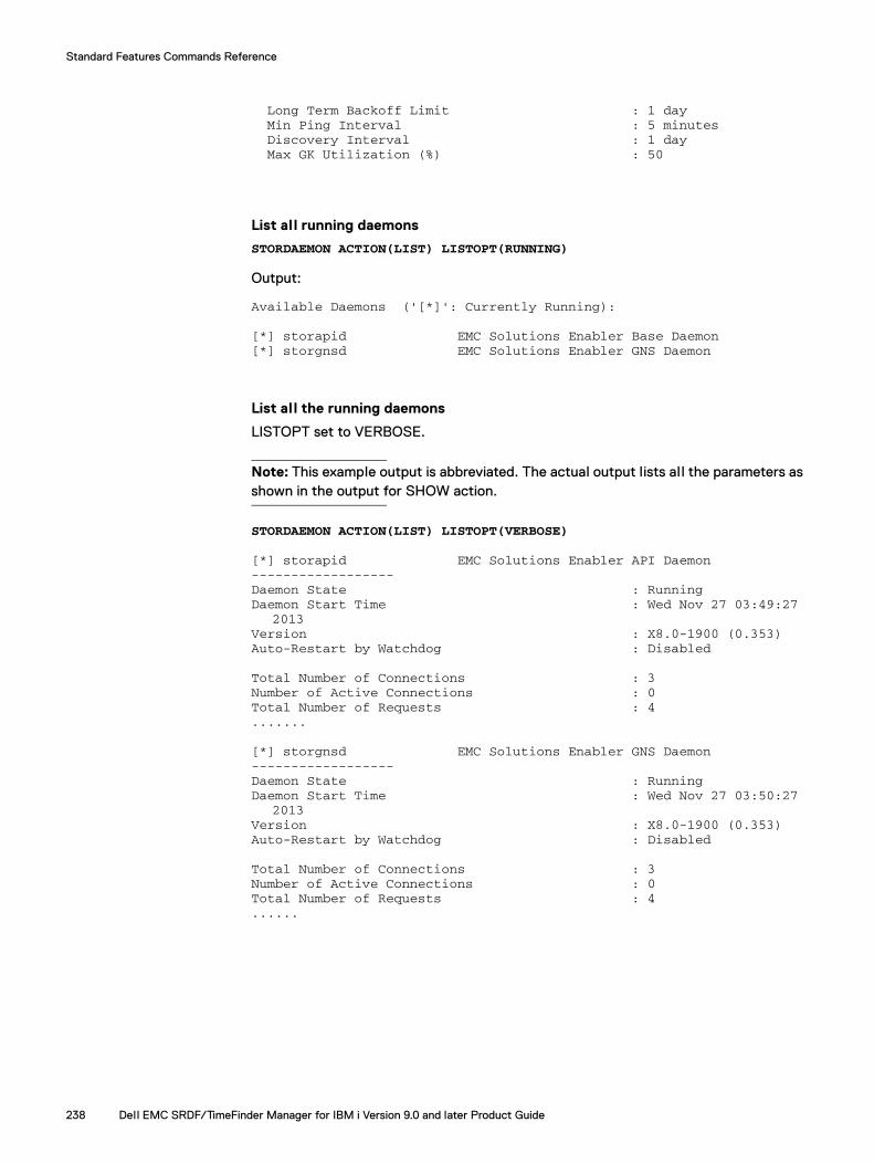
Standard Features Commands Reference
Long Term Backoff Limit : 1 day Min Ping Interval : 5 minutes Discovery Interval : 1 day Max GK Utilization (%) : 50
List all running daemons
STORDAEMON ACTION(LIST) LISTOPT(RUNNING)
Output:
Available Daemons ('[*]': Currently Running):
[*] storapid EMC Solutions Enabler Base Daemon[*] storgnsd EMC Solutions Enabler GNS Daemon
List all the running daemons
LISTOPT set to VERBOSE.
Note: This example output is abbreviated. The actual output lists al l the parameters as shown in the output for SHOW action.
STORDAEMON ACTION(LIST) LISTOPT(VERBOSE)
[*] storapid EMC Solutions Enabler API Daemon------------------Daemon State : RunningDaemon Start Time : Wed Nov 27 03:49:27
2013Version : X8.0-1900 (0.353)Auto-Restart by Watchdog : Disabled
Total Number of Connections : 3Number of Active Connections : 0Total Number of Requests : 4.......
[*] storgnsd EMC Solutions Enabler GNS Daemon------------------Daemon State : RunningDaemon Start Time : Wed Nov 27 03:50:27
2013Version : X8.0-1900 (0.353)Auto-Restart by Watchdog : Disabled
Total Number of Connections : 3Number of Active Connections : 0Total Number of Requests : 4......
238 Dell EMC SRDF/TimeFinder Manager for IBM i Version 9.0 and later Product Guide
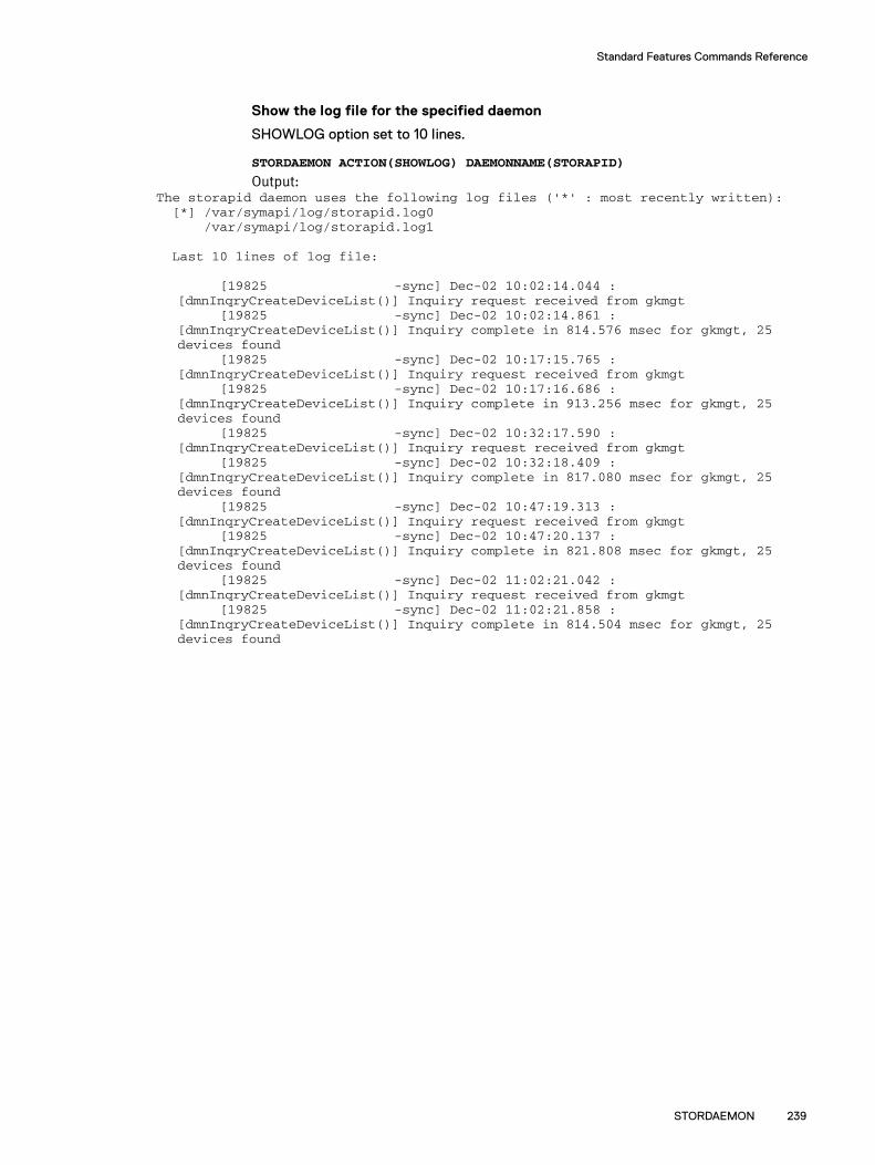
Standard Features Commands Reference
Show the log file for the specified daemon
SHOWLOG option set to 10 lines.
STORDAEMON ACTION(SHOWLOG) DAEMONNAME(STORAPID)
Output:The storapid daemon uses the following log files ('*' : most recently written): [*] /var/symapi/log/storapid.log0
/var/symapi/log/storapid.log1
Last 10 lines of log file:
[19825 -sync] Dec-02 10:02:14.044 : [dmnInqryCreateDeviceList()] Inquiry request received from gkmgt
[19825 -sync] Dec-02 10:02:14.861 : [dmnInqryCreateDeviceList()] Inquiry complete in 814.576 msec for gkmgt, 25 devices found
[19825 -sync] Dec-02 10:17:15.765 : [dmnInqryCreateDeviceList()] Inquiry request received from gkmgt
[19825 -sync] Dec-02 10:17:16.686 : [dmnInqryCreateDeviceList()] Inquiry complete in 913.256 msec for gkmgt, 25 devices found
[19825 -sync] Dec-02 10:32:17.590 : [dmnInqryCreateDeviceList()] Inquiry request received from gkmgt
[19825 -sync] Dec-02 10:32:18.409 : [dmnInqryCreateDeviceList()] Inquiry complete in 817.080 msec for gkmgt, 25 devices found
[19825 -sync] Dec-02 10:47:19.313 : [dmnInqryCreateDeviceList()] Inquiry request received from gkmgt
[19825 -sync] Dec-02 10:47:20.137 : [dmnInqryCreateDeviceList()] Inquiry complete in 821.808 msec for gkmgt, 25 devices found
[19825 -sync] Dec-02 11:02:21.042 : [dmnInqryCreateDeviceList()] Inquiry request received from gkmgt
[19825 -sync] Dec-02 11:02:21.858 : [dmnInqryCreateDeviceList()] Inquiry complete in 814.504 msec for gkmgt, 25 devices found
STORDAEMON 239

Standard Features Commands Reference
STRSTMSRVStarts the SRDF/TimeFinder Manager server job.
SyntaxSTRSTMSRV USERID(user_id) PORTNUM(port_number) JOBQ(job_queue)CCSID(*CURRENT|*USRPRF|*SYSVAL|*HEX|1-65535)
DescriptionSTRSTMSRV starts the job that runs the server job on the node on which the command executes. This command must be run on all nodes. If you do not supply a port number, the STRSTMSRV command uses the default of 8000.
Required parametersUSERID(user_id)
The user ID of the submitted job under which the server job runs. The default value is *CURRENT.
PORTNUM(port_number)The TCP/IP port number. The default value is 8000. If you use a different port number, keep the port number consistent on all nodes participating in IASP operations.
JOBQ(job_queue)The name of the job queue where the server job runs. The default value is *LIBL/EMCCTL.
CCSID(*CURRENT|*USRPRF|*SYSVAL|*HEX|1-65535)The setting of the coded character set ID (CCSID) for the SRDF/TimeFinder Manager server job. The values are:
*CURRENT — The CCSID specified for the job that is currently running is used.
*USRPRF — The CCSID specified in the user profile where the submitted job initial ly runs is used.
*SYSVAL — The CCSID specified in the system value QCCSID at the time the job is started is used.
*HEX — The CCSID 65535 is used.
1-65535 — Specify the CCSID.
Usage notesIf STRSTMSRV fails to start, use the NETSTAT option 3 (IPV4) or option 6 (IPV6) to ensure no communication jobs are using 8000. STMSERVER runs one job constantly; others are submitted and subsequently ended during operations.
Example STRSTMSRV USERID(*CURRENT) PORTNUM(8000) JOBQ(*LIBL/EMCCTL)
240 Dell EMC SRDF/TimeFinder Manager for IBM i Version 9.0 and later Product Guide

APPENDIX BSymmetrix Integration Toolkit
Invisible Body Tagefernce
This appendix lists the supported Solutions Enabler CLI commands that are packaged with the SRDF/TimeFinder Manager software in the Symmetrix Integration Toolkit, and provides some examples. These commands are run from the IBM i command line or Qshell.
◆ Supported Solutions Enabler CLI commands..................................................... 242◆ Command line examples .................................................................................... 243◆ Supporting documentation................................................................................. 243
Symmetrix Integration Toolkit 241
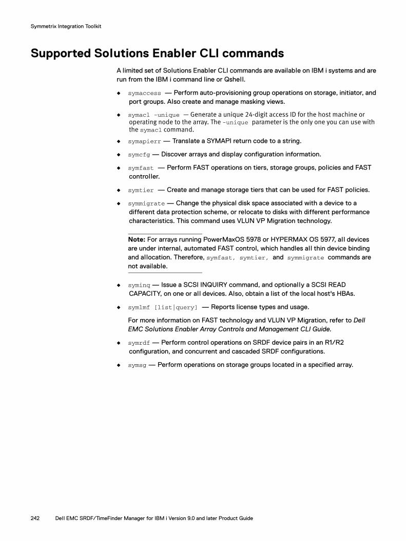
Symmetrix Integration Toolkit
Supported Solutions Enabler CLI commandsA limited set of Solutions Enabler CLI commands are available on IBM i systems and are run from the IBM i command line or Qshell.
◆ symaccess — Perform auto-provisioning group operations on storage, initiator, and port groups. Also create and manage masking views.
◆ symacl -unique — Generate a unique 24-digit access ID for the host machine or operating node to the array. The -unique parameter is the only one you can use with the symacl command.
◆ symapierr — Translate a SYMAPI return code to a string.
◆ symcfg — Discover arrays and display configuration information.
◆ symfast — Perform FAST operations on tiers, storage groups, policies and FAST controller.
◆ symtier — Create and manage storage tiers that can be used for FAST policies.
◆ symmigrate — Change the physical disk space associated with a device to a different data protection scheme, or relocate to disks with different performance characteristics. This command uses VLUN VP Migration technology.
Note: For arrays running PowerMaxOS 5978 or HYPERMAX OS 5977, al l devices are under internal, automated FAST control, which handles all thin device binding and allocation. Therefore, symfast, symtier, and symmigrate commands are not available.
◆ syminq — Issue a SCSI INQUIRY command, and optionally a SCSI READ CAPACITY, on one or al l devices. Also, obtain a list of the local host's HBAs.
◆ symlmf [list|query] — Reports license types and usage.
For more information on FAST technology and VLUN VP Migration, refer to Dell EMC Solutions Enabler Array Controls and Management CLI Guide.
◆ symrdf — Perform control operations on SRDF device pairs in an R1/R2 configuration, and concurrent and cascaded SRDF configurations.
◆ symsg — Perform operations on storage groups located in a specified array.
242 Dell EMC SRDF/TimeFinder Manager for IBM i Version 9.0 and later Product Guide

Symmetrix Integration Toolkit
Command line examplesThe following example displays information about all front-end directors for the specified array using the symcfg command in both the IBM i command line and Qshell formats.
IBM i command line Addlible emcctlCALL PGM(SYMCFG) PARM(list '-SA' 'ALL' '-sid' '710')
Qshell From the IBM i command line, enter the Qshell setup commands:
Addlible emcctl strqshcd /qsys.lib/emcctl.lib
From the Qshell, enter:
symcfg.pgm list -SA ALL -sid 710
Note: There is a save file available called symapicnfg. This file is restored during installation and is called /var/symapi/config/alias/qshrc. This file holds aliases for the symcli's. To enable them follow the instructions in the header of both files.
Supporting documentationDetails on command actions and parameters, options, and error codes for each supported command are in the Dell EMC Solutions Enabler CLI Reference Guide.
Help is also available using the -h parameter with the command. For example:
IBM i command line CALL PGM(SYMCFG) PARM('-h')
Qshell symcfg.pgm -h
Or when alias file is configured:
symcfg -h
Command line examples 243

Symmetrix Integration Toolkit
244 Dell EMC SRDF/TimeFinder Manager for IBM i Version 9.0 and later Product Guide
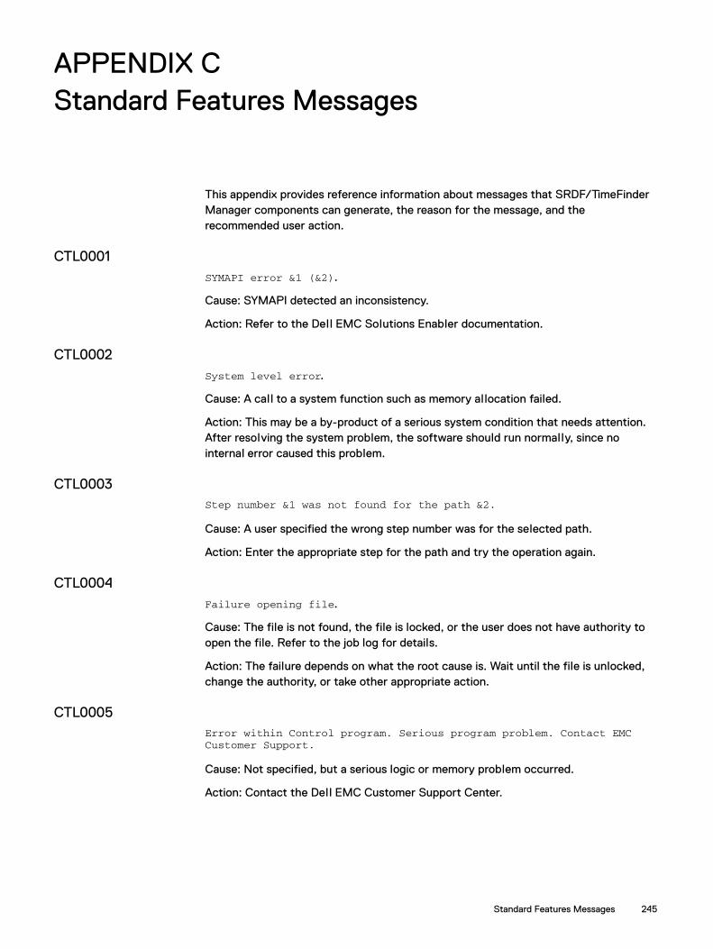
APPENDIX CStandard Features Messages
Invisible Body Tag
This appendix provides reference information about messages that SRDF/TimeFinder Manager components can generate, the reason for the message, and the recommended user action.
CTL0001SYMAPI error &1 (&2).
Cause: SYMAPI detected an inconsistency.
Action: Refer to the Dell EMC Solutions Enabler documentation.
CTL0002System level error.
Cause: A call to a system function such as memory allocation failed.
Action: This may be a by-product of a serious system condition that needs attention. After resolving the system problem, the software should run normally, since no internal error caused this problem.
CTL0003Step number &1 was not found for the path &2.
Cause: A user specified the wrong step number was for the selected path.
Action: Enter the appropriate step for the path and try the operation again.
CTL0004Failure opening file.
Cause: The file is not found, the file is locked, or the user does not have authority to open the file. Refer to the job log for details.
Action: The failure depends on what the root cause is. Wait until the file is unlocked, change the authority, or take other appropriate action.
CTL0005Error within Control program. Serious program problem. Contact EMCCustomer Support.
Cause: Not specified, but a serious logic or memory problem occurred.
Action: Contact the Dell EMC Customer Support Center.
Standard Features Messages 245
Standard Features Messages
CTL0006Path &1 is not disassociated from the image &2.
Cause: The path associated with the selected image has configured steps. The user opted not to disassociate the path.
Action: This is an informational message; no user action is necessary.
CTL0007Cannot show logical devices for device group &1.
Cause: SYMAPI reports numeric error &2 (&3 - error message description).
Action: Refer to the Dell EMC Solutions Enabler documentation.
CTL0008Error running SYMAPI program.
Cause: SYMAPI reports numeric error &1 (&2 - error message description).
Action: Refer to the Dell EMC Solutions Enabler documentation. If the documentation does not provide a solution to the problem, contact the Dell EMC Customer Support Center.
CTL0009On Symmetrix &1 standard device &2 now is paired with BCV device &3.
Cause: The standard device was previously paired with BCV device &4, which is on the same physical disk as one of the mirrors of the standard device.
Action: Manually unpair the standard device and then pair it again.
CTL0010No available unpaired BCV/SNAP devices.
Cause: There are no available BCV or Snap devices of the right model and capacity.
Action: Either free up the BCV or Snap devices by unpairing them from another use, or have the Dell EMC Customer Support Engineer configure additional BCV or Snap devices within the array.
CTL0011Cannot unpair BCV devices which are synchronized or in progress or
unpaired.
Cause: An attempt was made to unpair devices for the step where devices are established or in progress.
Action: Use control options to split BCV pairs before trying this option. To change device pairing, you must first split the established pairs. If the devices are already unpaired, do nothing. If the devices are in a Synchronized or SyncInProg state, split the devices before making another attempt to unpair the devices.
246 Dell EMC SRDF/TimeFinder Manager for IBM i Version 9.0 and later Product Guide
Standard Features Messages
CTL0012On Symmetrix &1 standard device &2 is not paired.
Cause: There are no available BCV/Snap devices of the matching configuration.
Action: Make the appropriate device changes for the configuration.
CTL0036User cancelled SRDF Links processing.
Cause: A user opted to cancel the SRDF links control action processing.
Action: This is an informational message; no user action is necessary.
CTL0037Processing failed with SYMAPI error &1(&2).
Cause: An error occurred while processing a control action.
Action: Error number and description are provided. Either use this information to correct the problem, or contact Dell EMC Customer Support.
CTL0041System is not in restricted state. Split control action cannot be run.
Cause: A Split control action can be run only when the system is in a restricted state.
Action: Refer to “Split BCV pairs: Restricted state” on page 132 for information to bring a system to a Restricted state.
CTL0042System is not in restricted state. Suspend SRDF links and action cannot
be run.
Cause: A Suspend control action can be run only when the system is in a Restricted state.
Action: Refer to “Splitting/Suspending SRDF links: Restricted state” on page 179 for information to bring a system to a restricted state.
CTL0048BCV device &1 attached to STD device &2 is in process of being Split.
Cause: The BCV device pair status is SplitInProg. An Establish control action cannot be performed on this pair.
Action: Wait until the Split operation completes and try the operation again.
CTL0049Control action failed for device pair &1(S) and &2(B).
Cause: The control action &3 processing failed.
Action: Check the job log for errors.
247

Standard Features Messages
CTL0050Processing complete for device pair &1(S) and &2(B).
Cause: Control action &3 initiated successfully.
Action: This is an informational message; no user action is necessary.
CTL0051Error with devices %s(S) and %s(T).
Cause: This device pair is in invalid state.
Action: Check the devices and their statuses.
CTL0052Source device &1 has a Target device &2.
Cause: Synchronizing RDF pair is in progress or completed.
Action: Resume SRDF links can be run only when the RDF pair state is in the Suspended state. Establish SRDF links can be run only when the RDF pair state is in a Suspended or Split state.
CTL0053Source device is &1 and Target device is &2.
Cause: This RDF pair state is in &3 state.
Action: Resume SRDF links can only be run when the links are in a Suspended state. Establish SRDF links can only be run when the links are in a Suspended or Split state.
CTL0055Control action is initiated for the Image &1.
Cause: &2 control action initiated successfully.
Action: This is an informational message; no user action is necessary.
CTL0056Standard device &1 (S) has a BCV device &2 (B).
Cause: Synchronizing this BCV pair is in progress or completed.
Action: This is an informational message; no user action is necessary.
CTL0057User cancelled Establish/Re-establish BCV pairs processing.
Cause: A user opted to cancel the Establish/Re-establish BCV pairs control action processing at this time.
Action: This is an informational message; no user action is necessary.
248 Dell EMC SRDF/TimeFinder Manager for IBM i Version 9.0 and later Product Guide

Standard Features Messages
CTL0060SRDF status for the &1 image is not in Synchronized state so the remoteBCV operation may not present a current image of data.
Cause: The SRDF links are not synchronized at this time, so the remote BCV operation may not present a current copy of data on the remote BCV devices.
Action: Make sure that the SRDF links are synchronized to get a current image of data from R1 devices to R2 devices and remote BCV devices.
CTL0064Error message &1 was received during the IBM i &2 API Call.
Cause: An error occurred while &2 API call was made on the IBM i host.
Action: Refer to the job log for errors. Either use this information to correct the problem, or contact Dell EMC Customer Support
CTL0076 User cancelled Establishing SRDF Links processing.
Cause: A user opted to cancel the Establish SRDF Links control action processing.
Action: This is an informational message; no user action is necessary.
CTL0077 Job not on Hold (User Name: &1, Job Name: &2, Job Number: &3).
Cause: The job could not be put on hold.
Action: This is an informational message; no user action is necessary.
CTL0078Job Queue not on Hold (Job Queue Name: &1, Job Queue Library Name: &2).
Cause: The job could not be put on hold.
Action: This is an informational message; no user action is necessary.
CTL0081Vary off failed for the Independent ASP &1.
Cause: Check the job log for errors.
Action: Make sure that no job is using the independent ASP and then retry the operation.
249

Standard Features Messages
CTL0083On Symmetrix &1 paired BCV &2 is on the same physical disk as one ofthe mirrors of the standard device &3.
Cause: No alternate matching BCV device was found on the separate disk.
Action: This informational message indicates that no user action is required, unless performance of the BCV synchronization needs improvement. Sometimes unpairing of other devices of similar emulation makes other candidates available for pairing. Contact Dell EMC Customer Support if an array reconfiguration is required to reassign volumes or add new BCV devices.
CTL0084Inconsistencies were detected in the configuration. The Discovercommand had not been run.
Cause: There is a disk with serial number &1 currently in the ASP &2 with unit number &3, but the configuration database contains ASP &4 with unit number &5.
Action: Run the DISCOVER command to refresh the configuration database.
CTL0085Inconsistencies were detected in the configuration.
Cause: There is a disk with serial number &1 currently in the ASP &2 with unit number &3, but the configuration database contains ASP &4 with unit number &5.
Action: Refer to the job log for errors. Use this information to correct the problem or contact Dell EMC Customer Support.
CTL0086SymSync failed with error code 34.
Cause: SRDF/TimeFinder Manager cannot communicate with the array with serial number &1. The array could be offline (temporarily or permanently) or the gatekeeper device has been removed or changed.
Action: In case of permanently removed arrays or problems with gatekeeper devices, the configuration database should be refreshed. Run the DISCOVER command with option *YES.
CTL0087Path &1 was not found for the image &2.
Cause: The wrong path name was specified.
Action: Enter the appropriate path and try the operation again.
CTL0088Cannot remove device &1 from the device group &2.
Cause: SYMAPI reports numeric error &3 (&4 - error message description).
Action: Refer to the Dell EMC Solutions Enabler documentation.
250 Dell EMC SRDF/TimeFinder Manager for IBM i Version 9.0 and later Product Guide
Standard Features Messages
CTL0089Cannot delete device group &1.
Cause: SYMAPI reports numeric error &3 (&4 - error message description).
Action: Refer to the Dell EMC Solutions Enabler documentation.
CTL0090File &1 does not exist.
Cause: The file does not exist in the system.
Action: Make sure that the installation process completed successfully.
CTL0091Cannot connect to server on &1.
Cause: There are many possible causes for this error, such as the server name may be wrong, the port number may be wrong, and so on.
Action: Check the TCP/IP configuration.
CTL0092Target IOA is still active.
Cause: Target IOA is stil l active, but should not be active for this control action.
Action: Remove the target IOA from the node and try the control action again.
CTL0094Target devices cannot be presented to the host.
Cause: The target devices are already presented to the host.
Action: Remove the target devices from the host.
CTL0095Target devices cannot be added because the link is synchronized orSynchronize in progress.
Cause: Target devices cannot be added to a node if the devices in a Synchronized or SyncInProg state.
Action: Split the link before adding target devices.
CTL0096IOA file &1 is empty, please rebuild it first.
Cause: The IOA file &1 contains no record(s).
Action: Rebuild the IOA file &1 before proceeding with the operation.
251

Standard Features Messages
CTL0097 Error messages were issued during EMC control action &1 processing.Check the job log for details about errors.
Cause: Error messages were issued while processing the control action &1.
Action: Refer to the job log for errors. Either use this information to correct the problem, or contact Dell EMC Customer Support Center.
CTL0098EMC control action &1 processing initiated successfully. Check the joblog for details.
Cause: Control action &1 processing initiated successfully.
Action: This is an informational message; no user action is necessary.
CTL0099Error messages were issued during EMC control action &1 processing.Check the job log for details about errors.
Cause: Error messages were issued while processing the control action &1.
Action: Refer to the job log for errors. Either use this information to correct the problem, or contact the Dell EMC Customer Support Center.
CTL0100Socket operation failed, the failed operation is &1.
Cause: The socket operation failed.
Action: Check the TCP/IP configuration and job log.
CTL0104Operation failed, please check job log for more detail.
Cause: The operation failed.
Action: Check the job log to view a detailed message and then take the appropriate action.
CTL0105 Hold jobs option can be used only when the program is running from theconsole in an interactive session.
Cause: The application is not running from the console.
Action: Try the operation again from the console.
CTL0106 Path &1 is not deleted from the path file.
Cause: A user opted not to delete the path at this time.
Action: This is an informational message; no user action is necessary.
252 Dell EMC SRDF/TimeFinder Manager for IBM i Version 9.0 and later Product Guide

Standard Features Messages
CTL0107Image &1 was not found.
Cause: A user specified the wrong image name.
Action: Enter the appropriate image name and try the operation again.
CTL0108ASP &1 was not found in the list of asps for the image &2.
Cause: Some errors occurred.
Action: Try the operation again.
CTL0109Path &1 was not found in the list of path types.
Cause: A user specified a wrong path name.
Action: Enter the appropriate path and try the operation again.
CTL0110Specified step number &1 is greater, than number of steps for path &2.
Cause: A user specified the wrong step number.
Action: Enter the appropriate step number and try the operation again.
CTL0111Cannot add device &1 to the device group &2.
Cause: SYMAPI reports numeric error &3 (&4 - error message description).
Action: Refer to the Dell EMC Solutions Enabler documentation.
CTL0112Cannot create device group &1.
Cause: SYMAPI reports numeric error &2 (&3 - error message description).
Action: Refer to the Dell EMC Solutions Enabler documentation.
CTL0121Path &1 is invalid for image &2.
Cause: Not all source devices in the step &3 are RDF capable.
Action: Move ASPs containing one or more non-RDF capable devices to the NON_CONFIG image.
253

Standard Features Messages
CTL0123The &1 is &5 for the devices in the &2 image, &3 path, step number &4.
Cause: Control action processing initiated for the image &2.
Action: This is an informational message; no user action is necessary.
CTL0124&1 processing failed for the &2 image, &3 path and step number &4.
Cause: Control action processing failed for the image &2.
Action: Check the errors in the job log. Contact the Dell EMC Customer Support Center if needed.
CTL0125&1 processing initiated for the &2 image, &3 path and step number &4.
Cause: Control action processing initiated successfully for the image &2.
Action: This is an informational message; no user action is necessary.
CTL0126BCV devices are in Sync_in_progress/Restore_in_progress state orSynchronized/Restored for the &1 image, &2 path and step number &3.
Cause: A user tried to Establish the BCV devices, but the BCV state is Synchronized or SyncInProg for the &1 image.
Action: This is an informational message; no user action is necessary.
CTL0127SPLIT control action cannot be run. Synchronizing/Restoring BCV pairsis in progress for the &1 image, &2 path and step number &3.
Cause: Control action Establish is in progress for the &1 image. The Split action cannot be run at this time.
Action: Wait until the BCV state becomes Synchronized and then try the Split control action.
CTL0128BCV devices are already in the Split state for the &1 image, &2 pathand step number &3.
Cause: A user tried to Split the BCV, but the devices are already in the Split state for the &1 image.
Action: BCV devices state must be Synchronized to run the Split BCV pairs option.
254 Dell EMC SRDF/TimeFinder Manager for IBM i Version 9.0 and later Product Guide
Standard Features Messages
CTL0129SRDF links are already Synchronized or Sync_in_progress state for the&1 image, &2 path and step number &3.
Cause: A user tried to Resume, Establish, or Restore the SRDF links, but the links are already in a Synchronized or SyncInProg state.
Action: This is an informational message; no user action is necessary.
CTL0130SRDF links are already Suspended for the &1 image, &2 path and stepnumber &3.
Cause: A user tried to Suspend the SRDF links, but the links are already in a Suspended state.
Action: SRDF links must be in a Synchronized state to run the Suspend SRDF links operation.
CTL0131Split or Suspend SRDF Links cannot be run. SRDF links are inSync_in_progress state for the &1 image, &2 path and step number &3.
Cause: The SRDF links are in SyncInProg state. Split or Suspend SRDF links action cannot be run at this time.
Action: Wait until the SRDF link state becomes Synchronized and then try the Split or Suspend control action.
CTL0132SRDF links are already Split for the &1 image, &2 path and step number&3.
Cause: A user tried to Split the SRDF links, but the links are already in a Split state.
Action: The SRDF links must be in a Synchronized state to run the Split SRDF links option.
CTL0133Resume SRDF Links cannot be run. SRDF links are in Split state for the&1 image, &2 path and step number &3.
Cause: The SRDF links are in a Split state. The Resume SRDF links control action cannot be run at this time.
Action: The SRDF links must be in a Suspended state to run the Resume SRDF links option.
CTL0134The devices for the &1 image, &2 path and step number &3 are inineligible state to perform the control action specified.
Cause: Check the status of the devices on the Configuration screen.
Action: Change any configuration details needed. Make sure that the devices are in eligible state for the control action requested.
255

Standard Features Messages
CTL0135SNAP devices are not in eligible state to be created, status must beNotCreated.
Cause: It is most likely that the devices have not been paired with the Snap target devices.
Action: Pair the devices with the Snap target devices.
CTL0136The &1 devices cannot be activated because they are being created.
Cause: The &1 devices cannot be activated because the devices are in the process of being created.
Action: Wait until the devices are created before activating them.
CTL0137The &1 devices have already been activated.
Cause: The &1 devices have already been activated.
Action: This is an informational message; no user action is necessary.
CTL0138The System is not in restricted state. The ACTIVATE control actioncannot be run.
Cause: The system is not in a Restricted state.
Action: Put the system in a Restricted state and try the operation again.
CTL0139Path &1 is not associated with the image &2.
Cause: The wrong path name was specified.
Action: Associate a path with the image first and then proceed with the operation.
CTL0140For &1 image path &2 step &3 unit &4 source device is not known.
Cause: The target device for the previous step is unknown. The previous step is not configured.
Action: Check the configuration.
CTL0141For &1 image path &2 and step &3 target device &4 is in ineligiblestate to be unpaired from standard device &5.
Cause: Target device is in &6 state.
Action: This is an informational message; no user action is necessary.
256 Dell EMC SRDF/TimeFinder Manager for IBM i Version 9.0 and later Product Guide
Standard Features Messages
CTL0142Not all devices in the &1 image are Symmetrix devices. Control actionscan be performed only for images having Symmetrix devices.
Cause: &1 image has &2 type of devices.
Action: Move ASPs with non-Symmetrix devices to the NON_CONFIG image.
CTL0143Additional time required to ensure SRDF/A consistent split.
Cause: Insufficient time was specified in the SRDFATIME data area to perform a consistent Split.
Action: Increase the value in the SRDFATIME data area and try the Split operation again.
CTL0144&1.
Cause: The load source mirror is in an ineligible state.
Action: From the Display Disk Configuration Status screen in SST, check the status of the disks and make appropriate changes.
CTL0145&1 action failed for the &2 image, &3 path and step number &4.
Cause: A user tried the operation, but the load source is in the &5 state.
Action: From the Display Disk Configuration Status screen in SST, check the status of the disks and make appropriate changes.
CTL0146Non-Symmetrix devices exist in the configuration.
Cause: The configuration contains devices that are not recognized by the array.
Action: Run the DISCOVER command to refresh the configuration database.
CTL0147SNAP devices for step &1 and &2 path could not be paired.
Cause: Some or al l source devices for the step are RAID 5 BCVs or RAID 6 BCVs and are clone enabled.
Action: This is an informational message; no user action is necessary.
CTL0148User cancelled the Cancel BCV pairs processing.
Cause: A user opted to cancel the Cancel BCV pairs control action processing at this time.
Action: This is an informational message; no user action is necessary.
257
Standard Features Messages
CTL0149Devices for step &1 and &2 path could not be unpaired.
Cause: Some or al l BCV devices for the step are RAID 5 BCVs or RAID 6 BCVs and are Clone enabled.
Action: The Cancel BCV pairs control action should be run first.
CTL0150Devices in step &1 and &2 path for &3 image have a mixed BCVconfiguration.
Cause: Some BCV devices in the step are standard devices and some are RAID 5 or RAID 6 BCVs. Refer to Table 6 on page 51 for greater detail.
Action: This is an informational message; no user action is necessary.
CTL0151System is not ended to restricted condition.
Cause: The system is not ended to the restricted condition in the allocated time.
Action: Use the WRKSBS command to check the status of the controlling subsystem and other subsystems.
CTL0152Establish control action cannot be run.
Cause: All BCV devices are standard BCVs and there are one or more Clone enabled BCV devices.
Action: Use the Cancel option to remove the incremental relationship between standard devices and the split BCV devices.
CTL0153On Symmetrix &1 for the step &2 target device &3 is in ineligible state to be unpaired from standard device &4.
Cause: Target device is in &5 state.
Action: This is an informational message; no user action is necessary.
CTL0154Cannot associate &1 device &2 with Composite Group &3.
Cause: The SYMAPI reports error &2(&3).
Action: Refer to the Dell EMC Solutions Enabler documentation.
258 Dell EMC SRDF/TimeFinder Manager for IBM i Version 9.0 and later Product Guide

Standard Features Messages
CTL0156User cancelled the RDF Clear Consistency state processing.
Cause: A user opted to cancel the RDF Clear Consistency state control action processing.
Action: This is an informational message; no user action is necessary.
CTL0157User cancelled the Disable SRDF ECA/MSC processing.
Cause: A user cancelled the Disable SRDF ECA/MSC control action processing.
Action: This is an informational message only. No user action is required.
CTL0158Cannot create composite group &1.
Cause: The SYMAPI reports error &2(&3).
Action: Refer to the EMC Solutions Enabler documentation.
CTL0159Cannot add device &1 to the composite group &2.
Cause: The SYMAPI reports error &3(&4).
Action: Refer to the Dell EMC Solutions Enabler documentation.
CTL0160Cannot delete Composite Group &1.
Cause: The SYMAPI reports error &3(&4).
Action: Refer to the Dell EMC Solutions Enabler documentation.
CTL0162Split while active not completed for step &1 , &2 path and &3 image.SRDF Consistency state not enabled.
Cause: The SRDF Consistency state is not enabled while the SPLIT with SPLITWA option is selected.
Action: Either enable the RDF Consistency State with the CTLACT command (RDFCSENABLE) or use another option with the SPLIT control action (RESTRICTED, MAINTENANCE or HOLDJOBS).
259
Standard Features Messages
CTL0163 Cannot use SPLITWA option for step that is greater than 2, unless if itis step 3 after cascading RDF.
Cause: Splitting with the SPLITWA option is unnecessary on steps greater than 2, unless it is a step 3 after cascading RDF. For example, a multihop configuration uses a remote BCV/R1 that must be split first to create a valid copy. A BCV/R1 does not have a step number greater than 2.
CTL0164Network address (NETWADDR) and node name (NODENAME) cannot be bothempty. Specify either network address or node name.
Cause: User did not specify NETWADDR and/or NODENAME.
Action: Specify a network address or node name. When specifying both parameters, make sure they are unique.
CTL0165SRDF ECA/MSC protection is not disabled.
Cause: SRDF ECA/MSC protection cannot be disabled because the consistency group does not exist.
Action: Enable the SRDF ECA/MSC protection by executing the CTLACT command with ECAENABLE option.
CTL0166SRDF SPLITWA cannot be run.
Cause: The user selected the SPLITWA control action for an unsupported feature.
Action: Select a different split control action.
CTL0167User cancelled the SN-ID Read/Clear action.
Cause: A user opted to cancel the SN-ID Read/Clear action processing.
Action: This is an Informational message. No action is necessary.
CTL0168Path &1 is invalid for image &2.
Cause: There are RAID 6 devices in the step &3.
Action: Check the configuration.
CTL0169Path &1 is invalid for image &2.
Cause: There are devices in the step &3 with the RDF group number greater than 64.
Action: Check the configuration.
260 Dell EMC SRDF/TimeFinder Manager for IBM i Version 9.0 and later Product Guide

Standard Features Messages
CTL0170User cancelled the Terminate SNAP pairs processing.
Cause: A user opted to cancel the Terminate the Snap pairs control action.
Action: This is an informational message; no action is required.
CTL0171User cancelled Failover processing.
Cause: A user opted to cancel the Failover control action.
Action: This is an informational message; no action is required.
CTL0172User cancelled Failback processing.
Cause: A user opted to cancel the Failback control action.
Action: This is an informational message; no action is required.
CTL0173 On the Symmetrix &1 changes are not done for the RDF group
Cause: SRDF/TimeFinder Manager did not detect any changes from the current configuration.
Action: This is an informational message; no action is required.
CTL0174 SRDF mode for the &1 image is Adaptive Copy, so the remote BCVoperation will not present a current image of data.
Cause: The SRDF links are in Adaptive Copy mode. Therefore, the remote BCV operation may not present a current copy of data on the remote BCV devices.
Action: Make sure that the SRDF links are in Synchronous or Asynchronous mode and the links are in Synchronized or Consistent state to get a current image of data from R1 devices to R2 devices and remote BCV devices.
CTL0176SymSync failed for the Symmetrix with serial number &1.
Cause: SymSync failed with SYMAPI error &2(&3). Array could be removed temporally or permanently, or the gatekeeper device removed or changed.
Action: In case of permanently removed array or a problem with gatekeeper device, configuration database should be refreshed. Command Discover should be run with option *YES.
261
Standard Features Messages
CTL0177Option is not allowed for current version of the operation system.
Cause: This option is only allowed for the V6R1M0 operating system or higher.
Action: Only MAINTENANCE SPLIT/SUSPEND/ACTIVATE is al lowed for an IASP image.
CTL0178Devices are not Varied OFF. Option is not allowed for current versionof the operating system.
Cause: This option is only allowed for the V6R1M0 operating system or higher.
Action: Vary off the devices.
CTL0179Control action &1 will be processed.
Cause: The devices are neither unavailable nor online.
Action: This is an informational message; no user action is necessary.
CTL0180Devices are not Varied OFF. Control action &1 failed.
Cause: This option is not allowed when devices are varied on.
Action: Vary off the devices.
CTL0181Data area &1 not found. Default values used.
Cause: Default values have been used: Suspend timeout: &2 Timeout action: &3 Auto-resume timeout: &4.
Action: Contact Dell EMC support to obtain the &1 data area.
CTL0182Access to ASP &1 is suspended.
Cause: Access to ASP &1 is suspended. New transactions cannot start until access is resumed. Transaction quiescing used &2 seconds. Operations quiescing used &3 seconds. Writes to disk used &4 seconds, for a total of &5 seconds.
Action: This is an informational message; no action is necessary.
262 Dell EMC SRDF/TimeFinder Manager for IBM i Version 9.0 and later Product Guide
Standard Features Messages
CTL0183&1 Processing timed out after &2 seconds for ASP &3.
Cause: &1 Processing for ASP &3 did not complete within the Suspend Timeout value of &2 seconds.
Action: Change the Suspend Timeout value using the command &P CHGDTAARA (&5/&4 (40 6)) 'nnnnnn'where nnnnnn is the desired Suspend Timeout value in seconds, which must be six digits with leading zeros.
CTL0184The command processing will continue for ASP &1.
Cause: The Timeout Action has been specified as Continue.
Action: Change the Timeout Action to end the operation on a timeout using the following command:CHGDTAARA (&3/&2 (90 1)) 'E'
CTL0185The command processing has been ended for ASP &1
Cause: Refer to the messages previously listed. The Timeout Action has been specified as End.
Action: Change the Timeout Action to continue command processing on a timeout with the following command:CHGDTAARA (&3/&2 (90 1)) 'C'
CTL0186Access to ASP &1 successfully resumed.
Cause: Access to ASP &1 is successfully resumed. Users may access data within the ASP.
Action: This is an informational message; no action is necessary.
CTL0187Source IOA is still active.
Cause: The target IOA has not been removed from that node.
Action: Remove the target IOA from the node.
CTL0188For &1 image path &2 step &3 not all source devices are reachable.
Cause: The Problems occur in the previous step.
Action: Check status of the previous step.
263
Standard Features Messages
CTL0189SRDF Failover operation failed.
Cause: SRDF Failover with Establish option is specified but these devices are not Dynamic SRDF devices.
Action: Use SRDF Failover with option *NO.
CTL0190 User cancelled the Recreate CLONE pairs processing.
Cause: User opted to cancel the Recreate CLONE pairs control action processing at this time.
Action: This is an informational message; no action is necessary.
CTL0191 User cancelled the Recreate SNAP pairs processing.
Cause: User opted to cancel the Recreate SNAP pairs control action processing at this time.
Action: Informational message. No action is necessary.
CTL0192 User cancelled the Terminate CLONE pairs processing.
Cause: User opted to cancel the Terminate CLONE pairs control action processing at this time.
Action: Informational message. No action is necessary.
CTL0193 Path &1 is invalid for image &2.
Cause: Not all source devices in the step &3 are standard devices.
Action: You can change pairing for previous step.
CTL0194 SRDF Create/Delete pair operation failed.
Cause: Control action &1 operation is specified but devices listed in the Device File are not Dynamic SRDF devices.
Action: Use Dynamic RDF devices.
CTL0195 Path &1 is invalid for image &2 for current code level.
Cause: Path is valid for Enginuity 5876 or later.
Action: Informational message. No action is necessary.
264 Dell EMC SRDF/TimeFinder Manager for IBM i Version 9.0 and later Product Guide
Standard Features Messages
CTL0196 Path &1 is invalid for image &2 for current code level.
Cause: Duplicate Snap is valid for Enginuity 5876 or later.
Action: Informational message. No action is necessary.
CTL0197 Device &1 on the Symmetrix &2 is a target device for TF/Clone Emulationsession and cannot be used for pairing.
Cause: Target device is already in a Clone emulation session.
Action: Informational message. No action is necessary.
CTL0198 Device &1 on the Symmetrix &2 is a target device for TF/Clone sessionand cannot be used for pairing.
Cause: Target device is already in a Clone session.
Action: Informational message. No action is necessary.
CTL0199 Cannot use SPLITWA option for second step if first step is not RDF.
Cause: There is no use splitting with SPLITWA option on the second step, unless if it is step 2 after RDF.
Action: Use other split option with the selected step.
CTL0200 Symmetrix &1 does not have &2 license.
Cause: Array does not have requested license.
Action: Informational message. No action is necessary.
CTL0201 Device &1 is not found on the Symmetrix &2 and cannot be used forpairing.
Cause: Target device is not found on the array.
Action: Informational message. Check the device file.
CTL0202 Device &1 on the Symmetrix &2 is &3 and cannot be used for pairing forthis type of the step.
Cause: Target device has not valid configuration type.
Action: Informational message. Check the device file.
265

Standard Features Messages
CTL0203 Device &1 on the Symmetrix &2 is in use, i.e. paired with anotherdevice and cannot be used for pairing.
Cause: Target device is already in use.
Action: Informational message. Check the device file.
CTL0204 SRDF type for source devices in this step is &1. The SRDF mode for thestep is &2.
Cause: Additional status for RDF type of the step is provided.
Action: This is an informational message; no user action is necessary.
CTL0205 SRDF mode for the &1 image, &2 path and step number &3 is AdaptiveCopy, so the Failover operation is not allowed.
Cause: Informs the user that the SRDF links are in Adaptive Copy mode.
Action: Make sure that the SRDF links are in Synchronous or Asynchronous mode.
CTL0206Save pool &1, specified for create virtual copy sessions is not validfor image &2, path &3 and step number &4.
Cause: Not all arrays in the configuration have a specified save pool.
Action: You can call program wrk_pool (option 5 from the main screen) and check available save pools.
CTL0207Operation to create virtual copy sessions cannot be executed for image&1, path &2 and step number &3.
Cause: Virtual copy session(s) already exists with &4 and &5 save pools.
Action: You can cancel existing sessions and create new ones with desired pool name.
CTL0208Save pool &1, specified for create virtual copy sessions for image &2,path &3 and step number &4 will be ignored.
Cause: Virtual copy session(s) exists with &5 save pool name.
Action: You can specify correct pool name or cancel existing sessions and create new ones with desired pool name.
266 Dell EMC SRDF/TimeFinder Manager for IBM i Version 9.0 and later Product Guide
Standard Features Messages
CTL0209Path &1 is invalid for image &2.
Cause: VP Snap should be the last step in the path.
Action: This is an informational message; no user action is necessary.
CTL0210Create VP Snap control action cannot be run.
Cause: Some or al l devices in previous step are clone enabled.
Action: This is an informational message; no user action is necessary.
CTL0211Configuration change &1 for pool &2 is failed.
Cause: Configuration change processing failed for the specified pool.
Action: Check the errors in the symapi log. Contact the Dell EMC Customer Support if needed.
CTL0212Configuration change &1 for pool &2 is successful.
Cause: Configuration change processing was successful for the specified pool.
Action: This is an informational message; no user action is necessary. Check symapi log for more details.
CTL0213Configuration change &1 for pool &2 is successful. Termination of theconfiguration session failed.
Cause: Configuration change processing was successful for the specified pool.
Action: Check the errors in the symapi log. Contact the Dell EMC Customer Support if needed.
CTL0214RTVSTMINF Error: &1
Cause: RTVSTMINF failed with an error
Action: Check joblog for earlier messages.
CTL0215&1 cannot be run for the &2 image, &3 path and step number &4.
Cause: Multisession Consistency (MSC) for SRDF/A is enabled. This configuration is not supported.
Action: Change the configuration if needed. Contact the Dell EMC Customer Support if needed.
267

Standard Features Messages
CTL0216&1 cannot be run for the &2 image, &3 path and step number &4.
Cause: SRDF Enginuity Consistency Assist (RDF-ECA) for SRDF/S is enabled. This configuration is not supported.
Action: Change the configuration if needed. Contact the Dell EMC Customer Support if needed.
CTL0217The devices for the &1 image, &2 path and step number &3 are inineligible state to perform the control action specified.
Cause: Snap restore from clone/clone emulation target and VP snap restore from clone target is not supported for this Enginuity version.
Action: Change any configuration details needed. Make sure that the devices are in eligible state for the control action requested.
CTL0218The devices for the &1 image, &2 path and step number &3 are inineligible state to perform the control action specified.
Cause: Source devices for snap restore from clone/clone emulation target or VP snap restore from clone target are in invalid state.
Action: Change any configuration details needed. Make sure that the devices are in eligible state for the control action requested.
CTL0219The devices for the &1 image, &2 path and step number &3 are inineligible state to perform the control action specified.
Cause: Clone operation with Snap/VP Snap from target is not available on this Enginuity version.
Action: Change any configuration details needed. Make sure that the devices are in eligible state for the control action requested.
CTL0220The devices for the &1 image, &2 path and step number &3 are inineligible state to perform the control action specified.
Cause: State for Snap/VP Snap from clone target is invalid for clone operation.
Action: Change any configuration details needed. Make sure that the devices are in eligible state for the control action requested.
268 Dell EMC SRDF/TimeFinder Manager for IBM i Version 9.0 and later Product Guide
Standard Features Messages
CTL0221The devices for the &1 image, &2 path and step number &3 are inineligible state to perform the control action specified.
Cause: Clone incremental restore to Snap or VP Snap Source is not supported for this Enginuity version.
Action: Change any configuration details needed. Make sure that the devices are in eligible state for the control action requested.
CTL0222The devices for the &1 image, &2 path and step number &3 are inineligible state to perform the control action specified.
Cause: State for Snap or VP Snap is invalid for clone incremental Restore to Snap or VP Snap Source.
Action: Change any configuration details needed. Make sure that the devices are in eligible state for the control action requested.
CTL0223Not all devices in a range are &1 devices.
Cause: All devices in a range should be &1 devices.
Action: Check devices in a range.
CTL0224Not all devices in a file are &1 devices.
Cause: All devices in a file should be &1 devices.
Action: Check devices in a file.
CTL0225Device &1(&2), specified in the range of devices is invalid for thecontrol operation.
Cause: All devices in a range should be &3 devices.
Action: Check devices in a range.
CTL0226Device &1(&2), specified in the device file is invalid for the controloperation.
Cause: All devices in a file should be &3 devices.
Action: Check devices in a file.
269
Standard Features Messages
CTL0227There are no SNAP pools on the Symmetrix &1.
Cause: Array does not have SNAP pools.
Action: Check the configuration.
CTL0230The System is not in restricted state. New Snapshots could not beESTABLISHED.
Cause: The system is not in restricted state.
Action: Please put the system in restricted state and retry the operation.
CTL0231The status of &1 (generation &2) snapshot from source devices of thestep &3, path &4 and &5 image is &6. &7
Cause: Control action processing initiated for the image &5.
Action: Informational message. No action is necessary.
CTL0232Snapshot is established from the &1 devices of the step. There are &2devices in the step.
Cause: Additional status for the snapshot is provided.
Action: Informational message. No action is necessary.
CTL0233&1 snapshot &2 generation &3.
Cause: Additional information for the step is provided.
Action: Informational message. No action is necessary.
CTL0234Operation is not supported for current code level.
Cause: Operation is supported for arrays running PowerMaxOS 5978 or HYPERMAX 5977.
Action: Informational message. No action is necessary.
CTL0235Snapshot has links. Terminate snapshot is notallowed.
Cause: Operation is not allowed.
Action: Informational message. No action is necessary.
270 Dell EMC SRDF/TimeFinder Manager for IBM i Version 9.0 and later Product Guide
Standard Features Messages
CTL0236There are no snapshots for the devices in the &1 image &2 path and step
number &3.
Cause: No control operations except Establish are allowed.
Action: Informational message. No action is necessary.
CTL0237There are no snapshots for the devices in the &1 image &2 path and stepnumber &3 or devices for this step are not paired
Cause: Link target devices is not allowed.
Action: Informational message. No action is necessary.
CTL0238There are no snapshots for the devices in the &1 image &2 path and stepnumber &3 or devices for this step are already restored.
Cause: Restore operation is not allowed.
Action: Informational message. No action is necessary.
CTL0239Status of the snapshot for the devices in the &1 image, &2 path andstep number &3 is Restore in Progress. Terminate action cannot be runat this time.
Cause: Terminate snapshot is not allowed.
Action: Wait until the snapshot state becomes Restored and then try the Terminate control action.
CTL0240System ended to a semi-restricted condition.
Cause: The STMSENDSBS command has run and completed successfully. The system is in a semi-restricted state and is available for maintenance activities.
271

Standard Features Messages
272 Dell EMC SRDF/TimeFinder Manager for IBM i Version 9.0 and later Product Guide
APPENDIX DMiscellaneous Device Information
Invisible Body Tag
This appendix lists miscellaneous device information such as device s and device pairing compatibility.
◆ 2105 to 2107 devices (thick devices).................................................................. 274◆ D910 device support (thin devices).................................................................... 275◆ Variable-sized LUNs........................................................................................... 277
Miscellaneous Device Information 273
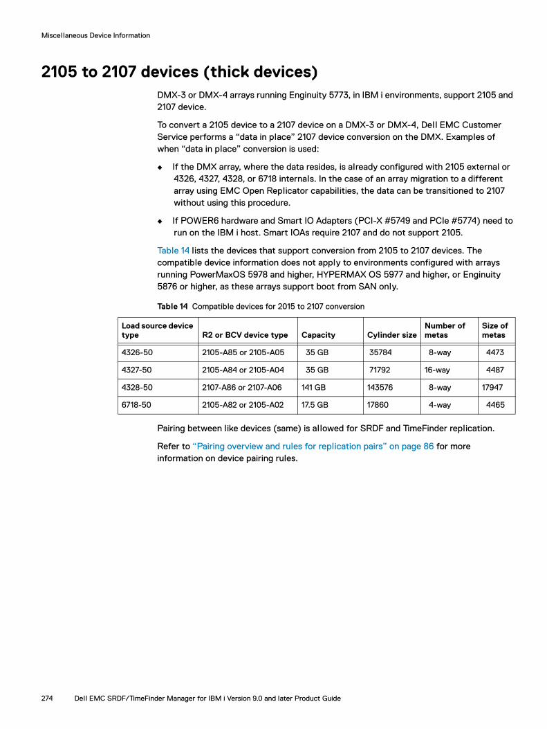
Miscellaneous Device Information
2105 to 2107 devices (thick devices)DMX-3 or DMX-4 arrays running Enginuity 5773, in IBM i environments, support 2105 and 2107 device.
To convert a 2105 device to a 2107 device on a DMX-3 or DMX-4, Dell EMC Customer Service performs a “data in place” 2107 device conversion on the DMX. Examples of when “data in place” conversion is used:
◆ If the DMX array, where the data resides, is already configured with 2105 external or 4326, 4327, 4328, or 6718 internals. In the case of an array migration to a different array using EMC Open Replicator capabilities, the data can be transitioned to 2107 without using this procedure.
◆ If POWER6 hardware and Smart IO Adapters (PCI-X #5749 and PCIe #5774) need to run on the IBM i host. Smart IOAs require 2107 and do not support 2105.
Table 14 lists the devices that support conversion from 2105 to 2107 devices. The compatible device information does not apply to environments configured with arrays running PowerMaxOS 5978 and higher, HYPERMAX OS 5977 and higher, or Enginuity 5876 or higher, as these arrays support boot from SAN only.
Pairing between like devices (same) is al lowed for SRDF and TimeFinder replication.
Refer to “Pairing overview and rules for replication pairs” on page 86 for more information on device pairing rules.
Table 14 Compatible devices for 2015 to 2107 conversion
Load source device type R2 or BCV device type Capacity Cylinder size
Number of metas
Size of metas
4326-50 2105-A85 or 2105-A05 35 GB 35784 8-way 4473
4327-50 2105-A84 or 2105-A04 35 GB 71792 16-way 4487
4328-50 2107-A86 or 2107-A06 141 GB 143576 8-way 17947
6718-50 2105-A82 or 2105-A02 17.5 GB 17860 4-way 4465
274 Dell EMC SRDF/TimeFinder Manager for IBM i Version 9.0 and later Product Guide
Miscellaneous Device Information
D910 device support (thin devices)Enginuity and Solutions Enabler provide support for 512 byte block FBA D910-099 as thin devices. This al lows users of Dell EMC SRDF/TimeFinder Manager for IBM i to take advantage of VMAX features FAST VP, VLUN VP Migration, and Virtual Provisioning which is available for arrays running Enginuity 5876; and automated FAST which is available for arrays running PowerMaxOS 5978 or HYPERMAX OS 5977.
Requirements and rules for D910 support
The rules and requirements for D910 device support are:
◆ Arrays running Enginuity 5876.
◆ For VMAX 10K arrays, and arrays running PowerMaxOS 5978 or HYPERMAX OS 5977:
D910 device only. Emulation for 2107 devices is not supported.
Thin devices only. Thick or meta devices are not supported.
Thin (bound) gatekeeper devices only.
◆ Server hardware must be POWER6 or higher.
◆ POWER6 model systems firmware must be FW3.5.0 or later.
Note: There is no minimum firmware level for POWER7 systems.
◆ Fibre Channel adapters must be Smart IOA Fibre Channel (IOPless) adapters FC5749, FC5774, FC5735, or future IBM i Fibre Channel adapters. Use of IOP-based adapters is not allowed.
◆ IBM i operating system must be version 6.1.1 or later.
◆ In a VIOS configuration that uses D910 devices with NPIV, the IBM i operating system must be version 7.1 or higher.
◆ Allows for pairing between like devices (same emulation type) for SRDF and TimeFinder replication.
◆ Allows for SRDF/TimeFinder Manager support for thin gatekeepers.
◆ When configuring D910 devices, the IBM i operating system must be version 6.1.1 or later, and the following minimum PTF levels must be applied to IBM i operating system:
6.1.1 requires a minimum CUM C2122610 (2122) MAY 14, 2012 (NPIV support is excluded)
7.1 requires a minimum of TECH REFRESH 4 (TR4) or CUM C2115710 (2115) May 17, 2012.
◆ 512-byte and 520-byte LUNs can reside on the same IBM i partition, and on the same fiber channel adapter.
D910 device support (thin devices) 275

Miscellaneous Device Information
◆ For disk units formatted with 520 byte sectors, the 520 bytes in each sector consists of 512 bytes of data and 8 bytes of header information. The 8 bytes of header are used by the IBM i licensed internal code to self-identify the data in the page, and during recovery operations to rebuild the directories of permanent extents. A page of data consists of 8 sectors.
◆ For disk units formatted with 512 byte sectors, the IBM i licensed internal code uses nine sectors for each page, since the physical sectors on a disk unit formatted with 512-byte sectors do not have room for an 8 byte header. The 9 sectors of the page consist of eight data sectors and one sector containing the eight headers for those data sectors (along with other control information). Since one of every nine sectors contains header and control information, the capacity usable for the client is approximately 11% smaller than the actual capacity of the logical unit.
◆ Only LUN Model Number 099 (protected) is used. Other LUN models such as A01, A81, and 050 are not allowed.
Note: Since the LUNs report to the IBM i partition as a protected unit, the operating system wil l not al low system level mirroring to be used.
◆ D910 device capacities (raw) can range from 3GB up to, but not including, 2TB.
Note: Once assigned, LUN capacities must remain constant, which is the case with any other storage attachment to IBM i (both 520 and 512). To change the capacity of a LUN, it must be removed from the configuration, destroyed, and recreated before adding it back into the partition's configuration.
◆ D910 devices can be used in the System ASP, User ASPs and IASPs.
◆ D910 devices can be used as an IBM i load source device. The minimum raw capacity for a D910 load source device is 20GB.
◆ The SCSI FORMAT UNIT command is supported as the Add to ASP action requires that the LUN is zeroed.
◆ D910 devices do not support SCSI Skip Read and Skip Write operations. Instead, IBM i sends aggregated data as several individual SCSI Read or Write commands. The 2107 device does support these operations.
Application impact
Only the low level IBM i licensed internal code Storage Management layer of the operating system is directly impacted by the way the disk sectors are formatted. Applications, databases, and programs do not need any modifications to use disks that are formatted with 512-byte sectors.
Performance impact
There is some additional data traffic through the I/O Adapter, because each “page” of data transfers 4608 byes (9 * 512) instead of 4160 byes (8 * 520). There is a very small amount of increased usage of the processors when the IBM i licensed internal code builds the header information into the 9th sector of the page.
276 Dell EMC SRDF/TimeFinder Manager for IBM i Version 9.0 and later Product Guide

Miscellaneous Device Information
Variable-sized LUNsSRDF/TimeFinder Manager for IBM i recognizes and tolerates volumes of non-fixed capacities (variable-sized LUNs) introduced in IBM i V6.1.1. These include device s 2107-099 and 2107-050. SRDF and TimeFinder replications are supported between like devices (same ) of the same size and characteristics.
Device s are:
◆ 2107-099 — Where 099 indicates the volume is treated as "Protected" DPY Parity devices (equivalent to the current IBM A0x models).
◆ 2107-050 — Where 050 indicates the volume is treated as "Unprotected" by the OS, and allows it to be mirrored by the OS (equivalent to current IBM A8x models).
Note: Enginuity supports a minimum size of 165 cylinders and a maximum of 2236962 cylinders for these device types.
Minimum Enginuity versions supported are 5876.
Variable-sized LUNs 277

Miscellaneous Device Information
278 Dell EMC SRDF/TimeFinder Manager for IBM i Version 9.0 and later Product Guide

APPENDIX ETroubleshooting
Invisible Body Tag
This appendix provides some troubleshooting information for SRDF/TimeFinder Manager. For information on backup, recovery, journaling, and journal management, refer to IBM documentation on the IBM website
◆ Handling failed or non-reporting hardware resources......................................... 280◆ Error generated when running Discover command within SST ........................... 280◆ Multipath reset .................................................................................................. 280◆ Error when running CRTSYMAPI or CRTSYMAPIC commands ........................... 281
Troubleshooting 279
Troubleshooting
Handling failed or non-reporting hardware resourcesIn some cases, non-reporting or failed hardware resources for disk units can interfere with operation of SRDF/TimeFinder Manager. For example, you may be unable to group or pair some devices.
Non-reporting or failed hardware resources can appear on a system after a hardware reconfiguration. You should remove non-reporting or failed hardware resources for disk units before using SRDF/TimeFinder Manager. This can be accomplished after a grouping or pairing error has occurred.
Remove failed and non-reporting hardware resources for disk units as follows:
1. Sign on as the authorized user and issue the IBM i STRSST command to display the System Service Tools (SST) Main menu.
2. From SST, select option 1 to start a service tool.
3. Select option 7 to start the hardware service manager.
4. Select option 4 to list failed and non-reporting hardware resources.
5. Select option 4 next to each failed and non-reporting hardware resource to remove it.
Refer to the IBM documentation for more information.
Error generated when running Discover command within SST
On a host running IBM i 7.1 operating system, an error may occur when running the STM Discover command after removing a disk unit from an ASP using SST (rather than DST). To avoid this issue, it is recommended to completely exit the SST environment before running the Discover command.
Multipath resetMultipath Resetting can be used to stop error messaging due to a multipath missing connection. For example, a missing connection occurs when the image is loaded on a different hardware set.
Multipath resetting is done from the IBM SST (Service Tool).
From the IBM console:
1. Sign on to SST.
2. Select option 1. Start a Service Tool.
3. Select option 7, Hardware service manager.
4. Select option 1, Packaging hardware resources.
5. Select option 9 for the required Disk Unit System. Select option 7, Paths to multiple path disk, to check the status of the paths.
280 Dell EMC SRDF/TimeFinder Manager for IBM i Version 9.0 and later Product Guide
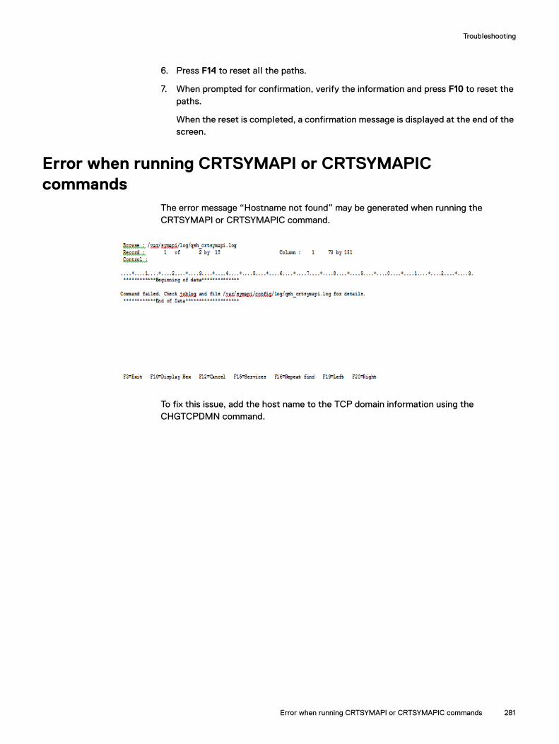
Troubleshooting
6. Press F14 to reset all the paths.
7. When prompted for confirmation, verify the information and press F10 to reset the paths.
When the reset is completed, a confirmation message is displayed at the end of the screen.
Error when running CRTSYMAPI or CRTSYMAPIC commands
The error message “Hostname not found” may be generated when running the CRTSYMAPI or CRTSYMAPIC command.
To fix this issue, add the host name to the TCP domain information using the CHGTCPDMN command.
Error when running CRTSYMAPI or CRTSYMAPIC commands 281

Troubleshooting
282 Dell EMC SRDF/TimeFinder Manager for IBM i Version 9.0 and later Product Guide
PART 2
SRDF/TimeFinder Manager Extended Features
Part 2 of this product guide describes how to prepare and configure SRDF/TimeFinder Manager to support IASP use in a clustered environment. It contains the following chapters and appendixes:
Chapter 7, “Extended Features Introduction”
Introduces the extended features, that EMC SRDF/TimeFinder Manager for IBM i provides, to support IBM Independent Auxiliary Storage Pools (IASPs) functionality.
Chapter 8, “Configuring for IASP Environment”
Explains how to prepare and configure SRDF/TimeFinder Manager to support IASP use in a clustered environment.
Chapter 9, “IASP-Supported Operations”
Describes how to use the SRDF/TimeFinder Manager interface to perform IASP-supported operations when working with SRDF and TimeFinder (BCV, Clones, or Snap) devices configured for multi-node backup and disaster recovery (DR) solutions.
Appendix F, “Non-EMC Procedures”
Provides guidelines when using IBM-related procedures.
Appendix G, “Extended Features Commands Reference”
Provides reference information, syntax, and examples for control commands.
Appendix H, “Extended Features Messages”
Provides reference information about messages that may display for the extended features components.


CHAPTER 7Extended Features Introduction
This chapter introduces the extended features that Dell EMC SRDF/TimeFinder Manager for IBM i provides to support IBM independent ASPs (IASPs) functionality.
◆ Extended features description ........................................................................... 286◆ Independent ASP functionality .......................................................................... 287
Extended Features Introduction 285

Extended Features Introduction
Extended features descriptionDell EMC SRDF/TimeFinder Manager for IBM i Extended Features provide support for the IBM independent ASP (IASP) functionality. An IASP is a set of switchable or private auxiliary disk pools (up to 223) that can be brought online or offline on an IBM i host without affecting the rest of the system.
This support, when combined with SRDF/TimeFinder Manager for IBM i, enables you to control SRDF or TimeFinder operations on PowerMax, VMAX All Flash, VMAX3, VMAX Family, and DMX arrays attached to IBM i hosts as described in “Standard features description” on page 22. In addition, the extended features can use IASPs to present one or more target devices containing an IASP image to another host for business continuance (BC) processes.
Extended features control operations can be performed two ways:
◆ From the SRDF/TimeFinder Manager menu-driven interface.
◆ From the command line using SRDF/TimeFinder Manager commands and associated IBM i commands.
286 Dell EMC SRDF/TimeFinder Manager for IBM i Version 9.0 and later Product Guide

Extended Features Introduction
Independent ASP functionalitySRDF/TimeFinder Manager supports two-node, three-node and four-node solutions for performing disaster recovery (DR) and normal operations on a backup node using IASP images in a combined IBM i and PowerMax, VMAX All Flash, VMAX3, VMAX, and DMX array environment for business continuance (BC) operations.
SRDF/TimeFinder Manager supports Multipath operations for IASP.
Depending on the disaster recover (DR) solution, IASP operations can be performed on several different IBM i systems. IASP operations are similar for a two and three-node solution.
Two-node solution
A two-node solution (Figure 101) can be used for disaster recovery or backup services.
Figure 101 Two-node cluster and two-node DR configuration
STD
BCV
IBM i Clusterand DeviceDomain
iASP A
iASP A
Node 1 (IASP A Primary)
Normal operation
Node 2(IASP A Backup)
TCP/IP
IBM i Clusterand DeviceDomain
Node 1 (IASP A Primary)
Primary failover to DR node
Node 2 (IASP A Backupassumes the role of Node 1 IASP A Primary)
TCP/IP
Independent ASP functionality 287

Extended Features Introduction
Three-node solution
In a three-node solution (Figure 102), disaster recovery and backup services are provided simultaneously as follows:
◆ One node serves as primary node.
◆ One node serves as a DR node.
◆ One backup node is configured with remote BCVs, clones, or snap devices for backing up an IASP image.
Figure 102 Three-node DR environment
R1
RMTBCV
R2
IBM iClusterand DeviceDomain
IASP A
IASP A
IASP A
Node 1 (IASP A Primary)
Normal operation
Node 2 (IASP A DR)
Node 3 (IASP A Backup)
SRDF/S for campus or SRDF/A for long distance
TCP/IP
IBM iClusterand DeviceDomain
Node 1 (IASP A Primary)
Primary failover to DR node
Node 2 (IASP A DR assumes the role of Node 1 IASP Primary)
Node 3 (IASP A Backup)
TCP/IP
ICO-IMG-000304
288 Dell EMC SRDF/TimeFinder Manager for IBM i Version 9.0 and later Product Guide
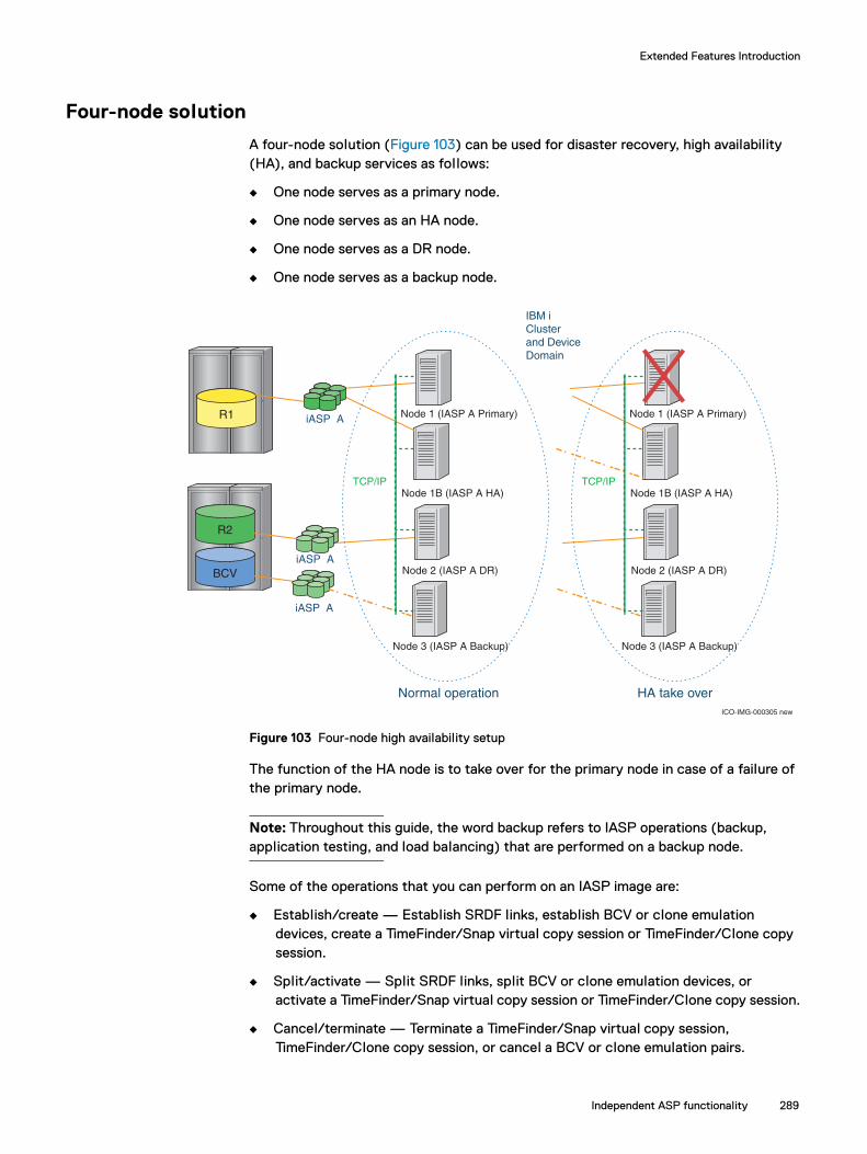
Extended Features Introduction
Four-node solution
A four-node solution (Figure 103) can be used for disaster recovery, high availability (HA), and backup services as follows:
◆ One node serves as a primary node.
◆ One node serves as an HA node.
◆ One node serves as a DR node.
◆ One node serves as a backup node.
Figure 103 Four-node high availability setup
The function of the HA node is to take over for the primary node in case of a failure of the primary node.
Note: Throughout this guide, the word backup refers to IASP operations (backup, application testing, and load balancing) that are performed on a backup node.
Some of the operations that you can perform on an IASP image are:
◆ Establish/create — Establish SRDF links, establish BCV or clone emulation devices, create a TimeFinder/Snap virtual copy session or TimeFinder/Clone copy session.
◆ Split/activate — Split SRDF links, split BCV or clone emulation devices, or activate a TimeFinder/Snap virtual copy session or TimeFinder/Clone copy session.
◆ Cancel/terminate — Terminate a TimeFinder/Snap virtual copy session, TimeFinder/Clone copy session, or cancel a BCV or clone emulation pairs.
R1
IBM i Clusterand DeviceDomain
iASP A
iASP A
Node 1 (IASP A Primary)
Normal operation
TCP/IP
HA take overICO-IMG-000305 new
R2
BCV
Node 1B (IASP A HA)
Node 2 (IASP A DR)
Node 3 (IASP A Backup)
Node 1 (IASP A Primary)
TCP/IPNode 1B (IASP A HA)
Node 2 (IASP A DR)
Node 3 (IASP A Backup)
iASP A
Independent ASP functionality 289

Extended Features Introduction
◆ Create logical point-in-time snapshots of images for arrays running PowerMaxOS 5978 or HYPERMAX OS 5977, using TimeFinder SnapVX.
Note: TimeFinder SnapVX is supported only on arrays running PowerMaxOS 5978 or HYPERMAX OS 5977.
◆ Add one or more IOAs to all nodes, or remove one or more IOAs from all nodes participating in the replication solution.
◆ Rebuild the IOA information file for source and target IOAs.
Note: IASP Vary on/Vary off operations are now performed through IBM commands. Chapter 9, “IASP-Supported Operations,” contains greater detail.
290 Dell EMC SRDF/TimeFinder Manager for IBM i Version 9.0 and later Product Guide

CHAPTER 8Configuring for IASP Environment
Invisible Body Tag
This chapter shows how to prepare and configure SRDF/TimeFinder Manager to support IASP use in a clustered environment.
◆ Requirements..................................................................................................... 292◆ Configuration procedures................................................................................... 293◆ Configuring the environment for IASP ............................................................... 300
Configuring for IASP Environment 291
Configuring for IASP Environment
RequirementsThe prerequisites for using an IASP and its image with SRDF/TimeFinder Manager are:
◆ All IBM software is installed and operational. Refer to the Dell EMC SRDF/TimeFinder Manager for IBM i Release Notes for a complete list of requirements.
◆ The latest IBM IASP and cluster PTFs, CUMs, or any other required PTFs have been applied. Refer to the IBM product documentation.
◆ SRDF/TimeFinder Manager is installed on the primary and HA nodes, and SRDF/TimeFinder Manager Client is installed on the Disaster Recovery and backup nodes. The Dell EMC SRDF/TimeFinder Manager for IBM i Release Notes show how to install SRDF/TimeFinder Manager.
◆ SRDF/TimeFinder Manager operations from the DR node require a gatekeeper device configured on the target array and the DR node.
Cluster requirements
The following are requirements for clusters:
◆ The cluster must be set up for IASP use according to IBM specifications. Create one or more secondary IASP pools, as necessary.
◆ The backup node must be the last node in the backup order.
◆ If clustering is configured through System i Navigator or IBM systems Director Navigator, the Service Tools Server must be configured and the port name “as-sts” is unblocked and enabled. Refer to the IBM product documentation for more information.
IOA requirements
The following are requirements for IOAs:
◆ When using IASPs, check that no two primary ASP groups share the same IOA. Primary and secondary IASPs are operated on simultaneously.
◆ All devices in each IASP group (or its image) must be on dedicated IOAs.
◆ No devices on the IOA can be part of a User ASP or System ASP (ASPs 1-32).
◆ An IASP image cannot share an IOA with another IASP image.
◆ A gatekeeper device cannot be presented to an IOA that contains an IASP image.
292 Dell EMC SRDF/TimeFinder Manager for IBM i Version 9.0 and later Product Guide

Configuring for IASP Environment
Configuration procedures The following sections provide detailed instructions on how to configure the SRDF/TimeFinder Manager environment to support IASPs in a multi-node environment:
◆ “Starting and stopping the server job”
◆ “Building/rebuilding the IOA file”
◆ “Making target devices visible to the backup node”
◆ “Performing initial TimeFinder/SRDF operations”
These sections are intended to be used as a reference for the section “Configuring the environment for IASP” on page 300.
Starting and stopping the server job
The SRDF/TimeFinder Manager server job, which runs in the EMCCTL subsystem (the default), must be running on all participating nodes. Depending on the request type received, the server job can perform tasks such as:
◆ Adding and removing IOAs
◆ Running a system command on the node
◆ Generating IOA files on all nodes
◆ Updating the IASP configuration files on the nodes
Prior to starting the SRDF/TimeFinder Manager server job, the following conditions are required:
TCP/IP must be active on all nodes.
The appropriate EMCCTL or EMCCTLC library must be in the library list.
Refer to the Dell EMC SRDF/TimeFinder Manager for IBM i Release Notes for more information about adding libraries.
The subsystem job EMCCTL must be started as follows:
STRSBS SBSD(EMCCTL)
Note: If another subsystem other than the default EMCCTL is used, start that subsystem.
Configuration procedures 293

Configuring for IASP Environment
Starting the server jobTo start the server job on each node, enter the following STRSTMSRV command:
STRSTMSRV USERID(*CURRENT) PORTNUM(8000) JOBQ(*LIBL/EMCCTL)
USERID — The parameter that submits the job under the user ID that issues the command. The default is *CURRENT.
This is the user ID that was created and is used to run SRDF/TimeFinder Manager.
All other nodes can use the user profile that has *IOSYSCFG, *JOBCTL, and *SERVICE special authority and *USE access to the following *SRVPGM objects in QSYS:
– QCSTCTL
– QCSTCRG1
– QCSTCRG4
For the server job STMSERVER, if the EMCCTL subsystem is not used, check that more than one job is al lowed to run in that subsystem.
PORTNUM — The port used for TCP/IP communications.
The default port number is 8000. If you use a port number other than 8000, make sure the port number is the same on the primary node, HA node, backup node, and DR node.
JOBQ — The subsystem where you want the STRSTMSRV server job to run. The default is *LIBL/EMCCTL.
If you use a different subsystem, enter that job queue name associated with the subsystem, for example:
jobq(*libl/<jobqname>)
Stopping the server jobTo stop the SRDF/TimeFinder server job, from the command line, enter the ENDSTMSRV command. Supply the port number that was used when the STRSTMSRV command was issued on the primary, backup, and DR nodes. For example:
ENDSTMSRV PORTNUM(8000)
The default port number is 8000.
294 Dell EMC SRDF/TimeFinder Manager for IBM i Version 9.0 and later Product Guide

Configuring for IASP Environment
Configuration procedures 295
Performing initial TimeFinder/SRDF operations
When configuring SRDF/TimeFinder Manager, perform initial SRDF or TimeFinder operations, such as Establish/Split, Create/Activate, or Link on the devices when IASP images are present in the configuration.
To perform SRDF or TimeFinder operations on an IASP image:
1. From the command line, enter the CTLACT command and press F4 to prompt.
The EMC SRDF or TimeFinder Control (CTLACT) screen (Figure 104) appears.
Figure 104 EMC SRDF or TimeFinder Control (CTLACT) screen with CREATE action
At this point in the configuration process, the IOA file for the target devices has not been built, and SRDF/TimeFinder Manager cannot perform its validation check. Therefore, make sure target devices are not visible to the DR node or backup node.
2. Enter the following information:
Image Name — The name of the image on which to perform a control action.
Path Name — The path name associated with the image on which to perform a control action.
Step Number — The specific step number for which the control action is to be initiated.
Control Action — The SRDF or TimeFinder control action to be performed.
3. If you are creating a SNAP session enter the Snap Pool Name which is the named SAVE pool to use for the session.
Note: You can supply the Snap Pool Name parameter only when creating new SNAP sessions. In al l other cases, the name is ignored.
Configuring for IASP Environment
4. If you are creating a Clone session using VP Snap mode, set the VP Snap parameter to *YES. The VP Snap attribute can only be set when creating new clone sessions.
For rules and restrictions and additional information for the snap pool name feature and VP Snap mode refer to “CTLACT” on page 194.
Set the control action to ESTABLISH for SRDF, TimeFinder Clone Emulation, SnapVX, or BCV devices. Use the control action CREATE for TimeFinder/Snap or TimeFinder/Clone devices.
If creating snapshots, first establish a session and then linking can be performed.
5. After the IASP image is synchronized, created, or for snapshots, established:
a. Vary off the source devices.
b. Re-enter the CTLACT command with the same IASP name and image name.
c. Set Control Action to SPLIT or ACTIVATE, or for SnapVX, LINK.
d. Set Split/Suspend Mode to MAINTENANCE.
Refer to “CTLACT” on page 342 for more information on the CTLACT command. Refer to “Controlling TimeFinder” on page 129 and “Controlling SRDF” on page 159 for more information on Establish/Create, Split/Activate/Link and other SRDF and TimeFinder control operations.
Once SRDF/TimeFinder Manager is configured for IASP use, you can use the Work with Associated Paths screen (Figure 105 on page 297) to perform ESTABLISH/CREATE and SPLIT/ACTIVATE and SnapVX operations.
Configuring an IASP image
Before using IASPs in an SRDF/TimeFinder Manager environment, you must configure one or more IASP images as needed for the replication solution.
IMPORTANT
To configure an IASP image, a valid copy of the IASP image must first be presented to the selected target node. Use the CTLACT command to do this. For SRDF, BCV, CLONE. or SNAP type of step, carry out a Split/Activate action so that this image to be visible at the target side. For SnapVX type of step, carry out a Link action on the image. Refer to “Performing initial TimeFinder/SRDF operations” on page 295 for using the CTLACT command. Once this is done a valid image is present at the target side and the IOA's can be presented to this node using the ADDIOA command described in “Making target devices visible to the backup node” on page 299.
To configure an IASP image:
1. Select option 1. Work with Images from the Dell EMC SRDF/TimeFinder Manager for IBM i main menu.
The Symmetrix Configuration by Image screen appears.
2. Select option 2. Work with paths from the Symmetrix Configuration by Image screen.
3. The Work with Associated Paths screen (Figure 105 on page 297) appears.
296 Dell EMC SRDF/TimeFinder Manager for IBM i Version 9.0 and later Product Guide

Configuring for IASP Environment
Figure 105 Work with Associated Paths screen
4. Type 16 (Configure IASP) next to the step associated with the path.
The Configure IASP Session screen (Figure 106) appears.
5. Enter the following information:
Target Node — The name of the target node for this step. The node name entered must be part of the cluster that is configured on this system. If this is not the case, a message appears indicating that the node cannot be found.
Note: The cluster node name can be found by running DSPCLUINF command. This command also displays the node IP address.
Port Number — The TCP/IP port that the SRDF/TimeFinder Manager server job uses for communications. The default is 8000.
Figure 106 Configure IASP Session screen with configuration detail
Note: SRDF/TimeFinder Manager checks the validity of the information supplied and then sends the information to all nodes currently configured. If the node name is not part of the configured cluster, a message appears at the bottom of the screen indicating that the node name is not part of the configured cluster on this system.
PIASP2 Configure IASP Session HOSTNAME
Target Node: R2DEVS
Port Number: 8000
F1=Help F3=Exit F12=Cancel
Configuration procedures 297
Configuring for IASP Environment
6. Repeat steps 2 - 5 for each IASP image that you plan to use for SRDF/TimeFinder Manager.
IMPORTANT
If the server job on any node is unavailable at the time of the request, the IASP configuration process fails. If this occurs, the IASPS file on the primary node and the IASPS file on other nodes are not updated.
Allowing multiple TimeFinder IASP copies to share the same IOAs on a single hostTo allow for this feature, each IASP copy needs to be presented to the target node making it possible to control each copy individually.
From the Work with Associated Path screen (Figure 105 on page 297) use Option 16, or use the “IASPCTL” command with CONFIG control action to create an entry that is written to the configuration file for each copy. A CONFIG action must be run for each copy on the host, and during the configuration process the other copies that share the IOA must be offline.
Note: When the IOA is shared between multiple TimeFinder copies, or when R2 and backup devices are sharing IOA's, be aware that if the IOA is enabled for one copy it is active at the same time for the other copy. For example, when trying to terminate a SNAP session for one copy the IOA needs to be inactive. If needed, the CTLACT command can then be used to terminate one copy while keeping the IOA active. Also one copy can be presented at any time, so make sure that access to the devices is only to one set of devices. This can be accomplished with the CLI command SYMACCESS.
Building/rebuilding the IOA file
When the IASP configuration is run, a rebuild action is automatically performed. As each IASP session is configured, the IOA files are also copied to the appropriate nodes.
However, IOA files must be current. SRDF/TimeFinder Manager depends on information stored in the files such as error checking or IOA status, prior to performing any operations against an IASP image. As a result, if the IOA files need to be reconfigured, the REBUILDIOA operation may need to be run as a separate action.
Failure to rebuild and maintain current IOA files may result in critical data loss and/or system crash.
To rebuild the IOA file, use the IASPCTL command. In the following example, the IASPCTL command adds an entry into the ISRCIOA file, and rebuilds the IOA file for the IASP image (PIASP2) associated with a path name of REMOTEBCV.
IASPCTL IMAGENAME(PIASP2) PATHNAME(REMOTEBCV) STEPNUM(1) ACTION(REBUILDIOA) NODENAME(NODE1)IASPCTL IMAGENAME(PIASP2) PATHNAME(REMOTEBCV) STEPNUM(2) ACTION(REBUILDIOA) NODENAME(NODE2)
Note: The REBUILDIOA control action can also be run from the EMC Independent ASP Control (IASPCTL) screen. Refer to “Executing IASP control actions on primary node” on page 322 for more information on executing actions from this screen.
298 Dell EMC SRDF/TimeFinder Manager for IBM i Version 9.0 and later Product Guide

Configuring for IASP Environment
Making target devices visible to the backup node
There are many ways to make target devices visible to the backup node, for example:
1. With the storage devices online, after the Split operation is complete, connect the cables to the backup node.
2. Use the ADDRMVOIA command to add IO resources. Refer to “ADDRMVIOA” on page 339.
Do not present target devices until the first Split operation completes. After making the target devices visible to the backup node, rebuild the IOA file for the target devices. “Building/rebuilding the IOA file” on page 298 describes this procedure.
Configuration procedures 299
Configuring for IASP Environment
Configuring the environment for IASPConfiguring the SRDF/TimeFinder Manager environment to support IASP use in a multi- node environment, requires using a combination of IBM commands, SRDF/TimeFinder Manager commands, and screen options.
The following sections describe how to configure the IASP environment (SRDF/S or SRDF/A with remote BCVs):
◆ “Prepare cluster and IASP nodes” on page 300
◆ “Start the server” on page 300
◆ “Configure paths” on page 301
◆ “Configure an IASP session” on page 302
◆ “Populate the IOAs for each node in the cluster” on page 303
◆ “Post-configuration considerations” on page 304
Note: In the IASP View by ASP screen, IOAs that are removed from an IASP configuration display a Not Active status, and IOAs that are added to an IASP configuration display an Active status. When there are secondary IASPs included in the configuration and the ADDRMVIOA command is being used, the primary and all secondary IASPs must be specified with the corresponding IOAs in the command. Refer to “ADDRMVIOA” on page 339 for more details.
Prepare cluster and IASP nodes
After creating all cluster nodes, start the cluster node on each node as follows:
STRCLUNOD CLUSTER(CLUSTERNAME) NODE(NODENAME)
1. Create IASP device domains.
2. On the DR node (R2) and backup node (RMTBCV):
a. Using the ADDRMVIOA command, make sure the IASP IOAs for the DR and backup nodes are removed. Refer to “ADDRMVIOA” on page 339 for more information on the ADDRMVIOA command.
b. Make sure the IOAs are active on the primary node.
c. Vary on the IASP for the primary node.
Start the server
1. On the primary node (R1) and HA node, add EMCCTL to the library list.
2. On the DR and backup (RMTBCV) nodes, add EMCCTLC to the library list.
3. Make sure TCP/IP is active on all nodes.
4. Start the subsystem job EMCCTL, or start another available subsystem. If you use a subsystem other than the default EMCCTL, start that subsystem first:
STRSBS SBSD(EMCCTL)
300 Dell EMC SRDF/TimeFinder Manager for IBM i Version 9.0 and later Product Guide

Configuring for IASP Environment
Configuring the environment for IASP 301
5. Start the SRDF/TimeFinder Manager server job (STRSTMSRV) on all nodes in the cluster:
EMCCTL/STRSTMSRV USERID(*CURRENT) PORTNUM(8000) JOBQ(*LIBL/EMCCTL)EMCCTLC/STRSTMSRV USERID(*CURRENT) PORTNUM(8000) JOBQ(*LIBL/EMCCTL)
If you started a different subsystem job in step 4, enter the jobq name associated with the subsystem, for example:
jobq(*libl/<jobq name>)
“Starting and stopping the server job” on page 293 shows how to start the SRDF/TimeFinder Manager server job using STRSTMSRV.
Configure paths
1. Call the following program:
CALL PGM(EMCCTL/CRTSYMAPI)
2. From the EMCCTL main menu, start SRDF/TimeFinder Manager:
GO MAINCTL
“Dell EMC SRDF/TimeFinder Manager for IBM i main menu” on page 43 shows how to access the SRDF/TimeFinder Manager Main menu.
3. Select option 1=Work with images.
The Symmetrix Configuration by Image screen appears.
4. Scroll down to the IASP image name and enter option 8=Associate path.
The Paths not Associated with the Image screen appears.
5. For a three-node configuration, type 1 (Select path) against the REMOTEBCV /RDF1/BCV1 path, and press Enter. For al l other configurations, type 1 (Select path) against the appropriate path, and press Enter.
The Work with Associated Paths screen appears.
Refer to “Work with Associated Paths screen” on page 47 for more information on accessing the Work with Associated Paths screen.
6. Type 2 (Work with Paths) for the IASP image.
The Work with Associated Paths screen appears.
Note: SRDF devices are automatically associated.
7. Type 6 (Pair) against the BCV1 step.
The remote BCVs are associated with the R2 devices.
8. From the command line, use CTLACT to establish the BCVs and synchronize the RDF devices as needed. “Performing initial TimeFinder/SRDF operations” on page 295 contains greater detail.
9. Make sure that IOA is active and primary node is varied on.
10. Split RDF devices and remote BCVs using CTLACT. “Split BCV pairs: Maintenance” on page 136 shows how to carry out a maintenance split.
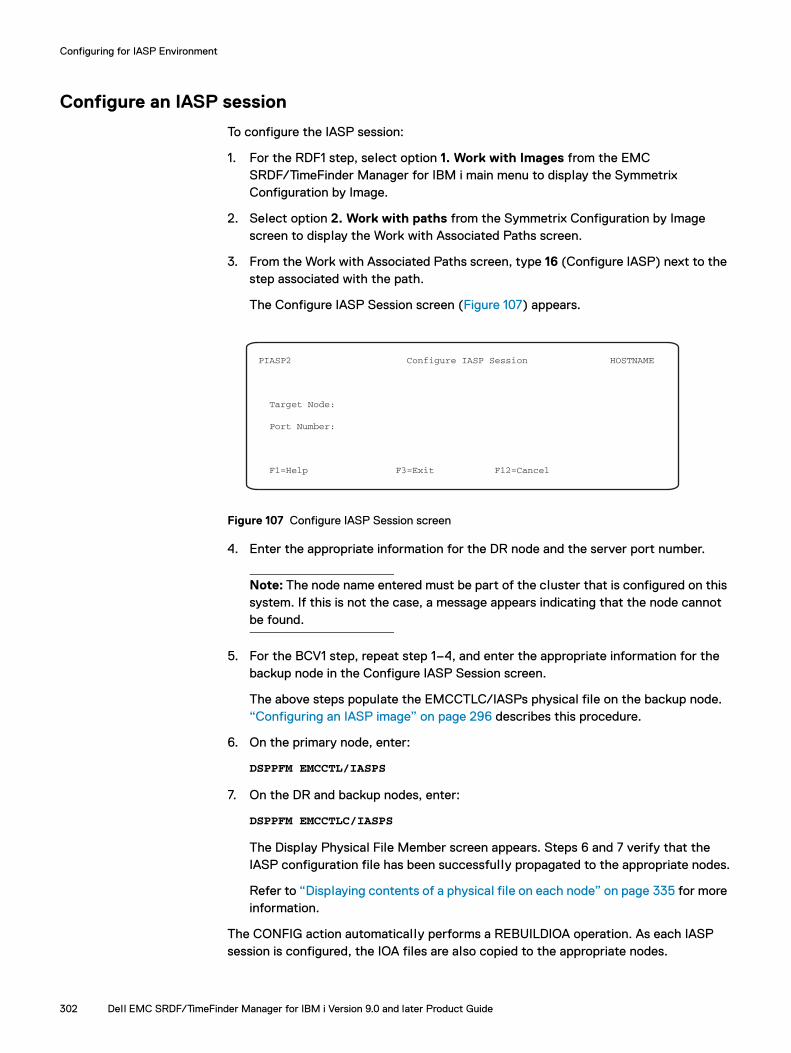
Configuring for IASP Environment
Configure an IASP session
To configure the IASP session:
1. For the RDF1 step, select option 1. Work with Images from the EMC SRDF/TimeFinder Manager for IBM i main menu to display the Symmetrix Configuration by Image.
2. Select option 2. Work with paths from the Symmetrix Configuration by Image screen to display the Work with Associated Paths screen.
3. From the Work with Associated Paths screen, type 16 (Configure IASP) next to the step associated with the path.
The Configure IASP Session screen (Figure 107) appears.
Figure 107 Configure IASP Session screen
4. Enter the appropriate information for the DR node and the server port number.
Note: The node name entered must be part of the cluster that is configured on this system. If this is not the case, a message appears indicating that the node cannot be found.
5. For the BCV1 step, repeat step 1–4, and enter the appropriate information for the backup node in the Configure IASP Session screen.
The above steps populate the EMCCTLC/IASPs physical file on the backup node. “Configuring an IASP image” on page 296 describes this procedure.
6. On the primary node, enter:
DSPPFM EMCCTL/IASPS
7. On the DR and backup nodes, enter:
DSPPFM EMCCTLC/IASPS
The Display Physical File Member screen appears. Steps 6 and 7 verify that the IASP configuration file has been successfully propagated to the appropriate nodes.
Refer to “Displaying contents of a physical file on each node” on page 335 for more information.
The CONFIG action automatically performs a REBUILDIOA operation. As each IASP session is configured, the IOA files are also copied to the appropriate nodes.
PIASP2 Configure IASP Session HOSTNAME
Target Node:
Port Number:
F1=Help F3=Exit F12=Cancel
302 Dell EMC SRDF/TimeFinder Manager for IBM i Version 9.0 and later Product Guide
Configuring for IASP Environment
However, IOA files must be current. SRDF/TimeFinder Manager depends on information stored in the files such as error checking or IOA status, prior to performing any operations against an IASP image. As a result, if the IOA files need to be reconfigured, the REBUILDIOA operation may need to be run as a separate action.
Populate the IOAs for each node in the cluster
These configuration steps are used only when issuing a REBUILD as a separate operation from a CONFIG operation.
The IOAs for each node must be presented to the system. The primary node IOAs are presented first followed by the backup and DR nodes.
Perform the following steps on the primary node:
1. Issue the following command for SRDF setup:
EMCCTL/IASPCTL IMAGENAME(IASPNAME)PATHNAME(REMOTEBCV) STEPNUM(1) ACTION(REBUILDIOA)NODENAME(PRIMARYNODENAME)
Note: STEPNUM(1) denotes the SRDF step.
Refer to “Building/rebuilding the IOA file” on page 298 for an example command to rebuild the IOA file.
Note: To rebuild primary node IOA file, you can also issue the IASPCTL which displays the EMC Independent ASP Control (IASPCTL) screen. Refer to “Executing IASP control actions on primary node” on page 322 for more information on using this screen.
2. Ensure that al l pairs in the path are in a split state.
3. Vary off the IASP.
4. Remove the IOA from the primary node using the SRDF/TimeFinder Manager IASPCTL or ADDRMVIOA command. Refer to “ADDRMVIOA” on page 339.
5. Perform the following steps on the DR node:
a. Add the IOA to the DR node using the ADDRMVIOA command.
b. For SRDF setup, issue the following commands:
EMCCTLC/IASPCTLC IMAGENAME(IASPNAME) PATHNAME(REMOTEBCV) STEPNUM(1) ACTION(REBUILDIOA)NODENAME(DRNODENAME)
6. Remove IOA from the DR node using the ADDRMVIOA command.
7. Perform the following steps on the backup node:
a. Add the IOA to the backup node using the ADDRMVIOA command.
b. For BCV setup, issue the following commands:
EMCCTLC/IASPCTLC IMAGENAME(IASPNAME) PATHNAME(REMOTEBCV) STEPNUM(2)ACTION(REBUILDIOA)NODENAME(BACKUPNODENAME)
Note: STEPNUM(2) denotes the BCV step.
Configuring the environment for IASP 303
Configuring for IASP Environment
Note: To rebuild the backup or DR node IOA file, you can also issue the IASPCTLC which displays the Dell EMC Independent ASP Control (IASPCTLC) screen. Refer to “Executing IASP control actions on DR or backup node” on page 324 for more information on using this screen.
8. Remove the IOA from the backup node using the ADDRMVIOA command. Refer to “ADDRMVIOA” on page 339.
9. Verify the IOA location information on all nodes by viewing the physical file (ISRCIOA file) in the EMCCTL and EMCCTLC libraries.
10. On the primary node, verify the IASP setup from SRDF/TimeFinder Manager as follows:
a. From the Work with Associated Paths screen, run the IASP view option against the step of the IASP.
b. View and verify the IASP information from the IASP view by ASP screen.
11. Add the IOA back to the primary node using the IASPCTL command, and then vary on the IASP using the IBM commands.
Post-configuration considerations
After SRDF/TimeFinder Manager is configured for IASP support, make a list of the hardware configurations, such as partitions and IOA bus and slot location information, for al l nodes. If a disaster occurs, having this information readily accessible makes the DR go more smoothly.
304 Dell EMC SRDF/TimeFinder Manager for IBM i Version 9.0 and later Product Guide
CHAPTER 9IASP-Supported Operations
Invisible Body Tag
This chapter shows how to use the SRDF/TimeFinder Manager interface to perform IASP-supported operations when working with SRDF and TimeFinder (BCV, Clones, Snap, or SnapVX) devices configured for multi-node backup and disaster recovery (DR) solutions.
◆ IASP-supported operations ................................................................................ 306◆ SRDF/TimeFinder Manager IASP-specific menu options ................................... 315◆ Executing IASP control actions.......................................................................... 322◆ Automated operations........................................................................................ 330
Note: This chapter covers the use of IASP in the SRDF/TimeFinder Manager environment only. It does not provide details on how to perform IBM-specific operations, except where necessary. For information on IASPs, refer to the IBM documentation.
IASP-Supported Operations 305

IASP-Supported Operations
IASP-supported operations The following sections show how to perform operations, such as disaster recovery (planned downtime and unplanned DR) and backup, in SRDF/TimeFinder Manager configured for IASP support:
◆ Three-node planned failover (downtime) operations on the primary node. See “Three-node planned failover (DR) and recovery solution” on page 306.
◆ Unplanned disaster recovery. See “Three-node failover and recovery (unplanned) solution” on page 308.
◆ Routine backup operation. See “Backup operations” on page 309.
◆ Switch to high availability node. See “Managing a four-node solution with a high availability node” on page 313.
See “Configuring the environment for IASP” on page 300 to ensure all cluster requirements are met. Many operations, such as failover and recovery processes, use a combination of commands (SRDF/TimeFinder Manager, Operations Navigator, or IBM i) and System Service Tools (SST) functions.
The DR and recovery operations detailed below require IASP images to be varied on or off. See “Varying on and varying off IASP images locally” on page 319 for more information.
Three-node planned failover (DR) and recovery solution
This section shows how to recover from a planned primary node downtime in a three-node environment. The following rules apply to this recovery solution:
◆ The primary node is where the IASP source devices (R1 devices) reside.
◆ The DR node is the node that takes over when the primary node fails or is taken offline.
◆ The backup node acts as the secondary owner for an IASP image. This node is configured with remote BCV, Clones Snap, or Snap VX for backing up an IASP image.
All tasks for a planned downtime must be completed as defined by the chosen failover process. Any deviation from this process may result in a system crash or possible data loss.
Perform the following steps for a three-node planned recovery solution:
1. End IASP operations using the internal procedures established at your site.
2. Vary off the source IASP image, using the IBM VRYCFG command issued from a source host.
3. Remove the source IOA from the primary node using the IASPCTL command. See “IASPCTL” on page 357 for more information
4. Do one of the following:
If the primary node is available, from the primary node, perform a failover using the SRDFDRCTL command with the Establish option.
306 Dell EMC SRDF/TimeFinder Manager for IBM i Version 9.0 and later Product Guide

IASP-Supported Operations
If the primary node is not available, run the CTLACTTGT command on the DR node and perform a failover with the ESTABLISH option to the target.
Note: Use the ESTABLISH/RESTORE option only with dynamic SRDF. This performs a dynamic directional swap of the replication and establish the R1 and R2 devices.
See “SRDFDRCTL” on page 386 and “CTLACTTGT” on page 343 for more information.
5. Add the IOAs for target devices to the DR node, using SRDF/TimeFinder Manager.
See “IASPCTL” on page 357 (if the primary node is available) or “IASPCTLC” on page 364 (if the primary node is down).
6. Vary on the IASP image on the DR node, using the IBM VRYCFG command from the DR node.
7. Verify the data, using IBM commands.
Refer to the IBM documentation for more information.
When the primary node is ready to re-assume normal operations:
1. Vary off the IASP image on the DR node, using the IBM VRYCFG command from the DR node.
2. Remove IOAs from the DR node.
See “Adding or removing IOAs” on page 317.
3. Do one of the following:
If the primary node is available, and it is a dynamic SRDF configuration, on the primary node, run the SRDFDRCTL command using the FAILOVER control action with the Establish option.
See “SRDFDRCTL” on page 386.
If the primary node is available, and it is not a dynamic SRDF configuration, perform a FAILBACK.
If the primary node is not available, and it is a dynamic SRDF configuration, on the DR node, run the CTLACTTGT command with the FAILOVER control action and the ESTABLISH option. Otherwise, perform a FAILBACK.
The CTLACTTGT command with the FAILOVER/FAILBACK control action performs all the steps listed as action items when the primary node is down.
See “CTLACTTGT” on page 343.
4. If required, do the following. The primary and DR nodes must be active.
a. Run the following commands on the respective node:
– ENDCLUNOD on the DR node
– STRCLUNOD on the primary node
– STRCLUNOD on the DR node
b. Check status of the cluster. See IBM documentation for more information.
IASP-supported operations 307

IASP-Supported Operations
5. Add IOAs for the source devices on the primary node.
See “IASPCTL” on page 357, if primary node is available, and “IASPCTLC” on page 364, if the primary node is down.
6. Vary on the source IASP image on the primary node, using the IBM VRYCFG command.
Three-node failover and recovery (unplanned) solution
This section shows how to recover from a primary node failure in a three-node environment. The following rules apply to this recovery solution:
◆ The primary node is where the IASP source devices (R1s) reside.
◆ The DR node is the node that takes over when the primary node fails or is taken offline.
◆ The backup node acts as the secondary owner for an IASP image. This node is configured with remote BCV, Clones, Snap, or SnapVX for backing up an IASP image.
To recover from a primary node failure in a three-node environment:
1. If the primary node is down:
a. Run the CTLACTTGT command on the DR node using the FAILOVER control action with the Establish option.
b. If the SRDF links are not available, run the CTLACTTGT command on the DR node with the FAILOVER *NO option.
Note: Use the Establish/Restore option only with dynamic SRDF. Establish performs a dynamic directional swap of the replication and establishes the R1 and R2 devices. For static SRDF configurations, use FAILOVER with *NO.
See “CTLACTTGT” on page 343 for more information.
2. Add IOA for target devices on the DR node, using the IASPCTLC command. See “IASPCTLC” on page 364 for more information.
3. Vary on the IASP image on the DR node using the IBM VRYCFG command.
4. Verify the data, using IBM commands.
Refer to the IBM documentation for more information.
To resume normal operations, perform the following steps:
1. Vary off the target IASP image on the DR node using the IBM VRYCFG command.
2. Remove the target IOA from the DR node using the IASPCTLC command. See “IASPCTLC” on page 364 for more information.
3. On the DR node, with dynamic SRDF, run the CTLACTTGT command with the FAILOVER control action and the ESTABLISH option.
On the DR node, without dynamic SRDF, perform a FAILBACK.
If a FAILOVER with option *NO was performed in step 1 , run the CTLACTTGT command with FAILBACK. See “CTLACTTGT” on page 343 for more information.
308 Dell EMC SRDF/TimeFinder Manager for IBM i Version 9.0 and later Product Guide

IASP-Supported Operations
4. Verify the primary node is available to resume normal operations. Refer to the IBM documentation for more information.
5. If not already done, add EMCCTL to the library list, and run the STRSTMSRV command to start the SRDF/TimeFinder Manager Server. See “STRSTMSRV” on page 390 for more information.
6. Make sure the source IASP devices are available to the host. If not, add IOAs for the source devices to the primary node. See “IASPCTL” on page 357, if primary node is available and “IASPCTLC” on page 364, if primary node is down.
7. Do the following, with primary and DR nodes active:
a. Run the following commands on the appropriate node:
– ENDCLUNOD on the DR node
– STRCLUNOD on the primary node
– STRCLUNOD on the DR node
b. Check status of the cluster.
8. Vary on the source IASP on the primary node, using the IBM VRYCFG command.
9. Verify the data.
Refer to the IBM documentation for more information.
Backup operations
This section shows how to do routine backup operations in a three-node IASP environment.
The following rules apply to backup operations:
◆ The primary node is where the IASP source devices (R1s) reside.
◆ The DR node is the node that takes over when the primary node fails or is taken offline.
◆ The backup node acts as the secondary owner for an IASP image. This node is configured with remote BCV, Clones, Snap, or SnapVX for backing up an IASP image.
If necessary, perform an IPL of the host. You do not need to restore any IASP data updates from this copy.
Managing remote TimeFinder devices from the DR or primary node for backup operationsWhen planned or unplanned DR events occur, and the primary node is unavailable, use the CTLACTTGT command on the DR node to control remote TimeFinder devices on the backup node.
Do the following (starting at either step 1 or 2), for backup operations, depending upon the availability of the primary node:
1. On the primary node, split the remote BCV devices to make them available for backup:
If the IASP is varied off, use the IASPCTL command to perform a maintenance split.
If the IASP is varied on, use the IASPCTL command for the split. SRDF/TimeFinder Manager uses the Change ASP Activity CL command (CHGASPACT) to quiesce IASP data for the split. See “IASPCTL” on page 357 for more information.
IASP-supported operations 309

IASP-Supported Operations
2. On the DR node, split the remote BCV devices to make them available for backup:
If the IASP is varied off, use the CTLACTTGT command to perform a maintenance split.
If IASP is varied on use the CTLACTTGT command with the CHG_ASP_ACT quiesce option for the split. This option uses the Change ASP Activity CL command (CHGASPACT) to quiesce IASP data for the split. See “CTLACTTGT” on page 343 for more information.
3. Vary on the source IASP image if it is stil l varied off.
4. Add IOA for target (remote BCV) devices to the backup node. See “Adding or removing IOAs” on page 317 for more information.
5. Vary on the IASP copy for the backup node.
6. Run the backup on the IASP data using the procedure established by your company.
7. Vary off the IASP image for the backup node using the IBM VRYCFG command issued from the backup node.
8. Remove IOA for target devices from the backup node.
9. Establish the remote BCV devices.
10. IPL the backup node in preparation for the next backup operation.
This step is needed only if an error occurs when varying on the IASP copy of the backup node.
Managing remote SnapVX devices from DR node or primary node for backup operationsWhen planned or unplanned DR events occur, and the primary node is unavailable, use the CTLACTTGT command on the DR node to control Remote SnapVX devices on the backup node.
Do the following (starting at either step 1 or 2), for backup operations, depending upon the availability of the primary node:
1. On the primary node, establish a snapshot:
If the IASP is varied off use the IASPCTL command to perform a consistent establish of a snapshot.
If the IASP is varied on, use the IASPCTL command for the establish snapshot operation.
SRDF/TimeFinder Manager uses the Change ASP Activity CL command (CHGASPACT) to quiesce IASP data for the establish snap shot operation. See “IASPCTL” on page 357 for more information.
2. If the primary node is not available, establish a snapshot on the DR node for backup availability:
If the IASP is varied off use the CTLACTTGT command to perform a consistent establish of a snapshot.
If IASP is varied on, use the CTLACTTGT command with the CHG_ASP_ACT quiesce option for the establish. This option uses the Change ASP activity CL command (CHGASPACT) to quiesce IASP data for the establish. See “CTLACTTGT” on page 343 for more information.
310 Dell EMC SRDF/TimeFinder Manager for IBM i Version 9.0 and later Product Guide
IASP-Supported Operations
3. When the snapshot is established use the IASPCTL command for the LINK snapshot operation. This makes the data available on the devices attached to the target node for the selected snapshot. To link a different snapshot to the target devices, use the LINK/RELINK action.
Note: If creating multiple snapshots over a period of time, use the link command to present each snapshot to the target node and create backups of al l snapshots.
4. Vary on the source IASP image.
5. Add IOA for target (remote SnapVX) devices to the backup node. See “Adding or removing IOAs” on page 317 on page 305 for more information.
6. Vary on the IASP copy for the backup node.
7. Run the backup on the IASP data using the procedure established by your company.
8. Vary off the IASP image for the backup node using the IBM VRYCFG command issued from the backup node.
9. If an error occurs when varying on the IASP copy on the backup node, remove IOA for target devices from the backup node.
10. To link a different snapshot to the target devices, use the LINK/RELINK action.
IASP-supported operations 311

IASP-Supported Operations
Restore operations
This section shows how to do routine restore operations in a three-node IASP environment. The following rules apply to restore operations:
◆ The primary node is where the IASP source devices (R1s) reside.
◆ The DR node is the node that takes over when the primary node fails or is taken offline.
◆ The backup node acts as the secondary owner for an IASP image. This node is configured with remote BCV, Clones, Snap, or SnapVX for backing up an IASP image. If necessary, perform an IPL of the host.
Managing remote SnapVX devices from the backup node for restore operations1. On the primary node use the IASPCTL command or menu option to perform a
consistent Establish to create a snapshot for step 2 (SVX1).
SRDF/TimeFinder Manager uses the Change ASP Activity CL command (CHGASPACT) to quiesce IASP data for the establish snapshot operation if the IASP is active, otherwise it uses maintenance. See “IASPCTL” on page 357 for more information.
2. When the snapshot is established, use the IASPCTL command or menu option to link the snapshot using Copy Mode. This makes the data available on the target devices for the selected snapshot (SVX1 step 2).
3. Add IOA for target devices (SVX1 step 2) to the backup node. See “Adding or removing IOAs” on page 317.
4. Vary on the IASP copy on the backup node (SVX1 step 2).
5. Create some data on the IASP copy, this data is restored and available later on the R1 devices of the IASP copy.
6. Vary off the IASP copy for the backup node using the IBM VRYCFG command.
7. Remove IOA for the target devices (SVX1 step 2) from the backup node. See “Adding or removing IOAs” on page 317.
8. Use the IASPCTL command or menu option to unlink the snapshot (SVX1 step 2). This makes the data unavailable to the target devices.
9. Pair step 3 (SVX2) with R2 devices (RDF1 step 1) using a file. See “SnapVX device pairing” on page 90.
10. On the primary node use the CTLACT command or menu option to perform a consistent Establish to create a snapshot for step 3 (SVX2).
11. On the primary node use the IASPCTL command or menu option to split step 1 (RDF1).
12. When the snapshot (SVX2 step 3) is established, use the CTLACT command to link the snapshot with Copy Mode to the target devices.
13. When the snapshot (SVX2 step 3) is 100% copied, use the CTLACT command to unlink the snapshot from the target devices.
312 Dell EMC SRDF/TimeFinder Manager for IBM i Version 9.0 and later Product Guide
IASP-Supported Operations
Note: Steps 14 -16 are only needed when the user decides to verify that the data was restored to the R2 devices, in preparation for restoring this data to the primary node devices.
14. Add IOA for target R2 devices (RDF1 step 1) to the DR node. See “Adding or removing IOAs” on page 317.
15. Vary on the IASP copy on the DR node for step 1 (RDF1). When satisfied the data is correct for restore, vary off the IASP copy on the DR node.
16. Remove IOA for target R2 devices (RDF1 step 1) from the DR node. See “Adding or removing IOAs” on page 317.
17. On the primary node use the SRDFDRCTL command to Execute a failback for step 1 (RDF1). See “SRDFDRCTL” on page 386.
18. Add IOA for R1 devices (RDF1 step 1) to the primary node. See “Adding or removing IOAs” on page 317.
19. Vary on the IASP copy on the primary node for step1 (RDF1) and verify data is restored.
Managing a four-node solution with a high availability node
This section shows how to switch to the high availability node.
Steps 1 through 5 need to be done only at initial setup or after a configuration change.
To switch to the high availability node:
1. On the primary node, vary off the IASP using the IBM VRYCFG command.
If the primary node has failed, go to step 5. Otherwise, proceed to step 2.
2. Remove the source IOA from the primary node using the IASPCTL command.
Refer to “IASPCTL” on page 357 for more information.
3. Start the STM servers on the primary and HA nodes in the configuration.
Refer to “STRSTMSRV” on page 390 for more information.
4. On the primary node, run the IASPCTLHA command using the control action CFGHAIASP.
Refer to “IASPCTLHA” on page 366 for more information.
5. End the STM server on the primary node using the ENDSTMSRV command.
Refer to “ENDSTMSRV” on page 356 for more information.
6. Using DST/SST (service tools), make sure that the IOAs are added to the HA machine and they are reporting in. If they are not added or reporting, use the ADDRMVIOA command for initial setup to add the IOAs to the HA machine. After the initial setup use the IASPCTL command to add IOAs.
7. On the HA node, run the IASPCTLHA command with the control action SWHAIASP.
Make sure the STM server is up and running on the HA, DR, and backup nodes.
8. On the HA node, vary on the IASP using the IBM VRYCFG command.
Continue normal operations on the HA node.
IASP-supported operations 313

IASP-Supported Operations
To switch back to the primary node from the HA node:
1. On the HA node, vary off the IASP using the IBM VRYCFG command.
2. Remove the source IOA from the HA node using the IASPCTL command.
Refer to “IASPCTL” on page 357 for more information.
3. Start the STM server on the primary and HA node.
Refer to “STRSTMSRV” on page 390 for more information.
4. Add the source IOA to the primary node using the IASPCTL or ADDRMVIOA command. Refer to “ADDRMVIOA” on page 339 or “IASPCTL” on page 357 for more information.
5. On the HA node, run the IASPCTLHA command using the control action CFGHAIASP. Use the primary node as the target node.
6. End the STM server on the HA node using the ENDSTMSRV command.
Refer to “ENDSTMSRV” on page 356 for more information.
7. On the primary node, run the IASPCTLHA command with the control action SWHAIASP.
Refer to “IASPCTLHA” on page 366 for more information.
Make sure the STM server is up and running on the primary, DR, and backup nodes.
8. On the primary node, vary on the IASP using the IBM VRYCFG command.
9. Continue normal operations on the primary node.
314 Dell EMC SRDF/TimeFinder Manager for IBM i Version 9.0 and later Product Guide
IASP-Supported Operations
SRDF/TimeFinder Manager IASP-specific menu optionsThe following sections describe the menu options you use when working with IASP images and SRDF and TimeFinder devices.
◆ “Establish/create, split/activate/link/relink, and cancel/terminate operations” on page 315.
◆ “Adding or removing IOAs” on page 317
◆ “Varying on and varying off IASP images locally” on page 319
◆ “Varying on and varying off IASP images remotely” on page 319
◆ “Displaying an IASP configuration by ASP” on page 320
◆ “Removing image information” on page 321
Establish/create, split/activate/link/relink, and cancel/terminate operations
With SRDF/TimeFinder Manager, you can perform Establish/Create, Split/Activate, Link/Relink, work with snapshots, change Link Mode, Restore, and Cancel/Terminate operations on devices the following ways:
◆ Executing the IASPCTL command from the command line or through the Control Menu. Refer to “Executing IASP control actions” on page 322 and “IASPCTL” on page 357.
◆ From the Work with Associated Paths screen, as described in the following sections.
“Work with Associated Paths screen” on page 47 contains details of the Work with Associated Paths screen.
An IASP pair always consists of a source device and its target device. After an IASP image is configured and initialized, the target device contains no data.
After an Establish/Create operation is performed on an IASP pair, the IASP target device is synchronized with the IASP source device. The target device contains an identical copy of the data from the source device, which is valid until a Split or Activate process begins. The data on the target device can be accessed after the Split or Activate operation completes successfully.
Note: With SnapVX a target device can only be used after Link command is performed. A Link command with the Copy option copies the data to the target devices. Links can be created in Copy mode for a permanent copy on the target device, or in NoCopy mode for temporary use. With NoCopy mode, an Unlink command removes the data from the target device.
SRDF/TimeFinder Manager IASP-specific menu options 315

IASP-Supported Operations
Establish/createTo perform an Establish/Create operation from a screen, from the Work with Associated Paths screen, type 14 (Establish/Create) next to the step for the associated IASP image.
The Establish Operations screen appears for you to complete the operation.
The establish operation for SnapVX creates and activates a snapshot of the selected image, path and step. When the source IASP is online a CHG_ASP_ACT is done to flush the memory to the disks.
In normal operations, make sure the server job is running on all nodes before you issue an Establish or Create command. Failure to do so may cause unpredictable results.
Split/activateTo perform a Split/Activate operation, from the Work with Associated Paths screen, type15 (Split/Activate) next to the step of the associated IASP image.
Link/RelinkFrom the Work with Associated Paths screen, type 20 (Link/Relink) next to the step for the associated IASP image.
The List of Snapshots screen appears for you to complete the operation. There you can select the snapshot that you want to select for the Link/Relink operation.
Note: Link/relink operations can also be performed from the Work with Shapshots screen. Enter option 1 (Link/Relink) next to the desired snapshot.
UnlinkFrom the Work with Associated Paths screen, enter option 21 (Unlink) next to the step for the associated IASP image.
This removes a link that exists to the target devices. To complete the operation the target IOA's connected to these devices need to removed first.
Work with snapshotsFrom the Work with Associated Paths screen, type 22 (Work with snapshots) next to the step for the associated IASP image.
The work with snapshots screen appears for selecting the following available options for the snapshots listed: 1 (Link/Relink), 2 (Restore), 3 (Set TTL), 5 (Show details), 7 (Rename), and 8 (Terminate).
Change Link ModeThe change link mode changes the link mode of the linked snapshot to Copy or NoCopy. In Copy mode, the data is copied to the target devices, and when the snapshot is unlinked the data remains on the target devices. In NoCopy mode, when the snapshot is unlinked the data is removed from the target devices.
To perform a Change Link Mode operation, from the Work with Associated Paths screen, type 23 (Change Link Mode) next to the step for the associated IASP image.
316 Dell EMC SRDF/TimeFinder Manager for IBM i Version 9.0 and later Product Guide
IASP-Supported Operations
RestoreFrom the Work with Associated Paths screen, type 24 (Restore) next to the step for the associated IASP image.
The List of Snapshots screen appears for selecting the snapshot for the Restore operation.
Note: Note: Restore operations can also be performed from the Work with Shapshots screen. Type 2 (Restore) next to the desired snapshot.
Cancel/terminateDepending upon the selected device type, you use the Cancel/Terminate option to perform either of the following:
◆ Cancel an incremental relationship between a standard device and a BCV device that are currently a pair in the BCV set. If the devices are clone-enabled BCVs, the clone sessions are terminated on the array.
◆ Terminate a TimeFinder/Snap virtual copy session or TimeFinder/Clone copy session.
To cancel or terminate a BCV, Snap, or Clone relationship, from the Work with Associated Paths screen, enter option 19 (Cancel/Terminate) next to the step of the configured path.
The Work with Associated Paths screen reappears with the status for the device changed to NeverEstab or NotCreated. SRDF/TimeFinder Manager displays a confirmation message.
Note: Terminate SnapVX snapshots can only be done from the Work with Snapshots screen.
Adding or removing IOAs
All disk units within a primary IASP and secondary IASP are operated on as one automatic operation.
Note: The ADDRMVIOA command does not physically add or remove the IOA from the system (LPAR), it enables or disables the IOA. Removal or addition of an IOA from the system or LPAR is performed from the Hardware Management Console.
SRDF/TimeFinder Manager IASP-specific menu options 317
IASP-Supported Operations
Rules and restrictions for adding or removing IOAsThe following rules apply to adding and removing IOAs in normal operations:
◆ When adding IOAs:
The IOA cannot be active on any node when the SRDF link is in sync or a BCV is established.
Target IOAs cannot be added if the devices are Established.
After an IOA is added, al l disk units belonging to that IOA are presented to the node, and the selected image can be varied on for user access.
The target and source devices cannot be simultaneously presented to the same node after the addition. Otherwise, the operation fails when an attempt to add another copy of the same IASP image is presented.
◆ When removing IOAs:
The respective image must be varied off.
If using the ADDRMVIOA command to remove IOAs, the primary and secondary IASPs must be specified in the command. Specifying only the primary IASP removes only the resources for the primary IASP. See “ADDRMVIOA” on page 339 for more details.
After an IOA is removed, al l disk units are removed from the configuration, and the data on those disks cannot be accessed.
Adding or removing IOAs on the primary nodeTo add or remove IOAs on the primary node use one of the following:
◆ IASPCTL on the primary node. See “IASPCTL” on page 357.
◆ IASPCTLC on the target DR or backup node. See “IASPCTLC” on page 364.
See “ADDRMVIOA” on page 339 for more information on adding or removing IOAs.
Note: For hosts running V6R1 or higher, when varying on an IASP on a different system with a different amount of fiber connections to the IASP devices, the vary on goes through DASD checks to detect if al l paths can be reestablished. To avoid a longer vary on time, a multi-path reset executes after the ADDIOA is completed and the devices have reported back in.
Adding or removing IOAs on the DR or backup nodesTo add or remove IOAs on a DR or backup node, from the Work with Associated Paths screen, type 17 (Add IOA) or type 18 (Remove IOA) in the OPT field next to the step associated with the path.
The Work with Associated Paths screen reappears.
Note: In a three-node remote BCV configuration, when options 17 or 18 are entered on the RDF1 step, the IOAs are added to or removed from the DR node. When options 17 or 18 are entered on the BCV1 step, the IOAs are added to or removed from the backup node. There is no interim screen that appears. The operation automatically occurs.
318 Dell EMC SRDF/TimeFinder Manager for IBM i Version 9.0 and later Product Guide

IASP-Supported Operations
Varying on and varying off IASP images locally
To vary on and vary off IASP images locally, use the following VRYCFG IBM i command with STATUS set to *ON or *OFF:
VRYCFG CFGOBJ(IASP832) CFGTYPE(*DEV) STATUS(*ON)VRYCFG CFGOBJ(IASP832) CFGTYPE(*DEV) STATUS(*OFF)
Varying on and varying off IASP images remotely
Using the REXEC serverTo vary on an IASP image:
1. Start the *REXEC server on the target (STRTCPSRV *REXEC).
2. Enter the following:
RUNRMTCMD CMD('VRYCFG CFGOBJ(IASP832) CFGTYPE(*DEV) STATUS(*ON)')RMTLOCNAME('10.xxx.xxx.xxx' *IP) RMTUSER(QSECOFR) RMTPWD(XXXX)
To vary off an IASP image:
1. Start the *REXEC server on the target (STRTCPSRV *REXEC).
2. Enter the following:
RUNRMTCMD CMD('VRYCFG CFGOBJ(IASP832) CFGTYPE(*DEV) STATUS(*OFF)')RMTLOCNAME('10.xxx.xxx.xx' *IP) RMTUSER(QSECOFR) RMTPWD(XXXX)
Using the STM serverTo vary on an IASP image:
1. Start the STM server (See “STRSTMSRV” on page 390.)
2. Enter the following:
STMRMTCMD CMD('VRYCFG CFGOBJ(IASP832) CFGTYPE(*DEV) STATUS(*ON)') RMTNODNAME(nodexyz) PORTNUM(8000)
To vary off an IASP image:
1. Start the STM server (See “STRSTMSRV” on page 390.)
2. Enter the following:
STMRMTCMD CMD('VRYCFG CFGOBJ(IASP832) CFGTYPE(*DEV) STATUS(*OFF)') RMTNODNAME(nodexyz) PORTNUM(8000)
SRDF/TimeFinder Manager IASP-specific menu options 319

IASP-Supported Operations
Displaying an IASP configuration by ASP
To display configuration details of an IASP image by ASP:
1. On the Work with Associated Paths screen, type 11 (IASP View) next to the step of the IASP image.
The IASP View by ASP screen (Figure 108) appears displaying the IASP view for the selected image and its associated path.
Note that only the step you selected (source and target) displays.
Figure 108 IASP View by ASP screen
Table 15 describes the fields on the IASP View by ASP screen.
CTLDASPVW IASP View by ASP HOSTNAME
Image PIASP1 Path REMOTEBCV Step number 1 Step type RDF1
# of SRCIOA TGTIOA SRCDEV TGTDEV Opt ASP Units Status Status Status Status 52 1 Not active Active Available Varied Off
BottomF3=Exit F5=Refresh F12=Cancel
Table 15 IASP View by ASP screen
Field Description
Image The name of the IASP image.
Path The name of the path used to move data on devices of the source image to devices of the target image.
Step number The description of how data is copied (the number of steps in the path identified by its position 1:5) from source devices to target devices, such as 1, 2, 3, 4, and 5.
Step type The replication step type for the device, such as BCVn, RDFn, CLNn, NCLn, SNPn, or SVXn.
Opt Entry field for configuration action options. This field is reserved for future use.
ASP ASP number.
# of Units The total number of devices in the ASP.
SRCIOA Status Active — The IOA is present in the configuration for the selected IASP. Not active — The IOA is not present in the configuration for the selected IASP.
TGTIOA Status Active — The IOA is present in the configuration for the selected IASP. Not active — The IOA is not present in the configuration for the selected IASP.
SRCDEV Status Any status that IBM i presents. The IBM WRKCFGSTS command contains greater detail.
TGTDEV Status Any status that IBM i presents. The IBM WRKCFGSTS command contains greater detail.
320 Dell EMC SRDF/TimeFinder Manager for IBM i Version 9.0 and later Product Guide

IASP-Supported Operations
Removing image information
Image information can be removed from the IASPs and ISRCIOA files using the IASPFILE command.
To remove image information:
1. On the command line enter IASPFILE.
The EMC IASP File Utility (IASPFILE) screen appears (Figure 109).
Figure 109 IASP File Utility (IASPFILE) screen
2. Enter the control action RMVIASPIMG.
3. Enter the image name.
4. Enter the path name for the image, or enter *ALL for al l paths of the image entered in step 3 .
Note: To remove image information, run the command from each node in the DR setup.
SRDF/TimeFinder Manager IASP-specific menu options 321
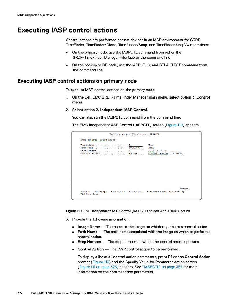
IASP-Supported Operations
Executing IASP control actions Control actions are performed against devices in an IASP environment for SRDF, TimeFinder, TimeFinder/Clone, TimeFinder/Snap, and TimeFinder SnapVX operations:
◆ On the primary node, use the IASPCTL command from either the SRDF/TimeFinder Manager interface or the command line.
◆ On the backup or DR node, use the IASPCTLC, and CTLACTTGT command from the command line.
Executing IASP control actions on primary node
To execute IASP control actions on the primary node:
1. On the Dell EMC SRDF/TimeFinder Manager main menu, select option 3. Control menu.
2. Select option 2. Independent IASP Control.
You can also run the IASPCTL command from the command line.
The EMC Independent ASP Control (IASPCTL) screen (Figure 110) appears.
Figure 110 EMC Independent ASP Control (IASPCTL) screen with ADDIOA action
3. Provide the following information:
Image Name — The name of the image on which to perform a control action. Path Name — The path name associated with the image on which to perform a
control action. Step Number — The step number on which the control action operates.
Control Action — The IASP control action to be performed.
To display a list of al l control action parameters, press F4 on the Control Action prompt (Figure 110) and the Specify Value for Parameter Action screen (Figure 111 on page 323) appears. See “IASPCTL” on page 357 for more information on the control action parameters.
322 Dell EMC SRDF/TimeFinder Manager for IBM i Version 9.0 and later Product Guide
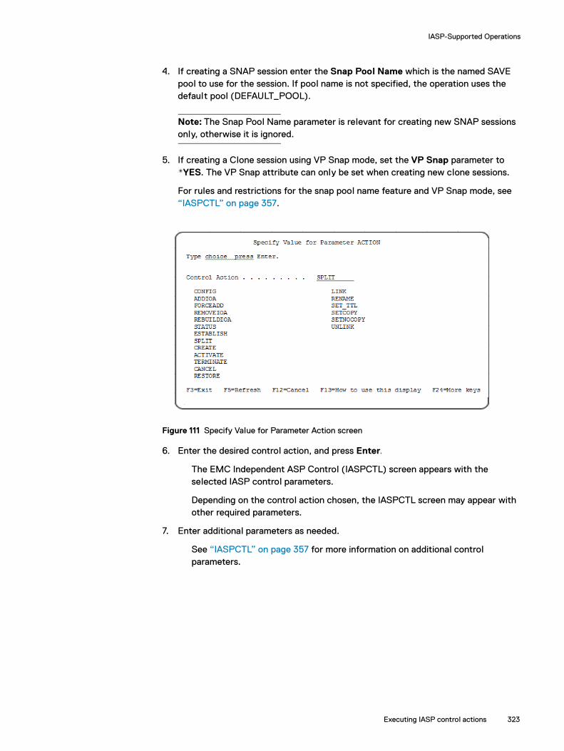
IASP-Supported Operations
4. If creating a SNAP session enter the Snap Pool Name which is the named SAVE pool to use for the session. If pool name is not specified, the operation uses the default pool (DEFAULT_POOL).
Note: The Snap Pool Name parameter is relevant for creating new SNAP sessions only, otherwise it is ignored.
5. If creating a Clone session using VP Snap mode, set the VP Snap parameter to *YES. The VP Snap attribute can only be set when creating new clone sessions.
For rules and restrictions for the snap pool name feature and VP Snap mode, see “IASPCTL” on page 357.
Figure 111 Specify Value for Parameter Action screen
6. Enter the desired control action, and press Enter.
The EMC Independent ASP Control (IASPCTL) screen appears with the selected IASP control parameters.
Depending on the control action chosen, the IASPCTL screen may appear with other required parameters.
7. Enter additional parameters as needed.
See “IASPCTL” on page 357 for more information on additional control parameters.
Executing IASP control actions 323
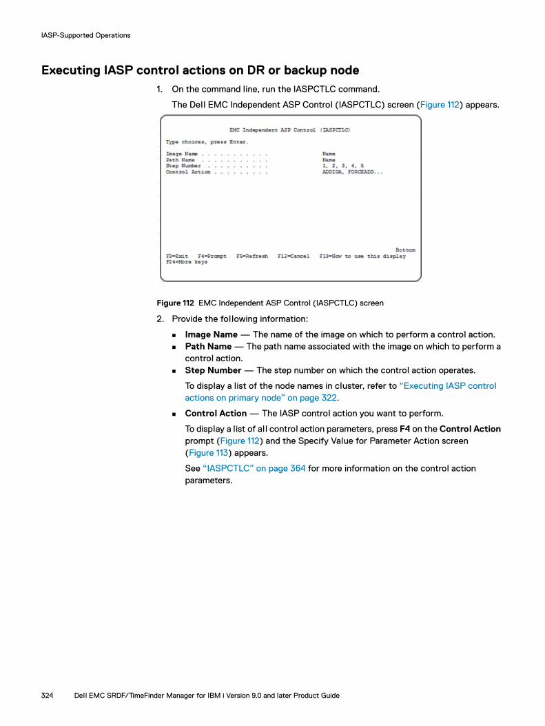
IASP-Supported Operations
Executing IASP control actions on DR or backup node1. On the command line, run the IASPCTLC command.
The Dell EMC Independent ASP Control (IASPCTLC) screen (Figure 112) appears.
Figure 112 EMC Independent ASP Control (IASPCTLC) screen
2. Provide the following information:
Image Name — The name of the image on which to perform a control action. Path Name — The path name associated with the image on which to perform a
control action. Step Number — The step number on which the control action operates.
To display a list of the node names in cluster, refer to “Executing IASP control actions on primary node” on page 322.
Control Action — The IASP control action you want to perform.
To display a list of al l control action parameters, press F4 on the Control Action prompt (Figure 112) and the Specify Value for Parameter Action screen (Figure 113) appears.
See “IASPCTLC” on page 364 for more information on the control action parameters.
324 Dell EMC SRDF/TimeFinder Manager for IBM i Version 9.0 and later Product Guide

IASP-Supported Operations
Figure 113 Specify Value for Parameter Action screen
3. Enter the desired control action (Figure 113 on page 325), and press Enter.
The Dell EMC Independent ASP Control (IASPCTLC) screen (Figure 114) appears with the IASP control parameters.
Figure 114 Control Action REMOVEIOA
Node Name — Parameter used in conjunction with the control action REBUILDIOA when the configuration file needs to be rebuilt for a node and to specify where the operation must be performed. This parameter is also used for STATUS, ADDIOA, REMOVEIOA, and FORCEADD.
The node name you provide must be part of the cluster that is configured on this system. If this is not the case a message appears indicating that the node cannot be found.
Note: The cluster node name can be found by running DSPCLUINF command. This command also displays the node IP address.
Executing IASP control actions 325

IASP-Supported Operations
See “IASPCTLC” on page 364 for more information on additional control action parameters.
Executing SRDF or TimeFinder control actions on DR or backup node
1. On the command line, run the CTLACTTGT command.
The Dell EMC SRDF or TimeFinder Control (CTLACTTGT) screen (Figure 115 on page 326) appears.
Figure 115 EMC SRDF or TimeFinder Control (CTLACTTGT) screen with CREATE action
2. Enter the following information:
Image Name — The name of the image to be used in an SRDF or TimeFinder control operation. Use this command for IASPs images only.
Path Name — The name of the path for the image to be used in an SRDF or TimeFinder operation.
Step Number — The step number for which the control action is initiated in an SRDF or TimeFinder operation.
Control Action — The SRDF or TimeFinder control action to perform on the IASP image. See “CTLACTTGT” on page 343 for a list of control actions.
3. If creating a SNAP session, enter the Snap Pool Name which is the named SAVE pool to use for the session. If pool name is not specified, the operation uses the default pool (DEFAULT_POOL).
Note: The Snap Pool Name parameter is relevant only when creating SNAP sessions.
4. If creating a Clone session using VP Snap mode, set the VP Snap parameter to *YES. The VP Snap attribute can only be set when creating new clone sessions.
For rules and restrictions for the snap pool name feature and VP Snap mode, see “CTLACT” on page 342.
326 Dell EMC SRDF/TimeFinder Manager for IBM i Version 9.0 and later Product Guide

IASP-Supported Operations
Note: If executing SnapVX operations additional parameters are required. See “CTLACTTGT” on page 343.
Preparing target HA node
The IASPCTLHA command pushes configuration files to the specified target HA node and prepares the node to assume the role of the primary node.
To push configuration files and prepare the target HA node for a primary take over:
1. Vary off the IASP that is connected to the production node and the HA node. Only one path can be active at any time. When switching from the primary to the HA node, make sure that the path to the primary node is removed and the path to HA node is active.
You can perform this through the fiber switch or using the FA ports that have a path to both the production and HA node devices. See the example setup in Figure 103 on page 289.
2. Ensure that EMCCTL is installed on the primary and the HA node and that the SRDF/TimeFinder Manager Server is started on all nodes.
3. On the primary node, execute the IASPCTLHA command.
The EMC IASP HA Control (IASPCTLHA) screen (Figure 116) appears.
Figure 116 EMC IASP HA Control (IASPCTLHA) screen
4. Provide the following information:
Control HA Action — Enter CFGHAIASP.
Image Name — Specifies which IASP image configuration files to push to the HA node. Use this command for IASPs images only.
– *ALL — Specifies configuration files for al l IASP images to be pushed to the HA node. This is the default.
Executing IASP control actions 327

IASP-Supported Operations
– Name — Name of the IASP image to be pushed to the HA node.
– + for more values — Allows for multiple IASP image configuration files to be pushed to the HA node.
Target HA Node— The name of the target HA node.
The node name entered must be part of the cluster that is configured on this system. If this is not the case a message appears indicating that the node cannot be found.
Note: The cluster node name can be found by running DSPCLUINF command. This command also displays the node IP address.
Port Number — Port number for HA node. Default is 8000. If using a different port number, keep the port number consistent on all nodes participating in IASP operations.
5. With the server ended on the Primary node and the path added to the HA node, run IASPCTLHA with the SWHAIASP control action on the HA node. This performs a REBUILDIOA operation on the HA node as well.
The HA system is now ready to perform normal STM operations.
6. To get to the original configuration, run IASPCTLHA with action CFGHAIASP on the HA machine, and then select the production host as the target node. On the production node, run IASPCTLHA with control action SWHAIASP.
If a rebuild of the primary node is necessary, follow the normal configuration steps.
When returning to the primary node from the HA node, or when going to the HA node from the Primary node (if the IASPCTLHA command with CFGHAIASP control action was run at least once on both nodes during initial configuration) and no configuration changes occurred, you do not need to run IASPCTLHA (CFGHAIASP) or IASPCTLHA (SWHAIASP) on the required nodes. You only need to run IASPCTLHA with RSTHAIASP on the node taking control of the configuration (primary or HA node).
328 Dell EMC SRDF/TimeFinder Manager for IBM i Version 9.0 and later Product Guide

IASP-Supported Operations
Executing SRDF control actions during DR on primary node
1. On the command line, run the SRDFDRCTL command.
The EMC SRDF DR Control (SRDFDRCTL) screen (Figure 117) appears.
Figure 117 EMC SRDF DR Control (SRDFDRCTL) screen
2. Provide the following information:
Image Name — The name of the image to be used in an SRDF control operation.
Path Name — The name of the path for the image to be used in an SRDF operation.
Step Number — The step number that the control action affects in an SRDF operation.
Control Action — The SRDF control action to perform on the IASP image:
– FAILOVER — Switches data processing from the source (R1) side to the target (R2) side. When running in SRDF asynchronous mode and a FAILOVER is executed, the consistency protection is disabled and then the FAILOVER operation is performed. With dynamic RDF, if ESTABLISH/RESTORE is specified, devices are failed over, swapped and then re-established. In SRDF asynchronous mode, consistency protection is automatically enabled after executing an ESTABLISH/RESTORE.
– FAILBACK — Performs a source (R1) device takeover when you are ready to resume normal SRDF operations by initiating read/write operations on the source (R1) devices, and stopping read/write operations on the target (R2) devices. The target (R2) devices become read-only to their local hosts while the source (R1) devices are read/write enabled to their local hosts.
– RESTORE — Restores data from SRDF R2 data devices back to source devices.
3. Enter the optional control action parameter, if appropriate:
Option for Failover — *NO, ESTABLISH, RESTORE. *NO is the default.
“SRDFDRCTL” on page 386 completely describes this optional parameter and its actions.
Executing IASP control actions 329
IASP-Supported Operations
Automated operationsUse the following commands to perform select IASP operations that are typically run using multiple manual steps. These commands have combined the manual steps into a single process to improve ease-of-use of SRDF/TimeFinder Manager.
Other batch process type commands are available besides the commands described below, and source code is provided in the install library file called QCLSRC.
Failing over/failing back
In addition to the multi-step recovery procedures described in this chapter, there are two commands that can run in batch mode and perform all the steps for a failover or failback of IASP images. The commands are as follows and are run from the DR node:
◆ IASPFAILOV — Performs the failover to the DR node.
◆ IASPFAILBK — Performs the failback to the primary node.
Note: When the initial command IASPFAILOV is used with the option parameter set to ESTABLISH or RESTORE the command IASPFAILOV needs to be run again on the DR node to get back to the original state. When the option parameter *NO is used on the initial IASPFAILOV command the IASPFAILBK command needs to be run to get back to the original state.
When these commands are run, a screen appears. After the required parameters are entered, the system then performs all the necessary steps to complete the IASP failover or failback. These commands can also be run from the command line. When running from the command line, a confirmation screen appears and asks if you want to continue with the operation. For more details on these commands, see “IASPFAILOV” on page 371 and “IASPFAILBK” on page 368.
The IASPFAILOV and IASPFAILBK commands are typically used if no additional user intervention is required for the failover or failback operations. If there are situations where user-supplied setup scripts need to be run or the DR machine requires changes before the IASP is varied on, then the multi-step procedures that follow should be used. However, the SRDF/TimeFinder Manager scripts used to run these commands can be modified to add user-specific actions. See “Modifying the script for the IASPFAILOV command” on page 373 and “Modifying the script for the IASPFAILBK command” on page 370.
Note: IASPFAILOV and IASPFAILBK commands are not available in Cascaded SRDF configurations.
330 Dell EMC SRDF/TimeFinder Manager for IBM i Version 9.0 and later Product Guide

IASP-Supported Operations
Preparing source/target nodes for backup and restore
There are two commands used to prepare the source and target nodes for TimeFinder backup, as well as restore operations of IASP images. The commands are as follows and are run from the target node:
◆ IASPTFBCK — Prepares the source and target nodes for a TimeFinder backup operations.
◆ IASPTFEST — Prepares source and target to go back to original state prior to issuing the IASPTFBCK command.
RTVSTMINF is used within the two scripts to return status information for the selected image, path and step. It also returns SRDF/TimeFinder Manager, Solutions Enabler, Enginuity, and IO driver release level information.
For more details on these commands, see “IASPTFBCK” on page 375, “IASPTFEST” on page 379, and “RTVSTMINF” on page 383.
Automated operations 331

IASP-Supported Operations
332 Dell EMC SRDF/TimeFinder Manager for IBM i Version 9.0 and later Product Guide

APPENDIX FNon-EMC Procedures
Invisible Body Tag
This appendix provides guidelines when using IBM-related procedures.
◆ Overview............................................................................................................ 334◆ Displaying contents of a physical file on each node ........................................... 335◆ Verifying IOA information ................................................................................... 336
Non-EMC Procedures 333

Non-EMC Procedures
Overview During setup, configuration, or recovering from a disaster, there are occasions when you must use IBM commands, perform DST or SST procedures, or use other third-party software. The sections that follow describe those procedures.
Refer to the IBM documentation for more information about IBM i and IASPs
334 Dell EMC SRDF/TimeFinder Manager for IBM i Version 9.0 and later Product Guide

Non-EMC Procedures
Displaying contents of a physical file on each nodeTo display the contents of the physical file IASPs on each node, on any node, type:
DSPPFM EMCCTLC/IASPS
The Display Physical File Member screen (Figure 118) appears.
Figure 118 Displaying the contents of a physical file
The screen displays the following information:
IASPBCV IASP device
LOCALNCL Configured path for the SRDF image
1 Step number
PRIMNODE Primary node name
SRCNODE Source node for this step
TGTNODE Target node for this step
1 Source node LPAR ID
3 Target node LPAR ID
1234567 System serial number for the source node
1234567 System serial number for the target node
IASPBCV IASP name
33 ASP number
8000 Port number of the SRDF/TimeFinder Manager server
Displaying contents of a physical file on each node 335

Non-EMC Procedures
Verifying IOA informationTo verify IOA information stored in the physical file ISRCIOA on any node, use the Display Physical File Member screen (Figure 119).
To verify one or more IOA serial numbers:
1. On the command line, type the following command:
DSPPFM EMCCTL/ISRCIOA
The Display Physical File Member screen or DSPPFM EMCCTLC/ISRCIOA on a DR or backup node appears.
Figure 119 Verifying IOA information
The screen shows the slot number, bus number, resource name, ASP number, and system serial number for each IOA.
2. If necessary, verify the slot number and bus number:
DSPHDWRSC TYPE(*STG) OUTPUT(*PRINT)
336 Dell EMC SRDF/TimeFinder Manager for IBM i Version 9.0 and later Product Guide

APPENDIX GExtended Features Commands Reference
Invisible Body Tag
This appendix provides reference information about the control commands.
◆ Conventions....................................................................................................... 338◆ ADDRMVIOA...................................................................................................... 339◆ CRTNETCNFG................................................................................................... 341◆ CTLACT ............................................................................................................. 342◆ CTLACTTGT ...................................................................................................... 343◆ DISCOVER......................................................................................................... 354◆ DISCOVERC ...................................................................................................... 355◆ ENDSTMSRV..................................................................................................... 356◆ IASPCTL ............................................................................................................ 357◆ IASPCTLC.......................................................................................................... 364◆ IASPCTLHA ....................................................................................................... 366◆ IASPFAILBK ....................................................................................................... 368◆ IASPFAILOV........................................................................................................ 371◆ IASPFILE ........................................................................................................... 374◆ IASPTFBCK ....................................................................................................... 375◆ IASPTFEST........................................................................................................ 379◆ RELDEVLCK ...................................................................................................... 381◆ RELDEVLCKC .................................................................................................... 382◆ RTVSTMINF ...................................................................................................... 383◆ SETRDFMOD..................................................................................................... 384◆ SETRDFMODC .................................................................................................. 385◆ SRDFDRCTL...................................................................................................... 386◆ STMRMTCMD ................................................................................................... 389◆ STRSTMSRV ..................................................................................................... 390
Extended Features Commands Reference 337
Extended Features Commands Reference
ConventionsThe descriptions of the commands in this appendix can contain the following sections:
◆ Syntax — Presents the syntax of the command. Variables that you specify are shown in italics. Optional parameters are indicated by brackets.
◆ Description — Describes the purpose and result of the command.
◆ Required parameters — Describes one or more parameters that must be specified at the command line. Each description contains all possible values of the variable and states which, if any, of the values is the default. Variables that you must specify are shown in italics.
◆ Optional parameters — Describes one or more parameters that can be included at the command line. Each description contains all possible values of the variable and states which, if any, of the values is the default. Variables that you can specify are shown in brackets [ ].
◆ Usage notes — Presents specific points that you should keep in mind when using the command.
◆ Examples — Presents examples of how to invoke the command.
338 Dell EMC SRDF/TimeFinder Manager for IBM i Version 9.0 and later Product Guide

Extended Features Commands Reference
ADDRMVIOAAdds or removes the IOAs for a selected IASP.
Note: The ADDRMVIOA command does not physically add or remove the IOA from the system (LPAR), it enables or disables the IOA. Removal or addition of an IOA from the system or LPAR is performed from the Hardware Management Console.
SyntaxADDRMVIOA ACTION(ADDIOA|REMOVEIOA) IASPRESC((iasp_name_1(ioa_resource_name_1, ioa_resource_name_2))(iasp_name_2(ioa_resource_name_1, ioa_resource_name_2)))
Description Adds or removes the IOAs for a selected IASP. This command replaces the CTLIOA command. Run this command on the node where the IOAs are added or removed.
Required parametersACTION(ADDIOA|REMOVEIOA)
Add or remove command
IASPRESC((iasp_name_1(ioa_resource_name_1 ioa_resource_name_2))(iasp_name_2(ioa_resource_name_1 ioa_resource_name_2)))
IASP name and IOA resource name. Up to 256 ASPs can be added, and up to 128 IOAs can be added for each ASP.
Note: The IOA resource name can be found in the ISRCIOA file or by using the System Service Tools (SST).
IASPRESC((primary_iasp_name(ioa_res_name_Prim_1 ioa_res_name__Prim_2))(secondary_iasp_name_1(ioa_res_name_Sec1_1 ioa_res_name_Sec1_2))(secondary_iasp_name_2(ioa_res_name_Sec2_1 ioa_res_name_Sec2_2)))
Primary and secondary IASP names, and primary and secondary IOA resource names.
Note: When the add or remove command is run on a primary IASP that has secondary IASPs, the secondary IASPs must to be entered into the same command.
Usage notesThe ADDRMVIOA command can be used to add an IOA even if SRDF/TimeFinder Manager is not yet configured.
This command can be executed from the command line with the required parameters, as shown in the example below, or the command ADDRMVIOA can be entered without parameters and the Dell EMC Add/Remove IOA screen appears (Figure 120 on page 340).
ADDRMVIOA 339
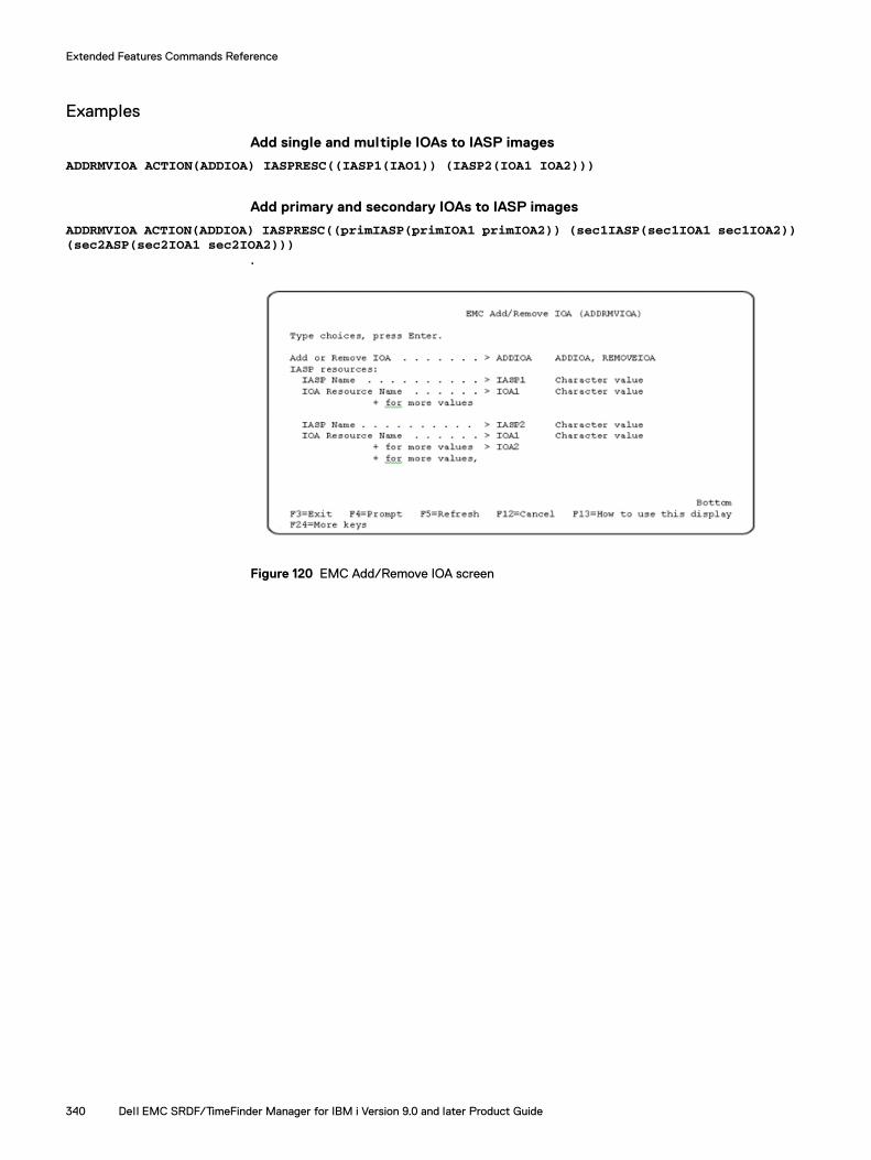
Extended Features Commands Reference
Examples
Add single and multiple IOAs to IASP images
ADDRMVIOA ACTION(ADDIOA) IASPRESC((IASP1(IAO1)) (IASP2(IOA1 IOA2)))
Add primary and secondary IOAs to IASP images
ADDRMVIOA ACTION(ADDIOA) IASPRESC((primIASP(primIOA1 primIOA2)) (sec1IASP(sec1IOA1 sec1IOA2)) (sec2ASP(sec2IOA1 sec2IOA2)))
.
Figure 120 EMC Add/Remove IOA screen
340 Dell EMC SRDF/TimeFinder Manager for IBM i Version 9.0 and later Product Guide

Extended Features Commands Reference
CRTNETCNFGCreates the NETCNFG file and adds network services to the file.
See “CRTNETCNFG” on page 193.
CRTNETCNFG 341

Extended Features Commands Reference
CTLACTProcesses SRDF and TimeFinder control actions for one or al l images (SYSTEM and IASP).
See “CTLACT” on page 194.
342 Dell EMC SRDF/TimeFinder Manager for IBM i Version 9.0 and later Product Guide
Extended Features Commands Reference
CTLACTTGTProcesses SRDF or TimeFinder control actions for IASP images on the target side.
SyntaxCTLACTTGT IMAGE_NAME(image_name|*ALL)PATH_NAME(path_name)STEPNUM(step_number)ACTION(control_action)[SPLIT_MODE(CHG_ASP_ACT|SPLITWA|MAINTENANCE)][PROT_ESTAB(*YES|*NO)][POOL_NAME(pool_name)][VP_SNAP(*YES|*NO)][SVX_MODE(CHG_ASP_ACT|CONSISTENT)][SNAPVXNAME(snapshot_name)][SNAPVXGEN(snapshot_generation)][SNAPVXTTL(DAYS|DATE)][N_SNPSHOT(new_snapshot_name)][LINK_MODE(NOCOPY|COPY)][TTL_DAYS(1-400)][TTL_DATE(Date)]
DescriptionCTLACTTGT processes SRDF or TimeFinder control actions for IASP images on the target side.
Required parametersIMAGE_NAME(image_name|*ALL)
The name of the image (image_name) or *ALL to indicated all images.
PATH_NAME(path_name)The path name associated with the image to be used in an SRDF or TimeFinder control operation.
STEPNUM(step_number)The specific step number for which the control action operates on in an SRDF or TimeFinder control operation.
Steps in the path are defined during configuration and are identified by their position (1 through 5) in the path.
ACTION(control_action)Specifies the control operation to perform:
STATUS — Provides SRDF, Snap, Clone, Clone emulation, or BCV control status information for the step in the associated path of the image. For SnapVX, if snapshot name and generation are specified, the state of the specified snapshot is provided.
Note: If the status of the SnapVX step is Linked, CopyInProg, Copied, Restored, RestoreInProg, RestNotPaired, or RestgNotPaired an additional message is provided with the snapshot name and generation.
CTLACTTGT 343

Extended Features Commands Reference
ESTABLISH — Establishes SRDF links for SRDF control or establishes/re-establishes BCV or Clone emulation pairs for BCV control. When running in SRDF/A mode, consistency protection is automatically enabled after executing an ESTABLISH operation is executed.
For SnapVX type of step, ESTABLISH creates and activates a SnapVX snapshot session.
SPLIT — Splits SRDF links for SRDF control or splits BCV or Clone emulation pairs for TimeFinder control. When the system is running in SRDF/A mode and a SPLIT is executed, consistency protection is disabled and then the SPLIT operation is performed.
Note: For TimeFinder/Clone configurations, if the devices are in Restored state, use the SPLIT option to change the direction of the clone relationship (that is, the original source device becomes the source device for a future copy), which allows the use of the RECREATE command and normal processing continues. This does not apply if VP Snap is enabled.
FAILOVER — Switches data processing from the source (R1) side to the target (R2) side. If the source (R1) is operational, FAILOVER suspends I/O traffic on the RDF links, and write disables the devices on the source (R1) side to their hosts, and then write enables the devices on the target side to their local hosts. When running in SRDF asynchronous mode and a FAILOVER is executed, the consistency protection is disabled and then the FAILOVER operation occurs.
With dynamic RDF, when you specify the ESTABLISH option, devices failover, swap, and then re-establish. In SRDF/A mode, consistency protection is automatically enabled after an ESTABLISH operation executes. For arrays or dynamic volumes, EMC recommends FAILOVER with the ESTABLISH option which swaps personality (the R1 devices become R2 devices and the R2 devices become R1 devices) and then starts the synchronization.
For dynamic RDF, if the RESTORE option is specified, devices failover, swap and then re-establish. Invalid tracks on the new R2 side (originally the R1 side) are restored to the new R1 side (formerly the R2 side).
When running in SRDF asynchronous mode, consistency protection is automatically enabled after executing a RESTORE operation.
FAILBACK — Performs a fail back, or source (R1) device takeover, when you are ready to resume normal SRDF operations by initiating read/write operations on the source (R1) devices, and stopping read/write operations on the target (R2) devices. The target (R2) devices become read-only to their local hosts while the source (R1) devices are read/write enabled to their local hosts. In SRDF/A mode, consistency protection is enabled after a FAILBACK operation executes.
R2RW — Enables the R2 read/write, enables R2 mirror write, and enables the target (R2) devices to their local hosts.
If the source (R1) is operational, R2RW suspends I/O traffic on the RDF links. Then, R2RW write enables the devices on the target side to their local hosts.
In SRDF asynchronous mode, when an R2RW executes, the consistency protection is disabled, and then the read/write enable R2 mirror operation is performed.
344 Dell EMC SRDF/TimeFinder Manager for IBM i Version 9.0 and later Product Guide

Extended Features Commands Reference
CTLACTTGT 345
SUSPEND — Suspends SRDF links for SRDF control. When the system is running in SRDF/A mode and a SUSPEND is executed, the consistency protection is disabled and then the SUSPEND operation is performed.
ENABLE — Enables the consistency protection for SRDF/A backed devices when running in SRDF/A mode. If data cannot be copied from the R1 to the R2, al l devices in the group are made Not Ready on the link to preserve the R2 data consistency.
Note: If devices are enabled for consistency group protection, the devices must be disabled before you change the mode to Synchronous or initiate the SPLIT/SUSPEND operation.
DISABLE — Disables the consistency protection for SRDF/A backed devices when running in SRDF asynchronous mode.
CREATE — Creates or recreates a TimeFinder/Snap virtual copy session or Clone copy session with devices in the image. While the operation is in progress for TimeFinder/Snap, the state of the device pair is CreateInProg. For TimeFinder/Clone the state of the device pair is PreCopy. When the Create operation completes, the state changes to Created.
Run CREATE before you activate the session, which has a shorter duration than an Establish operation.
For TimeFinder Snap, Recreate is only available in systems running Enginuity 5876 or higher.
See “TimeFinder/Snap Usage notes” on page 200 for more information about using Recreate.
ACTIVATE — Activates a TimeFinder/Snap virtual copy session or Clone copy session with the devices in the image. For TimeFinder/Snap, while the operation is in progress the state of the device pair is CopyOnWrite. For TimeFinder/Clone, while the operation is in progress the state of the device pair is CopyInProg. Once the copy is complete, the state changes to Copied.
Note: The point-in-time copy becomes available after an ACTIVATE operation. Create must be done before you can activate a TimeFinder/Snap copy session or Clone copy session.
LINK — Copies the SnapVX point-in-time data to the target device.
There are two types of links, NOCOPY (the default) or COPY. NOCOPY links do not retain point-in-time data once the link is removed and any previous target data is lost. Copy mode must be used in order for the linked target to retain data after the link is removed. When linking a snapshot, COPY or NOCOPY must be specified.
RELINK — Removes the current SnapVX link to target device(s) and presents a different snapshot. The relink may also be used to relink to the same snapshot. This has the effect of refreshing the point-in-time copy on the link target if it has been modified by host writes.
UNLINK - Removes the current SnapVX link to target device(s).
Extended Features Commands Reference
RESTORE — Restores data from target TimeFinder replication devices or from SRDF R2 data devices back to source devices or other devices. This can be a full or incremental restore operation.
The following behavior and rules apply to the restore operation for the different TimeFinder replication devices:
TimeFinder/Mirror and TimeFinder /Clone Emulation
A full restore operation copies the entire contents of the BCV device to the standard device. For an incremental restore process, the BCV device copies only the new data to the standard device that was written to the BCV device while the BCV pair was split. Any changed tracks on the standard device are also overwritten with the data on the corresponding tracks of the BCV device. This process is useful for porting an application that was tested on the BCV device, to the standard device. The restore process is complete when the standard device and the BCV device contain identical data.
The BCV device is not available to the host while it is assigned as a BCV mirror on a standard device. However, any new data written to the standard device is copied to the BCV device while the BCV pair exists.
When using native TimeFinder/Mirror and a BCV device is used to restore a point-in-time copy to the standard device, the point-in-time copy on the BCV device is modified if the host writes to the standard device during the restore operation. The -protected option used on the restore operation preserves the point-in-time stored on the BCV. When using mode, a protected restore operation is always in effect.
To continue normal operations, the BCV pairs should be split.
TimeFinder/Clone
The restore operation copies target data to another device (full restore), or back to the original source device (incremental restore). For a full restore, the original session terminates and a copy session to the target of the restore operation begins. For an incremental restore operation, the original session copy direction reverses, and changed data is copied from the target device to the source device. To support the restore operation, the session must be in a Copied state.
Use the SPLIT command to split a clone device pair that is in the Restored state. This command changes the direction of the clone relationship (that is, the original source device becomes the source device for a future copy), which allows the use of the recreate command. TimeFinder/Clone supports the SPLIT command. This does not apply if VP Snap is enabled.
TimeFinder/Snap
The restore operation creates a new restore copy session between the source device and the target virtual device. You can carry out a restore operation when an additional copy session is available for use. Any existing copy sessions persist until manually terminated. After the virtual device has been restored to another device, the restore copy session must be terminated before another restore operation is al lowed from that virtual device. All commands (CTLACTTGT, CTLACT, IASPCTL and IASPCTLC) and screens on the source
346 Dell EMC SRDF/TimeFinder Manager for IBM i Version 9.0 and later Product Guide
Extended Features Commands Reference
side would show RestInProg or Restored state. The original snap copy session remains in the CopyOnWrite state but is not shown. For an incremental restore, any changes made to the virtual device tracks during the active copy session are restored back to the original source device. Any changes written to the original source device during the copy session are overwritten by the virtual device tracks when the source device is restored.
The restore target device (source device) and virtual device are automatically set to the Not Ready state while the track protection bitmaps prepare to copy any changed tracks. The source device automatically becomes available for use (Ready state) once the track protection bitmap completes. The changed tracks then begin copying and continue to copy in the background until al l the protected tracks are restored.
To continue using the original copy session, the virtual device must be manually set to the Ready state after the restore operation has completed.
Once the restore operation completes, both the original and restore copy sessions are maintained, and must be manually terminated if not needed for future use. When an original session is terminated, the device pointers are deleted from the virtual device and the SAVE device space becomes available for future use. The restored copy session must be terminated first, before the original copy session is al lowed to be terminated.
TimeFinder/VP Snap
VP Snap supports incremental restore operations back to the original source device. Unlike TimeFinder/Clone restore operations, the source device does not have to be fully copied and the original session between the source device and the target device is maintained. The following restrictions apply:
– Only one restore session is allowed for the source device.
– Because the original session is maintained, an additional session is charged to the source device.
– If you have concurrent sessions off of a source device, al l of the concurrent sessions must be in the Copied or CopyOnWrite state.
– Splitting a clone device pair is not supported for VP Snap restored sessions.
– Starting from the time of the initiation of the incremental restore command until the restore copy is complete, existing sessions cannot be changed from one mode to another, nor can they perform a differential recreate operation. New sessions cannot be created with another create command.
TimeFinder/SnapVX
The restore operation copies the point-in-time data from a snapshot back to the original source device. The snapshot must be fully established to perform a restore.
SRDF restore operation rules and restrictions
The new data, that was updated on the target (R2) device while the SRDF pair was split, is copied to the source (R1) device. Any changed tracks on the source (R1) device are refreshed from the corresponding tracks on the target (R2)
CTLACTTGT 347

Extended Features Commands Reference
device. After the restore operation has successfully completed, the SRDF pairs synchronize. You can use the RTVSMINF command to confirm that the SRDF pairs are in a Synchronized state.
Note: The CTLACTTGT and IASPCTLC commands using control action STATUS can be used to confirm the status of SRDF pairs.
When an incremental restore is initiated for each specified SRDF pair in a device file:
– The source (R1) device is write disabled for the local hosts.
– The target (R2) device is write disabled for the local hosts.
– Data traffic is suspended on the SRDF links.
– The invalid tracks on the source (R1) device are refreshed with the changed tracks on the target (R2) side. The R1 and R2 track tables are merged.
– Traffic is resumed on the SRDF links.
– The source (R1) device is read/write enabled for the local hosts.
– The SRDF pair is in the Synchronized state when the source (R1) device and the target (R2) device contain identical data.
– The incremental restore operation is rejected if the target has invalid local (R2) tracks.
Note: When running in SRDF asynchronous mode, consistency protection is automatically enabled after executing a RESTORE operation.
RENAME — Changes the SnapVX snapshot name of a specified generation. If you do not specify a generation, the control operation renames generation.
SET TTL — Sets a time to live (TTL) for a SnapVX snapshot, from when TTL is set, in days or a date. The value in days can be set to a value between 1 and 400. The date value is a specified date up to 400 days in the future, from which a value in days is created, based on the difference between the specified absolute time and the host time when the action is performed. When the TTL expires the snapshot automatically terminates unless there are one or more links. Automatic termination takes place when the links are removed. If TTL is not set, the snapshot remains established until it is manually terminated.
SETCOPY - Changes the copy mode of a link to copy. Data is physically copied to the target device(s). When the link is terminated the data is retained on the target.
SETNOCOPY - Changes the copy mode of a link to NoCopy. Data is presented on the target device(s), but not physically copied. When the link is terminated the data is not retained on the target.
TERMINATE — Stops the existing TimeFinder/Snap virtual copy session or Clone copy session between the specified source and target devices in the image.
For SnapVX snapshot sessions, TERMINATE removes the snapshot. All links must be unlinked before terminating a snapshot.
Note: If a snapshot has restores, only the restored session is terminated.
348 Dell EMC SRDF/TimeFinder Manager for IBM i Version 9.0 and later Product Guide
Extended Features Commands Reference
CANCEL — Cancels the existing internal session between the specified standard device and the BCV devices in the image.
Once the session is cancelled, the corresponding BCV devices are placed in a SplitNoInc state, and the BCV pair can no longer be incrementally established or restored.
Use Cancel before performing an unpairing operation on Clone Enabled BCV devices. Failure to run Cancel causes hanging Clone sessions to remain on the array.
Optional parametersPOOL_NAME(DEFAULT_POOL|pool_name)
Specifies the named SAVE pool to use when creating a TimeFinder/Snap operation. If pool name is not specified, the operation uses the default pool (DEFAULT_POOL).
SNAP pool name rules and restrictions:◆ The POOL_NAME parameter is relevant only for creating new SNAP sessions,
otherwise it isignored.
◆ The specified pool must exist and contain at least one enabled device before creating a TimeFinder/Snap session.
◆ If the image spans over several arrays the specified pool must exist on all arrays.
◆ If at least one device in a step has established a SNAP session all other copy sessions wil l use the pool in the established copy session.
◆ With mixed device s (2107 and D910) only the DEFAULT_POOL can be used.
VP_SNAP(*YES|*NO)Specifies whether to use TimeFinder VP Snap mode. The VP Snap parameter may only be set when a session is created.
VP Snap allows for concurrent sessions.
VP Snap rules and restrictions:◆ Active sessions are in the CopyOnWrite state.
◆ Support is limited to D910 IBM i (512-byte block size) thin-to-thin device clone pairs. All other IBM i type devices are not supported.
◆ All VP Snap target devices must be bound to the same thin pool. Once a VP Snap session is created for a source device, additional new sessions are rejected if the new target device is not bound to the same thin pool as the target for the existing session.
Restrictions for cascaded sessions:
◆ Clone sessions must be in the Copied or Split state for a VP Snap session to be created from its target device.
◆ The Clone session must exist before the target device is used as a VP Snap source. Creating a Clone session using a VP Snap source as its target device is not permitted.
◆ Snap sessions and VP Snap sessions cannot be on the same source device.
◆ Rebind and VLUN VP Migration operations that cause a device to be rebound are not allowed on VP Snap target devices.
CTLACTTGT 349
Extended Features Commands Reference
◆ The target of a VP Snap session cannot be used as a source for any other Clone or Snap session.
◆ Cascading from TimeFinder Clone emulation is not supported.
Restrictions for SRDF/S and SRDF/A:
◆ SRDF devices used as VP Snap targets are not supported.
◆ The use of R2 devices as VP Snap source devices requires that SRDF/A Device-level Write Pacing (Device-level Pacing) is configured with autostart on the R1 side, or that the Device-level Pacing is activated and supported on the SRDF/A session.
◆ If the VP Snap source is an R2 device and the VP Snap session is in the RestoreInProgress state, SRDF restore to the R1 device is blocked.
Restrictions for incremental restore of VP Snap sessions:
◆ The VP Snap restore is similar to the snap persistent restore and results in an additional session charged to the source device. The original CopyOnWrite session is preserved.
◆ All clone sessions associated with the selected source device must be fully copied or split and any VP Snap sessions must be in the CopyOnWrite or Copied state. If any concurrent session is in any other state the incremental restore of the VP Snap session is blocked.
◆ The VP Snap source device can only have one restored session at a time.
◆ Once restored, the only operation allowed is termination of the restored session. The CopyOnWrite session is preserved.
◆ Clone Split is available for VP Snap restored sessions.
Restrictions for incremental restore operation until the restore data copy is complete
◆ One of the existing sessions may be the target of a differential Recreate or incremental Establish operation.
◆ No new session can be created using another Create or full Establish command.
SPLIT_MODE(CHG_ASP_ACT|SPLITWA|MAINTENANCE)Specifies method for stopping writes to the devices in the image. The options are:
CHG_ASP_ACT — Executes the operation after suspending initiation of new transactions and operations.
Note: The Change ASP Activity CL command (CHGASPACT) is used for hosts running V6R1M0 or higher. The selected IASP image that uses the command is quiesced at the start of new commitment control transactions, new database change operations, and new Integrated File System (IFS) change operations. The command suspends initiation of new transactions and operations before the split, writes changes to auxiliary storage, and resumes initiations of new transactions and operations after the split.
SPLITWA — Executes the operation after holding I/Os on the array. Splits a local or remote BCV, Clone, Clone emulation, or Snap image while the source system is operational. The resulting image is consistent and holds data upon the last commit.
With TimeFinder/CG (SPLITWA) operations, you do not have to set the IBM i host in a restricted state or perform a hold jobs operation.
350 Dell EMC SRDF/TimeFinder Manager for IBM i Version 9.0 and later Product Guide

Extended Features Commands Reference
The SRDF/TimeFinder Manager client and the controlling host must have a gatekeeper configured on each locally attached array. For detailed information on array gatekeeper management, refer to the Dell EMC Solutions Enabler Installation and Configuration Guide.
On the client, the netcnfg file must be configured using the CRTNETCNFG command. This ensures that correct information (node name, IP address, port, and security level) points to the remote server. Only non-secure connections are supported for IBM i.
MAINTENANCE — Splits or Suspends SRDF links, splits BCV pairs or activates a virtual copy session or Clone copy session in maintenance mode (that is, no interference with host operations).
PROT_ESTAB(*YES|*NO)Performs a Protected or normal BCV Establish operation:
*YES — Establish two mirrors of a BCV device to the standard device. When the split occurs, both mirrors are split simultaneously. This operation moves all mirrors of the locally mirrored BCV devices to join the mirrors of a standard device
*NO — Perform a normal Establish operation for the BCV device. This is the default.
SVX_MODE(CHG_ASP_ACT|CONSISTENT)The mode to use for the SnapVX Establish operation:
• CHG_ASP_ACT — Executes the operation after suspending initiation of new transactions and operations.
CONSISTENT —Executes the operation in Consistent mode (that is, no interference with the host operations). This is the default.
IMPORTANT
Use caution when using this Consistent Establish mode, as the data in main memory is not included in the image. Use this only when the host and applications are in a quiescent state. If that is unacceptable to your business needs, use other operating system functions such as journaling and database commitment control to obtain an image current with the last transaction.
SNAPVXNAMEThe name of the Snapshot.
Note: For ESTABLISH action SNAPVXNAME specifies the name for new snapshots. For al l other control actions SNAPVXNAME specifies the name of the existing snapshots to be operated on. This parameter is required for al l SnapVX control actions except STATUS where it is optional.
SNAPVXGEN The Generation of the Snapshot. For al l SnapVX control actions, except ESTABLISH, specifies the generation of the existing snapshots to be operated on. If set to zero, the most recent snapshot is used for the control action.
SNAPVXTTL For ESTABLISH and SET_TTL SnapVX controls specifies a Time to Live. The possible values are:
CTLACTTGT 351
Extended Features Commands Reference
DAYS -Specifies the time to live in days.
DATE - Specifies a date for the snapshot time to live.
If you do not specify a value, the Time to Live is set to unlimited and the Snapshot is kept until manually terminated.
N_SNPSHOT The new name of the Snapshot. Used only for RENAME operations.
LINK_MODE(NOCOPY|COPY) The mode used for a LINK SnapVX operation. Options are as follows:
NOCOPY —The target does not retain point-in-time data once the link is removed, and any previous target data is lost. This is the default.
COPY — Data is physically copied to the target devices. When the link is terminated the data is retained on the target.
TTL_DAYS Time to Live in days. The value in days can be set to any value between 1 and 400.
TTL_DATE Specifies a date for the snapshot time to live in the form MM/DD/YYYY (month/day/year) with reference to the host time. The specified date may be up to 400 days in the future.
Usage notesAll control commands executed on the DR or backup node use the image file built on the primary node and sent to the corresponding node. The PATH_NAME and STEPNUM parameters should use the path name and step used on the primary node for corresponding devices. For example, if the path REMOTEBCV /RDF1/BCV1 exists in the image file, use the path name REMOTEBCV and step number 2 to execute TimeFinder control operations on the DR node.
For TimeFinder Snap in environments prior to Enginuity 5876:
◆ Issue TERMINATE and then CREATE before creating a new point-in-time image.
◆ A Snap copy session requires the following steps:
1. Create a Snap session.
2. Activate a Snap session.
3. Terminate the Snap session.
In Enginuity 5876:
◆ The Recreate action occurs automatically if al l devices in the image have Enginuity 5876 and sessions are already activated.
◆ Recreating a Snap copy session requires the following steps:
1. Create a Snap session.
2. Activate a Snap session.
3. Recreate a Snap session.
4. Activate a Snap session.
5. Repeat steps 3 and 4, as necessary.
6. Terminate the Snap session when it is no longer needed.
352 Dell EMC SRDF/TimeFinder Manager for IBM i Version 9.0 and later Product Guide

Extended Features Commands Reference
ExamplesCTLACTTGT IMAGE_NAME (DISKPOOL) PATH_NAME(REMOTEBCV) STEPNUM(1)ACTION(FAILOVER) OPTION(ESTABLISH)
CTLACTTGT IMAGE_NAME(IASP1) PATH_NAME(SRDF) STEPNUM(1) ACTION(SWAP)REFRESH(R1)
CTLACTTGT IMAGE_NAME(IASP1) PATH_NAME(REMOTEBCV) STEPNUM(2)ACTION(SPLIT) SPLIT_MODE(SPLITWA)
For control action command examples for TimeFinder/SnapVX, see the examples section in “CTLACT” on page 194. Replace “CTLACT” with “CTLACTTGT”.
CTLACTTGT 353

Extended Features Commands Reference
DISCOVERDiscovers new devices, removes old device information from the SYMAPI database, and updates the database with new information. This command also updates information in the IMAGE file and controls checking and clearing of serial number IDs for al l devices.
See “DISCOVER” on page 212.
354 Dell EMC SRDF/TimeFinder Manager for IBM i Version 9.0 and later Product Guide
Extended Features Commands Reference
DISCOVERCDiscovers new devices, removes old device information from the SYMAPI database, and updates the database with new information. DISCOVERC performs the discover process on the target side that is required when the configuration on the host or array changes.
See “DISCOVERC” on page 213.
DISCOVERC 355

Extended Features Commands Reference
ENDSTMSRVShuts down the SRDF/TimeFinder Manager server job.
“ENDSTMSRV” on page 214.
356 Dell EMC SRDF/TimeFinder Manager for IBM i Version 9.0 and later Product Guide
Extended Features Commands Reference
IASPCTLPerforms IASP control functions on the primary node or DR node in a three-node DR solution.
Note: This command only performs IASP control functions on the DR node when the EMCCTL library is installed on the DR node.
SyntaxIASPCTL IMAGENAME(Image_name)PATHNAME(Path_name)STEPNUM(Step_number)ACTION(Control_action) NODENAME(Node)SRCORTGT (TGTDEV|SRCDEV)[POOL_NAME(pool_name)][VP_SNAP(*YES|*NO)][PROT_ESTAB(*YES|*NO)][TGTNAME(Node_name)][PORTNUM(port_number)][SNAPVXNAME(snapshot_name)][SNAPVXGEN(snapshot_generation)][SNAPVXTTL(DAYS|DATE)][N_SNPSHOT(new_snapshot_name)][LINK_MODE(NOCOPY|COPY)][TTL_DAYS(1-400)]
DescriptionIASPCTL performs the control action specified on the devices associated with the path of the selected IASP image.
Required parametersIMAGENAME(Image_name)
The name of the image on which to perform a control action.
PATHNAME(Path_name)The path name associated with the image to be used in an SRDF or TimeFinder control operation.
STEPNUM(Step_number)The specific step number for which the control action is initiated in an SRDF or TimeFinder control operation.
ACTION(control_action)The control action to perform:
ESTABLISH — Establishes SRDF links for SRDF control or Establishes/Re-establishes BCV pairs for BCV control. When the system is running in SRDF asynchronous mode, consistency protection is automatically enabled after executing an ESTABLISH operation.
For SnapVX type of step, ESTABLISH creates and activates a SnapVX snapshot session.
SPLIT — Splits SRDF links for SRDF control or splits BCV pairs for TimeFinder control. When the system is running in SRDF asynchronous mode and a SPLIT executes, the consistency protection is disabled and then the Split operation is
IASPCTL 357

Extended Features Commands Reference
performed. For TimeFinder/Clone configurations, if the devices are in Restored state, use the SPLIT option to change the direction of the clone relationship (that is, the original source device becomes the source device for a future copy), which allows the use of the RECREATE command and normal processing continues. This does not apply if VP Snap is enabled.
On the primary node, when performing a split operation follow the steps described below.
ADDIOA — Adds one or more IOAs with target TimeFinder replication devices to the backup node.
IMPORTANT
When varying on an IASP on a different system with different number of fiber connections to the IASP devices, the vary on goes through DASD checks to detect if all paths can be reestablished. To avoid a longer vary on time, a multi-path reset executes automatically after the ADDIOA completes and the devices have reported back in.
FORCEADD — Adds the IOA to the target host when the SRDF link is in a partitioned or transmit idle state when the regular ADDIOA control action fails, or when the source STM Server is not available. The message that appears when the regular add fails indicates this as well.
REMOVEIOA — Removes one or more IOAs with target devices from the backup node.
REBUILDIOA — Rebuilds the IOA file with IOA configuration information (slot number, bus number, and system serial number for the IOA). The rebuild action automatically runs with a CONFIG action.
CREATE — Creates or recreates a TimeFinder/Snap virtual copy session or Clone copy session with devices in the image. For TimeFinder/Snap, while the operation is in progress, the state of the device pair is CreateInProg. For TimeFinder/Clone the state of the device pair is PreCopy. When the Create operation completes, the state changes to Created.
Note: CREATE must be executed before you activate the session, which has a shorter duration than an ESTABLISH operation.
See “Usage notes” on page 363 for more information.
Status Step
Varied off Use the IASPCTL command to perform a maintenance split.
Varied on Use the IASPCTL command for the split. SRDF/TimeFinder Manager wil l use the Change ASP Activity CL command (CHGASPACT) to quiesce IASP data for the split.
358 Dell EMC SRDF/TimeFinder Manager for IBM i Version 9.0 and later Product Guide

Extended Features Commands Reference
ACTIVATE — Activates a TimeFinder/Snap virtual copy session or Clone copy session with the devices in the image. For TimeFinder/Snap, while the operation is in progress, the state of the device pair is CopyOnWrite. For TimeFinder/Clone, while the operation is in progress the state of the device pair is CopyInProg. Once the copy is complete, the state changes to Copied.
Note: CREATE must be executed before you activate a TimeFinder/Snap copy session.
When performing an ACTIVATE operation on the primary node, use the steps described in the next table.
RESTORE — Restores data from target devices back to source devices or other devices. This can be a full or incremental restore operation. See “CTLACTTGT” on page 343 for details on the behavior and rules that apply to the restore operation for TimeFinder replication devices.
TERMINATE — Stops the existing TimeFinder/Snap virtual copy session or Clone copy session between the specified source and target devices in the image.
For SnapVX snapshot sessions, Terminate removes the snapshot. All links must be unlinked before terminating a snapshot.
Note: Note: If a snapshot has restores, only the restored session is terminated.
CANCEL — Cancels the existing internal session between the specified standard device and the BCV devices in the image.
Once the session is cancelled, the corresponding BCV devices are placed in the SplitNoInc state, and the BCV pair can no longer be incrementally established or restored. CANCEL must be executed before you perform an unpairing operation on RAID 5/RAID 6 or mixed BCV devices. Failure to run CANCEL causes hanging Clone sessions to remain on the array.
LINK — Copies the SnapVX point-in-time data to a target device.
There are two types of links, NOCOPY (the default) or COPY. NOCOPY links do not retain point-in-time data once the link is removed and any previous target data is lost. Use copy mode so that the linked target retains data after the link is removed. When linking a snapshot, COPY or NOCOPY must be specified.
RELINK — Removes the current SnapVX link to target device(s) and presents a different snapshot. The relink may also be used to relink to the same snapshot. This has the effect of refreshing the point-in-time copy on the link target if it has been modified by host writes.
Status Step
Varied off Use the IASPCTL command to perform the ACTIVATE operation.
Varied on Use the IASPCTL command to perform the ACTIVATE operation. SRDF/TimeFinder Manager uses the Change ASP Activity CL command (CHGASPACT) to quiesce IASP data for the split.
IASPCTL 359

Extended Features Commands Reference
UNLINK - Removes the current SnapVX link to target device(s).
RENAME — Changes the SnapVX snapshot name. Renames on the specified generation. If generation is not specified, then generation 0 is renamed.
SET TTL — Sets a time to live (TTL) for a SnapVX snapshot, from when TTL is set, in days or a date. The value in days can be set to a value between 1 and 400. The date value is a specified date up to 400 days in the future, from which a value in days is created, based on the difference between the specified absolute time and the host time when the action is performed. When the TTL expires the snapshot terminates unless there are one or more links. Automatic termination occurs when the links are removed. If TTL is set to 0, the snapshot remains established until it is manually terminated.
STATUS — Retrieves link status, IOA status, and device status for the specified device. For SnapVX, if snapshot name and generation are specified then the state of the generation is provided.
CONFIG — Configure IASP operation and writes data to the IASP file. Also rebuilds the IOA file.
NODENAME(Node)The parameter used in conjunction with the control action REBUILDIOA when the configuration file needs to be rebuilt for a node and to specify where the operation must be performed. This parameter is also used for STATUS, ADDIOA, REMOVEIOA, and FORCEADD. The node name entered must be part of the cluster that is configured on this system. If this is not the case a message appears indicating that the node cannot be found.
SRCORTGT (TGTDEV|SRCDEV)This parameter is used in conjunction with the control actions ADDIOA, REMOVEIOA, STATUS, and FORCEADD to differentiate between source or target operations when both images are located on the same node. This parameter is only shown when both images are on the same node.
For example, if an R2 and remote BCV image are being used on the same node, only specifying the node is not enough. If the IASP file does not have an entry where the source and target node is the same, this parameter is set to the default value (TGTDEV).
It is required when the source and target node are the same in the IASPs file. This can be the case when using remote BCV's where the R2's and the BCV's are presented to the same host.
This parameter is available only when this is the case, in al l other cases this parameter is available and has the default value TGTDEV.
For any other control actions, this parameter is set to default and does not have an effect.
Optional ParametersPOOL_NAME(DEFAULT_POOL|pool_name)
Specifies the named SAVE pool to use when creating a TimeFinder/Snap operation. If pool name is not specified, the operation uses the default pool (DEFAULT_POOL).
360 Dell EMC SRDF/TimeFinder Manager for IBM i Version 9.0 and later Product Guide
Extended Features Commands Reference
SNAP pool name rules and restrictions:
◆ The POOL_NAME parameter is only allowed for creating new SNAP sessions, otherwise it is ignored.
◆ The specified pool must exist and contain at least one enabled device before creating a TimeFinder/Snap session.
◆ If the image spans over several arrays the specified pool should exist on all arrays.
◆ If at least one device in a step has established a SNAP session all other copy sessions use the pool in the established copy session.
◆ With mixed device s (2107 and D910) only the DEFAULT_POOL can be used.
VP_SNAP(*YES|*NO)Specifies whether to use TimeFinder VP Snap mode. The VP Snap parameter may only be set when a session is created.
VP Snap allows for concurrent sessions.
VP Snap rules and restrictions:
◆ Active sessions are in the CopyOnWrite state.
◆ Support is limited to D910 IBM i (512-byte block size) thin-to-thin device clone pairs. No other IBM i-type devices are not supported.
◆ All VP Snap target devices must be bound to the same thin pool. Once a VP Snap session is created for a source device, additional new sessions are rejected if the new target device is not bound to the same thin pool as the target for the existing session.
Restrictions for cascaded sessions:
◆ Clone sessions must be in the Copied or Split state for a VP Snap session to be created from its target device.
◆ The Clone session must exist before the target device is used as a VP Snap source. Creating a Clone session using a VP Snap source as its target device is not permitted.
◆ Snap sessions and VP Snap sessions cannot be on the same source device.
◆ Rebind and VLUN VP Migration operations that cause a device to be rebound are not allowed on VP Snap target devices.
◆ The target of a VP Snap session cannot be used as a source for any other Clone or Snap session.
◆ Cascading from TimeFinder Clone emulation is not supported.
Restrictions for SRDF/S and SRDF/A:
◆ SRDF devices used as VP Snap targets are not supported.
◆ The use of R2 devices as VP Snap source devices requires that SRDF/A Device-level Write Pacing (Device-level Pacing) is configured with autostart on the R1 side, or that the Device-level Pacing is activated and supported on the SRDF/A session.
◆ If the VP Snap source is an R2 device and the VP Snap session is in the RestoreInProgress state, SRDF restore to the R1 device is blocked.
IASPCTL 361

Extended Features Commands Reference
Restrictions for incremental restore of VP Snap sessions:
◆ The VP Snap restore is similar to the snap persistent restore and results in an additional session charged to the source device. The original CopyOnWrite session is preserved.
◆ All clone sessions associated with the selected source device must be fully copied or split and any VP Snap sessions must be in the CopyOnWrite or Copied state. If any concurrent session is in any other state the incremental restore of the VP Snap session is blocked.
◆ The VP Snap source device can only have one restored session at a time.
◆ Once restored, the only operation allowed is termination of the restored session. The CopyOnWrite session is preserved.
◆ Clone Split is not supported for VP Snap restored sessions.
Restrictions for incremental restore operation until the restore data copy is complete
◆ One of the existing sessions may be the target of a differential Recreate or incremental Establish operation.
◆ No new session can be created using another Create or full Establish command.
PROT_ESTAB(*YES|*NO)Performs protected BCV ESTABLISH/RESTORE operation:
*YES — Establishes two mirrors of a BCV device to the standard device. When the Split operation occurs, both mirrors are split simultaneously. This operation moves all mirrors of the locally mirrored BCV devices to join the mirrors of a standard device.
Note: Use the *YES parameter only when protected BCVs are in the configuration.
*NO — Performs a normal Establish operation for the BCV device. This is the default.
Note: When using native TimeFinder/Mirror and a BCV device is used to restore a point-in-time copy to the standard device, the point-in-time copy on the BCV device is modified if the host writes to the standard device during the restore operation. The protected option used on the restore operation preserves the point-in-time stored on the BCV. When using mode, a protected restore operation is always in effect.
TGTNAME(Node_name)The target name location to where the configuration of the selected step for this IASP is being set. The node name entered must be part of the cluster that is configured on this system. If this is not the case a message appears indicating that the node cannot be found.
PORTNUM(port_number)The TCP/IP port number.
The default value is 8000. If you used a port number other than the default, use that port number on the primary node, backup node, and main partition.
362 Dell EMC SRDF/TimeFinder Manager for IBM i Version 9.0 and later Product Guide

Extended Features Commands Reference
Usage notesIn systems running Enginuity 5876 or higher:
◆ The Recreate action is used automatically if al l devices in the image have Enginuity 5876 or higher and sessions are already activated.
◆ Recreating a Snap copy session requires the following steps:
1. Create a Snap session.
2. Activate a Snap session.
3. Recreate a Snap session.
4. Activate a Snap session.
5. Repeat steps 3 and 4 as necessary.
6. Terminate the Snap session when no longer needed.
Examples
Split the IASP image (PIASP2)
Associated path name is (REMOTEBCV) on the primary node.
IASPCTL IMAGENAME(PIASP2) PATHNAME(REMOTEBCV) STEPNUM(1) ACTION(SPLIT)
Establish the IASP image (PIASP2)
Associated path name is (REMOTEBCV) on the primary node.
IASPCTL IMAGENAME(PIASP2) PATHNAME(REMOTEBCV) STEPNUM(1) ACTION(ESTABLISH) PROT_ESTAB(*NO)
Rebuild IOA files on target devices for the IASP image (PIASP2) on the backup node
IASPCTL IMAGENAME(PIASP2) PATHNAME(REMOTEBCV) STEPNUM(2) ACTION(REBUILDIOA) NODENAME(NODE)
For control action command examples for TimeFinder/SnapVX, see the examples section for “CTLACT” on page 194. Replace “CTLACT” with “IASPCTL”.
IASPCTL 363
Extended Features Commands Reference
IASPCTLCPerforms IASP control functions on the backup node or DR node.
SyntaxIASPCTLC IMAGENAME(Image_name) PATHNAME(Path_name)STEPNUM(Step_number) ACTION(Control_action)NODENAME(Node)SRCORTGT (TGTDEV|SRCDEV)
DescriptionIASPCTLC performs the control action specified on the devices associated with the path of the selected IASP image.
Required parametersIMAGENAME(Image_name)
The name of the image on which to perform a control action.
PATHNAME(Path_name)The path name associated with the image to be used in an SRDF or TimeFinder control operation.
STEPNUM(Step_number)The specific step number for which the control action is initiated in an SRDF or TimeFinder control operation.
ACTION(Control_action)Specifies the control action to perform:
STATUS — Retrieves link status, IOA status, and device status for the specified device.
ADDIOA — Adds IOA(s) with source or target devices to the primary or backup node.
IMPORTANT
For hosts running V6R1 and higher, when you vary on an IASP on a different system with a different number of fiber connections to the IASP devices, the vary on goes through DASD checks to detect if al l paths can be reestablished. To avoid a longer vary on time, a multi-path reset executes automatically after the ADDIOA is completed and the devices have reported back in.
FORCEADD — Adds IOAs to the target host when the SRDF link is in a partitioned or transmit idle state when the regular ADDIOA control action fails, or when the source STM Server is not available. The message that appears when the regular add fails indicates this as well.
REMOVEIOA — Removes IOAs with source or target devices from the primary or backup node.
REBUILDIOA — Rebuilds the IOA file with IOA configuration information (slot number, bus number, and system serial number for the IOA). The rebuild action automatically runs with a CONFIG action.
364 Dell EMC SRDF/TimeFinder Manager for IBM i Version 9.0 and later Product Guide
Extended Features Commands Reference
NODENAME(Node)The parameter used in conjunction with the control action REBUILDIOA when the configuration file needs to be rebuilt for a node and the node where the operation must be performed must be varied on or off. This parameter is also used for STATUS, ADDIOA, REMOVEIOA, and FORCEADD. The node name entered must be part of the cluster that is configured on this system. If this is not the case a message appears indicating that the node cannot be found.
SRCORTGT (TGTDEV|SRCDEV)This parameter is used in conjunction with control actions ADDIOA, REMOVEIOA, STATUS and FORCEADD to be able to differentiate between source or target operations in case both images are located on the same node. This parameter is available only when both images are on the same node.
This can be the case if, for example, an R2 and remote BCV image are used on the same node. Only specifying the node is not enough in this case. If the IASP file does not have an entry where the source and target node is the same, this parameter is set to the default value (TGTDEV).
For any other control actions this parameter is set to default and has no effect.
Usage notesAll control commands executed on the DR or backup node use the image file built on the primary node and sent to the corresponding node. The path and step parameters should use the path name and step used on the primary node for corresponding devices.
When adding and removing I/O in an unplanned disaster recovery situation, you cannot verify whether:
◆ The target IASP image is varied on or varied off on the backup node before the IOA removal.
◆ The target device IOA has not been presented to any node before adding the IOA.
Examples
Add IOAs to the IASP image (PIASP2) with target devices to the backup node
IASPCTLC IMAGENAME(PIASP2) PATHNAME(REMOTEBCV) STEPNUM(2) ACTION(ADDIOA) NODENAME(NODE)
Rebuild the IOA file for the IASP image (PIASP2)
IASPCTLC IMAGENAME(PIASP2) PATHNAME(REMOTEBCV) STEPNUM(1) ACTION(REBUILDIOA) NODENAME(NODE)
IASPCTLC 365

Extended Features Commands Reference
IASPCTLHAPushes configuration files to the selected target HA host and prepares this host to act as the primary host.
SyntaxIASPCTLHA ACTION(Control_action)IMAGENAME(image_name1 image_name2...image_name(n)|*ALL)TGTNAME(node)PORTNUM(port_number)
DescriptionIASPCTLHA pushes configuration files to the selected target HA host and prepares this host to act as the primary host.
Required parametersACTION(Control_action)
Specifies the control action to perform:
CFGHAIASP — Makes copies of the original configuration files, then pushes configuration files to the selected target HA node.
SWHAIASP — Switches configuration files on the HA node so that this node acts as the primary node. It pushes the updated configuration files to target nodes in the cluster, as defined in the IASP file, and performs a rebuild of the IOAs for al l steps 1 in the configuration.
RSTHAIASP — Restores the original configuration files to the Primary node that were saved during the CFGHAIASP action.
IMAGENAME(Image_name1... imagename(n))|*ALL))Specifies which IASP image configuration files to push to the HA node. The command should be used only for IASP images. Use *ALL for al l images. This is the default.
TGTNAME(node)The HA node where the configuration files must be sent. The node name entered must be part of the cluster that is configured on this system. If this is not the case a message appears indicating that the node cannot be found.
PORTNUM(Port_number)The TCP/IP port number.
The default value is 8000. If you use a different port number, keep the port number consistent on all nodes participating in IASP operations.
Usage notesUsing IASPCTLHA with the control action SWHAIASP can return the configuration files to their original state if the command is run on the primary node.
Control action CFGHAIASP is typically used on the primary node, while the control action SWHAIASP is typically used on the HA node.
RSTHAIASP is run on the Primary node to restore original configuration files, and pushes configuration files to target nodes in the cluster, as defined in the IASP file .
366 Dell EMC SRDF/TimeFinder Manager for IBM i Version 9.0 and later Product Guide

Extended Features Commands Reference
ExamplesIASPCTLHA IMAGENAME(IASP1 IASP2 IASP3) TGTNAME(HANODE) PORTNUM(8000) ACTION(CFGHAIASP)IASPCTLHA IMAGENAME(*ALL) TGTNAME(HANODE) PORTNUM(8000) ACTION(CFGHAIASP)
IASPCTLHA 367
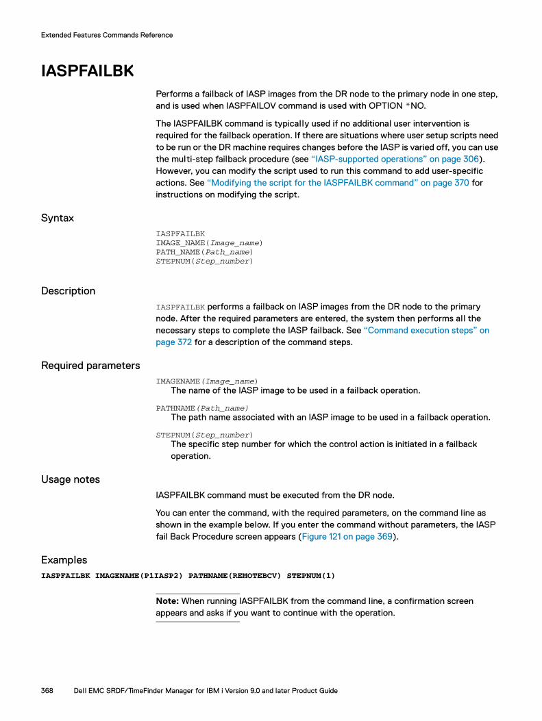
Extended Features Commands Reference
IASPFAILBKPerforms a failback of IASP images from the DR node to the primary node in one step, and is used when IASPFAILOV command is used with OPTION *NO.
The IASPFAILBK command is typically used if no additional user intervention is required for the failback operation. If there are situations where user setup scripts need to be run or the DR machine requires changes before the IASP is varied off, you can use the multi-step failback procedure (see “IASP-supported operations” on page 306). However, you can modify the script used to run this command to add user-specific actions. See “Modifying the script for the IASPFAILBK command” on page 370 for instructions on modifying the script.
SyntaxIASPFAILBKIMAGE_NAME(Image_name)PATH_NAME(Path_name)STEPNUM(Step_number)
DescriptionIASPFAILBK performs a failback on IASP images from the DR node to the primary node. After the required parameters are entered, the system then performs all the necessary steps to complete the IASP failback. See “Command execution steps” on page 372 for a description of the command steps.
Required parametersIMAGENAME(Image_name)
The name of the IASP image to be used in a failback operation.
PATHNAME(Path_name)The path name associated with an IASP image to be used in a failback operation.
STEPNUM(Step_number)The specific step number for which the control action is initiated in a failback operation.
Usage notesIASPFAILBK command must be executed from the DR node.
You can enter the command, with the required parameters, on the command line as shown in the example below. If you enter the command without parameters, the IASP fail Back Procedure screen appears (Figure 121 on page 369).
ExamplesIASPFAILBK IMAGENAME(P1IASP2) PATHNAME(REMOTEBCV) STEPNUM(1)
Note: When running IASPFAILBK from the command line, a confirmation screen appears and asks if you want to continue with the operation.
368 Dell EMC SRDF/TimeFinder Manager for IBM i Version 9.0 and later Product Guide
Extended Features Commands Reference
Figure 121 IASP Fail Back Procedure screen
Command execution stepsThe IASPFAILBK command does the following:
1. Checks the IASP files for valid input and configuration.
2. Checks the local IASP status to ensure it is offline.
3. Checks the SRDF status to ensure it is in failed over state.
4. Checks that the remote system is active.
5. Checks the remote IASP status to ensure it is offline.
6. Removes the IOAs for both the source and target IASP.
7. Carries out the failback operation.
8. Once failback is complete, adds an IOA for the user-selected IASP and step number on the primary node.
9. Varies on the user-selected IASP image on the primary node.
IASPFAILBK 369

Extended Features Commands Reference
Modifying the script for the IASPFAILBK commandUser-specific actions can be included in the IASPFAILBK command by editing the script that generates the failback command, as follows:
Note: In the EMCCTLC client library there is a Source Physical File called QCLSRC that contains the scripts needed for the failback operation, COMPILE.CLP and IASPFAILBK.CLLE.
1. Locate the IASPFAILBK.CLLE script and make desired changes to the script.
2. Compile the COMPILE.CLP script as follows:
CRTCLPGM PGM(EMCCTLC/COMPILE) SRCFILE(EMCCTLC/QCLSRC)
3. Execute the COMPILE program as follows:
CALL COMPILE PARM(<SRCLIB> <TGTLIB> <RELEASE>)Where:
– SRCLIB is the library where the IASPUTIL module and the QCLSRC file are located. Both files are located in the EMCCTLC library.
– TGTLIB is the library where the compiled programs wil l be located.
– RELEASE is the earliest operating system release level the program is al lowed to run on.
Running the COMPILE program generates the user-modified IASPFAILOV, IASPFAILBK, IASPTFBCK, and IASPTFEST commands and programs.
Note: The COMPILE.CLP can be also be edited and compiled (as shown in step 2 ).
370 Dell EMC SRDF/TimeFinder Manager for IBM i Version 9.0 and later Product Guide

Extended Features Commands Reference
IASPFAILOVPerforms a failover of IASP images from the primary node to the DR node in one step. To go back to the original state, run IASPFAILOV again on the DR node. When OPTION *NO is used the first time to do a failover, run the IASPFAILBK command to go back to the original state.
The IASPFAILOV command is typically used if no additional user intervention is required for the failover operation. If there are situations where user setup scripts need to be run, or the DR machine requires changes before the IASP is varied on, use the multi-step failover procedure (see “IASP-supported operations” on page 306). However, you can modify the script used to run this command to add user-specific actions. See “Modifying the script for the IASPFAILOV command” on page 373 for instructions on modifying the script.
SyntaxIASPFAILOVIMAGE_NAME(Image_name)PATH_NAME(Path_name)STEPNUM(Step_number)[OPTION(*NO|ESTABLISH|RESTORE)]
DescriptionIASPFAILOV performs a failover of IASP images from the primary node to the DR node. After the required parameters are entered, the system then performs all the necessary steps to complete the IASP failover. See “Command execution steps” on page 372 for a description of the command steps.
Required parametersIMAGE_NAME(Image_name)
The name of the IASP image to be used in a failover operation.
PATH_NAME(Path_name)The path name associated with an IASP image to be used in a failover operation.
STEPNUM(Step_number)The specific step number for which the control action is initiated in a failover operation.
Optional parametersOPTION(*NO|ESTABLISH|RESTORE)
Controls the failover operation:
*NO — Devices are left in the failed over state. This is the default.
ESTABLISH — With dynamic SRDF, the specified devices are failed over, swapped and then re-established. In SRDF asynchronous mode, consistency protection is automatically enabled after an ESTABLISH operation executes.
RESTORE — same as the ESTABLISH option except that after the swap, invalid tracks on the new R2 side (the original R1 side) are restored on the new R1 side (the original R2 side).
IASPFAILOV 371

Extended Features Commands Reference
Usage notesRun the IASPFAILOV command from the DR node.
You can enter the command from the command line with the required parameters, as shown in the example below. If you enter the command without parameters, the IASP fail over Procedure screen appears (Figure 122).
ExamplesIASPFAILOV IMAGENAME(P1IASP2) PATHNAME(REMOTEBCV) STEPNUM(1) OPTION(*NO)
Note: When running IASPFAILOV from the command line, a confirmation screen appears that asks if you want to continue with the operation.
Figure 122 IASP Fail Over Procedure screen
Command execution stepsThe IASPFAILOV command does the following:
1. Checks the IASP files for valid input and configuration.
2. Checks the local IASP status to ensure it is offline.
3. Checks the SRDF status to ensure it is synchronized.
4. Checks that the remote system is active.
5. Checks the remote IASP status to ensure it is offline.
6. Removes the IOAs for both the source and target IASP.
7. Carries out the failover operation.
8. Once failover is complete, adds an IOA for the user-selected IASP and step number.
9. Varies on the user-selected IASP image on the DR node.
372 Dell EMC SRDF/TimeFinder Manager for IBM i Version 9.0 and later Product Guide
Extended Features Commands Reference
Modifying the script for the IASPFAILOV commandYou can add user-specific actions to the IASPFAILOV command by editing the script that generates the command, as follows:
Note: In the EMCCTLC client library there is a Source Physical File called QCLSRC that contains the scripts needed for the failback operation, COMPILE.CLP and IASPFAILOV.CLLE.
1. Locate the IASPFAILOV.CLLE script and make desired changes to the script.
2. Compile the COMPILE.CLP script as follows:
CRTCLPGM PGM(EMCCTLC/COMPILE) SRCFILE(EMCCTLC/QCLSRC)
3. Execute the COMPILE program as follows:
CALL COMPILE PARM(<SRCLIB> <TGTLIB> <RELEASE>)Where:
– SRCLIB is the library where the IASPUTIL module and the QCLSRC file are located. Both files are located in the EMCCTLC library.
– TGTLIB is the library where the compiled programs are located.
– RELEASE is the earliest operating system release level the program can run on.
Running the COMPILE program generates the user-modified IASPFAILOV, IASPFAILBK, IASPTFBCK, and IASPTFEST commands and programs.
Note: The COMPILE.CLP can be also be edited and compiled (as shown in step 2 ).
IASPFAILOV 373
Extended Features Commands Reference
IASPFILERemoves image information.
SyntaxIASPFILEACTION(Control_action)IMAGENAME(image_name)[PATHNAME(pathname|*ALL)]
Description IASPFILE removes image information from the IASPs and ISRCIOA files for a specified image.
Required parametersACTION(Control_action)
Specifies the control action to perform:
• RMVIASPIMG — removes image information.
IMAGENAME(image_name)The name of the image.
Optional parametersPATHNAME(path_name|*ALL)
The name of the path associated with the image specified in the IMAGENAME parameter. Use *ALL to specify all paths of the image specified in the IMAGENAME parameter.
Usage notesTo remove image information run the command from each node in the DR setup.
ExamplesIASPFILE ACTION(RMVIASPIMG) IMAGENAME(IASPIMAGE) PATHNAME(*ALL)
374 Dell EMC SRDF/TimeFinder Manager for IBM i Version 9.0 and later Product Guide
Extended Features Commands Reference
IASPTFBCKPrepares the source and target node for TimeFinder backup operations on IASPs.
IASPTFBCKIMAGE_NAME(Image_name)PATH_NAME(Path_name)STEPNUM(Step_number)[SNAPVX(*YES|*NO)]SPLIT_MODE(CHG_ASP_ACT|SPLITWA|MAINTENANCE)[SNAPVXNAME(snapshot_name)][SNAPVXGEN(snapshot_generation)][SNAPVXTTL(DAYS|DATE)][LINK_MODE(NOCOPY|COPY)][TTL_DAYS(1-400)][TTL_DATE(Date)]
DescriptionPrepares the source and target node for TimeFinder backup operations on IASPs. After the required parameters are entered, the system performs all the necessary steps to prepare the source and target nodes for backup. See “Command execution steps” on page 377 for a description of the command steps.
Required parametersIMAGE_NAME(Image_name)
The name of the IASP image to be used in a backup operation.
PATH_NAME(Path_name)The path name associated with an IASP image to be used in a backup operation.
STEPNUM(Step_number)The specific step number for which the control action is initiated in a backup operation.
SPLIT_MODE(CHG_ASP_ACT|SPLITWA|MAINTENANCE)Specifies the method for stopping writes to the devices in the image:
CHG_ASP_ACT — Executes the operation after suspending initiation of new transactions and operations.
Note: The selected IASP image that uses the Change ASP Activity CL command (CHGASPACT) is quiesced at the start of new commitment control transactions, new database change operations, and new Integrated File System (IFS) change operations. The command suspends initiation of new transactions and operations before the split, writes changes to auxiliary storage, and resumes initiations of new transactions and operations after the split.
SPLITWA - Executes the operation after holding I/Os on the array. It splits a local or remote BCV, Clone, or Snap image while the source system is operational. The resulting image is consistent and holds data upon the last commit.
With TimeFinder/CG (SPLITWA) operations, you do not have to put the selected IASP in the quiesced state.
IASPTFBCK 375
Extended Features Commands Reference
SRDF/TimeFinder Manager client (the DR node) and the controlling host must have a gatekeeper configured on each locally attached array. When using the same controlling host for Primary and DR nodes, the controlling host must have additional gatekeeper device configured on each remotely attached array (local to the DR node). For detailed information on array gatekeeper management, refer to the Dell EMC Solutions Enabler Installation and Configuration Guide.
On the client, the netcnfg file must be configured using the “CRTNETCNFG” command. This ensures that correct information (node name, IP address, port, and security level) points to the remote server. Only non-secure connections are supported for IBM i.
Note: When using this split type, the data in main memory is not included in the image. Only use SPLITWA when the host and applications are in a quiescent state. If this is not suitable for your business needs, use other operating system functions such as journaling and database commitment control to create an image that includes the last transaction.
MAINTENANCE — Splits or suspends SRDF links or split BCV pairs or activates a virtual copy session or Clone copy session in maintenance mode (that is, no interference with host operations).
Optional parametersSNAPVX
Controls whether the system displays values of the parameters relating to SnapVX to the user. Set the value to *YES to display the values. The default value is *NO.
SNAPVXNAMEThe name of the Snapshot.
SNAPVXGEN The Generation of the Snapshot. For al l SnapVX control actions, except ESTABLISH, specifies the generation of the existing snapshots to be operated on. If set to zero, the most recent snapshot is used for the control action.
SNAPVXTTL The Time to Live for the Snapshot. The possible values are:
DAYS -Specifies the time to live in days.
DATE - Specifies a date for the snapshot time to live.
If you do not specify a value, the Time to Live is set to unlimited and the Snapshot is kept until manually terminated.
LINK_MODE(NOCOPY|COPY) The mode used for a LINK SnapVX operation. Options are as follows:
NOCOPY —The target does not retain point-in-time data once the link is removed, and any previous target data is lost. This is the default.
COPY — Data is physically copied to the target devices. When the link is terminated the data is retained on the target.
TTL_DAYS Time to Live in days. The value in days can be set to any value between 1 and 400.
376 Dell EMC SRDF/TimeFinder Manager for IBM i Version 9.0 and later Product Guide

Extended Features Commands Reference
TTL_DATE Specifies a date for the snapshot time to live in the form MM/DD/YYYY (month/day/year) with reference to the host time. The specified date may be up to 400 days in the future.
Usage notesThe IASPTFBCK command must be executed from the target node, and the STM server must be running.
ExamplesYou can enter the command from the command line with the required parameters, as shown in the example below. If you enter the command without parameters, the IASP TimeFinder Backup Procedure screen appears (Figure 123).
IASPTFBCK IMAGE_NAME(P1IASP2) PATH_NAME(REMOTEBCV) STEPNUM(2)SPLIT_MODE(SPLITWA)
Figure 123 IASP TimeFinder Backup procedure screen
Command execution steps1. Checks the IASP files for valid input and configuration.
2. Checks the local IASP status to ensure it is offline.
3. Checks that the source system is up.
4. Checks that the link status is Synchonized, Precopy or Recreated.
5. Carries out the Split/Activate control action.
6. Adds the target IOAs and varies on the target node.
7. Checks that the source IASP status is offline.
8. Removes the IOAs for the IASP from the source and target system.
IASPTFBCK 377
Extended Features Commands Reference
Modifying the script for the IASPTFBCK commandYou can add user-specific actions to the IASPTFBCK command by editing the script that generates the command, as follows:
Note: In the EMCCTLC client library, there is a Source Physical File called QCLSRC that contains the scripts needed for the failback operation, COMPILE.CLP and IASPTFBCK.CLLE.
1. Locate the IASPTFBCK.CLLE script and make desired changes to the script.
2. Compile the COMPILE.CLP script:
CRTCLPGM PGM(EMCCTLC/COMPILE) SRCFILE(EMCCTLC/QCLSRC)
3. Execute the COMPILE program:
CALL COMPILE PARM(<SRCLIB> <TGTLIB> <RELEASE>)Where:
– SRCLIB is the library where the IASPUTIL module and the QCLSRC file are located. Both files are located in the EMCCTLC library.
– TGTLIB is the library where the compiled programs are located.
– RELEASE is the earliest operating system release level the program can run on.
Running the COMPILE program generates the user-modified IASPFAILBK, IASPTFBCK, and IASPTFEST commands and programs.
4. The COMPILE.CLP can be also be edited and compiled (as shown in step 2 ).
378 Dell EMC SRDF/TimeFinder Manager for IBM i Version 9.0 and later Product Guide

Extended Features Commands Reference
IASPTFESTPrepares the source and target to go back to original state prior to running the IASPTFBCK operation.
IASPTFESTIMAGE_NAME(Image_name)PATH_NAME(Path_name)STEPNUM(Step_number)
DescriptionPrepares the source and target to go back to original state prior to running the IASPTFBCK operation. After the required parameters are entered, the system then performs all the necessary steps to prepare the source and target nodes for restore. See “Command execution steps” on page 380 for a description of the command steps.
Required parametersIMAGE_NAME(Image_name)
The name of the IASP image to be used in a restore operation.
PATH_NAME(Path_name)The path name associated with an IASP image to be used in a restore operation.
STEPNUM(Step_number)The specific step number for which the control action is initiated in a restore operation.
Usage notesRun the IASPTFEST command from the target node.
ExamplesYou can enter the command can be executed from the command line with the required parameters, as shown in the example below. If you enter the command without parameters, the IASP TimeFinder restore Procedure screen appears (Figure 121 on page 369).
IASPTFEST IMAGE_NAME(P1IASP2) PATH_NAME(REMOTEBCV) STEPNUM(2)
Figure 124 IASP TimeFinder Restore procedure screen
IASPTFEST 379

Extended Features Commands Reference
Command execution steps1. Checks the IASP files for valid input and configuration.
2. Checks that the local IASP status is offline.
3. Checks that the source system is up.
4. Removes the IOAs for the IASP from the target system.
5. Carries out an ESTABLISH/CREATE control action.
6. Carries out ADDIOA on the source node.
7. Varies on the source IASP.
Modifying the script for the IASPTFEST commandYou can add user-specific actions to the IASPTFEST command by editing the script that generates the command, as follows:
Note: In the EMCCTLC client library there is a Source Physical File called QCLSRC that contains the scripts needed for the failback operation, COMPILE.CLP and IASPTFEST.CLLE.
1. Locate the IASPTFEST.CLLE script and make desired changes to the script.
2. Compile the COMPILE.CLP script:
CRTCLPGM PGM(EMCCTLC/COMPILE) SRCFILE(EMCCTLC/QCLSRC)
3. Execute the COMPILE program:
CALL COMPILE PARM(<SRCLIB> <TGTLIB> <RELEASE>)Where:
– SRCLIB is the library where the IASPUTIL module and the QCLSRC file are located. Both files are located in the EMCCTLC library.
– TGTLIB is the library where the compiled programs wil l be located.
– RELEASE is the earliest operating system release level the program is al lowed to run on.
Running the COMPILE program generates the user-modified IASPFAILBK, IASPTFBCK, and IASPTFEST commands and programs.
4. The COMPILE.CLP can be also be edited and compiled (as shown in step 2 ).
380 Dell EMC SRDF/TimeFinder Manager for IBM i Version 9.0 and later Product Guide

Extended Features Commands Reference
RELDEVLCKChecks and releases device external locks (DEL) on an array for any image.
See “RELDEVLCK” on page 215.
RELDEVLCK 381

Extended Features Commands Reference
RELDEVLCKCChecks and releases device external locks (DEL) on an array for any image on the target side.
See “RELDEVLCKC” on page 216.
382 Dell EMC SRDF/TimeFinder Manager for IBM i Version 9.0 and later Product Guide

Extended Features Commands Reference
RTVSTMINFReturns status information for the selected image, path, and step. It also returns SRDF/TimeFinder Manager, Solutions Enabler, Enginuity, and IO driver and release level information.
See “RTVSTMINF” on page 217.
RTVSTMINF 383

Extended Features Commands Reference
SETRDFMODSets the SRDF mode for a selected image.
See “SETRDFMOD” on page 231.
384 Dell EMC SRDF/TimeFinder Manager for IBM i Version 9.0 and later Product Guide

Extended Features Commands Reference
SETRDFMODCSets the SRDF mode for a selected image on the target side.
SyntaxSETRDFMODC IMAGE_NAME(image_name) PATH_NAME(path_name) STEPNUM(step_number) MODE_TYPE(SYNC|ASYNC|ACDM|ACWP)
DescriptionSETRFDMODC sets the SRDF mode (synchronous, asynchronous, adaptive copy disk mode (ACDM), and adaptive copy write pending (ACWP)) for a selected image on the target side only. You must specify the image name, path name, and the SRDF mode associated with the image.
Note: SRDF mode adaptive copy write pending (ACWP) is not supported when the R1 mirror of the RDF pair is on an array running PowerMaxOS 5978 or HYPERMAX OS 5977. For this configuration, the SETRDFMODC command returns an error if the mode is set to adaptive copy write pending. In this case, set a different mode.
Required parametersIMAGE_NAME(image_name)
The name of the image to be used in an SRDF control operation.
PATH_NAME(path_name)The name of the path for the image to be used in an SRDF operation.
STEPNUM(step_number)The specific step number for which the control action is initiated in an SRDF control operation.
MODE_TYPE(SYNC|ASYNC|ACDM|ACWP)The parameter that sets the SRDF mode for a selected image to synchronous, asynchronous, adaptive copy disk mode, or adaptive copy write pending.
IMPORTANT
Do not use ACWP or ACDM mode for SRDF while creating RDF or remote TimeFinder images (split) using SRDF/TimeFinder Manager. This is not supported. Instead, use Sync or Async mode.
Usage notesAll control commands executed on the DR or backup node use the image file built on the primary node and sent to the corresponding node. The path and step parameters should use the path name and step used on the primary node for corresponding devices.
ExamplesSETRDFMODC IMAGE_NAME(PIASP2) PATH_NAME(SRDFA) STEPNUM(1) MODE_TYPE(SYNC)SETRDFMODC IMAGE_NAME(PIASP2) PATH_NAME(SRDFA) STEPNUM(1) MODE_TYPE(ASYNC)SETRDFMODC IMAGE_NAME(PIASP2) PATH_NAME(SRDFA) STEPNUM(1) MODE_TYPE(ACDM)
SETRDFMODC 385
Extended Features Commands Reference
SRDFDRCTLProcesses SRDF control actions for IASP images on the source host during disaster recovery situations.
SyntaxSRDFDRCTL IMAGE_NAME(Image_name) PATH_NAME(Path_name)STEPNUM(Step_number) ACTION(Control_action) [option(*NO|ESTABLISH|RESTORE)]
DescriptionSRDFDRCTL processes SRDF control actions for IASP images on the target (R2) side.
Required parametersIMAGE_NAME(Image_name)
The name of the IASP image to be used in an SRDF control operation.
PATH_NAME(Path_name)The path name associated with an IASP image to be used in an SRDF operation.
STEPNUM(Step_number)The specific step number for which the control action is initiated in an SRDF operation.
ACTION(Control_action)Specifies the control action to perform:
FAILOVER — Switches data processing from the source (R1) side to the target (R2) side. If the source (R1) is operational, FAILOVER suspends I/O traffic on the RDF links and write disables devices on the source (R1) side to their hosts. FAILOVER then write enables the devices on the target side to their local hosts. When running in SRDF asynchronous mode and a FAILOVER is executed, the consistency protection is disabled and then the FAILOVER operation is performed.
With dynamic RDF, when you specify the ESTABLISH option, devices failover, swap, and then re-establish.
Note: With control action FAILOVER with the ESTABLISH option or the RESTORE flag is set, and the R2 mirror of the SRDF pair are on an array running PowerMaxOS 5978 or HYPERMAX OS 5977, the RDF mode is automatically set to Adaptive Copy Disk
In SRDF/A mode, consistency protection is automatically enabled after an ESTABLISH operation executes.
For dynamic RDF, if option RESTORE is specified, devices failover, swap and then re-establish. Invalid tracks on the new R2 side (originally the R1 side) are restored to the new R1 side (formerly the R2 side).
When running in SRDF asynchronous mode, consistency protection is automatically enabled after executing an RESTORE operation.
386 Dell EMC SRDF/TimeFinder Manager for IBM i Version 9.0 and later Product Guide

Extended Features Commands Reference
FAILBACK — Performs a source (R1) device takeover when you are ready to resume normal SRDF operations by initiating read/write operations on the source (R1) devices, and stopping read/write operations on the target (R2) devices. The target (R2) devices become read-only to their local hosts while the source (R1) devices are read/write enabled to their local hosts.
Note: In SRDF/A mode, consistency protection is automatically enabled after a FAILBACK operation executes.
RESTORE — Restores data from SRDF R2 data devices back to source devices.
The new data, that was updated on the target (R2) device while the SRDF pair was split, is copied to the source (R1) device. Any changed tracks on the source (R1) device are refreshed from the corresponding tracks on the target (R2) device. After the restore operation has successfully completed, the SRDF pairs synchronize. The RTVSMINF command can be used to confirm that the SRDF pairs are in a Synchronized state.
Note: The CLACT and IASPCTL commands using control action STATUS or the Work with Associated Paths screen can be used to confirm the status of SRDF pairs.
When an incremental restore is initiated for each specified SRDF pair in a device file:
– The source (R1) device is write disabled for the local hosts.
– The target (R2) device is write disabled for the local hosts.
– Data traffic is suspended on the SRDF links.
– The invalid tracks on the source (R1) device are refreshed with the changed tracks on the target (R2) side. The R1 and R2 track tables are merged.
– Traffic is resumed on the SRDF links.
– The source (R1) device is read/write enabled for the local hosts.
– The SRDF pair is in the Synchronized state when the source (R1) device and the target (R2) device contain identical data.
– The incremental restore operation wil l be rejected if the target has invalid local (R2) tracks.
Note: In SRDF/A mode, consistency protection is automatically enabled after a RESTORE operation executes.
Option(*NO|ESTABLISH|RESTORE)Controls the failover operation:
*NO — Devices are left in the failed over state. This is the default.
ESTABLISH — With dynamic SRDF, the specified devices are failed over, swapped and then re-established. When running in SRDF asynchronous mode, consistency protection is automatically enabled after executing an ESTABLISH operation.
RESTORE — Same as the ESTABLISH option except that after the swap, invalid tracks on the new R2 side (the original R1 side) are restored on the new R1 side (the original R2 side).
SRDFDRCTL 387

Extended Features Commands Reference
ExamplesSRDFDRCTL IMAGE_NAME(DISKPOOL) PATH_NAME(REMOTEBCV) STEPNUM(1) ACTION(FAILOVER) OPTION(ESTABLISH)
388 Dell EMC SRDF/TimeFinder Manager for IBM i Version 9.0 and later Product Guide

Extended Features Commands Reference
STMRMTCMD Runs remote commands.
See “STMRMTCMD” on page 234.
STMRMTCMD 389
Extended Features Commands Reference
STRSTMSRVStarts the SRDF/TimeFinder Manager server job.
See “STRSTMSRV” on page 240.
390 Dell EMC SRDF/TimeFinder Manager for IBM i Version 9.0 and later Product Guide
APPENDIX HExtended Features Messages
Invisible Body Tag
This appendix provides reference information about messages that may display for the extended features components, the reason for the message, and the recommended user action. See “Standard Features Messages” on page 245 for messages that may display for standard feature components.
IAP0001Application is waiting for synchronization to finish.
Cause: SRDF/TimeFinder Manager is waiting for device synchronization to complete.
Action: This is an informational message; no user action is necessary.
IAP0002Application is waiting for split to finish.
Cause: SRDF/TimeFinder Manager is waiting for a Split operation to complete.
Action: This is an informational message; no user action is necessary.
IAP0003Operation is not supported, please check product guide.
Cause: The attempted operation is not supported with IASP images.
Action: Refer to the appropriate section in this guide.
IAP0004Operation failed, please use option #16 to configure the primary IASP.
Cause: The attempted operation on the primary IASP failed.
Action: Reconfigure the primary IASP and try the operation again.
IAP0005ASP number in IASP file does not match ASP number generated by
operating system, there might be an IASP system setup error.
Cause: The check to verify the IASP number returned an IASP number mismatch.
Action: Refer to the MATRMD section in the IBM documentation for details and take the following steps to verify the status of the IASP. Use SST to verify that al l IOAs have been successfully added to the system and the devices are active.
If al l devices in the IASP are active, use WRKCFGSTS CFGTYPE(*DEV) CFGD(IASP name) to verify the IASP status. If this was an ADDIOA operation, and the IOAs are on the system and the devices are active, continue with the VARYON of the IASP. If the IASP status is 'AVAILABLE', normal IASP operations can continue.
Extended Features Messages 391

Extended Features Messages
IAP0006Failure opening ISRCIOA file with member &1 on node &2.
Cause: ISRCIOA file with member &1 was not found or was not able to be opened.
Action: Make sure that correct image name is used or that the product installation is completed successfully.
IAP0007No IOAs of the target devices are found in file ISRCIOA.
Cause: The IOA serial numbers of the target devices are not present in the ISRCIOA file.
Action: Rebuild the target device IOA file as documented in “Building/rebuilding the IOA file” on page 298.
IAP0008The device SYMAPI status must be Synchronized/Created before a Split/Activate can occur.
Cause: An attempt was made to Split or Activate a device before the device has been synchronized or created.
Action: Correct the mistake and then attempt the Split or Activate operation again.
IAP0009ISRCIOA file with member &1 on node &2 has no records.
Cause: ISRCIOA file with member &1 has no records. Make sure that the configuration process completed correctly.
Action: Rebuild the IOA file for both source devices and target devices as documented in “Building/rebuilding the IOA file” on page 298.
IAP0010Application is locating disk units.
Cause: Missing disk units appear in the selected IASP.
Action: Wait until al l missing disk units report for the selected IASP.
IAP0011Missing disk units are detected in IASP prior to varying on the IASP.
Cause: Not all missing disk units report in the IASP image.
Action: Reset one or more IOAs to recover them. If the problem persists, IPL the host.
IAP0012Devices need to be varied off before removal.
Cause: One or more selected devices must be varied off before removal.
Action: Vary off the selected devices.
392 Dell EMC SRDF/TimeFinder Manager for IBM i Version 9.0 and later Product Guide
Extended Features Messages
IAP0013Missing disk units are detected in IASP prior to varying on IASP.
Cause: Not all missing disk units report in the IASP image.
Action: Complete adding one or more IOAs before varying on the IOAs. If ADDIOA has been completed, try resetting the IOAs to recover the IASP devices. If the problem persists, IPL the host.
IAP0014Devices must be varied on before rebuilding ISRCIOA file.
Cause: The selected devices are not varied off.
Action: Vary on the devices to make them available.
IAP0015File IASPS does not exist.
Cause: The file IASPs does not exist for the configuration.
Action: Make sure the installation completed successfully.
IAP0016Cannot locate IASPS record to be sent.
Cause: The record for the selected IASP does not exist.
Action: Reconfigure the selected IASP.
IAP0017Socket communication failed, the operation is SEND.
Cause: The socket communication failed for the SEND operation.
Action: Check the TCP/IP configuration and hardware.
IAP0018Socket communication failed, the operation is RECEIVE.
Cause: The socket communication failed for the RECEIVE operation.
Action: Check the TCP/IP configuration and hardware.
IAP0019&1 finished successfully, please check job log for detail.
Cause: The operation finished successfully.
Action: This is an informational message; no user action is necessary.
393

Extended Features Messages
IAP0020&1.
Cause: This is the result of a specific action that is determined when the operation occurs.
Action: The corrective action to take, if any, depends on the operation performed. Most often this is an informational message; no user action is necessary.
IAP0021&1.
Cause: This is the result of a specific action that is determined when the operation occurs.
Action: The corrective action to take, if any, depends on the operation performed. Most often this is an informational message; no user action is necessary.
IAP0022Range of port number does not include value entered, or parameterentered for the port number must be numeric
Cause: The value specified for the port number must be a numeric value that is greater than or equal to 1 or less than or equal to 65535.
Action: Enter a numeric value that is within the specified range.
IAP0023RESTORE action not allowed for path with R21 configured.
Cause: Path has R21 configured and cannot be used to do a restore.
Action: Select correct path and try again.
IAP0024Parameter NODENAME required.
Cause: A required parameter was not specified.
Action: Enter a value for parameter NODENAME.
IAP0025Parameter TGTNAME required.
Cause: A required parameter was not specified.
Action: Enter a value for parameter TGTNAME.
394 Dell EMC SRDF/TimeFinder Manager for IBM i Version 9.0 and later Product Guide

Extended Features Messages
IAP0026 Node with name &2 not found in cluster.
Cause: Node name entered cannot be found in list of nodes that are configured in the cluster on this system.
Action: Enter a valid node name or add the node to the cluster and try again.
IAP0027Cluster information could not be retrieved.
Cause: Cluster information could not be retrieved.
Action: Check if a cluster is configured correctly on this system. Cluster information is collected into a user space before processing. Check if user space CLUINFO is created in library SYMAPI.
IAP0028Split operation is not allowed for VP Snap copy sessions.
Action: Use a valid control action for the selected path and try again.
IAP0029Node name &1 not found in IASP file.
Cause: Node name &1 cannot be found in IASP file for selected image &2 path &3 and step
Action: Make sure that configuration is completed correctly and the IASP file contains the correct node name for the selected image path and step that is used.
IAP0030&1 Node name &2 not valid for this control action.
Cause: &1 Node name &2 cannot be used or is not valid for this control action.
Action: Make sure that node name &2 is valid for selected control action.
IAP0031Failure opening IASPS file on node &1.
Cause: IASPS file was not found or was not able to be opened.
IAP0032IASPS file on node &1 has no records.
Cause: IASPS file has no records. Make sure that the configuration process completed correctly.
395
Extended Features Messages
IAP0033Record read from IASPS file for selected image/path/step does not contain correct data.
Cause: Expected amount of data read from IASPS file did not match required data length.
Action: Make sure that the configuration process (option #16) completed correctly for selected image. Check if there is an entry for this image in the IASP file.
IAP0034Previous step is not configured. Previous step &4 not found in IASP file for image &1 path &2.
Cause: Previous step &4 need to be configured first before using configuring step &3
Action: Make sure that the configuration process (option #16, or IASPCTL with option CONFIG) completed correctly for step &4 before attempting to configure step &3.
IAP0035IASP status on node &1 could not be retrieved.
Action: Check joblog for details.
IAP0036IASP &1 on node &2 with path &3 step &4 is not eligible for control action &5.
Cause: Selected control action cannot be used with this path.
Action: Use a different control action with this path type.
IAP0037&1 IOA(s) connected to IASP &2 and path &3 step &4 on node &5 are stillactive.
Cause: IOAs for selected IASP &2 are stil l active.
Action: In order to complete this control action, the IOAs need to be deactivated (removed) first.
IAP0038&1 IOA(s) connected to IASP &2 and path &3 step &4 on node &5 are already deactivated (removed.
Cause: IOAs for selected IASP &1 are already deactivated (removed).
IAP0039&1 IOA(s) connected to IASP &2 and path &3, step &4 on node &5 arealready activated (added).
Cause: IOAs for selected IASP &1 are already activated (added).
396 Dell EMC SRDF/TimeFinder Manager for IBM i Version 9.0 and later Product Guide

Extended Features Messages
IAP0040IOA(s) connected to IASP &1 and path &2 step &3 on node &4 are not inthe same state.
Cause: IOAs for selected IASP &1 are not in the same state.
Action: Use SST to check the state of the IOAs that are connected to this IASP.
IAP0041One or more of the IOA(s) for IASP &1 and path &2 step &3 on node &4 is not dedicated.
Cause: To be able to activate or deactivate IOAs connected to this IASP &1, it is required that the IOAs are NOT shared between ASPs.
Action: Use SST to check the state of the IOAs that are connected to this IASP. Change configuration of the IOAs and retry.
IAP0042Could not find any IOA configured for IASP &1 and path &2 step &3 on node &4.
Cause: IOAs for selected IASP &1 could not be found.
Action: Make sure that the configuration was completed correctly. Use SST to check the state of the IOAs that are connected to this IASP.
IAP0043Could not detect status of the IOAs configured for IASP &1 and path &2 step &3 on node &4.
Cause: Status IOAs for selected IASP &1 could not be retrieved.
Action: Make sure that the configuration was completed correctly. Use SST to check the state of the IOAs that are connected to this IASP.
IAP0044IASP &1 has IOAs activated for other path &2 step &3 on node &4.
Cause: IASP &1 has IOAs active for paths that have same image and target node.
Action: Make sure that IASP &1 is only presented once to the node. Use SST to check the state of the IOAs that are connected to this IASP.
IAP0045HA IASP Operation &1 failed. Selected node name &2 is equal to local node name.
Cause: Selected node name &2 that is going to act as the HA node is equal to local node name.
Action: Use a different node name for the HA node. Change input and try again.
397

Extended Features Messages
IAP0046The STM Server job on the Primary node &2 is still active during HA IASP operation &1.
Cause: The STM Server job on primary node &2 as defined in the IASP file is stil l active.
Action: Stop the STM Server job on the primary node &2 and try again.
IAP0047HA IASP operation &1 failed.
Cause: Command &2 failed.
Action: Check joblog for details.
IAP0048Disk management operation failed for IASP &1 on node &2.
Cause: Maybe a SST session is already active on the selected node.
Action: End all SST sessions, IBM i Access sessions and any other programs that have access to DASD management tools and try again.
IAP0049STM Server on node &1 with port number &2 not ended.
Action: Check joblog for details.
IAP0050STM Server with port number &1 ended.
IAP0051Data queue not found.
Cause: API &1 failed with message id &2.
Action: Check joblog on remote node for details.
IAP0052Data queue read failed.
Cause: API &1 returned no data.
Action: Check job log on remote node for details.
IAP0053User space not created.
Cause: API QUSCRTUS failed with message id &1.
Action: Check job log on remote node for details.
398 Dell EMC SRDF/TimeFinder Manager for IBM i Version 9.0 and later Product Guide
Extended Features Messages
IAP0054User space pointer not resolved.
Cause: API &1 failed with message id &2.
Action: Check job log on remote node for details.
IAP0055Spawn process failed.
Path to program : &1.
Cause: &2
Action: Check job log on remote node for details.
IAP0056Command failed with message id &1.
Command: &2
Action: Check job log for details.
IAP0057Spool file info not found.
Cause: API &1 failed with message id &2.
Action: Check joblog on remote node for details.
IAP0058Remote command work file &1 open failed.
Cause: &2
Action: Check job log on remote node for details.
IAP0059Spool file information not received.
Cause: Number of spool files received from STM server is 0.
Action: Check job log on remote node for details.
IAP0060Remote command failed with message id &1.Command: &4.
Action: Check file &2 on this node or check joblog for job &3 on remote node for details.
IAP0061Job information not found.
Action: Check job log on remote node for details.
399

Extended Features Messages
IAP0062Failure opening PATH file on node &1.
Cause: PATH file was not found or was not able to be opened.
IAP0063Path &1 was not found for the iasp image &2.
Cause: Path name could not be found in list.
Action: Enter appropriate path name or check if configuration completed correctly and try operation again.
IAP0064Step number &1 was not found for the path &2 and image &3.
Cause: Step number could not be found in list.
Action: Enter appropriate step or check if configuration completed correctly and try operation again.
IAP0065Snapshot name is not valid.
Action: Provide a valid snapshot name and try the operation again.
IAP0066Snapshot generation value is not valid.
Action: Provide a valid value for the generation option and try the operation again
IAP0067Snapshot time to live (TTL) value is not valid.
Action: Provide a valid time to live value and try the operation again.
IAP0068New snapshot name is not valid.
Action: Provide a valid new snapshot name and try the operation again.'
IAP0069Invalid date specified.
Cause: A date is not in the required format of MM/DD/YYYY, with reference to the current node date.
Action: Provide a date in the required format that is up to 400 days in the future from the current node date and try the operation again.
400 Dell EMC SRDF/TimeFinder Manager for IBM i Version 9.0 and later Product Guide
Extended Features Messages
IAP0070Remote command not allowed to run.Command: &1.
Cause: Commands allowed to run are all commands included in the STM product library. Also the following IBM commands can be run through the STM server: PING, APING, DSPASPSTS, VRYCFG, VFYTCPCNN, and WRKCFGSTS.
Action: Either change the command or use the REXEC server to execute the unsupported commands
IAP9897Command &1 failed.Recovery.............: Check joblog for details
Cause: The command &1 failed to complete.
Action: Check the job log for cause.
IAP9898Command &1 finished successfully.
Cause: Notification that the command &1 completed successfully.
Action: Informational message. No action is necessary.
401

Extended Features Messages
402 Dell EMC SRDF/TimeFinder Manager for IBM i Version 9.0 and later Product Guide
GLOSSARY
This glossary contains terms related to business continuance operations and disk storage subsystems as they relate to Dell EMC SRDF/TimeFinder Manager for IBM i and Dell EMC arrays.
Aadapter Card that provides the physical interface between the director and disk devices,
director and serial channels (Serial adapter).
ASPs Individual disks (storage units) or sets of disks reserved for particular objects (such as libraries). ASPs help organize data to limit the impact of storage-device failures and reduce recovery time. ASPs can be used to isolate those objects to facilitate backup and recovery.
Bbackup node The partition or host that is the secondary owner for a particular IASP. The backup
node has target devices connected to it.
BCV devices Standard array devices with special attributes that al low the devices to independently support applications and processes. BCVs are active production images that are logically or physically separate from the production volumes with no reliance on the production host, thus providing protection from physical or logical corruption. Once the BCV task is complete, the volume can be resynchronized with the production volume, reassigned to another production volume, or maintained “as is” for another task. See also ”standard devices.”
BCV mirror A standard device mirror (one of M2, M3, or M4) assigned to the BCV device upon establishing or re-establishing a BCV pair. See also ”establish,” “re-establish” and “BCV pair.”
BCV pair Consists of a standard device and a BCV device attached together.
business continuance(BC) processes
Processes that al low customers to access and manage instant copies of standard devices. See also ”establish,” “re-establish” and “Split.”
business continuancevolume (BCV)
See ”BCV devices.”
Ccache Random access electronic storage used to retain frequently used data from disk for
faster access by the channel.
cache slot Unit of cache equivalent to one track.
Dell EMC SRDF/TimeFinder Manager for IBM i Version 9.0 and later Product Guide 403
Glossary
channel director The component in the array subsystem that interfaces between the host channels and data storage. It transfers data between the channel and cache.
concurrent establishedBCV pair
The relationship that establishes two BCV devices as concurrent mirrors of a single standard device that allows two synchronized copies of the standard data to be created simultaneously.
consistency group A composite group is a user-defined group of devices that can span multiple arrays and, if needed, provide consistency protection. When an SRDF composite group is enabled for consistency protection, it is known as an SRDF consistency group. Consistency means that the devices within the group act in unison to preserve dependent-write consistency of a database that may be distributed across multiple arrays or multiple SRDF groups within a single . (A device group can be used for consistency protection if the group of devices is within a single SRDF group in a single array.)
CRG (Cluster Resourcegroup)
A Cluster resource group is a a set or grouping of cluster resources that are used to manage events that occur in a high availability environment.
DDA Disk Adapter. See ”disk director.”
data availability Access to any and all user data by the application.
DEFAULT_POOL A special Snap pool that exists by default. This pool contains SAVE devices that have not been assigned to any named pools but are available for Snap operations. SAVE devices in the DEFAULT_POOL are either enabled or disabled but have used tracks. See also ”Save pool” and “Snap pool.”
DATA device A device that holds the actual storage space for the data written to a thin device. DATA devices are located in a thin pool.
define BCV pair The process of identifying a BCV device and a standard device to be established.
delayed fast write No existence of room in cache for the data presented by the write operation.
dependent-write I/O An I/O that cannot be issued until a related predecessor I/O has completed. Most applications have embedded dependent-write logic to ensure data integrity in the event of a failure in the host or server processor, software, storage subsystem, or if an environmental power failure occurs.
dependent-writeconsistency
Dependent-write consistency is a data state where data integrity is guaranteed by dependent-write I/Os embedded in application logic. Database management systems are examples of applications that utilize the dependent-write consistency strategy.
destage The asynchronous write of new or updated data from cache to disk device.
device A uniquely addressable part of the array subsystem that consists of a set of access arms, the associated disk surfaces, and the electronic circuitry required to locate, read, and write data.
device address A hexadecimal value that uniquely defines a physical I/O device on a channel path. A SCSI address consists of a Target ID and a Logical Unit Number (LUN).
404 Dell EMC SRDF/TimeFinder Manager for IBM i Version 9.0 and later Product Guide
Glossary
device number The value that logically identifies a disk device in a string.
Direct access storagedevice (DASD)
Most commonly known as a magnetic disk device.
director The component in the array subsystem that allows the array to transfer data between the host channels and disk devices. See also ”channel director” and “disk director.”
disaster recovery The process of restoring a previous copy of the data and applying logs or other necessary processes to that copy to bring it to a known point of consistency.
disaster recovery (DR)node
The node that takes over when the primary node fails in a three-node solution.
disk director The component in the array subsystem that interfaces between cache and the disk devices.
disk pool An auxiliary storage pool (ASP) of disks only. See also ”ASPs.”
DR node See ”disaster recovery (DR) node.”
DSE pools SRDF uses SRDF/A DSE pools to extend the cache space available for SRDF/A cycles by off loading some or al l of the cycle data from cache to a pre-configured disk storage pool. Using SRDF/A DSE pools provides a safety net for running SRDF/A sessions. However, SRDF/A continues to operate normally with this feature disabled. See also ”Snap pool.”
DSS Decision Support Systems. Database software used to support management decision making. Database data is extracted and analyzed, but not modified.
dual-Initiator An array feature that automatically creates a backup data path to the disk devices serviced directly by a disk director if that disk director or the disk management hardware for those devices fails.
dynamic sparing An array feature that automatically transfers data from a failing disk device to an available spare disk device without affecting data availability. This feature supports all non mirrored devices in the array subsystem.
dynamic SRDF pairing The process of creating or deleting SRDF pairs while the array is in operation. Once created, these RDF pairs can be synchronized and managed the same as static RDF pairs that are paired during initial array configuration.
E
EA ESCON Adapter.
establish A Business Continuance process which assigns a BCV device as the next available mirror of a standard device.
established The BCV pair condition where the BCV device and standard device are synchronized and functioning as an array mirror. A BCV pair is established by the BCV commands establish and re-establish.
Dell EMC SRDF/TimeFinder Manager for IBM i Version 9.0 and later Product Guide 405
Glossary
Ffast-wide SCSI channel
directorThe component in the array subsystem that interfaces between host SCSI channels and data storage. It transfers data between the channel and cache.
FC Fibre Channel. See ”Fibre Channel director.”
Fibre Channel director The component in the array subsystem that interfaces between the host fibre channel interface and data storage. A Fibre Channel Director transfers data between the channel and cache.
Ggatekeeper A small logical volume used to pass SCSI commands from a host to the array.
Hhead and disk assembly
(HDA)A field replaceable unit in the array subsystem containing the disk and actuator.
hyper-volume extension The ability to define more than one logical volume on a single physical disk device making use of its full formatted capacity. These logical volumes are user-selectable in size. The minimum volume size is one cylinder and the maximum size depends on the disk device capacity and the mode selected.
IIASP An independent disk pool, or independent auxiliary storage pool (ASP). An IASP is a
collection of disks that can be brought online or taken offline independently from the remainder of the system’s storage, which includes the system ASP, user ASPs, and other independent disk pools. An IASP can be either:
◆ Switchable among multiple systems in a clustered environment. ◆ Privately connected to a single server.
identifier (ID) A sequence of bits or characters that identifies a program, device, controller, or system.
IFS Integrated File System.
image The ASP set that can be operated on simultaneously.
image types There are several image types (UDFS IASP or an image containing primary and all secondary IASPs that belong to the same ASP group). See also ”System image” and “UDFS.”
IML Initial microcode program loading.
incremental establish A time-saving operation similar to an Establish. The source (R1) device copies to the target (R2) device only the new data that was updated on the source R1 device while the SRDF pair was split. Any changed tracks on the target (R2) device are also refreshed from the corresponding tracks on the source (R1) device. The R2 device is write disabled to the target host.
406 Dell EMC SRDF/TimeFinder Manager for IBM i Version 9.0 and later Product Guide
Glossary
independent auxiliarystorage pool
See ”IASP.”
instant split A method of splitting a BCV that improves the performance of a typical split operation by performing a quick foreground BCV split, which reduces the time the application needs to be frozen and is shorter than using a regular Split.
I/O device An addressable input/output unit, such as a disk device.
K
Kilobyte (K) 1024 bytes.
L
least recently usedalgorithm (LRU)
The algorithm used to identify and make cache space available by removing the least recently used data.
logical partition A subset of a single IBM i host that contains resources (processors, memory, and input/output devices). A logical partition operates as an independent system. When hardware requirements are met, multiple logical partitions can exist within a system.
logical volume A user-addressable unit of storage. In the array subsystem, the user can define multiple logical volumes on a single physical disk device. Logical volumes can reside on an SRDF-enabled array, but do not participate in SRDF activity. Local volumes are typically protected either by local mirroring, RAID-S, or a dynamic spare.
LPAR A function of the OS/400 licensed program that enables the creation of logical partitions.
M
media The disk surface on which data is stored.
meta device A logical device that spans multiple physical devices, which are concatenated to create larger devices. A meta device consists of a meta head and its member devices. The meta head is the first device in the meta device sequence and is responsible for receiving all incoming commands. It also identifies the entire meta device. When an incoming command for the metahead is processed, the array determines which meta device member should execute the command. Meta head devices can be added to a device group, however, a meta member cannot be added to a device group. This holds true for both standard and BCV devices. In an SRDF configuration, you can create meta devices for both primary and secondary volumes.
MII Machine Initiated Interrupt.
Mirroring The array maintains identical copies of a designated volume on separate disks. Each volume automatically updates during a write operation. If one disk device fails, the array automatically uses the other disk device(s).
Mirrored pair A logical volume comprised of two or more physical devices with all data recorded on each device.
Dell EMC SRDF/TimeFinder Manager for IBM i Version 9.0 and later Product Guide 407

Glossary
P
point of consistency A point in time to which data can be restored and recovered or restarted and maintain integrity for al l data and applications.
primary LPAR The partition identifier (0) on an IBM i host.
primary node The partition or host that is the primary owner for a particular IASP.
private ASP A private independent ASP that is owned by a single system or a single logical partition. See also ASPs
promotion The process of moving data from a track on the disk device to cache. See also stage
protected BCV establish The process of moving all mirrors of locally-mirrored BCV devices to join the mirrors of a standard device.
Q
query A command that reports the state of al l BCV devices in the system.
R
R1 See ”source volume (R1).”
R2 See ”target volume (R2).”
RA RLD Adapter. See ”SRDF remote link director.”
RAID Redundant Array of Independent Disks.
RDF/A DSE pool A collection of SAVE devices used for SRDF/A DSE. Also called RDF/A DSE Save Pool or RDF/A DSE Save Device Pool.
read hit Data requested by the read operation is in cache.
read miss Data requested by the read operation is not in cache.
re-establish A BC process which reassigns a BCV device as the next available mirror of the standard device with which it was previously paired. The BCV mirror is updated with the data that was written to the standard device during the period that the BCV pair was split. The data that was written to the BCV device during the split is overwritten by data from the standard device.
recreate A Snap session that is recreated on an existing virtual device (VDEV) to prepare to activate a new point-in-time image. The Recreate action is valid only when issued against sessions which have been previously activated. This feature is available with Enginuity 5876.
restore The process that reinstates a prior copy of the data.
rolling disaster A series of events that lead up to a complete disaster. For example, the loss of a communication link occurs prior to a site failure. Most disasters are rolling disasters; their duration may be only mil liseconds or up to hours.
408 Dell EMC SRDF/TimeFinder Manager for IBM i Version 9.0 and later Product Guide
Glossary
S
SA SCSI Adapter. See ”fast-wide SCSI channel director.”
SAVE device A device configured for use in TimeFinder/Snap operations and SRDF/A DSE. These devices provide polled physical storage space for storing pre-update images of the source device change tracks and new writes during a TimeFinder/Snap virtual copy session.
Save pool A collection of SAVE devices. Also called Save Device pool.
scrubbing The background process of reading, checking the error correction bits, and writing corrected data back to the source.
Snap device See ”virtual device” and “SAVE device.”
Snap pool A collection of SAVE devices used for Snap operation. Also called Snap Save pool or Snap Save Device pool (formerly known as SaveDev pool).
source image of an IASP The set of the standard/R1 devices in a particular IASP.
source volume (R1) A logical volume that is participating in SRDF operations. It resides in the local array. All CPUs attached to the array may access a source volume for read/write operations. All writes to this primary source volume are mirrored (copied to a secondary target volume) in another array, which can be remote. A source volume is not available for local mirroring or dynamic sparing operations.
Split A Business Continuance process that removes the BCV mirror from the existing BCV pair and assigns the BCV mirror back to its original device address. The BCV device then holds an instant copy of the data from the standard device.
source image of IASP A set of standard/R1 devices in a particular IASP. See also ASPs
SRDF Symmetrix Remote Data Facility. SRDF consists of the microcode and hardware required to support remote mirroring.
SRDF/Asynchronousmode
A combination of hardware and software that extends the capability of SRDF to support Asynchronous Ordered Writes that ensures a consistent copy of data for remote replication over unlimited distances, for a variety of uses. SRDF/A inherits al l the advantages of SRDF/Synchronous (SRDF/S).
SRDF/A DSE SRDF/A Delta Set Extension
SRDF remote linkdirector
The Remote Link Director (RLD) is a 2-port, serial-channel director microcode configured as the link between the two arrays in a Symmetrix Remote Data Facility (SRDF) configuration.
stage The process of writing data from a disk device to cache. See ”promotion” and “destage.”
standard devices Devices configured for normal array operation under a desired protection method (such as RAID 1, RAID 5, RAID 6, RAID-S, SRDF).
Dell EMC SRDF/TimeFinder Manager for IBM i Version 9.0 and later Product Guide 409

Glossary
switchable IASP An independent ASP that can switch between two separate IBM i hosts or separate LPARs. See also ASPs.
System ASP An auxiliary storage pool consisting of system programs and system data. See also ASPs
System image A combination of the system ASP and all user ASPs. SRDF/TimeFinder Manager references a System image as SYSTEM on its screens.
Ttarget image of an IASP A set of BCV/R2 or Snap devices comprising a mirror copy of an IASP. See also ASPs
target volume (R2) A Logical volume that is participating in SRDF operations. It resides in the remote array. This secondary target volume is paired with a primary source volume in the local array and receives all write data from its mirrored pair. This volume is not accessed by user applications during normal I/O operations. A target volume is not available for local mirroring or dynamic sparing operations.
TimeFinder A business continuance solution that allows customers to use special devices (BCVs, Clones, and VDEVs) that contain copies of devices while the standard devices are on-line for regular array operation.
UUDFS See ”user defined file system (UDFS).”
user defined file system(UDFS)
The user-defined file system that you create and manage. This file system resides on the auxiliary storage pool (ASP) or independent auxiliary storage pool (IASP) of your choice.
Vvalidate The action that makes all tracks for a source volume valid on a target volume.
vary off The process of making an IASP image unavailable for its intended (normal) use. All primary and secondary disk pools in the IASP vary off together.
vary on The process of making an IASP image available for its intended (normal) use. All primary and secondary disk pools in the IASP vary on together.
virtual device A host-accessible device containing track-level location information (pointers), which indicate where the copy session data is located in the physical storage. Virtual devices consume minimal physical disk storage, as they store only the address pointers to the data stored on the source device or a pool of SAVE devices. Using virtual devices, TimeFinder/Snap operations provide instant snapshot copies.
Virtual Provisioning Commonly known as thin provisioning allows for storage to be allocated and accessed on demand from a pool of storage devices. Virtual Provisioning provides for the separation of the physical storage devices from the storage devices as perceived by the host.
volume A general term referring to a storage device. In the array subsystem, a volume corresponds to single disk device.
410 Dell EMC SRDF/TimeFinder Manager for IBM i Version 9.0 and later Product Guide


