Dell EMC XC Series Networking Deployment and Best Practices Guide v1.1 Using Dell EMC Networking S-Series and Z-Series Switches with XC Series Hyper- Converged Appliances Dell EMC Networking Infrastructure Solutions November 2017
Transcript
Dell EMC XC Series Networking Deployment and Best Practices Guide v1.1 Using Dell EMC Networking S-Series and Z-Series Switches with XC Series Hyper-Converged Appliances
Dell EMC Networking Infrastructure Solutions November 2017
2 Dell EMC XC Series Networking Deployment and Best Practices Guide v1.1
Revisions
Date Description Authors
November 2017 v1.1 - Hyper-V and AHV hypervisors Dennis Dadey, Victor Teeter
July 2017 v1.0 - ESXi, OS9 Dennis Dadey, Harish Sampa, Victor Teeter
THIS WHITE PAPER IS FOR INFORMATIONAL PURPOSES ONLY, AND MAY CONTAIN TYPOGRAPHICAL ERRORS AND TECHNICAL
INACCURACIES. THE CONTENT IS PROVIDED AS IS, WITHOUT EXPRESS OR IMPLIED WARRANTIES OF ANY KIND.
All other marks and names mentioned herein may be trademarks of their respective companies.
3 Dell EMC XC Series Networking Deployment and Best Practices Guide v1.1
Table of contents Revisions............................................................................................................................................................................. 2
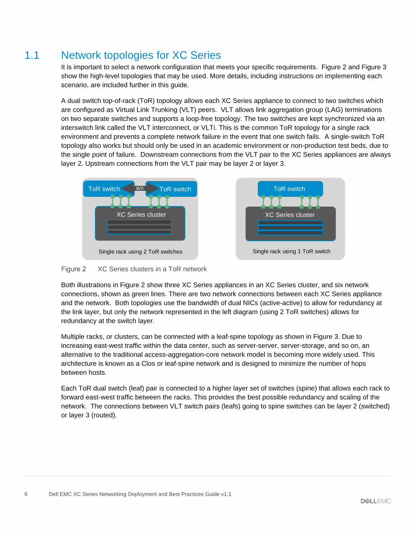
1.1 Network topologies for XC Series ....................................................................................................................... 6
5.2 Create an XC Series cluster ............................................................................................................................. 19
6.2 Create an XC Series cluster ............................................................................................................................. 31
6.3 ESXi - Configure vSwitch0 and management port group ................................................................................. 31
7 Network Time Protocol (NTP) .................................................................................................................................... 35
A Additional Resources ................................................................................................................................................. 43
B Supported network cards and cables ......................................................................................................................... 45
C Hardware and software versions used in this document ........................................................................................... 46
D Prism switch management for AHV hypervisors ........................................................................................................ 47
E Single ToR switch (non-production environments) .................................................................................................... 51
F Using PowerShell to set Teaming Mode to LACP using IP addresses ...................................................................... 54
G Glossary of Terms ...................................................................................................................................................... 55
4 Dell EMC XC Series Networking Deployment and Best Practices Guide v1.1
Executive summary
Dell EMC XC Series hyper-converged appliances enable both large and small IT organizations to efficiently
consolidate and run virtualized workloads on a single system. These hyper-converged appliances push the
scale of virtualization to new limits. Robust networks are required that can handle the higher utilization
demand of network bandwidth. These networks must be able to continuously deliver high performance and be
able to scale equally with the highly scalable hyper-converged systems as demand dictates.
This document provides best practices and details on how to deploy a network for the Dell EMC XC Series.
The goals of this document are to:
Assist administrators in selecting the best hardware and topology for their XC Series network
Deliver step-by-step instructions on cabling, configuring, and deploying the XC Series network
Provide best practices that ensure networking availability and scale
Provide examples of automating network configurations using Ansible playbooks
Show cabling diagram examples for various networking topologies
Note: XC Series cluster deployments, except for the Dell EMCTM XC430 Xpress, are installed by Dell Services. Contact your Dell Services representative before using this document to configure your network.
5 Dell EMC XC Series Networking Deployment and Best Practices Guide v1.1
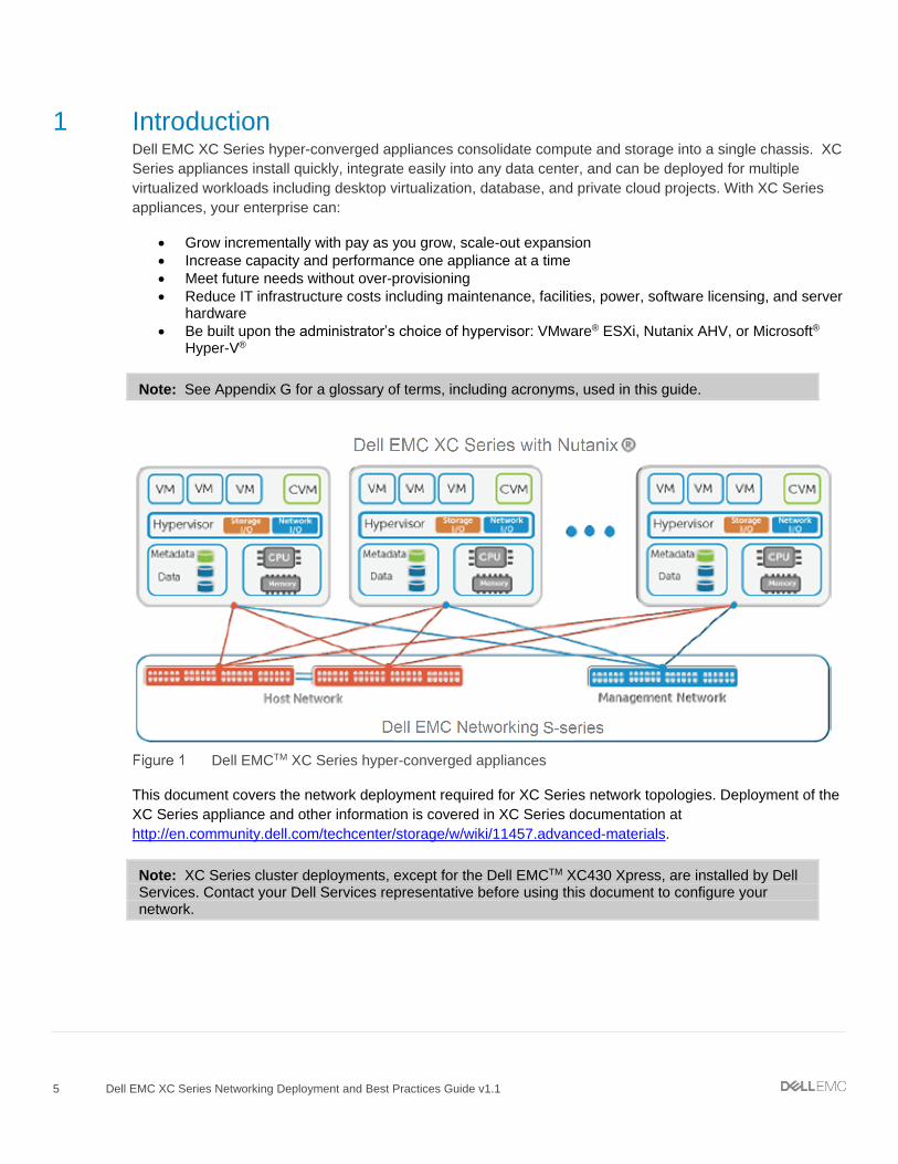
1 Introduction Dell EMC XC Series hyper-converged appliances consolidate compute and storage into a single chassis. XC
Series appliances install quickly, integrate easily into any data center, and can be deployed for multiple
virtualized workloads including desktop virtualization, database, and private cloud projects. With XC Series
appliances, your enterprise can:
Grow incrementally with pay as you grow, scale-out expansion
Increase capacity and performance one appliance at a time
Meet future needs without over-provisioning
Reduce IT infrastructure costs including maintenance, facilities, power, software licensing, and server hardware
Be built upon the administrator’s choice of hypervisor: VMware® ESXi, Nutanix AHV, or Microsoft® Hyper-V®
Note: See Appendix G for a glossary of terms, including acronyms, used in this guide.
Dell EMCTM XC Series hyper-converged appliances
This document covers the network deployment required for XC Series network topologies. Deployment of the
XC Series appliance and other information is covered in XC Series documentation at
Note: XC Series cluster deployments, except for the Dell EMCTM XC430 Xpress, are installed by Dell Services. Contact your Dell Services representative before using this document to configure your network.
1.6 Dell EMC XC Series hyper-converged appliances Dell EMC XC Series hyper-converged appliances start with the proven Dell EMC PowerEdge server platform
and incorporates the advanced software technologies that power leading scalable and cloud infrastructures.
Backed by Dell EMC global service and support, these 1RU and 2RU appliances are preconfigured for
specific virtualized workloads, and are designed to maintain data availability in case of appliance and disk
failures.
There are several XC Series configurations available to support various workloads. The examples in this
guide use the Dell EMC Networking XC630-10 shown here:
9 Dell EMC XC Series Networking Deployment and Best Practices Guide v1.1
8
9
3
1
2
06
7
4
5
Dell EMC Networking XC630 front view
112 750W 750W3
iDRAC
Dell EMC Networking XC630 rear view
The following table lists the Dell EMC XC Series hyper-converged appliances and example workloads:
Dell EMC Networking XC Series appliances
Appliance Workload examples
XC630-10 Compute/performance-intensive VDI, test & development, private cloud, server virtualization
XC730-16G VDI for graphics intensive workloads and knowledge workers with image-based apps
XC730xd-24 Performance-intensive SQL and Oracle OLTP
XC430-4 Balanced compute and storage for smaller scale virtualized environments
XC730xd-12 Storage-heavy Microsoft Exchange, SharePoint, data warehouse, big data
XC6320-6 High density compute and storage environments, service providers, private cloud
XC730xd-12C Storage capacity appliance for cluster with any supported hypervisor. Does not run workload VMs or virtual desktops. AHV only.
For the latest list of available XC Series appliances and technical specifications, visit Dell EMC XC Series
11 Dell EMC XC Series Networking Deployment and Best Practices Guide v1.1
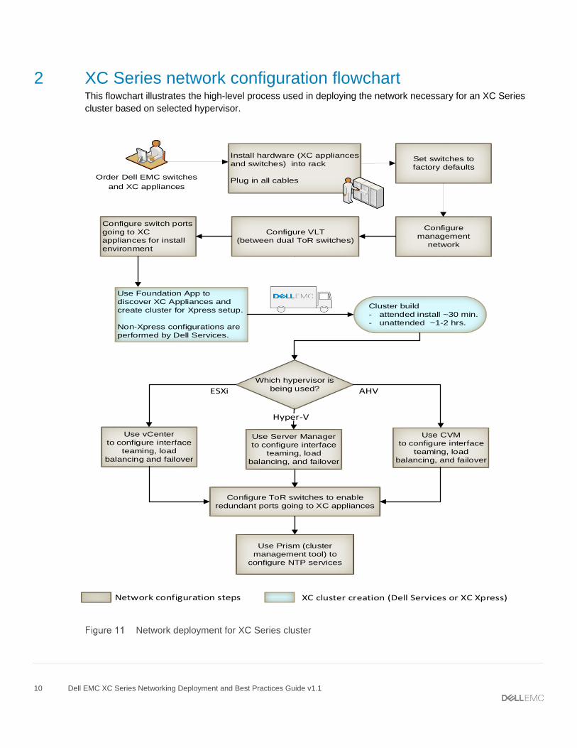
3 XC Series networking basics Deploying the XC Series cluster is performed in three stages. The first and third stages are related to the
network. The initial network is created in step one. The cluster is built in step two. The last step configures
the final production network. The stages are depicted in the flowchart in chapter 2. This guide walks the user
through all networking steps. The reader is directed to the XC Series cluster documentation for completing
step 2.
The information in this guide is helpful in ensuring your network devices are ready to connect XC Series
appliances for clustering. The following key points should be followed throughout this guide and when using
the Foundation applet for cluster creation:
The 10GbE Intel NIC ports in the XC Series appliance require either Twinax or Intel
SFP+. Connecting a different vendor’s SFP to the 10GbE Intel NICs will not work. See Appendix B for
more information.
Load balancing/NIC teaming is disabled for host appliances during initial building of cluster. The
instructions provided enables load balancing/NIC teaming to be used after the cluster is built.
When moving the hypervisor used from ESXi to AHV, or AHV to ESXi, load balancing/NIC teaming
must be disabled on the XC Series host. They may be re-enabled once the conversion is complete.
Layer 2 networking is required for implementing and using an XC Series cluster. Layer 3 should not
be used for connectivity between XC Series appliances and ToR/Leaf switches.
Dell EMC recommends using dual ToR switches in a VLT configuration as shown in Figure 13, when
running XC Series clusters in a production environment.
When creating the cluster, the following static IP addresses for each host, or XC Series appliance,
are required:
o A static IP address for the hypervisor host
o A static IP address for the Control VM (CVM)
o A static IP address for the iDRAC
o CVM and hypervisor hosts are required to be on the same IP subnet and VLAN
o Gateway, DNS, and NTP addresses should be available
The use of IP network 192.168.5.0 is forbidden as it causes hosts to fail. This private network is
designated for internal communication between the hypervisor and CVM.
Dell EMC recommends that all of the switch ports enable default VLAN access for deployment. If
default VLAN access is not permitted, refer to the Nutanix Field Installation Guide for assigning a
VLAN tag during deployment.
IPv6 is used for XC Series appliance discovery and cluster creation. Dell EMC Networking switches
pass IPv6 at Layer 2 by default. No modifications to switch configurations are required.
Use the spanning-tree rstp edge-port command on each ToR/leaf-switch interface
connecting to an XC Series appliance to put them into an immediate forwarding statedisable.
Note: Dell EMC recommends enabling Spanning Tree on all ToR/leaf switches and using edge-port on the ports connected to the XC Series servers. By default, Dell EMC Networking switches have Spanning Tree disabled globally.
Table 2 lists the IP addresses used in the example configurations in the guide:
12 Dell EMC XC Series Networking Deployment and Best Practices Guide v1.1
Example IP addresses
Host Name Host IP CVM IP
NIS-1 10.1.1.1 10.1.1.101
NIS-2 10.1.1.2 10.1.1.102
NIS-3 10.1.1.3 10.1.1.103
NIS-4 10.1.1.4 10.1.1.104
Cluster Virtual IP 10.1.1.50 Switch_1 Cluster VLAN 10.1.1.51
Switch_2 Cluster VLAN 10.1.1.52
Information contained in the bullet list and table above, along with the installation and setup guides, should be
referenced when creating or modifying a cluster.
Initial switch settings The configuration commands for the examples in this guide assume that the switches start at their factory
default settings. Use the commands for your corresponding OS to reset Dell EMC Networking switches used
in this guide to factory defaults.
Note: It is recommended that all switches mentioned in this guide be reset to factory defaults in advance of configuring any of the example network topologies.
Note: Copies of the configuration files validated in creating this document are attached. Click the
paperclip icon on the left to view or download local copies of these configuration files.
13 Dell EMC XC Series Networking Deployment and Best Practices Guide v1.1
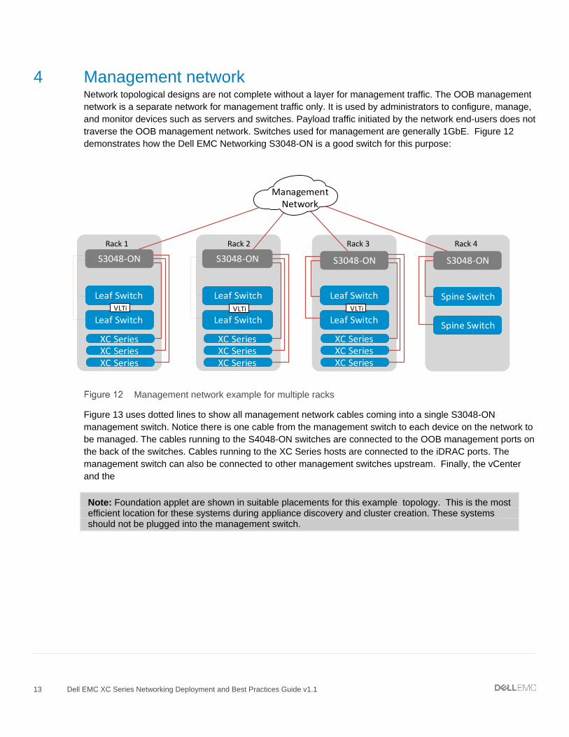
4 Management network Network topological designs are not complete without a layer for management traffic. The OOB management
network is a separate network for management traffic only. It is used by administrators to configure, manage,
and monitor devices such as servers and switches. Payload traffic initiated by the network end-users does not
traverse the OOB management network. Switches used for management are generally 1GbE. Figure 12
demonstrates how the Dell EMC Networking S3048-ON is a good switch for this purpose:
Rack 1 Rack 2
Leaf Switch
Leaf Switch
Leaf Switch
Leaf Switch
Rack 3
Leaf Switch
Leaf Switch
Rack 4
VLTi VLTi VLTi
ManagementNetwork
Spine Switch
Spine Switch
S3048-ONS3048-ONS3048-ON
XC SeriesXC SeriesXC Series
XC SeriesXC SeriesXC Series
XC SeriesXC SeriesXC Series
S3048-ON
Management network example for multiple racks
Figure 13 uses dotted lines to show all management network cables coming into a single S3048-ON
management switch. Notice there is one cable from the management switch to each device on the network to
be managed. The cables running to the S4048-ON switches are connected to the OOB management ports on
the back of the switches. Cables running to the XC Series hosts are connected to the iDRAC ports. The
management switch can also be connected to other management switches upstream. Finally, the vCenter
and the
Note: Foundation applet are shown in suitable placements for this example topology. This is the most efficient location for these systems during appliance discovery and cluster creation. These systems should not be plugged into the management switch.
14 Dell EMC XC Series Networking Deployment and Best Practices Guide v1.1
Configure management IP addresses Each switch that is to be managed through the management switch - over the network, requires an IP
address on the OOB port. For example, the OOB port for the Dell EMC Networking S4048-ON is
managementethernet 1/1.
Note: For this and other switches running OS9, enter the following commands, replacing the IP address with an available one for your network. Substitute the example default gateway (next hop) address of 192.168.1.1 with the one for your network.
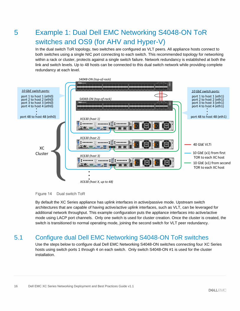
By default the XC Series appliance has uplink interfaces in active/passive mode. Upstream switch
architectures that are capable of having active/active uplink interfaces, such as VLT, can be leveraged for
additional network throughput. This example configuration puts the appliance interfaces into active/active
mode using LACP port channels. Only one switch is used for cluster creation. Once the cluster is created, the
switch is transitioned to normal operating mode, joining the second switch for VLT peer redundancy.
5.1 Configure dual Dell EMC Networking S4048-ON ToR switches Use the steps below to configure dual Dell EMC Networking S4048-ON switches connecting four XC Series
hosts using switch ports 1 through 4 on each switch. Only switch S4048-ON #1 is used for the cluster
installation.
17 Dell EMC XC Series Networking Deployment and Best Practices Guide v1.1
S4048-ON #1 S4048-ON #2
Set the management configuration
Dell#configure
Dell(conf)#interface managementethernet 1/1
Dell(conf-if-ma-1/1)#ip address
100.67.183.29/24
Dell(conf-if-ma-1/1)#no shutdown
Dell(conf-if-ma-1/1)#exit
Dell(conf)#management route 0.0.0.0/0
100.67.183.254
Set port channel for VLTi Interswitch peer links
Dell(conf)#interface port-channel 100
Dell(conf-if-po-100)#channel-member
fortyGigE 1/53,1/54
Dell(conf-if-po-100)#no shutdown
Dell(conf-if-po-100)#exit
Dell(conf)#interface range fortyGigE 1/53-
1/54
Dell(conf–if-range-fo-1/53-1/54)#no
shutdown
Dell(conf–if-range-fo-1/53-1/54)#exit
Set VLT
Dell(conf)#vlt domain 1
Dell(conf-vlt-domain)#peer-link port-
channel 100
Dell(conf-vlt-domain)#back-up destination
100.67.183.30
Dell(conf-vlt-domain)#Unit-id 0
Dell(conf-vlt-domain)#exit
Note: Use the show vlt brief command to verify the VLT configuration.
Configure cluster-facing ports Dell#configure
Dell(conf)#interface range te 1/1-1/4
Dell(conf-if-range-te-1/1-1/4)#description
XC nodes port 0
Dell(conf-if-range-te-1/1-1/4)#no ip
address
Dell(conf-if-range-te-1/1-1/4)#portmode
hybrid
Dell(conf-if-range-te-1/1-1/4)#switchport
Dell(conf-if-range-te-1/1-1/4)#no shutdown
Dell(conf-if-range-te-1/1-1/4)#exit
Set the management configuration
Dell#configure
Dell(conf)#interface managementethernet 1/1
Dell(conf-if-ma-1/1)#ip address
100.67.183.30/24
Dell(conf-if-ma-1/1)#no shutdown
Dell(conf-if-ma-1/1)#exit
Dell(conf)#management route 0.0.0.0/0
100.67.183.254
Set port channel for VLTi Interswitch peer links
Dell(conf)#interface port-channel 100
Dell(conf-if-po-100)#channel-member
fortyGigE 1/53,1/54
Dell(conf-if-po-100)#no shutdown
Dell(conf-if-po-100)#exit
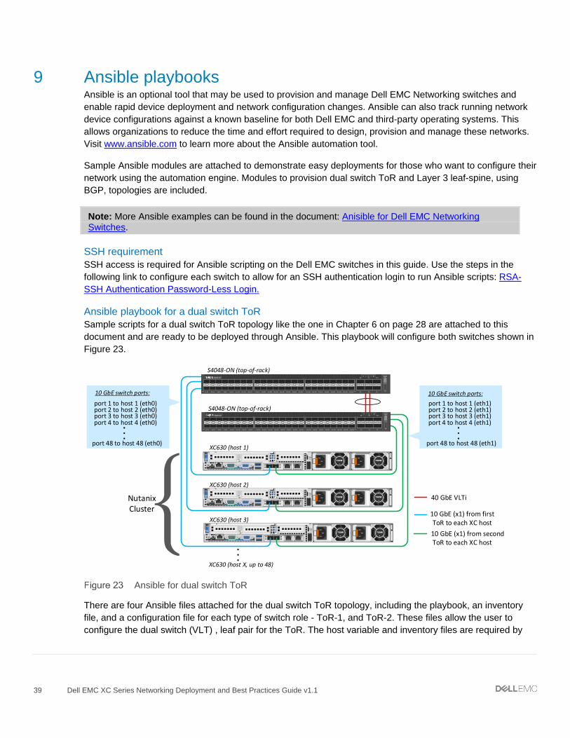
Dell(conf)#interface range fortyGigE 1/53-
1/54
Dell(conf–if-range-fo-1/53-1/54)#no
shutdown
Dell(conf–if-range-fo-1/53-1/54)#exit
Set VLT
Dell(conf)#vlt domain 1
Dell(conf-vlt-domain)#peer-link port-
channel 100
Dell(conf-vlt-domain)#back-up destination
100.67.183.29
Dell(conf-vlt-domain)#Unit-id 1
Dell(conf-vlt-domain)#exit
Note: Use the show vlt brief command to verify the VLT configuration.
Configure cluster-facing ports Dell#configure
Dell(conf)#interface range te 1/1-1/4
Dell(conf-if-range-te-1/1-1/4)#description
XC nodes port 1
Dell(conf-if-range-te-1/1-1/4)#no ip
address
Dell(conf-if-range-te-1/1-1/4)#shutdown
Dell(conf-if-range-te-1/1-1/4)#exit
Dell(conf)#interface te 1/1
18 Dell EMC XC Series Networking Deployment and Best Practices Guide v1.1
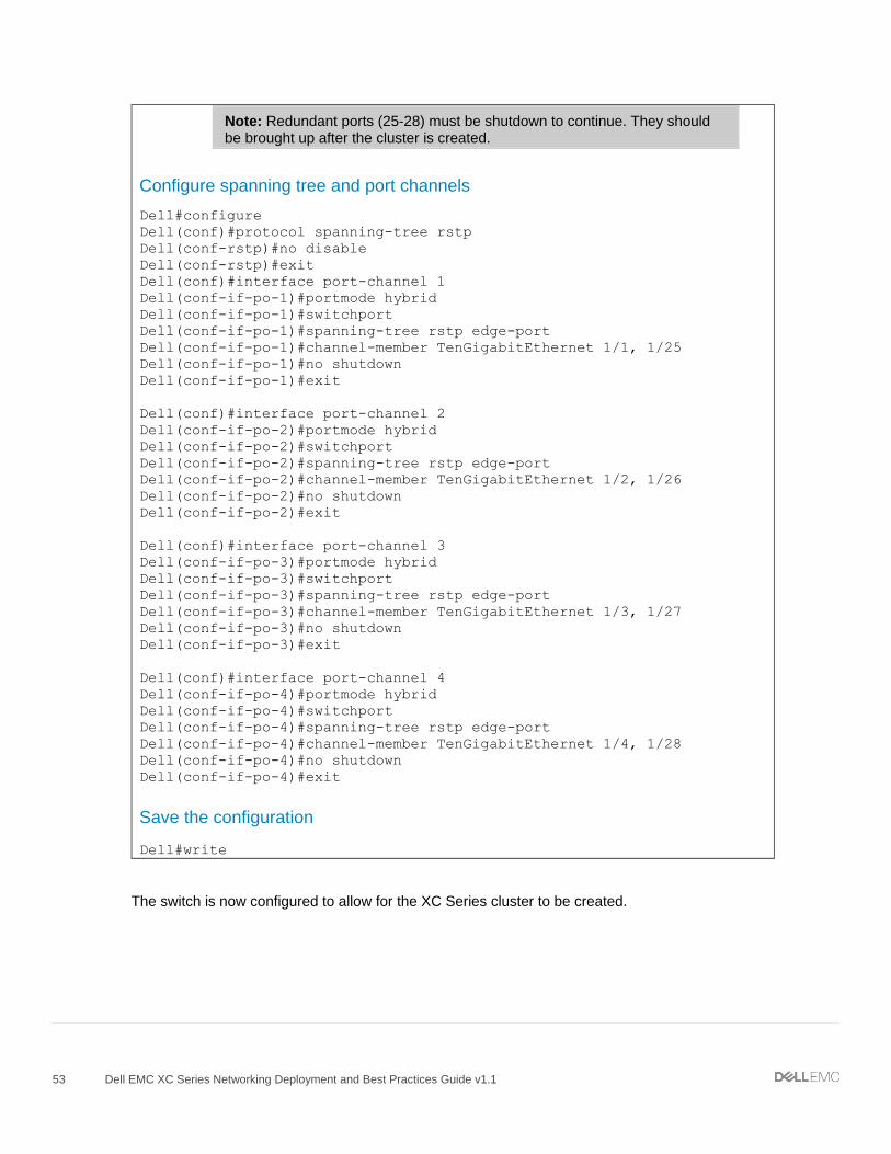
Configure spanning tree and port channels
Dell#configure
Dell(conf)#protocol spanning-tree rstp
Dell(conf-rstp)#no disable
Dell(conf-rstp)#exit
Dell(conf)#interface port-channel 1
Dell(conf-if-po-1)#portmode hybrid
Dell(conf-if-po-1)#switchport
Dell(conf-if-po-1)#spanning-tree rstp edge-
port
Dell(conf-if-po-1)#vlt-peer-lag port-
channel 1
Dell(conf-if-po-1)#no shutdown
Dell(conf-if-po-1)#exit
Dell(conf-if-te-1/1)#port-channel-protocol
lacp
Dell(conf-if-te-1/1-lacp)#port-channel 1
mode active
Dell(conf-if-te-1/1-lacp)#exit
Dell(conf-if-te-1/1)#exit
Dell(conf)#interface te 1/2
Dell(conf-if-te-1/2)#port-channel-protocol
lacp
Dell(conf-if-te-1/2-lacp)#port-channel 2
mode active
Dell(conf-if-te-1/2-lacp)#exit
Dell(conf-if-te-1/2)#exit
Dell(conf)#interface te 1/3
Dell(conf-if-te-1/3)#port-channel-protocol
lacp
Dell(conf-if-te-1/3-lacp)#port-channel 3
mode active
Dell(conf-if-te-1/3-lacp)#exit
Dell(conf-if-te-1/3)#exit
Dell(conf)#interface te 1/4
Dell(conf-if-te-1/4)#port-channel-protocol
lacp
Dell(conf-if-te-1/4-lacp)#port-channel 4
mode active
Dell(conf-if-te-1/4-lacp)#exit
Dell(conf-if-te-1/4)#exit
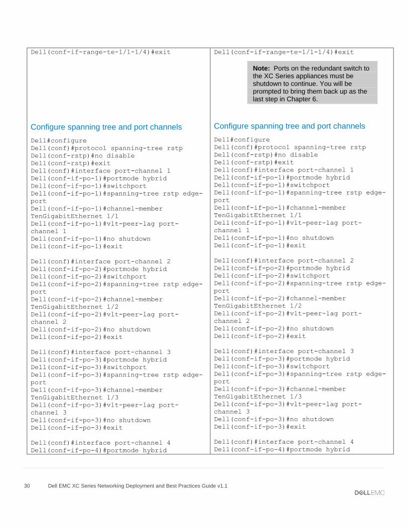
Note: Ports on the redundant switch to the XC Series appliances must be shutdown to continue. You will be prompted to bring them back up as the last step in Chapter 6.
Configure spanning tree and port channels
Dell#configure
Dell(conf)#protocol spanning-tree rstp
Dell(conf-rstp)#no disable
Dell(conf-rstp)#exit
Dell(conf)#interface port-channel 1
Dell(conf-if-po-1)#portmode hybrid
Dell(conf-if-po-1)#switchport
Dell(conf-if-po-1)#spanning-tree rstp edge-
port
Dell(conf-if-po-1)#vlt-peer-lag port-
channel 1
Dell(conf-if-po-1)#no shutdown
Dell(conf-if-po-1)#exit
19 Dell EMC XC Series Networking Deployment and Best Practices Guide v1.1
Dell(conf)#interface port-channel 2
Dell(conf-if-po-2)#portmode hybrid
Dell(conf-if-po-2)#switchport
Dell(conf-if-po-2)#spanning-tree rstp edge-
port
Dell(conf-if-po-2)#vlt-peer-lag port-
channel 2
Dell(conf-if-po-2)#no shutdown
Dell(conf-if-po-2)#exit
Dell(conf)#interface port-channel 3
Dell(conf-if-po-3)#portmode hybrid
Dell(conf-if-po-3)#switchport
Dell(conf-if-po-3)#spanning-tree rstp edge-
port
Dell(conf-if-po-3)#vlt-peer-lag port-
channel 3
Dell(conf-if-po-3)#no shutdown
Dell(conf-if-po-3)#exit
Dell(conf)#interface port-channel 4
Dell(conf-if-po-4)#portmode hybrid
Dell(conf-if-po-4)#switchport
Dell(conf-if-po-4)#spanning-tree rstp edge-
port
Dell(conf-if-po-4)#vlt-peer-lag port-
channel 4
Dell(conf-if-po-4)#no shutdown
Dell(conf-if-po-4)#exit
Save the configuration
Dell#write
5.2 Create an XC Series cluster
Note: XC Series cluster deployments, except for the XC430 Xpress, are installed by Dell Services.
The network is ready to deploy the XC Series appliances into an XC Series cluster. Before creating the XC
Series cluster, the Installer/Foundation applet systems should have proper placement on the network. One
recommended setup is shown in Figure 13 on page 14.
If deploying Xpress, use the documentation that comes with your XC430 appliances.
20 Dell EMC XC Series Networking Deployment and Best Practices Guide v1.1
Note: The Foundation applet generally used for the XC430 Xpress may also be used for appliance discovery and creation of other XC Series clusters. To obtain the applet, sign in to the Nutanix portal: https://portal.nutanix.com and select Downloads > Foundation. A Nutanix account is required.
The process of discovering XC Series appliances and building the cluster usually takes 1-3 hours. Most of
this time will be unattended while the cluster is being built. Once the cluster is created, use the steps below to
complete the network configuration.
5.3 Hypervisor configuration Below are the instructions to configure the hypervisor network stack. Skip to the section that applies to the
hypervisor selected duing cluster installation:
5.3.1 AHV
5.3.2 Hyper-V
5.3.1 AHV The AHV Networking Nutanix Best Practices guide provides advanced illustrations on how to configure the
network with the Dell EMC XC630-10 appliance.
The following example provides the steps for setting up the “Scenario 2: 2x 10 Gb and 2x 1 Gb Separated”
design described in section 5.1 of the guide. The default configuration of the virtual switch has uplinks to the
switch as active-backup. Use the following procedure to change the adapters to balance-tcp:
1. From the iDRAC virtual console, open an SSH connection to the local cluster controller.
2. Use the following commands to configure virtual switches and uplinks.
6. Skip to chapter 7 to set up NTP on the cluster and complete the deployment.
5.3.2 Hyper-V After the cluster has been installed and added to active directory domain, use the steps below to configure
load balancing and failover (LBFO) and complete the setup of the Hyper-V cluster.
Note: Prism is the cluster management tool used after the cluster is created to add the cluster to the active directory domain. Consult your XC Series Server documentation for more information.
1. Run the following commands on the redundant switch (S4048-ON #2) of the VLT pair to enable the
redundant ports:
23 Dell EMC XC Series Networking Deployment and Best Practices Guide v1.1
S4048-ON #2
Dell#configure
Dell(conf)#interface range te 1/1-1/4
Dell(conf-if-range-te-1/1-1/4)#no shutdown
Dell(conf-if-range-te-1/1-1/4)#exit
2. Open Server Manager using iDRAC or RDP, and select NIC Teaming. For this procedure, we used
iDRAC.
Note: The default password is nutanix/4u.
3. In NIC Teaming select NetAdapterTeam.
24 Dell EMC XC Series Networking Deployment and Best Practices Guide v1.1
4. Either NIC1 or NIC2 will show Active, and the other will show Disconnected, depending on your cabling
configuration. Expand the Additional properties section and from the Teaming mode drop-down, select
LACP.
Note: Alternativity, PowerShell commandlets may be used to set teaming mode. See page 26 for more information.
25 Dell EMC XC Series Networking Deployment and Best Practices Guide v1.1
5. Repeat the GUI commands above on all of the nodes in the cluster.
Note: Proceed to step 6 after the commands above have been repeated on all of the nodes.
6. Run the following commands on the install switch (S4048-ON #1) of a VLT pair to enable the redundant
ports for this scenario. This transitions the install switch to operating mode.
S4048-ON #1
Dell#configure
Dell(conf)#interface range te 1/1-1/4
Dell(conf-if-range-te-1/1-1/4)#shutdown
Dell(conf-if-range-te-1/1-1/4)#no switchport
Dell(conf-if-range-te-1/1-1/4)#no portmode hybrid
Dell(conf-if-range-te-1/1-1/4)#description XC nodes port 0
Dell(conf-if-range-te-1/1-1/4)#exit
Dell(conf)#interface te 1/1
Dell(conf-if-te-1/1)#no ip address
Dell(conf-if-te-1/1)#port-channel-protocol lacp
Dell(conf-if-te-1/1-lacp)#port-channel 1 mode active
Dell(conf-if-te-1/1-lacp)#exit
Dell(conf-if-te-1/1)#exit
Dell(conf)#interface te 1/2
Dell(conf-if-te-1/2)#no ip address
Dell(conf-if-te-1/2)#port-channel-protocol lacp
Dell(conf-if-te-1/2-lacp)#port-channel 2 mode active
Dell(conf-if-te-1/2-lacp)#exit
Dell(conf-if-te-1/2)#exit
Dell(conf)#interface te 1/3
Dell(conf-if-te-1/3)#no ip address
Dell(conf-if-te-1/3)#port-channel-protocol lacp
Dell(conf-if-te-1/3-lacp)#port-channel 3 mode active
Dell(conf-if-te-1/3-lacp)#exit
Dell(conf-if-te-1/3)#exit
Dell(conf)#interface te 1/4
Dell(conf-if-te-1/4)#no ip address
Dell(conf-if-te-1/4)#port-channel-protocol lacp
Dell(conf-if-te-1/4-lacp)#port-channel 4 mode active
Dell(conf-if-te-1/4-lacp)#exit
Dell(conf-if-te-1/4)#exit
Dell(conf)#interface range te 1/1-1/4
Dell(conf-if-range-te-1/1-1/4)#no shutdown
7. Member adapters should now be Active on all member NICs as shown below.
26 Dell EMC XC Series Networking Deployment and Best Practices Guide v1.1
Note: To verify LACP is up on the appliance and switch, use the commands show lacp <port channel>, and show vlt detail.
Note: For best practices on using XC Series with Microsoft® Windows® 2012 Server R2 with Hyper-V, download: Dell EMC XC Series Running Windows Server 2012 R2 with Hyper-V. The document provides recommendations for maintaining the stability and performance of the platform and workloads.
8. Skip to chapter 7 to set up NTP on the cluster and complete the deployment.
5.3.3 Alternative method to set teaming mode on appliances using PowerShell A PowerShell method may be used in place of steps 2 through 5 in the GUI above. Use the PowerShell
commandlets below to set teaming mode on all servers.
Dual switch ToR using Dell EMC Networking S4048-ON with OS9
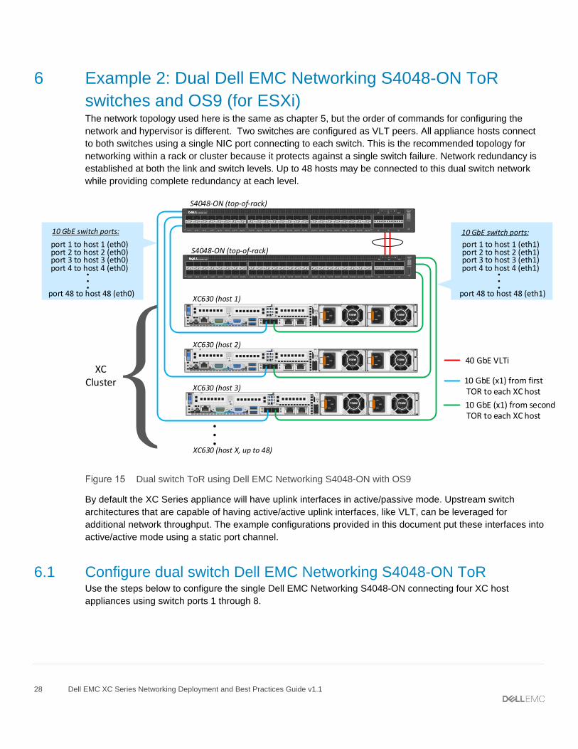
By default the XC Series appliance will have uplink interfaces in active/passive mode. Upstream switch
architectures that are capable of having active/active uplink interfaces, like VLT, can be leveraged for
additional network throughput. The example configurations provided in this document put these interfaces into
active/active mode using a static port channel.
6.1 Configure dual switch Dell EMC Networking S4048-ON ToR Use the steps below to configure the single Dell EMC Networking S4048-ON connecting four XC host
appliances using switch ports 1 through 8.
29 Dell EMC XC Series Networking Deployment and Best Practices Guide v1.1
S4048-ON #1 S4048-ON #2
Set management configuration
Dell#configure
Dell(conf)#interface managementethernet 1/1
Dell(conf-if-ma-1/1)#ip address
100.67.183.29/24
Dell(conf-if-ma-1/1)#no shutdown
Dell(conf-if-ma-1/1)#exit
Dell(conf)#management route 0.0.0.0/0
100.67.183.254
Set port channel for VLTi
Dell(conf)#interface port-channel 100
Dell(conf-if-po-100)#Channel-member
fortyGigE 1/53,1/54
Dell(conf-if-po-100)#no shutdown
Dell(conf-if-po-100)#exit
Dell(conf)#interface range fortyGigE 1/53-
1/54
Dell(conf–if-range-fo-1/53-1/54)#no
shutdown
Dell(conf–if-range-fo-1/53-1/54)#exit
Set VLT
Dell(conf)#vlt domain 1
Dell(conf-vlt-domain)#peer-link port-
channel 100
Dell(conf-vlt-domain)#back-up destination
100.67.183.30
Dell(conf-vlt-domain)#Unit-id 0
Dell(conf-vlt-domain)#exit
Note: Use the show vlt brief command to verify the configuration.
Configure cluster facing ports Dell#configure
Dell(conf)#interface range te 1/1-1/4
Dell(conf-if-range-te-1/1-1/4)#description
XC nodes port 0
Dell(conf-if-range-te-1/1-1/4)#no ip
address
Dell(conf-if-range-te-1/1-1/4)#no shutdown
Set management configuration
Dell#configure
Dell(conf)#interface managementethernet 1/1
Dell(conf-if-ma-1/1)#ip address
100.67.183.30/24
Dell(conf-if-ma-1/1)#no shutdown
Dell(conf-if-ma-1/1)#exit
Dell(conf)#management route 0.0.0.0/0
100.67.183.254
Set port channel for VLTi
Dell(conf)#interface port-channel 100
Dell(conf-if-po-100)#Channel-member
fortyGigE 1/53,1/54
Dell(conf-if-po-100)#no shutdown
Dell(conf-if-po-100)#exit
Dell(conf)#interface range fortyGigE 1/53-
1/54
Dell(conf–if-range-fo-1/53-1/54)#no
shutdown
Dell(conf–if-range-fo-1/53-1/54)#exit
Set VLT
Dell(conf)#vlt domain 1
Dell(conf-vlt-domain)#peer-link port-
channel 100
Dell(conf-vlt-domain)#back-up destination
100.67.183.29
Dell(conf-vlt-domain)#Unit-id 1
Dell(conf-vlt-domain)#exit
Note: Use the show vlt brief command to verify the configuration.
Configure cluster facing ports Dell#configure
Dell(conf)#interface range te 1/1-1/4
Dell(conf-if-range-te-1/1-1/4)#description
XC nodes port 1
Dell(conf-if-range-te-1/1-1/4)#no ip
address
Dell(conf-if-range-te-1/1-1/4)#shutdown
30 Dell EMC XC Series Networking Deployment and Best Practices Guide v1.1
Dell(conf-if-range-te-1/1-1/4)#exit
Configure spanning tree and port channels
Dell#configure
Dell(conf)#protocol spanning-tree rstp
Dell(conf-rstp)#no disable
Dell(conf-rstp)#exit
Dell(conf)#interface port-channel 1
Dell(conf-if-po-1)#portmode hybrid
Dell(conf-if-po-1)#switchport
Dell(conf-if-po-1)#spanning-tree rstp edge-
port
Dell(conf-if-po-1)#channel-member
TenGigabitEthernet 1/1
Dell(conf-if-po-1)#vlt-peer-lag port-
channel 1
Dell(conf-if-po-1)#no shutdown
Dell(conf-if-po-1)#exit
Dell(conf)#interface port-channel 2
Dell(conf-if-po-2)#portmode hybrid
Dell(conf-if-po-2)#switchport
Dell(conf-if-po-2)#spanning-tree rstp edge-
port
Dell(conf-if-po-2)#channel-member
TenGigabitEthernet 1/2
Dell(conf-if-po-2)#vlt-peer-lag port-
channel 2
Dell(conf-if-po-2)#no shutdown
Dell(conf-if-po-2)#exit
Dell(conf)#interface port-channel 3
Dell(conf-if-po-3)#portmode hybrid
Dell(conf-if-po-3)#switchport
Dell(conf-if-po-3)#spanning-tree rstp edge-
port
Dell(conf-if-po-3)#channel-member
TenGigabitEthernet 1/3
Dell(conf-if-po-3)#vlt-peer-lag port-
channel 3
Dell(conf-if-po-3)#no shutdown
Dell(conf-if-po-3)#exit
Dell(conf)#interface port-channel 4
Dell(conf-if-po-4)#portmode hybrid
Dell(conf-if-range-te-1/1-1/4)#exit
Note: Ports on the redundant switch to the XC Series appliances must be shutdown to continue. You will be prompted to bring them back up as the last step in Chapter 6.
Configure spanning tree and port channels
Dell#configure
Dell(conf)#protocol spanning-tree rstp
Dell(conf-rstp)#no disable
Dell(conf-rstp)#exit
Dell(conf)#interface port-channel 1
Dell(conf-if-po-1)#portmode hybrid
Dell(conf-if-po-1)#switchport
Dell(conf-if-po-1)#spanning-tree rstp edge-
port
Dell(conf-if-po-1)#channel-member
TenGigabitEthernet 1/1
Dell(conf-if-po-1)#vlt-peer-lag port-
channel 1
Dell(conf-if-po-1)#no shutdown
Dell(conf-if-po-1)#exit
Dell(conf)#interface port-channel 2
Dell(conf-if-po-2)#portmode hybrid
Dell(conf-if-po-2)#switchport
Dell(conf-if-po-2)#spanning-tree rstp edge-
port
Dell(conf-if-po-2)#channel-member
TenGigabitEthernet 1/2
Dell(conf-if-po-2)#vlt-peer-lag port-
channel 2
Dell(conf-if-po-2)#no shutdown
Dell(conf-if-po-2)#exit
Dell(conf)#interface port-channel 3
Dell(conf-if-po-3)#portmode hybrid
Dell(conf-if-po-3)#switchport
Dell(conf-if-po-3)#spanning-tree rstp edge-
port
Dell(conf-if-po-3)#channel-member
TenGigabitEthernet 1/3
Dell(conf-if-po-3)#vlt-peer-lag port-
channel 3
Dell(conf-if-po-3)#no shutdown
Dell(conf-if-po-3)#exit
Dell(conf)#interface port-channel 4
Dell(conf-if-po-4)#portmode hybrid
31 Dell EMC XC Series Networking Deployment and Best Practices Guide v1.1
Dell(conf-if-po-4)#switchport
Dell(conf-if-po-4)#spanning-tree rstp edge-
port
Dell(conf-if-po-4)#channel-member
TenGigabitEthernet 1/4
Dell(conf-if-po-4)#vlt-peer-lag port-
channel 4
Dell(conf-if-po-4)#no shutdown
Dell(conf-if-po-4)#exit
Save the configuration
Dell#write
Dell(conf-if-po-4)#switchport
Dell(conf-if-po-4)#spanning-tree rstp edge-
port
Dell(conf-if-po-4)#channel-member
TenGigabitEthernet 1/4
Dell(conf-if-po-4)#vlt-peer-lag port-
channel 4
Dell(conf-if-po-4)#no shutdown
Dell(conf-if-po-4)#exit
Save the configuration
Dell#write
6.2 Create an XC Series cluster
Note: XC Series cluster deployments, except for the XC430 Xpress, are installed by Dell Services.
The network is ready to deploy the XC Series appliances into an XC Series cluster. Before creating the XC
Series cluster, the Installer/Foundation applet systems should have proper placement on the network. One
recommended setup is shown in Figure 13 on page 14.
If deploying Xpress, use the documentation that comes with your XC430 appliances.
Note: The Foundation applet generally used for the XC430 Xpress may also be used for appliance discovery and creation of other XC Series clusters. To obtain the applet, sign in to the Nutanix portal: https://portal.nutanix.com and select Downloads > Foundation. A Nutanix account is required.
The process of discovering XC Series appliances and building the cluster usually takes 1-3 hours. Most of
this time will be unattended while the cluster is being built. Once the cluster is created, use the steps below to
complete the network setup.
6.3 ESXi - Configure vSwitch0 and management port group
Note: This ESXi example is using a standard switch which supports static LAG only. For LACP, a VMware distributed switch (vDS) is required. Consult your VMware documentation for information on using a vDS, including products licensed for it’s use.
The default configuration of the virtual switch has uplinks to the switch as active-standby. Use the following
procedure to change the adapters to active-active:
1. Open the VMware vCenter Home page and select Hosts and Clusters.
4. Open the Manage Physical Network Adapters for the vSwitch0 virtual switch. The default configuration
is shown in Figure 17 (based on an XC630 appliance with two 10GbE and two 1GbE ports).
Physical network adapters for vSwitch0
5. Select and remove the 1GbE adapters, vmnic2 and vmnic3, using the red X button.
6. Click OK.
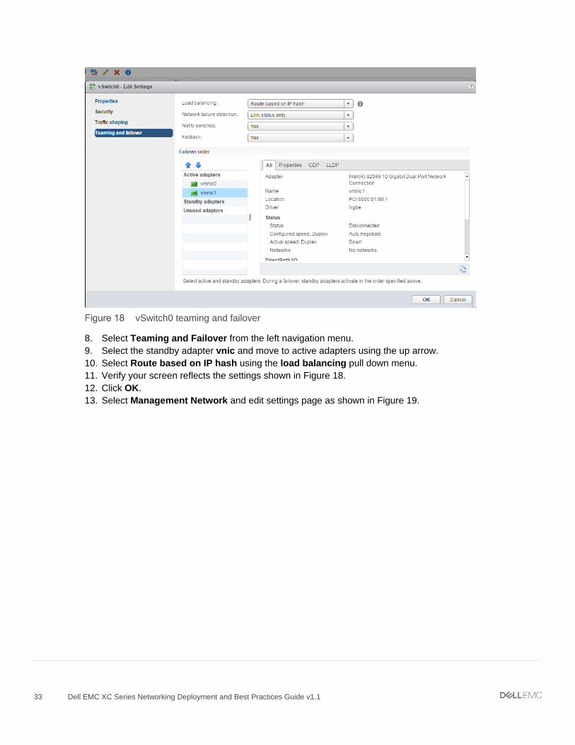
7. Open Vswitch0 Edit Settings page (Figure 18).
33 Dell EMC XC Series Networking Deployment and Best Practices Guide v1.1
vSwitch0 teaming and failover
8. Select Teaming and Failover from the left navigation menu.
9. Select the standby adapter vnic and move to active adapters using the up arrow.
10. Select Route based on IP hash using the load balancing pull down menu.
11. Verify your screen reflects the settings shown in Figure 18.
12. Click OK.
13. Select Management Network and edit settings page as shown in Figure 19.
34 Dell EMC XC Series Networking Deployment and Best Practices Guide v1.1
Management network teaming and failover settings
14. Select Teaming and failover from the left navigation menu.
15. Verify that the Load balancing Override is not selected. Uncheck this option if necessary.
16. Ensure that the Failover order Overrride is not selected. Uncheck this option if necessary.
17. Verify that your settings reflect the settings shown in Figure 19.
18. Click OK.
19. Repeat steps 1 through 18 for all XC Series appliances.
Note: Repeat steps above for all XC Series appliances before continuing to the next step.
20. Run the following commands on the redundant switch (S4048-ON #2) of a VLT pair to enable the
redundant ports for this scenario:
S4048-ON #2
Dell#configure
Dell(conf)#interface range te 1/1-1/4
Dell(conf-if-range-te-1/1-1/4)#no shutdown
Dell(conf-if-range-te-1/1-1/4)#exit
21. Skip to chapter 7 to set up NTP on the cluster and complete the deployment.
Note: The Dell XC Series Appliances – Reference Architecture for VMware ESXi Cluster demonstrates how the Dell XC630-10 appliance functions with mixed workloads when configured as a VMware vSphere cluster. Additionally, it provides best practices and a configuration guide for setting up the solution to run VMware vSphere in the datacenter of a medium-sized business.
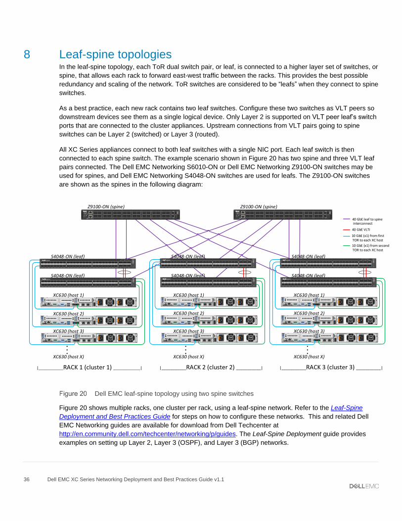
Note: Deployment examples in the Leaf-Spine Deployment and Best Practices Guide include the Cisco Nexus 5600 and 7000 series switches used as spines. These spine switches are configured for interoperability with Dell EMC Networking switches at the leaf level.
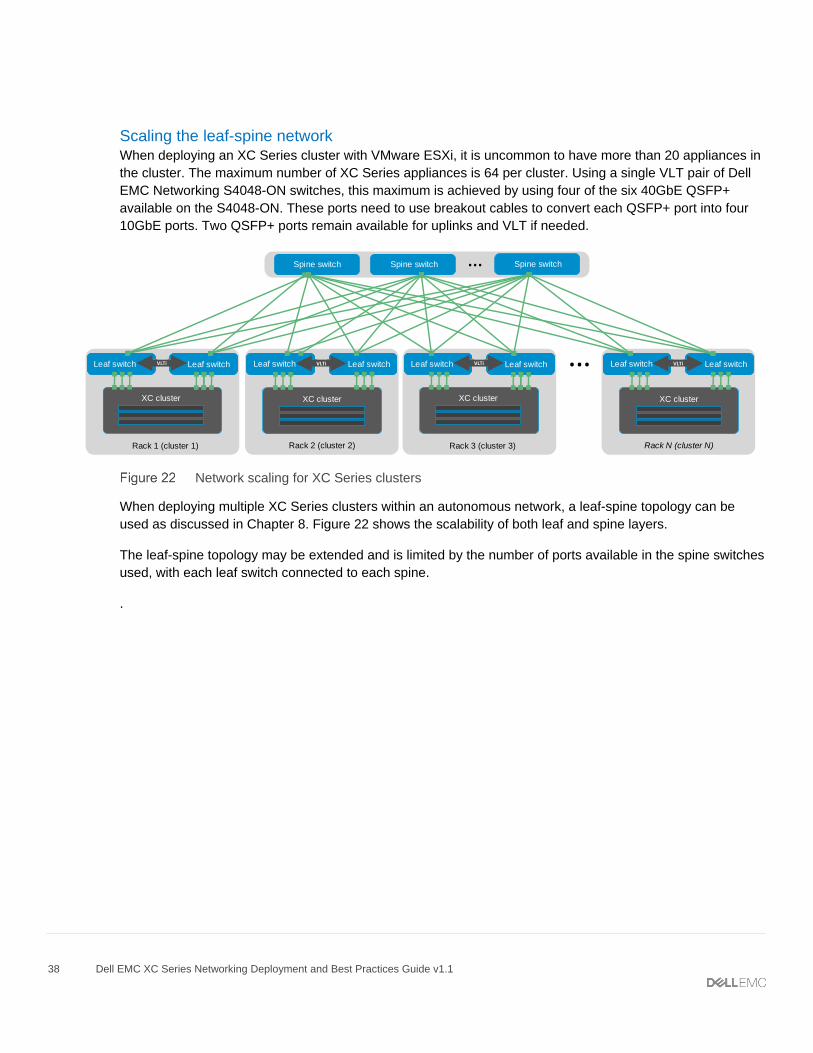
45 Dell EMC XC Series Networking Deployment and Best Practices Guide v1.1
B Supported network cards and cables
This section provides information about supported network cards and NICs for your XC Series appliance.
Intel-branded network daughter cards (NDCs) and network interface cards (NICs) specify the use of only Intel
branded SFP+ optical modules for use with optical cables. When ordering a system with optics, the
appropriate Intel branded SFP+ optical modules are included with your order. If you already have SFP+
optical modules, ensure they are the Intel branded modules before inserting into the NDC or NIC. Twinax
network cables are also supported with the Intel X520 NDC and NIC. See Table 7 for a list of supported
network cards and cables for the XC Series.
Note: The use of non-Intel branded SFP+ modules during deployment disables 10GbE ports. Contact Dell EMC Support to recover port functionality.
Note: Hot-plugging an unsupported SFP+ module causes the Vmware ESXi host to fail and displays a purple diagnostic screen. Call Dell EMC Support to recover from this situation.
XC630 network cards and cables
Name Firmware version
Supported cables
Intel X520 Dual 1GbE + Dual 10 GbE SFP+ (NDC)
16.0.24 or later Intel branded SFP+ modules only (10GbE)
Twinax Cable (10GbE)
Standard Category 6 Ethernet (1GbE)
Intel X540 Dual 1 GbE + Dual 10 GbE BaseT (NDC)
16.0.24 or later Standard Category 6 Ethernet (up to 10GbE)
Intel X520 Dual 10 GbE SFP+ (NIC) 16.0.24 or later Intel branded SFP+ modules only (10GbE)
Twinax Cable (10GbE)
Intel X540 Dual 10 GbE BaseT (NIC) 16.0.24 or later Standard Category 6 Ethernet (up to 10GbE)
For the latest information on XC Series support of network, disk drives, hypervisors, and other equipment and
For a list of supported optics and cables, visit: http://i.dell.com/sites/doccontent/shared-content/data-sheets/en/Documents/Dell-Networking-Optics-Spec-Sheet.pdf.
46 Dell EMC XC Series Networking Deployment and Best Practices Guide v1.1
C Hardware and software versions used in this document
The examples in this document were validated using the following software versions
Hardware/software Version
Dell EMC Networking S3048-ON
DNOS 9.11.2.0 P0 Dell EMC Networking S4048-ON
Dell EMC Networking S6010-ON
Dell EMC Networking Z9100-ON
Dell EMC XC630 BIOS 2.3.4
Dell EMC XC630 iDRAC 2.41.40.40 (Build 07)
AOS 5.1.2
VMware ESXi 6.0
Hyper-V Windows 2012 R2 Standard
AHV 20160925.84
47 Dell EMC XC Series Networking Deployment and Best Practices Guide v1.1
D Prism switch management for AHV hypervisors
When deploying an AHV hypervisor cluster, such as the Dell EMC Networking S4048-ON, users have the
option to see the switches listed on the Virtual Networks screen in Prism. This is not a requirement and will
not benefit or impede operations of the cluster. It only provides a topological graph of the network as shown in
Figure 27. Follow the steps below with OS9 to configure this feature in Prism.
Note: Feature is only available for the AHV hypervisor (using OS9) on the Dell EMC Networking switch. No other hypervisors are supported.
After completing the configuration steps in Chapters 5 and 7 for setting up an AHV cluster and NTP, use the
following commands to set up Prism switch management:
S4048-ON #1 S4048-ON #2
Configure VLAN Dell(conf)#interface vlan 1
Dell(conf-if-vl-1)#ip address 10.1.1.51/24
Dell(conf-if-vl-1)#uptagged Port-channel 1-
4
Dell(conf-if-vl-1)#no shutdown
Configure SNMP
Dell(conf)#snmp-server community public ro
Dell(conf)#snmp-server contact
http://www.dell.com/support
Dell(conf)#snmp-server location Server Rack
Configure VLAN Dell(conf)#interface vlan 1
Dell(conf-if-vl-1)#ip address 10.1.1.52/24
Dell(conf-if-vl-1)#uptagged Port-channel 1-
4
Dell(conf-if-vl-1)#no shutdown
Configure SNMP
Dell(conf)#snmp-server community public ro
Dell(conf)#snmp-server contact
http://www.dell.com/support
Dell(conf)#snmp-server location Server Rack
Note: The default administrator ID and password for Prism is admin/admin.
1. From Prism, select gear icon dropdown.
2. Select Network Switch.
3. Click the Add Switch Configuration button as shown in Figure 25.
48 Dell EMC XC Series Networking Deployment and Best Practices Guide v1.1
Adding a switch configuration using Prism
4. Enter the switch and host IP and SNMP details as shown in Figure 26.
49 Dell EMC XC Series Networking Deployment and Best Practices Guide v1.1
Switch configuration details using Prism
1 Click Save.
2 Repeat the steps in this section to configure additional switches.
After all switches have been added, the Virtual Networks page looks similar to the one in Figure 27.
50 Dell EMC XC Series Networking Deployment and Best Practices Guide v1.1
Virtual Networks shown in Prism
51 Dell EMC XC Series Networking Deployment and Best Practices Guide v1.1
E Single ToR switch (non-production environments)
Note: Use of a single top-of-rack (ToR) switch in a production environment is not recommended. For non-production environments such as evaluations, proof of concept, or academia, a single ToR switch is usually acceptable.
In a single ToR switch topology, all appliances connect to a single switch using both NIC ports. This topology
has the advantages of lower cost, but does not protect against a switch failure. Network redundancy is only
established at the link level. It is the minimum network requirement in order to deploy an XC Series cluster.
This topology should only be used in an academic environment or a non-production test bed due to the single
point of failure.
Any of the dual switch examples in this document may also be implemented with a single switch by simply
configuring one switch instead of two. For example, a single Dell EMC Networking S4048-ON can support up
to 24 appliances using 10GbE ports only, or 32 appliances if using four of the available six QSFP+ ports.
Using QSFP+ ports for a 32-appliance topology would require four 4x10GbE breakout cables.
Note: Active Directory is not required when using the PowerShell commands in this appendix, nor is it required when using the GUI in Chapter 5. Active Directory may be required when using the CLI commands in Chapter 5.
55 Dell EMC XC Series Networking Deployment and Best Practices Guide v1.1
G Glossary of Terms
Acropolis Hypervisor (AHV) - based on Linux KVM, used for deploying and serving virtual computers
Ansible – a tool for IT automation such as network deployments. Aquired by Red Hat® in 2015
BaseT – Ethernet cables for baseband transmissions using twisted pair copper wires
Border Gateway Protocol (BGP) – a standardized exterior gateway protocol used to route traffic across the Internet
Command Line Interface (CLI) – text-based interface for issuing commands to a device
Control VM (CVM) – runs Nutanix on each host appliance, executing I/O operations for hypervisors and VMs
Cluster– A collection of servers that communicate with each other to create high availability services to clients
Direct Attached Cable (DAC) – a high speed cable with built-in SFP connectors on each end
Domain Name Server (DNS) – a server used to maintain a directory of domain names for IP address translations
Downstream – data in and out of a network switch that flows toward and from end devices
ESXi – a hypervisor developed by VMware for deploying and serving virtual computers
Gateway – a network device (usually a router) that functions as an entrance to another network
Hyper-converged – an infrastructure integrating compute, storage, networking and virtualization into a single system
Hyper-V – a hypervisor developed by Microsoft for deploying and serving virtual computers
Hypervisor – software or hardware used to create and run virtual machines. AHV, ESXi, and Hyper-V are hypervisors
Integrated Dell Remote Access Controller (iDRAC) – an OOB management platform offered on some Dell servers
Information Technology (IT) – the broad subject of managing and processing information electronically
Local Area Network (LAN) – a network connecting computers within a limited area such as a building or house
Layer 2 (L2) – an OSI model layer pertaining to switching network packets based on MAC addresses
Layer 3 (L3) – an OSI model layer that uses IP routing tables to route packets between VLANs
Out-of-band (OOB) – a port on a switch, server or other networked device that allows management traffic only
Link Aggregation (LAG) – enables grouping Ethernet interfaces together to form a single logical interface
Leaf – a switch that connects to all spines in a leaf-spine network and provides network access to servers and storage
Leaf-spine – a two-layer network topology consisting of leaf switches and spine switches
Network Interface Card (NIC) – integrated into computers, it allows connections to networks with cables or wirelessly
56 Dell EMC XC Series Networking Deployment and Best Practices Guide v1.1
Network Time Protocol (NTP) – used for clock synchronization between computers on a network
Open Shortest Path First (OSPF) – a link-state routing protocols typically used in single autonomous systems
Quad Small Form-factor Pluggable+ (QSFP+) – a transceiver used for 40 GbE data communications
Rack Unit (RU) – a unit of measurement equal to 44.45 mm (1.75 in) that describes the height of rackable devices
Small Form-factor Pluggable+ (SFP+) – a transceiver used for 10 GbE data communications
Spanning Tree – a network protocol that creates a loop-free network topology
Spine – a switch that connects to leafs in a leaf-spine network for east-west communications between leafs
Secure Shell (SSH) – a network protocol ensuring secure data transmission over a network
Terabytes Per Second (Tbps) – a data transmission rate equal to one trillion bytes per second
Telnet – a protocol that allows users to log into remote computers
Top-of-rack (ToR) – a switch that sits near or at the top of an IT rack typically used for connecting devices in the rack
Twinax – a name often used interchangeably with Direct Attached Cable (DAC), though other types of twinax exist
Upstream – data flow in and out of a network switch directed to and from the network core; opposite of downstream
Virtual LAN (VLAN) – any group of devices in the same broadcast domain, isolated within a Layer 2 network
Virtual Link Trunking (VLT) – a protocol that connects two physical switches into a single logical switch
Virtual Link Trunking interconnect (VLTi) – the cables and ports used to connect two switches to form a VLT
VMware – a subsidiary of Dell Technologies and leader in virtualization software
57 Dell EMC XC Series Networking Deployment and Best Practices Guide v1.1
Contact Technical Support
Support Contact Information
Web: http://Support.Dell.com/
Telephone: USA: 1-800-945-3355
Feedback for this document
We encourage readers of this publication to provide feedback on the quality and usefulness of this
Sample files for Dual Dell EMC Networking S4048-ON ToR switches using OS9 (for ESXi)
November 2017
Use the paperclip icon on the left to view and download sample configuration files for S4048-ON ToR switches using
OS9 (for ESXi).
Sample files for Dual Dell EMC Networking S4048-ON ToR switches and OS9 (for AHV and Hyper-V)
November 2017
Use the paperclip icon on the left to view and download sample configuration files for the Dual S4048-ON ToR switches
with OS9 (for AHV and Hyper-V).
Sample Ansible files for Dual ToR switches October 2017
Use the paperclip icon on the left to view and download sample Ansible files for dual S4048-ON ToR switches using OS9 (for ESXi).
There are four Ansible files attached for the ToR topology, including the playbook, an inventory file, and a configuration file for each switch. This example demonstrates an Ansible playbook for configuring one dual switch (VLT) ToR pair. The host variable and inventory files are required by the playbook for the configuration deployment and should all reside in the same folder on the Unix host.
Ansible files for a ToR Ansible file for XC ToR Role XC_TOR_PB.yml Ansible playbook (PB) file XC_TOR_1.yml Host variable file for the first leaf in the VLT pair XC_TOR_2.yml Host variable file for the second leaf in the VLT pair XC_TOR_Inventory.yml Inventory file for switches in this solution
Resulting configuration files Resulting files for XC ToR switches Role OS9-ESXi-sw1-cfg Configuration of ToR-1 switch OS9-ESXi-sw2-cfg Configuration of ToR-2 switch
1 Ansible Playbook Sample for Leaf-Spine | version DRAFT
Ansible Playbook Sample for Leaf-Spine October 2017
Use the paperclip icon on the left to view or download configuration files and Ansible playbook for the topologies shown below
Example configuration files are provided for two leaf S4048-ON switches and one Z9100 switch as shown in the topology below.
Dell EMC leaf-spine topology using two spine switches
Ansible Playbook for a Leaf-spine using BGP Example scripts for a Leaf-spine topology using BGP like the one shown below are attached and ready to be deployed through Ansible. This playbook demonstrates how to configure a spine and VLT leaf pair as shown in Figure 2, with a single Dell EMC S6010 as the spine and dual S4048-ON switches as leafs. The playbook can be expanded to configure multiple spines and leafs in any environment.
2 Ansible Playbook Sample for Leaf-Spine | version DRAFT
There are five Ansible files attached for the Leaf-spine topology, including the playbook, an inventory file, and a configuration file for each type of switch role (spine, leaf-1, and leaf-2). This example demonstrates an Ansible playbook for configuring one spine and a dual switch (VLT) leaf pair. The host variable and inventory files are required by the playbook for the configuration deployment and should all reside in the same folder on the Unix host. Copy and modify these files as needed to automate the configuring of additional Leaf-spine switches onto the network.
Ansible files for a Leaf-spine using BGP Ansible file for XC Leaf-spine for BGP Role XC_BGP_LEAF-SPINE_PB.yml Ansible playbook (PB) file XC_SPINE1.yml Host variable file for the spine switch XC_LEAF1.yml Host variable file for the first leaf in the VLT pair XC_LEAF2.yml Host variable file for the second leaf in the VLT pair XC_LEAF-SPINE_INVT Inventory file for switches in this solution
Resulting configuration files Ansible file for XC Leaf-spine Role XC_S4048-Leaf1-BGP_cfg Configuration of Leaf-1 switch XC_S4048-Leaf2-BGP_cfg Configuration of Leaf-2 switch XC_Z9100-Spine1-BGP_cfg Configuration of Spine switch