Page 1
Dell EqualLogic Best Practices Series
Best Practices for Dell EqualLogic SANs Utilizing Cisco Nexus
A Dell Technical Whitepaper Storage Infrastructure and Solutions Engineering Dell Product Group March 2012
Page 2
BP1025 Best Practices for Dell EqualLogic SANs utilizing Cisco Nexus i
THIS WHITE PAPER IS FOR INFORMATIONAL PURPOSES ONLY, AND MAY CONTAIN TYPOGRAPHICAL
ERRORS AND TECHNICAL INACCURACIES. THE CONTENT IS PROVIDED AS IS, WITHOUT EXPRESS
OR IMPLIED WARRANTIES OF ANY KIND.
© 2011 Dell Inc. All rights reserved. Reproduction of this material in any manner whatsoever without
the express written permission of Dell Inc. is strictly forbidden. For more information, contact Dell.
Dell, the DELL logo, and the DELL badge, PowerConnect™, EqualLogic™, PowerEdge™ and
PowerVault™ are trademarks of Dell Inc. Broadcom® is a registered trademark of Broadcom
Corporation. Intel® is a registered trademark of Intel Corporation in the U.S. and other countries.
Microsoft®, Windows®, Windows Server®, and Active Directory® are either trademarks or registered
trademarks of Microsoft Corporation in the United States and/or other countries.
Page 3
BP1025 Best Practices for Dell EqualLogic SANs utilizing Cisco Nexus ii
Table of Contents
1 Introduction ....................................................................................................................................................... 5
1.1 Audience ..................................................................................................................................................... 5
1.2 EqualLogic peer storage architecture ................................................................................................... 5
2 Cisco Nexus architecture.................................................................................................................................. 7
2.1 Quality of Service ....................................................................................................................................... 7
2.1.1 System Class .......................................................................................................................................... 7
2.1.2 Class maps ............................................................................................................................................ 8
2.1.3 Policy maps .......................................................................................................................................... 9
2.1.4 Putting it all together ........................................................................................................................ 10
2.2 Flow Control ............................................................................................................................................ 10
2.2.1 MAC PAUSE ........................................................................................................................................ 10
2.2.2 Priority Flow Control .......................................................................................................................... 11
2.2.3 Drop vs. no-drop class ...................................................................................................................... 11
2.3 Virtual PortChannel (vPC) .......................................................................................................................12
3 Dedicated iSCSI SAN (single traffic type) .....................................................................................................13
3.1 Focus of testing ........................................................................................................................................13
3.1.1 Workload ..............................................................................................................................................13
3.1.2 System Classes ....................................................................................................................................13
3.1.3 Network topology ............................................................................................................................. 14
3.2 Virtual Port Channel ................................................................................................................................ 14
3.2.1 Switch interconnect strategy .......................................................................................................... 14
3.3 Flow Control recommendations .......................................................................................................... 16
3.4 Layer 2 frame size .................................................................................................................................... 17
3.5 Configuring Flow Control and jumbo frames .................................................................................... 19
3.6 Single traffic results ..................................................................................................................................21
4 Shared network (iSCSI and LAN) ................................................................................................................... 22
4.1 Focus of testing ....................................................................................................................................... 22
4.1.1 Workload ............................................................................................................................................. 22
4.1.2 System Classes ................................................................................................................................... 23
4.2 Mixed traffic topology ............................................................................................................................ 24
4.2.1 Switch interconnect strategy .......................................................................................................... 25
4.3 Configuration details .............................................................................................................................. 27
Page 4
BP1025 Best Practices for Dell EqualLogic SANs utilizing Cisco Nexus iii
4.4 Results ....................................................................................................................................................... 29
5 Conclusions...................................................................................................................................................... 30
Appendix A Test configuration details .............................................................................................................31
A.1 Server configuration ................................................................................................................................31
Appendix B Load generation configuration file ............................................................................................ 33
B.1 iPerf configs, traffic server (Win_vm04) .............................................................................................. 33
Appendix C Switch running-config files ......................................................................................................... 34
C.1 Switch 1 ..................................................................................................................................................... 34
Appendix D Port mapping ................................................................................................................................. 47
Page 5
BP1025 Best Practices for Dell EqualLogic SANs utilizing Cisco Nexus 4
Acknowledgements
This whitepaper was produced by the PG Storage Infrastructure and Solutions of Dell Inc.
The team that created this whitepaper:
Gregory Brent Seaton, Tony Ansley, and Camille Daily
We would like to thank the following Dell team members for providing significant support during
development and review:
Mike Kosacek and Ron Bellomio
Feedback
We encourage readers of this publication to provide feedback on the quality and usefulness of this
information by sending an email to [email protected] .
Executive Summary
The networking infrastructure is the glue that binds all computing devices together; therefore it is critical for that infrastructure to be reliable and well understood. This paper studies the design of the Cisco® Nexus® policy engine and highlights configuration recommendations as well as important design considerations.
From the tests and data analysis, we conclude in this paper that:
• The Cisco Nexus architecture, with NX-OS, provides flexible and powerful configuration ability with its policy-map, class-map, and system class configuration structure. When the network design and configuration are carefully considered the Nexus performs in a dedicated iSCSI SAN and in a shared, converged network.
• A correctly designed network infrastructure can provide many practical benefits such as: o Increased performance with the use of Jumbo Frames for Large Block IO. o Reduction in loss of Ethernet frames with the proper use of Flow Control. o Many benefits of a controlled shared network infrastructure can be achieved without
the use of the iSCSI TLV, albeit with a few compromises.
[email protected]
Page 6
BP1025 Best Practices for Dell EqualLogic SANs utilizing Cisco Nexus 5
1 Introduction IT professionals and businesses are continually challenged with providing increased services to both
internal and external customers. With this comes the need to manage complex data centers with vast
amounts of storage, high speed/reliable networks, and large amounts of highly virtualized computing
power.
To support the delivery of this new set of IT demands, the concept of a converged, shared data center
network has been brought to the forefront for the data center of the future. Several networking and
storage vendors have been a driving factor in bringing this concept to the real world. For most of the
industry, the new set of IEEE Data Center Bridging standards have provided a mechanism for
implementing a shared, converged Ethernet-based data center network. Both Cisco with the Nexus
switch family and Dell™ with the EqualLogic™ PS Series storage area network solution have been
leaders in making the converged data center a reality.
After introducing both EqualLogic PS Series storage arrays and Cisco’s Nexus switch architecture, this
paper presents analysis and provides guidance for incorporating Cisco Nexus and EqualLogic together
to form a reliable, stable, and well performing ecosystem that takes advantage of the Nexus
networking platform for two specific usage scenarios:
• Dedicated SAN network
• Shared, converged network.
1.1 Audience This white paper is primarily intended for IT professionals (IT Managers, Solution Architects,
Storage/Network Engineers, and Administrators) who are involved in defining or implementing an
EqualLogic storage network utilizing the Cisco Nexus architecture. This document assumes the reader
is familiar with EqualLogic storage operation and general networking fundamentals.
1.2 EqualLogic peer storage architecture EqualLogic storage solutions deliver the benefits of consolidated networked storage in a self-
managing, iSCSI storage area network that is affordable and easy to use, regardless of scale. By
eliminating complex tasks and enabling fast and flexible storage provisioning, these solutions
dramatically reduce the costs of storage acquisition and ongoing operations.
Patented page-based volume management enables automatic movement of data while it is in use.
This technology provides the foundation for online expansion, automatic configuration and load
balancing, performance optimization, and advanced software functionalities — all with continuous
access to data. That means there is no downtime for increasing capacity, moving data between
storage tiers, or load balancing storage. In addition, most management tasks are handled by the array,
not the administrator. As a result, the EqualLogic PS Series arrays make enterprise-class shared-block
storage practical for all servers and applications.
With its unique peer storage architecture, the PS Series delivers high performance and availability in a
flexible environment with low cost of ownership. Whether you are seeking to consolidate storage,
migrate from DAS or NAS, streamline data protection, or expand capacity, the PS Series of proven,
Page 7
BP1025 Best Practices for Dell EqualLogic SANs utilizing Cisco Nexus 6
self-managing storage arrays will meet the demanding requirements of your business-critical
environment.
With the release of Array Software 5.1 and 10 Gb Array models, EqualLogic now has the ability to
leverage the full suite of Data Center Bridging functionality that allows a converged data center
Ethernet network to host multiple, disparate streams of traffic such as Fibre Channel, Client-Server
LAN, and iSCSI SAN traffic at the same time.
Page 8
BP1025 Best Practices for Dell EqualLogic SANs utilizing Cisco Nexus 7
2 Cisco Nexus architecture The Cisco Nexus series of switches provide a flexible Ethernet data center infrastructure for Layer 2
(Ethernet), Layer 3 (IP), and FCoE traffic in a common data center platform. Depending on the specific
Nexus switch model, it offers multipurpose functionality with unified port functionality that can
support standard Ethernet, Fibre Channel (native), and Fibre Channel over Ethernet (FCoE). It runs the
latest Cisco modular operating system, Cisco NX-OS, providing incredible flexibility in data center
design and configuration.
2.1 Quality of Service The Cisco Nexus 5000 provides a robust set of QoS features that allow the shaping and prioritization
of traffic on many parameters. In this paper many of these Data Center Bridging (DCB)/QoS features as
well as their use in the development of an EqualLogic storage network are discussed. The following
sections provide an overview of the NX-OS class and policy configuration paradigm that will be critical
to successfully configuring the Nexus switch environment to support iSCSI storage traffic such as that
used by the EqualLogic PS Series storage solution.
2.1.1 System Class Nexus depends on a set of System Classes that contain all attributes associated with a specific class of
predefined or customer defined traffic as it traverses the switch. Every system class is uniquely
identified by a QoS-group value. The Nexus allows for the configuration of up to six separate system
classes with two predefined by default as shown in the table below. The other four class groups are
available for the creation of customer classes to fit the user’s specific traffic shaping needs.
Table 1 Default system classes
System Class QoS-
Group Details
Default System Class (Default)
0 All unicast and multicast Ethernet traffic (Cannot delete, very limited configurability)
FCoE System Class (Default)
1 All FCoE control and data traffic (Cannot delete, can change CoS value associated with class)
Open 2 - Open 3 - Open 4 - Open 5 -
Page 9
BP1025 Best Practices for Dell EqualLogic SANs utilizing Cisco Nexus 8
2.1.2 Class maps Independently, the Cisco Nexus architecture provides the ability to define one or more class maps that
are used to classify or represent network traffic based on a variety of user defined criteria. This
includes, but is not limited to Access Control Lists (ACL) and Class of Service (CoS)/Differentiated
Services Code Point (DSCP) values.
The following diagram shows the breakout of the class map command structure.
Figure 1 Class map breakout
Page 10
BP1025 Best Practices for Dell EqualLogic SANs utilizing Cisco Nexus 9
2.1.3 Policy maps Once the Class Maps and the System Classes have been defined, a policy-map is used to police or
define the policies/actions to be applied to traffic that has been matched by a defined class map.
The following diagram shows breakout of the policy map command structure.
Figure 2 Policy map breakout
Page 11
BP1025 Best Practices for Dell EqualLogic SANs utilizing Cisco Nexus 10
2.1.4 Putting it all together A system class along with one or more class maps and one or more policy maps combine together to
form a single, cohesive picture with Cisco’s System QoS Class. To utilize the policy maps in an efficient
manner, apply policies to the entire switch, not just individual ports.
Figure 3 System QoS Class
The System QoS Class provides a QoS target where policies can be applied and affect the entire
switch, while policies may still be applied to individual QoS targets such as individual ports. When
doing this, note that the policy applied to the most specific entity takes priority over policies applied to
the system QoS target. In other words, the policy that sits the closest to a QoS target–such as an
individual port – takes precedence.
Dell recommends a top-down approach to designing a network infrastructure built on the Nexus
policy architecture to ensure that consistent configuration of the switches within the network can be
applied throughout the network.
2.2 Flow Control Ethernet was originally designed to provide a best effort delivery networking solution. There is no
delivery guarantee scheme in place, and no method for pacing the delivery of frames from one device
to the next. Ethernet accomplishes this by relying on the remaining layers of the OSI stack, such as the
TCP protocol at Layer 4. In an attempt to bring more control (and fewer retransmissions) to the
Ethernet layer, IEEE defined the optional ability to stop traffic briefly with the MAC PAUSE functionality.
2.2.1 MAC PAUSE The link level flow control or Media Access Control (MAC) PAUSE was created as an attempt to resolve
the issue described above and has been defined by the IEEE in standard 802.3x. MAC PAUSE operates
by sending a MAC Control frame with the pause command to the reserved destination multicast
address of 01-80-C2-00-00-01. This process pauses all traffic on the affected link or port, regardless
of type or class of service settings potentially resulting in unfortunate, but unavoidable delays to
Page 12
BP1025 Best Practices for Dell EqualLogic SANs utilizing Cisco Nexus 11
network traffic that may have a higher priority than the traffic that caused the PAUSE frame to be
generated. Each PAUSE frame includes a specific period of time for the traffic to be paused. The traffic
can be unpaused at any time by sending a PAUSE frame with a pause time of zero. The net result of
this feature is fewer in-flight data frames from being dropped entirely and thus requiring
retransmission by higher-level networking protocols such as TCP.
2.2.2 Priority Flow Control Priority Flow Control is part of a larger, more recent set of standards set forth by the IEEE called Data
Center Bridging (DCB). The DCB standards are comprised of the following IEEE standards.
• Priority-based Flow Control: (PFC; IEEE 802.1Qbb) Expands the function of the standard class
of service structure of Ethernet to provide a mechanism to allow for lossless classes of service
since a non-lossless class cannot be paused.
• Enhanced Transmission Selection: (ETS; IEEE 802.1Qaz) Provides administrators with the
ability to group multiple classes of service together and then define a guaranteed minimum
bandwidth allocation from the shared network connection.
• Datacenter Bridging Capability Exchange: (DCBx) The glue that binds all of the standards by
allowing networking components to understand the settings required to operate within the
DCB environment. DCBx is an exchange protocol that conveys configuration of features
between neighboring devices to ensure consistent configuration throughout the ecosystem.
o iSCSI TLV: The iSCSI TLV in conjunction with DCBx is used to tell the end device
(server or storage) to place iSCSI traffic into a user configured PFC class. The ability for
the end device to separate iSCSI traffic from LAN traffic allows both traffic types to be
passed along the same physical wire and yet controlled or paused independently,
decreasing the amount of physical connections required. Cisco does not (as of March
2012) support the iSCSI TLV function needed to utilize DCB with EqualLogic storage.
• Congestion Notification: (CN; IEEE 802.1Qau) Enables DCB switches to identify primary
bottlenecks and take preventative action to ensure that these primary points of congestion do
not spread to other parts of the network infrastructure.
PFC operates by providing more granularity on the traffic to pause. This is achieved with the ability to
pause one of the multiple CoS traffic priorities instead pausing all traffic on a link, this allows traffic in
other classes of service the ability to still utilize the link.
2.2.3 Drop vs. no-drop class Applying a no-drop policy to a QoS target results in the enabling of flow control. No-drop policies
default to Per Class Flow Control (PFC), however when a no-drop policy is applied to a link where the
attached device (e.g. network controller, switch, or storage array) either is not operating in PFC mode
or does not understand PFC, it reverts to link level flow control (MAC PAUSE). To enable flow control
on any traffic there must be a no-drop policy applied to the desired network-QoS class type and
policy-map type.
For more information on Data Center Bridging see Creating a DCB Compliant EqualLogic iSCSI SAN with Mixed Traffic at: http://en.community.dell.com/techcenter/storage/w/wiki/creating-
a-dcb-compliant-equallogic-iscsi-san-with-mixed-traffic.aspx.
Page 13
BP1025 Best Practices for Dell EqualLogic SANs utilizing Cisco Nexus 12
A drop policy is simply the absence of the pause no-drop configuration command in a network-QoS
policy map.
The following policy map sample shows a user created class (class-iSCSI) with the no-drop policy
enabled and a built-in class (class-default) without the no-drop class applied (implicitly creating a drop
policy).
policy-map type network-qos policy-nq
class type network-qos class-iSCSI
mtu 9216
pause no-drop
class type network-qos class-default
mtu 9216
multicast-optimize
Note: Class-default has very limited configuration ability, for more flexibility use a custom class for
other forms of traffic as shown in the example above with the user created class class-iSCSI.
2.3 Virtual PortChannel (vPC) Virtual PortChannel is a Cisco proprietary feature that provides the ability to reduce the spanning tree
footprint and the ability to configure a Link Aggregation Group (LAG), commonly referred to in various
switching platforms as port channel or channel group, from a single non-Nexus device with
connection split across multiple Nexus devices providing additional redundancy into the network
design. See figure below.
Figure 4 Virtual PortChannel connections
Virtual PortChannel does not replace traditional LAGs/port channels. Instead it is built upon a standard
port-channel and extends and/or enhances the capability of the switch.
Note: Using vPC/PortChannel from the host to the network for balancing iSCSI connections over
multiple host links is not recommended. Dell recommends using multipath Input/Output (MPIO) with
Dell Host Integration Tools for Linux, Windows, or VMware. Please see
https://supports.equallogic.com for more information.
Page 14
BP1025 Best Practices for Dell EqualLogic SANs utilizing Cisco Nexus 13
3 Dedicated iSCSI SAN (single traffic type) This section provides an explanation of the technology used to test the single traffic type as well as
observations and test results gathered.
3.1 Focus of testing The single traffic type testing analyzed concentrates on providing a reliable and well performing
network dedicated for EqualLogic iSCSI storage using Cisco Nexus switches.
3.1.1 Workload The table below shows the breakdown for the load applied to the EqualLogic storage. Each test was
run for a nine hour duration to ensure the configuration exhibited expected stability and consistent
performance over an extended period of time. For each test cycle, each workload was run in the order
shown, and for the duration shown.
Table 2 Storage load breakdown
Sample storage load generation configuration files can be found in Appendix B of this white paper.
3.1.2 System Classes The following table shows the system classes configured when the environment is dedicated to iSCSI
traffic. Note the creation of a new system class (class-nodrop) assigned to QoS Group 2. This class is
created and configured by the user to match all iSCSI traffic, in the case of a dedicated SAN this
implies all traffic on the switch. Also note that the Default system class and the FCoE system class
remain as they cannot be deleted.
Table 3 System class details
System Class QoS-
Group Details
Default System Class (Default)
0 All unicast and multicast Ethernet traffic (Cannot delete, very limited configurability)
FCoE System Class (Default)
1 All FCoE control and data traffic (Cannot delete, can change CoS value associated with class)
Class-nodrop 2 User created Matches all traffic on switch Enables Flow Control and jumbo frames
Open 3 - Open 4 - Open 5 -
IO Pattern Block Size Read/Write Ratio Duration Random 8 KB 67/33 3 Hours Sequential Read
256 KB 100 / 0 3 Hours
Sequential Write
64 KB 0 / 100 3 Hours
Page 15
BP1025 Best Practices for Dell EqualLogic SANs utilizing Cisco Nexus 14
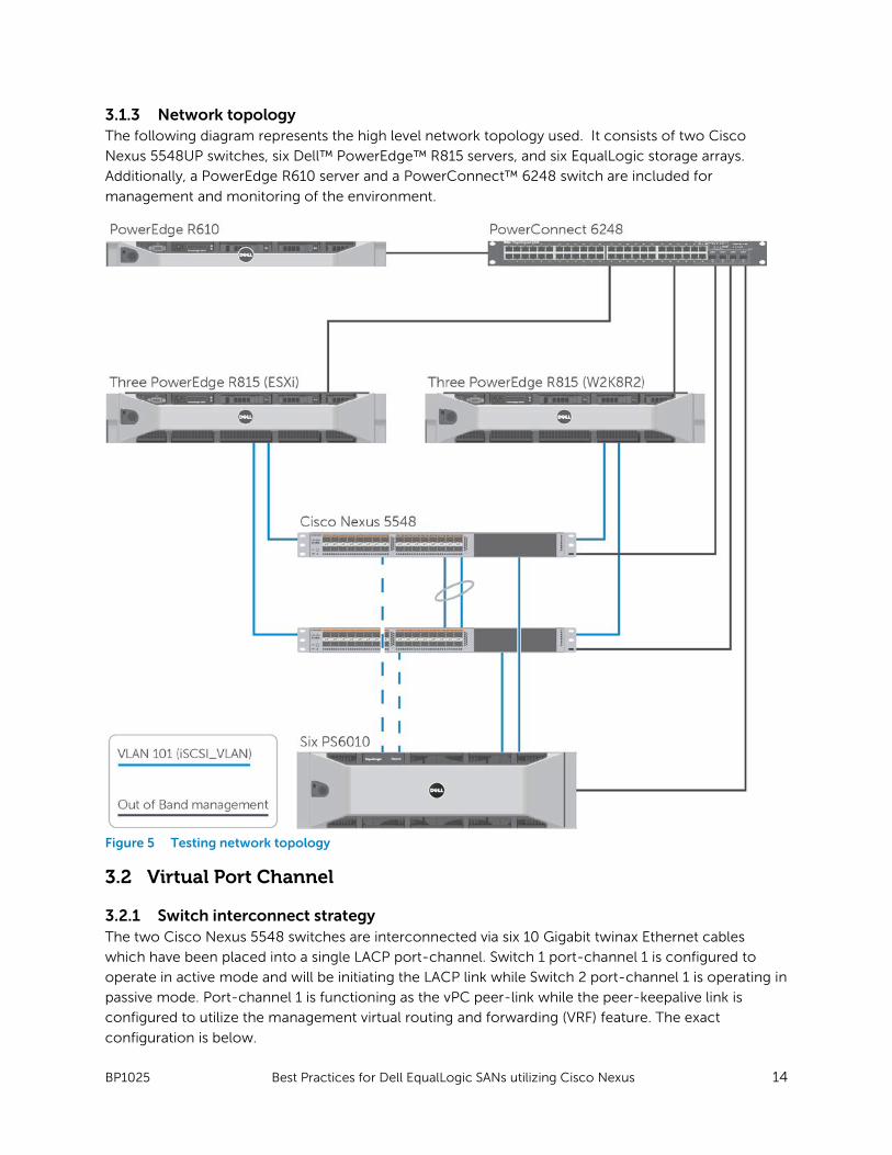
3.1.3 Network topology The following diagram represents the high level network topology used. It consists of two Cisco
Nexus 5548UP switches, six Dell™ PowerEdge™ R815 servers, and six EqualLogic storage arrays.
Additionally, a PowerEdge R610 server and a PowerConnect™ 6248 switch are included for
management and monitoring of the environment.
Figure 5 Testing network topology
3.2 Virtual Port Channel
3.2.1 Switch interconnect strategy The two Cisco Nexus 5548 switches are interconnected via six 10 Gigabit twinax Ethernet cables
which have been placed into a single LACP port-channel. Switch 1 port-channel 1 is configured to
operate in active mode and will be initiating the LACP link while Switch 2 port-channel 1 is operating in
passive mode. Port-channel 1 is functioning as the vPC peer-link while the peer-keepalive link is
configured to utilize the management virtual routing and forwarding (VRF) feature. The exact
configuration is below.
Page 16
BP1025 Best Practices for Dell EqualLogic SANs utilizing Cisco Nexus 15
There are several things to note about the configuration:
• The vPC domain is the same on each switch (vpc domain 1)
• The peer-keepalive destination IP address is just that, the destination IP address of the remote
switch in the vPC configuration.
• Port-channel 1 and the member ports have been configured to operate in switchport mode
trunk, and to allow VLAN 101.
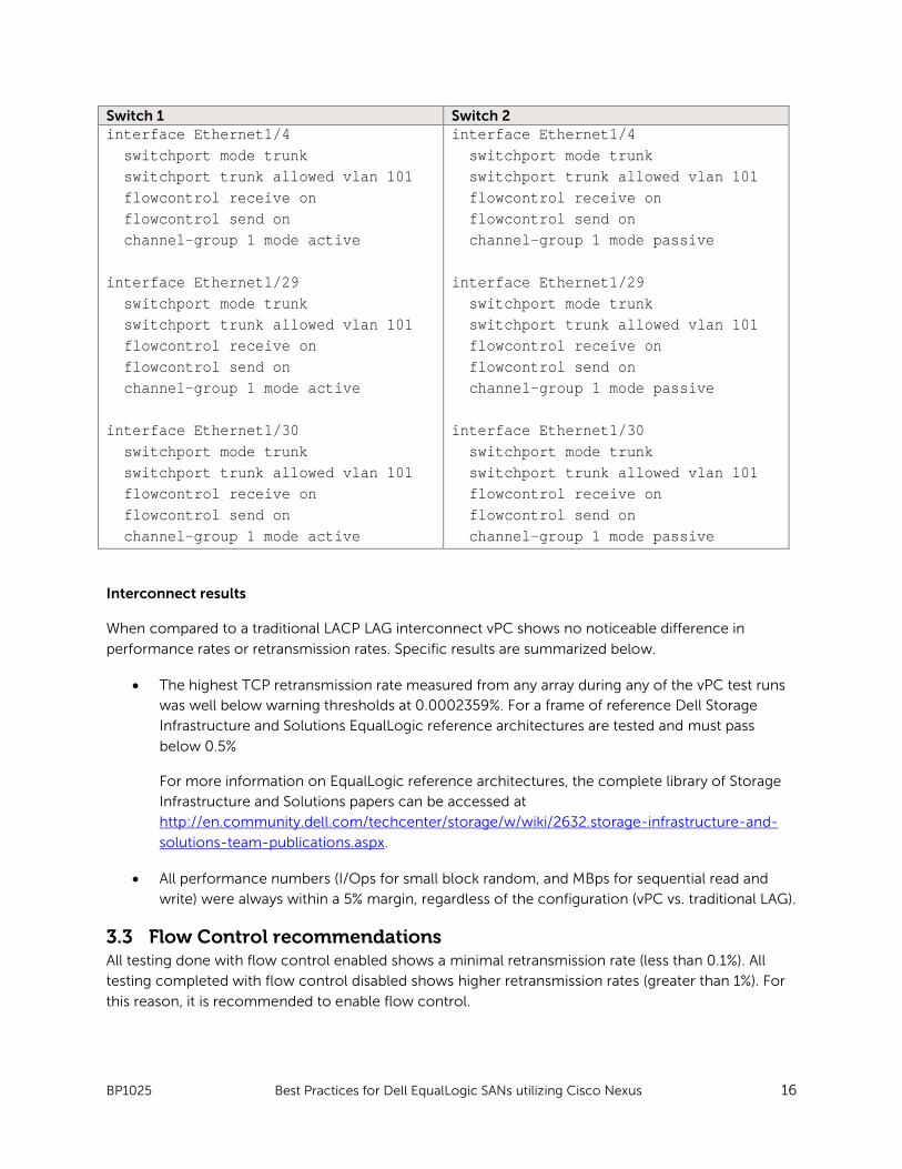
Table 4 Interconnect configuration Switch 1 Switch 2 vpc domain 1 peer-keepalive destination 192.168.2.9 interface mgmt0 ip address 192.168.2.8/24 interface port-channel1 switchport mode trunk vpc peer-link switchport trunk allowed vlan 101 spanning-tree port type network flowcontrol receive on flowcontrol send on interface Ethernet1/1 switchport mode trunk switchport trunk allowed vlan 101 flowcontrol receive on flowcontrol send on channel-group 1 mode active interface Ethernet1/2 switchport mode trunk switchport trunk allowed vlan 101 flowcontrol receive on flowcontrol send on channel-group 1 mode active interface Ethernet1/3 switchport mode trunk switchport trunk allowed vlan 101 flowcontrol receive on flowcontrol send on channel-group 1 mode active
vpc domain 1 peer-keepalive destination 192.168.2.8 interface mgmt0 ip address 192.168.2.9/24 interface port-channel1 switchport mode trunk vpc peer-link switchport trunk allowed vlan 101 spanning-tree port type network flowcontrol receive on flowcontrol send on interface Ethernet1/1 switchport mode trunk switchport trunk allowed vlan 101 flowcontrol receive on flowcontrol send on channel-group 1 mode passive interface Ethernet1/2 switchport mode trunk switchport trunk allowed vlan 101 flowcontrol receive on flowcontrol send on channel-group 1 mode passive interface Ethernet1/3 switchport mode trunk switchport trunk allowed vlan 101 flowcontrol receive on flowcontrol send on channel-group 1 mode passive
Page 17
BP1025 Best Practices for Dell EqualLogic SANs utilizing Cisco Nexus 16
Switch 1 Switch 2 interface Ethernet1/4 switchport mode trunk switchport trunk allowed vlan 101 flowcontrol receive on flowcontrol send on channel-group 1 mode active interface Ethernet1/29 switchport mode trunk switchport trunk allowed vlan 101 flowcontrol receive on flowcontrol send on channel-group 1 mode active interface Ethernet1/30 switchport mode trunk switchport trunk allowed vlan 101 flowcontrol receive on flowcontrol send on channel-group 1 mode active
interface Ethernet1/4 switchport mode trunk switchport trunk allowed vlan 101 flowcontrol receive on flowcontrol send on channel-group 1 mode passive interface Ethernet1/29 switchport mode trunk switchport trunk allowed vlan 101 flowcontrol receive on flowcontrol send on channel-group 1 mode passive interface Ethernet1/30 switchport mode trunk switchport trunk allowed vlan 101 flowcontrol receive on flowcontrol send on channel-group 1 mode passive
Interconnect results
When compared to a traditional LACP LAG interconnect vPC shows no noticeable difference in
performance rates or retransmission rates. Specific results are summarized below.
• The highest TCP retransmission rate measured from any array during any of the vPC test runs
was well below warning thresholds at 0.0002359%. For a frame of reference Dell Storage
Infrastructure and Solutions EqualLogic reference architectures are tested and must pass
below 0.5%
For more information on EqualLogic reference architectures, the complete library of Storage
Infrastructure and Solutions papers can be accessed at
http://en.community.dell.com/techcenter/storage/w/wiki/2632.storage-infrastructure-and-
solutions-team-publications.aspx.
• All performance numbers (I/Ops for small block random, and MBps for sequential read and
write) were always within a 5% margin, regardless of the configuration (vPC vs. traditional LAG).
3.3 Flow Control recommendations All testing done with flow control enabled shows a minimal retransmission rate (less than 0.1%). All
testing completed with flow control disabled shows higher retransmission rates (greater than 1%). For
this reason, it is recommended to enable flow control.
Page 18
BP1025 Best Practices for Dell EqualLogic SANs utilizing Cisco Nexus 17
3.4 Layer 2 frame size The layer 2 frame size portion of this paper examines the benefits of adjusting the default MTU size on
the Cisco Nexus 5548. With Cisco positioning the 5548 as a very capable FCoE switch, the effects of
EqualLogic Storage running on a network infrastructure configured at common frame sizes were
examined; 1500 MTU for standard Ethernet frame size, 2500 MTU for standard FCoE frame size and
9000 MTU for generally agreed jumbo frame size.
Note: EqualLogic storage will only negotiate to 1500 and 9000 MTU.
Note: In the graphs below, each physical server is driving two NICs while each virtual machine is
driving a single NIC.
• No change is observed when going from 1500MTU to 2500MTU
• The number of I/Os per second remained constant with the varying frame size, and all three
variations resulted in numbers within 4% of each other.
• The number of MBps for sequential reads shows a minimum increase of three times when
going from 1500MTU to 9216MTU
Page 19
BP1025 Best Practices for Dell EqualLogic SANs utilizing Cisco Nexus 18
• The number of MBps for sequential writes shows an increase of 1.5 times when going from
1500MTU to 9216MTU
Page 20
BP1025 Best Practices for Dell EqualLogic SANs utilizing Cisco Nexus 19
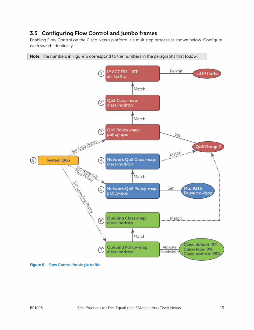
3.5 Configuring Flow Control and jumbo frames Enabling Flow Control on the Cisco Nexus platform is a multistep process as shown below. Configure
each switch identically.
Note: The numbers in Figure 6 correspond to the numbers in the paragraphs that follow.
Figure 6 Flow Control for single traffic
Page 21
BP1025 Best Practices for Dell EqualLogic SANs utilizing Cisco Nexus 20
Quality of Service
In a single traffic type (dedicated iSCSI) environment, all traffic should be in the no-drop policy. To
configure this, create an IP access list that will match all traffic, and then configure a class-map of type
QoS to match all traffic matched by the IP access list. Finally, configure a policy-map of type QoS to
place all traffic matched by the class map into QoS group 2.
1. Define IP access list
sw1(config)# ip access-list all_traffic
sw1(config-acl)# permit ip any any
2. Define qos class-map
sw1(config)# class-map type qos class-nodrop
sw1(config-cmap-qos)# match access-group name all_traffic
3. Define qos policy-map
sw1(config)# policy-map type qos policy-qos
sw1(config-pmap-qos)# class type qos class-nodrop
sw1(config-pmap-c-qos)# set qos-group 2
Network-QoS
The type network QoS policy is used to match (class map) the specified system class (qos-group 2)
and then apply (policy map) the desired changes, in this case maximum transmission unit (MTU) and to
enable the no-drop action.
4. Define network-qos Class-Map
sw1(config)# class-map type network-qos class-nodrop
sw1(config-cmap-nq)# match qos-group 2
5. Define network-qos Policy-map with no-drop and add jumbo frames
sw1(config)# policy-map type network-qos policy-nq
sw1(config-pmap-nq)# class type network-qos class-nodrop
sw1(config-pmap-nq-c)# mtu 9216
sw1(config-pmap-nq-c)# pause no-drop
Queuing
The type queuing policy is used to match (class map) the specified system class (QoS group 2) and
then to apply (policy map) the specified queuing parameters, in this scenario the bandwidth utilization.
6. Define queuing Class-map
sw1(config)# class-map type queuing class-nodrop
sw1(config-cmap-qos)# match qos-group 2
Page 22
BP1025 Best Practices for Dell EqualLogic SANs utilizing Cisco Nexus 21
7. Define queuing Policy-map
sw1(config-cmap-qos)# policy-map type queuing policy-queuing
sw1(config-policy-c-que)# class type queuing class-default
sw1(config-policy-c-que# bandwidth percent 5
sw1(config-policy-c-que)# class type queuing class-fcoe
sw1(config-policy-c-que))# bandwidth percent 0
sw1(config-policy-c-que)# class type queuing class-nodrop
sw1(config-policy-c-que)# bandwidth percent 95
QoS target: system
Each of the previously defined policy maps are then attached to their respective types at the system
level QoS target: system QoS.
8. Apply new policy-maps to system qos target
sw1(config)# system qos
sw1(config-sys-qos)# service-policy type qos input policy-qos
sw1(config-sys-qos)# service-policy type queuing output policy-queuing
sw1(config-sys-qos)# service-policy type network-qos policy-nq
9. Enable PAUSE for all interfaces and PortChannel
sw1(config)interface e1/1
sw1(config-if)# flowcontrol send on
sw1(config-if)# flowcontrol receive on
3.6 Single traffic results When using the configuration detailed above for a dedicated iSCSI network, iSCSI traffic is able to
traverse the network successfully. Success is defined as minimal TCP/IP retransmissions for iSCSI
traffic, no iSCSI disconnects, and no major failures (BSoD, PSoD, etc).
Page 23
BP1025 Best Practices for Dell EqualLogic SANs utilizing Cisco Nexus 22
4 Shared network (iSCSI and LAN) Cisco provides support for DCB and DCBx for FCoE. However, Cisco does not (as of March 2012)
support the iSCSI TLV function needed to utilize DCB with EqualLogic storage. This paper outlines
designing a network that safely transports iSCSI traffic along with LAN traffic in lieu of Cisco providing
iSCSI TLV support.
4.1 Focus of testing The mixed traffic types testing analyzed in this section concentrates on providing a reliable and well
performing network for EqualLogic iSCSI storage and LAN traffic using Cisco Nexus switches. Several
varying workloads (Storage and LAN) were used to simulate network load.
4.1.1 Workload The table below shows the breakdown for the load applied to the EqualLogic storage. Each test was
run for nine hour duration to ensure the configuration exhibited expected stability and consistent
performance over an extended period of time. For each test cycle, each workload was run in the order
shown, and for the duration shown.
Table 5 Storage load breakdown
During mixed workload scenarios, LAN traffic (IP traffic) load was provided using an IP load generation
tool; the load consumed 70% of the pipe when at a steady state with no storage traffic running. More
information is provided in the section titled, “Mixed traffic types through a single Ethernet Core” on
page 22.
Sample storage load and IP load generation configurations can be found in Appendix B of this
whitepaper.
IO Pattern Block Size Read/Write Ratio Duration Random 8 KB 67/33 3 Hours Sequential Read
256 KB 100 / 0 3 Hours
Sequential Write
64 KB 0 / 100 3 Hours
Page 24
BP1025 Best Practices for Dell EqualLogic SANs utilizing Cisco Nexus 23
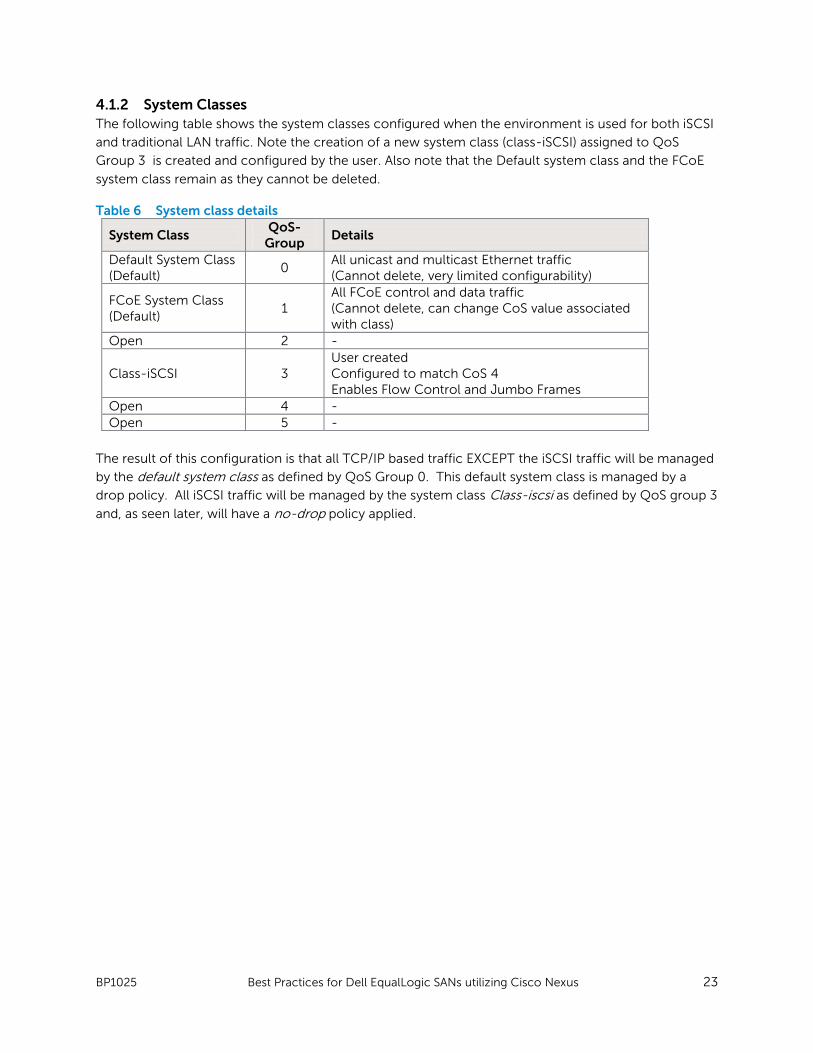
4.1.2 System Classes The following table shows the system classes configured when the environment is used for both iSCSI
and traditional LAN traffic. Note the creation of a new system class (class-iSCSI) assigned to QoS
Group 3 is created and configured by the user. Also note that the Default system class and the FCoE
system class remain as they cannot be deleted.
Table 6 System class details
The result of this configuration is that all TCP/IP based traffic EXCEPT the iSCSI traffic will be managed
by the default system class as defined by QoS Group 0. This default system class is managed by a
drop policy. All iSCSI traffic will be managed by the system class Class-iscsi as defined by QoS group 3
and, as seen later, will have a no-drop policy applied.
System Class QoS-
Group Details
Default System Class (Default)
0 All unicast and multicast Ethernet traffic (Cannot delete, very limited configurability)
FCoE System Class (Default)
1 All FCoE control and data traffic (Cannot delete, can change CoS value associated with class)
Open 2 -
Class-iSCSI 3 User created Configured to match CoS 4 Enables Flow Control and Jumbo Frames
Open 4 - Open 5 -
Page 25
BP1025 Best Practices for Dell EqualLogic SANs utilizing Cisco Nexus 24
4.2 Mixed traffic topology Below is the network topology for the mixed traffic configuration. Note that there are now four
network connections from each server into the Nexus Fabric: two are used exclusively for iSCSI traffic
and are placed into vlan 101 (iSCSI_VLAN), and two are used exclusively for LAN or other IP traffic and
are placed into vlan 102 (LAN_VLAN). For exact port mapping details please see Appendix D.
Figure 7 Mixed traffic network topology
Page 26
BP1025 Best Practices for Dell EqualLogic SANs utilizing Cisco Nexus 25
4.2.1 Switch interconnect strategy The two Cisco Nexus 5548 switches are interconnected via six 10 Gigabit twinax connections which
have been placed into a single LACP port-channel. Switch 1 port-channel 1 is active in initiating the
LACP link, while Switch 2 port-channel 1 is passive. Port-channel 1 is functioning as the vPC peer-link
while the peer-keepalive link is configured to utilize the management virtual routing and forwarding
(VRF). The exact configuration is below.
There are several things to note about the configuration:
• The vPC domain is the same on each switch (vpc domain 1)
• The peer-keepalive destination IP address is just that, the destination IP address of the remote
switch in the vPC configuration.
• Port-Channel 1 and the member ports have been configured to operate in switchport mode
trunk, and to allow both VLAN 101 and VLAN 102.
Table 7 Interconnect configuration Switch 1 Switch 2 vpc domain 1 peer-keepalive destination 192.168.2.9 interface mgmt0 ip address 192.168.2.8/24 interface port-channel1 switchport mode trunk vpc peer-link switchport trunk allowed vlan 101-102 spanning-tree port type network flowcontrol receive on flowcontrol send on interface Ethernet1/1 switchport mode trunk switchport trunk allowed vlan 101-102 flowcontrol receive on flowcontrol send on channel-group 1 mode active interface Ethernet1/2 switchport mode trunk switchport trunk allowed vlan 101-102 flowcontrol receive on
vpc domain 1 peer-keepalive destination 192.168.2.8 interface mgmt0 ip address 192.168.2.9/24 interface port-channel1 switchport mode trunk vpc peer-link switchport trunk allowed vlan 101-102 spanning-tree port type network flowcontrol receive on flowcontrol send on interface Ethernet1/1 switchport mode trunk switchport trunk allowed vlan 101-102 flowcontrol receive on flowcontrol send on channel-group 1 mode passive interface Ethernet1/2 switchport mode trunk switchport trunk allowed vlan 101-102 flowcontrol receive on
Page 27
BP1025 Best Practices for Dell EqualLogic SANs utilizing Cisco Nexus 26
Switch 1 Switch 2 flowcontrol send on channel-group 1 mode active interface Ethernet1/3 switchport mode trunk switchport trunk allowed vlan 101-102 flowcontrol receive on flowcontrol send on channel-group 1 mode active interface Ethernet1/4 switchport mode trunk switchport trunk allowed vlan 101-102 flowcontrol receive on flowcontrol send on channel-group 1 mode active interface Ethernet1/29 switchport mode trunk switchport trunk allowed vlan 101-102 flowcontrol receive on flowcontrol send on channel-group 1 mode active interface Ethernet1/30 switchport mode trunk switchport trunk allowed vlan 101-102 flowcontrol receive on flowcontrol send on channel-group 1 mode active
flowcontrol send on channel-group 1 mode passive interface Ethernet1/3 switchport mode trunk switchport trunk allowed vlan 101-102 flowcontrol receive on flowcontrol send on channel-group 1 mode passive interface Ethernet1/4 switchport mode trunk switchport trunk allowed vlan 101-102 flowcontrol receive on flowcontrol send on channel-group 1 mode passive interface Ethernet1/29 switchport mode trunk switchport trunk allowed vlan 101-102 flowcontrol receive on flowcontrol send on channel-group 1 mode passive interface Ethernet1/30 switchport mode trunk switchport trunk allowed vlan 101-102 flowcontrol receive on flowcontrol send on channel-group 1 mode passive
Page 28
BP1025 Best Practices for Dell EqualLogic SANs utilizing Cisco Nexus 27
4.3 Configuration details This section describes configuring class maps and policy maps for a mixed traffic environment. The
configuration shows how to create separate policies for iSCSI and LAN traffic, how to enable Flow
Control and jumbo frames for iSCSI traffic, and how to match iSCSI traffic without the assistance of
the iSCSI TLV (manual classification).
Figure 8 Flow Control for mixed traffic
Page 29
BP1025 Best Practices for Dell EqualLogic SANs utilizing Cisco Nexus 28
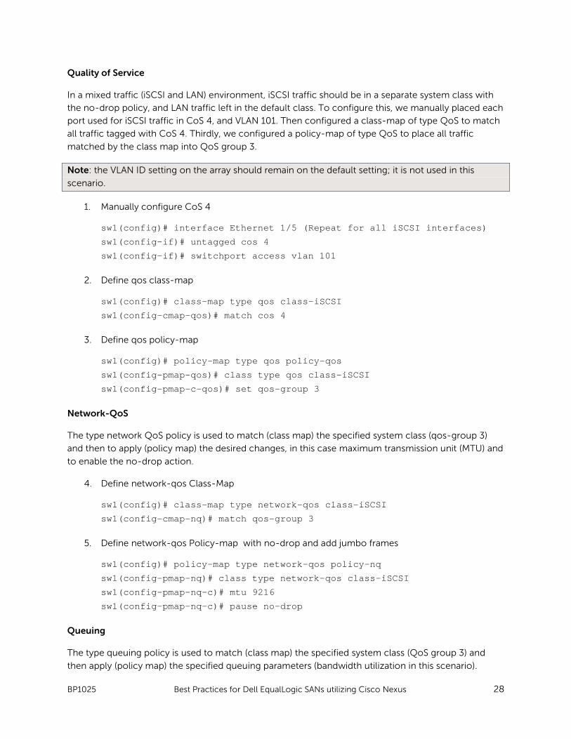
Quality of Service
In a mixed traffic (iSCSI and LAN) environment, iSCSI traffic should be in a separate system class with
the no-drop policy, and LAN traffic left in the default class. To configure this, we manually placed each
port used for iSCSI traffic in CoS 4, and VLAN 101. Then configured a class-map of type QoS to match
all traffic tagged with CoS 4. Thirdly, we configured a policy-map of type QoS to place all traffic
matched by the class map into QoS group 3.
Note: the VLAN ID setting on the array should remain on the default setting; it is not used in this
scenario.
1. Manually configure CoS 4
sw1(config)# interface Ethernet 1/5 (Repeat for all iSCSI interfaces)
sw1(config-if)# untagged cos 4
sw1(config-if)# switchport access vlan 101
2. Define qos class-map
sw1(config)# class-map type qos class-iSCSI
sw1(config-cmap-qos)# match cos 4
3. Define qos policy-map
sw1(config)# policy-map type qos policy-qos
sw1(config-pmap-qos)# class type qos class-iSCSI
sw1(config-pmap-c-qos)# set qos-group 3
Network-QoS
The type network QoS policy is used to match (class map) the specified system class (qos-group 3)
and then to apply (policy map) the desired changes, in this case maximum transmission unit (MTU) and
to enable the no-drop action.
4. Define network-qos Class-Map
sw1(config)# class-map type network-qos class-iSCSI
sw1(config-cmap-nq)# match qos-group 3
5. Define network-qos Policy-map with no-drop and add jumbo frames
sw1(config)# policy-map type network-qos policy-nq
sw1(config-pmap-nq)# class type network-qos class-iSCSI
sw1(config-pmap-nq-c)# mtu 9216
sw1(config-pmap-nq-c)# pause no-drop
Queuing
The type queuing policy is used to match (class map) the specified system class (QoS group 3) and
then apply (policy map) the specified queuing parameters (bandwidth utilization in this scenario).
Page 30
BP1025 Best Practices for Dell EqualLogic SANs utilizing Cisco Nexus 29
6. Define queuing Class-map
sw1(config)# class-map type queuing class-iSCSI
sw1(config-cmap-qos)# match qos-group 3
7. Define queuing Policy-map
sw1(config-cmap-qos)# policy-map type queuing policy-queuing
sw1(config-policy-c-que)# class type queuing class-default
sw1(config-policy-c-que# bandwidth percent 50
sw1(config-policy-c-que)# class type queuing class-fcoe
sw1(config-policy-c-que))# bandwidth percent 0
sw1(config-policy-c-que)# class type queuing class-iSCSI
sw1(config-policy-c-que)# bandwidth percent 50
QoS Target: System
Next, each of the previously defined policy maps are attached to their respective types at the system
level QoS target: system QoS.
8. Apply new policy-maps to system qos target
sw1(config)# system qos
sw1(config-sys-qos)# service-policy type qos input policy-qos
sw1(config-sys-qos)# service-policy type queuing output policy-queuing
sw1(config-sys-qos)# service-policy type network-qos policy-nq
9. Enable PAUSE for all interfaces and PortChannel
sw1(config)interface Ethernet 1/1
sw1(config-if)# flowcontrol send on
sw1(config-if)# flowcontrol receive on
4.4 Results When using the configuration detailed above, both iSCSI and simulated LAN traffic were able to
traverse the network successfully. Success is defined as minimal TCP/IP retransmissions for iSCSI
traffic, no iSCSI disconnects, and no major failures (BSoD, PSoD, etc).
To ensure appropriate flow control response, the switch interconnect was reduced to two 10 Gb links,
creating a network bottleneck and guaranteeing resource contention when under a heavy workload
(large block sequential reads). Even in this scenario, retransmission rates remained below 0.01% with
no iSCSI disconnects and storage traffic was able to sustain 50% of the total available as allocated in
the policy-map.
Note: creating a network bottleneck is not recommended as storage performance will be degraded
while in this state, although, data loss remained minimal.
Page 31
BP1025 Best Practices for Dell EqualLogic SANs utilizing Cisco Nexus 30
5 Conclusions The most secure and most reliable method of transporting iSCSI traffic is to dedicate at least one pair
of switches for a dedicated iSCSI network. This provides many benefits while avoiding overly complex
scenarios and organizational issues.
As Data Center Bridging capable infrastructures are deployed, the reality of a shared, converged data
center network infrastructure requires that networked storage solutions be able to coexist while
continuing to provide deterministic, reliable performance. By following the recommendations in this
paper, EqualLogic can provide consistent, high-performance storage services within a shared network
environment built on the Cisco Nexus network platform.
Planning for a shared network will take additional planning and coordination and the following general
recommendations should be considered:
• Separation of traffic: Many forms of Ethernet traffic can be chatty. At a minimum, place iSCSI
traffic on a separate VLAN to reduce noise from other networks.
• Priority of traffic: The network design should be carefully examined to ensure that every
network device in the path can and will recognize the priority of CoS 4 as a no-drop class to
ensure proper flow control management.
• Size switch interconnects: When designing the network, be sure to appropriately size
interconnects between switches. This is fairly simple for two switches, but becomes
increasingly complex as the number of switches grows. For this reason, exam every network
device in the path individually and then examine all the paths holistically to guarantee reliable
service.
• Provide adequate bandwidth for storage traffic: DCB provides the ability to configure
bandwidth guarantees through the ETS protocol by using the Nexus queuing policy bandwidth
parameter. Designing your bandwidth map for multiple traffic types needs to be tested to
ensure that storage network traffic bandwidth is adequate to support your application storage
needs.
• Flexibility is powerful and dangerous: The Cisco Nexus architecture, with NX-OS, provides
flexible and powerful configuration ability with its policy map, class map, and system class
configuration structure. But be aware that a seemingly simple change in the configuration file
can have sweeping impacts.
A correctly designed shared network infrastructure provides many practical benefits. This paper
describes a safe way to accommodate a shared infrastructure utilizing Cisco Nexus and many of the
benefits of DCB even without the use of the iSCSI TLV and still protecting iSCSI traffic.
Page 32
BP1025 Best Practices for Dell EqualLogic SANs utilizing Cisco Nexus 31
Appendix A Test configuration details This appendix contains the required information to reproduce the environment and simulated
scenarios described throughout the paper.
A.1 Server configuration Table 8 Physical load server
Dell PowerEdge R815 Configuration (x3) Function Physical load generation servers
Processors 4 x AMD Opteron™ Processor 6174 2.20GHz, L2/L3 Cache: 6MB/10MB
Memory 128 GB BIOS 1.5.2
Onboard NIC Broadcom 5709 Quad Port 1GbE NIC with TOE iSCSI test network interface Intel® 10 Gigabit AF DA Dual Port Server Adapter LAN test network interface Intel® 10 Gigabit AF DA Dual Port Server Adapter Embedded Management iDRAC6 Enterprise Operating System Windows Server 2008 R2with SP1
Table 9 PowerEdge R815 server
PowerEdge R815 Configuration (x3) Function Host to load generation virtual machines
Processors 4 x AMD Opteron™ Processor 6174 2.20GHz, L2/L3 Cache: 6MB/10MB
Memory 128 GB BIOS 1.5.2
Onboard NIC Broadcom 5709 Quad Port 1GbE NIC with TOE iSCSI test network interface Intel® 10 Gigabit AF DA Dual Port Server Adapter LAN test network interface Intel® 10 Gigabit AF DA Dual Port Server Adapter Embedded Management iDRAC6 Enterprise Operating System VMware ESXi 4.1 update 1
Table 10 PowerEdge R610 server
PowerEdge R610 Configuration (x1) Function Management Host
Processors 2 x Intel Xeon X5520, 2.27Ghz, 8M Cache, 5.86 GT/s QPI, Turbo, HT
Memory 24GB Memory BIOS 1.2.7
Onboard NIC Broadcom 5709 Quad Port 1GbE NIC with TOE Embedded Management iDRAC6 Enterprise Operating System Windows Server 2008 R2with SP1
Page 33
BP1025 Best Practices for Dell EqualLogic SANs utilizing Cisco Nexus 32
Table 11 Network configuration
Cisco Nexus 5548 UP (x2) Function Test Fabric
Expansion Card Not installed NX-OS Version BIOS: version 3.5.0
loader: version N/A
kickstart: version 5.0(3)N2(2)
system: version 5.0(3)N2(2)
Table 12 Array
Dell PowerConnect 6248 Function Out-of-Band Management
Table 13 Storage
Dell EqualLogic PS6010E (x6) Function iSCSI SAN
Disks 7.2K 500GB SATA-II Firmware V5.1.2
Page 34
BP1025 Best Practices for Dell EqualLogic SANs utilizing Cisco Nexus 33
Appendix B Load generation configuration file Multiple tools were utilized for load generation. To provide storage traffic to the disks, VDBench was
used for its simplicity and script ability. To provide TCP traffic, emulated LAN traffic iPerf was used for
its simplicity and script ability.
VDBench Config Server01 (Physical Windows Host)
sd=A-a,lun=\\.\PhysicalDrive1
sd=A-b,lun=\\.\PhysicalDrive2
sd=A-c,lun=\\.\PhysicalDrive3
sd=A-d,lun=\\.\PhysicalDrive4
sd=B-a,lun=\\.\PhysicalDrive1,range=(30m,60m)
sd=B-b,lun=\\.\PhysicalDrive2,range=(30m,60m)
sd=B-c,lun=\\.\PhysicalDrive3,range=(30m,60m)
sd=B-d,lun=\\.\PhysicalDrive4,range=(30m,60m)
wd=wd1,sd=A-*,seekpct=100,rdpct=67,xfersize=8k,iorate=9999999,priority=1
wd=wd2,sd=B-
*,seekpct=0,rdpct=100,xfersize=256k,iorate=9999999,priority=1
wd=wd3,sd=B-*,seekpct=0,rdpct=0,xfersize=64k,iorate=9999999,priority=1
rd=rd1,wd=wd1,elapsed=10800,interval=30,forthreads=20
rd=rd2,wd=wd2,elapsed=10800,interval=30,forthreads=5
rd=rd3,wd=wd3,elapsed=10800,interval=30,forthreads=5
B.1 iPerf configs, traffic server (Win_vm04) Iperf.exe -f M -i 3 -l 256K -w 256K -s -B 192.168.15.70
Flag Explanation
-f [kmKM] Format to report: Kbits, Mbits, Kbytes, MBytes -i # Seconds between periodic bandwidth reports -l #[KM] Length of buffer to read or write -w #[KM] TCP Window size -s Run in server mode -B [IP Address] Bind to local interface at local IP Address
Traffic Generator (Win_vm01)
iperf.exe -f M -i 3 -l 256k -w 256k -c 192.168.15.70 -B 192.168.15.65 -P
48 -t 57600
Flag Explanation
-c [IP Address] Run in client mode and connect to Sink at IP Address -P # Number of parallel client threads to run -t # Time in seconds to transmit
Page 35
BP1025 Best Practices for Dell EqualLogic SANs utilizing Cisco Nexus 34
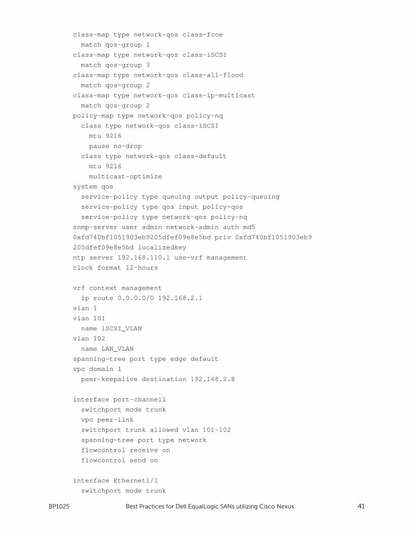
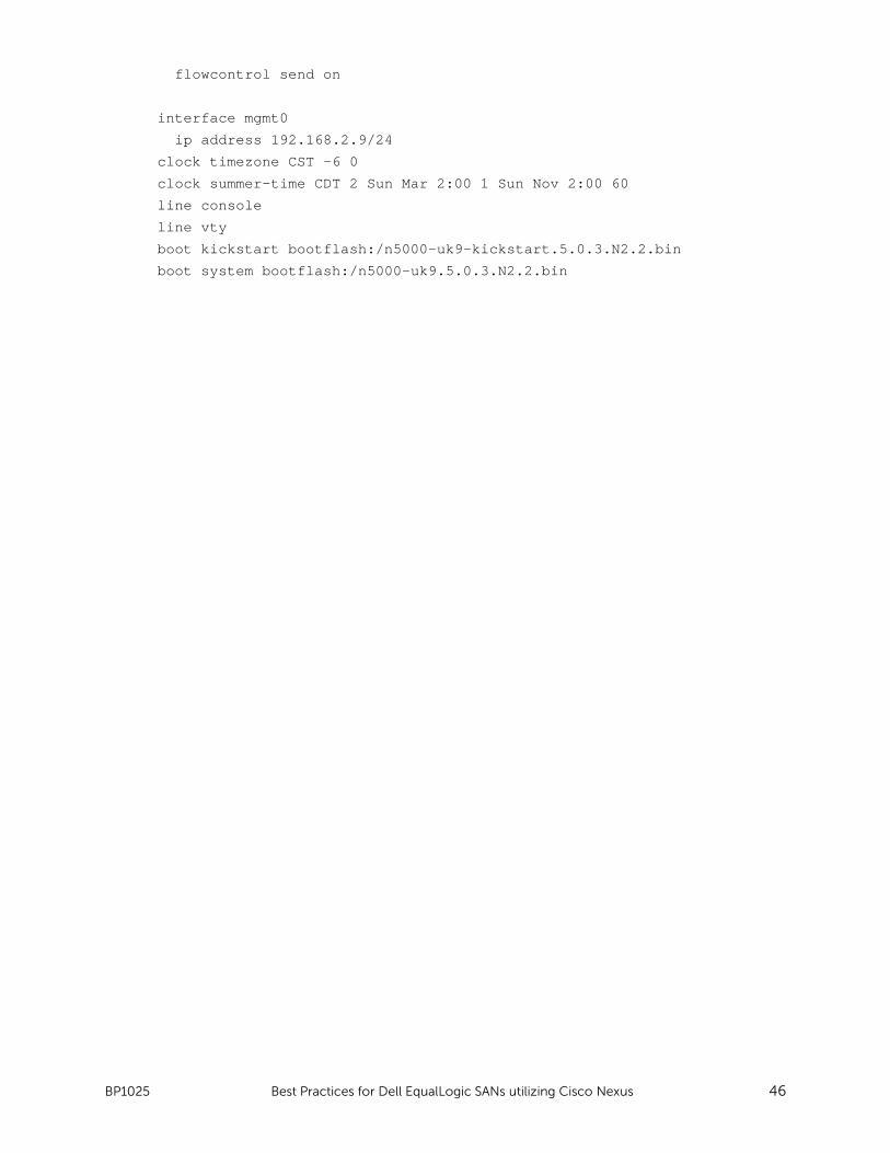
Appendix C Switch running-config files
C.1 Switch 1 !Command: show running-config
!Time: Thu Feb 2 17:16:45 2012
version 5.0(3)N2(2)
feature telnet
cfs eth distribute
feature lacp
feature vpc
feature lldp
username admin password 5 $1$x8xyDrUL$1khlgBhZkG8F6HA2wZDWY/ role
network-admin
no password strength-check
ip domain-lookup
hostname admin
class-map type qos class-fcoe
class-map type qos match-all class-temp
class-map type qos match-all class-iSCSI
match cos 4
class-map type queuing class-fcoe
match qos-group 1
class-map type queuing class-iSCSI
match qos-group 3
class-map type queuing class-all-flood
match qos-group 2
class-map type queuing class-ip-multicast
match qos-group 2
policy-map type qos policy-qos
class class-iSCSI
set qos-group 3
policy-map type queuing policy-queuing
class type queuing class-fcoe
bandwidth percent 0
class type queuing class-iSCSI
bandwidth percent 50
class type queuing class-default
bandwidth percent 50
class-map type network-qos class-fcoe
match qos-group 1
class-map type network-qos class-iSCSI
match qos-group 3
Page 36
BP1025 Best Practices for Dell EqualLogic SANs utilizing Cisco Nexus 35
class-map type network-qos class-nodrop
match qos-group 2
class-map type network-qos class-all-flood
match qos-group 2
class-map type network-qos class-ip-multicast
match qos-group 2
policy-map type network-qos policy-nq
class type network-qos class-iSCSI
mtu 9216
pause no-drop
class type network-qos class-default
mtu 9216
multicast-optimize
system qos
service-policy type qos input policy-qos
service-policy type network-qos policy-nq
service-policy type queuing output policy-queuing
snmp-server user admin network-admin auth md5
0xcbacad45ab1363cf74d40d069a60454f priv 0xcbacad45
ab1363cf74d40d069a60454f localizedkey
ntp server 192.168.110.1 use-vrf management
clock format 12-hours
vrf context management
ip route 0.0.0.0/0 192.168.2.1
vlan 1
vlan 101
name iSCSI_VLAN
vlan 102
name LAN_VLAN
spanning-tree port type edge default
vpc domain 1
peer-keepalive destination 192.168.2.9
interface port-channel1
switchport mode trunk
vpc peer-link
switchport trunk allowed vlan 101-102
spanning-tree port type network
flowcontrol receive on
flowcontrol send on
interface Ethernet1/1
switchport mode trunk
switchport trunk allowed vlan 101-102
flowcontrol receive on
Page 37
BP1025 Best Practices for Dell EqualLogic SANs utilizing Cisco Nexus 36
flowcontrol send on
channel-group 1 mode active
interface Ethernet1/2
switchport mode trunk
switchport trunk allowed vlan 101-102
flowcontrol receive on
flowcontrol send on
channel-group 1 mode active
interface Ethernet1/3
switchport mode trunk
switchport trunk allowed vlan 101-102
flowcontrol receive on
flowcontrol send on
channel-group 1 mode active
interface Ethernet1/4
switchport mode trunk
switchport trunk allowed vlan 101-102
flowcontrol receive on
flowcontrol send on
channel-group 1 mode active
interface Ethernet1/5
untagged cos 4
switchport access vlan 101
flowcontrol receive on
flowcontrol send on
interface Ethernet1/6
switchport access vlan 102
flowcontrol receive on
flowcontrol send on
interface Ethernet1/7
untagged cos 4
switchport access vlan 101
flowcontrol receive on
flowcontrol send on
interface Ethernet1/8
switchport access vlan 102
flowcontrol receive on
flowcontrol send on
Page 38
BP1025 Best Practices for Dell EqualLogic SANs utilizing Cisco Nexus 37
interface Ethernet1/9
untagged cos 4
switchport access vlan 101
flowcontrol receive on
flowcontrol send on
interface Ethernet1/10
switchport access vlan 102
flowcontrol receive on
flowcontrol send on
interface Ethernet1/11
untagged cos 4
switchport access vlan 101
flowcontrol receive on
flowcontrol send on
interface Ethernet1/12
switchport access vlan 102
flowcontrol receive on
flowcontrol send on
interface Ethernet1/13
untagged cos 4
switchport access vlan 101
flowcontrol receive on
flowcontrol send on
interface Ethernet1/14
shutdown
interface Ethernet1/15
untagged cos 4
switchport access vlan 101
flowcontrol receive on
flowcontrol send on
interface Ethernet1/16
switchport access vlan 102
flowcontrol receive on
flowcontrol send on
interface Ethernet1/17
untagged cos 4
switchport access vlan 101
flowcontrol receive on
Page 39
BP1025 Best Practices for Dell EqualLogic SANs utilizing Cisco Nexus 38
flowcontrol send on
interface Ethernet1/18
untagged cos 4
switchport access vlan 101
flowcontrol receive on
flowcontrol send on
interface Ethernet1/19
untagged cos 4
switchport access vlan 101
flowcontrol receive on
flowcontrol send on
interface Ethernet1/20
untagged cos 4
switchport access vlan 101
flowcontrol receive on
flowcontrol send on
interface Ethernet1/21
untagged cos 4
switchport access vlan 101
flowcontrol receive on
flowcontrol send on
interface Ethernet1/22
untagged cos 4
switchport access vlan 101
flowcontrol receive on
flowcontrol send on
interface Ethernet1/23
untagged cos 4
switchport access vlan 101
flowcontrol receive on
flowcontrol send on
interface Ethernet1/24
untagged cos 4
switchport access vlan 101
flowcontrol receive on
flowcontrol send on
interface Ethernet1/25
untagged cos 4
Page 40
BP1025 Best Practices for Dell EqualLogic SANs utilizing Cisco Nexus 39
switchport access vlan 101
flowcontrol receive on
flowcontrol send on
interface Ethernet1/26
untagged cos 4
switchport access vlan 101
flowcontrol receive on
flowcontrol send on
interface Ethernet1/27
untagged cos 4
switchport access vlan 101
flowcontrol receive on
flowcontrol send on
interface Ethernet1/28
untagged cos 4
switchport access vlan 101
flowcontrol receive on
flowcontrol send on
interface Ethernet1/29
switchport mode trunk
switchport trunk allowed vlan 101-102
flowcontrol receive on
flowcontrol send on
channel-group 1 mode active
interface Ethernet1/30
switchport mode trunk
switchport trunk allowed vlan 101-102
flowcontrol receive on
flowcontrol send on
channel-group 1 mode active
interface Ethernet1/31
shutdown
interface Ethernet1/32
switchport access vlan 102
flowcontrol receive on
flowcontrol send on
interface mgmt0
ip address 192.168.2.8/24
Page 41
BP1025 Best Practices for Dell EqualLogic SANs utilizing Cisco Nexus 40
clock timezone CST -6 0
clock summer-time CDT 2 Sun Mar 2:00 1 Sun Nov 2:00 60
line console
line vty
boot kickstart bootflash:/n5000-uk9-kickstart.5.0.3.N2.2.bin
boot system bootflash:/n5000-uk9.5.0.3.N2.2.bin
Switch 2
!Command: show running-config
!Time: Thu Feb 2 17:18:36 2012
version 5.0(3)N2(2)
feature telnet
cfs eth distribute
feature lacp
feature vpc
feature lldp
username admin password 5 $1$K1k8cv8B$APGIzKeladpZP0ZQUwxoI. role
network-admin
no password strength-check
ip domain-lookup
hostname admin
class-map type qos class-fcoe
class-map type qos match-all class-iSCSI
match cos 4
class-map type queuing class-fcoe
match qos-group 1
class-map type queuing class-iSCSI
match qos-group 3
class-map type queuing class-all-flood
match qos-group 2
class-map type queuing class-ip-multicast
match qos-group 2
policy-map type qos policy-qos
class class-iSCSI
set qos-group 3
policy-map type queuing policy-queuing
class type queuing class-fcoe
bandwidth percent 0
class type queuing class-iSCSI
bandwidth percent 50
class type queuing class-default
bandwidth percent 50
policy-map type queuing policy-queueing
class type queuing class-default
Page 42
BP1025 Best Practices for Dell EqualLogic SANs utilizing Cisco Nexus 41
class-map type network-qos class-fcoe
match qos-group 1
class-map type network-qos class-iSCSI
match qos-group 3
class-map type network-qos class-all-flood
match qos-group 2
class-map type network-qos class-ip-multicast
match qos-group 2
policy-map type network-qos policy-nq
class type network-qos class-iSCSI
mtu 9216
pause no-drop
class type network-qos class-default
mtu 9216
multicast-optimize
system qos
service-policy type queuing output policy-queuing
service-policy type qos input policy-qos
service-policy type network-qos policy-nq
snmp-server user admin network-admin auth md5
0xfd740bf1051903eb9205dfef09e8e5bd priv 0xfd740bf1051903eb9
205dfef09e8e5bd localizedkey
ntp server 192.168.110.1 use-vrf management
clock format 12-hours
vrf context management
ip route 0.0.0.0/0 192.168.2.1
vlan 1
vlan 101
name iSCSI_VLAN
vlan 102
name LAN_VLAN
spanning-tree port type edge default
vpc domain 1
peer-keepalive destination 192.168.2.8
interface port-channel1
switchport mode trunk
vpc peer-link
switchport trunk allowed vlan 101-102
spanning-tree port type network
flowcontrol receive on
flowcontrol send on
interface Ethernet1/1
switchport mode trunk
Page 43
BP1025 Best Practices for Dell EqualLogic SANs utilizing Cisco Nexus 42
switchport trunk allowed vlan 101-102
flowcontrol receive on
flowcontrol send on
channel-group 1 mode passive
interface Ethernet1/2
switchport mode trunk
switchport trunk allowed vlan 101-102
flowcontrol receive on
flowcontrol send on
channel-group 1 mode passive
interface Ethernet1/3
switchport mode trunk
switchport trunk allowed vlan 101-102
flowcontrol receive on
flowcontrol send on
channel-group 1 mode passive
interface Ethernet1/4
switchport mode trunk
switchport trunk allowed vlan 101-102
flowcontrol receive on
flowcontrol send on
channel-group 1 mode passive
interface Ethernet1/5
untagged cos 4
switchport access vlan 101
flowcontrol receive on
flowcontrol send on
interface Ethernet1/6
switchport access vlan 102
flowcontrol receive on
flowcontrol send on
interface Ethernet1/7
untagged cos 4
switchport access vlan 101
flowcontrol receive on
flowcontrol send on
interface Ethernet1/8
switchport access vlan 102
flowcontrol receive on
Page 44
BP1025 Best Practices for Dell EqualLogic SANs utilizing Cisco Nexus 43
flowcontrol send on
interface Ethernet1/9
untagged cos 4
switchport access vlan 101
flowcontrol receive on
flowcontrol send on
interface Ethernet1/10
switchport access vlan 102
flowcontrol receive on
flowcontrol send on
interface Ethernet1/11
untagged cos 4
switchport access vlan 101
flowcontrol receive on
flowcontrol send on
interface Ethernet1/12
switchport access vlan 102
flowcontrol receive on
flowcontrol send on
interface Ethernet1/13
untagged cos 4
switchport access vlan 101
flowcontrol receive on
flowcontrol send on
interface Ethernet1/14
switchport access vlan 102
flowcontrol receive on
flowcontrol send on
interface Ethernet1/15
untagged cos 4
switchport access vlan 101
flowcontrol receive on
flowcontrol send on
interface Ethernet1/16
shutdown
interface Ethernet1/17
untagged cos 4
Page 45
BP1025 Best Practices for Dell EqualLogic SANs utilizing Cisco Nexus 44
switchport access vlan 101
flowcontrol receive on
flowcontrol send on
interface Ethernet1/18
untagged cos 4
switchport access vlan 101
flowcontrol receive on
flowcontrol send on
interface Ethernet1/19
untagged cos 4
switchport access vlan 101
flowcontrol receive on
flowcontrol send on
interface Ethernet1/20
untagged cos 4
switchport access vlan 101
flowcontrol receive on
flowcontrol send on
interface Ethernet1/21
untagged cos 4
switchport access vlan 101
flowcontrol receive on
flowcontrol send on
interface Ethernet1/22
untagged cos 4
switchport access vlan 101
flowcontrol receive on
flowcontrol send on
interface Ethernet1/23
untagged cos 4
switchport access vlan 101
flowcontrol receive on
flowcontrol send on
interface Ethernet1/24
untagged cos 4
switchport access vlan 101
flowcontrol receive on
flowcontrol send on
Page 46
BP1025 Best Practices for Dell EqualLogic SANs utilizing Cisco Nexus 45
interface Ethernet1/25
untagged cos 4
switchport access vlan 101
flowcontrol receive on
flowcontrol send on
interface Ethernet1/26
untagged cos 4
switchport access vlan 101
flowcontrol receive on
flowcontrol send on
interface Ethernet1/27
untagged cos 4
switchport access vlan 101
flowcontrol receive on
flowcontrol send on
interface Ethernet1/28
untagged cos 4
switchport access vlan 101
flowcontrol receive on
flowcontrol send on
interface Ethernet1/29
switchport mode trunk
switchport trunk allowed vlan 101-102
flowcontrol receive on
flowcontrol send on
channel-group 1 mode passive
interface Ethernet1/30
switchport mode trunk
switchport trunk allowed vlan 101-102
flowcontrol receive on
flowcontrol send on
channel-group 1 mode passive
interface Ethernet1/31
switchport access vlan 101
flowcontrol receive on
flowcontrol send on
interface Ethernet1/32
switchport access vlan 102
flowcontrol receive on
Page 47
BP1025 Best Practices for Dell EqualLogic SANs utilizing Cisco Nexus 46
flowcontrol send on
interface mgmt0
ip address 192.168.2.9/24
clock timezone CST -6 0
clock summer-time CDT 2 Sun Mar 2:00 1 Sun Nov 2:00 60
line console
line vty
boot kickstart bootflash:/n5000-uk9-kickstart.5.0.3.N2.2.bin
boot system bootflash:/n5000-uk9.5.0.3.N2.2.bin
Page 48
BP1025 Best Practices for Dell EqualLogic SANs utilizing Cisco Nexus 47
Appendix D Port mapping Table 14 Nexus 5548 Switch A=array P=port
Switch 1 Switch 2
Switch Port #
Traffic Type
Server/Array Port Switch Port #
Traffic Type
Server/Array Port
1 - Switch 2 (vPC) 0 1 - Switch 1 (vPC) 0
2 - Switch 2 (vPC) 1 2 - Switch 1 (vPC) 1
3 - Switch 2 (vPC) 2 3 - Switch 1 (vPC) 2
4 - Switch 2 (vPC) 3 4 - Switch 1 (vPC) 3
5 iSCSI Server 1 Slot 5 p1 5 iSCSI Server 1 Slot 5 p2
6 Lan Server 1 Slot 6 p1 6 Lan Server 1 Slot 6 p2
7 iSCSI Server 2 Slot 5 p1 7 iSCSI Server 2 Slot 5 p2
8 Lan Server 2 Slot 6 p1 8 Lan Server 2 Slot 6 p2
9 iSCSI Server 3 Slot 5 p1 9 iSCSI Server 3 Slot 5 p2
10 Lan Server 3 Slot 6 p1 10 Lan Server 3 Slot 6 p2
11 iSCSI Server 4 Slot 5 p1 11 iSCSI Server 4 Slot 5 p2
12 Lan Server 4 Slot 6 p1 12 Lan Server 4 Slot 6 p2
13 iSCSI Server 5 Slot 5 p1 13 iSCSI Server 5 Slot 5 p2
14 - - Slot 6 p1 14 Lan Server 5 Slot 6 p2
15 iSCSI Server 6 Slot 5 p1 15 iSCSI Server 6 Slot 5 p2
16 Lan Server 6 Slot 6 p1 16 - - Slot 6 p2
17 iSCSI Array1 Controller1 eth0 17 iSCSI Array1 Controller1 eth1
18 iSCSI Array1 Controller2 eth1 18 iSCSI Array1 Controller2 eth0
19 iSCSI Array2 Controller1 eth0 19 iSCSI Array2 Controller1 eth1
20 iSCSI Array2 Controller2 eth1 20 iSCSI Array2 Controller2 eth0
21 iSCSI Array3 Controller1 eth0 21 iSCSI Array3 Controller1 eth1
22 iSCSI Array3 Controller2 eth1 22 iSCSI Array3 Controller2 eth0
23 iSCSI Array4 Controller1 eth0 23 iSCSI Array4 Controller1 eth1
24 iSCSI Array4 Controller2 eth1 24 iSCSI Array4 Controller2 eth0
25 iSCSI Array5 Controller1 eth0 25 iSCSI Array5 Controller1 eth1
26 iSCSI Array5 Controller2 eth1 26 iSCSI Array5 Controller2 eth0
27 iSCSI Array6 Controller1 eth0 27 iSCSI Array6 Controller1 eth1
28 iSCSI Array6 Controller2 eth1 28 iSCSI Array6 Controller2 eth0
29 - Switch 2 (vPC)
29 - Switch 1 (vPC)
30 - Switch 2 (vPC)
30 - Switch 1 (vPC)
31
-
31 iSCSI Mgmt Host
32 Lan Server 5
32 Lan Server 6
33 - -
33 - -
34 - -
34 - -
35 - -
35 - -
36 - -
36 - -
37 - -
37 - -
38 - -
38 - -
39 - -
39 - -
40 - -
40 - -
41 - -
41 - -
42 - -
42 - -
43 - -
43 - -
44 - -
44 - -
Page 49
BP1025 Best Practices for Dell EqualLogic SANs utilizing Cisco Nexus 48
45 - -
45 - -
46 - -
46 - -
47 - -
47 - -
48 - -
48 - -
Page 50
BP1025 Best Practices for Dell EqualLogic SANs utilizing Cisco Nexus 49
Additional resources
Support.dell.com is focused on meeting your needs with proven services and support.
DellTechCenter.com is an IT Community where you can connect with Dell Customers and Dell
employees for the purpose of sharing knowledge, best practices, and information about Dell products
and your installations.
Referenced or recommended Dell publications:
• Dell EqualLogic PS Series Network Performance Guidelines:
http://www.equallogic.com/resourcecenter/assetview.aspx?id=5229
• Creating a DCB Compliant EqualLogic iSCSI SAN with Mixed Traffic:
http://en.community.dell.com/techcenter/storage/w/wiki/creating-a-dcb-compliant-
equallogic-iscsi-san-with-mixed-traffic.aspx
• Dell EqualLogic Configuration Guide:
http://en.community.dell.com/techcenter/storage/w/wiki/equallogic-configuration-
guide.aspx
The following Cisco publications are referenced in this document or are recommended sources for
additional information.
Cisco Nexus 5000 Series NX-OS Quality of Service Configuration Guide:
http://www.cisco.com/en/US/docs/switches/datacenter/nexus5000/sw/configuration/guide/cli/QoS.
html
For EqualLogic best practices white papers, reference architectures, and sizing guidelines for
enterprise applications and SANs, refer to Storage Infrastructure and Solutions Team Publications at:
http://dell.to/sM4hJT
Page 51
THIS WHITE PAPER IS FOR INFORMATIONAL PURPOSES ONLY, AND MAY CONTAIN TYPOGRAPHICAL
ERRORS AND TECHNICAL INACCURACIES. THE CONTENT IS PROVIDED AS IS, WITHOUT EXPRESS
OR IMPLIED WARRANTIES OF ANY KIND.