126
www.dell.com | support.dell.com Dell™ PowerConnect™ M6220 Configuration Guide Model M6220

Dell™ PowerConnect™ M6220
Configuration Guide
w w w . d e l l . c o m | s u p p o r t . d e l l . c o m
Model M6220

Notes, Notices, and Cautions NOTE: A NOTE indicates important information that helps you make better use of your computer.
NOTICE: A NOTICE indicates either potential damage to hardware or loss of data and tells you how to avoid the problem.
CAUTION: A CAUTION indicates a potential for property damage, personal injury, or death.
____________________
Information in this document is subject to change without notice.© 2008 Dell Inc. All rights reserved.
Reproduction in any manner whatsoever without the written permission of Dell Inc. is strictly forbidden.
Trademarks used in this text: Dell, Dell OpenManage, the DELL logo, Inspiron, Dell Precision, Dimension, OptiPlex, PowerConnect, PowerApp, PowerVault, Axim, DellNet, and Latitude are trademarks of Dell Inc.; Microsoft, Windows, and Windows Vista are either trademarks or registered trademarks of Microsoft Corporation in the United States and/or other countries. Procomm Plus is a registered trademark of Symantec Corporation or its affiliates in the U.S. and other countries.
Other trademarks and trade names may be used in this document to refer to either the entities claiming the marks and names or their products. Dell Inc. disclaims any proprietary interest in trademarks and trade names other than its own.
Model M6220
September 2008 Rev. A02

Contents
1 About this Document . . . . . . . . . . . . . . . . . . . . . . . . . . . 9
Organization . . . . . . . . . . . . . . . . . . . . . . . . . . . . . . . . . . . . 9
Additional Documentation . . . . . . . . . . . . . . . . . . . . . . . . . . . . . 9
2 System Configuration . . . . . . . . . . . . . . . . . . . . . . . . . . . 11
Traceroute . . . . . . . . . . . . . . . . . . . . . . . . . . . . . . . . . . . . 11
CLI Example . . . . . . . . . . . . . . . . . . . . . . . . . . . . . . . . . 12
Configuration Scripting . . . . . . . . . . . . . . . . . . . . . . . . . . . . . 13
Overview . . . . . . . . . . . . . . . . . . . . . . . . . . . . . . . . . . 13Considerations . . . . . . . . . . . . . . . . . . . . . . . . . . . . . . . 13CLI Examples . . . . . . . . . . . . . . . . . . . . . . . . . . . . . . . . 13
Outbound Telnet . . . . . . . . . . . . . . . . . . . . . . . . . . . . . . . . . 16
Overview . . . . . . . . . . . . . . . . . . . . . . . . . . . . . . . . . . 16CLI Examples . . . . . . . . . . . . . . . . . . . . . . . . . . . . . . . . 17
Simple Network Time Protocol (SNTP) . . . . . . . . . . . . . . . . . . . . . 17
Overview . . . . . . . . . . . . . . . . . . . . . . . . . . . . . . . . . . 17CLI Examples . . . . . . . . . . . . . . . . . . . . . . . . . . . . . . . . 17
Syslog. . . . . . . . . . . . . . . . . . . . . . . . . . . . . . . . . . . . . . . 19
Overview . . . . . . . . . . . . . . . . . . . . . . . . . . . . . . . . . . 19CLI Examples . . . . . . . . . . . . . . . . . . . . . . . . . . . . . . . . 20
Port Description . . . . . . . . . . . . . . . . . . . . . . . . . . . . . . . . . 21
CLI Example . . . . . . . . . . . . . . . . . . . . . . . . . . . . . . . . . 21
Storm Control. . . . . . . . . . . . . . . . . . . . . . . . . . . . . . . . . . . 22
CLI Example . . . . . . . . . . . . . . . . . . . . . . . . . . . . . . . . . 22
Cable Test for Copper Ports . . . . . . . . . . . . . . . . . . . . . . . . . . . 23
CLI Example . . . . . . . . . . . . . . . . . . . . . . . . . . . . . . . . . 23
3

3 Switching Configuration . . . . . . . . . . . . . . . . . . . . . . . . . 25
Virtual LANs . . . . . . . . . . . . . . . . . . . . . . . . . . . . . . . . . . . 25
VLAN Configuration Example . . . . . . . . . . . . . . . . . . . . . . . . 26CLI Examples . . . . . . . . . . . . . . . . . . . . . . . . . . . . . . . . 26Web Interface . . . . . . . . . . . . . . . . . . . . . . . . . . . . . . . . 28IP Subnet and MAC-Based VLANs . . . . . . . . . . . . . . . . . . . . . 28CLI Examples . . . . . . . . . . . . . . . . . . . . . . . . . . . . . . . . 28Private Edge VLANs. . . . . . . . . . . . . . . . . . . . . . . . . . . . . 29CLI Example . . . . . . . . . . . . . . . . . . . . . . . . . . . . . . . . . 30
IGMP Snooping. . . . . . . . . . . . . . . . . . . . . . . . . . . . . . . . . . 30
Overview . . . . . . . . . . . . . . . . . . . . . . . . . . . . . . . . . . 30CLI Examples . . . . . . . . . . . . . . . . . . . . . . . . . . . . . . . . 31
IGMP Snooping Querier . . . . . . . . . . . . . . . . . . . . . . . . . . . . . 32
CLI Examples . . . . . . . . . . . . . . . . . . . . . . . . . . . . . . . . 32
Link Aggregation/Port Channels. . . . . . . . . . . . . . . . . . . . . . . . . 33
CLI Example . . . . . . . . . . . . . . . . . . . . . . . . . . . . . . . . . 34Web Interface Configuration: LAGs/Port-channels . . . . . . . . . . . . 36
Port Mirroring . . . . . . . . . . . . . . . . . . . . . . . . . . . . . . . . . . 37
Overview . . . . . . . . . . . . . . . . . . . . . . . . . . . . . . . . . . 37CLI Examples . . . . . . . . . . . . . . . . . . . . . . . . . . . . . . . . 37
Port Security . . . . . . . . . . . . . . . . . . . . . . . . . . . . . . . . . . . 37
Overview . . . . . . . . . . . . . . . . . . . . . . . . . . . . . . . . . . 37Operation . . . . . . . . . . . . . . . . . . . . . . . . . . . . . . . . . . 38CLI Examples . . . . . . . . . . . . . . . . . . . . . . . . . . . . . . . . 38
Link Layer Discovery Protocol . . . . . . . . . . . . . . . . . . . . . . . . . . 39
CLI Examples . . . . . . . . . . . . . . . . . . . . . . . . . . . . . . . . 39
Denial of Service Attack Protection . . . . . . . . . . . . . . . . . . . . . . . 41
Overview . . . . . . . . . . . . . . . . . . . . . . . . . . . . . . . . . . 41CLI Examples . . . . . . . . . . . . . . . . . . . . . . . . . . . . . . . . 42
DHCP Filtering . . . . . . . . . . . . . . . . . . . . . . . . . . . . . . . . . . 43
Overview . . . . . . . . . . . . . . . . . . . . . . . . . . . . . . . . . . 43Limitations. . . . . . . . . . . . . . . . . . . . . . . . . . . . . . . . . . 43CLI Examples . . . . . . . . . . . . . . . . . . . . . . . . . . . . . . . . 43
Port Aggregator . . . . . . . . . . . . . . . . . . . . . . . . . . . . . . . . . 44
4

Overview . . . . . . . . . . . . . . . . . . . . . . . . . . . . . . . . . . 45CLI Examples . . . . . . . . . . . . . . . . . . . . . . . . . . . . . . . . 49Simple Switch Mode Supported CLI Commands . . . . . . . . . . . . . . 54
4 Routing Configuration . . . . . . . . . . . . . . . . . . . . . . . . . . 61
VLAN Routing. . . . . . . . . . . . . . . . . . . . . . . . . . . . . . . . . . . 61
CLI Examples . . . . . . . . . . . . . . . . . . . . . . . . . . . . . . . . 61Using the Web Interface to Configure VLAN Routing . . . . . . . . . . . 63
Virtual Router Redundancy Protocol . . . . . . . . . . . . . . . . . . . . . . 64
CLI Examples . . . . . . . . . . . . . . . . . . . . . . . . . . . . . . . . 64Using the Web Interface to Configure VRRP . . . . . . . . . . . . . . . . 66
Proxy Address Resolution Protocol (ARP). . . . . . . . . . . . . . . . . . . . 66
Overview . . . . . . . . . . . . . . . . . . . . . . . . . . . . . . . . . . 66CLI Examples . . . . . . . . . . . . . . . . . . . . . . . . . . . . . . . . 66
OSPF . . . . . . . . . . . . . . . . . . . . . . . . . . . . . . . . . . . . . . . 67
OSPF Concepts and Terms . . . . . . . . . . . . . . . . . . . . . . . . . 67CLI Examples . . . . . . . . . . . . . . . . . . . . . . . . . . . . . . . . 69
Routing Information Protocol . . . . . . . . . . . . . . . . . . . . . . . . . . 77
RIP Configuration . . . . . . . . . . . . . . . . . . . . . . . . . . . . . . 77CLI Examples . . . . . . . . . . . . . . . . . . . . . . . . . . . . . . . . 78Using the Web Interface to Configure RIP . . . . . . . . . . . . . . . . . 79
Route Preferences . . . . . . . . . . . . . . . . . . . . . . . . . . . . . . . . 80
Assigning Administrative Preferences to Routing Protocols. . . . . . . . 80Using Equal Cost Multipath . . . . . . . . . . . . . . . . . . . . . . . . . 81
Loopback Interfaces . . . . . . . . . . . . . . . . . . . . . . . . . . . . . . . 83
5 Device Security . . . . . . . . . . . . . . . . . . . . . . . . . . . . . . . 85
802.1x Network Access Control . . . . . . . . . . . . . . . . . . . . . . . . . 85
802.1x Network Access Control Examples . . . . . . . . . . . . . . . . . 86
802.1X Authentication and VLANs . . . . . . . . . . . . . . . . . . . . . . . . 88
Authenticated and Unauthenticated VLANs . . . . . . . . . . . . . . . . 88Guest VLAN . . . . . . . . . . . . . . . . . . . . . . . . . . . . . . . . . 89CLI Examples . . . . . . . . . . . . . . . . . . . . . . . . . . . . . . . . 89
5
Authentication Server Filter Assignment . . . . . . . . . . . . . . . . . . . . 90
Access Control Lists (ACLs) . . . . . . . . . . . . . . . . . . . . . . . . . . . 90
Overview . . . . . . . . . . . . . . . . . . . . . . . . . . . . . . . . . . 90MAC ACLs . . . . . . . . . . . . . . . . . . . . . . . . . . . . . . . . . . 92IP ACLs . . . . . . . . . . . . . . . . . . . . . . . . . . . . . . . . . . . 93ACL Configuration Process . . . . . . . . . . . . . . . . . . . . . . . . . 93IP ACL CLI Examples . . . . . . . . . . . . . . . . . . . . . . . . . . . . 93MAC ACL CLI Examples . . . . . . . . . . . . . . . . . . . . . . . . . . . 95
RADIUS . . . . . . . . . . . . . . . . . . . . . . . . . . . . . . . . . . . . . . 97
RADIUS Configuration Examples . . . . . . . . . . . . . . . . . . . . . . 98
TACACS+ . . . . . . . . . . . . . . . . . . . . . . . . . . . . . . . . . . . . 100
TACACS+ Configuration Example . . . . . . . . . . . . . . . . . . . . . 100
6 IPv6 . . . . . . . . . . . . . . . . . . . . . . . . . . . . . . . . . . . . . . 103
Overview . . . . . . . . . . . . . . . . . . . . . . . . . . . . . . . . . . . . 103
Interface Configuration . . . . . . . . . . . . . . . . . . . . . . . . . . . . 103
CLI Example . . . . . . . . . . . . . . . . . . . . . . . . . . . . . . . . 104
DHCPv6 . . . . . . . . . . . . . . . . . . . . . . . . . . . . . . . . . . . . . 106
CLI Examples . . . . . . . . . . . . . . . . . . . . . . . . . . . . . . . 107
7 Quality of Service . . . . . . . . . . . . . . . . . . . . . . . . . . . . 109
Class of Service Queuing . . . . . . . . . . . . . . . . . . . . . . . . . . . 109
Ingress Port Configuration . . . . . . . . . . . . . . . . . . . . . . . . 109Egress Port Configuration—Traffic Shaping . . . . . . . . . . . . . . . 110Queue configuration . . . . . . . . . . . . . . . . . . . . . . . . . . . 110Queue Management Type . . . . . . . . . . . . . . . . . . . . . . . . 110CLI Examples . . . . . . . . . . . . . . . . . . . . . . . . . . . . . . . 110
Differentiated Services . . . . . . . . . . . . . . . . . . . . . . . . . . . . 113
CLI Example . . . . . . . . . . . . . . . . . . . . . . . . . . . . . . . . 114DiffServ for VoIP Configuration Example . . . . . . . . . . . . . . . . . 116
6
8 Multicast . . . . . . . . . . . . . . . . . . . . . . . . . . . . . . . . . . 119
Overview . . . . . . . . . . . . . . . . . . . . . . . . . . . . . . . . . . . . 119
IGMP Configuration . . . . . . . . . . . . . . . . . . . . . . . . . . . . . . 119
CLI Example . . . . . . . . . . . . . . . . . . . . . . . . . . . . . . . . 120
IGMP Proxy. . . . . . . . . . . . . . . . . . . . . . . . . . . . . . . . . . . 120
CLI Examples . . . . . . . . . . . . . . . . . . . . . . . . . . . . . . . 120
DVMRP . . . . . . . . . . . . . . . . . . . . . . . . . . . . . . . . . . . . . 122
CLI Example . . . . . . . . . . . . . . . . . . . . . . . . . . . . . . . . 122
PIM . . . . . . . . . . . . . . . . . . . . . . . . . . . . . . . . . . . . . . . 123
PIM-SM . . . . . . . . . . . . . . . . . . . . . . . . . . . . . . . . . . 123PIM-DM . . . . . . . . . . . . . . . . . . . . . . . . . . . . . . . . . . 124
7

8
1
About this DocumentThis configuration guide provides examples of how to use the Dell™PowerConnect™ 6200 Series switch in a typical network. It describes the advantages of specific functions the PowerConnect 6200 Series switch provides and includes information about configuring those functions using the command line interface (CLI).OrganizationThis document is organized as follows:
• "System Configuration" on page 11 describes how to configure basic system and port settings, use system interfaces and utilities, and create and use CLI scripts.
• "Switching Configuration" on page 25 provides configuration scenarios for layer 2 switching, including creating virtual local area networks (VLANs) and Internet Group Management Protocol (IGMP) snooping interfaces, and enabling port security.
• "Routing Configuration" on page 61 provides configuration scenarios for layer 3 features such as VLAN routing, Open Shortest Path First (OSPF), and Routing Information Protocol (RIP).
• "Device Security" on page 85 provides information on creating access control lists and configuring RADIUS and TACACS+ servers.
• "IPv6" on page 103 describes configuring and using IPv6-enabled interfaces in a mixed IPv6/IPv4 network.
• "Quality of Service" on page 109 provides configuration scenarios for class-of-service (CoS) queueing and differentiated services (DiffServ).
• "Multicast" on page 119 describes how to configure IGMP, IGMP proxy, Distance Vector Multicast Routing Protocol (DVMRP), and Protocol Independent Multicast (PIM) on the switch.
Additional DocumentationThe following documentation provides additional information about PowerConnect 6200 Series software:
About this Document 9

• The CLI Command Reference for your Dell PowerConnect switch describes the commands available from the command-line interface (CLI) for managing, monitoring, and configuring the switch.
• The User’s Guide for your Dell PowerConnect switch describes the Web GUI. Many of the scenarios described in this document can be fully configured using the Web interface. This guide also provides initial system setup and configuration instructions.
• The Getting Started Guide for your Dell PowerConnect switch provides basic information to install, configure, and operate the system.
• Release notes for your Dell PowerConnect product detail the platform-specific functionality of the software packages, including issues and workarounds.
10 About this Document
2
System ConfigurationThis section provides configuration scenarios for the following features:• "Traceroute" on page 11
• "Configuration Scripting" on page 13
• "Outbound Telnet" on page 16
• "Simple Network Time Protocol (SNTP)" on page 17
• "Syslog" on page 19
• "Port Description" on page 21
• "Storm Control" on page 22
• "Cable Test for Copper Ports" on page 23
NOTE: For information on setting up the hardware and serial or TFTP connection, refer to the Getting Started Guide for your system.
TracerouteUse Traceroute to discover the routes that packets take when traveling on a hop-by-hop basis to their destination through the network.
• Maps network routes by sending packets with small Time-to-Live (TTL) values and watches the ICMP time-out announcements
• Command displays all L3 devices
• Can be used to detect issues on the network
• Tracks up to 20 hops
• Default UDP port uses 33434 unless modified in the traceroute command
System Configuration 11
CLI ExampleThe following shows an example of using the traceroute command to determine how many hops there are to the destination. The command output shows each IP address the packet passes through and how long it takes to get there. In this example, the packet takes 16 hops to reach its destination.console#traceroute ?
ipv6 Use keyword 'ipv6' if entering IPv6 Address.<cr> Press enter to execute the command.<ip-address|hostname> Enter IP Address or Host Name.console#traceroute
console#traceroute 72.14.253.99
Tracing route over a maximum of 20 hops
1 10.131.10.1 <10 ms <10 ms <10 ms 2 210.210.108.193 <10 ms 10 ms <10 ms 3 192.168.81.1 <10 ms 10 ms <10 ms 4 210.214.5.161 <10 ms 10 ms 10 ms 5 210.214.5.169 <10 ms <10 ms 10 ms 6 124.7.202.2 10 ms <10 ms <10 ms 7 210.18.7.166 40 ms 30 ms 30 ms 8 202.144.2.193 30 ms 30 ms 30 ms 9 202.144.113.151 30 ms 40 ms 30 ms10 72.14.196.97 40 ms 30 ms 100 ms11 216.239.43.216 40 ms 40 ms 30 ms12 216.239.43.209 60 ms 40 ms 40 ms13 216.239.43.222 40 ms 50 ms 50 ms14 216.239.43.221 100 ms 110 ms 100 ms15 209.85.250.88 130 ms 130 ms 120 ms16 209.85.250.105 130 ms 120 ms 130 ms17 209.85.250.91 160 ms 160 ms 160 ms18 216.239.47.237 290 ms 240 ms 250 ms19 216.239.46.211 240 ms 270 ms 250 ms--More-- or (q)uit20 64.233.174.99 250 ms 240 ms 250 ms
console#traceroute
Switch-traceroute> Enter the ip-address|hostname : 10.27.64.141
Switch-traceroute> Packet size (default: 40 bytes): 60
Switch-traceroute> Max ttl value (default: 20): 30
Switch-traceroute> Number of probes to send at each level (default 3): 4
12 System Configuration

Switch-traceroute> Timeout (default: 3 seconds): 5
Switch-traceroute> Source ip-address (default to select best interface address):
Switch-traceroute> Type of service byte (default) :
Tracing route over a maximum of 20 hops
1 10.27.64.141 0 ms 0 ms 0 ms
Configuration ScriptingConfiguration scripting allows you to generate a text-formatted script file that shows the current system configuration. You can generate multiple scripts and upload and apply them to more than one switch.
OverviewConfiguration scripting:
• Provides scripts that can be uploaded and downloaded to the system.
• Provides flexibility to create command configuration scripts.
• Can be applied to several switches.
• Can save up to ten scripts up to a maximum size of 2 MB of memory.
• Provides List, Delete, Apply, Upload, Download.
• Provides script format of one CLI command per line.
NOTE: The startup-config and backup-config scripts are not bound by the 2 MB memory limit.
ConsiderationsWhen you use configuration scripting, keep the following considerations in mind:
• The total number of scripts stored on the system is limited by NVRAM/FLASH size.
• The application of scripts is partial if the script fails. For example, if the script executes five of ten commands and the script fails, the script stops at five.
• Scripts cannot be modified or deleted while being applied.
• Validation of scripts checks for syntax errors only. It does not validate that the script will run.
CLI ExamplesThe following are examples of the commands used for configurations scripting.
Example #1: Viewing the Script Optionsconsole#script ?
System Configuration 13
apply Applies configuration script to the switch.delete Deletes a configuration script file from the switch.list Lists all configuration script files present on the switch.show Displays the contents of configuration script.validate Validate the commands of configuration script.
Example #2: Viewing and Deleting Existing Scriptsconsole#script list
Configuration Script Name Size(Bytes)-------------------------------- -----------abc.scr 360running-config.scr 360startup-config 796test.scr 360
4 configuration script(s) found.2046 Kbytes free.
console#script delete test.scr
Are you sure you want to delete the configuration script(s)? (y/n)y
1 configuration script(s) deleted.
Example #3: Applying a Script to the Active Configurationconsole#script apply abc.scr
Are you sure you want to apply the configuration script? (y/n)y.........Configuration script 'abc.scr' applied.
Example #4: Copying the Active Configuration into a Script
Use this command to capture the running configuration into a script.console#show running-config running-config.scr
Config script created successfully.
Example #5: Uploading a Configuration Script to the TFTP Server
Use this command to upload a configuration script to the TFTP server.
14 System Configuration
console#copy script abc.scr tftp://10.27.64.141/abc.scr
Mode........................................... TFTPSet TFTP Server IP............................. 10.27.64.141TFTP Path...................................... ./TFTP Filename.................................. abc.scrData Type...................................... Config ScriptSource Filename................................ abc.scr
Management access will be blocked for the duration of the transferAre you sure you want to start? (y/n) y
267 bytes transferred
File transfer operation completed successfully.
Example #6: Downloading a Configuration Script to the TFTP ServerUse this command to download a configuration script from the TFTP server to the switch.
console#copy tftp://10.27.64.141/abc.scr script abc.scr
Mode........................................... TFTPSet TFTP Server IP............................. 10.27.64.141TFTP Path...................................... ./TFTP Filename.................................. abc.scrData Type...................................... Config ScriptDestination Filename........................... abc.scr
Management access will be blocked for the duration of the transferAre you sure you want to start? (y/n) y
193 bytes transferred
Validating configuration script...configureexitconfigurelogging web-sessionbridge aging-time 100exit
Configuration script validated.File transfer operation completed successfully.
Example #7: Validating a Scriptconsole#script validate abc.scr
System Configuration 15

configurestackmember 1 2exitexitconfigurestackexitip address dhcpusername "admin" password 16d7a4fca7442dda3ad93c9a726597e4 level 15 encryptedexit
Configuration script 'abc' validated.
console#script apply abc.scr
Are you sure you want to apply the configuration script? (y/n)y
configurestackmember 1 2
Switch 1 already exists!exitexitconfigurestackexitip address dhcpusername "admin" password 16d7a4fca7442dda3ad93c9a726597e4 level 15 encryptedexit
Configuration script 'abc.scr' applied.
Outbound Telnet
OverviewOutbound telnet:
• Establishes an outbound telnet connection between a device and a remote host.
• When a telnet connection is initiated, each side of the connection is assumed to originate and terminate at a “Network Virtual Terminal” (NVT).
• Server and user hosts do not maintain information about the characteristics of each other’s terminals and terminal handling conventions.
• Must use a valid IP address.
16 System Configuration
CLI ExamplesThe following are examples of the commands used in the outbound telnet feature.
Example #1: Connecting to Another System by Using Telnetconsole#telnet 192.168.77.151Trying 192.168.77.151...console# User:adminPassword:(Dell PC62XX Routing) >enablePassword:
console#show ip interface
Management Interface:
IP Address..................................... 10.27.65.89Subnet Mask.................................... 255.255.254.0Default Gateway................................ 10.27.64.1Burned In MAC Address.......................... 00FF.F2A3.6688Network Configuration Protocol Current......... DHCPManagement VLAN ID............................. 4022
Routing Interfaces: Netdir MultiInterface IP Address IP Mask Bcast CastFwd---------- --------------- --------------- -------- --------
Simple Network Time Protocol (SNTP)
OverviewThe SNTP implementation has the following features:
• Used for synchronizing network resources
• Adaptation of NTP
• Provides synchronized network timestamp
• Can be used in broadcast or unicast mode
• SNTP client implemented over UDP that listens on port 123
CLI ExamplesThe following are examples of the commands used in the SNTP feature.
System Configuration 17
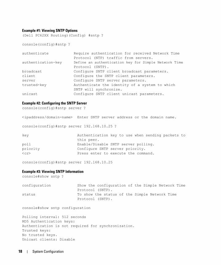
Example #1: Viewing SNTP Options(Dell PC62XX Routing)(Config) #sntp ?
console(config)#sntp ?
authenticate Require authentication for received Network Time Protocol (NTP) traffic from servers.
authentication-key Define an authentication key for Simple Network TimeProtocol (SNTP).
broadcast Configure SNTP client broadcast parameters.client Configure the SNTP client parameters.server Configure SNTP server parameters.trusted-key Authenticate the identity of a system to which
SNTP will synchronize.unicast Configure SNTP client unicast parameters.
Example #2: Configuring the SNTP Serverconsole(config)#sntp server ?
<ipaddress/domain-name> Enter SNTP server address or the domain name.
console(config)#sntp server 192.168.10.25 ?
key Authentication key to use when sending packets to this peer.poll Enable/Disable SNTP server polling.priority Configure SNTP server priority.<cr> Press enter to execute the command.
console(config)#sntp server 192.168.10.25
Example #3: Viewing SNTP Informationconsole#show sntp ?
configuration Show the configuration of the Simple Network Time Protocol (SNTP).status To show the status of the Simple Network Time Protocol (SNTP).
console#show sntp configuration
Polling interval: 512 secondsMD5 Authentication keys:Authentication is not required for synchronization.Trusted keys:No trusted keys.Unicast clients: Disable
18 System Configuration
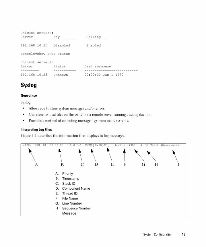
Unicast servers:Server Key Polling--------- ----------- -----------192.168.10.25 Disabled Enabled
console#show sntp status
Unicast servers:Server Status Last response--------- ----------- --------------------------192.168.10.25 Unknown 00:00:00 Jan 1 1970
Syslog
OverviewSyslog:
• Allows you to store system messages and/or errors.
• Can store to local files on the switch or a remote server running a syslog daemon.
• Provides a method of collecting message logs from many systems.
Interpreting Log Files
Figure 2-1 describes the information that displays in log messages.
<130> JAN 01 00:00:06 0.0.0.0-1 UNKN [0x800023]: bootos.c(386) 4 %% Event (0xaaaaaaaa)
A. PriorityB. Timestamp
C. Stack IDD. Component NameE. Thread ID
F. File NameG. Line NumberH Sequence Number
I. Message
A B C D E F G H I
System Configuration 19
Figure 2-1. Log Files Key
CLI ExamplesThe following are examples of the commands used in the Syslog feature.
Example #1: Viewing Logging Informationconsole#show logging
Logging is enabledConsole Logging: level warning. Console Messages: 230 Dropped.Buffer Logging: level info. Buffer Messages: 230 Logged, 200 MaxFile Logging: level notActive. File Messages: 0 Dropped.CLI Command Logging : disabledWeb Session Logging : disabledSNMP Set Command Logging : disabled0 Messages were not logged.Buffer Log:<189> JAN 01 03:57:58 10.27.65.86-1 TRAPMGR[216282304]: traputil.c(908) 31 %% Instance 0 has elected a new STP root: 8000:00ff:f2a3:8888<189> JAN 01 03:57:58 10.27.65.86-1 TRAPMGR[216282304]: traputil.c(908) 32 %% Instance 0 has elected a new STP root: 8000:0002:bc00:7e2c<189> JAN 01 04:04:18 10.27.65.86-1 TRAPMGR[231781808]: traputil.c(908) 33 %% New Spanning Tree Root: 0, Unit: 1<189> JAN 01 04:04:18 10.27.65.86-1 TRAPMGR[216282304]: traputil.c(908) 34 %% The unit 1 elected as the new STP root
Example #2: Viewing the Logging File
console#show logging file
Persistent Logging : disabledPersistent Log Count : 0
Example #5: Configuring Syslog Serverconsole(config)#logging ?
buffered Buffered (In-Memory) Logging Configuration.cli-command CLI Command Logging Configuration.console Console Logging Configuration.facility Syslog Facility Configuration.file Configure logging file parameters.on Enable logging to all supporting destinations.snmp SNMP Set Command Logging Configuration.web-session Web Session Logging Configuration.<ip-address|hostname> Configure syslog server IP address.
20 System Configuration

console(config)#logging 192.168.10.65
console(Config-logging)#?
description Specify syslog server description.exit To exit from the mode.level Specify logging level.port Specify UDP port (default is 514).
console(Config-logging)#level ?
alert Immediate action neededcritical Critical conditionsdebug Debugging messagesemergency System is unusableerror Error conditionsinfo Informational messagesnotice Normal but significant conditionswarning Warning conditions
console(Config-logging)#level critical
Port DescriptionThe Port Description feature lets you specify an alphanumeric interface identifier that can be used for SNMP network management.
CLI ExampleUse the commands shown below for the Port Description feature.
Example #1: Enter a Description for a Port
This example specifies the name “Test” for port 1/g10:console#configureconsole(config)#interface ethernet 1/g2console(config-if-1/g2)#description Testconsole(config-if-1/g2)#exitconsole(config)#exit
Example #2: Show the Port Descriptionconsole#show interfaces description ethernet 1/g2
Port Description---- ----------------------------------------------------------1/g2 Test
System Configuration 21
Storm ControlA traffic storm is a condition that occurs when incoming packets flood the LAN, which creates performance degradation in the network. The Storm Control feature protects against this condition.
The switch software provides broadcast, multicast, and unicast storm recovery for individual interfaces.
Unicast Storm Control protects against traffic whose MAC addresses are not known by the system.
For broadcast, multicast, and unicast storm control, if the rate of traffic ingressing on an interface increases beyond the configured threshold for that type, the traffic is dropped.
To configure storm control, you will enable the feature for all interfaces or for individual interfaces, and you will set the threshold (storm control level) beyond which the broadcast, multicast, or unicast traffic will be dropped.
Configuring a storm-control level also enables that form of storm-control. Disabling a storm-control level (using the “no” version of the command) sets the storm-control level back to default value and disables that form of storm-control. Using the “no” version of the “storm-control” command (not stating a “level”) disables that form of storm-control but maintains the configured “level” (to be active next time that form of storm-control is enabled).
NOTE: The actual rate of ingress traffic required to activate storm-control is based on the size of incoming packets and the hard-coded average packet size of 512 bytes - used to calculate a packet-per-second (pps) rate - as the forwarding-plane requires pps versus an absolute rate kbps. For example, if the configured limit is 10%, this is converted to ~25000 pps, and this pps limit is set in forwarding plane (hardware). You get the approximate desired output when 512bytes packets are used.
CLI ExampleThe following examples show how to configure the storm control feature on port two, which is an Ethernet interface. The interface number is 1/g2.
Example #1: Set Broadcast Storm Control for an Interfaceconsole#configure
console(config)#interface ethernet 1/g2
console(config-if-1/g2)#storm-control broadcast ?
level Configure storm-control thresholds.<cr> Press enter to execute the command.
console(config-if-1/g2)#storm-control broadcast level ?
<rate> Enter the storm-control threshold as percent of portspeed. Percent of port speed is converted toPacketsPerSecond based on 512 byte average packetsize and applied to HW. Refer to documentation forfurther details.
22 System Configuration

console(config-if-1/g2)#storm-control broadcast level 7
Example #2: Set Multicast Storm Control for an Interfaceconsole(config-if-1/g2)#storm-control multicast level 8
Example #3: Set Unicast Storm Control for an Interfaceconsole(config-if-1/g2)#storm-control unicast level 5
Cable Test for Copper PortsThe cable test feature enables you to determine the cable connection status on a selected port. The switch uses Time Domain Reflectometry (TDR) technology to determine the quality and characteristics of a copper cable attached to a port.
NOTE: The cable test feature is supported only for copper cable. it is not supported for optical fiber cable.
In privileged exec mode, enter test copper-port tdr unit/port to run the cable test on the specified port. One of the following statuses are returned:
• Normal: The cable is working correctly.
• Open: The cable is disconnected or there is a faulty connector.
• Short: There is an electrical short in the cable.
• Cable Test Failed: The cable status could not be determined. The cable may in fact be working.
The command also returns a cable length estimate if this feature is supported by the PHY for the current link speed. The length is displayed as the estimated length. Note that if the link is down and a cable is attached to a 10/100 Ethernet adapter, then the cable status may display as Open or Short because some Ethernet adapters leave unused wire pairs unterminated or grounded. Unknown is displayed if the cable length could not be determined.
If the port has an active link while the cable test is run, the link can go down for the duration of the test. The test may take several seconds to run.
To view cable status information for multiple ports, enter show copper-ports tdr. If the cable test has not been run on a port, the results indicate that the test has not been performed.
CLI Exampleconsole#test copper-port tdr 1/g1
Cable Status................................... ShortCable Length................................... 5m
console#show copper-ports tdr
Port Result Length [meters] Date------- ------ --------------- ---------------------1/g1 Short 9 Jan 01 1970 18:03:231/g2 Test has not been performed
System Configuration 23

1/g3 Test has not been performed1/g4 Test has not been performed1/g5 Test has not been performed--More-- or (q)uit
NOTE: You can also run a cable test using the Web Interface. In the navigation tree, click System > Diagnostics.
24 System Configuration

3
Switching ConfigurationThis section provides configuration scenarios for the following features:• "Virtual LANs" on page 25
• "IGMP Snooping" on page 30
• "IGMP Snooping Querier" on page 32
• "Link Aggregation/Port Channels" on page 33
• "Port Mirroring" on page 37
• "Port Security" on page 37
• "Link Layer Discovery Protocol" on page 39
• "Denial of Service Attack Protection" on page 41
• "DHCP Filtering" on page 43
• "Port Aggregator" on page 44
Virtual LANsAdding Virtual LAN (VLAN) support to a Layer 2 switch offers some of the benefits of both bridging and routing. Like a bridge, a VLAN switch forwards traffic based on the Layer 2 header, which is fast. Like a router, it partitions the network into logical segments, which provides better administration, security and management of multicast traffic.
A VLAN is a set of end stations and the switch ports that connect them. You can have many reasons for the logical division, for example, department or project membership. The only physical requirement is that the end station, and the port to which it is connected, both belong to the same VLAN.
Each VLAN in a network has an associated VLAN ID, which appears in the IEEE 802.1Q tag in the Layer 2 header of packets transmitted on a VLAN. An end station may omit the tag, or the VLAN portion of the tag, in which case the first switch port to receive the packet may either reject it or insert a tag using its default VLAN ID. A given port may handle traffic for more than one VLAN, but it can only support one default VLAN ID.
Two features let you define packet filters that the switch uses as the matching criteria to determine if a particular packet belongs to a particular VLAN.
• The IP-subnet Based VLAN feature lets you map IP addresses to VLANs by specifying a source IP address, network mask, and the desired VLAN ID.
Switching Configuration 25

• The MAC-based VLAN feature let packets originating from end stations become part of a VLAN according to source MAC address. To configure the feature, you specify a source MAC address and a VLAN ID.
The Private Edge VLAN feature lets you set protection between ports located on the switch. This means that a protected port cannot forward traffic to another protected port on the same switch.
The feature does not provide protection between ports located on different switches.
For information about authenticated, unauthenticated, and guest VLANs, see "802.1X Authentication and VLANs" on page 88.
VLAN Configuration ExampleThe diagram in this section shows a switch with four ports configured to handle the traffic for two VLANs. Port 1/g2 handles traffic for both VLANs, while port 1/g1 is a member of VLAN 2 only, and ports 1/g3 and 1/g4 are members of VLAN 3 only. The script following the diagram shows the commands you would use to configure the switch as shown in the diagram.
Figure 3-1. VLAN Example Network Diagram
CLI ExamplesThe following examples show how to create VLANs, assign ports to the VLANs, and assign a VLAN as the default VLAN to a port.
Port 1/0/1VLAN 2
Port 1/0/2VLANs 2 & 3
Port 1/0/3VLAN 3
Port 1/0/4VLAN 3
Layer 3 Switch
VLAN 2 VLAN 3
Port 1/g1VLAN 2
Port 1/g4VLAN 3
Port 1/g3VLAN 3
Port 1/g2VLANs 2 & 3
26 Switching Configuration

Example #1: Create Two VLANs
Use the following commands to create two VLANs and to assign the VLAN IDs while leaving the names blank.console(config)#vlan databaseconsole(config-vlan)#vlan 2console(config-vlan)#vlan 3console(config-vlan)#exit
Example #2: Assign Ports to VLAN2
This sequence shows how to assign ports to VLAN2, specify that frames will always be transmitted tagged from all member ports, and that untagged frames will be rejected on receipt.console(config)#interface ethernet 1/g1console(config-if-1/g1)#switchport mode generalconsole(config-if-1/g1)#switchport general allowed vlan add 2console(config-if-1/g1)#switchport general acceptable-frame-type tagged-onlyconsole(config-if-1/g1)#exitconsole(config)#interface ethernet 1/g2console(config-if-1/g2)#switchport mode generalconsole(config-if-1/g2)#switchport general allowed vlan add 2console(config-if-1/g2)#switchport general acceptable-frame-type tagged-onlyconsole(config-if-1/g2)#exit
Example #3: Assign Ports to VLAN3
This example shows how to assign the ports that will belong to VLAN 3. Untagged frames will be accepted on ports 1/g3 and 1/g4.
Note that port 1/g2 belongs to both VLANs and that port 1/g1 can never belong to VLAN 3. console(config)#interface ethernet 1/g2cconsole(config-if-1/g2)#switchport general allowed vlan add 3console(config-if-1/g2)#exitconsole(config)#interface ethernet 1/g3console(config-if-1/g3)#switchport general allowed vlan add 3console(config-if-1/g3)#exitconsole(config)#interface ethernet 1/g4console(config-if-1/g4)#switchport general allowed vlan add 3
Example #4: Assign VLAN3 as the Default VLAN
This example shows how to assign VLAN 3 as the default VLAN for port 1/g2.console(config)#interface ethernet 1/g2console(config-if-1/g2)#switchport general pvid 3
Switching Configuration 27
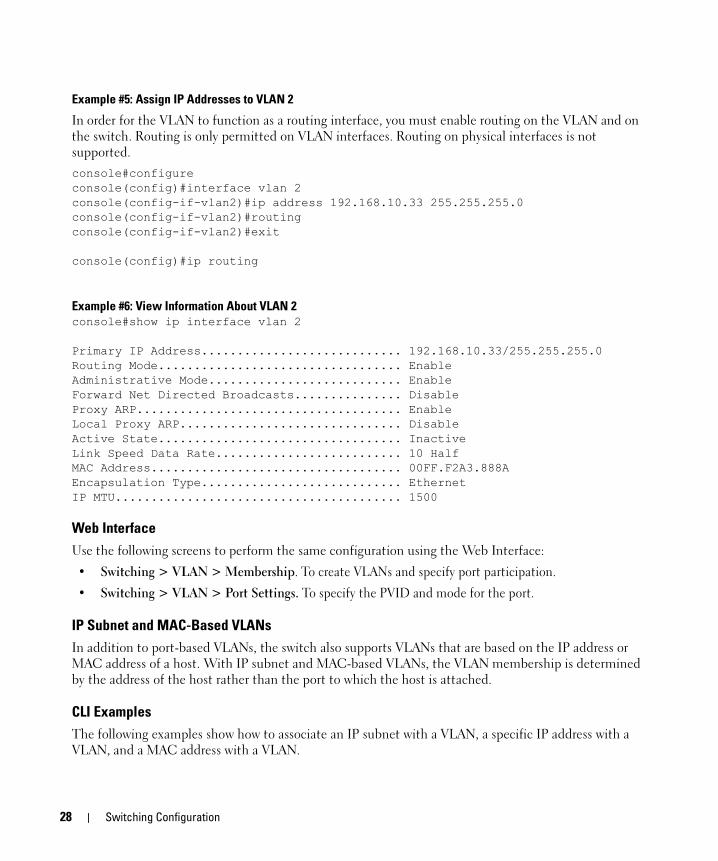
Example #5: Assign IP Addresses to VLAN 2
In order for the VLAN to function as a routing interface, you must enable routing on the VLAN and on the switch. Routing is only permitted on VLAN interfaces. Routing on physical interfaces is not supported. console#configureconsole(config)#interface vlan 2console(config-if-vlan2)#ip address 192.168.10.33 255.255.255.0console(config-if-vlan2)#routingconsole(config-if-vlan2)#exit
console(config)#ip routing
Example #6: View Information About VLAN 2console#show ip interface vlan 2
Primary IP Address............................ 192.168.10.33/255.255.255.0Routing Mode.................................. EnableAdministrative Mode........................... EnableForward Net Directed Broadcasts............... DisableProxy ARP..................................... EnableLocal Proxy ARP............................... DisableActive State.................................. InactiveLink Speed Data Rate.......................... 10 HalfMAC Address................................... 00FF.F2A3.888AEncapsulation Type............................ EthernetIP MTU........................................ 1500
Web InterfaceUse the following screens to perform the same configuration using the Web Interface:
• Switching > VLAN > Membership. To create VLANs and specify port participation.
• Switching > VLAN > Port Settings. To specify the PVID and mode for the port.
IP Subnet and MAC-Based VLANsIn addition to port-based VLANs, the switch also supports VLANs that are based on the IP address or MAC address of a host. With IP subnet and MAC-based VLANs, the VLAN membership is determined by the address of the host rather than the port to which the host is attached.
CLI ExamplesThe following examples show how to associate an IP subnet with a VLAN, a specific IP address with a VLAN, and a MAC address with a VLAN.
28 Switching Configuration
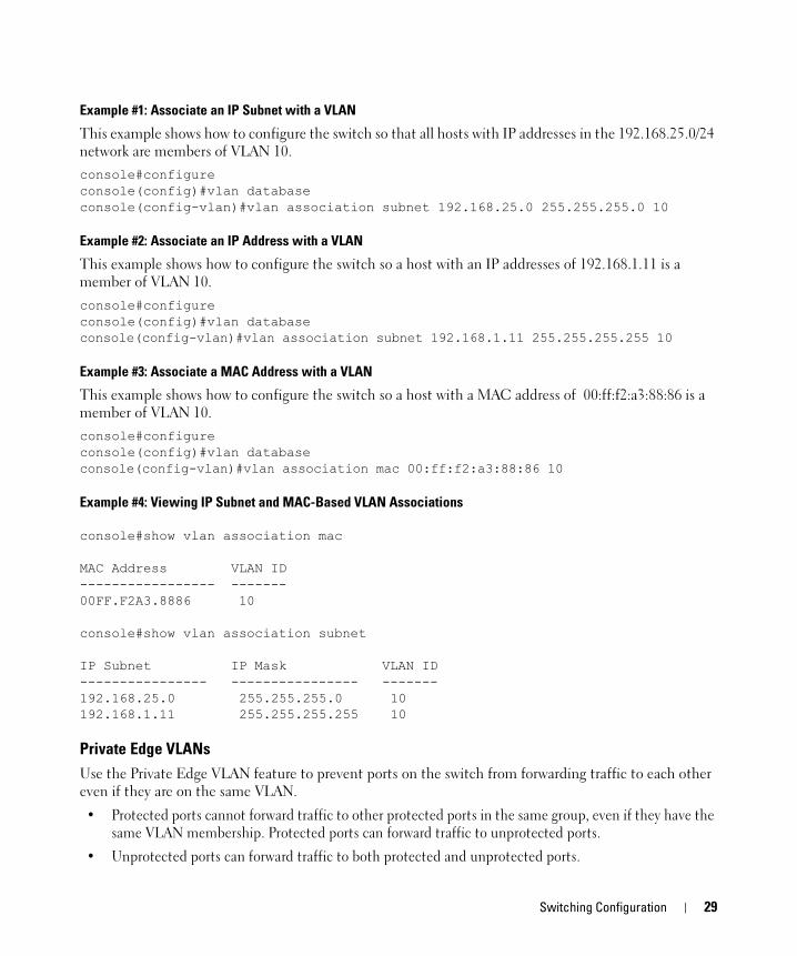
Example #1: Associate an IP Subnet with a VLAN
This example shows how to configure the switch so that all hosts with IP addresses in the 192.168.25.0/24 network are members of VLAN 10.console#configureconsole(config)#vlan databaseconsole(config-vlan)#vlan association subnet 192.168.25.0 255.255.255.0 10
Example #2: Associate an IP Address with a VLAN
This example shows how to configure the switch so a host with an IP addresses of 192.168.1.11 is a member of VLAN 10.console#configureconsole(config)#vlan databaseconsole(config-vlan)#vlan association subnet 192.168.1.11 255.255.255.255 10
Example #3: Associate a MAC Address with a VLAN
This example shows how to configure the switch so a host with a MAC address of 00:ff:f2:a3:88:86 is a member of VLAN 10.console#configureconsole(config)#vlan databaseconsole(config-vlan)#vlan association mac 00:ff:f2:a3:88:86 10
Example #4: Viewing IP Subnet and MAC-Based VLAN Associations
console#show vlan association mac
MAC Address VLAN ID----------------- -------00FF.F2A3.8886 10
console#show vlan association subnet
IP Subnet IP Mask VLAN ID---------------- ---------------- -------192.168.25.0 255.255.255.0 10192.168.1.11 255.255.255.255 10
Private Edge VLANsUse the Private Edge VLAN feature to prevent ports on the switch from forwarding traffic to each other even if they are on the same VLAN.
• Protected ports cannot forward traffic to other protected ports in the same group, even if they have the same VLAN membership. Protected ports can forward traffic to unprotected ports.
• Unprotected ports can forward traffic to both protected and unprotected ports.
Switching Configuration 29
You can also configure groups of protected ports, but unprotected ports are independent and cannot be added to a group. Each group’s configuration consists of a name and a mask of ports. A port can belong to only one set of protected ports, but an unprotected port can be added to a group as a protected port.
The group name is configurable by the network administrator.
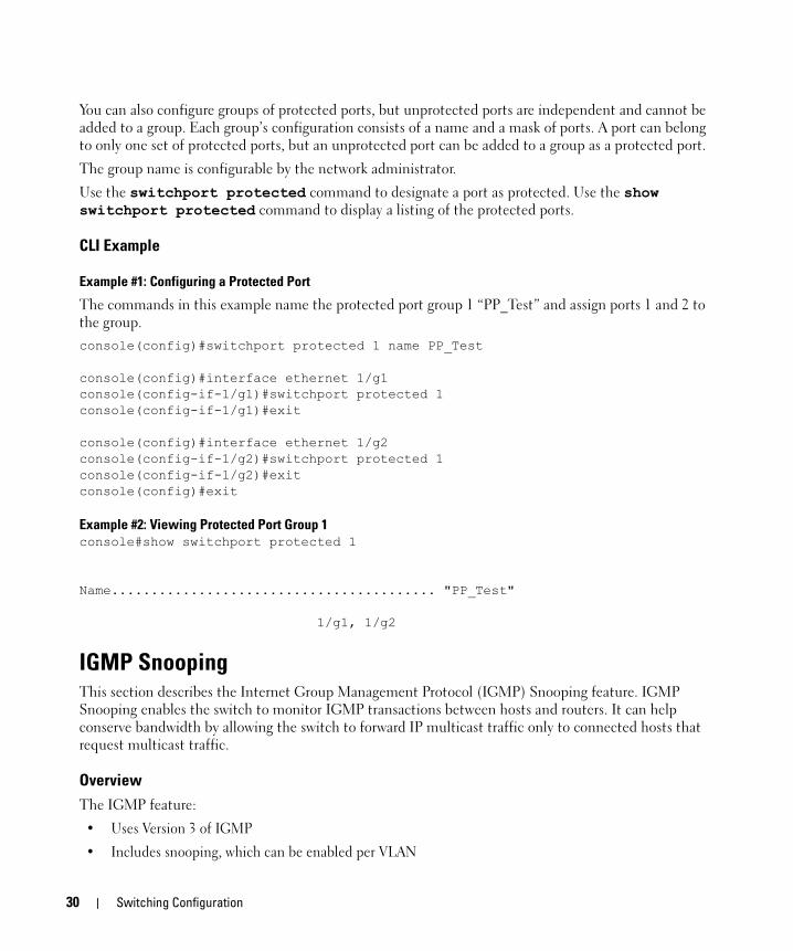
Use the switchport protected command to designate a port as protected. Use the show switchport protected command to display a listing of the protected ports.
CLI Example
Example #1: Configuring a Protected Port
The commands in this example name the protected port group 1 “PP_Test” and assign ports 1 and 2 to the group.console(config)#switchport protected 1 name PP_Test
console(config)#interface ethernet 1/g1console(config-if-1/g1)#switchport protected 1console(config-if-1/g1)#exit
console(config)#interface ethernet 1/g2console(config-if-1/g2)#switchport protected 1console(config-if-1/g2)#exitconsole(config)#exit
Example #2: Viewing Protected Port Group 1console#show switchport protected 1
Name......................................... "PP_Test"
1/g1, 1/g2
IGMP SnoopingThis section describes the Internet Group Management Protocol (IGMP) Snooping feature. IGMP Snooping enables the switch to monitor IGMP transactions between hosts and routers. It can help conserve bandwidth by allowing the switch to forward IP multicast traffic only to connected hosts that request multicast traffic.
OverviewThe IGMP feature:
• Uses Version 3 of IGMP
• Includes snooping, which can be enabled per VLAN
30 Switching Configuration
CLI ExamplesThe following examples show commands to use with the IGMP Snooping feature.
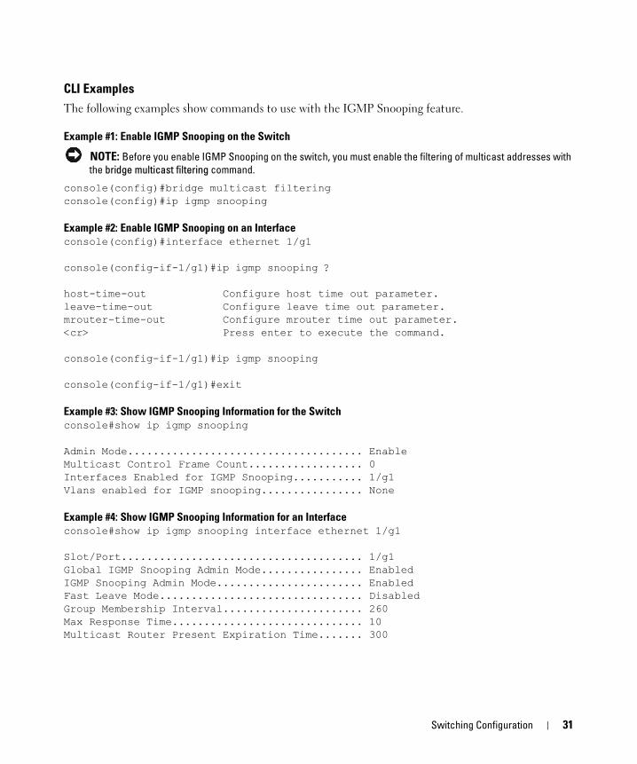
Example #1: Enable IGMP Snooping on the Switch
NOTE: Before you enable IGMP Snooping on the switch, you must enable the filtering of multicast addresses with the bridge multicast filtering command.
console(config)#bridge multicast filteringconsole(config)#ip igmp snooping
Example #2: Enable IGMP Snooping on an Interfaceconsole(config)#interface ethernet 1/g1
console(config-if-1/g1)#ip igmp snooping ?
host-time-out Configure host time out parameter.leave-time-out Configure leave time out parameter.mrouter-time-out Configure mrouter time out parameter.<cr> Press enter to execute the command.
console(config-if-1/g1)#ip igmp snooping
console(config-if-1/g1)#exit
Example #3: Show IGMP Snooping Information for the Switchconsole#show ip igmp snooping
Admin Mode..................................... EnableMulticast Control Frame Count.................. 0Interfaces Enabled for IGMP Snooping........... 1/g1Vlans enabled for IGMP snooping................ None
Example #4: Show IGMP Snooping Information for an Interfaceconsole#show ip igmp snooping interface ethernet 1/g1
Slot/Port...................................... 1/g1Global IGMP Snooping Admin Mode................ EnabledIGMP Snooping Admin Mode....................... EnabledFast Leave Mode................................ DisabledGroup Membership Interval...................... 260Max Response Time.............................. 10Multicast Router Present Expiration Time....... 300
Switching Configuration 31

IGMP Snooping QuerierWhen PIM and IGMP are enabled in a network with IP multicast routing, the IP multicast router acts as the IGMP querier. However, if the IP-multicast traffic in a VLAN needs to be Layer 2 switched only, an IP-multicast router is not required. The IGMP Snooping Querier can perform the IGMP snooping functions on the VLAN.
NOTE: Without an IP-multicast router on a VLAN, you must configure another switch as the IGMP querier so that it can send queries.
When the IGMP snooping querier is enabled, the IGMP snooping querier sends out periodic IGMP queries that trigger IGMP report messages from the switch that wants to receive IP multicast traffic. The IGMP snooping feature listens to these IGMP reports to establish appropriate forwarding.
CLI ExamplesThe following examples show commands to use with the IGMP Snooping Querier feature.
Example #1: Enable IGMP Snooping Querier on the Switch
The first command in this example enables the IGMP snooping querier on the switch. The second command specifies the IP address that the snooping querier switch should use as the source address when generating periodic queries. console(config)#ip igmp snoopingconsole(config)#ip igmp snooping querierconsole(config)#ip igmp snooping querier address 10.10.20.12
NOTE: The IGMP snooping must be enabled for the IGMP snooping querier function to operate.
Example #2: Configure IGMP Snooping Querier Properties
The first command in this example sets the IGMP Querier Query Interval time to 100. This means that the switch waits 100 seconds before sending another general query. The second command sets the IGMP Querier timer expiration period to 100. This means that the switch remains in Non-Querier mode for 100 seconds after it has discovered that there is a Multicast Querier in the network. console(config)#ip igmp snooping querier query-interval 100console(config)#ip igmp snooping querier timer expiry 100
Example #3: Show IGMP Snooping Querier Informationconsole#show ip igmp snooping querier
Global IGMP Snooping querier status-----------------------------------IGMP Snooping Querier Mode..................... EnableQuerier Address................................ 10.10.10.33IGMP Version................................... 2Querier Query Interval......................... 100Querier Expiry Interval........................ 100
32 Switching Configuration

Example #4: Enable IGMP Snooping Querier on a VLAN
To configure IGMP Snooping Querier on a VLAN, enter VLAN Database mode. The first ip igmp snooping command in this example enables the IGMP snooping querier on VLAN 10. The second ip igmp snooping command specifies the IP address that the snooping querier switch should use as source address when generating periodic queries. The final command enables the Snooping Querier to participate in the Querier Election process when it discovers the presence of another Querier in the VLAN.
NOTE: For IGMP Snooping Querier functionality to be operationally enabled on the VLAN, IGMP Snooping and IGMP Snooping Querier must both be enabled globally on the switch.
console(config)#vlan databaseconsole(config-vlan)#ip igmp snooping querier 10console(config-vlan)#ip igmp snooping querier 10 address 10.10.11.40console(config-vlan)#ip igmp snooping querier election participate 10
Example #5: Show IGMP Snooping Querier Information for VLAN 10console#show ip igmp snooping querier vlan 10
Vlan 10 : IGMP Snooping querier status----------------------------------------------IGMP Snooping Querier Vlan Mode................ EnableQuerier Election Participate Mode.............. EnableQuerier Vlan Address........................... 10.10.11.40Operational State.............................. QuerierOperational version............................ 2Operational Max Resp Time...................... 10
Link Aggregation/Port ChannelsThis section shows how to use the Link Aggregation feature to configure port-channels via the Command Line Interface and the Graphical User Interface.
The Link Aggregation (LAG) feature allows the switch to treat multiple physical links between two end-points as a single logical link called a port-channel. All of the physical links in a given port-channel must operate in full-duplex mode at the same speed.
You can use the feature to directly connect two switches when the traffic between them requires high bandwidth and reliability, or to provide a higher bandwidth connection to a public network.
You can configure the port-channels as either dynamic or static. Dynamic configuration uses the IEEE 802.3ad standard, which provides for the periodic exchanges of LACPDUs. Static configuration is used when connecting the switch to an external switch that does not support the exchange of LACPDUs.
The feature offers the following benefits:
• Increased reliability and availability: If one of the physical links in the port-channel goes down, traffic is dynamically and transparently reassigned to one of the other physical links.
Switching Configuration 33
• Increased bandwidth: The aggregated physical links deliver higher bandwidth than each individual link.
• Incremental increase in bandwidth: A physical upgrade could produce a 10-times increase in bandwidth; LAG produces a two- or five-times increase, useful if only a small increase is needed.
Management functions treat a port-channel as if it were a single physical port.
You can include a port-channel in a VLAN. You can configure more than one port-channel for a given switch.
CLI ExampleThe following shows an example of configuring the software to support Link Aggregation (LAG) to a server and to a Layer 3 switch.
Figure 3-2 shows the example network.
34 Switching Configuration
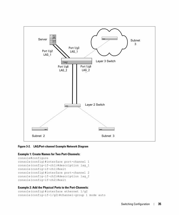
Figure 3-2. LAG/Port-channel Example Network Diagram
Example 1: Create Names for Two Port-Channels:console#configureconsole(config)#interface port-channel 1console(config-if-ch1)#description lag_1console(config-if-ch1)#exitconsole(config)#interface port-channel 2console(config-if-ch2)#description lag_2console(config-if-ch2)#exit
Example 2: Add the Physical Ports to the Port-Channels:console(config)#interface ethernet 1/g2console(config-if-1/g2)#channel-group 1 mode auto
Subnet3
Port 1/0/8LAG_20
Layer 2 Switch
Port 1/0/9LAG_20
Server
Port 1/0/2LAG_10
Port 1/0/3LAG_10
Layer 3 Switch
Subnet 3Subnet 2
Port 1/g2LAG_1
Port 1/g3LAG_1
Port 1/g8LAG_2
Port 1/g9LAG_2
Switching Configuration 35
console(config-if-1/g2)#exitconsole(config)#interface ethernet 1/g3console(config-if-1/g3)#channel-group 1 mode autoconsole(config-if-1/g3)#exitconsole(config)#interface ethernet 1/g8console(config-if-1/g8)#channel-group 2 mode autoconsole(config-if-1/g8)#exitconsole(config)#interface ethernet 1/g9console(config-if-1/g9)#channel-group 2 mode autoconsole(config-if-1/g9)#exitconsole(config)#exit
Example 3: Show the Port Channels
By default, the system enables link trap notificationconsole#show interfaces port-channel
Channel Ports Hash Algorithm Type------- ----------------------------- -------------------ch1 Inactive: 1/g2, 1/g3 3ch2 Inactive: 1/g8, 1/g9 3ch3 No Configured Ports 3ch4 No Configured Ports 3ch5 No Configured Ports 3ch6 No Configured Ports 3--More-- or (q)uit
At this point, the LAGs could be added to the default management VLAN.
Web Interface Configuration: LAGs/Port-channelsTo perform the same configuration using the Graphical User Interface, click Switching > Link Aggregation > LAG Membership in the navigation tree.
36 Switching Configuration
Port MirroringThis section describes the Port Mirroring feature, which can serve as a diagnostic tool, debugging tool, or means of fending off attacks.
OverviewPort mirroring selects network traffic from specific ports for analysis by a network analyzer, while allowing the same traffic to be switched to its destination. You can configure many switch ports as source ports and one switch port as a destination port. You can also configure how traffic is mirrored on a source port. Packets received on the source port, transmitted on a port, or both received and transmitted, can be mirrored to the destination port.
CLI ExamplesThe following are examples of the commands used in the Port Mirroring feature.
Example #1: Set up a Port Mirroring Session
The following command sequence enables port mirroring and specifies a source and destination ports.console#configureconsole(config)#monitor session 1 modeconsole(config)#monitor session 1 source interface 1/g7 ?
rx Monitor ingress packets only.tx Monitor egress packets only.<cr> Press enter to execute the command.
console(config)#monitor session 1 source interface 1/g7console(config)#monitor session 1 destination interface 1/g10console(config)#exit
Example #2: Show the Port Mirroring Sessionconsole#show monitor session 1
Session ID Admin Mode Probe Port Mirrored Port Type---------- ---------- ---------- ------------- -----1 Enable 1/g10 1/g7 Rx,Tx
Port SecurityThis section describes the Port Security feature.
OverviewPort Security:
• Allows for limiting the number of MAC addresses on a given port.
Switching Configuration 37
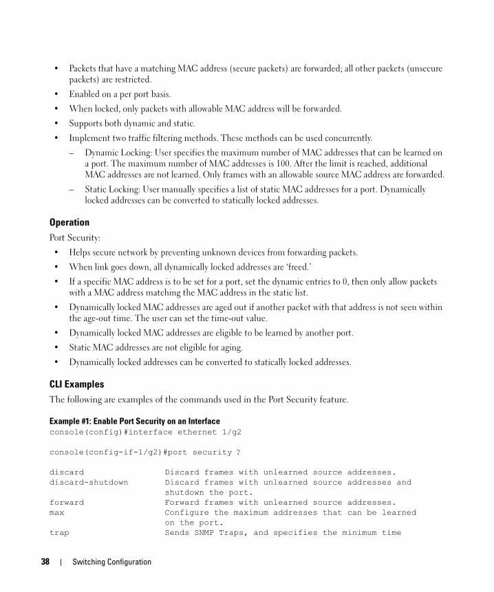
• Packets that have a matching MAC address (secure packets) are forwarded; all other packets (unsecure packets) are restricted.
• Enabled on a per port basis.
• When locked, only packets with allowable MAC address will be forwarded.
• Supports both dynamic and static.
• Implement two traffic filtering methods. These methods can be used concurrently.
– Dynamic Locking: User specifies the maximum number of MAC addresses that can be learned on a port. The maximum number of MAC addresses is 100. After the limit is reached, additional MAC addresses are not learned. Only frames with an allowable source MAC address are forwarded.
– Static Locking: User manually specifies a list of static MAC addresses for a port. Dynamically locked addresses can be converted to statically locked addresses.
OperationPort Security:
• Helps secure network by preventing unknown devices from forwarding packets.
• When link goes down, all dynamically locked addresses are ‘freed.’
• If a specific MAC address is to be set for a port, set the dynamic entries to 0, then only allow packets with a MAC address matching the MAC address in the static list.
• Dynamically locked MAC addresses are aged out if another packet with that address is not seen within the age-out time. The user can set the time-out value.
• Dynamically locked MAC addresses are eligible to be learned by another port.
• Static MAC addresses are not eligible for aging.
• Dynamically locked addresses can be converted to statically locked addresses.
CLI ExamplesThe following are examples of the commands used in the Port Security feature.
Example #1: Enable Port Security on an Interfaceconsole(config)#interface ethernet 1/g2
console(config-if-1/g2)#port security ?
discard Discard frames with unlearned source addresses.discard-shutdown Discard frames with unlearned source addresses and
shutdown the port.forward Forward frames with unlearned source addresses.max Configure the maximum addresses that can be learned
on the port.trap Sends SNMP Traps, and specifies the minimum time
38 Switching Configuration
between consecutive traps.<cr> Press enter to execute the command.
console(config-if-1/g2)#port security
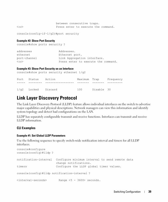
Example #2: Show Port Securityconsole#show ports security ?
addresses Addresses.ethernet Ethernet port.port-channel Link Aggregation interface.<cr> Press enter to execute the command.
Example #3: Show Port Security on an Interfaceconsole#show ports security ethernet 1/g2
Port Status Action Maximum Trap Frequency----- -------- ----------------- ------- ------- ---------
1/g2 Locked Discard 100 Disable 30
Link Layer Discovery ProtocolThe Link Layer Discovery Protocol (LLDP) feature allows individual interfaces on the switch to advertise major capabilities and physical descriptions. Network managers can view this information and identify system topology and detect bad configurations on the LAN.
LLDP has separately configurable transmit and receive functions. Interfaces can transmit and receive LLDP information.
CLI Examples
Example #1: Set Global LLDP Parameters
Use the following sequence to specify switch-wide notification interval and timers for all LLDP interfaces.console#configureconsole(config)#lldp ?
notification-interval Configure minimum interval to send remote data change notifications.
timers Configure the LLDP global timer values.
console(config)#lldp notification-interval ?
<interval-seconds> Range <5 - 3600> seconds.
Switching Configuration 39
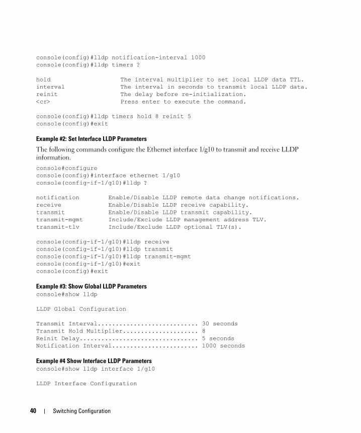
console(config)#lldp notification-interval 1000console(config)#lldp timers ?
hold The interval multiplier to set local LLDP data TTL.interval The interval in seconds to transmit local LLDP data.reinit The delay before re-initialization.<cr> Press enter to execute the command.
console(config)#lldp timers hold 8 reinit 5console(config)#exit
Example #2: Set Interface LLDP Parameters
The following commands configure the Ethernet interface 1/g10 to transmit and receive LLDP information.console#configureconsole(config)#interface ethernet 1/g10console(config-if-1/g10)#lldp ?
notification Enable/Disable LLDP remote data change notifications.receive Enable/Disable LLDP receive capability.transmit Enable/Disable LLDP transmit capability.transmit-mgmt Include/Exclude LLDP management address TLV.transmit-tlv Include/Exclude LLDP optional TLV(s).
console(config-if-1/g10)#lldp receiveconsole(config-if-1/g10)#lldp transmitconsole(config-if-1/g10)#lldp transmit-mgmtconsole(config-if-1/g10)#exitconsole(config)#exit
Example #3: Show Global LLDP Parametersconsole#show lldp
LLDP Global Configuration
Transmit Interval............................ 30 secondsTransmit Hold Multiplier..................... 8Reinit Delay................................. 5 secondsNotification Interval........................ 1000 seconds
Example #4 Show Interface LLDP Parametersconsole#show lldp interface 1/g10
LLDP Interface Configuration
40 Switching Configuration

Interface Link Transmit Receive Notify TLVs Mgmt--------- ------ -------- -------- -------- ------- ----1/g10 Down Enabled Enabled Disabled Y
TLV Codes: 0- Port Description, 1- System Name 2- System Description, 3- System Capabilities
Denial of Service Attack ProtectionThis section describes the PowerConnect 6200 Series Denial of Service Protection feature.
OverviewDenial of Service:
• Spans two categories:
– Protection of the switch
– Protection of the network
• Protects against the exploitation of a number of vulnerabilities which would make the host or network unstable
• Compliant with Nessus. Dell tested the switch software with Nessus version 2.0.10. Nessus is a widely-used vulnerability assessment tool.
• PowerConnect 6200 Series software provides a number of features that help a network administrator protect networks against DoS attacks.
There are 6 available types of attacks which can be monitored for and blocked. Each type of attack is represented by a dos-control command keyword.console(config)#dos-control ?
firstfrag Enables IPv4 first fragment checking.icmp Enables ICMP size checking.l4port Enables L4 port number checking.sipdip Enables SIP=DIP checking.tcpflag Enables TCP flag checking.tcpfrag Enables TCP fragment checking.
Switching Configuration 41

Table 3-1 describes the dos-control keywords.
Table 3-1. DoS Control
CLI ExamplesThe commands shown below show how to enable DoS protection and view its status.
Example #1: Enabling all DOS Controlsconsole#configureconsole(config)#dos-control sipdipconsole(config)#dos-control firstfragconsole(config)#dos-control tcpfragconsole(config)#dos-control l4portconsole(config)#dos-control icmpconsole(config)#exit
Example #2: Viewing the DoS Configuration Informationconsole#show dos-control
SIPDIP Mode.................................... EnableFirst Fragment Mode............................ EnableMin TCP Hdr Size............................... 20TCP Fragment Mode.............................. EnableTCP Flag Mode.................................. DisableL4 Port Mode................................... EnableICMP Mode...................................... EnableMax ICMP Pkt Size.............................. 512
Keyword Meaning
firstfrag Enabling First Fragment DoS prevention causes the switch to drop packets that have a TCP header smaller then the configured Min TCP Hdr Size.
icmp ICMP DoS prevention causes the switch to drop ICMP packets that have a type set to ECHO_REQ (ping) and a size greater than the configured ICMP Pkt Size.
l4port Enabling L4 Port DoS prevention causes the switch to drop packets that have TCP/UDP source port equal to TCP/UDP destination port.
sipdip Enabling SIP=DIP DoS prevention causes the switch to drop packets that have a source IP address equal to the destination IP address.
tcpflag Enabling TCP Flag DoS prevention causes the switch to drop packets that have TCP flag SYN set and TCP source port less than 1024 or TCP control flags set to 0 and TCP sequence number set to 0 or TCP flags FIN, URG, and PSH set and TCP sequence number set to 0 or both TCP flags SYN and FIN set.
tcpfrag Enabling TCP Fragment DoS prevention causes the switch to drop packets that have an IP fragment offset equal to 1.
42 Switching Configuration

DHCP FilteringThis section describes the Dynamic Host Configuration Protocol (DHCP) Filtering feature.
OverviewDHCP filtering provides security by filtering untrusted DHCP messages. An untrusted message is a message that is received from outside the network or firewall, and that can cause traffic attacks within network.
You can use DHCP Filtering as a security measure against unauthorized DHCP servers. A known attack can occur when an unauthorized DHCP server responds to a client that is requesting an IP address. The unauthorized server can configure the gateway for the client to be equal to the IP address of the server. At that point, the client sends all of its IP traffic destined to other networks to the unauthorized machine, giving the attacker the possibility of filtering traffic for passwords or employing a ‘man-in-the-middle’ attack.
DHCP filtering works by allowing the administrator to configure each port as a trusted or untrusted port. The port that has the authorized DHCP server should be configured as a trusted port. Any DHCP responses received on a trusted port will be forwarded. All other ports should be configured as untrusted. Any DHCP (or BootP) responses received on the ingress side will be discarded.
Limitations• Port Channels (LAGs): If an interface becomes a member of a LAG, DHCP filtering is no longer
operationally enabled on the interface. Instead, the interface follows the configuration of the LAG port. End user configuration for the interface remains unchanged. When an interface is no longer a member of a LAG, the current end user configuration for that interface automatically becomes effective.
• Mirroring: If an interface becomes a probe port, DHCP filtering can no longer become operationally enabled on the interface. End user configuration for the interface remains unchanged. When an interface no longer acts as a probe port, the current end user configuration for that interface automatically becomes effective.
• DHCP Relay: When DHCP Filtering is administratively enabled, the IP Helper function must check whether a port is trusted before a DHCP (or BootP) response is forwarded on the port. If the port is untrusted, the response is dropped. The forwarding of DHCP or BootP request is unaffected.
• If DHCP Filtering is administratively disabled, the operation of the DHCP relay function is unaffected.
CLI ExamplesThe commands shown below show examples of configuring DHCP Filtering for the switch and for individual interfaces.
Example #1: Enable DHCP Filtering for the Switchconsole#configure
Switching Configuration 43
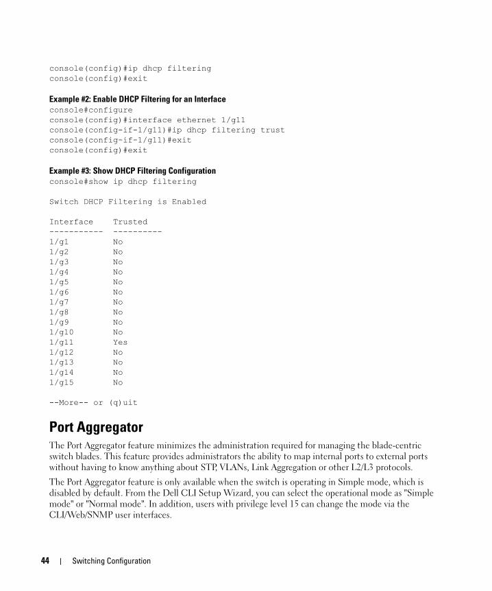
console(config)#ip dhcp filteringconsole(config)#exit
Example #2: Enable DHCP Filtering for an Interfaceconsole#configureconsole(config)#interface ethernet 1/g11console(config-if-1/g11)#ip dhcp filtering trustconsole(config-if-1/g11)#exitconsole(config)#exit
Example #3: Show DHCP Filtering Configurationconsole#show ip dhcp filtering
Switch DHCP Filtering is Enabled
Interface Trusted----------- ----------1/g1 No1/g2 No1/g3 No1/g4 No1/g5 No1/g6 No1/g7 No1/g8 No1/g9 No1/g10 No1/g11 Yes1/g12 No1/g13 No1/g14 No1/g15 No
--More-- or (q)uit
Port AggregatorThe Port Aggregator feature minimizes the administration required for managing the blade-centric switch blades. This feature provides administrators the ability to map internal ports to external ports without having to know anything about STP, VLANs, Link Aggregation or other L2/L3 protocols.
The Port Aggregator feature is only available when the switch is operating in Simple mode, which is disabled by default. From the Dell CLI Setup Wizard, you can select the operational mode as "Simple mode" or "Normal mode". In addition, users with privilege level 15 can change the mode via the CLI/Web/SNMP user interfaces.
44 Switching Configuration
NOTE: A Trap identified by "operationalModeChangeTrap" is issued when the SNMP user changes the operational mode.
If the new mode is selected from the Dell Setup wizard, or if a mode selected from the CLI/Web/SNMP user interfaces, the mode is effective only after the next reload.
Overview• Port Aggregator is simple to configure. If internal port(s) are mapped to multiple external ports for
bandwidth/high availability, these external ports will automatically be configured as an LACP trunk group (if the Aggregator Group is configured to enable LACP automatically). All connectivity mapping is done through a simplified user interface. This functionality is supported across stacked switches as well, where all ports in the stack will be shown in a single interface and can be configured.
• Port Aggregator is completely interoperable. Dynamic (via LACP) and static LAGs are supported.
Figure 3-3 illustrates the default condition on a standalone M6220(not in a stack) with Port Aggregator enabled.
Switching Configuration 45
Figure 3-3. Default Aggregator Groups on Standalone Switch (Blade)
The default Port Aggregator Group mapping is shown in Table 3-2.
Switch Blade
Server Blade 1
Server Blade16
Mid Plane
Internal Port Connections
g1
HiGig ports xg1 to xg4
g5 g9 g13
g2 g6 g10 g14
g3 g7 g11 g15
g4 g8 g12 g16
g17
g18
g19
g20
Aggregator Group
46 Switching Configuration
Table 3-2. Default Port Aggregator Group Mapping
The same default configuration is extended to a stack of switches, with internal member ports 3/g1 to 3/g16 and external member ports 3/g17 to 3/g20 in one Aggregator Group, and so on. Default configuration does not include 10Gig ports as part of any Aggregator Group, although they can be used if desired.
1G and 10G external ports cannot be used at the same time.
A standalone switch in Simple Mode will support up to 8 Aggregator Groups and a stack will support up to ‘6*<Number of Units in stack>’ Aggregator Groups. For example, in a stack of 4 units, the maximum number of Aggregator Groups is 24. On a 12 unit stack, the maximum number of groups is 72.
The number of internal ports in an Aggregator Group is unlimited and you can configure any number of internal ports in each Aggregator Group. The number of external ports that can be included in a group is limited to the maximum number of ports that can be included in a LAG. On the M6220, eight ports is the maximum number that can be in a LAG. Any member port, either internal port or external port, is not allowed to participate in more than one Aggregator Group.
To prevent traffic from different groups being seen by other groups, a VLAN is reserved for each Aggregator Group by default. This VLAN reservation per group is not configurable; however you can configure each group to participate in more than one user-created (unreserved) VLAN. VLANs 4022 to 4093 are reserved for each Aggregator Group, starting from 4022 for Group 1. The reserved VLANs are excluded from the user-configurable VLAN list. Member ports of the Aggregator Group are excluded from all other VLANs except the one reserved for that Group. With this reserved VLAN count, the maximum user-configurable VLANs becomes 952 (1024-72). This VLAN segregation ensures that the flooding occurs only within the Aggregator Group but not across. The MAC Address tables are shown for each Aggregator Group separately and an ‘all’ option in the CLI command can be used to show all the mac-addresses in all the groups. You are not allowed to include a VLAN in more than one aggregator group.
To prevent network loops and maximize bandwidth to and from the switch, when the number of uplink ports (external ports) is more than 1, you can configure the LACP (802.3ad) capability on the uplink ports. The LAG uses hashing mode that is based on source MAC and destination MAC. You can configure the LACP mode to static/auto/off on the multiple uplink ports. When configured in “static” mode, the uplink ports will be set to Static mode (static LAG). When configured in “auto” mode, the uplink ports will be put into passive state (will be able to receive LACP PDU’s only) and listen for the
Aggregator Group
Member Internal Ports Member Uplink (External) Ports
Group 1 1/g1,1/g2,1/g3,1/g4, 1/g5, 1/g6, 1/g7, 1/g8, 1/g9, 1/g10, 1/g11, 1/g12, 1/g13, 1/g14, 1/g15, 1/g16
1/g17, 1/g18, 1/g19, 1/g20
Group 2 2/g1,2/g2,2/g3,2/g4, 2/g5, 2/g6, 2/g7, 2/g8, 2/g9, 2/g10, 2/g11, 2/g12, 2/g13, 2/g14, 2/g15, 2/g16
2/g17, 2/g18, 2/g19, 2/g20
Group 3 — —
Switching Configuration 47

LACPDUs from the partner and negotiate the Link Aggregation. This means that the external (uplink) ports will be re-enabled once LACP is detected on the active uplink without user intervention. When configured in “off” mode, links on all but one uplink port in that Aggregator group will be forced to DOWN. In this case, lowest numbered uplink port will be active, and all other ports will be forced to “DOWN” state.
To support NIC teaming failover on the server blades, all the internal ports in the Aggregator Group will be brought DOWN, if the links on all the uplink ports in that Aggregator Group are DOWN. As soon as one or more of the uplink ports come UP, all the internal ports will be brought UP again. This is the default behavior with respect to Link Dependency. You can also configure the minimum number of physical uplinks ports to be active for an Aggregator Group to be active. By default this (minimum number of uplinks ports to be active) is 1, which means if there is at least 1 external port UP in the Aggregator Group, all the internal ports will be kept open. Internal ports in the Aggregator Group will be downed only when all the mapped external ports are down or disconnected. For example if you configure 1/g1, 1/g2, 1/g3, 1/g4, 1/g17, 1/g18 as members of Group 1, and configure that the minimum number of uplink ports to be active as ‘2’, all the internal ports of the Aggregator Group will be brought DOWN if any one of the links on 1/g17 or 1/g18 is DOWN. As soon as the links on both 1/g17 and 1/g18 are UP, the internal ports shall be brought UP again.
• A new configuration mode, Aggregator Group Mode, has been created. You can enter this mode using the command port-aggregator group <group id> in Global Configuration mode. When Simple Mode is enabled, negotiation, speed, duplex, vlan, and mtu configurations are allowed on the Aggregator Group but not on the individual ports. These configuration are applied to all the member ports of the Aggregator Group.
• Operational mode is set to Normal mode on resetting the configuration to Factory defaults from the software boot menu. The switch will boot up in this mode unless you select a different mode from the setup wizard.
• If the new mode is selected from the Dell Setup wizard, or if the mode is selected from the CLI/Web/SNMP user interfaces, the mode is effective only after the next reload.
• When you change the operational mode, a trap is generated apart from logging a message.
• The switch maintains two separate config files, one for Simple mode and another for Normal mode. The selection of the configuration file while applying the configuration is based on the mode selection. If there is no saved configuration, then the default configuration of the selected mode is applied.
• Simple mode allows you to create Aggregation Groups (Figure 3-3) where internal ports and external ports can be configured in a separate broadcast domain.
• Security-related configurations: dot1x, RADIUS, TACACS+ are allowed when the switch is operating in Simple Mode.
• The switch handles traffic in the following way when in Simple Mode:
• Ingress filtering is enabled on all ports. This means that tagged traffic would be dropped if the incoming port is not a member of the incoming packet’s VLAN.
• Untagged traffic should be switched and untagged at the egress.
48 Switching Configuration
• Default VLAN tagged traffic should be switched and egress as untagged.
• Tagged traffic that belongs to a user-created VLAN gets switched in that VLAN and egresses as tagged.
NOTE: The reserved VLAN ID assigned to a group is also referred to as a default VLAN.
• The hashing algorithm in Simple mode is the same as in Normal mode. In Normal mode, the default Hashing is based on source + destination MAC address. You cannot change the hash algorithm in Simple mode. Ports that are already a member of a LAG are external ports that are shown using the show port-aggregator port summary command. In Simple mode, you can set the LACP mode on a group, but not on an individual port. Use the show interface status command to check the lag status.
CLI ExamplesThe following are examples of the commands used for port aggregator.
Example #1: Set the Operational Mode
A user with privilege level 15 can change the operational mode from Normal to Simple and vice versa with a two-phase process. You select the mode in the first phase and confirm the selection in the second phase. The selection of the new mode in the first phase would be invalid if you do not confirm the mode selection within 60 seconds. The mode selected from the user interface is effective only after the next reload.
Enter the commands to get into Global Configuration mode:
console>enable
console#configure
console(config)#
In the first phase, use the mode simple command from the Global Configuration Mode to select the Simple mode as the start up mode.
console(config)#mode simple
Warning: Confirm mode selection within 60 seconds using “mode change confirm” command.
In the second phase, use the mode-change confirm command to confirm the mode selection. This command must be executed within 60 seconds of executing the mode simple command. The selected mode is applied as operational mode.
console(config)#mode-change confirm
To select Normal mode as the operational mode, use the no form of mode simple command.
console(config)#no mode simple
Switching Configuration 49

Example #2: Enter Port Aggregator Mode
Use the port-aggregator group <GroupId> command to enter the Port Aggregator mode to configure aggregator group attributes. GroupId is the Port Aggregator group identifier. (Range: 1-8 or 1-72) On a standalone switch, it is up to 8. On a stack, it is 1 to (6 x<number of units in stack). For a stack of 12 units it is 1-72. By default, all ports are in aggregator group 1.
console(config)#port-aggregator group 1
console(config-aggregator-1)#
Example #3: Add Member Ethernet Ports to the Aggregator Group
Use the add ethernet <intf-list> command to add member Ethernet port(s) to the Aggregator Group. <intf-list> is a list of Ethernet interfaces.
console(config)#port-aggregator group 1
console(config-aggregator-1)#add ethernet 1/g1
console(config-aggregator-1)#
Example #4: Set Group MTU Size on All Member Ports
Use the mtu disable command to set the mtu size to default (1518) on all the member ports in the Aggregator Group.
console(config)#port-aggregator group 1
console(config-aggregator-1)#mtu disable
console(config-aggregator-1)#
Example #5: Enable Group Auto-negotiation of All Member Ports
Use the negotiation command in port aggregator mode to enable auto-negotiation of all member ports in the aggregator group.
console(config)#port-aggregator group 1
console(config-aggregator-1)#negotiation
console(config-aggregator-1)#
Example #6: Configure Group Speed of All Member Ports
Use the speed command in port aggregator configuration mode to configure the speed of all member ports in the aggregator group. The example command below configures the port to 1000 Mbps operation.
console(config)#port-aggregator group 1
console(config-aggregator-1)#speed 1000
console(config-aggregator-1)#
50 Switching Configuration
Example #7: Configure Group Full/Half Duplex Operation of All Member Ports
Use the duplex command in port aggregator configuration mode to configure the full/half duplex operation of all member ports in the aggregator group. The example command below configures all member ports to full duplex operation.
console(config)#port-aggregator group 1
console(config-aggregator-1)#duplex full
console(config-aggregator-1)#
Example #8: Set Group LACP Mode to Static
Use the lacp static command to set the LACP (Link Aggregation) mode to static for that Aggregator Group. This means that when more than one uplink port is in the Group, those uplink ports will be enabled automatically and will not use LACP.
console(config)#port-aggregator group 2
console(config-aggregator-2)#lacp static
console(config-aggregator-2)#
Example #9: Set Group LACP Mode to Dynamic
Use the lacp auto command to set the LACP (Link Aggregation) mode to dynamic for that Aggregator Group. This means that when more than one uplink port is in the Group, those uplink ports will be enabled automatically with LACP.
console(config)#port-aggregator group 2
console(config-aggregator-2)#lacp auto
console(config-aggregator-2)#
Example #10: Set Group LACP Mode
Use the lacp off command to set the LACP (Link Aggregation) mode to off for that Aggregator Group. This means that when more than one uplink port is in the Group, all the uplinks are shut down except the lowest numbered one.
console(config)#port-aggregator group 2
console(config-aggregator-2)#lacp off
console(config-aggregator-2)#
Example #11: Set Minimum Active Uplinks
Use the minimum active uplinks <number of uplinks> command to set the minimum number of uplinks to be active for the Group. For example, if the number of uplink ports in the group is 2 and the number of internal ports is 4. If the user sets the minimum active uplink ports to be 2, then both the
Switching Configuration 51

uplink ports should be active; otherwise, all the internal ports in the Group will be brought down. By default, the minimum active uplinks for a Group is 1, which means at least one uplink port should be active for the Aggregator Group to be active.
console(config)#port-aggregator group 2
console(config-aggregator-2)#minimum active uplinks 2
console(config-aggregator-2)#
Example #12: Show Group MAC Address Table
Use the show bridge address-table [port-aggregator group < GroupId >] command to show the MAC address table for a particular aggregator group. [port-aggregator group <Group Id> is an optional parameter in the command and, if not specified, shows all the MAC entries in all the Groups.
console#show bridge address-table port-aggregator group 2
Aggregator Group: 2
Aging time is 300 Sec
VLAN MAC Address Port Type
----- ---------------- ------ --------------------
3 0006.2932.814D 1/g2 Static
1001 0006.2932.814B 1/g17 Static
Example #13: Show Group VLAN Table
Use the show vlan [port-aggregator group < GroupId >] command to show the VLAN table for a particular aggregator group. [port-aggregator group <Group Id> is an optional parameter in the command and, if not specified, shows all the MAC entries in all the Groups.
console#show vlan port-aggregator group 2
Aggregator Group: 2
VLAN AggregatorGroup Type Authorization
----- ---------------- ------ -------------
3 2 Static Required
1000 2 Static Required
console#show vlan
VLAN AggregatorGroup Type Authorization
52 Switching Configuration

----- ---------------- ------ -------------
2 4 Static Required
3 2 Static Required
1000 2 Static Required
1001 3 Static Required
Example #14: Show Group Configuration Summary
Use the show port-aggregator group summary [< GroupId >] command to show the parameters configured on the aggregator group. <Group Id> is an optional parameter in the command and, if not specified, the command shows all the configured parameters for all the Groups.
console#show port-aggregator group summary 2
Group VLANs Uplinks MTU Negotiation Speed Duplex
----- ----- ------- ------- ----------- ------- -------
2 4023 1 Default Default Default Default
console#show port-aggregator group summary
Gid VLANs Minimum MTU Negotiation Speed Duplex
Uplinks
--- ----- ------- ------- ----------- ------- -------
1 4022 1 Disabled Default Default Default
2 4023 1 Disabled Default Default Default
3 4024 1 Disabled Default Default Default
4 4025 1 Disabled Default Default Default
Example #15: Show Port Summary
Use the show port-aggregator [group < GroupId >] command to show the member ports in the aggregator group. <Group Id> is an optional parameter in the command and, if not specified, the command shows all the Groups and member ports.
Switching Configuration 53
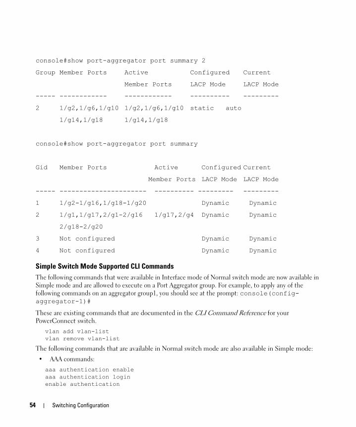
console#show port-aggregator port summary 2
Group Member Ports Active Configured Current
Member Ports LACP Mode LACP Mode
----- ------------ ------------ ---------- ---------
2 1/g2,1/g6,1/g10 1/g2,1/g6,1/g10 static auto
1/g14,1/g18 1/g14,1/g18
console#show port-aggregator port summary
Gid Member Ports Active Configured Current
Member Ports LACP Mode LACP Mode
----- ---------------------- ---------- --------- ---------
1 1/g2-1/g16,1/g18-1/g20 Dynamic Dynamic
2 1/g1,1/g17,2/g1-2/g16 1/g17,2/g4 Dynamic Dynamic
2/g18-2/g20
3 Not configured Dynamic Dynamic
4 Not configured Dynamic Dynamic
Simple Switch Mode Supported CLI CommandsThe following commands that were available in Interface mode of Normal switch mode are now available in Simple mode and are allowed to execute on a Port Aggregator group. For example, to apply any of the following commands on an aggregator group1, you should see at the prompt: console(config-aggregator-1)#
These are existing commands that are documented in the CLI Command Reference for your PowerConnect switch.
vlan add vlan-listvlan remove vlan-list
The following commands that are available in Normal switch mode are also available in Simple mode:
• AAA commands:aaa authentication enableaaa authentication loginenable authentication
54 Switching Configuration

enable passwordip http authenticationip https authenticationlogin authenticationpassword (Line Configuration)password (User EXEC)show authentication methodsshow user accountsshow users login historyusername
• Configuration and Image File Commands:boot systemclear configcopydelete backup-configdelete backup-imagedelete startup-configfiledescrscript applyscript deletescript listscript showscript validateshow backup-configshow bootvarshow running-configshow startup-configupdate bootcode
• Ethernet configuration commands:clear counters [ethernet interface | port-channel port-channel-number]
show interfaces counters [ethernet interface | port-channel port-channel-number]
show interfaces status [ethernet interface | port-channel port-channel-number ]
show statistics ethernet {<unit>/<port-type><port> | switchport }
shutdown
• Line Commands:exec-timeout
Switching Configuration 55

historyhistory sizelineshow linespeed
• Password Management Commands:passwords agingpasswords historypasswords lockoutpasswords min-lengthshow passwords configuration
• Port Channel Commands:show interfaces port-channelshow statistics port-channel
• Radius commands:auth-portdeadtimekeypriorityradius-server deadtimeradius-server hostradius-server keyradius-server retransmitradius-server source-ipradius-server timeoutretransmitshow radius-serverssource-iptimeoutusage
• SNMP Commands:show snmpshow snmp engineIDshow snmp groupsshow snmp viewssnmp-server communitysnmp-server community-groupsnmp-server contact
56 Switching Configuration
snmp-server enable trapssnmp-server engineID localsnmp-server groupsnmp-server hostsnmp-server locationsnmp-server trap authentication
• SSH commands:crypto key generate dsacrypto key generate rsacrypto key pubkey-chain sship ssh portip ssh pubkey-authip ssh serverkey-stringshow crypto key mypubkeyshow crypto key pubkey-chain sshshow ip sshuser-key
• System Management Commands:asset-taghostnamemembermovemanagementpingreloadset descriptionshow sessionsshow stack-portshow stack-port countersshow stack-port diagshow supported switchtypeshow switchshow systemshow system idshow usersshow versionstackswitch priorityswitch renumbertelnettraceroutetraceroute {ipaddress|hostname}
Switching Configuration 57

• Tacacs commands:keyportpriorityshow tacacstacacs-server hosttacacs-server keytacacs-server timeouttimeout
• Web Server Commands:common-namecountrycrypto certificate generatecrypto certificate importcrypto certificate requestdurationip http portip http serverip https certificateip https portip https serverkey-generatelocationorganization-unitshow crypto certificate mycertificateshow ip httpshow ip httpsstate
• Dot1x feature commands:aaa authentication dot1x aaa authorization network default radiusdot1x max-req dot1x port-controldot1x re-authenticatedot1x re-authenticationdot1x system-auth-controldot1x timeout quiet-perioddot1x timeout re-authperioddot1x timeout server-timeoutdot1x timeout supp-timeout dot1x timeout tx-period
58 Switching Configuration

show dot1x show dot1x statisticsshow dot1x users
• Dot1x Advanced Features:dot1x guest-vlan <vlan-id>dot1x unauth-vlan <vlan-id>dot1x max-usersshow dot1x clients
Switching Configuration 59

60 Switching Configuration

4
Routing ConfigurationThis section describes configuration scenarios and instructions for the following routing features:• "VLAN Routing" on page 61
• "Virtual Router Redundancy Protocol" on page 64
• "Proxy Address Resolution Protocol (ARP)" on page 66
• "OSPF" on page 67
• "Routing Information Protocol" on page 77
• "Route Preferences" on page 80
• "Loopback Interfaces" on page 83
VLAN RoutingThis section provides an example of how to configure PowerConnect 6200 Series software to support VLAN routing.
NOTE: The management VLAN cannot be configured as a routing interface. The switch may also be managed via VLAN routing interfaces.
CLI ExamplesThe diagram in this section shows a Layer 3 switch configured for VLAN routing. It connects two VLANs, with two ports participating in one VLAN, and one port in the other. The script shows the commands you would use to configure PowerConnect 6200 Series software to provide the VLAN routing support shown in the diagram.
Routing Configuration 61
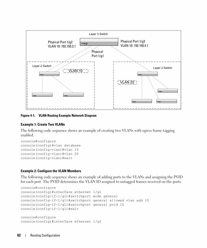
Figure 4-1. VLAN Routing Example Network Diagram
Example 1: Create Two VLANs
The following code sequence shows an example of creating two VLANs with egress frame tagging enabled.console#configureconsole(config)#vlan databaseconsole(config-vlan)#vlan 10console(config-vlan)#vlan 20console(config-vlan)#exit
Example 2: Configure the VLAN Members
The following code sequence shows an example of adding ports to the VLANs and assigning the PVID for each port. The PVID determines the VLAN ID assigned to untagged frames received on the ports.console#configureconsole(config)#interface ethernet 1/g1console(config-if-1/g1)#switchport mode generalconsole(config-if-1/g1)#switchport general allowed vlan add 10console(config-if-1/g1)#switchport general pvid 10console(config-if-1/g1)#exit
console#configureconsole(config)#interface ethernet 1/g2
Physical Port 1/0/2VLAN Router Port 3/1
192.150.3.1
Physical Port 1/0/3VLAN Router Port 3/2
192.150.4.1
Layer 3 Switch
Layer 2 SwitchLayer 2 Switch
VLAN 20
VLAN 10
PhysicalPort 1/0/1
Physical Port 1/g2VLAN 10: 192.150.3.1
Physical Port 1/g3VLAN 10: 192.150.4.1
Physical Port 1/g1
62 Routing Configuration
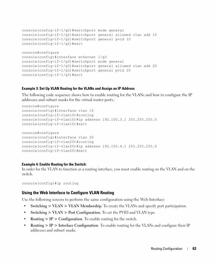
console(config-if-1/g2)#switchport mode generalconsole(config-if-1/g2)#switchport general allowed vlan add 10console(config-if-1/g2)#switchport general pvid 10console(config-if-1/g2)#exit
console#configureconsole(config)#interface ethernet 1/g3console(config-if-1/g3)#switchport mode generalconsole(config-if-1/g3)#switchport general allowed vlan add 20console(config-if-1/g3)#switchport general pvid 20console(config-if-1/g3)#exit
Example 3: Set Up VLAN Routing for the VLANs and Assign an IP Address
The following code sequence shows how to enable routing for the VLANs and how to configure the IP addresses and subnet masks for the virtual router ports.:console#configureconsole(config)#interface vlan 10console(config-if-vlan10)#routingconsole(config-if-vlan10)#ip address 192.150.3.1 255.255.255.0console(config-if-vlan10)#exit
console#configureconsole(config)#interface vlan 20console(config-if-vlan20)#routingconsole(config-if-vlan20)#ip address 192.150.4.1 255.255.255.0console(config-if-vlan20)#exit
Example 4: Enable Routing for the Switch:In order for the VLAN to function as a routing interface, you must enable routing on the VLAN and on the switch.
console(config)#ip routing
Using the Web Interface to Configure VLAN RoutingUse the following screens to perform the same configuration using the Web Interface:
• Switching > VLAN > VLAN Membership. To create the VLANs and specify port participation.
• Switching > VLAN > Port Configuration. To set the PVID and VLAN type.
• Routing > IP > Configuration. To enable routing for the switch.
• Routing > IP > Interface Configuration. To enable routing for the VLANs and configure their IP addresses and subnet masks.
Routing Configuration 63

Virtual Router Redundancy ProtocolWhen an end station is statically configured with the address of the router that will handle its routed traffic, a single point of failure is introduced into the network. If the router goes down, the end station is unable to communicate. Since static configuration is a convenient way to assign router addresses, Virtual Router Redundancy Protocol (VRRP) was developed to provide a backup mechanism.
VRRP eliminates the single point of failure associated with static default routes by enabling a backup router to take over from a “master” router without affecting the end stations using the route. The end stations will use a “virtual” IP address that will be recognized by the backup router if the master router fails. Participating routers use an election protocol to determine which router is the master router at any given time. A given port may appear as more than one virtual router to the network, also, more than one port on a switch may be configured as a virtual router. Either a physical port or a routed VLAN may participate.
CLI ExamplesThis example shows how to configure the switch to support VRRP. Router 1 will be the default master router for the virtual route, and Router 2 will be the backup router.
Port 1/0/2192.150.2.1
Virtual Router ID 20Virtual Addr. 192.150.2.1
Port 1/0/4192.150.4.1
Virtual Router ID 20Virtual Addr. 192.150.2.1
Hosts
Layer 3 Switch actingas Router 1
Layer 2 Switch
Layer 3 Switch actingas Router 2
VLAN 50
VLAN 60
64 Routing Configuration

Figure 4-2. VRRP Example Network Configuration
Example 1: Configuring VRRP on the Switch as a Master Router
Enable routing for the switch. IP forwarding is then enabled by default.console#config console(config)#ip routing
Configure the IP addresses and subnet masks for the VLAN routing interfaces that will participate in the protocol, for example:console(config)#interface vlan 50console(config-if-vlan50)#routingconsole(config-if-vlan50)#ip address 192.150.2.1 255.255.255.0console(config-if-vlan50)#exit
Enable VRRP for the switch:console#config console(config)#ip vrrp
Assign virtual router IDs to the port that will participate in the protocol:console(config)#interface vlan 50console(config-if-vlan50)#ip vrrp 20
Specify the IP address that the virtual router function will recognize. The priority default is 255.console(config-if-vlan50)#ip vrrp 20 ip 192.150.2.1
Enable VRRP on the port:console(config-if-vlan50)#ip vrrp 20 modeconsole(config-if-vlan50)#exit
Example 2: Configuring VRRP on the Switch as a Backup Router
Enable routing for the switch. IP forwarding is then enabled by default.console#config console(config)#ip routing
Configure the IP addresses and subnet masks for the port that will participate in the protocol:console(config)#interface vlan 60console(config-if-vlan60)#routingconsole(config-if-vlan60)#ip address 192.150.4.1 255.255.255.0console(config-if-vlan60)#exit
Enable VRRP for the switch.console#config console(config)#ip vrrp
Assign virtual router IDs to the port that will participate in the protocol:console(config)#interface vlan 60console(config-if-vlan60)#ip vrrp 20
Routing Configuration 65
Specify the IP address that the virtual router function will recognize.
console(config-if-vlan60)#ip vrrp 20 ip 192.150.2.1
Set the priority for the port. The default priority is 100.console(config-if-vlan60)#ip vrrp 20 priority 254
Enable VRRP on the port. console(config-if-vlan60)#ip vrrp 20 modeconsole(config-if-vlan60)#exit
Using the Web Interface to Configure VRRPUse the following screens to perform the same configuration using the Graphical User Interface:
• Routing > IP > Configuration. To enable routing for the switch.
• Routing > IP > Interface Configuration. To enable routing for the VLAN interfaces and configure their IP addresses and subnet masks.
• Routing > VRRP > VRRP Configuration. To enable VRRP for the switch
• Routing > VRRP > Virtual Router Configuration. To configure the interface for VRRP.
Proxy Address Resolution Protocol (ARP)This section describes the Proxy Address Resolution Protocol (ARP) feature.
Overview• Proxy ARP allows a router to answer ARP requests where the target IP address is not the router itself
but a destination that the router can reach.
• If a host does not know the default gateway, proxy ARP can learn the first hop.
• Machines in one physical network appear to be part of another logical network.
• Without proxy ARP, a router responds to an ARP request only if the target IP address is an address configured on the interface where the ARP request arrived.
CLI ExamplesThe following are examples of the commands used in the proxy ARP feature.
Example #1: Enabling Proxy ARP
To enable IP Proxy ARP:console#configconsole(config)#interface vlan 50
console(config-if-vlan50)#ip proxy-arpconsole(config-if-vlan50)#exit
66 Routing Configuration

Example #2 Viewing the Interface Informationconsole#show ip interface vlan 50
Primary IP Address............................. 192.150.2.1/255.255.255.0Routing Mode................................... EnableAdministrative Mode............................ EnableForward Net Directed Broadcasts................ DisableProxy ARP...................................... EnableLocal Proxy ARP................................ DisableActive State................................... InactiveLink Speed Data Rate........................... 10 HalfMAC Address.................................... 00FF.F2A3.888AEncapsulation Type............................. EthernetIP MTU......................................... 1500Encapsulation Type............................. EthernetIP MTU......................................... 1500
OSPFLarger networks typically use the Open Shortest Path First (OSPF) protocol instead of RIP. To the administrator of a large and/or complex network, OSPF offers several benefits:
• Less network traffic:
– Routing table updates are sent only when a change has occurred.
– Only the part of the table that has changed is sent.
– Updates are sent to a multicast, not a broadcast, address.
• Hierarchical management: allows the network to be subdivided.
The switch supports OSPFv2, which is used on IPv4 networks and OSPFv3, which has enhancements for handling 128-bit IPv6 addresses. The protocols are configured separately within the software, but their functionality is largely similar for IPv4 and IPv6 networks. The following description applies to both protocols, except where noted.
OSPF Concepts and TermsFigure 4-3, Figure 4-4, and Figure 4-5 show example OSPF topologies that illustrate the concepts described in this section.
Areas and Topology
The top level of the hierarchy of an OSPF network is known as an autonomous system (AS) or routing domain, and is a collection of networks with a common administration and routing strategy. The AS is divided into areas. Routers within an area must share detailed information on the topology of their area, but require less detailed information about the topology of other areas. Segregating a network into areas enables limiting the amount of route information communicated throughout the network.
Routing Configuration 67
Areas are identified by a numeric ID in IP address format n.n.n.n (note, however, that these are not used as actual IP addresses). For simplicity, the area can be configured and referred to in normal integer notation; however, the software converts these to dot notation by using the right-most octet up to 255 and proceeding to the next left octet for higher values (i.e., Area 20 is identified as 0.0.0.20 and Area 256 as 0.0.1.0). The area identified as 0.0.0.0 is referred to as Area 0 and is considered the OSPF backbone. All other OSPF areas in the network must connect to Area 0 directly or through a virtual link. The backbone area is responsible for distributing routing information between non-backbone areas.
A virtual link can be used to connect an area to Area 0 when a direct link is not possible. A virtual link traverses an area between the remote area and Area 0 (see <Cross-Ref>Figures 4-5).
A stub area is an area that does not receive routes that were learned from a protocol other than OSPF or were statically configured. These routes typically send traffic outside the AS. Therefore, routes from a stub area to locations outside the AS use the default gateway. A virtual link cannot be configured across a stub area. A Not So Stubby Area can import limited external routes only from a connected ASBR.
OSPF Routers and LSAs
OSPF routers keep track of the state of the various links they send data to. Routers share OSPF link state advertisements (LSAs) with other routers. Various LSA types provide detailed information on a link for sharing within an area or summary information for sharing outside an area. External LSAs provide information on static routes or routes learned from other routing protocols.
OSPF defines various router types:
• Backbone routers have an interface in Area 0. They condense and summarize information about all the areas in the AS and advertise this information on the backbone.
• Area border routers (ABRs) connect areas to the OSPF backbone (in the case of virtual links, the an ABR may connect to another ABR that provides a direct connection to Area 0). An ABR is a member of each area it connects to.
• Internal routers (IRs) route traffic within an area. When two routers in an area discover each other through OSPF Hello messages, they are called OSPF neighbors. Neighbors share detailed information on the topology of the area using local LSAs.
• Autonomous system boundary routers (ASBRs) connect to other ASes. ASBRs use other protocols such as BGP or RIP to communicate outside the AS. The ASBR performs route redistribution; i.e., when it learns routes from other protocols, it originates external LSAs that advertise those prefixes within the AS.
Metrics and Route Selection
You can configure the metric type of external routes originated through route redistribution. The metric type influences the routes computed by other OSPF routers in the domain.
OSPF determines the best route using the assigned cost and the type of the OSPF route. The following order is used for choosing a route if more than one type of route exists:
1 Intra-area (the source and destination address are in the same area)
68 Routing Configuration
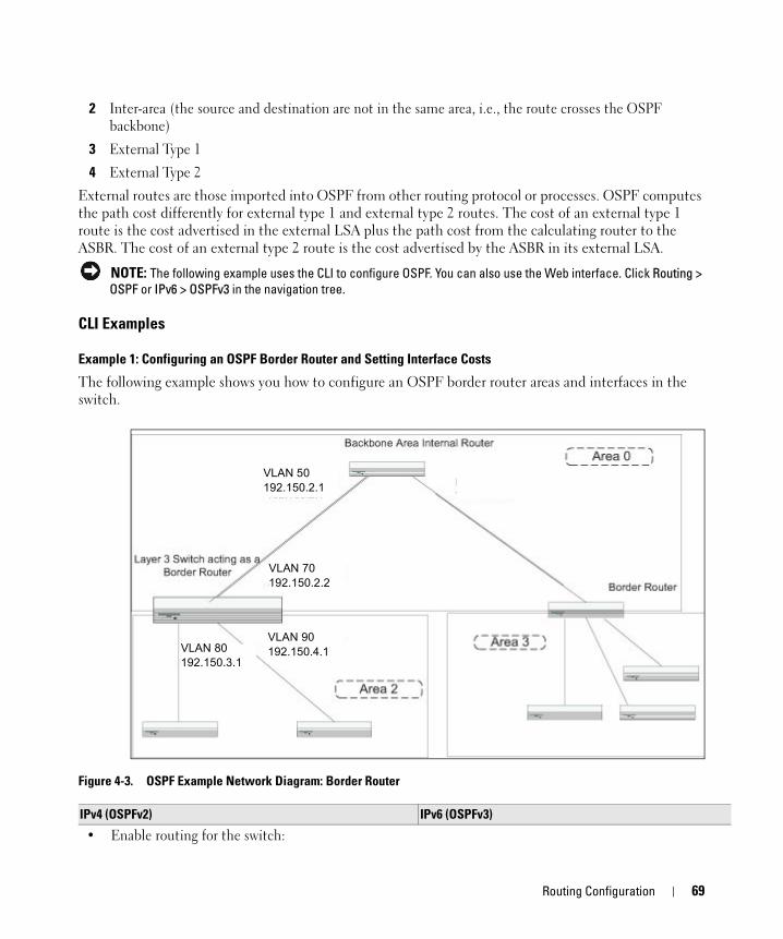
2 Inter-area (the source and destination are not in the same area, i.e., the route crosses the OSPF backbone)
3 External Type 1
4 External Type 2
External routes are those imported into OSPF from other routing protocol or processes. OSPF computes the path cost differently for external type 1 and external type 2 routes. The cost of an external type 1 route is the cost advertised in the external LSA plus the path cost from the calculating router to the ASBR. The cost of an external type 2 route is the cost advertised by the ASBR in its external LSA.
NOTE: The following example uses the CLI to configure OSPF. You can also use the Web interface. Click Routing > OSPF or IPv6 > OSPFv3 in the navigation tree.
CLI Examples
Example 1: Configuring an OSPF Border Router and Setting Interface Costs
The following example shows you how to configure an OSPF border router areas and interfaces in the switch.
Figure 4-3. OSPF Example Network Diagram: Border Router
VLAN 50192.150.2.1
VLAN 70192.150.2.2
VLAN 80192.150.3.1
VLAN 90192.150.4.1
IPv4 (OSPFv2) IPv6 (OSPFv3)
• Enable routing for the switch:
Routing Configuration 69
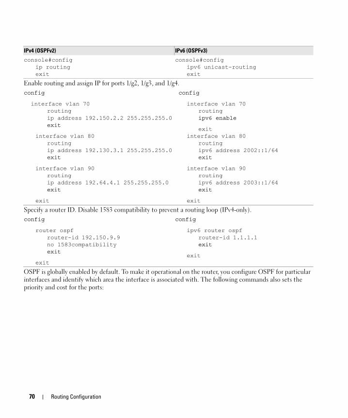
console#configip routingexit
console#configipv6 unicast-routingexit
Enable routing and assign IP for ports 1/g2, 1/g3, and 1/g4.config
interface vlan 70routingip address 192.150.2.2 255.255.255.0exit
interface vlan 80routingip address 192.130.3.1 255.255.255.0exit
interface vlan 90routingip address 192.64.4.1 255.255.255.0exit
exit
config
interface vlan 70routingipv6 enable
exitinterface vlan 80
routingipv6 address 2002::1/64exit
interface vlan 90routingipv6 address 2003::1/64exit
exit
Specify a router ID. Disable 1583 compatibility to prevent a routing loop (IPv4-only). config
router ospfrouter-id 192.150.9.9no 1583compatibilityexit
exit
config
ipv6 router ospfrouter-id 1.1.1.1exit
exit
OSPF is globally enabled by default. To make it operational on the router, you configure OSPF for particular interfaces and identify which area the interface is associated with. The following commands also sets the priority and cost for the ports:
IPv4 (OSPFv2) IPv6 (OSPFv3)
70 Routing Configuration
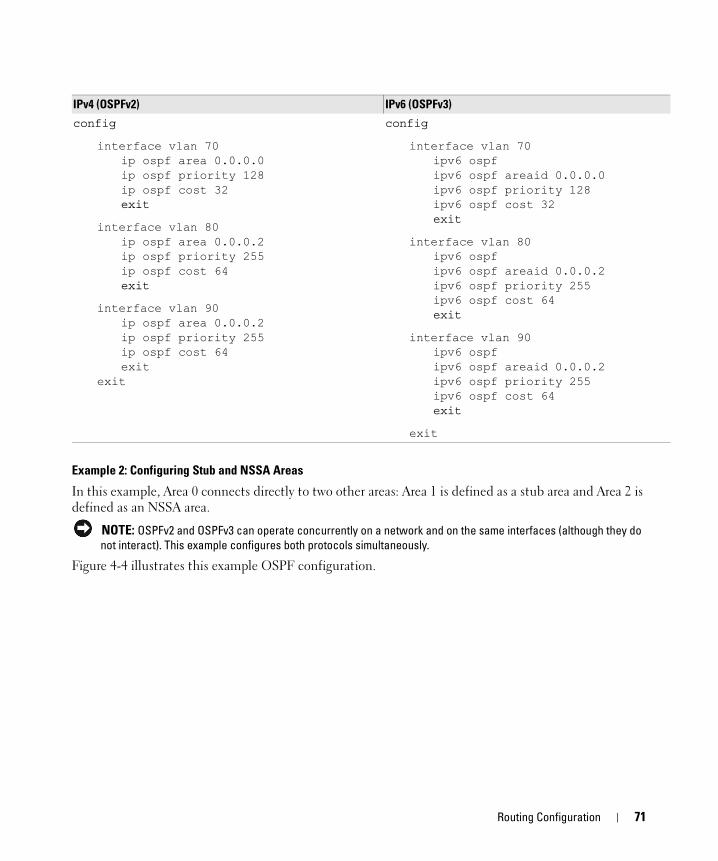
Example 2: Configuring Stub and NSSA Areas
In this example, Area 0 connects directly to two other areas: Area 1 is defined as a stub area and Area 2 is defined as an NSSA area.
NOTE: OSPFv2 and OSPFv3 can operate concurrently on a network and on the same interfaces (although they do not interact). This example configures both protocols simultaneously.
Figure 4-4 illustrates this example OSPF configuration.
config
interface vlan 70ip ospf area 0.0.0.0ip ospf priority 128ip ospf cost 32exit
interface vlan 80ip ospf area 0.0.0.2ip ospf priority 255ip ospf cost 64exit
interface vlan 90ip ospf area 0.0.0.2ip ospf priority 255ip ospf cost 64exit
exit
config
interface vlan 70ipv6 ospfipv6 ospf areaid 0.0.0.0ipv6 ospf priority 128ipv6 ospf cost 32exit
interface vlan 80ipv6 ospfipv6 ospf areaid 0.0.0.2ipv6 ospf priority 255ipv6 ospf cost 64exit
interface vlan 90ipv6 ospfipv6 ospf areaid 0.0.0.2ipv6 ospf priority 255ipv6 ospf cost 64exit
exit
IPv4 (OSPFv2) IPv6 (OSPFv3)
Routing Configuration 71

Figure 4-4. OSPF Configuration—Stub Area and NSSA Area
Configure Router A: Router A is a backbone router. It links to an ASBR (not defined here) that routes traffic outside the AS.
• Globally enable IPv6 and IPv4 routing:(console) #configure
ipv6 unicast-routingip routing
• Configure IP address and enable OSPF on VLAN routing interfaces 6 and 12 and enable IPv6 OSPF on the interfaces. (OSPF is enabled on the IPv4 interface in the next code group.)
interface vlan 6routingip address 10.2.3.3 255.255.255.0ipv6 address 3000:2:3::/64 eui64ip ospf area 0.0.0.0ipv6 ospfexit
interface vlan 12routingip address 10.3.100.3 255.255.255.0
Router B - ABR (5.5.5.5)10.1.2.2/24
3000:1:2::/64 eui64
10.2.4.23000:2:4::/64
10.2.3.23000:2:3::/64
Area 1 (0.0.0.1) - Stub
IR (5.3.0.0) ASBR (5.1.0.0)10.2.3.3/24
3000:2:3::/64 Router A - backbone (3.3.3.3)
IR (5.4.0.0)
Area 2 (0.0.0.2) - NSSA
Area 0 (0.0.0.0) - backbone
AS-1 AS-2
10.3.100.3/243000:3:100::/64
VLAN 10 VLAN 5
VLAN 17
VLAN 6 VLAN 12
72 Routing Configuration
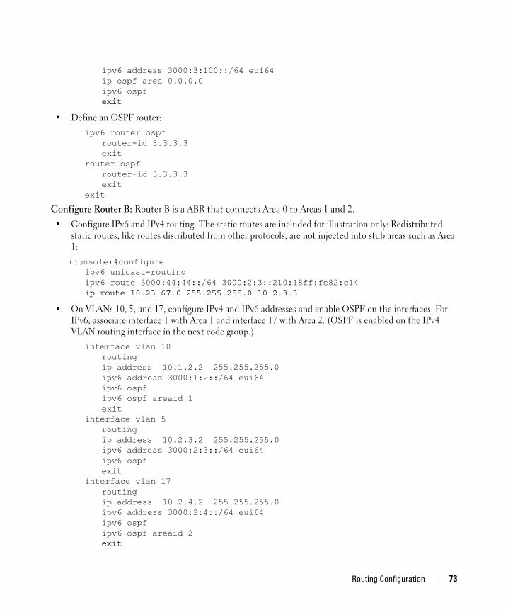
ipv6 address 3000:3:100::/64 eui64ip ospf area 0.0.0.0ipv6 ospfexit
• Define an OSPF router:ipv6 router ospf
router-id 3.3.3.3exit
router ospfrouter-id 3.3.3.3exit
exit
Configure Router B: Router B is a ABR that connects Area 0 to Areas 1 and 2.
• Configure IPv6 and IPv4 routing. The static routes are included for illustration only: Redistributed static routes, like routes distributed from other protocols, are not injected into stub areas such as Area 1:(console)#configure
ipv6 unicast-routingipv6 route 3000:44:44::/64 3000:2:3::210:18ff:fe82:c14ip route 10.23.67.0 255.255.255.0 10.2.3.3
• On VLANs 10, 5, and 17, configure IPv4 and IPv6 addresses and enable OSPF on the interfaces. For IPv6, associate interface 1 with Area 1 and interface 17 with Area 2. (OSPF is enabled on the IPv4 VLAN routing interface in the next code group.)
interface vlan 10routingip address 10.1.2.2 255.255.255.0ipv6 address 3000:1:2::/64 eui64ipv6 ospfipv6 ospf areaid 1exit
interface vlan 5routingip address 10.2.3.2 255.255.255.0ipv6 address 3000:2:3::/64 eui64ipv6 ospfexit
interface vlan 17routingip address 10.2.4.2 255.255.255.0ipv6 address 3000:2:4::/64 eui64ipv6 ospfipv6 ospf areaid 2exit
Routing Configuration 73
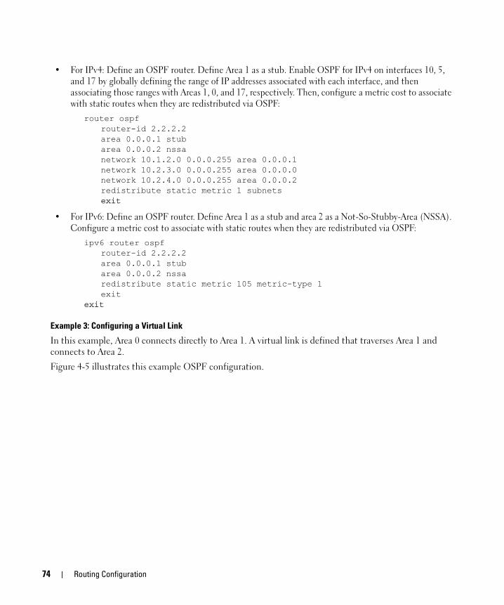
• For IPv4: Define an OSPF router. Define Area 1 as a stub. Enable OSPF for IPv4 on interfaces 10, 5, and 17 by globally defining the range of IP addresses associated with each interface, and then associating those ranges with Areas 1, 0, and 17, respectively. Then, configure a metric cost to associate with static routes when they are redistributed via OSPF:
router ospfrouter-id 2.2.2.2area 0.0.0.1 stubarea 0.0.0.2 nssanetwork 10.1.2.0 0.0.0.255 area 0.0.0.1network 10.2.3.0 0.0.0.255 area 0.0.0.0network 10.2.4.0 0.0.0.255 area 0.0.0.2redistribute static metric 1 subnetsexit
• For IPv6: Define an OSPF router. Define Area 1 as a stub and area 2 as a Not-So-Stubby-Area (NSSA). Configure a metric cost to associate with static routes when they are redistributed via OSPF:
ipv6 router ospfrouter-id 2.2.2.2area 0.0.0.1 stubarea 0.0.0.2 nssaredistribute static metric 105 metric-type 1exit
exit
Example 3: Configuring a Virtual Link
In this example, Area 0 connects directly to Area 1. A virtual link is defined that traverses Area 1 and connects to Area 2.
Figure 4-5 illustrates this example OSPF configuration.
74 Routing Configuration
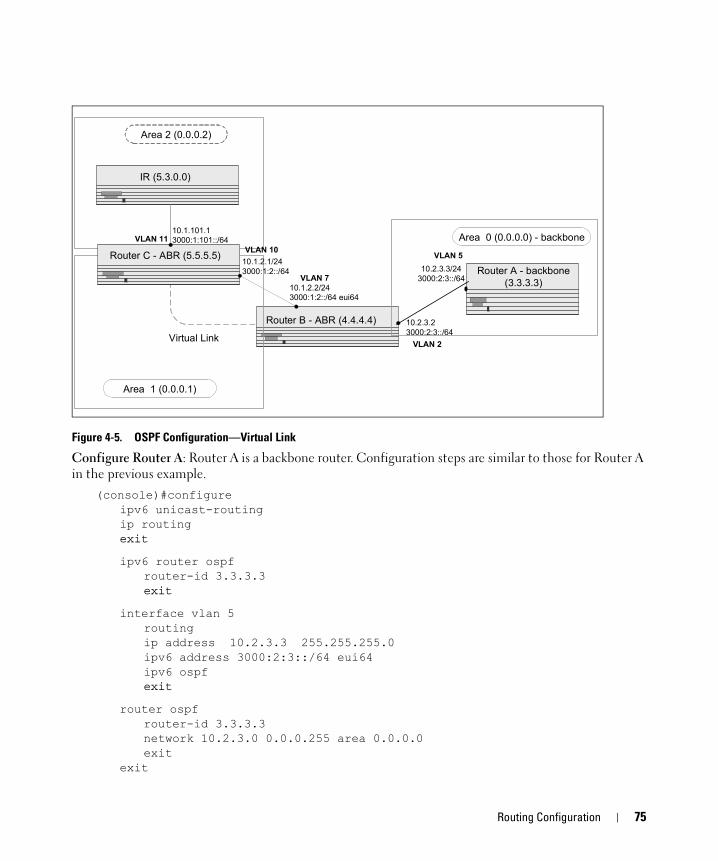
Figure 4-5. OSPF Configuration—Virtual Link
Configure Router A: Router A is a backbone router. Configuration steps are similar to those for Router A in the previous example.
(console)#configureipv6 unicast-routingip routingexit
ipv6 router ospfrouter-id 3.3.3.3exit
interface vlan 5routingip address 10.2.3.3 255.255.255.0ipv6 address 3000:2:3::/64 eui64ipv6 ospfexit
router ospfrouter-id 3.3.3.3network 10.2.3.0 0.0.0.255 area 0.0.0.0exit
exit
Router B - ABR (4.4.4.4)
Virtual Link
10.1.101.13000:1:101::/64
10.1.2.2/243000:1:2::/64 eui64
10.2.3.23000:2:3::/64
Area 2 (0.0.0.2)
IR (5.3.0.0)
Area 1 (0.0.0.1)
Router C - ABR (5.5.5.5)10.1.2.1/243000:1:2::/64 10.2.3.3/24
3000:2:3::/64Router A - backbone
(3.3.3.3)
Area 0 (0.0.0.0) - backboneVLAN 10
VLAN 7
VLAN 11
VLAN 2
VLAN 5
Routing Configuration 75
Configure Router B: Router B is a ABR that directly connects Area 0 to Area 1. In addition to the configuration steps described in the previous example, we define a virtual link that traverses Area 1 to Router C (5.5.5.5).
(console)#configureipv6 unicast-routingip routing
interface vlan 2routingip address 10.2.3.2 255.255.255.0ipv6 address 3000:2:3::/64 eui64ipv6 ospfexit
interface vlan 7routingip address 10.1.2.2 255.255.255.0ipv6 address 3000:1:2::211:88FF:FE2A:3CB3/64 eui64ipv6 ospfipv6 ospf areaid 1exit
router ospfrouter-id 4.4.4.4area 0.0.0.1 virtual-link 5.5.5.5network 10.2.3.0 0.0.0.255 area 0.0.0.0network 10.1.2.0 0.0.0.255 area 0.0.0.1exit
ipv6 router ospfrouter-id 4.4.4.4area 0.0.0.1 virtual-link 5.5.5.5exit
exit
Configure Router C: Router C is a ABR that enables a virtual link from the remote Area 2 in the AS to Area 0. In addition to the configuration steps described for Router C in the previous example, we define a virtual link that traverses Area 1 to Router B (4.4.4.4).
(console)#configureipv6 unicast-routingip routing
interface vlan 10routingip address 10.1.2.1 255.255.255.0ipv6 address 3000:1:2::/64 eui64ipv6 ospfipv6 ospf areaid 1exit
76 Routing Configuration

interface vlan 11routingip address 10.1.101.1 255.255.255.0ipv6 address 3000:1:101::/64 eui64ipv6 ospfipv6 ospf areaid 2exit
ipv6 router ospfrouter-id 5.5.5.5area 0.0.0.1 virtual-link 4.4.4.4exit
router ospfrouter-id 5.5.5.5area 0.0.0.1 virtual-link 4.4.4.4network 10.1.2.0 0.0.0.255 area 0.0.0.1network 10.1.101.0 0.0.0.255 area 0.0.0.2exit
exit
Routing Information ProtocolRouting Information Protocol (RIP) is one of the protocols which may be used by routers to exchange network topology information. It is characterized as an “interior” gateway protocol, and is typically used in small to medium-sized networks.
RIP ConfigurationA router running RIP sends the contents of its routing table to each of its adjacent routers every 30 seconds. When a route is removed from the routing table it is flagged as unusable by the receiving routers after 180 seconds, and removed from their tables after an additional 120 seconds.
There are two versions of RIP:
• RIP-1 defined in RFC 1058
– Routes are specified by IP destination network and hop count
– The routing table is broadcast to all stations on the attached network
• RIP-2 defined in RFC 1723
– Route specification is extended to include subnet mask and gateway
– The routing table is sent to a multicast address, reducing network traffic
– An authentication method is used for security
The PowerConnect 6200 Series software supports both versions of RIP. You may configure a given port:
• To receive packets in either or both formats
• To transmit packets formatted for RIP-1 or RIP-2 or to send RIP-2 packets to the RIP-1 broadcast address
Routing Configuration 77

• To prevent any RIP packets from being received
• To prevent any RIP packets from being transmitted
CLI ExamplesThe configuration commands used in the following example enable RIP on ports vlan 2 and vlan 3 as shown in the network illustrated in Figure 4-6.
Figure 4-6. Port Routing Example Network Diagram
Example #1: Enable Routing for the Switch
The following sequence enables routing for the switch:console#config
ip routingexit
Example #2: Enable Routing for Ports
The following command sequence enables routing and assigns IP addresses for ports vlan 2 and vlan 3.console#config
interface vlan 2routingip address 192.150.2.2 255.255.255.0exit
Subnet 3
Subnet 5Subnet 2
Port 1/0/2192.150.2.2
Port 1/0/3192.130.3.1
Port 1/0/5192.64.4.1
Layer 3 Switchacting as a router
VLAN 3192.130.3.1
VLAN 2192.150.2.2
VLAN 5192.64.4.1
78 Routing Configuration
interface vlan 3 routingip address 192.130.3.1 255.255.255.0exit
exit
Example #3. Enable RIP for the Switch
The next sequence enables RIP for the switch. The route preference defaults to 15.console#config
router ripenableexit
exit
Example #4. Enable RIP for the VLAN Routing Interfaces
This command sequence enables RIP for ports vlan 2 and vlan 3. Authentication defaults to none, and no default route entry is created. The commands specify that both ports receive both RIP-1 and RIP-2 frames, but send only RIP-2 formatted frames.console#config
interface vlan 2ip ripip rip receive version bothip rip send version rip2exit
interface vlan 3ip ripip rip receive version bothip rip send version rip2exit
exit
Using the Web Interface to Configure RIPUse the following screens to perform the same configuration using the Graphical User Interface:
• Routing > IP > Configuration> To enable routing for the switch.
• Routing > IP > Interface Configuration > To configure the VLAN routing interfaces.
• Routing > RIP > Configuration. To enable RIP for the switch.
• Routing > RIP > Interface Configuration. To enable RIP for the VLAN routing interfaces and specify the RIP versions.
Routing Configuration 79
Route PreferencesYou can use route preference assignment to control how the router chooses which routes to use when alternatives exist. This section describes three uses of route preference assignment:
• "Assigning Administrative Preferences to Routing Protocols" on page 80
• "exit" on page 81
• "Using Equal Cost Multipath" on page 81
Assigning Administrative Preferences to Routing ProtocolsThe router may learn routes from various sources: static configuration, local route discovery, RIP, and OSPF. Most routing protocols use a route metric to determine the shortest path known to the protocol; however, these metrics are independent of one another and not easily comparable. Therefore, when the router learns a route to a particular destination from two different sources, the metrics do not provide a means of choosing the best route for your network.
The PowerConnect 6200 Series switch enables you to identify the preferred route type by assigning an administrative preference value to each type. The values are arbitrary (1 to 255); however, a route type that has a lower value is preferred over higher-value types.
Local routes are assigned an administrative preference value of 0 and are always preferred over other route types to local hosts. Static routes have a default value of 1; however, this value and all other default preference values are user-configurable.
A protocol can be assigned a preference value of 255 to prevent the router from forwarding packets using that protocol.
Example 1: Configure Administrative Preferences
The following commands configure the administrative preference for the RIP and OSPF:console#Config
router ripdistance rip 130exit
For OSPF, an additional parameter identifies the type of OSPF route that the preference value applies to:router ospf
distance ospf ?
inter Enter preference type inter.intra Enter preference type intra.type1 Enter preference type type1.type2 Enter preference type type2.
distance ospf inter 170exit
80 Routing Configuration
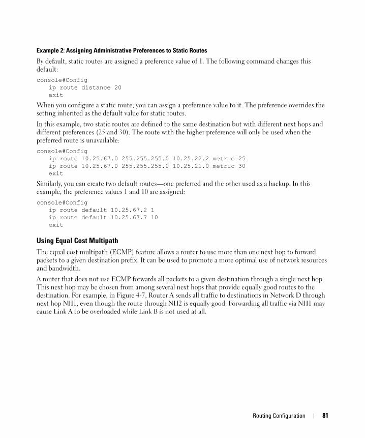
Example 2: Assigning Administrative Preferences to Static Routes
By default, static routes are assigned a preference value of 1. The following command changes this default: console#Config
ip route distance 20exit
When you configure a static route, you can assign a preference value to it. The preference overrides the setting inherited as the default value for static routes.
In this example, two static routes are defined to the same destination but with different next hops and different preferences (25 and 30). The route with the higher preference will only be used when the preferred route is unavailable:console#Config
ip route 10.25.67.0 255.255.255.0 10.25.22.2 metric 25ip route 10.25.67.0 255.255.255.0 10.25.21.0 metric 30exit
Similarly, you can create two default routes—one preferred and the other used as a backup. In this example, the preference values 1 and 10 are assigned:console#Config
ip route default 10.25.67.2 1ip route default 10.25.67.7 10exit
Using Equal Cost MultipathThe equal cost multipath (ECMP) feature allows a router to use more than one next hop to forward packets to a given destination prefix. It can be used to promote a more optimal use of network resources and bandwidth.
A router that does not use ECMP forwards all packets to a given destination through a single next hop. This next hop may be chosen from among several next hops that provide equally good routes to the destination. For example, in Figure 4-7, Router A sends all traffic to destinations in Network D through next hop NH1, even though the route through NH2 is equally good. Forwarding all traffic via NH1 may cause Link A to be overloaded while Link B is not used at all.
Routing Configuration 81
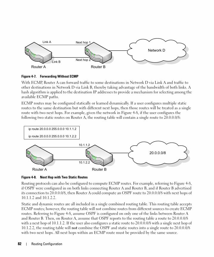
Figure 4-7. Forwarding Without ECMP
With ECMP, Router A can forward traffic to some destinations in Network D via Link A and traffic to other destinations in Network D via Link B, thereby taking advantage of the bandwidth of both links. A hash algorithm is applied to the destination IP addresses to provide a mechanism for selecting among the available ECMP paths.
ECMP routes may be configured statically or learned dynamically. If a user configures multiple static routes to the same destination but with different next hops, then those routes will be treated as a single route with two next hops. For example, given the network in Figure 4-8, if the user configures the following two static routes on Router A, the routing table will contain a single route to 20.0.0.0/8:
Figure 4-8. Next Hop with Two Static Routes
Routing protocols can also be configured to compute ECMP routes. For example, referring to Figure 4-8, if OSPF were configured in on both links connecting Router A and Router B, and if Router B advertised its connection to 20.0.0.0/8, then Router A could compute an OSPF route to 20.0.0.0/8 with next hops of 10.1.1.2 and 10.1.2.2.
Static and dynamic routes are all included in a single combined routing table. This routing table accepts ECMP routes; however, the routing table will not combine routes from different sources to create ECMP routes. Referring to Figure 4-8, assume OSPF is configured on only one of the links between Router A and Router B. Then, on Router A, assume that OSPF reports to the routing table a route to 20.0.0.0/8 with a next hop of 10.1.1.2. If the user also configures a static route to 20.0.0.0/8 with a single next hop of 10.1.2.2, the routing table will not combine the OSPF and static routes into a single route to 20.0.0.0/8 with two next hops. All next hops within an ECMP route must be provided by the same source.
Router A
Network D
Router B
Link A
Link B
Next hop 1
Next hop 2
Router A
20.0.0.0/8
Router B
10.1.1.2
10.1.2.2
ip route 20.0.0.0 255.0.0.0 10.1.1.2
ip route 20.0.0.0 255.0.0.0 10.1.2.2
82 Routing Configuration
An ECMP route contains only next hops whose paths to the destination are of equal cost. Referring to Figure 4-8, if OSPF were configured on all links, but Router A's interface to the 10.1.1.x network had an OSPF link cost of 5 and its interface to the 10.1.2.x network had an OSPF link cost of 10, then OSPF would use only 10.1.1.2 as the next hop to 20.0.0.0/8.
Example 1: Configuring an ECMP Route
In the following example, two static routes to the same destination are configured to use different next hops (e.g., for load balancing purposes). Note that the preference metric is not specified, so both routes assume the default static route preference of 1.console#Config
ip route 20.0.0.0 255.0.0.0 10.1.1.2ip route 20.0.0.0 255.0.0.0 10.1.2.2exit
The following command adds a third route with a preference value of 5. This route will be used only when the first two are unreachable:
ip route 20.0.0.0 255.0.0.0 10.1.3.2 5
Loopback InterfacesPowerConnect 6200 Series software provides for the creation, deletion, and management of loopback interfaces.
A loopback interface is a software-only interface that is not associated with a physical location; as such it is not dependent on the physical status of a particular router interface and is always considered “up” as long as the router is running. It enables configuring a stable IP address for remote clients to refer to. The client can communicate with the loopback interface using any available, active router interface.
NOTE: In this context, loopback interfaces should not be confused with the loopback IP address, usually 127.0.0.1, assigned to a host for handling self-routed packets.
Loopbacks are typically used for device management purposes. A client can use the loopback interface to communicate with the router through various services such as telnet and SSH. The address on a loopback behaves identically to any of the local addresses of the router in terms of the processing of incoming packets. This interface provides the source address for sent packets and can receive both local and remote packets.
NOTE: The following example uses the CLI to configure a loopback interface. You can also use the Web interface. Click Routing > Loopbacks in the navigation tree.
You can create a loopback interface in the Global Config mode by assigning it a unique ID from 0 to 7:console#configureconsole(config)#interface loopback 0
Next, you assign an IPv4 or IPv6 address to the interface:console(config-if-loopback0)#ip address 192.168.1.2 255.255.255.255
Routing Configuration 83
console(config-if-loopback0)#exitconsole(config)#exit
You can view the interface configuration from the Privileged Exec mode:console#show ip interface loopback 0
Primary IP Address............................. 192.168.1.2/255.255.255.255Routing Mode................................... EnableAdministrative Mode............................ EnableForward Net Directed Broadcasts................ DisableProxy ARP...................................... EnableLocal Proxy ARP................................ DisableActive State................................... ActiveLink Speed Data Rate........................... InactiveMAC Address.................................... 00FF.F2A3.8888Encapsulation Type............................. --------IP MTU......................................... 1500
To delete a loopback interface, enter the following command from the Global Config mode:console(config)#no interface loopback 0console(config)#
84 Routing Configuration
5
Device SecurityThis section describes configuration scenarios for the following features:• "802.1x Network Access Control" on page 85
• "802.1X Authentication and VLANs" on page 88
• "Authentication Server Filter Assignment" on page 90
• "Access Control Lists (ACLs)" on page 90
• "RADIUS" on page 97
• "TACACS+" on page 100
802.1x Network Access ControlPort-based network access control allows the operation of a system’s port(s) to be controlled to ensure that access to its services is permitted only by systems that are authorized to do so.
Port Access Control provides a means of preventing unauthorized access by supplicants or users to the services offered by a system. Control over the access to a switch and the LAN to which it is connected can be desirable in order to restrict access to publicly accessible bridge ports or departmental LANs.
The PowerConnect 6200 Series switch achieves access control by enforcing authentication of supplicants that are attached to an authenticator’s controlled ports. The result of the authentication process determines whether the supplicant is authorized to access services on that controlled port.
A PAE (Port Access Entity) can adopt one of two roles within an access control interaction:
• Authenticator – Port that enforces authentication before allowing access to services available via that Port.
• Supplicant – Port that attempts to access services offered by the Authenticator.
Additionally, there exists a third role:
• Authentication server – Server that performs the authentication function necessary to check the credentials of the supplicant on behalf of the Authenticator.
Completion of an authentication exchange requires all three roles. The PowerConnect 6200 Series switch supports the authenticator role only, in which the PAE is responsible for communicating with the supplicant. The authenticator PAE is also responsible for submitting information received from the supplicant to the authentication server in order for the credentials to be checked, which
Device Security 85

determines the authorization state of the port. Depending on the outcome of the authentication process, the authenticator PAE then controls the authorized/unauthorized state of the controlled Port.
Authentication can be handled locally or via an external authentication server. Two are: Remote Authentication Dial-In User Service (RADIUS) or Terminal Access Controller Access Control System (TACACS+).
802.1x Network Access Control ExamplesThis section contains examples of the CLI commands used to configure 802.1X.
Example #1: Configure RADIUS Server for Authentication
This example configures a single RADIUS server used for authentication at 10.10.10.10. The shared secret is configured to be secret. The process creates a new authentication list, called radiusList, which uses RADIUS as the authentication method. This authentication list is associated with the 802.1x default login. 802.1x port based access control is enabled for the system, and interface 1/g1 is configured to be in force-authorized mode because this is where the RADIUS server and protected network resources are located.
Figure 5-1. Switch with 802.1x Network Access Control
If a user, or supplicant, attempts to communicate via the switch on any interface except interface 1/g1, the system challenges the supplicant for login credentials. The system encrypts the provided information and transmits it to the RADIUS server. If the RADIUS server grants access, the system sets the 802.1x port state of the interface to authorized and the supplicant is able to access network resources.console(config)#radius-server host 10.10.10.10console(Config-radius)#exitconsole(config)#radius-server key secretconsole(config)#exit
console#show radius-servers
IP address Auth. TimeOut Retran. DeadTime source IP Prio. Usage--------------- ----- ------- ------- -------- --------------- ----- -----
10.10.10.10 1812 Global Global Global Global 0 all
86 Device Security

Global values---------------Timeout : 3Retransmit : 3Deadtime : 0Source-ip : 0.0.0.0
console(config)#aaa authentication login radiusList radiusconsole(config)#aaa authentication dot1x default radiusconsole(config)#dot1x system-auth-control
console(config)#interface ethernet 1/g1console(config-if-1/g1)#dot1x port-control force-authorizedconsole(config-if-1/g1)#exit
Example #2: MAC-Based Authentication Mode
Beginning in release 2.1, the PowerConnect 6200 Series switches support MAC-based 801.X authentication. This feature allows multiple hosts to authenticate on a single port. The hosts are distinguished by their MAC addresses.
When multiple hosts (for example, a PC, a printer, and a phone in the same office) are connected to the switch on the same port, each of the connected hosts authenticates separately with the RADIUS server.
The following command enables MAC-based authentication on port 1/g8 and limits the number of devices that can authenticate on that port to 3. The switchport mode general command sets the port to an 802.1Q VLAN. The port must be in general mode in order to enable MAC-based 802.1X authentication.console#configureconsole(config)#interface ethernet 1/g8
console(config-if-1/g8)#switchport mode generalconsole(config-if-1/g8)#dot1x port-control mac-basedconsole(config-if-1/g8)#dot1x max-users 3console(config-if-1/g8)#exitconsole(config)#exit
console#show dot1x ethernet 1/g8
Administrative Mode............... Enabled
Port Admin Oper Reauth Reauth Mode Mode Control Period------- ------------------ ------------ -------- ----------1/g8 mac-based Unauthorized FALSE 3600
Quiet Period................................... 60Transmit Period................................ 30
Device Security 87
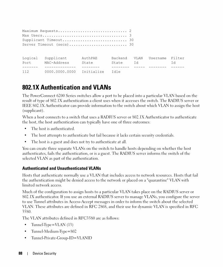
Maximum Requests............................... 2Max Users...................................... 3Supplicant Timeout............................. 30Server Timeout (secs).......................... 30
Logical Supplicant AuthPAE Backend VLAN Username FilterPort MAC-Address State State Id Id------- -------------- -------- -------- ----- -------- ------112 0000.0000.0000 Initialize Idle
802.1X Authentication and VLANsThe PowerConnect 6200 Series switches allow a port to be placed into a particular VLAN based on the result of type of 802.1X authentication a client uses when it accesses the switch. The RADIUS server or IEEE 802.1X Authenticator can provide information to the switch about which VLAN to assign the host (supplicant).
When a host connects to a switch that uses a RADIUS server or 802.1X Authenticator to authenticate the host, the host authentication can typically have one of three outcomes:
• The host is authenticated.
• The host attempts to authenticate but fail because it lacks certain security credentials.
• The host is a guest and does not try to authenticate at all.
You can create three separate VLANs on the switch to handle hosts depending on whether the host authenticates, fails the authentication, or is a guest. The RADIUS server informs the switch of the selected VLAN as part of the authentication.
Authenticated and Unauthenticated VLANsHosts that authenticate normally use a VLAN that includes access to network resources. Hosts that fail the authentication might be denied access to the network or placed on a "quarantine" VLAN with limited network access.
Much of the configuration to assign hosts to a particular VLAN takes place on the RADIUS server or 802.1X authenticator. If you use an external RADIUS server to manage VLANs, you configure the server to use Tunnel attributes in Access-Accept messages in order to inform the switch about the selected VLAN. These attributes are defined in RFC 2868, and their use for dynamic VLAN is specified in RFC 3580.
The VLAN attributes defined in RFC3580 are as follows:
• Tunnel-Type=VLAN (13)
• Tunnel-Medium-Type=802
• Tunnel-Private-Group-ID=VLANID
88 Device Security
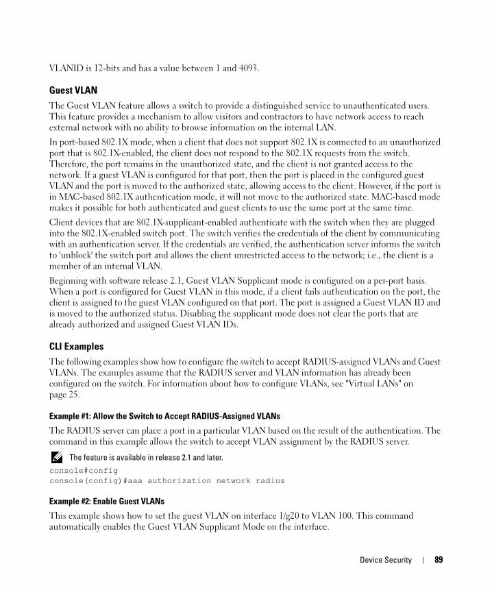
VLANID is 12-bits and has a value between 1 and 4093.
Guest VLANThe Guest VLAN feature allows a switch to provide a distinguished service to unauthenticated users. This feature provides a mechanism to allow visitors and contractors to have network access to reach external network with no ability to browse information on the internal LAN.
In port-based 802.1X mode, when a client that does not support 802.1X is connected to an unauthorized port that is 802.1X-enabled, the client does not respond to the 802.1X requests from the switch. Therefore, the port remains in the unauthorized state, and the client is not granted access to the network. If a guest VLAN is configured for that port, then the port is placed in the configured guest VLAN and the port is moved to the authorized state, allowing access to the client. However, if the port is in MAC-based 802.1X authentication mode, it will not move to the authorized state. MAC-based mode makes it possible for both authenticated and guest clients to use the same port at the same time.
Client devices that are 802.1X-supplicant-enabled authenticate with the switch when they are plugged into the 802.1X-enabled switch port. The switch verifies the credentials of the client by communicating with an authentication server. If the credentials are verified, the authentication server informs the switch to 'unblock' the switch port and allows the client unrestricted access to the network; i.e., the client is a member of an internal VLAN.
Beginning with software release 2.1, Guest VLAN Supplicant mode is configured on a per-port basis. When a port is configured for Guest VLAN in this mode, if a client fails authentication on the port, the client is assigned to the guest VLAN configured on that port. The port is assigned a Guest VLAN ID and is moved to the authorized status. Disabling the supplicant mode does not clear the ports that are already authorized and assigned Guest VLAN IDs.
CLI ExamplesThe following examples show how to configure the switch to accept RADIUS-assigned VLANs and Guest VLANs. The examples assume that the RADIUS server and VLAN information has already been configured on the switch. For information about how to configure VLANs, see "Virtual LANs" on page 25.
Example #1: Allow the Switch to Accept RADIUS-Assigned VLANs
The RADIUS server can place a port in a particular VLAN based on the result of the authentication. The command in this example allows the switch to accept VLAN assignment by the RADIUS server.
The feature is available in release 2.1 and later.console#configconsole(config)#aaa authorization network radius
Example #2: Enable Guest VLANs
This example shows how to set the guest VLAN on interface 1/g20 to VLAN 100. This command automatically enables the Guest VLAN Supplicant Mode on the interface.
Device Security 89
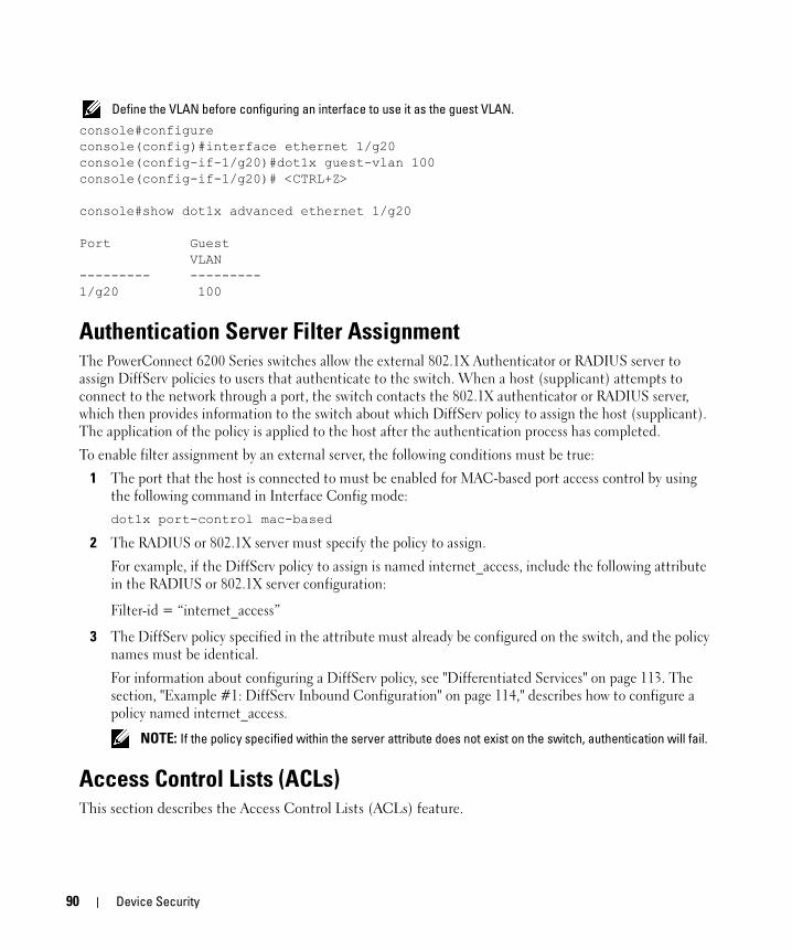
Define the VLAN before configuring an interface to use it as the guest VLAN.
console#configureconsole(config)#interface ethernet 1/g20console(config-if-1/g20)#dot1x guest-vlan 100console(config-if-1/g20)# <CTRL+Z>
console#show dot1x advanced ethernet 1/g20
Port Guest VLAN--------- ---------1/g20 100
Authentication Server Filter AssignmentThe PowerConnect 6200 Series switches allow the external 802.1X Authenticator or RADIUS server to assign DiffServ policies to users that authenticate to the switch. When a host (supplicant) attempts to connect to the network through a port, the switch contacts the 802.1X authenticator or RADIUS server, which then provides information to the switch about which DiffServ policy to assign the host (supplicant). The application of the policy is applied to the host after the authentication process has completed.
To enable filter assignment by an external server, the following conditions must be true:
1 The port that the host is connected to must be enabled for MAC-based port access control by using the following command in Interface Config mode:dot1x port-control mac-based
2 The RADIUS or 802.1X server must specify the policy to assign.
For example, if the DiffServ policy to assign is named internet_access, include the following attribute in the RADIUS or 802.1X server configuration:
Filter-id = “internet_access”
3 The DiffServ policy specified in the attribute must already be configured on the switch, and the policy names must be identical.
For information about configuring a DiffServ policy, see "Differentiated Services" on page 113. The section, "Example #1: DiffServ Inbound Configuration" on page 114," describes how to configure a policy named internet_access.
NOTE: If the policy specified within the server attribute does not exist on the switch, authentication will fail.
Access Control Lists (ACLs)This section describes the Access Control Lists (ACLs) feature.
90 Device Security
OverviewAccess Control Lists (ACLs) are a collection of permit and deny conditions, called rules, that provide security by blocking unauthorized users and allowing authorized users to access specific resources.
ACLs can also provide traffic flow control, restrict contents of routing updates, and decide which types of traffic are forwarded or blocked. Normally ACLs reside in a firewall router or in a router connecting two internal networks.
The PowerConnect 6200 Series switch supports ACL configuration in both the ingress and egress direction. Egress ACLs provide the capability to implement security rules on the egress flows rather than the ingress flows. Ingress and egress ACLs can be applied to any physical port (including 10G), or port-channel, or VLAN routing port.
Ingress ACLs support Flow-based Mirroring and ACL Logging, which have the following characteristics:
• Flow-based mirroring is the ability to mirror traffic that matches a permit rule to a specific physical port or LAG. Flow-based mirroring is similar to the redirect function, except that in flow-based mirroring a copy of the permitted traffic is delivered to the mirror interface while the packet itself is forwarded normally through the device. You cannot configure a given ACL rule with mirror and redirect attributes.
• ACL Logging provides a means for counting the number of “hits” against an ACL rule. When you configure ACL Logging, you augment the ACL deny rule specification with a "log" parameter that enables hardware hit count collection and reporting. The switch uses a fixed five minute logging interval, at which time trap log entries are written for each ACL logging rule that accumulated a non-zero hit count during that interval. You cannot configure the logging interval.
Using ACLs to mirror traffic is called flow-based mirroring since the traffic flow is defined by the ACL classification rules. This is in contrast to port mirroring, where all traffic encountered on a specific interface is replicated on another interface.
You can set up ACLs to control traffic at Layer 2, Layer 3, or Layer 4. MAC ACLs operate on Layer 2. IP ACLs operate on Layers 3 and 4.
Limitations
The following limitations apply to ingress and egress ACLs.
• Maximum of 100 ACLs.
• Maximum rules per ACL is 12.
• You can configure mirror or redirect attributes for a given ACL rule, but not both.
• Only one ACL per interface.
• The PowerConnect 6200 Series switch does not support MAC ACLs and IP ACLs on the same interface.
• The PowerConnect 6200 Series switch supports a limited number of counter resources, so it may not be possible to log every ACL rule. You can define an ACL with any number of logging rules, but the number of rules that are actually logged cannot be determined until the ACL is applied to an interface.
Device Security 91

Furthermore, hardware counters that become available after an ACL is applied are not retroactively assigned to rules that were unable to be logged (the ACL must be un-applied then re-applied). Rules that are unable to be logged are still active in the ACL for purposes of permitting or denying a matching packet.
• The order of the rules is important: when a packet matches multiple rules, the first rule takes precedence. Also, once you define an ACL for a given port, all traffic not specifically permitted by the ACL is denied access.
NOTE: Although the maximum number of ACLs is 100, and the maximum number of rules per ACL is 12, the system cannot support 100 ACLs that each have 12 rules.
Egress ACL Limitations
Egress ACLs have some additional limitations. The following limitations apply to egress ACLs only:
• Egress ACLs support IP Protocol/Destination, IP Address Source/Destination, L4 Source/Destination port, IP DSCP, IP ToS, and IP precedence match conditions only.
• MAC ACLs are not supported in the egress direction.
• Egress ACLs only support Permit/Deny Action. Logging, mirroring and redirect action are not supported.
• Only one Egress ACL can be applied on an interface. The ACL can have multiple rules to classify flows and apply permit/deny action.
• If the Egress ACLs have "over-lapping" rules, then there can be undesired behavior. This limitation is only applicable if the conflicting ACLs are within the same unit. The restriction is explained below:
– ACL 1: permit tcp destination port 3000; deny all
– ACL 2: drop ip source 10.1.1.1; permit all
– ACL 1 is applied on port 1 and ACL 2 is applied on port 2. Due to this limitation, all the packets egressing port 2 with Source IP 10.1.1.1 and tcp source port 3000 will be permitted even though they should be dropped.
MAC ACLsMAC ACLs are Layer 2 ACLs. You can configure the rules to inspect the following fields of a packet:
• Source MAC address
• Source MAC mask
• Destination MAC address
• Destination MAC mask
• VLAN ID
• Class of Service (CoS) (802.1p)
• Ethertype
92 Device Security

L2 ACLs can apply to one or more interfaces.
Multiple access lists can be applied to a single interface; sequence number determines the order of execution.
You can assign packets to queues using the assign queue option.
IP ACLsIP ACLs classify for Layers 3 and 4.
Each ACL is a set of up to ten rules applied to inbound traffic. Each rule specifies whether the contents of a given field should be used to permit or deny access to the network, and may apply to one or more of the following fields within a packet:
• Destination IP with wildcard mask
• Destination L4 Port
• Every Packet
• IP DSCP
• IP Precedence
• IP TOS
• Protocol
• Source IP with wildcard mask
• Source L4 port
• Destination Layer 4 port
ACL Configuration ProcessTo configure ACLs, follow these steps:
1 Create a MAC ACL by specifying a name.
2 Create an IP ACL by specifying a number.
3 Add new rules to the ACL.
4 Configure the match criteria for the rules.
5 Apply the ACL to one or more interfaces.
IP ACL CLI ExamplesThe script in this section shows you how to set up an IP ACL with two rules, one applicable to TCP traffic and one to UDP traffic. The content of the two rules is the same. TCP and UDP packets will only be accepted by the PowerConnect 6200 Series switch if the source and destination stations have IP addresses that fall within the defined sets.
Device Security 93
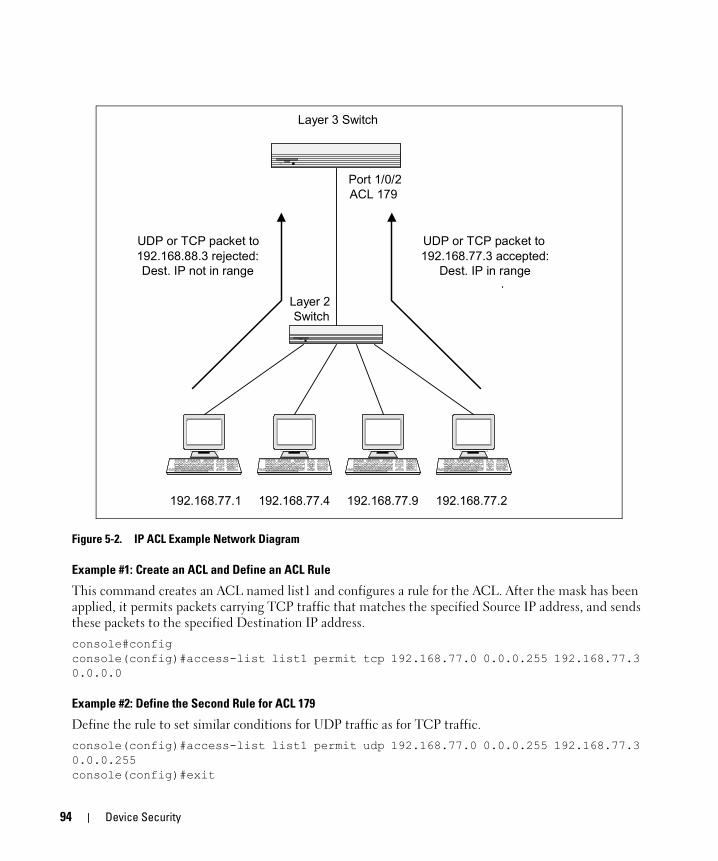
Figure 5-2. IP ACL Example Network Diagram
Example #1: Create an ACL and Define an ACL Rule
This command creates an ACL named list1 and configures a rule for the ACL. After the mask has been applied, it permits packets carrying TCP traffic that matches the specified Source IP address, and sends these packets to the specified Destination IP address.console#configconsole(config)#access-list list1 permit tcp 192.168.77.0 0.0.0.255 192.168.77.3 0.0.0.0
Example #2: Define the Second Rule for ACL 179
Define the rule to set similar conditions for UDP traffic as for TCP traffic.console(config)#access-list list1 permit udp 192.168.77.0 0.0.0.255 192.168.77.3 0.0.0.255console(config)#exit
Port 1/0/2ACL 179
192.168.77.1 192.168.77.2192.168.77.9192.168.77.4
UDP or TCP packet to192.168.77.3 accepted:
Dest. IP in range
UDP or TCP packet to192.168.88.3 rejected:Dest. IP not in range
Layer 2 Switch
Layer 3 Switch
94 Device Security

Example #3: Apply the Rule to Outbound (Egress) Traffic on Port 1/g2
Only traffic matching the criteria will be accepted.console(config)#interface ethernet 1/g2console(config-if-1/g2)#ip access-group list1 outconsole(config-if-1/g2)#exit
MAC ACL CLI ExamplesThe following are examples of the commands used for the MAC ACLs feature.
Example #4: Set up a MAC Access Listconsole#configconsole(config)#mac access-list extended mac1console(config)#exit
Example #5: Specify MAC ACL Attributesconsole(config-mac-access-list)#deny ?
any Configure a match condition for all the source MACaddresses in the Source MAC Address field.
<srcmac> Enter a MAC Address.
console(config-mac-access-list)#deny any ?
any Configure a match condition for all the destinationMAC addresses in the Destination MAC Address field.
bpdu Match on any BPDU destination MAC Address.<dstmac> Enter a MAC Address.
console(config-mac-access-list)#deny any 00:11:22:33:44:55 ?
<dstmacmask> Enter a MAC Address bit mask.
console(config-mac-access-list)#deny any 00:11:22:33:44:55 00:00:00:00:FF:FF ?
assign-queue Configure the Queue Id assignment attribute.cos Configure a match condition based on a COS value.log Configure logging for this access list rule.mirror Configure the packet mirroring attribute.redirect Configure the packet redirection attribute.vlan Configure a match condition based on a VLAN ID.<0x0600-0xffff> Enter a four-digit hexadecimal number in the range of
0x0600 to 0xffff to specify a custom Ethertype value.<cr> Press enter to execute the command.<ethertypekey> Enter one of the following keywords to specify an
Ethertype (appletalk, arp, ibmsna, ipv4, ipv6, ipx,
Device Security 95

mplsmcast, mplsucast, netbios, novell, pppoe, rarp).
console(config-mac-access-list)#deny any 00:11:22:33:44:55 00:00:00:00:FF:FF log ?
assign-queue Configure the Queue Id assignment attribute.mirror Configure the packet mirroring attribute.redirect Configure the packet redirection attribute.<cr> Press enter to execute the command.
console(config-mac-access-list)#deny any 00:11:22:33:44:55 00:00:00:00:FF:FF log
Example #6 Configure MAC Access Groupconsole(config)#interface ethernet 1/g5
console(config-if-1/g5)#mac access-group mac1 ?
in Enter the direction <in>.<cr> Press enter to execute the command.
console(config-if-1/g5)#mac access-group mac1 in ?
<1-4294967295> Enter the sequence number (greater than 0) to rankprecedence for this interface and direction. A lowersequence number has higher precedence.
<cr> Press enter to execute the command.
console(config-if-1/g5)#mac access-group mac1 in 6
Example #7: Setup an ACL with Permit Actionconsole# Configconsole(config)#mac access-list extended mac2
console(config-mac-access-list)#permit ?
any Configure a match condition for all the source MACaddresses in the Source MAC Address field.
<srcmac> Enter a MAC Address.
console(config-mac-access-list)#permit any ?
any Configure a match condition for all the destinationMAC addresses in the Destination MAC Address field.
bpdu Match on any BPDU destination MAC Address.<dstmac> Enter a MAC Address.
96 Device Security
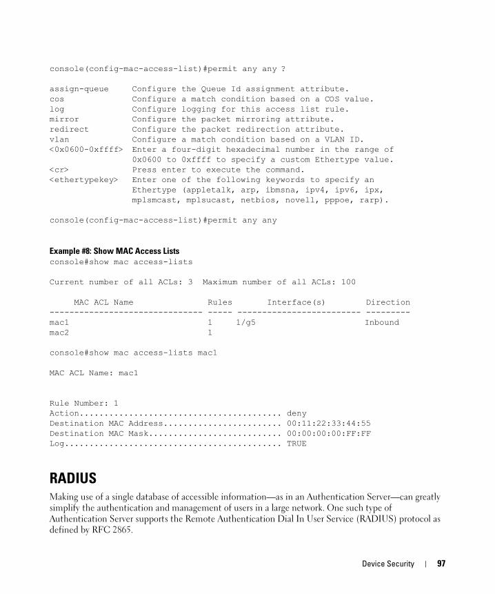
console(config-mac-access-list)#permit any any ?
assign-queue Configure the Queue Id assignment attribute.cos Configure a match condition based on a COS value.log Configure logging for this access list rule.mirror Configure the packet mirroring attribute.redirect Configure the packet redirection attribute.vlan Configure a match condition based on a VLAN ID.<0x0600-0xffff> Enter a four-digit hexadecimal number in the range of
0x0600 to 0xffff to specify a custom Ethertype value.<cr> Press enter to execute the command.<ethertypekey> Enter one of the following keywords to specify an
Ethertype (appletalk, arp, ibmsna, ipv4, ipv6, ipx,mplsmcast, mplsucast, netbios, novell, pppoe, rarp).
console(config-mac-access-list)#permit any any
Example #8: Show MAC Access Listsconsole#show mac access-lists
Current number of all ACLs: 3 Maximum number of all ACLs: 100
MAC ACL Name Rules Interface(s) Direction------------------------------- ----- ------------------------- ---------mac1 1 1/g5 Inboundmac2 1
console#show mac access-lists mac1
MAC ACL Name: mac1
Rule Number: 1Action......................................... denyDestination MAC Address........................ 00:11:22:33:44:55Destination MAC Mask........................... 00:00:00:00:FF:FFLog............................................ TRUE
RADIUSMaking use of a single database of accessible information—as in an Authentication Server—can greatly simplify the authentication and management of users in a large network. One such type of Authentication Server supports the Remote Authentication Dial In User Service (RADIUS) protocol as defined by RFC 2865.
Device Security 97
For authenticating users prior to access, the RADIUS standard has become the protocol of choice by administrators of large accessible networks. To accomplish the authentication in a secure manner, the RADIUS client and RADIUS server must both be configured with the same shared password or “secret”. This “secret” is used to generate one-way encrypted authenticators that are present in all RADIUS packets. The “secret” is never transmitted over the network.
RADIUS conforms to a secure communications client/server model using UDP as a transport protocol. It is extremely flexible, supporting a variety of methods to authenticate and statistically track users. RADIUS is also extensible, allowing for new methods of authentication to be added without disrupting existing functionality.
As a user attempts to connect to a functioning RADIUS supported network, a device referred to as the Network Access Server (NAS) or switch/router first detects the contact. The NAS or user-login interface then prompts the user for a name and password. The NAS encrypts the supplied information and a RADIUS client transports the request to a pre-configured RADIUS server. The server can authenticate the user itself, or make use of a back-end device to ascertain authenticity. In either case a response may or may not be forthcoming to the client. If the server accepts the user, it returns a positive result with attributes containing configuration information. If the server rejects the user, it returns a negative result. If the server rejects the client or the shared “secrets” differ, the server returns no result. If the server requires additional verification from the user, it returns a challenge, and the request process begins again.
RADIUS Configuration ExamplesThis section contains examples of commands used to configure RADIUS settings on the switch.
Example #1: Basic RADIUS Server Configuration
This example configures two RADIUS servers at 10.10.10.10 and 11.11.11.11. Each server has a unique shared secret key. The shared secrets are configured to be secret1 and secret2 respectively. The server at 10.10.10.10 is configured as the primary server. The process creates a new authentication list, called radiusList, which uses RADIUS as the primary authentication method, and local authentication as a backup method in the event that the RADIUS server cannot be contacted.
98 Device Security
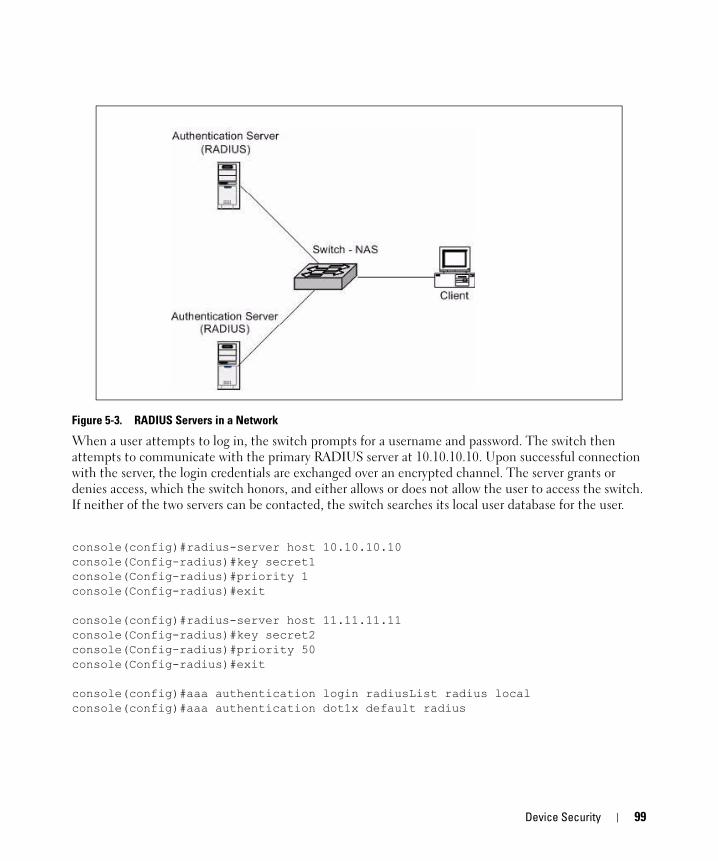
Figure 5-3. RADIUS Servers in a Network
When a user attempts to log in, the switch prompts for a username and password. The switch then attempts to communicate with the primary RADIUS server at 10.10.10.10. Upon successful connection with the server, the login credentials are exchanged over an encrypted channel. The server grants or denies access, which the switch honors, and either allows or does not allow the user to access the switch. If neither of the two servers can be contacted, the switch searches its local user database for the user.
console(config)#radius-server host 10.10.10.10console(Config-radius)#key secret1console(Config-radius)#priority 1console(Config-radius)#exit
console(config)#radius-server host 11.11.11.11console(Config-radius)#key secret2console(Config-radius)#priority 50console(Config-radius)#exit
console(config)#aaa authentication login radiusList radius localconsole(config)#aaa authentication dot1x default radius
Device Security 99
Example #2: Set the NAS-IP Address for the RADIUS Server
The NAS-IP address attribute identifies the IP Address of the network authentication server (NAS) that is requesting authentication of the user. The address should be unique to the NAS within the scope of the RADIUS server.
The NAS-IP-Address is only used in Access-Request packets. Either the NAS-IP-Address or NAS-Identifier must be present in an Access-Request packet.
NOTE: The feature is available in release 2.1 and later.
The following command sets the NAS-IP address to 192.168.20.12. If you do not specify an IP address in the command, the NAS-IP address uses the interface IP address that connects the switch to the RADIUS server.console#configconsole(config)#radius-server attribute 4 192.168.20.12
TACACS+TACACS+ (Terminal Access Controller Access Control System) provides access control for networked devices via one or more centralized servers. Similar to RADIUS, this protocol simplifies authentication by making use of a single database that can be shared by many clients on a large network. TACACS+ uses TCP to ensure reliable delivery and a shared key configured on the client and daemon server to encrypt all messages.
After you configure TACACS+ as the authentication method for user login, the NAS (Network Access Server) prompts for the user login credentials and requests services from the TACACS+ client. The client then uses the configured list of servers for authentication, and provides results back to the NAS. You can configure the TACACS+ server list with one or more hosts defined via their network IP address. You can also assign each a priority to determine the order in which the TACACS+ client will contact them. TACACS+ contacts the server when a connection attempt fails or times out for a higher priority server.
You can configure each server host with a specific connection type, port, timeout, and shared key, or you can use global configuration for the key and timeout.
Like RADIUS, the TACACS+ server can do the authentication itself, or redirect the request to another back-end device. All sensitive information is encrypted and the shared secret is never passed over the network; it is used only to encrypt the data.
TACACS+ Configuration ExampleThis example configures two TACACS+ servers at 10.10.10.10 and 11.11.11.11. Each server has a unique shared secret key. The server at 10.10.10.10 has a default priority of 0, the highest priority, while the other server has a priority of 2. The process creates a new authentication list, called tacacsList, which uses TACACS+ to authenticate, and uses local authentication as a backup method.
100 Device Security
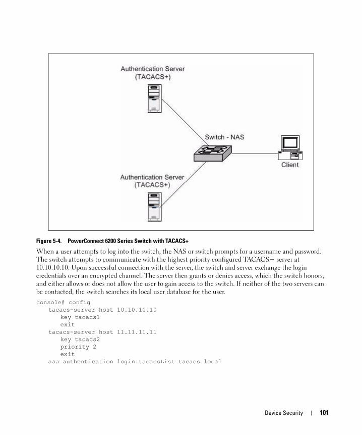
Figure 5-4. PowerConnect 6200 Series Switch with TACACS+
When a user attempts to log into the switch, the NAS or switch prompts for a username and password. The switch attempts to communicate with the highest priority configured TACACS+ server at 10.10.10.10. Upon successful connection with the server, the switch and server exchange the login credentials over an encrypted channel. The server then grants or denies access, which the switch honors, and either allows or does not allow the user to gain access to the switch. If neither of the two servers can be contacted, the switch searches its local user database for the user.console# config
tacacs-server host 10.10.10.10 key tacacs1exit
tacacs-server host 11.11.11.11key tacacs2priority 2exit
aaa authentication login tacacsList tacacs local
Device Security 101

102 Device Security

6
IPv6This section includes the following subsections:• "Overview" on page 103
• "Interface Configuration" on page 103
• "DHCPv6" on page 106
OverviewThere are many conceptual similarities between IPv4 and IPv6 network operation. Addresses still have a network prefix portion (subnet) and a device interface specific portion (host). While the length of the network portion is still variable, most users have standardized on using a network prefix length of 64 bits. This leaves 64 bits for the interface specific portion, called an Interface ID in IPv6. Depending upon the underlying link addressing, the Interface ID can be automatically computed from the link (e.g., MAC address). Such an automatically computed Interface ID is called an EUI64 identifier.
IPv6 packets on the network are of an entirely different format than traditional IPv4 packets and are also encapsulated in a different EtherType (contained within the L2 header to indicate which L3 protocol is used). In order to route these packets across L3 requires an infrastructure equivalent to and parallel to that provided for IPv4.
NOTE: The PowerConnect 6200 Series switch also implements OSPFv3 for use with IPv6 networks. These configuration scenarios are included with the OSPFv2 scenarios in "OSPF" on page 67.
Interface ConfigurationIn PowerConnect 6200 Series software, IPv6 coexists with IPv4. As with IPv4, IPv6 routing can be enabled on physical and VLAN interfaces. Each L3 routing interface can be used for IPv4, IPv6, or both.
Neighbor discovery is the IPv6 replacement for Address Resolution Protocol (ARP). Router advertisement is part of the neighbor discovery process and is required for IPv6. As part of router advertisement, PowerConnect 6200 Series software supports stateless auto configuration of end nodes. The switch supports both EUI-64 interface identifiers and manually configured interface IDs.
IPv6 103

While optional in IPv4, router advertisement is mandatory in IPv6. Router advertisements specify the network prefix(es) on a link which can be used by receiving hosts, in conjunction with an EUI64 identifier, to auto configure a host’s address. Routers have their network prefixes configured and may use EUI64 or manually configured interface IDs. In addition to one or more global addresses, each IPv6 interface also has an auto-configured link-local address which is:
• Allocated from part of the IPv6 unicast address space
• Not visible off the local link
• Not globally unique
Next hop addresses computed by routing protocols are usually link-local.
During a transition period, a global IPv6 Internet backbone may not be available. The solution of this is to tunnel IPv6 packets inside IPv4 to reach remote IPv6 islands. When a packet is sent over such a link, it is encapsulated in IPv4 in order to traverse an IPv4 network and has the IPv4 headers removed at the other end of the tunnel.
CLI ExampleIn Figure 6-1, two devices are connected as shown in the diagram. The VLAN 15 routing interface on both devices connects to an IPv4 backbone network where OSPF is used as the dynamic routing protocol to exchange IPv4 routes. OSPF allows device 1 and device 2 to learn routes to each other (from the 20.20.20.x network to the 10.10.10.x network and vice versa). The VLAN 2 routing interface on both devices connects to the local IPv6 network. OSPFv3 is used to exchange IPv6 routes between the two devices. The tunnel interface allows data to be transported between the two remote IPv6 networks over the IPv4 network.
Figure 6-1. IPv6 Example
Device 1console# config
ip routingipv6 unicast-routingrouter ospf
router-id 1.1.1.1exit
ipv6 router ospf
Interface 0/1 Interface 0/1
Interface 0/2 Interface 0/2NetworkVLAN 2
VLAN 15
VLAN 2
VLAN 15
104 IPv6

router-id 1.1.1.1exit
interface vlan 15routingip address 20.20.20.1 255.255.255.0ip ospf area 0.0.0.0exit
interface vlan 2routingipv6 enableipv6 address 2020:1::1/64ipv6 ospfipv6 ospf network point-to-pointexit
interface tunnel 0ipv6 address 2001::1/64tunnel mode ipv6iptunnel source 20.20.20.1tunnel destination 10.10.10.1ipv6 ospfipv6 ospf network point-to-pointexit
interface loopback 0ip address 1.1.1.1 255.255.255.0exit
exit
Device 2console# config
ip routingipv6 unicast-routingrouter ospf
router-id 2.2.2.2exit
ipv6 router ospfrouter-id 2.2.2.2exit
interface vlan 15routingip address 10.10.10.1 255.255.255.0
IPv6 105
ip ospf area 0.0.0.0exit
interface vlan 2routingipv6 enableipv6 address 2020:2::2/64ipv6 ospfipv6 ospf network point-to-pointexit
interface tunnel 0ipv6 address 2001::2/64tunnel mode ipv6iptunnel source 10.10.10.1tunnel destination 20.20.20.1ipv6 ospfipv6 ospf network point-to-pointexit
interface loopback 0ip address 2.2.2.2 255.255.255.0exit
exit
DHCPv6DHCP is generally used between clients (e.g., hosts) and servers (e.g., routers) for the purpose of assigning IP addresses, gateways, and other networking definitions such as DNS, NTP, and/or SIP parameters. However, IPv6 natively provides for autoconfiguration of IP addresses through IPv6 Neighbor Discovery Protocol (NDP) and through the use of Router Advertisement messages. Thus, the role of DHCPv6 within the network is different than that of DHCPv4 in that it is less relied upon for IP address assignment.
DHCPv6 server and client interactions are described by RFC 3315 [6]. There are many similarities between DHCPv6 and DHCPv4 interactions and options, but the messages and option definitions are sufficiently different such that there is no DHCPv4 to DHCPv6 migration or interoperability.
DHCPv6 incorporates the notion of the “stateless” server, where DHCPv6 is not used for IP address assignment to a client; rather, it only provides other networking information such as DNS, NTP, and/or SIP information. The stateless server behavior is described by RFC 3736 [7], which simply contains descriptions of the portions of RFC 3315 that are necessary for “stateless” server behavior. In order for a router to drive a DHCPv6 client to utilize stateless DHCPv6, the “other stateful configuration” option must be configured for neighbor discovery on the corresponding IPv6 router interface. This, in turn, causes DHCPv6 clients to send the DHCPv6 “Information Request” message in response. A DHCPv6 server then responds by providing only networking definitions such as DNS domain name and server definitions, NTP server definitions, and/or SIP definitions.
106 IPv6
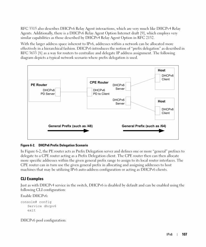
RFC 3315 also describes DHCPv6 Relay Agent interactions, which are very much like DHCPv4 Relay Agents. Additionally, there is a DHCPv6 Relay Agent Option Internet draft [9], which employs very similar capabilities as those described by DHCPv4 Relay Agent Option in RFC 2132.
With the larger address space inherent to IPv6, addresses within a network can be allocated more effectively in a hierarchical fashion. DHCPv6 introduces the notion of “prefix delegation” as described in RFC 3633 [8] as a way for routers to centralize and delegate IP address assignment. The following diagram depicts a typical network scenario where prefix delegation is used.
Figure 6-2. DHCPv6 Prefix Delegation Scenario
In Figure 6-2, the PE router acts as Prefix Delegation server and defines one or more “general” prefixes to delegate to a CPE router acting as a Prefix Delegation client. The CPE router then can then allocate more specific addresses within the given general prefix range to assign to its local router interfaces. The CPE router can in turn use the given general prefix in allocating and assigning addresses to host machines that may be utilizing IPv6 auto-address configuration or acting as DHCPv6 clients.
CLI ExamplesJust as with DHCPv4 service in the switch, DHCPv6 is disabled by default and can be enabled using the following CLI configuration:
Enable DHCPv6:console# config
Service dhcpv6exit
DHCPv6 pool configuration:
CPE RouterPE Router
Host
Host
DHCPv6Client
DHCPv6Client
DHCPv6PD Server
DHCPv6PD to Client
DHCPv6Server
DHCPv6Server
General Prefix (such as /48) General Prefix (such as /64)
IPv6 107

console# configipv6 dhcp pool testpool
domain-name dell.comdns-server 2001::1exit
exit
Per-interface DHCPv6 configuration:console#config
interface vlan 15ipv6 dhcp server testpool preference 10exit
exit
108 IPv6
7
Quality of Service This section includes the following subsections:• "Class of Service Queuing" on page 109
• "Differentiated Services" on page 113
Class of Service QueuingThe Class of Service (CoS) feature lets you give preferential treatment to certain types of traffic over others. To set up this preferential treatment, you can configure the ingress ports, the egress ports, and individual queues on the egress ports to provide customization that suits your environment.
The level of service is determined by the egress port queue to which the traffic is assigned. When traffic is queued for transmission, the rate at which it is serviced depends on how the queue is configured and possibly the amount of traffic present in other queues for that port.
Some traffic is classified for service (i.e., packet marking) before it arrives at the switch. If you decide to use these classifications, you can map this traffic to egress queues by setting up a CoS Mapping table.
Each ingress port on the switch has a default priority value (set by configuring VLAN Port Priority in the Switching sub-menu) that determines the egress queue its traffic gets forwarded to. Packets that arrive without a priority designation, or packets from ports you’ve identified as “untrusted,” get forwarded according to this default.
Ingress Port Configuration
Trusted and Untrusted Ports/CoS Mapping Table
The first task for ingress port configuration is to specify whether traffic arriving on a given port is “trusted” or “untrusted.”
A trusted port means that the system will accept at face value a priority designation within arriving packets. You can configure the system to trust priority designations based on one of the following fields in the packet header:
• 802.1 Priority: values 0-7
• IP DSCP: values 0-63
• IP Precedence: values 0-7
You can also configure an ingress port as untrusted, where the system ignores priority designations of incoming packets and sends the packet to a queue based on the ingress port’s default priority.
Quality of Service 109
CoS Mapping Table for Trusted Ports
Mapping is from the designated field values on trusted ports’ incoming packets to a traffic class priority (actually a CoS traffic queue). The trusted port field-to-traffic class configuration entries form the Mapping Table the switch uses to direct ingress packets from trusted ports to egress queues.
Egress Port Configuration—Traffic ShapingFor unit/slot/port interfaces, you can specify the shaping rate for the port, which is an upper limit of the transmission bandwidth used, specified as a percentage of the maximum link speed.
Queue configurationFor each queue, you can specify:
• Minimum bandwidth guarantee
• Scheduler type – strict/weighted: Strict priority scheduling gives an absolute priority, with highest priority queues always sent first, and lowest priority queues always sent last. Weighted scheduling requires a specification of priority for each queue relative to the other queues, based on their minimum bandwidth values.
• Queue management – tail drop
Queue Management TypeThe switch supports the tail drop method of queue management. This means that any packet forwarded to a full queue is dropped regardless of its importance.
CLI ExamplesFigure 7-1 illustrates the network operation as it relates to CoS mapping and queue configuration.
Four packets arrive at the ingress port 1/g10 in the order A, B, C, and D. You’ve configured port 1/g10 to trust the 802.1p field of the packet, which serves to direct packets A, B, and D to their respective queues on the egress port. These three packets utilize port 1/g10’s 802.1p to COS Mapping Table. In this case, the 802.1p user priority 3 was set up to send the packet to queue 5 instead of the default queue 3. Since packet C does not contain a VLAN tag, the 802.1p user priority does not exist, so Port 1/g10 relies on its default port priority (2) to direct packet C to egress queue 1.
110 Quality of Service

Figure 7-1. CoS Mapping and Queue Configuration
Continuing this example, you configured the egress Port 1/g8 for strict priority on queue 6, and a set a weighted scheduling scheme for queues 5-0. Assuming queue 5 has a higher weighting than queue 1 (relative weight values shown as a percentage, with 0% indicating the bandwidth is not guaranteed), the queue service order is 6 followed by 5 followed by 1. Assuming each queue unloads all packets shown in the diagram, the packet transmission order as seen on the network leading out of Port 1/g8 is B, A, D, C. Thus, packet B, with its higher user precedence than the others, is able to work its way through the device with minimal delay and is transmitted ahead of the other packets at the egress port.
UserPri=3
packet A
UserPri=7
packet B
(untagged)
packet C
UserPri=6packet D
Port 1/0/10
mode='trust dot1p'
0 21 02 13 54 45 56 57 6
802.1p->COS Q Map
port defaultpriority->traffic class
Port 1/0/8
AD
Q6
Q5
strict
weighted 20%
Q4 weighted 10%
Q3 weighted 5%
Q2 weighted 5%
CQ1
Q0
weighted 0%
weighted 0%
Forward viaswitch fabric to
egress Port 1/0/8
Ingress
Egress
Packet Transmission order: B, A, D, C
2 1
B
Port 1/g10
Port 1/g8
Quality of Service 111

Figure 7-2. CoS Configuration Example System Diagram
You will configure the ingress interface uniquely for all cos-queue and VLAN parameters.console#config
interface ethernet 1/g10classofservice trust dot1pclassofservice dot1p-mapping 6 3vlan priority 2exit
interface ethernet 1/g8cos-queue min-bandwidth 0 0 5 5 10 20 40cos-queue strict 6exit
exit
You can also set traffic shaping parameters for the interface. If you wish to shape the egress interface for a sustained maximum data rate of 80 Mbps (assuming a 100Mbps link speed), you would add a simple configuration line expressing the shaping rate as a percentage of link speed.console#config
interface ethernet 1/g8traffic-shape 80
Server
Port1/0/10 Port1/0/8Port 1/g10 Port 1/g8
112 Quality of Service

exitexit
Differentiated ServicesDifferentiated Services (DiffServ) is one technique for implementing Quality of Service (QoS) policies. Using DiffServ in your network allows you to directly configure the relevant parameters on the switches and routers rather than using a resource reservation protocol.This section explains how to configure the switch to identify which traffic class a packet belongs to, and how it should be handled to provide the desired quality of service. As implemented in PowerConnect 6200 Series software, DiffServ allows you to control what traffic is accepted and what traffic is discarded.
Traffic to be processed by the DiffServ feature requires an IP header if the system uses IP Precedence or IP DSCP marking.
How you configure DiffServ support in PowerConnect 6200 Series software varies depending on the role of the switch in your network:
• Edge device: An edge device handles ingress traffic, flowing towards the core of the network, and egress traffic, flowing away from the core. An edge device segregates inbound traffic into a small set of traffic classes, and is responsible for determining a packet’s classification. Classification is primarily based on the contents of the Layer 3 and Layer 4 headers, and is recorded in the Differentiated Services Code Point (DSCP) added to a packet’s IP header.
• Interior node: A switch in the core of the network is responsible for forwarding packets, rather than for classifying them. It decodes the DSCP in an incoming packet, and provides buffering and forwarding services using the appropriate queue management algorithms.
Before configuring DiffServ on a particular PowerConnect 6200 Series switch, you must determine the QoS requirements for the network as a whole. The requirements are expressed in terms of rules, which are used to classify inbound traffic on a particular interface. The switch does not support DiffServ in the outbound direction.
During configuration, you define DiffServ rules in terms of classes, policies and services:
• Class: A class consists of a set of rules that identify which packets belong to the class. Inbound traffic is separated into traffic classes based on Layer 2, Layer 3, and Layer 4 header data. One class type is supported, All, which specifies that every match criterion defined for the class must be true for a match to occur.
• Policy: Defines the QoS attributes for one or more traffic classes. An example of an attribute is the ability to mark a packet at ingress. The switch supports the ability to assign traffic classes to output CoS queues, and to mirror incoming packets in a traffic stream to a specific egress interface (physical port or LAG).PowerConnect 6200 Series software supports the Traffic Conditioning Policy type which is associated with an inbound traffic class and specifies the actions to be performed on packets meeting the class rules:
– Marking the packet with a given DSCP, IP precedence, or CoS
Quality of Service 113
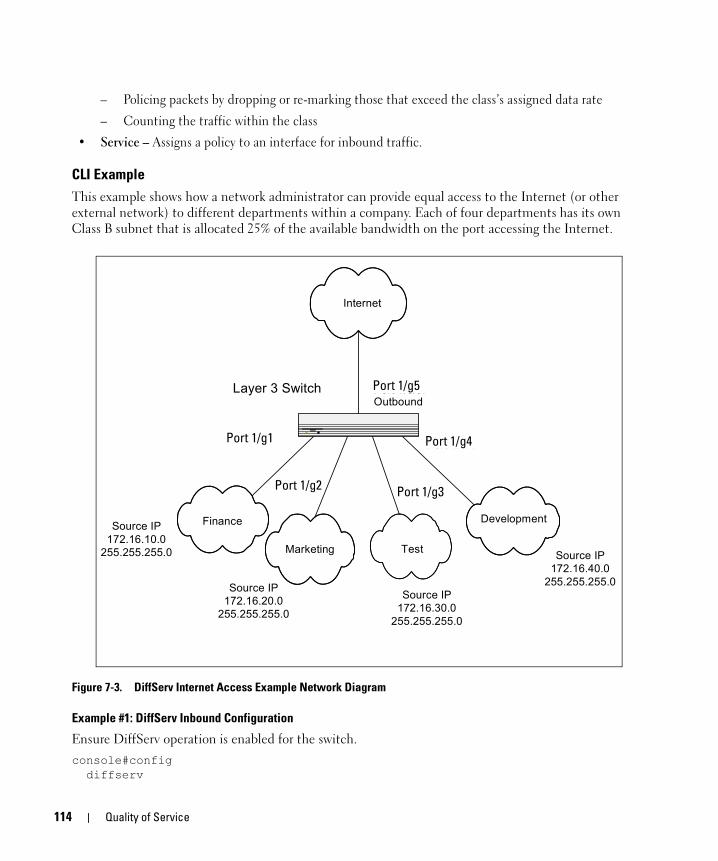
– Policing packets by dropping or re-marking those that exceed the class’s assigned data rate
– Counting the traffic within the class
• Service – Assigns a policy to an interface for inbound traffic.
CLI ExampleThis example shows how a network administrator can provide equal access to the Internet (or other external network) to different departments within a company. Each of four departments has its own Class B subnet that is allocated 25% of the available bandwidth on the port accessing the Internet.
Figure 7-3. DiffServ Internet Access Example Network Diagram
Example #1: DiffServ Inbound Configuration
Ensure DiffServ operation is enabled for the switch.console#config diffserv
Internet
Port 1/0/5:Outbound
Layer 3 Switch
Finance
Port 1/0/1
Marketing
Port 1/0/2
Test
Port 1/0/3
Development
Port 1/0/4
Source IP172.16.10.0
255.255.255.0
Source IP172.16.20.0
255.255.255.0
Source IP172.16.30.0
255.255.255.0
Source IP172.16.40.0
255.255.255.0
Port 1/g1
Port 1/g2 Port 1/g3
Port 1/g4
Port 1/g5
114 Quality of Service

Create a DiffServ class of type “all” for each of the departments, and name them. Define the match criteria—Source IP address—for the new classes.
class-map match-all finance_deptmatch srcip 172.16.10.0 255.255.255.0exit
class-map match-all marketing_deptmatch srcip 172.16.20.0 255.255.255.0exit
class-map match-all test_deptmatch srcip 172.16.30.0 255.255.255.0exit
class-map match-all development_deptmatch srcip 172.16.40.0 255.255.255.0exit
Create a DiffServ policy for inbound traffic named internet_access, adding the previously created department classes as instances within this policy. This policy uses the assign-queue attribute to put each department's traffic on a different egress queue. This is how the DiffServ inbound policy connects to the CoS queue settings established below.
policy-map internet_access inclass finance_dept
assign-queue 1exit
class marketing_deptassign-queue 2exit
class test_deptassign-queue 3exit
class development_deptassign-queue 4exit
exit
Attach the defined policy to interfaces 1/g1 through 1/g4 in the inbound directioninterface ethernet 1/g1
service-policy in internet_accessexit
interface ethernet 1/g2service-policy in internet_accessexit
interface ethernet 1/g3service-policy in internet_accessexit
Quality of Service 115
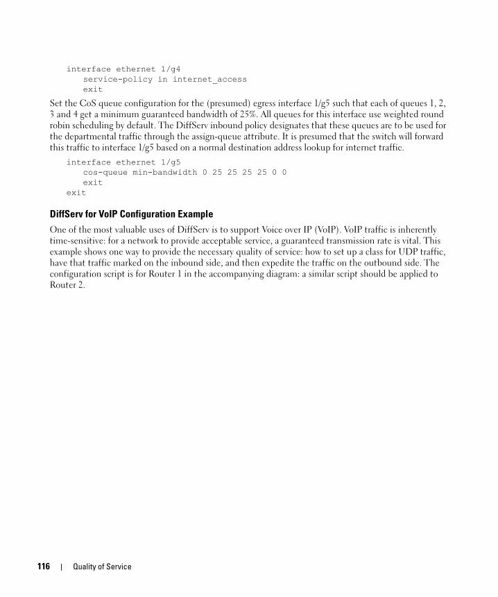
interface ethernet 1/g4service-policy in internet_accessexit
Set the CoS queue configuration for the (presumed) egress interface 1/g5 such that each of queues 1, 2, 3 and 4 get a minimum guaranteed bandwidth of 25%. All queues for this interface use weighted round robin scheduling by default. The DiffServ inbound policy designates that these queues are to be used for the departmental traffic through the assign-queue attribute. It is presumed that the switch will forward this traffic to interface 1/g5 based on a normal destination address lookup for internet traffic.
interface ethernet 1/g5cos-queue min-bandwidth 0 25 25 25 25 0 0exit
exit
DiffServ for VoIP Configuration ExampleOne of the most valuable uses of DiffServ is to support Voice over IP (VoIP). VoIP traffic is inherently time-sensitive: for a network to provide acceptable service, a guaranteed transmission rate is vital. This example shows one way to provide the necessary quality of service: how to set up a class for UDP traffic, have that traffic marked on the inbound side, and then expedite the traffic on the outbound side. The configuration script is for Router 1 in the accompanying diagram: a similar script should be applied to Router 2.
116 Quality of Service
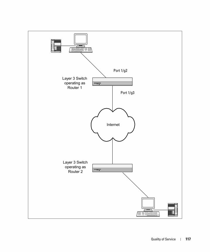
1 2 34 5 67 8 9
* 8 #
Port 1/0/2
Port 1/0/3
Layer 3 Switchoperating as
Router 1
Layer 3 Switchoperating as
Router 2
Internet
Port 1/g2
Port 1/g3
Quality of Service 117
Figure 7-4. DiffServ VoIP Example Network Diagram
Example #2: Configuring DiffServ VoIP Support
Enter Global Config mode. Set queue 5 on all ports to use strict priority mode. This queue shall be used for all VoIP packets. Activate DiffServ for the switch.console#config
cos-queue strict 5 diffserv
Create a DiffServ classifier named class_voip and define a single match criterion to detect UDP packets. The class type match-all indicates that all match criteria defined for the class must be satisfied in order for a packet to be considered a match.
class-map match-all class_voipmatch protocol udpexit
Create a second DiffServ classifier named class_ef and define a single match criterion to detect a DiffServ code point (DSCP) of EF (expedited forwarding). This handles incoming traffic that was previously marked as expedited elsewhere in the network.
class-map match-all class_efmatch ip dscp efexit
Create a DiffServ policy for inbound traffic named pol_voip, then add the previously created classes 'class_ef' and 'class_voip' as instances within this policy.
This policy handles incoming packets already marked with a DSCP value of EF (per class_ef definition), or marks UDP packets per the class_voip definition) with a DSCP value of EF. In each case, the matching packets are assigned internally to use queue 5 of the egress port to which they are forwarded.
policy-map pol_voip inclass class_efassign-queue 5exit
class class_voipmark ip-dscp efassign-queue 5exit
exit
Attach the defined policy to an inbound service interface. interface ethernet 1/g2
service-policy in pol_voipexit
exit
118 Quality of Service
8
MulticastOverviewIP Multicasting enables a network host (or multiple hosts) to send an IP datagram to multiple destinations simultaneously. The initiating host sends each multicast datagram only once to a destination multicast group address, and multicast routers forward the datagram only to hosts who are members of the multicast group. Multicast enables efficient use of network bandwidth, as each multicast datagram needs to be transmitted only once on each network link, regardless of the number of destination hosts. Multicasting contrasts with IP unicasting, which sends a separate datagram to each recipient host.
Hosts must have a way to identify their interest in joining any particular multicast group, and routers must have a way to collect and maintain group memberships: these functions are handled by the IGMP protocol in IPv4. In IPv6, multicast routers use the Multicast Listener Discover (MLD) protocol to maintain group membership information.
Multicast routers must also be able to construct a multicast distribution tree that enables forwarding multicast datagrams only on the links that are required to reach a destination group member. Protocols such as DVMRP, and PIM handle this function.
This section describes the following multicast protocols:
• "IGMP Configuration" on page 119
• "IGMP Proxy" on page 120
• "DVMRP" on page 122
• "PIM" on page 123
IGMP ConfigurationThe Internet Group Management Protocol (IGMP) is used by IPv4 hosts to send requests to join (or leave) multicast groups so that they receive (or discontinue receiving) packets sent to those groups.
In IPv4 multicast networks, multicast routers are configured with IGMP so that they can receive join and leave request from directly-connected hosts. They use this information to build a multicast forwarding table.
IPv6 multicast routers use the MLD protocol to perform the functions that IGMP performs in IPv4 networks.
Multicast 119
CLI ExampleThe following example configures IGMP on a PowerConnect 6200 Series switch. IP routing, IP multicasting, and IGMP are globally enabled on the router. Then, IGMP is configured on the selected interface(s).console#configure
ip routingip multicastip igmpinterface vlan 2
routingip address 3.3.3.1 255.255.255.0ip igmpexit
exit
A multicast router must also have a way to determine how to efficiently forward multicast packets. The information gathered by IGMP is provided to a multicast routing protocol (i.e., DVMRP, PIM-DM, and PIM-SM) configured on the router to ensure that multicast packets are delivered to all networks where there are interested receivers. Refer to those sections for configuration instructions.
IGMP ProxyIGMP proxy enables a multicast router to learn multicast group membership information and forward multicast packets based upon the group membership information. The IGMP Proxy is capable of functioning only in certain topologies that do not require Multicast Routing Protocols (i.e., DVMRP, PIM-DM, and PIM-SM) and have a tree-like topology, as there is no support for features like reverse path forwarding (RPF) to correct packet route loops.
The proxy contains many downstream interfaces and a unique upstream interface explicitly configured. It performs the host side of the IGMP protocol on its upstream interface and the router side of the IGMP protocol on its downstream interfaces.
The IGMP proxy offers a mechanism for multicast forwarding based only on IGMP membership information. The router must decide about forwarding packets on each of its interfaces based on the IGMP membership information. The proxy creates the forwarding entries based on the membership information and adds it to the multicast forwarding cache (MFC) in order not to make the forwarding decision for subsequent multicast packets with same combination of source and group.
CLI ExamplesThe CLI component of the Dell switch allows the end users to configure the network device and to view device settings and statistics using a serial interface or telnet session.
120 Multicast

Example #1: Configuring IGMP Proxy on the Router
This command enables the IGMP Proxy on the router. To enable IGMP Proxy on the router no multicast routing protocol should be enabled and also multicast forwarding must be enabled on the router. Use these commands from the Interface mode:console#configure
ip routingip multicastip igmpinterface vlan 15
ip igmp-proxy
Additional configuration options are available for the igmp-proxy command:<cr> Press Enter to execute the command.reset-status Reset All the proxy interface status
parameters.unsolicited-report-interval Configure IGMP Proxy unsolicited report
interval.
The value of the unsolicited report interval can range from 1 to 260 seconds. The default is 1 second. Use this command from the Interface mode.
Example #2: View IGMP Proxy Configuration Data
You can use various commands from Privileged EXEC or User EXEC modes to show IGMP proxy configuration data.
• Use the following command to display a summary of the host interface status parameters. It displays the parameters only when IGMP Proxy is enabled.
console#show ip igmp-proxyInterface Index................................ vlan 15Admin Mode..................................... EnabledOperational Mode............................... Disabled
• Use the following command to display interface parameters when IGMP Proxy is enabled:console#show ip igmp-proxy interface
• Use this command to display information about multicast groups that IGMP proxy reported. It displays a table of entries with the following as the fields of each column.
console#show ip igmp-proxy groups
• Use the following command to display information about multicast groups that IGMP proxy reported. It displays a table of entries with the following as the fields of each column:
console#show ip igmp-proxy groups detail
Multicast 121
DVMRPThe Distance Vector Multicast Routing Protocol (DVMRP) is one of several multicast routing protocols you can configure on the switch (PIM-SM and PIM-DM are the others). Note that only one multicast routing protocol (MRP) can be operational on a router at any time.
DVMRP is an interior gateway protocol; i.e., it is suitable for use within an autonomous system, but not between different autonomous systems.
DVMRP is based on RIP: it forwards multicast datagrams to other routers in the AS and constructs a forwarding table based on information it learns in response. More specifically, it uses this sequence.
• A new multicast packet is forwarded to the entire multicast network, with respect to the time-to-live (TTL) of the packet.
• The TTL restricts the area to be flooded by the message.
• All routers that do not have members on directly-attached subnetworks send back Prune messages to the upstream router.
• The branches that transmit a prune message are deleted from the delivery tree.
• The delivery tree which is spanning to all the members in the multicast group, is constructed in the form of a DVMRP forwarding table.
CLI ExampleThe following example configures two DVMRP interfaces. First, this example configures an OSPF router1 and globally enables IP routing and IP multicast. IGMP is globally enabled so that this router can manage group membership information for its directly-connected hosts (IGMP may not be required when there are no directly connected hosts). Next, DVMRP is globally enabled. Finally, DVMRP, IGMP, and OSPF are enabled on several interfaces.console#configure
router ospfrouter-id 3.3.1.1exit
ip routingip multicastip igmpip dvmrpinterface vlan 15
routingip address 3.3.3.1 255.255.255.0ip dvmrpip igmpip ospf area 0exit
interface vlan 30
1. OSPF configuration is added as a unicast protocol for illustration purposes; static unicast routing could also be configured.
122 Multicast

routingip address 1.1.1.1 255.255.255.0ip dvmrpip igmpip ospf area 0exit
exit
PIMProtocol Independent Multicast (PIM) is a standard multicast routing protocol that provides scalable inter-domain multicast routing across the Internet, independent of the mechanisms provided by any particular unicast routing protocol.
PIM has two types:
• PIM-Dense Mode (PIM-DM)
• PIM-Sparse Mode (PIM-SM)
PIM-SMPIM-SM is used to efficiently route multicast traffic to multicast groups that may span wide area networks where bandwidth is a constraint.
PIM-SM uses shared trees by default and implements source-based trees for efficiency; it assumes that no hosts want the multicast traffic unless they specifically ask for it. It creates a shared distribution tree centered on a defined rendezvous point (RP) from which source traffic is relayed to the receivers. Senders first send the multicast data to the RP, which in turn sends the data down the shared tree to the receivers. Shared trees centered on an RP do not necessarily provide the shortest, most optimal path. In such cases, PIM-SM provides a means to switch to more efficient source-specific trees. A data threshold rate is configured to determine when to switch from shared-tree to source-tree.
PIM-SM uses a Bootstrap Router (BSR), which advertises information to other multicast routers about the RP. In a given network, a set of routers can be administratively enabled as candidate bootstrap routers. If it is not apparent which router should be the BSR, the candidates flood the domain with advertisements. The router with the highest priority is elected. If all the priorities are equal, then the candidate with the highest IP address becomes the BSR.
PIM-SM is defined in RFC 4601.
Example: PIM-SM
The following example configures PIM-SM for IPv4 on a router.
First, configure an OSPF1 router and globally enable IP routing, multicast, IGMP, and PIM-SM. Next, configure a PIM-SM rendezvous point with an IP address and group range. The IP address will serve as an RP for the range of potential multicast groups specified in the group range. Finally, enable routing, IGMP, PIM-SM, and OSPF on one or more interfaces.
Multicast 123
console#configurerouter ospf
router-id 3.3.1.1exit
ip routingip multicastip igmpip pimsm [NOTE: This router should be an RP.]ip pimsm rp-address 1.1.1.1 224.0.0.0 240.0.0.0interface vlan 15
routingip address 3.3.3.1 255.255.255.0ip pimsmip igmpip ospf area 0exit
interface vlan 30routingip address 1.1.1.1 255.255.255.0ip pimsmip igmpip ospf area 0exit
exit
PIM-DMPIM-DM protocol is a simple, protocol-independent multicast routing protocol. It uses existing unicast routing table and join/prune/graft mechanism to build a tree. PIM-DM creates source-based shortest-path distribution trees making use of Reverse Path Forwarding (RPF).
PIM-DM cannot be used to build a shared distribution tree, as PIM-SM can. PIM-DM assumes that when a sender starts sending data, all downstream routers and hosts want to receive a multicast datagram. PIM-DM initially floods multicast traffic throughout the network. Routers that do not have any downstream neighbors send back Prune messages that instruct the upstream router to remove that multicast route from its forwarding table. In addition to the Prune messages, PIM-DM makes use of two more messages: Graft and Assert. Graft messages are used whenever a new host wants to join the group. Assert messages are used to shut off duplicate flows onto the same multi-access network.
To minimize the repeated flooding of datagrams and subsequent pruning associated with a particular source-group (S,G) pair, PIM-DM uses a State Refresh message. This message is sent by the router(s) directly connected to the source and is propagated throughout the network. When received by a router on its RPF interface, the State Refresh message causes an existing prune state to be refreshed. State Refresh messages are generated periodically by the router directly attached to the source.
PIM-DM is appropriate for:
1. OSPF configuration is added as a unicast protocol for illustration purposes; static unicast routing could also be configured.
124 Multicast
• Densely distributed receivers
• A ratio of few senders-to-many receivers (due to frequent flooding)
• High volume of multicast traffic
• Constant stream of traffic
Example: PIM-DM
The following example configures PIM-DM for IPv4 on a router.
First, configure an OSPF1 router and globally enable IP routing, multicast, IGMP, and PIM-DM. Next, enable routing, IGMP, PIM-DM, and OSPF on one more interfaces. console#configure
router ospfrouter-id 3.3.1.1exit
ip routingip multicastip igmpip pimdminterface vlan 1
routingip address 3.3.3.1 255.255.255.0ip pimdmip igmpip ospf area 0exit
interface vlan 3routingip address 1.1.1.1 255.255.255.0ip pimdmip igmpip ospf area 0exit
exit
1. OSPF configuration is added as a unicast protocol for illustration purposes; static unicast routing could also be configured.
Multicast 125


