42
Delphi SOFC Development Update Steven Shaffer Chief Engineer – Fuel Cell Development Pittsburgh, PA 2008 SECA Annual Review Meeting
Delphi SOFC Development Update
Steven ShafferChief Engineer – Fuel Cell Development
Pittsburgh, PA2008 SECA Annual Review Meeting
2
OutlineCell and Stack DevelopmentReformer DevelopmentBalance of Plant DevelopmentSystems Development Programs Leveraging SECA Activities
3
SOFC Subsystem DevelopmentCells and Stacks
4
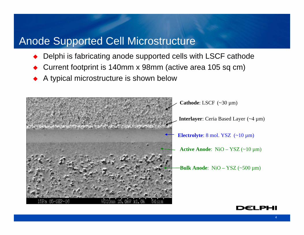
Electrolyte: 8 mol. YSZ (~10 µm)
Active Anode: NiO – YSZ (~10 µm)
Bulk Anode: NiO – YSZ (~500 µm)
Interlayer: Ceria Based Layer (~4 µm)
Cathode: LSCF (~30 µm)
Anode Supported Cell MicrostructureDelphi is fabricating anode supported cells with LSCF cathodeCurrent footprint is 140mm x 98mm (active area 105 sq cm)A typical microstructure is shown below
5
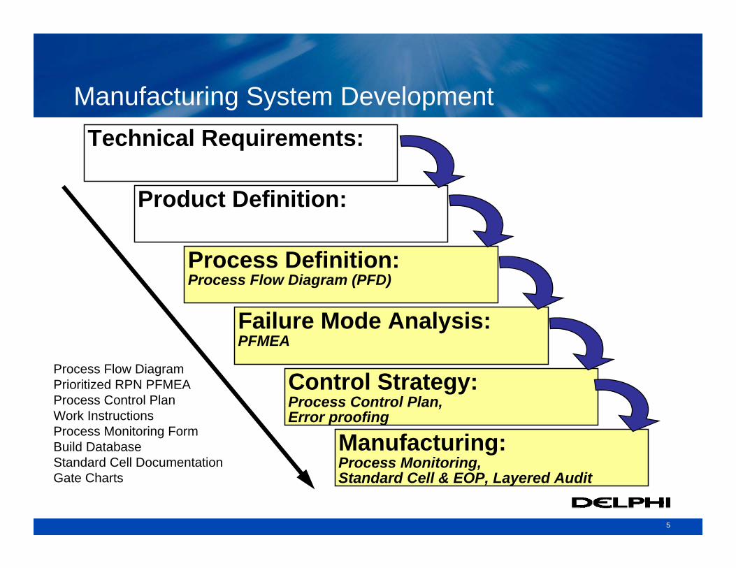
Manufacturing System Development
Process Flow Diagram (PFD)
Product Definition:
Process Definition:
Failure Mode Analysis:PFMEA
Control Strategy:Process Control Plan,Error proofing
Technical Requirements:
Manufacturing:Process Monitoring,Standard Cell & EOP, Layered Audit
Process Flow DiagramPrioritized RPN PFMEAProcess Control PlanWork InstructionsProcess Monitoring FormBuild DatabaseStandard Cell DocumentationGate Charts
6
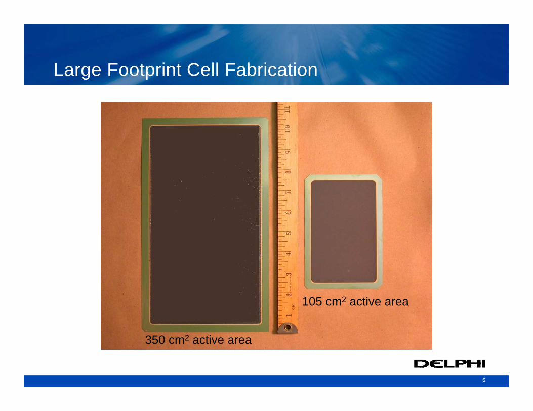
Large Footprint Cell Fabrication
350 cm2 active area
105 cm2 active area
7
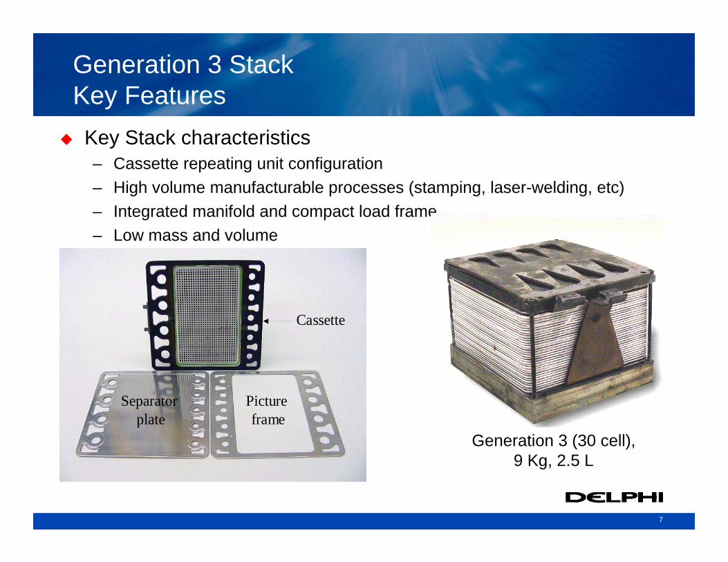
Generation 3 StackKey Features
Key Stack characteristics– Cassette repeating unit configuration – High volume manufacturable processes (stamping, laser-welding, etc)– Integrated manifold and compact load frame– Low mass and volume
Cassette
Separator plate
Picture frame
Cassette
Separator plate
Picture frame
Generation 3 (30 cell),9 Kg, 2.5 L
8
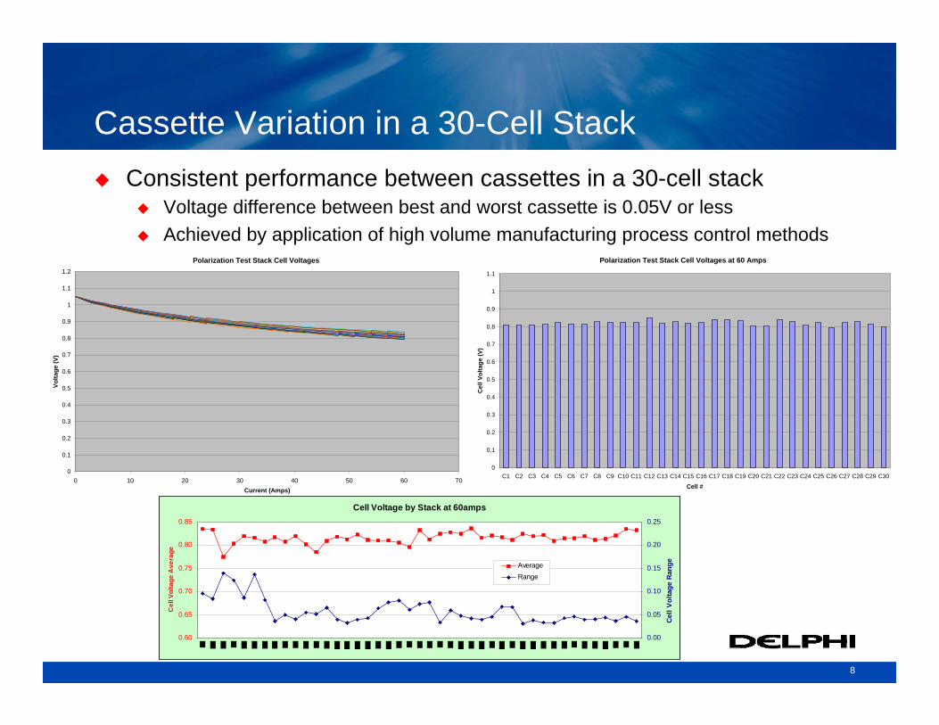
Cassette Variation in a 30-Cell StackConsistent performance between cassettes in a 30-cell stack
Voltage difference between best and worst cassette is 0.05V or lessAchieved by application of high volume manufacturing process control methods
Polarization Test Stack Cell Voltages
0
0.1
0.2
0.3
0.4
0.5
0.6
0.7
0.8
0.9
1
1.1
1.2
0 10 20 30 40 50 60 70Current (Amps)
Volta
ge (V
)
Polarization Test Stack Cell Voltages at 60 Amps
0
0.1
0.2
0.3
0.4
0.5
0.6
0.7
0.8
0.9
1
1.1
C1 C2 C3 C4 C5 C6 C7 C8 C9 C10 C11 C12 C13 C14 C15 C16 C17 C18 C19 C20 C21 C22 C23 C24 C25 C26 C27 C28 C29 C30
Cell #C
ell V
olta
ge (V
)
Cell Voltage by Stack at 60amps
0.60
0.65
0.70
0.75
0.80
0.85
Cel
l Vol
tage
Ave
rage
0.00
0.05
0.10
0.15
0.20
0.25
Cell
Volta
ge R
angeAverage
Range
9
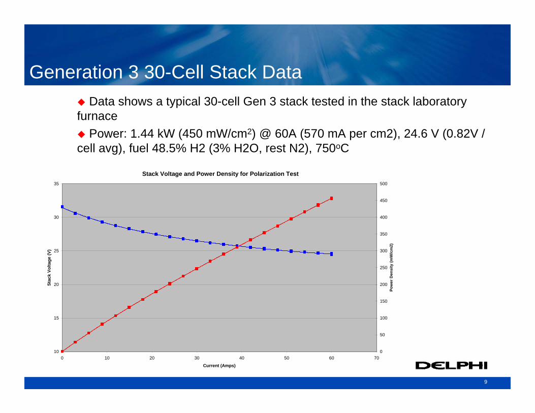
Generation 3 30-Cell Stack Data
Stack Voltage and Power Density for Polarization Test
10
15
20
25
30
35
0 10 20 30 40 50 60 70
Current (Amps)
Stac
k Vo
ltage
(V)
0
50
100
150
200
250
300
350
400
450
500
Pow
er D
ensi
ty (m
W/c
m2)
Data shows a typical 30-cell Gen 3 stack tested in the stack laboratory furnace
Power: 1.44 kW (450 mW/cm2) @ 60A (570 mA per cm2), 24.6 V (0.82V / cell avg), fuel 48.5% H2 (3% H2O, rest N2), 750oC
10
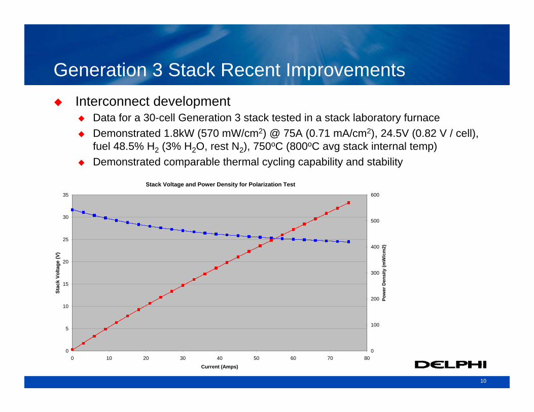
Generation 3 Stack Recent Improvements
Stack Voltage and Power Density for Polarization Test
0
5
10
15
20
25
30
35
0 10 20 30 40 50 60 70 80
Current (Amps)
Stac
k Vo
ltage
(V)
0
100
200
300
400
500
600
Pow
er D
ensi
ty (m
W/c
m2)
Interconnect developmentData for a 30-cell Generation 3 stack tested in a stack laboratory furnaceDemonstrated 1.8kW (570 mW/cm2) @ 75A (0.71 mA/cm2), 24.5V (0.82 V / cell), fuel 48.5% H2 (3% H2O, rest N2), 750oC (800oC avg stack internal temp)Demonstrated comparable thermal cycling capability and stability
11
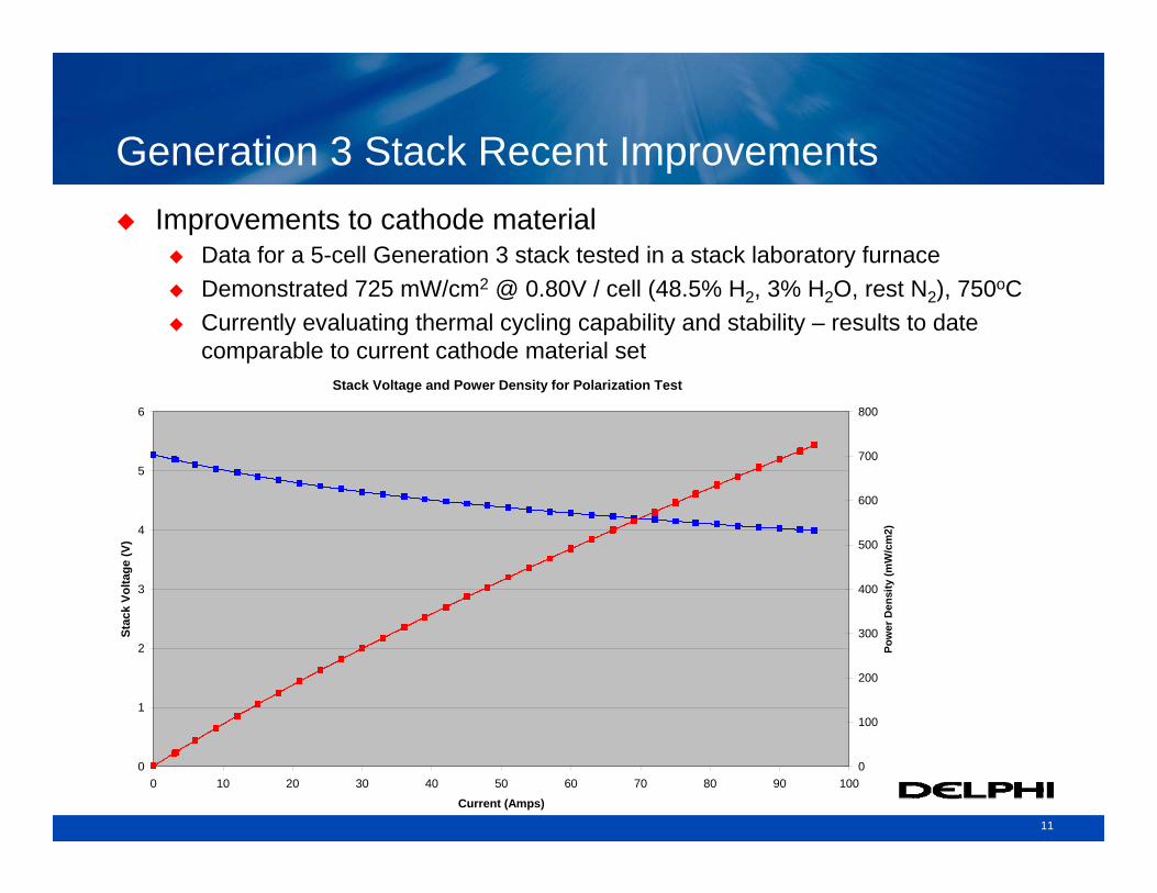
Generation 3 Stack Recent ImprovementsImprovements to cathode material
Data for a 5-cell Generation 3 stack tested in a stack laboratory furnaceDemonstrated 725 mW/cm2 @ 0.80V / cell (48.5% H2, 3% H2O, rest N2), 750oCCurrently evaluating thermal cycling capability and stability – results to date comparable to current cathode material set
Stack Voltage and Power Density for Polarization Test
0
1
2
3
4
5
6
0 10 20 30 40 50 60 70 80 90 100
Current (Amps)
Stac
k Vo
ltage
(V)
0
100
200
300
400
500
600
700
800
Pow
er D
ensi
ty (m
W/c
m2)
12
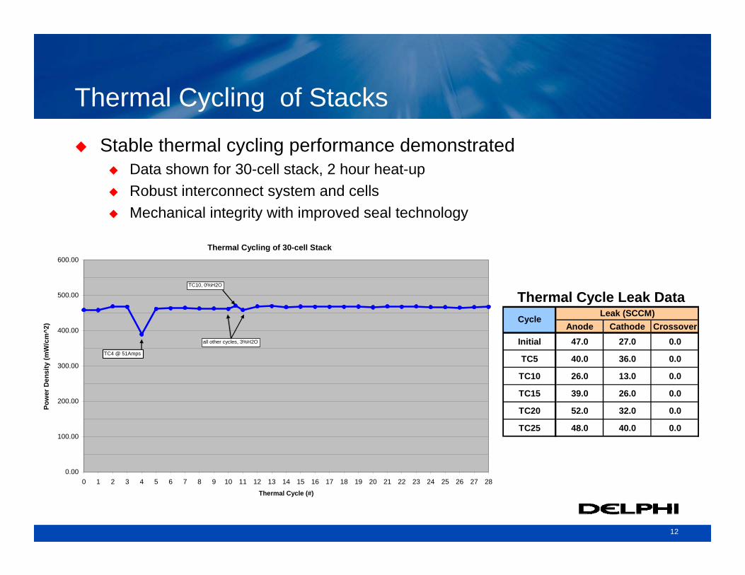
Thermal Cycling of Stacks
Stable thermal cycling performance demonstratedData shown for 30-cell stack, 2 hour heat-upRobust interconnect system and cellsMechanical integrity with improved seal technology
Thermal Cycling of 30-cell Stack
0.00
100.00
200.00
300.00
400.00
500.00
600.00
0 1 2 3 4 5 6 7 8 9 10 11 12 13 14 15 16 17 18 19 20 21 22 23 24 25 26 27 28Thermal Cycle (#)
Pow
er D
ensi
ty (m
W/c
m^2
)
TC10, 0%H2O
TC4 @ 51Amps
all other cycles, 3%H2O
Anode Cathode CrossoverInitial 47.0 27.0 0.0
TC5 40.0 36.0 0.0
TC10 26.0 13.0 0.0
TC15 39.0 26.0 0.0
TC20 52.0 32.0 0.0
TC25 48.0 40.0 0.0
Thermal Cycle Leak Data Leak (SCCM)Cycle
13
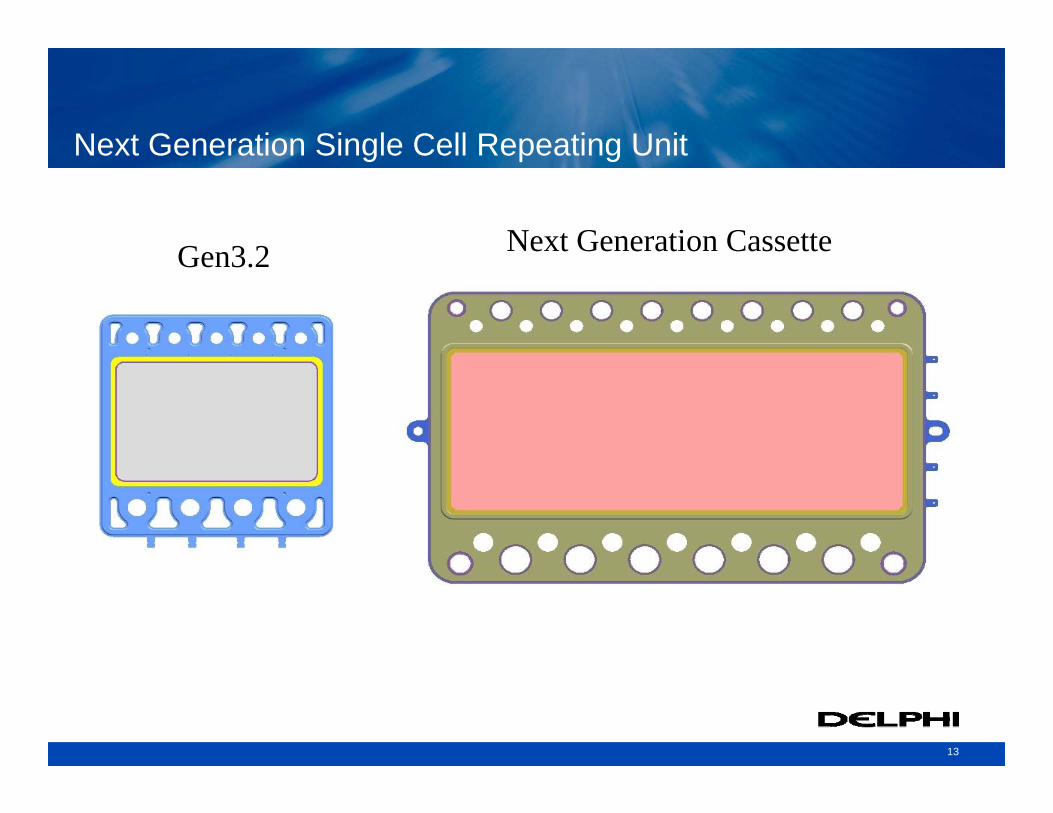
Next Generation Single Cell Repeating Unit
Gen3.2 Next Generation Cassette
14
SOFC Subsystem DevelopmentReformer
15
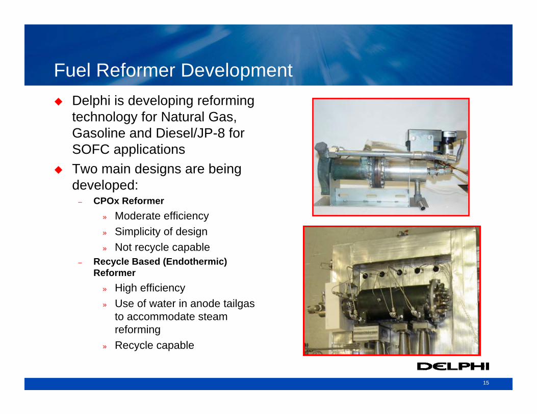
Fuel Reformer DevelopmentDelphi is developing reforming technology for Natural Gas, Gasoline and Diesel/JP-8 for SOFC applicationsTwo main designs are being developed:
– CPOx Reformer» Moderate efficiency» Simplicity of design» Not recycle capable
– Recycle Based (Endothermic) Reformer
» High efficiency » Use of water in anode tailgas
to accommodate steam reforming
» Recycle capable
16
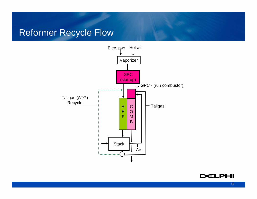
Reformer Recycle Flow
Vaporizer
GPC(startup)
Stack
REF
COMB
GPC - (run combustor)
Tailgas
Air
Elec. pwr Hot air
Tailgas (ATG)Recycle
17
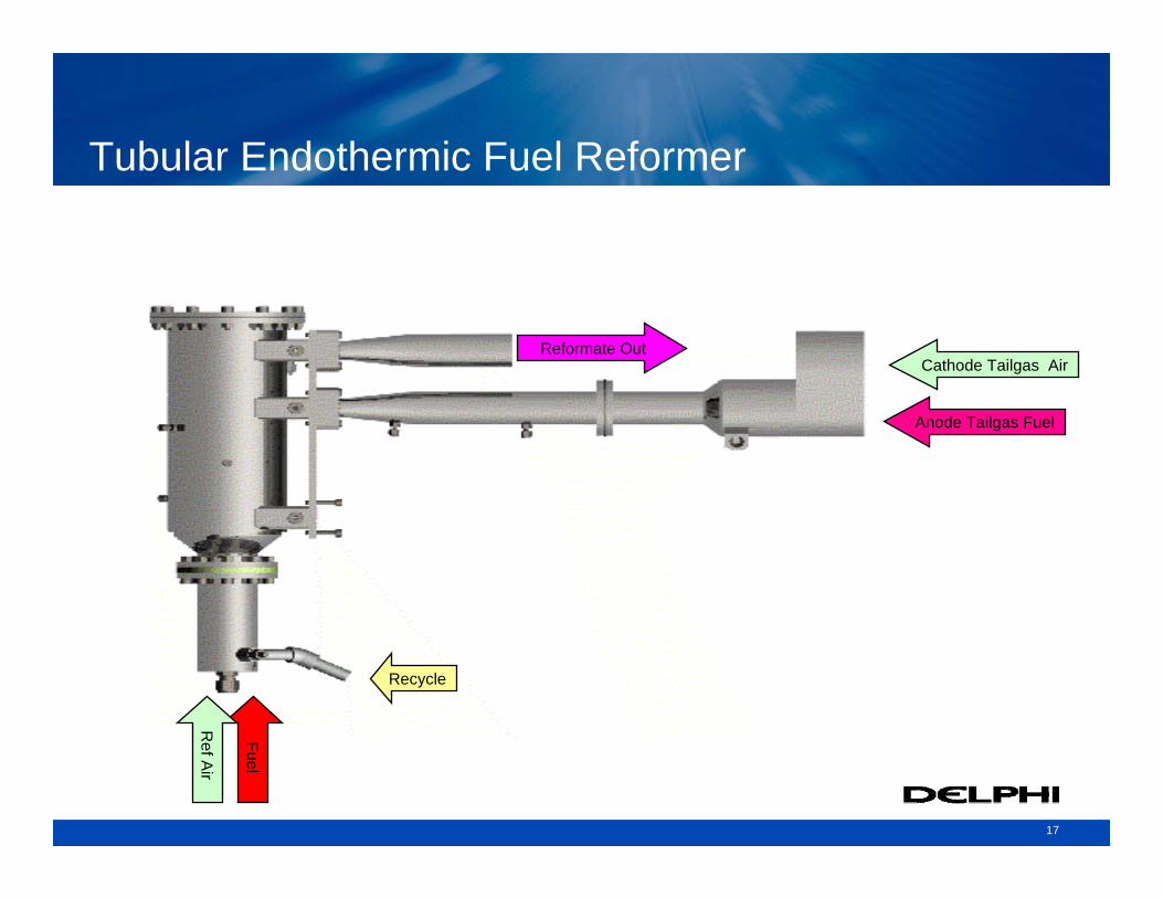
Tubular Endothermic Fuel Reformer
Reformate Out
Anode Tailgas Fuel
Cathode Tailgas Air
Recycle
Fuel
Ref A
ir
18
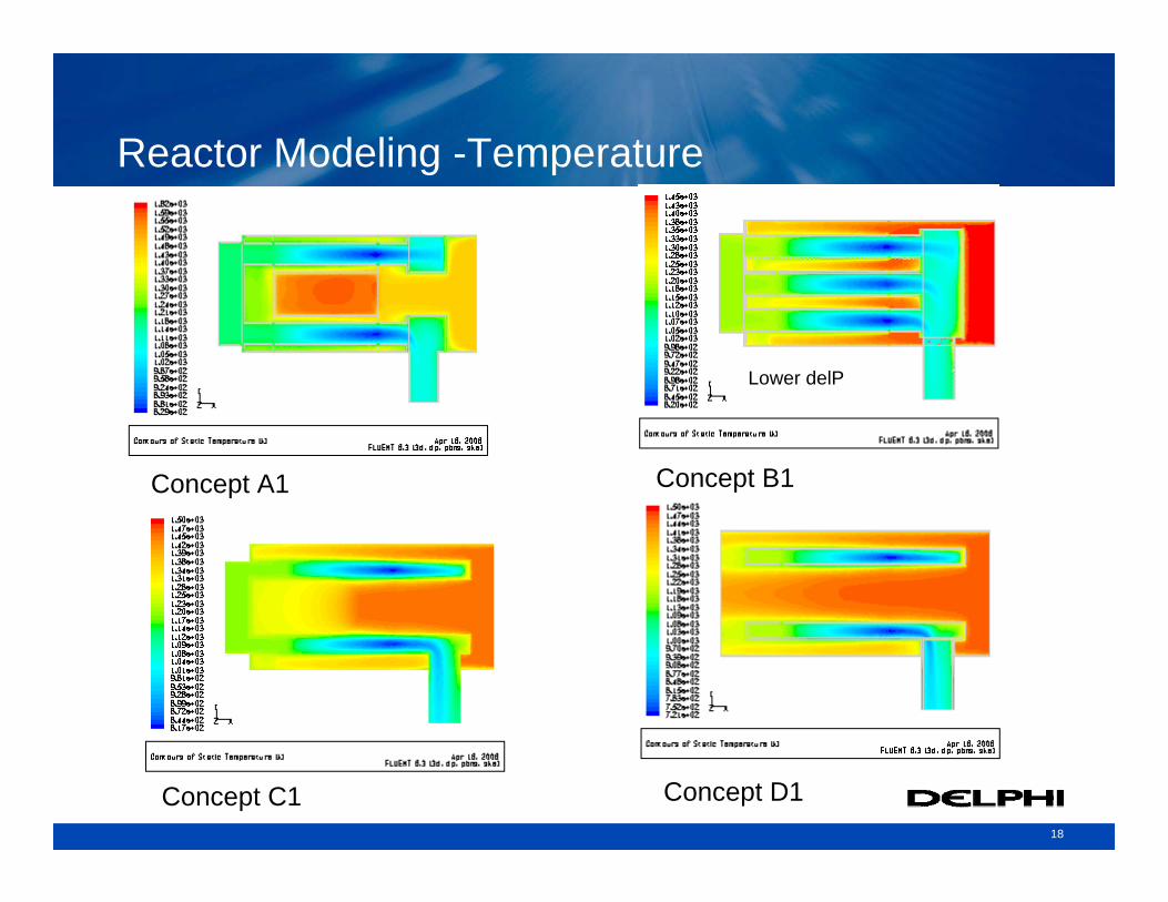
Concept A1 Concept B1
Concept C1 Concept D1
Reactor Modeling -Temperature
Lower delP
19
SOFC Subsystem DevelopmentBalance of Plant
20
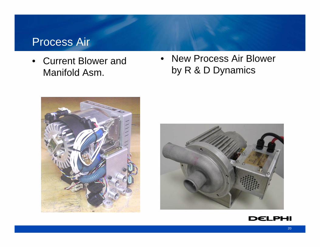
Process Air• Current Blower and
Manifold Asm. • New Process Air Blower
by R & D Dynamics
21
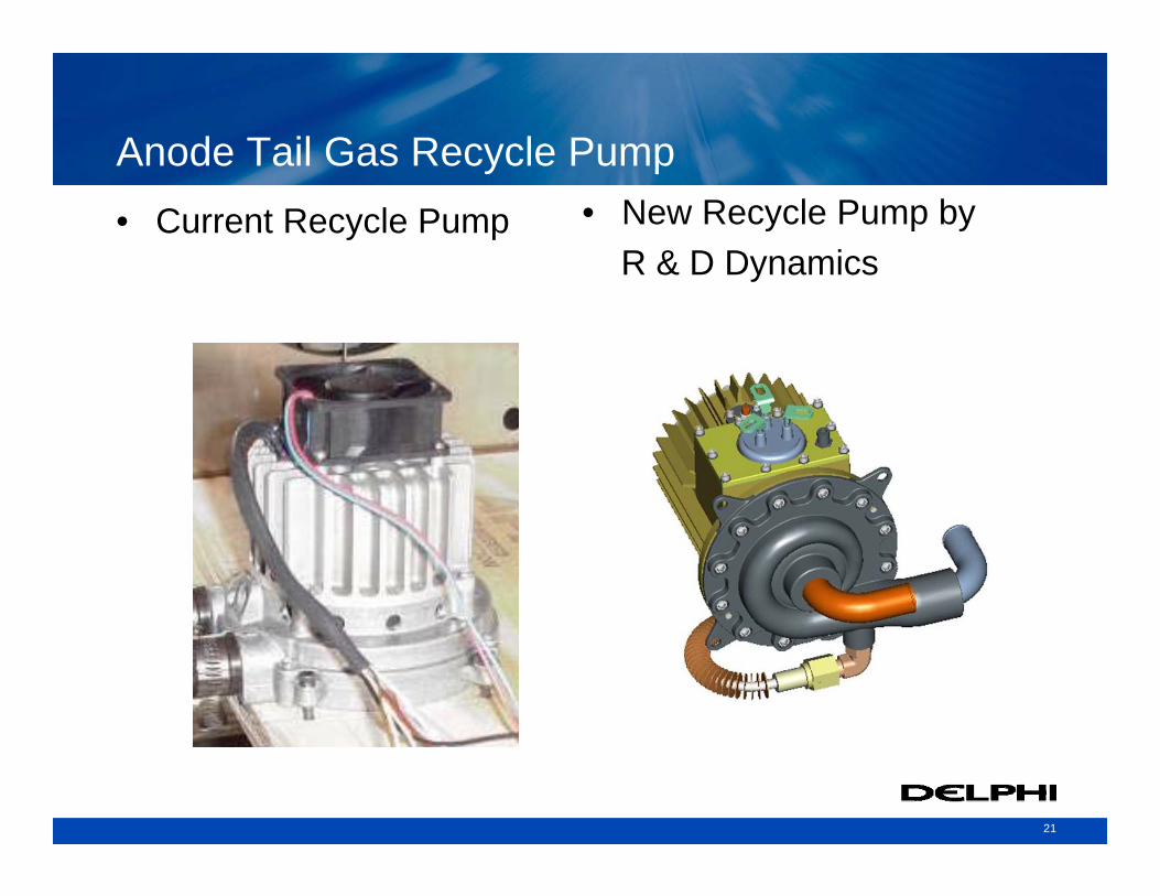
Anode Tail Gas Recycle Pump• Current Recycle Pump • New Recycle Pump by
R & D Dynamics
22
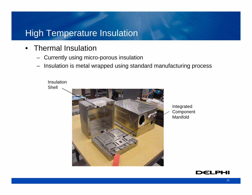
High Temperature Insulation• Thermal Insulation
– Currently using micro-porous insulation – Insulation is metal wrapped using standard manufacturing process
Integrated Component Manifold
Insulation Shell
23
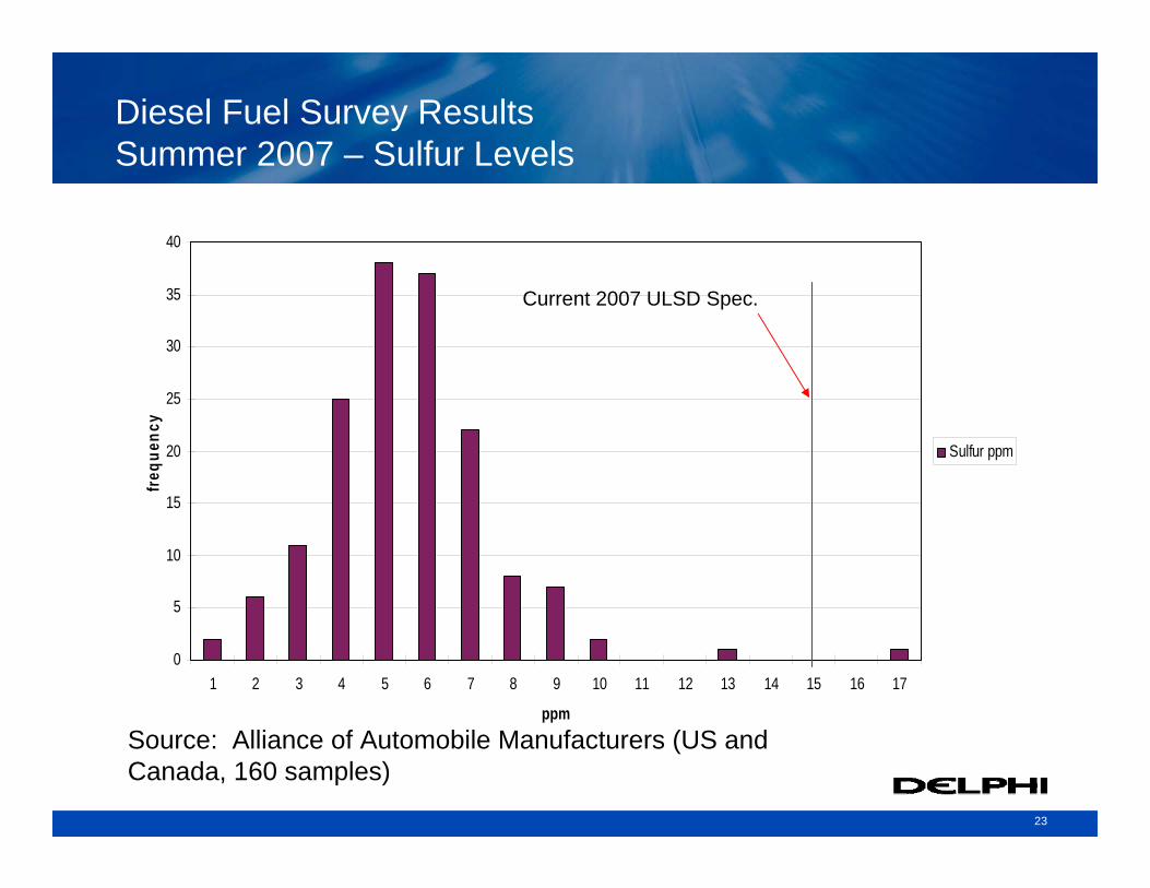
Diesel Fuel Survey ResultsSummer 2007 – Sulfur Levels
0
5
10
15
20
25
30
35
40
1 2 3 4 5 6 7 8 9 10 11 12 13 14 15 16 17
ppm
freq
uenc
y
Sulfur ppm
Source: Alliance of Automobile Manufacturers (US and Canada, 160 samples)
Current 2007 ULSD Spec.
24
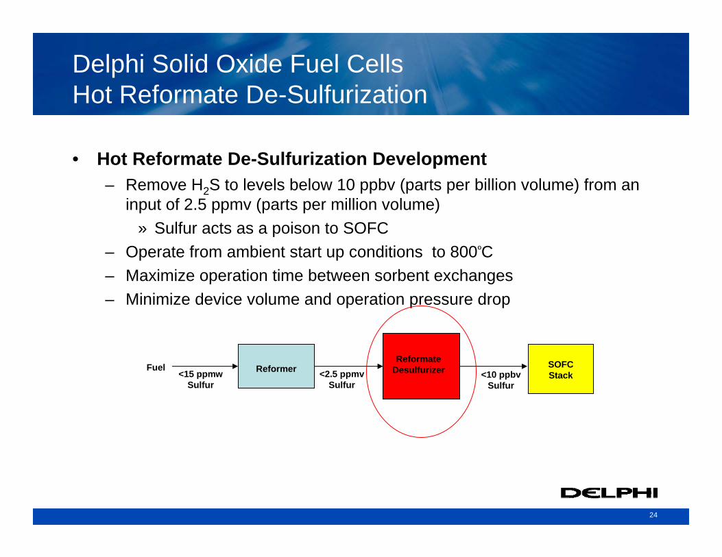
Delphi Solid Oxide Fuel CellsHot Reformate De-Sulfurization
• Hot Reformate De-Sulfurization Development– Remove H2S to levels below 10 ppbv (parts per billion volume) from an
input of 2.5 ppmv (parts per million volume)» Sulfur acts as a poison to SOFC
– Operate from ambient start up conditions to 800ºC– Maximize operation time between sorbent exchanges– Minimize device volume and operation pressure drop
<2.5 ppmv Sulfur
ReformerReformate
Desulfurizer SOFC Stack
Fuel<15 ppmw
Sulfur<10 ppbv
Sulfur
25
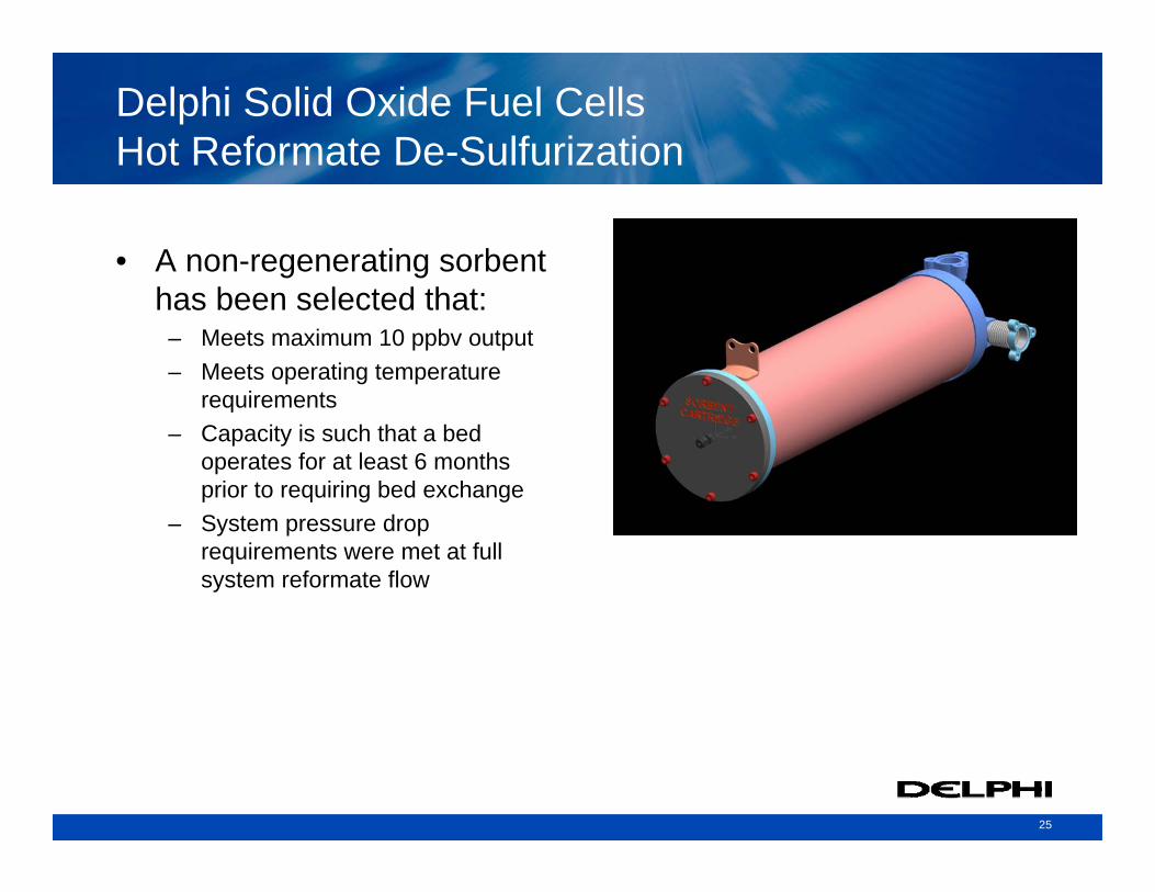
Delphi Solid Oxide Fuel CellsHot Reformate De-Sulfurization
• A non-regenerating sorbent has been selected that:
– Meets maximum 10 ppbv output– Meets operating temperature
requirements– Capacity is such that a bed
operates for at least 6 months prior to requiring bed exchange
– System pressure drop requirements were met at full system reformate flow
26
SOFC Power System Development
27
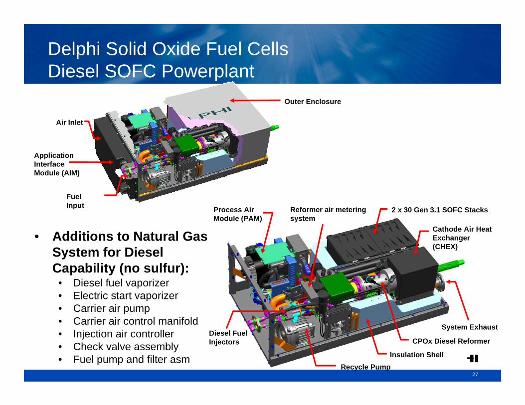
Delphi Solid Oxide Fuel Cells Diesel SOFC Powerplant
2 x 30 Gen 3.1 SOFC Stacks
System Exhaust
CPOx Diesel Reformer
Insulation ShellRecycle Pump
Diesel Fuel Injectors
Process Air Module (PAM)
Reformer air metering system
Cathode Air Heat Exchanger (CHEX)
Fuel Input
Application Interface Module (AIM)
Air Inlet
Outer Enclosure
• Additions to Natural Gas System for Diesel Capability (no sulfur):
• Diesel fuel vaporizer• Electric start vaporizer• Carrier air pump• Carrier air control manifold• Injection air controller• Check valve assembly• Fuel pump and filter asm
28
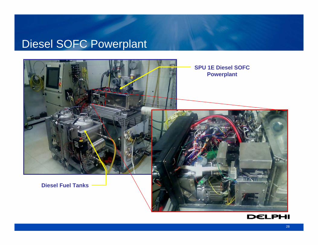
Diesel SOFC Powerplant
SPU 1E Diesel SOFC Powerplant
Diesel Fuel Tanks
29
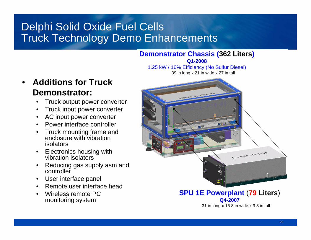
Delphi Solid Oxide Fuel Cells Truck Technology Demo Enhancements
SPU 1E Powerplant (79 Liters)Q4-2007
31 in long x 15.8 in wide x 9.8 in tall
Demonstrator Chassis (362 Liters)Q1-2008
1.25 kW / 16% Efficiency (No Sulfur Diesel)39 in long x 21 in wide x 27 in tall
• Additions for Truck Demonstrator:
• Truck output power converter• Truck input power converter• AC input power converter• Power interface controller• Truck mounting frame and
enclosure with vibration isolators
• Electronics housing with vibration isolators
• Reducing gas supply asm and controller
• User interface panel• Remote user interface head• Wireless remote PC
monitoring system
3030
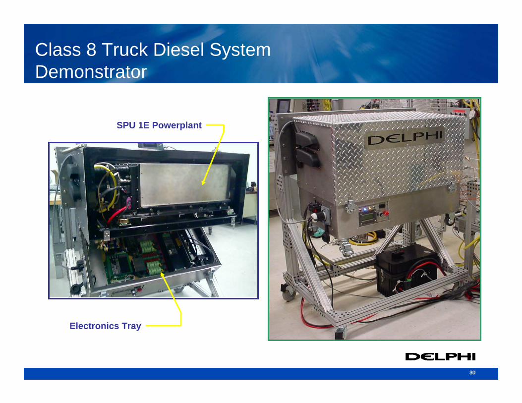
Class 8 Truck Diesel System Demonstrator
Electronics Tray
SPU 1E Powerplant
31
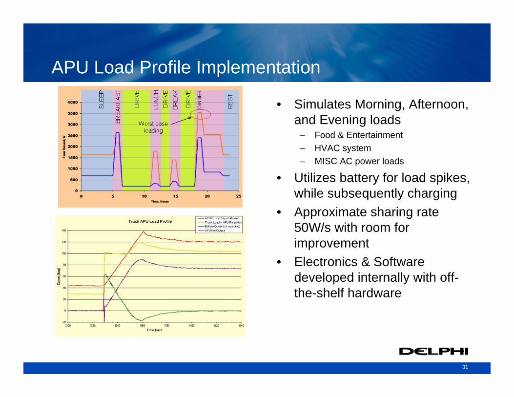
APU Load Profile Implementation
• Simulates Morning, Afternoon, and Evening loads
– Food & Entertainment– HVAC system– MISC AC power loads
• Utilizes battery for load spikes, while subsequently charging
• Approximate sharing rate 50W/s with room for improvement
• Electronics & Software developed internally with off-the-shelf hardware
32
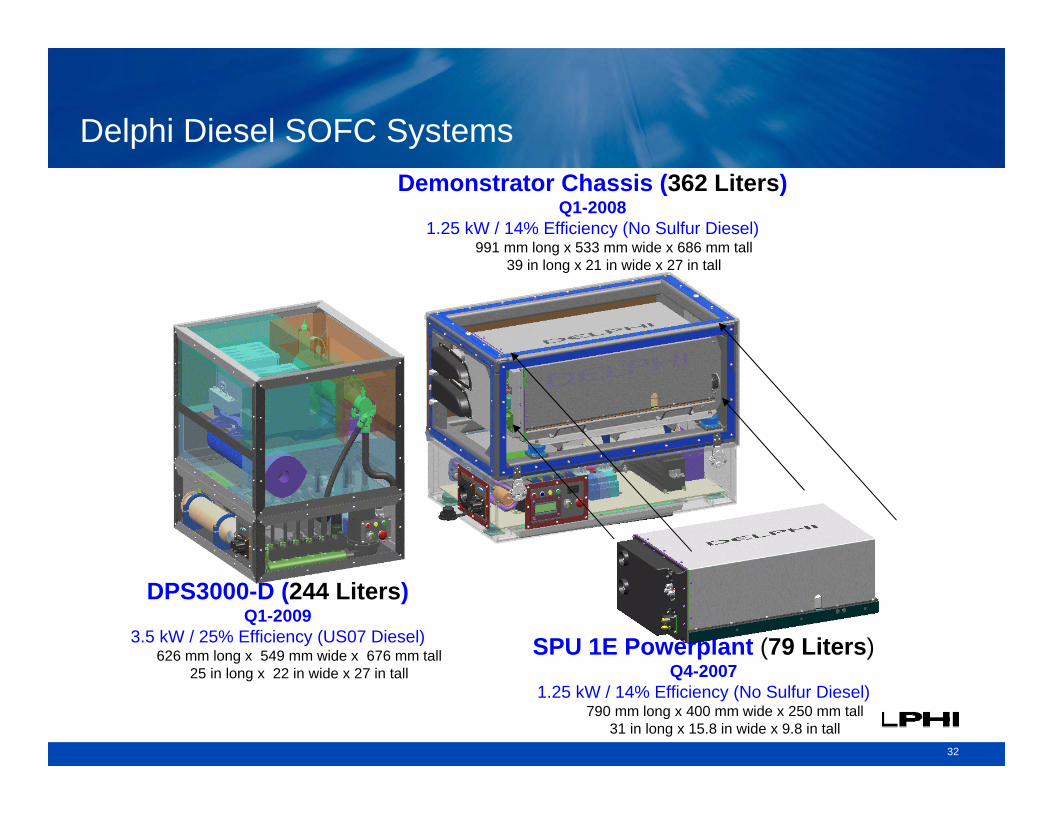
Delphi Diesel SOFC Systems
SPU 1E Powerplant (79 Liters)Q4-2007
1.25 kW / 14% Efficiency (No Sulfur Diesel)790 mm long x 400 mm wide x 250 mm tall
31 in long x 15.8 in wide x 9.8 in tall
Demonstrator Chassis (362 Liters)Q1-2008
1.25 kW / 14% Efficiency (No Sulfur Diesel)991 mm long x 533 mm wide x 686 mm tall
39 in long x 21 in wide x 27 in tall
DPS3000-D (244 Liters)Q1-2009
3.5 kW / 25% Efficiency (US07 Diesel)626 mm long x 549 mm wide x 676 mm tall
25 in long x 22 in wide x 27 in tall
33
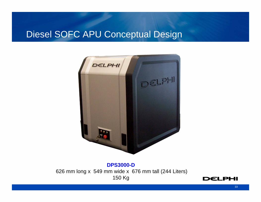
Diesel SOFC APU Conceptual Design
DPS3000-D626 mm long x 549 mm wide x 676 mm tall (244 Liters)
150 Kg
3434
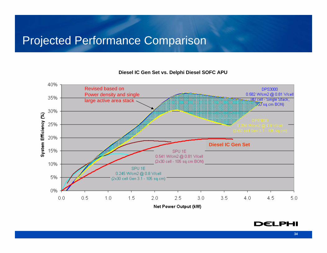
Projected Performance Comparison
Revised based onPower density and single large active area stack
Diesel IC Gen Set
Diesel IC Gen Set vs. Delphi Diesel SOFC APU
35
Programs Leveraging SECA Activities
36
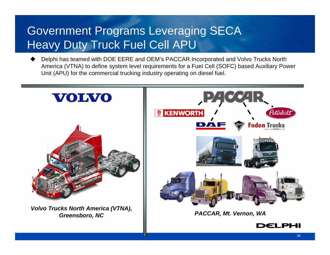
Government Programs Leveraging SECAHeavy Duty Truck Fuel Cell APU
Delphi has teamed with DOE EERE and OEM’s PACCAR Incorporated and Volvo Trucks North America (VTNA) to define system level requirements for a Fuel Cell (SOFC) based Auxiliary Power Unit (APU) for the commercial trucking industry operating on diesel fuel.
Volvo Trucks North America (VTNA), Greensboro, NC PACCAR, Mt. Vernon, WA
37
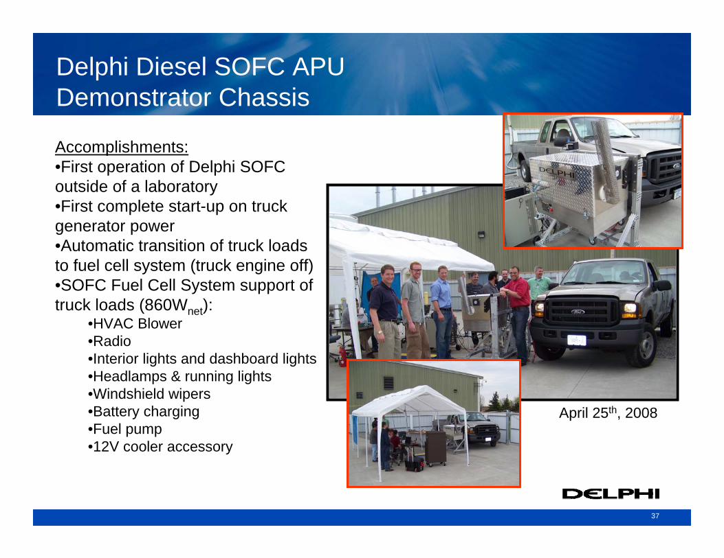
Delphi Diesel SOFC APU Demonstrator Chassis
Accomplishments:•First operation of Delphi SOFC outside of a laboratory•First complete start-up on truck generator power•Automatic transition of truck loads to fuel cell system (truck engine off)•SOFC Fuel Cell System support of truck loads (860Wnet):
•HVAC Blower•Radio•Interior lights and dashboard lights•Headlamps & running lights•Windshield wipers•Battery charging•Fuel pump•12V cooler accessory
April 25th, 2008
38
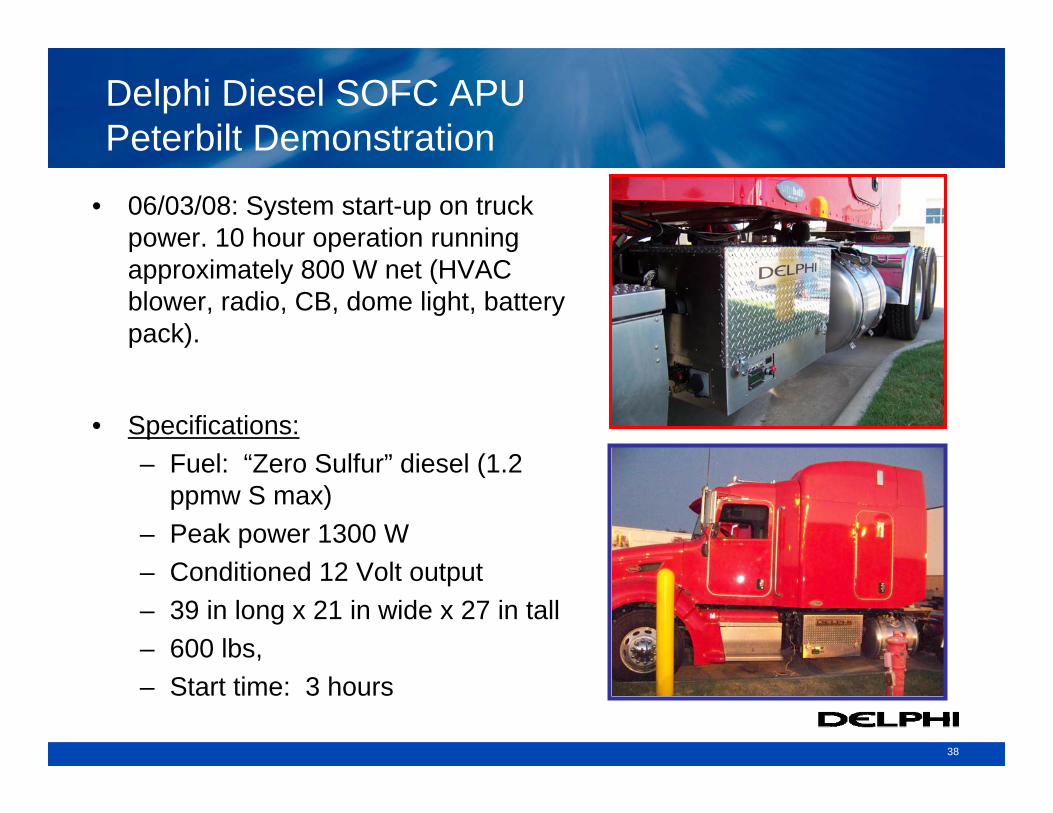
Delphi Diesel SOFC APU Peterbilt Demonstration
• 06/03/08: System start-up on truck power. 10 hour operation running approximately 800 W net (HVAC blower, radio, CB, dome light, battery pack).
• Specifications:– Fuel: “Zero Sulfur” diesel (1.2
ppmw S max)– Peak power 1300 W– Conditioned 12 Volt output– 39 in long x 21 in wide x 27 in tall– 600 lbs, – Start time: 3 hours
39
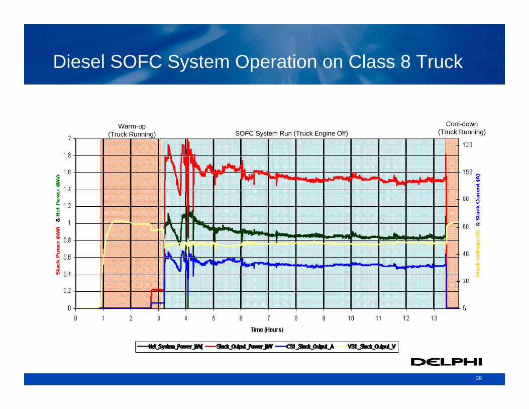
Diesel SOFC System Operation on Class 8 Truck
Warm-up(Truck Running)
Cool-down(Truck Running)SOFC System Run (Truck Engine Off)
40
Stack Testing at NUWC
Ref: Solid Oxide Fuel Cells for Undersea Naval Applications
10th Electrochemical Power Sources R&D Symposium
Alan Burke, Ph.D.; Louis G. Alan Burke, Ph.D.; Louis G. CarreiroCarreiro, Ph.D., Ph.D.
Naval Undersea Warfare Center (NUWC), Division NewportNaval Undersea Warfare Center (NUWC), Division Newport
Delphi, SECA (Dept. of Energy) and the Navy are collaborating for Solid Oxide Fuel Cell technology development for Undersea Naval applicationsA Delphi 10-cell stack developed under the SECA program was tested at the Naval Undersea Warfare Center (NUWC) under simulated conditions specific for this applicationStack produced very encouraging performance
Demonstrated excellent reproducibility during the offsite testDemonstrated and met power density requirement that was set for this specific application test (see next slide)Testing included performance evaluation with pure oxygen on the cathode side and actual reformate on the anode side
Next step is to test a stack at higher power levels
41
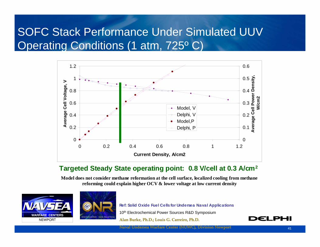
SOFC Stack Performance Under Simulated UUV Operating Conditions (1 atm, 725º C)
Ref: Solid Oxide Fuel Cells for Undersea Naval Applications
10th Electrochemical Power Sources R&D Symposium
Alan Burke, Ph.D.; Louis G. Alan Burke, Ph.D.; Louis G. CarreiroCarreiro, Ph.D., Ph.D.
Naval Undersea Warfare Center (NUWC), Division NewportNaval Undersea Warfare Center (NUWC), Division Newport
0
0.2
0.4
0.6
0.8
1
1.2
0 0.2 0.4 0.6 0.8 1 1.2
Current Density, A/cm2
Ave
rage
Cel
l Vol
tage
, V
0
0.1
0.2
0.3
0.4
0.5
0.6
Ave
rage
Cel
l Pow
er D
ensi
ty,
W/c
m2
Model, VDelphi, VModel,PDelphi, P
Targeted Steady State operating point: 0.8 V/cell at 0.3 A/cm2
Model does not consider methane reformation at the cell surface, localized cooling from methane reforming could explain higher OCV & lower voltage at low current density
42
Acknowledgements


