Congratulations on your purchase of the Delta 1010LT PCI Audio Card designed and builtby M-Audio. The Delta 1010LT is an excellent choice for audio and MIDI productionutilizing your PC or Macintosh computer, and will interface easily with professional and“prosumer” recording gear as well as consumer playback devices.
Even if you are experienced in digital recording, please take the time to read this manual. Itwill give you valuable information on installing your new card and the supporting software,plus help you to fully understand the function and usability of the Delta 1010LT. Once you’reup and running, you will quickly discover the power and brilliance, both in sound and design,of your Delta 1010LT PCI Audio Card.
What’s in the Box?
Your Delta 1010LT box contains:• This instruction manual.• Two (2) Delta 1010LT breakout cables.• The Delta 1010LT PCI host adapter card.• CD containing drivers & Delta Control Panel software for Windows XP,
2000/ME/98/95/NT and for Macintosh OS 8.5.1 or higher.• M-Audio Warranty Registration card.
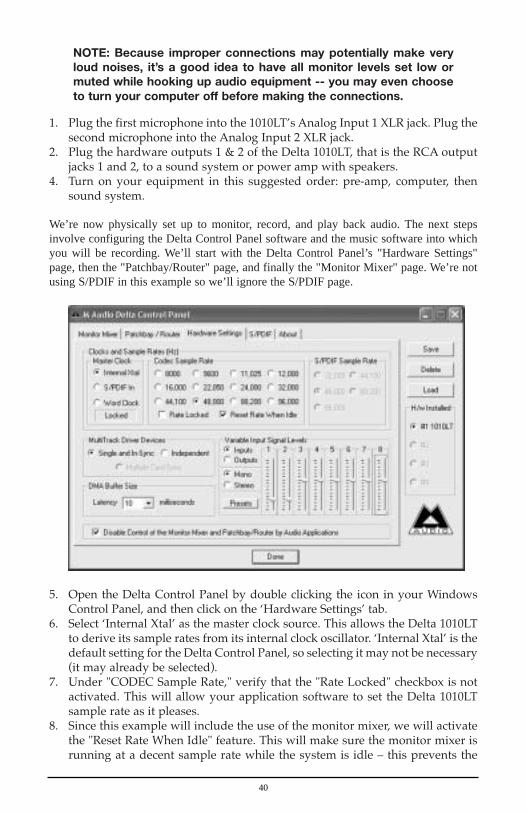
About the Delta 1010LT Digital PCI Audio Card
The Delta 1010LT functions as a 10-input, 10-output digital recording/playback interfacewith 1x1 MIDI operation. Eight analog inputs and eight analog outputs plus coaxialS/PDIF I/O give you the highest quality analog and digital I/O available -- all with up to24-bit data width and at any sampling rate from 8kHz to 96kHz. All connections are locatedon two rugged breakout cables, which also include word clock I/O connectors for superiorsynchronization between the Delta 1010LT and other word clock capable audio gear.
You can connect your microphone, instrument, mixer, or pre-amp to the Delta 1010LT’sfemale XLR jacks or the RCA input jacks to monitor and record incoming audio. You canalso transfer a digital audio to and from your DAT, MiniDisc, CD, or external A/Dconverter via the Delta 1010LT’s S/PDIF input and output. The 1010LT also includes thecomprehensive Delta Control Panel software, giving you ultimate control over routingplus many other Delta settings including master clock selection and S/PDIF copyprotection.
The 1010LT’s XLR jacks will accept balanced mic or line level audio signals, while theRCA inputs are better suited to unbalanced operation. The XLR inputs can be configuredto accept either microphone level signals or balanced line level signals, accomplished bysetting the jumpers located on the 1010LT PCI card. There are some options to consider,and since this is a decision you may want to make before installing the PCI card, pleaseread the section “Setting the Jumpers” that precedes the “Hardware Installation” section.Finally, line level settings for all inputs and outputs can be controlled via the includedDelta Control Panel software.
2
Within the Delta 1010LT’s PCI chip is a hardware digital mixer. Controlled by the DeltaControl Panel software, it may handle all of your mixdown needs, give you extra controlof all left, right and stereo levels plus pans, solos, and mutes, or simply give you analternate or headphone mix.
Quick Start Guide
There may not be any instant tips or tricks for understanding and using an audio interfacethat is as versatile as the Delta 1010LT. However, we may be able to include some“straight talk” to help light the way.
On the PC: Following the installation procedures for both the Delta hardware andsoftware will enable the 1010LT for use in Windows. The Delta 1010LT will become yourWindows sound card simply by going to My Computer | Control Panel | Multimedia, andchanging Audio settings to one of the Delta stereo pairs. In this way, the Delta card willbe the default audio device for your Windows and other media players.
On the Mac: Following the installation procedures for both the Delta hardware andsoftware will enable the 1010LT to be configured for use in a music program that utilizesthe ASIO drivers supplied with the Delta. Additionally, the Delta 1010LT can be used inthe Apple Sound Manager for your system sounds or in a music/recording program thatdirects itself to the Sound Manager. The Delta 1010LT will become your Macintosh’saudio device simply by going to the Apple menu | Control Panel | Sound, and changingaudio settings from “built-in” to the Delta. In this way, the Delta card will be the defaultaudio device for your Apple applets and a variety of media players. If you wish only touse the Delta with an ASIO compliant music program, leave this setting on “built-in.”
You will, however, need a music/recording software application to take full advantage ofthe Delta 1010LT as a production tool, and most likely that software will need to analyzeand configure the Delta 1010LT--this usually occurs when first launching the programafter the Delta 1010LT has been installed. On the PC, the 1010LT is also capable ofplaying an encoded surround sound signal from the S/PDIF output using some of theDVD player applications that exist on the market. This usually takes some audio outputconfiguration within the player.
The Delta Control Panel controls many of the card’s settings, and includes controls for thedigital mixer that is contained on the Delta card. While all of those settings may seem dauntingat first, it may help to know that by using only the default settings, the card is ready to playbackaudio files from your computer (the control panel is set to play audio outputs from software).This can be done from a media player or from your music application, provided the outputsare set to a Delta output port and the software and card are properly configured.
You will be able to hear the Delta inputs under certain conditions. Using a recordingprogram that utilizes the ASIO or EASI drivers with the Delta 1010LT, or (in Windows)using the Windows WDM drivers with programs that take full advantage of them, will allowyou to monitor the Delta inputs through the program, and thereby continue to use the defaultsettings in the Delta Control Panel (as mentioned, these are audio outputs from software).When using the Delta card and monitoring in this fashion, there is always some degree oflatency, or delay between the the actual input signal and the monitoring of that input signal.
3
Another way to approach this is by directly monitoring those inputs. This can be done inthe Delta Control Panel’s “Patchbay/Router” page by selecting the Delta input andconnecting it directly to the Delta output. You can also use the Delta panel’s MonitorMixer to send the signal at the inputs to the Delta outputs, as well as mix those signalswith the software outputs, i.e., your music software sending audio to the Delta outputs.This, and other recording/monitoring scenarios are covered in the Tutorials section towardthe end of the manual.
Product Features & Specifications
• 10x10 24-bit/96khz full-duplex recording interface.• PCI host card with two external, color-coded breakout cables.• 8x8 analog I/O, balanced on female XLR and unbalanced on gold-plated RCA
connectors, with output line level adjustments selectable within the Delta Control Panel.• The two balanced analog inputs can be set via hardware jumpers to accept
microphone level signals or line level signals.• S/PDIF digital I/O supports a variety of settings, including AC3 or DTS surround
(PC only) and copy protection schemes, which can be set via the Delta Control Panel.• External synchronization up to 100kHz via word clock I/O on BNC connectors.• 1x1 MIDI I/O on standard DIN jacks.• High dynamic range (A-weighted measured): D/A 101.5 dB, A/D 99.6 dB.• Low distortion (measured THD @ 0dBFS): A/D and D/A less than 0.002%.• Frequency Response: 22-22kHz, -0.2,-0.4dB @48kHz; 22-40kHz,-0.2,-0.7dB @96kHz• All data paths support up to 24bit/96kHz performance, no upgrades necessary.• Comprehensive digital mixing, routing, and monitoring capabilities with
included Delta Control Panel software.• Hardware sample-accurate sync will allow linking of multiple Delta units via S/PDIF.• Windows XP, 2000/ME and 95/98 multi-card, multi-client drivers with ASIO1
and ASIO2 multi-card, GSIF and EASI drivers included; Windows NTmulti-card drivers also included.
• Macintosh control panel and drivers with ASIO1, ASIO2, and legacy ASIOsupport for OS 8.5.1 or higher.
Minimum System Requirements
Windows
• Windows 95, 98, NT, ME, 2000 or XP• Pentium III 500Mhz - (96kHz operation)• Pentium II 400 - (48kHz operation)• 128 MB of RAM - (96kHz operation)
64 MB of SDRAM - (48kHz operation)• UDMA EIDE
4
Macintosh
• 128 MB of RAM for 96kHz operation. 64MB SDRAM for 48kHz or less.
• Mac G3 with 128 MB of RAM recommended. Some faster Power PCs willperform adequately.
• Mac OS 8.5.1 or higher.• UDMA EIDE or fast SCSI HDD recommended.
Breakout Cable 1:
1. Word Clock Input: This female BNC connector is used to input word clocksignals from external sources. The Delta 1010 is capable of synchronizing itssample rate with that of the incoming word clock signal. The input providesbuilt-in 75-ohm termination. The use of 75-ohm coaxial cables (with maleBNC connectors) is highly recommended. The connector cover is tan in color.
2. Word Clock Output: This female BNC connector outputs a word clock signal thatis in-sync with the present sample rate clock of the Delta 1010. The outputcircuitry is designed to drive a word clock signal across 75-ohm coaxial cables andinto a device with 75-ohm termination. This connector cover is black in color.
3. Coaxial S/PDIF Input: This RCA connector receives a S/PDIF stereo signalfrom your coaxial S/PDIF digital source such as a DAT, MiniDisc player orexternal A/D converter. This cable is tan in color to denote input, with theconnector cover colored red to designate it as a digital input.
4. Coaxial S/PDIF Output: This RCA connector sends a S/PDIF stereo signal toyour coaxial S/PDIF digital target device such as a DAT, MiniDisc player orexternal D/A converter. This cable is black in color, denoting output.
5. MIDI Input jack: This standard MIDI connector accepts a standard MIDI cable.Typically a MIDI controller or MTC source would be connected to theDelta 1010LT’s MIDI input jack. The cable is tan in color.
6. MIDI Output jack: This standard MIDI connector accepts a standard MIDIcable. Typically a MIDI keyboard or sound module would be connected to theMIDI output jack. The cable is black in color.
B C
5
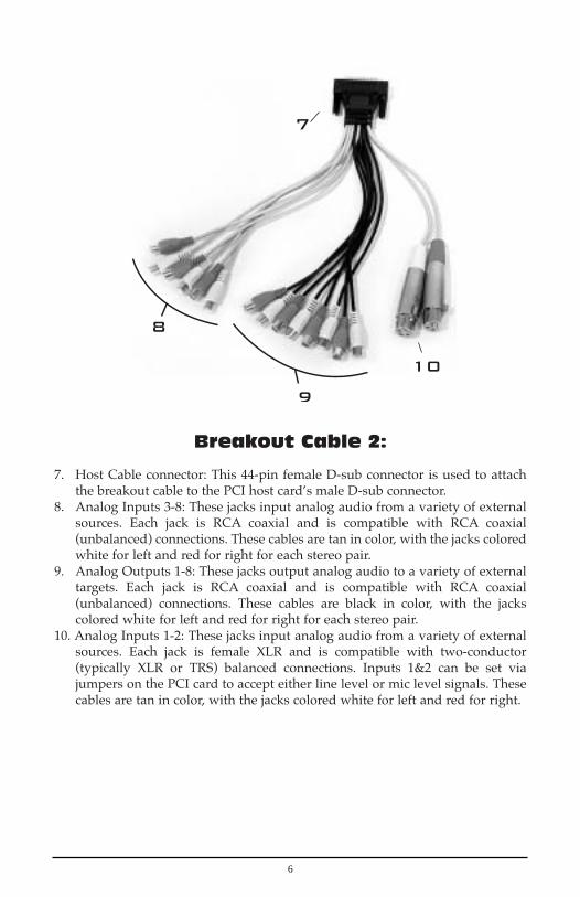
Breakout Cable 2:
7. Host Cable connector: This 44-pin female D-sub connector is used to attachthe breakout cable to the PCI host card’s male D-sub connector.
8. Analog Inputs 3-8: These jacks input analog audio from a variety of externalsources. Each jack is RCA coaxial and is compatible with RCA coaxial(unbalanced) connections. These cables are tan in color, with the jacks coloredwhite for left and red for right for each stereo pair.
9. Analog Outputs 1-8: These jacks output analog audio to a variety of externaltargets. Each jack is RCA coaxial and is compatible with RCA coaxial(unbalanced) connections. These cables are black in color, with the jackscolored white for left and red for right for each stereo pair.
10. Analog Inputs 1-2: These jacks input analog audio from a variety of externalsources. Each jack is female XLR and is compatible with two-conductor(typically XLR or TRS) balanced connections. Inputs 1&2 can be set viajumpers on the PCI card to accept either line level or mic level signals. Thesecables are tan in color, with the jacks colored white for left and red for right.
B C
6
PCI Host Adapter Card:
11. Host Cable connector 1: This 15-pin D-sub connector attaches to the suppliedbreakout cable #1 to allow communication between the PCI host card andexternal digital devices.
12. Host Cable connector 2: This 44-pin D-sub connector attaches to the suppliedbreakout cable #2 to allow communication between the PCI host card andexternal analog devices.
13. Line Level Jumper #1: This jumper set allows you to switch the XLR analoginput #1 level setting from balanced microphone level to a +4dBu line levelsetting. The default setting shown is the microphone level setting.
14. Line Level Jumper #2: This jumper set allows you to switch the XLR analoginput #2 level setting from balanced microphone level to a +4dBu line levelsetting. The default setting shown is the microphone level setting.
Setting the Jumpers
The Delta 1010LT’s PCI card has two sets of jumpers that can be used to control theoperating line level for the 1010LT’s analog inputs 1&2 on XLR jacks. The location ofthese jumpers is illustrated in the previous section under “PCI Host Adapter Card.”
Two basic settings are possible, one for a microphone line level compatible withlow impedance dynamic microphones (those that do not require phantom power,such as condenser mics), and the other is an operating line level of +4dBu(typical for balanced line levels). Two variations are possible for each of theseline level settings. This is shown in the illustrations below.
The default setting when you receive your 1010LT is with the jumpers set to themicrophone line level setting. If you wish to use either or both inputs 1&2 as a +4dBuline level input, then you will need to change the jumper setting on the 1010LT PCI card.
7
Changing the jumper setting is easy to do when the 1010LT PCI card is notinstalled in the computer. Since it is usually impossible to change the jumperswhile the card is in the computer, it’s a good idea to make a decision now. If youwish to connect a dynamic or ribbon microphone directly to the Delta 1010LT’sXLR analog inputs 1&2, then leave the jumpers set to their default setting,+4dBu. If you wish to connect the XLR analog inputs 1&2 to the output of abalanced +4dBu device such as a pre amp or dynamics processor, you will needto change the jumper setting.
Remember that you can change one set of jumpers and not the other, if that suitsyour needs. To change the jumper:
1. Before removing the Delta 1010LT PCI host card from its protective anti-static bag,touch the metal power supply case of the computer in order to dissipate any staticelectricity your body may have accumulated. You might want to pick up a groundingwrist strap (available from electronics stores like Radio Shack) if you want to bedoubly sure you aren't carrying a static charge that could damage the card.
2. Either hold the PCI card in your hand, or place it on an anti-static surface(such as its protective bag). Using your fingertips or a tweezer, remove theplastic jumper that is covering the top-most and middle metal pins. SeeIllustrations 1 and 1a, below.
3. Place the jumper over the middle and bottom-most metal pins. SeeIllustrations 2 and 2a, below.
NOTE: Illustrations 1a and 2a show a variation on the mic levelsetting and the line level setting, respectively. If you find that yoursignal is too hot using the +4dBu selection in the Delta ControlPanel’s “Variable Signal Level” section of the Hardware Settingspage, then try these alternate settings.
Hardware Installation
To mechanically install the Delta 1010LT, do the following:
1. Turn off your computer and unplug the AC cord.2. Remove the computer’s cover and position the computer so that you may
easily access its PCI slots.
Mic Level+30dB gain
Mic Level
+30dB byAttenuates
11dB (i.e.,+19dB gain)
Line Level+14dBu peak(+4 mode)
Line LevelChangesLine Level to+3dBu peak (+4 mode)
1 1A 2 2A
8
3. Select the PCI slot where you will install your Delta 1010LT PCI host card.Make sure the slot is a PCI slot. If you don't know what "PCI slot" means,check the owner’s manual for your computer. PCI slots are distinguishablefrom ISA slots by being shorter and set back farther from the outside of thecomputer, however some newer computers have only PCI slots.
4. Before removing the Delta 1010LT PCI host card from its protective anti-static bag,touch the metal power supply case of the computer in order to dissipate any staticelectricity your body may have accumulated. You might want to pick up a groundingwrist strap (available from electronics stores like Radio Shack) if you want to bedoubly sure you aren't carrying a static charge that could damage the card.
5. Remove the metal bracket that covers the access hole on the back of thecomputer. This bracket is usually fastened to the computer with a single screw.
6. Position the Delta 1010LT PCI host card over the target PCI slot and fit the cardloosely over it with the card in the upright position. Press the card gently butfirmly downward into the slot until the card is completely and squarely seatedin the slot. If the card seems difficult to seat, a slight rocking motion may help.
7. Screw the Delta 1010LT PCI host card’s metal bracket down into the screw holeon the back of your computer using the screw you removed in step 5 above.
8. Place the cover back on your computer.
IMPORTANT: Complete the attachment of your Delta 1010LTbreakout cables to the PCI card before powering up your computer.Never attach a breakout cable to the PCI card while the computeris on. Doing so could damage the PCI card and void the warranty.
With your computer turned off, it is now time to connect the Delta 1010LT breakoutcables to the PCI host card that you have just installed. You may at this time also want toconnect to audio gear that you using in conjunction with your Delta 1010LT.
Delta Driver Software Installation - for PC
The Delta 1010LT system includes a driver CD for Windows XP/2000/ME/98/95/NT (andMacintosh, too), containing all Windows drivers and Delta Control Panel software. To installthese on your system, please follow these steps:
Windows XP,2000, and ME Installation
1. After installing the Delta 1010LT hardware, boot your system and startWindows. During the Windows boot procedure, new hardware will beautomatically detected by the Add New Hardware Wizard announcing “NewHardware Found.” Click ‘Next>’.
2. The ‘Add New Hardware Wizard’ will now ask how you want to find thedriver. "Search for the best driver for your device" is already selected. Click‘Next>’.
3. Windows will give you a selection of locations to search. Make sure that only“Choose a Path” is checked, or click on the check box to do so. Insert the DriverCD into your CD ROM drive. Type in the drive letter of your CD drive (we willassume here that it is D:\) and the path to the Delta drivers, which will beD:\Delta Series\Wdm. Click ‘Next>’.
9
4. The ‘Wizard’ reports that its Windows driver file search has found theM-Audio Delta 1010LT. Click Next>. If announcements that “No DriverSignature” pop up, ignore them and continue with the installation procedure.
5. Windows is now ready to install the driver files from the specified location.Click Next>. Windows will start to copy the files and show you a progressreport screen.
6. The Wizard reports that Windows has finished installing the software. Click‘Finish’. Your Delta 1010LT is ready for action.
After completion of the driver installation, Windows may require you to restart. If it doesrequest a restart, remove the Drivers CD Disk from the CD drive and respond “Yes.” Thesystem will restart and your Delta 1010LT is ready for play.
Windows 98 Installation
1. After installing the Delta 1010LT hardware, boot your system and startWindows. During the Windows boot procedure, new hardware will beautomatically detected by the Add New Hardware Wizard. Click ‘Next>’.
2. The ‘Add New Hardware Wizard’ will now ask how you want to find the driver."Search for the best driver for your device" is already selected. Click ‘Next>’.
3. Windows will give you a selection of locations to search. Make sure that only“Choose a Path” is checked, or click on the check box to do so. Insert theDriver CD into your CD ROM drive. Type in the drive letter of your CD drive(we will assume here that it is D:\) and the path to the Delta drivers, whichwill be D:\Delta Products\Delta98. Click ‘Next>’.
4. The ‘Wizard’ reports that its Windows driver file search has found theM-Audio Delta 1010LT. Click Next>.
5. Windows is now ready to install the driver files from the specified location.Click Next>. Windows will start to copy the files and show you a progressreport screen.
6. The Wizard reports that Windows has finished installing the software. Click‘Finish’. Your Delta 1010LT is ready for action.
After completion of the driver installation, Windows may require you to restart. If it doesrequest a restart, remove the Drivers CD Disk from the CD drive and respond “Yes”. Thesystem will restart and your Delta 1010LT is ready for play.
Windows 95 Installation
1. After installation of the Delta 1010LT hardware, boot your system and startWindows. During the Windows boot procedure, new hardware will beautomatically detected.
2. Choose the Install of "driver from disk provided by hardware manufacturer,"then click OK.
3. An ‘Install From Disk’ will prompt you to copy files from the A:\ drive. Insert the Driver software CD into your CD ROM drive. Type in thedrive letter of your CD drive (we will assume here that it is D:\) and the path
10
to the Delta drivers, which will be D:\Delta Products\Delta98 (these driversalso work in Win95). Click ‘Next>’.
4. Windows will start to copy files, with a progress indicator on the screen. Oncethis process completes itself, your Delta 1010LT will be ready for action.
After completion of the driver installation, Windows may require you to restart. If it doesrequest a restart, remove the Drivers CD Disk from the CD drive and respond “Yes.” Thesystem will restart and your Delta 1010LT is ready for play.
Windows NT Installation
1. Power up your computer after physically installing the Delta 1010LT interfacecard.
2. Go to Start | Settings | Control Panel and double click on ‘Multimedia.’3. Click the ‘Devices’ tab, then click the ‘Add’ button.4. “Unlisted or Updated Driver" will be highlighted at the top of the list. Click
OK.5. The ‘Install Driver’ box will prompt you to insert the driver disk, and the A:
prompt will appear as the path. Insert the Drivers CD into your CD ROMdrive. Type in the drive letter of your CD drive (we will assume here that it isD:\) and the path to the Delta drivers, which will be D:\DeltaProducts\DeltaNT. Click OK.
6. The "M Audio Delta Interface Card" driver will appear in the Add Unlisted orUpdated Driver dialog box. Click OK.
7. Windows NT will require you to restart your computer for the changes to takeeffect. Choose "Restart Now." Upon restart, your Delta 1010LT will be readyfor use.
Verifying Windows Driver Installation
Windows displays the Delta 1010LT driver status in the Device Manager page of theSystem Properties dialog box. The Device Manager page is opened via the Windows Startbutton: select Start | Settings | Control Panel | System | Device Manager. With the DeviceManager displayed, click on the "+" next to "Sound, video and game controllers" to opena list of devices, the Delta 1010LT being a device of that nature. Below is an example viewof the Device Manager.
11
This example shows the M-Audio Delta 1010LT entry in the Windows Device Manager devicelist. The Delta 1010LT is properly installed with no conflicts. If you do not see your M-AudioDelta 1010LT in your Device Manager in this fashion, please jump ahead to the"Troubleshooting" section of this manual located on pg 56.
Verifying Delta Control Panel SoftwareInstallation in Windows
In Windows, open the Windows Control Panel (do so via Start | Settings | Control Panel).If your Delta 1010LT hardware and Delta Control Panel software are properly installed, theWindows Control Panel should display an "M Audio Delta H/W" icon. By double-clickingon that icon, you can launch the Delta Control Panel software. For convenience, you mayalso create a shortcut on your desktop by dragging a copy of the "M Audio Delta H/W"icon from the Control Panel to your Windows desktop using your mouse or trackball. Aftercompleting the drag operation, a dialog box will ask you if you wish to create a shortcut --click on ‘Yes.’ Once the shortcut is installed, all you have to do is double-click on theshortcut icon on your desktop to launch the Delta Control Panel software.
NOTE: When using a music software program that is ASIO capable,launch the Delta Control Panel software from within that program.Some of the control panel functions will be controlled from withinthat program, such as master clock setting and sample rate, so itis desirable to launch the music program first, and then the DeltaControl Panel from the the program’s “launch” or “control panel”button. Without the music program open however, it is okay toopen the Delta panel from your desktop or other location.
12
Delta Driver Software Installation on the Mac
1. Open the System folder on your Macintosh hard drive. In the System folder,locate the Extensions folder.
2. On you Drivers CD disk, open the Mac Delta Drivers folder. Place theextension file "Delta 1010LT Driver" in your Extensions folder by clicking on itand dragging it to the Extensions folder.
3. If you are using a music program that uses ASIO drivers, it will also have anASIO folder within the application’s folder. In your Mac Delta Drivers folderyou will find three Delta 1010LT ASIO drivers. For Cubase versions 4.x, use the"ASIO2 Delta1010LT" driver. For Metro, or earlier versions of Cubase, use the"ASIO Delta1010LTv3" driver. For any music program that is not ASIO2 capable,use the “ASIO Delta 1010LT” driver instead (check your program’sdocumentation). Place the file "ASIO Delta" in your program's ASIO folder byclicking on it and dragging it to the ASIO folder.
3. Drag the "DeltaPanel PPC" file onto your Macintosh hard drive. You can run theDelta Control Panel from any place that's convenient, though music softwareapplications that use ASIO will allow you to launch the Delta panel from within theprogram. If not, we suggest creating an alias to the control panel by highlighting itand pressing Command (Apple key)+M. Then, drag the alias to the desktop.
4. With the Delta 1010LT PCI card installed, restarting the computer will load theDelta 1010LT extension. You will be able to visually see the Delta extensionicon pass by as your system loads extension.
5. Go to the Apple menu |Control Panel | Sound. You should see the “built-in” soundicon, plus the Delta icon if your Delta 1010LT is properly installed. If your musicprogram does use ASIO, you may want to leave the Sound Manager driver set to"built-in" for both Sound In and Sound Out. If your program does not use ASIO(check your software’s documentation) and you will be using the Sound Managerto communicate with your Delta 1010LT, set Sound In and Sound Out to “Delta.”See the section “Hardware Settings Page” in the Delta 1010LT “Control PanelSoftware” section for information on selecting Sound Manger inputs and outputs.
Your Delta 1010LT is now ready for audio input and output. To configure the Delta for MIDI,you will need to have Opcode’s OMS (Open Music System) installed first. OMS is provided onthe CD that came with the unit. Opening the OMS 2.3.7 folder and double-clicking on the “InstallOMS 2.3.7” program will install OMS in your system. To install the Delta MIDI driver onceOMS is properly installed:
1. Open the “Delta Products”folder on the driver CD, then the Delta 1010LT Macfolder. Locate the “Delta OMS Driver.”
2. On your Macintosh hard drive, in your System folder, you will find an “OMSFolder.”Drag the Delta OMS Driver into the OMS Folder.
3. Restart your computer.
To Configure your Delta 1010LT MIDI in OMS, go to the Control Panel or Chooser underthe Apple Menu, and make sure AppleTalk is turned off (this is recommended, althoughOMS will sense that it is on and prompt you to turn it off). If you are configuring OMSfor the first time, follow these instructions to configure OMS.
13
1. In the Opcode folder, which you will find on your hard drive, locate the OMSApplications folder, "then OMS Setup." Double click on OMS Setup.
2. OMS will inform you that it has not yet been configured. Click OK.3. The Create A New Studio Setup dialog box now appears. Click OK.4. The "OMS Driver Search" box asks you to choose the port on which you've
attached the Delta MIDI (either Modem or Printer). DO NOT choose a port,just click "Search." OMS begins Searching.
5. "OMS Driver Setup" shows the "Delta" MIDI in a list when OMS successfullyfinds the driver. Click OK. OMS will now define (shows "Identifying") theDelta output port. The "OMS MIDI Device Setup" dialog box will appearshowing the Delta's output port with a check box to the left of the port,indicating that the port is enabled. Now click on OK.
6. Next, the "My Studio Setup" appears with a 'file save' dialog box over it. Youwill now need to save your new Studio Setup before you can assign aninstrument to the Delta's MIDI output and input. Assign your instrument andyou are done. You may now exit OMS Setup by quitting the application.
Delta Control Panel Installation on the Mac
The Delta Control Panel may be placed anywhere on your hard drive, or any partition ofyour hard drive that you find convenient. Once the control panel file has been draggedfrom the CD onto your hard drive, you may double click it to launch the Delta ControlPanel software. You may also create an alias to the control panel by highlighting it, thenholding Apple key+M. This alias can then be placed on your desktop.
NOTE: When using a music software program that is ASIO capable,launch the Delta Control Panel software from within that program.Some of the control panel functions will be controlled from withinthat program, such as master clock setting and sample rate, so itis desirable to launch the music program first, and then the DeltaControl Panel from the the program’s “launch” or “control panel”button. Without the music program open however, it is okay toopen the Delta panel from your desktop or other location.
Delta System Basics
Delta’s Analog Inputs/Outputs
The Delta 1010LT PCI Audio Card’s analog inputs and outputs are compatible with a widevariety of audio products. The Delta Control Panel software allows you to configure thesignal level of each analog output individually, or all analog outputs as a group. Signallevel settings of +4dBu, “Consumer” (-4dBu), and “-10” are available.
+4dBu is considered a professional operating line level, and is generally associated withbalanced, two-conductor cables and connectors such as the 1010LT’s analog inputs 1 & 2.The +4dBu setting will allow you to accept or output a “hotter” signal. The ‘Consumer’setting is preferred for semi-pro audio equipment and some consumer equipment that canoutput accept a ‘hotter’ signal than the ‘-10’ setting. The ‘Consumer’ setting offers
14
approximately 6dB more headroom than does the ‘-10’ setting. Semi-pro and consumerdevice signal levels vary from manufacturer-to-manufacturer and even product-to-product, so a little experimentation between Consumer and –10 settings may be requiredfor optimal results.
NOTE: Analog inputs 3 through 8 on the Delta 1010LT do not havemicrophone pre-amplifiers built into them. Therefore directconnection to a microphone is not recommended. Instead run themicrophone signal through a microphone pre-amp (such as theM-Audio "Audio Buddy™" or M-Audio “DMP2™”) and then connectthe pre-amp output to the input of the Delta 1010LT.
Inputs 1 & 2 are female XLR connectors, and allow connection to balanced microphoneor line level audio signals. All other analog jacks on the Delta 1010LT breakout cable areof the RCA (coaxial) variety. The RCA jacks allow connection to unbalanced (typicallysemi-pro or consumer) connections.
The Digital Monitor Mixer
The Delta 1010LT PCI Audio Card has a hardware digital audio mixer built into its PCIcontroller chip. It accepts digital audio streams from all hardware inputs and all outgoingsoftware audio devices, mixes them with 36-bit internal precision and then provides themixed output to one or more locations. For the purpose of monitoring, the output of themixer may be routed, via the control panel’s Patchbay/Router page, to the first set ofDelta 1010LT analog outputs (OUT1/OUT2 as a stereo pair) and/or the S/PDIF digitaloutput. At the same time, the mixer may be used for stereo mix-down, with the mixer’soutput recorded into the user’s application software. The digital audio mixer is configuredand controlled by the included Delta Control Panel Software.
The Patchbay / Router
In addition to the built-in monitor mixer, the Delta 1010LT PCI Audio Card includes anoutput patchbay/router. The patchbay/router allows each output (analog or digital) to beconnected to a variety of input sources. The 1010LT’s outputs may accept audio fromsoftware sources (these output devices are visible in your audio software applications) orfrom hardware sources such as the analog and digital inputs or the monitor mixer. Thiscapability makes the Delta 1010LT quite flexible for playing and monitoring any audiofile format, or directly connecting inputs to outputs for system test purposes.
Synchronization
For proper operation, the entire Delta 1010LT system is always synchronized to a singlemaster clock. The master clock is chosen via the Delta Control Panel software and thisclock may be derived from the Delta 1010LT’s internal crystal oscillators, S/PDIF In, orWord Clock In. Most of the time the master clock is taken from the internal crystaloscillators. However, the S/PDIF and Word Clock options are used in situations wherethe Delta 1010LT must be synchronized to external digital audio or sample rates derivedfrom an external device.
15
Using the initial default setting, the master clock is derived from the internal crystaloscillators. Operation in this mode is similar to that of a generic sound card – for instance,when an audio file is played through the Delta drivers, the software application playingthe audio file is responsible for setting the sample rate in the sound card hardware. TheDelta 1010LT supports these sample rates by using either of its internal crystal oscillatorsand dividing the rate of that oscillator by some value to derive the proper sample rate.
In situations where S/PDIF In is being used, the Delta 1010LT should usually be configuredto get its master clock from the S/PDIF In data stream. The reason for this is simple – anS/PDIF data stream coming from an external source is rarely going to be in sync with theDelta 1010LT (or other digital audio devices in the system for that matter), even if thesample rates are set the same. If the master clock were set to use the internal crystal, thenthe incoming S/PDIF audio would have "pops," "crackles," and other undesirable audioartifacts present in it. Instead, setting the master clock to "S/PDIF In" will synchronize theDelta 1010LT to the S/PDIF input data and its digital audio will be transferred properly.There is one special case to consider, however. The external unit sending the S/PDIF digitalaudio to the Delta 1010LT may be "locked" to the word clock emitted from the Delta 1010,or both the external unit and the Delta 1010LT are locked to the same external word clock.In these cases, the Delta 1010LT and the external S/PDIF device are in-sync, and theS/PDIF data would therefore be in-sync with the Delta 1010LT system.
We’ve discussed internal crystals and S/PDIF In as master clock sources. The third optionis Word Clock. Word Clock is the desirable choice when you want to synchronize theDelta 1010LT with the word clock of something else in your system. That "somethingelse" may be a another unit that has a word clock output, or it may be a dedicated houseword clock generator.
Finally, the Word Clock and S/PDIF In options may be used to operate the Delta 1010LTat non-standard sample rates. When one of these two options is selected, theDelta 1010LT’s sample rate will automatically match that of the incoming word clock orS/PDIF data stream.
NOTE: When either the S/PDIF In or Word Clock is selectedas the master clock source, the Delta 1010LT mixer’sfrequency response will be affected by whatever samplerates you inject at the S/PDIF In or Word Clock In. This isbecause (1) the digital mixer operates at the same samplerate as the rest of the board, and (2) sample rate andfrequency response are directly correlated.
Using the Delta 1010LT with your MusicSoftware Application
Once the Delta 1010LT’s hardware and driver software are properly installed, it is ready foruse with your music application software. Some of these applications may require you tohighlight or enable the Delta 1010LT drivers within the program, and others may have autility that analyzes or profiles the audio cards in your system and enables the drivers. Yoursoftware should have an audio device driver setup page.
16
WINDOWS MME AUDIO INPUT DEVICES: All Delta 1010LT analog and S/PDIFinputs may be used simultaneously for a total of 10 input channels. Within your softwareapplication(s), the names of the Delta 1010LT audio input devices are:
PCM In 1/2 Delta-1010LT
PCM In 3/4 Delta-1010LT
PCM In 5/6 Delta-1010LT
PCM In 7/8 Delta-1010LT
S/PDIF In Delta-1010LT
Mon. Mixer Delta-1010LT
The PCM In devices allow recording a stereo stream directly from the specified analoginput pairs. The S/PDIF In device allows you to record a stereo stream directly from theS/PDIF input. The Mon. Mixer device allows stereo recording from the digital "monitor"mixer built-into the Delta 1010LT. The audio data recorded from this device is the mix ofinput and output streams that is set up in the Delta Control Panel software’s MonitorMixer page (see Delta 1010LT Control Panel Software section).
Note that all of the input devices are stereo. Your application software may break these downfurther to "left" and "right" mono devices. Therefore you may see them as "Left PCM In 1/2Delta-1010LT, Right PCM In 1/2 Delta-1010LT," "Left S/PDIF In Delta-1010LT, Right S/PDIFIn Delta-1010LT," or "Left Mon. Mixer Delta-1010LT, Right Mon. Mixer Delta-1010LT," etc.from within your recording software.
WINDOWS MME AUDIO OUTPUT DEVICES: All Delta 1010LT analog and S/PDIFoutputs may be used simultaneously for a total of 10 output channels. Within yoursoftware application(s), the names of the Delta 1010LT audio output devices are:
WavOut 1/2 Delta-1010LT
WavOut 3/4 Delta-1010LT
WavOut 5/6 Delta-1010LT
WavOut 7/8 Delta-1010LT
WavOut S/PDIF Delta-1010LT
All WavOut devices allow playing a stereo audio stream to the analog hardware outputs (forWavOut 1/2, 3/4, 5/6, 7/8), the S/PDIF hardware output (for WavOut S/PDIF), and/or into thehardware router or mixer. Your application software may break each of these stereo devicesdown further to "left" and "right" mono devices. Therefore you may see them as "LeftWavOut 1/2 Delta-1010LT, Right WavOut 1/2 Delta-1010LT", or "Left WavOut S/PDIFDelta-1010LT, Right WavOut S/PDIF Delta-1010LT", etc. from within your music software.Other software will handle the outputs as stereo pairs, but allow you to pan audio left or rightwithin the pair.
Note that each device name begins with "WavOut." This is to remind you that these aresoftware devices, and not always connected directly to output hardware. Instead they areconnected to the Delta 1010LT’s internal patchbay/router and may be sent to one of manydestinations. For more on the patchbay/router, see the Patchbay/Router section of theDelta Control Panel software discussion.
17
ASIO or EASI DRIVER INPUT DEVICES: When using the ASIO or the EASI audiodrivers with music programs that support this type of audio, the input devices aredisplayed as mono devices. Within these software applications, the names of theDelta 1010LT audio input devices are:
Analog In1 Delta-1010LT
Analog In2 Delta-1010LT
Analog In3 Delta-1010LT
Analog In4 Delta-1010LT
Analog In5 Delta-1010LT
Analog In6 Delta-1010LT
Analog In7 Delta-1010LT
Analog In8 Delta-1010LT
S/PDIF In L Delta-1010LT
S/PDIF In R Delta-1010LT
Mon. Mixer L Delta-1010LT
Mon. Mixer R Delta-1010LT
Notice the S/PDIF In and Monitor Mixer names include "L" and "R" characters. "L" indicatesthe left channel of the stereo stream, while "R" indicates right channel.
ASIO or EASI DRIVER OUTPUT DEVICES: The Delta 1010LT’s ASIO and EASIoutput devices appear in stereo pairs. Because each device is stereo, you may see "left"and "right" references within your software application. This allows the application to panaudio left and right under software control. To send a signal to a Delta ASIO output 1 (forexample) as a mono output send, one would choose "Analog 1/2 Delta-1010LT" for thattrack’s output port, and then pan that output hard left. These outputs are named as follows:
Analog 1/2 Delta-1010LT
Analog 3/4 Delta-1010LT
Analog 5/6 Delta-1010LT
Analog 7/8 Delta-1010LT
S/PDIF L/R Delta-1010LT
MIDI DRIVERS: The Delta 1010LT MIDI drivers, once enabled in your software’s MIDISetup, will appear as a MIDI source and a MIDI port within that program’s trackconfiguration windows. The MIDI input driver is named "MIDI In Delta-1010LT," and theMIDI output driver is named "MIDI Out Delta-1010LT." Some software applications allowyou to redefine/rename these devices per supplied or manually entered instrument definitions.
WINDOWS MULTIMEDIA SETTINGS: Windows may be set up to use theDelta 1010LT as its default audio device, allowing system sounds to be sent out theDelta 1010LT. This also enables you to use the Delta 1010LT with the sound appletsincluded with Windows. To set this up, go to Control Panel | Multimedia. In the AudioProperties page, set the Playback and Recording devices to the Delta 1010LT input andoutput devices of your choice.
18
Windows may also use the Delta 1010LT as its default MIDI device. This allows theDelta 1010LT to be used with the MIDI applications included with Windows. To set thisup, go to Control Panel | Multimedia | MIDI. Set the Delta MIDI driver as the defaultWindows MIDI driver by clicking on the "MIDI Out Delta-1010LT" entry in the driverlist, then selecting "OK" or "Apply."
MACINTOSH SOUND MANAGER INPUTS AND OUTPUTS: The Apple SoundManager limits the user to one stereo pair for input and one stereo pair for output. Withinyour music software, the device selection when using the Sound Manager drivers for inputand output will be “Sound Manager” both for input source and for output port.
To select the Sound Manager driver, open the Apple Menu and go to Control Panel |Sounds. For both “Sound In” and “Sound Out,” click and highlight the Delta icon, thenexit. You may select which Delta hardware stereo input pair and stereo output pair will beused for the Sound Manager’s Sound In and Sound Out in the Delta Control Panel“Hardware Settings Page” (see section, “Hardware Settings Page”under “Delta ControlPanel”). Whichever stereo pair you select, the software input and output device selectionwithin your music program will remain the same, namely, “Sound Manager.”
Delta 1010LT Control Panel Software - PC
Once the Delta 1010LT is properly installed, an "M Audio Delta H/W" icon will bedisplayed in your Windows Control Panel. By double-clicking on that icon, you willlaunch the Delta Control Panel software. You may also launch the Delta Control Panelsoftware from the desktop if you have previously created a shortcut there (see "VerifyingDelta Control Panel Software Installation" section for instructions on how to do this).Once the Delta Control Panel software has been opened, you will see the main panel andits several tabs. To display a desired page, click on its tab. Below are functionaldescriptions of each page.
NOTE: When using a music software program that is ASIO capable,launch the Delta Control Panel software from within that program.There will be a button in the ASIO or Audio setup page that willallow you to do so. Some of the control panel functions will becontrolled from within that program, such as master clock settingand sample rate, so it is desirable to launch the music programfirst, and then the Delta Control Panel from the the program’s“launch” or “control panel” button. Without the music programopen however, it is okay to open the Delta panel from your desktopor other location.
Monitor Mixer Page
The Monitor Mixer is the first page that appears when the Delta Control Panel is opened,and controls the digital mixer built into the Delta 1010LT’s PCI controller chip. Asdescribed in previous sections, the output of this mixer may be assigned to theOUT1/OUT2 analog outputs and/or the S/PDIF Out digital output (this selection is madein the Patchbay Router page). At the same time, the mixer outputs may be recorded instereo by software.
19
The Monitor Mixer Page is essentially a collection of volume level faders, audio level (or‘peak’) meters, and solo/mute controls. For each mixer output and input channel there isone of each: a volume fader, a peak meter, a solo control, and a mute control.
LEVEL FADERS: Each volume fader may be controlled by dragging the fader ‘handle’vertically with the mouse, or by clicking on the ‘handle’ to make it active and thenadjusting it with the up/down cursor keys of your computer keyboard. Because the mixerhas no gain, these faders only attenuate (reduce) the signal levels. The highest setting is0dB, or ‘Unity Gain.’ The default fader setting is the quietest setting, –144dB, whichessentially mutes the audio. A pair of level faders may be "ganged" so that both channelsmay be adjusted together as a stereo pair.
Also, at the top of each fader and meter is a fader level "fine adjustment" control. Clickingon the small "up" and "down" arrows will adjust the corresponding fader setting in 0.5dBincrements. Next to each fine adjustment control is a numerical fader readout that is alwayscurrent and active.
PEAK METERS: Each peak meter indicates an audio signal level in "dB relative tofull-scale." This means that a full-scale signal is referred to as "0 dB" and a signal that is12dB "quieter" than full-scale is referred to as "-12dB." The meters are verticallycolor-coded into three sections: green, yellow and red. The green section represents a safezone, ranging from approximately -48dB to -12dB. Most audio signals shouldappropriately fill this section of the meter. The yellow section ranges from -12dB to -3dBas the signal approaches a ‘hotter’ level. For best capture resolution, recording in this areais both safe and advised. The red section of the meter ranges from -3dB to 0dB. On theinput level meters, a 0dB condition indicates overload and audio clipping may occur.Therefore be careful to adjust the incoming audio levels so that they do not peak in the redsection too long (you might use the monitoring capability of the Delta 1010LT to let yourears be the judge). On all output level meters, 0dB indicates full-scale output. Unlike theinputs, clipping is impossible on the outputs because of the 36-bit resolution built into themixer hardware.
20
MASTER VOLUME: At the left side of the Monitor Mixer page, you will see the ‘MasterVolume’ faders and peak meters. These faders have the longest ‘throw’ and highest meterresolution of any level controls in the mixer page. They control the overall stereo level ofthe mixer output. The peak meters indicate the output signal levels with respect to full-scaleand are directly affected by the settings of the master volume faders.
MIXER INPUTS: The ‘Mixer Inputs’ are inputs to the monitor mixer. These inputs accepthardware audio streams (directly from the Delta’s analog and digital input ports) andsoftware audio streams (digital audio generated in software to be output). This combinationof streams makes the monitor mixer extremely flexible. Each mixer input channel has itsown level fader and may be panned anywhere in the left/right stereo field. Each input alsohas its own peak meter. The peak meters indicate the incoming "pre-fader" levels of theincoming audio and are therefore not affected by the fader settings. However, the inputfaders do affect the levels of the signals exiting the mixer and you will see the affect of theinput faders on the output "Master Volume" peak meters.
Because of the large number of mixer inputs, not all inputs are displayed simultaneously.You may use the scroll bar at the bottom of the Delta Control Panel to scroll the view leftor right. On the PC, from far left to right the inputs are labeled "WavOut 1/2” through“WavOut 7/8," then "WavOut S/PDIF." These inputs accept the digital audio streams beingsent from your software application (or Windows) to the driver devices with those samenames. Each name begins with "WavOut" to remind you that these are software streamsand may not necessarily be routed to any physical outputs (see Patchbay/Router Page).
Further to the right are more channels, labeled "H/W In S/PDIF" and "H/W In 1/2 through7/8." These mixer inputs are audio streams from the physical Delta 1010LT hardwareinputs, hence the "H/W" at the front of each label.
PAN: Each mixer input may be individually panned anywhere in the stereo output mix. Apan control is positioned directly under each input channel peak meter and has theappearance of a small vertical pointer. To make a coarse adjustment, click on the pan controlwith your mouse and drag it to the desired position. For finer adjustment (in 1% increments),you may click on the pan control to make it active, and then use the left/right or up/downcursor keys on your computer keyboard. Either way, while the pan setting is being adjusted,its value will appear numerically in the Master Volume’s status box (below the MasterVolume Stereo Gang control) as a percentage from left pan to right pan: -100% representsfar left, +100% represents far right, and 0% represents the center.
SOLO: Each mixer input channel has a "Solo" checkbox associated with it. Clicking on andactivating a Solo box will solo the selected channel by essentially muting all other signals.When more than one channel has Solo selected, all solo channels will be summed to thesolo ‘buss’ (path), which is what one might consider an ‘in place’ solo as opposed to a PFL,or pre-fader listen (levels and pans still apply). Deactivating all solo boxes will return allinput channels to their previous mute/unmute states.
MUTE: Every mixer input channel has a "Mute" checkbox associated with it. Clicking onand activating the Mute box will remove that signal from the stereo buss. Deactivating theMute box will add the signal back into the stereo buss.
STEREO GANG: All input channel pairs have a "Stereo Gang" capability. Clicking on andactivating the Stereo Gang checkbox will link (or "gang") the left/right faders so that bothchannels may be adjusted together as a stereo pair.
21
Patchbay/Router Page
The Patchbay/Router page allows you to connect each of the Delta 1010LT’s hardwareoutputs (4 pairs of analog outputs and 1 pair of digital output channels) to specific audiosources within the Delta 1010LT board. To display this page, click the "Patchbay/Router"tab of the Delta Control Panel.
The leftmost vertical column of Patchbay/Router page, "H/W Out 1/2," connects thisanalog stereo pair to one of eight stereo sources:
1. The default setting, "WavOut 1/2," connects ports OUT1 and OUT2 to yourmusic software or Windows multimedia applet. In other words, when musicsoftware plays audio to the device named "WavOut 1/2 Delta-1010LT" it willbe routed directly to the "hardware" analog outputs 1 & 2 of your 1010LTbreakout cable.
2. The second option, "Monitor Mixer," connects ports OUT1 and OUT2 to theoutputs of the Delta 1010LT monitor mixer. For more information of thecapabilities of the monitor mixer, please see the section "Monitor Mixer Page."
3. The third option, "S/PDIF In," connects ports OUT1 and OUT2 directly tothe hardware S/PDIF input on the Delta 1010LT PCI host card. The leftchannel of the S/PDIF In is routed to OUT1 and the right channel of theS/PDIF In is routed to OUT2.
4. The fourth option, "S/PDIF In (L/R Rev.)," functions identically to the thirdoption, except that the left and right channels are swapped. Therefore inthis mode, the left channel of the S/PDIF In is routed to OUT2 and the rightchannel of the S/PDIF In is routed to OUT1.
5. Selections five through eight connect the hardware analog inputs 1 & 2, 3 &4, 5 & 6, or 7 & 8 (respectively) directly to the 1010LT’s hardware analogoutputs 1 & 2. For example, if "H/W In 1/2" were selected, any signalpresent at the IN1 port will be copied to OUT1, and any signal present at theIN2 port will be copied to OUT2. This same behavior applies to "H/W In3/4," "H/W In 5/6," and "H/W In 7/8" when selected.
The next three vertical columns of the Patchbay/Router page (from left to right), "H/WOut 3/4," "H/W Out 5/6," and "H/W Out 7/8," connect these hardware analog outputs toone of four sources. Since the three columns function identically, we’ll use "H/W Out 3/4"as the example:
1. The default setting, "WavOut 3/4," connects ports OUT3 and OUT4 to yourmusic software or Windows multimedia applet. In other words, when musicsoftware plays audio to the device named "WavOut 3/4 Delta-1010LT" it willbe routed directly to the "hardware" analog outputs 3 & 4 of your 1010LTbreakout cable.
2. The second option, "S/PDIF In," connects ports OUT3 and OUT4 directly tothe hardware S/PDIF input on the Delta 1010LT PCI host card. The leftchannel of the S/PDIF In is routed to OUT3 and the right channel of theS/PDIF In is routed to OUT4.
3. The third option, "S/PDIF In (L/R Rev.)," functions identically to the secondoption, except that the left and right channels are swapped. Therefore in this
22
mode, the left channel of the S/PDIF In is routed to OUT4 and the rightchannel of the S/PDIF In is routed to OUT3.
4. Options four through seven connect the hardware analog inputs 1 & 2, 3 & 4, 5 &6, or 7 & 8 (respectively) directly to the 1010LT’s hardware analog outputs 3 & 4.For example, if "H/W In 1/2" were selected, any signal present at the IN1 portwill be copied to OUT3, and any signal present at the IN2 port will be copied toOUT4. This same behavior applies to "H/W In 3/4," "H/W In 5/6," and "H/WIn 7/8" when selected.
The rightmost vertical column of Patchbay/Router page, "H/W Out S/PDIF," connects theDelta 1010LT’s hardware S/PDIF outputs to one of eight sources:
1. The default setting, "WavOut S/PDIF," connects the S/PDIF Out port to yourmusic software or Windows multimedia applet. In other words, when musicsoftware plays audio to the device named "WavOut S/PDIF Delta-1010LT" itwill be routed directly to the hardware S/PDIF output on your Delta 1010LTPCI host card.
2. The second option, "Monitor Mixer," connects the S/PDIF Out port to theoutputs of the Delta 1010LT monitor mixer. For more information on thecapabilities of the monitor mixer, please see the section "Monitor Mixer Page."
3. The third option, "S/PDIF In," connects the S/PDIF Out port directly to thehardware S/PDIF input on the Delta 1010LT PCI host card. The left channelof the S/PDIF In is routed to the left channel of S/PDIF Out and the rightchannel of the S/PDIF In is routed to the right channel of S/PDIF Out.
4. The fourth option, "S/PDIF In (L/R Rev.)," functions identically to the thirdoption, except that the left and right channels are swapped. Therefore in thismode, the left channel of the S/PDIF In is routed to the right channel ofS/PDIF Out and the right channel of the S/PDIF In is routed to the leftchannel of S/PDIF Out.
5. Selections five through eight connect the hardware analog inputs 1 & 2, 3 & 4,5 & 6, or 7 & 8 (respectively) directly to the 1010LT’s S/PDIF Out port. Forexample, if "H/W In 1/2" were selected, any signal present at the IN1 port willbe sent to the left channel of the S/PDIF Out, and any signal present at the IN2port will be sent to the right channel of the S/PDIF Out. This same behaviorapplies to "H/W In 3/4," "H/W In 5/6," and "H/W In 7/8" when selected.
At this point, you may begin to realize the versatility of the Monitor Mixer and thePatchbay/Router, and the relationship between the two. You may want to re-read this sectionand make some practice adjustments within the Delta Control Panel software to becomeproficient in routing and mixing, as well as check out the Tutorials section toward the end ofthis manual. If somewhere in the process you become confused, you may always restore thedefault settings to use the card as a straight 10-in 10-out device -- just choose the topmostoption in each of the Patchbay/Router columns.
Hardware Settings Page
The Hardware Settings page of the Delta Control Panel gives you control overmiscellaneous features of the Delta 1010LT. To display this page, click the "HardwareSettings" tab of the Delta Control Panel.
23
MASTER CLOCK: This section allows you to select the source of the board’s masterclock: Internal Xtal (crystal), S/PDIF In, or Word Clock. Master clock operation isoutlined in the Synchronization section of this manual. Internal Xtal is the default setting.Be sure to select "S/PDIF In" if you will be recording or monitoring an S/PDIF stream, or"Word Clock" if you wish to synchronize your digital audio with a source device that isWord Clock capable.
NOTE: If "S/PDIF In" is selected as the master clock source, besure to supply a valid S/PDIF signal to the board’s active S/PDIFinput. Otherwise, erratic timing and/or improper sample rates willbe experienced. The same is true for selecting "Word Clock" as themaster clock setting – make sure there is a valid word clock signalpresent at the Delta 1010’s Word Clock In.
Once a master clock source has been selected, its synchronization status is continuallymonitored and displayed below the master clock radio buttons. If internal crystal is selected,the status display will always say "Locked." On the other hand, if S/PDIF In or Word Clockis selected as the master clock source, the control panel will display "Locked" only when avalid S/PDIF or Word Clock signal is detected. It will display "Unlocked" when there is nosignal at the selected input, or when the signal is corrupt or invalid for any reason.
CODEC SAMPLE RATE: This section indicates the present board sample rate, as set byapplication software. The sample rate selected here will be used to drive the digital mixerand all outputs. The "Rate Locked" checkbox is used to force a sample rate upon thesystem. It is disabled by default to allow software access to all supported sample rates.When checked, it causes the driver to only operate at the selected sample rate. This meansthat any application that attempts to open the Delta 1010LT driver at a sample rate otherthan the one selected here will fail to do so and will post an error message. "Reset RateWhen Idle" is selected when you want the sample rate to return to a particular settingwhen a software application is not actively using the board. This is particularly handy forkeeping the digital mixer running at a specific sample rate.
NOTE: Because the digital monitor mixer runs at the sample rate ofthe rest of the board, and because sample rate directly affectsfrequency response, it may be desirable to keep the sample rate ator above 44.1 kHz while using the monitor mixer. This isaccomplished by enabling "Reset Rate When Idle" and selecting asample rate of 44.1 kHz or greater.
S/PDIF SAMPLE RATE: When using S/PDIF In as your master clock, this section tells thedriver what the expected S/PDIF input sample rate is. The section is only displayed when theboard is set to use S/PDIF In as the master clock source. From the list, select the sample rateclosest to that of the S/PDIF input data. The sample rate selected here will be the only samplerate available to the software applications. Therefore, you must set your audio softwareapplication to this same sample rate or else the application will display an error message.
NOTE: When S/PDIF In is the master clock source, the digitalmonitor mixer will run at the sample rate received at the S/PDIF In.Since frequency response and sample rate are directly related, themixer frequency response will be directly related to the sample rateof the S/PDIF input data.
24
WORD CLOCK SAMPLE RATE: When using Word Clock In as your master clock, thissection tells the driver what the expected word clock input sample rate is. The section isonly displayed when the board is set to use Word Clock In as the master clock source.From the list, select the sample rate closest to that of the incoming word clock. The samplerate selected here will be the only sample rate available to the software applications.Therefore, you must set your audio software application to this same sample rate or elsethe application will display an error message.
NOTE: When Word Clock is the master clock source, the digitalmonitor mixer will run at the sample rate received at the WordClock in. Since frequency response and sample rate are directlyrelated, the mixer frequency response will be directly related to thesample rate of the S/PDIF input data.
MULTITRACK DRIVER DEVICES: The Delta 1010LT drivers intelligently synchronize thebeginning of recording and playback across all audio devices on the board. When usingapplication software that is capable of using multiple channels simultaneously, select "Single andIn-Sync" to ensure that all audio channels will begin playback and/or recording at the same time.Otherwise select "Independent" to allow the audio channels to play independently – this settingmay be desirable if more than one application needs to access the Delta 1010LT simultaneously.
The selection “Multi-card Sync” will remain grayed out until a second Delta PCI card (of whichthere are a variety) is installed in the system. When you wish to synchronize two (or more, upto four) Delta cards, select Multi-card Sync on the second and successive cards. Then, selectS/PDIF as your master clock, and connect the S/PDIF output of the first card to the S/PDIF inputof the second card, etc. This ensures that when the application goes into record or playback, itwaits until all audio ports are open before it commences with recording or playback of audio.
DMA BUFFER SIZES: This section specifies the amount of system memory dedicated todigital audio buffering. Setting a buffer size that is too small may result in clicks or popsin the audio stream as some data may be lost. Larger buffers cause slightly more latencybut prevent the pops and clicks that might occur with smaller buffer sizes – the defaultsettings are recommended but you may desire to tweak these default settings to suit yourtastes. This buffer size must be set in the Delta Control Panel before you launch yourmusic software. When using ASIO with the Delta 1010LT, set the buffer size in the controlpanel, then exit the control panel. After doing so, launch your music software.
VARIABLE SIGNAL LEVELS: This section has two layers, providing extremelyversatile control of your Delta 1010LT’s input and output operating line levels.
In the first layer there are three selections available for globally setting the operating linelevels for the Delta 1010LT’s analog input and output ports. These selections are labeled“+4dBu,” “Consumer” (-4dB), and “-10dBV,” represented by sets of radio buttons each forboth the Delta analog inputs and the Delta analog outputs. These sections are labeled “AllInputs” and “All Outputs,” respectively.
The default setting is “Consumer” for both the input and output levels. Consumer is agood “middle of the road” setting, and will work well in many situations. The setting youchoose ultimately should match the line level of the source audio device (for the inputs),and the target audio device (for the outputs). Check the user’s guide for these externaldevices for information on their input and/or output line levels.
25
At the Delta analog outputs, a +4dBu setting will give the “hottest” output signal level.Generally, this signal level is associated with balanced audio inputs. The Delta 1010LT’soutputs are unbalanced, but can still interface successfully with balanced inputs. TheConsumer and -10dBV settings are typically associated with unbalanced operation for bothconsumer and prosumer audio gear, with Consumer being less hot (-4dBV) and -10dBVbeing the least hot. As a rule of thumb, if your signal levels in the computer are sufficientbut your target device is not receiving enough level, try a hotter output signal level setting.
At the Delta analog outputs, a +4dBu setting will give the most headroom for recording,allowing the Delta 1010LT to accept a hotter signal level. If your source audio device putsout less signal, such as unbalanced consumer and prosumer equipment, then the lowersettings of Consumer and -10dBV will lower the headroom, bringing record ceiling closerto the signal that you are recording. As a rule of thumb, the lower the signal level of yoursource audio, the lower the input signal level should be set.
A unique case here are the Delta 1010LT’s inputs 1&2. While all of the other inputs andall of the outputs are unbalanced on RCA connectors (single conductor with a shield),inputs 1&2 will accept balanced cables on XLR jacks (two conductor with a shield). Youmay want to set these inputs to a +4dBu signal level setting while setting the rest of theinputs to a different line level setting.
Eight faders are also available for setting each input and output level either individuallyor in stereo pairs. This should be considered an advanced settings page, useful when thesource audio or target devices are diverse and need custom configuration. To access thissecond layer, click the button labeled “Sliders” located in the lower left-hand corner of theVariable Signal Levels section of the Hardware Settings page.
Initially, the location of the faders will reflect the last radio button selection made in thefirst layer. After a change has been made in the second layer, the first layer will show noradio button selection, indicating that a custom setting has been made. The screenshotbelow shows this second layer with the first two faders adjusted to a line level of +4dBufor the two balanced inputs on XLR jacks.
26
You will notice that the “Input” radio button is selected here, giving us a set of eight fadersthat control input levels. Click the “Output” radio button to access the output faders. Also,you can click the “Mono” button to control each fader individually, or the “Stereo” buttonto control faders in stereo pairs.
At any time, the individual faders may be set to vary the input and output levels of aparticular port or ports. You can use the +4dBu, Consumer, and -10dBV buttons as astarting point, or operate independently of them. The faders can be set incrementally in.5dB steps, of which there are 18. If working in surround sound, these faders can be usedto calibrate speakers for monitoring purposes. If using the 1010LT inputs or outputs forother purposes, the faders allow you to address multiple sources and targets individually.
S/PDIF Page
The S/PDIF page of the Delta Control Panel configures the S/PDIF output format anddisplays the status of the S/PDIF input. To display this page, click the "S/PDIF" tab of theDelta Control Panel software.
DIGITAL INPUT: This group box displays the current S/PDIF input status. TheDelta 1010LT’s S/PDIF receiver is capable of recognizing a valid input signal versus aninvalid, corrupt or non-present one. When a valid signal is detected at S/PDIF In, thisgroup box displays "Valid Input Detected." When an invalid signal is detected or no signalis present, the group box displays "Invalid or Not Present." Below this message are two‘grayed-out’ buttons: "Coax(RCA)" and "Optical." These are functions of the Delta DiO2496, another product in the M-Audio Delta line, one with both optical and coaxialS/PDIF inputs. These controls do not apply to the Delta 1010LT.
DIGITALOUTPUTFORMAT: Within the "Digital Output Format" group, you choose the digital audioformat of the S/PDIF output. The default setting, "Consumer," is a true S/PDIF format and is recognizedby all consumer devices. The alternate "Professional" setting is an AES/EBU type data stream, butelectrically S/PDIF. This is a work-around that is recognized by some but not all AES/EBU devices.
For both consumer and professional output formats, the "Advanced" checkbox will allow youto force a few particular status bits in the outgoing S/PDIF signal. The advanced option is forexpert users only; however, if you decide to go exploring, change a few bit settings and getlost, you can always select the "Restore Defaults" button to restore the outgoing status bits totheir factory settings. When "Consumer" and "Advanced" are both selected, the group"Consumer Format Advanced Settings" will appear. When "Professional" and "Advanced" areboth selected, the group "Professional Format Advanced Settings" will appear. These groupsare described below:
CONSUMER FORMAT ADVANCED SETTINGS (Copy Mode): Copy protection, alsoknown as Serial Copy Management System (SCMS), is written into the S/PDIF subcode, areserved part of the S/PDIF digital stream that is independent of the actual audio data beingtransmitted. It can be used to inhibit the amount of copies that can be made, or allow forunlimited copying. Three SCMS modes are available. "Original (Copy Permitted)" indicatesthat the source material may be copied by a receiving device. "1st Generation" indicates thatthe source material is a first generation copy. Most devices that are capable of recording willreject material with this SCMS mode set. The final option is "No SCMS" which may be usedto override the other two modes and allow a recording device to successfully record the audio
27
data. Different manufacturers’ products may interpret these codes differently and require youto set these bits by "trial-and-error" until proper operation is achieved.
CONSUMER FORMATADVANCED SETTINGS (Emphasis): This status bit is used to indicateif pre-emphasis has been applied to the outgoing digital audio signal. The default is "None" andrarely will any user want to set the value to "50/15uSec" unless the transmitted audio has beenencoded with 50/15uSec pre-emphasis.
PROFESSIONAL FORMATADVANCED SETTINGS (Data Type): The user may assign theoutgoing data as audio or non-audio data. Many devices ignore this setting. The obviousdefault is "audio," however, choosing “non-audio” is appropriate if you wish to send an AC3signal (Dolby Digital 5.1 surround sound) out of the S/PDIF output. Some software DVDplayers are capable of this, as well as AC3 or Dolby Digital encoding software.
PROFESSIONAL FORMAT ADVANCED SETTINGS (Emphasis): The user may choose toindicate or not indicate if pre-emphasis has been applied to the outgoing digital audio signal.The default is "None" and rarely will any user want to set the value to "CCITT" or "50/15uSec"unless the transmitted audio has been encoded with one of those types of pre-emphasis.
About Page
The "About" page, while displaying the handsome M-Audio logo and applicablecopyright information, also reports the driver version and control panel software version.If you have Internet browsing capabilities and are currently connected to the Internet,clicking on the Midiman copyright will link you to the M-Audio / Midiman web site.
Save, Delete, Load Buttons; H/W Installed
At the rightmost side of the Delta Control Panel are the Save, Load and Delete buttons aswell as an "installed hardware" set of radio buttons. These controls appear regardless ofwhat Delta Control Panel page is being displayed.
SAVE, DELETE, LOAD: The Delta Control Panel always retains the last settings entered.However the Save, Delete, and Load functions expand this capability to store differentsets of control panel settings using different configuration file names. Theseconfigurations are then available for recall at a later date and time.
Clicking the ‘Save’ button brings up a dialog box prompting you to name the currentconfiguration. Once you have done this, click ‘OK’, and your current configuration has beensaved to disk. If you decide that you no longer need a particular configuration, click the‘Delete’ button. Highlight the name of the configuration file that you wish to delete, and clickthe ‘OK’ button. To recall or reload a saved configuration, click the ‘Load’ button. Highlightthe name of the configuration file that you wish to recall, and click ‘OK’. Those settings willnow appear in the Delta Control Panel and the driver will automatically update the hardware.
H/W INSTALLED: Up to four Delta cards may be installed in a system at one time. Thissection displays all installed Delta cards, and allows you to select which particular card isunder the control of the control panel software. To select a card for configuration, clickthe radio button to the left of that particular card in the “H/W Installed” list.
28
Delta 1010LT Control Panel Software - Mac
The Delta Control Panel must be placed on the hard drive by dragging the application fromthe Drivers CD. Once this is done, an alias may be created by highlighting the DeltaControl Panel on the hard drive and pressing the Apple key+M. Then, this alias may bedragged to the desktop. Double clicking either will launch the control panel. Once the DeltaControl Panel software has been opened, you will see the main panel and its several tabs.To display a desired page, click on its tab. Below are functional descriptions of each page.
NOTE: When using a music software program that is ASIO capable,launch the Delta Control Panel software from within that program.There will be a button in the ASIO or Audio setup page that willallow you to do so. Some of the control panel functions will becontrolled from within that program, such as master clock settingand sample rate, so it is desirable to launch the music programfirst, and then the Delta Control Panel from the the program’s“launch” or “control panel” button. Without the music programopen however, it is okay to open the Delta panel from your desktopor other location.
Monitor Mixer Page
The Monitor Mixer is the first page that appears when the Delta Control Panel is opened,and controls the digital mixer built into the Delta 1010LT’s PCI controller chip. Asdescribed in previous sections, the output of this mixer may be assigned to theOUT1/OUT2 analog outputs and/or the S/PDIF Out digital output (this selection is madein the Patchbay Router page). At the same time, the mixer outputs may be recorded instereo by software.
The Monitor Mixer Page is essentially a collection of volume level faders, audio level (or‘peak’) meters, and solo/mute controls. For each mixer output and input channel there is oneof each: a volume fader, a peak meter, a solo control, and a mute control.
29
LEVEL FADERS: Each volume fader may be controlled by dragging the fader ‘handle’vertically with the mouse, or by clicking on the ‘handle’ to make it active and thenadjusting it with the up/down cursor keys of your computer keyboard. Because the mixerhas no gain, these faders only attenuate (reduce) the signal levels. The highest setting is0dB, or ‘Unity Gain.’ The default fader setting is the quietest setting, –144dB, whichessentially mutes the audio. A pair of level faders may be "ganged" so that both channelsmay be adjusted together as a stereo pair.
Also, at the top of each fader and meter is a fader level "fine adjustment" control. Clickingon the small "up" and "down" arrows will adjust the corresponding fader setting in 0.5dBincrements. Next to each fine adjustment control is a numerical fader readout that isalways current and active.
PEAK METERS: Each peak meter indicates an audio signal level in "dB relative tofull-scale." This means that a full-scale signal is referred to as "0 dB" and a signal that is 12dB"quieter" than full-scale is referred to as "-12dB." The meters are vertically color-coded intothree sections: green, yellow and red. The green section represents a safe zone, ranging fromapproximately -48dB to -12dB. Most audio signals should appropriately fill this section ofthe meter. The yellow section ranges from -12dB to -3dB as the signal approaches a ‘hotter’level. For best capture resolution, recording in this area is both safe and advised. The redsection of the meter ranges from -3dB to 0dB. On the input level meters, a 0dB conditionindicates overload and audio clipping may occur. Therefore be careful to adjust the incomingaudio levels so that they do not peak in the red section too long (you might use the monitoringcapability of the Delta 1010LT to let your ears be the judge). On all output level meters, 0dBindicates full-scale output. Unlike the inputs, clipping is impossible on the outputs because ofthe 36-bit resolution built into the mixer hardware.
MASTER VOLUME: At the left side of the Monitor Mixer page, you will see the ‘MasterVolume’ faders and peak meters. These faders have the longest ‘throw’ and highest meterresolution of any level controls in the mixer page. They control the overall stereo level ofthe mixer output. The peak meters indicate the output signal levels with respect tofull-scale and are directly affected by the settings of the master volume faders.
MIXER INPUTS: The ‘Mixer Inputs’ are inputs to the monitor mixer. These inputs accepthardware audio streams (directly from the Delta’s analog and digital input ports) andsoftware audio streams (digital audio generated in software to be output). Thiscombination of streams makes the monitor mixer extremely flexible. Each mixer inputchannel has its own level fader and may be panned anywhere in the left/right stereo field.Each input also has its own peak meter. The peak meters indicate the incoming "pre-fader"levels of the incoming audio and are therefore not affected by the fader settings.However, the input faders do affect the levels of the signals exiting the mixer and you willsee the affect of the input faders on the output "Master Volume" peak meters.
Because of the large number of mixer inputs, not all inputs are displayed simultaneously.You may use the scroll bar at the bottom of the Delta Control Panel to scroll the view left orright. From far left to right the inputs are labeled "SM/ASIO 1/2” through “ SM/ASIO 7/8,"then "SM/ASIO S/PDIF." These inputs accept the digital audio streams being sent from yoursoftware application (or the Sound Manager) to those driver devices. Each name begins with"SM/ASIO" to remind you that these are software streams and may not necessarily be routedto any physical outputs, and need to be connected (see Patchbay/Router Page).
30
Further to the right are more channels, labeled "H/W In S/PDIF" and "H/W In 1/2." Thesemixer inputs are audio streams from the physical Delta 1010LT hardware inputs, hencethe "H/W" at the front of each label.
PAN: Each mixer input may be individually panned anywhere in the stereo output mix. Apan control is positioned directly under each input channel peak meter and has theappearance of a small vertical pointer. To make a coarse adjustment, click on the pancontrol with your mouse and drag it to the desired position. For finer adjustment (in 1%increments), you may click on the pan control to make it active, and then use the left/rightor up/down cursor keys on your computer keyboard. Either way, while the pan setting isbeing adjusted, its value will appear numerically in the Master Volume’s status box (belowthe Master Volume Stereo Gang control) as a percentage from left pan to right pan: -100%represents far left, +100% represents far right, and 0% represents the center.
SOLO: Each mixer input channel has a "Solo" checkbox associated with it. Clicking onand activating a Solo box will solo the selected channel by essentially muting all othersignals. When more than one channel has Solo selected, all solo channels will be summedto the solo ‘buss’ (path), which is what one might consider an ‘in place’ solo as opposedto a PFL, or pre-fader listen (levels and pans still apply). Deactivating all solo boxes willreturn all input channels to their previous mute/unmute states.
MUTE: Every mixer input channel has a "Mute" checkbox associated with it. Clicking onand activating the Mute box will remove that signal from the stereo buss. Deactivating theMute box will add the signal back into the stereo buss.
STEREO GANG: All input channel pairs have a "Stereo Gang" capability. Clicking onand activating the Stereo Gang checkbox will link (or "gang") the left/right faders so thatboth channels may be adjusted together as a stereo pair.
Patchbay/Router Page
The Patchbay/Router page allows you to connect each of the Delta 1010LT’s hardwareoutputs (4 pairs of analog outputs and 1 pair of digital output channels) to specific audiosources within the Delta 1010LT board. To display this page, click the "Patchbay/Router"tab of the Delta Control Panel.
The leftmost vertical column of Patchbay/Router page, "H/W Out 1/2," connects thisanalog stereo pair to one of eight stereo sources:
1. The default setting, "SM/ASIO 1/2," connects ports OUT1 and OUT2 to yourmusic software or Sound Manager applet (provided that Out 1/2 is yourselection for Sound Manager output. See next section, Hardware SettingsPage”). In other words, when music software plays audio to the device named"Sound Manager” or “Analog 1/2 Delta-1010LT," it will be routed directly tothe "hardware" analog outputs 1 & 2 of your 1010LT breakout cable.
2. The second option, "Monitor Mixer," connects ports OUT1 and OUT2 to theoutputs of the Delta 1010LT monitor mixer. For more information of thecapabilities of the monitor mixer, please see the section "Monitor Mixer Page.”
31
3. The third option, "S/PDIF In," connects ports OUT1 and OUT2 directly to thehardware S/PDIF input on the Delta 1010LT PCI host card. The left channelof the S/PDIF In is routed to OUT1 and the right channel of the S/PDIF In isrouted to OUT2.
4. The fourth option, "S/PDIF In (L/R Rev.)," functions identically to the thirdoption, except that the left and right channels are swapped. Therefore in thismode, the left channel of the S/PDIF In is routed to OUT2 and the rightchannel of the S/PDIF In is routed to OUT1.
5. Selections five through eight connect the hardware analog inputs 1 & 2, 3 & 4, 5& 6, or 7 & 8 (respectively) directly to the 1010LT’s hardware analog outputs 1 &2. For example, if "H/W In 1/2" were selected, any signal present at the IN1 portwill be copied to OUT1, and any signal present at the IN2 port will be copied toOUT2. This same behavior applies to "H/W In 3/4," "H/W In 5/6," and "H/WIn 7/8" when selected.
The next three vertical columns of the Patchbay/Router page (from left to right), "H/WOut 3/4," "H/W Out 5/6," and "H/W Out 7/8," connect these hardware analog outputs toone of four sources. Since the three columns function identically, we’ll use "H/W Out 3/4"as the example:
1. The default setting, "SM/ASIO 3/4," connects ports OUT3 and OUT4 to yourmusic software or Sound Manager applet (provided that Out 3/4 is yourselection for Sound Manager output. See next section, Hardware SettingsPage”). In other words, when music software plays audio to the device named"Sound Manager” or Analog 3/4 Delta 1010LT" it will be routed directly to the"hardware" analog outputs 3 & 4 of your 1010LT breakout cable.
2. The second option, "S/PDIF In," connects ports OUT3 and OUT4 directly tothe hardware S/PDIF input on the Delta 1010 PCI host card. The left channelof the S/PDIF In is routed to OUT3 and the right channel of the S/PDIF In isrouted to OUT4.
3. The third option, "S/PDIF In (L/R Rev.)," functions identically to the secondoption, except that the left and right channels are swapped. Therefore in thismode, the left channel of the S/PDIF In is routed to OUT4 and the rightchannel of the S/PDIF In is routed to OUT3.
4. Options four through seven connect the hardware analog inputs 1 & 2, 3 & 4, 5 &6, or 7 & 8 (respectively) directly to the 1010LT’s hardware analog outputs 3 & 4.For example, if "H/W In 1/2" were selected, any signal present at the IN1 portwill be copied to OUT3, and any signal present at the IN2 port will be copied toOUT4. This same behavior applies to "H/W In 3/4,” "H/W In 5/6," and "H/WIn 7/8" when selected.
The rightmost vertical column of Patchbay/Router page, "H/W Out S/PDIF," connects theDelta 1010LT’s hardware S/PDIF outputs to one of eight sources:
1. The default setting, "SM/ASIO S/PDIF," connects the S/PDIF Out port toyour music software or Sound Manager applet (provided that S/PDIF is yourselection for Sound Manager output. See next section, Hardware SettingsPage”). In other words, when music software plays audio to the device named"Sound Manager” or “S/PDIF Delta-1010LT," it will be routed directly to the
32
hardware S/PDIF output on your Delta 1010LT PCI host card.2. The second option, "Monitor Mixer," connects the S/PDIF Out port to the
outputs of the Delta 1010LT monitor mixer. For more information on thecapabilities of the monitor mixer, please see the section "Monitor Mixer Page.”
3. The third option, "S/PDIF In," connects the S/PDIF Out port directly to thehardware S/PDIF input on the Delta 1010LT PCI host card. The left channelof the S/PDIF In is routed to the left channel of S/PDIF Out and the rightchannel of the S/PDIF In is routed to the right channel of S/PDIF Out.
4. The fourth option, "S/PDIF In (L/R Rev.)," functions identically to the thirdoption, except that the left and right channels are swapped. Therefore in thismode, the left channel of the S/PDIF In is routed to the right channel ofS/PDIF Out and the right channel of the S/PDIF In is routed to the leftchannel of S/PDIF Out.
5. Selections five through eight connect the hardware analog inputs 1 & 2, 3 & 4,5 & 6, or 7 & 8 (respectively) directly to the 1010LT’s S/PDIF Out port. Forexample, if "H/W In 1/2" were selected, any signal present at the IN1 portwill be sent to the left channel of the S/PDIF Out, and any signal present atthe IN2 port will be sent to the right channel of the S/PDIF Out. This samebehavior applies to "H/W In 3/4," "H/W In 5/6," and "H/W In 7/8" whenselected.
At this point, you may begin to realize the versatility of the Monitor Mixer and thePatchbay/Router, and the relationship between the two. You may want to re-read thissection and make some practice adjustments within the Delta Control Panel software tobecome proficient in routing and mixing, as well as check out the Tutorials section towardthe end of this manual. If somewhere in the process you become confused, you mayalways restore the default settings to use the card as a straight 4-in 10-out device -- justchoose the topmost option in each of the Patchbay/Router columns.
Hardware Settings Page
The Hardware Settings page of the Delta Control Panel gives you control overmiscellaneous features of the Delta 1010LT. To display this page, click the "HardwareSettings" tab of the Delta Control Panel. MASTER CLOCK: This section allows you toselect the source of the board’s master clock: Internal Xtal (crystal), S/PDIF In, or WordClock. Master clock operation is outlined in the Synchronization section of this manual.Internal Xtal is the default setting. Be sure to select "S/PDIF In" if you will be recordingor monitoring an S/PDIF stream, or "Word Clock" if you wish to synchronize your digitalaudio with a source device that is Word Clock capable.
NOTE: If "S/PDIF In" is selected as the master clock source, besure to supply a valid S/PDIF signal to the board’s active S/PDIFinput. Otherwise, erratic timing and/or improper sample rates willbe experienced. The same is true for selecting "Word Clock" as themaster clock setting – make sure there is a valid word clock signalpresent at the Delta 1010’s Word Clock In.
Once a master clock source has been selected, its synchronization status is continuallymonitored and displayed below the master clock radio buttons. If internal crystal isselected, the status display will always say "Locked." On the other hand, if S/PDIF In or
33
Word Clock is selected as the master clock source, the control panel will display "Locked"only when a valid S/PDIF or Word Clock signal is detected. It will display "Unlocked"when there is no signal at the selected input, or when the signal is corrupt or invalid forany reason.
CODEC SAMPLE RATE: This section indicates the present board sample rate, as set byapplication software. The sample rate selected here will be used to drive the digital mixerand all outputs. The "Rate Locked" checkbox is used to force a sample rate upon thesystem. It is disabled by default to allow software access to all supported sample rates.When checked, it causes the driver to only operate at the selected sample rate. This meansthat any application that attempts to open the Delta 1010LT driver at a sample rate otherthan the one selected here will fail to do so and will post an error message. "Reset RateWhen Idle" is selected when you want the sample rate to return to a particular settingwhen a software application is not actively using the board. This is particularly handy forkeeping the digital mixer running at a specific sample rate.
NOTE: Because the digital monitor mixer runs at the sample rate ofthe rest of the board, and because sample rate directly affectsfrequency response, it may be desirable to keep the sample rate ator above 44.1 kHz while using the monitor mixer. This isaccomplished by enabling "Reset Rate When Idle" and selecting asample rate of 44.1 kHz or greater.
S/PDIF SAMPLE RATE: When using S/PDIF In as your master clock, this section tells thedriver what the expected S/PDIF input sample rate is. The section is only displayed when theboard is set to use S/PDIF In as the master clock source. From the list, select the sample rateclosest to that of the S/PDIF input data. The sample rate selected here will be the only samplerate available to the software applications. Therefore, you must set your audio softwareapplication to this same sample rate or else the application will display an error message.
NOTE: When S/PDIF In is the master clock source, the digitalmonitor mixer will run at the sample rate received at the S/PDIF In.Since frequency response and sample rate are directly related, themixer frequency response will be directly related to the sample rateof the S/PDIF input data.
WORD CLOCK SAMPLE RATE: When using Word Clock In as your master clock, thissection tells the driver what the expected word clock input sample rate is. The section isonly displayed when the board is set to use Word Clock In as the master clock source.From the list, select the sample rate closest to that of the incoming word clock. The samplerate selected here will be the only sample rate available to the software applications.Therefore, you must set your audio software application to this same sample rate or elsethe application will display an error message.
NOTE: When Word Clock is the master clock source, the digitalmonitor mixer will run at the sample rate received at the WordClock in. Since frequency response and sample rate are directlyrelated, the mixer frequency response will be directly related to thesample rate of the S/PDIF input data.
34
MULTITRACK DRIVER DEVICES: The Delta 1010LT drivers intelligently synchronizethe beginning of recording and playback across all audio devices on the board. When usingapplication software that is capable of using multiple channels simultaneously, select "Singleand In-Sync" to ensure that all audio channels will begin playback and/or recording at thesame time. Otherwise select "Independent" to allow the audio channels to play independently– this setting may be desirable if more than one application needs to access the Delta 1010LTsimultaneously.
DMA BUFFER SIZES: This section specifies the amount of system memory dedicated todigital audio buffering. Setting a buffer size that is too small may result in clicks or popsin the audio stream as some data may be lost. Larger buffers cause slightly more latencybut prevent the pops and clicks that might occur with smaller buffer sizes – the defaultsettings are recommended but you may desire to tweak these default settings to suit yourtastes. This buffer size must be set in the Delta Control Panel before you launch yourmusic software. When using ASIO with the Delta 1010LT, set the buffer size in the controlpanel, then exit the control panel. After doing so, launch your music software.
SOUND MANAGER: The Hardware Settings Page in the Delta Control Panel also containssoftware switches that allow you to select which Delta input and output stereo pair will beused by the Sound Manager, if and when you choose the Delta as the Sound Manager inputand output device. If you go to the Apple menu | Control Panel |Sounds and highlight theDelta icon for Sound In and Sound Out, then your Apple system sounds will be routed to theDelta hardware output that you have selected here, and Alert Sounds, if you choose torecord, will receive their input from the Delta hardware input that you select here.
You will want to choose the Delta for input and output in the Sounds control panel if yourmusic program does not use ASIO and the Delta ASIO drivers. If you are using the ASIOdrivers (see Mac Software Installation), you may want to leave the Sounds control panelselection to “built-in.” With the Sounds control panel set to built-in, these Sound Managersettings in the Delta Control Panel will have no effect, and your system sounds will comefrom your internal sound card.
The Sound Manager driver limits you to using only one of the Delta 1010LT stereo inputpairs for audio input and only one of the stereo output pairs for output. These do not needto be matched pairs- you can use inputs 1&2 for Sound In and S/PDIF for Sound Out, forexample, or any combination that you choose. The following screen shot shows theHardware Settings page on the Mac with the Sound Manager I/O set to “Analog 1&2” forInput and “Analog 1&2” for Output. Once you have made a selection, go to the File menuand “Save as Preferences.”
35
VARIABLE OUTPUT LEVELS: This section has two layers, providing extremely versatilecontrol of your Delta 1010LT’s input and output operating line levels.
In the first layer there are three selections available for globally setting the operating linelevels for the Delta 1010LT’s analog input and output ports. These selections are labeled“+4dBu,” “Consumer” (-4dB), and “-10dBV,” represented by sets of radio buttons each forboth the Delta analog inputs and the Delta analog outputs. These sections are labeled “AllInputs” and “All Outputs,” respectively.
The default setting is “Consumer” for both the input and output levels. Consumer is a good“middle of the road” setting, and will work well in many situations. The setting youchoose ultimately should match the line level of the source audio device (for theinputs), and the target audio device (for the outputs). Check the user’s guide forthese external devices for information on their input and/or output line levels.
At the Delta analog outputs, a +4dBu setting will give the “hottest” output signallevel. Generally, this signal level is associated with balanced audio inputs. TheDelta 1010LT’s outputs are unbalanced, but can still interface successfully withbalanced inputs. The Consumer and -10dBV settings are typically associated withunbalanced operation for both consumer and prosumer audio gear, with Consumerbeing less hot (-4dBV) and -10dBV being the least hot. As a rule of thumb, if yoursignal levels in the computer are sufficient but your target device is not receivingenough level, try a hotter output signal level setting.
At the Delta analog inputs, a +4dBu setting will give the most headroom for recording,allowing the Delta 1010LT to accept a hotter signal level. If your source audio deviceputs out less signal, such as unbalanced consumer and prosumer equipment, then thelower settings of Consumer and -10dBV will lower the headroom, bringing recordceiling closer to the signal that you are recording. As a rule of thumb, the lower thesignal level of your source audio, the lower the input signal level should be set.
36
A unique case here are the Delta 1010LT’s inputs 1&2. While all of the other inputsand all of the outputs are unbalanced on RCA connectors (single conductor with ashield), inputs 1&2 will accept balanced cables on XLR jacks (two conductor with ashield). You may want to set these inputs to a +4dBu signal level setting while settingthe rest of the inputs to a different line level setting.
Eight faders are also available for setting each input and output level either individually or instereo pairs. This should be considered an advanced settings page, useful when the source audioor target devices are diverse and need custom configuration. To access this second layer, clickthe button labeled “Sliders” located in the lower left-hand corner of the Variable Signal Levelssection of the Hardware Settings page.
Initially, the location of the faders will reflect the last radio button selection made in the first layer.After a change has been made in the second layer, the first layer will show no radio buttonselection, indicating that a custom setting has been made.
You will notice when you access the second layer that the “Input” radio button is selected,giving us a set of eight faders that control input levels. Click the “Output” radio button toaccess the output faders. Also, you can click the “Mono” button to control each faderindividually, or the “Stereo” button to control faders in stereo pairs.
At any time, the individual faders may be set to vary the input and output levels of a particularport or ports. You can use the +4dBu, Consumer, and -10dBV buttons as a starting point, oroperate independently of them. The faders can be set incrementally in .5dB steps, of whichthere are 18. If working in surround sound, these faders can be used to calibrate speakers formonitoring purposes. If using the 1010LT inputs or outputs for other purposes, the faders allowyou to address multiple sources and targets individually.
S/PDIF Page
The S/PDIF page of the Delta Control Panel configures the S/PDIF output format anddisplays the status of the S/PDIF input. To display this page, click the "S/PDIF" tab of theDelta Control Panel software.
DIGITAL INPUT: This group box displays the current S/PDIF input status. TheDelta 1010LT’s S/PDIF receiver is capable of recognizing a valid input signal versus aninvalid, corrupt or non-present one. When a valid signal is detected at S/PDIF In, this groupbox displays "Valid Input Detected." When an invalid signal is detected or no signal is present,the group box displays "Invalid or Not Present." Below this message are two ‘grayed-out’buttons: "Coax(RCA)" and "Optical." These are functions of the Delta DiO 2496, anotherproduct in the M-Audio Delta line, one with both optical and coaxial S/PDIF inputs. Thesecontrols do not apply to the Delta 1010LT.
DIGITAL OUTPUT FORMAT: Within the "Digital Output Format" group, you choose thedigital audio format of the S/PDIF output. The default setting, "Consumer," is a trueS/PDIF format and is recognized by all consumer devices. The alternate "Professional"setting is an AES/EBU type data stream, but electrically S/PDIF. This is a work-aroundthat is recognized by some but not all AES/EBU devices.
37
For both consumer and professional output formats, the "Advanced" checkbox will allowyou to force a few particular status bits in the outgoing S/PDIF signal. The advancedoption is for expert users only; however, if you decide to go exploring, change a few bitsettings and get lost, you can always select the "Restore Defaults" button to restore theoutgoing status bits to their factory settings. When "Consumer" and "Advanced" are bothselected, the group "Consumer Format Advanced Settings" will appear. When"Professional" and "Advanced" are both selected, the group "Professional FormatAdvanced Settings" will appear. These groups are described below:
CONSUMER FORMAT ADVANCED SETTINGS (Copy Mode): Copy protection, alsoknown as Serial Copy Management System (SCMS), is written into the S/PDIF subcode,a reserved part of the S/PDIF digital stream that is independent of the actual audio databeing transmitted. It can be used to inhibit the amount of copies that can be made, or allowfor unlimited copying. Three SCMS modes are available. "Original (Copy Permitted)"indicates that the source material may be copied by a receiving device. "1st Generation"indicates that the source material is a first generation copy. Most devices that are capableof recording will reject material with this SCMS mode set. The final option is "No SCMS"which may be used to override the other two modes and allow a recording device tosuccessfully record the audio data. Different manufacturers’ products may interpret thesecodes differently and require you to set these bits by "trial-and-error" until properoperation is achieved.
CONSUMER FORMAT ADVANCED SETTINGS (Emphasis): This status bit is used toindicate if pre-emphasis has been applied to the outgoing digital audio signal. The default is"None" and rarely will any user want to set the value to "50/15uSec" unless the transmittedaudio has been encoded with 50/15uSec pre-emphasis.
PROFESSIONAL FORMAT ADVANCED SETTINGS (Data Type): The user may assignthe outgoing data as audio or non-audio data. Many devices ignore this setting. Theobvious default is "audio," however, choosing “non-audio” is appropriate if you wish tosend an AC3 signal (Dolby Digital 5.1 surround sound) out of the S/PDIF output. Somesoftware DVD players are capable of this, as well as AC3 or Dolby Digital encodingsoftware.
PROFESSIONAL FORMAT ADVANCED SETTINGS (Emphasis): The user may choose toindicate or not indicate if pre-emphasis has been applied to the outgoing digital audio signal.The default is "None" and rarely will any user want to set the value to "CCITT" or "50/15uSec"unless the transmitted audio has been encoded with one of those types of pre-emphasis.
About Page
The "About" page, while displaying the handsome M-Audio logo and applicablecopyright information, also reports the driver version and control panel software version.
Save, Delete, Load Buttons; H/W Installed
To save your Delta control Panel settings, go to the File menu and select “Save,”or “Saveas.” A dialog box will appear, prompting you to name the current configuration. Once youhave done so, click the Save button. To save the current settings as your default, go to theFile menu and choose “Save as Preferences.”
38
In the upper righthand corner of the control panel is a “H/W Installed” drop-down list. Atthe time of this writing, the Delta Mac ASIO drivers will support only a single Delta device,and of course the Sound Manager will support only one stereo pair regardless of how manyaudio cards are installed in your system. The H/W Installed list will display“Delta 1010LT” as the active device in the control panel.
Delta 1010LT Recording Tutorials
In this section we will explore a few sample setups for recording and playback using theDelta 1010LT PCI Audio Card. This is by no means an exhaustive tutorial but its intent isto help you understand most of the Delta 1010LT’s feature set. Before beginning, youshould open your music software and profile the Delta 1010LT, enable its drivers, orotherwise setup the software for operation with the Delta 1010LT.
NOTE: All of these examples refer to the Windows MME drivernames. If you’re using ASIO drivers (or the Apple Sound Manager),you’ll need to substitute the appropriate driver names whenreferring to software inputs or outputs.
Typical Setup #1
Let’s assume for this setup that we’re recording two vocals, then overdubbing other vocaltracks while listening to the first tracks. The following diagram shows two dynamicmicrophones plugged into the Delta 1010LT’s analog inputs 1 & 2. Different instruments,such as MIDI modules or keyboards, may also be connected directly to theDelta 1010LT’s inputs.
Delta 1010LT
breakout 2
breakout 1
MIDIS/PDIFWORDCLOCK
39
NOTE: Because improper connections may potentially make veryloud noises, it’s a good idea to have all monitor levels set low ormuted while hooking up audio equipment -- you may even chooseto turn your computer off before making the connections.
1. Plug the first microphone into the 1010LT’s Analog Input 1 XLR jack. Plug thesecond microphone into the Analog Input 2 XLR jack.
2. Plug the hardware outputs 1 & 2 of the Delta 1010LT, that is the RCA outputjacks 1 and 2, to a sound system or power amp with speakers.
4. Turn on your equipment in this suggested order: pre-amp, computer, thensound system.
We’re now physically set up to monitor, record, and play back audio. The next stepsinvolve configuring the Delta Control Panel software and the music software into whichyou will be recording. We’ll start with the Delta Control Panel’s "Hardware Settings"page, then the "Patchbay/Router" page, and finally the "Monitor Mixer" page. We’re notusing S/PDIF in this example so we’ll ignore the S/PDIF page.
5. Open the Delta Control Panel by double clicking the icon in your WindowsControl Panel, and then click on the ‘Hardware Settings’ tab.
6. Select ‘Internal Xtal’ as the master clock source. This allows the Delta 1010LTto derive its sample rates from its internal clock oscillator. ‘Internal Xtal’ is thedefault setting for the Delta Control Panel, so selecting it may not be necessary(it may already be selected).
7. Under "CODEC Sample Rate," verify that the "Rate Locked" checkbox is notactivated. This will allow your application software to set the Delta 1010LTsample rate as it pleases.
8. Since this example will include the use of the monitor mixer, we will activatethe "Reset Rate When Idle" feature. This will make sure the monitor mixer isrunning at a decent sample rate while the system is idle – this prevents the
40
mixer sample rate from being set too low and therefore lowering its frequencyresponse. Select a sample rate in the "CODEC Sample Rate" group to use asthis idle sample rate. Choose a 44.1kHz or higher setting for best results, andselect the same sample rate you will be using in your application if possible.We’ve chosen 48,000kHz for this example.
Now click on the Delta Control Panel’s "Patchbay/Router" tab. In the first column of thePatchbay/Router page, click the radio button "Monitor Mixer" to connect the monitormixer’s stereo output directly to Delta analog outputs OUT1 and OUT2. Now, everythingthat we hear at outputs 1 & 2 will reflect our settings in the Monitor Mixer page.
Select the "Monitor Mixer" tab of the Delta Control Panel. The default Master Volumefader settings are 0dB and unmuted, and all other faders are set to full attenuation(-144dB) and muted. We will need to adjust these to our preference. The screen captureon the next page shows the settings that we wish to achieve.
41
9. In the Mixer Input column labeled "WavOut 1/2," click on each fader handleand drag it up to the 0dB setting. Also, deactivate (uncheck) each WavOut 1/2mute box to unmute the channels. This will allow us, once we’ve recordedinto a music software program, to hear those software outputs upon playback.
10. Using the scroll bar at the bottom of the control panel, scroll to the right untilyou see the column labeled "H/W In 1/2." Test mic #1, and you should see anindication in the left meter, which represents signal levels from the Deltaanalog input 1. Test mic #2, and you should see an indication in the rightmeter, which represents signal levels from Delta hardware input 2.
42
11. You want to be seeing a good level on the input meters, about –6dB to –3dB inthe loudest parts (this is playing it a safe because you don’t want to hit 0dBand “clip” the signal). These are the levels at which the signals will berecorded. If your signal is too hot, i.e, clipping in the red, then go into theVariable Signal Level section of the Delta control Panel’s “Hardware Settings”page and raise the input line level setting to a higher setting. If your signaldoesn’t seem hot enough, lower the input line level setting to a lower setting,i.e. Consumer or -10.
12. Now let’s set the levels at which you will monitor both microphones whilerecording. These are not to be confused with the levels that are recorded bythe software – these levels are merely monitor levels that appear in the mixeroutputs (in this case at Delta 1010LT analog outs 1 & 2). Click on the left faderhandle of H/W In 1/2, and drag it about halfway up. Test mic #1. If it’s notloud enough, bring it up all of the way. If it is still not loud enough, you willhave to raise the listening level of your sound system. Make similaradjustments for microphone #2, using the right fader. You may want to set thepan position to suit your needs.
13. Now fine-tune your monitor levels. Sing and otherwise test the microphones,adjusting your listening levels using the H/W In 1/2 faders so that you havea comfortable blend of mic levels.
Now is the time to launch your music software and set it up to record and playback audiotracks. We’re going to speak in general terms here, since setup within software programswill vary somewhat. Minimize your Delta Control Panel so that you can easily access itfrom your Windows taskbar. Then open your music software program.
14. First set up the sample rate in the software application. This operation will dependon the software. Choose a sample rate that is high enough to capture thefrequency response of the vocals. A general rule of thumb is to multiply thehighest frequency you would like to capture by two and add maybe a little on topof that – that gives you a suitable sample rate. Also keep in mind that if the finalresults of your work will end up on a CD-ROM burned from your audio file, youprobably want to use 44.1kHz, the native sample rate of "redbook" CD audio.
15. In your software application, set the ‘source’ or ‘input port’ to "Left PCM In1/2 Delta-1010LT" on track one, and "Right PCM In 1/2 Delta-1010LT" ontrack two. Arm the tracks for recording. Track one is now set up to recordmicrophone #1, and track two microphone#2. If your software requires this,set the software’s clock source to ‘Audio.’
16. Press record on your software’s transport bar. Record a take of your Vocals.Understand that while recording, you are monitoring the Delta inputs by wayof the Monitor Mixer settings for H/W In 1/2, and according to the selection of‘Monitor Mixer’ within the Patchbay/Router page. At the same time, yoursoftware is recording from H/W In 1/2.
17. When you are done playing, stop the recording software and rewind the take.Before playing back what you’ve recorded, you will need to assign therecorded tracks to output devices on the Delta 1010LT.
43
Note: For efficiency’s sake, this step could have taken place whileyou were setting up the recording track assignments. However,since this step only affects playback and does not affect therecording setup in any way, we’ve placed it here to lessenconfusion. This setting only needs to be made once, but may bechanged if necessary.
Assign software track 1 to output device "WavOut 1/2 Delta-1010LT" and panthe track (within your software) all the way to the left (hard left). Then assigntrack 2 to output device "WavOut 1/2 Delta-1010LT" and pan the track all theway to the hard right. Now, when you start playback, track one (mic #1) willbe sent to the Delta software (WavOut) output 1, and track two (mic #2) toDelta software output 2 (you may also choose a panning scheme). These twosoftware outputs are connected to the inputs of the monitor mixer, thereforethe recorded vocal track channels will be sent to the monitor mixer, levels willbe modified by the mixer and the output of the mixer will be heard at analogoutputs 1 & 2.
18. Start playback from your software’s transport bar. Open the Delta Control Paneland go to the Monitor Mixer page. Observe the meters at "WavOut 1/2" – theseare the playback levels of your recorded vocal tracks. Adjust the faders andmute controls so that you may hear the vocal tracks at the appropriate levels andmix. These are the levels at which you may monitor the pre-recorded tracks whileyou overdub (record other tracks while listening to the first) additional parts.
Let’s assume that you like this take, and wish to overdub an additional harmony vocals. Wecan still use hardware inputs 1 & 2 of the Delta. We’re set up to do so and there’s no reasonto change these inputs. Let’s set ourselves up to overdub these next two tracks. We willrecord the next two tracks of material to tracks 3 & 4 of the software:
19. Back in your music program, set the ‘source’ or ‘input port’ to "Left PCM In 1/2Delta-1010LT" on track three, and "Right PCM In 1/2 Delta-1010LT" on track four.Arm the tracks for recording. Track three is now set up to record the firstmicrophone, and track four the second microphone. Usually at this point youwould want to return to the Delta Control Panel monitor mixer to set up levels.However, because you will be recording the same instruments that you did on thefirst two tracks, you probably won’t need to adjust input or monitoring levels.
20. Press record on your software’s transport bar. Record a take of your new vocaltracks. Because you have set up the first two tracks to play back through themonitor mixer, you should hear those original tracks along with the ones thatyou are now recording.
21. When you are done playing, stop the recording software and rewind the take.Before playing back what you’ve recorded, you will need to assign the newlyrecorded tracks to output devices on the Delta 1010LT. In your software, set theoutput ports of tracks three and four to "WavOut 3/4 Delta-1010LT." Now trackthree (first mic) will be sent to the Delta software output 3, and track four(second mic) to Delta software output 4.
22. Press play on your software’s transport bar. Understand now that the four
44
recorded tracks from the software are being sent to WavOut 1, WavOut 2,WavOut 3, and WavOut 4 simultaneously. Therefore they are all being inputto the monitor mixer and their playback levels can be controlled at thecorresponding channels of the monitor mixer. Open the Monitor Mixer pageof the Delta Control Panel and adjust the levels of the four channels accordingto your taste. You may also experiment with the Mute and Solo controls whilelistening to the playback. Note also that the mixer continues to monitor themicrophones at analog inputs 1 & 2.
At this point, you should be able to see how this multi-tracking session is developing. Aswe add more tracks within our music software, we set them to the next pair of Deltasoftware outputs (3/4, then 5/6…), and bring up the faders of those software inputs in themonitor mixer (WavOut 3/4, WavOut 5/6…). We continually monitor from the Deltahardware outs 1 & 2, via the ‘Mon. Mixer’ setting as the monitor ‘source’ in thePatchbay/Router page, and adjusting our mix of the software outputs (and the way wemonitor our guitar and vocal at the inputs) via the Monitor Mixer settings.
Notice that if we continue to overdub past track 8, we run out of WavOut devices to assignto. In this case, you may want to do some of your level mixing within the softwareapplication if it supports it. Most applications will allow you to assign more than one trackto an output device and then set the relative levels of the tracks within the software, lettingthe software do the mixing. In this example you could have assigned all of the playbacktracks to "WavOut 1/2" and let the software handle the mix.
Typical Setup #2
Let’s look at a setup that involves a typical transfer of information from DAT to computerand back to DAT. Here, we’ll be using the Delta 1010LT’s S/PDIF I/O, plus one of theanalog output stereo pairs.
For this setup, we will connect a DAT to the Delta 1010LT PCI Host card using coaxialS/PDIF cables (75-ohm impedance RCA-to-RCA). We’ll also connect the 1010LT’sanalog outputs to a sound system for monitoring purposes. A setup like this might be usedto transfer a number of mixes from a DAT into an audio editing program, performing theappropriate edits, and then transferring the edited material back to DAT.
NOTE: Because improper connections can potentially make veryloud noises, it’s a good idea to have monitor levels down whilehooking up audio equipment -- you may even choose to turn yourcomputer off before making the connections.
The following examples, at first glance, may look rather long and laborious. However, youwill find that most of the settings are factory defaults and will rarely need to be modified.
45
Transferring from DAT to Delta 1010LT
1. Connect the DAT’s coaxial S/PDIF output to the S/PDIF In of theDelta 1010LT PCI host card, using a good quality cable.
2. Connect the 1010LT analog outputs 1 & 2 to some type of amplified soundsystem. The sound system should be equipped with speakers or head-phones.
3. Because you will be recording from the S/PDIF input, you will need to set upthe Delta 1010LT to synchronize its master clock with the S/PDIF input. To dothis, open the Hardware Settings page of the control panel software. UnderMaster Clock, select "S/PDIF In."
4. Next, you will need to tell your application software the expected sample rate.We’ll use 44.1 kHz in this example. Therefore, on the Hardware Settings page,set the "S/PDIF Sample Rate" to 44,100.
Delta 1010LT
WORDCLOCK
MIDIS/PDIF IN
S/P
DIF
OUT
S/P
DIF
OUT
46
5. In order to monitor the digital signal coming into the 1010LT, switch to thePatchbay/Router page of the control panel software. In the "H/W Out 1/2"column, select the radio button named "S/PDIF In." This will copy all S/PDIFinput audio directly over to the analog outputs – therefore in this example, themonitor mixer will be completely bypassed. Once this assignment is made,you may play the DAT material at any time and verify that it is making it intothe Delta 1010LT successfully. This can be done regardless of whether or notyour recording software is open.
6. Within your recording software, select "S/PDIF In Delta-1010LT," as the audioinput device. The Delta input appears as a stereo pair.
7. Start your software recording and then start your DAT material playing. Youshould be able to hear the DAT material through your sound system.
Transferring from 1010LT to DAT, monitoring with DAT
Delta 1010LT
WORDCLOCK
MIDIS/PDIF IN
S/PDIF IN
S/P
DIF
OUT
analog out
47
1. Connect the Delta 1010LT’s S/PDIF Out to the DAT’s coaxial S/PDIF Input usinga good quality cable.
2. Connect the DAT analog outputs to some type of amplified sound system. Thesound system should be equipped with speakers or headphones.
3. Because you will be playing back at the recorded sample rate, you will want to setthe Delta 1010LT’s master clock to use the 1010LT internal crystal. Do this byopening the Hardware Settings page of the Delta Control Panel software andunder Master Clock, selecting "Internal Xtal." Also, under the Codec Sample Ratesection you may uncheck "Rate Locked" if it is previously checked. This allows formore flexible sample rate playback.
4. In order to verify proper S/PDIF Output routing, open the Patchbay/Routerpage of the control panel software. In the "H/W Out S/PDIF" column, select theradio button named "WavOut S/PDIF." Now everything that is sent by yoursoftware to the "WavOut S/PDIF" device will be routed to the hardware S/PDIFoutput, and consequently to the DAT.
5. Next let’s make sure the S/PDIF output format is correct. Open the S/PDIF pageof the control panel software. Under Digital Output Format, choose "Consumer."Uncheck "Advanced" if it is checked previously. Now click on the "RestoreDefaults" button to set the default S/PDIF outgoing status bits. This will disablecopy protection and also set the emphasis to "none," allowing the DAT to acceptand record the audio properly.
6. Within your recording software, select "WavOut S/PDIF Delta-1010LT" as theaudio output device.
7. Start your DAT recording and then start your software playing. You should be ableto hear the DAT material through your sound system. This verifies that the digitalaudio is making it into the DAT correctly.
48
Troubleshooting
This section addresses potential problems that can occur in all operating systemenvironments, with emphasis on hardware troubleshooting. Within the PC environmentthere are a limited number of hardware resources (I/O addresses, IRQs, and DMAchannels) available for use. Since audio cards require many resources, most audio cardinstallation problems arise from unavailable or improperly set resources. This is importantenough to repeat:
IMPORTANT: Most sound card installation problems result fromattempting to use system resources (IRQs, address locations)already in use by other hardware (or software acting as “virtual”hardware) in the system.
The Delta 1010LT has been carefully designed to minimize the number of resourcesconsumed (it requires just one IRQ and does not require any DMA channel resources). Itis also capable of sharing an IRQ in some cases. However, the possibility of resourceconflicts still exists due to the nature of the Windows environment. Many resource conflictsare automatically recognized by Windows’ Plug-and-Play (PnP) system. When a resourceconflict is detected, it is displayed in the Windows Device Manager. The Device Managerplaces a yellow exclamation point on top of the icon associated with the problem device.For an example of how the Device Manager should look when a Delta 1010LT issuccessfully installed, see the "Verifying Windows Driver Installation" section of thismanual. If a yellow exclamation point does appear over your Delta 1010LT icon, you mayhave a resource conflict. There are several ways to approach this problem.
NOTE: When resolving conflicts between PnP and non-PnPdevices, it is recommended to re-adjust the resource settings ofthe non-PnP device first. Typically, Windows is only aware of theresource settings of the installed PnP devices and has noinformation available to it for adjusting the PnP devices’ resourcesaround those of the non-PnP devices. The exceptions to this arewhen: (1) a non-PnP device has a true Windows 98/95 driver writtenfor it, (2) the BIOS setup allows reserving an IRQ for a legacy deviceas opposed to a PnP device, or (3) resource requirements for thenon-PnP device have been manually entered into the WindowsDevice Manager. In these cases Windows is aware of the non-PnPdevice’s resource requirements.
One of the quickest ways to change the resources assigned to a PCI card like theDelta 1010LT is to merely relocate the card to another PCI slot. Before doing so, it is agood idea to locate the device in the Device Manager, highlight it, and click “Remove”(in 95/98) or select “Uninstall” from the Actions menu (in Win 2000). With thecomputer’s power off, remove the Delta 1010LT from its current PCI slot, move it toanother available PCI slot, and turn your computer back on. More often than not, this willchange the IRQ assignment of the Delta 1010LT when you re-enter Windows. Afterreturning to Windows, follow the steps outlined in the "Verifying Windows DriverInstallation" section of this manual. It might take more than one PCI slot relocation to findan open IRQ.
49
If relocating your card to another PCI slot does not cure the Delta 1010LT’s conflict(s),then you must do some further investigation to determine the exact nature of theconflict(s). Again, go to the Windows Device Manager, highlight the Delta 1010LT orother devices with conflicts and click the "Properties" button at the bottom of the DeviceManager window. This will open the properties page for that device. Select the"Resources tab" in order to view the resource assignments, plus possible conflicts. Youmay learn more about a conflict by highlighting each item one-by-one (done by clickingon them, or scrolling through the list using your keyboard cursor keys) and examining the"Conflicting resource list:" at the bottom of the box.
Sometimes it is possible that a resource problem is not showing up in the conflictingresource list or as a yellow exclamation point in the Device Manager. If you have any doubtabout the configuration of your device (or just want to double-check), you can view all ofthe devices and their assigned resources by highlighting "Computer" at the top of theDevice Manager list and clicking the Properties button. This will allow you to view a listof assigned IRQ numbers on the left, and the associated devices on the right. If a numberdoes not show up in this list, it means that it is available for use. Look also for IRQs thatare shared by more than one device. While the Delta 1010LT may share an IRQ with somedevices, not all devices are capable of sharing IRQs. An entry that reads "IRQ Holder forPCI Steering" along with an installed PCI device (such as the Delta 1010LT) is normal. Ifyou see another device showing up on the same IRQ as the Delta 1010LT (such as a videocard, SCSI adapter, USB Host Controller or hard disk controller), then it is possible thatthis is the source of the conflict. Typically, if you move one of the conflicting cards toanother PCI slot, an IRQ conflict will disappear.
50
Address conflicts are rare amongst PCI devices, but if there is no obvious IRQ conflict,why not check for I/O Address conflicts while in the Device Manager? You may view thelist of assigned I/O addresses by selecting the "Input/output (I/O)" radio button below the"Interrupt Request (IRQ)" radio button at the top of the Device Manager page. I/Oaddresses are displayed as 16-bit hexadecimal numbers, therefore one might note that anaddress of 300h will read "0300" in this list.
If scanning all the resource lists in the Device Manager does not provide an answer or clueto the resource conflict, you might want to exit Windows and do a final inspection of yourcomputer’s BIOS setup. Some newer BIOS' (see your computer manual) allow thereservation of an IRQ for each PCI slot on the motherboard. This may be very handy inresolving IRQ assignments for PCI devices.
Also, sometimes a BIOS is configured to direct a particular IRQ to an ISA legacy device(non-PnP ISA card), and needs to be told to look for a PCI/ISA PnP device (some systemsdefault to this, especially with IRQs 3 and 4). Consult your computer or motherboardmanual for advice on how to do this.
With some systems you will reach the dead-end realization that you have no availableIRQs – every one of them is assigned to some device in the system. This most typicallyoccurs with pre-packaged computers made by the big-name O.E.M. computer companies.These computers have so many features packed into them that every IRQ is consumed. Inthis type of situation, some kind of reconfiguring or reprioritizing your system is in order.Optionally, Windows may allow you to create a second "hardware configuration" whichdisables some of the installed devices and makes their resources available for general use.See your Windows documentation for information on this subject.
Windows 2000: ACPI mode is the default configuration for Windows 2000, which loadsall devices configurable by the OS onto one IRQ. This will not work for most of us.Changing settings in the BIOS or moving devices to different PCI slots will not causethem to change IRQs.
You can change your Windows 2000 system to “Standard PC” mode easily. This willcause your system to reconfigure ALL of the devices, including printer ports and COMports. While this may sound like a scary proposition, doing so will then allow your devicesto accept different IRQs, also allowing your BIOS to take control if your BIOS is capableof this.
The best way to approach this is to change to Standard PC mode before you install yourDelta card or any additional PnP expansion cards. If you’ve already installed thesedevices, you may need to completely start over to get each one to configure properly toits own IRQ. This means removing the device from the Device Manager, powering down,removing, and then installing each device one by one. It sounds sinister, but it is the bestway to insure that each device configures properly.
To remove a device from the Device Manager, right-click My Computer and selectProperties. Click the Hardware tab, then select Device Manager. Locate the device in thelist (clicking on the + sign opens the list for that device category), highlight it, then select“Uninstall” from the Actions menu. This is a good practice when reconfiguring a device,as it removes entries in the Registry for that particular device. Power down, and physicallyremove the expansion card from its PCI slot.
51
To change your system to Standard PC mode:
1. Boot into Windows and open the Device Manager. Right-click the + sign next to“Computer.”
2. Double-click the entry that appears under Computer, which should indicate that thecomputer is in ACPI mode. Click the Driver tab, then click the “Update Driver” button.
3. The Upgrade Device Driver Wizard will appear. Click Next>. Select “Display a list ofknown drivers for this device...”and click Next>.
4. Select the radio button “Show all hardware of this device class.” In the list on the right,select “Standard PC,”then click Next>. Follow the prompts, and restart your computerwhen instructed.
Troubleshooting Tips for Frequently Asked Questions
Problem: No Sound.
Possible Cause 1: The Delta 1010LT hardware or software device driversare not properly installed. See the installation sections of this manual for furtherinformation.Possible Cause 2: There is a resource conflict between the Delta 1010LT andanother device in your computer. Check the Delta 1010LT configuration (Address, IRQ)against those of the other installed devices. If necessary, change the settings for the one ormore of the devices.
Possible Cause 3: Your application software has not been properly configured touse the Delta 1010LT as its audio output device.
Possible Cause 4: Misrouted outputs in the Delta Control Panel. Check the DeltaControl Panel’s Patchbay/Router page to verify output routing assignments. Also, makesure that if the output is routed from the digital mixer, that the mixer’s faders, solo andmute controls are set up properly.
Possible Cause 5: Improper connections of the audio accessories. Verify that theDelta 1010LT analog audio outputs are properly connected to a digital mix deck orexternal mixer/amplifier, or the S/PDIF Out is connected to an external digital audiodevice capable of receiving S/PDIF.
Problem: No visual activity on Audio Input volume (VU) meters of user software.
Possible Cause 1: The Delta 1010LT input devices are not properly selected inthe user’s application software.
Possible Cause 2: If the software is recording from the Delta 1010LT’s monitormixer device, be sure that the mixer’s faders, solo and mute controls are set up properly.
Possible Cause 3: Improper connections to audio accessories.
52
Problem: Repetitious Sound.
Possible Cause: An IRQ resource conflict. Often this will result in a smallsegment of sound (0.5 to 1 second) repeating itself over and over, sometimes completelylocking up the computer. See the general troubleshooting suggestions at the beginning ofthis section.
Problem: I’m getting some pops and clicks in my audio recording.
Possible Cause 1: Input levels are too "hot," causing clipping or input distortion.Make sure you have the proper signal levels set on the Hardware Settings page of the DeltaControl Panel. "Consumer" can handle hotter signals than "-10." If you find that you arestill clipping at the Consumer setting, you will need to turn down the audio at the source.
Possible Cause 2: If you are recording from the S/PDIF input, but you have theDelta 1010LT’s master clock set to something other than the S/PDIF input, you arerecording an out-of-sync S/PDIF stream. This can result in lost or bogus samples beingrecorded.
Possible Cause 3: Your application software may not have the proper audiobuffer sizes set. Each software application handles this differently, but typically there issomewhere in the software’s setup to set the size of the playback and recording buffersused by the application. Some applications also require you to run a card calibration(sometimes called "profiling") the first time you use the software with a new audio card.
Possible Cause 4: Some accelerated graphics cards use excessive amounts ofsystem bandwidth, preventing the recording buffer of an audio card from keeping up withdemand. This can cause clicks in the recording. Reducing or turning off the graphicscard’s graphics acceleration feature often resolves this problem. In Windows, the level ofgraphics acceleration is accessed from Start |Settings | Control Panel | System |Performance | Graphics.
Problem: The sound from the monitor mixer is muffled. It sounds as if it wererunning through a mixer with the treble control turned all the way down!
Possible Cause: The current Delta 1010LT sample rate is too low. The monitormixer is a digital device that runs at the current sample rate of the Delta 1010LT board. Thefrequency response of the mixer is roughly one-half of the sample rate. There is no way toprevent this lost frequency response while playing back or recording at a low sample rate.However, it may be prevented when the system is idle. See the "CODEC SAMPLE RATE"paragraph of the section ‘Hardware Settings Page’ for more information.
Before You Call Midiman/M-Audio Technical Support
The technical support team at Midiman/M-Audio wants to get you up andrunning in an efficient and timely manner. To help us help you, please read thefollowing before calling technical support.
53
Use Midiman/M-Audio Resources
In addition to your manuals, we also provide you with the following sources ofinformation:
Read Me Files: In your CD ROM, locate the Midiman/M-Audio product you own andopen that folder. Find the appropriate Platform (Windows 95, 98, ME, 2000, Mac OS 9,X, etc.) that the folder may contain for your product. The Read Me Files often containimportant information regarding updated drivers or driver installation procedures.
Website: Studies show that over 75% of our calls can be avoided, thereby saving you thehold-time and inherent phone bill, by tapping into the resources our website has to offer.The Midiman/M-Audio web page is also available to you on your drivers CD ROM. Thereyou will find FAQs, Tips & Tricks, and How-To Guides to walk you through installingyour product as well as configuring it with some of today’s most popular softwareapplications. You can also find updated web pages on the world wide web atwww.midiman.net or www.midiman.com. Go to SUPPORT and browse through theHow-To Guides and FAQs to read up on issues related to product drivers.
Gather Important Information
If you cannot find what you are looking for within the Midiman/M-Audio resources, you cancall our technical support line. Please be ready to provide the following basic information.
Product Name: Please know the exact name of the Midiman/M-Audio product you own(make and model— Example: “Midisport 2x2”, “Delta Audiophile 2496”). Tell the techhow long you have owned the product. If you start with the frame of mind of providingbasic information, your tech call will go smoothly from the get-go.
System Information: The next most important piece of information is what computerplatform you are using—i.e. Is this a Macintosh or a PC, and what Operating System(O.S.) are you running with it Windows 98, ME, etc. or Mac OS 9.1, 9.2 etc.?
Also tell us what kind of processor you are using (Athlon, G4, Pentium, etc.) and howmuch RAM you have.
If you are a PC user, be prepared to let us know the following:
What kind of chipset does your motherboard has? (Consult your motherboard manual orcomputer’s manual for help with this).
Are devices such as Modems, Soundcards, Ethernet adapters embedded on themotherboard, or connected via USB, ISA, or PCI. How many PCI/ISA slots do you haveand are you using any USB hubs?
Are you recording to IDE or SCSI hard drives?
These are extremely important pieces of information to know when calling us.
Finally, Mac users using OS X must know what their System Administrator Password is.
54
Symptoms: Please be ready to describe the symptoms to the best of your abilities(crackle, stuck notes, jitter, etc.) and whether or not they are consistent (Do they happenat the same place at the same time —each time? Etc.). You may also want to note whenyou started experiencing these problems and whether it was related to any specificincident or not.
After gathering this information, please have your telephone near your computer and/orMidiman/M-Audio product. If you’re calling from a cell phone, please prepare plenty ofbattery power as well as make sure that a cellular signal can be clearly reached where youare calling from. Sit back, try to relax and then dial. Our top-notch technical support teamwill be ready to help you fix your problems. Thanks for using Midiman/M-Audio products.
55
Appendix A - Technical Specs
Analog Audio
Peak Analog Input Signal: +14.2 dBu (+4dBu setting+2.1dBV (-10dBV setting)
Peak Analog Output Signal: +14.0dBu (+4dBu setting),+2.0dBV (-10dBV setting)
Dynamic Range:Outputs: 101.5 dB (a-weighted),Inputs: 99.6 dB (a-weighted)
THD (at 0dBFS):Outputs: less than 0.002%,Inputs: less than 0.002%
Digital Output Format: S/PDIF coaxial, or AES/EBU data stream over S/PDIF coaxial.
Digital Output Sample Rate: 8kHz to 100kHz.
Adapter Resource Requirements
IRQ: One required
I/O Addresses: Four blocks: 32, 16, 16, and 64 bytes
DMA Channels: None required
56
Appendix B-If You Use An External Mixer...
Our main objective is to get the signal we want to record to the Delta 1010LT, and tomonitor the outputs from the Delta 1010LT. The 1010LT has a mixer contained on its chipthat allows you to mix hardware inputs and software outputs and send it to an analogstereo output pair and/or the S/PDIF out. The 1010LT also allows you to record that mixinto your music software as a hardware input. Still, some of you may choose to use amixing console to achieve your multi-tracking goals.
A mixing console (sometimes referred to as mixing ‘board’ or ‘desk’) that is designed formulti-track recording has the ability to fulfill these two basic functions -- getting thesignal to the recording device, and receiving the outputs of that recording device formixing or monitoring. In this sense, a recording console is two mixers in one. A mixerdesigned for recording will also have the ability to send to one or more mixdown decks,to monitor these mixdown decks, to control separate control room and studio listeninglevels, as well as other recording-specific functions.
There are two basic layouts for the recording console, "split section" and "in-line." Thesplit section design is arranged with a recording or ‘channel’ section (to send the signal tothe recording device) side-by-side with a monitoring section (to receive the outputs of therecording device). The in-line design has the recording and monitoring sections "in line"within each channel module, so that each channel has two line inputs.
The recording section is distinguished by its bussing system, which takes the recordingchannel signal through a summing matrix to multiple outputs- usually in multiples ofeight. It could be said that an ‘8-buss system’ is designed for 8 track recording, and a24-buss system for 24 track recording, etc., but this is not written in stone.
What we are describing here is the extreme- a professional, costly piece of gear that hasbeen purchased for this one specialized purpose. There are features inherent in other typesof consoles, however, that will allow us to perform these two separate functions ofrecording and monitoring. A sound reinforcement or a broadcast console, and in somecases a recording console, might offer a bussing system in the form of "sub-mix outs."These are usually arranged in stereo pairs with a set of level control faders for each pair.This configuration can be effectively used for recording, as long as the record channelsare taken out of the stereo buss. The difference here is that there is no real distinctionbetween the recording and monitoring sections.
Some line mixers have a number of effect or auxiliary sends for each channel. These sendswill have their own individual level control and will receive the signal either pre fader orpost fader, i.e. either independent or dependent on that channel’s fader level. It is possibleto use these "aux sends" to send a signal to the recording device. A pre fader send iscertainly preferable, since this will allow for a recording level that is separate from themonitoring level.
The bottom line here is that you can not use the ‘main output’ of your mixer to send asignal to the recording device, and then take the outputs of that recording device back intothe mixer (whose signal also goes to the main out). This creates a feedback loop, bad foryour eardrums and bad for your equipment.
One modern console design gets around that by offering an "alt out," which is an alternate
57
stereo buss or output. When selecting ‘alt out’ on a channel, it mutes that channel to thestereo buss and redirects it to the alt out buss. This could be viewed as a 2-buss system,and can be used effectively for recording purposes.
In our Typical Setup 1 and 2 in the previous section, we used pre-amps to handle therecording. A line mixer that simply received the line outputs from the 1010LT and mixedthem to stereo could handle the monitoring needs. Hopefully, the information here willgive you some insight into how to use the gear that you own, or what to look for if youare seeking additional equipment to facilitate your hard disk recording.
58
Limited Lifetime Warranty
MIDIMAN warrants that this product is free of defects in materials and workmanshipunder normal use so long as the product is: owned by the original purchaser; the originalpurchaser has proof of purchase from an authorized MIDIMAN dealer; and the purchaserhas registered his/her ownership of the product by sending in the completed warrantycard.
This warranty explicitly excludes power supplies and included cables which may becomedefective as a result of normal wear and tear.
In the event that MIDIMAN receives written notice of defects in materials orworkmanship from such an original purchaser, MIDIMAN will either replace the product,repair the product, or refund the purchase price at its option. In the event any repair isrequired, shipment to and from MIDIMAN and a nominal handling charge shall be bornby the purchaser. In the event that repair is required, a Return Authorization number mustbe obtained from MIDIMAN. After this number is obtained, the unit should be shippedback to MIDIMAN in a protective package with a description of the problem and theReturn Authorization clearly written on the package.
In the event that MIDIMAN determines that the product requires repair because of usermisuse or regular wear, it will assess a fair repair or replacement fee. The customer willhave the option to pay this fee and have the unit repaired and returned, or not pay this feeand have the unit returned unrepaired.
The remedy for breach of this limited warranty shall not include any other damages.MIDIMAN will not be liable for consequential, special, indirect, or similar damages orclaims including loss of profit or any other commercial damage, even if its agents havebeen advised of the possibility of such damages, and in no event will MIDIMAN'sliability for any damages to the purchaser or any other person exceed the price paid forthe product, regardless of any form of the claim. MIDIMAN specifically disclaims allother warranties, expressed or implied. Specifically, MIDIMAN makes no warranty thatthe product is fit for any particular purpose.
This warranty shall be construed, interpreted, and governed by the laws of the state ofCalifornia. If any provision of this warranty is found void, invalid or unenforceable, it willnot affect the validity of the balance of the warranty, which shall remain valid andenforceable according to its terms. In the event any remedy hereunder is determined tohave failed of its essential purpose, all limitations of liability and exclusion of damagesset forth herein shall remain in full force and effect.